Embed Size (px)
Citation preview

UFC 3-270-01 15 March 2001
UNIFIED FACILITIES CRITERIA (UFC)
ASPHALT MAINTENANCE AND
REPAIR
APPROVED FOR PUBLIC RELEASE; DISTRIBUTION UNLIMITED
CANCELL
ED
UFC 3-270-01 15 March 2001
UNIFIED FACILITIES CRITERIA (UFC)
ASPHALT MAINTENANCE AND REPAIR
Any copyrighted material included in this UFC is identified at its point of use. Use of the copyrighted material apart from this UFC must have the permission of the copyright holder. U.S. ARMY CORPS OF ENGINEERS (Preparing Activity) NAVAL FACILITIES ENGINEERING COMMAND AIR FORCE CIVIL ENGINEER SUPPORT AGENCY Record of Changes (changes are indicated by \1\ ... /1/) Change No. Date Location 1 16 May 2006 Revised Foreword
The format of this document does not conform to UFC 1-300-1; however, it will be reformatted at the next major revision.
1CANCELL
ED

UFC 3-270-01 15 March 2001
FOREWORD \1\ The Unified Facilities Criteria (UFC) system is prescribed by MIL-STD 3007 and provides planning, design, construction, sustainment, restoration, and modernization criteria, and applies to the Military Departments, the Defense Agencies, and the DoD Field Activities in accordance with USD(AT&L) Memorandum dated 29 May 2002. UFC will be used for all DoD projects and work for other customers where appropriate. All construction outside of the United States is also governed by Status of forces Agreements (SOFA), Host Nation Funded Construction Agreements (HNFA), and in some instances, Bilateral Infrastructure Agreements (BIA.) Therefore, the acquisition team must ensure compliance with the more stringent of the UFC, the SOFA, the HNFA, and the BIA, as applicable. UFC are living documents and will be periodically reviewed, updated, and made available to users as part of the Services’ responsibility for providing technical criteria for military construction. Headquarters, U.S. Army Corps of Engineers (HQUSACE), Naval Facilities Engineering Command (NAVFAC), and Air Force Civil Engineer Support Agency (AFCESA) are responsible for administration of the UFC system. Defense agencies should contact the preparing service for document interpretation and improvements. Technical content of UFC is the responsibility of the cognizant DoD working group. Recommended changes with supporting rationale should be sent to the respective service proponent office by the following electronic form: Criteria Change Request (CCR). The form is also accessible from the Internet sites listed below. UFC are effective upon issuance and are distributed only in electronic media from the following source: • Whole Building Design Guide web site http://dod.wbdg.org/. Hard copies of UFC printed from electronic media should be checked against the current electronic version prior to use to ensure that they are current. /1/
2CANCELL
ED

UFC 3-270-01 15 March 2001
AUTHORIZED BY: ______________________________________ DONALD L. BASHAM, P.E. Chief, Engineering and Construction U.S. Army Corps of Engineers
______________________________________DR. JAMES W WRIGHT, P.E. Chief Engineer Naval Facilities Engineering Command
______________________________________ KATHLEEN I. FERGUSON, P.E. The Deputy Civil Engineer DCS/Installations & Logistics Department of the Air Force
______________________________________Dr. GET W. MOY, P.E. Director, Installations Requirements and Management Office of the Deputy Under Secretary of Defense (Installations and Environment)
3CANCELL
ED

Contents
i
Chapter 1 Introduction1.1. Scope . . . . . . . . . . . . . . . . . . . . . . . . 11.2. References . . . . . . . . . . . . . . . . . . . . 1
UFC 3-270-0115 March 2001
Chapter 2 Purpose and Types of Maintenance and Repair2.1. Purpose . . . . . . . . . . . . . . . . . . . . . . . 32.2. Types of Maintenance and Repair. . . 32.3. Repair Options. . . . . . . . . . . . . . . . . . 52.4. Importance of Weather . . . . . . . . . . . 5
Chapter 3 Full-Depth and Partial-Depth Patches3.1. Introduction . . . . . . . . . . . . . . . . . . . . 73.2. Procedural Steps
(Full-Depth Patch) . . . . . . . . . . . . . . 73.3. Procedural Steps
(Partial-Depth Patch) . . . . . . . . . . . 103.4. Problem Areas. . . . . . . . . . . . . . . . . 11
CANCELLED

ii
Chapter 4 Sprayed Asphalt Surface Treatments4.1. Prime Coat. . . . . . . . . . . . . . . . . . . . 194.2. Procedural Steps (Prime Coat) . . . . 194.3. Problem Areas (Prime Coat) . . . . . . 194.4. Tack Coat . . . . . . . . . . . . . . . . . . . . 204.5. Procedural Steps (Tack Coat) . . . . . 204.6. Problem Areas (Tack Coat) . . . . . . . 204.7. Fog Seals and Rejuvenators . . . . . . 214.8. Procedural Steps (Fog Seals
and Rejuvenators) . . . . . . . . . . . . . 214.9. Problem Areas (Fog Seals
and Rejuvenators) . . . . . . . . . . . . . 22
UFC 3-270-0115 March 2001
Chapter 5 Sprayed Asphalt with Surface Aggregate5.1. Introduction . . . . . . . . . . . . . . . . . . . 255.2. Single Bituminous Surface
Treatment . . . . . . . . . . . . . . . . . . . 255.3. Procedural Steps (SBST) . . . . . . . . 255.4. Problem Areas (SBST) . . . . . . . . . . 275.5. Multiple Bituminous Surface
Treatment . . . . . . . . . . . . . . . . . . . 285.6. Procedural Steps (DBST) . . . . . . . . 295.7. Problem Areas (DBST) . . . . . . . . . . 305.8. Sandseal . . . . . . . . . . . . . . . . . . . . . 305.9. Sand Application and Rolling. . . . . . 31
Table 5.1. Aggregate Gradations for SBST . . . . . . . . . . . . . . . . . . . . . . . . . . . . . 26Table 5.2. SBST Binder and Aggregate Application Rates . . . . . . . . . . . . . . . . . . . . 26Table 5.3. Aggregate Gradations for DBST . . . . . . . . . . . . . . . . . . . . . . . . . . . . . 28Table 5.4. DBST Binder and Aggregate Application Rates . . . . . . . . . . . . . . . . . . . . 29Table 5.5. Aggregate Gradations for Sandseal . . . . . . . . . . . . . . . . . . . . . . . . . . 30Table 5.6. Sandseal Binder and Aggregate Application Rates . . . . . . . . . . . . . . . . . . . . 31
CANCELLED

iii
Chapter 6 Asphalt Slurry Seals6.1. Introduction . . . . . . . . . . . . . . . . . . . 356.2. Mixture Materials . . . . . . . . . . . . . . . 356.3. Procedural Steps . . . . . . . . . . . . . . . 366.4. Problem Areas. . . . . . . . . . . . . . . . . 37
Table 6.1. Aggregate Gradations for Slurry Seals . . . . . . . . . . . . . . . . . . . . . . . . . . . . . 35
Chapter 7 Patching (Filling Ruts and Depressions)7.1. Introduction . . . . . . . . . . . . . . . . . . . 397.2. Procedural Steps . . . . . . . . . . . . . . . 397.3. Problem Areas. . . . . . . . . . . . . . . . . 40
UFC 3-270-0115 March 2001
Chapter 8 Porous Friction Surfaces8.1. Introduction . . . . . . . . . . . . . . . . . . . 438.2. Sealing Cracks . . . . . . . . . . . . . . . . 438.3. Patching PFS. . . . . . . . . . . . . . . . . . 448.4. Raveling Control . . . . . . . . . . . . . . . 448.5. Patching Using Standard
Hot-Asphalt Plant Mix . . . . . . . . . . 44
CANCELLED

Acknowledgment
This handbook was prepared by Mr. Carroll J. Smith, U.S. Army Engineer Research andDevelopment Center (ERDC), Vicksburg, MS, and is an update of an earlier version prepared bySMSgt Michael L. Sonnenberg, U.S. Air Force Civil Engineer Support Agency (AFCESA/CESC),Tyndall Air Force Base, Florida. Funding for this project was provided by AFCESA/CESC, and itwas monitored by Mr. Richard Smith, AFCESA/CESC.
iv
UFC 3-270-0115 March 2001
CANCELLED

CHAPTER 1
INTRODUCTION
1.1. Scope. This handbook contains information on materials, equipment, and procedures forrepairing asphalt cement concrete (ACC) pavements. Problem areas are also presented for thetypes of maintenance and repair of ACC pavements. Additional information can be found in thereferences listed in the following paragraph. AF Records Disposition. Ensure that all recordscreated by this handbook are maintained and disposed of IAW AFMAN 37-139, “RecordsDisposition Schedule.”
1.2. References.
1.2.1. Departments of the Army, Navy, and Air Force. (1995). “Maintenance and Repair ofSurface Areas,” TM 5-624/NAVFAC MO-102/AFJM 32-1040, Washington, DC.
1.2.2. Departments of the Army, Navy, and Air Force. (1997). “Flexible Pavement Design forAirfields,” TM 5-825-2/NAVFAC DM 21.3/AFJMAN 32-1014, Washington, DC.
1.2.3. Departments of the Army and Air Force. (1987). “Bituminous Pavements - StandardPractice,” TM 5-822-8/AFM 88-6, Chapter 9, Washington, DC.
1.2.4. Departments of the Army and Air Force. (1992). “Pavement Design for Roads, Streets,Walks, and Open Storage Areas,” TM 5-822-5/AFM 88-7, Chapter 1, Washington, DC.
1.2.5. Departments of the Army and Air Force. (1989). “Procedures for U.S. Army and U.S. AirForce Airfield Pavement Condition Surveys,” TM 5-826/AFR 93-5, Washington, DC.
1.2.6. Department of the Army. (1982). “Pavement Maintenance Management,” TM 5-623,Washington, DC.
1
UFC 3-270-0115 March 2001
1
CANCELLED

1.2.7. Department of the Army, Corps of Engineers. (1997). “Bituminous Surface Treatment,”CEGS-02745, Washington, DC.
1.2.8. Department of the Army, Corps of Engineers. (1998). “Bituminous Tack and PrimeCoats,” CEGS-02748, Washington, DC.
1.2.9. Department of the Army, Corps of Engineers. (1997). “Bituminous Seal Coat, SprayApplication,” CEGS-02785, Washington, DC.
1.2.10. Department of the Army, Corps of Engineers. (1998). “Asphalt Slurry Seal,”CEGS-02786, Washington, DC.
1.2.11. U.S. Air Force Engineering and Services Center. (1980). “Maintenance of PorousFriction Surfaces,” Special Study, Tyndall Air Force Base, Florida.
1.2.12. Asphalt Institute. (1989). “The Asphalt Handbook,” MS-4, Lexington, Kentucky.
1.2.13. Asphalt Institute. (1996). “Asphalt in Pavement Maintenance,” MS-16, Lexington,Kentucky.
1.2.14. U.S. Army Corps of Engineers Cold Regions Research and Engineering Laboratory.(1981). “Pothole Primer,” Special Report 81-21, Hanover, New Hampshire.
1.2.15. U.S. Army Corps of Engineers Cold Regions Research and Engineering Laboratory.(1984). “The Engineer’s Pothole Repair Guide,” Cold Regions Technical Digest No. 84-1,Hanover, New Hampshire.
1.2.16. Departments of the Air Force, Army, and Navy. (In preparation). “Asphalt Crack Repair,” AFM 32-1232V4(I)/TI 822-05/NAVFAC DM 1102/6, Tyndall Air Force Base, Florida.
2
UFC 3-270-0115 March 2001
CANCELLED

CHAPTER 2
PURPOSE AND TYPES OF MAINTENANCE AND REPAIR
2.1. Purpose. The purpose of maintenace and repair (M&R) of asphalt pavements is to extendthe useful life of the pavement, maintain a smooth riding surface, and prevent water from entering the underlying soil. Limited manpower and resources have increased the importance of M&R tothe life of a pavement. To keep a pavement in the best possible condition, it is important to usean effective pavement management and inspection system. As pavements are repaired, it isextremely important to analyze and repair the “true cause” of the pavement distress and not justrepair the distress. The intended function of pavements depends on proper and timelymaintenance and repair. To implement an effective pavement management and inspectionprogram, TM 5-826/AFR 93-5 and TM 5-623 should be used. These technical manuals describeall ACC pavement distresses and severity levels.
2.2. Types of Maintenance and Repair. There are numerous types of M&R methods for ACCpavements which include crack sealing (presented in UFC 3-270-02, “Asphalt Crack Repair”),sealcoats, and overlays. This handbook presents the basic M&R procedures along with relevantdistresses. The handbook will not present overlays or new construction. M&R procedurespresented in this handbook include the following:
2.2.1. Full-depth and partial-depth patch. A full-depth patch is used to repair distresses such asalligator cracking, corrugation, depression, oil spillage, rutting, swelling, edge cracking, andbumps and sags, and replacing patches. A partial-depth patch is used to maintain/repairdistresses of low and medium severity, such as alligator cracking, corrugation, depression,rutting, shoving, slippage cracking, swelling, and replacing patches.
3
UFC 3-270-0115 March 2001
2
CANCELLED

2.2.2. Sprayed asphalt surface treatments. Surface treatments include prime coats, tack coats,fog seals, and rejuvenators. A prime coat is applied to a nonbituminous base course duringconstruction and prior to placement of a bituminous pavement. A tack coat is applied to an oldpavement surface prior to the surface being overlaid with a new ACC pavement. Fog seals andrejuvenators are repair alternatives used for repairing small cracks (less than 1/4 inch(6 millimeters)) or pavements with weathered, oxidized, or brittle surfaces.
(NOTE: Due to possible foreign object damage (FOD) problems, the major command (MAJCOM) or Transportation Systems Center (TSMCX) engineer must be consulted prior to using a surfaceseal or rejuvenators as repair options.)
2.2.3. Sprayed asphalt with surface aggregate. Surface aggregate treatments consist of sprayed asphalt applications followed by one or more layers of aggregate. The two types of treatmentsare single bituminous surface treatment (SBST) and double bituminous surface treatment(DBST). These two treatments are used to repair areas containing small cracks (1/4 inch (6millimeters) or less), weathering/raveling, polished aggregate, block cracking, and low-severityalligator cracking (usually a temporary repair). A variational treatment used to repair bleedingconsists of applying hot sand to the distress, followed by rolling.
2.2.4. Asphalt slurry seal. A slurry seal consists of a mixture of aggregate and asphalt emulsion.Slurry seals are used to repair the same distresses as discussed in Paragraph 2.2.3. (sprayedasphalt with surface aggregate).
2.2.5. Patching (filling ruts and depressions). A patch can be used to repair rutting anddepressions by filling the distresses with asphalt.
2.2.6. Porous friction surfaces. Special repair procedures specifically applicable to these porousfriction surfaces are presented and discussed in Chapter 8.
4
UFC 3-270-0115 March 2001
CANCELLED

2.3. Repair Options. There are usually several different options for repairing a distress. The“true cause” of a distress should be analyzed and then a repair method should be selected tobest resolve the distress cause. The M&R procedures in Paragraph 2.2. are presented in thefollowing chapters with logical and sequential steps to accomplish the tasks.
2.4. Importance of Weather. The following guidance should be followed to successfully repairasphalt pavement during appropriate weather conditions.
2.4.1. Preferably, patching or resurfacing work should be performed during warm, 50 degreesFahrenheit (10 degrees Celsius) and above, and dry weather. When hot or warm asphaltmixtures are placed on cold pavements, they may cool quickly and cause adequate compactionto be difficult. Moreover, asphalt and asphalt mixtures usually do not bond well to damp surfaces.
2.4.2. Mixtures containing emulsified or cutback asphalt are slow curing when the humidity ishigh. Low temperatures also slow evaporation during curing.
2.4.3. Seal coats and other surface treatments can be affected by moisture during the first fewhours after placement. Rainfall prior to the time the liquid asphalt solidifies can result in theleaching away or segregation of the asphalt from the aggregate. This could result in the loss ofsome or all of the applied surface treatment.
2.4.4. This does not mean that repairs cannot be performed during cold or damp weather.Rather, they require much greater care when made during such weather conditions, and therepairs are much less likely to be satisfactory. It is better, however, when the safety and comfortof the traveling public are concerned, to make the repairs even though they may be onlytemporary. Also, a delay in repairs may allow small surface defects to progress into majorfailures.
5
UFC 3-270-0115 March 2001
2
CANCELLED

CHAPTER 3
FULL-DEPTH AND PARTIAL-DEPTH PATCHES
3.1. Introduction. Various distresses (see Paragraph 2.2.) can be repaired by using full-depthor partial-depth patches. A graphic presentation for the emplacement of a full-depth patch andutility cut repair on an ACC pavement is shown in Figures 3.1. and 3.2., respectively. Full-depthrepairs involve removal of the complete pavement down to the subgrade or to an intermediatebase or subbase layer that is intact. Partial-depth repairs usually involve removing the failedbituminous surface excluding the base course and replacing the surface layer with hot-asphaltplant mix.
3.2. Procedural Steps (Full-Depth Patch). The following steps should be conducted for theplacement of a full-depth patch.
3.2.1. Mark the repair area. A string line or straight edge should be used to mark straight linesaround the repair area. The lines should be marked with spray paint so they are easily visiblewhen sawing the pavement. Repair areas should be marked to form a square or rectangle with at least 12 inches (300 millimeters) beyond the distressed area (Figure 3.3.).
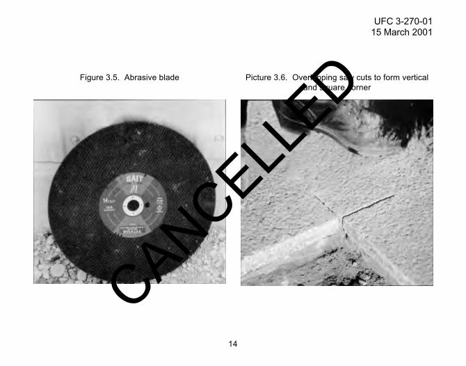
3.2.2. Saw the pavement. A concrete saw equipped with a diamond-tip or abrasive blade(Figures 3.4. and 3.5.) is used to saw the pavement. Saw cuts shall overlap so that a vertical and square corner is formed (Figure 3.6.). Since diamond-tip blades usually require water, the repairarea should be completely dry before it is repaired. However, there are some types ofdiamond-tip blades designed to dry cut asphalt pavements. The abrasive saw blade hasadvantages of lower cost and does not require water when sawing. A disadvantage is that theabrasive blade tends to wear quickly. One should make sure that the saw blade is the correctdiameter to allow cutting to the full depth of the pavement. Make sure that the saw blade is rated
7
UFC 3-270-0115 March 2001
3
CANCELLED

for the revolutions per minute (RPM) of the saw; otherwise, the blade could shatter during sawingif the blade does not have the correct RPM rating.
3.2.3. Jackhammer and remove defective material. An asphalt bit shall be used in thejackhammer. The jackhammer should be operated from the middle of the repair area and movetoward the edges. (Do not rock the hammer near the edge — this will destroy the vertical face.)If a saw is not available, the perimenter of the patch can be cut with the jackhammer. Since thismethod forms rough edges, it is not recommended. It is important that the cuts around thedistress should be as vertical as possible. After jackhammering, remove and discard the loosematerial.
3.2.4. Remove, replace, and compact the base. When performing a full-depth patch, the baseshould be visually inspected to ensure that the condition of the material is adequate. Allinadequate base, subbase, or subgrade materials should be removed until a good, dry, anddense material is located. The poor-quality material shall be replaced with a good-quality,well-graded base material. If subgrade material is removed, crushed stone or other suitable base material may be used to backfill to the top of the subgrade. New materials shall be placed in 2- to 3-inch (50- to 75-millimeter) lifts with each lift compacted to the required density. When removing the defective pavement, the base material is always disturbed. Therefore, the base materialshould always be recompacted prior to performing the next step.
3.2.5. Apply tack coat (and prime coat if used). A prime coat can be used to spray the sides andbottom of the hole to be patched with hot-asphalt plant mix. Recommended prime coat materialsare RC-70, MC-30, MC-70, or SC-70 cutback; an SS-1, SS-1h, CSS-1, or CSS-1h emulsion. The application rate is 0.10 to 0.25 gallons per square yard (0.45 to 1.13 liters per square meter). Too heavy an application could cause bleeding. Prime coats must be allowed time to penetrate thebase material. They are usually absorbed in 2 to 3 hours and should be fully cured in up to
8
UFC 3-270-0115 March 2001
CANCELLED
48 hours. If a prime coat is not used, a thin tack coat should be applied to the edges and bottomof the patch. This coating provides a good bond between the old and new materials. The patcharea edges shall be clean, dry, and free of any dust to ensure that the tack coat will bond to theedges. Recommended tack coat materials include the use of cutback grades RC-70, RC-250; oremulsion grades RS-1, MS-1, SS-1, SS-1h, CSS-1, CSS-1h; or asphalt cement grades AC-2.5,AC-5, AC-10, AR-1000, AR-2000, or AR-4000. The tack coat application rate is 0.05 to0.10 gallons per square yard (0.23 to 0.45 liters per square meter). A handspray wand should beused to apply the tack coat (Figure 3.7.). If a wand is not available, a stiff brush can be used. Inorder to prevent bleeding, too much tack should not be applied to the patch areas. (Too little tack is better than too much.)
3.2.6. Place the patch material. A good-quality, hot-asphalt plant mix material should be used tofill the patch. The material should be placed and compacted in 2- to 3-inch (50- to 75-millimeter)lifts. In order for the patch to be level with the surrounding pavement, the patch area should beoverfilled to allow for compaction (Figure 3.8.). (A good rule of thumb for overfilling is about40 percent — depending on the mix; i.e., 3 inches (50 millimeters) compacted = 4 1/4 inches(106 millimeters) uncompacted.) Patch material should not be overworked with a lute, shovel, orrake. Overworking, especially at the surface, causes segregation of the mix.
3.2.7. Compact the patch area. Using an appropriate method, the mix shall be compacted to theproper level. The size of the patch will determine which type compactor to use. For a very smallpatch area or areas, a hand tamper can be used. Larger areas require the use of a vibratoryplate tamper or a steel-wheel roller (Figures 3.9. and 3.10.). To ensure the required compaction,the proper equipment should be used and determined by the size of the patch. The edges of thepatch should always be compacted first, followed by compacting the remaining patch area in thedirection of traffic. Previous compaction lanes should be overlapped by about 6 inches(150 millimeters) across the patch area (Figure 3.11.). When the patch is competely compacted,
9
UFC 3-270-0115 March 2001
3
CANCELLED

it should be level or no higher than 1/8 inch (3 millimeters) above the surrounding patch surface(Figure 3.12.).
3.2.8. Seal the patch. After completing the patch, the final step is to seal the edges with anappropriate joint sealant material (Figure 3.13.). This will give added protection from waterinfiltration. The edge seal should be no more than 2 inches (50 millimeters) wide.
3.3. Procedural Steps (Partial-Depth Patch). The following steps should be conducted for theplacement of a partial-depth patch.
3.3.1. Mark the repair area. This is the same as for a full-depth patch (Paragraph 3.2.1.).
3.3.2. Saw the pavement. A concrete saw equipped with a diamond-tip or abrasive blade(Figures 3.4. and 3.5.) is used to saw the pavement. Saw cuts shall overlap so that a vertical and square corner is formed (Figure 3.6.). Since diamond-tip blades usually require water, the repairarea should be completely dry before it is repaired. However, there are some types ofdiamond-tip blades designed to dry cut asphalt pavements. The abrasive saw blade hasadvantages of lower cost and does not require water when sawing. A disadvantage is that theabrasive blade tends to wear quickly. The depth of cut should be controlled to allow cutting to the depth required for the repair. Make sure that the saw blade is rated for the RPM of the saw;otherwise, the blade could shatter during sawing if the blade does not have the correct RPMrating.
3.3.3. Jackhammer and remove defective material. This is the same as for a full-depth patch(Paragraph 3.2.3.).
3.3.4. Apply tack coat. A thin tack coat should be applied to the edges and bottom of the patch.This coating provides a good bond between the old and new materials. The patch area edgesshall be clean, dry, and free of any dust to ensure that the tack coat will bond to the edges.
10
UFC 3-270-0115 March 2001
CANCELLED

Recommended tack coat materials include the use of cutback grades RC-70, RC-250; oremulsion grades RS-1, MS-1, SS-1, SS-1h, CSS-1, CSS-1h; or asphalt cement grades AC-2.5,AC-5, AC-10, AR-1000, AR-2000, or AR-4000. The tack coat application rate is 0.05 to 0.10gallons per square yard (0.23 to 0.45 liters per square meter). A handspray wand should be used to apply the tack coat (Figure 3.7.). If a wand is not available, a stiff brush can be used. In orderto prevent bleeding, too much tack should not be applied to the patch areas. (Too little tack isbetter than too much.)
3.3.5. Place the patch material. This is the same as for full-depth patch (Paragraph 3.2.6.).
3.3.6. Compact the patch area. This is the same as for full-depth patch (Paragraph 3.2.7.).
3.3.7. Seal the patch. This is the same as for full-depth patch (Paragraph 3.2.8.).
3.4. Problem Areas. The major problem in constructing a successful patch is compaction ofboth the base and patch material. Thin lifts (less than 3 inches (75 millimeters)) for compactionwill work best for each material. Too much prime or tack coat is also a problem. If a spray wandis used, a test on an adjacent area should be performed to ensure the correct amount of prime ortack coat is being applied. If not, spray nozzles, settings, or operational procedures should bechanged to assure the correct amount of coatings.
(NOTE: If RC-70 or other cutbacks are used as a prime or tack coat, their use must comply withlocal environmental regulations.)
113
UFC 3-270-0115 March 2001
CANCELLED

12
UFC 3-270-0115 March 2001
Figure 3.1. Steps for full-depth patch Figure 3.2. Steps for utility cut repair
CANCELLED

13
Figure 3.3. Saw cutting marked repair area Figure 3.4. Diamond-tip blade
3
UFC 3-270-0115 March 2001
CANCELLED
14
UFC 3-270-0115 March 2001
Figure 3.5. Abrasive blade Picture 3.6. Overlapping saw cuts to form verticaland square corner
CANCELLED

15
Figure 3.7. Applying tack coat with spray wand Figure 3.8. Overfilled patch area
3
UFC 3-270-0115 March 2001
CANCELLED

16
Figure 3.9. Vibratory plate tamper Figure 3.10. Steel-wheel roller
UFC 3-270-0115 March 2001
CANCELLED

17
Figure 3.11. Overlapping compaction lanes Figure 3.12. Level patch surface
3
UFC 3-270-0115 March 2001
CANCELLED

18
UFC 3-270-0115 March 2001
Figure 3.13. Sealing edges of the patch
CANCELLED

CHAPTER 4
SPRAYED ASPHALT SURFACE TREATMENTS
4.1. Prime Coat. A prime coat is a spray application of bituminous material applied to thesurface of a base course which is to be covered with a pavement layer. The purpose is towaterproof and prevent raveling of the base during construction and to form a dense base towhich a bituminous pavement will adhere. Materials that can be used for prime coats are listedas follows: RC-70, MC-30, MC-70, or SC-70 cutback; SS-1, SS-1h, CSS-1, or CSS-1h emulsion.
4.2. Procedural Steps (Prime Coat). The following steps should be conducted to apply a prime coat.
4.2.1. Prepare the surface. The surface shall be free of all loose material such as dirt, clay, dust, or any other undesirable material. A light brooming should be used to remove these undesirablematerials. If the base is excessively dry, it should be lightly sprinkled with water.
4.2.2. Apply the prime. If the area to be primed is large, a distributor should be used. Prime coat applications on smaller areas can be sprayed with a handspray wand. Prime coat applicationrates are 0.10 to 0.25 gallons per square yard (0.45 to 1.13 liters per square meter). The entirearea shall be coated.
4.2.3. Allow prime to cure. Prime coats shall be allowed to cure for as long as necessary.Curing time can be up to 48 hours. If there is excess prime, it should be blotted with fine sand ormineral dust.
4.3. Problem Areas (Prime Coat). A major problem is overpriming. Application rates should be tested prior to priming. Proper nozzles and settings on the distributor spray bar or handwandshould be checked. Nozzles should be checked to ensure they are not plugged and nozzles
194
UFC 3-270-0115 March 2001
CANCELLED

should be set at the proper angle (Figure 4.1.). The use of RC-70 or other cutbacks as a primecoat must comply with local environmental regulations.
4.4. Tack Coat. The tack coat is applied to an existing pavement surface before it is overlaidwith a new ACC pavement. The tack provides a bond between the old and new pavement.Materials which can be used for tack coats are listed as follows: cutback grades RC-70, RC-250;emulsion grades RS-1, MS-1, SS-1, SS-1h, CSS-1, CSS-1h; or asphalt cement grades AC-2.5,AC-5, AC-10, AR-1000, AR-2000, or AR-4000.
4.5. Procedural Steps (Tack Coat). The following steps should be conducted to apply a tackcoat.
4.5.1. Prepare the surface. The surface must be clean and dry; and free of dust, loose dirt, andall other objectionable debris. The surface around and inside the patch should be cleaned withbrooms, air, and water.
4.5.2. Apply the tack. Tack coats for large areas require the use of a distributor. A handwandcan be used for patches and hard-to-apply areas. If a wand is not available, the tack can beapplied to patch edges with a stiff brush. The tack coat should be applied in an even and uniform coat over the entire area. If the surface should appear that there is not enough tack — it shouldbe remembered that too little tack is better than too much. No more tack material should beapplied than can be covered by the end of a working day. Application rates for tack coats rangefrom 0.05 to 0.15 gallons per square yard (0.23 to 0.68 liters per square meter).
4.5.3. Allow tack to cure. The tack coat shall be allowed to cure before placing the overlay orpatch material. Cure times will vary according to the type tack material used.
4.6. Problem Areas (Tack Coat). An over application of tack will cause bleeding and slippage;therefore, the proper application rate should be ensured. Application rates should be tested prior
20
UFC 3-270-0115 March 2001
CANCELLED

to spraying the tack material. Proper nozzles and settings on the distributor spray bar orhandwand should be checked. Nozzles should be checked to ensure they are not plugged andnozzles should be adjusted to the proper angle and height. Areas for tack coating shall be cleanand dry. The use of RC-70 or other cutbacks as a tack coat must comply with localenvironmental regulations.
4.7. Fog Seals and Rejuvenators. A fog seal is a spray application of a diluted asphalt or taremulsion. Fog seals are used on sound plant mixed surfaces to seal a weathered, oxidizedpavement or on a pavement containing numerous small cracks. Emulsions used for fog seals are SS-1, SS-1h, CSS-1, or CSS-1h. Rejuvenators are commercially available products which areused to restore oxidized pavement surfaces. They should not be used on pavements that exhibitraveling (unless raveling is very minor) or that have cracking (unless cracking is a very minorhairline). Rejuvenators can cause restored pavement surfaces to be slippery for up to a year;therefore, extreme care should be taken in choosing areas and application rates. Since there are numerous commercially available products, a list of rejuvenators will not be presented.
4.8. Procedural Steps (Fog Seals and Rejuvenators). The following steps should beconducted for the application of fog seals and rejuvenators.
4.8.1. Prepare the surface. The surface shall be thoroughly cleaned prior to application. This isdiscussed in Paragraphs 4.2.1. and 4.5.1. Other distresses should be repaired beforeapplication.
4.8.2. Determine proper application rate. The application rate will vary according to the quantityof material the pavement absorbs. Therefore, field test sections should be sprayed with differentapplication rates to determine the best rate. The rate should be adjusted so that the treatedsurface is not slick, unstable, and does not contain excess material after 12 to 24 hours curing.
214
UFC 3-270-0115 March 2001
CANCELLED

4.8.3. Dilute the material. The material can be used undiluted, but it is usually diluted. Dilutionrates can be as high as 1 part emulsion to 10 parts water, with an average of 1 part emulsion to4 parts water. Manufacturer’s dilution directions for rejuvenators should be followed.
4.8.4. Apply the material. A calibrated asphalt distributor shall be used for material application(Figure 4.2.). The calibration of the distributor is very important. The spray bar nozzles should be set at the proper angle and height. Nozzles shall be the proper size and all nozzles should be the same size for proper material application. Make sure that the nozzles are not plugged beforeasphalt material is applied. To avoid slick surfaces, the asphalt material should be applied inmultiple applications over the entire area.
4.8.5. Cure time. The fog seal should be allowed to fully cure before traffic is allowed on thetreated pavement. Cure time is usually 12 to 24 hours.
4.9. Problem Areas (Fog Seals and Rejuvenators). The distributor calibration and spray barcan cause possible problems during material application; therefore, the distributor should becalibrated, adjusted, and cleaned. The MAJCOM or TSMCX pavement engineer should becontacted before a rejuvenator is used. Generally, fog seals are not allowed for airfieldtreatments because they tend to reduce skid resistance; however, the MAJCOM or TSMCXshould be contacted. A major problem is over application of material; therefore, properapplication and dilution rates should be followed. Preliminary tests should be conducted todetermine the proper application and dilution rate.
22
UFC 3-270-0115 March 2001
CANCELLED

23
Figure 4.2. Asphalt distributor
4
Figure 4.1. Spray bar and nozzlesettings
UFC 3-270-0115 March 2001
CANCELLED

CHAPTER 5
SPRAYED ASPHALT WITH SURFACE AGGREGATE
5.1. Introduction. Single and double bituminous surface treatments (SBST and DBST, respectively)consist of sprayed asphalt applications followed immediately by one or more layers of aggregate.These treatments are used to retard deterioration of raveling, improve skid resistance, seal smallcracks, and waterproof the surface. They are usually used on light-traffic roads and overruns.Another type SBST, sandseal, is also presented. Also, a variational procedure of SBST to repairbleeding is presented and consists of applying hot sand followed by rolling.
5.2. Single Bituminous Surface Treatment. Bituminous materials which can be used for SBST are as follows: cutback (RC-250, RC-800, or RC-3000); emulsion (RS-1, RS-2, CRS-1, orCRS-2); asphalt cement (AC-2.5 or AC-5); or road tar (RT-5 through -12). Aggregate gradationsto be used are shown in Table 5.1.
5.3. Procedural Steps (SBST). The following steps should be conducted for placement of anSBST.
5.3.1. Prepare the area. Prior to applying an SBST, all failed areas shall be repaired andsurfaces for treatment shall be thoroughly cleaned. The same procedures for prime and tackcoats should be followed and are discussed in Paragraphs 4.2.1. and 4.5.1.
5.3.2. Apply the binder material. The binder (asphalt material) should be applied with an asphaltdistributor. The distributor must be properly calibrated and the same precautions should be taken as discussed for sprayed asphalt treatments (Chapter 4). Application rates of the binder andaggregate for SBST are shown in Table 5.2.
255
UFC 3-270-0115 March 2001
CANCELLED

Table 5.1. Aggregate Gradations for SBST
Table 5.2. SBST Binder and Aggregate Application Rates
26
Sieve Size
% Passing by Weight, Gradation Designation
No. 1 No. 2 No. 3
1 in. (25.4 mm) 100 —- —-3/4 in. (19.1 mm) 90 - 100 100 —-1/2 in. (12.7 mm) 20 - 55 90 - 100 1003/8 in. (9.5 mm) 0 - 15 40 - 70 85 - 100No. 4 (4.8 mm) 0 - 5 0 - 15 10 - 30No. 8 (2.4 mm) —- 0 - 5 0 - 10
No. 16 (1.2 mm) —- —- 0 - 5
Gradation No.Bituminous Material*
gal/yd2 (l/m2)Aggregate
lb/yd2 (kg/m2)
1 0.40 - 0.50 (1.81 - 2.26) 40 - 50 (22 - 27)
2 0.30 - 0.45 (1.36 - 2.04) 25 - 30 (14 - 16)
3 0.20 - 0.35 (0.91 - 1.58) 20 - 25 (11 - 14)
* If an emulsion is used, increase the application rate by 10 percent.
UFC 3-270-0115 March 2001
CANCELLED

5.3.3. Apply the aggregate. The aggregate shall be immediately applied after binder materialapplication. The aggregate can be applied with tailgate spreaders on dump trucks or by self-propelled hopper-type spreaders (Figures 5.1. and 5.2.). Spreaders should be calibrated toensure proper aggregate application. Aggregate that is clean, dry, and free of dust or otherundesirable material shall be used. Also, the aggregate should be hard, angular, and abrasionresistant.
5.3.4. Roll the aggregate. The aggregate shall be immediately rolled after application. Apneumatic-tire roller with tire pressures of 60 to 90 pounds per square inch (414 to620 kilopascals) and appropriate size (weight) should roll the aggregate. To avoid crushing theaggregate, a pneumatic-tire roller should be used. A steel-wheel roller can be used; however, the weight shall be heavy enough to seat the aggregate but not crush it. The steel wheel will bridgelow spots and may not properly seat the aggregate. Rolling should continue until all aggregateparticles are properly seated.
5.3.5. Sweep the area. The treated area shall be allowed to cure for at least 24 hours beforebrooming to remove loose particles (Figure 5.3.). It is better to broom during the coolest portionof the day to prevent dislodging aggregate. Care should be taken to use only enough pressureon the broom to remove the loose particles.
5.4. Problem Areas (SBST). All equipment shall be properly calibrated before material place-ment. A test section can be used to ensure all equipment is in correct working order. To makeclean and straight transverse joints, it is recommended that building paper be used where thespreading of the binder and aggregate begins and ends. After applications, the paper is removed and a straight edge is formed (Figure 5.4.). To prevent a buildup of aggregate along thelongitudinal joint, the aggregate spread shall be stopped where the asphalt is a full thickness(Figure 5.5.). This distance varies according to the spray width of the nozzle, but it is usually
275
UFC 3-270-0115 March 2001
CANCELLED

about 6 to 8 inches (150 to 200 millimeters). On the adjacent pass, aggregate should be appliedalong the full spray width. After completing the work and opening the treated area to traffic,speed limits should be posted to no more than 20 miles per hour (32 kilometers per hour) for afew days. This will ensure that the asphalt is fully cured and prevent dislodging of additionalaggregate.
5.5. Multiple Bituminous Surface Treatment. This treatment is essentially the same as theSBST, except that more than one application of binder and aggregate is used. The mostcommon treatment is the DBST. The same bituminous materials used for SBST can also beused for DBST (Paragraph 5-2). Aggregate gradations to be used are shown in the followingtable.
Table 5.3. Aggregate Graduations for DBST
28
Sieve Size
% Passing by Weight, Gradation Designation
No. 1 No. 2 No. 3 No. 4
1 in. (25.4 mm) 100 —- —- —-3/4 in. (19.1 mm) 90 - 100 —- 100 —-1/2 in. (12.7 mm) 20 - 55 100 90 - 100 —-3/8 in. (9.5 mm) 0 - 15 85 - 100 40 - 70 100No. 4 (4.8 mm) 0 - 5 10 - 30 0 - 15 85 - 100No. 8 (2.4 mm) —- 0 - 10 0 - 5 10 - 40No. 16 (1.2 mm) —- 0 - 5 —- 0 - 10No. 50 (300µm) —- —- —- 0 - 5
UFC 3-270-0115 March 2001
CANCELLED

5.6. Procedural Steps (DBST). The following steps should be conducted for placement of aDBST.
5.6.1. Prepare the area. This is the same as for SBST (Paragraph 5.3.1.).
5.6.2. Apply the binder material. This is the same as discussed for SBST (Paragraph 5.3.2.),except two applications of binder and aggregate are placed with rates as follows:
Table 5.4. DBST Binder and Aggregate Application Rates
29
First Application
Gradation No.Bituminous Material*
gal/yd2 (l/m2)Aggregate
lb/yd2 (kg/m2)
1 0.20 - 0.30 (0.91 - 1.36) 40 - 50 (22 - 27)
3 0.15 - 0.20 (0.68 - 0.91) 25 - 30 (14 -16)
Second Application
Gradation No.Bituminous Material**
gal/yd2 (l/m2)Aggregate
lb/yd2 (kg/m2)
2 0.30 - 0.45 (1.36 - 2.04) 20 - 25 (11 - 14)
4 0.20 - 0.30 (0.91 - 1.36) 15 - 20 (8 - 11)
* If an emulsion is used, increase the application rate by 10 percent.** Second application shall be 50 percent greater than first application.
NOTE: Graduations shall be used in pairs. If gradation 1 is used for the first application, thengradation 2 must be used for the second application and the same for gradations 3 and 4.
5
UFC 3-270-0115 March 2001
CANCELLED

5.6.3. Apply the aggregate. This is the same as for SBST (Paragraph 5.3.3.).
5.6.4. Roll the aggregate. This is the same as discussed for SBST (Paragraph 5.3.4.).
5.6.5. Sweep the area. This is the same as for SBST (Paragraph 5.3.5.).
5.6.6. Apply second application. To apply the second application of binder and aggregate, the above steps (5.6.1.-5.6.5.) should be followed.
5.7. Problem Areas (DBST). The same problems for SBST are applicable to DBST. Theseproblems are discussed in Paragraph 5.4.
5.8. Sandseal. This is another type of SBST; therefore, the same procedural steps for an SBST(Paragraph 5.3.) should be followed except the following aggregate gradations and applicationrates should be used:
Table 5.5. Aggregate Gradations for Sandseal
30
Sieve Size
% Passing by Weight, Gradation Designation
No. 1 No. 2
1/2 in. (12.7 mm) —- —-
3/8 in. (9.5 mm) 100 —-No. 4 (4.8 mm) 85 - 100 100No. 8 (2.4 mm) 10 - 40 10 - 40No. 16 (1.2 mm) 0 - 10 0 - 10
No. 50 (300 µm) 0 - 5 0 - 5
UFC 3-270-0115 March 2001
CANCELLED

Table 5.6. Sandseal Binder and Aggregate Application Rates
5.9. Sand Application and Rolling. This SBST variational method can be used to repairbleeding pavement. The following steps should be conducted.
5.9.1. Apply hot sand. Sand should be heated to above 275 degrees Fahrenheit (135 degreesCelsius) and then the sand can be spread with a tailgate or box spreader, or by hand. Therecommended application rate is 10 to 15 pounds per square yard (5 to 8 kilograms per squaremeter).
5.9.2. Roll the sand. Immediately after spreading the sand, it shall be rolled with a pneumatic-tire roller.
5.9.3. Sweep excess material. After the treated area has sufficiently cooled, an appropriatesweeping method should be used to remove excess sand.
31
Application Rates
Gradation No.Bituminous Material*
gal/yd2 (l/m2)Aggregate
lb/yd2 (kg/m2)
1 0.20 - 0.35 (0.91 - 1.58) 20 - 25 (11 - 14)
2 0.15 - 0.25 (0.68 - 1.13) 15 - 20 (8 - 11)
3 0.15 - 0.25 (0.68 - 1.13) 10 - 15 (5 - 8)
* If an emulsion is used, increase the application rate by 10 percent.
5
UFC 3-270-0115 March 2001
CANCELLED

32
Figure 5.1. Applying aggregate with tailgatespreader on dump truck
Figure 5.2. Applying aggregate with self-propelledhopper-type spreader
UFC 3-270-0115 March 2001
CANCELLED

33
Figure 5.3. Brooming the treated area Figure 5.4. Straight edge formed afterbuilding paper removed
5
UFC 3-270-0115 March 2001
CANCELLED

34
Figure 5.5. Aggregate and sprayed asphalt spead pattern
UFC 3-270-0115 March 2001
CANCELLED
CHAPTER 6
ASPHALT SLURRY SEALS
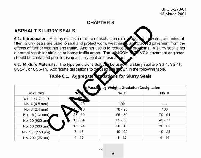
6.1. Introduction. A slurry seal is a mixture of asphalt emulsion, aggregate, water, and mineralfiller. Slurry seals are used to seal and protect worn, weathered, and cracked pavement from theeffects of further weather and traffic. Another use is to reduce skid problems. A slurry seal is nota normal repair for airfields or heavy traffic areas. The MAJCOM or TSMCX pavement engineershould be contacted prior to using a slurry seal on these areas.
6.2. Mixture Materials. The type emulsions that can be used in a slurry seal are SS-1, SS-1h,CSS-1, or CSS-1h. Aggregate gradations to be used are shown in the following table.
Table 6.1. Aggregate Gradations for Slurry Seals
356
Sieve Size
% Passing by Weight, Gradation Designation
No. 1 No. 2 No. 3
3/8 in. (9.5 mm) 100 —- —-No. 4 (4.8 mm) 70 - 90 100 —-No. 8 (2.4 mm) 45 - 70 78 - 95 100
No. 16 (1.2 mm) 28 - 50 55 - 80 70 - 94No. 30 (600 µm) 19 - 34 35 - 60 45 - 73
No. 50 (300 µm) 12 - 24 20 - 40 25 - 50
No. 100 (150 µm) 7 - 16 10 - 22 10 - 25
No. 200 (75 µm) 4 - 12 4 - 12 4 - 14
UFC 3-270-0115 March 2001
CANCELLED

If a mineral filler is used in the slurry, a portland cement or hydrated lime should be used. Thefiller tends to improve the stability of the mixture. If stability or segregation problems occur,mineral filler at 0.4 to 0.5 percent of the total mixture should be used. Only potable water shall be used. Water is the primary control for workability of the mixture.
6.3. Procedural Steps. The following are steps for placement of a slurry seal.
6.3.1. Prepare the surface. All loose material (including any loose or flaking paint), dirt, andvegetation shall be removed from the surface. Cracks greater than 1/8 inch (3 millimeters) wideshall be sealed. During sealing, the sealant should be placed 1/8 to 1/4 inch (3 to 6 millimeters)below the surface. After sealing all cracks and cleaning the surface, a very light tack coat shouldbe sprayed at a rate of 0.05 to 0.10 gallons per square yard (0.23 to 0.45 liters per square meter)and allowed to fully cure.
6.3.2. Apply the slurry. Immediately before applying the slurry, a fog spray of water should beapplied to the surface with the spray bar on the slurry machine. There should be no standingwater after the spray. The spray should be adjusted to compensate for temperature, surfacetexture, humidity, and dryness of the surface. The slurry shall be applied with a slurry machine(Figure 6.1.). The slurry machine is a self-propelled, continuous-flow mixing unit. It should becapable of delivering the proper amount of aggregate, water, mineral filler, and emulsion to themixing unit (Figure 6.2.). The mixing unit is either a single or double pugmill mixer. The mixingunit discharges the material into the spreader box that is equipped with flexible squeegees andwidth adjustment. Other parts of the machine include the spray bar for wetting the pavement andan aggregate prewetting device. Most of the time, a burlap drag is located behind the spreaderbox to improve the joints and overall appearance of the mixture. The slurry is applied from1/8 inch (3 millimeters) and is usually no more than 1/4 inch (6 millimeters) thick in one pass. If
36
UFC 3-270-0115 March 2001
CANCELLED

more than one pass is applied, the previous layer should fully cure before applying the secondapplication.
6.3.3. Roll the slurry. The slurry shall be rolled to reduce the voids, limit surface imperfections,and increase the slurry’s resistance to water. The rolling should be performed after the slurry has cured enough to support the roller without removing any of the slurry mixture. A 5-ton(4,540-kilogram) pneumatic-tire roller with tire pressures of 50 pounds per square inch(345 kilopascals) should be used to roll the slurry.
6.3.4. Cure the slurry. The time to allow for curing will vary according to the amounts of theemulsion and aggregate. The slurry could cure by evaporation of water from the surface, bydeposition of asphalt on the aggregate which frees the water, or by a combination of these. Ifcuring is from top to bottom, the material at the top will cure faster than the material at the bottom. Before opening the treated area to traffic, the slurry seal shall be fully cured.
6.4. Problem Areas. To ensure proper slurry machine calibration and correct mixture, a teststrip should be used. When hand applying the slurry, it should not be overworked; this causesthe emulsion to break prematurely. If possible, the second lane should be applied while the edgeof the previous lane is still fluid and workable. If the previous lane’s edge is not workable, thenallow the slurry material to cure enough for the spreader box not to damage the previous lane.Since material buildup on the burlap drag causes streaking and gouging, the burlap drag shouldbe kept clean and it should be replaced when necessary. The flexible lining of the spreader boxshould be inspected for wear or accumulation of cured slurry.
376
UFC 3-270-0115 March 2001
CANCELLED

38
Figure 6.1. View of slurry seal machine Figure 6.2. Slurry seal machine
UFC 3-270-0115 March 2001
CANCELLED

CHAPTER 7
PATCHING (FILLING RUTS AND DEPRESSIONS)
7.1. Introduction. Ruts and depressions are frequently repaired by filling the distressed areaswith layers of asphalt. The procedure is usually a temporary repair. If the rut or depression areais accompanied by alligator cracking, full- or partial-depth repairs should be conducted.
7.2. Procedural Steps. The following steps should be conducted to repair a rut or depression.
7.2.1. Determine repair boundaries. If a depression or rut is to be repaired, the repair areashould extend to where the area is the same elevation as the surrounding pavement. For repairof other distresses, the repair should extend beyond the distress (usually 1 foot (300 millimeters))and into sound pavement.
7.2.2. Cut the patch and remove pavement. For repair of depressions and ruts, the edges shall be sawed or a grinder can be used to grind down the pavement. A vertical edge should be atleast 2 inches (50 millimeters) deep. If the edges are saw cut, a lightweight jackhammer shouldbe used to remove the pavement along the edges by placing the jackhammer about 3 inches (75millimeters) inside the patch area with the hammer toward the edge. This will avoid damaging the vertical edge.
7.2.3. Prepare area. After removal of the pavement from the patch area, the area should bethoroughly cleaned with high-pressure air, brooms, water, or combinations of these. The areashould also be dry before applying the tack coat. After the repair area is clean and dry, a tackcoat is applied to the edges and bottom of the patch area. Apply the tack as discussed inParagraph 4.5.2. The tack shall be allowed to cure.
397
UFC 3-270-0115 March 2001
CANCELLED

7.2.4. Place and compact repair material. For the patch to be most effective, a good-qualityhot-asphalt plant mix should be used. If the repair is deep enough, the asphalt should be placedin lifts of no more than 2 to 3 inches (50 to 75 millimeters) thick. To repair ruts, level lifts shouldfill the ruts rather than lifts conforming to the shape of the rut (Figure 7.1.). Use the appropriateequipment to compact the asphalt. On the final lift placement, the patch area should be overfilled to allow for compaction. When fully compacted, the patch should be level or within 1/8 inch (3millimeters) of the surrounding surface. A pneumatic-tire roller works best for compactingmaterial in ruts and depressions. If hot-mix material is not available, a cold-mix material can beused; however, the patch will not have a long service life. During inclement weather conditions, it is recommended that cold-mix materials be used for repairs.
7.3. Problem Areas. The edges of the patch shall be as straight and vertical as possible. Toomuch tack coating should be avoided. When repairing a rut or depression, the asphalt materialshould be properly placed to ensure the repair is level with the surrounding pavement.
40
UFC 3-270-0115 March 2001
CANCELLED

417
UFC 3-270-0115 March 2001
Figure 7.1. Correct method for filling ruts and depressions in lifts
CANCELLED
CHAPTER 8
POROUS FRICTION SURFACES
8.1. Introduction. A porous friction surface (PFS) is an open-graded asphaltic concrete wearing surface containing a large amount of air voids that allow water to drain vertically and laterallythrough the pavement structure (Figure 8.1.). These surfaces are usually 3/4 to 1 inch (19 to25 millimeters) thick and the large void content provides a means to prevent hydroplaning at highspeeds. The surface texture of the PFC provides for excellent skid resistance and decreases thetire spray under wet conditions. Several procedures to repair a PFS are presented in thefollowing paragraphs.
8.2. Sealing Cracks. The guidelines for sealing cracks in a PFS are different from a normalasphalt surface. The materials used for sealing cracks on a PFS are the same as for a normalasphalt pavement. The following steps should be conducted for sealing cracks on a PFS.
8.2.1. Prepare the crack. To prepare the crack, all loose material shall be removed and thecrack should be free of dust and dirt.
8.2.2. Seal the crack. The same sealant placement procedures shall be followed as for anasphalt surface (UFC 3-270-02, “Asphalt Crack Repair”). If the crack is 1/4 inch (6 millimeters)wide or less, the crack should not be sealed unless loose debris is causing an FOD problem.Cracks from 1/4 to 3/4 inch (6 to 19 millimeters) should be sealed if they are raveling and causing an FOD problem. Cracks greater than 3/4 inch (19 millimeters) wide shall be filled with a PFSasphalt mixture and rolled with a steel-wheel roller. Only seal longitudinal cracks when regularsweeping methods no longer remove all loose aggregate from the surface. The loose aggregatecould block internal drainage. Transverse cracks should be sealed except those perpendicular to the water flow. In any case, do not seal the joint if it will interfere with water drainage.
438
UFC 3-270-0115 March 2001
CANCELLED

8.3. Patching PFS. If correctly performed, a PFS patch should be virtually indistinguishablefrom the remainder of the surface. The following steps shall be conducted for patching PFS.
8.3.1. Remove defective PFS. Sawing shall not be performed to patch a PFS. It isrecommended that a milling machine be used to remove any defective PFS. The full depth andextent of PFS damage shall be milled.
8.3.2. Clean and tack repair area. Remove the defective material and, if necessary, repair theunderlying pavement. The repair area should be thoroughly cleaned before placing the tack coat. A light tack coat should be applied to the bottom but not the edges.
8.3.3. Place patch material. The repair material should conform as closely as possible to theexisting PFS. After material placement, it should be rolled by using the same method as theoriginal construction. A cold-mix asphalt can be used for a temporary repair.
8.4. Raveling Control. A procedure that will help control raveling of the porous friction surface,until replacement, is a very light spray application of asphalt emulsion. If this procedure isperformed, care should be taken not to hinder drainage of the PFS.
8.5. Patching Using Standard Hot-Asphalt Plant Mix. If a standard hot-asphalt plant mix isused to repair a PFS, the following steps shall be taken.
8.5.1. Mark the repair area. The boundaries of the repair shall be determined and marked forsaw cutting. The patch must be diamond shaped with a point of the diamond at the highelevation (Figure 8.2.). This will allow water to flow around the patch area.
8.5.2. Remove defective PFS. The area should be sawed to the thickness of the porous frictionsurface. Defective material should be removed and care taken not to destroy the edges of thepatch.
44
UFC 3-270-0115 March 2001
CANCELLED

8.5.3. Place patch material. The sides and bottom of the patch area shall be tack coated;however, do not over-tack. After the tack coat has cured, a well-graded hot-asphalt plant mixshall be placed and compacted.
458
UFC 3-270-0115 March 2001
CANCELLED

46
Figure 8.1. View of a porous friction surface (PFS) Figure 8.2. Porous friction pavementpatch using hot-asphalt plant mix
UFC 3-270-0115 March 2001
CANCELLED