Embed Size (px)
Citation preview

Plastic Molding Module
Inject, Clamp, and Eject Mode
(Cat. No. 1771-QDC)
Allen-Bradley Parts
PLC is a registered trademark of Allen-Bradley Company, Inc.
PanelView, and PanelBuider are trademarks of Allen-Bradley Company, Inc
Because of the variety of uses for the products described in this publication,those responsible for the application and use of this control equipment mustsatisfy themselves that all necessary steps have been taken to assure thateach application and use meets all performance and safety requirements,including any applicable laws, regulations, codes and standards.
The illustrations, charts, sample programs and layout examples shown inthis guide are intended solely for purposes of example. Since there aremany variables and requirements associated with any particular installation,Allen-Bradley does not assume responsibility or liability (to includeintellectual property liability) for actual use based upon the examples shownin this publication.
Allen-Bradley publication SGI-1.1, Safety Guidelines for the Application,Installation, and Maintenance of Solid State Control (available from yourlocal Allen-Bradley office), describes some important differences betweensolid-state equipment and electromechanical devices that should be takeninto consideration when applying products such as those described in thispublication.
Reproduction of the contents of this copyrighted publication, in whole or inpart, without written permission of Allen-Bradley Company, Inc. is prohibited.
Throughout this manual we use ATTENTION and Important to alert youto the following:
ATTENTION: Tells readers where people may be hurt,machinery may be damaged, or economic loss may occur, ifprocedures are not followed properly.
ATTENTION helps you:
- identify a hazard
- avoid the hazard
- recognize the consequences
Important: Identifies information that is especially important for successfulapplication and understanding of the product.
Important: We recommend that you frequently back up your applicationprograms on an appropriate storage medium to avoid possible data loss.
Important User Information

Important Information P�1. . . . . . . . . . . . . . . . . . . . . . . . . . . .
Manual Objectives P�1. . . . . . . . . . . . . . . . . . . . . . . . . . . . . . . . . . .
Audience P�2. . . . . . . . . . . . . . . . . . . . . . . . . . . . . . . . . . . . . . . . . .
Use of Terms P�2. . . . . . . . . . . . . . . . . . . . . . . . . . . . . . . . . . . . . . .
Related Publications P�5. . . . . . . . . . . . . . . . . . . . . . . . . . . . . . . . . .
Overview of Inject, Clamp, and Eject Mode 1�1. . . . . . . . . . . .
Chapter Objectives 1�1. . . . . . . . . . . . . . . . . . . . . . . . . . . . . . . . . . .
Inject Control 1�1. . . . . . . . . . . . . . . . . . . . . . . . . . . . . . . . . . . . . . .
Clamp Control 1�9. . . . . . . . . . . . . . . . . . . . . . . . . . . . . . . . . . . . . .
Ejector Control 1�13. . . . . . . . . . . . . . . . . . . . . . . . . . . . . . . . . . . . . .
System Pressure 1�15. . . . . . . . . . . . . . . . . . . . . . . . . . . . . . . . . . . .
Example Hydraulic Circuits for the Inject, Clamp, and Eject Mode 1�16. .
Summary of Inject, Clamp, and Eject Mode of Operation 1�20. . . . . . . .
Install the QDC Module 2�1. . . . . . . . . . . . . . . . . . . . . . . . . . .
Chapter Objectives 2�1. . . . . . . . . . . . . . . . . . . . . . . . . . . . . . . . . . .
Record I/O Ranges 2�1. . . . . . . . . . . . . . . . . . . . . . . . . . . . . . . . . .
Set Module Jumpers 2�2. . . . . . . . . . . . . . . . . . . . . . . . . . . . . . . . .
Key the I/O Chassis 2�5. . . . . . . . . . . . . . . . . . . . . . . . . . . . . . . . . .
Install the QDC Module 2�6. . . . . . . . . . . . . . . . . . . . . . . . . . . . . . . .
Wire I/O Devices 2�7. . . . . . . . . . . . . . . . . . . . . . . . . . . . . . . . . . . .
Ground and Shield Your I/O Devices 2�9. . . . . . . . . . . . . . . . . . . . . .
Plan for E�STOPs and Machine Interlocks 2�11. . . . . . . . . . . . . . . . . .
Configure the QDC Module's I/O 3�1. . . . . . . . . . . . . . . . . . . .
Chapter Objectives 3�1. . . . . . . . . . . . . . . . . . . . . . . . . . . . . . . . . . .
Select Module Parameters and I/O Ranges 3�2. . . . . . . . . . . . . . . . .
Determine Initial Sensor�configuration Values 3�4. . . . . . . . . . . . . . . .
Download MCC Parameters to the QDC Module 3�5. . . . . . . . . . . . . .
Use Set�output Operation to Move the Ram (screw), Clamp, and Ejector 3�7. . . . . . . . . . . . . . . . . . . . . . . . . . . . . . . .
Complete your Sensor Configuration 3�8. . . . . . . . . . . . . . . . . . . . . .
Select Optional Configurations 3�14. . . . . . . . . . . . . . . . . . . . . . . . . .
Table of Contents
Allen-Bradley Parts

Table of Contentsii
Overview of Remaining Configuration Procedures 4�1. . . . . .
Chapter Objectives 4�1. . . . . . . . . . . . . . . . . . . . . . . . . . . . . . . . . . .
Configuration Concepts 4�1. . . . . . . . . . . . . . . . . . . . . . . . . . . . . . .
System Command and Status Blocks 4�2. . . . . . . . . . . . . . . . . . . . . .
Overview of Procedures 4�3. . . . . . . . . . . . . . . . . . . . . . . . . . . . . . .
Enter Data Table Values and Download Data Blocks 4�4. . . . . . . . . . .
Jog Your Machine 5�1. . . . . . . . . . . . . . . . . . . . . . . . . . . . . . .
Chapter Objectives 5�1. . . . . . . . . . . . . . . . . . . . . . . . . . . . . . . . . . .
About Jogging 5�1. . . . . . . . . . . . . . . . . . . . . . . . . . . . . . . . . . . . . .
Use These Worksheets 5�1. . . . . . . . . . . . . . . . . . . . . . . . . . . . . . .
Determine Initial Jog Values 5�2. . . . . . . . . . . . . . . . . . . . . . . . . . . .
Write Ladder Logic 5�5. . . . . . . . . . . . . . . . . . . . . . . . . . . . . . . . . . .
Jog Your Ram (Screw), Clamp, and Ejector 5�7. . . . . . . . . . . . . . . . .
Configure Screw�rotate Jogs for Indirect Control 5�7. . . . . . . . . . . . . .
Write Ladder Logic to Assist with Screw�rotate Jogs 5�8. . . . . . . . . . .
Rotate the Screw 5�9. . . . . . . . . . . . . . . . . . . . . . . . . . . . . . . . . . . .
Select Command and Status Bits to Sequence Machine Operation 6�1. . . . . . . . . . . . . . . . . . . . . . . . . . .
Chapter Objectives 6�1. . . . . . . . . . . . . . . . . . . . . . . . . . . . . . . . . . .
Assess Your Logic Requirements 6�1. . . . . . . . . . . . . . . . . . . . . . . .
Use Command and Status Bit Tables 6�2. . . . . . . . . . . . . . . . . . . . . .
Chapter Objectives 7�1. . . . . . . . . . . . . . . . . . . . . . . . . . . . . . . . . . .
Use These Worksheets 7�2. . . . . . . . . . . . . . . . . . . . . . . . . . . . . . .
Procedure to Determine and Record Initial Values 7�19. . . . . . . . . . . . .
Determine Bit Selections: Assign Module Outputs for Your Control Valves 7�19. . . . . . . . . . . . . . . . . . . . . . . . . . . . . . . .
Select the Type of PID Algorithm 7�21. . . . . . . . . . . . . . . . . . . . . . . . .
Determine Word Values:Select Values for Expert Response Compensation (ERC) 7�22. . . . .
Determine Unselected Valve Set�output Values 7�22. . . . . . . . . . . . . . .
Set Your Acceleration/Deceleration Ramp Rates 7�24. . . . . . . . . . . . . .
Determine Set�output Values for End of Profiles 7�25. . . . . . . . . . . . . .
Set Pressure Control Limits 7�26. . . . . . . . . . . . . . . . . . . . . . . . . . . . .
Set Velocity Control Limits 7�28. . . . . . . . . . . . . . . . . . . . . . . . . . . . . .
Set Profile Gain Constants, Pressure�Alarm Setpoints, and Watchdog Timer Presets 7�29. . . . . . . . . . . . . . . . . . . . . . . . .
Enter and Download your Worksheet Values 7�31. . . . . . . . . . . . . . . .
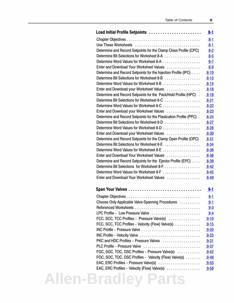
Table of Contents iii
Load Initial Profile Setpoints 8�1. . . . . . . . . . . . . . . . . . . . . . .
Chapter Objectives 8�1. . . . . . . . . . . . . . . . . . . . . . . . . . . . . . . . . . .
Use These Worksheets 8�1. . . . . . . . . . . . . . . . . . . . . . . . . . . . . . .
Determine and Record Setpoints for the Clamp Close Profile (CPC) 8�2
Determine Bit Selections for Worksheet 8�A 8�5. . . . . . . . . . . . . . . . .
Determine Word Values for Worksheet 8�A 8�7. . . . . . . . . . . . . . . . . .
Enter and Download Your Worksheet Values 8�9. . . . . . . . . . . . . . . .
Determine and Record Setpoints for the Injection Profile (IPC) 8�10. . . .
Determine Bit Selections for Worksheet 8�B 8�13. . . . . . . . . . . . . . . . .
Determine Word Values for Worksheet 8�B 8�14. . . . . . . . . . . . . . . . . .
Enter and Download your Worksheet Values 8�18. . . . . . . . . . . . . . . .
Determine and Record Setpoints for the Pack/Hold Profile (HPC) 8�18.
Determine Bit Selections for Worksheet 8�C 8�21. . . . . . . . . . . . . . . . .
Determine Word Values for Worksheet 8�C 8�22. . . . . . . . . . . . . . . . . .
Enter and Download your Worksheet Values 8�23. . . . . . . . . . . . . . . .
Determine and Record Setpoints for the Plastication Profile (PPC) 8�24.
Determine Bit Selections for Worksheet 8�D 8�27. . . . . . . . . . . . . . . . .
Determine Word Values for Worksheet 8�D 8�28. . . . . . . . . . . . . . . . . .
Enter and Download your Worksheet Values 8�30. . . . . . . . . . . . . . . .
Determine and Record Setpoints for the Clamp Open Profile (OPC) 8�31
Determine Bit Selections for Worksheet 8�E 8�34. . . . . . . . . . . . . . . . .
Determine Word Values for Worksheet 8�E 8�36. . . . . . . . . . . . . . . . . .
Enter and Download Your Worksheet Values 8�38. . . . . . . . . . . . . . . .
Determine and Record Setpoints for the Ejector Profile (EPC) 8�39. . . .
Determine Bit Selections for Worksheet 8�F 8�42. . . . . . . . . . . . . . . . .
Determine Word Values for Worksheet 8�F 8�45. . . . . . . . . . . . . . . . . .
Enter and Download Your Worksheet Values 8�49. . . . . . . . . . . . . . . .
Span Your Valves 9�1. . . . . . . . . . . . . . . . . . . . . . . . . . . . . . . .
Chapter Objectives 9�1. . . . . . . . . . . . . . . . . . . . . . . . . . . . . . . . . . .
Choose Only Applicable Valve�Spanning Procedures 9�1. . . . . . . . . .
Referenced Worksheets 9�3. . . . . . . . . . . . . . . . . . . . . . . . . . . . . . .
LPC Profile - Low Pressure Valve 9�4. . . . . . . . . . . . . . . . . . . . . . . .
FCC, SCC, TCC Profiles - Pressure Valve(s) 9�10. . . . . . . . . . . . . . .
FCC, SCC, TCC Profiles - Velocity (Flow) Valve(s) 9�15. . . . . . . . . . . .
INC Profile - Pressure Valve 9�20. . . . . . . . . . . . . . . . . . . . . . . . . . . .
INC Profile - Velocity Valve 9�25. . . . . . . . . . . . . . . . . . . . . . . . . . . . .
PKC and HDC Profiles - Pressure Valves 9�31. . . . . . . . . . . . . . . . . .
PLC Profile - Pressure Valve 9�37. . . . . . . . . . . . . . . . . . . . . . . . . . .
FOC, SOC, TOC, OSC Profiles - Pressure Valve(s) 9�42. . . . . . . . . . .
FOC, SOC, TOC, OSC Profiles - Velocity (Flow) Valve(s) 9�48. . . . . . .
EAC, ERC Profiles - Pressure Valve(s) 9�53. . . . . . . . . . . . . . . . . . . .
EAC, ERC Profiles - Velocity (Flow) Valve(s) 9�58. . . . . . . . . . . . . . . .
Allen-Bradley Parts

Table of Contentsiv
Tune Your Machine 10�1. . . . . . . . . . . . . . . . . . . . . . . . . . . . . .
Chapter Objectives 10�1. . . . . . . . . . . . . . . . . . . . . . . . . . . . . . . . . . .
Closed�loop Tuning 10�2. . . . . . . . . . . . . . . . . . . . . . . . . . . . . . . . . .
Injection Tuning Considerations for Producing Parts 10�10. . . . . . . . . . .
Tuning Considerations for Clamp and Ejector Operations 10�23. . . . . . .

Table of Contents v
Troubleshoot with LEDs 11�1. . . . . . . . . . . . . . . . . . . . . . . . . .
Chapter Objectives 11�1. . . . . . . . . . . . . . . . . . . . . . . . . . . . . . . . . . .
Use LEDs to Troubleshoot Your QDC Module 11�1. . . . . . . . . . . . . . . .
Blank Worksheets A�1. . . . . . . . . . . . . . . . . . . . . . . . . . . . . . .
Allen-Bradley Parts
Preface
P-1
Important Information
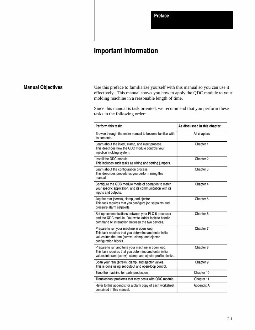
Use this preface to familiarize yourself with this manual so you can use iteffectively. This manual shows you how to apply the QDC module to yourmolding machine in a reasonable length of time.
Since this manual is task oriented, we recommend that you perform thesetasks in the following order:
Perform this task: As discussed in this chapter:
Browse through the entire manual to become familiar withits contents.
All chapters
Learn about the inject, clamp, and eject process. This describes how the QDC module controls yourinjection molding system.
Chapter 1
Install the QDC module. This includes such tasks as wiring and setting jumpers.
Chapter 2
Learn about the configuration process. This describes procedures you perform using thismanual.
Chapter 3
Configure the QDC module mode of operation to matchyour specific application, and its communication with itsinputs and outputs.
Chapter 4
Jog the ram (screw), clamp, and ejector. This task requires that you configure jog setpoints andpressure alarm setpoints.
Chapter 5
Set up communications between your PLC�5 processorand the QDC module. You write ladder logic to handlecommand bit interaction between the two devices.
Chapter 6
Prepare to run your machine in open loop. This task requires that you determine and enter initialvalues into the ram (screw), clamp, and ejectorconfiguration blocks.
Chapter 7
Prepare to run and tune your machine in open loop. This task requires that you determine and enter initialvalues into ram (screw), clamp, and ejector profile blocks.
Chapter 8
Span your ram (screw), clamp, and ejector valves. This is done using set�output and open�loop control.
Chapter 9
Tune the machine for parts production. Chapter 10
Troubleshoot problems that may occur with QDC module. Chapter 11
Refer to this appendix for a blank copy of each worksheetcontained in this manual.
Appendix A
Manual Objectives

Preface
P-2
Before attempting to apply the QDC module to a molding machine weassume that you are:
an injection molding professional
an experienced PLC programmer (especially with the Allen-Bradley PLC-5 family of processors)
an hydraulics designer or technician
We use abbreviated catalog numbers when referring to Allen-Bradleyequipment:
Abbreviated Name: Title:
QDC module 1771�QDC Plastic Molding Module
PLC�5 processor PLC�5 Programmable Controller
T45 or T47 T50 oe T53 terminal
1784�T45 or �47 Portable Programming Terminal1784�T50 or �53 Industrial Terminal
Pro�Set 600 Software 6500�PS600 Pro�Set 600 Injection Molding Operator Interface Software
PanelView Color display 2711�KC1 PanelView Operator Interface Terminal
ERC Expert Response Compensation
The next table presents other terms we commonly use in this manual:
Term: Definition:
Selected Valve In multi�valve systems, depending on the configured profile, the QDCmodule controls one valve and presets the setting of the remainingvalves to produce molding�machine profiles. We call the valve beingcontrolled by the QDC modules algorithms the selected valve.
Unselected Valves In multi�valve systems, depending on the configured profile, the QDCmodule controls one valve and presets the setting of the remainingvalves to produce molding�machine profiles. We call the valves that arepreset with an open�loop percentage setpoint the unselected valves.
Profile A group of mold/part setpoints which define a given machine operationto the QDC module.
Command Block Data blocks downloaded from the PLC�5 data table to the QDC moduleto make configuration changes or to initiate machine actions.
Status Block Data blocks used by the QDC module to relay information to the PLC�5processor about the QDC module's current operating status.
Profile Block Command block containing mold/part setpoints.
Configuration Block Command block containing machine setpoints.
Direct Acting Valve An analog control valve that delivers increasing velocity or pressure withincreasing signal input.
Reverse Acting Valve An analog control valve that delivers increasing velocity or pressure withdecreasing signal input.
Audience
Use of Terms
Allen-Bradley Parts
Preface
P-3
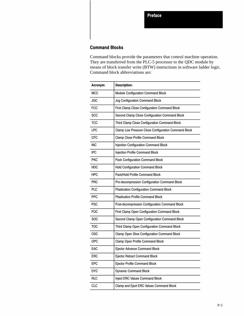
Command Blocks
Command blocks provide the parameters that control machine operation.They are transferred from the PLC-5 processor to the QDC module bymeans of block transfer write (BTW) instructions in software ladder logic.Command block abbreviations are:
Acronym: Description:
MCC Module Configuration Command Block
JGC Jog Configuration Command Block
FCC First Clamp Close Configuration Command Block
SCC Second Clamp Close Configuration Command Block
TCC Third Clamp Close Configuration Command Block
LPC Clamp Low Pressure Close Configuration Command Block
CFC Clamp Close Profile Command Block
INC Injection Configuration Command Block
IPC Injection Profile Command Block
PKC Pack Configuration Command Block
HDC Hold Configuration Command Block
HPC Pack/Hold Profile Command Block
PRC Pre�decompression Configuration Command Block
PLC Plastication Configuration Command Block
PPC Plastication Profile Command Block
PSC Post�decompression Configuration Command Block
FOC First Clamp Open Configuration Command Block
SOC Second Clamp Open Configuration Command Block
TOC Third Clamp Open Configuration Command Block
OSC Clamp Open Slow Configuration Command Block
OPC Clamp Open Profile Command Block
EAC Ejector Advance Command Block
ERC Ejector Retract Command Block
EPC Ejector Profile Command Block
DYC Dynamic Command Block
RLC Inject ERC Values Command Block
CLC Clamp and Eject ERC Values Command Block

Preface
P-4
Status Blocks
Status blocks report current status of molding-machine operation. Theyare returned from the QDC module to the PLC-5 processor by means ofblock transfer read (BTR) instructions in software ladder logic. Statusblock abbreviations are:
Acronym: Description:
SYS System Status Block
CPS Clamp Close Profile Status Block
IPS Injection Profile Status Block
HPS Pack/Hold Profile Status Block
PPS Plastication Profile Status Block
OPS Clamp Open Profile Status Block
EPS Ejector Profile Status block
RLS Inject ERC Values Status Block
CLS Clamp and Eject ERC Values Status Block
Word and bit Numbering
The QDC module stores data in command and status blocks. Each wordlocation in a command or status block is identified by an alphanumericcode containing the block acronym and word number. For example, word09 of the Module Configuration Command Block (MCC) is identified asMCC09.
Identify bits in a word location by adding bit numbering to the abbreviatedword location. For example:
Specific: MCC09-B15 General: MCCxx-Byy
where:
MCC = Module Configuration Command Block xx=word number (01-64) B = bit identifier yy = bit number (00-15)
Allen-Bradley Parts
Preface
P-5
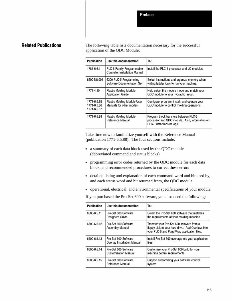
The following table lists documentation necessary for the successfulapplication of the QDC Module:
Publication Use this documentation: To:
1785�6.6.1 PLC�5 Family ProgrammableController Installation Manual
Install the PLC�5 processor and I/O modules.
6200�N8.001 6200 PLC�5 ProgrammingSoftware Documentation Set
Select instructions and organize memory whenwriting ladder logic to run your machine.
1771�4.10 Plastic Molding ModuleApplication Guide
Help select the module mode and match yourQDC module to your hydraulic layout.
1771�6.5.851771�6.5.861771�6.5.87
Plastic Molding Module UserManuals for other modes.
Configure, program, install, and operate yourQDC module to control molding operations.
1771�6.5.88 Plastic Molding ModuleReference Manual
Program block transfers between PLC�5processor and QDC module. Also, information onPLC�5 data transfer logic.
Take time now to familiarize yourself with the Reference Manual(publication 1771-6.5.88). The four sections include:
a summary of each data block used by the QDC module (abbreviated command and status blocks)
programming error codes returned by the QDC module for each datablock, and recommended procedures to correct these errors
detailed listing and explanation of each command word and bit used by,and each status word and bit returned from, the QDC module
operational, electrical, and environmental specifications of your module
If you purchased the Pro-Set 600 software, you also need the following:
Publication Use this documentation: To:
6500�6.5.11 Pro�Set 600 SoftwareDesigners Guide
Select the Pro�Set 600 software that matchesthe requirements of your molding machine.
6500�6.5.12 Pro�Set 600 SoftwareAssembly Manual
Transfer your Pro�Set 600 software from afloppy disk to your hard drive. Add Overlays intoyour PLC�5 and PanelView application files.
6500�6.5.13 Pro�Set 600 SoftwareOverlay Installation Manual
Install Pro�Set 600 overlays into your applicationfiles.
6500�6.5.14 Pro�Set 600 SoftwareCustomization Manual
Customize your Pro�Set 600 build for yourmachine control requirements.
6500�6.5.15 Pro�Set 600 SoftwareReference Manual
Support customizing your software controlsystem.
Related Publications
Chapter
1
1-1
Overview of Inject, Clamp, and Eject Mode
This chapter presents an overview of the 1771-QDC Plastic MoldingModule in the inject, clamp, and eject mode. We present a summary ofoperating features followed by sample applications.
Important: This chapter assumes you have already read your PlasticMolding Module Application Guide (publication 1771-4.10) and havechosen inject, clamp, and eject as your QDC module’s mode of operation.
Next we describe the control operations of this mode.
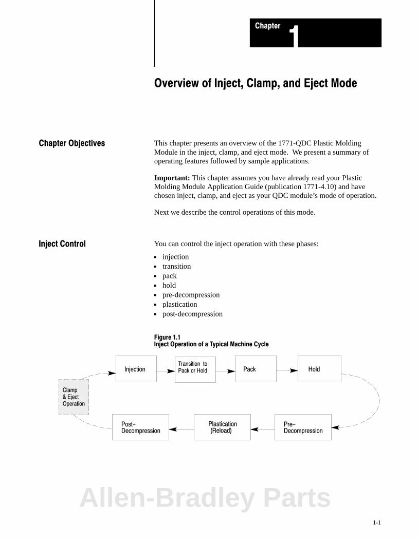
You can control the inject operation with these phases:
injection transition pack hold pre-decompression plastication post-decompression
Figure 1.1Inject Operation of a Typical Machine Cycle
Injection Pack Hold
Post- Pre-Decompression Decompression
Plastication(Reload)
Transition to Pack or Hold
Clamp & Eject Operation
Chapter Objectives
Inject Control
Allen-Bradley Parts

Overview of Inject, Clamp, and Eject ModeChapter 1
1-2
Injection Phase
You can vary the velocity of the ram (screw), or the pressure driving it, sothe leading edge of the melt moves through the mold cavity at the desiredspeed. The pattern of velocity or pressure variation during injection iscalled the injection profile. The QDC module lets you chose from fourdifferent injection profiles:
velocity vs. position pressure-limited velocity vs. position pressure vs. position pressure vs. time
Figure 1.2Example Injection Profile
11 10 9 8 7 6 5 4 3 2 1
Position or Time
Vel
ocity
or
Pre
ssur
e
You enter setpoints to create a profile. You can select from 1 to 11segments of position or time. Segment numbers represent the order ofoperation. By convention the ram (screw) injects plastic by moving fromright to left.
With this Profile: You Control Injection: With up to 11 SegmentsDistributed over the:
Velocity vs. Position Speed Length of the shot
Pressure�limited1 Velocity vs. position
Speed with a maximum pressure
Length of the shot
Pressure vs. Position Pressure Length of the shot
Pressure vs. Time Pressure Time for a shot
1 Pressure�limited velocity vs. position profile differs from the velocity vs. position profile as follows:During any segment, if the pressure exceeds a preset limit, the module switches to PID pressurecontrol with the pressure limit as the setpoint. Then if velocity exceeds the velocity setpoint, themodule returns to velocity control.
Overview of Inject, Clamp, and Eject ModeChapter 1
1-3
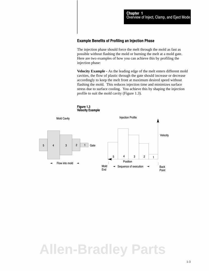
Example Benefits of Profiling an Injection Phase
The injection phase should force the melt through the mold as fast aspossible without flashing the mold or burning the melt at a mold gate.Here are two examples of how you can achieve this by profiling theinjection phase:
Velocity Example - As the leading edge of the melt enters different moldcavities, the flow of plastic through the gate should increase or decreaseaccordingly to keep the melt front at maximum desired speed withoutflashing the mold. This reduces injection time and minimizes surfacestress due to surface cooling. You achieve this by shaping the injectionprofile to suit the mold cavity (Figure 1.3).
Figure 1.3Velocity Example
Mold Cavity
5 4 3 2 1
Flow into mold
12345
Position
Sequence of execution Back Point
MoldEnd
Injection Profile
Velocity
Gate
Allen-Bradley Parts
Overview of Inject, Clamp, and Eject ModeChapter 1
1-4
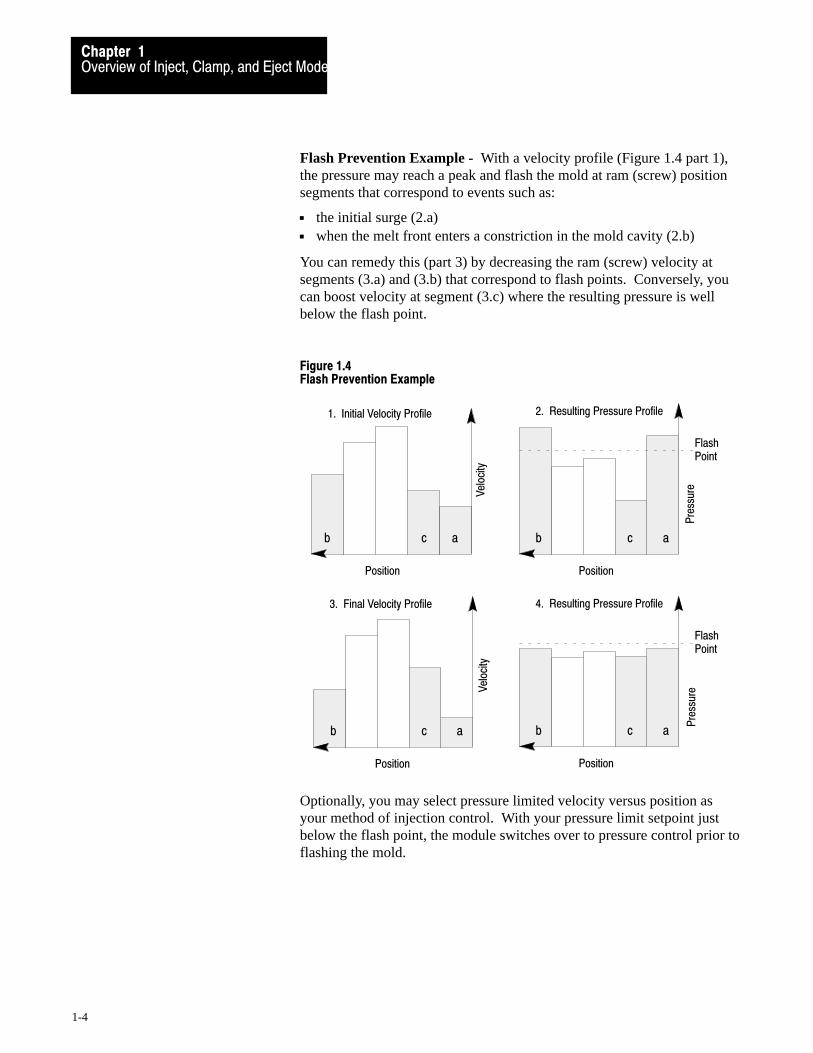
Flash Prevention Example - With a velocity profile (Figure 1.4 part 1),the pressure may reach a peak and flash the mold at ram (screw) positionsegments that correspond to events such as:
the initial surge (2.a) when the melt front enters a constriction in the mold cavity (2.b)
You can remedy this (part 3) by decreasing the ram (screw) velocity atsegments (3.a) and (3.b) that correspond to flash points. Conversely, youcan boost velocity at segment (3.c) where the resulting pressure is wellbelow the flash point.
Figure 1.4Flash Prevention Example
1. Initial Velocity Profile 2. Resulting Pressure Profile
b a
Flash Point
3. Final Velocity Profile
c
b c a
b c a
Vel
ocity
Vel
ocity
Pre
ssur
e
Position Position
Position
Pre
ssur
e
Position
4. Resulting Pressure Profile
b a
Flash Point
c
Optionally, you may select pressure limited velocity versus position asyour method of injection control. With your pressure limit setpoint justbelow the flash point, the module switches over to pressure control prior toflashing the mold.

Overview of Inject, Clamp, and Eject ModeChapter 1
1-5
Injection�to�pack Transition
The QDC module ends the injection phase and automatically starts thepack or hold phase when it detects the first of up to three events occurred:
Ram (screw) position exceeds a preset limit Ram (screw) pressure exceeds a preset limit Injection phase elapsed time exceeds a preset limit
You select which of these events you want monitored for transition byentering the appropriate setpoint, or zero for ignoring the event. You alsomay specify the zone of ram (screw) travel over which the QDC moduleinhibits or allows a pressure transition.
Pack Phase
The QDC module controls the pack phase with a pressure vs. time profile.You create the profile based on controlling the hydraulic pressure againstthe ram (screw). You can control pressure with up to five segments. Byconvention, events occur from right to left on the time axis (Figure 1.5).You determine the pressure setpoints and time durations for the packprofile based on molding requirements. The pack phase is optional.
Figure 1.5Pack Phase Example
Pressure
Time
12345
Allen-Bradley Parts
Overview of Inject, Clamp, and Eject ModeChapter 1
1-6
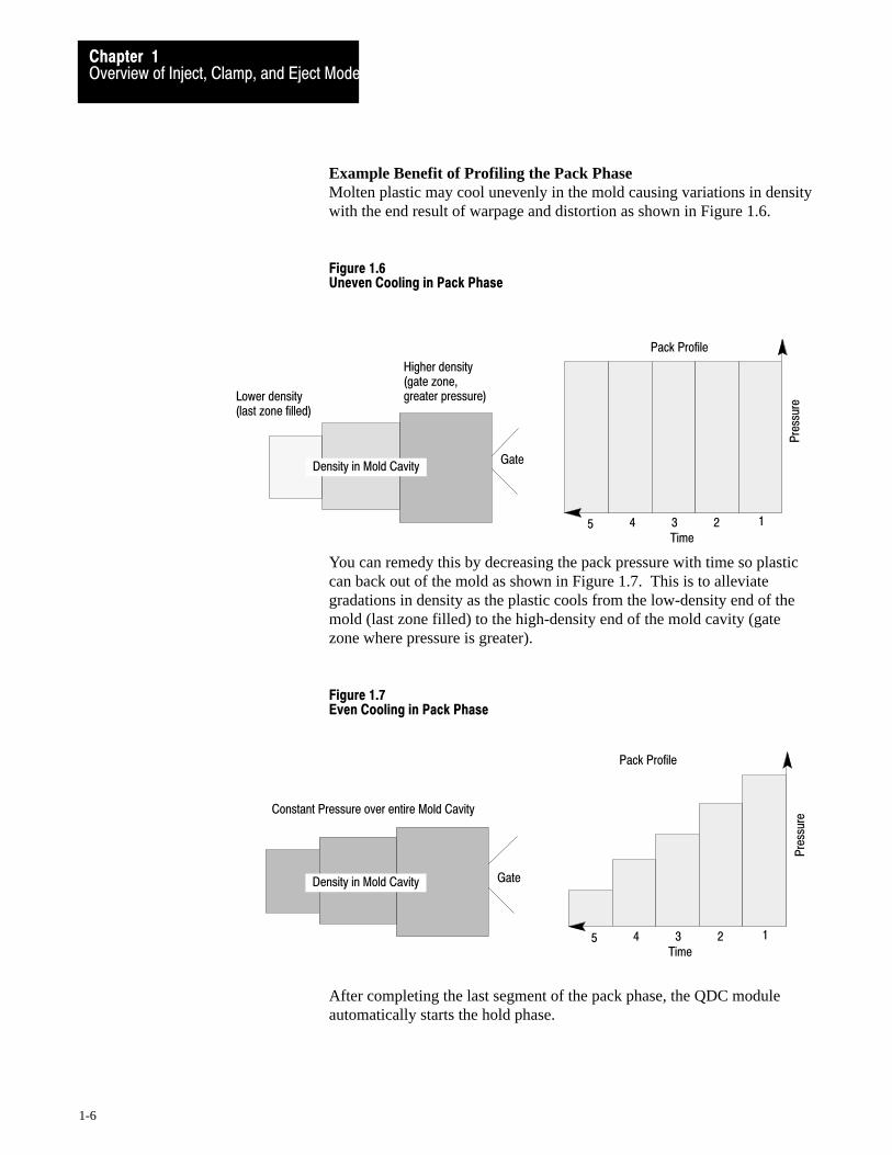
Example Benefit of Profiling the Pack Phase Molten plastic may cool unevenly in the mold causing variations in densitywith the end result of warpage and distortion as shown in Figure 1.6.
Figure 1.6Uneven Cooling in Pack Phase
Gate
Time
12345
Density in Mold Cavity
Pack Profile
Lower density (last zone filled)
Higher density (gate zone, greater pressure)
Pre
ssur
e
You can remedy this by decreasing the pack pressure with time so plasticcan back out of the mold as shown in Figure 1.7. This is to alleviategradations in density as the plastic cools from the low-density end of themold (last zone filled) to the high-density end of the mold cavity (gatezone where pressure is greater).
Figure 1.7Even Cooling in Pack Phase
Gate
Time
12345
Density in Mold Cavity
Pack Profile
Pre
ssur
eConstant Pressure over entire Mold Cavity
After completing the last segment of the pack phase, the QDC moduleautomatically starts the hold phase.

Overview of Inject, Clamp, and Eject ModeChapter 1
1-7
Hold Phase
The QDC module controls the hold phase with a pressure vs. time profile.You create the profile based on controlling the hydraulic pressure againstthe ram (screw). The pressure can be controlled using up to five segments.You determine the pressure setpoints and time durations for the holdprofile based on molding requirements.
After completing the last segment of the hold phase, the QDC moduleeither immediately starts the optional pre-decompression movement, skipsthe pre-decompression movement if none is required and immediatelystarts the plastication phase, or waits for a command from your PLC-5program to continue.
Pre�decompression Movement
You select a length of pullback for the ram (screw) prior to the plasticationphase to separate plastic solidifying in the sprue from molten cushionremaining in the barrel.
After completing the pre-decompression movement, the QDC moduleeither immediately starts the plastication phase or waits for a commandfrom your PLC-5 program to continue.
Plastication Phase
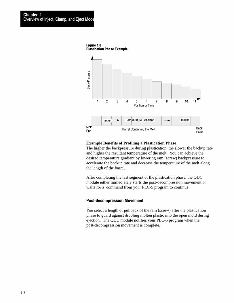
The plastication phase lets you achieve a melt temperature gradient in thebarrel containing the ram (screw). To program the desired temperatures,you consult backup rate (backpressure) vs. temperature tables. You cancreate the profile with up to 11 segments of position or time (figure 1.8).
You chose from two plastication profiles:
Backpressure vs. position Backpressure vs. time
Allen-Bradley Parts
Overview of Inject, Clamp, and Eject ModeChapter 1
1-8
Figure 1.8Plastication Phase Example
1 2 3 4 5 6 7 8 9 10 11Position or Time
MoldEnd
Back Point
hotter cooler
Barrel Containing the Melt
Temperature Gradient
Bac
k�P
ress
ure
Example Benefits of Profiling a Plastication Phase The higher the backpressure during plastication, the slower the backup rateand higher the resultant temperature of the melt. You can achieve thedesired temperature gradient by lowering ram (screw) backpressure toaccelerate the backup rate and decrease the temperature of the melt alongthe length of the barrel.
After completing the last segment of the plastication phase, the QDCmodule either immediately starts the post-decompression movement orwaits for a command from your PLC-5 program to continue.
Post�decompression Movement
You select a length of pullback of the ram (screw) after the plasticationphase to guard against drooling molten plastic into the open mold duringejection. The QDC module notifies your PLC-5 program when thepost-decompression movement is complete.
L 0
Stationary Platen
Clamp Cylinder
Position
Vel
ocityMoving
Platen1st Close Profile
2nd Close Profile 3rd Close
Profile
X
Overview of Inject, Clamp, and Eject ModeChapter 1
1-9
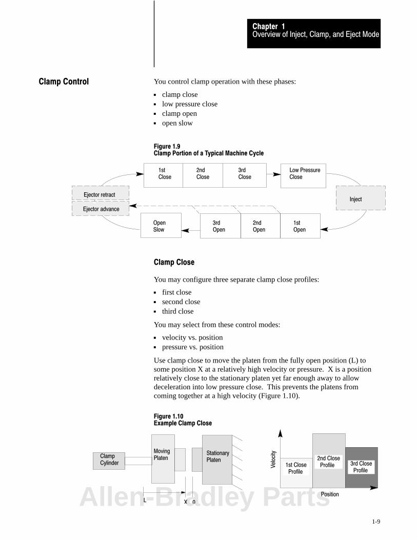
You control clamp operation with these phases:
clamp close low pressure close clamp open open slow
Figure 1.9Clamp Portion of a Typical Machine Cycle
InjectEjector retract
1st Close
2nd Close
3rd Close
1st Open
2nd Open
3rd Open
Low Pressure Close
Open Slow
Ejector advance
Clamp Close
You may configure three separate clamp close profiles:
first close second close third close
You may select from these control modes:
velocity vs. position pressure vs. position
Use clamp close to move the platen from the fully open position (L) tosome position X at a relatively high velocity or pressure. X is a positionrelatively close to the stationary platen yet far enough away to allowdeceleration into low pressure close. This prevents the platens fromcoming together at a high velocity (Figure 1.10).
Figure 1.10Example Clamp Close
Clamp Control
Allen-Bradley Parts
Overview of Inject, Clamp, and Eject ModeChapter 1
1-10
You may start these operations between the three clamp close profiles:
pick up the 3rd plate of a mold (on a floating 3-plate mold) or set cores program other events for all valves automatically bridge between profiles, or let ladder logic decide when to
begin the next profile
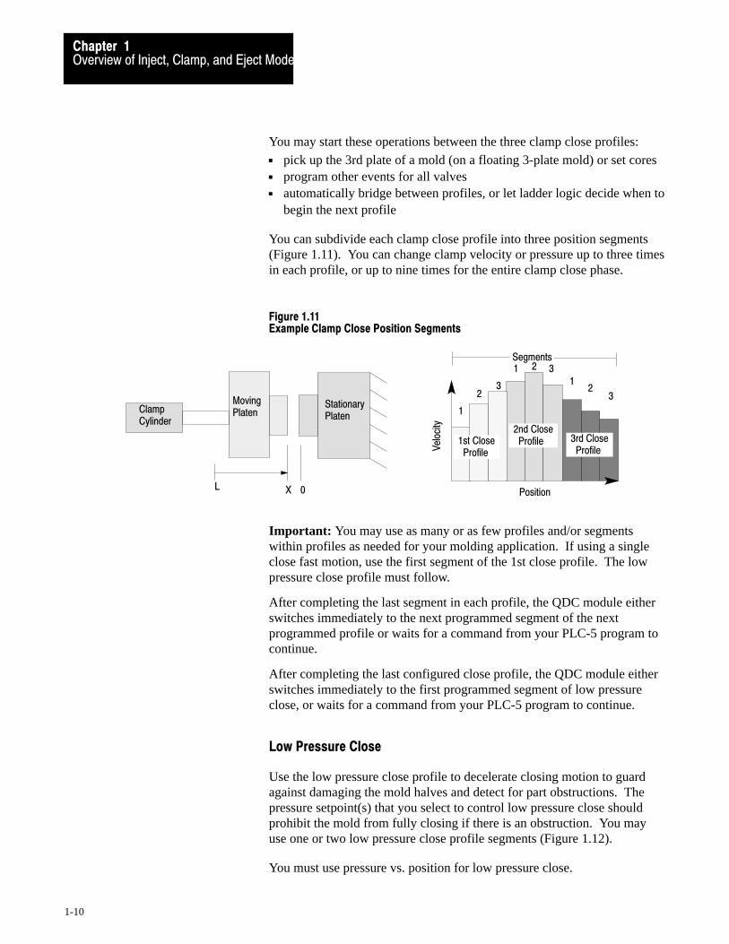
You can subdivide each clamp close profile into three position segments(Figure 1.11). You can change clamp velocity or pressure up to three timesin each profile, or up to nine times for the entire clamp close phase.
Figure 1.11Example Clamp Close Position Segments
Position
Vel
ocity
1st Close Profile
2nd Close Profile 3rd Close
Profile
1
11
2
2
23
3
3
Segments
L 0
Stationary Platen
Clamp Cylinder
Moving Platen
X
Important: You may use as many or as few profiles and/or segmentswithin profiles as needed for your molding application. If using a singleclose fast motion, use the first segment of the 1st close profile. The lowpressure close profile must follow.
After completing the last segment in each profile, the QDC module eitherswitches immediately to the next programmed segment of the nextprogrammed profile or waits for a command from your PLC-5 program tocontinue.
After completing the last configured close profile, the QDC module eitherswitches immediately to the first programmed segment of low pressureclose, or waits for a command from your PLC-5 program to continue.
Low Pressure Close
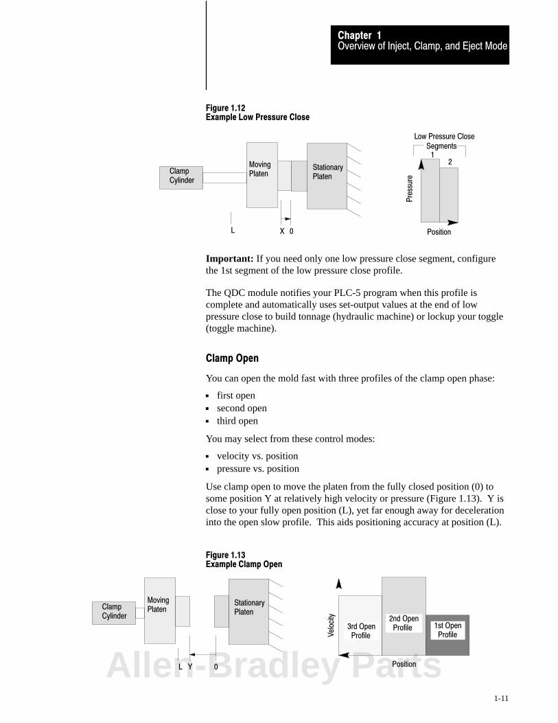
Use the low pressure close profile to decelerate closing motion to guardagainst damaging the mold halves and detect for part obstructions. Thepressure setpoint(s) that you select to control low pressure close shouldprohibit the mold from fully closing if there is an obstruction. You mayuse one or two low pressure close profile segments (Figure 1.12).
You must use pressure vs. position for low pressure close.
Overview of Inject, Clamp, and Eject ModeChapter 1
1-11
Figure 1.12Example Low Pressure Close
Clamp Cylinder
Moving Platen
Low Pressure Close
Position
Pre
ssur
e
L 0X
Segments1
2Stationary Platen
Important: If you need only one low pressure close segment, configurethe 1st segment of the low pressure close profile.
The QDC module notifies your PLC-5 program when this profile iscomplete and automatically uses set-output values at the end of lowpressure close to build tonnage (hydraulic machine) or lockup your toggle(toggle machine).
Clamp Open
You can open the mold fast with three profiles of the clamp open phase:
first open second open third open
You may select from these control modes:
velocity vs. position pressure vs. position
Use clamp open to move the platen from the fully closed position (0) tosome position Y at relatively high velocity or pressure (Figure 1.13). Y isclose to your fully open position (L), yet far enough away for decelerationinto the open slow profile. This aids positioning accuracy at position (L).
Figure 1.13Example Clamp Open
Position
Vel
ocity
1st Open Profile
2nd Open Profile3rd Open
Profile
L 0
Clamp Cylinder
Moving Platen
Y
Stationary Platen
Allen-Bradley Parts
Overview of Inject, Clamp, and Eject ModeChapter 1
1-12
You may start these operations between the three clamp open profiles:
drop the third plate of a mold (on a floating 3-plate mold) or pull cores program other events for all valves automatically bridge between profiles, or let ladder logic decide when to
begin the next profile.
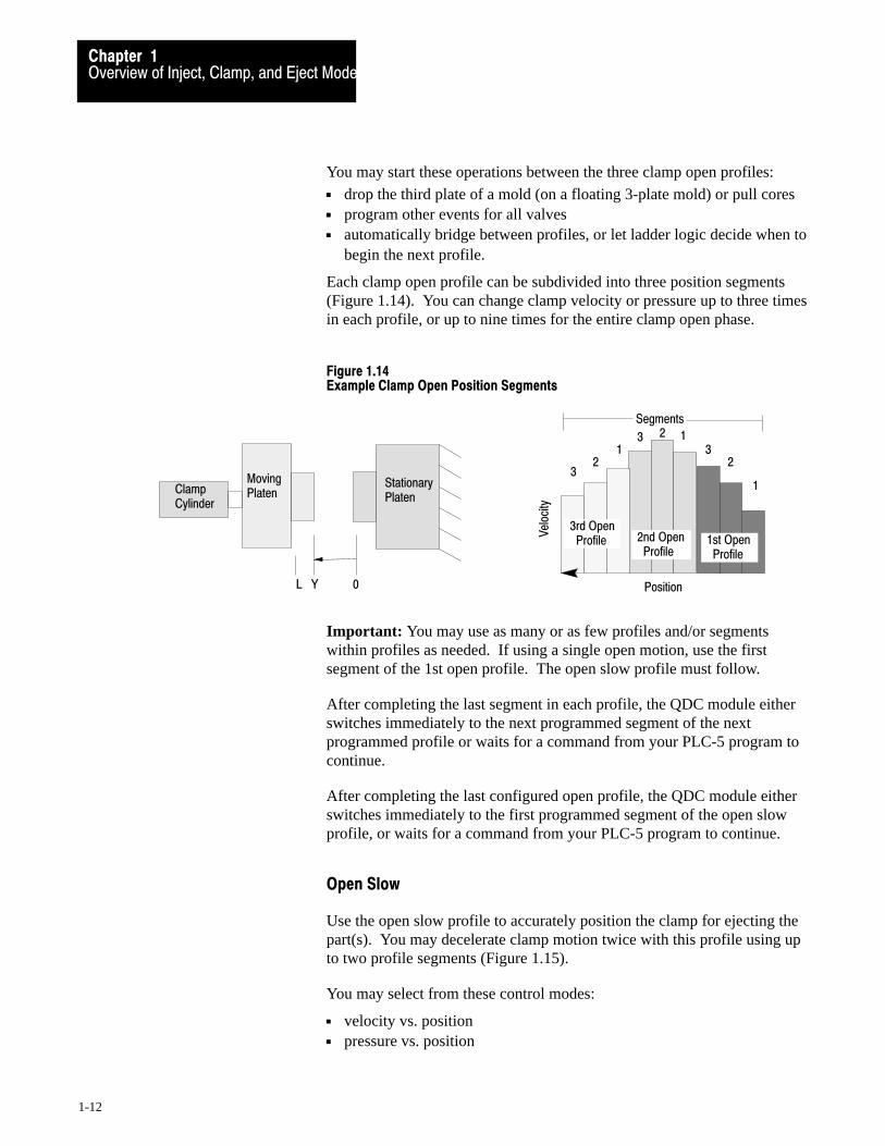
Each clamp open profile can be subdivided into three position segments(Figure 1.14). You can change clamp velocity or pressure up to three timesin each profile, or up to nine times for the entire clamp open phase.
Figure 1.14Example Clamp Open Position Segments
Position
Vel
ocity
3rd Open Profile 2nd Open
Profile1st Open Profile
3
33
2
2
21
1
1
Segments
L 0
Clamp Cylinder
Moving Platen
Y
Stationary Platen
Important: You may use as many or as few profiles and/or segmentswithin profiles as needed. If using a single open motion, use the firstsegment of the 1st open profile. The open slow profile must follow.
After completing the last segment in each profile, the QDC module eitherswitches immediately to the next programmed segment of the nextprogrammed profile or waits for a command from your PLC-5 program tocontinue.
After completing the last configured open profile, the QDC module eitherswitches immediately to the first programmed segment of the open slowprofile, or waits for a command from your PLC-5 program to continue.
Open Slow
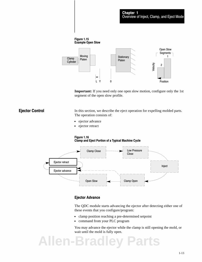
Use the open slow profile to accurately position the clamp for ejecting thepart(s). You may decelerate clamp motion twice with this profile using upto two profile segments (Figure 1.15).
You may select from these control modes:
velocity vs. position pressure vs. position
Overview of Inject, Clamp, and Eject ModeChapter 1
1-13
Figure 1.15Example Open Slow
Open Slow
Clamp Cylinder
Moving Platen
L 0Y
Vel
ocity
Position
2
1Stationary Platen
Segments
Important: If you need only one open slow motion, configure only the 1stsegment of the open slow profile.
In this section, we describe the eject operation for expelling molded parts.The operation consists of:
ejector advance ejector retract
Figure 1.16Clamp and Eject Portion of a Typical Machine Cycle
Inject
Open Slow
Low PressureClose
Clamp Close
Clamp Open
Ejector advance
Ejector retract
Ejector Advance
The QDC module starts advancing the ejector after detecting either one ofthese events that you configure/program:
clamp position reaching a pre-determined setpoint command from your PLC program
You may advance the ejector while the clamp is still opening the mold, orwait until the mold is fully open.
Ejector Control
Allen-Bradley Parts

Overview of Inject, Clamp, and Eject ModeChapter 1
1-14
You may use up to three ejector-advance profile segments, and select fromthese control modes:
velocity vs. position pressure vs. position
Figure 1.17Example Ejector Advance
Vel
ocity
0
Ejector
Fully Advanced Position
Velocity
Position
Ejector Advance
1Segments
2
3
Important: If you need only one ejector-advance motion, configure onlythe 1st advance segment.
Ejector Retract
After ejector advance is completed, the QDC module executes ejectorretract. Similar to ejector advance, you retract the ejector with up to threeprofile segments. You may select from these control modes:
velocity vs. position pressure vs. position
Figure 1.18Example Ejector Retract
0
Ejector
Fully Advanced Position
Velocity
Vel
ocity
Position
Ejector Retract
2
Segments
3
1
Overview of Inject, Clamp, and Eject ModeChapter 1
1-15
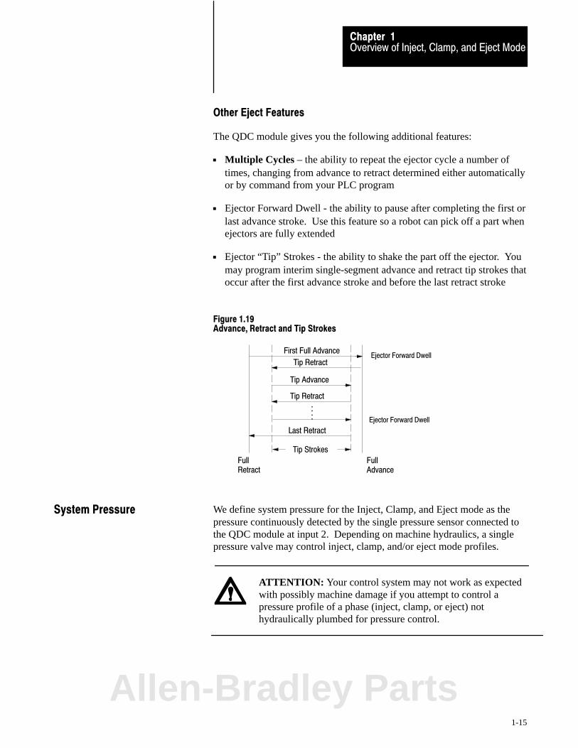
Other Eject Features
The QDC module gives you the following additional features:
Multiple Cycles – the ability to repeat the ejector cycle a number oftimes, changing from advance to retract determined either automaticallyor by command from your PLC program
Ejector Forward Dwell - the ability to pause after completing the first orlast advance stroke. Use this feature so a robot can pick off a part whenejectors are fully extended
Ejector “Tip” Strokes - the ability to shake the part off the ejector. Youmay program interim single-segment advance and retract tip strokes thatoccur after the first advance stroke and before the last retract stroke
Figure 1.19Advance, Retract and Tip Strokes
Full Retract
Full Advance
Tip Strokes
First Full Advance
Tip Advance
Tip Retract
Last Retract
Ejector Forward Dwell
::
Tip RetractEjector Forward Dwell
We define system pressure for the Inject, Clamp, and Eject mode as thepressure continuously detected by the single pressure sensor connected tothe QDC module at input 2. Depending on machine hydraulics, a singlepressure valve may control inject, clamp, and/or eject mode profiles.
ATTENTION: Your control system may not work as expectedwith possibly machine damage if you attempt to control apressure profile of a phase (inject, clamp, or eject) nothydraulically plumbed for pressure control.
System Pressure
Allen-Bradley Parts
Overview of Inject, Clamp, and Eject ModeChapter 1
1-16
Because system pressure may change from one phase to the next, werecommend that you:
assign pressure control to phases that require pressure profiles(and are hydraulically plumbed to support it)
place the system pressure sensor accordingly in the hydraulic circuit configure the remaining phases with velocity profiles
We define open-loop pressure control as when the QDC module controlsphase pressure without input from the system pressure sensor. For example:when the system pressure sensor monitors the clamp for closed-loop pressurecontrol, the QDC module can control:
ram (screw) pressure for pack, hold, and plastication in open loop ejector velocity in closed- or open-loop using a position sensor
For example:
For this Phase The QDC Module Can Control it With
clamp close and open closed�loop pressure
injection open�loop pressure�limited velocity
pack/hold open�loop pressure
plastication open�loop pressure
ejector advance and retract velocity
In general:
If your system pressure sensorreads pressure for only ONE ofthese modes:
Then you must control the other modes by either of:1. closed� or open�loop velocity2. open�loop pressure
inject clamp, eject
clamp inject , eject
eject inject, clamp
We illustrate three examples of hydraulic circuits compatible with the QDCmodule in the inject, clamp, and eject mode:
4-valve system with system pressure sensor 3-valve system with ram (screw) pressure sensor 2-valve system for inject phase with clamp and ejector position inputs
(clamp and ejector direction solenoid valves controlled by ladder logic)
Example Hydraulic Circuitsfor the Inject, Clamp, andEject Mode

A B
Tank
Tank
Clamp Ram (Screw)
Ejector
P T
A B
P
A B
P TT
TankTank
ClampFlow Valve
EjectorFlow Valve
Ram (Screw)Flow Valve
SystemPressure Valve
Pump
PSystemPressureSensor
12468�I
Overview of Inject, Clamp, and Eject ModeChapter 1
1-17
Example 4�valve System with System Pressure Sensor
With this hydraulic system, a QDC module in the Inject, Clamp, and Ejectmode, has maximum control flexibility. It can control all profiles with:
pressure or velocity open or closed loop
Figure 1.20Example 4�valve System for Inject/Clamp/Eject Control
QDC I/O: Designation
Input 1 Ram (screw) Position
Input 2 System Pressure
Input 3 Clamp Position
Input 4 Ejector Position
Output 1 Ram (screw) Flow
Output 2 System Pressure
Output 3 Clamp Flow
Output 4 Ejector Flow
Allen-Bradley Parts
A B
Tank
Clamp Ram (Screw)
P T P T
Tank
A B
ClampFlow Valve
SystemFlow Valve
Ram (Screw)DirectionalValve
Tank
SystemPressureValve
Pump
P T
Tank
A B
Ejector
EjectorDirectionalValve
P
PressureSensor
12469�I
Overview of Inject, Clamp, and Eject ModeChapter 1
1-18
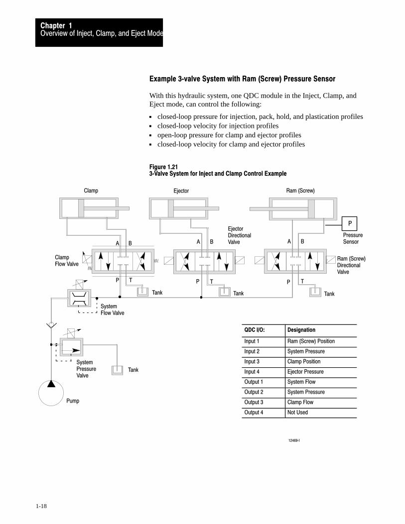
Example 3�valve System with Ram (Screw) Pressure Sensor
With this hydraulic system, one QDC module in the Inject, Clamp, andEject mode, can control the following:
closed-loop pressure for injection, pack, hold, and plastication profiles closed-loop velocity for injection profiles open-loop pressure for clamp and ejector profiles closed-loop velocity for clamp and ejector profiles
Figure 1.213�Valve System for Inject and Clamp Control Example
QDC I/O: Designation
Input 1 Ram (Screw) Position
Input 2 System Pressure
Input 3 Clamp Position
Input 4 Ejector Pressure
Output 1 System Flow
Output 2 System Pressure
Output 3 Clamp Flow
Output 4 Not Used
Overview of Inject, Clamp, and Eject ModeChapter 1
1-19
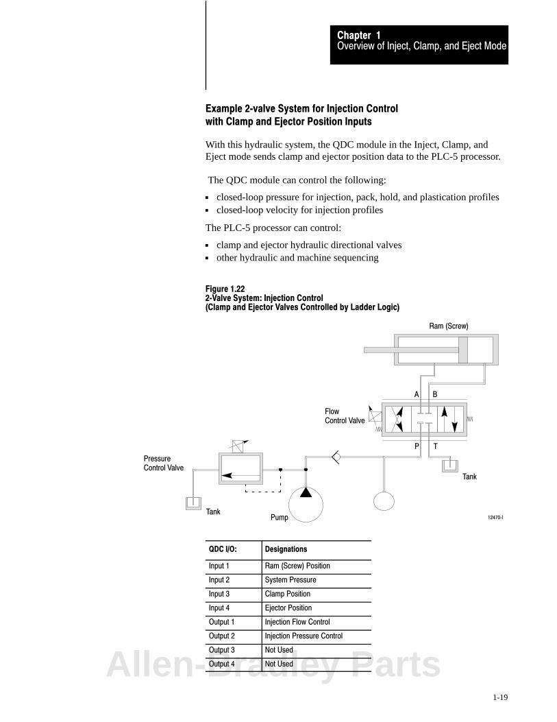
Example 2�valve System for Injection Control with Clamp and Ejector Position Inputs
With this hydraulic system, the QDC module in the Inject, Clamp, andEject mode sends clamp and ejector position data to the PLC-5 processor.
The QDC module can control the following:
closed-loop pressure for injection, pack, hold, and plastication profiles closed-loop velocity for injection profiles
The PLC-5 processor can control:
clamp and ejector hydraulic directional valves other hydraulic and machine sequencing
Figure 1.222�Valve System: Injection Control(Clamp and Ejector Valves Controlled by Ladder Logic)
Tank
Ram (Screw)
A B
P T
Tank
PressureControl Valve
FlowControl Valve
Pump 12470�I
QDC I/O: Designations
Input 1 Ram (Screw) Position
Input 2 System Pressure
Input 3 Clamp Position
Input 4 Ejector Position
Output 1 Injection Flow Control
Output 2 Injection Pressure Control
Output 3 Not Used
Output 4 Not UsedAllen-Bradley Parts

Overview of Inject, Clamp, and Eject ModeChapter 1
1-20
When you select this mode, you can use the following phases of operation:
Inject Phase: Description:
Injection The ram (screw) injects plastic into the mold. You can vary the velocity of the ram (screw), or the pressuredriving it, to fill areas of the mold cavity at different rates to achieve uniform quality of the molded part. Thisphase can be critical to part quality. The pattern of velocity or pressure variation during injection is called theinjection profile.
Transition Detects when injection is complete.
Pack (optional) Packing pressurizes the plastic to a specified density which determines the flexibility of the molded part. Toachieve uniform density, you can release or increase pressure in steps according to cooling gradients acrossthe mold. Thus, as the plastic cools unevenly, the pack profile can compress the plastic uniformly.
Hold Holding lets the plastic cool and shrink slightly from the mold cavity in preparation for ejection. The effect issimilar to packing. You can hold at predetermined pressures for predetermined lengths of time throughoutthe hold phase.
Pre�decompression (optional) This single, backward movement of the ram (screw) separates plastic solidifying in the mold from moltencushion remaining in the barrel prior to plastication. This phase is also called sprue break or suckback.
Plastication Phase The machine reloads by drawing plastic beads into the barrel containing the ram (screw). The mechanicalaction of the rotating ram (screw) grinds and melts the beads. The longer it grinds, the hotter it melts. Youcan vary the backpressure on the ram (screw) causing it to remain longer in an area. Thus, you can induceany desired temperature gradient along the length of the shot by controlling ram (screw) backpressure.
Post�decompression(optional)
This single, backward movement of the ram (screw) guards against drooling molten plastic into the openmold during ejection prior to clamp close. This phase is also called melt pullback or suckback.
1st Close2nd Close3rd Close
You can program a single�step clamp�close profile and not use a second or third profile. Or, you can programup to three clamp�close profiles that let you do the following at up to three different points in the clamp�closephase:• pick up a third mold plate• set cores• pick up or drop out pumps to change clamp speed or pressure
Low Pressure Close To guard against damaging the mold when the two mold surfaces make contact and to detect obstructions tomold closure, you close the mold slowly with low pressure and closed�loop or open�loop control. LowPressure Close can only be controlled through a pressure vs. position profile.
1st Open2nd Open3rd Open
You can program a single�step clamp�open profile and not use a second or third profile. Or, you canprogram up to three clamp�open profiles that let you do the following at up to three different points in theclamp�open phase: • drop out a third mold plate• pull cores• drop out or pick up pumps to change clamp speed or pressure
Open Slow To decelerate the moving platen to accurately position it before ejecting the part.
Ejector AdvanceEjector Retract
You can advance and retract the ejector in a single stroke or in multiple strokes using closed� or open�loopcontrol.
Tip Strokes You can shake the part off the ejector tip by programming rapid single�stroke interim ejector cycles startingafter the first advance stroke and ending before the last retract stroke.
Forward Dwell You can pause after the first advance stroke or before the last retract stroke to let a robot remove the partwhen the ejectors are extended.
Summary of Inject, Clamp,and Eject Mode of Operation

Chapter
2
2-1
Install the QDC Module
This chapter helps you install the QDC module with these procedures:
record I/O ranges set module jumpers key the I/O chassis install the QDC module wire I/O devices to the QDC module ground and shield I/O devices plan for E-STOPs and machine interlocks
To match your QDC module to your I/O devices, record the I/O ranges ofyour I/O devices on Worksheet 2-A. You will use this information in thischapter for hardware configuration (setting jumper plugs) and in chapter 4to configure the module’s inputs and outputs with software.
Circle or check the I/O ranges on Worksheet 2-A. Cross off I/O not used.
Worksheet 2�ARecord I/O Ranges
I/O Connection: Voltage 1: Voltage 2: Current:
Input 1 (Screw position) 0 to 10V dc 1 to 5V dc 4 to 20 mA
Input 2 (System pressure) 0 to 10V dc 1 to 5V dc 4 to 20 mA
Input 3 (Clamp position) 0 to 10V dc 1 to 5V dc 4 to 20 mA
Input 4 (Ejector position) 0 to 10V dc 1 to 5V dc 4 to 20 mA
Output 1 �10 to 10V dc 0 to 10V dc 4 to 20 mA
Output 2 �10 to 10V dc 0 to 10V dc 4 to 20 mA
Output 3 �10 to 10V dc 0 to 10V dc 4 to 20 mA
Output 4 �10 to 10V dc 0 to 10V dc 4 to 20 mA
Chapter Objectives
Record I/O Ranges
Allen-Bradley Parts

Install the QDC ModuleChapter 2
2-2
Before installing the QDC module, you must select with jumper plugs theI/O ranges that you recorded on Worksheet 2-A
Access and Position the Jumpers
Access the jumper plugs and set them as follows:
ATTENTION: To avoid damage to internal circuits, observehandling precautions and rid yourself of any electrostaticcharge. Use an anti-static work station when setting jumpers.
1. Remove the label-side cover plate by removing the four screws.
2. Remove the circuit board from the module housing by removing thetwo screws located center-front at the swingarm catch.
3. Carefully turn over the circuit board so it is oriented as in figure 2.1.Handle it by the edges to avoid touching conductors or components.
4. Use figure 2.1 to locate the jumpers.
5. Set the jumpers according to Table 2.A (next page) using
your I/O ranges from Worksheet 2-A needle-nose pliers.
6. After setting the jumpers, carefully re-assemble the module with steps3, 2, and 1.
Set Module Jumpers

Install the QDC ModuleChapter 2
2-3
Figure 2.1Jumper Locations on the QDC Module's Circuit Board
E6
E7
E8
E9
E17
E13
E14
E10
E16
E11
E15
E12
E5
E1
TOP
BOTTOM
RIGHTLEFT
10908�I
Important: We define jumper positions as left, right, top, and bottom.This represents the position of the jumper on the 3-pin connector relativeto the orientation of the circuit board shown above.
Allen-Bradley Parts
Install the QDC ModuleChapter 2
2-4
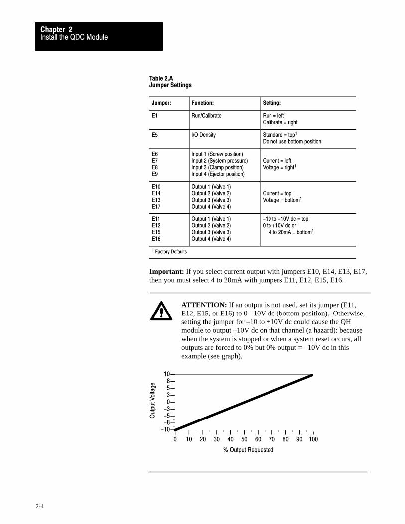
Table 2.AJumper Settings
Jumper: Function: Setting:
E1 Run/Calibrate Run = left1
Calibrate = right
E5 I/O Density Standard = top1
Do not use bottom position
E6E7E8E9
Input 1 (Screw position)Input 2 (System pressure)Input 3 (Clamp position)Input 4 (Ejector position)
Current = leftVoltage = right1
E10E14E13E17
Output 1 (Valve 1)Output 2 (Valve 2)Output 3 (Valve 3)Output 4 (Valve 4)
Current = topVoltage = bottom1
E11E12E15E16
Output 1 (Valve 1)Output 2 (Valve 2)Output 3 (Valve 3)Output 4 (Valve 4)
-10 to +10V dc = top0 to +10V dc or
4 to 20mA = bottom1
1 Factory Defaults
Important: If you select current output with jumpers E10, E14, E13, E17,then you must select 4 to 20mA with jumpers E11, E12, E15, E16.
ATTENTION: If an output is not used, set its jumper (E11,E12, E15, or E16) to 0 - 10V dc (bottom position). Otherwise,setting the jumper for –10 to +10V dc could cause the QHmodule to output –10V dc on that channel (a hazard): becausewhen the system is stopped or when a system reset occurs, alloutputs are forced to 0% but 0% output = –10V dc in thisexample (see graph).
% Output Requested
Out
put V
olta
ge
-10-8-5-3
0358
10
0 10 20 30 40 50 60 70 80 90 100

Install the QDC ModuleChapter 2
2-5
Use plastic keying bands, shipped with each I/O chassis, for keying thebackplane connector to accept only one type of module. Do this to preventinadvertent installation of the wrong module into the designated slotlocation.
Important: You must use the following slot location in the I/O chassis forthe QDC module because this is the address used by your Pro-Set 600software to communicate with the QDC module.
rack 0 module group 0 slot 0
The QDC module is slotted in two places on the rear edge of the circuitboard. The position of the keying bands on the backplane connector mustcorrespond to these slots to allow insertion of the module.
Place keying bands between the following terminal numbers labeled on thebackplane connector of your I/O chassis (see Figure 2.2):
between 20 and 22 between 26 and 28
Figure 2.2Keying Positions
24681012141618202224262830323436
12676
KeyingBands
1771�QDC
Key the I/O Chassis
Allen-Bradley Parts

Install the QDC ModuleChapter 2
2-6
To install your QDC module in an I/O chassis, complete the following:
1. Turn off power to the I/O chassis.
ATTENTION: Remove power from the 1771 I/O chassis back-plane and wiring arm before removing or installing a module.
Failure to remove power from the backplane could cause injuryor equipment damage due to possible unexpected operation.
Failure to remove power from the backplane or wiring armcould cause injury, module damage, and/or degradation ofmodule performance.
2. Place the module in the plastic guides on the top and bottom of theslot that slides the module into position.
Important: Pro-Set 600 software expects your QDC module (configuredfor inject, clamp, and eject mode) to be placed in rack 0, module group 0,slot 0. If you choose to install it in some other slot, you must modify yourPLC-5 application program accordingly (refer to your Pro-Set 600documentation for details).
3. Do not force the module into its backplane connector. Apply firm,even pressure on the module to seat it properly.
4. Snap the chassis latch over the top of the module to secure it.
5. Connect the wiring arm to the module.
Install the QDC Module

Install the QDC ModuleChapter 2
2-7
Use the wiring arm (1771-WF) supplied with the QDC module to wire I/Odevices (Figure 2.3). The wiring arm lets you install or remove the QDCmodule from the I/O chassis without rewiring. Wiring arm terminals arenumbered in descending order, from the top down, starting with terminal18 (Table 2.B).
Figure 2.3I/O Wiring and Grounding
Customer PS
ScrewPositionSensor
SystemPressureSensor
ClampPositionSensor
AmplifierValve 1
AmplifierValve 2
Customer PS
Earth Ground
Input 1
Input 2
Input 3
To Valve 1
To Valve 2
Output 1
Output 2
Wiring Arm1771�WF
+
–
+
–+
–
+
–
+
–
+
–
+
+
+
–
+AmplifierValve 4
To Valve 4
Output 4
+
–
+AmplifierValve 3
To Valve 3
Output 3
Input 4+
–
EjectorPositionSensor
18
17
16
15
14
13
12
11
10
9
8
7
6
5
4
3
2
1
–
+
–
–
–
–
10909�I
Wire I/O Devices
Allen-Bradley Parts

Install the QDC ModuleChapter 2
2-8
Table 2.BI/O Terminal Designations
Transducer: I/O Designation: Terminal:
Screw position(see Important below)
Input 1 (+) (-)
1817
System pressure(see ATTENTION below)
Input 2 (+) (-)
1615
N/A Input common 14
Clamp position (see Important below)
Input 3 (+) (-)
1312
Ejector position (see Important below)
Input 4 (+) (-)
1110
Valve 1 Output 1 (+)Output common
09 08
Valve 2 Output 2 (+)Output common
0706
Valve 3 Output 3 (+)Output common
0504
Valve 4 Output 4 (+)Output common
0302
Not used 01
Important: For the QDC module to operate in the inject, clamp, and ejectmode, you must connect position sensors to these two inputs:
input 1 (screw position) input 3 (clamp position)
ATTENTION: Your control system may not work as expectedwith possibly machine damage if you attempt to control apressure profile of a phase (inject, clamp, or eject) nothydraulically plumbed for pressure control.
Because system pressure may change from one phase to the next, werecommend that you:
assign pressure control to phases that require pressure profiles(and are hydraulically plumbed to support it)
place the system pressure sensor accordingly in the hydraulic circuit configure the remaining phases with velocity profiles

Install the QDC ModuleChapter 2
2-9
ATTENTION: The QDC module has ESD protection to 20kV,but you can damage the module by accidental application of thewrong voltage to the I/O terminals. Do not exceed:
This voltage: On these terminals: When in:
+12V dc input (18 thru 10) any mode
+12V dc output (09 thru 02) voltage mode
+24V dc output (09 thru 02) current mode
Analog inputs and outputs are sensitive to electrical noise interference.Take care to ground and shield them properly.
Guidelines:
Use 22-gage (or larger) twisted-pair cable, 100% shielded with drainwire, such as Belden 8761. For cable distances over 50 ft, use 18-gagecable such as Belden 8760.
Ground the cable shield at one end only; generally at the sensor oramplifier end, not at the I/O chassis (see Figure 2.4 and Figure 2.5).
Figure 2.4Shielding Differential Inputs
Connect the cable shieldand case ground to earthground at the Input Sensor
Input Sensor
18
17
14
QDC Module Input
Input Module Common(should float)
+
–
10910�I
Ground and Shield Your I/O Devices
Allen-Bradley Parts
Install the QDC ModuleChapter 2
2-10
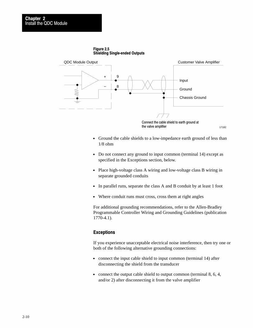
Figure 2.5Shielding Single�ended Outputs
Connect the cable shield to earth ground atthe valve amplifier
QDC Module Output
9
8
Customer Valve Amplifier
Input
Ground
Chassis Ground
17182
+
–
Ground the cable shields to a low-impedance earth ground of less than1/8 ohm
Do not connect any ground to input common (terminal 14) except asspecified in the Exceptions section, below.
Place high-voltage class A wiring and low-voltage class B wiring inseparate grounded conduits
In parallel runs, separate the class A and B conduit by at least 1 foot
Where conduit runs must cross, cross them at right angles
For additional grounding recommendations, refer to the Allen-BradleyProgrammable Controller Wiring and Grounding Guidelines (publication1770-4.1).
Exceptions
If you experience unacceptable electrical noise interference, then try one orboth of the following alternative grounding connections:
connect the input cable shield to input common (terminal 14) afterdisconnecting the shield from the transducer
connect the output cable shield to output common (terminal 8, 6, 4,and/or 2) after disconnecting it from the valve amplifier

Install the QDC ModuleChapter 2
2-11
You must consider the installation of Emergency Stop switches andmachine interlocks when you:
design your system
assemble mechanical/hydraulic components
wire system components
develop system ladder logic
ATTENTION: The Electrical Standard for IndustrialMachinery (NFPA 79-1987) requires an emergency stop that,when actuated, de-energizes all electrical power circuits whichprovide electrical energy to sustain machine motion.Maintained contact “Emergency Stop” push buttons arerecommended.
ATTENTION: The American National Standard for PlasticsMachinery — Horizontal Injection Molding Machines — forConstruction, Care, and Use (ANSI B151.1-1984) requireshydraulic, mechanical, and electrical interlocks to preventinadvertent clamp closing with a safety gate in an open position.
In addition, we strongly recommend that the electricalinterlocks consist of redundant devices and that the controlcircuit be so arranged that malfunction or improper sequencingof either redundant device prevents further operation of themachine.
ATTENTION: NEMA Standards Publication ICS1.1, Safetyguidelines for the Application, Installation, and Maintenance ofSolid State Control recommends that the emergency stop andsafety gate electrical interlocks should directly control theirappropriate functions through an electromechanical deviceindependent of the solid state logic.
The next page shows an illustration of a typical grounded PLC-5 powerdistribution circuit. For ungrounded systems or for more information ongrounding and wiring guidelines, refer to Allen-Bradley ProgrammableController Wiring and Grounding Guidelines (publication 1770-4.1).
Plan for E�STOPs andMachine Interlocks
Allen-Bradley Parts

Install the QDC ModuleChapter 2
2-12
Figure 2.6Typical PLC�5 Power Distribution with Interlocks
IncomingAC
L1
L2
L3
1FU
2FU
3FU
H
FUSE
Disconnect
To MotorStarters
L1
L2
L3
H
Back-PanelGround Bus
EnclosureWall
Grounding ElectrodeConductor toGrounding ElectrodeSystem
ConnectWhenApplicable
EquipmentGroundingConductors
User DCSupply
CRM
To DC I/ODevices
+ –
OutputModuleWiringArm
InputModuleWiringArm
OutputDevice
InputDevice
I/O Chassis
10907�I
Power SupplyL N1
GND
CRM
Start
Use any numberof E-Stop switchesin Series
CRM
CRM
1 4
H 3 H 2 Step-downTransformer
X 1 X 2
To minimize EMI generation, you should connect a suppression network: for 120V AC, use Allen-Bradleycat. no. 700-N24; for 220/240V AC, use cat. no. 599-KA04.
To minimize EMI generation, you should connect a suppression network: for 120V AC, use Allen-Bradleycat. no. 599-K04; for 220/240V AC, use cat. no. 599-KA04.
For a power supply with a groundable chassis, this represents connection to the chassis only. For a power supplywithout a groundable chassis, this represents connection to both the chassis and the GND terminal.
In many applications, a second transformer provides power to the input circuits and power supplies for isolation from theoutput circuits.
1
2
3
4
1
2
3
4
** See WARNING for Interlock Wiring Instructions **5
5 Reference the current NEC code and ANSI B151.1 for additional wiring guidelines.To minimize EMI generation, suppression networks should be connected across coils of electromagnetic devices.
••
Chapter
3
3-1
Configure the QDC Module's I/O
Your QDC module needs to know the characteristics of your ram (screw),clamp, and ejector sensors. In this chapter, we describe how to determinethese characteristics and download them to the QDC module for the following:
signal ranges from pressure and position sensors minimum and maximum sensor signals corresponding to
minimum and maximum pressures and positions alarm values and travel limits
We describe how to configure the QDC module in these sections:
Select Module Parameters and I/O Ranges Determine Initial Sensor-configuration Values Download MCC Parameters to the QDC module Use Set-output Mode to Move the Ram (screw), Clamp, and Ejector Complete Your Sensor Configuration Select Optional Configurations
Important: You must properly configure the QDC module usingprocedures in this chapter before attempting further configurations.
Important: If you have not already done so, install Pro-Set 600 software.The procedures in this and the next several chapters assume that you havedone so.
Chapter Objectives
Allen-Bradley Parts

Select Inject , Clamp, and Eject Mode
Required bit 03 = 1(0 generates a programming error)
Select English = 0 metric = 1
With bit 05 = 04 = 1
Configure the QDC Module's I/OChapter 3
3-2
You select module parameters and I/O ranges by setting configuration bitsin control words.
To Configure: In Control Word: Starting AtPro�Set 600 Address:
Use this Worksheet:
Module Parameters MCC02 B34/528 Worksheet 3�A
Input Range MCC03 B34/544 Worksheet 3�B
Output Range MCC04 B34/560 Worksheet 3�C
Select module parameters with Worksheet 3-A:
Operating mode of the QDC module to inject, clamp, and eject Units of measure to English or metric
Select I/O ranges with Worksheets 3-B and 3-C.
Refer to Worksheet 2-A from chapter 2 which you filled out when settingthe QDC module’s jumper plugs. Apply this information to Worksheet 3-Bfor input ranges and Worksheet 3-C for output ranges.
Important: Software input/output selections that you are about to make inMCC03 and MCC04 must match the jumper plug settings for eachrespective input and output that you configured in chapter 2.
Important: The QDC module detects loss of sensor at all four inputsregardless of the input range you select. When detected, the QDC module:
sets status bits SYS08-B00, 01, 02, and 03 for inputs 1, 2, 3, and 4 E-stops the profile in progress ignores any action execution commands in DYC02
Worksheet 3�ASelect Module Parameters
Control Word MCC02�Bxx 15 14 13 12 11 10 09 08 07 06 05 04 03 02 01 00
Pro�Set 600 Addr. B34/bit 543 542 541 540 539 538 537 536 535 534 533 532 531 530 529 528
Value 0 0 0 0 0 0 0 0 0 0 1 1 1 0 0
Example: If you select Inject, Clamp, and Eject mode with English units: MCC02 = 00000000 00111000
Select Module Parametersand I/O Ranges

Select Input 1 (Ram Screw Position) Range with bits 01, 00Select Input 2 (System Pressure) Range with bits 03, 02
Select Input 3 (Clamp Position) Range with bits 05, 04
Select Input 4 (Ejector Position) Range with bits 07, 06
Input Range 0 - 10V dc 0 0 1 - 5V dc 0 1 4 - 20 mA 1 0 Not connected 1 1
Select Output 1 Range with bits 01, 00Select Output 2 Range with bits 03, 02
Select Output 3 Range with bits 05, 04
Select Output 4 Range with bits 07, 06
Output Range -10to +10V dc0 0 0 to +10V dc 0 1 4 to 20 mA 1 0 Not connected 1 1
Configure the QDC Module's I/OChapter 3
3-3
Worksheet 3�BSelect Input Ranges for your Sensors
Control Word MCC03�Bxx 15 14 13 12 11 10 09 08 07 06 05 04 03 02 01 00
Pro�Set 600 Addr. B34/bit 559 558 557 556 555 554 553 552 551 550 549 548 547 546 545 544
Value 1 1 1 1 1 1 1 1
Example: If you select an input range of 4-20 mA for all four inputs: MCC03 = 11111111 10101010.
Important: Software input selections must match the jumper settings foreach respective input.
Worksheet 3�CSelect Output Ranges for your Valves
Control Word MCC04�Bxx 15 14 13 12 11 10 09 08 07 06 05 04 03 02 01 00
Pro�Set 600 Addr. B34/bit 575 574 573 572 571 570 569 568 567 566 565 564 563 562 561 560
Value 1 1 1 1 1 1 1 1
Example: If you select 0-10V dc for all four output ranges:MCC04 = 11111111 01010101.
Important: Software output selections must match the jumper settings foreach respective output.Allen-Bradley Parts
Configure the QDC Module's I/OChapter 3
3-4
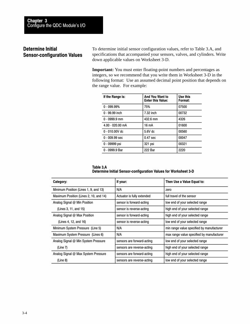
To determine initial sensor configuration values, refer to Table 3.A, andspecifications that accompanied your sensors, valves, and cylinders. Writedown applicable values on Worksheet 3-D.
Important: You must enter floating-point numbers and percentages asintegers, so we recommend that you write them in Worksheet 3-D in thefollowing format: Use an assumed decimal point position that depends onthe range value. For example:
If the Range is: And You Want toEnter this Value:
Use thisFormat:
0 � 099.99% 75% 07500
0 � 99.99 inch 7.32 inch 00732
0 � 0999.9 mm 432.6 mm 4326
4.00 � 020.00 mA 16 mA 01600
0 � 010.00V dc 5.6V dc 00560
0 � 009.99 sec 0.47 sec 00047
0 � 09999 psi 321 psi 00321
0 � 0999.9 Bar 222 Bar 2220
Table 3.ADetermine Initial Sensor�configuration Values for Worksheet 3�D
Category: If your: Then Use a Value Equal to:
Minimum Position (Lines 1, 9, and 13) N/A zero
Maximum Position (Lines 2, 10, and 14) Actuator is fully extended full travel of the sensor
Analog Signal @ Min Position sensor is forward�acting low end of your selected range
(Lines 3, 11, and 15) sensor is reverse�acting high end of your selected range
Analog Signal @ Max Position sensor is forward�acting high end of your selected range
(Lines 4, 12, and 16) sensor is reverse�acting low end of your selected range
Minimum System Pressure (Line 5) N/A min range value specified by manufacturer
Maximum System Pressure (Lines 6) N/A max range value specified by manufacturer
Analog Signal @ Min System Pressure sensors are forward�acting low end of your selected range
(Line 7) sensors are reverse�acting high end of your selected range
Analog Signal @ Max System Pressure sensors are forward�acting high end of your selected range
(Line 8) sensors are reverse�acting low end of your selected range
Determine InitialSensor�configuration Values

Record Your Initial Values Here
Configure the QDC Module's I/OChapter 3
3-5
Worksheet 3�DDetermine Initial Sensor�configuration Values
Input Line Control Word Pro�Set 600 Addr. Value Description
1 1 MCC09 N40:5 0 Minimum Screw Position 1
2 MCC10 N40:6 Maximum Screw Position 1
3 MCC11 N40:7 Analog Signal @ Min Screw Position 2
4 MCC12 N40:8 Analog Signal @ Max Screw Position 2
2 5 MCC57 N40:53 0 Minimum System Pressure 3
6 MCC58 N40:54 Maximum System Pressure 3
7 MCC59 N40:55 Analog Signal @ Min System Pressure 2
8 MCC60 N40:56 Analog Signal @ Max System Pressure 2
3 9 MCC23 N40:19 0 Minimum Clamp Position 1
10 MCC24 N40:20 Maximum Clamp Position 1
11 MCC25 N40:21 Analog Signal @ Min Clamp Position 2
12 MCC26 N40.22 Analog Signal @ Max Clamp Position 2
4 13 MCC31 N40:27 0 Minimum Ejector Position 1
14 MCC32 N40:28 Maximum Ejector Position 1
15 MCC33 N40:29 Analog Signal @ Min Ejector Position 2
16 MCC34 N40:30 Analog Signal @ Max Ejector Position 2
1 Incremental Distance 2 Input Signal Range 3 Pressure
00.00 to 99.99in 00.00 to 10.00VDC or 0000 to 9999 PSI000.0 to 999.9mm 01.00 to 05.00VDC or 000.0 to 999.9 Bar
04.00 to 20.00MADC
Use this download procedure now and later in this chapter. The procedurerequires you to complete the following general steps:
enter MCC parameters into the PLC-5 data table download them to the QDC module (with PLC-5 processor in run mode) correct any programming errors
Next, we describe the general steps.
Enter MCC Parameters into Your PLC�5 Data Table
With your programming terminal, enter values from Worksheet 3-A thru4-D into your PLC-5 data table as follows:
1. Switch the PLC-5 processor to PROGRAM mode.
2. Display your PLC-5 data table.
Download MCC Parametersto the QDC Module
Allen-Bradley Parts

Configure the QDC Module's I/OChapter 3
3-6
3. Locate the data file for storing the MCC block. PLC-5 data tableword addresses are listed on the worksheets.
4. Enter the value for each word and bit.
When you enter bit selections in words prefixed with file identifier B(example: B34), the PLC-5 processor automatically switches the radix tobinary format so you can conveniently enter binary data.
Download MCC Parameters
To download the MCC block to the QDC module, switch the PLC-5processor from PROGRAM mode to RUN mode. Pro-Set 600 softwaredownloads the MCC to the QDC module for you.
Important: You can verify that the MCC block was successfully down-loaded or you made a programming error by evaluating the followingwords that Pro-Set 600 software continuously reports to the PLC-5processor.
If: And: Then:
SYS01�B08 = 1(B34/8)
N/A QDC module accepted a valid MCC.
SYS19�B00 = 1(B34/288)
SYS61 = 1(ID code for MCC blockstored in N40:213)
You made a programming error in MCC.Read the error code in SYS62 (N40:214), andlook up the error in Section 2 of the PlasticMolding Module Reference Manual (pub. no.1771�6.5.88).
Important: Pro-Set 600 software downloads all command blocks whenyour PLC-5 processor enters run mode and after a valid MCC is accepted.All programming errors reported in SYS62 (N40:214) are referenced to theMCC until SYS01-B08 (B34/08) equals zero.
Correct Any Data�entry Errors
Upon receipt of MCC block, the QDC module tests data for data-entryerrors, such as a value out of range. When it detects an error, The QDCmodule halts operation until you correct the error. For a complete list oferror codes to help you correct errors, refer to Section 2 of the PlasticMolding Module Reference Manual, publication 1771-6.5.88.
You must correct errors by entering the changed configuration values intoyour PLC-5 data table and downloading the new values to the QDCmodule as outlined above. Pro-Set 600 software continues to attempt todownload the MCC block to the QDC module until an MCC is acceptedand the QDC module returns SYS01-B08 (B34/08) equal to 1.

Configure the QDC Module's I/OChapter 3
3-7
To finish configuring the QDC module, you actuate the ram (screw),clamp, and ejector axes with the QDC module’s set-output operation thatapplies percentage values to your QDC module’s outputs to move theactuator in a controllable fashion. To do this, you apply a %-output signalto a module output so you can move the actuator over its intended range.
ATTENTION: Do not rely on pressure valves connected to theQDC module for pressure relief. Use them only for pressurecontrol below the setting of the system pressure-relief valve.
ATTENTION: A value of zero in set-output wordsN40:121-124 does not necessarily correspond to zero pressureor flow. If you configured jumpers E11, E12, E15, or E16 forbi-directional valve operation, an output of 0% gives –10V dc,50% gives 0V dc (see chart). Amplifier electronics orspool-null offsets may also allow pressure or flow at zero voltssignal input. Consult your valve and amplifier specifications.
% Output Requested
Out
put V
olta
ge
-10
-8
-5
-3
0
3
5
8
10
0 10 20 30 40 50 60 70 80 90 100
ATTENTION: As soon as you enable set-output operation, theQDC module’s outputs drive the connected valves according tothe values you entered into DYC09-12 (N40:121-124). Be surethese values RESULT IN NO MOVEMENT until you adjustthem one-at-a-time with your programming terminal in theprocedures that follow.
Use Set�output Operation toMove the Ram (screw),Clamp, and Ejector
Allen-Bradley Parts

Configure the QDC Module's I/OChapter 3
3-8
Follow this procedure to actuate the ram (screw), clamp, and ejector:
1. Enter values in words DYC09-12 that result in no motion.
Output: In Data Word: At Pro�Set 600 Address:
1 DYC09 N40:121
2 DYC10 N40:122
3 DYC11 N40:123
4 DYC12 N40:124
2. Enable set-output operation by entering a 1 in DYC01-B08(B34/392). The QDC module sets outputs 1-4 to percentage valuesthat you entered in DYC09-12 respectively.
Important: The DYC is constantly transferred to the QDC module byPro-Set 600 software, so changes you make to %-output values areimmediately implemented.
3. With your programming terminal, slowly change the %-output valueof each output, one at a time, as you observe the correspondingactuator movement.
4. Increase the %-output value until you reach a safe actuator speed touse in the next procedure.
Complete the procedure for configuring the QDC module to match itssensors by spanning them over their intended range with the machine inoperation. Here we describe how you determine:
ram (screw) position sensor values system pressure sensor values clamp position sensor values ejector position sensor values
In the procedures that follow, measure and record:
min/max positions and corresponding signal values min/max system pressure and corresponding signal values
After determining these values from the procedures, write them down onWorksheet 3-E.
Important: You must complete this configuration before proceeding toany other chapters on module configuration.
Complete your SensorConfiguration

Record Your Final Values Here
Configure the QDC Module's I/OChapter 3
3-9
Worksheet 3�EFinal Sensor�configuration Values
Input Line Control Word Pro�Set 600 Addr. Value Description
1 1 MCC09 N40:5 0 Minimum Screw Position 1
2 MCC10 N40:6 Maximum Screw Position 1
3 MCC11 N40:7 Analog Signal @ Min Screw Position 2
4 MCC12 N40:8 Analog Signal @ Max Screw Position2
2 5 MCC57 N40:53 0 Minimum System Pressure 3
6 MCC58 N40:54 Maximum System Pressure 3
7 MCC59 N40:55 Analog Signal @ Min System Pressure 2
8 MCC60 N40:56 Analog Signal @ Max System Pressure 2
3 9 MCC23 N40:19 0 Minimum Clamp Position 1
10 MCC24 N40:20 Maximum Clamp Position 1
11 MCC25 N40:21 Analog Signal @ Min Clamp Position 2
12 MCC26 N40:22 Analog Signal @ Max Clamp Position 2
4 13 MCC31 N40:27 0 Minimum Ejector Position 1
14 MCC32 N40:28 Maximum Ejector Position 1
15 MCC33 N40:29 Analog Signal @ Min Ejector Position 2
16 MCC34 N40:30 Analog Signal @ Max Ejector Position 2
1 Incremental Distance 2 Input Signal Range 3 Pressure
00.00 to 99.99in 00.00 to 10.00VDC or 0000 to 9999 PSI000.0 to 999.9mm 01.00 to 05.00VDC or 000.0 to 999.9 Bar
04.00 to 20.00MADC
Determine Values for Ram (Screw) Position Sensor
ATTENTION: Incorrect values entered in DYC09-12 mayresult in rapid ram (screw) motion and potential damage to yourbarrel and seals of your injection cylinder.
To complete the configuration for your ram (screw) position sensor, do thefollowing and enter the results on Worksheet 3-E:
1. Move the ram (screw) forward until it reaches its mechanical stop atthe nozzle end. This is the zero position.
2. Remove ram (screw) pressure and/or flow to stop movement.
Allen-Bradley Parts

Configure the QDC Module's I/OChapter 3
3-10
3. Record this position value (normally 0000) on line 1 for MCC09 onWorksheet 3-E.
4. With your programming terminal, read the signal level returned inSYS33 (N40:185) from your position sensor.
Important: If your position sensor has a potentiometer for setting the zeroreference, do so now.
5. Record this value on line 3 for MCC11 (should be at minimum signalif you zeroed your position sensor in step 4).
6. Move the ram (screw) backward to the backpoint mechanical stop.
7. Remove ram (screw) pressure and/or flow to stop movement.
8. Measure the distance travelled.
9. Record this distance on line 2 for MCC10.
10. With your programming terminal, read the signal level returned inSYS33 (N40:185) from your positioning sensor.
Important: If your position sensor has a potentiometer to set the span(linear resolution), do so now.
11. Record this value on line 4 for MCC12.
You may now download your adjusted values to the QDC module usingthe MCC download procedure presented earlier in this chapter.
Determine Values for the Clamp Position Sensor
Important: Use the following procedure and subsequent set-upinformation for each different mold used on a hydraulic machine. On atoggle clamp (with die height adjust), complete it only once.
ATTENTION: Incorrect values entered in DYC09-12 mayresult in rapid clamp motion and potential damage to your moldor cylinder seals. We strongly recommend using a “dummy”mold on hydraulic machines and no mold on toggle machines.
1. Move the clamp forward until it reaches its mechanical close stop.This is the zero position.
2. Remove clamp pressure and/or flow to stop clamp movement.

Configure the QDC Module's I/OChapter 3
3-11
3. Record this position value (usually 0000) on line 9 for MCC23 onWorksheet 3-E.
4. With your programming terminal, read the signal level returned inSYS35 (N40:187) from your position sensor.
Important: If your position sensor has a potentiometer to set the zeroreference, do so now.
5. Record this value on line 11 for MCC25 (should be at minimumsignal if you zeroed your position sensor in step 4).
6. Move the clamp backward to the mechanical open stop.
7. Remove clamp pressure and/or flow to stop clamp movement.
8. Measure the distance travelled.
9. Record this distance on line 10 for MCC24.
10. With your programming terminal, read the signal level returned inSYS35 (N40:187) from your positioning sensor.
Important: If your position sensor has a potentiometer to set the span(linear resolution), do so now.
11. Record this value on line 12 for MCC26.
You may now download your adjusted values to the QDC module usingthe MCC download procedure presented earlier in this chapter.
Determine Values for Ejector Position Sensor
ATTENTION: Be sure to open the clamp sufficiently to allowfull ejector travel before proceeding. Otherwise, you coulddamage the ejectors and/or the mold.
To complete the configuration for your ejector position sensor, do thefollowing and enter the results on Worksheet 3-E:
1. Move the ejector backward until it reaches its mechanical retract stop.This is the zero position.
2. Remove ejector pressure and/or flow to stop movement.
3. Record this position value (normally 0000) on line 13 for MCC31 onWorksheet 3-E.Allen-Bradley Parts

Configure the QDC Module's I/OChapter 3
3-12
4. With your programming terminal, read the signal level returned inSYS33 (N40:185) from your position sensor.
Important: If your position sensor has a potentiometer for setting the zeroreference, do so now
5. Record this value on line 15 for MCC33 (should be at minimumsignal if you zeroed your position sensor in step 4).
6. Move the ejector forward to the mechanical advance stop.
7. Remove ejector pressure and/or flow to stop movement.
8. Measure the distance travelled by the ejector.
9. Record this distance on line 14 for MCC32.
10. With your programming terminal, read the signal level returned inSYS33 (N40:185) from your positioning sensor.
Important: If your position sensor has a potentiometer to set the span(linear resolution), do so now.
11. Record this value on line 16 for MCC34.
You may now download your adjusted values to the QDC module usingthe MCC download procedure presented earlier in this chapter.
Determine Values for the System Pressure Sensor
To complete the sensor configuration procedure, record minimum andmaximum system pressures and corresponding signal levels from thesensor manufacturer’s specifications onto Worksheet 3-E, wordsMCC57-60. Most applications require no further spanning. If yourapplication requires greater accuracy, follow the procedure below:
1. Release system pressure to a minimum.
2. Read the system pressure gauge.
3. Record minimum pressure (normally 0000) on line 5 for MCC57 onWorksheet 4-E.
4. With your programming terminal, read the signal level returned inSYS34 (N40:186) from your pressure sensor.
Important: If your pressure sensor has a potentiometer for setting the zeroreference, do so now
5. Record this signal level on line 7 for MCC59. It should be atminimum signal if you zeroed your pressure sensor in step 4.

Configure the QDC Module's I/OChapter 3
3-13
ATTENTION: Use extreme caution during the next stepsbecause you stress the hydraulic system to its maximum ratedpressure. Loose fittings or faulty components could fail, causingpossible damage to equipment and/or injury to personnel.
ATTENTION: If the ram (screw), clamp, and/or ejectors arenot disconnected from the hydraulic circuit, be sure that they arefully retracted with their hydraulics aligned in the retractposition. This forces the cylinders to press against themechanical limits of travel and builds max system pressure.Otherwise, they could suddenly move, causing possible damageto equipment and/or injury to personnel.
6. Re-torque all hydraulic connections and joints before proceeding.
7. Boost system pressure to maximum.
8. Read the system pressure gauge. Do this while the ram (screw) ismechanically bound from moving.
9. Record this maximum pressure on line 6 for MCC58.
10. With your programming terminal, read the signal level returned inSYS34 (N40:186) from your pressure sensor.
Important: If your pressure sensor has a potentiometer to set the span(linear resolution), do so now.
11. Record this signal level on line 8 for MCC60.
12. Release pressure.
You may now download your adjusted values to the QDC module usingthe MCC download procedure presented earlier in this chapter.
Allen-Bradley Parts

Configure the QDC Module's I/OChapter 3
3-14
You have the option of configuring the following QDC module features:
Use this Option: For this Benefit:
Software Travel Limits to guard against damaging the nozzle, mold, or ejectors
Pressure Alarm Time Delay to warn of excessive pressure without nuisance alarms
Digital Filter to compensate for electrical noise on position inputs
Configure Software Travel Limits
You may want to use software restrictions to stop the travel of your ram(screw), clamp, and/or ejector before either reaches its maximum limits(configured earlier in this chapter).
Figure 3.1Software Restrictions
Physical Travel Range
Max Position Min Position
d d
Max SWTL Min SWTL
d = deadbandSafe Zone
Important: With the orientation shown, clamp movement is from left toright. By convention, ram (screw) and ejector movement is reversed.
During normal machine operation and whenever your cylinder travelsoutside the safe zone (outside the specified software travel limits, SWTL),the QDC module:
sets an alarm status bit forces its outputs to zero ignores all profile commands (except set-output and jogs) until you jog
the cylinder back through the deadband into the safe zone at either end
The deadband guards against sensor noise flickering the SWTL alarms andrequires that the operator jog the cylinder a set distance away from thesoftware overtravel limit. We recommend a value of 00.10 inch as astarting deadband. Your sensor may require a greater deadband.
ATTENTION: When jogging or when performing a set-outputoperation, the QDC module ignores SWTLs. In these modes, itwill not zero its outputs so equipment damage could occur.
Select OptionalConfigurations

Record Your SWTL Configuration Values Here
Configure the QDC Module's I/OChapter 3
3-15
Configure the QDC module for SWTL alarms as follows:
1. Determine these SWTL values for ram (screw), clamp, and/or ejectortravel with respect to the range of physical travel.
SWTL deadband Maximum SWTL Minimum SWTL
2. Record non-zero SWTL values on Worksheet 3-F. Zero valuesdisable the corresponding SWTLs.
ATTENTION: Leaving your SWTL settings at zero (MCC13,14, 27, 28, 41, 42) inhibits the QDC module from performingthis safety function.
Worksheet 3�FSWTL Configuration Values
Control Word Pro�Set 600 Addr. Value Description
MCC13 N40:9 Screw Minimum SWTL 1
MCC14 N40:10 Screw Maximum SWTL 1
MCC15 N40:11 10 Screw SWTL Deadband 2
MCC27 N40:23 Clamp Minimum SWTL 1
MCC28 N40:24 Clamp Maximum SWTL 1
MCC29 N40:25 10 Clamp SWTL Deadband 2
MCC41 N40:37 Ejector Minimum SWTL 1
MCC42 N40:38 Ejector Maximum SWTL 1
MCC43 N40:39 10 Ejector SWTL Deadband 2
1 Incremental distance measured from zero 2 Incremental distance measured as noted
00.00 to 99.99 Inches 00.00 to 99.99 Inches
000.0 to 999.9 Millimeters 000.0 to 999.9 Millimeters
You may now download your adjusted values to the QDC module usingthe MCC download procedure presented earlier in this chapter.
Allen-Bradley Parts

Enter Your Pressure�alarm and Time�delay Values Here
Configure the QDC Module's I/OChapter 3
3-16
Set Up Maximum Pressure Alarms and Time Delays
The QDC module continuously monitors the system pressure input. Whenit detects that the process input equals or exceeds a preset alarm setpoint,the QDC module sets an alarm bit. A setpoint of zero disables theassociated alarm.
To guard against nuisance alarms caused by noise spikes or pressuretransients, you can set a time delay so the QDC module must monitorcontinuous excessive pressure for an amount of time before setting thehigh pressure alarm. A setpoint of zero disables this delay.
Configure the QDC module for the system pressure alarm as follows:
1. Determine these values:
pressure-alarm setpoint time-delay setpoint
2. Record non-zero setpoints on Worksheet 3-G for the pressure alarmand time delay.
3. Download them to the QDC module using the procedures presentedearlier in this chapter.
Worksheet 3�GPressure�alarm and Time�delay Setpoints
Control Word Pro�Set 600 Addr. Value Description
MCC61 N40:57 System Pressure�alarm Setpoint 2
MCC62 N40:58 System Pressure Time�delay Setpoint 1
1 Time Measured in Seconds 2 Pressure
00.00 to 00.99 0000 to 9999 PSI 000.0 to 999.9 Bar
Configure the QDC Module's I/OChapter 3
3-17
Configure Digital Filters for Position Inputs
You may enable an optional digital filter on position inputs to reduceelectrical noise from a potentiometer-type position sensors or picked up byyour input circuits.
To determine if you need a digital filter, move the ram (screw), clamp,and/or ejector very slowly. With your programming terminal, look forerratic position numbers reported for ram (screw), clamp, and/or ejectorposition by examining these words:
For this Input: In Word: Look at this Pro�Set 600 Address:
Ram (Screw) SYS25 N40:177
Clamp SYS27 N40:179
Ejector SYS28 N40:180
To determine the time constant (00.10 sec max), start with a small valuesuch as 00.01. A value of zero disables the filter.
To Filter this Input: In Word: Enter a Filter Time Constant in:
Ram (Screw) MCC16 N40:12
Clamp MCC30 N40:26
Ejector MCC44 N40:40
ATTENTION: Increasing the value of the time constantdecreases the QDC module’s capability to respond quickly totravel limits and/or to accurately locate programmed positions.We recommend that you keep the time constant under 00.10.
For example, with a clamp velocity of 2 inches/sec, a 00.01 time constantallows a 0.20 inch travel before the QDC module can react to a travel limit.
Important: If you have a noisy potentiometer-type position sensor anddigital filtering slows the QDC module’s response time too much, considerreplacing the sensor with a non-contact, linear-displacement type.
Download time constants to the QDC module using the procedurespresented earlier in this chapter.
Allen-Bradley Parts

Chapter
4
4-1
Overview of Remaining Configuration Procedures
This chapter gives you and overview of the remaining configurationprocedures necessary to successfully configure your QDC module for theinject, clamp, and eject mode
Important: You must follow the configuration procedures presented inchapters 5-10 in given order. Please use this chapter as a guide.
The QDC module communicates with your PLC-5 processor through data“blocks”. These blocks are made up of several 16-bit words stored in thePLC-5 data table. The QDC module accesses these areas of data tablethrough the 1771 backplane. There are two types of data blocks:
Command Blocks - these blocks are downloaded from the PLC-5 datatable to the QDC module to make configuration changes or initiatemachine actions
Status Blocks - the QDC module uses these blocks to send informationto the PLC-5 processor about current operating status
The configuration procedure detailed over the next several chapters makesextensive use of command and status blocks. You will:
enter important operating data into all applicable command blocks read machine operating data in status blocks to assist you in the
configuration procedure
Command Blocks
You configure the QDC module with a series of command blocks.Command blocks are an area of the PLC-5 data table containing machinecommands, set-up, and operating information for the QDC module. Onpower-up, or when you initiate a download, command blocks aredownloaded from the PLC-5 data table to the QDC module.
Chapter Objectives
Configuration Concepts
Overview of RemainingConfiguration Procedures
Chapter 4
4-2
There are two types of command blocks, presented in the following table:
Type of Command Block: Which Contains: Examples:
Configuration Information necessary to configure yourmodule to run a certain portion of a profile.
Valve spanninginformation for the 1stclamp close profile.
Profile Actual process setpoints necessary toproduce a desired part.
1st clamp close profileoperating setpoints.
Status Blocks
The QDC module returns critical operating status and values to the PLC-5data table through status blocks. Like configuration blocks, status blocksare areas of PLC-5 data table. Status blocks, however, contain actualmachine operation information rather than machine setpoints and actioncommands.
Type of Block: Which Contains: Examples:
Status Information about machine operation andQDC module operating status.
The molding machine iscurrently performing aninjection operation.
The Module Configuration Block (MCC), Dynamic Command BlockDYC), and the System Status Block (SYS) are system data blocks becauseof functions they perform:
Type of Block: Description: Examples:
Module Configuration(MCC)
Contains configuration information usedthroughout all phases of machineoperation.
Sensor spanning informationand global alarm setpoints.
Dynamic Command(DYC)
Includes all commands necessary to jog,run, and stop any applicable machinephase or operation.
Command to start the injectionphase.
System Status (SYS)
Returns to the PLC�5 processorinformation relevant to common moduleparameters.
Actual voltages andengineering units read at thefour QDC module inputs.
System Command andStatus Blocks
Allen-Bradley Parts
Overview of RemainingConfiguration Procedures
Chapter 4
4-3
Configuration procedures described in the next several chapters areoutlined below. They are sequential in nature: configuration informationdetermined in initial chapters is needed in later chapters.
Step: Procedure: Description: Refer to:
1 Jog Your Machine You enter machine jog pressure and flow setpointsinto the Jog Configuration (JGC) block.
You jog your ram (screw), clamp, and ejectorwith commands in the DYC block to further refineyour jog configuration.
You enter jog pressure alarm setpoints into the JGCblock.
Chapter 5
2 Select Command and StatusBits to Sequence MachineOperation
You write PLC�5 ladder logic required to cycle themachine in the desired manner.
Chapter 6
3 Load Initial Configuration Values
You load initial values for controlling pressure orflow, ramp rates, pressure alarms.
Chapter 7
(Used in Chapters 9 & 10)
4 Load Initial Profile Setpoints You load Initial setpoints for process control, suchas pressure, velocity, position, and time setpoints.
Chapter 8
(Used in Chapters 9 & 10)
5 Span your Valves You span your inject, clamp, and ejector valves.and set profile pressure alarms.
Chapter 9
6 Tune your Machine forProducing Parts
We discuss topics to consider when tuning yourmachine.
Chapter 10
7 Troubleshoot the QDCModule with LEDs
We present a troubleshooting table based on LEDindicator conditions
Chapter 11
Important: Throughout the rest of this manual, we refer to systempressure during profile or axis movement as corresponding to:
inject pressure, or clamp pressure, or ejector pressure
All three are the pressure measured at input 2 of the QDC module.
For additional information, refer to System Pressure in chapter 1.
Overview of Procedures
Overview of RemainingConfiguration Procedures
Chapter 4
4-4
We refer to these procedures throughout this manual whenever you must:
enter data table values download data blocks
Enter Values into Your PLC� Data Table
With your programming terminal, enter worksheet values into your PLC-5data table as follows:
1. Switch the PLC-5 processor to PROGRAM mode.
2. Display your PLC-5 data table
3. Locate the data files for storing the subject block as specified onindividual worksheets.
4. Enter the value for each word and bit.
When you set bits in words prefixed with file identifier B (example: B34),the PLC-5 processor automatically switches the radix to binary format.
Download Data Blocks
We define the following data words and functions used in the procedure todownload data blocks.
This Word: At Address: Provides this Function:
DYC61 N40:173 Requests that the QDC module return an error if itfinds one in the designated data block. The QDCmodule reports the error in SYS61 and SYS62.
SYS61 N40:213 The QDC module reports the ID of the data blockcontaining the error (identified in SYS62). This wordwill match a non�zero DYC61.
SYS62 N40:214 The QDC module reports the error code in thisword. This error code relates to the data blockwhose ID is reported in SYS61.
The following steps outline the procedure to download data blocks fromthe PLC-5 data table to the QDC module.
Important: The exception to this procedure is the MCC block that has itsown download procedure already outlined in chapter 3. The QDC modulemust store a valid MCC block before you can use the following procedure.
1. For the block you want to download (subject block), get its IDnumber from Table 4.A and enter it into DYC61.
Enter Data Table Valuesand Download Data Blocks
Allen-Bradley Parts

Overview of RemainingConfiguration Procedures
Chapter 4
4-5
Table 4.AInformation Required to Download a Block
Block toDownload:
Pro�Set 600Block ID.:
Pro�Set 600 Download Bit B21/
CompanionBlock:
JGC 02 1
FCC 03 2 CPC
SCC 04 3 CPC
TCC 05 4 CPC
LPC 06 5 CPC
CPC 07 6
INC 08 7 IPC
IPC 09 8
PKC 10 9 HPC
HDC 11 10 HPC
HPC 12 11
PRC 13 12
PLC 14 13 PPC
PPC 15 14
PSC 16 15
FOC 17 16 OPC
SOC 18 17 OPC
TOC 19 18 OPC
OSC 20 19 OPC
OPC 21 20
EAC 22 21 EPC
ERC 23 22 EPC
EPC 24 23
2. Confirm that the QDC module returns the ID in SYS61.
Important: If the value returned in SYS61 is NOT the ID numberyou entered, you have an error in the MCC or DYC block:
If SYS61 hasthis value:
This block has errors:
Fix them as follows:
1 MCC Refer to chapter 3 �Correct Programming Errors in MCC"
25 DYC Go to steps 8 and 9 of this procedure.
Fix MCC and DYC errors before starting the download procedure
MCC and DYC errors are corrected when SYS61≠ 1 or 25, butwhen SYS61=DYC61=ID number of the subject block
When you have done all three: Then:
1. Corrected all errors in MCC and DYC blocks2. Entered the ID of the subject block in DYC613. Downloaded the subject block
The QDC module immediatelyreports any programming errors itdetected in the subject block

Overview of RemainingConfiguration Procedures
Chapter 4
4-6
3. Start the download procedure by setting the corresponding downloadbit (Table 4.A) in your PLC-5 data table.
4. Watch the bit you set in step 3 and wait for Pro-Set 600 software toreset it to zero. This indicates the PLC-5 processor has transferredthe block to the QDC module.
5. Observe the value of SYS62 (N40:214) in your PLC-5 data table:
If SYS62 = 0, the QDC module detected no errors. Go to step 6. If SYS62 ≠ 0, the QDC module detected an error. Go to step 8.
6. Since the QDC module did not detect a programming error, checkTable 4.A to see if the subject block has a required companion block.
Important: When downloading multiple subject blocks that share thesame companion block, you may download the companion block:
after each subject block once after the last subject block
To simplify troubleshooting your data entry (programming) errors duringinitial configuration procedures, we recommend that you download thecompanion block after each subject block. Otherwise, the procedure tocorrect multiple errors becomes too complex.
7. Complete the procedure as follows:
a. If the subject block has a required companion block, return tostep 2 and repeat the procedure for the next block or companionblock.
b. If the subject block is the companion block, download it.Return to step 2 to download additional blocks if required.
8. The QDC module detected a programming error. Interpret the errorcode returned by the QDC module in SYS62. The code identifies thefirst detected programming error in the subject block whose ID isreported in SYS61 (N40:213). Refer to Section 2 of the PlasticMolding Module Reference Manual (publication 1771-6.5.88) forhow to interpret and correct the cause of programming errors.
9. Correct the error in the PLC-5 data table corresponding to the subjectblock. Since you may have more than one programming error in thesubject block, return to step 4 and repeat the download procedureuntil you have corrected all errors in this block. Then SYS62 = 0.
Important: Pro-Set 600 software forces the PLC-5 processor to downloadall command blocks to the QDC module when you switch the processorfrom PROGRAM to RUN or power it up.Allen-Bradley Parts
Chapter
5
5-1
Jog Your Machine
This chapter describes how to:
configure jog block values necessary to jog the ram (screw), clamp, and ejector
test jog values and make changes, if necessary configure values which indirectly affect screw-rotate jogs
Jogging your machine is similar to operating in set-output mode: You apply percentage values to your QDC module’s outputs to obtain thedesired motion. The jog configuration block (JGC) lets you set up jogparameters to control QDC module outputs to jog the:
ram (screw) forward and backward clamp open and closed ejector advance and retract
Although the QDC module (in the inject, clamp, and eject mode) may notdirectly control your machine’s screw-rotate jogs, your hydraulics mayrequire that valves connected to QDC module outputs assume a certainposition to assure proper screw-rotate jog functions. The QDC jogconfiguration block allows you to set up these indirect jog values.
The following table lists the worksheets for recording initial values in theJGC block to configure the QDC module for jogging the ram (screw),clamp, and ejector.
To configure the QDC module for jogging the:
Use this Worksheet
OnPage
ram (screw), clamp, and ejector 5�A 5-3
screw�rotate (indirect control) 5�B 5-8
Chapter Objectives
About Jogging
Use These Worksheets
Jog Your MachineChapter 5
5-2
Worksheet 5-A lists all words in which you must enter values tosuccessfully configure your QDC module for jogging the ram (screw),clamp, and ejector in both directions. Use it to record:
initial values
Enter initial values just sufficient to jog in the desired direction. Keep this information in mind:
The numbers you enter are %-signal output. For a range of –10 to +10V dc, zero output occurs @ 50%
(See Warning on next page.)
Later in this chapter you modify these values to obtain desired results.
pressure alarm setpoints for ram (screw), clamp, and/or ejector jogs
The QDC module sets an alarm any time system pressure equals orexceeds the corresponding alarm setpoints during a jog. A zero entryinhibits alarm actuation.
Important: The system high pressure alarm that you set in chapter 4 isalso active during jog functions.
Determine Initial Jog Values
Allen-Bradley Parts

Record Your Initial Values Here
Jog Your MachineChapter 5
5-3
Worksheet 5. A Ram (screw), Clamp, and Ejector Jog Configuration Values
Block Word Pro�Set 600 Addr. Value Description
Inject, Forward Jog
JGC17 N40:73 Set�output Values Output #1 1
JGC18 N40:74 Output #2 1
JGC19 N40:75 Output #3 1
JGC20 N40:76 Output #4 1
Inject, Reverse Jog
JGC25 N40:81 Set�output Values Output #1 1
JGC26 N40:82 Output #2 1
JGC27 N40:83 Output #3 1
JGC28 N40:84 Output #4 1
Clamp, Forward Jog
JGC33 N40:89 Set�output Values Output #1 1
JGC34 N40:90 Output #2 1
JGC35 N40:91 Output #3 1
JGC36 N40:92 Output #4 1
Clamp, Reverse Jog
JGC41 N40:97 Set�output Values Output #1 1
JGC42 N40:98 Output #2 1
JGC43 N40:99 Output #3 1
JGC44 N40:100 Output #4 1
Ejector, Advance Jog
JGC49 N40:105 Set Output Values Output #1 1
JGC50 N40:106 Output #2 1
JGC51 N40:107 Output #3 1
JGC52 N40:108 Output #4 1
Ejector, Retract Jog
JGC57 N40:113 Set Output Values Output #1 1
JGC58 N40:114 Output #2 1
JGC59 N40:115 Output #3 1
JGC60 N40:116 Output #4 1
Jog Pressure Alarms
JGC06 N40:62 Ram Jog Pressure, Alarm Setpoint 2
JGC07 N40:63 Clamp Jog Pressure, Alarm Setpoint 2
JGC08 N40:64 Ejector Jog Pressure, Alarm Setpoint 2
1 % Signal Output 2 Pressure 00.00 to 99.99 % 0000 to 9999 PSI
000.0 to 999.9 Bar

Jog Your MachineChapter 5
5-4
ATTENTION: You can connect up to four different valves toyour QDC module. Although all four may not directly jog theram (screw), clamp, and/or ejector, consider their indirect effectwhen setting jog set-output values. Indirectly, they could causeunexpected machine motion with possible damage to equipmentor injury to personnel.
ATTENTION: A value of 0 entered in your data table does notnecessarily correspond to zero pressure or flow. For an outputconfigured + 10V dc, an output of 50% corresponds to zerovolts signal output (see graph). Amplifier electronics or spooloffsets may also be designed such that zero volts signal inputdoes not result in no flow or pressure. Please consult your valveand amplifier specifications for more details.
-10
-5
0
5
10
0 10 20 30 40 50 60 70 80 90 100
% Output Requested
Out
put V
olta
ge
Enter and Download Initial Jog Values
Enter values from Worksheet 5-A into PLC-5 data table and download theJGC block to the QDC module with your programming terminal. Use theprocedures from chapter 4, Enter Data Table Values and Download DataBlocks. We repeat the JGC block download data.
To download Set B21/
JGC 1
Allen-Bradley Parts

Jog Your MachineChapter 5
5-5
Take time now to develop ladder logic (independent of Pro-Set 600software) to jog the ram (screw), clamp, and ejector. You may need tomonitor switches on your operator control panel, and set correspondingcommand bits.
Use word 1 in the dynamic command block (DYC01) to enable and disableindividual jogs. Use word 1 in the system status block (SYS01) to monitorthe QDC module’s reaction to jog commands. Tables 5.A and 5.B identifycommand and status bits for jogging the ram (screw), clamp, and ejector.
Table 5.AEnable Bits for Ram (Screw), Clamp, and Ejector Jogs
Control Block Word: Pro�Set 600 Address: Description:
DYC01�B10 B34/394 Execute Ram (Screw) Jog Forward
DYC01�B11 B34/395 Execute Ram (Screw) Jog Reverse
DYC01�B12 B34/396 Execute Clamp Jog Forward
DYC01�B13 B34/397 Execute Clamp Jog Reverse
DYC01�B14 B34/398 Execute Ejector Jog Advance
DYC01�B15 B34/399 Execute Ejector Jog Retract
Table 5.BStatus Bits for Ram (Screw), Clamp, and Ejector Jogs
Status Block Word: Pro�Set 600 Address: Description:
SYS01�B10 B34/10 Ram (Screw) Jog Forward in Progress
SYS01�B11 B34/11 Ram (Screw) Jog Reverse in Progress
SYS01�B12 B34/12 Clamp Jog Forward in Progress
SYS01�B13 B34/13 Clamp Jog Reverse in Progress
SYS01�B14 B34/14 Ejector Jog Advance in Progress
SYS01�B15 B34/15 Ejector Jog Retract in Progress
We provide a programming example (Figure 5.1) of jog control forinstructional purposes only. Your application-specific programming mayvary significantly from this example.
Important: You may also need to develop ladder logic that changes thedirection of ram (screw), clamp, and/or ejector travel hydraulically whenyou command the QDC module to jog in reverse.
Write Ladder Logic

Jog Your MachineChapter 5
5-6
Figure 5.1Example Programming for Ram (Screw), Clamp, and Ejector Jogs
Rung 6:1 DYC02-B15
| EMERGENCY ********* || STOP EXECUTE || CONDITION ALL STOP || EXISTS COMMAND || B3 B34 |+––––] [–––––––––––––––––––––––––––––––––––––––––––––––––––––––––––––––( )–––––+| 0 415 |Rung 6:2| CYCLE | MANUAL |DIRECTION DYC01-B10 || CONTROL | SCREW |SOLENOIDS ********** || SELECTOR | FORWARD |ALIGNED TO EXECUTE || (A/S/M) IN| JOG |MOVE SCREW SCREW || “MANUAL” | ALLOWED |FORWARD FWD JOG || I:003 B11 B11 B34 |+––––] [––––––––] [––––––––] [–––––––––––––––––––––––––––––––––––––––––( )–––––+| 05 1 8 394 |Rung 6:3| CYCLE | MANUAL |DIRECTION DYC01-B11 || CONTROL | SCREW |SOLENOIDS ********** || SELECTOR | REVERSE |ALIGNED TO EXECUTE || (A/S/M) IN| JOG |MOVE SCREW SCREW || “MANUAL” | ALLOWED |REVERSE REV JOG || I:003 B11 B11 B34 |+––––] [––––––––] [––––––––] [–––––––––––––––––––––––––––––––––––––––––( )–––––+| 05 2 9 395 |Rung 6:4 || CYCLE | |DIRECTION DYC01-B12 || CONTROL | MANUAL |SOLENOIDS ********** || SELECTOR |CLAMP JOG |ALIGNED TO EXECUTE || (A/S/M) IN| FORWARD |MOVE CLAMP CLAMP || “MANUAL” | ALLOWED |FORWARD FWD JOG || I:003 B11 B11 B34 |+––––] [––––––––] [––––––––] [–––––––––––––––––––––––––––––––––––––––––( )–––––+| 05 4 11 396 |Rung 6:5| CYCLE | |DIRECTION DYC01-B13 || CONTROL | MANUAL |SOLENOIDS ********** || SELECTOR |CLAMP JOG |ALIGNED TO EXECUTE || (A/S/M) IN| REVERSE |MOVE CLAMP CLAMP || “MANUAL” | ALLOWED |REVERSE REV JOG || I:003 B11 B11 B34 |+––––] [––––––––] [––––––––] [–––––––––––––––––––––––––––––––––––––––––( )–––––+| 05 5 12 397 |Rung 6:6 || CYCLE | MANUAL |DIRECTION DYC01-B14 || CONTROL | EJECTOR |SOLENOIDS ********** || SELECTOR | JOG |ALIGNED TO EXECUTE || (A/S/M) IN| ADVANCE |ADVANCE EJECTOR || “MANUAL” | ALLOWED |EJECTOR ADV JOG || I:003 B11 B11 B34 |+––––] [––––––––] [––––––––] [–––––––––––––––––––––––––––––––––––––––––( )–––––+| 05 6 13 398 |Rung 6:7| CYCLE | MANUAL |DIRECTION DYC01-B15 || CONTROL | EJECTOR |SOLENOIDS ********** || SELECTOR | JOG |ALIGNED TO EXECUTE || (A/S/M) IN| RETRACT |RETRACT EJECTOR || “MANUAL” | ALLOWED |EJECTOR RET JOG || I:003 B11 B11 B34 |+––––] [––––––––] [––––––––] [–––––––––––––––––––––––––––––––––––––––––( )–––––+| 05 7 14 399 |
Allen-Bradley Parts
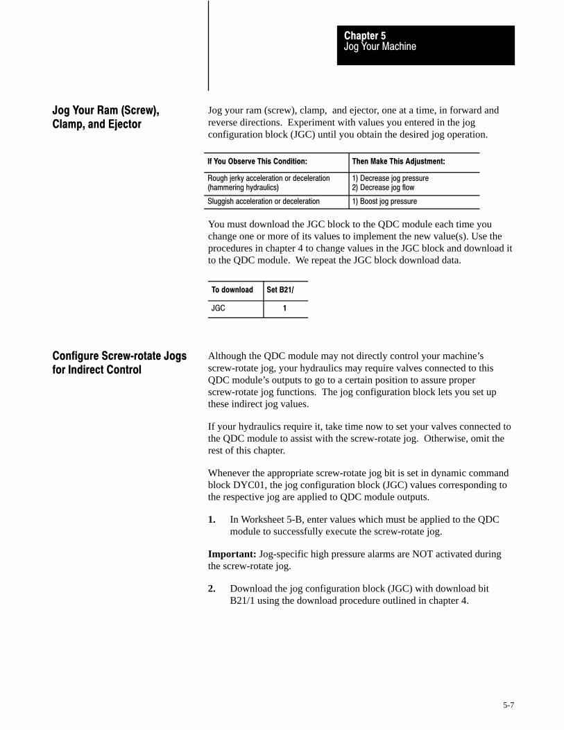
Jog Your MachineChapter 5
5-7
Jog your ram (screw), clamp, and ejector, one at a time, in forward andreverse directions. Experiment with values you entered in the jogconfiguration block (JGC) until you obtain the desired jog operation.
If You Observe This Condition: Then Make This Adjustment:
Rough jerky acceleration or deceleration (hammering hydraulics)
1) Decrease jog pressure 2) Decrease jog flow
Sluggish acceleration or deceleration 1) Boost jog pressure
You must download the JGC block to the QDC module each time youchange one or more of its values to implement the new value(s). Use theprocedures in chapter 4 to change values in the JGC block and download itto the QDC module. We repeat the JGC block download data.
To download Set B21/
JGC 1
Although the QDC module may not directly control your machine’sscrew-rotate jog, your hydraulics may require valves connected to thisQDC module’s outputs to go to a certain position to assure properscrew-rotate jog functions. The jog configuration block lets you set upthese indirect jog values.
If your hydraulics require it, take time now to set your valves connected tothe QDC module to assist with the screw-rotate jog. Otherwise, omit therest of this chapter.
Whenever the appropriate screw-rotate jog bit is set in dynamic commandblock DYC01, the jog configuration block (JGC) values corresponding tothe respective jog are applied to QDC module outputs.
1. In Worksheet 5-B, enter values which must be applied to the QDCmodule to successfully execute the screw-rotate jog.
Important: Jog-specific high pressure alarms are NOT activated duringthe screw-rotate jog.
2. Download the jog configuration block (JGC) with download bitB21/1 using the download procedure outlined in chapter 4.
Jog Your Ram (Screw),Clamp, and Ejector
Configure Screw�rotate Jogsfor Indirect Control

Enter Your Initial Values Here
Jog Your MachineChapter 5
5-8
Worksheet 5. B Screw�rotate Jog Configuration Values for Indirect Control
Block Word Pro�Set 600 Addr. Value Description
Screw Rotate Jog
JGC09 N40:65 Set Output Values Output #1 1
JGC10 N40:66 Output #2 1
JGC11 N40:67 Output #3 1
JGC12 N40:68 Output #4 1
1 % Signal Output 00.00 to 99.99 %
If your hydraulics require it, take time now to develop ladder logic(independent of Pro-Set 600 software) so the QDC module can assist inscrew-rotate jogs. Otherwise, omit the rest of this chapter.
Use word 1 in the dynamic command block (DYC01) to enable and disableindividual jogs. Use word 1 in the system status block (SYS01) to monitorthe QDC module’s reaction to jog commands. Tables 5.C and 5.D identifycommand and status bits for jogging screw rotation.
Table 5.CEnable Bits for Screw�rotate Jogs
Command Block Word: Pro�Set 600 Address: Description:
DYC01�B09 B34/393 Execute Screw�rotate Jog
Table 5.DStatus Bits for Screw�rotate Jogs
Status Block Word: Pro�Set 600Address:
Description:
SYS01�B09 B34/9 Screw�rotate Jog in Progress
We provide a programming example (Figure 5.2) of assisted jog control forinstructional purposes only. Your application-specific programming mayvary significantly from this example.
Write Ladder Logic to Assistwith Screw�rotate Jogs
Allen-Bradley Parts

Jog Your MachineChapter 5
5-9
Figure 5.2Example Programming for Assisting Screw�rotate Jogs
Rung 6:6| CYCLE | MANUAL |DIRECTION DYC01-B09 || CONTROL | SCREW |SOLENOIDS ********** || SELECTOR | ROTATE |ALIGNED TO EXECUTE || (A/S/M) IN| JOG | ROTATE SCREW ROTATE || “MANUAL” | ALLOWED | SCREW JOG || I:003 B11 B11 B34 |+––––] [––––––––] [––––––––] [–––––––––––––––––––––––––––––––––––––––––( )–––––+| 05 3 10 393 |
Do this only after writing all direct and assisted ladder logic for controllingscrew-rotate jogs.
Rotate the ram (screw) by jogging. Experiment with values you entered inthe jog configuration block (JGC) until you obtain the desired jogoperation.
If You Observe This Condition: Then Make This Adjustment:
Rough jerky acceleration or deceleration (hammering hydraulics)
1) Decrease jog pressure 2) Decrease jog flow
Sluggish acceleration or deceleration 1) Boost jog pressure
You must download the JGC block to the QDC module each time youchange one or more of its values to implement the new value(s). Usedownload bit B21/1. If necessary, refer to the download procedure inchapter 4.
Rotate the Screw

Chapter
6
6-1
Select Command and Status Bits to SequenceMachine Operation
In this chapter, we provide you with tables of command and status bits thatyou use to write ladder logic to:
implement manual functions such as jog, set outputs, and stop step your QDC module through machine cycles
We suggest how to assess your logic requirements and based on thoserequirements how to use bit tables to write your machine’s sequentialladder logic.
Important: You must write your own ladder logic for machine sequencingbecause it depends on your machine’s hydraulic configuration and yourapplication. It is not included in Pro-Set 600 software.
Assess your logic requirements according to how your machine must besequenced.
If you need to Refer to this table for requiredcommand and/or status bits
Execute phases of the inject, clamp,and eject mode without interruption
no additional ladder logic required
Jog your machine in manual mode,set outputs, or stop
6.A
Start the next profile or movement 6.B and 6.C
Interrupt movement between profiles 6.D
Trigger new events 6.E
Review all available status bits 6.F
Review all available command and configuration bits 6.G
Important: For a more thorough description of all command and statusbits presented in this chapter, refer to Section 3 of the Plastic MoldingModule Reference Manual (publication 1771-6.5.88).
Chapter Objectives
Assess YourLogic Requirements
Allen-Bradley Parts

Select Command and Status Bits toSequence Machine Operation
Chapter 6
6-2
Use the following tables to select command and status bits when writingladder logic to control manual functions and machine sequencing.
Table 6.ACommand and Status Bits for Manual Control
To Initiate this action: Set this bit: Pro�SetB34/xx:
The QDC sets this bitduring execution:
Pro�SetB34/xx:
Direct Set�output DYC01�B08 392 SYS01�B08 08
Unassigned #1 Jog DYC01�B09 393 SYS01�B09 09
Ram (screw) Forward Jog DYC01�B10 394 SYS01�B10 10
Ram (screw) Reverse Jog DYC01�B11 395 SYS01�B11 11
Clamp Forward Jog DYC01�B12 396 SYS01�B12 12
Clamp Reverse Jog DYC01�B13 397 SYS01�B13 13
Ejector Advance Jog DYC01�B14 398 SYS01�B14 14
Ejector Retract Jog DYC01�B15 399 SYS01�B15 15
Stop DYC02�B15 415 SYS02�B15 31
Table 6.BCommand Bits for Starting Profiles
To initiate thisProfile/Movement:
Toggle thisbit in DYC02:
Pro�SetB34/xx:
If this bit isReset:
Pro�SetAddress:
The Profile/Movement in column 1starts automatically after:
1st Clamp Close 00 400 --- --- ---
2nd Clamp Close 01 401 CPC03�B08 B37/296 1st Clamp Close
3rd Clamp Close 02 402 CPC03�B09 B37/297 2nd Clamp Close
Low Pressure Close 03 403 CPC03�B10 B37/298 3rd Clamp Close
Injection 04 404 1 --- --- ---
Pack 05 405 1 --- --- Injection
Hold 06 406 1 --- --- Pack
Pre�decompression 07 407 HPC03�B08 B38/296 Hold
Plastication 08 408 HPC03�B09 B38/297 Pre�decompression
Post�decompression 09 409 PPC03�B08 B38/488 Plastication
1st Clamp Open 10 410 --- --- ---
2nd Clamp Open 11 411 OPC03�B08 B37/616 1st Clamp Open
3rd Clamp Open 12 412 OPC03�B09 B37/617 2nd Clamp Open
Clamp Open Slow 13 413 OPC03�B10 B37/618 3rd Clamp Open
1st Ejector Advance 14 414 EPC03�B08 B39/168 On Clamp Position During Open
Ejector Continue 15 415 EPC03�B12 B39/172 Previous Ejector Stroke
1 Injection, Pack, and Hold are always linked as one profile.
Use Command and StatusBit Tables

Select Command and Status Bits toSequence Machine Operation
Chapter 6
6-3
Table 6.CStatus and Command Bit Interaction for Profile Execution
For thisProfile/Movement:
During Executionthis bit in B34 is:
At Completion this bit in B34 is:
At completionIf this Then this command bit is: status bit is:
SET RESET SET RESET also SET also SET
1st Clamp Close SYS21�B00 SYS02�B00 SYS02�B00 SYS21�B00 CPC03�B08 SYS22�B00
2nd Clamp Close SYS21�B01 SYS02�B01 SYS02�B01 SYS21�B01 CPC03�B09 SYS22�B01
3rd Clamp Close SYS21�B02 SYS02�B02 SYS02�B02 SYS21�B02 CPC03�B10 SYS22�B02
Low Pressure Close SYS21�B03 SYS02�B03 SYS02�B03 SYS21�B03 --- SYS22�B03
Injection SYS21�B04 SYS02�B04 SYS02�B04 SYS21�B04 --- ---
Pack SYS21�B05 SYS02�B05 SYS02�B05 SYS21�B05 --- ---
Hold SYS21�B06 SYS02�B06 SYS02�B06 SYS21�B06 HPC03�B08 SYS22�B06
Pre�decompression SYS21�B07 SYS02�B07 SYS02�B07 SYS21�B07 HPC03�B09 SYS22�B07
Plastication SYS21�B08 SYS02�B08 SYS02�B08 SYS21�B08 PPC03�B08 SYS22�B08
Post�decompression SYS21�B09 SYS02�B09 SYS02�B09 SYS21�B09 --- SYS22�B09
1st Clamp Open SYS21�B10 SYS02�B10 SYS02�B10 SYS21�B10 OPC03�B08 SYS22�B10
2nd Clamp Open SYS21�B11 SYS02�B11 SYS02�B11 SYS21�B11 OPC03�B09 SYS22�B11
3rd Clamp Open SYS21�B12 SYS02�B12 SYS02�B12 SYS21�B12 OPC03�B10 SYS22�B12
Clamp Open Slow SYS21�B13 SYS02�B13 SYS02�B13 SYS21�B13 --- SYS22�B13
Ejector Advance SYS21�B14 SYS02�B14 SYS21�B14 SYS02�B14 EPC03�B12 SYS22�B14
Ejector Retract (tip strokes)
SYS21�B14 SYS02�B14 SYS21�B14 SYS02�B14 EPC03�B12 SYS22�B15
Final Ejector Retract SYS21�B14 SYS02�B14 SYS02�B14 SYS21�B14 --- SYS22�B15
where:
These Bits: Report These Functions: or Command These Functions:
SYS21�B00 thru B14 profile in progress
SYS02�B00 thru B14 profile complete
SYS22�B00 thru B03 and B06 thru B15 executing end�of�profile %�outputs
CPC03/HPC03/PPC03/OPC03/EPC03Bits B08, 09, 10, 12
interrupt movement between profiles(see tables 6.B and 6.D)
Allen-Bradley Parts
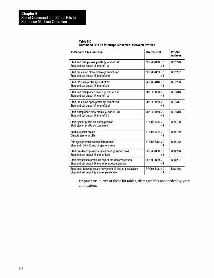
Select Command and Status Bits toSequence Machine Operation
Chapter 6
6-4
Table 6.DCommand Bits To Interrupt Movement Between Profiles
To Perform T his Function Use This Bit Pro�SetAddress:
Start 2nd clamp close profile @ end�of 1stStop and set�output @ end�of 1st
CPC03�B08 = 0= 1
B37/296
Start 3rd clamp close profile @ end�of 2ndStop and set�output @ end�of 2nd
CPC03�B09 = 0= 1
B37/297
Start LP close profile @ end�of 3rdStop and set�output @ end�of 3rd
CPC03�B10 = 0= 1
B37/298
Start 2nd clamp open profile @ end�of 1stStop and set�output @ end�of 1st
OPC03�B08 = 0= 1
B37/616
Start 3rd clamp open profile @ end�of 2ndStop and set�output @ end�of 2nd
OPC03�B09 = 0= 1
B37/617
Start clamp open slow profile @ end�of 3rdStop and set�output @ end�of 3rd
OPC03�B10 = 0= 1
B37/618
Start ejector profile on clamp positionStart ejector profile on command
EPC03�B08 = 0= 1
B39/168
Enable ejector profileDisable ejector profile
EPC03�B09 = 0= 1
B39/169
Run ejector profile without interruptionStop and notify @ end of ejector stroke
EPC03�B12 = 0= 1
B39/172
Start pre�decompression movement @ end�of holdStop and set output @ end�of hold
HPC03�B08 = 0= 1
B38/296
Start plastication profile @ end�of pre�decompressionStop and set output @ end�of pre�decompression
HPC03�B09 = 0= 1
B38/297
Start post�decompression movement @ end�of plasticationStop and set output @ end�of plastication
PPC03�B08 = 0= 1
B38/488
Important: In any of these bit tables, disregard bits not needed by yourapplication.

Select Command and Status Bits toSequence Machine Operation
Chapter 6
6-5
Table 6.EMiscellaneous Status Bits To Trigger New Action
Reason for Using: Bit Description: QDC BlockAddress:
Pro�SetB34/xx:
To drop pump adders, or shift solenoids beforestarting pack/hold profile
Injection complete SYS02�B04
To drop pump adders, or shift solenoids Clamp in mold�protect zone SYS03�B00 32
To add pump adders, or shift solenoids for tonnagebuild or lock�up
Mold safe SYS03�B01 33
To start inject cycle Tonnage complete SYS03�B02 34
To inhibit clamp from opening in auto mode Cure timer timing SYS03�B03 35
To start clamp�open phase Ram (screw) retracted, andCure time complete
SYS03�B04,and �B05
36, 37
To drop pump adders, or shift solenoids Clamp in open�slow zone SYS03�B06 38
To idle the machine until starting next action Mold fully open SYS03�B07 39
To shift solenoids before starting next ejector strokeafter the 1st advance strode
Ejector profile stopped at end of stroke SYS03�B08 40
To prevent starting next cycle with machine in automode
Open�dwell timer is timing SYS03�B09 41
To prevent starting ejector retract until valves have shifted
Ejector forward dwell timer is timing SYS03�B10 42
To start next cycle with machine in auto mode Cycle complete SYS03�B11 43
To start ejector retract Ejector fully advanced SYS03�B12 44
To start ejector retract when tip stroking is ON Ejector is beyond tip advance position SYS03�B13 45
To start ejector advance when tip stroking is ON Ejector is within tip retract position SYS03�B14 46
To start ejector advance Ejector fully retracted SYS03�B15 47
To re�open the clamp when the part is stuck LP close watchdog time�out SYS04�B03 51
To idle the machine and activate an alarm becausethe hopper is running out of plastic
Watchdog for plastication phase SYS04�B08 56
To shift solenoids for pre�decompression Set�output in progress @ end of hold SYS22�B06 342
To shift solenoids for plastication Set�output in progress @ end ofpre�decompression
SYS22�B07 343
To shift solenoids for post�decompression Set�output in progress @ end ofplastication
SYS22�B08 344
To idle the machine until starting next action Set�output in progress @ end ofpost�decompression
SYS22�B09 345
Allen-Bradley Parts

Select Command and Status Bits toSequence Machine Operation
Chapter 6
6-6
Table 6.FStatus Bits
Category: Bit Status(when = 1):
QDC BlockAddress
Pro�SetB34/xx:
Jog Status executing unassigned #1 jog SYS01�B09 09
executing ram (screw) forward jog SYS01�B10 10
executing ram (screw) reverse jog SYS01�B11 11
executing clamp forward jog SYS01�B12 12
executing clamp reverse jog SYS01�B13 13
executing ejector advance jog SYS01�B14 14
executing ejector retract jog SYS01�B15 15
Profile Complete 1st clamp close profile complete SYS02�B00 16
2nd clamp close profile complete SYS02�B01 17
3rd clamp close profile complete SYS02�B02 18
LP close profile complete SYS02�B03 19
injection profile complete SYS02�B04 20
pack profile complete SYS02�B05 21
hold profile complete SYS02�B06 22
pre�decompress movement complete SYS02�B07 23
plastication profile complete SYS02�B08 24
post�decompress movement complete SYS02�B09 25
1st clamp open profile complete SYS02�B10 26
2nd clamp open profile complete SYS02�B11 27
3rd clamp open profile complete SYS02�B12 28
clamp open slow profile complete SYS02�B13 29
ejector profile complete SYS02�B14 30
Busy Status no action (outputs at zero) SYS02�B15 31
Miscellaneous Status clamp in mold protection zone SYS03�B00 32
mold safe SYS03�B01 33
tonnage complete SYS03�B02 34
cure timer timing SYS03�B03 35
ram (screw) retracted SYS03�B04 36
cure time complete SYS03�B05 37
clamp in open�slow zone SYS03�B06 38
mold open SYS03�B07 39
ejector stopped at end of stroke SYS03�B08 40
mold open�dwell timer is timing SYS03�B09 41
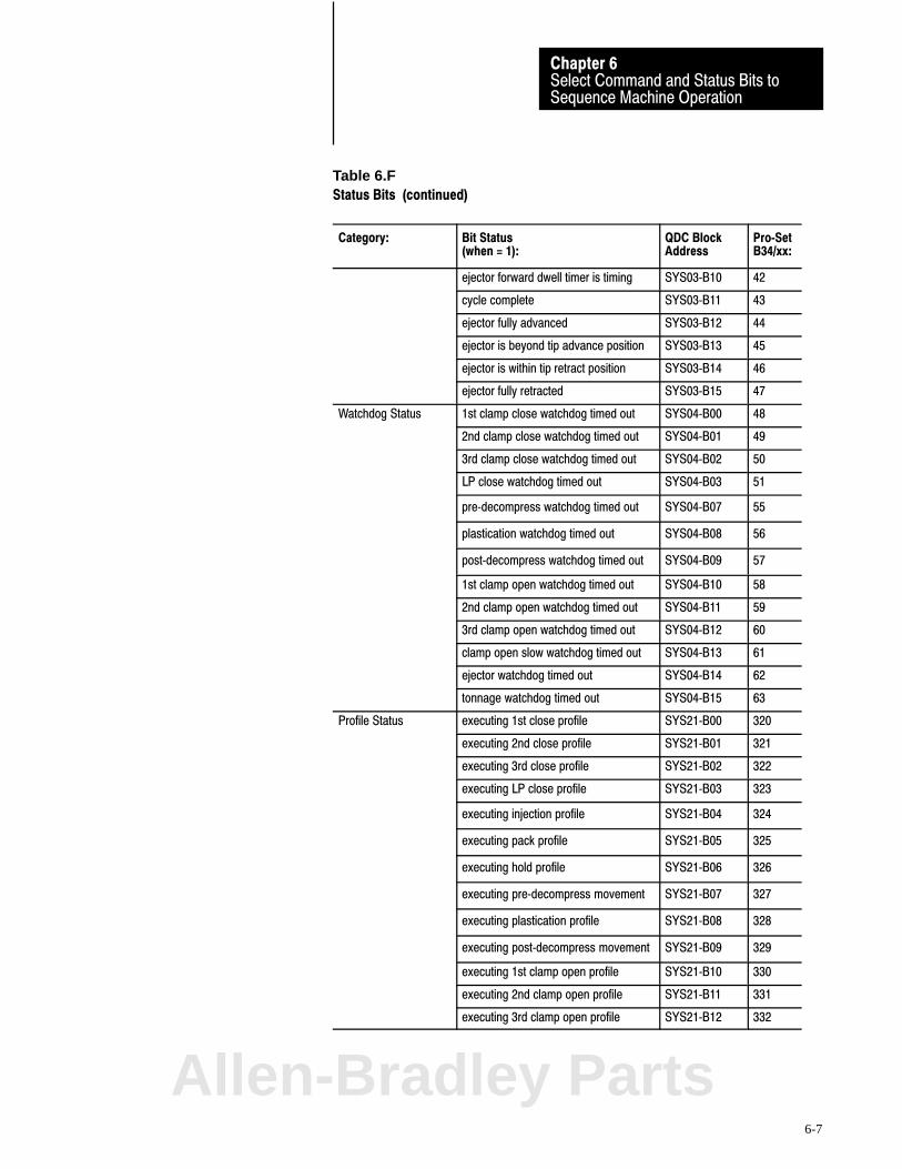
Select Command and Status Bits toSequence Machine Operation
Chapter 6
6-7
Table 6.FStatus Bits (continued)
Category: Bit Status(when = 1):
QDC BlockAddress
Pro�SetB34/xx:
ejector forward dwell timer is timing SYS03�B10 42
cycle complete SYS03�B11 43
ejector fully advanced SYS03�B12 44
ejector is beyond tip advance position SYS03�B13 45
ejector is within tip retract position SYS03�B14 46
ejector fully retracted SYS03�B15 47
Watchdog Status 1st clamp close watchdog timed out SYS04�B00 48
2nd clamp close watchdog timed out SYS04�B01 49
3rd clamp close watchdog timed out SYS04�B02 50
LP close watchdog timed out SYS04�B03 51
pre�decompress watchdog timed out SYS04�B07 55
plastication watchdog timed out SYS04�B08 56
post�decompress watchdog timed out SYS04�B09 57
1st clamp open watchdog timed out SYS04�B10 58
2nd clamp open watchdog timed out SYS04�B11 59
3rd clamp open watchdog timed out SYS04�B12 60
clamp open slow watchdog timed out SYS04�B13 61
ejector watchdog timed out SYS04�B14 62
tonnage watchdog timed out SYS04�B15 63
Profile Status executing 1st close profile SYS21�B00 320
executing 2nd close profile SYS21�B01 321
executing 3rd close profile SYS21�B02 322
executing LP close profile SYS21�B03 323
executing injection profile SYS21�B04 324
executing pack profile SYS21�B05 325
executing hold profile SYS21�B06 326
executing pre�decompress movement SYS21�B07 327
executing plastication profile SYS21�B08 328
executing post�decompress movement SYS21�B09 329
executing 1st clamp open profile SYS21�B10 330
executing 2nd clamp open profile SYS21�B11 331
executing 3rd clamp open profile SYS21�B12 332
Allen-Bradley Parts

Select Command and Status Bits toSequence Machine Operation
Chapter 6
6-8
Table 6.FStatus Bits (continued)
Category: Bit Status(when = 1):
QDC BlockAddress:
Pro�SetB34/xx:
executing clamp open slow profile SYS21�B13 333
executing ejector profile SYS21�B14 334
End�of ProfileSet�output Status
executing end�of 1st clamp closeset�output
SYS22�B00 336
executing end�of 2nd clamp closeset�output
SYS22�B01 337
executing end�of 3rd clamp closeset�output
SYS22�B02 338
executing end�of LP close set�output SYS22�B03 339
executing end of hold set�output SYS22�B06 342
executing end of pre�decompressionset�output
SYS22�B07 343
executing end of plastication set�output SYS22�B08 344
executing end of post�decompressionset�output
SYS22�B09 345
executing end�of 1st clamp openset�output
SYS22�B10 346
executing end�of 2nd clamp openset�output
SYS22�B11 347
executing end�of 3rd clamp openset�output
SYS22�B12 348
executing end�of clamp open slowset�output
SYS22�B13 349
executing end�of ejector advanceset�output
SYS22�B14 350
executing end�of ejector retractset�output
SYS22�B15 351

Select Command and Status Bits toSequence Machine Operation
Chapter 6
6-9
Table 6.GCommand and Configuration Bits
Operation: Function Enabled(when = 1):
QDC BlockAddress:
Pro�SetB34/xx:
Non�profiled execute set�output DYC01�B08 392
Action Commands execute unassigned # 1 jog DYC01�B09 393
execute ram (screw) forward jog DYC01�B10 394
execute ram (screw) reverse jog DYC01�B11 395
execute clamp forward jog DYC01�B12 396
execute clamp reverse jog DYC01�B13 397
execute ejector advance jog DYC01�B14 398
execute ejector retract jog DYC01�B15 399
Profile Action execute 1st clamp close profile DYC02�B00 400
Commands execute 2nd clamp close profile DYC02�B01 401
execute 3rd clamp close profile DYC02�B02 402
execute LP clamp close profile DYC02�B03 403
execute injection profile DYC02�B04 404
execute pack profile DYC02�B05 405
execute hold profile DYC02�B06 406
execute pre�decompression movement DYC02�B07 407
execute plastication profile DYC02�B08 408
execute post�decompression movement DYC02�B09 409
execute 1st clamp open profile DYC02�B10 410
execute 2nd clamp open profile DYC02�B11 411
execute 3rd clamp open profile DYC02�B12 412
execute clamp open slow profile DYC02�B13 413
execute ejector profile DYC02�B14 414
Stop Command execute all stop (outputs = zero) DYC02�B15 415
Miscellaneous reset tonnage watchdog timer DYC03�B00 416
Commands reset cure timer DYC03�B01 417
reset SYS01�B08 DYC03�B08 424
reset latched alarms DYC03�B09 425
reset complete bits DYC03�B10 426
continue ejector profile DYC03�B15 431
Allen-Bradley Parts
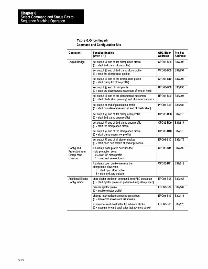
Select Command and Status Bits toSequence Machine Operation
Chapter 6
6-10
Table 6.G (continued)
Command and Configuration Bits
Operation: Function Enabled(when = 1):
QDC BlockAddress:
Pro�SetAddress:
Logical Bridge set output @ end of 1st clamp close profile(0 = start 2nd clamp close profile)
CPC03�B08 B37/296
set output @ end of 2nd clamp close profile(0 = start 3rd clamp close profile)
CPC03�B09 B37/297
set output @ end of 3rd clamp close profile(0 = start clamp LP close profile)
CPC03�B10 B37/298
set output @ end of hold profile(0 = start pre�decompress movement @ end of hold)
HPC03�B08 B38/296
set output @ end of pre�decompress movement(0 = start plastication profile @ end of pre�decompress)
HPC03�B09 B38/297
set output at end of plastication profile(0 = start post�decompression at end of plastication)
PPC03�B08 B38/488
set output @ end of 1st clamp open profile (0 = start 2nd clamp open profile)
OPC03�B08 B37/616
set output @ end of 2nd clamp open profile (0 = start 3rd clamp open profile)
OPC03�B09 B37/617
set output @ end of 3rd clamp open profile (0 = start clamp open slow profile)
OPC03�B10 B37/618
set output @ end of all ejector strokes (0 = start each new stroke at end of previous)
EPC03�B12 B39/172
ConfiguredProtection fromClamp�zoneOverrun
If a clamp close profile overruns the mold protection zone: 0 = start LP�close profile 1 = stop and zero outputs
CPC03�B11 B37/299
If a clamp open profile overruns the clamp open slow zone 0 = start open slow profile 1 = stop and zero outputs
OPC03�B11 B37/619
Additional EjectorConfiguration
start ejector profile on command from PLC processor(0 = start ejector profile on position during clamp open)
EPC03�B08 B39/168
disable ejector profile(0 = enable ejector profile)
EPC03�B09 B39/169
change intermediate strokes to tip strokes(0 = all ejector strokes are full strokes)
EPC03�B13 B39/173
execute forward dwell after 1st advance stroke(0 = execute forward dwell after last advance stroke)
EPC03�B15 B39/175

Chapter
7
7-1
Load Initial Configuration Values
This chapter helps you load the QDC module with machine-specificconfiguration values by performing four tasks:
Determine initial configuration values Record them on worksheets Enter them in PLC-5 data table Download them to the QDC module
Initial values that you load include:
configuration bits set-output values acceleration and deceleration ramp rates pressure or velocity control limits pressure or velocity gain constants pressure alarm setpoints
We already recorded many initial values on worksheets for you.
Important: Do not start this chapter until you have:
spanned your sensors, and moved hydraulic cylinders (chapter 3) jogged the ram (screw), clamp, and ejector (chapter 5)
Chapter Objectives
Allen-Bradley Parts
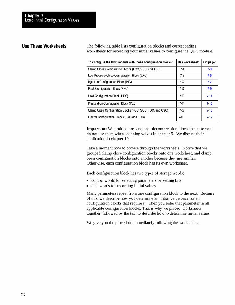
Load Initial Configuration ValuesChapter 7
7-2
The following table lists configuration blocks and correspondingworksheets for recording your initial values to configure the QDC module.
To configure the QDC module with these configuration blocks: Use worksheet: On page:
Clamp Close Configuration Blocks (FCC, SCC, and TCC) 7�A 7�3
Low Pressure Close Configuration Block (LPC) 7�B 7�5
Injection Configuration Block (INC) 7�C 7�7
Pack Configuration Block (PKC) 7�D 7�9
Hold Configuration Block (HDC) 7�E 7�11
Plastication Configuration Block (PLC) 7�F 7�13
Clamp Open Configuration Blocks (FOC, SOC, TOC, and OSC) 7�G 7�15
Ejector Configuration Blocks (EAC and ERC) 7�H 7�17
Important: We omitted pre- and post-decompression blocks because youdo not use them when spanning valves in chapter 9. We discuss theirapplication in chapter 10.
Take a moment now to browse through the worksheets. Notice that wegrouped clamp close configuration blocks onto one worksheet, and clampopen configuration blocks onto another because they are similar. Otherwise, each configuration block has its own worksheet.
Each configuration block has two types of storage words:
control words for selecting parameters by setting bits data words for recording initial values
Many parameters repeat from one configuration block to the next. Becauseof this, we describe how you determine an initial value once for allconfiguration blocks that require it. Then you enter that parameter in allapplicable configuration blocks. That is why we placed worksheetstogether, followed by the text to describe how to determine initial values.
We give you the procedure immediately following the worksheets.
Use These Worksheets
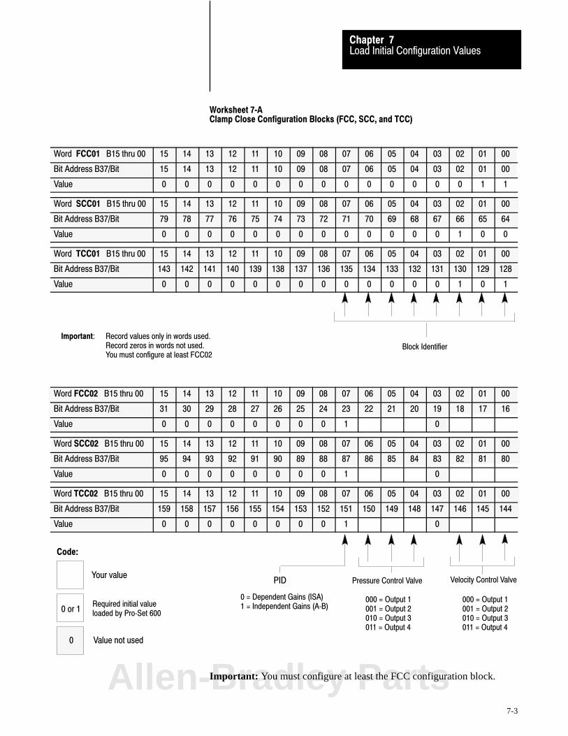
Velocity Control ValvePressure Control Valve
Block Identifier
000 = Output 1001 = Output 2010 = Output 3011 = Output 4
000 = Output 1001 = Output 2010 = Output 3011 = Output 4
Important: Record values only in words used.Record zeros in words not used.You must configure at least FCC02
Code:
Your value
Required initial valueloaded by Pro�Set 600
PID
0 = Dependent Gains (ISA)1 = Independent Gains (A�B)0 or 1
0 Value not used
Load Initial Configuration ValuesChapter 7
7-3
Worksheet 7�AClamp Close Configuration Blocks (FCC, SCC, and TCC)
Word FCC01 B15 thru 00 15 14 13 12 11 10 09 08 07 06 05 04 03 02 01 00
Bit Address B37/Bit 15 14 13 12 11 10 09 08 07 06 05 04 03 02 01 00
Value 0 0 0 0 0 0 0 0 0 0 0 0 0 0 1 1
Word SCC01 B15 thru 00 15 14 13 12 11 10 09 08 07 06 05 04 03 02 01 00
Bit Address B37/Bit 79 78 77 76 75 74 73 72 71 70 69 68 67 66 65 64
Value 0 0 0 0 0 0 0 0 0 0 0 0 0 1 0 0
Word TCC01 B15 thru 00 15 14 13 12 11 10 09 08 07 06 05 04 03 02 01 00
Bit Address B37/Bit 143 142 141 140 139 138 137 136 135 134 133 132 131 130 129 128
Value 0 0 0 0 0 0 0 0 0 0 0 0 0 1 0 1
Word FCC02 B15 thru 00 15 14 13 12 11 10 09 08 07 06 05 04 03 02 01 00
Bit Address B37/Bit 31 30 29 28 27 26 25 24 23 22 21 20 19 18 17 16
Value 0 0 0 0 0 0 0 0 1 0
Word SCC02 B15 thru 00 15 14 13 12 11 10 09 08 07 06 05 04 03 02 01 00
Bit Address B37/Bit 95 94 93 92 91 90 89 88 87 86 85 84 83 82 81 80
Value 0 0 0 0 0 0 0 0 1 0
Word TCC02 B15 thru 00 15 14 13 12 11 10 09 08 07 06 05 04 03 02 01 00
Bit Address B37/Bit 159 158 157 156 155 154 153 152 151 150 149 148 147 146 145 144
Value 0 0 0 0 0 0 0 0 1 0
Important: You must configure at least the FCC configuration block.Allen-Bradley Parts

Enter Your Values Here
Load Initial Configuration ValuesChapter 7
7-4
Worksheet 7�A (continued)
Clamp Close Configuration Blocks (FCC, SCC, and TCC)
For these Parameters (footnote = units) Word FCC N43: FCC Value SCC N43: SCC Value TCC N43: TCC Value
Minimum ERC Percentage - Velocity 8 05 1 1000 61 1000 121 1000
Minimum ERC Percentage - Pressure 8 06 2 1000 62 1000 122 1000
Profile Watchdog Timer Preset 1 08 4 0 64 0 124 0
Output #1 Selected Valve %�Output During Profile 4 09 5 * 65 * 125 *
Output #2 Selected Valve %�Output During Profile 4 10 6 * 66 * 126 *
Output #3 Selected Valve %�Output During Profile 4 11 7 * 67 * 127 *
Output #4 Selected Valve %�Output During Profile 4 12 8 * 68 * 128 *
Output #1 Acceleration Ramp Rate During Profile 5 17 13 0 73 0 133 0
Output #2 Acceleration Ramp Rate During Profile 5 18 14 0 74 0 134 0
Output #3 Acceleration Ramp Rate During Profile 5 19 15 0 75 0 135 0
Output #4 Acceleration Ramp Rate During Profile 5 20 16 0 76 0 136 0
Output #1 Deceleration Ramp Rate During Profile 5 25 21 0 81 0 141 0
Output #2 Deceleration Ramp Rate During Profile 5 26 22 0 82 0 142 0
Output #3 Deceleration Ramp Rate During Profile 5 27 23 0 83 0 143 0
Output #4 Deceleration Ramp Rate During Profile 5 28 24 0 84 0 144 0
Output #1 End�of�profile Set�output Value 4 33 29 * 89 * 149 *
Output #2 End�of�profile Set�output Value 4 34 30 * 90 * 150 *
Output #3 End�of�profile Set�output Value 4 35 31 * 91 * 151 *
Output #4 End�of�profile Set�output Value 4 36 32 * 92 * 152 *
Pressure Minimum Control Limit 3 41 37 0 97 0 157 0
Pressure Maximum Control Limit 3 42 38 Syst Press 98 Syst Press 158 Syst Press
Selected Pressure Valve Output for Minimum 4 43 39 * 99 * 159 *
Selected Pressure Valve Output for Maximum 4 44 40 * 100 * 160 *
Velocity Minimum Control Limit 2 45 41 0 101 0 161 0
Velocity Maximum Control Limit 2 46 42 per OEM * 102 per OEM * 162 per OEM *
Selected Velocity Valve Output for Minimum 4 47 43 * 103 * 163 *
Selected Velocity Valve Output for Maximum 4 48 44 * 104 * 164 *
Proportional Gain for Pressure Control (none) 49 45 100 105 100 165 100
Integral Gain for Pressure Control 6 50 46 400 106 400 166 400
Derivative Gain for Pressure Control 7 51 47 0 107 0 167 0
Proportional Gain for Velocity Control 6 52 48 200 108 200 168 200
Feed Forward Gain for Velocity Control (none) 53 49 0 109 0 169 0
Profile High Pressure Alarm Setpoint 3 57 53 0 113 0 173 0
1 Time 2 Velocity along Axis 3 Pressure 4 Percent Signal Output 00.00 to 99.99 Seconds 00.00 to 99.99 Inches per Second 0000 to 9999 PSI 00.00 to 99.99
000.0 to 999.9 Millimeters per Sec 000.0 to 999.9 Bar5 Percent Signal Output per Second 6 Inverse Time (Algorithm) 7 Time (Algorithm) 8 Percent
0000 to 9999 00.00 to 99.99 Minutes 00.00 to 99.99 Minutes 00.00 to 99.9900.00 to 99.99 Seconds
*Important: Refer to the appropriate section later in this chapter for information on this parameter

Pressure Control Valve
Block Identifier
000 = Output 1001 = Output 2010 = Output 3011 = Output 4
Important:
Verify block identifier.
PID0 = Dependent Gains (ISA)1 = Independent Gains (A�B)
Code:
Your value
Required initial valueloaded by Pro�Set 6000 or 1
0 Value not used
Load Initial Configuration ValuesChapter 7
7-5
Worksheet 7�BLow Pressure Close Configuration Block (LPC)
Word LPC01 Bits 15 thru 00 15 14 13 12 11 10 09 08 07 06 05 04 03 02 01 00
Bit Addresses B37/Bxxx 207 206 205 204 203 202 201 200 199 198 197 196 195 194 193 192
Value 0 0 0 0 0 0 0 0 0 0 0 0 0 1 1 0
Word LPC02 Bits 15 thru 00 15 14 13 12 11 10 09 08 07 06 05 04 03 02 01 00
Bit Addresses B37/Bxxx 223 222 221 220 219 218 217 216 215 214 213 212 211 210 209 208
Value 0 0 0 0 0 0 0 0 1 0 0 0 0
Important: You must configure the LPC configuration block.
Allen-Bradley Parts

Enter Your Values Here
Load Initial Configuration ValuesChapter 7
7-6
Worksheet 7�B (continued)
Low Pressure Close Configuration Block (LPC)
For these Parameters (footnote = units) Word LPC N43: LPC Value
Minimum ERC Percentage 8 06 182 1000
Tonnage Watchdog Timer Preset 1 07 183 0
Profile Watchdog Timer Preset 1 08 184 0
#1 Selected Valve Set�Output During Profile 4 09 185 *
#2 Selected Valve Set�Output During Profile 4 10 186 *
#3 Selected Valve Set�Output During Profile 4 11 187 *
#4 Selected Valve Set�Output During Profile 4 12 188 *
Output #1 Acceleration Ramp Rate During Profile 5 17 193 0
Output #2 Acceleration Ramp Rate During Profile 5 18 194 0
Output #3 Acceleration Ramp Rate During Profile 5 19 195 0
Output #4 Acceleration Ramp Rate During Profile 5 20 196 0
Output #1 Deceleration Ramp Rate During Profile 5 25 201 0
Output #2 Deceleration Ramp Rate During Profile 5 26 202 0
Output #3 Deceleration Ramp Rate During Profile 5 27 203 0
Output #4 Deceleration Ramp Rate During Profile 5 28 204 0
#1 End�of�profile Set�output Value 4 33 209 *
#2 End�of�profile Set�output Value 4 34 210 *
#3 End�of�profile Set�output Value 4 35 211 *
#4 End�of�profile Set�output Value 4 36 212 *
Pressure Minimum Control Limit 3 41 217 0
Pressure Maximum Control Limit 3 42 218 System Pressure
Selected Pressure Valve Output for Minimum 4 43 219 *
Selected Pressure Valve Output for Maximum 4 44 220 *
Proportional Gain for Pressure Control (none) 49 225 100
Integral Gain for Pressure Control 6 50 226 400
Derivative Gain for Pressure Control 7 51 227 0
Profile High Pressure Alarm Setpoint 3 57 233 0
1 Time 3 Pressure 4 Percent Signal Output 5 Percent Signal Output per Sec00.00 to 99.99 Sec 0000 to 9999 PSI 00.00 to 99.99 0000 to 9999
000.0 to 999.9 Bar6 Inverse Time (Algorithm) 7 Time (Algorithm) 8 Percent
00.00 to 99.99 Minutes 00.00 to 99.99 Minutes 00.00 to 99.9900.00 to 99.99 Sec
* Important: Refer to the appropriate section later in this chapter for information on this parameter

SelectedVelocity Valve
SelectedPressure Valve
PID Pressure Algorithm
INC Block Identifier
000 = Output 1001 = Output 2010 = Output 3011 = Output 4
000 = Output 1001 = Output 2010 = Output 3011 = Output 4
0 = Dependent Gains1 = Independent Gains
Code:
Your value
Required initial valueloaded by Pro�Set 6000 or 1
0 Value not used
Load Initial Configuration ValuesChapter 7
7-7
Worksheet 7�CInjection Configuration Block (INC)
Control Word INC01�Bxx 15 14 13 12 11 10 09 08 07 06 05 04 03 02 01 00
Pro�Set 600 Addr. B38/bit 15 14 13 12 11 10 09 08 07 06 05 04 03 02 01 00
Value 0 0 0 0 0 0 0 0 0 0 0 0 1 0 0 0
Control Word INC02�Bxx 15 14 13 12 11 10 09 08 07 06 05 04 03 02 01 00
Pro�Set 600 Addr. B38/bit 31 30 29 28 27 26 25 24 23 22 21 20 19 18 17 16
Value 0 0 0 0 0 0 0 0 1 0
Allen-Bradley Parts
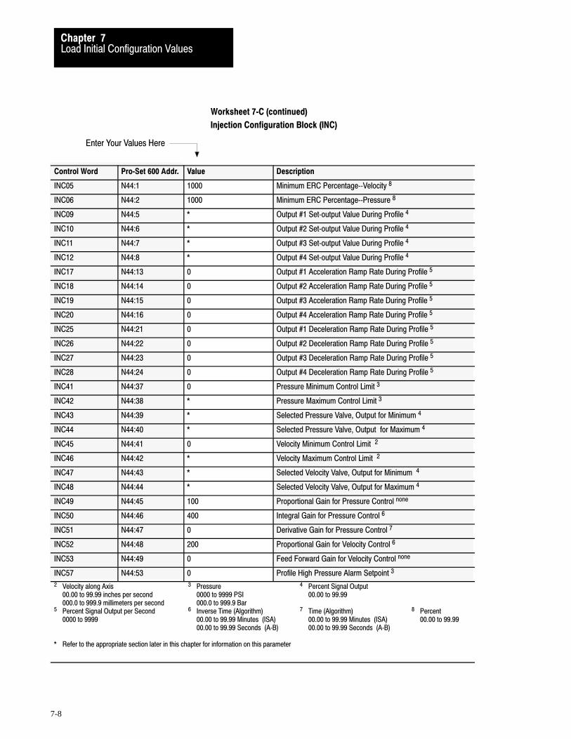
Enter Your Values Here
Load Initial Configuration ValuesChapter 7
7-8
Worksheet 7�C (continued)
Injection Configuration Block (INC)
Control Word Pro�Set 600 Addr. Value Description
INC05 N44:1 1000 Minimum ERC Percentage��Velocity 8
INC06 N44:2 1000 Minimum ERC Percentage��Pressure 8
INC09 N44:5 * Output #1 Set�output Value During Profile 4
INC10 N44:6 * Output #2 Set�output Value During Profile 4
INC11 N44:7 * Output #3 Set�output Value During Profile 4
INC12 N44:8 * Output #4 Set�output Value During Profile 4
INC17 N44:13 0 Output #1 Acceleration Ramp Rate During Profile 5
INC18 N44:14 0 Output #2 Acceleration Ramp Rate During Profile 5
INC19 N44:15 0 Output #3 Acceleration Ramp Rate During Profile 5
INC20 N44:16 0 Output #4 Acceleration Ramp Rate During Profile 5
INC25 N44:21 0 Output #1 Deceleration Ramp Rate During Profile 5
INC26 N44:22 0 Output #2 Deceleration Ramp Rate During Profile 5
INC27 N44:23 0 Output #3 Deceleration Ramp Rate During Profile 5
INC28 N44:24 0 Output #4 Deceleration Ramp Rate During Profile 5
INC41 N44:37 0 Pressure Minimum Control Limit 3
INC42 N44:38 * Pressure Maximum Control Limit 3
INC43 N44:39 * Selected Pressure Valve, Output for Minimum 4
INC44 N44:40 * Selected Pressure Valve, Output for Maximum 4
INC45 N44:41 0 Velocity Minimum Control Limit 2
INC46 N44:42 * Velocity Maximum Control Limit 2
INC47 N44:43 * Selected Velocity Valve, Output for Minimum 4
INC48 N44:44 * Selected Velocity Valve, Output for Maximum 4
INC49 N44:45 100 Proportional Gain for Pressure Control none
INC50 N44:46 400 Integral Gain for Pressure Control 6
INC51 N44:47 0 Derivative Gain for Pressure Control 7
INC52 N44:48 200 Proportional Gain for Velocity Control 6
INC53 N44:49 0 Feed Forward Gain for Velocity Control none
INC57 N44:53 0 Profile High Pressure Alarm Setpoint 3
2 Velocity along Axis 3 Pressure 4 Percent Signal Output 00.00 to 99.99 inches per second 0000 to 9999 PSI 00.00 to 99.99000.0 to 999.9 millimeters per second 000.0 to 999.9 Bar
5 Percent Signal Output per Second 6 Inverse Time (Algorithm) 7 Time (Algorithm) 8 Percent0000 to 9999 00.00 to 99.99 Minutes (ISA) 00.00 to 99.99 Minutes (ISA) 00.00 to 99.99
00.00 to 99.99 Seconds (A�B) 00.00 to 99.99 Seconds (A�B)
* Refer to the appropriate section later in this chapter for information on this parameter

PKC Block Identifier
PID Pressure Algorithm
SelectedPressure Valve
000 = Output 1001 = Output 2010 = Output 3011 = Output 4
0 = Dependent Gains1 = Independent Gains
Code:
Your value
Required initial valueloaded by Pro�Set 6000 or 1
0 Value not used
Load Initial Configuration ValuesChapter 7
7-9
Worksheet 7�DPack Configuration Block (PKC)
Control Word PKC01�Bxx 15 14 13 12 11 10 09 08 07 06 05 04 03 02 01 00
Pro�Set 600 Addr. B38/bit 143 142 141 140 139 138 137 136 135 134 133 132 131 130 129 128
Value 0 0 0 0 0 0 0 0 0 0 0 0 1 0 1 0
Control Word PKC02�Bxx 15 14 13 12 11 10 09 08 07 06 05 04 03 02 01 00
Pro�Set 600 Addr. B38/bit 159 158 157 156 155 154 153 152 151 150 149 148 147 146 145 144
Value 0 0 0 0 0 0 0 0 1 0 0 0 0
Allen-Bradley Parts

Enter Your Values Here
Load Initial Configuration ValuesChapter 7
7-10
Worksheet 7�D (continued)
Pack Configuration Block (PKC)
Control Word Pro�Set 600 Addr. Value Description Units
PKC06 N44:122 1000 Minimum ERC Percentage��Pressure Percent 8
PKC09 N44:125 * Output #1 Set�output Value During Profile Percent Signal Output 4
PKC10 N44:126 * Output #2 Set�output Value During Profile Percent Signal Output 4
PKC11 N44:127 * Output #3 Set�output Value During Profile Percent Signal Output 4
PKC12 N44:128 * Output #4 Set�output Value During Profile Percent Signal Output 4
PKC17 N44:133 0 Output #1 Acceleration Ramp Rate During Profile Percent Signal Output per Second 5
PKC18 N44:134 0 Output #2 Acceleration Ramp Rate During Profile Percent Signal Output per Second 5
PKC19 N44:135 0 Output #3 Acceleration Ramp Rate During Profile Percent Signal Output per Second 5
PKC20 N44:136 0 Output #4 Acceleration Ramp Rate During Profile Percent Signal Output per Second 5
PKC25 N44:141 0 Output #1 Deceleration Ramp Rate During Profile Percent Signal Output per Second 5
PKC26 N44:142 0 Output #2 Deceleration Ramp Rate During Profile Percent Signal Output per Second 5
PKC27 N44:143 0 Output #3 Deceleration Ramp Rate During Profile Percent Signal Output per Second 5
PKC28 N44:144 0 Output #4 Deceleration Ramp Rate During Profile Percent Signal Output per Second 5
PKC41 N44:157 0 Pressure Minimum Control Limit Pressure 3
PKC42 N44:158 * Pressure Maximum Control Limit Pressure 3
PKC43 N44:159 * Selected Pressure Valve, Output for Minimum Percent Signal Output 4
PKC44 N44:160 * Selected Pressure Valve, Output for Maximum Percent Signal Output 4
PKC49 N44:165 100 Proportional Gain for Pressure Control None
PKC50 N44:166 400 Integral Gain for Pressure Control Inverse Time (Algorithm) 6
PKC51 N44:167 0 Derivative Gain for Ram Pressure Control Time (Algorithm) 7
PKC57 N44:173 0 Profile High Pressure Alarm Setpoint Pressure 3
3 Pressure 4 Percent Signal Output 0000 to 9999 PSI 00.00 to 99.99
000.0 to 999.9 Bar5 Percent Signal Output per Second 6 Inverse Time (Algorithm) 7 Time (Algorithm) 8 Percent
0000 to 9999 00.00 to 99.99 Minutes (ISA) 00.00 to 99.99 Minutes (ISA) 00.00 to 99.9900.00 to 99.99 Seconds (A�B) 00.00 to 99.99 Seconds (A�B)
* Refer to the appropriate section later in this chapter for information on this parameter
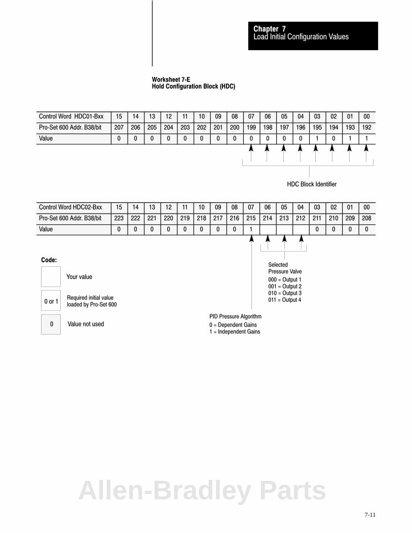
HDC Block Identifier
PID Pressure Algorithm
SelectedPressure Valve
000 = Output 1001 = Output 2010 = Output 3011 = Output 4
0 = Dependent Gains1 = Independent Gains
Code:
Your value
Required initial valueloaded by Pro�Set 6000 or 1
0 Value not used
Load Initial Configuration ValuesChapter 7
7-11
Worksheet 7�EHold Configuration Block (HDC)
Control Word HDC01�Bxx 15 14 13 12 11 10 09 08 07 06 05 04 03 02 01 00
Pro�Set 600 Addr. B38/bit 207 206 205 204 203 202 201 200 199 198 197 196 195 194 193 192
Value 0 0 0 0 0 0 0 0 0 0 0 0 1 0 1 1
Control Word HDC02�Bxx 15 14 13 12 11 10 09 08 07 06 05 04 03 02 01 00
Pro�Set 600 Addr. B38/bit 223 222 221 220 219 218 217 216 215 214 213 212 211 210 209 208
Value 0 0 0 0 0 0 0 0 1 0 0 0 0
Allen-Bradley Parts

Enter Your Values Here
Load Initial Configuration ValuesChapter 7
7-12
Worksheet 7�E (continued)
Hold Configuration Block (HDC)
Control Word Pro�Set 600 Addr. Value Description Units
HDC06 N44:182 1000 Minimum ERC Percentage��Pressure Percent 8
HDC09 N44:185 * Output #1 Set�output Value During Profile Percent Signal Output 4
HDC10 N44:186 * Output #2 Set�output Value During Profile Percent Signal Output 4
HDC11 N44:187 * Output #3 Set�output Value During Profile Percent Signal Output 4
HDC12 N44:188 * Output #4 Set�output Value During Profile Percent Signal Output 4
HDC17 N44:193 0 Output #1 Acceleration Ramp Rate During Profile Percent Signal Output per Second 5
HDC18 N44:194 0 Output #2 Acceleration Ramp Rate During Profile Percent Signal Output per Second 5
HDC19 N44:195 0 Output #3 Acceleration Ramp Rate During Profile Percent Signal Output per Second 5
HDC20 N44:196 0 Output #4 Acceleration Ramp Rate During Profile Percent Signal Output per Second 5
HDC25 N44:201 0 Output #1 Deceleration Ramp Rate During Profile Percent Signal Output per Second 5
HDC26 N44:202 0 Output #2 Deceleration Ramp Rate During Profile Percent Signal Output per Second 5
HDC27 N44:203 0 Output #3 Deceleration Ramp Rate During Profile Percent Signal Output per Second 5
HDC28 N44:204 0 Output #4 Deceleration Ramp Rate During Profile Percent Signal Output per Second 5
HDC33 N44:209 * Output #1 Set�output Value at End�of Profile Percent Signal Output 4
HDC34 N44:210 * Output #2 Set�output Value at End�of Profile Percent Signal Output 4
HDC35 N44:211 * Output #3 Set�output Value at End�of Profile Percent Signal Output 4
HDC36 N44:212 * Output #4 Set�output Value at End�of Profile Percent Signal Output 4
HDC41 N44:217 0 Pressure Minimum Control Limit Pressure 3
HDC42 N44:218 * Pressure Maximum Control Limit Pressure 3
HDC43 N44:219 * Selected Pressure Valve, Output for Minimum Percent Signal Output 4
HDC44 N44:220 * Selected Pressure Valve, Output for Maximum Percent Signal Output 4
HDC49 N44:225 100 Proportional Gain for Pressure Control None
HDC50 N44:226 400 Integral Gain for Pressure Control Inverse Time (algorithm) 6
HDC51 N44:227 0 Derivative Gain for Pressure Control Time (algorithm) 7
HDC57 N44:233 0 Profile High Pressure Alarm Setpoint Pressure 3
3 Pressure 4 Percent Signal Output 0000 to 9999 PSI 00.00 to 99.99
000.0 to 999.9 Bar5 Percent Signal Output per Second 6 Inverse Time (Algorithm) 7 Time (Algorithm) 8 Percent
0000 to 9999 00.00 to 99.99 Minutes (ISA) 00.00 to 99.99 Minutes (ISA) 00.00 to 99.9900.00 to 99.99 Seconds (A�B) 00.00 to 99.99 Seconds (A�B)
* Refer to the appropriate section later in this chapter for information on this parameter

SelectedPressure Valve
PID Pressure Algorithm
PLC Block Identifier
000 = Output 1001 = Output 2010 = Output 3011 = Output 4
0 = Dependent Gains1 = Independent Gains
Code:
Your value
Required initial valueloaded by Pro�Set 6000 or 1
0 Value not used
Load Initial Configuration ValuesChapter 7
7-13
Worksheet 7�FPlastication Configuration Block (PLC)
Control Word PLC01�Bxx 15 14 13 12 11 10 09 08 07 06 05 04 03 02 01 00
Pro�Set 600 Addr. B38/bit 399 398 397 396 395 394 393 392 391 390 389 388 387 386 385 384
Value 0 0 0 0 0 0 0 0 0 0 0 0 1 1 1 0
Control Word PLC02�Bxx 15 14 13 12 11 10 09 08 07 06 05 04 03 02 01 00
Pro�Set 600 Addr. B38/bit 415 414 413 412 411 410 409 408 407 406 405 404 403 402 401 400
Value 0 0 0 0 0 0 0 0 1 0 0 0 0
Allen-Bradley Parts

Enter Your Values Here
Load Initial Configuration ValuesChapter 7
7-14
Worksheet 7�F (continued)
Plastication Configuration Block (PLC)
Control Word Pro�Set 600 Addr. Value Description Units
PLC06 N44:362 1000 Minimum ERC Percentage��Pressure Percent 8
PLC08 N44:364 0 Profile Watchdog Timer Preset Time 1
PLC09 N44:365 * Output #1 Set�output Value During Profile Percent Signal Output 4
PLC10 N44:366 * Output #2 Set�output Value During Profile Percent Signal Output 4
PLC11 N44:367 * Output #3 Set�output Value During Profile Percent Signal Output 4
PLC12 N44:368 * Output #4 Set�output Value During Profile Percent Signal Output 4
PLC17 N44:373 0 Output #1 Acceleration Ramp Rate During Profile Percent Signal Output per Second 5
PLC18 N44:374 0 Output #2 Acceleration Ramp Rate During Profile Percent Signal Output per Second 5
PLC19 N44:375 0 Output #3 Acceleration Ramp Rate During Profile Percent Signal Output per Second 5
PLC20 N44:376 0 Output #4 Acceleration Ramp Rate During Profile Percent Signal Output per Second 5
PLC25 N44:381 0 Output #1 Deceleration Ramp Rate During Profile Percent Signal Output per Second 5
PLC26 N44:382 0 Output #2 Deceleration Ramp Rate During Profile Percent Signal Output per Second 5
PLC27 N44:383 0 Output #3 Deceleration Ramp Rate During Profile Percent Signal Output per Second 5
PLC28 N44:384 0 Output #4 Deceleration Ramp Rate During Profile Percent Signal Output per Second 5
PLC33 N44:389 * Output #1 Set�output Value at End�of Profile Percent Signal Output 4
PLC34 N44:390 * Output #2 Set�output Value at End�of Profile Percent Signal Output 4
PLC35 N44:391 * Output #3 Set�output Value at End�of Profile Percent Signal Output 4
PLC36 N44:392 * Output #4 Set�output Value at End�of Profile Percent Signal Output 4
PLC41 N44:397 0 Pressure Minimum Control Limit Pressure 3
PLC42 N44:398 * Pressure Maximum Control Limit Pressure 3
PLC43 N44:399 * Selected Pressure Valve, Output for Minimum Percent Signal Output 4
PLC44 N44:400 * Selected Pressure Valve, Output for Maximum Percent Signal Output 4
PLC49 N44:405 100 Proportional Gain for Pressure Control None
PLC50 N44:406 400 Integral Gain for Pressure Control Inverse Time (Algorithm) 6
PLC51 N44:407 0 Derivative Gain for Pressure Control Time (Algorithm) 7
PLC57 N44:413 0 Profile High Pressure Alarm Setpoint Pressure 3
1 Time 3 Pressure 4 Percent Signal Output00.00 to 99.99 seconds 0000 to 9999 PSI 00.00 to 99.99
000.0 to 999.9 Bar5 Percent Signal Output per Second 6 Inverse Time (Algorithm) 7 Time (Algorithm) 8 Percent
0000 to 9999 00.00 to 99.99 Minutes (ISA) 00.00 to 99.99 Minutes (ISA) 00.00 to 99.9900.00 to 99.99 Seconds (A�B) 00.00 to 99.99 Seconds (A�B)
* Refer to the appropriate section later in this chapter for information on this parameter

Velocity Control ValvePressure Control Valve
Block Identifier
000 = Output 1001 = Output 2010 = Output 3011 = Output 4
000 = Output 1001 = Output 2010 = Output 3011 = Output 4
Important: Record values only in words used.Record zeros in words not used.You must configure at least FOC02
Code:
Your value
Required initial valueloaded by Pro�Set 6000 or 1
PID0 = Dependent Gains (ISA)1 = Independent Gains (A�B)
0 Value not used
Load Initial Configuration ValuesChapter 7
7-15
Worksheet 7�GClamp Open Configuration Blocks (FOC, SOC, TOC, and OSC)
Word FOC01 B15 thru 00 15 14 13 12 11 10 09 08 07 06 05 04 03 02 01 00
Bit Address B37/Bit 335 334 333 332 331 330 329 328 327 326 325 324 323 322 321 320
Value 0 0 0 0 0 0 0 0 0 0 0 1 0 0 0 1
Word SOC01 B15 thru 00 15 14 13 12 11 10 09 08 07 06 05 04 03 02 01 00
Bit Address B37/Bit 399 398 397 396 395 394 393 392 391 390 389 388 387 386 385 384
Value 0 0 0 0 0 0 0 0 0 0 0 1 0 0 1 0
Word TOC01 B15 thru 00 15 14 13 12 11 10 09 08 07 06 05 04 03 02 01 00
Bit Address B37/Bit 463 362 461 460 459 458 457 456 455 454 453 452 451 450 449 448
Value 0 0 0 0 0 0 0 0 0 0 0 1 0 0 1 1
Word OSC01 B15 thru 00 15 14 13 12 11 10 09 08 07 06 05 04 03 02 01 00
Bit Address B37/Bit 527 526 525 524 523 522 521 520 519 518 517 516 515 514 513 512
Value 0 0 0 0 0 0 0 0 0 0 0 1 0 1 0 0
Word FOC02 B15 thru 00 15 14 13 12 11 10 09 08 07 06 05 04 03 02 01 00
Bit Address B37/Bit 351 350 349 348 347 346 345 344 343 342 341 340 339 338 337 336
Value 0 0 0 0 0 0 0 0 1 0
Word SOC02 B15 thru 00 15 14 13 12 11 10 09 08 07 06 05 04 03 02 01 00
Bit Address B37/Bit 415 414 413 412 411 410 409 408 407 406 405 404 403 402 401 400
Value 0 0 0 0 0 0 0 0 1 0
Word TOC02 B15 thru 00 15 14 13 12 11 10 09 08 07 06 05 04 03 02 01 00
Bit Address B37/Bit 479 478 477 476 475 474 473 472 471 470 469 468 467 466 465 464
Value 0 0 0 0 0 0 0 0 1 0
Word OSC02 B15 thru 00 15 14 13 12 11 10 09 08 07 06 05 04 03 02 01 00
Bit Address B37/Bit 543 542 541 540 539 538 537 536 535 534 533 532 531 530 529 528
Value 0 0 0 0 0 0 0 0 1 0
Important: You must configure at least the FOC and OSC configuration blocks.Allen-Bradley Parts
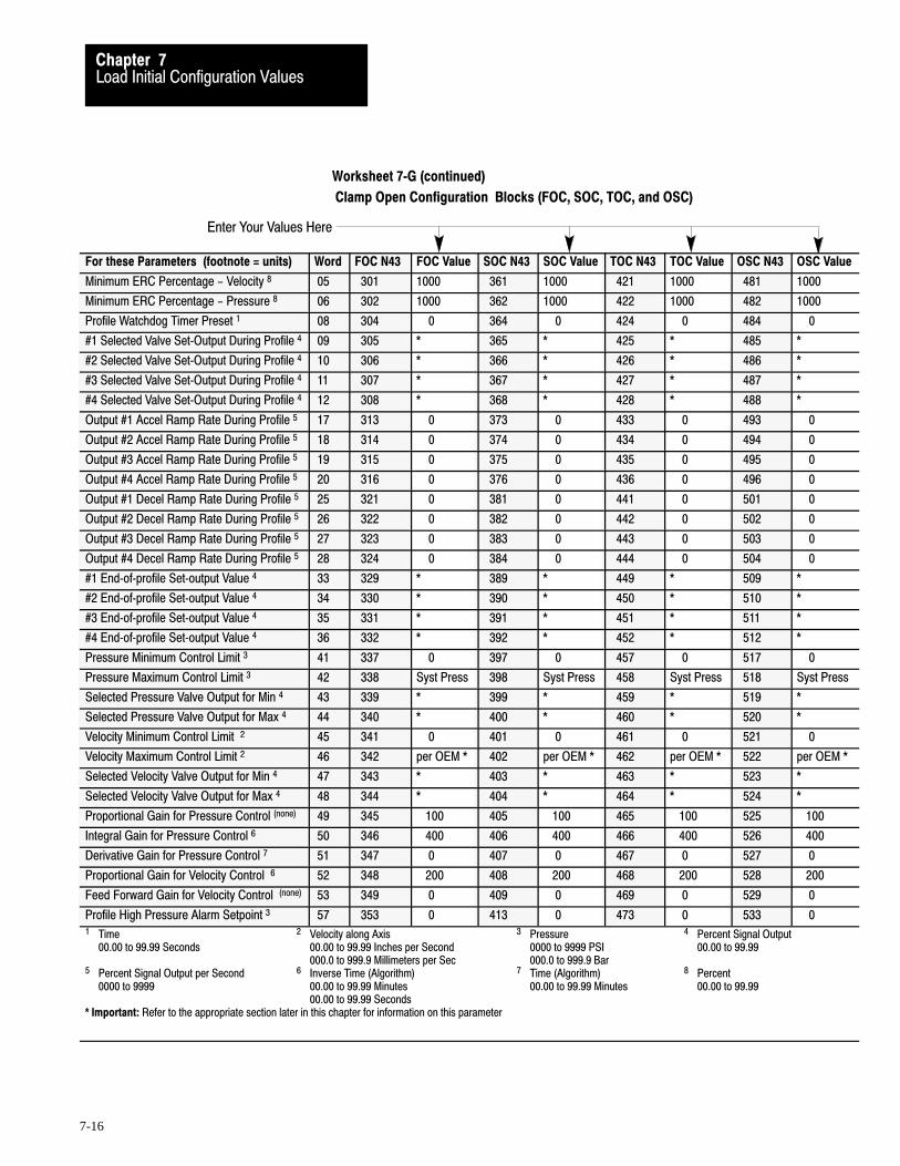
Enter Your Values Here
Load Initial Configuration ValuesChapter 7
7-16
Worksheet 7�G (continued)
Clamp Open Configuration Blocks (FOC, SOC, TOC, and OSC)
For these Parameters (footnote = units) Word FOC N43 FOC Value SOC N43 SOC Value TOC N43 TOC Value OSC N43 OSC Value
Minimum ERC Percentage - Velocity 8 05 301 1000 361 1000 421 1000 481 1000
Minimum ERC Percentage - Pressure 8 06 302 1000 362 1000 422 1000 482 1000
Profile Watchdog Timer Preset 1 08 304 0 364 0 424 0 484 0
#1 Selected Valve Set�Output During Profile 4 09 305 * 365 * 425 * 485 *
#2 Selected Valve Set�Output During Profile 4 10 306 * 366 * 426 * 486 *
#3 Selected Valve Set�Output During Profile 4 11 307 * 367 * 427 * 487 *
#4 Selected Valve Set�Output During Profile 4 12 308 * 368 * 428 * 488 *
Output #1 Accel Ramp Rate During Profile 5 17 313 0 373 0 433 0 493 0
Output #2 Accel Ramp Rate During Profile 5 18 314 0 374 0 434 0 494 0
Output #3 Accel Ramp Rate During Profile 5 19 315 0 375 0 435 0 495 0
Output #4 Accel Ramp Rate During Profile 5 20 316 0 376 0 436 0 496 0
Output #1 Decel Ramp Rate During Profile 5 25 321 0 381 0 441 0 501 0
Output #2 Decel Ramp Rate During Profile 5 26 322 0 382 0 442 0 502 0
Output #3 Decel Ramp Rate During Profile 5 27 323 0 383 0 443 0 503 0
Output #4 Decel Ramp Rate During Profile 5 28 324 0 384 0 444 0 504 0
#1 End�of�profile Set�output Value 4 33 329 * 389 * 449 * 509 *
#2 End�of�profile Set�output Value 4 34 330 * 390 * 450 * 510 *
#3 End�of�profile Set�output Value 4 35 331 * 391 * 451 * 511 *
#4 End�of�profile Set�output Value 4 36 332 * 392 * 452 * 512 *
Pressure Minimum Control Limit 3 41 337 0 397 0 457 0 517 0
Pressure Maximum Control Limit 3 42 338 Syst Press 398 Syst Press 458 Syst Press 518 Syst Press
Selected Pressure Valve Output for Min 4 43 339 * 399 * 459 * 519 *
Selected Pressure Valve Output for Max 4 44 340 * 400 * 460 * 520 *
Velocity Minimum Control Limit 2 45 341 0 401 0 461 0 521 0
Velocity Maximum Control Limit 2 46 342 per OEM * 402 per OEM * 462 per OEM * 522 per OEM *
Selected Velocity Valve Output for Min 4 47 343 * 403 * 463 * 523 *
Selected Velocity Valve Output for Max 4 48 344 * 404 * 464 * 524 *
Proportional Gain for Pressure Control (none) 49 345 100 405 100 465 100 525 100
Integral Gain for Pressure Control 6 50 346 400 406 400 466 400 526 400
Derivative Gain for Pressure Control 7 51 347 0 407 0 467 0 527 0
Proportional Gain for Velocity Control 6 52 348 200 408 200 468 200 528 200
Feed Forward Gain for Velocity Control (none) 53 349 0 409 0 469 0 529 0
Profile High Pressure Alarm Setpoint 3 57 353 0 413 0 473 0 533 01 Time 2 Velocity along Axis 3 Pressure 4 Percent Signal Output
00.00 to 99.99 Seconds 00.00 to 99.99 Inches per Second 0000 to 9999 PSI 00.00 to 99.99000.0 to 999.9 Millimeters per Sec 000.0 to 999.9 Bar
5 Percent Signal Output per Second 6 Inverse Time (Algorithm) 7 Time (Algorithm) 8 Percent0000 to 9999 00.00 to 99.99 Minutes 00.00 to 99.99 Minutes 00.00 to 99.99
00.00 to 99.99 Seconds* Important: Refer to the appropriate section later in this chapter for information on this parameter

Velocity Control ValvePressure Control Valve
Pressure Algorithm Selection
Block Identifier
000 = Output 1001 = Output 2010 = Output 3011 = Output 4
000 = Output 1001 = Output 2010 = Output 3011 = Output 4
0 = Dependent Gains1 = Independent Gains
Code:
Your value
Required initial valueloaded by Pro�Set 6000 or 1
0 Value not used
Load Initial Configuration ValuesChapter 7
7-17
Worksheet 7�HEjector Configuration Blocks (EAC and ERC)
Control Word EAC01�Bxx 15 14 13 12 11 10 09 08 07 06 05 04 03 02 01 00
Pro�Set 600 Addr. B39/bit 15 14 13 12 11 10 09 08 07 06 05 04 03 02 01 00
Value 0 0 0 0 0 0 0 0 0 0 0 1 0 1 1 0
Control Word ERC01�Bxx 15 14 13 12 11 10 09 08 07 06 05 04 03 02 01 00
Pro�Set 600 Addr. B39/bit 79 78 77 76 75 74 73 72 71 70 69 68 67 66 65 64
Value 0 0 0 0 0 0 0 0 0 0 0 1 0 1 1 1
Control Word EAC02�Bxx 15 14 13 12 11 10 09 08 07 06 05 04 03 02 01 00
Pro�Set 600 Addr. B39/bit 31 30 29 28 27 26 25 24 23 22 21 20 19 18 17 16
Value 0 0 0 0 0 0 0 0 1 0
Control Word ERC02�Bxx 15 14 13 12 11 10 09 08 07 06 05 04 03 02 01 00
Pro�Set 600 Addr. B39/bit 95 94 93 92 91 90 89 88 87 86 85 84 83 82 81 80
Value 0 0 0 0 0 0 0 0 1 0
Allen-Bradley Parts

Enter Your Values Here
Load Initial Configuration ValuesChapter 7
7-18
Worksheet 7�H (continued)
Ejector Configuration Blocks (EAC and ERC)
Description Word EAC @ N45: EAC Value ERC @ N45: ERC Value
Minimum ERC Percentage��Velocity 8 05 N45:1 1000 N45:61 1000
Minimum ERC Percentage��Pressure 8 06 N45:2 1000 N45:62 1000
Profile Watchdog Timer Preset 1 08 N45:4 0 N/A N/A
Output #1 Set�Output Value during Advance 4 09 N45:5 * N45:65 *
Output #2 Set�Output Value during Advance 4 10 N45:6 * N45:66 *
Output #3 Set�Output Value during Advance 4 11 N45:7 * N45:67 *
Output #4 Set�Output Value during Advance 4 12 N45:8 * N45:68 *
Output #1 Acceleration Ramp Rate during Advance 5 17 N45:13 0 N45:73 0
Output #2 Acceleration Ramp Rate during Advance 5 18 N45:14 0 N45:74 0
Output #3 Acceleration Ramp Rate during Advance 5 19 N45:15 0 N45:75 0
Output #4 Acceleration Ramp Rate during Advance 5 20 N45:16 0 N45:76 0
Output #1 Deceleration Ramp Rate during Advance 5 25 N45:21 0 N45:81 0
Output #2 Deceleration Ramp Rate during Advance 5 26 N45:22 0 N45:82 0
Output #3 Deceleration Ramp Rate during Advance 5 27 N45:23 0 N45:83 0
Output #4 Deceleration Ramp Rate during Advance 5 28 N45:24 0 N45:84 0
Output #1 Set�Output Value at End�of Advance 4 33 N45:29 * N45:89 *
Output #2 Set�Output Value at End�of Advance 4 34 N45:30 * N45:90 *
Output #3 Set�Output Value at End�of Advance 4 35 N45:31 * N45:91 *
Output #4 Set�Output Value at End�of Advance 4 36 N45:32 * N45:92 *
Pressure Minimum Control Limit 3 41 N45:37 0 N45:97 0
Pressure Maximum Control Limit 3 42 N45:38 System Pressure N45:98 System Pressure
Selected Pressure Valve Output for Minimum 4 43 N45:39 * N45:99 *
Selected Pressure Valve Output for Maximum 4 44 N45:40 * N45:100 *
Velocity Minimum Control Limit 2 45 N45:41 0 N45:101 0
Velocity Maximum Control Limit 2 46 N45:42 Max Velocity perOEM specs*
N45:102 Max Velocity perOEM specs*
Selected Velocity Valve Output for Minimum 4 47 N45:43 * N45:103 *
Selected Velocity Valve Output for Maximum 4 48 N45:44 * N45:104 *
Proportional Gain for Pressure Control None 49 N45:45 100 N45:105 100
Integral Gain for Pressure Control 6 50 N45:46 400 N45:106 400
Derivative Gain for Pressure Control 1, 7 51 N45:47 0 N45:107 0
Proportional Gain for Velocity Control 6 52 N45:48 200 N45:108 200
Feed Forward Gain for Velocity Control None 53 N45:49 0 N45:109 0
Profile High Pressure Alarm Setpoint 3 57 N45:53 0 N/A N/A1 Time 2 Velocity along Axis 3 Pressure 4 Percent Signal Output
00.00 to 99.99 Seconds 00.00 to 99.99 Inches per Second 0000 to 9999 PSI 00.00 to 99.99000.0 to 999.9 Millimeters per Sec 000.0 to 999.9 Bar
5 Percent Signal Output per Second 6 Inverse Time (Algorithm) 7 Time (Algorithm) 8 Percent0000 to 9999 00.00 to 99.99 Minutes 00.00 to 99.99 Minutes 00.00 to 99.99
00.00 to 99.99 Seconds
*Refer to the appropriate section later in this chapter for information on this parameter

Load Initial Configuration ValuesChapter 7
7-19
Follow this procedure to complete each worksheet:
1. Decide which profiles you will and will not use.
2. Read the text for the subject parameter.
3. Determine your initial value for that parameter.
Important: If you need additional information when determining yourinitial values, refer to the same configuration blocks in Section 3 of thePlastic Molding Module Reference Manual, publication 1771-6.5.88.
Important: In the text that follows the worksheets, configuration wordsthat require the subject parameter are listed under the title of each subjectparameter. The address codes identify the configuration blocks that uses it.
4. Locate each worksheet that requires the subject parameter.
5. Record the value on the corresponding line(s) in the worksheet.
Important: Block identifier codes are already recorded for you.
Selected Valve for Velocity Control (FCC02, SCC02, TCC02, INC02, FOC02, SOC02, TOC02, OSC02, EAC02, ERC02)
The QDC module can control ram (screw), clamp, and ejector movementusing a velocity vs. position algorithm. Since you can connect up to fourvalves to your QDC module, you must tell it which valve to use forvelocity (flow) control.
B02 B01 B00 Selects:
0 0 0 Output #1 Used for Velocity Control
0 0 1 Output #2 Used for Velocity Control
0 1 0 Output #3 Used for Velocity Control
0 1 1 Output #4 Used for Velocity Control
Record the appropriate bit selections for your valve configurations in thecontrol word of applicable worksheets.
Procedure to Determine andRecord Initial Values
Determine Bit Selections:Assign Module Outputs forYour Control Valves
Allen-Bradley Parts

Load Initial Configuration ValuesChapter 7
7-20
Selected Valve for Pressure Control (FCC02, SCC02, TCC02, LPC02, INC02, PKC02, HDC02, PLC02, FOC02, SOC02,
TOC02, OSC02, EAC02, ERC02)
Important: We define system pressure for the Inject, Clamp, and Eject modeas the pressure continuously detected by the single pressure sensor connectedto the QDC module at input 2. Depending on machine hydraulics, a singlepressure valve may control inject, clamp, and/or eject mode profiles.
ATTENTION: Your control system may not work as expectedwith possibly machine damage if you attempt to control apressure profile of a phase (inject, clamp, or eject) nothydraulically plumbed for pressure control.
Because system pressure may change between the inject, clamp, and ejectphases, we recommend that you:
assign pressure control to phases that require pressure profiles(and are hydraulically plumbed to support it)
place the system pressure sensor accordingly in the hydraulic circuit configure the remaining phases with velocity profiles
The QDC module can control ram (screw), clamp, and ejector movementusing pressure vs. position (or time) algorithms. For the plasticationalgorithm, the pressure component is backpressure. You must inform theQDC module which valve to use for controlling pressure with thesealgorithms.
B06 B05 B04 Selects:
0 0 0 Output #1 Used for Pressure Control
0 0 1 Output #2 Used for Pressure Control
0 1 0 Output #3 Used for Pressure Control
0 1 1 Output #4 Used for Pressure Control
Record the appropriate bit selections for your valve configurations in thecontrol word of applicable worksheets.

Load Initial Configuration ValuesChapter 7
7-21
Type of PID Pressure Algorithm (FCC02, SCC02, TCC02, LPC02, INC02, PKC02, HDC02, PLC02, FOC02, SOC02,
TOC02, OSC02, EAC02, ERC02)
When executing pressure versus position or time profiles, the QDC modulecan use one of two types of PID algorithms: dependent gains (ISA) orindependent gains (Allen-Bradley).
If B07 = : Then it uses:
0 Dependent Gains (ISA)
1 Independent Gains (A�B)
Dependent gains (ISA):Output = Kc[(E) + 1/Ti o∫ t (E)dt + Td*d(E)/dt]
Independent gains (AB):Output = Kp(E) + Ki o∫ t (E)dt + Kd*d(E)/dt
Comparison of Gain Constants
Compare dependent and independent gains constants as follows:
Dependent Gains Constants: Independent Gains Constants:
Controller Gain Kc (dimensionless) Proportional Gain Kp (dimensionless)
Reset Term 1/Ti (minutes per repeat) Integral Gain Ki (inverse seconds)
Rate Term Td (minutes) Derivative Term Kd (seconds)
Other variables used in any algorithm choice include:
Output = Percentage of full scaleE = Error (scaled) SP-PV (Setpoint-Process Variable)PV = Process Variable (scaled)
Convert from dependent to independent gains constants by substitutingcontroller gain (Kc), reset (1/Ti), and rate (Td) values in these formulas:
Kp = Kc unitless
Ki =Kc
60 Ti
inverse seconds
Kd = Kc(Td)60 seconds
We recorded bit B07 = 1 for A-B independent gains on all correspondingworksheets.
Select the Type ofPID Algorithm
Allen-Bradley Parts

Load Initial Configuration ValuesChapter 7
7-22
Important: PID gain constants that we entered on worksheets and used inclosed-loop tuning procedures in chapter 10 were independent (A-B) gains.If, after attempting to tune your pressure loops in chapter 10, you must usedependent (ISA) gain constants, refer to Section 3 of the Plastic MoldingModule Reference Manual (publication 1771-6.5.88) for more information.
Expert Response Compensation Minimum Percentages (FCC05�06, SCC05�06, TCC05�06, LPC06, INC05�06, PKC06, HDC06, PLC06, FOC05�06,
SOC05�06, TOC05�06, OSC05�06, EAC05�06, ERC05�06)
The QDC module uses a proprietary control scheme called ExpertResponse Compensation. It accounts for changes in your machine,machine hydraulics, raw materials, and other process variables. Itcompensates for abrupt upsets and long term deviations to your process.
We already recorded initial values of 10% (1000) on all worksheets.
We help you select final values required by your application in chapter 10.For additional information, refer to Section 3 of the Plastic MoldingModule Reference Manual (publication 1771-6.5.88).
Unselected Valve Set�output Values (FCC09�12, SCC09�12, TCC09�12, LPC09�12, INC09�12, PKC09�12, HDC09�12,
PLC09�12, FOC09�12, SOC09�12, TOC09�12, OSC09�12, EAC09�12, ERC09�12)
Earlier in this chapter, you told the QDC module which of its four outputswas being used to control pressure and flow profiles. Your machinehydraulics probably require that the remaining unselected valves connectedto your QDC module assume a set-output condition during the profile.
Words 09 through 12 define set-output values for your unselected valves.The QDC module sets its four outputs to the values in these words eachtime it starts the appropriate profile with this exception:
Important: The QDC module ignores the set-output value associated withthe selected valve, and drives that output independently.
To assist you when determining unselected valve set-output values, refer toTable 7.A. We present this table for reference, only. Your application willdictate your setpoints.
Determine Word Values:Select Values for ExpertResponse Compensation(ERC)
Determine Unselected ValveSet�output Values

Load Initial Configuration ValuesChapter 7
7-23
Table 7.ASet�output Values for Unselected Valves
If the unselectedvalve controls:
and the unselectedvalve type is:
and during profile,valve action is:
and during profile,you require:
Then Enter:
Pressure Uni�directional Direct acting Maximum Pressure 9999
Pressure Uni�directional Direct acting Medium Pressure 7500 to 5000
Pressure Uni�directional Direct acting Low Pressure 5000 to 2500
Pressure Uni�directional Direct acting Minimum Pressure 0
Pressure Uni�directional Reverse acting Maximum Pressure 0
Pressure Uni�directional Reverse acting Medium Pressure 2500 to 5000
Pressure Uni�directional Reverse acting Low Pressure 5000 to 7500
Pressure Uni�directional Reverse acting Minimum Pressure 9999
Flow Uni�directional Direct acting Maximum Flow 9999
Flow Uni�directional Direct acting Medium Flow 7500 to 5000
Flow Uni�directional Direct acting Low Flow 5000 to 2500
Flow Uni�directional Direct acting Minimum Flow 0
Flow Uni�directional Reverse acting Maximum Flow 0
Flow Uni�directional Reverse acting Medium Flow 2500 to 5000
Flow Uni�directional Reverse acting Low Flow 5000 to 7500
Flow Uni�directional Reverse acting Minimum Flow 9999
Flow Bi�directional Direct acting Maximum Flow 9999
Flow Bi�directional Direct acting Medium Flow 8750 to 7500
Flow Bi�directional Direct acting Low Flow 7500 to 6250
Flow Bi�directional Direct acting Minimum Flow 5000
Flow Bi�directional Reverse acting Maximum Flow 0
Flow Bi�directional Reverse acting Medium Flow 1250 to 2500
Flow Bi�directional Reverse acting Low Flow 2500 to 3750
Flow Bi�directional Reverse acting Minimum Flow 5000
Record all set-output values for unselected valves on your worksheets.
Important: Valve spanning procedures in chapter 9 require unselectedvalves be driven at signal levels representative of a normal production run.We discuss process considerations that impend changing these values inchapter 10. Changing these values may require you to re-span your valves.
Allen-Bradley Parts

Load Initial Configuration ValuesChapter 7
7-24
ATTENTION: A value of zero entered in your set-outputwords does not necessarily correspond to zero pressure or flow.If you configured for bi-directional valve operation (–10 to+10V dc), a set-output value of 50% gives zero volts signaloutput (see graph) while a set-output value of 0% or 100% givesmaximum signal output. Amplifier electronics or spool-nulloffsets may also allow pressure or flow at zero signal input.Consult your valve and amplifier specifications for more details.
% Output Requested
Out
put V
olta
ge
-10
-8
-5
-3
0
3
5
8
10
0 10 20 30 40 50 60 70 80 90 100
For additional information, refer to Section 3 of the Plastic MoldingModule Reference Manual (publication 1771-6.5.88).
You may need ramp rates for smooth actuator motion. The QDC modulegives you multi-stepped profiles to reduce the need for ramp rates, so werecommend starting with zero ramp rates. If you observe rough, jerkymotion during profile tuning in chapter 10, enter other values at that time.
ATTENTION: Using ramp rates may degrade closed-loopcontrol, ERC calculations, and QDC control capability. Useramp rates only if machine operation mandates them.
Set YourAcceleration/Deceleration Ramp Rates

Load Initial Configuration ValuesChapter 7
7-25
Acceleration Ramp Rates(FCC17�20, SCC17�20, TCC17�20, LPC17�20, INC17�20, PKC17�20, HDC17�20,
PLC17�20, FOC17�20, SOC17�20, TOC17�20, OSC17�20, EAC17�20, ERC17�20)
The QDC module uses acceleration ramp rates when moving its outputs toa higher setpoint during execution of a profile. They affect both selectedand unselected valves. A ramp rate of zero disables ramping, and the QDCmodule steps directly from setpoint to setpoint.
We recorded zero on corresponding worksheets.
Deceleration Ramp Rates(FCC25�28, SCC25�28, TCC25�28, LPC25�28, INC25�28, PKC25�28, HDC25�28,
PLC25�28, FOC25�28, SOC25�28, TOC25�28, OSC25�28, EAC25�28, ERC25�28)
The QDC module uses deceleration ramp rates when moving its outputs toa lower setpoint during execution of a profile. They affect selected andunselected valves alike. A ramp rate of zero disables ramping, and theQDC module steps directly from setpoint to setpoint.
We recorded zero on corresponding worksheets.
Important: The valve spanning procedures in chapter 9 require zeroacceleration and deceleration ramp rates. We help you select the correctfinal values required by your application in chapter 10. For additionalinformation, refer to Section 3 of the Plastic Molding Module ReferenceManual (publication 1771-6.5.88).
End�of�Profile Set�output Values (FCC33�36, SCC33�36, TCC33�36, LPC33�36, HDC33�36, PLC33�36, FOC33�36,
SOC33�36, TOC33�36, OSC33�36, EAC33�36, ERC33�36)
The QDC module sets its outputs to these values every time it completesthe appropriate profile when commanded NOT to “bridge” to the nextprofile or movement. Set-outputs remain in effect until the QDC module iscommanded to start the next programmed profile (or movement) or isstopped using stop command DYC02-B15.
Record values that correspond to zero pressure or zero flow on worksheets.For assistance in determining your set-output values, refer to Table 7-A.
Important: Valve spanning procedures in chapter 9 require no flow orpressure after profile execution. We help you select the correct final valuesrequired by your application in chapter 10. For additional information,refer to Section 3 of the Plastic Molding Module Reference Manual(publication 1771-6.5.88).
Determine Set�output Valuesfor End of Profiles
Allen-Bradley Parts

Load Initial Configuration ValuesChapter 7
7-26
Control limits let you span your selected valve outputs for effective controlwith either direct-acting or reverse-acting valves. Your machinemanufacturer typically provides you with values to configure these limits.
Important: We refer to system pressure during profile or axis movement as:
inject pressure clamp pressure ejector pressure
All three are the pressure measured at input 2 of the QDC module.
Minimum Pressure Control Limit (FCC41, SCC41, TCC41, LPC41, INC41, PKC41, HDC41, PLC41, FOC41, SOC41,
TOC41, OSC41, EAC41, ERC41)
The value in this word corresponds to the minimum controllable pressureduring the respective profile. The QDC module uses this word with theSelected Pressure Valve, Output for Minimum (word 43) below. The QDCmodule expects this pressure when setting the selected pressure valve tothe percentage output you enter in word 43.
We recorded zero on corresponding worksheets.
Maximum Pressure Control Limit(FCC42, SCC42, TCC42, LPC42, INC42, PKC42, HDC42, PLC42, FOC42, SOC42,
TOC42, OSC42, EAC42, ERC42)
The value in this word corresponds to the maximum controllable pressureduring the respective profile. The QDC module uses this word with theSelected Pressure Valve, Output for Maximum (word 44) below. The QDCmodule expects this pressure when setting the selected pressure valve tothe percentage output you enter in word 44.
Record an initial control limit equal to the maximum pressure availablethrough the selected pressure valve during the profile.
Selected Pressure Valve, Output for Minimum (FCC43, SCC43, TCC43, LPC43, INC43, PKC43, HDC43, PLC43, FOC43, SOC43,
TOC43, OSC43, EAC43, ERC43)
The QDC module uses this word with the Minimum Pressure ControlLimit (word 41) above. Enter the %-signal output that the QDC moduleuses to drive the selected pressure valve for minimum profile pressure.The QDC module expects a pressure equal to word 41 when setting theselected pressure valve to this percentage output.
Set Pressure Control Limits

Load Initial Configuration ValuesChapter 7
7-27
Determine Output for Minimum values as follows:
0 (0%) for uni-directional direct acting valves 5000 (50%) for bi-directional valves 9999 (100%) for uni-directional reverse acting valves
If your selectedpressure valve is:
Then the value in word 43should be:
And during the profile, the QDCmodule does NOT drive the valvewith a % output:
Direct Acting less than the value in word 44 less than the value in word 43
Reverse Acting greater than the value in word 44 greater than the value in word 43
Record initial Output for Minimum values on corresponding worksheets.
Selected Pressure Valve, Output for Maximum(FCC44, SCC44, TCC44, LPC44, INC44, PKC44, HDC44, PLC44, FOC44, SOC44,
TOC44, OSC44, EAC44, ERC44)
The QDC module uses this word with the Maximum Pressure ControlLimit (word 42) above. Enter the %-signal output that the QDC moduleuses to drive the selected pressure valve for maximum profile pressure.The QDC expects a pressure equal to word 42 when setting the selectedpressure valve to this percentage output.
Determine Output for Maximum values as follows:
9999 (100%) for uni-directional direct acting valves 0 (0%) or 9999 (100%) for bi-directional valves depending on direction 0 (0%) for uni-directional reverse acting valves
If your selectedpressure valve is:
Then the value in word 44should be:
And during the profile, the QDCmodule does NOT drive the valvewith a % output:
Direct Acting greater than the value in word 43 greater than the value in word 44
Reverse Acting less than the value in word 43 less than the value in word 44
Record initial Output for Maximum values on corresponding worksheets.
Allen-Bradley Parts

Load Initial Configuration ValuesChapter 7
7-28
Minimum Velocity Control Limit (FCC45, SCC45, TCC45, INC45, FOC45, SOC45, TOC45, OSC45, EAC45, ERC45)
The value in this word corresponds to the minimum controllable velocityduring the respective profile. The QDC module uses this word with theSelected Velocity Valve, Output for Minimum (word 47) below. The QDCmodule expects this velocity when setting the selected velocity valve to thepercentage output you enter in word 47.
We recorded zero on corresponding worksheets.
Maximum Velocity Control Limit(FCC46, SCC46, TCC46, INC46, FOC46, SOC46, TOC46, OSC46, EAC46, ERC46)
The value in this word corresponds to the maximum controllable velocityduring the respective profile. The QDC module uses this word with theSelected Velocity Valve, Output for Maximum (word 48) below. The QDCmodule expects this velocity when setting the selected velocity valve to thepercentage output you enter in word 48.
Record the maximum ram (screw), clamp, and/or ejector speed per yourOEM specifications on corresponding worksheets.
Selected Velocity Valve, Output for Minimum(FCC47, SCC47, TCC47, INC47, FOC47, SOC47, TOC47, OSC47, EAC47, ERC47)
The QDC module uses this word with the Minimum Velocity ControlLimit (word 45) above. Enter the %-signal output that the QDC moduleuses to drive the selected velocity valve for minimum profile velocity. TheQDC expects a velocity equal to word 45 when setting the selectedvelocity valve to this percentage output.
The QDC module uses this setpoint to drive the selected velocity valve toattain zero ram (screw), clamp, or ejector velocity. It should drive theselected velocity valve to a spool position that prohibits hydraulic flow.
Determine Output for Minimum values as follows:
0 (0%) for uni-directional direct acting valves 5000 (50%) for bi-directional valves 9999 (100%) for uni-directional reverse acting valves
If your selectedvelocity valve is:
Then the value in word 47should be:
And during the profile or stroke,the QDC module does NOT drivethe valve with a % output:
Direct Acting less than the value in word 48 less than word 47
Reverse Acting greater than the value in word 48 greater than word 47
Set Velocity Control Limits
Load Initial Configuration ValuesChapter 7
7-29
Record initial Output for Minimum values on corresponding worksheets.
Selected Velocity Valve, Output for Maximum(FCC48, SCC48, TCC48, INC48, FOC48, SOC48, TOC48, OSC48, EAC48, ERC48)
The QDC module uses this word with the Maximum Velocity ControlLimit (word 46) above. Enter the %-signal output that the QDC moduleuses to drive the selected velocity valve for maximum profile velocity.The QDC module expects a velocity equal to word 46 above when settingthe selected velocity valve to this percentage output.
The QDC module uses this setpoint to drive the selected velocity valvewhen attempting to attain maximum ram (screw), clamp, or ejectorvelocity. It should drive the selected velocity valve to a spool position thatprovides full hydraulic flow.
Determine Output for Maximum values as follows:
9999 (100%) for uni-directional direct acting valves 0 (0%) or 9999 (100%) for bi-directional valves depending on direction 0 (0%) for uni-directional reverse acting valves
If your selectedvelocity valve is:
Then the value in word 48should be:
And during the profile, the QDCmodule does NOT drive the valvewith a % output:
Direct Acting greater than the value in word 47 greater than word 48
Reverse Acting less than the value in word 47 less than word 48
Record initial Output for Maximum values on corresponding worksheets.
Important: Valve spanning procedures in chapter 9 require these initialvelocity control limits. For additional information, refer to section 3 ofthe Plastic Molding Module Reference Manual (publication 1771-6.5.88).
Profile Gain Constants (FCC49�53, SCC49�53, TCC49�53, LPC49�51, INC49�53, PKC49�51, HDC49�51,
PLC49�51, FOC49�53, SOC49�53, TOC49�53, OSC49�53, EAC49�53, ERC49�53)
The QDC module’s PID and velocity feedforward (VelFF) algorithms aredifferent from classic PID and VelFF algorithms. QDC module algorithmsare sensitive to changes in load (not changes in setpoint) because the QDCmodule must respond to a system that is undergoing constant load changeswhen hydraulic fluid is introduced into or relieved from the hydrauliccircuit. The algorithm gain constants are typically lower than those used tocontrol a process that reacts to setpoints changes.
We recorded all profile gain constants on corresponding worksheets.
Set Profile Gain Constants,Pressure�Alarm Setpoints,and Watchdog TimerPresets
Allen-Bradley Parts

Load Initial Configuration ValuesChapter 7
7-30
Profile Pressure�Alarm Setpoints (FCC57, SCC57, TCC57, LPC57, INC57, PKC57, HDC57, PLC57, FOC57, SOC57,
TOC57, OSC57, EAC57)
The QDC module compares real-time clamp pressure against these entrieswhen executing the appropriate profile. The QDC module sets acorresponding alarm bit any time pressure equals or exceeds these entriesduring the respective profile. A zero entry inhibits each respective alarm.
We recorded zero for each alarm setpoint on corresponding worksheets.
Watchdog Timer Presets (FCC08, SCC08, TCC08, LPC07�08, PLC08, FOC08, SOC08, TOC08, OSC08, EAC08)
Use the watchdog timer to signal an alarm if the associated profile takeslonger than expected. To inhibit each timer, enter a preset of zero.
When the QDC module starts a profile, it:
starts the associated internal timer stops the timer, reports execution time, and resets the accumulated value
to zero when it completes the profile sets an alarm bit if the accumulated value exceeds this preset
We recorded zero on corresponding worksheets to inhibit all watchdogtimers.
The closed-loop tuning procedures in chapter 10 require these initialvalues. In that chapter, we help you select the correct final values requiredby your application. For additional information, refer to Section 3 of thePlastic Molding Module Reference Manual (publication 1771-6.5.88).
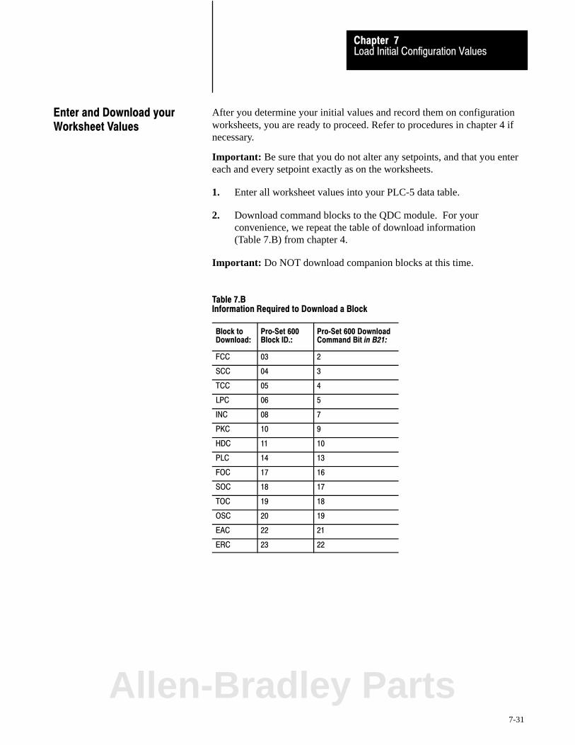
Load Initial Configuration ValuesChapter 7
7-31
After you determine your initial values and record them on configurationworksheets, you are ready to proceed. Refer to procedures in chapter 4 ifnecessary.
Important: Be sure that you do not alter any setpoints, and that you entereach and every setpoint exactly as on the worksheets.
1. Enter all worksheet values into your PLC-5 data table.
2. Download command blocks to the QDC module. For yourconvenience, we repeat the table of download information(Table 7.B) from chapter 4.
Important: Do NOT download companion blocks at this time.
Table 7.BInformation Required to Download a Block
Block toDownload:
Pro�Set 600Block ID.:
Pro�Set 600 DownloadCommand Bit in B21:
FCC 03 2
SCC 04 3
TCC 05 4
LPC 06 5
INC 08 7
PKC 10 9
HDC 11 10
PLC 14 13
FOC 17 16
SOC 18 17
TOC 19 18
OSC 20 19
EAC 22 21
ERC 23 22
Enter and Download yourWorksheet Values
Allen-Bradley Parts

Chapter
8
8-1
Load Initial Profile Setpoints
In this chapter you load the QDC module with profile setpoints byperforming four tasks:
Determine initial profile setpoints from text Record them on worksheets Enter them into PLC-5 data table Download profile blocks to the QDC module
Initial profile setpoints that you load include:
control bits velocity setpoints pressure setpoints position setpoints timer presets
Important: Complete all previous chapters before starting this chapter.
The following table lists profile blocks and corresponding worksheets forrecording initial profile setpoints that you download to the QDC module.
To configure the QDC module with this profile block
See this Worksheet
OnPage
Clamp Close Profile Block (CPC) Worksheet 8-A 8-3
Injection Profile Command Block (IPC) Worksheet 8-B 8-11
Pack/Hold Profile Command Block (HPC) Worksheet 8-C 8-19
Plastication Profile Command Block (PPC) Worksheet 8-D 8-25
Clamp Open Profile Block (OPC) Worksheet 8-E 8-32
Ejector Profile Command Block (EPC) Worksheet 8�F 8-39
Take a moment to browse through a worksheet. It contains two parts:
control words for selecting parameters by setting bits data words for recording initial profile setpoints
We present each worksheet followed by text telling you how to determineinitial setpoints. Complete one worksheet before going to the next. If youneed additional word/bit descriptions, refer to the Plastic Molding ModuleReference Manual (publication 1771-6.5.88).
Chapter Objectives
Use These Worksheets
Load Initial Profile SetpointsChapter 8
8-2
The following two pages contain Worksheet 8-A for the clamp closeprofile (one page for bit entries and one for word entries). The valvespanning procedures in chapter 9 require specific values. We have alreadyrecorded many setpoints for you on the worksheet. You must determine theremaining setpoints based on your specific machine.
Important: You record setpoints for pressure vs. position and velocity vs.position profiles on Worksheet 8-A. We assist you in determining values.
Determine and RecordSetpoints for theClamp Close Profile (CPC)
Allen-Bradley Parts

Algorithm 0 = Vel/Pos1 = Press/Pos
FCCSCCTCCFCCSCCTCC
Logical Bridge0 = Start next profile at end of profile1 = Stop and set output at end of profile
Mold Protection Zone 0 = Start LPC when clamp reaches CPC611 = Stop and zero outputs when clamp reaches CPC61
Velocity Units 0 = Percent Velocity1 = Inches (mm)/Second
CPC Block Identifier
ERC 0 = ON 1 = OFF
bit 15 = Press/Pos LPCbit 13 = Press/Pos TCCbit 12 = Vel/Pos TCCbit 11 = Press/Pos SCCbit 10 = Vel/Pos SCCbit 09 = Press/Pos FCCbit 08 = Vel/Pos FCC
Open/Closed�Loop 0 = Closed�Loop 1 = Open�Loop
bit 07 = Press/Pos LPCbit 05 = Press/Pos TCCbit 04 = Vel/Pos TCCbit 03 = Press/Pos SCCbit 02 = Vel/Pos SCCbit 01 = Press/Pos FCCbit 00 = Vel/Pos FCC
Required initial valueloaded by Pro�Set 6000 or 1
Code:
0
Your value
Value not used
Load Initial Profile SetpointsChapter 8
8-3
Worksheet 8�AClamp Close Profile Block (CPC)
Control Word CPC01�Bxx 15 14 13 12 11 10 09 08 07 06 05 04 03 02 01 00
Pro�Set 600 Addr. B37/ bit 271 270 269 268 267 266 265 264 263 262 261 260 259 258 257 256
Value 0 0 0 0 0 0 0 0 0 0 0 0 0 1 1 1
Control Word CPC03�Bxx 15 14 13 12 11 10 09 08 07 06 05 04 03 02 01 00
Pro�Set 600 Addr. B37/bit 303 302 301 300 299 298 297 296 295 294 293 292 291 290 289 288
Value 0 1 0 0 0 0 0 0 0 0 0 1 0 1 0 1
Control Word CPC04�Bxx 15 14 13 12 11 10 09 08 07 06 05 04 03 02 01 00
Pro�Set 600 Addr. B37/bit 319 318 317 316 315 314 313 312 311 310 309 308 307 306 305 304
Value 1 0 1 1 1 1 1 1 1 0 1 1 1 1 1 1

Enter Your Values Here
Load Initial Profile SetpointsChapter 8
8-4
Worksheet 8- A (continued)
Clamp Close Profile Block (CPC)
Control Word Pro�Set 600 Addr. Value Description Units
CPC09 N43:245 * FCC Segment 1 Velocity Setpoint Percent of Maximum Velocity 1 or Velocity along Axis 2
CPC10 N43:246 * FCC Segment 1 Pressure Setpoint Pressure 3
CPC11 N43:247 * FCC End�of Segment 1 Position Setpoint Incremental Distance 4
CPC12 N43:248 * FCC Segment 2 Velocity Setpoint Percent of Maximum Velocity 1 or Velocity along Axis 2
CPC13 N43:249 * FCC Segment 2 Pressure Setpoint Pressure 3
CPC14 N43:250 * FCC End�of Segment 2 Position Setpoint Incremental Distance 4
CPC15 N43:251 * FCC Segment 3 Velocity Setpoint Percent of Maximum Velocity 1 or Velocity along Axis 2
CPC16 N43:252 * FCC Segment 3 Pressure Setpoint Pressure 3
CPC17 N43:253 * FCC End�of Segment 3 Position Setpoint Incremental Distance 4
CPC18 N43:254 0 SCC Segment 1 Velocity Setpoint Percent of Maximum Velocity 1 or Velocity along Axis 2
CPC19 N43:255 0 SCC Segment 1 Pressure Setpoint Pressure 3
CPC20 N43:256 0 SCC End�of Segment 1 Position Setpoint Incremental Distance 4
CPC21 N43:257 0 SCC Segment 2 Velocity Setpoint Percent of Maximum Velocity 1 or Velocity along Axis 2
CPC22 N43:258 0 SCC Segment 2 Pressure Setpoint Pressure 3
CPC23 N43:259 0 SCC End�of Segment 2 Position Setpoint Incremental Distance 4
CPC24 N43:260 0 SCC Segment 3 Velocity Setpoint Percent of Maximum Velocity 1 or Velocity along Axis 2
CPC25 N43:261 0 SCC Segment 3 Pressure Setpoint Pressure 3
CPC26 N43:262 0 SCC End�of Segment 3 Position Setpoint Incremental Distance 4
CPC27 N43:263 0 TCC Segment 1 Velocity Setpoint Percent of Maximum Velocity 1 or Velocity along Axis 2
CPC28 N43:264 0 TCC Segment 1 Pressure Setpoint Pressure 3
CPC29 N43:265 0 TCC End�of Segment 1 Position Setpoint Incremental Distance 4
CPC30 N43:266 0 TCC Segment 2 Velocity Setpoint Percent of Maximum Velocity 1 or Velocity along Axis 2
CPC31 N43:267 0 TCC Segment 2 Pressure Setpoint Pressure 3
CPC32 N43:268 0 TCC End�of Segment 2 Position Setpoint Incremental Distance 4
CPC33 N43:269 0 TCC Segment 3 Velocity Setpoint Percent of Maximum Velocity 1 or Velocity along Axis 2
CPC34 N43:270 0 TCC Segment 3 Pressure Setpoint Pressure 3
CPC35 N43:271 0 TCC End�of Segment 3 Position Setpoint Incremental Distance 4
CPC37 N43:273 * LPC Segment 1 Pressure Setpoint Pressure 3
CPC38 N43:274 0 LPC End�of�Segment 1 Position Setpoint Incremental Distance 4
CPC40 N43:276 0 LPC Segment 2 Pressure Setpoint Pressure 3
CPC61 N43:297 * Start LPC Position Setpoint Incremental Distance 4
CPC62 N43:298 * Mold Safe Position Setpoint Incremental Distance 4
CPC63 N43:299 0 Tonnage Complete Pressure Setpoint Pressure 3
1 Percent of Maximum Velocity 2 Velocity along Axis 3 Pressure 4 Axis Measured from MCC27 00.00 to 99.99 00.00 to 99.99 Inches per Second 0000 to 9999 PSI (if non�zero) or MCC23
000.0 to 999.9 Millimeters per Second 000.0 to 999.9 Bar 00.00 to 99.99 Inches00.00 to 999.9 Millimeters
* Refer to the appropriate section later in this chapter for information on this parameterAllen-Bradley Parts

Load Initial Profile SetpointsChapter 8
8-5
Block Identifier (CPC01)
Bits 07-00 of this word identify it as the first word in a series used todefine the clamp close profile. Pro-Set 600 sets these bits to 00000111.
We recorded this value on Worksheet 8-A.
Velocity Units (CPC03)The following bit determines units of measure for velocity values.
- BIT 14 selects units of measure.
0 = Percent velocity1 = Inches or millimeters per second
We recorded a value of 1 for units per second on Worksheet 8-A.
Mold Protection (CPC03)The following bit controls QDC module reaction if it moves the clamp intothe mold protection zone while executing the 1st or 2nd or 3rd clamp closeprofile.
- BIT 11 determines QDC module response to the protection zone.
0 = Start executing low pressure close if clamp reaches CPC611 = Stop and zero outputs if clamp reaches CPC61
We recorded a value of 0 for start executing LPC on Worksheet 8-A.
Logical Bridges (CPC03)Logical bridges control the action taken by the QDC module when itcompletes a profile.
- BIT 10 controls action at end of third clamp close.
- BIT 09 controls action at end of second clamp close.
- BIT 08 controls action at end of first clamp close.
0 = Start next profile when this profile is complete1 = Stop and set output when this profile is complete
We recorded a value of 0 for start next profile on Worksheet 8-A.
Determine Bit Selections forWorksheet 8-A

Load Initial Profile SetpointsChapter 8
8-6
Profile Algorithm (CPC03)The following bits determine the algorithm for each clamp close profile.
- BIT 04 configures third clamp close profile
- BIT 02 configures second clamp close profile
- BIT 00 configures first clamp close profile
0 = Velocity vs. position algorithm1 = Pressure vs. position algorithm
We recorded a value of 1 for pressure vs. position on Worksheet 8-A.
Important: All other bit selections in CPC03 should be zero.
Expert Response Compensation (CPC04)
- BITs 15, 13, 12, 11, 10, 09, and 08 determine whether you applyExpert Response Compensation (ERC) to clamp close profiles. ERCis an exclusive algorithm that adjusts for changes in your machine,hydraulics, raw materials, and other process variables. Itcompensates for abrupt upsets and long term deviations.
0 = Expert Response Compensation ON1 = Expert Response Compensation OFF
We recorded a value of 1 (ERC = Off) on Worksheet 8-A.
Open�loop or Closed�loop Control (CPC04)
- BITs 07, 05, 04, 03, 02, 01, and 00 determine whether you use open-or closed-loop control of clamp close profiles. In open loop, a valveposition moves the cylinder without sensor feedback. In closed loop,sensor feedback controls the valve regulating the pressure or velocity.
0 = Closed loop1 = Open loop
We recorded a value of 1 for open-loop control on Worksheet 8-A.
Important: All other bit selections in CPC04 should be zero.
The valve spanning procedures in chapter 9 require these initial bitsettings. Where required, we help you select correct final bit settings foryour application in chapter 10. For additional information, refer to thePlastic Molding Module Reference Manual (publication 1771-6.5.88)
Allen-Bradley Parts
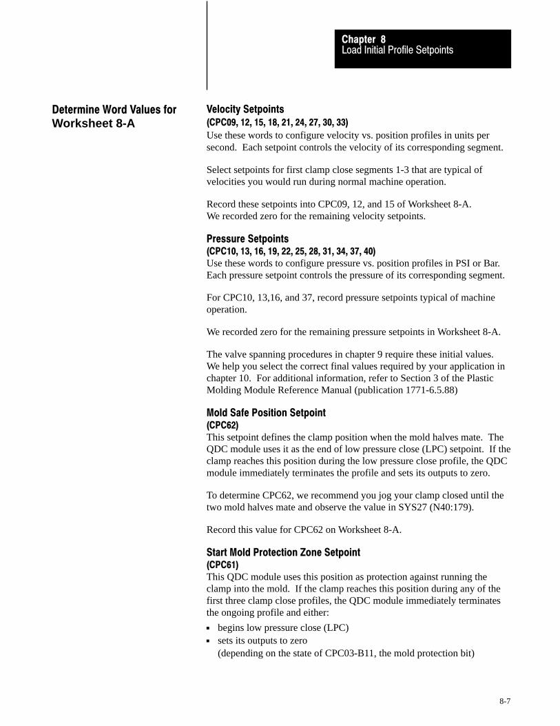
Load Initial Profile SetpointsChapter 8
8-7
Velocity Setpoints (CPC09, 12, 15, 18, 21, 24, 27, 30, 33)
Use these words to configure velocity vs. position profiles in units persecond. Each setpoint controls the velocity of its corresponding segment.
Select setpoints for first clamp close segments 1-3 that are typical ofvelocities you would run during normal machine operation.
Record these setpoints into CPC09, 12, and 15 of Worksheet 8-A.We recorded zero for the remaining velocity setpoints.
Pressure Setpoints (CPC10, 13, 16, 19, 22, 25, 28, 31, 34, 37, 40)Use these words to configure pressure vs. position profiles in PSI or Bar.Each pressure setpoint controls the pressure of its corresponding segment.
For CPC10, 13,16, and 37, record pressure setpoints typical of machineoperation.
We recorded zero for the remaining pressure setpoints in Worksheet 8-A.
The valve spanning procedures in chapter 9 require these initial values.We help you select the correct final values required by your application inchapter 10. For additional information, refer to Section 3 of the PlasticMolding Module Reference Manual (publication 1771-6.5.88)
Mold Safe Position Setpoint (CPC62)This setpoint defines the clamp position when the mold halves mate. TheQDC module uses it as the end of low pressure close (LPC) setpoint. If theclamp reaches this position during the low pressure close profile, the QDCmodule immediately terminates the profile and sets its outputs to zero.
To determine CPC62, we recommend you jog your clamp closed until thetwo mold halves mate and observe the value in SYS27 (N40:179).
Record this value for CPC62 on Worksheet 8-A.
Start Mold Protection Zone Setpoint (CPC61)This QDC module uses this position as protection against running theclamp into the mold. If the clamp reaches this position during any of thefirst three clamp close profiles, the QDC module immediately terminatesthe ongoing profile and either:
begins low pressure close (LPC) sets its outputs to zero
(depending on the state of CPC03-B11, the mold protection bit)
Determine Word Values forWorksheet 8-A
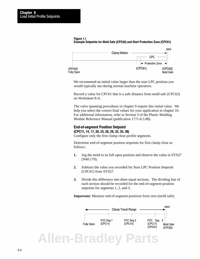
Load Initial Profile SetpointsChapter 8
8-8
Figure 1.1Example Setpoints for Mold Safe (CPC62) and Start Protection Zone (CPC61)
(OPC62)Fully Open Mold Safe
Clamp Motionzero
(CPC61) (CPC62)
LPC
Protection Zone
We recommend an initial value larger than the start LPC position youwould typically use during normal machine operation.
Record a value for CPC61 that is a safe distance from mold safe (CPC62)on Worksheet 8-A.
The valve spanning procedures in chapter 9 require this initial value. Wehelp you select the correct final values for your application in chapter 10.For additional information, refer to Section 3 of the Plastic MoldingModule Reference Manual (publication 1771-6.5.88).
End�of�segment Position Setpoint (CPC11, 14, 17, 20, 23, 26, 29, 32, 35, 38)Configure only the first clamp close profile segments.
Determine end-of-segment position setpoints for first clamp close asfollows:
1. Jog the mold to its full open position and observe the value in SYS27(N40:179).
2. Subtract the value you recorded for Start LPC Position Setpoint(CPC61) from SYS27.
3. Divide this difference into three equal sections. The dividing line ofeach section should be recorded for the end-of-segment positionsetpoints for segments 1, 2, and 3.
Important: Measure end-of-segment positions from zero (mold safe).
Fully Open
FCC Seg 1(CPC11) Mold Safe
(CPC62)
FCC Seg 2(CPC14)
FCC Seg 3(CPC17)(CPC61)
Clamp Travel Rangezero
Allen-Bradley Parts

Load Initial Profile SetpointsChapter 8
8-9
4. Record your FCC end-of-segment position setpoints for CPC11, 14,and 17 on Worksheet 8-A.
We recorded zero for the remaining position setpoints on Worksheet 8-A.
The valve spanning procedures in chapter 9 require these initial values.We help you select correct final values for your application in chapter 10.For additional information, refer to Section 3 of the Plastic MoldingModule Reference Manual (publication 1771-6.5.88).
Tonnage�complete Pressure Setpoint (CPC63)The QDC module compares clamp pressure with this value, and sets statusbit SYS03-B02 when clamp pressure equals or exceeds this value.
We recorded zero for the tonnage watchdog timer preset.
The valve spanning procedures in chapter 9 require this initial value. Wehelp you select correct final values for your application in chapter 10. Foradditional information, refer to Section 3 of the Plastic Molding ModuleReference Manual (publication 1771-6.5.88).
After you determine initial values and record them on Worksheet 8-A, youare ready to proceed. Refer to procedures in chapter 4 if necessary.
Important: Be sure that you do not alter any setpoints, and that you entereach and every setpoint exactly as on the worksheet.
1. Enter all worksheet values into your PLC-5 data table.
2. Download command blocks to the QDC module. We repeat the CPCblock download data.
Block toDownload:
Pro�Set 600Block ID:
DownloadCommand Bit:
CompanionBlock:
CPC 07 B21/6 none
3. Check SYS61 and SYS62 for programming error. Correct as needed.
Enter and Download YourWorksheet Values

Load Initial Profile SetpointsChapter 8
8-10
The following two pages contain Worksheet 8-B for the injection profile(one page for bit entries and one for word entries). The valve spanningprocedures in chapter 9 require specific values. We have already recordedmany values for you on the worksheet. You must determine the remainingsetpoints based on your specific machine.
Important: You record setpoints for a pressure vs. time and a velocity vs.position profile on Worksheet 8-B. We assist you in determining them.
Determine and RecordSetpoints for the Injection Profile (IPC)
Allen-Bradley Parts

Algorithm Selection
IPC Block Identifier
00 = Vel/Pos 01 = Vel/Pos (pressure limited) 10 = Press/Pos11 = Press/Time
Sign of Velocity Offset0 = Positive1 = Negative
Velocity Units0 = Parameters in �Percent Velocity"1 = Parameters in Inches (mm)/Sec
Sign of Pressure Offset0 = Positive1 = Negative
0 = Vel/Pos Closed Loop1 = Open Loop
0 = Vel/Pos (limited) Closed Loop1 = Open Loop
0 = Press/Pos Closed Loop1 = Open Loop
0 = Press/Time Closed Loop1 = Open Loop
0 = ERC On for Vel/Pos 1 = ERC Off
0 = ERC On for Vel/Pos (limited) 1 = ERC Off
0 = ERC On for Press/Pos 1 = ERC Off
0 = ERC On for Press/Time1 = ERC Off
Code:
Your value
0 or 1Required initial valueloaded by Pro�Set 600
Value not used0
0 Value not used
Enter Your Values Here
Load Initial Profile SetpointsChapter 8
8-11
Worksheet 8�BInjection Profile Block (IPC)
Control Word IPC01�Bxx 15 14 13 12 11 10 09 08 07 06 05 04 03 02 01 00
Pro�Set 600 Addr. B38/bit 79 78 77 76 75 74 73 72 71 70 69 68 67 66 65 64
Value 0 0 0 0 0 0 0 0 0 0 0 0 1 0 0 1
Control Word IPC03�Bxx 15 14 13 12 11 10 09 08 07 06 05 04 03 02 01 00
Pro�Set 600 Addr. B38/bit 111 110 109 108 107 106 105 104 103 102 101 100 99 98 97 96
Value 0 1 0 0 0 0 0 0 0 0 0 0 0 0 1 1
Control Word IPC04�Bxx 15 14 13 12 11 10 09 08 07 06 05 04 03 02 01 00
Pro�Set 600 Addr. B38/bit 127 126 125 124 123 122 121 120 119 118 117 116 115 114 113 112
Value 0 0 0 0 1 1 1 1 0 0 0 0 1 1 1 1
Control Word Pro�Set 600 Addr. Value Description Units
IPC09 N44:65 * Segment 1 Velocity Setpoint Velocity 4
IPC10 N44:66 * Segment 1 Pressure Setpoint Pressure 3
IPC11 N44:67 * End�of Segment 1 Position Setpoint Distance from Mold�end 2
IPC12 N44:68 100 Segment 1 Time Setpoint Time 1
IPC13 N44:69 * Segment 2 Velocity Setpoint Velocity 4
IPC14 N44:70 * Segment 2 Pressure Setpoint Pressure 3
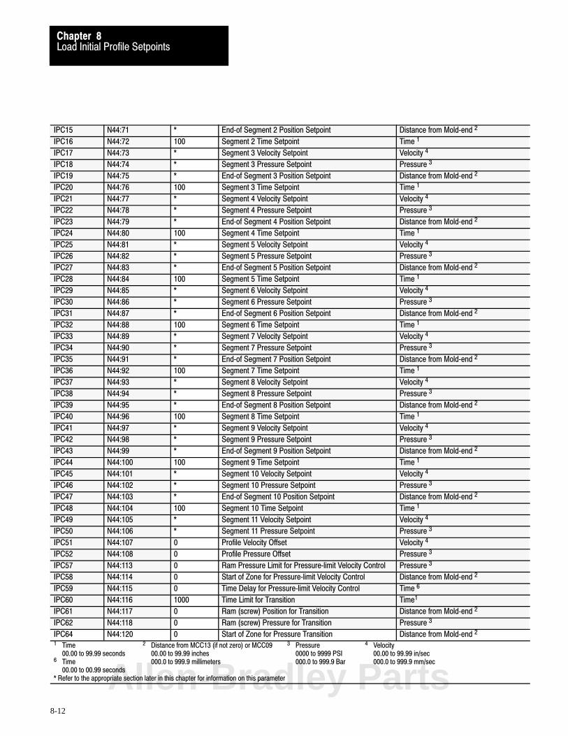
Load Initial Profile SetpointsChapter 8
8-12
IPC15 N44:71 * End�of Segment 2 Position Setpoint Distance from Mold�end 2
IPC16 N44:72 100 Segment 2 Time Setpoint Time 1
IPC17 N44:73 * Segment 3 Velocity Setpoint Velocity 4
IPC18 N44:74 * Segment 3 Pressure Setpoint Pressure 3
IPC19 N44:75 * End�of Segment 3 Position Setpoint Distance from Mold�end 2
IPC20 N44:76 100 Segment 3 Time Setpoint Time 1
IPC21 N44:77 * Segment 4 Velocity Setpoint Velocity 4
IPC22 N44:78 * Segment 4 Pressure Setpoint Pressure 3
IPC23 N44:79 * End�of Segment 4 Position Setpoint Distance from Mold�end 2
IPC24 N44:80 100 Segment 4 Time Setpoint Time 1
IPC25 N44:81 * Segment 5 Velocity Setpoint Velocity 4
IPC26 N44:82 * Segment 5 Pressure Setpoint Pressure 3
IPC27 N44:83 * End�of Segment 5 Position Setpoint Distance from Mold�end 2
IPC28 N44:84 100 Segment 5 Time Setpoint Time 1
IPC29 N44:85 * Segment 6 Velocity Setpoint Velocity 4
IPC30 N44:86 * Segment 6 Pressure Setpoint Pressure 3
IPC31 N44:87 * End�of Segment 6 Position Setpoint Distance from Mold�end 2
IPC32 N44:88 100 Segment 6 Time Setpoint Time 1
IPC33 N44:89 * Segment 7 Velocity Setpoint Velocity 4
IPC34 N44:90 * Segment 7 Pressure Setpoint Pressure 3
IPC35 N44:91 * End�of Segment 7 Position Setpoint Distance from Mold�end 2
IPC36 N44:92 100 Segment 7 Time Setpoint Time 1
IPC37 N44:93 * Segment 8 Velocity Setpoint Velocity 4
IPC38 N44:94 * Segment 8 Pressure Setpoint Pressure 3
IPC39 N44:95 * End�of Segment 8 Position Setpoint Distance from Mold�end 2
IPC40 N44:96 100 Segment 8 Time Setpoint Time 1
IPC41 N44:97 * Segment 9 Velocity Setpoint Velocity 4
IPC42 N44:98 * Segment 9 Pressure Setpoint Pressure 3
IPC43 N44:99 * End�of Segment 9 Position Setpoint Distance from Mold�end 2
IPC44 N44:100 100 Segment 9 Time Setpoint Time 1
IPC45 N44:101 * Segment 10 Velocity Setpoint Velocity 4
IPC46 N44:102 * Segment 10 Pressure Setpoint Pressure 3
IPC47 N44:103 * End�of Segment 10 Position Setpoint Distance from Mold�end 2
IPC48 N44:104 100 Segment 10 Time Setpoint Time 1
IPC49 N44:105 * Segment 11 Velocity Setpoint Velocity 4
IPC50 N44:106 * Segment 11 Pressure Setpoint Pressure 3
IPC51 N44:107 0 Profile Velocity Offset Velocity 4
IPC52 N44:108 0 Profile Pressure Offset Pressure 3
IPC57 N44:113 0 Ram Pressure Limit for Pressure�limit Velocity Control Pressure 3
IPC58 N44:114 0 Start of Zone for Pressure�limit Velocity Control Distance from Mold�end 2
IPC59 N44:115 0 Time Delay for Pressure�limit Velocity Control Time 6
IPC60 N44:116 1000 Time Limit for Transition Time1
IPC61 N44:117 0 Ram (screw) Position for Transition Distance from Mold�end 2
IPC62 N44:118 0 Ram (screw) Pressure for Transition Pressure 3
IPC64 N44:120 0 Start of Zone for Pressure Transition Distance from Mold�end 2
1 Time 2 Distance from MCC13 (if not zero) or MCC09 3 Pressure 4 Velocity00.00 to 99.99 seconds 00.00 to 99.99 inches 0000 to 9999 PSI 00.00 to 99.99 in/sec
6 Time 000.0 to 999.9 millimeters 000.0 to 999.9 Bar 000.0 to 999.9 mm/sec00.00 to 00.99 seconds
* Refer to the appropriate section later in this chapter for information on this parameterAllen-Bradley Parts

Load Initial Profile SetpointsChapter 8
8-13
Block Identifier (IPC01)Bits 07-00 of this word identify it as the first word in a series used todefine the injection profile. Pro-Set 600 sets these bits to 00001001.
We recorded this value on Worksheet 8-B.
Velocity Units (IPC03)The following bit determines units of measure for velocity values.
- BIT 14 selects units of measure.0 = Percent velocity1 = Inches or millimeters per second
We recorded a value of 1 for units per second on Worksheet 8-B.
Profile Offset Sign (IPC03)Profile offsets let you shift the amplitude of entire profiles up or down, ifnecessary. The offset sign determines the direction of shift.
- BIT 13 controls the direction of pressure profile offset.0 = Pressure offset is positive (more pressure)1 = Pressure offset is negative (less pressure)
We set this bit to 0 for positive offset on Worksheet 8-B.
- BIT 12 controls the direction of velocity profile offset.0 = Velocity offset is positive (more velocity)1 = Velocity offset is negative (less velocity)
We recorded a value of 0 for positive offset on Worksheet 8-B.
Profile Algorithm (IPC03)The following bits determine the type of injection profile.
- BITS 01 and 00 select the algorithm for the injection profile.00 = Velocity vs. Position01 = Velocity vs. Position (pressure-limited)10 = Pressure vs. Position11 = Pressure vs. Time
We recorded a value of 11 for pressure vs. time on Worksheet 8-B.
Important: All other bit selections in IPC03 should be zero.
Determine Bit Selectionsfor Worksheet 8-�B

Load Initial Profile SetpointsChapter 8
8-14
Expert Response Compensation (IPC04)
- BITS 11, 10, 09, and 08 determine whether you apply ExpertResponse Compensation (ERC) to injection profiles. ERC is anexclusive algorithm that adjusts for changes in your machine,hydraulics, raw materials, and other process variables. Itcompensates for abrupt upsets and long term deviations.
0 = Expert Response Compensation ON1 = Expert Response Compensation OFF
We recorded a value of 1 (ERC = Off) on Worksheet 8-B.
Open�loop or Closed�loop Control (IPC04)
- BITS 03, 02, 01, and 00 determine whether you use open- orclosed-loop control of injection profiles. In open loop, a valveposition moves the cylinder without sensor feedback . In closed loop,sensor feedback controls the valve regulating pressure or velocity.
0 = Closed loop 1 = Open loop
We recorded a value of 1 for open-loop control on Worksheet 8-B.
Important: All other bit selections in IPC04 should be zero.
The valve spanning procedures in chapter 9 require these initial bitsettings. Where required, we help you select correct final bit settings foryour application in chapter 10. For additional information, refer to thePlastic Molding Module Reference Manual (publication 1771-6.5.88).
Velocity Setpoints (IPC09, 13, 17, 21, 25, 29, 33, 37, 41, 45, and 49)Use these words when configuring velocity vs. position profiles. Thisvelocity is used between the last completed profile segment and theend-of-segment position setpoint. You may use from 1 to 11 segments inyour profile. The procedures in chapter 9 require all eleven.
We recommend that you use initial velocity setpoints equal to themaximum velocity your ram (screw) is capable of traveling. Get this valuefrom your OEM specs for your specific machine.
Record this initial value for all 11 velocity setpoints on Worksheet 8-B.
Determine Word Valuesfor Worksheet 8�B
Allen-Bradley Parts

Load Initial Profile SetpointsChapter 8
8-15
Pressure Setpoints (IPC10, 14, 18, 22, 26, 30, 34, 38, 42, 46, and 50)Use these words when configuring pressure vs. position or time profiles inPSI or Bar. Each pressure setpoint controls the pressure of itscorresponding segment. You may use from 1 to 11 segments in yourprofile. The procedures in chapter 9 require all eleven.
Record the initial value of one-half system pressure for all 11 pressuresetpoints on Worksheet 8-B.
The valve spanning procedures in chapter 9 require these initial velocityand pressure values. For additional information, refer to the PlasticMolding Module Reference Manual (publication 1771-6.5.88).
End�of�Segment Position Setpoints (IPC11, 15, 19, 23, 27, 31, 35, 39, 43, and 47)Use these words to configure velocity or pressure vs. position profiles.The procedures in chapter 9 require that you use all 10 position setpoints.
Determine end-of-segment position setpoints for your velocity vs. positioninjection profile for use in chapter 9 as follows:
1. Back up the ram (screw) from the mold end to its maximum positionand read this length in SYS25 (N40:177).
2. Divide this length by 11 to use all segments of this profile. Thedividing line for each segment is a multiple of this division.
For example, if the ram travel distance in step 1 was 11”, the11-segment profile has dividing lines at 1” intervals. That is,end-of-segment positions are 1”, 2”, 3”, ... 9” and 10”.
Important: Measure end-of-segment positions from mold end.
Mold End
IPC47IPC43
IPC39
Direction of Ram (Screw) Travel
IPC11
Seg 11 Seg 10 Seg 9 Seg 8 Seg 1
3. Record end-of-segment position setpoints on Worksheet 8-B.
The valve spanning procedures in chapter 9 require these initial values. Foradditional information, refer to the Plastic Molding Module ReferenceManual (publication 1771-6.5.88).
Load Initial Profile SetpointsChapter 8
8-16
Time Setpoints (IPC12, 16, 20, 24, 28, 32, 36, 40, 44, and 48)Use these words when configuring pressure vs.time profiles in seconds (1second as 100). Each setpoint controls the time of its own segment. Youmust use one less time setpoint than pressure setpoints.
We recorded 1 second (100) for these time setpoints on Worksheet 8-B.
The valve spanning procedures in chapter 9 require these initial values.For additional information, refer to the Plastic Molding Module ReferenceManual (publication 1771-6.5.88).
Profile Offsets (IPC51 and 52)Profile offset let you shift the amplitude of the entire injection profile up ordown, if necessary.
- IPC51 determines the offset for velocity profiles in inches (ormm)/sec.
We recorded zero (no offset) on Worksheet 8-B.
- IPC52 determines the offset for pressure profiles in PSI or Bar.
We recorded zero (no offset) on Worksheet 8-B.
Pressure Limiting Setpoints (IPC57, 58, and 59)Use these words in a pressure-limited velocity vs. position profile.
- IPC57 determines the ram (screw) pressure limit for the pressure-limited velocity vs. position profile in PSI or Bar.
- IPC58 determines the position at which the QDC module beginspressure-limited control. A non-zero value measured from mold endforces the QDC module NOT to apply pressure-limiting control untilthe ram (screw) reaches this point. A zero entry forces the QDCmodule to apply pressure limiting over the entire shot length.
- IPC59 determines the time delay in a pressure-limited velocity vs.position profile that has exceeded the pressure limit during:
over-pressure before QDC module returns to a pressure-limit PIDalgorithm
over-velocity before QDC module returns to its VelFF algorithm
A non-zero value filters pressure spikes to avoid nuisance pressurelimiting during pressure-limited velocity vs. position profiles.
We recorded zero for these three setpoints on Worksheet 8-B.Allen-Bradley Parts
Load Initial Profile SetpointsChapter 8
8-17
The valve spanning procedures in chapter 9 require these initial values.We help you select correct final values for your application in chapter 10.For additional information, refer to Section 3 of the Plastic MoldingModule Reference Manual (publication 1771-6.5.88).
Transition Setpoints (IPC60, 61, 62, and 64)Use these words when configuring the type of transition from injection tothe pack (or hold) profile. The QDC module starts the transition when itdetects the first of the following conditions that you enable with a non-zerosetpoint. You may enable one or more of the following:
- IPC60 determines the transition time limit. The QDC moduleimmediately terminates the injection profile and begins the pack (orhold) profile if total injection-profile execution time equals orexceeds the non-zero entry in this word.
We recorded 10 seconds (1000) for this setpoint on Worksheet 8-B.
- IPC61 determines the ram (screw) position for transition. The QDCmodule immediately terminates the injection profile and begins thepack (or hold) profile if the ram (screw) position is less than or equalto the non-zero entry in this word. Use a position equal to or justbeyond top-of-cushion position PPC61 measured from the mold end.
We recorded zero on Worksheet 8-B to inhibit a position transition.
- IPC62 determines the ram (screw) pressure for transition. The QDCmodule immediately terminates the injection profile and begins thepack (or hold) profile if both occur:
ram (screw) position is less than or equal to any non-zero entry inINC64, start of zone for pressure transition
ram (screw) pressure equals or exceeds the non-zero entry in thisword. Typically, you use a setpoint below mold-flash pressure.
We recorded zero on Worksheet 8-B to inhibit pressure transition.
- IPC64 determines the start of zone in which the QDC module allowspressure transitions. A non-zero value measured from the mold endforces the QDC module NOT to transition on pressure until the ram(screw) reaches this position. A zero setpoint forces the QDCmodule to use any non-zero pressure setpoint in IPC62 over the entireinjection profile.
We recorded zero on Worksheet 8-B to inhibit this function.
The valve spanning procedures in chapter 9 require these initial values.We help you select correct final values for your application in chapter 10.For additional information, refer to Section 3 of the Plastic MoldingModule Reference Manual (publication 1771-6.5.88).
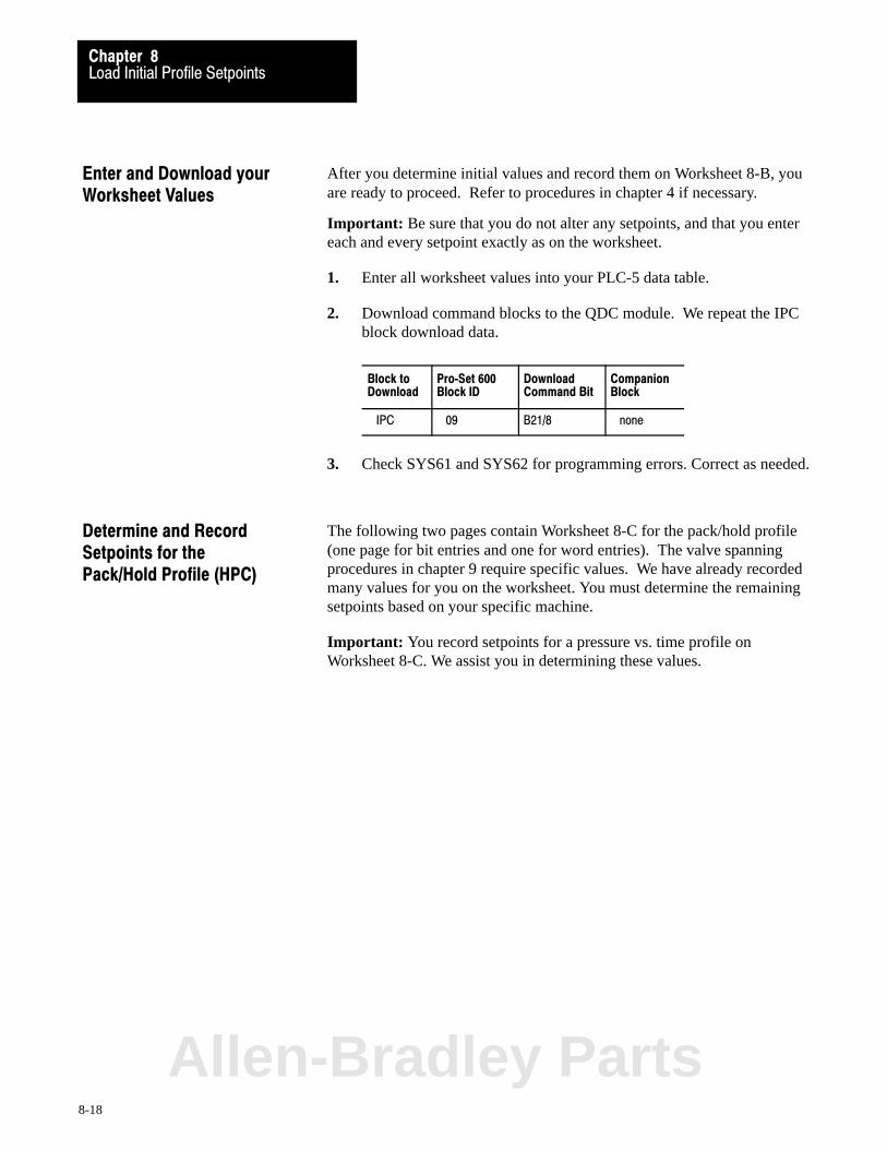
Load Initial Profile SetpointsChapter 8
8-18
After you determine initial values and record them on Worksheet 8-B, youare ready to proceed. Refer to procedures in chapter 4 if necessary.
Important: Be sure that you do not alter any setpoints, and that you entereach and every setpoint exactly as on the worksheet.
1. Enter all worksheet values into your PLC-5 data table.
2. Download command blocks to the QDC module. We repeat the IPCblock download data.
Block toDownload
Pro�Set 600Block ID
DownloadCommand Bit
CompanionBlock
IPC 09 B21/8 none
3. Check SYS61 and SYS62 for programming errors. Correct as needed.
The following two pages contain Worksheet 8-C for the pack/hold profile(one page for bit entries and one for word entries). The valve spanningprocedures in chapter 9 require specific values. We have already recordedmany values for you on the worksheet. You must determine the remainingsetpoints based on your specific machine.
Important: You record setpoints for a pressure vs. time profile onWorksheet 8-C. We assist you in determining these values.
Enter and Download yourWorksheet Values
Determine and RecordSetpoints for the Pack/Hold Profile (HPC)
Allen-Bradley Parts
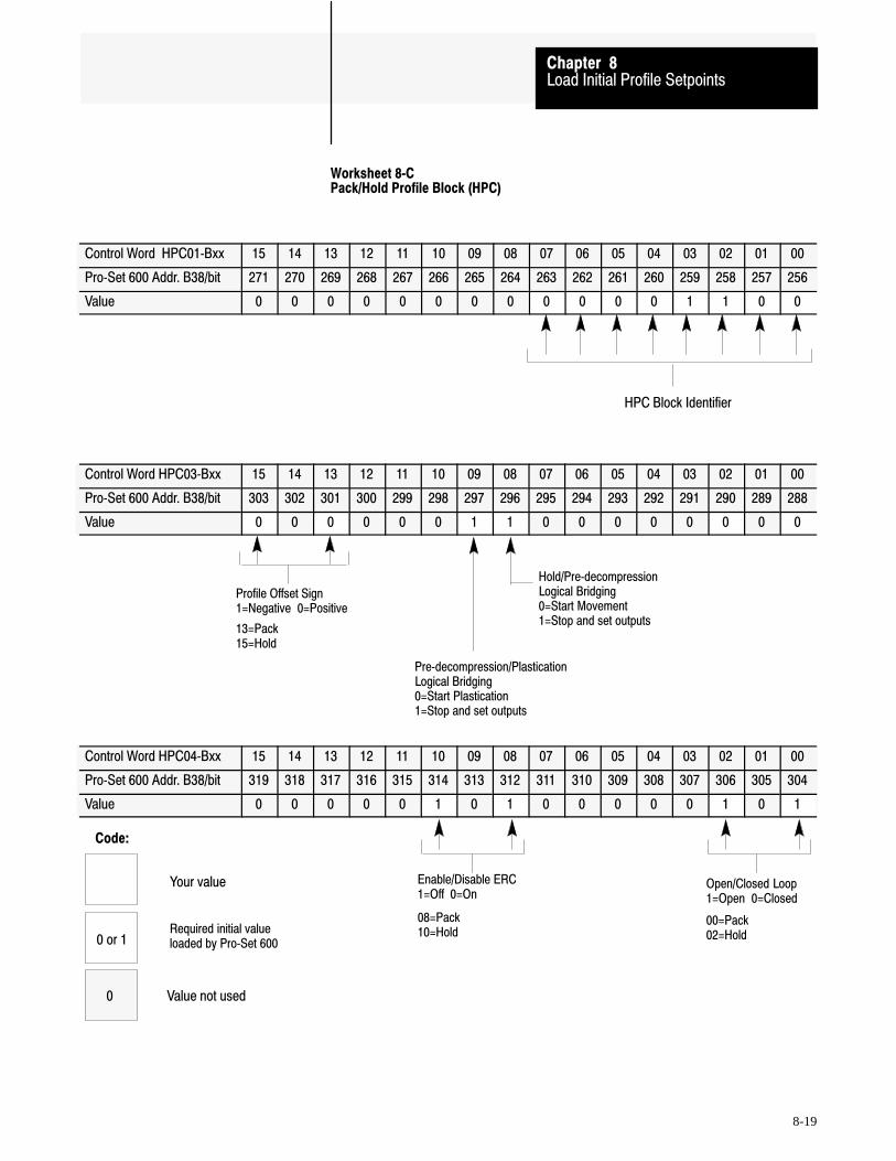
HPC Block Identifier
Hold/Pre�decompressionLogical Bridging0=Start Movement1=Stop and set outputs
Pre�decompression/PlasticationLogical Bridging0=Start Plastication1=Stop and set outputs
Profile Offset Sign 1=Negative 0=Positive
13=Pack15=Hold
Open/Closed Loop1=Open 0=Closed
Enable/Disable ERC 1=Off 0=On
00=Pack 02=Hold
08=Pack 10=Hold
Code:
Your value
0 or 1Required initial valueloaded by Pro�Set 600
Value not used0
Load Initial Profile SetpointsChapter 8
8-19
Worksheet 8�CPack/Hold Profile Block (HPC)
Control Word HPC01�Bxx 15 14 13 12 11 10 09 08 07 06 05 04 03 02 01 00
Pro�Set 600 Addr. B38/bit 271 270 269 268 267 266 265 264 263 262 261 260 259 258 257 256
Value 0 0 0 0 0 0 0 0 0 0 0 0 1 1 0 0
Control Word HPC03�Bxx 15 14 13 12 11 10 09 08 07 06 05 04 03 02 01 00
Pro�Set 600 Addr. B38/bit 303 302 301 300 299 298 297 296 295 294 293 292 291 290 289 288
Value 0 0 0 0 0 0 1 1 0 0 0 0 0 0 0 0
Control Word HPC04�Bxx 15 14 13 12 11 10 09 08 07 06 05 04 03 02 01 00
Pro�Set 600 Addr. B38/bit 319 318 317 316 315 314 313 312 311 310 309 308 307 306 305 304
Value 0 0 0 0 0 1 0 1 0 0 0 0 0 1 0 1

Enter Your Values Here
Load Initial Profile SetpointsChapter 8
8-20
Worksheet 8-�C (continued)
Pack/Hold Profile Block (HPC)
Control Word Pro�Set 600 Addr. Value Description Units
HPC10 N44:246 * Pack Segment 1 Pressure Setpoint Pressure 3
HPC11 N44:247 100 Pack Segment 1 Time Setpoint Time 1
HPC13 N44:249 * Pack Segment 2 Pressure Setpoint Pressure 3
HPC14 N44:250 100 Pack Segment 2 Time Setpoint Time 1
HPC16 N44:252 * Pack Segment 3 Pressure Setpoint Pressure 3
HPC17 N44:253 100 Pack Segment 3 Time Setpoint Time 1
HPC19 N44:255 * Pack Segment 4 Pressure Setpoint Pressure 3
HPC20 N44:256 100 Pack Segment 4 Time Setpoint Time 1
HPC22 N44:258 * Pack Segment 5 Pressure Setpoint Pressure 3
HPC23 N44:259 100 Pack Segment 5 Time Setpoint Time 1
HPC25 N44:261 0 Pack Profile Pressure Offset Pressure 3
HPC27 N44:263 * Hold Segment 1 Pressure Setpoint Pressure 3
HPC28 N44:264 100 Hold Segment 1 Time Setpoint Time 1
HPC30 N44:266 * Hold Segment 2 Pressure Setpoint Pressure 3
HPC31 N44:267 100 Hold Segment 2 Time Setpoint Time 1
HPC33 N44:269 * Hold Segment 3 Pressure Setpoint Pressure 3
HPC34 N44:270 100 Hold Segment 3 Time Setpoint Time 1
HPC36 N44:272 * Hold Segment 4 Pressure Setpoint Pressure 3
HPC37 N44:273 100 Hold Segment 4 Time Setpoint Time 1
HPC39 N44:275 * Hold Segment 5 Pressure Setpoint Pressure 3
HPC40 N44:276 100 Hold Segment 5 Time Setpoint Time 1
HPC42 N44:278 0 Hold Profile Pressure Offset Pressure 3
HPC61 N44:297 0 Cure Timer Preset Time 4
1 Time 3 Pressure 4 Time00.00 to 99.99 seconds 0000 to 9999 PSI 000.0 to 999.9 seconds
000.0 to 999.9 Bar
* Refer to the appropriate section later in this chapter for information on this parameter
Allen-Bradley Parts
Load Initial Profile SetpointsChapter 8
8-21
Block Identifier (HPC01)Bits 07-00 of this word identify it as the first word in a series used todefine the pack/hold profile. Pro-Set 600 sets these bits to 00001100.
We recorded this value on Worksheet 8-C.
Profile Offset Sign (HPC03)Profile offsets let you shift the amplitude of entire profiles up or down, ifnecessary. The offset sign determines the direction of shift.
- BIT 15 selects the profile offset sign for the hold profile.
- BIT 13 selects the profile offset sign for the pack profile.
We recorded the value of 0 for positive offset on Worksheet 8-C.
Logical Bridges (HPC03)Logical bridges control the action taken by the QDC module when itcompletes a profile or movement.
The following bits of HPC03 determine whether the QDC module stops orcontinues when entering and/or leaving the pre-decompression movement.
- BIT 09 determines if the QDC continues to the plastication profileafter the pre-decompression movement, or stops and sets outputs.
- BIT 08 determines if the QDC continues to the pre-decompressionmovement after the hold profile, or stops and sets outputs.
0 = continues to next phase1 = stops and sets outputs
We recorded a value of 1 to stop and set outputs on Worksheet 8-C.
Important: All other bit selections in HPC03 should be zero.
Expert Response Compensation (HPC04)
- BITS 10 and 08 determine whether you apply Expert ResponseCompensation (ERC) to pack and hold profiles. ERC is an exclusivealgorithm that adjusts for changes in your machine, hydraulics, rawmaterials, and other process variables. It compensates for abruptupsets and long term deviations.
0 = Expert Response Compensation ON1 = Expert Response Compensation OFF
We recorded a value of 1 (ERC = Off) on Worksheet 8-C.
Determine Bit Selectionsfor Worksheet 8-�C
Load Initial Profile SetpointsChapter 8
8-22
Open�loop or Closed�loop Control (HPC04)
- BITS 03 and 01 determine whether you use open- or closed-loopcontrol of pack and hold profiles. In open loop, a valve positionmoves the cylinder without sensor feedback . In closed loop, sensorfeedback controls the valve regulating pressure.
0 = Closed loop 1 = Open loop
We recorded a value of 1 for open-loop control on Worksheet 8-C.
The valve spanning procedures in chapter 9 require these initial bitsettings. Where required, we help you select correct final bit settings foryour application in chapter 10. For additional information, refer to thePlastic Molding Module Reference Manual (publication 1771-6.5.88).
Time Setpoints (for pack profile: HPC11, 14, 17, 20, and 23)(for hold profile: HPC28, 31, 34, 37, and 40)Use these words when configuring pack or hold profiles in seconds. Eachsetpoint controls the time of its corresponding segment. You must use thesame number of time setpoints as pressure setpoints. The procedures inchapter 9 require all five.
We recorded a value of 1 second (100) on Worksheet 8-C for each of the10 time setpoints listed above.
The valve spanning procedures in chapter 9 require these initial values.For additional information, refer to the Plastic Molding Module ReferenceManual (publication 1771-6.5.88).
Profile Offsets (for Pack profile: HPC25)(for Hold profile: HPC42)Profile offsets let you shift the amplitude of the entire pack or hold profileup or down, if necessary. You record these setpoints in PSI or Bar.
We recorded zeros for no pressure offsets on Worksheet 8-C.
Determine Word Valuesfor Worksheet 8�-C
Allen-Bradley Parts

Load Initial Profile SetpointsChapter 8
8-23
Cure Timer Preset (HPC61)Use this word to set the length of cure time that starts at completion of thehold profile. You record this preset in seconds (000.0 to 999.9). After theQDC module starts the internal cure timer, it:
reports the accumulated value of the timer in SYS58 sets bit SYS03-B03 when the timer is timing sets the done bit SYS03-B05 when SYS58 equals or exceeds HPC61
stops this timer when: SYS58 = 999.9 seconds, or when it sees a true-to-false transition of DYC03-B01
resets SYS58 to zero on a false-to-true transition of DYC03-B01
We recorded zero for this preset on Worksheet 8-C.
The valve spanning procedures in chapter 9 require these initial values.We help you select correct final values for your application in chapter 10.For additional information, refer to the Plastic Molding Module ReferenceManual (publication 1771-6.5.88).
After you determine initial values and record them on Worksheet 8-C, youare ready to proceed. Refer to procedures in chapter 4 if necessary.
Important: Be sure that you do not alter any setpoints, and that you entereach and every setpoint exactly as on the worksheet.
1. Enter all worksheet values into your PLC-5 data table.
2. Download command blocks to the QDC module. We repeat the HPCblock download data:
Block Block ID Command Bit Companion
HPC 12 B21/11 none
3. Check SYS61 and SYS62 for programming errors. Correct as needed.
Enter and Download yourWorksheet Values
Load Initial Profile SetpointsChapter 8
8-24
The following two pages contain Worksheet 8-D for the plastication profile(one page for bit entries and one for word entries). The valve spanningprocedures in chapter 9 require specific values. We have already recordedmany setpoints for you on the worksheet. You must determine theremaining setpoints based on your specific machine.
Important: You enter setpoints for a backpressure vs. position profile onWorksheet 8-D. We assist you in determining them.
Determine and RecordSetpoints for thePlastication Profile (PPC)
Allen-Bradley Parts
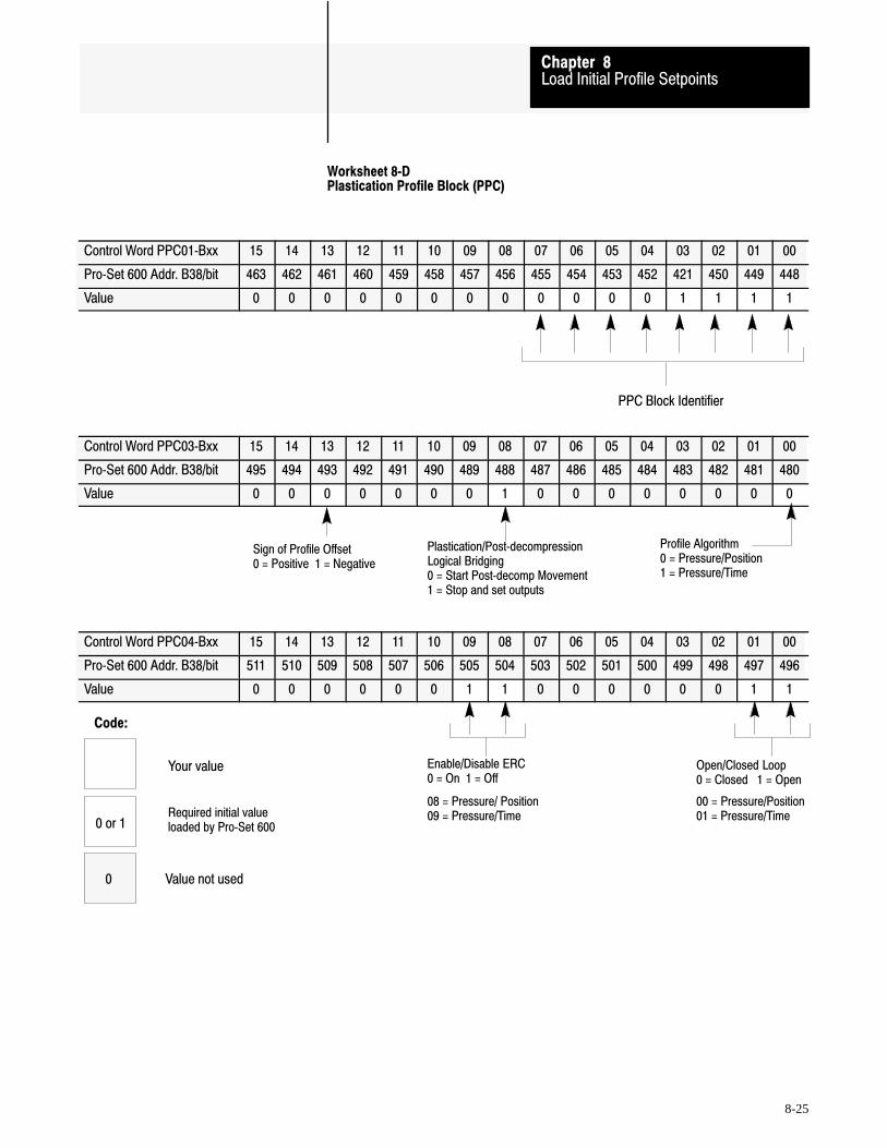
PPC Block Identifier
Open/Closed Loop0 = Closed 1 = Open
Enable/Disable ERC0 = On 1 = Off
00 = Pressure/Position01 = Pressure/Time
08 = Pressure/ Position09 = Pressure/Time
Sign of Profile Offset0 = Positive 1 = Negative
Plastication/Post�decompressionLogical Bridging0 = Start Post�decomp Movement1 = Stop and set outputs
Profile Algorithm 0 = Pressure/Position1 = Pressure/Time
Code:
Your value
0 or 1Required initial valueloaded by Pro�Set 600
Value not used0
Load Initial Profile SetpointsChapter 8
8-25
Worksheet 8�DPlastication Profile Block (PPC)
Control Word PPC01�Bxx 15 14 13 12 11 10 09 08 07 06 05 04 03 02 01 00
Pro�Set 600 Addr. B38/bit 463 462 461 460 459 458 457 456 455 454 453 452 421 450 449 448
Value 0 0 0 0 0 0 0 0 0 0 0 0 1 1 1 1
Control Word PPC03�Bxx 15 14 13 12 11 10 09 08 07 06 05 04 03 02 01 00
Pro�Set 600 Addr. B38/bit 495 494 493 492 491 490 489 488 487 486 485 484 483 482 481 480
Value 0 0 0 0 0 0 0 1 0 0 0 0 0 0 0 0
Control Word PPC04�Bxx 15 14 13 12 11 10 09 08 07 06 05 04 03 02 01 00
Pro�Set 600 Addr. B38/bit 511 510 509 508 507 506 505 504 503 502 501 500 499 498 497 496
Value 0 0 0 0 0 0 1 1 0 0 0 0 0 0 1 1

Enter Your Values Here
Load Initial Profile SetpointsChapter 8
8-26
Worksheet 8�-D (continued)
Plastication Profile Block (PPC)
Control Word Pro�Set 600 Addr. Value Description Units
PPC10 N44:426 * Segment 1 Pressure Setpoint Pressure 3
PPC11 N44:427 * End�of Segment 1 Position Setpoint Distance from Mold�end 2
PPC12 N44:428 0 Segment 1 Time Setpoint Time 1
PPC14 N44:430 * Segment 2 Pressure Setpoint Pressure 3
PPC15 N44:431 * End�of Segment 2 Position Setpoint Distance from Mold�end 2
PPC16 N44:432 0 Segment 2 Time Setpoint Time 1
PPC18 N44:434 * Segment 3 Pressure Setpoint Pressure 3
PPC19 N44:435 * End�of Segment 3 Position Setpoint Distance from Mold�end 2
PPC20 N44:436 0 Segment 3 Time Setpoint Time 1
PPC22 N44:438 * Segment 4 Pressure Setpoint Pressure 3
PPC23 N44:439 * End�of Segment 4 Position Setpoint Distance from Mold�end 2
PPC24 N44:440 0 Segment 4 Time Setpoint Time 1
PPC26 N44:442 * Segment 5 Pressure Setpoint Pressure 3
PPC27 N44:443 * End�of Segment 5 Position Setpoint Distance from Mold�end 2
PPC28 N44:444 0 Segment 5 Time Setpoint Time 1
PPC30 N44:446 * Segment 6 Pressure Setpoint Pressure 3
PPC31 N44:447 * End�of Segment 6 Position Setpoint Distance from Mold�end 2
PPC32 N44:448 0 Segment 6 Time Setpoint Time 1
PPC34 N44:450 * Segment 7 Pressure Setpoint Pressure 3
PPC35 N44:451 * End�of Segment 7 Position Setpoint Distance from Mold�end 2
PPC36 N44:452 0 Segment 7 Time Setpoint Time 1
PPC38 N44:454 * Segment 8 Pressure Setpoint Pressure 3
PPC39 N44:455 * End�of Segment 8 Position Setpoint Distance from Mold�end 2
PPC40 N44:456 0 Segment 8 Time Setpoint Time 1
PPC42 N44:458 * Segment 9 Pressure Setpoint Pressure 3
PPC43 N44:459 * End�of Segment 9 Position Setpoint Distance from Mold�end 2
PPC44 N44:460 0 Segment 9 Time Setpoint Time 1
PPC46 N44:462 * Segment 10 Pressure Setpoint Pressure 3
PPC47 N44:463 * End�of Segment 10 Position Setpoint Distance from Mold�end 2
PPC48 N44:464 0 Segment 10 Time Setpoint Time 1
PPC50 N44:466 * Segment 11 Pressure Setpoint Pressure 3
PPC52 N44:468 * Profile Pressure Offset Pressure 3
PPC61 N44:477 0 Cushion Size Distance from Mold�end 2
PPC62 N44:478 * Shot Size Incremental Distance 4
1 Time 2 Distance from MCC13 (if not zero) or MCC09 3 Pressure 4 Distance from PPC6100.00 to 99.99 Seconds 00.00 to 99.99 Inches 0000 to 9999 PSI 00.00 to 99.99 Inches
000.0 to 999.9 Millimeters 000.0 to 999.9 Bar 000.0 to 999.9 Millimeter
* Refer to the appropriate section later in this chapter for information on this parameter
Allen-Bradley Parts
Load Initial Profile SetpointsChapter 8
8-27
Block Identifier (PPC01)Bits 07-00 of this word identify it as the first word in a series used todefine the plastication profile. Pro-Set 600 sets these bits to 00001111.
We recorded this value on Worksheet 8-D.
Profile Offset Sign (PPC03)The profile offset lets you shift the amplitude of the entire profile up ordown, if necessary. The offset sign determines the direction of shift.
- BIT 13 selects the profile offset sign for the plastication profile.0 = positive offset (more pressure)1 = negative offset (less pressure)
We recorded a value of 0 for positive offset on Worksheet 8-D.
Logical Bridge (PPC03)The logical bridge controls the action taken by the QDC module when itcompletes the plastication profile.
- BIT 08 determines if the QDC continues to the post-decompressionmovement after the plastication profile, or stops and sets outputs.0 = continues to post-decompression1 = stops and sets outputs
We recorded a value of 1 to stop and set outputs on Worksheet 8-D.
Profile Algorithm (PPC03)The following bit determines the type of plastication profile.
- BIT 00 selects the algorithm for the plastication profile.0 = Ram (screw) backpressure vs. position1 = Ram (screw) backpressure vs. time
We recorded a value of 0 for backpressure vs. position onWorksheet 8-D.
Important: All other bit selections in PPC03 should be zero.
Determine Bit Selectionsfor Worksheet 8�-D

Load Initial Profile SetpointsChapter 8
8-28
Expert Response Compensation (PPC04)
- BITS 09 and 08 determine whether you apply Expert ResponseCompensation (ERC) to plastication profiles. ERC is an exclusivealgorithm that adjusts for changes in your machine, hydraulics, rawmaterials, and other process variables. It compensates for abruptupsets and long term deviations.
0 = Expert Response Compensation ON1 = Expert Response Compensation OFF
We recorded a value of 1 (ERC = Off) on Worksheet 8-D.
Open�loop or Closed�loop Control (PPC04)
- BITS 01 and 00 determine whether you use open- or closed-loopcontrol of plastication profiles. In open loop, a valve position movesthe cylinder without sensor feedback. In closed loop, sensor feedbackcontrols the valve regulating pressure.
0 = Closed loop1 = Open loop
We recorded a value of 1 for open-loop control on Worksheet 8-D.
Important: All other bit selections in PPC04 should be zero.
The valve spanning procedures in chapter 9 require these initial bitsettings. Where required, we help you select correct final bit settings foryour application in chapter 10. For additional information, refer to thePlastic Molding Module Reference Manual (publication 1771-6.5.88).
Backpressure Setpoints (PPC10, 14, 18, 22, 26, 30, 34, 38, 42, 46, and 50)Use these words when configuring backpressure vs. position or timeprofiles in PSI or Bar. Each setpoint controls the pressure of itscorresponding segment. You may use from 1 to 11 segments in yourprofile. The procedures in chapter 9 require all eleven.
Record backpressure setpoints on Worksheet 8-D equal to the maximumplastication backpressure you would ever expect in the backpressure vs.position profile for each of the 11 backpressure setpoints listed above.
The valve spanning procedures in chapter 9 require these initial values. Foradditional information, refer to the Plastic Molding Module ReferenceManual (publication 1771-6.5.88).
Determine Word Valuesfor Worksheet 8-�D
Allen-Bradley Parts
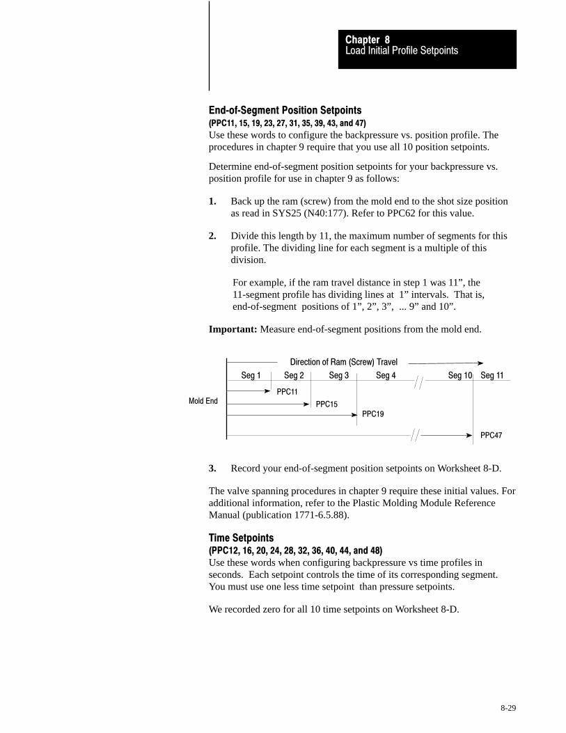
Load Initial Profile SetpointsChapter 8
8-29
End�of�Segment Position Setpoints (PPC11, 15, 19, 23, 27, 31, 35, 39, 43, and 47)
Use these words to configure the backpressure vs. position profile. Theprocedures in chapter 9 require that you use all 10 position setpoints.
Determine end-of-segment position setpoints for your backpressure vs.position profile for use in chapter 9 as follows:
1. Back up the ram (screw) from the mold end to the shot size positionas read in SYS25 (N40:177). Refer to PPC62 for this value.
2. Divide this length by 11, the maximum number of segments for thisprofile. The dividing line for each segment is a multiple of thisdivision.
For example, if the ram travel distance in step 1 was 11”, the11-segment profile has dividing lines at 1” intervals. That is,end-of-segment positions of 1”, 2”, 3”, ... 9” and 10”.
Important: Measure end-of-segment positions from the mold end.
Mold End
PPC11
PPC15PPC19
Direction of Ram (Screw) Travel
PPC47
Seg 1 Seg 2 Seg 3 Seg 4 Seg 10 Seg 11
3. Record your end-of-segment position setpoints on Worksheet 8-D.
The valve spanning procedures in chapter 9 require these initial values. Foradditional information, refer to the Plastic Molding Module ReferenceManual (publication 1771-6.5.88).
Time Setpoints (PPC12, 16, 20, 24, 28, 32, 36, 40, 44, and 48)Use these words when configuring backpressure vs time profiles inseconds. Each setpoint controls the time of its corresponding segment.You must use one less time setpoint than pressure setpoints.
We recorded zero for all 10 time setpoints on Worksheet 8-D.
Load Initial Profile SetpointsChapter 8
8-30
Profile Offset (PPC52)The profile offset lets you shift the amplitude of the backpressure profileup or down, if necessary. You record this setpoint in PSI or Bar.
We recorded zero (no offset) on Worksheet 8-D.
Cushion Size (PPC61)This word determines the length of molten plastic that should remain in thebarrel at the conclusion of the hold profile. The QDC uses this length incomputing the 100% shot size. Units are inches or millimeters.
We recorded zero (no cushion) on Worksheet 8-D.
Shot Size (PPC62)This word determines the length of molten plastic drawn during theplastication profile. Use this value to determine segment length inEnd-of-segment Positions, above. Units are inches or millimeters. TheQDC uses this length for computing the end-of-plastication position (100%shot size). 100% shot size = shot size + cushion = PPC62 + PPC61
Record a typical shot size for your machine on Worksheet 8-D.
The valve spanning procedures in chapter 9 require these initial cushionand shot size values. Where required, we help you select correct finalvalues for your application in chapter 10. For additional information, referto Plastic Molding Module Reference Manual (publication 1771-6.5.88).
After you determine initial values and record them on Worksheet 8-D, youare ready to proceed. Refer to procedures in chapter 4 if necessary.
Important: Be sure that you do not alter any setpoints, and that you entereach and every setpoint exactly as on the worksheet.
1. Enter all worksheet values into your PLC-5 data table.
2. Download command blocks to the QDC module. We repeat the PPCblock download data.
Block Block ID Command Bit Companion
PPC 15 B21/14 none
3. Check SYS61 and SYS62 for programming errors. Correct as needed.
Enter and Download yourWorksheet Values
Allen-Bradley Parts

Load Initial Profile SetpointsChapter 8
8-31
The following two pages contain Worksheet 8-E for the clamp open profile(one worksheet for bit entries and one for word entries). The valvespanning procedures in chapter 9 require specific values. We have alreadyrecorded many values for you on the worksheet. You must determine theremaining setpoints based on your specific machine.
Important: You enter setpoints for pressure vs. position and velocity vs.position profiles on Worksheet 8-E. We assist you in determining them.
Determine and RecordSetpoints for theClamp Open Profile (OPC)

Algorithm 0 = Vel/Pos1 = Press/Pos
FOCSOCTOC
FOCSOCTOC
Logical Bridge0 = Start Next Profile at end1 = Stop and Set Output at end
Zone Overrun0 = Start Clamp Open Slow on Zone Overrun1 = Stop and Zero Outputs on Zone Overrun
Velocity Units 0 = Percent Velocity1 = Inches (mm)/Second
OPC Block Identifier
ERC Enable/Disable Selection 0 = ON 1 = OFF
bit 15 = Press/Pos OSCbit 14 = Vel/Pos OSCbit 13 = Press/Pos TOCbit 12 = Vel/Pos TCCbit 11 = Press/Pos SOCbit 10 = Vel/Pos SOCbit 09 = Press/Pos FOCbit 08 = Vel/Pos FOC
Open/Closed�Loop Selection 0 = Closed�Loop 1 = Open�Loop
bit 07 = Press/Pos OSCbit 06 = Vel/Pos OSCbit 05 = Press/Pos TOCbit 04 = Vel/Pos TOCbit 03 = Press/Pos SOCbit 02 = Vel/Pos SOCbit 01 = Press/Pos FOCbit 00 = Vel/Pos FOC
OSC
Code:
Your value
0 or 1Required initial valueloaded by Pro�Set 600
Value not used0
Load Initial Profile SetpointsChapter 8
8-32
Worksheet 8�EClamp Open Profile Block (OPC)
Control Word OPC01�Bxx 15 14 13 12 11 10 09 08 07 06 05 04 03 02 01 00
Pro�Set 600 Addr. B37/bit 591 590 589 588 587 586 585 584 583 582 581 580 579 578 577 576
Value 0 0 0 0 0 0 0 0 0 0 0 1 0 1 0 1
Control Word OPC03�Bxx 15 14 13 12 11 10 09 08 07 06 05 04 03 02 01 00
Pro�Set 600 Addr. B37/bit 623 622 621 620 619 618 617 616 615 614 613 612 611 610 609 608
Value 0 1 0 0 0 0 0 0 0 1 0 1 0 1 0 1
Control Word OPC04�Bxx 15 14 13 12 11 10 09 08 07 06 05 04 03 02 01 00
Pro�Set 600 Addr. B37/bit 639 638 637 636 635 634 633 632 631 630 629 628 627 626 625 624
Value 1 1 1 1 1 1 1 1 1 1 1 1 1 1 1 1
Allen-Bradley Parts
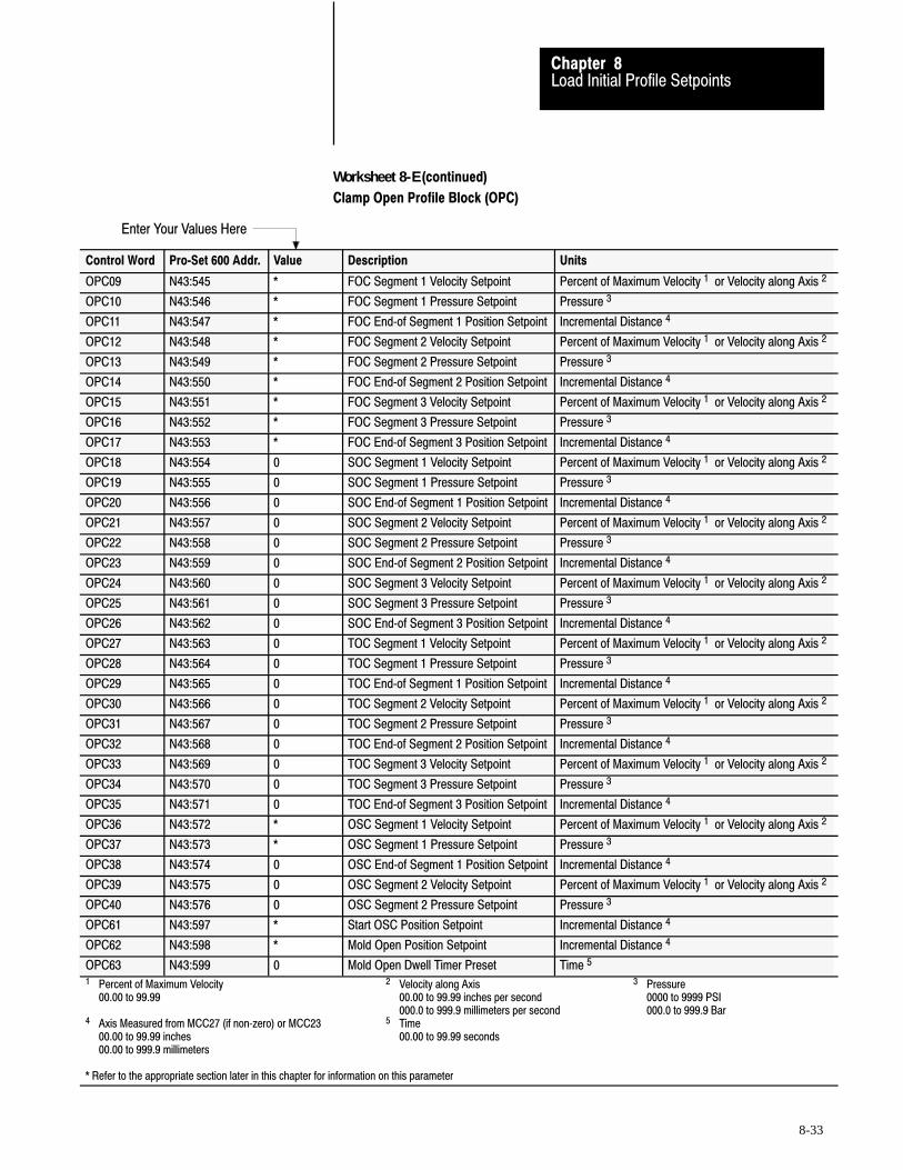
Enter Your Values Here
Load Initial Profile SetpointsChapter 8
8-33
Worksheet 8-�E (continued)
Clamp Open Profile Block (OPC)
Control Word Pro�Set 600 Addr. Value Description Units
OPC09 N43:545 * FOC Segment 1 Velocity Setpoint Percent of Maximum Velocity 1 or Velocity along Axis 2
OPC10 N43:546 * FOC Segment 1 Pressure Setpoint Pressure 3
OPC11 N43:547 * FOC End�of Segment 1 Position Setpoint Incremental Distance 4
OPC12 N43:548 * FOC Segment 2 Velocity Setpoint Percent of Maximum Velocity 1 or Velocity along Axis 2
OPC13 N43:549 * FOC Segment 2 Pressure Setpoint Pressure 3
OPC14 N43:550 * FOC End�of Segment 2 Position Setpoint Incremental Distance 4
OPC15 N43:551 * FOC Segment 3 Velocity Setpoint Percent of Maximum Velocity 1 or Velocity along Axis 2
OPC16 N43:552 * FOC Segment 3 Pressure Setpoint Pressure 3
OPC17 N43:553 * FOC End�of Segment 3 Position Setpoint Incremental Distance 4
OPC18 N43:554 0 SOC Segment 1 Velocity Setpoint Percent of Maximum Velocity 1 or Velocity along Axis 2
OPC19 N43:555 0 SOC Segment 1 Pressure Setpoint Pressure 3
OPC20 N43:556 0 SOC End�of Segment 1 Position Setpoint Incremental Distance 4
OPC21 N43:557 0 SOC Segment 2 Velocity Setpoint Percent of Maximum Velocity 1 or Velocity along Axis 2
OPC22 N43:558 0 SOC Segment 2 Pressure Setpoint Pressure 3
OPC23 N43:559 0 SOC End�of Segment 2 Position Setpoint Incremental Distance 4
OPC24 N43:560 0 SOC Segment 3 Velocity Setpoint Percent of Maximum Velocity 1 or Velocity along Axis 2
OPC25 N43:561 0 SOC Segment 3 Pressure Setpoint Pressure 3
OPC26 N43:562 0 SOC End�of Segment 3 Position Setpoint Incremental Distance 4
OPC27 N43:563 0 TOC Segment 1 Velocity Setpoint Percent of Maximum Velocity 1 or Velocity along Axis 2
OPC28 N43:564 0 TOC Segment 1 Pressure Setpoint Pressure 3
OPC29 N43:565 0 TOC End�of Segment 1 Position Setpoint Incremental Distance 4
OPC30 N43:566 0 TOC Segment 2 Velocity Setpoint Percent of Maximum Velocity 1 or Velocity along Axis 2
OPC31 N43:567 0 TOC Segment 2 Pressure Setpoint Pressure 3
OPC32 N43:568 0 TOC End�of Segment 2 Position Setpoint Incremental Distance 4
OPC33 N43:569 0 TOC Segment 3 Velocity Setpoint Percent of Maximum Velocity 1 or Velocity along Axis 2
OPC34 N43:570 0 TOC Segment 3 Pressure Setpoint Pressure 3
OPC35 N43:571 0 TOC End�of Segment 3 Position Setpoint Incremental Distance 4
OPC36 N43:572 * OSC Segment 1 Velocity Setpoint Percent of Maximum Velocity 1 or Velocity along Axis 2
OPC37 N43:573 * OSC Segment 1 Pressure Setpoint Pressure 3
OPC38 N43:574 0 OSC End�of Segment 1 Position Setpoint Incremental Distance 4
OPC39 N43:575 0 OSC Segment 2 Velocity Setpoint Percent of Maximum Velocity 1 or Velocity along Axis 2
OPC40 N43:576 0 OSC Segment 2 Pressure Setpoint Pressure 3
OPC61 N43:597 * Start OSC Position Setpoint Incremental Distance 4
OPC62 N43:598 * Mold Open Position Setpoint Incremental Distance 4
OPC63 N43:599 0 Mold Open Dwell Timer Preset Time 5
1 Percent of Maximum Velocity 2 Velocity along Axis 3 Pressure00.00 to 99.99 00.00 to 99.99 inches per second 0000 to 9999 PSI
000.0 to 999.9 millimeters per second 000.0 to 999.9 Bar4 Axis Measured from MCC27 (if non�zero) or MCC23 5 Time
00.00 to 99.99 inches 00.00 to 99.99 seconds00.00 to 999.9 millimeters
* Refer to the appropriate section later in this chapter for information on this parameter

Load Initial Profile SetpointsChapter 8
8-34
Block Identifier(OPC01)
Bits 07-00 of this word identify it as the first word in a series used todefine the clamp open profile. Pro-Set 600 sets these bits to 00010101.
We recorded this value on Worksheet 8-E.
Velocity Units (OPC03)The following bit determines units of measure for velocity values.
- BIT 14 selects units of measure.
0 = Percent Velocity1 = Inches or Millimeters per second
We recorded the value of 1 for units per second on Worksheet 8-E.
Overrun Zone (OPC03)The following bit controls QDC module reaction if it moves the clamp intothe overrun zone while executing the 1st, 2nd, or 3rd clamp open profile.
- BIT 11 determines the QDC modules response to the overrun zone.
0 = Start executing open slow (OSC) if clamp reaches OPC611 = Stop and zero outputs if clamp reaches OPC61
We recorded the value of 0 for start executing open slow onWorksheet 8-E.
Logical Bridges (OPC03)Logical bridges control the action taken by the QDC module when itcompletes a profile.
- BIT 10 controls action at end of third clamp open
- BIT 09 controls action at end of second clamp open
- BIT 08 controls action at end of on first clamp open
0 = Start next Profile when this profile is complete1 = Stop and set output when this profile is complete
We recorded the value of 0 for start next profile on Worksheet 8-E.
Determine Bit Selections forWorksheet 8�-E
Allen-Bradley Parts

Load Initial Profile SetpointsChapter 8
8-35
Profile Algorithm (OPC03)The following bits determine the algorithm for each clamp open profile.
- BIT 06 configures the open slow profile- BIT 04 configures the third clamp open profile- BIT 02 configures the second clamp open profile- BIT 00 configures the first clamp open profile
0 = Velocity vs. Position algorithm1 = Pressure vs. Position algorithm
We recorded the value of 1 for pressure vs. position onWorksheet 8-E.
Important: All other bit selections in OPC03 should be zero.
Expert Response Compensation (OPC04)
- BITs 15, 14, 13, 12, 11, 10, 09, and 08 determine whether you applyExpert Response Compensation (ERC) to clamp open profiles. ERCis an exclusive algorithm that adjusts for changes in your machine,hydraulics, raw materials, and other process variables. Itcompensates for abrupt upsets and long run term deviations.
0 = Expert Response Compensation ON1 = Expert Response Compensation OFF
We recorded the value of 1 (ERC = Off) on Worksheet 8-E.
Open�loop or Closed�loop Control (OPC04)
- BITs 07, 06, 05, 04, 03, 02, 01, and 00 determine whether you useopen- or closed-loop control of clamp open profiles. In open loop, avalve position moves the cylinder without sensor feedback. In closedloop, sensor feedback controls the valve regulating pressure or flow.
0 = Closed loop1 = Open loop
We recorded the value of 1 for open-loop control on Worksheet 8-E.
Important: All other bit selections in OPC03 should be zero.

Load Initial Profile SetpointsChapter 8
8-36
The valve spanning procedures in chapter 9 require these initial bitsettings. Where required, we help you select correct final values for yourapplication in chapter 10. For additional information, refer to the PlasticMolding Module Reference Manual (publication 1771-6.5.88).
Velocity Setpoints (OPC09, 12, 15, 18, 21, 24, 27, 30, 33, 36, 39)
Use these words to configure velocity vs. position profiles in units persecond. Each velocity setpoint controls the velocity of its correspondingsegment.
Select setpoints for first clamp open segments 1-3 and open slow segment1, typical of velocities you would run during normal machine operation.
Record these setpoints into OPC09, 12, 15, and 36 on Worksheet 8-E.We recorded zero for the remaining velocity setpoints.
Pressure Setpoints (OPC10, 13, 16, 19, 22, 25, 28, 31, 34, 37, 40)Use these words to configure pressure vs. position profiles in PSI or Bar.Each pressure setpoint controls the pressure of its corresponding segment.
For OPC10, 13, 16, and 37, record pressure setpoints typical of machineoperation.
We recorded zero for the remaining pressure setpoints on Worksheet 8-E.
The valve spanning procedures in chapter 9 require these initial velocityand pressure values. We help you select correct final values for yourapplication in chapter 10. For additional information, refer to Section 3 ofthe Plastic Molding Module Reference Manual (publication 1771-6.5.88).
Fully Open Position Setpoint (OPC62)This setpoint defines the position when the clamp is fully open. The QDCmodule uses it as the end of open slow position setpoint. If the clampreaches this position during the open slow profile, the QDC moduleimmediately terminates the profile and sets its outputs to zero.
To determine OPC62, we recommend you jog your clamp to its maximumopen position and observe the value in SYS27 (N40:179).
Record this value for OPC62 on Worksheet 8-E.
Determine Word Values forWorksheet 8-�E
Allen-Bradley Parts

Load Initial Profile SetpointsChapter 8
8-37
Start Overrun Zone Setpoint (OPC61)The QDC module uses this position as protection against opening theclamp too far. If the clamp reaches this position during any of the firstthree clamp open profiles ( FOC, SOC, or TOC), the QDC moduleimmediately terminates the ongoing profile and either:
begins the open slow profile (OSC) sets its outputs to zero
(depending on the state of OPC03-B11, the overrun zone bit)
Figure 1.2Example R4 Setpoints
Mold Safe
Clamp Motion
Fully Open
zero
OPC62) (OPC61) (CPC62)
OSC
Overrun Zone
We recommend an initial value larger than the start OSC position youwould typically use during normal machine operation.
Record a value for OPC61 that is a safe distance from fully open (OPC62).
The valve spanning procedures in chapter 9 require these initial OPC61and OPC62 values. We help you select correct final values for yourapplication in chapter 10. For additional information, refer to Section 3 ofthe Plastic Molding Module Reference Manual (publication 1771-6.5.88).
End�of�segment Position Setpoint (OPC11, 14, 17, 20, 23, 26, 29, 32, 35, 38)Configure only the first clamp open profile segments.
Determine end-of-segment position setpoints for the first clamp openprofile as follows:
1. Jog the mold fully closed and observe the value in SYS27 (N40:179).
2. Subtract the mold safe position setpoint (CPC62) from the value yourecorded for start overrun zone setpoint (OPC61).
3. Divide this difference into three equal sections. The dividing line ofeach section should be recorded for the end-of-segment positionsetpoints for segments 1, 2, and 3.
Important: Measure end-of-segment positions from zero (mold safe).

Load Initial Profile SetpointsChapter 8
8-38
FOC Seg 3(OPC17)(OPC61)
FOC Seg 2(OPC14)
Mold Safe(CPC62)
FOC Seg 1(OPC11)
Clamp Travel Range
Fully Open(OPC62)
zero
4. Record your FOC end-of-segment position setpoints for OPC11, 14,and 17 on Worksheet 8-E.
We recorded zero for the remaining position setpoints on Worksheet 8-E.
The valve spanning procedures in chapter 9 require these initial values.We help you select correct final values for your application in chapter 10.for additional information, refer to Section 3 of the Plastic MoldingModule Reference Manual (publication 1771-6.5.88).
Mold Open Dwell Timer Preset (OPC63)The QDC module starts its internal mold open dwell timer according tohow you set OPC03-B15.
We recorded zero for the mold open dwell timer preset.
The valve spanning procedures in chapter 9 require this initial value. Wehelp you select correct final values for your application in chapter 10. Foradditional information, refer to Section 3 of the Plastic Molding ModuleReference Manual (publication 1771-6.5.88).
After you determine initial values and record them on Worksheet 8-E, youare ready to proceed. Refer to procedures in chapter 4 if necessary.
Important: Be sure that you do not alter any setpoints, and that you entereach and every setpoint exactly as on the worksheet.
1. Enter all worksheet values into your PLC-5 data table.
2. Download command blocks to the QDC module. We repeat the OPCblock download data.
Block toDownload:
Pro�Set 600Block ID:
DownloadCommand Bit:
CompanionBlock:
OPC 21 B21/20 none
3. Check SYS61 and SYS62 for programming errors. Correct as needed.
Enter and Download YourWorksheet Values
Allen-Bradley Parts

Load Initial Profile SetpointsChapter 8
8-39
The following two pages contain Worksheet 8-F for the ejector profile (oneworksheet for bit entries and one for word entries). The valve spanningprocedure in chapter 9 requires specific values. We have already enteredthose values for you on the worksheet. You must determine the remainingsetpoints based on your specific machine.
Important: You enter setpoints for a pressure vs. position profile onWorksheet 8-F. We assist you in determining them.
Determine and RecordSetpoints for the Ejector Profile (EPC)
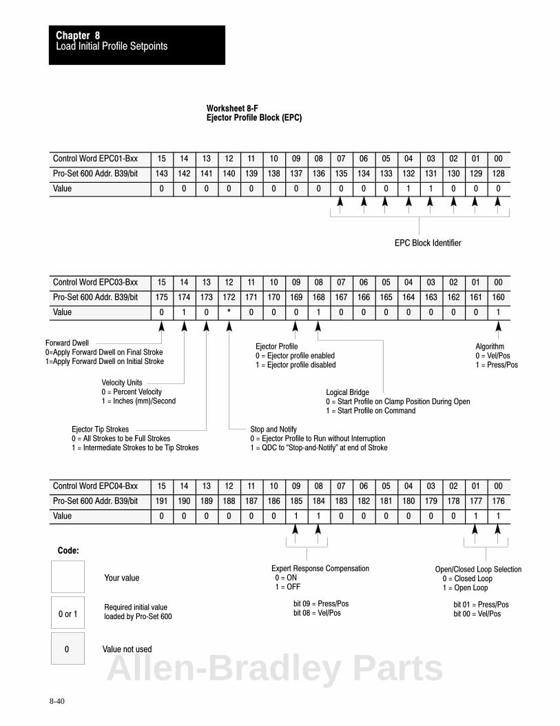
Algorithm 0 = Vel/Pos1 = Press/Pos
Logical Bridge0 = Start Profile on Clamp Position During Open1 = Start Profile on Command
Stop and Notify0 = Ejector Profile to Run without Interruption1 = QDC to �Stop�and�Notify" at end of Stroke
Ejector Tip Strokes 0 = All Strokes to be Full Strokes1 = Intermediate Strokes to be Tip Strokes
EPC Block Identifier
Expert Response Compensation 0 = ON 1 = OFF
bit 09 = Press/Pos bit 08 = Vel/Pos
Open/Closed Loop Selection 0 = Closed Loop 1 = Open Loop
bit 01 = Press/Posbit 00 = Vel/Pos
Forward Dwell0=Apply Forward Dwell on Final Stroke1=Apply Forward Dwell on Initial Stroke
Velocity Units 0 = Percent Velocity1 = Inches (mm)/Second
Ejector Profile0 = Ejector profile enabled1 = Ejector profile disabled
Code:
Your value
0 or 1Required initial valueloaded by Pro�Set 600
Value not used0
Load Initial Profile SetpointsChapter 8
8-40
Worksheet 8�FEjector Profile Block (EPC)
Control Word EPC01�Bxx 15 14 13 12 11 10 09 08 07 06 05 04 03 02 01 00
Pro�Set 600 Addr. B39/bit 143 142 141 140 139 138 137 136 135 134 133 132 131 130 129 128
Value 0 0 0 0 0 0 0 0 0 0 0 1 1 0 0 0
Control Word EPC03�Bxx 15 14 13 12 11 10 09 08 07 06 05 04 03 02 01 00
Pro�Set 600 Addr. B39/bit 175 174 173 172 171 170 169 168 167 166 165 164 163 162 161 160
Value 0 1 0 * 0 0 0 1 0 0 0 0 0 0 0 1
Control Word EPC04�Bxx 15 14 13 12 11 10 09 08 07 06 05 04 03 02 01 00
Pro�Set 600 Addr. B39/bit 191 190 189 188 187 186 185 184 183 182 181 180 179 178 177 176
Value 0 0 0 0 0 0 1 1 0 0 0 0 0 0 1 1
Allen-Bradley Parts
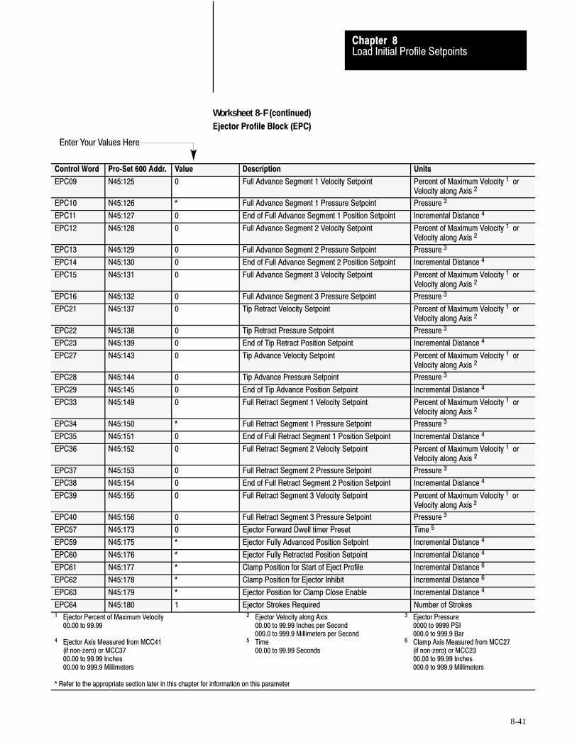
Enter Your Values Here
Load Initial Profile SetpointsChapter 8
8-41
Worksheet 8-�F (continued)
Ejector Profile Block (EPC)
Control Word Pro�Set 600 Addr. Value Description Units
EPC09 N45:125 0 Full Advance Segment 1 Velocity Setpoint Percent of Maximum Velocity 1 orVelocity along Axis 2
EPC10 N45:126 * Full Advance Segment 1 Pressure Setpoint Pressure 3
EPC11 N45:127 0 End of Full Advance Segment 1 Position Setpoint Incremental Distance 4
EPC12 N45:128 0 Full Advance Segment 2 Velocity Setpoint Percent of Maximum Velocity 1 orVelocity along Axis 2
EPC13 N45:129 0 Full Advance Segment 2 Pressure Setpoint Pressure 3
EPC14 N45:130 0 End of Full Advance Segment 2 Position Setpoint Incremental Distance 4
EPC15 N45:131 0 Full Advance Segment 3 Velocity Setpoint Percent of Maximum Velocity 1 orVelocity along Axis 2
EPC16 N45:132 0 Full Advance Segment 3 Pressure Setpoint Pressure 3
EPC21 N45:137 0 Tip Retract Velocity Setpoint Percent of Maximum Velocity 1 orVelocity along Axis 2
EPC22 N45:138 0 Tip Retract Pressure Setpoint Pressure 3
EPC23 N45:139 0 End of Tip Retract Position Setpoint Incremental Distance 4
EPC27 N45:143 0 Tip Advance Velocity Setpoint Percent of Maximum Velocity 1 orVelocity along Axis 2
EPC28 N45:144 0 Tip Advance Pressure Setpoint Pressure 3
EPC29 N45:145 0 End of Tip Advance Position Setpoint Incremental Distance 4
EPC33 N45:149 0 Full Retract Segment 1 Velocity Setpoint Percent of Maximum Velocity 1 orVelocity along Axis 2
EPC34 N45:150 * Full Retract Segment 1 Pressure Setpoint Pressure 3
EPC35 N45:151 0 End of Full Retract Segment 1 Position Setpoint Incremental Distance 4
EPC36 N45:152 0 Full Retract Segment 2 Velocity Setpoint Percent of Maximum Velocity 1 orVelocity along Axis 2
EPC37 N45:153 0 Full Retract Segment 2 Pressure Setpoint Pressure 3
EPC38 N45:154 0 End of Full Retract Segment 2 Position Setpoint Incremental Distance 4
EPC39 N45:155 0 Full Retract Segment 3 Velocity Setpoint Percent of Maximum Velocity 1 orVelocity along Axis 2
EPC40 N45:156 0 Full Retract Segment 3 Pressure Setpoint Pressure 3
EPC57 N45:173 0 Ejector Forward Dwell timer Preset Time 5
EPC59 N45:175 * Ejector Fully Advanced Position Setpoint Incremental Distance 4
EPC60 N45:176 * Ejector Fully Retracted Position Setpoint Incremental Distance 4
EPC61 N45:177 * Clamp Position for Start of Eject Profile Incremental Distance 6
EPC62 N45:178 * Clamp Position for Ejector Inhibit Incremental Distance 6
EPC63 N45:179 * Ejector Position for Clamp Close Enable Incremental Distance 4
EPC64 N45:180 1 Ejector Strokes Required Number of Strokes1 Ejector Percent of Maximum Velocity 2 Ejector Velocity along Axis 3 Ejector Pressure
00.00 to 99.99 00.00 to 99.99 Inches per Second 0000 to 9999 PSI000.0 to 999.9 Millimeters per Second 000.0 to 999.9 Bar
4 Ejector Axis Measured from MCC41 5 Time 6 Clamp Axis Measured from MCC27(if non�zero) or MCC37 00.00 to 99.99 Seconds (if non�zero) or MCC2300.00 to 99.99 Inches 00.00 to 99.99 Inches00.00 to 999.9 Millimeters 000.0 to 999.9 Millimeters
* Refer to the appropriate section later in this chapter for information on this parameter

Load Initial Profile SetpointsChapter 8
8-42
Block Identifier (EPC01)
Bits 07-00 of this word identify it as the first word in a series used todefine the ejector profile. Pro-set 600 sets these bits to 00011000.
We recorded this value on Worksheet 8-F.
Ejector Forward Dwell (EPC03)Forward dwell stops the ejector in its full advance position to let a robotremove a part when ejectors are fully extended.
- BIT 15 selects when the QDC module starts its internal ejectorforward dwell timer:
0 = after final advance stroke1 = after initial advance stroke
We recorded the value of 0 to start forward dwell on final advancestroke.
Velocity Units(EPC03)
- BIT 14 selects units of measure for velocity values.0 = Percent velocity1 = Inches or millimeters per second
We recorded the value of 1 for units per second on Worksheet 8-F.
Type of Ejector Strokes(EPC03)
- BIT 13 selects the type of intermediate ejector strokes, if you selectmultiple strokes (EPC64 greater than one).
0 = All ejector strokes are full strokes1 = Intermediate ejector strokes are tip strokes
We recorded the value of 0 for full strokes on Worksheet 8-F.
Determine Bit Selections for Worksheet 8�F
Allen-Bradley Parts
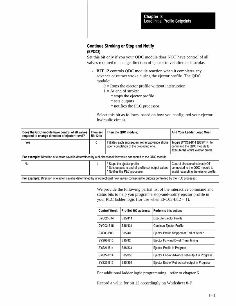
Load Initial Profile SetpointsChapter 8
8-43
Continue Stroking or Stop and Notify(EPC03)
Set this bit only if you your QDC module does NOT have control of allvalves required to change direction of ejector travel after each stroke.
- BIT 12 controls QDC module reaction when it completes anyadvance or retract stroke during the ejector profile. The QDCmodule:
0 = Runs the ejector profile without interruption1 = At end of stroke:
* stops the ejector profile* sets outputs* notifies the PLC processor
Select this bit as follows, based on how you configured your ejectorhydraulic circuit.
Does the QDC module have control of all valvesrequired to change direction of ejector travel?
Then set Bit 12 to
Then the QDC module; And Your Ladder Logic Must:
Yes 0 Initiates each subsequent retract/advance strokeupon completion of the preceding one.
Toggle DYC02�B14 (B35/414) tocommand the QDC module toexecute the entire ejector profile.
For example: Direction of ejector travel is determined by a bi�directional flow valve connected to the QDC module.
No 1 * Stops the ejector profile* Sets outputs to end�of�profile set�output values* Notifies the PLC processor
Control directional valves NOTconnected to the QDC module toassist executing the ejector profile.
For example: Direction of ejector travel is determined by uni�directional flow valves connected to outputs controlled by the PLC processor.
We provide the following partial list of the interactive command andstatus bits to help you program a stop-and-notify ejector profile inyour PLC ladder logic (for use when EPC03-B12 = 1).
Control Word: Pro�Set 600 address: Performs this action:
DYC02�B14 B35/414 Execute Ejector Profile
DYC03�B15 B35/431 Continue Ejector Profile
SYS03�B08 B35/40 Ejector Profile Stopped at End�of Stroke
SYS03�B10 B35/42 Ejector Forward Dwell Timer timing
SYS21�B14 B35/334 Ejector Profile in Progress
SYS22�B14 B35/350 Ejector End�of Advance set�output in Progress
SYS22�B15 B35/351 Ejector End�of Retract set�output in Progress
For additional ladder logic programming, refer to chapter 6.
Record a value for bit 12 accordingly on Worksheet 8-F.
Load Initial Profile SetpointsChapter 8
8-44
Enable/Disable Ejectors(EPC03)
- BIT 09 controls whether the QDC module performs any profiledejector movement. The QDC module:
0 = Executes profiled ejector movement 1 = Inhibits any profiled ejector movement
We recorded zero to enable ejector movement on Worksheet 8-F.
Logical Bridge(EPC03)
- BIT 08 controls how the QDC module starts the ejector profile:0 = upon clamp position during clamp open profiles1 = on command from the PLC processor
We recorded a 1 to start on PLC command on Worksheet 8-F.
Profile Algorithm(EPC03)
- BIT 00 selects which algorithm the QDC module uses for the ejectorprofile.
0 = Velocity vs. position algorithm1 = Pressure vs. position algorithm
We recorded a value of 1 for a pressure vs. position algorithm.
Important: All other bit selections in EPC03 should be zero.
Expert Response Compensation (EPC04)
- BITs 09 and 08 determine whether you apply Expert ResponseCompensation (ERC) to ejector profiles. ERC is an exclusivealgorithm that adjusts for changes in your machine, hydraulics, rawmaterials, and other process variables. It compensates for abruptupsets and long term deviations.
0 = Expert Response Compensation ON1 = Expert Response Compensation OFF
We recorded a value of 1 (ERC = Off) on Worksheet 8-F.
Allen-Bradley Parts
Load Initial Profile SetpointsChapter 8
8-45
Open�loop or Closed�loop Control (EPC04)
- BITs 01 and 00 determine whether you use open- or closed-loopcontrol of ejector profiles. In open loop, a valve position moves thecylinder without sensor feedback. In closed loop, sensor feedbackcontrols the valve regulating the pressure or velocity.
0 = Closed loop1 = Open loop
We recorded a value of 1 for open-loop control on Worksheet 8-A.
Important: All other bit selections in EPC04 should be zero.
The valve spanning procedures in chapter 9 require these initial bitsettings. Where required, we help you select correct final bit settings foryour application in chapter 10. For additional information, refer to thePlastic Molding Module Reference Manual (publication 1771-6.5.88)
Velocity Setpoints (EPC09, 12, 15, 21, 27, 33, 36, 39)Use these words to configure velocity vs. position profiles in units persecond. Each velocity setpoint controls the velocity of its correspondingsegment.
We recorded zero for these setpoints on Worksheet 8-F.
Pressure Setpoints (EPC10 and 34)(EPC13, 16, 22, 28, 37, and 40)Use these words to configure pressure vs. position profiles in PSI or Bar.Each pressure setpoint controls the pressure of its segment.
Configure only the 1st full advance and the 1st full retract segments for apressure vs. position profile for machine tuning in chapter 9. Do this byrecording typical pressure setpoints for normal machine operation into:
EPC10 full advance, segment 1, pressure setpoint EPC34 full retract, segment 1, pressure setpoint
We recorded zero for the other pressure setpoints on Worksheet 8-F.
Determine Word Values forWorksheet 8�F

Load Initial Profile SetpointsChapter 8
8-46
End�of�segment Position Setpoints (EPC11, 14, 23, 29, 35, 38) Use these words to configure pressure vs. position or velocity vs. positionejector profiles. Record positions in inches or millimeters. Measure eachposition setpoint from the ejector minimum software travel limit.
We recorded zero for EPC11, 14, 23, 29, 35, and 38 end-of-segmentposition setpoints on Worksheet 8-F.
The valve spanning procedures in chapter 9 require these initial values forvelocity, pressure, and end-of-segment setpoints. We help you selectcorrect final values for your application in chapter 10. For additionalinformation, refer to the Plastic Molding Module Reference Manual(publication 1771-6.5.88)
Ejector Forward Dwell Timer Preset(EPC57) The QDC module starts an internal ejector forward dwell timer dependentof EPC03-B15 (dwell on initial or final stroke).
We recorded zero for the forward dwell preset on Worksheet 8-F.
The valve spanning procedures in chapter 9 require this initial value. Foradditional information to help you select a correct final value, refer to thePlastic Molding Module Reference Manual (publication 1771-6.5.88).
Ejector Fully Advanced Position Setpoint (EPC59)This setpoint defines the ejector position when fully extended. The QDCmodule uses this position as the end-of-full-advance position setpoint. Ifreached while the QDC module is executing a full advance ejector stroke,the QDC module immediately terminates the advance stroke and checksEPC03-B12 (continue or stop/notify) to determine its next action.
To determine this position setpoint, we recommend that you jog the ejectorto its fully advanced position and observe the value in SYS28 (N40:180).Record this initial value for EPC59.
The valve spanning procedures in chapter 9 require this initial value. Foradditional information to help you select a correct final value, refer to thePlastic Molding Module Reference Manual (publication 1771-6.5.88).
Allen-Bradley Parts

Load Initial Profile SetpointsChapter 8
8-47
Ejector Fully Retracted Position Setpoint (EPC60)This setpoint defines the ejector position when fully retracted. The QDCmodule uses this position as the end-of-full-retract position setpoint. Ifreached while the QDC module is executing a full retract ejector stroke,the QDC module immediately terminates the retract stroke and checksEPC03-B12 (continue or stop/notify) to determine its next action.
To determine this position setpoint, we recommend that you jog the ejectorto its fully retracted position and observe the value in SYS28 (N40:180).Record this initial value for EPC60.
The valve spanning procedures in chapter 9 require this initial value. Foradditional information to help you select a correct final value, refer to thePlastic Molding Module Reference Manual (publication 1771-6.5.88).
Clamp Position for Start of Ejector Profile (EPC61)The QDC module uses this setpoint as the clamp position at which it startsejector movement during any clamp open profile if you configured theQDC module to start the profile on clamp position (EPC03-B08 = 0).
Record a value for EPC61 equal to the mold open position (OPC62).
The valve spanning procedures in chapter 9 require this initial value. Wehelp you select a correct final value for your application in chapter 10. Foradditional information, refer to the Plastic Molding Module ReferenceManual (publication 1771-6.5.88)
Clamp Position for Ejector Inhibit (EPC62)The QDC module uses this clamp position as protection against starting orcontinuing any ejector profile when clamp clearance is not adequate forfull ejector travel.
If the clamp position is equal to or less than this setpoint when the QDCmodule is commanded to start (or continues) an ejector profile, the QDCmodule ignores the command and sets alarm bit SYS14-B09 (B34/217).
If the clamp attains a position equal to or less than this setpoint duringexecution of an ejector profile, the QDC module sets its outputs to zeroand sets alarm bit SYS14-B09 (B34/217).
Load Initial Profile SetpointsChapter 8
8-48
To determine this clamp position, jog the clamp open and measure the gapbetween the two mold halves. When the gap equals the ejector-fully-advanced position setpoint (EPC 59), observe the position reported inSYS27 (N40:179). Record this observed position (N40:179) as your initialsetpoint for EPC62.
The valve spanning procedures in chapter 9 require this initial value. Wehelp you select a correct final value for your application in chapter 10. Foradditional information, refer to the Plastic Molding Module ReferenceManual (publication 1771-6.5.88)
Ejector Position for Clamp Close Enable (EPC63)The QDC module uses this ejector position as protection against starting orcontinuing any clamp close profile when the ejector is not safe.
If the ejector position is greater than this setpoint when the QDCmodule is commanded to start a clamp close profile, the QDC moduleignores the command and sets alarm bit SYS14/B08 (B34/216).
If the ejector attains a position greater than this setpoint duringexecution of a clamp close profile, the QDC module sets its outputs tozero and sets alarm bit SYS14-B08 (B34/216).
ATTENTION: Verify that your ejector jog pressure and flowvalues are set low enough to guard against damaging ejectorpins when advancing them against the closed clamp, next.
To determine this position (EPC63), we recommend that you jog the clampclosed until the two mold halves mate. Then jog the ejector toward its fullyadvanced position while constrained by the closed mold and observe thevalue in SYS28 (N40:180). Record this as your initial value for EPC63.
The valve spanning procedures in chapter 9 require this initial value. Wehelp you select a correct final value for your application in chapter 10. Foradditional information, refer to the Plastic Molding Module ReferenceManual (publication 1771-6.5.88)
Ejector Strokes Required (EPC64)The QDC module uses this counter preset to determine how many timesthe ejector must attain one of its advanced positions (EPC59 or EPC29)during the ejector profile before the QDC module starts the final full-retract portion of the ejector profile.
Important: A zero entry inhibits the entire ejector profile.Allen-Bradley Parts

Load Initial Profile SetpointsChapter 8
8-49
Record 1 for one ejector stroke.
The valve spanning procedures in chapter 9 require this initial value. Wehelp you select a correct final value for your application in chapter 10. Foradditional information, refer to the Plastic Molding Module ReferenceManual (publication 1771-6.5.88)
After you determine initial values and record them on Worksheet 8-F, youare ready to proceed. Refer to procedures in chapter 4 if necessary.
Important: Be sure that you do not alter any setpoints, and that you entereach and every setpoint exactly as on the worksheet.
1. Enter all worksheet values into your PLC-5 data table.
2. Download command blocks to the QDC module. We repeat EPCdownload data.
Block toDownload:
Pro�Set 600Block ID:
DownloadBit, B21/:
CompanionBlock:
EPC 24 23 none
3. Check SYS61 and SYS62 for programming errors. Correct as needed.
Enter and Download YourWorksheet Values
Chapter
9
9-1
Span Your Valves
This chapter describes how to span your valves using set-output operation,and verify valve linearity by running simple open-loop profiles.
The procedures in this chapter require the values and setpoints that yourecorded on worksheets in chapters 7 and 8.
ATTENTION: Do not attempt this chapter unless you completedall previous chapters. The results could be unpredictable machinemotion, with possible personal injury and/or equipment damage.
We describe how to span these selected valves:
low pressure close valve clamp close pressure valve clamp close velocity valve injection pressure valve injection velocity valve pack/hold pressure valve plastication pressure valve clamp open pressure valve clamp open velocity valve ejector pressure valve ejector velocity valve
We also describe how to:
test valve linearity set profile pressure alarms
You may omit parts of this chapter if either of the following applies:
If you have the manufacturer’s valve spanning data, you may omit thevalve spanning procedure in corresponding sections of this chapter.
You may omit whole sections of this chapter that do not apply to yourmachine application (see next table).
Chapter Objectives
Choose Only ApplicableValve�Spanning Procedures
Allen-Bradley Parts

Span Your ValvesChapter 9
9-2
For this Phase If Using Only this Control Then Skip the Section(s) Titled:
clamp close velocity FCC, SCC, TCC Profiles - Pressure Valves
pressure: and your valveconfiguration is the same for allfour profiles FCC, SCC, TCC, LPC
LPC Profile - Low Pressure ValveandFCC, SCC, TCC Profiles - Velocity Valve
injection velocity INC Profile - Pressure Valve
pressure INC Profile - Velocity Valve
clamp open velocity FOC, SOC, TOC, OSC Profiles - Pressure Valve
pressure FOC, SOC, TOC, OSC Profiles - Velocity Valve
ejection velocity EAC, ERC Profiles - Pressure Valves
pressure EAC, ERC Profiles - Velocity Valves
For each of the available profiles, decide which ones you will:
span for pressure control span for velocity control operate in closed loop operate in open loop not use
To assist you, we provide worksheet 9.A. Use it to select only the valve-spanning procedures required for your particular application.
Table 9.AProfiles Required for Valve Spanning
Check the boxes that apply to your application.
Profile Pressure Velocity Closed Loop Open Loop Not Used
LPC
FCC
SCC
TCC
INC
PKC
HDC
PLC
FOC
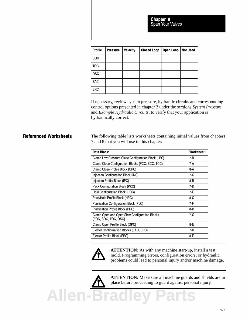
Span Your ValvesChapter 9
9-3
Profile Not UsedOpen LoopClosed LoopVelocityPressure
SOC
TOC
OSC
EAC
ERC
If necessary, review system pressure, hydraulic circuits and correspondingcontrol options presented in chapter 2 under the sections System Pressureand Example Hydraulic Circuits, to verify that your application ishydraulically correct.
The following table lists worksheets containing initial values from chapters7 and 8 that you will use in this chapter.
Data Block: Worksheet:
Clamp Low Pressure Close Configuration Block (LPC) 7�B
Clamp Close Configuration Blocks (FCC, SCC, TCC) 7�A
Clamp Close Profile Block (CPC) 8�A
Injection Configuration Block (INC) 7�C
Injection Profile Block (IPC) 8�B
Pack Configuration Block (PKC) 7�D
Hold Configuration Block (HDC) 7�E
Pack/Hold Profile Block (HPC) 8�C
Plastication Configuration Block (PLC) 7�F
Plastication Profile Block (PPC) 8�D
Clamp Open and Open Slow Configuration Blocks (FOC, SOC, TOC, OSC)
7�G
Clamp Open Profile Block (OPC) 8�E
Ejector Configuratiion Blocks (EAC, ERC) 7�H
Ejector Profile Block (EPC) 8�F
ATTENTION: As with any machine start-up, install a testmold. Programming errors, configuration errors, or hydraulicproblems could lead to personal injury and/or machine damage.
ATTENTION: Make sure all machine guards and shields are inplace before proceeding to guard against personal injury.
Referenced Worksheets
Allen-Bradley Parts

Span Your ValvesChapter 9
9-4
We recommend that you first span for optimum performance your lowpressure valve used for the LPC profile. You do this in five parts:
Confirm critical values Span your low pressure valve Test value linearity with a LPC profile Set up tonnage (hydraulic clamp) or hold pressure (toggle clamp) Set the profile pressure alarm
Important: You may omit the procedure Span your low pressure valve inthis section if the recorded valve spanning data from the manufacturer forpressure control limits LPC41-44 (chapter 7) are adequate for yourapplication.
Confirm Critical Values
Important: Confirm that your configuration values (chapter 7) and profilevalues (chapter 8) for the low pressure close profile are as follows:
On Worksheet: Confirm Your Configuration: With These Words or Bits: Pro�Set Addr.
7�D QDC module output to which you connected yourselected pressure control valve
LPC02�B06, B05, B04your selection
B37/214, 213, 212
Your unselected set�output values for outputs 1�4 LPC09�LPC12 = your values N43:185�188
All ramping is disabled with zero ramp rates LPC17�LPC20 = 0LPC25�LPC28 = 0
N43:193�196N43:201�204
Pressure limits:Minimum Control LimitMaximum Control LimitSelected Pressure Valve, Output for MinimumSelected Pressure Valve, Output for Maximum
LPC41 = 0LPC42 = your valueLPC43 = your valueLPC44 = your value
N43:217N41:218N41:219N41:220
8�A Start LPC at overrun zone CPC03�B11 = 0 B37/299
Expert Response Compensation (ERC) is disabled CPC04�B15 = 1 B37/319
Open�loop control CPC04�B07 = 1 B37/311
Pressure setpoint CPC37 = your value N43:273
Start LPC position CPC61 = your value N43:297
Mold safe position CPC62 = your value N43:298
If these are not your current values, we suggest that you correct them nowusing the download procedure discussed in chapter 4.
LPC Profile - Low Pressure Valve

Span Your ValvesChapter 9
9-5
Span Your Low Pressure Close Pressure Valve(s)
Span your clamp pressure valve for smooth operation at the highest desiredLPC pressure. Do this in the following procedure by finding the optimumvalues for these words:
Minimum Pressure Control Limit LPC41 Maximum Pressure Control Limit LPC42 Selected Pressure Valve, Output for Minimum LPC43 Selected Pressure Valve, Output for Maximum LPC44
Important: If PanelView is operational for clamp profiles, use it to:
observe actuals change and download setpoints run profiles
Important: We suggest that you read this procedure before starting.
ATTENTION: As with any machine start-up, make sure youinstalled a test mold in the machine. Programming errors,configuration errors, or hydraulic problems could lead topersonal injury and/or machine damage.
ATTENTION: Be sure all machine guards and shields are inplace before proceeding to guard against personal injury.
1. Jog your clamp to the full close position (mold halves mated).
2. Align all other machine hydraulics to simulate low pressure close.For example, shut off applicable pumps and align applicable valves.
3. Copy initial values from LPC09-12 into DYC09-12 (N40:121-124 ofyour PLC-5 data table) with this exception:
Important: Enter a value corresponding to zero pressure into the wordDYC09-12 (N40:121-124) for output 1, 2, 3, or 4 that drives the selectedclamp LPC valve.
ATTENTION: A value of 0 does not always correspond to zeropressure or flow. For example, a bi-directional valve requires aset-output value of 50% (5000) to obtain 0 PSI. Valve spools oramplifier electronics may also allow pressure or flow at 0 volts.
Allen-Bradley Parts

Span Your ValvesChapter 9
9-6
4. Enable set-output by changing DYC01-B08 (B34/392) to 1. Thisforces the QDC module to apply the values in DYC09-12 directly toits outputs 1-4, respectively.
5. Adjust the set-output value DYC09-12 (N40:121-124) thatcorresponds to the selected clamp LPC valve, and observe thepressure reported in SYS26 (N40:178).
For a bi-directional valve with a spool offset:If this pressure is greater than zero, adjust the set-output value tothe clamp LPC valve to obtain zero pressure. Stop the adjustmentswhen you observe the smallest pressure attainable.
For a uni-directional valve with no response at low signal level:If this pressure is zero, adjust the set-output value to the clamppressure valve until the observed pressure just exceeds zero. Thenre-adjust this value until you just observe zero again.
For a uni-directional valve with a pressure actual greater thanzero but with zero output to the valve: This is lowest pressure.
6. Once you are satisfied that you obtained the lowest possible pressureor the highest possible signal at zero pressure, copy the pressureobserved in SYS26 (N40:178) into LPC41 (N43:217), the LPCminimum control limit.
7. While maintaining this minimum pressure, observe the actualset-output value in SYS41-44 (N40:193-196) that corresponds to yourclamp LPC valve. Copy this value into LPC43 (N43:219), theselected LPC valve, output for minimum.
8. Change the set-output value in DYC09-12 (N40:121-124) thatcorresponds to the clamp LPC valve in 5% steps while observing thepressure in SYS26 (N40:178). Stop adjusting it when the observedpressure is equal to the maximum LPC pressure that you run on thismachine. In most cases, this value is substantially less that themaximum obtainable system pressure.
9. Copy this observed maximum LPC pressure from SYS26 (N40:178)into LPC42 (N43:218), the maximum LPC control limit.
10. While maintaining this maximum LPC pressure, observe the actualset-output value in SYS41-44 (N40:193-196) that corresponds to yourselected clamp LPC valve. Copy this value into LPC44 (N43:220),the selected LPC valve, output for maximum.
11. Lower the set-output value in DYC09-12 corresponding to theselected clamp LPC valve to a safe level.
12. Disable set-output operation. Toggle DYC01-B08 (B34/392) to 0.
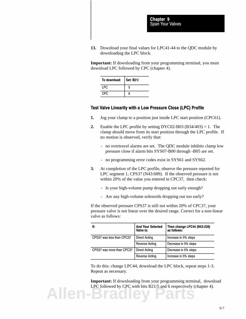
Span Your ValvesChapter 9
9-7
13. Download your final values for LPC41-44 to the QDC module bydownloading the LPC block.
Important: If downloading from your programming terminal, you mustdownload LPC followed by CPC (chapter 4).
To download: Set: B21/
LPC 5
CPC 6
Test Valve Linearity with a Low Pressure Close (LPC) Profile
1. Jog your clamp to a position just inside LPC start position (CPC61).
2. Enable the LPC profile by setting DYC02-B03 (B34/403) = 1. Theclamp should move from its start position through the LPC profile. Ifno motion is observed, verify that:
- no overtravel alarms are set. The QDC module inhibits clamp lowpressure close if alarm bits SYS07-B00 through -B05 are set.
- no programming error codes exist in SYS61 and SYS62.
3. At completion of the LPC profile, observe the pressure reported forLPC segment 1, CPS37 (N43:689). If the observed pressure is notwithin 20% of the value you entered in CPC37, then check:
- Is your high-volume pump dropping out early enough?
- Are any high-volume solenoids dropping out too early?
If the observed pressure CPS37 is still not within 20% of CPC37, yourpressure valve is not linear over the desired range. Correct for a non-linearvalve as follows:
If: And Your SelectedValve is:
Then change LPC44 (N43:220)as follows:
CPS37 was less than CPC37 Direct Acting Increase in 5% steps
Reverse Acting Decrease in 5% steps
CPS37 was more than CPC37 Direct Acting Decrease in 5% steps
Reverse Acting Increase in 5% steps
To do this: change LPC44, download the LPC block, repeat steps 1-3.Repeat as necessary.
Important: If downloading from your programming terminal, downloadLPC followed by CPC with bits B21/5 and 6 respectively (chapter 4).
Allen-Bradley Parts

Span Your ValvesChapter 9
9-8
What You Have Accomplished
The valve spanning procedure you just completed has defined the:
range of pressure available during low pressure close
end-of-range maximum and minimum signal levels for linear control ofthe clamp LPC valve in open-loop control
For thisrange limit
When trying to obtainthe pressure in:
The QDC module drives the selectedpressure valve to % output signal in:
Minimum LPC41 LPC43
Maximum LPC42 LPC44
Now for the open-loop LPC profile, the QDC module assumes a linearrelationship between LPC clamp pressure and signal output.
Set Tonnage on Hydraulic Clamps or Hold Pressure on Toggle Clamps
Once the clamp has completed low pressure close, use the LPCend-of-profile set-output values to:
build tonnage on your hydraulic clamp lock up your toggle clamp
1. Jog your clamp to the full close position (mold halves mated).
2. Enter a value corresponding to minimum pressure into the set-outputword DYC09-12 (N40:121-124) that corresponds to your clamp-tonnage or lock-up pressure valve.
3. Copy the other three set-output values from LPC33-36(N43:209-212) to DYC09-12 (N40:121-124), values that you wouldnormally use during tonnage (or lock up).
ATTENTION: A value of 0 entered in your data table does notnecessarily correspond to zero pressure or flow. For example, abi-directional valve would require a set-output value of 50%(5000) to obtain 0 PSI. Amplifier electronics or valve spoolsmay also allow pressure or flow at 0 volts signal input.
4. Align all other machine hydraulics to simulate clamp tonnage orlock-up for a toggle clamp. For example, enable required pumps andalign required valves.
5. Enable set-output by transitioning DYC01-B08 (B34/392) to 1.
Span Your ValvesChapter 9
9-9
6. Change the set-output word DYC09-12 (N40:121-124) correspondingto your clamp tonnage (lock-up) pressure valve in 5% incrementswhile observing clamp pressure in SYS26 (N40:178). Stop changingit when the observed clamp pressure equals the desired tonnagepressure. If you cannot reach the desired pressure, verify that theother three set-output values are correct.
7. Copy the resultant set-output values from DYC09-12 (N40:121-124)into LPC33-36 (N43:209-212). The QDC module will apply thesevalues to the valves when the clamp completes low pressure close.
8. Disable set-output by transitioning DYC01-B08 (B34/392) to 0.
9. Enter the desired tonnage pressure for your machine (step 6) into thetonnage complete pressure setpoint CPC63 (N43:299).
10. Download your changes in LPC and CPC to the QDC module.
Important: If downloading from your programming terminal, downloadLPC followed by CPC with download bits B21/5 and 6 (chapter 4).
Set the Profile Pressure Alarm
Set your clamp LPC maximum pressure alarm LPC57 (N43:233) to apressure that should:
not be exceeded during the clamp close profile not exceed the maximum pressure control limit LPC42 (N43:218)
Entering a value of zero disables this alarm.
Download the alarm setpoint to the QDC by downloading the LPC block.
Important: If downloading from your programming terminal, downloadLPC followed by CPC with download bits B21/5 and 6 (chapter 4).
Allen-Bradley Parts
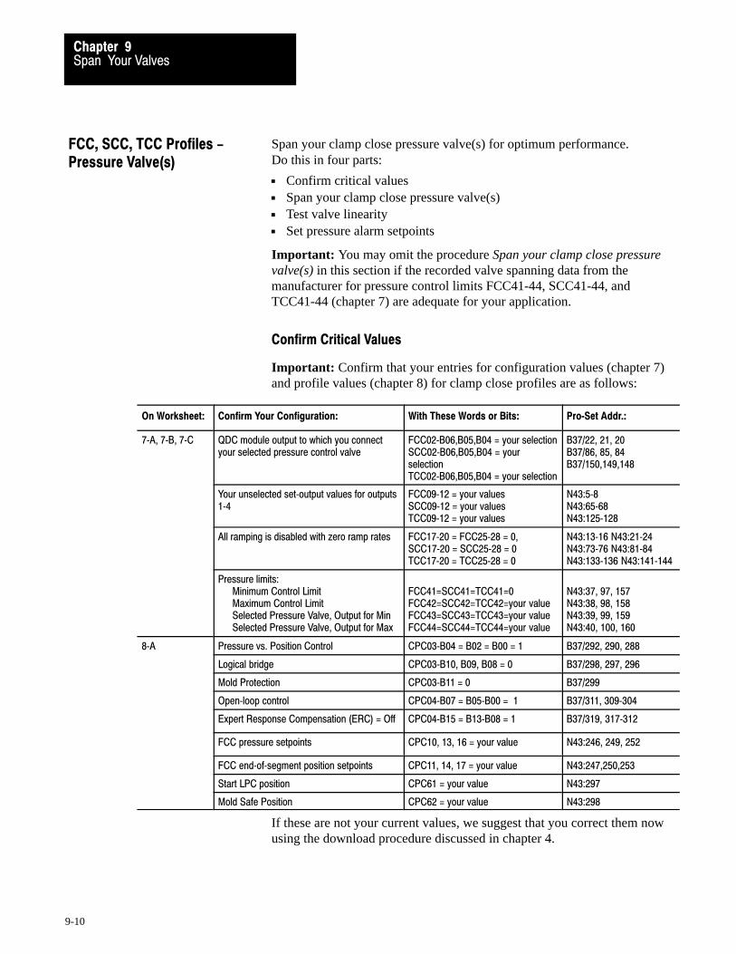
Span Your ValvesChapter 9
9-10
Span your clamp close pressure valve(s) for optimum performance. Do this in four parts:
Confirm critical values Span your clamp close pressure valve(s) Test valve linearity Set pressure alarm setpoints
Important: You may omit the procedure Span your clamp close pressurevalve(s) in this section if the recorded valve spanning data from themanufacturer for pressure control limits FCC41-44, SCC41-44, andTCC41-44 (chapter 7) are adequate for your application.
Confirm Critical Values
Important: Confirm that your entries for configuration values (chapter 7)and profile values (chapter 8) for clamp close profiles are as follows:
On Worksheet: Confirm Your Configuration: With These Words or Bits: Pro�Set Addr.:
7�A, 7�B, 7�C QDC module output to which you connectyour selected pressure control valve
FCC02�B06,B05,B04 = your selectionSCC02�B06,B05,B04 = yourselectionTCC02�B06,B05,B04 = your selection
B37/22, 21, 20B37/86, 85, 84B37/150,149,148
Your unselected set�output values for outputs1�4
FCC09�12 = your values SCC09�12 = your values TCC09�12 = your values
N43:5�8N43:65�68N43:125�128
All ramping is disabled with zero ramp rates FCC17�20 = FCC25�28 = 0, SCC17�20 = SCC25�28 = 0 TCC17�20 = TCC25�28 = 0
N43:13�16 N43:21�24N43:73�76 N43:81�84N43:133�136 N43:141�144
Pressure limits:Minimum Control LimitMaximum Control LimitSelected Pressure Valve, Output for MinSelected Pressure Valve, Output for Max
FCC41=SCC41=TCC41=0FCC42=SCC42=TCC42=your valueFCC43=SCC43=TCC43=your valueFCC44=SCC44=TCC44=your value
N43:37, 97, 157N43:38, 98, 158N43:39, 99, 159N43:40, 100, 160
8�A Pressure vs. Position Control CPC03�B04 = B02 = B00 = 1 B37/292, 290, 288
Logical bridge CPC03�B10, B09, B08 = 0 B37/298, 297, 296
Mold Protection CPC03�B11 = 0 B37/299
Open�loop control CPC04�B07 = B05�B00 = 1 B37/311, 309�304
Expert Response Compensation (ERC) = Off CPC04�B15 = B13�B08 = 1 B37/319, 317�312
FCC pressure setpoints CPC10, 13, 16 = your value N43:246, 249, 252
FCC end�of�segment position setpoints CPC11, 14, 17 = your value N43:247,250,253
Start LPC position CPC61 = your value N43:297
Mold Safe Position CPC62 = your value N43:298
If these are not your current values, we suggest that you correct them nowusing the download procedure discussed in chapter 4.
FCC, SCC, TCC Profiles -Pressure Valve(s)

Span Your ValvesChapter 9
9-11
Span Your Clamp Close Pressure Valve(s)
Span your clamp close pressure valve(s) for smooth operation at highestdesired clamp pressure. Do this by finding optimum values for:
Minimum Pressure Control Limit FCC41, SCC41, TCC41 Maximum Pressure Control Limit FCC42, SCC42, TCC42 Selected Pressure Valve, Output For Minimum FCC43, SCC43, TCC43 Selected Pressure Valve, Output For Maximum FCC44, SCC44, TCC44
Important: If your hydraulics are identical for first, second, and thirdclamp close, complete the procedure for first clamp close by finding valuesfor FCC41-44 and enter the same four values for second and third clampclose. If your hydraulics are different, repeat the procedure as needed.
Important: If PanelView is operational for clamp profiles, use it to:
observe actuals change and download setpoints run profiles
Important: We suggest that you read this procedure before starting.
ATTENTION: As with any machine start-up, install a testmold. Programming errors, configuration errors, or hydraulicproblems could lead to personal injury and/or machine damage.
ATTENTION: Be sure all machine guards and shields are inplace before proceeding to guard against personal injury.
1. Jog your clamp to the full close position (mold halves mated).
2. Align all other machine hydraulics to simulate clamp close. Forexample, enable required pumps and align required valves.
3. Copy initial values from FCC09-12 (N43:5-8) into DYC09-12(N40:121-124) of your PLC-5 data table with this exception:
Important: Enter a value corresponding to zero pressure into the wordDYC09-12 for the output that drives the selected clamp pressure valve.
ATTENTION: A value of 0 does not always correspond to zeropressure or flow. For example, a bi-directional valve requires aset-output value of 50% (5000) to obtain 0 PSI. Valve spools oramplifier electronics may also allow pressure or flow at 0 volts.
Allen-Bradley Parts

Span Your ValvesChapter 9
9-12
4. Enable set-output by changing DYC01-B08 (B34/392) from 0 to 1.This forces the QDC module to apply the values in DYC09-12directly to its outputs 1-4, respectively.
5. Adjust the set-output value DYC09-12 (N40:121-124) thatcorresponds to the selected clamp close pressure valve, and observethe pressure reported in SYS26 (N40:178).
For a bi-directional valve with a spool offset:If this pressure is greater than zero, adjust the set-output value tothe clamp close pressure valve to obtain zero pressure. Stop theadjustments when you observe the smallest pressure attainable.
For a uni-directional valve with no response at low signal level:If this pressure is zero, adjust the set-output value to the clampclose pressure valve until the observed pressure just exceeds zero.Then re-adjust this value until you just observe zero again.
For a uni-directional valve with a pressure actual greater thanzero but with zero output to the valve: This is lowest pressure.
6. Once you are satisfied that you obtained the lowest possible pressureor the highest possible signal at zero pressure, copy the pressureobserved in SYS26 (N40:178) into FCC41, SCC41, and TCC41(N43:37, N43:97, and N43:157), the clamp close minimum pressurecontrol limit.
7. While maintaining this minimum pressure, observe the actualset-output value in SYS41-44 (N40:193-196) that corresponds to yourclamp close pressure valve. Copy this value into FCC43, SCC43, andTCC43 (N43:39, 99, and 159), the selected clamp close pressurevalve output for minimum.
8. Change the set-output value in DYC09-12 (N40:121-124) thatcorresponds to the clamp close pressure valve by 50%, and then in5% steps while observing the clamp pressure in SYS26 (N40:178).Stop adjusting it when the observed pressure no longer increases withan increase in set-output value. The pressure in SYS26 (N40:178) isnow the maximum attainable clamp close pressure.
9. Copy this observed pressure from SYS26 (N40:178) into FCC42,SCC42, and TCC42 (N43:38, 98, and 158), the maximum clampclose pressure control limits.
10. While maintaining this maximum pressure, observe the actualset-output value in SYS41-44 (N40:193-196) that corresponds to yourselected clamp close pressure valve. Copy this value into FCC44,SCC44, and TCC44 (N43:40, 100, and 160), the selected clamp closepressure valve, output for maximum.

Span Your ValvesChapter 9
9-13
11. Lower the set-output value in DYC09-12 corresponding to theselected clamp close pressure valve to a safe level.
12. Disable set-output operation. Toggle DYC01-B08 (B34:392) to 0.
13. Download your changes in FCC, SCC, and TCC to the QDC module.
Important: If downloading from your programming terminal, downloadFCC, SCC, TCC, and CPC in that order (chapter 4).
To download Set B21/
FCC 2
SCC 3
TCC 4
CPC 6
Test Valve Linearity with a Clamp Close Pressure Profile
1. Jog your clamp to the full open position.
2. Enable the first clamp close profile by setting DYC02-B00 (B34/400)to 1. The clamp should move from its start position through clampclose and low pressure close profiles. If no motion, verify that:
- no clamp overtravel alarms are set. The QDC module inhibitsclamp close if SYS07-B00 through -B05 are set
- no programming error codes exist in SYS61 and SYS62
3. At completion of clamp close, observe the pressure reported for firstclamp close segment 2 CPS13 (N43:665). If it is not approximatelyequal to the setpoint you entered in CPC13, then check:
- was your valve and solenoid alignment the same for clamp closeprofile execution and clamp close action in set-output?
If the observed pressure CPS13 is still not within 20% of CPC13, yourpressure valve is not linear over the desired range. Correct as follows:
If: And Your SelectedValve is:
Then change FCC44 (N43:40) as follows:
CPS13 was less than CPC13 Direct Acting Increase in 5% steps
Reverse Acting Decrease in 5% steps
CPS13 was more thanCPC13
Direct Acting Decrease in 5% steps
Reverse Acting Increase in 5% steps
Allen-Bradley Parts

Span Your ValvesChapter 9
9-14
To do this: change FCC44, download the FCC block, and repeat steps 1-3.Repeat as necessary.
Important: If downloading from your programming terminal, downloadFCC followed by CPC with download bits B21/2 and 6 (chapter 4).
4. Copy final FCC44 (N43:40) into SCC44 and TCC44 (N43:100 and160) and download these changes to the QDC module.
Important: If downloading from your programming terminal, downloadFCC, SCC, TCC, and CPC in that order with download bits B21/2, 3, 4,and 6 respectively (chapter 4).
What You Have Accomplished
The valve spanning procedure you just completed has defined the:
range of pressure available during first, second and third clamp close
end-of-range maximum and minimum signal levels for linear control ofthe clamp close pressure valve in open-loop control.
For thisrange limit
When trying to obtainthe pressure in:
The QDC module drives the selectedpressure valve to % output signal in:
Minimum FCC41, SCC41, TCC41 FCC43, SCC43, TCC43
Maximum FCC42, SCC42, TCC42 FCC44, SCC44, TCC44
Now for all open-loop clamp close pressure profiles, the QDC moduleassumes a linear relationship between clamp pressure and signal output.
Set Profile Pressure Alarms
For clamp close profiles, set your maximum pressure alarms FCC57,SCC57, and TCC57 (N43:53, 113, and 173) to a pressure that should:
not be exceeded during the clamp close profile not exceed the maximum pressure control limit FCC42, SCC42, TCC42
Entering a value of zero disables this alarm.
Send new values to QDC module by downloading FCC, SCC, and TCC.
Important: If downloading from your programming terminal, downloadFCC, SCC, TCC, and CPC in that order with download bits B21/2, 3, 4,and 6 respectively (chapter 4).
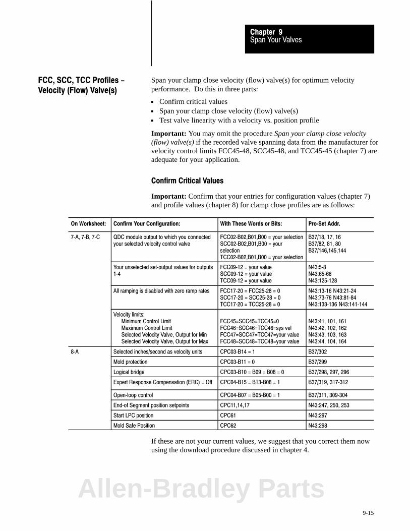
Span Your ValvesChapter 9
9-15
Span your clamp close velocity (flow) valve(s) for optimum velocityperformance. Do this in three parts:
Confirm critical values Span your clamp close velocity (flow) valve(s) Test valve linearity with a velocity vs. position profile
Important: You may omit the procedure Span your clamp close velocity(flow) valve(s) if the recorded valve spanning data from the manufacturer forvelocity control limits FCC45-48, SCC45-48, and TCC45-45 (chapter 7) areadequate for your application.
Confirm Critical Values
Important: Confirm that your entries for configuration values (chapter 7)and profile values (chapter 8) for clamp close profiles are as follows:
On Worksheet: Confirm Your Configuration: With These Words or Bits: Pro�Set Addr.
7�A, 7�B, 7�C QDC module output to which you connectedyour selected velocity control valve
FCC02�B02,B01,B00 = your selectionSCC02�B02,B01,B00 = yourselectionTCC02�B02,B01,B00 = your selection
B37/18, 17, 16B37/82, 81, 80B37/146,145,144
Your unselected set�output values for outputs1�4
FCC09�12 = your valueSCC09�12 = your valueTCC09�12 = your value
N43:5�8N43:65�68N43:125�128
All ramping is disabled with zero ramp rates FCC17�20 = FCC25�28 = 0SCC17�20 = SCC25�28 = 0TCC17�20 = TCC25�28 = 0
N43:13�16 N43:21�24N43:73�76 N43:81�84N43:133�136 N43:141�144
Velocity limits:Minimum Control LimitMaximum Control LimitSelected Velocity Valve, Output for MinSelected Velocity Valve, Output for Max
FCC45=SCC45=TCC45=0FCC46=SCC46=TCC46=sys velFCC47=SCC47=TCC47=your valueFCC48=SCC48=TCC48=your value
N43:41, 101, 161N43:42, 102, 162N43:43, 103, 163N43:44, 104, 164
8�A Selected inches/second as velocity units CPC03�B14 = 1 B37/302
Mold protection CPC03�B11 = 0 B37/299
Logical bridge CPC03�B10 = B09 = B08 = 0 B37/298, 297, 296
Expert Response Compensation (ERC) = Off CPC04�B15 = B13�B08 = 1 B37/319, 317�312
Open�loop control CPC04�B07 = B05�B00 = 1 B37/311, 309�304
End�of Segment position setpoints CPC11,14,17 N43:247, 250, 253
Start LPC position CPC61 N43:297
Mold Safe Position CPC62 N43:298
If these are not your current values, we suggest that you correct them nowusing the download procedure discussed in chapter 4.
FCC, SCC, TCC Profiles -Velocity (Flow) Valve(s)
Allen-Bradley Parts
Span Your ValvesChapter 9
9-16
Span Your Clamp Close Velocity Valve(s)
Span your clamp close velocity valve(s) for smooth operation at highestdesired clamp velocity. Do this in the following procedure by findingoptimum values for:
Minimum Pressure Control Limit FCC45, SCC45, TCC45 Maximum Pressure Control Limit FCC46, SCC46, TCC46 Selected Pressure Valve, Output For Minimum FCC47, SCC47, TCC47 Selected Pressure Valve, Output For Maximum FCC48, SCC48, TCC48
Important: If your hydraulics are identical for first, second, and thirdclamp close, complete the procedure for first clamp close by finding valuesfor FCC45-48 and enter the same four values for second and third clampclose, SSC45-48 and TCC45-48. If your hydraulics are different, repeatthe procedure as needed.
Important: If PanelView is operational for clamp profiles, use it to:
observe actuals change and download setpoints run profiles
Important: We suggest that you read this procedure before starting.
ATTENTION: As with any machine start-up, install a testmold. Programming errors, configuration errors, or hydraulicproblems could lead to personal injury and/or machine damage.
ATTENTION: Be sure all machine guards and shields are inplace before proceeding to guard against personal injury.
1. Obtain a copy of the flow rate curves provided by your flow valvemanufacturer. The flow rate curves graphically illustrate the flowthrough a valve at different voltage or input current levels and atdifferent pressure drops across the valve’s spool.
2. From the above curves, determine the minimum and maximum clampclose flows available from your flow valve at the pressure you wouldnormally run during clamp close operation. Record these flows,along with the input voltages/current associated with them.
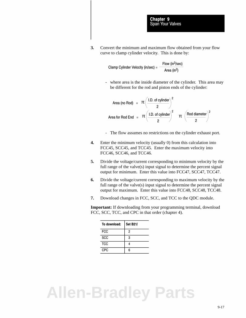
Span Your ValvesChapter 9
9-17
3. Convert the minimum and maximum flow obtained from your flowcurve to clamp cylinder velocity. This is done by:
Clamp Cylinder Velocity (in/sec) =Flow (in3/sec)
Area (in2)
- where area is the inside diameter of the cylinder. This area maybe different for the rod and piston ends of the cylinder:
Area for Rod End =I.D. of cylinder
2
Rod diameter
2π
22
Area (no Rod) =I.D. of cylinder
2π
2
π
- The flow assumes no restrictions on the cylinder exhaust port.
4. Enter the minimum velocity (usually 0) from this calculation intoFCC45, SCC45, and TCC45. Enter the maximum velocity intoFCC46, SCC46, and TCC46.
5. Divide the voltage/current corresponding to minimum velocity by thefull range of the valve(s) input signal to determine the percent signaloutput for minimum. Enter this value into FCC47, SCC47, TCC47.
6. Divide the voltage/current corresponding to maximum velocity by thefull range of the valve(s) input signal to determine the percent signaloutput for maximum. Enter this value into FCC48, SCC48, TCC48.
7. Download changes in FCC, SCC, and TCC to the QDC module.
Important: If downloading from your programming terminal, downloadFCC, SCC, TCC, and CPC in that order (chapter 4).
To download: Set B21/
FCC 2
SCC 3
TCC 4
CPC 6
Allen-Bradley Parts
Span Your ValvesChapter 9
9-18
Test Valve Linearity with a Velocity Profile
1. Select velocity vs. position control for the entire clamp closeoperation by resetting the following bits to zero:
CPC03-B00 (B37/288) CPC03-B02 (B37/290) CPC03-B04 (B37/292)
2. Download the CPC block to the QDC module.
Important: If downloading from your programming terminal, downloadCPC by setting B21/6 (chapter 4).
3. Jog your clamp to the full open position.
4. Enable first clamp close by setting DYC02-B00 (B34/400) to 1. Theclamp should move from its start position through the first clampclose and low pressure close profiles. If no motion, verify that:
- no overtravel alarms are set. The QDC module inhibits clampclose if SYS07-B00 through -B05 are set
- no programming error codes exist in SYS61 and SYS62
5. Upon completion of clamp close, observe the velocity reported for 1stclamp close segment 2 CPS12 (N43:664). This velocity should berelatively close to the setpoint you entered in CPC12 (N43:248). Ifthe observed velocity is not within 25% of the setpoint, verify that:
- the values from your flow rate curves are correct
- your calculations are correct
If the observed velocity CPS12 is still not within 25% of CPC12, yourflow valve is not linear over the desired range. Correct as follows:
If: And Your SelectedValve is:
Then change FCC48 (N43:44) as follows:
CPS12 was less than CPC12 Direct Acting Increase in 5% steps
Reverse Acting Decrease in 5% steps
CPS12 was more thanCPC12
Direct Acting Decrease in 5% steps
Reverse Acting Increase in 5% steps
To do this: change FCC48, download the FCC block, and repeat steps 3-5.Repeat as necessary.
6. Copy final FCC48 (N43:44) into SCC48 and TCC48 (N43:104 and164), and download these changes to the QDC module.

Span Your ValvesChapter 9
9-19
Important: If downloading from your programming terminal, downloadFCC, SCC, and/or TCC followed by CPC (chapter 4).
To download: Set B21/
FCC 2
SCC 3
TCC 4
CPC 6
What You Have Accomplished
The valve spanning procedure you just completed has defined the:
range of velocity available during any clamp close profile
end-of-range maximum and minimum signal levels for linear control ofthe clamp velocity valve in open-loop control.
For thisrange limit
When trying to obtainthe velocity in:
The QDC module drives the selectedvelocity valve to % output signal in:
Minimum FCC45, SCC45, TCC45 FCC47, SCC47, TCC47
Maximum FCC46, SCC46, TCC46 FCC48, SCC48, TCC48
Now for all open-loop velocity profiles for clamp close, the QDC moduleassumes a linear relationship between clamp velocity and signal output.
Allen-Bradley Parts
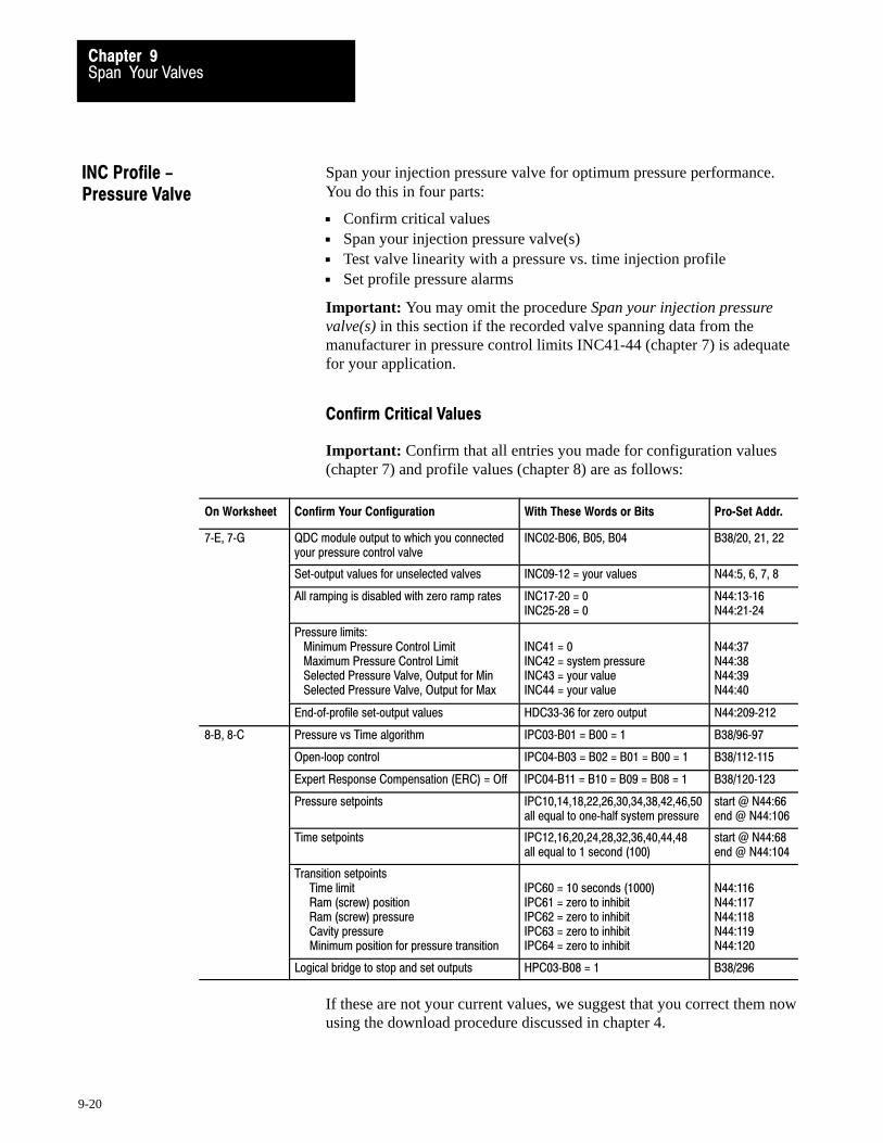
Span Your ValvesChapter 9
9-20
Span your injection pressure valve for optimum pressure performance.You do this in four parts:
Confirm critical values Span your injection pressure valve(s) Test valve linearity with a pressure vs. time injection profile Set profile pressure alarms
Important: You may omit the procedure Span your injection pressurevalve(s) in this section if the recorded valve spanning data from themanufacturer in pressure control limits INC41-44 (chapter 7) is adequatefor your application.
Confirm Critical Values
Important: Confirm that all entries you made for configuration values(chapter 7) and profile values (chapter 8) are as follows:
On Worksheet Confirm Your Configuration With These Words or Bits Pro�Set Addr.
7�E, 7�G QDC module output to which you connectedyour pressure control valve
INC02�B06, B05, B04 B38/20, 21, 22
Set�output values for unselected valves INC09�12 = your values N44:5, 6, 7, 8
All ramping is disabled with zero ramp rates INC17�20 = 0INC25�28 = 0
N44:13�16N44:21�24
Pressure limits: Minimum Pressure Control Limit Maximum Pressure Control Limit Selected Pressure Valve, Output for Min Selected Pressure Valve, Output for Max
INC41 = 0INC42 = system pressureINC43 = your value INC44 = your value
N44:37N44:38N44:39N44:40
End�of�profile set�output values HDC33�36 for zero output N44:209�212
8�B, 8�C Pressure vs Time algorithm IPC03�B01 = B00 = 1 B38/96�97
Open�loop control IPC04�B03 = B02 = B01 = B00 = 1 B38/112�115
Expert Response Compensation (ERC) = Off IPC04�B11 = B10 = B09 = B08 = 1 B38/120�123
Pressure setpoints IPC10,14,18,22,26,30,34,38,42,46,50all equal to one�half system pressure
start @ N44:66end @ N44:106
Time setpoints IPC12,16,20,24,28,32,36,40,44,48all equal to 1 second (100)
start @ N44:68end @ N44:104
Transition setpoints Time limit Ram (screw) position Ram (screw) pressure Cavity pressure Minimum position for pressure transition
IPC60 = 10 seconds (1000)IPC61 = zero to inhibitIPC62 = zero to inhibitIPC63 = zero to inhibitIPC64 = zero to inhibit
N44:116N44:117N44:118N44:119N44:120
Logical bridge to stop and set outputs HPC03�B08 = 1 B38/296
If these are not your current values, we suggest that you correct them nowusing the download procedure discussed in chapter 4.
INC Profile -Pressure Valve
Span Your ValvesChapter 9
9-21
Span Your Injection Pressure Valve
Span your injection valve for smooth operation at highest desired pressure.Do this in the following procedure by finding the optimum values for:
Minimum Pressure Control Limit INC41 (N44:37) Maximum Pressure Control Limit INC42 (N44:38) Selected Pressure Valve, Output for Minimum INC43 (N44:39) Selected Pressure Valve, Output for Maximum INC44 (N44:40)
Important: If PanelView is operational for injection profiles, use it to:
observe actuals change and download setpoints run profiles
Important: We suggest that you read this procedure before starting.
ATTENTION: As with any machine start-up, install a testmold. Programming errors, configuration errors, or hydraulicproblems could lead to personal injury and/or machine damage.
ATTENTION: Be sure all machine guards and shields are inplace before proceeding to guard against personal injury.
1. Manually jog your ram (screw) to the mold-end position so you canexert maximum pressure against the nozzle tip.
2. Align all other machine hydraulics to simulate injection: enablepumps and align valves to their normal injection state.
3. Copy initial values INC09-12 (N44:5-8) into DYC09-12(N40:121-124) of your PLC-5 data table with this exception:
Important: Enter a value corresponding to zero pressure into the wordDYC09-12 (N40:121-124) for output 1, 2, 3, or 4 that drives the selectedclamp pressure valve.
ATTENTION: A value of 0 does not always correspond to zeropressure or flow. For example, a bi-directional valve requires aset-output value of 50% (5000) to obtain 0 PSI. Valve spools oramplifier electronics may also allow pressure or flow at 0 volts.
Allen-Bradley Parts

Span Your ValvesChapter 9
9-22
4. Enable set-output by changing DYC01-B08 (B34/392) from 0 to 1.This forces the QDC module to apply the values in DYC09-12directly to its outputs 1-4, respectively.
5. Adjust the set-output value DYC09-12 (N40:121-124) thatcorresponds to the selected ram (screw) pressure valve, and observeactual pressure reported in SYS26 (N40:178).
For a bi-directional valve with a spool offset:If this pressure is greater than zero, adjust the set-output value tothe ram (screw) pressure valve to obtain zero pressure. Stop theadjustments when you observe the smallest pressure attainable.
For a uni-directional valve with no response at low signal level:If this pressure is zero, adjust the set-output value to the ram(screw) pressure valve until the observed pressure just exceedszero. Then re-adjust this value until you just observe zero again.
For a uni-directional valve with a pressure actual greater thanzero but with zero output to the valve: This is lowest pressure.
6. Once satisfied that you obtained the lowest possible pressure or thehighest possible signal at zero pressure, copy the pressure observed inSYS26 into INC41 (N44:37), the minimum pressure control limit.
7. While maintaining this minimum pressure, observe the actualset-output value in SYS41-44, (N40:193-196) that corresponds toyour ram (screw) pressure valve. Copy this value into INC43(N44:39), the selected pressure valve output for minimum.
8. Modify the value in DYC09-12 (N40:121-124) that corresponds tothe ram (screw) pressure valve in 5% steps while observing risingpressure in SYS26 (N40:178). Stop adjusting it when the observedpressure no longer increases with a change in the set-output value.Now the pressure in SYS26 is the maximum obtainable pressure.
9. Copy the pressure observed in SYS26 (N40:178) into INC42(N44:38), the maximum pressure control limit.
10. While maintaining this maximum pressure, observe the actualset-output value in SYS41-44 (N40:193-196) that corresponds to yourram (screw) pressure valve. Copy this value into INC44 (N44:40),the selected pressure valve output for maximum.
11. Disable set-output operation. Toggle DYC01-B08 (B34/392) to 0.
12. Download your final values for INC41-44 to the QDC module.
Important: If downloading from your programming terminal, downloadINC followed by IPC with download bits B21/7 and 8 (chapter 4).

Span Your ValvesChapter 9
9-23
Test Valve Linearity with a Pressure vs. Time Injection Profile
1. Confirm that your pressure setpoints are equal to one-half systempressure in IPC10, 14, 18, 22, 26, 30, 34, 38, 42, 46, and 50 (N44:66, 70, 74, 78, 82, 86, 90, 94, 98, 102, 106).
If not, correct them and download them to the QDC module. Forinstructions, refer to chapter 4.
2. Check that the ram (screw) is still at the mold-end position.
3. Run a pressure vs. time injection profile by toggling DYC02-B04(B34/404) from 0 to 1 to 0. The ram (screw) remains fixed so it canexert pressure against the nozzle tip. If no pressure, verify that:
- no overtravel alarms are set. The QDC module inhibits injectionprofiles if alarm bits SYS07-B00 through -B05 are set.
- no programming error codes exist in SYS61 and SYS62.
4. The QDC module automatically runs injection, pack, and holdprofiles in succession. At completion, observe the pressures reportedfor the middle segments in IPS22, 26, 30, and 34 (N44:614, 618, 622,and 626). If the observed pressures are not within 20% of thesetpoints entered in IPC22, 26, 30, and 34, then check:
- Was your valve and solenoid alignment for the injection profilethe same as for set-output ram (screw) action in the previoussection? If not the same, correct and repeat steps 3 and 4.
5. If the observed actual pressures IPS22, 26, 30, and 34 are still notwithin 20% of IPC22, 26, 30, and 34, your pressure valve is not linearover the desired range. Correct for a non-linear valve as follows:
If actuals are at least 20%: And Your SelectedValve is:
Then change INC44 (N44:40) asfollows:
Less than setpoints Direct Acting Increase in 5% steps
Reverse Acting Decrease in 5% steps
Greater than setpoints Direct Acting Decrease in 5% steps
Reverse Acting Increase in 5% steps
To do this: change INC44, download INC, and repeat steps 3-5. Repeat as necessary.
Important: If downloading from your programming terminal, downloadINC followed by IPC with download bits B21/7 and 8 (chapter 4).
Allen-Bradley Parts
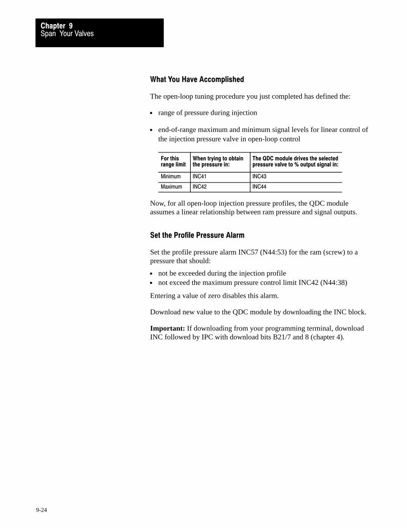
Span Your ValvesChapter 9
9-24
What You Have Accomplished
The open-loop tuning procedure you just completed has defined the:
range of pressure during injection
end-of-range maximum and minimum signal levels for linear control ofthe injection pressure valve in open-loop control
For thisrange limit
When trying to obtainthe pressure in:
The QDC module drives the selectedpressure valve to % output signal in:
Minimum INC41 INC43
Maximum INC42 INC44
Now, for all open-loop injection pressure profiles, the QDC moduleassumes a linear relationship between ram pressure and signal outputs.
Set the Profile Pressure Alarm
Set the profile pressure alarm INC57 (N44:53) for the ram (screw) to apressure that should:
not be exceeded during the injection profile not exceed the maximum pressure control limit INC42 (N44:38)
Entering a value of zero disables this alarm.
Download new value to the QDC module by downloading the INC block.
Important: If downloading from your programming terminal, downloadINC followed by IPC with download bits B21/7 and 8 (chapter 4).

Span Your ValvesChapter 9
9-25
Span your flow valve for optimum velocity performance in three parts:
Confirm critical values Span your injection flow valve Test valve linearity with a velocity vs. position profile
Important: You may omit the procedure Span your injection flow valve inthis section if the recorded valve spanning data from the manufacturer invelocity control limits INC45-48 (chapter 7) are adequate for yourapplication.
Confirm Critical Values
Confirm that all entries you made for configuration values (chapter 7) andprofile values (chapter 8) are correct for the velocity vs. position profile.
Important: Use the following configuration and profile values:
On Worksheet Confirm Your Configuration With These Words or Bits Pro�Set Addr.
7�E, 7�G QDC module output to which you connectedyour flow control valve
INC02�B02, B01, B00your selection
B38/16, 17, 18
Set�output values for outputs to unselectedvalves
INC09�12 = your values N44:5, 6, 7, 8
All ramping is disabled with zero ramp rates INC17�20 = 0INC25�28 = 0
N44:13�16N44:21�24
Velocity limits: Minimum Velocity Control Limit Maximum Velocity Control Limit Selected Velocity Valve, Output for Min Selected Velocity Valve, Output for Max
INC45 = 0INC46 = max velocity per valve specsINC47 = your valueINC48 = your value
N44:41N44:42N44:43N44:44
End�of�profile set�output values HDC33�36 for zero output N44:209�212
8�B, 8�C Velocity units are inches (mm)/sec IPC03�B14 = 1 B38/110
Open�loop control IPC04�B03 = B02 = B01 = B00 = 1 B38/112�115
Expert Response Compensation (ERC) = Off IPC04�B11 = B10 = B09 = B08 = 1 B38/120�123
Velocity setpoints IPC09,13,17,21,25,29,33,37,41,45,49all equal to max velocity per valve specs
start @ N44:65end @N44:105
End�of segment position setpoints IPC11, 15, 19, 23, 27, 31, 35, 39, 43, 47,equal segments over length of travel
start @ N44:67end @N44:103
Logical bridge to stop and set outputs HPC03�B08 = 1 B38/296
INC Profile -Velocity Valve
Allen-Bradley Parts
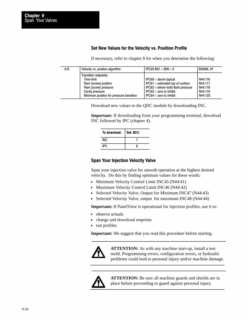
Span Your ValvesChapter 9
9-26
Set New Values for the Velocity vs. Position Profile
If necessary, refer to chapter 8 for when you determine the following:
8�B Velocity vs. position algorithm IPC03�B01 = B00 = 0 B38/96, 97
Transition setpoints: Time limit Ram (screw) position Ram (screw) pressure Cavity pressure Minimum position for pressure transition
IPC60 = above typicalIPC61 = estimated top of cushion IPC62 = below mold flash pressureIPC63 = zero to inhibitIPC64 = zero to inhibit
N44:116N44:117N44:118N44:119N44:120
Download new values to the QDC module by downloading INC.
Important: If downloading from your programming terminal, downloadINC followed by IPC (chapter 4).
To download: Set: B21/
INC 7
IPC 8
Span Your Injection Velocity Valve
Span your injection valve for smooth operation at the highest desiredvelocity. Do this by finding optimum values for these words:
Minimum Velocity Control Limit INC45 (N44:41) Maximum Velocity Control Limit INC46 (N44:42) Selected Velocity Valve, Output for Minimum INC47 (N44:43) Selected Velocity Valve, output for maximum INC48 (N44:44)
Important: If PanelView is operational for injection profiles, use it to:
observe actuals change and download setpoints run profiles
Important: We suggest that you read this procedure before starting.
ATTENTION: As with any machine start-up, install a testmold. Programming errors, configuration errors, or hydraulicproblems could lead to personal injury and/or machine damage.
ATTENTION: Be sure all machine guards and shields are inplace before proceeding to guard against personal injury.

Span Your ValvesChapter 9
9-27
Find optimum values for INC46, 48
1. Jog the ram (screw) all the way to the backpoint position.
2. Set machine hydraulics to simulate injection. Enable pumps andalign valves to their normal state during injection.
3. Run an open-loop velocity vs. position injection profile by togglingDYC02-B04 (B34/404) from 0 to 1 to 0.
4. The QDC module automatically runs the injection, pack, and holdprofiles in succession. At completion, observe the maximumsegment velocity reported by the QDC module in IPS09, 13, 17, 21,25. . . (N44:601, 605, 609, 613, 617, 621, 625, 629, 632, 637, or 641) for all segments of the profile. Record the highest reported velocity.
5. With your programming terminal, enter the highest velocity from step4 into INC46 (N44:42) the maximum velocity control limit.
6. Change all profile velocity setpoints to the value in INC46. Do thisin IPC09, 13, 17, 21, 25, 29, 33, 37, 41, 45, and 49 (N44:65, 69, 73, 77, 81, 85, 89, 93, 97, 101, and 105).
7. Download these values to the QDC module.
Important: If downloading from your programming terminal, downloadINC first, followed by IPC (chapter 4).
To download : Set: B21/
INC 7
IPC 8
8. Re-run the profile and verify that segment velocity actuals are aboutequal to segment setpoints.
9. Modify (in the proper direction for flow reduction) the value inINC48 (N44:44) in 5% increments until you observe the highestvelocity referred to in step 4. To do this, enter a new value in INC48and repeat steps 7, 3, 4, and 9 as needed. INC48 is the selectedvelocity valve, output for maximum.
10. After reaching the point where the maximum velocity starts todecrease, change the signal in INC48 just enough to restore thehighest velocity referred to in step 4. Enter a new INC48 and repeatsteps 7, 3, and 4 one last time.
Allen-Bradley Parts
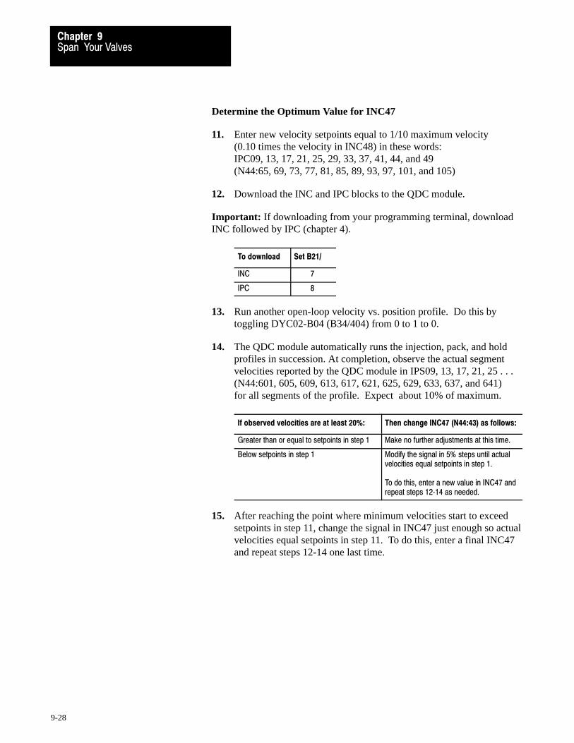
Span Your ValvesChapter 9
9-28
Determine the Optimum Value for INC47
11. Enter new velocity setpoints equal to 1/10 maximum velocity (0.10 times the velocity in INC48) in these words: IPC09, 13, 17, 21, 25, 29, 33, 37, 41, 44, and 49(N44:65, 69, 73, 77, 81, 85, 89, 93, 97, 101, and 105)
12. Download the INC and IPC blocks to the QDC module.
Important: If downloading from your programming terminal, downloadINC followed by IPC (chapter 4).
To download Set B21/
INC 7
IPC 8
13. Run another open-loop velocity vs. position profile. Do this bytoggling DYC02-B04 (B34/404) from 0 to 1 to 0.
14. The QDC module automatically runs the injection, pack, and holdprofiles in succession. At completion, observe the actual segmentvelocities reported by the QDC module in IPS09, 13, 17, 21, 25 . . . (N44:601, 605, 609, 613, 617, 621, 625, 629, 633, 637, and 641) for all segments of the profile. Expect about 10% of maximum.
If observed velocities are at least 20%: Then change INC47 (N44:43) as follows:
Greater than or equal to setpoints in step 1 Make no further adjustments at this time.
Below setpoints in step 1 Modify the signal in 5% steps until actualvelocities equal setpoints in step 1.
To do this, enter a new value in INC47 andrepeat steps 12�14 as needed.
15. After reaching the point where minimum velocities start to exceedsetpoints in step 11, change the signal in INC47 just enough so actualvelocities equal setpoints in step 11. To do this, enter a final INC47and repeat steps 12-14 one last time.

Span Your ValvesChapter 9
9-29
Test Valve Linearity with a Velocity vs. Position Profile
1. Change your velocity setpoints to one-half maximum velocity(0.5 times the velocity in INC48) in these words: IPC09, 13, 17, 21, 25, 29, 33, 37, 41, 45, and 49 (N44:65, 69, 73, 77, 81, 85, 89, 93, 97, 101, 105).
Important: Be sure the correct pump adders are set for this velocity.
2. Download the INC and IPC data blocks to the QDC module.
Important: If downloading from your programming terminal, downloadINC followed by IPC (chapter 4).
To download Set B21/
INC 7
IPC 8
3. Run an open-loop velocity vs. position profile. Do this by togglingDYC02-B04 (B34/404) from 0 to 1 to 0.
4. The QDC module automatically runs the injection, pack, and holdprofiles in succession. At completion, observe the actual segmentvelocities reported by the QDC module in mid-profile segments 5, 6,and 7 in IPS25, 29, and 33 (N44:617, 621, and 625).
If they are not within 20% of mid-profile velocity setpoints IPC25,29, and 33, your flow valve is not linear over the desired range ofoperation. Correct for a non-linear valve by adjusting as follows:
If observed velocity is 20%or more:
And Your SelectedValve is:
Then change INC47(N44:43) as follows:
Below setpoints Direct Acting Increase in 5% steps
Reverse Acting Decrease in 5% steps
Above setpoints Direct Acting Decrease in 5% steps
Reverse Acting Increase in 5% steps
To do this: change INC47, download INC and IPC blocks, and repeatsteps 2-4. Repeat as necessary.
Allen-Bradley Parts

Span Your ValvesChapter 9
9-30
What You Have Accomplished
The valve-spanning procedure you just completed has defined the:
range of ram (screw) velocity during any injection profile
end-of-range maximum and minimum signal levels for linear control ofthe injection velocity valve in open-loop control
For thisrange limit
When trying to obtainthe velocity in:
The QDC module drives the selectedvelocity valve to % output signal in:
Minimum INC45 INC47
Maximum INC46 INC48
Now for all open-loop injection velocity profiles, the QDC moduleassumes a liner relationship between ram velocity and signal output.
Note that there are no velocity profile alarms.

Span Your ValvesChapter 9
9-31
We recommend that you span your pack and hold pressure valves foroptimum pressure performance in four parts:
Confirm critical values Span your pack and hold pressure valves Test valve linearity with a pressure vs. time profile Set profile pressure alarms
Important: You may omit the procedure Span your pack and hold pressurevalves in this section if the recorded valve spanning data from the manu-facturer in pressure control limits PKC41-44 and HDC41-44 (chapter 7) areadequate for your application.
Important: If your machine hydraulics for pack and hold are identical tothose for injection, you may use your injection pressure valve spanningparameters for pack and hold. If so, enter your values for INC41-44 intoPKC41-44 and into HDC41-44, and skip to Set Profile Pressure Alarms.
Confirm Critical Values
Important: Confirm that all entries you made for configuration values(chapter 7) and profile values (chapter 8) are as follows:
OnWorksheet
Confirm Your Configuration With These Words or Bitsfor Pack Pressure
Pro�Set Addr
7�F QDC module output to which you connected yourpressure control valve
PKC02�B06, B05, B04 B38/148�150
Set�output values for unselected valves PKC09�12 = your values N44:125�128
All ramping is disabled with zero ramp rates PKC17�20 = 0PKC25�28 = 0
N44:133�136N44:141�144
Pressure limits: Minimum Pressure Control Limit Maximum Pressure Control Limit Selected Pressure Valve, Output for Minimum Selected Pressure Valve, Output for Maximum
PKC41 = 0PKC42 = system pressurePKC43 = your value PKC44 = your value
N44:157N44:158N44:159N44:160
7�G QDC module output to which you connected yourpressure control valve
HDC02�B06, B05, B04 B38/212�214
Set�output values for unselected valves HDC09�12 = your values N44:185�188
All ramping is disabled with zero ramp rates HDC17�20 = 0HDC25�28 = 0
N44:193�196N44:201�204
End�of�profile set�output values HDC33�36 for zero output N44:209�212
Pressure limits: Minimum Pressure Control Limit Maximum Pressure Control Limit Selected Pressure Valve, Output for Min Selected Pressure Valve, Output for Max
HDC41 = 0HDC42 = system pressureHDC43 = your value HDC44 = your value
N44:217N44:218N44:219N44:220
PKC and HDC Profiles -Pressure Valves
Allen-Bradley Parts
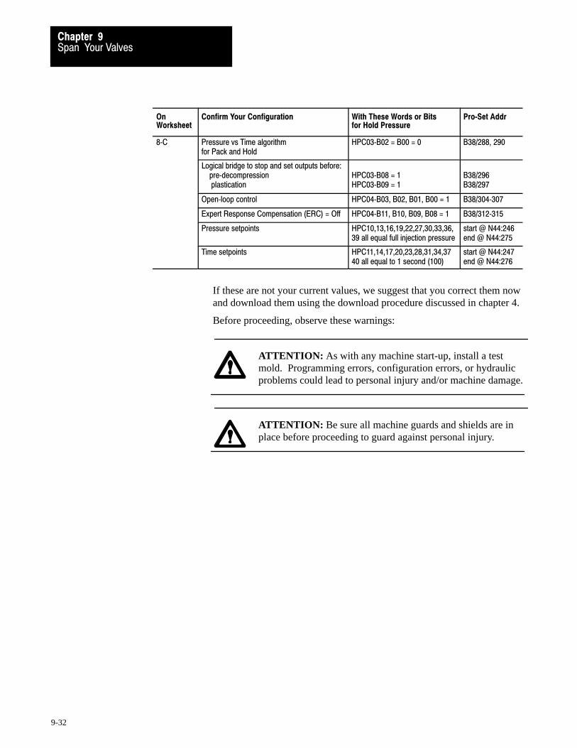
Span Your ValvesChapter 9
9-32
OnWorksheet
Confirm Your Configuration With These Words or Bitsfor Hold Pressure
Pro�Set Addr
8�C Pressure vs Time algorithmfor Pack and Hold
HPC03�B02 = B00 = 0 B38/288, 290
Logical bridge to stop and set outputs before: pre�decompression plastication
HPC03�B08 = 1HPC03�B09 = 1
B38/296B38/297
Open�loop control HPC04�B03, B02, B01, B00 = 1 B38/304�307
Expert Response Compensation (ERC) = Off HPC04�B11, B10, B09, B08 = 1 B38/312�315
Pressure setpoints HPC10,13,16,19,22,27,30,33,36,39 all equal full injection pressure
start @ N44:246end @ N44:275
Time setpoints HPC11,14,17,20,23,28,31,34,3740 all equal to 1 second (100)
start @ N44:247end @ N44:276
If these are not your current values, we suggest that you correct them nowand download them using the download procedure discussed in chapter 4.
Before proceeding, observe these warnings:
ATTENTION: As with any machine start-up, install a testmold. Programming errors, configuration errors, or hydraulicproblems could lead to personal injury and/or machine damage.
ATTENTION: Be sure all machine guards and shields are inplace before proceeding to guard against personal injury.

Span Your ValvesChapter 9
9-33
Span Your Pack and Hold Pressure Valves
Span your pack valve for smooth operation at the highest desired pressure.Do this in the following procedure by finding optimum values for words:
Title of Word Pack Word (Address) Hold Word (Address)
Minimum Pressure Control Limit PKC41 (N44:157) HDC41 (N44:217)
Maximum Pressure Control Limit PKC42 (N44:158) HDC42 (N44:218)
Selected Pressure Valve, Output for Minimum PKC43 (N44:159) HDC43 (N44:219)
Selected Pressure Valve, Output for Maximum PKC44 (N44:160) HDC44 (N44:210)
Important: If using the same valve for pack and hold with similar valuesin PKC and HDC, span this valve for pack and hold at the same time.When you enable the pack profile, the QDC module automatically runs thepack and hold profiles in succession. If using different valves for pack andhold or substantially different hydraulic circuit during the profiles, span thepack valve first. Then repeat the procedure for the hold valve.
Important: If PanelView is available for pack and hold profiles, use it to:
observe actuals change and download setpoints run profiles
Important: We suggest that you read this procedure before starting.
1. Manually jog your ram (screw) to the mold-end position so you canexert maximum pressure against the nozzle tip.
2. Align all other machine hydraulics to simulate pack and hold: enable pumps and align valves to their normal state for pack or hold.
3. Copy initial values PKC09-12 (N44:125-128) into DYC09-12(N40:121-124) of your PLC-5 data table with this exception:
Important: Enter a value corresponding to zero pressure into the wordDYC09-12 (N40:121-124) for output 1, 2, 3, or 4 that drives the selectedram (screw) pressure valve.
ATTENTION: A value of 0 does not always correspond to zeropressure or flow. For example, a bi-directional valve requires aset-output value of 50% (5000) to obtain 0 PSI. Valve spools oramplifier electronics may allow pressure or flow at 0 volts.
Allen-Bradley Parts

Span Your ValvesChapter 9
9-34
4. Enable set-output by changing DYC01-B08 (B34/392) from 0 to 1.This forces the QDC module to apply the values in DYC09-12directly to its outputs 1-4, respectively.
5. Adjust the value of DYC09-12 (N40:121-124) that corresponds to theselected pressure valve, and observe actual pressure reported inSYS26 (N40:178).
For a bi-directional valve with a spool offset:If this pressure is greater than zero, adjust the set-output value tothe pressure valve to obtain zero pressure. Stop adjusting whenyou observe the smallest pressure attainable.
For a uni-directional valve with no response at low signal level:If this pressure is zero, adjust the set-output value to the pressurevalve until the observed pressure just exceeds zero. Then re-adjustthis value until you just observe zero again.
For a uni-directional valve with a pressure actual greater thanzero but with zero output to the valve: This is lowest pressure.
6. Once satisfied that you obtained the lowest possible pressure or thehighest possible signal at zero pressure, copy the actual pressureobserved in SYS26 into the minimum pressure control limit: PKC41(N44:157) for pack, HDC41 (N44: 217) for hold.
7. While maintaining this minimum pressure, observe the actualset-output value SYS41-44 (N40:193-196) that corresponds to yourpressure valve. Copy this value into the selected pressure valve,output for minimum: PKC43 (N44:159) for pack, HDC43 (N44:219)for hold.
8. Modify the value in DYC09-12 (N40:121-124) that corresponds tothe pressure valve in 5% steps while observing rising pressure inSYS26 (N40:178). Stop adjusting it when the observed pressure nolonger increases with a change in the set-output value. Now thepressure in SYS26 is the maximum obtainable pressure.
9. Copy the pressure in SYS26 (N44:178) into the maximum pressurecontrol limit: PKC42 (N44:158) for pack, HDC42 (N44:218) for hold
10. While maintaining this maximum pressure, observe the actualset-output value in SYS41-44 (N40:193-196) that corresponds to yourselected pressure valve. Copy this value into the selected pressurevalve, output for maximum: PKC44 (N44:160) for pack, HDC44(N44:220) for hold.
11. Disable set-output operation. Toggle DYC01-B08 (B34/392) to 0.

Span Your ValvesChapter 9
9-35
12. Download your final values for PKC41-44 and HDC41-44 to theQDC module by downloading the PKC block.
Important: If downloading from your programming terminal, downloadPKC and HDC, followed by HPC (chapter 4).
To download Set B21/
PKC 9
HDC 10
HPC 11
Test Valve Linearity with a Pressure vs. Time Profile
After you span the pressure valve for ram (screw) pack and hold, testlinearity for pack and hold profiles with this procedure:
1. Confirm that pressure setpoints equal full injection pressure: for pack: HPC10, 13, 16, 19, 22 (N44:246, 249, 252, 255, 258)for hold: HPC27, 30, 33, 36, 39 (N44:263, 266, 269, 272, 275)
If not, correct them and download them to the QDC module. Forinstructions, refer to chapter 4.
2. Check that the ram (screw) is still at the mold-end position.
3. Run the pressure vs. time pack profile by toggling DYC02-B05(B34/405) from 0 to 1 to 0. The ram (screw) remains fixed so it canexert pressure against the nozzle tip. If no pressure, verify that:
- no ram (screw) overtravel alarms are set. The QDC moduleinhibits injection profiles if alarm bits SYS07-B00 throughSYS07-B05 are set.
- no programming error codes exist in SYS61 and SYS62.
4. The QDC module automatically runs pack and hold profiles insuccession. At completion, observe the pressures reported for themiddle segment pressure in HPS16 (N44:664) for pack and HPS33(N44:681) for hold.
5. If observed pressures are not within 20% of entered setpoints, checkthat valve and solenoid alignment for the profile is the same as forset-output (previous procedure). If not, correct. Repeat steps 3 and 4.
Allen-Bradley Parts

Span Your ValvesChapter 9
9-36
6. If the observed pressure HPS16 for pack and HPS33 for hold are stillnot within 20% of setpoints HPC16 and HPC33, your pressure valveis not linear over the desired range. Correct by adjusting the selectedpressure valve, output for minimum PKC43 and HDC43 as follows:
If actuals are at least 20%: And Your SelectedValve is:
Then change PKC43, HDC43(N44:159, N44:219) as follows
Less than setpoints Direct Acting Increase in 5% steps
Reverse Acting Decrease in 5% steps
Greater than setpoints Direct Acting Decrease in 5% steps
Reverse Acting Increase in 5% steps
To do this: change PKC43 and HDC43, download PKC and HDC,and repeat steps 3 and 4. Repeat as needed.
Important: If downloading from your programming terminal, downloadPKC, HDC, and HPC in that order with bits B21/9, 10, and 11 (chapter 4).
What You Have Accomplished
The open-loop tuning procedure you just completed has defined the:
range of pressure during pack and hold
end-of-range maximum and minimum signal levels for linear control ofthe pack and hold pressure valve in open-loop control
For thisrange limit
When trying to obtainthe pressure in:
The QDC module drives the selectedpressure valve to % output signal in:
Minimum PKC41 or HDC41 PKC43 or HDC43
Maximum PKC42 or HDC42 PKC44 or HDC44
Now for all open-loop pack or hold pressure profiles, the QDC moduleassumes a linear relationship between ram pressure and signal outputs.
Set Profile Pressure Alarms
Set profile maximum pressure alarm setpoints PKC57 (N44:173) for packand HDC57 (N44:233) for hold to a pressure that should:
not be exceeded during either profile not be greater than maximum pressure control limits PKC42, HDC42
Entering a value of zero disables these alarms.
Download new values to the QDC module by downloading PKC, HDC.
Important: If downloading from your programming terminal, downloadPKC, HDC, and HPC in that order with bits B21/9, 10, and 11 (chapter 4).
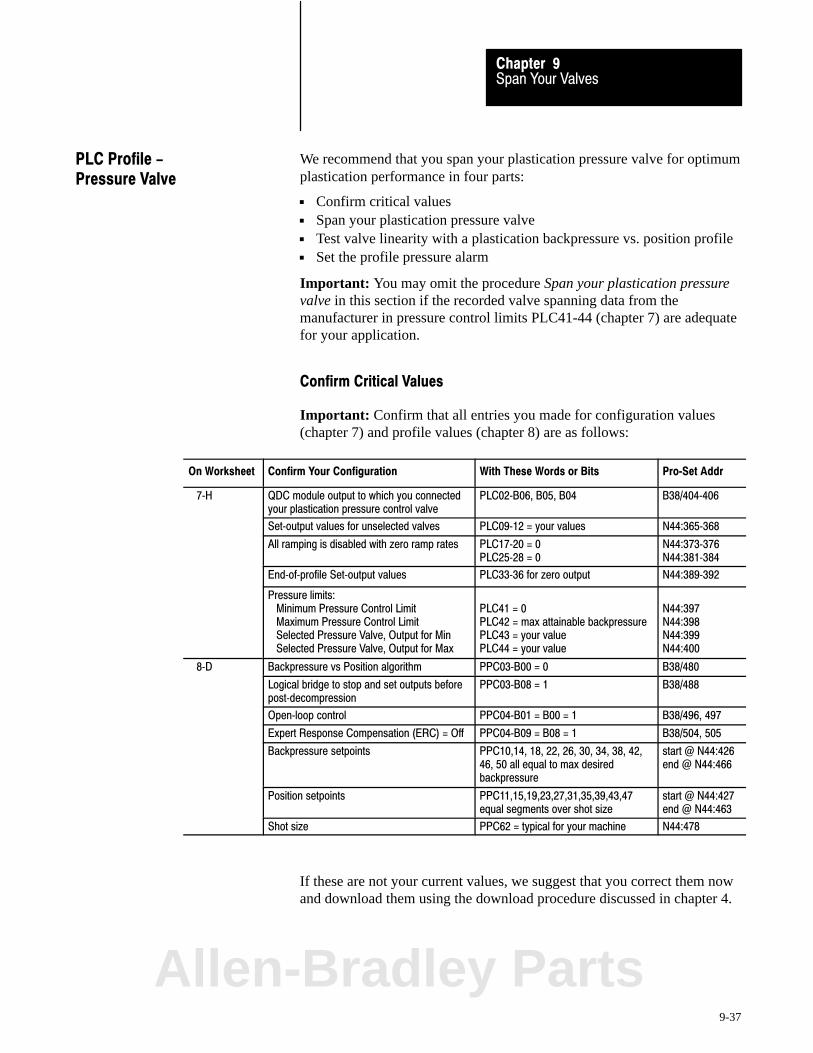
Span Your ValvesChapter 9
9-37
We recommend that you span your plastication pressure valve for optimumplastication performance in four parts:
Confirm critical values Span your plastication pressure valve Test valve linearity with a plastication backpressure vs. position profile Set the profile pressure alarm
Important: You may omit the procedure Span your plastication pressurevalve in this section if the recorded valve spanning data from themanufacturer in pressure control limits PLC41-44 (chapter 7) are adequatefor your application.
Confirm Critical Values
Important: Confirm that all entries you made for configuration values(chapter 7) and profile values (chapter 8) are as follows:
On Worksheet Confirm Your Configuration With These Words or Bits Pro�Set Addr
7�H QDC module output to which you connectedyour plastication pressure control valve
PLC02�B06, B05, B04 B38/404�406
Set�output values for unselected valves PLC09�12 = your values N44:365�368
All ramping is disabled with zero ramp rates PLC17�20 = 0PLC25�28 = 0
N44:373�376N44:381�384
End�of�profile Set�output values PLC33�36 for zero output N44:389�392
Pressure limits: Minimum Pressure Control Limit Maximum Pressure Control Limit Selected Pressure Valve, Output for Min Selected Pressure Valve, Output for Max
PLC41 = 0PLC42 = max attainable backpressurePLC43 = your value PLC44 = your value
N44:397N44:398N44:399N44:400
8�D Backpressure vs Position algorithm PPC03�B00 = 0 B38/480
Logical bridge to stop and set outputs beforepost�decompression
PPC03�B08 = 1 B38/488
Open�loop control PPC04�B01 = B00 = 1 B38/496, 497
Expert Response Compensation (ERC) = Off PPC04�B09 = B08 = 1 B38/504, 505
Backpressure setpoints PPC10,14, 18, 22, 26, 30, 34, 38, 42,46, 50 all equal to max desiredbackpressure
start @ N44:426end @ N44:466
Position setpoints PPC11,15,19,23,27,31,35,39,43,47equal segments over shot size
start @ N44:427end @ N44:463
Shot size PPC62 = typical for your machine N44:478
If these are not your current values, we suggest that you correct them nowand download them using the download procedure discussed in chapter 4.
PLC Profile -Pressure Valve
Allen-Bradley Parts

Span Your ValvesChapter 9
9-38
Before proceeding, observe these warnings:
ATTENTION: As with any machine start-up, install a testmold. Programming errors, configuration errors, or hydraulicproblems could lead to personal injury and/or machine damage.
ATTENTION: Be sure all machine guards and shields are inplace before proceeding to guard against personal injury.
ATTENTION: Load the hopper with plastic before starting thisprocedure. Absence of plastic during plastication:
nullifies this procedure may cause excessive wear to the barrel and ram (screw)
Span Your Plastication Backpressure Valve
Span your plastication valve for smooth operation at the highest desiredbackpressure. Do this by finding the optimum values for these words:
Minimum Pressure Control Limit PLC41 (N44:397) Maximum Pressure Control Limit PLC42 (N44:398) Selected Pressure Valve, Output for Minimum PLC43 (N44:399) Selected Pressure Valve, Output for Maximum PLC44 (N44:400)
Important: If PanelView is operational for injection profiles, use it to:
observe actuals change and download setpoints run profiles
Important: We suggest that you read this procedure before starting.
1. Jog your ram (screw) to the mold-end position.
2. Set machine hydraulics to simulate ram (screw) backpressure: enable pumps and align valves to normal state during plastication.
Important: Move injection carriage up to mold block to build pressure.

Span Your ValvesChapter 9
9-39
3. While observing actual pressure in SYS26 (N40:178) and the outputin SYS41-44 (N40:193-196) that corresponds to the selectedplastication valve, run a plastication backpressure vs. position profile.Do this by toggling DYC04-B08 (B34/408) from 0 to 1 to 0.
4. With your programming terminal, record:
maximum profile backpressure displayed in SYS26 (N40:178)Record here a) ___________
%-output signal in SYS41-44 (N40:193-196) corresponding to theram (screw) plastication valve Record here b)___________
5. Compute the signal level required for the Selected Pressure Valve,Output for Maximum PLC44 as follows:
PLC44 =
Max desiredbackpressure
x Observed %�signal output in SYS41�44 thatcorresponds to the ram plastication valve
Observed Pressure in SYS26
Important: If your valve is reverse acting, apply the algebraic sign (–) ofvalue b correctly when computing PLC44.
PLC44 =xPPC10 Your recorded value b
Your recorded value a
PLC44 = _______________ For example, 1000 for 10%
6. Enter new values into the PLC data table:
- value from step 5 into PLC44 (N44:400)
- maximum desired backpressure PPC10 from step 5 into PLC42(N44:398)
7. Download the PLC block to the QDC module.
Important: If downloading from your programming terminal, downloadPLC followed by PPC with download bits B21/13 and 14 (chapter 4).
8. Run an open-loop backpressure vs. position profile. Do this bytoggling DYC02-B08 (B34/408) from 0 to 1 to 0.Allen-Bradley Parts

Span Your ValvesChapter 9
9-40
9. Observe and record actual backpressures reported by the QDCmodule for all profile segments in PPS10, 14, 18, 22, 26, 30, 34 etc.(N44:714, 718, 722, 726, 730, 734, 738, 742, 746, 750, 754).
10. Compare actual backpressures with your setpoints in PPC10, 14, 18, 22, 26, 30, 34, 38, 42, 46, 50 as follows:
If Then
Actuals are greater than setpoints by 20% or more
1. Decrease PLC44 by 10%.2. Enter this new value into PLC data table.3. Repeat the profile with steps 7�9.4. Repeat these adjustments until actuals just drop below setpoints.
Actuals are less than setpoints by 20% or more
1. Increase PLC44 by 10%.2. Enter this new value into PLC data table.3. Repeat the profile with steps 7�9.4. Repeat these adjustments until actuals are equal to or greater than setpoints.
Actuals are less thansetpoints by 20% and PLC44 = 100%
1. Decrease PLC42 by 10%.2. Enter this new value into PLC data table.3. Repeat the profile with steps 7�9.4. Repeat these adjustments until actuals are equal to or greater than setpoints.
Test Valve Linearity with a Plastication Backpressure Profile
1. Change backpressure setpoints to 1/2 PLC44 (1/2 Max Control Limit)in PPC10, 14, 18, 22, 26, 30, 34, 38, 42, 46, and 50 (in N44:426, 430, 434, 438, 442, 446, 450, 454, 458, 462, 466).
2. Download the PLC block to the QDC module.
Important: If downloading from your programming terminal, downloadPLC followed by PPC with download bits B21/13 and 14 (chapter 4).
3. Run an open-loop backpressure vs. position profile. Do this bytoggling DYC02-B08 (B34/408) from 0 to 1 to 0.
4. Compare backpressures reported in middle segments 5, 6, and 7 inPPS26, 30, 34 (N44:730, 734, 738) with setpoints PLC26, 30, and 34.Adjust PLC41 or PLC43 as follows:
If actual backpressures are: And Your SelectedValve is:
Then change PLC41 or 43(N44:397 or 399) as follows:
Greater than or equal to setpoints Either one Increase PLC41 in 5% steps
Less than setpoints Direct Acting Increase PLC43 n 5% steps
Reverse Acting Decrease PLC43 in 5% steps

Span Your ValvesChapter 9
9-41
To do this: change PLC41 and/or PLC43, download the block, andrepeat steps 2-4. Repeat as necessary.
Important: If downloading from your programming terminal, downloadPLC followed by PPC with download bits B21/13 and 14 (chapter 4).
What You Have Accomplished
The open-loop tuning procedure you just completed has defined the:
range of ram (screw) backpressure during plastication
end-of-range maximum and minimum signal levels for linear control ofthe plastication pressure valve in open-loop control
For thisrange limit
When trying to obtainthe pressure in:
The QDC module drives the selectedpressure valve to % output signal in:
Minimum PLC41 PLC43
Maximum PLC42 PLC44
Now for open-loop plastication profiles, the QDC module assumes a linerrelationship between backpressure and signal output.
Set the Profile Pressure Alarm
Set the maximum pressure alarm PLC57 (N44:413) equal to a back-pressure that should:
not be exceeded during the plastication profile not be greater than PLC42 (N44:398) maximum pressure control limit
Entering zero disables this alarm.
Download the PLC block to the QDC module.
Important: If downloading from your programming terminal, downloadPLC followed by PPC with download bits B21/13 and 14 (chapter 4).
Allen-Bradley Parts
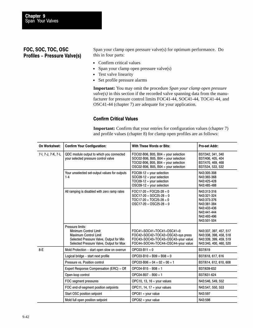
Span Your ValvesChapter 9
9-42
Span your clamp open pressure valve(s) for optimum performance. Dothis in four parts:
Confirm critical values Span your clamp open pressure valve(s) Test valve linearity Set profile pressure alarms
Important: You may omit the procedure Span your clamp open pressurevalve(s) in this section if the recorded valve spanning data from the manu-facturer for pressure control limits FOC41-44, SOC41-44, TOC41-44, andOSC41-44 (chapter 7) are adequate for your application.
Confirm Critical Values
Important: Confirm that your entries for configuration values (chapter 7)and profile values (chapter 8) for clamp open profiles are as follows:
On Worksheet: Confirm Your Configuration: With These Words or Bits: Pro�set Addr:
7�I, 7�J, 7�K, 7�L QDC module output to which you connectedyour selected pressure control valve
FOC02�B06, B05, B04 = your selectionSOC02�B06, B05, B04 = your selectionTOC02�B06, B05, B04 = your selectionOSC02�B06, B05, B04 = your selection
B37/342, 341, 340B37/406, 405, 404B37/470, 469, 468B37/534, 533, 532
Your unselected set�output values for outputs1�4
FOC09�12 = your selectionSOC09�12 = your selectionTOC09�12 = your selectionOSC09�12 = your selection
N43:305�308N43:365�368N43:425�428N43:485�488
All ramping is disabled with zero ramp rates FOC17�20 = FOC25�28 = 0SOC17�20 = SOC25�28 = 0TOC17�20 = TOC25�28 = 0OSC17�20 = OSC25�28 = 0
N43:313�316N43:321�324N43:373�376N43:381�384N43:433�436N43:441�444N43:493�496N43:501�504
Pressure limits:Minimum Control LimitMaximum Control LimitSelected Pressure Valve, Output for MinSelected Pressure Valve, Output for Max
FOC41=SOC41=TOC41=OSC41=0FOC42=SOC42=TOC42=OSC42=sys pressFOC43=SOC43=TOC43=OSC43=your valueFOC44=SOC44=TOC44=OSC44=your value
N43:337, 397, 457, 517N43:338, 398, 458, 518N43:339, 399, 459, 519N43:340, 400, 460, 520
8�E Mold Protection - start open slow on overrun OPC03�B11 = 0 B37/619
Logical bridge - start next profile OPC03�B10 = B09 = B08 = 0 B37/618, 617, 616
Pressure vs. Position control OPC03�B06 = 04 = 02 = 00 = 1 B37/614, 612, 610, 608
Expert Response Compensation (ERC) = Off OPC04�B15 - B08 = 1 B37/639�632
Open�loop control OPC04�B07 - B00 = 1 B37/631�624
FOC segment pressures OPC10, 13, 16 = your values N43:546, 549, 552
FOC end�of�segment position setpoints OPC11, 14, 17 = your values N43:547, 550, 553
Start OSC position setpoint OPC61 = your value N43:597
Mold full open position setpoint OPC62 = your value N43:598
FOC, SOC, TOC, OSCProfiles - Pressure Valve(s)

Span Your ValvesChapter 9
9-43
If these are not your current values, we suggest that you correct them nowusing the download procedure discussed in chapter 4.
Span Your Clamp Open Pressure Valve(s)
Span your clamp pressure valve for smooth operation at highest desiredclamp open pressure. Do this in the following procedure by findingoptimum values for:
Minimum Pressure Control Limit FOC41, SOC41, TOC41, and OSC41 Maximum Pressure Control Limit FOC42, SOC42, TOC42, and OSC42 Selected Pressure Valve, Output For Minimum
FOC43, SOC43, TOC43, and OSC43 Selected Pressure Valve, Output For Maximum
FOC44, SOC44, TOC44, and OSC44
Important: If your machine hydraulics are identical for all clamp openand open slow profiles, complete the procedure for first clamp open byfinding values for FOC41-44, and copy them into the other clamp openprofile words SOC41-44, TOC41-44, and OSC41-44 when told. Otherwise, repeat the procedure as needed.
Important: If PanelView is operational for clamp profiles, use it to:
observe actuals change and download setpoints run profiles
Important: We suggest that you read this procedure before starting.
ATTENTION: As with any machine start-up, install a testmold. Programming errors, configuration errors, or hydraulicproblems could lead to personal injury and/or machine damage.
ATTENTION: Be sure all machine guards and shields are inplace before proceeding to guard against personal injury.
1. Jog your clamp to the full open position.
2. Align all other machine hydraulics to simulate clamp open motion.For example, enable required pumps and align required valves.
3. Copy initial values from FOC09-12 (N43:305-308) into DYC09-12(N40:121-124) of your PLC-5 data table with this exception:
Allen-Bradley Parts
Span Your ValvesChapter 9
9-44
Important: Enter a value corresponding to zero pressure into the wordDYC09-12 for output 1, 2, 3, or 4 that drives the selected clamp pressurevalve.
ATTENTION: A value of 0 does not always correspond to zeropressure or flow. For example, a bi-directional valve requires aset-output value of 50% (5000) to obtain 0 PSI. Valve spools oramplifier electronics may also allow pressure or flow at 0 volts.
4. Enable set-output by transitioning DYC01-B08 (B34/392) to 1. Thisforces the QDC module to apply the values in DYC09-12 directly toits outputs 1-4, respectively.
5. Adjust the set-output value DYC09-12 (N40:121-124) thatcorresponds to the selected clamp open pressure valve, and observethe pressure reported in SYS26 (N40:178).
For a bi-directional valve with a spool offset:If this pressure is greater than zero, adjust the selected valveset-output value to obtain zero pressure. Stop adjusting it whenyou observe the smallest pressure attainable.
For a uni-directional valve with no response at low signal level:If this pressure is zero, adjust the selected valve set-output valueuntil the observed pressure just exceeds zero. Then re-adjust ituntil you just observe zero again.
For a uni-directional valve with a pressure actual greater thanzero but with zero output to the valve: This is lowest pressure.
6. Once you are satisfied you obtained the lowest possible pressure orthe highest possible signal at zero pressure, copy the pressureobserved in SYS26 (N40:178), (usually 0 PSI or Bar) into FOC41,SOC41, TOC41, and OSC41 (N43:337, 397, 457, and 517), theminimum pressure control limits.
7. While maintaining this minimum pressure, observe the actualset-output value in SYS41-44 (N40:193-196) that corresponds to yourselected clamp open pressure valve. Copy this value into FOC43,SOC43, TOC43, and OSC43 (N43:339, 399, 459, and 519), theselected pressure valve output for minimum.
8. Change the set-output value in DYC09-12 (N40:121-124) thatcorresponds to the clamp open pressure valve by 50%, and then in5% steps while observing the clamp pressure in SYS26 (N40:178).Stop adjusting it when the observed pressure no longer increases withan increase in the set-output value. Now the pressure in SYS26(N40:178) is the maximum obtainable clamp open pressure.

Span Your ValvesChapter 9
9-45
9. Copy this observed maximum pressure from SYS26 (N40:178) intoFOC42, SOC42, TOC42, and OSC42 (N43:338, 398, 458, and 518),the maximum pressure control limits.
10. While maintaining this maximum pressure, observe the actualset-output value in the SYS41-44 (N40:193-196) that corresponds toyour selected clamp open pressure valve. Copy this value intoFOC44, SOC44, TOC44, and OSC44 (N43:340, 400, 460, and 520),the selected pressure valve, output for maximum.
11. Lower the set-output value in DYC09-12 corresponding to theselected clamp open pressure valve to a safe level.
12. Disable set-output by transitioning DYC01-B08 (B34/392) to 0.
13. Download the changes FOC, SOC, TOC, OSC to the QDC module.
Important: If downloading from your programming terminal, you mustdownload FOC, SOC, TOC, OSC, and OPC in that order (chapter 4).
To download: Set: B21/
FOC 16
SOC 17
TOC 18
OSC 19
OPC 20
Test Valve Linearity with a Clamp Open Pressure Profile
1. Jog your clamp to the fully open position.
2. Enable first clamp open by setting DYC02-B10 (B34/410) = 1. Theclamp should move from its start position through the first clampopen and open slow profiles. If no motion, verify that:
- no overtravel alarms are set. The QDC module inhibits clampopen if SYS07-B00 through SYS07-B05 are set
- no programming error codes exist in SYS61 and SYS62
3. Upon completion of clamp open, observe the pressure reported for 1stclamp open segment 2 (OPS13, N43:721). If the observed pressure isnot about equal to the setpoint you entered in OPC13, then check:
- was your valve and solenoid alignment the same for clamp openprofile execution and clamp open action in set-output?
If the observed pressure OPS13 is still not within 20% of OPC13, yourpressure is not linear over the desired range. Correct as follows:Allen-Bradley Parts

Span Your ValvesChapter 9
9-46
If: And Your SelectedValve is:
Then change FOC44(N43:340) as follows:
OPS13 was less than OPC13 Direct Acting Increase in 5% steps
Reverse Acting Decrease in 5% steps
OPS13 was more than OPC13 Direct Acting Decrease in 5% steps
Reverse Acting Increase in 5% steps
To do this: change FOC44, download the FOC block, and repeat steps 1-3. Do this as necessary.
Important: If downloading from your programming terminal, downloadFOC followed by OPC with download bits B21/16 and 20 (chapter 4).
4. Copy final FOC44 (N43:340) into SOC44, TOC44 and OSC44(N43:400, 460, and 520), and download these changes.
Important: If downloading from your programming terminal, downloadFOC, SOC, TOC and/or OSC followed by OPC (chapter 4).
To download: Set B21/
FOC 16
SOC 17
TOC 18
OSC 19
OPC 20
What You Have Accomplished
The valve spanning procedure you just completed has defined the:
range of pressure available during any clamp open profile
end-of-range maximum and minimum signal levels for linear control ofthe clamp open pressure valve in open-loop control.
For thisrange limit
When trying to obtain thepressure in:
The QDC module drives the selectedpressure valve to % output signal in:
Minimum FOC41,SOC41,TOC41,OSC41 FOC43, SOC43, TOC43, and OSC43
Maximum FOC42,SOC42,TOC42,OSC42 FOC44, SOC44, TOC44, and OSC44
Now, for all open-loop pressure profiles for clamp open, the QDC moduleassumes a linear relationship between clamp pressure and signal output.

Span Your ValvesChapter 9
9-47
Set Profile Pressure Alarms
For clamp open profiles, set the maximum pressure alarm (FOC57,SOC57, TOC57, OSC57) to a pressure value that should:
not be exceeded during the clamp profile not exceed the max pressure control limit
FOC42, SOC42, TOC42, and OSC42
Entering a value of zero disables these alarms.
Download new values to the QDC module.
Important: If downloading from your programming terminal, downloadFOC, SOC, TOC, OSC, and OPC in that order (chapter 4):
To download Set B21/
FOC 16
SOC 17
TOC 18
OSC 19
OPC 20
Allen-Bradley Parts
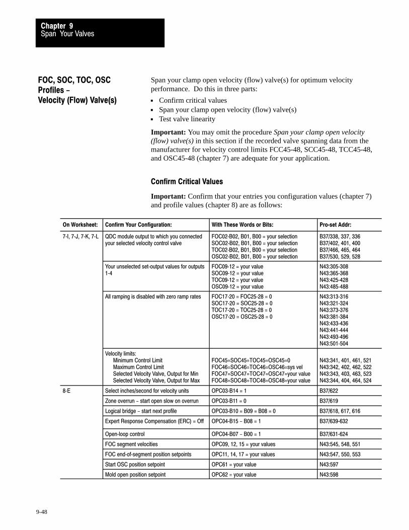
Span Your ValvesChapter 9
9-48
Span your clamp open velocity (flow) valve(s) for optimum velocityperformance. Do this in three parts:
Confirm critical values Span your clamp open velocity (flow) valve(s) Test valve linearity
Important: You may omit the procedure Span your clamp open velocity(flow) valve(s) in this section if the recorded valve spanning data from themanufacturer for velocity control limits FCC45-48, SCC45-48, TCC45-48,and OSC45-48 (chapter 7) are adequate for your application.
Confirm Critical Values
Important: Confirm that your entries you configuration values (chapter 7)and profile values (chapter 8) are as follows:
On Worksheet: Confirm Your Configuration: With These Words or Bits: Pro�set Addr:
7�I, 7�J, 7�K, 7�L QDC module output to which you connectedyour selected velocity control valve
FOC02�B02, B01, B00 = your selectionSOC02�B02, B01, B00 = your selectionTOC02�B02, B01, B00 = your selectionOSC02�B02, B01, B00 = your selection
B37/338, 337, 336B37/402, 401, 400B37/466, 465, 464B37/530, 529, 528
Your unselected set�output values for outputs1�4
FOC09�12 = your valueSOC09�12 = your valueTOC09�12 = your valueOSC09�12 = your value
N43:305�308N43:365�368N43:425�428N43:485�488
All ramping is disabled with zero ramp rates FOC17�20 = FOC25�28 = 0SOC17�20 = SOC25�28 = 0TOC17�20 = TOC25�28 = 0OSC17�20 = OSC25�28 = 0
N43:313�316N43:321�324N43:373�376N43:381�384N43:433�436N43:441�444N43:493�496N43:501�504
Velocity limits:Minimum Control LimitMaximum Control LimitSelected Velocity Valve, Output for MinSelected Velocity Valve, Output for Max
FOC45=SOC45=TOC45=OSC45=0FOC46=SOC46=TOC46=OSC46=sys velFOC47=SOC47=TOC47=OSC47=your valueFOC48=SOC48=TOC48=OSC48=your value
N43:341, 401, 461, 521N43:342, 402, 462, 522N43:343, 403, 463, 523N43:344, 404, 464, 524
8�E Select inches/second for velocity units OPC03�B14 = 1 B37/622
Zone overrun - start open slow on overrun OPC03�B11 = 0 B37/619
Logical bridge - start next profile OPC03�B10 = B09 = B08 = 0 B37/618, 617, 616
Expert Response Compensation (ERC) = Off OPC04�B15 - B08 = 1 B37/639�632
Open�loop control OPC04�B07 - B00 = 1 B37/631�624
FOC segment velocities OPC09, 12, 15 = your values N43:545, 548, 551
FOC end�of�segment position setpoints OPC11, 14, 17 = your values N43:547, 550, 553
Start OSC position setpoint OPC61 = your value N43:597
Mold open position setpoint OPC62 = your value N43:598
FOC, SOC, TOC, OSCProfiles - Velocity (Flow) Valve(s)

Span Your ValvesChapter 9
9-49
If these are not your current values, we suggest that you correct them nowusing the download procedure discussed in chapter 4.
Span Your Clamp Open Velocity Valve(s)
Span your clamp open velocity valve(s) for smooth operation at highestvelocity. Do this in the following procedure by finding optimum valuesfor:
Minimum Velocity Control Limit FOC45, SOC45, TOC45, OSC45 Maximum Velocity Control Limit FOC46, SOC46, TOC46, OSC45 Selected Velocity Valve, Output For Minimum
FOC47, SOC47, TOC47, OSC45 Selected Velocity Valve, Output For Maximum
FOC48, SOC48, TOC48, OSC45
Important: If your machine hydraulics are identical for all clamp openand open slow profiles, complete the procedure for first clamp open byfinding values for FOC45-48, and copy them into the other clamp openprofile words SOC45-48, TOC45-48, and OSC45-48 when told. Otherwise, repeat the procedure as needed.
Important: If PanelView is operational for clamp profiles, use it to:
observe actuals change and download setpoints run profiles
Important: We suggest that you read this procedure before starting.
ATTENTION: As with any machine start-up, install a testmold. Programming errors, configuration errors, or hydraulicproblems could lead to personal injury and/or machine damage.
ATTENTION: Be sure all machine guards and shields are inplace before proceeding to guard against personal injury.
1. Obtain a copy of the flow rate curves provided by your flow valvemanufacturer. Flow rate curves graphically illustrate the flowthrough a valve at different voltage or input current levels and atdifferent pressure drops across the valve’s spool.
2. From these curves, determine the minimum and maximum clampopen flow available from your flow valve at the pressure you wouldnormally run during clamp open operation. Record these flows,along with the input voltage/current associated with them.Allen-Bradley Parts

Span Your ValvesChapter 9
9-50
Important: If the pressure during clamp open slow differs from thatduring clamp open fast, complete the calculations for both pressures. Besure to record words with correct prefixes:
open slow values with the OSC prefix clamp open fast values with FOC, SOC and TOC prefixes
3. Convert the minimum and maximum flow obtained from your flowcurve to clamp cylinder velocity. This is done by:
Clamp Cylinder Velocity (in/sec) =Flow (in3/sec)
Area (in2)
- where area is the inside diameter of the cylinder. This area maybe different for the rod and piston ends of the cylinder:
Area for Rod End =I.D. of cylinder
2
Rod diameter
2π
22
Area (no Rod) =I.D. of cylinder
2π
2
π
- Flow assumes no restrictions on the exhaust port of the cylinder.
4. Enter the minimum velocity (usually 0) from these calculations intoFOC45, SOC45, TOC45, and OSC45. Enter the maximum velocityinto FOC46, SOC46, TOC46, and OSC46.
5. Divide the voltage/current corresponding to minimum velocity by thefull range of valve input signal to determine the percent signal outputfor minimum. Enter this value into FOC47, SOC47, TOC47, OSC47.
6. Divide the voltage/current corresponding to maximum velocity by thefull range of valve input signal to determine the percent signal outputfor maximum. Enter this value into FOC48, SOC48, TOC48, OSC48.
7. Download changes to the QDC module.
Important: If downloading from your programming terminal, downloadFOC, SOC, TOC, OSC, and OPC in that order (chapter 4).
To download Set B21/
FOC 16
SOC 17
TOC 18
OSC 19
OPC 20
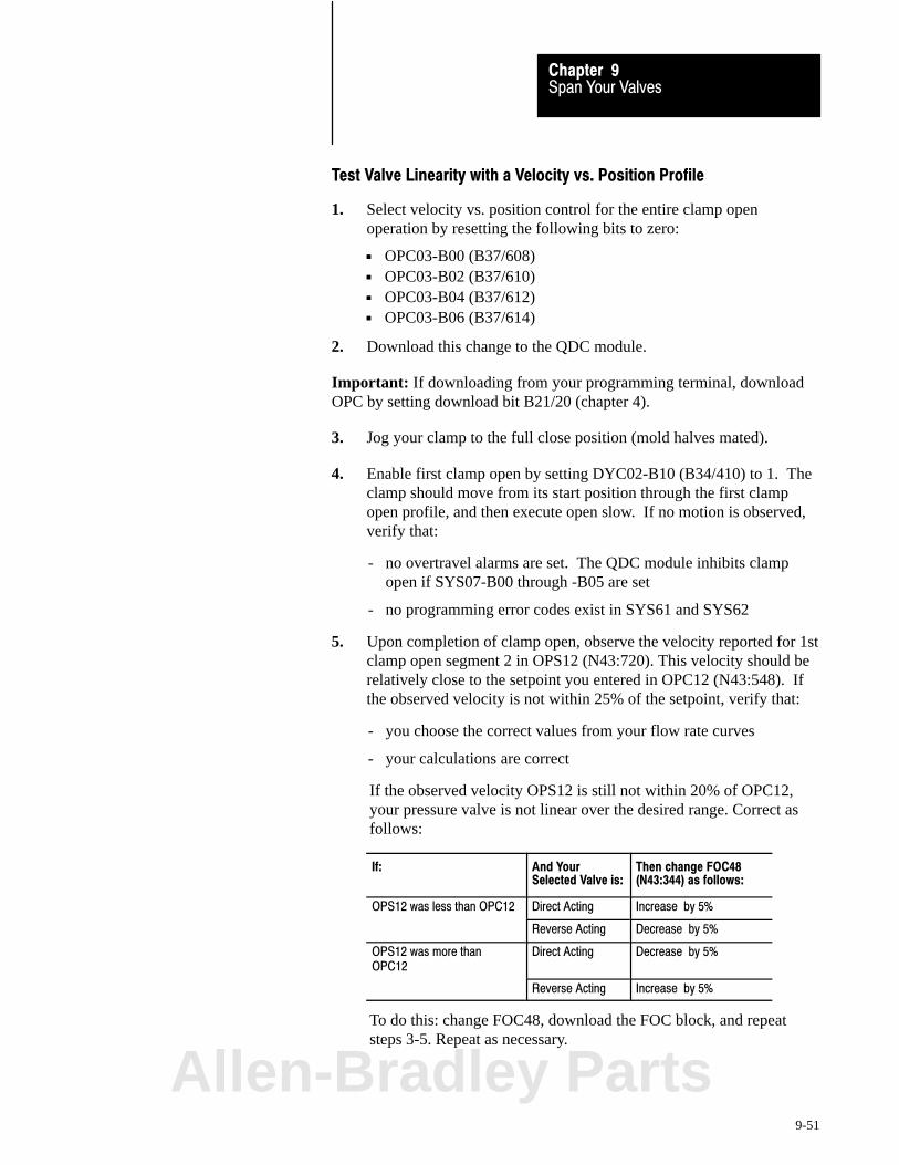
Span Your ValvesChapter 9
9-51
Test Valve Linearity with a Velocity vs. Position Profile
1. Select velocity vs. position control for the entire clamp openoperation by resetting the following bits to zero:
OPC03-B00 (B37/608) OPC03-B02 (B37/610) OPC03-B04 (B37/612) OPC03-B06 (B37/614)
2. Download this change to the QDC module.
Important: If downloading from your programming terminal, downloadOPC by setting download bit B21/20 (chapter 4).
3. Jog your clamp to the full close position (mold halves mated).
4. Enable first clamp open by setting DYC02-B10 (B34/410) to 1. Theclamp should move from its start position through the first clampopen profile, and then execute open slow. If no motion is observed,verify that:
- no overtravel alarms are set. The QDC module inhibits clampopen if SYS07-B00 through -B05 are set
- no programming error codes exist in SYS61 and SYS62
5. Upon completion of clamp open, observe the velocity reported for 1stclamp open segment 2 in OPS12 (N43:720). This velocity should berelatively close to the setpoint you entered in OPC12 (N43:548). Ifthe observed velocity is not within 25% of the setpoint, verify that:
- you choose the correct values from your flow rate curves
- your calculations are correct
If the observed velocity OPS12 is still not within 20% of OPC12,your pressure valve is not linear over the desired range. Correct asfollows:
If: And YourSelected Valve is:
Then change FOC48(N43:344) as follows:
OPS12 was less than OPC12 Direct Acting Increase by 5%
Reverse Acting Decrease by 5%
OPS12 was more thanOPC12
Direct Acting Decrease by 5%
Reverse Acting Increase by 5%
To do this: change FOC48, download the FOC block, and repeatsteps 3-5. Repeat as necessary.
Allen-Bradley Parts

Span Your ValvesChapter 9
9-52
Important: If downloading from your programming terminal, downloadFOC followed by OPC with download bits B21/16 and 20 (chapter 4).
6. Copy final FOC48 (N43:344) into SOC48, TOC48 and OSC48(N43:404, 464, and 524), and download these changes.
Important: If downloading from your programming terminal, downloadFOC, SOC, TOC and/or OSC followed by OPC (chapter 4).
To download: Set B21/
FOC 16
SOC 17
TOC 18
OSC 19
OPC 20
What You Have Accomplished
The valve spanning procedure you just completed has defined the:
range of velocity available during any clamp open profile
end-of-range maximum and minimum signal levels for linear control ofthe clamp velocity valve in open-loop control:
For thisrange limit
When trying to obtain thevelocity in:
The QDC module drives the selectedvelocity valve to % output signal in:
Minimum FOC45,SOC45,TOC45,OSC45 FOC47, SOC47, TOC47, and OSC47
Maximum FOC46,SOC46,TOC46,OSC46 FOC48, SOC48, TOC48, and OSC48
Now, for all clamp-open velocity profiles, the QDC module assumes alinear relationship between clamp velocity and signal output in open loop.
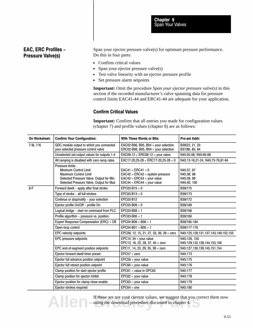
Span Your ValvesChapter 9
9-53
Span your ejector pressure valve(s) for optimum pressure performance. Do this in four parts:
Confirm critical values Span your ejector pressure valve(s) Test valve linearity with an ejector pressure profile Set pressure alarm setpoints
Important: Omit the procedure Span your ejector pressure valve(s) in thissection if the recorded manufacturer’s valve spanning data for pressurecontrol limits EAC41-44 and ERC41-44 are adequate for your application.
Confirm Critical Values
Important: Confirm that all entries you made for configuration values(chapter 7) and profile values (chapter 8) are as follows:
On Worksheet: Confirm Your Configuration: With These Words or Bits: Pro�set Addr:
7�M, 7�N QDC module output to which you connectedyour selected pressure control valve
EAC02�B06, B05, B04 = your selectionERC02�B06, B05, B04 = your selection
B39/22, 21, 20B37/86, 85, 84
Unselected set�output values for outputs 1�4 EAC09�12 = ERC09�12 = your value N45:05�08, N45:65�68
All ramping is disabled with zero ramp rates EAC17�20,25�28 = ERC17�20,25�28 = 0 N45:13�16,21�24, N45:73�76,81�84
Pressure limits:Minimum Control LimitMaximum Control LimitSelected Pressure Valve, Output for MinSelected Pressure Valve, Output for Max
EAC41 = ERC41 = 0EAC42 = ERC42 = system pressureEAC43 = ERC43 = your valueEAC44 = ERC44 = your value
N45:37, 97N45:38, 98N45:39, 99N45:40, 100
8�F Forward dwell - apply after final stroke EPC03�B15 = 0 B39/175
Type of stroke - all full strokes EPC03�B13 = 0 B39/173
Continue or stop/notify - your selection EPC03�B12 B39/172
Ejector profile On/Off - profile On EPC03�B09 = 0 B39/169
Logical bridge - start on command from PLC EPC03�B08 = 1 B39/168
Profile algorithm - pressure vs. position EPC03�B00 = 1 B39/160
Expert Response Compensation (ERC) = Off EPC04�B09 = B08 = 1 B39/185�184
Open�loop control EPC04�B01 = B00 = 1 B39/177�176
EPC velocity setpoints EPC09, 12, 15, 21, 27, 33, 36, 39 = zero N45:125,128,131,137,143,149,152,155
EPC pressure setpoints EPC10, 34 = your valueEPC13, 16, 22, 28, 37, 40 = zero
N45:126, 150N45:129,132,138,144,153,156
EPC end�of�segment position setpoints EPC11, 14, 23, 29, 35, 38 = zero N45:127,130,139,145,151,154
Ejector forward dwell timer preset EPC57 = zero N45:173
Ejector full advance position setpoint EPC59 = your value N45:175
Ejector full retract position setpoint EPC60 = your value N45:176
Clamp position for start ejector profile EPC61 = value in OPC62 N45:177
Clamp position for ejector inhibit EPC62 = your value N45:178
Ejector position for clamp close enable EPC63 = your value N45:179
Ejector strokes required EPC64 = one N45:180
If these are not your current values, we suggest that you correct them nowusing the download procedure discussed in chapter 4.
EAC, ERC Profiles -Pressure Valve(s)
Allen-Bradley Parts
Span Your ValvesChapter 9
9-54
Span Your Ejector Pressure Valve(s)
Span your ejector valve(s) for smooth operation at highest desiredpressure. Do this in the following procedure by finding the optimumvalues for:
Minimum Pressure Control Limit EAC41, ERC41 Maximum Pressure Control Limit EAC42, ERC42 Selected Pressure Valve, Output for Minimum EAC43, ERC43 Selected Pressure Valve, Output for Maximum EAC44, ERC44
Important: This procedure must be done twice, because cylinderdynamics are different for the rod side and piston side.
Important: If PanelView is operational for ejector profiles, use it to:
observe actuals change and download setpoints run profiles
Important: We suggest that you read this procedure before starting.
ATTENTION: As with any machine start-up, install a testmold. Programming errors, configuration errors, or hydraulicproblems could lead to personal injury and/or machine damage.
ATTENTION: Be sure all machine guards and shields are inplace before proceeding to guard against personal injury.
1. Jog your ejectors to the full advanced position.
2. Align all other machine hydraulics to simulate ejector advance. For example, enable required pumps and align required valves.
3. Copy initial values from EAC09-12 (N45:05-08) into DYC09-12(N40:121-124) of your PLC-5 data table with this exception:
Important: Enter a value that gives zero pressure into the word for output1, 2, 3, or 4 (DYC09-12) that drives the selected ejector pressure valve.
ATTENTION: A value of 0 does not always correspond to zeropressure or flow. For example, a bi-directional valve requires aset-output value of 50% (5000) to obtain 0 PSI.
4. Enable set-output by setting DYC01-B08 (B34/392) to 1. The QDCmodule applies the values in DYC09-12 directly to its outputs 1-4.

Span Your ValvesChapter 9
9-55
5. Observe the pressure reported in SYS26 (N40:178).
For a bi-directional valve with a spool offset:If this pressure is greater than zero, adjust the selected valveset-output value to obtain zero pressure. Stop adjusting it whenyou observe the smallest pressure attainable.
For a uni-directional valve with no response at low signal level:If this pressure is zero, adjust the selected valve set-output valueuntil the observed pressure just exceeds zero. Then re-adjust ituntil you just observe zero again.
For a uni-directional valve with a pressure actual greater thanzero but with zero output to the valve: This is lowest pressure.
6. Once you are satisfied you obtained the lowest possible pressure orthe highest possible signal at zero pressure, copy the pressureobserved in SYS26 (N40:178), (usually 0 PSI or Bar) into EAC41(N45:37), the minimum pressure control limit.
7. While maintaining this minimum pressure, observe the actualset-output value in SYS41-SYS44 (N40:193-196) that corresponds toyour selected ejector advance pressure valve. Copy this value intoEAC43 (N45:39), the selected pressure valve, output for minimum.
8. Change the set-output value in DYC09-12 (N40:121-124) thatcorresponds to the selected ejector pressure valve by 50%, and then in5% increments while observing the ejector pressure in SYS26. Stopadjusting it when the observed pressure no longer increases with anincrease in the set-output value. The pressure now observed inSYS26 is the maximum obtainable ejector pressure.
9. Copy this observed maximum pressure from SYS26 (N40:178) intoEAC42 (N45:38), the maximum pressure control limit.
10. While maintaining this maximum pressure, observe the actual valveset-output value in SYS41-SYS44 (N40:193-196) that corresponds toyour selected pressure valve. Copy this value into EAC44 (N45:40),the selected pressure valve, output for maximum.
11. Lower the set-output value in DYC09-12 corresponding to theselected ejector pressure valve to a safe level.
Allen-Bradley Parts
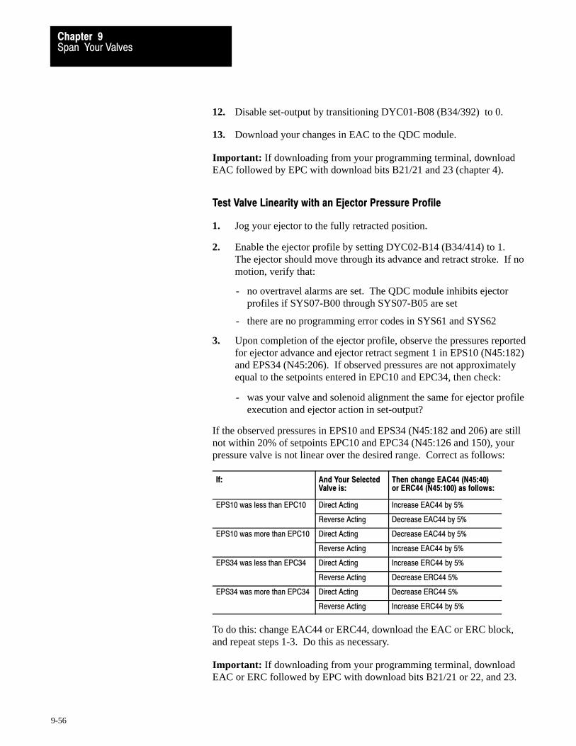
Span Your ValvesChapter 9
9-56
12. Disable set-output by transitioning DYC01-B08 (B34/392) to 0.
13. Download your changes in EAC to the QDC module.
Important: If downloading from your programming terminal, downloadEAC followed by EPC with download bits B21/21 and 23 (chapter 4).
Test Valve Linearity with an Ejector Pressure Profile
1. Jog your ejector to the fully retracted position.
2. Enable the ejector profile by setting DYC02-B14 (B34/414) to 1.The ejector should move through its advance and retract stroke. If nomotion, verify that:
- no overtravel alarms are set. The QDC module inhibits ejectorprofiles if SYS07-B00 through SYS07-B05 are set
- there are no programming error codes in SYS61 and SYS62
3. Upon completion of the ejector profile, observe the pressures reportedfor ejector advance and ejector retract segment 1 in EPS10 (N45:182)and EPS34 (N45:206). If observed pressures are not approximatelyequal to the setpoints entered in EPC10 and EPC34, then check:
- was your valve and solenoid alignment the same for ejector profileexecution and ejector action in set-output?
If the observed pressures in EPS10 and EPS34 (N45:182 and 206) are stillnot within 20% of setpoints EPC10 and EPC34 (N45:126 and 150), yourpressure valve is not linear over the desired range. Correct as follows:
If: And Your SelectedValve is:
Then change EAC44 (N45:40)or ERC44 (N45:100) as follows:
EPS10 was less than EPC10 Direct Acting Increase EAC44 by 5%
Reverse Acting Decrease EAC44 by 5%
EPS10 was more than EPC10 Direct Acting Decrease EAC44 by 5%
Reverse Acting Increase EAC44 by 5%
EPS34 was less than EPC34 Direct Acting Increase ERC44 by 5%
Reverse Acting Decrease ERC44 5%
EPS34 was more than EPC34 Direct Acting Decrease ERC44 5%
Reverse Acting Increase ERC44 by 5%
To do this: change EAC44 or ERC44, download the EAC or ERC block,and repeat steps 1-3. Do this as necessary.
Important: If downloading from your programming terminal, downloadEAC or ERC followed by EPC with download bits B21/21 or 22, and 23.
Span Your ValvesChapter 9
9-57
What You Have AccomplishedThe valve spanning procedure you just completed has defined the:
range of pressure available during any ejector profile
end-of-range minimum and maximum signal levels for linear control ofthe ejector pressure valve in open-loop control.
For thisrange limit
When trying to obtainthe pressure in:
The QDC module drives the selectedpressure valve to % output signal in:
Minimum EAC41, ERC41 EAC43,. ERC43
Maximum EAC42, ERC42 EAC44, ERC44
Now for open-loop ejector profiles, the QDC module assumes a linerrelationship between ejector pressure and signal output.
Set the Profile Pressure Alarm
Set the maximum pressure alarm EAC57 (N45:53) equal to an ejectorpressure that should:
not be exceeded during the ejector profile not be greater than EAC42 (N45:38) or ERC42 (N45:98) maximum
pressure control limits
Entering zero disables this alarm.
Download the EAC block to the QDC module.
Important: If downloading from your programming terminal, downloadEAC followed by EPC, with download bits B21/21 and 23 (chapter 4).
Allen-Bradley Parts

Span Your ValvesChapter 9
9-58
Span your ejector velocity (flow) valve(s) for optimum velocityperformance. Do this in three parts:
Confirm critical values Span your ejector velocity (flow) valve(s) Test valve linearity with an ejector velocity profile
Important: Omit the procedure Span your ejector velocity (flow) valve(s)in this section if the recorded manufacturer’s valve spanning data forpressure control limits EAC45-48 and ERC45-48 are adequate.
Confirm Critical Values
Important: Confirm that all your entries for configuration values (chapter7) and profile values (chapter 8) are as follows:
On Worksheet: Confirm Your Configuration: With These Words or Bits: Pro�set Addr:
7�M, 7�N QDC module output to which you connectedyour selected velocity control valve
EAC02�B02, B01, B00 = your selectionERC02�B02, B01, B00 = your selection
B39/18, 17, 16B39/82, 81, 80
Unselected set�output values for outputs 1�4 EAC09�12 = ERC09�12 = your value N45:05�08, 65�68
All ramping is disabled with zero ramp rates EAC17�20, 25�28 = ERC17�20, 25�28 =0
N45:13�16, 21�24, 73�76, 81�84
Velocity limits:Minimum Control LimitMaximum Control LimitSelected Velocity Valve, Output for MinSelected Velocity Valve, Output for Max
EAC45 = ERC45 = 0EAC46 = ERC46 = max velocity spec.EAC47 = ERC47 = your valueEAC48 = ERC48 = your value
N45:41, 101N45:42, 102N45:43, 103N45:44, 104
8�F Forward Dwell - apply after final stroke EPC03�B15 = 0 B39/175
Velocity Units - inches/second EPC03�B14 = 1 B39/174
Type of stroke - all full strokes EPC03�B13 = 0 B39/173
Continue or stop/notify - your selection EPC03�B12 B39/172
Ejector profile On/Off - profile On EPC03�B09 = 0 B39/169
Logical bridge - start on command from PLC EPC03�B08 = 1 B39/168
Expert Response Compensation (ERC) = Off EPC04�B09 = B08 = 1 B39/185�184
Open�loop control EPC04�B01 = B00 = 1 B39/177�176
EPC end�of�segment position setpoints EPC11, 14, 23, 29, 35, 38 = zero N45:127,130,139,145,151,154
Ejector forward dwell timer preset EPC57 = zero N45:173
Ejector full advance position setpoint EPC59 = your value N45:175
Ejector full retract position setpoint EPC60 = your value N45:176
Clamp position for start ejector profile EPC61 = value in OPC62 N45:177
Clamp position for ejector inhibit EPC62 = your value N45:178
Ejector position for clamp close enable EPC63 = your value N45:179
Ejector strokes required EPC64 = one N45:180
If these are not your current values, we suggest that you correct them nowusing the download procedure discussed in chapter 4.
EAC, ERC Profiles -Velocity (Flow) Valve(s)

Span Your ValvesChapter 9
9-59
Span Your Ejector Velocity Valve(s)
Span your ejector valve(s) for smooth operation at highest desired velocity.Do this in the following procedure by finding the optimum values for:
Minimum Velocity Control Limit EAC45, ERC45 Maximum Velocity Control Limit EAC46, ERC46 Selected Velocity Valve, Output for Minimum EAC47, ERC47 Selected Velocity Valve, Output for Maximum EAC48, ERC48
Important: This procedure must be done twice, because cylinderdynamics are different for the rod side and piston side.
Important: If PanelView is operational for ejector profiles, use it to:
observe actuals change and download setpoints run profiles
Important: We suggest that you read this procedure before starting.
ATTENTION: As with any machine start-up, install a testmold. Programming errors, configuration errors, or hydraulicproblems could lead to personal injury and/or machine damage.
ATTENTION: Be sure all machine guards and shields are inplace before proceeding to guard against personal, injury.
1. Obtain a copy of the flow rate curves provided by your flow valvemanufacturer. The flow rate curves graphically illustrate the flowthrough a valve at different input voltage or current levels and atdifferent pressure drops across the valve’s spool.
2. From these curves, determine the minimum and maximum ejectoradvance and retract flows available from your flow valve at thepressure you would normally run during ejector operation. Recordthe flows, along with the input voltages/current associated with them.
Allen-Bradley Parts
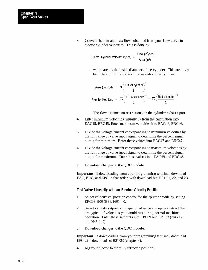
Span Your ValvesChapter 9
9-60
3. Convert the min and max flows obtained from your flow curve toejector cylinder velocities. This is done by:
Ejector Cylinder Velocity (in/sec) =Flow (in3/sec)
Area (in2)
- where area is the inside diameter of the cylinder. This area maybe different for the rod and piston ends of the cylinder:
Area for Rod End =I.D. of cylinder
2
Rod diameter
2π −
22
Area (no Rod) =I.D. of cylinder
2π
2
π
- The flow assumes no restrictions on the cylinder exhaust port .
4. Enter minimum velocities (usually 0) from the calculation intoEAC45, ERC45. Enter maximum velocities into EAC46, ERC46.
5. Divide the voltage/current corresponding to minimum velocities bythe full range of valve input signal to determine the percent signaloutput for minimum. Enter these values into EAC47 and ERC47.
6. Divide the voltage/current corresponding to maximum velocities bythe full range of valve input signal to determine the percent signaloutput for maximum. Enter these values into EAC48 and ERC48.
7. Download changes to the QDC module.
Important: If downloading from your programming terminal, downloadEAC, ERC, and EPC in that order, with download bits B21/21, 22, and 23.
Test Valve Linearity with an Ejector Velocity Profile
1. Select velocity vs. position control for the ejector profile by settingEPC03-B00 (B39/160) = 0.
2. Select velocity setpoints for ejector advance and ejector retract thatare typical of velocities you would run during normal machineoperation. Enter these setpoints into EPC09 and EPC33 (N45:125and N45:149).
3. Download changes to the QDC module.
Important: If downloading from your programming terminal, downloadEPC with download bit B21/23 (chapter 4).
4. Jog your ejector to the fully retracted position.

Span Your ValvesChapter 9
9-61
5. Enable the ejector profile by setting DYC02-B14 (B34/414) to 1.The ejector should move through its advance and retract stroke. If nomotion, verify that::
- none of your overtravel alarms are set. The QDC module inhibitsejector profiles if SYS07-B00 through SYS07-B05 are set
- there are no programming error codes in SYS61 and SYS62
6. Upon completion of the ejector profile, observe the velocitiesreported for ejector advance and ejector retract segment 1 in EPS09(N45:181) and EPS33 (N45:205). These velocities should berelatively close to the setpoints you entered in EPC09 and EPC33(N45:125, N45:149). If observed velocities are not within 25% of thesetpoints, verify that:
- you chose the correct values from your flow rate curves
- your calculations are correct
If the actual velocities are still not representative of your setpoints, yourflow valve is not linear over the range of your setpoints. Correct asfollows:
If: And Your SelectedValve is:
Then:
EPS09 was less than EPC09 Direct Acting Increase EAC48 by 5%
Reverse Acting Decrease EAC48 5%
EPS09 was more than EPC09 Direct Acting Decrease EAC48 5%
Reverse Acting Increase EAC48 by 5%
EPS33 was less than EPC33 Direct Acting Increase ERC48 by 5%
Reverse Acting Decrease ERC48 5%
EPS33 was more than EPC33 Direct Acting Decrease ERC48 5%
Reverse Acting Increase ERC48 by 5%
To do this: change EAC48 or ERC48, download the EAC or ERC block,and repeat steps 4-6. Do this as necessary.
Important: If downloading from your programming terminal, downloadEAC or ERC followed by EPC with download bits B21/21 or 22, and 23.
Allen-Bradley Parts

Span Your ValvesChapter 9
9-62
What You Have AccomplishedThe valve spanning procedure you just completed has defined the:
range of velocity available during any ejector profile
end-of-range minimum and maximum signal levels for linear control ofthe ejector velocity valve in open-loop control.
For thisrange limit
When trying to obtainthe velocity in:
The QDC module drives the selectedvelocity valve to % output signal in:
Minimum EAC45, ERC45 EAC47, ERC47
Maximum EAC46, ERC46 EAC48, ERC48
Now for open-loop ejector profiles, the QDC module assumes a linerrelationship between ejector velocity and signal output.

Chapter
10
10-1
Tune Your Machine
In chapter 9 you ran simple open-loop profiles to span your valves. Thischapter presents guidelines to help you adjust parameters in configurationand profile blocks to optimize machine performance for production runs.
We present this chapter in three major sections:
Closed-loop Tuning – We discuss the usage and effect of the QDCmodule’s PID gain constants, and procedures to determine proper gainsettings for inject, clamp, and eject operations of your plastic moldingprocess. If your application does not require closed-loop operation, skipthis section and proceed to the section entitled Injection TuningConsiderations for Producing Parts.
Injection Tuning Considerations for Producing Parts – We presentthe usage and effect of QDC module injection parameters that requirespecific considerations. We assume you are familiar with conventions,terminology, and procedures used in the injection molding industry, thismanual, and the Plastic Molding Module Reference Manual, publication1771-6.5.88.
Tuning Considerations for Clamp and Eject Operations – We present the usage and effect of other QDC module parameters forclamp and eject operations that require specific considerations. As withthe previous section, we assume you are familiar with conventions,terminology, and procedures used in the injection molding industry, thismanual, and the Plastic Molding Module Reference Manual, publication1771-6.5.88.
Chapter Objectives
Allen-Bradley Parts
Tune Your MachineChapter 10
10-2
Closed�loop Control
So far, you have run open-loop profiles with the QDC module’s PID andVelFF algorithms disabled. We suggest that you use open-loop control:
for spanning valves for troubleshooting machine performance when the machine has no pressure sensors for feedback
Important: You can achieve considerably better consistency of finishedparts when the QDC module operates in closed-loop control. With fewexceptions, you should run machine production with closed-loop profiles.
Correctly tuned closed-loop profiles are essential for precise, repeatableoperation. In chapter 7 you entered our recommended values. They maygive you desired machine performance.
Important: If you need to improve performance, continue with thissection. If not, skip to Injection Tuning Considerations for Producing Parts.
General Guidelines for Pressure Tuning
In this section we present two procedures:
Tune Pressure Loops without an Oscilloscope Tune Pressure Loops with an Oscilloscope
Repeat either one of these procedures as needed for tuning thepressure-control loop of these profiles:
Injection – Pressure vs. Position or Time Pack and Hold – Pressure vs. Time Plastication – Backpressure vs. Position Clamp Open (3) – Pressure vs. Position Clamp Open Slow – Pressure vs. Position Clamp Close (3) – Pressure vs. Position Low Pressure Close – Pressure vs. Position Ejector – Pressure vs. Position
Follow these general guidelines when tuning closed-loop pressure profiles:
Disable ramping Disable Expert Response Compensation (ERC)
Reset ERC values to zero by setting DYC05-B15 (B34/463) = 1. (Pro-Set 600 resets this bit to zero after resetting ERC values.)
Important: Gain constants differ between pressure profiles. Thedynamics of loads being moved and different hydraulic characteristicswarrant separate PID tuning considerations for each profile.
Closed�loop Tuning
Tune Your MachineChapter 10
10-3
Important: In most cases, adding a derivative term to pressure controlalgorithms makes it too sensitive and does not enhance loop stability.
Use only proportional and integral control.
Use the highest possible P and I gain constants for inject-mode profilesfor precise performance without hammering your hydraulics, but use thelowest possible P and I gain constants for clamp and eject profiles forrepeatable performance.
First tune your proportional gain. Then add integral gain.
Typically, the integral term will be larger than the proportional term.The QDC module’s pressure algorithm differs from classic PIDalgorithms.
Use an oscilloscope, if available. You can tune loops faster and easierwith it connected to QDC module’s output driving the selected valve.
Important: If you have an oscilloscope, skip to the section Tune PressureLoops with an Oscilloscope.
Tune Pressure Loops Without An Oscilloscope Repeat this procedure for each applicable pressure profile.
Before you begin tuning PID pressure loops, confirm that you:
selected the pressure vs. position algorithm selected closed-loop control disabled ERC reset ERC values disabled ramping
ATTENTION: Verify that you have correctly set the followingwords and bits in CPC and OPC that control zone overrun toguard against damaging the clamp or mold.
CPC03-B11 = 0: execute low pressure close if zone overrun occurs set CPC61 to a value larger than normal for a larger mold-protect zone OPC03-B11 = 0: execute open slow if zone overrun occurs set OPC61 to a value smaller than normal for a larger open-slow zone
1. Enter an operational profile representative of the characteristics youdesire for your production cycle.
2. Check that you zeroed the profile’s integral and derivative terms.Leave the proportional term at the value you entered in chapter 7.Allen-Bradley Parts
Tune Your MachineChapter 10
10-4
3. Downloaded all setpoint changes to the QDC module.
4. Run several cycles of the profile while comparing profile actuals(returned in the corresponding status block) with profile setpoints.Also look for abnormal flexing or pulsing of hydraulic hoses leadingto the controlled cylinder.
If: Then:
Observed actuals are consistently well belowprofile setpoints
Increase the proportional term
Observed actuals are consistently well aboveprofile setpoints
Decrease the proportional term
Excessive hammering and vibration isobserved in the cylinder's hydraulic lines
Decrease the proportional term
Important: Each time you change a gain constant, you must download thechange to the QDC module. Refer to download procedure in chapter 4.
5. Re-run the profile after each change to the proportional term untilactuals are close to setpoints, and there is no hammering andvibration in hydraulic lines to the controlled cylinder.
6. Slowly increase the integral term while running machine cycles untilprofile pressure actuals overshoot profile setpoints. Now decrease theintegral term until overshoot disappear.
Important: If you cannot make pressures actuals match entered setpoints,verify your unselected valve set-output values are correct for yourapplication (Refer to chapter 7 and the discussion later in this chapter).
Tune Pressure Loops With An Oscilloscope Before you begin tuning your pressure loops, confirm that you:
selected the pressure vs. position algorithm selected closed-loop control disabled ERC reset ERC values disabled ramping
ATTENTION: Verify that you have correctly set the followingwords and bits in CPC and OPC that control zone overrun toguard against damaging the clamp or mold.
CPC03-B11 = 0: execute low pressure close if zone overrun occurs set CPC61 to a value larger than normal for a larger mold-protect zone OPC03-B11 = 0: execute open slow if zone overrun occurs set OPC61 to a value smaller than normal for a larger open-slow zone
Tune Your MachineChapter 10
10-5
1. Enter an operational profile representative of the characteristics youdesire for your production cycle.
2. Check that you zeroed the profile’s integral and derivative terms.Leave the proportional term at the value you recorded in chapter 7.
3. Downloaded all setpoint changes to the QDC module.
4. Connect an oscilloscope to your selected pressure control valve
5. Run several profile cycles while observing the oscilloscope trace.
Ideally for each step of a multi-step profile, the oscilloscope traceshould rise or fall quickly to a controlled level and then flatten out.Bounce or chatter when rising or falling is undesirable.
If: Then:
Your scope trace for any given profile stepnever levels off (it is either rising or falling forthe entire step)
Increase the proportional term
Your scope trace for any given profile steprises (or falls) quickly and then �bounces" or�chatters" around a voltage/current
Decrease the proportional term
Excessive hammering and vibration isobserved in the cylinder's hydraulic lines
Decrease the proportional term
Important: Each time you change a gain constant, you must download thechange to the QDC module. Refer to download procedure in chapter 4.
6. Re-run the profile after each change to the proportional term untiloscilloscope traces quickly level off without bounce or chatter.
7. Slowly increase the integral term while running machine cycles untilyou observe overshoots on the oscilloscope trace. Now decrease theintegral term until overshoots disappear.
Important: If you cannot alter your proportional and integral terms so thatoscilloscope traces quickly level off without bouncing or chattering, verifyyour unselected valve set-output values are correct for your application(Refer to chapter 7 and the discussion later in this chapter).
Allen-Bradley Parts

Tune Your MachineChapter 10
10-6
General Guidelines for Velocity Tuning
If your machine will never run velocity profiles, skip this section.
In this section we present two procedures:
Tune Pressure Loops without an Oscilloscope Tune Pressure Loops with an Oscilloscope
Repeat either one of these procedures as needed for tuning closed-loopcontrol of these velocity vs. position profiles:
Injection Clamp Open (3 movements) Clamp Open Slow Clamp Close (3 movements) Ejector (2 movements)
Follow these general guidelines when tuning closed-loop velocity profiles:
Disable ramping Disable Expert Response Compensation (ERC)
Reset ERC values to zero by setting DYC05-B15 (B35/463) = 1. (Pro-Set 600 resets this bit to zero after resetting ERC values.)
Important: Gain constants differ between velocity profiles. The dynamicsof loads being moved and different hydraulic characteristics warrantseparate VelFF tuning considerations for each profile.
Important: Never use feedforward gain and ERC in the same velocityprofile.
Important: In most cases, adding a feedforward term to the VelFFalgorithm makes it too sensitive and does not enhance loop stability.
Use proportional control with a zero feedforward term. (Add feedforward only if required)
Use the highest possible P gain constant for injection profiles for precise performance without hammering your hydraulics, but use the lowest possible P gain constant for clamp and ejector profilesfor repeatable performance.
Use an oscilloscope, if available. You can tune loops faster and easierwith it connected to QDC module’s output driving the selected valve.
Important: If you have an oscilloscope, skip to Tune Velocity Loops withan Oscilloscope.
Tune Your MachineChapter 10
10-7
Tune Velocity Loops Without An Oscilloscope Before you begin tuning your velocity loop, confirm that you:
selected the velocity vs. position algorithm selected closed-loop control zeroed the VelFF term disabled ERC reset ERC values disabled ramping
ATTENTION: Verify that you have correctly set the followingwords and bits in CPC and OPC that control zone overrun toguard against damaging the clamp or mold.
CPC03-B11 = 0: execute low pressure close if zone overrun occurs set CPC61 to a value larger than normal for a larger mold-protect zone OPC03-B11 = 0: execute open slow if zone overrun occurs set OPC61 to a value smaller than normal for a larger open-slow zone
1. Enter an operational profile representative of characteristics youdesire for your production cycle.
2. Downloaded all setpoint changes to the QDC module.
3. Run several profile cycles while comparing profile actuals withprofile setpoints. Also observe hydraulic hoses leading to thecylinder as follows:
If: Then:
Observed actuals are consistently well belowprofile setpoints
Increase the proportional term
Observed actuals are consistently well aboveprofile setpoints
Decrease the proportional term
Excessive hammering and vibration isobserved in the cylinder's hydraulic lines
Decrease the proportional term
Important: Each time you change a gain constant, you must download thechange to the QDC module. Refer to download procedure in chapter 4.
4. Re-run the profile after each change to the proportional term untilobserved actuals are close to setpoints without hammering andvibration in hydraulic lines to the controlled cylinder.
Important: If you cannot make velocity actuals match entered setpoints,verify that your unselected valve set-output values are correct for yourapplication (Refer to chapter 7 and the discussion later in this chapter).Allen-Bradley Parts
Tune Your MachineChapter 10
10-8
5. If you are satisfied with your unselected valve set-output values andstill cannot match velocity actuals to desired setpoints, your controlmay require a small feedforward gain.
6. If necessary, slowly increase the feedforward term while runningmachine cycles until velocity actuals satisfactorily match enteredsetpoints.
Important: If you must use feedforward gain to adequately tune yourvelocity profile, do NOT enable ERC for this profile.
Tune Velocity Loops With An Oscilloscope Before you begin tuning your velocity loop, confirm that you:
selected the velocity vs. position algorithm selected closed-loop control zeroed the VelFF term disabled ERC reset ERC values disabled ramping
ATTENTION: Verify that you have correctly set the followingwords and bits in CPC and OPC that control zone overrun toguard against damaging the clamp or mold.
CPC03-B11 = 0: Execute low pressure close if zone overrun occurs set CPC61 to a value larger than normal for a larger mold-protect zone OPC03-B11 = 0: Execute open slow if zone overrun occurs set OPC61 to a value smaller than normal for a larger open-slow zone
1. Enter an operational profile representative of characteristics youdesire for your production cycle.
2. Check that you zeroed the profile’s feedforward term. Leave theproportional term at the value you entered in chapter 7.
3. Downloaded all setpoint changes to the QDC module.
4. Connect an oscilloscope to your selected velocity control valve
5. Run several profile cycles while observing the oscilloscope trace.
Ideally for each step of a multi-stepped profile, the oscilloscope traceshould rise or fall quickly to a controlled level and then flatten out.Bounce or chatter when rising or falling is undesirable.
Tune Your MachineChapter 10
10-9
If: Then:
Your scope trace for any given profile stepnever levels off (it is either rising or falling forthe entire step)
Increase the proportional term
Your scope trace for any given profile steprises (or falls) quickly and then �bounces" or�chatters" around a voltage/current
Decrease the proportional term
Excessive hammering and vibration isobserved in the cylinder's hydraulic lines
Decrease the proportional term
Important: Each time you change a gain constant, you must download thechange to the QDC module. Refer to the download procedure in chapter 4.
6. Re-run the profile after each change to the proportional term untiloscilloscope traces quickly level off without bounce or chatter.
Important: If you cannot alter the proportional term so that oscilloscopetraces quickly level off without bounce or chatter, verify that yourunselected valve set-output values are correct for your application. (Referto chapter 7 and the discussion later in this chapter).
7. If you are satisfied with the unselected valve set-output values andstill cannot make the oscilloscope trace quickly level off withoutbounce or chatter, your control may require a small feedforward gain.
8. If necessary, slowly increase the feedforward term while runningmachine cycles until the oscilloscope trace levels off without bounceor chatter.
Important: If you must use feedforward gain to adequately tune yourvelocity profile, do NOT enable ERC for this profile.
Allen-Bradley Parts

Tune Your MachineChapter 10
10-10
In this section, we discuss the usage and effect of the following items asthey apply to the inject operation:
Profile Requirements Cushion, Shot Size, and Transition Setpoints Unselected Valve Set-output Values Logical Bridges End-of-profile Set-output Values Pre- and Post-decompression Pullback Acceleration and Deceleration Ramp Rates Watchdog Timer and Profile Offsets Pressure Alarm Setpoints Pressure-limited Velocity vs. Position Injection Expert Response Compensation
We assume you are familiar with conventions, terminology, and proceduresused in the Injection Molding Industry, in this manual, and in the PlasticMolding Module Reference Manual.
Profile Requirements
A profile is a series of position (or time) and pressure (or velocity)setpoints which uniquely define a phase of the injection molding processfor a given part. The complexity of the profile depends on your machineand the part you want to mold. Next we discuss required setpoints.
Velocity Setpoints Use velocity setpoints for the injection velocity vs. position profile tocontrol the fill rate of various mold cavities with repeatability.
Do not be concerned if the reported velocity in the first segment of yourvelocity vs. position profile does not match its setpoint. For example, thevelocity of the first segment could:
Undershoot if you programmed a short length or time. It takes time forthe hydraulics to overcome the inertia of the injection cylinder andaccelerate the ram (screw) to desired velocity.
Do NOT increase velocity gain constants to compensate. Excessivegain may de-stabilize the velocity loop during the rest of the profile.
Overshoot if you configured a large post-decompression pullback afterplastication. The ram (screw) sees little resistance pushing plastic overthe post-decompression distance until the plastic reaches the mold gate.
Do NOT decrease velocity gain constants to compensate. Too little gainmay cause the velocity loop to be sluggish during the rest of the profile.
Injection TuningConsiderationsfor Producing Parts

Tune Your MachineChapter 10
10-11
Important: The injection velocity profile requires one additional velocitysetpoint beyond the last non-zero end-of position setpoint, so you mustprogram one more velocity setpoint than position setpoint, such that
total velocity setpoints = total position setpoints + 1
If not, the ram (screw) stops at the final end-of-position setpoint (if it doesnot see a pressure transition beforehand).
Pressure Setpoints You may use pressure setpoints in all phases of the inject mode:
For injection, use pressure setpoints to fill the mold cavity. Make them:
high enough to give sufficient pressure to fill the mold low enough to avoid flashing the mold
For pack and hold, use pressure setpoints to relax the pressure applied tothe molten plastic as it cools in the mold.
For plastication, use backpressure setpoints to control heating the plasticdue to shearing as the rotating ram (screw) backs up the length of theshot against a backpressure determined by your setpoints.
Important: The injection and plastication pressure profiles require oneadditional pressure setpoint beyond the last non-zero end-of positionsetpoint (or last non-zero segment time setpoint), so you must program onemore pressure setpoint than position (or time) setpoint, such that
total pressure setpoints = total position (or time) setpoints + 1
If not,
for the injection pressure profile, the ram (screw) stops at the finalend-of-position (or time) setpoint, unless it sees a transition before:
reaching the last end-of position setpoint the final time setpoint has expired
for the plastication pressure profile, the final backpressure becomeszero unless the ram (screw) reaches 100% shot size before:
reaching the final end-of-segment position the final time setpoint has expired
End-of-segment Position Setpoints Shot size is subdivided into profile segments, the lengths of which aredetermined by your end-of-segment position setpoints. Each segment hasits velocity or pressure setpoint for controlling the ram (screw).
Allen-Bradley Parts
Tune Your MachineChapter 10
10-12
Important: Avoid multiple adjacent segments having the same velocity orpressure setpoint. For better control, use a constant velocity or pressureover a single equivalent length segment.
For injection velocity or pressure profiles, you must always program onefinal velocity or pressure setpoint without an associated end-of-positionsetpoint that the QDC module uses until it reaches transition (for injection)or 100% shot size (for plastication).
Time Setpoints Time setpoints define the duration of each profile segment that appliespressure to the ram (screw).
Important: Avoid multiple adjacent segments having the same pressuresetpoint. For better control, use a constant pressure over a singleequivalent time segment.
For injection or plastication pressure profiles, you must always programone final pressure setpoint without an associated time setpoint that theQDC module uses until it reaches transition (for injection) or 100% shotsize (for plastication).
Minimum Profile Requirements We present minimum requirements for inject-mode profiles. Use this as astarting point for developing your own part-specific profiles.
Profile End�of�SegmentPosition Setpts
TimeSetpoints
VelocitySetpoints
PressureSetpoints
Other
Injection
Velocity vs. Position None required N/A IPC09 N/A one of IPC60, 61, or 62
Pressure�limited Velocity vs. Position
None required N/A IPC09 N/A one of IPC60, 61, or 62IPC57, 58, and 59
Pressure vs. Position None required N/A N/A IPC10 one of IPC60, 61, or 62
Pressure vs. Time N/A None required N/A IPC10 one of IPC60, 61, or 62
Pack Pressure vs. Time
N/A HPC11 N/A HPC10 ----
Hold Pressure vs. Time
N/A HPC28 N/A HPC27 ----
Plastication
Pressure vs. Position None required N/A N/A PPC10 PPC61 and 62
Pressure vs. Time N/A None required N/A PPC10 PPC61 and 62

Tune Your MachineChapter 10
10-13
Cushion, Shot Size, and Transition Setpoints
Shot Size is the amount of molten plastic injected into the mold. Cushion isthe amount of molten plastic that remains in the barrel after injection.Thesum of shot size (PPC61) plus cushion (PPC62) tells the QDC modulewhere to terminate the Plastication profile.
During injection, the QDC module does NOT terminate the shot atcushion, but continues injecting until one of the three injection transitionconditions occurs. These three conditions during the injection profile are:
elapsed time exceeds a preset limit ram (screw) pressure exceeds a preset limit ram (screw) position exceeds a preset limit
Shot Size (PPC61) Shot size (measured from cushion) is the amount of molten plastic neededto fill the mold (figure 10.3). Determine it with these general steps:
1. Start with a shot size you know will NOT fill the mold.
2. Enter a ram(screw) transition position about 1/2” from ram bottom.
3. Run a shot with transition on position.
The end-of-hold position will be at ram bottom, because moldcavities continue to fill during pack and hold.
4. While continuing to transition on position, slowly increase the shotsize until the end-of-hold position is
above ram bottom approximately equal to cushion
5. The shot size is correct for the mold/part you are tuning when:
the end-of-hold position is approximately equal to cushion all cavities on the mold are being fully filled
Cushion (PPC62)Cushion (measured from mold end) is the length of molten plastic youwant remaining in the barrel after filling mold cavities (figure 10.3). TheQDC module adds this length to shot size length to determine where toterminate plastication.
Allen-Bradley Parts
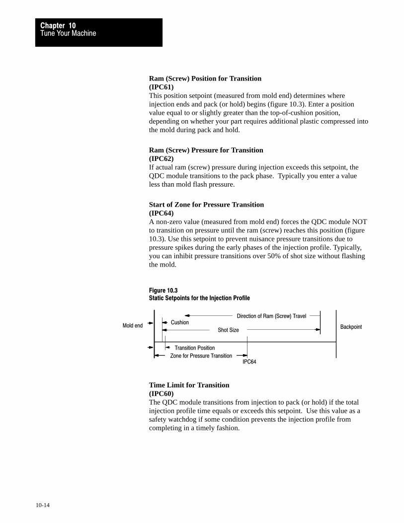
Tune Your MachineChapter 10
10-14
Ram (Screw) Position for Transition (IPC61)This position setpoint (measured from mold end) determines whereinjection ends and pack (or hold) begins (figure 10.3). Enter a positionvalue equal to or slightly greater than the top-of-cushion position,depending on whether your part requires additional plastic compressed intothe mold during pack and hold.
Ram (Screw) Pressure for Transition (IPC62)If actual ram (screw) pressure during injection exceeds this setpoint, theQDC module transitions to the pack phase. Typically you enter a valueless than mold flash pressure.
Start of Zone for Pressure Transition (IPC64) A non-zero value (measured from mold end) forces the QDC module NOTto transition on pressure until the ram (screw) reaches this position (figure10.3). Use this setpoint to prevent nuisance pressure transitions due topressure spikes during the early phases of the injection profile. Typically,you can inhibit pressure transitions over 50% of shot size without flashingthe mold.
Figure 10.3Static Setpoints for the Injection Profile
BackpointMold endCushion
Shot Size
Transition Position
Zone for Pressure Transition
Direction of Ram (Screw) Travel
IPC64
Time Limit for Transition (IPC60)The QDC module transitions from injection to pack (or hold) if the totalinjection profile time equals or exceeds this setpoint. Use this value as asafety watchdog if some condition prevents the injection profile fromcompleting in a timely fashion.
Tune Your MachineChapter 10
10-15
Unselected Valve Set�output Values
We presented guidelines to assist you in determining unselected valveset-output values (words 09 through 12 in configuration command blocks)in chapter 7 prior to spanning your machine valves in chapter 9. The valuein these words is the signal level sent to all outputs not selected for controlby the QDC module’s algorithm during a profile.
In chapter 7, you determined the signal output percentages required todrive the unselected valves during respective profiles. These values shouldallow desired ram (screw) control. Although different part set-ups andother process considerations may require that you modify them during aparticular profile, you should adjust them only if you are unable to obtaindesired closed-loop control by modifying profile gain constants.
Important: When attempting to achieve desired closed-loop control, doNOT change unselected valve set-output values until after you haveadjusted the profile gain constants.
Important: Large changes to your unselected valve set-output values mayrequire re-spanning the selected valve for that profile. Refer to chapter 9for valve spanning procedures.
If you believe your unselected valve set-output values are adverselyaffecting your ability to obtain quality closed-loop control, consider thefollowing:
If your Selectedvalve controls:
And you observe: Then:
Pressure Profile segment pressuressubstantially greater thansetpoint
Decrease the flow available during theprofile by appropriately modifying theset�output value driving the flow valve.
Pressure Profile segment pressuressubstantially less thansetpoint
Increase the flow available during the profileby appropriately modifying the set�outputvalue driving the flow valve.
Velocity Profile segment velocitiessubstantially greater thansetpoint
Decrease the pressure available during theprofile by appropriately modifying theset�output value driving the pressure valve.
Velocity Profile segment velocitiessubstantially less thansetpoint
Increase the flow available during the profileby appropriately modifying the set�outputvalue driving the pressure valve.
Allen-Bradley Parts
Tune Your MachineChapter 10
10-16
Logical Bridges
In chapter 8, you configured your hold and plastication profiles to stop andset outputs for no flow or pressure at completion. If your hydraulics and/orprocess require NO changes controlled by your PLC-5 processor beforecontinuing a molding cycle, you may configure the QDC module tologically bridge the following profile/movement pairs as integratedmachine phases:
hold/pre-decompression (HPC03-B08 = 0) pre-decompression/plastication (HPC03-B09 = 0) plastication/post-decompression (PPC03-B08 = 0)
Important: The QDC module always logically bridges the injection, packand hold phases as a single integrated machine movement.
Bridging machine phases has benefits such as:
reduced cycle time smoother QDC control less chance of hydraulic pressure transients
If your hydraulics and/or process require changes controlled by yourPLC-5 processor before continuing a molding cycle, you may configurethe QDC module to stop at completion of:
hold (HPC03-B08 = 1) pre-decompression (HPC03-B09 = 1) plastication (PPC03-B08 = 1)
Then the QDC module sends a fixed signal to each of its four outputswhile awaiting further commands from the PLC-5 processor.
Important: The QDC module always stops and sets outputs at completionof the post-decompression movement.
End�of�profile Set�output Values
End-of-profile set-output values have uses including:
adjusting flow through a variable pump between profiles initializing valves for the next profile or movement re-aligning solenoid valves by PLC-5 processor before starting the next
profile or movement
When configuring end-of-profile set-output values, remember:
The QDC module ignores these values on all profiles that are logicallybridged to the next profile or movement
Tune Your MachineChapter 10
10-17
After the QDC module sets them, they remain set until the QDC moduleis commanded to start another movement or profile, or until the stopcommand is asserted
Pre� and Post�decompression Pullback (for pre�decompression PRC05)(for post�decompression PSC05)
Pre-decompression separates plastic solidifying in the sprue from themolten cushion remaining in the barrel. The QDC module applies pre-decompression pullback to the ram (screw) after hold, before plastication.
Post-decompression guards against drooling molten plastic into the openmold when the clamp is opening. The QDC module applies post-decompression pullback to the ram (screw) after plastication.
When configuring pre- and post-decompression:
Enter values into PRC05 and PSC05 only after you have tested shot sizeand cushion (PPC61 and PPC62).
Enter set-output values into PRC09-12 and PSC09-12 for the pre-andpost-decompression movements equal to the ram (screw) reverse jogset-output values (JGC25-28) from chapter 5.
Enter end-of-movement set-output values into PRC33-36 and PSC33-36as required by your application.
Acceleration and Deceleration Ramp Rates
The zero ramp rate values entered in chapter 7 disabled ramping. Thisforces the QDC module to step from setpoint to setpoint during a profile.
If required by your application, you may configure your QDC module toramp its outputs during a profile. The QDC module uses configuredacceleration and deceleration ramp rates to move all outputs from setpointto setpoint during execution of any profile (figure 10.1).
ATTENTION: Ramp rates are not applied until the QDCmodule is actually executing the profile. Because ramp ratesare time based, using excessively slow (low value) ramp ratesmay inhibit effective closed-loop control, reduce ERCcalculation accuracy, and limit QDC control capability. Useramps only if machine operation mandates them.
Allen-Bradley Parts

Tune Your MachineChapter 10
10-18
Figure 10.1Example Injection, Pack, and Hold Profiles with Ramps
Time
Hold Profile Selected ValveDecel. Ramps
Pack Profile SelectedValve Accel. & Decel.Ramps
Injection ProfileSelected Valve Accel. Ramps
Hold Profile
PackProfile
InjectionProfile
Pressure Velocity
Position
Important: When enabled, the QDC module applies ramp rates at thebeginning of each profile segment.
With caution, you can use ramp rates to smooth out jerky motion presentduring large increases or decreases in pressure or flow.
If your application requires the use of ramp rates:
Never apply ramp rates until you have already tuned all applicablepressure and velocity loops.
Ramp rates control selected and unselected valves. Therefore, eventhough you may be controlling velocity, you can ramp ram (screw)pressure during an injection profile prior to pack.
Ramp rates and ERC may not function properly together. Be verycareful if applying ERC and ramp rates on the same profile.
Using slow ramp rates may force pressure and velocity actuals out ofcontrol because these actuals include the time spent ramping as well asthe time for each segment.
The QDC module uses ramp rates when beginning a profile ormovement, or when stepping from segment to segment within a profile.
You enter ramp rates in units of 0 to 9999 percent signal output persecond (note that there is no decimal point). A ramp rate of 9999 letsthe output move full range in 10 milliseconds, while a ramp rate of 99requires a full second to go full range. Lower values = slower ramps.

Tune Your MachineChapter 10
10-19
Profile Watchdog Timer and Profile Offsets
Profile Watchdog Timer(PLC08)Set your plastication profile watchdog timer preset after your machine isrunning repeatable, quality parts. Set it just longer than the repetitiveduration of the profile to warn that a process problem may be developing.For example, warn of a low feed level from the hopper.
Profile Offsets (for velocity – IPC51)(for pressure – IPC52, HPC25 and 42, PPC52)The offset shifts the amplitude of all pressure or velocity setpoints (y-axis)of a profile by a single value. Use it during set-up after you have obtainedthe desired profile shape to boost or reduce the overall effect of the profile.
Pressure Alarm Setpoints
The QDC monitors process pressure and compares it against two differenttypes of high pressure alarm setpoints. Pressure is compared to theabsolute pressure alarm setpoint (configured in the MCC - refer to chapter4) on a continuous basis and without regard to current machine mode oroperational cycle. Pressure is compared to profile pressure alarm setpoints(configured in the respective configuration blocks - refer to chapter 7) onlyduring the execution of the subject profile. In general:
Use the absolute pressure alarm to detect dangerously high pressureconditions. We recommend that you set this alarm setpoint well abovenormal operating levels while still below levels that could result inmachinery damage or danger to personnel. Program your PLC-5 ladderlogic to stop the QDC module and place the machine in a safe conditionif this alarm is triggered.
Use profile pressure alarms to detect abnormally high pressureconditions. We recommend these alarm setpoints be set only marginallyabove the highest pressure expected during any acceptable iteration ofthe subject profile while still low enough to be indicative of processproblems. Program your PLC-5 ladder logic to interrupt the process orsignal the machine operator to determine corrective action if one ofthese alarms is triggered.
Allen-Bradley Parts

Tune Your MachineChapter 10
10-20
Pressure�limited Velocity vs. Position Injection
Pressure-limited velocity vs. position differs from both velocity andpressure injection control. During normal operation, pressure-limitedvelocity control acts the same as velocity vs. position control. However,when ram (screw) pressure exceeds a preset, the QDC module changesfrom velocity to pressure control to guard against flashing the mold.
Use pressure-limited velocity vs. position control during:
Set-up – It lets you enter a pressure-limiting preset just below the moldflash point to guard against flashing the mold.
Normal operation – It lets you run high speed velocity vs. positionprofiles while guarding against flashing the mold.
In general, pressure-limited injection velocity works as follows startingwith velocity control:
When the QDC module And And Then the QDC module
Controls ram velocity Ram pressureexceeds IPC57
Ram position is withinpressure�limit zonedefined by IPC58
1) Freezes its outputs at current levels.2) Starts time delay in IPC59.
Freezes its outputs afterram pressure exceedsIPC57 during velocitycontrol
Time delay IPC59expires
Ram pressureexceeds IPC57
1) Switches to PID control of the selected pressurevalve using IPC57 as the PID setpoint..2) Resets the selected velocity valve (if differentfrom the selected pressure valve) to its set�outputvalue from INC09�12.
Ram pressure is lessthan IPC57
Resumes velocity control.
Controls ram pressure Ram velocity exceedsa segment setpoint
--- 1) Freezes its out puts as current levels.2) Starts time delay IPC59.
Freezes its outputs afterram velocity exceeds asegment setpoint duringpressure control
Time delay IPC59expires
Velocity exceeds thesegment setpoint
1) Returns to VelFF control of the selected velocityvalve using current setpoint.2) Resets the selected pressure valve (if differentfrom the selected velocity valve) to its set�outputvalue from INC09�12.
Velocity is less thanthe segment setpoint
Resumes pressure control
You control the maximum pressure of the pressure-limited velocity vs.position profile with setpoint IPC57.
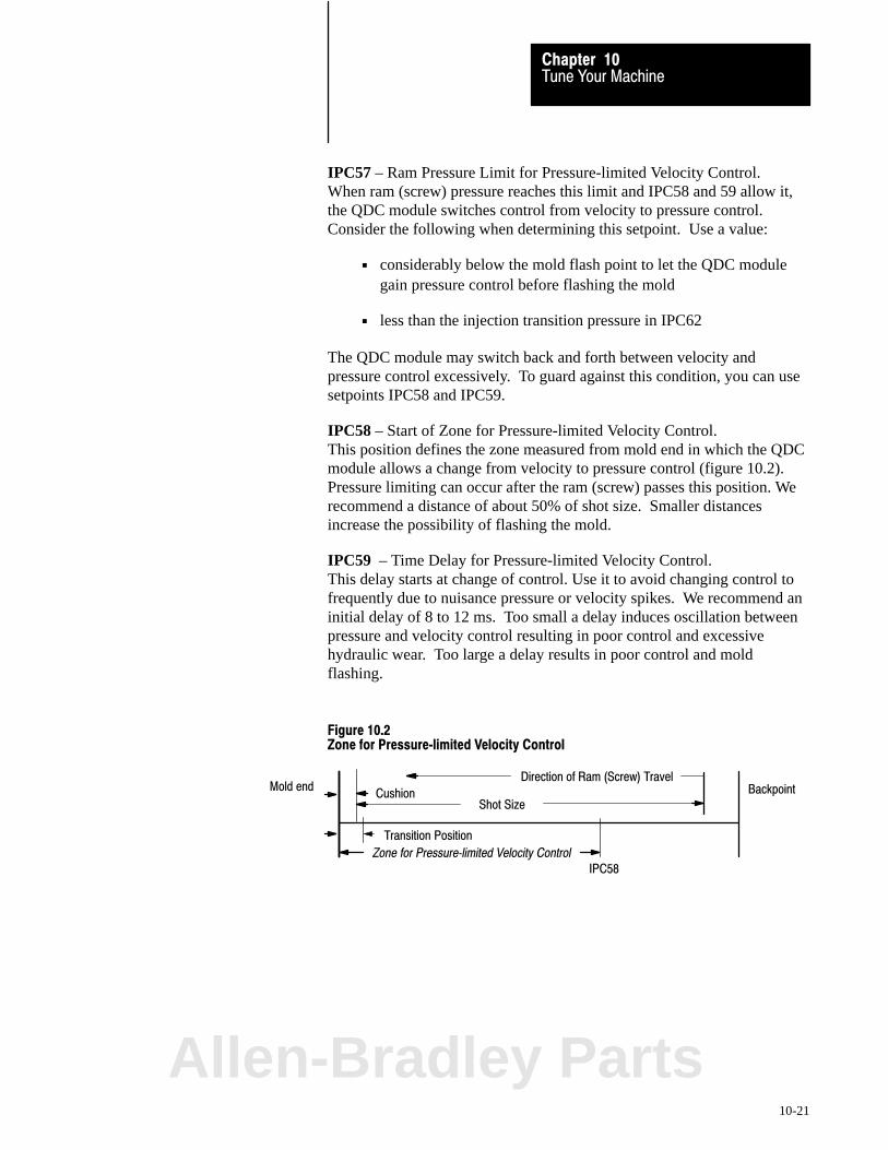
Tune Your MachineChapter 10
10-21
IPC57 – Ram Pressure Limit for Pressure-limited Velocity Control. When ram (screw) pressure reaches this limit and IPC58 and 59 allow it,the QDC module switches control from velocity to pressure control.Consider the following when determining this setpoint. Use a value:
considerably below the mold flash point to let the QDC modulegain pressure control before flashing the mold
less than the injection transition pressure in IPC62
The QDC module may switch back and forth between velocity andpressure control excessively. To guard against this condition, you can usesetpoints IPC58 and IPC59.
IPC58 – Start of Zone for Pressure-limited Velocity Control. This position defines the zone measured from mold end in which the QDCmodule allows a change from velocity to pressure control (figure 10.2).Pressure limiting can occur after the ram (screw) passes this position. Werecommend a distance of about 50% of shot size. Smaller distancesincrease the possibility of flashing the mold.
IPC59 – Time Delay for Pressure-limited Velocity Control. This delay starts at change of control. Use it to avoid changing control tofrequently due to nuisance pressure or velocity spikes. We recommend aninitial delay of 8 to 12 ms. Too small a delay induces oscillation betweenpressure and velocity control resulting in poor control and excessivehydraulic wear. Too large a delay results in poor control and moldflashing.
Figure 10.2Zone for Pressure�limited Velocity Control
BackpointMold endCushion
Shot Size
Transition Position
Zone for Pressure�limited Velocity Control
Direction of Ram (Screw) Travel
IPC58
Allen-Bradley Parts

Tune Your MachineChapter 10
10-22
Expert Response Compensation
The QDC module uses a proprietary, enhanced control scheme calledExpert Response Compensation (ERC). It compensates for changes inyour machine dynamics, machine hydraulics, raw materials, and otherprocess variables. It also adjusts the open-loop and closed-loop controlalgorithms to compensate for abrupt upsets and long term deviations toyour process. In previous chapters, you ran profiles with the QDCmodule’s ERC algorithm disabled.
Use ERC:
for normal operation when strict adherence to velocity or pressure (notposition) setpoints is required.
Do NOT use ERC:
when spanning your valves if using velocity feedforward Vel/FF gain if using acceleration or deceleration ramp rates until you have properly tuned the control loop
ATTENTION: Jerky, abrupt ram (screw) motion may result ifyou apply ERC to a control loop that has not been properlytuned.
ERC Minimum Percentage ValuesIf using ERC, adjust values recommended in chapter 7 as follows:
If ERC is enabled (on) and: Then:
The actual velocity or pressure swings wildlyaround the setpoint from cycle to cycle
Decrease the ERC minimum % value
The actual velocity or pressure takes severalcycles to achieve the desired setpoint
Increase the ERC minimum % value

Tune Your MachineChapter 10
10-23
In this section, we discuss the usage and effect of the following items asthey apply to clamp operation:
Control Objectives for Clamp and Ejector Operations Profile Requirements Logical Bridges End-of-profile (-stroke) Set-output Values Unselected Valve Set-output Values Acceleration and Deceleration Ramp Rates Pressure Alarm Setpoints Watchdog Timer Expert Response Compensation
We assume you are familiar with conventions, terminology, and proceduresused in the Injection Molding Industry, in this manual, and in the PlasticMolding Module Reference Manual.
Control Objectives for Clamp and Ejector Operations
Most molders share the following objectives when tuning their clamp andejector operations and setting up molds to produce parts. These objectivesapply to both toggle and hydraulic machines.
Repeatable mold full open position. Automated removal of parts frommold cavities makes repeatable mold full open positioning a necessity.
Precise pressure control during low pressure close. This is necessaryto detect obstructions to mold closure and prevent mold damage.Recent advances in control technology let you do this with closed-loopalgorithms, not relying on hydraulic components and circuit design.
High speed clamp operation. This lets you achieve minimum machinecycle time with repeatable mold positioning and precise low pressureclose control.
Smooth clamp operation. Abrupt clamp movements can causedamage to clamp mechanisms and accelerate wear on machinehydraulics.
High certainty of parts ejection. Parts not automatically or completelyejected can cause machine downtime and equipment damage.
Part quality protection . Care must be taken not to damage the partswhen ejecting them from the mold cavities.
Repeatable ejection position. The advent of automated part removalfrom mold cavities has made repeatable ejector advance positioning aprocess necessity.
Tuning Considerationsfor Clamp and EjectorOperations
Allen-Bradley Parts
Tune Your MachineChapter 10
10-24
High speed ejector operation while meeting the above objectives.Molders want to achieve minimal machine cycle time while insuringpart quality, achieving repeatable ejector advance positioning, andpositive part ejection.
Profile Requirements
A profile is a series of position and pressure (or velocity) setpoints whichuniquely define a phase of clamp or ejector motion. The complexity ofthe profile depends on your mold, clamp, and ejector mechanism. Nextwe discuss required setpoints.
Velocity Setpoints for Clamp and Ejector ProfilesIn general, choose velocity setpoints to move the clamp and ejector quicklywithout damaging the machine, mold, or parts. Because of the clamp’slarge dynamic load, be very careful if you configure the clamp to operate athigh speeds because once accelerated, the moving platen/moldcombination is extremely difficult to stop in a short period of time.
When configuring velocity profiles:
Start with relatively low velocity setpoints.
Increase them in small increments while observing clamp motion andrepeatability at critical positions in the cycle.
Because of the inertia and momentum of moving large masses, remember:
Unless the first clamp close/open profile segment is of long duration,actual velocities generally will undershoot setpoints. It takes time forthe hydraulics to overcome the clamp’s inertia and build adequatepressure and flow to accelerate the clamp to the requested velocity.
Actual velocities of your second and/or third clamp close/open profilesegments generally will overshoot setpoints. Overshoot increases withhigher velocities. Once the platen/mold combination gains momentum,it is difficult to slow it to the requested velocity.
Low Pressure Close (LPC) Pressure Setpoints In general, use LPC pressure setpoints low enough to let obstructions (suchas sprues or un-ejected parts) resist mold closure and halt clamp movementbefore the clamp reaches the mold-safe position. Use the low pressureclose watchdog timer to signal the PLC-5 processor that a mold-protectionfault has occurred.

Tune Your MachineChapter 10
10-25
End-of-segment Position Setpoints for Clamp and EjectorThese setpoints depend on the mold, clamp, and ejector configurations ofyour molding machine. In general, you are not required to enter anyend-of-segment position setpoints for the clamp or ejector. If you DONOT use them, expect the following results in these movements:
For this movement The QDC module Then the QDC module:
First Clamp Close Uses any non�zero velocity setpoint (CPC09)or pressure setpoint (CPC10) until the clampreaches the protective start LPC position(CPC61). The 2nd and 3rd clamp closemovements are not used.
• Either stops and zeros outputs (CPC03�B11 = 1)
• or begins LPC movement (CPC03�B11 = 0) until the clamp reaches the configured mold�safeposition (CPC62).
First Clamp Open Uses any non�zero velocity setpoint (OPC09)or pressure setpoint (OPC10 until the clampreaches the protective start open slow position(OPC61). The 2nd and 3rd clamp openmovements are not used.
• Either stops and zeros outputs (OPC03�B11 = 1)
• or begins Open�Slow movement (OPC03�B11 = 0)until the clamp reaches the configured mold fullyopen position (OPC62).
Ejector Uses velocity setpoint (EPC09) or pressuresetpoint (EPC10) until the ejector reaches itsfully advanced position (EPC59).
• Either stops and sets outputs (EPC03�B12 = 1)
• or begins retract movement (EPC03�B12 = 0) with velocity setpoint (EPC33) or pressuresetpoint (EPC34) until the ejector reaches theconfigured fully retract position (EPC60).
During normal operation, the only required end-of-segment positionsetpoints are for:
first clamp close (CPC11) to identify the operational start LPC position first clamp open (OPC11) to identify the operational start open-slow
position
If you need additional profile segments (with the same unselected valveset-output values), begin with:
2nd segment of first clamp close for clamp close profiles 2nd segment of first clamp open for open profiles
Use all available segments in first clamp close and first clamp open beforeusing any in second and third clamp close/open (unless you requiredifferent unselected valve set-output values for successive segments).
If using ejectors, start with the first advance and retract setpoints. Ifadditional profiled setpoints are required, add the second, then the thirdadvance and retract setpoints.
Allen-Bradley Parts

Tune Your MachineChapter 10
10-26
Important: Fast segment velocities or high segment pressures may causethe clamp to overshoot the start low pressure close or start open-slowposition. If you increase a velocity or pressure setpoint in a fast clampclose (or open) movement, we recommend that you increase the distance tothe start LPC position (or decrease the distance to the open-slow position)at least temporarily to assure a successful low pressure close (or openslow) movement and mold closure (or opening).
Important: Avoid using the same velocity or pressure setpoint onsequential segments. For better control, use a single segment of longerlength or duration (figure 10.3).
Figure 10.3Better Control from Fewer and Longer Steps
Clamp Close Profiles
Rather than using a profile withmultiple steps at the samevelocity or pressure...
Use fewer, longer steps
Start Clamp LPC Position Setpoint (CPC61) The QDC module uses this clamp position as protection against running aclamp close profile into the mold protection zone. Although you can use itas an operational setpoint when CPC03-B11 = 0 (see discussion ofEnd-of-Segment Position Setpoints above), its purpose is to guard againstmold damage resulting from profile entry errors.
Important: This position setpoint should be determined and set only byqualified personnel, so we do not present it on any Pro-Set 600 screen.
Calculate CPC61 by determining the smallest distance required for theQDC module to safely assume pressure control:
prior to mating the two mold halves with the clamp closing at maximum velocity and pressure

Tune Your MachineChapter 10
10-27
Figure 10.1Example Setpoints for Mold Safe (CPC62) and Start Protection Zone (CPC61)
(OPC62)Fully Open Mold Safe
Clamp Motionzero
(CPC61) (CPC62)
LPC
Protection Zone
By setting this clamp position as stated, you minimize the possibility ofmold damage that could result from changing clamp-close velocity,pressure, or position setpoints.
ATTENTION: On hydraulic (non-toggle) clamp mechanisms,re-adjust this parameter to account for mold thickness each timeyou install a different mold to guard against damage to themachine and personal injury.
Start Clamp Open Slow Position Setpoint (OPC61) The QDC module uses this clamp position to guard against running aclamp-open profile into the open-slow zone. Although you can use it as anoperational setpoint OPC03-B11 = 0 (see discussion of End-of SegmentPosition Setpoints above), its purpose is to maintain precision clamppositioning regardless of profile entry errors.
Important: This position setpoint should be determined and set only byqualified personnel, so we do not present it on any Pro-Set 600 screen.
Calculate OPC61 by determining the smallest distance required for theQDC module to safely assume pressure control:
prior to the mold reaching full open position with the clamp opening at maximum velocity and pressure
Figure 10.2Example R4 Setpoints
Mold Safe
Clamp Motion
Fully Open
zero
(OPC62) (OPC61) (CPC62)
OSC
Overrun Zone
Allen-Bradley Parts

Tune Your MachineChapter 10
10-28
By setting this clamp position as stated, you guard against the possibility ofdamaging your clamp mechanism that could result from changingclamp-open velocity, pressure, or position setpoints.
Important: Re-adjust this value each time you install a new mold.
Zone Overrun for CPC61 and OPC61 The following summarizes the choices of control action when the QDCmodule detects that the clamp passed these positions:
start open slow position (OPC61) start LPC position (CPC61)
When the clamppasses this position
The QDC module If you configured
CPC61 changes to low pressure close CPC03�B11 = 0
start LPC position stops and zeros outputs CPC03�B11 = 1
OPC61 changes to clamp open slow OPC03�B11 = 0
start open�slow position stops and zeros outputs OPC03�B11 = 1
Ejector Position for Clamp Close Enable (EPC63)The QDC module uses this position as protection against starting (orcontinuing) any clamp close profile when the ejector is not safely retracted.This includes possible extension of ejectors after full retraction due to:
bi-directional proportional flow valves which cannot be centered delays in the shifting directional solenoid valves
The QDC module requires this parameter to guard against starting a closeoperation by operator error or faulty logic when the ejector is advanced.
In chapter 8, you determined the maximum safe ejector position for EPC63by jogging the ejectors against a fully closed mold.
Important: If you change ejector tooling or the mold on your machine,repeat the procedure in chapter 8 and recalculate this value to guard againstdamaging ejectors when closing the mold.
Clamp Position for Ejector Inhibit (EPC62)The QDC module uses this clamp position as protection against starting (orcontinuing) any ejector profile when the clamp opening is not adequate forfull ejector action. Nominally, this clamp position is equal to the sum of:
mold safe position + ejector full stroke length (CPC62) + (EPC59-EPC60)

Tune Your MachineChapter 10
10-29
Important: If you change tooling or set-up which results in changingeither of these two distances, you must recalculate clamp position EPC62.
Clamp Position for Start of Ejector Profile (EPC61)If you select to start the ejector profile on position (EPC03-B08 = 0) ratherthan on command (EPC03-B08 = 1), the QDC module immediately beginsexecuting the ejector profile once the clamp reaches this position duringany clamp open profile.
Any position greater than EPC62 is satisfactory for this clamp position.Starting ejector movement before the clamp is fully open has industryacceptance as a legitimate method to reduce overall machine cycle time.
If your machine shares hydraulic flow between clamp and ejectormanifolds, operating the two cylinders in tandem decreases the accuracy of
valve spanning parameters determined in chapter 9 tuning constants determined earlier in this chapter
In closed-loop mode, the QDC module attempts to fully open both theejector and clamp flow valves to maintain velocity setpoints. When theclamp reaches the full open position and full flow is again made availableto the ejector, closed-loop ejector operation may become unstable.
ATTENTION: Use extreme caution when operating the clampand ejector in tandem on machines that share fluid between thetwo cylinders in closed-loop, especially with ERC enabled.Unstable operation could result in unpredictable operation withpossible equipment damage and injury to personnel.
Logical Bridges
In chapter 8, you configured your QDC module to logically bridge all yourclamp profiles. This forced the QDC module to start each successiveprofile at completion of the previous one in each direction of movement.If your hydraulics and/or process require NO changes between profilescontrolling clamp motion, you may configure the QDC module to logicallybridge the clamp open and close profiles as integrated machine phases:
first clamp close to second clamp close (CPC03-B08 = 0) second clamp close to third clamp close (CPC03-B09 = 0) third clamp close to low pressure close (CPC03-B10 = 0) first clamp open to second clamp open (OPC03-B08 = 0) second clamp open to third clamp open (OPC03-B09 = 0) third clamp open to open slow (OPC03-B10 = 0)
Allen-Bradley Parts
Tune Your MachineChapter 10
10-30
Bridging machine phases has benefits such as:
reduced cycle time smoother control less chance of hydraulic pressure transients
End�of�profile (�stroke) Set�output Values
If required by your application, you may configure the QDC module tostop at the completion of any profile (or stoke) and provide a constantsignal to each of its four outputs while awaiting further commands fromyour PLC-5 processor. Disabling logical bridges and configuring end-of-profile (-stroke) set-output values let you do this. Recall in chapter 9 thatwe used set-output values at the end of the low pressure close profile toachieve tonnage on hydraulic clamps and hold pressure on toggle clamps.
If your hydraulics and/or process require changes controlled by yourPLC-5 processor between profiles controlling clamp or ejector motion, youmay configure the QDC module to stop at the completion of:
first clamp close (CPC03-B08 = 1) second clamp close (CPC03-B09 = 1) third clamp close (CPC03-B10 = 1) first clamp open (OPC03-B08 = 1) second clamp open (OPC03-B09 = 1) third clamp open (OPC03-B10 = 1) end-of-stroke position (EPC03-B12 = 1)
Then the QDC module sends a fixed signal to each of its four outputswhile awaiting further commands from the PLC-5 processor.
Important: The QDC module always stops and sets outputs at completionof the low pressure close and open slow profiles.
End-of-profile set-output values have uses including:
setting cores between clamp close profiles pulling cores between clamp open profiles third plate drop-off and pick-up building tonnage/holding pressure on the clamp prior to injection adjusting flow with a variable pump after clamping or between profiles initializing valves for the next profile or movement re-aligning solenoid valves by PLC-5 processor before starting the next
profile or movement decreasing ejector hydraulic circuit volume after the clamp is fully open resting your hydraulics before switching directional valves by PLC
processor and retracting the ejector

Tune Your MachineChapter 10
10-31
When configuring end-of-profile (-stroke) set-output values, remember:
The QDC module ignores these values on all profiles (or strokes) thatare logically bridged to the next profile or movement
After the QDC module sets them, they remain in set until the QDCmodule is commanded to start another movement or profile, or until thestop command is asserted
Unselected Valve Set�output Values
Refer to this title in Injection Tuning Considerations for Producing Parts.
Acceleration and Deceleration Ramp Rates
The zero ramp rates that you entered in chapter 7 disabled ramping. Thisforced the QDC module to step from setpoint to setpoint during a profile.
If required by your application, you may configure your QDC module toramp its outputs during any profile. The QDC module uses configuredacceleration and deceleration ramp rates when moving all of its outputsfrom setpoint to setpoint during any profile (figures 10.4 and 10.5).
ATTENTION: Because ramp rates are time based, using veryslow (low value) ramp rates may inhibit effective closed-loopcontrol, reduce ERC calculation accuracy, and limit the QDCmodule’s control capability. Use ramp rates only if machineoperation mandates them.
Important: When enabled, the QDC module applies ramp rates at thebeginning of each profile segment.
With caution, you can use ramp rates to smooth jerky motion resultingfrom large changes in clamp pressure or flow.
Allen-Bradley Parts
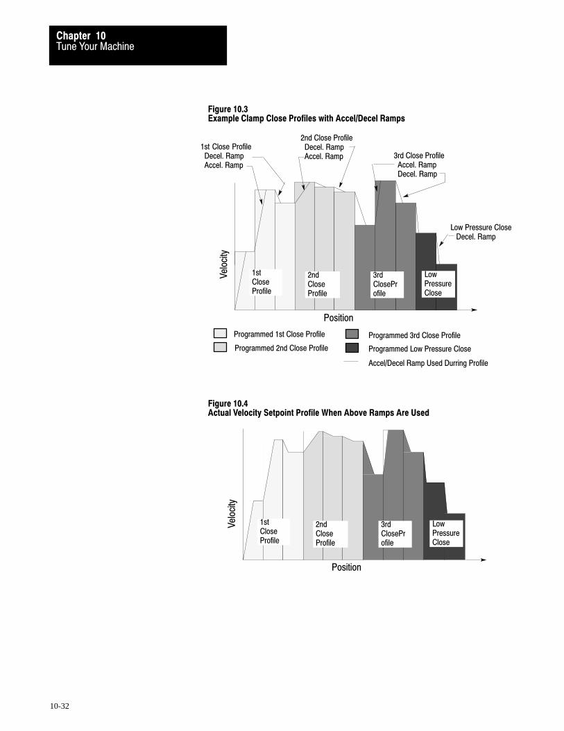
Tune Your MachineChapter 10
10-32
Figure 10.3Example Clamp Close Profiles with Accel/Decel Ramps
Position
Vel
ocity
1stCloseProfile
2nd CloseProfile
3rdCloseProfile
Low PressureClose
Programmed 1st Close Profile
Programmed 2nd Close Profile
Programmed 3rd Close Profile
Programmed Low Pressure Close
Accel/Decel Ramp Used Durring Profile
1st Close Profile Decel. Ramp Accel. Ramp
2nd Close Profile Decel. Ramp Accel. Ramp 3rd Close Profile
Accel. Ramp Decel. Ramp
Low Pressure Close Decel. Ramp
Figure 10.4Actual Velocity Setpoint Profile When Above Ramps Are Used
Position
Vel
ocity
1stCloseProfile
2nd CloseProfile
3rdCloseProfile
Low PressureClose
Tune Your MachineChapter 10
10-33
You can configure ramp rates to decelerate the clamp:
at the beginning of low pressure close. This may avoid possible damageto mold or machinery when moving toward the mold protection zone athigh velocities during the clamp close operation.
at the beginning of open slow. This may help achieve consistentrepeatability of the full open position when moving toward the openslow zone at high velocities during the clamp open operation.
If your application requires the use of ramp rates, remember:
Never apply ramp rates until you tuned all applicable clamp pressureand velocity loops.
You can apply ramp rates to selected and unselected valves. Therefore,even though you may be controlling velocity, you can ramp clamppressure during low pressure close.
Ramp rates and ERC may not function properly together. Be verycareful if applying ERC and ramp rates in the same profile.
Using slow ramp rates may force pressure and velocity actuals out ofcontrol because these actuals include the time spent ramping plus thetime each segment is controlled.
The QDC module uses ramp rates upon entry into a profile and whenstepping between segments in that profile. See figures 10.4 and 10.5.
You enter ramp rates in units of 0 to 9999% signal output per second(note that there is no decimal point). A ramp rate entry of 9999 lets theoutput move full range in 10 milliseconds, while a ramp rate entry of 99requires a full second to go full range. Lower values = slower ramps.
Pressure Alarm Setpoints
The QDC module monitors high pressure and compares it with two typesof alarm setpoints for:
absolute pressure that you configure in the MCC block (chapter 4)The QDC module monitors this continuously without regard to currentmachine mode or operational cycle.
profile pressure that you configure in configuration blocks (chapter 7) The QDC module monitors these only during the subject profile.
Allen-Bradley Parts
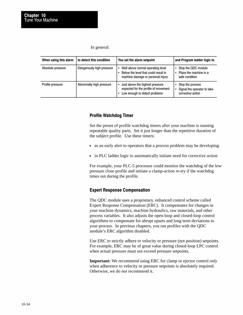
Tune Your MachineChapter 10
10-34
In general:
When using this alarm to detect this condition You set the alarm setpoint and Program ladder logic to
Absolute pressure Dangerously high pressure • Well above normal operating level
• Below the level that could result inmachine damage or personal injury
• Stop the QDC module
• Place the machine in asafe condition
Profile pressure Abnormally high pressure • Just above the highest pressureexpected for the profile of movement
• Low enough to detect problems
• Stop the process
• Signal the operator to takecorrective action
Profile Watchdog Timer
Set the preset of profile watchdog timers after your machine is runningrepeatable quality parts. Set it just longer than the repetitive duration ofthe subject profile. Use these timers:
as an early alert to operators that a process problem may be developing
in PLC ladder logic to automatically initiate need for corrective action
For example, your PLC-5 processor could monitor the watchdog of the lowpressure close profile and initiate a clamp-action re-try if the watchdogtimes out during the profile.
Expert Response Compensation
The QDC module uses a proprietary, enhanced control scheme calledExpert Response Compensation (ERC). It compensates for changes inyour machine dynamics, machine hydraulics, raw materials, and otherprocess variables. It also adjusts the open-loop and closed-loop controlalgorithms to compensate for abrupt upsets and long term deviations toyour process. In previous chapters, you ran profiles with the QDCmodule’s ERC algorithm disabled.
Use ERC to strictly adhere to velocity or pressure (not position) setpoints.For example, ERC may be of great value during closed-loop LPC controlwhen actual pressure must not exceed pressure setpoints.
Important: We recommend using ERC for clamp or ejector control onlywhen adherence to velocity or pressure setpoints is absolutely required.Otherwise, we do not recommend it.

Tune Your MachineChapter 10
10-35
ERC is not required for repeatable clamp or ejector positioning. WithoutERC, the QDC module will still force the clamp or ejector to overshoot bya constant repeatable amount (relative to cylinder speed and QDCmodule’s 2 ms scan time).
Do NOT use ERC when:
spanning your valves using velocity feedforward gain using profile ramp rates to smooth the operation. you have NOT tuned the machine in closed-loop control
ATTENTION: Jerky, abrupt clamp motion may result if youapply ERC to a control loop that has not been properly tuned.
ERC Minimum Percentage ValuesIf using ERC, adjust values recommended in chapter 7 as follows:
If ERC is enabled (on) and: Then:
The actual velocity or pressure swings wildlyaround the setpoint from cycle to cycle
Decrease the ERC minimum % value
The actual velocity or pressure takes severalcycles to achieve the desired setpoint
Increase the ERC minimum % value
Allen-Bradley Parts

Chapter
11
11-1
Troubleshoot with LEDs
This chapter tells you how to troubleshoot your QDC module using LEDindicators.
The front panel of the QDC module contains three Light Emitting Diodes(LEDs). Use them to troubleshoot problems that may occur duringintegration or operation of the QDC module. Each LED is a differentcolor for easy identification.
Color of LED: Identified as:
Green ACTIVE
Red FAULT
Yellow COMM
Chapter Objectives
Use LEDs to TroubleshootYour QDC Module
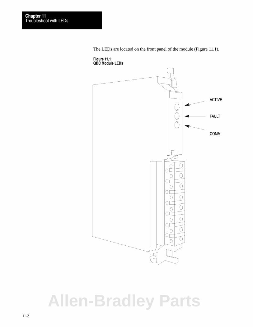
Troubleshoot with LEDsChapter 11
11-2
The LEDs are located on the front panel of the module (Figure 11.1).
Figure 11.1QDC Module LEDs
ACTIVE
FAULT
COMM
Allen-Bradley Parts
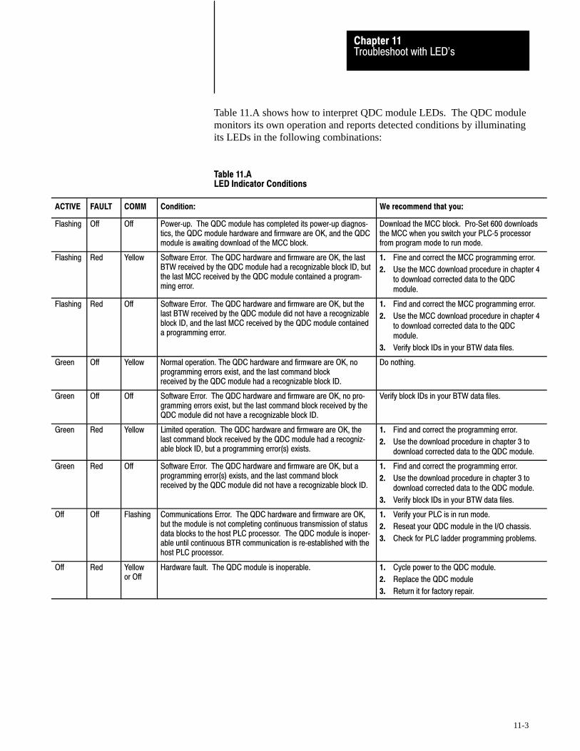
Troubleshoot with LED'sChapter 11
11-3
Table 11.A shows how to interpret QDC module LEDs. The QDC modulemonitors its own operation and reports detected conditions by illuminatingits LEDs in the following combinations:
Table 11.ALED Indicator Conditions
ACTIVE FAULT COMM Condition: We recommend that you:
Flashing Off Off Power�up. The QDC module has completed its power�up diagnos�tics, the QDC module hardware and firmware are OK, and the QDCmodule is awaiting download of the MCC block.
Download the MCC block. Pro�Set 600 downloadsthe MCC when you switch your PLC�5 processorfrom program mode to run mode.
Flashing Red Yellow Software Error. The QDC hardware and firmware are OK, the lastBTW received by the QDC module had a recognizable block ID, butthe last MCC received by the QDC module contained a program�ming error.
1. Fine and correct the MCC programming error.
2. Use the MCC download procedure in chapter 4to download corrected data to the QDCmodule.
Flashing Red Off Software Error. The QDC hardware and firmware are OK, but thelast BTW received by the QDC module did not have a recognizableblock ID, and the last MCC received by the QDC module containeda programming error.
1. Find and correct the MCC programming error.
2. Use the MCC download procedure in chapter 4to download corrected data to the QDCmodule.
3. Verify block IDs in your BTW data files.
Green Off Yellow Normal operation. The QDC hardware and firmware are OK, noprogramming errors exist, and the last command blockreceived by the QDC module had a recognizable block ID.
Do nothing.
Green Off Off Software Error. The QDC hardware and firmware are OK, no pro�gramming errors exist, but the last command block received by theQDC module did not have a recognizable block ID.
Verify block IDs in your BTW data files.
Green Red Yellow Limited operation. The QDC hardware and firmware are OK, thelast command block received by the QDC module had a recogniz�able block ID, but a programming error(s) exists.
1. Find and correct the programming error.
2. Use the download procedure in chapter 3 todownload corrected data to the QDC module.
Green Red Off Software Error. The QDC hardware and firmware are OK, but aprogramming error(s) exists, and the last command blockreceived by the QDC module did not have a recognizable block ID.
1. Find and correct the programming error.
2. Use the download procedure in chapter 3 todownload corrected data to the QDC module.
3. Verify block IDs in your BTW data files.
Off Off Flashing Communications Error. The QDC hardware and firmware are OK,but the module is not completing continuous transmission of statusdata blocks to the host PLC processor. The QDC module is inoper�able until continuous BTR communication is re�established with thehost PLC processor.
1. Verify your PLC is in run mode.
2. Reseat your QDC module in the I/O chassis.
3. Check for PLC ladder programming problems.
Off Red Yellowor Off
Hardware fault. The QDC module is inoperable. 1. Cycle power to the QDC module.
2. Replace the QDC module
3. Return it for factory repair.

Select System Operation with bits 05 and 04Inject and Clamp 0 1
Select Single�unit Operation with bit 03 = 1(0 generates a programming error)
Select English = 0 or metric = 1 with bit 00
Appendix
A
A-1
Blank Worksheets
Worksheet 4�A
Selecting Module Parameters
Control Word MCC02�Bxx 15 14 13 12 11 10 09 08 07 06 05 04 03 02 01 00
Pro�Set 600 Addr. B34/bit 543 542 541 540 539 538 537 536 535 534 533 532 531 530 529 528
Value 0 0 0 0 0 0 0 0 0 0 0 0
Example: If you select Inject and Clamp operation with English units: MCC02 = 00000000 00011000
Allen-Bradley Parts

Select Input 1 (Screw Position) Range with bits 01, 00Select Input 2 (Screw Pressure) Range with bits 03, 02
Select Input 3 (Clamp Position) Range with bits 05, 04
Select Input 4 (Clamp Pressure) Range with bits 07, 06
Input Range 0 - 10V dc 0 0 1 - 5V dc 0 1 4 - 20 mA 1 0 Not connected 1 1
Select Output 1 Range with bits 01, 00Select Output 2 Range with bits 03, 02
Select Output 3 Range with bits 05, 04
Select Output 4 Range with bits 07, 06
Output Range -10 to +10V dc 0 0 0 to +10V dc 0 1 4 to 20 mA 1 0 Not connected 1 1
Blank WorksheetsAppendix A
A-2
Worksheet 4�B
Selecting Input Ranges for your Sensors
Control Word MCC03�Bxx 15 14 13 12 11 10 09 08 07 06 05 04 03 02 01 00
Pro�Set 600 Addr. B34/bit 559 558 557 556 555 554 553 552 551 550 549 548 547 546 545 544
Value 1 1 1 1 1 1 1 1
Example: If you select an input range of 4-20 mA for all four inputs: MCC03 = 11111111 10101010.
Important: Software input selections must match the jumper settings foreach respective input.
Worksheet 4�C
Selecting Output Ranges for your Valves
Control Word MCC04�Bxx 15 14 13 12 11 10 09 08 07 06 05 04 03 02 01 00
Pro�Set 600 Addr. B34/bit 575 574 573 572 571 570 569 568 567 566 565 564 563 562 561 560
Value 1 1 1 1 1 1 1 1
Example: If you select 0-10V dc for all four output ranges:MCC04 = 11111111 01010101.
Important: Software output selections must match the jumper settings foreach respective output.

Enter Your Initial Values Here
Blank WorksheetsAppendix A
A-3
Worksheet 4�D
Determining Initial Sensor�configuration Values
Input Line Control Word Pro�Set 600 Addr. Value Description Units
1 1 MCC09 N40:5 Minimum Screw Position Screw Axis Measured from zero 1
2 MCC10 N40:6 Maximum Screw Position Screw Axis Measured from zero 1
3 MCC11 N40:7 Analog Signal @ Min Screw Position Input Signal Range 2
4 MCC12 N40:8 Analog Signal @ Max Screw Position Input Signal Range 2
2 5 MCC17 N40:13 Minimum Screw Pressure Screw Pressure 3
6 MCC18 N40:14 Maximum Screw Pressure Screw Pressure 3
7 MCC19 N40:15 Analog Signal @ Min Screw Pressure Input Signal Range 2
8 MCC20 N40:16 Analog Signal @ Max Screw Pressure Input Signal Range 2
3 9 MCC23 N40:19 Minimum Clamp Position Clamp Axis Measured from zero 1
10 MCC24 N40:20 Maximum Clamp Position Clamp Axis Measured from zero 1
11 MCC25 N40:21 Analog Signal @ Min Clamp Position Input Signal Range 2
12 MCC26 N40.22 Analog Signal @ Max Clamp Position Input Signal Range 2
4 13 MCC31 N40:27 Minimum Clamp Pressure Clamp Pressure 3
14 MCC32 N40:28 Maximum Clamp Pressure Clamp Pressure 3
15 MCC33 N40:29 Analog Signal @ Min Clamp Pressure Input Signal Range 2
16 MCC34 N40:30 Analog Signal @ Max Clamp Pressure Input Signal Range 2
1 Incremental Distance 2 Input Signal Range 3 Pressure
00.00 to 99.99in 00.00 to 10.00VDC or 0000 to 9999 PSI000.0 to 999.9mm 01.00 to 05.00VDC or 000.0 to 999.9 Bar
04.00 to 20.00MADC
Allen-Bradley Parts
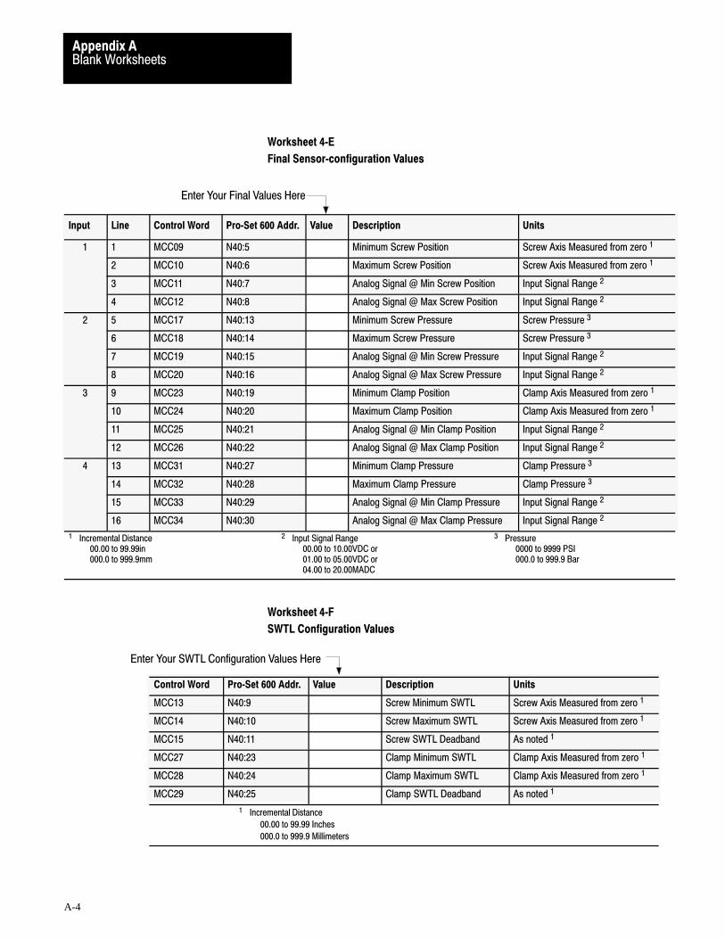
Enter Your Final Values Here
Enter Your SWTL Configuration Values Here
Blank WorksheetsAppendix A
A-4
Worksheet 4�E
Final Sensor�configuration Values
Input Line Control Word Pro�Set 600 Addr. Value Description Units
1 1 MCC09 N40:5 Minimum Screw Position Screw Axis Measured from zero 1
2 MCC10 N40:6 Maximum Screw Position Screw Axis Measured from zero 1
3 MCC11 N40:7 Analog Signal @ Min Screw Position Input Signal Range 2
4 MCC12 N40:8 Analog Signal @ Max Screw Position Input Signal Range 2
2 5 MCC17 N40:13 Minimum Screw Pressure Screw Pressure 3
6 MCC18 N40:14 Maximum Screw Pressure Screw Pressure 3
7 MCC19 N40:15 Analog Signal @ Min Screw Pressure Input Signal Range 2
8 MCC20 N40:16 Analog Signal @ Max Screw Pressure Input Signal Range 2
3 9 MCC23 N40:19 Minimum Clamp Position Clamp Axis Measured from zero 1
10 MCC24 N40:20 Maximum Clamp Position Clamp Axis Measured from zero 1
11 MCC25 N40:21 Analog Signal @ Min Clamp Position Input Signal Range 2
12 MCC26 N40:22 Analog Signal @ Max Clamp Position Input Signal Range 2
4 13 MCC31 N40:27 Minimum Clamp Pressure Clamp Pressure 3
14 MCC32 N40:28 Maximum Clamp Pressure Clamp Pressure 3
15 MCC33 N40:29 Analog Signal @ Min Clamp Pressure Input Signal Range 2
16 MCC34 N40:30 Analog Signal @ Max Clamp Pressure Input Signal Range 2
1 Incremental Distance 2 Input Signal Range 3 Pressure
00.00 to 99.99in 00.00 to 10.00VDC or 0000 to 9999 PSI000.0 to 999.9mm 01.00 to 05.00VDC or 000.0 to 999.9 Bar
04.00 to 20.00MADC
Worksheet 4�F
SWTL Configuration Values
Control Word Pro�Set 600 Addr. Value Description Units
MCC13 N40:9 Screw Minimum SWTL Screw Axis Measured from zero 1
MCC14 N40:10 Screw Maximum SWTL Screw Axis Measured from zero 1
MCC15 N40:11 Screw SWTL Deadband As noted 1
MCC27 N40:23 Clamp Minimum SWTL Clamp Axis Measured from zero 1
MCC28 N40:24 Clamp Maximum SWTL Clamp Axis Measured from zero 1
MCC29 N40:25 Clamp SWTL Deadband As noted 1
1 Incremental Distance
00.00 to 99.99 Inches
000.0 to 999.9 Millimeters

Enter Your Pressure�alarm and Time�delay Values Here
Blank WorksheetsAppendix A
A-5
Worksheet 4�G
Pressure�alarm and Time�delay Setpoints
Control Word Pro�Set 600 Addr. Value Description Units
MCC21 N40:17 Screw Pressure�alarm Setpoint Ram (screw) Pressure 2
MCC22 N40:18 Screw�pressure Time�delay Setpoint Time Measured in Seconds 1
MCC35 N40:31 Clamp Pressure�alarm Setpoint Clamp Pressure 2
MCC36 N40:32 Clamp�pressure Time�delay Setpoint Time Measured in Seconds 1
1 Time Measured in Seconds 2 Pressure
00.00 to 00.99 0000 to 9999 PSI 000.0 to 999.9 Bar
Allen-Bradley Parts
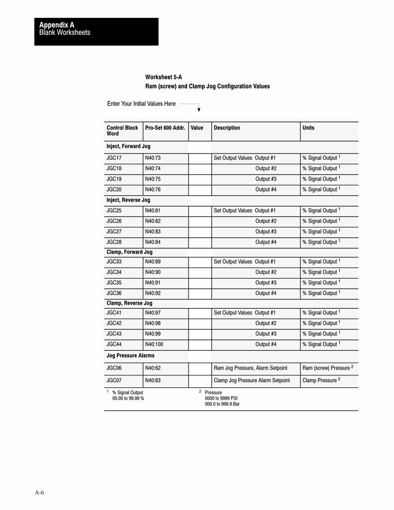
Enter Your Initial Values Here
Blank WorksheetsAppendix A
A-6
Worksheet 5�A
Ram (screw) and Clamp Jog Configuration Values
Control BlockWord
Pro�Set 600 Addr. Value Description Units
Inject, Forward Jog
JGC17 N40:73 Set Output Values Output #1 % Signal Output 1
JGC18 N40:74 Output #2 % Signal Output 1
JGC19 N40:75 Output #3 % Signal Output 1
JGC20 N40:76 Output #4 % Signal Output 1
Inject, Reverse Jog
JGC25 N40:81 Set Output Values Output #1 % Signal Output 1
JGC26 N40:82 Output #2 % Signal Output 1
JGC27 N40:83 Output #3 % Signal Output 1
JGC28 N40:84 Output #4 % Signal Output 1
Clamp, Forward Jog
JGC33 N40:89 Set Output Values Output #1 % Signal Output 1
JGC34 N40:90 Output #2 % Signal Output 1
JGC35 N40:91 Output #3 % Signal Output 1
JGC36 N40:92 Output #4 % Signal Output 1
Clamp, Reverse Jog
JGC41 N40:97 Set Output Values Output #1 % Signal Output 1
JGC42 N40:98 Output #2 % Signal Output 1
JGC43 N40:99 Output #3 % Signal Output 1
JGC44 N40:100 Output #4 % Signal Output 1
Jog Pressure Alarms
JGC06 N40:62 Ram Jog Pressure, Alarm Setpoint Ram (screw) Pressure 2
JGC07 N40:63 Clamp Jog Pressure Alarm Setpoint Clamp Pressure 2
1 % Signal Output 2 Pressure00.00 to 99.99 % 0000 to 9999 PSI
000.0 to 999.9 Bar
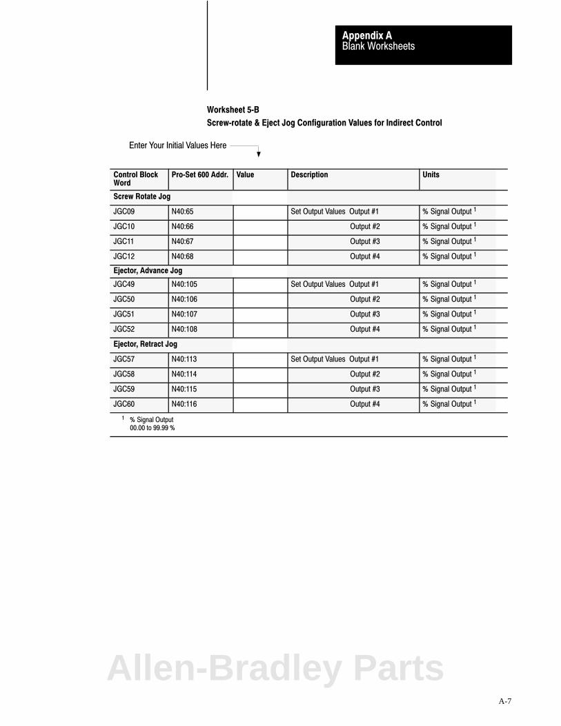
Enter Your Initial Values Here
Blank WorksheetsAppendix A
A-7
Worksheet 5�B
Screw�rotate & Eject Jog Configuration Values for Indirect Control
Control BlockWord
Pro�Set 600 Addr. Value Description Units
Screw Rotate Jog
JGC09 N40:65 Set Output Values Output #1 % Signal Output 1
JGC10 N40:66 Output #2 % Signal Output 1
JGC11 N40:67 Output #3 % Signal Output 1
JGC12 N40:68 Output #4 % Signal Output 1
Ejector, Advance Jog
JGC49 N40:105 Set Output Values Output #1 % Signal Output 1
JGC50 N40:106 Output #2 % Signal Output 1
JGC51 N40:107 Output #3 % Signal Output 1
JGC52 N40:108 Output #4 % Signal Output 1
Ejector, Retract Jog
JGC57 N40:113 Set Output Values Output #1 % Signal Output 1
JGC58 N40:114 Output #2 % Signal Output 1
JGC59 N40:115 Output #3 % Signal Output 1
JGC60 N40:116 Output #4 % Signal Output 1
1 % Signal Output 00.00 to 99.99 %
Allen-Bradley Parts

Velocity Control ValvePressure Control Valve
Block Identifier
000 = Output 1001 = Output 2010 = Output 3011 = Output 4
000 = Output 1001 = Output 2010 = Output 3011 = Output 4
Important: Record values only in words used.Record zeros in words not used.You must configure at least FCC02
PID
0 = Dependent Gains (ISA)1 = Independent Gains (A�B)
Code:
Your value
Required initial valueloaded by Pro�Set 6000 or 1
0 Value not used
Blank WorksheetsAppendix A
A-8
Worksheet 7�A
Clamp Close Configuration Blocks (FCC, SCC, and TCC)
Word FCC01 B15 thru 00 15 14 13 12 11 10 09 08 07 06 05 04 03 02 01 00
Bit Address B37/Bit 15 14 13 12 11 10 09 08 07 06 05 04 03 02 01 00
Value 0 0 0 0 0 0 0 0 0 0 0 0 0 0 1 1
Word SCC01 B15 thru 00 15 14 13 12 11 10 09 08 07 06 05 04 03 02 01 00
Bit Address B37/Bit 79 78 77 76 75 74 73 72 71 70 69 68 67 66 65 64
Value 0 0 0 0 0 0 0 0 0 0 0 0 0 1 0 0
Word TCC01 B15 thru 00 15 14 13 12 11 10 09 08 07 06 05 04 03 02 01 00
Bit Address B37/Bit 143 142 141 140 139 138 137 136 135 134 133 132 131 130 129 128
Value 0 0 0 0 0 0 0 0 0 0 0 0 0 1 0 1
Word FCC02 B15 thru 00 15 14 13 12 11 10 09 08 07 06 05 04 03 02 01 00
Bit Address B37/Bit 31 30 29 28 27 26 25 24 23 22 21 20 19 18 17 16
Value 0 0 0 0 0 0 0 0 1 0
Word SCC02 B15 thru 00 15 14 13 12 11 10 09 08 07 06 05 04 03 02 01 00
Bit Address B37/Bit 95 94 93 92 91 90 89 88 87 86 85 84 83 82 81 80
Value 0 0 0 0 0 0 0 0 1 0
Word TCC02 B15 thru 00 15 14 13 12 11 10 09 08 07 06 05 04 03 02 01 00
Bit Address B37/Bit 159 158 157 156 155 154 153 152 151 150 149 148 147 146 145 144
Value 0 0 0 0 0 0 0 0 1 0
Important: You must configure at least the FCC configuration block.

Enter Your Values Here
Blank WorksheetsAppendix A
A-9
Worksheet 7�A (continued)
Clamp Close Configuration Blocks (FCC, SCC, and TCC)
For these Parameters (footnote = units) Word FCC N43: FCC Value SCC N43: SCC Value TCC N43: TCC Value
Minimum ERC Percentage - Velocity 8 05 1 1000 61 1000 121 1000
Minimum ERC Percentage - Pressure 8 06 2 1000 62 1000 122 1000
Profile Watchdog Timer Preset 1 08 4 0 64 0 124 0
Output #1 Selected Valve %�Output During Profile 4 09 5 * 65 * 125 *
Output #2 Selected Valve %�Output During Profile 4 10 6 * 66 * 126 *
Output #3 Selected Valve %�Output During Profile 4 11 7 * 67 * 127 *
Output #4 Selected Valve %�Output During Profile 4 12 8 * 68 * 128 *
Output #1 Acceleration Ramp Rate During Profile 5 17 13 0 73 0 133 0
Output #2 Acceleration Ramp Rate During Profile 5 18 14 0 74 0 134 0
Output #3 Acceleration Ramp Rate During Profile 5 19 15 0 75 0 135 0
Output #4 Acceleration Ramp Rate During Profile 5 20 16 0 76 0 136 0
Output #1 Deceleration Ramp Rate During Profile 5 25 21 0 81 0 141 0
Output #2 Deceleration Ramp Rate During Profile 5 26 22 0 82 0 142 0
Output #3 Deceleration Ramp Rate During Profile 5 27 23 0 83 0 143 0
Output #4 Deceleration Ramp Rate During Profile 5 28 24 0 84 0 144 0
Output #1 End�of�profile Set�output Value 4 33 29 * 89 * 149 *
Output #2 End�of�profile Set�output Value 4 34 30 * 90 * 150 *
Output #3 End�of�profile Set�output Value 4 35 31 * 91 * 151 *
Output #4 End�of�profile Set�output Value 4 36 32 * 92 * 152 *
Pressure Minimum Control Limit 3 41 37 0 97 0 157 0
Pressure Maximum Control Limit 3 42 38 Syst Press 98 Syst Press 158 Syst Press
Selected Pressure Valve Output for Minimum 4 43 39 * 99 * 159 *
Selected Pressure Valve Output for Maximum 4 44 40 * 100 * 160 *
Velocity Minimum Control Limit 2 45 41 0 101 0 161 0
Velocity Maximum Control Limit 2 46 42 per OEM * 102 per OEM * 162 per OEM *
Selected Velocity Valve Output for Minimum 4 47 43 * 103 * 163 *
Selected Velocity Valve Output for Maximum 4 48 44 * 104 * 164 *
Proportional Gain for Pressure Control (none) 49 45 100 105 100 165 100
Integral Gain for Pressure Control 6 50 46 400 106 400 166 400
Derivative Gain for Pressure Control 7 51 47 0 107 0 167 0
Proportional Gain for Velocity Control 6 52 48 200 108 200 168 200
Feed Forward Gain for Velocity Control (none) 53 49 0 109 0 169 0
Profile High Pressure Alarm Setpoint 3 57 53 0 113 0 173 0
1 Time 2 Velocity along Axis 3 Pressure 4 Percent Signal Output 00.00 to 99.99 Seconds 00.00 to 99.99 Inches per Second 0000 to 9999 PSI 00.00 to 99.99
000.0 to 999.9 Millimeters per Sec 000.0 to 999.9 Bar5 Percent Signal Output per Second 6 Inverse Time (Algorithm) 7 Time (Algorithm) 8 Percent
0000 to 9999 00.00 to 99.99 Minutes 00.00 to 99.99 Minutes 00.00 to 99.9900.00 to 99.99 Seconds
*Important: Refer to the appropriate section later in this chapter for information on this parameter
Allen-Bradley Parts
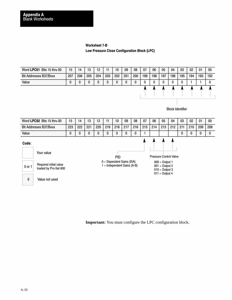
Pressure Control Valve
Block Identifier
000 = Output 1001 = Output 2010 = Output 3011 = Output 4
PID0 = Dependent Gains (ISA)1 = Independent Gains (A�B)
Code:
Your value
Required initial valueloaded by Pro�Set 6000 or 1
0 Value not used
Blank WorksheetsAppendix A
A-10
Worksheet 7�B
Low Pressure Close Configuration Block (LPC)
Word LPC01 Bits 15 thru 00 15 14 13 12 11 10 09 08 07 06 05 04 03 02 01 00
Bit Addresses B37/Bxxx 207 206 205 204 203 202 201 200 199 198 197 196 195 194 193 192
Value 0 0 0 0 0 0 0 0 0 0 0 0 0 1 1 0
Word LPC02 Bits 15 thru 00 15 14 13 12 11 10 09 08 07 06 05 04 03 02 01 00
Bit Addresses B37/Bxxx 223 222 221 220 219 218 217 216 215 214 213 212 211 210 209 208
Value 0 0 0 0 0 0 0 0 1 0 0 0 0
Important: You must configure the LPC configuration block.
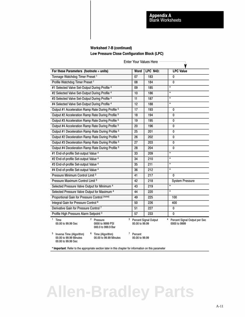
Enter Your Values Here
Blank WorksheetsAppendix A
A-11
Worksheet 7�B (continued)
Low Pressure Close Configuration Block (LPC)
For these Parameters (footnote = units) Word LPC N43: LPC Value
Tonnage Watchdog Timer Preset 1 07 183 0
Profile Watchdog Timer Preset 1 08 184 0
#1 Selected Valve Set�Output During Profile 4 09 185 *
#2 Selected Valve Set�Output During Profile 4 10 186 *
#3 Selected Valve Set�Output During Profile 4 11 187 *
#4 Selected Valve Set�Output During Profile 4 12 188 *
Output #1 Acceleration Ramp Rate During Profile 5 17 193 0
Output #2 Acceleration Ramp Rate During Profile 5 18 194 0
Output #3 Acceleration Ramp Rate During Profile 5 19 195 0
Output #4 Acceleration Ramp Rate During Profile 5 20 196 0
Output #1 Deceleration Ramp Rate During Profile 5 25 201 0
Output #2 Deceleration Ramp Rate During Profile 5 26 202 0
Output #3 Deceleration Ramp Rate During Profile 5 27 203 0
Output #4 Deceleration Ramp Rate During Profile 5 28 204 0
#1 End�of�profile Set�output Value 4 33 209 *
#2 End�of�profile Set�output Value 4 34 210 *
#3 End�of�profile Set�output Value 4 35 211 *
#4 End�of�profile Set�output Value 4 36 212 *
Pressure Minimum Control Limit 3 41 217 0
Pressure Maximum Control Limit 3 42 218 System Pressure
Selected Pressure Valve Output for Minimum 4 43 219 *
Selected Pressure Valve Output for Maximum 4 44 220 *
Proportional Gain for Pressure Control (none) 49 225 100
Integral Gain for Pressure Control 6 50 226 400
Derivative Gain for Pressure Control 7 51 227 0
Profile High Pressure Alarm Setpoint 3 57 233 0
1 Time 2 Pressure 3 Percent Signal Output 4 Percent Signal Output per Sec00.00 to 99.99 Sec 0000 to 9999 PSI 00.00 to 99.99 0000 to 9999
000.0 to 999.9 Bar
5 Inverse Time (Algorithm) 6 Time (Algorithm) 7 Percent00.00 to 99.99 Minutes 00.00 to 99.99 Minutes 00.00 to 99.9900.00 to 99.99 Sec
* Important: Refer to the appropriate section later in this chapter for information on this parameter
Allen-Bradley Parts

SelectedVelocity Valve
SelectedPressure Valve
PID Pressure Algorithm
INC Block Identifier
000 = Output 1001 = Output 2010 = Output 3011 = Output 4
000 = Output 1001 = Output 2010 = Output 3011 = Output 4
0 = Dependent Gains1 = Independent Gains
Code:
Your value
Required initial valueloaded by Pro�Set 6000 or 1
0 Value not used
Blank WorksheetsAppendix A
A-12
Worksheet 7�C
Injection Configuration Block (INC)
Control Word INC01�Bxx 15 14 13 12 11 10 09 08 07 06 05 04 03 02 01 00
Pro�Set 600 Addr. B38/bit 15 14 13 12 11 10 09 08 07 06 05 04 03 02 01 00
Value 0 0 0 0 0 0 0 0 0 0 0 0 1 0 0 0
Control Word INC02�Bxx 15 14 13 12 11 10 09 08 07 06 05 04 03 02 01 00
Pro�Set 600 Addr. B38/bit 31 30 29 28 27 26 25 24 23 22 21 20 19 18 17 16
Value 0 0 0 0 0 0 0 0 1 0
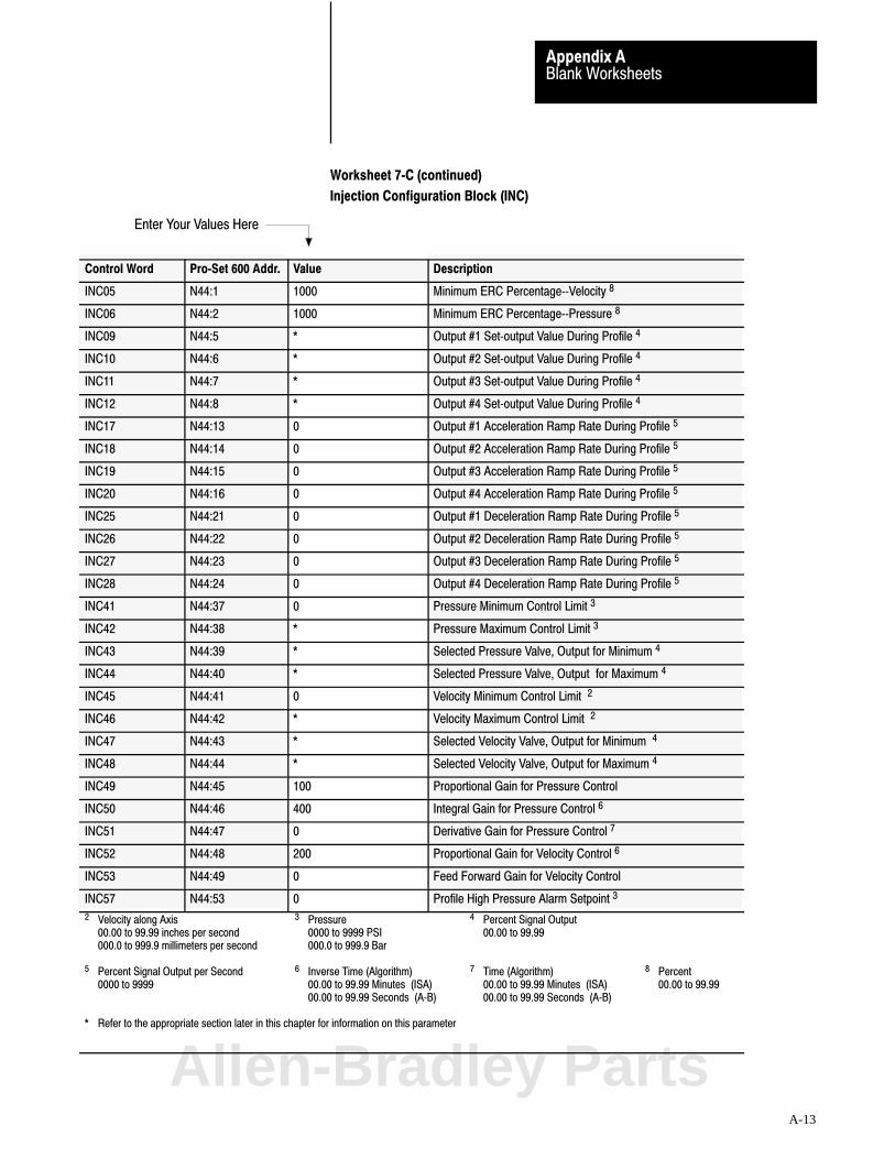
Enter Your Values Here
Blank WorksheetsAppendix A
A-13
Worksheet 7�C (continued)
Injection Configuration Block (INC)
Control Word Pro�Set 600 Addr. Value Description
INC05 N44:1 1000 Minimum ERC Percentage��Velocity 8
INC06 N44:2 1000 Minimum ERC Percentage��Pressure 8
INC09 N44:5 * Output #1 Set�output Value During Profile 4
INC10 N44:6 * Output #2 Set�output Value During Profile 4
INC11 N44:7 * Output #3 Set�output Value During Profile 4
INC12 N44:8 * Output #4 Set�output Value During Profile 4
INC17 N44:13 0 Output #1 Acceleration Ramp Rate During Profile 5
INC18 N44:14 0 Output #2 Acceleration Ramp Rate During Profile 5
INC19 N44:15 0 Output #3 Acceleration Ramp Rate During Profile 5
INC20 N44:16 0 Output #4 Acceleration Ramp Rate During Profile 5
INC25 N44:21 0 Output #1 Deceleration Ramp Rate During Profile 5
INC26 N44:22 0 Output #2 Deceleration Ramp Rate During Profile 5
INC27 N44:23 0 Output #3 Deceleration Ramp Rate During Profile 5
INC28 N44:24 0 Output #4 Deceleration Ramp Rate During Profile 5
INC41 N44:37 0 Pressure Minimum Control Limit 3
INC42 N44:38 * Pressure Maximum Control Limit 3
INC43 N44:39 * Selected Pressure Valve, Output for Minimum 4
INC44 N44:40 * Selected Pressure Valve, Output for Maximum 4
INC45 N44:41 0 Velocity Minimum Control Limit 2
INC46 N44:42 * Velocity Maximum Control Limit 2
INC47 N44:43 * Selected Velocity Valve, Output for Minimum 4
INC48 N44:44 * Selected Velocity Valve, Output for Maximum 4
INC49 N44:45 100 Proportional Gain for Pressure Control
INC50 N44:46 400 Integral Gain for Pressure Control 6
INC51 N44:47 0 Derivative Gain for Pressure Control 7
INC52 N44:48 200 Proportional Gain for Velocity Control 6
INC53 N44:49 0 Feed Forward Gain for Velocity Control
INC57 N44:53 0 Profile High Pressure Alarm Setpoint 3
2 Velocity along Axis 3 Pressure 4 Percent Signal Output 00.00 to 99.99 inches per second 0000 to 9999 PSI 00.00 to 99.99000.0 to 999.9 millimeters per second 000.0 to 999.9 Bar
5 Percent Signal Output per Second 6 Inverse Time (Algorithm) 7 Time (Algorithm) 8 Percent0000 to 9999 00.00 to 99.99 Minutes (ISA) 00.00 to 99.99 Minutes (ISA) 00.00 to 99.99
00.00 to 99.99 Seconds (A�B) 00.00 to 99.99 Seconds (A�B)
* Refer to the appropriate section later in this chapter for information on this parameter
Allen-Bradley Parts
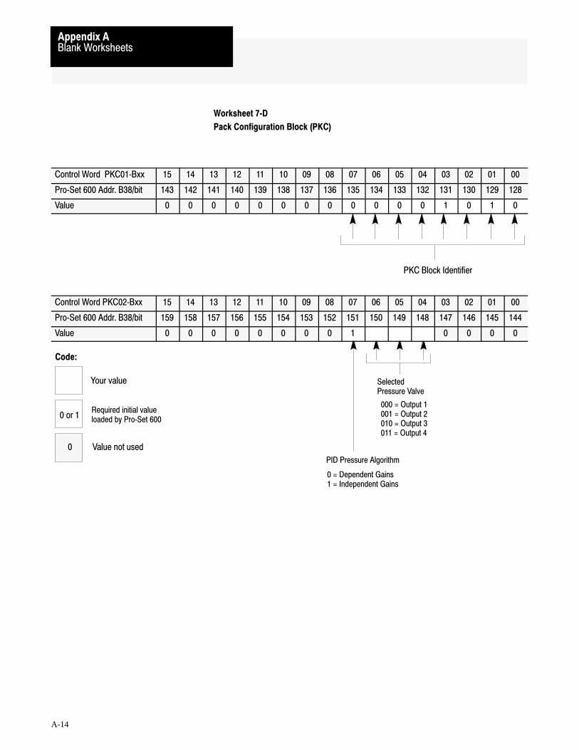
PKC Block Identifier
PID Pressure Algorithm
SelectedPressure Valve
000 = Output 1001 = Output 2010 = Output 3011 = Output 4
0 = Dependent Gains1 = Independent Gains
Code:
Your value
Required initial valueloaded by Pro�Set 6000 or 1
0 Value not used
Blank WorksheetsAppendix A
A-14
Worksheet 7�D
Pack Configuration Block (PKC)
Control Word PKC01�Bxx 15 14 13 12 11 10 09 08 07 06 05 04 03 02 01 00
Pro�Set 600 Addr. B38/bit 143 142 141 140 139 138 137 136 135 134 133 132 131 130 129 128
Value 0 0 0 0 0 0 0 0 0 0 0 0 1 0 1 0
Control Word PKC02�Bxx 15 14 13 12 11 10 09 08 07 06 05 04 03 02 01 00
Pro�Set 600 Addr. B38/bit 159 158 157 156 155 154 153 152 151 150 149 148 147 146 145 144
Value 0 0 0 0 0 0 0 0 1 0 0 0 0

Enter Your Values Here
Blank WorksheetsAppendix A
A-15
Worksheet 7�D (continued)
Pack Configuration Block (PKC)
Control Word Pro�Set 600 Addr. Value Description Units
PKC06 N44:122 1000 Minimum ERC Percentage��Pressure Percent 8
PKC09 N44:125 * Output #1 Set�output Value During Profile Percent Signal Output 4
PKC10 N44:126 * Output #2 Set�output Value During Profile Percent Signal Output 4
PKC11 N44:127 * Output #3 Set�output Value During Profile Percent Signal Output 4
PKC12 N44:128 * Output #4 Set�output Value During Profile Percent Signal Output 4
PKC17 N44:133 0 Output #1 Acceleration Ramp Rate During Profile Percent Signal Output per Second 5
PKC18 N44:134 0 Output #2 Acceleration Ramp Rate During Profile Percent Signal Output per Second 5
PKC19 N44:135 0 Output #3 Acceleration Ramp Rate During Profile Percent Signal Output per Second 5
PKC20 N44:136 0 Output #4 Acceleration Ramp Rate During Profile Percent Signal Output per Second 5
PKC25 N44:141 0 Output #1 Deceleration Ramp Rate During Profile Percent Signal Output per Second 5
PKC26 N44:142 0 Output #2 Deceleration Ramp Rate During Profile Percent Signal Output per Second 5
PKC27 N44:143 0 Output #3 Deceleration Ramp Rate During Profile Percent Signal Output per Second 5
PKC28 N44:144 0 Output #4 Deceleration Ramp Rate During Profile Percent Signal Output per Second 5
PKC41 N44:157 0 Pressure Minimum Control Limit Pressure 3
PKC42 N44:158 * Pressure Maximum Control Limit Pressure 3
PKC43 N44:159 * Selected Pressure Valve, Output for Minimum Percent Signal Output 4
PKC44 N44:160 * Selected Pressure Valve, Output for Maximum Percent Signal Output 4
PKC49 N44:165 100 Proportional Gain for Pressure Control None
PKC50 N44:166 400 Integral Gain for Pressure Control Inverse Time (Algorithm) 6
PKC51 N44:167 0 Derivative Gain for Ram Pressure Control Time (Algorithm) 7
PKC57 N44:173 0 Profile High Pressure Alarm Setpoint Pressure 3
3 Pressure 4 Percent Signal Output 0000 to 9999 PSI 00.00 to 99.99
000.0 to 999.9 Bar5 Percent Signal Output per Second 6 Inverse Time (Algorithm) 7 Time (Algorithm) 8 Percent
0000 to 9999 00.00 to 99.99 Minutes (ISA) 00.00 to 99.99 Minutes (ISA) 00.00 to 99.9900.00 to 99.99 Seconds (A�B) 00.00 to 99.99 Seconds (A�B)
* Refer to the appropriate section later in this chapter for information on this parameter
Allen-Bradley Parts

HDC Block Identifier
PID Pressure Algorithm
SelectedPressure Valve
000 = Output 1001 = Output 2010 = Output 3011 = Output 4
0 = Dependent Gains1 = Independent Gains
Code:
Your value
Required initial valueloaded by Pro�Set 6000 or 1
0 Value not used
Blank WorksheetsAppendix A
A-16
Worksheet 7�E
Hold Configuration Block (HDC)
Control Word HDC01�Bxx 15 14 13 12 11 10 09 08 07 06 05 04 03 02 01 00
Pro�Set 600 Addr. B38/bit 207 206 205 204 203 202 201 200 199 198 197 196 195 194 193 192
Value 0 0 0 0 0 0 0 0 0 0 0 0 1 0 1 1
Control Word HDC02�Bxx 15 14 13 12 11 10 09 08 07 06 05 04 03 02 01 00
Pro�Set 600 Addr. B38/bit 223 222 221 220 219 218 217 216 215 214 213 212 211 210 209 208
Value 0 0 0 0 0 0 0 0 1 0 0 0 0
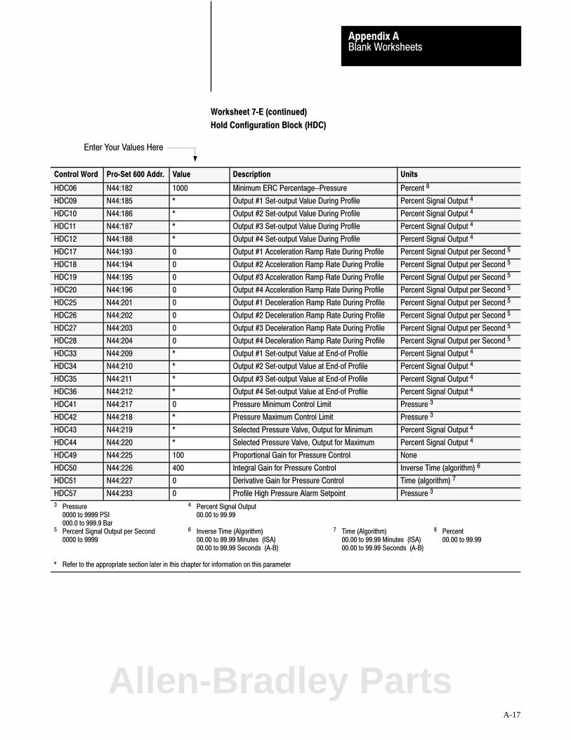
Enter Your Values Here
Blank WorksheetsAppendix A
A-17
Worksheet 7�E (continued)
Hold Configuration Block (HDC)
Control Word Pro�Set 600 Addr. Value Description Units
HDC06 N44:182 1000 Minimum ERC Percentage��Pressure Percent 8
HDC09 N44:185 * Output #1 Set�output Value During Profile Percent Signal Output 4
HDC10 N44:186 * Output #2 Set�output Value During Profile Percent Signal Output 4
HDC11 N44:187 * Output #3 Set�output Value During Profile Percent Signal Output 4
HDC12 N44:188 * Output #4 Set�output Value During Profile Percent Signal Output 4
HDC17 N44:193 0 Output #1 Acceleration Ramp Rate During Profile Percent Signal Output per Second 5
HDC18 N44:194 0 Output #2 Acceleration Ramp Rate During Profile Percent Signal Output per Second 5
HDC19 N44:195 0 Output #3 Acceleration Ramp Rate During Profile Percent Signal Output per Second 5
HDC20 N44:196 0 Output #4 Acceleration Ramp Rate During Profile Percent Signal Output per Second 5
HDC25 N44:201 0 Output #1 Deceleration Ramp Rate During Profile Percent Signal Output per Second 5
HDC26 N44:202 0 Output #2 Deceleration Ramp Rate During Profile Percent Signal Output per Second 5
HDC27 N44:203 0 Output #3 Deceleration Ramp Rate During Profile Percent Signal Output per Second 5
HDC28 N44:204 0 Output #4 Deceleration Ramp Rate During Profile Percent Signal Output per Second 5
HDC33 N44:209 * Output #1 Set�output Value at End�of Profile Percent Signal Output 4
HDC34 N44:210 * Output #2 Set�output Value at End�of Profile Percent Signal Output 4
HDC35 N44:211 * Output #3 Set�output Value at End�of Profile Percent Signal Output 4
HDC36 N44:212 * Output #4 Set�output Value at End�of Profile Percent Signal Output 4
HDC41 N44:217 0 Pressure Minimum Control Limit Pressure 3
HDC42 N44:218 * Pressure Maximum Control Limit Pressure 3
HDC43 N44:219 * Selected Pressure Valve, Output for Minimum Percent Signal Output 4
HDC44 N44:220 * Selected Pressure Valve, Output for Maximum Percent Signal Output 4
HDC49 N44:225 100 Proportional Gain for Pressure Control None
HDC50 N44:226 400 Integral Gain for Pressure Control Inverse Time (algorithm) 6
HDC51 N44:227 0 Derivative Gain for Pressure Control Time (algorithm) 7
HDC57 N44:233 0 Profile High Pressure Alarm Setpoint Pressure 3
3 Pressure 4 Percent Signal Output 0000 to 9999 PSI 00.00 to 99.99
000.0 to 999.9 Bar5 Percent Signal Output per Second 6 Inverse Time (Algorithm) 7 Time (Algorithm) 8 Percent
0000 to 9999 00.00 to 99.99 Minutes (ISA) 00.00 to 99.99 Minutes (ISA) 00.00 to 99.9900.00 to 99.99 Seconds (A�B) 00.00 to 99.99 Seconds (A�B)
* Refer to the appropriate section later in this chapter for information on this parameter
Allen-Bradley Parts

SelectedPressure Valve
PID Pressure Algorithm
PLC Block Identifier
000 = Output 1001 = Output 2010 = Output 3011 = Output 4
0 = Dependent Gains1 = Independent Gains
Code:
Your value
Required initial valueloaded by Pro�Set 6000 or 1
0 Value not used
Blank WorksheetsAppendix A
A-18
Worksheet 7�F
Plastication Configuration Block (PLC)
Control Word PLC01�Bxx 15 14 13 12 11 10 09 08 07 06 05 04 03 02 01 00
Pro�Set 600 Addr. B38/bit 399 398 397 396 395 394 393 392 391 390 389 388 387 386 385 384
Value 0 0 0 0 0 0 0 0 0 0 0 0 1 1 1 0
Control Word PLC02�Bxx 15 14 13 12 11 10 09 08 07 06 05 04 03 02 01 00
Pro�Set 600 Addr. B38/bit 415 414 413 412 411 410 409 408 407 406 405 404 403 402 401 400
Value 0 0 0 0 0 0 0 0 1 0 0 0 0

Enter Your Values Here
Blank WorksheetsAppendix A
A-19
Worksheet 7�F (continued)
Plastication Configuration Block (PLC)
Control Word Pro�Set 600 Addr. Value Description Units
PLC06 N44:362 1000 Minimum ERC Percentage��Pressure Percent 8
PLC08 N44:364 0 Profile Watchdog Timer Preset Time 1
PLC09 N44:365 * Output #1 Set�output Value During Profile Percent Signal Output 4
PLC10 N44:366 * Output #2 Set�output Value During Profile Percent Signal Output 4
PLC11 N44:367 * Output #3 Set�output Value During Profile Percent Signal Output 4
PLC12 N44:368 * Output #4 Set�output Value During Profile Percent Signal Output 4
PLC17 N44:373 0 Output #1 Acceleration Ramp Rate During Profile Percent Signal Output per Second 5
PLC18 N44:374 0 Output #2 Acceleration Ramp Rate During Profile Percent Signal Output per Second 5
PLC19 N44:375 0 Output #3 Acceleration Ramp Rate During Profile Percent Signal Output per Second 5
PLC20 N44:376 0 Output #4 Acceleration Ramp Rate During Profile Percent Signal Output per Second 5
PLC25 N44:381 0 Output #1 Deceleration Ramp Rate During Profile Percent Signal Output per Second 5
PLC26 N44:382 0 Output #2 Deceleration Ramp Rate During Profile Percent Signal Output per Second 5
PLC27 N44:383 0 Output #3 Deceleration Ramp Rate During Profile Percent Signal Output per Second 5
PLC28 N44:384 0 Output #4 Deceleration Ramp Rate During Profile Percent Signal Output per Second 5
PLC33 N44:389 * Output #1 Set�output Value at End�of Profile Percent Signal Output 4
PLC34 N44:390 * Output #2 Set�output Value at End�of Profile Percent Signal Output 4
PLC35 N44:391 * Output #3 Set�output Value at End�of Profile Percent Signal Output 4
PLC36 N44:392 * Output #4 Set�output Value at End�of Profile Percent Signal Output 4
PLC41 N44:397 0 Pressure Minimum Control Limit Pressure 3
PLC42 N44:398 * Pressure Maximum Control Limit Pressure 3
PLC43 N44:399 * Selected Pressure Valve, Output for Minimum Percent Signal Output 4
PLC44 N44:400 * Selected Pressure Valve, Output for Maximum Percent Signal Output 4
PLC49 N44:405 100 Proportional Gain for Pressure Control None
PLC50 N44:406 400 Integral Gain for Pressure Control Inverse Time (Algorithm) 6
PLC51 N44:407 0 Derivative Gain for Pressure Control Time (Algorithm) 7
PLC57 N44:413 0 Profile High Pressure Alarm Setpoint Pressure 3
1 Time 3 Pressure 4 Percent Signal Output00.00 to 99.99 seconds 0000 to 9999 PSI 00.00 to 99.99
000.0 to 999.9 Bar5 Percent Signal Output per Second 6 Inverse Time (Algorithm) 7 Time (Algorithm) 8 Percent
0000 to 9999 00.00 to 99.99 Minutes (ISA) 00.00 to 99.99 Minutes (ISA) 00.00 to 99.9900.00 to 99.99 Seconds (A�B) 00.00 to 99.99 Seconds (A�B)
* Refer to the appropriate section later in this chapter for information on this parameter
Allen-Bradley Parts

Velocity Control ValvePressure Control Valve
Block Identifier
000 = Output 1001 = Output 2010 = Output 3011 = Output 4
000 = Output 1001 = Output 2010 = Output 3011 = Output 4
Important: Record values only in words used.Record zeros in words not used.You must configure at least FOC02
PID0 = Dependent Gains (ISA)1 = Independent Gains (A�B)
Code:
Your value
Required initial valueloaded by Pro�Set 6000 or 1
0 Value not used
Blank WorksheetsAppendix A
A-20
Worksheet 4�GClamp Open Configuration Blocks (FOC, SOC, TOC, and OSC)
Word FOC01 B15 thru 00 15 14 13 12 11 10 09 08 07 06 05 04 03 02 01 00
Bit Address B37/Bit 335 334 333 332 331 330 329 328 327 326 325 324 323 322 321 320
Value 0 0 0 0 0 0 0 0 0 0 0 1 0 0 0 1
Word SOC01 B15 thru 00 15 14 13 12 11 10 09 08 07 06 05 04 03 02 01 00
Bit Address B37/Bit 399 398 397 396 395 394 393 392 391 390 389 388 387 386 385 384
Value 0 0 0 0 0 0 0 0 0 0 0 1 0 0 1 0
Word TOC01 B15 thru 00 15 14 13 12 11 10 09 08 07 06 05 04 03 02 01 00
Bit Address B37/Bit 463 362 461 460 459 458 457 456 455 454 453 452 451 450 449 448
Value 0 0 0 0 0 0 0 0 0 0 0 1 0 0 1 1
Word OSC01 B15 thru 00 15 14 13 12 11 10 09 08 07 06 05 04 03 02 01 00
Bit Address B37/Bit 527 526 525 524 523 522 521 520 519 518 517 516 515 514 513 512
Value 0 0 0 0 0 0 0 0 0 0 0 1 0 1 0 0
Word FOC02 B15 thru 00 15 14 13 12 11 10 09 08 07 06 05 04 03 02 01 00
Bit Address B37/Bit 351 350 349 348 347 346 345 344 343 342 341 340 339 338 337 336
Value 0 0 0 0 0 0 0 0 1 0
Word SOC02 B15 thru 00 15 14 13 12 11 10 09 08 07 06 05 04 03 02 01 00
Bit Address B37/Bit 415 414 413 412 411 410 409 408 407 406 405 404 403 402 401 400
Value 0 0 0 0 0 0 0 0 1 0
Word TOC02 B15 thru 00 15 14 13 12 11 10 09 08 07 06 05 04 03 02 01 00
Bit Address B37/Bit 479 478 477 476 475 474 473 472 471 470 469 468 467 466 465 464
Value 0 0 0 0 0 0 0 0 1 0
Word OSC02 B15 thru 00 15 14 13 12 11 10 09 08 07 06 05 04 03 02 01 00
Bit Address B37/Bit 543 542 541 540 539 538 537 536 535 534 533 532 531 530 529 528
Value 0 0 0 0 0 0 0 0 1 0
Important: You must configure at least the FOC and OSC configuration blocks.
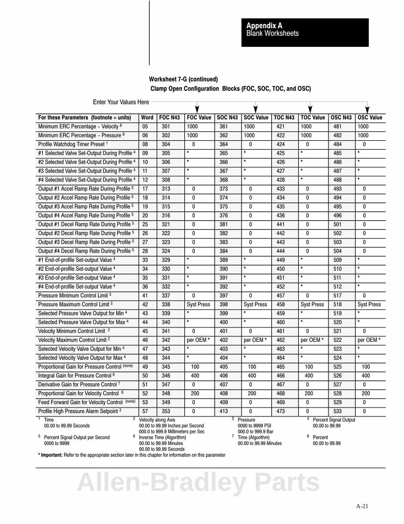
Enter Your Values Here
Blank WorksheetsAppendix A
A-21
Worksheet 7�G (continued)
Clamp Open Configuration Blocks (FOC, SOC, TOC, and OSC)
For these Parameters (footnote = units) Word FOC N43 FOC Value SOC N43 SOC Value TOC N43 TOC Value OSC N43 OSC Value
Minimum ERC Percentage - Velocity 8 05 301 1000 361 1000 421 1000 481 1000
Minimum ERC Percentage - Pressure 8 06 302 1000 362 1000 422 1000 482 1000
Profile Watchdog Timer Preset 1 08 304 0 364 0 424 0 484 0
#1 Selected Valve Set�Output During Profile 4 09 305 * 365 * 425 * 485 *
#2 Selected Valve Set�Output During Profile 4 10 306 * 366 * 426 * 486 *
#3 Selected Valve Set�Output During Profile 4 11 307 * 367 * 427 * 487 *
#4 Selected Valve Set�Output During Profile 4 12 308 * 368 * 428 * 488 *
Output #1 Accel Ramp Rate During Profile 5 17 313 0 373 0 433 0 493 0
Output #2 Accel Ramp Rate During Profile 5 18 314 0 374 0 434 0 494 0
Output #3 Accel Ramp Rate During Profile 5 19 315 0 375 0 435 0 495 0
Output #4 Accel Ramp Rate During Profile 5 20 316 0 376 0 436 0 496 0
Output #1 Decel Ramp Rate During Profile 5 25 321 0 381 0 441 0 501 0
Output #2 Decel Ramp Rate During Profile 5 26 322 0 382 0 442 0 502 0
Output #3 Decel Ramp Rate During Profile 5 27 323 0 383 0 443 0 503 0
Output #4 Decel Ramp Rate During Profile 5 28 324 0 384 0 444 0 504 0
#1 End�of�profile Set�output Value 4 33 329 * 389 * 449 * 509 *
#2 End�of�profile Set�output Value 4 34 330 * 390 * 450 * 510 *
#3 End�of�profile Set�output Value 4 35 331 * 391 * 451 * 511 *
#4 End�of�profile Set�output Value 4 36 332 * 392 * 452 * 512 *
Pressure Minimum Control Limit 3 41 337 0 397 0 457 0 517 0
Pressure Maximum Control Limit 3 42 338 Syst Press 398 Syst Press 458 Syst Press 518 Syst Press
Selected Pressure Valve Output for Min 4 43 339 * 399 * 459 * 519 *
Selected Pressure Valve Output for Max 4 44 340 * 400 * 460 * 520 *
Velocity Minimum Control Limit 2 45 341 0 401 0 461 0 521 0
Velocity Maximum Control Limit 2 46 342 per OEM * 402 per OEM * 462 per OEM * 522 per OEM *
Selected Velocity Valve Output for Min 4 47 343 * 403 * 463 * 523 *
Selected Velocity Valve Output for Max 4 48 344 * 404 * 464 * 524 *
Proportional Gain for Pressure Control (none) 49 345 100 405 100 465 100 525 100
Integral Gain for Pressure Control 6 50 346 400 406 400 466 400 526 400
Derivative Gain for Pressure Control 7 51 347 0 407 0 467 0 527 0
Proportional Gain for Velocity Control 6 52 348 200 408 200 468 200 528 200
Feed Forward Gain for Velocity Control (none) 53 349 0 409 0 469 0 529 0
Profile High Pressure Alarm Setpoint 3 57 353 0 413 0 473 0 533 01 Time 2 Velocity along Axis 3 Pressure 4 Percent Signal Output
00.00 to 99.99 Seconds 00.00 to 99.99 Inches per Second 0000 to 9999 PSI 00.00 to 99.99000.0 to 999.9 Millimeters per Sec 000.0 to 999.9 Bar
5 Percent Signal Output per Second 6 Inverse Time (Algorithm) 7 Time (Algorithm) 8 Percent0000 to 9999 00.00 to 99.99 Minutes 00.00 to 99.99 Minutes 00.00 to 99.99
00.00 to 99.99 Seconds* Important: Refer to the appropriate section later in this chapter for information on this parameter
Allen-Bradley Parts
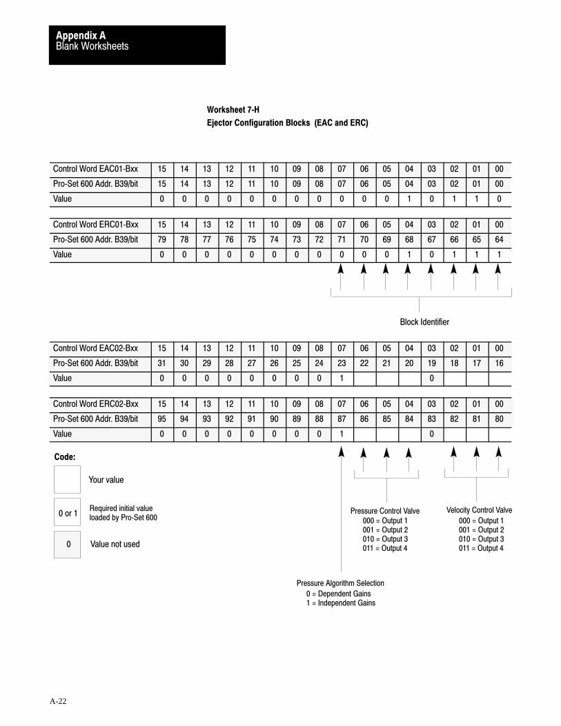
Velocity Control ValvePressure Control Valve
Pressure Algorithm Selection
Block Identifier
000 = Output 1001 = Output 2010 = Output 3011 = Output 4
000 = Output 1001 = Output 2010 = Output 3011 = Output 4
0 = Dependent Gains1 = Independent Gains
Code:
Your value
Required initial valueloaded by Pro�Set 6000 or 1
0 Value not used
Blank WorksheetsAppendix A
A-22
Worksheet 7�H
Ejector Configuration Blocks (EAC and ERC)
Control Word EAC01�Bxx 15 14 13 12 11 10 09 08 07 06 05 04 03 02 01 00
Pro�Set 600 Addr. B39/bit 15 14 13 12 11 10 09 08 07 06 05 04 03 02 01 00
Value 0 0 0 0 0 0 0 0 0 0 0 1 0 1 1 0
Control Word ERC01�Bxx 15 14 13 12 11 10 09 08 07 06 05 04 03 02 01 00
Pro�Set 600 Addr. B39/bit 79 78 77 76 75 74 73 72 71 70 69 68 67 66 65 64
Value 0 0 0 0 0 0 0 0 0 0 0 1 0 1 1 1
Control Word EAC02�Bxx 15 14 13 12 11 10 09 08 07 06 05 04 03 02 01 00
Pro�Set 600 Addr. B39/bit 31 30 29 28 27 26 25 24 23 22 21 20 19 18 17 16
Value 0 0 0 0 0 0 0 0 1 0
Control Word ERC02�Bxx 15 14 13 12 11 10 09 08 07 06 05 04 03 02 01 00
Pro�Set 600 Addr. B39/bit 95 94 93 92 91 90 89 88 87 86 85 84 83 82 81 80
Value 0 0 0 0 0 0 0 0 1 0

Enter Your Values Here
Blank WorksheetsAppendix A
A-23
Worksheet 7�H (continued)
Ejector Configuration Blocks (EAC and ERC)
Description Word EAC @ N45: EAC Value ERC @ N45: ERC Value
Minimum ERC Percentage��Velocity 8 05 N45:1 1000 N45:61 1000
Minimum ERC Percentage��Pressure 8 06 N45:2 1000 N45:62 1000
Profile Watchdog Timer Preset 1 08 N45:4 0 N/A N/A
Output #1 Set�Output Value during Advance 4 09 N45:5 * N45:65 *
Output #2 Set�Output Value during Advance 4 10 N45:6 * N45:66 *
Output #3 Set�Output Value during Advance 4 11 N45:7 * N45:67 *
Output #4 Set�Output Value during Advance 4 12 N45:8 * N45:68 *
Output #1 Acceleration Ramp Rate during Advance 5 17 N45:13 0 N45:73 0
Output #2 Acceleration Ramp Rate during Advance 5 18 N45:14 0 N45:74 0
Output #3 Acceleration Ramp Rate during Advance 5 19 N45:15 0 N45:75 0
Output #4 Acceleration Ramp Rate during Advance 5 20 N45:16 0 N45:76 0
Output #1 Deceleration Ramp Rate during Advance 5 25 N45:21 0 N45:81 0
Output #2 Deceleration Ramp Rate during Advance 5 26 N45:22 0 N45:82 0
Output #3 Deceleration Ramp Rate during Advance 5 27 N45:23 0 N45:83 0
Output #4 Deceleration Ramp Rate during Advance 5 28 N45:24 0 N45:84 0
Output #1 Set�Output Value at End�of Advance 4 33 N45:29 * N45:89 *
Output #2 Set�Output Value at End�of Advance 4 34 N45:30 * N45:90 *
Output #3 Set�Output Value at End�of Advance 4 35 N45:31 * N45:91 *
Output #4 Set�Output Value at End�of Advance 4 36 N45:32 * N45:92 *
Pressure Minimum Control Limit 3 41 N45:37 0 N45:97 0
Pressure Maximum Control Limit 3 42 N45:38 System Pressure N45:98 System Pressure
Selected Pressure Valve Output for Minimum 4 43 N45:39 * N45:99 *
Selected Pressure Valve Output for Maximum 4 44 N45:40 * N45:100 *
Velocity Minimum Control Limit 2 45 N45:41 0 N45:101 0
Velocity Maximum Control Limit 2 46 N45:42 Max Velocity perOEM specs*
N45:102 Max Velocity perOEM specs*
Selected Velocity Valve Output for Minimum 4 47 N45:43 * N45:103 *
Selected Velocity Valve Output for Maximum 4 48 N45:44 * N45:104 *
Proportional Gain for Pressure Control None 49 N45:45 100 N45:105 100
Integral Gain for Pressure Control 6 50 N45:46 400 N45:106 400
Derivative Gain for Pressure Control 1, 7 51 N45:47 0 N45:107 0
Proportional Gain for Velocity Control 6 52 N45:48 200 N45:108 200
Feed Forward Gain for Velocity Control None 53 N45:49 0 N45:109 0
Profile High Pressure Alarm Setpoint 3 57 N45:53 0 N/A N/A1 Time 2 Velocity along Axis 3 Pressure 4 Percent Signal Output
00.00 to 99.99 Seconds 00.00 to 99.99 Inches per Second 0000 to 9999 PSI 00.00 to 99.99000.0 to 999.9 Millimeters per Sec 000.0 to 999.9 Bar
5 Percent Signal Output per Second 6 Inverse Time (Algorithm) 7 Time (Algorithm) 8 Percent0000 to 9999 00.00 to 99.99 Minutes 00.00 to 99.99 Minutes 00.00 to 99.99
00.00 to 99.99 Seconds
*Refer to the appropriate section later in this chapter for information on this parameter
Allen-Bradley Parts

Algorithm 0 = Vel/Pos1 = Press/Pos
FCCSCCTCCFCCSCCTCC
Logical Bridge0 = Start Next Profile at end1 = Stop and Set Output at end
Mold Protection 0 = Start LPC on Zone Overrun1 = Stop and Zero Outputs on Zone Overrun
Velocity Units 0 = Percent Velocity1 = Inches (mm)/Second
CPC Block Identifier
ERC Enable/Disable Selection 0 = ON 1 = OFF
bit 15 = Press/Pos LPCbit 13 = Press/Pos TCCbit 12 = Vel/Pos TCCbit 11 = Press/Pos SCCbit 10 = Vel/Pos SCCbit 09 = Press/Pos FCCbit 08 = Vel/Pos FCC
Open/Closed�Loop Selection 0 = Closed�Loop 1 = Open�Loop
bit 07 = Press/Pos LPCbit 05 = Press/Pos TCCbit 04 = Vel/Pos TCCbit 03 = Press/Pos SCCbit 02 = Vel/Pos SCCbit 01 = Press/Pos FCCbit 00 = Vel/Pos FCC
Code:
Your value
Required initial valueloaded by Pro�Set 6000 or 1
0 Value not used
Blank WorksheetsAppendix A
A-24
Worksheet 8�A
Clamp Close Profile Command Block (CPC)
Control Word CPC01�Bxx 15 14 13 12 11 10 09 08 07 06 05 04 03 02 01 00
Pro�Set 600 Addr. B37/ bit 271 270 269 268 267 266 265 264 263 262 261 260 259 258 257 256
Value 0 0 0 0 0 0 0 0
Control Word CPC03�Bxx 15 14 13 12 11 10 09 08 07 06 05 04 03 02 01 00
Pro�Set 600 Addr. B37/bit 303 302 301 300 299 298 297 296 295 294 293 292 291 290 289 288
Value 0 0 0 0 0 0 0 0
Control Word CPC04�Bxx 15 14 13 12 11 10 09 08 07 06 05 04 03 02 01 00
Pro�Set 600 Addr. B37/bit 319 318 317 316 315 314 313 312 311 310 309 308 307 306 305 304
Value 0 0
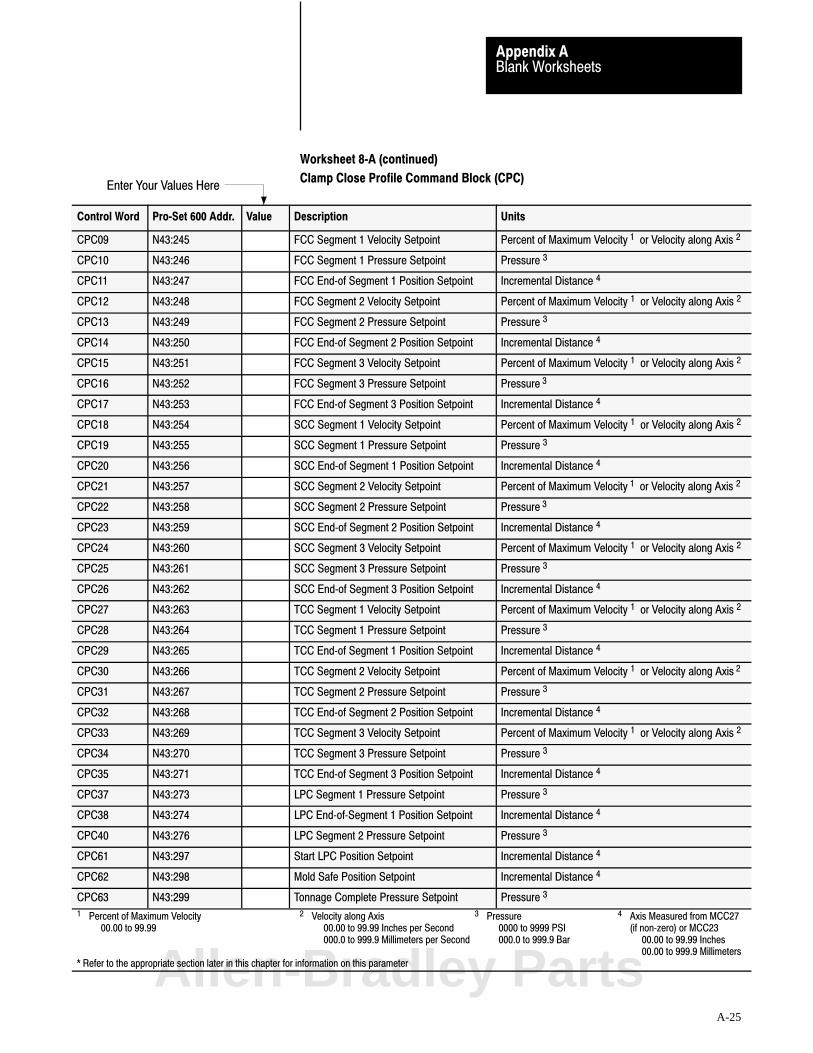
Enter Your Values Here
Blank WorksheetsAppendix A
A-25
Worksheet 8�A (continued)
Clamp Close Profile Command Block (CPC)
Control Word Pro�Set 600 Addr. Value Description Units
CPC09 N43:245 FCC Segment 1 Velocity Setpoint Percent of Maximum Velocity 1 or Velocity along Axis 2
CPC10 N43:246 FCC Segment 1 Pressure Setpoint Pressure 3
CPC11 N43:247 FCC End�of Segment 1 Position Setpoint Incremental Distance 4
CPC12 N43:248 FCC Segment 2 Velocity Setpoint Percent of Maximum Velocity 1 or Velocity along Axis 2
CPC13 N43:249 FCC Segment 2 Pressure Setpoint Pressure 3
CPC14 N43:250 FCC End�of Segment 2 Position Setpoint Incremental Distance 4
CPC15 N43:251 FCC Segment 3 Velocity Setpoint Percent of Maximum Velocity 1 or Velocity along Axis 2
CPC16 N43:252 FCC Segment 3 Pressure Setpoint Pressure 3
CPC17 N43:253 FCC End�of Segment 3 Position Setpoint Incremental Distance 4
CPC18 N43:254 SCC Segment 1 Velocity Setpoint Percent of Maximum Velocity 1 or Velocity along Axis 2
CPC19 N43:255 SCC Segment 1 Pressure Setpoint Pressure 3
CPC20 N43:256 SCC End�of Segment 1 Position Setpoint Incremental Distance 4
CPC21 N43:257 SCC Segment 2 Velocity Setpoint Percent of Maximum Velocity 1 or Velocity along Axis 2
CPC22 N43:258 SCC Segment 2 Pressure Setpoint Pressure 3
CPC23 N43:259 SCC End�of Segment 2 Position Setpoint Incremental Distance 4
CPC24 N43:260 SCC Segment 3 Velocity Setpoint Percent of Maximum Velocity 1 or Velocity along Axis 2
CPC25 N43:261 SCC Segment 3 Pressure Setpoint Pressure 3
CPC26 N43:262 SCC End�of Segment 3 Position Setpoint Incremental Distance 4
CPC27 N43:263 TCC Segment 1 Velocity Setpoint Percent of Maximum Velocity 1 or Velocity along Axis 2
CPC28 N43:264 TCC Segment 1 Pressure Setpoint Pressure 3
CPC29 N43:265 TCC End�of Segment 1 Position Setpoint Incremental Distance 4
CPC30 N43:266 TCC Segment 2 Velocity Setpoint Percent of Maximum Velocity 1 or Velocity along Axis 2
CPC31 N43:267 TCC Segment 2 Pressure Setpoint Pressure 3
CPC32 N43:268 TCC End�of Segment 2 Position Setpoint Incremental Distance 4
CPC33 N43:269 TCC Segment 3 Velocity Setpoint Percent of Maximum Velocity 1 or Velocity along Axis 2
CPC34 N43:270 TCC Segment 3 Pressure Setpoint Pressure 3
CPC35 N43:271 TCC End�of Segment 3 Position Setpoint Incremental Distance 4
CPC37 N43:273 LPC Segment 1 Pressure Setpoint Pressure 3
CPC38 N43:274 LPC End�of�Segment 1 Position Setpoint Incremental Distance 4
CPC40 N43:276 LPC Segment 2 Pressure Setpoint Pressure 3
CPC61 N43:297 Start LPC Position Setpoint Incremental Distance 4
CPC62 N43:298 Mold Safe Position Setpoint Incremental Distance 4
CPC63 N43:299 Tonnage Complete Pressure Setpoint Pressure 3
1 Percent of Maximum Velocity 2 Velocity along Axis 3 Pressure 4 Axis Measured from MCC27 00.00 to 99.99 00.00 to 99.99 Inches per Second 0000 to 9999 PSI (if non�zero) or MCC23
000.0 to 999.9 Millimeters per Second 000.0 to 999.9 Bar 00.00 to 99.99 Inches00.00 to 999.9 Millimeters
* Refer to the appropriate section later in this chapter for information on this parameterAllen-Bradley Parts

Algorithm Selection
IPC Block Identifier
00 = Vel/Pos 01 = Vel/Pos (pressure limited) 10 = Press/Pos11 = Press/Time
Sign of Velocity Offset0 = Positive1 = Negative
Velocity Units0 = Parameters in �Percent Velocity"1 = Parameters in Inches (mm)/Sec
Sign of Pressure Offset0 = Positive1 = Negative
0 = Vel/Pos Closed Loop1 = Open Loop
0 = Vel/Pos (limited) Closed Loop1 = Open Loop
0 = Press/Pos Closed Loop1 = Open Loop
0 = Press/Time Closed Loop1 = Open Loop
0 = ERC On for Vel/Pos 1 = ERC Off
0 = ERC On for Vel/Pos (limited) 1 = ERC Off
0 = ERC On for Press/Pos 1 = ERC Off
0 = ERC On for Press/Time1 = ERC Off
Code:
Your value
Required initial valueloaded by Pro�Set 6000 or 1
0 Value not used
Enter Your Values Here
Blank WorksheetsAppendix A
A-26
Worksheet 8�B
Injection Profile Command Block (IPC)
Control Word IPC01�Bxx 15 14 13 12 11 10 09 08 07 06 05 04 03 02 01 00
Pro�Set 600 Addr. B38/bit 79 78 77 76 75 74 73 72 71 70 69 68 67 66 65 64
Value 0 0 0 0 0 0 0 0
Control Word IPC03�Bxx 15 14 13 12 11 10 09 08 07 06 05 04 03 02 01 00
Pro�Set 600 Addr. B38/bit 111 110 109 108 107 106 105 104 103 102 101 100 99 98 97 96
Value 0 0 0 0 0 0 0 0 0 0 0
Control Word IPC04�Bxx 15 14 13 12 11 10 09 08 07 06 05 04 03 02 01 00
Pro�Set 600 Addr. B38/bit 127 126 125 124 123 122 121 120 119 118 117 116 115 114 113 112
Value 0 0 0 0 0 0 0 0
Worksheet 8�B (continued)
Injection Profile Command Block (IPC)
Control Word Pro�Set 600 Addr. Value Description Units
IPC09 N44:65 Segment 1 Velocity Setpoint Velocity 4
IPC10 N44:66 Segment 1 Pressure Setpoint Pressure 3
IPC11 N44:67 End�of Segment 1 Position Setpoint Distance from Mold�end 2
IPC12 N44:68 Segment 1 Time Setpoint Time 1
IPC13 N44:69 Segment 2 Velocity Setpoint Velocity 4
IPC14 N44:70 Segment 2 Pressure Setpoint Pressure 3
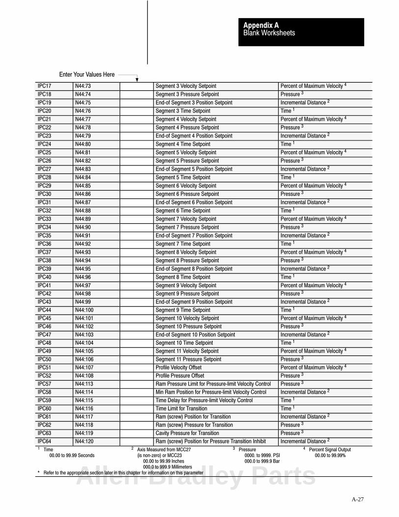
Enter Your Values Here
Blank WorksheetsAppendix A
A-27
IPC17 N44:73 Segment 3 Velocity Setpoint Percent of Maximum Velocity 4
IPC18 N44:74 Segment 3 Pressure Setpoint Pressure 3
IPC19 N44:75 End�of Segment 3 Position Setpoint Incremental Distance 2
IPC20 N44:76 Segment 3 Time Setpoint Time 1
IPC21 N44:77 Segment 4 Velocity Setpoint Percent of Maximum Velocity 4
IPC22 N44:78 Segment 4 Pressure Setpoint Pressure 3
IPC23 N44:79 End�of Segment 4 Position Setpoint Incremental Distance 2
IPC24 N44:80 Segment 4 Time Setpoint Time 1
IPC25 N44:81 Segment 5 Velocity Setpoint Percent of Maximum Velocity 4
IPC26 N44:82 Segment 5 Pressure Setpoint Pressure 3
IPC27 N44:83 End�of Segment 5 Position Setpoint Incremental Distance 2
IPC28 N44:84 Segment 5 Time Setpoint Time 1
IPC29 N44:85 Segment 6 Velocity Setpoint Percent of Maximum Velocity 4
IPC30 N44:86 Segment 6 Pressure Setpoint Pressure 3
IPC31 N44:87 End�of Segment 6 Position Setpoint Incremental Distance 2
IPC32 N44:88 Segment 6 Time Setpoint Time 1
IPC33 N44:89 Segment 7 Velocity Setpoint Percent of Maximum Velocity 4
IPC34 N44:90 Segment 7 Pressure Setpoint Pressure 3
IPC35 N44:91 End�of Segment 7 Position Setpoint Incremental Distance 2
IPC36 N44:92 Segment 7 Time Setpoint Time 1
IPC37 N44:93 Segment 8 Velocity Setpoint Percent of Maximum Velocity 4
IPC38 N44:94 Segment 8 Pressure Setpoint Pressure 3
IPC39 N44:95 End�of Segment 8 Position Setpoint Incremental Distance 2
IPC40 N44:96 Segment 8 Time Setpoint Time 1
IPC41 N44:97 Segment 9 Velocity Setpoint Percent of Maximum Velocity 4
IPC42 N44:98 Segment 9 Pressure Setpoint Pressure 3
IPC43 N44:99 End�of Segment 9 Position Setpoint Incremental Distance 2
IPC44 N44:100 Segment 9 Time Setpoint Time 1
IPC45 N44:101 Segment 10 Velocity Setpoint Percent of Maximum Velocity 4
IPC46 N44:102 Segment 10 Pressure Setpoint Pressure 3
IPC47 N44:103 End�of Segment 10 Position Setpoint Incremental Distance 2
IPC48 N44:104 Segment 10 Time Setpoint Time 1
IPC49 N44:105 Segment 11 Velocity Setpoint Percent of Maximum Velocity 4
IPC50 N44:106 Segment 11 Pressure Setpoint Pressure 3
IPC51 N44:107 Profile Velocity Offset Percent of Maximum Velocity 4
IPC52 N44:108 Profile Pressure Offset Pressure 3
IPC57 N44:113 Ram Pressure Limit for Pressure�limit Velocity Control Pressure 3
IPC58 N44:114 Min Ram Position for Pressure�limit Velocity Control Incremental Distance 2
IPC59 N44:115 Time Delay for Pressure�limit Velocity Control Time 1
IPC60 N44:116 Time Limit for Transition Time 1
IPC61 N44:117 Ram (screw) Position for Transition Incremental Distance 2
IPC62 N44:118 Ram (screw) Pressure for Transition Pressure 3
IPC63 N44:119 Cavity Pressure for Transition Pressure 3
IPC64 N44:120 Ram (screw) Position for Pressure Transition Inhibit Incremental Distance 2
1 Time 2 Axis Measured from MCC27 3 Pressure 4 Percent Signal Output 00.00 to 99.99 Seconds (is non�zero) or MCC23 0000. to 9999. PSI 00.00 to 99.99%
00.00 to 99.99 Inches 000.0 to 999.9 Bar000.0 to 999.9 Millimeters
* Refer to the appropriate section later in this chapter for information on this parameterAllen-Bradley Parts
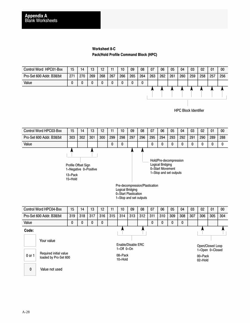
HPC Block Identifier
Hold/Pre�decompressionLogical Bridging0=Start Movement1=Stop and set outputs
Pre�decompression/PlasticationLogical Bridging0=Start Plastication1=Stop and set outputs
Profile Offset Sign 1=Negative 0=Positive
13=Pack15=Hold
Open/Closed Loop1=Open 0=Closed
Enable/Disable ERC 1=Off 0=On
00=Pack 02=Hold
08=Pack 10=Hold
Code:
Your value
Required initial valueloaded by Pro�Set 6000 or 1
0 Value not used
Blank WorksheetsAppendix A
A-28
Worksheet 8�C
Pack/Hold Profile Command Block (HPC)
Control Word HPC01�Bxx 15 14 13 12 11 10 09 08 07 06 05 04 03 02 01 00
Pro�Set 600 Addr. B38/bit 271 270 269 268 267 266 265 264 263 262 261 260 259 258 257 256
Value 0 0 0 0 0 0 0 0
Control Word HPC03�Bxx 15 14 13 12 11 10 09 08 07 06 05 04 03 02 01 00
Pro�Set 600 Addr. B38/bit 303 302 301 300 299 298 297 296 295 294 293 292 291 290 289 288
Value 0 0 0 0 0 0 0 0 0 0
Control Word HPC04�Bxx 15 14 13 12 11 10 09 08 07 06 05 04 03 02 01 00
Pro�Set 600 Addr. B38/bit 319 318 317 316 315 314 313 312 311 310 309 308 307 306 305 304
Value 0 0 0 0 0 0 0 0
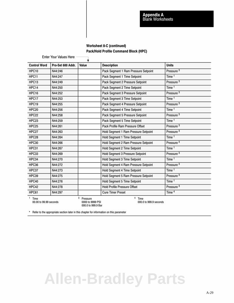
Enter Your Values Here
Blank WorksheetsAppendix A
A-29
Worksheet 8�C (continued)
Pack/Hold Profile Command Block (HPC)
Control Word Pro�Set 600 Addr. Value Description Units
HPC10 N44:246 Pack Segment 1 Ram Pressure Setpoint Pressure 3
HPC11 N44:247 Pack Segment 1 Time Setpoint Time 1
HPC13 N44:249 Pack Segment 2 Pressure Setpoint Pressure 3
HPC14 N44:250 Pack Segment 2 Time Setpoint Time 1
HPC16 N44:252 Pack Segment 3 Pressure Setpoint Pressure 3
HPC17 N44:253 Pack Segment 3 Time Setpoint Time 1
HPC19 N44:255 Pack Segment 4 Pressure Setpoint Pressure 3
HPC20 N44:256 Pack Segment 4 Time Setpoint Time 1
HPC22 N44:258 Pack Segment 5 Pressure Setpoint Pressure 3
HPC23 N44:259 Pack Segment 5 Time Setpoint Time 1
HPC25 N44:261 Pack Profile Ram Pressure Offset Pressure 3
HPC27 N44:263 Hold Segment 1 Ram Pressure Setpoint Pressure 3
HPC28 N44:264 Hold Segment 1 Time Setpoint Time 1
HPC30 N44:266 Hold Segment 2 Ram Pressure Setpoint Pressure 3
HPC31 N44:267 Hold Segment 2 Time Setpoint Time 1
HPC33 N44:269 Hold Segment 3 Pressure Setpoint Pressure 3
HPC34 N44:270 Hold Segment 3 Time Setpoint Time 1
HPC36 N44:272 Hold Segment 4 Ram Pressure Setpoint Pressure 3
HPC37 N44:273 Hold Segment 4 Time Setpoint Time 1
HPC39 N44:275 Hold Segment 5 Ram Pressure Setpoint Pressure 3
HPC40 N44:276 Hold Segment 5 Time Setpoint Time 1
HPC42 N44:278 Hold Profile Pressure Offset Pressure 3
HPC61 N44:297 Cure Timer Preset Time 4
1 Time 3 Pressure 4 Time00.00 to 99.99 seconds 0000 to 9999 PSI 000.0 to 999.9 seconds
000.0 to 999.9 Bar
* Refer to the appropriate section later in this chapter for information on this parameter
Allen-Bradley Parts

PPC Block Identifier
Open/Closed Loop0 = Closed 1 = Open
Enable/Disable ERC0 = On 1 = Off
01 = Pressure/Position00 = Pressure/Time
08 = Pressure/ Position09 = Pressure/Time
Sign of Profile Offset0 = Positive 1 = Negative
Plastication/Post�decompressionLogical Bridging0 = Start Post�decomp Movement1 = Stop and set outputs
Profile Algorithm 0 = Pressure/Position1 = Pressure/Time
Code:
Your value
Required initial valueloaded by Pro�Set 6000 or 1
0 Value not used
Blank WorksheetsAppendix A
A-30
Worksheet 8�D
Plastication Profile Command Block (PPC)
Control Word PPC01�Bxx 15 14 13 12 11 10 09 08 07 06 05 04 03 02 01 00
Pro�Set 600 Addr. B38/bit 463 462 461 460 459 458 457 456 455 454 453 452 421 450 449 448
Value 0 0 0 0 0 0 0 0
Control Word PPC03�Bxx 15 14 13 12 11 10 09 08 07 06 05 04 03 02 01 00
Pro�Set 600 Addr. B38/bit 495 494 493 492 491 490 489 488 487 486 485 484 483 482 481 480
Value 0 0 0 0 0 0 0 0 0 0 0 0 0
Control Word PPC04�Bxx 15 14 13 12 11 10 09 08 07 06 05 04 03 02 01 00
Pro�Set 600 Addr. B38/bit 511 510 509 508 507 506 505 504 503 502 501 500 499 498 497 496
Value 0 0 0 0 0 0 0 0 0 0 0 0

Enter Your Values Here
Blank WorksheetsAppendix A
A-31
Worksheet 8�D (continued)
Plastication Profile Command Block (PPC)
Control Word Pro�Set 600 Addr. Value Description Units
PPC10 N44:426 Segment 1 Pressure Setpoint Pressure 3
PPC11 N44:427 End�of Segment 1 Position Setpoint Distance from Mold�end 2
PPC12 N44:428 Segment 1 Time Setpoint Time 1
PPC14 N44:430 Segment 2 Pressure Setpoint Pressure 3
PPC15 N44:431 End�of Segment 2 Position Setpoint Distance from Mold�end 2
PPC16 N44:432 Segment 2 Time Setpoint Time 1
PPC18 N44:434 Segment 3 Pressure Setpoint Pressure 3
PPC19 N44:435 End�of Segment 3 Position Setpoint Distance from Mold�end 2
PPC20 N44:436 Segment 3 Time Setpoint Time 1
PPC22 N44:438 Segment 4 Pressure Setpoint Pressure 3
PPC23 N44:439 End�of Segment 4 Position Setpoint Distance from Mold�end 2
PPC24 N44:440 Segment 4 Time Setpoint Time 1
PPC26 N44:442 Segment 5 Pressure Setpoint Pressure 3
PPC27 N44:443 End�of Segment 5 Position Setpoint Distance from Mold�end 2
PPC28 N44:444 Segment 5 Time Setpoint Time 1
PPC30 N44:446 Segment 6 Pressure Setpoint Pressure 3
PPC31 N44:447 End�of Segment 6 Position Setpoint Distance from Mold�end 2
PPC32 N44:448 Segment 6 Time Setpoint Time 1
PPC34 N44:450 Segment 7 Pressure Setpoint Pressure 3
PPC35 N44:451 End�of Segment 7 Position Setpoint Distance from Mold�end 2
PPC36 N44:452 Segment 7 Time Setpoint Time 1
PPC38 N44:454 Segment 8 Pressure Setpoint Pressure 3
PPC39 N44:455 End�of Segment 8 Position Setpoint Distance from Mold�end 2
PPC40 N44:456 Segment 8 Time Setpoint Time 1
PPC42 N44:458 Segment 9 Pressure Setpoint Pressure 3
PPC43 N44:459 End�of Segment 9 Position Setpoint Distance from Mold�end 2
PPC44 N44:460 Segment 9 Time Setpoint Time 1
PPC46 N44:462 Segment 10 Pressure Setpoint Pressure 3
PPC47 N44:463 End�of Segment 10 Position Setpoint Distance from Mold�end 2
PPC48 N44:464 Segment 10 Time Setpoint Time 1
PPC50 N44:466 Segment 11 Pressure Setpoint Pressure 3
PPC52 N44:468 Profile Pressure Offset Pressure 3
PPC61 N44:477 Cushion Size Distance from Mold�end 2
PPC62 N44:478 Shot Size Incremental Distance 4
1 Time 2 Distance from MCC13 (if not zero) or MCc09 3 Pressure 4 Distance from PPC6100.00 to 99.99 Seconds 00.00 to 99.99 Inches 0000 to 9999 PSI 00.00 to 99.99 Inches
000.0 to 999.9 Millimeters 000.0 to 999.9 Bar 000.0 to 999.9 Millimeter
* Refer to the appropriate section later in this chapter for information on this parameter
Allen-Bradley Parts
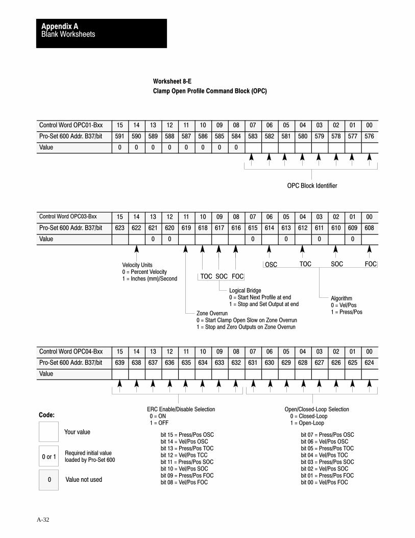
Algorithm 0 = Vel/Pos1 = Press/Pos
FOCSOCTOC
FOCSOCTOC
Logical Bridge0 = Start Next Profile at end1 = Stop and Set Output at end
Zone Overrun0 = Start Clamp Open Slow on Zone Overrun1 = Stop and Zero Outputs on Zone Overrun
Velocity Units 0 = Percent Velocity1 = Inches (mm)/Second
OPC Block Identifier
ERC Enable/Disable Selection 0 = ON 1 = OFF
bit 15 = Press/Pos OSCbit 14 = Vel/Pos OSCbit 13 = Press/Pos TOCbit 12 = Vel/Pos TCCbit 11 = Press/Pos SOCbit 10 = Vel/Pos SOCbit 09 = Press/Pos FOCbit 08 = Vel/Pos FOC
Open/Closed�Loop Selection 0 = Closed�Loop 1 = Open�Loop
bit 07 = Press/Pos OSCbit 06 = Vel/Pos OSCbit 05 = Press/Pos TOCbit 04 = Vel/Pos TOCbit 03 = Press/Pos SOCbit 02 = Vel/Pos SOCbit 01 = Press/Pos FOCbit 00 = Vel/Pos FOC
OSC
Code:
Your value
Required initial valueloaded by Pro�Set 6000 or 1
0 Value not used
Blank WorksheetsAppendix A
A-32
Worksheet 8�E
Clamp Open Profile Command Block (OPC)
Control Word OPC01�Bxx 15 14 13 12 11 10 09 08 07 06 05 04 03 02 01 00
Pro�Set 600 Addr. B37/bit 591 590 589 588 587 586 585 584 583 582 581 580 579 578 577 576
Value 0 0 0 0 0 0 0 0
Control Word OPC03�Bxx 15 14 13 12 11 10 09 08 07 06 05 04 03 02 01 00
Pro�Set 600 Addr. B37/bit 623 622 621 620 619 618 617 616 615 614 613 612 611 610 609 608
Value 0 0 0 0 0 0
Control Word OPC04�Bxx 15 14 13 12 11 10 09 08 07 06 05 04 03 02 01 00
Pro�Set 600 Addr. B37/bit 639 638 637 636 635 634 633 632 631 630 629 628 627 626 625 624
Value
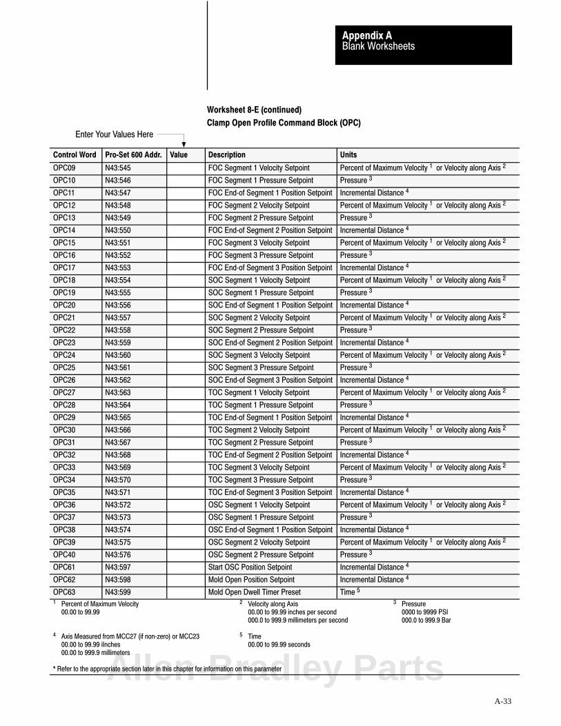
Enter Your Values Here
Blank WorksheetsAppendix A
A-33
Worksheet 8�E (continued)
Clamp Open Profile Command Block (OPC)
Control Word Pro�Set 600 Addr. Value Description Units
OPC09 N43:545 FOC Segment 1 Velocity Setpoint Percent of Maximum Velocity 1 or Velocity along Axis 2
OPC10 N43:546 FOC Segment 1 Pressure Setpoint Pressure 3
OPC11 N43:547 FOC End�of Segment 1 Position Setpoint Incremental Distance 4
OPC12 N43:548 FOC Segment 2 Velocity Setpoint Percent of Maximum Velocity 1 or Velocity along Axis 2
OPC13 N43:549 FOC Segment 2 Pressure Setpoint Pressure 3
OPC14 N43:550 FOC End�of Segment 2 Position Setpoint Incremental Distance 4
OPC15 N43:551 FOC Segment 3 Velocity Setpoint Percent of Maximum Velocity 1 or Velocity along Axis 2
OPC16 N43:552 FOC Segment 3 Pressure Setpoint Pressure 3
OPC17 N43:553 FOC End�of Segment 3 Position Setpoint Incremental Distance 4
OPC18 N43:554 SOC Segment 1 Velocity Setpoint Percent of Maximum Velocity 1 or Velocity along Axis 2
OPC19 N43:555 SOC Segment 1 Pressure Setpoint Pressure 3
OPC20 N43:556 SOC End�of Segment 1 Position Setpoint Incremental Distance 4
OPC21 N43:557 SOC Segment 2 Velocity Setpoint Percent of Maximum Velocity 1 or Velocity along Axis 2
OPC22 N43:558 SOC Segment 2 Pressure Setpoint Pressure 3
OPC23 N43:559 SOC End�of Segment 2 Position Setpoint Incremental Distance 4
OPC24 N43:560 SOC Segment 3 Velocity Setpoint Percent of Maximum Velocity 1 or Velocity along Axis 2
OPC25 N43:561 SOC Segment 3 Pressure Setpoint Pressure 3
OPC26 N43:562 SOC End�of Segment 3 Position Setpoint Incremental Distance 4
OPC27 N43:563 TOC Segment 1 Velocity Setpoint Percent of Maximum Velocity 1 or Velocity along Axis 2
OPC28 N43:564 TOC Segment 1 Pressure Setpoint Pressure 3
OPC29 N43:565 TOC End�of Segment 1 Position Setpoint Incremental Distance 4
OPC30 N43:566 TOC Segment 2 Velocity Setpoint Percent of Maximum Velocity 1 or Velocity along Axis 2
OPC31 N43:567 TOC Segment 2 Pressure Setpoint Pressure 3
OPC32 N43:568 TOC End�of Segment 2 Position Setpoint Incremental Distance 4
OPC33 N43:569 TOC Segment 3 Velocity Setpoint Percent of Maximum Velocity 1 or Velocity along Axis 2
OPC34 N43:570 TOC Segment 3 Pressure Setpoint Pressure 3
OPC35 N43:571 TOC End�of Segment 3 Position Setpoint Incremental Distance 4
OPC36 N43:572 OSC Segment 1 Velocity Setpoint Percent of Maximum Velocity 1 or Velocity along Axis 2
OPC37 N43:573 OSC Segment 1 Pressure Setpoint Pressure 3
OPC38 N43:574 OSC End�of Segment 1 Position Setpoint Incremental Distance 4
OPC39 N43:575 OSC Segment 2 Velocity Setpoint Percent of Maximum Velocity 1 or Velocity along Axis 2
OPC40 N43:576 OSC Segment 2 Pressure Setpoint Pressure 3
OPC61 N43:597 Start OSC Position Setpoint Incremental Distance 4
OPC62 N43:598 Mold Open Position Setpoint Incremental Distance 4
OPC63 N43:599 Mold Open Dwell Timer Preset Time 5
1 Percent of Maximum Velocity 2 Velocity along Axis 3 Pressure00.00 to 99.99 00.00 to 99.99 inches per second 0000 to 9999 PSI
000.0 to 999.9 millimeters per second 000.0 to 999.9 Bar
4 Axis Measured from MCC27 (if non�zero) or MCC23 5 Time00.00 to 99.99 iInches 00.00 to 99.99 seconds00.00 to 999.9 millimeters
* Refer to the appropriate section later in this chapter for information on this parameterAllen-Bradley Parts

A
alarm, pressure setpoint forclamp close profile, 9�14clamp LPC profle, 9�9clamp open profiles, 9�47ejector profile, 9�57inject-mode profiles, 10�19injection profile, 9�24pack and hold profile, 9�36plastication profile, 9�41profile vs absolute, 10�33
alarm, profile pressure, 7�30
alarm, system pressure, 3�16
algorithmselect for profile, 8�6, 8�13, 8�27,
8�35, 8�44select gain constants, 7�21
audience, P�2
Auxiliary analog inputs, 2�1
B
bit numbering, P�4
block identifier, 8�5
C
clamp, configure position sensor, 3�10
clamp closeinitial profile values, 8�2overview, 1�9position segments, 1�10
clamp controlend�of�segment positions, 10�25LPC pressure setpoints, 10�24start LPC position, 10�26start open slow position, 10�27tuning considerations, 10�23velocity setpoints, 10�24zone overrun, 10�28
clamp mode, overview, 1�9
clamp openinitial profile values, 8�31overview, 1�11position segments, 1�12
command blocks, P�3, 4�1
configuration proceduresconcepts, 4�1
determine initial values, 7�19overview of, 4�3
control limitspressure min/max, 7�26
outputs for min/max, 7�26velocity min/max, 7�28
outputs for min/max, 7�28
cure timer preset, 8�23
cushion, 8�30, 10�13diagram, 10�14
D
decompression, 10�17
digital filter, 3�17
download procedurescorrect data�entry errors, 4�6data blocks, 4�4download bit table, 4�5enter into data table, 4�4enter/download values, 8�9MCC block, 3�6
E
E-stops, 2�11
eject mode, overview, 1�13
ejectoradvance, 1�13configure position sensor, 3�11enable/disable, 8�44end�of�segment positions, 10�25forward dwell, 8�42forward dwell timer, 8�46initial profile values, 8�39other features, 1�15retract, 1�14stop and notify, 8�43strokes required, 8�48tip strokes, 1�15tuning considerations, 10�23type of strokes, 8�42
end-of-segment positionsclamp and ejector, 10�25determine for clamp close, 8�8determine for ejector, 8�46determine for injection, 8�15determine for open slow, 8�37determine for plastication, 8�29
Index

IndexI–2
inject-mode, 10�11
ERCclamp and eject mode, 10�34initial values, 7�22inject-mode, 10�22select on/off, 8�6, 8�14, 8�21, 8�28,
8�35, 8�44
error correction for, data entry indata blocks, 4�6MCC block, 3�6
F
flash prevention, 1�4
G
gain constants, 7�21for profiles, 7�29P and VelFF, 10�6PID for pressure control, 10�3
glossary, P�2, 1�20
grounding, QDC module, 2�9
H
hold phase, overview, 1�7
I
I/Oauxiliary analog inputs, 2�1record ranges, 2�1
I/O config procedures (optional)digital input filter, 3�17software travel limits, 3�14system pressure alarm, 3�16time delays, 3�16
I/O configuration procedures, 3�1clamp position sensor, 3�10correct data entry errors, 3�6download MCC block, 3�6ejector position sensor, 3�11enter MCC into data table, 3�5move ram, clamp, ejector, 3�7screw position sensor, 3�9select I/O ranges, 3�2sensor config values, 3�4sensor configuration, final, 3�8system pressure sensor, 3�12
inject modeoverview, 1�1pressure limited, 10�20
injection profileexample benefits, 1�3initial values, 8�10overview, 1�2
inputsclamp position sensor, 3�10digital input filter, 3�17ejector position sensor, 3�11optional configurations, 3�14screw position sensor, 3�9select ranges, 3�3sensor config values, 3�4sensor configuration, final, 3�8software travel limits, 3�14system pressure alarm, 3�16system pressure sensor, 3�12time delays, 3�16
installation proceduresground the QDC module, 2�9install the QDC module, 2�6jumper settings, 2�2key the I/O chassis, 2�5plan machine interlocks, 2�11wire the QDC module, 2�7
J
jog procedures, 5�1determine initial jog values, 5�2download jog values, 5�4jog the ram, clamp, ejector, 5�7ladder logic for jogs, 5�5, 5�8rotate the screw, 5�9screw rotate, indirect, 5�7
jogging, 5�1
jumper plugsaccessing, 2�2location diagram, 2�3settings, 2�4
K
key the I/O chassis, 2�5
L
ladder logicassess requirements, 6�1command/status bit tables, 6�2ram, clamp, ejector jogs, 5�5screw-rotate, assist, 5�8
LEDs to troubleshoot, 11�1Allen-Bradley Parts

Index I–3
logical bridgesclamp and ejector, 10�29inject mode, 10�16select, 8�21, 8�27selection of, 8�5, 8�34, 8�44
loop controlclosed loop, 10�2open loop, 10�2select open/closed, 8�6, 8�14, 8�22,
8�28, 8�35, 8�45
low pressure close, overview, 1�10
LPC start position, 10�26
M
machine cycle, clamp, 1�9
machine cycle, inject, 1�1
machine interlocks, 2�11
mold opendwell timer preset, 8�38position setpoint, 8�36
mold protectiondiagram, 8�8LPC start position, 8�7selection of, 8�5
mold safediagram, 8�8, 8�37position setpoint, 8�7
O
offsetselect sign, 8�13, 8�21, 8�27value, 8�16, 8�22, 8�30
offset, profile, 10�19
open slow, overview, 1�12
OSC start position, 10�27
outputsselect ranges, 3�3set-output, end of profile, 7�25to selected valve
pressure control, 7�20velocity control, 7�19
to unselected valves, set output values, 7�22, 10�15
overview of manual, P�1
P
pack phase, example benefits, 1�6
pack profileinitial values, 8�18overview, 1�5
plasticationexample benefits, 1�8initial profile values, 8�24overview, 1�7
position setpointclamp position to inhibit ejector, 8�47clamp position to start ejector, 8�47ejector fully advanced, 8�46ejector fully retracted, 8�47ejector position to inhibit clamp close,
8�48mold fully open, 8�36start OSC, 8�37
position setpointsclamp to inhibit ejector, 10�28clamp to start ejector, 10�29clamp zone overrun, 10�28cushion, 10�13ejector to enable clamp close, 10�28end�of�segment, 10�11end�of�segment, clamp/eject, 10�25ram (screw) for transition, 10�14shot size, 10�13start clamp LPC, 10�26start clamp open slow, 10�27start zone for pres�lim velocity, 10�21start zone, pressure transition, 10�14
post-decompress movement, 1�8
power distribution, 2�12
pre-decompress movement, 1�7
pressure setpoints, 8�15CPC, 8�7EPC, 8�45IPC, 8�15LPC, 10�24OPC, 8�36PPC, 8�28tuning of, 10�11
pressure�limited injection, velocity control, 10�21
pressure-limited injection, 10�20diagram, 10�21ram pressure limit, 8�16start zone for, 8�16time delay for, 8�16
profile requirementsclamp and eject mode, 10�24inject mode, 10�10
min requirements, 10�12
IndexI–4
profiles, initial valuesclamp close, 8�2clamp open, 8�31ejector, 8�39injection, 8�10pack and hold, 8�18plastication, 8�24
publications, related, P�5
pullback, decompression, 10�17
Q
QDC moduledigital input filter, 3�17ground, 2�9I/O ranges, 3�2I/O terminal designations, 2�8install, 2�6optional configurations, 3�14rack address, 2�5select parameters, 3�2sensor config values, initial, 3�4sensor configuration, final, 3�8set jumper plugs, 2�2troubleshoot, 11�1wire I/O, 2�7
QH module, record I/O ranges, 2�1
R
ram (screw)configure position sensor, 3�9jog screw rotation, 5�9
ramp ratesinitial values, 7�24inject mode, 10�17tuning, 10�18tuning of, 10�31
S
sensor config values, 3�4
sensor configuration, 3�8
set�output, move ram, clamp, ejector, 3�7
set-output valuesat end of inject profiles, 10�16end of clamp/ejector motion, 10�30for unselected valves, 10�15
shot size, 8�30, 10�13diagram, 10�14
software travel limits, 3�14
status blocks, P�4, 4�2
stop�and�notify, ejector profile, 8�43
summary, inject, clamp, & eject, 1�20
system pressure, 1�15, 7�20configure pressure sensor, 3�12
T
time delay, pressure�limited velocity, 10�21
time delays, 3�16
time setpoints, 10�12HPC, 8�22IPC, 8�16PPC, 8�29
timer preset, ejector forward dwell, 8�46
tip strokes, 1�15selection of, 8�42
tonnage, procedure to set, 9�8
tonnage-complete setpt, 8�9
transition, 1�5, 10�14conditions for, 10�13diagram, 10�14setpoints, 8�17
troubleshoot, 11�1
tune closed looppressure control, 10�2
with an oscilloscope, 10�4without an oscilloscope, 10�3
velocity control, 10�6with an oscilloscope, 10�8without an oscilloscope, 10�7
tuning considerationsfor clamp and ejector, 10�23for producing parts, 10�10ramp rates, 10�18
V
valve-linearity procedures, forclamp close pressure, 9�13clamp close velocity, 9�18clamp low pressure close, 9�7clamp open pressure, 9�45clamp open velocity, 9�51ejector pressure, 9�56ejector velocity, 9�60injection pressure, 9�23injection velocity, 9�29pack and hold pressure, 9�35plastication backpressure, 9�40
valve-spanning procedures, forclamp close pressure, 9�10clamp close velocity, 9�15clamp open pressure, 9�42, 9�43,
9�49, 9�54, 9�59Allen-Bradley Parts

Index I–5
clamp open velocity, 9�48ejector pressure, 9�53ejector velocity, 9�58injection pressure, 9�20injection velocity, 9�25pack and hold pressure, 9�31plastication backpressure, 9�37
Valve�spanning procedures, for, clamp lowpressure close, 9�4
velocity setpointsclamp, 10�24CPC, 8�7EPC, 8�45injection, 10�10IPC, 8�14OPC, 8�36
velocity units, selection of, 8�5, 8�13, 8�34, 8�42
W
watchdog timer, 10�19for profiles, 7�30, 10�34
wiring, QDC module I/O, 2�7
word numbering, P�4
worksheetsconfiguration worksheet list, 7�2configure EAC, ERC, 7�17
configure FCC, SCC, TCC, 7�3, A�8configure FOC, SOC, TOC, OSC, 7�15,
A�20configure HDC, 7�11, A�16configure INC, 7�7, A�12configure LPC, 7�5, A�10configure PKC, 7�9, A�14configure PLC, 7�13, A�18jog ram, clamp, ejector, 5�3jog screw-rotate, indirect, 5�8pressure alarm setpts, 3�16profile worksheet list, 8�1profile, CPC values, 8�3profile, EPC values, 8�40profile, HPC values, 8�19profile, IPC values, 8�11profile, OPC values, 8�32profile, PPC values, 8�25QDC module parameters, 3�2sensor config values, 3�5, 3�9sensor I/O ranges, 3�3software travel limits, 3�15
Worksheets, for, I/O ranges, 2�1
Z
zone overrun, 10�28selection of, 8�34
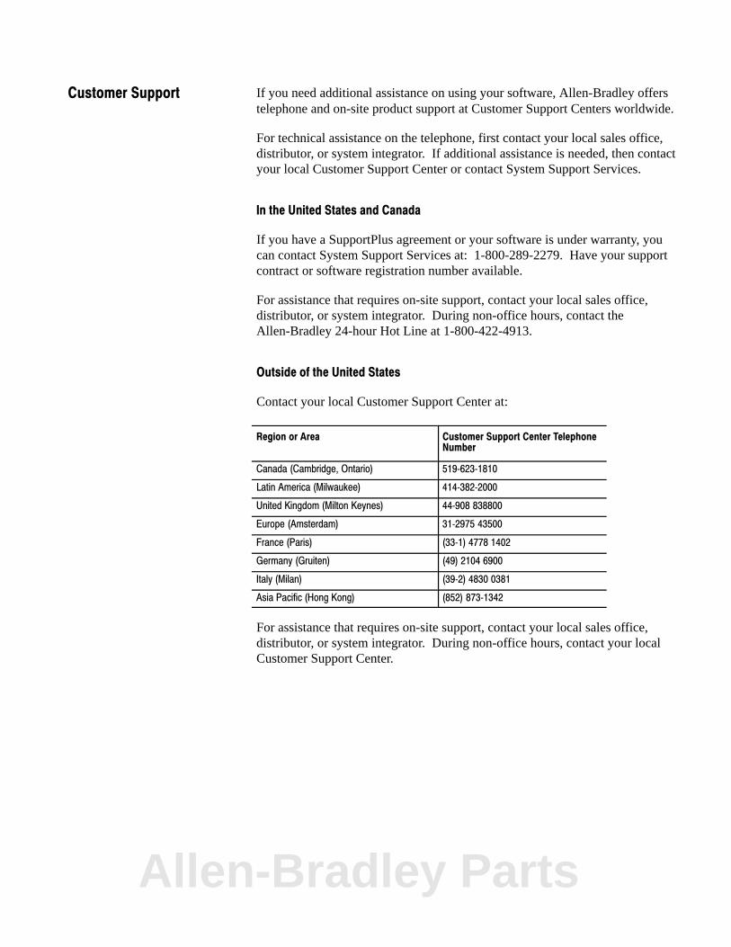
If you need additional assistance on using your software, Allen-Bradley offerstelephone and on-site product support at Customer Support Centers worldwide.
For technical assistance on the telephone, first contact your local sales office,distributor, or system integrator. If additional assistance is needed, then contactyour local Customer Support Center or contact System Support Services.
In the United States and Canada
If you have a SupportPlus agreement or your software is under warranty, youcan contact System Support Services at: 1-800-289-2279. Have your supportcontract or software registration number available.
For assistance that requires on-site support, contact your local sales office,distributor, or system integrator. During non-office hours, contact theAllen-Bradley 24-hour Hot Line at 1-800-422-4913.
Outside of the United States
Contact your local Customer Support Center at:
Region or Area Customer Support Center TelephoneNumber
Canada (Cambridge, Ontario) 519�623�1810
Latin America (Milwaukee) 414�382�2000
United Kingdom (Milton Keynes) 44�908 838800
Europe (Amsterdam) 31�2975 43500
France (Paris) (33�1) 4778 1402
Germany (Gruiten) (49) 2104 6900
Italy (Milan) (39�2) 4830 0381
Asia Pacific (Hong Kong) (852) 873�1342
For assistance that requires on-site support, contact your local sales office,distributor, or system integrator. During non-office hours, contact your localCustomer Support Center.
Customer Support
Allen-Bradley Parts

With major offices worldwide.
Algeria • Argentina • Australia • Austria • Bahrain • Belgium • Brazil • Bulgaria • Canada • Chile • China, PRC • Colombia • Costa Rica • Croatia • Cyprus • Czech
Republic • Denmark • Ecuador • Egypt • El Salvador • Finland • France • Germany • Greece • Guatemala • Honduras • Hong Kong • Hungary • Iceland • India •Indonesia • Israel • Italy • Jamaica • Japan • Jordan • Korea • Kuwait • Lebanon • Malaysia • Mexico • New Zealand • Norway • Oman • Pakistan • Peru • Philippines
• Poland • Portugal • Puerto Rico • Qatar • Romania • Russia-CIS • Saudi Arabia • Singapore • Slovakia • Slovenia • South Africa, Republic • Spain • Switzerland •Taiwan • Thailand • The Netherlands • Turkey • United Arab Emirates • United Kingdom • United States • Uruguay • Venezuela • Yugoslavia
World Headquarters, Allen�Bradley, 1201 South Second Street, Milwaukee, WI 53204 USA, Tel: (1) 414 382�2000 Fax: (1) 414 382�4444
Allen�Bradley has been helping its customers improve productivity and quality for 90 years.
A�B designs, manufactures and supports a broad range of control and automation products
worldwide. They include logic processors, power and motion control devices, man�machine
interfaces and sensors. Allen�Bradley is a subsidiary of Rockwell International, one of the
world's leading technology companies.
Publication 1771�6.5.93 November 1992 P/N 955111�36Copyright 1992 Allen�Bradley Company, Inc. Printed in USA