Embed Size (px)
Citation preview
UC400ETH ethernet motion controller user's guide
Version of this document: 1.0001
1/21

Contents1.Description of the UC400ETH device.2.Safety notes.3.Physical installation of the device.
3.1.Dimensions and mounting drills.3.2.Horizontal installation on the bottom of the mounting plate.3.3.Vertical installation to an opening.
4.Systems requirements.5.Setting up the network.
5.1.Setting up the network on the PC side.5.1.1.Setup with direct connection to a LAN card.5.1.2.Setup with connection via switch/router.
5.2.Network settings on the UC400ETH.5.2.1.The UCxxx_utility.exe software.5.2.2.Resetting the network settings.
6.LEDs signs.7.External power supply connection.8.I/O connections of the device.9.Running the UC400ETH with the UCCNC software.
1 .Description of the UC400ETH device.
For first of all we thank you for your interest in our product and for reading this user's guide.
The UC400ETH is a motion controller with ethernet interface. The device can communicate with a connection to the control computer's network card. The connection can be built with direct connection or via router/switch devices.The device can be used to contol machine tools with stepper or servo motor controls with step and direction interfaces.The controller can output a maximum of 400kHz stepping frequency and can work with upto 6-axes. This user's guide describes how to establish connection between the device and the control computer, how to setup the LAN network and the device for the communication. This document also describes the electrical parameters and properties of the motion controller.How to run the device with a CNC control software is not described in this manual and is described in a separate document. Please read the UCCNC control software user's guide for more informations about running the device with the software.
2 .Safety notes.
Moving objects like machine tool axes and automatition equipments can be dangerous. Always make sure to keep all machine safety standards. Always install e-stop switches and the required safety equipments to your control system and make sure that the equipment controlled by our device meets all the safety standards.
Always keep the board dry and away from falling chips and dust, protect the device from taint damage.
2/21
CNCdrive Kft. cannot take responsibility for any personal injury and/or financial losscaused by any device failure or caused by following an error in this documentation.
3 .Physical installation of the device.
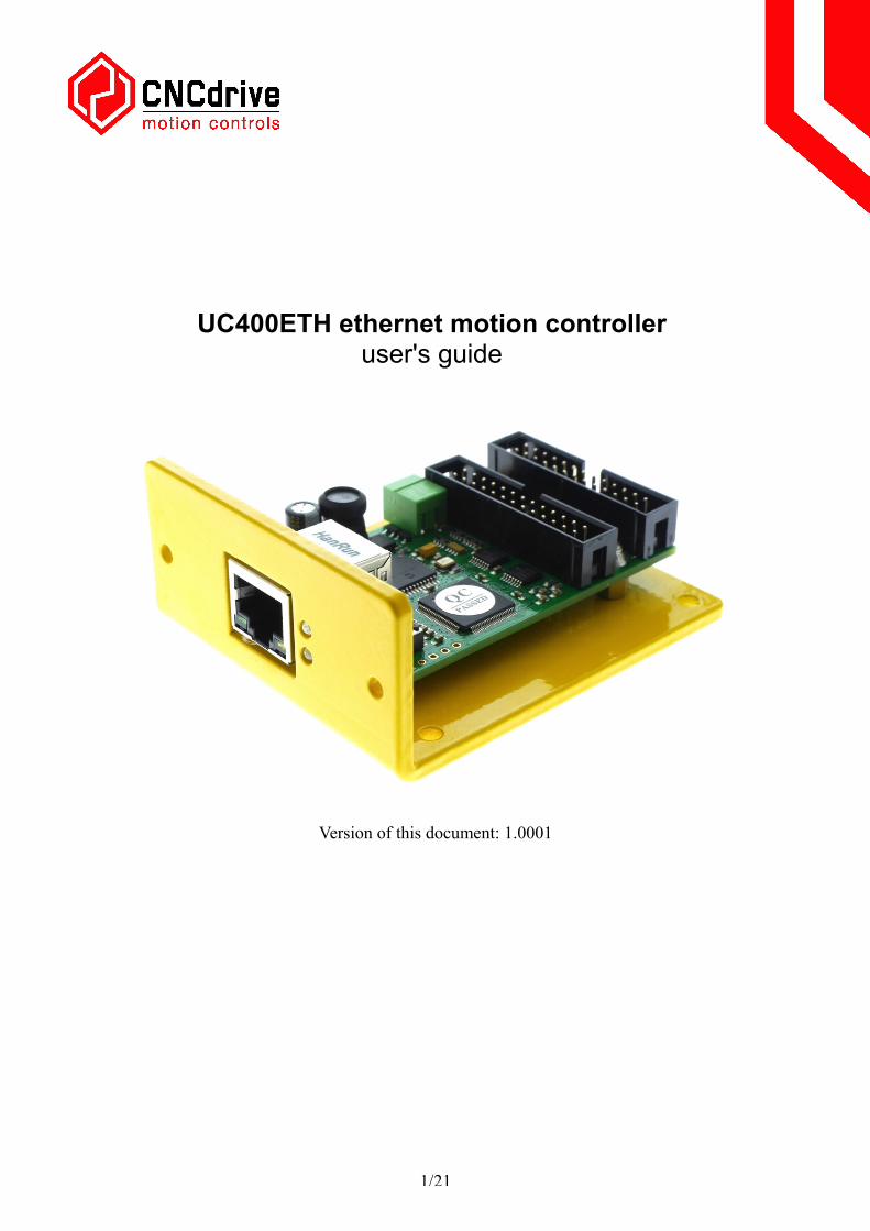
The UC400ETH printed circuit board is mounted on a 3mm thick aluminium plate. This plate is for mounting the device into a control box and it is also used as a cooling plate for the board electronics. The device can be installed 2 ways, horizontally and vertically via the drills on the aluminium mounting plate.
3.1 .Dimensions and mounting drills.
The following drawings show the outline dimensions of the device and the mounting drills placements.
3/21
3.2 .Horizontal installation on the bottom of the mounting plate.
The device can be installed horizontally with bolting the device to inside the control box via the 4pcs of 3.50mm dia drills on the bottom of the aluminium mounting plate.
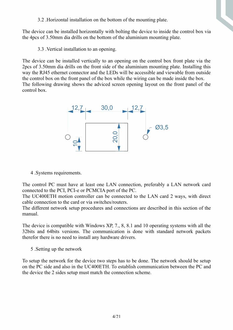
3.3 .Vertical installation to an opening.
The device can be installed vertically to an opening on the control box front plate via the 2pcs of 3.50mm dia drills on the front side of the aluminium mounting plate. Installing this way the RJ45 ethernet connector and the LEDs will be accessible and viewable from outside the control box on the front panel of the box while the wiring can be made inside the box.The following drawing shows the adviced screen opening layout on the front panel of the control box.
4 .Systems requirements.
The control PC must have at least one LAN connection, preferably a LAN network card connected to the PCI, PCI-e or PCMCIA port of the PC.The UC400ETH motion controller can be connected to the LAN card 2 ways, with direct cable connection to the card or via switches/routers.The different network setup procedures and connections are described in this section of the manual.
The device is compatible with Windows XP, 7., 8, 8.1 and 10 operating systems with all the 32bits and 64bits versions. The communication is done with standard network packets therefor there is no need to install any hardware drivers.
5 .Setting up the network
To setup the network for the device two steps has to be done. The network should be setup on the PC side and also in the UC400ETH. To establish communication between the PC and the device the 2 sides setup must match the connection scheme.
4/21
5.1 .Setting up the network on the PC side
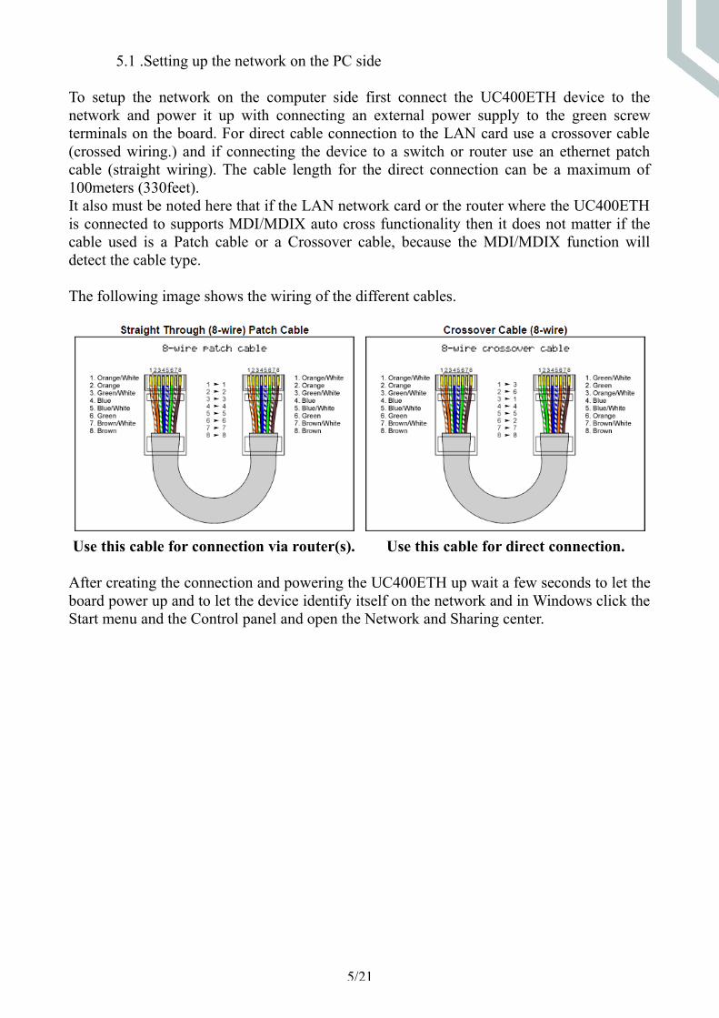
To setup the network on the computer side first connect the UC400ETH device to the network and power it up with connecting an external power supply to the green screw terminals on the board. For direct cable connection to the LAN card use a crossover cable (crossed wiring.) and if connecting the device to a switch or router use an ethernet patch cable (straight wiring). The cable length for the direct connection can be a maximum of 100meters (330feet).It also must be noted here that if the LAN network card or the router where the UC400ETH is connected to supports MDI/MDIX auto cross functionality then it does not matter if the cable used is a Patch cable or a Crossover cable, because the MDI/MDIX function will detect the cable type.
The following image shows the wiring of the different cables.
Use this cable for connection via router(s). Use this cable for direct connection.
After creating the connection and powering the UC400ETH up wait a few seconds to let the board power up and to let the device identify itself on the network and in Windows click the Start menu and the Control panel and open the Network and Sharing center.
5/21
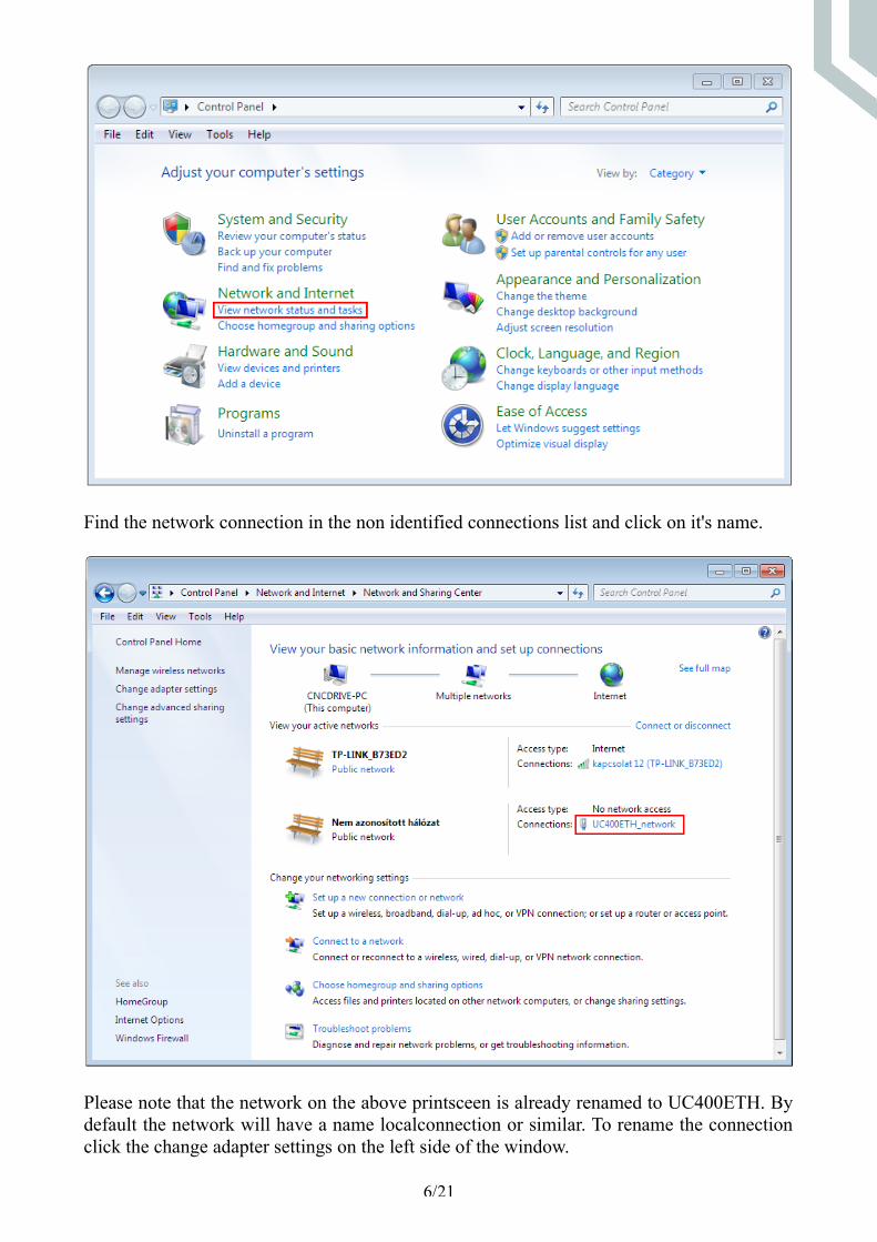
Find the network connection in the non identified connections list and click on it's name.
Please note that the network on the above printsceen is already renamed to UC400ETH. By default the network will have a name localconnection or similar. To rename the connection click the change adapter settings on the left side of the window.
6/21

And left click the name of the adapter and click 'Rename this connection' and enter the new name of the connection.
After finding and optionally renaming the connection it is time to setup the network parameters.
5.1.1 .Setup with direct connection to a LAN network card.
To setup the connection with direct cable connection click on the name of the connection and on the pop-up window press the Properties button. Please note that for this action to work the user must have administrator rights in the Windows account.
7/21

8/21

On the popup window find and select the 'Internet Protocol Version 4(TCP/IPv4)' row and click the Properties button.On the pop up Internet Protocol Version 4( (TCP/IPv4) Properties window select the Use the following IP address option and fill in the IP address of the UC400ETH device and set the Subnet mask. The default IP address of the UC400ETH is 10.10.10.10 (this can be changed and this will be described in a later section of this manual.) and set the subnet mask to 255.255.255.0 value.
After filling the values don't forget to set the 'Validate settings upon exit' checkbox to let the parameters validate automaticaly when closing the setup. Finally press OK to all the pop up windows to exit the setup.Wait a few seconds to let Windows to update the settings in the LAN card.To verify that the settings got validated open up a command window with typing 'cmd' into the start menu and in the command window type 'ipconfig'.The result should look like as on the following image. Please note that the Ipv4 address of our adapter got the 10.10.10.10 value with a subnet mask of 255.255.255.0 value.
9/21
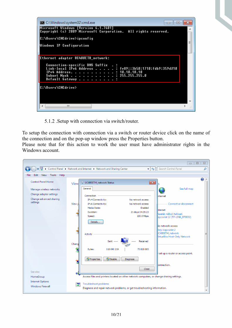
5.1.2 .Setup with connection via switch/router.
To setup the connection with connection via a switch or router device click on the name of the connection and on the pop-up window press the Properties button. Please note that for this action to work the user must have administrator rights in the Windows account.
10/21

On the popup window find and select the 'Internet Protocol Version 4(TCP/IPv4)' row and click the Properties button.If the DHCP is enabled in the router and in the UC400ETH then set the Obtain an IP address autoatically setting, because this way the DHCP server will provide an IP address to the UC400ETH device, no need to set a fixed IP address.
11/21
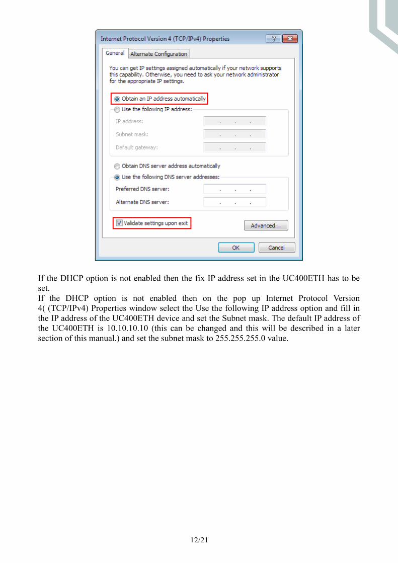
If the DHCP option is not enabled then the fix IP address set in the UC400ETH has to be set.If the DHCP option is not enabled then on the pop up Internet Protocol Version 4( (TCP/IPv4) Properties window select the Use the following IP address option and fill in the IP address of the UC400ETH device and set the Subnet mask. The default IP address of the UC400ETH is 10.10.10.10 (this can be changed and this will be described in a later section of this manual.) and set the subnet mask to 255.255.255.0 value.
12/21

After filling the values don't forget to set the 'Validate settings upon exit' checkbox to let the parameters validate automaticaly when closing the setup. Finally press OK to all the pop up windows to exit the setup.Wait a few seconds to let Windows to update the settings in the LAN card.To verify that the settings got validated open up a command window with typing 'cmd' into the start menu and in the command window type 'ipconfig'.The result should look like as on the following image. Please note that the Ipv4 address of our adapter got the 10.10.10.10 value with a subnet mask of 255.255.255.0 value.
13/21

5.2 .Network settings on the UC400ETH.
The UC400ETH network settings should be setup to fit the network settings on the PC side. To do the setup run the UCxxx_utility.exe application which file can be found in the UCCNC software installation folder.
5.2.1 .The UCxxx_utility.exe utility.
The UCxxx_utility.exe software can be used to list our USB and ethernet motion controllers and to check and configure the network parameters of the connected ethernet motion controllers.The setup utility software looks the following on startup:
Press the 'scan' button to list the motion controller devices connected to the network. Doing so the software will send a broadcast massege to the network and will map all the available motion controller devices connected and running and will list the devices serial numbers in the listbox on the application form like this:
14/21

If the device of interest does not show up in the list then check the network cable connections and the router/switch device if there is any. Also check if the PC side network parameters are correct.If the device serial number shows up in the list then click it's row to configure it.
Selecting the device in the list will enable the network settings area on the screen.Now the network parameters can be changed with typing in the new values.The default parameter values are shown on the above picture and in the PC side network setup topic we setup the connection for these parameters.The default IP address value is 10.10.10.11, the Subnet mask is 255.255.255.0 and the gateway is 10.10.10.0.Ofcourse if the PC side setup values were different then the UC400ETH side setup should follow those different network settings.If the UC400ETH is connected via a direct cable then the DHCP option should be left unchecked, because in this case the device will be called directly with a fixed IP address.If the UC400ETH is connected via a router/switch then the DHCP option can be enabled depending on if the DHCP is enabled and setup in the router device.A router could be also setup to provide a fix IP address to the UC400ETH device, in this case the DHCP option in the UCxxx_utility software should be not set.With the DHCP enabled and working the router will give a dynamic IP address to the UC400ETH device and the PC will get connected to the UC400ETH via the router using the routing informations provided by the router.To save all parameters press the 'Save network settings' button and this will save the parameters to the UC400ETH non volatile memory.
The network connection can be tested with a command line pinging, like on the below picture:
15/21
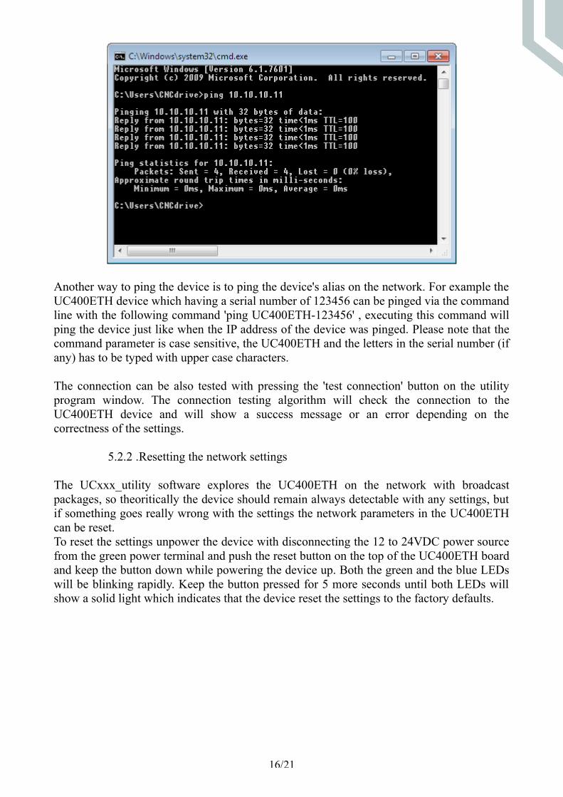
Another way to ping the device is to ping the device's alias on the network. For example the UC400ETH device which having a serial number of 123456 can be pinged via the command line with the following command 'ping UC400ETH-123456' , executing this command will ping the device just like when the IP address of the device was pinged. Please note that the command parameter is case sensitive, the UC400ETH and the letters in the serial number (if any) has to be typed with upper case characters.
The connection can be also tested with pressing the 'test connection' button on the utility program window. The connection testing algorithm will check the connection to the UC400ETH device and will show a success message or an error depending on the correctness of the settings.
5.2.2 .Resetting the network settings
The UCxxx_utility software explores the UC400ETH on the network with broadcast packages, so theoritically the device should remain always detectable with any settings, but if something goes really wrong with the settings the network parameters in the UC400ETH can be reset.To reset the settings unpower the device with disconnecting the 12 to 24VDC power source from the green power terminal and push the reset button on the top of the UC400ETH board and keep the button down while powering the device up. Both the green and the blue LEDs will be blinking rapidly. Keep the button pressed for 5 more seconds until both LEDs will show a solid light which indicates that the device reset the settings to the factory defaults.
16/21

The following picture shows the reset button on the board:
6 .LEDs signs.
There are 4 LEDs in total on the UC400ETH board. Two of these LEDs are inside the RJ45 jack. The green LED is the 'Link' Led which lights when there is an active connection to the computer or switch/router. The orange LED is the 'Activity' LED which lights when packets being received or transmitted by the device.The other 2 LEDs are on the front panel of the UC400ETH. The green LED is the power LED. This LED has a few different signs indicated with different blinking sequences.There are 2 execution states in the UC400ETH processor with different green LED sequences, one state is when the device is executing the bootloader in the processor of the UC400ETH board and the other state is when the DSP is executing the firmware.The DSP is executing the bootloader when the device resets and starting up and when the firmware code has an error and when a new firmware is being downloaded from the host computer to the UC400ETH device.
The possible LED blink sequences when the device is in the bootloader:
0000111100000 - No valid IP address (DCHP request in progress), Firmware OK.0000111101000 - The IP address is valid, Firmware OK.0000111100010 - No valid IP address, Firmare has error.0000111101010 - The IP address is valid, Firmware has error.
The possible blinking sequences when the device is executing the firmware:
11110 - No vaid IP address.11111 - IP address is valid.
17/21

Notes: 0 – means the green LED is off. 1 – means the green LED is on. One 0 and 1 character state has a 200milliseconds execution time interval.The blue LED on the board is the communication LED and this LED lights when there is a connection to the software on the host PC and there is an active communication ongoing.
7 .External power supply connection.
Ethernet communication is isolated and power is not transmitted on the network on the ethernet cable and therefor the UC400ETH board needs an external 12 to 24Volts DC powersupply to be connected to the plug type green 2 pole power terminal on the side of the board.There is a step down switching regulator circuitry onboard which creates the nessessary 5Volts and other Voltage levels for the operation.We recommend to use a power supply with at least 500mAmps of current capability if a 12Volts power supply is used and minimum 250mAmps if a 24Volts power supply is used.The following image shows the correct power supply connection polarity:
8 .I/O connections of the device.
There are 2 pieces of IDC26 I/O ports on the board. Both ports has the same pinout.The pinout is the same as the pinout of a standard LPT port in addition the 26. pin (there is no 26.pin on the LPT port) has a 5Volts power output.All output pins are TTL level with 0/5Volts output Voltage levels and an absolute maximum of 20mAmps current per output channel. All inputs are TTL compatible and accept 0/5Volts Voltage levels.
The following image shows the I/O port numbers. In the CNC control software the port numbers are assigned according to the drawing.
18/21

Both ports have 12 digital outputs and 5 digital inputs which is 24 digital outputs and 10 digital inputs in total.
Plugging a IDC26 to DSUB25 female crimped cable to the IDC26 ports the DSUB25 port will have exactly the same pinput as the standard LPT printer ports on PCs.
If the connection has to be made to a breakout board with a DSUB25 female connection then a crimped IDC26 to DSUB25 male cable can be used.If our HDBB2 breakout board is used then the connection can be made with an IDC26 to IDC26 crimped ribbon cable.
We carry all the IDC26 to DSUB25 female cables, the IDC26 to DSUB25 male cables and the IDC26 to IDC26 cables in 250mm lengths. These cables can be ordered separately.
19/21
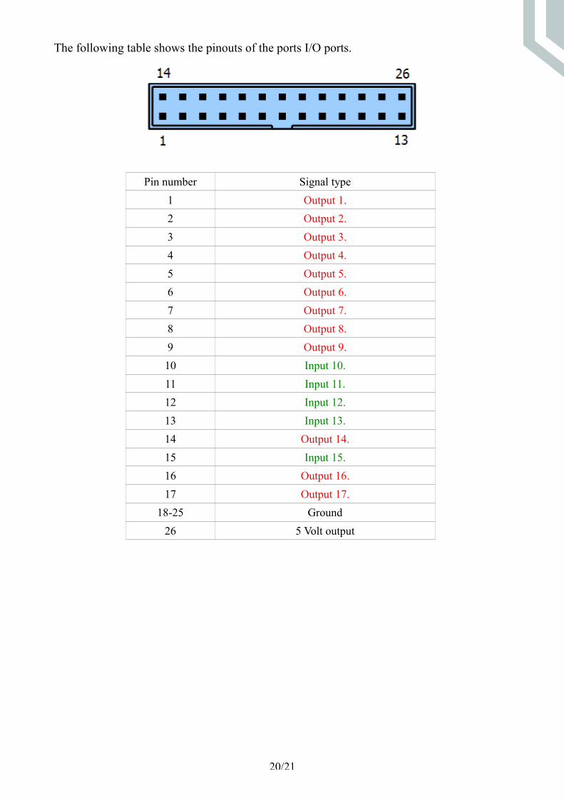
The following table shows the pinouts of the ports I/O ports.
Pin number Signal type1 Output 1.2 Output 2.3 Output 3.4 Output 4.5 Output 5.6 Output 6.7 Output 7.8 Output 8.9 Output 9.10 Input 10.11 Input 11.12 Input 12.13 Input 13.14 Output 14.15 Input 15.16 Output 16.17 Output 17.
18-25 Ground26 5 Volt output
20/21

9 .Running the UC400ETH with the UCCNC software.
After the network for the UC400ETH got setup it is time to run the device with the UCCNC software, but before doing so make sure to copy the license key file for the device to the UCCNC installation directory.The UC400ETH hardware is compatible with the UCCNC software versions starting from 1.2001.To use the software first power the UC400ETH and connect it to the LAN network and run the software. In case of a successful connection the blue LED on the UC400ETH will light up as soon as starting the software and will remain on while the software is running.For more informations about the software licensing and the usage of the UCCNC software please read the UCCNC software user's guide which is available on the software product page at: http://www.cncdrive.com/UCCNC . The same user's guide is available in the installation folder /Documentation subfolder of the software.
21/21