Embed Size (px)
Citation preview

UASBOUNDER™
Geofence Enforcer for Drones
User GuideRev. 1 — Sept 2020
IntroductionThe UAS Bounder™ ensures that your unmanned aircraft system (UAS) stays out of trouble and within its authorized flight envelope. It is completely independent of, and transparent to the autopilot system to ensure reliability. It can be used to eliminate the need for visual line-of-sight operation on authorized test ranges and permit rapid autopilot development by avoiding costly reviews after each change. It can easily be adapted to any UAS that uses standard RC servos and electronic speed controllers (ESC). The UAS Bounder™ detects range violations andsafely terminates the flight when a boundary is breached.

UAS Bounder™ — User Guide — Rev. 1
The UAS BounderTM is a secondary geofence controller for unmanned aircraft systems. Its features include:
• Multiple activation parameters to choose from:
◦ GPS geofences, acceleration, magnetometer, and timer limits
• Five-channel Servo Routing Switch (SRS)
• Six configurable servo PWM outputs
• Programmed via a micro-SD card prior to launch
• Independent omni-directional GPS receiver
• Separate power that also provides backup power for servo motors after activation
• Ability to log GPS position, acceleration, and other flight characteristics
• Opto-isolated uni-directional autopilot interface for status and position reports
• No RF spectrum approval necessary
loonatec .com Balloon Ascent Technologies, LLC 2

UAS Bounder™ — User Guide — Rev. 1
Table of Contents1 Operating Specifications.....................................................................................42 Interface..............................................................................................................5
Programming — micro-SD Card......................................................................................................................... 5Data Logging — micro-SD Card.......................................................................................................................... 5Power-On Button................................................................................................................................................. 5Audio Tunes......................................................................................................................................................... 5Status LED........................................................................................................................................................... 6Opto-Isolated Autopilot Connection................................................................................................................... 6Error Mode.......................................................................................................................................................... 6
3 Servos.................................................................................................................8Servo Connectors................................................................................................................................................. 8Servo Power......................................................................................................................................................... 8Servo Channels.................................................................................................................................................... 9
Relay #1.......................................................................................................................................................... 9Relay #2.......................................................................................................................................................... 9Relay #3.......................................................................................................................................................... 9Relay #4 —TERM_SERVO............................................................................................................................ 9
Servo Status in Data File.................................................................................................................................... 104 Programming.....................................................................................................11
Configuration Section............................................................................................................................11Command Section................................................................................................................................. 13
Conditions.......................................................................................................................................................... 14Compare:....................................................................................................................................................... 14GeoFenceBox:............................................................................................................................................... 14
Actions................................................................................................................................................................ 15Example................................................................................................................................................. 17
5 Log Files............................................................................................................18The Flight.CSV Data File................................................................................................................................... 18
Data............................................................................................................................................................... 18The Flight.LOG File........................................................................................................................................... 19
Device Section............................................................................................................................................... 19Sensors Section............................................................................................................................................. 19Configuration Section................................................................................................................................... 19Flight Section................................................................................................................................................ 19
The Flight.KML Data File.................................................................................................................................. 206 Mechanical........................................................................................................217 Troubleshooting................................................................................................22
Device Will Not Turn On................................................................................................................................... 22Device Cannot Acquire GPS Fix........................................................................................................................ 22Updating the Firmware..................................................................................................................................... 22
8 Consumables.....................................................................................................23Batteries............................................................................................................................................................. 23Memory Card..................................................................................................................................................... 23
9 Safety Precautions and Recommendations.......................................................24Regulatory.......................................................................................................................................................... 24
loonatec .com Balloon Ascent Technologies, LLC 3

UAS Bounder™ — User Guide — Rev. 1
1 Operating Specifications
Parameter Min Typical Max Unit
Operating: Temperature -20 - 60 °C
Operating: Power, No Relays Active(V = 7.5) - 25 651 mA
Operating: Power, All Relays Active (V = 7.5) - 105 1452 mA
Operating: Power, Current to Motors (total) 0 - 7 A
Operating: Battery Voltage 3.6 - 17 VDC
Trigger: Mission Elapsed Time 1 - - seconds
Trigger: GPS Geofence Altitude -500 - 50,000 meters
Trigger: GPS Geofence Longitude -180 - 180 degrees
Trigger: GPS Geofence Latitude -90 - 90 degrees
Trigger: GPS Ascent Rate, Threshold -500 - 50,000 meters
Trigger: GPS Min Ascent Rate, Rate -12.5 - 12.5 m/s
Servo: PWM Pulse Width 10 800-2200 9,999 micro-sec
Servo: PWM Pulse Rate 25 50-250 1,500 Hz
Sensor: GPS Altitude - - 50,000 meters
Sensor: Accelerometer -2 - +2 g’s
Sensor: Magnetometer -4 - +4 gauss
Mechanical: Mass (no Enclosure or Batteries) - 45 - g
Mechanical: Size without mating connectors 96mm long, 58mm wide, 19 mm heigh
1 Max current values are due to extra power being consumed to play a tone.2 Max current values are due to extra power being consumed to play a tone.
loonatec .com Balloon Ascent Technologies, LLC 4

UAS Bounder™ — User Guide — Rev. 1
2 InterfaceThe UAS Bounder™ uses a micro-SD card for both programming and data logging.
Programming — micro-SD Card
The UAS Bounder™ looks on the micro-SD card for “/Config/Flight.cfg” to load the desired settings from. Settings are entered in a pseudo-json format, outlined in the Programming section (pg 11).
Data Logging — micro-SD Card
The UAS Bounder™ creates a new directory each time it is powered on and acquires GPS time. This directory is named in the following format: YYYYMMDD.XXX where XXX is an auto-incrementing value to distinguish multiple flights that occur on the same day.
Inside of this directory are the following files:
• Flight.CSV – Contains comma-separated data recorded at 1 Hz
• Flight.KML – Contains position data in a format that programs like Google Earth use
• Flight.LOG – Contains a time-stamped system log for post-flight analysis
Power-On Button
Press and hold for 3-5 seconds until the tone starts playing, otherwise it will turn back off .
Pressing this button will turn the UAS Bounder™ on. Repeated pressing or constant pressing will have no impact on the UAS Bounder’s™ operation. It cannot turn off the UAS Bounder.
To shutdown the UAS Bounder remove its battery(s). Note: the UAS Bounder’s logic power remains separate from the AP_XXX power even when a relay is active. Removing power from the autopilot connections is not necessary to shutdown the UAS Bounder™.
Audio Tunes
GPS Wait: the UAS Bounder™ will play a 2-tone beep briefly once every two seconds to indicate that GPS position fix has not yet been obtained. It should not be flown until GPS fix is acquired.
Launch Tune: Once the UAS Bounder™ has successfully acquired GPS fix and the config file has been read, the intro to Beethoven’s Für Elise will play to indicate that the UAS Bounder™ is ready to be flown.
loonatec .com Balloon Ascent Technologies, LLC 5

UAS Bounder™ — User Guide — Rev. 1
ERROR Tune: If an error is detected during the power-on sequence, a continuous rapid 2-tone sound will be played. The UAS Bounder™ is unusable while this rapid continuous beepingis sounding.
Servo Relay Activation Tune: A user configurable note can be played multiple times to indicate command activation.
Status LED
The UAS Bounder™ has one yellow Status LED. Possible blink patterns are:
While acquiring GPS lock it will double-flash at 1/2 Hz with the GPS Wait tune.
In normal operations the status LED will flash at 4 Hz (with varying flash durations).
If there is an error, the Status LED will flash rapidly, indicating that the UAS Bounder™ is unusable until the error is corrected.
Opto-Isolated Autopilot Connection
The UAS Bounder™ has a uni-directional serial connection that can provide the UAS Bounder’s™ real-time operating information to the UAS’s autopilot.
It is configured by the line below in the Flight.cfg file.
CommDevice: Serial, 1, 57600, 10
• Serial → communication method, not user selectable
• 1 microprocessor’s→ serial port, not user selectable
• 57600 → baud rate, user selectable (9600 to 115200 are supported)
• 10 → output interval in seconds, user selectable (1 to 600 are common)
Hardware interface is via the COMM_AP connector. All three pins are electrically isolated by the 6N135. The 3-pin wiring is as follows:
1) Ground
2) Power (3.3 to 20 VDC)
3) Serial Signal
Error Mode
The UAS Bounder™ will enter Error Mode if any of the following problems are encountered:
• micro-SD Card Problem—No card present, incorrect formatting, or no available space
loonatec .com Balloon Ascent Technologies, LLC 6

UAS Bounder™ — User Guide — Rev. 1
• Sensor Problem—An issue was detected with an onboard sensor
• GPS Problem—An issue was detected with the onboard GPS sensor
Check the Flight.LOG file for an indication of which subsystem failed. Note: if the Flight.LOG does not exist then it is likely that there is an issue with the micro-SD card itself.
loonatec .com Balloon Ascent Technologies, LLC 7

UAS Bounder™ — User Guide — Rev. 1
3 Servos
Servo Connectors
All of the servo connectors, both incoming from the autopilot (XXX_AP) as well as outgoing to the servo motors (XXX_SERVO), utilize 3-pin Molex SL latching connectors. These connectorsaccept:
• Molex SL latching housings (Molex Part #50-57-9403)
• Standard RC Servo connectors (non-latching)
Servo Power
Under pre-termination circumstances, power to the servo motors can only come from the servoinput connectors from the autopilot. Once Relay #1 is activated, power can come from both the servo input connectors and from the UAS Bounder’s™ own battery. In this case, the power source is determined by a high-power diode-OR circuit to ensure reliable flight termination is achieved.
loonatec .com Balloon Ascent Technologies, LLC 8
Iso
late
d G
rou
nd
3 to
20
VD
CS
eria
l Ou
t
Gro
un
d3.
6 to
17
VD
CS
ervo
PW
M
Gro
un
d3.
6 to
17
VD
CS
ervo
PW
M
Gro
un
d3.
6 to
17
VD
CS
ervo
PW
M
Gro
un
d3.
6 to
17
VD
CS
ervo
PW
M
Gro
un
d3.
6 to
17
VD
CS
ervo
PW
M
UAS Bounder™ — User Guide — Rev. 1
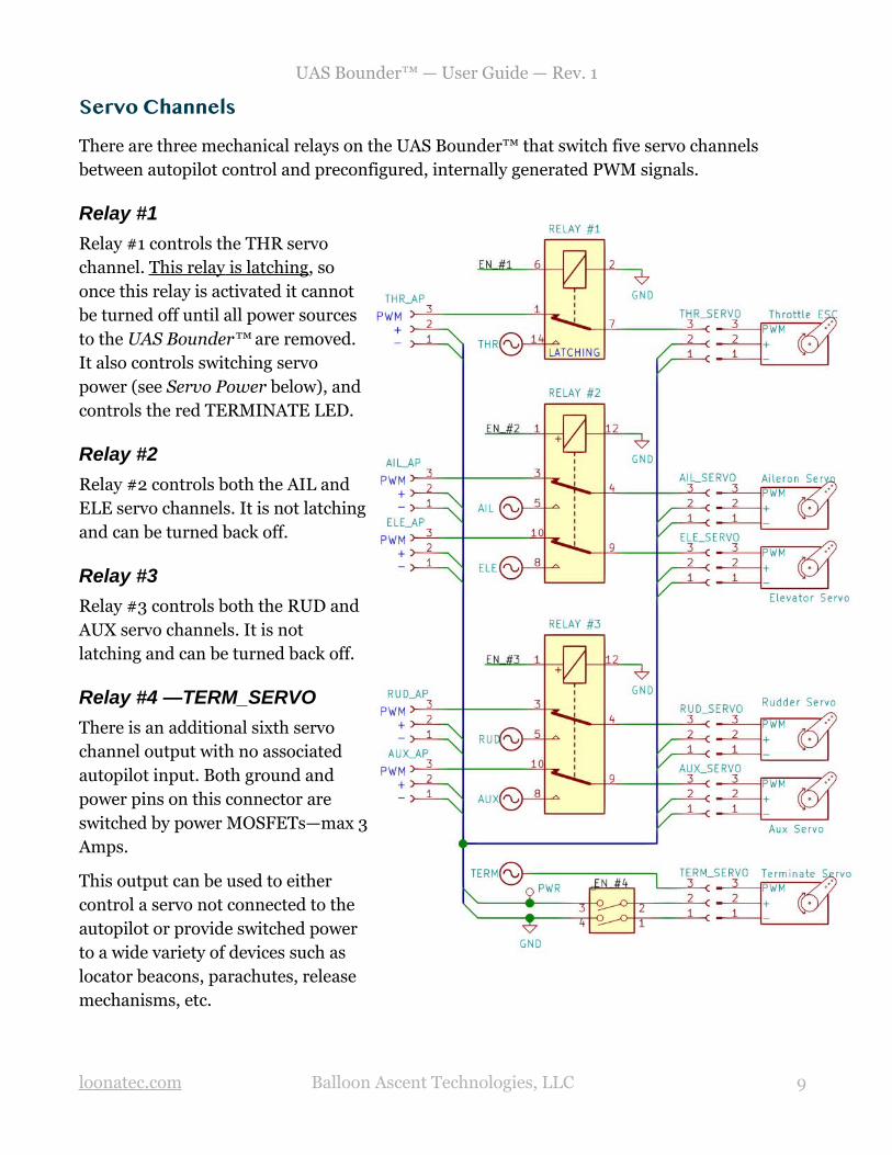
Servo Channels
There are three mechanical relays on the UAS Bounder™ that switch five servo channels between autopilot control and preconfigured, internally generated PWM signals.
Relay #1
Relay #1 controls the THR servochannel. This relay is latching , soonce this relay is activated it cannotbe turned off until all power sourcesto the UAS Bounder™ are removed.It also controls switching servopower (see Servo Power below), andcontrols the red TERMINATE LED.
Relay #2
Relay #2 controls both the AIL andELE servo channels. It is not latchingand can be turned back off.
Relay #3
Relay #3 controls both the RUD and AUX servo channels. It is notlatching and can be turned back off.
Relay #4 —TERM_SERVO
There is an additional sixth servochannel output with no associatedautopilot input. Both ground andpower pins on this connector areswitched by power MOSFETs—max 3Amps.
This output can be used to either control a servo not connected to theautopilot or provide switched powerto a wide variety of devices such as locator beacons, parachutes, releasemechanisms, etc.
loonatec .com Balloon Ascent Technologies, LLC 9

UAS Bounder™ — User Guide — Rev. 1
Servo Status in Data File
Each Servo Channel has a column in the Flight.csv data file. Each entry indicates one of the following states:
• “_” → Relay controlling this channel was not active, autopilot in control of this servo
channel
• “OFF” → Relay controlling this channel is active, servo output is continuously low
• “ON” → Relay controlling this channel is active, servo output is continuously high
• XXX Relay controlling this channel is active, servo output is indicated by the →
displayed number (PWM delay in microseconds)
loonatec .com Balloon Ascent Technologies, LLC 10

UAS Bounder™ — User Guide — Rev. 1
4 Programming
The UAS Bounder™ is programmed via the “Config/Flight.cfg” file. The following is an explanation of the various options in that file.
Note: Each line is preceded by a line number “[XXXX]”. This number is autogenerated in the UAS Bounder’s™ log but does not need to be sequential in the Flight.cfg file for.
Configuration SectionThis section is used to configure the UAS Bounder™ and its subsystems. The following is an example of the default settings for a version 1 UAS Bounder™:
[ 1] Version: 1 [ 2] DataLoggerSDCard: Timestamp, System, Position, AccMag [ 3] DataLoggerCommDevice: Timestamp, System, Position, AccMag [ 4] DataLoggerCommDeviceBinary: false [ 5] DataLoggerCommDeviceHeader: true [ 7] CommDevice: Serial, 1, 57600, 10 [ 8] ServoMux: 25000000, 250
• Version 1 → A user configurable version number for tracking Flight.cfg differences.
• DataLoggerSDCard → The collection of data containers to be logged to the SD card’s
Flight.csv file. Arguments:
• Timestamp → GPS timestamp and UAS Bounder’s™ MET
• System → System data such as Battery Voltage, Status flags, and ServoMux info
• Position → Longitude, Latitude, Altitude, Heading, Ground Speed, Vertical Speed
• AccMag → Acceleration in XYZ, Aggregate acceleration, Magnetometer in XYZ, and
RPM
• DataLoggerCommDevice → The collection of data containers to be transmitted on
the opto-isolated serial link, same options as with DataLoggerSDCard
• DataLoggerCommDeviceBinary Whether to transmit binary or ASCII data over →
the opto-isolated serial connection
• Arguments: true or false
• DataLoggerCommDeviceHeader Whether to transmit an ASCII header at →
power-on to aid in decoding the subsequent binary or ASCII data [true/false]
• CommDevice The opto-isolated serial connection settings. → Arguments:
loonatec .com Balloon Ascent Technologies, LLC 11
UAS Bounder™ — User Guide — Rev. 1
• Serial Name of the port type [not user selectable]→
• 1 Number of the port [not user selectable]→
• 57600 Baud rate [9600 to 115200 are supported]→
• 10 Output interval in seconds, user selectable (1 to 600 are common)→
• ServoMux Servo PWM generation settings. → Arguments:
• 25000000 Frequency of the PWM generator → in Hz. This can be tuned for very
precise PWM generation if needed
• Typical: 25000000, normal range: 23000000 to 28000000
• 250 → Servo PWM output frequency in Hz. 250 Hz is typical for a digital servo, 50
Hz is typical for an analog servo. Note: all servo channels will use the same output frequency rate so combining digital and analog servos may not work well.
loonatec .com Balloon Ascent Technologies, LLC 12

UAS Bounder™ — User Guide — Rev. 1
Command SectionThe UAS Bounder™ can be configured to have a reasonable number of commands. The actual allowable number of commands is dependent on their complexity and RAM usage; but under most circumstances at least ten commands should be easily supported.
Each of these commands is acted upon independently by the conditions set and results in the various actions being executed. The name, PwrOnTest in the below example, is user configurable and used to identify the command activation in the log and kml files.
The PwrOnTest command, shown below, will result in the following:
1) Activate once, 30 seconds after GPS fix is acquired
2) Turn on Relays #2 & #3, leaving Relays #1 and #4 deactivated
3) Configure all of the servo channels to output 1000 microsecond PWM signal
4) Play a G5 note twice of duration one second, separated by one second delays
5) Configure all of the servo channels to output 2000 microsecond PWM signal
6) Play a A5 note twice of duration one second, separated by one second delays
7) Configure all of the servo channels to output 1500 microsecond PWM signal
8) Play a B5 note twice of duration one second, separated by one second delays
9) Pause for 6 seconds
10)Deactivate all of the Relays (test runs for a total of 18 seconds)
[ 9] Command: PwrOnTest [ 10] { [ 11] Conditions: [ 12] { [ 13] Trigger: [ 14] { [ 15] Compare: Timestamp.MET = 30.000000 [ 16] } [ 17] } [ 18] Actions: [ 19] { [ 20] SetServoRelays: false, true, true, false [ 21] SetServoPWMs: OFF, 1000, 1000, 1000, 1000, 1000 [ 22] PlayTone: 784, 1.00, 1.00, 2 [ 23] SetServoPWMs: ON, 2000, 2000, 2000, 2000, 2000 [ 24] PlayTone: 880, 1.00, 1.00, 2[ 25] SetServoPWMs: OFF, 1500, 1500, 1500, 1500, 1500 [ 26] PlayTone: 988, 1.00, 1.00, 2[ 27] Pause: 6.00 [ 28] SetServoRelays: false, false, false, false [ 29] } [ 30] }
loonatec .com Balloon Ascent Technologies, LLC 13

UAS Bounder™ — User Guide — Rev. 1
Conditions
This is a list of conditions that must be met for the command to be acted upon. Activate optionsinclude:
Arm → Conditions that must be met before the Trigger conditions are compared. Can permit aCommand to be activated multiple times instead of the normal single activation.
Trigger → Conditions that must be met before the actions can be executed
Disarm → Conditions that disable the command
Example: The following example causes a geofence boundary to activate once, from one minuteuntil ten minutes after GPS fix acquisition.
[ 09] Conditions: [ 10] Arm: [ 11] { [ 12] Compare: Timestamp.MET = 60 [ 13] } [ 14] Trigger: [ 15] { [ 16] GeoFenceBox: outside, -70.63170, 41.58350, -200, -70.63030, 41.58500, 200[ 17] } [ 18] Disarm: [ 19] { [ 20] Compare: Timestamp.MET >= 600 [ 21] } [ 22] }
The following is a list of possible logical conditions:
Compare:
This command compares an operational value against a preset value using “<”, “>”, “=”, “<=”, “>=”. Some possible operational values:
• Timestamp.MET
• System.BatV
• AccMag.AccN
• AccMag.MagN
• AccMag.RPM
• Position.Longitude
• Position.Latitude
• Position.Altitude
• Position.GroundSpeed
• Position.VerticalSpeed
GeoFenceBox:
This condition compares the UAS Bounder’s™ current position against a rectangular geofence.
[ 16] GeoFenceBox: outside, -70.63170, 41.58350, -200, -70.63030, 41.58500, 200
Arguments include:
loonatec .com Balloon Ascent Technologies, LLC 14

UAS Bounder™ — User Guide — Rev. 1
• outside → triggers if the UAS Bounder™ goes outside of the geofence region, while inside will trigger if the UAS Bounder™ enters into the geofence region.
• Lat, Lon, Alt → Two pairs of 3D coordinates are needed to define the geofence region.
Actions
This section holds the commands that the UAS Bounder™ will execute when the Conditions are satisfied. The commands are executed sequentially.
Options include:
• SetServoRelays: → Takes a sequential string of up to four relay activation states.
◦ Arguments: true or false, x4
◦ If less than four arguments are supplied, then remainder will be set to false.
◦ Note: Servo Relays remain in the last state set, unless SetServoRelays is called again by either the same Command’s Actions or by a different Command
◦ Relay Order:
▪ Relay #1 → Controls the THR channel
▪ Relay #2 → Controls the AIL & ELE channels
▪ Relay #3 → Controls the RUD & AUX channels
▪ Relay #4 → Controls the TERM channel
• SetServoPWMs: → Takes a sequential string of up to six servo channel PWM values.
◦ Arguments: Servo PWM duration in microseconds (800 to 2200 typical), x6
◦ If less than six are supplied, then the remainder will be populated from either the UAS Bounder’s™ default or previous values if set since power-on
◦ Servo channel order is: THR, AIL, ELE, RUD, AUX, TERM
• PlayTone: → Causes an audible tone to be played. The Command’s Action execution will pause while the tone is played. The arguments:
◦ Frequency, in Hz
◦ Duration on in seconds
◦ Duration off in seconds
◦ Number of iterations through the on/off cycle
loonatec .com Balloon Ascent Technologies, LLC 15

UAS Bounder™ — User Guide — Rev. 1
• Pause: → Causes the Action execution to be paused
◦ Argument: Seconds to delay
loonatec .com Balloon Ascent Technologies, LLC 16

UAS Bounder™ — User Guide — Rev. 1
ExampleBelow is a complete example that both tests the servos briefly at power-on and then ensures that the UAS Bounder™ stays within a geofence region. It configures the COMM_AP opto-isolated serial port for ASCII at 57,600 baud, 10 second intervals, and sends all of the possible data both there and to the SD card. It runs a brief (18 second) test 30 seconds after GPS fix is acquired. It also sets a geofence that triggers if the UAS Bounder™ is taken inside of a small area. If this geofence command triggers, all the relays are enabled, a 30 second tune is played, and the relays remain on until power is removed.
[ 1] Version: 1 [ 2] DataLoggerSDCard: Timestamp, System, Position, AccMag [ 3] DataLoggerCommDevice: Timestamp, System, Position, AccMag [ 4] DataLoggerCommDeviceBinary: false [ 5] DataLoggerCommDeviceHeader: true [ 6] CommDevice: Serial, 1, 57600, 1 0[ 7] ServoMux: 25000000, 250 [ 8] Command: PwrOnTest [ 9] { [ 10] Conditions: [ 11] { [ 12] Trigger: [ 13] { [ 14] Compare: Timestamp.MET = 30.000000 [ 15] } [ 16] } [ 17] Actions: [ 18] { [ 19] SetServoRelays: true, true, true, false [ 20] SetServoPWMs: 1000, 1000, 1000, 1000, 2000, 1000 [ 21] PlayTone: 784, 1.00, 1.00, 2 [ 22] SetServoPWMs: ON, 2000, 2000, 2000, 2000, 1000 [ 23] PlayTone: 880, 1.00, 1.00, 2 [ 24] SetServoPWMs: OFF, 1500, 1500, 1500, 2000, 1000 [ 25] PlayTone: 988, 1.00, 1.00, 2 [ 26] Pause: 6.00 [ 27] SetServoRelays: false, false, false, false [ 28] PlayTone: 1047, 1.00, 0.00, 1 [ 29] } [ 30] } [ 31] Command: Street_Alert [ 32] { [ 33] Conditions: [ 34] { [ 35] Trigger: [ 36] { [ 37] GeoFenceBox: inside, -70.63360, 41.58350, -200, -70.63230, 41.58450, 200 [ 38] } [ 39] } [ 40] Actions: [ 41] { [ 42] SetServoPWMs: 1400, 1500, 1600, 1700, 2000, 1000 [ 43] SetServoRelays: true, true, true, false [ 44] PlayTone: 1568, 1.00, 1.00, 15 [ 45] } [ 46] }
loonatec .com Balloon Ascent Technologies, LLC 17

UAS Bounder™ — User Guide — Rev. 1
5 Log FilesAll SD-card data files are buffered at either 1 Hz or 1/10 Hz but only written every two minutes.
The Flight.CSV Data File
Data
• DateTime GPS date in YYYY/MM/DD HH:MM:SS format
• MET Internal second timer, starts counting from 0 after initial GPS acquisition
• Servo Status
◦ S_THR Throttle Servo Channel Status
◦ S_AIL Aileron Servo Channel Status
◦ S_ELE Elevator Servo Channel Status
◦ S_RUD Rudder Servo Channel Status
◦ S_AUX Auxiliary Servo Channel Status
◦ S_TAS Terminate Activated Servo Channel Status
• Status A bit-mapped data flag
◦ Bit-0 Reserved
◦ Bit-1 Reserved
◦ Bit-2 GPS Power Save Mode active
• Measurements
◦ BatV The battery voltage
◦ NumSat Number of GPS Satellites currently used by the GPS module
◦ Lon /Lat GPS longitude in degree decimal
◦ Alt GPS altitude in meters above Ellipsoid
◦ GndS GPS ground speed in m/s
◦ VerS GPS vertical rate in m/s
◦ HDG GPS heading in degrees
loonatec .com Balloon Ascent Technologies, LLC 18

UAS Bounder™ — User Guide — Rev. 1
◦ AccX/Y/Z Accelerometer readings in indicated axis, in g’s
◦ AccAgg Max Aggregate Acceleration of all 3 axis, in g’s, since last report
◦ MagX/Y/Z Magnetometer readings in indicated axis, in degrees
◦ RPM Integrated Aggregate Magnetometer, in degrees per minute
Note: unless otherwise noted, each data value is updated for every entry.
The Flight.LOG File
This file provides a log of the system operations, commands sent and received, as well as any issues encountered and errors generated.
Device Section
Basic information to help identify the UAS Bounder™ for troubleshooting
Sensors Section
Displays the power-on status for each subsystem
Configuration Section
Provides a copy of the Flight.cfg file that was used for this flight
Flight Section
Displays when Commands were executed as well as any error messages that arose during the flight
loonatec .com Balloon Ascent Technologies, LLC 19

UAS Bounder™ — User Guide — Rev. 1
The Flight.KML Data File
This file allows rapid plotting of the geofences, events, and flight path in applications such as Google Earth.
Geofence boundaries are shown by a red (inside) or green (outside) box. Because KML does notsupport floating boxes (the UAS Bounder’s™ geofence minimum altitude can be any altitude less than 50 km), the min/max altitudes are included as a note that shows up if the box is clicked.
Each Command event position is included as a KML <Point> to show where it occurred.
Flight Tracks are time-stamped in a KML <gx:Track> to permit reviewing the flight progression through time. Tracks are marked in blue.
Note: Command event points and Flight Tracks may be shown ‘below’ the ground due to GPS or map inaccuracies. Google Earth allows each point and track to be raised independently for viewing by the “Get Info” dialog -> “Altitude” tab.
loonatec .com Balloon Ascent Technologies, LLC 20

UAS Bounder™ — User Guide — Rev. 1
6 MechanicalFour 3.2 mm (1/8 inch) holes for M3 (#4) screws are provided for mounting.
The GPS module (indicated by U5 below) has a fairly omni-directional antenna. It works best ifthe antenna is on the side or top when placed in the UAS. The orientation depicted below would be the worst possible flight orientation, both for the antenna orientation and because theservo wiring could partially obscure its view of the sky.
loonatec .com Balloon Ascent Technologies, LLC 21

UAS Bounder™ — User Guide — Rev. 1
7 Troubleshooting
Device Will Not Turn On
The UAS Bounder™ should turn on (Status LED illuminated) within two seconds of the power-on button being pressed. If it doesn’t, check the following:
• The power-on button not fully being depressed to actuate the switch
• Check the battery orientation
• Install new fully charged batteries
Device Cannot Acquire GPS Fix
The UAS Bounder™ normally acquires GPS fix in less than 5 minutes. If it is not able to acquire a GPS fix within 20 minutes then please:
• Try power-cycling it as the GPS module sometimes seems to lock onto spurious signals at power-on
• Check that it has a clear and unobstructed view of most of the sky down to the horizon
• Check that there are GPS satellites overhead and visible to the UAS Bounder™. https://in-the-sky.org/satmap_worldmap.php
Updating the Firmware
1. Place the UPDATE.bin file in the root directory of the micro-SD card2. Insert the card3. Press and hold the power-on button (5-7 seconds) until the tone starts playing4. Let the UAS Bounder™ acquire GPS fix, then wait for an additional two minutes5. Power off, remove the micro-SD card6. Look at the latest Flight.log file to ensure that the Device section’s firmware line
indicates the date associated with the UPDATE.bin file you just used
loonatec .com Balloon Ascent Technologies, LLC 22
UAS Bounder™ — User Guide — Rev. 1
8 Consumables
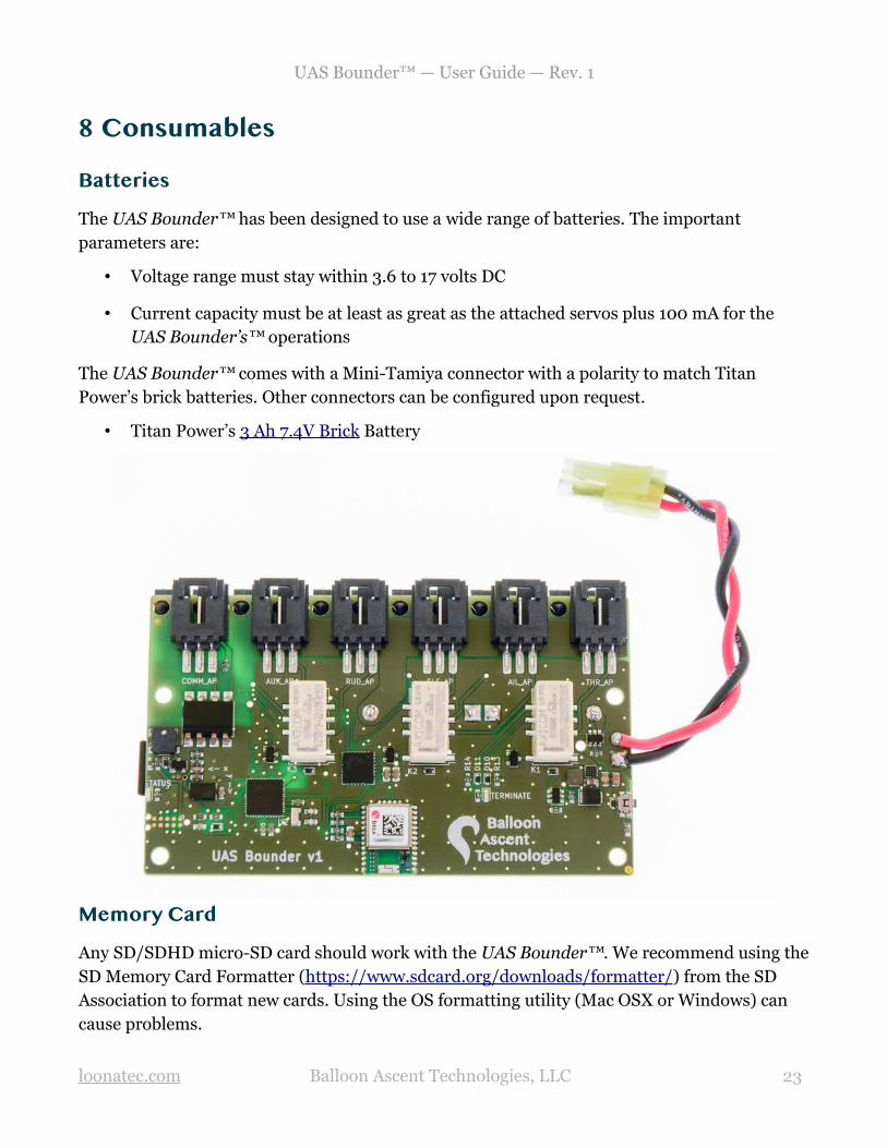
Batteries
The UAS Bounder™ has been designed to use a wide range of batteries. The important parameters are:
• Voltage range must stay within 3.6 to 17 volts DC
• Current capacity must be at least as great as the attached servos plus 100 mA for the UAS Bounder’s™ operations
The UAS Bounder™ comes with a Mini-Tamiya connector with a polarity to match Titan Power’s brick batteries. Other connectors can be configured upon request.
• Titan Power’s 3 Ah 7.4V Brick Battery
Memory Card
Any SD/SDHD micro-SD card should work with the UAS Bounder™. We recommend using theSD Memory Card Formatter (https://www.sdcard.org/downloads/formatter/) from the SD Association to format new cards. Using the OS formatting utility (Mac OSX or Windows) can cause problems.
loonatec .com Balloon Ascent Technologies, LLC 23

UAS Bounder™ — User Guide — Rev. 1
9 Safety Precautions and Recommendations
Regulatory
Always adhere to the regulations governing Unmanned Aircraft Systems applicable in the country of operation.
The owner shall be liable for any damages resulting from any use of the UAS Bounder™ and other related materials, and shall defend, hold harmless and indemnify Balloon Ascent Technologies LLC, officers, employees and agents, against any and all claims, suits, actions, costs, counsel fees, expenses, damages, judgments and decrees, by reason of any person or property being injured or damaged directly or indirectly by use of the UAS Bounder™ or activities arising therefrom.
loonatec .com Balloon Ascent Technologies, LLC 24