Embed Size (px)
Citation preview

U10C034 Telephony MSO User’s Manual Version 1.4 Date: Aug 2008

U10C034 Telephony Version v1.4 June 2008
ii

U10C034 MSO User’s Manual v1.4 June 2008
iiiRevision History
Revision History Issue Date Author/Prime Description of changes 1.2 ISSUED 19th-May-08 Billy Lo Issued for customer
1.3 ISSUED 5th-June-08 Billy Add new mib object (provisionalResponseEnable) in section 2.2.15
1.4 ISSUED 5th-August-08 Billy Add description about digital loopback Digital loopback support in section 6.5

U10C034 Telephony Version v1.4 June 2008
iv

U10C034 MSO User’s Manual v1.4 June 2008
v
Contents
AUDIENCE ......................................................................................................... VII ABOUT THE U10C034 TELEPHONY FIRMWARE ................................................. VII IN THIS DOCUMENT .......................................................................................... VIII TERMINOLOGY ................................................................................................. VIII
OVERVIEW 12 U10C034 TELEPHONY MODEMS ..................................................................... 13 CORE FUNCTIONALITY ...................................................................................... 14 FIRMWARE FUNCTIONALITY ............................................................................ 14 MULTIPLE COUNTRY PROFILE SUPPORT ............................................................ 15
PROVISIONING 18 2.1 CONFIGURING CABLE MODEM BEHAVIOR ................................................... 20
2.1.1 Disabling the CM miniFirewall ...................................................... 20 2.1.2 Resetting non-volatile Memory to Factory Default ........................ 20 2.1.3 Configuring Downstream Scanning ............................................... 20 2.1.4 Non-PacketCable DSx Messaging ................................................. 22
2.2 CONFIGURING EMTA BEHAVIOR .................................................................. 23 2.2.1 Management Provisioning .............................................................. 23 2.2.2 Disabling the eMTA firewall.......................................................... 29 2.2.3 MTA DHCP Option 122/177 ......................................................... 29 2.2.4 Software Upgrade During Calls ..................................................... 30 2.2.5 Configuring the Jitter Buffer .......................................................... 30 2.2.6 Configuring for Network Maintenance Operations ........................ 33 2.2.8 EndPoint Provisioning .................................................................... 37 2.2.9 Telephony Port Diagnostics ........................................................... 40 2.2.10 Audible Tone Tables .................................................................... 45 2.2.11 DQoS Lite Enable ........................................................................ 48 2.2.12 RFC2833 Enable .......................................................................... 48 2.2.13 Configure MTA syslog server Ip address. .................................... 48 2.2.14 Configure Battery Low Threshold ................................................ 49 2.2.15 Configure MGCP Provisional Response ...................................... 50
WEB INTERFACE 51 3.1 Accessing the Web User Interface .................................................... 52 3.2 Web User Interface Home Page ........................................................ 53 3.3 Status ................................................................................................. 53 3.4 CM Hardware .................................................................................... 54 3.5 Event Log .......................................................................................... 55 3.6 CM State ............................................................................................ 56 3.7 Web User Interface Advanced Page .................................................. 57 3.8 Product – Display status, interface information ................................ 58 3.9 DHCP – Display CM and MTA DHCP information ......................... 59 3.10 MTA – Display some detail MTA parameters ................................ 60 3.11 QoS – Display service flow information ......................................... 61 3.12 Config Params – Display CM and MTA config files information .. 62

U10C034 Telephony Version v1.4 June 2008
vi
3.13 Event Log – Display CM and MTA event logs ............................... 63 3.14 Using the Password of the day Tool ................................................ 64 3.15 Using the POTD tool ....................................................................... 64
SSH CLI 65 4.1 Battery ............................................................................................... 66 4.2 CM .................................................................................................... 66 4.3 EMTA ............................................................................................... 67 4.4 ENET................................................................................................. 68 4.5 PINGHELPER .................................................................................. 68 4.6 SYSTEM ........................................................................................... 70
BATTERY OPERATION 71 5.1 Battery operation in different termperature ....................................... 72 5.2 Adaptor Mode ................................................................................... 72 5.3 Battery Mode ..................................................................................... 73 5.4 Battery Trap ...................................................................................... 74
TROBULE SHOOTING 76 6.1 Ambit EMTA supports following troubleshooting interface: ............ 77 6.2 Using MIB for Troubleshooting ........................................................ 77 6.3 LED Verification ............................................................................... 86 6.4 Troubleshooting the USB driver Installation ..................................... 87 6.5 Digital Loopback Support ................................................................. 88
APPENDIX A:EMTA LED BEHAVIOR 89

U10C034 MSO User’s Manual v1.4 June 2008
vii
About This Document
This document describes standards compliance, telephony features, and data features of U10C034 Telephony firmware, and how to manage it via MIBs/VSIFs/Telent-CLI.
Some features described in this document may not be fully tested and supported in your specific firmware release version. Where possible, features supported only by specific versions are indicated in this document. See the Release Notes/Letter of Operational Considerations accompanying your firmware for further details.
AUDIENCE
If you are evaluating U10C034 Telephony products for use in your VoIP network, you should read this entire manual.
This manual assumes that you have a basic understanding of DOCSIS and PacketCable standards, and a working knowledge of cable data and telephony networks.
ABOUT THE U10C034 TELEPHONY FIRMWARE U10C034 Telephony firmware provides operating, maintenance and trou-bleshooting functions for the following AMBIT eMTA:
• U10C034 Telephony Modem

U10C034 Telephony Version v1.4 June 2008
viii
IN THIS DOCUMENT This document contains the following information:
• Chapter 1, ‘‘Overview,’’ provides a brief overview of the U10C034 MSO User’s Manual.
• Chapter 2, ‘‘Provisioning’’ gives a detail descriptions on Ambit/Broadcom private Mibs to show you how to use this modem, while which includes new features required by customer.
• Chapter 3, “Ambit VSIFs” outlines all supported VSIFs in current U10C034 firmware.
• Chapter 4, ‘‘Telnet CLI,’’ outlines all tenet commands of U10C034.
TERMINOLOGY The following is a list of terms and abbreviations used in this manual.
AckCel A Broadcom-proprietary protocol which is to increase TCP-based performance.
AES Advanced Encryption Standard. A symmetric 128-bit block cipher that has been adopted by the US Federal Government as its symmetric data encryption standard in October 2000, replacing the DES encryption it used.
CM Cable Modem. Typically a device installed at the subscriber premises that provides a high-speed data (Internet) connection through the HFC network.
CMS Call Management Server. A generic term for the devices connecting a VoIP network to the PSTN. A CMS includes both a Call Agent and the PSTN gateway, and controls audio call connections.

U10C034 MSO User’s Manual v1.4 June 2008
ix
CMTS Cable Modem Termination System. A device at a cable headend that connects to cable modems over an HFC network to an IP network.
CPE Customer Premises Equipment. Subscriber-owned equipment con-nected to the network. Technically, a cable modem, MTA, or eMTA falls into this category, although many operators do not designate them as such.
CODEC COder-DECoder. In VoIP products, one of several possible schemes of converting audio (i.e. a phone call) to digital data and vice versa. Attributes of a CODEC include fidelity (e.g. voice quality), bandwidth, and latency.
DOCSIS Data Over Cable Service Interface Specification. The interoperability standards used for data communications equipment on an HFC network.
DTMF Dual Tone Multi-Frequency. The tones generated by touching the keys on the phone are used for a variety of purposes including voice mail systems and voice messaging. Also known as Touchtone.
eMTA Embedded MTA. A device, such as the AMBIT U10C034 Telephony Modem, that contains both an MTA and a Cable Modem.
Euro-DOCSIS The European version of DOCSIS. Euro-DOCSIS specifies an 8 MHz downstream bandwidth (vs. 6 MHz for DOCSIS); other minor differences exist as well.
G.711 G.711 is an ITU-T standard for audio companding. It is primarily used in telephony. This audio standard is mandatory for all video conferencing systems. It requires a data rate of 56 or 64 kbit/s and provides an audio bandwidth of 300 ... 3400 Hz.
G.729 G.729 is an audio data compression algorithm for voice that compresses voice audio in chunks of 10 milliseconds. Music or tones such as DTMF or fax tones cannot be transported reliably with this codec, and thus use G.711 or out-of-band methods to transport these signals. Also very common is G.729a which is compatible with G.729, but requires less computation. This lower complexity is not free since speech quality is marginally worsened.
HFC Hybrid Fiber-Coaxial. A broadband, bi-directional shared media transmission system using fiber trunks between the headend and fiber nodes, and coaxial distribution cable between the fiber nodes and subscriber premises.

U10C034 Telephony Version v1.4 June 2008
x
iLBC internet Low Bitrate Codec. The codec is designed for narrowband speech and operates either with 30ms or 20ms frame sizes. The bit rate is 13.3 kbit/s for 30 ms frames (400 bits per block) or 15.2 kbit/s for 20 ms frames (304 bits per block). The iLBC codec enables graceful speech quality degradation in the case of lost frames, which occurs in connection with lost or delayed IP packets.
MIB Management Information Base. The data representing the state of a managed object in an SNMP-based network management system.
MTA Multimedia Terminal Adapter. A subscriber premises device that contains the network interface, CODECs, and all signaling and encapsulation functions required for telephony support, CLASS features signaling, and QoS signaling. The MTA is an integral part of U10C034 Telephony embedded MTA (eMTA) products.
NCS Network Call Signaling. The PacketCable protocol used to control calls.
PacketCable A CableLabs-led initiative aimed at developing interoperable interface specifications for delivering advanced, real-time multimedia services over two-way cable plant.
PHS Payload Header Suppression. A technology used to describe the process of suppressing the repetitive portion of payload headers at sender and restoring the headers at the receiver.
QoS Quality of Service. An attribute of a Service Flow, defining limitations or guarantees for data rate, latency, and jitter.
Quarantine A state where an endpoint (phone line) may potentially buffer events. Events not quarantined are processed normally. Processing of quarantined events may be delayed, potentially indefinitely.
REN Ringer Equivalency Number. It is a somewhat arbitrary number which denotes the loading a telephone ringer has on the line

U10C034 MSO User’s Manual v1.4 June 2008
xi
RF Radio Frequency
SHA-1 Secure Hash Algorithm. A one-way cryptographic function which takes a message procedures to a 160-bit message digest.
SNMP Simple Network Management Protocol.
TDD Telecommunication Device for the Deaf. An electronic device for text communication via a telephone line, used when one or more the parties has hearing or speech difficulties. Other names for TDD include TTY (Telephone TYpewriter), textphone (common in Europe), and minicom (U.K.).
VoIP Telephony over IP. The AMBIT implementation of PacketCable- compliant telephony services over an HFC network..
UGS Unsolicited Grant Service. A Service Flow type used for applications such as telephony in which latency and jitter are critical. Packets have a fixed size and interval. Within the constraints of IP networking, UGS flows attempt to deliver a constant bit rate stream of data.

U10C034 Telephony Version v1.4 June 2008
xii
1
Overview
This chapter describes U10C034 Telephony hardware and firmware features.
U10C034 Telephony eMTA (also referred to as Embedded MTAs or eMTA), provide the subscriber connection to the HFC IP network.
U10C034 eMTA firmware complies to following standards:
• DOCSIS 1.1 and DOCSIS 2.0
• PacketCable 1.5

U10C034 MSO User’s Manual v1.4 June 2008
13
U10C034 TELEPHONY MODEMS This section describes the Telephony Modems supported by the current release of U10C034 firmware. U10C034 Telephony Modems are the latest generation of AMBIT eMTA, providing improved technology and features. As with previous generations, U10C034 Telephony Modems provide telephony via MGCP, 10/100BaseT Ethernet and USB data connections.

U10C034 Telephony Version v1.4 June 2008
14
CORE FUNCTIONALITY
U10C034 firmware provides the following core functionality:
• Multiple provisioning methods.
• Support for up to 16 Upstream Service Flows (SIDs).
• Support for various packetization rates.
• Support of SNMP v1/v2c and v3 coexistence.
• CPE Ethernet — 10/100 BaseT / full-duplex / auto-negotiate function-ality.
• CPE USB — 1.1 fully supported
• USB to Ethernet bridging functionality
FIRMWARE FUNCTIONALITY The firmware provides the following functionality:
• Standards compatibility as follows:
– DOCSIS 2.0 and DOCSIS 1.1
– PacketCable 1.5
• Interoperability with main CMTS products.
• MGCP signaling protocol support
• PacketCable provisioning with SNMPv2 Network Management capabilities.
• Support USB and Ethernet interfaces to CPE.
• Support Telnet access to a troubleshooting command line interface.
• Support for automatically timing out Telnet sessions after a certain amount of idle time.
• Supports the AckCel technology, increasing performance of TCP application such as FTP.

U10C034 MSO User’s Manual v1.4 June 2008
15
• Secure firmware downloading, conforming to the DOCSIS 1.1 specification.
• Support end of call statistics
• Country Code Profile Support
• Support Time Warner NCS VoIP eMTA Addendum to Vendor Product Requirements.
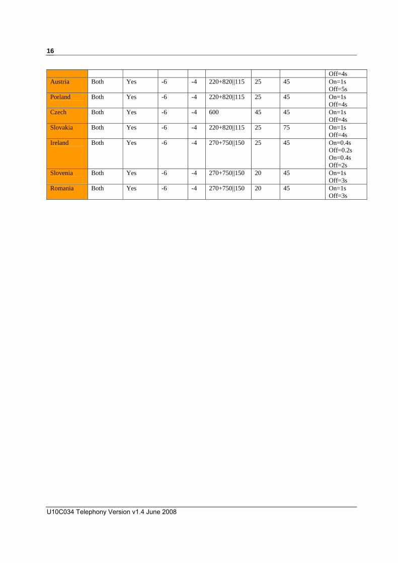
MULTIPLE COUNTRY PROFILE SUPPORT
This product supports following telephony standards for different country. You can use telnet command or MTA configuration file to indicate modem to follow a specific standard for your VOIP network.
Country Code Mu or A law 2 Wire Input D/A
(dB) A/D(dB)
Impedance (Ω)
Ring frq. (Hz)
Ring Waveform (Vrms)
Ring Cadence
North America
Both Yes -4 -2 600 20 57 On=2s Off=4s
TR-57 Both Yes -3 -3 900+2160 20 45 On=2s Off=4s
Japan Both Yes -3 -3 600+1000 20 45 On=1s Off=2s
Germany Both Yes -10 -4 220+820||115 25 45 On=1s Off=4s
Sweden Both Yes -10 -4 270+750||150 25 45 On=1s Off=5s
UK Both Yes -9 -4 300+1000||220 16.66 45 On=0.4s Off=0.2s On=0.4s Off=2s
France Both Yes -10 -4 600 50 45 On=1.5s Off=3.5s
Belgium Both Yes -6 -3 150+830||72 25 45 On=1s Off=3s
Finland
Yes -10 -4 270+910||120 25 45 On=1s Off=4s
Italy Both Yes -3 -3 400+700||200 20 45 On=1s Off=4s
Switzerland Both Yes -11 -4 270+750||150 25 45 On=1s Off=4s
ETSI Both Yes -6 -4 270+750||150 20 45 On=1s Off=3s
Netherlands Both Yes -10 -4 472+637||219 25 45 On=1s Off=4s
Denmark Both Yes -11 -4 279+750||150 25 45 On=0.75s Off=7.5s
Chile Both Yes -11 -4 270+750||150 20 50 On=1s Off=4s
Hungary Both Yes -11 -4 600 25 50 On=1..25s Off=3.75s
Brazil Both Yes -11 -4 279+750||150 25 45 On=1s
U10C034 Telephony Version v1.4 June 2008
16
Off=4s Austria Both Yes -6 -4 220+820||115 25 45 On=1s
Off=5s Porland Both Yes -6 -4 220+820||115 25 45 On=1s
Off=4sCzech Both Yes -6 -4 600 45 45 On=1s
Off=4s Slovakia Both Yes -6 -4 220+820||115 25 75 On=1s
Off=4s Ireland Both Yes -6 -4 270+750||150 25 45 On=0.4s
Off=0.2s On=0.4s Off=2s
Slovenia Both Yes -6 -4 270+750||150 20 45 On=1s Off=3s
Romania Both Yes -6 -4 270+750||150 20 45 On=1s Off=3s

U10C034 MSO User’s Manual v1.4 June 2008
17

U10C034 Telephony Version v1.4 June 2008
18
2 Provisioning
Ambit/Broadcom private MIBs provide extensive support for configuring and controlling PacketCable NCS based eMTAs where additional functionality has been added to software above and beyond CableLabs and other industry specifications. Ambit and Broadcom’s private enterprise MIBs for Cable data products(1.3.6.1.4.1.4684/1.3.6.1.4.1.4413.2) currently consist of the class of devices adhering to Cablelabs and Excentis specifications for DOCSIS, PacketCable, and eDOCSIS based devices. Normally the MIB definitions themselves provide a good overview and enough information for understanding the purpose and how to control objects but additional details will be provided where appropriate. Throughout the descriptions to MIB objects are references to interfaces. Ambit’s software can support 8 IP stacks or interfaces. The assignments of IP addresses is different if an ePS is included in conjunction with an eMTA but for the purposes of this document the follow assignment shows the combined functionality of DOCSIS or a cable modem along with an eMTA:
• IP Stack (1) = Cable Modem’s public WAN IP address
• IP Stack (2) = eMTA public WAN IP address
• IP Stack (3) = Cable Modem’s private LAN IP address 192.168.100.1
Ambit eMTA Proprietary MIBS
• mtaMaintenance.mib
Broadcom CM Proprietary MIBS
• brcm-ping-mgmt.mib
• brcm-bfc-mgmt.mib
• brcm-cm-mgmt-ext.mib

U10C034 MSO User’s Manual v1.4 June 2008
19
• brcm-cm-mgmt.mib
Broadcom eMTA Proprietary MIBS • brcm-emta-mgmt.mib

U10C034 Telephony Version v1.4 June 2008
20
2.1 CONFIGURING CABLE MODEM BEHAVIOR
2.1.1 Disabling the CM miniFirewall
brcm-cm-mgmt-ext.mib
MIB Default Value Access
cmMiniFirewallEnable true read-write cmMiniFirewallEnable (1.3.6.1.4.1.4413.2.2.2.1.2.1.3.0 Integer32)
This specifies whether the CM mini-firewall will be enabled, provided the mini-firewall feature is supported. If the feature is not supported, this object will always report false(2) and an attempt to set it to true(1) will be rejected with an inconsistent error.
2.1.2 Resetting non-volatile Memory to Factory Default
brcm-cm-mgmt-ext.mib
MIB Default Value Access
cmResetFactoryDefaults NA read-write cmResetFactoryDefaults (1.3.6.1.4.1.4413.2.2.2.1.2.1.6.0 Integer32) Setting this object to true(1) will cause the device to reset all non-volatile settings to their factory default state. Note that only dynamic settings will be affected; permanent settings (MAC addresses, etc) will remain unchanged. When read, this object always returns false(2)."
2.1.3 Configuring Downstream Scanning brcm-cm-mgmt-ext.mib
MIB Default Value Access
mScanPushFrequency NA read-write
cmScanTable NA table item

U10C034 MSO User’s Manual v1.4 June 2008
21
cmScanEntry NA table item
cmScanIndex NA table item
cmScanFrequency read cmScanPushFrequency (1.3.6.1.4.1.4413.2.2.99.4413.2.2.1.0 Integer32) Setting this object will add a new entry to the cmScanTable. The new entry will be at index 1, and all existing entries will be re-indexed starting at 2. If the table is full, the last entry in the table will be dropped. If the value set here already exists in the table, it will be moved from its current position in the table to become entry 1 (a duplicate entry will not be added). Setting this object to a value of 0 will flush the cmScanTable. When read,
cmScanTable (1.3.6.1.4.1.4413.2.2.99.4413.2.2.2 SEQUENCE OF CmScanEntry) A table of the most recent known good frequencies to which the CM has registered. The most recent good frequency will be at index 1, with subsequent entries being in chronological order from newest to oldest. Note that the table will not grow unbounded. Once the maximum number of entries is reached which is currently 16 the oldest entries will be discarded.
cmScanEntry (1.3.6.1.4.1.4413.2.2.99.4413.2.2.2.1 CmScanEntry) An entry which identifies a downstream frequency to which the CM has recently successfully registered.
cmScanIndex (1.3.6.1.4.1.4413.2.2.99.4413.2.2.2.1.1.x Integer32)
Identifies the instance of this scan entry
cmScanFrequency (1.3.6.1.4.1.4413.2.2.99.4413.2.2.2.1.1.x Integer32)
A downstream frequency to which the CM has recently successfully registered, or which has been provisioned by way of a set to cmScanPushFrequency.

U10C034 Telephony Version v1.4 June 2008
22
2.1.4 Non-PacketCable DSx Messaging
brcm-cm-mgmt-ext.mib
MIB Default Value Access
cmDsdExtendedRetryEnable false read-write cmDsdExtendedRetryEnable (1.3.6.1.4.1.4413.2.2.2.1.2.1.4.0 Integer32)
Specifies the behavior of the CM with regards to retrying DSD requests when no reply is received. If set to true(1), the CM will continue to retry the request until a reply is received or roughly one hour of time has passed. If set to false(2), the CM will stop retrying after three retries as required by the DOCSIS specification. Note that this setting is not persistent across reboot."

U10C034 MSO User’s Manual v1.4 June 2008
23
2.2 CONFIGURING EMTA BEHAVIOR
2.2.1 Management Provisioning
mtaMgmtMib.mib
MIB Default Value Access maxResetDelay 86400 read-write postCallCompletionResetDelay 30 read-write
brcm-cm-mgmt-ext.mib
MIB Default Value Access
emtaIncludedInCmMaxCpe toe read-write
emtaUseAlternateTelephonyRootCert false read-write
emtaInhibitNcsSyslog true read-write
emtaPhsConfiguration enabled(1) read-write
emtaMaxResetDelay 86400 read-write
emtaPostCallCompletionResetDelay 30 read-write
emtaDhcpRebindRule strict(1) read-write
emtaDhcpIgnoreNaks disabled(2) read-write
emtaPhsUpstreamMask BITS (111110111101111010000000)
read-write
emtaPhsDownstreamMask BITS (110011010110100000000000)
read-writ
emtaPhsDownstreamVerification auto(3) read-write
emtaSignalingMaxNumberQueuedNcsEvents
100 read-write
emtaSignalingRtpBaseReceiveUdpPort
53456 read-write
emtaSignalingT38FaxRelaySupport true read-write
emtaSignalingEcanTailLength ecanTail32ms(4) read-write

U10C034 Telephony Version v1.4 June 2008
24
emtaSignalingDQoSActivationModel twoPhase(2) read
emtaSignalingGR303Support disabled(2) read
emtaSignalingDefRtcpDSCP 0 read-write maxResetDelay/emtaMaxResetDelay (1.3.6.1.4.1.4413.2.2.2.1.6.1.11.0 Unsigned32) This object identifies the length of time, in seconds, that the MTA should wait after the software download for syslog event and reset there after. MTA will start a timer with this value after the completion of the SW download and an active phone call, upon expiry it will send an event notifying of the reset and restart the timer with the same value and upon second expiry MTA will be reset. This prevents software download reset from interrupting an active phone call. The default value of zero disables the reset delay and resets the unit immediately after the software download.
postCallCompletionResetDelay/emtaPostCallCompletionResetDelay (1.3.6.1.4.1.4413.2.2.2.1.6.1.12.0 Unsigned32) This object identifies the length of time, in seconds, that the MTA should wait after terminating a call before resetting the MTA if a reset is pending after the software download completion. The default value of zero disables the reset delay and reset the unit immediately after a software download.
emtaIncludedInCmMaxCpe (1.3.6.1.4.1.4413.2.2.2.1.6.1.4.0 Integer32) This object specifies whether the EMTA MAC address will be included when calculating the number of CPEs allowed by the CM as specified in the CM configuration file. Setting of the MIB takes effect on the next re-boot. Note that the eDOCSIS specification requires the value of this object to be true(1) and setting it to false(2) will violate the spec and render the device uncertifiable.
emtaUseAlternateTelephonyRootCert (1.3.6.1.4.1.4413.2.2.2.1.6.1.6.0 Integer32) This object controls which telephony root certificate the MTA will be using during its authentication phases. As per PacketCable 1.x, the telephony root certificate should be used so that it can be modified by way of a firmware upgrade if necessary. However, the alternate certificate may sometimes be required for testing, development, or other special situations. If set to true(1), the EMTA will use the alternate telephony root certificate provisioned in non-volatile storage. If set to false(2), the EMTA will use the telephony root certificate which is embedded in the firmware image.
emtaInhibitNcsSyslog (1.3.6.1.4.1.4413.2.2.2.1.6.1.8.0 Integer32) This object controls the logging of the NCS messages to Syslog. Generally,

U10C034 MSO User’s Manual v1.4 June 2008
25
reporting of the events with NCS messages is following the PacketCable 1.x MEM Specification and Event MIB Specification. However, if this object has a value of true(1), logging of the NCS messages to syslog is inhibited. Otherwise, NCS logging control logic follows the requirements of the PacketCable 1.x Event MIB. The MTA must not persist this MIB object.
emtaPhsConfiguration (1.3.6.1.4.1.4413.2.2.2.1.6.1.10.0 Integer32)
This object controls the application of Payload Header Suppression (PHS) to voice RTP traffic. When disabled(1), PHS is not applied to either upstream or downstream RTP traffic. When enabled(2), PHS is applied to both upstream and downstream RTP traffic."
‧ enabled(1)
‧ disabled(2)
emtaDhcpRebindRule (1.3.6.1.4.1.4413.2.2.2.1.6.1.13.0 Integer32) This object is used to control the DHCP client behavior for the MTA when a DHCP REBIND (T2 timeout) occurs. The value strict(1) will only allow the MTA to accept a valid DHCP ACK only from the DHCP server that provided the initial lease. The value relaxed(2) will allow the MTA to accept a valid DHCP ACK from any DHCP server.
‧ strict(1)
‧ relaxed(2)
emtaDhcpIgnoreNaks (1.3.6.1.4.1.4413.2.2.2.1.6.1.14.0 Integer32) This object controls the DhcpIgnoreNaks Feature. When set to enabled(1) the mta dhcp client will ignore DHCP Naks when a line is offhook. When set to disabled(2) the mta DHCP client will operate normally.
‧ enabled(1),
‧ disabled(2)
emtaPhsUpstreamMask (1.3.6.1.4.1.4413.2.2.2.1.6.1.16.0 BITS) This object sets the PHS mask for upstream voice DQoS flows using IPv4 addressing. Setting a bit to '1' will cause the MTA to suppress this field for upstream voice flows.
The default configuration is all bits set except for ipTotalLength(5), ipHeaderChecksum(10), and udpLength(15) since these fields are required to properly handle connections using silence suppression.

U10C034 Telephony Version v1.4 June 2008
26
If silence suppression will never be enabled by the CMS, all bits may be set.
Note that this setting only applies if emtaPhsConfiguration is set to enabled(1). If emtaPhsConfiguration is set to disabled(2), then the value of this object will be ignored.
‧ ethDA(0),
‧ ethSA(1),
‧ ethEtherType(2),
‧ ipVersionIHL(3),
‧ ipTOS(4),
‧ ipTotalLength(5),
‧ ipIdent(6),
‧ ipFlagsFragOffset(7),
‧ ipTTL(8),
‧ ipProtocol(9),
‧ ipHeaderChecksum(10),
‧ ipSA(11),
‧ ipDA(12),
‧ udpSourcePort(13),
‧ udpDestPort(14),
‧ udpLength(15),
‧udpChecksum(16)
emtaPhsDownstreamMask (1.3.6.1.4.1.4413.2.2.2.1.6.1.17.0 BITS) This object sets the PHS mask for downstream voice DQoS flows using IPv4 addressing. Setting a bit to '1' will cause the CMTS to suppress this field for downstream voice flows.
The default configuration is the ethEthertype(0), ipVersionIHL(1), ipIdent(4), ipFlagsFragOffset(5), ipProtocol(7), ipSA(9), ipDA(10), and udpDestPort(12) bits are set.
If silence suppression will never be enabled by the CMS, ipTotalLength(3) and udpLength(13) may also be set.
If silence suppression will never be enabled by the CMS and emtaPhsDownstreamVerification is set to either disabled(2) or auto(3), all bits may be set.
Note that this setting only applies if emtaPhsConfiguration is set to enabled(1). If emtaPhsConfiguration is set to disabled(2), then the value

U10C034 MSO User’s Manual v1.4 June 2008
27
of this object will be ignored.
‧ ethEtherType(0),
‧ ipVersionIHL(1),
‧ ipTOS(2),
‧ ipTotalLength(3),
‧ ipIdent(4),
‧ ipFlagsFragOffset(5),
‧ ipTTL(6),
‧ ipProtocol(7),
‧ ipHeaderChecksum(8),
‧ ipSA(9),
‧ ipDA(10),
‧ udpSourcePort(11),
‧ udpDestPort(12),
‧ udpLength(13),
‧ udpChecksum(14)
emtaPhsDownstreamVerification (1.3.6.1.4.1.4413.2.2.2.1.6.1.18.0 Integer32) This object controls whether or not the MTA requests PHS verification (PHSV) by the CMTS on downstream PHS operations. The default is auto(3).
When set to auto(3), the MTA will automatically disable PHSV if the ipTOS(2), ipTTL(6), ipHeaderChecksum(8) or udpChecksum(14) bits are set in emtaPhsDownstreamMask.
When set to disabled(2), the MTA will disable PHSV at all times.
When set to enabled(1), the MTA will enable PHSV at all times.
This setting should be used with caution as it is possible to create a non-working configuration if verification is enabled and a non-predictable downstream field (e.g. ipTTL) is suppressed.
Note that this setting only applies if emtaPhsConfiguration is set to enabled(1). If emtaPhsConfiguration is set to disabled(2), then the value of this object will be ignored.
‧ enabled(1),
‧ disabled(2),
‧ auto(3)
U10C034 Telephony Version v1.4 June 2008
28
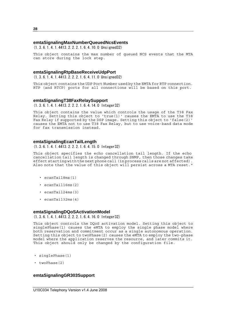
emtaSignalingMaxNumberQueuedNcsEvents (1.3.6.1.4.1.4413.2.2.2.1.6.4.10.0 Unsigned32) This object contains the max number of queued NCS events that the MTA can store during the lock step.
emtaSignalingRtpBaseReceiveUdpPort (1.3.6.1.4.1.4413.2.2.2.1.6.4.11.0 Unsigned32) This object contains the UDP Port Number used by the EMTA for RTP connection. RTP (and RTCP) ports for all connections will be based on this port.
emtaSignalingT38FaxRelaySupport (1.3.6.1.4.1.4413.2.2.2.1.6.4.14.0 Integer32) This object contains the value which controls the usage of the T38 Fax Relay. Setting this object to 'true(1)' causes the EMTA to use the T38 Fax Relay if supported by the DSP image. Setting this object to 'false(2)' causes the EMTA not to use T38 Fax Relay, but to use voice-band data mode for fax transmission instead.
emtaSignalingEcanTailLength (1.3.6.1.4.1.4413.2.2.2.1.6.4.15.0 Integer32) This object specifies the echo cancellation tail length. If the echo cancellation tail length is changed through SNMP, then those changes take effect starting with the next phone call (in process calls are not affected). Also note that the value of this object will persist across a MTA reset."
‧ ecanTail8ms(1)
‧ ecanTail16ms(2)
‧ ecanTail24ms(3)
‧ ecanTail32ms(4)
emtaSignalingDQoSActivationModel (1.3.6.1.4.1.4413.2.2.2.1.6.4.16.0 Integer32) This object controls the DQoS activation model. Setting this object to singlePhase(1) causes the eMTA to employ the single phase model where both reservation and commitment occur as a single autonomous operation. Setting this object to twoPhase(2) causes the eMTA to employ the two-phase model where the application reserves the resource, and later commits it. This object should only be changed by the configuration file.
‧ singlePhase(1)
‧ twoPhase(2)
emtaSignalingGR303Support

U10C034 MSO User’s Manual v1.4 June 2008
29
(1.3.6.1.4.1.4413.2.2.2.1.6.4.17.0 Integer32) Setting this object to enabled(1) causes the eMTA to switch to GR303 mode. The MTA will generate RTP on-hook event packets in the media stream until off-hook is detected or the connection is deleted. Also MTA will treat flash hook as separate on-hook and off-hook events, and send each event triple redundantly, replacing voice packets in the RTPstream. Setting this object to disabled(2) causes the eMTA not to use GR303 mode. This object should only be changed by the configuration file.
‧ enabled(1)
‧ disabled(2)
emtaSignalingDefRtcpDSCP (1.3.6.1.4.1.4413.2.2.2.1.6.4.23.0 Integer32) This object contains the default value used in the IP header for setting the DSCP for RTCP packets. When the value of this object is updated by SNMP, the MTA MUST use the new value as a default starting from the new connection. Existing connections are not affected by the value’s update.
2.2.2 Disabling the eMTA firewall (1.3.6.1.4.1.4413.2.2.2.1.6.1.2.0 Integer32) The eMTA stack has what is referred to as a lightweight firewall that has a default value of enabled (true), but can be set to disabled (false) when necessary.
brcm-cm-mgmt-ext.mib
MIB Default Value Access
emtaFirewallEnable true read-write
2.2.3 MTA DHCP Option 122/177 mtaDhcpOption (1.3.6.1.4.1.4413.2.2.2.1.6.1.5.0 OCTET STRING) This object specifies the value of the PacketCable DHCP option which will be used in MTA provisioning. Current PacketCable 1.x Provisioning Specification requires value 122, but certain legacy systems still use the currently obsolete value of 177. ‧ cableLabsClientConfiguraton(122), ‧ packetCableAndCableHomeObsolete(177)

U10C034 Telephony Version v1.4 June 2008
30
2.2.4 Software Upgrade During Calls
brcm-cm-mgmt-ext.mib
MIB Default Value Access
emtaInhibitSwDownloadDuringCall False read-write emtaInhibitSwDownloadDuringCall (1.3.6.1.4.1.4413.2.2.2.1.6.1.1.0 Integer32) This object controls the processing logic of software downloading requests when there are specific telephony related EMTA activities. If this object has a value of true(1), DOCSIS software download by way of the docsDevSwAdminStatus MIB object will be inhibited if the value of esafeDevServiceIntImpact for the eMTA entry has a value of significant(1), indicating a call in progress. If docsDevSwAdminStatus is set to upgradeFromMgt(1) under these conditions, an error code of resourceUnavailable(13) will be returned and an appropriate event logged to the CM.
2.2.5 Configuring the Jitter Buffer There are 4 MIBs that constitute the control of the jitter buffer which can be configured as either fixed or adaptive by the emtaSignalingVoiceJitterBufferType MIB. The jitter buffer holds RTP frames for a configurable period of time in order to smooth out network jitter. In the case of a fixed jitter buffer the frames are held for a fixed period of time. A fixed jitter buffer with a high holding period is appropriate for VBD because delay is not as important as reducing packet loss, but in the case of voice calls where minimizing delay is more important than reducing packet loss an adaptive jitter buffer is appropriate. The adaptive jitter buffer adjusts the holding time as required based on the detected network jitter. The default values controlling the jitter buffer are for an adaptive jitter buffer with a maximum hold time of 200ms. The MIB default of 0 for emtaSignalingVoiceJitterBufferNomValue and emtaSignalingVoiceJitterBufferMinValue means they can adjust up to the maximum which is 200ms. The nominal hold time will be adjusted immediately when a voice call starts up. If you freeze the voice jitter buffer it uses the emtaSignalingVoiceJitterNomValue for the fixed size of the jitter buffer. There are three MIBs for configuring the jitter buffer: • emtaSignalingVoiceJitterNomValue
• emtaSignalingVoiceJitterMinValue
• emtaSignalingVoiceJitterMaxValue
brcm-emta-mgmt.mib

U10C034 MSO User’s Manual v1.4 June 2008
31
MIB Default Value Access
emtaSignalingVoiceJitterBufferType jitterBufferTypeAdaptive(2) read-write
emtaSignalingVoiceJitterNomValue 0 read-write
emtaSignalingVoiceJitterMinValue 0 read-write
emtaSignalingVoiceJitterMaxValue 0 read-write
emtaSignalingDataJitterNomValue 60 read-write
emtaSignalingDataJitterMaxValue 0 read-write
emtaStatsAvgJitterMeasurement - read
emtaStatsMaxJitterMeasurement - read emtaSignalingVoiceJitterBufferType (1.3.6.1.4.1.4413.2.2.2.1.6.4.3.0 Integer32) This object contains the type of the jitter buffer. Setting this object to jitterBufferTypeFixed(1) causes the eMTA to employ a fixed jitter buffer. Setting this object to jitterBufferTypeAdaptive(2) causes the eMTA to use an adaptive jitter buffer. If the jitter buffer type value is changed through SNMP, then those changes take affect starting with the next phone call (in process calls are not affected). When the voice jitter buffer is frozen it uses the emtaSignalingVoiceJitterNomValue for the fixed size of the jitter buffer."
‧ jitterBufferTypeFixed(1), ‧ jitterBufferTypeAdaptive(2)
emtaSignalingVoiceJitterNomValue (1.3.6.1.4.1.4413.2.2.2.1.6.4.4.0 Unsigned32) If the voice jitter buffer value is changed through SNMP, then those changes take affect starting with the next phone call (in process calls are not affected). This MIB sets the target hold time for the voice jitter buffer in milliseconds. This is the initial hold time for the adaptive jitter buffer. The actual target holding time will adapt above or below this in response to observed network jitter. The MTA will reject all attempts to set the value which is not within the interval defined by the emtaSignalingVoiceJitterMinValue and emtaSignalingVoiceJitterMaxValue MIB Objects. When the jitter buffer is frozen, this MIB controls the static size of the voice jitter buffer. The default value is 0 which is interpreted as the maximum jitter buffer size for the product. emtaSignalingVoiceJitterMinValue (1.3.6.1.4.1.4413.2.2.2.1.6.4.5.0 Unsigned32) If the voice jitter buffer value is changed through SNMP, then those changes take affect starting with the next phone call (in process calls are not affected). This MIB sets the minimum hold time for the voice jitter buffer in milliseconds. The target hold time cannot take on a value below the minimum either through a MIB setting or through adaptation. That is, packets

U10C034 Telephony Version v1.4 June 2008
32
will be held in the jitter buffer for at least this duration (on average). When a packet is received late it may be held for less than this time.
emtaSignalingVoiceJitterMaxValue (1.3.6.1.4.1.4413.2.2.2.1.6.4.6.0 Unsigned32) If the voice jitter buffer value is changed through SNMP, then those changes take affect starting with the next phone call (in process calls are not affected). This MIB sets the maximum hold time for the voice jitter buffer in milliseconds. The maximum size of the jitter buffer is only relevant for an adaptive jitter buffer. The target hold time cannot take on a value greater than the maximum either through a MIB setting or through adaptation. On average, packets will not be held longer than this time. However, if a packet is received quite early it may be held longer than the max hold time. The default value is 0 which is interpreted as the maximum jitter buffer size for the product.
emtaSignalingDataJitterNomValue (1.3.6.1.4.1.4413.2.2.2.1.6.4.7.0 Unsigned32) If the jitter buffer value is changed through SNMP, then those changes take affect starting with the next phone call (in process calls are not affected). This object controls the hold time for a fixed VBD jitter buffer. The jitter buffer always fixes itself when VBD is detected and never adapts below this level, so this value serves as a minimum too. The default value is 60 msec..
emtaSignalingDataJitterMaxValue (1.3.6.1.4.1.4413.2.2.2.1.6.4.19.0 Unsigned32) If the voice buffer value is changed through SNMP, then those changes take affect starting with the next phone call (in process calls are not affected). This MIB sets the maximum hold time for the fixed VBD jitter buffer and is only relevant when emtaSignalingVoiceJitterBufferType is set to 'jitterbufferTypeFixed(1)'. The default value is 0 which is interpreted as the maximum jitter buffer size for the product.
emtaStatsAvgJitterMeasurement (1.3.6.1.4.1.4413.2.2.2.1.6.5.8.0 Unsigned32) This objects contains the average jitter measurements for the last 24 hours.
emtaStatsMaxJitterMeasurement (1.3.6.1.4.1.4413.2.2.2.1.6.5.9.0 Unsigned32)
This objects contains the maximum jitter measurements for the last 24 hours.

U10C034 MSO User’s Manual v1.4 June 2008
33
2.2.6 Configuring for Network Maintenance Operations The network maintenance operations provide control over the loop voltage behavior of the eMTA, and they can be done by either the private emtaMgmtMaintenance MIBs or the PacketCable pktcEnNcsEndPntLVMgmtTable MIBs. By default, the private MIBs are used. The PacketCable MIBs are used only for PacketCable 1.5 builds without vendor-specific build option.
mtaSecurityMib.mib
MIB Default Value Access
MaintenanceWindowBegin - read-write
MaintenanceWindowDuration 0 read-write
MaintenanceControlMask maintenanceOnCmReset(0), maintenanceOnRFLoss(1), maintenanceOnMtaReset(2), maintenanceOnCMSLoss(3),
read-write
MaintenanceQuarantineTimeout 0 read-write
MaintenanceDisconnectedTimeout 0 read-write
MaintenanceRFDisconnectTimeout 0 read-write You can also configure these values via following MIBs. brcm-emta-mgmt.mib
MIB Default Value Access
emtaMaintenanceWindowBegin - read-write
emtaMaintenanceWindowDuration 0 read-write
emtaMaintenanceControlMask maintenanceOnCmReset(0), maintenanceOnRFLoss(1), maintenanceOnMtaReset(2), maintenanceOnCM
read-write

U10C034 Telephony Version v1.4 June 2008
34
SLoss(3),
emtaMaintenanceQuarantineTimeout 0 read-write
emtaMaintenanceDisconnectedTimeout 0 read-write
emtaMaintenanceRFDisconnectTimeout 0 read-write MaintenanceWindowBegin/emtaMaintenanceWindowBegin (1.3.6.1.4.1.4413.2.2.2.1.6.2.1.0 OCTET STRING) This object identifies the start of an eMTA maintenance window. A maintenance window is a period of time during which the ISP may perform network maintenance operations and network outages or software resets may occur. During a maintenance window, the eMTA will maintain the line voltage of an MTA regardless of CM resets, MTA resets, or RF losses. If any of these conditions occurs or persists outside of the scheduled maintenance window then the line voltage will be dropped unless the corresponding bit for the condition in question is set in the emtaMaintenanceControlMask MIB. If this object has never been set, it will have the value of midnight, January 1, 1970. Note that the time value used here is the local time as known by the device, as opposed to UTC. Also note that the value of this object will persist across a system reboot.
MaintenanceWindowDuration/emtaMaintenanceWindowDuration (1.3.6.1.4.1.4413.2.2.2.1.6.2.2.0 Unsigned32) This object identifies the duration, in seconds, of an eMTA maintenance window. Setting the value of this object to the default value of zero will cancel the maintenance window. Note that the value of this object will persist across a system reboot.
MaintenanceControlMask/emtaMaintenanceControlMask (1.3.6.1.4.1.4413.2.2.2.1.6.2.3.0 BITS) This object identifies the bit mask to control the line voltage behavior of the eMTA in various scenarios: maintenanceOnCmReset(0) - if this bit is set to 1 it requires the line voltage be maintained in the case when the CM has been reset, regardless of the reason (reset after downloading a new firmware, or hard reboot, or SNMP induced CM reset), and regardless of whether the MTA is in a valid maintenance window maintenanceOnRFLoss(1) - if this bit is set to 1 it requires the line voltage be maintained in the case when RF communication is lost, regardless of the reason, and regardless of whether the MTA is in a valid maintenance window maintenanceOnMtaReset(2) - if this bit is set to 1 it requires the line voltage be maintained in the case when the eMTA is being reset, regardless of the reason (e.g. SNMP induced eMTA reset, etc), and regardless of whether the MTA is in a valid maintenance window maintenanceOnCMSLoss(3) - if this bit is set to 1 it requires the line voltage be maintained in the case when communication is lost with the CMS, regardless of the reason (e.g. endpoint disconnected, etc), and regardless of whether the duration of the communication loss has exceeded the value in the MIB emtaMaintenanceQuarantineTimeout and/or emtaMaintenanceDisconnectedTimeout.

U10C034 MSO User’s Manual v1.4 June 2008
35
The default value of this object may change based on build specific options. However, it's highly recommended that the default value in the image submitted for (E)PC 1.x Certification be chosen in such a way that it will correspond to the functionality compliant with the PacketCable requirements and will preserve the backward compatibility with the previously certified behavior. Note that to satisfy the latter, 'maintenanceOnCMSLoss(3)' bit should be set by default.
‧ maintenanceOnCmReset(0), ‧ maintenanceOnRFLoss(1), ‧ maintenanceOnMtaReset(2), ‧ maintenanceOnCMSLoss(3)
MaintenanceQuarantineTimeout/emtaMaintenanceQuarantineTimeout (1.3.6.1.4.1.4413.2.2.2.1.6.2.4.0 Unsigned32) This object identifies the length of time, in seconds, that the MTA should maintain the line voltage after any of the endpoints enters the quarantine state. If any of the endpoints remains in the quarantine state for longer than this period the line voltage is dropped unless the maintenanceOnCMSLoss bit is set in the emtaMaintenanceControlMask MIB. Note that the value of this object will persist across a system reboot.
MaintenanceDisconnectedTimeout/emtaMaintenanceDisconnectedTimeout (1.3.6.1.4.1.4413.2.2.2.1.6.2.5.0 Unsigned32) This object identifies the length of time, in seconds, that the MTA should maintain the line voltage after any of the endpoints is disconnected. If any of the endpoints remains disconnected for longer than this period the line voltage is dropped unless the maintenanceOnCMSLoss bit is set in the emtaMaintenanceControlMask MIB. Note that the value of this object will persist across a system reboot.
MaintenanceRFDisconnectTimeout/emtaMaintenanceRFDisconnectTimeout (1.3.6.1.4.1.4413.2.2.2.1.6.2.6.0 Unsigned32) This object identifies the length of time, in seconds, that the MTA should maintain the line voltage after the RF lock with the CMTS is lost. If the MTA remains disconnected from the CMTS for longer than this period the line voltage is dropped unless the maintenanceOnRFLoss bit is set in the emtaMaintenanceControlMask MIB. Note that the value of this object will persist across a system reboot.
Differences between the private MIB feature and the PacketCable MIB feature: • Private MIBs allow one or more of the conditions of CM reset, RF
loss, MTA reset, and CMS loss to be configured. The configurability for CMS Loss is not available for PacketCable MIBs.
• The pktcEnNcsEndPntLVMgmtResetTimer applies to all the conditions of CM reset, RF loss, MTA reset, and CMS loss. The timers (the timeout MIBs) from private MIBs can apply to individual condition for CMS loss and RF loss, but there is no timer specific to CM reset and MTA reset.
• In the event of a RF Loss, the PacketCable MIB feature will complete

U10C034 Telephony Version v1.4 June 2008
36
a full scan on the spectrum after the T4 timeout before dropping the line voltage. The Private MIB feature will drop the line voltage as soon as there is a T4 timeout.
• The PacketCable MIBs provide control on whether line voltage should be maintained if MTA fails provisioning. The Private MIBs do not.
• The PacketCable MIBs provide control on the reset timer value for CM reset and MTA reset. The Private MIBs do not.
PacketCable Policy
PacketCable Timers emtaMaintenanceControlMask emtaMaintenance Timers
Policy 1 None OnCmReset(0),
OnRFLoss(1),
OnMtaReset(2),
OnCMSLoss(3)
None
Policy 2 None OnCmReset(0),
OnMtaReset(2),
OnCMSLoss(3)
emtaMaintenanceRF- DisconnectTimeout
Policy 3 pktcEnNcsEndPntLVMgmtMaintTimer Not Required emtaMaintenanceWindowBegin,
emtaMaintenanceWindowDuration,
emtaMaintenance QuarantineTimeout,
emtaMaintenance DisconnectTimeout,
emtaMaintenance RFDisconnectTimeout
Policy 4 None Not Required None required.
N/A N/A Any other bit settings Any combination of the emtaMaintenanceWindow-Begin, emtaMaintenanceWindow-Duration, and the Timeout MIB settings.
2.2.7 Configuring Stuck Service-Flow Cleanup Control brcm-emta-mgmt.mib
MIB Default Value Access

U10C034 MSO User’s Manual v1.4 June 2008
37
emtaSignalingEndptConnectionCleanupTimeout
60 Read
emtaSignalingEmtaResetCleanupTimeout 0 Read emtaSignalingEndptConnectionCleanupTimeout (1.3.6.1.4.1.4413.2.2.2.1.6.4.12.0 Unsigned32)
This object causes the EMTA to tear down and clean up connections and the associated service flows on any endpoint that detects a transition from off-hook to on-hook, remains onhook for a period longer than the value set in this MB object, and has connections that were active prior to the endpoint going onhook. If the MIB object is set to 0 then this function is disabled. If the MIB is set from 1 to 64000 seconds then the feature is enabled and this value is used for the timeout. This object should only be changed by the configuration file.
emtaSignalingEmtaResetCleanupTimeout (1.3.6.1.4.1.4413.2.2.2.1.6.4.13.0 Unsigned32) This object causes the entire EMTA to reset if voice connections have been active and both voice lines have been on-hook for a period greater than the value defined via this MIB object. This will guarantee that orphaned connections and/or service flows are properly cleaned up and freed when the CMTS and CMS fail to perform the correct clean up operations. It will also ensure that the EMTA state machine, DSP voice channels, NCS connection handling, etc. are also restored to a default state. This protects against any unknown case that could possibly cause stuck service flows and/or connections. If the MIB object is set to 0 then this function is disabled. If the MIB is set from 1 to 64000 minutes then the feature is enabled and this value is used for the timeout. This object should only be changed by the configuration file.
2.2.8 EndPoint Provisioning brcm-emta-mgmt.mib
MIB Default Value Access emtaRingWithDCOffset false read-write
emtaSignalingEndptCtrlAnalogLoopback false read-write
emtaSignalingEndptCtrlLineReset false read-write
emtaSignalingEndptCtrlBoostedLoopCurrent false read-write
emtaSignalingEndptCtrlTxGain 0 read-write
emtaSignalingEndptCtrlRxGain 0 read-write
emtaSignalingEndptCtrlDialToneMsecTO 0 read-write

U10C034 Telephony Version v1.4 June 2008
38
emtaSignalingEndptCtrlToneDetectionControl AlarmPOSDisabled(4) read-write
emtaSignalingPowerRingFrequency f20Hz(1), read
emtaSignalingRingWaveform Sinusoidal(1) read-write emtaRingWithDCOffset (1.3.6.1.4.1.4413.2.2.2.1.6.1.3.0 Integer32) This object specifies whether the ring with DC offset option is enabled.
emtaSignalingEndptCtrlAnalogLoopback (1.3.6.1.4.1.4413.2.2.2.1.6.4.1.1.1.x Integer32) This object controls the implementation of the analog loopback by the MTA. When the object is set to true(1), the MTA MUST implement analog loopback operations. When the object is set to false(2), the MTA MUST stop loopback operations immediately. The default value of this object corresponds to the functionality compliant with the PacketCable requirements.
emtaSignalingEndptCtrlLineReset (1.3.6.1.4.1.4413.2.2.2.1.6.4.1.1.2.x Integer32) This object controls the resetting the telephone line. Setting this object to true(1) causes the eMTA to reset the telephone line of the corresponding endpoint. Setting this object to false(2) does not have any affect. Reading this object always returns 'false(2)'.
emtaSignalingEndptCtrlBoostedLoopCurrent (1.3.6.1.4.1.4413.2.2.2.1.6.4.1.1.8.x Integer32) This object indicates whether the loop current should be boosted (true(1)) or not (false(2)). The particular value for the loop current depends on the particular hardware (SLIC) being used.
emtaSignalingEndptCtrlTxGain (1.3.6.1.4.1.4413.2.2.2.1.6.4.1.1.9.x Integer32) This Object represents the per line transmitter (A/D) gain. A positive number reflects a signal gain; a negative number reflects a signal loss. This Object does not reflect the desired level at the Telco (POTS) a-b (T/R) terminals as it does not include the affects of the gain settings on the analog interfaces which are pre-configured for a given country specification. The gain setting specified in this MIB object will be applied on top of the preconfigured settings and therefore represents a relative level, while ambitTxGain will overwrite the preconfigured settings and represents a absolute level.
emtaSignalingEndptCtrlRxGain (1.3.6.1.4.1.4413.2.2.2.1.6.4.1.1.10.x Integer32)
U10C034 MSO User’s Manual v1.4 June 2008
39
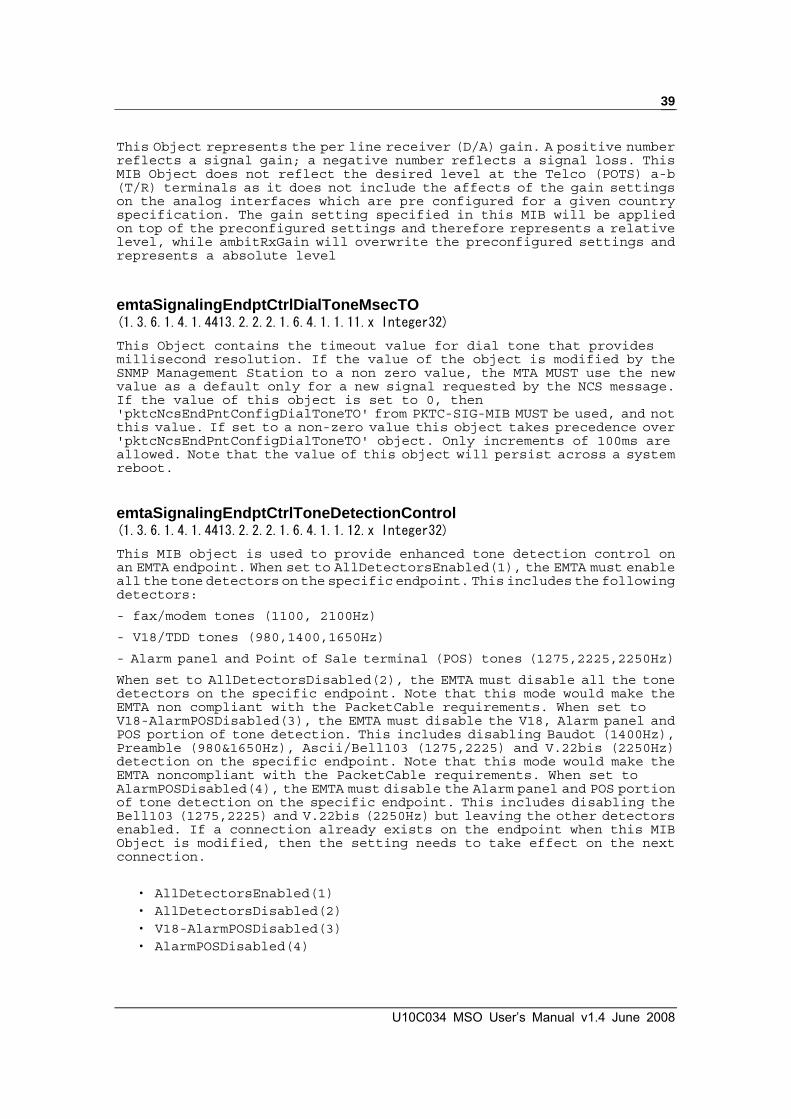
This Object represents the per line receiver (D/A) gain. A positive number reflects a signal gain; a negative number reflects a signal loss. This MIB Object does not reflect the desired level at the Telco (POTS) a-b (T/R) terminals as it does not include the affects of the gain settings on the analog interfaces which are pre configured for a given country specification. The gain setting specified in this MIB will be applied on top of the preconfigured settings and therefore represents a relative level, while ambitRxGain will overwrite the preconfigured settings and represents a absolute level
emtaSignalingEndptCtrlDialToneMsecTO (1.3.6.1.4.1.4413.2.2.2.1.6.4.1.1.11.x Integer32) This Object contains the timeout value for dial tone that provides millisecond resolution. If the value of the object is modified by the SNMP Management Station to a non zero value, the MTA MUST use the new value as a default only for a new signal requested by the NCS message. If the value of this object is set to 0, then 'pktcNcsEndPntConfigDialToneTO' from PKTC-SIG-MIB MUST be used, and not this value. If set to a non-zero value this object takes precedence over 'pktcNcsEndPntConfigDialToneTO' object. Only increments of 100ms are allowed. Note that the value of this object will persist across a system reboot.
emtaSignalingEndptCtrlToneDetectionControl (1.3.6.1.4.1.4413.2.2.2.1.6.4.1.1.12.x Integer32) This MIB object is used to provide enhanced tone detection control on an EMTA endpoint. When set to AllDetectorsEnabled(1), the EMTA must enable all the tone detectors on the specific endpoint. This includes the following detectors:
- fax/modem tones (1100, 2100Hz)
- V18/TDD tones (980,1400,1650Hz)
- Alarm panel and Point of Sale terminal (POS) tones (1275,2225,2250Hz)
When set to AllDetectorsDisabled(2), the EMTA must disable all the tone detectors on the specific endpoint. Note that this mode would make the EMTA non compliant with the PacketCable requirements. When set to V18-AlarmPOSDisabled(3), the EMTA must disable the V18, Alarm panel and POS portion of tone detection. This includes disabling Baudot (1400Hz), Preamble (980&1650Hz), Ascii/Bell103 (1275,2225) and V.22bis (2250Hz) detection on the specific endpoint. Note that this mode would make the EMTA noncompliant with the PacketCable requirements. When set to AlarmPOSDisabled(4), the EMTA must disable the Alarm panel and POS portion of tone detection on the specific endpoint. This includes disabling the Bell103 (1275,2225) and V.22bis (2250Hz) but leaving the other detectors enabled. If a connection already exists on the endpoint when this MIB Object is modified, then the setting needs to take effect on the next connection.
‧ AllDetectorsEnabled(1) ‧ AllDetectorsDisabled(2) ‧ V18-AlarmPOSDisabled(3) ‧ AlarmPOSDisabled(4)

U10C034 Telephony Version v1.4 June 2008
40
emtaSignalingPowerRingFrequency (1.3.6.1.4.1.4413.2.2.2.1.6.4.18.0 Integer32) This object must only be provided via the configuration file during the provisioning process. The power ring frequency is the frequency at which the sinusoidal voltage must travel down the twisted pair to make terminal equipment ring. Different countries define different electrical characteristics to make terminal equipment ring.
‧ f20Hz(1) ‧ f25Hz(2) ‧ f33Point33Hz(3) ‧ f50Hz(4) ‧ f15Hz(5) ‧ f16Hz(6) ‧ f22Hz(7) ‧ f23Hz(8) ‧ f45Hz(9) ‧ f17Hz(10)
emtaSignalingRingWaveform (1.3.6.1.4.1.4413.2.2.2.1.6.4.20.0 Integer32) This MIB object is controls the shape of the ring waveform. The setting of sinusoidal(1) would result in a sinusoidal ring waveform with crest factor of 1.414, while the setting of trapezoidal(2) would result in a trapezoidal ring waveform with crest factor of 1.25.
‧ Sinusoidal(1) ‧ Trapezoidal(2)
2.2.9 Telephony Port Diagnostics TPD testing can be used to diagnose problems with customer cabling, terminations and unexpected foreign voltages sources. Testing encompasses the ability to detect the hook state, the ability to communicate with a CMS, detect shorts, opens and foreign voltages. Sense inputs connected directly to tip and ring are provided to the eMTA for direct access to the telephony interface. The pin of the SLIC which gives a voltage representation of the loop current also has a sense input. These inputs allow TPD tests to be performed in order to fully diagnose the loop condition. The resources in the codec and SLIC are available to perform loop diagnostics (i.e. be able to stimulate and measure the loop). The different telephony test available and their explanation consist of the following: Hazardous Potential Test

U10C034 MSO User’s Manual v1.4 June 2008
41
This test checks for high voltage levels on the Tip and Ring pins. Hazardous potential is based on two terminal T-G and R-G AC voltage and two terminal T-G and R-G DC voltage. The system shall provide a fail indication if the T-G or R-G AC voltage is greater than 50 volts RMS or the T-G or R-G DC voltage is greater than 135 volts. This is accomplished by putting the SLIC into the high impedance disconnected mode. The tip and ring sense inputs are then read to see if a hazardous potential voltage is present. This test fails if the voltages are greater than the thresholds stated meaning that a hazardous voltage has been detected. Foreign Electromotive Force Test (FEMF)
This test checks for high voltage levels on the Tip and Ring pins. FEMF is based on two terminal T-G and R-G AC voltage and two terminal T-G and R-G DC voltage. The system shall provide a fail indication if the T-G or R-G AC voltage is greater than 10 volts or the T-G or R-G DC voltage is greater than 6 volts. This is accomplished by using the results from the previous hazardous potential test. This test fails if the voltages are greater than the thresholds stated. Notes: In this test, if the T-G or R-G DC voltage is greater than 6 volts, this test will be failed in normal way, but due to the hardware design, there has tolerance detected by our SW. Receiver Off hook Test (ROH)
This test determines if the telephone receiver is in the off hook state. A receiver off hook is identified by sequentially generating two AC voltages across Tip and Ring, one at approximately 10 Vrms and one at approximately 5 Vrms. The tip and ring voltages are measured at each voltage setting to look for a non-linear relationship. If the second set of voltage readings is less than 85% of the intended value the test fails. This test differentiates between an off hook condition and a simple resistive fault. Tip to Ring Resistive Faults Test
This test checks for resistive faults which are DC resistance faults across Tip and Ring. The test provides a fail indication if the measured resistance is less than 150 K Ohms. Tip to Ground Resistive Faults Test
This test checks for resistive faults which are DC resistance faults across Tip and Ground. The test provides a fail indication if the measured resistance is less than 150 K Ohms. Ring to Ground Resistive Faults Test
This test checks for resistive faults which are DC resistance faults across Ring and Ground. The test provides a fail indication if the measured resistance is less

U10C034 Telephony Version v1.4 June 2008
42
than 150 K Ohms. Ringers Test
This test determines the presence of appropriate ringer terminations on the customer line. The test provides a fail indication when the equivalent ringer load across tip and ring is less than 0.175 REN or greater than 5 REN. During this test a low voltage AC signal is applied to the line. The voltage and current across the load are measured as the AC signal is applied. The ringing voltage is below the required level to activate a ring so audible ringing will not occur. The measured AC resistance is linearly proportional to the load on the endpoint in question and is converted to REN units. If this value is below 0.175 REN or above 5 REN the test fails. If not, this test passes. Off hook Simulation Test
This test simulates an off hook condition by utilizing an external relay. The test provides a pass indication if the following sequence of events occurs successfully. First, the MTA causes the external relay to simulate an off hook condition. Second, the MTA detects the off hook condition and sends a NTFY event to the CMS. Third the CMS acknowledges this NTFY and sends an RQNT to play dial tone. If all of these conditions occur within two second the test passes. After the test is completed the relay is disabled and the off hook condition ceases regardless of whether the test was successful or not. Note: this test will not pass unless a CMS is active that will request dial tone upon receiving a notification of off hook from the MTA. Self Check Test
This test verifies that several of the voice support modules of the MTA are operating correctly. In particular this test uses a variety of methods to verify that the APM, the DSP core software, and the HVG are all functioning as expected. If any of these modules is not operating as expected this test fails and an error is reported in the MIB. If each module is functioning as expected the test passes The below table enumerates the applicable MIBS for conducting the telephony port diagnostics. When executing any of these tests you must always set the startForceTestExecution bit which tells the software that I am running a line diagnostic test as opposed to an actual call.
brcm-emta-mgmt.mib
MIB Default Value Access
emtaSignalingEndptCtrlDiagTestsStart read-write
emtaSignalingEndptCtrlDiagTestsStop read-write
emtaSignalingEndptCtrlDiagTestValid read
emtaSignalingEndptCtrlDiagTestValue read

U10C034 MSO User’s Manual v1.4 June 2008
43
emtaSignalingEndptCtrlDiagTestsStart (1.3.6.1.4.1.4413.2.2.2.1.6.4.1.1.3.x BITS) This object is used to start one or more diagnostic tests associated with a corresponding endpoint. Thus, whenever one or more BITS corresponding to diagnostic test are set to a value of '1', the MTA will conduct those tests. Before starting the test, the MTA clears all the BITS of the following MIBS:
‧ emtaSignalingEndptCtrlDiagTestValid
‧ emtaSignalingEndptCtrlDiagTestResult
‧ emtaSignalingEndptCtrlDiagTestsStop
Once the designated tests are completed the MTA updates the corresponding BITS in the MIBS:
‧ emtaSignalingEndptCtrlDiagTestValid
‧ emtaSignalingEndptCtrlDiagTestResult
Whenever a test is being run on an endpoint the corresponding 'ifOperStatus' MIB object is set to a value of 'testing(3)' for the duration of the test. When the test is completed, the MTA sets ifOperStatus to the value corresponding to the current state of the line. The selected tests will not run if the corresponding endpoint is offhook. To force execution of the selected tests regardless of the endpoint status set the corresponding startForceTestExecution(11) BIT.
‧ startTipToGroundShortDetection(0) ‧ startRingToGroundShortDetection(1) ‧ startTipToRingShortDetection(2) ‧ startRingerEquivalenceNetwork(3) ‧ startSelfTestNoReboot(4) ‧ startOffHookSimulationTest(5) ‧ startTip1ToRing2Short(6), -- Not currently implemented ‧ startTip2ToRing1Short(7), -- Not currently implemented ‧ startHazardousPotentialsTest(8), ‧ startstartForeignElectromotiveForceTest(9), ‧ startReceiverOffhook(10), ‧ startForceTestExecution(11)
emtaSignalingEndptCtrlDiagTestsStop (1.3.6.1.4.1.4413.2.2.2.1.6.4.1.1.4.x BITS) This object is used to stop the test corresponding to the bit being set if the test is not complete yet by the time when the bit is set.
‧ stopTipToGroundShortDetection(0), ‧ stopRingToGroundShortDetection(1), ‧ stopTipToRingShortDetection(2), ‧ stopRingerEquivalenceNetwork(3),

U10C034 Telephony Version v1.4 June 2008
44
‧ stopSelfTestNoReboot(4), ‧ stopOffHookSimulationTest(5),
‧ stopTip1ToRing2Short(6), -- Not currently implemented ‧ stopTip2ToRing1Short(7), -- Not currently implemented ‧ stopHazardousPotentialsTest(8), ‧ stopForeignElectromotiveForceTest(9), ‧ stopReceiverOffhook(10)
emtaSignalingEndptCtrlDiagTestValid (1.3.6.1.4.1.4413.2.2.2.1.6.4.1.1.5.x BITS) This object indicates the validity of the corresponding test case that was initiated in the emtaSignalingEndptCtrlDiagTestsStart MIB. The corresponding bit will be set if the test was able to run and the test result is valid. Clear the corresponding bit if the MTA was not able to run the test or the test was not initiated or the test was not complete for any reason and hence, the result is invalid.
emtaSignalingEndptCtrlDiagTestResult(1.3.6.1.4.1.4413.2.2.2.1.6.4.1.1.6.x BITS)
This object indicates the result of the corresponding test that was initiated using emtaSignalingEndptCtrlDiagTestsStart MIB. If the corresponding completed successfully the bit will be set and if the test failed the bit will be cleared or 0.
‧ stopTipToGroundShortDetection(0), ‧ stopRingToGroundShortDetection(1), ‧ stopTipToRingShortDetection(2), ‧ stopRingerEquivalenceNetwork(3), ‧ stopSelfTestNoReboot(4), ‧ stopOffHookSimulationTest(5),
‧ stopTip1ToRing2Short(6), -- Not currently implemented ‧ stopTip2ToRing1Short(7), -- Not currently implemented ‧ stopHazardousPotentialsTest(8), ‧ stopForeignElectromotiveForceTest(9), ‧ stopReceiverOffhook(10)
emtaSignalingEndptCtrlDiagTestValue (1.3.6.1.4.1.4413.2.2.2.1.6.4.1.1.7.x OCTET STRING) This object contains the value which represents the results of the corresponding test. Each value of the result is represented as a human readable string indicating the value of the particular parameter used to evaluate the testing results.
The format of the string containing the results is as follows:
[P=<param>,V=<value>,U=<unit>]
where:
<param> - is the name of the particular parameter evaluated during the test,
<value> - is the human readable representation of the testing result

U10C034 MSO User’s Manual v1.4 June 2008
45
of the particular parameter (e.g. '3.5', 'state is on-hook', etc),
<unit> - is the human readable representation of the unit describing the <value>.
If there are several parameters constituting the result of the individual test, then all values will be presented in the following format:
[P=<param-1>,V=<value-1>,U=<unit-1>][P=<param-2>,V=<value-2>,U=<unit-2>].....
If the test is not represented by the measurable value, or the test has not been complete for any reason, then the object must contain zero-length string.
2.2.10 Audible Tone Tables Audible tone tables can be used to configure the settings for each audible tone for service interruptions or UPS battery conditions. Whether these tones are played is controlled by the MIB emtaSignalingAnnouncementCtrl, and the settings for the tones can be configured by the MIBs within the emtaSignalingDevToneTable and the emtaSignalingDevMultiFreqToneTable. The emtaSignalingDevToneTable is indexed by tone type, which is the pre-defined service interruptions of “RF Loss”, “Endpoint Disabled”, and “Endpoint Disconnected”, and the pre-defined UPS battery condition of “Loss of AC Power”, “Low Battery”, “Bad Battery”, and “Battery Over Temp”. The emtaSignalingDevMultiFreqToneTable is indexed by tone type and a frequency number.
brcm-emta-mgmt.mib
MIB Default Value Access
emtaSignalingAnnouncementCtrl BITS (000) read-write
emtaSignalingDevToneWholeToneRepeatCount - read
emtaSignalingDevToneSteady - read
emtaSignalingDevToneFirstFreqValue - read
emtaSignalingDevToneSecondFreqValue - read
emtaSignalingDevToneDbLevel - read
emtaSignalingDevToneFreqOnDuration - read
emtaSignalingDevToneOffDuration - read
emtaSignalingDevToneFreqRepeatCount - read

U10C034 Telephony Version v1.4 June 2008
46
emtaSignalingAnnouncementCtrl (1.3.6.1.4.1.4413.2.2.2.1.6.4.2.0 BITS) This object contains the value controlling the announcements being played by the MTA in case of service interruption or UPS battery condition. The service interruptions announcements are required to be played if the phone is off-hook.
If bit announcementOnRfLoss(0) is set, the MTA MUST play an Announcement on all endpoints upon the RF loss. Otherwise (the bit is cleared) - the MTA MUST NOT play the announcement.
If bit announcementOnEndptDisabled(1) is set, the MTA MUST play the announcement on the end-point which has been disabled by one of the PacketCable compliant means: ifOperStatus/ifAdmingStatus becomes down(2), or end-point is not assigned to the particular CMS, or 'pktcMtaDevEnabled' MIB object is set to false(2). Otherwise - the MTA MUST NOT play the announcement.
If bit announcementOnEndptDisconnected(2) is set, the MTA MUST play the announcement on the end-point which becomes NCS disconnected (pktcNcsEndPntStatusError is in disconnected(3) state). Otherwise - the MTA MUST NOT play the announcement.
The UPS battery condition announcements are required to be played if the phone is off-hook and before dial tone.
If bit announcementOnACLoss(3) is set, the MTA MUST play an audible tone announcement upon detecting the loss of AC Power. The announcements are required to be played if the phone is off-hook and before dial tone. Otherwise (the bit is cleared) - the MTA MUST NOT play the announcement.
If bit announcementOnLowBatt(4) is set, the MTA MUST play an audible tone announcement upon detecting the low battery condition. The announcements are required to be played if the phone is off-hook and before dial tone. Otherwise (the bit is cleared) - the MTA MUST NOT play the announcement.
If bit announcementOnBadBatt(5) is set, the MTA MUST play an audible tone announcement upon detecting the bad battery condition. The announcements are required to be played if the phone is off-hook and before dial tone. Otherwise (the bit is cleared) - the MTA MUST NOT play the announcement.
If bit announcementOnBattOverTemp(6) is set, the MTA MUST play an audible tone announcement upon detecting the battery over temperature condition. The announcements are required to be played if the phone is off-hook and before dial tone. Otherwise (the bit is cleared) - the MTA MUST NOT play the announcement.
The default value of this object corresponds to the functionality compliant with the PacketCable requirements - all bits are cleared.
‧ announcementOnRfLoss(0)
‧ announcementOnEndptDisabled(1),
‧ announcementOnEndptDisconnected(2)
‧ announcementOnACLoss(3)
‧ announcementOnLowBatt(4)
‧ announcementOnBadBatt(5)
‧ announcementOnBattOverTemp(6)

U10C034 MSO User’s Manual v1.4 June 2008
47
emtaSignalingDevToneWholeToneRepeatCount (1.3.6.1.4.1.4413.2.2.2.1.6.4.24.1.2.x Unsigned32) This is the repeat count which signifies how many times to repeat the entire on-off cadence sequence. This object should only be changed by the configuration file.
emtaSignalingDevToneSteady(1.3.6.1.4.1.4413.2.2.2.1.6.4.24.1.3.x Integer32)
This is the steady tone. Device must play out the on-off cadence sequence for pktcSigDevToneWholeRepeatCount times and then apply the last tone forever. This object should only be changed by the configuration file.
emtaSignalingDevToneFirstFreqValue(1.3.6.1.4.1.4413.2.2.2.1.6.4.25.1.2.x Unsigned32)
This object represents the value of the first frequency of a tone type. This object should only be changed by the configuration file.
emtaSignalingDevToneSecondFreqValue
(1.3.6.1.4.1.4413.2.2.2.1.6.4.25.1.3.x Unsigned32)
This object represents the value of the second frequency of a tone type. This object should only be changed by the configuration file.
emtaSignalingDevToneDbLevel (1.3.6.1.4.1.4413.2.2.2.1.6.4.25.1.4.x Integer32) This object contains the decibel level for each analog signal (tone) that is locally generated (versus in band supervisory tones) and sourced to the a-b terminals (TE connection point). Each tone in itself may consist of multiple frequencies as defined by the MIB table ‘emtaSignalingDevMultiFreqToneTable’. This object should only be changed by the configuration file.
emtaSignalingDevToneFreqOnDuration (1.3.6.1.4.1.4413.2.2.2.1.6.4.25.1.5.x Unsigned32) This object contains the duration for which the frequency reference corresponding to the tone type is turned on. This object should only be changed by the configuration file.
emtaSignalingDevToneFreqOffDuration (1.3.6.1.4.1.4413.2.2.2.1.6.4.25.1.6.x Unsigned32) This object contains the duration for which the frequency reference corresponding to the tone type is turned off. This object should only be changed by the configuration file.
emtaSignalingDevToneFreqRepeatCount (1.3.6.1.4.1.4413.2.2.2.1.6.4.25.1.7.x Unsigned32)
This object indicates the number of times to repeat the cadence cycle represented by the on/off durations (represented by

U10C034 Telephony Version v1.4 June 2008
48
emtaSignalingDevToneFreqOnDuration and emtaSignalingDevToneFreqOffDuration). This object should only be changed by the configuration file.
2.2.11 DQoS Lite Enable emtaEnableDQoSLite (1.3.6.1.4.1.4413.2.2.2.1.6.1.7.0 Integer32) This object specifies whether DQoS Lite is enabled. When enabled, gateid enforcement is disabled, which makes the EMTA use service flows (lite DQoS) even in absence of gate IDs. When DQoS lite is disabled, gate ID enforcement on the EMTA is enabled, which makes the EMTA use real DQoS (no lite DQoS).
2.2.12 RFC2833 Enable emtaSignalingDtmfToneRelayRFC2833Support (1.3.6.1.4.1.4413.2.2.2.1.6.4.8.0 Integer32) This object contains the value which controls the usage of the RFC2833 DTMF Relay. Setting this object to 'enabled(1)' causes the MTA to use the DTMF Tone Relay as per RFC2833. Setting this object to 'disabled(2)' causes the eMTA not to use RFC2833 for DTMF Tone Relay. Setting this object to 'subtract(3)' causes eMTA to subtract DTMF tones from the encoded audio but not generate RFC2833 packets. ‧ enabled(1), ‧ disabled(2), ‧ subtract(3)
2.2.13 Configure MTA syslog server Ip address.
pktcEvent.mib
MIB Default Value Access pktcDevEvSyslogAddress Prov. Server IP read-write
pktcDevEvSyslogAddress (1.3.6.1.4.1.4491.2.2.3.1.3.0 InetAddress)
This MIB Object contains the IP address of the Syslog server. If this is set to either 0.0.0.0 or 255.255.255.255 the device MUST inhibit syslogtransmission. The use of FQDNs is syntactically allowed, but discouraged since a failure to resolve them in a timely manner may leave the device without access to the Syslog daemon during critical network events. The type of address this object represents is defined by the MIB Object pktDevEvSyslogAddressType. If an SNMP SET results in a type that does not match that indicated by the MIB Object pktcDevEvSyslogAddressType, the PacketCable device MUST

U10C034 MSO User’s Manual v1.4 June 2008
49
reject the SNMP SET with an 'inconsistent value' error.
2.2.14 Configure Battery Low Threshold
ups_rfc1628.mib
MIB Default Value Access upsEstimatedMinutesRemaining - read-only upsEstimatedChargeRemaining - read-only upsConfigLowBattTime 30 read-write
upsEstimatedMinutesRemaining (1.3.6.1.2.1.33.1.2.3.0 Integer32)
An estimate of the time to battery charge depletion under the present load conditions if the utility power is off and remains off, or if it were to be lost and remain off. upsEstimatedChargeRemaining (1.3.6.1.2.1.33.1.2.4.0 Integer32)
An estimate of the battery charge remaining expressed as a percent of full charge. upsConfigLowBattTime (1.3.6.1.2.1.33.1.9.7.0 Integer32)
The value of upsEstimatedMinutesRemaining at which a lowBattery condition is declared, describes in minutes . For agents which support only discrete (discontinuous) values, then the agent shall round up to the next supported value. If the requested value is larger than the largest supported value, then the largest supported value shall be selected. Battery Low event will be brought up if the return value of upsEstimatedMinutesRemaining is less than this threshold.

U10C034 Telephony Version v1.4 June 2008
50
2.2.15 Configure MGCP Provisional Response provisionalResponseEnable (1.3.6.1.4.1.4684.36.1.99.3.0 Interger32)
U10C034 can support MGCP provisional response for MGCP CRCX and MDCX. According to MGCP spec, provisional response will not be applied to DLCX. Its default setting is disabled. Note that this setting is persistent across reboot."
U10C034 MSO User’s Manual v1.4 June 2008
51
3 Web Interface
MTA supports web interface for remote administrator or local installer for debugging. Basically, the web interface supports two users. One is user/user and another one is admin/cableroot. The web interface also supports POTD features so that advanced-webpage has a daily changes password. Administer needs to know correct seed and date of access time to generate correct password to access advanced-webpage.

U10C034 Telephony Version v1.4 June 2008
52
3.1 Accessing the Web User Interface
Open the web browser and set the address to: http://192.168.100.1 for local access or
Open the web browser and set the address to: http://Cable-RF-IP-address for remote access
Click LOGIN. Enter user for User name and user for Password, and then click OK.
*** User Name: user & Password: user only can access to basic web page *** User Name: admin & Password: cableroot can access to advanced web interface. The ‘admin’ account only available if web access is from remote

53
3.2 Web User Interface Home Page A main menu is shown at the top of the pages and the user can select different options to view the cable modem information. They include:
3.3 Status
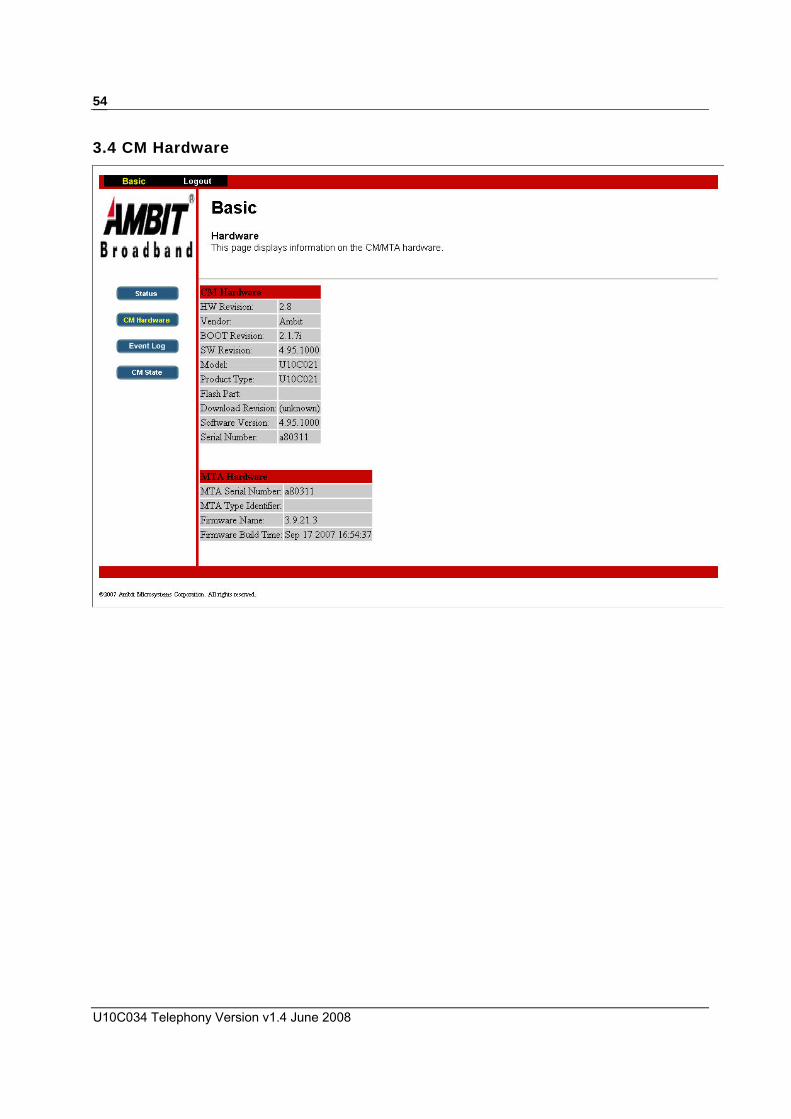
U10C034 Telephony Version v1.4 June 2008
54
3.4 CM Hardware

55
3.5 Event Log

U10C034 Telephony Version v1.4 June 2008
56
3.6 CM State

57
3.7 Web User Interface Advanced Page The advanced web page only available for ‘admin’ account access to web interface The advanced web page was protected by ‘Password of the Day’(POTD), the POTD was changed every day, need to use a utility to generate POTD, Chapter 5 will show you how to generate the POTD.
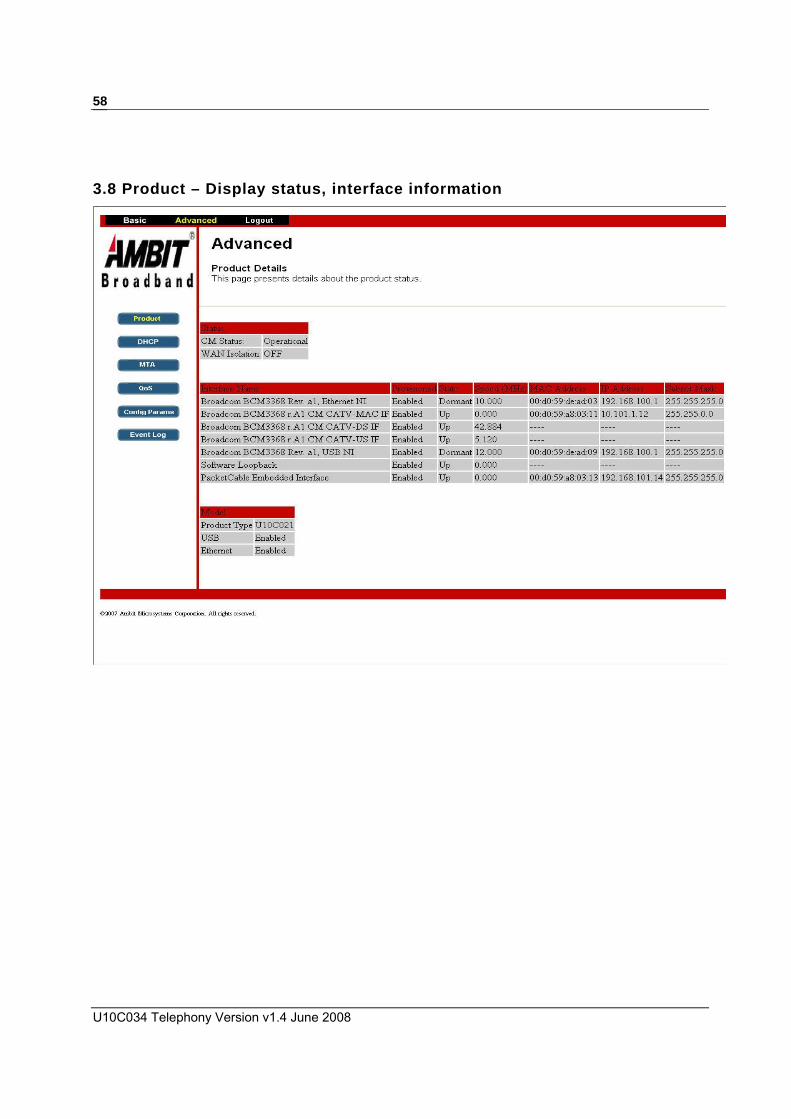
U10C034 Telephony Version v1.4 June 2008
58
3.8 Product – Display status, interface information

59
3.9 DHCP – Display CM and MTA DHCP information

U10C034 Telephony Version v1.4 June 2008
60
3.10 MTA – Display some detail MTA parameters

61
3.11 QoS – Display service flow information
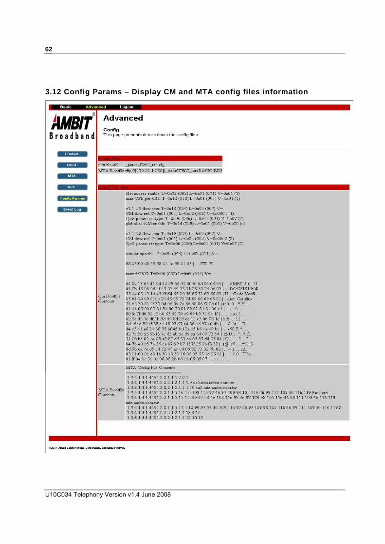
U10C034 Telephony Version v1.4 June 2008
62
3.12 Config Params – Display CM and MTA config files information

63
3.13 Event Log – Display CM and MTA event logs

U10C034 Telephony Version v1.4 June 2008
64
3.14 Using the Password of the day Tool The POTD tool, POTD.exe, is available on the TS5.0 firmware CD. It is a Windows application, with the following software requirements: Windows 98, Windows NT, Windows 2000 or Windows XP Microsoft.Net plus Service Pack 2. The installer provides this package if required. Internet Explorer version 5.1 or newer. The newest version of Internet Explorer is available at Microsoft web site (http://www.microsoft.com/windows/ie/default.asp) The POTD tool can create a single password. For added security, you can also define a seed value used to generate the passwords.
3.15 Using the POTD tool This procedure provides instructions for using the POTD.exe tool. Before performing any of the tasks in this procedure, please run the application POTD.exe from windows DOS command line.
Generating the Password Follow these steps to generate a single password. 1. Execute the POTD.exe tool, if you have not done so already. 2. POTD tool can use a default seed to generate the password of the day. For added security,
you can create a different seed to change the password pattern. You can input seed in the Seed field. It’s up to 40 characters. If none of seed is input, the default seed will be used.
3. Set the ‘Date’ field.
4. Click ‘Generate’ button, the password will appear in the Password text box. You can
select and copy the password as needed. Changing the Seed Using the following MIB can change the default seed, to read the value will always return
empty OID: 1.3.6.1.4.1.4413.2.2.2.1.1.3.7.0 Type: OCTET STRING
The maximum length of the seed is 40bytes The default seed value is TghksDfkeorQdkfhnxzlaoeutrb18skd7jDds7Wi

65
4 SSH CLI
Ambit EMTA can be configured via SSH (no Telnet). A SSH client utility is needed for connecting to SSH server embedded in EMTA. Through SSH, EMTA’s configurations like cable modem settings, battery settings, etc all can be changed. The SSH server can only be accessed from CM’s IP address. It cannot be accessed by MTA and local IP address. SSH is only allowed to login by “admin”, “user” account is not allowed. The login password changed every day, so a POTD utility is needed to general correct password. Regarding the usage guideline of POTD, please refer to chapter 3.15.
U10C034 Telephony Version v1.4 June 2008
66
4.1 Battery Battery relative information can be showed and settings can be changed. It has the following
commands. set Set the timer to disable Ethernet or USB interface when loosing A/C. show Show all battery relative settings.
4.2 CM Provides the commands to show Cable Modem relative information and control downstream
channel, upstream channel, log display ON or off and firewall.
gotoDownstream Changes to specific downstream channel. gotoUpstream Changes to specific upstream channel log Enable or disable message logging. ping Pings to the specific IP address from CM IP stack. set Enable or disable CM mini firewall. show Show various information including: ARP table BPI status CM certificates DOCSIS classifiers CM config file name and contents CPE info/table Downstream status and signal quality DSx message history CM event log

67
DOCSIS service flows CM IP and DHCP options Routing table Time of day Upstream descriptors Upstream status
HW Counters Hal debug
4.3 EMTA Provides the commands to show and control EMTA relative information and settings. diag Runs various MTA diagnostics including: Reset a line Run line diagnostics and report results Enable analog loopback on a line Sends HD and HU NCS message to the call agent Simulates line off hook for a short interval of time Triggers a Log Event in the MTA, sending a SysLog or SNMP Trap if necessary Force one of the processor to assert and crash
Prints voice statistics at specified intervals log Enable or disable message logging. ping Pings to the specific IP address from EMTA IP stack. reset Reset the mta now set Many MTA parameters could be configured like: Requested DHCP option number [122|177] Inhibit SW download during call RFC2833 DTMF Tone Relay T.38 Fax Relay Enable the EMTA IP stack firewall Jitter buffer type and parameters Line voltage maintenance on reboot, sync loss and CMS down Boosted loop current Inclusion of MTA in CM max CPE limit
Set up PHS enabled and suppressed fields

U10C034 Telephony Version v1.4 June 2008
68
Set depth of the NCS message quarantine buffer Ring with DC offset RTP port number for MTA Root certificate for use during provisioning Enable the logging of extended Events Enhanced tone detection control on an endpoint Reset (CMS / Prov) Kerberos tickets Set Ring Waveform shape to sinusoidal(1) or trapezoidal(2) Enable or Disable DQoS-lite for the EMTA
show Show various information including: Call history MTA certificates Supported codec list MTA config file content
Kerberos ticket and state MTA IP address and DHCP options for the current lease Line states NCS message history Shows PHS settings for voice calls Provisioning state RTP info Security association info State of any NCS connections List of supported countries and active country Processor debug information IPC Statistics for a channel FAXR Statistics for a channel
4.4 ENET Provides the command to show the debug state of the Ethernet interface. show Shows debug state of Ethernet RX/TX DMA rings.
4.5 PINGHELPER Provides all ping relative commands.

69
all_sizes Configures the settings for sweeping all packet sizes from 64-1518. end_size Sets or shows the size of the largest ping packet that will be sent. hs_nowait Configures the settings for doing high-speed pings, without waiting for the reply. hs_wait Configures the settings for doing high-speed pings (infinite), waiting for the reply. ip_address Sets or shows the IP address of the device to be pinged. ip_stack Sets the IP stack number that the pings should be sent to. ip_sweep Pings all IP addresses on the specified subnet. number_of_pings Sets or shows the number of pings to be sent. ping Begins pinging the specified IP address, using the current settings. restore_defaults Restores all of the options to their default values. show_settings Displays the current ping settings. start_size Sets or shows the size of the first ping packet that will be sent. stats Displays the ping statistics summary from the last set of pings. step_amount Sets or shows the amount that the packet size will be increased for each packet. stop Stops the ping that is currently running.

U10C034 Telephony Version v1.4 June 2008
70
time_between_pings Sets or shows the number of milliseconds that the ping helper will wait before sending the next ping. verbosity Sets the level of information that will be displayed while pinging. verify_enable Enables/disables verification of ping replies. wait_enable Enables/disables waiting for ping replies. wait_time Sets or shows the number of milliseconds that the ping helper will wait for a ping response before continuing.
4.6 SYSTEM The system commands have two major functions. First one is the log packets function. Packets
are logged when receiving from the specific interfaces sending to the specific interfaces. Another function is to show all system relative information like flash, memory…, etc.
log_packets This enables/disables logging for packets received from the specified interfaces and being sent to the specified interfaces. show Show system information including:
flash memory fwd_learning_tbl blocks

71
5 Battery Operation
This Chapter defines how to battery mechanism working in different temperature. According to current design, the best temperature range for battery is within 0 degree C and 45 degree C. If room temperature is out of this range, charger or discharger might be disabled. You can refer the following description to understand its details. Modem will enter power saving mode (CPE interface is disabled and PWR LED flashing) if high temperature ( > 55 degree C) occurs. Battery charger will be disabled in this case, too.

U10C034 Telephony Version v1.4 June 2008
72
5.1 Battery operation in different termperature When temperature is over 45 degrees(C) or under 0 degrees(C), the battery charge will be disabled, battChargerState will be 2 (sleep), and the modem is still in normal operation mode. When temperature is over 55 degrees(C), the battery charge remains disabled, battChargerState will be 2 (sleep), and the modem will go into power save mode. After temperature is over 60 degrees(C) or under -10 degrees(C),the battery charge & discharge both will be disabled. If then it goes down below 57 degrees(C), the battery discharge will be re-enabled (hysteresis mechanism), and the modem remains in power save mode. If it goes down below 42 degrees(C), the battery charge will be re-enabled. If battery is fully charged, the battChargerStat value stays in 2 (sleep). For more detailed description please refer section 5.2 and 5.3.
5.2 Adaptor Mode The figure show you how battery/LED works in different room temperature if AC adaptor is existing.
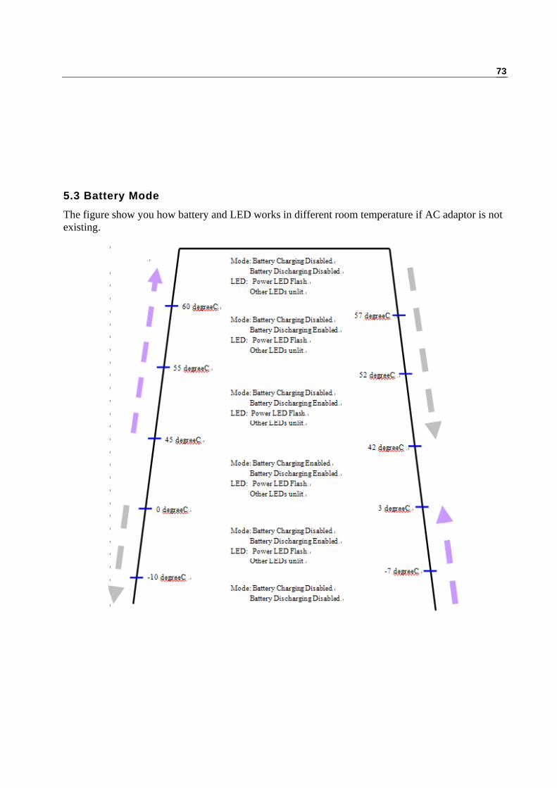
73
5.3 Battery Mode The figure show you how battery and LED works in different room temperature if AC adaptor is not existing.

U10C034 Telephony Version v1.4 June 2008
74
5.4 Battery Trap The following traps will be sent to SNMP management if battery status is changed. MSO operators can understand current battery and modem situation when trap is received.. PS: NMAccess must be configured for SNMP trap sent. Alarm Name OID Description
upsAlarmGeneralFault 1.3.6.1.2.1.33.1.6.3.18.0 A general fault in the UPS has been
detected.
upsAlarmOnBattery 1.3.6.1.2.1.33.1.6.3.2.0 The UPS is drawing power from the
batteries.
upsAlarmLowBattery 1.3.6.1.2.1.33.1.6.3.3.0 The remaining battery run-time is less than
or equal to upsConfigLowBattTime.
upsAlarmDepletedBattery 1.3.6.1.2.1.33.1.6.3.4.0
The UPS will be unable to sustain the
present load when and if the utility power
is lost.
upsAlarmBatteryBad 1.3.6.1.2.1.33.1.6.3.1.0 One or more batteries have been
determined to require replacement.
upsAlarmShutdownImminent 1.3.6.1.2.1.33.1.6.3.23.0
The UPS will turn off power to the load in
less than 5 seconds; this may be either a
timed shutdown or a low battery
shutdown.
upsAlarmShutdownPending 1.3.6.1.2.1.33.1.6.3.22.0 A upsShutdownAfterDelay countdown is
underway.
upsAlarmUpsOutputOff 1.3.6.1.2.1.33.1.6.3.14.0 The output of the UPS is in the off state.
upsAlarmOutputOffAsRequested 1.3.6.1.2.1.33.1.6.3.11.0 The UPS has shutdown as requested, i.e.,
the output is off.
upsAlarmAwaitingPower 1.3.6.1.2.1.33.1.6.3.21.0 The UPS output is off and the UPS is
awaiting the return of input power.
bcmAlarmTempBadChargeSuspended 1.3.6.1.4.1.4413.2.2.2.1.10.4.2.0
The temperature of the device has exceeded
operational limits for safe battery charging,
and battery charging has been suspended.
bcmAlarmTempBadPowerReduced 1.3.6.1.4.1.4413.2.2.2.1.10.4.3.0
The temperature of the device has exceeded
operational limits, and the device has been
placed in low power mode in an to attempt
to reduce heat production.

75
bcmAlarmLowBatteryCharge 1.3.6.1.4.1.4413.2.2.2.1.10.4.1.0
The value of
upsEstimatedChargeRemaining is less than
or equal to the value of
battChargerLowChargeThreshold.
bcmAlarmBatteryMissing 1.3.6.1.4.1.4413.2.2.2.1.10.4.4.0
There are no batteries installed in the
device and the device will not be capable of
sustaining power in the event of utility
power loss.

U10C034 Telephony Version v1.4 June 2008
76
6 Trobule Shooting
This Chapter defines how to run trouble shooting procedure in U10C034 product.

77
6.1 Ambit EMTA supports following troubleshooting interface: SNMP MIB Interface
Using an SNMP-based network management system, you can read cable modem and MTA MIB to determine the status of EMTA.
LED Interface Each EMTA has a group of LEDs on its front panel. These LEDs are especially useful to track the configuration and registration process of the EMTA attempting to connect to the network.
Web-based Interface The EMTA includes a simple HTTP (web) server that provides several pages showing status and other information about the EMTA. You can access the web pages from either the subscriber (CPE) side or network (cable) side.
6.2 Using MIB for Troubleshooting Using an SNMP manager to read cable modem and MTA MIB variables can be useful for troubleshooting. The following are MIBs that can provide information to resolve many common issues.
Cable Device MIB The following MIB are part of the DOCS-CABLE-DEVICE-MIB, they provide status and control for the cable modem as a system (as opposed to interface MIBs, which operate on a single interface).
DocsDevServer MIB These variables display and control the status of communications with network servers (CMTS, DHCP server, and so forth).
docsDevServerBootState If operational(1), the cable modem has completed loading and processing of configuration parameters and the CMTS has completed the registration exchange. If disabled(2), then the cable modem was administratively disabled, possibly by being refused network access in the configuration file. If waitingForDhcpOffer(3), then a DHCP Discover has been transmitted and no offer has yet been received. If waitingForDhcpResponse(4), then a DHCP Request has been transmitted and no response has yet been received. If waitingForTimeServer(5), then a Time request has been transmitted and no response has yet been received. If waitingForTftp(6), then a request to the TFTP parameter server has been made and no response received. If refusedByCmts(7), then the Registration Request/Response exchange with the CMTS failed. If forwardingDenied(8), then the registration process completed, but the network access option in the received configuration file prohibits forwarding.
docsDevServerDhcp

U10C034 Telephony Version v1.4 June 2008
78
The IP address of the DHCP server that assigned an IP address to this cable modem. Returns 0.0.0.0 if DHCP was not used for IP address assignment.
docsDevServerTime The IP address of the Time server (RFC-868). Returns 0.0.0.0 if the time server IP address is unknown.
docsDevServerTftp The IP address of the TFTP server responsible for downloading provisioning and configuration parameters to this cable modem. Returns 0.0.0.0 if the TFTP server address is unknown.
docsDevServerConfig File The name of the configuration file read from the TFTP server. Returns an empty string if the configuration file name is unknown.
DocsDevEvent MIB These variables control event reporting, and describe network or device events that may be of interest in fault isolation and troubleshooting. Multiple sequential identical events are represented by incrementing docsDevEv-Counts and setting docsDevEvLastTime to the current time rather than creating multiple rows. Entries are created with the first occurrence of an event. Use docsDevEvControl to clear the table. Individual events can not be deleted.
docsDevEvControl Set this object to resetLog(1) to erase the event log. Set this object to useDefaultReporting(2) to restore all event priorities to their factory-default reporting.Reading this object always returns useDefaultReporting(2).
docsDevEvSyslog The IP address of the Syslog server. If 0.0.0.0, Syslog transmission is inhibited.
docsDevEvIndex Provides relative ordering of the objects in the event log. This object always increases except when the log is reset via docsDevEvControl, the cable modem reboots and does not keep the event log in non-volatile storage, or the value reaches 2ˆ31. The next entry for all the above cases is 1.
docsDevEvFirstTime The time that a particular event log entry was created. Multiple identical events can be reported using a single entry.
docsDevEvLastTime If multiple events are reported using the same entry, the time that the last event for this entry occurred. Otherwise this should have the same value as docsDevEvFirstTime.
docsDevEvCounts The number of consecutive event instances reported by this entry. This starts at 1 with the creation of this entry and increments by 1 for each subsequent duplicate event.
docsDevEvLevel The priority level of this event. These are ordered from most serious (emergency) to least serious (debug).
docsDevEvId For a particular device, uniquely identifies the type of event that is reported by this entry.
docsDevEvText A text string describing the event, including all relevant contexts.
PacketCable Event MIB The following variables are part of the PKTC-EVENT-MIB. They supply the basic management objects for reporting events.
pktcDevEventControl MIB

79
The following variables control PacketCable event reporting pktcDevEvControl
Defines actions related to the event log configuration. Settings are: resetLog(1)—empties the event log (deletes all data). setDefaults(2)—restores all event priorities to factory default reporting parameters. useConfigured(3)—reloads previously configured reporting parameters.
pktcDevEvControlState The state of the device as modified by pktcDevEvControl. The possible states are as follows: logReset(1) defaultSet(2) useConfigured(3) processing(4)—a state change is underway.
pktcDevEvSyslogAddressType The type of Internet address of the Syslog server.
pktcDevEvSyslogAddress The IP address of the Syslog server. Use 0.0.0.0 to specify no Syslog server. Using an FQDN is allowed but not recommended.
pktcDevEvSyslogUdpPort The UDP port number that the MTA uses to send requests to the Syslog server.
pktcDevEventThrottle MIB The following variables control event throttling.
pktcDevEvThrottleAdminStatus Controls the transmission of traps and Syslog messages with respect to the trap pacing threshold. throttlingInhibited(1)—transmit traps and Syslog messages without regard to the threshold settings. (default) dynamicThresholding(2)—suppresses trap transmission and Syslog messages to be suppressed if the number of traps would otherwise exceed the threshold. manualThresholding(3)—trap transmissions cease at the threshold, and do not resume until directed to do so. eventsInhibited(4)—suppresses all trap transmission and Syslog messages. A single event is always treated as a single event for threshold counting. That is, an event causing both a trap and a Syslog message is still treated as a single event. Writing to this object resets the thresholding state.
pktcDevEvThrottleInhibited If true(1), trap/inform and Syslog transmission is currently inhibited due to: thresholds; the current setting of pktcDevEvThrottleAdminStatus; or no Syslog (pktcDevEvSyslogAddress) or trap/inform (pktcMtaDevSnmpEntity) destinations have been set.
pktcDevEvThrottleThreshold Sets the number of trap/Syslog events per pktcDevEvThrottleInterval to be transmitted before throttling. A single event is always treated as a single event for Threshold counting. That is, an event causing both a trap/inform and a Syslog message is still treated as a single event. At initial startup, this object returns 2.
pktcDevEvThrottleInterval The interval over which the throttle threshold applies. At initial startup, this object has a value of 1.
pktcDevEvProgrammableTable This table is part of the pktcDevEventConfig MIB. It configures the reporting of the various programmable events. This table allows control of the reporting of event classes. For each event priority, a combination of logging and reporting mechanisms may be chosen. The mapping of event types to

U10C034 Telephony Version v1.4 June 2008
80
priorities is vendor-dependent. Vendors may also choose to allow the user to control that mapping through proprietary means.
pktcDevEvProgrammableId ID for a specific programmable event to which the priority and display string are matched. These Event Ids are vendor specific or in the case of PacketCable events defined in pkt-tr-memevent-id--v01-001128.
pktcDevEvProgrammableEnterprise Provides the IANA enterprise number of the device manufacturer for proprietary events, and the CableLabs IANA enterprise number for PacketCable specified events.
pktcDevEvProgrammableLevel The priority level controlled by this entry. These are ordered from most (critical) to least (information) critical. Each event has a particular priority level associated with it. The levels are described as: critical(1)—A service-affecting condition that requires immediate corrective action. major(2)—A service-affecting condition that requires urgent corrective action. minor(3)—A non-service-affecting fault condition which warrants corrective action in order to avoid a more serious fault. warning(4)—A potential or impending condition which can lead to a fault; diagnostic action is suggested. information(5)—Normal event meant to convey information.
pktcDevEvProgrammableReporting Defines the action to be taken on occurrence of this event class. Implementations may not necessarily support all options for all event classes, but at minimum must allow traps and Syslog to be disabled. The value is a collection of bits: local(0) bit—log to the internal log raps(1) bit—generate a trap syslog(2) bit—send a Syslog message (assuming the Syslog address is set) inform(3) bit—generate an inform none(4) bit—this event is not generated
pktcDevEvProgrammableText A programmable event display string providing a human-readable description of the event.
pktcDevEvFixedTable MIB This table is part of the pktcDevEventConfig MIB. It configures the reporting of the various fixed events (including level, and report type) and event classes. For each event priority, a combination of logging and reporting mechanisms may be chosen. The mapping of event types to priorities is vendor-dependent.
pktcDevEvFixedId ID for a specific fixed event to which the priority and display string are matched. These Event Ids are vendor specific or in the case of PacketCable events defined in pkt-tr-memevent-id-v01-001128.
PktcDevEvFixedEnterprise Provides the IANA enterprise number of the device manufacturer. For proprietary events, and the CableLabs IANA enterprise number for PacketCable specified events.
pktcDevEvFixedLevel The priority level that is controlled by this entry. These are ordered from most (critical) to least (information) critical. Each event has a particular priority level associated with it (as defined by the vendor). The levels are: critical(1)—A service-affecting condition that requires immediate corrective action. major(2)—A service-affecting condition that requires urgent corrective action.

81
minor(3)—A non-service-affecting fault condition which warrants corrective action in order to avoid more serious fault. warning(4)—A potential or impending condition which can lead to a fault; diagnostic action is suggested. information(5)—Normal event meant to convey information.
pktcDevEvFixedReporting Defines the action to be taken on occurrence of this event class. Implementations may not necessarily support all options for all event classes, but at minimum must allow traps and Syslog to be disabled. The value is a collection of bits: local(0) bit—log to the internal log traps(1) bit—generate a trap syslog(2) bit—send a Syslog message (assuming the Syslog address is set) inform(3) bit—generate an inform none(4) bit—this event is not generated.
pktcDevEvFixedText A fixed event display string providing a human-readable description of the event.
pktcDevEventLocal MIB This MIB provides the pktcDevEvent table, that contains a log of network and device events that may be of interest in fault isolation and troubleshooting.
pktcDevEvIndex Provides relative ordering of the objects in the event log. This object will always increase except when 1. The log is reset via pktcDevEvControl 2. The device reboots and does not implement non-volatile storage for this log 3. It reaches the value 2ˆ31. The next entry for all the above cases is 1. This also serves as a indicator of event sequence.
PktcDevEvTime Provides a human-readable description of the time at which the event occurred.
pktcDevEvLevel The priority level of this event as defined by the vendor. These are ordered from most serious (critical) to least serious (debug).
pktcDevEvEnterprise Provides the IANA enterprise number of the device manufacturer for proprietary events, and the CableLabs IANA enterprise number for PacketCable specified events.
pktcDevEvId ID for a specific event to which the priority and display string are matched. These Event Ids are vendor specific or in the case of PacketCable events defined in pkt-tr-memevent-id-v01-001128.
pktcDevEvText Provides a human-readable description of the event, including all relevant context (interface numbers, etc.).
pktcDevEvMacAddress Provides the MAC address of the device generating the event.
pktcDevEvEndpointName This is the endpoint identifier followed by the FQDN/IP Address of the device. This is in the form—AALN/X:FQDN/IP Address. If the event is not specific to an endpoint, then the contents is just the FQDN/IP address.
MTA MIB

U10C034 Telephony Version v1.4 June 2008
82
This MIB module supplies the basic management objects for the MTA Device. The MTA MIB only supports a single provisioning server.
pktcMtaDevResetNow Setting this object to true(1) causes the eMTA to reset. Reading this object always returns false(2). When set to true, the following actions occur: 1. All connections (if present) are flushed locally. 2. All current actions such as ringing immediately terminate. 3. Requests for notifications such as notification based on digit map recognition are flushed. 4. All endpoints are disabled in resetting state. 5. The provisioning flow is started at step MTA-1 of the provisioning process.
pktcMtaDevMacAddress The MTA MAC address for this device.
pktcMtaDevFQDN The Fully Qualified Domain Name for this MTA.
pktcMtaDevEndPntCount The physical end points for this MTA.
pktcMtaDevEnabled The MTA Administrative Status of this device, where true(1) means the voice feature is enabled and false(2) indicates that it is disabled.
pktcMtaDevProvisioningState The completion state of the initialization process, sent as part of the final INFORM (step MTA-25 of the provisioning process). The states are: pass(1)—the configuration file could be parsed successfully and the MTA is able to reflect the same in its MIB. inProgress(2)—the configuration file is currently being processed. failConfigFileError(3)—the configuration file was in error due to incorrect values in the mandatory parameters. passWithWarnings(4)—the configuration file had proper values for all the mandatory parameters but had errors in the optional parameters (including any vendor specific OIDs which are incorrect or not known to the MTA). passWithIncompleteParsing(5)—the configuration file is proper, but the MTA cannot reflect the same in its MIB (for example, too many entries leading to memory exhaustion). failureInternalError(6)—the configuration file cannot be parsed due to an internal error. failOtherReason(7)—the MTA cannot accept the configuration file.
pktcMtaDevHttpAccess Indicates whether HTTP file access is supported for MTA configuration file transfer.
pktcMtaDevProvisioningTimer Enables setting the duration of the provisioning timeout timer. The timer covers the provisioning sequence from step MTA-1 to step MTA-23. The value is in minutes and setting the timer to 0 disables this timer. The default value for the timer is 10.
pktcMtaDevProvisioningCounter This object is the count of the number of times the provisioning cycle has looped through step MTA-1 since the last reboot.
pktcMtaDevErrorOidsTable If pktcMtaDevProvisioningState is reported with anything other than a pass(1), then this table is populated with the necessary information, each pertaining to observations of the configuration file. Even if different parameters share the same error (for example, all Realm Names are invalid), all recognized errors must be reported as different instances. This contains the necessary information an MTA must attempt to provide in case the configuration file is not parsed and/or accepted in its entirety.

83
pktcMtaDevErrorOidIndex This is the index to pktcMtaDevErrorOidsEntry. This is an integer value and will start from the value 1 and be incremented for each error encountered in the configuration file. The indices need not necessarily reflect the order of error occurrences in the configuration file.
pktcMtaDevErrorOid This is the OID associated with the particular error. If the error was not due to an identifiable OID, then this can be populated with impartial identifiers, in hexadecimal or numeric format.
pktcMtaDevErrorGiven If the error was due to the value associated with the corresponding pktcMtaDevErrorOid, then this contains the value of the OID as interpreted by the MTA in the configuration file provided. If the error was not due to the value of an OID this must be set to an empty string. This is provided to eliminate errors due to misrepresentation or misinterpretation of data.
pktcMtaDevErrorReason This indicates the reason for the error, as per the MTA’s interpretation, in human readable form. For example: VALUE NOT IN RANGE VALUE DOES NOT MATCH TYPE UNSUPPORTED VALUE LAST 4 BITS MUST BE SET TO ZERO OUT OF MEMORY—CANNOT STORE This MAY also contain vendor specific errors for vendor specific OIDs and any proprietary error codes/messages which can help diagnose errors better, in a manner the vendor deems fit.
pktcMtaDevConfigFile The URL of the TFTP/HTTP file for downloading provisioning and configuration parameters to this device. Returns NULL if the server address is unknown. Supports both TFTP and HTTP.
pktcMtaDevSnmpEntity The FQDN of the SNMP V3 entity of the Provisioning Server to which the MTA has to communicate in order to receive the access method, location and the name of the Configuration file during MTA provisioning. This would also be the entity which caters to the Endpoint provisioning needs of the MTA and is the destination for all provisioning informs. It may be also used for post-provisioning SNMP operations.
pktcMtaDevProvState operational(1)—the device has completed loading and processing of initialization parameters. waitingForSnmpSetInfo(2)—the device is waiting on configuration file download access information. waitingForTftpAddrResponse(3)—a DNS request has been transmitted and no reply has yet been received. waitingForConfigFile(4)—a TFTP request has been transmitted and no reply has yet been received or a download is in progress.
pktcMtaDevServerDhcp1 The IP address of the primary DHCP server which would cater to the MTA during its provisioning. Contains 255.255.255.255 if there was no preference given with respect to the DHCP servers for MTA provisioning.
pktcMtaDevServerDhcp2 The IP address of the Secondary DHCP server which could cater to the MTA during its provisioning. Contains 0.0.0.0 if there is no specific secondary DHCP server to be considered during MTA provisioning.
pktcMtaDevTimeServer IP address of the Time Server from which to obtain the time. Contains 0.0.0.0 if the Time Protocol is not used for time synchronization.

U10C034 Telephony Version v1.4 June 2008
84
pktcMtaDevRealmOrgName The value of the X.500 organization name attribute in the subject name of the Service provider certificate.
pktcMtaDevRealmUnsolicitedKeyMaxTimeout This timeout applies only when the MTA initiated key management. The maximum timeout is the value which may not be exceeded in the exponential backoff algorithm. DHCP Option 122 sub-option 4 overrides this value, if provided. The default is 30.
pktcMtaDevRealmUnsolicitedKeyNomTimeout Defines the starting value of the timeout for the AS-REQ/REP Backoff and Retry mechanism with exponential timeout. If provided, DHCP Option 122 Sub-option 4 overrides this value. The default is 10000.
pktcMtaDevRealmUnsolicitedKeyMaxRetries The maximum number of retries before the MTA gives up attempting to establish a security association. DHCP Option 122 suboption 4 overrides this value, if provided.
pktcMtaDevRealmStatus Contains the Row Status associated with the pktcMtaDevRealmTable.
pktcMtaDevCmsTable Shows the IPSec key management policy relating to a particular CMS. The table is indexed with pktcMtaDevCmsFQDN. Contains per CMS key management policy.
pktcMtaDevCmsFqdn The fully qualified domain name of the CMS. This is the index into the pktcMtaDevCmsTable. When used as an index, the upper case ASCII representation of the associated CMS FQDN MUST be used by both the Manager (SNMPv3 Entity) and the MTA.
pktcMtaDevCmsMaxClockSkew The maximum allowable clock skew between the MTA and CMS.
pktcMtaDevCmsSolicitedKeyTimeout This timeout applies only when the CMS initiated key management (with a Wake Up or Rekey message). It is the period during which the MTA will save a nonce (inside the sequence number field) from the sent out AP Request and wait for the matching AP Reply from the CMS.
pktcMtaDevCmsUnsolicitedKeyMaxTimeout This timeout applies only when the MTA initiated key management. The maximum timeout is the value which may not be exceeded in the exponential backoff algorithm.
pktcMtaDevCmsUnsolicitedKeyNomTimeout Defines the starting value of the timeout for the AP-REQ/REP Backoff and Retry mechanism with exponential timeout for CMS.
pktcMtaDevCmsUnsolicitedKeyMaxRetries The maximum number of retries before the MTA gives up attempting to establish a security association.
pktcMtaDevCmsStatus Contains the Row Status associated with the pktcMtaDevCmsTable.
pktcMtaDevCmsIpsecCtrl If true(1), IPSEC and IPSEC Key Management MUST be used to communicate with the CMS.

85
If false(2), IPSEC Signaling Security is disabled for both the IPSEC Key Management and IPSEC protocol (for the specific CMS).
Signaling MIB This MIB module supplies the basic management object for the PacketCable Signaling protocols. This version of the MIB includes common signaling and Network Call Signaling (NCS) related signaling objects.
PktcCodecType Textual Convention defines various types of CODECs that MAY be supported. The list of CODECs MUST be consistent with the CODEC specification PKT-SP-CODEC-I05-040113.
PktcRingCadence Represents a ring cadence in bit string format. The ring cadence representation starts with the first 1 in the pattern (the leading 0s in the MSB are padding and are to be ignored). Each bit represents 100ms of tone; 1 is tone, 0 is no tone. 60 bits are used for cadence representation, the least significant 4 bits represent repeatable characteristics. 0000 means repeatable, and 1000 means non repeatable. As an example, the hex representation of a ring cadence of 0.5 seconds on; 4 seconds off; repeatable would be: 0x1 F0000000000.
PktcSigType The various types of signaling that may be supported. ncs —Network Call Signaling; a derivation of MGCP (Media Gateway Control Protocol) version 1.0. dcs —Distributed Call Signaling; a derivation of SIP (Session Initiation Protocol) RFC 3261.
pktcSigDevCodecTable This table describes the MTA supported CODEC types.
pktcSigDevCodecIndex The index value which uniquely identifies an entry in the pktcSigDevCodecTable.
pktcSigDevCodecType A CODEC type supported by this MTA.
pktcSigDevCodecMax The maximum number of simultaneous sessions of the specific CODEC that the MTA can support.
pktcSigDefNcsReceiveUdpPort Contains the MTA User Datagram Protocol (UDP) receive port that is being used for NCS call signaling. This object should only be changed by the configuration file, default value is 2427.
pktcSigNcsServiceFlowState Contains a status value of the Call Signaling Service Flow. not-active indicates that the NCS SF is not being used, and has not tried to be created. active indicates that the NCS SF is in use. error indicates that the NCS SF creation resulted in an error and the best effort channel is used for NCS Signaling
pktcNcsEndPntConfigCallAgentId Contains a string indicating the call agent name (for example, [email protected]). The call agent name after the character @ MUST be a fully qualified domain name and MUST have a corre-sponding pktcMtaDevCmsFqdn entry in the pktcMtaDevCmsTable.
Troubleshooting

U10C034 Telephony Version v1.4 June 2008
86
pktcNcsEndPntConfigCallAgentUdpPort Contains the call agent User Datagram Protocol (UDP) receive port that is being used for this instance of call signaling, i.e. the default port on which the call agent receives NCS signaling from the gateway. The default port number is 2727.
pktcNcsEndPntConfigStatus Contains the Row Status associated with the pktsNcsEndPntTable.
pktcNcsEndPntConfigCallWaitingMaxRep Contains the maximum number of repetitions of the call waiting tone that the MTA plays from a single CMS request. A value of zero (0) can be used if the CMS is to control the repetitions of the call waiting tone.
pktcNcsEndPntConfigCallWaitingDelay Contains the delay between repetitions of the call waiting tone that the MTA plays from a single CMS request.
pktcNcsEndPntStatusCallIpAddress Contains the IP address of the CMS currently being used for this endpoint. This IP address creates the appropriate security association.
pktcNcsEndPntStatusError Contains the error status for this interface. The operational state indicates that all operations necessary to put the line in service have occurred. The noSecurityAssociation status indicates that no security association yet exists for this endpoint. The disconnected status indicates one of the following:
1. If pktcMtaDevCmsIpsecCtrl is disabled, then no security association is involved with this endpoint; the NCS signaling firmware is in the process of establishing the NCS signaling link through an RSIP exchange. 2. Otherwise, pktcMtaDevCmsIpsecCtrl is enabled, the security association has been established and the NCS signaling firmware is in the process of establishing the NCS signaling link through an RSIP exchange.
6.3 LED Verification Installer can check the LED pattern table to know which state modem kept. If modem has registered CMTS, PWR, DS, US and Online must be lit. If Tel1 is always flash and Tel2 is always unlit, it means that MTA can not receive a valid offer from DHCP server. If Tel1 is always unlit and Tel2 is always flash, it means that MTA can not download configuration file. If Tel1 and Tel2 are flash, it means that the MTA does not send RSIP to CMS yet (waiting for MWD timeout).

87
6.4 Troubleshooting the USB driver Installation Q: None of the LEDs is on when I power on the LAN Cable Modem. A: Check the connection between the power adapter and the cable modem. Power off the Cable
Modem and wait for 5 Seconds and power on the modem again. If the problem still exists, you may have a hardware problem.
Q: All of the LEDs on the front of my modem look correct, but I cannot access the Internet. A:
• If the POWER, DS, US and Online are solidly lit, the cable modem is working properly. Use the following procedures to verify connectivity between the PC and the cable modem: 1. Launch Your PC’ Internet Browser (e.g., Netscape, IE) 2. Enter http://192.168.100.1 into your browser. This URL connects you directly to the
web server within your cable modem. A successful connection indicates that the PC is able to communicate with the cable modem. The next step is to enter a public URL to ensure connectivity between the cable modem and your cable service provider. If this fails, please contact your cable service provider for further assistance.
• Try restarting the computer so that it could re-establish a connection with the cable modem. • Power cycle the cable modem by removing the power adapter from the electrical outlet and
plugging it back in. Wait several minutes for the cable modem to re-establish communications with your cable service provider.
• Remove any other USB devices from your computer and connect the cable modem’ USB cable directly to the USB port on your computer.
• If you are using a cable splitter, try removing the splitter and connect the cable modem directly to the cable wall outlet. Wait several minutes for the cable modem to re-establish communications with your cable service provider.
• Your USB or coaxial cable may be damaged. Try using another cable. • If none of these suggestions work, contact your cable service provider for further assistance.
Troubleshooting the Ethernet Installation Q: None of the LEDs are on when I power on the Cable Modem. A: Check the connection between the power adapter and the cable modem. Power off the Cable
Modem and wait for 5 seconds and power on the modem again. If the problem still exists, you may have a hardware problem.
Q: The Link LED on my cable modem is not lit. A:
• Try restarting the computer so that is could re-establish a connection with the cable modem. • Check for a resource conflict (Windows users only). To do this:
1. Right-click on the My Computer icon on your desktop and choose Properties. 2. Click the Device Manager tab and look for a yellow exclamation point or red X over the
NIC in the Network Adapters field. If you see either one, you may have an IRQ
U10C034 Telephony Version v1.4 June 2008
88
conflict. Refer to the manufacturer’ documentation or you cable service provider for further assistance.
• Verify that TCP/IP is the default protocol for your network interface card (NIC) • Power cycle the cable modem by removing the power adapter from the electrical outlet and
plugging it back in. Wait several minutes for the cable modem to re-establish communications with your cable service provider.
• Your Ethernet cable may be damaged. Try another cable.
Q: All of the LEDs on the front of my modem look correct, but I cannot access the Internet. A:
• If the POWER, DS, US, Online and Link LEDs are solidly lit, the cable modem is working properly. Try restarting the computer so that is could re-establish a connection with the cable modem.
• Power cycle the cable modem by removing the power adapter from the electrical outlet and plugging it back in. Wait several minutes for the cable modem to re-establish communications with your cable service provider.
• If your PC is connected to a hub or gateway, try connecting the PC directly into the cable modem.
• If you are using a cable splitter, try removing the splitter and connect the cable modem directly to the cable wall outlet. Wait several minutes for the cable modem to re-establish communications with your cable service provider.
• Your Ethernet or coaxial cable may be damaged. Try using another cable. • If none of these suggestions work, contact your cable service provider for further assistance.
6.5 Digital Loopback Support The model can support digital loopback support by two connection MGCP/NCS modes, "network loopback," and “network continuity”. If the mode is set to "network loopback," the audio signals received from the connection will be echoed back on the same connection. The "network loopback" mode SHOULD simply operate as an RTP packet reflector. The "network continuity test" mode is used for continuity checking across the IP network. An endpoint-type specific signal is sent to the endpoints over the IP network, and the endpoint is then supposed to echo the signal over the IP network after passing it through the gateway's internal equipment to verify proper operation. The signal MUST go through internal decoding and re-encoding prior to being passed back. For analog access lines, the signal will be an audio signal, and the signal MUST NOT be passed on to a telephone connected to the analog access line, regardless of the current hook-state of that handset, i.e., on-hook or off-hook. New and existing connections for the endpoint MUST NOT be affected by connections placed in "network loopback" or "network continuity test" mode. However, local resource constraints may limit the number of new connections that can be made. The detail procedure should be described in CMS user’s manual.

89
7 Appendix A:eMTA LED Behavior
This section describes a matrix details the U10C034 LED behavior.

U10C034 Telephony Version v1.4 June 2008
90
U10C034 Telephony MSO User’s Manual