Embed Size (px)
Citation preview

„fP'lJSPFT^v ' T..
00
^U. S. AR ^J TRANSPORTATION RESEARCH COMMAND
I FORT EUSTIS, VIRGINIA i »)
TRECOM TECHNICAL REPORT 64-42
THEORETICAL AND EXPERIMENTAL STUDIES OF ■
IMPINGING UNIFORM AND NONUNIFORM XTS
Talk 1O121401A14129 C«««c.DA44-.T7-AMC-1.(T!f.lcR0F|CHE
August 1964
pripini I): # CORNELL AERONAUTICAL LABORATORY. Inc.
Buffalo, ft«w York 14221
DDC
k DDC-IRA B

I
(■
'

'
DISCLAIMER NOTICE
When Government drawings, specification«, 01; other data are used for any purpose other than in connection with'k itiefifirtely related Government procurement operation, the United States Government thereby incurs no rotponsibiltty nor any obligation whatsoever,; and the feet that the Government nlay have formulated, furnished, or in any way supplied the said drawings, specifications, or other data is not to be regarded by implication or otherwise at in any manner licensing the holder or any other person or corporation, or conveying tny rights or permission, to manufacture, use, or sell any patented Invention that may in any way be related thereto.
DDC AVAILABILITY NOTICE
Qualified requesters may obtain copies of this report from
Defense Documentation Center Cameron Station
\lexandria, Virginia 22314
This report has been released to the Office of Technical Services. U. S. Department of Commerce, Washington 25, D. C. , for sale to the general public.
Reproduction of this document in whole or in part is prohibited except with specific written permission of the Commanding Officer, U. S. Army Transportation Research Command.
4ue information contained herein will not be used to/ advertising purposes.
The fUpdiaf s *ad ««commendations contained in this report are those of the coatractor and do not necessarily reflect the views of the U. S. Army Mobility Command, the U. S. Army Materiel Command, or the Departmom of the Army.
U r"

v
^ -^ t^mmmmti

- ^^.^»►.»«^«■•»»^«fsp^
HCAOQUAftTCRS U S ARMY TRANSPORTATION RESEARCH COMMAND
FORT CUSTI8. VIRGINIA 2M04
« . This repoi-t ha* been reviewed by the U. S. Anqr Trensportetion
Research Cniind end Is considered Co be technically sound. The
report Is published for the exchange of Information and the
stlnulatlon of Ideas.
FOR THf C0MHANDE1;
PATRICK A. CAfSo Project Engineer
JSJOHM E. TBAKS Acting Leader Aeroaschanlcs Group
APPROVED.
FOR THE COMfAIIDER:
fechnlcal Director

P.-.:-- ? ^
I Task 1D121401A14129
Contract DA 44-177-AMC-18(T)
TRECOM Technical Report 64-42
August 1964
THEORETICAL AND EXPERIMENTAL STUDIES OF
IMPINGING UNIFORM AND NONUNIFORM JETS
CAL Report TG-lSlS-S-l
Prepared by Cornell Aeronautical Laboratory, Inc.
Buffalo. New York 14221
for U. S. ARMY TRANSPORTATION RESEARCH COMMAND
FORT EUSTIS, VIRGINIA

FOREWORD
4 .
The work described in this report was accomplished by the Cornell
Aeronautical Laboratory, Inc. (CAL), Buffalo. New York, for the
U.S. Army Transportation Research Command (USATRECOM). Fort
Eustis, Virginia, over an eleven-month period starting May 1963.
The work was performed under Contract DA 44-177-AMC-18(T),
"VTOL Downwash Impingement Problems. " Dr. Gary R. Ludwig and
Mr. W. Gordon Brady of CAL conducted the study, and Mr. J. McHu]
and, subsequently, Mr. P. Cancro administered the project for
USATRECOM.
The authors extend their appreciation to Messrs. C. Ryan, J. Balcer
and J. Nemeth of CAL for their significant contributions to the investi
gation.
The work reported herein is a continuation of the initial effort under
Contract DA 44-177-TC-782 that was reported in TKECOM Technical
Report 63-11, Theoretical and Experimental Studies of Impirä'ing
Uniform Jets, April 1963.
in TR 64-42
TABLE OF CONTENTS
FOREWORD
LIST OF ILLUSTRATIONS
LIST OF SYMBOLS
SUMMARY
CONCLUSIONS
RECOMMENDATIONS
TECHNICAL DISCUSSION
I INTRODUCTION
II EXPERIMENTAL PROGRAM
III THEORETICAL ANALYSES
IV COMPARISON OF THEORY AND EXPERIMENT AND DISCUSSION OF RESULTS
BIBLIOGRAPHY
APPENDIX I GENERAL COMMENTS ON THE FLOW VISUALIZATION PICTURES
APPENDIX II DETAILS OF UNIFORM INVISCID IMPINGING JET ANALYSIS
DISTRIBUTION
Paf
Hi
vi
ix
1
2
4
5
5
6
16
25
34
35
38
92
TR 64-42
■
■

*.IST OF ILLUSTRATIONS
Figure Page
1 Shear Screen Assembly 50
2 Flow Visualization apparatus 51
3 Flow in Plane of Symmetry of Normally Impinging Uniform Jet, H/D =2 52
4 Flow Visualization Pictures of Normally Impinging ronuniform Jet, H/D - 1. 99
(a) Flow in Plane of Symmetry 53 (b) Flow Along Ground 54
5 Flow Visualization Pictures of Tilted Impinging Nonuniform Jet, H/D = 1. 99
(a) Flow in Plane of Symmetry 55 (b) Flow Along Ground 56
6 Notation for Flow in Impinging Jet 57
7 Velocity Profiles in Free Nonuniform Jet at Nozzle Exit 58
8 Mean Velocity Profiles in Free Nonuniform Jet at Various Distances From Nozzle 59
9 Variation of Max'mum Velocity and Center- line Velocity in Nonuniform Free Jet with Distance from Nozzle 60
10 Variation of Mass Flow in Uniform and Non- uniform Free Jets with Distance from Nozzle 61
11 Mean Velocity Profiles in Nozzle Exit Plane for Various H/D, Nonuniform Jet 62
12 Mean Static Pressure Profiles in Nozzle Exit Plane for Various H/D, Nonuniform Jet 63
13 Ground Static Pressure Distributions, Normally Impinging Nonuniform Jet
(a) H/D = 0.49 64 (b) H/D = 0.99 65 (c) H/D = 1.99 66 (d) H/D = 4.07 67
vi TR 64-42

Figure Pa^e
14 Ground Static Pressure Distribution, Non- uniform Jet, H/D s 1. 99, Tilt Angle «s 5 degrees 66
15 Static Pressure Distributions on Jet Center- line, Nonuniform Jet 69
16 Absolute Velocity Distributions in Turning Region of Impinging Nonuniform Jet at Several Constant Distances from Ground, H/D = 1, 99 70
17 Velocity Profiles Near Ground, Normally Impinging Nonuniform Jet
(a) H/D = 0.49 71 (b) H/D= 1.99 72 (c) H/D = 4. 07 73
18 Velocity Profiles Near the Ground for r/D > 1. 0. Nonuniform Jet, H/D = 1.99 74
19 Boundary-Layer Profiles for r/D> 1. 0, Nonuni- form Jet, H/D = 1.99 75
?0 Computer Jet Boundaries for Uniform Inviscid Jet 76
21 Jet-Centerline Static Pressure Distributions. Uniform Jet 77
22 Ground-Plane Static Pressure Distributions, Uniform Jet 78
23 Velocity Distributions at Nossle Exit. Uniform Jet 79
24 Notation Used in Calculation of Radial Momentum Flux of Flow Under Nonuniform Impinging Jet 80
25 Nondimensional Radial Mass Flow vs r/R for Both Uniform and Nonuniform Jets 81
26 Variation of Flow Properties Near Ground with Radial Distance from Stagnation Point. Normally Impinging Uniform Jet
(a) Maximum Velocity Near Ground 82 (b) Flow Thickness 83
VI i TR 64-42

Figure Pag«
27 Variation of Flow Properties Near Ground with Radial Distance from Stagnation Point, Normally Impinging Nonunifor<r. Jet
(a) Maximum Velocity Near Ground (b) Flow Thickness
28
29
30
31
32
33
Computed Absolute Velocity Profile Per- pendicular to Ground Plane for r/D = 1. 7, H/D =1.0, Inviscid Uniform Jet Analysis
Variation of U/UL with H/D lor a Uniform Jet
Comparison of Calculated Maximum Velocity Near Ground at Start of Wall Jet under Uniform and Nonuniform Jets of Equal Thrust Loading
Representation of Vorticity Layer on Edge of Inviscid Jet
Flow Model used in Inviscid Analysis of Circular Impinging Uniform Jet
Breakdown of Regions of Integration
84 85
86
87
88
89
90
91
. ••
viu TR 64-42

UST OF SYMBOLS
D
H
Mr
PA
Pi
Pf
Qr
R
0
N
u m
Diameter of Jet Nozzle at Exit = 1 foot
Distance of Jet Nozzle Exit Frcm Ground, feet
Radial Momentum Flux, Slugs-ft./(sec. )
Atmospheric Pressure, psf.
Static Pressure, psf.
Total Pressure, psf.
Radial Mass Flow. Slugs/sec.
D/2 , ** Avei ige Velocity in Nozzle = TJ \y^MärH , fps.
ffi W**rM* fP«.
v
Mean Radial Momentum Velocity I
Reference Velocity *4 JtB., fps.
Jet Reference Velocity = -J~— , fp«. (Uniform Jet Only)
Absolute Value of Velocity, fps.
Reference Dynamic Pressure = Wind Tunnel Settling Chamber Pressure, psf.
Radial Distance Along Ground Board from Stagnation Point, feet
Radial Distance from Jet Axis in Nozzle Exit Plane, feet
Distance from Nozzle Exit, Positive Toward Ground Plane, feet
Local Velocity Parallel to Ground Plane, fps.
Maximum Value of u Attained in the Ground Flow at Any One Radial Station, fps. (See Figure 6)
Local Velocity Perpendicular to Ground Plane, fps.
IX TR 64-42

/^CPr 'PA)' Wf Velocity Based on Local Total Pressure = "f ■ ' fps.
y Distance Above G ound Board, feet
y^ y When a.: um (see Figure 6)
u y When a-^Um in Outer Ground Flow Region (see Figure 6)
i Distance Above Ground Board Along Jet Centerline, feet
OC Form Parameter Associated With Ground Flow Reynolds Number for Radial Wall-Jet (see Reference 4)
^ Angular Coordinate About Jet Centerline ( S is measured clockwise looking downstream. 0*0 is vertically upward. )
3 /O Air Density, Slugs/ft
^ = Vm-Vvt ' feet
y Kinematic Viscosity, ft /sec
TR 64-42

SUMMARY
The results of an experimental investigation of the flow under a
normally impinging nonuniform jet are presented. The jet velocity
profile was designed to be representative of rotors and ducted fans.
Primary emphasis was placed on determining the properties of the
flo / near the ground. Some measurements of the flow in the turning
region of the jet are also presented along with flow visualization
pictures. The jet was tested at distances from the ground of 4, 2,
and j nozzle diameters. The data are compared to corresponding,
previously published data obtained with a uniform jet. An approximate
analysis which uses an empirical relation for radial mast flow near
the ground is used to calculate the properties of the flow along the
ground at radii large enough so that the pressure gradient is approxi-
mately zero. The results of the approximate analysis are compared
to the experimental data for both the uniform and the nonuniform
impinging jets.
A method of calculating the properties of the flow in an inviscid,
normally impinging, uniform jet has been formulated. The formula-
tion is applicable for all distances between the jet nozzle and the ground.
Solutions have been obtained for jets at nozzle-to-ground distances of
£ and 1 jet diameters. The mathematical model used was based on
a vortex-sheet representation, and solutions were obtained by means
of an iterative technique using an IBM 704 digital computer. Good
agreement was obtained with experimental ground-plane and jet-
centerline pressure distributions.and with nozzle-exit velocity profiles.
TR 64-42

CONCLUSIONS I
On the basis of the results presented both in this report and in Refer-
ence 1, the following conclusions can be drawn regarding the flow under
impinging uniform and nonuniform jets of circular cross section. The
nonuniform jet considered here is one with a triangular velocity dis-
tribution similar to that generated by rotors and ducted fans.
1. The flow in the turning region of a normally impinging non-
uniform jet with a triangular velocity distribution is sub-
stantially different from that under a uniform jet. Under
the nonuniform jet there is a region of upwash near the
center of impingement which is not present with a uniform
jet.
?,. Once the jet has been completely turned by the ground, the
flows under both types of jets rapidly approach the form of
a turbulent radial wall jet. For the same thrust per unit
area,the maximum velocity and thickness of the flow in the
wall jet region are almost identical for both jets for values
of H/Diil. At larger values of H/D, the flow under the
nonuniform jet is thicker and reaches a lower maximum
velocity than that under a uniform jet of equal radius and
thrust. These differences are relatively small.
3, The flow under a nonuniform jet with a triangular velocity
distribution is extremely sensitive to small deviation angles
from the normal impingement condition. (No check of the
effect of tilt angle was made during the earlier uniform jet
experiments; but based on the general experience gained
in setting up conditions for normal flow impingement for
both types of jets, a uniform jet may not exhibit such
sensit.vity. )
■
•
1
TR 64-42

4. An approximate analysis developed to predict the properties
of the flow along the ground under both uniform and nonuniform
jets provided satisfactory agreement with the experimental
data for sufficiently large radii. (This analysis, based on
Glauert's wall-jet theory and an empirical curve for radial
mass flow, is strictly valid only in regions where the static
pressure gradient along the ground is zero. )
5. Solutions for the properties of the in^iscid flow under uniform
imp'nging jets with H/D =1.0 and H/D = 0. 25 have been obtained
on a digital computer using a vortex-sheet representation
for the free-jet boundary. The computed results for the
flow in the turning region of the impinging uniform jet can
be applied to the real viscous jet problem with good accuracy
in the range H/D^l. At larger values of H/D, viscous mixing
significantly alters the real flow from the inviscid flow.
TR 64-42

RECOMMENDATIONS
On the basis of the results presented herein and in Reference I, the
following recommendations are made.
1. A brief quantitative experimental investigation of the
effect of tilting the uniform and nonuniform jets from the
normal impingement condition should be made.
2. Experimental measurements of the aerodynamic forces
o i objects in ground.plane flows similar to those observed
under the uniform and nonuniform jets should be made.
The resulting data should then be combined with the com-
pleted studies of the flow field under impinging jets to
provide a means of predicting particle entrainment under
hovering VTOL vehicles.
TR 64-42

TECHNICAL DISCUSSION
I INTRODUCTION \
A major attraction of VTOL aircraft is their ability to operate from
unprepared sites. Such an ability does not com'? without some serious
problems, ons of which is the entrainment of particles on the ground
into the jet or rotor downwash during takeoff, and hovering or slow-
speed flight near the ground. In order to obtain an understanding of
the ground particle entrainment process, it is necessary to know both
the nature of the flow nt.^r the ground and the forces which act on
particles immersed in such a flow. The research described in this
report is part of a continuing program conducted at Cornell Aeronauti-
cal Laboratory, designed to investigate particle entrainment under
hovering VTOL vehicles.
To date, the properties of the flow under normally impinging uniform
and nonuniform jets have been studied. The experimeital investigation
of the flow in a uniform impinging jet and the formulation of a method
of solution for the equivalent inviscid problem have been presented
in References 1 and 2. This report presents the results of an experi-
mental study of a normally impinging nonuniform jet and the completed
inviscid analysis of the uniform impinging jet. The nonuriform jet had
an approximately triangular velocity profile similar to that generated
by rotors and ducted fans. In addition, an approximate method of
analysis to determine the properties of the flow along the ground after
the jet has been turned is presented and the results are compared with
experiment.
TR 64-42

II EXPERIMENTAL PROGRAM
A. Experimental Apparatus
The CAL-Air Force One-Fbot High-Speed Wind Tunnel was used
during the experimental research. The transonic-supersonic test
section was completely removed. A 12-inch-diameter molded fiber-
glass nozzle, designed to produce a uniform parallel flow at the exit,
was mounted to an adapter plate on the test section face of the wind
tunnel settling chamber. An axisymmetric shear screen mounted in a
circular 1-foot-diameter tube (Figure 1) was fastened to the end of
the uniform jet nozzle. This shear screen was designed to generate
a near triangular jet velocity distribution across the radius at the exit
of the extended nozzle. The ground board was 8 by 8 feet square
and could be set at varying distances from the nozzle. A pattern of
static pressure taps was located on the ground board. These taps
were connected to an inclined manometer board. Photographs of
the experimental apparatus, excluding the shear screen assembly, have
been presented in References 1 and 2.
Velocities and static pressures in the jet were measured with total
and static pressure probes mounted on a traverse mechanism. In
addition, some velocity profiles in the jet near the ground were mea-
sured with a hot-wire anemometer. Ground flow measurements were
obtained with small static and total-head probes extending through holes
in the ground board and mounted to a second traversing mechanism, so
made tha* the position of the probe relati e to the ground could be
determined with accuracy. The boundary layer total-head probe was
made from 0.014-inch O. D. hypodermic tubing with a tip tapered to
0. 009 inch. The static probe was made from iiypodermic tuning with an
TR 64-42

outside diameter of O.Oiit inch. The boundary l&yer probes were
attached to a small U-tube manometer on the reverse side of the
ground board.
A flow visualization technique was used to obtain pictures of the flow
in the impinging jets. A typical arrangement for these tests is shown
in Figure 2. This photograph was taken during the earlier un 'orm
jet experiments,so the shear screen is not shown. In these tests, a
thin steel or aluminum plate (splitter plate) was suspended by an angle-
iron frame in the horizontal plane of symmetry of the jet. The frame
was constructed so that it did not interfere with the flow. The plate
was coated with a mixture of powdered graphite (lampblack) and
kerosene, and the flow was started. When a well-defined pattern had
developed,the flow was stopped. When the mixture was completely dry.
the plate was removed and photographed. In addition, patterns were
obtained for the flow along the ground under the nonuuiform jet. No
flow visualization pictures were recorded for the flow along the ground
under the uniform jet because exploratory tests showed nothing of
significance, only the expected symmetrical pattern of radial stream-
lines originating at the jet centerline.
B. Experimental Results
I. Flow Visualization Pictures
Since the lampblack and kerosene flow pictures provide a visualization
of the turning process,these pictures will be presented first so that the
quantitative measurements can more easily be interpreted. Some
general comments on the technique and its limitations are given in
Appendix 1. A previously obtained flow picture for the uniform im-
pinging jet is included for purposes of comparison.
TR 64-42
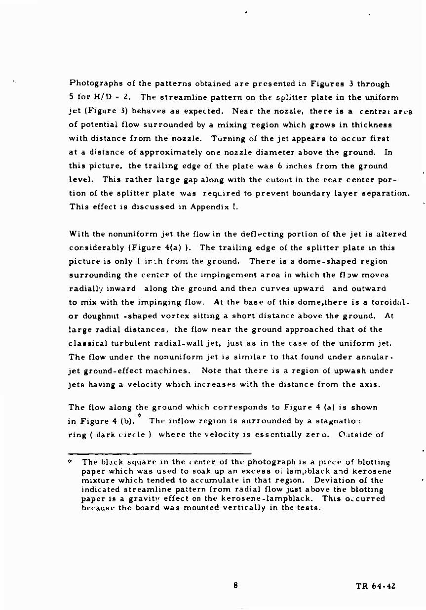
Photographs of the patterns obtained are presented in Figures 3 through
5 for H/D = 2. The streamline pattern on the splitter plate in the uniform
jet (Figure 3) behaves as expected. Near the nozzle, there is a central area
of potential flow surrounded by a mixing region which grows in thickness
with distance from the nozzle. Turning of the jet appears to occur first
at a distance of approximately one nozzle diameter above the ground. In
this picture, the trailing edge of the plate was 6 inches from the ground
level. This rather large gap along with the cutout in the rear center por-
tion of the splitter plate was required to prevent boundary layer separation.
This effect is discussed in Appendix I.
With the nonuniform jet the flow in the deflecting portion of the jet is altered
considerably (Figure 4(a) ). The trailing edge of the splitter plate in this
picture is only 1 inch from the ground. There is a dome-shaped region
surrounding the center of the impingement area in which the flow moves
radially inward along the ground and then curves upward and outward
to mix with the impinging flow. At the base of this dome,there is a toroidal-
or doughnut -shaped vortex sitting a short distance above the ground. At
large radial distances, the flow near the ground approached that of the
classical turbulent radial-wall jet, just as in the case of the uniform jet.
The flow under the nonuniform jet is similar to that found under annular-
jet ground-effect machines. Note that there is a region of upwash under
jets having a velocity which increases with the distance from the axis.
The flow along the ground which corresponds to Figure 4 (a) is shown
in Figure 4 (b). The inflow region is surrounded by a stagnatio.:
ring ( dark circle ) where the velocity is essentially zero. Outside of
* The black square in the center of the photograph is a piece of blotting paper which was used to soak up an excess Oi lampblack and kerosene mixture which tended to accumulate in that region. Deviation of the indicated streamline pattern from radial flow just above the blotting paper is a gravity effect on the kerosene-lampblack. This occurred because the board was mounted vertically in the tests.
8 TR 64-42
% »
this ring, the flow is directed racaally outward. In all cases for which
flow pictures were obtained (H/D = 4, 2, 1, j)r the stagnation ring
coincided with the position of maximum static pressure along the ground,
and its radiut was larger than the radius of the toroidal vortex observed
on the corresponding splitter-plate pictures.
The general features of the pictures obtained at the other values of
f H/D were similar to those shown here, the only difference being that the
size of the dome-shaped region, the toroidal vortex and the stagnation ring
all became smaller as H/D was either increased or decreased from the
value of 2. A probable explanation for this effect is that or one hand,
as H/D is decreased, the jet is constrained by the nozzle walls and
so the region in which turning of the jet occurs must be reduced. On
the other hand, as H/D is increased beyond 2, mixing of the jet with
still air prior to turning tends to reduce the effective shear in the
jet so that any effect associated with shear in the jet before impinge-
ment will also tend to be reduced. The type of shear being considered
here is that which will provide a velocity minimum on the jet axis.
Parabolic profiles such as are found in fully-developed pipe flow have
a shear of the opposite sense. This latter type of velocity profile will
not form a toroidal vortex with its associated central region of reversed
flow.
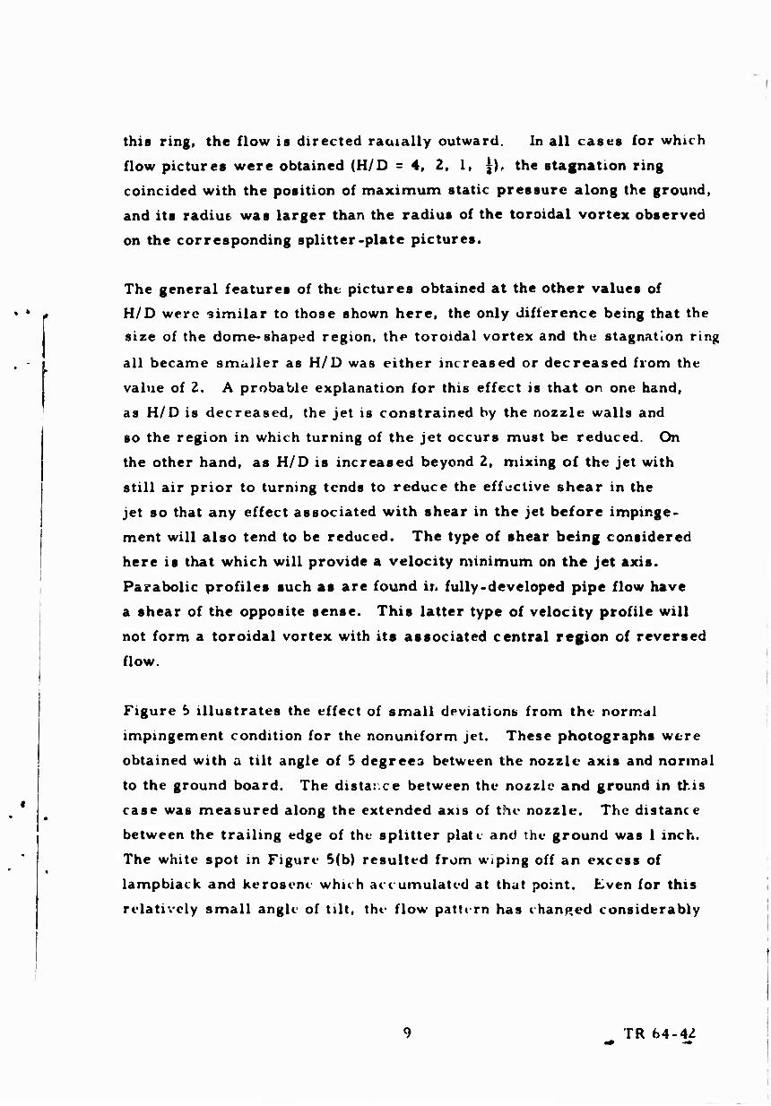
Figure b illustrates the effect of small deviations from the normal
impingement condition for the nonuniform jet. These photographs were
obtained with a tilt angle of 5 degrees between the nozzle axis and normal
to the ground board. The distar.ee between the nozzle and ground in this
case was measured along the extended axis of the nozzle. The distance
between the trailing edge of the splitter plate and the ground was 1 inch.
The white spot in Figure 5(b) resulted from wiping off an excess of
lampblack and kerosene which ace umulated at that po:nt. Kven for this
relatively small angle of tilt, the flow pattern has changed considerably
TR 64-42

, ,^, .■***r?Pi9'
from that obtained with the nonunifo/m jet impinging normally. The
flow near the ground is appreciably thicker on the side furthest removed
from the nozzle (right side cf Figure 5(a) ), and the stagnation ring has
been broken on this same side (left side of Figure 5(b) ). Although
no quantitative measurements were made with the tilted jet, it is
apparent from the pictures alone that the nonuniform jet is extremely
sensitive to tilt angle. Mo check of the effect of tilt angle was made
during the earlier uniform jet experiments, but it is believed, on the
basis of the general experience gained in setting up conditions for
normal flow impingement for both types of jets, that the uniform jet
is not as sensitive as the nonuniform jet to small angles of tilt.
Z. Quantitative Measurements
Tests were conducted on the nonuniform jet at ground-board locations
corresponding to nozzle-height-to-nozzle-diameter ratios, H/D, of
4. 07, 1. 99 and 0. 49. Most of the data were obtained with the settling
chamber pressure held constant at 16 inches of water, which provided a
maximum velocity near the outer edge of the jet of approximately
188 fps at the nozzle exit. Sample measurements were also made
with a maximum jet velocity of 119 fps at the nozzle exit. At each
H/D, velocity surveys were made at the nozzle exit and in the flow
along the ground at various radial distances from the stagnation point
up to a maximum of r - 42 inches. Static pressure distributions were
measured along the jet centerline between the ground board and the jet
nozzle and also along the ground board. The notation used in the pre-
sentation of the data is shown in Figure 6.
It was found that the flow at the nozzle-exit plane was somewhat
irregular. A typical set of velocity data is shown in Figure 7. This
figure shows the velocity measured along four radial lines at 90-degree
10 TR 64-42

intervals in the exit plane of the nozzle for the jet exhausting into
essentially free air. The data have been made nondimensional by a
reference velocity l/^,which was chosen for experimental convenience
and which is a reflection of the pressure in the settling chamber of
the wind tunnel. The dashed line is an estimated mean curve drawn
through the data. This curve was used to evaluate the momentum and
mass flow of the jet. The accuracy of such a procedure can be
judged by comparison of the jet momentum calculated from mean
curves for different distances from the nozzle. The nondimensional
jet momentum, ^j^ t, calculated from the mean profile at the
nozzle exit, was 0. 302, as compared to 0. 308 for -4=2. 02. This
is a difference of 2 percent, which is quite satisfactory.
It can be seen that the triangular velocity pt jfile for which the
shear screen was designed was only partially attained. In particular,
the velocity at the outer edge of the jet deviates considerably from
the desired distribution. The irregularities in this region ar : a
consequence of insufficient nozzle length. A greater length of
nozzle downstream of the shear screen would have allowed more
mixing of the ilow and, hence, smoothed out the velocity profile.
The greater nozzle length *vas prohibited, however, by the space
available for the tests.
The mean-velocity profiles in tl.e free nonuniform jet measured at
various distances from the nozzle arc shown in Figure 8. The
profile of a uniform jet with equal thrust is shown for comparison.
The irregularities in the profiles disappeared rapidly with distance
from the nozzle. At the same time the peak velocity in the jet
moved toward the axis and decayed almost linearly with distance
from the nozzle, while the velocity along the jet c enterline increased.
The behavior of the maximum velocity in the free jet and the velocity
11 TR 64-42

■ . ■■-».*•.-•■ «c «ii tmnt* i— "in m • •-■>»- mr'^-n *.-ymmm--'m.'-'*m* ■■
on the jet centerline are shown in Figure 9. The decay of the maxi-
mum velocity for this particular nonuniform jet is represented quite
well by the expression -¥**■ = 0. 695 - 0.0225 -i .
A comparison of the entrainment in the uniform and nonuniform jets
is shown in Figure 10. In this figure the mass flow in each jet is
plotted as a function of distance from the nozzle. The mass flow has
been normalised by the value measured at the nozzle exit. When
reduced in this way» the entrainment properties of the two jets appear
to be identical. The dashed line is an empirical straight.line
approximation to the data.
Figure 11 shows tl e velocity distributions at the nozzle for H/D = 4,
2, 1 and 0. 5; the velocities are again normalized by the reference
velocity Uff. The velocity distribution for H/D = 4 was essentially
identical to that for H/D = eo . The effect of the proximity of the
ground is most evident near the jet axis. Perhaps a better indication
of the ground effect is given by Figure 12, where the static-pressure
profiles at the nozzle are plotted. The pressures have been nondimen-
sionalized by the settling chamber pressure, <fß , The static pressure
difference was zero for H/D = 4 and •• . At H/D = 0. 49, the non-
dimensional static pressure on the jet axis reached a value of 0. 25.
This is approximately 50 percent of the maximum total pressure
measured at the outer edge of the jet. There was some ground effect
even at H/D = 1. 99. The corresponding tests cf the uniform jet
showed no back pressure at HI D = 2. The first evidence of ground
effect in that case appeared at H/D = 1.
The static pressure distributions on the ground are presented in
Figures 13(a) through 13(d). Data are shown for four radial lines
separated by 90-degree intervals. The line Q - tlQ degrees is the
« 7 See List of Symbols
12 TR 64-42

one on which boundary-layer measurements were made. It i«
evident from the data that perfect axial symmetry was not attained
in these experiments. There is a general tendency for the peak
static pressure to be higher in the horizontal plane ( 0 = 90 and
270 degrees) than in the vertical plane (0=0 and 180 degress).
The position of the maximum static pressure coincided with the
position of the stagnation ring in the flow visualisation pictures as
one might expect. The static pressure on the ground under the
tilted nonuniform jet is shown in Figure 14. The plane correspond-
ing to 0 - 90 and 270 degrees is the one in which a 5-degree
angle of tilt was imposed, with the line 9 - 270 degrees being
farthest from the nozzle. The break in the stagnation ring illustrated
in Figure 5(b) is reflected in Figure 14 as a suppression of the
peak in static pressure along the line B = 270 degrees.
Figure 15 shows the static pressure distribution along the jet
centerline as a function of nondimensional distance from the
ground. B/D. Inspection of Figures 13 and IS shows that ihe static
pressure is approximately constant in the region surrounding the
center of impingement, and, in addition, this constant pressure
region is largest in extent for H/D « 2. These observations are
in accord with the behavior of the jet as determined from the flow
visualization pictures. The increase in static pressure along the
jet axis near the ground at H/D - 4 over that at H/D * 2 is a reflec-
tion of the mixing process before impingement. The dynamic
pressure on the centerline ot the free jet increases with distance
from the nozzle because of viscous mixing (Figure 8), and this
increase causes a rise in static pressure recovery near the center
of impingement.
13 TR 64-42

\ *'-
A brief hot-wire survey of the impingement region was performed
for the normally impinging nonuniform jet with H/D = 1.99. The
result of this survey is shown in Figure 16. The velocities shown
are absolute velocities; the direction of the flow is not indicated by
a single hot wire. This should be kept in mind when studying
Figure 16. In particular, the flow visualization pictures indicated
that the direction of the velocity along the jet axis near the board
was perpendicular to and away from the board. The main point
which can be determined from Figure 16 is that the velocity in the
dome-shaped region of Figure 5(a) is only a small fract'on of that
found outside the dome and, hence, should not play an ii iportant
role in the entrainment problem. There is, however, the possibil-
ity that particles entrained in the flow in higher velocity regions
may be carried to the center of the impingement region by this
secondary flow and deposited as a mound near the axis of symmetry
of the flow.
Figure 17 presents velocity profiles in the flow along the ground
at various radial stations in the turning region for H/D - 0.49,
1.99, and 4.07. A velocity profile measured inside the stagnation
ring with H/D - 1. 99 is included in Figure 17(b). Note that for radii
near the stagnation ring, the maximum velocity is reached at a
considerable height above the ground. Below this maximum velocity
point, the velocity decreases gradually as the wall is approached
until at a very small distance from the wall, the beginning of a
true boundary layer is discernable. The region of increasing
velocity between the very thin boundary layer and the maximum
velocity is due to the static pressure difference between the wall
and the outer edge of the flow. The decay in velocity at larger
distances from the wall is due to viscous mixing. As the radius is
increased to regions where the static pressure gradunl at the wall
14 TR 64-42

approaches zero («ee Figure 13), the velocity profiles rapidly approach
the fo m associated with the classical turbulent radial wall jet.
The experimental data tor H/D = 1. 99 and r/D > I are plotted as a/Um
vs y/yv^ in Figure 18; y//Ä is the distance to the point in the outer
mixing region at which a = i<^ll(«ee Figure 6). In general, the data
fall on a single curve when plotted in this way so long aj the radius is
sufficiently large that the pressure gradient at the ground is approxi-
mately zero. Identical results were obtained for H/D - 0.49 and 4. 07
with the exception that the minimum radius at which the data collapsed
to a wall-jet type of velocity profile changed with H/D. For each H/D,
the largest value of r /D indicated in Figure 17 is the smallest r/D at
which the wall-jet profile was obtained. The next smaller value of r/D
in each case followed the wall-jet profile in the outer portion of the flow
except for H/D = 0.49 (see.e. g., Figure 18, r/D = 1.33). Sample data
at a second, lower, value of mass flow in each case gave essentially
the same results when nondimensionalized. This is illustrated in Figure
18 for r/D = 2.10.
In Figure 19 the boundary layer region for the data of Figure 18 is
plotted on a greatly expanded scale. The cc mments made above apply
to Figure 19 as well.
15 TR 64-42

Ill THEORETICAL ANALYSE!
A. Uniform Inviscid Impinging Jet Theory
A theory for the flow along the ground plane of an impinging jet, particu-
larly for the boundary layer flow, requires, first, that the ground-plane
pressure distribution be predicted. It was recognized that for free jets
in air, viscous effects are important. However, the work reported in
Reference 1 indicated that, for H/D less than approximately 2, the
ground-plane pressure distribution under the uniform impinging jet wai
essentially that of the inviscid jet. Furthermore, the available theoreti-
cal results for inviscid impinging jets were not applicable for H/D less
than Z. For H/D less than Z, as the jet exit approaches the ground plane,
there is a back-pressure which is reflected at the exit in terms of re-
duced dynamic pressure in the center of the jet. Hence, the jet exit
velocity profile is no longer uniform. As H/D is reduced below 2, there
are, in addition, substantial changes in t. e ground-plane pressure distri-
bution.
analysis of the uniform inviscid impinging jet was a continuation
of ine study partially reported in Reference 1. Work was brought to a
conclusion during the present research. The analysis is based on a
vortex sheet representation for the jet boundaries. The resultant
mathematical model was programmed for an IBM 704 digital computer.
An iterative technique was developed in which successive positions of the
jet boundary were computed until the appropriate boundary conditions
for the flow were satisfied. Details of the mathematical model and the
implementation of this mo^el on the computer are presented in Appendix II.
For the sake of completeness, parts of the discussion of Reference 1 arc
repeated.
lb TR 64-42

During the formulation stage of the analytical program, it was
realized that problems could arise concerning convergence of the
iterative technioue which might be amplified by the approximations
inherent in any digital computer program for continuous systems.
Hence, the convergence properties were investigated from an experi-
mental point of view- by a trial and error process. Fortunately, con-
vergence was ultimately attained.
Boundaries and flow properties were computed for H/D = 1 and
H/D = 0. 25. The computed boundaries are shown in Figure 20.
where the results of Leclerc, Reference 3 . for H/D = 2 (approxi-
mately equivalent to H/D = e^are shown for comparison. Computed
static pressure distributions along the jet centerline are shown in
Figure 21 , and along the ground plane in Figure 22 . Computed
velocity profiles and flow angularity with reference to the jet axis
at the nozzle are presented in Figure 23.
B. Boundary Layer Analysis
An approximate method of analysis was developed in Reference 1
which appeared to he adequate for predicting the flow along the
ground under an impinging uniform jet. The method was semi-
empirical in that it was based on the experimentally determined fact
that the mass flow along the ground could be made independent of
H/D ( at least in the range £5 H/D 24) by a proper choice of non-
dimensionalizing parameters. In addition, the analysis required
knowledge of the pressure distribution along the ground. This latter
requirement was to be met by the inviscid solution to the problem of
the impinging uniform jet. Such a solution is reported in Section III (A).
Since this solution was not available at the time the boundary layer
analysis was performed, the experimental pressure distributions were
used in anticipation of the invisiid solution.
17 TR 64-42 -

■ MHjMUJW'Wtf
i : . . ■ . i i i ■ r* .... r _
The problem became more difficult when an initially nonupiform, jet
was considered. Since a theoretical solution for the pre sure distri-
bution on the ground under such a jet was not available, it was ■I.>J ;.). i ^ -i , i • 'u-. ■ ' •.,.,.. .■■' '
necessary to restrict the analysis to regions of the flow where the
pressure gradient is approximately zero. The logical proceuure
appeared to be to search for a correlation between the mass flow param-
cters of the uniform and nonuniform jets and to use such a correlation,
if found, in conjunction with a simple momentum balance to describe
the flow at radii sufficiently large for the pressure to have reached
nearly ambient conditions, A method of analysis based on this
correlation would then be applicable to both the uniform and the non- ■■.ii*'..;. ■••.,,> ' '". [j. . . ■
uniform jets.
A factor in favor of this procedure is that the velocity profiles near the ii . . • • . ' j'^i.: !■ ..■■•.. r <;. Ki . . . ■ i
ground in the nearly ambient pressure region can be founc from Glauert's
radial wall jet analysis (Reference 4 \. The turbulent flow solution is
the one of interest for this investigation. The shape of the theoretical
velocity profile was prescribed by a parameter a. which in turn
depended weakly on the Reynold's number -Tp-' where u^ is the locc 1
peak velocity in the radial flow and 6r is the distance between the
point at which u- u and the point at which u«ia (Figure 6).
It is desirable to obtain an estimate of a from the properties of the
jet before impingement. Because of the weak dependence of <* on
U'm** , this can be accomplished with considerable accuracy even if y
some relatively broad assumptions are made. It was assumed that
Glauert's theory applies for r/R - 3, that the loss in radial momentum
flux due to skin friction is negligible at this radius, and that um equals
the value of ttm in the free jet at a distance t/R* H/R+ (-^ - ^ where S",» ?
for this calculation. A discussion of this method of estimating a has
been presented in Appendix II of Reference I and will not be repeated
here. The value a «1.16 computed in this manner compares very closely
18 TR 64-42
i

with those derived from the experimental measurements of —^ 'J)
Once the shape of the velocity profile has been determined by a , the
functional dependence of t/,/t and um on r is given by o'Ä
*m/Om • C* Wi Vw /« ' % M** f ■ (1)
where the exponents "a" and "b" depend on the value of Or , the constants
Cu and Cy may be function« of H/D and the type of jet considered,
and t^» is a reference velocity which will be defined shortly. The approxi
mate determination of C^ and C forms the remaining portion of the
analysis.
I
Consideration of the momentum in the jet provides one relation for
finding the unknown constants £a and C . Consider an impinging jet in
which both the total and the static pressure distributions at the noasle
exit are functions of radius (Figure 24). If,for the moment, one arti-
fici&Uy allows no mixing to occur, then one may «ay that the total
pressure along any streamline will be a constant. Along any strei m
tube annulus (dotted lint; in Figure 24) in the impinging jet.
2rr/Ov(rtt)rt4ärtt - Znp r a(y)dy,
PT ' PA - constant in the streamtube and
i- J • - 1 (2)
(3)
where the subscript TV denotes.that the quantities are evaluated at the
nozzle exit plane. If one considers the flow along the ground where
P3-PA'0. then . . , ufu) - /MIS - IJEEES us
therefore from <2), (3), and (4). ,
. m v(rM)rHdrM m r^ 1(PT'PA)N H^lJPw
• ..iv
19 TR 64-42
■

or
■fzfmi"-"' ".-ßW3 (5)
Note that the thickness of the flow, y (r) , is obtained simply by replac
rw ing / with/ in equation (5). The radial momentum flux at r is
given by
Mr 'Zrr/orj u'dy. (6)
Substitution of equation (5) into (6) gives
"r -'*/}* ^)^f-(^l-rNärNt (7)
which is the radial momentum flux in terms of conditions at the nozzle
exit plane provided that the radial station considered is sufficiently far
from the jet axis so that the pressure at the wall has become approxi-
mately atmospheric.
Since Equation (7) deals with momentum flux, it is valid for the flow
under a real impinging jet even though entrainment was neglected in
its derivation, provided that the momentum flux loss due to wall skin
friction can be neglected. The momentum flux loss at the start of the
wall-jet flow has be^n found experimentally to be small for all cases
tested to date, so Equation (7) will be used in the following analysis.
It is convenient at this point to define two characteristic mean velocities
based on conditions at the nozzle exit. These are a mean mass flow
velocity a* |4jf trrMdrN
nrr* ' and a mean momentum velocity UM s ~i ~2 Vj V^N^^N
f2(p .pT ' R Jo where i/; - J — . With this definition of Uu , Equation (7)
ZO TR 64-42

simplifies to
TrTl ~ * («kin friction neglected). (7a)
An additional relationship is required to obtain the two unknowns,
Cu and Cyt\r\ Equation (1). In the tests of the uniform jet (Reference
1 ), this relation was obtained empirically. It was found that the
radial mass flow, dJL , in the wall-jet region was independent of Qr /U y* ¥*
H/D when plotted as j vfh^R where U^ is the velocity at
the edge of the uniform jet. On reviewing the calculations for the
uniform jet, however, a small error in the calculation of Ü/u^ from
the experimental data was found for H/D = 0. 25. The revised
estimate of ÜfO^ became 0. 56 as compared to the original estimate
of 0. 60. With this more accurate value for f~ , the nondimensional
mass flow parameter became j—/-??]. This revised parameter
will be used in the following analysis. Application of the definition
of U^f to the uniform jet ( note i^.»^, for the uniform jet) shows that
UM"iü (^|So that the equivalent mass flow parameter in terms of
OH is ^- (l¥~) '^lc correlation of the experimental data
for both the uniform and the nonuniform jets is illustrated in Figure 25.
The data for each type of jet correlate when plotted in this wa^ but there
is 15 percent difference between the two sets of data. It is possible
that some of the difference may be attributable to small deviations
from axial symmetry in the tents of the nonuniform jet. Such devi-
ations are noted in Section II. A further indication of asymmetry in
the flow under the nonuniform jet is that the experimental radial
momentum flux with H/D = 4 reached values up to 10 percent higher than
is theoretically possible for an axisymmetric jet with no losses.
Since th^ measurements in the flow along the ground were made only
along one radial line, the results are subject to error if the flow is
not accurately axisymmetric. In view of this uncertainty in the
experimental results, it was decided that a weighted average of the
two sets of data would be used to complement Equation (7a) in the
21 TR 64-42

calculation of C and 6 .
The variation of Qr with r is prescribed by Glauert's form param-
eter oc . For a - I. 16, the theoretical values of a and h in
Equation (1) are -1.075 and 1.008 respectively. However, the ex- i
perimental values of a and b as found in the uniform jet tests proved
to be better represented by a = -1. 143 and b = 1.028. Since, in
practice, the value of a is unlikely to differ very much from that
found in the present work because of an insensitivity of Ct to nozzle
Reynold's number, and the values of a and b in turn are only weakly
dependent on of in this range, it was ftlt justified to assume that the
experimental values of a. and b were representative of all practical
cases. Hence, <?r -u^y^r -~ (r)aW. The relations
r, .on .^ . o.9B5
rrpR UQ-(-%*-) =0.fo(~} for the uniform jet
=■ 05&(r/#)0 aSf for the nonuniform jet
appear to give the best tit to the experimental data. A weighted Q /j so." /r\0,t*
average of these two curves, 2- f^l =Ö52(—I , is used in the subse
quent ana'ysis. In arriving at this value, most of the emphasis was
placed on the uniform jet data because it was believed that these data
were the most accurate.
The following relations determine the flow near the ground:
Or
* / ^ < LL (7a)
oB§r
and
npt%[z) *0HR) W (8)
0; HRI- • ir'cÄR) R --R (1)
where r^ is the radius where the wall-jet flow begins. Further, it
will be assumed that at the start of the wall jet, u„ is equal to the
maximum velocity in an equivalent free jet at a distance — * ~.*-lJ -fj
*
22 TR 64-42

from the nozzle exit. For the two jets tested, the above assumption
gives
uniform jet: ^22 « / a^ ^ provided HlO <>,*+
nonuniform jet: nonuniiorm jei: - s*i *. \\ 17) (see Figure 9) ty ' [OtST'OOMffc* %-1jW!*L a*
(9)
where C^ is a reference velocity used for experimental convenience and
is representative of the wind tunnel settling chamber pressure.
The method of solution for Cu and Cy is as follows. From Equation
for JL m ± R R
X . A R
R
(7(a)) one obtains
and, since U^/ü^ has been assumed in this region, then
*** -!~fa*L\~'(S)'1 for R fJ5 \UM) \Rl
and ♦ _o£^ ^m^Vnü. wf**]" for
^/?aJv \ 0/ \üj\ü /
The combination of Equations (8) and (11) gives
which may be solved for rt/* with the aid of Equation (9), or its
equivalent if other jet profiles are of interest.
R r
'R
r
~R
(10)
(ID
(12)
Once rt/R has been found, then Cu and Cy are given by
(13)
The numerical constants in these equation were obtained by integration of the theoretical veioctiy profiles, That is.
and
Or^^^^^li^d^yiZZirpru^^ for l.1Sa</.2
<a <*.(,
23 TR 64-42

Equations (1), (9), (10), (12) and (13) along with Gianert's velocity
profile for «x ~ 1. 16 constitute a complete description of the flow along
the ground in the region where the wall static pressure gradient
approaches zero. The solution may be applicable for radii slightly less
than «^ . The flow near the ground at r»^ will have a minimum in
thickness and an approximate maximum in velocity,and hence this is
probably the radius where the entrainment problem will be most
severe.
The results of the calculations are presented in Figures 26 and 27
for the uniform and nonuniform jets respectively.
24 TR 64-42

IV COMPARISON OF THEORY AND EXPERIMENT. AND DISCUSSION OF RESULTS
A, Invigcid Impinging Uniform Jet Analyiis
Computed jet boundaries are presented in Figure 20 for H/D = 1.0
and H/D - 0. IS. Also shown is the boundary derived by Leclerc from
an electric analog tank experiment for H/D = 2. Comparison of these
computed boundaries with experimental data is not possible, because
the experimental jet boundaries are obscured by viscous mixing. It
is apparent from Figure 20 that as H/D decreases, the theoretical
thickness of the jet above th 3 ground plane decreases. This was inferred
in Reference 1 from mass flow considerations. As H/D decreases,
the equivalent uniform velocity, U , in the tube (or nozzle) also decreases.
Conservation of mass requires that at some distance along the ground
plane from the stagnation point, where the pressure has fallen to near
ambient pressure.
Y(r) m * u
(14)
which is Equation (1) of Reference 1 ; Yt(r) is the height of the jet
boundary above the ground plane. Equation (14) is consistent with
Equation (5), Section III B, which applies generally for impinging jets
with no mixing.
Computed static pressure distributions along the jet centerline and along
the ground plane are compared with corresponding experimental results
from Reference 1 in Figures 21and 22 respectively. It is apparent that
excellent agreement was obtained, although computed ground plane
pressures are slightly low for 0. 7 < -^ < 1. 4 at H/D =1.0. The small
discrepancies probably reflect the effects of viscosity (mixing), in view
of the excellent agreement obtained for the ground plane pressure dis-
tribution at H/D = 0. 25, and for the jet centerline pressure distribuuon
TR 64-42

f jr H/D =1.0. Comparison of computed and experimental velocity
profiles at the nozzle are shown in Figure 23 . Again, agreement is
good, particularly for H/D = 0. 25. Also shown in Figure 23 is the com-
puted variation of flow angularity at the nozzle with reference to the jet axis
for H/ O = 0.25 . Of interest is the fact that the computed angularity is
as large as 18. 5 in this particular instance.
Of those values of H/D for which experimental data are available from
Reference 1 , the H/D = 0. 25 case is the one most critically affected
by the ground. The excellent agreement with experimental results for
H/D = 0. ?5 clearly demonstrates the accuracy of the theory.
Convergence of the iteration process was relatively slow. The
H/D = 1.0 computation required approximately 70 iterations and about
4 hours of computing time on the CAL IBM 704 computer. The iteration
technique involves so-called "gain" constants (See Equation (II-5) of
Appendix II). The appropriate gain constants for convergence must be
determined by trial and error. If they are too large, successive curves
computed as the iteration program proceeds tend to oscillate through
larger and larger amplitudes wnich ultimately diverge violently. For
somewhat smaller values, the oscillations become damped, and the
program ultimately converges. If the "gain" constants are reduced
still more,the successively computed curves tend to approach the solution
asymptotically. Apparently, there is an optimum "gain" constant which
is analogous to critical damping and for which convergence will be obtained
most rapidly. Unfortunately, a detailed investigation of this point was
not believed to be practicable during the present program. Once "gain"
constants were determined lor which the successive iterations showed a
converging solution, these constants were used thereafter, and
the program was permitted to run to convergence. It is believed that the
* An improved iteration technique which should provide much more rapid convergence is out'ined in Appendix II.
2^ TR 64-42

■ftrtcv«* BMi
convergence criterion used in these computations insures an accuracy
of between three and four significant figures in the final computed curve,
within the approximations inherent in the IBM program.
t- As a partial check on the accuracy of the computing program, absolute
velocities just inside the free-jet boundary at the control points were
computed. If the solution were exact, these velocities would all be equal
to L/,0 • For H/D = 1.0, for the five control points, these velocities
for the converged solution varied from 0. 9 3 to 0. 99 of C^.with three of the
five being within 3 percent of Um . For H/D J. <i5, these velocities
varied from 0. 96 to 1. 06 of Um , with three of the five within 3 percent of
(J^ . Largest deviations from U^ occurred for the control points
closest to the nozzle, and hence closest to regions where shape approxi-
mations have been used. It is believed that these results could be
improved by using more control points, and by using a finer breakdown
for numerical integration purposes. This can be done easily, but at
the expense of increased computer running time.
Another indication of the accuracy of the analysis is provided by
Figure 28, in which the absolute velocity is plotted versus distance
from the ground plane for H/D - 1. 0 at r/^ = 1. 7. The absolute velocity
outside the jet should be zero for the correct jet boundary and correct
area vorticity density distribution. For the computed points shown
in Figure 38. velocities outside the boundary are less than 0. 01 Um ;
the calculations also show the abrupt change- in velocity across the jet
boundary which should be obtained theoretically.
A detailed investigation of the various approximations in the program
as they effect the computed results was believed to be unnecessary for
the present orogram in view of the «'xcellent agreement between computed
and experimental pressure distributions. However, it is hoped thM such
27 TR 64-42

—m:Tt'- ' fumtr ***■•■ ■•■***&■■«?'
an investigation will be made because of the potential application of the
general technique employed in this analytical program to other axially
symmetric, three-dimensional, free-streamline flows.
B. Boundary Layer Analysis
Because of the complexity of the flow in the turning region under the
impinging nonuniform jet, the analysis of the flow along the ground was
restricted to those regions where the pressure gradient at the wall
became approximately zero. Such a restriction required a treatment
which was somewhat different from that presented for the uniform jet in
Reference 1. The properties of the wall-jet portion of the flow for both the
uniform jet and the nonuniform jet were computed using the method of
analysis presented in this report. The uniform jet analysis predicts
that the wall-jet velocity profiles should be given by Glauert's theory for
CZ = l.i 6. It was shown in Reference 1 that the velocity profiles
obtained with the uniform jet were in excellent agreement with Glauert's
theory iorOf- 1.16, and consequently these data will not be reproduced
herein.
The experimental velocity profiles in the wall-jet region of the nonuniform
jet with H/D = 1. 99 are shown in Figure 18 along with the velocity profiles
predicted by dauert for values oi a, - 1. land 1.2. These results are
typical of the data obtained for all values of H/D tested. The appropriate
value of at was found to be 1. 16 in Section III B. The accuracy of the pre-
dicted profile is somewhat less than it was for the uniform jet. The
portion of the data shown in Figure 18 would appear to be best represented
by a value of or slightly less than 1. 1 except in the range y/yL > 1. 2.
The divergence from the theory at large values of y/y^ was found also
in the uniform jet work and by other experiments and is probably due to
a combination of angularity of the flow with respect to th»- probe and the
decreasing accuracy of the measurements at the very low velocities
encountered.
.'8 I K U\-M

The boundary layer region of Figure 18 is plotted in Figure 19. The
theoretical profile for a 1.16 has been added tu this figure. In this
region, the experimental data are reasonably well represented by the
curve for at - 1.16 except at values of •£■ < 1. 33, where the pressure gradi-
ent increases rapidly. The curve for ae - 1.16 has been modified from
Glauert's theory to account for the laminar sublayer. As in Reference 1 ,
the outer edge of the laminar sublayer is in the region ^ ^O. 015. The
theoretical profile was modified by matching the inner portion of the
universal velocity distribution for smooth pipes (Figure Z0. 4 of Reference
5 ) to Glauert's profile at J^. = 0.015.
The fact that slightly different values of a appear to be required in the
boundary layer and outer regions of the velocity profile for agreement
with the experimental results may be due to the deviations from radial
symmetry discussed earlier, especially since the uniform jet tests, where
the radial symmetry was excellent, provided extremely good agreement
with the theoretical wall-jet profiles. The small deviations from theory
in these velocity profiles constituted no serious problem in the calculation
of <z and y. in Section III, since the numerical values of the integrals
(or nondimensional mass flow and momentum used in the analysis are
almost independent of a in the range of a which is applicable to the
problem.
The calculated values of <^w/^0and zjt* 1°* ^e uniform jet are compared
to the experimental data in Figure 26(a) and 26(b) respectively. As
shown, the over-all accuracy is quite satisfactory: the difference between
theory and experiment never exc cvds 10 percent and is generally closer.
The effect of varying H/D is to reduce the radius at which the apparent
wall-jet flow starts. A similar comparison between theory and experi-
ment is made in Figure 27(a) and 27(b) for the nonuniform jet. In
Figure 27(a) Um has been nondimensiomiÜKed by U^ and div Jed by 2
29 TR 64 42

The factor ] is used only for convenience in presenting the results on
logarithmic graph paper. Note that the sample data obtained at a second
value of nozzle mass flow (solid symbols) are essentially the same as those
obtained at the mass flow used for the bulk of the teats. Again the accuracy
of the approximate analysis is satisfactory except near the start of the
wall-jet flow at H/D = 1. 99. In this case the assumption that the maxi-
mum velocity at the start of the wall jet can be approximated by the
velocity in the free jet at an equivalent distance from the nozzle was not
realized, although the use of this assun ption provided reasonable results
for radii slightly larger than that corresponding to the start of the wall-jet
flow. The error in predicting j^ for the nonuniform jet is somewhat
larger than that for the uniform jet. This is primarily due to the higher
emphasis placed on the uniform jet data when estimating the mass flow
parameter. Generally, the radii for which the calculated results dis-
agreed most with the experimental data coincided with the turning region
of the jet as defined by the ground static pressure distributions of
Figure 13. Since it was assumed in the analysis that the jet was com-
pletely turned, such results are not unexpected. Unfortunately, the
extent of the turning region of the non-imforni jet at H/D - I. 99 is larger
than the apparent radius for the start of the wall jet, and the calculated
properties are in error in this region. The error is on the conservative
side so that the use of the method of analysis will at least provide an
upper limit to the seriousness of the entrainment problem even in this
case.
It is evident from the experimental results and from the analysis that
the lack of a method for predicting the flow along the ground in th^
turning region of the jet is no» a serious limitation. In all cases exc ept
H/D ** 2 with the nonuniform jet, the method of analysis provides rea-
sonably accurate estimates of the properties jf the flow along the ground
at the start of th»' wall-jet flow. Since this radius cor responds to an
approximate maximum in velocity and a minimum in thickness of the flow.
30 TR 64-42

it will in all probability, from what is known about particle entrainment.
be the region most critical to the entrainment problem.
C. Comparison of Boundary Layer Under Uniform and Nonuniform Jet
In Section III Biexperimental properties of the flow along the ground
under both jets were compared to the results of an approximate
analysis. Application of this analysis requires a knowledge of the
conditions at the nozzle as a function of H/D as well as the free air
velocity decay curve or each jet. However, the properties of non-
uniform jets at values of H/D sufficiently small that there is a ground
effect at the nozzle (H/D.5 2) are not predictable by current theoretical
techniques. Hence, it would appear advisable to compare directly the
two types of jets to discover if the results from the uniform jet can be
applied to the nonuniform jet at these low values of H/D. At higher values
of H/D, there is no static pressure rise at the nozzle so that these cases
require only a knowledge of the free air properties of the jet being con-
sidered. The comparison will be made on the basis of constant thrust
per unit nozzle area.
The above basis for comparison poses no problem in the comparison
of j^ül fc
27(b) as
of jL?i for both types of jets. Thf results shown in Figures 26(b) and
ilß versus — are independent of thrust, so they canbe com-
pared directly. In the range of H/D covered by the experiments and r
for jf t 4, the two sets of data are essentially the same if jne allows for
probable errors in the nonuniform jet data due to slight flow asymmetry.
The results of the two analyses are almost identical for the cases
H/D = [ and 2 over the complete range of £ shown. This indicates that,
as far as the prediction of JLV/ is com t-rnt d, ihr uniform jet analysis
can be applied directly to the nonumform jet in ti.e rangt- H/D ^ 2. The
result for the nonuniform jet will be ;n error at H/D ä 2 for-^ near the
start of the wall-jet flow for the rt-asons disc ussed previously in the
31 TR 64-42

«.ompanson of theory and experiment. At H/D - 4, and in the range
r/R < 4, both the experimental and analytical result« indicate that
the two jets are not comparable, the flow under the uniform jet being
thinner than that under the nonuniform jet. Hence, for H/D > 2, the
decay in maximum velocity in the nonuniform jet must be accounted
for if reasonably accurate predictions are to be obtained.
In order to compare the maximum velocity near the ground generated
by the two jets, it is necessary first to convert the results presented
in Figures 26(a) and 26(b) to j' . i , where T is the thrust and A is T 'P
nozzle area (rrf') . For the uniform jet, this IB done by expressing
the thrust in terms of L//um • It can be shown that
and hence
Um
v/>* The variation of -;— with H/D is shown in Figure 29 , for a uniform
jet. The limit of —i^- as H/D approaches zero was calculated from
considerations of two-dimensional inviscid flow through a sluice gate.
Since t^/L^ reached a maximum value of approximately 1 at the start
of the wall jet for all H/D< 4, the maximum velocity reached at the
ground is simply <A / ^—^
for the uniform jet. The value of ^m/foA ls -shown in Figure 30
for both the uniform jet and the nonumform jet. The points for the
latter were taken directly from Figure 27(a) because the experimental
data for the nonunilorm jet indicated that, m the range ]l/D— ],
* Figure 29 may also be used to obtain an estimate of the thrust variation with constant power input for an axially symmetric, uniform, impinging jet. Using Equations (14) and (IS) and the require ment that power remain constant, one can show S 1f^m^\t./Q. i'l
T,.„ i{ v J ['*{uJ J for constant power. This equation plus Figure 29 may be used to calculate the variation of T/Tu*— as a function of H/D.
i2 TR 64-42

Wfi^Um1' 1 and hence *m/y£Ä * ^m/^M • The point« shown are
the calculated velocity at the start of the wall jet (break in the curves of
Figure 27(a) ).
It can be seen that the uniform jet analysis provides results for
4 T identical to those obtained with the nonuniform jet analysis in
the range H/D^ 2. In view of this result and the corresponding results
for y1il/R t it can be assumed with reasonable certainty that the
uniform jet analysis can be applied to calculate the properties of the
flow along the ground under nonuniform jets for values of H/D < Z.
The results of the analysis will of course be valid only for radii suffi-
ciently large that the flow has been completely turned. At values of
H/D £2, the velocity decay characteristic of the nonuniform jet ex-
hausting into free air must be included in the analysis.
A general comparison of both the analytical and the experimental results
for the two jets provides the following features. At values of H/D S 1>
the flows along the ground under the two jets are essentially the same.
The limit H/D < 1 rather than | in stipulated,even though quantitative
measurements of the flow along the ground were not obtained with
the nonmiform jet at H/D = 1. Flow visualization pictures and the
ground static pressure distribution obtained at H/D - 1 indicated that
the effective turning radius of the jet was sufficiently small as to caus ?
no such problems as those observed at H/D = 2. At values of H/D > 1.
the flow along the ground under the nonuniform jet had a lower maximum
velocity and larger thickness than that under the uniform jet. These
differences were not large, but they do provide the unexpected result
that the nonuniform jet is slightly less prone to cause particle entrain-
ment at large values of H/D, and i> no worse than the uniform jet
at small values of H/D.
3 3 rn »)4- \:

BIBLIOGRAPHY
1. Brady, W. C, and Ludwig, G. R., Theoretical and Experimental
Studies of Impinging Uniform Jets. TRECOM TR 63-11 ,
April 1963.
I, Brady, W. G.,and Ludwig, G . R., "Theoretical and Experi-
mental Studies ot Impinging Uniform Jets", Journal of the
American Helicopter Society, Vol. 8, No. I, April 1963,
pp. 1 - I 3.
3. LeClerc, A., Deflection of a Liquid Jet by a Perpendicular
Boundary, M.S. Thesis, State University of Iowa( 1948,
4. Glauert, M. B. , 'The Wall Jt-t", Journal of Fluid Mechanics.
Vol. 1, Part 6, December 1956 , p. bib.
5 Schluhting, H. , Boundary Layer Theory, Fourth Edition,
McGraw Hill Book Company. Nt w York, l(>bü .
6. Milne-Thompson, L. M., Theoretual Hydrodynamics,
Second Edition, The Mac Millan Company, New York, 1950.
APPENDIX I
GENERAL COMMENTS
ON THE FLOW VISUALIZATION PICTURES
Splitter Plate Pictures
The streamline patterns obtained on the splitter plates must not be
taken as an exact picture of the flow which wou.d occur in the absence
of such a plate. Since a surlace has been inserted in the flow, there
will be a boundary layer developed on this surface. In general, the
combined thickness of the plate and the displacement thicknesses of
the boundary layers developed on each side of the plate will be a
negligible fraction of the jet diameter.so that this thickness will have
little effect on the flow outside the boundary layer. However, in
regions where there is a pressure gradient in the flow (close tc the
ground in this rast'), the eff« the pressure gradient on the flow in
* e boundary layer will be ! celerale or decelerate mostly that
pction of the air with the Ive it kinetic energy. This is, of course,
the region adjacent to the surface, the one instrumental in producing
the streamline patterns
The net effect of the pressure gradients in the flow near the ground
will be twofold. First, near the jet c enterlme the adverse pressure
gradient occurring as the ground is approached will separate the
boundary layer. Such behavior was observed in the uniform jet tests
and is the reason why the trailing edge of the splitter plate was kept
at least 6 inches from the ground b. ard. In this case the flow in the
core oi the jet was essentially free of turbulence and the veloi ity at
whu h the tests were conducted was sufficiently low so as to sustain
a lamin.r boundary layer near the jet axis and hence to provide a high
l
!
■
^S TR b4-4J

susceptibility to separation. With the nonuniform jet, the turbulence
in the flow probably caused a forced transition to a turbulent boundary
layer near the plate leading edge. The higher resistance of a turbulent
boundary layer to separation and the less adverse pressure gradient»
observed with this jet explain the absence of separation in the flow
pictures which were made with the trailing edge of the splitter plate
only 1 inch from the ground board.
The second effect is that of the pressure gradient in the radial direction
in the absence of separated flow. In this case, the flow in the boundary
layer very near the wall will be turned rr.ore than that in the free stream,
again because of the difference in kinetic energy. This will show up in
the flow pictures as an exaggerated turning of the flow near the ground
and possibly an increased apparent thickness of the radial outflow along
the ground. The portions of the flow patterns ir l'»e center of the
impingement region under the nonuniform jet shoulc be least affected
by the interaction of boundary layer and radial pressure gradient, as
this region appeared to be at roughly constant pressure.
The above comments apply only to the patterns obtained on the splitter
plates. The conclusions to be drawn are that the patterns must be
regarded as providing only an approximate picture of the flow in any
region where the streamline patterns show a large curvature, with the
possible exception oi flow in the center of the impingement area under
the nonuniform jet.
Ground Flow Pictures
The streamline patterns shown reflect the flow in the boundary layer
along the ground. Since the surface used to obtain the patterns is in the
flow at all times and is not an additional surface as with the splitter
plate, the resulting streamline pattern is reasonably representative of
36 TR 64-'.2

the actual flow, except for a gravity effect. The board was mounted
vertically in these tests ; hence, in regions where the flow velocity
was low, gravity caused the lampblack and kerosene mixture to flow
downward. This is especially apparent in the center of the impingement
region where, in some cases, there is a ptonounced downward curvature
to all of the streamlines.
37 TR 64-42

APPKNDIX 11
DETAILS OF UNIFORM INVISCID IMPINGING JET ANALYSIS
A. Derivations of Equalions lor Inviscid Impinging
Jet Flow Basu Formulation
Consider a Cartesian coordinate system with the z-axis directed
along the axis of symmetry of the flow, positive vertically up
from the ground plane, and the x-y plane ( ä 0) coincident with
the ground plane. Consider an element of volume dX {x,a[t')
with vorticity vector <f Cjc', y' l'). For vorluity distributed through
out a given /olume / , one can write the vector velocity, Q ,
at any point ( x, y, a) in th'- fluid as (Reference 6)
^■^•^imp^ä^w^ lo'l3 "' ' (11-1)
where d »{%-%') i + ( y - tj') j + (i - l')k
A A A
and L.J,* are unit vectors in the x, y, and /, directions, respect
ively. In the case of axially symmetru flow,
The transformation to • ylindru <U i oordin.ttes ( f, £ , Q ) where
x - r cos (^ , tj = r si.n 0
and
g i v «.• s
^K FR ' J-4.
«•>•> • t
and
where 6r,jg and ^ are unit vectors in the ••_. a aud g
directions, respectively. Because of axial symmetry, only the
0*0 plane need be considered.
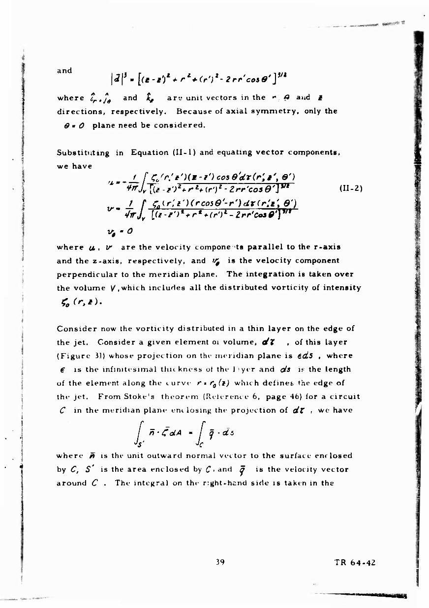
Substituting in Equation (II-1) and equating vector components,
we have
^___f_f ZSr/t'Hm-i^cose'drir'.i' e') (II-2)
v0 ' 0
where u, , V are the velocity compone ts parallel to the r-axis
and the z-axis, respectively, and fcj is the velocity component
perpendicular to the meridian plane. The integration is taken over
the volume /.which includes all the distributed vorticity of intensity
Consider now the vorticity distributed in a thin layer on the edge of
the jet. Consider a given element oi volume, dX , of this layer
(Figure H) whose projection on the meridian plane is tdiS , where
€ is the infinitesimal thickness ol the liyer and ök »^ the length
of the element along the curve r» f0(l) which defines the edge of
the jet. FromStoke's theorem (Reference 6. page 46) for a circuit
C in the meridian plane em losing the projection of dt , we have
n ' C dA » / a - db j$- Jc
where fi is the unit outward normal vector to the surface enclosed
by C, S is the area enclosed by C > and a is the velocity vector
around C . The integral on the right-hand side is taken in the
39 TR 64-42

clockwise dir*»rt»on. Then
Jr n CaLA = C0^^s
hence, j q-tTs *(%-<it)dLs :
?o6 * I,?! where a and ^ are as shown in Figure 31 If we let €-+0, C—0* such that
then
Also,
Coe s %, a constant
t'<tf-9z
to** • t0er9dsdQ'
dide'
Thus, Equation (II-2) can be written
Z(**)r0{*') *fl* [^^j'cz-/; cos O'di to'
^^ ** L [il-l')1*' *^[fJrK- Zrr^*) cosQ'] W
(11-3)
f f fM^W-jt+ty^ [fcose'-ro(i')]di'd0'
where the integration is carried out over the entire vortex sheet $ .
The Boundary Conditions for Infinite Impinging Jet
The boundary conditions on the inviscid impinging jet flow are as follows;
Along the surface,z = 0, W = 0. Along the jet boundary which is a
free streamline, the velocity is equal to a constant; therefore,
£ is also constant, as just outside the jet the velocity is zero.
40 TR 64-42
To satisfy the boundary condition that tr - 0 for z = 0, the plane
z = 0 is mads a plane of symmetry for the impinging jet and it«
image. Hence, the integration over S , Equation (11-3), must be
carried out over two vortex sheets, that defining the impinging
jet and that for the image jet.
The Boundary Conditons for Jet Nozzle at Finite Height Above the Ground ""
The jet is assumed to issue from a straight tube of constant
diameter (Figure 32) at finite height, H , above the ground. A
free-stream surface issues from the edge of the jet exit, B in
Figure 32, such that the free streamline velocity vector at B is
parallel to the side of the tube. The flow inside the tube along the
side of the tube must be tangential to the side; but, of course, the
streamline along this side is no longer a free streamline, as a
pressure difference can exist and, hence, the magnitude of the
edge velocity may vary. The boundary condition along the e *^e of
the tube is, then, that the normal component of velocity, u, , is
zero. In addition, at B in Figure 32, tf is continuous. Again,
along the free streamline BC, the velocity and, hence, «f axe con-
stant.
Final Form for Velocity Components
Figure 32 illustrates the flow model as thus far developed. The
straight tube of constant diameter, D , centered on the z-axis
extends from z ■= H to z - <*» . For 0<t<H , the curve r- f^ii)
defines the edge of the jet. To insure that v is tangential at
B ».'. Figure 32, we require that __i -O at /. - H; that is, there is di
no discontinuity in slope between the side of the norzle and the free-
stream surface. The sides of the tube and the jet are represented
i
\
41 TR 64-42

-
by a vortex sheet of vortusty £(r0,£) per unit area whose r- and z-
components are zero. The image of this vortex system for O*z.s-oo
assures that the boundary condition (no normal flow) along OD
is satisfied.
The integrations with respect to 6 can be done in closed form in each
of the integrals of Equation (11-3). If this is done, and we let t*Bft .
*'•//?, r-/»^ , r0'ro# and £-%%(#). there results
*w.*4ä\i mm^v*^:^1^^,
~ / V 2 =f ~2 t. E(*M) - <(*!)
-/ di
di
V(Ft1) . i^iir ULI 2n Uf i{i-p)lH**ir
^ 2B(k )-K(ks) if-F) Hr-0
di'
?(?') [(i*i'/+ra-f 1 TITrFH^t)* £(**>-x^i)**
Jo l(ft/')*'[r*r.(*')}z[(f+F'fi[f.f(i')]2 J (11-4)
4^ TR 64-4Z

where f((k) is the complete elliptic integral of the first kind and
£(k) is the complete elliptic integral of the second kind, with modu-
lus k ; also,
4r (k,) '(g-¥')'*(**1>* * ^ '(iTWTTfTJP
(**)*' 4wF^iO
These integrals are valid everywhere except on the boundaries, at
(1,9) for ffejf *nd (F0(l)tl)lor fsU • where the integrands are
singular. However, even on the boundaries, it can be shown that the
Cauchy principal values of these integrals exist.
Equations (II-4) enable the velocity at any point in the flow to be com-
puted, once the form of Ft(M) , the curve defining the boundary of the
jet, and £(i) , the vorticity area density of the vortex sheet on the
boundary of the jet and the tube, are known.
Equations (11-4) with the associated boundary conditions
Urn u(r,t)-0> * * H/* * f<f
r ro v(r%i) di * 0
give rise to simultaneous nonlinear . ttegral equations for £(§)a.nd
ftii) • which, as they stand, do not admit of solution in closed form.
However, by means of a high-speed, large-capacity digital computer,
a solution might be possible if a convergent iterative process can be
derived which will permit the determination of the jet boundary ^(1) .
43 TR 64-42
B. Detail» of IBM 704 Computer Program
The general computational procedure adopted is at iollows:
1. An initial shape of the free-streamline boundary is assumed.
2. The boundary condition that the flow at the wall of the tube
is parallel to the tube is used to determine the varying area
vorticity density of the vortex sheet representing the tube
and the constant area vorticity density of the free-stream
surface vortex sheet.
3. The flow normal to the tree-stream surface is then evaluated,
if there is a velocity normal tc the boundary assumed for
the tree-stream surface, that assumed boundary is incorrect
and must be adjusted.
4. The iteration proceeds for the adjusted boundary ( by going
back to step 1).
The boundary condition at the wall of the tube, step 2, is satis-
fied at a discrete number of points, or values of # , along the
tube. The nondimens^onal area vorticity oensity, %(i) in Equation
(II-4), is assumed to be a constant within the increment &i cen-
tered on each of these points (but, of course varying from point
to point). The firs* two integrals in the expr' ssion for V, Equa-
tions (II-4), can then be expressed as a sum. Setting V= 0 at each
of the specified values of £ , there results a series of linear, simul-
taneous equations in the unknown $(f) . For f large enough, %(i)
approaches a constant limiting value, and this fa*-* is utilized to
limit the number of simultaneous equations which must be solved.
It happens that if £(t) is a constant, the first two integrals in the
equation for tA in Equations (II 4) can be integrated explicitly, which
eases the rumerical integration process on the computer and also
lends considerably to the accuracy with which V i jn be computed.
44 TP 64-42

BLANK PAGE

In practice, the value of / at which £(f) approaches a constant
is initially guessed at, and then adjusted after initial runs have been
made. The computed distributions of f (J) do not appear to vary
significantly with variations in the assumed jet boundary for a given
H/D, at least for the two cases computed in the present work.
The process of determining the revised jet boundary in step 3 is
based on the boundary condition along the jet boundary free stream
lines, that the velocity normal to the boundary is zero. For example,
if the computed velocity normal to the jet boundary is directed out-
ward, this intuitively would suggest that the assumed boundary should
be displaced outward. Let the curve for the assumed free jet boundary
BC (Figure 32) for the i repetition of steps 1 through 3 be
(roh - [W)]i. Once the distribution of the vorticity in the vortex sheet is known
from step 2, above, it is possible to compute the velocity vector
anywhere in the flow, based on (r0)t' , the assumed free-stream
surface boundary using Equations (II-4). The velocity components
U(rt,i) , TsiFp,!) at the boundary are computed; then
[tJt'(f:9ti)/v(^li)\\s the slope of the velocity vector along the i1
assumed boundary. If this slope is equal to d(r0) ld.i all along
the assumed boundary, (f^l is the correct curve, as all boundary
conditions are then satisfied. If not, we let
where /C is a constant, called the "gain" constant. It should be
noted that no mathematical rigor is claimed for this procedure; it
is primarily a systemization of the method which a computer might
use to adjust boundaries in a successive approximation technique.
Convergence can, thus far, be determined only by a trial and error
process. Several iterations are made with a selected value of the
45 TR 64-42

constant. If the successive boundaries appear to be diverging, then
succe^siveiy smaller values of & are used until convergence is ob-
tained.
Although the integrations indicated in Equations (II-4) are all taken
with respect to the coordinate / , in actuality the integrals with
limits ol integration from 0 to H/R were broken up into several integrals;
see Figure 33. In region I, the integration is with respect to i
between the limitö I0 and H/R. For regions II, III, and IV, the in-
tegral is transformed so that integration is with respect to ^ , with
limits as shown in Figure 33. In each of the noted regions, breakdowns
for purposes of numerical integration can be varied individually.
Certain assumptions and approximations are involved in the actual
computer program. Equation (II-5) is applied at each iteration at
specified values of r , called "control points, " in regions II and III
in Figure 33, These control points may or may not coincide with values
of A used in numeriral integrations. Once the jet boundary at the
control points has been adjusted in accordance with Equation (II-5),
increments are added to the jet boundary curve; these increments
vary linearly between the control points and match the increments at
the control points computed from Equation (II-5). The value of ?f is
kept as close to unity as possible, consistent with accuracy of integra-
tion. Variation of r0 ($} between f • §t ^nd f * M/ff is based
on the variation of $ir) at the control point closest to ^ , although
the shape is determined by the initial assumed curve. For F > 7^ ,
the shape of §(7) is assumed to vary as C/r , with C a con-
stant, determined from Equation (14). Integration is cut off at ^ ;
the value of /> is made as large as necessary so as not to affect the
accuracy of velocities computed at the control points. The computations
for which result» are presented in this report were made with five control
points. For H/D= i. 0, r, = 1.2 and r, =4.4; for H/D -- 0.25, rf= 1.05 and
Fy = 4. 5, In both cases, fy - 50.
46 TR 64-42

,..*»■•*»'
C. Outline of a Po»gible improved Iteration Technique
Consider the flow tangency boundary condition on the free ttreamline
a(re , I) - *££» v(^.l) .0. <U-6» For an assumed free-streamline curve ^?VA other than that for the
exact solution, there would result
For purposes of numerical integration on a digital computer, the
integrals constituting u- and if are evaluated by computing the
integrand at specific values of / , say, fj , and summing th^
results by an appropriate rule such as Simpson's rule. On this basis.
Equation (II-7) can be stated (at T * £„)
£ AuJCr,)^ i (F0)M . /„ ) (11-8)
Now, let
where (f0)i is the exact value of /^ at E-F^ and (&T0)i
is the incremental error in (f^)^ at f *§J If Equation (II-9)
is substituted in Equation (II-8) and the terms Auuj , Av/ are expanded
to first order in (Afo)i > there results
*S £n(Fn) , for n-O to M
(U-10)
i-'O
47 TR 64-42

whi-rt- equation (II-l) has been applied, £u I > Al7/ are the
coefficients of the first-or ler terms in ^ ro) - of the expansions of
Am; , &Vt' Equation (11-10) for n* 0 to n * m results in M + 1
linear, simultaneous algebraic equations in the M -t 1 unknowns
(&P*) ' \ i ' 0 to M. However, the ^ I* are also unknown; hence,
the substitution
is made in Equation (11-10).
This is the basis of the proposed iteration scheme. The initial assumed
shape of the free-streamline boundary \Cfo)a2 1 *s used in Equation
(II-7) to compute Fn(in) , and the M + 1 equations resulting from
Equation (11-10) (with Equation (11-11) included) are solved for the
M+l I (A^J) ■ 1 . The process is repeated v^ith
The iteration proceeds until all the [(Af0 /^ ]■ are as small as desired.
Whether convergence is obtained at all undoubtedly depends on how
close the assumed boundary is to the exa^t boundary. However, there
seems to be no quest on that if convergence were obtained by the
iteration method actually used during the present calculations (empiric-
ally determined "gain constant, " Equation (11-5) ), convergence would be
obtained much more rapidly by the method proposed here. It is noted
thai if ail (Art); except (A^o )„ had been asgumed to be zero, then an
analytic expression for the empirical "gain constant' (Equation (II-5) )
would result. Hence, such a value of K^ at each §n would undoubt-
edly be an optimum value for most rapid convergence using Equation
48 TR 64-4<i

(II-5). However, the proposed method based on Lquations (11-10)
and (II-IP should result in even faster convergence. Unfortunately,
this method was devised too lafe in the present research to be in-
corporated in the IBM 704 program. It is hop-d that in th^ near
future, there will be opportunity to employ the method in the
• olution of a different problem.
49 TR 64-42


Zfr-*9 HX ZS
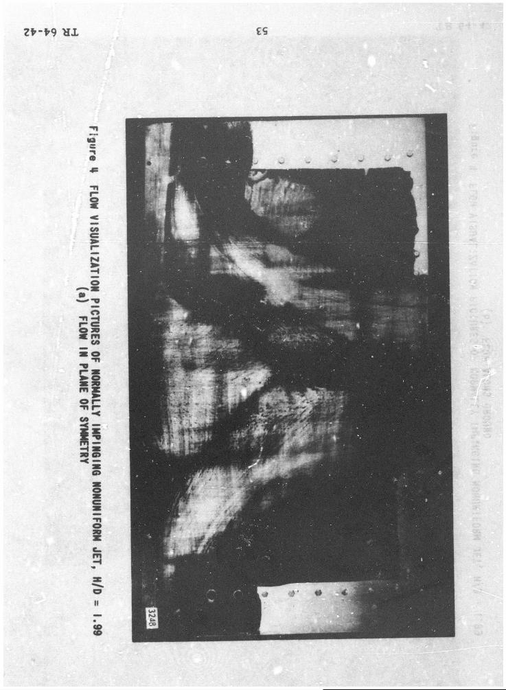

HX

HI

7V-V9 H I
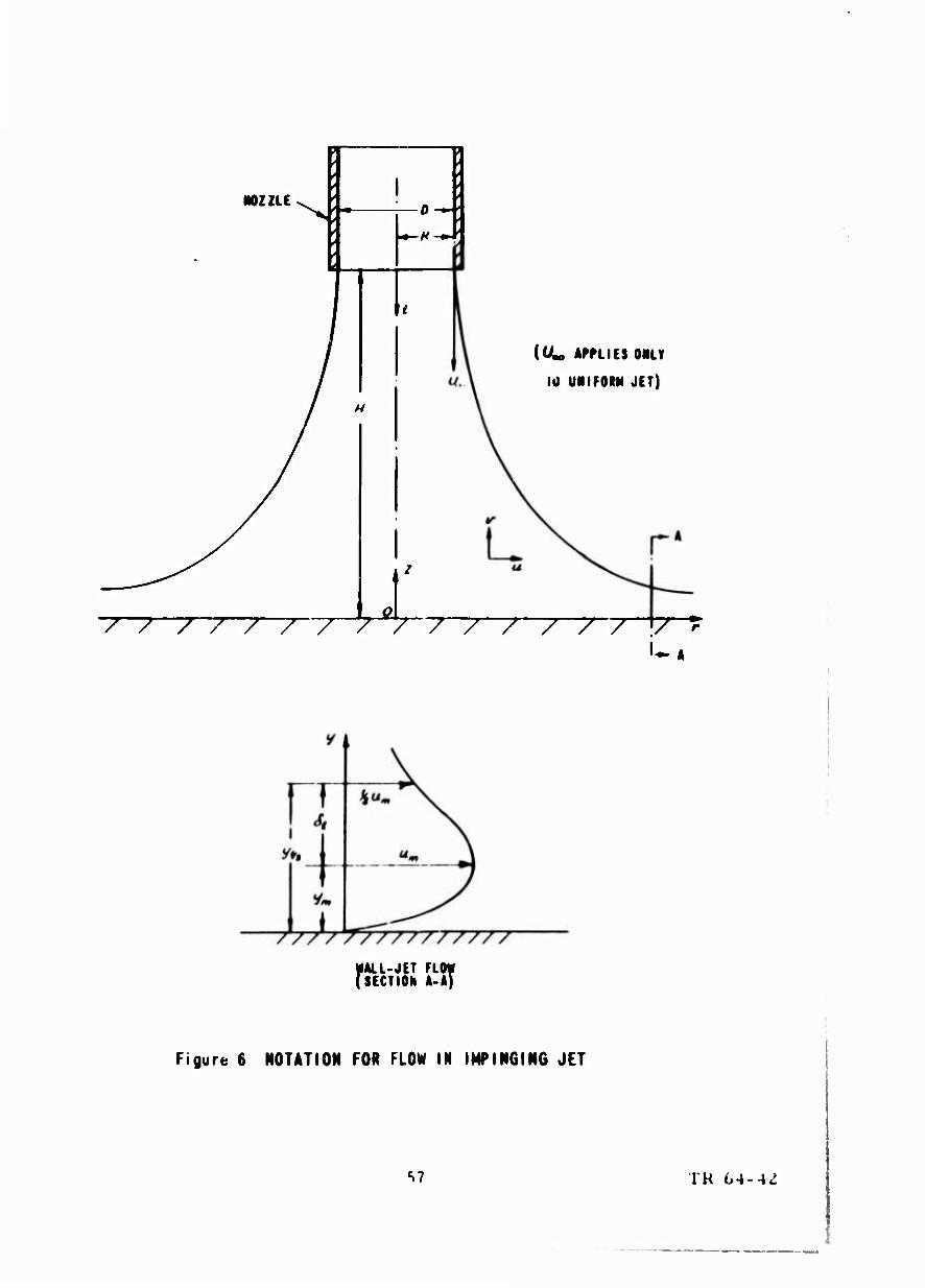
102ZLE 0
i
H
(OL APPLIES ONLY
Iti UMIFORM JET)
/////////////// V
MALL-JET FLM (SECTION A-A)
Figure 6 NOTATION FOR FLOW IN IMPINGING JET
S7 TH 64-4^

?i--\-<) Hl R^
i
P O o
3
o
3 «:
y o
o i
O M
-IA/Ü, O *
T tr
»Vv
O-Qf»"-^
D
IS»
□ ^<p o
V.
•_ — t;-*«
0
0
-o—►—
OCf^
\
'o-o»--vr
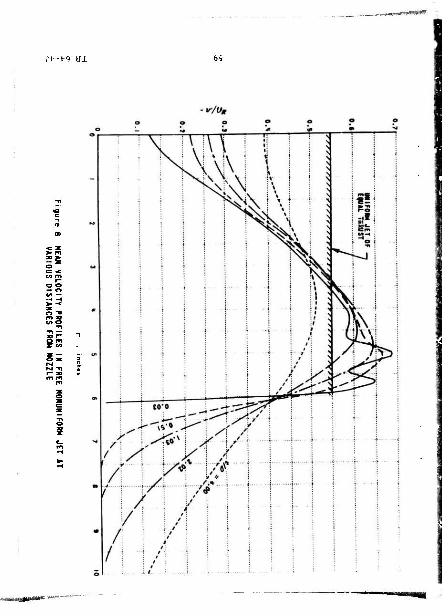
rt-f-q HJ. 6^
OD
o c < v» m
r- o o — o to —
o -o m ag co o
o
r- "» m tn
3 O 3"
3 i

I - I '» HI ()'»
~ir/Un
^"^
o o
c -1
O O
c X
« r- — O rt^ ~« o -v.
o >► —I X
o o ir
s o m rsi
o o
O O s o
o •<
■< o
A
V
\ \
o IT
v
o
/ / ;
/ /
i i \
o
in n
/
/
i i
2 i
i

2.2
2.0
1.8
1.6
I.H
1.2
1.0
O UNIFORM JET V NONUNIFORM JET
END OF POTENTIAL CORE IN NONUNIFORM JET
v ^ \- (I > 0. (I > 0.21 i/P)
V-
%
0.8 1.6 2.H
Ho 3.2 H.O 4.8
Figure 10 VARIATION OF MASS FLOW IN UNIFORM AND NONHNIFORM FREE JETS WITH DISTANCE FROM NOZZLE
61 TR 64-42

Figuren MEAN VELOCITY PROFILES IN NOZZLE EXIT PLANE FOR VARIOUS H/O. NONUNIFORM JET
62 TR 64-42

Flgurt 12 »JA« STATIC MESSURC PROFILCt IN N0I2I.C MIT FLAME FOI VARIOUS H/I>, mmmmtu
63 TR 64-42

7*'*° Hl ^9
(P^-PA I ft) o
8
e
M
'«•
05 oS
i
§
r ...
i I i i
i-o-r
a»
i
O I
I
■♦r
I i
•4
■f ■ i
-I f- t" i i
1 r
4-••-•{--•-|-
o !
• + I
•t- i
i
4-
i
t" ■4- * i
i \ ■ I i-
! •f
1 r ! I
I
4 i
!
o ^ o o|
e 8 8 o
i I 4-
t
J. i.
•I i i

Z¥'*9 Hl S9
<S-V^)
2 o
3 M
«Si
S!
^ >. t)
i i
t • • < 9 *
• « 5
•
5 • « X k
; i
: i i j l •
i j i i i •
: I * I 1 J • !
1 1 j j .1
i
e 1 •
1 .X ...i..
,
, \ i s ! 1
M
1 i i 1 i-4
j i i
•
r |
e • i j i f j • : 1 i i
1 h.*.>....
■! •■■•■-
i 1 i L. i i J f#-« i- -1 ► < k |1«......*4 ^•.•••» »i
• « • 1 1 i
i : j- 4 ■
!
i 1 : [ i +
1 ^ ►• i
1 1 O ■i 1
i ! 1 O • * ! 1 i i
> ■f 1
i 1 i *l It
j
f i J i
• 1 •
I *
i ■ •
-•»I* i j i > ] i ' • t 1
• o
0
...9...
1 «1 • ■
i J
1 j 1- j
i
!
1
! i 1
«
|
|
.%i
0 T 1 i
r
« •
y * - | * -j j- j
j {
"O "j ...... .^ • • --J i 1 0 ^ O li i 1
<m T 0. 1
*
| |
^
H
...... .J
»
* '■"< t ! j "-I
j 1 •♦ • 1 \
1 ( t
»
i i i ! 1 I
• i o »
i j
1
1 ;
j 1
1 . ... s
1 5
1 ft
1
i i
! |
■ ■ .... &
i *

7f-l-9 \L] 99
("s-l/f*) tr wi
o
8
c
fl»
| o
5
O —
II -<
is»
^ ^
I s
i I i -n O
♦ O D
OD
jo > a < - j
I 9
1 u

jfr-t-g HI L9
n-'Ju)
*A
(A
•M
II — i
I
n i
■4-
L....1.
»
! •f-
<*1D
! ..{..
+- ...4... • "I
i
•f--
0 ^ D 0
3i«
>-•-
■
1 +•
: t
.i.
■\

7t--t-o ax <?9
(1 -'*/<>*)
IB c
• IS»
-1 »
«
-< O e ^8 -H c:
2 ^ o pc« m » >. -H >^ W — • i
r> ot a»
-o O. 90 <• m io bo -i c/» « c= o 1 » 3D ■ 1
«» m OB 1
o CO 1 -< < 30 ^
g
o s
I ^
0 t> «A 1
o r- j
3 o i CD
8° a 5
^ - ... ^.-—'.

Z>-^9 Hl 69
"i-VfJ
3»
3
s
o 0
8 i 3 S

■
7*-*9 Hl OL
c
8
%/tm
^8 8:3
P 1
M
58 V* -4
is
o o
o m
II
-^
o
o
s
II
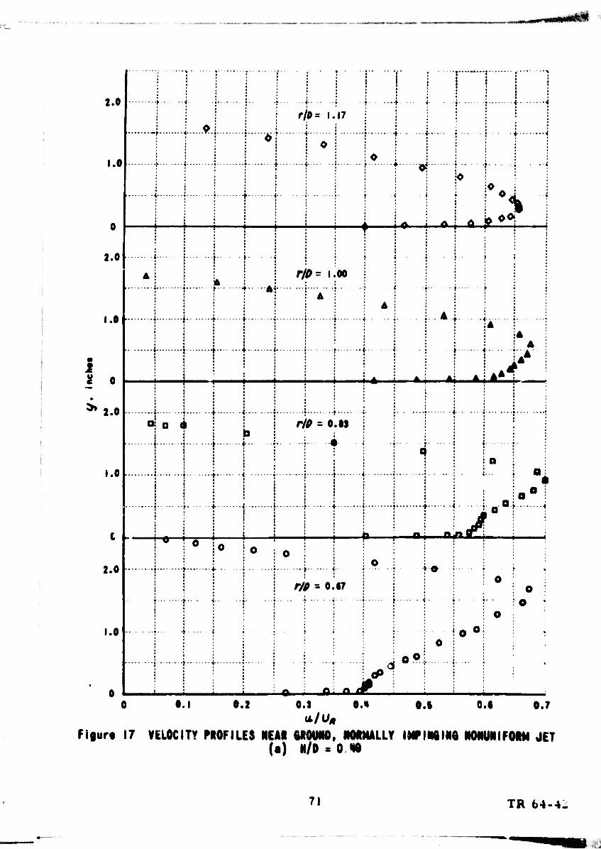
2.0
1.0
2.0
I .Of
2.0
1.0
2.0
1.0
—f-
+•
r/0= 1.17 ■i | — I O : I i j
••■< !•• • *•
< a i—a.
- >
.f.. r/p= i.oo
Ai-
t- ■t-
» o *
i e '
—»•
b .f..
r/P - O.IS :
*-SL ooi i
■u
Md
MM £ r/e - 0.17
t •
■ <
0.1 0.2 0.1 0.0 0.7 O.S 0.«
Figurt 17 VELOCITY PROFILES NEAR GROUND. N0RHALLY INTIMINQ N0NUNIF0RM JET (•) N/D'OHO
71 TR 64-4-

1.5
i.O
0.5
1.5
1.0
0.5
1.5
u I 1.0
0.5
1.5
1.0
0.5
a
1.5
1.0
0.5
0
i '
i i
■ i-
j I
o t
*£ op t
rfO - 1.67
r/0 = 1.33
r/D = i 17 ■ ■■> i ■-■
r/0 r i.oo
*^
■♦-.—♦-
o O
a o
a ■t- + • ■*■
♦ ■ >- jxxtxai I
A
j A I Aj i^ r/^ = 0.51
* ft. ■
.« i
kd5
•0.2 •0.1 0 O.i u/U,
0.2 0.3 0.H
Figurt 17 VELOCITY PROFILES «(EAR QROUND, NORMALLY INPINQINQ NONUNIFORM JET (b) H/D = 1.99
72 TR 64-42

2.0
1.0
0
2.0
1.0
« u c - 2.0
i.o
2.0
1.0
> I }
}
f
A.
-•—♦■
V ft fr^
rlD - 1.17
t
rm
s • A!
J ...j.
= 1.00 -t
a
rJO= 0.S3 ■o
P o!
0.! 0.2
a
il 0.S 0.1 0.7 0.3 0.«
Figure 17 VELOCITY PROFILES NEAR ftOUND, NORMALLY I^IN6IN6 NONUNIFORM JET (c) N/D = H.07
73 TR 64-42

s
ZV-V9 HX *L
, fum
ml
s § o 3

WJ »«4». -.-„
^^-l'9 HJ. SA
**/um
to c -i A
s c:
o
o
s -n r- m CO
1
V
o o
e
5 i C-
I II
is o
o I
o
ft QR u II II
»z-ir* — — —
II -*-*ö ^o 5 o -wm
— m^ 0»ll m
5*8
I I
il 2353222t
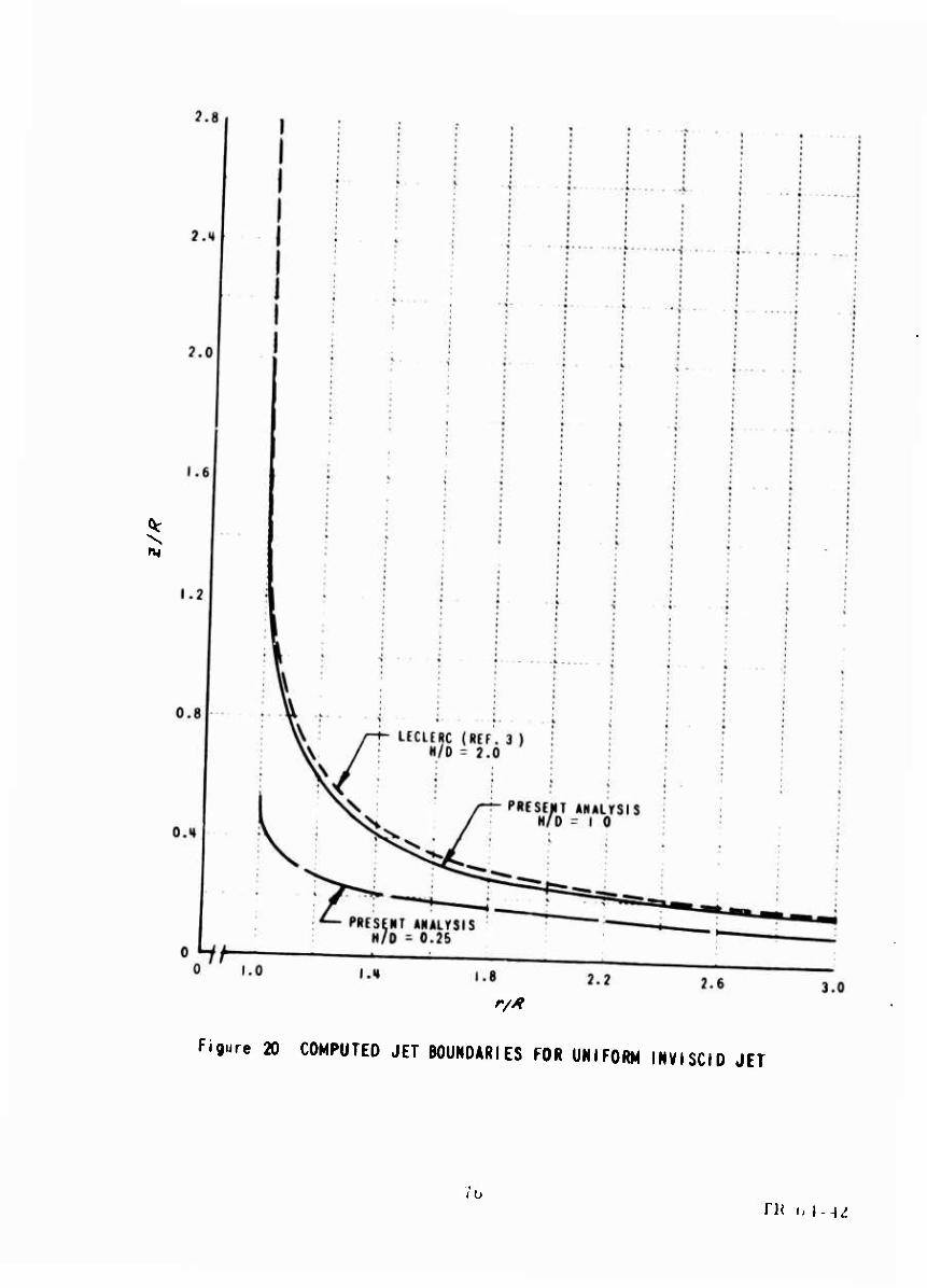
^ \ m
r//f
Figure 20 COMPUTED JET BOUNDARIES FOR UNIFORM INVISCID JET
ib TH t, J--^

■«»•¥*«'
, i , i "i r r i i t t < p » • tiii ... • i i , i , , . ||l< • . • I I 1 . 1 • . ' • | | I I I ■ ' '
i i i i \ i i 1
+■
0.8
^ 0.1
EXPERIMENTAL H/0 - 0.26
mm SVM00L
0 o
N/0 0.26 1.0
o.*
0.2
L........X,. mm~mmmJLmmm Y t
1 • • •
I- k— -1—" I — JD 1 1 1 t 1 1
4r-4—■ -----r•••••• •**f
• • i ■ 1 -r •
\ v-j. EXPERIMENTAL
^T i/O« 1.0 (REF. i) • *
.....4*** >••*** «(* mm mm •-rN -—+ V i "t" i--- •v--
< •
■-j
^ si
• •
i—
i
i
1 • 1
'1" * 1 1 * * 1
\ -j - |- f —- ....j,.... .- .•.p......
-rs
* i
■ • » • ) t
-
* 1 t i
k • t • * 1 1
0.2 0.« 0.0 0.6 1.0
*/*
Figure 21 JET-CENTERLINE STATIC PRESSURE DISTRIBUTIONS, UNIFORM JET
77 TR 64-42

71-^9 HI. VL
^s-v/dpuJ)
c
<»
3D
|
W
iA
m
iA
V*
3

0.2
• arj&s&TiSTm ...},. ..4.
0.1 •.« o.i o.i i.f
n* Fifurt 21 VELOCITY OltTllMITIOftS AT NOZZLE El!?; IMIFOM JET
79 TU 64-42

I -I 'I >l.l OH
to
•P
I- O
X >• •H
O — -n O
o CO < nj o c: o x m 30 O
3^
o o X o — *n
— > at o o — z r* o c§ m X ■H m
^

10
9
8
7
1— ' ' ' UNIFORM JET j
r* ' —I \ HOHUNIFORM JET I
SYM % ^ SYN H/o H %J
O « 1.0 • «.07 0.550 0.582 1 A 2 1.0 4 I.N 0.557 0.537 o 1 0.077 o 0.5 0.81 ■ 0.8t 0.582 0.881 o 0.2S 0.56
5 8 7 • • 10
Figure 25 NONOIMENSIONAL RAQIAL MASS FLOW vt. r/R FOR BOTH UNIFORM AND NONUNIFORM JETS
f
Hl 1R (.\~-id

Figure 26 VARIATION OF FLOW PROPERTIES NEAR GROUND WITH RADIAL DISTANCE FROM STAGNATION POINT, NORMALLY IMPINGING UNIFORM JET
(a) MAXIMUM VELOCITY NEAR GROUND
82 TR 64-42
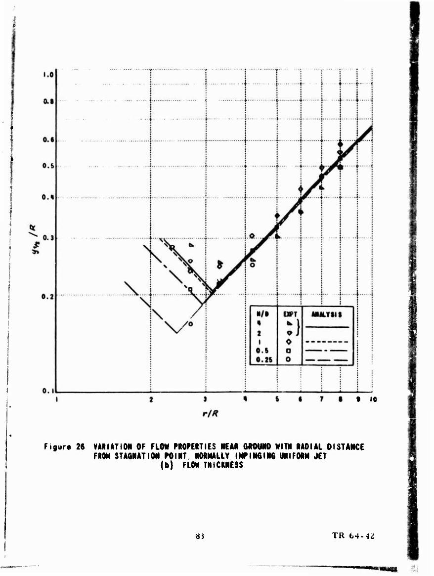
t 10
Figure 26 VARIATION OF FLOW PROPERTIES NEAR GROUND WITH RADIAL DISTANCE FROM STAGNATION POINT NORMALLY IMPINGING UNIFORM JET
(b) FLOW THICKNESS
Hi TR 64-4Z

TAILED SYMBOLS - VELOCITY PROFILE DIFFERENT FROM WALL JET PROFILE OPEN SYMMLS - HION MASS FLOH(6V = 270 fps CLOSED SYMMLS - LOM MASS FLOH, «4 = 171 fp«
0.1 9 10
r/*
Figure 27 VARIATION OF FLOW PROPERTIES NEAR GROUND WITH RADIAL DISTANCE FROM STAGNATION POINT, NORMALLY IMPINGING NONUNIFORM JET
(a) MAXIMUM VELOCITY NEAR GROUND
84 TK 64-4iJ

1.0
o.s
0.6
0.5
0.«
(V 0.3
0.2
0.1
TAILED SYMMLS - «LOCITY MOFILE DIFFEIENT FMN HILL JET flOFILE OPEN SYMMLS - HI8N NASS FLO«, (^ = 270 fpt aOSED SYMMLS - LOW MASS FLOW, U, - 171 fM
S • • 10
Figure 27 VARIATION OF FLOW PROPERTIES NUR GROUND WITH RADIAL DISTANCE FROM STAGNATION POINT, NORMALLY IMPINGING NONUNIFORM JET
(b) FLO« THICKNESS
85 TR 64-4i

If M.I ')«
//A?
M a>
-n o o o 3D z
-o 1 c: »^ —« O m ii
^ ~ as • 8 >• r-
c ^ -H ■^w» m o
•«: II m
r* _ o • o o
■•
^ X -• < s o -n o —
5 2
c^ o
in
^ ^
^ f
c > < • < 0
» < • > • e
c • o o •
o •
o •
o *
...g. c e
r- ... » ... m
p - - - - r ■
•
. .J. 4 t 1
( 1
t
1
i-
1
n ; o . J.. o ; m I
o ;
I0
i-
o 1
a» 1
. 1 1
'
•
-c-^ i o
•
; • - ' • 4
"i
......
^

•H «MSKft-j'lft?**
7 t--K* HI. LU
01 Um
5^1
I S
s
V
\
O - ^N
M ^%^^ *
^.
o N \
•
m s v V fr
1 !
i t
- 3 8 5
•
* m
1" 3
• \ m >
V o \
\
o
• M
• «
• •t
^^
•
1

Zfr-fr9 Hl 88
o v*\4fipA
8
1%
oo
o
ii f»
33
m
Is 3
c/>
g5 o
M
I
/
'
/
/
/
/
'
—
UilFO
RM JET
O ■O
WIH
IFOM JET
\
' 5

*.*
rtr
Figure 31 REPRESENTATION OF VORTICITY LAYER ON ED6E OF INVISCID JET
a9 TR 64-42

r'r0(*)
77777777777777. V////////////A ^•r
Figure 32 FLOW MOOa USED IN INVISCID ANALYSIS OF CIRCULAR IMPINGING UNIFORM JET
'/() IK M- 1^

t
*-?
Figure 33 BREAKDOW OF REGIONS OF INTEQRATION
'II TR 64-42

DISTRIBUTION
U. S. Army Materiel Command 3 U. S. Army Mobility Command 3 U. S. Army Aviation Materiel Command 4 Chief of R&D, D/A U. S. Army Transportation Research Command 67 U. S. Army Research and Development Group (Europe) » I U. S. Army Engineer Research and Development
Laboratories 3 Army Research Office-Durham Z Ü. S. Army Test and Evaluation Command 1 U. S. Army Engineer Waterways Experiment Station 1 U. S. Army Combat Developments Command
Aviation Agency 1 U. 5. Army War College 1 U. S. Army Command and General Staff College 1 U. S. Army Aviation School 1 U. S. Army Infantry Center 2 U. S. Army Aviation Test Board 1 Air Force Systems Command, Wright-Patterson AFB 1 Air Force Flight Test Center, Edwards AFB 1 Bureau of Naval Weapons 4 U. S. Naval Postgraduate School 1 Naval Air Test Center 1 David Taylor Model Basin 1 Ames Research Center, NASA 1 NASA-LRC, Lengley Station 1 Lewis Research Center, NASA 1 Manned Spacecraft Center, NASA 1 NASA Representative, Scientific and Technical
Information Facility 2 Research Analysis Corporation 1 National Aviation Facilities Experimental Center 1 U, S. Army Standardization Group, Canada 1 Canadian Liaison Officer,
U. S. Army Transportation School 1 British Army Staff, British Embassy 1 U. S. Army Standardization Group, U. K. 1 Defense Documentation Center 10
92

li I km i m m H ill! m
-IB B
I ill " r
i r
5!?
ill IS ^' illii r ' in

m jig' F
iir 11
.,<*•■