Embed Size (px)
Citation preview

N777AR U C MS
IO M N c C 4, E ) AR SA VI F A
iII NO 83NPRDV N 84 71/6 W li
I~~~ lhhhhhhIME hNhhEE
"r---- -- --
Igo
I M18I I
11111 . 5 1111
MICROCOPY RESOLUTION TEST CHARTNATIONAL BUREAU OF STANOAROS,,.,3A

PNPRDC SR 84-7 NOVEMBER 1983
NATO SEASPARROW SURFACE MISSILE SYSTEM (NSSMS)ORDNANCE PUBLICATIONS: A REVIEW AND
RECOMMENDATIONS FOR REVISION
PROVED FOR PUBLIC RELFASE;
DISTRIBUTION UNLIMITED
: NAVY PERSONNEL RESEARCHSAND
" DEVELOPMENT CENTER X/
€. San Diego, Californi 92152
84 01 17 096
-4-
NPRDC Special Report 84-7 November 1983
NATO SEASPARROW SURFACE MISSILE SYSTEM (NSSMS)ORDNANCE PUBLICATIONS: A REVIEW AND RECOMMENDATIONS
FOP REVISION
Robert 3. SmillieThomas E. Curran
Reviewed byR. E. Blanchard
Released by3. W. Renard
Captain, U.S. NavyCommanding Officer
Navy Personnel Research and Development CenterSan Diego, California 92152
-4, - • ,K;

UNCLASSIFIEDSECURITY CLASSFICATION or THIS PAO% (IRAR Do. 011010000_______________
REPORT. DOCM ENTATMO PAGEED I1. REPORT NUMERN jL VT AATCCESS101011O11
NPRDC SR 84-7 jq/}.)13(p ?17 _________
4. TITLE (and #"t~)S.Tpor11ORaPEIDC8410
NATO SEASPARROW SURFACE MISSILE SYSTEM Mpa 82-Nor8(NSSMS) ORDNANCE PUBLICATIONS: A REVIEW *. 1191OIK ON.I"OR VS~AND RECOMMENDATIONS FOR REVISION
7. AUTHOR(@) i 5GRNNU8
Robert 3. SmillieThomas Curran
S. PERFORMING ORGANIZATION NAME AND ADDRESS IS. P@AISEUI 7 PRgJ TOS
Navy Personnel Research and Development Center WR02464San Diego, California 92152
11. CONTROLLING OFFICE NAME AND ADDRESS 12. REPORT DATE
DevelpmentNovember 1983Navy Personnel Research and DvlpetCenter 13. NUN9ER OF PAGESSan Diego, California 92152 3
14. MONITORING AGENCY NAME A ADDRIESS(11 dfetent 0001 Cent0 01d O10194) $S. SIECURITY CLASS. (Of 16de~n~
16. DISTRIUUTION STATEMENT (of this Repect)
Approved for public release; distribution unlimited.
17. DIST RIOUTION STATEMENT (of the ahbftauI entered Inl tReek ".,It Offers"I Avon RhpeeI)
I0. SUPPLEMENTARY NOTES
It. KEY WORDS (Caetbm.e of rweere side It nonessay and identity 6F wleek Near.)
(6 Technical manualsOrdnance publicationsTechnical documentation
C Technical manual usability20. AUSTRACT (CaNS... - SPOWWO Od f e.mpEadf bSekae)
'M-Iuman factors criteria were used to identify information presentation discre-pancies in the NATO SEASPARROW Surface Missile System (NSSMS) ordnancepublications (OPs). Concurrently with the human factors review, fleet personnel weresent questionnaires and were interviewed to determine if general usability problemsexist and to identify specific problems fleet personnel have had with the NSSMS OPs. P
o un R43KEITIOIN OP I Nov so Is GSOILSTI UCLASSIFIEI)'S/N 0 102- LF- 0 14 6601 cmwCA.IAIOPTNPGSIrGU
'1UM

UNCLASSIFIED
fACUfTy CIAM"CATM OP T141 PAiS MNI 8 &
. The following problems were identified: A systematic top-down approach was notused in presenting and organizing the NSSMS technical data; the format changes frommanual to manual and even from chapter to chapter; information is difficult to locateand access; faults are difficult to isolate; the maintenance philosophy and the level oftechnical detail do not always match; and the coverage is redundant in some areas andincomplete in others. Suggestions for resolving these problems were made.
I
S/N 0102- I.F- 014- 6601 UNCLASSIFIED
l1CURUTY CLASSICAION OF THIS PAiG9Mb DOD bfm
-- o

FOREWORD
This project was conducted for the NATO SEASPARROW Surface Missile System(NSSMS) project office (SEA-06P) in response to a request by Commander, Naval SeaSystems Command (NAVSEA 0141(3)). The project resulted from initial efforts that wereconducted under the advanced development task area Z0828-PN (Enlisted PersonnelIndividualized Career System (EPICS)).
NSSMS ordnance publications were analyzed according to human factors documentdesign criteria and fleet input. The results of this effort are intended for use by NSSMSproject office to reformat the NSSMS ordnance publications.
3. W. RENARD JAMES W. TWEEDDALECaptain, U.S. Navy Technical DirectorCommanding Officer
NTIS GRA&IDTIC TABtannounced 0Justificatio
By
Distribution/
Availability CodesAvail and/or
1st Special
v
-- p
-4--

* 1 ~ '' 4 2q,
11
p I
I -fit N, - "
-4 -i--J

CONTENTS
Page
INTRODUCTION ........................................................... I
Problem ................................................................. IPurpose ................................................................. IBackground ....................... ...................................... I
APPROACH ............................................................... I
RESULTS AND DISCUSSION ................................................. 2
General Problem Areas .................................................... 2Automatic Fault Isolation ............................................... 3Trouble Isolation ....................................................... 3Organization and Packaging .............................................. 5
Readability Analysis ...................................................... 6Specific Problem Areas ................................................... 9
OP 4004 ............................................................... 9OP 4005 ............................................................... IIOP 4006 ............................... ............................... 12OP 4007 ............................................................... 13OP 4036 ............................................................... 14OP 4053 ............................................................... 14System Evaluation and Test Manuals ...................................... 14Illustrations ................................................ ........... 14
Fleet Input .............................................................. 17Fleet Questionnaires .................................................... 17Fleet Interviews ........................................................ 19
CONCLUSIONS ............................................................ 20
RECOMMENDATIONS ..................................................... 21
REFERENCES ............................................................. 25
APPENDIX-FLEET SURVEY INSTRUMENTS .................................. A-0
DISTRIBUTION LIST
ix

LIST OF FIGURES
Page
1. Overview of the NSSMS troubleshooting data categories ................... 4
2. Selected NSSMS passages with lowest and highest RGL .................... 8
3. OP 4005, paragraph 2-184, without and with breaks ........................ 10
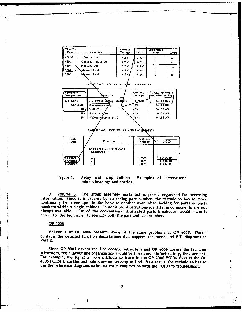
4. Relay and lamp indices: Examples of inconsistent columnheadings and enti ies .............................................. 12
5. Foreword for OP 4007 describing its confusing organization ................ 13
6. Comparing the grid coordinate referencing systems used in OP 4036and OP 4005 ......................................................... 15
7. Examples of different referencing systems used to trace a signal from oneOP to another ........................................................ 16
8. Example of development process for revising NSSMS technical data ......... 22
x
1"
1.t

INTRODUCTION
Problem
Concern expressed by fleet commanders in chief regarding inadequate technicaldocumentation of the NATO SEASPARROW Surface Missile System (NSSMS) and theextensive cost of updating the technical manuals in their current configurations promptedthe NS7MS project office to consider the effectiveness of the NSSMS technical publica-tions. With the Naval Ship Weapon Systems Engineering Station (NSWSES) assuringtechnical accuracy of the NSSMS data, a human factors review was initiated to identifycontent and organizational discrepancies in the technical information.
The purpose of this effort was to identify specific problem areas in the NSSMSordnance publications (O0s) and make recommendations for improving the usability of theNSSMS technical data.
Background
The technical data for the NSSMS comprise 48 OPs in the following seven majordivisions: (1) overall system, (2) fire control subsystem, (3) launcher subsystem, (4)computer, (5) signal data converter, (6) low-level light television, and (7) systemevaluation trainer.
Booher and Mroz (1981) reviewed the NSSMS documentation and found that most ofthe technical data in the OPs were oriented toward engineers rather than technicians.They concluded that the large NSSMS technical data base was poorly organized andindexed for the user. It was not readily apparent from the OPs if a top-down systemsapproach had been used to organize and sort the technical data.
APPROACH
The NSSMS OPs were reviewed using human factors criteria to identify informationpresentation discrepancies. Each category of information (e.g., function diagrams,schematics, troubleshooting tables, etc.) was reviewed and examined for completeness andoverall usability. Samples of the NSSMS OPs were analyzed from the user's viewpoint toidentiiy any technical content areas that are incompatible with user needs. To determineusability, the technical data were assessed according to (1) user access schemes requiredto locate specific sets of data, (2) completeness of the information for fault isolation, (3)consistency of data organization across and within subsystems, and (4) comprehensibilityrequirements of the user population.
The organization of the troubleshooting data was examined to determine if itprovided a logical layout for the technicians to reference for fault isolation. Thecontribution of the automatic fault isolation circuitry to the troubleshooting data wasexamined. The following troubleshooting data were analyzed for completeness andconsistency at the equipment, subsystem, and system levels: (1) troubleshooting indices,(2) mode block diagrams, (3) fault isolation and detection (FID) block diagrams, (4) fault-oriented interconnector diagrams (FOlDs), (5) power distribution diagrams, (6) reference(schematic) diagrams, (7) maintenance control and indicator tables, and (8) relay and lampindices. Problems in p "kaging and accessibility of the data were noted and described.
I
-- I

The comprehensibility of the OPs was examined by assessing both reading difficultyand text layout of the OP material. In the readability analysis, narrative samples fromfive of the seven major OP divisions were analyzed using the "Writer's Workbench" textprocessing package developed by Bell Telephone Laboratories (Macdonald, Frase, Ginsrich,& Kennan, 1982). Reading grade levels (RGLs) were determined according to the methoddescribed by Kincaid, Rodgers, Fishburne, and Chissom (1975).
The quasi-random samples of materials selected from the various NSSMS manualswere passages of continuous text, preferably an entire paragraph, approximately 100 to200 words in length, without tabular material, and with a minimum of symbols peculiar tothe NSSMS system. The number of samples from any given volume was approximately indirect proportion to the amount of text in that volume.
Concurrently with the human factors review, fleet personnel were sent questionnairesand interviewed (see appendix) to determine if general usability problems exist and toidentify specific problems fleet personnel have had with the NSSMS OPs. Twentytechnicians--17 in the fire control technician (surface missile fire control) (FTM) ratingand 3 in the gunner's mate (missiles) (GMM) rating- -responded to the questionnaire. Theirexperience on the NSSMS ranged from 7 months to 4-1/2 years. Only three had less than 2years experience, while nine had 3 or more years experience. During the interview phase,comments were obtained from nine FTMs and two GMMs. All of these had at least 2years experience on the NSSMS; six had 3 or more years.
Because of the problems of obtaining field data, a randomized design was notpossible. Rather, an "as available" basis was used to obtain both questionnaire andinterview data from both Atlantic and Pacific Fleet personnel. The range of experienceof respondents, however, indicated that the sample is representative of NSSMStechnicians.
Upon completion of the review, a plan for reformatting the NSSMS technicaldocumentation was defined. This plan provides for OPs that satisfy the users' needs andare consistent with the user's skills and knowledge, while making maximum use of currenttechnical content. The objectives of the reformatted OPs are to provide a set ofdocuments that (1) the schools can use readily to teach troubleshooting while alsoproviding the operational information needed to understand how the NSSMS functions, (2)users can easily access for troubleshooting data, and (3) the NSSMS Project Office canupdate inexpensively when modifications are made to the NSSMS.
RESULTS AND DISCUSSION
General Problem Areas
Careful examination of the NSSMS OPs indicates that they were not systematicallydeveloped. Neither the separation nor the relationship of the operational andtroubleshooting data are evident. It appears that an original core of technical data wasdeveloped first and then augmented with more detailed information. What emerges is aconvoluted mix of operational and troubleshooting data that requires making a choicebetween teaching the system or teaching how to troubleshoot. A more integratedapproach would use the operational data as the basis for understanding how the systemworks, while at the same time using the troubleshooting data to supplement theoperational data and provide the user with the necessary information to operate andmaintain the system.
2 -4!~

Confusion between understanding how the system operates and how to troubleshoot itis apparent in OP 4004, the technical manual that should provide the overall structure tothe technical data. Volume 1 presents an overall operational description, while Volume 2attempts to integrate the various data in the subsystem OPs to provide the technicianwith a cohesive structure for troubleshooting. Unfortunately, the pattern that emerges isnot what technicians use to fault isolate malfunctioning components.
Automatic Fault Isolation
Built-in test (BIT) and FID circuits, which are an integral part of the NSSMScircuitry, are designed to provide the technician with shortcuts to corrective maintenar-eby permitting the normal troubleshooting documentation to be bypassed for some failt:Supposedly, faults not isolated by the BIT-FID circuits are detected during the NF 5system level test (i.e., the daily system operability test (DSOT)). Unfortunately, -proportions of the NSSMS circuitry covered by BIT-FID circuits and DSOT are ,Iindicated. To compound the situation, an indication of failure by the BIT-FID circuit Imean that either the operational or the BIT-FID circuitry failed. It is impossible toTherefore, regardless of initial fault indication, the basic troubleshooting procedure isame: Start with the indication and work backwards until the fault is discovered. ihetechnical data do not provide the user with the information necessary to go directly to thesuspected fault.
Trouble Isolation
In OP 4004 , the user is lead to believe that the trouble isolation data are
systematically organized with three levels or sets of trouble isolation documentation:system, subsystem, and equipment.
At the system level, system functional diagrams depict development and transfer ofmajor system functions. A narrative, detailed functional description is also provided.Using these data facilitates checking interface signals and commands between theexternal designation source (e.g., search radar and NSSMS). At the subsystem level,design of the trouble isolation documentation is supposed to provide troubleshooting downto the ship replaceable assembly (SRA). Thus, at this level, only overall fault directoriesare used to categorize the trouble symptoms and reference the trouble isolation data forspecific equipment.
At the equipment level, fault directories from either the system or subsystem levelsprovide additional references to the trouble isolation documentation needed to isolate thefault to a defective SRA and effect necessary corrective action. Descriptions areprovided of these troubleshooting data (i.e., troubleshooting indices, mode block diagrams,FID block diagrams, FOlDs, power distribution diagrams, reference (schematic) diagrams,maintenance control and indicator tables, and relay and lamp indices) but not of theirinterrelationships.
Figure 1 is an attempt to illustrate the various relationships among these data.Several problems, however, must be noted. The usual entry points for troubleshooting areeither DSOT or the BIT off-line tests and, although additional information sources areavailable, the usual troubleshooting path is directly from the indication to the FOLD. Forexample, consider that a faulty filter-rectifier assembly (15/16A4) lights the AMPLIFIERARC indicator on the control monitor. Technicians using the trace-back method wouldbegin with FOlD Figure 5-231, sheet 3 of 3 and trace back through sheet 3 to sheet 2 andeventually to sheet 1. From there, another book, the power distribution diagrams, has to
3
I__ _ _ _ _ _ _ I .IlIlI• I-4-

NORMAL OPERATION
FAULT INDICATION4MODE INDICATOR FUNCTION-SYSTEM FAULT LEVEL -SUBSYSTEM FAULT
FAULT DIRECTORIES DIRECTORY DIRECTORIES
OSOTI
SYSTE PERFORMANCE CODESSYSTEM FUNCTIONAL FAULT DIRECTORY
DIAGRAMS
TROUBLESHOOTING
INDICESBITOFF-LINES
TESTPROCEDURES
VOID MODE/FID DETAILSBLOCK DIAGRAMS
M C REFERENCESDIAGRAMS
Figure 1. Overview of the NSSMS troubleshooting data categories.
be consulted to find Figure 5-411, sheet 6. Tracing back from sheet 6 to sheet 5 leads backto the first book to FOID Figure 5-239, sheet 7 of 14. Tracing back from sheet 7 to sheet6 and finally to sheet 5, the filter-rectifier assembly can be isolated as the source. Foradditional technical information on that assembly, however, the technician must consult athird book, the reference diagrams, to find the schematic, Figure 6-110. Thus, technicianshad to refer to nine pages of data not in a direct sequence and in three books. Since onlyfigure numbers are referenced, technicians must know which figure numbers are in whichbook to avoid having to search through several books to locate a specific figure. With amore complicated problem, the laborious process of signal tracing through many pages caneasily become confusing and it is easy for the technicians to lose their place going from .one sheet to another. With many sheet and figure references involved, a typographical 4error can easily lead the technicians astray.
In addition to FOlDs, mode and FID data, both in narrative and diagrams, areavailable in the OPs to facilitate the troubleshooting process. The mode and FIDdiagrams are presented, at both the general and detailed levels, as separate types of databut integrated with each other. Both are important when troubleshooting beyond the BIT-FID circuitry and are usually referenced whenever a FOlD is referenced. However, the
4----

mode and FID data are in the operational section of the technical manuals and areessentially redundant with the FOlDs. Their main differences are that (1) the FOIDspresent all the relevant data together, based on indicator entries instead of firstpresenting the circuitry associated with a particular mode or FID circuit and (2) theyidentify test points, which the mode and FID diagrams do not. The end result is 15,000 or20,000 pages of data, of which technicians only use about 5,000. While the mode diagramsmay be useful in a school environment, time in that environment is limited. Since theschool is designed to teach troubleshooting, use of the FOlDs is emphasized over the modeand FID data, even though narrative explanations are available for the mode and FIDdiagrams and not for the FOlDs.
Although the maintenance philosophy is to troubleshoot to the ship replaceableassembly (SRA), inconsistencies it. the data do not always permit easy identification ofthe SRA. For example, the master oscillator power supply (MOPS) filament power supply(1 /12AIAIA4) has been identified as an SRA in some, but not all, of the documentation.The FOID (Figure 5-233), power distribution diagrams (Figure 5-411), and the additionalinformation on the schematic (Figure 6-384) do not identify the I I/12AIAIA4 as an SRAthat can be replaced. The mode and FID'diagrams (Figures 2-47 and 2-127) illustrate themaster oscillator power supply (1 /12A I A 1) as an identifiable unit and provide no furtherinformation.
Organization and Packaging
One of the more basic problems with the NSSMS OPs is that they are not designed forthe technicians' use. One might assume that a logical breakdown of the NSSMS wouldinclude a system-level document, a document for each of the subsystems, and, within eachof those documents, operational and troubleshooting data. In fact, there are a system-level document and subsystem documents. Unfortunately, there are also equipmentdocuments organized at the subsystem level. For example, the computer complex andsignal data converter, parts of the fire control subsystem, are presented in separatedocuments.
Each document consists of one, two, three, or five volumes with each volumeconsisting of one to ten parts. Why such a confusing organization was selected is notobvious or explained. To add further obfuscation, some of the classified parts containlarge sections of unclassified material. Apparently, continuity was more important than
• , was convenient user access.
Sizing is also a problem. While some material was easily packaged into an 8-1/2- byI l-inch book, the numerous oversized drawings necessitated the use of many 1 - by 16-inch books. Unfortunately, these books have no identifying marks on their spine and theonly way to store them is one on top of the other.
One might have assumed that, with so many books (48) and the problems arising from
different security classifications and sizes, the designer would have provided extensiveindexing to locate the numerous types of technical data. Unfortunately, this was notdone. In fact, only a single table of contents is provided in any given volume. Thus, tolocate a drawing in Part 7, the table of contents in Part I has to be consulted to obtain thepage number. This is particularly troublesome for OP 4005, Volume 1, because Part I isclassified and four of the remaining parts are not.
5
I'

Readability Analysis
Analyses to determine reading grade levels (RGLs) do not take into account thereader's overall life experiences that have brought the reader into contact with words andideas that have no true correlation with RGL. In addition, the vocabulary words peculiarto an individual's area of interest or vocation are learned independently of RGL and,therefore, do not contribute to the difficulty of written material regardless of length.Such words as superheterodyne, oscilloscope, or ionospheric inflate the RGL because theyconsist of so many syllables but are not difficult to read for those in the field ofelectronics. Therefore, the concept of RGL should be interpreted cautiously and notliterally. To say that NSSMS technicians with an RGL of 12 cannot read technicalmaterial with an RGL of 14.5 is to interpret the facts much too literally.
Table I provides the number of words and sentences, the average sentence and wordlength, the longest sentence, and the RGL for the passages with the lowest and thehighest RGL from each manual and the overall RGL for all passages from that manual.As can be seen from Table 1, passages analyzed in the total NSSMS documentation rangedfrom an RGL of 6.9 (OP 4006, paragraph 2-453) to 21.3 (OP 4007, paragraph 2-180). Forcomparison, these two passages are reproduced in Figure 2. The nature of the words usedin the two passages does not vary extensively. However, the second sentence in Figure 2bplaces a very great burden on the reader in maintaining the train of thought because it is67 words in length. That is, the critical characteristic of these passages for readabilityseems to be sentence length and not word length and its associated issue of the use oftechnical terminology.
Sometimes, however, word length is a problem that is not tied to the technicallanguage of the system. Take, for example, paragraph 1.2 of OP 4005, which reads:
1.2. Guided Missile Fire Control System MK 91 Mods 0 and 1,hereinafter referred to as the GMFCS, together with Guided MissileLaunching System MK 29 Mod 0, hereinafter referred to as theGMLS, and eight Guided Missiles RIM-7H, hereinafter referred to asthe missile, comprise the NATO SEASPARROW Surface MissileSystem MK 57 Mods 0 and 1, hereinafter referred to as the NSSMS.The NSSMS and GMFCS Mod 0 is equipped with a single radar; theMod I is equipped with dual radars.
This passage ha an RGL of 20.8, an average sentence length of 41.5 words, and anaverage word length of 4.57 characters. The information in this paragraph is relativelystraightforward and simple, but its "legalistic" language inflates the RGL considerably andprobably confuses some of the personnel who must read and understand the paragraph.Such terminology has no place in Navy technical manuals.
The solution to the problem of such writing may be relatively simple. In cases wherethe RGL is too high, an experienced technical writer/editor should be able to lower theRGL as needed.
It should be noted that there is no evidence to show that the usability or compehensi-bility of technical writing has any one-to-one correspondence with its measured reada-bility or RGL. However, warning flags should fly when the computed RGL reaches the
6

Table I
Readability Data for Selected NSSMS Passages
Sentences WordsAvg. Length Longest Avg. Length
Sample RGL No. (words) (words) No. (characters)
OP 4004Lowest RGL 10.0 6 20.2 22 121 4.68Highest RGL 19.4 4 31.5 56 126 5.32
Overall 13.4 62 22.2 56 1377 5.04
OP 4005Lowest RGL 9.5 5 15.6 26 78 4.54Highest RGL 20.8 2 41.5 63 83 4.57
Overall 14.3 51 23.5 63 1200 5.11
OP 4006Lowest RGLb 6.9 8 21.3 44 170 4.09Highest RGL 18.9 4 32.0 36 128 5.30
Overall 12.8 378 24.0 49 3785 4.81
OP 4007Lowest RGL 7.4 7 18.0 36 126 4.35Highest RGLc 21.3 2 48.0 67 96 4.70
Overall 12.7 55 25.2 67 1388 4.83
OP 4036Lowest RGL 9.9 6 20.3 39 122 4.66Highest RGL 21.1 2 40.0 42 80 5.47
Overall 12.6 76 23.1 51 1756 4.97
aRGL=reading grade level.
bSee Figure 2a for paragraph 2-453.
CSee Figure 2b for paragraph 2-180.
7_ _ __"
__ __ _ 4

2-453. Controlling the RAM during 2-180. Although for each channel thereSTAA. In the DECODER (B3) the are only two address registers, oneRAM write enable is generated by an associated with inputs and one withAND gate on receipt of CROM BIT outputs, the output data may be normal10, CROM BIT II, CLOCK 3, and 4 data or external function code words.MHZ CLOCK. This input combina- Therefore, for each channel, threetion produces a 125-nanosecond pulse separate address blocks must be used,in the second half of the third 4- each according to the type of data to beMHZ CLOCK period. In the RAM transmitted (i.e., input data, normal(A) and DATA RAM logic, the, output data, or output of externalLOAD RAM ADDRESS COUNTER function code words) and a commandpulse is generated by a NAND) gate must be accompanied by one of nineon receipt of CROM BIT 11, Clock 2, output device addresses (three for eachand 4 MHZ CLOCK. This input channel) to identify both the channel andcombination produces a 125-nano- type of data to which the new addresssecond pulse in the second half of block refers.the second 4-MHZ clock period. Thepulse sets the address counter to thevalue of CROM BIT 0-7. The RAMADDRESS COUNTER output is theADDRESS input to the RAM. There-fore, it can be seen that MUX OUT-PUT BITS 0-7 are received by theRAM at the start of the instruction,the RAM is addressed in the secondclock period and the word is writteninto the RAM in the third clockperiod.
a. OP 4006, paragraph 2-453: b. OP 4007, paragraph 2-180:RGL = 6.9. RGL = 21.3.
Figure 2. Selected NSSMS passages with the lowest and highest RGL.
proportions found in these manuals. Assume for a moment that technicians can read anymaterial written at the high school graduate level (i.e., RGL=12), which may or may notbe a safe assumption. Table 2 illustrates what this cutoff grade indicates for the samplesfrom the NSSMS manuals. If this assumption is correct (and the median RGL of Navypersonnel in general is closer to 10 than 12), technicians have some problem in compre-hending 60 percent or more of the NSSMS technical data.
The major issue in this effort is the improvement of comprehensibility and not justthe measurement of readability. Because of the issues involved in the learning of thelanguage of one's work and social milieu, RGL probably does not adequately reflect thecomprehensibility of material. Rather, it is only an indication as to whether or not thematerial is comprehensible. It is safe to assume that RGL underestimates the readingpotential of the incumbent technician. Unfortunately, there is no convenient method of 6assessing the comprehensibility of material as the readability formula assesses read-abity. The only true measure of whether or not material is comprehensible is to havethe technician read the material and perform the task it prescribes. If the task isperformed in an efficient and effective manner, it is safe to say that the techniciancomprehends the material.
8
' " , , ,,-4I,

Table 2
Percentage of Samples From NSSMS Technical Manualswith RGLs Below and Above 12
Percentage of SamplesManual RGL - Below 12 RGL = Above 12
OP 4004 38 62OP 4005 09 91OP 4006 28 72OP 4007 31 69OP 4036 29 71
Organization is another characteristic of written material that is directly related tocomprehensibility. There is no objective index, however, indicating how well the materialis organized. Some aspects of organization are (1) indexing so that the location of allmajor topics can be readily located in the text, (2) logical flow of paragraphs withinsections and of ideas within paragraphs, and (3) "formatting" so that single units (e.g.,paragraphs) contain single major ideas.
In general, the NSSMS documentation suffers from a lack of sufficient breakdown oftextual information. That is, many paragraphs attempt to cover an entire sequence ofideas that, with some forethought and a more suitable format, could be offered in a moreorganized manner. Take, for example, paragraph 2-184 from OP 4005, presented in Figure3a, which was picked basically at random. This paragraph conveys a great deal ofinformation without benefit of the pauses provided by a new paragraph. (This is not anisolated instance but is the rule rather than the exception.)
Note the difference in the ease with which the information can be accessed ifsuitable breaks are provided as shown in Figure 3b. No effort was made to perform otherchanges to make this material more readable. Further, there is no evidence that therevised version is any more comprehensible than the original. But intuitively, the revisionappears to be more readily understandable than the original version.
Specific Problem Areas
OP 4004
1. Volume 1. Volume I does not refer the reader to the more detailed descriptionsin the subsystem documents. Part I is classified but contains unclassified referenceinformation (e.g., Tables 1-1 to 1-4) that may be more useful as an unclassified appendix.Part 2 is an oversized volume with excessive white space: Two-thirds of the pagescontain text and tables on only one-half of the page. It contains oversized unclassifieddrawings that could be reduced and turned to fit on an 8-1/2- by l-inch page. Volume 1does not provide adequate information on how the entire OP suite is organized or how touse its components, although it is a general description document.
2. Volume 2. Volume 2 presents a confusing array of information on theorganization of the NSSMS fault isolation data. System functional diagrams are
9I
4 9 i~
S ---

c -U
0-u- u T . ~ Z~L O-
-u Mu~ ))~ )a
LL SO
Z0T.
',aE 0 aj u G0 L
E S4.d,7 E-.~tU
on .. ' u-
z o c -u z.-.-.00..11)n . l w D0n4<O <
~o o C) p C4) a. _j <0. b ~-6.
ul c w, cu j)c OIl u)) A! 0 u w - 1- .V
E ~ ~ 4 u14)CC;;u
Lu z 4) U11 .U 4 )
E <~E-~Z0 )0~
-c CK 0u( u 070
a4 v 0.00
I,I00
C4-

presented, but the narrative explaining the diagrams is in a separate book, Part I ofVolume I. In the sample problems described in Volume 2, the system performance-codesfault directory has much of the same information as the performance fault trouble-shooting indices of the subsystem OPs. The sample problem implies that the trouble-shooting procedure will ensure the fault is isolated, but that the FOIDs have to beconsulted to determine if a maintenance requirement card (MRC) is available to describethe corrective maintenance procedures. A more concise approach would have deleted theredundant information and reduced the amount of page turning.
OP 4005
1. Volume 1. Part I repeats the introductory material of OP 4004. Although Part Iis supposed to be the introductory document for the NSSMS fire control system, itcontains no information on the signal data converter or the low-light level television.Part I is a classified document that contains the mostly unclassified, general functionalnarrative description that supports the function description diagrams presented in Part 2.
Part 3 is also classified and contains the detailed functional description.However, the mode diagrams that this descriptive narrative supports are in Part 4.
Part 5 is the narrative that supports the general block and detailed FID diagramsin Part 6. While it may be important to know that there are FID circuits and operationalcircuits, it is not readily apparent why the FID is presented separately from the modecircuitry. To know how both the FID and mode circuits are integrated in the NSSMS, thereader has to refer back and forth between six different books.
2. Volume 2. Volume 2 has ten parts and is the primary source for troubleshootingdata for the fire control subsystem. It contains at least ten categories of usefultroubleshooting data, which are very difficult to use because of inconsistent presentationmethods and poor organization schemes.
Troubleshooting flowcharts are described in Part I but without location informa-tion. The format of fault directories for each equipment varies from two to threecolumns while that of troubleshooting indices, which the fault directories reference,varies from three to four columns. Column headings differ from equipment to equipment(see Figure 4). Those on the BITs differ from those on the MRCs. Maintenance turn-onprocedures are included only for selected equipment. The format of the relay and lampindices varies from four to six columns (see Figure 4). The maintenance controls andindicators are described as reference indices and illustrated in another book. Referencesto these illustrations are sometimes omitted.
The FOIDs are the basic data used to troubleshoot. Unlike the other trouble-shooting data, the FOIDs are organized separately by cabinet and placed into individualbooks. The ship replaceable items index in each FOID book lists much of the sameinformation listed in the parts breakdown in Volume 3. The power distribution diagrams,on the other hand, are separate from both the FOIDs and the other troubleshooting dataand are organized into a single volume. The reference diagrams (mostly schematics) areorganized by drawing number and not by cabinet. As the schematics are assigned newdrawing numbers, a blank page with a reference to the new drawing number is used as amarker for the old schematic, thus adding time and confusion to searches for a specificschematic.
11
1 I I
D.Control Reference3 Des. I '-nction Voltage FOSD heet
A3DSI POWER ON +25V 5-22A3KI Control Power On +25V 5-22 1A
Heater Off +25V 5-390 1 AZ,4 Manual Test +25V 5-26 2 A7
AZS3 nual Test +Z5V 5-26 2 B7
TA 5-7. .C RELAYANLAM INDEX
Vef crolt ae o,p,..ataon \hein and entries .ig
.S/6 K HV Power ply pntertck ist izS if19/LAA2A J=9 1 De.igna,re y +V I S-149 "3
co n Tunal frm on +so e Ive we
Ref c Control
a vile. Usea o h nvetionaillstra pars breadonouldm
:! ~ ~ eirforathen teian to identif bot thcedn part tnumber. ehiia a om
~OP 4006
! Volume i of OP 4006 presents some of the same problems as OP 4005. Part I~contains the detailed function descriptions that support the mode and FID diagrams in~Part 2.
Since OP 4005 covers the fire control subsystem and OP 4006 covers the launchersubsystem, their layout and organization should be the same. Unfortunately, they are not.For example, the signal is more difficult to trace in the OP 4006 FOlDs than in the OP4005 FOlDs since the test points are not as easy to find. As a result, the technician has toause the reference diagrams (schematics) in conjunction with the FOlDs to troubleshoot.
12
SYSTE PERFRMANC
"---READOUi

References to a particular schematic includes the zone coordinates. The dawings,
however, have no zone identification marks.
OP 4007
The foreword to OP 4007 indicates its unusual layout (see Figure 5). It introducesfive volumes to OP 4007, but a footnote informs the reader that Volumes 2 and 4 havebeen incorporated into Volumes I and 3, respectively. Therefore, the reader is confrontedwith a document that has only three volumes, which are numbered Volumes 1, 3, and 5.
FOREWORD
Ordnance Publication 4007 (PMS/SMS) explains the principles of operation and provides informationnecessary for operation and maintenance of Digital Computer MK 157 Mod 0.
This publication consists of five volumes:
Volume 1 (PMS/SMS) - Description and Operation
Chapter 1 - IntroductionChapter 2 - DescriptionChapter 3 - Operation
* Volume 2 (PMS/SMs) - Scheduled Maltanance
Chapter 4 - Scheduled Mainteanace
Volume 3 (PMS/SMS) - Trouble Isolation ad Referamo Diagram#
Chapter 5 - Trouble IsolationChapter 6 - Reference Diagrame
* Volume 4 (PMS/SMS) - Corrective Mainteance. Yard and Tender Reapr.
Chapter 7 - Correcttve Mattteamoe
Chapter 8 - Yard sad Tender Repair
Volume 5 (PMIS/SMS) - ReplacemMA Pts ,
Chapter 9 - Replacemeet Parts
* Chapter 4, Volume 2 is incorporated into Voluue 1.
Chapters 7 and 8, Volume 4 are incorporated intoVolume 3 Part 4.
Figure 5. Foreword for OP 4007 describing its confusing organization.
13

OP 4007 differs greatly from OP 4005 and OP 4006 in format and level of detailpresented. The text of OP 4007 is presented in a double column instead of in a singlecolumn and is in smaller type. Rather than having the illustrations in separate books, theillustrations for OP 4007 are integrated with the narrative. Instead of having generalblock, detailed block, and FID diagrams in separate books, the block-text diagrams areintegrated with the narrative to provide the reader with an operational understanding ofthe computer.
Fault isolation data are limited to fault response tables. In other words, the faultindices, troubeshooting indices, and FOlDs that facilitate troubleshooting on the otherparts of the fire control subsystem are not used for the computer. The technician has touse a different troubleshooting %trategy that requires starting at the beginning of thefault response table and proceeding until a condition fails and the faulty component isidentified.
OP 4036
Like OP 4007, OP 4036 is a complete departure from the formats used in both thefire control and launcher subsystem volumes (OP 4005 and OP 4006). Test procedures areembedded in the narrative. The coordinate system used to locate areas on the drawings iscompletely different from that used on other fire control subsystem drawings (see Figure6);, neither system complies with the specification. Function diagrams are used instead ofdetailed description diagrams. FID diagrams are not used. Connection diagrams are usedinstead of FOlDs. Only partial reference designations are used. Schematics are also in adifferent format.
OP 4053
OP 4053 is similar in format to OP 4007 and in organization to OP 4036. It does notresemble OP 4005 or OP 4006. The illustrations are integrated with the text with detailedblock diagrams supplemented with schematics. Its organization and integration oftechnical material are the best of the NSSMS documents.
System Evaluation and Test Manuals
The system evaluation and test (SEAT) manuals consist of an assortment of manualswhose format differs from manual to manual and even from chapter to chapter.Incorporating off-the-shelf manuals as NSSMS documents is economical for the acquisitioncycle costs but may affect the life-cycle cost of the NSSMS greatly. The organization ofthe appendices make it extremely difficult to access information (e.g., there are threeAppendix 3s, each with its own table of contents). Because these are vendor manuals,much of the information has no relationship to SEAT operation and repair (e.g., the powersupply information includes mounting instructions, which are unnecessary since the powersupplies have already been mounted into the SEAT cabinet).
Illustrations
Overall, one of the more inconsistent and confusing areas for accessing troubleshoot-ing information is the referencing system to go from one drawing to another. Figure 7presents examples of some of the drawing reference schemes used in the OPs.
14

NAVSEA OP 4005 (PMS/SMS) VOLUME 2
EE11 NAVSEA OP 4036 (PMS/SMS) VOLUME 7
I Lii I
* "1 I
Figure 6. Comparing the grid coordinate referencing systems used in OP 4036 and OPo005.
4 - 1

NAVSEA Up- 4005 M/SS VOLIUMFI 2 NAVSFA OP 4036 (PN%/SMS) VOLUME 2
II
I -JOON hT 0CE
-. 16
NAVSA OP4006(PM/SMS VOLMI

In OP 4005, reference to the same FOID is made by grid coordinates only. To referto another fire control drawing, both the figure number and grid coordinates are given.References to OP 4036 include OP number, full figure title and drawing number, and gridcoordinates, but no figure or page numbers. References to OP 4006 include only the OPnumber and the ftll figure title.
In 01 4006, the only difference from the reference system used in OP 4005 is thereference to OP 4005. In OP 4006, the drawings are identified as FOlDs.
Being a different design from either OP 4005 or OP 4006, OP 4036 has a differentreference system. References to either the same drawing or other drawings within OP4036 include the use of a "D" number to identify the figure, the sheet number of thefigure, and the grid coordinates. References to drawings in other manuals use only thephrase "to/from peripheral equipment." The technicians have to find the signal path. Inaddition, drawings of similar cards are not repeated. Users have to identify the card theyare troubleshooting and than refer to a table of values to determine what values apply in agiven situation.
In OP 4053, the schematics provide no references between drawings. The technician
is forced to follow the signal by name.
Fleet Input
Fleet Questionnaires
Packaging and Organization. The technicians did not like the intermixing of the sizesof the volume (8-1/2" x 11" vs. I" x 16"). Many responded that experience was needed tounderstand the organization of data within the OPs. They wanted the troubleshootinginformation to be organized by cabinet, instead of providing all the fault indices, etc. in asingle book, while the FOIDs are organized by cabinet and placed into separate books withone for each cabinet or cabinet group. A systems OP could illustrate the interconnectionsamong the cabinets. With the schematics and parts information for all the cabinets alsopackaged together, the troubleshooting data are too spread out for the technicians to useefficiently.
Technicians expressed frustration at the inconsistent level of detail of the trouble-shooting data. If more detailed schematics for specific ship replaceable assemblies (e.g.,power supplies) were available, the technicians could identify and replace some of thefailed components when SRAs are unavailable.
Using the OPs for Troubleshooting. Technicians stated that it was not always clearwhere the troubleshooting process should begin and sometimes the information flow withinthe OPs would mislead them. Necessary branching information was absent when one pathfailed to isolate the fault. All the technicians stated that good information was notavailable for troubleshooting multiple faults. OP 4036 was cited as an example for beingvery hard to find a starting place for troubleshooting the signal data converter. Thetechnicians troubleshooting the computer disliked the way in which the troubleshootingdata were organized in OP 4007. 1
Amount of Data. In response to questions concerning the amount of data in the OPs,the technicians wanted a more detailed breakdown to be able to identify the failedcomponents. All agreed that insufficient guidance was given for evaluating specificwaveform patterns. The description of what the waveform should look like is incomplete,
17
__, 1I0

incorrect waveforms are presented, or the waveforms are inadequately explained. Allwould like a narrative to explain the FOlDs.
Specific Problems. The specific problems cited by the 20 technicians who respondedto the questionnaire are listed below:
1. In OP 4006, Volume 1, detailed functional descriptions are often difficult tofollow due to the necessity to refer back and forth through the diagrams in Part 2 whiletrying to follow the functional descriptions in Part I (e.g., the initialization circuits,Figure 2-21). Tracing the ship's power requires seven sheet changes--from 1-6-5-1-5-1-6-1; the system control power, four sheet changes--from 1-8-13-1; and the stow lockoperation, seven sheet changes--from 1-9-7-11-1-12-1.
2. In OP 4006, Volume 2, Part 2, Figure 5-123, voltages must be read at various testpoints when troubleshooting. However, actual voltages rarely equal the assigned BITEtest mode value listed on the FOlD and no tolerances are given to indicate an acceptablevoltage range. Thus, technicians must guess if a circuit is functioning properly when, infact, a lower or higher voltage might be an indication of other circuit problems. Due tothe lack of replacement units for the servo electronics, troubleshooting is very limitedand diagnosis cannot be verified by replacing suspected bad cards. Therefore, more timemust be spent comparing input and output voltages of circuit components to determinethe exact cause of system failures. Listing voltage tolerances under operationalconditions at the test points on the FOID would facilitate trouble isolation and eliminateguesswork. Tolerances are needed at all fault test points in FID circuits and FOlDs.
3. If the waveforms for various comporients were provided on the FOlDs instead ofon supplemental sheets, troubleshooting would be less confusing.
4. Waveform information was unclear and could not be used to evaluate the "airsignal" in the radar target data processor (RTDP) FOlDs.
5. To troubleshoot the computer, the technician has to start at the beginning of thetroubleshooting table and continue along until the fault is found. If the fault is not found, Ithe technician is not provided with amplifying information such as what has been checkedor what schematics to reference.
6. The launcher OP (4006) referenced a terminal board signal that was notmeasurable because the references were off by two and the signal that was referenced didnot exist on the referenced terminal board.
7. Reference diagrams do not contain the parts number information needed toidentify a specific component (e.g., resistors and capacitors) when the component either ismissing or has burned.
8. Following a signal from the fire control system OP (4005) to the launcher OP(4006) is very difficult because the figure number for the continuation of the signal is notprovided.
9. The RTDP FOlDs provide insufficient or inaccurate information for identifying
specific signals.
10. Not enough information is provided at specific testpoints,
18

I-I
11. Parts breakdown illustrations do not identify specific components that havefailed (e.g., the amplifier-oscillator cooling plate).
12. Not enough component information for areas of the transmitter (e.g., repairing
the MOPS rather than replacing the entire assembly for a minor component).
Fleet Interviews
Using OPs to Troubleshoot (Appendix, Questions 1-7 and 11-14). While the majorityof the 11 interviewees stated that, after initial indication of a fault, they run a BITE testor BIT off-line test to amplify the fault, all indicated they eventually use the FOlDs totroubleshoot. Regardless of the additional troubleshooting data that may be available inthe mode, FID, or schematic diagrams, the basic troubleshooting procedure was to startwith the fault light and trace the signal backwards from that light.
Only three technicians responded that they use the fault directories to help locate aFOLD. Their responses were further qualified, however, because the directories' use waslimited to the more difficult troubleshooting problems (e.g., the continuously monitoredfault codes for the FOC or the fault light codes for the missile control unit).
Nine technicians stated that troubleshooting would be easier if a narrative wasavailable for the FOlDs. Three of the eight technicians who had not used the modediagrams for troubleshooting agreed that the mode was useful for teaching the system.Only one technician stated that he had used FID diagrams to troubleshoot; specifically, tohelp isolate a fault in the transmitter.
While all the respondents related that they use schematics, only four use theclassified OPs, mostly for general NSSMS descriptive information. All stated that theyuse the group assembly parts list to identify part numbers. Four technicians, however,stated that they generally use the ship replaceable items indices (in the FOID books).
Changing the OPs (Appendix, Questions 8-10). All the technicians, except one, statedthat a better indexing scheme would make the OPs easier to use. Several said that, if theinformation was indexed in a couple of different ways, a starting point could be located~faster.
While all the technicians agreed that the oversized books presented a storageproblem, only two expressed an interest in having foldout pages in place of oversizedbooks.
When asked about specific changes to the OPs (question 8), the following responseswere given:
1. Add narratives to the FOlDs.
2. Reorganize the data; there are too many different types of data.
3. Reduce the bulk; it is too easy to get lost in the data when troubleshooting.
4. Periodically review the OP suite aboard each ship to verify that the latestchanges have been incorporated correctly.
5. Provide more information on the computer.
19
V~) -----

6. Redo OP 4036 in same format as OP 4005 because the information in existing OP4036 is hard to follow.
7. Make OPs more consistent; the launcher OP (4006) is not as detailed as the firecontrol system OP (4005) and requires additional referencing to the schematics.
8. Both OP 4007 and OP 4036 need to be improved to facilitate fault isolation.
CONCLUSIONS
1. No systematic top-down breakdown approach was applied to the organization anddevelopment of the NSSMS technical data that were incorporated into the OPs. Theevolution of the OPs produced documents that present functional and fault isolationinformation independently. Thus, the technician has to integrate both types ofinformation to build a complete model of the system.
2. Technicians use, at most, 5,000 pages of the 15,000 to 20,000 pages of technicaldata to maintain NSSMS. Technical information relating to specific equipment is spreadout within the OPs in a manner that makes it extremely hard to determine if all availableinformation has been accessed. Redundant coverage exists in some areas, while gaps existin others.
3. The maintenance philosophy and the level of detail of the technical data differ.
4. Trouble isolation almost always consists of tracing back from a fault indicatorthrough many pages located in different books.
5. No narratives exist for the main troubleshooting data source, the FOlDs.
6. Overall packaging and organization of the OP documents are insensitive to theI
users' access requirements.
7. No comprehensive index or cross-indexing of the technical data is provided.
8. Only 15 of the 48 plus books have tables of contents.
9. The overall RGL for all the samples analyzed is over 13.0 with some sections ashigh as 21.0. Combining the high RGL with the poor layout and organization of the textualmaterial provides a set of documents that cannot be easily accessed for specificinformation topics.
10. The overall system OP (4004) is too general with few references to thesubsystem and equipment OPs.
11. To understand how the fire control subsystem functions in different modes, theuser has to refer back and forth between six different books.
12. Different formats are used to present similar troubleshooting data (fault tables,troubleshooting indices, etc.).
13. Technical data in OP 4006 are presented at a different level of detail than aredata in OP 4005.
20
II ii i I I I Ill

14. OP 4007 is very different from either OP 4005 or OP 4006.
15. OP 4036 is also very different from either OP 4005 or OP 4006. The scheme forillustration references differs completely from that used in the rest of the NSSMS OPs.
16. The format and organization of OP 4053 are best; as a result, its format differsfrom the other OPs.
17. SEAT manuals are off-the-shelU vendor manuals that have not been integratedwith the other NSSMS OPs. The technical data in the SEAT OPs are excessive, far moredetailed than required for shipboard maintenance, and, in some sections, totallyirrelevant.
18. Grid reference schemes for illustrations are inconsistent within and among theNSSMS OPs.
19. Fleet personnel have problems using the OPs. They prefer to have a moreconcise and usable set of OP documents. For some areas, more detailed information is
desired; for others, less.
RECOMMENDATIONS
It is suggested that the NSSMS project office reformat the OPs to provide the fleetwith a concise set of systematically designed documents that (1) can be used by both
experienced and inexperienced NSSMS technicians, (2) fully integrate trainingrequirements and the PMS procedures, and (3) provide fault isolation data that can also beused in the school to provide an operational understanding of the system.
To accomplish the systematic development of NSSMS OPs, the original task analysisshould be reexamined to ensure that the function analysis has been completed and allpersonnel requirements have been identified. I
A complete functional analysis is necessary to determine if the required source dataare available for categorizing equipment types and complexity and for matching the besttechnical information format to them. From the personnel requirements, a userdescription can be developed to establish the level of detail required for the technicalmaterials. The user should be described in terms of job relevant skills, knowledge,experience, and reading ability. The user description provides the basis for theassumptions concerning the technical capabilities of the NSSMS technician before andafter training. The user description will have to be integrated with the maintenancephilosophy to ensure that an NSSMS technician has the technical data, at the proper levelof detail, to maintain the NSSMS.
An example of a systematic development and implementation effort for revision ofthe NSSMS technical data is given in Figure 8. To ensure the timely completion of thistype of effort, the following tasks are recommended.
FI
21

Rev lop PreliminaryAnalysis/Usar Technical DataDescription Data Accoding to
Spati ficat ion
IPR
Determine OP Prfo.- Preiminary(incloding PNS Shipboard Validationprocedures)/ to Assess Usability
Training Treaf-off
Eetb l i
eh karel of
Fo
rmat Tachnical
Detail For Data According toTechnical Data Specifiation wnd(OP and PMS PreI InPro dures)
Vldat ion
IPR IPR
Review Task Analyaieand Failure NodeEffacts Analysis
IPR
Figure 8. Example of development process for revising NSSMS technical data.
1. Organize and conduct an adhoc committee review of the NSSMS discrepancies.
NAVPERSRANDCEN will organize and conduct an adhoc meeting with PACFLT andLANTFLT personnel to discuss the discrepancies with the existing OPs. Based upon the
,1 priorities assigned by the adhoc committee, NAVPERSRANDCEN will develop a specifica-tion.
2. Develop specification for design and development, of NSSMS OPs. NAVPERS-RANDCEN will combine the technical input from the Naval Ship Weapon SystemsEngineering Station (NSWSES) with tested information presentation principles to designand develop a specification for NSSMS OPs. The specification will be designed to providea technically accurate document at a level of detail that is usable and complete for awide range of users. The quality assurance section will include the guidance needed toensure that the revised OPs are validated and verified using a representative userpopulation. NAVPERSRANDCEN will provide the necessary support to the NSSMS projectoffice to ensure that the contractor understands all parts of the specification.
3. Attend IPRs. Upon issuance of the OP development contract, NAVPERSRAND-CEN will provide the technical support required at in-process reviews (PRs) to review andevaluate the contractor's product according to the behaviorally-oriented guidance of thespecification. In coordination with NSWSES, NAVPERSRANDCEN will determine if thecontractor's interim products are leading towards a document that is technically accurate,
22,_________
" I -I -

complete, and usable by a wide range of users. In addition to the analytical review,preliminary validations will be conducted.
4. Preliminary validations and problem resolutions using fleet personnel. To ensurethat the end document, a revised set of NSSM50 Ps, is technically accurate, complete,and usable, NAVPERSRANDCEN will conduct preliminary validations using the contrac-tor's interim products. Results and recommendations for changes will be provided to theproject office upon completion of each validation. In addition, any problems that ariseduring the development cycle regarding the usability of a format will also be examined inan operational environment.
I
*'623
_ -K

V -- -
REFERENCES
Booher, H. B. & Mroz, K. 3. Troubleshooting goals and requirements analysis (SEIReport H-8 1-001). San Diego: Systems Exploration, Inc., January 1981.
Kincaid, J. P., Fishburne, R. P. Jr., Rodgers, R. L., & Chissom, B. S. Derivation of newreadability formulas for Navy enlisted personnel (Research Branch Report). Milling-ton, TN: Chief of Naval Technical Training, February 1975.
Macdonald, N., Frase, L. T., Ginsrich, P. 5., & Kennan, S. A. The writer's workbench:Computer aid for text analysis. IEEE Transactions on Communications, 1982, 30, 105-110.
Naval Sea Systems Command. NATO SEASPARROW surface missile system, MK 57MODs 0/l (NAVSEA OP 4004) (2 vols.). Washington, DC: Author, 15 July 1976.
Naval Sea Systems Command. Guided missile fire control system MK 91 MODs 0/1(NAVSEA OP 4005) (3 vols.). Washington, DC: Author, 15 July 1976.
Naval Sea Systems Command. Guided missile launching system MK 29 MOD 0 (NAVSEAOP 4006) (3 vols.). Washington, DC: Author, 1 July 1976.
Naval Sea Systems Command. Digital computer MK 157 MOD 0 (NAVSEA OP 4007) (3vols.). Washington, DC: Author, 15 June 1976.
Naval Sea Systems Command. Signal data converter MK 80 MODs 0/1 (NAVSEA OP4036) (3 vols.). Washington, DC: Author, 1 June 1976.
Naval Sea Systems Command. Low-light level television system MK 6 MOD 0 (NAVSEAOP 4053). Washington, DC: Author, I April 1977.
Raytheon Company. Trainer, system evaluation (SEAT), operation and maintenance(ST890-MO-MMO-010/TSE MK 16 MOD 0/1) (6 vols.). Wayland, MA: Radar and ShipSystems Directorate, 15 July 1981.
2-
-4

APPENDIX
FLEET SURVEY DISTRUMENTS
A-0

FLEET SURVEY INSTRUMENTS
Questionnaire
1. Do the OPs provide you with enough introductory information on how the OPsare organized?
2. Do the OPs provide you with enough information on how to use the OPs fortroubleshooting?
3. Do you like the way the OPs are organized?
4. Are there too much or too little technical data in the OPs?
3. If you could change the way the technical data are presented in the OPs, howwould you change it?
6. Cite a specific problem you have had with the OPs (e.g., after identifying theinitial symptoms for the malfunctioning widget, OP 400X was consulted, which led to atroubleshooting table that provided no additional data on the problem; i.e., it was a deadend).
i
)6
A-I
___ ___ __ ___ - ~--i ..i"

Structured Interview Questionnaire
1. How do you use the OPs to troubleshoot?
2. Have you ever used the fault directories or troubleshooting indices in 4005 (4006)Volume II, Part I to help you locate a specific FOlD?
3. If FOlDs had a narrative description, would that make troubleshooting anyeasier?
4. Have you ever encountered a fault where you used the mode diagrams tounderstand what was supposed to be happening in the system?
5. Do you ever use the FID diagrams?
6. Do you ever use the information contained in the CONFIDENTIAL OPs?
7. Do you ever use the schematics?
8a. Do you ever use the Group Assembly Parts List (GAPL) in Volume III?
8b. Would an IPB be easier than the GAPL to use?
9. How would you explain to another technician how a subsystem works (i.e., whatparts of the OPs would you use, if any)?
10. Would the OPs be easier to use if each part had a table of contents or index?
11. Would the OPs be easier to use if the oversized books were composed of foldoutpages?
12. What would you like to see added to or deleted from the OPs?
A-
dS
A-2
j;.
DISTRBUTION LIST
Assistant Secretary of Defense (Manpower, Reserve Affairs & Logistics)Deputy Assistant Secretary of Defense (Equal Opportunity) (OASD(M,RA&L))Chief of Naval Operations (OP- 115) (2), (OP-35CO), (OP-140F2), (OP-987H)Chief of Naval Material (NMAT 0722)Chief of Naval Research (Code 270), (Code 440) (3), (Code 442), (Code 442PT)Chief of Naval Education and Training (00A), (N-21)Chief of Naval Technical Training (0 16)Commandant of the Marine Corps (MPI- 20)Commander Naval Sea Systems CommandCommander Naval Military Personnel Command (NMPC-013C)Cormmander Training Command, U.S. Atlantic FleetCommander Training Command, U.S. Pacific FleetCommanding Officer, Naval Aerospace Medical Institute (Library Code 12) (2)Commanding Officer, Naval Technical Training Center, Corry Station (Code 101B)Commanding Officer, Naval Training Equipment Center (Technical Library) (5), (Code
N-I)Commanding Officer, Office of Naval Research Branch Office, Chicago (Coordinator for
Psychological Sciences)Commander, Army Research Institute for the Behavioral and Social Sciences, Alexandria
(PERI-ASL), (PERI-ZT), (PERI-SZ)Commander, Air Force Human Resources Laboratory, Brooks Air Force Base (Manpower
and Personnel Division), (Scientific and Technical Information Office)Commander, Air Force Human Resources Laboratory, Williams Air Force Base
(AFHRL/OT)Commander, Air Force Human Resources Laboratory, Wright-Patterson Air Force Base
(AFHRL/LR)Commanding Officer, U.S. Coast Guard Research and Development Center, Avery PointInstitute for Defense Analyses, Science and Technology Division (Orlansky)Defense Technical Information Center (DDA) (12)
.4

IATE
,LMED