Embed Size (px)
Citation preview
7/21/2019 Tyre Coupling Catalog
http://slidepdf.com/reader/full/tyre-coupling-catalog 1/9
C-5
MMaarrttiinn-Flex®
Couplings
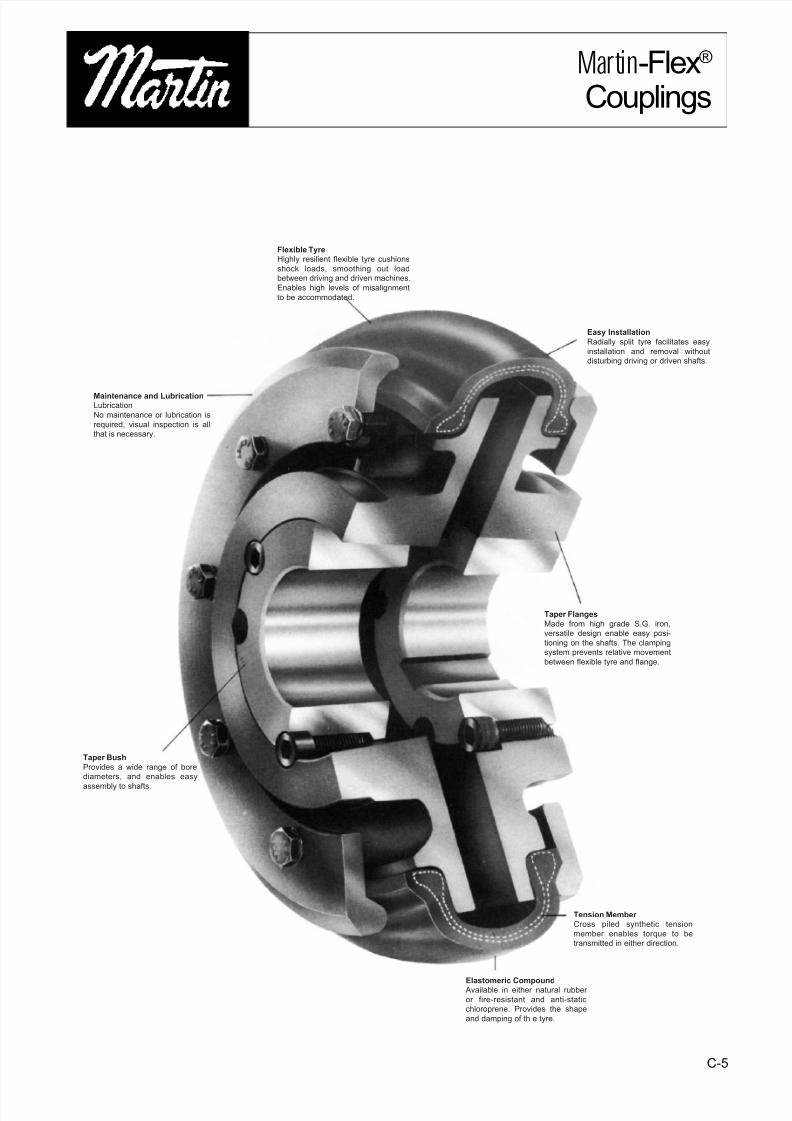
Flexible Tyre
Highly resilient flexible tyre cushions
shock loads, smoothing out load
between driving and driven machines.
Enables high levels of misalignment
to be accommodated.
Easy Installation
Radially split tyre facilitates easy
installation and removal without
disturbing driving or driven shafts.
Taper Flanges
Made from high grade S.G. iron,
versatile design enable easy posi-
tioning on the shafts. The clamping
system prevents relative movement
between flexible tyre and flange.
Tension Member
Cross piled synthetic tension
member enables torque to be
transmitted in either direction.
Elastomeric Compound Available in either natural rubber
or fire-resistant and anti-static
chloroprene. Provides the shape
and damping of th e tyre.
Taper Bush
Provides a wide range of bore
diameters, and enables easy
assembly to shafts.
Maintenance and LubricationLubrication
No maintenance or lubrication is
required, visual inspection is all
that is necessary.

7/21/2019 Tyre Coupling Catalog
http://slidepdf.com/reader/full/tyre-coupling-catalog 2/9
C-6
MMaarrttiinn-Flex couplings provide all the desirable features of an ideal flexible coupling, including Taper Bush fixing. TheM Maarrttiinn-Flex
coupling is a “torsionally elastic’ coupling offering versatility to designers and engineers with a choice of flange combinations to
suit most applications.
The flanges are available in either F (face) or H (hub) Taper Bush fitting or bored to size.
With the addition of a spacer flange the coupling can be used to accommodate standard distance between shaft ends and
facilitate pump maintenance.
M
M
a
a
r
r
t
t
i
i
n
n-Flex couplings can accommodate simultaneous maximum misalignment in all planes without imposing undue loads on
adjacent bearings and the excellent shock-absorbing properties of the flexible tyre reduce vibration and torsional oscillation.
M
M
a
a
r
r
t
t
i
i
n
n-Flex tyres are available in natural rubber compounds for use in ambient temperatures between -50°C and +50°C.
Chloroprene rubber compounds are available for use in adverse operating conditions (e.g. oil or grease contamination) and
can be used in temperatures of -15°C to +70°C. The chloroprene component should also be used when fire-resistance and anti-
static (F.R.A.S.) properties are required.
SELECTION
1. Service Factor Determine the required Service Factor from
table below.
2. Design Power Multiply the normal running power by the
service factor. This gives the design power which is used as a basis for selecting the
coupling.
3. Coupling Size
Refer to Power Ratings table page C-7 and
from the appropriate speed read across until a
power greater than that required in step (b)
is found.
The size of MMaarrttiinn-Flex coupling required is
given at the head of that column.
4. Bore SizeCheck for Dimensions table page C-9, C-10 that
chosen flanges can accommodate requiredbores.
EXAMPLE
AM Maarrttiinn-Flex coupling is required to transmit
50kW from an A.C. electric motor which runs at
1440 rev/min to a rotary screen for 10 hours per
day. The motor shaft is 60mm diameter and thescreen shaft is 55mm diameter. Taper Bush is
required.
1. Service Factor
The appropriate service factor is 1,3.
2. Design Power Design Power = 50 x 1,3 = 65kW.
3. Coupling Size
By reading across from 1440 rev/min in the
power ratings table the first power figure to
exceed the required 65kW in step(b) is
75,4kW. The size of coupling is F90
M
M
a
a
r
r
t
t
i
i
n
n-Flex.
4. Bore SizeBy referring to the dimensions table it can be
seen that both shaft diameters fall within thebore range available.
SERVICE FACTORS
Type of Driven Unit
Type of Driven Machine
CLASS 1 Agitators, Brewing machinery, Centrifugal compressors and
pumps. Belt conveyors, Dynamometers, Lineshafts, Fans up to7,5kW. Blowers and exhausters (except positive displacement),
Generators.CLASS 2*
Clay working machinery, General machine tools, paper millbeaters and winders, Rotary pumps, Rubber extruders, Rotary
screens, Textile machinery, Marine propellers and Fans over 7,5kw.
CLASS 3*Bucket elevators, Cooling tower fans, Piston compressors and
pumps, Foundry machinery, Metal presses, Paper mill calenders,Hammer mills, Presses and pulp grinders, Rubber calenders,
Pulverizers and Positive displacement blowers.
CLASS 4*Reciprocating conveyors, Gyratory crushers, Mills (ball, pebbleand rod), Rubber machinery (Banbury mixers and mills) and
Vibratory screens.
SPECIAL CASESFor applications where substantial shock, vibration and torquefluctuations occur, and for reciprocating machines (e.g. internalcombustion engines, piston pumps and compressors) refer toM
Ma
ar
rt
ti
in
n with full machine details for analysis.
Electric Motors Internal Combustion EnginesSteam Turbines Steam Engines
Water Turbines
Hours per day duty Hours per day duty
10 and over 10 over 10 and over 10 over under to 16 incl. 16 under to 16 incl. 16
0,8 0,9 1,0 1,3 1,4 1,5
1,3 1,4 1,5 1,8 1,9 2,0
1,8 1,9 2,0 2,3 2,4 2,5
2,3 2,4 2,5 2,8 2,9 3,0
*It is recommended that keys (with top clearance if in Taper bushes) are fitted on application where load function is expected.
+ Couplings for use with internal combustion engines may require special consideration, such as a flywheel configuration. Consult Martin for specifications.
MMaarrttiinn-Flex®
Couplings
7/21/2019 Tyre Coupling Catalog
http://slidepdf.com/reader/full/tyre-coupling-catalog 3/9
C-7
Coupling Size
MMaarrttiinn-Flex®
Couplings
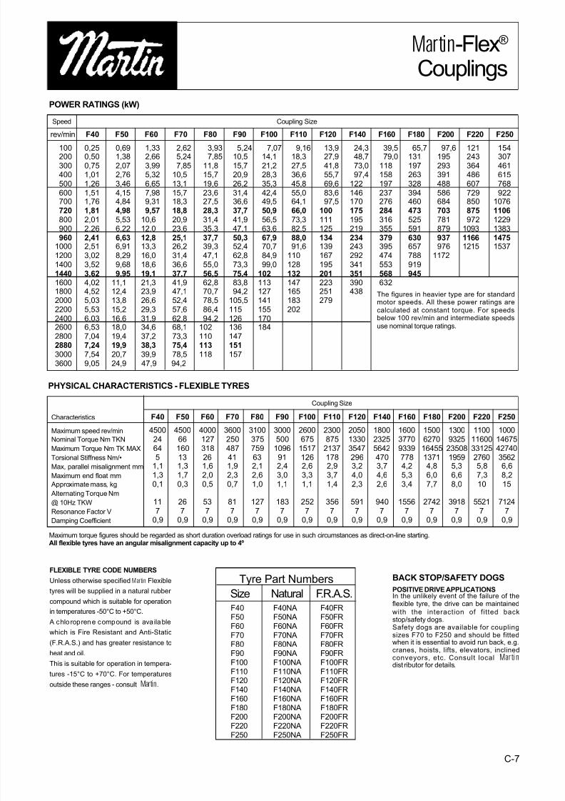
POWER RATINGS (kW)
F40F50F60F70F80F90F100F110F120F140
F160F180F200F220F250
F40NAF50NAF60NAF70NAF80NAF90NAF100NAF110NAF120NAF140NA
F160NAF180NAF200NAF220NAF250NA
F40FRF50FRF60FRF70FRF80FRF90FRF100FRF110FRF120FRF140FR
F160FRF180FRF200FRF220FRF250FR
100200300400500600700720800900960
1000120014001440
1600180020002200240026002800288030003600
0,250,500,751,011,261,511,761,812,012,262,412,513,023,523,62
4,024,525,035,536,036,537,047,247,549,05
0,691,382,072,763,464,154,844,985,536,226,636,918,299,689,95
11,112,413,815,216,618,019,419,920,724,9
1,332,663,995,326,657,989,319,57
10,612,012,813,316,018,619,1
21,323,926,629,331,934,637,238,339,947,9
2,625,247,85
10,513,115,718,318,820,923,625,126,231,436,637,7
41,947,152,457,662,868,173,375,478,594,2
3,937,85
11,815,719,623,627,528,331,435,337,739,347,155,056,5
62,870,778,586,494,2
102110113118
5,2410,515,720,926,231,436,637,741,947,150,352,462,873,375,4
83,894,2
105,5115126136147151157
7,0714,121,228,335,342,449,550,956,563,667,970,784,999,0
102
113127141155170184
9,1618,327,536,645,855,064,166,073,382,588,091,6
110128132
147165183202
13,927,941,855,769,683,697,5
100111125134139167195201
223251279
24,348,773,097,4
122146170175195219234243292341351
390438
39,579,0
118158197237276284316355379395474553568
632
65,7131197263328394460473525591630657788919945
97,6195293391488586684703781879937976
1172
121243364486607729850875972
109311661215
154307461615768922
107611061229138314751537
F40450024645
1,11,30,1
117
0,9
F50450066160131,31,70,3
267
0,9
F604000127318261,62,00,5
537
0,9
F703600250487411,92,30,7
817
0,9
F803100375759632,12,61,0
1277
0,9
F903000500
1096912,43,01,1
1837
0,9
F1002600675
15171262,63,31,1
2527
0,9
F1102300875
21371782,93,71,4
3567
0,9
F1202050133035472963,24,02,3
5917
0,9
F1401800232556424703,74,62,6
9407
0,9
F1601600377093397784,25,33,4
15567
0,9
F180150062701645513714,86,07,7
27427
0,9
F20013009325
2350819595,36,68,0
39187
0,9
F2201100
116003312527605,87,310
55217
0,9
F2501000
146754274035626,68,215
71247
0,9
PHYSICAL CHARACTERISTICS - FLEXIBLE TYRES
Characteristics
Maximum speed rev/min
Nominal Torque Nm TKN
Maximum Torque Nm TK MAX
Torsional Stiffness Nm/•
Max, parallel misalignment mm
Maximum end float mm
Approximate mass, kg
Alternating Torque Nm
@ 10Hz TKW
Resonance Factor V
Damping Coefficient
Maximum torque figures should be regarded as short duration overload ratings for use in such circumstances as direct-on-line starting.All flexible tyres have an angular misalignment capacity up to 4º
rev/min F40 F50 F60 F70 F80 F90 F100 F110 F120 F140 F160 F180 F200 F220 F250
Speed Coupling Size
Size Natural F.R.A.S.
The figures in heavier type are for standardmotor speeds. All these power ratings are
calculated at constant torque. For speedsbelow 100 rev/min and intermediate speeds
use nominal torque ratings.
FLEXIBLE TYRE CODE NUMBERS
Unless otherwise specified
M
M
a
a
r
r
t
t
i
i
n
n Flexible
tyres will be supplied in a natural rubber
compound which is suitable for operation
in temperatures -50°C to +50°C.
A chlo roprene compound is ava ilable
which is Fire Resistant and Anti-Static
(F.R.A.S.) and has greater resistance to
heat and oil.
This is suitable for operation in tempera-
tures -15°C to +70°C. For temperatures
outside these ranges - consultMMaarrttiinn.
BACK STOP/SAFETY DOGS
POSITIVE DRIVE APPLICATIONSIn the unlikely event of the failure of theflexible tyre, the drive can be maintained
with the interaction of fitted backstop/safety dogs.Safety dogs are available for couplingsizes F70 to F250 and should be fittedwhen it is essential to avoid run back, e.g.cranes, hoists, lifts, elevators, inclinedconveyors, etc. Consult local MMaarrttiin ndist ributor for details.
Tyre Part Numbers
7/21/2019 Tyre Coupling Catalog
http://slidepdf.com/reader/full/tyre-coupling-catalog 4/9
C-8
MMaarrttiinn-Flex®
Couplings
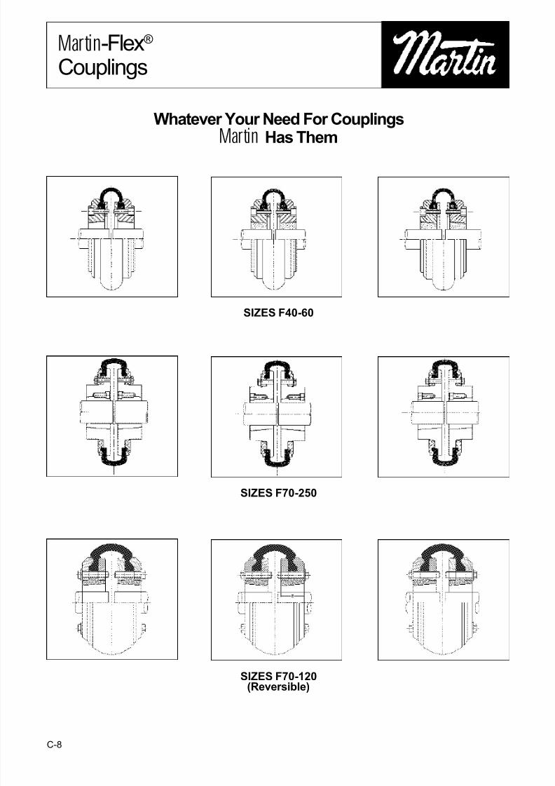
SIZES F40-60
SIZES F70-250
Whatever Your Need For CouplingsM
Ma
ar
rt
ti
in
n Has Them
SIZES F70-120
(Reversible)
7/21/2019 Tyre Coupling Catalog
http://slidepdf.com/reader/full/tyre-coupling-catalog 5/9
C-9
MMaarrttiinn-Flex®
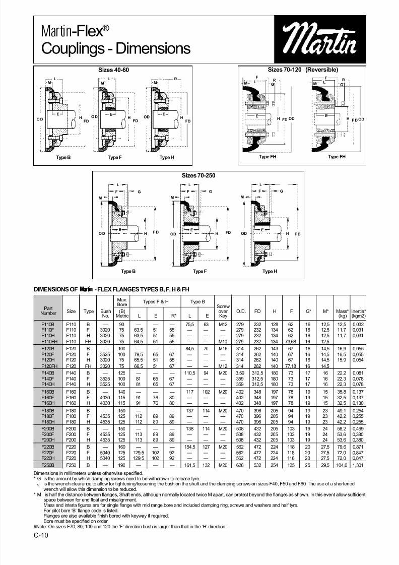
Couplings - Dimensions
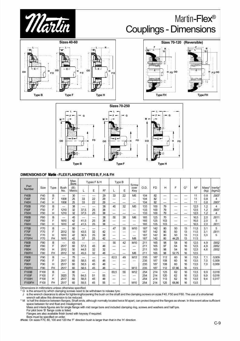
DIMENSIONS OF MMaarr ttiinnMMaarr ttiinn - FLEX FLANGES TYPES B, F, H & FH
Max. Types F & H Type B
PartBore Screw
Number Size Type Bush (B) over O.D. FD H F G* M* Mass* Inertia*No. Metric L E R* L E Key (kg) (kgm2)
F40B F40 B — 30 — — 29 33 22 M5 104 82 — — — 11 0,8 ,0007F40F F40 F 1008 25 33 22 29 — — — 104 82 — — — 11 0,8 4
F40H F40 H 1008 25 33 22 29 — — — 104 82 — — — 11 0,8 ,0007
F50B F50 B — 38 — — 38 45 32 M5 133 100 79 — — 12,5 1,2 4
F50F F50 F 1210 32 37,5 25 38 — — — 133 100 79 — — 12,5 1,2 ,0007F50H F50 H 1210 32 37,5 25 38 — — — 133 100 79 — — 12,5 1,2 4
F60B F60 B — 45 — — 38 55 38 M6 165 125 70 — — 16,5 2,0 ,0011F60F F60 F 1610 42 41,5 25 38 — — — 165 125 103 — — 16,5 2,0 5
F60H F60 H 1610 42 41,5 25 38 — — — 165 125 103 — — 16,5 2,0 ,0011
F70B F70 B — 50 — — — 47 35 M10 187 142 80 50 13 11,5 3,1 5F70F F70 F 2012 50 43,5 32 42 — — — 187 142 80 50 13 11,5 3,1 ,0011
F70H F70 H 1610 42 36,5 25 38 — — — 187 142 80 50 13 11,5 3,0 5
F70FH F70 FH 1610 42 37 25 42 — — M8 187 142 80 44,25 13 11,5F80B F80 B — 63 — — — 55 42 M10 211 165 98 54 16 12,5 4,9 ,0052F80F F80 F 2517 60 57,5 45 48 — — — 211 165 97 54 16 12,5 4,9 ,0052
F80H F80 H 2012 50 44,5 32 32 — — — 211 165 98 54 16 12,5 4,6 ,0052
F80FH F80 FH 2012 50 45,5 32 48 — — M8 211 165 98 52,75 16 12,5
F90B F90 B — 75 — — — 62,5 49 M12 235 187 112 60 16 13,5 7,1 0,009F90F F90 F 2517 60 58,5 45 48 — — — 235 187 108 60 16 13,5 7,0 0,009
F90H F90 H 2517 60 58,5 45 48 — — — 235 187 108 60 16 13,5 7,0 0,009
F90FH F90 FH 2517 60 58,5 45 48 — — M10 235 187 112 67,86 16 13,5
F100B F100 B — 80 — — — 69,5 56 M12 254 214 125 62 16 13,5 9,9 0,018
F100F F100 F 3020 75 64,5 51 55 — — — 254 214 120 62 16 13,5 9,9 0,018F100H F100 H 2517 60 58,5 45 48 — — — 254 214 113 62 16 13,5 9,4 0,017
F100FH F100 FH 2517 60 59,5 45 55 — — M10 254 214 125 68,86 16 13,5
Dimensions in millimeters unless otherwise specified.* G is the amount by which clamping screws need to be withdrawn to release tyre.
J is the wrench clearance to allow for tightening/loosening the bush on the shaft and the clamping screws on sizes F40, F50 and F60. The use of a shortened
wrench will allow this dimension to be reduced.* M is half the distance between flanges, Shaft ends, although normally located twice M apart, can protect beyond the flanges as shown. In this event allow sufficientspace between for end float and misalignment.Mass and interia figures are for single flange with mid range bore and included clamping ring, screws and washers and half tyre.For pilot bore ‘B’ flange code is listed.Flanges are also available finish bored with keyway if required.Bore must be specified on order.
#Note: On sizes F70, 80, 100 and 120 the ‘F’ direction bush is larger than that in the ‘H’ direction.
Type B Type F Type H
Type B TypeF Type H
Type FH Type FH
Sizes 40-60 Sizes 70-120 (Reversible)
Sizes 70-250
LM
OD
EH
F D
LM
ODE
HF D
LM
ODE
HF D
R
L
F G
M
EOD H FD
OD H FD
M
GF
L L
HO D
M
F G
FDEE
LM
F
GR
EH FD OD
LM
F
GR
EH FD OD
7/21/2019 Tyre Coupling Catalog
http://slidepdf.com/reader/full/tyre-coupling-catalog 6/9
C-10
MMaarrttiinn-Flex®
Couplings - Dimensions
Dimensions in millimeters unless otherwise specified.* G is the amount by which clamping screws need to be withdrawn to release tyre.
J is the wrench clearance to allow for tightening/loosening the bush on the shaft and the clamping screws on sizes F40, F50 and F60. The use of a shortenedwrench will allow this dimension to be reduced.
* M is half the distance between flanges, Shaft ends, although normally located twice M apart, can protect beyond the flanges as shown. In this event allow sufficientspace between for end float and misalignment.Mass and interia figures are for single flange with mid range bore and included clamping ring, screws and washers and half tyre.For pilot bore ‘B’ flange code is listed.Flanges are also available finish bored with keyway if required.Bore must be specified on order.
#Note: On sizes F70, 80, 100 and 120 the ‘F’ direction bush is larger than that in the ‘H’ direction.
DIMENSIONS OF MMaarrttiinnMMaarr ttiinn - FLEX FLANGES TYPES B, F, H & FH
F110B F110 B — 90 — — — 75,5 63 M12 279 232 128 62 16 12,5 12,5 0,032F110F F110 F 3020 75 63,5 51 55 — — — 279 232 134 62 16 12,5 11,7 0,031
F110H F110 H 3020 75 63,5 51 55 — — — 279 232 134 62 16 12,5 11,7 0,031
F110FH F110 FH 3020 75 64,5 51 55 — — M10 279 232 134 73,68 16 12,5
F120B F120 B — 100 — — — 84,5 70 M16 314 262 143 67 16 14,5 16,9 0,055
F120F F120 F 3525 100 79,5 65 67 — — — 314 262 140 67 16 14,5 16,5 0,055F120H F120 H 3020 75 65,5 51 55 — — — 314 262 140 67 16 14,5 15,9 0,054
F120FH F120 FH 3020 75 66,5 51 67 — — M12 314 262 140 77,18 16 14,5
F140B F140 B — 125 — — — 110,5 94 M20 3.59 312,5 180 73 17 16 22,2 0,081
F140F F140 F 3525 100 81 65 67 — — — 359 312,5 180 73 17 16 22,3 0,078F140H F140 H 3525 100 81 65 67 — — — 359 312,5 180 73 17 16 22,3 0,078
F160B F160 B — 140 — — — 117 102 M20 402 348 197 78 19 15 35,8 0,137
F160F F160 F 4030 115 91 76 80 — — — 402 348 197 78 19 15 32,5 0,137F160H F160 H 4030 115 91 76 80 — — — 402 348 197 78 19 15 32,5 0,130
F180B F180 B — 150 — — — 137 114 M20 470 396 205 94 19 23 49,1 0,254F180F F180 F 4535 125 112 89 89 — — — 470 396 205 94 19 23 42,2 0,255
F180H F180 H 4535 125 112 89 89 — — — 470 396 205 94 19 23 42,2 0,255
F200B F200 B — 150 — — — 138 114 M20 508 432 205 103 19 24 58,2 0,469
F200F F200 F 4535 125 113 89 89 — — — 508 432 205 103 19 24 53,6 0,380F200H F200 H 4535 125 113 89 89 — — — 508 432 205 103 19 24 53,6 0,380
F220B F220 B — 160 — — — 154,5 127 M20 562 472 224 118 20 27,5 79,6 0,871
F220F F220 F 5040 125 129,5 102 92 — — — 562 472 224 118 20 27,5 72,0 0,847F220H F220 H 5040 125 129,5 102 92 — — — 562 472 224 118 20 27,5 72,0 0,847
F250B F250 B — 190 — — — 161,5 132 M20 628 532 254 125 25 29,5 104,0 1,301
Max. Types F & H Type B
PartBore Screw
Number Size Type Bush (B) over O.D. FD H F G* M* Mass* Inertia*No. Metric L E R* L E Key (kg) (kgm2)
TypeB Type F TypeH
Type B TypeF Type H
Sizes 40-60
Sizes 70-250
LM
O D
EH
FD
LM
O DE
HFD
LM
ODE
HFD
R
L
F G
M
EO D H FD
OD H FD
M
GF
L L
HOD
M
F G
F DEE
Type FH Type FH
Sizes 70-120 (Reversible)
LM
F
GR
EH FD OD
LM
F
G
R
EH FD OD
7/21/2019 Tyre Coupling Catalog
http://slidepdf.com/reader/full/tyre-coupling-catalog 7/9
C-11
F40
F50F60
F70F80F90
F100
F110F120F140
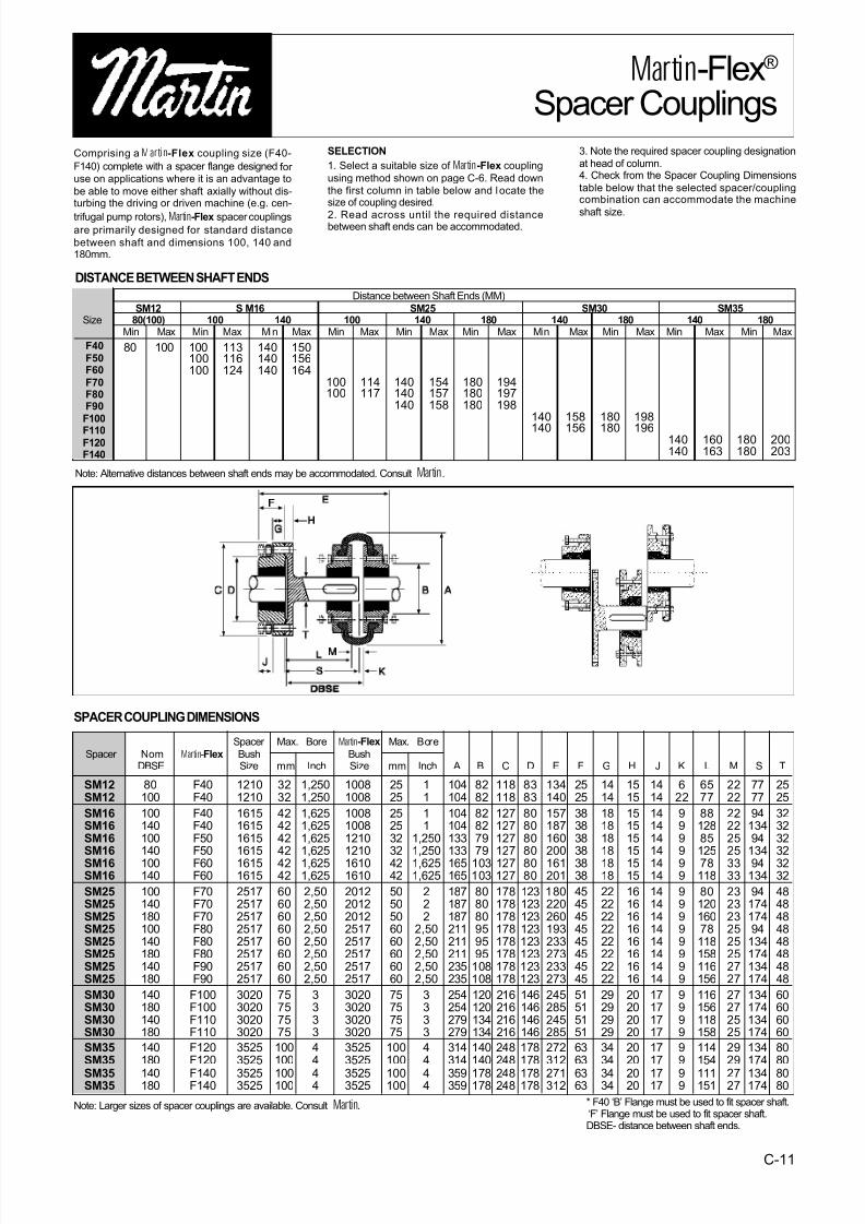
Comprising aM Maarrttiinn-Flex coupling size (F40-
F140) complete with a spacer flange designed for use on applications where it is an advantage to
be able to move either shaft axially without dis-turbing the driving or driven machine (e.g. cen-
trifugal pump rotors),
M
M
a
a
r
r
t
t
i
i
n
n-Flex spacer couplingsare primarily designed for standard distance
between shaft and dimensions 100, 140 and180mm.
SELECTION
1. Select a suitable size of MMaarrttiinn-Flex coupling
using method shown on page C-6. Read down
the first column in table below and locate thesize of coupling desired.
2. Read across until the required distancebetween shaft ends can be accommodated.
3. Note the required spacer coupling designation
at head of column.4. Check from the Spacer Coupling Dimensions
table below that the selected spacer/couplingcombination can accommodate the machine
shaft size.
MMaarrttiinn-Flex®
Spacer Couplings
DISTANCE BETWEEN SHAFT ENDS
80 100 100100100
113116124
140140140
150156164
100100
114117
140140140
154157158
180180180
194197198
140
140
158
156
180
180
198
196140140
160163
180180
200203
Distance between Shaft Ends (MM)
SM12 S M16 SM25 SM30 SM35Size 80(100) 100 140 100 140 180 140 180 140 180
Min Max Min Max Min Max Min Max Min Max Min Max Min Max Min Max Min Max Min Max
Note: Alternative distances between shaft ends may be accommodated. Consult
M
M
a
a
r
r
t
t
i
i
n
n.
Spacer Max. Bore M Maarrttiinn-Flex Max. Bore
Spacer NomM
Ma
ar
rt
ti
in
n-Flex Bush BushDBSE Size mm Inch Size mm Inch A B C D E F G H J K L M S T
Note: Larger sizes of spacer couplings are available. Consult
M
M
a
a
r
r
t
t
i
i
n
n.
SPACER COUPLING DIMENSIONS
SM12 80 F40 1210 32 1,250 1008 25 1 104 82 118 83 134 25 14 15 14 6 65 22 77 25SM12 100 F40 1210 32 1,250 1008 25 1 104 82 118 83 140 25 14 15 14 22 77 22 77 25
SM16 100 F40 1615 42 1,625 1008 25 1 104 82 127 80 157 38 18 15 14 9 88 22 94 32SM16 140 F40 1615 42 1,625 1008 25 1 104 82 127 80 187 38 18 15 14 9 128 22 134 32SM16 100 F50 1615 42 1,625 1210 32 1,250 133 79 127 80 160 38 18 15 14 9 85 25 94 32SM16 140 F50 1615 42 1,625 1210 32 1,250 133 79 127 80 200 38 18 15 14 9 125 25 134 32SM16 100 F60 1615 42 1,625 1610 42 1,625 165 103 127 80 161 38 18 15 14 9 78 33 94 32SM16 140 F60 1615 42 1,625 1610 42 1,625 165 103 127 80 201 38 18 15 14 9 118 33 134 32
SM25 100 F70 2517 60 2,50 2012 50 2 187 80 178 123 180 45 22 16 14 9 80 23 94 48SM25 140 F70 2517 60 2,50 2012 50 2 187 80 178 123 220 45 22 16 14 9 120 23 174 48SM25 180 F70 2517 60 2,50 2012 50 2 187 80 178 123 260 45 22 16 14 9 160 23 174 48SM25 100 F80 2517 60 2,50 2517 60 2,50 211 95 178 123 193 45 22 16 14 9 78 25 94 48SM25 140 F80 2517 60 2,50 2517 60 2,50 211 95 178 123 233 45 22 16 14 9 118 25 134 48SM25 180 F80 2517 60 2,50 2517 60 2,50 211 95 178 123 273 45 22 16 14 9 158 25 174 48SM25 140 F90 2517 60 2,50 2517 60 2,50 235 108 178 123 233 45 22 16 14 9 116 27 134 48SM25 180 F90 2517 60 2,50 2517 60 2,50 235 108 178 123 273 45 22 16 14 9 156 27 174 48
SM30 140 F100 3020 75 3 3020 75 3 254 120 216 146 245 51 29 20 17 9 116 27 134 60SM30 180 F100 3020 75 3 3020 75 3 254 120 216 146 285 51 29 20 17 9 156 27 174 60SM30 140 F110 3020 75 3 3020 75 3 279 134 216 146 245 51 29 20 17 9 118 25 134 60SM30 180 F110 3020 75 3 3020 75 3 279 134 216 146 285 51 29 20 17 9 158 25 174 60
SM35 140 F120 3525 100 4 3525 100 4 314 140 248 178 272 63 34 20 17 9 114 29 134 80SM35 180 F120 3525 100 4 3525 100 4 314 140 248 178 312 63 34 20 17 9 154 29 174 80
SM35 140 F140 3525 100 4 3525 100 4 359 178 248 178 271 63 34 20 17 9 111 27 134 80SM35 180 F140 3525 100 4 3525 100 4 359 178 248 178 312 63 34 20 17 9 151 27 174 80
* F40 ‘B’ Flange must be used to fit spacer shaft.‘F’ Flange must be used to fit spacer shaft.DBSE- distance between shaft ends.

7/21/2019 Tyre Coupling Catalog
http://slidepdf.com/reader/full/tyre-coupling-catalog 8/9
C-12
MMaarrttiinn-Flex® CouplingsInstallation Instructions
NOTE: Satisfactory performance depends on correct installation and maintenance. Under no circumstances should any
machine be started unless the coupling and associated machine is completely assembled. All instructions in this manualshould therefore be followed accurately.
1. Thoroughly clean all components, paying particular attention to the removal of the protective coating in flange
bores and on bushes.2. Fit flanges to the shafts after placing the external clamp
rings on the shafts. (Where Taper flanges are used, seeseparate fitting instructions supplied with the Taper
Bushes.) Locate flanges so that dimension M is obtained(see paragraph 3). Flanges with internal clamping rings
should then have the clamping rings fitted, engaging onlytwo or three of the threads of the screws at this time.
3. Bring shafts into line until dimension M is obtained (table2). If shaft end float is to occur, locate the shafts at mid-
position of end float when checking dimension M. Note theshafts ends may project beyond the faces of the flanges if
required. In this event, allow sufficient space between shaf-tends for end float and mis-alignment. Flanges should be
fitted flush with the end of the shaft when used with Mill-Motor flanges.
4. Check parallel alignment by laying a straight edge acrossthe flanges at several positions around the circumference.
Check angular alignment by measuring gap betweenflanges at several positions around the circumference. It is
desirable to align the coupling as accurately as possible,particularly on high speed applications.
5. Open out tyre and fit over coupling flanges ensuring thatthe tyre beads seat properly on the flanges and/or clamping
rings. To ensure proper seating, it may be necessary tostrike the outside diameter of the tyre with a small mallet.
When seated there should be a gap between the ends of the tyre as shown in Table 1.
6. Tighten clamping ring screws alternately and evenly (half
turn at a time) working round each flange until the requiredscrew torque is achieved (table 2).
CouplingSize
Tyre
Gap mm
F40to
F60
2
F70to
F120
3
F140andF160
5
F180to
F250
6
TABLE 1
Coupling Size F40 F50 F60 F70 F80 F90 F100 F110 F120 F140 F160 F180 F200 F220 F250
M MM 22 25 33 23 25 27 27 25 29 32 30 46 48 55 59
Screw Size M6 M6 M6 M8 M8 M10 M10 M10 M12 M12 M16 M16 M16 M20 M20
Clamping Screw Nm 15 15 15 24 24 40 40 40 50 55 80 105 120 165 165Torque
TABLE 2
7/21/2019 Tyre Coupling Catalog
http://slidepdf.com/reader/full/tyre-coupling-catalog 9/9
C-13
MMaarrttiinn-Flex®
Couplings
M
M
a
a
r
r
t
t
i
i
n
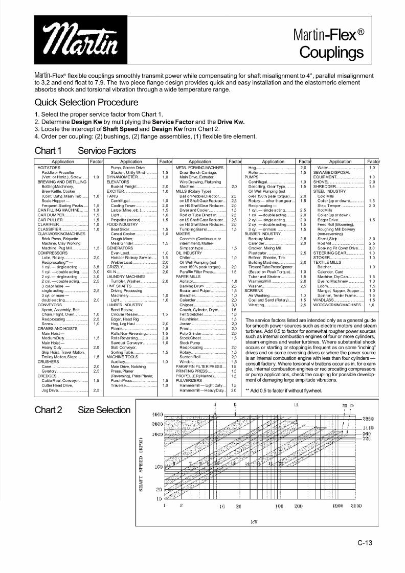
n-Flex® flexible couplings smoothly transmit power while compensating for shaft misalignment to 4°, parallel misalignmentto 3,2 and end float to 7,9. The two piece flange design provides quick and easy installation and the elastomeric elementabsorbs shock and torsional vibration through a wide temperature range.
Quick Selection Procedure1. Select the proper service factor from Chart 1.
2. Determine Design Kw by multiplying the Service Factor and the Drive Kw.3. Locate the intercept of Shaft Speed and Design Kw from Chart 2.
4. Order per coupling: (2) bushings, (2) flange assemblies, (1) flexible tire element.
Chart 1 Service Factors
Chart 2 Size Selection
AGITATORS
Paddle or Propeller (Vert. or Horiz.), Screw....... 1,0
BREWING AND DISTILLINGBottling Machinery,
Brew Kettle, Cooker
(Cont. Duty), Mash Tub...... 1,0
Scale Hopper —Frequent Starting Peaks..... 1,5
CAN FILLING MACHINE....... 1,0
CAR DUMPER....................... 1,5
CAR PULLER......................... 1,5CLARIFIER............................ 1,0
CLASSIFIER.......................... 1,0CLAY-WORKING MACHINES
Brick Press, BriquetteMachine, Clay Working
Machine, Pug Mill............... 1,5
COMPRESSORSLobe, Rotary....................... 2,0
Reciprocating** —1 cyl. — single acting ......... 3,5
1 cyl. — double acting........ 3,0
2 cyl. — single acting ......... 3,02 cyl. — double acting........ 2,5
3 cyl.or more —single acting....................... 2,5
3 cyl. or more —
double acting...................... 2,0CONVEYORS
Apron, Assembly, Belt,Chain, Flight, Oven............. 1,0
Reciprocating ..................... 2,5Screw................................. 1,0
CRANES AND HOISTS
Main Hoist —Medium Duty...................... 1,5
Main Hoist —Heavy Duty......................... 2,0
Skip Hoist, Travel Motion,Trolley Motion, Slope.......... 1,5
CRUSHERS
Cane................................... 2,0Gyratory ............................. 2,5
DREDGESCable Reel, Conveyor........ 1,5
Cutter Head Drive,
Jog Drive............................ 2,5
Pump, Screen Drive,
Stacker, Utility Winch ......... 1,5DYNAMOMETER................... 1,0
ELEVATORSBucket, Freight................... 2,0
EXCITER............................... 1,0
FANS
Centrifugal.......................... 1,0Cooling Tower.................... 2,0Large (Mine, etc.)............... 1,5
Light ................................... 1,0
Propeller (indoor) ............... 1,5FOOD INDUSTRY
Beet Slicer.......................... 1,5Cereal Cooker.................... 1,0
Dough Mixer,Meat Grinder...................... 1,5
GENERATORS
Even Load.......................... 1,0Hoist or Railway Service .... 1,5
Welder Load....................... 2,0GRIZZLY................................ 2,0
KIL N....................................... 2,0
LAUNDRY MACHINESTumbler, Washer................ 2,0
LINE SHAFTS........................Driving Processing
Machinery........................... 1,0
Light ................................... 1,0LUMBER INDUSTRY
Band Resaw,Circular Resaw................... 1,5
Edger, Head Rig,Hog, Log Haul .................... 2,0
Planer................................. 1,5
Rolls Non-Reversing.......... 1,5Rolls Reversing.................. 2,0
Sawdust Conveyor............. 1,0Slab Conveyor,
Sorting Table...................... 1,5MACHINE TOOLS
Auxiliary.............................. 1,0
Main Drive, NotchingPress, Planer
(Reversing), Plate Planer,Punch Press........................ 1,5
Traverse............................. 1,0
METAL FORMING MACHINES
Draw Bench Carriage,Main Drive, Extruder,
Wire Drawing, FlatteningMachine.............................. 2,0
MILLS (Rotary Type)
Ball or Pebble Direct or...... 2,5
on LS Shaft Gear Reducer... 2,5on HS Shaft Gear Reducer... 2,0Dryer and Cooler................ 1,5
Rod or Tube Direct or......... 2,5
on LS Shaft Gear Reducer... 2,5on HS Shaft Gear Reducer... 2,0
Tumbling Barrel.................. 1,5MIXERS
Concrete (Continuous or intermittent), Muller-
Simpson type ..................... 1,5
OIL INDUSTRYChiller................................. 1,0
Oil Well Pumping (notover 150% peak torque)..... 2,0
Paraffin Filter Press............ 1,5
PAPER MILLS Agitator............................... 1,0
Barking Drum..................... 2,5Beater and Pulper.............. 1,5
Bleacher............................. 1,0
Calender............................. 2,0Chipper............................... 3,0
Couch, Cylinder, Dryer....... 1,5Felt Stretcher...................... 1,0
Fourdrinier.......................... 1,5Jordan ................................ 2,0
Press .................................. 2,0
Pulp Grinder....................... 2,0Stock Chest........................ 1,5
Stock PumpReciprocating ..................... 2,0
Rotary................................. 1,5Suction Roll........................ 2,0
Winder................................ 1,5
PARAFFIN FILTER PRESS... 1,5PRINTING PRESS................. 1,5
PROPELLER(Marine)........... 1,5PULVERIZERS
Hammermill — Light Duty... 1,5
Hammermill —Heavy Duty.. 2,0
Hog..................................... 2,0
Roller.................................. 1,5PUMPS
Centrifugal.......................... 1,0Descaling, Gear Type......... 1,5
Oil Well Pumping (not
over 150% peak torque)..... 2,0
Rotary — other than gear... 1,5Reciprocating —1 cyl. — single acting......... 2,5
1 cyl. — double acting........ 2,0
2 cyl. — single acting......... 2,02 cyl. — double acting........ 1,5
3 cyl. — or more ................ 1,5RUBBER INDUSTRY
Banbury Mixer.................... 2,5Calender............................. 2,0
Cracker, Mixing Mill,
Plasticator .......................... 2,5Refiner, Sheeter, Tire
Building Machine................ 2,0Tire and Tube Press Opener
(Based on Peak Torque).... 1,0
Tuber and Strainer............. 1,5Warming Mill ...................... 2,0
Washer............................... 2,5SCREENS
Air Washing........................ 1,0
Coal and Sand (Rotary)...... 1,5Vibrating............................. 2,5
Water.................................. 1,0
SEWAGE DISPOSALEQUIPMENT.......................... 1,0
SHOVEL ................................ 2,0SHREDDER........................... 1,5
STEEL INDUSTRY
Cold Mills
Coiler (up or down)............. 1,5Strip, Temper ..................... 2,0Hot Mills
Coiler (up or down),
Edger Drive........................ 1,5Feed Roll (Blooming),
Roughing Mill Delivery(non-reversing),
Sheet, Strip ........................ 3,0Rod Mill .............................. 2,5
Soaking Pit Cover Drive..... 3,0
STEERING GEAR.................. 1,0STOKER................................ 1,0
TEXTILE MILLSBatcher............................... 1,0
Calender, Card
Machine, Dry Can............... 1,5Dyeing Machinery .............. 1,0
Loom.................................. 1,5Mangel, Napper, Soaper.... 1,0
Spinner, Tenter Frame....... 1,5
WINDLASS............................ 1,5WOODWORKING MACHINES.. 1,0
Application Factor Application Factor Application Factor Application Factor Application Factor
The service factors listed are intended only as a general guidefor smooth power sources such as electric motors and steamturbines. Add 0,5 to factor for somewhat rougher power sourcessuch as internal combustion engines of four or more cylinders,steam engines and water turbines. Where substantial shockoccurs or starting or stopping is frequent as on some “inching”drives and on some reversing drives or where the power sourceis an internal combustion engine with less than four cylinders —consult factory. Where torsional vibrations occur as in, for exam-ple, internal combustion engines or reciprocating compressorsor pump applications, check the coupling for possible develop-ment of damaging large amplitude vibrations.
** Add 0,5 to factor if without flywheel.


![Coupling Catalog [Powerdrive.com]](https://img.dokumen.tips/doc/110x75/544ecb4caf79595b278b4c44/coupling-catalog-powerdrivecom.jpg)