Embed Size (px)
Citation preview


A - 1
SAFETY INSTRUCTIONS (Always read these instructions before using this equipment.)
Before using this product, please read this manual and the relevant manuals introduced in this manual carefully and pay full attention to safety to handle the product correctly. The instructions given in this manual are concerned with this product. For the safety instructions of the programmable logic controller system, please read the CPU module User's Manual. In this manual, the safety instructions are ranked as "DANGER" and "CAUTION".
! DANGER
CAUTION!
Indicates that incorrect handling may cause hazardous conditions,resulting in death or severe injury.
Indicates that incorrect handling may cause hazardous conditions,resulting in medium or slight personal injury or physical damage.
Note that the ! CAUTION level may lead to a serious consequence according to the circumstances. Always follow the instructions of both levels because they are important to personal safety. Please save this manual to make it accessible when required and always forward it to the end user. [Design Instructions]
! DANGER Provide a safety circuit outside the programmable logic controller so that the entire system will operate safely even when an external power supply error or PLC fault occurs. Failure to observe this could lead to accidents for incorrect outputs or malfunctioning. (1) Configure an emergency stop circuit and interlock circuit such as a positioning upper
limit/lower limit to prevent mechanical damage outside the PLC. (2) The machine OPR operation is controlled by the OPR direction and OPR speed data.
Deceleration starts when the near-point dog turns ON. Thus, if the OPR direction is incorrectly set, deceleration will not start and the machine will continue to travel. Configure an interlock circuit to prevent mechanical damage outside the PLC.
(3) When the module detects an error, normally deceleration stop or sudden stop will take place according to the parameter stop group settings. Set the parameters to the positioning system specifications. Make sure that the OPR parameter and positioning data are within the parameter setting values.

A - 2
[Design Instructions] ! CAUTION
Do not bundle or adjacently lay the control wire or communication cable with the main circuit or power wire. Separate these by 100mm (3.94in.) or more. Failure to observe this could lead to malfunctioning caused by noise.
[Mounting Instructions]
! CAUTION Use the PLC within the general specifications environment given in this manual. Using the PLC outside the general specification range environment could lead to electric shocks, fires, malfunctioning, product damage or deterioration.
While pressing the installation lever located at the bottom of module, insert the module fixing tab into the fixing hole in the base unit until it stops. Then, securely mount the module with the fixing hole as a supporting point. Incorrect loading of the module can cause a malfunction, failure or drop. When using the PLC in the environment of much vibration, tighten the module with a screw. Tighten the screw in the specified torque range. Undertightening can cause a drop, short circuit or malfunction. Overtightening can cause a drop, short circuit or malfunction due to damage to the screw or module.
Completely turn off the externally supplied power used in the system before mounting or removing the module. Not doing so may damage the product.
[Wiring Instructions]
! DANGER Always confirm the terminal layout before connecting the wires to the module.
[Startup/Maintenance Instructions]
! DANGER Completely turn off the externally supplied power used in the system before cleaning or tightening the screws. Failure to turn all phases OFF could lead to electric shocks.

A - 3
[Startup/Maintenance Instructions] ! CAUTION
Never disassemble or modify the module. Failure to observe this could lead to trouble, malfunctioning, injuries or fires.
Completely turn off the externally supplied power used in the system before installing or removing the module. Failure to turn all phases OFF could lead to module trouble or malfunctioning.
Do not install/remove the module to/from the base unit, or the terminal block to/from the module more than 50 times after the first use of the product. (IEC 61131-2 compliant) Failure to do so may cause malfunction.
Before starting test operation, set the parameter speed limit value to the slowest value, and make sure that operation can be stopped immediately if a hazardous state occurs.
Always make sure to touch the grounded metal to discharge the electricity charged in the body, etc., before touching the module. Failure to do so may cause a failure or malfunctions of the module.
[Precautions for use]
! CAUTION Note that when the reference axis speed is designated for interpolation operation, the speed of the partner axis (2nd axis, 3rd axis and 4th axis) may be larger than the set speed (larger than the speed limit value).
[Disposal Instructions]
! CAUTION When disposing of the product, handle it as industrial waste.

A - 4
REVISIONS
The manual number is given on the bottom left of the back cover. Print Date Manual Number Revision Dec., 1999 SH (NA)-080058-A First edition Oct., 2000 SH (NA)-080058-B Addition of function version B
(Overall revisions based on the Japanese Manual Version SH-080047-E)
Jun., 2001 SH (NA)-080058-C The software package names (GPP function software package, QD75 software package) have been replaced by the product names (GX Developer, GX Configurator-QP) for standardization.
Partial corrections and additions CONTENTS, About Manuals, Generic Terms and Abbreviations, Section 1.4, Section 2.2, Section 2.3, Section 3.2.2 to Section 3.2.4, Section 3.3.2, Section 3.3.3, Section 3.4.1, Section 3.4.3, Section 3.4.4, Section 4.1.2, Section 4.3, Section 5.1.2, Section 5.1.3, Section 5.2.3, Section 5.2.5, Section 5.6.2, Section 5.7.1, Section 6.2 to Section 6.4, Section 6.5.3, Section 7.2, Section 8.2.2, Section 8.2.5, Section 8.2.6, Section 9.1.2, Section 9.2.1, Section 9.2.16, Section 9.2.17, Section 10.3.2, Section 10.6.2, Section 11.2.3, Section 11.3.3, Section 11.3.4, Section 11.4.3, Section 12.1.1, Section 12.5 to Section 12.7, Section 13.1, Section 13.3, Section 13.4, Section 14.2 to Section 14.7, Section 15.1, Section 15.2, Section 15.4, Appendix 1, Appendix 9.2, Appendix 11, INDEX
Apr., 2003 SH (NA)-080058-D Partial corrections and additions SAFETY INSTRUCTIONS, CONTENTS, Component List, Section 1.2.3, Section 1.4, Section 2.3, Section 2.4, Section 3.1, Section 3.2.1, Section 3.2.3, Section 3.2.4, Section 3.4.1, Section 3.4.4, Section 4.1.2, Section 4.3.1, Section 4.3.2, Section 5.1.1, Section 5.1.7, Section 5.1.8, Section 5.2.1, Section 5.2.4, Section 5.6.2, Section 5.7.1, Section 6.4, Section 6.5.4, Section 6.5.6, Section 8.2.3 to Section 8.2.8, Section 9.2.17, Section 9.2.19, Section 11.2.1, Section 11.3.1, Section 11.4.1, Section 12.1.1, Section 12.5.1, Section 12.5.2, Section 12.7.3, Section 12.7.5, Section 12.7.9, Section 14.4, Section 15.2, Appendix 1.1, Appendix 4.1 to Appendix 4.3, Appendix 7.1, Appendix 9.2, Appendix 10 to Appendix 13, INDEX
Oct., 2003 SH (NA)-080058-E Partial corrections and additions CONTENTS, Section 1.1.1, Section 1.4, Section 2.2, Section 2.4, Section 3.2.1, Section 3.2.3, Section 3.2.4, Section 3.3.2, Section 3.4.3, Section 3.4.4, Section 5.1.1, Section 5.1.8, Section 5.7.1, Section 6.5.3, Section 6.5.6, Section 7.1.2, Section 9.1.2, Section 9.2.3 to Section 9.2.9, Section 11.2.1, Section 11.3.1, Section 11.4.1, Section 12.2.1, Section 12.7.10, Appendix 9.2, Appendix 12, INDEX

A - 5
REVISIONS
The manual number is given on the bottom left of the back cover. Print Date Manual Number Revision Feb., 2004 SH (NA)-080058-F Partial corrections and additions
CONTENTS, Section 3.4.1, Section 3.4.3, Section 3.4.4, Section 5.2.1, Section 5.4, Section 5.5, Section 5.6.2, Section 8.2.6, Section 10.1.2, Section 10.3.3, Section 10.3.5, Section 10.3.7, Appendix 9.2, Appendix 12
Nov., 2004 SH (NA)-080058-G Partial corrections and additions SAFETY INSTRUCTIONS, Section 1.4, Section 2.3, Section 2.4, Section 4.2.1, Section 4.3.1, Section 4.5.1, Section 5.1.7, Section 5.2.1, Section 5.2.6, Section 5.6.2, Section 6.1, Section 9.2.19, Section 12.2.1, Section 12.4.4, Section 12.7.4, Appendix 1.1, Appendix 9.1
Jun., 2005 SH (NA)-080058-H Partial corrections and additions Section 5.1.2, Section 9.1.2, Section 9.2.10, Section 9.2.21, Section 10.3.8, Section 11.4.1, Section 12.5.2, Section 12.7.1, Section 12.7.6, Section 15.1, Section 15.2
Aug., 2006 SH (NA)-080058-I Partial corrections and additions Section 3.4.4, Section 5.2.1, Section 14.5 to 14.7, Appendix 6.1, INDEX
Jul., 2008 SH (NA)-080058-J Partial corrections and additions SAFETY INSTRUCTIONS, ABOUT MANUALS, Compliance with the EMC and Low Voltage Directives, Section 1.3, Section 2.3, 2.4, Section 3.1, 3.4.1, Section 4.1.2, 4.2.1, 4.3.1, Section 5.1.2, 5.2.1, 5.2.4, 5.2.5, Section 6.2, Section 6.4, Section 9.2.16, 9.2.17, Section 12.6, Section 12.7.2, Section 14.3 to14.7, Appendix 12,13
Japanese Manual Version SH-080047-P
This manual confers no industrial property rights or any rights of any other kind, nor does it confer any patent licenses. Mitsubishi Electric Corporation cannot be held responsible for any problems involving industrial property rights which may occur as a result of using the contents noted in this manual.
© 1999 MITSUBISHI ELECTRIC CORPORATION

A - 6
INTRODUCTION
Thank you for purchasing the Mitsubishi general-purpose programmable logic controller MELSEC-Q Series. Always read through this manual, and fully comprehend the functions and performance of the Q Series PLC before starting use to ensure correct usage of this product.
CONTENTS
SAFETY INSTRUCTIONS.............................................................................................................................A- 1 REVISIONS....................................................................................................................................................A- 4 INTRODUCTION ...........................................................................................................................................A- 6 CONTENTS....................................................................................................................................................A- 6 About Manuals ..............................................................................................................................................A- 13 Using This Manual.........................................................................................................................................A- 13 Compliance with the EMC and Low Voltage Directives...............................................................................A- 14 Generic Terms and Abbreviations ................................................................................................................A- 15 Component List .............................................................................................................................................A- 16
Section 1 Product Specifications and Handling
1. Product Outline 1- 1 to 1- 22
1.1 Positioning control.................................................................................................................................... 1- 2 1.1.1 Features of QD75.............................................................................................................................. 1- 2 1.1.2 Purpose and applications of positioning control............................................................................... 1- 5 1.1.3 Mechanism of positioning control ..................................................................................................... 1- 7 1.1.4 Outline design of positioning system................................................................................................ 1- 9 1.1.5 Communicating signals between QD75 and each module............................................................. 1- 12
1.2 Flow of system operation........................................................................................................................ 1- 15 1.2.1 Flow of all processes........................................................................................................................ 1- 15 1.2.2 Outline of starting ............................................................................................................................. 1- 18 1.2.3 Outline of stopping ........................................................................................................................... 1- 20 1.2.4 Outline of restarting .......................................................................................................................... 1- 21
1.3 Restrictions with a system using a stepping motor................................................................................ 1- 22 1.4 Function additions/modifications according to function version B......................................................... 1- 22
2. System Configuration 2- 1 to 2- 10
2.1 General image of system......................................................................................................................... 2- 2 2.2 Configuration list....................................................................................................................................... 2- 4 2.3 Applicable system .................................................................................................................................... 2- 5 2.4 How to check the function version and SERIAL No. ............................................................................. 2- 8

A - 7
3. Specifications and Functions 3- 1 to 3- 24
3.1 Performance specifications...................................................................................................................... 3- 2 3.2 List of functions ....................................................................................................................................... 3- 4
3.2.1 QD75 control functions...................................................................................................................... 3- 4 3.2.2 QD75 main functions......................................................................................................................... 3- 6 3.2.3 QD75 sub functions and common functions .................................................................................... 3- 8 3.2.4 Combination of QD75 main functions and sub functions................................................................ 3- 12
3.3 Specifications of input/output signals with PLC CPU ............................................................................ 3- 14 3.3.1 List of input/output signals with PLC CPU....................................................................................... 3- 14 3.3.2 Details of input signals (QD75 PLC CPU) .................................................................................. 3- 15 3.3.3 Details of output signals (PLC CPU QD75) ................................................................................ 3- 16
3.4 Specifications of input/output interfaces with external devices ............................................................. 3- 17 3.4.1 Electrical specifications of input/output signals ............................................................................... 3- 17 3.4.2 Signal layout for external device connection connector.................................................................. 3- 19 3.4.3 List of input/output signal details...................................................................................................... 3- 20 3.4.4 Input/output interface internal circuit................................................................................................ 3- 22
4. Installation, Wiring and Maintenance of the Product 4- 1 to 4- 16
4.1 Outline of installation, wiring and maintenance....................................................................................... 4- 2 4.1.1 Installation, wiring and maintenance procedures............................................................................. 4- 2 4.1.2 Names of each part........................................................................................................................... 4- 3 4.1.3 Handling precautions ........................................................................................................................ 4- 5
4.2 Installation ................................................................................................................................................ 4- 7 4.2.1 Precautions for installation................................................................................................................ 4- 7
4.3 Wiring........................................................................................................................................................ 4- 8 4.3.1 Precautions for wiring........................................................................................................................ 4- 8 4.3.2 Wiring of the differential driver common terminal............................................................................ 4- 13
4.4 Confirming the installation and wiring..................................................................................................... 4- 14 4.4.1 Items to confirm when installation and wiring are completed ......................................................... 4- 14
4.5 Maintenance............................................................................................................................................ 4- 15 4.5.1 Precautions for maintenance ........................................................................................................... 4- 15 4.5.2 Disposal instructions ........................................................................................................................ 4- 15
5. Data Used for Positioning Control (List of buffer memory addresses) 5- 1 to 5-132
5.1 Types of data............................................................................................................................................ 5- 2 5.1.1 Parameters and data required for control......................................................................................... 5- 2 5.1.2 Setting items for positioning parameters .......................................................................................... 5- 4 5.1.3 Setting items for OPR parameters.................................................................................................... 5- 6 5.1.4 Setting items for positioning data...................................................................................................... 5- 7 5.1.5 Setting items for block start data ..................................................................................................... 5- 10 5.1.6 Setting items for condition data ....................................................................................................... 5- 11 5.1.7 Types and roles of monitor data ...................................................................................................... 5- 12 5.1.8 Types and roles of control data ....................................................................................................... 5- 16

A - 8
5.2 List of parameters ................................................................................................................................... 5- 20
5.2.1 Basic parameters 1 .......................................................................................................................... 5- 20 5.2.2 Basic parameters 2 .......................................................................................................................... 5- 26 5.2.3 Detailed parameters 1...................................................................................................................... 5- 28 5.2.4 Detailed parameters 2...................................................................................................................... 5- 36 5.2.5 OPR basic parameters..................................................................................................................... 5- 46 5.2.6 OPR detailed parameters ................................................................................................................ 5- 54
5.3 List of positioning data ............................................................................................................................ 5- 58 5.4 List of block start data ............................................................................................................................. 5- 74 5.5 List of condition data ............................................................................................................................... 5- 80 5.6 List of monitor data.................................................................................................................................. 5- 86
5.6.1 System monitor data ........................................................................................................................ 5- 86 5.6.2 Axis monitor data.............................................................................................................................. 5- 96
5.7 List of control data..................................................................................................................................5-110 5.7.1 System control data ........................................................................................................................5-110 5.7.2 Axis control data..............................................................................................................................5-112
6. Sequence Program Used for Positioning Control 6- 1 to 6- 44
6.1 Precautions for creating program ............................................................................................................ 6- 2 6.2 List of devices used.................................................................................................................................. 6- 5 6.3 Creating a program ................................................................................................................................. 6- 11
6.3.1 General configuration of program.................................................................................................... 6- 11 6.3.2 Positioning control operation program............................................................................................. 6- 12
6.4 Positioning program examples ............................................................................................................... 6- 15 6.5 Program details ....................................................................................................................................... 6- 24
6.5.1 Initialization program ........................................................................................................................ 6- 24 6.5.2 Start details setting program............................................................................................................ 6- 25 6.5.3 Start program.................................................................................................................................... 6- 27 6.5.4 Continuous operation interrupt program.......................................................................................... 6- 37 6.5.5 Restart program ............................................................................................................................... 6- 39 6.5.6 Stop program.................................................................................................................................... 6- 42
7. Memory Configuration and Data Process 7- 1 to 7- 12
7.1 Configuration and roles of QD75 memory .............................................................................................. 7- 2 7.1.1 Configuration and roles of QD75 memory........................................................................................ 7- 2 7.1.2 Buffer memory area configuration .................................................................................................... 7- 5
7.2 Data transmission process ...................................................................................................................... 7- 6

A - 9
Section 2 Control Details and Setting
8. OPR Control 8- 1 to 8- 22
8.1 Outline of OPR control ............................................................................................................................. 8- 2 8.1.1 Two types of OPR control ................................................................................................................. 8- 2
8.2 Machine OPR........................................................................................................................................... 8- 4 8.2.1 Outline of the machine OPR operation............................................................................................. 8- 4 8.2.2 Machine OPR method....................................................................................................................... 8- 5 8.2.3 OPR method (1): Near-point dog method ........................................................................................ 8- 6 8.2.4 OPR method (2): Stopper method 1) ............................................................................................... 8- 8 8.2.5 OPR method (3): Stopper method 2) .............................................................................................. 8- 11 8.2.6 OPR method (4): Stopper method 3) .............................................................................................. 8- 14 8.2.7 OPR method (5): Count method 1) ................................................................................................. 8- 16 8.2.8 OPR method (6): Count method 2) ................................................................................................. 8- 18
8.3 Fast OPR................................................................................................................................................. 8- 20 8.3.1 Outline of the fast OPR operation.................................................................................................... 8- 20
9. Major Positioning Control 9- 1 to 9-114
9.1 Outline of major positioning controls ....................................................................................................... 9- 2 9.1.1 Data required for major positioning control ...................................................................................... 9- 4 9.1.2 Operation patterns of major positioning controls ............................................................................. 9- 5 9.1.3 Designating the positioning address................................................................................................ 9- 15 9.1.4 Confirming the current value............................................................................................................ 9- 16 9.1.5 Control unit "degree" handling ......................................................................................................... 9- 18 9.1.6 Interpolation control.......................................................................................................................... 9- 21
9.2 Setting the positioning data ................................................................................................................... 9- 25 9.2.1 Relation between each control and positioning data ...................................................................... 9- 25 9.2.2 1-axis linear control .......................................................................................................................... 9- 27 9.2.3 2-axis linear interpolation control ..................................................................................................... 9- 29 9.2.4 3-axis linear interpolation control ..................................................................................................... 9- 33 9.2.5 4-axis linear interpolation control ..................................................................................................... 9 -39 9.2.6 1-axis fixed-feed control ................................................................................................................... 9- 43 9.2.7 2-axis fixed-feed control (interpolation) ........................................................................................... 9- 45 9.2.8 3-axis fixed-feed control (interpolation) ........................................................................................... 9- 47 9.2.9 4-axis fixed-feed control (interpolation) .......................................................................................... 9- 51 9.2.10 2-axis circular interpolation control with sub point designation .................................................... 9- 53 9.2.11 2-axis circular interpolation control with center point designation ................................................ 9- 59 9.2.12 1-axis speed control ....................................................................................................................... 9- 67 9.2.13 2-axis speed control ....................................................................................................................... 9- 70 9.2.14 3-axis speed control ....................................................................................................................... 9- 73 9.2.15 4-axis speed control ....................................................................................................................... 9- 77 9.2.16 Speed-position switching control (INC mode)............................................................................... 9- 82 9.2.17 Speed-position switching control (ABS mode).............................................................................. 9- 90 9.2.18 Position-speed switching control ................................................................................................... 9- 98 9.2.19 Current value changing.................................................................................................................9-105

A - 10
9.2.20 NOP instruction .............................................................................................................................9-110 9.2.21 JUMP instruction ...........................................................................................................................9-111 9.2.22 LOOP.............................................................................................................................................9-113 9.2.23 LEND .............................................................................................................................................9-114
10. High-Level Positioning Control 10- 1 to 10- 26
10.1 Outline of high-level positioning control............................................................................................... 10- 2 10.1.1 Data required for high-level positioning control............................................................................ 10- 3 10.1.2 " Block start data" and "condition data" configuration.................................................................. 10- 4
10.2 High-level positioning control execution procedure ........................................................................... 10- 6 10.3 Setting the block start data .................................................................................................................. 10- 7
10.3.1 Relation between various controls and block start data .............................................................. 10- 7 10.3.2 Block start (normal start) .............................................................................................................. 10- 8 10.3.3 Condition start ..............................................................................................................................10- 10 10.3.4 Wait start.......................................................................................................................................10- 11 10.3.5 Simultaneous start ......................................................................................................................10- 12 10.3.6 Repeated start (FOR loop) .........................................................................................................10- 13 10.3.7 Repeated start (FOR condition) ..................................................................................................10- 14 10.3.8 Restrictions when using the NEXT start......................................................................................10- 15
10.4 Setting the condition data ...................................................................................................................10- 16 10.4.1 Relation between various controls and the condition data .........................................................10- 16 10.4.2 Condition data setting examples .................................................................................................10- 19
10.5 Multiple axes simultaneous start control ............................................................................................10- 20 10.6 Start program for high-level positioning control .................................................................................10- 23
10.6.1 Starting high-level positioning control..........................................................................................10- 23 10.6.2 Example of a start program for high-level positioning control ....................................................10- 24
11. Manual Control 11- 1 to 11- 36
11.1 Outline of manual control .................................................................................................................... 11- 2 11.1.1 Three manual control methods..................................................................................................... 11- 2
11.2 JOG operation...................................................................................................................................... 11- 4 11.2.1 Outline of JOG operation .............................................................................................................. 11- 4 11.2.2 JOG operation execution procedure ............................................................................................ 11- 7 11.2.3 Setting the required parameters for JOG operation..................................................................... 11- 8 11.2.4 Creating start programs for JOG operation.................................................................................11- 10 11.2.5 JOG operation example...............................................................................................................11- 13
11.3 Inching operation.................................................................................................................................11- 17 11.3.1 Outline of inching operation .........................................................................................................11- 17 11.3.2 Inching operation execution procedure .......................................................................................11- 20 11.3.3 Setting the required parameters for inching operation................................................................11- 21 11.3.4 Creating a program to enable/disable the inching operation......................................................11- 22 11.3.5 Inching operation example...........................................................................................................11- 25
11.4 Manual pulse generator operation......................................................................................................11- 27 11.4.1 Outline of manual pulse generator operation..............................................................................11- 27 11.4.2 Manual pulse generator operation execution procedure ............................................................11- 31 11.4.3 Setting the required parameters for manual pulse generator operation ....................................11- 32

A - 11
11.4.4 Creating a program to enable/disable the manual pulse generator operation ..........................11- 33
12. Control Sub Functions 12- 1 to 12- 98
12.1 Outline of sub functions ....................................................................................................................... 12- 2 12.1.1 Outline of sub functions ................................................................................................................ 12- 2
12.2 Sub functions specifically for machine OPR ....................................................................................... 12- 4 12.2.1 OPR retry function......................................................................................................................... 12- 4 12.2.2 OP shift function ........................................................................................................................... 12- 8
12.3 Functions for compensating the control .............................................................................................12- 11 12.3.1 Backlash compensation function.................................................................................................12- 11 12.3.2 Electronic gear function ...............................................................................................................12- 13 12.3.3 Near pass function .......................................................................................................................12- 18
12.4 Functions to limit the control ...............................................................................................................12- 21 12.4.1 Speed limit function......................................................................................................................12- 21 12.4.2 Torque limit function.....................................................................................................................12- 23 12.4.3 Software stroke limit function.......................................................................................................12- 26 12.4.4 Hardware stroke limit function .....................................................................................................12- 32
12.5 Functions to change the control details..............................................................................................12- 34 12.5.1 Speed change function ................................................................................................................12- 34 12.5.2 Override function ..........................................................................................................................12- 41 12.5.3 Acceleration/deceleration time change function .........................................................................12- 44 12.5.4 Torque change function ...............................................................................................................12- 48
12.6 Absolute position restoration function ................................................................................................12- 50 12.7 Other functions....................................................................................................................................12- 58
12.7.1 Step function.................................................................................................................................12- 58 12.7.2 Skip function .................................................................................................................................12- 63 12.7.3 M code output function.................................................................................................................12- 66 12.7.4 Teaching function.........................................................................................................................12- 70 12.7.5 Target position change function ..................................................................................................12- 77 12.7.6 Command in-position function .....................................................................................................12- 81 12.7.7 Acceleration/deceleration processing function............................................................................12- 84 12.7.8 Pre-reading start function.............................................................................................................12- 87 12.7.9 Deceleration start flag function ....................................................................................................12- 92 12.7.10 Stop command processing for deceleration stop function........................................................12- 96
13. Common Functions 13- 1 to 13- 8
13.1 Outline of common functions ............................................................................................................... 13- 2 13.2 Parameter initialization function........................................................................................................... 13- 3 13.3 Execution data backup function .......................................................................................................... 13- 5 13.4 External I/O signal logic switching function......................................................................................... 13- 7 13.5 External I/O signal monitor function .................................................................................................... 13- 8
14. Dedicated instructions 14- 1 to 14- 22
14.1 List of dedicated instructions ............................................................................................................... 14- 2 14.2 Interlock during dedicated instruction is executed.............................................................................. 14- 2 14.3 Z.ABRST1, Z.ABRST2, Z.ABRST3, Z.ABRST4................................................................................. 14- 3

A - 12
14.4 ZP.PSTRT1, ZP.PSTRT2, ZP.PSTRT3, ZP.PSTRT4........................................................................ 14- 8 14.5 ZP.TEACH1, ZP.TEACH2, ZP.TEACH3, ZP.TEACH4.....................................................................14- 12 14.6 ZP.PFWRT..........................................................................................................................................14- 16 14.7 ZP.PINIT..............................................................................................................................................14- 20
15. Troubleshooting 15- 1 to 15- 38
15.1 Error and warning details ..................................................................................................................... 15- 2 15.2 List of errors ......................................................................................................................................... 15- 6 15.3 List of warnings ...................................................................................................................................15- 32 15.4 LED display functions .........................................................................................................................15- 38
Appendices Appendix- 1 to Appendix-108
Appendix 1 Version up of the functions............................................................................................Appendix- 2 Appendix 1.1 Comparison of functions according to function versions.......................................Appendix- 2
Appendix 2 Format sheets ................................................................................................................Appendix- 4 Appendix 2.1 Positioning Module operation chart .......................................................................Appendix- 4 Appendix 2.2 Parameter setting value entry table .......................................................................Appendix- 6 Appendix 2.3 Positioning data setting value entry table ............................................................Appendix- 12
Appendix 3 Positioning data (No. 1 to 600) List of buffer memory addresses...............................Appendix- 13 Appendix 4 Connection examples with servo amplifiers manufactured by MITSUBISHI Electric Corporation
.......................................................................................................................................Appendix- 37 Appendix 4.1 Connection example of QD75D and MR-H A (Differential driver) ...............Appendix- 37 Appendix 4.2 Connection example of QD75D and MR-J2/J2S- A (Differential driver) .....Appendix- 38 Appendix 4.3 Connection example of QD75D and MR-C A (Differential driver) ...............Appendix- 39
Appendix 5 Connection examples with stepping motors manufactured by ORIENTALMOTOR Co., Ltd. .......................................................................................................................................Appendix- 40
Appendix 5.1 Connection example of QD75P and VEXTA UPD (Open collector)................Appendix- 40 Appendix 6 Connection examples with servo amplifiers manufactured by Matsushita Electric Industrial Co.,
Ltd. ................................................................................................................................Appendix- 41 Appendix 6.1 Connection example of QD75D and MINAS-A series (Differential driver)......Appendix- 41
Appendix 7 Connection examples with servo amplifiers manufactured by SANYO DENKI Co., Ltd. .......................................................................................................................................Appendix- 42
Appendix 7.1 Connection example of QD75D and PYO series (Differential driver)..............Appendix- 42 Appendix 8 Connection examples with servo amplifiers manufactured by YASKAWA Electric Corporation
.......................................................................................................................................Appendix- 43 Appendix 8.1 Connection example of QD75D and Σ- series (Differential driver) .................Appendix- 43
Appendix 9 Comparisons with conventional positioning modules..................................................Appendix- 44 Appendix 9.1 Comparisons with A1SD71S2 model....................................................................Appendix- 44 Appendix 9.2 Comparisons with A1SD75P1-S3/A1SD75P2-S3/ A1SD75P3-S3 models.........Appendix- 45
Appendix 10 MELSEC Explanation of positioning terms................................................................Appendix- 68 Appendix 11 Positioning control troubleshooting ............................................................................Appendix- 92 Appendix 12 List of buffer memory addresses.................................................................................Appendix-98 Appendix 13 External dimension drawing ......................................................................................Appendix-107

A - 13
About Manuals
The following manuals are also related to this product. In necessary, order them by quoting the details in the tables below.
Related Manuals
Manual Name Manual Number (Model Code)
GX Configurator-QP Operating Manual Describes how to use GX Configurator-QP for the following and other purposes: creating data
(parameters, positioning data, etc.), sending the data to the module, monitoring the positioning
operations, and testing. (The manual is supplied with the software.)
SH-080172 (13JU19)
Using This Manual
The symbols used in this manual are shown below.
Pr. ........ Symbol indicating positioning parameter and OPR parameter item. Da. ....... Symbol indicating positioning data, block start data and condition
data item. Md. ....... Symbol indicating monitor data item. Cd. ....... Symbol indicating control data item.
(A serial No. is inserted in the mark.)
Representation of numerical values used in this manual.
Buffer memory addresses, error codes and warning codes are represented in decimal.
X/Y devices are represented in hexadecimal. Setting data and monitor data are represented in decimal or hexadecimal. Data ended by "H" are represented in hexadecimal.
(Example) 10.........Decimal 10H ......Hexadecimal

A - 14
Compliance with the EMC and Low Voltage Directives
(1) For programmable controller system To configure a system meeting the requirements of the EMC and Low Voltage Directives when incorporating the Mitsubishi programmable controller (EMC and Low Voltage Directives compliant) into other machinery or equipment, refer to Chapter 9 "EMC AND LOW VOLTAGE DIRECTIVES" of the QCPU User's Manual (Hardware Design, Maintenance and Inspection). The CE mark, indicating compliance with the EMC and Low Voltage Directives, is printed on the rating plate of the programmable controller.
(2) For the product For the compliance of this product with the EMC and Low Voltage Directives, refer to Section 4.3.1 "Precautions for wiring".

A - 15
Generic Terms and Abbreviations
Unless specially noted, the following generic terms and abbreviations are used in this manual.
Generic term/abbreviation Details of generic term/abbreviation PLC CPU Generic term for PLC CPU on which QD75 can be mounted. QD75 Generic term for positioning module QD75P1, QD75P2, QD75P4, QD75D1, QD75D2, and
QD75D4. The module type is described to indicate a specific module.
Peripheral device Generic term for DOS/V personal computer that can run the following "GX Developer" and "GX Configurator-QP".
GX Configurator-QP Abbreviation for GX Configurator-QP (SW2D5C-QD75P-E or later). GX Developer Abbreviation for GX Developer (SW4D5C-GPPW-E or later). Drive unit (servo amplifier) Abbreviation for pulse input compatible drive unit (servo amplifier). Manual pulse generator Abbreviation for manual pulse generator (prepared by user).
DOS/V personal computer IBM PC/AT® and compatible DOS/V compliant personal computer.
Personal computer Generic term for DOS/V personal computer. Workpiece Generic term for moving body such as workpiece and tool, and for various control targets. Axis 1, axis 2, axis 3, axis 4
Indicates each axis connected to QD75.
1-axis, 2-axis, 3-axis, 4-axis
Indicates the number of axes. (Example: 2-axis = Indicates two axes such as axis 1 and axis 2, axis 2 and axis 3, and axis 3 and axis 1.)

A - 16
Component List
The table below shows the component included in respective positioning modules:
Module name Description Quantity
QD75P1 QD75P1 Positioning Module(1-axis open collector output system) 1
QD75P2 QD75P2 Positioning Module(2-axes open collector output system) 1
QD75P4 QD75P4 Positioning Module(4-axes open collector output system) 1
QD75D1 Positioning Module(1-axis differential driver output system) 1 QD75D1
Differential driver common terminal 1
QD75D2 Positioning Module(2-axes differential driver output system) 1 QD75D2
Differential driver common terminal 1
QD75D4 Positioning Module(4-axes differential driver output system) 1 QD75D4
Differential driver common terminal 1

Se
ctio
n 1
Section 1 Product Specifications and Handling
Section 1 is configured for the following purposes (1) to (5).
(1) To understand the outline of positioning control, and the QD75 specifications and functions (2) To carry out actual work such as installation and wiring (3) To set parameters and data required for positioning control (4) To create a sequence program required for positioning control (5) To understand the memory configuration and data transmission process
Read Section 2 for details on each control.
Chapter 1 Product outline .............................................................................................. 1- 1 to 1- 22 Chapter 2 System configuration .................................................................................... 2- 1 to 2- 10 Chapter 3 Specifications and Functions........................................................................ 3- 1 to 3- 24 Chapter 4 Installation, Wiring and Maintenance of the Product ................................... 4- 1 to 4- 16 Chapter 5 Data Used for Positioning Control ................................................................ 5- 1 to 5-132 Chapter 6 Sequence Program Used for Positioning Control........................................ 6- 1 to 6- 44 Chapter 7 Memory Configuration and Data Process.................................................... 7- 1 to 7- 12

MEMO

1 - 1
1
Chapter 1 Product Outline
The purpose and outline of positioning control using QD75 are explained in this chapter.Reading this chapter will help you understand what can be done using the positioningsystem and which procedure to use for a specific purpose.
By understanding "What can be done", and "Which procedure to use" beforehand, thepositioning system can be structured smoothly.
1.1 Positioning control ........................................................................................................1- 21.1.1 Features of QD75 ...........................................................................................1- 21.1.2 Purpose and applications of positioning control ............................................1- 51.1.3 Mechanism of positioning control...................................................................1- 71.1.4 Outline design of positioning system .............................................................1- 91.1.5 Communicating signals between QD75 and each module ..........................1- 12
1.2 Flow of system operation ............................................................................................1- 151.2.1 Flow of all processes .....................................................................................1- 151.2.2 Outline of starting...........................................................................................1- 181.2.3 Outline of stopping.........................................................................................1- 201.2.4 Outline of restarting........................................................................................1- 21
1.3 Restrictions with a system using a stepping motor ....................................................1- 221.4 Function additions/modifications according to function version B .............................1- 22

1 - 2
MELSEC-Q1 PRODUCT OUTLINE
1.1 Positioning control
1.1.1 Features of QD75
The features of the QD75 are shown below.
(1) Availability of one, two, and four axis modules(a) One, two and four axis modules are available for both the open collector
system pulse output (QD75P1, QD75P2, and QD75P4) and differentialdriver system pulse output (QD75D1, QD75D2, and QD75D4), comprisingsix different models.A model is determined by the drive unit type and number of axes. (Refer toSection 2.2.)
(b) For connecting any of the QD75 modules to the base unit, a single slot and32 dedicated I/O channels are required.Within the limit imposed by the maximum number of inputs and outputssupported by the PLC CPU, up to 64 modules can be used. (Refer toSection 3.1.)
(2) Wide variety of positioning control functions(a) A wide variety of positioning control functions essential to any positioning
system are supported: positioning to an arbitrary position, fixed-feedcontrol, equal-speed control, and so on. (Refer to Section 5.3 and 9.2.)1) Up to 600 positioning data items, including such information as
positioning addresses, control systems, and operation patterns, can beprepared for each axis.Using the prepared positioning data, the positioning control isperformed independently for each axis. (In addition, such controls asinterpolation involving two to four axes and simultaneous startup ofmultiple axes are possible.)
2) Independent control of each axis can be achieved in linear controlmode (executable simultaneously over four axes).Such control can either be the independent positioning control using asingle positioning data or the continuous positioning control enabled bythe continuous processing of multiple positioning data.
3) Coordinated control over multiple axes can take the form of either thelinear interpolation through the speed or position control of two to fouraxes or the circular interpolation involving two axes.Such control can either be the independent positioning control using asingle positioning data or the continuous positioning control enabled bythe continuous processing of multiple positioning data.
(b) For each positioning data, the user can specify any of the following controlsystems: position control, speed control, speed-position switching control,position-speed switching control, and so on. (Refer to Section 5.3 and 9.2.)

1 - 3
MELSEC-Q1 PRODUCT OUTLINE
(c) Continuous positioning control using multiple positioning data can beexecuted in accordance with the operation patterns the user assigned tothe positioning data. (Refer to Section 5.3 and 9.1.2)Continuous positioning control can be executed over multiple blocks, whereeach block consists of multiple positioning data. (Refer to Section 10.3.2.)
(d) OPR control is given additional features (Refer to Section 8.2.)1) Six different machine OPR methods are provided: near point dog
method (one method), stopper methods (three methods), and countmethods (two methods).
2) OPR retry function facilitates the machine OPR control from anarbitrary position.(The machine OP a premier reference position for positioning control.The machine is set to the machine OP through one of the machineOPR methods mentioned in 1) above.)
(e) Two acceleration/deceleration control methods are provided: automatictrapezoidal acceleration/deceleration and S-curveacceleration/deceleration. (Refer to Section 12.7.7.)(The S-curve acceleration/deceleration control is disabled if steppingmotors are used. Refer to Section 1.3.)
(3) Quick startup (Refer to Section 3.1.)A positioning operation starts up quickly taking as little as 6 ms to 7 ms.When operation using simultaneous start function or interpolation operation isexecuted, the axes start without delay.
(Example) Axis 1 and Axis 3 are started by thesimultaneous start function
: No delay in Axis 1 andAxis 3 start
Axis 2 and Axis 4 are started by theinterpolation operation
: No delay in Axis 2 andAxis 4 start
(4) Faster pulse output and allowance of longer distance to drive unit(Refer to Section 3.1.)The modules with a differential driver (QD75D1, QD75D2, and QD75D4)incorporate the improvements in pulse output speed and maximum distance tothe drive unit.• QD75D1/QD75D2/QD75D4: 1 Mpulse/s, 10 m max.• QD75P1/QD75P2/QD75P4: 200 kpulse/s, 2 m max.
(5) Easy maintenanceEach QD75 positioning module incorporates the following improvements inmaintainability:(a) Data such as the positioning data and parameters can be stored on a flash
ROM inside the QD75, eliminating the need of a battery for retaining data.(Refer to Section 7.1.1.)
(b) Error messages are classified in more detail to facilitate the initialtroubleshooting procedure. (Refer to Section 15.1.)
(c) The module retains 16 error messages and 16 warning messages recentlyoutput, offering more complete error and warning histories.(Refer to Section 5.6.1.)

1 - 4
MELSEC-Q1 PRODUCT OUTLINE
(6) Support of intelligent function module dedicated instructionsDedicated instructions such as the absolute position restoration instruction,positioning start instruction, and teaching instruction are provided.The use of such dedicated instruction simplifies sequence programs.(Refer toChapter 14.)
(7) Setups, monitoring, and testing through GX Configurator-QPUsing GX Configurator-QP, the user can control the QD75 parameters andpositioning data without having to be conscious of the buffer memory addresses.Moreover, GX Configurator-QP has a test function which allows the user to checkthe wiring before creating a sequence program for positioning control, or testoperation the QD75 using created parameters and positioning data for checkingtheir integrity.The control monitor function of GX Configurator-QP allows the user to debugprograms efficiently.

1 - 5
MELSEC-Q1 PRODUCT OUTLINE
1.1.2 Purpose and applications of positioning control
"Positioning" refers to moving a moving body, such as a workpiece or tool (hereinafter,generically called "workpiece") at a designated speed, and accurately stopping it at thetarget position. The main application examples are shown below.
Punch press (X, Y feed positioning)
Y axis servomotor
Gear and ball screw
Y axis X axis
Y axis
320mm 160mm 15m/min(2000r/min)
15m/min(1875r/min)
12 s
AD75
Press head
Servo amplifier
X axisGear and rack & pinion
X axisservomotor PLC
MELSEC-Q
X axis
Y axis
Servo amplifier
Press punching
QD75
• To punch insulation material or leather, etc.,as the same shape at a high yield, positioningis carried out with the X axis and Y axisservos.
• After positioning the table with the X axisservo, the press head is positioned with the Yaxis servo, and is then punched with thepress.
• When the material type or shape changes, thepress head die is changed, and the positioningpattern is changed.
Palletizer
Servo amplifier
PLCMELSEC-Q
AD75
Conveyor controlConveyor
Servomotor (with brakes)
Position detector
Reductiongears
Ball screw(From QD75)
PalletizerUnloader control
Teaching unit AD75TU
G
QD75
• Using the servo for one axis, the palletizer ispositioned at a high accuracy.
• The amount to lower the palletizer according tothe material thickness is saved.
Compact machining center (ATC magazine positioning)
Servomotor
Servo amplifier
PLCMELSEC-Q
AD75
Coupling
ATC toolmagazine
Reductiongears
Positioningpin Tool
(12 pcs., 20 pcs.)
<No. of tools: 12> <No. of tools: 20>
Currentvalueretrievalposition
Currentvalueretrievalposition
Rotation directionfor calling11, 12, 1, 2 or 3
Rotation directionfor calling17 to 20, 1 to 5
Rotation directionfor calling 5, 6, 7, 8, 9 or 10
Rotation directionfor calling 7 to 16
QD75
• The ATC tool magazine for a compactmachining center is positioned.
• The relation of the magazine's current valueand target value is calculated, and positioningis carried out with forward run or reverse run toachieve the shortest access time.

1 - 6
MELSEC-Q1 PRODUCT OUTLINE
Lifter (Storage of Braun tubes onto aging rack)
PLC MELSEC-QServo amplifier
Servomotor
B conveyor
UnloaderLoader/unloader
Aging rack
Lifter C conveyor
Counter-weight
A conveyor Servo amplifier
Reductiongears
Servomotor(with brakes)
Loader Positioning module
G2
G1 QD75
• During the aging process of braun tubes,storage onto the rack is carried out bypositioning with the AC servo.
• The up/down positioning of the lifter is carriedout with the 1-axis servo, and the horizontalposition of the aging rack is positioned with the2-axis servo.
Index table (High-accuracy indexing of angle)
Detector ServomotorWorm gears
Index table
Digital switch
PLCMELSEC-Q
AD75
Servo amplifier
QD75• The index table is positioned at a high accuracy
using the 1-axis servo.
Inner surface grinder
PLCMELSEC-Q
QD75
abc
de
Servomotor
Servo amplifier
220VAC60Hz
1M G
Inverter
Motor
Grinding stoneWorkpiece
Motor
Fix the grindingstone, feed the workpiece, and grind.
Operation panel
G 1M
a. Total feed amount (mm)b. Finishing feed amount (mm)c. Compensation amount (mm)
d. Rough grind- ing speed (mm/s)e. Fine grinding speed (mm/s)
Inverter
• The grinding of the workpiece's inner surfaceis controlled with the servo and inverter.
• The rotation of the workpiece is controlled withthe 1-axis inverter, and the rotation of thegrinding stone is controlled with the 2-axisinverter. The workpiece is fed and ground withthe 3-axis servo.

1 - 7
MELSEC-Q1 PRODUCT OUTLINE
1.1.3 Mechanism of positioning control
Positioning control using the QD75 is carried out with "pulse signals". (The QD75 is amodule that generates pulses). In the positioning system using the QD75, varioussoftware and devices are used for the following roles. The QD75 realizes complicatedpositioning control when it reads in various signals, parameters and data and iscontrolled with the PLC CPU.
Workpiece
Creates control order andconditions as a sequence program.
Stores the created program.
The QD75 outputs the start signal andstop signal following the stored program.
QD75 errors, etc., are detected.
GX Developer PLC CPU
Outputs signals such as the start signal, stop signal, limit signal andcontrol changeover signal to the QD75.
GXConfigurator-QP
QD75 positioningmodule
External signal
Manual pulsegenerator
Issues commands bytransmitting pulses.
Sets the parameters and positioning data for control.
Outputs the start command for JOG operation, etc., during testoperation with the test mode.
Monitors the positioning operation. Servo amplifier
Stores the parameter and data.
Outputs pulses to the servo according to theinstructions from the PLC CPU, GX Configurator-QP,external signals and manual pulse generator.
Receives pulse commands from QD75, and drives the motor.
Outputs the drive unit READY signal andzero signal to the QD75.
Motor
Carries out the actual work according to commandsfrom the servo.

1 - 8
MELSEC-Q1 PRODUCT OUTLINE
The principle of "position control" and "speed control" operation is shown below.
Position controlThe total No. of pulses required to move the designated distance is obtained in thefollowing manner.
Total No. of pulses required to move designated distance
=Designated distance
Movement amount of machine (load) side when motor rotates once
No. of pulses required for motor to rotate once
The No. of pulses required for the motor to rotate once is the "encoder resolution"described in the motor catalog specification list.
When this total No. of pulses is issued from the QD75 to the servo amplifier, control tomove the designated distance can be executed.The machine side movement amount when one pulse is issued to the servo amplifier iscalled the "movement amount per pulse". This value is the min. value for the workpieceto move, and is also the electrical positioning precision.
Speed controlThe "Total No. of pulses" mentioned above is invariably required for controlling thedistance. For positioning or speed control, the speed must be controlled as well.The speed is determined by the frequency of pulses sent from the QD75 to the driveunit.
Positioningmodule
Servoamplifier
Servomotor
Detector(Pulse encoder)
Feedback pulsesSpeed = Pulses frequencyMovement amount = No.of pulsesFeedback pulses = Pulses generated by detector
Movement amount t = 2
0.4 1.2 0.4
ta td (s)
Pulse frequency[pps]
A
This area is the totalNo. of commandedpulses.
Fig. 1.1 Relationship between position control and speed control
POINTThe QD75 controls the position with the "total No. of pulses", and the speed withthe "pulse frequency".

1 - 9
MELSEC-Q1 PRODUCT OUTLINE
1.1.4 Outline design of positioning system
The outline of the positioning system operation and design, using the QD75, is shownbelow.
(1) Positioning system using QD75
M
PLG
Forward run pulse train
Reverse run pulse train
Drive unit Servomotor
Devia-tion counter
D/A converter
Speed command Servo
amplifier
Interface
Feedback pulse
Positioning module QD75
Setting data
PLC CPU
Program
Read, write, etc.
GX Configurator-QP
Peripheraldevicesinterface
Read, write, etc.
Read, write, etc.
Fig. 1.2 Outline of the operation of positioning system using QD75
(a) Positioning operation by the QD751) The QD75 output is a pulse train.
The pulse train output by the QD75 is counted by and stored in thedeviation counter in the drive unit.The D/A converter outputs an analog DC current proportionate to thecount maintained by the deviation counter (called "pulse droop"). Theanalog DC current serves as the servomotor speed control signal.
2) The motor rotation is controlled by the speed control signal from thedrive unit.As the motor rotates, the pulse encoder (PLG) attached to the motorgenerates feedback pulses, the frequency of which is proportionate tothe rotation speed.The feedback pulses are fed back to the drive unit and decrements thepulse droop, the pulse count maintained by the deviation counter.The motor keeps on rotating as the pulse droop is maintained at acertain level.
3) When the QD75 terminates the output of a pulse train, the motordecelerates as the pulse droop decreases and stops when the countdrops to zero.Thus, the motor rotation speed is proportionate to the pulse frequency,while the overall motor rotation angle is proportionate to the totalnumber of pulses output by the QD75.Therefore, when a movement amount per pulse is given, the overallmovement amount can be determined by the number of pulses in thepulse train.The pulse frequency, on the other hand, determines the motor rotationspeed (feed speed).

1 - 10
MELSEC-Q1 PRODUCT OUTLINE
(b) Pulse train output from the QD751) As shown in Fig. 1.3, the pulse frequency increases as the motor
accelerates. The pulses are sparse when the motor starts and morefrequent when the motor speed comes close to the target speed.
2) The pulse frequency stabilizes when the motor speed equals the targetspeed.
3) The QD75 decreases the pulse frequency (sparser pulses) todecelerate the motor before it finally stops the output.There will be a little difference in timing between the decrease in thepulse frequency and the actual deceleration and stopping of the motor.This difference, called "the stop settling time", is required for gaining astopping accuracy.
Speed V Pulse droopamount Pulse
distribution
Servomotor speed
Accel-eration
Decel-eration
Time t
Stop settling time
Pulse train Rough Dense Rough
Fig. 1.3 QD75 output pulses
(2) Movement amount and speed in a system using worm gears
V
RL
P0P
Pulse encoder(PLG)
WorkpieceWorm gear
Table
Servomotor
A : Movement amount per pulse (mm/pulse)Vs : Command pulse frequency (pulse/s)n : Pulse encoder resolution (pulse/rev)L : Worm gear lead (mm/rev)R : Deceleration ratioV : Movable section speed (mm/s)N : Motor speed (r/min)K : Position loop gain (1/s)ε : Deviation counter droop pulse amountP0 : OP (pulse)P : Address (pulse)
Fig. 1.4 System using worm gears
1 - 11
MELSEC-Q1 PRODUCT OUTLINE
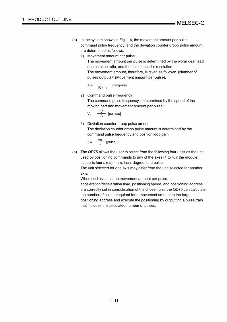
(a) In the system shown in Fig. 1.4, the movement amount per pulse,command pulse frequency, and the deviation counter droop pulse amountare determined as follows:1) Movement amount per pulse
The movement amount per pulse is determined by the worm gear lead,deceleration ratio, and the pulse encoder resolution.The movement amount, therefore, is given as follows: (Number ofpulses output) × (Movement amount per pulse).
LA = R × n [mm/pulse]
2) Command pulse frequencyThe command pulse frequency is determined by the speed of themoving part and movement amount per pulse:
VVs = A [pulse/s]
3) Deviation counter droop pulse amount.The deviation counter droop pulse amount is determined by thecommand pulse frequency and position loop gain.
Vsε = K [pulse]
(b) The QD75 allows the user to select from the following four units as the unitused by positioning commands to any of the axes (1 to 4, if the modulesupports four axes): mm, inch, degree, and pulse.The unit selected for one axis may differ from the unit selected for anotheraxis.When such data as the movement amount per pulse,acceleration/deceleration time, positioning speed, and positioning addressare correctly set in consideration of the chosen unit, the QD75 can calculatethe number of pulses required for a movement amount to the targetpositioning address and execute the positioning by outputting a pulse trainthat includes the calculated number of pulses.

1 - 12
MELSEC-Q1 PRODUCT OUTLINE
1.1.5 Communicating signals between QD75 and each module
The outline of the signal communication between the QD75 and PLC CPU, peripheraldevice and drive unit, etc., is shown below.(A peripheral device communicates with the QD75 via the PLC CPU to which it isconnected)
PLC READY signal QD75 READY signal
Positioning start signalPositioning complete signal
BUSY signal
Axis stop signalStart complete signal
Error detection signal
Upper/lower limit signalExternalsignalNear-point dog signal
Zero signal
Drive unit READY signal
Driveunit
Manual pulse generator A-phase
Deviation counter clearPulse train
Manual pulsegenerator
Externalinterface
QD75
Data write/read
Y0
Y10,Y11,Y12,Y13
X0
Y8,YA,YC,YE
PLCCPU
Externalsignal
Stop signalExternal command signal
Positioning data write/readBlock start data write/read
Operation monitor
Parameter write/read
JOG/Inching operationPositioning operation (test)
OPR operation (test)
Peripheraldevice
Peripheraldeviceinterface
Y9,YB,YD,YF
X14,X15,X16,X17
XC,XD,XE,XFX10,X11,X12,X13
Y4,Y5,Y6,Y7
X4,X5,X6,X7
X8,X9,XA,XB
Syncronization flagX1Forward run JOG start signal
Reverse run JOG start signal
M code ON signal
InterfacewithPLCCPU
Manual pulse generator B-phase
Execution prohibition flagY14,Y15,Y16,Y17

1 - 13
MELSEC-Q1 PRODUCT OUTLINE
QD75 PLC CPUThe QD75 and PLC CPU communicate the following data via the base unit.
DirectionCommunication
QD75 PLC CPU PLC CPU QD75
Control signal Signal indicating QD75 state, such asQD75 READY signal, BUSY signal.
Signal related to commands such as PLCREADY signal, various start signals, stopsignals
Data (read/write)
• Parameter• Positioning data• Block start data• Control data• Monitor data
• Parameter• Positioning data• Block start data• Control data
Refer to Section 3.3 "Specifications of input/output signals with PLC CPU" for details.
QD75 Peripheral deviceThe QD75 and peripheral device communicate the following data via the PLC CPU:
DirectionCommunication
QD75 Peripheral device Peripheral device QD75
Data (read/write)• Parameter• Positioning data• Block start data
• Parameter• Positioning data• Block start data
Test operation –
• OPR control start command• Positioning control start command• JOG/Inching operation start command• Teaching start command• Manual pulse generator operation enable/disable command
Operation monitor • Monitor data –
QD75 Drive unitThe QD75 and drive unit communicate the following data via the external deviceconnection connector.
DirectionCommunication
QD75 Drive unit Drive unit QD75
Control signal Signals related to commands such asdeviation counter clear signal
Signals indicating drive unit state such asdrive unit READY signal
Pulse train • Pulse train output –
QD75 Manual pulse generatorThe QD75 and manual pulse generator communicate the following data via theexternal device connection connector.(The manual pulse generator should be connected to an external device connectionconnector for axis 1 or for axes 1 and 2.)
DirectionCommunication
QD75 Manual pulse generator Manual pulse generator QD75
Pulse signal – Manual pulse generator A-phase, manualpulse generator B-phase

1 - 14
MELSEC-Q1 PRODUCT OUTLINE
QD75 External signalThe QD75 and external signal communicate the following data via the externaldevice connection connector.
DirectionCommunication
QD75 External signal External signal QD75
Control signal –
• Signals from detector such as near-pointdog signal, upper/lower limit signal, zerosignal
• Control signals from external device suchas stop signal, external command signal

1 - 15
MELSEC-Q1 PRODUCT OUTLINE
1.2 Flow of system operation 1.2.1 Flow of all processes
The positioning control processes, using the QD75, are shown below.
GX Configurator-QP Servo, etc.QD75 PLC CPU GX Developer
Design Understand the functions and performance, and determine the positioning operation method (system design)
1)
Preparation
Installation, wiring
Setting of the: · Parameters · Positioning data · Block start data · Condition data
Creation of sequence program for operation
Refer to (Note)
2)
3) 4)
5) 6)
7) 8)
Writing of setting data Writing of program
Monitoring withtest operation,and debuggingof setting data
Connection confirmation
Test operation
Monitoring anddebugging of operationprogram
9)
10)
11)
Operation Monitor Actual operation
Maintenance
Monitor
Disposal
(Note)When not using GX Configurator-QP, carry outsetting, monitoringand debugging of the data in 3) with GX Developer.
Maintenance
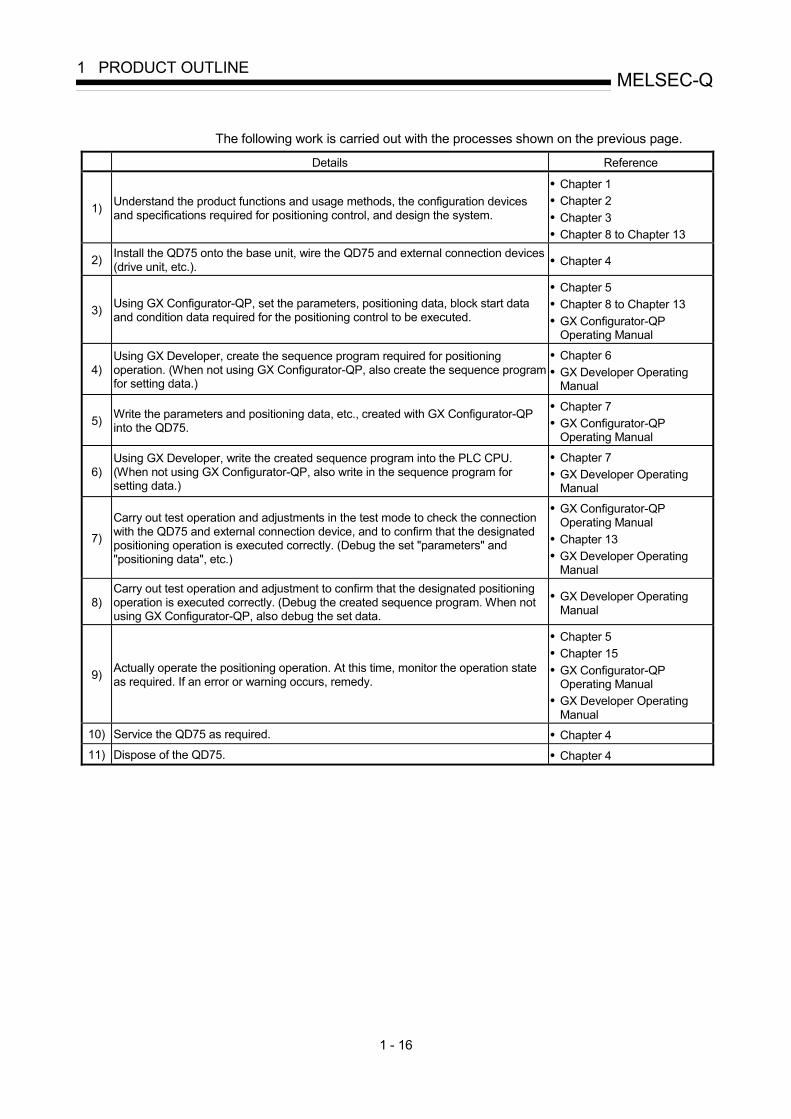
1 - 16
MELSEC-Q1 PRODUCT OUTLINE
The following work is carried out with the processes shown on the previous page.
Details Reference
1) Understand the product functions and usage methods, the configuration devices and specifications required for positioning control, and design the system.
• Chapter 1 • Chapter 2 • Chapter 3 • Chapter 8 to Chapter 13
2) Install the QD75 onto the base unit, wire the QD75 and external connection devices (drive unit, etc.). • Chapter 4
3) Using GX Configurator-QP, set the parameters, positioning data, block start data and condition data required for the positioning control to be executed.
• Chapter 5 • Chapter 8 to Chapter 13 • GX Configurator-QP
Operating Manual
4) Using GX Developer, create the sequence program required for positioning operation. (When not using GX Configurator-QP, also create the sequence program for setting data.)
• Chapter 6 • GX Developer Operating
Manual
5) Write the parameters and positioning data, etc., created with GX Configurator-QP into the QD75.
• Chapter 7 • GX Configurator-QP
Operating Manual
6) Using GX Developer, write the created sequence program into the PLC CPU. (When not using GX Configurator-QP, also write in the sequence program for setting data.)
• Chapter 7 • GX Developer Operating
Manual
7)
Carry out test operation and adjustments in the test mode to check the connection with the QD75 and external connection device, and to confirm that the designated positioning operation is executed correctly. (Debug the set "parameters" and "positioning data", etc.)
• GX Configurator-QP Operating Manual
• Chapter 13 • GX Developer Operating
Manual
8) Carry out test operation and adjustment to confirm that the designated positioning operation is executed correctly. (Debug the created sequence program. When not using GX Configurator-QP, also debug the set data.
• GX Developer Operating Manual
9) Actually operate the positioning operation. At this time, monitor the operation state as required. If an error or warning occurs, remedy.
• Chapter 5 • Chapter 15 • GX Configurator-QP
Operating Manual • GX Developer Operating
Manual 10) Service the QD75 as required. • Chapter 4 11) Dispose of the QD75. • Chapter 4

1 - 17
MELSEC-Q1 PRODUCT OUTLINE
MEMO

1 - 18
MELSEC-Q1 PRODUCT OUTLINE
1.2.2 Outline of starting
The outline for starting each control is shown with the following flowchart. It is assumed that each module is installed, and the required system configuration, etc., has been prepared.
Flow of starting
PreparationInstallation and connection of module
Setting of hardware
Control functions
Major position-ing control High-level positioning
control OPR control Manual control·Position control·Speed control·Speed-position switching control·Position-speed switching control·Other control
·Block start (Normal start)·Condition start·Wait start·Simultaneous start·Repeated start
·Machine OPR control
·Fast OPR control
·JOG operation
·Manual pulse generator operation
Positioning parameters
OPR parametersSet the OPR parameters.
Positioningdata
Set the positioning data.
Block start dataSet the block startdata.
Control data Set the positioning start No. Set the JOG speed
Set the positioning starting point No.
Set the manual pulse generator enable flag to "1".
Set the manual pulse generator1 pulse input magnification.
Start signal
Input the start signal. Method (1) Turn ON the QD75 start signal from the PLC CPU Method (2) Issue the Z.PSTRT instruction from the PLC CPU. Method (3) Turn the QD75 external start signal ON
Turn the QD75 JOG start signal ON from the PLC CPU
Operate the manual pulse generator
Control start
Control end
Operation
Stop
Set the positioning parameters. to ,) Pr.1 Pr.42 )Pr.150
to) Da.1 )Da.10
to) Pr.43 )Pr.57
to)Da.11 )Da.19
)) Cd.3
)) Cd.4
))Cd.17))Cd.21
))Cd.20
·Inching operation
))Cd.16
Set the inching movement amount to other than 0.
))Cd.16
Set the inching movement amount to 0.

1 - 19
MELSEC-Q1 PRODUCT OUTLINE
Setting method
: Indicates the sequence program that must be created.
QD75
<GX Configurator-QP>
Set with GX Configurator-QP
Set the parameter and data for executing main function, and the sub functions that need to be set beforehand.
Write
<GX Developer>
Create sequence program for setting data
When set with "GX Configurator-QP", this does not need to be created.
PLC CPU WriteWrite
Write
<GX Developer>
Create sequence program for executing main function
Create sequence program for outputting control signals, such as start signal, to QD75.
Operation sequence program PLC CPU
<GX Developer>
Create a sequence program for the sub functions.
· Speed change· Current value changing· Torque limit· Restart, etc.

1 - 20
MELSEC-Q1 PRODUCT OUTLINE
1.2.3 Outline of stopping
Each control is stopped in the following cases.
(1) When each control is completed normally. (2) When the drive unit READY signal is turned OFF. (3) When a PLC CPU error occurs (4) When the PLC READY signal is turned OFF. (5) When an error occurs in the QD75. (6) When control is intentionally stopped (Stop signal from PLC CPU turned ON, stop
signal from an external device, etc.)
The outline for the stopping process in these cases is shown below. (Excluding (1) for normal stopping.)
Stop process OPR control Manual control
Stop cause Stop axis
M code ON signal after stop
Axis operation
status after
stopping
( Md.26 )
Machine OPR
control
Fast OPR
control
Major positioning control
High-level positioning control
JOG/ Inching operation
Manual pulse generator operation
Forced stop Drive unit READY signal OFF
Each axis
No change
During error Immediate stop Deceleration
stop
Fatal stop (Stop group 1)
Hardware stroke limit upper/lower limit error occurrence
Each axis
No change
During error
Deceleration stop/sudden stop
(Select with “ Pr.37 Sudden stop group1 sudden stop selection” )
Decelerationstop
PLC CPU error occurrence
No change
PLC READY signal OFF
Turns OFF
Emergency stop (Stop group 2)
Error in test mode
All axes
No change
During error
Deceleration stop/sudden stop
(Select with “ Pr.38 Sudden stop group2 sudden stop selection” )
Decelerationstop
Axis error detection (Error other than stop group 1 or 2)
Relatively safe stop (Stop group 3) “Stop signal”
from peripheral device
Each axis
No change
During error
"Stop signal" ON from external source Intentional stop
(Stop group 3) "Axis stop signal" ON from PLC CPU
Each axis
No change
When stopped (While waiting)
Deceleration stop/sudden stop (Select with “ Pr.39 Sudden stop group3 sudden stop selection”)
Decelerationstop

1 - 21
MELSEC-Q1 PRODUCT OUTLINE
1.2.4 Outline of restarting
When a stop cause has occurred during operation with position control causing the axis to stop, positioning to the end point of the positioning data can be restarted from the stopped position by using the " Cd.6 Restart command".
If issued during a continuous positioning or continuous path control operation, the restart command will cause the positioning to be re-executed using the current position (pointed by the positioning data No. associated with the moment when the movement was interrupted) as the start point.
When " Cd.6 Restart command" is ON
(1) If the " Md.26 Axis operation status" is stopped, positioning to the end point of
the positioning data will be restarted from the stopped position regardless of the absolute system or incremental system.
(2) When " Md.26 Axis operation status" is not stopped, the warning "Restart not possible" (warning code: 104) will be applied, and the restart command will be ignored.
[Example for incremental system]
(a) The restart operation when the axis 1 movement amount is 300, and the axis 2 movement amount is 600 is shown below.
Start pointaddress
Stop position due to stop causeDesignated end point position
Axis 1
400
200
100
100 300 700Axis 2
Stop position due to stop causeStop positionafter restart
Axis 1
400
200
100
100 300 700Axis 2
Restart
Operation duringrestart
Reference
If the positioning start signal [Y10 to Y13]/external command signal is turned ON while the " Md.26 Axis operation status" is waiting or stopped, positioning will be restarted from the start of the positioning start data regardless of the absolute system or incremental system. ( : When the external command signal is set to "External positioning start") (Same as normal positioning.)
[Example for incremental system]
(a) The positioning start operation when the axis 1 movement amount is 300 and the axis 2 movement amount is 600 is shown below.
Start pointaddress
Stop position due to stop causeDesignated end point position
Axis 1
400
200
100
100 300 700Axis 2
Stop position due to stop causeStop positionafter restart
Axis 1
500
200
100
100 300 900Axis 2
Positioningstart
Operation duringpositioning start

1 - 22
MELSEC-Q1 PRODUCT OUTLINE
1.3 Restrictions with a system using a stepping motor
Note the following restrictions applicable to a system that uses a stepping motor:
(1) For the system that uses a stepping motor, executing the S-curve acceleration/deceleration may cause step-out. Before using the S-curve acceleration/deceleration, confirm that step-out does not occur.
(2) Although setting the bias speed at start is required by the characteristics of the
stepping motor, the setting of the bias speed at start is disabled for circular interpolation control.
1.4 Function additions/modifications according to function version B
POINT When it is desired to check the following items, refer to the corresponding explanation sections. How to check the function version and SERIAL No. (Refer to Section 2.4)
The following function additions/modifications according to the function version B of the QD75:
Function Outline Reference Multiple PLC compatible function Refer to QCPU User's Manual (Multiple CPU System).
Speed-position switching control (ABS mode)
Function which starts the axis under speed control, switches to position control at the external command signal input, then positions the axis to a stop at the designated address.
Section 9.2.17
Pre-reading start function Function which shortens virtual start time. Section 12.7.8
External I/O signal monitor function
Function which monitors the external I/O signal monitor information in the module's detailed information which can be displayed on the system monitor of GX Developer 1.
Section 13.5
Deceleration start flag function 2
Function that turns ON the flag when the constant speed status or acceleration status switches to the deceleration status during position control whose operation pattern is "Positioning complete".
Section 12.7.9
Stop command processing for deceleration stop function 3
Function that selects a deceleration curve when a stop cause occurs during deceleration stop processing to speed 0.
Section 12.7.10
1: Usable on GX Developer (SW6D5C-GPPW-E or later). For details, refer to GX Developer Operating Manual. 2: Usable with the module whose first five digits of SERIAL No. are "03042" or later. 3: Usable with the module whose first five digits of SERIAL No. are "05072" or later.

2 - 1
2
Chapter 2 System Configuration
In this chapter, the general image of the system configuration of the positioning controlusing QD75, the configuration devices, applicable CPU and the precautions of configuringthe system are explained.Prepare the required configuration devices to match the positioning control system.
2.1 General image of system .............................................................................................2- 2 2.2 Configuration list ...........................................................................................................2- 4 2.3 Applicable system.........................................................................................................2- 5 2.4 How to check the function version and SERIAL No....................................................2- 8

2 - 2
MELSEC-Q2 SYSTEM CONFIGURATION
2.1 General image of system
The general image of the system, including the QD75, PLC CPU and peripheral devices is shown below. (The Nos. in the illustration refer to the "No." in Section 2.2 "Component list".
CPUmodule 1
Positioningmodule
I/Omodule
Extensionsystem
RS-232 cable
1
4
USB cable5
Extensioncable
Main base unit 2
REMARK
1 Refer to Section 2.3 "Applicable system" for the CPU modules that can be used. 2 Refer to the CPU module User's Manual for the base units that can be used.

2 - 3
MELSEC-Q2 SYSTEM CONFIGURATION
Driveunit Motor
Manual pulse generator
Machine system inputs (switches)Cable
Near point dogLimit switchExternal commandsignalStop signal
Peripheral device
Personalcomputer
6
8
7
(For details, refer to GX Configurator-QP Operating Manual.)
SWnD5C-QD75P-E
3 2GX Configurator-QP

2 - 4
MELSEC-Q2 SYSTEM CONFIGURATION
2.2 Configuration list
The positioning system using the QD75 is configured of the following devices. No. Part name Type Remarks
1 Positioning module
QD75P1 QD75P2 QD75P4 QD75D1 QD75D2 QD75D4
QD75No. of control axes
P: Open collector output systemD: Differential driver output system
2 GX Configurator-QP SW D5C-QD75P-E Refer to GX Configurator-QP Operating Manual for details.
3 Personal computer DOS/V personal computer
(Prepared by user) Refer to GX Configurator-QP Operating Manual for details.
4 RS-232 cable QC30R2
(Prepared by user) An RS-232 cable is needed for connecting the CPU module with a personal computer (DOS/V). For details, refer to GX Configurator-QP Operating Manual.
5 USB cable –
(Prepared by user) A USB cable is needed for connecting the CPU module with a personal computer (DOS/V). For details, refer to GX Configurator-QP Operating Manual.
6 Drive unit – (Prepared by user)
7 Manual pulse generator –
(Prepared by user) Recommended: MR-HDP01 (Mitsubishi Electric)
8
Connection cable (For connecting between the QD75 and the drive unit)
–
(Prepared by user) Cables are needed to connect the QD75 with the drive unit, manual pulse generator, and input devices in the machine system. (Prepare them referring to the manuals for the connected devices and information given in 3.4.2 of this manual.)
Specifications of recommended manual pulse generator
Item Specifications
Model name MR-HDP01 Pulse resolution 25pulse/rev (100 pulse/rev after magnification by 4)
Output method Voltage-output (power supply voltage -1V or more),
Output current Max. 20mA Power supply voltage 4.5 to 13.2VDC Current consumption 60mA Life time 100 revolutions (at 200r/min)
Radial load: Max. 19.6N Permitted axial loads
Thrust load: Max. 9.8N Operation temperature -10 to 60 (14 to 140 ) Weight 0.4 (0.88) [kg(lb)] Number of max. revolution Instantaneous Max. 600r/min. normal 200r/min Pulse signal status 2 signals: A phase, B phase, 90 phase difference Friction torque 0.1N/m (at 20 (68 ))

2 - 5
MELSEC-Q2 SYSTEM CONFIGURATION
2.3 Applicable system
The QD75 can be used in the following system. (1) Applicable modules and base units, and No. of modules
(a) When mounted with a CPU module
The table below shows the CPU modules and base units applicable to the QD75 and quantities for each CPU model. Depending on the combination with other modules or the number of mounted modules, power supply capacity may be insufficient. Pay attention to the power supply capacity before mounting modules, and if the power supply capacity is insufficient, change the combination of the modules.
Applicable CPU module Base unit*2 CPU type CPU model
No. of modules*1 Main base unit Extension base unit
Q00JCPU Up to 8 Q00CPU Basic model
QCPU Q01CPU
Up to 24
Q02CPU Q02HCPU Q06HCPU Q12HCPU
High Performance model QCPU
Q25HCPU
Up to 64
Q12PHCPU Process CPU
Q25PHCPU Up to 64
Q12PRHCPU Redundant CPU
Q25PRHCPU Up to 53
Q02UCPU Up to 36 Q03UDCPU Q04UDHCPU Q06UDHCPU Q13UDHCPU Q26UDHCPU Q03UDECPU Q04UDEHCPU Q06UDEHCPU Q13UDEHCPU
Universal model QCPU
Q26UDEHCPU
Up to 64
Programmable controller CPU
Safety CPU QS001CPU N/A Q06CCPU-V-H01 Q06CCPU-V C Controller module*3 Q06CCPU-V-B
Up to 64
: Applicable, : N/A 1: Limited within the range of I/O points for the CPU module. 2: Can be installed to any I/O slot of a base unit. 3: Use the QD75 of function version B or later.
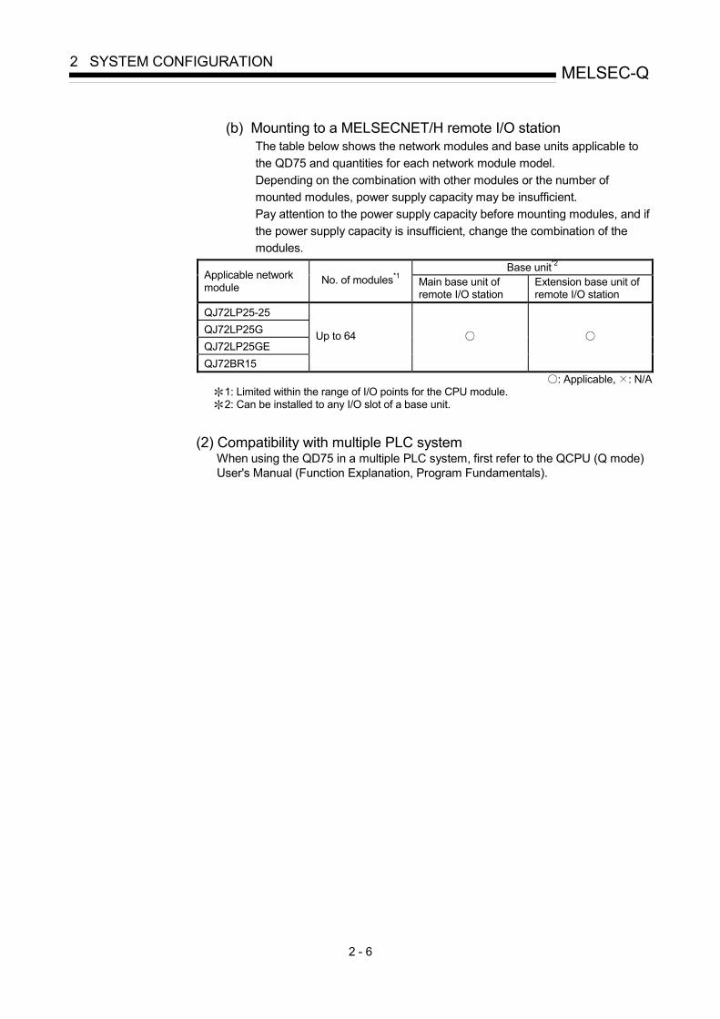
2 - 6
MELSEC-Q2 SYSTEM CONFIGURATION
(b) Mounting to a MELSECNET/H remote I/O station
The table below shows the network modules and base units applicable to the QD75 and quantities for each network module model. Depending on the combination with other modules or the number of mounted modules, power supply capacity may be insufficient. Pay attention to the power supply capacity before mounting modules, and if the power supply capacity is insufficient, change the combination of the modules.
Base unit*2 Applicable network module
No. of modules*1 Main base unit of remote I/O station
Extension base unit of remote I/O station
QJ72LP25-25 QJ72LP25G QJ72LP25GE QJ72BR15
Up to 64
: Applicable, : N/A 1: Limited within the range of I/O points for the CPU module. 2: Can be installed to any I/O slot of a base unit.
(2) Compatibility with multiple PLC system When using the QD75 in a multiple PLC system, first refer to the QCPU (Q mode) User's Manual (Function Explanation, Program Fundamentals).

2 - 7
MELSEC-Q2 SYSTEM CONFIGURATION
(3) Supported software packages
The following table lists the compatibility between the systems using the QD75 and the software packages. GX Developer is required for use of the QD75.
Software version GX Developer GX Configurator-QP
Single PLC system Version 7 or more
Q00J/Q00/Q01CPU Multiple PLC
system Version 8 or more
Single PLC system Version 4 or more Q02/Q02H/Q06H/
Q12H/Q25HCPU Multiple PLC system Version 6 or more
Version 2.10L or more
Single PLC system Q02PH/Q06PHCPU
Multiple PLC system
Version 8.68W or more Version 2.29F or more
Single PLC system Q12PH/Q25PHCPU
Multiple PLC system
Version 7.10L or more Version 2.13P or more
Single PLC system Q02UCPU/Q03UDC
PU/Q04UDHCPU/ Q06UDHCPU Multiple PLC
system
Version 8.48A or more Version 2.25B or more
Single PLC system
Q13UDH/Q26UDH/Q03UDE/Q04UDEH/Q06UDEH/Q13UDE
H/Q26UDEHCPU Multiple PLC
system
Version 8.68W or more Version 2.29F or more
For use on MELSECNET/H remote I/O station Version 6 or more Version 2.10L or more

2 - 8
MELSEC-Q2 SYSTEM CONFIGURATION
2.4 How to check the function version and SERIAL No.
(1) Confirming the serial number on the rating plate The rating plate is situated on the side face of the QD75.
SERIAL No. (The first six digits)Function version
Standard symbol for conformance is discribed
100113
(2) Checking on the front of the module The serial No. on the rating plate is also indicated on the front of the module (lower part).
SERIAL No.
100113000000000-B

2 - 9
MELSEC-Q2 SYSTEM CONFIGURATION
REMARK
The serial number is displayed on the front of the module from January 2008 production. Products manufactured during switching period may not have the serial number on the front of the module.
(3) Confirming the serial number on the system monitor (Product
Information List) Check the function version and SERIAL No. in "Product information" displayed on System monitor "Module's Detailed Information" of GX Developer or on "OS information" of GX Configurator-QP *1
<GX Developer display screen>
<GX Configurator-QP display screen>
Function version
SERIAL No.
100113000000000
1: For details, refer to GX Configurator-QP Operating Manual.

2 - 10
MELSEC-Q2 SYSTEM CONFIGURATION
MEMO

3 - 1
3
Chapter 3 Specifications and Functions
The various specifications of the QD75 are explained in this chapter.
The "General specifications", "Performance specifications", "List of functions", "Specifications of input/output signals with PLC CPU", and the "Specifications of input/output interfaces with external devices", etc., are described as information requiredwhen designing the positioning system.Confirm each specification before designing the positioning system.
3.1 Performance specifications..........................................................................................3- 2
3.2 List of functions ............................................................................................................3- 4
3.2.1 QD75 control functions ...................................................................................3- 4
3.2.2 QD75 main functions ......................................................................................3- 6
3.2.3 QD75 sub functions and common functions..................................................3- 8
3.2.4 Combination of QD75 main functions and sub functions .............................3- 12
3.3 Specifications of input/output signals with PLC CPU.................................................3- 14
3.3.1 List of input/output signals with PLC CPU ....................................................3- 14
3.3.2 Details of input signals (QD75 PLC CPU) ................................................3- 15
3.3.3 Details of output signals (PLC CPU QD75)..............................................3- 16
3.4 Specifications of input/output interfaces with external devices..................................3- 17
3.4.1 Electrical specifications of input/output signals.............................................3- 17
3.4.2 Signal layout for external device connection connector ...............................3- 19
3.4.3 List of input/output signal details ...................................................................3- 20
3.4.4 Input/output interface internal circuit .............................................................3- 22

3 - 2
MELSEC-Q3 SPECIFICATIONS AND FUNCTIONS
3.1 Performance specifications
Model Item
QD75P1 1 QD75D1
QD75P2 1 QD75D2
QD75P4 1 QD75D4
No. of control axes 1 axis 2 axes 4 axes
Interpolation function None 2-axis linear interpolation 2-axis circular interpolation
2-, 3-, or 4-axis linear interpolation
2-axis circular interpolation
Control system PTP (Point To Point) control, path control (both linear and arc can be set), speed control, speed-position switching control, position-speed switching control
Control unit mm, inch, degree, pulse
Positioning data 600 data (positioning data Nos. 1 to 600)/axis (Can be set with peripheral device or sequence program.)
Backup Parameters, positioning data, and block start data can be saved on flash ROM (battery-less backup)
Positioning system
PTP control: Incremental system/absolute system Speed-position switching control: Incremental system/absolute system 2 Position-speed switching control: Incremental system Path control: Incremental system/absolute system In absolute system
• –214748364.8 to 214748364.7 (µm) • –21474.83648 to 21474.83647 (inch) • 0 to 359.99999 (degree) • –2147483648 to 2147483647 (pulse)
In incremental system • –214748364.8 to 214748364.7 (µm) • –21474.83648 to 21474.83647 (inch) • –21474.83648 to 21474.83647 (degree) • –2147483648 to 2147483647 (pulse)
In speed-position switching control (INC mode) / position-speed switching control • 0 to 214748364.7 (µm) • 0 to 21474.83647 (inch) • 0 to 21474.83647 (degree) • 0 to 2147483647 (pulse)
In speed-position switching control (ABS mode)
Positioning range
• 0 to 359.99999 (degree)
Speed command
0.01 to 20000000.00 (mm/min) 0.001 to 2000000.000 (inch/min) 0.001 to 2000000.000 (degree/min) 1 to 1000000 (pulse/s)
Acceleration/ deceleration process Automatic trapezoidal acceleration/deceleration, S-curve acceleration/deceleration
Acceleration/ deceleration time
1 to 8388608 (ms) Four patterns can be set for each of acceleration time and deceleration time
Positioning
Sudden stop deceleration time 1 to 8388608 (ms)
1: QD75P represents the open collector output system, and QD75D represents the differential driver output system. 2: In speed-position switching control (ABS mode), the control unit available is "degree" only. (For details, refer to Section 9.2.17 "Speed-
position switching control (ABS mode)".

3 - 3
MELSEC-Q3 SPECIFICATIONS AND FUNCTIONS
Model
Item QD75P1 1 QD75D1
QD75P2 1 QD75D2
QD75P4 1 QD75D4
1-axis linear control 61-axis speed control 62-axis linear interpolation control (Composite speed) 72-axis linear interpolation control (Reference axis speed) 72-axis circular interpolation control 72-axis speed control 63-axis linear interpolation control (Composite speed) 73-axis linear interpolation control (Reference axis speed) 73-axis speed control 64-axis linear interpolation control 7
Starting time (ms) 3
4-axis speed control 7
Factors in starting time extension The following times will be added to the starting time in the described conditions: • S-curve acceleration/
deceleration is selected: 0.5 • Other axis is in
operation: 1.5 • During continuous
positioning control: 0.2 • During continuous path
control: 1.0 External wiring connection system 40-pin connector Applicable wire size 0.3 mm2 (AWG#22)or less (for A6CON1 or A6CON4), AWG #24 (for A6CON2) Applicable connector for external device A6CON1, A6CON2, A6CON4 (sold separately)
Max. output pulse QD75P1, QD75P2, QD75P4 : 200kpps QD75D1, QD75D2, QD75D4 : 1Mpps
Max. connection distance between servos
QD75P1, QD75P2, QD75P4 : 2m QD75D1, QD75D2, QD75D4 : 10m
Internal current consumption (5VDC)
QD75P1 : 0.40A QD75D1 : 0.52A
QD75P2 : 0.46A QD75D2 : 0.56A
QD75P4 : 0.58A QD75D4 : 0.82A
Flash ROM write count Max. 100000 times No. of occupied I/O points 32 points (I/O assignment: 32 points for intelligent function module) Outline dimensions 98 (H) × 27.4 (W) × 90 (D) mm Weight 0.15 kg 0.15 kg 0.16 kg
1: QD75P represents the open collector output system, and QD75D represents the differential driver output system. 3: Using the "Pre-reading start function", the virtual start time can be shortened. (For details, refer to Section 12.7.8 "Pre-reading start
function".
Differential driver common terminal specifications(QD75D1, QD75D2, QD75D4 only)
Applicable wire size 12AWG
Solid wire: 0.2 to 0.8 mm2 2 pcs. Rated multiple wire connection size Stranded wire: 0.2 to 0.8 mm2 2 pcs. Screw tightening torque 0.5N • m

3 - 4
MELSEC-Q3 SPECIFICATIONS AND FUNCTIONS
3.2 List of functions
3.2.1 QD75 control functions
The QD75 has several functions. In this manual, the QD75 functions are categorized and explained as follows.
Main functions
(1) OPR control
"OPR control" is a function that established the start point for carrying out positioning control, and carries out positioning toward that start point. This is used to return a workpiece, located at a position other than the OP when the power is turned ON or after positioning stop, to the OP. The "OPR control" is preregistered in the QD75 as the "Positioning start data No. 9001 (Machine OPR)", and "Positioning start data No. 9002 (Fast OPR). (Refer to Chapter 8 "OPR Control".)
(2) Major positioning control This control is carried out using the "Positioning data" stored in the QD75. Positioning control, such as position control and speed control, is executed by setting the required items in this "positioning data" and starting that positioning data. An "operation pattern" can be set in this "positioning data", and with this whether to carry out control with continuous positioning data (ex.: positioning data No. 1, No. 2, No. 3, ...) can be set. (Refer to Chapter 9 "Major Positioning Control".)
(3) High-level positioning control This control executes the "positioning data" stored in the QD75 using the "block start data". The following types of applied positioning control can be carried out. • Random blocks, handling several continuing positioning data items as
"blocks", can be executed in the designated order. • "Condition judgment" can be added to position control and speed control. • The operation of the designated positioning data No. that is set for multiple
axes can be started simultaneously. (Pulses are output simultaneously to multiple servos.)
• The designated positioning data can be executed repeatedly, etc., (Refer to Chapter 10 "High-level Positioning Control".)
(4) Manual control By inputting a signal into the QD75 from an external source, the QD75 will output a random pulse train and carry out control. Use this manual control to move the workpiece to a random position (JOG operation), and to finely adjust the positioning (inching operation, manual pulse generator operation), etc. (Refer to Chapter 11 "Manual Control".)
Sub functions When executing the main functions, control compensation, limits and functions can be added. (Refer to Chapter 12 "Control Sub Functions".)
Common functions Common control using the QD75 for "parameter initialization" or "backup of execution data" can be carried out. (Refer to Chapter 13 "Common Functions".)

3 - 5
MELSEC-Q3 SPECIFICATIONS AND FUNCTIONS
Position control
Main functions Sub functions
OPR control Control registered in QD75
[Positioning start No.]
[9002]
[9001] Machine OPR
Fast OPR
(Functions characteristic to machine OPR) OPR retry function
OP shift function
<Functions that compensate control> Backlash compensation function
Electronic gear function Near pass function
<Functions that limit control> Speed limit function Torque limit function Software stroke limit function Hardware stroke limit function
<Functions that change control details> Speed change function Override function Acceleration/deceleration time change function Torque change function
<Absolute position restoration function>
<Other functions> Step function Skip function Continuous operation interrupt function M code output function Teaching function Target position change function Command in-position function Acceleration/deceleration processing function Pre-reading start function Deceleration start flag function Stop command processing for deceleration stop function
Major positioning control Control using "Positioning data"
<Control system>·1-axis linear control·2-, 3-, or 4-axis linear interpolation control·1-axis fixed-feed control·2-, 3-, or 4-axis fixed-feed control·2-axis circular interpolation control·1-axis linear control·2-axis linear interpolation control·3-axis linear interpolation control·4-axis linear interpolation control ·Current value changing, NOP instruction·JUMP instruction, LOOP to LEND
<Operation pattern>
Independent positioning control (Positioning complete)
Continuous positioning control
Continuous path control
High-level positioning controlControl using "positioning data" + "Block start data"
Major positioningcontrol
[Block start data]
Block start (Normal start)Condition startWait startSimultaneous startRepeated start (FOR loop)Repeated start(FOR condition)Multiple axes simultaneous start control
Parameter initialization function Execution data backup function External I/O logic switching function
Manual control Control with signals input from external source
Common functions
[Positioning start signal]
JOG start signal ONPulse input from manual pulse generator
JOG operation, Inching operation
Manual pulse generatoroperation
Other control
Speed-position switching controlPosition-speed switching control
[Positioning start No.]
[9004]
Speed control
External I/O signal monitor function

3 - 6
MELSEC-Q3 SPECIFICATIONS AND FUNCTIONS
3.2.2 QD75 main functions
The outline of the main functions for positioning control with the QD75 is described below. (Refer to Section 2 for details on each function.)
Main functions Details Reference section
Machine OPR control Mechanically establishes the positioning start point using a near-point dog or stopper. (Positioning start No. 9001) 8.2
OPR
con
trol
Fast OPR control Positions a target to the OP address ( Md.21 Machine feed value) stored in the QD75 using machine OPR. (Positioning start No. 9002)
8.3
Linear control (1-axis linear control) (2-axis linear interpolation control) (3-axis linear interpolation control) (4-axis linear interpolation control)
Positions a target using a linear path to the address set in the positioning data or to the position designated with the movement amount.
9.2.2 9.2.3 9.2.4 9.2.5
Fixed-feed control (1-axis fixed-feed control) (2-axis fixed-feed control) (3-axis fixed-feed control) (4-axis fixed-feed control)
Positions a target by the movement amount designated with the amount set in the positioning data.
(With fixed-feed control, the " Md.20 Current feed value" is set to "0" when the control is started. With 2-, 3-, or 4-axis fixed-feed control, the fixed-feed is fed along a linear path obtained by interpolation.)
9.2.6 9.2.7 9.2.8 9.2.9
Position control
2-axis circular interpolation control Positions a target using an arc path to the address set in the positioning data, or to the position designated with the movement amount, sub point or center point.
9.2.10 9.2.11
Speed control
Linear control (1-axis linear control) (2-axis linear interpolation control) (3-axis linear interpolation control) (4-axis linear interpolation control)
Continuously outputs the pulses corresponding to the command speed set in the positioning data.
9.2.12 9.2.13 9.2.14 9.2.15
Speed-position switching control
First, carries out speed control, and then carries out position control (positioning with designated address or movement amount) by turning the "speed-position switching signal" ON.
9.2.16 9.2.17
Position-speed switching control
First, carries out position control, and then carries out speed control (continuous output of the pulses corresponding to the designated command speed) by turning the "position-speed switching signal" ON.
9.2.18
Current value changing
Changes the Current feed value ( Md.20 ) to the address set in the positioning data. The following two methods can be used. (The machine feed value cannot be changed.)
• Current value changing using positioning data • Current value changing using current value changing
start No. (No. 9003)
9.2.19
NOP instruction No execution control system. When NOP instruction is set, this instruction is not executed and the operation of the next data is started.
9.2.20
JUMP instruction Unconditionally or conditionally jumps to designated positioning data No. 9.2.21
LOOP Carries out loop control with repeated LOOP to LEND. 9.2.22
Maj
or p
ositi
onin
g co
ntro
l
Other control
LEND Returns to the beginning of the loop control with repeated LOOP to LEND. 9.2.23

3 - 7
MELSEC-Q3 SPECIFICATIONS AND FUNCTIONS
Main functions Details Reference section
Block start (Normal start) With one start, executes the positioning data in a random block with the set order. 10.3.2
Condition start
Carries out condition judgment set in the "condition data" for the designated positioning data, and then executes the "block start data". When the condition is established, the "block start data" is executed. When not established, that "block start data" is ignored, and the next point's "block start data" is executed.
10.3.3
Wait start
Carries out condition judgment set in the "condition data" for the designated positioning data, and then executes the "block start data". When the condition is established, the "block start data" is executed. When not established, stops the control until the condition is established. (Waits.)
10.3.4
Simultaneous start Simultaneously executes the positioning data having the No. for the axis designated with the "condition data". (Outputs pulses at the same timing.)
10.3.5
Repeated start (FOR loop) Repeats the program from the block start data set with the "FOR loop" to the block start data set in "NEXT" for the designated No. of times.
10.3.6
Repeated start (FOR condition) Repeats the program from the block start data set with the "FOR condition" to the block start data set in "NEXT" until the conditions set in the "condition data" are established.
10.3.7
Hig
h-le
vel p
ositi
onin
g co
ntro
l
Multiple axes simultaneous start control
Starts the operation of multiple axes simultaneously according to the pulse output level. (Positioning start No. 9004, same as the "simultaneous start" above)
10.5
JOG operation Outputs a pulse to drive unit while the JOG start signal is ON. 11.2
Inching operation Outputs pulses corresponding to minute movement amount by manual operation to drive unit. (Performs fine adjustment with the JOG start signal.)
11.3
Man
ual c
ontro
l
Manual pulse generator operation Outputs pulses commanded with the manual pulse generator to drive unit. (Carry out fine adjustment, etc., at the pulse level.) 11.4
With the "major positioning control" ("high-level positioning control"), whether or not to continuously execute the positioning data can be set with the "operation pattern". Outlines of the "operation patterns" are given below.
Da.1 Operation pattern Details Reference section
Independent positioning control (Positioning complete)
When "independent positioning control" is set for the operation pattern of the started positioning data, only the designated positioning data will be executed, and then the positioning will end.
Continuous positioning control
When "continuous positioning control" is set for the operation pattern of the started positioning data, after the designated positioning data is executed, the program will stop once, and then the next following positioning data will be executed.
Continuous path control
When "continuous path control" is set for the operation pattern of the started positioning data, the designated positioning data will be executed, and then without decelerating, the next following positioning data will be executed.
9.1.2

3 - 8
MELSEC-Q3 SPECIFICATIONS AND FUNCTIONS
3.2.3 QD75 sub functions and common functions
Sub functions The functions that assist positioning control using the QD75 are described below. (Refer to Section 2 for details on each function.
Sub function Details Reference section
OPR retry function
This function retries the machine OPR with the upper/lower limit switches during machine OPR. This allows machine OPR to be carried out even if the axis is not returned to before the near-point dog with JOG operation, etc.
12.2.1 Functions characteristic to machine OPR
OP shift function After returning to the machine OP, this function compensates the position by the designated distance from the machine OP position and sets that position as the OP address.
12.2.2
Backlash compensation function
This function compensates the mechanical backlash. Feed pulses equivalent to the set backlash amount are output each time the movement direction changes.
12.3.1
Electronic gear function
By setting the movement amount per pulse, this function can freely change the machine movement amount per commanded pulse. When the movement amount per pulse is set, a flexible positioning system that matches the machine system can be structured.
12.3.2 Functions that compensate control
Near pass function 1 This function suppresses the machine vibration when the speed changes during continuous path control in the interpolation control.
12.3.3
Speed limit function If the command speed exceeds " Pr.8 Speed limit value" during control, this function limits the commanded speed to within the " Pr.8 Speed limit value" setting range.
12.4.1
Torque limit function 2
If the torque generated by the servomotor exceeds " Pr.17
Torque limit setting value" during control, this function limits the generated torque to within the " Pr.17 Torque limit setting value" setting range.
12.4.2
Software stroke limit function
If a command outside of the upper/lower limit stroke limit setting range, set in the parameters, is issued, this function will not execute positioning for that command.
12.4.3
Functions that limit control
Hardware stroke limit function
This function carries out deceleration stop with the limit switch connected to the QD75 external device connector. 12.4.4
Speed change function
This function changes the speed during positioning. Set the new speed in the speed change buffer memory ( Cd.14 New speed value), and change the speed with the
Speed change request ( Cd.15 ).
12.5.1
Override function This function changes the speed within a percentage of 1 to 300% during positioning. This is executed using " Cd.13 Positioning operation speed override".
12.5.2
Acceleration/deceleration time change function
This function changes the acceleration/deceleration time during speed change. 12.5.3
Functions that change control details
Torque change function This function changes the "torque limit value" during control. 12.5.4 Absolute position restoration function 3 This function restores the absolute position of designated axis. 12.6
1: The near pass function is featured as standard and is valid only for position control. It cannot be set to be invalid with parameters. 2: Using "Torque limit function" requires a "D/A conversion module" and a "drive unit capable of torque limit command with analog voltage". 3: Using "Absolute position restoration function" requires a "16-point input module", a "16-point output module", and a "drive unit that can
construct absolute position detection system".

3 - 9
MELSEC-Q3 SPECIFICATIONS AND FUNCTIONS
Sub function Details Reference section
Step function
This function temporarily stops the operation to confirm the positioning operation during debugging, etc. The operation can be stopped at each "automatic deceleration" or "positioning data".
12.7.1
Skip function This function stops (decelerates to a stop) the positioning being executed when the skip signal is input, and carries out the next positioning.
12.7.2
M code output function This function issues a command for a sub work (clamp or drill stop, tool change, etc.) corresponding to the M code No. (0 to 65535) that can be set for each positioning data.
12.7.3
Teaching function This function stores the address positioned with manual control into the positioning address having the designated positioning data No. ( Cd.39 ).
12.7.4
Target position change function
This function changes the target position during positioning. Position and speed can be changed simultaneously. 12.7.5
Command in-position function
At each automatic deceleration, this function calculates the remaining distance for the QD75 to reach the positioning stop position. When the value is less than the set value, the "command in-position flag" is set to "1". When using another auxiliary work before ending the control, use this function as a trigger for the sub work.
12.7.6
Acceleration/deceleration process function This function adjusts the control acceleration/deceleration. 12.7.7
Continuous operation interrupt function
This function interrupts continuous operation. When this request is accepted, the operation stops when the execution of the current positioning data is completed.
6.5.4
Pre-reading start function This function shortens the virtual start time. 12.7.8
Deceleration start flag function
Function that turns ON the flag when the constant speed status or acceleration status switches to the deceleration status during position control, whose operation pattern is "Positioning complete", to make the stop timing known.
12.7.9
Other functions
Stop command processing for deceleration stop function
Function that selects a deceleration curve when a stop cause occurs during deceleration stop processing to speed 0. 12.7.10

3 - 10
MELSEC-Q3 SPECIFICATIONS AND FUNCTIONS
Common functionsThe outline of the functions executed as necessary are described below.(Refer to Section 2 for details on each function.)
Common functions DetailsReference
section
Parameter initialization function
This function returns the "parameters" stored in the QD75buffer memory and flash ROM to the default values.The following two methods can be used.1) Method using sequence program2) Method using GX Configurator-QP
13.2
Execution data backup function
This functions stores the "setting data", currently beingexecuted, into the flash ROM.1) Method using sequence program2) Method using GX Configurator-QP
13.3
External I/O signal logic switching function
This function switches I/O signal logic according to externallyconnected devices.
This function enables the use of the system that does not use b(N.C.)-contact signals, such as Drive unit READY orUpper/lower limit signal, by setting parameters to positive logic.
13.4
External I/O signal monitor functionThis function monitors the external I/O signal monitorinformation in the module's detailed information which can bedisplayed on the system monitor of GX Developer*4.
13.5
4: Usable on GX Developer (SW6D5C-GPPW-E or later).

3 - 11
MELSEC-Q3 SPECIFICATIONS AND FUNCTIONS
MEMO
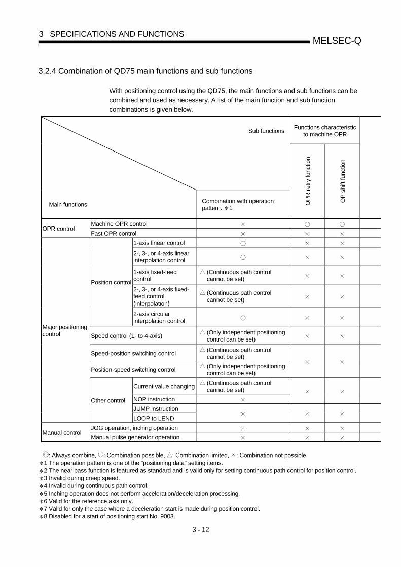
3 - 12
MELSEC-Q3 SPECIFICATIONS AND FUNCTIONS
3.2.4 Combination of QD75 main functions and sub functions
With positioning control using the QD75, the main functions and sub functions can be
combined and used as necessary. A list of the main function and sub function
combinations is given below.
Functions characteristicto machine OPR
Sub functions
Main functionsCombination with operationpattern. 1
OP
R r
etry
func
tion
OP
shi
ft fu
nctio
n
Machine OPR controlOPR control
Fast OPR control
1-axis linear control
2-, 3-, or 4-axis linearinterpolation control
1-axis fixed-feedcontrol
(Continuous path controlcannot be set)
2-, 3-, or 4-axis fixed-feed control(interpolation)
(Continuous path controlcannot be set)
Position control
2-axis circularinterpolation control
Speed control (1- to 4-axis)(Only independent positioningcontrol can be set)
Speed-position switching control(Continuous path controlcannot be set)
Position-speed switching control(Only independent positioningcontrol can be set)
Current value changing(Continuous path controlcannot be set)
NOP instruction
JUMP instruction
Major positioningcontrol
Other control
LOOP to LEND
JOG operation, inching operationManual control
Manual pulse generator operation
: Always combine, : Combination possible, : Combination limited, : Combination not possible1 The operation pattern is one of the "positioning data" setting items.2 The near pass function is featured as standard and is valid only for setting continuous path control for position control.3 Invalid during creep speed.4 Invalid during continuous path control.5 Inching operation does not perform acceleration/deceleration processing.6 Valid for the reference axis only.7 Valid for only the case where a deceleration start is made during position control.8 Disabled for a start of positioning start No. 9003.

3 - 13
MELSEC-Q3 SPECIFICATIONS AND FUNCTIONS
Functions thatcompensate
control
Functions that limitcontrol
Functions that changecontrol details
Other functions
Bac
klas
h co
mpe
nsat
ion
func
tion
Ele
ctro
nic
gear
func
tion
Nea
r pa
ss fu
nctio
n
Spe
ed li
mit
func
tion
Tor
que
limit
func
tion
Sof
twar
e st
roke
lim
itfu
nctio
n
Har
dw
are
stro
ke li
mit
func
tion
Spe
ed c
hang
e fu
nctio
n
Ove
rrid
e fu
nctio
n
Acc
eler
atio
n/ d
ecel
erat
ion
time
chan
ge fu
nctio
n
Tor
que
chan
ge fu
nctio
n
Ste
p fu
nctio
n
Ski
p fu
nctio
n
M c
ode
outp
ut fu
nctio
n
Tea
chin
g fu
nctio
n
Tar
get p
ositi
on c
hang
efu
nctio
n
Com
man
d in
-pos
ition
func
tion
Acc
eler
atio
n/de
cele
ratio
npr
oces
s fu
nctio
n
Pre
-rea
ding
sta
rt fu
nctio
n
Dec
eler
atio
n st
art f
lag
func
tion
Sto
p co
mm
and
proc
essi
ngfo
r de
cele
ratio
n st
opfu
nctio
n
3 3
4
6
6
7
8
5
2
REMARK
• The "common functions" are functions executed as necessary. (These are not combinedwith the control.)
• "High-level positioning control" is a control used in combination with the "major positioningcontrol". For combinations with the sub functions, refer to the combinations of the "majorpositioning control" and sub functions.

3 - 14
MELSEC-Q3 SPECIFICATIONS AND FUNCTIONS
3.3 Specifications of input/output signals with PLC CPU
3.3.1 List of input/output signals with PLC CPU
The QD75 uses 32 input points and 32 output points for exchanging data with the PLC
CPU.
The input/output signals when the QD75 is mounted in slot No. 0 of the main base unit
are shown below.
Device X refers to the signals input from the QD75 to the PLC CPU, and device Y
refers to the signals output from the PLC CPU to the QD75.
Signal direction: QD75 PLC CPU Signal direction: PLC CPU QD75Device No. Signal name Device No. Signal name
X0 QD75 READY Y0 PLC READYX1 Synchronization flag Y1X2 Y2X3
Use prohibitedY3
Use prohibited
X4 Axis 1 Y4 Axis 1X5 Axis 2 Y5 Axis 2X6 Axis 3 Y6 Axis 3X7 Axis 4
M code ON
Y7 Axis 4
Axis stop
X8 Axis 1 Y8 Axis 1 Forward run JOG startX9 Axis 2 Y9 Axis 1 Reverse run JOG startXA Axis 3 YA Axis 2 Forward run JOG startXB Axis 4
Error detection
YB Axis 2 Reverse run JOG startXC Axis 1 YC Axis 3 Forward run JOG startXD Axis 2 YD Axis 3 Reverse run JOG startXE Axis 3 YE Axis 4 Forward run JOG startXF Axis 4
BUSY
YF Axis 4 Reverse run JOG startX10 Axis 1 Y10 Axis 1X11 Axis 2 Y11 Axis 2X12 Axis 3 Y12 Axis 3X13 Axis 4
Start complete
Y13 Axis 4
Positioning start
X14 Axis 1 Y14 Axis 1X15 Axis 2 Y15 Axis 2X16 Axis 3 Y16 Axis 3X17 Axis 4
Positioning complete
Y17 Axis 4
Execution prohibition flag
X18 Y18X19 Y19X1A Y1AX1B Y1BX1C Y1CX1D Y1DX1E Y1EX1F
Use prohibited
Y1F
Use prohibited
Important[Y1 to Y3], [Y18 to Y1F], [X2, X3], and [X18 to X1F] are used by the system, and cannot be
used by the user.
If these devices are used, the operation of the QD75 will not be guaranteed.
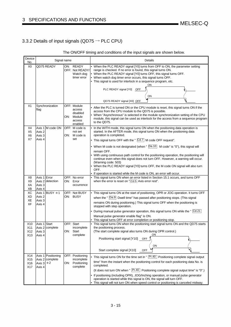
3 - 15
MELSEC-Q3 SPECIFICATIONS AND FUNCTIONS
3.3.2 Details of input signals (QD75 PLC CPU)
The ON/OFF timing and conditions of the input signals are shown below.
DeviceNo.
Signal name Details
X0 QD75 READY ON: READYOFF: Not READY/
Watch dogtimer error
• When the PLC READY signal [Y0] turns from OFF to ON, the parameter settingrange is checked. If no error is found, this signal turns ON.
• When the PLC READY signal [Y0] turns OFF, this signal turns OFF.• When watch dog timer error occurs, this signal turns OFF.• This signal is used for interlock in a sequence program, etc.
PLC READY signal [Y0] OFF
ON
QD75 READY signal [X0] OFF
ON
X1 Synchronizationflag
OFF: Moduleaccessdisabled
ON: Moduleaccessenabled
• After the PLC is turned ON or the CPU module is reset, this signal turns ON if theaccess from the CPU module to the QD75 is possible.
• When "Asynchronous" is selected in the module synchronization setting of the CPUmodule, this signal can be used as interlock for the access from a sequence programto the QD75.
X4X5X6X7
Axis 1Axis 2Axis 3Axis 4
M code ON OFF: M code isnot set
ON: M code isset
• In the WITH mode, this signal turns ON when the positioning data operation isstarted. In the AFTER mode, this signal turns ON when the positioning dataoperation is completed.
• This signal turns OFF with the " Cd.7 M code OFF request".
• When M code is not designated (when " Da.10 M code" is "0"), this signal will
remain OFF.• With using continuous path control for the positioning operation, the positioning will
continue even when this signal does not turn OFF. However, a warning will occur.(Warning code: 503)
• When the PLC READY signal [Y0] turns OFF, the M code ON signal will also turnOFF.
• If operation is started while the M code is ON, an error will occur.X8X9XAXB
Axis 1Axis 2Axis 3Axis 4
Errordetection
OFF: No errorON: Error
occurrence
• This signal turns ON when an error listed in Section 15.1 occurs, and turns OFFwhen the error is reset on " Cd.5 Axis error rest".
XCXDXEXF
Axis 1Axis 2Axis 3Axis 4
BUSY 1 OFF: Not BUSYON: BUSY
• This signal turns ON at the start of positioning, OPR or JOG operation. It turns OFF
when the " Da.9 Dwell time" has passed after positioning stops. (This signal
remains ON during positioning.) This signal turns OFF when the positioning isstopped with step operation.
• During manual pulse generator operation, this signal turns ON while the " Cd.21
Manual pulse generator enable flag" is ON.• This signal turns OFF at error completion or positioning stop.
X10X11X12X13
Axis 1Axis 2Axis 3Axis 4
Startcomplete
OFF: Startincomplete
ON: Startcomplete
• This signal turns ON when the positioning start signal turns ON and the QD75 startsthe positioning process.(The start complete signal also turns ON during OPR control.)
OFF
ON
OFF
ON
Positioning start signal [Y10]
Start complete signal [X10]
X14X15X16X17
Axis 1Axis 2Axis 3Axis 4
Positioningcomplete
2
OFF: Positioningincomplete
ON: Positioningcomplete
• This signal turns ON for the time set in " Pr.40 Positioning complete signal output
time" from the instant when the positioning control for each positioning data No. iscompleted.
(It does not turn ON when " Pr.40 Positioning complete signal output time" is "0".)
• If positioning (including OPR), JOG/Inching operation, or manual pulse generatoroperation is started while this signal is ON, the signal will turn OFF.
• This signal will not turn ON when speed control or positioning is canceled midway.

3 - 16
MELSEC-Q3 SPECIFICATIONS AND FUNCTIONS
Important1: The BUSY signal turns ON even when position control of movement amount 0 is
executed. However, since the ON time is short, the ON status may not be detected in thesequence program.
2: "Positioning complete" of the QD75 refers to the point when the pulse output from QD75 iscompleted.Thus, even if the QD75's positioning complete signal turns ON, the system may continueoperation.
3.3.3 Detail of output signals (PLC CPU QD75)
The ON/OFF timing and conditions of the output signals are shown below.
Device No. Signal name DetailsY0 PLC READY OFF:
PLC READY OFFON:
PLC READY ON
(a) This signal notifies the QD75 that the PLC CPU is normal.• It is turned ON/OFF with the sequence program.• The PLC READY signal is turned ON during positioning
control, OPR control, JOG operation, inching operation, andmanual pulse generator operation, unless the system is in theperipheral device test mode.
(b) When parameters are changed, the PLC READY signal is turnedOFF depending on the parameter (Refer to Chapter 7.).
(c) The following processes are carried out when the PLC READYsignal turns from OFF to ON.• The parameter setting range is checked.• The QD75 READY signal [X0] turns ON.
(d) The following processes are carried out when the PLC READYsignal turns from ON to OFF.In these cases, the OFF time should be set to 100ms or more.• The QD75 READY signal [X0] turns OFF.• The operating axis stops.• The M code ON signal [X4 to X7] for each axis turns OFF, and
"0" is stored in " Md.25 Valid M code".
(e) When parameters or positioning data (No. 1 to 600) are writtenfrom the peripheral device or PLC CPU to the flash ROM, thePLC READY signal will turn OFF.
Y4Y5Y6Y7
Axis 1Axis 2Axis 3Axis 4
Axis stop OFF:Axis stop notrequested
ON:Axis stop requested
• When the axis stop signal turns ON, the OPR control, positioningcontrol, JOG operation, inching operation and manual pulsegenerator operation will stop.
• By turning the axis stop signal ON during positioning operation, thepositioning operation will be "stopped".
• Whether to decelerate or suddenly stop can be selected with
" Pr.39 Stop group 3 sudden stop selection".
• During interpolation control of the positioning operation, if the axisstop signal of any axis turns ON, all axes in the interpolationcontrol will decelerate and stop.
Y8Y9YAYBYCYDYEYF
Axis 1Axis 1Axis 2Axis 2Axis 3Axis 3Axis 4Axis 4
Forward run JOG startReverse run JOG startForward run JOG startReverse run JOG startForward run JOG startReverse run JOG startForward run JOG startReverse run JOG start
OFF:JOG not started
ON:JOG started
• When the JOG start signal is ON, JOG operation will be carried
out at the " Cd.17 JOG speed". When the JOG start signal turns
OFF, the operation will decelerate and stop.• When inching movement amount is set, the designated movement
amount is output for one control cycle and then the operationstops.
Y10Y11Y12Y13
Axis 1Axis 2Axis 3Axis 4
Positioning start OFF:Positioning start notrequested
ON:Positioning startrequested
• OPR operation or positioning operation is started.• The positioning start signal is valid at the rising edge, and the
operation is started.• When the positioning start signal turns ON during BUSY, the
operation starting warning will occur (warning code: 100).
Y14Y15Y16Y17
Axis 1Axis 2Axis 3Axis 4
Execution prohibitionflag
OFF:Not during executionprohibition
ON:During executionprohibition
• If the execution prohibition flag is ON when the positioning startsignal turns ON, positioning control does not start until theexecution prohibition flag turns OFF. (Pulse output not provided)Used with the "Pre-reading start function". (Refer to Section12.7.8)

3 - 17
MELSEC-Q3 SPECIFICATIONS AND FUNCTIONS
3.4 Specifications of input/output interfaces with external devices
3.4.1 Electrical specifications of input/output signals
Input specifications
Signal name Rated input voltage/current
Working voltage range
ON voltage/current
OFF voltage/current
Input resistance
Response time
Drive unit READY (READY) Stop signal (STOP) Upper limit signal (FLS) Lower limit signal (RLS)
24VDC/5mA 19.2 to 26.4VDC
17.5VDC or more/3.5mA or more
7VDC or less/1.7mA or less Approx. 4.7kΩ 4ms or less
5VDC/5mA 4.5 to 6.1VDC 2VDC or more/2mA or more
0.5VDC or less/0.5mA or less Approx. 0.3kΩ 1ms or less
24VDC/5mA 12 to 26.4VDC 10VDC or more/3mA or more
3VDC or less/0.2mA or less Approx. 4.7kΩ 1ms or less
3 s or less1ms or more
3 s or lessON
OFF
Zero signal (PG05/PG024)
Differential receiver equivalent to Am26LS32 (ON/OFF level ON: 1.8V or more, OFF: 0.6V or less)
5VDC/5mA 4.5 to 6.1VDC 2.5VDC or more/2mA or more
1VDC or less/0.1mA or less Approx. 1.5kΩ 1ms or less
1 Pulse width
4ms or more
2ms or more
2ms or more
(Duty ratio: 50%)
2 Phase difference
Manual pulse generator A phase (PULSE GENERATOR A) Manual pulse generator B phase (PULSE GENERATOR B)
A phase
B phase1ms or more
When the A phase leads the B phase, the positioning address (current value) increases.
Near-point dog signal (DOG) External command signal (CHG)
24VDC/5mA 19.2 to 26.4VDC
17.5VDC or more/3.5mA or more
7VDC or less/1.7mA or less Approx. 4.3kΩ 1ms or less

3 - 18
MELSEC-Q3 SPECIFICATIONS AND FUNCTIONS
Output specifications
Signal name Rated load voltage
Working load voltage range
Max. load current/rush
current
Max. voltage drop at ON
Leakage current at OFF Response time
5 to 24VDC 4.75 to 30VDC 50mA/1 point/200mA 10ms or
less 0.5VDC (TYP) 0.1mA or less —
The table below shows the rising/falling edge time and duty ratio when the QD75P is used. QD75P
tr
OFF
tf
ON
QD75D Differential driver equivalent to Am26C31 (For QD75D ) • Select the CW/CCW type, PULSE/SIGN type and A phase/B phase type using the parameter ( Pr.5 Pulse
output mode) according to the drive unit specifications. • The relation of the pulse output with the " Pr.5 Pulse output mode" and " Pr.23 Output signal logic
selection" is shown below:
Pr.23 Output signal logic selection (bit 0)
Positive logic Negative logic
Pr.5 Pulse output mode
Forward run Reverse run Forward run Reverse run
CW CCW
PULSE SIGN High Low Low High
Aφ Bφ
Pulse output (CW/PULSE/A phase) Pulse sign (CCW/SIGN/B phase)
Deviation counter clear (CLEAR) 5 to 24VDC 4.75 to 30VDC 0.1A/1 point/0.4A
10ms or less 1VDC (TYP)
2.5VDC (MAX) 0.1mA or less 2ms or less (resistance load)
: Pulse rising/falling edge time when the QD75P is used (Unit for "tr" and "tf": µs, unit for "Duty": %)
... When ambient temperature is room temperature. Load voltage (V) 26.4 4.75 Cable length (m) 1 2 1 2 Load
current (mA)
Pulse speed (kpps)
tr (Rising edge)
tf (Falling edge)
Duty tr
(Rising edge)
tf (Falling edge)
Duty tr
(Rising edge)
tf (Falling edge)
Duty tr
(Rising edge)
tf (Falling edge)
Duty
200 2.33 0.08 6.6 2.20 0.08 14.6 0.57 0.07 44.8 0.95 0.07 39.0 100 2.42 0.09 34.7 4.44 0.10 12.6 0.57 0.07 47.5 1.01 0.08 45.3 2 10 2.44 0.09 48.7 4.52 0.10 47.7 0.60 0.07 49.7 1.04 0.08 49.5 200 1.00 0.09 39.8 1.77 0.11 24.5 0.32 0.07 48.4 0.45 0.08 45.8 100 1.01 0.09 45.3 1.76 0.10 40.3 0.31 0.07 49.2 0.45 0.08 48.7 5 10 1.00 0.10 49.6 1.72 0.10 49.2 0.33 0.08 49.9 0.49 0.08 49.8 200 0.27 0.10 50.1 0.44 0.11 48.0 0.15 0.08 50.7 0.15 0.08 51.3 100 0.29 0.10 49.8 0.48 0.11 49.1 0.15 0.08 50.4 0.18 0.08 50.4 20 10 0.30 0.10 49.9 0.48 0.12 49.9 0.17 0.08 50.1 0.18 0.08 49.9 200 0.19 0.11 50.5 0.24 0.12 50.6 0.15 0.10 51.8 0.14 0.11 51.7 100 0.19 0.11 50.4 0.24 0.12 50.4 0.14 0.10 50.7 0.15 0.10 50.8 50 10 0.18 0.12 50.0 0.22 0.13 50.1 0.14 0.10 50.1 0.15 0.12 50.1
The time for H/L width of differential output waveform with the QD75D . (Cable length: 2m, Ambient temperature: room temperature)
Pulse speed H width L width
1Mpps 410ns 456ns 500kpps 936ns 1µs

3 - 19
MELSEC-Q3 SPECIFICATIONS AND FUNCTIONS
3.4.2 Signal layout for external device connection connector
The specifications of the connector section, which is the input/output interface for the QD75 and external device, are shown below. The signal layout for the QD75 external device connection connector is shown.
QD75P1RUN
ERR
AX1
AX1
QD75P2RUN
ERR
AX1
AX1
QD75P4RUN
ERR
AX1
AX1
AX2
AX2
AX2AX3AX4
AX2AX3AX4
Axis 4(AX4) Axis 3(AX3) Axis 2(AX2) Axis 1(AX1) Pin layout
Pin No. Signal name Pin No. Signal name Pin No. Signal name Pin No. Signal name 2B20 Vacant 2A20 Vacant 1B20 PULSER B– 1A20 PULSER B+ 2B19 Vacant 2A19 Vacant 1B19 PULSER A– 1A19 PULSER A+ 2B18
3 PULSE COMPULSE R–
2A183
PULSE COMPULSE R–
1B183
PULSE COM PULSE R–
1A18 3
PULSE COMPULSE R–
2B17 3
PULSE R PULSE R+
2A173
PULSE R PULSE R+
1B173
PULSE R PULSE R+
1A17 3
PULSE R PULSE R+
2B16 3
PULSE COMPULSE F–
2A163
PULSE COMPULSE F–
1B163
PULSE COM PULSE F–
1A16 3
PULSE COMPULSE F–
2B15 3
PULSE F PULSE F+
2A153
PULSE F PULSE F+
1B153
PULSE F PULSE F+
1A15 3
PULSE F PULSE F+
2B14 CLRCOM 2A14 CLRCOM 1B14 CLRCOM 1A14 CLRCOM 2B13 CLEAR 2A13 CLEAR 1B13 CLEAR 1A13 CLEAR 2B12 RDYCOM 2A12 RDYCOM 1B12 RDYCOM 1A12 RDYCOM 2B11 READY 2A11 READY 1B11 READY 1A11 READY 2B10 PGOCOM 2A10 PGOCOM 1B10 PGOCOM 1A10 PGOCOM 2B9 PG05 2A9 PG05 1B9 PG05 1A9 PG05 2B8 PG024 2A8 PG024 1B8 PG024 1A8 PG024 2B7 COM 2A7 COM 1B7 COM 1A7 COM 2B6 COM 2A6 COM 1B6 COM 1A6 COM 2B5 CHG 2A5 CHG 1B5 CHG 1A5 CHG 2B4 STOP 2A4 STOP 1B4 STOP 1A4 STOP 2B3 DOG 2A3 DOG 1B3 DOG 1A3 DOG 2B2 RLS 2A2 RLS 1B2 RLS 1A2 RLS
A1A2A3A4A5A6A7A8A9A10A11A12A13A14A15A16A17A18A19A20
B1B2B3B4B5B6B7B8B9B10B11B12B13B14B15B16B17B18B19B20
Front view of the module
2B1 FLS 2A1 FLS 1B1 FLS 1A1 FLS 1: Pin No. "1 " indicates the pin No. for the right connector. Pin No. "2 " indicates the pin No. for the left connector. 2: When a 1-axis module is used, pin Nos. 1B1 to 1B18 are "vacant". 3: The upper line indicates the signal name for the QD75P1/QD75P2/QD75P4, and the lower line indicates the signal name for the
QD75D1/QD75D2/QD75D4.

3 - 20
MELSEC-Q3 SPECIFICATIONS AND FUNCTIONS
3.4.3 List of input/output signal details
The details of each QD75 external device connection connector are shown below: Pin No.
Signal name AX1 AX2 AX3 AX4
Signal details (Negative logic is selected by external I/O signal logic selection)
Manual pulse generator A phase Manual pulse generator B phase
1A19 1A20
—
• Input the pulse signal from the manual pulse generator A phase and B phase.
• If the A phase leads the B phase, the positioning address will increase at the rising and falling edges of each phase.
• If the B phase leads the A phase, the positioning address will decrease at the rising and falling edges of each phase.
[When increased] [When decreased]
Manual pulse generator A common Manual pulse generator B common
1B19 1B20
—
+1+1+1+1+1+1+1+1 -1 -1 -1 -1 -1 -1 -1 -1
A phase
B phase
Positioningaddress
A phase
B phase
Positioningaddress
Zero signal (+24V) 1A8 1B8 2A8 2B8
Zero signal (+5V) 1A9 1B9 2A9 2B9
• Input the zero signal for machine OPR. Use the pulse encoder's zero signal and so on.
• Also use this signal when the machine OPR method is the stopper method and the OPR complete is input from an external source.
• The zero signal is detected at turning from OFF to ON.
Zero signal common 1A10 1B10 2A10 2B10 • Common for zero signal (+5V) and zero signal (+24V). Pulse output F (+) <CW+> Pulse output F (–) <CW–>
1A15 1A16
1B15 1B16
2A15 2A16
2B152B16
Pulse output R (+) <CCW+> Pulse output R (–) <CCW–>
1A17
1A18
1B17
1B18
2A17
2A18
2B17
2B18
• Output the positioning pulses and pulse sign for the differential driver output system compatible drive unit. (QD75D only)
Pulse output F <CW> Pulse output F common <CWCOM>
1A15
1A16
1B15
1B16
2A15
2A16
2B15
2B16
Pulse output R <CCW> Pulse output R common <CCWCOM>
1A17
1A18
1B17
1B18
2A17
2A18
2B17
2B18
• Output the positioning pulses and pulse sign for the open collector output system compatible drive unit. (QD75P only)
Upper limit signal 1A1 1B1 2A1 2B1
• This signal is input from the limit switch installed at the upper limit position of the stroke.
• Positioning will stop when this signal turns OFF. • When OPR retry function is valid, this will be the upper limit for finding the
near-point dog signal.
Lower limit signal 1A2 1B2 2A2 2B2
• This signal is input from the limit switch installed at the lower limit position of the stroke.
• Positioning will stop when this signal turns OFF. • When OPR retry function is valid, this will be the lower limit for finding the
near-point dog signal.
Near-point dog signal 1A3 1B3 2A3 2B3• This signal is used for detecting the near-point dog during OPR. • The near-point dog signal is detected at turning from OFF to ON.

3 - 21
MELSEC-Q3 SPECIFICATIONS AND FUNCTIONS
Pin No.
Signal name AX1 AX2 AX3 AX4
Signal details (Negative logic is selected by external I/O signal logic selection)
Stop signal 1A4 1B4 2A4 2B4
• Input this signal to stop positioning. • When this signal turns ON, the QD75 will stop the positioning being
executed. After that, even if this signal is turned from ON to OFF, the system will not start.
External command signal 1A5 1B5 2A5 2B5
• Input a control switching signal during speed-position or position-speed switching control.
• Use this signal as the input signal of positioning start, speed change request, and skip request from an external source. Set the function to use this signal in " Pr.42 External command function
selection".
Common 1A6 1A7
1B6 1B7
2A6 2A7
2B62B7
• Common for upper/lower limit, near-point dog, stop, and external command signals.
Drive unit READY 1A11 1B11 2A11 2B11
• This signal turns ON when the drive unit is normal and can accept the feed pulse.
• The QD75 checks the drive unit READY signal, and outputs the OPR request if the system is not in the READY state.
• When the drive unit is inoperable, such as if an error occurs in the drive unit's control power supply, this signal will turn OFF.
• If this signal is turned OFF during positioning, the system will stop. The system will not start even if this signal is turned ON again.
• When this signal turns OFF, the OPR complete signal will also turn OFF. Drive unit READY common 1A12 1B12 2A12 2B12 • Common for drive unit READY signal.
Deviation counter clear 1A13 1B13 2A13 2B13
• This signal is output during machine OPR. (Note that it is not output during the count method 2 .) (Example) When machine OPR is carried out in the stopper 2 method.
Pr.46
Creep speed
Near-point dog
Zero signal
Time
Speed
CLEAR
After feed pulse output stops
Stopper
Pr.47
Pr.55 Deviation counter
clear signal output time
OPR speed
OFFON
OFFON
• The output time of the deviation counter clear signal is set in " Pr.55
Deviation counter clear signal output time". • Use the drive unit that can reset the droop pulse amount in the internal
deviation counter when the QD75 turns this signal ON. (Note) The deviation counter clear is a signal output by the QD75 during
machine OPR. It cannot be output randomly by the user. Deviation counter clear common 1A14 1B14 2A14 2B14 • Common for deviation counter clear signal

3 - 22
MELSEC-Q3 SPECIFICATIONS AND FUNCTIONS
3.4.4 Input/output interface internal circuit
The outline diagrams of the internal circuits for the QD75P1/QD75D1 external device connection interface are shown below. (1) Input (Common to QD75P1 and QD75D1)
External wiring Pin No. Internal circuit Signal name Need for wiring 1
1A3 Near-point dog signal DOG
1A1 Upper limit signal FLS
1A2 Lower limit signal RLS
1A4 Stop signal STOP
1A5 External command signal CHG
1A6
1A7 Common COM
(+) 1A19 PULSER A+
(–) 1B19
Manual pulse generator A phase
PULSER A–
(+) 1A20 PULSER B+
(–) 1B20
Manual pulse generator B phase
PULSER B–
1A11 Drive unit READY READY
1A12 Drive unit READY common RDY COM
1A8 PG024
1A9 Zero signal
PG05
5VDC
5V
0V
A
B
Manual pulse generator
(MR-HDP01)
When upper limit switch is not used
When lower limit switch is not used
24VDC2
1A10
Zero signal common PG0 COM
1: The symbols in Need for wiring column indicate the following meanings: • : Wiring is necessary for positioning. • : Wiring is necessary depending on the situation.
2: Either polarity can be connected to the common (COM).

3 - 23
MELSEC-Q3 SPECIFICATIONS AND FUNCTIONS
(a) Input signal ON/OFF status
The input signal ON/OFF status is defied by the external wiring and logic setting. This is explained below with the example of near-point dog signal (DOG). (The other input signals also perform the same operations as the near-point dog signal (DOG).)
Logic setting 3, 4
External wiring 4 ON/OFF status of near-point dog signal (DOG) as seen from QD75
(Voltage not applied)
DOG
COM24VDC
OFF
Negative logic (Initial value) (Voltage applied)
DOG
COM24VDC
ON
(Voltage not applied)
DOG
COM24VDC
ON
Positive logic (Voltage applied)
DOG
COM24VDC
OFF
3: Set the logic setting using " Pr.22 Input signal logic selection". For details of the settings, refer to "Section 5.2.3 Detailed parameters 1" and "Section 13.4 External I/O signal logic switching function".
4: When using the upper limit signal (FLS) or lower limit signal (RLS), always wire it as a "b" (normally closed) contact in the negative logic setting. The signal will turn OFF to stop positioning.
(b) About logic setting and internal circuit
In the QD75, the case where the internal circuit (photocoupler) is OFF in the negative logic setting is defined as "input signal OFF". Reversely, the case where the internal circuit (photocoupler) is OFF in the positive logic setting is defined as "input signal ON".
<Photocoupler ON/OFF status>
When voltage is not applied : Photocoupler OFF When voltage is applied : Photocoupler ON

3 - 24
MELSEC-Q3 SPECIFICATIONS AND FUNCTIONS
(2) Output (For QD75P1)
External wiring Pin No. Internal circuit Signal name Need for wiring 1
1A13 Deviation counter clear CLEAR
1A14 Common CLEAR COM
1A15 PULSE F
1A16
CW A phase PULSE PULSE COM
1A17 PULSE R
1A18
CCW B phase SIGN PULSE COM
(3) Output (For QD75D1)
External wiring Pin No. Internal circuit Signal name Need for wiring1
1A13 Deviation counter clear CLEAR
1A14 Common CLEAR COM
1A15 PULSE F+
1A16
CW A phase PULSE PULSE F–
1A17 PULSE R+
1A18
CCW B phase SIGN PULSE R–
2
2
Differential driver common terminal SG
1: The symbols in Need for wiring column indicate the following meanings: • : Wiring is necessary for positioning. • : Wiring is necessary depending on the situation.
2 : A terminal block at the bottom of the module. (Refer to Section 4.1.2)

4 - 1
4
Chapter 4 Installation, Wiring and Maintenanceof the Product
The installation, wiring and maintenance of the QD75 are explained in this chapter.
Important information such as precautions to prevent malfunctioning of the QD75, accidents and injuries as well as the proper work methods are described. Read this chapter thoroughly before starting installation, wiring or maintenance, and always following the precautions.
4.1 Outline of installation, wiring and maintenance...........................................................4- 24.1.1 Installation, wiring and maintenance procedures ..........................................4- 24.1.2 Names of each part ........................................................................................4- 34.1.3 Handling precautions ......................................................................................4- 5
4.2 Installation.....................................................................................................................4- 74.2.1 Precautions for installation .............................................................................4- 7
4.3 Wiring .........................................................................................................................4- 84.3.1 Precautions for wiring .....................................................................................4- 84.3.2 Wiring of the differential driver common terminal .........................................4- 13
4.4 Confirming the installation and wiring .........................................................................4- 144.4.1 Items to confirm when installation and wiring are completed.......................4- 14
4.5 Maintenance ................................................................................................................4- 154.5.1 Precautions for maintenance.........................................................................4- 154.5.2 Disposal instructions......................................................................................4- 15

4 - 2
MELSEC-Q4 INSTALLATION, WIRING AND MAINTENANCE OF THE PRODUCT
4.1 Outline of installation, wiring and maintenance
4.1.1 Installation, wiring and maintenance procedures
The outline and procedures for QD75 installation, wiring and maintenance are shown below.
STEP 1
STEP 2
STEP 3
STEP 4
STEP 5
STEP 6
STEP 7
Refer to Section 4.5
Refer to Section 4.5
Refer to Section 4.3
Refer to Section 4.3
Refer to Section 4.2
Refer to Section 4.1
PreparationUnderstand the "Handling precautions" and "Names of each part" of the module (QD75)
Installing the module
Install the module (QD75) on the base unit.
Wiring the module
Wire the external device connection connector pins, and assemble the connector.
Connect the cable to the module (QD75)
Wire and connect the manufactured cable to QD75 after reading the precautions for wiring.
Confirming the installation andwiring
Servicing the module
Confirm the connectionCheck the connection using GX Configurator-QP.
Operation of the positioning system.
Carry out maintenanceCarry out maintenance as necessary.
Dispose of the QD75When the QD75 is no longer necessary, dispose of it with the specified methods.
Refer to Section 4.4
The cables used to connect the QD75 with thedrive unit, with the mechanical system input(each input/output signal), and with the manualpulse generator are manufactured by soldering each signal wire onto the "external device connection connector" sold separately.(Refer to"Applicable connector for external wiring" in Section 3.1 "Performance specifications" for the optional connector.)

4 - 3
MELSEC-Q4 INSTALLATION, WIRING AND MAINTENANCE OF THE PRODUCT
4.1.2 Names of each part
(1) The part names of the QD75 are shown below:
(1)
(2)
(3)
(5)
(1)
(2)
(3)
(5)
(4)
No. Name Details (1) RUN indicator LED, ERR indicator LED (2) Axis display LED (AX1 to AX4)
Refer to the next page.
(3) External device connector
Connector for connection with the drive unit, mechanical system input or manual pulse generator. (40-pin connector) AX1: Axis 1, AX2: Axis 2, AX3: Axis 3, AX4: Axis 4 For details, refer to Section 3.4.2 "Signal layout for external device connection connector".
(4) Differential driver common terminal (Differential driver output system (QD75D1, QD75D2, QD75D4) only)
Terminal connected to the differential receiver common of the drive unit. For details, refer to Section 4.3.2 "Wiring of the differential driver common terminal".
(5) Serial number plate Indicates the serial number of the QD75

4 - 4
MELSEC-Q4 INSTALLATION, WIRING AND MAINTENANCE OF THE PRODUCT
(2) The LED display indicates the following operation statuses of the QD75 and axes.
QD75P4RUN
ERR
AX1AX2AX3AX4
Display Attention point Description Display Attention point Description
RUN
ERR
AX1AX2AX3AX4
RUN is OFF. Hardware failure, watch dog timer error
RUN
ERR
AX1AX2AX3AX4
AX1 (or other axis) illuminates.
The corresponding axis is in operation.
RUN
ERR
AX1AX2AX3AX4
RUN illuminates. ERR is OFF.
The module operates normally.
RUN
ERR
AX1AX2AX3AX4
ERR flashes. AX1 (or other axis) flashes.
An error occurs on the corresponding axis.
RUN
ERR
AX1AX2AX3AX4
ERR illuminates. System error
RUN
ERR
AX1AX2AX3AX4
All LEDs illuminate. Hardware failure
RUN
ERR
AX1AX2AX3AX4
AX1 to AX4 are OFF.
The axes are stopped or on standby.
The symbols in the Display column indicate the following statuses:
: Turns OFF. : Illuminates. : Flashes.
(3) The interface of each QD75 is as shown below.
QD75D1RUN
ERR
AX1
AX1
QD75D2RUN
ERR
AX1
AX1
QD75D4RUN
ERR
AX1
AX1
AX2
AX2
AX2AX3AX4
AX2AX3AX4
QD75P1RUN
ERR
AX1
AX1
QD75P2RUN
ERR
AX1
AX1
QD75P4RUN
ERR
AX1
AX1
AX2
AX2
AX2AX3AX4
AX2AX3AX4
QD75P1 QD75P2 QD75P4 QD75D1 QD75D2 QD75D4

4 - 5
MELSEC-Q4 INSTALLATION, WIRING AND MAINTENANCE OF THE PRODUCT
4.1.3 Handling precautions
Handle the QD75 and cable while observing the following precautions.
[1] Handling precautions
! CAUTION Use the PLC within the general specifications environment given in this manual. Using the PLC outside the general specification range environment could lead to electric shocks, fires, malfunctioning, product damage or deterioration.
Do not directly touch the conductive section and electronic parts of the module. Failure to observe this could lead to module malfunctioning or trouble.
Make sure that foreign matter, such as cutting chips or wire scraps, do not enter the module. Failure to observe this could lead to fires, trouble or malfunctioning.
Never disassemble or modify the module. Failure to observe this could lead to trouble, malfunctioning, injuries or fires.

4 - 6
MELSEC-Q4 INSTALLATION, WIRING AND MAINTENANCE OF THE PRODUCT
[2] Other precautions
(1) Main body
• The main body case is made of plastic. Take care not to drop or apply strong impacts onto the case.
• Do not remove the QD75 PCB from the case. Failure to observe this could lead to faults.
(2) Cable
• Do not press on the cable with a sharp object. • Do not twist the cable with force. • Do not forcibly pull on the cable. • Do not step on the cable. • Do not place objects on the cable. • Do not damage the cable sheath.
(3) Installation environment
Do not install the module in the following type of environment. • Where the ambient temperature exceeds the 0 to 55°C range. • Where the ambient humidity exceeds the 5 to 95%RH range. • Where there is sudden temperature changes, or where dew condenses. • Where there is corrosive gas or flammable gas. • Where there are high levels of dust, conductive powder, such as iron
chips, oil mist, salt or organic solvents. • Where the module will be subject to direct sunlight. • Where there are strong electric fields or magnetic fields. • Where vibration or impact could be directly applied onto the main body.

4 - 7
MELSEC-Q4 INSTALLATION, WIRING AND MAINTENANCE OF THE PRODUCT
4.2 Installation
4.2.1 Precautions for installation
The precautions for installing the QD75 are given below. Refer to this section as well as "4.1.3 Handling precautions" when carrying out the work.
Precautions for installation
! DANGER Completely turn off the externally supplied power used in the system before cleaning or tightening the screws. Failure to turn all phases OFF could lead to electric shocks.
! CAUTION Never disassemble or modify the module. Failure to observe this could lead to trouble, malfunctioning, injuries or fires.
Completely turn off the externally supplied power used in the system before installing or removing the module. Failure to turn all phases OFF could lead to module trouble or malfunctioning.
Do not install/remove the module to/from the base unit, or the terminal block to/from the module more than 50 times after the first use of the product (IEC 61131-2 compliant). Failure to do so may cause the module to malfunction due to poor contact of connector.
Use the PLC within the general specifications environment given in this manual. Using the PLC outside the general specification range environment could lead to electric shocks, fires, malfunctioning, product damage or deterioration.
Hold down the module mounting lever at the bottom of the module and securely insert the module fixing projection into the fixing holes of the base module. Improper mounting of the module may lead to malfunctioning, faults, or dropping. When using the module in the environment subject to much vibration, secure the module with a screw. Tighten the screw within the range of the specified tightening torque. Insufficient tightening may lead to dropping, short-circuit, or malfunctioning. Excessive tightening may damage the screw or module, leading to dropping, short-circuit, or malfunctioning.

4 - 8
MELSEC-Q4 INSTALLATION, WIRING AND MAINTENANCE OF THE PRODUCT
4.3 Wiring
The precautions for wiring the QD75 are given below. Refer to this section as well as "4.1.3 Handling precautions" when carrying out the work.
4.3.1 Precautions for wiring
(1) Always confirm the terminal layout before connecting the wires to the QD75. (For the terminal layout, refer to Section 3.4.2 "Signal layout for external device connection connector".)
(2) Correctly solder the external wiring connector. An incomplete soldering could lead to malfunctioning.
(3) Make sure that foreign matter such as cutting chips and wire scraps does not enter the QD75. Failure to observe this could lead to fires, faults or malfunctioning.
(4) A protective label is attached on the top of the QD75 to avoid foreign matter such as wire scraps from entering inside during wiring process. Do not remove the label until the wiring is completed. Before starting the system, however, be sure to remove the label to ensure heat radiation.
(5) Securely mount the external device connector to the connector on the QD75 with two screws.
(6) Do not disconnect the external wiring cable connected to the QD75 and the drive unit by pulling the cable section. When the cable has a connector, be sure to hold the connector connected to the QD75 and the drive unit. Pulling the cable while it is connected to the QD75 and the drive unit may lead to malfunctioning or damage of the QD75 and the drive unit or cable.
(7) Do not bundle or adjacently lay the connection cable connected to the QD75 external I/O signals or drive unit with the main circuit line, power line, or the load line other than that for the PLC. Separate these by 100mm as a guide. Failure to observe this could lead to malfunctioning caused by noise, surge, or induction.
(8) The shielded cable for connecting QD75 can be secured in place. If the shielded cable is not secured, unevenness or movement of the shielded cable or careless pulling on it could result in damage to the QD75 or drive unit or shielded cable or defective cable connections could cause mis-operation of the unit.
(9) If the cable connected to the QD75 and the power line must be adjacently laid (less than 100mm), use a shielded cable. Ground the shield of the cable securely to the control panel on the QD75 side. (A wiring example is given on the next page.)

4 - 9
MELSEC-Q4 INSTALLATION, WIRING AND MAINTENANCE OF THE PRODUCT
[Wiring example of shielded cable]
The following shows a wiring example for noise reduction in the case where the connector A6CON1 is used.
To externaldevices
Connector
Shieldedcable
Driveunit
Connector(A6CON1)
To drive unit
Use the shortest possible length toground the 2mm or more FG wire.(The shield must be grounded onthe QD75 side.)The length between the connector and the shielded
cables should be the shortest possible.
To QD75
To externaldevice
2
[Processing example of shielded cables]
Coat the wire withinsulaing tape.
Remove the covering from all shielded cables and bindthe appeared shield with a conductive tape.
Solder the shield of any one of theshielded cables to the FG wire.

4 - 10
MELSEC-Q4 INSTALLATION, WIRING AND MAINTENANCE OF THE PRODUCT
Assembling of connector (A6CON1)
Wrap the coated partswith a heat contractiletube.

4 - 11
MELSEC-Q4 INSTALLATION, WIRING AND MAINTENANCE OF THE PRODUCT
(10) To make this product conform to the EMC and Low Voltage Directive, be
sure to use a AD75CK type cable clamp (manufactured by Mitsubishi Electric) for grounding to the control box.
QD
75
AD75CK20cm(7.88inch) to 30cm(11.82inch)
Inside control box
[How to ground shielded cable using AD75CK]
Shield cable
Shield
Installation screw to control box (M4 screw)
Ground terminal
Ground terminal installation screw(M4 8 screw)
Using the AD75CK, you can tie four cables of about 7mm outside diameter together for grounding.

4 - 12
MELSEC-Q4 INSTALLATION, WIRING AND MAINTENANCE OF THE PRODUCT
[Wiring examples using duct (incorrect example and corrected example)]
Relay
Drive unit
Drive unit
Noise source
Relay
Relay
PLCQD75
Relay Relay
Relay
PLCQD75
Drive unit
Drive unit
Changed
Wiring duct
Wiring duct
Control panel
Control panel
The QD75 and drive units are placed closely. The connection cable between the QD75 and drive units is separately laid from the power line (in this example, the cable is outside of the duct) and is as short as possible.
(power system, etc.)
Noise source
(power system, etc.)
The drive units are placed near the noise source. The connection cable between the QD75 and drive units is too long.
(11) The influence of noise may be reduced by installing ferrite cores to the cable connected to the QD75 as a noise reduction technique. For the noise reduction techniques related to connection with the servo amplifier, also refer to the instruction manual of the servo amplifier.
(12) If compliance with the EMC directive is not required, the influence of external noise may be reduced by making the configuration compliant with the EMC directive. For the configuration compliant with the EMC directive, refer to Chapter 9 "EMC AND LOW VOLTAGE DIRECTIVES" of the QCPU User's Manual (Hardware Design, Maintenance and Inspection).

4 - 13
MELSEC-Q4 INSTALLATION, WIRING AND MAINTENANCE OF THE PRODUCT
4.3.2 Wiring of the differential driver common terminal
When the differential driver output system (QD75D1, QD75D2, QD75D4) is used, a potential difference between commons may occur between the differential driver common terminal and the differential receiver common terminal of the drive unit. To remove the potential difference between commons, connect the differential driver common terminal of the QD75D1/QD75D2/QD75D4 and the differential receiver common terminal of the drive unit. When the common terminal of the drive unit is photocoupler-connected, the wiring to the differential driver common terminal of the QD75D1/QD75D2/QD75D4 is not needed since a potential difference between commons does not exist. (For the drive unit specifications, refer to the manual of the used drive unit.) The following shows an example of wiring to the differential driver common terminal of the QD75D1/QD75D2/QD75D4. Up to two cables can be connected to one differential driver common terminal. (For details, refer to Section 3.1 "Performance specifications".
To differential receiver common terminal of drive unit
Module front
Differential driver common terminal
Module bottom
Module front
Module bottom
Insert until hookcatches.
Module side

4 - 14
MELSEC-Q4 INSTALLATION, WIRING AND MAINTENANCE OF THE PRODUCT
4.4 Confirming the installation and wiring
4.4.1 Items to confirm when installation and wiring are completed
Check the following points when completed with the QD75 installation and wiring.
• Is the module correctly wired? ... "Connection confirmation" With "connection confirmation", the following three points are confirmed using GX Configurator-QP's connection confirmation function. (GX Configurator-QP is required for this "connection confirmation".)
• Are the QD75 and servo amplifier correctly connected? • Are the servo amplifier and servomotor correctly connected? • Are the QD75 and external device (input/output signal) correctly connected?
With this "connection confirmation", "whether the direction that the QD75 recognizes as forward run matches the address increment direction in the actual positioning work", and "whether the QD75 recognizes the external input/output signals such as the near-point dog signal and stop signal" can be checked.
Refer to GX Configurator-QP Operating Manual for details on "Connection confirmation". Note that GX Developer may also be used to "confirm the connection between the QD75 and external device (I/O signals). For details, refer to Section 13.5 "External I/O signal monitor function" and GX Developer Operating Manual (SW6D5C-GPPW-E or later).
Important If the QD75 is faulty, or when the required signals such as the near-point dog signal and stop signal are not recognized, unexpected accidents such as "not decelerating at the near-point dog during machine OPR and colliding with the stopper", or "not being able to stop with the stop signal" may occur. The "connection confirmation" must be carried out not only when structuring the positioning system, but also when the system has been changed with module replacement or rewiring, etc.

4 - 15
MELSEC-Q4 INSTALLATION, WIRING AND MAINTENANCE OF THE PRODUCT
4.5 Maintenance
4.5.1 Precautions for maintenance
The precautions for servicing the QD75 are given below. Refer to this section as well as "4.1.3 Handling precautions" when carrying out the work.
! DANGER Always turn all phases of the power supply OFF externally before cleaning or tightening the screws. Failure to turn all phases OFF could lead to electric shocks.
! CAUTION Never disassemble or modify the module. Failure to observe this could lead to trouble, malfunctioning, injuries or fires.
Completely turn off the externally supplied power used in the system before installing or removing the module. Failure to turn all phases OFF could lead to module trouble or malfunctioning.
4.5.2 Disposal instructions
! CAUTION When disposing of the product, handle it as industrial waste.

4 - 16
MELSEC-Q4 INSTALLATION, WIRING AND MAINTENANCE OF THE PRODUCT
MEMO
5 - 1
5
Chapter 5 Data Used for Positioning Control
The parameters and data used to carry out positioning control with the QD75 are explainedin this chapter.
With the positioning system using the QD75, the various parameters and data explained in this chapter are used for control. The parameters and data include parameters set according to the device configuration, such as the system configuration, and parametersand data set according to each control. Read this section thoroughly and make settingsaccording to each control or application.
Refer to Section 2 for details on each control.
5.1 Types of data ................................................................................................................5- 25.1.1 Parameters and data required for control ......................................................5- 25.1.2 Setting items for positioning parameters........................................................5- 45.1.3 Setting items for OPR parameters .................................................................5- 65.1.4 Setting items for positioning data ...................................................................5- 75.1.5 Setting items for block start data ...................................................................5- 105.1.6 Setting items for condition data .....................................................................5- 115.1.7 Types and roles of monitor data....................................................................5- 125.1.8 Types and roles of control data .....................................................................5- 16
5.2 List of parameters........................................................................................................5- 205.2.1 Basic parameters 1........................................................................................5- 205.2.2 Basic parameters 2........................................................................................5- 265.2.3 Detailed parameters 1 ...................................................................................5- 285.2.4 Detailed parameters 2 ...................................................................................5- 365.2.5 OPR basic parameters ..................................................................................5- 465.2.6 OPR detailed parameters ..............................................................................5- 54
5.3 List of positioning data.................................................................................................5- 585.4 List of block start data..................................................................................................5- 745.5 List of condition data....................................................................................................5- 805.6 List of monitor data ......................................................................................................5- 86
5.6.1 System monitor data......................................................................................5- 865.6.2 Axis monitor data ...........................................................................................5- 96
5.7 List of control data ......................................................................................................5-1105.7.1 System control data ......................................................................................5-1105.7.2 Axis control data ...........................................................................................5-112
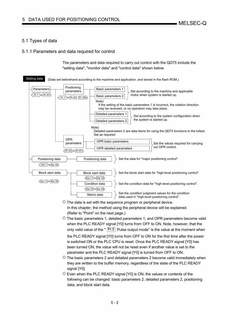
5 - 2
MELSEC-Q5 DATA USED FOR POSITIONING CONTROL
5.1 Types of data
5.1.1 Parameters and data required for control
The parameters and data required to carry out control with the QD75 include the "setting data", "monitor data" and "control data" shown below.
Setting data (Data set beforehand according to the machine and application, and stored in the flash ROM.)
Parameters Positioning parameters Basic parameters 1
Set according to the machine and applicable motor when system is started up.
Note) If the setting of the basic parameters 1 is incorrect, the rotation direction may be reversed, or no operation may take place.
Basic parameters 2
Detailed parameters 1
Detailed parameters 2Set according to the system configuration whenthe system is started up.
Note) Detailed parameters 2 are data items for using the QD75 functions to the fullest. Set as required.
OPR basic parameters
OPR detailed parametersSet the values required for carrying out OPR control.
Positioning data Positioning data Set the data for "major positioning control".
Block start data Set the block start data for "high-level positioning control".
Condition data Set the condition data for "high-level positioning control".
Memo data Set the condition judgment values for the conditiondata used in "high-level positioning control".
to) Pr.1 )Pr.57to) Pr.1 )Pr.42 ,
OPRparameters
to) Pr.43 )Pr.57
to) Da.1 )Da.10
to)Da.11 )Da.19
to)Da.15 )Da.19
to)Da.11 )Da.14
Block start data
Pr.150
The data is set with the sequence program or peripheral device. In this chapter, the method using the peripheral device will be explained. (Refer to "Point" on the next page.)
The basic parameters 1, detailed parameters 1, and OPR parameters become valid when the PLC READY signal [Y0] turns from OFF to ON. Note, however, that the only valid value of the " Pr.5 Pulse output mode" is the value at the moment when
the PLC READY signal [Y0] turns from OFF to ON for the first time after the power is switched ON or the PLC CPU is reset. Once the PLC READY signal [Y0] has been turned ON, the value will not be reset even if another value is set to the parameter and the PLC READY signal [Y0] is turned from OFF to ON.
The basic parameters 2 and detailed parameters 2 become valid immediately when they are written to the buffer memory, regardless of the state of the PLC READY signal [Y0].
Even when the PLC READY signal [Y0] is ON, the values or contents of the following can be changed: basic parameters 2, detailed parameters 2, positioning data, and block start data.

5 - 3
MELSEC-Q5 DATA USED FOR POSITIONING CONTROL
The only valid data assigned to these parameters are the data read at the moment when a positioning or JOG operation is started. Once the operation has started, any modification to the data is ignored. Exceptionally, however, modifications to the following are valid even when they are made during a positioning operation: acceleration time 0 to 3, deceleration time 0 to 3, and external start command.
• Acceleration time 0 to 3 and deceleration time 0 to 3: Positioning data are pre-read and pre-analyzed. Modifications to the data four or more steps after the current step are valid.
• External command function selection: The value at the time of detection is valid.
The data is monitored with the sequence program or peripheral device. In this chapter, the method using the peripheral device will be explained.
Monitor data (Data that indicates the control state. Stored in the buffer memory, and monitors as necessary.)
System monitor data Monitors the QD75 specifications and the operation history.
Axis monitor data Monitors the data related to the operating axis, such as the current positionand speed.
toMd.1 Md.48:
to) Md.1 )Md.19
to)Md.20 )Md.48
Control using the control data is carried out with the sequence program.
Control data (Data for user to control positioning system.)
System control data Performs write/initialization, etc. of the "setting data" in the module.
Axis control data Makes settings related to the operation, and controls the speed change during operation, and stops/restarts the operation.
toCd.1 Cd.42:
to) Cd.1 Cd.2
to) Cd.3 )Cd.40
Cd.41,
Cd.41" Deceleration start flag valid" is valid for only the value at the time
when the PLC READY signal [Y0] turns from OFF to ON.
)Cd.42,
POINT (1) The "setting data" is created for each axis. (2) The "setting data" parameters have determined default values, and are set to
the default values before shipment from the factory. (Parameters related to axes that are not used are left at the default value.)
(3) The "setting data" can be initialized with GX Configurator-QP or the sequence program.
(4) It is recommended to set the "setting data" with GX Configurator-QP. When executed with the sequence program, many sequence programs and devices must be used. This will not only complicate the program, but will also increase the scan time.

5 - 4
MELSEC-Q5 DATA USED FOR POSITIONING CONTROL
5.1.2 Setting items for positioning parameters
The table below lists items set to the positioning parameters. Setting of positioning parameters is similarly done for individual axes for all controls achieved by the QD75. For details of controls, refer to Section 2. For details of setting items, refer to Section 5.2 "List of parameters".
Control Major positioning control Manual control Position control Other control Positioning parameter O
PR c
ontro
l
1-ax
is li
near
con
trol
2/3/
4-ax
is li
near
inte
rpol
atio
n co
ntro
l
1-ax
is fi
xed-
feed
con
trol
2/3/
4-ax
is fi
xed-
feed
con
trol
2-ax
is c
ircul
ar in
terp
olat
ion
cont
rol
1 to
4 a
xis
spee
d co
ntro
l
Spee
d-po
sitio
n or
pos
ition
-spe
ed
cont
rol
Cur
rent
val
ue c
hang
ing
JUM
P in
stru
ctio
n, N
OP
inst
ruct
ion,
LO
OP
to L
END
Man
ual p
ulse
gen
erat
or o
pera
tion
JOG
ope
ratio
n In
chin
g op
erat
ion
Rel
ated
sub
func
tion
Pr.1 Unit setting –
Pr.2 No. of pulses per rotation (Ap) (Unit: pulse)
Pr.3 Movement amount per rotation (Al) Pr.4 Unit magnification (Am)
12.3.2
Pr.5 Pulse output mode –
Pr.6 Rotation direction setting – Basi
c pa
ram
eter
s 1
Pr.7 Bias speed at start – – – – –
Pr.8 Speed limit value – – 12.4.1
Pr.9 Acceleration time 0 – – – Basi
c pa
ram
eter
s 2
Pr.10 Deceleration time 0 – – –
12.7.7
Pr.11 Back compensation amount – – 12.3.1
Pr.12 Software stroke limit upper limit value – – –
Pr.13 Software stroke limit lower limit value – – –
Pr.14 Software stroke limit selection – – –
Pr.15 Software stroke limit valid/invalid selection – – – – – –
12.4.3
Pr.16 Command in-position width – – – – – – 12.7.6
Pr.17 Torque limit setting value – – 12.4.2
Pr.18 M code ON signal output timing – – – – 12.7.3
Pr.19 Speed switching mode – – – – – – – –
Pr.20 Interpolation speed designation method – – – – – – –
Pr.21 Current feed value during speed control – – – – – – – – –
Pr.22 Input signal logic selection –
Pr.23 Output signal logic selection –
Pr.24 Manual pulse generator input selection – – – – – – – – – –
Det
aile
d pa
ram
eter
s 1
Pr.150 Speed-position function selection – – – – – – – – – – : Always set : Set as required (Read "–" when not required.) : Setting not possible : Setting restricted – : Setting not required. (This is an irrelevant item, so the set value will be ignored. If the value is the default value or within the setting range, there is no
problem.)

5 - 5
MELSEC-Q5 DATA USED FOR POSITIONING CONTROL
Control Major positioning control Manual control Position control Other control Positioning parameter O
PR c
ontro
l
1-ax
is li
near
con
trol
2/3/
4-ax
is li
near
inte
rpol
atio
n co
ntro
l
1-ax
is fi
xed-
feed
con
trol
2/3/
4-ax
is fi
xed-
feed
con
trol
2-ax
is c
ircul
ar in
terp
olat
ion
cont
rol
1 to
4 a
xis
spee
d co
ntro
l
Spee
d-po
sitio
n or
pos
ition
-spe
ed
cont
rol
Cur
rent
val
ue c
hang
ing
JUM
P in
stru
ctio
n, N
OP
inst
ruct
ion,
LO
OP
to L
END
Man
ual p
ulse
gen
erat
or o
pera
tion
JOG
ope
ratio
n In
chin
g op
erat
ion
Rel
ated
sub
func
tion
Pr.25 Acceleration time 1 – – – Pr.26 Acceleration time 2 – – – Pr.27 Acceleration time 3 – – – Pr.28 Deceleration time 1 – – – Pr.29 Deceleration time 2 – – – Pr.30 Deceleration time 3 – – –
12.7.7
Pr.31 JOG speed limit value – – – – – – – – – 12.4.1
Pr.32 JOG operation acceleration time selection – – – – – – – – – –
Pr.33 JOG operation deceleration time selection – – – – – – – – – –
Pr.34 Acceleration/deceleration process selection – – –
Pr.35 S-curve ratio – – – Pr.36 Sudden stop deceleration time – – –
12.7.7
Pr.37 Stop group 1 sudden stop selection – – – –
Pr.38 Stop group 2 sudden stop selection – – – –
Pr.39 Stop group 3 sudden stop selection – – – –
Pr.40 Positioning complete signal output time – – – – –
Pr.41 Allowable circular interpolation error width – – – – – – – – – –
Det
aile
d pa
ram
eter
s 2
Pr.42 External command function selection – – 12.5.1 12.7.2
: Always set : Set as required ("–" when not set) – : Setting not required (This is an irrelevant item, so the setting value will be ignored. If the value is the default value or within the setting range, there is no
problem.)
Checking the positioning parameters Pr.1 to Pr.42 are checked with the following timing.
(1) When the "PLC READY signal [Y0]" output from the PLC CPU to the QD75
changes from OFF to ON (2) When the test operation button is turned ON in the test mode using GX
Configurator-QP (3) When an error check is carried out with GX Configurator-QP
REMARK
• "High-level positioning control" is carried out in combination with the "major positioning control". Refer to the "major positioning control" parameter settings for details on the parameters required for "high-level positioning control".

5 - 6
MELSEC-Q5 DATA USED FOR POSITIONING CONTROL
5.1.3 Setting items for OPR parameters
When carrying out "OPR control", the "OPR parameters" must be set. The setting items for the "OPR parameters" are shown below. The "OPR parameters" are set commonly for each axis. Refer to Chapter 8 "OPR control" for details on the "OPR control", and to Section 5.2 "List of parameters" for details on each setting item.
OPR control OPR parameters
Machine OPR control Fast OPR control
Pr.43 OPR method
Nea
r-poi
nt d
og
met
hod
Stop
per m
etho
d 1)
Stop
per m
etho
d 2)
Stop
per m
etho
d 3)
Cou
nt m
etho
d 1)
Cou
nt m
etho
d 2)
Pr.44 OPR direction
Pr.45 OP address
Pr.46 OPR speed
Pr.47 Creep speed
OPR
bas
ic p
aram
eter
s
Pr.48 OPR retry R R R – R R
Pr.49 OPR dwell time – – – – –
Pr.50 Setting for the movement amount after near-point dog ON – – – –
Pr.51 OPR acceleration time selection
Pr.52 OPR deceleration time selection
Pr.53 OP shift amount S S S S S S
Pr.54 OPR torque limit value – – –
Pr.55 Deviation counter clear signal output time C C C C C –
Pr.56 Speed designation during OP shift S S S S S S
OPR
det
aile
d pa
ram
eter
s
Pr.57 Dwell time during OPR retry R R R – R R
: Always set : Preset parameters are used for machine OPR control. – : Setting not required (This is an irrelevant item, so the setting value will be ignored. If the value is the default value or
within the setting range, there is no problem.) R : Set when using the "12.2.1 OPR retry function". ("–" when not set.) S : Set when using the "12.2.2 OP shift function". ("–" when not set.) C : Set the deviation counter clear signal output time. (Read as "–" when the setting is not required.)
Checking the OPR parameters. Pr.43 to Pr.57 are checked with the following timing.
(1) When the "PLC READY signal [Y0]" output from the PLC CPU to the QD75
changes from OFF to ON (2) When the test operation button is turned ON in the test mode using GX
Configurator-QP (3) When an error check is carried out with GX Configurator-QP

5 - 7
MELSEC-Q5 DATA USED FOR POSITIONING CONTROL
5.1.4 Setting items for positioning data
Positioning data must be set for carrying out any "major positioning control". The table below lists the items to be set for producing the positioning data. One to 600 positioning data items can be set for each axis. For details of the major positioning controls, refer to Chapter 9 "Major Positioning Control". For details of the individual setting items, refer to Section 5.3 "List of positioning data".
Major positioning control Position control Other control Positioning data 1-
axis
line
ar c
ontro
l 2/
3/4-
axis
line
ar
inte
rpol
atio
n co
ntro
l
1-ax
is fi
xed-
feed
con
trol
2/3/
4-ax
is fi
xed-
feed
con
trol
2-ax
is c
ircul
ar in
terp
olat
ion
cont
rol
1 to
4 a
xis
spee
d co
ntro
l
Spee
d-po
sitio
n sw
itchi
ng
cont
rol
Posi
tion-
spee
d sw
itchi
ng
cont
rol
NO
P in
stru
ctio
n
Cur
rent
val
ue c
hang
ing
JUM
P in
stru
ctio
n
LOO
P
LEN
D
Independent positioning control
– – – –
Continuous positioning control
– – – – Da.1
Operation pattern
Continuous path control – – – –
Da.2
Control system
Linear 1 Linear 2 Linear 3 Linear 4
Fixed- feed 1 Fixed- feed 2 Fixed- feed 3 Fixed- feed 4
Circular sub
Circular right
Circular left
Forward run speed 1Reverse run
speed 1 Forward
run speed 2Reverse run
speed 2 Forward
run speed 3Reverse run
speed 3 Forward
run speed 4Reverse run
speed 4
Forward run
speed/positionReverse
run speed/position
Forward run
position/speed
Reverse run
position/speed
NOP instruction
Current value
changing
JUMP instruction LOOP LEND
Da.3
Acceleration time No. – – – – –
Da.4
Deceleration time No. – – – – –
Da.5
Axis to be interpolated
: 2 axes – : 1/3/4 axes – – – – – – – – – – –
Da.6
Positioning address/ movement amount – –
New address – – –
Da.7
Arc address – – – – – – – – – –
Da.8
Command speed – – – – –
Da.9
Dwell time (JUMP destination positioning data No.)
– –
JUMP destination positioning data No.
– –
Da.10 M code (JUMP condition data No.) –
JUMP condition data No.
No. of LOOP to
LEND repetitions
–
: Always set : Set as required (Read "–" when not required.) : Setting not possible – : Setting not required.
(This is an irrelevant item, so the set value will be ignored. If the value is the default value or within the setting range, there is no problem.) : Two control systems are available: the absolute (ABS) system and incremental (INC) system.

5 - 8
MELSEC-Q5 DATA USED FOR POSITIONING CONTROL
Checking the positioning data The items Da.1 to Da.10 are checked at the following timings:
(1) Startup of a positioning operation (2) Error check performed by GX Configurator-QP

5 - 9
MELSEC-Q5 DATA USED FOR POSITIONING CONTROL
MEMO

5 - 10
MELSEC-Q5 DATA USED FOR POSITIONING CONTROL
5.1.5 Setting items for block start data
The "block start data" must be set when carrying out "high-level positioning control". The setting items for the " block start data" are shown below. Up to 50 points of " block start data" can be set for each axis. Refer to Chapter 10 "High-level Positioning Control" for details on the "high-level positioning control", and to Section 5.4 "List of block start data" for details on each setting item.
High-level positioning control
Block start data
Block start(Normal start)
Condition start Wait start Simultaneous
start
Repeated start
(FOR loop)
Repeated start (FOR
condition)
Da.11 Shape (end/continue)
Da.12 Start data No.
Da.13 Special start instruction –
Da.14 Parameter –
: Set as required ("–" when not set) – : Setting not required (This is an irrelevant item, so the setting value will be ignored. If the value is the default value or within the
setting range, there is no problem.)
Checking the block start data Da.11 to Da.14 are checked with the following timing.
(1) When the "Block start data" starts (2) When an error check is carried out with GX Configurator-QP

5 - 11
MELSEC-Q5 DATA USED FOR POSITIONING CONTROL
5.1.6 Setting items for condition data
When carrying out "high-level positioning control" or using the JUMP instruction in the "major positioning control", the "condition data" must be set as required. The setting items for the "condition data" are shown below. Up to 10 "condition data" items can be set for each axis. Refer to Chapter 10 "High-level Positioning Control" for details on the "high-level positioning control", and to Section 5.5" List of condition data" for details on each setting item.
Major positioning control High-level positioning control Control
Condition data
Other than JUMP
instruction
JUMP instruction
Block start(Normal start )
Condition start Wait start
Simul-taneous
start
Repeated start (FOR loop)
Repeated start (FOR
condition)
Da.15 Condition target – – –
Da.16 Condition operator – – –
Da.17 Address – – – –
Da.18 Parameter 1 – – –
Da.19 Parameter 2 – – – : Set as required ("–" when not set) : Setting limited – : Setting not required (This is an irrelevant item, so the setting value will be ignored. If the value is the default value or within the
setting range, there is no problem.)
Checking the condition data Da.15 to Da.19 are checked with the following timing.
(1) When the " Block start data" starts (2) When "JUMP instruction" starts (3) When an error check is carried out with GX Configurator-QP

5 - 12
MELSEC-Q5 DATA USED FOR POSITIONING CONTROL
5.1.7 Types and roles of monitor data
The monitor data area in the buffer memory stores data relating to the operating state of the positioning system, which are monitored as required while the positioning system is operating. The following data are available for monitoring.
• System monitoring:
Monitoring of the QD75 configuration and operation history (through the system monitor data Md.1 through Md.19 )
• Axis operation monitoring:
Monitoring of the current position and speed, and other data related to the movements of axes (through the axis monitor data Md.20 through Md.48 )
The axis monitor data are refreshed every 1.8 ms. Note that " Md.21 Machine feed value", " Md.22 Feedrate", " Md.28 Axis feedrate" and " Md.30 External input/output signal" are refreshed every 56.8ms. Also, " Md.23 Valid M code", is updated when the "M code ON signal [X4, X5, X6, X7]" turns ON.
[1] Monitoring the system
Monitoring the positioning system operation history
Monitoring details Corresponding item
Whether the system is in the test mode or not Md.1 In test mode flag
Start information Md.3 Start information
Start No. Md.4 Start No.
Hour Md.5 Start (Hour)
Start Minute:second Md.6
Start (Minute:second)
Error upon starting Md.7 Error judgment
History of data that started an operation
Latest pointer No. Md.8 Start history pointer
Axis in which the error occurred Md.9 Axis in which the error occurred
Axis error No. Md.10 Axis error No.
Hour Md.11 Axis error occurrence Hour Axis error occurrence
Minute:second Md.12 Axis error occurrence Minute:second
History of all errors
Latest pointer No. Md.13 Error history pointer
Axis in which the warning occurred Md.14 Axis in which the warning occurred
Axis warning No. Md.15 Axis warning No.
Hour Md.16 Axis warning occurrence (Hour) Axis warning occurrence Minute:second Md.17 Axis warning occurrence (Minute:second)
History of all warnings
Latest pointer No. Md.18 Warning history pointer
Number of write accesses to the flash ROM after the power is switched ON
Number of write accesses to flash ROM Md.19 No. of write accesses to flash ROM

5 - 13
MELSEC-Q5 DATA USED FOR POSITIONING CONTROL
[2] Monitoring the axis operation state
Monitoring the position
Monitor details Corresponding item
Monitor the current machine feed value Md.21 Machine feed value
Monitor the current "current feed value" Md.20 Current feed value
Monitor the current target value Md.32 Target value
Monitoring the speed
Monitor details Corresponding item
During independent axis control Indicates the speed of each axis
When "0: Composite speed" is set for " Pr.20
Interpolation speed designation method"
Indicates the composite speed During
interpola-tion control
When "1: Reference axis speed"is set for " Pr.20
Interpolation speed designation method"
Indicates the reference axis speed
Md.22 Feedrate Monitor the current speed
Constantly indicates the speed of each axis Md.28 Axis feedrate
Monitor the current target speed Md.33 Target speed

5 - 14
MELSEC-Q5 DATA USED FOR POSITIONING CONTROL
Monitoring the state
Monitor details Corresponding item
Monitor the axis operation state Md.26 Axis operation status
Monitor the latest error code that occurred with the axis Md.23 Axis error No.
Monitor the latest warning code that occurred with the axis Md.24 Axis warning No.
Monitor the external input/output signal and flag Md.30
Md.31External input/output signal
Status
Monitor the valid M codes Md.25 Valid M code
Monitor whether the speed is being limited Md.39 In speed control flag
Monitor whether the speed is being changed Md.40 In speed change processing flag
Monitor the "start data" point currently being executed Md.43 Start data pointer being executed
Monitor the "positioning data No." currently being executed Md.44 Positioning data No. being executed
Monitor the remaining No. of repetitions (special start) Md.41 Special start repetition counter
Monitor the remaining No. of repetitions (control system) Md.42 Control system repetition counter
Monitor the block No. Md.45 Block No. being executed
Monitor the current torque limit value Md.35 Torque limit stored value
Monitor the "instruction code" of the special start data when using special start
Md.36 Special start data instruction code setting value
Monitor the "instruction parameter" of the special start data when using special start
Md.37 Special start data instruction parameter setting value
Monitor the "start data No." of the special start data when using special start
Md.38 Start positioning data No. setting value
Monitor the "positioning data No." executed last Md.46 Last executed positioning data No.
Monitor the positioning data currently being executed Md.47 Positioning data being executed
Monitor the movement amount after the current position control switching when using "speed-position switching control (INC mode)"
Md.29 Speed-position switching control positioning amount
Monitor switching from the constant speed status or acceleration status to the deceleration status during position control whose operation pattern is "Positioning complete"
Md.48 Deceleration start flag

5 - 15
MELSEC-Q5 DATA USED FOR POSITIONING CONTROL
MEMO

5 - 16
MELSEC-Q5 DATA USED FOR POSITIONING CONTROL
5.1.8 Types and roles of control data
Operation of the positioning system is achieved through the execution of necessary controls. (Data required for controls are given through the default values when the power is switched ON, which can be modified as required by the sequence program.) Controls are performed over system data or machine operation.
• Controlling the system data :
Performs write/initialization, etc. of the QD75 "setting data". (through the system control data Cd.1 , Cd.2 , Cd.41 and Cd.42 )
• Controlling the operation :
Setting operation parameters, changing speed during operation, interrupting or restarting operation (through the axis control data Cd.3 to Cd.40 )
[1] Controlling the system data
Setting and resetting the setting data Control details Controlled data item
Write setting data from buffer memory to flash ROM Cd.1 Flash ROM write request
Reset (initialize) parameters Cd.2 Parameter initialization request

5 - 17
MELSEC-Q5 DATA USED FOR POSITIONING CONTROL
[2] Controlling the operation
Controlling the operation
Control details Corresponding item
Set which positioning to execute (start No.) Cd.3 Positioning start No.
Clear (reset) the axis error ( Md.23 ) and warning ( Md.24 ) Cd.5 Axis error reset
Issue instruction to restart (When axis operation is stopped) Cd.6 Restart command
End current positioning (deceleration stop), and start next positioning Cd.37 Skip command
Set start point No. for executing block start Cd.4 Positioning starting point No.
Stop continuous control Cd.18 Interrupt request during continuous operation
Cd.30 Simultaneous starting axis start data No. (axis 1 start data No.)
Cd.31 Simultaneous starting axis start data No. (axis 2 start data No.)
Cd.32 Simultaneous starting axis start data No. (axis 3 start data No.)
Set start data Nos. for axes that start up simultaneously
Cd.33 Simultaneous starting axis start data No. (axis 4 start data No.)
Specify write destination for teaching results Cd.38 Teaching data selection
Specify data to be taught Cd.39 Teaching positioning data No.
Controlling operation per step
Control details Corresponding item
Stop positioning operation after each operation Cd.35 Step valid flag
Set unit to carry out step Cd.34 Step mode
Issue instruction to continuous operation or restart from stopped step
Cd.36 Step start information
Controlling the speed
Control details Corresponding item
Set new speed when changing speed during operation Cd.14 New speed value
Issue instruction to change speed in operation to Cd.14 value
(Only during positioning operation and JOG operation) Cd.15 Speed change request
Change positioning operation speed between 1 and 300% range Cd.13 Positioning operation speed override
Set inching movement amount Cd.16 Inching movement amount
Set JOG speed Cd.17 JOG speed
When changing acceleration time during speed change, set new acceleration time
Cd.10 New acceleration time value
When changing deceleration time during speed change, set new deceleration time
Cd.11 New deceleration time value
Set acceleration/deceleration time validity during speed change Cd.12Acceleration/deceleration time change during speed change, enable/disable selection

5 - 18
MELSEC-Q5 DATA USED FOR POSITIONING CONTROL
Making settings related to operation
Control details Corresponding item
Turn M code ON signal OFF Cd.7 M code OFF request
Set new value when changing current value Cd.9 New current value
Validate speed-position switching signal from external source Cd.24 Speed-position switching enable flag
Change movement amount for position control during speed-position switching control (INC mode)
Cd.23 Speed-position switching control movement amount change register
Validate external position-speed switching signal Cd.26 Position-speed switching enable flag
Change speed for speed control during position-speed switching control
Cd.25 Position-speed switching control speed change register
Set up a flag when target position is changed during positioning Cd.29 Target position change request flag
Set new positioning address when changing target position during positioning
Cd.27 Target position change value(new address)
Set new speed when changing target position during positioning Cd.28 Target position change value(new speed)
Set absolute (ABS) moving direction in degrees Cd.40 ABS direction in degrees
Set manual pulse generator operation validity Cd.21 Manual pulse generator enable flag
Set scale per pulse of No. of input pulses from manual pulse generator
Cd.20 Manual pulse generator 1 pulse input magnification
Change OPR request flag from "ON to OFF" Cd.19 OPR request flag OFF request
Validate external command signal Cd.8 External command valid
Change " Md.35 Torque limit stored value" Cd.22 New torque value
Set whether " Md.48 Deceleration start flag" is valid or invalid Cd.41 Deceleration start flag valid Set the stop command processing for deceleration stop function (deceleration curve re-processing/deceleration curve continuation) Cd.42 Stop command processing for
deceleration stop selection

5 - 19
MELSEC-Q5 DATA USED FOR POSITIONING CONTROL
MEMO

5 - 20
MELSEC-Q5 DATA USED FOR POSITIONING CONTROL
5.2 List of parameters
5.2.1 Basic parameters 1
Setting value, setting range Setting value buffer memory address Item
Value set with peripheral device Value set with sequence program
Default value
Axis 1 Axis 2 Axis 3 Axis 4
0 : mm 0 1 : inch 1 2 : degree 2
Pr.1 Unit setting
3 : pulse 3
3 0 150 300 450
Pr.2
No. of pulses per rotation (Ap) (Unit : pulse)
1 to 65535
1 to 65535 1 to 32767 :Set as a decimal 32768 to 65535 :Convert into hexadecimal and set
20000 1 151 301 451
Pr.3
Movement amount per rotation (Al)
The setting value range differs according to the " Pr.1 Unit setting". Here, the value within the [Table 1] range is set.
[Table 1] on right page
20000 2 152 302 452
1 : 1-fold 1 10 : 10-fold 10
100 : 100-fold 100
Mov
emen
t am
ount
per
pul
se
Pr.4
Unit magnification (Am) 1000 : 1000-fold 1000
1 3 153 303 453
Pr.1 Unit setting
Set the unit used for defining positioning operations. Choose from the following units depending on the type of the control target: mm, inch, degree, or pulse. Different units can be defined for different axes (axis 1 to 4). (Example) Different units (mm, inch, degree, and pulse) are applicable to different
systems: mm or inch..... X-Y table, conveyor (Select mm or inch depending on the
machine specifications.) degree ........... Rotating body (360 degrees/rotation) pulse.............. X-Y table, conveyor
When you change the unit, note that the values of other parameters and data will not be changed automatically. After changing the unit, check if the parameter and data values are within the allowable range. Set "degree" to exercise speed-position switching control (ABS mode).

5 - 21
MELSEC-Q5 DATA USED FOR POSITIONING CONTROL
Pr.2 to Pr.4 Movement amount per pulse These parameters define the amount of movement achieved by each single pulse within a pulse train output by the QD75. The following paragraphs explain how to set the individual parameters Pr.2 ,
Pr.3 , and Pr.4 assuming that the unit "mm" is selected with Pr.1 . The movement amount per pulse is given by the following expression:
Movement amount per rotation (Al) Movement amount per pulse =
No. of pulses per rotation (Ap)
Due to the mechanical tolerance, the actual movement amount may differ slightly from the instructed movement amount. The error can be compensated by adjusting the movement amount per pulse defined here. (Refer to Section 12.3.2 "Electronic gear function".)
POINT
If the movement amount per pulse is less than 1, command frequency variations will occur.Smaller setting will increase variations and may cause machine vibration.If the movement amount per pulse becomes less than 1, also use the electronic gear function of the drive unit and make setting so that the movement amount per pulse is 1 or greater.
Pr.2 No. of pulses per rotation (Ap) Set the number of pulses required for a complete rotation of the motor shaft. If you are using the Mitsubishi servo amplifier MR-H, MR-J2/J2S , or MR-C, set the value given as the "resolution per servomotor rotation" in the speed/position detector specifications.
No. of pulses per rotation (Ap) = Resolution per servomotor rotation
Since the "Resolution per servomotor revolution" of Mitsubishi servo amplifier MR-J2S exceeds 65535 pulses, make setting after referring to the Servo Amplifier Instruction Manual.
[Table 1]
Pr.1 setting value Value set with peripheral device
(unit) Value set with sequence program
(unit)
0 : mm 0.1 to 6553.5 (μm) 1 to 65535 (×10-1μm)
1 : inch 0.0001 to 0.65535 (inch) 1 to 65535 (×10-5inch)
2 : degree 0.00001 to 0.65535 (degree) 1 to 65535 (×10-5degree)
3 : pulse 1 to 65535 (pulse) 1 to 65535 (pulse)
1 to 32767 : Set as a decimal 32768 to 65535 : Convert into hexadecimal and set
Pr.3 Movement amount per rotation (Al), Pr.4 Unit magnification (Am)
The amount how the workpiece moves with one motor rotation is determined by the mechanical structure. If the worm gear lead (mm/rev) is PB and the deceleration rate is 1/n, then Movement amount per rotation (AL) = PB × 1/n

5 - 22
MELSEC-Q5 DATA USED FOR POSITIONING CONTROL
However, the maximum value that can be set for this "movement amount per rotation (Al)" parameter is 6553.5μm (approx. 6.5mm). Set the "movement amount per rotation (Al)" as shown below so that the "movement amount per rotation (AL)" does not exceed this maximum value. Movement amount per rotation (AL)
= PB × 1/n = Movement amount per rotation (Al) × Unit magnification (Am)
Note) The unit magnification (Am) is a value of 1, 10, 100 or 1000. If the "PB ×
1/n" value exceeds 6553.5μm, adjust with the unit magnification so that the "movement amount per rotation (Al) " does not exceed 6553.5μm.
Example 1)
When movement amount per rotation (AL) = PB × 1/n = 6000.0μm (= 6mm) Movement amount per rotation (AL)
= Movement amount per rotation (Al) × Unit magnification (Am) = 6000 × 1
Example 2)
When movement amount per rotation (AL) = PB × 1/n = 60000.0μm (= 60mm) Movement amount per rotation (AL)
= Movement amount per rotation (Al) × Unit magnification (Am) = 6000 × 10 = 600 × 100
M G
1n
Pf
PB
PLC
PLC CPU QD75
Servo amplifier ServomotorWorkpiece
Encoder
Reduction gears
: Worm gear lead (mm/rev): Deceleration rate: No. of encoder pulses (pulse/rev)
PB1/nPf
Movement amount per pulse 1n
PB
Pf= [mm/pulse]
Setting value, setting range Setting value buffer memory address Item
Value set with peripheral device Value set with sequence program
Default value
Axis 1 Axis 2 Axis 3 Axis 4
0 : PULSE/SIGN mode 0 1 : CW/CCW mode 1 2 : A phase/B phase
(multiple of 4) 2 Pr.5
Pulse output mode
3 : A phase/B phase (multiple of 1) 3
1 4 154 304 454
0 : Current value increment with forward run pulse output 0 Pr.6
Rotation direction setting 1 : Current value increment with
reverse run pulse output 1 0 5 155 305 455

5 - 23
MELSEC-Q5 DATA USED FOR POSITIONING CONTROL
Pr.5 Pulse output mode Set the pulse output mode to match the servo amplifier being used.
IMPORTANT The only valid value of the " Pr.5 Pulse output mode" is the value at the moment
when the PLC READY signal [Y0] turns from OFF to ON for the first time after the power is switched ON or the PLC CPU is reset. Once the PLC READY signal [Y0] has been turned ON, the value will not be reset even if another value is set to the parameter and the PLC READY signal [Y0] is turned from OFF to ON.
Use " Pr.23 Output signal logic selection" to choose between the positive logic (pulse rising edge detection) and negative logic (pulse falling edge detection). An example of the pulse output mode for positive and negative logic is shown below.
(1) PULSE/SIGN mode
Positive logic Negative logic Forward run and reverse run are controlled with the ON/OFF of the direction sign (SIGN). • The motor will forward run when the direction sign is HIGH.• The motor will reverse run when the direction sign is LOW.
Forward run and reverse run are controlled with the ON/OFF of the direction sign (SIGN). • The motor will forward run when the direction sign is LOW.• The motor will reverse run when the direction sign is HIGH.
Forwardrun
Reverserun
PULSE
SIGN
Move in +direction
Move in -direction
PULSE
SIGN
Forwardrun
Reverserun
Move in +direction
move in -direction
(2) CW/CCW mode
During forward run, the forward run feed pulse (PULSE F) will be output. During reverse run, the reverse run feed pulse (PULSE R) will be output.
Positive logic Negative logic
Forward run
CW
CCW
Reverse run
Forwardrun
Reverserun
CW
CCW

5 - 24
MELSEC-Q5 DATA USED FOR POSITIONING CONTROL
(3) A phase/B phase mode
Forward run and reverse run are controlled with the phase difference of the A phase (A ) and B phase (B ). • When the B phase is 90° behind the A phase, the motor will forward run. • When the B phase is 90° ahead of the A phase, the motor will reverse run.
1) For multiple of 1 setting Positive logic Negative logic
Forward run Reverse run
When B phase is 90° behind A phase
When B phase is90° ahead of A phase
A phase(A )
B phase(B )
Command 1 pulse output Command 1 pulse output
Reverse run
When B phase is 90° behind A phase
When B phase is90° ahead of A phase
Forward runCommand 1 pulse output Command 1 pulse output
A phase(A )
B phase(B )
Example) When the command 1 pulse output is 1 pulse/s, the pulse rises and falls by four times per second.
2) For multiple of 4 setting
Positive logic Negative logic
A phase(A )
B phase(B )
Forward run Reverse run
When B phase is 90° behind A phase
When B phase is90° ahead of A phase
Command 1 pulse output Command 1 pulse outputForward run Reverse run
When B phase is 90° behind A phase
When B phase is90° ahead of A phase
Command 1 pulse output Command 1 pulse output
A phase(A )
B phase(B )
Example) When the command 1 pulse output is 1 pulse/s, the pulse rises and falls by one times per second.

5 - 25
MELSEC-Q5 DATA USED FOR POSITIONING CONTROL
Pr.6 Rotation direction setting
Set the relation of the motor rotation direction and current value address increment/decrement.
[Setting procedure]
1) Set "0" in Pr.6 , and carry out forward run JOG operation.
("0" is set as the default value for Pr.6 .)
2) When workpiece "W" moves toward the address increment direction, keep the current setting. When workpiece "W" moves toward the address decrement direction, set "1" in Pr.6
to change the
rotation direction. 3) Carry out forward run JOG operation again, and if "W" moves toward the increment direction, the
setting is complete.
M W
QD75
1) Forward run pulse
Motor
Address decre-ment direction
Address incre-ment direction
2) Workpiece
OP 3)
POINT
When Pr.6 has been changed from "0" to "1", check if the upper and lower limit
switches operate properly by JOG operation. If any malfunction is identified, check and correct the wiring.

5 - 26
MELSEC-Q5 DATA USED FOR POSITIONING CONTROL
Setting value, setting range Setting value buffer memory address Item
Value set with peripheral device Value set with sequence program
Default value
Axis 1 Axis 2 Axis 3 Axis 4
Pr.7
Bias speed at start
The setting range differs depending on the " Pr.1 Unit setting".
Here, the value within the [Table 1] range is set.
[Table 1] on right page
0 6 7
156 157
306 307
456 457
Pr.7 Bias speed at start Set the bias speed (minimum speed) upon starting. The bias speed has to be defined to allow the motor to start smoothly especially when a stepping motor is used. (A stepping motor will not start smoothly if a low rotation speed is instructed at the beginning.) The specified "bias speed at start" will be valid during the following operations:
• Positioning operation • OPR operation • JOG operation
Note that the bias speed should not exceed " Pr.8 Speed limit value".
5.2.2 Basic parameters 2
Setting value, setting range Setting value buffer memory address Item
Value set with peripheral device Value set with sequence program
Default value
Axis 1 Axis 2 Axis 3 Axis 4
Pr.8
Speed limit value
The setting range differs depending on the " Pr.1 Unit setting".
Here, the value within the [Table 2] range is set.
[Table 2] on right page
200000 10 11
160 161
310 311
460 461
Pr.9
Acceleration time 0 1 to 8388608 (ms) 1 to 8388608 (ms) 1000 12
13 162 163
312 313
462 463
Pr.10
Deceleration time 0 1 to 8388608 (ms) 1 to 8388608 (ms) 1000 14
15 164 165
314 315
464 465

5 - 27
MELSEC-Q5 DATA USED FOR POSITIONING CONTROL
[Table 1]
Pr.1 setting value Value set with peripheral device (unit) Value set with sequence program (unit)
0 : mm 0 to 20000000.00 (mm/min) 0 to 2000000000 (×10-2mm/min) 1 : inch 0 to 2000000.000 (inch/min) 0 to 2000000000 (×10-3inch/min) 2 : degree 0 to 2000000.000 (degree/min) 0 to 2000000000 (×10-3degree/min) 3 : pulse 0 to 1000000 (pulse/s) 0 to 1000000 (pulse/s)
[Table 2]
Pr.1 setting value Value set with peripheral device (unit) Value set with sequence program (unit)
0 : mm 0.01 to 20000000.00 (mm/min) 1 to 2000000000 (×10-2mm/min) 1 : inch 0.001 to 2000000.000 (inch/min) 1 to 2000000000 (×10-3inch/min) 2 : degree 0.001 to 2000000.000 (degree/min) 1 to 2000000000 (×10-3degree/min)
3 : pulse
[Select type 1 is QD75P] 1 to 200000 (pulse/s) [Select type 1 is QD75D] 1 to 1000000 (pulse/s)
1 to 1000000 (pulse/s) 2
1: For Select type, refer to GX Configurator-QP Operating Manual. 2: When using the QD75P (open collector output type), set the value to within "1 to 200000 (pulse/s)".
Pr.8 Speed limit value Set the maximum speed during positioning and OPR operations. The maximum speed during positioning control has to be limited in consideration of the drive unit and control target specifications. Take account of the following when determining the speed limit value:
1) Motor speed 2) Workpiece movement speed
Pr.9 Acceleration time 0, Pr.10 Deceleration time 0 " Pr.9 Acceleration time 0" specifies the time for the speed to increase from zero
to the speed limit value ( Pr.8 ).
" Pr.10 Deceleration time 0" specifies the time for the speed to decrease from the
speed limit value ( Pr.8 ) to zero.
Actualaccelerationtime
Actual deceleration time
Time
Speed Speed limit value
Positioning speed
Acceleration time 0Pr.9 Pr.10
Pr.8
Deceleration time 0
1) If the positioning speed is set lower than the parameter-defined speed limit value, the actual acceleration/deceleration time will be relatively short. Thus, set the maximum positioning speed equal to or only a little lower than the parameter-defined speed limit value.
2) These settings are valid for OPR, positioning and JOG operations. 3) When the positioning involves interpolation, the acceleration/deceleration time
defined for the reference axis is valid.

5 - 28
MELSEC-Q5 DATA USED FOR POSITIONING CONTROL
5.2.3 Detailed parameters 1
Setting value, setting range Setting value buffer memory address Item
Value set with peripheral device Value set with sequence program
Default value Axis 1 Axis 2 Axis 3 Axis 4
Pr.11
Backlash compensation amount
The setting value range differs according to the " Pr.1 Unit setting". Here, the value within the [Table 1] range is set.
[Table 1] on right page
0 17 167 317 467
Pr.12
Software stroke limit upper limit value
2147483647 18 19
168 169
318319
468469
Pr.13
Software stroke limit lower limit value
The setting value range differs according to the " Pr.1 Unit setting". Here, the value within the [Table 2] range is set.
[Table 2] on right page
–2147483648 20 21
170 171
320321
470471
0 : Apply software stroke limit on current feed value 0 Pr.14
Software stroke limit selection
1 : Apply software stroke limit on machine feed value 1
0 22 172 322 472
0 : Software stroke limit valid during JOG operation,inching operation and manual pulse generator operation
0 Pr.15
Software stroke limit valid/invalid setting
1 : Software stroke limit invalid during JOG operation ,inching operation and manual pulse generator operation
1
0 23 173 323 473
Pr.11 Backlash compensation amount The error that occurs due to backlash when moving the machine via gears can be compensated. When the backlash compensation amount is set, pulses equivalent to the compensation amount will be output each time the direction changes during positioning.
Workpiece(moving body)
Worm gear
Backlash (compensation amount)
Pr.44 OPR direction

5 - 29
MELSEC-Q5 DATA USED FOR POSITIONING CONTROL
1) The backlash compensation is valid after machine OPR. Thus, if the backlash
compensation amount is set or changed, always carry out machine OPR once. 2) The backlash compensation amount setting range is 0 to 65535, but it should
be set to 255 or less by using the following expression. Backlash compensation amount 0 ≤ Movement amount per pulse ≤ 255
[Table 1]
Pr.1
setting value Value set with peripheral device
(unit) Value set with sequence program
(unit)
0 : mm 0 to 6553.5 (μm) 0 to 65535 (×10-1μm)
1 : inch 0 to 0.65535 (inch) 0 to 65535 (×10-5inch)
2 : degree 0 to 0.65535 (degree) 0 to 65535 (×10-5degree)
3 : pulse 0 to 65535 (pulse) 0 to 65535 (pulse)
1 to 32767 : Set as a decimal 32768 to 65535 : Convert into hexadecimal and set
[Table 2]
Pr.1
setting value
Value set with peripheral device (unit)
Value set with sequence program (unit)
0 : mm -214748364.8 to 214748364.7 (μm) -2147483648 to 2147483647 (×10-1μm)
1 : inch -21474.83648 to 21474.83647(inch) -2147483648 to 2147483647 (×10-5inch)
2 : degree 0 to 359.99999 (degree) 0 to 35999999 (×10-5degree)
3 : pulse -2147483648 to 2147483647(pulse) -2147483648 to 2147483647 (pulse)
Pr.12 Software stroke limit upper limit value Set the upper limit for the machine's movement range during positioning control.
Pr.13 Software stroke limit lower limit value Set the lower limit for the machine's movement range during positioning control.
Software stroke limit lower limit
Software stroke limit upper limit
OP(Machine movement range)
Emergency stop limit switch
Emergency stop limit switch

5 - 30
MELSEC-Q5 DATA USED FOR POSITIONING CONTROL
1) Generally, the OP is set at the lower limit or upper limit of the stroke limit. 2) By setting the upper limit value or lower limit value of the software stroke limit,
overrun can be prevented in the software. However, an emergency stop limit switch must be installed nearby outside the range.
3) To invalidate the software stroke limit, set the setting value to "upper limit value = lower limit value". (The setting value can be anything.)
4) When the unit is "degree", the software stroke limit check is invalid during speed control (including speed-position switching control, position-speed switching control) or during manual control.
Pr.14 Software stroke limit selection Set whether to apply the software stroke limit on the "current feed value" or the "machine feed value". The software stroke limit will be validated according to the set value.
Pr.15 Software stroke limit valid/invalid setting Set whether to validate the software stroke limit during JOG/Inching operation and manual pulse generator operation.
Setting value, setting range Setting value buffer memory address Item
Value set with peripheral device Value set with sequence program
Default value
Axis 1 Axis 2 Axis 3 Axis 4
Pr.16
Command in-position width
The setting value range differs depending on the " Pr.1 Unit setting". Here, the value within the [Table 1] range is set.
[Table 1] on right page
100 24 25
174 175
324325
474475
Pr.17 Torque limit setting value
1 to 500 (%) 1 to 500 (%) 300 26 176 326 476
0 : WITH mode 0 Pr.18
M code ON signal output timing 1 : AFTER mode 1
0 27 177 327 477
Pr.16 Command in-position width
Set the remaining distance that turns the command in-position ON. The command in-position signal is used as a front-loading signal of the positioning complete signal. When positioning control is started, the "command in-position flag" (3rd flag from right) in " Md.31 Status" turns OFF, and the "command in-position flag" turns ON at the set position of the command in-position signal.
ON
OFF
Pr.16 Command in-position width
Speed
Position control start
Commandin-position flag

5 - 31
MELSEC-Q5 DATA USED FOR POSITIONING CONTROL
Pr.17 Torque limit setting value Set the maximum value of the torque generated by the servomotor as a percentage between 1 and 500%.
The torque limit function limits the torque generated by the servomotor within the set range. If the torque required for control exceeds the torque limit value, it is controlled with the set torque limit value.
Usage conditions Limits for pulse train output type (a) A drive unit that can issue a torque limit command with the analog voltage is
required. (b) The D/A conversion module and the D/A conversion module and drive unit
must be wired. (c) The set " Pr.17 Torque limit setting value" is set in the buffer memory
" Md.35 Torque limit stored value", so transmit that " Md.35 Torque limit
stored value" to the D/A conversion module with the sequence program.
[Table 1]
Pr.1 setting value Value set with peripheral device
(unit) Value set with sequence program
(unit)
0 : mm 0.1 to 214748364.7 (µm) 1 to 2147483647 (×10–1µm)
1 : inch 0.00001 to 21474.83647 (inch) 1 to 2147483647 (×10–5inch)
2 : degree 0.00001 to 21474.83647 (degree) 1 to 2147483647 (×10–5degree)
3 : pulse 1 to 2147483647 (pulse) 1 to 2147483647 (pulse)
Pr.18 M code ON signal output timing This parameter sets the M code ON signal output timing. Choose either WITH mode or AFTER mode as the M code ON signal output timing.
WITH mode......... An M code is output and the M code ON signal is turned ON when a positioning operation starts.
m1 m2
01 (continuous) 00 (end)
Positioning start signal[Y10,Y11,Y12,Y13]
BUSY signal[XC,XD,XE,XF]
Positioning
M code ON signal[X4,X5,X6,X7]
M code OFF request[1504,1604,1704,1804]Cd.7
Operation patternDa.1
Valid M codeMd.25
: m1 and m2 indicate set M codes.
AFTER mode ...... An M code is output and the M code ON signal is turned ON when a positioning operation completes.
: m1 and m2 indicate set M codes.
m1 m2
01 (continuous) 00 (end)
Positioning complete signal[X14,X15,X16,X17]
BUSY signal[XC,XD,XE,XF]
Positioning
M code ON signal[X4,X5,X6,X7]
M code OFF request[1504,1604,1704,1804]Cd.7
Operation patternDa.1
Valid M codeMd.25
Note: If AFTER mode is used with speed control, an M code will not be output and the M code ON signal will not be turned ON.

5 - 32
MELSEC-Q5 DATA USED FOR POSITIONING CONTROL
An M code is a number between 0 and 65535 that can be assigned to each positioning data ( Da.10 ).
The sequence program can be coded to read an M code from the buffer memory address specified by " Md.25 Valid M code" whenever the M code ON signal [X4, X5,
X6, X7] turns ON so that a command for the sub work (e.g. clamping, drilling, tool change) associated with the M code can be issued.
Setting value, setting range Setting value buffer memory address Item
Value set with peripheral device Value set with sequence program
Default value
Axis 1 Axis 2 Axis 3 Axis 4
0 : Standard speed switching mode 0 Pr.19
Speed switching mode 1 : Front-loading speed switching
mode 1 0 28 178 328 478
0 : Composite speed 0 Pr.20
Interpolation speed designation method 1 : Reference axis speed 1
0 29 179 329 479
0 : Do not update current feed value 0
1 : Update current feed value 1 Pr.21
Current feed value during speed control
2 : Clear current feed value to zero 2
0 30 180 330 480
b0 Lower limit b1 Upper limit
b2 Drive unit READY
b3 Stop signal
b4 External command
b5 Zero signal
b6 Near-point signal
b7 Not used
b8 Manual pulse generator input
Pr.22
Input signal logic selection
b9 to b15
Not used
0: Negative logic
1: Positive logic
b0123456789101112131415
Always "0" is set tothe part not used.
0 31 181 331 481
b0 Command pulse signal
b1 Not used b2 Not used b3 Not used
b4 Deviation counter clear
Pr.23 Output signal logic selection
b5 to b15
Not used
0: Negative logic
1: Positive logic
b0123456789101112131415
Always "0" is set tothe part not used.
0 32 182 332 482
0: A-phase/B-phase multiplied by 4 0 1: A-phase/B-phase multiplied by 2 1 2: A-phase/B-phase multiplied by 1 2
Pr.24
Manual pulse generator input selection 3: PULSE/SIGN 3
0 33 – – –
0: Speed-position switching control (INC mode) 0 Pr.150
Speed-position function selection 2: Speed-position switching control
(ABS mode) 2 0 34 184 334 484

5 - 33
MELSEC-Q5 DATA USED FOR POSITIONING CONTROL
Pr.19 Speed switching mode
Set whether to switch the speed switching mode with the standard switching or front-loading switching mode. 0 : Standard switching............... Switch the speed when executing the next
positioning data. 1 : Front-loading switching........ The speed switches at the end of the positioning
data currently being executed.
t
n n+1
Switch the speed when executing the next positioning data
Speed
n: Positioning data No.
<For standard switching>
<For front-loading switching>
The next positioning data starts positioning at the designated speed
t
n n+1
Speed
Pr.20 Interpolation speed designation method
When carrying out linear interpolation/circular interpolation, set whether to designate the composite speed or reference axis speed. 0: Composite speed .................. The movement speed for the control target is
designated, and the speed for each axis is calculated by the QD75.
1: Reference axis speed ........... The axis speed set for the reference axis is designated, and the speed for the other axis carrying out interpolation is calculated by the QD75.
X axis
Y axis
Designate composite speed
Calculated by QD75
<When composite speed is designated>
Designate speed for reference axis
<When reference axis speed is designated>
X axis
Y axis
Calculated by QD75
Note: Always specify the reference axis speed if the 4-axis linear interpolation or 2 to 4 axis speed control has to be performed. If you specify the composite speed for a positioning operation that involves the 4-axis linear interpolation or 2 to 4 axis speed control, the error code 523 "interpolation mode error" will be output when the positioning operation is attempted. For a positioning operation that involves the circular interpolation, specify the composite speed always.

5 - 34
MELSEC-Q5 DATA USED FOR POSITIONING CONTROL
Pr.21 Current feed value during speed control Specify whether you wish to enable or disable the update of " Md.20 Current feed value" while operations are performed under the speed control (including the speed-position and position-speed switching control). 0: The update of the current feed value is disabled
The current feed value will not change. (The value at the beginning of the speed control will be kept.)
1: The update of the current feed value is enabled The current feed value will be updated. (The current feed value will change from the initial.)
2: The current feed value is cleared to zero The current feed will be set initially to zero and change from zero while the speed control is in effect.
Note1: When the speed control is performed over two to four axes, the choice between enabling and disabling the update of " Md.20 Current feed value" depends on how the reference axis is set.
Note2: Set "1" to exercise speed-position switching control (ABS mode).
Pr.22 Input signal logic selection, Pr.23 Output signal logic selection Set the I/O signal logic that matches the signaling specification of the connected external device. Note1: A mismatch in the signal logic will disable normal operation. Be careful of
this when you change from the default value. Note2: Set the manual pulse generator input logic selection (b8) to axis 1. (Setting
of any of axes 2 to 4 is invalid.)
Pr.24 Manual pulse generator input selection Set the manual pulse generator input pulse mode. (Only the value specified against the axis 1 is valid.)
0: A-phase/B-phase; multiplied by 4 1: A-phase/B-phase; multiplied by 2 2: A-phase/B-phase; multiplied by 1 3: PULSE/SIGN
Pr.150 Speed-position function selection
Select the mode of speed-position switching control. 0: INC mode 2: ABS mode
Note1: If the setting is other than 0 and 2, operation is performed in the INC mode with the setting regarded as 0.

5 - 35
MELSEC-Q5 DATA USED FOR POSITIONING CONTROL
MEMO

5 - 36
MELSEC-Q5 DATA USED FOR POSITIONING CONTROL
5.2.4 Detailed parameters 2
Setting value, setting range Setting value buffer memory address Item
Value set with peripheral device Value set with sequence program
Default value
Axis 1 Axis 2 Axis 3 Axis 4
Pr.25 Acceleration time 1 36 37
186 187
336 337
486 487
Pr.26 Acceleration time 2 38 39
188 189
338 339
488 489
Pr.27 Acceleration time 3 40 41
190 191
340 341
490 491
Pr.28 Deceleration time 1 42 43
192 193
342 343
492 493
Pr.29 Deceleration time 2 44 45
194 195
344 345
494 495
Pr.30 Deceleration time 3
1 to 8388608 (ms) 1 to 8388608 (ms) 1000
46 47
196 197
346 347
496 497
Pr.31
JOG speed limit value
The setting range differs depending on the " Pr.1 Unit setting".
Here, the value within the [Table 1] range is set.
[Table 1] on right page
20000 48 49
198 199
348 349
498 499
0: Pr.9 Acceleration time 0 0
1: Pr.25 Acceleration time 1 1
2: Pr.26 Acceleration time 2 2
Pr.32
JOG operation acceleration time selection
3: Pr.27 Acceleration time 3 3
0 50 200 350 500
0: Pr.10 Deceleration time 0 0
1: Pr.28 Deceleration time 1 1
2: Pr.29 Deceleration time 2 2
Pr.33
JOG operation deceleration time selection
3: Pr.30 Deceleration time 3 3
0 51 201 351 501
Pr.25 Acceleration time 1 to Pr.27 Acceleration time 3 These parameters set the time for the speed to increase from zero to the speed limit value ( Pr.8 ) during a positioning operation.
Pr.28 Deceleration time 1 to Pr.30 Deceleration time 3 These parameters set the time for the speed to decrease from the speed limit value ( Pr.8 ) to zero during a positioning operation.

5 - 37
MELSEC-Q5 DATA USED FOR POSITIONING CONTROL
[Table 1]
Pr.1 setting value Value set with peripheral device
(unit) Value set with sequence program
(unit)
0 : mm 0.01 to 20000000.00 (mm/min) 1 to 2000000000 (×10-2mm/min)
1 : inch 0.001 to 2000000.000 (inch/min) 1 to 2000000000 (×10-3inch/min)
2 : degree 0.001 to 2000000.000 (degree/min) 1 to 2000000000 (×10-3degree/min)
3 : pulse
[Select type 1 is QD75P] 1 to 200000 (pulse/s) [Select type 1 is QD75D] 1 to 1000000 (pulse/s)
1 to 1000000 (pulse/s) 2
1: For Select type, refer to GX Configurator-QP Operating Manual "Section 11.1.2". 2: When using the QD75P (open collector output type), set the value to within "1 to 200000
(pulse/s)".
Pr.31 JOG speed limit value
Set the maximum speed for JOG operation. Note) • Set the "JOG speed limit value" to less than " Pr.8 Speed limit value".
If the "speed limit value" is exceeded, the "JOG speed limit value error" (error code: 956) will occur.
Pr.32 JOG operation acceleration time selection
Set which of "acceleration time 0 to 3" to use for the acceleration time during JOG operation. 0 : Use value set in " Pr.9 Acceleration time 0".
1 : Use value set in " Pr.25 Acceleration time 1".
2 : Use value set in " Pr.26 Acceleration time 2".
3 : Use value set in " Pr.27 Acceleration time 3".
Pr.33 JOG operation deceleration time selection
Set which of "deceleration time 0 to 3" to use for the deceleration time during JOG operation. 0 : Use value set in " Pr.10 Deceleration time 0".
1 : Use value set in " Pr.28 Deceleration time 1".
2 : Use value set in " Pr.29 Deceleration time 2".
3 : Use value set in " Pr.30 Deceleration time 3".

5 - 38
MELSEC-Q5 DATA USED FOR POSITIONING CONTROL
Setting value, setting range Setting value buffer memory address Item
Value set with peripheral device Value set with sequence program
Default value
Axis 1 Axis 2 Axis 3 Axis 4
0 : Automatic trapezoid acceleration/deceleration process 0 Pr.34
Acceleration/deceleration process selection
1 : S-curve acceleration/deceleration process 1
0 52 202 352 502
Pr.35
S-curve ratio 1 to 100 (%) 1 to 100 (%) 100 53 203 353 503
Pr.36
Sudden stop deceleration time
1 to 8388608 (ms) 1 to 8388608 (ms) 1000 54 55
204 205
354355
504505
Pr.37
Stop group 1 sudden stop selection
56 206 356 506 0 : Normal deceleration stop 0
Pr.38
Stop group 2 sudden stop selection
57 207 357 507
Pr.39
Stop group 3 sudden stop selection
1 : Sudden stop 1
0
58 208 358 508
Pr.34 Acceleration/deceleration process selection
Set whether to use automatic trapezoid acceleration/deceleration or S-curve acceleration/deceleration for the acceleration/deceleration process. Note) Refer to Section 12.7.7 "Acceleration/deceleration process function" for details.
Speed
Time
The acceleration anddeceleration are linear.
<Automatic trapezoid acceleration/deceleration> <S-curve acceleration/deceleration>
The acceleration anddeceleration follow a sine curve.
Speed
Time
The S-curve acceleration/deceleration is disabled when a stepping motor is used.
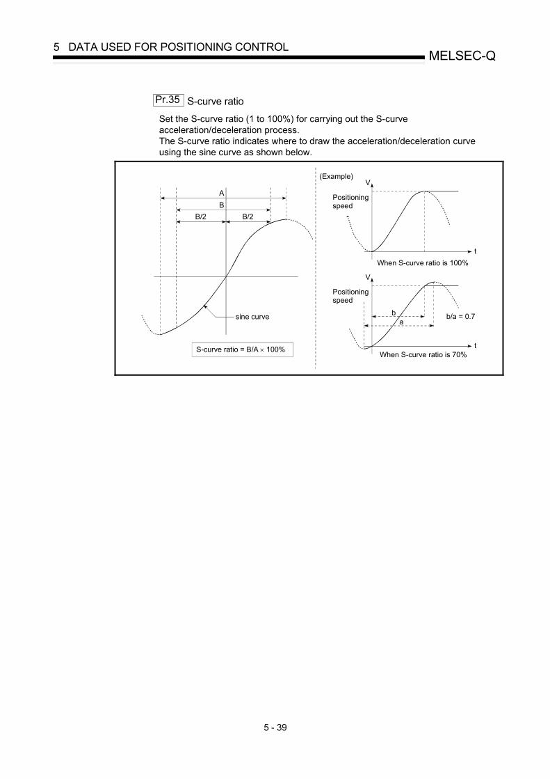
5 - 39
MELSEC-Q5 DATA USED FOR POSITIONING CONTROL
Pr.35 S-curve ratio
Set the S-curve ratio (1 to 100%) for carrying out the S-curve acceleration/deceleration process. The S-curve ratio indicates where to draw the acceleration/deceleration curve using the sine curve as shown below.
AB
B/2 B/2
V
t
V
t
b/a = 0.7ba
sine curve
S-curve ratio = B/A × 100%
(Example)
Positioningspeed
Positioningspeed
When S-curve ratio is 100%
When S-curve ratio is 70%

5 - 40
MELSEC-Q5 DATA USED FOR POSITIONING CONTROL
Pr.36 Sudden stop deceleration time Set the time to reach speed 0 from " Pr.8 Speed limit value" during the sudden stop. The illustration below shows the relationships with other parameters.
When positioning is started, the acceleration starts followingthe "acceleration time".
1) Positioning start 2) Sudden stop cause occurrenceWhen a "sudden stop cause" occurs, the deceleration starts following the "sudden stop deceleration time".
3) Positioning stopWhen a "sudden stop cause" does not occur, the decelera-tion starts toward the stop position following the "decel-eration time".
Actual accel-eration time
Actual sudden stop deceleration time
Acceleration time
Actual decel-eration time
Deceleration time
Speed limit value
Pr.8
Command speed
Da.8
Pr.36Sudden stopdeceleration time
Acceleration time 0Pr.9
Acceleration time 1Pr.25
Acceleration time 2Pr.26
Acceleration time 3Pr.27
Deceleration time 0Pr.10
Deceleration time 1Pr.28
Deceleration time 2Pr.29
Deceleration time 3Pr.30

5 - 41
MELSEC-Q5 DATA USED FOR POSITIONING CONTROL
Pr.37 Stop group 1 sudden stop selection
to Pr.39 Stop group 3 sudden stop selection
Set the method to stop when the stop causes in the following stop groups occur. • Stop group 1 .............. Stop with hardware stroke limit • Stop group 2 .............. PLC CPU error occurrence, PLC READY signal [Y0] OFF,
Fault in test mode • Stop group 3 .............. External stop signal
Stop signal from PLC CPU Stop signal from peripheral device Error occurrence (excludes errors in stop groups 1 and 2: includes only the software stroke limit errors during JOG operation, speed control, speed-position switching control, and position-speed switching control) Stop made when the near-point dog signal turns from OFF to ON in counter method machine OPR
The methods of stopping include "0: Normal deceleration stop" and "1: Sudden stop". If "1: Sudden stop" is selected, the axis will suddenly decelerate to a stop when the stop signal is input.

5 - 42
MELSEC-Q5 DATA USED FOR POSITIONING CONTROL
Setting value, setting range Setting value buffer memory address Item
Value set with peripheral device Value set with sequence program
Default value
Axis 1 Axis 2 Axis 3 Axis 4
Pr.40
Positioning complete signal output time
0 to 65535 (ms)
0 to 65535 (ms) 0 to 32767 :
Set as a decimal 32768 to 65535:
Convert into hexadecimal and set
300 59 209 359 509
Pr.41
Allowable circular interpolation error width
The setting value range differs depending on the " Pr.1 Unit
setting". Here, the value within the [Table 1] range is set.
[Table 1] on right page
100 60 61
210 211
360361
510511
0: External positioning start 0 1: External speed change
request 1
2: Speed-position, position- speed switching request 2
Pr.42
External command function selection
3: Skip request 3
0 62 212 362 512
Pr.40 Positioning complete signal output time
Set the output time of the positioning complete signal [X14, X15, X16, X17] output from the QD75. A positioning completes when the specified dwell time has passed after the QD75 had terminated the output.
M
QD75
[Y10, Y11, Y12, Y13]
PLC
PLC CPUPositioning start signal
Positioningcomplete signal
[X14, X15, X16, X17]
Positioning
Positioning start signal
Start completesignal
BUSY signal
Positioning complete signal
Positioning complete signal(after dwell time has passed)
Output time
Positioning complete signal output time

5 - 43
MELSEC-Q5 DATA USED FOR POSITIONING CONTROL
[Table 1]
Pr.1 setting value Value set with peripheral device
(unit) Value set with sequence program
(unit)
0 : mm 0 to 10000.0 (μm) 0 to 100000 (×10-1μm)
1 : inch 0 to 1.00000 (inch) 0 to 100000 (×10-5inch)
2 : degree 0 to 1.00000 (degree) 0 to 100000 (×10-5degree)
3 : pulse 0 to 100000 (pulse) 0 to 100000 (pulse)
Pr.41 Allowable circular interpolation error width
With the "allowable circular interpolation error width", the allowable error range of the calculated arc path and end point address is set. If the error of the calculated arc path and end point address is within the set range, circular interpolation will be carried out to the set end point address while compensating the error with spiral interpolation. The allowable circular interpolation error width is set in the following axis buffer memory addresses. • If axis 1 is the reference axis, set in the axis 1 buffer memory address
[60, 61]. • If axis 2 is the reference axis, set in the axis 2 buffer memory address
[210, 211]. • If axis 3 is the reference axis, set in the axis 3 buffer memory address
[360, 361]. • If axis 4 is the reference axis, set in the axis 4 buffer memory address
[510, 511].
Path with spiral interpolation Error
End point address with calculation
End point address
Start point address Center point address
With circular interpolation control using the center point designation, the arc path calculated with the start point address and center point address and the end point address may deviate.

5 - 44
MELSEC-Q5 DATA USED FOR POSITIONING CONTROL
Pr.42 External command function selection Select a command with which the external command signal should be associated.
0: External positioning start The external command signal input is used to start a positioning operation.
1: External speed change request The external command signal input is used to change the speed in the current positioning operation. The new speed should be set in the " Cd.14 Speed change value"
2: Speed-position, position-speed switching request The external command signal input is used to switch from the speed control to the position control while in the speed-position switching control mode, or from the position control to the speed control while in the position-speed switching control mode. To enable the speed-position switching control, set the " Cd.24 Speed-position switching enable flag" to "1". To enable the position-speed switching control, set the " Cd.26 Position-speed switching enable flag" to "1".
3: Skip request The external command signal input is used skip the current positioning operation.
POINT
To enable the external command signal, set the " Cd.8 External command enable"
to "1".

5 - 45
MELSEC-Q5 DATA USED FOR POSITIONING CONTROL
MEMO

5 - 46
MELSEC-Q5 DATA USED FOR POSITIONING CONTROL
5.2.5 OPR basic parameters
Setting value, setting range Setting value buffer memory address Item
Value set with peripheral device Value set with sequence program
Default value
Axis 1 Axis 2 Axis 3 Axis 4
0 : Near-point dog method 0 1 : Stopper method 1) 1 2 : Stopper method 2) 2 3 : Stopper method 3) 3 4 : Count method 1) 4
Pr.43
OPR method
5 : Count method 2) 5
0 70 220 370 520
Pr.43 OPR method
Set the "OPR method" for carrying out machine OPR. 0 : Near-point dog method ........ After decelerating at the near-point dog ON, stop
at the zero signal and complete the machine OPR. 1 : Stopper method 1) ............... After decelerating at the near-point dog ON, stop
with the stopper, and complete the machine OPR after the dwell time has passed.
2 : Stopper method 2) ............... After decelerating at the near-point dog ON, stop with the stopper, and complete the machine OPR with the zero signal.
3 : Stopper method 3) ............... After starting with the creep speed, stop with the stopper, and complete the machine OPR with the zero signal.
4 : Count method 1) .................. After decelerating at the near-point dog ON, move the designated distance, and complete the machine OPR with the zero signal.
5 : Count method 2) .................. After decelerating at the near-point dog ON, move the designated distance, and complete the machine OPR.
Note) Refer to Section 8.2.2 "Machine OPR method" for details on the OPR methods.
OPR method
0 : Near-point dog method
(1) Start machine OPR. (Start movement at the " Pr.46 OPR speed" in the
" Pr.44 OPR direction".)
(2) Detect the near-point dog ON, and start deceleration.
(3) Decelerate to " Pr.47 Creep speed", and move with the creep speed. (At this time, the near-point dog must be ON. If the near-point dog is OFF, the axis will decelerate to a stop.)
(4) At the first zero signal (one pulse output at one motor revolution) after the near-point dog OFF, the pulse output from the QD75 stops, and the machine OPR is completed.
t
V
ON(1)
(2)
(3) (4)
Near-point dog OFF
Zero signal
OPR speedPr.46
Pr.47Creep speed

5 - 47
MELSEC-Q5 DATA USED FOR POSITIONING CONTROL
1 : Stopper method 1)
(1) Start machine OPR. (Start movement at the " Pr.46 OPR speed" in the
" Pr.44 OPR direction".)
(2) Detect the near-point dog ON, and start deceleration.
(3) Decelerate to " Pr.47 Creep speed", and move with the creep speed. (At this time " Pr.54 OPR torque limit value" is required. If the torque is not limited, the servomotor could be damaged in step (4).)
(4) The axis contacts against the stopper at " Pr.47 Creep speed", and then stops.
(5) When the near-point dog turns ON and the " Pr.49 OPR dwell time" is passed, the pulse output from the QD75 stops, and the machine OPR is completed.
t
V
(1)
(2)
(3) (4) (5)
Near-point dog OFF
OPR speedPr.46
Creep speedPr.47
Range to forcibly stop the servomotor rotation with the stopper.
Dwell time countingDwell time up
ON
2 : Stopper method 2)
(1) Start machine OPR. (Start movement at the " Pr.46 OPR speed" in the
" Pr.44 OPR direction".)
(2) Detect the near-point dog ON, and start deceleration.
(3) Decelerate to " Pr.47 Creep speed", and move with the creep speed. (At this time " Pr.54 OPR torque limit value" is required. If the torque is not limited, the servomotor could be damaged in step (4).)
(4) The axis contacts against the stopper at " Pr.47 Creep speed", and then stops.
(5) After stopping, the pulse output from the QD75 stops with the zero signal (signal that is output on detection of contact with the stopper. Input externally), and the machine OPR is completed.
t
V
ON
(1)
(2)
(3) (4)(5)
Near-point dog
Zero signal
OPR speedPr.46Pr.47Creep speed
Stop with stopper
OFF
3 : Stopper method 3)
(1) Start machine OPR. (Start movement at the " Pr.47 Creep speed" in the
" Pr.44 OPR direction". At this time " Pr.54 OPR torque limit value" is required. If the torque is not limited, the servomotor could be damaged in step (2).)
(2) The axis contacts against the stopper at " Pr.47 Creep speed", and then stops.
(3) After stopping, the pulse output from the QD75 stops with the zero signal (signal that is output on detection of contact with the stopper. Input externally), and the machine OPR is completed.
t
V
(1)
(2)
(3)Zero signal
Creep speedPr.47
Stop with stopper

5 - 48
MELSEC-Q5 DATA USED FOR POSITIONING CONTROL
4 : Count method 1)
(1) Start machine OPR. (Start movement at the " Pr.46 OPR speed" in the
" Pr.44 OPR direction".)
(2) Detect the near-point dog ON, and start deceleration.
(3) Decelerate to " Pr.47 Creep speed", and move with the creep speed.
(4) After the near-point dog turns ON and the movement amount set in " Pr.50 Setting for the movement amount after near-point dog ON" has passed, the pulse output from the QD75 stops with the first zero signal (one pulse output at one motor revolution), and the machine OPR is completed.
t
V
ON
(4)(3)
(2)
(1)
Near-point dog OFF
Zero signal
OPR speedPr.46
Pr.47 Creep speed
Pr.50Setting for the movementamount after near-poing dog ON
First zero signal after moving the movement amount after near-point dog ON
Movement amount afternear-point dog ON
Md.34
The near-point dog must turn OFF at a sufficient distance away from the OP position.
5 : Count method 2)
(1) Start machine OPR. (Start movement at the " Pr.46 OPR speed" in the
" Pr.44 OPR direction".)
(2) Detect the near-point dog ON, and start deceleration.
(3) Decelerate to " Pr.47 Creep speed", and move with the creep speed.
(4) After the near-point dog turns ON and the movement amount set in " Pr.50 Setting for the movement amount after near-point dog ON" has passed, the pulse output from the QD75 stops with the first zero signal, and the machine OPR is completed.
t
V
ON
(1)
(2)
(3)
(4)
Near-point dog OFF
Movement amount afternear-point dog ON
Md.34
OPR speedPr.46
Pr.47 Creep speed
Pr.50Setting for the movementamount after near-poing dog ON
Setting value, setting range Setting value buffer memory address Item
Value set with peripheral device Value set with sequence program
Default value
Axis 1 Axis 2 Axis 3 Axis 4
0 : Positive direction (address increment direction) 0 Pr.44
OPR direction 1 : Negative direction (address
decrement direction) 1 0 71 221 371 521
Pr.45
OP address
The setting value range differs depending on the " Pr.1 Unit
setting". Here, the value within the [Table 1] range is set.
[Table 1] on right page
0 72 73
222 223
372373
522523
Pr.46
OPR speed
The setting value range differs depending on the " Pr.1 Unit
setting". Here, the value within the [Table 2] range is set.
[Table 2] on right page
1 74 75
224 225
374375
524525

5 - 49
MELSEC-Q5 DATA USED FOR POSITIONING CONTROL
Pr.44 OPR direction
Set the direction to start movement when starting machine OPR. 0: Positive direction (address increment direction)
Moves in the direction that the address increments. (Arrow 2)) 1: Negative direction (address decrement direction)
Moves in the direction that the address decrements. (Arrow 1)) Normally, the OP is set near the lower limit or the upper limit, so " Pr.44 OPR direction" is set as shown below.
Address decrementdirection
Lower limit
OP
Upper limit
Address increment direction
1)
2)
Address decrementdirection
Lower limit
OP
Upper limit
Address increment direction
When the OP is set at the upper limit side, the OPR directionis in the direction of arrow 2).Set "0" for .Pr.44
When the zero point is set at the lower limit side, the OPR direction is in thedirection of arrow 1).Set "1" for .Pr.44
[Table 1]
Pr.1 setting value Value set with peripheral device (unit)
Value set with sequence program (unit)
0 : mm -214748364.8 to 214748364.7 (μm) -2147483648 to 2147483647 (×10-1μm)
1 : inch -21474.83648 to 21474.83647 (inch) -2147483648 to 2147483647 (×10-5inch)
2 : degree 0 to 359.99999 (degree) 0 to 35999999 (×10-5degree)
3 : pulse -2147483648 to 2147483647 (pulse) -2147483648 to 2147483647 (pulse)
[Table 2]
Pr.1 setting value Value set with peripheral device
(unit) Value set with sequence program
(unit)
0 : mm 0.01 to 20000000.00 (mm/min) 1 to 2000000000 (×10-2mm/min)
1 : inch 0.001 to 2000000.000 (inch/min) 1 to 2000000000 (×10-3inch/min)
2 : degree 0.001 to 2000000.000 (degree/min) 1 to 2000000000 (×10-3degree/min)
3 : pulse 1 to 1000000 (pulse/s) 1 to 1000000 (pulse/s)

5 - 50
MELSEC-Q5 DATA USED FOR POSITIONING CONTROL
Pr.45 OP address
Set the address used as the reference point for positioning control (ABS system). (When the machine OPR is completed, the stop position address is changed to the address set in " Pr.45 OP address". At the same time, the " Pr.45 OP address"
is stored in " Md.20 Current feed value" and " Md.21 Machine feed value".)
Pr.46 OPR speed
Set the speed for OPR. Note) Set the "OPR speed" to less than " Pr.8 Speed limit value". If the "speed
limit value" is exceeded, the "Out of speed limit value range" (error code: 910) occurs and OPR is not performed. The "OPR speed" should be equal to or faster than the " Pr.7 Bias speed
at start" and " Pr.47 Creep speed".
Setting value, setting range Setting value buffer memory address Item
Value set with peripheral device Value set with sequence program
Default value
Axis 1 Axis 2 Axis 3 Axis 4
Pr.47
Creep speed
The setting value range differs depending on the " Pr.1 Unit
setting". Here, the value within the [Table 1] range is set.
[Table 1] on right page
1 76 77
226 227
376377
526527
0 : Do not retry OPR with limit switch 0 Pr.48
OPR retry 1 : Retry OPR with limit switch 1
0 78 228 378 528

5 - 51
MELSEC-Q5 DATA USED FOR POSITIONING CONTROL
Pr.47 Creep speed
Set the creep speed after near-point dog ON (the low speed just before stopping after decelerating from the OPR speed). The creep speed is set within the following range. ( Pr.46 OPR speed ) ( Pr.47 Creep speed) ( Pr.7 Bias speed at start)
Note) The creep speed is related to the detection error when using the OPR
method with zero signal, and the size of the collision if a collision occurs during OPR method using the stopper method. Set a speed equal to or faster than the bias speed at start.
ON
V
Machine OPR start
Near-point dog signal OFF
Zero signal
OPR speedPr.46
Creep speedPr.47
[Table 1]
Pr.1 setting value Value set with peripheral device
(unit) Value set with sequence program
(unit)
0 : mm 0.01 to 20000000.00 (mm/min) 1 to 2000000000 (×10-2mm/min)
1 : inch 0.001 to 2000000.000 (inch/min) 1 to 2000000000 (×10-3inch/min)
2 : degree 0.001 to 2000000.000 (degree/min) 1 to 2000000000 (×10-3degree/min)
3 : pulse 1 to 1000000 (pulse/s) 1 to 1000000 (pulse/s)

5 - 52
MELSEC-Q5 DATA USED FOR POSITIONING CONTROL
Pr.48 OPR retry
Set whether to carry out OPR retry. When the OPR retry function is validated and the machine OPR is started, first the axis will move in the OPR direction (1)). If the upper/lower limit signal turns OFF before the near-point dog signal ON is detected (2)), the axis will decelerate to a stop, and then will move in the direction opposite to the specified OPR direction (3)). If the falling edge of the near-point dog signal is detected during movement in the opposite direction, the axis will decelerate to a stop (4)), and will carry out machine OPR again (5)), (6)).
ON
Start position
Near-point dog signalLimit signal OFF state
Zero signal
5)
4)
6)
1) 2)
3)
[Operation for OPR retry function] 1) Movement in the OPR direction starts with the machine OPR start. 2) The axis decelerates when the limit signal OFF is detected. 3) After stopping at detection of the limit switch signal OFF, the axis moves at the OPR
speed in the direction opposite to the specified OPR direction. 4) The axis decelerates when the near-point dog signal turns OFF. 5), 6) After stopping with the near-point dog signal OFF, carries out machine OPR in the
OPR direction.

5 - 53
MELSEC-Q5 DATA USED FOR POSITIONING CONTROL
MEMO

5 - 54
MELSEC-Q5 DATA USED FOR POSITIONING CONTROL
5.2.6 OPR detailed parameters
Setting value, setting range Setting value buffer memory address Item
Value set with peripheral device Value set with sequence program
Default value
Axis 1 Axis 2 Axis 3 Axis 4
Pr.49
OPR dwell time 0 to 65535 (ms)
0 to 65535 (ms) 0 to 32767 :
Set as a decimal 32768 to 65535 :
Convert into hexadecimal and set
0 79 229 379 529
Pr.50
Setting for the movement amount after near-point dog ON
The setting value range differs depending on the " Pr.1 Unit
setting". Here, the value within the [Table 1] range is set.
[Table 1] on right page
0 80 81
230 231
380381
530531
0 : Pr.9 Acceleration time 0 0
1 : Pr.25 Acceleration time 1 1
2 : Pr.26 Acceleration time 2 2
Pr.51
OPR acceleration time selection
3 : Pr.27 Acceleration time 3 3
0 82 232 382 532
0 : Pr.10 Deceleration time 0 0
1 : Pr.28 Deceleration time 1 1
2 : Pr.29 Deceleration time 2 2
Pr.52
OPR deceleration time selection
3 : Pr.30 Deceleration time 3 3
0 83 233 383 533
Pr.49 OPR dwell time
When stopper method 1) is set for " Pr.43 OPR method", set the time for the machine OPR to complete after the near-point dog signal turns ON. The setting value must be longer than the movement time from the near-point dog signal ON to stopping with the stopper. (If the OPR method is not "stopper method 1)", the " Pr.49 OPR dwell time" value is irrelevant.)
Pr.50 Setting for the movement amount after near-point dog ON
When using the count method 1) or 2), set the movement amount to the OP after the near-point dog signal turns ON. (The movement amount after near-point dog ON should be equal to or greater than the sum of the "distance covered by the deceleration from the OPR speed to the creep speed" and "distance of movement in 10 ms at the OPR speed".)

5 - 55
MELSEC-Q5 DATA USED FOR POSITIONING CONTROL
[Table 1]
Pr.1 setting value Value set with peripheral device
(unit) Value set with sequence program
(unit)
0 : mm 0 to 214748364.7 (μm) 0 to 2147483647 (×10-1μm)
1 : inch 0 to 21474.83647 (inch) 0 to 2147483647 (×10-5inch)
2 : degree 0 to 21474.83647 (degree) 0 to 2147483647 (×10-5degree)
3 : pulse 0 to 2147483647 (pulse) 0 to 2147483647 (pulse)
Deceleration time: Tb=300ms
Creep speed: Vc=1kpulse/s
Actual deceleration time:t = Tb tVzVp
Pr.47
Speed limit value: Vp=200kpulse/sPr.8
OPR speed:Vz=10kpulse/s
Pr.46
[Machine OPR operation]
Example of setting for " Pr. 50 Setting for the movement amount after near-point dog ON"
Assuming that the " Pr. 8 Speed limit value" is set to 200 kpulse/s, " Pr. 46 OPR speed" to 10 kpulse/s, " Pr. 47 Creep speed" to 1 kpulse/s, and deceleration time to 300 ms, the minimum value of " Pr. 50 Setting for the movement amount after near-point dog ON" is calculated as follows:
[Deceleration distance] =12
Vz1000 t + 0.01 Vz
Movement amount for 10ms at OPR speed
=Tb Vz
Vp + 0.01 VzVz
2000
=300 10 10
200 1010 102000
3 3
3+ 0.01 10 10
3
= 75 + 100= 175
Setting for the movement amount after near-point dog ON ( Pr. 50 ) should be equal to or larger than 175.
Pr.51 OPR acceleration time selection
Set which of "acceleration time 0 to 3" to use for the acceleration time during OPR. 0 : Use the value set in " Pr.9 Acceleration time 0".
1 : Use the value set in " Pr.25 Acceleration time 1".
2 : Use the value set in " Pr.26 Acceleration time 2".
3 : Use the value set in " Pr.27 Acceleration time 3".
Pr.52 OPR deceleration time selection
Set which of "deceleration time 0 to 3" to use for the deceleration time during OPR. 0 : Use the value set in " Pr.10 Deceleration time 0".
1 : Use the value set in " Pr.28 Deceleration time 1".
2 : Use the value set in " Pr.29 Deceleration time 2".
3 : Use the value set in " Pr.30 Deceleration time 3".

5 - 56
MELSEC-Q5 DATA USED FOR POSITIONING CONTROL
Setting value, setting range Setting value buffer memory address Item
Value set with peripheral device Value set with sequence program
Default value
Axis 1 Axis 2 Axis 3 Axis 4
Pr.53
OP shift amount
The setting value range differs depending on the " Pr.1 Unit setting".
Here, the value within the [Table 1] range is set.
[Table 1] on right page
0 84 85
234 235
384385
534535
Pr.54
OPR torque limit value 1 to 300 (%) 1 to 300 (%) 300 86 236 386 536
Pr.55
Deviation counter clear signal output time
1 to 65535 (ms)
1 to 65535 (ms) 0 to 32767:
Set the decimal value as it is. 32768 to 65535:
Convert the decimal value into a hexadecimal value and set the latter.
11 87 237 387 537
0 : OPR speed 0 Pr.56
Speed designation during OP shift 1 : Creep speed 1
0 88 238 388 538
Pr.57
Dwell time during OPR retry
0 to 65535 (ms)
0 to 65535 (ms) 0 to 32767 :
Set as a decimal 32768 to 65535 :
Convert into hexadecimal and set
0 89 239 389 539
Pr.53 OP shift amount
Set the amount to shift (move) from the position stopped at with machine OPR.
The OP shift function is used to compensate the OP position stopped at with machine OPR. If there is a physical limit to the OP position, due to the relation of the near-point dog installation position, use this function to compensate the OP to an optimum position.
OPR direction
When " OP shift amount" is positive
Shift point
Shift point
When " OPshift amount" is negative
Start point
Shift after deviation counter clear is canceled
Near-point dog signal
Zero signal
Pr.53
Pr.53
Pr.44

5 - 57
MELSEC-Q5 DATA USED FOR POSITIONING CONTROL
[Table 1]
Pr.1 setting value Value set with peripheral device
(unit) Value set with sequence program
(unit)
0 : mm -214748364.8 to 214748364.7 (μm) -2147483648 to 2147483647 (×10-1μm)
1 : inch -21474.83648 to 21474.83647 (inch) -2147483648 to 2147483647 (×10-5inch)
2 : degree -21474.83648 to 21474.83647 (degree) -2147483648 to 2147483647 (×10-5degree)
3 : pulse -2147483648 to 2147483647 (pulse) -2147483648 to 2147483647 (pulse)
Pr.54 OPR torque limit value
Set the value to limit the servomotor torque after reaching the creep speed during machine OPR. Refer to Section 12.4.2 "Torque limit function" for details on the torque limits.
Pr.55 Deviation counter clear signal output time
Set the duration of the deviation counter clear signal output during a machine OPR operation using any of the following methods: the near-point dog method, stopper methods 1) to 3), and count method 1). (For details, refer to your drive unit manual.)
Pr.56 Speed designation during OP shift
Set the operation speed for when a value other than "0" is set for " Pr.53 OP shift amount". Select the setting from " Pr.46 OPR speed" or " Pr.47 Creep speed".
0 : Designate " Pr.46 OPR speed" as the setting value.
1 : Designate " Pr.47 Creep speed" as the setting value.
Pr.57 Dwell time during OPR retry
When OPR retry is validated (when "1" is set for Pr.48 ), set the stop time after decelerating in 2) and 4) in the following drawing.
Start position
Temporarily stop forthe time set in Pr. 57
Temporarily stop forthe time set in Pr. 571) 2)
3)
4)
5)
6)

5 - 58
MELSEC-Q5 DATA USED FOR POSITIONING CONTROL
5.3 List of positioning data
Before explaining the positioning data setting items Da.1 to Da.10 , the configuration
of the positioning data will be shown below. The positioning data stored in the QD75 buffer memory has the following type of configuration.
Ê̂ ’u Œ̂ ‚ß Ž̄ •Ê Žq
Da.1�@ �̀ �@ Da.4
Ž²‚P
Ê̂ ’u Œ̂ ‚ß ƒA ƒh ƒŒ ƒXDa.5
‰~ ŒÊ ƒA ƒh ƒŒ ƒXDa.6
Žw —ß ‘¬ “xDa.7
ƒh ƒE ƒF ƒ‹ ƒ̂ ƒC ƒ€Da.8
MƒR �[ ƒhDa.9
Ê̂ ’u Œ̂ ‚ß ƒf �[ ƒ̂ ‡‚ �@ 600
Ê̂ ’u Œ̂ ‚ß Ž̄ •Ê Žq
Da.1�@ �̀ �@ Da.4
Ž²‚P
Ê̂ ’u Œ̂ ‚ß ƒA ƒh ƒŒ ƒXDa.5
‰~ ŒÊ ƒA ƒh ƒŒ ƒXDa.6
Žw —ß ‘¬ “xDa.7
ƒh ƒE ƒF ƒ‹ ƒ̂ ƒC ƒ€Da.8
MƒR �[ ƒhDa.9
Ê̂ ’u Œ̂ ‚ß ƒf �[ ƒ̂ ‡‚ �@ 599
Ê̂ ’u Œ̂ ‚ß Ž̄ •Ê Žq
Da.1�@ �̀ �@ Da.4
Ž²‚P
Ê̂ ’u Œ̂ ‚ß ƒA ƒh ƒŒ ƒXDa.5
‰~ ŒÊ ƒA ƒh ƒŒ ƒXDa.6
Žw —ß ‘¬ “xDa.7
ƒh ƒE ƒF ƒ‹ ƒ̂ ƒC ƒ€Da.8
MƒR �[ ƒhDa.9
Ê̂ ’u Œ̂ ‚ß Ž̄ •Ê Žq
Da.1�@ �̀ �@ Da.4
Ž²‚P
Ê̂ ’u Œ̂ ‚ß ƒA ƒh ƒŒ ƒXDa.5
‰~ ŒÊ ƒA ƒh ƒŒ ƒXDa.6
Žw —ß ‘¬ “xDa.7
ƒh ƒE ƒF ƒ‹ ƒ̂ ƒC ƒ€Da.8
MƒR �[ ƒhDa.9
2
Axi
s 1
Positioning identifier
Da.1 to Da.5
Positioning address/movement amount
Da.6
Arc addressDa.7
Command speedDa.8
Dwell timeDa.9
M codeDa.10
Positioning data No. 1
2000
2001
2002
20042005
20062007
20082009
2010
2011
2012
20142015
20162017
20182019
2020
2021
2022
20242025
20262027
20282029
7980
7981
7982
79847985
79867987
79887989
7990
7991
7992
79947995
79967997
79987999
Ê̂ ’u Œ̂ ‚ß Ž̄ •Ê Žq
Da.1�@ �̀ �@ Da.4
Ž²‚P
Ê̂ ’u Œ̂ ‚ß ƒA ƒh ƒŒ ƒXDa.5
‰~ ŒÊ ƒA ƒh ƒŒ ƒXDa.6
Žw —ß ‘¬ “xDa.7
ƒh ƒE ƒF ƒ‹ ƒ̂ ƒC ƒ€Da.8
MƒR �[ ƒhDa.9
Ê̂ ’u Œ̂ ‚ß ƒf �[ ƒ̂ ‡‚ �@ 600
Ê̂ ’u Œ̂ ‚ß Ž̄ •Ê Žq
Da.1�@ �̀ �@ Da.4
Ž²‚P
Ê̂ ’u Œ̂ ‚ß ƒA ƒh ƒŒ ƒXDa.5
‰~ ŒÊ ƒA ƒh ƒŒ ƒXDa.6
Žw —ß ‘¬ “xDa.7
ƒh ƒE ƒF ƒ‹ ƒ̂ ƒC ƒ€Da.8
MƒR �[ ƒhDa.9
Ê̂ ’u Œ̂ ‚ß ƒf �[ ƒ̂ ‡‚ �@ 599
Ê̂ ’u Œ̂ ‚ß Ž̄ •Ê Žq
Da.1�@ �̀ �@ Da.4Ž²‚P
Ê̂ ’u Œ̂ ‚ß ƒA ƒh ƒŒ ƒXDa.5
‰~ ŒÊ ƒA ƒh ƒŒ ƒXDa.6
Žw —ß ‘¬ “xDa.7
ƒh ƒE ƒF ƒ‹ ƒ̂ ƒC ƒ€Da.8
MƒR �[ ƒhDa.9
Ê̂ ’u Œ̂ ‚ß Ž̄ •Ê Žq
Da.1�@ �̀ �@ Da.4Ž²‚P
Ê̂ ’u Œ̂ ‚ß ƒA ƒh ƒŒ ƒXDa.5
‰~ ŒÊ ƒA ƒh ƒŒ ƒXDa.6
Žw —ß ‘¬ “xDa.7
ƒh ƒE ƒF ƒ‹ ƒ̂ ƒC ƒ€Da.8
MƒR �[ ƒhDa.9
Axi
s 2
Positioning identifier
Da.1 to Da.5
Positioning address/movement amount
Da.6
Arc addressDa.7
Command speedDa.8
Dwell timeDa.9
M codeDa.10
8000
8001
8002
80048005
80068007
80088009
8010
8011
8012
80148015
80168017
80188019
8020
8021
8022
80248025
80268027
80288029
13980
13981
13982
1398413985
1398613987
1398813989
13990
13991
13992
1399413995
1399613997
1399813999
b15 b12 b0b4b8
Control system Da.1Da.2
Deceleration time No.
Da.3
Da.4
Operation pattern
Acceleration time No.
Configuration of positioning identifier
Up to 600 positioning data items can be set (stored) for each axisin the buffer memory address shown on the left.This data is controlled as positioning data No. 1 to 600 for each axis.
One positioning data item is configured of the items shown in the bold box.
Buffer memory
Da.5 Axis to be interpolated
3
2Positioning data No. 13

5 - 59
MELSEC-Q5 DATA USED FOR POSITIONING CONTROL
Ê̂ ’u Œ̂ ‚ß Ž̄ •Ê Žq
Da.1�@ �̀ �@ Da.4
Ž²‚P
Ê̂ ’u Œ̂ ‚ß ƒA ƒh ƒŒ ƒXDa.5
‰~ ŒÊ ƒA ƒh ƒŒ ƒXDa.6
Žw —ß ‘¬ “xDa.7
ƒh ƒE ƒF ƒ‹ ƒ̂ ƒC ƒ€Da.8
MƒR �[ ƒhDa.9
Ê̂ ’u Œ̂ ‚ß Ž̄ •Ê Žq
Da.1�@ �̀ �@ Da.4
Ž²‚P
Ê̂ ’u Œ̂ ‚ß ƒA ƒh ƒŒ ƒXDa.5
‰~ ŒÊ ƒA ƒh ƒŒ ƒXDa.6
Žw —ß ‘¬ “xDa.7
ƒh ƒE ƒF ƒ‹ ƒ̂ ƒC ƒ€Da.8
MƒR �[ ƒhDa.9
Ê̂ ’u Œ̂ ‚ß Ž̄ •Ê Žq
Da.1�@ �̀ �@ Da.4
Ž²‚P
Ê̂ ’u Œ̂ ‚ß ƒA ƒh ƒŒ ƒXDa.5
‰~ ŒÊ ƒA ƒh ƒŒ ƒXDa.6
Žw —ß ‘¬ “xDa.7
ƒh ƒE ƒF ƒ‹ ƒ̂ ƒC ƒ€Da.8
MƒR �[ ƒhDa.9
Ê̂ ’u Œ̂ ‚ß Ž̄ •Ê Žq
Da.1�@ �̀ �@ Da.4
Ž²‚P
Ê̂ ’u Œ̂ ‚ß ƒA ƒh ƒŒ ƒXDa.5
‰~ ŒÊ ƒA ƒh ƒŒ ƒXDa.6
Žw —ß ‘¬ “xDa.7
ƒh ƒE ƒF ƒ‹ ƒ̂ ƒC ƒ€Da.8
MƒR �[ ƒhDa.9
Axi
s 3
Positioning identifier
Da.1 to Da.5
Positioning address/movement amount
Da.6
Arc addressDa.7
Command speedDa.8
Dwell timeDa.9
M codeDa.10
Positioning data No. 1
14000
14001
14002
1400414005
1400614007
1400814009
14010
14011
14012
1401414015
1401614017
1401814019
14020
14021
14022
1402414025
1402614027
1402814029
19980
19981
19982
1998419985
1998619987
1998819989
19990
19991
19992
1999419995
1999619997
1999819999
Buffer memory address
2 3
600599
Ê̂ ’u Œ̂ ‚ß Ž̄ •Ê Žq
Da.1�@ �̀ �@ Da.4Ž²‚P
Ê̂ ’u Œ̂ ‚ß ƒA ƒh ƒŒ ƒXDa.5
‰~ ŒÊ ƒA ƒh ƒŒ ƒXDa.6
Žw —ß ‘¬ “xDa.7
ƒh ƒE ƒF ƒ‹ ƒ̂ ƒC ƒ€Da.8
MƒR �[ ƒhDa.9
Ê̂ ’u Œ̂ ‚ß Ž̄ •Ê Žq
Da.1�@ �̀ �@ Da.4
Ž²‚P
Ê̂ ’u Œ̂ ‚ß ƒA ƒh ƒŒ ƒXDa.5
‰~ ŒÊ ƒA ƒh ƒŒ ƒXDa.6
Žw —ß ‘¬ “xDa.7
ƒh ƒE ƒF ƒ‹ ƒ̂ ƒC ƒ€Da.8
MƒR �[ ƒhDa.9
Ê̂ ’u Œ̂ ‚ß Ž̄ •Ê Žq
Da.1�@ �̀ �@ Da.4
Ž²‚P
Ê̂ ’u Œ̂ ‚ß ƒA ƒh ƒŒ ƒXDa.5
‰~ ŒÊ ƒA ƒh ƒŒ ƒXDa.6
Žw —ß ‘¬ “xDa.7
ƒh ƒE ƒF ƒ‹ ƒ̂ ƒC ƒ€Da.8
MƒR �[ ƒhDa.9
Ê̂ ’u Œ̂ ‚ß Ž̄ •Ê Žq
Da.1�@ �̀ �@ Da.4
Ž²‚P
Ê̂ ’u Œ̂ ‚ß ƒA ƒh ƒŒ ƒXDa.5
‰~ ŒÊ ƒA ƒh ƒŒ ƒXDa.6
Žw —ß ‘¬ “xDa.7
ƒh ƒE ƒF ƒ‹ ƒ̂ ƒC ƒ€Da.8
MƒR �[ ƒhDa.9
Positioning identifier
Da.1 to Da.5
Positioning address/movement amount
Da.6
Arc addressDa.7
Command speedDa.8
Dwell timeDa.9
M codeDa.10
20000
20001
20002
2000420005
2000620007
2000820009
20010
20011
20012
2001420015
2001620017
2001820019
20020
20021
20022
2002420025
2002620027
2002820029
25980
25981
25982
2598425985
2598625987
2598825989
25990
25991
25992
2599425995
2599625997
2599825999
Positioning data No. 1 2 3
600599
Axi
s 4
Buffer memory address
The descriptions that follow relate to the positioning data set items Da.1 to Da.10 .
(The buffer memory addresses shown are those of the "positioning data No. 1" for the axes 1 to 4.)

5 - 60
MELSEC-Q5 DATA USED FOR POSITIONING CONTROL
Setting value Setting value buffer memory
address Item Value set with peripheral device Value set with sequence program
Default value
Axis 1 Axis 2 Axis 3 Axis 400: Positioning complete 0001: Continuous positioning control 01
Da.1 Operation pattern 11: Continuous path control 11
ABS1 : 1-axis linear control (ABS) 01H
INC1 : 1-axis linear control (INC) 02H
FEED1 : 1-axis fixed-feed control 03H
VF1 : 1-axis speed control (forward run) 04H
VR1 : 1-axis speed control (reverse run) 05H
VPF : Speed-position switching control (forward run) 06H
VPR : Speed-position switching control (reverse run) 07H
PVF : Position-speed switching control (forward run) 08H
PVR : Position-speed switching control (reverse run) 09H
ABS2 : 2-axis linear interpolation control (ABS) 0AH
INC2 : 2-axis linear interpolation control (INC) 0BH
FEED2 : Fixed-feed control by 2-axis linear interpolation 0CH
ABS
(
: Circular interpolation control with sub point specified (ABS) 0DH
INC
( : Circular interpolation control with sub point specified (INC) 0EH
ABS . : Circular interpolation control with center point specified (ABS, CW) 0FH
ABS . : Circular interpolation control with center point specified (ABS, CCW) 10H
INC . : Circular interpolation control with center point specified (INC, CW) 11H
INC . : Circular interpolation control with center point specified (INC, CCW) 12H
VF2 : 2-axis speed control (forward run) 13H
VR2 : 2-axis speed control (reverse run) 14H
ABS3 : 3-axis linear interpolation control (ABS) 15H
INC3 : 3-axis linear interpolation control (INC) 16H
FEED3 : Fixed-feed control by 3-axis linear interpolation control 17H
VF3 : 3-axis speed control (forward run) 18H
VR3 : 3-axis speed control (reverse run) 19H
ABS4 : 4-axis linear interpolation control (ABS) 1AH
INC4 : 4-axis linear interpolation control (INC) 1BH
FEED4 : Fixed-feed control by 4-axis linear interpolation control 1CH
VF4 : 4-axis speed control (forward run) 1DH
VR4 : 4-axis speed control (reverse run) 1EH
NOP : NOP instruction 80H
POS : Current value changing 81H
JUMP : JUMP instruction 82H
LOOP : Declares the beginning of LOOP to LEND section 83H
Da.2 Control system
LEND : Declares the end of LOOP to LEND section 84H
0: Pr.9 Acceleration time 0 00
1: Pr.25 Acceleration time 1 012: Pr.26 Acceleration time 2 10
Da.3 Acceleration time No.
3: Pr.27 Acceleration time 3 11
0: Pr.10 Deceleration time 0 00
1: Pr.28 Deceleration time 1 01
2: Pr.29 Deceleration time 2 10
Da.4 Deceleration time No.
3: Pr.30 Deceleration time 3 110: Axis1 001: Axis 2 012: Axis 3 10
Posi
tioni
ng id
entif
ier
Da.5 Axis to be interpolated
3: Axis 4 11
Setting value
Control system
Operation pattern
Acceleration time
Deceleration time
H
b15 b12 b8 b4 b0
Convert into hexadecimal
Axis to be interpolated(in 2-axis interpolation only)
0000H 2000 8000 14000 20000

5 - 61
MELSEC-Q5 DATA USED FOR POSITIONING CONTROL
Da.1 Operation pattern
The operation pattern designates whether positioning of a certain data No. is to be ended with just that data, or whether the positioning for the next data No. is to be carried out in succession. [Operation pattern]
Positioning complete Independent positioning control(Positioning complete)
Positioning continued
Continuous positioning with one start signal Continuous positioning control
Continuous path positioning with speed change Continuous path control
.............................................................................
.....
..........
1) Positioning complete..................... Set to execute positioning to the designated address, and then complete positioning.
2) Continuous positioning control ..... Positioning is carried out successively in order of data Nos. with one start signal. The operation halts at each position indicated by a positioning data.
3) Continuous path control................ Positioning is carried out successively in order of data Nos. with one start signal. The operation does not stop at each positioning data.
Da.2 Control system
Set the "control system" for carrying out positioning control. Note) • When "JUMP instruction" is set for the control system, the " Da.9
Dwell time" and " Da.10 M code" setting details will differ.
• In case you selected "LOOP" as the control system, the " Da.10
M code" should be set differently from other cases. • Refer to Chapter 9 "Major positioning control" for details on the control
systems. • If "degree" is set for " Pr.1 Unit setting", circular interpolation control
cannot be carried out. (The "Circular interpolation not possible error" will occur when executed (error code: 535).)
Da.3 Acceleration time No.
Set which of "acceleration time 0 to 3" to use for the acceleration time during positioning. 0 : Use the value set in " Pr.9 Acceleration time 0".
1 : Use the value set in " Pr.25 Acceleration time 1".
2 : Use the value set in " Pr.26 Acceleration time 2".
3 : Use the value set in " Pr.27 Acceleration time 3".
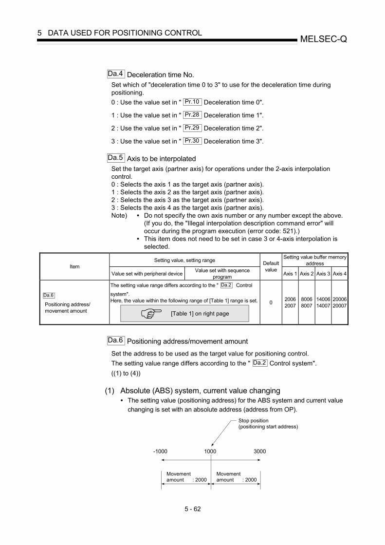
5 - 62
MELSEC-Q5 DATA USED FOR POSITIONING CONTROL
Da.4 Deceleration time No.
Set which of "deceleration time 0 to 3" to use for the deceleration time during positioning. 0 : Use the value set in " Pr.10 Deceleration time 0".
1 : Use the value set in " Pr.28 Deceleration time 1".
2 : Use the value set in " Pr.29 Deceleration time 2".
3 : Use the value set in " Pr.30 Deceleration time 3".
Da.5 Axis to be interpolated Set the target axis (partner axis) for operations under the 2-axis interpolation control. 0 : Selects the axis 1 as the target axis (partner axis). 1 : Selects the axis 2 as the target axis (partner axis). 2 : Selects the axis 3 as the target axis (partner axis). 3 : Selects the axis 4 as the target axis (partner axis). Note) • Do not specify the own axis number or any number except the above.
(If you do, the "Illegal interpolation description command error" will occur during the program execution (error code: 521).)
• This item does not need to be set in case 3 or 4-axis interpolation is selected.
Setting value, setting range Setting value buffer memory address Item
Value set with peripheral device Value set with sequence program
Default value
Axis 1 Axis 2 Axis 3 Axis 4
Da.6
Positioning address/ movement amount
The setting value range differs according to the " Da.2 Control
system". Here, the value within the following range of [Table 1] range is set.
[Table 1] on right page
0 2006 2007
8006 8007
1400614007
2000620007
Da.6 Positioning address/movement amount
Set the address to be used as the target value for positioning control. The setting value range differs according to the " Da.2 Control system". ((1) to (4))
(1) Absolute (ABS) system, current value changing
• The setting value (positioning address) for the ABS system and current value changing is set with an absolute address (address from OP).
-1000 30001000
Stop position (positioning start address)
Movement amount : 2000
Movement amount : 2000

5 - 63
MELSEC-Q5 DATA USED FOR POSITIONING CONTROL
(2) Incremental (INC) system, fixed-feed 1, fixed-feed 2, fixed-feed 3,
fixed-feed 4 • The setting value (movement amount) for the INC system is set as a
movement amount with sign. When movement amount is positive: Moves in the positive direction (address increment direction) When movement amount is negative: Moves in the negative direction (address decrement direction)
Stop position (positioning start position)
(Movement amount) -30000
(Movement amount) 30000
Moves in negative direction
Moves in positive direction
[Table 1]
When " Pr.1 Unit Setting" is "mm" The table below lists the control systems that require the setting of the positioning address or movement amount and the associated setting ranges. (With any control system excluded from the table below, neither the positioning address nor the movement amount needs to be set.)
Da.2 setting value Value set with peripheral device (μm)
Value set with sequence program 1 (×10-1μm)
ABS Linear 1 : 01H ABS Linear 2 : 0AH ABS Linear 3 : 15H ABS Linear 4 : 1AH Current value changing : 81H
◊ Set the address -214748364.8 to 214748364.7
◊ Set the address -2147483648 to 2147483647
INC Linear 1 : 02H INC Linear 2 : 0BH INC Linear 3 : 16H INC Linear 4 : 1BH Fixed-feed 1 : 03H Fixed-feed 2 : 0CH Fixed-feed 3 : 17H Fixed-feed 4 : 1CH
◊ Set the movement amount -214748364.8 to 214748364.7
◊ Set the movement amount -2147483648 to 2147483647
Forward run speed/position : 06H Reverse run speed/position : 07H Forward run position/speed : 08H Reverse run position/speed : 09H
◊ Set the movement amount 0 to 214748364.7
◊ Set the movement amount 0 to 2147483647
ABS circular sub : 0DH ABS circular right : 0FH ABS circular left : 10H
◊ Set the address -214748364.8 to 214748364.7
◊ Set the address -2147483648 to 2147483647
INC circular sub : 0EH INC circular right : 11H INC circular left : 12H
◊ Set the movement amount -214748364.8 to 214748364.7
◊ Set the movement amount -2147483648 to 2147483647
1: Set an integer because the sequence program cannot handle fractions. (The value will be converted properly within the system.)

5 - 64
MELSEC-Q5 DATA USED FOR POSITIONING CONTROL
(3) Speed-position switching control
• INC mode: Set the amount of movement after the switching from speed control to position control.
• ABS mode: Set the absolute address which will be the target value after speed control is switched to position control. (The unit is "degree" only)
Speed
Positioncontrol
Movement amount setting (INC mode)
Time
Speed-position switching
Speed control Target address setting (ABS mode)
(4) Position-speed switching control • Set the amount of movement before the switching from position control to
speed control.
When " Pr.1 Unit Setting" is "degree" The table below lists the control systems that require the setting of the positioning address or movement amount and the associated setting ranges. (With any control system excluded from the table below, neither the positioning address nor the movement amount needs to be set.)
Da.2 setting value Value set with peripheral device (degree)
Value set with sequence program 1 (×10-5 degree)
ABS Linear 1 : 01H ABS Linear 2 : 0AH ABS Linear 3 : 15H ABS Linear 4 : 1AH Current value changing : 81H
◊ Set the address 0 to 359.99999
◊ Set the address 0 to 35999999
INC Linear 1 : 02H INC Linear 2 : 0BH INC Linear 3 : 16H INC Linear 4 : 1BH Fixed-feed 1 : 03H Fixed-feed 2 : 0CH Fixed-feed 3 : 17H Fixed-feed 4 : 1CH
◊ Set the movement amount -21474.83648 to 21474.83647
◊ Set the movement amount -2147483648 to 2147483647
Forward run speed/position : 06H Reverse run speed/position : 07H
In INC mode ◊ Set the movement amount 0 to 21474.83647 In ABS mode ◊ Set the address 0 to 359.99999
In INC mode ◊ Set the movement amount 0 to 2147483647 In ABS mode ◊ Set the address 0 to 35999999
Forward run position/speed : 08H Reverse run position/speed : 09H
◊ Set the movement amount 0 to 21474.83647
◊ Set the movement amount 0 to 2147483647
1: Set an integer because the sequence program cannot handle fractions. (The value will be converted properly within the system.)

5 - 65
MELSEC-Q5 DATA USED FOR POSITIONING CONTROL
When " Pr.1 Unit Setting" is "pulse" The table below lists the control systems that require the setting of the positioning address or movement amount and the associated setting ranges. (With any control system excluded from the table below, neither the positioning address nor the movement amount needs to be set.)
Da.2 setting value Value set with peripheral device (pulse)
Value set with sequence program 1 (pulse)
ABS Linear 1 : 01H ABS Linear 2 : 0AH ABS Linear 3 : 15H ABS Linear 4 : 1AH Current value changing : 81H
◊ Set the address -2147483648 to 2147483647
◊ Set the address -2147483648 to 2147483647
INC Linear 1 : 02H INC Linear 2 : 0BH INC Linear 3 : 16H INC Linear 4 : 1BH Fixed-feed 1 : 03H Fixed-feed 2 : 0CH Fixed-feed 3 : 17H Fixed-feed 4 : 1CH
◊ Set the movement amount -2147483648 to 2147483647
◊ Set the movement amount -2147483648 to 2147483647
Forward run speed/position : 06H Reverse run speed/position : 07H Forward run position/speed : 08H Reverse run position/speed : 09H
◊ Set the movement amount 0 to 2147483647
◊ Set the movement amount 0 to 2147483647
ABS circular sub : 0DH ABS circular right : 0FH ABS circular left : 10H
◊ Set the address -2147483648 to 2147483647
◊ Set the address -2147483648 to 2147483647
INC circular sub : 0EH INC circular right : 11H INC circular left : 12H
◊ Set the movement amount -2147483648 to 2147483647
◊ Set the movement amount -2147483648 to 2147483647
1: Set an integer because the sequence program cannot handle fractions. (The value will be converted properly within the system.)

5 - 66
MELSEC-Q5 DATA USED FOR POSITIONING CONTROL
When " Pr.1 Unit Setting" is "inch" The table below lists the control systems that require the setting of the positioning address or movement amount and the associated setting ranges. (With any control system excluded from the table below, neither the positioning address nor the movement amount needs to be set.)
Da.2 setting value Value set with peripheral device (inch)
Value set with sequence program 1 (×10-5 inch)
ABS Linear 1 : 01H ABS Linear 2 : 0AH ABS Linear 3 : 15H ABS Linear 4 : 1AH Current value changing : 81H
◊ Set the address -21474.83648 to 21474.83647
◊ Set the address -2147483648 to 2147483647
INC Linear 1 : 02H INC Linear 2 : 0BH INC Linear 3 : 16H INC Linear 4 : 1BH Fixed-feed 1 : 03H Fixed-feed 2 : 0CH Fixed-feed 3 : 17H Fixed-feed 4 : 1CH
◊ Set the movement amount -21474.83648 to 21474.83647
◊ Set the movement amount -2147483648 to 2147483647
Forward run speed/position : 06H Reverse run speed/position : 07H Forward run position/speed : 08H Reverse run position/speed : 09H
◊ Set the movement amount 0 to 21474.83647
◊ Set the movement amount 0 to 2147483647
ABS circular sub : 0DH ABS circular right : 0FH ABS circular left : 10H
◊ Set the address -21474.83648 to 21474.83647
◊ Set the address -2147483648 to 2147483647
INC circular sub : 0EH INC circular right : 11H INC circular left : 12H
◊ Set the movement amount -21474.83648 to 21474.83647
◊ Set the movement amount -2147483648 to 2147483647
1: Set an integer because the sequence program cannot handle fractions. (The value will be converted properly within the system.)

5 - 67
MELSEC-Q5 DATA USED FOR POSITIONING CONTROL
MEMO

5 - 68
MELSEC-Q5 DATA USED FOR POSITIONING CONTROL
Setting value, setting range Setting value buffer memory address Item
Value set with peripheral device Value set with sequence program
Default value
Axis 1 Axis 2 Axis 3 Axis 4
Da.7
Arc address
The setting value range differs according to the " Da.2 Control
system". Here, the value within the [Table 1] range is set.
[Table 1] on right page
0 2008 2009
8008 8009
1400814009
2000820009
Da.7 Arc address
The arc address is data required only when carrying out circular interpolation control. (1) When carrying out circular interpolation with sub point designation, set the sub
point (passing point) address as the arc address. (2) When carrying out circular interpolation with center point designation, set the
center point address of the arc as the arc address.
End point address(Address set with Da.6 )
Sub point(Address set with Da.7 )
Start point address (Address before starting positioning) Start point address (Address before starting positioning)
Center point address(Address set with Da.7 )
End point address(Address set with Da.6 )
<(1) Circular interpolation with sub
point designation> <(2) Circular interpolation with center
point designation>
When not carrying out circular interpolation control, the value set in " Da.7 Arc address" will be invalid.
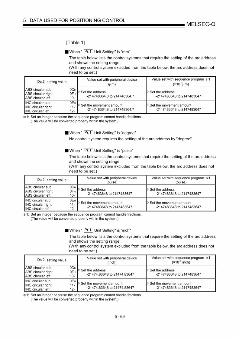
5 - 69
MELSEC-Q5 DATA USED FOR POSITIONING CONTROL
[Table 1]
When " Pr.1 Unit Setting" is "mm" The table below lists the control systems that require the setting of the arc address and shows the setting range. (With any control system excluded from the table below, the arc address does not need to be set.)
Da.2 setting value Value set with peripheral device (μm)
Value set with sequence program 1 (×10-1μm)
ABS circular sub : 0DH ABS circular right : 0FH ABS circular left : 10H
◊ Set the address -214748364.8 to 214748364.7
◊ Set the address -2147483648 to 2147483647
INC circular sub : 0EH INC circular right : 11H INC circular left : 12H
◊ Set the movement amount -214748364.8 to 214748364.7
◊ Set the movement amount -2147483648 to 2147483647
1: Set an integer because the sequence program cannot handle fractions. (The value will be converted properly within the system.)
When " Pr.1 Unit Setting" is "degree" No control system requires the setting of the arc address by "degree".
When " Pr.1 Unit Setting" is "pulse" The table below lists the control systems that require the setting of the arc address and shows the setting range. (With any control system excluded from the table below, the arc address does not need to be set.)
Da.2 setting value Value set with peripheral device (pulse)
Value set with sequence program 1 (pulse)
ABS circular sub : 0DH ABS circular right : 0FH ABS circular left : 10H
◊ Set the address -2147483648 to 2147483647
◊ Set the address -2147483648 to 2147483647
INC circular sub : 0EH INC circular right : 11H INC circular left : 12H
◊ Set the movement amount -2147483648 to 2147483647
◊ Set the movement amount -2147483648 to 2147483647
1: Set an integer because the sequence program cannot handle fractions. (The value will be converted properly within the system.)
When " Pr.1 Unit Setting" is "inch" The table below lists the control systems that require the setting of the arc address and shows the setting range. (With any control system excluded from the table below, the arc address does not need to be set.)
Da.2 setting value Value set with peripheral device (inch)
Value set with sequence program 1 (×10-5 inch)
ABS circular sub : 0DH ABS circular right : 0FH ABS circular left : 10H
◊ Set the address -21474.83648 to 21474.83647
◊ Set the address -2147483648 to 2147483647
INC circular sub : 0EH INC circular right : 11H INC circular left : 12H
◊ Set the movement amount -21474.83648 to 21474.83647
◊ Set the movement amount -2147483648 to 2147483647
1: Set an integer because the sequence program cannot handle fractions. (The value will be converted properly within the system.)

5 - 70
MELSEC-Q5 DATA USED FOR POSITIONING CONTROL
Setting value, setting range Setting value buffer memory address Item
Value set with peripheral device Value set with sequence program
Default value
Axis 1 Axis 2 Axis 3 Axis 4
The setting value range differs depending on the " Pr.1 Unit setting". Here, the value within the [Table 1] range is set.
[Table 1] on right page
Da.8
Command speed
-1: Current speed (Speed set for previous positioning data No.)
-1
0 2004 2005
8004 8005
1400414005
2000420005
Dwell time Da.9
Dwell time/ JUMP destination positioning data No.
JUMP destination positioning data No.
The setting value range differs according to the " Da.2 Control system". Here, the value within the [Table 2] range is set.
[Table 2] on right page
0 2002 8002 14002 20002
M code
Condition data No.
Da.10
M code No. of LOOP to LEND repetitions
The setting value range differs according to the " Da.2 Control system". Here, the value within the [Table 3] range is set.
[Table 3] on right page
0 2001 8001 14001 20001
Da.8 Command speed
Set the command speed for positioning. (1) If the set command speed exceeds " Pr.8 Speed limit value", positioning will
be carried out at the speed limit value. (2) If "-1" is set for the command speed, the current speed (speed set for previous
positioning data No.) will be used for positioning control. Use the current speed for uniform speed control, etc. If "-1" is set for continuing positioning data, and the speed is changed, the following speed will also change. (Note that when starting positioning, if the "-1" speed is set for the positioning data that carries out positioning control first, the error "No command speed" (error code: 503) will occur, and the positioning will not start. Refer to Section 15.2 "List of errors" for details on the errors.)

5 - 71
MELSEC-Q5 DATA USED FOR POSITIONING CONTROL
Da.10 M code (or condition data No./No. of LOOP to LEND repetitions)
Set an "M code", a "condition data No. ", or the "number of LOOP to LEND repetitions" depending on how the " Da.2 Control system" is set.
• If a method other than "JUMP instruction" and "LOOP" is selected as the " Da.2 Control system" ............... Set an "M code".
If no "M code" needs to be output, set "0" (default value). • If "JUMP instruction" or "LOOP" is selected as the " Da.2 Control system"
............... Set the "condition data No." for JUMP. 0 : Unconditional JUMP to the positioning data specified
by Da.9 . 1 to 10 : JUMP performed according to the condition data No.
specified (a number between 1 and 10). Make sure that you specify the number of LOOP to LEND repetitions by a number other than "0". The "Control system LOOP setting error" will occur if you specify "0". (error code: 545)
The condition data specifies the condition for the JUMP instruction to be executed. (A JUMP will take place when the condition is satisfied.)
[Table 1]
Pr.1 setting value Value set with peripheral device
(unit) Value set with sequence program
(unit)
0 : mm 0.01 to 20000000.00 (mm/min) 1 to 2000000000 (×10-2mm/min)
1 : inch 0.001 to 2000000.000 (inch/min) 1 to 2000000000 (×10-3inch/min)
2 : degree 0.001 to 2000000.000 (degree/min) 1 to 2000000000 (×10-3degree/min)
3 : pulse 1 to 1000000 (pulse/s) 1 to 1000000 (pulse/s)
[Table 2]
Da.2 setting value Setting item Value set with peripheral
device Value set with sequence
program JUMP instruction: 82H Positioning data No. 1 to 600 1 to 600 Other than JUMP instruction Dwell time 0 to 65535 (ms) 0 to 65535 (ms)
[Table 3]
Da.2 setting value Setting item Value set with peripheral
device Value set with sequence
program JUMP instruction: 82H Condition data No. 0 to 10 0 to 10 Other than JUMP instruction M code 0 to 65535 0 to 65535 LOOP: 83H Repetition count 1 to 65535 1 to 65535
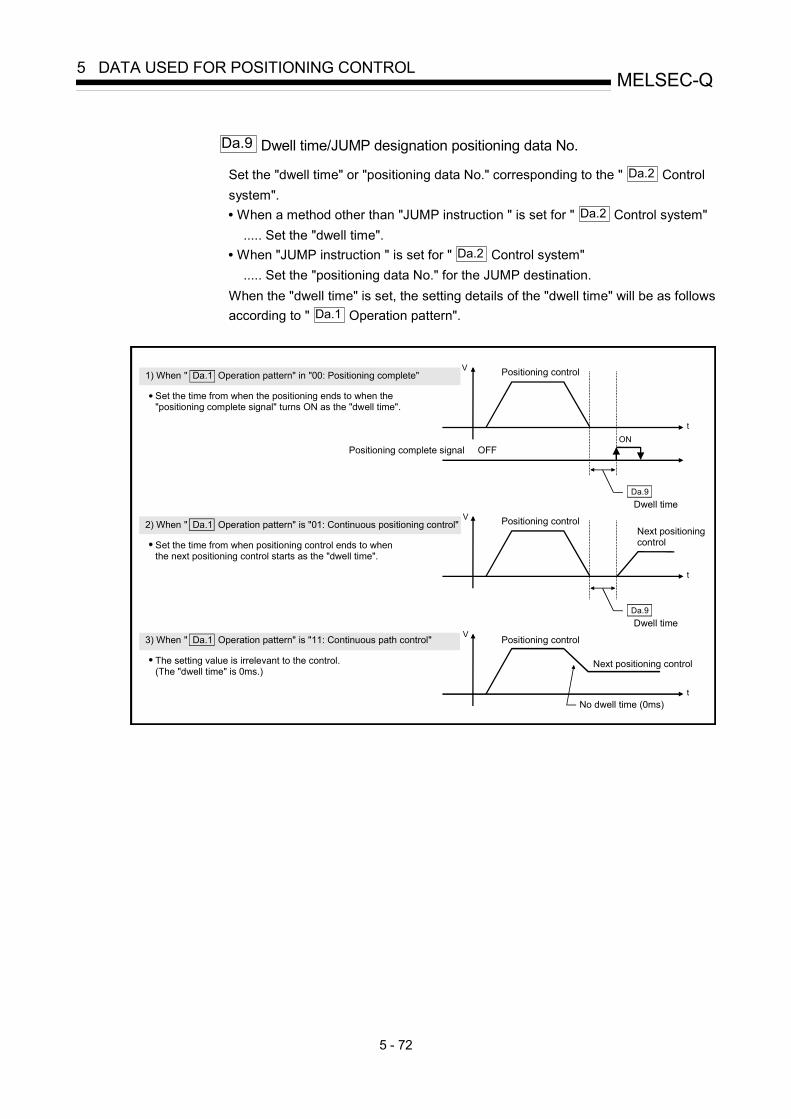
5 - 72
MELSEC-Q5 DATA USED FOR POSITIONING CONTROL
Da.9 Dwell time/JUMP designation positioning data No.
Set the "dwell time" or "positioning data No." corresponding to the " Da.2 Control system". • When a method other than "JUMP instruction " is set for " Da.2 Control system" ..... Set the "dwell time". • When "JUMP instruction " is set for " Da.2 Control system" ..... Set the "positioning data No." for the JUMP destination. When the "dwell time" is set, the setting details of the "dwell time" will be as follows according to " Da.1 Operation pattern".
ON
V
t
V
t
V
t
1) When " Da.1 Operation pattern" in "00: Positioning complete"
Set the time from when the positioning ends to when the "positioning complete signal" turns ON as the "dwell time".
Positioning control
Positioning complete signal OFF
2) When " Da.1 Operation pattern" is "01: Continuous positioning control"
Set the time from when positioning control ends to when the next positioning control starts as the "dwell time".
Next positioning control
3) When " Da.1 Operation pattern" is "11: Continuous path control"
The setting value is irrelevant to the control.(The "dwell time" is 0ms.)
No dwell time (0ms)
Positioning control
Positioning control
Dwell timeDa.9
Dwell timeDa.9
Next positioning control

5 - 73
MELSEC-Q5 DATA USED FOR POSITIONING CONTROL
MEMO

5 - 74
MELSEC-Q5 DATA USED FOR POSITIONING CONTROL
5.4 List of block start data
The illustrations below show the organization of the block start data stored in the QD75 buffer memory. The block start data setting items Da.11 to Da.14 are explained in
the pages that follow.
Setting itemBuffer memoryaddress
26049
26099
�œ Ê̂ ’u Œ̂ ‚ß Žn “® ƒf �[ ƒ̂
26001
26051
b15 b0b7b8
Da.11 ShapeDa.12 Start data No.
26000
b15 b0b7b8
Da.13 Special start instruction
Da.14 Parameter
26050
Buffer memoryaddressBuffer memory
address
Setting item
Setting item
1st point2nd point
50th point
Axi
s 1
(Sta
rt bl
ock
0)
27049
27099
27001
27051
�œ Ê̂ ’u Œ̂ ‚ß Žn “® ƒf �[ ƒ̂
b15 b0b7b8
Da.11 ShapeDa.12 Start data No.
27000
b15 b0b7b8
Da.13 Special start instruction
Da.14 Parameter
27050
Setting itemBuffer memoryaddress
Buffer memoryaddressBuffer memory
address
Setting item
Setting item
1st point2nd point
50th point
Axi
s 2
(Sta
rt bl
ock
0)
Up to 50 block start data points can be set(stored) for each axis in the buffer memoryaddresses shown on the left.Items in a single unit of block start data areshown included in a bold frame.Each axis has five start blocks (block Nos.0 to 4).
For information on the organization of thebuffer memory addresses assigned to thestart blocks 1 to 4, refer to Appendix 12 "List of buffer memory addresses".

5 - 75
MELSEC-Q5 DATA USED FOR POSITIONING CONTROL
Setting itemBuffer memoryaddress
28049
28099
�œ Ê̂ ’u Œ̂ ‚ß Žn “® ƒf �[ ƒ̂
28001
28051
b15 b0b7b8
Da.11 ShapeDa.12 Start data No.
28000
b15 b0b7b8
Da.13 Special start instruction
Da.14 Parameter
28050
Buffer memoryaddressBuffer memory
address
Setting item
Setting item
1st point2nd point
50th pointA
xis
3 (S
tart
bloc
k 0)
29049
29099
29001
29051
�œ Ê̂ ’u Œ̂ ‚ß Žn “® ƒf �[ ƒ̂
b15 b0b7b8
Da.11 ShapeDa.12 Start data No.
29000
b15 b0b7b8
Da.13 Special start instruction
Da.14 Parameter
29050
Setting itemBuffer memoryaddress
Buffer memoryaddressBuffer memory
address
Setting item
Setting item
1st point2nd point
50th point
Axi
s 4
(Sta
rt bl
ock
0)
The pages that follow explain the block start data setting items ( Da.11 to Da.14 ).
(The buffer memory addresses shown are those of the "1st point block start data (block No. 7000)" for the axes 1 to 4.)

5 - 76
MELSEC-Q5 DATA USED FOR POSITIONING CONTROL
REMARK
To perform an high-level positioning control using block start data, set a number between 7000 and 7004 to the " Cd.3 Positioning start No." and use the
" Cd.4 Positioning starting point No." to specify a point number between 1 and 50, a
position counted from the beginning of the block. The number between 7000 and 7004 specified here is called the "block No.". With the QD75, up to 50 "block start data" points and up to 10 "condition data" items can be assigned to each "block No.".
Block No. Axis Block start data Condition Buffer memory
GX Configurator-
QP Axis 1 Condition data (1 to 10)Axis 2 Condition data (1 to 10)Axis 3 Condition data (1 to 10)
7000
Axis 4
Start block 0
Condition data (1 to 10)Axis 1 Condition data (1 to 10)Axis 2 Condition data (1 to 10)Axis 3 Condition data (1 to 10)
7001
Axis 4
Start block 1
Condition data (1 to 10)Axis 1 Condition data (1 to 10)Axis 2 Condition data (1 to 10)Axis 3 Condition data (1 to 10)
7002
Axis 4
Start block 2
Condition data (1 to 10)Axis 1 Condition data (1 to 10)Axis 2 Condition data (1 to 10)Axis 3 Condition data (1 to 10)
7003
Axis 4
Start block 3
Condition data (1 to 10)Axis 1 Condition data (1 to 10)Axis 2 Condition data (1 to 10)Axis 3 Condition data (1 to 10)
7004
Axis 4
Start block 4
Condition data (1 to 10)
Supports the settings
Supports the settings
: Setting cannot be made when the "Pre-reading start function" is used. If you set any of Nos.
7000 to 7004 and perform the Pre-reading start function, "Outside start No. range error (error code: 543)" will occur. (For details, refer to Section 12.7.8 "Pre-reading start function".)

5 - 77
MELSEC-Q5 DATA USED FOR POSITIONING CONTROL
Setting value Setting value buffer memory address Item
Value set with peripheral device Value set with sequence program
Default value
Axis 1 Axis 2 Axis 3 Axis 4
0 : End 0
Da.11
Shape
1 : Continue 1
Da.12
Start data No.
Positioning data No.: 1 to 600 (01H to 258H)
01H to
258H
b15 b0b3b7b110 0 0
0000H 26000 27000 28000 29000
0 : Block start (normal start) 00H
1 : Condition start 01H
2 : Wait start 02H
3 : Simultaneous start 03H
4 : FOR loop 04H
5 : FOR condition 05H
Da.13
Special start instruction
6 : NEXT start 06H
Da.14
Parameter
Condition data No.: 1 to 10 (01H to 0AH)
No. of repetitions: 0 to 255 (00H to FFH)
00H to
FFH
b15 b11 b7 b0b3
Special start instruction
Parameter
0000H 26050 27050 28050 29050

5 - 78
MELSEC-Q5 DATA USED FOR POSITIONING CONTROL
Da.11 Shape
Set whether to carry out only the local "block start data" and then end control, or to execute the "block start data" set in the next point.
Setting value Setting details 0 : End Execute the designated point's "block start data", and then complete the control.
1 : Continue Execute the designated point's "block start data", and after completing control, execute the next point's "block start data".
Da.12 Start data No.
Set the "positioning data No." designated with the "block start data".
Da.13 Special start instruction
Set the "special start instruction " for using "high-level positioning control". (Set how to start the positioning data set in " Da.12 Start data No.".)
Setting value Setting details
00H : Block start (Normal start) Execute the random block positioning data in the set order with one start.
01H : Condition start Carry out the condition judgment set in "condition data" for the designated positioning data, and when the conditions are established, execute the "block start data". If not established, ignore that "block start data", and then execute the next point's "block start data".
02H : Wait start Carry out the condition judgment set in "condition data" for the designated positioning data, and when the conditions are established, execute the "block start data". If not established, stop the control (wait) until the conditions are established.
03H : Simultaneous start
Simultaneous execute (output pulses at same timing) the positioning data with the No. designated for the axis designated in the "condition data". Up to four axes can start simultaneously.
04H : Repeated start (FOR loop)
Repeat the program from the block start data with the "FOR loop" to the block start data with "NEXT" for the designated No. of times.
05H : Repeated start (FOR condition)
Repeat the program from the block start data with the "FOR condition" to the block start data with "NEXT" until the conditions set in the "condition data" are established.
06H : NEXT start Set the end of the repetition when "05H: Repetition start (FOR loop)" or "06H: Repetition start (FOR condition)" is set.
Refer to Chapter 10 "High-level Positioning Control" for details on the control.

5 - 79
MELSEC-Q5 DATA USED FOR POSITIONING CONTROL
Da.14 Parameter
Set the value as required for " Da.13 Special start instruction ".
Da.13 Special start instruction Setting value Setting details
Block start (Normal start) – Not used. (There is no need to set.)
Condition start
Wait start
Simultaneous start
1 to 10
Set the condition data No. (No. of "condition data" set to perform condition judgment) (For details of the condition data, refer to Section 5.5.)
Repeated start (FOR loop) 0 to 255 Set the No. of repetitions.
Repeated start (FOR condition) 1 to 10
Set the condition data No. (No. of "condition data" set to perform condition judgment) (For details of the condition data, refer to Section 5.5.)

5 - 80
MELSEC-Q5 DATA USED FOR POSITIONING CONTROL
5.5 List of condition data
The illustrations below show the organization of the condition data stored in the QD75 buffer memory. The condition data setting items Da.15 to Da.19 are explained in the
pages that follow.
No.10
Setting item
26190
261912619226193261942619526196261972619826199
No.2
Setting item
26110
261112611226113261142611526116261172611826119
Buffer memoryaddress
Buffer memoryaddress
No.1
Setting item
26100
Da.17 Address
Open
Da.18 Parameter 1
Da.19 Parameter 2
b15 b0b7b8b11b12
Da.16 Condition operator
Da.15 Condition target
261012610226103261042610526106261072610826109
Buffer memoryaddress
Axi
s 1
(sta
rt bl
ock
0)
Open
Up to 10 block start data points can be set (stored)for each axis in the buffer memory addresses shownon the left.Items in a single unit of condition data are shownincluded in a bold frame.Each axis has five start blocks (block Nos. 0 to 4).
For information on the organization of the buffermemory addresses assigned to the start blocks 1to 4, refer to Appendix 12 "List of buffer memoryaddresses".
No.10
Setting itemNo.2
27190
271912719227193271942719527196271972719827199
27110
271112711227113271142711527116271172711827119
Setting itemNo.1
Setting item
27100
Da.17 AddressOpen
Open
Da.18 Parameter 1
Da.19 Parameter 2
b15 b0b7b8b11b12
Da.16 Condition operator
Da.15 Condition target
271012710227103271042710527106271072710827109
Buffer memoryaddress
Axi
s 2
(sta
rt bl
ock
0)
Buffer memoryaddress
Buffer memoryaddress

5 - 81
MELSEC-Q5 DATA USED FOR POSITIONING CONTROL
No.10
Setting itemNo.2
28190
281912819228193281942819528196281972819828199
28110
281112811228113281142811528116281172811828119
Setting itemNo.1
Setting item
28100
Da.17 AddressOpen
Da.18 Parameter 1
Da.19 Parameter 2
b15 b0b7b8b11b12
Da.16 Condition operator
Da.15 Condition target
281012810228103281042810528106281072810828109
Buffer memoryaddress
Axis
3 (s
tart
bloc
k 0)
Buffer memoryaddress
Buffer memoryaddress
Open
No.10
Setting itemNo.2
29190
291912919229193291942919529196291972919829199
29110
291112911229113291142911529116291172911829119
Setting itemNo.1
Setting item
29100
Da.17 AddressOpen
Da.18 Parameter 1
Da.19 Parameter 2
b15 b0b7b8b11b12
Da.16 Condition operator
Da.15 Conditiion target
291012910229103291042910529106291072910829109
Buffer memoryaddress
Axis
4 (s
tart
bloc
k 0)
Buffer memoryaddress
Buffer memoryaddress
Open
The pages that follow explain the condition data setting items ( Da.15 to Da.19 ).
(The buffer memory addresses shown are those of the "condition data No. 1 (block No. 7000)" for the axes 1 to 4.)

5 - 82
MELSEC-Q5 DATA USED FOR POSITIONING CONTROL
REMARK
To perform an high-level positioning control using block start data, set a number between 7000 and 7004 to the " Cd.3 Positioning start No." and use the
" Cd.4 Positioning starting point No." to specify a point number between 1 and 50, a
position counted from the beginning of the block. The number between 7000 and 7004 specified here is called the "block No.". With the QD75, up to 50 "block start data" points and up to 10 "condition data" items can be assigned to each "block No.".
Block No. Axis Block start data Condition Buffer memory
GX Configurator-
QP Axis 1 Condition data (1 to 10)Axis 2 Condition data (1 to 10)Axis 3 Condition data (1 to 10)
7000
Axis 4
Start block 0
Condition data (1 to 10)Axis 1 Condition data (1 to 10)Axis 2 Condition data (1 to 10)Axis 3 Condition data (1 to 10)
7001
Axis 4
Start block 1
Condition data (1 to 10)Axis 1 Condition data (1 to 10)Axis 2 Condition data (1 to 10)Axis 3 Condition data (1 to 10)
7002
Axis 4
Start block 2
Condition data (1 to 10)Axis 1 Condition data (1 to 10)Axis 2 Condition data (1 to 10)Axis 3 Condition data (1 to 10)
7003
Axis 4
Start block 3
Condition data (1 to 10)Axis 1 Condition data (1 to 10)Axis 2 Condition data (1 to 10)Axis 3 Condition data (1 to 10)
7004
Axis 4
Start block 4
Condition data (1 to 10)
Supports the settings
Supports the settings
: Setting cannot be made when the "Pre-reading start function" is used. If you set any of Nos. 7000 to 7004 and perform the Pre-reading start function, "Outside start No. range error (error code: 543)" will occur. (For details, refer to Section 12.7.8 "Pre-reading start function".)

5 - 83
MELSEC-Q5 DATA USED FOR POSITIONING CONTROL
Setting value Setting value buffer memory address Item
Value set with peripheral device Value set with sequence program
Default value
Axis 1 Axis 2 Axis 3 Axis 401 : Device X 01H
02 : Device Y 02H
03 : Buffer memory (1-word) 03H
04 : Buffer memory (2-word) 04H
Da.15
Condition target
05 : Positioning data No. 05H
01 : ∗∗=P1 01H
02 : ∗∗≠P1 02H
03 : ∗∗≤P1 03H
04 : ∗∗≥P1 04H
05 : P1≤∗∗≤ P2 05H
06 : ∗∗≤P1, P2≤∗∗ 06H
07 : DEV=ON 07H
08 : DEV=OFF 08H
10: Axis 1 selected 10H
20: Axis 2 selected 20H
30: Axes 1 and 2 selected 30H
40: Axis 3 selected 40H
50: Axes 1 and 3 selected 50H
60: Axes 2 and 3 selected 60H
70: Axes 1, 2, and 3 selected 70H
80: Axis 4 selected 80H
90: Axes 1 and 4 selected 90H
A0: Axes 2 and 4 selected A0H
B0: Axes 1, 2, and 4 selected B0H
C0: Axes 3 and 4 selected C0H
D0: Axes 1, 3, and 4 selected D0H
Con
ditio
n id
entif
ier
Da.16
Condition operator
E0: Axes 2, 3, and 4 selected E0H
b15 b0b7b8
Condition operator
Condition target
0000H 26100 27100 28100 29100
Da.17
Address Buffer memory address b0b15b16b31
26103 26102Example)
(High-order) (Low-order)
Buffer memory address
0000H 26102 26103
27102 27103
2810228103
2910229103
Da.18
Parameter 1 Value b0b15b16b31
26105 26104Example)
(High-order) (Low-order)
Value
0000H 26104 26105
27104 27105
2810428105
2910429105
Da.19
Parameter 2 Value b0b15b16b31
26107 26106Example)
(High-order) (Low-order)
Value
0000H 26106 26107
27106 27107
2810628107
2910629107

5 - 84
MELSEC-Q5 DATA USED FOR POSITIONING CONTROL
Da.15 Condition target
Set the condition target as required for each control. Setting value Setting details
01H : Device X 02H : Device Y
Set the input/output signal ON/OFF as the conditions.
03H : Buffer memory (1-word)
04H : Buffer memory (2-word)
Set the value stored in the buffer memory as the condition. 03H: The target buffer memory is "1-word (16 bits)" 04H: The target buffer memory is "2-word (32 bits)"
05H : Positioning data No. Select only for "simultaneous start".
Da.16 Condition operator Set the condition operator as required for the " Da.15 Condition target".
Da.15 Condition target Setting value Setting details
07H : DEV=ON 01H: Device X 02H: Device Y 08H : DEV=OFF
The state (ON/OFF) of an I/O signal is defined as the condition. Select ON or OFF as the trigger.
01H : ∗∗=P1 02H : ∗∗≠P1 03H : ∗∗≤P1 04H : ∗∗≥P1 05H : P1≤∗∗≤P2
03H: Buffer memory (1-word) 04H: Buffer memory (2-word)
06H : ∗∗≤P1, P2≤∗∗
Select how to use the value (∗∗) in the buffer memory as a part of the condition.
10H : Axis 1 selected 20H : Axis 2 selected 30H : Axes 1 and 2 selected 40H : Axis 3 selected 50H : Axes 1 and 3 selected 60H : Axes 2 and 3 selected 70H : Axes 1, 2, and 3 selected 80H : Axis 4 selected 90H : Axes 1 and 4 selected A0H : Axes 2 and 4 selected B0H : Axes 1, 2, and 4 selected C0H : Axes 3 and 4 selected D0H : Axes 1, 3, and 4 selected
05H: Positioning data No.
E0H : Axes 2, 3, and 4 selected
If "simultaneous start" is specified, select the axis (or axes) that should start simultaneously.
Da.17 Address Set the address as required for the " Da.15 Condition target".
Da.15 Condition target Setting value Setting details
01H : Device X 02H : Device Y
– Not used. (There is no need to set.)
03H : Buffer memory (1-word)
04H : Buffer memory (2-word) Value
(Buffer memory address)
Set the target "buffer memory address". (For 2 word, set the low-order buffer memory address.)
05H : Positioning data No. – Not used. (There is no need to set.)
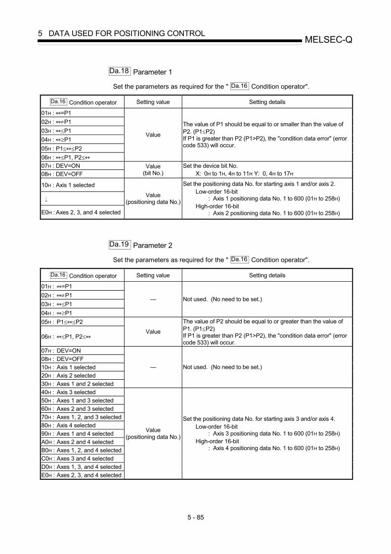
5 - 85
MELSEC-Q5 DATA USED FOR POSITIONING CONTROL
Da.18 Parameter 1
Set the parameters as required for the " Da.16 Condition operator".
Da.16 Condition operator Setting value Setting details
01H : ∗∗=P1 02H : ∗∗≠P1 03H : ∗∗≤P1 04H : ∗∗≥P1 05H : P1≤∗∗≤P2 06H : ∗∗≤P1, P2≤∗∗
Value
The value of P1 should be equal to or smaller than the value of P2. (P1≤P2) If P1 is greater than P2 (P1>P2), the "condition data error" (error code 533) will occur.
07H : DEV=ON 08H : DEV=OFF
Value (bit No.)
Set the device bit No. X: 0H to 1H, 4H to 11H Y: 0, 4H to 17H
10H : Axis 1 selected
E0H : Axes 2, 3, and 4 selected
Value (positioning data No.)
Set the positioning data No. for starting axis 1 and/or axis 2. Low-order 16-bit
: Axis 1 positioning data No. 1 to 600 (01H to 258H) High-order 16-bit
: Axis 2 positioning data No. 1 to 600 (01H to 258H)
Da.19 Parameter 2
Set the parameters as required for the " Da.16 Condition operator".
Da.16 Condition operator Setting value Setting details
01H : ∗∗=P1 02H : ∗∗≠P1 03H : ∗∗≤P1 04H : ∗∗≥P1
— Not used. (No need to be set.)
05H : P1≤∗∗≤P2
06H : ∗∗≤P1, P2≤∗∗ Value
The value of P2 should be equal to or greater than the value of P1. (P1≤P2) If P1 is greater than P2 (P1>P2), the "condition data error" (error code 533) will occur.
07H : DEV=ON 08H : DEV=OFF 10H : Axis 1 selected 20H : Axis 2 selected 30H : Axes 1 and 2 selected
— Not used. (No need to be set.)
40H : Axis 3 selected 50H : Axes 1 and 3 selected 60H : Axes 2 and 3 selected 70H : Axes 1, 2, and 3 selected 80H : Axis 4 selected 90H : Axes 1 and 4 selected A0H : Axes 2 and 4 selected B0H : Axes 1, 2, and 4 selected C0H : Axes 3 and 4 selected D0H : Axes 1, 3, and 4 selected E0H : Axes 2, 3, and 4 selected
Value (positioning data No.)
Set the positioning data No. for starting axis 3 and/or axis 4. Low-order 16-bit
: Axis 3 positioning data No. 1 to 600 (01H to 258H) High-order 16-bit
: Axis 4 positioning data No. 1 to 600 (01H to 258H)

5 - 86
MELSEC-Q5 DATA USED FOR POSITIONING CONTROL
5.6 List of monitor data
5.6.1 System monitor data
Storage item Storage details
Md.1 In test mode flag
Whether the mode is the test mode from the peripheral device or not is stored.• When not in test mode : OFF• When in test mode : ON

5 - 87
MELSEC-Q5 DATA USED FOR POSITIONING CONTROL
Reading the monitor value Default value
Storage buffermemory address
(common for axis 1 toaxis 4)
Monitoring is carried out with a decimal.
Storage value 0: Not in test mode 1: In test mode
Monitor value 0 1200
(Unless noted in particular, the monitor value is saved as binary data.)

5 - 88
MELSEC-Q5 DATA USED FOR POSITIONING CONTROL
Storage item Storage details Reading the monitor value
Md.3
Startinformation
[Storage details] This area stores the start information (restart flag, start origin, and startaxis):
• Restart flag: Indicates whether the operation has or has not beenhalted and restarted.
• Start origin : Indicates the source of the start signal.• Start axis : Indicates the started axis.
[Reading the monitor value] Monitoring is carried out with a hexadecimal display.
Not used
0 0 0 0 0
b15 b12 b8 b4 b0
Buffermemory
Monitorvalue
PLC CPU
Stored contents Storage value
00
01
10
External signal
Peripheral device
Start origin
Restart flag OFF
0
1Restart flag ON
Restart flag
3
Axis 1
Axis 2
Axis 3
Axis 4
Start axis
1
2
4
Stored contents Storage value
Stored contents Storage value
Md.4
Start No.The starting No. is stored.
Monitoring is carried out with a hexadecimal display.
Simultaneous start 2 3 2 C 9004
JOG operation 2 3 3 2 9010
Machine OPR
2 3 3 3 9011Manual pulse generator
2 3 2 9 9001
Fast OPR 2 3 2 A 9002
Current value changing 2 3 2 B 9003
b15 b12 b8 b4 b0
A B C D
BA C D
Buffermemory
Monitor value
DCBA
Positioning operation
Stored contentsStorage value Reference
(Decimal)
Start No.
A
0 0 0to
B C D
1 001
1 B 5 8
0 2 5 8
7000
1 B 5 9 7001
1 B 5 A 7002
1 B 5 B 7003
1 B 5 C 7004
600
Md.5
Start
(Hour)
The starting time is stored.
Monitoring is carried out with a hexadecimal display.
Not used
0b15 b12
0 0 0 0 0 0 0 0 0 0 1 0 1 0 1b8 b4 b0
0 1 50
Buffer memory (stored with BCD code)
0 0 0 to 200 to 23 (hour)
0 to 3
Monitor value
00 1 5
Sta
rtin
g hi
stor
y (U
p to
16
reco
rds
can
be s
tore
d)
Md.6
Start
(Minute:second)
The starting time is stored.
Monitoring is carried out with a hexadecimal display.
0 to 500 to 59 (second)
0b15 b12
1 0 0 1 0 0 1 0 0 0 0 0 1 1 1b8 b4 b0
9 0 74
Buffer memory (stored with BCD code)
0 to 5 0 to 900 to 59 (minute)
0 to 9
Monitor value
94 0 7
Note: If a start signal is issued against an operating axis, a record relating to this event may be output before a
record relating to an earlier start signal is output.

5 - 89
MELSEC-Q5 DATA USED FOR POSITIONING CONTROL
Default value Storage buffer memory address (common to axes 1 to 4)
0000H
0000H
0000
0000
1287
15
1288
1289
1290
1291
14
1282
1283
1284
1285
1286
13
1277
1278
1279
1280
1281
12
1272
1273
1274
1275
1276
11
1267
1268
1269
1270
1271
10
1262
1263
1264
1265
1266
9
1257
1258
1259
1260
1261
8
1252
1253
1254
1255
1256
7
1247
1248
1249
1250
1251
6
1242
1243
1244
1245
1246
5
1237
1238
1239
1240
1241
4
1232
1233
1234
1235
1236
3
1227
1228
1229
1230
1231
2
1222
1223
1224
1225
1226
1
1217
1218
1219
1220
1221
Pointer No. 0
Pointer No.
Item Buffer memory address
1212
1213
1214
1215
1216
Sta
rtin
g h
isto
ry
Md.3
Start information
Md.4
Start No.
1292Md.8
Start history pointer
Md.5
Start hour
Md.6
Start min: sec
Md.7
Error judgement
Indicates a pointer No. that is next to the Pointer No.
assigned to the latest of the existing starting history records.
Each group of buffer memory addresses storing a complete starting history
record is assigned a pointer No.
Example: Pointer No. 0 = Buffer memory addresses 1212 to 1216
Pointer No. 1 = Buffer memory addresses 1217 to 1221
Pointer No. 2 = Buffer memory addresses 1222 to 1226
Pointer No. 15 = Buffer memory addresses 1287 to 1291
Each history record is assigned a pointer No. in the range between 0 and 15.
If the pointer No. 15 has been assigned to a new record, the next record will
be assigned the pointer number 0.
(A new record replaces an older record when a pointer No. is reassigned.)

5 - 90
MELSEC-Q5 DATA USED FOR POSITIONING CONTROL
Storage item Storage details Reading the monitor value
Md.7
Errorjudgment
[Storage details] This area stores the following results of the error judgment performedupon starting:
• BUSY start warning flag• Error flag• Error No.
[Reading the monitor value] Monitoring is carried out with a hexadecimal display.
b15 b12 b8 b4 b0
A B C D
Ba C D
Buffer memory
Monitor value
DCBA
Error flag OFF
Stored contents Storage value
0
1Error flag ON
Error flag Error No.Convert the hexadecimal value "a, B, C, D" into a decimal value andmatch it with "15.2 List of errors".
BUSY startwarning OFF
Stored contents Storage value
0
1BUSY startwarning ON
BUSY start warning flag
Sta
rtin
g hi
stor
y (U
p to
16
reco
rds
can
be s
tore
d)
Md.8
Start historypointer
Indicates a pointer No. thatis next to the Pointer No.assigned to the latest of theexisting starting historyrecords.
Monitoring is carried out with a decimal display.
Monitor value
Storage value (Pointer number)0 to 15

5 - 91
MELSEC-Q5 DATA USED FOR POSITIONING CONTROL
Default value Storage buffer memory address (common to axes 1 to 4)
0000H
1287
15
1288
1289
1290
1291
14
1282
1283
1284
1285
1286
13
1277
1278
1279
1280
1281
12
1272
1273
1274
1275
1276
11
1267
1268
1269
1270
1271
10
1262
1263
1264
1265
1266
9
1257
1258
1259
1260
1261
8
1252
1253
1254
1255
1256
7
1247
1248
1249
1250
1251
6
1242
1243
1244
1245
1246
5
1237
1238
1239
1240
1241
4
1232
1233
1234
1235
1236
3
1227
1228
1229
1230
1231
2
1222
1223
1224
1225
1226
1
1217
1218
1219
1220
1221
Pointer No. 0
Pointer No.
Item Buffer memory address
1212
1213
1214
1215
1216
Sta
rtin
g h
istr
oy
Md.3
Start information
Md.4
Start No.
1292Md.8
Start history pointer
Md.5
Start hour
Md.6
Start min: sec
Md.7
Error judgement
Indicates a pointer No. that is next to the Pointer No.
assigned to the latest of the existing starting history records.
Each group of buffer memory addresses storing a complete starting history
record is assigned a pointer No.
Example: Pointer No. 0 = Buffer memory addresses 1212 to 1216
Pointer No. 1 = Buffer memory addresses 1217 to 1221
Pointer No. 2 = Buffer memory addresses 1222 to 1226
Pointer No. 15 = Buffer memory addresses 1287 to 1291
Each history record is assigned a pointer No. in the range between 0 and 15.
If the pointer No. 15 has been assigned to a new record, the next record will
be assigned the pointer number 0.
(A new record replaces an older record when a pointer No. is reassigned.)
0 1292

5 - 92
MELSEC-Q5 DATA USED FOR POSITIONING CONTROL
Storage item Storage details Reading the monitor value
Md.9
Axis in whichthe erroroccurred
Stores a number (Axis No.)that indicates the axis thatencountered an error.
Monitoring is carried out with a decimal display.
Monitorvalue
Storage value1: Axis 12: Axis 23: Axis 34: Axis 4
Md.10
Axis error No.Stores an axis error No.
Monitoring is carried out with a decimal display.
Monitor value Error No.For details on the error Nos.(Error codes),refer to Section 15.2 "List of errors".
Md.11
Axis erroroccurrence
(Hour)
Stores the time at which anaxis error was detected.
Monitoring is carried out with a hexadecimal display.
0b15 b12
0 0 0 0 0 0 0 0 0 0 1 0 1 0 1b8 b4 b0
0 1 50
Buffer memory (stored with BCD code)
0 to 2 0 to 300 to 23 (hour)
Monitor value
00 1 5Not used
Md.12
Axis erroroccurrence
(Minute:
second)
Stores the time at which anaxis error was detected.
Monitoring is carried out with a hexadecimal display.
0b15 b12
1 0 0 1 0 0 1 0 0 0 0 0 1 1 1b8 b4 b0
9 0 74
Buffer memory (stored with BCD code)
0 to 5 0 to 900 to 59 (minute) 00 to 59 (second)
0 to 9
Monitor value
94 0 70 to 5
Err
or h
isto
ry (
Up
to 1
6 re
cord
s ca
n be
sto
red)
Md.13
Error historypointer
Indicates a pointer No. thatis next to the Pointer No.assigned to the latest of theexisting records.
Monitoring is carried out with a decimal display.
Monitor value
Storage value(Pointer number)
0 to 15

5 - 93
MELSEC-Q5 DATA USED FOR POSITIONING CONTROL
Default value Storage buffer memory address (common to axes 1 to 4)
0
0
0000
0000
15
1353
1354
1355
1356
14
1349
1350
1351
1352
13
1345
1346
1347
1348
12
1341
1342
1343
1344
11
1337
1338
1339
1340
10
1333
1334
1335
1336
9
1329
1330
1331
1332
8
1325
1326
1327
1328
7
1321
1322
1323
1324
6
1317
1318
1319
1320
5
1313
1314
1315
1316
4
1309
1310
1311
1312
3
1305
1306
1307
1308
2
1301
1302
1303
1304
1
1297
1298
1299
1300
Pointer No. 0
Pointer No.
Item Buffer memory address
1293
1294
1295
1296
Err
or
his
tory
Md.9
Axis in which the erroroccured
Md.10
Axis error No.
1357Md.13
Error history pointer
Md.11Axis error occurrencehour
Md.12
Indicates a pointer No. that is next to the Pointer No.
assigned to the latest of the existing error history records.
Each group of buffer memory addresses storing a complete error history
record is assigned a pointer No.
Example: Pointer No. 0 = Buffer memory addresses 1293 to 1296
Pointer No. 1 = Buffer memory addresses 1297 to 1300
Pointer No. 2 = Buffer memory addresses 1301 to 1304
Pointer No. 15 = Buffer memory addresses 1353 to 1356
Each history record is assigned a pointer No. in the range between 0 and 15.
If the pointer No. 15 has been assigned to a new record, the next record will
be assigned the pointer number 0.
(A new record replaces an older record when a pointer No. is reassigned.)
Axis error occurrencemin: sec
0 1357

5 - 94
MELSEC-Q5 DATA USED FOR POSITIONING CONTROL
Storage item Storage details Reading the monitor value
Md.14
Axis in whichthe warningoccurred
Stores a number (Axis No.)that indicates the axis thatencountered a warning.
Monitoring is carried out with a decimal display.
Monitorvalue
Storage value1: Axis 12: Axis 23: Axis 34: Axis 4
Md.15
Axis warningNo.
Stores an axis warning No.
Monitoring is carried out with a decimal display.
Monitorvalue
Warning No.For details of warning Nos. (warning codes), refer to Section 15.3 "List of warnings".
Md.16
Axis warningoccurrence
(Hour)
Stores the time at which anaxis warning was detected.
Monitoring is carried out with a hexadecimal display.
0b15 b12
0 0 0 0 0 0 0 0 0 0 1 0 1 0 1b8 b4 b0
0 1 50
Buffer memory (stored with BCD code)
0 to 2 0 to 300 to 23 (hour)
Monitor value
00 1 5Not used
Md.17
Axis warningoccurrence
(Minute:second)
Stores the time at which anaxis warning was detected.
Monitoring is carried out with a hexadecimal display.
0b15 b12
1 0 0 1 0 0 1 0 0 0 0 0 1 1 1b8 b4 b0
9 0 74
Buffer memory (stored with BCD code)
0 to 5 0 to 900 to 59 (minute) 00 to 59 (second)
0 to 9
Monitor value
94 0 70 to 5
War
ning
his
tory
(U
p to
16
reco
rds
can
be s
tore
d)
Md.18
Warninghistory pointer
Indicates a pointer No. thatis next to the Pointer No.assigned to the latest of theexisting records.
Monitoring is carried out with a decimal display.
Monitor value
Storage value(Pointer number)
0 to 15
Md.19
No. of writeaccesses to flashROM
Stores the number of writeaccesses to the flash ROMafter the power is switchedON.
The count is cleared to "0"when the number of writeaccesses reach 26 and anerror reset operation isperformed.
Monitoring is carried out with a decimal display.
Monitor value
Storage value 0 to 25

5 - 95
MELSEC-Q5 DATA USED FOR POSITIONING CONTROL
Default value Storage buffer memory address (common to axes 1 to 4)
0
0
0000
0000
15
1418
1419
1420
1421
14
1414
1415
1416
1417
13
1410
1411
1412
1413
12
1406
1407
1408
1409
11
1402
1403
1404
1405
10
1398
1399
1400
1401
9
1394
1395
1396
1397
8
1390
1391
1392
1393
7
1386
1387
1388
1389
6
1382
1383
1384
1385
5
1378
1379
1380
1381
4
1374
1375
1376
1377
3
1370
1371
1372
1373
2
1366
1367
1368
1369
1
1362
1363
1364
1365
Pointer No. 0
Pointer No.
Item Buffer memory address
1358
1359
1360
1361
Wa
rnin
g h
isto
ry
Md.14
Axis in which the warning occured
Md.15
Axis warning No.
1422Md.18
Warning historypointer
Md.16
Axis warning occurrencehour
Md.17
Indicates a pointer No. that is next to the Pointer No.
assigned to the latest of the existing warning history records.
Each group of buffer memory addresses storing a complete warning history
record is assigned a pointer No.
Example: Pointer No. 0 = Buffer memory addresses 1358 to 1361
Pointer No. 1 = Buffer memory addresses 1362 to 1365
Pointer No. 2 = Buffer memory addresses 1366 to 1369
Pointer No. 15 = Buffer memory addresses 1418 to 1421
Each history record is assigned a pointer No. in the range between 0 and 15.
If the pointer No. 15 has been assigned to a new record, the next record will
be assigned the pointer number 0.
(A new record replaces an older record when a pointer No. is reassigned.)
Axis warning occurrencemin: sec
0 1422
01424
1425

5 - 96
MELSEC-Q5 DATA USED FOR POSITIONING CONTROL
5.6.2 Axis monitor data
Storage item Storage details
Md.20 Current feed value
The currently commanded address is stored.(Different from the actual motor position during operation)
The current position address is stored.
If "degree" is selected as the unit, the addresses will have a ring structure for valuesbetween 0 and 359.9999 degrees.
• Update timing : 1.8ms• The OP address is stored when the machine OPR is completed.• When the current value is changed with the current value changing function, the
changed value is stored.
Md.21 Machine feed value
The address of the current position according to the machine coordinates will bestored. (Different from the actual motor position during operation)
Note that the current value changing function will not change the machine feedvalue.
Under the speed control mode, the machine feed value is constantly updatedalways, irrespective of the parameter setting.
The value will not be cleared to "0" at the beginning of fixed-feed control.
Even if "degree" is selected as the unit, the addresses will not have a ring structurefor values between 0 and 359.99999 degrees.
• Machine coordinates: Characteristic coordinates determined with machine• Update timing: 56.8ms
Md.22 Feedrate
The command output speed of the operating workpiece is stored. (May be differentfrom the actual motor speed during operation)
• During interpolation operation, the speed is stored in the following manner.Reference axis : Composite speed or reference axis speed
(Set with Pr.20 )
Interpolation axis : 0• Update timing: 56.8ms
Md.23 Axis error No.
When an axis error is detected, the error code corresponding to the error details isstored.
• The latest error code is always stored.(When a new axis error occurs, the error code is overwritten.)
• When " Cd.5 Axis error reset" (axis control data) turns ON, the axis error No. is
cleared (set to 0).

5 - 97
MELSEC-Q5 DATA USED FOR POSITIONING CONTROL
Storage buffermemory addressReading the monitor value
Defaultvalue
Axis 1 Axis 2 Axis 3 Axis 4
0000H800801
900901
10001001
1100
1101
0000H802803
902903
1002
1003
1102
1103
Monitoring is carried out with a hexadecimal.
A B C D
A B C D
E F G H
E
R
F G H
b15 b12 b4 b0b8
E F G H
b31 b28 b20 b16b24
A B C D
Monitorvalue
Low-order buffer memory Example) 800
High-order buffer memory Example) 801
Sorting
Decimal integer value
Converted from hexadecimal to decimal
-1 m
-5 inch
-5 degree
0 pulse
n Unit
n
-2 mm/min
-3 inch/min
-3 degree/min
0 pulse/s
Unit
Unit conversion table
Unit conversion
Actual value
(High-order buffer memory) (Low-order buffer memory)
R 10n)Md.20 )Md.21
Unit conversion table))Md.22
Current feed valueMd.20
Machine feed valueMd.21
FeedrateMd.22
0000H804805
904905
10041005
1104
1105
Monitoring is carried out with a decimal.
Monitor value Error code
Refer to Section 15.2 "List of errors" for details on the errorNos. (error codes).
0 806 906 1006 1106

5 - 98
MELSEC-Q5 DATA USED FOR POSITIONING CONTROL
Storage item Storage details
Md.24 Axis warning No.
Whenever an axis warning is reported, a related warning code is stored.• This area stores the latest warning code always. (Whenever an axis warning is
reported, a new warning code replaces the stored warning code.)
• When the " Cd.5 Axis error reset" (axis control data) is set to ON, the axis
warning No. is cleared to "0".
Md.25 Valid M code
This area stores an M code that is currently active (i.e. set to the positioning datarelating to the current operation).
• Update timing : turning ON of the M code ON signal
When the PLC READY signal (Y0) goes OFF, the value is set to "0".
Md.26 Axis operation status This area stores the axis operation status.
Md.27 Current speed
" Da.8 Command speed" of the positioning data currently in execution is stored.
(Stores "0" under the speed control.)
• If " Da.8 Command speed" is set to "-1", this area stores the command speed
set by the positioning data used one step earlier.
• If " Da.8 Command speed" is set to a value other than "-1", this area stores the
command speed set by the current positioning data.
• If the speed change function is executed, " Cd.14 New speed value" is stored.
(For details of the speed change function, refer to Section 12.5.1.)
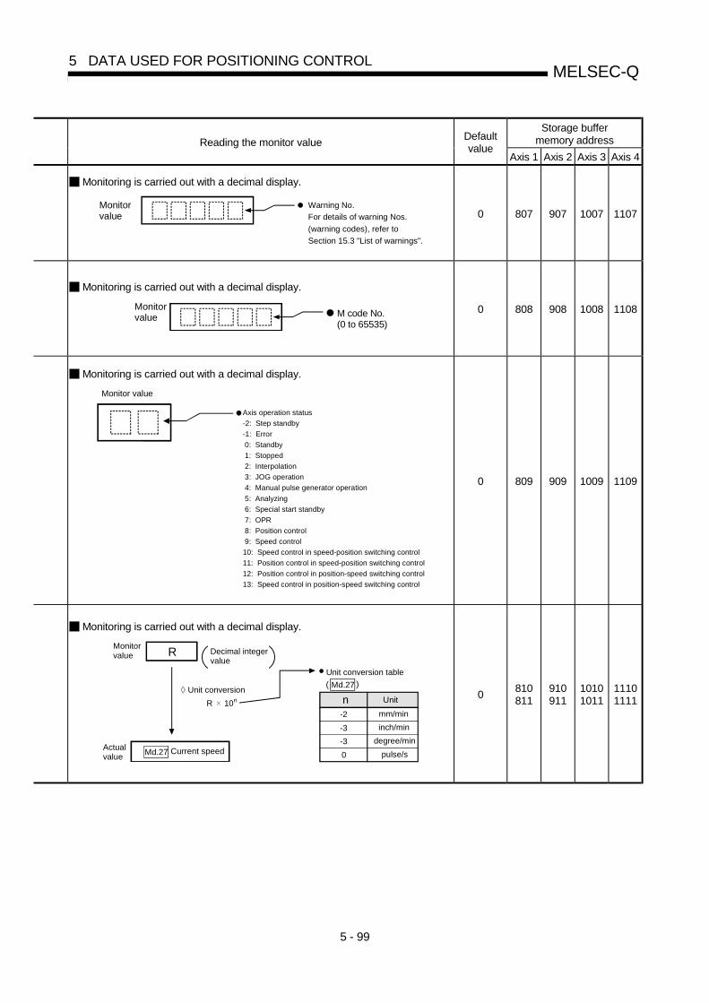
5 - 99
MELSEC-Q5 DATA USED FOR POSITIONING CONTROL
Storage buffermemory addressReading the monitor value
Defaultvalue
Axis 1 Axis 2 Axis 3 Axis 4
Monitoring is carried out with a decimal display.
Monitorvalue
Warning No. For details of warning Nos.
(warning codes), refer to
Section 15.3 "List of warnings".
0 807 907 1007 1107
Monitoring is carried out with a decimal display.
Monitor value M code No.
(0 to 65535)
0 808 908 1008 1108
Monitoring is carried out with a decimal display.
Monitor value
Axis operation status
-2: Step standby
-1: Error
0: Standby
1: Stopped
2: Interpolation
3: JOG operation
4: Manual pulse generator operation
5: Analyzing
6: Special start standby
7: OPR
8: Position control
9: Speed control
10: Speed control in speed-position switching control
11: Position control in speed-position switching control
12: Position control in position-speed switching control
13: Speed control in position-speed switching control
0 809 909 1009 1109
Monitoring is carried out with a decimal display.
R
Monitorvalue Decimal integer
valueUnit conversion table
Actualvalue
Unit conversion
R 10n
))
Md.27
Current speedMd.27
-2 mm/min
-3 inch/min
-3 degree/min
0 pulse/s
n Unit 0810811
910911
10101011
11101111
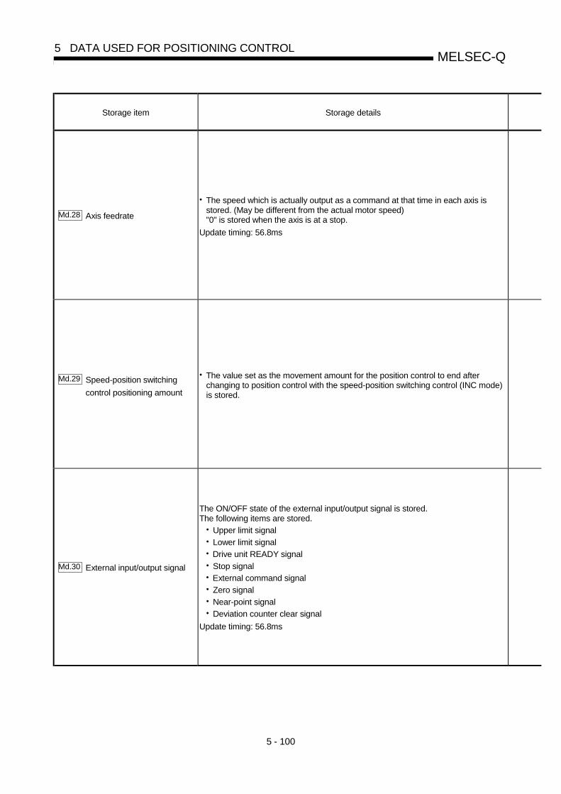
5 - 100
MELSEC-Q5 DATA USED FOR POSITIONING CONTROL
Storage item Storage details
Md.28 Axis feedrate
• The speed which is actually output as a command at that time in each axis isstored. (May be different from the actual motor speed)"0" is stored when the axis is at a stop.
Update timing: 56.8ms
Md.29 Speed-position switching
control positioning amount
• The value set as the movement amount for the position control to end afterchanging to position control with the speed-position switching control (INC mode)is stored.
Md.30 External input/output signal
The ON/OFF state of the external input/output signal is stored.The following items are stored.
• Upper limit signal• Lower limit signal• Drive unit READY signal• Stop signal• External command signal• Zero signal• Near-point signal• Deviation counter clear signal
Update timing: 56.8ms

5 - 101
MELSEC-Q5 DATA USED FOR POSITIONING CONTROL
Storage buffermemory addressReading the monitor value
Defaultvalue
Axis 1 Axis 2 Axis 3 Axis 4
0000H812813
912913
10121013
11121113
Monitoring is carried out with a hexadecimal.
A B C D
A B C D
E F G H
E
R
F G H
b15 b12 b4 b0b8
E F G H
b31 b28 b20 b16b24
A B C D
Monitorvalue
Low-order buffer memory Example) 812
High-order buffer memory Example) 813
Sorting
Decimal integer value
Converted from hexadecimal to decimal
n
-2 mm/min
-3 inch/min
-3 degree/min
0 pulse/s
Unit
Unit conversion table
Unit conversion
Actual value
(High-order buffer memory) (Low-order buffer memory)
R 10n Unit conversion table))Md.29
Axis feedrateMd.28
))Md.28
Speed-position switchingcontrol positioning amount
Md.29
-1
-5 inch
-5 degree
0 pulse
n Unit
m
0000H814815
914915
10141015
11141115
Monitoring is carried out with a hexadecimal.
0 0 0 0 0 0 0 0 0 0 0 0 0 0 0 0b15 b0b4b8b12
0
0
0
0
0
0
0
0
0
0: OFF
1: ON
0
b0
b1
b2
b3
b4
b5
b6
b7
b8
Monitorvalue
Buffermemory
Not usedD efaultva lueStored items Meaning
Drive unit READY signal
Zero signal
Not used
Near-point signal
Stop signal
Upper limit signal
Lower limit signal
External command signal
Deviation counter clear signal
0
0000H 816 916 1016 1116

5 - 102
MELSEC-Q5 DATA USED FOR POSITIONING CONTROL
Storage item Storage details
Md.31 Status
This area stores the states (ON/OFF) of various flags.Information on the following flags is stored.
In speed control flag:This signal that comes ON under the speed control can be used to judge whether theoperation is performed under the speed control or position control. The signal goes OFFwhen the power is switched ON, under the position control, and during JOG operation ormanual pulse generator operation. During the speed-position or position-speed switchingcontrol, this signal comes ON only when the speed control is in effect. During the speed-position switching control, this signal goes OFF when the speed-position switching signalexecutes a switching over from speed control to position control. During the position-speed switching control, this signal comes ON when the position-speed switching signalexecutes a switching over from position control to speed control.
Speed-position switching latch flag:This signal is used during the speed-position switching control (INC mode) for interlockingthe movement amount change function. During the speed-position switching control (INCmode), this signal comes ON when position control takes over. This signal goes OFFwhen the next positioning data is processed, and during JOG operation or manual pulsegenerator operation.
Command in-position flag:This signal is ON when the remaining distance is equal to or less than the command in-position range (set by a detailed parameter). This signal remains OFF with data thatspecify the continuous path control (P11) as the operation pattern. The state of this signalis monitored every 1.8 ms except when the monitoring is canceled under the speed controlor while the speed control is in effect during the speed-position or position-speed switchingcontrol. While operations are performed with interpolation, this signal comes ON only inrespect of the starting axis. (This signal goes OFF in respect of all axes upon starting.)
OPR request flag:This signal comes ON when the power is switched ON, when the drive unit READY signalgoes OFF, when the PLC READY signal goes ON, when a machine OPR operationstarts. This signal goes OFF when a machine OPR operation completes.
OPR complete flag:This signal comes ON when a machine OPR operation completes normally. This signalgoes OFF when the operation starts and when the drive unit READY signal goes OFF.
Position-speed switching latch flag:This signal is used during the position-speed switching control for interlocking thecommand speed change function. During the position-speed switching control, this signalcomes ON when speed control takes over. This signal goes OFF when the nextpositioning data is processed, and during JOG operation or manual pulse generatoroperation.
Axis warning detection flag:This signal comes On when an axis warning is reported and goes OFF when the axis errorreset signal comes ON.
Speed change 0 flag:This signal comes ON when a speed change request that specifies 0 as the new speedvalue is issued. This signal comes ON when a speed change request that specifies a newspeed value other than 0 is issued.
Md.32 Target value
This area stores the target value ( Da.6 Positioning address/movement amount)
for a positioning operation.
• At the beginning of positioning control: Stores the value of " Da.6 Positioning
address/movement amount".• At other times : Stores "0".

5 - 103
MELSEC-Q5 DATA USED FOR POSITIONING CONTROL
Storage buffermemory addressReading the monitor value
Defaultvalue
Axis 1 Axis 2 Axis 3 Axis 4
Monitoring is carried out with a hexadecimal display.
0 0 0 0 0 0 0 0 0 0 0 0 0 0 0 0b15 b0b4b8b12
0
0
0
0
0
0
0
0
0: OFF
1: ON
b0
b1
b2
b3
b4
b5
b9
b10
Monitorvalue
Buffermemory
Not used DefaultvalueStored items Meaning
Not used
In speed control flag
Speed-position switching latch flag
Command in-position flag
OPR request flag
OPR complete flag
Axis warning detection
Speed change 0 flag
Position-speed switching latch flag
0
0000H 817 917 1017 1117
Monitoring is carried out with a decimal display.
R
Monitorvalue Decimal integer
valueUnit conversion table
Actualvalue
Unit conversion
R 10n
))Md.32
Target valueMd.32
-1 m
-5 inch
-5 degree
0 pulse
n Unit 0818819
918919
10181019
11181119

5 - 104
MELSEC-Q5 DATA USED FOR POSITIONING CONTROL
Storage item Storage details
Md.33 Target speed
• During operation with positioning data : The actual target speed, consideringthe override and speed limit value,etc., is stored. "0" is stored whenpositioning is completed.
• During interpolation : The composite speed or referenceaxis speed is stored in the referenceaxis address, and "0" is stored in theinterpolation axis address.
• During JOG operation : The actual target speed, consideringthe JOG speed limit value for theJOG speed, is stored.
• During manual pulse generator operation : "0" is stored.
Md.34 Movement amount after
near-point dog ON
• "0" is stored when machine OPR starts.• After machine OPR starts, the movement amount from the near-point dog ON to
the machine OPR completion is stored.(Movement amount: Movement amount to machine OPR completion using near-point dog ON as "0".)
• "0" is always stored when not using the near-point dog, or when using the stoppermethod.
Md.35 Torque limit stored value
The " Pr.17 Torque limit setting value" or " Cd.22 New torque value" is stored.
• During positioning start, JOG operation start, manual pulse generator operation
...The " Pr.17 Torque limit setting value" is stored.
• When value is changed to " Cd.22 New torque value" during operation
...The " Cd.22 New torque value" is stored.

5 - 105
MELSEC-Q5 DATA USED FOR POSITIONING CONTROL
Storage buffermemory addressReading the monitor value
Defaultvalue
Axis 1 Axis 2 Axis 3 Axis 4
0000H820821
920921
10201021
11201121
Monitoring is carried out with a hexadecimal display.
A B C D
A B C D
E F G H
E
R
F G H
b15 b12 b4 b0b8
E F G H
b31 b28 b20 b16b24
A B C D
Monitorvalue
Low-order buffer memory Example) 820
High-order buffer memory Example) 821
Sorting
Decimal integer value
Converted from hexadecimal to decimal
-1 m
-5 inch
-5 degree
0 pulse
n Unit
n
-2 mm/min
-3 inch/min
-3 degree/min
0 pulse/s
Unit
Unit conversion table
Unit conversion
Actual value
(High-order buffer memory) (Low-order buffer memory)
R 10n Unit conversion table
Target speedMd.33
))Md.33
)Md.34
Movement amount afternear-point dog ON
Md.34
)
0000H822823
922923
10221023
11241125
Monitoring is carried out with a decimal display.
Storage value 0 to 500 (%)
Monitor value 300 826 926 1026 1126

5 - 106
MELSEC-Q5 DATA USED FOR POSITIONING CONTROL
Storage item Storage details
Md.36 Special start data instruction
code setting value
• The " instruction code" used with special start and indicated by the start datapointer currently being executed is stored.
Md.37 Special start data instruction
parameter setting value
The " instruction parameter" used with special start and indicated by the start datapointer currently being executed is stored.
The stored value differs according to the value set for Md.36 .
Md.38 Start positioning data No.
setting value
• The "positioning data No." indicated by the start data pointer currently beingexecuted is stored.
Md.39 In speed limit flag
• If the speed exceeds the " Pr.8 Speed limit value" due to a speed change or
override, the speed limit functions, and the in speed limit flag turns ON.
• When the speed drops to less than " Pr.8 Speed limit value", or when the axis
stops, the in speed limit flag turns OFF.
Md.40 In speed change processing
flag
• The speed change process flag turns ON when the speed is changed duringpositioning control.
• After the speed change process is completed or when deceleration starts with thestop signal during the speed change process, the in speed change process flagturns OFF.

5 - 107
MELSEC-Q5 DATA USED FOR POSITIONING CONTROL
Storage buffermemory addressReading the monitor value
Defaultvalue
Axis 1 Axis 2 Axis 3 Axis 4
Monitoring is carried out with a decimal display.
00: Block start (Normal start)01: Condition start02: Wait start03: Simultaneous start04: FOR loop05: FOR condition06: NEXT
Storage value Monitor value
0 827 927 1027 1127
Monitoring is carried out with a decimal display.
Storage value
Monitor value
setting valueMd.36
0006
01020305
04
1 to 10
0 to 255
Stored contents Storage value
None None
Condition data No.
No. of repetitions
0 828 928 1028 1128
Monitoring is carried out with a decimal display.
Storage value 1 to 600
Monitor value 0 829 929 1029 1129
Monitoring is carried out with a decimal display.
Storage value Monitor value 0: Not in speed limit (OFF)
1: In speed limit (ON)
0 830 930 1030 1130
Monitoring is carried out with a decimal display.
Storage value Monitor value 0: Not in speed change (OFF)
1: In speed change (ON)
0 831 931 1031 1131

5 - 108
MELSEC-Q5 DATA USED FOR POSITIONING CONTROL
Storage item Storage details
Md.41 Special start repetition
counter
• This area stores the remaining number of repetitions during "repetitions" specificto special starting.
• The count is decremented by one (-1) at the loop end.• The control comes out of the loop when the count reaches "0".• This area stores "0" within an infinite loop.
Md.42 Control system repetition
counter
• This area stores the remaining number of repetitions during "repetitions" specificto control system.
• The count is decremented by one (-1) at the loop end.• The control comes out of the loop when the count reaches "0".• This area stores "0" within an infinite loop.
Md.43 Start data pointer being
executed
• This area stores a point No. (1 to 50) attached to the start data currently beingexecuted.
• This area stores "0" after completion of a positioning operation.
Md.44 Positioning data No. being
executed
• This area stores a positioning data No. attached to the positioning data currentlybeing executed.
Md.45 Block No. being executed• When the operation is controlled by "block start data", this area stores a block
number (7000 to 7004) attached to the block currently being executed.• At other times, this area stores "0".
Md.46 Last executed positioning
data No.
• This area stores the positioning data No. attached to the positioning data that wasexecuted last time.
• The value is retained until a new positioning operation is executed.
Md.47 Positioning data being
executed
• The addresses shown to the right store details of the positioning data currently
being executed (positioning data No. given by Md.44 ).
Md.48 Deceleration start flag
• "1" is stored when the constant speed status or acceleration status switches to thedeceleration status during position control whose operation pattern is "Positioningcomplete".
• "0" is stored at the next operation start or manual pulse generator operationenable.

5 - 109
MELSEC-Q5 DATA USED FOR POSITIONING CONTROL
Storage buffermemory addressReading the monitor value
Defaultvalue
Axis 1 Axis 2 Axis 3 Axis 4
Monitoring is carried out with a decimal display.
Monitor value
Storage value0 to 255
0 832 932 1032 1132
Monitoring is carried out with a hexadecimal display.
Monitor valueStorage value0 to FFFF 0000H 833 933 1033 1133
Monitoring is carried out with a decimal display.
Monitor value
Storage value1 to 50
0 834 934 1034 1134
Monitoring is carried out with a decimal display.
Monitor value
Storage value1 to 600
0 835 935 1035 1135
Monitoring is carried out with a decimal display.
Monitor value
Storage value1 to 50
0 836 936 1036 1136
Monitoring is carried out with a decimal display.
Monitor value
Storage value1 to 600
0 837 937 1037 1137
Information is stored in the following addresses:
Stored item
Positioning identifier
M code
Dwell time
Open
Command speed
Arc address
Da.1 to Da.5
Da.9
Da.8
Da.6
Da.7
Positioning address
Stored address (Monitor value) Reference
Axis1 Axis2 Axis3
847 947 1047
846 946 1046
845 945 1045
844 944 1044
843 943 1043
842 942 1042
841 941 1041
840 940 1040
839 939 1039
838 938 1038
Da.10
Axis4
1138
1139
1140
1141
1142
1143
1144
1145
1146
1147
0838to
847
938to
947
1038to
1047
1138to
1147
Monitoring is carried out with a decimal display.
Monitor valueStorage value
0: Status other than below1: Status from deceleration start to next operation start or manual pulse generator operation enable
0 899 999 1099 1199

5 - 110
MELSEC-Q5 DATA USED FOR POSITIONING CONTROL
5.7 List of control data
5.7.1 System control data
Setting item Setting details
Cd.1 Flash ROM write request• Requests writing of data (parameters, positioning data, and block start data) from
the buffer memory to the flash ROM.
• Requests initialization of setting data.Initialization: Resetting of setting data to default values
Note: After completing the initialization of setting data, reset the PLC CPU or rebootthe PLC power.
Initialized setting data
Parameters ( Pr.1 to Pr.57 , Pr.150 )
Positioning data (No. 1 to No. 600)
Block start data (No. 7000 to 7004)
Cd.2 Parameter initialization request
Cd.41 Deceleration start flag valid Set whether " Md.48 Deceleration start flag" is made valid or invalid.
Cd.42 Stop command processing fordeceleration stop selection
• Set the stop command processing for deceleration stop function (decelerationcurve re-processing/deceleration curve continuation).

5 - 111
MELSEC-Q5 DATA USED FOR POSITIONING CONTROL
Setting value Default value
Storage buffermemory address
(common to axes 1to 4)
Set with a decimal.
Settingvalue
K 1
Flash ROM write request
1: Requests write access to flash ROM.
The QD75 resets the value to "0" automatically when the write access completes.
(This indicates the completion of write operation.)
0 1900
Set with a decimal.
Settingvalue
K
Parameter initialization request
1: Requests parameter initialization.
The QD75 resets the value to "0" automatically when the initialization completes.
(This indicates the completion of parameter initialization.)
1
0 1901
Set with a decimal.
Settingvalue
K
Deceleration start flag valid 0: Deceleration start flag invalid 1: Deceleration start flag valid
0 1905
Set with a decimal.
Settingvalue
K
Stop command processing for deceleration stop selection 0: Deceleration curve re-processing 1: Deceleration curve continuation
0 1907

5 - 112
MELSEC-Q5 DATA USED FOR POSITIONING CONTROL
5.7.2 Axis control data
Setting item Setting details
Cd.3 Positioning start No.• Set the positioning start No.
(Only 1 to 600 for the Pre-reading start function. For details, refer to Section12.7.8 "Pre-reading start function".)
Cd.4 Positioning starting point No.• Set a " starting point No." (1 to 50) if block start data is used for positioning.
(Handled as "1" if the value of other than 1 to 50 is set.)
Cd.5 Axis error reset
• Clears the axis error detection, axis error No., axis warning detection and axiswarning No.
• When the QD75 axis operation state is "in error occurrence", the error is clearedand the QD75 is returned to the "waiting" state.
Cd.6 Restart command
• When positioning is stopped for any reason (when axis operation state is
"stopped"), set "1" in Cd.6 . Positioning will be carried out again from the stopped
position to the end point of the stopped positioning data.
Cd.7 M code OFF request • The M code ON signal turns OFF.

5 - 113
MELSEC-Q5 DATA USED FOR POSITIONING CONTROL
Storage buffermemory addressSetting value
Defaultvalue
Axis 1 Axis 2 Axis 3 Axis 4
Set with a decimal.
Settingvalue
Positioning data No.
1 to 6007000 to70049001900290039004
K
: Positioning data No.: Block start designation: Machine OPR: Fast-OPR: Current value changing: Simultaneous starting of multiple axes
0 1500 1600 1700 1800
Set with a decimal.
Settingvalue
K
Positioning starting point No.
The value is set to "0" by the QD75 automatically when the continuous
operation is interrupted.
1 to 50
0 1501 1601 1701 1801
Set with a decimal.
K 1
Error reset request
Setting value
After the axis error reset is completed, "0" is stored by the QD75 automatically. (Indicates that the axis error reset is completed.)
1: Axis error is reset.
0 1502 1602 1702 1802
Set with a decimal.
K
1
Restart command
Setting value
After restart acceptance is completed, "0" is stored by the QD75 automatically. (Indicates that the restart acceptance is completed.)
1: Restarts
0 1503 1603 1703 1803
Set with a decimal.
K
1
M code OFF request
Setting value
After the M code ON signal turns OFF, "0" is stored by the QD75 automatically. (Indicates that the OFF request is completed.)
1: M code ON signal turns OFF
0 1504 1604 1704 1804

5 - 114
MELSEC-Q5 DATA USED FOR POSITIONING CONTROL
Setting item Setting details
Cd.8 External command valid • Validates or in validates external command signals.
• When changing the "current feed value" using the start No. "9003", use this dataitem to specify a new feed value.
• Set a value within the following range:
Pr.1mm
(×10-1 µm)inch
(×10-5 inch)degree
(×10-5 degree)pulse
(pulse)
Setting range-2147483648
to+2147483647
-2147483648to
+21474836470 to 35999999
-2147483648to
+2147483647
Cd.9 New current value

5 - 115
MELSEC-Q5 DATA USED FOR POSITIONING CONTROL
Storage buffermemory addressSetting value
Defaultvalue
Axis 1 Axis 2 Axis 3 Axis 4
Set with a decimal.
Setting value
External command valid0: Invalidates an external command.1: Validates an external command.
K0 1505 1605 1705 1805
Set with a decimal.
Actual value
Conversion into an integer value
Cd.9 New current value
10nUnit conversion table ( Cd.9 )
n-1 m
-5 inch
-5 degree
0 pulse
Unit
RSetting value
(Decimal)
015061507
16061607
17061707
18061807

5 - 116
MELSEC-Q5 DATA USED FOR POSITIONING CONTROL
Setting item Setting details
• When changing the acceleration time during a speed change, use this data itemto specify a new acceleration time.
Cd.10 setting range (unit)
0 to 8388608 (ms)
Cd.10 New acceleration time value
• When changing the deceleration time during a speed change, use this data itemto specify a new deceleration time.
Cd.11 setting range (unit)
0 to 8388608 (ms)
Cd.11 New deceleration time value
Cd.12 Acceleration/deceleration timechange during speed change,enable/disable selection
• Enables or disables modifications to the acceleration/deceleration time during aspeed change.

5 - 117
MELSEC-Q5 DATA USED FOR POSITIONING CONTROL
Storage buffermemory addressSetting value
Defaultvalue
Axis 1 Axis 2 Axis 3 Axis 4
015081509
16081609
17081709
18081809 Set with a decimal.
Cd.10 New acceleration time value
Cd.11 New deceleration time value
Settingvalue
Example: When the " Cd. 10 New acceleration
time value" is set as "60000 ms", the
buffer memory stores "60000".
015101511
16101611
17101711
18101811
Set with a decimal.
Settingvalue
K
Acceleration/deceleration time change
during speed change, enable/disable selection
1 : Enables modifications to
acceleration/deceleration time
Other than 1: Disables modifications to
acceleration/deceleration time
0 1512 1612 1712 1812

5 - 118
MELSEC-Q5 DATA USED FOR POSITIONING CONTROL
Setting item Setting details
Cd.13 Positioning operation speedoverride
• To use the positioning operation speed override function, use this data item tospecify an "override" value.
For details of the override function, refer to Section 12.5.2" Override function".
If the speed resulting from a small override value (e.g. 1%) includes fractionsbelow the minimum unit, the speed is raised to make a complete unit and thewarning No. 110 is output.
• When changing the speed, use this data item to specify a new speed.• The operation halts if you specify "0".• Set a value within the following range:
Pr.1mm
(×10-2 mm/min)inch
(×10-3 inch/min)degree
(×10-3 degree/min)pulse
(pulse/s)
Setting range0 to
20000000000 to
20000000000 to
20000000000 to 1000000
Cd.14 New speed value
Cd.15 Speed change request• After setting the " Cd.14 New speed value", set this data item to "1" to execute
the speed change (through validating the new speed value).

5 - 119
MELSEC-Q5 DATA USED FOR POSITIONING CONTROL
Storage buffermemory addressSetting value
Defaultvalue
Axis 1 Axis 2 Axis 3 Axis 4
Set with a decimal.
Setting value
Override value (%)
1 to 300
K 100 1513 1613 1713 1813
Set with a decimal.
Actual value
Conversion into an integer value
Cd.14 New speed value
10nUnit conversion table ( Cd.14 )
n-2 mm/min
-3 inch/min
-3 degree/min
0 pulse/s
Unit
RSetting value(Decimal)
Example: When the " Cd. 14 New speed
value" is set as "20000.00mm
/min", the buffer memory
stores "2000000".
015141515
16141615
17141715
18141815
Set with a decimal.
Settingvalue
Speed change request1: Executes speed change.
K
The QD75 resets the value to "0" automatically
when the speed change request has been processed.
(This indicates the completion of speed change request.)
1
0 1516 1616 1716 1816

5 - 120
MELSEC-Q5 DATA USED FOR POSITIONING CONTROL
Setting item Setting details
• Use this data item to set the amount of movement by inching.• The machine performs a JOG operation if "0" is set.• Set a value within the following range:
Pr.1mm
(×10-1 µm)inch
(×10-5 inch)degree
(×10-5 degree)pulse
(pulse)
Setting range 0 to 65535 0 to 65535 0 to 65535 0 to 65535
Cd.16 Inching movement amount
• Use this data item to set the JOG speed.• Set a value within the following range:
Pr.1mm
(×10-2 mm/min)inch
(×10-3 inch/min)degree
(×10-3 degree/min)pulse
(pulse/s)
Setting range0 to
20000000000 to
20000000000 to
20000000000 to 1000000
Cd.17 JOG speed
Cd.18 Interruption request duringcontinuous operation
• To interrupt a continuous operation, set "1" to this data item.• After processing the interruption request ("1"), the QD75 automatically resets the
value to "0".
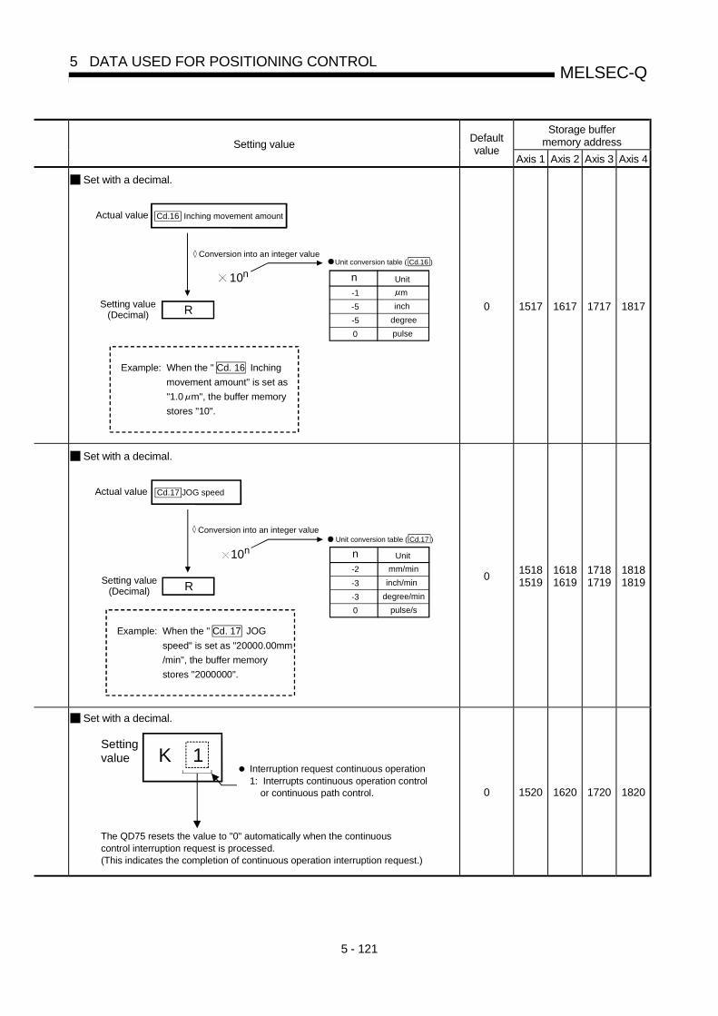
5 - 121
MELSEC-Q5 DATA USED FOR POSITIONING CONTROL
Storage buffermemory addressSetting value
Defaultvalue
Axis 1 Axis 2 Axis 3 Axis 4
Set with a decimal.
Actual value
Conversion into an integer value
Cd.16 Inching movement amount
10nUnit conversion table ( Cd.16 )
n-1 m
-5 inch
-5 degree
0 pulse
Unit
RSetting value
(Decimal)
Example: When the " Cd. 16 Inching
movement amount" is set as
"1.0 m", the buffer memory
stores "10".
0 1517 1617 1717 1817
Set with a decimal.
Actual value
Conversion into an integer value
Cd.17 JOG speed
10nUnit conversion table ( Cd.17 )
n-2 mm/min
-3 inch/min
-3 degree/min
0 pulse/s
Unit
RSetting value
(Decimal)
Example: When the " Cd. 17 JOG
speed" is set as "20000.00mm
/min", the buffer memory
stores "2000000".
015181519
16181619
17181719
18181819
Set with a decimal.
Settingvalue
Interruption request continuous operation 1: Interrupts continuous operation control or continuous path control.
K
The QD75 resets the value to "0" automatically when the continuouscontrol interruption request is processed.(This indicates the completion of continuous operation interruption request.)
1
0 1520 1620 1720 1820

5 - 122
MELSEC-Q5 DATA USED FOR POSITIONING CONTROL
Setting item Setting details
Cd.19 OPR request flag OFFrequest
• The sequence program can use this data item to forcibly turn the OPR requestflag from ON to OFF.
Cd.20 Manual pulse generator 1pulse input magnification
• This data item determines the factor by which the number of pulses from themanual pulse generator is magnified.
• Value "0" : read as "1".• Value "101" or less: read as "100".
Cd.21 Manual pulse generatorenable flag
• This data item enables or disables operations using a manual pulse generator.
Cd.22 New torque value
• When changing the " Md.35 Torque limit stored value", use this data item tospecify a new torque limit stored value.
• Set a value within the allowable range of the " Pr.17 Torque limit setting value".

5 - 123
MELSEC-Q5 DATA USED FOR POSITIONING CONTROL
Storage buffermemory addressSetting value
Defaultvalue
Axis 1 Axis 2 Axis 3 Axis 4
Set with a decimal.
Settingvalue
K
OPR request flag OFF request1: Turns the "OPR request flag" from ON to OFF.
The QD75 resets the value to "0" automatically when the OPRrequest flag is turned OFF.(This indicates the completion of OPR request flag OFF request.)
1
0 1521 1621 1721 1821
Set with a decimal.
Setting value K
Manul pulse generator1 pulse inputmagnification
1 to 100
115221523
16221623
17221723
18221823
Set with a decimal.
Setting value
Manual pulse generator enable flag0: Disable manual pulse generator operation.1: Enable manual pulse generator operation.
K 0 1524 1624 1724 1824
Set with a decimal.
Setting value K
Torque change value
1 to Pr.17 Torque limit setting value 0 1525 1625 1725 1825

5 - 124
MELSEC-Q5 DATA USED FOR POSITIONING CONTROL
Setting item Setting details
• During the speed control stage of the speed-position switching control (INCmode), it is possible to change the specification of the movement amount duringthe position control stage. For that, use this data item to specify a new movementamount.
• The new movement amount has to be set during the speed control stage of thespeed-position switching control (INC mode).
• The value is reset to "0" when the next operation starts.• Set a value within the following range:
Pr.1mm
(×10-1 µm)inch
(×10-5 inch)degree
(×10-5 degree)pulse
(pulse)
Setting range0 to
21474836470 to
21474836470 to
21474836470 to
2147483647
Cd.23 Speed-position switchingcontrol movement amountchange register
Cd.24 Speed-position switchingenable flag
• Set whether the external control signal (external command signal [CHG]: "speed-position, position-speed switching request" is selected) is enabled or not.
• During the position control stage of the position-speed switching control, it ispossible to change the specification of the speed during the speed control stage.For that, use this data item to specify a new speed.
• The new speed has to be set during the position control stage of the position-speed switching control.
• The value is reset to "0" when the next operation starts.• Set a value within the following range:
Pr.1mm
(×10-2 mm/min)inch
(×10-3 inch/min)degree
(×10-3 degree/min)pulse
(pulse/s)
Setting range0 to
20000000000 to
20000000000 to
20000000000 to 1000000
Cd.25 Position-speed switchingcontrol speed change register

5 - 125
MELSEC-Q5 DATA USED FOR POSITIONING CONTROL
Storage buffermemory addressSetting value
Defaultvalue
Axis 1 Axis 2 Axis 3 Axis 4
Set with a decimal.
10n
Actual value
n-1 m
-5 inch
-5 degree
0 pulse
Unit
R
Setting value(Decimal)
Conversion into an integer value
Unit conversion table ( Cd.23 )
Speed-position switchingcontrol movement amountchange register
Cd.23
Example: If " Cd. 23 Speed-position switching control movement amount change register" is set as "20000.0 m", the buffer memory stores "200000".
015261527
16261627
17261727
18261827
Set with a decimal.
Settingvalue
K
Speed-position switching enable flag0: Speed control will not be taken over by position control even when the external command signal comes ON.1: Speed control will be taken over by position control when the external command signal comes ON.
0 1528 1628 1728 1828
Set with a decimal.
10n
Actual value
n-2 mm/min
-3 inch/min
-3 degree/min
0 pulse/s
Unit
R
Setting value(Decimal)
Conversion into an integer value
Unit conversion table ( Cd.25 )
Position-speed switchingcontrol speed changeregister
Cd.25
Example: If " Cd. 25 Position-speed switching control speed change register" is set as "2000.00 mm/min", the buffer memory stores "200000".
015301531
16301631
17301731
18301831

5 - 126
MELSEC-Q5 DATA USED FOR POSITIONING CONTROL
Setting item Setting details
Cd.26 Position-speed switchingcontrol enable flag
• Set whether the external control signal (external command signal [CHG]: "speed-position, position-speed switching request" is selected) is enabled or not.
• When changing the target position during a positioning operation, use this dataitem to specify a new positioning address.
• Set a value within the following range:
Pr.1mm
(×10-1 µm)inch
(×10-5 inch)degree
(×10-5 degree)pulse
(pulse)
ABS-2147483648
to+2147483647
-2147483648to
+21474836470 to 35999999
-2147483648to
+2147483647
INC-2147483648
to+2147483647
-2147483648to
+2147483647
-2147483648to
+2147483647
-2147483648to
+2147483647
Cd.27 Target position change value(New address)
• When changing the target position during a positioning operation, use this dataitem to specify a new speed.
• The speed will not change if "0" is set.• Set a value within the following range:
Pr.1mm
(×10-2 mm/min)inch
(×10-3 inch/min)degree
(×10-3 degree/min)pulse
(pulse/s)
Setting range0 to
20000000000 to
20000000000 to
20000000000 to 1000000
Cd.28 Target position change value(New speed)
Cd.29 Target position changerequest flag
• Requests a change in the target position during a positioning operation.

5 - 127
MELSEC-Q5 DATA USED FOR POSITIONING CONTROL
Storage buffermemory addressSetting value
Defaultvalue
Axis 1 Axis 2 Axis 3 Axis 4
Set with a decimal.
Setting value K
Position-speed switching enable flag 0: Position control will not be taken over by speed control even when the external command signal comes ON. 1: Position control will be taken over by speed control when the external command signal comes ON.
0 1532 1632 1732 1832
015341535
16341635
17341735
18341835
Set with a decimal.
Actual value
R
Setting value(Decimal)
10n
n
-1 m
-5 inch
-5 degree
0 pulse
Unit
n
-2 mm/min
-3 inch/min
-3 degree/min
0 pulse/s
Unit
Conversion into an integer value
Unit conversion table ( Cd.27 )
Unit conversion table ( Cd.28 )
Cd. 27 Target position change value (address)Cd. 28 Target position change value (speed)
Example: If " Cd. 28 Target position change value (speed) is set as "10000.00 mm/min", the buffer memory stores "1000000".
015361537
16361637
17361737
18361837
Set with a decimal.
Settingvalue
K
Target position change request flag1: Requests a change in the target position
The QD75 resets the value to "0" automatically when the new target position value has been written.(This indicates the completion of write operation.)
1
0 1538 1638 1738 1838

5 - 128
MELSEC-Q5 DATA USED FOR POSITIONING CONTROL
Setting item Setting details
Cd.30 Simultaneous starting axisstart data No. (axis 1 startdata No.)
Cd.31 Simultaneous starting axisstart data No. (axis 2 startdata No.)
Cd.32 Simultaneous starting axisstart data No. (axis 3 startdata No.)
Cd.33 Simultaneous starting axisstart data No. (axis 4 startdata No.)
• Use these data items to specify a start data No. for each axis that has to startsimultaneously.
• Set "0" to any axis that should not start simultaneously.
Cd.34 Step mode• To perform a step operation, use this data item to specify the units by which the
stepping should be performed.
Cd.35 Step valid flag • This data item validates or invalidates step operations.

5 - 129
MELSEC-Q5 DATA USED FOR POSITIONING CONTROL
Storage buffermemory addressSetting value
Defaultvalue
Axis 1 Axis 2 Axis 3 Axis 4
0 1540 1640 1740 1840
0 1541 1641 1741 1841
0 1542 1642 1742 1842
Set with a decimal.
Settingvalue K
Cd.30 to Cd.33
1 to 600
Simultaneous startingaxis start data No.:
0 1543 1643 1743 1843
Set with a decimal.
Settingvalue
Step mode0: Stepping by deceleration units1: Stepping by data No. units
K 0 1544 1644 1744 1844
Set with a decimal.
Settingvalue
Step valid flag0: Invalidates step operations1: Validates step operations
K0 1545 1645 1745 1845

5 - 130
MELSEC-Q5 DATA USED FOR POSITIONING CONTROL
Setting item Setting details
Cd.36 Step start information• During a step operation, this data item determines whether the operation is
continued or restarted.
Cd.37 Skip command • To skip the current positioning operation, set "1" in this data item.
Cd.38 Teaching data selection • This data item specifies the teaching result write destination.
Cd.39 Teaching positioning data No.
• This data item specifies data to be produced by teaching.• If a value between 1 and 600 is set, a teaching operation is done.• The value is cleared to "0" when the QD75 is initialized, when a teaching
operation completes, and when a illegal value (601 or higher) is entered.
Cd.40 ABS direction in degrees• This data item specifies the ABS moving direction carrying out the position control
when "degree" is selected as the unit.

5 - 131
MELSEC-Q5 DATA USED FOR POSITIONING CONTROL
Storage buffermemory addressSetting value
Defaultvalue
Axis 1 Axis 2 Axis 3 Axis 4
Set with a decimal.
Settingvalue
Step start information1: Continues step opration2: Restarts operation
K
The QD75 resets the value to "0" automatically
when processing of the step start request completes.
0 1546 1646 1746 1846
Set with a decimal.
Settingvalue
Skip request1:
K
The QD75 resets the value to "0" automatically when processing of the skip request completes.
1
Issues a skip request to have
the machine decelerate, stop,
and then start the next positioning
operation.
0 1547 1647 1747 1847
Set with a decimal.
Settingvalue
Teaching data selection
K
0: Takes the current feed value as a positioning
address.
1: Takes the current feed value as an arc data.
0 1548 1648 1748 1848
Set with a decimal.
Setting valueK
Teaching positioning data No. 1 to 600
0 1549 1649 1749 1849
Set with a decimal.
Settingvalue
ABS direction in degrees
K
0: Takes a shortcut.
(Specified direction ignored.)
1: ABS circular right
2: ABS circular left
0 1550 1650 1750 1850

5 - 132
MELSEC-Q5 DATA USED FOR POSITIONING CONTROL
MEMO

6 - 1
6
Chapter 6 Sequence Program Used forPositioning Control
The programs required to carry out positioning control with the QD75 are explained in this chapter.
The sequence program required for control is created allowing for the "start conditions","start time chart", "device settings" and general control configuration. (The parameters,positioning data, block start data and condition data, etc., must be set in the QD75 according to the control to be executed, and program for setting the control data or a program for starting the various control must be created.)
The first half of this chapter explains the program configuration of general control, and the latter half explains the program details. Create the required program while referring to the various control details explained in Section 2, and to Chapter 5 "Data used for positioning control".
6.1 Precautions for creating program ................................................................................6- 26.2 List of devices used......................................................................................................6- 56.3 Creating a program .....................................................................................................6- 11
6.3.1 General configuration of program .................................................................6- 116.3.2 Positioning control operation program ..........................................................6- 12
6.4 Positioning program examples................................................................................... 6- 156.5 Program details........................................................................................................... 6- 24
6.5.1 Initialization program..................................................................................... 6- 246.5.2 Start details setting program......................................................................... 6- 256.5.3 Start program ................................................................................................ 6- 276.5.4 Continuous operation interrupt program ...................................................... 6- 376.5.5 Restart program............................................................................................ 6- 396.5.6 Stop program ................................................................................................ 6- 42

6 - 2
MELSEC-Q6 SEQUENCE PROGRAM USED FOR POSITIONING CONTROL
6.1 Precautions for creating program
The common precautions to be taken when writing data from the PLC CPU to the QD75 buffer memory are described below. When diverting any of the program examples introduced in this manual to the actual system, fully verify that there are no problems in the controllability of the target system.
(1) Reading/writing the data
Setting the data explained in this chapter (various parameters, positioning data, block start data) should be set using GX Configurator-QP. When set with the sequence program, many sequence programs and devices must be used. This will not only complicate the program, but will also increase the scan time. When rewriting the positioning data during continuous path control or continuous positioning control, rewrite the data four positioning data items before the actual execution. If the positioning data is not rewritten before the positioning data four items earlier is executed, the process will be carried out as if the data was not rewritten.
(2) Restrictions to speed change execution interval Provide an interval of 100ms or more when changing the speed with the QD75.
(3) Process during overrun Overrun is prevented by the setting of the upper and lower stroke limits with the detail parameter 1. However, this applies only when the QD75 is operating correctly. It is recommended to create an external circuit including a boundary limit switch to ensure the whole system safety as follows: the external circuit powers OFF the motor when the boundary limit switch operates.

6 - 3
MELSEC-Q6 SEQUENCE PROGRAM USED FOR POSITIONING CONTROL
(4) System configuration
Unless particularly designated, the sequence program for the following system is shown in this chapter and subsequent. Refer to Section 6.2 for the application of the devices to be used.
External devices
Q35B
Pow
er s
uppl
y m
odul
e
Q25HCPU
QD75P4
QX41
QX40
QY40
Q62DA
Servo-amplifier
M
Y50 to Y52 (for absolute position restoration)CH.1 output (for torque changing)
X40 to X45
X20 to X3F
Servomotor
X47 to X49(for absolute
position restoration)
00
1Fto
X20
X3Fto
X40
X4Fto
Y50
Y5Fto
60
6Fto
(5) Control unit In the program, the unit of "0 (mm)" is set for the basic parameter 1.
(6) Communication with QD75
There are two methods for communication with QD75 using the sequence program: a method using an "intelligent function device" and a method using a FROM/TO command. In the sequence program in this chapter and subsequent, the program example using the "intelligent function device" is shown without using an FROM/TO command for communication with QD75. When using the FROM/TO command for communication with QD75, change the circuit incorporating the "intelligent function device" as follows. (a) When the circuit uses the "intelligent function device" on the destination (D)
side of a MOV command, change the command to a TO command.
MOVP K1 G1505
Intelligent function device
X21
TOP K1X21
K1505H0 K1
U0\
Designated value at U0
Designated value
at G1505
Number of write data (1)
0
0

6 - 4
MELSEC-Q6 SEQUENCE PROGRAM USED FOR POSITIONING CONTROL
(b) When the circuit uses the "intelligent function device" on the source(s) side
and the destination (D) side of a MOV command, change the command to a FROM command and a TO command.
MOVP G826 G1
X15
FROMP D100X15
K826H0 K1
U6\
TOP D100K1H6 K1
X0C
X0C U0\
Set the same device.
0
0
(c) When the circuit uses the "intelligent function device" for a COMPARISON command, change the command to a FROM command and a COMPARISON command.
RST M0
M0
FROMP D102M0
K1521H0 K1
RST M0
= G1521 K0
= D102 K0
0
0
Data read out
U0\
(d) When the circuit uses the "intelligent function device" for a WAND command, change the command to a FROM command and a WAND command.
H8 D0
M2
FROMP D101M2
K817H0 K1
0
0
G817WANDPU0\
H8 D0D101WANDPData read out
REMARK
Refer to QCPU (Q mode) User's Manual (Functions and Programs Basic Part) for the intelligent function devices. Refer to QCPU (Q mode) Programming Manual (Common Commands Part) for detail commands used in those programs shown in this chapter and subsequent.

6 - 5
MELSEC-Q6 SEQUENCE PROGRAM USED FOR POSITIONING CONTROL
6.2 List of devices used
In the sequence programs shown in this chapter and subsequent, the application of the devices used are as follows. The I/O numbers for QD75 indicate those when QD75 is mounted in the 0-slot of the main base. If it is mounted in the slot other than the 0-slot of the main base, change the I/O number to that for the position where QD75 was installed. In addition, change the external inputs, external outputs, internal relays, data resisters, and timers according to the system used. (1) Inputs/outputs, external inputs/external outputs, and internal relays
of QD75 Device Device
name Axis 1 Axis 2 Axis 3 Axis 4 Application Details when ON
X0 QD75 READY signal Preparation completed X1 Synchronization flag QD75 buffer memory accessible
X4 X5 X6 X7 M code ON signal M code outputting X8 X9 XA XB Error detection signal Error detected XC XD XE XF BUSY signal BUSY (operating) X10 X11 X12 X13 Start complete signal Start completed
Input
X14 X15 X16 X17 Positioning complete signal Positioning completed Y0 PLC READY signal PLC CPU preparation completed
Y4 Y5 Y6 Y7 Axis stop signal Requesting stop Y8 YA YC YE Forward run JOG start signal Starting forward run JOG Y9 YB YD YF Reverse run JOG start signal Starting reverse run JOG
Inputs/ outputs
of QD75
Out-put
Y10 Y11 Y12 Y13 Positioning start signal Requesting start X20 OPR request OFF command Commanding OPR request OFF
X21 External command valid command Commanding external command valid setting
X22 External command invalid command Commanding external command invalid
X23 Machine OPR command Commanding machine OPR X24 Fast OPR command Commanding fast OPR X25 Positioning start command Commanding positioning start
X26 Speed-position switching operation command
Commanding speed-position switching operation
X27 Speed-position switching enable command
Commanding speed-position switching enable command
X28 Speed-position switching prohibit command
Commanding speed-position switching prohibit
X29 Movement amount change command Commanding movement amount change
X2A High-level positioning control start command
Commanding high-level positioning control start
External input
(command)
X2B
—
Positioning start command (dedicated instruction) Commanding positioning start

6 - 6
MELSEC-Q6 SEQUENCE PROGRAM USED FOR POSITIONING CONTROL
Device Device
name Axis 1 Axis 2 Axis 3 Axis 4 Application Details when ON
X2C M code OFF command Commanding M code OFF
X2D JOG operation speed setting command
Commanding JOG operation speed setting
X2E Forward run JOG/inching command Commanding forward run JOG/inching operation
X2F Reverse run JOG/inching command Commanding reverse run JOG/inching operation
X30 Manual pulse generator operation enable command
Commanding manual pulse generator operation enable
X31 Manual pulse generator operation disable command
Commanding manual pulse generator operation disable
X32 Speed change command Commanding speed change X33 Override command Commanding override
X34 Acceleration/deceleration time change command
Commanding acceleration/deceleration time change
X35 Acceleration/deceleration time change disable command
Commanding acceleration/deceleration time change disable
X36 Torque change command Commanding torque change X37 Step operation command Commanding step operation X38 Skip operation command Commanding skip operation X39 Teaching command Commanding teaching
X3A Continuous operation interrupt command
Commanding continuous operation interrupt command
X3B
—
Restart command Commanding restart X3C Parameter initialization command Commanding parameter initialization X3D Flash ROM write command Commanding flash ROM write
X3E Error reset command Commanding error reset X3F Stop command Commanding stop
X40 Position-speed switching operation command
Position-speed switching operation command
X41 Position-speed switching enable command
Position-speed switching enable command
X42 Position-speed switching prohibit command
Position-speed switching prohibit command
X43 Speed change command Speed change command
X44 Inching movement amount setting command
Inching movement amount setting command
X45 Target position change command Target position change command
X4D Speed-position switching control (ABS mode) setting command
Speed-position switching control (ABS mode) setting command
External input
(command)
X4E
—
Positioning start command (Y start) Positioning start command being given
X47 ABS data bit 0 —
X48 ABS data bit 1 —
External input
(absolute position
restoration) X49
—
Transmission data READY flag —
Y50 Servo ON signal —
Y51 ABS transmission mode —
External output
(absolute position
restoration) Y52
—
ABS request mode —

6 - 7
MELSEC-Q6 SEQUENCE PROGRAM USED FOR POSITIONING CONTROL
Device Device
name Axis 1 Axis 2 Axis 3 Axis 4 Application Details when ON
M0 OPR request OFF command Commanding OPR request OFF M1 OPR request OFF command pulse OPR request OFF commanded M2 OPR request OFF command storage OPR request OFF command held M3 Fast OPR command Commanding fast OPR M4 Fast OPR command storage Fast OPR command held M5 Positioning start command pulse Positioning start commanded M6 Positioning start command storage Positioning start command held M7 In-JOG/Inching operation flag In-JOG/Inching operation flag
M8 Manual pulse generator operation enable command
Commanding manual pulse generator operation enable
M9 Manual pulse generator operating flag Manual pulse generator operating flag
M10 Manual pulse generator operation disable command
Commanding manual pulse generator operation disable
M11 Speed change command pulse Speed change commanded M12 Speed change command storage Speed change command held M13 Override command Requesting override
M14 Acceleration/deceleration time change command
Requesting acceleration/deceleration time change
M15 Torque change command Requesting torque change M16 Step operation command pulse Step operation commanded M17 Skip command pulse Skip commanded M18 Skip command storage Skip command held M19 Teaching command pulse Teaching commanded M20 Teaching command storage Teaching command held
M21 Continuous operation interrupt command
Requesting continuous operation interrupt
M22 Restart command Requesting restart M23
—
Restart command storage Restart command held
M24 Parameter initialization command pulse Parameter initialization commanded
M25 Parameter initialization command storage Parameter initialization command held
M26 Flash ROM write command pulse Flash ROM write commanded M27 Flash ROM write command storage Flash ROM write command held
M28 Error reset Error reset completed M29 Stop command pulse Stop commanded
M30 Target position change command pulse Target position change commanded
M31 Target position change command storage Target position change command held
M32 PSTRT1 instruction complete device PSTRT1 instruction completed
Internal relay
M33
—
PSTRT1 instruction error complete device PSTRT1 instruction error completed
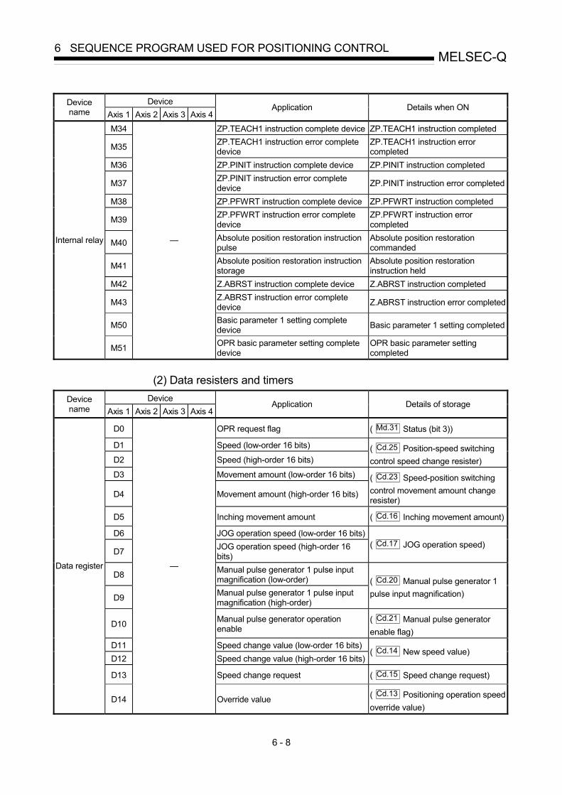
6 - 8
MELSEC-Q6 SEQUENCE PROGRAM USED FOR POSITIONING CONTROL
Device Device
name Axis 1 Axis 2 Axis 3 Axis 4 Application Details when ON
M34 ZP.TEACH1 instruction complete device ZP.TEACH1 instruction completed
M35 ZP.TEACH1 instruction error complete device
ZP.TEACH1 instruction error completed
M36 ZP.PINIT instruction complete device ZP.PINIT instruction completed
M37 ZP.PINIT instruction error complete device ZP.PINIT instruction error completed
M38 ZP.PFWRT instruction complete device ZP.PFWRT instruction completed
M39 ZP.PFWRT instruction error complete device
ZP.PFWRT instruction error completed
M40 Absolute position restoration instruction pulse
Absolute position restoration commanded
M41 Absolute position restoration instruction storage
Absolute position restoration instruction held
M42 Z.ABRST instruction complete device Z.ABRST instruction completed
M43 Z.ABRST instruction error complete device Z.ABRST instruction error completed
M50 Basic parameter 1 setting complete device Basic parameter 1 setting completed
Internal relay
M51
—
OPR basic parameter setting complete device
OPR basic parameter setting completed
(2) Data resisters and timers
Device Device name Axis 1 Axis 2 Axis 3 Axis 4
Application Details of storage
D0 OPR request flag ( Md.31 Status (bit 3))
D1 Speed (low-order 16 bits)
D2 Speed (high-order 16 bits) ( Cd.25 Position-speed switching control speed change resister)
D3 Movement amount (low-order 16 bits)
D4 Movement amount (high-order 16 bits)
( Cd.23 Speed-position switching control movement amount change resister)
D5 Inching movement amount ( Cd.16 Inching movement amount)
D6 JOG operation speed (low-order 16 bits)
D7 JOG operation speed (high-order 16 bits)
( Cd.17 JOG operation speed)
D8 Manual pulse generator 1 pulse input magnification (low-order)
D9 Manual pulse generator 1 pulse input magnification (high-order)
( Cd.20 Manual pulse generator 1 pulse input magnification)
D10 Manual pulse generator operation enable
( Cd.21 Manual pulse generator enable flag)
D11 Speed change value (low-order 16 bits) D12 Speed change value (high-order 16 bits)
( Cd.14 New speed value)
D13 Speed change request ( Cd.15 Speed change request)
Data register
D14
—
Override value ( Cd.13 Positioning operation speed override value)

6 - 9
MELSEC-Q6 SEQUENCE PROGRAM USED FOR POSITIONING CONTROL
Device Device
name Axis 1 Axis 2 Axis 3 Axis 4 Application Details of storage
D15 Acceleration time setting (low-order 16 bits)
D16 Acceleration time setting (high-order 16 bits)
( Cd.10 New acceleration time value)
D17 Deceleration time setting (low-order 16 bits)
D18 Deceleration time setting (high-order 16 bits)
( Cd.11 New deceleration time value)
D19 Acceleration/deceleration time change enable
( Cd.12 Acceleration/deceleration time change enable/disable selection in speed change)
D20 Step valid flag ( Cd.35 step valid flag)
D21 Step mode ( Cd.34 Step mode)
D22 Unused — D23 Target position (low-order 16 bits)
D24 Target position (high-order 16 bits) ( Cd.27 New target position value (address))
D25 Target speed (low-order 16 bits)
D26 Target speed (high-order 16 bits) ( Cd.28 New target position value (speed))
D27 Target position change request ( Cd.29 New target position change value flag)
D28 Unused — D29 Unused — D30 ZP.PSTRT1 instruction control data — D31 Completion status — D32 Start number — D33 ZP.TEACH1 instruction control data — D34 Completion status — D35 Teaching data — D36 Positioning data No. — D37 ZP.PINIT instruction control data — D38 Completion status — D39 ZP.PFWRT instruction control data — D40 Completion status — D41 Z.ABRST1 control data — D42 Completion status — D43 Signals received from servo — D44 Signals transmitted to servo — D45 Status — D46 System area — D47 System area — D48 System area —
D49 Error code Error code at absolute position restoration
D50 Unit setting ( Pr.1 Unit setting)
Data register
D51
—
No. of pulses per rotation ( Pr.2 No. of pulses per rotation)

6 - 10
MELSEC-Q6 SEQUENCE PROGRAM USED FOR POSITIONING CONTROL
Device Device
name Axis 1 Axis 2 Axis 3 Axis 4 Application Details of storage
D52 Movement amount per rotation ( Pr.3 Movement amount per rotation)
D53 Unit magnification ( Pr.4 Unit magnification)
D54 Pulse output mode ( Pr.5 Pulse output mode)
D55 Rotation direction setting ( Pr.6 Rotation direction setting)
D56 Bias speed at start (low-order 16 bits) D57 Bias speed at start (high-order 16 bits)
( Pr.7 Bias speed at start)
D200 OPR method ( Pr.43 OPR method)
D201 OPR direction ( Pr.44 OPR direction) D202 OP address (low-order 16 bits) D203 OP address (high-order 16 bits)
( Pr.45 OP address)
D204 OPR speed (low-order 16 bits) D205 OPR speed (high-order 16 bits)
( Pr.46 OPR speed)
D206 Creep speed (low-order 16 bits) D207 Creep speed (high-order 16 bits)
( Pr.47 Creep speed)
D208 OPR retry ( Pr.48 OPR retry)
D58 Positioning identifier
( Da.1 Operation pattern)
( Da.2 Control system)
( Da.3 Acceleration time No.)
( Da.4 Deceleration time No.)
( Da.5 Axis to be interpolated)
D59 M code ( Da.10 M code)
D60 Dwell time ( Da.9 Dwell time)
D61 (Dummy) — D62 Command speed (low-order 16 bits) D63 Command speed (high-order 16 bits)
( Da.8 Command speed)
D64 (low-order 16 bits)
D65
Positioning address/ movement amount
(high-order 16 bits)( Da.6 Positioning address/movement amount)
D66 (low-order 16 bits) D67
Posi
tioni
ng d
ata
No.
1
Arc address (high-order 16 bits)
( Da.7 Arc address)
D68 Point 1 (shape, start No.) D69 Point 2 (shape, start No.) D70 Point 3 (shape, start No.) D71 Point 4 (shape, start No.) D72 Point 5 (shape, start No.) D73 Point 1 (special start instruction) D74 Point 2 (special start instruction) D75 Point 3 (special start instruction) D76 Point 4 (special start instruction)
Data register
D77
—
Bloc
k st
art d
ata
(Blo
ck 0
)
Point 5 (special start instruction)
( Da.11 Shape)
( Da.12 Start data No.)
( Da.13 Specilal start instruction)
( Da.14 Parameter)
T0 PLC READY signal OFF confirmation Timer T1
— PLC READY signal OFF confirmation
PLC READY signal OFF

6 - 11
MELSEC-Q6 SEQUENCE PROGRAM USED FOR POSITIONING CONTROL
6.3 Creating a program
The "positioning control operation program" actually used is explained in this chapter.
The functions and programs explained in Section 2 are assembled into the "positioning
control operation program" explained here. (To monitor the control, add the required
monitor program that matches the system. Refer to Section 5.6 "List of monitor data"
for details on the monitor items.)
6.3.1 General configuration of program
The general configuration of the "positioning control operation program" is shown
below.
Parameter and data are...
Set using GXConfigurator-QP
Set using the sequence program
Initialization program
Parameter and data setting program
Start details setting program
Start program
JOG operation program
Manual pulse generator operation program
Sub program
Stop program
Completion of programcreation
Start of program creation
Inching operation program
Program for carrying out initialization
Program required to carry out "OPR control",
"major positioning control" and "high-level positioning control"
Program required to carry out "manual control"
Program required for "sub functions" and "common functions"
Program for stopping control

6 - 12
MELSEC-Q6 SEQUENCE PROGRAM USED FOR POSITIONING CONTROL
6.3.2 Positioning control operation program
The various programs that configure the "positioning control operation program" are
shown below. When creating the program, refer to the explanation of each program
and Section 6.4 "Positioning program examples", and create an operation program that
matches the positioning system. (Numbers are assigned to the following programs.
Configuring the program in the order of these numbers is recommended.)
Continued on next page
Carried outOPR request OFF program
No.4
No.5 External command function valid setting program
No.6
PLC READY signal [Y0] ON program
Refer to Section 6.5.1
Refer to Section 6.5.1
Set using GXConfigurator-QP
Set using sequence program (TO command)
No.1
No.2
Not carried out
Parameter and data are...
Positioning data setting program
No.3
Block start data setting program
OPR is...
Start of program creation
Parameter and datasetting program
Initialization program
Parameter setting program
When not carrying out "OPR control", the OPR parameters
do not need to be set.
Required

6 - 13
MELSEC-Q6 SEQUENCE PROGRAM USED FOR POSITIONING CONTROL
Continued from previous page
No.7Positioning start No. setting program
No.10JOG operation program
No.13Manual pulse generator operation program
No.8Positioning start program
No.9M code OFF program
Refer to Section 6.5.2
Refer to Section 6.5.3
Refer to Section 11.2.4
Refer to Section 11.4.4
Program to reset the start signal and turn the M codeON signal OFF
Start details setting program
Start program
JOG operation program
Manual pulse generatoroperation program
Continued on next page
No.12
No.11Inching operation program Refer to Section 11.3.4
Inching operation program
No.12
Program required to carry out
• "OPR control"
• "Major positioning control"
• "High-level positioning control"
Program required to carry out "manual control"

6 - 14
MELSEC-Q6 SEQUENCE PROGRAM USED FOR POSITIONING CONTROL
No.14
No.28Stop program
Speed change program
No.15
No.16
No.17
No.18
No.19
No.20
No.21
No.24
No.25
No.26
No.27
Override program
Acceleration/deceleration time change program
Torque change program
Step operation program
Skip program
Teaching program
Flash ROM write program
Error reset program
Parameter initialization program
Restart program
Continuous operation interrupt program
Refer to Section 12.5.1
Refer to Section 12.5.3
Refer to Section 12.5.4
Refer to Section 12.7.1
Refer to Section 12.7.2
Refer to Section 12.7.4
Refer to Section 6.5.4
Refer to Section 6.5.5
Refer to Section 13.2
Refer to Section 13.3
Refer to Section 12.5.2
Refer to Section 6.5.6
Program required to reset errors
Sub program
Continued from previous page
Stop program
End of program creation
No.22
No.23
Target position change program
Absolute position restoration program
Refer to Section 12.7.5
Refer to Section 14.3
Program added according to control details. (Create as required.)
Program used to stop control
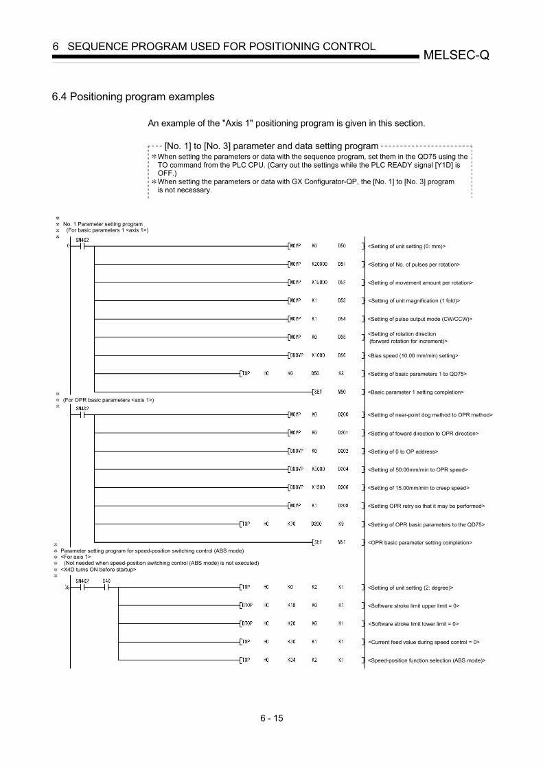
6 - 15
MELSEC-Q6 SEQUENCE PROGRAM USED FOR POSITIONING CONTROL
6.4 Positioning program examples
An example of the "Axis 1" positioning program is given in this section.
[No. 1] to [No. 3] parameter and data setting program When setting the parameters or data with the sequence program, set them in the QD75 using the TO command from the PLC CPU. (Carry out the settings while the PLC READY signal [Y1D] is OFF.) When setting the parameters or data with GX Configurator-QP, the [No. 1] to [No. 3] program is not necessary.
(For basic parameters 1 <axis 1>)
<X4D turns ON before startup>
No. 1 Parameter setting program
Parameter setting program for speed-position switching control (ABS mode)<For axis 1>
(Not needed when speed-position switching control (ABS mode) is not executed)
<Setting of unit setting (2: degree)>
<Setting of basic parameters 1 to QD75>
<Basic parameter 1 setting completion>
<Software stroke limit upper limit = 0>
<Software stroke limit lower limit = 0>
<Current feed value during speed control = 0>
<Speed-position function selection (ABS mode)>
<Setting of unit setting (0: mm)>
<Setting of No. of pulses per rotation>
<Setting of movement amount per rotation>
<Setting of unit magnification (1 fold)>
<Setting of pulse output mode (CW/CCW)>
<Setting of rotation direction (forward rotation for increment)>
<Bias speed (10.00 mm/min) setting>
(For OPR basic parameters <axis 1>)
<Setting of near-point dog method to OPR method>
<Setting of foward direction to OPR direction>
<Setting of 0 to OP address>
<Setting of 50.00mm/min to OPR speed>
<Setting of 15.00mm/min to creep speed>
<Setting OPR retry so that it may be performed>
<Setting of OPR basic parameters to the QD75>
<OPR basic parameter setting completion>

6 - 16
MELSEC-Q6 SEQUENCE PROGRAM USED FOR POSITIONING CONTROL
(For positioning data No. 1 <axis 1>)No. 2 Positioning data setting program
<Positioning identifier> Operation pattern: Positioning completeControl system: 1-axis linear control (ABS)Acceleration time No.: 1, deceleration time No.: 2
<Setting of positioning identifier>
<Setting of M code (9843)>
<Setting of dwell time (300ms)>
<(Dummy data)>
<Setting of command speed (180.00mm/min)>
<Positioning address (412.6 m) setting>
<Setting of arc address (0.0 m)>
<Setting of positioning data No. 1 to QD75>
Block start data of start block 0 (axis 1)No. 3 Block start data setting program
For setting of points 1 to 5
Shape: Continued at points 1 to 4, ended at point 5Special start instruction: Normal start at all of points 1 to 5<Positioning data are already preset>
(Conditions)
[Setting of shape and start data No.]
<Setting of continue and start data No. 1>
<Setting of continue and start data No. 2>
<Setting of continue and start data No. 5>
<Setting of continue and start data No. 10>
<Setting of end and start data No. 15>
<Setting of block start data to QD75>

6 - 17
MELSEC-Q6 SEQUENCE PROGRAM USED FOR POSITIONING CONTROL
[Setting of special start instruction to normal start]
<Setting of normal start>
<Setting of normal start>
<Setting of normal start>
<Setting of normal start>
<Setting of normal start>
<Setting of block start data to QD75>
<OPR request OFF command pulse>
<OPR request OFF command hold>
<OPR request flag ON/OFF extraction>
<OPR request OFF command ON>
<OPR request OFF command storage OFF>
<OPR request OFF write>
<OPR request OFF command OFF>
No. 4 OPR request OFF program
No. 5 External command function valid setting program
<External command valid write>
<External command invalid write>
No. 6 PLC READY signal [Y0] ON program(M50 contact not required for synchronous mode.)
<PLC READY signal ON/OFF>
No. 7 Positioning start No. setting program(1) Machine OPR
<Machine OPR (9001) write>
(2) Fast OPR
<OPR requset flag ON/OFF extraction>
<Fast OPR start enable>
<Fast OPR (9002) write>
<Fast OPR command hold>
<Positioning data No. 1 setting>
(3) Positioning with positioning data No. 1
150
183
190
195
211
223
232
238
249
280
258

6 - 18
MELSEC-Q6 SEQUENCE PROGRAM USED FOR POSITIONING CONTROL
(5) Position-speed switching operation positioning data No. 3
(4) Speed-position switching operation (positioning data No. 2)(In the ABS mode, new movement amount write is not needed.)
(6) High-level positioning control
(7) Fast OPR command and fast OPR command storage OFF(Not required when fast OPR is not used)
(1) When dedicated instruction (PSTRT1) is usedNo. 8 Positioning start program
(When fast OPR is not made, contacts of M3 and M4 are not needed.)(When M code is not used, contact of X04 is not needed.)(When JOG operation/inching operation is not performed, contact of M7 is not needed.)(When manual pulse generator operation is not performed, contact of M9 is not needed.)
287
295
301
307
313
320
326
338
345
359
372
384
332
<Positioning data No. 2 setting>
<Speed-position switching signal enable setting>
<Speed-position switching signal prohibit setting>
<New movement amount write>
<Positioning data No. 3 setting>
<Position-speed switching signal enable setting>
<Position-speed switching signal prohibit setting>
<New speed write>
<Block positioning (7000) write>
<Fast OPR command OFF>
<Fast OPR command storage OFF>
<Positioning start command pulse>
<Positioning start command hold>
<Positioning start execution>
<Positioning start command storage OFF>

6 - 19
MELSEC-Q6 SEQUENCE PROGRAM USED FOR POSITIONING CONTROL
<Positioning start command pulse>
(2) When positioning start signal (Y10) is used(When fast OPR is not made, contacts of M3 and M4 are not needed.)(When M code is not used, contact of X04 is not needed.)(When JOG operation/inching operation is not performed, contact of M7 is not needed.)(When manual pulse generator operation is not performed, contact of M9 is not needed.)
<Positioning start command hold>
<Positioning start No. setting>
<Positioning start execution>
<Positioning start command storage OFF>
<Positioning start signal OFF>
No. 10 JOG operation setting program
<M code OFF request write>
No. 11 Inching operation setting program
<JOG operation speed (100.00 mm/min) setting>
<Setting of 0 for inching movement amount>
<JOG operation request write>
No. 12 JOG operation/inching operation execution program
<Inching movement amount (1.0 m) setting>
<Inching movement amount write>
<JOG/inching operating flag ON>
<JOG/inching operation completed>
<Forward run JOG/inching operation execution>
<Reverse run JOG/inching operation execution>
DX0C
397
408
421
431
No. 9 M code OFF program(Not required when M code is not used)
439
449
480
505
512
521
516

6 - 20
MELSEC-Q6 SEQUENCE PROGRAM USED FOR POSITIONING CONTROL
526
533
551
555
565
572
576
596
603
613
620
639
No. 13 Manual pulse generator operation program
No. 15 Override program
No. 14 Speed change program
No. 16 Acceleration/deceleration time change program
<Manual pulse generator operation command pulse>
<Manual pulse generator 1 pulse input magnification setting>
<Manual pulse generator operation enable write>
<Manual pulse generator data write>
<Manual pulse generator operating flag ON>
<Manual pulse generator operation disable command pulse>
<Manual pulse generator operation disable write>
<Manual pulse generator operating flag OFF>
<Speed change command pulse>
<Speed change command hold>
<New speed value (20.00 mm/min) setting>
<Speed change request setting>
<Speed change write>
<Speed change command storage OFF>
<Override command pulse>
<Setting of override value to 200 %>
<Override value write>
<Acceleration/deceleration time change command pulse>
<Setting of acceleration time to 2000 ms>
<Setting of deceleration time to without change (0)>
<Acceleration/deceleration time write>
<Acceleration/deceleration time change enable write>
<Acceleration/deceleration time change disable write>

6 - 21
MELSEC-Q6 SEQUENCE PROGRAM USED FOR POSITIONING CONTROL
<Torque change command pulse>
<Write of torque limit value in Q62DA>
<Step operation command pulse>
<Step operation run selection>
<Data No. unit step mode selection>
<Step operation command write>
<Skip pulse>
<Skip command ON storage>
<Skip command write>
<Skip command storage OFF>
No. 21 Continuous operation interrupt program
No. 22 Target position change program
<Teaching command pulse>
<Teaching command hold>
<Teaching data setting>
<Positioning data No. setting>
<Teaching execution>
<Teaching command storage OFF>
<Continuous operation interrupt command pulse>
<Continuous operation interrupt write>
<Target position change command pulse>
<Target position change command hold>
<Setting of target position address to 300.0 m>
<Target position change request setting>
<Speed change write>
<Speed change request storage OFF>
645
652
660
681
704
715
719
740
747
667
688
692
No. 17 Torque change program
No. 18 Step operation program
No. 19 Skip program
No. 20 Teaching program
Positioned manually to target position.
754
761
765

6 - 22
MELSEC-Q6 SEQUENCE PROGRAM USED FOR POSITIONING CONTROL
<Status reset>
<Error code transmission to D49>
<ABS data bit 0 ON/OFF>
<ABS data bit 1 ON/OFF>
<Transmission data preparation complete flag ON/OFF>
<ABRST1 instruction execution>
<Restart command pulse>
<Restart command ON during stop>
<Restart request write>
<Restart command storage OFF>
<Parameter initialization command pulse>
<Parameter initialization command hold>
<PLC READY output to QD75 standby>
<Parameter initialization execution>
<Parameter initialization command storage OFF>
796
788
802
823
850
857
864
878
885
889
896
No. 23 Absolute position restoration program(1) Absolute position restoration command acceptance
(3) ABS data setting and ABRST1 instruction execution
No. 24 Restart program
No. 25 Parameter initialization program
(2) Setting of transmit data to servo-amplifier and confirmation of absolute position restoration completionABRST1 instruction completed when M42 is ON and M43 is OFF.Absolute position data restoration completed when status = 0.
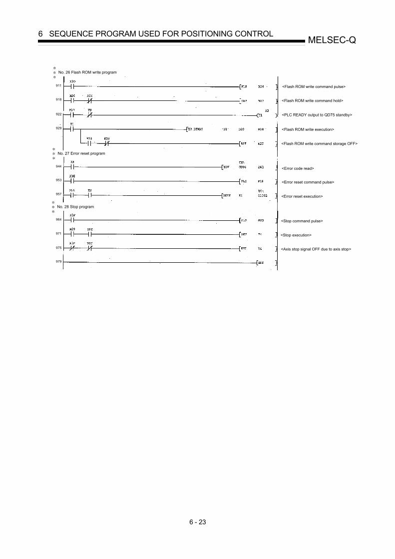
6 - 23
MELSEC-Q6 SEQUENCE PROGRAM USED FOR POSITIONING CONTROL
<Flash ROM write command pulse>
<Flash ROM write command hold>
<PLC READY output to QD75 standby>
<Flash ROM write execution>
<Flash ROM write command storage OFF>
<Error code read>
<Error reset command pulse>
<Error reset execution>
<Stop command pulse>
<Stop execution>
<Axis stop signal OFF due to axis stop>
No. 26 Flash ROM write program
No. 27 Error reset program
No. 28 Stop program
911
918
922
929
944
953
957
964
971
975
979

6 - 24
MELSEC-Q6 SEQUENCE PROGRAM USED FOR POSITIONING CONTROL
6.5 Program details
6.5.1 Initialization program
[1] OPR request OFF programThis program forcibly turns OFF the "OPR request flag" ( Md.31 Status : b3)
which is ON.When using a system that does not require OPR, assemble the program tocancel the "OPR request" made by the QD75 when the power is turned ON, etc.
Data requiring settingSet the following data to use the OPR request flag OFF request.
Buffer memory addressSetting item Setting
value Setting detailsAxis 1 Axis 2 Axis 3 Axis 4
Cd.19 OPR request flag OFFrequest 1 Set to "1: Turn OPR request flag OFF". 1521 1621 1721 1821
Refer to Section 5.7 "List of control data" for details on the setting details.
Time chart for OPR request OFF
OFF
ON
OFF
0 1 0
ON
OFF
PLC READY signal [Y0]
QD75 READY signal [X0]
OPR request OFF flag[ Md. 31 Status: b3]
Cd. 19 OPR request flag OFF request
ON
Fig. 6.1 Time chart for OPR request OFF
[2] External command function valid setting programThis program is used to validate the "external command signal" beforehand whenusing the external command functions (external start, speed change, speed-position switching, position-speed switching, skip). (Set which function to usebeforehand in " Pr.42 External command function selection".)
Set the following data to validate the "external command signal".
Buffer memory addressSetting item Setting
value Setting detailsAxis 1 Axis 2 Axis 3 Axis 4
Cd.8 External command valid 1 Set to "1: Validate external command". 1505 1605 1705 1805
Refer to Section 5.7 "List of control data" for details on the setting details.

6 - 25
MELSEC-Q6 SEQUENCE PROGRAM USED FOR POSITIONING CONTROL
6.5.2 Start details setting program
This program sets which control, out of "OPR", "major positioning control" or "high-levelpositioning control" to execute. For " high-level positioning control", "fast OPR", "speed-position switching control" and "position-speed switching control", add the respectivelyrequired sequence program.(Refer to Chapter 10 for details on starting the " high-level positioning control.)
Procedures for setting the starting details
(1) Set the "positioning start No." corresponding to the control to be started in" Cd.3 Positioning start No.".
Buffer memory addressSetting item Setting
value Setting detailsAxis 1 Axis 2 Axis 3 Axis 4
Cd.3 Positioning start No.
1 to 600 : Positioning data No.9001 : Machine OPR9002 : Fast OPR9003 : Current value changing9004 : Simultaneous start7000 to 7004 : Block No.
(For "high-level positioningcontrol")
1500 1600 1700 1800
Refer to Section 5.7 "List of control data" for details on the setting details.
(2) For " high-level positioning control", set the "positioning start point No." of theblock to be started in " Cd.4 Positioning start point No.".
Buffer memory addressSetting item Setting
value Setting detailsAxis 1 Axis 2 Axis 3 Axis 4
Cd.4 Positioning start point No. 1 to 50 : Point No. of block start data 1501 1601 1701 1801
Refer to Section 5.7 "List of control data" for details on the setting details.
(3) Set the following control data for "speed-position switching control (INCmode)".(Set " Cd.23 Speed-position switching control movement amount changeregister as required". Setting is not required in the ABS mode.)
Buffer memory addressSetting item Setting
value Setting detailsAxis 1 Axis 2 Axis 3 Axis 4
Cd.23Speed-position switchingcontrol movement amountchange register
Set the new value when the position control'smovement amount is to be changed duringspeed control.
15261527
16261627
17261727
18261827
Cd.24 Speed-position switchingenable flag 1 When "1" is set, the speed-position switching
signal will be validated. 1528 1628 1728 1828
Refer to Section 5.7 "List of control data" for details on the setting details.

6 - 26
MELSEC-Q6 SEQUENCE PROGRAM USED FOR POSITIONING CONTROL
(4) For "position-speed switching control", set the control data shown below.(As required, set the " Cd.25 Position-speed switching control speed changeresister".)
Buffer memory addressSetting item Setting
value Setting detailsAxis 1 Axis 2 Axis 3 Axis 4
Cd.25Position-speed switchingcontrol speed changeresister
Used to set a new value when speed is changedduring positioning control.
15301531
16301631
17301731
18301831
Cd.26 Position-speed switchingenable flag 1 To validate position-speed switching signal, this
is set to 1. 1532 1632 1732 1832
Refer to Section 5.7 "List of control data" for details on the setting details.
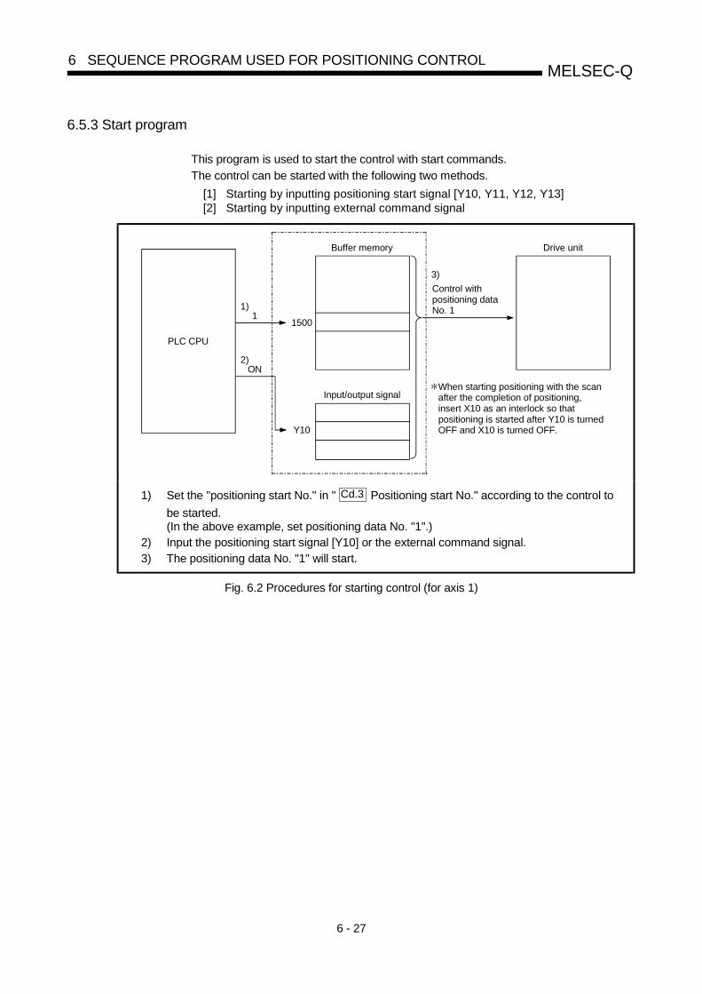
6 - 27
MELSEC-Q6 SEQUENCE PROGRAM USED FOR POSITIONING CONTROL
6.5.3 Start program
This program is used to start the control with start commands.
The control can be started with the following two methods.
[1] Starting by inputting positioning start signal [Y10, Y11, Y12, Y13][2] Starting by inputting external command signal
PLC CPU
Buffer memory
1500
Input/output signal
11)
ON2)
Y10
Drive unit
Control with positioning data No. 1
3)
When starting positioning with the scan after the completion of positioning, insert X10 as an interlock so that positioning is started after Y10 is turnedOFF and X10 is turned OFF.
1) Set the "positioning start No." in " Cd.3 Positioning start No." according to the control to
be started.(In the above example, set positioning data No. "1".)
2) Input the positioning start signal [Y10] or the external command signal.3) The positioning data No. "1" will start.
Fig. 6.2 Procedures for starting control (for axis 1)

6 - 28
MELSEC-Q6 SEQUENCE PROGRAM USED FOR POSITIONING CONTROL
Starting conditions
To start the control, the following conditions must be satisfied.The necessary start conditions must be incorporated in the sequence program sothat the control is not started when the conditions are not satisfied.
DeviceSignal name Signal state
Axis 1 Axis 2 Axis 3 Axis 4
PLC READY signal ON PLC CPU preparation completed Y0
QD75 READY signal ON QD75 preparation completed X0
Synchronization flag ONQD75 buffer memoryAccessible
X1
Axis stop signal OFF Axis stop signal is OFF. Y4 Y5 Y6 Y7
M code ON signal OFF M code ON signal is OFF. X4 X5 X6 X7
Error detection signal OFF No error is present. X8 X9 XA XB
BUSY signal OFF BUSY signal is OFF. XC XD XE XF
Interfacesignal
Start complete signal OFF Start complete signal is OFF. X10 X11 X12 X13
Drive unit READY signal ON Drive unit preparation completed –
Stop signal OFF Stop signal is OFF. –
Upper limit (FLS) ON Within limit range –Externalsignal
Lower limit (RLS) ON Within limit range –
: When the synchronous setting of the PLC CPU is made in the nonsynchronous mode, this must beprovided as an interlock.When it is made in the synchronous mode, no interlock must be provided in the program because theflag is turned ON when calculation is run on the PLC CPU.

6 - 29
MELSEC-Q6 SEQUENCE PROGRAM USED FOR POSITIONING CONTROL
[1] Starting by inputting positioning start signal
Operation when starting
(1) When the positioning start signal turns ON, the start complete signal andBUSY signal turn ON, and the positioning operation starts.It can be seen that the axis is operating when the BUSY signal is ON.
(2) When the positioning start signal turns OFF, the start complete signal alsoturns OFF.If the positioning start signal is ON even after positioning is completed, thestart complete signal will remain ON.
(3) If the positioning start signal turns ON again while the BUSY signal is ON, thewarning "operating start (warning code: 100)" will occur.
(4) The process taken when positioning is completed will differ according to case(a) and (b) below.
(a) When next positioning is not to be carried out• If a dwell time is set, the system will wait for the set time to pass, and then
positioning will be completed.• When positioning is completed, the BUSY signal will turn OFF and the
positioning complete signal will turn ON. However, when using speedcontrol or when the positioning complete signal ON time is "0", the signalwill not turn ON.
• When the positioning complete signal ON time is passed, the positioningcomplete signal will turn OFF.
(b) When next positioning is to be carried out• If a dwell time is set, the system will wait for the set time to pass.• When the set dwell time is passed, the next positioning will start.
t
Positioning start signal [Y10, Y11, Y12, Y13]
OFF
ON
Start complete signal [X10, X11, X12, X13]
OFF
ON
OFF
ON
OFF
ON
Positioning
V
Dwell time
BUSY signal[XC, XD, XE, XF]
Positioning completesignal
[X14, X15, X16, X17]
Fig. 6.3 ON/OFF timing of each signal at start of positioning
POINTSThe BUSY signal [XC, XD, XE, XF] turns ON even when position control of movement amount 0 is
executed. However, since the ON time is short, the ON status may not be detected in the sequence
program.
(The ON status of the start complete signal [X10, X11, X12, X13], positioning complete signal [X14,
X15, X16, X17] and M code ON signal [X4, X5, X6, X7] can be detected in the sequence program.)

6 - 30
MELSEC-Q6 SEQUENCE PROGRAM USED FOR POSITIONING CONTROL
Starting time chart
The time chart for starting each control is shown below.
(1) Time chart for starting "machine OPR"
QD75 READY signal
Start complete signal
BUSY signal
Error detection signal
OFF
OFF
ON
ON
ON
ON
OFF
OFF
OFF
9001
ON
ON
OFF
OFF
Near-point dog
V
t
OPR request flag [ Md. 31 Status: b3]
Cd. 3 Positioning start No.
Positioning start signal [Y10]
PLC READY signal [Y0]
[X0]
[X10]
[XC]
[X8]
OPR complete flag [ Md. 31 Status: b4]
Zero signal
ON
OFF
Fig. 6.4 Time chart for starting "machine OPR"

6 - 31
MELSEC-Q6 SEQUENCE PROGRAM USED FOR POSITIONING CONTROL
(2) Time chart for starting "fast OPR"
OFF
OFF
ON
ON
ON
ON
OFF
OFF
OFF
9002
V
t
ON
OFF
Positioning start signal
PLC READY signal
QD75 READY signal
Start complete signal
BUSY signal
Error detection signal
Cd. 3 Positioning start No.
[Y10]
[Y0]
[X0]
[X10]
[XC]
[X8]
Fig. 6.5 Time chart for starting "fast OPR"

6 - 32
MELSEC-Q6 SEQUENCE PROGRAM USED FOR POSITIONING CONTROL
(3) Time chart for starting "major positioning control"
1
V
t
Positioning data No.Dwell time
2(00)
Operation pattern
1(11)
Positioning start signal
PLC READY signal
QD75 READY signal
Start complete signal
BUSY signal
Error detection signal
Cd. 3 Positioning start No.
Positioning complete signal
[Y10]
[Y0]
[X0]
[X10]
[XC]
[X14]
[X8]
Fig. 6.6 Time chart for starting "major positioning control"
(4) Time chart for starting "speed-position switching control"
V
t
Dwell timeOperation pattern(00) Speed control
Speed-position switching signal
Position control
0
1
1
Positioning data No.(1)
Positioning start signal
PLC READY signal
QD75 READY signal
Start complete signal
BUSY signal
Error detection signal
Positioning complete signal
Cd. 3 Positioning start No.
Cd. 24 Speed-position switching enable flag
[Y10]
[Y0]
[X0]
[X10]
[XC]
[X14]
[X8]
(external)
Fig. 6.7 Time chart for starting "speed-position switching control"

6 - 33
MELSEC-Q6 SEQUENCE PROGRAM USED FOR POSITIONING CONTROL
(5) Time chart for starting "position-speed switching control"
Positioning start signal
PLC READY signal
QD75 READY signal
Start complete signal
BUSY signal
Positioning complete signal
V
t
Error detection signal
Operation pattern (00)
Positioning data No. (1)Position control Speed control
0
1Cd. 3 Positioning start No.
Cd. 26 Position-speed
switching enable flag1
[Y10]
[Y0]
[X0]
[X10]
[XC]
[X14]
[X8]
Stop command
Position-speed switching signal(external)
Fig. 6.8 Time chart for starting "position-speed switching control"

6 - 34
MELSEC-Q6 SEQUENCE PROGRAM USED FOR POSITIONING CONTROL
Machine OPR operation timing and process time
BUSY signal
Waiting In OPR Waiting
Output pulse to external source (PULSE)
Positioning operation
t1
t4
t2
t3
Md. 26 Axis operation status
OPR request flag [ Md. 31 Status: b3]
Positioning start signal[Y10, Y11, Y12, Y13]
[XC, XD, XE, XF]
Start complete signal[X10, X11, X12, X13]
OPR complete flag [ Md. 31 Status: b4]
Fig. 6.9 Machine OPR operation timing and process time
Normal timing time Unit: ms
t1 t2 t3 t4
1.0 to 1.4 2.7 to 4.4 0 to 1.8 0 to 1.8
• The t1 timing time could be delayed depending on the operating conditions ofthe other axis.

6 - 35
MELSEC-Q6 SEQUENCE PROGRAM USED FOR POSITIONING CONTROL
Position control operation timing and process time
t1
t2
t3
t4
t5
t2
t6
Cd. 7 M code OFF request
Waiting Controlling position Waiting
BUSY signal
Output pulse to external source (PULSE)
Positioning operation
Md. 26 Axis operation status
Cd. 7 M code OFF request
Positioning start signal[Y10, Y11, Y12, Y13]
[XC, XD, XE, XF]
M code ON signal (WITH mode) [X4, X5, X6, X7]
Start complete signal[X10, X11, X12, X13]
M code ON signal(AFTER mode)
[X4, X5, X6, X7]
[X14, X15, X16, X17]Positioning complete signal
OPR complete flag [ Md. 31 Status: b4]
Fig. 6.10 Position control operation timing and process time
• When the positioning start signal turns ON, if all signals marked with anasterisk ( ) are already ON, the signals marked with an asterisk ( ) will turnOFF when the positioning start signal turns ON.
Normal timing time Unit: ms
t1 t2 t3 t4 t5 t6
1.2 to 2.3 0 to 1.8 0 to 1.8 2.7 to 4.4 0 to 1.8Follows
parameters
• The t1 timing time could be delayed depending on the operating conditions ofthe other axis.
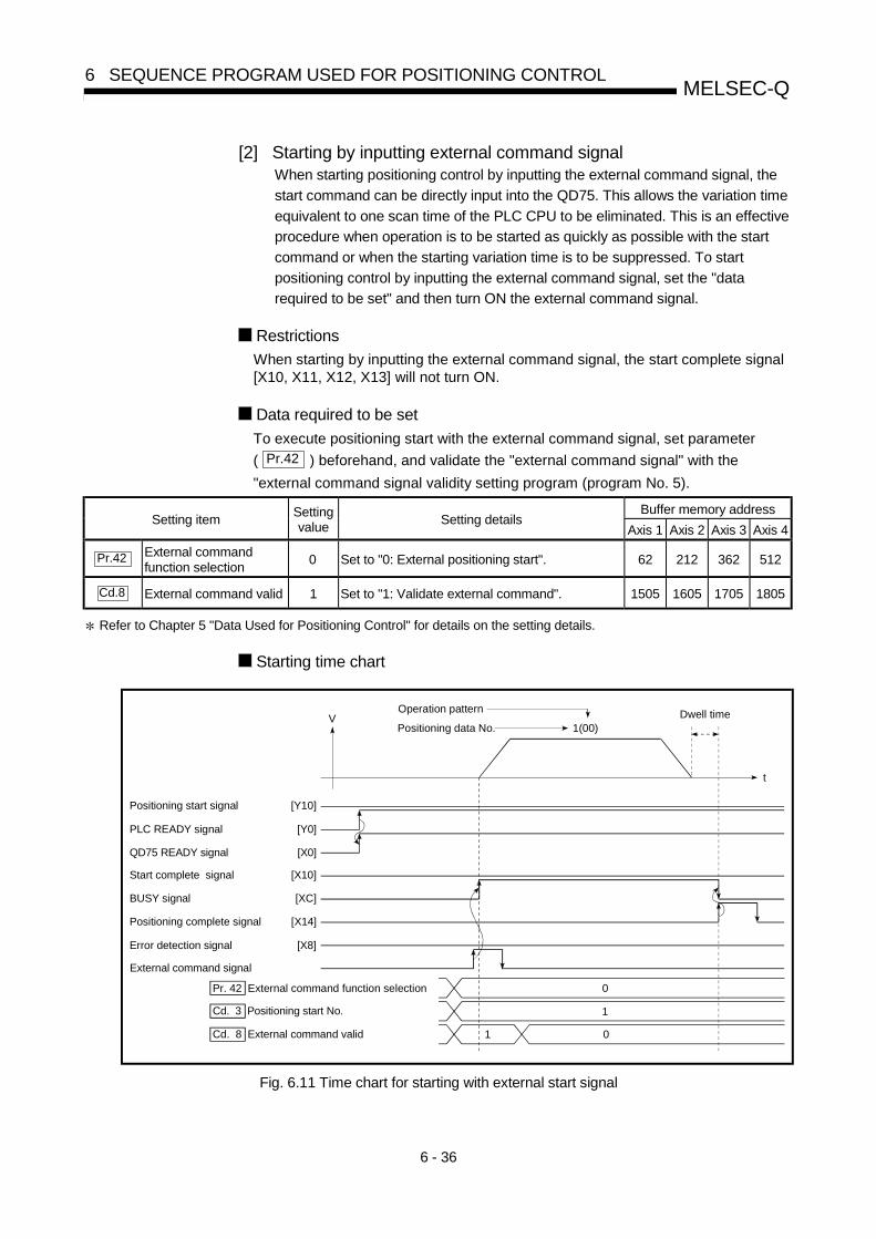
6 - 36
MELSEC-Q6 SEQUENCE PROGRAM USED FOR POSITIONING CONTROL
[2] Starting by inputting external command signalWhen starting positioning control by inputting the external command signal, the
start command can be directly input into the QD75. This allows the variation time
equivalent to one scan time of the PLC CPU to be eliminated. This is an effective
procedure when operation is to be started as quickly as possible with the start
command or when the starting variation time is to be suppressed. To start
positioning control by inputting the external command signal, set the "data
required to be set" and then turn ON the external command signal.
Restrictions
When starting by inputting the external command signal, the start complete signal[X10, X11, X12, X13] will not turn ON.
Data required to be set
To execute positioning start with the external command signal, set parameter
( Pr.42 ) beforehand, and validate the "external command signal" with the
"external command signal validity setting program (program No. 5).
Buffer memory addressSetting item
Settingvalue
Setting detailsAxis 1 Axis 2 Axis 3 Axis 4
Pr.42 External commandfunction selection
0 Set to "0: External positioning start". 62 212 362 512
Cd.8 External command valid 1 Set to "1: Validate external command". 1505 1605 1705 1805
Refer to Chapter 5 "Data Used for Positioning Control" for details on the setting details.
Starting time chart
0
V
t
1(00)
External command signal
1
01Cd. 8 External command valid
Dwell timeOperation pattern
Positioning start signal
PLC READY signal
QD75 READY signal
Start complete signal
BUSY signal
Error detection signal
Positioning complete signal
Positioning data No.
Pr. 42 External command function selection
Cd. 3 Positioning start No.
[Y10]
[Y0]
[X0]
[X10]
[XC]
[X14]
[X8]
Fig. 6.11 Time chart for starting with external start signal

6 - 37
MELSEC-Q6 SEQUENCE PROGRAM USED FOR POSITIONING CONTROL
6.5.4 Continuous operation interrupt program
During positioning control, the control can be interrupted during continuous positioning
control and continuous path control (continuous operation interrupt function). When
"continuous operation interruption" is execution, the control will stop when the
operation of the positioning data being executed ends. To execute continuous
operation interruption, set "1: Continuous operation interrupt request" for " Cd.18
Interrupt request during continuous operation".
[1] Operation during continuous operation interruption
Start
Positioning data No. 10 Positioning data No. 11 Positioning data No. 12
Stop command ON or continuous operation interrupt request
V
t
Stop process at continuous operation interrupt request
Stop process when stop command turns ON
Fig. 6.12 Operation during continuous operation interruption
[2] Restrictions(1) When the "continuous operation interrupt request" is executed, the positioning
will end.Thus, after stopping, the operation cannot be "restarted".
When " Cd.6 Restart command" is issued, a warning "Restart not possible"
(warning code: 104) will occur.(2) Even if the stop command is turned ON after executing the "continuous
operation interrupt request", the "continuous operation interrupt request"cannot be canceled.Thus, if "restart" is executed after stopping by turning the stop command ON,the operation will stop when the positioning data No. where "continuousoperation interrupt request" was executed is completed.
Axis 2
Axis 1
Positioning for positioning data No. 12 is not executed
Positioning with positioning data No. 10
Positioning with positioning data No. 11
������������������������������������������������������������������������������������������������������������������������������������������������������������������������������������������������������������
������������������������������������������������������������������������������������������������������������������������������������
Continuous operation interrupt request
Positioning ends with continuousoperation interrupt request

6 - 38
MELSEC-Q6 SEQUENCE PROGRAM USED FOR POSITIONING CONTROL
(3) If the operation cannot be decelerated to a stop because the remainingdistance is insufficient when "continuous operation interrupt request" isexecuted with continuous path control, the interruption of the continuousoperation will be postponed until the positioning data shown below.
• Positioning data No. have sufficient remaining distance • Positioning data No. for positioning complete (pattern: 00) • Positioning data No. for continuous positioning control (pattern: 01)
Start
V
t
Stop process when operation cannot stop at positioning data No. 10
Positioninig data No. 10 Positioning data No. 11 Positioning data No. 12
Continuous operation interrupt request
Even when the continuous operation interrupt is requested, the remaining distance is insufficient, and thus, the operation cannot stop at the positioning No. being executed.
(4) When operation is not performed (BUSY signal [XC, XD, XE, XF] is OFF), theinterrupt request during continuous operation is not accepted. It is cleared to 0at a start or restart.
[3] Control data requiring settingsSet the following data to interrupt continuous operation.
Buffer memory addressSetting item
Settingvalue
Setting detailsAxis 1 Axis 2 Axis 3 Axis 4
Cd.18 Interrupt request duringcontinuous operation
1Set "1: Interrupt request during continuousoperation".
1520 1620 1720 1820
Refer to Section 5.7 "List of control data" for details on the setting details.

6 - 39
MELSEC-Q6 SEQUENCE PROGRAM USED FOR POSITIONING CONTROL
6.5.5 Restart program
When a stop factor occurs during position control and the operation stops, the
positioning can be restarted from the stopped position to the position control end point
by using the "restart command" ( Cd.6 Restart command).
("Restarting" is not possible when "continuous operation is interrupted.")
[1] Restart operation
Axis 2
Axis 1
Stop with stop command
Positioning data No. 11 continues with restart command
Positioning with positioning data No. 11
Positioning with positioning data No. 10
Positioning with positioning data No. 12
Fig. 6.13 Restart operation
[2] Restrictions
(1) Restarting can be executed only when the " Md.26 Axis operation status" is
"stopped".If the axis operation is not "stopped", restarting is not possible.
(2) Do not execute restart while the stop command is ON.If restart is executed while stopped, an error "Stop signal ON at start" (error
code: 106) will occur, and the " Md.26 Axis operation status" will change to
"error occurring".Thus, even if the error is reset, the operation cannot be restarted.
(3) Restarting can be executed even while the positioning start signal is ON.However, make sure that the positioning start signal does not change fromOFF to ON while stopped.If the positioning start signal changes from OFF to ON, positioning will startfrom the positioning data No. of designated point's positioning data No. set in
" Cd.3 Positioning start No.".
(4) If positioning is ended with the continuous operation interrupt request, theoperation cannot be restarted.If restart is requested, a warning "Restart not possible" (warning code: 104)will occur.
(5) When stopped with interpolation operation, write "1: Restarts" into
" Cd.6 Restart command" for the reference axis, and then restart.
(6) If the " Md.26 Axis operation status" is not "stopped" when restarting, a
warning "Restart not possible" (warning code: 104) will occur, and the processat that time will be continued.
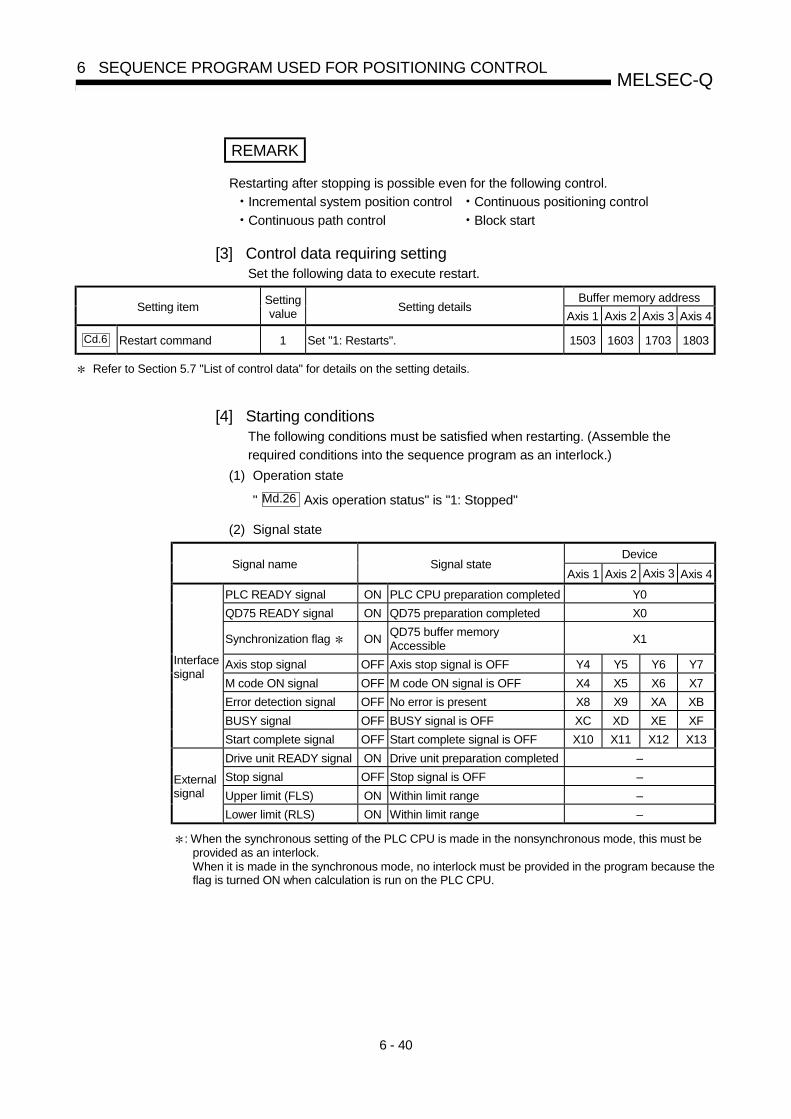
6 - 40
MELSEC-Q6 SEQUENCE PROGRAM USED FOR POSITIONING CONTROL
REMARK
Restarting after stopping is possible even for the following control.
• Incremental system position control • Continuous positioning control
• Continuous path control • Block start
[3] Control data requiring settingSet the following data to execute restart.
Buffer memory addressSetting item
Settingvalue
Setting detailsAxis 1 Axis 2 Axis 3 Axis 4
Cd.6 Restart command 1 Set "1: Restarts". 1503 1603 1703 1803
Refer to Section 5.7 "List of control data" for details on the setting details.
[4] Starting conditionsThe following conditions must be satisfied when restarting. (Assemble the
required conditions into the sequence program as an interlock.)
(1) Operation state
" Md.26 Axis operation status" is "1: Stopped"
(2) Signal state
DeviceSignal name Signal state
Axis 1 Axis 2 Axis 3 Axis 4
PLC READY signal ON PLC CPU preparation completed Y0
QD75 READY signal ON QD75 preparation completed X0
Synchronization flag ONQD75 buffer memoryAccessible
X1
Axis stop signal OFF Axis stop signal is OFF Y4 Y5 Y6 Y7
M code ON signal OFF M code ON signal is OFF X4 X5 X6 X7
Error detection signal OFF No error is present X8 X9 XA XB
BUSY signal OFF BUSY signal is OFF XC XD XE XF
Interfacesignal
Start complete signal OFF Start complete signal is OFF X10 X11 X12 X13
Drive unit READY signal ON Drive unit preparation completed –
Stop signal OFF Stop signal is OFF –
Upper limit (FLS) ON Within limit range –Externalsignal
Lower limit (RLS) ON Within limit range –
: When the synchronous setting of the PLC CPU is made in the nonsynchronous mode, this must beprovided as an interlock.When it is made in the synchronous mode, no interlock must be provided in the program because theflag is turned ON when calculation is run on the PLC CPU.

6 - 41
MELSEC-Q6 SEQUENCE PROGRAM USED FOR POSITIONING CONTROL
(5) Time chart for restarting
0
V
t
1
Dwell time
8 1 8 0
00
Positioning start signal
Axis stop signal
QD75 READY signal
Start complete signal
BUSY signal
Error detection signal
Cd. 6 Restart command
Positioning complete signal
PLC READY signal
Md. 26 Axis operation status
[Y10]
[Y4]
[Y0]
[X0]
[X10]
[XC]
[X14]
[X8]
Fig. 6.14 Time chart for restarting

6 - 42
MELSEC-Q6 SEQUENCE PROGRAM USED FOR POSITIONING CONTROL
6.5.6 Stop program
The axis stop signal [Y4, Y5, Y6, Y7] or a stop signal from an external source is used
to stop the control.
Create a program to turn ON the axis stop signal [Y4, Y5, Y6, Y7] as the stop program.
The process for stopping control is explained below.
Each control is stopped in the following cases.
(1) When each control is completed normally.
(2) When the drive unit READY signal is turned OFF.
(3) When a PLC CPU error occurs
(4) When the PLC READY signal is turned OFF.
(5) When an error occurs in QD75.
(6) When control is intentionally stopped
(Stop signal from PLC CPU turned ON, stop signal from peripheral devices)
The stop process for the above cases is shown below.
(Excluding item (1) above "When each control is completed normally".)
[1] Stop processStop process
OPR control Manual control
Stop causeStopaxis
M codeON
signalafter stop
Axisoperation
status
( Md.26 )
afterstopping
MachineOPR
control
Fast OPRcontrol
Majorpositioning
control
High-levelpositioning
control
JOG/Inching
operation
Manualpulse
generatoroperation
Forced stopDrive unitREADY signalOFF
Eachaxis
Nochange
Duringerror
Immediate stopDecelerationstop
Fatal stop(Stop group 1)
Hardware strokelimit upper/lowerlimit erroroccurrence
Eachaxis
Nochange
Duringerror
Deceleration stop/sudden stop
(Select with " Pr.37 Sudden stop group 1 sudden stop
selection".
Decelerationstop
PLC CPU erroroccurrence
Nochange
PLC READYsignal OFF
TurnsOFF
Emergency stop(Stop group 2)
Error in testmode
All axes
Nochange
Duringerror
Delegation stop/sudden stop
(Select with " Pr.38 Sudden stop group 2 sudden stop
selection".
Decelerationstop
Axis errordetection (Errorother than stopgroup 1 or 2)
Relatively safestop(Stop group 3)
"Stop" input fromperipheral device
Eachaxis
Nochange
Duringerror
"Stop signal" ONfrom externalsourceIntentional stop
(Stop group 3) "Axis stop signal"ON from PLCCPU
Eachaxis
Nochange
Duringstop(duringstandingby)
Deceleration stop/sudden stop
(Select with " Pr.39 Sudden stop group 3 sudden stop
selection".
Decelerationstop

6 - 43
MELSEC-Q6 SEQUENCE PROGRAM USED FOR POSITIONING CONTROL
[2] Types of stop processesThe operation can be stopped with deceleration stop, sudden stop or immediate
stop.
(1) Deceleration stop 1
The operation stops with "deceleration time 0 to 3" ( Pr.10 , Pr.28 , Pr.29 ,
Pr.30 ).
Which time from "deceleration time 0 to 3" to use for control is set in positioning
data ( Da.4 ).
(2) Sudden stop
The operation stops with " Pr.36 Sudden stop deceleration time".
(3) Immediate stop
The operation does not decelerate.The QD75 immediately stops the pulse output, but the operation will coast forthe droop pulses accumulated in the drive unit's deviation counter.
Actual deceleration time
Set deceleration time
Positioning speed
Actual sudden stop deceleration time
Pr. 36 Sudden stop deceleration time
Coast for the droop pulses accumulated in the drive unit's deviation counter.
Positioning speed Positioning speed
Fig. 6.15 Types of stop processes
REMARK
1 "Deceleration stop" and "sudden stop" are selected with the details parameter 2
"stop group 1 to 3 sudden stop selection". (The default setting is "deceleration
stop".)
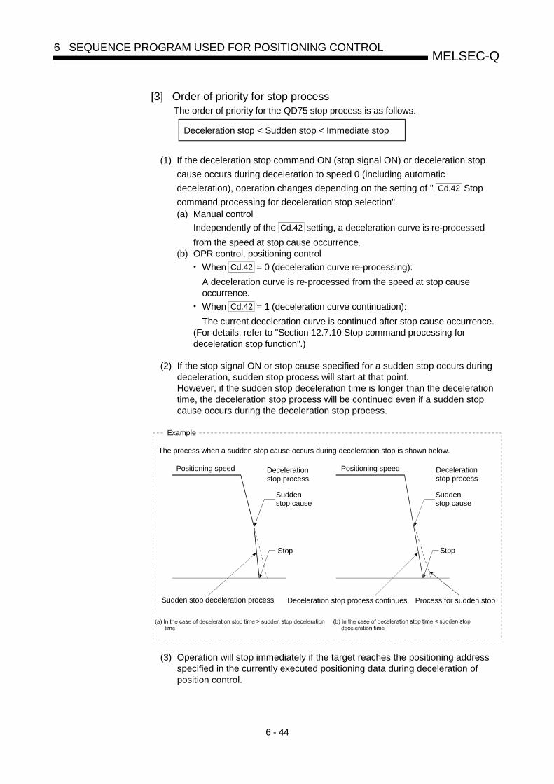
6 - 44
MELSEC-Q6 SEQUENCE PROGRAM USED FOR POSITIONING CONTROL
[3] Order of priority for stop processThe order of priority for the QD75 stop process is as follows.
Deceleration stop < Sudden stop < Immediate stop
(1) If the deceleration stop command ON (stop signal ON) or deceleration stop
cause occurs during deceleration to speed 0 (including automatic
deceleration), operation changes depending on the setting of " Cd.42 Stop
command processing for deceleration stop selection".(a) Manual control
Independently of the Cd.42 setting, a deceleration curve is re-processed
from the speed at stop cause occurrence.(b) OPR control, positioning control
• When Cd.42 = 0 (deceleration curve re-processing):
A deceleration curve is re-processed from the speed at stop causeoccurrence.
• When Cd.42 = 1 (deceleration curve continuation):
The current deceleration curve is continued after stop cause occurrence.(For details, refer to "Section 12.7.10 Stop command processing fordeceleration stop function".)
(2) If the stop signal ON or stop cause specified for a sudden stop occurs duringdeceleration, sudden stop process will start at that point.However, if the sudden stop deceleration time is longer than the decelerationtime, the deceleration stop process will be continued even if a sudden stopcause occurs during the deceleration stop process.
Positioning speed Deceleration stop process
Stop
Sudden stop cause
Sudden stop deceleration process Deceleration stop process continues Process for sudden stop
Positioning speed Deceleration stop process
Stop
Sudden stop cause
Example
The process when a sudden stop cause occurs during deceleration stop is shown below.
(3) Operation will stop immediately if the target reaches the positioning addressspecified in the currently executed positioning data during deceleration ofposition control.

7 - 1
7
Chapter 7 Memory Configuration and DataProcess
The QD75 memory configuration and data transmission are explained in this chapter.
The QD75 is configured of two memories. By understanding the configuration androles of two memories, the QD75 internal data transmission process, such as "whenthe power is turned ON" or "when the PLC READY signal changes from OFF to ON" can be easily understood. This also allows the transmission process to be carried out correctly when saving or changing the data.
7.1 Configuration and roles of QD75 memory...................................................................7- 27.1.1 Configuration and roles of QD75 memory .....................................................7- 27.1.2 Buffer memory area configuration..................................................................7- 5
7.2 Data transmission process...........................................................................................7- 6

7 - 2
MELSEC-Q7 MEMORY CONFIGURATION AND DATA PROCESS
7.1 Configuration and roles of QD75 memory
7.1.1 Configuration and roles of QD75 memory
The QD75 is configured of the following two memories.
Area configuration
Memoryconfiguration
Role
Par
amet
er a
rea
Mon
itor
data
are
a
Con
trol
dat
a ar
ea
Pos
ition
ing
data
are
a
(No.
1 to
600
)
Blo
ck s
tart
dat
a ar
ea(N
o.70
00 to
700
4)
PLC
CP
U m
emo
area
Bac
kup
• Buffer memoryArea that can be directly accessedwith sequence program from PLCCPU.
Notpos-sible
• Flash ROMArea for backing up data requiredfor positioning.
– – –Pos-sible
: Setting and storage area provided, Not possible: Data is lost when power is turned OFF
– : Setting and storage area not provided, Possible: Data is held even when power is turned OFF

7 - 3
MELSEC-Q7 MEMORY CONFIGURATION AND DATA PROCESS
Details of areas
• Parameter area
Area where parameters, such as positioning parameters and OPR parameters,required for positioning control are set and stored.
(Set the items indicated with Pr.1 to Pr.57 , Pr.150 for each axis.)
• Monitor data area
Area where positioning system or QD75 operation state is stored.
(Set the items indicated with Md.1 to Md.48 .)
• Control data area
Area where data for operating and controlling positioning system is set and
stored. (Set the items indicated with Cd.1 to Cd.42 .)
• Positioning data area (No.1 to 600)
Area where positioning data No.1 to 600 is set and stored.
(Set the items indicated with Da.1 to Da.10 for each positioning data.)
• Block start data area (No.7000 to 7004)
Area where information required only when carrying out block No. 7000 to 7004
high-level positioning is set and stored. (Set the items indicated with Da.11 toDa.19 .)
• PLC CPU memo area
Area where condition judgment values required for special positioning, etc., areset and stored.

7 - 4
MELSEC-Q7 MEMORY CONFIGURATION AND DATA PROCESS
Parameter area
Positioning data area(No.1 to 600)
Block start data area(No. 7000 to 7004)
PLC CPUmemo area
Monitor data area
Control data area
QD75
Flash ROM
Data is backed uphere.
Buffer memory
User accesseshere.
Parameter area
Positioning data area(No.1 to 600)
Block start data area(No.7000 to 7004)
Copy

7 - 5
MELSEC-Q7 MEMORY CONFIGURATION AND DATA PROCESS
7.1.2 Buffer memory area configuration
The QD75 buffer memory is configured of the following types of areas.
Buffer memory addressBuffer memory area configuration
Axis 1 Axis 2 Axis 3 Axis 4
Writing
possibility
Basic parameter area 0 to 15 150 to 165 300 to 315 450 to 465
Detailed parameter area 17 to 62 167 to 212 317 to 362 467 to 512
OPR basic parameter area 70 to 78 220 to 228 370 to 378 520 to 528Parameter area
OPR detailed parameter
area79 to 89 229 to 239 379 to 389 529 to 539
Possible
System monitor area 1200 to 1425
Monitor data areaAxis monitor area
800 to 847,
899
900 to 947,
999
1000 to
1047, 1099
1100 to
1147, 1199
Not possible
System control data area 1900, 1901, 1905, 1907Control data area
Axis control data area 1500 to 1550 1600 to 1650 1700 to 1750 1800 to 1850Possible
Positioning data area (No.1
to 600)Positioning data area 2000 to 7999
8000 to
13999
14000 to
19999
20000 to
25999
26000 to
26049
27000 to
27049
28000 to
28049
29000 to
29049Block start data area
26050 to
26099
27050 to
27099
28050 to
28099
29050 to
29099
Block start data area
(No.7000)
Condition data area26100 to
26199
27100 to
27199
28100 to
28199
29100 to
29199
26200 to
26249
27200 to
27249
28200 to
28249
29200 to
29249Block start data area
26250 to
26299
27250 to
27299
28250 to
28299
29250 to
29299
Block start data area
(No.7001)
Condition data area26300 to
26399
27300 to
27399
28300 to
28399
29300 to
29399
26400 to
26449
27400 to
27449
28400 to
28449
29400 to
29449Block start data area
26450 to
26499
27450 to
27499
28450 to
28499
29450 to
29499
Block start data area
(No.7002)
Condition data area26500 to
26599
27500 to
27599
28500 to
28599
29500 to
29599
26600 to
26649
27600 to
27649
28600 to
28649
29600 to
29649Block start data area
26650 to
26699
27650 to
27699
28650 to
28699
29650 to
29699
Block start data area
(No.7003)
Condition data area26700 to
26799
27700 to
27799
28700 to
28799
29700 to
29799
26800 to
26849
27800 to
27849
28800 to
28849
29800 to
29849Block start data area
26850 to
26899
27850 to
27899
28850 to
28899
29850 to
29899
Block start data area
(No.7004)
Condition data area26900 to
26999
27900 to
27999
28900 to
28999
29900 to
29999
Possible
PLC CPU memo area PLC CPU memo area 30000 to 30099 Possible
Use of address Nos. skipped above is prohibited. If used, the system may not operate correctly.
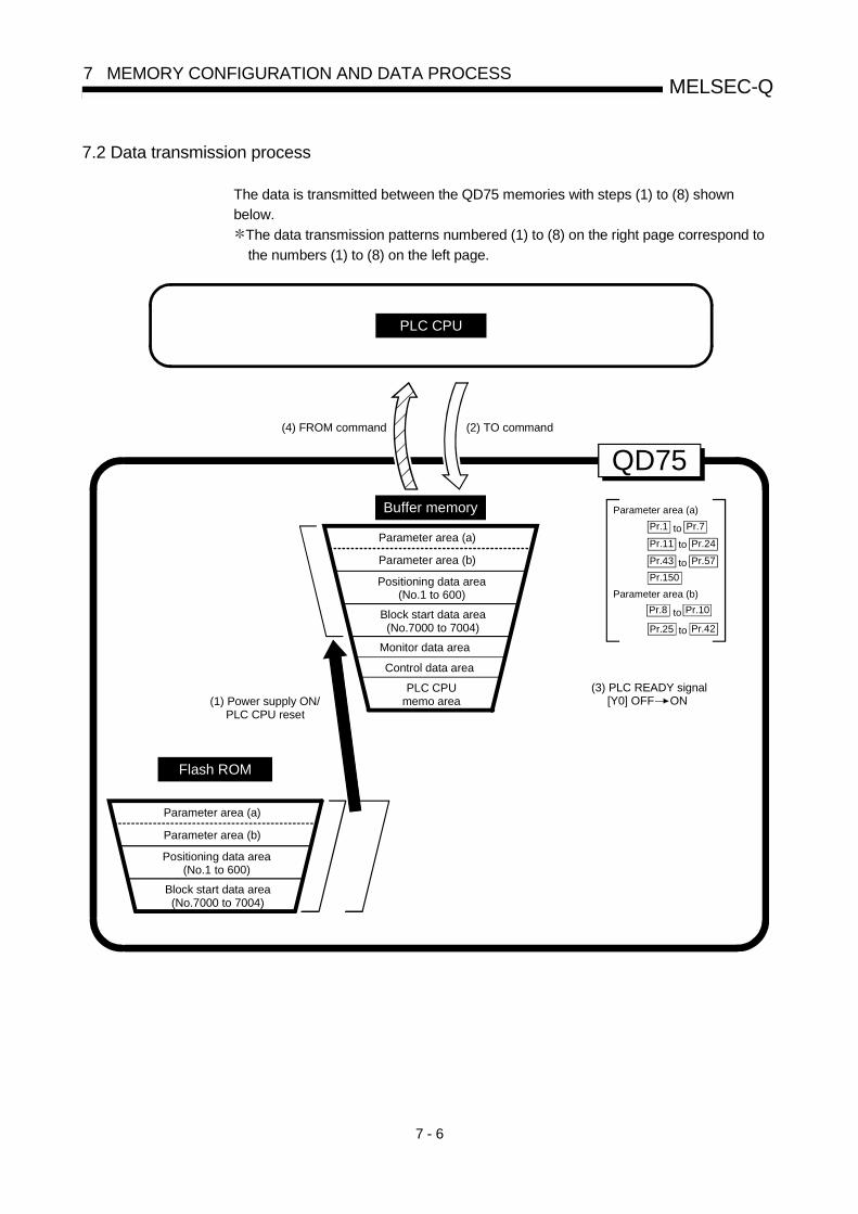
7 - 6
MELSEC-Q7 MEMORY CONFIGURATION AND DATA PROCESS
7.2 Data transmission process
The data is transmitted between the QD75 memories with steps (1) to (8) shown
below.
The data transmission patterns numbered (1) to (8) on the right page correspond to
the numbers (1) to (8) on the left page.
Parameter area (a)
Parameter area (a)
Parameter area (b)
Positioning data area(No.1 to 600)
Block start data area(No.7000 to 7004)
PLC CPUmemo area
Monitor data area
Control data area
Buffer memory
Flash ROM ROM
(3) PLC READY signal [Y0] OFF ON(1) Power supply ON/
PLC CPU reset
(2) TO command(4) FROM command
QD75
Pr.7Pr.1 to
Pr.11 Pr.24to
Pr.43 Pr.57to
Parameter area (b)
Pr.10Pr.8 to
Pr.25 Pr.42to
PLC CPU
Parameter area (a)
Parameter area (b)
Positioning data area(No.1 to 600)
Block start data area(No.7000 to 7004)
Pr.150

7 - 7
MELSEC-Q7 MEMORY CONFIGURATION AND DATA PROCESS
(1) Transmitting data when power is turned ON or PLC CPU is reset( )
When the power is turned ON or the PLC CPU is reset, the "parameters",
"positioning data" and "block start data" stored (backed up) in the flash ROM is
transmitted to the buffer memory.
(2) Transmitting data with TO command from PLC CPU ( )
The parameters or data is written from the PLC CPU to the buffer memory using
the TO command. At this time, when the "parameter area (b) 1", "positioning
data (No. 1 to 600)", "block start data (No. 7000 to 7004)", "control data" and
"PLC CPU memo area" are written into the buffer memory with the TO command,
it is simultaneously valid.
1 Parameter area (b) ...... Parameters validated simultaneously with the writing
to the buffer memory with the TO command.
( Pr.8 to Pr.10 , Pr.25 to Pr.42 )
(3) Validate parameters when PLC READY signal [Y0] changes fromOFF to ONWhen the PLC READY signal [Y0] changes from OFF to ON, the data stored in
the buffer memory's "parameter area (a) 2" is validated.
For Pr.5 , however, only the data obtained first after the PLC READY signal [Y0]
changes from OFF to ON when the power is turned ON or PLC CPU is reset
becomes validate.
(Refer to Section 5.2 "List of parameters" for details.)
2: Parameter area (a) .... Parameters validated when PLC READY signal [Y0]
changes from OFF to ON.
( Pr.1 to Pr.7 , Pr.11 to Pr.24 , Pr.43
to Pr.57 , Pr.150 )
POINTThe setting values of the parameters that correspond to parameter area (b) are
valid when written into the buffer memory with the TO command.
However, the setting values of the parameters that correspond to parameter area
(a) are not validated until the PLC READY signal [Y0] changes from OFF to ON.
(4) Accessing with FROM command from PLC CPU ( )
The data is read from the buffer memory to the PLC CPU using the FROM
command.

7 - 8
MELSEC-Q7 MEMORY CONFIGURATION AND DATA PROCESS
Parameter area (a)
Parameter area (a)
Parameter area (b)
Positioning data area(No.1 to 600)
Block start data area(No.7000 to 7004)
PLC CPUmemo area
Monitor data area
Control data area
Buffer memory
PLC CPU
Peripheral devices
(6) Flash ROM request (Write)
(6) Flash ROM request (Write)
(6) Flash ROM request (Write)
QD75
Pr.7Pr.1 to
Pr.11 Pr.24to
Pr.43 Pr.57to
Parameter area (b)
Pr.10Pr.8 to
Pr.25 Pr.42 to
Flash ROM
Parameter area (a)
Parameter area (b)
Positioning data area(No.1 to 600)
Block start data area(No.7000 to 7004)
(5) Flash ROM write(Set "1" in Cd.1 with TO command)
(5) Flash ROM write
Pr.150

7 - 9
MELSEC-Q7 MEMORY CONFIGURATION AND DATA PROCESS
(5) Flash ROM write ( )
The following transmission process is carried out by setting "1" in " Cd.1 Flash
ROM write request" (buffer memory [1900]).
1) The "parameters", "positioning data (No. 1 to 600)" and "block start data (No.7000 to 7004)" in the buffer memory area are transmitted to the flash ROM.
The writing to the flash ROM may also be carried out using a dedicatedinstruction "PFWRT". (Refer to Chapter 14 "Dedicated instructions" for details.)
(6) Flash ROM request (writing) ( )
The following transmission processes are carried out with the [flash ROM
request] (write) from the peripheral device.
1) The "parameters", "positioning data (No. 1 to 600)" and "block start data (No.7000 to 7004)" in the buffer memory area are transmitted to the flash ROM.
Note) This transmission process is the same as (5) above.
IMPORTANT(1) Do not turn the power OFF or reset the PLC CPU while writing to the flash
ROM. If the power is turned OFF or the PLC CPU is reset to forcibly end the
process, the data backed up in the flash ROM will be lost.
(2) Do not write the data to the buffer memory before writing to the flash ROM is
completed.
(3) The number of writes to the flash ROM with the PLC program is 25 max. while
the power is turned ON.
Writing to the flash ROM beyond 25 times will cause an error (error code: 805).
Refer to Section 15.2 "List of errors" for details.
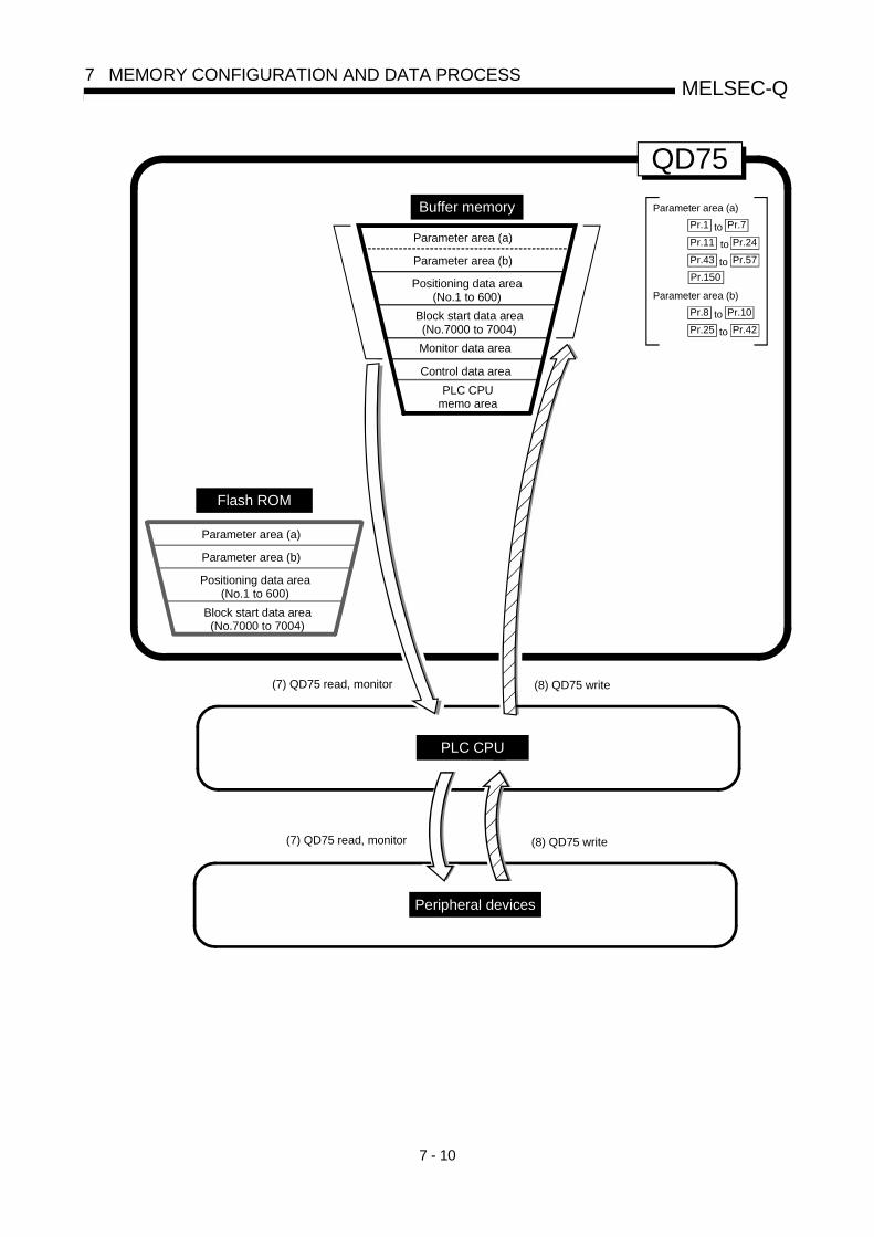
7 - 10
MELSEC-Q7 MEMORY CONFIGURATION AND DATA PROCESS
Parameter area (a)
Parameter area (a)
Parameter area (b)
Positioning data area(No.1 to 600)
Block start data area(No.7000 to 7004)
PLC CPUmemo area
Monitor data area
Control data area
Buffer memory
(8) QD75 write(7) QD75 read, monitor
QD75
Pr.7Pr.1 to
Pr.11 Pr.24to
Pr.43 Pr.57to
Parameter area (b)
Pr.10Pr.8 to
Pr.25 Pr.42to
(8) QD75 write(7) QD75 read, monitor
Peripheral devices
PLC CPU
Flash ROM
Parameter area (a)
Parameter area (b)
Positioning data area(No.1 to 600)
Block start data area(No.7000 to 7004)
Pr.150

7 - 11
MELSEC-Q7 MEMORY CONFIGURATION AND DATA PROCESS
(7) Reading data from buffer memory to peripheral device ( )
The following transmission processes are carried out with the [Read from
module] from the peripheral device.
1) The "parameters", "positioning data (No. 1 to 600)" and "block start data (No.7000 to 7004)" in the buffer memory area are transmitted to the peripheraldevice via the PLC CPU.
The following transmission processes are carried out with the [monitor] from the
peripheral device.
2) The "monitor data" in the buffer memory area is transmitted to the peripheraldevice via the PLC CPU.
(8) Writing data from peripheral device to buffer memory ( )
The following transmission processes are carried out with the [Write to module]
from the peripheral device.
1) The "parameters", "positioning data (No. 1 to 600)" and "block start data (No.7000 to 7004)" in the peripheral device area transmitted to the buffer memoryvia the PLC CPU.
At this time, when [Flash ROM write] is set with the peripheral device, the
transmission processes indicated with the following are carried out.
(5) Flash ROM write

7 - 12
MELSEC-Q7 MEMORY CONFIGURATION AND DATA PROCESS
The data transmission is carried out as shown in the previous pages, but the main
method of using this data process is shown below.
(Ex.) Setting the positioning dataThe following methods can be used to set the positioning data.
From peripheral device Using sequense program
Set the data according to theperipheral device menu.
Write the data set with the peripheral device into thebuffer memory.
Completion
Write positioning data into buffer memory using TO command.
User work
QD75 state

Sec
tion
2
Section 2 Control Details and Setting
Section 2 is configured for the following purposes shown in (1) to (3).
(1) Understanding of the operation and restrictions of each control. (2) Carrying out the required settings in each control (3) Dealing with errors
The required settings in each control include parameter setting, positioning data setting, control data setting by a sequence program, etc. Carry out these settings while referring to Chapter 5 "Data used for positioning". Also refer to Chapter 6 "Sequence programs used in positioning control" when creatingthe sequence programs required in each control, and consider the entire control programconfiguration when creating each program.
Chapter 8 OPR Control .............................................................................................. 8- 1 to 8- 22
Chapter 9 Major Positioning Control......................................................................... 9- 1 to 9-114
Chapter 10 High-Level Positioning Control ............................................................. 10- 1 to 10- 26
Chapter 11 Manual Control...................................................................................... 11- 1 to 11- 36
Chapter 12 Control Sub Functions .......................................................................... 12- 1 to 12- 98
Chapter 13 Common Functions................................................................................ 13- 1 to 13- 8
Chapter 14 Dedicated instructions........................................................................... 14- 1 to 14- 22
Chapter 15 Troubleshooting .................................................................................... 15- 1 to 15- 38

MEMO

8 - 1
8
Chapter 8 OPR Control
The details and usage of "OPR control" are explained in this chapter.
OPR control includes "machine OPR" that establish a machine OP without using addressdata, and "fast OPR" that store the coordinates established by the machine OPR, andcarry out positioning to that position. OPR carried out by sequence programs from the PLC CPU are explained in this chapter. Refer to GX Configurator-QP Operating Manual for details on OPR using theperipheral device.
8.1 Outline of OPR control .................................................................................................8- 28.1.1 Two types of OPR control...............................................................................8- 2
8.2 Machine OPR ...............................................................................................................8- 48.2.1 Outline of the machine OPR operation ..........................................................8- 48.2.2 Machine OPR method ....................................................................................8- 58.2.3 OPR method (1): Near-point dog method......................................................8- 68.2.4 OPR method (2): Stopper method 1) .............................................................8- 88.2.5 OPR method (3): Stopper method 2) ........................................................... 8- 118.2.6 OPR method (4): Stopper method 3) ........................................................... 8- 148.2.7 OPR method (5): Count method 1) .............................................................. 8- 168.2.8 OPR method (6): Count method 2) .............................................................. 8- 18
8.3 Fast OPR .................................................................................................................... 8- 208.3.1 Outline of the fast OPR operation ................................................................ 8- 20
8 - 2
MELSEC-Q8 OPR CONTROL
8.1 Outline of OPR control
8.1.1 Two types of OPR control
In "OPR control" a position is established as the starting point (or "OP") when carrying out positioning control, and positioning is carried out toward that starting point. It is used to return a machine system at any position other than the OP to the OP when the QD75 issues a "OPR request" with the power turned ON or others, or after a positioning stop. In the QD75, the two types of controls shown below are defined as "OPR control", following the flow of the OPR work. These two types of OPR control can be executed by setting the "OPR parameters", setting "Positioning start No. 9001" and "Positioning start No. 9002" prepared beforehand in the QD75 to " Cd.3 Positioning start No.", and turning ON the positioning start signal.
The ZP.PSTRT start numbers of the dedicated instruction can also be set to 9001 or 9002 to execute the OPR control. (For details, refer to Chapter 14 "Dedicated instructions".) (1) Establish a positioning control OP – "Machine OPR" (positioning start No. 9001) (2) Carry out positioning toward the OP – "Fast OPR" (positioning start No. 9002).
The "machine OPR" in (1) above must always be carried out before executing the "fast OPR" in (2).
REMARK
OPR request The "OPR request flag" ( Md.31 Status: b3) must be turned ON in the QD75, and a machine OPR must be executed in the following cases. • When the power is turned ON • At the ON OFF of the drive unit READY signal ( Md.30 External input/output signal:
b2). • At the OFF ON of the PLC READY signal [Y0]
The address information stored in the QD75 cannot be guaranteed while the "OPR request flag" is ON. The "OPR request flag" turns OFF and the "OPR complete flag" ( Md.31 Status: b4) turns ON if the machine OPR is executed and is completed normally.

8 - 3
MELSEC-Q8 OPR CONTROL
OPR sub functions Refer to Section 3.2.4 "Combination of QD75 main functions and sub functions" for details on "sub functions" that can be combined with OPR control. Also refer to Chapter 12 "Control sub functions" for details on each sub function.
[Remarks]
The following two sub functions are only related to machine OPR. Sub function name Machine OPR Fast OPR Reference
OPR retry function Section 12.2.1OP shift function Section 12.2.2
: Combination possible, : Restricted, : Combination not possible
When an OPR is not required Control can be carried out ignoring the "OPR request flag" ( Md.31 Status: b3) in systems that do not require an OPR. In this case, the "OPR parameters ( Pr.43 to Pr.57 )" must all be set to their initial values or a value at which an error does not occur.
OPR from peripheral devices "Machine OPR" and "fast OPR" can be executed from the test mode of the peripheral device. Refer to GX Configurator-QP Operating Manual for details on OPR from the peripheral device.
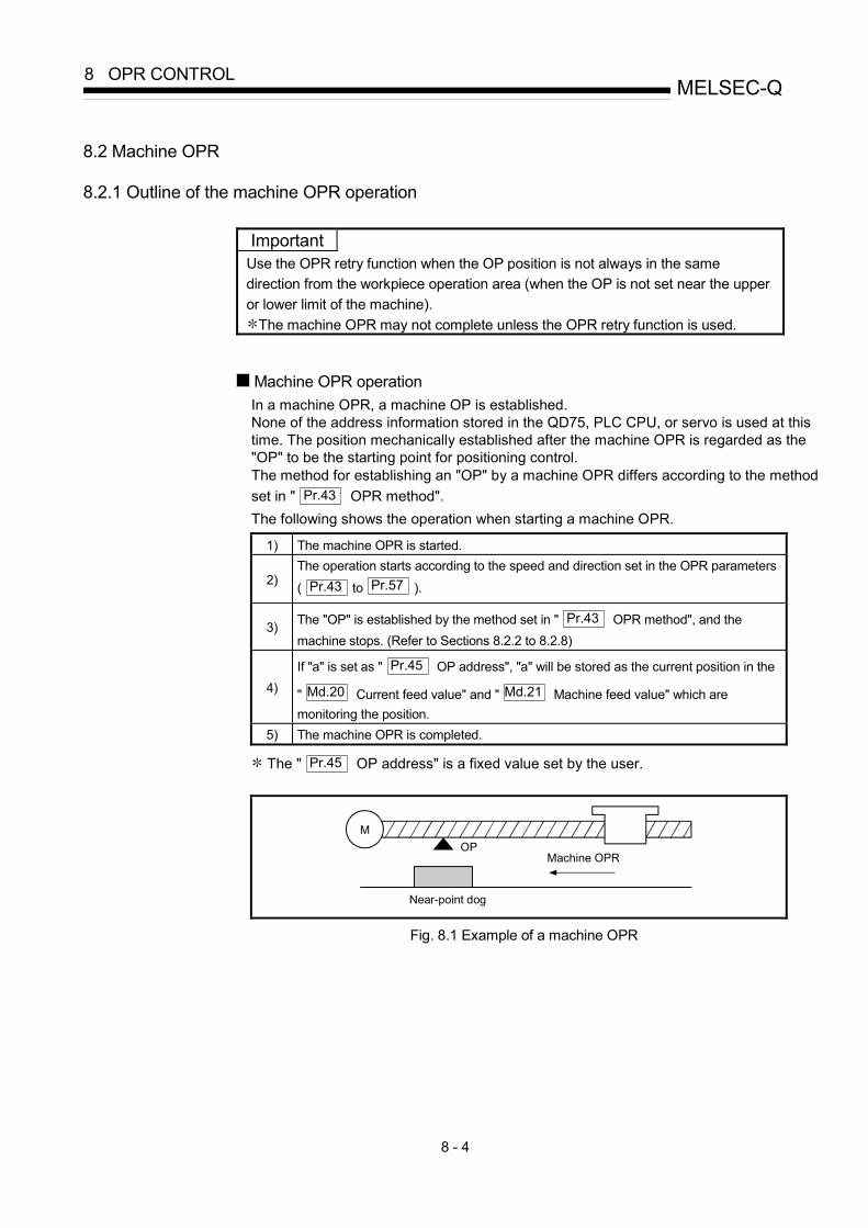
8 - 4
MELSEC-Q8 OPR CONTROL
8.2 Machine OPR
8.2.1 Outline of the machine OPR operation
Important Use the OPR retry function when the OP position is not always in the same direction from the workpiece operation area (when the OP is not set near the upper or lower limit of the machine).
The machine OPR may not complete unless the OPR retry function is used.
Machine OPR operation In a machine OPR, a machine OP is established. None of the address information stored in the QD75, PLC CPU, or servo is used at this time. The position mechanically established after the machine OPR is regarded as the "OP" to be the starting point for positioning control. The method for establishing an "OP" by a machine OPR differs according to the method set in " Pr.43 OPR method". The following shows the operation when starting a machine OPR.
1) The machine OPR is started.
2) The operation starts according to the speed and direction set in the OPR parameters
( Pr.43 to Pr.57 ).
3) The "OP" is established by the method set in " Pr.43 OPR method", and the machine stops. (Refer to Sections 8.2.2 to 8.2.8)
4) If "a" is set as " Pr.45 OP address", "a" will be stored as the current position in the
" Md.20 Current feed value" and " Md.21 Machine feed value" which are monitoring the position.
5) The machine OPR is completed.
The " Pr.45 OP address" is a fixed value set by the user.
MOP
Near-point dog
Machine OPR
Fig. 8.1 Example of a machine OPR
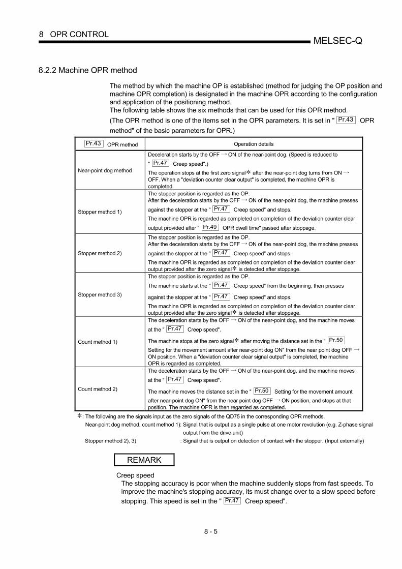
8 - 5
MELSEC-Q8 OPR CONTROL
8.2.2 Machine OPR method
The method by which the machine OP is established (method for judging the OP position and machine OPR completion) is designated in the machine OPR according to the configuration and application of the positioning method. The following table shows the six methods that can be used for this OPR method. (The OPR method is one of the items set in the OPR parameters. It is set in " Pr.43 OPR method" of the basic parameters for OPR.)
Pr.43 OPR method Operation details
Near-point dog method
Deceleration starts by the OFF ON of the near-point dog. (Speed is reduced to
" Pr.47 Creep speed".) The operation stops at the first zero signal after the near-point dog turns from ON OFF. When a "deviation counter clear output" is completed, the machine OPR is completed.
Stopper method 1)
The stopper position is regarded as the OP. After the deceleration starts by the OFF ON of the near-point dog, the machine presses
against the stopper at the " Pr.47 Creep speed" and stops. The machine OPR is regarded as completed on completion of the deviation counter clear
output provided after " Pr.49 OPR dwell time" passed after stoppage.
Stopper method 2)
The stopper position is regarded as the OP. After the deceleration starts by the OFF ON of the near-point dog, the machine presses
against the stopper at the " Pr.47 Creep speed" and stops. The machine OPR is regarded as completed on completion of the deviation counter clear output provided after the zero signal is detected after stoppage.
Stopper method 3)
The stopper position is regarded as the OP.
The machine starts at the " Pr.47 Creep speed" from the beginning, then presses
against the stopper at the " Pr.47 Creep speed" and stops. The machine OPR is regarded as completed on completion of the deviation counter clear output provided after the zero signal is detected after stoppage.
Count method 1)
The deceleration starts by the OFF ON of the near-point dog, and the machine moves
at the " Pr.47 Creep speed".
The machine stops at the zero signal after moving the distance set in the " Pr.50 Setting for the movement amount after near-point dog ON" from the near point dog OFF ON position. When a "deviation counter clear signal output" is completed, the machine OPR is regarded as completed.
Count method 2)
The deceleration starts by the OFF ON of the near-point dog, and the machine moves
at the " Pr.47 Creep speed".
The machine moves the distance set in the " Pr.50 Setting for the movement amount after near-point dog ON" from the near point dog OFF ON position, and stops at that position. The machine OPR is then regarded as completed.
: The following are the signals input as the zero signals of the QD75 in the corresponding OPR methods. Near-point dog method, count method 1): Signal that is output as a single pulse at one motor revolution (e.g. Z-phase signal
output from the drive unit) Stopper method 2), 3) : Signal that is output on detection of contact with the stopper. (Input externally)
REMARK
Creep speed The stopping accuracy is poor when the machine suddenly stops from fast speeds. To improve the machine's stopping accuracy, its must change over to a slow speed before stopping. This speed is set in the " Pr.47 Creep speed".

8 - 6
MELSEC-Q8 OPR CONTROL
8.2.3 OPR method (1): Near-point dog method
The following shows an operation outline of the "near-point dog method" OPR method.
Operation chart
1)
The machine OPR is started.
(The machine begins the acceleration designated in " Pr.51 OPR acceleration time selection", in the direction
designated in " Pr.44 OPR direction". It then moves at the " Pr.46 OPR speed" when the acceleration is completed.)
2) The machine begins decelerating when the near-point dog ON is detected.
3) The machine decelerates to the " Pr.47 Creep speed", and subsequently moves at that speed. (At this time, the near-point dog must be ON. The workpiece will continue decelerating and stop if the near-point dog is OFF.)
4)
After the near-point dog turns OFF, the pulse output from the QD75 will stop at the first zero signal, outputting a "deviation counter clear signal" to the drive unit. (The "deviation counter clear signal output time" is set in Pr.55 .)
5) After a "deviation counter clear signal" is output to the drive unit, the OPR complete flag ( Md.31 Status:
b4) turns from OFF to ON and the OPR request flag ( Md.31 Status: b3) turns from ON to OFF.
t
Machine OPR start(Positioning start signal)
ON
OFF
OPR speed Deceleration at the near-point dog ON
Creep speed
ON
OFF
OFF
ON
Standing by In OPR Standing by Axis operation status
Inconsistent 0 Movement amount after near-point dog ON
Value of the machine moved is stored. OP address Current feed value Machine feed value
V
Zero signal
Value of 1
Deviation counter clear output
Movement amount after near-point dog ON
Near-point dog
ON
OFF
One servomotor rotation
1
OPR request flag
OPR complete flag
Md.34
Adjust so the near-point dog OFF position isas close as possible to the center of the zerosignal HIGH level.If the near-point dog OFF position overlaps with the zero signal, the machine OPR stop position may deviate by one servomotor rotation.
1) 2) 3) 4) 5)
Pr.46
Pr.47
Md.34
Md.20Md.21
Md.26
Md.31
Md.31
Deviation counter clearsignal output timePr.55
Status: b3
Status: b4
Inconsistent
Fig. 8.2 Near-point dog method machine OPR

8 - 7
MELSEC-Q8 OPR CONTROL
Restrictions A pulse generator with a zero signal is required. When using a pulse generator without a zero signal, generate a zero signal using an external signal.
Precautions during operation (1) An error "Start at OP (error code: 201)" will occur if another machine OPR is
attempted after a machine OPR completion when the OPR retry function is not set ("0" is set in " Pr.48 OPR retry").
(2) Machine OPR carried out from the near-point dog ON position will start at the " Pr.47 Creep speed".
(3) The near-point dog must be ON during deceleration from the OPR speed " Pr.47 Creep speed".
The workpiece will continue decelerating and stop if the near-point dog is turned OFF before it has decelerated to the creep speed, thus causing an error "Dog detection timing fault (error code: 203)".
t
V
ON
OFF
ON
OFF
OFF
0
ONNear-point dog OFF
In error
Pr. 46 OPR speed
Pr. 47 Creep speed
In OPRStanding by
Inconsistent
Inconsistent Value the machine moved is stored Address at stop
Machine OPR start (Positioning start signal)
OPR request flag [ Md.31 Status : b3]
OPR complete flag [ Md.31 Status : b4]
Md.26 Axis operation status
Md.34 Movement amount after near-point dog ON
Md.20 Current feed valueMd.21 Machine feed value
Fig. 8.3 Operation when the near-point dog is turned OFF before the creep speed is reached
(4) When a machine OPR is stopped with the stop signal, perform a machine OPR again. If the restart command is turned ON after a stop with the stop signal, an error "OPR restart not possible" (error code: 209) occurs.

8 - 8
MELSEC-Q8 OPR CONTROL
8.2.4 OPR method (2): Stopper method 1)
The following shows an operation outline of the "stopper method 1)" OPR method. Operation chart
1)
The machine OPR is started.
(The machine begins the acceleration designated in " Pr.51 OPR acceleration time selection", in the direction designated in
" Pr.44 OPR direction". It then moves at the " Pr.46 OPR speed" when the acceleration is completed.)
2) The machine begins decelerating when the near-point dog ON is detected.
3) The machine decelerates to the " Pr.47 Creep speed", and subsequently moves at that speed. (Torque limiting is required at this time. If the torque is not limited, the servomotor may fail in step 4).)
4) The machine presses against the stopper at the creep speed and stops.
5) The pulse output from the QD75 will stop when the " Pr.49 OPR dwell time" has elapsed after the near-point dog turns ON, outputting the "deviation counter clear output" to the drive unit.
(A "deviation counter clear signal output time" is set in the Pr.55 .)
6) After a "deviation counter clear output" is output to the drive unit, the OPR complete flag ( Md.31 Status: b4) turns from OFF to ON,
and the OPR request flag ( Md.31 Status: b3) turns from ON to OFF.
0
t
ON
OFF
Valid torque limit range
Torque limit
Dwell time measurement Time out of dwell time
ON
OFF
OFF
ON
V
ON
1) 2) 3) 4) 5) 6)Range in which the servomotor rotation is forcibly stopped by the stopper
Near-point dog OFF
Machine OPR start (Positioning start signal)
Deviation counter clear output
Md.26 Axis operation status Standing by
Inconsistent
Inconsistent
In OPR Standing by
OP address Value the machine moved is stored
Pr. 46 OPR speed
Pr. 47 Creep speed
OPR request flag [ Md.31 Status : b3]
OPR complete flag [ Md.31 Status : b4]
Md.34 Movement amount after near-point dog ONMd.20 Current feed valueMd.21 Machine feed value
Stops at stopper
Pr.55Deviation counter clear signaloutput time
Fig. 8.4 Stopper method 1) machine OPR

8 - 9
MELSEC-Q8 OPR CONTROL
Restrictions (1) Always limit the servomotor torque after the " Pr.47 Creep speed" is reached. If the
torque is not limited, the servomotor may fail when the machine presses against the stopper. (Refer to Section 12.4.2 "Torque limit function".)
(2) In the "stopper method 1)", the OPR retry function is unusable.
Precautions during operation (1) Set a value in the " Pr.49 OPR dwell time" that is equal to or higher than the
movement time from the near-point dog ON to the time the machine presses against the stopper.
(2) The workpiece will continue decelerating and stop if the " Pr.49 OPR dwell time" elapses during deceleration from the " Pr.46 OPR speed", thus causing an error "Dwell time fault (error code: 205)".
Md.34 Movement amount after near-point dog ON
Md.26 Axis operation status
t
V
ON
OFF
ON
OFF
OFF
0
In error
Address at stop
" Pr.49 OPRdwell time" setting
Pr. 46 OPR speed
Pr. 47 Creep speed
Machine OPR start(Positioning start signal)
OPR request flag [ Md.31 Status : b3]
OPR complete flag [ Md.31 Status : b4]
Md.20 Current feed valueMd.21 Machine feed value
Standing by
Inconsistent
Inconsistent
In OPR
Value the machine moved is stored
Stops at stopper
Fig. 8.5 Operation when the dwell time elapses during deceleration from the OPR speed

8 - 10
MELSEC-Q8 OPR CONTROL
(3) If the " Pr.49 OPR dwell time" elapses before the stop at the stopper, the workpiece
will stop at that position, and that position will be regarded as the OP. At this time, an error will not occur.
Pr. 46 OPR speed
ON
ON
OFF
OFF
ON
0
V
ON
t
Pr. 47 Creep speed
Torque limit
Near-point dog OFF
Valid torque limit range
Dwell time measurement Time out of dwell time
Machine OPR start (Positioning start signal)
Deviation counter clear output
Md.26 Axis operation status
OPR request flag [ Md.31 Status : b3]
OPR complete flag [ Md.31 Status : b4]
Md.34 Movement amount after near-point dog ON
Md.20 Current feed valueMd.21 Machine feed value
Standing by In OPR
Inconsistent
Inconsistent Value the machine moved is stored
Standing by
OP address
OFF
Stops at stopper
Pr.55 Deviation counter clear signal output time
Fig. 8.6 Operation when the dwell time elapses before the stop at the stopper
(4) Machine OPR started while the near-point dog is ON will start at the " Pr.47 Creep speed".
(5) When a machine OPR is stopped with the stop signal, perform a machine OPR again. If the restart command is turned ON after a stop with the stop signal, an error "OPR restart not possible" (error code: 209) occurs.

8 - 11
MELSEC-Q8 OPR CONTROL
8.2.5 OPR method (3): Stopper method 2)
The following shows an operation outline of the "stopper method 2)" OPR method. Operation chart
1)
The machine OPR is started. (The machine begins the acceleration designated in " Pr.51 OPR acceleration time selection", in the direction designated in
" Pr.44 OPR direction". It then moves at the " Pr.46 OPR speed" when the acceleration is completed.)
2) The machine begins decelerating when the near-point dog ON is detected.
3) The machine decelerates to the " Pr.47 Creep speed", and subsequently moves at that speed. (Torque limiting is required at this time. If the torque is not limited, the servomotor may fail in step 4).)
4) The machine presses against the stopper at the creep speed and stops.
5)
The pulse output from the QD75 will stop at the zero signal after the machine stops, outputting the "deviation counter clear output" to the drive unit. (A "deviation counter clear signal output time" is set in the Pr.55 .)
6) After a "deviation counter clear output" is output to the drive unit, the OPR complete flag ( Md.31 Status: b4) turns from OFF to ON,
and the OPR request flag ( Md.31 Status: b3) turns from ON to OFF.
t
ON
OFF
ON
OFF
OFF
ON
0
V
ON
Zero signal
1) 2) 3) 4)
Pr. 46 OPR speed Pr. 47 Creep speed
Stops at stopper
6)5)
Valid torque limit range
Near-point dog OFF
Torque limit
Machine OPR start(Positioning start signal)
Deviation counter clear output
Md.26 Axis operation status Standing by
Inconsistent
Inconsistent
In OPR
Value the machine moved is stored
OPR request flag [ Md.31 Status : b3]
OPR complete flag [ Md.31 Status : b4]
Md.34 Movement amount after near-point dog ON
Md.20 Current feed valueMd.21 Machine feed value
Standing by
OP address
Pr.55 Deviation counter clear signal output time
Fig. 8.7 Stopper method 2) machine OPR

8 - 12
MELSEC-Q8 OPR CONTROL
Restrictions (1) Always limit the servomotor torque after the " Pr.47 Creep speed" is reached. If the
torque is not limited, the servomotor may fail when the machine presses against the stopper. (Refer to Section 12.4.2 "Torque limit function".)
(2) Use an external input signal as the zero signal. (3) In the "stopper method 2)", the OPR retry function is unusable. Precautions during operation (1) Input a zero signal from an external source after the machine presses against the
stopper. The workpiece will continue decelerating and stop if a zero signal is input before deceleration to the " Pr.47 Creep speed". An error "OP detection timing fault (error code: 204)" will occur after the machine stops.
(2) The near-point dog must be turned ON until it presses against the stopper.
t
V
ON
OFF
ON
OFF
OFF
0
ON
In error
Pr. 46 OPR speed
Pr. 47 Creep speed
Zero signal
Near-point dog OFF
In OPR
Value the machine moved is stored
Inconsistent
Inconsistent
Standing by
Address at stop
Machine OPR start (Positioning start signal)
OPR request flag [ Md.31 Status : b3]
OPR complete flag [Md.31 Status : b4]
Md.34 Movement amount after near-point dog ON
Md.20 Current feed valueMd.21 Machine feed value
Md.26 Axis operation status
Stops at stopper
Fig. 8.8 Operation when a zero signal is input before the creep speed is reached
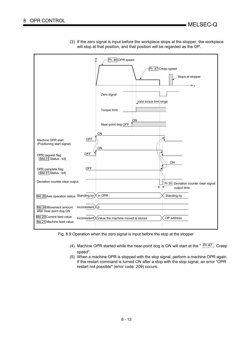
8 - 13
MELSEC-Q8 OPR CONTROL
(3) If the zero signal is input before the workpiece stops at the stopper, the workpiece
will stop at that position, and that position will be regarded as the OP.
t
ON
OFF
ON
OFF
OFF
ON
V
ON
Zero signal
0
Torque limit
Valid torque limit range
Pr. 47 Creep speed
Pr. 46 OPR speed
Near-point dog OFF
Machine OPR start (Positioning start signal)
Deviation counter clear output
Md.26 Axis operation status Standing by
Inconsistent
Value the machine moved is stored
OPR request flag [ Md.31 Status : b3]
OPR complete flag [ Md.31 Status : b4]
Md.34 Movement amount after near-point dog ON
Md.20 Current feed valueMd.21 Machine feed value
Standing by
OP address Inconsistent
In OPR
Stops at stopper
Pr.55 Deviation counter clear signal output time
Fig. 8.9 Operation when the zero signal is input before the stop at the stopper
(4) Machine OPR started while the near-point dog is ON will start at the " Pr.47 Creep speed".
(5) When a machine OPR is stopped with the stop signal, perform a machine OPR again. If the restart command is turned ON after a stop with the stop signal, an error "OPR restart not possible" (error code: 209) occurs.

8 - 14
MELSEC-Q8 OPR CONTROL
8.2.6 OPR method (4): Stopper method 3)
The following shows an operation outline of the "stopper method 3)" OPR method. The "stopper method 3)" method is effective when a near-point dog has not been installed. (Note that the operation is carried out from the start at the " Pr.47 Creep speed", so it will
take some time until the machine OPR completion.)
Operation chart
1)
The machine OPR is started. (The machine moves at the " Pr.47 Creep speed", in the direction designated in " Pr.44 OPR direction". Torque limiting is required at this time. If the torque is not limited, the servomotor may fail when the machine presses against the stopper in step 2.)
2) The machine presses against the stopper at the " Pr.47 Creep speed" and stops.
3) The pulse output from the QD75 will stop at the zero signal after the machine stops, outputting the "deviation counter clear output" to the drive unit. (A "deviation counter clear signal output time" is set in the Pr.55 .)
4) After a "deviation counter clear output" is output to the drive unit, the OPR complete flag ( Md.31 Status: b4) turns
from OFF to ON, and the OPR request flag ( Md.31 Status: b3) turns from ON to OFF.
t
ON
OFF
ON
OFF
OFF
ON
V
0
Pr. 47 Creep speed
Valid torque limit range
Machine OPR start (Positioning start signal)
Deviation counter clear output
Md.26 Axis operation status Standing by
Inconsistent Value the machine moved is stored
OPR request flag [ Md.31 Status : b3]
OPR complete flag [ Md.31 Status : b4]
Md.34 Movement amount after near-point dog ON
Md.20 Current feed valueMd.21 Machine feed value
OP address
In OPR Standing by
Inconsistent
Zero signal
Torque limit
Stops at stopper
Pr.55 Deviation counter clear signal output time
Fig. 8.10 Stopper method 3) machine OPR

8 - 15
MELSEC-Q8 OPR CONTROL
Restrictions (1) Always limit the servomotor torque after the " Pr.47 Creep speed" is reached. If the
torque is not limited, the servomotor may fail when the machine presses against the stopper. (Refer to Section 12.4.2 "Torque limit function".)
(2) Use an external input signal as the zero signal. (3) The OPR retry function cannot be used in "stopper stop method 3)".
Precautions during operation (1) If the zero signal is input before the workpiece stops at the stopper, the workpiece
will stop at that position, and that position will become the OP. At this time an error will not occur.
t
ON
OFF
ON
OFF
OFFON
V
0
Pr. 47 Creep speed
Valid torque limit range
Machine OPR start (Positioning start signal)
Md.26 Axis operation status
Value the machine moved is stored
OPR request flag [ Md.31 Status : b3]
OPR complete flag [ Md.31 Status : b4]
Md.34 Movement amount after near-point dog ONMd.20 Current feed value OP address Inconsistent
Standing by In OPR
Inconsistent
Standing by
Md.21 Machine feed value
Torque limit
Zero signal
Deviation counter clear output
Stops at stopper
Pr.55 Deviation counter clear signal output time
Fig. 8.11 When the zero signal is input before the stop at the stopper
(2) When a machine OPR is stopped with the stop signal, perform a machine OPR again. If the restart command is turned ON after a stop with the stop signal, an error "OPR restart not possible" (error code: 209) occurs.

8 - 16
MELSEC-Q8 OPR CONTROL
8.2.7 OPR method (5): Count method1)
The following shows an operation outline of the "count method 1)" OPR method.In the "count method 1)" machine OPR, the following can be performed:
• Machine OPR on near-point dog ON• Second machine OPR after completion of first machine OPR
Operation chart
1)
The machine OPR is started.
(The machine begins the acceleration designated in " Pr.51 OPR acceleration time selection", in the direction
designated in " Pr.44 OPR direction". It then moves at the " Pr.46 OPR speed" when the acceleration is
completed.)2) The machine begins decelerating when the near-point dog ON is detected.
3) The machine decelerates to the " Pr.47 Creep speed", and subsequently moves at that speed.
4)
On detection of the first zero signal after the axis has traveled the movement amount set in " Pr.50 Setting for the
movement amount after near-point dog ON" after near-point dog ON, the pulse output from the QD75 stops and the"deviation counter clear output" is output to the drive unit.
(A "deviation counter clear signal output time" is set in Pr.55 .)
5)After a "deviation counter clear output" is output to the drive unit, the OPR complete flag Md.31 Status: b4) turns from
OFF to ON, and the OPR request flag ( Md.31 Status: b3) turns from ON to OFF.
t
ON
OFF
ON
OFF
OFF
ON
0
V
ON
Pr. 47 Creep speed
Pr. 46 OPR speed Pr. 50 Setting for the movement amount after near-point dog ON
Md.34 Movement amount after near-point dog ON
Zero signal
Near-point dog OFF
Leave sufficient distance from the zero pointposition to the near-point dog OFF
Machine OPR start (Positioning start signal)
Standing by In OPRMd.26 Axis operation status
Inconsistent
Value the machine moved is stored OP address
Value of 1.
Deviation counter clear output
Standing by
Inconsistent
OPR request flag [ Md.31 Status : b3]
OPR complete flag [ Md.31 Status : b4]
Md.21 Machine feed value
Md.34 Movement amount after near-point dog ON
Md.20 Current feed value
Pr.55 Deviation counter clearsignal output time
1
Adjust the setting for the movement amount after near-point dog ON to be as near as possible to the center of the zero signal HIGH.If the setting for the movement amount afternear-point dog ON falls within the zero signal, there may be produced an error of one servomotor rotation in the machine OPR stop position.
One servomotor rotation
First zero signal after travel of the movement amount set to " Pr. 50 Setting for the movement amount after near-point dog ON"
Fig. 8.12 Count method1) machine OPR

8 - 17
MELSEC-Q8 OPR CONTROL
Restrictions
A pulse generator with a zero signal is required.When using a pulse generator without a zero signal, generate a zero signal usingan external signal.
Precautions during operation
(1) An error "Count method movement amount fault (error code: 206)" will occur
and the operation will not start if the " Pr.50 Setting for the movement
amount after near-point dog ON" is smaller than the deceleration distance
from the " Pr.46 OPR speed" to " Pr.47 Creep speed".
A deceleration stop will be carried out if the speed is changed during theoperation and an error occurs.
(2) The following shows the operation when a machine OPR is started while thenear-point dog is ON.
ON
1) 5)4)
3)2)
Zero signal
Near-point dog OFF
Pr. 50 Setting for the movement amount after near-point dog ON
[Operation when a machine OPR is started atthe near-point dog ON position]
1) A machine OPR is started.2) The machine moves at the OPR speed in the
opposite direction of an OPR.3) Deceleration processing is carried out by
" Pr.39 Stop group 3 sudden stop
selection" when the near-point dog OFF isdetected.
4) After the machine stops, a machine OPR iscarried out in the OPR direction.
5) The machine OPR is completed after thedeviation counter clear output is provided ondetection of the first zero signal after thetravel of the movement amount set to
" Pr.50 Setting for the movement amount
after near-point dog ON" on detection of thenear-point dog signal ON.
Fig. 8.13 Count method 1) machine OPR on the near-point dog ON position
(3) Turn OFF the near-point dog at a sufficient distance from the OP.Although there is no harm in operation if the near-point dog is turned OFFduring a machine OPR, it is recommended to leave a sufficient distance fromthe OP when the near-point dog is turned OFF for the following reason.
If machine OPRs are performed consecutively after the near-point dog is
turned OFF at the time of machine OPR completion, operation will be
performed at the OPR speed until the hardware stroke limit (upper/lower limit)
is reached.(4) When a machine OPR is stopped with the stop signal, perform a machine
OPR again.If the restart command is turned ON after a stop with the stop signal, an error"OPR restart not possible" (error code: 209) occurs.

8 - 18
MELSEC-Q8 OPR CONTROL
8.2.8 OPR method (6): Count method 2)
The following shows an operation outline of the "method 2)" OPR method.
The "count method 2)" method is effective when a "zero signal" cannot be received.
(Note that compared to the "count method 1)" method, using this method will result in
more deviation in the stop position during machine OPR.)
Operation chart
1)
The machine OPR is started.
(The machine begins the acceleration designated in " Pr.51 OPR acceleration time selection", in the
direction designated in " Pr.44 OPR direction". It then moves at the " Pr.46 OPR speed" when the
acceleration is completed.)
2) The machine begins decelerating when the near-point dog ON is detected.
3) The machine decelerates to the " Pr.47 Creep speed", and subsequently moves at that speed.
4)
The pulse output from the QD75 will stop and the machine OPR will be completed when the machinemoves the movement amount set in " Pr.50 Setting for the movement amount after near-point dog ON "
from the near-point dog ON position.
Md.21 Machine feed value
t
V
ON
OFF
ON
OFF
ON
ON
OFF
0
OFF
Pr. 46 OPR speed
Pr. 47 Creep speed
Pr.50 Setting for the movement amount after near-point dog ON
Md.34 Movement amount after near-point dog ON
Leave sufficient distance from the OP position to the near-point dog OFF
Machine OPR start (Positioning start signal)
In OPR
Inconsistent
Value the machine moved is storedInconsistent
Md.34 Movement amount after near-point dog ON
Md.20 Current feed value
OPR request flag [ Md.31 Status : b3]
OPR complete flag [ Md.31 Status : b4]
Md.26 Axis operation status Standing by Standing by
Value of .
OP address
1
1
Near-point dog
Fig. 8.14 Count method 2) machine OPR

8 - 19
MELSEC-Q8 OPR CONTROL
Restrictions
When this method is used, a deviation will occur in the stop position (OP)compared to other OPR methods because an error of about 1 ms occurs in takingin the near-point dog ON.
Precautions during operation
(1) An error "Count method movement amount fault (error code: 206)" will occur
and the operation will not start if the " Pr.50 Setting for the movement
amount after near-point dog ON" is smaller than the deceleration distance
from the " Pr.46 OPR speed" to " Pr.47 Creep speed".
A deceleration stop will be carried out if the speed is changed during theoperation and an error occurs.
(2) The following shows the operation when a machine OPR is started while thenear-point dog is ON.
Pr.50 Setting for the movement amount after near-point dog ON
ON
1) 5)4)
3)2)
Near-point dog OFF
[Operation when a machine OPR is started atthe near-point dog ON position]
1) A machine OPR is started.2) The machine moves at the OPR speed in the
opposite direction of an OPR.3) Deceleration processing is carried out by
" Pr.39 Stop group 3 sudden stop
selection" when the near-point dog OFF isdetected.
4) After the machine stops, a machine OPR iscarried out in the OPR direction.
5) The machine OPR is completed after moving
the movement amount set in the " Pr.50
Setting for the movement amount after near-point dog ON".
Fig. 8.15 Count method 2) machine OPR on the near-point dog ON position
(3) Turn OFF the near-point dog at a sufficient distance from the OP.Although there is no harm in operation if the near-point dog is turned OFFduring a machine OPR, it is recommended to leave a sufficient distance fromthe OP when the near-point dog is turned OFF for the following reason.
If machine OPRs are performed consecutively after the near-point dog is
turned OFF at the time of machine OPR completion, operation will be
performed at the OPR speed until the hardware stroke limit (upper/lower limit)
is reached.(4) When a machine OPR is stopped with the stop signal, perform a machine
OPR again.If the restart command is turned ON after a stop with the stop signal, an error"OPR restart not possible" (error code: 209) occurs.

8 - 20
MELSEC-Q8 OPR CONTROL
8.3 Fast OPR
8.3.1 Outline of the fast OPR operation
Fast OPR operation
In a fast OPR, positioning is carried out by a machine OPR to the " Md.21
Machine feed value" stored in the QD75.The following shows the operation during a fast OPR start.
1) The fast OPR is started.
2) Positioning control to the " Md.21 Machine feed value" begins at the speed set
in the OPR parameters ( Pr.43 to Pr.57 ).
3) The fast OPR is completed.
Machine OP(OP position)
Pr. 46 OPR speed
Fast OPR start(Positioning start signal)
Md.26 Axis operation status In position controlStanding by Standing by
OP
Positioning to the OP
M
Fig. 8.16 Fast OPR
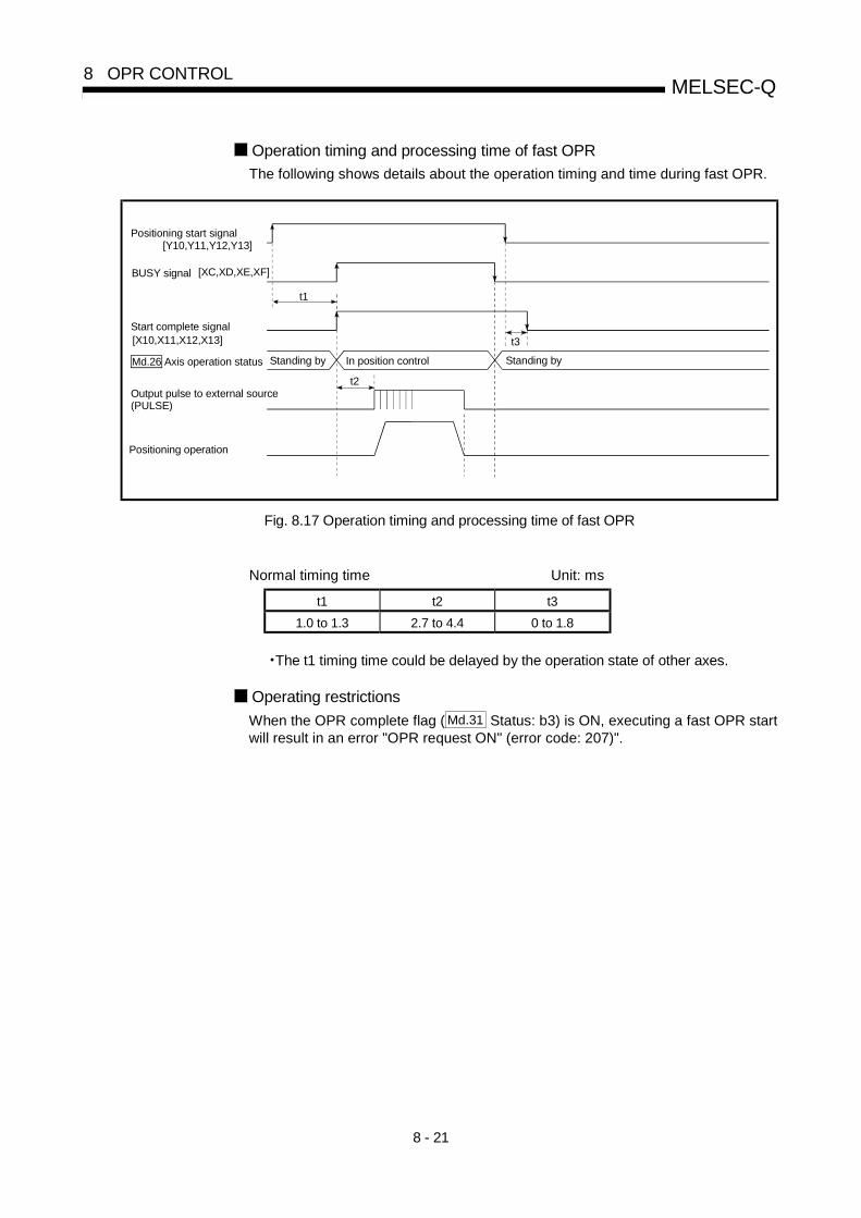
8 - 21
MELSEC-Q8 OPR CONTROL
Operation timing and processing time of fast OPR
The following shows details about the operation timing and time during fast OPR.
t1
t3
t2
In position controlStanding by Standing by
Positioning start signal
BUSY signal
Start complete signal
Output pulse to external source (PULSE)
Positioning operation
Md.26 Axis operation status
[Y10,Y11,Y12,Y13]
[X10,X11,X12,X13]
[XC,XD,XE,XF]
Fig. 8.17 Operation timing and processing time of fast OPR
Normal timing time Unit: ms
t1 t2 t3
1.0 to 1.3 2.7 to 4.4 0 to 1.8
•The t1 timing time could be delayed by the operation state of other axes.
Operating restrictions
When the OPR complete flag ( Md.31 Status: b3) is ON, executing a fast OPR startwill result in an error "OPR request ON" (error code: 207)".

8 - 22
MELSEC-Q8 OPR CONTROL
MEMO

9 - 1
9
Chapter 9 Major Positioning Control
The details and usage of the major positioning controls (control functions using the"positioning data") are explained in this chapter. The major positioning controls include such controls as "positioning control" in which positioning is carried out to a designated position using the address information, "speed control" in which a rotating object is controlled at a constant speed, "speed-position switching control" in which the operation is shifted from "speed control" to "position control" and "position-speed switching control" in which the operation isshifted from "position control" to "speed control".
Carry out the required settings to match each control.
9.1 Outline of major positioning controls............................................................................9- 29.1.1 Data required for major positioning control....................................................9- 49.1.2 Operation patterns of major positioning controls ...........................................9- 59.1.3 Designating the positioning address ............................................................ 9- 159.1.4 Confirming the current value ........................................................................ 9- 169.1.5 Control unit "degree" handling...................................................................... 9- 189.1.6 Interpolation control ...................................................................................... 9- 21
9.2 Setting the positioning data ....................................................................................... 9- 259.2.1 Relation between each control and positioning data................................... 9- 259.2.2 1-axis linear control....................................................................................... 9- 279.2.3 2-axis linear interpolation control.................................................................. 9- 299.2.4 3-axis linear interpolation control.................................................................. 9- 339.2.5 4-axis linear interpolation control.................................................................. 9 -399.2.6 1-axis fixed-feed control................................................................................ 9- 439.2.7 2-axis fixed-feed control (interpolation) ........................................................ 9- 459.2.8 3-axis fixed-feed control (interpolation) ........................................................ 9- 479.2.9 4-axis fixed-feed control (interpolation) ....................................................... 9- 519.2.10 2-axis circular interpolation control with sub point designation ................... 9- 539.2.11 2-axis circular interpolation control with center point designation............... 9- 599.2.12 1-axis speed control...................................................................................... 9- 679.2.13 2-axis speed control...................................................................................... 9- 709.2.14 3-axis speed control...................................................................................... 9- 739.2.15 4-axis speed control...................................................................................... 9- 779.2.16 Speed-position switching control (INC mode).............................................. 9- 829.2.17 Speed-position switching control (ABS mode) ............................................ 9- 909.2.18 Position-speed switching control.................................................................. 9- 989.2.19 Current value changing................................................................................. 9-1059.2.20 NOP instruction............................................................................................. 9-1109.2.21 JUMP instruction........................................................................................... 9-1119.2.22 LOOP ............................................................................................................ 9-1139.2.23 LEND............................................................................................................. 9-114

9 - 2
MELSEC-Q9 MAJOR POSITIONING CONTROL
9.1 Outline of major positioning controls
"Major positioning controls" are carried out using the "positioning data" stored in theQD75.The basic controls such as position control and speed control are executed by settingthe required items in this "positioning data", and then starting that positioning data.The control system for the "major positioning controls" is set in setting item " Da.2Control system" of the positioning data.Control defined as a "major positioning control" carries out the following types ofcontrol according to the " Da.2 Control system" setting.
Major positioning controlDa.2 Control system
Details
1-axis linearcontrol
ABS Linear 1INC Linear 1
Positioning of a designated 1 axis is carried out from thestart address (current stop position) to the designatedposition.
2-axis linearinterpolationcontrol
ABS Linear 2INC Linear 2
Using a designated 2 axes, linear interpolation control iscarried out from the start address (current stop position) tothe designated position.
3-axis linearinterpolationcontrol
ABS Linear 3INC Linear 3
Using a designated 3 axes, linear interpolation control iscarried out from the start address (current stop position) tothe designated position.
Linear control
4-axis linearinterpolationcontrol
ABS Linear 4INC Linear 4
Using a designated 4 axes, linear interpolation control iscarried out from the start address (current stop position) tothe designated position.
1-axis fixed-feed control
Fixed-feed 1
Positioning of a designated 1 axis is carried out from thestart address (current stop position).
(The " Md.20 Current feed value" is set to "0" at the start.)
2-axis fixed-feed control
Fixed-feed 2
Using a designated 2 axes, linear interpolation control iscarried out from the start address (current stop position).
(The " Md.20 Current feed value" is set to "0" at the start.)
3-axis fixed-feed control
Fixed-feed 3
Using a designated 3 axes, linear interpolation control iscarried out from the start address (current stop position).
(The " Md.20 Current feed value" is set to "0" at the start.)
Fixed-feedcontrol
4-axis fixed-feed control
Fixed-feed 4
Using a designated 4 axes, linear interpolation control iscarried out from the start address (current stop position).
(The " Md.20 Current feed value" is set to "0" at the start.)
Sub pointdesignation
ABS Circular subINC Circular sub
Pos
ition
con
trol
2-axis circularinterpolationcontrol Center point
designation
ABS Circular rightABS Circular leftINC Circular rightINC Circular left
The axis in which the interpolation control system is set isregarded as the reference axis. Positioning is carried out inan arc path to a designated position, while controlling theother axis (interpolation axis) to match the positioning dataset in the reference axis.
1-axis speedcontrol
Forward run speed 1Reverse run speed 1
The speed control of the designated 1 axis is carried out.
2-axis speedcontrol
Forward run speed 2Reverse run speed 2
The speed control of the designated 2 axes is carried out.
3-axis speedcontrol
Forward run speed 3Reverse run speed 3
The speed control of the designated 3 axes is carried out.Speed control
4-axis speedcontrol
Forward run speed 4Reverse run speed 4
The speed control of the 4 axes is carried out.

9 - 3
MELSEC-Q9 MAJOR POSITIONING CONTROL
Major positioning controlDa.2 Control system
Details
Speed-position switching control
Forward runspeed/positionReverse runspeed/position
The control is continued as position control (positioning forthe designated address or movement amount) by turningON the "speed-position switching signal" after first carryingout speed control.
Position-speed switching control
Forward runposition/speedReverse runposition/speed
The control is continued as speed control by turning ONthe "position-speed switching signal" after first carrying outposition control.
NOPinstruction
NOP instructionA nonexecutable control system. When this instruction isset, the operation is transferred to the next data operation,and the instruction is not executed.
Current valuechanging
Current value changing
The current feed value ( Md.20 ) is changed to an address
set in the positioning data.This can be carried out by either of the following 2methods.(The machine feed value cannot be changed.)
• Current value changing using the control system• Current value changing using the current value
changing start No. (No. 9003).JUMPinstruction
JUMP instructionAn unconditional or conditional JUMP is carried out to adesignated positioning data No.
LOOP LOOP A repeat control is carried out by repeat LOOP to LEND.
Other control
LEND LENDControl is returned to the top of the repeat control byrepeat LOOP to LEND. After the repeat operation iscompleted specified times, the next positioning data is run.
In "2-axis linear interpolation control", "3-axis linear interpolation control", "4-axis linear interpolation control", "2-axisfixed-feed control", "3-axis fixed-feed control", "4-axis fixed-feed control", "2-axis circular interpolation control", "2-axisspeed control", "3-axis speed control" and "4-axis speed control", control is carried out so that linear and arc paths aredrawn using a motor set in two or more axes directions. This kind of control is called "interpolation control". (Refer toSection 9.1.6 "Interpolation control" for details.)

9 - 4
MELSEC-Q9 MAJOR POSITIONING CONTROL
9.1.1 Data required for major positioning control
The following table shows an outline of the "positioning data" configuration and setting
details required to carry out the "major positioning controls".
Setting item Setting details
Da.1 Operation patternSet the method by which the continuous positioning data (Ex: positioning data No. 1,No. 2, No. 3) will be controlled. (Refer to Section 9.1.2.)
Da.2 Control system Set the control system defined as a "major positioning control". (Refer to Section 9.1.)
Da.3 Acceleration time No.Select and set the acceleration time at control start. (Select one of the four values set
in Pr.9 , Pr.25 , Pr.26 , and Pr.27 for the acceleration time.)
Da.4 Deceleration time No.Select and set the deceleration time at control stop. (Select one of the four values set
in Pr.10 , Pr.28 , Pr.29 , and Pr.30 for the deceleration time.)
Da.5Axis to beinterpolated
Set an axis to be interpolated (partner axis) during the 2-axis interpolation operation(Refer to Section 9.1.6).
Da.6Positioning address/movement amount
Set the target value during position control. (Refer to Section 9.1.3.)
Da.7 Arc address Set the sub point or center point address during circular interpolation control.
Da.8 Command speed Set the speed during the control execution.
Da.9 Dwell timeSet the time the machine waits from the completion of the executed positioning controland the stopping of the workpiece until the judgment of the QD75 positioningcompletion.
Pos
ition
ing
data
No.
1
Da.10 M codeSet this item when carrying out sub work (clamp and drill stops, tool replacement, etc.)corresponding to the code No. related to the positioning data execution.
The settings and setting requirement for the setting details of Da.1 to Da.10 differ according to the
" Da.2 Control system". (Refer to Section 9.2 "Setting the positioning data".)
Major positioning control sub functions
Refer to Section 3.2.4 "Combination of QD75 major functions and sub functions"for details on "sub functions" that can be combined with the major positioningcontrol.Also refer to Chapter 12 "Control sub Functions" for details on each sub function.
Major positioning control from peripheral devices
"Major positioning control" can be executed from the peripheral device test mode.Refer to GX Configurator-QP Operating Manual for details on carrying out majorpositioning control from the peripheral device.
REMARK
• 600 positioning data (positioning data No. 1 to 600) items can be set per axis.

9 - 5
MELSEC-Q9 MAJOR POSITIONING CONTROL
9.1.2 Operation patterns of major positioning controls
In "major positioning control" (high-level positioning control), " Da.1 Operationpattern" can be set to designate whether to continue executing positioning data afterthe started positioning data. The "operation pattern" includes the following 3 types.
Positioning complete (1) Independent positioning control (operation pattern: 00)
Positioning continue (2) Continuous positioning control (operation pattern: 01)
(3) Continuous path control (operation pattern: 11)
The following shows examples of operation patterns when "1-axis linear control (ABSlinear 1)" is set in positioning data No. 1 to No. 6 of axis 1. Details of each operationpattern are shown on the following pages.
< Operation example when "1-axis linear positioning" is set in the positioning data of axis 1 >
(Direction in which axis 1 addresses increase)
1-axis linear control
(One motor is driven, and positioning is carried out to an addresses designated in one direction.)
Speed
Positioning data No.1
0
Operation pattern = 11: Continuous path control Positioning to address [A] at command speed [a]
No.2
No.3
No.4
No.5
Address
a
b
NO.1 No.2 No.3 No.4 No.5
Speed is changedwithout stopping
The machine stops, and then continues the nextpositioning.
Positioning is terminated
No.6Control stop
No.1 Start
11
11
01
01
00
Time
Da. 1 Operation pattern
(Positioning data)
(Setting details)
Positioning to address [C] at command speed [a]
Positioning to address [D] at command speed [b]
Positioning to address [E] at command speed [a]
Positioning to address [F] at command speed [a]
Positioning to address [B] at command speed [b] Operation pattern = 11: Continuous path control
Operation pattern = 01: Continuous positioning control
Operation pattern = 00: Independent positioning control (Positioning complete)
Operation pattern = 11: Continuous path control
Operation pattern = 01: Continuous positioning control
A EDCB F
For
POINTThe BUSY signal [XC, XD, XE, XF] turns ON even when position control ofmovement amount 0 is executed. However, since the ON time is short, the ONstatus may not be detected in the sequence program.

9 - 6
MELSEC-Q9 MAJOR POSITIONING CONTROL
[1] Independent positioning control (Positioning complete)This control is set when executing only one designated data item of positioning. If
a dwell time is designated, the positioning will complete after the designated time
elapses.
This data (operation pattern [00] data) becomes the end of block data when
carrying out block positioning. (The positioning stops after this data is executed.)
Time
Start complete signal
OFFON
Dwell time
[X10, X11, X12, X13] OFFON
BUSY signal OFF
ON
Positioning complete signal OFFON
Positioning complete (00)
[Y10, Y11, Y12, Y13]Positioning start signal
[XC, XD, XE, XF]
[X14, X15, X16, X17]
V
Fig. 9.1 Operation during independent positioning control

9 - 7
MELSEC-Q9 MAJOR POSITIONING CONTROL
[2] Continuous positioning control
(1) The machine always automatically decelerates each time the positioning iscompleted. Acceleration is then carried out after the QD75 command speedreaches 0 to carry out the next positioning data operation. If a dwell time isdesignated, the acceleration is carried out after the designated time elapses.
(2) In operation by continuous positioning control (operation pattern "01"), thenext positioning No. is automatically executed. Always set operation pattern"00" in the last positioning data to complete the positioning.If the operation pattern is set to positioning continue ("01" or "11"), theoperation will continue until operation pattern "00" is found.If the operation pattern "00" cannot be found, the operation may be carriedout until the positioning data No. 600. If the operation pattern of thepositioning data No. 600 is not completed, the operation will be started againfrom the positioning data No. 1.
Time
OFFON
OFF
ON
OFF
ON
OFF
Positioning continue (01)
Address (+) direction
Address (-) directionPositioningcomplete (00)
Dwelltime
ON
Positioning continue (01)
Start complete signal
BUSY signal
Positioning complete signal
Positioning start signal[Y10, Y11, Y12, Y13]
[X10, X11, X12, X13]
[XC, XD, XE, XF]
[X14, X15, X16, X17]
Dwell timenot designated
Fig. 9.2 Operation during continuous positioning control

9 - 8
MELSEC-Q9 MAJOR POSITIONING CONTROL
[3] Continuous path control(1) Continuous path control
(a) The speed is changed without deceleration stop between thecommand speed of the positioning data currently being run and thespeed of the positioning data that will be run next.The speed is not changed if the current speed and the next speed areequal.
(b) The speed will become the speed used in the previous positioningoperation if the command speed is set to "-1".
(c) Dwell time will be ignored, even if set.(d) The next positioning No. is executed automatically in operations by
continuous path control (operation pattern "11"). Always complete thepositioning by setting operation pattern "00" in the last positioning data.If the operation pattern is set to positioning continue ("01" or "11"), theoperation will continue until operation pattern "00" is found.If the operation pattern "00" cannot be found, the operation may becarried out until the positioning data No. 600. If the operation pattern ofthe positioning data No. 600 is not completed, the operation will bestarted again from the positioning data No. 1.
(e) The speed switching patterns include the "front-loading speedswitching pattern" in which the speed is changed at the end of thecurrent positioning side, and the "standard speed switching pattern" inwhich the speed is at the start of the next positioning side. (Refer to
" Pr.19 Speed switching mode".)
Continuous path control Standard speed switching mode
Front-loading speed switching mode
(f) In the continuous path control, the positioning may be completedbefore the set address/movement amount and the current data may beswitched to the "positioning data that will be run next".
This is because a preference is given to the positioning at a command
speed. In actuality, the positioning is completed before the set
address/movement amount by an amount of remaining distance at
speeds less than the command speed. The remaining distance ( )
at speeds less than the command speed is 0 (distance
moved in 1.8ms at a speed at the time of completion of the
positioning).

9 - 9
MELSEC-Q9 MAJOR POSITIONING CONTROL
OFFON
OFFON
OFFON
OFFON
Time
Positioning continue (11)Dwell time
Positioning continue (11)
Start complete signal
BUSY signal
Positioning complete signal
Positioning start signal
Positioningcomplete (00) Address (+) direction
Address (-) direction
[Y10, Y11, Y12, Y13]
[X10, X11, X12, X13]
[XC, XD, XE, XF]
[X14, X15, X16, X17]
Fig. 9.3 Operation during continuous path control (Standard speed switching mode)
POINTIn the continuous path control, a speed variation will not occur using the near-pass
function when the positioning data No. is switched (Refer to Section 12.3.3 "Near-
pass function").
(2) Deceleration stop conditions during continuous path controlDeceleration stops are basically not carried out in continuous path control,
but the machine will carry out a deceleration stop to speed "0" in the
following cases (a) to (d).
(a) When the operation pattern of the positioning data currently beingexecuted is "continuous path control: 11", and the movement directionof the positioning data currently being executed differs from that of thenext positioning data. (Only for 1-axis positioning control (Refer to the"Point" in the next page.))
V
Positioning data No.2Operation pattern : 00
Speed becomes 0
Positioning data No.1Operation pattern : 11

9 - 10
MELSEC-Q9 MAJOR POSITIONING CONTROL
(b) When the operation pattern of the positioning data currently beingexecuted is "continuous path control: 11", and the movement amountof the next positioning data is "0".
(c) During operation by step operation.(Refer to Section 12.7.1 Step function".)
(d) When there is an error in the positioning data to carry out the nextoperation.
POINTS(1) The movement direction is not checked during interpolation operations. Thus, automatic deceleration to a stop will
not be carried out even if the movement direction is changed (See the figures below).Because of this, the interpolation axis may suddenly reverse direction.To avoid this sudden direction reversal in the interpolation axis, set the pass point to continuous positioning control"01" instead of setting it to continuous path control "11".
[Positioning by interpolation] [Reference axis operation] [Interpolation axis operation]
Interpola-tion axis
Positioning data
No.1
Reference axis
Positioning data
No.2
Positioning data No.1 • • • Continuous path control
V
Positioning data
No.1
t
Positioning data
No.2
V
Positioning data
No.1
t
Positioning data
No.2
(2) When the interpolation axis reveres direction suddenly, the command pulses from QD75 are output as shown in thefigure below.
Reverse run command
t1
t2
Forward run command
The t1 and t2 are calculated using the following expressions, where a command frequency is f (pps).
t1 = 1/2 f (s) t2 = 1/f (s)A time of t1 must be maintained by the drive unit for a specified period T (s).(T depends on the drive unit specifications.)
If t1 cannot be maintained for T or longer, lower the " Da.8 Command speed" of the positioning data.
(3) When a "0" is set in the " Da.6 Positioning address/movement amount" of the continuous path control positioningdata, the command speed of about 2 ms is reduced to 0.
When a "0" is set in the " Da.6 Positioning address/movement amount" to increase the number of speed change
points in the future, change the " Da.2 Control system" to the "NOP instruction" to make the controlnonexecutable.(Refer to Section 9.2.20 "NOP instruction".)
(4) In the continuous path control positioning data, assure a movement distance so that the execution time with thatdata is 100 ms or longer, or lower the command speed.

9 - 11
MELSEC-Q9 MAJOR POSITIONING CONTROL
(3) Speed handling(a) Continuous path control command speeds are set with each
positioning data.The QD75 then carries out the positioning at the speed designatedwith each positioning data.
(b) The command speed can be set to "–1" in continuous path control.The control will be carried out at the speed used in the previouspositioning data No. if the command speed is set to "–1". *1
(The "current speed" will be displayed in the command speed whenthe positioning data is set with a peripheral device. The current speedis the speed of the positioning control being executed currently.)
1) The speed does not need to be set in each positioning data whencarrying out uniform speed control if "–1" is set beforehand in thecommand speed.
2) If the speed is changed in the previous positioning data when "–1"is set in the command speed, the operation can be continued atthe new speed.
3) An error "no command speed" (error code: 503) occurs andpositioning cannot be started if "–1" is set in the command speedof the first positioning data at start.
[Relation between the command speed and current speed]
The current speed is changed even if the command speed is not reached in P2.
2000
1000
3000
30001000
1000
-1
3000
-1
3000
-1
3000
P1 P2 P3 P4 P5Speed
3000
Da. 7 Command speed
Md. 36 Current speed
2000
1000
3000
P1 P2 P3 P4 P5Speed
30001000
1000
-1
3000
-1
3000
-1
30003000
Da. 7 Command speed
Md. 36 Current speed
*2*1
POINTS(1) In the continuous path control, a speed variation will not occur using the near-pass function when the
positioning data is switched (Refer to Section 12.3.3 "Near-pass function").
(2) The QD75 holds the command speed set with the positioning data, and the latest value of the speed
set with the speed change request as the " Md.27 Current speed". It controls the operation at the
"current speed" when "-1" is set in the command speed.
(Depending on the relation between the movement amount and the speed, the feedrate may not reach
the command speed value, but even then the current speed will be updated. *2)
(3) When the address for speed change is identified beforehand, generate and execute the positioning
data for speed change by the continuous path control to carry out the speed change without requesting
the speed change with a sequence program.

9 - 12
MELSEC-Q9 MAJOR POSITIONING CONTROL
(4) Speed switching
(Refer to " Pr.19 Speed switching mode".)
(a) Standard speed switching mode
1) If the respective command speeds differ in the "positioning datacurrently being executed" and the "positioning data to carry outthe next operation", the machine will accelerate or decelerateafter reaching the positioning point set in the "positioning datacurrently being executed" and the speed will change over to thespeed set in the "positioning data to carry out the next operation".
2) The parameters used in acceleration/deceleration to thecommand speed set in the "positioning data to carry out the nextoperation" are those of the positioning data to carry outacceleration/deceleration.Speed switching will not be carried out if the command speedsare the same.
OFF
ON
OFF
ON
OFF
ON
OFF
ON
11 11 11 01 00
V Dwell time
t
Speedswitching
Da. 1 Operation pattern
Positioning
Start complete signal
BUSY signal
Positioning complete signal
Positioning start signal
[XC, XD, XE, XF]
[X10, X11, X12, X13]
[Y10, Y11, Y12, Y13]
Dwell time
[X14, X15, X16, X17]
Fig. 9.4 Operation for the standard speed switching mode
3) Speed switching conditionIf the movement amount is small in regard to the target speed, thecurrent speed may not reach the target speed even ifacceleration/deceleration is carried out. In this case, the machineis accelerated/decelerated so that it nears the target speed.If the movement amount will be exceeded when automaticdeceleration is required (Ex. Operation patterns "00", "01"), themachine will immediately stop at the designated positioningaddress, and a "insufficient movement distance warning (warningcode: 513)" will occur.

9 - 13
MELSEC-Q9 MAJOR POSITIONING CONTROL
[When the speed cannot change over in P2]
When the relation of the speeds is P1 =P4, P2 = P3, P1 < P2.
[When the movement amount is small duringautomatic deceleration]
The movement amount required to carry out theautomatic deceleration cannot be secured, so themachine immediately stops in a speed ≠ 0 status.
P1 P2 P3 P4
Positioning address.
(b) Front-loading speed switching mode
1) If the respective command speeds differ in the "positioning datacurrently being executed" and the "positioning data to carry outthe next operation", the speed will change over to the speed set inthe "positioning data to carry out the next operation" at the end ofthe "positioning data currently being executed".
2) The parameters used in acceleration/deceleration to thecommand speed set in the "positioning data to carry out the nextoperation" are those of the positioning data to carry outacceleration/deceleration.Speed switching will not be carried out if the command speedsare the same.
OFF
ON
OFF
ON
OFF
ON
OFF
ON
11 11 11 01 00
V Dwell time
t
Da. 1 Operation pattern
Start complete signal
BUSY signal
Positioning complete signal
Positioning start signal
Positioning
[Y10, Y11, Y12, Y13]
[X10, X11, X12, X13]
Dwell time
[XC, XD, XE, XF]
[X14, X15, X16, X17]
Fig. 9.5 Operation for the front-loading speed switching mode

9 - 14
MELSEC-Q9 MAJOR POSITIONING CONTROL
3) Speed switching conditionIf the movement amount is small in regard to the target speed, thecurrent speed may not reach the target speed even ifacceleration/deceleration is carried out. In this case, the machineis accelerated/decelerated so that it nears the target speed.If the movement amount will be exceeded when automaticdeceleration is required (Ex. Operation patterns "00", "01"), themachine will immediately stop at the designated positioningaddress, and a "insufficient movement distance warning (warningcode: 513)" will occur.
[When the speed cannot change over to theP2 speed in P1]
When the relation of the speeds is P1 =P4, P2 = P3, P1 < P2.
[When the movement amount is small duringautomatic deceleration]
The movement amount required to carry out theautomatic deceleration cannot be secured, so themachine immediately stops in a speed ≠ 0 status.
Positioning address
P1 P2 P3 P4

9 - 15
MELSEC-Q9 MAJOR POSITIONING CONTROL
9.1.3 Designating the positioning address
The following shows the two methods for commanding the position in control using
positioning data.
Absolute system
Positioning is carried out to a designated position (absolute address) having theOP as a reference. This address is regarded as the positioning address. (Thestart point can be anywhere.)
Address100 Address
150 Address300
100
A point
150
B point
300
C point
Within the stroke limit range
Address 150
Address100
Address 100
Address 150
OP(Reference point)
Start point End point
Fig. 9.6 Absolute system positioning
Incremental system
The position where the machine is currently stopped is regarded as the start point,and positioning is carried out for a designated movement amount in a designatedmovement direction.
Movement amount+100
Movementamount -150
Movement amount-100
Movement amount+50
100 150 300
Movement amount-100
A point B point
Within the stroke limit range
C point
Movement amount+100
Movement amount +100
Start point
End point
Fig. 9.7 Incremental system positioning

9 - 16
MELSEC-Q9 MAJOR POSITIONING CONTROL
9.1.4 Confirming the current value
Values showing the current value
The following two types of addresses are used as values to show the position inthe QD75.These addresses ("current feed value" and "machine feed value") are stored in themonitor data area, and used in monitoring the current value display, etc.
Current feed value
• This is the value stored in " Md.20 Current feed value".
• This value has an address established with a "machine OPR" as areference, but the address can be changed by changing the currentvalue to a new value.
• This value is updated every 1.8ms.
Machine feed value
• This is the value stored in " Md.21 Machine feed value".
• This value always has an address established with a "machine OPR"as a reference. The address cannot be changed, even if the currentvalue is changed to a new value.
• This value is updated every 56.8ms.
The "current feed value" and "machine feed value" are used in monitoring thecurrent value display, etc.
0 1 toMd. 20 Current feed value
t
V
OP
20000
Current value changed to
20000 with current value
changing instruction
0 1 toMd. 21 Machine feed value
Address after the currentvalue is changed is stored
10000
10000
Address does not change even
after the current value is changed
Fig. 9.8 Current feed value and machine feed value

9 - 17
MELSEC-Q9 MAJOR POSITIONING CONTROL
Restrictions
(1) A 1.8ms error will occur in the current value update timing when the stored"current feed value" is used in the control.A 56.8ms error will occur in the current value update timing when the stored"machine feed value" is used in the control.
(2) The "current feed value" and "machine feed value" may differ from the values
set in " Da.6 Positioning address/movement amount" of the positioning data if
the movement amount per pulse is not set to "1".
Monitoring the current value
The "current feed value" and "machine feed value" are stored in the followingbuffer memory addresses, and can be read using a "DFRO (P) command" fromthe PLC CPU.
Buffer memory addresses
Axis 1 Axis 2 Axis 3 Axis 4
Md.20 Current feed value 800, 801 900, 900 1000, 1001 1100, 1101
Md.21 Machine feed value 802, 803 902, 903 1002, 1003 1102, 1103
Example
Program in which the axis 1 current feed value is read to D104 and D105
<Read current feed value to D104 and D105>

9 - 18
MELSEC-Q9 MAJOR POSITIONING CONTROL
9.1.5 Control unit "degree" handling
When the control unit is set to "degree", the following items differ from when other
control units are set.
[1] Current feed value and machine feed value addressesThe address of “ Md.20 Current feed value” becomes a ring address from 0 to
359.99999°.
But the address of “ Md.21 Machine feed value” doesn’t become a ring address.
0° 0° 0°
359.99999° 359.99999°
[2] Software stroke limit valid/invalid settingWith the control unit set to "degree", the software stroke limit upper and lower
limit values are 0 to 359.99999.(a) Setting to validate software stroke limit
To validate the software stroke limit, set the software stroke limit lower limit
value and the upper limit value in a clockwise direction.
Section A
Section B
315.00000
90.00000
Clockwise direction
0
1) To set the movement range A, set as follows.• Software stroke limit lower limit value..................................315.00000º
• Software stroke limit upper limit value ...................................90.00000º2) To set the movement range B, set as follows.
• Software stroke limit lower limit value....................................90.00000º
• Software stroke limit upper limit value .................................315.00000º
(b) Setting to invalidate software stroke limitTo invalidate the software stroke limit, set the software stroke limit lower
limit value equal to the software stroke limit upper limit value.
The control can be carried out irrespective of the setting of the software
stroke limit.
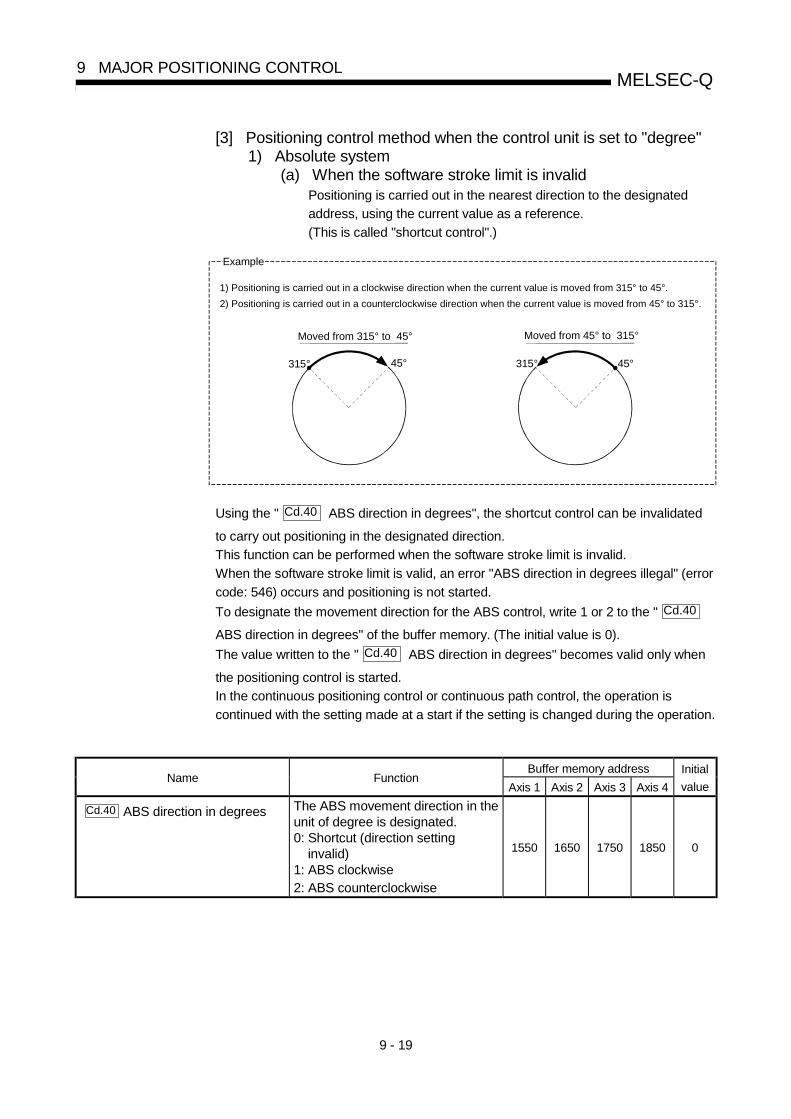
9 - 19
MELSEC-Q9 MAJOR POSITIONING CONTROL
[3] Positioning control method when the control unit is set to "degree"1) Absolute system
(a) When the software stroke limit is invalidPositioning is carried out in the nearest direction to the designated
address, using the current value as a reference.
(This is called "shortcut control".)
Example
1) Positioning is carried out in a clockwise direction when the current value is moved from 315° to 45°.
2) Positioning is carried out in a counterclockwise direction when the current value is moved from 45° to 315°.
315° 45°315° 45°
Moved from 315° to 45° Moved from 45° to 315°
Using the " Cd.40 ABS direction in degrees", the shortcut control can be invalidated
to carry out positioning in the designated direction.
This function can be performed when the software stroke limit is invalid.
When the software stroke limit is valid, an error "ABS direction in degrees illegal" (error
code: 546) occurs and positioning is not started.
To designate the movement direction for the ABS control, write 1 or 2 to the " Cd.40
ABS direction in degrees" of the buffer memory. (The initial value is 0).
The value written to the " Cd.40 ABS direction in degrees" becomes valid only when
the positioning control is started.
In the continuous positioning control or continuous path control, the operation is
continued with the setting made at a start if the setting is changed during the operation.
Buffer memory addressName Function
Axis 1 Axis 2 Axis 3 Axis 4
Initial
value
Cd.40 ABS direction in degrees The ABS movement direction in theunit of degree is designated.0: Shortcut (direction setting invalid)1: ABS clockwise2: ABS counterclockwise
1550 1650 1750 1850 0

9 - 20
MELSEC-Q9 MAJOR POSITIONING CONTROL
(b) When the software stroke limit is validThe positioning is carried out in a clockwise/counterclockwise direction
depending on the software stroke limit range setting method.
Because of this, positioning with "shortcut control" may not be
possible.
Example
0°345.00000°
315.00000°
Positioning carried out in the clockwise direction.
When the current value is moved from 0° to 315°, positioning is carried out in the clockwise direction if the software stroke limit lower limit value is 0° and the upper limit value is 345°.
POINTPositioning addresses are within a range of 0° to 359.99999°.
Use the incremental system to carry out positioning of one rotation or more.
2) Incremental systemPositioning is carried out for a designated movement amount in a
designated movement direction when in the incremental system of
positioning.
The movement direction is determined by the sign (+, –) of the movement
amount.• For a positive (+) movement direction......Clockwise• For a negative (–) movement direction.....Counterclockwise
POINTPositioning of 360° or more can be carried out with the incremental system.
At this time, set as shown below to invalidate the software stroke limit.
[Software stroke limit upper limit value = Software stroke limit lower limit value]

9 - 21
MELSEC-Q9 MAJOR POSITIONING CONTROL
9.1.6 Interpolation control
Meaning of interpolation control
In "2-axis linear interpolation control", "3-axis linear interpolation control", "4-axislinear interpolation control", "2-axis fixed-feed control", "3-axis fixed-feed control","4-axis fixed-feed control", “2-axis speed control”, “3-axis speed control”, “4-axisspeed control”, and "2-axis circular interpolation control", control is carried out sothat linear and arc paths are drawn using a motor set in two to four axis directions.This kind of control is called "interpolation control".In interpolation control, the axis in which the control system is set is defined as the"reference axis", and the other axis is defined as the "interpolation axis".The QD75 controls the "reference axis" following the positioning data set in the"reference axis", and controls the "interpolation axis" corresponding to thereference axis control so that a linear or arc path is drawn.The following table shows the reference axis and interpolation axis combinations.
Axis definition
Axis set to interpolationcontrol in " Da.2 Control method"
Reference axis Interpolation axis
2-axis linear interpolation control, "2-axis fixed-feedcontrol, 2-axis circular interpolation control, 2-axisspeed control
Any of axes 1, 2,3, and 4
"Axes to beinterpolated" set inreference axis
Axis 1 Axis 2, Axis 3
Axis 2 Axis 3, Axis 4
Axis 3 Axis 4, Axis 13-axis linear interpolation control, "3-axis fixed-feedcontrol, 3-axis speed control
Axis 4 Axis 1, Axis 2
Axis 1 Axis 2, Axis 3, Axis 4
Axis 2 Axis 3, Axis 4, Axis 1
Axis 3 Axis 4, Axis 1, Axis 2
4-axis linear interpolation control, "4-axis fixed-feedcontrol, 4-axis speed control
Axis 4 Axis 1, Axis 2, Axis 3

9 - 22
MELSEC-Q9 MAJOR POSITIONING CONTROL
Setting the positioning data during interpolation control
When carrying out interpolation control, the same positioning data Nos. are set forthe "reference axis" and the "interpolation axis".The following table shows the "positioning data" setting items for the referenceaxis and interpolation axis.
Axis
Setting itemReference axis setting item Interpolation axis setting item
Da.1 Operation pattern –
Da.2 Control system
Linear 2, 3, 4, Fixed-feed 2, 3, 4,Circular sub, Circular right,Circular leftForward run speed 2, 3, 4Reverse run speed 2, 3, 4
–
Da.3 Acceleration time No. –
Da.4 Deceleration time No. –
Da.5Axis to beinterpolated. –
Da.6Positioning address/movement amount
Forward run speed 2, 3, and 4.Reverse run speed 2, 3, and 4 notrequired.
Forward run speed 2, 3, and 4.Reverse run speed 2, 3, and 4 notrequired.
Da.7 Arc address (Only during circular sub, circularright, and circular left).
(Only during circular sub, circularright, and circular left).
Da.8 Command speed Only during forward run speed 2,3, 4 and reverse run speed 2, 3, 4.
Da.9 Dwell time –
Sam
e po
sitio
ning
dat
a N
os
Da.10 M code –
: Setting always required: Set according to requirements (Set to "–" when not used.): Setting restrictions exist
– : Setting not required (Unrelated setting item, so any setting value will be ignored. Use the initialvalue or a value within the setting range.)
: For 2-axis interpolation, the partner axis is set. If the self-axis is set, an error "Illegal interpolationdescription command (error code: 521)" will occur. For 3- and 4-axis interpolation, the axis settingis not required.
: Refer to Section 5.3 "List of positioning data" for information on the setting details.

9 - 23
MELSEC-Q9 MAJOR POSITIONING CONTROL
Starting the interpolation control
The positioning data Nos. of the reference axis (axis in which interpolation control
was set in " Da.2 Control system") are started when starting the interpolation
control. (Starting of the interpolation axis is not required.)The following errors or warnings will occur and the positioning will not start if bothreference axis and the interpolation axis are started.
• Reference axis : Interpolation while interpolation axis BUSY (error code:519)
• Interpolation axis : Control system setting error (error code: 524), start duringoperation (warning code: 100).
Interpolation control continuous positioning
When carrying out interpolation control in which "continuous positioning control"and "continuous path control" are designated in the operation pattern, thepositioning method for all positioning data from the started positioning data to thepositioning data in which "positioning complete" is set must be set to interpolationcontrol.The QD75 may malfunction if a control system other than interpolation control isset.
Speed during interpolation control
Either the "composite speed" or "reference axis speed" can be designated as thespeed during interpolation control.
( Pr.20 Interpolation speed designation method)
Only the "Reference axis speed" can be designated in the following interpolationcontrol.When a "composite speed" is set and positioning is started, the "Interpolationmode error (error code: 523)" occurs, and the system will not start. • 4-axis linear interpolation • 2-axis speed control • 3-axis speed control • 4-axis speed control
Cautions in interpolation control(1) If a stepping motor is used, the circular interpolation control cannot be carried
out.Ensure to use a servomotor when the circular interpolation control is carriedout.
(2) If either of the axes exceeds the " Pr.8 Speed limit value" in the 2 to 4 axes
speed control, the axis which exceeded the speed limit value is controlled bythe speed limit value.For the other axes which perform interpolation, the speed can be suppressedby the ratio of a command speed.
If the reference axis exceeds " Pr.8 Speed limit value" during 2- to 4-axis
linear interpolation control, 2- to 4-axis fixed-feed control or 2-axis circularinterpolation control, the reference axis is controlled at the speed limit value.(The speed limit does not function on the interpolation axis side.)
(3) In 2-axis interpolation, you cannot change the combination of interpolated axesmidway through operation.

9 - 24
MELSEC-Q9 MAJOR POSITIONING CONTROL
POINT• When the "reference axis speed" is set during interpolation control, set so the
major axis side becomes the reference axis. If the minor axis side is set as the
reference axis, the major axis side speed may exceed the " Pr.8 Speed limit
value".
Limits to interpolation control
There are limits to the interpolation control that can be executed and speed
( Pr.20 Interpolation speed designation method) that can be set, depending on
the " Pr.1 Unit setting" of the reference axis and interpolation axis. (For example,
circular interpolation control cannot be executed if the reference axis andinterpolation axis units differ.)The following table shows the interpolation control and speed designation limits.
Pr.1 Unit setting 1
" Da.2 Control system"
interpolation control
Pr.20 Interpolation speed
designation method
Reference axis and interpolationaxis units are the same, or acombination of "mm" and "inch".
3
Reference axis andinterpolation axis unitsdiffer 3
Composite speedLinear 2 (ABS, INC)Fixed-feed 2 Reference axis speed
Composite speed 2Circular sub (ABS, INC)Circular right (ABS, INC)Circular left (ABS, INC) Reference axis speed
Composite speedLinear 3 (ABS, INC)Fixed-feed 3 Reference axis speed
Composite speedLinear 4 (ABS, INC)Fixed-feed 4 Reference axis speed
: Setting possible, : Setting not possible.
1 "mm" and "inch" unit mix possible. 2 "degree" setting not possible. A "Circular interpolation not possible (error code: 535)" will occur and the position
cannot start if circular interpolation control is set when the unit is "degree". The machine will immediately stop if"degree" is set during positioning control.
3 The unit set in the reference axis will be used for the speed unit during control if the units differ or if "mm" and "inch"are combined.
Axis operation status during interpolation control
"In interpolation" will be stored in the " Md.26 Axis operation status" during
interpolation control. "Standing by" will be stored when the interpolation operationis terminated. Both the reference axis and interpolation axis will carry out adeceleration stop if an error occurs during control, and "error occurring" will bestored in the operation status.

9 - 25
MELSEC-Q9 MAJOR POSITIONING CONTROL
9.2 Setting the positioning data
9.2.1 Relation between each control and positioning data
The setting requirements and details for the setting items of the positioning data to be
set differ according to the " Da.2 Control system".
The following table shows the positioning data setting items corresponding to thedifferent types of control. Details and settings for the operation of each control areshown in Section 9.2.2 and subsequent sections.(In this section, it is assumed that the positioning data setting is carried out using GXConfigurator-QP.)
Position control Speed controlMajor positioning control
Positioning data setting items
1-axis linearcontrol2-axis linearinterpolationcontrol3-axis linearinterpolationcontrol4-axis linearinterpolationcontrol
1-axis fixed-feedcontrol2-axis fixed-feedcontrol3-axis fixed-feedcontrol4-axis fixed-feedcontrol
2-axis circularinterpolationcontrol
1-axis, 2-axis,3-axis, 4-axisSpeed control
Speed-positionswitchingcontrol
Position-speedswitchingcontrol
Independentpositioning control
(Positioning complete)
Continuous positioningcontrol
Da.1 Operationpattern
Continuous pathcontrol
Da.2 Control system
Linear 1Linear 2Linear 3Linear 4
Fixed-feed 1Fixed-feed 2Fixed-feed 3Fixed-feed 4
Circular subCircular rightCircular left
Forward runspeed 1Reverse runspeed 1Forward runspeed 2Reverse runspeed 2Forward runspeed 3Reverse runspeed 3Forward runspeed 4Reverse runspeed 4
Forward runspeed/posi-tionReverse runspeed/posi-tion
Forward runposition/speed
Reverse runposition/speed
Da.3 Acceleration time No.
Da.4 Deceleration time No.
Da.5 Axis to be interpolated : 2-ax is –: 1, 3, 4-axis – –
Da.6Positioning address/movementamount
–
Da.7 Arc address – – – – –
Da.8 Command speed
Da.9 Dwell time
Da.10 M code
: Always set : Set as required ("–" when not set): Setting not possible (If setting is made, an error (error code: 516) will occur at a start.)
– : Setting not required (Setting value is invalid. Use the initial values or setting values within a range where no error occurs.): The "ABS (absolute) system" or "INC (incremental) system" can be used for the control system.

9 - 26
MELSEC-Q9 MAJOR POSITIONING CONTROL
REMARK• It is recommended that the "positioning data" be set whenever possible with GX Configurator-QP.
Execution by sequence program uses many sequence programs and devices. The execution becomescomplicated, and the scan times will increase.
Other controlMajor positioning control
Positioning data setting items
NOP instructionCurrent value
changingJUMP instruction LOOP instruction LEND instruction
Independentpositioning control
(Positioning complete)– – – –
Continuous positioningcontrol – – – –
Da.1 Operationpattern
Continuous pathcontrol – – – –
Da.2 Control system NOP instructionCurrent value
changingJUMP instruction LOOP instruction LEND instruction
Da.3 Acceleration time No. – – – – –
Da.4 Deceleration time No. – – – – –
Da.5 Axis to be interpolated – – – – –
Da.6Positioning address/movementamount –
Change
destination
address
– – –
Da.7 Arc address – – – – –
Da.8 Command speed – – – – –
Da.9 Dwell time – –
JUMP
destination-
positioning data
No.
– –
Da.10 M code –Condition data
No. at JUMPNo. of repetition –
: Always set : Set as required ("–" when not set): Setting not possible (If setting is made, an error (error code: 515) will occur.)
– : Setting not required (Setting value is invalid. Use the initial values or setting values within a range where no error occurs.)
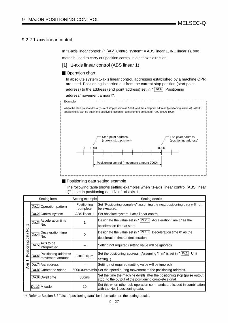
9 - 27
MELSEC-Q9 MAJOR POSITIONING CONTROL
9.2.2 1-axis linear control
In "1-axis linear control" (" Da.2 Control system" = ABS linear 1, INC linear 1), one
motor is used to carry out position control in a set axis direction.
[1] 1-axis linear control (ABS linear 1)
Operation chart
In absolute system 1-axis linear control, addresses established by a machine OPRare used. Positioning is carried out from the current stop position (start point
address) to the address (end point address) set in " Da.6 Positioning
address/movement amount".
0 1000 8000
Positioning control (movement amount 7000)
Start point address(current stop position)
End point address(positioning address)
Example
When the start point address (current stop position) is 1000, and the end point address (positioning address) is 8000,positioning is carried out in the positive direction for a movement amount of 7000 (8000-1000)
Positioning data setting example
The following table shows setting examples when "1-axis linear control (ABS linear1)" is set in positioning data No. 1 of axis 1.
Setting item Setting example Setting details
Da.1 Operation patternPositioningcomplete
Set "Positioning complete" assuming the next positioning data will notbe executed.
Da.2 Control system ABS linear 1 Set absolute system 1-axis linear control.
Da.3Acceleration timeNo.
1Designate the value set in " Pr.25 Acceleration time 1" as the
acceleration time at start.
Da.4Deceleration timeNo.
0Designate the value set in " Pr.10 Deceleration time 0" as the
deceleration time at deceleration.
Da.5Axis to beinterpolated
– Setting not required (setting value will be ignored).
Da.6Positioning address/movement amount 8000.0µm
Set the positioning address. (Assuming "mm" is set in " Pr.1 Unit
setting".)
Da.7 Arc address – Setting not required (setting value will be ignored).
Da.8 Command speed 6000.00mm/min Set the speed during movement to the positioning address.
Da.9 Dwell time 500msSet the time the machine dwells after the positioning stop (pulse outputstop) to the output of the positioning complete signal.
Axi
s 1
Pos
ition
ing
data
No.
1
Da.10 M code 10Set this when other sub operation commands are issued in combinationwith the No. 1 positioning data.
Refer to Section 5.3 "List of positioning data" for information on the setting details.
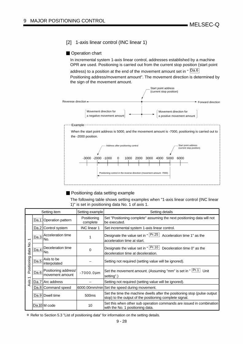
9 - 28
MELSEC-Q9 MAJOR POSITIONING CONTROL
[2] 1-axis linear control (INC linear 1)
Operation chart
In incremental system 1-axis linear control, addresses established by a machineOPR are used. Positioning is carried out from the current stop position (start point
address) to a position at the end of the movement amount set in " Da.6
Positioning address/movement amount". The movement direction is determined bythe sign of the movement amount.
Reverese direction Forward direction
Start point address(current stop position)
Movement direction for
a negative movement amount
Movement direction for
a positive movement amount
-3000 -2000 5000
Positioning control in the reverse direction (movement amount -7000)
Address after positioning control Start point address(current stop position)
-1000 0 1000 2000 3000 4000 6000
Example
When the start point address is 5000, and the movement amount is -7000, positioning is carried out to
the -2000 position.
Positioning data setting example
The following table shows setting examples when "1-axis linear control (INC linear1)" is set in positioning data No. 1 of axis 1.
Setting item Setting example Setting details
Da.1 Operation patternPositioningcomplete
Set "Positioning complete" assuming the next positioning data will notbe executed.
Da.2 Control system INC linear 1 Set incremental system 1-axis linear control.
Da.3Acceleration timeNo.
1 Designate the value set in " Pr.25 Acceleration time 1" as the
acceleration time at start.
Da.4Deceleration timeNo.
0 Designate the value set in " Pr.10 Deceleration time 0" as the
deceleration time at deceleration.
Da.5Axis to beinterpolated
– Setting not required (setting value will be ignored).
Da.6Positioning address/movement amount -7000.0µm Set the movement amount. (Assuming "mm" is set in " Pr.1 Unit
setting".)
Da.7 Arc address – Setting not required (setting value will be ignored).
Da.8 Command speed 6000.00mm/min Set the speed during movement.
Da.9 Dwell time 500msSet the time the machine dwells after the positioning stop (pulse outputstop) to the output of the positioning complete signal.
Axi
s 1
Pos
ition
ing
data
No.
1
Da.10 M code 10Set this when other sub operation commands are issued in combinationwith the No. 1 positioning data.
Refer to Section 5.3 "List of positioning data" for information on the setting details.
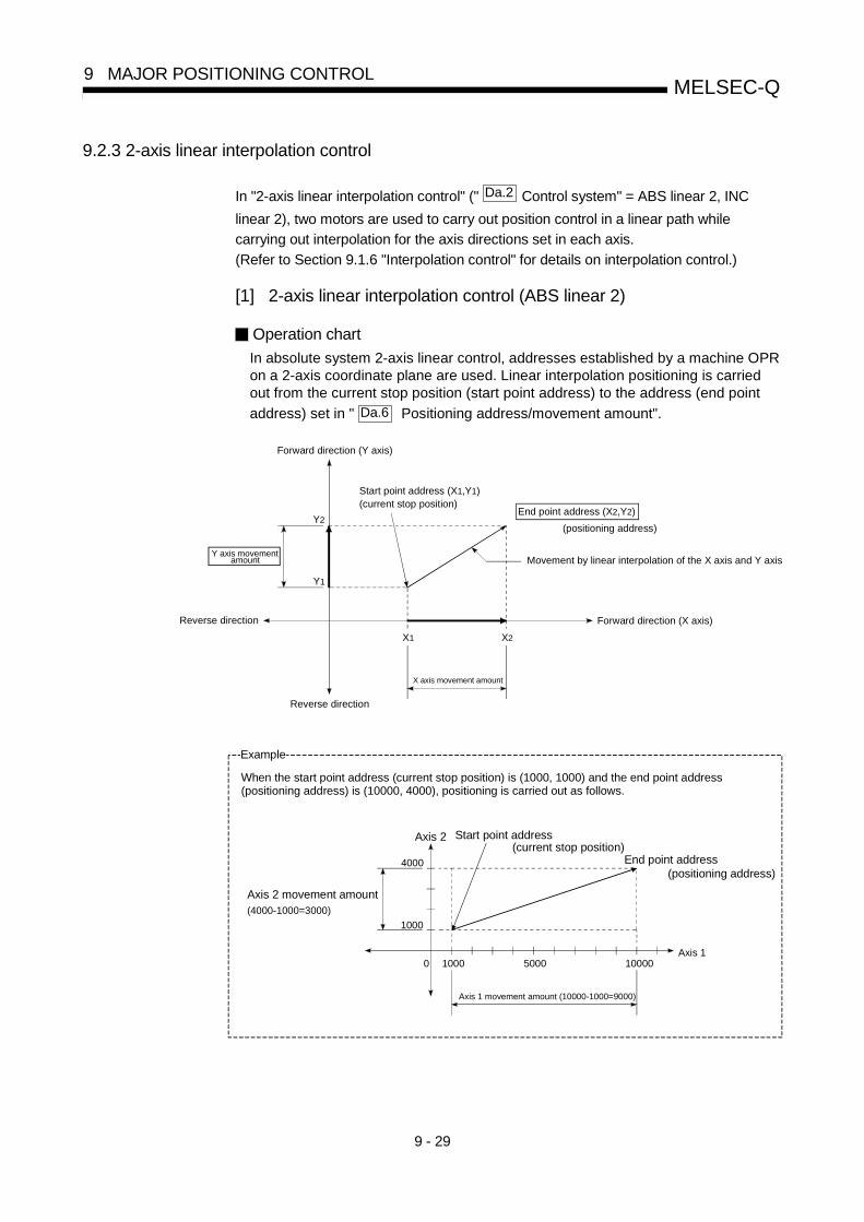
9 - 29
MELSEC-Q9 MAJOR POSITIONING CONTROL
9.2.3 2-axis linear interpolation control
In "2-axis linear interpolation control" (" Da.2 Control system" = ABS linear 2, INC
linear 2), two motors are used to carry out position control in a linear path while
carrying out interpolation for the axis directions set in each axis.
(Refer to Section 9.1.6 "Interpolation control" for details on interpolation control.)
[1] 2-axis linear interpolation control (ABS linear 2)
Operation chart
In absolute system 2-axis linear control, addresses established by a machine OPRon a 2-axis coordinate plane are used. Linear interpolation positioning is carriedout from the current stop position (start point address) to the address (end point
address) set in " Da.6 Positioning address/movement amount".
X1 X2
Y1
Y2
Reverse direction Forward direction (X axis)
Reverse direction
Forward direction (Y axis)
Movement by linear interpolation of the X axis and Y axis
Start point address (X1,Y1)(current stop position)
Y axis movement
X axis movement amount
amount
End point address (X2,Y2)
(positioning address)
Example
5000 10000
Axis 2 movement amount (4000-1000=3000)
4000
1000
Axis 2
Axis 10
(current stop position)End point address
When the start point address (current stop position) is (1000, 1000) and the end point address(positioning address) is (10000, 4000), positioning is carried out as follows.
Axis 1 movement amount (10000-1000=9000)
Start point address
(positioning address)
1000

9 - 30
MELSEC-Q9 MAJOR POSITIONING CONTROL
Restrictions
An error will occur and the positioning will not start in the following cases. Themachine will immediately stop if the error is detected during a positioning control.• If the movement amount of each axis exceeds "1073741824 (=230)" when "0:
Composite speed" is set in " Pr.20 Interpolation speed designation method"... The "Outside linear movement amount range error (error code: 504)" occurs
at a positioning start.
(The maximum movement amount that can be set in " Da.6 Positioning
address/movement amount" is "1073741824 (=230)".)
Positioning data setting example
[Reference axis and interpolation axis are designated as axis 1 and axis 2,respectively.]The following table shows setting examples when "2-axis linear interpolationcontrol (ABS linear 2)" is set in positioning data No. 1 of axis 1. (The requiredvalues are also set in positioning data No. 1 of axis 2.)
Axis
Setting item
Axis 1(reference
axis) settingexample
Axis 2(interpolationaxis) setting
example
Setting details
Da.1 Operation patternPositioningcomplete
–Set "Positioning complete" assuming the next positioningdata will not be executed.
Da.2 Control system ABS linear 2 – Set absolute system 2-axis linear interpolation control.
Da.3Acceleration timeNo.
1 –Designate the value set in " Pr.25 Acceleration time 1" as
the acceleration time at start.
Da.4Deceleration timeNo.
0 –Designate the value set in " Pr.10 Deceleration time 0" as
the deceleration time at deceleration.
Da.5Axis to beinterpolated
1 –Set the axis to be interpolated (partner axis).
If the self-axis is set, an error will occur.
Da.6Positioning address/movement amount 10000.0 µm 4000.0 µm
Set the end point address. (Assuming "mm" is set in
" Pr.1 Unit setting".)
Da.7 Arc address – – Setting not required (setting value will be ignored).
Da.8 Command speed6000.00mm/min
– Set the speed during movement to the end point address.
Da.9 Dwell time 500ms –Set the time the machine dwells after the positioning stop(pulse output stop) to the output of the positioning completesignal.
Axi
s 1
Pos
ition
ing
data
No.
1
Da.10 M code 10 –Set this when other sub operation commands are issued incombination with the No. 1 positioning data.
Refer to Section 5.3 "List of positioning data" for information on the setting details.
POINT• When the "reference axis speed" is set during 2-axis linear intrpolation control, set
so the major axis side becomes the reference axis. If the minor axis side is set as
the reference axis, the major axis side speed may exceed the " Pr.8 Speed limit
value".

9 - 31
MELSEC-Q9 MAJOR POSITIONING CONTROL
[2] 2-axis linear interpolation control (INC linear 2)
Operation chart
In incremental system 2-axis linear interpolation control, addresses established bya machine OPR on a 2-axis coordinate plane are used. Linear interpolationpositioning is carried out from the current stop position (start point address) to a
position at the end of the movement amount set in " Da.6 Positioning
address/movement amount". The movement direction is determined by the sign ofthe movement amount.
X1 X2
Y1
Y2
Reverse direction Forward direction (X axis)
Reverse direction
Forward direction (Y axis)
Movement by linear interpolationpositioning of the X axis and Y axis
Start point address (X1,Y1)(current stop position)
Y axis movement
X axis movement amount
amount
Example
5000 10000
Axis 2 movement amount (-3000)
4000
1000
Axis 2
Axis 10
(current stop position)
Stop address after thepositioning control
When the axis 1 movement amount is 9000 and the axis 2 movement amount is -3000, positioningis carried out as follows.
Axis 1 movement amount (9000)
Start point address
1000

9 - 32
MELSEC-Q9 MAJOR POSITIONING CONTROL
Restrictions
An error will occur and the positioning will not start in the following cases. Themachine will immediately stop if the error is detected during a positioningoperation.• If the movement amount of each axis exceeds "1073741824 (=230)" when "0:
Composite speed" is set in " Pr.20 Interpolation speed designation method"... The "Outside linear movement amount range error (error code: 504)" occurs
at a positioning start.
(The maximum movement amount that can be set in " Da.6 Positioning
address/movement amount" is "1073741824 (=230)".)
Positioning data setting example
[Reference axis and interpolation axis are designated as axis 1 and axis 2,respectively.]The following table shows setting examples when "2-axis linear interpolationcontrol (INC linear 2)" is set in positioning data No. 1 of axis 1. (The requiredvalues are also set in positioning data No. 1 of axis 2.)
Axis
Setting item
Axis 1(reference
axis) settingexample
Axis 2(interpolationaxis) setting
example
Setting details
Da.1 Operation patternPositioningcomplete
–Set "Positioning complete" assuming the next positioningdata will not be executed.
Da.2 Control system INC linear 2 – Set incremental system 2-axis linear interpolation control.
Da.3Acceleration timeNo.
1 – Designate the value set in " Pr.25 Acceleration time 1" asthe acceleration time at start.
Da.4Deceleration timeNo.
0 – Designate the value set in " Pr.10 Deceleration time 0" as
the deceleration time at deceleration.
Da.5Axis to beinterpolated
1 –Set the axis to be interpolated (partner axis).
If the self-axis is set, an error will occur.
Da.6Positioning address/movement amount
9000.0 µm -3000.0 µmSet the movement amount. (Assuming "mm" is set in
" Pr.1 Unit setting".)
Da.7 Arc address – – Setting not required (setting value will be ignored).
Da.8 Command speed6000.00mm/min
– Set the speed during movement.
Da.9 Dwell time 500ms –Set the time the machine dwells after the positioning stop(pulse output stop) to the output of the positioning completesignal.
Axi
s 1
Pos
ition
ing
data
No.
1
Da.10 M code 10 –Set this when other sub operation commands are issued incombination with the No. 1 positioning data.
Refer to Section 5.3 "List of positioning data" for information on the setting details.
POINT• When the "reference axis speed" is set during 2-axis linear intrpolation control, set
so the major axis side becomes the reference axis. If the minor axis side is set as
the reference axis, the major axis side speed may exceed the " Pr.8 Speed limit
value".
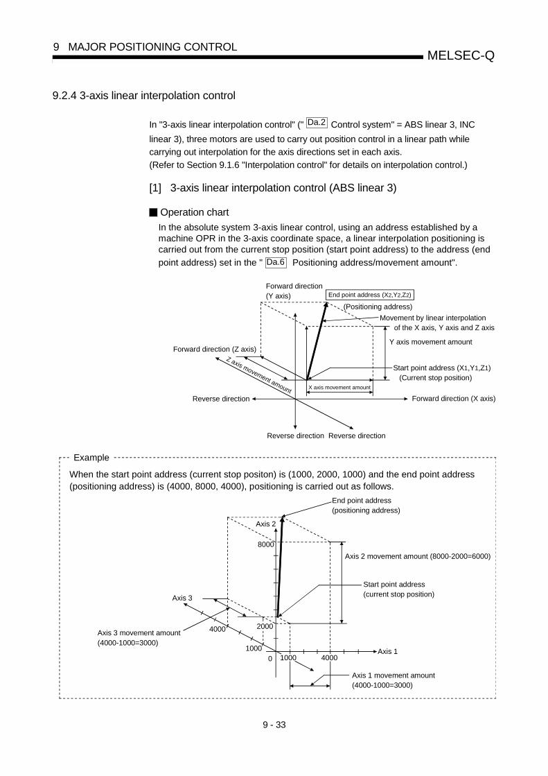
9 - 33
MELSEC-Q9 MAJOR POSITIONING CONTROL
9.2.4 3-axis linear interpolation control
In "3-axis linear interpolation control" (" Da.2 Control system" = ABS linear 3, INC
linear 3), three motors are used to carry out position control in a linear path while
carrying out interpolation for the axis directions set in each axis.
(Refer to Section 9.1.6 "Interpolation control" for details on interpolation control.)
[1] 3-axis linear interpolation control (ABS linear 3)
Operation chart
In the absolute system 3-axis linear control, using an address established by amachine OPR in the 3-axis coordinate space, a linear interpolation positioning iscarried out from the current stop position (start point address) to the address (end
point address) set in the " Da.6 Positioning address/movement amount".
End point address (X2,Y2,Z2)
(Positioning address)
Movement by linear interpolation of the X axis, Y axis and Z axis
Y axis movement amount
Start point address (X1,Y1,Z1) (Current stop position)
Forward direction (X axis)
Forward direction (Z axis)
Reverse direction
Forward direction(Y axis)
X axis movement amount
Z axis movement amount
Reverse direction Reverse direction
End point address(positioning address)
Axis 2 movement amount (8000-2000=6000)
Start point address(current stop position)
Axis 1
Axis 3
Axis 2
8000
Axis 3 movement amount(4000-1000=3000)
4000 2000
100010000 4000
Axis 1 movement amount(4000-1000=3000)
Example
When the start point address (current stop positon) is (1000, 2000, 1000) and the end point address(positioning address) is (4000, 8000, 4000), positioning is carried out as follows.
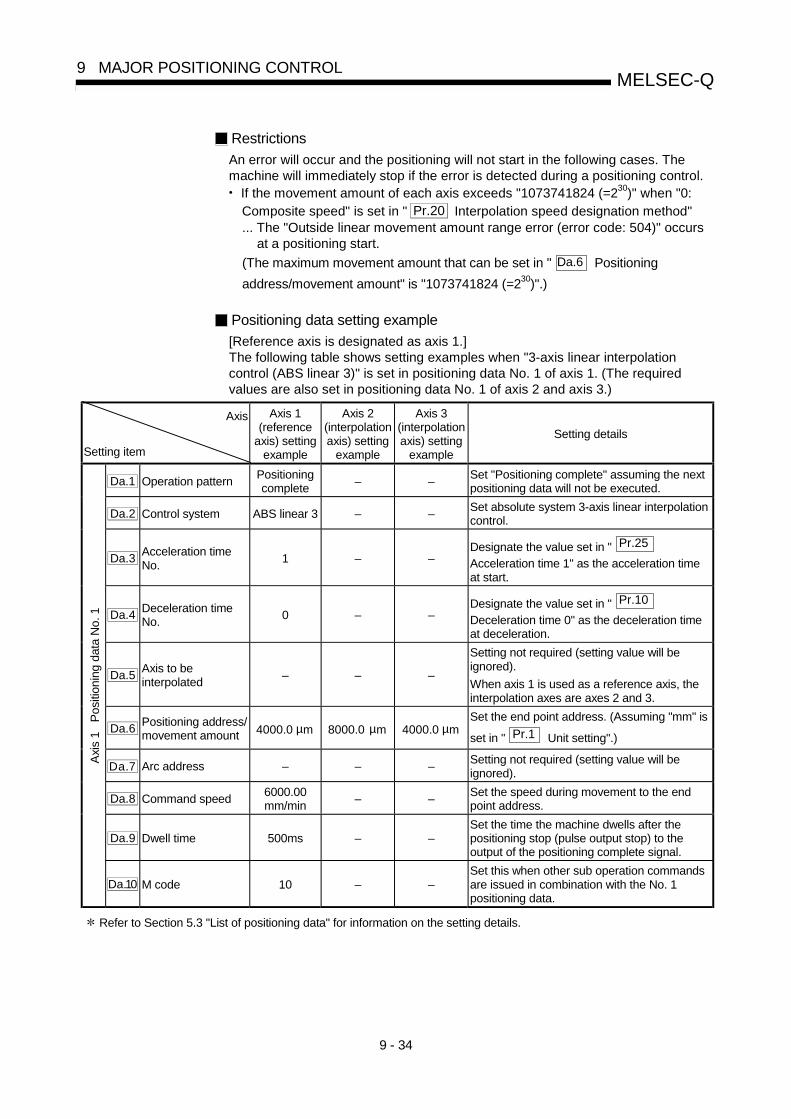
9 - 34
MELSEC-Q9 MAJOR POSITIONING CONTROL
Restrictions
An error will occur and the positioning will not start in the following cases. Themachine will immediately stop if the error is detected during a positioning control.• If the movement amount of each axis exceeds "1073741824 (=230)" when "0:
Composite speed" is set in " Pr.20 Interpolation speed designation method"... The "Outside linear movement amount range error (error code: 504)" occurs
at a positioning start.
(The maximum movement amount that can be set in " Da.6 Positioning
address/movement amount" is "1073741824 (=230)".)
Positioning data setting example
[Reference axis is designated as axis 1.]The following table shows setting examples when "3-axis linear interpolationcontrol (ABS linear 3)" is set in positioning data No. 1 of axis 1. (The requiredvalues are also set in positioning data No. 1 of axis 2 and axis 3.)
Axis
Setting item
Axis 1(reference
axis) settingexample
Axis 2(interpolationaxis) setting
example
Axis 3(interpolationaxis) setting
example
Setting details
Da.1 Operation patternPositioningcomplete
– –Set "Positioning complete" assuming the nextpositioning data will not be executed.
Da.2 Control system ABS linear 3 – –Set absolute system 3-axis linear interpolationcontrol.
Da.3Acceleration timeNo.
1 – –Designate the value set in " Pr.25
Acceleration time 1" as the acceleration timeat start.
Da.4Deceleration timeNo.
0 – –Designate the value set in " Pr.10
Deceleration time 0" as the deceleration timeat deceleration.
Da.5Axis to beinterpolated
– – –
Setting not required (setting value will beignored).
When axis 1 is used as a reference axis, theinterpolation axes are axes 2 and 3.
Da.6Positioning address/movement amount 4000.0 µm 8000.0 µm 4000.0 µm
Set the end point address. (Assuming "mm" is
set in " Pr.1 Unit setting".)
Da.7 Arc address – – –Setting not required (setting value will beignored).
Da.8 Command speed6000.00mm/min
– –Set the speed during movement to the endpoint address.
Da.9 Dwell time 500ms – –Set the time the machine dwells after thepositioning stop (pulse output stop) to theoutput of the positioning complete signal.
Axi
s 1
Pos
ition
ing
data
No.
1
Da.10 M code 10 – –Set this when other sub operation commandsare issued in combination with the No. 1positioning data.
Refer to Section 5.3 "List of positioning data" for information on the setting details.

9 - 35
MELSEC-Q9 MAJOR POSITIONING CONTROL
POINTS• When the "reference axis speed" is set during 3-axis linear intrpolation control, set
so the major axis side becomes the reference axis. If the minor axis side is set as
the reference axis, the major axis side speed may exceed the " Pr.8 Speed limit
value".• Refer to Section 9.1.6 "Interpolation control" for the reference axis and
interpolation axis combinations.
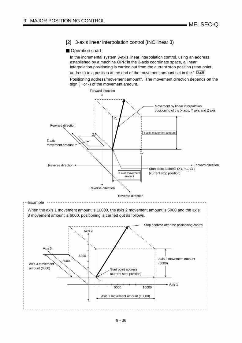
9 - 36
MELSEC-Q9 MAJOR POSITIONING CONTROL
[2] 3-axis linear interpolation control (INC linear 3)
Operation chart
In the incremental system 3-axis linear interpolation control, using an addressestablished by a machine OPR in the 3-axis coordinate space, a linearinterpolation positioning is carried out from the current stop position (start point
address) to a position at the end of the movement amount set in the " Da.6
Positioning address/movement amount". The movement direction depends on thesign (+ or -) of the movement amount.
Z axismovement amount
X axis movementamount
Y axis movement amount
Start point address (X1, Y1, Z1)(current stop position)
Forward direction
Forward direction
Forward direction
Movement by linear interpolationpositioning of the X axis, Y axis and Z axis
Z2
Y2
X2
Reverse direction
Reverse direction
Reverse direction
When the axis 1 movement amount is 10000, the axis 2 movement amount is 5000 and the axis3 movement amount is 6000, positioning is carried out as follows.
Start point address(current stop position)
Axis 1
Axis 3
Stop address after the positioning control
6000
Axis 2
Axis 3 movementamount (6000)
5000Axis 2 movement amount(5000)
5000 10000
Axis 1 movement amount (10000)
Example

9 - 37
MELSEC-Q9 MAJOR POSITIONING CONTROL
Restrictions
An error will occur and the positioning will not start in the following cases. Themachine will immediately stop if the error is detected during a positioningoperation.• If the movement amount of each axis exceeds "1073741824 (=230)" when "0:
Composite speed" is set in " Pr.20 Interpolation speed designation method"... The "Outside linear movement amount range error (error code: 504)" occurs
at a positioning start.
(The maximum movement amount that can be set in " Da.6 Positioning
address/movement amount" is "1073741824 (=230)".)
Positioning data setting example
[Reference axis is designated as axis 1.]The following table shows setting examples when "3-axis linear interpolationcontrol (INC linear 3)" is set in positioning data No. 1 of axis 1. (The requiredvalues are also set in positioning data No. 1 of axis 2 and axis 3.)
Axis
Setting item
Axis 1(reference
axis) settingexample
Axis 2(interpolationaxis) setting
example
Axis 3(interpolationaxis) setting
example
Setting details
Da.1 Operation patternPositioningcomplete
– –Set "Positioning complete" assuming the nextpositioning data will not be executed.
Da.2 Control system INC linear 3 – –Set incremental system 3-axis linearinterpolation control.
Da.3Acceleration timeNo.
1 – –Designate the value set in " Pr.25
Acceleration time 1" as the acceleration timeat start.
Da.4Deceleration timeNo.
0 – –Designate the value set in " Pr.10
Deceleration time 0" as the deceleration timeat deceleration.
Da.5Axis to beinterpolated
– – –
Setting not required (setting value will beignored).
When axis 1 is used as a reference axis, theinterpolation axes are axes 2 and 3.
Da.6Positioning address/movement amount
10000.0 µm 5000.0 µm 6000.0 µmSet the movement amount. (Assuming "mm"
is set in " Pr.1 Unit setting".)
Da.7 Arc address – – –Setting not required (setting value will beignored).
Da.8 Command speed6000.00mm/min
– – Set the speed during movement.
Da.9 Dwell time 500ms – –Set the time the machine dwells after thepositioning stop (pulse output stop) to theoutput of the positioning complete signal.
Axi
s 1
Pos
ition
ing
data
No.
1
Da.10 M code 10 – –Set this when other sub operation commandsare issued in combination with the No. 1positioning data.
Refer to Section 5.3 "List of positioning data" for information on the setting details.

9 - 38
MELSEC-Q9 MAJOR POSITIONING CONTROL
POINTS(1) When the "reference axis speed" is set during 3-axis linear intrpolation control,
set so the major axis side becomes the reference axis. If the minor axis side is
set as the reference axis, the major axis side speed may exceed the " Pr.8
Speed limit value".
(2) Refer to Section 9.1.6 "Interpolation control" for the reference axis and
interpolation axis combinations.

9 - 39
MELSEC-Q9 MAJOR POSITIONING CONTROL
9.2.5 4-axis linear interpolation control
In "4-axis linear interpolation control" (" Da.2 Control system" = ABS linear 4, INC
linear 4), four motors are used to carry out position control in a linear path while
carrying out interpolation for the axis directions set in each axis.
(Refer to Section 9.1.6 "Interpolation control" for details on interpolation control.)
[1] 4-axis linear interpolation control (ABS linear 4)In the absolute system 4-axis linear control, using an address established by a
machine OPR in the 4-axis coordinate space, a linear interpolation positioning is
carried out from the current stop position (start point address) to the address (end
point address) set in the " Da.6 Positioning address/movement amount".
Restrictions
An error will occur and the positioning will not start in the following cases. Themachine will immediately stop if the error is detected during a positioning control.• If the movement amount of each axis exceeds "1073741824 (=230)" when "0:
Composite speed" is set in " Pr.20 Interpolation speed designation method"... The "Outside linear movement amount range error (error code: 504)" occurs
at a positioning start.
(The maximum movement amount that can be set in " Da.6 Positioning
address/movement amount" is "1073741824 (=230)".)

9 - 40
MELSEC-Q9 MAJOR POSITIONING CONTROL
Positioning data setting example
[Reference axis is designated as axis 1.]The following table shows setting examples when "4-axis linear interpolationcontrol (ABS linear 4)" is set in positioning data No. 1 of axis 1. (The requiredvalues are also set in positioning data No. 1 of axis 2, axis 3 and axis 4.)
Axis
Setting item
Axis 1(reference
axis) settingexample
Axis 2(interpolationaxis) setting
example
Axis 3(interpolationaxis) setting
example
Axis 4(interpolationaxis) setting
example
Setting details
Da.1 Operation patternPositioningcomplete
– – –Set "Positioning complete"assuming the next positioningdata will not be executed.
Da.2 Control system ABS linear 4 – – –Set absolute system 4-axislinear interpolation control.
Da.3Acceleration timeNo.
1 – – –
Designate the value set in
" Pr.25 Acceleration time 1"as the acceleration time at start.
Da.4Deceleration timeNo.
0 – – –
Designate the value set in
" Pr.10 Deceleration time 0"
as the deceleration time atdeceleration.
Da.5Axis to beinterpolated
– – – –
Setting not required (settingvalue will be ignored).
When axis 1 is used as areference axis, the interpolationaxes are axes 2, 3 and 4.
Da.6Positioning address/movement amount 4000.0 µm 8000.0 µm 4000.0 µm 3000.0 µm
Set the end point address.(Assuming "mm" is set in
" Pr.1 Unit setting".)
Da.7 Arc address – – – –Setting not required (settingvalue will be ignored).
Da.8 Command speed6000.00mm/min
– – –Set the speed during movementto the end point address.
Da.9 Dwell time 500ms – – –
Set the time the machine dwellsafter the positioning stop (pulseoutput stop) to the output of thepositioning complete signal.
Axi
s 1
Pos
ition
ing
data
No.
1
Da.10 M code 10 – – –
Set this when other suboperation commands are issuedin combination with the No. 1positioning data.
Refer to Section 5.3 "List of positioning data" for information on the setting details.
POINTS• When the "reference axis speed" is set during 4-axis linear intrpolation control, set
so the major axis side becomes the reference axis. If the minor axis side is set as
the reference axis, the major axis side speed may exceed the " Pr.8 Speed limit
value".• Refer to Section 9.1.6 "Interpolation control" for the reference axis and
interpolation axis combinations.

9 - 41
MELSEC-Q9 MAJOR POSITIONING CONTROL
[2] 4-axis linear interpolation control (INC linear 4)
Operation chart
In the incremental system 4-axis linear interpolation control, using an addressestablished by a machine OPR in the 4-axis coordinate plane, a linear interpolationpositioning is carried out from the current stop position (start point address) to a
position at the end of the movement amount set in the " Da.6 Positioning
address/movement amount". The movement direction depends on the sign (+ or -)of the movement amount.
Restrictions
An error will occur and the positioning will not start in the following cases. Themachine will immediately stop if the error is detected during a positioningoperation.• If the movement amount of each axis exceeds "1073741824 (=230)" when "0:
Composite speed" is set in " Pr.20 Interpolation speed designation method"... The "Outside linear movement amount range error (error code: 504)" occurs
at a positioning start.
(The maximum movement amount that can be set in " Da.6 Positioning
address/movement amount" is "1073741824 (=230)".)

9 - 42
MELSEC-Q9 MAJOR POSITIONING CONTROL
Positioning data setting example
[Reference axis is designated as axis 1.]The following table shows setting examples when "4-axis linear interpolationcontrol (INC linear 4)" is set in positioning data No. 1 of axis 1. (The requiredvalues are also set in positioning data No. 1 of axis 2, axis 3 and axis 4.)
Axis
Setting item
Axis 1(reference
axis) settingexample
Axis 2(interpolationaxis) setting
example
Axis 3(interpolationaxis) setting
example
Axis 4(interpolationaxis) setting
example
Setting details
Da.1 Operation patternPositioningcomplete
– – –Set "Positioning complete"assuming the next positioningdata will not be executed.
Da.2 Control system INC linear 4 – – –Set incremental system 4-axislinear interpolation control.
Da.3Acceleration timeNo.
1 – – –
Designate the value set in
" Pr.25 Acceleration time 1"
as the acceleration time at start.
Da.4Deceleration timeNo.
0 – – –
Designate the value set in
" Pr.10 Deceleration time 0"
as the deceleration time atdeceleration.
Da.5Axis to beinterpolated
– – – –
Setting not required (settingvalue will be ignored).
When axis 1 is used as areference axis, the interpolationaxes are axes 2, 3 and 4.
Da.6Positioning address/movement amount
4000.0 µm 8000.0 µm 4000.0 µm 3000.0 µm
Set the movement amount.(Assuming "mm" is set in
" Pr.1 Unit setting".)
Da.7 Arc address – – – –Setting not required (settingvalue will be ignored).
Da.8 Command speed6000.00mm/min
– – –Set the speed duringmovement.
Da.9 Dwell time 500ms – – –
Set the time the machine dwellsafter the positioning stop (pulseoutput stop) to the output of thepositioning complete signal.
Axi
s 1
Pos
ition
ing
data
No.
1
Da.10 M code 10 – – –
Set this when other suboperation commands are issuedin combination with the No. 1positioning data.
Refer to Section 5.3 "List of positioning data" for information on the setting details.
POINTS(1) When the "reference axis speed" is set during 4-axis linear interpolation control,
set so the major axis side becomes the reference axis. If the minor axis side is
set as the reference axis, the major axis side speed may exceed the " Pr.8
Speed limit value".
(2) Refer to Section 9.1.6 "Interpolation control" for the reference axis and
interpolation axis combinations.

9 - 43
MELSEC-Q9 MAJOR POSITIONING CONTROL
9.2.6 1-axis fixed-feed control
In "1-axis fixed-feed control" (" Da.2 Control system" = fixed-feed 1), one motor is
used to carry out fixed-feed control in a set axis direction.
In fixed-feed control, any remainder of the movement amount designated in the
positioning data is rounded down if less than that required for control accuracy to
output the same amount of pulses. (The remainder of the movement amount with an
accuracy below the control accuracy does not affect the regular controls.)
Operation chart
In 1-axis fixed-feed control, the address ( Md.20 Current feed value) of the current
stop position (start point address) is set to "0". Positioning is then carried out to a
position at the end of the movement amount set in " Da.6 Positioning
address/movement amount".The movement direction is determined by the movement amount sign.
0 0 0 0 0
" Md. 20 Current feed value" is set to "0" at the positioning start
Designated movementPositioningstart amount
Reverse direction Forward direction
Stop position
Movement direction for
a negative movement amount
Movement direction for
a positive movement amount
Restrictions
(1) An axis error "Continuous path control not possible (error code: 516)" willoccur and the operation cannot start if "continuous path control" is set in
" Da.1 Operation pattern". ("Continuous path control" cannot be set in fixed-
feed control.)
(2) "Fixed-feed" cannot be set in " Da.2 Control system" in the positioning data
when "continuous path control" has been set in " Da.1 Operation pattern" of
the immediately prior positioning data. (For example, if the operation pattern ofpositioning data No. 1 is "continuous path control", fixed-feed control cannotbe set in positioning data No. 2.) An axis error "Continuous path control notpossible (error code: 516)" will occur and the machine will carry out adeceleration stop if this type of setting is carried out.

9 - 44
MELSEC-Q9 MAJOR POSITIONING CONTROL
Positioning data setting example
The following table shows setting examples when "1-axis fixed-feed control (fixed-feed 1)" is set in positioning data No. 1 of axis 1.
Setting item Setting example Setting details
Da.1 Operation patternPositioningcomplete
Set "Positioning complete" assuming the next positioning data will notbe executed.
Da.2 Control system Fixed-feed 1 Set 1-axis fixed-feed control.
Da.3Acceleration timeNo.
1Designate the value set in " Pr.25 Acceleration time 1" as the
acceleration time at start.
Da.4Deceleration timeNo.
0Designate the value set in " Pr.10 Deceleration time 0" as the
deceleration time at deceleration.
Da.5Axis to beinterpolated
– Setting not required (setting value will be ignored).
Da.6Positioning address/movement amount 8000.0µm
Set the positioning address. (Assuming "mm" is set in " Pr.1 Unit
setting".)
Da.7 Arc address – Setting not required (setting value will be ignored).
Da.8 Command speed 6000.00mm/min Set the speed during movement to the positioning address.
Da.9 Dwell time 500msSet the time the machine dwells after the positioning stop (pulse outputstop) to the output of the positioning complete signal.
Axi
s 1
Pos
ition
ing
data
No.
1
Da.10 M code 10Set this when other sub operation commands are issued incombination with the No. 1 positioning data.
* Refer to Section 5.3 "List of positioning data" for information on the setting details.

9 - 45
MELSEC-Q9 MAJOR POSITIONING CONTROL
9.2.7 2-axis fixed-feed control (interpolation)
In "2-axis fixed-feed control" (" Da.2 Control system" = fixed-feed 2), two motors are
used to carry out fixed-feed control in a linear path while carrying out interpolation forthe axis directions set in each axis.In fixed-feed control, any remainder of the movement amount designated in thepositioning data is rounded down if less than that required for control accuracy tooutput the same amount of pulses. (The remainder of the movement amount with anaccuracy below the control accuracy does not affect the regular controls.)(Refer to Section 9.1.6 "Interpolation control" for details on interpolation control.)
Operation chart
In incremental system 2-axis fixed-feed control, the addresses ( Md.20 Current
feed value) of the current stop position (start addresses) of both axes are set to"0". Linear interpolation positioning is then carried out from that position to a
position at the end of the movement amount set in " Da.6 Positioning
address/movement amount". The movement direction is determined by the sign ofthe movement amount.
" Md. 20 Current feed value" of each axis
is set to "0" at the positioning start
(0,0)
(0,0)
(0,0)
X axis
Y axis
Designated movementamount
Designated movementamount
Restrictions
(1) An axis error "Continuous path control not possible (error code: 516)" willoccur and the operation cannot start if "continuous path control" is set in
" Da.1 Operation pattern". ("Continuous path control" cannot be set in fixed-
feed control.)(2) If the movement amount of each axis exceeds "1073741824 (=230)" when "0:
Composite speed" is set in " Pr.20 Interpolation speed designation method",
the "Outside linear movement amount range error (error code: 504)" occurs ata positioning start and positioning cannot be started. (The maximum
movement amount that can be set in " Da.6 Positioning address/movement
amount" is "1073741824 (= 230)".
(3) "Fixed-feed" cannot be set in " Da.2 Control system" in the positioning data
when "continuous path control" has been set in " Da.1 Operation pattern" of
the immediately prior positioning data. (For example, if the operation pattern ofpositioning data No. 1 is "continuous path control", fixed-feed control cannotbe set in positioning data No. 2.) An axis error "Continuous path control notpossible (error code: 516)" will occur and the machine will carry out adeceleration stop if this type of setting is carried out.

9 - 46
MELSEC-Q9 MAJOR POSITIONING CONTROL
Positioning data setting example
[Reference axis and interpolation axis are designated as axis 1 and axis 2,respectively.]The following table shows setting examples when "2-axis fixed-dimension feedcontrol (fixed-feed 2)" is set in positioning data No. 1 of axis 1. (The requiredvalues are also set in positioning data No. 1 of axis 2.)
Axis
Setting item
Axis 1(reference
axis) settingexample
Axis 2(interpolationaxis) setting
example
Setting details
Da.1 Operation patternPositioningcomplete
–Set "Positioning complete" assuming the next positioningdata will not be executed.
Da.2 Control method Fixed-feed 2 – Set 2-axis fixed-feed control.
Da.3Acceleration timeNo.
1 –Designate the value set in " Pr.25 Acceleration time 1" as
the acceleration time at start.
Da.4Deceleration timeNo.
0 –Designate the value set in " Pr.10 Deceleration time 0" as
the deceleration time at deceleration.
Da.5Axis to beinterpolated
1 –Set the axis to be interpolated (partner axis).
If the self-axis is set, an error will occur.
Da.6Positioning address/movement amount
8000.0 µm 6000.0 µmSet the positioning address. (Assuming "mm" is set in
" Pr.1 Unit setting".)
Da.7 Arc address – – Setting not required (setting value will be ignored).
Da.8 Command speed6000.00mm/min
–
Set the speed during movement. (Designate the composite
speed of reference axis speed in " Pr.20 Interpolation
speed designation method".)
Da.9 Dwell time 500ms –Set the time the machine dwells after the positioning stop(pulse output stop) to the output of the positioning completesignal.
Axi
s 1
Pos
ition
ing
data
No.
1
Da.10 M code 10 –Set this when other sub operation commands are issued incombination with the No. 1 positioning data.
* Refer to Section 5.3 "List of positioning data" for information on the setting details.
POINT• When the "reference axis speed" is set during 2-axis fixed-feed control, set so the major axis side
becomes the reference axis. If the minor axis side is set as the reference axis, the major axis side
speed may exceed the " Pr.8 Speed limit value".
9 - 47
MELSEC-Q9 MAJOR POSITIONING CONTROL
9.2.8 3-axis fixed-feed control (interpolation)
In "3-axis fixed-feed control" (" Da.2 Control system" = fixed-feed 3), three motors are
used to carry out fixed-feed control in a linear path while carrying out interpolation forthe axis directions set in each axis.
In fixed-feed control, any remainder of the movement amount designated in the
positioning data is rounded down if less than that required for control accuracy to
output the same amount of pulses. (The remainder of the movement amount with an
accuracy below the control accuracy does not affect the regular controls.)(Refer to Section 9.1.6 "Interpolation control" for details on interpolation control.)

9 - 48
MELSEC-Q9 MAJOR POSITIONING CONTROL
Operation chart
In incremental system 3-axis fixed-feed control, the addresses ( Md.20 Current
feed value) of the current stop position (start addresses) of every axes are set to"0". Linear interpolation positioning is then carried out from that position to a
position at the end of the movement amount set in " Da.6 Positioning
address/movement amount". The movement direction is determined by the sign ofthe movement amount.
Designated movementamount
Designated movementamount
Md.20
Designated movement amount
" Current feed value" of each axis is set to "0" at the positioning start.
(0,0,0)
(0,0,0)
(0,0,0)
Y axis
X axis
Z axis

9 - 49
MELSEC-Q9 MAJOR POSITIONING CONTROL
Restrictions
(1) An axis error "Continuous path control not possible (error code: 516)" willoccur and the operation cannot start if "continuous path control" is set in
" Da.1 Operation pattern". ("Continuous path control" cannot be set in fixed-
feed control.)(2) If the movement amount of each axis exceeds "1073741824 (=230)" when "0:
Composite speed" is set in " Pr.20 Interpolation speed designation method",
the "Outside linear movement amount range error (error code: 504)" occurs ata positioning start and positioning cannot be started. (The maximum
movement amount that can be set in " Da.6 Positioning address/movement
amount" is "1073741824 (= 230)".
(3) "Fixed-feed" cannot be set in " Da.2 Control system" in the positioning data
when "continuous path control" has been set in " Da.1 Operation pattern" of
the immediately prior positioning data. (For example, if the operation pattern ofpositioning data No. 1 is "continuous path control", fixed-feed control cannotbe set in positioning data No. 2.) An axis error "Continuous path control notpossible (error code: 516)" will occur and the machine will carry out adeceleration stop if this type of setting is carried out.
Positioning data setting example
[Reference axis is designated as axis 1.]The following table shows setting examples when "3-axis fixed-feed control (fixed-feed 3)" is set in positioning data No. 1 of axis 1. (The required values are also setin positioning data No. 1 of axis 2 and axis 3.)

9 - 50
MELSEC-Q9 MAJOR POSITIONING CONTROL
Axis
Setting item
Axis 1(reference
axis) settingexample
Axis 2(interpolationaxis) setting
example
Axis 3(interpolationaxis) setting
example
Setting details
Da.1 Operation patternPositioningcomplete
– –Set "Positioning complete" assuming the nextpositioning data will not be executed.
Da.2 Control method Fixed-feed 3 – – Set 3-axis fixed-feed control.
Da.3Acceleration timeNo.
1 – –Designate the value set in " Pr.25
Acceleration time 1" as the acceleration timeat start.
Da.4Deceleration timeNo.
0 – –Designate the value set in " Pr.10
Deceleration time 0" as the deceleration timeat deceleration.
Da.5Axis to beinterpolated
– – –
Setting not required (setting value will beignored).
When axis 1 is used as a reference axis, theinterpolation axes are axes 2 and 3.
Da.6Positioning address/movement amount
10000.0 µm 5000.0 µm 6000.0 µmSet the positioning address. (Assuming "mm"
is set in " Pr.1 Unit setting".)
Da.7 Arc address – – –Setting not required (setting value will beignored).
Da.8 Command speed6000.00mm/min
– – Set the speed during movement.
Da.9 Dwell time 500ms – –Set the time the machine dwells after thepositioning stop (pulse output stop) to theoutput of the positioning complete signal.
Axi
s 1
Pos
ition
ing
data
No.
1
Da.10 M code 10 – –Set this when other sub operation commandsare issued in combination with the No. 1positioning data.
Refer to Section 5.3 "List of positioning data" for information on the setting details.
POINTS(1) When the "reference axis speed" is set during 3-axis fixed-feed control, set so the major axis side
becomes the reference axis. If the minor axis side is set as the reference axis, the major axis side
speed may exceed the " Pr.8 Speed limit value".
(2)Refer to Section 9.1.6 "Interpolation control" for the reference axis and interpolation axis
combinations.

9 - 51
MELSEC-Q9 MAJOR POSITIONING CONTROL
9.2.9 4-axis fixed-feed control (interpolation)
In "4-axis fixed-feed control" (" Da.2 Control system" = fixed-feed 4), four motors are
used to carry out fixed-feed control in a linear path while carrying out interpolation forthe axis directions set in each axis.
In fixed-feed control, any remainder of the movement amount designated in the
positioning data is rounded down if less than that required for control accuracy to
output the same amount of pulses. (The remainder of the movement amount with an
accuracy below the control accuracy does not affect the regular controls.)(Refer to Section 9.1.6 "Interpolation control" for details on interpolation control.)
Operation chart
In incremental system 4-axis fixed-feed control, the addresses ( Md.20 Current
feed value) of the current stop position (start addresses) of every axes are set to"0". Linear interpolation positioning is then carried out from that position to a
position at the end of the movement amount set in " Da.6 Positioning
address/movement amount". The movement direction is determined by the sign ofthe movement amount.
Restrictions
(1) An axis error "Continuous path control not possible (error code: 516)" willoccur and the operation cannot start if "continuous path control" is set in
" Da.1 Operation pattern". ("Continuous path control" cannot be set in fixed-
feed control.)
(2) "Fixed-feed" cannot be set in " Da.2 Control system" in the positioning data
when "continuous path control" has been set in " Da.1 Operation pattern" of
the immediately prior positioning data. (For example, if the operation pattern ofpositioning data No. 1 is "continuous path control", fixed-feed control cannotbe set in positioning data No. 2.) An axis error "Continuous path control notpossible (error code: 516)" will occur and the machine will carry out adeceleration stop if this type of setting is carried out.
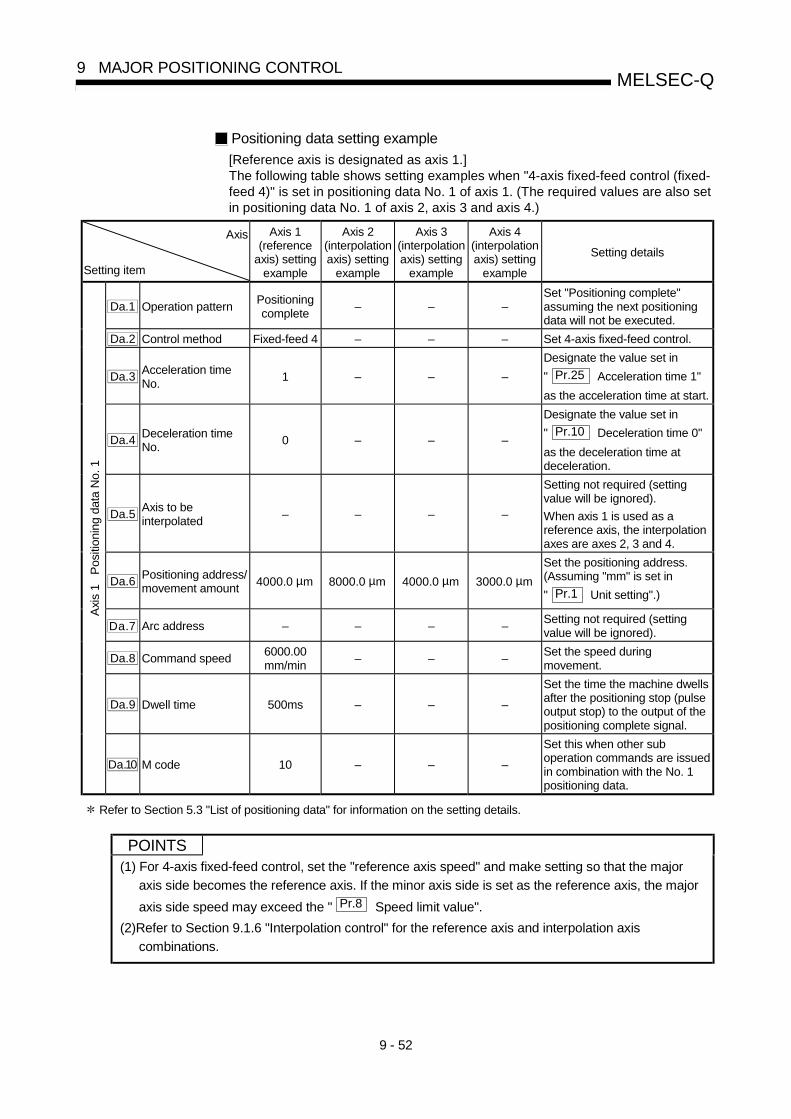
9 - 52
MELSEC-Q9 MAJOR POSITIONING CONTROL
Positioning data setting example
[Reference axis is designated as axis 1.]The following table shows setting examples when "4-axis fixed-feed control (fixed-feed 4)" is set in positioning data No. 1 of axis 1. (The required values are also setin positioning data No. 1 of axis 2, axis 3 and axis 4.)
Axis
Setting item
Axis 1(reference
axis) settingexample
Axis 2(interpolationaxis) setting
example
Axis 3(interpolationaxis) setting
example
Axis 4(interpolationaxis) setting
example
Setting details
Da.1 Operation patternPositioningcomplete
– – –Set "Positioning complete"assuming the next positioningdata will not be executed.
Da.2 Control method Fixed-feed 4 – – – Set 4-axis fixed-feed control.
Da.3Acceleration timeNo.
1 – – –
Designate the value set in
" Pr.25 Acceleration time 1"
as the acceleration time at start.
Da.4Deceleration timeNo.
0 – – –
Designate the value set in
" Pr.10 Deceleration time 0"
as the deceleration time atdeceleration.
Da.5Axis to beinterpolated
– – – –
Setting not required (settingvalue will be ignored).
When axis 1 is used as areference axis, the interpolationaxes are axes 2, 3 and 4.
Da.6Positioning address/movement amount
4000.0 µm 8000.0 µm 4000.0 µm 3000.0 µm
Set the positioning address.(Assuming "mm" is set in
" Pr.1 Unit setting".)
Da.7 Arc address – – – –Setting not required (settingvalue will be ignored).
Da.8 Command speed6000.00mm/min
– – –Set the speed duringmovement.
Da.9 Dwell time 500ms – – –
Set the time the machine dwellsafter the positioning stop (pulseoutput stop) to the output of thepositioning complete signal.
Axi
s 1
Pos
ition
ing
data
No.
1
Da.10 M code 10 – – –
Set this when other suboperation commands are issuedin combination with the No. 1positioning data.
Refer to Section 5.3 "List of positioning data" for information on the setting details.
POINTS(1) For 4-axis fixed-feed control, set the "reference axis speed" and make setting so that the major
axis side becomes the reference axis. If the minor axis side is set as the reference axis, the major
axis side speed may exceed the " Pr.8 Speed limit value".
(2)Refer to Section 9.1.6 "Interpolation control" for the reference axis and interpolation axis
combinations.

9 - 53
MELSEC-Q9 MAJOR POSITIONING CONTROL
9.2.10 2-axis circular interpolation control with sub point designation
In "2-axis circular interpolation control" (" Da.2 Control system" = ABS circular sub,
INC circular sub), two motors are used to carry out position control in an arc path
passing through designated sub points, while carrying out interpolation for the axis
directions set in each axis.
(Refer to Section 9.1.6 "Interpolation control" for details on
interpolation control.)
[1] 2-axis circular interpolation control with sub point designation (ABScircular sub)
Operation chart
In the absolute system, 2-axis circular interpolation control with sub pointdesignation, addresses established by a machine OPR on a 2-axis coordinateplane are used. Positioning is carried out from the current stop position (start point
address) to the address (end point address) set in " Da.6 Positioning
address/movement amount", in an arc path that passes through the sub point
address set in " Da.7 Arc address".
The resulting control path is an arc having as its center the intersection point ofperpendicular bisectors of a straight line between the start point address (currentstop position) and sub point address (arc address), and a straight line between thesub point address (arc address) and end point address (positioning address).
OP
Reverse direction
Forward direction
Arc center point
Movement by circular interpolation
Forward direction
End point address(arc address)(positioning address)
Start point address
(current stop position)Reverse direction
Sub point address
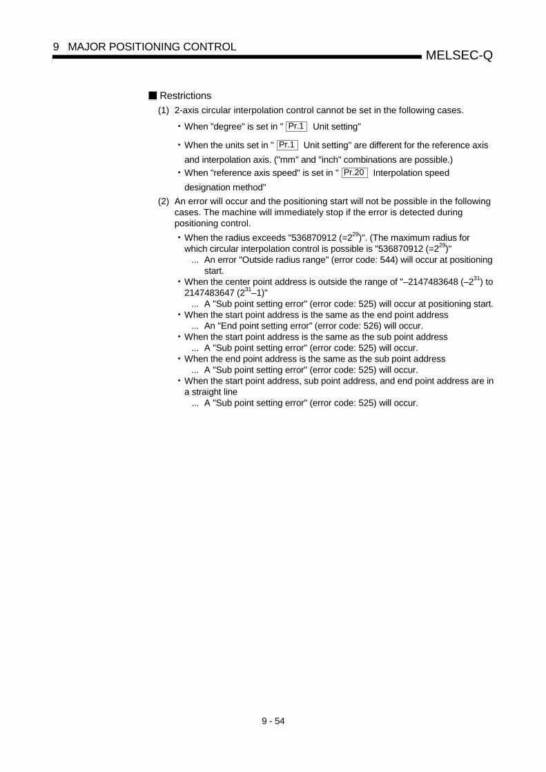
9 - 54
MELSEC-Q9 MAJOR POSITIONING CONTROL
Restrictions
(1) 2-axis circular interpolation control cannot be set in the following cases.
• When "degree" is set in " Pr.1 Unit setting"
• When the units set in " Pr.1 Unit setting" are different for the reference axis
and interpolation axis. ("mm" and "inch" combinations are possible.)• When "reference axis speed" is set in " Pr.20 Interpolation speed
designation method"
(2) An error will occur and the positioning start will not be possible in the followingcases. The machine will immediately stop if the error is detected duringpositioning control.
• When the radius exceeds "536870912 (=229)". (The maximum radius forwhich circular interpolation control is possible is "536870912 (=229)"
... An error "Outside radius range" (error code: 544) will occur at positioningstart.
• When the center point address is outside the range of "–2147483648 (–231) to2147483647 (231–1)"
... A "Sub point setting error" (error code: 525) will occur at positioning start.• When the start point address is the same as the end point address
... An "End point setting error" (error code: 526) will occur.• When the start point address is the same as the sub point address
... A "Sub point setting error" (error code: 525) will occur.• When the end point address is the same as the sub point address
... A "Sub point setting error" (error code: 525) will occur.• When the start point address, sub point address, and end point address are in
a straight line... A "Sub point setting error" (error code: 525) will occur.

9 - 55
MELSEC-Q9 MAJOR POSITIONING CONTROL
Positioning data setting example
[Reference axis and interpolation axis are designated as axis 1 and axis 2,respectively.]The following table shows setting examples when "2-axis circular interpolationcontrol with sub point designation (ABS circular sub)" is set in positioning data No.1 of axis 1. (The required values are also set in positioning data No. 1 of axis 2.)
Axis
Setting item
Axis 1(reference
axis) settingexample
Axis 2(interpolationaxis) setting
example
Setting details
Da.1 Operation patternPositioningcomplete
–Set "Positioning complete" assuming the next positioningdata will not be executed.
Da.2 Control systemABS circular
sub–
Set absolute system, 2-axis circular interpolation control withsub point designation.
Da.3Acceleration timeNo.
1 –Designate the value set in " Pr.25 Acceleration time 1" as
the acceleration time at start.
Da.4Deceleration timeNo.
0 –Designate the value set in " Pr.10 Deceleration time 0" as
the deceleration time at deceleration.
Da.5Axis to beinterpolated
1 –Set the axis to be interpolated (partner axis).
If the self-axis is set, an error will occur.
Da.6Positioning address/movement amount
8000.0 µm 6000.0 µmSet the positioning address. (Assuming "mm" is set in
" Pr.1 Unit setting".)
Da.7 Arc address 4000.0 µm 3000.0 µmSet the sub point address. (Assuming that the " Pr.1 Unit
setting" is set to "mm".)
Da.8 Command speed6000.00mm/min
–
Set the speed when moving to the end point address.
(Designate the composite speed in " Pr.20 Interpolation
speed designation method".)
Da.9 Dwell time 500ms –Set the time the machine dwells after the positioning stop(pulse output stop) to the output of the positioning completesignal.
Axi
s 1
Pos
ition
ing
data
No.
1
Da.10 M code 10 –Set this when other sub operation commands are issued incombination with the No. 1 positioning data.
Refer to Section 5.3 "List of positioning data" for information on the setting details.
POINTSet a value in " Da.8 Command speed" so that the speed of each axis does not
exceed the " Pr.8 Speed limit value". (The speed limit does not function for the
speed calculated by the QD75 during interpolation control.)

9 - 56
MELSEC-Q9 MAJOR POSITIONING CONTROL
[2] 2-axis circular interpolation control with sub point designation (INCcircular sub)
Operation chartIn the incremental system, 2-axis circular interpolation control with sub pointdesignation, positioning is carried out from the current stop position (start point
address) to a position at the end of the movement amount set in " Da.6
Positioning address/movement amount" in an arc path that passes through the sub
point address set in " Da.7 Arc address". The movement direction depends on
the sign (+ or -) of the movement amount.The resulting control path is an arc having as its center the intersection point ofperpendicular bisectors of the straight line between the start point address (currentstop position) and sub point address (arc address) calculated from the movementamount to the sub point, and a straight line between the sub point address (arcaddress) and end point address (positioning address) calculated from themovement amount to the end point.
Reverse direction
Reverse direction
Forward direction
Movement by circular interpolationForward direction
Movement amount to the end point
Movement
amount to the
sub point
Movement amount
to sub pointMovement amount
to the end point
Arc center
Sub point address
(arc address)
Start point
address

9 - 57
MELSEC-Q9 MAJOR POSITIONING CONTROL
Restrictions
(1) 2-axis circular interpolation control cannot be set in the following cases.
• When "degree" is set in " Pr.1 Unit setting"
• When the units set in " Pr.1 Unit setting" are different for the reference axis
and interpolation axis. ("mm" and "inch" combinations are possible.)• When "reference axis speed" is set in " Pr.20 Interpolation speed
designation method"
(2) An error will occur and the positioning start will not be possible in the followingcases. The machine will immediately stop if the error is detected duringpositioning control.
• When the radius exceeds "536870912 (=229)". (The maximum radius forwhich circular interpolation control is possible is "536870912 (=229)"
... An error "Outside radius range" (error code: 544) will occur at positioningstart.
• When the auxiliary point address is outside the range of -2147483648 (–231)to 2147483647 (231–1).
... An error 525 will occur.• When the end point address is outside the range of -2147483648 (–231) to
2147483647 (231–1).... An error 526 will occur.
• When the auxiliary point address, center point address is outside the range of"–2147483648 (–231) to 2147483647 (231–1)"
... A "Sub point setting error" (error code: 525) will occur at positioning start.• When the start point address is the same as the end point address
... An "End point setting error" (error code: 526) will occur.• When the start point address is the same as the sub point address
... A "Sub point setting error" (error code: 525) will occur.• When the end point address is the same as the sub point address
... A "Sub point setting error" (error code: 525) will occur.• When the start point address, sub point address, and end point address are in
a straight line... A "Sub point setting error" (error code: 525) will occur.

9 - 58
MELSEC-Q9 MAJOR POSITIONING CONTROL
Positioning data setting example
[Reference axis and interpolation axis are designated as axis 1 and axis 2,respectively.]The following table shows setting examples when "2-axis circular interpolationcontrol with sub point designation (INC circular sub)" is set in positioning data No.1 of axis 1. (The required values are also set in positioning data No. 1 of axis 2.)
Axis
Setting item
Axis 1(reference
axis) settingexample
Axis 2(interpolationaxis) setting
example
Setting details
Da.1 Operation patternPositioningcomplete
–Set "Positioning complete" assuming the next positioningdata will not be executed.
Da.2 Control systemINC circular
sub–
Set incremental system, 2-axis circular interpolation controlwith sub point designation.
Da.3Acceleration timeNo.
1 –Designate the value set in " Pr.25 Acceleration time 1" as
the acceleration time at start.
Da.4Deceleration timeNo.
0 –Designate the value set in " Pr.10 Deceleration time 0" as
the deceleration time at deceleration.
Da.5Axis to beinterpolated
1 –Set the axis to be interpolated (partner axis).
If the self-axis is set, an error will occur.
Da.6Positioning address/movement amount
8000.0 µm 6000.0 µmSet the movement amount. (Assuming that the " Pr.1 Unit
setting" is set to "mm".)
Da.7 Arc address 4000.0 µm 3000.0 µmSet the sub point address. (Assuming that the " Pr.1 Unit
setting" is set to "mm".)
Da.8 Command speed6000.00mm/min
–
Set the speed during movement. (Designate the composite
speed in " Pr.20 Interpolation speed designation
method".)
Da.9 Dwell time 500ms –Set the time the machine dwells after the positioning stop(pulse output stop) to the output of the positioning completesignal.
Axi
s 1
Pos
ition
ing
data
No.
1
Da.10 M code 10 –Set this when other sub operation commands are issued incombination with the No. 1 positioning data.
Refer to Section 5.3 "List of positioning data" for information on the setting details.
POINTSet a value in " Da.8 Command speed" so that the speed of each axis does not
exceed the " Pr.8 Speed limit value". (The speed limit does not function for the
speed calculated by the QD75 during interpolation control.)

9 - 59
MELSEC-Q9 MAJOR POSITIONING CONTROL
9.2.11 2-axis circular interpolation control with center point designation
In "2-axis circular interpolation control" (" Da.2 Control system" = ABS circular right,
INC circular right, ABS circular left, INC circular left), two motors are used to carry out
position control in an arc path having a designated center point, while carrying out
interpolation for the axis directions set in each axis.
(Refer to Section 9.1.6 "Interpolation control" for details on interpolation control.)
The following table shows the rotation directions, arc center angles that can be
controlled, and positioning paths for the different control systems.
Control system Rotation directionArc center angle that
can be controlledPositioning path
ABS circular right
INC circular right
Clockwise
Positioning path
0° < < 360°
Center point
Start point (current stopposition)
End point(positioning address)
ABS circular left
INC circular left
Counterclockwise
0° < θ ≤ 360°Center point
Positioning path
Start point (current stop position)
End point(positioning address)
0°< < 360°

9 - 60
MELSEC-Q9 MAJOR POSITIONING CONTROL
Circular interpolation error compensation
In circular interpolation control with center point designation, the arc pathcalculated from the start point address and arc address may deviate from the
position of the end point address set in " Da.6 Positioning address/movement
amount".
(Refer to " Pr.41 Allowable circular interpolation error width".)
(1) Calculated error < " Pr.41 Allowable circular interpolation error width"
Circular interpolation control to the set end point address is carried out whilethe error compensation is carried out. (This is called "spiral interpolation".)
Path using spiral interpolation
Center point addressStart point address
Error
Calculated end point address
End point address
In circular interpolation control with center point designation, an angularvelocity is calculated on the assumption that operation is carried out at acommand speed on the arc using the radius calculated from the start pointaddress and center point address, and the radius is compensated in proportionto the angular velocity deviated from that at the start point.Thus, when there is a difference (error) between a radius calculated from thestart point address and center point address (start point radius) and a radiuscalculated from the end point address and center point address (end pointradius), the composite speed differs from the command speed as follows.
Start point radius > End point radius: As compared with the speed withouterror, the speed becomes slower asend point address is reached.
Start point radius < End point radius: As compared with the speed withouterror, the speed becomes faster asend point address is reached.
(2) Calculated error > " Pr.41 Allowable circular interpolation error width"
At the positioning start, an error "Large arc error deviation" (error code: 506)will occur and the control will not start. The machine will immediately stop if theerror is detected during positioning control.

9 - 61
MELSEC-Q9 MAJOR POSITIONING CONTROL
[1] 2-axis circular interpolation control with center point designation(ABS circular right, ABS circular left)
Operation chart
In the absolute system, 2-axis circular interpolation control with center pointdesignation, addresses established by a machine OPR on a 2-axis coordinateplane are used. Positioning is carried out from the current stop position (start point
address) to the address (end point address) set in " Da.6 Positioning
address/movement amount", in an arc path having as its center the address (arc
address) of the center point set in " Da.7 Arc address".
Radius
Movement by circular interpolation Forward direction
Reverse direction
End point addressStart point address(current stop position)
Arc address
Forward direction Reverse direction
(positioning address)
Positioning of a complete round with a radius from the start point address to thearc center point can be carried out by setting the end point address (positioningaddress) to the same address as the start point address.
Arc center point
Reverese direction
Forward direction
(Arc address)
(current stop position)
Start point address =
Reverese direction Forward direction
End point address
(positioning address)

9 - 62
MELSEC-Q9 MAJOR POSITIONING CONTROL
In circular interpolation control with center point designation, an angular velocity iscalculated on the assumption that operation is carried out at a command speed onthe arc using the radius calculated from the start point address and center pointaddress, and the radius is compensated in proportion to the angular velocitydeviated from that at the start point.Thus, when there is a difference (error) between a radius calculated from the startpoint address and center point address (start point radius) and a radius calculatedfrom the end point address and center point address (end point radius), thecomposite speed differs from the command speed as follows.
Start point radius > End point radius: As compared with the speed without error,the speed becomes slower as end pointaddress is reached.
Start point radius < End point radius: As compared with the speed without error,the speed becomes faster as end pointaddress is reached.
Restrictions
(1) 2-axis circular interpolation control cannot be set in the following cases.
• When "degree" is set in " Pr.1 Unit setting"
• When the units set in " Pr.1 Unit setting" are different for the reference axis
and interpolation axis. ("mm" and "inch" combinations are possible.)• When "reference axis speed" is set in " Pr.20 Interpolation speed
designation method"
(2) An error will occur and the positioning start will not be possible in the followingcases. The machine will immediately stop if the error is detected duringpositioning control.
• When the radius exceeds "536870912 (=229)". (The maximum radius forwhich circular interpolation control is possible is "536870912 (=229)"
... An error "Outside radius range " (error code: 544) will occur atpositioning start.
• When the start point address is the same as the center point address... A "Center point setting error" (error code: 527) will occur.
• When the end point address is the same as the center point address... A "Center point setting error" (error code: 527) will occur.
• When the center point address is outside the range of -231 to 231-1... A "Center point setting error" (error code: 527) will occur.

9 - 63
MELSEC-Q9 MAJOR POSITIONING CONTROL
Positioning data setting examples
[Reference axis and interpolation axis are designated as axis 1 and axis 2,respectively.]The following table shows setting examples when "2-axis circular interpolationcontrol with center point designation (ABS right arc, ABS left arc)" is set inpositioning data No. 1 of axis 1. (The required values are also set in positioningdata No. 1 of axis 2.)
Axis
Setting item
Axis 1(reference
axis) settingexample
Axis 2(interpolationaxis) setting
example
Setting details
Da.1 Operation patternPositioningcomplete
–Set "Positioning complete" assuming the next positioningdata will not be executed.
Da.2 Control system
ABS circularright
ABS circularleft
–Set absolute system, 2-axis circular interpolation control withcenter point designation. (Select clockwise orcounterclockwise according to the control.)
Da.3Acceleration timeNo.
1 –Designate the value set in " Pr.25 Acceleration time 1" as
the acceleration time at start.
Da.4Deceleration timeNo.
0 –Designate the value set in " Pr.10 Deceleration time 0" as
the deceleration time at deceleration.
Da.5Axis to beinterpolated
1 –Set the axis to be interpolated (partner axis).
If the self-axis is set, an error will occur.
Da.6Positioning address/movement amount
8000.0 µm 6000.0 µmSet the positioning address. (Assuming "mm" is set in
" Pr.1 Unit setting".)
Da.7 Arc address 4000.0 µm 3000.0 µmSet the arc address. (Assuming that the " Pr.1 Unit
setting" is set to "mm".)
Da.8 Command speed6000.00mm/min
–
Set the speed when moving to the end point address.
(Designate the composite speed in " Pr.20 Interpolation
speed designation method".)
Da.9 Dwell time 500ms –Set the time the machine dwells after the positioning stop(pulse output stop) to the output of the positioning completesignal.
Axi
s 1
Pos
ition
ing
data
No.
1
Da.10 M code 10 –Set this when other sub operation commands are issued incombination with the No. 1 positioning data.
Refer to Section 5.3 "List of positioning data" for information on the setting details.
POINTSet a value in " Da.8 Command speed" so that the speed of each axis does not
exceed the " Pr.8 Speed limit value". (The speed limit does not function for the
speed calculated by the QD75 during interpolation control.)

9 - 64
MELSEC-Q9 MAJOR POSITIONING CONTROL
[2] 2-axis circular interpolation control with center point designation(INC circular right, INC circular left)
Operation chart
In the incremental system, 2-axis circular interpolation control with center pointdesignation, addresses established by a machine OPR on a 2-axis coordinateplane are used. Positioning is carried out from the current stop position (start point
address) to a position at the end of the movement amount set in " Da.6
Positioning address/movement amount", in an arc path having as its center the
address (arc address) of the center point set in " Da.7 Arc address".
Radius
Movement by circular interpolationForward direction
Reversedirection Forward direction
Movement amountto the end point
Start point address(Current stop position)
Arc center point
(Arc address)
Movement amount to the end pointReversedirection
Positioning of a complete round with a radius of the distance from the start pointaddress to the arc center point can be carried out by setting the movement amountto "0".
Arc center point
Reverese direction
Forward direction
(Arc address)
Reverese direction Forward direction
Movement amount = 0

9 - 65
MELSEC-Q9 MAJOR POSITIONING CONTROL
In circular interpolation control with center point designation, an angular velocity iscalculated on the assumption that operation is carried out at a command speed onthe arc using the radius calculated from the start point address and center pointaddress, and the radius is compensated in proportion to the angular velocitydeviated from that at the start point.Thus, when there is a difference (error) between a radius calculated from the startpoint address and center point address (start point radius) and a radius calculatedfrom the end point address and center point address (end point radius), thecomposite speed differs from the command speed as follows.
Start point radius > End point radius: As compared with the speed without error,the speed becomes slower as end pointaddress is reached.
Start point radius < End point radius: As compared with the speed without error,the speed becomes faster as end pointaddress is reached.
Restrictions
(1) 2-axis circular interpolation control cannot be set in the following cases.
• When "degree" is set in " Pr.1 Unit setting"
• When the units set in " Pr.1 Unit setting" are different for the reference axis
and interpolation axis. ("mm" and "inch" combinations are possible.)• When "reference axis speed" is set in " Pr.20 Interpolation speed
designation method"
(2) An error will occur and the positioning start will not be possible in the followingcases. The machine will immediately stop if the error is detected duringpositioning control.
• When the radius exceeds "536870912 (=229)". (The maximum radius forwhich circular interpolation control is possible is "536870912 (=229)"
... An error "Outside radius range" (error code: 544) will occur at positioningstart.
• When the end point address is outside the range of -231 to 231-1... An "End point setting error" (error code: 526) will occur.
• When the start point address is the same as the center point address... A "Center point setting error" (error code: 527) will occur.
• When the end point address is the same as the center point address... A "Center point setting error" (error code: 527) will occur.
• When the center point address is outside the range of -231 to 231-1... A "Center point setting error" (error code: 527) will occur.

9 - 66
MELSEC-Q9 MAJOR POSITIONING CONTROL
Positioning data setting examples
[Reference axis and interpolation axis are designated as axis 1 and axis 2,respectively.]The following table shows setting examples when "2-axis circular interpolationcontrol with center point designation (INC circular right, INC circular left)" is set inpositioning data No. 1 of axis 1. (The required values are also set in positioningdata No. 1 of axis 2.)
Axis
Setting item
Axis 1(reference
axis) settingexample
Axis 2(interpolationaxis) setting
example
Setting details
Da.1 Operation patternPositioningcomplete
–Set "Positioning complete" assuming the next positioningdata will not be executed.
Da.2 Control system
INC circularright
INC circularleft
–Set incremental system, 2-axis circular interpolation controlwith center point designation. (Select clockwise orcounterclockwise according to the control.)
Da.3Acceleration timeNo.
1 –Designate the value set in " Pr.25 Acceleration time 1" as
the acceleration time at start.
Da.4Deceleration timeNo.
0 –Designate the value set in " Pr.10 Deceleration time 0" as
the deceleration time at deceleration.
Da.5Axis to beinterpolated
1 –Set the axis to be interpolated (partner axis).
If the self-axis is set, an error will occur.
Da.6Positioning address/movement amount 8000.0 µm 6000.0 µm
Set the movement amount. (Assuming that the " Pr.1 Unit
setting" is set to "mm".)
Da.7 Arc address 4000.0 µm 3000.0 µmSet the center point address. (Assuming that the " Pr.1
Unit setting" is set to "mm".)
Da.8 Command speed6000.00mm/min
–
Set the speed when moving to the end point address.
(Designate the composite speed in " Pr.20 Interpolation
speed designation method".)
Da.9 Dwell time 500ms –Set the time the machine dwells after the positioning stop(pulse output stop) to the output of the positioning completesignal.
Axi
s 1
Pos
ition
ing
data
No.
1
Da.10 M code 10 –Set this when other sub operation commands are issued incombination with the No. 1 positioning data.
Refer to Section 5.3 "List of positioning data" for information on the setting details.
POINTSet a value in " Da.8 Command speed" so that the speed of each axis does not
exceed the " Pr.8 Speed limit value". (The speed limit does not function for the
speed calculated by the QD75 during interpolation control.)

9 - 67
MELSEC-Q9 MAJOR POSITIONING CONTROL
9.2.12 1-axis speed control
In "1-axis speed control" (" Da.2 Control system" = Forward run: speed 1, Reverse
run: speed 1), control is carried out in the axis direction in which the positioning data has been set by continuously outputting pulses for the speed set in " Da.8 Command
speed" until the input of a stop command. The two types of 1-axis speed control are "Forward run: speed 1" in which the control starts in the forward run direction, and "Reverse run: speed 1" in which control starts in the reverse run direction.
Operation chart The following chart shows the operation timing for 1-axis speed control with axis 1 as the reference axis. The "in speed control" flag ( Md.31 Status: b0) is turned ON during speed control. The "Positioning complete signal" is not turned ON.
t
V
BUSY signalOFF
ON
Positioning start signalOFF
ON
Positioning complete signal OFF
Axis stop signal(stop command) [Y4]
OFF
ON
Does not turn ON even when control is stoppedby stop command.
OFF
ON
Md.31 Status:b0In speed control flag
Da. 8 Command speed
[Y10]
[XC]
[X14]
Fig.9.9 1-axis speed control operation timing

9 - 68
MELSEC-Q9 MAJOR POSITIONING CONTROL
Current feed value during 1-axis speed control The following table shows the " Md.20 Current feed value" during 1-axis speed
control corresponding to the " Pr.21 Current feed value during speed control" settings.
" Pr.21 Current feed value during speed control" setting
Md.20 Current feed value
0: Do not update current feed value The current feed value at speed control start is maintained.
1: Update current feed value The current feed value is updated. 2: Zero clear current feed value The current feed value is fixed at 0.
Speed
t
In speed control
Current feed value during speed control start is maintained
(a) Current feed value not updated
t
Current feed value is updated
(b) Current feed value updated (c) Current feed value zero cleared
t
0
Speed In speed control In speed controlSpeed
Restrictions (1) Set "Positioning complete" in " Da.1 Operation pattern". An axis error
"Continuous path control not possible (error code: 516)" will occur and the operation cannot start if "continuous positioning control" or "continuous path control" is set in " Da.1 Operation pattern". ("Continuous positioning control" and "continuous path control" cannot be set in speed control.)
(2) Set the WITH mode in " Pr.18 M code ON signal output timing" when using an M code. The M code will not be output, and the M code ON signal will not turn ON if the AFTER mode is set.
(3) An error "No command speed" (error code: 503) will occur if the current speed (-1) is set in " Da.8 command speed".
(4) The software stroke limit check will not carried out if the control unit is set to "degree".
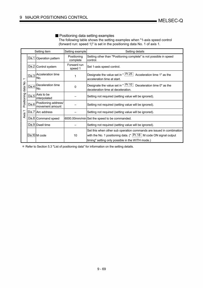
9 - 69
MELSEC-Q9 MAJOR POSITIONING CONTROL
Positioning data setting examples The following table shows the setting examples when "1-axis speed control (forward run: speed 1)" is set in the positioning data No. 1 of axis 1.
Setting item Setting example Setting details
Da.1 Operation pattern Positioning complete
Setting other than "Positioning complete" is not possible in speed control.
Da.2 Control system Forward run speed 1 Set 1-axis speed control.
Da.3 Acceleration time No. 1 Designate the value set in " Pr.25 Acceleration time 1" as the
acceleration time at start.
Da.4 Deceleration time No. 0 Designate the value set in " Pr.10 Deceleration time 0" as the
deceleration time at deceleration.
Da.5 Axis to be interpolated – Setting not required (setting value will be ignored).
Da.6 Positioning address/ movement amount – Setting not required (setting value will be ignored).
Da.7 Arc address – Setting not required (setting value will be ignored).
Da.8 Command speed 6000.00mm/min Set the speed to be commanded.
Da.9 Dwell time – Setting not required (setting value will be ignored).
Axis
1
Posi
tioni
ng d
ata
No.
1
Da.10 M code 10 Set this when other sub operation commands are issued in combination with the No. 1 positioning data. (" Pr.18 M code ON signal output timing" setting only possible in the WITH mode.)
Refer to Section 5.3 "List of positioning data" for information on the setting details.

9 - 70
MELSEC-Q9 MAJOR POSITIONING CONTROL
9.2.13 2-axis speed control
In "2-axis speed control" (" Da.2 Control system" = Forward run: speed 2, Reverse
run: speed 2), control is carried out in the 2-axis direction in which the positioning data has been set by continuously outputting pulses for the speed set in " Da.8 Command
speed" until the input of a stop command. The two types of 2-axis speed control are "Forward run: speed 2" in which the control starts in the forward run direction, and "Reverse run: speed 2" in which control starts in the reverse run direction. (Refer to Section 9.1.6 "Interpolation control" for the combination of the reference axis with the interpolation axis.)
Operation chart The following chart shows the operation timing for 2-axis (axes 1 and 2) speed control with axis 1 as the reference axis. The "in speed control" flag ( Md.31 Status: b0) is turned ON during speed control. The "positioning complete signal" is not turned ON.
t
V
BUSY signal[XC,XD]
OFF
ON
Positioning start signal[Y10]
OFF
ON
Positioning complete signal[X14,X15]
OFF
Axis stop signal (stop command)(Either Y4 or Y5)
OFF
ON
Does not turn ON evenwhen control is stoppedby stop command.
OFF
ON
Md.31In speed control flag
Da. 8Referense axis (axis1)
t
V
Command speedDa. 8Interpolation axis (axis 2)
Command speed
Status: b0
Fig. 9.10 2-axis speed control operation timing

9 - 71
MELSEC-Q9 MAJOR POSITIONING CONTROL
Current feed value during 2-axis speed control The following table shows the " Md.20 Current feed value" during 2-axis speed
control corresponding to the " Pr.21 Current feed value during speed control" settings. (Note that the reference axis setting values are used for parameters.)
" Pr.21 Current feed value during speed control" setting
Md.20 Current feed value
0: Do not update current feed value The current feed value at speed control start is maintained.
1: Update current feed value The current feed value is updated. 2: Zero clear current feed value The current feed value is fixed at 0.
Speed
t
In speed control
Current feed value during speed control start is maintained
(a) Current feed value not updated
t
Current feed value is updated
(b) Current feed value updated (c) Current feed value zero cleared
t
0
Speed In speed control In speed controlSpeed
Restrictions (1) Set "Positioning complete" in " Da.1 Operation pattern". An axis error
"Continuous path control not possible (error code: 516)" will occur and the operation cannot start if "continuous positioning control" or "continuous path control" is set. ("Continuous positioning control" and "continuous path control" cannot be set in speed control.)
(2) Set the WITH mode in " Pr.18 M code ON signal output timing" when using an M code. The M code will not be output, and the M code ON signal will not turn ON if the AFTER mode is set.
(3) Set the "reference axis speed" in " Pr.20 Interpolation speed designation method". An "Interpolation mode error (error code: 523)" will occur and the operation cannot start if a composite speed is set.
(4) When either of two axes exceeds the speed limit, that axis is controlled with the speed limit value. The speeds of the other axes are limited at the ratios of " Da.8 Command speed". (Examples)
Axis
Setting item Axis 1 setting Axis 2 setting
Pr.8 Speed limit value 4000.00mm/min 5000.00mm/min
Da.8 Command speed 8000.00mm/min 6000.00mm/min
With the settings shown above, the operation speed in speed control is as follows. Axis 1: 4000.00 mm/min (Speed is limited by Pr.8 ). Axis 2: 3000.00 mm/min (Speed is limited at an ratio of an axis 1 command speed to an axis 2 command speed).

9 - 72
MELSEC-Q9 MAJOR POSITIONING CONTROL
(5) An error "No command speed" (error code: 503) occurs if a current speed (-1)
is set in " Da.8 Command speed". (6) The software stroke limit check is not carried out when the control unit is set to
"degree".
Positioning data setting examples [Setting examples when the reference axis and interpolation axis are designated as axes 1 and 2, respectively.] The following table shows the setting examples when "2-axis speed control (forward run: speed 2)" is set in the positioning data No. 1 of axis 1 (reference axis).
Axis
Setting item
Axis 1 (reference
axis) setting example
Axis 2 (interpolation axis) setting
example
Setting details
Da.1 Operation pattern Positioning complete – Setting other than "Positioning complete" is not possible in
speed control.
Da.2 Control system Forward run speed 2 – Set 2-axis speed control.
Da.3 Acceleration time No. 1 – Designate the value set in " Pr.25 Acceleration time 1" as
the acceleration time at start.
Da.4 Deceleration time No. 0 – Designate the value set in " Pr.10 Deceleration time 0" as
the deceleration time at deceleration.
Da.5 Axis to be interpolated 1 –
Set the axis to be interpolated (partner axis). If the self-axis is set, an error will occur.
Da.6 Positioning address/ movement amount – – Setting not required (setting value will be ignored).
Da.7 Arc address – – Setting not required (setting value will be ignored).
Da.8 Command speed 6000.00 mm/min
3000.00 mm/min Set the speed to be commanded.
Da.9 Dwell time – – Setting not required (setting value will be ignored).
Axis
1
Posi
tioni
ng d
ata
No.
1
Da.10 M code 10 –
Set this when other sub operation commands are issued in combination with the No. 1 positioning data. (" Pr.18 M code ON signal output timing" setting only possible in the WITH mode.)
Refer to Section 5.3 "List of positioning data" for information on the setting details.

9 - 73
MELSEC-Q9 MAJOR POSITIONING CONTROL
9.2.14 3-axis speed control
In "3-axis speed control" (" Da.2 Control system" = Forward run: speed 3, Reverse
run: speed 3), control is carried out in the 3-axis direction in which the positioning data has been set by continuously outputting pulses for the speed set in " Da.8 Command
speed" until the input of a stop command. The two types of 3-axis speed control are "Forward run: speed 3" in which the control starts in the forward run direction, and "Reverse run: speed 3" in which control starts in the reverse run direction. (Refer to Section 9.1.6 "Interpolation control" for the combination of the reference axis with the interpolation axes.)
Operation chart The following chart shows the operation timing for 3-axis (axes 1, 2, and 3) speed control with axis 1 as the reference axis. The "in speed control" flag ( Md.31 Status: b0) is turned ON during speed control. The "positioning complete signal" is not turned ON.
t
V
BUSY signal[XC,XD,XE]
OFF
ON
Positioning start signal[Y10]
OFF
ON
Positioning complete signal[X14,X15,X16]
OFF
Axis stop signal(stop command)(Either Y4,Y5 or Y6)
OFF
ON
Does not turn ON evenwhen control is stoppedby stop command.
Status: b0 OFF
ON
Md.31In speed control flag
Da. 8Referense axis (axis 1)
t
V
Da. 8Interpolation axis (axis 2)
t
V
Command speedDa. 8Interpolation axis (axis 3)
Command speed
Command speed
Fig. 9.11 3-axis speed control operation timing

9 - 74
MELSEC-Q9 MAJOR POSITIONING CONTROL
Current feed value during 3-axis speed control The following table shows the " Md.20 Current feed value" during 3-axis speed
control corresponding to the " Pr.21 Current feed value during speed control" settings. (Note that the reference axis setting values are used for parameters.)
" Pr.21 Current feed value during speed control" setting
Md.20 Current feed value
0: Do not update current feed value The current feed value at speed control start is maintained.
1: Update current feed value The current feed value is updated. 2: Zero clear current feed value The current feed value is fixed at 0.
Speed
t
In speed control
Current feed value during speed control start is maintained
(a) Current feed value not updated
t
Current feed value is updated
(b) Current feed value updated (c) Current feed value zero cleared
t
0
Speed In speed control In speed controlSpeed
Restrictions (1) Set "Positioning complete" in " Da.1 Operation pattern". An axis error
"Continuous path control not possible (error code: 516)" will occur and the operation cannot start if "continuous positioning control" or "continuous path control" is set. ("Continuous positioning control" and "continuous path control" cannot be set in speed control.)
(2) Set the WITH mode in " Pr.18 M code ON signal output timing" when using an M code. The M code will not be output, and the M code ON signal will not turn ON if the AFTER mode is set.
(3) Set the "reference axis speed" in " Pr.20 Interpolation speed designation method". An "Interpolation mode error (error code: 523)" will occur and the operation cannot start if a composite speed is set.

9 - 75
MELSEC-Q9 MAJOR POSITIONING CONTROL
(4) When either of three axes exceeds the speed limit, that axis is controlled with
the speed limit value. The speeds of the other axes are limited at the ratios of " Da.8 Command speed". (Examples)
Axis
Setting item Axis 1 setting Axis 2 setting Axis 3 setting
Pr.8
Speed limit value 4000.00mm/min 5000.00mm/min 6000.00mm/min
Da.8 Command speed 8000.00mm/min 6000.00mm/min 4000.00mm/min
With the settings shown above, the operation speed in speed control is as follows. Axis 1: 4000.00 mm/min (Speed is limited by Pr.8 ). Axis 2: 3000.00 mm/min (Speed is limited at ratios in axes 1, 2, and 3
command speeds). Axis 3: 2000.00 mm/min (Speed is limited at ratios in axes 1, 2, and 3
command speeds). (5) An error "No command speed" (error code: 503) will occur if a current speed
(-1) is set in " Da.8 Command speed". (6) The software stroke limit check is not carried out when the control unit is set to
"degree".

9 - 76
MELSEC-Q9 MAJOR POSITIONING CONTROL
Positioning data setting examples The following table shows the setting examples when "3-axis speed control (forward run: speed 3)" is set in the positioning data No. 1 of axis 1 (reference axis).
Axis
Setting item
Axis 1 (reference
axis) setting example
Axis 2 (interpolation axis) setting
example
Axis 3 (interpolation axis) setting
example
Setting details
Da.1 Operation pattern Positioning complete – – Setting other than "Positioning complete" is
not possible in speed control.
Da.2 Control system Forward run
speed 3 – – Set 3-axis speed control.
Da.3 Acceleration time No. 1 – –
Designate the value set in " Pr.25 Acceleration time 1" as the acceleration time at start.
Da.4 Deceleration time No. 0 – –
Designate the value set in " Pr.10 Deceleration time 0" as the deceleration time at deceleration.
Da.5 Axis to be interpolated – – –
Setting not required (setting value will be ignored). When axis 1 is used as a reference axis, the interpolation axes are axes 2 and 3.
Da.6 Positioning address/ movement amount – – – Setting not required (setting value will be
ignored).
Da.7 Arc address – – – Setting not required (setting value will be ignored).
Da.8 Command speed 6000.00 mm/min
3000.00 mm/min
2000.00 mm/min Set the speed to be commanded.
Da.9 Dwell time – – – Setting not required (setting value will be ignored).
Axis
1
Posi
tioni
ng d
ata
No.
1
Da.10 M code 10 – –
Set this when other sub operation commands are issued in combination with the No. 1 positioning data. (" Pr.18 M code ON signal output timing" setting only possible in the WITH mode.)
Refer to Section 5.3 "List of positioning data" for information on the setting details.
9 - 77
MELSEC-Q9 MAJOR POSITIONING CONTROL
9.2.15 4-axis speed control
In "4-axis speed control" (" Da.2 Control system" = Forward run: speed 4, Reverse
run: speed 4), control is carried out in the 4-axis direction in which the positioning data has been set by continuously outputting pulses for the speed set in " Da.8 Command
speed" until the input of a stop command. The two types of 4-axis speed control are "Forward run: speed 4" in which the control starts in the forward run direction, and "Reverse run: speed 4" in which control starts in the reverse run direction. (Refer to Section 9.1.6 "Interpolation control" for the combination of the reference axis with the interpolation axes.)

9 - 78
MELSEC-Q9 MAJOR POSITIONING CONTROL
Operation chart The following chart shows the operation timing for 4-axis speed control with axis 1 as the reference axis. The "in speed control" flag ( Md.31 Status: b0) is turned ON during speed control. The "positioning complete signal" is not turned ON.
t
V
BUSY signal[XC,XD,XE,XF]
OFF
ON
Positioning start signal[Y10]
OFF
ON
Positioning complete signal[X14,X15,X16,X17]
OFF
Axis stop signal (stop command)(Either Y4,Y5,Y6 or Y7)
OFF
ON
Does not turn ON evenwhen control is stoppedby stop command.
Status: b0 OFF
ON
Md.31In speed control flag
Referense axis (axis 1)
t
V
Interpolation axis (axis 3)
t
V
Command speedDa. 8Interpolation axis (axis 4)
t
V
Interpolation axis (axis 2)
Command speedDa. 8
Command speedDa. 8
Command speedDa. 8
Fig. 9.12 4-axis speed control operation timing

9 - 79
MELSEC-Q9 MAJOR POSITIONING CONTROL
Current feed value during 4-axis speed control The following table shows the " Md.20 Current feed value" during 4-axis speed
control corresponding to the " Pr.21 Current feed value during speed control" settings. (Note that the reference axis setting values are used for parameters.)
" Pr.21 Current feed value during speed control" setting
Md.20 Current feed value
0: Do not update current feed value The current feed value at speed control start is maintained.
1: Update current feed value The current feed value is updated. 2: Zero clear current feed value The current feed value is fixed at 0.
Speed
t
In speed control
Current feed value during speed control start is maintained
(a) Current feed value not updated
t
Current feed value is updated
(b) Current feed value updated (c) Current feed value zero cleared
t
0
Speed In speed control In speed controlSpeed
Restrictions (1) Set "Positioning complete" in " Da.1 Operation pattern". An axis error
"Continuous path control not possible (error code: 516)" will occur and the operation cannot start if "continuous positioning control" or "continuous path control" is set. ("Continuous positioning control" and "continuous path control" cannot be set in speed control.)
(2) Set the WITH mode in " Pr.18 M code ON signal output timing" when using an M code. The M code will not be output, and the M code ON signal will not turn ON if the AFTER mode is set.
(3) Set the "reference axis speed" in " Pr.20 Interpolation speed designation method". An "Interpolation mode error (error code: 523)" will occur and the operation cannot start if a composite speed is set.

9 - 80
MELSEC-Q9 MAJOR POSITIONING CONTROL
(4) When either of four axes exceeds the speed limit, that axis is controlled with
the speed limit value. The speeds of the other axes are limited at the ratios of " Da.8 Command speed". (Examples)
Axis
Setting item
Axis 1 setting
Axis 2 setting
Axis 3 setting
Axis 4 setting
Pr.8
Speed limit value
4000.00mm/min
5000.00mm/min
6000.00mm/min
8000.00mm/min
Da.8 Command speed
8000.00mm/min
6000.00mm/min
4000.00mm/min
1500.00mm/min
With the settings shown above, the operation speed in speed control is as follows. Axis 1: 4000.00 mm/min (Speed is limited by Pr.8 ). Axis 2: 3000.00 mm/min (Speed is limited at ratios in axes 1, 2, 3 and 4
command speeds). Axis 3: 2000.00 mm/min (Speed is limited at ratios in axes 1, 2, 3 and 4
command speeds). Axis 4: 750.00 mm/min (Speed is limited at ratios in axes 1, 2, 3 and 4
command speeds). (5) An error "No command speed" (error code: 503) will occur if a current speed
(-1) is set in " Da.8 Command speed". (6) The software stroke limit check is not carried out when the control unit is set to
"degree".

9 - 81
MELSEC-Q9 MAJOR POSITIONING CONTROL
Positioning data setting examples The following table shows the setting examples when "4-axis speed control (forward run: speed 4)" is set in the positioning data No. 1 of axis 1 (reference axis).
Axis
Setting item
Axis 1 (reference
axis) setting example
Axis 2 (interpolation axis) setting
example
Axis 3 (interpolation axis) setting
example
Axis 4 (interpolation axis) setting
example
Setting details
Da.1 Operation pattern Positioning complete – – –
Setting other than "Positioning complete" is not possible in speed control.
Da.2 Control system Forward run speed 4 – – – Set 4-axis speed control.
Da.3 Acceleration time No. 1 – – –
Designate the value set in
" Pr.25 Acceleration time 1" as the acceleration time at start.
Da.4 Deceleration time No. 0 – – –
Designate the value set in
" Pr.10 Deceleration time 0" as the deceleration time at deceleration.
Da.5 Axis to be interpolated – – – –
Setting not required (setting value will be ignored). When axis 1 is used as a reference axis, the interpolation axes are axes 2, 3 and 4.
Da.6 Positioning address/ movement amount – – – – Setting not required (setting
value will be ignored).
Da.7 Arc address – – – – Setting not required (setting value will be ignored).
Da.8 Command speed 6000.00 mm/min
3000.00 mm/min
2000.00 mm/min
1000.00 mm/min
Set the speed to be commanded.
Da.9 Dwell time – – – – Setting not required (setting value will be ignored).
Axis
1
Posi
tioni
ng d
ata
No.
1
Da.10 M code 10 – – –
Set this when other sub operation commands are issued in combination with the No. 1 positioning data. (" Pr.18 M code ON signal output timing" setting only possible in the WITH mode.)
Refer to Section 5.3 "List of positioning data" for information on the setting details.

9 - 82
MELSEC-Q9 MAJOR POSITIONING CONTROL
9.2.16 Speed-position switching control (INC mode)
In "speed-position switching control (INC mode)" (" Da.2 Control system" = Forward
run: speed/position, Reverse run: speed/position), the pulses of the speed set in " Da.8
Command speed" are kept output on the axial direction set to the positioning
data. When the "speed-position switching signal" is input, position control of the movement amount set in " Da.6
Positioning address/movement amount" is exercised.
"Speed-position switching control (INC mode)" is available in two different types: "forward run: speed/position" which starts the axis in the forward run direction and "reverse run: speed/position" which starts the axis in the reverse run direction. Use the detailed parameter 1 " Pr.150 Speed-position function selection" with regard to the choice for "speed-position switching control (INC mode)".
Buffer memory address Setting item Setting
value Setting details
Axis 1 Axis 2 Axis 3 Axis 4
Pr.150
Speed-position function selection
0 Speed-position switching control (INC mode) 34 184 334 484
If the set value is other than 0 and 2, it is regarded as 0 and operation is performed in the INC mode. For details of the setting, refer to Section 5.2 "List of parameters".
Switching over from speed control to position control (1) The control is switched over from speed control to position control by the
external signal "speed-position switching signal". (2) Besides setting the positioning data, the " Cd.24 Speed-position switching
enable flag" must also be turned ON to switch over from speed control to position control. (If the " Cd.24 Speed-position switching enable flag" turns ON after the speed-position switching signal turns ON, the control will continue as speed control without switching over to position control. Only position control will be carried out when the " Cd.24 Speed-position switching enable flag" and speed-position switching signal are ON at the operation start.)

9 - 83
MELSEC-Q9 MAJOR POSITIONING CONTROL
Operation chart The following chart (Fig.9.13) shows the operation timing for speed-position switching control (INC mode). The "in speed control flag" ( Md.31
Status: b0) is turned ON during speed control of speed-position switching control (INC mode).
t
V
Positioning start signalOFF
ON
BUSY signalOFF
ON
Positioning complete signal OFF
ON
Speed-position switching signal
ON
Speed control Position control Dwell time
In speed control flagMd. 31 Status: b0
Cd. 24 Speed-positionswitching enable flag
Da. 8 Command speedMovement amount set in " Da. 6Positioning address/movement amount"
OFF
OFF
OFF
ON
ON
[Y10,Y11,Y12,Y13]
[XC,XD,XE,XF]
[X14,X15,X16,X17]
Fig. 9.13 Speed-position switching control (INC mode) operation timing

9 - 84
MELSEC-Q9 MAJOR POSITIONING CONTROL
[Operation example]
The following operation assumes that the speed-position switching signal is input at the position of the current feed value of 90.00000 [degree] during execution of " Da.2 Control system" "Forward run: speed/position" at " Pr.1 Unit setting" of "2: degree" and " Pr.21 Current feed value during speed
control" setting of "1: Update current feed value". (The value set in " Da.6 Positioning address/movement amount" is 270.00000 [degree])
Speed-positionswitching signal ON
90.00000+270.00000=360.00000=Stop at 0.00000 [degree]
0.00000
90.00000
0.00000
90.00000

9 - 85
MELSEC-Q9 MAJOR POSITIONING CONTROL
Operation timing and processing time during speed-position switching control (INC mode)
Positioning startsignal [Y10,Y11,Y12,Y13]
BUSY signal
M code ON signal[X4,X5,X6,X7](WITH mode)
Standing by In speed control
Start complete signal
Output pulse to external source(PULSE)
Positioning operation
Positioning complete signal
M code ON signal (AFTER mode)
t1
t2
t3
t4
t5
t2
t7
In position control
Speedcontrol
Positioncontrol
External speed-positionswitching command
t6
Speed control carried out until speed-position switching signal turns ON
Position control movement amount is from the input position ofthe external speed-position switching signal
Md.26 Axis operation status
Cd. 23 Speed-position switchingcontrol movement amountchange register
OPR complete flagMd.31 Status: b4
Cd.7 M code OFF request
Cd.7 M code OFF request
Standing by
[XC,XD,XE,XF]
[X10,X11,X12,X13]
[X14,X15,X16,X17]
[X4,X5,X6,X7]
Fig. 9.14 Operation timing and processing time during speed-position switching control (INC mode)
Normal timing time Unit: ms t1 t2 t3 t4 t5 t6 t7 1.1 0 to 1.8 0 to 1.8 2.7 to 4.4 0 to 1.8 1.0 Follows parameters
• The t1 timing time could be delayed by the operation state of other axes.

9 - 86
MELSEC-Q9 MAJOR POSITIONING CONTROL
Current feed value during speed-position switching control (INC mode) The following table shows the " Md.20 Current feed value" during speed-position
switching control (INC mode) corresponding to the " Pr.21 Current feed value during speed control" settings.
" Pr.21 Current feed value during speed control" setting
Md.20 Current feed value
0: Do not update current feed valueThe current feed value at control start is maintained during speed control, and updated from the switching to position control.
1: Update current feed value The current feed value is updated during speed control and position control.
2: Zero clear current feed value The current feed value is cleared (set to "0") at control start, and updated from the switching to position control.
t
0 Updated from 0
t
Speed
t
Position control
Maintained Updated
Speed control Speed Position control Speed control Speed Position control Speed control
Updated
(a) Current feed value not updated (b) Current feed value updated (c) Current feed value zero cleared
Switching time from speed control to position control There is 1ms from the time the speed-position switching signal is turned ON to the time the speed-position switching latch flag ( Md.31 Status: b1) turns ON.
Speed-position switching signal OFF
ON
OFF
ON
1ms
Speed-position switching latch flag
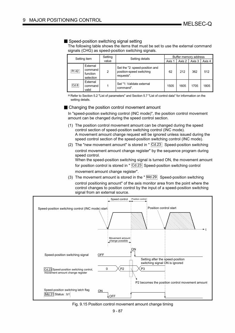
9 - 87
MELSEC-Q9 MAJOR POSITIONING CONTROL
Speed-position switching signal setting The following table shows the items that must be set to use the external command signals (CHG) as speed-position switching signals.
Buffer memory address Setting item Setting value
Setting details Axis 1 Axis 2 Axis 3 Axis 4
Pr.42
External command function selection
2 Set the "2: speed-position and position-speed switching requests".
62 212 362 512
Cd.8
External command valid
1 Set "1: Validate external command". 1505 1605 1705 1805
Refer to Section 5.2 "List of parameters" and Section 5.7 "List of control data" for information on the setting details.
Changing the position control movement amount In "speed-position switching control (INC mode)", the position control movement amount can be changed during the speed control section.
(1) The position control movement amount can be changed during the speed
control section of speed-position switching control (INC mode). A movement amount change request will be ignored unless issued during the speed control section of the speed-position switching control (INC mode).
(2) The "new movement amount" is stored in " Cd.23 Speed-position switching control movement amount change register" by the sequence program during speed control. When the speed-position switching signal is turned ON, the movement amount for position control is stored in " Cd.23 Speed-position switching control movement amount change register".
(3) The movement amount is stored in the " Md.29 Speed-position switching control positioning amount" of the axis monitor area from the point where the control changes to position control by the input of a speed-position switching signal from an external source.
t
Movement amount
Speed-position switching signal
ON
OFF
Speed control Position control
Position control start Speed-position switching control (INC mode) start
0 P2
OFF
Speed-position switching latch flag ON
P3
P2 becomes the position control movement amount
Cd.23 Speed-position switching control,movement amount change register
Md.31 Status : b1
change possible
Setting after the speed-positionswitching signal ON is ignored
Fig. 9.15 Position control movement amount change timing

9 - 88
MELSEC-Q9 MAJOR POSITIONING CONTROL
POINT
• The machine recognizes the presence of a movement amount change request when the data is written to " Cd.23 Speed-position switching control movement amount change register" with the sequence program.
• The new movement amount is validated after execution of the speed-position switching control (INC mode), before the input of the speed-position switching signal.
• The movement amount change can be enable/disable with the interlock function in position control using the “speed-position switching latch flag” ( Md.31
Status : b1) of the axis monitor area.
Restrictions (1) An axis error (error code: 516) will occur and the operation cannot start if
"continuous positioning control" or "continuous path control" is set in " Da.1 Operation pattern".
(2) "Speed-position switching control" cannot be set in " Da.2 Control system" of
the positioning data when "continuous path control" has been set in " Da.1 Operation pattern" of the immediately prior positioning data. (For example, if the operation pattern of positioning data No. 1 is "continuous path control", "speed-position switching control" cannot be set in positioning data No. 2.) An axis error (error code: 516) will occur and the machine will carry out a deceleration stop if this type of setting is carried out.
(3) An error (error code: 503) will occur if "current speed (-1)" is set in " Da.8 command speed".
(4) The software stroke limit range check during speed control is made only when the following (a) and (b) are satisfied: (a) " Pr.21 Current feed value during speed control" is "1: Update current feed
value". If the movement amount exceeds the software stroke limit range during speed control in case of the setting of other than "1: Update current feed value", an error (error code: 507 or 508) will occur as soon as speed control is changed to position control and the axis will decelerate to a stop.
(b) When " Pr.1 Unit setting" is other than "2: degree"
If the unit is "degree", the software stroke limit range check is not performed. (5) If the value set in " Da.6 Positioning address/movement amount" is negative,
an error (error code: 530) will occur. (6) Deceleration processing is carried out from the point where the speed-position
switching signal is input if the position control movement amount set in " Da.6 Positioning address/movement amount" is smaller than the
deceleration distance from the " Da.8 Command speed". (7) Turn ON the speed-position switching signal in the speed stabilization region
(constant speed status). A warning (warning code: 508) will occur because of large deviation in the droop pulse amount if the signal is turned ON during acceleration. During use of the servomotor, the actual movement amount after switching of speed control to position control is the "preset movement amount + droop pulse amount". If the signal is turned ON during acceleration/deceleration, the stop position will vary due to large variation of the droop pulse amount. Even though " Md.29 Speed-position switching control positioning amount" is the same, the stop position will change due to a change in droop pulse amount when " Da.8 Command speed" is different.

9 - 89
MELSEC-Q9 MAJOR POSITIONING CONTROL
Positioning data setting examples The following table shows setting examples when "speed-position switching control (INC mode) by forward run" is set in positioning data No. 1 of axis 1.
Setting item Setting example Setting details
Da.1 Operation pattern Positioning complete
Set "Positioning complete" assuming the next positioning data will not be executed. ("Continuous path control" cannot be set in "speed-position switching control (INC mode)".)
Da.2 Control system Forward run: speed/position Set speed-position switching control by forward run.
Da.3 Acceleration time No. 1 Designate the value set in " Pr.25 Acceleration time 1" as the acceleration time at start.
Da.4 Deceleration time No. 0 Designate the value set in " Pr.10 Deceleration time 0" as the
deceleration time at deceleration.
Da.5 Axis to be interpolated – Setting not required. (Setting value is ignored.)
Da.6 Positioning address/ movement amount 10000.0μm
INC mode ( Pr.150 = 0) Set the movement amount after the switching to position control. (Assuming that the " Pr.1 Unit setting" is set to "mm".)
Da.7 Arc address – Setting not required. (Setting value is ignored.)
Da.8 Command speed 6000.00mm/min Set the speed to be controlled.
Da.9 Dwell time 500ms Set a time from the positioning stop (pulse output stop) by position control until the positioning complete signal is output. When the system is stopped by speed control, ignore the setting value.
Axis
1
Posi
tioni
ng d
ata
No.
1
Da.10 M code 10 Set this when other sub operation commands are issued in combination with the No. 1 positioning data.
Refer to Section 5.3 "List of positioning data" for information on the setting details.
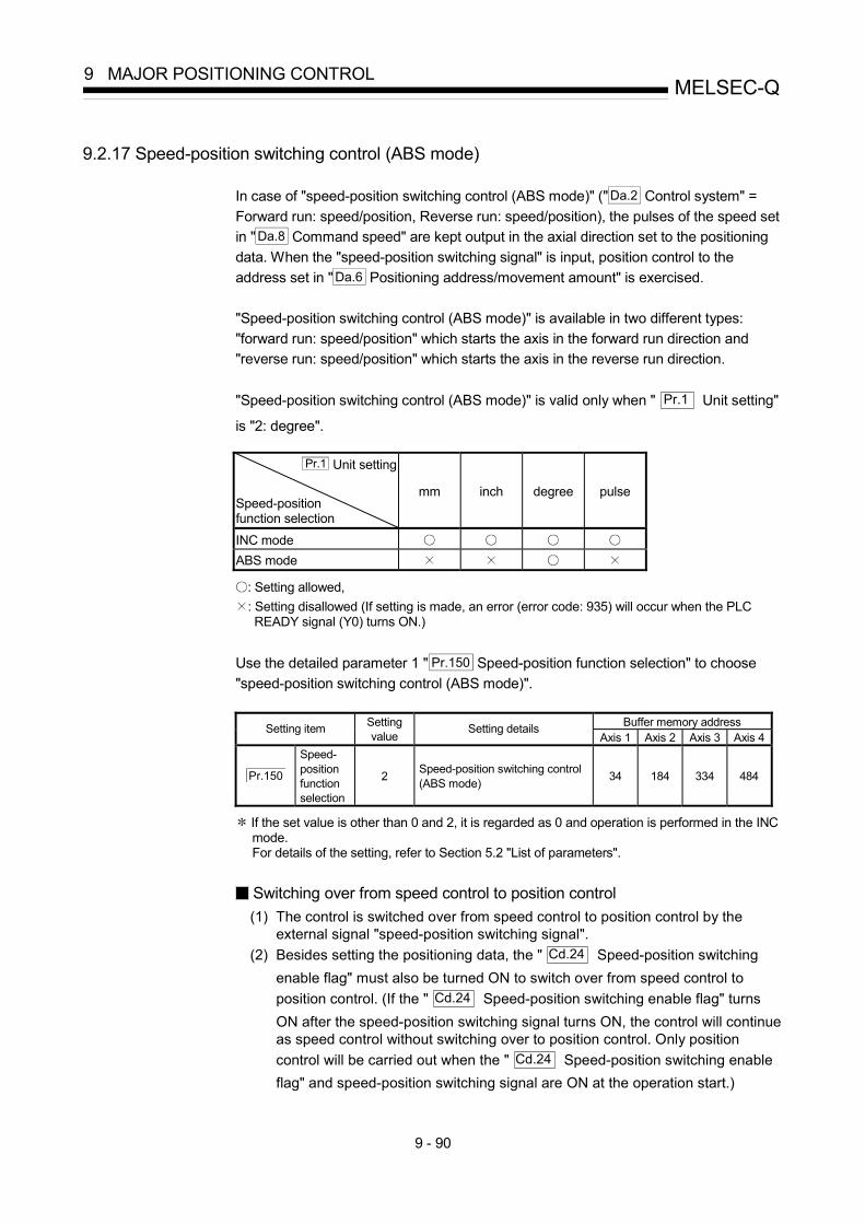
9 - 90
MELSEC-Q9 MAJOR POSITIONING CONTROL
9.2.17 Speed-position switching control (ABS mode)
In case of "speed-position switching control (ABS mode)" (" Da.2 Control system" = Forward run: speed/position, Reverse run: speed/position), the pulses of the speed set in " Da.8 Command speed" are kept output in the axial direction set to the positioning data. When the "speed-position switching signal" is input, position control to the address set in " Da.6 Positioning address/movement amount" is exercised. "Speed-position switching control (ABS mode)" is available in two different types: "forward run: speed/position" which starts the axis in the forward run direction and "reverse run: speed/position" which starts the axis in the reverse run direction. "Speed-position switching control (ABS mode)" is valid only when " Pr.1 Unit setting"
is "2: degree".
Pr.1 Unit setting Speed-position function selection
mm inch degree pulse
INC mode ABS mode
: Setting allowed, : Setting disallowed (If setting is made, an error (error code: 935) will occur when the PLC READY signal (Y0) turns ON.)
Use the detailed parameter 1 " Pr.150 Speed-position function selection" to choose "speed-position switching control (ABS mode)".
Buffer memory address Setting item Setting value
Setting details Axis 1 Axis 2 Axis 3 Axis 4
Pr.150
Speed-position function selection
2 Speed-position switching control (ABS mode) 34 184 334 484
If the set value is other than 0 and 2, it is regarded as 0 and operation is performed in the INC mode. For details of the setting, refer to Section 5.2 "List of parameters".
Switching over from speed control to position control (1) The control is switched over from speed control to position control by the
external signal "speed-position switching signal". (2) Besides setting the positioning data, the " Cd.24 Speed-position switching
enable flag" must also be turned ON to switch over from speed control to position control. (If the " Cd.24 Speed-position switching enable flag" turns ON after the speed-position switching signal turns ON, the control will continue as speed control without switching over to position control. Only position control will be carried out when the " Cd.24 Speed-position switching enable flag" and speed-position switching signal are ON at the operation start.)

9 - 91
MELSEC-Q9 MAJOR POSITIONING CONTROL
Operation chart The following chart (Fig.9.16) shows the operation timing for speed-position switching control (ABS mode). The "in speed control flag" ( Md.31 Status: b0) is turned ON during speed control of speed-position switching control (ABS mode).
t
V
Positioning start signalOFF
ON
BUSY signalOFF
ON
Positioning complete signal OFF
ON
Speed-position switching signal
ON
Speed control Position control Dwell time
In speed control flagMd. 31 Status: b0
Cd. 24 Speed-positionswitching enable flag
Da. 8 Command speed
OFF
OFF
OFF
ON
ON
[Y10,Y11,Y12,Y13]
[XC,XD,XE,XF]
[X14,X15,X16,X17]
Address set in " Da. 6 Positioning address/movementamount"
Fig. 9.16 Speed-position switching control (ABS mode) operation timing

9 - 92
MELSEC-Q9 MAJOR POSITIONING CONTROL
[Operation example]
The following operation assumes that the speed-position switching signal is input at the position of the current feed value of 90.00000 [degree] during execution of " Da.2 Control system" "Forward run: speed/position" at " Pr.1 Unit setting" of "2: degree" and " Pr.21 Current feed value during speed control" setting of "1: Update current feed value". (The value set in " Da.6 Positioning address/movement amount" is 270.00000 [degree])
Stop at 270.00000 [degree]
Speed-positionswitching signal ON0.00000
90.00000
0.00000
90.00000270.00000

9 - 93
MELSEC-Q9 MAJOR POSITIONING CONTROL
Operation timing and processing time during speed-position switching control (ABS mode)
Positioning startsignal [Y10,Y11,Y12,Y13]
BUSY signal
M code ON signal[X4,X5,X6,X7](WITH mode)
Standing by In speed control
Start complete signal
Output pulse to external source(PULSE)
Positioning operation
Positioning complete signal
M code ON signal (AFTER mode)
t1
t2
t3
t4
t5
t2
t7
In position control
Speedcontrol
Positioncontrol
External speed-positionswitching command
t6
Speed control carried out until speed-position switching signal turns ON
Md.26 Axis operation status
OPR complete flagMd.31 Status: b4
Cd.7 M code OFF request
Cd.7 M code OFF request
Standing by
[XC,XD,XE,XF]
[X10,X11,X12,X13]
[X14,X15,X16,X17]
[X4,X5,X6,X7]
Fig. 9.17 Operation timing and processing time during speed-position switching control (ABS mode)
Normal timing time Unit: ms t1 t2 t3 t4 t5 t6 t7 1.1 0 to 1.8 0 to 1.8 2.7 to 4.4 0 to 1.8 1.0 Follows parameters
• The t1 timing time could be delayed by the operation state of other axes.
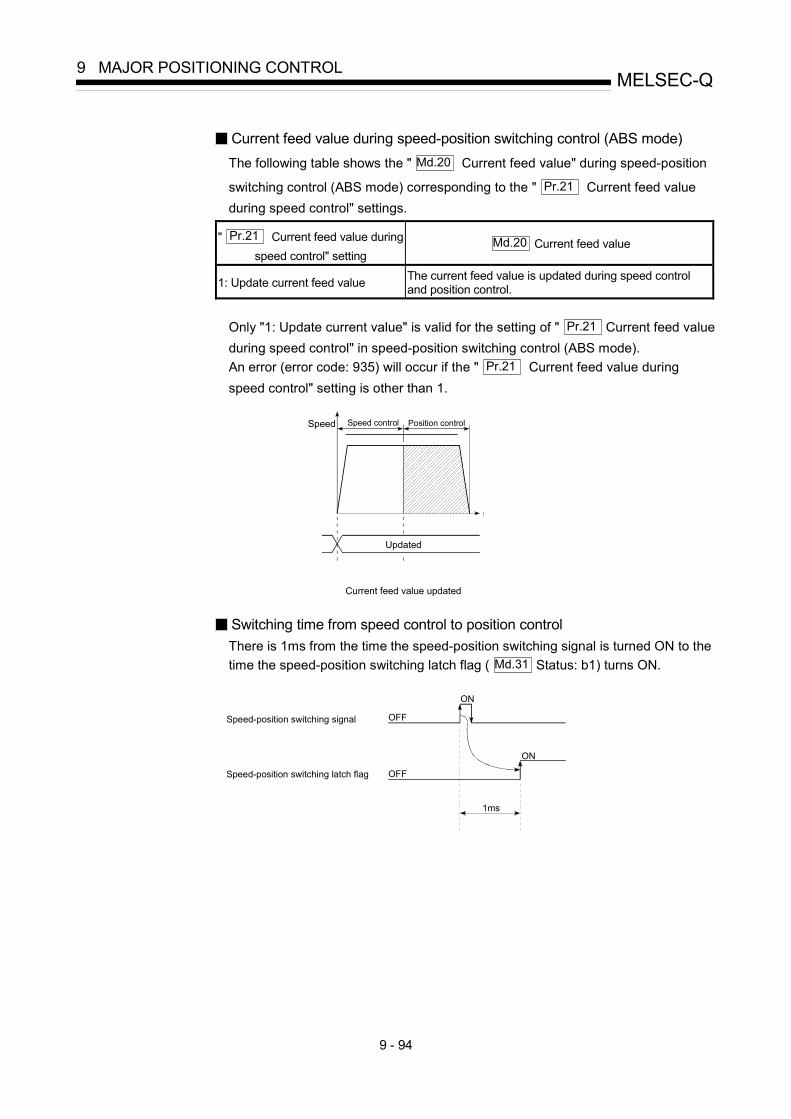
9 - 94
MELSEC-Q9 MAJOR POSITIONING CONTROL
Current feed value during speed-position switching control (ABS mode) The following table shows the " Md.20 Current feed value" during speed-position
switching control (ABS mode) corresponding to the " Pr.21 Current feed value during speed control" settings.
" Pr.21 Current feed value during speed control" setting
Md.20 Current feed value
1: Update current feed value The current feed value is updated during speed control and position control.
Only "1: Update current value" is valid for the setting of " Pr.21 Current feed value during speed control" in speed-position switching control (ABS mode). An error (error code: 935) will occur if the " Pr.21 Current feed value during speed control" setting is other than 1.
t
Speed Position control Speed control
Updated
Current feed value updated
Switching time from speed control to position control There is 1ms from the time the speed-position switching signal is turned ON to the time the speed-position switching latch flag ( Md.31 Status: b1) turns ON.
Speed-position switching signal OFF
ON
OFF
ON
1ms
Speed-position switching latch flag

9 - 95
MELSEC-Q9 MAJOR POSITIONING CONTROL
Speed-position switching signal setting The following table shows the items that must be set to use the external command signals (CHG) as speed-position switching signals.
Buffer memory address Setting item Setting value
Setting details Axis 1 Axis 2 Axis 3 Axis 4
Pr.42
External command function selection
2 Set the "2: speed-position and position-speed switching requests".
62 212 362 512
Cd.8
External command valid
1 Set "1: Validate external command". 1505 1605 1705 1805
Refer to Section 5.2 "List of parameters" and Section 5.7 "List of control data" for information on the setting details.

9 - 96
MELSEC-Q9 MAJOR POSITIONING CONTROL
Restrictions (1) An axis error (error code: 516) will occur and the operation cannot start if
"continuous positioning control" or "continuous path control" is set in " Da.1 Operation pattern".
(2) "Speed-position switching control" cannot be set in " Da.2 Control system" of
the positioning data when "continuous path control" has been set in " Da.1 Operation pattern" of the immediately prior positioning data. (For example, if the operation pattern of positioning data No. 1 is "continuous path control", "speed-position switching control" cannot be set in positioning data No. 2.) An axis error (error code: 516) will occur and the machine will carry out a deceleration stop if this type of setting is carried out.
(3) An error (error code: 503) will occur if "current speed (-1)" is set in " Da.8 command speed".
(4) If the value set in " Da.6 Positioning address/movement amount" is negative, an error (error code: 530) will occur.
(5) Even though the axis control data " Cd.23 Speed-position switching control movement amount change register" was set in speed-position switching control (ABS mode), it would not function. The set value is ignored.
(6) To exercise speed-position switching control (ABS mode), the following conditions must be satisfied: (a) " Pr.1 Unit setting" is "2: degree" (b) The software stroke limit function is invalid (upper limit value = lower limit
value) (c) " Pr.21 Current feed value during speed control" is "1: Update current
feed value" (d) The " Da.6 Positioning address/movement amount" setting range is 0 to
359.99999 (degree) If the value is outside of the range 0 to 359.99999 (degree), an error (error code: 530) will occur at a start.
(e) The " Pr.150 Speed-position function selection" setting is "2: Speed-position switching control (ABS mode)".
(7) If any of the conditions in (6)(a) to (6)(c) is not satisfied in the case of (6)(e), an error (error code: 935) will occur when the PLC READY signal [Y0] turns from OFF to ON.
(8) If the axis reaches the positioning address midway through deceleration after automatic deceleration started at the input of the speed-position switching signal, the axis will not stop immediately at the positioning address. The axis will stop at the positioning address after N revolutions so that automatic deceleration can always be made. (N: Natural number) In this case, make the movement amount after speed-position switching signal input within 21474.83647 (degree). If the movement amount exceeds 21474.83647 (degree), make the movement amount smaller by reducing the command speed or shortening the deceleration time, for example. In the following example, since making deceleration in the path of dotted line will cause the axis to exceed the positioning addresses twice, the axis will decelerate to a stop at the third positioning address.
Speed-position switching signal
positioning address360 added 360 added
positioning address positioning address
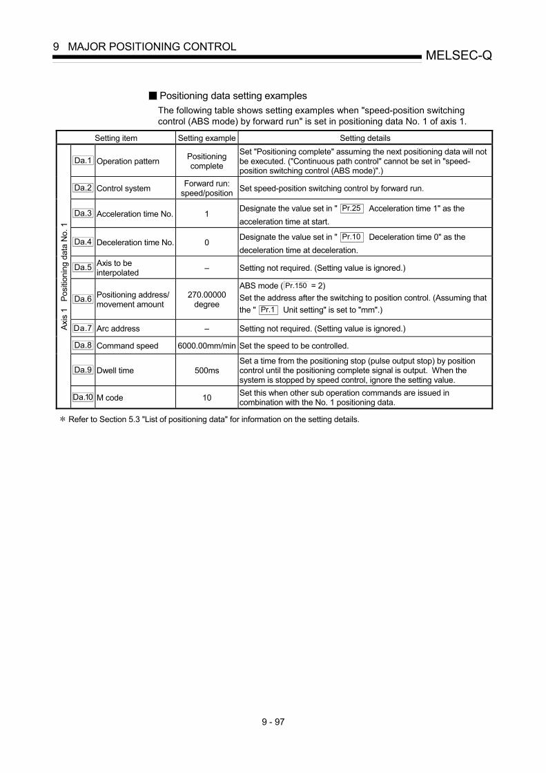
9 - 97
MELSEC-Q9 MAJOR POSITIONING CONTROL
Positioning data setting examples The following table shows setting examples when "speed-position switching control (ABS mode) by forward run" is set in positioning data No. 1 of axis 1.
Setting item Setting example Setting details
Da.1 Operation pattern Positioning complete
Set "Positioning complete" assuming the next positioning data will not be executed. ("Continuous path control" cannot be set in "speed-position switching control (ABS mode)".)
Da.2 Control system Forward run: speed/position Set speed-position switching control by forward run.
Da.3 Acceleration time No. 1 Designate the value set in " Pr.25 Acceleration time 1" as the acceleration time at start.
Da.4 Deceleration time No. 0 Designate the value set in " Pr.10 Deceleration time 0" as the deceleration time at deceleration.
Da.5 Axis to be interpolated – Setting not required. (Setting value is ignored.)
Da.6 Positioning address/ movement amount
270.00000 degree
ABS mode ( Pr.150 = 2) Set the address after the switching to position control. (Assuming that the " Pr.1 Unit setting" is set to "mm".)
Da.7 Arc address – Setting not required. (Setting value is ignored.)
Da.8 Command speed 6000.00mm/min Set the speed to be controlled.
Da.9 Dwell time 500ms Set a time from the positioning stop (pulse output stop) by position control until the positioning complete signal is output. When the system is stopped by speed control, ignore the setting value.
Axis
1
Posi
tioni
ng d
ata
No.
1
Da.10 M code 10 Set this when other sub operation commands are issued in combination with the No. 1 positioning data.
Refer to Section 5.3 "List of positioning data" for information on the setting details.
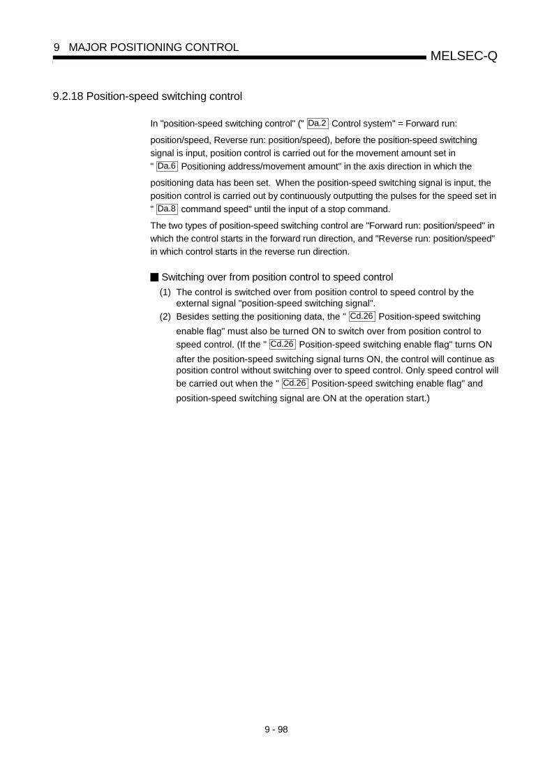
9 - 98
MELSEC-Q9 MAJOR POSITIONING CONTROL
9.2.18 Position-speed switching control
In "position-speed switching control" (" Da.2 Control system" = Forward run:
position/speed, Reverse run: position/speed), before the position-speed switching
signal is input, position control is carried out for the movement amount set in
" Da.6 Positioning address/movement amount" in the axis direction in which the
positioning data has been set. When the position-speed switching signal is input, the
position control is carried out by continuously outputting the pulses for the speed set in
" Da.8 command speed" until the input of a stop command.
The two types of position-speed switching control are "Forward run: position/speed" in
which the control starts in the forward run direction, and "Reverse run: position/speed"
in which control starts in the reverse run direction.
Switching over from position control to speed control
(1) The control is switched over from position control to speed control by theexternal signal "position-speed switching signal".
(2) Besides setting the positioning data, the " Cd.26 Position-speed switching
enable flag" must also be turned ON to switch over from position control to
speed control. (If the " Cd.26 Position-speed switching enable flag" turns ON
after the position-speed switching signal turns ON, the control will continue asposition control without switching over to speed control. Only speed control will
be carried out when the " Cd.26 Position-speed switching enable flag" and
position-speed switching signal are ON at the operation start.)

9 - 99
MELSEC-Q9 MAJOR POSITIONING CONTROL
Operation chart
The following chart shows the operation timing for position-speed switchingcontrol.
The "in speed control" flag ( Md.31 Status: b0) is turned ON during speed control
of position-speed switching control.
Position-speed switching enable flag
Cd.26
t
V
Positioning start signal[Y10,Y11,Y12,Y13]
OFF
ON
Command speed
BUSY signal[XC,XD,XE,XF]
OFF
ON
Positioning complete signal[X14,X15,X16,X17]
OFF
Position-speedswitching signal
OFF
ON
Positioncontrol
Speed control
OFF
ON
OFF
ONIn speed control flag
Status: b0Md.31
Da. 8
OFFON
Stop command
Does not turn ON evenwhen control is stoppedby stop command.
Fig. 9.18 Position-speed switching control operation timing

9 - 100
MELSEC-Q9 MAJOR POSITIONING CONTROL
Operation timing and processing time during position-speed switchingcontrol
Positioning start signal[Y10,Y11,Y12,Y13]
BUSY signal [XC,XD,XE,XF]
M code ON signal
[X4,X5,X6,X7](WITH mode)
Standing by In position control Standing byAxis operation status
M code OFF request
Start complete signal [X10,X11,X12,X13]
Output pulse to an external source
(PULSE)
Positioning operation
M code ON signal [X4,X5,X6,X7]
(AFTER mode)
M code OFF request
t1
t2
t3
t4
t2
Positioning complete signal[X14,X15,X16,X17]
In speed control
Position
control
Speed
control
External position-speed switching
command
t6
Position control carried out until position-speed switchingsignal turns ON.
Speed control command speed is from the input position ofthe external position-speed switching signal.
Md.26
Position-speed switching
control speed change register
Cd.25
Cd. 7
Cd. 7
Status: b4
OPR complete flag
Md.31
Stop signal
[STOP]
Fig. 9.19 Operation timing and processing time during position-speed switching control
Normal timing time Unit: ms
t1 t2 t3 t4 t5 t6
1.0 to 1.4 0 to 1.8 0 to 1.8 2.7 to 4.4 - 1.0
• The t1 timing time could be delayed by the operation state of other axes.
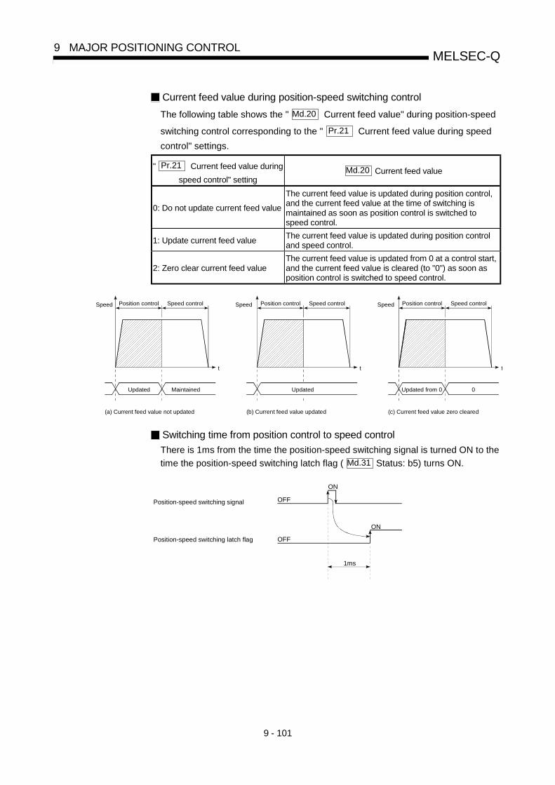
9 - 101
MELSEC-Q9 MAJOR POSITIONING CONTROL
Current feed value during position-speed switching control
The following table shows the " Md.20 Current feed value" during position-speed
switching control corresponding to the " Pr.21 Current feed value during speed
control" settings.
" Pr.21 Current feed value during
speed control" settingMd.20 Current feed value
0: Do not update current feed value
The current feed value is updated during position control,and the current feed value at the time of switching ismaintained as soon as position control is switched tospeed control.
1: Update current feed valueThe current feed value is updated during position controland speed control.
2: Zero clear current feed valueThe current feed value is updated from 0 at a control start,and the current feed value is cleared (to "0") as soon asposition control is switched to speed control.
(a) Current feed value not updated (b) Current feed value updated
Speed
t
Speed control
Updated from 0
(c) Current feed value zero cleared
0
Position controlSpeed
t
Speed control
Updated
Position controlSpeed
t
Speed control
Updated Maintained
Position control
Switching time from position control to speed control
There is 1ms from the time the position-speed switching signal is turned ON to the
time the position-speed switching latch flag ( Md.31 Status: b5) turns ON.
Position-speed switching signal
Position-speed switching latch flag
OFF
ON
OFF
ON
1ms

9 - 102
MELSEC-Q9 MAJOR POSITIONING CONTROL
Position-speed switching signal settingThe following table shows the items that must be set to use the external commandsignals (CHG) as position-speed switching signals.
Buffer memory addressSetting item
Settingvalue
Setting detailsAxis 1 Axis 2 Axis 3 Axis 4
Pr.42
Externalcommandfunctionselection
2Set the "2: speed-position andposition-speed switchingrequests".
62 212 362 512
Cd.8Externalcommandvalid
1Set "1: Validate externalcommand".
1505 1605 1705 1805
Refer to Section 5.2 "List of parameters" and Section 5.7 "List of control data" for information on thesetting details.
Changing the speed control command speed
In "position-speed switching control", the speed control command speed can bechanged during the position control.(1) The speed control command speed can be changed during the position control
of position-speed switching control.A command speed change request will be ignored unless issued during theposition control of the position-speed switching control.
(2) The "new command speed" is stored in " Cd.25 Position-speed switching
control speed change register" by the sequence program during positioncontrol.This value then becomes the speed control command speed when theposition-speed switching signal turns ON.
Stop signal
t
Speed changeenable
Position-speed switchingsignal
ON
OFF
Positioncontrol
Speedcontrol
Position control startPosition-speed switching control start
0 V2
OFFPosition-speed switching
latch flag
Status: b5
ON
V3
V2 becomes the speed control command speed.
Setting after the position-speedswitching signal ON is ignored.
Position-speedswitching controlspeed change register
Md.31ON
Cd.25
OFF
Fig. 9.20 Speed control speed change timing

9 - 103
MELSEC-Q9 MAJOR POSITIONING CONTROL
POINTS• The machine recognizes the presence of a command speed change request when the data is
written to " Cd.25 Position-speed switching control speed change register" with the sequence
program.• The new command speed is validated after execution of the position-speed switching control before
the input of the position-speed switching signal.• The command speed change can be enabled/disabled with the interlock function in speed control
using the "position-speed switching latch flag" ( Md.31 Status: b5) of the axis monitor area.
Restrictions
(1) An axis error (error code: 516) will occur and the operation cannot start if"continuous positioning control" or "continuous path control" is set in
" Da.1 Operation pattern".
(2) "Position-speed switching control" cannot be set in " Da.2 Control system" of
the positioning data when "continuous path control" has been set in
" Da.1 Operation pattern" of the immediately prior positioning data. (For
example, if the operation pattern of positioning data No. 1 is "continuous pathcontrol", "position-speed switching control" cannot be set in positioning dataNo. 2.) An axis error (error code: 516) will occur and the machine will carryout a deceleration stop if this type of setting is carried out.
(3) The software stroke limit range is only checked during speed control if the "1:
Update current feed value" is set in " Pr.21 Current feed value during speed
control".The software stroke limit range is not checked when the control unit is set to"degree".
(4) An error (error code: 507 or 508) will occur and the operation cannot start ifthe start point address or end point address for position control exceeds thesoftware stroke limit range.
(5) Deceleration stop will be carried out if the position-speed switching signal isnot input before the machine is moved by a specified movement amount.When the position-speed switching signal is input during automaticdeceleration by positioning control, acceleration is carried out again to thecommand speed to continue speed control.When the position-speed switching signal is input during deceleration to a stopwith the stop signal, the control is switched to the speed control to stop themachine.Restart is carried out by speed control using the restart command.
(6) A warning (warning code: 501) will occur and control is continued by
" Pr.8 Speed limit value" if a new speed exceeds " Pr.8 Speed limit value" at
the time of change of the command speed.(7) If the value set in " Da.6 Positioning address/movement amount" is negative,
an error (error code: 530) will occur.

9 - 104
MELSEC-Q9 MAJOR POSITIONING CONTROL
Positioning data setting examples
The following table shows setting examples when "position-speed switchingcontrol (forward run: position/speed)" is set in positioning data No. 1 of axis 1.
Setting item Setting example Setting details
Da.1 Operation patternPositioningcomplete
Set "Positioning complete" assuming the next positioning data will notbe executed. ("Continuous positioning control" and "Continuous pathcontrol" cannot be set in "position/speed changeover control".)
Da.2 Control systemForward run:
position/speedSet position-speed switching control.
Da.3 Acceleration time No. 1Designate the value set in " Pr.25 Acceleration time 1" as the
acceleration time at start.
Da.4 Deceleration time No. 0Designate the value set in " Pr.10 Deceleration time 0" as the
deceleration time at deceleration.
Da.5 Axis to beinterpolated
– Setting not required. (Setting value is ignored.)
Da.6 Positioning address/movement amount 10000.0µm
Set the movement amount at the time of position control before the
switching to speed control. (Assuming that the " Pr.1 Unit setting" is
set to "mm".)
Da.7 Arc address – Setting not required. (Setting value is ignored.)
Da.8 Command speed 6000.00mm/min Set the speed to be controlled.
Da.9 Dwell time 500ms
Set the time the machine dwells after the positioning stop (pulseoutput stop) by position control to the output of the positioningcomplete signal. If the machine is stopped by speed control, thesetting value will be ignored.
Axi
s 1
Pos
ition
ing
data
No.
1
Da.10 M code 10Set this when other sub operation commands are issued incombination with the No. 1 positioning data.
Refer to Section 5.3 "List of positioning data" for information on the setting details.

9 - 105
MELSEC-Q9 MAJOR POSITIONING CONTROL
9.2.19 Current value changing
When the current value is changed to a new value, control is carried out in which the
" Md.20 Current feed value" of the stopped axis is changed to a random address set
by the user. (The " Md.21 Machine feed value" is not changed when the current value
is changed.)
The two methods for changing the current value are shown below.[1] Changing to a new current value using the positioning data[2] Changing to a new current value using the start No. (No. 9003) for a current
value changing
The current value changing using method [1] is used during continuous positioning of
multiple blocks, etc.
[1] Changing to a new current value using the positioning data
Operation chart
The following chart shows the operation timing for a current value changing. The
" Md.20 Current feed value" is changed to the value set in " Da.6 Positioning
address/movement amount" when the positioning start signal turns ON.
Positioning start signal[Y10,Y11,Y12,Y13]
Md.20 50000 0
OFF
ON
Current feed value changes to the
positioning address designated by the
positioning data of the current value changing.
The above chart shows an example
when the positioning address is "0".
Current feed value
Restrictions
(1) An axis error "New current value not possible (error code: 515)" will occur and
the operation cannot start if "continuous path control" is set in " Da.1
Operation pattern". ("Continuous path control" cannot be set in current valuechanging.)
(2) "Current value changing" cannot be set in " Da.2 Control system" of the
positioning data when "continuous path control" has been set in " Da.1
Operation pattern" of the immediately prior positioning data. (For example, ifthe operation pattern of positioning data No. 1 is "continuous path control","current value changing" cannot be set in positioning data No. 2.) An axis error"New current value not possible (error code: 515)" will occur and the machinewill carry out a deceleration stop if this type of setting is carried out.
(3) An axis error "Outside new current value range (error code: 514)" will occur
and the operation cannot start if "degree" is set in " Pr.1 Unit setting" and the
value set in " Da.6 Positioning address/movement amount" is outside the
setting range (0 to 359.99999 [degree]).

9 - 106
MELSEC-Q9 MAJOR POSITIONING CONTROL
(4) If the value set in " Da.6 Positioning address/movement amount" is outside
the software stroke limit ( Pr.12 , Pr.13 ) setting range, an error "Software
stroke limit +, – (error code: 507 or 508)" will occur at the positioning start, andthe operation will not start.
(5) An error (error code: 507 or 508) will occur if the new current value is outsidethe software stroke limit range.
Positioning data setting examplesThe following table shows the setting examples when " current value changing" isset in the positioning data No. 1 of axis 1.
Setting item Setting example Setting details
Da.1 Operation
patternPositioning complete
Set "Positioning complete" assuming that
the next positioning data will be executed.
("Continuous path control" cannot be set by
current value change.)
Da.2 Control
systemCurrent value changing Set the current value changing.
Da.3 Acceleration
time No.–
Setting not required (Setting value is
ignored.)
Da.4 Deceleration
time No.–
Setting not required (Setting value is
ignored.)
Da.5 Axis to be
interpolated–
Setting not required (Setting value is
ignored.)
Da.6
Positioning
address/
movement
amount
10000.0 m
Set the address to which address change is
desired. (Assuming that the " Pr.1 Unit
setting" is set to "mm".)
Da.7 Arc address –Setting not required (Setting value is
ignored.)
Da.8 Command
speed–
Setting not required (Setting value is
ignored.)
Da.9 Dwell time –Setting not required (Setting value is
ignored.)
Axis 1
positioning
data No. 1
Da.10 M code 10
Set this when other sub operation
commands are issued in combination with
the No. 1 positioning data.
Refer to Section 5.3 "List of positioning data" for information on the setting details.
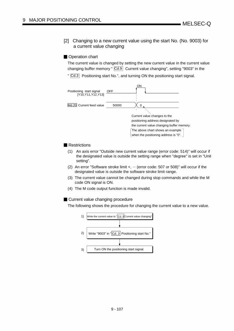
9 - 107
MELSEC-Q9 MAJOR POSITIONING CONTROL
[2] Changing to a new current value using the start No. (No. 9003) fora current value changing
Operation chart
The current value is changed by setting the new current value in the current value
changing buffer memory " Cd.9 Current value changing", setting "9003" in the
" Cd.3 Positioning start No.", and turning ON the positioning start signal.
Positioning start signal
Md.20 Current feed value 50000 0
OFF
ON
Current value changes to the
positioning address designated by
the current value changing buffer memory.
The above chart shows an example
when the positioning address is "0".
[Y10,Y11,Y12,Y13]
Restrictions
(1) An axis error "Outside new current value range (error code: 514)" will occur ifthe designated value is outside the setting range when "degree" is set in "Unitsetting".
(2) An error "Software stroke limit +, (error code: 507 or 508)" will occur if thedesignated value is outside the software stroke limit range.
(3) The current value cannot be changed during stop commands and while the Mcode ON signal is ON.
(4) The M code output function is made invalid.
Current value changing procedure
The following shows the procedure for changing the current value to a new value.
Turn ON the positioning start signal.
Write "9003" in " Cd. 3 Positioning start No."
1)
2)
3)
Write the current value to " Cd. 9 Current value changing"
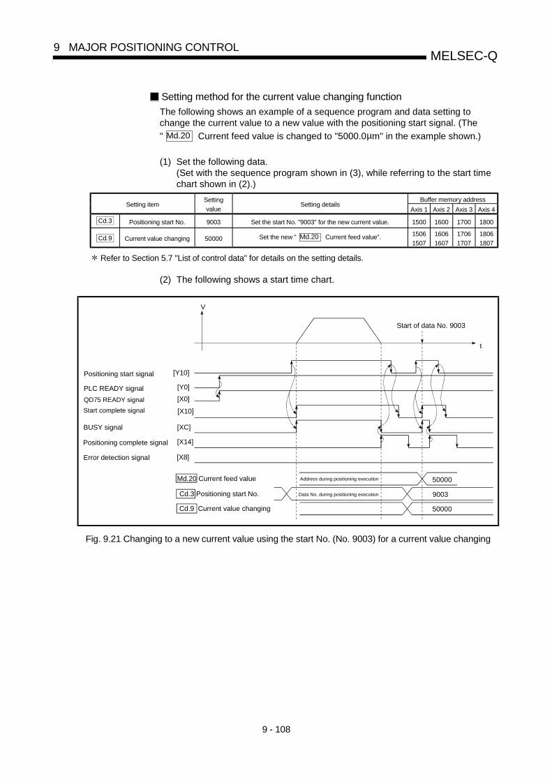
9 - 108
MELSEC-Q9 MAJOR POSITIONING CONTROL
Setting method for the current value changing function
The following shows an example of a sequence program and data setting tochange the current value to a new value with the positioning start signal. (The
" Md.20 Current feed value is changed to "5000.0µm" in the example shown.)
(1) Set the following data.(Set with the sequence program shown in (3), while referring to the start timechart shown in (2).)
Buffer memory addressSetting item
Setting
valueSetting details
Axis 1 Axis 2 Axis 3 Axis 4
Cd.3 Positioning start No. 9003 Set the start No. "9003" for the new current value. 1500 1600 1700 1800
Cd.9 Current value changing 50000 Set the new " Md.20 Current feed value". 1506
1507
1606
1607
1706
1707
1806
1807
Refer to Section 5.7 "List of control data" for details on the setting details.
(2) The following shows a start time chart.
Positioning start signal
PLC READY signal
QD75 READY signal
Start complete signal
BUSY signal
Positioning complete signal
9003
V
t
Error detection signal
50000
Start of data No. 9003
Data No. during positioning execution
Address during positioning executionMd.20 Current feed value
Cd.3 Positioning start No.
Cd.9 Current value changing 50000
[Y10]
[Y0]
[X0]
[X10]
[XC]
[X14]
[X8]
Fig. 9.21 Changing to a new current value using the start No. (No. 9003) for a current value changing

9 - 109
MELSEC-Q9 MAJOR POSITIONING CONTROL
(3) Add the following sequence program to the control program, and write it to thePLC CPU.
—áExample
Current value changing
Store new current feed value in D106 and D107
<Pulsate current value changing command>
<Write current value changing to the QD75>
<Write the current value changing (9003)>
<Execute current value changing>
<Turn OFF positioning start signal>

9 - 110
MELSEC-Q9 MAJOR POSITIONING CONTROL
9.2.20 NOP instruction
The NOP instruction is used for the nonexecutable control system.
Operation
The positioning data No. to which the NOP instruction is set transfers, without anyprocessing, to the operation for the next positioning data No.
Positioning data setting examples
The following table shows the setting examples when "NOP instruction" is set inpositioning data No. 1 of axis 1.
Setting item Setting example Setting details
Da.1 Operation
pattern–
Setting not required (Setting value
is ignored.)
Da.2 Control
systemNOP instruction Set the NOP instruction
Da.3 Acceleration
time No.–
Setting not required (Setting value
is ignored.)
Da.4 Deceleration
time No.–
Setting not required (Setting value
is ignored.)
Da.5 Axis to be
interpolated–
Setting not required (Setting value
is ignored.)
Da.6
Positioning
address/
movement
amount
–Setting not required (Setting value
is ignored.)
Da.7 Arc address –Setting not required (Setting value
is ignored.)
Da.8 Command
speed–
Setting not required (Setting value
is ignored.)
Da.9 Dwell time –Setting not required (Setting value
is ignored.)
Axis 1
positioning
data No. 1
Da.10 M code –Setting not required (Setting value
is ignored.)
Refer to Section 5.3 "List of positioning data" for information on the setting details.
Restrictions
An error "Control system setting error (error code: 524)" will occur if the "NOPinstruction" is set for the control system of the positioning data No. 600.
POINT<Use example of NOP instruction>
If there is a possibility of speed switching or temporary stop (automatic deceleration) at a point
between two points during positioning, that data can be reserved with the NOP instruction to change
the data merely by the replacement of the identifier.

9 - 111
MELSEC-Q9 MAJOR POSITIONING CONTROL
9.2.21 JUMP instruction
The JUMP instruction is used to control the operation so it jumps to a positioning data
No. set in the positioning data during "continuous positioning control" or "continuous
path control".
JUMP instruction include the following two types of JUMP.
(1) Unconditional JUMPWhen no execution conditions are set for the JUMP instruction(When "0" is set as the condition data No.)
(2) Conditional JUMPWhen execution conditions are set for the JUMP instruction(The conditions are set in the "condition data" used with "high-level positioningcontrol".)
Using the JUMP instruction enables repeating of the same positioning control, or
selection of positioning data by the execution conditions during "continuous positioning
control" or "continuous path control".
Operation
(1) Unconditional JUMPThe JUMP instruction is unconditionally executed. The operation jumps to the
positioning data No. set in " Da.9 Dwell time".
(2) Conditional JUMPThe block start condition data is used as the JUMP instruction executionconditions.• When block positioning data No. 7000 to 7004 is started:
Each block condition data is used.• When positioning data No. 1 to 600 is started:
Start block 0 condition data is used.• When the execution conditions set in " Da.10 M code" of the JUMP
instruction have been established:the JUMP instruction is executed to jump the operation to the positioning
data No. set in " Da.9 Dwell time".
• When the execution conditions set in " Da.10 M code" of the JUMP
instruction have not been established:the JUMP instruction is ignored, and the next positioning data No.isexecuted.
Restrictions
(1) When using a conditional JUMP instruction, establish the JUMP instructionexecution conditions by the 4th positioning data No. before the JUMPinstruction positioning data No.If the JUMP instruction execution conditions are not established by the timethe 4th positioning control is carried out before the JUMP instructionpositioning data No., the operation will be processed as an operation withoutestablished JUMP instruction execution conditions.(During execution of continuous path control/continuous positioning control,the QD75 calculates the positioning data of the positioning data No. four itemsahead of the current positioning data.)

9 - 112
MELSEC-Q9 MAJOR POSITIONING CONTROL
(2) The operation pattern, if set, is ignored in the JUMP instruction.
(3) Positioning control such as loops cannot be executed by conditional JUMPinstructions alone until the conditions have been established.As the target of the JUMP instruction, specify a positioning data that iscontrolled by other than JUMP and NOP instructions.
Positioning data setting example
The following table shows setting examples when "JUMP instruction" is set inpositioning data No. 1 of axis 1.
Setting item Setting example Setting details
Da.1 Operation pattern – Setting not required. (Setting value is ignored.)
Da.2 Control systemJUMP
instructionSet the JUMP instruction.
Da.3 Acceleration time No. – Setting not required. (Setting value is ignored.)
Da.4 Deceleration time No. – Setting not required. (Setting value is ignored.)
Da.5 Axis to beinterpolated
– Setting not required. (Setting value is ignored.)
Da.6 Positioning address/movement amount
– Setting not required. (Setting value is ignored.)
Da.7 Arc address – Setting not required. (Setting value is ignored.)
Da.8 Command speed – Setting not required. (Setting value is ignored.)
Da.9 Dwell time 500
Set the positioning data No. 1 to 600 for the JUMP destination. (Thepositioning data No. of the JUMP instruction cannot be set. Setting itsown positioning data No. will result in an error "Illegal data No." (errorcode: 502).)
Axi
s 1
Pos
ition
ing
data
No.
1
Da.10 M code 1
Set the JUMP instruction execution conditions with the condition dataNo.
0 : Unconditional JUMP
1 to 10 : Condition data No. ("Simultaneous start" condition data cannot be set.)
Refer to Section 5.3 "List of positioning data" for information on the setting details.

9 - 113
MELSEC-Q9 MAJOR POSITIONING CONTROL
9.2.22 LOOP
The LOOP is used for loop control by the repetition of LOOP to LEND.
Operation
The LOOP to LEND loop is repeated by set repeat cycles.
Positioning data setting examples
The following table shows the setting examples when "LOOP" is set in positioningdata No. 1 of axis 1.
Setting item Setting example Setting details
Da.1 Operation pattern – Setting not required. (Setting value is ignored.)
Da.2 Control system LOOP Set the LOOP.
Da.3 Acceleration time No. – Setting not required. (Setting value is ignored.)
Da.4 Deceleration time No. – Setting not required. (Setting value is ignored.)
Da.5 Axis to beinterpolated
– Setting not required. (Setting value is ignored.)
Da.6 Positioning address/movement amount
– Setting not required. (Setting value is ignored.)
Da.7 Arc address – Setting not required. (Setting value is ignored.)
Da.8 Command speed – Setting not required. (Setting value is ignored.)
Da.9 Dwell time – Setting not required. (Setting value is ignored.)
Axi
s 1
Pos
ition
ing
data
No.
1
Da.10 M code 5 Set the LOOP to LEND repeat cycles.
Refer to Section 5.3 "List of positioning data" for information on the setting details.
Restrictions
(1) An error "Control system LOOP setting error (error code: 545)" will occur if a"0" is set for the repeat cycles.
(2) Even if LEND is absent after LOOP, no error will occur, but repeat processingwill not be carried out.
(3) Nesting is not allowed between LOOP-LEND's. If such setting is made, only theinner LOOP-LEND is processed repeatedly.
POINTThe setting by this control system is easier than that by the special start "FOR loop" of "High-level
Positioning Control" (refer to Chapter 10).
<Setting data>
• For special start: Positioning start data, special start data, condition data, and positioning data
• For control system : Positioning data
For the special start FOR to NEXT, the positioning data is required for each of FOR and NEXT
points. For the control system, loop can be executed even only by one data.
Also, nesting is enabled by using the control system LOOP to LEND in combination with the special
start FOR to NEXT.
However LOOP to LEND cannot be set across block. Always set LOOP to LEND so that the
processing ends within one block.
(For details of the "block", refer to Section 10.1 "Outline of high-level positioning control".)

9 - 114
MELSEC-Q9 MAJOR POSITIONING CONTROL
9.2.23 LEND
The LEND is used to return the operation to the top of the repeat (LOOP to LEND)
loop.
Operation
When the repeat cycle designated by the LOOP becomes 0, the loop isterminated, and the next positioning data No. processing is started. (The operationpattern, if set to "Positioning complete", will be ignored.)When the operation is stopped after the repeat operation is executed bydesignated cycles, the dummy positioning data (for example, incrementalpositioning without movement amount) is set next to LEND.
Positioning data
No.Operation pattern Control system Conditions Operation
1 Continuous control ABS2
2Positioning
completeLOOP
Number of loop
cycles: 2
3Continuous path
controlABS2
4 Continuous control ABS2
5Positioning
completeLEND
6Positioning
completeABS2
Executed in the
order of the
positioning data
No. 1 2 3
4 5 2 3
4 5 6.
(The operation
patterns of the
positioning data
Nos. 2 and 5 are
ignored.)
Positioning data setting examples
The following table shows the setting examples when "LEND" is set in positioningdata No. 8 of axis 1.
Setting item Setting example Setting details
Da.1 Operation pattern – Setting not required. (Setting value is ignored.)
Da.2 Control system LEND Set the LEND.
Da.3 Acceleration time No. – Setting not required. (Setting value is ignored.)
Da.4 Deceleration time No. – Setting not required. (Setting value is ignored.)
Da.5 Axis to beinterpolated
– Setting not required. (Setting value is ignored.)
Da.6 Positioning address/movement amount
– Setting not required. (Setting value is ignored.)
Da.7 Arc address – Setting not required. (Setting value is ignored.)
Da.8 Command speed – Setting not required. (Setting value is ignored.)
Da.9 Dwell time – Setting not required. (Setting value is ignored.)
Axi
s 1
Pos
ition
ing
data
No.
8
Da.10 M code – Setting not required. (Setting value is ignored.)
Refer to Section 5.3 "List of positioning data" for information on the setting details.
Restrictions
(1) Ignore the "LEND" before the "LOOP" is executed.

10 - 1
10
Chapter 10 High-level Positioning Control
The details and usage of high-level positioning control (control functions using the "block start data") are explained in this chapter.
High-level positioning control is used to carry out applied control using the "positioning data". Examples of applied control are using conditional judgment to control "positioning data" set with the major positioning control, or simultaneously starting "positioning data" for several different axes.
Read the execution procedures and settings for each control, and set as required.
10.1 Outline of high-level positioning control ..................................................................10- 210.1.1 Data required for high-level positioning control.........................................10- 310.1.2 " Block start data" and "condition data" configuration...............................10- 4
10.2 High-level positioning control execution procedure ...............................................10- 610.3 Setting the block start data......................................................................................10- 7
10.3.1 Relation between various controls and block start data ...........................10- 710.3.2 Block start (normal start) ...........................................................................10- 810.3.3 Condition start ...........................................................................................10- 1010.3.4 Wait start ...................................................................................................10- 1110.3.5 Simultaneous start ...................................................................................10- 1210.3.6 Repeated start (FOR loop) ......................................................................10- 1310.3.7 Repeated start (FOR condition) ...............................................................10- 1410.3.8 Restrictions when using the NEXT start...................................................10- 15
10.4 Setting the condition data.......................................................................................10- 1610.4.1 Relation between various controls and the condition data ......................10- 1610.4.2 Condition data setting examples ..............................................................10- 19
10.5 Multiple axes simultaneous start control................................................................10- 2010.6 Start program for high-level positioning control .....................................................10- 23
10.6.1 Starting high-level positioning control.......................................................10- 2310.6.2 Example of a start program for high-level positioning control .................10- 24

10 - 2
MELSEC-Q10 HIGH-LEVEL POSITIONING CONTROL
10.1 Outline of high-level positioning control
In "high-level positioning control" the execution order and execution conditions of the"positioning data" are set to carry out more applied positioning. (The execution orderand execution conditions are set in the "block start data" and "condition data".)The following applied positioning controls can be carried out with "high-level positioningcontrol".
High-level positioningcontrol
Details
Block 1 start(Normal start)
With one start, executes the positioning data in a random block with the set order.
Condition start
Carries out condition judgment set in the "condition data" for the designatedpositioning data, and then executes the "block start data".• When the condition is established, the " block start data" is executed.• When not established, that " block start data" is ignored, and the next point's " block
start data" is executed.
Wait start
Carries out condition judgment set in the "condition data" for the designatedpositioning data, and then executes the " block start data".• When the condition is established, the " block start data" is executed.• When not established, stops the control until the condition is established. (Waits.)
Simultaneous start
2
Simultaneously executes the positioning data having the No. for the axis designatedwith the "condition data". (Outputs pulses at the same timing.)
Repeated start (FORloop)
Repeats the program from the " block start data" set with the "FOR loop" to the "block start data" set in "NEXT" for the designated No. of times.
Repeated start (FORcondition)
Repeats the program from the " block start data" set with the "FOR condition" to the "block start data" set in "NEXT" until the conditions set in the "condition data" areestablished.
High-level positioning control sub functions
"High-level positioning control" uses the "positioning data" set with the "majorpositioning control". Refer to Section 3.2.4 "Combination of QD75 main functionsand sub functions" for details on sub functions that can be combined with themajor positioning control.Note that the sub function Section 12.7.8 "Pre-reading start function" cannot beused together with "high-level positioning control".
High-level positioning control from peripheral devices
"High-level positioning control" (start of the "block start data") can be executedfrom GX Configurator-QP test mode.Refer to GX Configurator-QP Operating Manual for details on starting of the "blockstart data" from GX Configurator-QP.
REMARK
Block 1:"1 block" is defined as all the data continuing from the positioning data in which"continuous positioning control" or "continuous path control" is set in the
operation pattern ( Da.1 ) to the positioning data in which "independent
positioning control (Positioning complete)" is set.
Simultaneous start 2:Besides the simultaneous start of "block start data" system, the "simultaneousstarts" include the "multiple axes simultaneous start control" of control system.Refer to Section 10.5 "Multiple axes simultaneous start control" for details.

10 - 3
MELSEC-Q10 HIGH-LEVEL POSITIONING CONTROL
10.1.1 Data required for high-level positioning control
"High-level positioning control" is executed by setting the required items in the "block
start data" and "condition data", then starting that "block start data". Judgment about
whether execution is possible, etc., is carried out at execution using the "condition
data" designated in the "block start data".
"Block start data" can be set for each No. from 7000 to 7004 (called "block Nos."), and
up to 50 points can be set for each axis. (This data is controlled with Nos. called
"points" to distinguish it from the positioning data. For example, the 1st block start data
item is called the "1st point block start data" or "point No. 1 block start data".)
"Condition data" can be set for each No. from 7000 to 7004 (called "block Nos."), and
up to 10 data items can be set for each axis.
The " block start data" and "condition data" are set as 1 set for each block No.
The following table shows an outline of the " block start data" and "condition data"
stored in the QD75.
Setting item Setting details
Da.11 ShapeSet whether to end the control after executing only the "blockstart data" of the shape itself, or continue executing the "blockstart data" set in the next point.
Da.12 Start data No. Set the "positioning data No." to be executed.
Da.13 Special startinstruction
Set the method by which the positioning data set in Da.12
will be started.
Blo
ck s
tart
dat
a
Da.14 Parameter
Set the conditions by which the start will be executed
according to the commands set in Da.13 . (Designate the
"condition data No." and "No. of repetitions".)
Setting item Setting details
Da.15 Condition targetDesignate the "device", "buffer memory storage details", and"positioning data No." elements for which the conditions areset.
Da.16 Conditionoperator
Set the judgment method carried out for the target set in
Da.15 .
Da.17 Address
Set the buffer memory address in which condition judgment is
carried out (only when the details set in Da.15 are "buffer
memory storage details").
Da.18 Parameter 1Set the required conditions according to the details set in
Da.15 and Da.16 .
Con
ditio
n da
ta
Da.19 Parameter 2Set the required conditions according to the details set in
Da.15 and Da.16 .

10 - 4
MELSEC-Q10 HIGH-LEVEL POSITIONING CONTROL
10.1.2 "Block start data" and "condition data" configuration
The "block start data" and "condition data" corresponding to "block No. 7000" can bestored in the buffer memory. (The following drawing shows an example for axis 1.)
7000Block No. Set in the QD75 with a sequence programor GX Configurator-QP.
Setting item
50th point
Buffer memoryaddress
No.10
26190
261912619226193261942619526196261972619826199
No.2
Setting item
26110
261112611226113261142611526116261172611826119
Low-order buffer memory High-order buffer memory
Condition identifier
No.1
26100
b15 b0b7b8b11b12
261012610226103261042610526106261072610826109
Da.16 Condition operator
Da.17 Address
Da.18 Parameter 1
Da.19 Parameter 2
Da.15 Condition target
(Same for axis 2, axis 3 and axis 4.)
Setting item
Setting item
26049
26099
�œˆÊ’uŒˆ‚ß�n“®ƒf�[ƒ ̂
Setting item Buffer memory
address
26001
26051
1st point
b15 b0b7b8
26000
b15 b0b7b8
26050
Da.13 Special start instruction
Da.11 Shape
Da.14 Parameter
Da.12 Positioning data No.
2nd point
Setting item Buffer memoryaddress
Axi
s 1
blo
ck s
tart
dat
a A
xis
1 c
on
ditio
n d
ata
Buffer memoryaddress
Condition identifier
Buffer memoryaddress
Buffer memoryaddress
Blank
Blank

10 - 5
MELSEC-Q10 HIGH-LEVEL POSITIONING CONTROL
Set in QD75 the " block start data" and "condition data" corresponding to the following
"block Nos. 7001 to 7004" using GX Configurator-QP or the sequence program. (The
following drawing shows an example for axis 1.)
7001 7004
50th point
Setting item
26249
26299
�œˆÊ’uŒˆ‚ß�n“®ƒf�[ƒ^
2nd point
Setting item
26201
26251
No.10
Setting item
26390
263912639226393263942639526396263972639826399
Condition identifier No.2
Setting item
26310
263112631226313263142631526316263172631826319
1st point
Setting item
b15 b0b7b8
Shape
Positioning data No.
26200
b15 b0b7b8
Special startinstruction
Parameter
26250
Da13
Da11
Da14
Da12
Condition identifier
No.1
Setting item
26300
AddressOpen
Open
Parameter 1
Parameter 2
b15 b0b7b8b11b12
Conditionoperater
Condition target
2630126302 2630326304 2630526306263072630826309
Da16
Da17
Da18
Da19
Da15
Buffer memoryaddress
Buffer memoryaddress
Buffer memoryaddress
Axi
s 1
blo
ck s
tart
da
ta
Buffer memoryaddress
Buffer memoryaddress
Buffer memoryaddress
Axi
s 1
co
ndi
tion
da
ta
50th point
Setting item
26849
26899
�œˆÊ’uŒˆ‚ß�n“®ƒf�[ƒ^
2nd point
Setting item
26801
26851
No.10
Setting item
26990
269912699226993269942699526996269972699826999
Condition identifier No.2
Setting item
26910
269112691226913269142691526916269172691826919
1st point
Setting item
b15 b0b7b8
Shape
Positioning data No.
26800
b15 b0b7b8
Special startinstruction
Parameter
26850
Da13
Da11
Da14
Da12
Condition identifier
No.1
Setting item
26900
AddressOpen
Open
Parameter 1
Parameter 2
b15 b0b7b8b11b12
Conditionoperater
Condition target
2690126902 2690326904 2690526906269072690826909
Da16
Da17
Da18
Da19
Da15
Buffer memoryaddress
Buffer memoryaddress
Buffer memoryaddress
Axi
s 1
blo
ck s
tart
da
ta
Buffer memoryaddress
Buffer memoryaddress
Buffer memoryaddress
Axi
s 1
co
ndi
tion
da
ta

10 - 6
MELSEC-Q10 HIGH-LEVEL POSITIONING CONTROL
10.2 High-level positioning control execution procedure
High-level positioning control is carried out using the following procedure.
STEP 1Preparation
Starting the control
Monitoring the control
Refer to Chapter 9
Carry out the "major positioning control" setting.
Control termination
"High-level positioning control" executes each control ("major positioning control") set in the positioning data with the designated conditions,so first carry out preparations so that "major positioning control" can be executed.
STEP 2
Set the block start data corresponding to each control.( Da. 11 to Da. 14 ) × required data amount.
The 50 "block start data" points from 1 to 50 points
can be set.
Set the "condition data" for designation with the "block start data". Up to 10 condition data items can be set.
STEP 3
Set the "condition data"( Da. 15 to Da. 19 ) × required data amount .
The QD75 recognizes that the control is high-level
positioning control using " block start data" by the
"7000" designation.
Use GX Developer to create a sequence program
to execute the "high-level positioning control".
(Set the control data in the QD75 buffer memory using
a TO command.)
STEP 4
Create a sequence program in which "7000"*is set in
the " Cd. 3 Positioning start No". (Control data setting)
STEP 5
Refer to Chapter 6
Write the sequence program created in STEP 4 to the PLC CPU using GX Developer.
Same procedure as for the "major positioning control"
start.
STEP 6
Use one of the following two methods.
Method (1): Monitor using GX Configurator-QP.
Method (2): Monitor using GX Developer.
Same procedure as for the "major positioning control" stop.
STEP 7
Create a sequence program in which the "positioning
start signal" is turned ON by a positioning start command.
Create a sequence program in which the "block start
data point No. to be started" (1 to 50) is set in the
" Cd. 4 Positioning start point No". (Control data setting)
Write the sequence programs to the PLC CPU.
Turn ON the "positioning start command" ofthe axis to be started.
Stopping the control STEP 8
Stop when control is completed
Monitor the high-level positioning control.
Refer to Section 10.3
Refer to Section 10.6
Refer to Section 10.4
Refer to Section 6.5.3
Refer to Section 6.5.6
REMARK
(1) Five sets of "block start data (50 points)" and "condition data (10 items)corresponding to "7000" to "7004" are set with a sequence program.
(2) Five sets of data from "7000" to "7004" can be set when GX Configurator-QPis used. If GX Configurator-QP is used to set the "block start data" and"condition data" corresponding to "7001" to "7004" and write the data to the
QD75, "7001" to "7004" can be set in " Cd.3 Positioning start No." in STEP
4.

10 - 7
MELSEC-Q10 HIGH-LEVEL POSITIONING CONTROL
10.3 Setting the block start data
10.3.1 Relation between various controls and block start data
The " block start data" must be set to carry out "high-level positioning control". The
setting requirements and details of each " block start data" item to be set differ
according to the " Da.13 Special start instruction" setting.
The following shows the " block start data" setting items corresponding to various
control systems. The operation details of each control type are explained starting in
Section 10.3.2. Also refer to Section 10.4 "Setting the condition data for details on
"condition data" with which control execution is judged.
(The " block start data" settings in this chapter are assumed to be carried out using GX
Configurator-QP.)
High-level positioningcontrol
Block start datasetting items
Block start(Normal
start)
Conditionstart
Wait startSimulta-
neous start
Repeatedstart
(FOR loop)
Repeatedstart(FOR
condition)
NEXT start
0 : EndDa.11 Shape
1 : Continue
Da.12 Start data No. 1 to 600
Da.13 Special start instruction 0 1 2 3 4 5 6
Da.14 Parameter – Condition data No.No. of
repetitionsConditiondata No.
–
: One of the two setting items must be set.
: Set when required (Set to " – " when not used.)
: Setting not possible
– : Setting not required (Setting value will be ignored. Use the initial value or a value within the setting range.)
The "NEXT start" instruction is used in combination with "repeated start (FOR loop)" and "repeated start (FORcondition)". Control using only the "NEXT start" will not be carried out.
REMARK
It is recommended that the "block start data" be set whenever possible with GX
Configurator-QP. Execution by sequence program uses many sequence programs
and devices. The execution becomes complicated, and the scan times will increase.

10 - 8
MELSEC-Q10 HIGH-LEVEL POSITIONING CONTROL
10.3.2 Block start (normal start)
In a "block start (normal start)", the positioning data groups of a block are continuously
executed in a set sequence starting from the positioning data set in " Da.12 Start data
No." by one start.
Section [2] shows a control example where the " block start data" and "positioning
data" are set as shown in section [1].
[1] Setting examples
(1) Block start data setting example
Axis 1 blockstart data
Da.11Shape
Da.12Start data No.
Da.13Special startinstruction
Da.14Parameter
1st point 1: Continue 1 0: Block start –2nd point 1: Continue 2 0: Block start –3rd point 1: Continue 5 0: Block start –4th point 1: Continue 10 0: Block start –5th point 0: End 15 0: Block start –
••
(2) Positioning data setting example
Axis 1 position-ing data No.
Da.1Operation pattern
1 00: Positioning complete2 11: Continuous path control3 01: Continuous positioning control4 00: Positioning complete5 11: Continuous path control6 00: Positioning complete
1 block
1 block
•10 00: Positioning complete
•15 00: Positioning complete
•
REMARK
Block :"1 block" is defined as all the data continuing from the positioning data in which"continuous positioning control" or "continuous path control" is set in the operation
pattern ( Da.1 ) to the positioning data in which "independent positioning control
(Positioning complete)" is set.

10 - 9
MELSEC-Q10 HIGH-LEVEL POSITIONING CONTROL
[2] Control examplesThe following shows the control executed when the "block start data" of the 1st
point of axis 1 is set as shown in section [1] and started.
<1> The positioning data is executed in the following order before stopping.Axis 1 positioning data No. 1 2 3 4 5 6 10 15.
Dwell time of corresponding positioning data
Positioning start signal
1(00)
Start complete signal
BUSY signal
[X14,X15,X16,X17]
t
2(11)
3(01)4(00)
5(11)6(00)
15(00)
Positioningaccording to the 1stpoint settings
Address(-)
10(00)
OFF
OFF
ON
ON
ON
Operation pattern Positioning data No.
Positioningaccording to the 5thpoint settings
Positioningaccording to the4th point settings
Positioningaccording to the 3rdpoint settings
Positioningaccording to the 2ndpoint settings
Address(+)
[Y10,Y11,Y12,Y13]
[X10,X11,X12,X13]
[XC,XD,XE,XF]
Positioning complete signal
1
1 1
1 1
11
OFF
OFF
ON
Fig. 10.1 Block start control example

10 - 10
MELSEC-Q10 HIGH-LEVEL POSITIONING CONTROL
10.3.3 Condition start
In a "condition start", the "condition data" conditional judgment designated in " Da.14
Parameter" is carried out for the positioning data set in " Da.12 Start data No.". If the
conditions have been established, the " block start data" set in "1: condition start" isexecuted. If the conditions have not been established, that " block start data" will beignored, and the "block start data" of the next point will be executed.
Section [2] shows a control example where the " block start data" and "positioningdata" are set as shown in section [1].
[1] Setting examples
(1) Block start data setting example
Axis 1 blockstart data
Da.11Shape
Da.12Start data No.
Da.13Special startinstruction
Da.14Parameter
1st point 1: Continue 1 1: Condition start 12nd point 1: Continue 10 1: Condition start 23rd point 0: End 50 0: Block start –
••
The "condition data Nos." have been set in " Da.14 Parameter".
(2) Positioning data setting example
Axis 1 position-ing data No.
Da.1Operation pattern
1 01: Continuous positioning control2 01: Continuous positioning control3 00: Positioning complete•
10 11: Continuous path control11 11: Continuous path control12 00: Positioning complete•
50 00: Positioning complete•
[2] Control examplesThe following shows the control executed when the " block start data" of the 1stpoint of axis 1 is set as shown in section [1] and started.
<1> The conditional judgment set in "condition data No. 1" is carried out beforeexecution of the axis 1 "positioning data No. 1".
Conditions established Execute positioning data No. 1, 2, and 3 Go to <2>.Conditions not established Go to <2>.
<2> The conditional judgment set in "condition data No. 2" is carried out beforeexecution of the axis 1 "positioning data No. 10".
Conditions established Execute positioning data No. 10, 11, and 12 Go to <3>.
Conditions not established Go to <3>.
<3> Execute axis 1 "positioning data No. 50" and stop the control.

10 - 11
MELSEC-Q10 HIGH-LEVEL POSITIONING CONTROL
10.3.4 Wait start
In a "wait start", the "condition data" conditional judgment designated in " Da.14
Parameter" is carried out for the positioning data set in " Da.12 Start data No.". If the
conditions have been established, the " block start data" is executed. If the conditionshave not been established, the control stops (waits) until the conditions areestablished.
Section [2] shows a control example where the " block start data" and "positioningdata" are set as shown in section [1].
[1] Setting examples
(1) Block start data setting example
Axis 1 blockstart data
Da.11
ShapeDa.12
Start data No.
Da.13Special startinstruction
Da.14Parameter
1st point 1: Continue 1 2: Wait start 32nd point 1: Continue 10 0: Block start –3rd point 0: End 50 0: Block start –
••
The "condition data Nos." have been set in " Da.14 Parameter".
(2) Positioning data setting example
Axis 1 position-ing data No.
Da.1Operation pattern
1 01: Continuous positioning control2 01: Continuous positioning control3 00: Positioning complete•
10 11: Continuous path control11 11: Continuous path control12 00: Positioning complete•
50 00: Positioning complete•
[2] Control examplesThe following shows the control executed when the " block start data" of the 1stpoint of axis 1 is set as shown in section [1] and started.
<1> The conditional judgment set in "condition data No. 3" is carried out beforeexecution of the axis 1 "positioning data No. 1".
Conditions established Execute positioning data No. 1, 2, and 3 Go to <2>.Conditions not established Control stops (waits) until conditions areestablished Go to <1>.
<2> Execute the axis 1 "positioning data No. 10, 11, 12, and 50" and stop thecontrol.

10 - 12
MELSEC-Q10 HIGH-LEVEL POSITIONING CONTROL
10.3.5 Simultaneous start
In a "simultaneous start", the positioning data set in the " Da.12 Start data No." and
positioning data of other axes set in the "condition data" are simultaneously executed(pulses are output with the same timing).
(The "condition data" is designated with " Da.14 Parameter".)
Section [2] shows a control example where the " block start data" and "positioningdata" are set as shown in section [1].
[1] Setting examples
(1) Block start data setting example
Axis 1 blockstart data
Da.11
ShapeDa.12
Start data No.
Da.13Special startinstruction
Da.14Parameter
1st point 1: Continue 1 3: Simultaneous start 42nd point 1: Continue 10 3: Simultaneous start 53rd point 0: End 50 3: Simultaneous start 6
••
It is assumed that the "axis 2 positioning data" for simultaneous starting is set in the
"condition data" designated with " Da.14 Parameter".
(2) Positioning data setting example
Axis 1 position-ing data No.
Da.1Operation pattern
1 01: Continuous positioning control2 01: Continuous positioning control3 00: Positioning complete•
10 11: Continuous path control11 11: Continuous path control12 00: Positioning complete•
50 00: Positioning complete•
[2] Control examplesThe following shows the control executed when the " block start data" of the 1stpoint of axis 1 is set as shown in section [1] and started.<1> Simultaneously start the axis 1 "positioning data No. 1" and axis 2
positioning data set in "condition data No. 4". After the execution of axis 1"positioning data No. 1, 2, and 3" is completed, go to <2>.
<2> Simultaneously start the axis 1 "positioning data No. 10" and axis 2positioning data set in "condition data No. 5".
Standing by after completion of axis 2 positioning data simultaneouslystarted in <1>. Go to <3>.Executing axis 2 positioning data simultaneously started in <1>. "Error".
<3> Simultaneously start the axis 1 "positioning data No. 50" and the axis 2positioning data set in "condition data No. 6" after the completion of theexecution of axis 1 "positioning data No. 10, 11, and 12".
Standing by after completion of axis 2 positioning data simultaneouslystarted in <2>. Go to <4>.Executing axis 2 positioning data simultaneously started in <2>. "Error".
<4> After the execution of the axis 1 "positioning data No. 50" is completed, stopthe control.

10 - 13
MELSEC-Q10 HIGH-LEVEL POSITIONING CONTROL
10.3.6 Repeated start (FOR loop)
In a "repeated start (FOR loop)", the data between the " block start data" in which "4:
FOR loop" is set in " Da.13 Special start instruction" and the "block start data" in
which "6: NEXT start" is set in " Da.13 Special start instruction " is repeatedly
executed for the No. of times set in " Da.14 Parameter". An endless loop will result ifthe No. of repetitions is set to "0".
(The No. of repetitions is set in " Da.14 Parameter" of the " block start data" in which
"4: FOR loop" is set in " Da.13 Special start instruction".)
Section [2] shows a control example where the " block start data" and "positioningdata" are set as shown in section [1].
[1] Setting examples
(1) Block start data setting example
Axis 1 blockstart data
Da.11
ShapeDa.12
Start data No.
Da.13Special startinstruction
Da.14Parameter
1st point 1: Continue 1 4: FOR loop 22nd point 1: Continue 10 0: Block start –3rd point 0: End 50 6: NEXT start –
••
The "condition data Nos." have been set in " Da.14 Parameter".
(2) Positioning data setting example
Axis 1 position-ing data No.
Da.1Operation pattern
1 01: Continuous positioning control2 01: Continuous positioning control3 00: Positioning complete•
10 11: Continuous path control11 00: Positioning complete•
50 01: Continuous positioning control51 00: Positioning complete•
[2] Control examplesThe following shows the control executed when the " block start data" of the 1stpoint of axis 1 is set as shown in section [1] and started.
<1> Execute the axis 1 "positioning data No. 1, 2, 3, 10, 11, 50, and 51".
<2> Return to the axis 1 "1st point block start data". Again execute the axis 1"positioning data No. 1, 2, 3, 10, 11, 50 and 51", and then stop the control.
(Repeat for the No. of times (2 times) set in Da.14 .)

10 - 14
MELSEC-Q10 HIGH-LEVEL POSITIONING CONTROL
10.3.7 Repeated start (FOR condition)
In a "repeated start (FOR condition)", the data between the " block start data" in which
"5: FOR condition" is set in " Da.13 Special start instruction" and the " block start
data" in which "6: NEXT start" is set in " Da.13 Special start instruction" is repeatedly
executed until the establishment of the conditions set in the "condition data".
(The "condition data" designation is set in " Da.14 Parameter" of the " block start
data" in which "5: FOR condition" is set in " Da.13 Special start instruction".)
Section [2] shows a control example where the " block start data" and "positioningdata" are set as shown in section [1].
[1] Setting examples
(1) Block start data setting example
Axis 1 blockstart data
Da.11
Shape
Da.12
Start data No.
Da.13
Special startinstruction
Da.14
Parameter
1st point 1: Continue 1 5: FOR condition 52nd point 1: Continue 10 0: Block start –3rd point 0: End 50 6: NEXT start –
••
The "condition data Nos." have been set in " Da.14 Parameter".
(2) Positioning data setting example
Axis 1 position-ing data No.
Da.1
Operation pattern
1 01: Continuous positioning control2 01: Continuous positioning control3 00: Positioning complete•
10 11: Continuous path control11 00: Positioning complete•
50 01: Continuous positioning control51 00: Positioning complete•
[2] Control examplesThe following shows the control executed when the " block start data" of the 1stpoint of axis 1 is set as shown in section [1] and started.
<1> Carry out the conditional judgment set in "condition data No. 5" for the axis 1"positioning data No. 1".
Conditions not established Go to <2>.Conditions established Go to <3>.
<2> Execute axis 1 "positioning data No. 1, 2, 3, 10, 11, 50, and 51", then go to<1>.
<3> Execute axis 1 "positioning data No. 1, 2, 3, 10, 11, 50, and 51", then stopthe control.

10 - 15
MELSEC-Q10 HIGH-LEVEL POSITIONING CONTROL
10.3.8 Restrictions when using the NEXT start
The "NEXT start" is a instruction indicating the end of the repetitions when executing
Section 10.3.6 "Repeated start (FOR loop)" and Section 10.3.7 "Repeated start (FOR
condition)".
The following shows the restrictions when setting "6: NEXT start" in the " block start
data".
(1) The processing when "6: NEXT start" is set before execution of "4: FOR loop" or
"5: FOR condition" is the same as that for a "0: block start".
(2) Repeated processing will not be carried out if there is no "6: NEXT start"
instruction after the "4: FOR loop" or "5: FOR condition" instruction. (Note that an
"error" will not occur.)
(3) Nesting is not possible between "4: FOR loop" and "6: NEXT start", or between
"5: FOR condition" and "6: NEXT start". A warning "FOR to NEXT nest
construction (warning code: 506)" will occur if nesting is attempted.
[Operating examples without nesting structure] [Operating examples with nesting structure]
Start block dataDa.12 Special start
commandStart block data
Da.12 Special startcommand
1st point Normal start 1st point Normal start
2nd point FOR 2nd point FOR
3rd point Normal start 3rd point Normal start
4th point NEXT
4th point FOR
5th point Normal start 5th point Normal start
6th point Normal start 6th point Normal start
7th point FOR 7th point NEXT
8th point Normal start 8th point Normal start
9th point NEXT
9th point NEXT
• •
• •
A warning will occur when starting the 4thpoint "FOR".The JUMP destination of the 7th point "NEXT"is the 4th point. The 9th point "NEXT" isprocessed as normal start.

10 - 16
MELSEC-Q10 HIGH-LEVEL POSITIONING CONTROL
10.4 Setting the condition data
10.4.1 Relation between various controls and the condition data
"Condition data" is set in the following cases.
(1) When setting conditions during execution of Section 9.2.21 "JUMP instruction"
(major positioning control)
(2) When setting conditions during execution of "high-level positioning control"
The "condition data" to be set includes the 5 setting items from Da.15 to Da.19 , but
the setting requirements and details differ according to the control system and setting
conditions.
The following shows the "condition data" " Da.15 Condition target" corresponding to
the different types of control.
(The "condition data" settings in this chapter are assumed to be carried out using GX
Configurator-QP.)
High-level positioning controlMajor positioning
controlControl type
Da.15
Setting item
Blockstart
Waitstart
Simultaneousstart
Repeated start(For condition)
JUMP instruction
01: Device X
02: Device Y
03: Buffer memory(1 word)
04: Buffer memory(2 words)
05: Positioning dataNo.
: One of the setting items must be set.: Setting not possible
REMARK
It is recommended that the "condition data" be set whenever possible with GX
Configurator-QP. Execution by sequence program uses many sequence programs
and devices. The execution becomes complicated, and the scan times will increase.
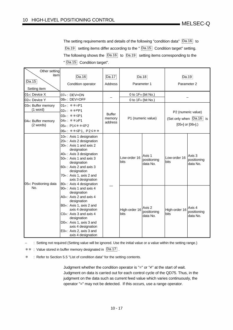
10 - 17
MELSEC-Q10 HIGH-LEVEL POSITIONING CONTROL
The setting requirements and details of the following "condition data" Da.16 to
Da.19 setting items differ according to the " Da.15 Condition target" setting.
The following shows the Da.16 to Da.19 setting items corresponding to the
" Da.15 Condition target".
Other settingitem
Da.15
Setting item
Da.16
Condition operator
Da.17
Address
Da.18
Parameter 1
Da.19
Parameter 2
01H: Device X 0 to 1FH (bit No.)
02H: Device Y
07H : DEV=ON08H : DEV=OFF
–0 to 1FH (bit No.)
–
03H: Buffer memory(1 word)
04H: Buffer memory(2 words)
01H : =P1
02H : ≠P1
03H : ≤P104H : ≥P1
05H : P1≤ ≤P2
06H : ≤P1, P2 ≤
Buffermemoryaddress
P1 (numeric value)
P2 (numeric value)
(Set only when Da.16 is
[05H] or [06H].)
Low-order 16bits
Axis 1positioningdata No.
Low-order 16bits
Axis 3positioningdata No.
05H: Positioning dataNo.
10H : Axis 1 designation20H : Axis 2 designation30H : Axis 1 and axis 2
designation40H : Axis 3 designation50H : Axis 1 and axis 3
designation60H : Axis 2 and axis 3
designation70H : Axis 1, axis 2 and
axis 3 designation80H : Axis 4 designation90H : Axis 1 and axis 4
designationA0H : Axis 2 and axis 4
designationB0H : Axis 1, axis 2 and
axis 4 designationC0H : Axis 3 and axis 4
designationD0H : Axis 1, axis 3 and
axis 4 designationE0H : Axis 2, axis 3 and
axis 4 designation
—
High-order 16bits
Axis 2positioningdata No.
High-order 16bits
Axis 4positioningdata No.
– : Setting not required (Setting value will be ignored. Use the initial value or a value within the setting range.)
: Value stored in buffer memory designated in Da.17 .
: Refer to Section 5.5 "List of condition data" for the setting contents.
Judgment whether the condition operator is "=" or "=” at the start of wait.
Judgment on data is carried out for each control cycle of the QD75. Thus, in the
judgment on the data such as current feed value which varies continuously, the
operator "=" may not be detected. If this occurs, use a range operator.

10 - 18
MELSEC-Q10 HIGH-LEVEL POSITIONING CONTROL
REMARK
The "PLC CPU memory area" can be designated as the buffer memory address to
be designated in Da.17 . (Refer to Section 7.1.1 "Configuration and roles of QD75
memory".)
Address 30000
30001
30099
QD75 buffer memory

10 - 19
MELSEC-Q10 HIGH-LEVEL POSITIONING CONTROL
10.4.2 Condition data setting examples
The following shows setting examples for "condition data".
(1) Setting the device ON/OFF as a condition
[Condition] Device "X0" (=QD75 READY) is OFF
Da.15Condition target
Da.16Conditionoperator
Da.17Address
Da.18
Parameter 1Da.19
Parameter 2
01H: Device X 08H: DEV=OFF – 0 –
(2) Setting the numeric value stored in the "buffer memory" as acondition
[Condition]
The value stored in buffer memory addresses "800, 801" (= " Md.20 Current
feed value") is "1000" or larger.
Da.15Condition target
Da.16Conditionoperator
Da.17Address
Da.18
Parameter 1Da.19
Parameter 2
04H: Buffer memory(2 words) 04H: ≥ P1 800 1000 –
(3) Designating the axis and positioning data No. to be simultaneouslystarted in "simultaneous start"
[Condition]Simultaneously starting "axis 2 positioning data No.3".
Da.15Condition target
Da.16Conditionoperator
Da.17Address
Da.18
Parameter 1Da.19
Parameter 2
05H: Positioningdata No.
20H: Axis 2designation
–High-order 16bits "0003H"
–

10 - 20
MELSEC-Q10 HIGH-LEVEL POSITIONING CONTROL
10.5 Multiple axes simultaneous start control
The "multiple axes simultaneous start control" starts and controls the multiple axes
simultaneously by outputting pulses to the axis to be started at the same timing as the
start axis.
The maximum of four axes can be started simultaneously.
[1] Control detailsThe multiple axes simultaneous start control is carried out by setting the
simultaneous start an object axis start data No. (positioning data No. to start
simultaneously for each axis) to the multiple axes simultaneous start control
buffer memory " Cd.30 to Cd.33 Simultaneous starting axis start data No. (1 to
4 axis start data No.)" of the axis control data, and the "9004" to
" Cd.3 positioning start No." of the start axis, and then turning ON the positioning
start signal.
[2] Restrictions(1) An error will occur and all simultaneously started axes will not start (error
code: 501) if the simultaneously started axis start data No. is not set to the
axis control data on the start axis or set outside the setting range.
(2) An error will occur and all simultaneously started axes will not start (error
code: 501) if either of the simultaneously started axes is BUSY.
(3) An error will occur and all simultaneously started axes will not start (error
code: 501) if an error occurs during the analysis of the positioning data on the
simultaneously started axes.
(4) No error or warning will occur if only the start axis is the simultaneously
started axis.
(5) This function cannot be used with the sub function Section 12.7.8 "Pre-
reading start function".
[3] Multiple axes simultaneous start control procedureThe procedure for multiple axes simultaneous start control is as follows.
3)
1)
2)
Set " Cd. 30 to Cd. 33 Simultaneouslystarted data No.".
Write [9004] to " Cd. 3 Positioning start No.".
Turn ON the positioning start signal to bestarted.

10 - 21
MELSEC-Q10 HIGH-LEVEL POSITIONING CONTROL
[4] Multiple axes simultaneous start control function setting methodThe following shows the setting of the data used to execute the multiple axes
simultaneous start control with positioning start signals (The axis control data on
the start axis is set).
Buffer memory address
Setting itemSettingvalue
Setting details Axis1
Axis2
Axis
3Axis
4
Cd.3 Positioning startNo.
9004Set the multiple axes simultaneous start controlstart No. "9004".
1500 1600 1700 1800
Cd.30
Simultaneousstarting axis startdata No. (Axis 1start data No.)
1540 1640 1740 1840
Cd.31
Simultaneousstarting axis startdata No. (Axis 2start data No.)
1541 1641 1741 1841
Cd.32
Simultaneousstarting axis startdata No. (Axis 3start data No.)
1542 1642 1742 1842
Cd.33
Simultaneousstarting axis startdata No. (Axis 4start data No.)
Set the simultaneously started axis start data No.
Set a "0" for the axis other than the simultaneously startedaxes.
1543 1643 1743 1843
Refer to Section 5.7 "List of control data" for information on setting details.
[5] Setting examplesThe following shows the setting examples in which the axis 1 is used as the start
axis and the simultaneously started axes are used as the axes 2 and 4.
Setting itemSettingvalue
Setting detailsBuffer memory address
(Axis 1)
Cd.3 Positioning startNo.
9004Set the multiple axes simultaneous start controlstart No. "9004".
1500
Cd.30
Simultaneousstarting axis startdata No. (Axis 1start data No.)
100The axis 1 starts the positioning data No.100.
1540
Cd.31
Simultaneousstarting axis startdata No. (Axis 2start data No.)
200Immediately after the start of the axis 1,the axis 2 starts the axis 2 positioning dataNo. 200.
1541
Cd.32
Simultaneousstarting axis startdata No. (Axis 3start data No.)
0 Will not start simultaneously. 1542
Cd.33
Simultaneousstarting axis startdata No. (Axis 4start data No.)
300Immediately after the start of the axis 1,the axis 4 starts the axis 4 positioning dataNo. 300.
1543

10 - 22
MELSEC-Q10 HIGH-LEVEL POSITIONING CONTROL
POINTS(1) The "multiple axes simultaneous start control" carries out an operation equivalent to the
"simultaneous start" using the "block start data".
(2) The setting of the "multiple axes simultaneous start control" is easier than that of the
"simultaneous start" using the "block start data".
• Setting items for "simultaneous start" using "block start data"
Positioning start data, block start data, condition data, and positioning data
• Setting items for "multiple axes simultaneous start control"
Positioning data and axis control data

10 - 23
MELSEC-Q10 HIGH-LEVEL POSITIONING CONTROL
10.6 Start program for high-level positioning control
10.6.1 Starting high-level positioning control
To execute high-level positioning control, a sequence program must be created to start
the control in the same method as for major positioning control.
The following shows the procedure for starting the "1st point block start data"
(regarded as block No. 7000) set in axis 1.
1500
Y10
1501PLC CPU
7000
1
ON
QD75
Input/output signal
Drive unit Buffer memory
Control by designatedpositioning data
When carrying out a positioning start with the next scan after a positioning operation is completed, input signal X10 as an interlock so that the start is carried out once the X10 signal turns OFF after the Y10 signal turns OFF.
1)
3)
2)
4)
1) Set "7000" in " Cd. 3 Positioning start No.".
(This establishes that the control as "high-level positioning control" using block start data.)
2) Set the point No. of the "block start data" to be started. (In this case "1".)
3) Turn ON the start signal.
4) The positioning data set in the "1st point block start data" is started.
Fig. 10.2 High-level positioning control start procedure

10 - 24
MELSEC-Q10 HIGH-LEVEL POSITIONING CONTROL
10.6.2 Example of a start program for high-level positioning control
The following shows an example of a start program for high-level positioning control in
which the 1st point " block start data" of axis 1 is started. (The block No. is regarded as
"7000".)
Control data that require setting
The following control data must be set to execute high-level positioning control.The setting is carried out using a sequence program.
Buffer memory addressSetting item
Settingvalue
Setting details Axis1
Axis2
Axis3
Axis4
Cd.3 Positioning startNo.
7000Set "7000" to indicate control using " block startdata".
1500 1600 1700 1800
Cd.4 Positioning startingpoint No.
1Set the point No. of the " block start data" to bestarted.
1501 1601 1701 1801
Refer to Section 5.7 "List of control data" for details on the setting details.
Start conditions
The following conditions must be fulfilled when starting the control. The requiredconditions must also be integrated into the sequence program, and configured sothe control does not start unless the conditions are fulfilled.
DeviceSignal name Signal state Axis
1Axis
2Axis
3Axis
4
PLC READY signal ON PLC CPU preparation completed Y0
QD75 READY signal ON QD75 preparation completed X0
Synchronization flag ONQD75 buffer memory
The access is possible.X1
Axis stop signal OFF Axis stop signal is OFF Y4 Y5 Y6 Y7
Start complete signal OFF Start complete signal is OFF X10 X11 X12 X13
BUSY signal OFF BUSY signal is OFF XC XD XE XF
Error detection signal OFF There is no error X8 X9 XA XB
Interfacesignal
M code ON signal OFF M code ON signal is OFF X4 X5 X6 X7
Drive unit READY signal ON Drive unit preparation completed –
Stop signal OFF Stop signal is OFF –
Upper limit (FLS) ON Within limit range –Externalsignal
Lower limit (RLS) ON Within limit range –

10 - 25
MELSEC-Q10 HIGH-LEVEL POSITIONING CONTROL
Start time chart
The following chart shows a time chart in which the positioning data No. 1, 2, 10,11, and 12 of axis 1 are continuously executed as an example.
(1) Block start data setting example
Axis 1 blockstart data
Da.11
ShapeDa.12
Start data No.
Da.13Special startinstruction
Da.14Parameter
1st point 1: Continue 1 0: Block start –
2nd point 0: End 10 0: Block start –
•
•
(2) Positioning data setting example
Axis 1 position-ing data No.
Da.1Operation pattern
1 11: Continuous path control
2 00: Positioning complete
•
10 11: Continuous path control
11 11: Continuous path control
12 00: Positioning complete
•
(3) Start time chart
[Y10]
PLC READY signal
QD75 READY signal
[X10]
[XC]
Positioning complete signal
V
t
Error detection signal
Positioning data No.
Dwell time
12(00)
Operation pattern
1(11)
1st point [buffer memory address 26000]
2nd point [buffer memory address 26001]
11(11)10(11)
2(00)
7000
1
-32767
10
(8001H)
(000AH)
Cd.3 Positioning start No.
Cd.4 Positioning start point No.
Positioning start signal
[X0]
Start complete signal
BUSY signal
[X8]
[X14]
[Y0]
Dwell time
Fig. 10.3 Start time chart for high-level positioning control (block start)

10 - 26
MELSEC-Q10 HIGH-LEVEL POSITIONING CONTROL
Creating the program
<Pulse the positioning start command.>M104PLS
Y10M104
<Turn ON the positioning start signal.>Y10SET
K1K1K1501H0TO <Write the positioning start point No.>
K1K7000K1500H0TO <Write the positioning data No. 7000
for block positioning.>
X10
Set the block start data beforehand.
Y10: Positioning start signal
X10: Start complete signal
M104: Positioning start command pulse
Example
Positioning startcommand

11 - 1
11
Chapter 11 Manual Control
The details and usage of manual control are explained in this chapter. In manual control, pulse output commands are issued during a JOG operation and aninching operation executed by the turning ON of the JOG START signal, or from a manualpulse generator connected to the QD75.Manual control using a sequence program from the PLC CPU is explained in this chapter. Refer to GX Configurator-QP Operating Manual for an explanation of manual control (JOG operation, inching operation and manual pulse generator operation) using theperipheral devices.
11.1 Outline of manual control ........................................................................................11- 211.1.1 Three manual control methods..................................................................11- 2
11.2 JOG operation..........................................................................................................11- 411.2.1 Outline of JOG operation ...........................................................................11- 411.2.2 JOG operation execution procedure .........................................................11- 711.2.3 Setting the required parameters for JOG operation..................................11- 811.2.4 Creating start programs for JOG operation..............................................11- 1011.2.5 JOG operation example............................................................................11- 13
11.3 Inching operation ....................................................................................................11- 1711.3.1 Outline of inching operation ......................................................................11- 1711.3.2 Inching operation execution procedure ....................................................11- 2011.3.3 Setting the required parameters for inching operation ............................11- 2111.3.4 Creating a program to enable/disable the inching operation...................11- 2211.3.5 Inching operation example........................................................................11- 25
11.4 Manual pulse generator operation .........................................................................11- 2711.4.1 Outline of manual pulse generator operation...........................................11- 2711.4.2 Manual pulse generator operation execution procedure .........................11- 3111.4.3 Setting the required parameters for manual pulse generator operation .11- 3211.4.4 Creating a program to enable/disable the manual pulse generator
operation ...................................................................................................11- 33

11 - 2
MELSEC-Q11 MANUAL CONTROL
11.1 Outline of manual control
11.1.1 Three manual control methods
"Manual control" refers to control in which positioning data is not used, and apositioning operation is carried out in response to signal input from an external source.The three types of this "manual control" are explained below.
[1] JOG operation"JOG operation" is a control method in which the machine is moved by only amovement amount (pulses are continuously transmitted while the JOG STARTsignal is ON). This operation is used to move the workpiece in the direction inwhich the limit signal is ON, when the operation is stopped by turning the limitsignal OFF to confirm the positioning system connection and obtain thepositioning data address (Refer to Section 12.7.4 "Teaching function").
M
Movement continues while the JOG START signal is ON.
JOG start signal
ONOFF
Fig. 11.1 JOG operation
[2] Inching operation"Inching operation" is a control method in which a minute movement amount ofpulses is output manually in one control cycle.When the "inching movement amount" of the axis control data is set by JOGoperation, the workpiece is moved by a set movement amount. (When the"inching movement amount" is set to "0", the machine functions as JOGoperation.)
M
JOG start signal is turnedON to move the workpieceby the movement amountof pulses which is output inone control cycle.
JOG start signalON
OFF
Fig. 11.2 Inching operation

11 - 3
MELSEC-Q11 MANUAL CONTROL
[3] Manual pulse generator operation"Manual pulse generator operation" is a control method in which positioning iscarried out in response to the No. of pulses input from a manual pulse generator(the No. of input pulses is output). This operation is used for manual fineadjustment, etc., when carrying out accurate positioning to obtain the positioningaddress.
M
Movement in response to the command pulses
QD75
Output pulses
Manual pulse generator
Pulse input
Fig. 11.3 Manual pulse generator control
Manual control sub functionsRefer to Section 3.2.4 "Combination of QD75 major functions and sub functions"for details on "sub functions" that can be combined with manual control. Also referto Chapter 12 "Control sub functions" for details on each sub function.
Carrying out manual control from peripheral devices"JOG operation", "Inching operation" and enabling/disabling of the "manual pulsegenerator operation" can be executed from GX Configurator-QP test mode.Refer to GX Configurator-QP Operating Manual for details on manual control fromGX Configurator-QP.
Monitoring manual controlRefer to Section 5.6 "List of monitor data" when directly monitoring the buffermemory using GX Developer.Also refer to GX Configurator-QP Operating Manual when monitoring with themonitor functions of GX Configurator-QP.

11 - 4
MELSEC-Q11 MANUAL CONTROL
11.2 JOG operation
11.2.1 Outline of JOG operation
ImportantUse the hardware stroke limit function when carrying out JOG operation near theupper or lower limits. (Refer to Section 12.4.4). * If the hardware stroke limit function is not used, the workpiece may exceed the
moving range, causing an accident.
JOG operationIn JOG operation, the FORWARD run JOG start signal (Y8, YA, YC, YE) orREVERSE run JOG start signal (Y9, YB, YD, YF) turns ON, causing pulses to beoutput to the drive unit from the QD75 while the signal is ON. The workpiece isthen moved in the designated direction.The following shows examples of JOG operation.
1)
When the START signal turns ON, acceleration begins in the direction designated by theSTART signal, and continues for the acceleration time designated in " Pr.32 JOGoperation acceleration time selection". At this time, the BUSY signal changes from OFF toON.
2)When the workpiece being accelerated reaches the speed set in " Cd.17 JOG speed",the movement continues at this speed.The constant speed movement takes place at 2) and 3).
3)When the START signal is turned OFF, deceleration begins from the speed set in" Cd.17 JOG speed", and continues for the deceleration time designated in " Pr.33
JOG operation deceleration time selection".
4) The operation stops when the speed becomes "0". At this time, the BUSY signal changesfrom ON to OFF.
PLC READY signal [Y0] OFF
ON
Reverse run JOG start signal [Y9, YB, YD, YF]
OFF
ON
OFFON
BUSY signal[XC, XD, XE, XF] OFF
ON
Forward JOG run
Reverse JOG run
QD75 READY signal [X0]
Forward run JOG start signal [Y8, YA, YC, YE]
Cd. 17 JOG speed
Acceleration for the accelerationtime selected in Pr. 32
Deceleration for the deceleration time selected in Pr. 33
1) 2) 3) 4)
OFF
ON
Fig. 11.4 JOG operation
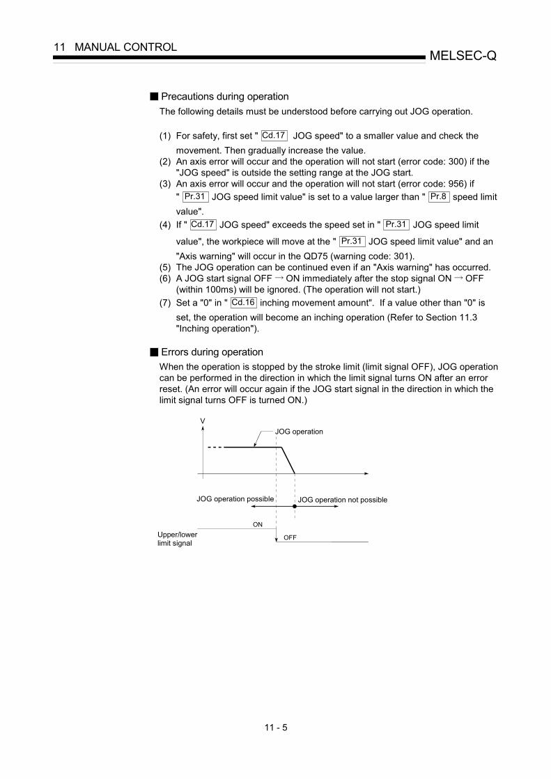
11 - 5
MELSEC-Q11 MANUAL CONTROL
Precautions during operationThe following details must be understood before carrying out JOG operation.
(1) For safety, first set " Cd.17 JOG speed" to a smaller value and check themovement. Then gradually increase the value.
(2) An axis error will occur and the operation will not start (error code: 300) if the"JOG speed" is outside the setting range at the JOG start.
(3) An axis error will occur and the operation will not start (error code: 956) if" Pr.31 JOG speed limit value" is set to a value larger than " Pr.8 speed limitvalue".
(4) If " Cd.17 JOG speed" exceeds the speed set in " Pr.31 JOG speed limit
value", the workpiece will move at the " Pr.31 JOG speed limit value" and an"Axis warning" will occur in the QD75 (warning code: 301).
(5) The JOG operation can be continued even if an "Axis warning" has occurred.(6) A JOG start signal OFF ON immediately after the stop signal ON OFF
(within 100ms) will be ignored. (The operation will not start.)(7) Set a "0" in " Cd.16 inching movement amount". If a value other than "0" is
set, the operation will become an inching operation (Refer to Section 11.3"Inching operation").
Errors during operationWhen the operation is stopped by the stroke limit (limit signal OFF), JOG operationcan be performed in the direction in which the limit signal turns ON after an errorreset. (An error will occur again if the JOG start signal in the direction in which thelimit signal turns OFF is turned ON.)
JOG operation possible JOG operation not possible
Upper/lowerlimit signal
JOG operationV
ON
OFF

11 - 6
MELSEC-Q11 MANUAL CONTROL
JOG operation timing and processing timeThe following drawing shows details of the JOG operation timing and processingtime.
Reverse run JOG start signal [Y9, YB, YD, YF]
BUSY signal [XC, XD, XE, XF]
Forward run JOG start signal [Y8, YA, YC, YE] t2
Standing by In JOG operation
t1
t3
t4
Pulse output to an external source (PULSE)
Positioning operation
Positioning complete signal [X14, X15, X16, X17]
Md. 26 Axis operation status
ON
ON
OFF
OFF
OFF
OFF
Standing by
Fig. 11.5 JOG operation timing and processing times
Normal timing times Unit: ms
t1 t2 t3 t41.0 to 3.0 0 to 1.8 2.7 to 4.4 0 to 1.8
• Delays may occur in the t1 timing time due to the operation status of other axes.

11 - 7
MELSEC-Q11 MANUAL CONTROL
11.2.2 JOG operation execution procedure
The JOG operation is carried out by the following procedure.
STEP 1Preparation
Refer to Chapter 5and Section 11.2.3.
End of control
Set the parameters
STEP 2
Refer to Section11.2.4.
Set the " Cd. 17 JOG speed".
STEP 3 Write the sequence program created in STEP 1 and STEP 2 to the PLC CPU using GX Developer.
Turn ON the JOG start signal. STEP 4
One of the following two methods can be used.
<Method 1>
Monitor using GX Configurator-QP.
<Method 2>
Monitor using GX Developer.
One of the following two methods can be used.
<Method 1>
Directly set (write) the parameters in the QD75 using GX
Configurator-QP.
<Method 2>
Set (write) the parameters from the PLC CPU to the QD75 usingthe sequence program (TO command).
STEP 5
Create a sequence program in which the "JOG startsignal" is turned ON by a JOG operation start command.
Using GX Developer, set the control data and create a sequence program for executing the JOG operation. (Set the control data in the QD75 buffer memory using the TO command.)
Write the sequence program to the PLC CPU.
Turn ON the JOG start signal of the axis to be started.
Monitoring of theJOG operation
Stop the JOG operation when the JOG start signal is turned OFF using the sequence program in STEP 2.
STEP 6Turn OFF the JOG operation start signal that is ON.
Monitor the JOG operation status.
Forward run JOG start signal Reverse run JOG start signal
Axis 1
Y8
Y9
YA
YB
YC
YD
Refer to Chapter 6.
Axis 3 Axis 2 JOG operationstart
JOG operationstop
to) Pr.1 )Pr.39
(Control data setting)
YE
YF
Axis 4
Set a "0" in " Cd. 16 Inching movementamount".
REMARK
• Mechanical elements such as limit switches are considered as already installed.• Parameter settings work in common for all control using the QD75.

11 - 8
MELSEC-Q11 MANUAL CONTROL
11.2.3 Setting the required parameters for JOG operation
The "Parameters" must be set to carry out JOG operation.The following table shows the setting items of the required parameters for carrying outJOG operation. When only JOG operation will be carried out, no parameters other thanthose shown below need to be set. (Use the initial values or setting values within arange where no error occurs for trouble-free operation.)
Setting item Setting requirement Factory-set initial value(setting details)
Pr.1 Unit setting 3 (pulse)
Pr.2 No. of pulses per rotation (Ap) (Unit: pulse) 20000
Pr.3 Movement amount per rotation (Al) (Unit: pulse) 20000
Pr.4 Unit magnification (Am) 1 (1-fold)
Pr.5 Pulse output mode 1 (CW/CCW mode)
Pr.6 Rotation direction setting 0 (current value increases byforward run pulse output)
Pr.7 Bias speed at start (Unit: pulse/s) 0
Pr.8 Speed limit value (Unit: pulse/s) 20000
Pr.9 Acceleration time 0 (Unit: pulse/s) 1000
Pr.10 Deceleration time 0 (Unit: pulse/s) 1000
Pr.11 Backlash compensation amount (Unit: pulse) 0
Pr.12 Software stroke limit upper limit value (Unit: pulse) 2147483647
Pr.13 Software stroke limit lower limit value (Unit: pulse) –2147483648
Pr.14 Software stroke limit selection 0 (current feed value)
Pr.15 Software stroke limit valid/invalid setting 0 (valid)
Pr.17 Torque limit setting value (Unit: %) 300
Para
met
ers
Pr.23 Output signal logic selection 0 (Pulse output to drive unit isnegative logic.)
: Setting always required.: Set according to requirements (Leave set to the initial value when not used.)
REMARK
• Parameter settings work in common for all control using the QD75. When carryingout other control ("major positioning control", "high-level positioning control", "OPRpositioning control"), the respective setting items must also be matched and set.
• Parameters are set for each axis.• Refer to Chapter 5 "Data Used for Positioning Control" for setting details.

11 - 9
MELSEC-Q11 MANUAL CONTROL
Setting item Setting requirement Factory-set initial value(setting details)
Pr.25 Acceleration time 1 (Unit: pulse) 1000
Pr.26 Acceleration time 2 (Unit: pulse) 1000
Pr.27 Acceleration time 3 (Unit: pulse) 1000
Pr.28 Deceleration time 1 (Unit: pulse) 1000
Pr.29 Deceleration time 2 (Unit: pulse) 1000
Pr.30 Deceleration time 3 (Unit: pulse) 1000
Pr.31 JOG speed limit value (Unit: pulse/s) 20000
Pr.32 JOG operation acceleration time selection 0 (acceleration time 0)
Pr.33 JOG operation deceleration time selection 0 (deceleration time 0)
Pr.34 Acceleration/deceleration process selection 0 (trapezoidal acceleration/deceleration processing)
Pr.35 S-curve ratio (Unit: %) 100
Pr.36 Sudden stop deceleration time (Unit: ms) 1000
Pr.37 Stop group 1 sudden stop selection 0 (deceleration stop)
Pr.38 Stop group 2 sudden stop selection 0 (deceleration stop)
Para
met
ers
Pr.39 Stop group 3 sudden stop selection 0 (deceleration stop)
: Setting always required.: Set according to requirements (Leave set to the initial value when not used.)

11 - 10
MELSEC-Q11 MANUAL CONTROL
11.2.4 Creating start programs for JOG operation
A sequence program must be created to execute a JOG operation. Consider the
"required control data setting", "start conditions" and "start time chart" when creating
the program.
The following shows an example when a JOG operation is started for axis 1.
(" Cd.17 JOG speed" is set to "100.00mm/min" in the example shown.)
Required control data setting
The control data shown below must be set to execute a JOG operation. Thesetting is carried out with the sequence program.
Buffer memory addressSetting item
Settingvalue
Setting details Axis1
Axis2
Axis3
Axis4
Cd.16 Inching movementamount
0 Set “0”. 1517 1617 1717 1817
Cd.17 JOG speed 10000
Set a value equal to or above the " Pr.7 Bias
speed at start" and equal to or below the
" Pr.31 JOG speed limit value".
1518
1519
1618
1619
1718
1719
1818
1819
Refer to Section 5.7 "List of control data" for details on the setting details.
Start conditions
The following conditions must be fulfilled when starting. The required conditionsmust also be assembled in the sequence program, and the sequence programmust be configured so the operation will not start if the conditions are not fulfilled.
DeviceSignal name Signal state Axis
1Axis
2Axis
3Axis
4
PLC READY signal ON PLC CPU preparation completed Y0
QD75 READY signal ON QD75 preparation completed X0
Synchronization flag ONQD75 buffer memory
The access is possible.X1
Axis stop signal OFF Axis stop signal is OFF Y4 Y5 Y6 Y7
Start complete signal OFF Start complete signal is OFF X10 X11 X12 X13
BUSY signal OFF QD75 is not operating XC XD XE XF
Error detection signal OFF There is no error X8 X9 XA XB
Interfacesignal
M code ON signal OFF M code ON signal is OFF X4 X5 X6 X7
Drive unit READY signal ON Drive unit preparation completed –
Stop signal OFF Stop signal is OFF –
Upper limit (FLS) ON Within limit range –Externalsignal
Lower limit (RLS) ON Within limit range –
If the PLC CPU is set to the asynchronous mode in the synchronization setting, this must be
inserted in the program for interlocking. If it is set to the synchronous mode, it must not be
inserted in the program for interlocking because it is turned ON when the PLC CPU executes
calculation.

11 - 11
MELSEC-Q11 MANUAL CONTROL
Start time chart
t
Forward run JOG start signal
Forward JOG run
BUSY signal
Error detection signal
OFF
OFF
OFF
OFF
OFF
ON
ON
ON
ON
[X8]
[XC]
PLC READY signal
QD75 READY signal
Reverse run JOG start signal
Reverse JOG run
[Y8]
[Y9]
[X0]
[Y0]
OFF
ON
Fig. 11.6 JOG operation start time chart

11 - 12
MELSEC-Q11 MANUAL CONTROL
Creating the program
—áExample
No. 10 JOG operation setting program
<Set JOG operation speed (100.00mm/min)>
<Set a "0" for inching movement amount>
No.12 JOG operation/inching operation execution program
<Write JOG operation speed>
<JOG/inching operation flag ON>
<JOG/inching operation termination>
<Execute forward JOG/inching operation>
<Execute reverse JOG operation>

11 - 13
MELSEC-Q11 MANUAL CONTROL
11.2.5 JOG operation example
When the "stop signal" is turned ON during JOG operation
When the "stop signal" is turned ON during JOG operation, the JOG operation willstop by the "deceleration stop" method.JOG start signals will be ignored while the stop signal is ON.The operation can be started by turning the stop signal OFF, and turning the JOGstart signal from OFF to ON again.
OFF
ON
BUSY signal[XC, XD, XE, XF] OFF
ON
A JOG start signal OFF ON while the stop signal is ON will be ignored.
Axis stop signal [Y4, Y5, Y6, Y7]
OFF
ON
OFF
ONForward run JOG start signal [Y8, YA, YC, YE]
QD75 READY signal [X0]
PLC READY signal [Y0]
OFF
ON
Fig. 11.7 Operation when the stop signal is turned ON during JOG operation
POINTThe QD75 will not receive a "JOG start signal" while the "stop signal" is ON.

11 - 14
MELSEC-Q11 MANUAL CONTROL
When both the "forward run JOG start signal" and "reverse run JOG startsignal" are turned ON simultaneously for one axis
When both the "forward run JOG start signal" and "reverse run JOG start signal"are turned ON simultaneously for one axis, the "forward run JOG start signal" isgiven priority. In this case, the "reverse run JOG start signal" is validated when theQD75 BUSY signal is turned OFF.If the forward run JOG operation is stopped due to stop or axis error by a stopsignal, the reverse run JOG operation will not be executed even if the "reverse runJOG start signal" turns ON.
OFF
ON
OFF
ON
BUSY signal[XC, XD, XE, XF]OFF
ON
Forward run JOG operation
t
The reverse run JOGstart signal is ignored.
Reverse run JOG operation
Forward run JOG start signal [Y8, YA, YC, YE]
Reverse run JOG start signal [Y9, YB, YD, YF]
Fig. 11.8 Operation when both the forward run JOG start signal and reverse run JOG start signal areturned ON simultaneously

11 - 15
MELSEC-Q11 MANUAL CONTROL
When the "JOG start signal" is turned ON again during deceleration causedby the ON OFF of the "JOG start signal"
When the "JOG start signal" is turned ON again during deceleration caused by theON OFF of the "JOG start signal", the JOG operation will be carried out from thetime the "JOG start signal" is turned ON.
OFF
ON
t
BUSY signal[XC, XD, XE, XF] OFF
ON
Forward run JOG operation
Forward run JOG start signal [Y8, YA, YC, YE]
Fig. 11.9 Operation when the JOG start signal is turned ON during deceleration
When the "JOG start signal" is turned ON during a peripheral device testmode
When the "JOG start signal" is turned ON during a peripheral device test mode, itwill be ignored and the JOG operation will not be carried out.
In test mode
ON
t
Forward run JOG start signal [Y8, YA, YC, YE]
OFF
ON
OFF
Forward run JOG operation execution JOG operation not possible
because this is not the rising edge of the JOGstart signal
JOG operation not possible because the operation is in the test mode
Fig. 11.10 Operation when the JOG start signal is turned ON during a test mode

11 - 16
MELSEC-Q11 MANUAL CONTROL
When the "JOG start signal" is turned ON immediately after the stop signalOFF (within 100ms)
When the "JOG start signal" is turned ON immediately after the stop signal OFF(within 100ms), it will be ignored and the JOG operation will not be carried out.
ON
Axis stop signal [Y4, Y5, Y6, Y7]
OFF
ON
OFF
100ms
A rise of JOG start signal is ignored.
Forward run JOG operation
Forward run JOG start signal [Y8, YA, YC, YE]
Fig. 11.11 Operation when the JOG start signal is turned ON immediately after the stop signal OFF

11 - 17
MELSEC-Q11 MANUAL CONTROL
11.3 Inching operation
11.3.1 Outline of inching operation
ImportantWhen the inching operation is carried out near the upper or lower limit, use the
hardware stroke limit function (Refer to Section 12.4.4).
If the hardware stroke limit function is not used, the workpiece may exceed the
movement range, and an accident may result.
Inching operation
In inching operation, pulses are input to the drive unit at the first control cycle (1.8ms) to move the workpiece by a designated movement amount after the forwardrun JOG start signal [Y8, YA, YC, YE] or reverse JOG start signal [Y9, YB, YD, YF]is turned ON.The following shows the example of inching operation.
1)When the start signal is turned ON, inching operation is carried out in the directiondesignated by the start signal. In this case, BUSY signal is turned from OFF to ON.
2)The workpiece is moved by a movement amount set in " Cd.16 Inching movement
amount".
3)The workpiece movement stops when the speed becomes "0". In this case, BUSY signalis turned from ON to OFF. The positioning complete signal is turned from OFF to ON.
4)The positioning complete signal is turned from ON to OFF after a time set in
" Pr.40 Positioning complete signal output time" has been elapsed.
PLC READY signal [Y0]OFF
ON
BUSY signal[XC,XD,XE,XF]
OFF
OFF
ON
Positioning completesignal[X14,X15,X16,X17]
OFF
ON
Forward run inching operation
ON
OFFQD75 READY signal[X0]
Forward run JOG start signal[Y8,YA,YC,YE]
1)
2)
3) 4)
Positioning complete signaloutput time
Pr.40
ON
Fig. 11.12 Inching operation

11 - 18
MELSEC-Q11 MANUAL CONTROL
Precautions during operation
The following details must be understood before inching operation is carried out.(1) Acceleration/deceleration processing is not carried out during inching
operation.(Pulses corresponding to the designated inching movement amount are outputat the first control cycle of the QD75 (1.8 ms). The movement direction ofinching operation is reversed and, when a backlash compensation is carriedout, first pulses corresponding to the backlash amount are output in the firstcontrol cycle of the QD75 and then pulses corresponding to the designatedinching movement amount are output in the subsequent control cycles.)
The " Cd.17 JOG speed" is ignored even if it is set. An error will occur in the
following cases (error code: 301).
( Cd.16 Inching movement amount) x (A) > ( Pr.31 JOG speed limit value)
Where (A) is as follows.• When the unit is pulse: 562.5• When the unit is other than pulse: 337.5
(2) JOG start signal OFF ON immediately after stop signal ON OFF (within100 ms) is ignored.(Operation will not start.)
(3) Set a value other than a "0" in " Cd.16 Inching movement amount".
If a "0" is set, the operation will become JOG operation (Refer to Section 11.2"JOG operation".
Errors during operation
When the operation is stopped by the stroke limit (limit signal OFF), inchingoperation can be performed in the direction in which the limit signal turns ON afteran error reset. (An error will occur again if the JOG start signal in the direction inwhich the limit signal turns OFF is turned ON.)
Inching operation possible
Upper/lower limit signal
Inching operation
V
Inching operation not possible
ON
OFF

11 - 19
MELSEC-Q11 MANUAL CONTROL
Inching operation timing and processing times
The following drawing shows the details of the inching operation timing andprocessing time.
Reverse run JOG start signal
[Y9,YB,YD,YF]
BUSY signal[XC,XD,XE,XF]
Forward run JOG start signal
[Y8,YA,YC,YE]
ON
Standing by Inching operationAxis operationstatus
t1
t2
t4
Pulse output to an external
source
(PULSE)
Positioning operation
Positioning completesignal[X14,X15,X16,X17]
Md.26
ON
ON
OFF
OFF
OFF
OFF
t3
Standing by
Fig. 11.13 Inching operation timing and processing times
Normal timing times Unit : ms
t1 t2 t3 t4
1.0 to 3.0 2.7 to 4.4 0 to 1.8Depending on
parameters
• Depending on the operating statuses of the other axes, delay may occur in thet1 timing time.

11 - 20
MELSEC-Q11 MANUAL CONTROL
11.3.2 Inching operation execution procedure
The inching operation is carried out by the following procedure.
STEP 1Preparation
Refer to Chapter 5and Section 11.3.3.
End of control
Set the parameters.
STEP 2
Refer to Section11.3.4.
STEP 3 Write the sequence program created in STEP 1 and STEP 2 to the PLC CPU using GX Developer.
Turn ON the JOG start signal. STEP 4
One of the following two methods can be used.
<Method 1>
Monitor using GX Configurator-QP.
<Method 2>
Monitor using GX Developer.
One of the following two methods can be used.
<Method 1>
Directly set (write) the parameters in the QD75 using GX
Configurator-QP.
<Method 2>
Set (write) the parameters from the PLC CPU to the QD75 usingthe sequence program (TO command).
STEP 5
Create a sequence program in which the "JOG startsignal" is turned ON by an inching operation startcommand.
Using GX Developer, set the control data and create a sequence program for executing the inching operation. (Set the control data in the QD75 buffer memory using the TO command.)
Write the sequence program to the PLC CPU.
Turn ON the JOG start signal of the axis to be started.
Monitoring of theinching operation
STEP 6Turn OFF the JOG operation start signal that is ON.
Monitor the inching operation status.
Forward run JOG start signal Reverse run JOG start signal
Axis 1
Y8
Y9
YA
YB
YC
YD
Refer to Chapter 6.
Axis 3 Axis 2 Inching operationstart
Inching operationstop
to)
Pr.1 )Pr.31
Set the " Cd.16 inching movement amount".(Control data setting)
YE
YF
Axis 4
End the inching operation after moving a workpieceby an inching movement amount with the sequenceprogram created in STEP 2.
REMARK
• Mechanical elements such as limit switches are considered as already installed.• Parameter settings work in common for all control using the QD75.
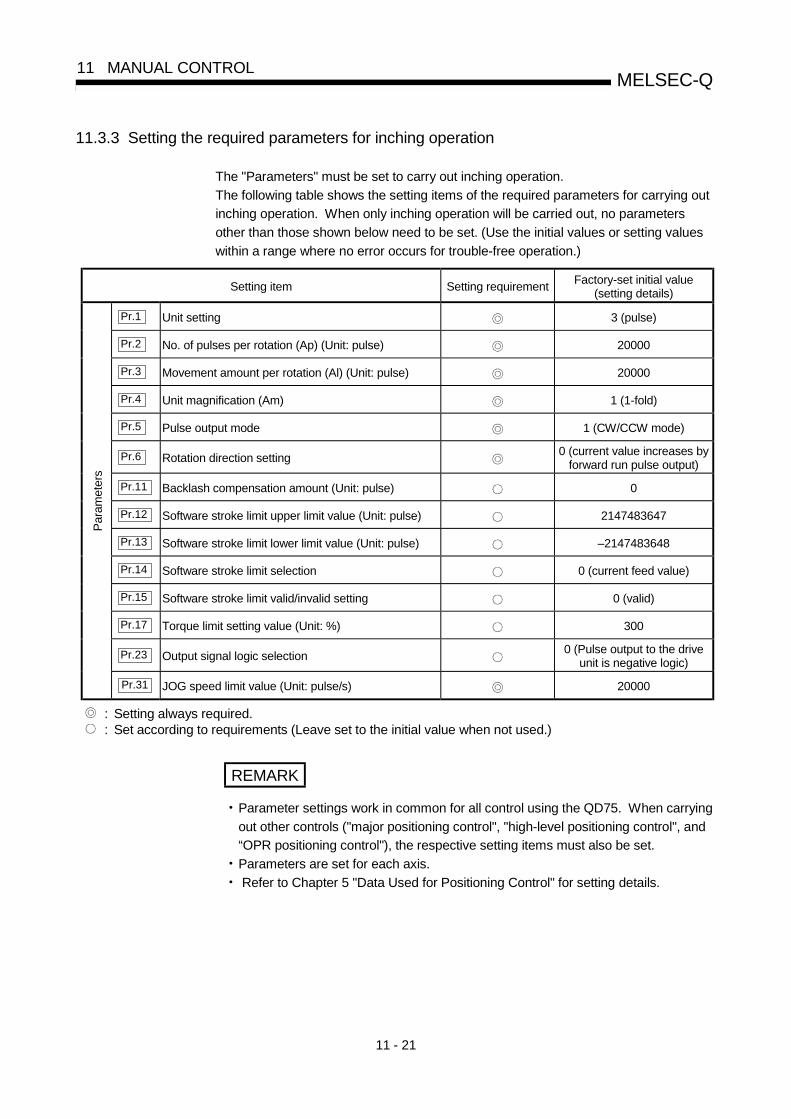
11 - 21
MELSEC-Q11 MANUAL CONTROL
11.3.3 Setting the required parameters for inching operation
The "Parameters" must be set to carry out inching operation.
The following table shows the setting items of the required parameters for carrying out
inching operation. When only inching operation will be carried out, no parameters
other than those shown below need to be set. (Use the initial values or setting values
within a range where no error occurs for trouble-free operation.)
Setting item Setting requirementFactory-set initial value
(setting details)
Pr.1 Unit setting 3 (pulse)
Pr.2 No. of pulses per rotation (Ap) (Unit: pulse) 20000
Pr.3 Movement amount per rotation (Al) (Unit: pulse) 20000
Pr.4 Unit magnification (Am) 1 (1-fold)
Pr.5 Pulse output mode 1 (CW/CCW mode)
Pr.6 Rotation direction setting0 (current value increases by
forward run pulse output)
Pr.11 Backlash compensation amount (Unit: pulse) 0
Pr.12 Software stroke limit upper limit value (Unit: pulse) 2147483647
Pr.13 Software stroke limit lower limit value (Unit: pulse) –2147483648
Pr.14 Software stroke limit selection 0 (current feed value)
Pr.15 Software stroke limit valid/invalid setting 0 (valid)
Pr.17 Torque limit setting value (Unit: %) 300
Pr.23 Output signal logic selection0 (Pulse output to the drive
unit is negative logic)
Par
amet
ers
Pr.31 JOG speed limit value (Unit: pulse/s) 20000
: Setting always required.: Set according to requirements (Leave set to the initial value when not used.)
REMARK
• Parameter settings work in common for all control using the QD75. When carrying
out other controls ("major positioning control", "high-level positioning control", and
“OPR positioning control"), the respective setting items must also be set.• Parameters are set for each axis.• Refer to Chapter 5 "Data Used for Positioning Control" for setting details.
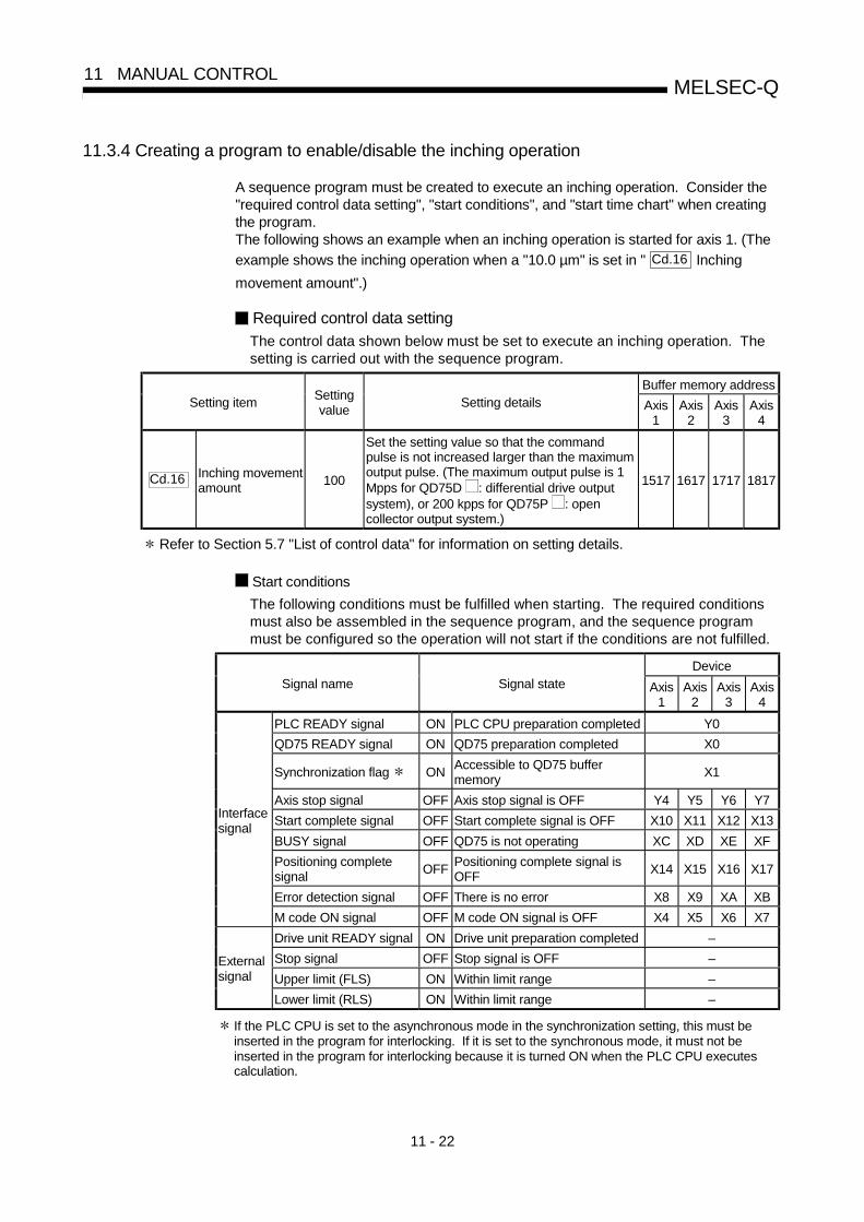
11 - 22
MELSEC-Q11 MANUAL CONTROL
11.3.4 Creating a program to enable/disable the inching operation
A sequence program must be created to execute an inching operation. Consider the"required control data setting", "start conditions", and "start time chart" when creatingthe program.The following shows an example when an inching operation is started for axis 1. (The
example shows the inching operation when a "10.0 µm" is set in " Cd.16 Inching
movement amount".)
Required control data setting
The control data shown below must be set to execute an inching operation. Thesetting is carried out with the sequence program.
Buffer memory addressSetting item
Settingvalue
Setting details Axis1
Axis2
Axis3
Axis4
Cd.16 Inching movementamount
100
Set the setting value so that the commandpulse is not increased larger than the maximumoutput pulse. (The maximum output pulse is 1Mpps for QD75D : differential drive outputsystem), or 200 kpps for QD75P : opencollector output system.)
1517 1617 1717 1817
Refer to Section 5.7 "List of control data" for information on setting details.
Start conditions
The following conditions must be fulfilled when starting. The required conditionsmust also be assembled in the sequence program, and the sequence programmust be configured so the operation will not start if the conditions are not fulfilled.
DeviceSignal name Signal state Axis
1Axis
2Axis
3Axis
4
PLC READY signal ON PLC CPU preparation completed Y0
QD75 READY signal ON QD75 preparation completed X0
Synchronization flag ONAccessible to QD75 buffermemory
X1
Axis stop signal OFF Axis stop signal is OFF Y4 Y5 Y6 Y7
Start complete signal OFF Start complete signal is OFF X10 X11 X12 X13
BUSY signal OFF QD75 is not operating XC XD XE XF
Positioning completesignal
OFFPositioning complete signal isOFF
X14 X15 X16 X17
Error detection signal OFF There is no error X8 X9 XA XB
Interfacesignal
M code ON signal OFF M code ON signal is OFF X4 X5 X6 X7
Drive unit READY signal ON Drive unit preparation completed –
Stop signal OFF Stop signal is OFF –
Upper limit (FLS) ON Within limit range –Externalsignal
Lower limit (RLS) ON Within limit range –
If the PLC CPU is set to the asynchronous mode in the synchronization setting, this must beinserted in the program for interlocking. If it is set to the synchronous mode, it must not beinserted in the program for interlocking because it is turned ON when the PLC CPU executescalculation.

11 - 23
MELSEC-Q11 MANUAL CONTROL
Start time chart
Forward run JOG start signal [Y8]
PLC READY signal [Y0]
QD75 READY signal [X0]
t
Reverse run JOG start signal [Y9]
Reverse run inching operation
Forward run inching operation
BUSY signal [XC]
Error detection signal [X8]
OFF
OFF
OFF
OFF
OFF
ON
ON
ON
ON
ON
OFF
OFF
ONPositioning complete signal [X14]
Fig. 11.14 Inching operation start time chart

11 - 24
MELSEC-Q11 MANUAL CONTROL
Creating the program
—áExample
No.11 Inching operation setting program
<Set inching movement amount>
<JOG/inching operation flag ON>
<JOG/inching operation termination>
<Execute forward JOG/inching operation>
<Execute reverse JOG operation>
<Write inching movement amount>
No.12 JOG operation/inching operation execution program

11 - 25
MELSEC-Q11 MANUAL CONTROL
11.3.5 Inching operation example
When "stop signal" is turned ON during inching operation:
If "stop signal" is turned ON during inching operation, the inching operation will bestopped.While the stop signal is turned ON, the JOG start signal is ignored.The inching operation can be re-started when the stop signal is turned OFF andthen re-turned ON.
PLC READY
signal [Y0] OFF
ON
BUSY signal[XC,XD,XE,XF]
OFF
ON
A JOG start signal OFF ON
while the stop signal is ON will be ignored.
Axis stop signal[Y4,Y5,Y6,Y7]
OFF
ON
QD75 READYsignal [X0]
ON
OFF
Forward run JOGstart signal[Y8,YA,YC,YE]
OFF
ON
Fig. 11.15 Operation when stop signal is turned ON during inching operation
POINTThe QD75 will not accept "JOG start signal" while "stop signal" is turned ON.

11 - 26
MELSEC-Q11 MANUAL CONTROL
When "JOG start signal" is turned ON when peripheral devices are in thetest mode:
If "JOG star signal" is turned ON when peripheral devices are in the test mode, the"JOG start signal" will be ignored and inching operation will not be carried out.
In test mode
ON
t
Forward run JOG start signal[Y8,YA,YC,YE] OFF
ON
OFF
Forward run inchingoperation executedInching operation not possible
because the operation is in the
test mode.
Inching operation not
possible because JOG
start signal does not rise
Fig. 11.16 Operation when JOG start signal is turned ON in test mode
When "JOG start signal" is turned ON immediately after stop signal OFF(within 100 ms):
If "JOG start signal" is turned ON immediately after the stop signal is turned OFF(within 100 ms), the "JOG start signal" will be ignored and inching operation willnot be carried out.
Forward run JOG start signal[Y8,YA,YC,YE]
ON
Axis stop signal[Y4,Y5,Y6,Y7]
OFF
ON
OFF
Forward run inching operation
100ms
A rise of JOG start signal
is ignored.
Fig. 11.17 Operation when JOG start signal is turned ON immediately after stop signal is turned OFF

11 - 27
MELSEC-Q11 MANUAL CONTROL
11.4 Manual pulse generator operation
11.4.1 Outline of manual pulse generator operation
ImportantCreate the sequence program so that " Cd.21 Manual pulse generator enable
flag" is always set to "0" (disabled) when a manual pulse generator operation is not
carried out.
Mistakenly touching the manual pulse generator when the manual pulse
generator enable flag is set to "1" (enable) can cause accidents or incorrect
positioning.
Manual pulse generator operation
In manual pulse generator operations, pulses are input to the QD75 from themanual pulse generator. This causes the same No. of input pulses to be outputfrom the QD75 to the servo amplifier, and the workpiece is moved in thedesignated direction.The following shows and example of manual pulse generator operation.
1)When the " Cd.21 Manual pulse generator enable flag" is set to "1", the BUSY signal
turns ON and the manual pulse generator operation is enabled.
2)The workpiece is moved corresponding to the No. of pulses input from the manual pulsegenerator.
3)The workpiece movement stops when no more pulses are input from the manual pulsegenerator.
4)When the " Cd.21 Manual pulse generator enable flag" is set to "0", the BUSY signal
turns OFF and the manual pulse generator operation is disabled.
������������������������������������������������������������������������������������������������������������������������������������������
Manual pulse generator operation stops
t
BUSY signal [XC, XD, YE, XF]
Manual pulse generator input
Start complete signal[X10, X11, X12, X13]
Manual pulse generator operation enabled
0
OFF
ON
OFF
1) 2) 3) 4)
1 0Cd. 21 Manual pulsegenerator enable flag
1
2
[Precautions]1 If the input from the manual pulse generator stops, the machine will decelerate to a stop within
90 ms.2 The start complete signal does not turn ON in manual pulse generator operation.
Fig. 11.18 Manual pulse generator operation

11 - 28
MELSEC-Q11 MANUAL CONTROL
Restricted items
A manual pulse generator is required to carry out manual pulse generatoroperation.
Precautions during operation
The following details must be understood before carrying out manual pulsegenerator operation.
(1) The speed during manual pulse generator operation is not limited by the
" Pr.8 Speed limit value".
(2) If the " Cd.21 Manual pulse generator enable flag" is turned ON while the
QD75 is BUSY (BUSY signal ON), a warning will occur (warning code 100:start during operation).
(3) If a stop factor occurs during manual pulse generator operation, the operationwill stop, and the BUSY signal will turn OFF.
At this time, the " Cd.21 Manual pulse generator enable flag" will be left ON,
but manual pulse generator operation will not be possible. To carry out manualpulse generator operation again, measures must be carried out to eliminatethe stop factor. Once eliminated, the operation can be carried out again by
turning the " Cd.21 Manual pulse generator enable flag" ON OFF ON.
(4) Pulses will not be output if an error occurs when the manual pulse generatoroperation starts.
REMARK
• One QD75 module can be connected to one manual pulse generator.• The QD75 module can simultaneously output pulses to the axis 1 to axis 4 drive
units by one manual pulse generator.
(1-axis to 4-axis simultaneous operation is possible.)
Errors during operation
When the operation is stopped by the stroke limit (limit signal OFF), manual pulsegenerator operation can be performed in the direction in which the limit signal turnsON after an error reset. (An error will occur again if pulse input is provided in thedirection in which the limit signal turns OFF is turned ON.)
Upper/lower limit signal
Manual pulse generatoroperation possible
Manual pulse generatoroperation not possible
V
Manual pulsegenerator operation
ON
OFF

11 - 29
MELSEC-Q11 MANUAL CONTROL
Manual pulse generator operation timing and processing time
The following drawing shows details of the manual pulse generator operationtiming and processing time.
Manual pulse generator input pulses
BUSY signal [XC,XD,XE,XF]
Start complete signal
[X10, X11, X12, X13]
Pulse output to an external source (PULSE)
Positioning operation
Cd. 21 Manual pulse generator enable flag (axis control data)
Md. 26 Axis operation status
t1
t3t4
Standing by
t2
0 01
Standing by In manual pulse generator operation
The start complete signal does not turn ON in manual pulse generator operation.
Fig. 11.19 Manual pulse generator operation timing and processing times
Normal timing times Unit : ms
t1 t2 t3 t4
0 to 2.6 6.2 to 32 64 to 90 28.4 to 57.6
• Delays may occur in the t1 timing time due to the operation status of other axes.

11 - 30
MELSEC-Q11 MANUAL CONTROL
Position control by manual pulse generator operation
In manual pulse generator operation, the position is moved by a "manual pulsegenerator 1 pulse movement amount" per pulse.The current feed value in the positioning control by manual pulse generatoroperation can be calculated using the expression shown below.
Current feed value = Number of input pulses × Cd.20 Manual pulse generator 1
pulse input magnification × Manual pulse generator 1 pulsemovement amount
Pr.1 Unit setting mm inch degree pulse
Manual pulsegenerator 1 pulsemovement amount
0.1µm 0.00001inch 0.00001degree 1pulse
For example, when " Pr.1 Unit setting" is mm and " Cd.20 Manual pulse
generator 1 pulse input magnification" is 2, and 100 pulses are input from themanual pulse generator, the current feed value is as follows.
100 × 2 × 0.1 = 20 [µm]
The number of pulses output actually to the drive unit is "Manual pulse generator 1pulse movement amount/movement amount per pulse ". For example, when
" Pr.1 Unit setting" is mm and the movement amount per pulse is 1 µm, 0.1/1 =
1/10, i.e., the output to the drive unit per pulse from the manual pulse generator is1/10 pulse. Thus, the QD75 outputs 1 pulse to the drive unit after receiving 10pulses from the manual pulse generator.
Movement amount per pulse =Movement amount per rotation
No. of pulses per rotation
Pr.3
Pr.2Unit magnificationPr.4
Speed control by manual pulse generation operation
The speed during positioning control by manual pulse generator operation is aspeed corresponding to the No. of input pulses per unit time, and can be obtainedusing the following equation.
Output command frequency = Input frequency × Cd.20 Manual pulse generator
1 pulse input magnification

11 - 31
MELSEC-Q11 MANUAL CONTROL
11.4.2 Manual pulse generator operation execution procedure
The manual pulse generator operation is carried out by the following procedure.
Write the sequence program created in STEP 1 and
STEP 2 to the PLC CPU using GX Developer.
Using GX Developer, set the control data and create a
sequence program to enable/disable the manual pulse
generator operation. (Set the control data in the QD75
buffer memory using the TO command.)
One of the following two methods can be used.
<Method 1>
Directly set (write) the parameters in the QD75 using
GX Configurator-QP.
<Method 2> Set (write) the parameters from the PLC CPU to the QD75using the sequence program (TO command).
STEP 1
Manual pulsegenerator operationstart
End of control
STEP 2
STEP 3
STEP 4
STEP 5
Issue a command to enable the manual pulse generatoroperation, and input the signals from the manual pulsegenerator.
End the input from the manual pulse generator, and issue a command to disable the manual pulse
Manual pulsegenerator operationstop
STEP 6
Monitor the manual pulse generator operation.
Preparation
Refer to Chapter 5and Section 11.4.3.
Refer to Section11.4.4.
Set the parameters
Write the sequence program to the PLC CPU.
One of the following two methods can be used.
<Method 1>
Monitor using GX Configurator-QP.
<Method 2>Monitor using GX Developer.
Monitoring of themanual pulsegenerator operation
Set " Cd. 20 Manual pulse generator 1 pulse input
magnification". (control data setting)
to)
Pr.1 )Pr.24
Create a sequence program in which the enable/disable is
(" Cd. 21 Manual pulse generator enable flag" setting.)set for the manual pulse generator operation.
Stop operating the manual pulse generator, and write "0"
in " Cd. 21 Manual pulse generator enable flag".
Write "1" in " Cd.21 Manual pulse generator enable
flag", and operate the manual pulse generator.
REMARK
• Mechanical elements such as limit switches are considered as already installed.• Parameter settings work in common for all control using the QD75.
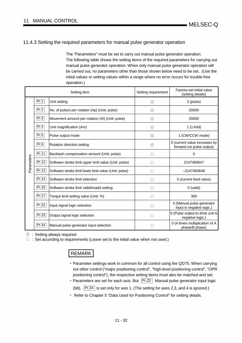
11 - 32
MELSEC-Q11 MANUAL CONTROL
11.4.3 Setting the required parameters for manual pulse generator operation
The "Parameters" must be set to carry out manual pulse generator operation.
The following table shows the setting items of the required parameters for carrying out
manual pulse generator operation. When only manual pulse generator operation will
be carried out, no parameters other than those shown below need to be set. (Use the
initial values or setting values within a range where no error occurs for trouble-free
operation.)
Setting item Setting requirementFactory-set initial value
(setting details)
Pr.1 Unit setting 3 (pulse)
Pr.2 No. of pulses per rotation (Ap) (Unit: pulse) 20000
Pr.3 Movement amount per rotation (Al) (Unit: pulse) 20000
Pr.4 Unit magnification (Am) 1 (1-fold)
Pr.5 Pulse output mode 1 (CW/CCW mode)
Pr.6 Rotation direction setting0 (current value increases by
forward run pulse output)
Pr.11 Backlash compensation amount (Unit: pulse) 0
Pr.12 Software stroke limit upper limit value (Unit: pulse) 2147483647
Pr.13 Software stroke limit lower limit value (Unit: pulse) –2147483648
Pr.14 Software stroke limit selection 0 (current feed value)
Pr.15 Software stroke limit valid/invalid setting 0 (valid)
Pr.17 Torque limit setting value (Unit: %) 300
Pr.22 Input signal logic selection0 (Manual pulse generator
input is negative logic.)
Pr.23 Output signal logic selection0 (Pulse output to drive unit is
negative logic.)
Par
amet
ers
Pr.24 Manual pulse generator input selection0 (4 times multiplication of A
phase/B phase)
: Setting always required.: Set according to requirements (Leave set to the initial value when not used.)
REMARK
• Parameter settings work in common for all control using the QD75. When carrying
out other control ("major positioning control", "high-level positioning control", "OPR
positioning control"), the respective setting items must also be matched and set.• Parameters are set for each axis. But Pr.22 Manual pulse generator input logic
(b8), Pr.24 is set only for axis 1. (The setting for axes 2,3, and 4 is ignored.)
• Refer to Chapter 5 "Data Used for Positioning Control" for setting details.

11 - 33
MELSEC-Q11 MANUAL CONTROL
11.4.4 Creating a program to enable/disable the manual pulse generator operation
A sequence program must be created to execute a manual pulse generator operation.
Consider the "required control data setting", "start conditions" and "start time chart"
when creating the program.
The following shows an example when a manual pulse generator operation is started
for axis 1.
Required control data setting
The control data shown below must be set to execute a manual pulse generatoroperation. The setting is carried out with the sequence program.
Buffer memory addressSetting item
Settingvalue
Setting details Axis1
Axis2
Axis3
Axis4
Cd.20Manual pulsegenerator 1 pulseinput magnification
1Set the manual pulse generator 1 pulse inputmagnification.
1522
1523
1622
1623
1722
1723
1822
1823
Cd.21Manual pulsegenerator enableflag
1 (0)
Set "1: Enable manual pulse generatoroperation". (Set "0: Disable manual pulsegenerator operation" when finished with themanual pulse generator operation.)
1524 1624 1724 1824
Refer to Section 5.7 "List of control data" for details on the setting details.
Start conditions
The following conditions must be fulfilled when starting. The required conditionsmust also be assembled in the sequence program, and the sequence programmust be configured so the operation will not start if the conditions are not fulfilled.
DeviceSignal name Signal state Axis
1Axis
2Axis
3Axis
4
PLC READY signal ON PLC CPU preparation completed Y0
QD75 READY signal ON QD75 preparation completed X0
Synchronization flag ONQD75 buffer memory
The access is possible.X1
Axis stop signal OFF Axis stop signal is OFF Y4 Y5 Y6 Y7
Start complete signal OFF Start complete signal is OFF X10 X11 X12 X13
BUSY signal OFF QD75 is not operating XC XD XE XF
Error detection signal OFF There is no error X8 X9 XA XB
Interfacesignal
M code ON signal OFF M code ON signal is OFF X4 X5 X6 X7
Drive unit READY signal ON Drive unit preparation completed –
Stop signal OFF Stop signal is OFF –
Upper limit (FLS) ON Within limit range –Externalsignal
Lower limit (RLS) ON Within limit range –
If the PLC CPU is set to the asynchronous mode in the synchronization setting, this must be
inserted in the program for interlocking. If it is set to the synchronous mode, it must not be
inserted in the program for interlocking because it is turned ON when the PLC CPU executes
calculation.

11 - 34
MELSEC-Q11 MANUAL CONTROL
Start time chart
Pulse input A phase
OFF
ON
OFF
OFF
1
t
OFF
0 0
1
Forward run
Reverse run
ON
Pulse input B phase
BUSY signal
QD75 READY signal
PLC READY signal
Start complete signal
Error detection signal
[Y0]
[X0]
[X10]
[XC]
[X8]
Cd. 21 Manual pulse generator
enable flag
Cd. 20 Manual pulse generator
1 pulse input magnification
OFF
ON
Fig. 11.20 Manual pulse generator operation start time chart
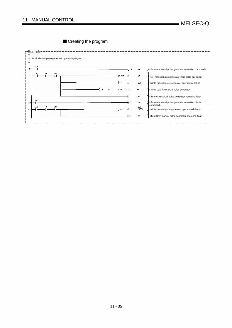
11 - 35
MELSEC-Q11 MANUAL CONTROL
Creating the program
—áExample
No.13 Manual pulse generator operation program
<Pulsate manual pulse generator operation command>
<Set manual pulse generator input scale per pulse>
<Write manual pulse generator operation enable>
<Write data for manual pulse generator>
<Turn ON manual pulse generator operating flag>
<Pulsate manual pulse generator operation disblecommand>
<Write manual pulse generator operation disble>
<Turn OFF manual pulse generator operating flag>

11 - 36
MELSEC-Q11 MANUAL CONTROL
MEMO

12 - 1
12
Chapter 12 Control Sub Functions
The details and usage of the "sub functions" added and used in combination with the main functions are explained in this chapter.
A variety of sub functions are available, including functions specifically for machine OPR and generally related functions such as control compensation, etc. More appropriate, finer control can be carried out by using these sub functions. Each sub function is used together with a main function by creating matching parameter settings and sequence programs. Read the execution procedures and settings for each sub function, and set as required.
12.1 Outline of sub functions ...........................................................................................12- 212.1.1 Outline of sub functions .............................................................................12- 2
12.2 Sub functions specifically for machine OPR...........................................................12- 412.2.1 OPR retry function......................................................................................12- 412.2.2 OP shift function ........................................................................................12- 8
12.3 Functions for compensating the control.................................................................12- 1112.3.1 Backlash compensation function..............................................................12- 1112.3.2 Electronic gear function ............................................................................12- 1312.3.3 Near pass function ....................................................................................12- 18
12.4 Functions to limit the control...................................................................................12- 2112.4.1 Speed limit function...................................................................................12- 2112.4.2 Torque limit function..................................................................................12- 2312.4.3 Software stroke limit function....................................................................12- 2612.4.4 Hardware stroke limit function ..................................................................12- 32
12.5 Functions to change the control details .................................................................12- 3412.5.1 Speed change function .............................................................................12- 3412.5.2 Override function.......................................................................................12- 4112.5.3 Acceleration/deceleration time change function ......................................12- 4412.5.4 Torque change function ............................................................................12- 48
12.6 Absolute position restoration function ....................................................................12- 5012.7 Other functions........................................................................................................12- 58
12.7.1 Step function .............................................................................................12- 5812.7.2 Skip function..............................................................................................12- 6312.7.3 M code output function..............................................................................12- 6612.7.4 Teaching function......................................................................................12- 7012.7.5 Target position change function ...............................................................12- 7712.7.6 Command in-position function ..................................................................12- 8112.7.7 Acceleration/deceleration processing function.........................................12- 8412.7.8 Pre-reading start function..........................................................................12- 8712.7.9 Deceleration start flag function .................................................................12- 9212.7.10 Stop command processing for deceleration stop function.......................12- 96
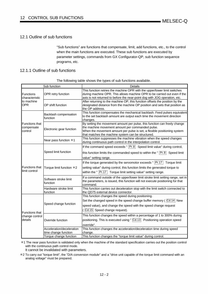
12 - 2
MELSEC-Q12 CONTROL SUB FUNCTIONS
12.1 Outline of sub functions
"Sub functions" are functions that compensate, limit, add functions, etc., to the control
when the main functions are executed. These sub functions are executed by
parameter settings, commands from GX Configurator-QP, sub function sequence
programs, etc.
12.1.1 Outline of sub functions
The following table shows the types of sub functions available.
Sub function Details
OPR retry functionThis function retries the machine OPR with the upper/lower limit switchesduring machine OPR. This allows machine OPR to be carried out even if theaxis is not returned to before the near-point dog with JOG operation, etc.
Functionscharacteristicto machineOPR OP shift function
After returning to the machine OP, this function offsets the position by thedesignated distance from the machine OP position and sets that position asthe OP address.
Backlash compensationfunction
This function compensates the mechanical backlash. Feed pulses equivalentto the set backlash amount are output each time the movement directionchanges.
Electronic gear function
By setting the movement amount per pulse, this function can freely changethe machine movement amount per commanded pulse.When the movement amount per pulse is set, a flexible positioning systemthat matches the machine system can be structured.
Functions thatcompensatecontrol
Near pass function 1This function suppresses the machine vibration when the speed changesduring continuous path control in the interpolation control.
Speed limit function
If the command speed exceeds " Pr.8 Speed limit value" during control,
this function limits the commanded speed to within the " Pr.8 Speed limit
value" setting range.
Torque limit function 2
If the torque generated by the servomotor exceeds " Pr.17 Torque limit
setting value" during control, this function limits the generated torque to
within the " Pr.17 Torque limit setting value" setting range.
Software stroke limitfunction
If a command outside of the upper/lower limit stroke limit setting range, set inthe parameters, is issued, this function will not execute positioning for thatcommand.
Functions thatlimit control
Hardware stroke limitfunction
This function carries out deceleration stop with the limit switch connected tothe QD75 external device connector.
Speed change function
This function changes the speed during positioning.
Set the changed speed in the speed change buffer memory ( Cd.14 New
speed value), and change the speed with the speed change request
( Cd.15 Speed change request).
Override function
This function changes the speed within a percentage of 1 to 300% during
positioning. This is executed using " Cd.13 Positioning operation speed
override".Acceleration/decelerationtime change function
This function changes the acceleration/deceleration time during speedchange.
Functions thatchange controldetails
Torque change function This function changes the "torque limit value" during control.
1 The near pass function is validated only when the machine of the standard specification carries out the position controlwith the continuous path control mode.It cannot be invalidated with parameters.
2 To carry out "torque limit", the "D/A conversion module" and a "drive unit capable of the torque limit command with ananalog voltage" must be prepared.

12 - 3
MELSEC-Q12 CONTROL SUB FUNCTIONS
Sub function Details
Absolute positionrestoration function 3
This function restores the absolute position of the designated axis.
Step function
This function temporarily stops the operation to confirm the positioningoperation during debugging, etc.The operation can be stopped at each "automatic deceleration" or"positioning data".
Skip functionThis function stops the positioning being executed (decelerates to a stop)when the skip signal is input, and carries out the next positioning.
M code output functionThis function issues a sub work (clamp or drill stop, tool change, etc.)according to the code No. (0 to 65535) set for each positioning data.
Teaching function
This function stores the address positioned with manual control into the
positioning address ( Da.6 Positioning address/movement amount) having
the designated positioning data No.
Target position changefunction
This function changes the target position during the execution of positioning.At the same time, this also can change the speed.
Command in-positionfunction
At each automatic deceleration, this function calculates the remainingdistance for the QD75 to reach the positioning stop position, and when thevalue is less than the set value, sets the "command in-position flag".When using another sub work before ending the control, use this function asa trigger for the sub work.
Acceleration/decelerationprocess function
This function adjusts the control acceleration/deceleration.
Pre-reading start function This function shortens the virtual start time.
Deceleration start flagfunction
Function that turns ON the flag when the constant speed status oracceleration status switches to the deceleration status during positioncontrol, whose operation pattern is "Positioning complete", to make the stoptiming known.
Other functions
Stop command processingfor deceleration stopfunction
Function that selects a deceleration curve when a stop cause occurs duringdeceleration stop processing to speed 0.
3 "The 16-point input module", "16-point output module", and "the drive unit capable of configuring anabsolute position detection system" are required to execute the "absolute position restoration function".

12 - 4
MELSEC-Q12 CONTROL SUB FUNCTIONS
12.2 Sub functions specifically for machine OPR
The sub functions specifically for machine OPR include the "OPR retry function" and"OP shift function". Each function is executed by parameter setting.
12.2.1 OPR retry function
When the workpiece goes past the OP without stopping during positioning control, itmay not move back in the direction of the OP although a machine OPR is commanded,depending on the workpiece position. This normally means the workpiece has to bemoved to a position before the near-point dog by a JOG operation, etc., to start themachine OPR again. However, by using the OPR retry function, a machine OPR canbe carried out regardless of the workpiece position.
The details shown below explain about the "OPR retry function".
[1] Control details
[2] Precautions during control
[3] Setting the OPR retry function
[1] Control detailsThe following drawing shows the operation of the OPR retry function.(1) OPR retry point return retry operation when the workpiece is within the range
between the upper and lower limits.
1) The movement starts in the " Pr.44 OPR direction" by a machine OPR start.
2) The operation decelerates when the limit signal OFF is detected.
3) After stopping at detection of the limit signal OFF, the operation moves at the " Pr.46 OPR speed" in the
direction opposite to the " Pr.44 OPR direction".
4) The operation decelerates when the near-point dog turns OFF.
5) After stopping due to the near-point dog OFF, a machine OPR is carried out in the " Pr.44 OPR
direction".6) Machine OPR completion
5) 1)
Near-point dog
Limit signal OFFON
2)
3)6)
4)
Zero signal
Fig. 12.1 OPR retry operation by limit signal detection

12 - 5
MELSEC-Q12 CONTROL SUB FUNCTIONS
(2) OPR retry operation when the workpiece is outside the range between theupper and lower limits.
1) When the direction from the workpiece to the OP is the same as the " Pr.44 OPR direction", a
normal machine OPR is carried out.
Pr. 44 OPR direction
Upper limit Lower limit
Movement range
Machine OPR start OP
Zero signal
Near-point dog
2) When the direction from the workpiece to the OP is the opposite direction from the " Pr.44 OPR
direction", the operation carries out a deceleration stop when the near-point dog turns OFF, andthen carries out a machine OPR in the direction set in " Pr.44 OPR direction".
Pr. 44 OPR direction
Near-point dog
Upper limit Lower limit
Movement range
Machine OPR start
OP
Zero signal
Note) The above figures (a) and (b) are examples where " Pr.44 OPR direction" is set to "0: Positive
direction". When "0: Positive direction" is set in Pr.44 , check that the limit switch placed in the
OPR direction acts as the upper limit. When "1: Negative direction" is set in Pr.44 , check thatthe limit switch placed in the OPR direction acts as the lower limit. Incorrect wiring of these limitswitches may cause improper OPR retry operation. If any malfunction is identified, check andcorrect " Pr.6 Rotation direction setting" and the wiring.
Fig. 12.2 OPR retry operation from on limit (limit switch OFF)

12 - 6
MELSEC-Q12 CONTROL SUB FUNCTIONS
(3) Setting the dwell time during an OPR retryThe OPR retry function can perform such function as the dwell time using
" Pr.57 Dwell time at OPR retry" when the reverse run operation is carried
out due to detection by the limit signal for upper and lower limits and whenthe machine OPR is executed after the near point dog is turned OFF to stopthe operation.
" Pr.57 Dwell time during OPR" is validated when the operation stops at
the "A" and "B" positions in the following drawing. (The dwell time is thesame value at both positions "A" and "B".)
Machine OPRexecuted again
Stop by near-pointdog OFF
Stop by limit signal detection
Reverse run operationafter limit signal detection
B OP
Pr. 44 OPR direction
Machine OPR start
A
Limit signal OFFNear-point dog
Zero signal
Fig. 12.3 Setting the dwell time during an OPR retry

12 - 7
MELSEC-Q12 CONTROL SUB FUNCTIONS
[2] Precaution during control(1) The following table shows whether the OPR retry function may be executed
by the " Pr.43 OPR method".
Pr.43 OPR method Execution status of OPR retry function
Near-point dog method : Execution possible
Stopper method 1) : Execution not possible
Stopper method 2) : Execution not possible
Stopper method 3) : Execution not possible
Count method 1) : Execution possible
Count method 2) : Execution possible
(2) Always establish upper/lower limit switches at the upper/lower limit positionsof the machine, and connect an QD75 module. If the OPR retry function isused without hardware stroke limit switches, the motor will continue rotationuntil a hardware stroke limit signal is detected.
(3) Always wire QD75 upper/lower limit switches even when the OPR functionis invalidated. Control cannot be carried out with the QD75 unless the wiringis carried out.
(4) Do not carry out settings so that the drive unit power turns OFF by theupper/lower limit switches connected to the QD75. If the drive unit power isturned OFF, the OPR retry cannot be carried out.
[3] Setting the OPR retry functionTo use the "OPR retry function", set the required details in the parameters shown
in the following table, and write them to the QD75.
When the parameters are set, the OPR retry function will be added to the
machine OPR control. The set details are validated at the rising edge (OFF
ON) of the PLC READY signal (Y0). Set " Pr.57 Dwell time during OPR retry"
according to the user's requirements.
Setting itemSettingvalue
Setting detailsFactory-setinitial value
Pr.48 OPR retry 1 Set "1: Carry out OPR retry by limit switch". 0
Pr.57 Dwell time duringOPR retry
Set the deceleration stop time during OPR retry.(Random value between 0 and 65535 (ms))
0
Refer to Section 5.2 "List of parameters" for setting details.
REMARK
• Parameters are set for each axis.• It is recommended that the parameters be set whenever possible with GX
Configurator-QP. Execution by sequence program uses many sequence programs
and devices. The execution becomes complicated, and the scan times will
increase.

12 - 8
MELSEC-Q12 CONTROL SUB FUNCTIONS
12.2.2 OP shift function
When a machine OPR is carried out, the OP is normally established using the near-
point dog, stopper, and zero signal. However, by using the OP shift function, the
machine can be moved a designated movement amount from the position where the
zero signal was detected. A mechanically established OP can then be interpreted at
that point.
The OP shift function can be used without relation to " Pr.43 OPR method".
The details shown below explain about the "OP shift function".
[1] Control details
[2] Setting range for the OP shift amount
[3] Movement speed during OP shift
[4] Precautions during control
[5] Setting the OP shift function
[1] Control detailsThe following drawing shows the operation of the OP shift function.
Machine OPR start
Pr.53 OP shift amount
Speed selected by the " Pr. 56Speed designation during OP shift"
Pr.47 Creep speed
Shift operation carried out after
the deviation counter clear and reset.
Pr. 44 OPR direction
Near-point dog
Pr. 46 OPR speed
Zero signal
Fig. 12.4 OP shift operation

12 - 9
MELSEC-Q12 CONTROL SUB FUNCTIONS
[2] Setting range for the OP shift amountSet the OP shift amount within the range from the detected zero signal to the
upper/lower limit switches.
Setting range of thenegative OPshift amount Setting range of the positive OP shift amount
Address decreasedirection
Upper limit Lower limit
Near-point dog
Pr. 44 OPR direction
Zero signal
Address increasedirection
Fig. 12.5 Setting range for the OP shift amount
[3] Movement speed during OP shiftWhen using the OP shift function, the movement speed during the OP shift is set
in " Pr.56 Speed designation during OP shift". The movement speed during the
OP shift is selected from either the " Pr.46 OPR speed" or the " Pr.47 Creep
speed".
The following drawings show the movement speed during the OP shift when a
mechanical OPR is carried out by the near-point dog method.
(1) OP shift operation at the " Pr.46 OPR speed"
(When " Pr.56 speed designation during OP shift" is 0)
OP
When the " Pr. 53 OPshift amount" is positive
When the " Pr. 53 OPshift amount" is negative
Pr. 44 OPRdirection
Machine OPR start
Pr. 46 OPRspeed
Near-point dog
Zero signal
Fig. 12.6 OP shift operation at the OPR speed

12 - 10
MELSEC-Q12 CONTROL SUB FUNCTIONS
(2) OP shift operation at the " Pr.47 Creep speed"
(When " Pr.56 Speed designation during OP shift" is 1)
When the " Pr. 53 OPshift amount" is negative
When the " Pr. 53 OPshift amount" is positive
Pr. 44 OPRdirection
Zero point
Machine OPR start
Near-point dog
Zero signal
OP
Pr. 47 Creepspeed
Fig. 12.7 OP shift operation at the creep speed
[4] Precautions during controlThe following data are set after the OP shift amount is complete.
• OPR complete flag (" Md.31 Status: b4)
• Md.20 Current feed value
• Md.21 Machine feed value
• Md.26 Axis operation status
• Md.34 Movement amount after near-point dog ON (" Pr.53 OP shift
amount" is not added.)
• OPR request flag ( Md.31 Status: b3) is reset after completion of the OP
shift.
[5] Setting the OP shift functionTo use the "OP shift function", set the required details in the parameters shown inthe following table, and write them to the QD75.When the parameters are set, the OP shift function will be added to the machineOPR control. The set details are validated at the rising edge (OFF ON) of thePLC READY signal (Y0).
Setting itemSettingvalue
Setting detailsFactory-setinitial value
Pr.53 OP shift amount Set the shift amount during the OP shift. 0
Pr.56Speeddesignationduring OP shift
Select the speed during the OP shift
0: Pr.46 OPR speed
1: Pr.47 Creep speed
0
Refer to Section 5.2 "List of parameters" for setting details.
REMARK
• Parameters are set for each axis.• It is recommended that the parameters be set whenever possible with GX
Configurator-QP. Execution by sequence program uses many sequence programsand devices. The execution becomes complicated, and the scan times willincrease.

12 - 11
MELSEC-Q12 CONTROL SUB FUNCTIONS
12.3 Functions for compensating the control
The sub functions for compensating the control include the "backlash compensation
function", "electronic gear function", and "near pass function". Each function is
executed by parameter setting or sequence program creation and writing.
12.3.1 Backlash compensation function
The "backlash compensation function" compensates the backlash amount in the
mechanical system. When the backlash compensation amount is set, an extra amount
of pulses equivalent to the set backlash amount is output every time the movement
direction changes.
The details shown below explain about the "backlash compensation function".
[1] Control details
[2] Precautions during control
[3] Setting the backlash compensation function
[1] Control detailsThe following drawing shows the operation of the backlash compensation
function.
Pr.11 Backlash compensation amount
Worm gear
Workpiece
Fig. 12.8 Backlash compensation amount

12 - 12
MELSEC-Q12 CONTROL SUB FUNCTIONS
[2] Precautions during control(1) The feed pulses of the backlash compensation amount are not added to the
" Md.20 Current feed value" or " Md.21 Machine feed value".
(2) Always carry out a machine OPR before starting the control when using the
backlash compensation function (when " Pr.11 Backlash compensation
amount" is set). The backlash in the mechanical system cannot be correctlycompensated if a machine OPR is not carried out.
(3) Set the No. of pulses output in one backlash compensation (value in which
the " Pr.11 Backlash compensation amount" is divided by the "movement
amount per pulse") to a value of 255 or lower. A "Backlash amountcompensation error (error code: 920)" will occur if a value over 255 is set.(Depending on the connected servo, tracking may not be possible if a largeamount of pulses is output at once.)
Backlash compensation amount0 ≤
Movement amount per pulse≤ 255
(Omit values after the decimal point.)
(4) Backlash compensation, which includes the movement amount and
" Pr.11 Backlash compensation amount", is output the moment at the
moving direction changes.
(5) Backlash compensation cannot be made when the stepping motor is used.
[3] Setting the backlash compensation functionTo use the "backlash compensation function", set the "backlash compensation
amount" in the parameter shown in the following table, and write it to the QD75.
The set details are validated at the rising edge (OFF ON) of the PLC READY
signal (Y0).
Setting itemSettingvalue
Setting detailsFactory-setinitial value
Pr.11Backlashcompensationamount
Set the backlash compensation amount. 0
Refer to Section 5.2 "List of parameters" for setting details.
REMARK
• Parameters are set for each axis.• It is recommended that the parameters be set whenever possible with GX
Configurator-QP. Execution by sequence program uses many sequence programs
and devices. The execution becomes complicated, and the scan times will
increase.

12 - 13
MELSEC-Q12 CONTROL SUB FUNCTIONS
12.3.2 Electronic gear function
The "electronic gear function" adjusts the pulses calculated and output according to the
parameters set in the QD75 with the actual machine movement amount.
The "electronic gear function" has the following three functions.
[A] During machine movement, the function increments in the QD75 values lessthan one pulse that could not be pulse output, and outputs the incrementedamount of pulses when the total incremented value reached one pulse ormore.
[B] When machine OPR is completed, current value changing is completed,speed control is started (except when current feed value change is present), orfixed-feed control is started, the function clears to "0" the cumulative values ofless than one pulse which could not be output. (If the cumulative value iscleared, an error will occur by a cleared amount in the feed machine value.Control can be constantly carried out at the same machine movement amount,even when the fixed-feed control is continued.)
[C] The function compensates the mechanical system error of the commandmovement amount and actual movement amount by adjusting the "movementamount per pulse".
(The "movement amount per pulse" value is defined by " Pr.2 No. of pulses
per rotation (Ap)", " Pr.3 Movement amount per rotation (Al)", and " Pr.4
Unit magnification (Am)".)
The QD75 automatically carries out the processing for [A] and [B].
The details shown below explain about the "electronic gear function", including the
method for compensating the error in [C] above, etc.
[1] Error compensation method
[2] Relation between the movement amount per pulse and speed
[3] Precautions during control

12 - 14
MELSEC-Q12 CONTROL SUB FUNCTIONS
[1] Error compensation methodWhen position control is carried out by the "movement amount per pulse" set in
the QD75 parameters, an error sometimes occurs between the command
movement amount (L) and the actual movement amount (L').
That error is compensated in the QD75 by adjusting the values in " Pr.2 No. of
pulses per rotation (Ap)", " Pr.3 Movement amount per rotation (Al)", and
" Pr.4 Unit magnification (Am)". (When " Pr.1 Unit setting" is "0: mm")
(1) DefinitionThe "error compensation amount" used to carry out the error compensation
is defined as follows.
Actual movement amount (L')Error compensation amount =
Designated movement amount (L)
The QD75 "movement amount per pulse" is calculated with the following
equation.
Movement amount per pulse is "A", " Pr.2 No. of pulses per rotation" is
(Ap), " Pr.3 Movement amount per rotation" is (Al), and " Pr.4 Unit
magnification" is (Am).
AlA =
Ap × Am
(2) Procedure(a) Set the "command movement amount (L)", and carry out positioning.
(Set the "movement amount per pulse (A)" according to Section 5.2"List of parameters".)
(b) After positioning, measure the "actual movement amount (L')".
(c) Calculate the "error compensation amount".
L'Error compensation amount =
L
(d) Calculate the post-compensation " Pr.2 No. of pulses per rotation
(Ap')", " Pr.3 Movement amount per rotation (Al')", and " Pr.4 Unit
magnification (Am')" from the "post-compensation movement amountper pulse (A')".
A = A × Error compensation amount
Al L'=
Ap × Am ×
L
Al'=
Ap' × Am'
(Adjust with Am' so that Al' and Ap' do not exceed the setting range.)

12 - 15
MELSEC-Q12 CONTROL SUB FUNCTIONS
Calculation example
(Conditions)
Movement amount per pulseNo. of pulses per rotationUnit magnification
: 500 (µm/rev): 12000 (pulse/rev): 1
(Positioning results)
Command movement amountActual movement amount
: 100mm: 101mm
(Compensation amount)
AL' 5×10³ 101×103 5050 101
AP'=
12000×
101×103=
12000=
240
Movement amount per pulseNo. of pulses per rotationUnit magnification
: 101 (µm/rev): 240 (pulse/rev): 1
[Set in Pr.3 ]
[Set in Pr.2 ]
[Set in Pr.4 ]
(e) Set the post-compensation " Pr.2 No. of pulses per rotation (Ap')",
" Pr.3 Movement amount per rotation (Al')", and " Pr.4 Unit
magnification (Am')" in the parameters, and write them to the QD75.The set details are validated at the rising edge (OFF ON) of thePLC READY signal (Y0).
Setting itemSettingvalue
Setting detailsPre-compensation
value
Pr.2 No. of pulses perrotation
Ap' Set the post-compensation value. Ap
Pr.3 Movement amountper rotation
Al ' Set the post-compensation value. Al
Pr.4 Unit magnification Am' Set the post-compensation value. Am
Refer to Section 5.2 "List of parameters" for setting details.
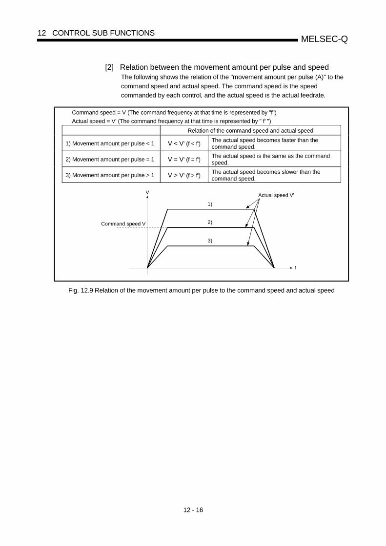
12 - 16
MELSEC-Q12 CONTROL SUB FUNCTIONS
[2] Relation between the movement amount per pulse and speedThe following shows the relation of the "movement amount per pulse (A)" to the
command speed and actual speed. The command speed is the speed
commanded by each control, and the actual speed is the actual feedrate.
Command speed = V (The command frequency at that time is represented by "f")
Actual speed = V' (The command frequency at that time is represented by " f' ")
Relation of the command speed and actual speed
1) Movement amount per pulse < 1 V < V' (f < f')The actual speed becomes faster than thecommand speed.
2) Movement amount per pulse = 1 V = V' (f = f')The actual speed is the same as the commandspeed.
3) Movement amount per pulse > 1 V > V' (f > f')The actual speed becomes slower than thecommand speed.
Command speed V
V
2)
1)
3)
Actual speed V'
t
Fig. 12.9 Relation of the movement amount per pulse to the command speed and actual speed
12 - 17
MELSEC-Q12 CONTROL SUB FUNCTIONS
[3] Precautions during controlIt is recommended that the "movement amount per pulse (A)" be set to a value
close to "1" for the following reasons. The "movement amount per pulse" of "1"means the minimum value in each " Pr.1 Unit setting". (0.1 [µm] for the unit
[mm])(1) If the setting of the movement amount per pulse is less than 1, the
command frequency may increase, causing the actual speed to exceed the
speed limit value (" Pr.8 Speed limit value", " Pr.31 JOG speed limit
value") and the servomotor to result in overspeed.
(2) If the setting of the movement amount per pulse is less than 1, themechanical system may oscillate. If the movement amount per pulsebecomes less than 1, use the electronic gear function of the drive unit andmake setting so that the movement amount per pulse is 1 or greater.
(3) Set the movement amount per pulse so that the pulse output frequency tothe drive unit becomes a value of 200kpps/1Mpps or less.If a value is set so that the pulse output frequency to the drive unit exceeds200kpps/1Mpps , the QD75 may not operate correctly.
They indicate the values of QD75P / QD75D.
(4) When using a hundred-thirty thousand pulses encoder, use the electronicgear function of a drive unit.
(5) Use the electronic gear function among the range indicated below.
Movement amount per pulse (A) > 1500
REMARK
In the QD75, the general term for the functions in items [1] to [3] above is defined as
the "electronic gear function". Refer to the User's Manual for the servomotor for the
definition of the "electronic gear" on the servomotor side.

12 - 18
MELSEC-Q12 CONTROL SUB FUNCTIONS
12.3.3 Near pass function
When continuous pass control is carried out using interpolation control, the near pass
function is carried out.
The "near pass function" is a function to suppress the mechanical vibration occurring at
the time of switching the positioning data when continuous pass control is carried out
using interpolation control.
[Near pass function]
The extra movement amount occurring at the end of each positioning data unit being
continuously executed is carried over to the next positioning data unit. Alignment is not
carried out, and thus the output speed drops are eliminated, and the mechanical
vibration occurring during speed changes can be suppressed. Because alignment is
not carried out, the operation is controlled on a path that passes near the position set
in " Da.6 Positioning address/movement amount".
The details shown below explain about the "near pass function".
[1] Control details
[2] Precautions during control
[1] Control detailsThe following drawing shows the path of the continuous path control.
[The path of the near pass]
Da. 6 Positioning address
Path of positioning data No. 4
V
t
Positioning data No. 3
Speed dropping does not occur.
Path of positioning data No.3
Positioning data No. 4
Fig. 12.10 The path of the continuous path control
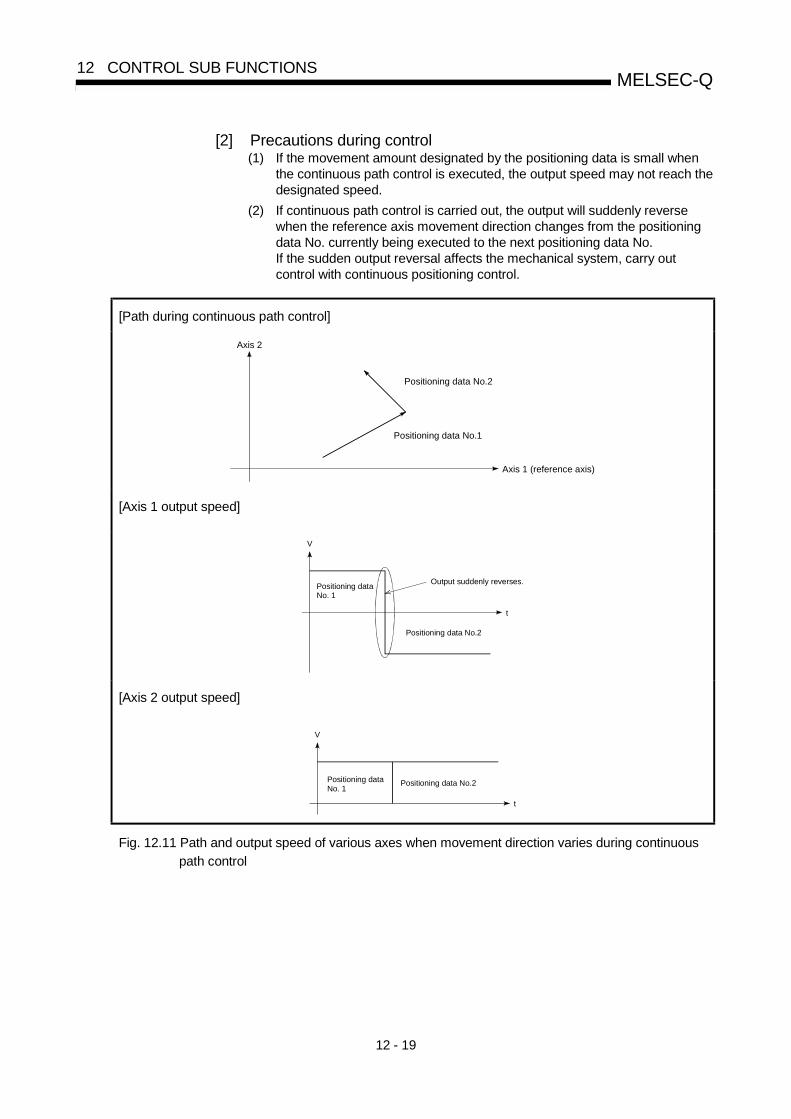
12 - 19
MELSEC-Q12 CONTROL SUB FUNCTIONS
[2] Precautions during control(1) If the movement amount designated by the positioning data is small when
the continuous path control is executed, the output speed may not reach thedesignated speed.
(2) If continuous path control is carried out, the output will suddenly reversewhen the reference axis movement direction changes from the positioningdata No. currently being executed to the next positioning data No.If the sudden output reversal affects the mechanical system, carry outcontrol with continuous positioning control.
[Path during continuous path control]
Axis 2
Axis 1 (reference axis)
Positioning data No.2
Positioning data No.1
[Axis 1 output speed]
V
t
Output suddenly reverses.Positioning dataNo. 1
Positioning data No.2
[Axis 2 output speed]
V
t
Positioning data No.2Positioning dataNo. 1
Fig. 12.11 Path and output speed of various axes when movement direction varies during continuous
path control

12 - 20
MELSEC-Q12 CONTROL SUB FUNCTIONS
(3) When continuous path control of a circular interpolation is being carried out inthe near pass, an address in which the extra movement amount is subtractedfrom the positioning address of the positioning data currently being executed isreplaced by the starting point address of the next positioning data No.Because the starting point address will be replaced, an error "Large arc errordeviation" (error code: 506) may occur.
In this case, adjust the " Pr.41 Allowable circular interpolation error width".
Address designated by positioning data No.1
Path of positioningaddress pass
Positioning data No.2
Positioning data No.1
Positioning data No.2starting point addressduring the near pass
Path of near pass
Fig. 12.12 Arc error during the near pass
(4) When a circle center is designated to continuously designate the circularinterpolation control by a continuous path designation in the near pass, andthe positioning address and starting point address of that arc are the sameaddress, the path will make one circle using the two data items. This isbecause the 2nd data starting point address is shifted by the extra amount ofthe movement amount occurring from the 1st data.
Path of positioning data No.1
Starting point address of positioning data No.1Starting point address of
positioning data No.2
Path of positioning data No.2
[Near pass]
Example
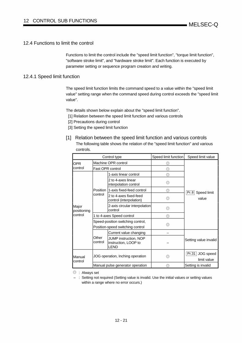
12 - 21
MELSEC-Q12 CONTROL SUB FUNCTIONS
12.4 Functions to limit the control
Functions to limit the control include the "speed limit function", "torque limit function",
"software stroke limit", and "hardware stroke limit". Each function is executed by
parameter setting or sequence program creation and writing.
12.4.1 Speed limit function
The speed limit function limits the command speed to a value within the "speed limit
value" setting range when the command speed during control exceeds the "speed limit
value".
The details shown below explain about the "speed limit function".
[1] Relation between the speed limit function and various controls
[2] Precautions during control
[3] Setting the speed limit function
[1] Relation between the speed limit function and various controlsThe following table shows the relation of the "speed limit function" and various
controls.
Control type Speed limit function Speed limit value
Machine OPR controlOPRcontrol Fast OPR control
1-axis linear control
2 to 4-axes linearinterpolation control
1-axis fixed-feed control
2 to 4-axes fixed-feedcontrol (interpolation)
Positioncontrol
2-axis circular interpolationcontrol
1 to 4-axes Speed control
Speed-position switching control,
Position-speed switching control
Pr.8 Speed limit
value
Current value changing –
Majorpositioningcontrol
Othercontrol
JUMP instruction, NOPinstruction, LOOP toLEND
–Setting value invalid
JOG operation, Inching operationPr.31 JOG speed
limit valueManualcontrol
Manual pulse generator operation Setting is invalid
: Always set– : Setting not required (Setting value is invalid. Use the initial values or setting values
within a range where no error occurs.)

12 - 22
MELSEC-Q12 CONTROL SUB FUNCTIONS
[2] Precautions during controlIf any axis exceeds " Pr.8 Speed limit value" during 2- to 4-axis speed control,
the axis in excess of the speed limit value is controlled at the speed limit value.
The speeds of the other axes interpolated are suppressed depending on their
command speed ratios.
If the reference axis exceeds " Pr.8 Speed limit value" during 2- to 4-axis linear
interpolation control, 2- to 4-axis fixed-feed control or 2-axis circular interpolation
control, the reference axis is controlled at the speed limit value (The speed limit
does not function on the interpolation axis side.)
[3] Setting the speed limit functionTo use the "speed limit function", set the "speed limit value" in the parameters
shown in the following table, and write them to the QD75.
The set details are validated after they are written to the QD75.
Setting itemSettingvalue
Setting detailsFactory-setinitial value
Pr.8 Speed limit value Set the speed limit value (max. speed during control). 200000
Pr.31 JOG speed limitvalue
Set the speed limit value during JOG operation (max.
speed during control). (Note that " Pr.31 JOG speed
limit value" shall be less than or equal to " Pr.8
Speed limit value".)
20000
Refer to Section 5.2 "List of parameters" for setting details.
REMARK
• Parameters are set for each axis.• It is recommended that the parameters be set whenever possible with GX
Configurator-QP. Execution by sequence program uses many sequence programs
and devices. The execution becomes complicated, and the scan times will
increase.

12 - 23
MELSEC-Q12 CONTROL SUB FUNCTIONS
12.4.2 Torque limit function
The "torque limit function" limits the generated torque to a value within the "torque limit
value" setting range when the torque generated in the servomotor exceeds the "torque
limit value".
The "torque limit function" protects the deceleration function, limits the power of the
operation pressing against the stopper, etc. It controls the operation so that
unnecessary force is not applied to the load and machine.
The details shown below explain about the "torque limit function".
[1] Relation between the torque limit function and various controls
[2] Control details
[3] Precautions during control
[4] Setting the torque limit function
[1] Relation between the torque limit function and various controlsThe following table shows the relation of the "torque limit function" and various
controls.
Control typeTorque limit
functionTorque limit value
Machine OPR control
Pr.17 Torque limit setting value
After the " Pr.47 Creep
speed" is reached, this value
becomes the " Pr.54 OPR
torque limit value".
OPRcontrol
Fast OPR control
1-axis linear control
2 to 4-axes linearinterpolation control
1-axis fixed-feed control
2 to 4-axes fixed-feedcontrol (interpolation)
Positioncontrol
2-axis circular interpolationcontrol
1 to 4-axes Speed control
Speed-position switching control
Position-speed switching control
Pr.17 Torque limit setting value
Current value changing –
Majorpositioningcontrol
Othercontrol
JUMP instruction, NOPinstruction, LOOP toLEND
–Setting value is invalid.
JOG operation, Inching operation Pr.17 Torque limit setting valueManualcontrol
Manual pulse generator operation Pr.17 Torque limit setting value
: Set when required (Set to " – " when not used.)– : Setting not required (Setting value is invalid. Use the initial values or setting values
within a range where no error occurs.)
: Shows the torque limit value when " Cd.22 New torque value" is set to "0".

12 - 24
MELSEC-Q12 CONTROL SUB FUNCTIONS
[2] Control detailsThe following drawing shows the operation of the torque limit function.
50%
0%
100%
0%
100% 50%
Torque limited at the parametertorque limit setting value (100%)
Various operations
PLC READY signal [Y0]
Pr.17 Torque limit setting value
Cd.22 New torque value
Md.35 Torque limit stored value
Torque limited at the parametertorque limit setting value (50%)
Fig. 12.13 Torque limit function operation
[3] Precautions during control(1) When limiting the torque at the " Pr.17 Torque limit setting value", confirm
that " Cd.22 New torque value" is set to "0". If this parameter is set to a
value besides "0", the " Cd.22 New torque value" will be validated, and the
torque will be limited at that value. (Refer to Section 12.5.4 "Torque changefunction" for details about the "new torque value".)
(2) When the “ Pr.54 OPR torque limit value “exceeds the “ Pr.17 Torque
limit setting value”, an error occurs. (Error code: 995)
(3) When limiting the torque, a D/A converter module and drive unit in whichtorque limit commands by analog voltage are possible.
(4) When the operation is stopped by torque limiting, the droop pulse will remainin the deviation counter. If a "deviation counter clear" is carried out byissuing an external signal at this time, positional deviation will occur whenthe operation is continued. If the load torque is eliminated, operation for theamount of droop pulses will be carried out.

12 - 25
MELSEC-Q12 CONTROL SUB FUNCTIONS
[4] Setting the torque limit function(1) To use the "torque limit function", set the "torque limit value" in the
parameters shown in the following table, and write them to the QD75.The set details are validated at the rising edge (OFF ON) of the PLCREADY signal (Y0).
Setting itemSettingvalue
Setting detailsFactory-setinitial value
Pr.17 Torque limitsetting value
Set the torque limit value as a percentage. 300
Pr.54 OPR torque limitvalue
Set the torque limit value after the " Pr.47 Creep
speed" is reached. Set as a percentage.300
Refer to Section 5.2 "List of parameters" for setting details.
(2) The "torque limit value" set in the QD75 is set in the " Md.35 Torque limit
stored value". The " Md.35 Torque limit stored value" in the sequence
program is transferred to the "D/A converter module", and the torque islimited.
PLC CPU Buffer memory Drive unit
Writing by aTO command
Stored torque limit value
826
D/A convertor module
Reading by a
FROM command
QD75
Torque limiting
Positioning control
Fig. 12.14 Limiting the torque to the drive unit (Axis 1)
The following table shows the " Md.35 Torque limit stored value" of the
buffer memory address.
Buffer memory addressMonitor item
Monitorvalue
Storage details Axis1
Axis2
Axis3
Axis4
Md.35 Torque limit storedvalue
The "torque limit value" valid at that time is
stored. ( Pr.17 , Pr.54 , or Cd.22 ) 826 926 1026 1126
Refer to Section 5.6 "List of monitor data" for information on the setting details.
REMARK
• Parameters are set for each axis.• It is recommended that the parameters be set whenever possible with GX
Configurator-QP. Execution by sequence program uses many sequence programs
and devices. The execution becomes complicated, and the scan times will
increase.

12 - 26
MELSEC-Q12 CONTROL SUB FUNCTIONS
12.4.3 Software stroke limit function
In the "software stroke limit function" the address established by a machine OPR is
used to set the upper and lower limits of the moveable range of the workpiece.
Movement commands issued to addresses outside that setting range will not be
executed.
In the QD75, the "current feed value" and "machine feed value" are used as the
addresses indicating the current position. However, in the "software stroke limit
function", the address used to carry out the limit check is designated in the " Pr.14
Software stroke limit selection". (Refer to Section 9.1.4 "Confirming the current value"
or details on the "current feed value" and "machine feed value".)
The upper and lower limits of the moveable range of the workpiece are set in " Pr.12
Software stroke limit upper limit value"/ " Pr.13 Software stroke limit lower limit
value".
The details shown below explain about the "software stroke limit function".
[1] Differences in the moveable range when "current feed value" and "machine feed
value" are selected.
[2] Software stroke limit check details
[3] Relation between the software stroke limit function and various controls
[4] Precautions during software stroke limit check
[5] Setting the software stroke limit function
[6] Invalidating the software stroke limit
[7] Setting when the control unit is "degree"
[1] Differences in the moveable range when "current feed value" and"machine feed value" are selected.The following drawing shows the moveable range of the workpiece when the
software stroke limit function is used.
FLSRLS Workpiece moveable range
Software stroke limit (lower limit) Software stroke limit (upper limit)
Fig. 12.15 Workpiece moveable range

12 - 27
MELSEC-Q12 CONTROL SUB FUNCTIONS
The following drawing shows the differences in the operation when " Md.20
Current feed value" and " Md.21 Machine feed value" are used in the moveable
range limit check.
[Conditions]Assume the current stop position is 2000, and the upper stroke limit is set to 5000.
50005000
Upper stroke limit
20002000
Stop position
Moveable range
Md. 20 Current feed value
Md. 21 Machine feed value
[Current value changing]When the current value is changed by a new current value command from 2000 to 1000, thecurrent value will change to 1000, but the machine feed value will stay the same at 2000.1) When the machine feed value is set at the limit
The machine feed value of 5000 (current feed value: 4000) becomes the upper stroke limit.
40005000
50006000
Upper stroke limit
10002000
Moveable range
Md. 20 Current feed value
Md. 21 Machine feed value
2) When the current feed value is set at the limitThe current feed value of 5000 (machine feed value: 6000) becomes the upper stroke limit.
40005000
50006000
Upper stroke limit
10002000
Moveable range
Md. 20 Current feed value
Md. 21 Machine feed value
Fig. 12.16 Software stroke limits of the current feed value and machine feed value
POINTWhen "machine feed value" is set in " Pr.14 Software stroke limit selection", the
moveable range becomes an absolute range referenced on the OP. When "current
feed value" is set, the moveable range is the relative range from the "current feed
value".

12 - 28
MELSEC-Q12 CONTROL SUB FUNCTIONS
[2] Software stroke limit check details
Check detailsProcessing whenan error occurs
1)
An error shall occur if the current value 1 is outside the softwarestroke limit range 2.
(Check " Md.20 Current feed value" or " Md.21 Machine feed value".)
2)
An error shall occur if the command address is outside the softwarestroke limit range.
(Check " Da.6 Positioning address/movement amount".)
An "axis error" willoccur (error code:507, 508)
1Check whether the " Md.20 Current feed value" or " Md.21 Machine feed value" is set in
" Pr.14 Software stroke limit selection".
2Moveable range from the " Pr.12 Software stroke limit upper limit value" to the " Pr.13
Software stroke limit lower limit value".
[3] Relation between the software stroke limit function and variouscontrols
Control typeLimitcheck
Processing at check
Machine OPR control –OPR control
Fast OPR control –Check not carried out.
1-axis linear control2 to 4-axes axis linearinterpolation control1-axis fixed-feed control2 to 4-axes fixed-feed control(interpolation)
Positioncontrol
2-axis circular interpolationcontrol
1 to 4-axes speed control3, 4
Speed-position switching controlPosition-speed switching control 3, 4
Checks 1) and 2) in the previous section [2] are carriedout.For speed control: The axis decelerates to a stop when
it exceeds the software stroke limitrange.
For position control: The axis comes to an immediatestop when it exceeds the softwarestroke limit range.
Current value changing –The current value will not be changed if the new currentvalue is outside the software stroke limit range.
Majorpositioningcontrol
Othercontrol JUMP instruction, NOP
instruction, LOOP to LEND– Check not carried out.
JOG operation, Inching operation 5
Manualcontrol Manual pulse generator operation 5
Check 1) in the previous section [2] is carried out.The machine will carry out a deceleration stop when thesoftware stroke limit range is exceeded. If the addressfalls out of the software stroke limit range, the operationcan be started only toward the movable range after anerror reset.
: Check valid
: Check is not made when the current feed value is not updated (Refer to Pr.21 ) at the setting of " current feed
value" in " Pr.14 Software stroke limit selection" during speed control.
– : Check not carried out (check invalid).
: Valid only when "1:valid" is set in the " Pr.15 Software stroke limit valid/invalid setting".
3 : The value in " Md.20 Current feed value" will differ according to the " Pr.21 Current feed value during speed
control" setting.
4: When the unit is "degree", check is not made during speed control.
5: When the unit is "degree", check is not carried out.

12 - 29
MELSEC-Q12 CONTROL SUB FUNCTIONS
[4] Precautions during software stroke limit check(1) A machine OPR must be executed beforehand for the "software stroke limit
function" to function properly.(2) During interpolation control, a stroke limit check is carried out for the every
current value of both the reference axis and the interpolation axis. Everyaxis will not start if an error occurs, even if it only occurs in one axis.
(3) During circular interpolation control, the " Pr.12 Software stroke limit upper
limit value"/" Pr.13 Software stroke limit lower limit value" may be
exceeded.In this case, a deceleration stop will not be carried out even if the stroke limitis exceeded. Always install an external limit switch if there is a possibility thestroke limit will be exceeded.
Arc address ( Da. 7 )
End point address ( Da. 6 )
Axis 1
Axis 1 stroke limit
Deceleration stop not carried out
Starting address
The software stroke limit check is carried out for the following addresses
during circular interpolation control. (Note that " Da. 7 Arc address" is carried
out only for circular interpolation control with sub point designation.
Current value/end point address ( Da. 6 )/arc address ( Da. 7 )
Axis 2
Example
(4) If an error is detected during continuous path control, the axis stopsimmediately on completion of execution of the positioning data located rightbefore the positioning data in error.
Md. 26Axis operation status
No.10 No.11 No.12 No.13
Immediate stop aterror detection No.10
P11
No.11P11
No.12P11
No.13P11
No.14P01
Controlling position Error occurring
Positioning data
• If the positioning address of positioning data No. 13 is outside the software stroke limit range,
the operation immediately stops after positioning data No. 12 has been executed.
Example

12 - 30
MELSEC-Q12 CONTROL SUB FUNCTIONS
(5) During simultaneous start, a stroke limit check is carried out for the currentvalues of every axis to be started. Every axis will not start if an error occurs,even if it only occurs in one axis.
[5] Setting the software stroke limit functionTo use the "software stroke limit function", set the required values in the
parameters shown in the following table, and write them to the QD75.
The set details are validated at the rising edge (OFF ON) of the PLC READY
signal (Y0).
Setting itemSettingvalue
Setting detailsFactory-setinitial value
Pr.12Software strokelimit upper limitvalue
Set the upper limit value of the moveable range. 2147483647
Pr.13Software strokelimit lower limitvalue
Set the lower limit value of the moveable range. –2147483648
Pr.14 Software strokelimit selection
Set whether to use the " Md.20 Current feed value" or
" Md.21 Machine feed value" as the "current value".
0: Current feedvalue
Pr.15Software strokelimit valid/invalidsetting
0:Val idSet whether the software stroke limit is validated orinvalidated during manual control (JOG operation,Inching operation, manual pulse generator operation).
0: valid
Refer to Section 5.2 "List of parameters" for setting details.
[6] Invalidating the software stroke limitTo invalidate the software stroke limit, set the following parameters as shown,
and write them to the QD75.
Pr.12 Software stroke limitupper limit value
= Pr.13 Software stroke limitlower limit value
(For manual operation, set "0: software stroke limit invalid" in the " Pr.15
Software stroke limit valid/invalid setting".)
The set details are validated at the rising edge (OFF ON) of the PLC READY
signal (Y0).
When the unit is "degree", the software stroke limit check is not performed during
speed control (including speed control in speed-position switching control or
position-speed switching control) or during manual control, independently of the
values set in Pr.12 , Pr.13 and Pr.15 .
REMARK
• Parameters are set for each axis.• It is recommended that the parameters be set whenever possible with GX
Configurator-QP. Execution by sequence program uses many sequence programs
and devices. The execution becomes complicated, and the scan times will
increase.

12 - 31
MELSEC-Q12 CONTROL SUB FUNCTIONS
[7] Setting when the control unit is "degree"
Current value address
The " Md.20 Current feed value" address is a ring address between 0 and
359.99999° .
0° 0° 0°
359.99999° 359.99999°
Fig. 12.17 Current value address when the control unit is "degree".
Setting the software stroke limit
The upper limit value/lower limit value of the software stroke limit is a valuebetween 0 and 359.99999° .
(1) Setting when the software stroke limit is to be validated.When the software stroke limit is to be validated, set the upper limit value in aclockwise direction from the lower limit value.
Section A
315ºSet in a clockwise direction
Upper limit
Lower limit
90º
Section B
(a) Set the movement range of section A as follows. • Software stroke limit lower limit value ................ 315.00000°. • Software stroke limit upper limit value................ 90.00000°.
(b) Set the movement range of section B as follows. • Software stroke limit lower limit value ................ 90.00000°. • Software stroke limit upper limit value................ 315.00000°.
Fig. 12.18 Software stroke limit when the control unit is "degree"

12 - 32
MELSEC-Q12 CONTROL SUB FUNCTIONS
12.4.4 Hardware stroke limit function
! DANGERWhen the hardware stroke limit is required to be wired, ensure to wire it in the negative logic using b-contact.
If it is set in positive logic using a-contact, a serious accident may occur.
In the "hardware stroke limit function", limit switches are set at the upper/lower limit of
the physical moveable range, and the control is stopped (by deceleration stop) by the
input of a signal from the limit switch. Damage to the machine can be prevented by
stopping the control before the upper/lower limit of the physical moveable range is
reached.
Hardware stroke limit switches are normally installed inside the stroke limit/stroke end
on the drive unit side, and the control is stopped before the stroke limit/stoke end on
the drive unit side is reached.
The details shown below explain about the "hardware stroke limit function".
[1] Control details
[2] Wiring the hardware stroke limit
[3] Precautions during control
[4] When the hardware stroke limit is not used
[1] Control detailsThe following drawing shows the operation of the hardware stroke limit function.
Mechanical stopper
Drive unit
QD75
Movement direction
Deceleration stop atupper limit switch detection
QD75 control moveable range
Lower limit Upper limit
Start
Upper limit switchLower limit switch Drive unit stroke limit
Drive unitstroke limit
StartMovement direction
Mechanical stopper
Deceleration stop atlower limit switch detection
Fig. 12.19 Hardware stroke limit function operation

12 - 33
MELSEC-Q12 CONTROL SUB FUNCTIONS
[2] Wiring the hardware stroke limitWhen using the hardware stroke limit function, wire the terminals of the QD75
upper/lower limit stroke limit as shown in the following drawing.
(When " Pr.22 Input signal logic selection" is set to the initial value)
QD75
FLS
RLS
COM
24VDC
Note) Connect the upper and lower limit switches to the directions of increasing and decreasingcurrent feed values respectively. When these switches are connected in wrong directions, thehardware stroke limit function does not operate properly and the motor does not stop.
For " Pr.6 Rotation direction setting", refer to "5.2.1 Basic parameters 1".
Fig. 12.20 Wiring when using the hardware stroke limit
[3] Precautions during control(1) If the machine is stopped outside the QD75 control range (outside the
upper/lower limit switches), or if stopped by hardware stroke limit detection,the "OPR control", "major positioning control", and "high-level positioningcontrol" cannot start. To carry out these types of control again, return theworkpiece to the QD75 control range by a "JOG operation", "inchingoperation" or "manual pulse generator operation".
(2) When " Pr.22 Input signal logic selection" is set to the initial value, the
QD75 cannot carry out the positioning control if FLS (upper limit signal) isseparated from COM or RLS (lower limit signal) is separated from COM(including when wiring is not carried out).
[4] When the hardware stroke limit function is not usedWhen not using the hardware stroke limit function, wire the terminals of the QD75
upper/lower limit stroke limit as shown in the following drawing.
When the logic of FLS and RLS is set to "positive logic" using " Pr.22 Input
signal logic selection", positioning control can be carried out even if FLS and RLS
are not wired.
(For details, refer to Section 13.4 "External I/O signal logic switching function".)
QD75
FLS
RLS
COM
24VDC
Fig. 12.21 Wiring when not using the hardware stroke limit function
(When " Pr.22 Input signal logic selection" is the initial value)

12 - 34
MELSEC-Q12 CONTROL SUB FUNCTIONS
12.5 Functions to change the control details
Functions to change the control details include the "speed change function", "override
function", "acceleration/deceleration time change function" and "torque change
function". Each function is executed by parameter setting or sequence program
creation and writing.
Both the "speed change function" or "override function" change the speed, but the
differences between the functions are shown below. Use the function that corresponds
to the application.
"Speed change function"• The speed is changed at any time, only in the control being executed.• The new speed is directly set.
"Override function"• The speed is changed for all control to be executed. (Note that this excludes
manual pulse generator operation.)• The new speed is set as a percent (%) of the command speed.
12.5.1 Speed change function
The speed control function is used to change the speed during control to a newly
designated speed at any time.
The new speed is directly set in the buffer memory, and the speed is changed by a
speed change command ( Cd.15 Speed change request) or external command signal.
During the machine OPR, a speed change to the creep speed cannot be carried out
after deceleration start because the near point dog ON is detected.
The details shown below explain about the "speed change function".
[1] Control details
[2] Precautions during control
[3] Setting the speed change function from the PLC CPU
[4] Setting the speed change function using an external command signal
[1] Control detailsThe following drawing shows the operation during a speed change.
V
V1
V2
V3
t
Speed changes to V2.
Operation during positioning by V1.
Speed changes to V3.
Md. 40 In speed change processing flag
Fig. 12.22 Speed change operation

12 - 35
MELSEC-Q12 CONTROL SUB FUNCTIONS
[2] Precautions during control(1) Control is carried out as follows at the speed change during continuous path
control.
a) When no speed designation (current speed) is provided in the next
positioning data:
The next positioning data is controlled at the " Cd.14 New speed
value".
b) When a speed designation is provided in the next positioning data:The next positioning data is controlled at its command speed
( Da.8 ).
Positioning control P1
Designated speed in P2
Cd. 14 New speed value
Next controlP2
Speed change
command
Designated speed in P1
[a] When no speed designation (current speed) is provided.[b] When a speed designation is provided.
Fig. 12.23 Speed change during continuous path control
(2) When changing the speed during continuous path control, the speed changewill be ignored if there is not enough distance remaining to carry out thechange.
(3) When the stop command was given to make a stop after a speed changethat had been made during position control, the restarting speed dependson the function version.
Function version Restarting speed
A Da.8 Command speed
B or later Cd.14 New speed value
Refer to Section 2.4 for the way to check the function version.
V
t
Speed change command
Stop commandRestarting command
Cd. 14 New speed value
Command speedDa. 8
Fig. 12.24 Restarting speed after speed change made during position control (Function version B)

12 - 36
MELSEC-Q12 CONTROL SUB FUNCTIONS
(4) When the speed is changed by setting " Cd.14 New speed value" to "0",
the operation is carried out as follows.• A deceleration stop is carried out, and the speed change 0 flag
( Md.31 Status: b10) turns ON.
(During interpolation control, the speed change 0 flag on the reference axis
side turns ON.)• The axis stops, but " Md.26 Axis operation status" does not change, and
the BUSY signal remains ON. (If a stop signal is input, the BUSY signal
will turn OFF, and " Md.26 Axis operation status" will change to
"stopped".)
In this case, setting the " Cd.14 New speed value" to a value besides "0"
will turn OFF the speed change 0 flag ( Md.31 Status: b10), and enable
continued operation.
Md. 31 status: b10
Positioning start signal
BUSY signal
Cd. 14 New speed value
Cd. 15 Speed change request
Positioning operation
10000
ON
OFFON
OFF
ON
OFFON
OFF
Speed change 0 flag
[Y10, Y11, Y12, Y13]
[XC,XD,XE,XF]
Fig. 12.25 Speed change at new speed value "0"
(5) A warning "Deceleration/stop speed change (warning code: 500)" occursand the speed cannot be changed in the following cases.• During deceleration by a stop command• During automatic deceleration during positioning control
(6) A warning "Speed limit value over (warning code: 501)" occurs and the
speed is controlled at the " Pr.8 Speed limit value" when the value set in
" Cd.14 New speed value" is equal to or larger than the " Pr.8 Speed limit
value".(7) When the speed is changed during interpolation control, the required speed
is set in the reference axis.(8) When carrying out consecutive speed changes, be sure there is an interval
between the speed changes of 100ms or more.
(If the interval between speed changes is short, the QD75 will not be able to
track, and it may become impossible to carry out commands correctly.)(9) When a speed change is requested simultaneously for multiple axes,
change the speed in the ascending axis number order.(10) Speed change cannot be carried out during the machine OPR. A request
for speed change is ignored.(11) When deceleration is started by the speed change function, the deceleration
start flag does not turn ON.

12 - 37
MELSEC-Q12 CONTROL SUB FUNCTIONS
[3] Setting the speed change function from the PLC CPUThe following shows the data settings and sequence program example for
changing the control speed of axis 1 from the PLC CPU. (In this example, the
control speed is changed to "20.00mm/min".)
(1) Set the following data.
(Use the start time chart shown in section (2) below as a reference, and set
using the sequence program shown in section (3).)
Buffer memory addressSetting item
Settingvalue
Setting details Axis1
Axis2
Axis3
Axis4
Cd.14 New speed value 2000 Set the new speed.1514
1515
1614
1615
1714
1715
1814
1815
Cd.15 Speed changerequest
1 Set "1: Change the speed". 1516 1616 1716 1816
Refer to Section 5.7 "List of control data" for details on the setting details.
(2) The following shows the speed change time chart.
Cd. 15 Speed change request
Cd. 14 New speed value
In speed changeprocessing flag
BUSY signal
QD75 READY signal
Error detection signal
V
t
1 0
01
0
2000
0
Start complete signal
Dwell time
PLC READY signal
Positioning start signal
Positioning complete signal
[Y10]
[Y0]
[X0]
[X10]
[XC]
[X14]
[X8]
Md. 40
Fig. 12.26 Time chart for changing the speed from the PLC CPU

12 - 38
MELSEC-Q12 CONTROL SUB FUNCTIONS
(3) Add the following sequence program to the control program, and write it tothe PLC CPU.
—áExample
No.14 Speed change program
<Pulsate speed change command>
<Hold speed change command>
<Set speed change value (20.00mm/min)><Set speed change request>
<Write speed change>
<Turn OFF speed change command memory>

12 - 39
MELSEC-Q12 CONTROL SUB FUNCTIONS
[4] Setting the speed change function using an external commandsignalThe speed can also be changed using an "external command signal".
The following shows the data settings and sequence program example for
changing the control speed of axis 1 using an "external command signal". (In this
example, the control speed is changed to "10000.00mm/min".)
(1) Set the following data to change the speed using an external commandsignal.(Use the start time chart shown in section (2) below as a reference, and setusing the sequence program shown in section (3).)
Buffer memory addressSetting item
Settingvalue
Setting details Axis1
Axis2
Axis3
Axis4
Pr.42 External commandfunction selection
1 Set "1: External speed change request". 62 212 362 512
Cd.8 External commandvalid
1 Set "1: Validate the external command". 1505 1605 1705 1805
Cd.14 New speed value 1000000 Set the new speed.1514
1515
1614
1615
1714
1715
1814
1815
Refer to Section 5.7 "List of control data" for details on the setting details.
(2) The following shows the speed change time chart.
Pr. 42 External command function selection
V
t
010
1
Md.40 In speed change processing flag
Cd. 14 New speed value 1000000
010Cd. 8 External command valid
Dwell time
BUSY signal
Error detection signal
PLC READY signal
Positioning start signal
Positioning complete signal
QD75 READY signal
Start complete signal
[Y10]
[XC]
[X0]
[Y0]
[X10]
[X8]
[X14]
External command signal
Fig. 12.27 Time chart for changing the speed using an external command signal

12 - 40
MELSEC-Q12 CONTROL SUB FUNCTIONS
(3) Add the following sequence program to the control program, and write it tothe PLC CPU.
External commandvalid signal
(QD75 starts speed change processing.)
[Speed change processing]<Write the new speed. >K1D108K1514H0DTOP
K1K1K1505H0TOP <Set the external command signal inputto valid.>
K1K1K62H0TOP
Input the external command signal.
<Set the external command function
selection to external speed change
request. >
Write 1000000 to D108 and D109.
Example

12 - 41
MELSEC-Q12 CONTROL SUB FUNCTIONS
12.5.2 Override function
The override function changes the command speed by a designated percentage (1 to
300%) for all control to be executed.
The speed can be changed by setting the percentage (%) by which the speed is
changed in " Cd.13 Positioning operation speed override".
However, when a machine OPR is performed, an override cannot be made after a
deceleration start to the creep speed following the detection of near-point dog ON.
[1] Control details
[2] Precautions during control
[3] Setting the override function
[1] Control detailsThe following shows that operation of the override function.
1) A value changed by the override function is monitored by " Md.22
Feedrate". (When Md.22 " becomes "0", the warning "Less than minimum
speed" (warning code: 110) is generated and the axis is controlled in thethen speed unit of "1".)
2) If " Cd.13 Positioning operation speed override" is set to 100%, the speed
will not change.
3) If " Cd.13 Positioning operation speed override" is set a value less than
100%, control will be carried out at speed unit "1" at the time " Md.22
Feedrate" becomes a value of "1" or less. (When Md.22 becomes "0", the
warning "Less than minimum speed (warning code: 110)" is generated andthe axis is controlled in the then speed unit of "1".)
4) If there is not enough remaining distance to change the speed when thespeed is changed during the position control of speed-position switchingcontrol or position-speed switching control, the operation will be carried outat the speed that could be changed.
5) If the speed changed by the "override function" is greater than the " Pr.8
Speed limit value", a warning "Speed limit value over (warning code: 501)"
will occur and the speed will be controlled at the " Pr.8 Speed limit value".
The " Md.39 Speed limit flag" will turn ON.
Cd. 13
Da. 8 Command speed
Md. 22 Feedrate
100 1 50 150 100 200
50
50 1 25 75 50 75
Not affected by the override valueduring deceleration
Not enough remaining distance could be secured,so operation is carried out at an increased speed.
t
V
Positioning operationspeed override
Fig. 12.28 Override function operation

12 - 42
MELSEC-Q12 CONTROL SUB FUNCTIONS
[2] Precaution during control(1) When changing the speed during continuous path control, the speed change
will be ignored if there is not enough distance remaining to carry out thechange.
(2) A warning "Deceleration/stop speed change (warning code: 500)" occursand the speed cannot be changed in the following cases.
(The value set in " Cd.13 Positioning operation speed override" is validated
after a deceleration stop.)• During deceleration by a stop command• During automatic deceleration during positioning control
(3) When the speed is changed during interpolation control, the required speedis set in the reference axis.
(4) When deceleration is started by the override function, the deceleration startflag does not turn ON.
[3] Setting the override functionThe following shows the data settings and sequence program example for setting
the override value of axis 1 to "200%".(1) Set the following data. (Use the start time chart shown in section (2) below
as a reference, and set using the sequence program shown in section (3).)
Buffer memory addressSetting item
Settingvalue
Setting details Axis1
Axis2
Axis3
Axis4
Cd.13Positioningoperation speedoverride
200 Set the new speed as a percentage (%). 1513 1613 1713 1813
Refer to Section 5.7 "List of control data" for details on the setting details.
(2) The following shows a time chart for changing the speed using the overridefunction.
Cd. 13 Positioning operation speed override
V
t
Dwell time
200
BUSY signal
Error detection signal
PLC READY signal
Positioning start signal
Positioning complete signal
QD75 READY signal
Start complete signal
[Y10]
[Y0]
[X0]
[X10]
[XC]
[X14]
[X8]
Fig. 12.29 Time chart for changing the speed using the override function

12 - 43
MELSEC-Q12 CONTROL SUB FUNCTIONS
(3) Add the following sequence program to the control program, and write it tothe PLC CPU.
—áExample
No.15 Override program
<Pulsate override command>
<Set override value (200%)>
<Write override value>

12 - 44
MELSEC-Q12 CONTROL SUB FUNCTIONS
12.5.3 Acceleration/deceleration time change function
The "acceleration/deceleration time change function" is used to change the acceleration/deceleration time during a speed change to a random value when carrying out the speed change indicated in Section 12.5.1 "Speed change function". In a normal speed change (when the acceleration/deceleration time is not changed), the acceleration/deceleration time previously set in the parameters ( Pr.9 , Pr.10 ,
and Pr.25 to Pr.30 values) is set in the positioning parameter data items Da.3 and Da.4 , and control is carried out with that acceleration/deceleration time. However, by setting the new acceleration/deceleration time ( Cd.10 , Cd.11 ) in the control data, and issuing an acceleration/deceleration time change enable command ( Cd.12 Acceleration/deceleration time change during speed change, enable/disable selection) to change the speed when the acceleration/deceleration time change is enabled, the speed will be changed with the new acceleration/deceleration time ( Cd.10 , Cd.11 ).
The details shown below explain about the "acceleration/deceleration time change function". [1] Control details [2] Precautions during control [3] Setting the acceleration/deceleration time change function
[1] Control details
The following drawing shows the operation during an acceleration/deceleration time change.
[For an acceleration/deceleration time change disable setting]
Cd.12 Acceleration/deceleration time change during speed change, enable/ disable selection
Cd.15 Speedchange request
t
VOperation with the acceleration/decelerationtime set in Da. 3 and Da. 4 .
Disabled
[For an acceleration/deceleration time change enable setting]
Cd.12 Acceleration/deceleration time change during speed change, enable/ disable selection
Cd.15 Speedchange request
Disabled Enabled
t
VOperation with the acceleration/deceleration
time ( Cd. 10 and Cd. 11 ) set in the buffer memory.
Fig. 12.30 Operation during an acceleration/deceleration time change

12 - 45
MELSEC-Q12 CONTROL SUB FUNCTIONS
[2] Precautions during control
(1) When "0" is set in " Cd.10 New acceleration time value" and " Cd.11 New deceleration time value", the acceleration/deceleration time will not be changed even if the speed is changed. In this case, the operation will be controlled at the acceleration/deceleration time previously set in the parameters.
(2) The "new acceleration/deceleration time" is valid during execution of the positioning data for which the speed was changed. In continuous positioning control and continuous path control, the speed is changed and control is carried out with the previously set acceleration/deceleration time at the changeover to the next positioning data, even if the acceleration/deceleration time is changed to the "new acceleration/deceleration time ( Cd.10 , Cd.11 )".
(3) Even if the acceleration/deceleration time change is set to disable after the "new acceleration/deceleration time" is validated, the positioning data for which the "new acceleration/deceleration time" was validated will continue to be controlled with that value. (The next positioning data will be controlled with the previously set acceleration/deceleration time.)
Cd.12 Acceleration/deceleration time change during speed change, enable/disable selection
Enabled
Speed change
New acceleration/deceleration
time ( Cd. 10 , Cd. 11 )
t
V
Disabled
Speed change
Positioning start
Disabled
Example

12 - 46
MELSEC-Q12 CONTROL SUB FUNCTIONS
(4) If the "new acceleration/deceleration time" is set to "0" and the speed is
changed after the "new acceleration/deceleration time" is validated, the operation will be controlled with the previous "new acceleration/deceleration time".
Disabled Enabled
0 01000
Speed change
t
V
New acceleration/decelerationtime ( Cd. 10 , Cd. 11 )
Cd.12
Cd.10 New acceleration time value
Cd.11 New deceleration time value
Example
Speed change
Speed change
Acceleration/deceleration timechange during speed change,enable/disable selection
Controlled with the acceleration/deceleration time in the parameter.
(5) The acceleration/deceleration time change function is disabled for JOG operation and inching operation.
POINT
If the speed is changed when an acceleration/deceleration change is enabled, the "new acceleration/deceleration time" will become the acceleration/deceleration time of the positioning data being executed. The "new acceleration/deceleration time" remains valid until the changeover to the next positioning data. (The automatic deceleration processing at the completion of the positioning will also be controlled by the "new acceleration/deceleration time".)
[3] Setting the acceleration/deceleration time change function
To use the "acceleration/deceleration time change function", write the data shown in the following table to the QD75 using the sequence program. The set details are validated when a speed change is executed after the details are written to the QD75.
Buffer memory addressSetting item Setting
value Setting details Axis 1
Axis 2
Axis 3
Axis 4
Cd.10 New acceleration time value Set the new acceleration time. 1508
1509 1608 1609
17081709
18081809
Cd.11 New deceleration time value Set the new deceleration time. 1510
1511 1610 1611
17101711
18101811
Cd.12
Acceleration/ deceleration time change during speed change, enable/disable selection
1 Set "1: Acceleration/deceleration time change enable". 1512 1612 1712 1812
Refer to Section 5.7 "List of control data" for details on the setting details.

12 - 47
MELSEC-Q12 CONTROL SUB FUNCTIONS
Example
No.16 Acceleration/deceleration time change program
<Pulsate acceleration/deceleration time changecommand><Set 2000ms for acceleration time>
<Set 0 (not change) for deceleration time>
<Write acceleration/deceleration time>
<Write acceleration/deceleration time changeenable><Write acceleration/deceleration time changedisable>

12 - 48
MELSEC-Q12 CONTROL SUB FUNCTIONS
12.5.4 Torque change function
The "torque change function" is used to change the torque limit value during torque limiting. The torque limit value during torque limiting is normally the value set in the " Pr.17
Torque limit setting value" that was previously set in the parameters. However, by setting the new torque limit value in the axis control data " Cd.22 New torque value",
and writing it to the QD75, the torque generated by the servomotor during control can be limited with the new torque value. (The " Cd.22 New torque value" is validated when written to the QD75.)
The details shown below explain about the "torque change function". [1] Control details [2] Precautions during control [3] Setting the torque change function start signal
[1] Control details
The torque value of the axis control data can be changed at all times. The torque can be limited with a new torque value from the time the new torque value has been written to the QD75. (a torque change is made only during operation.) The toque limiting is not carried out from the time the power supply is turned ON to the time the PLC READY signal (Y0) is turned ON. The torque setting range is from 0 to " Pr.17 Torque limit setting value".
When the new torque value is 0, a torque change is considered not to be carried out. The torque change range is 1 to " Pr.17 Torque limit setting value".
The following drawing shows the torque change operation.
50%100%
0%
Torque is limited by the torquelimit setting value (50%) of theparameters.
Various operations
PLC READY signal [Y0]
25%
0%
OFF
ON
V
t
Pr.17 Torque limit setting value
Cd.22 New torque value
Md.35 Torque limit stored value 50%100%
Torque is limited by the new
torque value (25%) of theaxis control data.
25%
25%
Ignores the new torque.
Fig. 12.31 Torque change operation

12 - 49
MELSEC-Q12 CONTROL SUB FUNCTIONS
[2] Precautions during control
(1) If a value besides "0" is set in the " Cd.22 New torque value", the torque generated by the servomotor will be limited by that value. To limit the torque with the value set in " Pr.17 Torque limit setting value", set the " Cd.22 New torque value" to "0".
(2) The " Cd.22 New torque value" is validated when written to the QD75.
(Note that it is not validated from the time the power supply is turned ON to the time the PLC READY signal (Y0) is turned ON.)
(3) If the setting value is outside the setting range, an axis warning "Outside
new torque value range" (warning code: 113) will occur and the torque will not be changed.
(4) If the time to hold the new torque value is not more than 100ms, a torque
change may not be executed.
[3] Setting the torque change function start signal To use the "torque change function", write the data shown in the following table to the QD75 using the sequence program. The set details are validated when written to the QD75.
Buffer memory addressSetting item Setting
value Setting details Axis 1
Axis 2
Axis 3
Axis 4
Cd.22 New torque value Set the new torque limit value. 1525 1625 1725 1825 Refer to Section 5.7 "List of control data" for details on the setting details.

12 - 50
MELSEC-Q12 CONTROL SUB FUNCTIONS
12.6 Absolute position restoration function
! CAUTION When the absolute position restoration is carried out, the servo ON signal may be turned OFF (servo OFF) for about 20 ms, and the motor may operate. If this is not desired, install an electromagnetic brake separately and lock the motor by that brake during the absolute position restoration.
The "absolute position restoration function" is a function to restore the absolute position of the designated axis by the absolute position detection system. By this function, the OPR after power OFF such as instantaneous power interruption and emergency stop is not required, and the restoration operation at site can be carried out easily. The details of the "absolute position restoration function" are described below. [1] Configuration and preparation of absolute position detection system [2] Outline of absolute position detection data communication [3] Absolute position signal transmission procedure [4] Precautions during control
[1] Configuration and preparation of absolute position detection system
(1) Configuration The following drawing shows the configuration of the absolute position detection system.
Servoamplifier
Powersupply
Detector cable
Absolute position holding battery
Control signal connector
1)
2)
3)
4)PLC system
QCPUQD75
I/Omodule
Operationpanel
Servomotor with absolute position detector
Fig. 12.32 Configuration of absolute position detection system

12 - 51
MELSEC-Q12 CONTROL SUB FUNCTIONS
(2) Preparation
Prepare the absolute position detection system taking care of the following.
Component Details 1) Servo amplifier • Install the battery to the servo amplifier.
• Validate the absolute position detection function of the servo amplifier.
Refer to the servo amplifier manual for details. 2) Servomotor • Use a servomotor with absolute position detector.
Refer to the servomotor manual for details. 3) Detector cable • Add a battery power connection cable (BAT/LG signal) for
wiring the incremental detector cable. Refer to the cable operation manual for details.
4) PLC system • Carry out the transmission and receiving of the absolute position detection data by the I/O modules (input 3 points/output 3 points).
• Use the "16 point input module" and "16 point output module".
[2] Outline of absolute position detection data communication
As shown in Fig. 12.33 System block diagram, the detector comprises an encoder for detecting its position in one rotation in addition to the A, B, Z phase signal for position control in normal operation and a cumulative rotation counter for detecting the number of rotations. The absolute position detection system detects the absolute position of the machine constantly and stores it with the backup of the battery irrespective of whether the PLC system power is turned ON/OFF. Thus, once the OP initial setting is carried out at the time of installation of the machine, the OPR is not required even when the power is later turned ON. The restoration can be carried out easily when an instantaneous power interruption or emergency stop occurs. In addition, because the absolute position data is backed up by a super condenser built in the detector, the absolute position data will be stored for a specified time even if the cable is disconnected or broken.
I/O module
PLC system
Current feed value
Currentpositionchange
QD75QCPU
Output
Input
Servo amplifier
Positioncontrol/speedcontrol
Pulse traincommand OP data
Backup atpower OFF
LS01X0
1XDetection ofposition in onerotation
LSSpeed
detection
Servomotor
Counter in one rotation
A.B.Z phase signal
Detector
1 pulse/rev cumulative rotationcounter Super condenser
High-speed serialcommunication
Battery
Currentposition
Machine feed valueE PROM memory2
Fig. 12.33 System block diagram

12 - 52
MELSEC-Q12 CONTROL SUB FUNCTIONS
[3] Absolute position signal transmission procedure
(1) Figure 12.34 shows the outline of the absolute position signal transmission procedure between the servo amplifier and the PLC system (PLC CPU, QD75, I/O module). Refer to the operation manual of the servo amplifier for details on the communication between the servo amplifier and the PLC system.
(2) Errors during communication (a) If the system expires during communication, an error "ABS transmission
timeout" (error code: 213) will occur. (b) If the transmission data causes a sum error, an error "ABS transmission
SUM" (error code: 214) will occur. Refer to Section 15.2 "List of errors" for the remedial method to be taken when an error occurs.
PLC CPU
[Dedicatedinstruction]
Z.ABRST1
Z.ABRST2
Z.ABRST3
Z.ABRST4
Servo amplifier I/O module
Servo ON signalABS transmissionmodeABS request
Transmission data
preparation completed
ABS bit0
ABS bit1
Current positiondata
Data transmission
<Absolute position detection request>
QD75
<Current position data>Md.20 Current feed valueMd.21 Machine feed value
Fig. 12.34 Absolute position signal transmission procedure
Refer to Chapter 14 "Dedicated instructions" for details of the dedicated instructions.

12 - 53
MELSEC-Q12 CONTROL SUB FUNCTIONS
(3) Connection example
The following diagram shows the example of connection between the PLC system and the Mitsubishi Electric servo amplifier (MR-H-A).
<Servo amplifier> <PLC system>
24(PF)
25(TLC)
23(ZSP)
12(SON)
44(DI3)
45(DI4)
0(X47)
1(X48)
2(X49)
0(Y50)
1(Y51)
2(Y52)
ABS bit0
ABS bit1
Transmission data preparation completed
Servo ON
ABS transmission mode
ABS request
MR-H-A QCPU
QD75
16 points input module
16 points output module
: The X and Y devices can be set arbitrarily with the sequence program. Details of servo amplifier connector pins The following table shows the pins for setting the "absolute position detection system". Refer to the MR-H operation manual for the details when the ABS transmission mode is turned OFF.
Signal name Abbreviation Pin No. Function and application
ABS transmission mode DI3 44
ABS transmission mode terminal. While this is turned ON, the servo amplifier is in the ABS transmission mode, and the DI4/PF/ZSP/TLC functions are as shown in this table.
ABS request DI4 45 This is turned ON when ABS data is requested in the ABS transmission mode.
ABS bit 0 PF 24 This indicates the lower order bit among 2 bits of ABS data to be transferred from the servo amplifier to the PLC system in the ABS transmission mode.
ABS bit 1 ZSP 23 This indicates the upper order bit among 2 bits of ABS data to be transferred from the servo amplifier to the PLC system in the ABS transmission mode.
Transmission data preparation completed
TLC 25 This indicates the transmission data preparation completed in the ABS transfer mode. When the preparation is completed, the signal is turned ON.
Refer to the MR-H operation manual for the I/O interface.

12 - 54
MELSEC-Q12 CONTROL SUB FUNCTIONS
[4] Controlling instructions
(1) When an absolute position detection system is constructed, absolute position restoration must be made at least once after power supply on or resetting. Also, the servo amplifier does not switch on unless the absolute position restoration is completed.
(2) For use of positioning in an absolute position detection system, the following controls cannot be carried out: • Limitless-feed control which exercises control only in the fixed direction,
e.g. turntable • Control where the movement amount from the OP address exceeds the
range of the following conditions 1 and 2 When performing positioning in an absolute position detection system, use it in the range which satisfies Conditions 1 and 2 given below. In the range which does not satisfy Conditions 1 and 2, positioning cannot be used in the absolute position detection system since the normal current value cannot be provided during absolute position restoration.
Condition 1. Number of output pulses
a) Indicates the number of pulses that may be output to a servo amplifier when an axis is to be positioned from the OP in an absolute position detection system. In the absolute position detection system, pulses within the range of the following expression can be output to the servo amplifier.
[-32768 (number of feedback pulses)]≤[number of output pulses]≤[32768 (number of feedback pulses)-1] b) Pulses are positive in the address increasing direction from the OP, and
negative in the address decreasing direction from the OP. Unit: μm
OP0-214748364.8 214748364.7
Negative pulse outputs Positive pulse outputs c) The number of output pulses varies with the number of feedback pulses as
indicated below: • When the number of feedback pulses is 8192 (pulse):
-268435456 (pulse) to 268435455 (pulse) • When the number of feedback pulses is 16384 (pulse):
-536870912 (pulse) to 536870911 (pulse)
Condition 2. Positioning address a) The following positioning addresses can be specified on the QD75:
• When the unit is mm: -214748364.8 (μm) to 214748364.7 (μm) • When the unit is inch: -21474.83648 (inch) to 21474.83647 (inch) • When the unit is pulse: -2147483648 (pulse) to 2147483647 (pulse) • When the unit is degree: 0° to 359.99999°

12 - 55
MELSEC-Q12 CONTROL SUB FUNCTIONS
[Calculation of positioning address and concept of absolute position detection system]
Use the following expression to calculate the positioning address. (Positioning address) = (movement amount per pulse) (number of output pulses)
+ (OP address).............................................. Expression 1
1. Concept for the unit of mm, inch or pulse The range which satisfies Conditions 1 and 2 can be used as the positioning address of the absolute position detection system. The range which does not satisfy Conditions 1 and 2 cannot be used as the positioning address of the absolute position detection system. The concepts of the positioning addresses in mm, inch and pulse are identical, the following examples provide those of the mm unit.
Example 1.
(1) There are the following conditions to calculate the positioning address: • Movement amount per pulse: 0.1 (μm) • OP address: 0.0 (μm) • Feedback pulses = 8192 (pulse)
(2) Calculate the upper and lower limit values of the positioning address which can be specified from the output pulse count using range in Condition 1 and the positioning address calculation expression (Expression 1). • Lower limit value of positioning address (the number of negative pulses in
Condition 1 is used for calculation) (Positioning address) = (Movement amount per pulse)
(number of output pulses) + (OP address) =0.1 (-268435456) + 0.0 =-26843545.6(μm)
• Upper limit value of positioning address (the number of positive pulses in Condition 1 is used for calculation) (Positioning address) = (Movement amount per pulse)
(number of output pulses) + (OP address) =0.1 (268435456) + 0.0 =26843545.5 (μm)
(3) The upper and lower limit values of the positioning address calculated are within the range of Condition 2. Hence, the positioning range [-26843545.6 (μm) to 26843545.5 (μm)] calculated in Condition 1 can be used in the absolute position detection system. Positioning outside of the range -26843545.6 (μm) to 26843545.5 (μm) cannot be used in the absolute position detection system.
Unit: μm OP0-214748364.8 214748364.7-26843545.6 26843545.5
Unusable range in absolute positiondetection system
Unusable range in absolute position detection system
Usable range in absolute position detection system
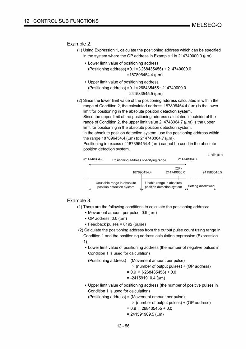
12 - 56
MELSEC-Q12 CONTROL SUB FUNCTIONS
Example 2.
(1) Using Expression 1, calculate the positioning address which can be specified in the system where the OP address in Example 1 is 214740000.0 (μm). • Lower limit value of positioning address
(Positioning address) =0.1 (-268435456) + 214740000.0 =187896454.4 (μm)
• Upper limit value of positioning address (Positioning address) =0.1 268435455+ 214740000.0
=241583545.5 (μm) (2) Since the lower limit value of the positioning address calculated is within the
range of Condition 2, the calculated address 187896454.4 (μm) is the lower limit for positioning in the absolute position detection system. Since the upper limit of the positioning address calculated is outside of the range of Condition 2, the upper limit value 214748364.7 (μm) is the upper limit for positioning in the absolute position detection system. In the absolute position detection system, use the positioning address within the range 187896454.4 (μm) to 214748364.7 (μm). Positioning in excess of 187896454.4 (μm) cannot be used in the absolute position detection system.
Unit: μm
(OP)
-214748364.8 214748364.7
Setting disallowedUsable range in absolute position detection system
Unusable range in absolute position detection system
Positioning address specifying range
241583545.5214740000.0187896454.4
Example 3. (1) There are the following conditions to calculate the positioning address:
• Movement amount per pulse: 0.9 (μm) • OP address: 0.0 (μm) • Feedback pulses = 8192 (pulse)
(2) Calculate the positioning address from the output pulse count using range in Condition 1 and the positioning address calculation expression (Expression 1). • Lower limit value of positioning address (the number of negative pulses in
Condition 1 is used for calculation) (Positioning address) = (Movement amount per pulse)
(number of output pulses) + (OP address) = 0.9 (-268435456) + 0.0 = -241591910.4 (μm)
• Upper limit value of positioning address (the number of positive pulses in Condition 1 is used for calculation) (Positioning address) = (Movement amount per pulse)
(number of output pulses) + (OP address) = 0.9 268435455 + 0.0 = 241591909.5 (μm)

12 - 57
MELSEC-Q12 CONTROL SUB FUNCTIONS
(3) Since the upper and lower limit values of the positioning address calculated
are outside of the range of Condition 2, use the positioning address within the positioning range of Condition 2 (-214748364.8(μm) to 214748364.7(μm)).
Unit: μm
OP0-214748364.8 214748364.7-241591910.4 241591909.5
Setting disallowedUsable range in absolute position detection system Setting disallowed
2. Concept for the unit of degree • The positioning address is within the range 0° to 359.99999° at the position
to which a machine OPR was made. When the OP position is not 0°, the range is also 0° to 359.99999°.
• For positioning in the same direction, control from maximum to minimum
(for address increase: 359.99999° to 0°/for address decrease: 0° to 359.99999°) cannot be exercised. (See below)
0 0
359.99999 359.99999
OP
Unusable in absolute position detection system.Current value cannot be restored properly at power supply on or resetting
Usable range in absolute position detection system
Unusable in absolute position detection system.Current value cannot be restored properly at power-on or reset.
0 359.99999( ~ )
• When positioning is to be used in the absolute position detection system, set the upper and lower limit values of the software stroke limit within the range 0° to 359.99999°.

12 - 58
MELSEC-Q12 CONTROL SUB FUNCTIONS
12.7 Other functions
Other functions include the "step function", "skip function", "M code output function", "teaching function", "target position change function", "command in-position function", "acceleration/deceleration processing function", "pre-reading start function", "deceleration start flag function" and "stop command processing for deceleration stop function". Each function is executed by parameter setting or sequence program creation and writing.
12.7.1 Step function
The "step function" is used to confirm each operation of the positioning control one by one. It is used in debugging work for major positioning control, etc. A positioning operation in which a "step function" is used is called a "step operation". In step operations, the timing for stopping the control can be set. (This is called the "step mode".) Control stopped by a step operation can be continued by setting "step continue" (to continue the control)" or restarted by setting "restart" in the "step start information".
The details shown below explain about the "step function". [1] Relation between the step function and various controls [2] Step mode [3] Step start information [4] Using the step operation [5] Control details [6] Precautions during control [7] Step function settings
[1] Relation between the step function and various controls
The following table shows the relation between the "step function" and various controls.
Control type Step function Step applicability Machine OPR control OPR control Fast OPR control
Step operation not possible
1-axis linear control 2 to 4-axes linear interpolation control 1-axis fixed-feed control 2 to 4- axes fixed-feed control (interpolation)
Position control
2-axis circular interpolation control
Step operation possible
1 to 4- axes Speed control Step operation not possible Speed-position switching control Position-speed switching control
Current value changing Step operation possible
Major positioning control
Other control JUMP instruction, NOP instruction,
LOOP to LEND Step operation not possible
JOG operation, Inching operation Manual control Manual pulse generator operation
Step operation not possible : Set when required. : Setting not possible
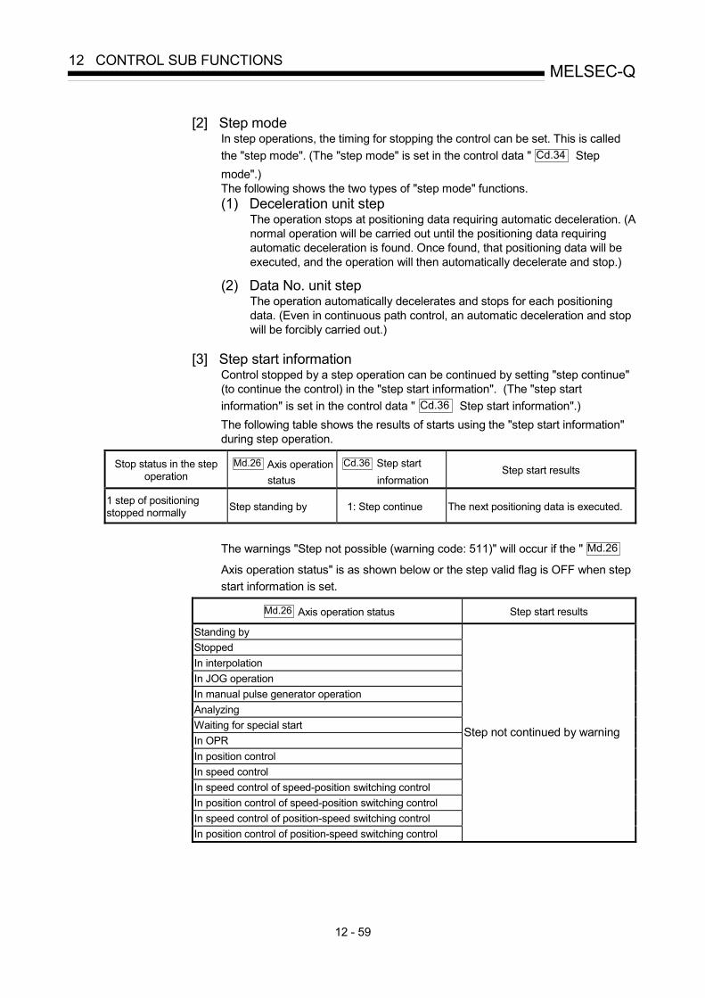
12 - 59
MELSEC-Q12 CONTROL SUB FUNCTIONS
[2] Step mode
In step operations, the timing for stopping the control can be set. This is called the "step mode". (The "step mode" is set in the control data " Cd.34 Step mode".) The following shows the two types of "step mode" functions. (1) Deceleration unit step
The operation stops at positioning data requiring automatic deceleration. (A normal operation will be carried out until the positioning data requiring automatic deceleration is found. Once found, that positioning data will be executed, and the operation will then automatically decelerate and stop.)
(2) Data No. unit step
The operation automatically decelerates and stops for each positioning data. (Even in continuous path control, an automatic deceleration and stop will be forcibly carried out.)
[3] Step start information
Control stopped by a step operation can be continued by setting "step continue" (to continue the control) in the "step start information". (The "step start information" is set in the control data " Cd.36 Step start information".) The following table shows the results of starts using the "step start information" during step operation.
Stop status in the step operation
Md.26 Axis operation status
Cd.36 Step start information
Step start results
1 step of positioning stopped normally Step standing by 1: Step continue The next positioning data is executed.
The warnings "Step not possible (warning code: 511)" will occur if the " Md.26
Axis operation status" is as shown below or the step valid flag is OFF when step start information is set.
Md.26 Axis operation status Step start results
Standing by Stopped In interpolation In JOG operation In manual pulse generator operation Analyzing Waiting for special start In OPR In position control In speed control In speed control of speed-position switching control In position control of speed-position switching control In speed control of position-speed switching control In position control of position-speed switching control
Step not continued by warning
12 - 60
MELSEC-Q12 CONTROL SUB FUNCTIONS
[4] Using the step operation
The following shows the procedure for checking positioning data using the step operation. (1) Turn ON the step valid flag before starting the positioning data.
(Write "1" (carry out step operation) in " Cd.35 Step valid flag".)
(2) Set the step mode before starting the positioning data. (Set in " Cd.34 Step mode".)
(3) Turn ON the positioning start signal, and check that the
positioning control starts normally.
(4) The control will stop for the following reasons. a) One step of positioning stopped normally. (Go to step (6)) b) Control stopped by a stop signal (Take appropriate measures, go to
step (5)) c) An error occurred and the control stopped. (Take appropriate
measures, go to step (3))
(5) Write "1" (restart) to " Cd.6 Restart command", and check that the positioning data where the control stopped operates normally. (Go to (4)).
(6) Write "1" (step continue) to " Cd.36 Step start information", and
check that the next positioning data operates normally. a) One step of positioning stopped normally. (Go to step (6)) b) Control stopped by a stop signal (Take appropriate measures, go to
step (5)) c) An error occurred and the control stopped. (Take appropriate
measures, go to step (3)) d) All positioning data operated normally (Go to step (7))
(7) Turn OFF the step valid flag, and quit the "step function".
(Write "0" (do not carry out step operation) in " Cd.35 Step valid flag".)

12 - 61
MELSEC-Q12 CONTROL SUB FUNCTIONS
[5] Control details
(1) The following drawing shows a step operation during a "deceleration unit step".
Positioning
Cd. 35 Step valid flag
Positioning data No.
Da. 1 Operation pattern
No.10
11
No.11
01
No positioning data No. unit, so operation patternbecomes one step of unit for carrying out automaticdeceleration.
t
OFFON
ON
OFF
V
ON
OFF
OFFON
BUSY signal
Positioning start signal
Positioning complete signal
[Y10, Y11, Y12, Y13]
[XC, XD, XE, XF]
[X14, X15, X16, X17]
Fig. 12.35 Operation during step execution by deceleration unit step
(2) The following drawing shows a step operation during a "data No. unit step".
Cd. 28 Step start information
Cd. 26 Step valid flag
Positioning
Positioning data No.
Da. 1 Operation pattern
BUSY signal
Positioning start signal
Positioning complete signal
[RXn4, RXn5]
[RY(n+1)0, RY(n+1)1]
[RXn7, RXn8]
No.10
11
No.11
01
Operation pattern becomes one step of positioning data No. unit,regardless of continuous path control (11).
00H 01H 00H
OFF
ON
OFF
OFF
ON
ON
ON
OFF
t
V
Fig. 12.36 Operation during step execution positioning data No. unit step

12 - 62
MELSEC-Q12 CONTROL SUB FUNCTIONS
[6] Precautions during control
(1) When step operation is carried out using interpolation control positioning data, the step function settings are carried out for the reference axis.
(2) When the step valid flag is ON, the step operation will start from the beginning if the positioning start signal is turned ON while " Md.26 Axis operation status" is "step standing by". (The step operation will be carried out from the positioning data set in " Cd.3 Positioning start No.".)
[7] Step function settings
To use the "step function", write the data shown in the following table to the QD75 using the sequence program. Refer to section [4] "Using the step operation" for the timing of the settings. The set details are validated when written to the QD75.
Buffer memory addressSetting item Setting
value Setting details Axis 1
Axis 2
Axis 3
Axis 4
Cd.34 Step mode Set "0: Deceleration unit step" or "1: Data No. unit step". 1544 1644 1744 1844
Cd.35 Step valid flag 1 Set "1: Carry out step operation". 1545 1645 1745 1845
Cd.36 Step start information
Set "1: Step continue", depending on the stop status. 1546 1646 1746 1846
Refer to Section 5.7 "List of control data" for details on the setting details.

12 - 63
MELSEC-Q12 CONTROL SUB FUNCTIONS
12.7.2 Skip function
The "skip function" is used to stop (deceleration stop) the control of the positioning data being executed at the time of the skip signal input, and execute the next positioning data. A skip is executed by a skip command ( Cd.37 Skip command) or external command
signal. The "skip function" can be used during control in which positioning data is used.
The details shown below explain about the "skip function". [1] Control details [2] Precautions during control [3] Setting the skip function from the PLC CPU [4] Setting the skip function using an external command signal
[1] Control details
The following drawing shows the skip function operation.
BUSYsignal
V
Deceleration byskip signal
Start of thenext positioning
ONOFF
OFF
OFF
OFF
ON
ON
ON
Positioning
Positioning start signal
Positioning complete signal
Skip signal
t
[XC, XD, XE, XF]
[Y10, Y11, Y12, Y13]
[X14, X15, X16, X17]
Fig. 12.37 Operation when a skip signal is input during positioning control
[2] Precautions during control (1) If the skip signal is turned ON at the last of an operation, a deceleration stop
will occur and the operation will be terminated. (2) When a control is skipped (when the skip signal is turned ON during a
control), the positioning complete signals (X14, X15, X16, X17) will not turn ON.
(3) When the skip signal is turned ON during the dwell time, the remaining dwell time will be ignored, and the next positioning data will be executed.
(4) When a control is skipped during interpolation control, the reference axis skip signal is turned ON. When the reference axis skip signal is turned ON, a deceleration stop will be carried out for every axis, and the next reference axis positioning data will be executed.
(5) The M code ON signals (X4, X5, X6, X7) will not turn ON when the M code output is set to the AFTER mode (when "1: AFTER mode" is set in " Pr.18 M code ON signal output timing"). (In this case, the M code will not be stored in " Md.25 Valid M code".)
(6) The skip cannot be carried out by the speed-position and position-speed switching control. It is processed in the same manner as in the speed control.

12 - 64
MELSEC-Q12 CONTROL SUB FUNCTIONS
[3] Setting the skip function from the PLC CPU
The following shows the settings and sequence program example for skipping the control being executed in axis 1 with a command from the PLC CPU. (1) Set the following data.
(The setting is carried out using the sequence program shown below in section (2)).
Buffer memory addressSetting item Setting
value Setting details Axis 1
Axis 2
Axis 3
Axis 4
Cd.37 Skip command 1 Set "1: Skip request". 1547 1647 1747 1847 Refer to Section 5.7 "List of control data" for details on the setting details.
(2) Add the following sequence program to the control program, and write it to the PLC CPU. 1) When the "skip command" is input, the value "1" (skip request) set in
" Cd.37 Skip command" is written to the QD75 buffer memory (1547).
Example
No.19 Skip program
<Pulsate skip command>
<Save skip command ON>
<Write skip command>
<Turn OFF skip commandmemory>

12 - 65
MELSEC-Q12 CONTROL SUB FUNCTIONS
[4] Setting the skip function using an external command signal
The skip function can also be executed using an "external command signal". The following shows the settings and sequence program example for skipping the control being executed in axis 1 using an "external command signal". (1) Set the following data to execute the skip function using an external
command signal. (The setting is carried out using the sequence program shown below in section (2)).
Buffer memory addressSetting item Setting
value Setting details Axis 1
Axis 2
Axis 3
Axis 4
Pr.42 External command function selection 3 Set "3: Skip request". 62 212 362 512
Cd.8 External command valid 1 Set "1: Validate external command". 1505 1605 1705 1805
Refer to Section 5.7 "List of control data" for details on the setting details.
(2) Add the following sequence program to the control program, and write it to the PLC CPU.
Skip functionselection command
<Select skip request>
<Set external command valid>
K1K3K62H0TOP
K1 K1K1505H0TOP
Skip request
External command valid
Input external command signal
Example
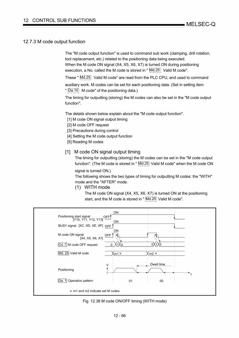
12 - 66
MELSEC-Q12 CONTROL SUB FUNCTIONS
12.7.3 M code output function
The "M code output function" is used to command sub work (clamping, drill rotation, tool replacement, etc.) related to the positioning data being executed. When the M code ON signal (X4, X5, X6, X7) is turned ON during positioning execution, a No. called the M code is stored in " Md.25 Valid M code".
These " Md.25 Valid M code" are read from the PLC CPU, and used to command
auxiliary work. M codes can be set for each positioning data. (Set in setting item " Da.10 M code" of the positioning data.)
The timing for outputting (storing) the M codes can also be set in the "M code output function".
The details shown below explain about the "M code output function". [1] M code ON signal output timing [2] M code OFF request [3] Precautions during control [4] Setting the M code output function [5] Reading M codes
[1] M code ON signal output timing
The timing for outputting (storing) the M codes can be set in the "M code output function". (The M code is stored in " Md.25 Valid M code" when the M code ON
signal is turned ON.) The following shows the two types of timing for outputting M codes: the "WITH" mode and the "AFTER" mode. (1) WITH mode
The M code ON signal (X4, X5, X6, X7) is turned ON at the positioning start, and the M code is stored in " Md.25 Valid M code".
Md. 25 Valid M code
Cd. 7 M code OFF request
Positioning start signal
BUSY signal
M code ON signal
Positioning
01 00
m1 m2
m1 and m2 indicate set M codes.
Dwell timeV
t
1 0 1 000
OFF
OFF
OFFON
ON
Da. 1 Operation pattern
[XC, XD, XE, XF]
[Y10, Y11, Y12, Y13]
[X4, X5, X6, X7]
ON
Fig. 12.38 M code ON/OFF timing (WITH mode)

12 - 67
MELSEC-Q12 CONTROL SUB FUNCTIONS
(2) AFTER mode
The M code ON signal (X4, X5, X6, X7) is turned ON at the positioning completion, and the M code is stored in " Md.25 Valid M code".
01 00
m1 m2
V
t
OFF
ON
OFF
OFF
ON
ON
00 1
Positioning start signal
BUSY signal
M code ON signal
Positioning
m1 and m2 indicate set M codes.
Md. 25 Valid M code
Da. 1 Operation pattern
Cd. 7 M code OFF request
[XC, XD, XE, XF]
[Y10, Y11, Y12, Y13]
[X4, X5, X6, X7]
Fig. 12.39 M code ON/OFF timing (AFTER mode)
[2] M code OFF request When the M code ON signal (X4, X5, X6, X7) is ON, it must be turned OFF by the sequence program. To turn OFF the M code ON signal, set "1" (turn OFF the M code signal) in " Cd.7 M code OFF request".
Buffer memory address
Setting item Setting value Setting details Axis
1 Axis
2 Axis
3 Axis
4
Cd.7 M code OFF request 1 Set "1: Turn OFF the M code ON signal". 1504 1604 1704 1804
Refer to Section 5.7 "List of control data" for details on the setting details.
The next positioning data will be processed as follows if the M code ON signal is not turned OFF. (The processing differs according to the " Da.1 Operation
pattern".) Da.1 Operation pattern Processing
00 Independent positioning control (Positioning complete)
01 Continuous positioning control
The next positioning data will not be executed until the M code ON signal is turned OFF.
11 Continuous path control The next positioning data will be executed, but a warning "M code ON signal ON start" (warning code: 503) will occur.
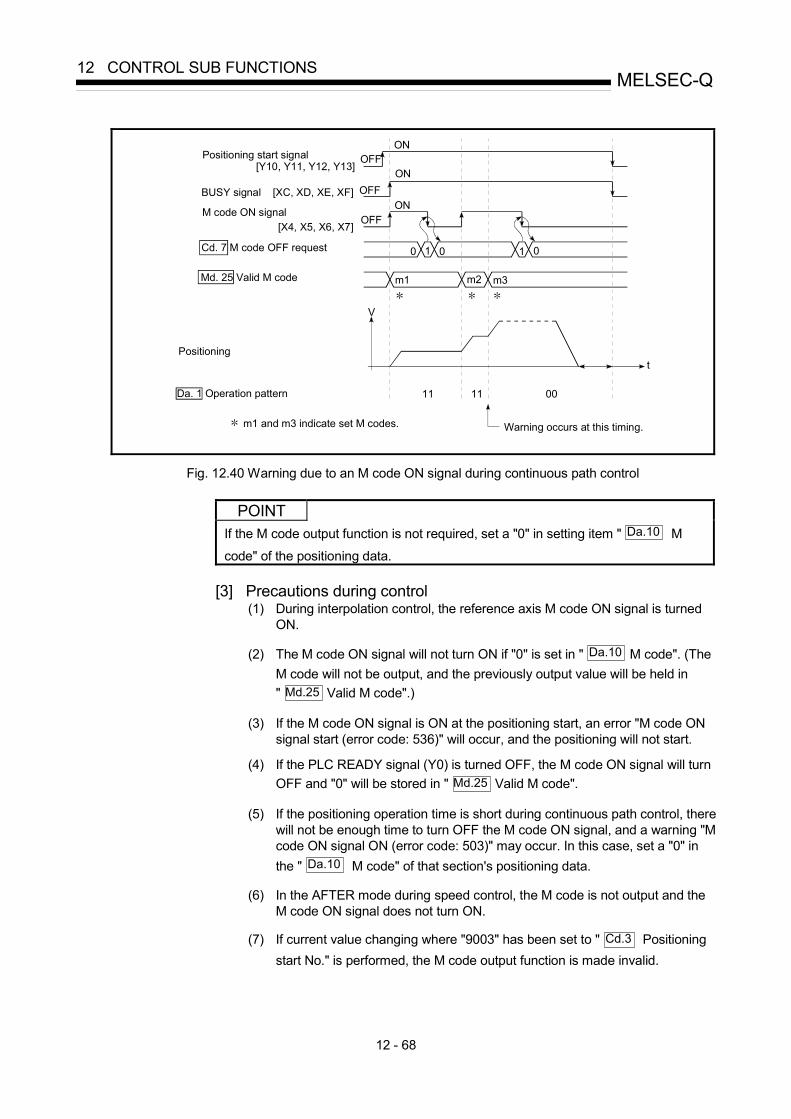
12 - 68
MELSEC-Q12 CONTROL SUB FUNCTIONS
Da. 1 Operation pattern
Md. 25 Valid M code
Cd. 7 M code OFF request
11 0011
Warning occurs at this timing.
t
m1 m3m2
V
1
OFFON
OFF
OFF
ON
ON
0 1 00
Positioning start signal
BUSY signal
M code ON signal
Positioning
m1 and m3 indicate set M codes.
[XC, XD, XE, XF]
[Y10, Y11, Y12, Y13]
[X4, X5, X6, X7]
Fig. 12.40 Warning due to an M code ON signal during continuous path control
POINT If the M code output function is not required, set a "0" in setting item " Da.10 M
code" of the positioning data.
[3] Precautions during control (1) During interpolation control, the reference axis M code ON signal is turned
ON.
(2) The M code ON signal will not turn ON if "0" is set in " Da.10 M code". (The M code will not be output, and the previously output value will be held in " Md.25 Valid M code".)
(3) If the M code ON signal is ON at the positioning start, an error "M code ON
signal start (error code: 536)" will occur, and the positioning will not start.
(4) If the PLC READY signal (Y0) is turned OFF, the M code ON signal will turn OFF and "0" will be stored in " Md.25 Valid M code".
(5) If the positioning operation time is short during continuous path control, there
will not be enough time to turn OFF the M code ON signal, and a warning "M code ON signal ON (error code: 503)" may occur. In this case, set a "0" in the " Da.10 M code" of that section's positioning data.
(6) In the AFTER mode during speed control, the M code is not output and the
M code ON signal does not turn ON.
(7) If current value changing where "9003" has been set to " Cd.3 Positioning start No." is performed, the M code output function is made invalid.
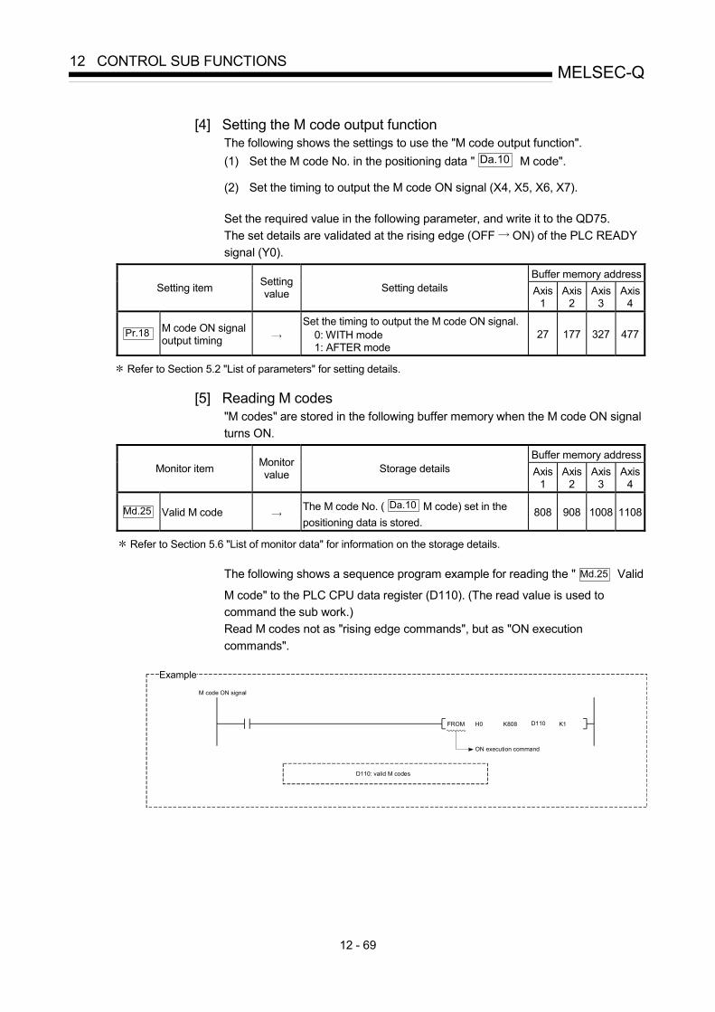
12 - 69
MELSEC-Q12 CONTROL SUB FUNCTIONS
[4] Setting the M code output function
The following shows the settings to use the "M code output function". (1) Set the M code No. in the positioning data " Da.10 M code".
(2) Set the timing to output the M code ON signal (X4, X5, X6, X7).
Set the required value in the following parameter, and write it to the QD75. The set details are validated at the rising edge (OFF ON) of the PLC READY signal (Y0).
Buffer memory addressSetting item Setting
value Setting details Axis 1
Axis 2
Axis 3
Axis 4
Pr.18 M code ON signal output timing
Set the timing to output the M code ON signal. 0: WITH mode 1: AFTER mode
27 177 327 477
Refer to Section 5.2 "List of parameters" for setting details.
[5] Reading M codes "M codes" are stored in the following buffer memory when the M code ON signal turns ON.
Buffer memory addressMonitor item Monitor
value Storage details Axis 1
Axis 2
Axis 3
Axis 4
Md.25 Valid M code The M code No. ( Da.10 M code) set in the positioning data is stored.
808 908 1008 1108
Refer to Section 5.6 "List of monitor data" for information on the storage details.
The following shows a sequence program example for reading the " Md.25 Valid
M code" to the PLC CPU data register (D110). (The read value is used to command the sub work.) Read M codes not as "rising edge commands", but as "ON execution commands".
M code ON signal
K1D110K808H0FROM
ON execution command
D110: valid M codes
Example

12 - 70
MELSEC-Q12 CONTROL SUB FUNCTIONS
12.7.4 Teaching function
The "teaching function" is used to set addresses aligned using the manual control (JOG operation, inching operation manual pulse generator operation) in the positioning data addresses (" Da.6 Positioning address/movement amount", " Da.7 Arc
address").
The details shown below explain about the "teaching function". [1] Control details [2] Precautions during control [3] Data used in teaching [4] Teaching procedure [5] Teaching program example
[1] Control details
(1) Teaching timing Teaching is executed using the sequence program when the BUSY signal (XC, XD, XE, XF) is OFF. (During manual control, teaching can be carried out as long as the axis is not BUSY, even when an error or warning has occurred.)
(2) Addresses for which teaching is possible
The addresses for which teaching is possible are "current feed values" ( Md.20 Current feed value) having the OP as a reference. The settings of
the "movement amount" used in incremental system positioning cannot be used. In the teaching function, these "current feed values" are set in the " Da.6 Positioning address/movement amount" or " Da.7 Arc address".
Positioning data Positions aligned by manual control
"Current feed value" A Da.6 Positioning address/movement
amount
"Current feed value" B Da.7 Arc address
(3) Dedicated instructions "ZP.TEACH 1, ZP.TEACH 2, ZP.TEACH 3, ZP.TEACH 4, ZP.PFWRT" When the dedicated instructions "ZP.TEACH 1, ZP.TEACH 2, ZP.TEACH 3, ZP.TEACH 4, ZP.PFWRT" are used to execute the teaching function, the programming becomes easier. Refer to Chapter 14 "Dedicated instructions" for details.

12 - 71
MELSEC-Q12 CONTROL SUB FUNCTIONS
[2] Precautions during control
(1) Before teaching, a "machine OPR" must be carried out to establish the OP. (When a current value changing, etc., is carried out, " Md.20 Current feed value" may not show absolute addresses having the OP as a reference.)
(2) Teaching cannot be carried out for positions to which movement cannot be executed by manual control (positions to which the workpiece cannot physically move). (During center point designation circular interpolation control, etc., teaching of " Da.7 Arc address" cannot be carried out if the center point of the arc is not within the moveable range of the workpiece.)
(3) Writing to the flash ROM can be executed up to 100,000 times. If writing to the flash ROM exceeds 100,000 times, the writing may become impossible (assured value is up to 100,000 times). If an error (error code: 805) occurs when writing to the flash ROM has been completed, check whether or not the program is created so as to write continuously to the flash ROM.
[3] Data used in teaching
The following control data is used in teaching. Buffer memory address
Setting item Setting value Setting details Axis
1 Axis
2 Axis
3 Axis
4
Cd.1 Flash ROM write request 1 Write the set details to the flash ROM (backup
the changed data). 1900
Cd.38 Teaching data selection
Sets to which "current feed value" is written. 0: Written to " Da.6 Positioning
address/movement amount". 1: Written to " Da.7 Arc address".
1548 1648 1748 1848
Cd.39 Teaching positioning data No.
Designates the data to be taught. (Teaching is carried out when the setting value is 1 to 600.) When teaching has been completed, the QD75 is zero cleared in the initial stage.
1549 1649 1749 1849
Refer to Section 5.7 "List of control data" for details on the setting details.

12 - 72
MELSEC-Q12 CONTROL SUB FUNCTIONS
[4] Teaching procedure
The following shows the procedure for a teaching operation. (1) When teaching to the " Da.6 Positioning address/movement amount"
(Teaching example on axis 1)
Start
Perform machine OPR on axis 1
Move the workpiece to the target position using a manual operation.
Set Writes the current feed value to Da.6 Positioning address/movement amount in teaching data selection.
Set the positioning data No. for which the teaching will be carried out.
End teaching?
Turn OFF the PLC READYsignal [Y0].
Carry out a writing request tothe flash ROM.
End
Confirm completion of writing.
Using a JOG operation, inching operation, or manual pulse generator.
Set the positioning data No. in buffer memory address [1549].
Set 0 in buffer memory address [1548].
Confirm completion of the teaching. Confirm 0 in buffer memory address [1549].
Set 1 in buffer memory address [1900].
Confirm 0 in buffer memory address [1900].
NO
YES
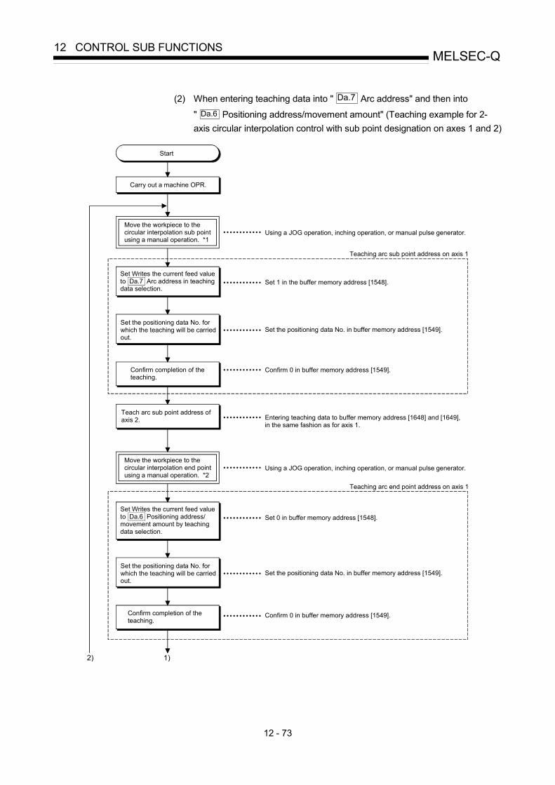
12 - 73
MELSEC-Q12 CONTROL SUB FUNCTIONS
(2) When entering teaching data into " Da.7 Arc address" and then into
" Da.6 Positioning address/movement amount" (Teaching example for 2-axis circular interpolation control with sub point designation on axes 1 and 2)
Start
Carry out a machine OPR.
Move the workpiece to the circular interpolation sub point using a manual operation. *1
Set Writes the current feed value to Da.7 Arc address in teaching data selection.
Set the positioning data No. for which the teaching will be carried out.
Using a JOG operation, inching operation, or manual pulse generator.
Set 1 in the buffer memory address [1548].
Set the positioning data No. in buffer memory address [1549].
Confirm completion of the teaching.
Confirm 0 in buffer memory address [1549].
Teach arc sub point address of axis 2. Entering teaching data to buffer memory address [1648] and [1649],
in the same fashion as for axis 1.
Move the workpiece to the circular interpolation end point using a manual operation. *2
Using a JOG operation, inching operation, or manual pulse generator.
Set Writes the current feed value to Da.6 Positioning address/movement amount by teaching data selection.
Set 0 in buffer memory address [1548].
Set the positioning data No. for which the teaching will be carried out.
Set the positioning data No. in buffer memory address [1549].
Confirm completion of the teaching.
Confirm 0 in buffer memory address [1549].
Teaching arc sub point address on axis 1
Teaching arc end point address on axis 1
2) 1)

12 - 74
MELSEC-Q12 CONTROL SUB FUNCTIONS
End teaching?
Turn OFF the PLC READYsignal [Y0].
Carry out a writing request tothe flash ROM.
End
Confirm completion of writing.
Teaching arc end point address on axis 2. Entering teaching data to buffer memory address [1648] and [1649],
in the same fashion as for axis 1.
Set 1 in buffer memory address [1900].
Confirm 0 in buffer memory address [1900].
2) 1)
[Motion path]
OP
Reverse direction
Forward direction (Axis 1)
Arc center point
Movement by circular interpolation
(Axis 2)Forward direction
*2 End point address (arc address)(positioning address)
Start point address
(current stop position)Reverse direction
*1 Sub point address

12 - 75
MELSEC-Q12 CONTROL SUB FUNCTIONS
[5] Teaching program example
The following shows a sequence program example for setting (writing) the positioning data obtained with the teaching function to the QD75. (1) Setting conditions
• When setting the current feed value as the positioning address, write it when the BUSY signal is OFF.
(2) Program example
• The following example shows a program to carry out the teaching of axis 1 by the dedicated instruction "ZP.TEACH 1". 1) Move the workpiece to the target position using a JOG operation (or
an inching operation, a manual pulse generator operation).
PLC READY signal
QD75 READY signal
V
t
Forward run JOG start signal
Target position
BUSY signal
[X8]
n2n1 nxMd.20 Current feed value
Example
Error detection signal
[XC]
[X0]
[Y0]
[Y8]

12 - 76
MELSEC-Q12 CONTROL SUB FUNCTIONS
2) Carry out the teaching operation with the following program.
Example
No.20 Teaching program
Position to the target position with manual operation.
<Pulsate teaching command>
<Hold teaching command>
<Set teaching data>
<Set positioning data No.>
<Execute teaching>
<Turn OFF teaching commandmemory>
POINT (1) Confirm the teaching function and teaching procedure before setting the positioning data. (2) The positioning addresses that are written are absolute address (ABS) values. (3) If the positioning operation is correctly completed with the written positioning data, it is
recommended that the positioning data be registered in the QD75 flash ROM.

12 - 77
MELSEC-Q12 CONTROL SUB FUNCTIONS
12.7.5 Target position change function
The "target position change function" is a function to change a target position to a newly designated target position at any timing during the position control (1-axis linear control). A command speed can also be changed simultaneously. The target position and command speed changed are set directly in the buffer memory, and the target position change is executed by " Cd.29 Target position
change request flag".
The following shows the details of the "target position change function". [1] Details of control [2] Precaution during operation [3] Method of setting target position change function from PLC CPU
[1] Details of control
The following charts show the details of control of the target position change function.
(a) When the address after change is positioned away from the start point more than the positioning address:
Target position change request Positioning address Address after change
(b) When the speed is changed simultaneously with changing the address:
Target position change request Positiioning address Address after change
Speed beforechange
Speed afterchange
(c) When the direction of the operation is changed:
Target position changerequest
Positioning address
Address afterchange
Fig. 12.41 Target position change operation

12 - 78
MELSEC-Q12 CONTROL SUB FUNCTIONS
[2] Precautions during operation
(1) If the positioning movement direction from the stop position to a new target position is reversed, stop the operation once and then position to the new target position. (Refer to Fig. 12.41 (c).)
(2) If a command speed exceeding the speed limit value is set to change the command speed, a warning will be given, and the new command speed will be the speed limit value (warning code: 501). Also, if the command speed change disables the remaining distance to the target value from being assured, a warning will be given (warning code: 509).
(3) During interpolation control, a target position change request given is ignored and a warning (warning code: 518) occurs if a new target position value (address) is outside the software stroke limit range, if the axis is decelerating to a stop, or if the operation pattern is continuous path control.
(4) When a command speed is changed, the current speed is also changed. When the next positioning speed uses the current speed in the continuous positioning, the next positioning operation is carried out at the new speed value. When the speed is set with the next positioning data, that speed becomes the current speed and the operation is carried out at the current speed.
(5) When a target position change request is given during automatic deceleration in position control, positioning control to a new position is exercised after the axis has stopped once if the moving direction is reversed. If the moving direction is not reversed, the axis is accelerated to the command speed again and positioned to the new position.
(6) If the constant speed status is regained or the output is reversed by a target position change made while " Md.48 Deceleration start flag" is ON, the deceleration start flag remains ON. (For details, refer to Section 12.7.9.)
POINT
When carrying out the target position change continuously, take an interval of 100 ms or longer between the times of the target position changes. Also, take an interval of 100 ms or longer when the speed change is carried out after changing the target position or the target position change is carried out after the speed change.
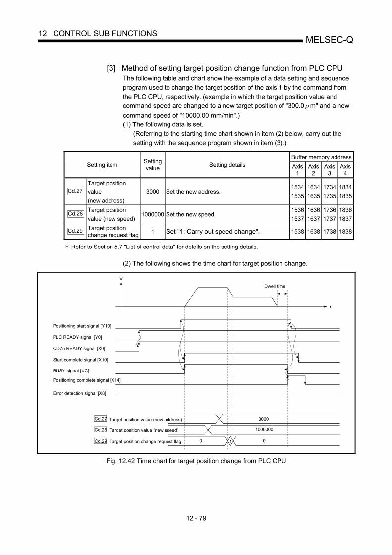
12 - 79
MELSEC-Q12 CONTROL SUB FUNCTIONS
[3] Method of setting target position change function from PLC CPU
The following table and chart show the example of a data setting and sequence program used to change the target position of the axis 1 by the command from the PLC CPU, respectively. (example in which the target position value and command speed are changed to a new target position of "300.0 m" and a new command speed of "10000.00 mm/min".) (1) The following data is set.
(Referring to the starting time chart shown in item (2) below, carry out the setting with the sequence program shown in item (3).)
Buffer memory address
Setting item Setting value Setting details Axis
1 Axis
2 Axis
3 Axis
4
Cd.27 Target position value (new address)
3000 Set the new address. 1534 1535
1634 1635
17341735
18341835
Cd.28 Target position value (new speed)
1000000 Set the new speed. 1536 1537
1636 1637
17361737
18361837
Cd.29 Target position change request flag 1 Set "1: Carry out speed change". 1538 1638 1738 1838
Refer to Section 5.7 "List of control data" for details on the setting details.
(2) The following shows the time chart for target position change.
PLC READY signal [Y0]
QD75 READY signal [X0]
Start complete signal [X10]
BUSY signal [XC]
Error detection signal [X8]
V
t
Positioning start signal [Y10]
Target position value (new address)
Target position value (new speed) 1000000
3000
Positioning complete signal [X14]
Dwell time
Cd.27
Cd.28
Target position change request flag 1 00Cd.29
Fig. 12.42 Time chart for target position change from PLC CPU

12 - 80
MELSEC-Q12 CONTROL SUB FUNCTIONS
(3) The following sequence program is added to the control program, and written
to the PLC CPU.
Example
No.22 Target position change program
<Pulsate target position change command>
<Hold target position change command>
<Set target position change value 300.0 m (address)>
<Set target position change request>
<Write speed change>
<Turn OFF speed change request memory>
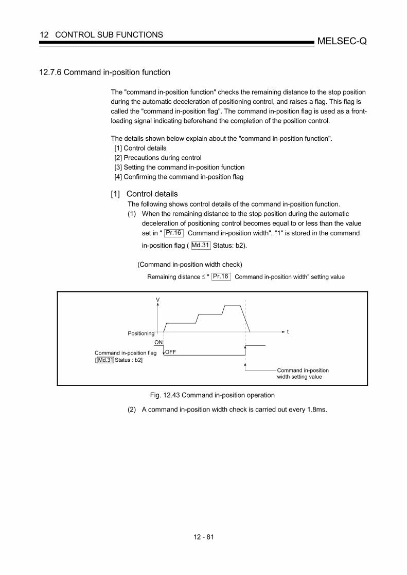
12 - 81
MELSEC-Q12 CONTROL SUB FUNCTIONS
12.7.6 Command in-position function
The "command in-position function" checks the remaining distance to the stop positionduring the automatic deceleration of positioning control, and raises a flag. This flag iscalled the "command in-position flag". The command in-position flag is used as a front-loading signal indicating beforehand the completion of the position control.
The details shown below explain about the "command in-position function". [1] Control details [2] Precautions during control [3] Setting the command in-position function [4] Confirming the command in-position flag
[1] Control detailsThe following shows control details of the command in-position function.(1) When the remaining distance to the stop position during the automatic
deceleration of positioning control becomes equal to or less than the valueset in " Pr.16 Command in-position width", "1" is stored in the command
in-position flag ( Md.31 Status: b2).
(Command in-position width check)
Remaining distance ≤ " Pr.16 Command in-position width" setting value
Command in-position width setting value
Positioning
V
t
ON
OFFCommand in-position flag[ Md.31 Status : b2]
Fig. 12.43 Command in-position operation
(2) A command in-position width check is carried out every 1.8ms.

12 - 82
MELSEC-Q12 CONTROL SUB FUNCTIONS
[2] Precautions during control(1) A command in-position width check will not be carried out in the following
cases.• During speed control• During speed control in speed-position switching control• During speed control in position-speed switching control
Command in-position flag[ Md. 31 Status: b2]
Speed to position switching
t
Positioning control start
Speed-positionswitchingcontrol start
Command in-position width setting valueV
Execution of the command in-position width check
OFF
ON
Command in-position width setting value
Execution of the command in-position width check
Fig. 12.44 Command in-position width check
(2) The command in-position flag will be turned OFF in the following cases.("0" will be stored in " Md.31 Status: b2".)• At the positioning control start• At the speed control start• At the speed-position switching control, position-speed switching control
start• At the OPR control start• At the JOG operation start• At the inching operation start• When the manual pulse generator operation is enabled.
(3) The " Pr.16 Command in-position width" and command in-position flag
( Md.31 Status: b2) of the reference axis are used during interpolation
control.
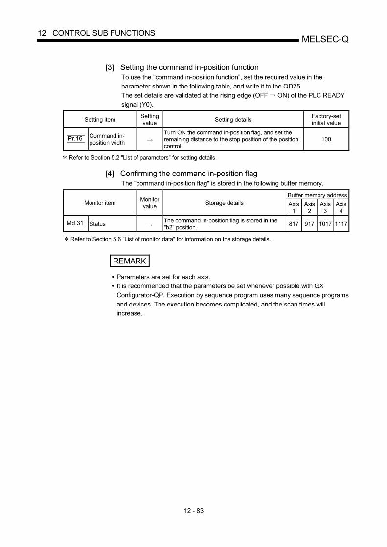
12 - 83
MELSEC-Q12 CONTROL SUB FUNCTIONS
[3] Setting the command in-position functionTo use the "command in-position function", set the required value in theparameter shown in the following table, and write it to the QD75.The set details are validated at the rising edge (OFF ON) of the PLC READYsignal (Y0).
Setting item Settingvalue Setting details Factory-set
initial value
Pr.16 Command in-position width
Turn ON the command in-position flag, and set theremaining distance to the stop position of the positioncontrol.
100
Refer to Section 5.2 "List of parameters" for setting details.
[4] Confirming the command in-position flagThe "command in-position flag" is stored in the following buffer memory.
Buffer memory addressMonitor item Monitor
value Storage details Axis1
Axis2
Axis3
Axis4
Md.31 Status The command in-position flag is stored in the"b2" position. 817 917 1017 1117
Refer to Section 5.6 "List of monitor data" for information on the storage details.
REMARK
• Parameters are set for each axis.• It is recommended that the parameters be set whenever possible with GX
Configurator-QP. Execution by sequence program uses many sequence programsand devices. The execution becomes complicated, and the scan times willincrease.

12 - 84
MELSEC-Q12 CONTROL SUB FUNCTIONS
12.7.7 Acceleration/deceleration processing function
The "acceleration/deceleration processing function" adjusts theacceleration/deceleration when each control is executed.Adjusting the acceleration/deceleration processing to match the control enables moreprecise control to be carried out.There are two acceleration/deceleration adjustment items that can be set:"Acceleration/deceleration time 0 to 3", and "acceleration/deceleration method setting".
The details shown below explain about the "acceleration/deceleration processingfunction". [1] "Acceleration/deceleration time 0 to 3" control details and setting [2] "Acceleration/deceleration method setting" control details and setting
[1] "Acceleration/deceleration time 0 to 3" control details and settingIn the QD75, four types each of acceleration time and deceleration time can beset. By using separate acceleration/deceleration times, control can be carried outwith different acceleration/deceleration times for positioning control, JOGoperation, OPR, etc.Set the required values for the acceleration/deceleration time in the parametersshown in the following table, and write them to the QD75.The set details are validated when written to the QD75.
Setting item Settingvalue Setting details Factory-set
initial value
Pr.9 Acceleration time 0 1000
Pr.25 Acceleration time 1 1000
Pr.26 Acceleration time 2 1000
Pr.27 Acceleration time 3
Set the acceleration time at a value within the rangeof 1 to 8388608 ms.
1000
Pr.10 Deceleration time 0 1000
Pr.28 Deceleration time 1 1000
Pr.29 Deceleration time 2 1000
Pr.30 Deceleration time 3
Set the deceleration time at a value within the rangeof 1 to 8388608 ms.
1000
Refer to Section 5.2 "List of parameters" for setting details.

12 - 85
MELSEC-Q12 CONTROL SUB FUNCTIONS
[2] "Acceleration/deceleration method setting" control details andsettingIn the "acceleration/deceleration method setting", the acceleration/decelerationprocessing method is selected and set. The set acceleration/decelerationprocessing is applied to all acceleration/deceleration.The two types of "acceleration/deceleration method setting" are shown below.(1) Automatic trapezoidal acceleration/deceleration processing
methodThis is a method in which linear acceleration/deceleration is carried outbased on the acceleration time, deceleration time, and speed limit value setby the user.
Velocity
Time
Fig. 12.45 Automatic trapezoidal acceleration/deceleration processing method
(2) S-curve acceleration/deceleration processing methodIn this method, the motor burden is reduced during starting and stopping.This is a method in which acceleration/deceleration is carried out gradually,based on the acceleration time, deceleration time, speed limit value, and" Pr.35 S-curve ratio" (1 to 100%) set by the user.
When the stepping motor is used, the S-curve acceleration/decelerationprocessing method cannot be carried out. When using this processingmethod, ensure to use a servomotor.
Velocity
Time
Fig. 12.46 S-curve acceleration/deceleration processing method

12 - 86
MELSEC-Q12 CONTROL SUB FUNCTIONS
When a speed change request is given during S-curve acceleration/deceleration processing, S-curve acceleration/decelerationprocessing begins at a speed change request start.
When speed change request is not given
Speed change (acceleration)
Command speed before speed change
Speed change request
Speed change (deceleration)
Fig. 12.47 Speed change during S-curve acceleration/deceleration processing
Set the required values for the "acceleration/deceleration method setting" inthe parameters shown in the following table, and write them to the QD75.The set details are validated when written to the QD75.
Setting item Settingvalue Setting details Factory-set
initial value
Pr.34Acceleration/decelerationprocess selection
Set the acceleration/deceleration method.0: Automatic trapezoidal acceleration/deceleration processing1: S-curve acceleration/deceleration processing
0
Pr.35 S-curve ratioSet the acceleration/deceleration curve when "1" is setin " Pr.34 Acceleration/deceleration processingselection".
100
Refer to Section 5.2 "List of parameters" for setting details.
REMARK
• Parameters are set for each axis.• It is recommended that the parameters be set whenever possible with GX
Configurator-QP. Execution by sequence program uses many sequence programsand devices. The execution becomes complicated, and the scan times willincrease.

12 - 87
MELSEC-Q12 CONTROL SUB FUNCTIONS
12.7.8 Pre-reading start function
The "pre-reading start function" does not output pulses while the execution prohibition flag is ON if a positioning start request is given with the execution prohibition flag ON, and starts outputting pulses within 3m after OFF of the execution prohibition flag is detected. The positioning start request is given when the axis is in a standby status, and the execution prohibition flag is turned OFF at the axis operating timing. This shortens the virtual start time. The QD75 normally takes 6 to 7ms from when it receives a positioning start request until it starts pulse output (start time). Some systems often need the start time to be shortened. This "pre-reading start function" can improve the tact time of the system.
The "pre-reading start function" will be explained below. [1] Controls [2] Controlling instructions [3] Program examples
[1] Controls
The pre-reading start function is performed by turning ON the positioning start signal [Y10, Y11, Y12, Y13] with the execution prohibition flag [Y14, Y15, Y16, Y17] ON, or by executing the dedicated instruction (ZP.PSTRT1, ZP.PSTRT2, ZP.PSTRT3, ZP.PSTRT4). However, if positioning is started with the execution prohibition flag ON, the positioning data is analyzed but pulse output is not provided. While the execution prohibition flag is ON, " Md.26 Axis operation
status" remains unchanged from "5: Analyzing". Pulse output starts within 3ms after the execution prohibition flag [Y14, Y15, Y16, Y17] has turned OFF, and " Md.26 Axis operation status" changes to the status (e.g. during position
control, during speed control) that matches the control system. (Refer to Fig. 12.48)
V
Positioning start signal[Y10,Y11,Y12,Y13]
Execution prohibition flag[Y14,Y15,Y16,Y17]BUSY signal[XC,XD,XE,XF]
OFF
OFF
ON
t
TaOFF
ON
ON
Md. 26 Axis operation status
Start time
Positioning start timing
3ms or less
Positioning data analysis Execution prohibition flag OFF waiting
Standby AnalyzingDuring positioncontrol
During positioncontrol
Fig. 12.48 Operations of pre-reading start function

12 - 88
MELSEC-Q12 CONTROL SUB FUNCTIONS
The pre-reading start function is effective for the system as shown below.
Cutter
Cutter shaft
Feed shaft
Stock
Fig. 12.49 System example using pre-reading start function
Fig. 12.49 shows a system example which repeats: 1) Feeding a stock with a feed shaft; and 2) Cutting it with a cutter
to cut the stock to fixed size. The operations of the feed shaft and cutter shaft are represented as shown in Fig. 12.50.

12 - 89
MELSEC-Q12 CONTROL SUB FUNCTIONS
V
t
TsTw
t
Ts
Ts
1
Feed shaft
Cutter shaft
Feed shaft start request
Cutter shaft start request
Start time
Start time
Start time
Stop time
2
Fig. 12.50 Operation timings of system example
The cutter shaft starts from the moment the feed shaft has completed feeding the stock " 1 ", and the feed shaft starts from the moment the cutter shaft has returned to the standby position " 2 ". Actually, however, there is a delay of start time Ts (6 to 7ms) from when the QD75 receives a start request until it outputs pulses. The system's tact time can be reduced by the shortening of this delay with the Pre-reading start function. In Fig. 12.50, the feed shaft stands by during the stop time Tw. Hence, pre-reading of the next data starts during the stop time Tw. If Tw is a certain period of time, the analysis of the next data is completed during that period, and the system is placed in an execution prohibition flag OFF waiting status. Therefore, replacing the positioning start timing at 2 with the execution prohibition flag OFF allows the time from when the axis operation request turns ON until pulse output starts to be reduced to within 3ms in the sequence program. (Refer to Fig. 12.48)

12 - 90
MELSEC-Q12 CONTROL SUB FUNCTIONS
[2] Controlling instructions
(1) The time required to analyze the positioning data is up to 7ms. (2) After positioning data analysis, the system is put in an execution prohibition
flag OFF waiting status. Any change made to the positioning data in the execution prohibition flag OFF waiting status is not reflected on the positioning data. Change the positioning data before turning ON the positioning start signal.
(3) The pre-reading start function is invalid if the execution prohibition flag is turned OFF between when the positioning start signal has turned ON and when positioning data analysis is completed (Ta<start time, Ta: Refer to Fig. 12.48).
(4) The data No. which can be executed positioning start using " Cd.3 Positioning start No." with the pre-reading start function are No. 1 to 600 only. Performing the pre-reading start function at the setting of No. 7000 to 7004 or 9001 to 9004 will result in an outside start No. range error (Error code: 543).
(5) Always turn ON the execution prohibition flag at the same time or before turning ON the positioning start signal. Pre-reading may not be started if the execution prohibition flag is turned ON during Ta after the positioning start signal is turned ON. The pre-reading start function is invalid if the execution prohibition flag is turned ON after positioning start (pulse output) with the execution prohibition flag OFF. (It is made valid at the next positioning start.)
[3] Program examples
Pre-reading start function (when positioning start signal Y10 is used)
<Pre-reading start command pulse>
<Sets 1 to positioning start No.>
<Turns ON execution prohibition flag>
<Turns ON positioning start signal>
<Turns OFF execution prohibition flag>
<Turns OFF positioning start signal>

12 - 91
MELSEC-Q12 CONTROL SUB FUNCTIONS
Pre-reading start function (when dedicated instruction PSTRT1 is used)
<Turns ON execution prohibition flag>
<Sets 1 to positioning start No.>
<Executes positioning start>
<Turns OFF execution prohibition flag>
<Normal termination of positioning>
<Sets error code>
<Abnormal termination of positioning>

12 - 92
MELSEC-Q12 CONTROL SUB FUNCTIONS
12.7.9 Deceleration start flag function
The "deceleration start flag function" turns ON the flag when the constant speed status or acceleration status switches to the deceleration status during position control whose operation pattern is "Positioning complete". This function can be used as a signal to start the operation to be performed by other equipment at each end of position control or to perform preparatory operation, etc. for the next position control.
For the "deceleration start flag function", the following will be explained. [1] Control details [2] Precautions during control [3] Deceleration start flag function setting method [4] Checking of deceleration start flag
[1] Control details
When deceleration for a stop is started in the position control whose operation pattern is "Positioning complete", "1" is stored into " Md.48 Deceleration start flag". When the next operation start is made or the manual pulse generator operation enable status is gained, "0" is stored. (Refer to Fig. 12.51.)
(1) Start made with positioning data No. specified
Time
Operation pattern: Positioning complete (00)V
Md.48 Deceleration start flag 0 1 0
Fig. 12.51 Operation of deceleration start flag

12 - 93
MELSEC-Q12 CONTROL SUB FUNCTIONS
(2) Block start
At a block start, this function is valid for only the position control whose operation pattern is "Positioning complete" at the point whose shape has been set to "End". (Refer to Fig. 12.52.)
The following table indicates the operation of the deceleration start flag in the case of the following block start data and positioning data.
Block start data
Da.11
Shape
Da.12
Start data No.
Da.13
Special start instruction
1st point 1: Continue 1 0: Block start 2nd point 1: Continue 3 0: Block start 3rd point 0: End 4 0: Block start
• •
Positioning Data No.
Da.1
Operation pattern 1 01: Continuous positioning control2 00: Positioning complete 3 00: Positioning complete 4 11: Continuous path control 5 00: Positioning complete • •
t
1st point: Continue (1) 3rd point: End (0)2nd point: Continue (1)Operation pattern
Continuous path control (11)
Positioning data No. 4
Positioning data No. 5
Positioning complete (00)Continuous positioning control (01)
Positioning data No. 1
Positioning data No. 2
Positioning complete (00)
Positioning data No. 3
Positioning complete (00)
V
Md.48 Deceleration start flag 0 1
Fig. 12.52 Operation of deceleration start flag at block start

12 - 94
MELSEC-Q12 CONTROL SUB FUNCTIONS
[2] Precautions during control
(1) The deceleration start flag function is valid for the control system of "1-axis
linear control", "2-axis linear interpolation control", "3-axis linear interpolation control", "4-axis linear interpolation control", "speed-position switching control" or "position-speed switching control". (In the case of linear interpolation control, the function is valid for only the reference axis.) Refer to Section 3.2.4 "Combination of QD75 main functions and sub functions".
(2) The deceleration start flag does not turn ON when the operation pattern is "continuous positioning control" or "continuous path control".
(3) The deceleration start flag function is invalid for an OPR, JOG operation, inching operation, manual pulse generator operation, and deceleration made with a stop signal.
(4) The deceleration start flag does not turn ON when a speed change or override is used to make deceleration.
(5) If a target position change is made while the deceleration start flag is ON, the deceleration start flag remains ON.
Time
Operation pattern: Positioning complet (00)
Md.48 Deceleration start flag 0 1
Deceleration start point
Execution of target position change request
(6) When the movement direction is reversed by a target position change, the
deceleration start flag turns ON.
Time
Operation pattern: Positioning complete (00)
Md.48 Deceleration start flag 0 1
Execution of target position change request
(7) During position control of position-speed switching control, the deceleration
start flag is turned ON by automatic deceleration. The deceleration start flag remains ON if position control is switched to speed control by the position-speed switching signal after the deceleration start flag has turned ON.
(8) During skip operation, the deceleration start flag is valid for only the positioning data whose operation pattern is "Positioning complete".
(9) If the condition start of a block start is not made since the condition is not satisfied, the deceleration start flag turns ON when the shape is "End".
(10) When an interrupt request during continuous operation is issued, the deceleration start flag turns ON at a start of deceleration in the positioning data being executed.

12 - 95
MELSEC-Q12 CONTROL SUB FUNCTIONS
[3] Deceleration start flag function setting method
To use the "deceleration start flag function", set "1" to the following control data using a sequence program. The set data is made valid on the rising edge (OFF to ON) of the PLC READY signal [Y0].
Setting item Setting value Setting details Buffer memory address
Cd.41 Deceleration start flag valid
Set whether the deceleration start flag function is made valid or invalid. 0: Deceleration start flag invalid 1: Deceleration start flag valid
1905
Refer to Section 5.7 "List of control data" for details on the setting details.
[4] Checking of deceleration start flag
The "deceleration start flag" is stored into the following buffer memory addresses.
Buffer memory addressMonitor item Monitor
value Storage details Axis 1
Axis 2
Axis 3
Axis 4
Md.48 Deceleration start flag
0: Status other than below 1: Status from deceleration start to next
operation start or manual pulse generator operation enable
899 999 1099 1199
Refer to Section 5.6 "List of monitor data" for information on the storage details.

12 - 96
MELSEC-Q12 CONTROL SUB FUNCTIONS
12.7.10 Stop command processing for deceleration stop function
The "stop command processing for deceleration stop function" is provided to set the deceleration curve if a stop cause occurs during deceleration stop processing (including automatic deceleration). This function is valid for both automatic trapezoidal and S-curve acceleration/deceleration processing methods. (For the stop cause, refer to Section 1.2.3 Outline of stopping.)
The "stop command processing for deceleration stop function" performs the following two operations: (1) Deceleration curve re-processing
Re-processes a deceleration curve starting from the speed at stop cause occurrence to stop, according to the preset deceleration time.
(2) Deceleration curve continuation Continues the current deceleration curve after a stop cause has occurred.
This section explains the "stop command processing for deceleration stop function" as follows: [1] Control [2] Precautions for control [3] Setting method
[1] Control
The operation of "stop command processing for deceleration stop function" is explained below.
(1) Deceleration curve re-processing
A deceleration curve is re-processed starting from the speed at stop cause occurrence to stop, according to the preset deceleration time. If a stop cause occurs during automatic deceleration of position control, the deceleration stop processing stops as soon as the target has reached the positioning address specified in the positioning data that is currently executed.
Stop cause occurrence
t
V
Deceleration stop processing (automatic
deceleration) start
Deceleration curve according to preset deceleration time
Deceleration curve when stop cause does not occur
Immediate stop at the specified positioning address
Fig. 12.53 Deceleration curve re-processing operation (for position control or S-curve acceleration/deceleration processing)

12 - 97
MELSEC-Q12 CONTROL SUB FUNCTIONS
(2) Deceleration curve continuation
The current deceleration curve is continued after a stop cause has occurred. If a stop cause occurs during automatic deceleration of position control, the deceleration stop processing may be complete before the target has reached the positioning address specified in the positioning data that is currently executed.
Stop cause occurrence
t
V
Deceleration stop processing (automatic
deceleration) start
Fig. 12.54 Deceleration curve continuation operation (for position control or S-curve acceleration/deceleration processing)
[2] Precautions for control
(1) In manual control (JOG operation, inching operation, manual pulse generator operation), the stop command processing for deceleration stop function is invalid.
(2) The stop command processing for deceleration stop function is valid when "0: Normal deceleration stop" is set in " Pr.37 Stop group 1 sudden stop selection" to " Pr.39 Stop group 3 sudden stop selection" as the stopping method for stop cause occurrence.
(3) The stop command processing for deceleration stop function is invalid when "1: Sudden stop" is set in " Pr.37 Stop group 1 sudden stop selection" to " Pr.39 Stop group 3 sudden stop selection". (A deceleration curve is re-processed, according to the " Pr.36 Sudden stop deceleration time" (starting from the speed at stop cause occurrence to a stop)) In the position control (including position control of speed/position changeover control or position/speed changeover control) mode, positioning may stop immediately depending on the stop cause occurrence timing and " Pr.36 Sudden stop deceleration time" setting.
Stop cause occurrence(Sudden stop cause)
Deceleration curve according to sudden
stop deceleration time
Deceleration curve when stop cause does not occur
(Immediate stop at the specified positioning address)
t
V
Deceleration stop processing (automatic
deceleration) start
Stop cause occurrence(Sudden stop cause)
Deceleration curve according to sudden stop deceleration time
Deceleration curve when stop cause does not occur
(Sudden stop in front of the specified positioning address)
t
V
Deceleration stop processing (automatic
deceleration) start
Fig. 12.55 Sudden stop operation (for position control or S-curve acceleration/deceleration processing)

12 - 98
MELSEC-Q12 CONTROL SUB FUNCTIONS
[3] Setting method
To use the "stop command processing for deceleration stop function", set the following control data in a sequence program. The set data are made valid as soon as they are written to the buffer memory. The PLC ready signal [Y0] is irrelevant.
Setting item Setting value Setting details Buffer memory address
Cd.42
Stop command processing for deceleration stop selection
Set the stop command processing for deceleration stop function. 0: Deceleration curve re-processing 1: Deceleration curve continuation
1907
For details of the setting details, refer to "Section 5.7 Control data list".

13 - 1
13
Chapter 13 Common Functions
The details and usage of the "common functions" executed according to the user's requirements are explained in this chapter.
Common functions include functions required when using the QD75, such as parameter initialization and execution data backup.Read the setting and execution procedures for each common function indicated in thischapter thoroughly, and execute the appropriate function where required.
13.1 Outline of common functions...................................................................................13- 213.2 Parameter initialization function ..............................................................................13- 313.3 Execution data backup function ..............................................................................13- 513.4 External I/O signal logic switching function.............................................................13- 713.5 External I/O signal monitor function ........................................................................13- 8

13 - 2
MELSEC-Q13 COMMON FUNCTIONS
13.1 Outline of common functions
"Common functions" are executed according to the user's requirements, regardless of the control system, etc. These common functions are executed by peripheral devices or using sequence programs. The following table shows the functions included in the "common functions".
Means Common function Details Sequence
program Peripheral
devices
Parameter initialization
This function returns the parameter stored in the QD75 buffer memory and flash ROM to the factory-set initial value.
Execution data backup
This function writes the "execution data", currently being used for control, to the flash ROM.
External I/O signal logic switching
This function switches I/O signal logic according to the equipment connected to the QD75. For the system in which drive unit READY with b-contact, upper limit switch, and lower limit switch are not used, the parameter logic setting can be controlled without wiring if it is changed to a "positive logic".
External I/O signal monitor
This function monitors the external I/O signal monitor information in the module's detailed information which can be displayed on the system monitor of GX Developer .
⎯ ⎯
Usable on GX Developer (SW6D5C-GPPW-E or later).

13 - 3
MELSEC-Q13 COMMON FUNCTIONS
13.2 Parameter initialization function
"The parameter initialization function" is used to return the setting data set in the QD75 buffer memory and flash ROM to their factory-set initial values. The details shown below explain about the "parameter initialization function". [1] Parameter initialization means [2] Control details [3] Precautions during control [4] Parameter initialization method
[1] Parameter initialization means
• Initialization is executed with a sequence program. • Initialization is executed by peripheral device.
Refer to GX Configurator-QP Operating Manual for the execution method by peripheral device.
[2] Control details
The following table shows the setting data initialized by the "parameter initialization function". (The data initialized are "buffer memory" and " flash ROM " setting data.)
Setting data
Basic parameters ( Pr.1 to Pr.10 )
Detailed parameters ( Pr.11 to Pr.42 , Pr.150 )
OPR basic parameters ( Pr.43 to Pr.48 )
OPR detailed parameters ( Pr.49 to Pr.57 )
Positioning data (No.1 to No.600)
Block start data (No.7000 to No.7004)
[3] Precautions during control (1) Parameter initialization is only executed when the positioning control is not
carried out (when the PLC READY signal (Y0) is OFF). A warning "In PLC READY (warning code: 111)" will occur if executed when the PLC READY signal (Y0) is ON.
(2) A writing to the flash ROM is up to 100,000 times. If writing to the flash ROM exceeds 100,000 times, the writing may become impossible, and a flash ROM write error (error code: 801) will occur.
(3) A "PLC CPU reset" or "PLC power restart" must be carried out after the
parameters are initialized.
(4) If an error occurs on the parameter set in the QD75 when the PLC READY signal [Y0] is turned ON, the QD75 READY signal [X0] will not be turned ON and the control cannot be carried out.
Important
Parameter initialization takes about 10 seconds. (Up to 30 seconds are sometimes required.) Do not turn the power ON/OFF; reset the PLC CPU, etc., during parameter initialization. The flash ROM data may be corrupted.

13 - 4
MELSEC-Q13 COMMON FUNCTIONS
[4] Parameter initialization method
(1) Parameter initialization is carried out using the dedicated instruction "ZP.PINIT". (Refer to Chapter 14 "Dedicated instructions" for details.)
(2) Parameter initialization can also be carried out by the writing of the data
shown in the table below to the buffer memory using the TO command/intelligent function device. The initialization of the parameter is executed at the time point the data is written to the QD75 buffer memory.
Buffer memory addressSetting item Setting
value Setting details Axis 1
Axis 2
Axis 3
Axis 4
Cd.2 Parameter initialization request 1 Set "1" (parameter initialization request). 1901
Refer to Section 5.7 "List of control data" for details on the setting details.
When the initialization is complete, "0" will be set in " Cd.2 Parameter
initialization request" by the QD75 automatically.

13 - 5
MELSEC-Q13 COMMON FUNCTIONS
13.3 Execution data backup function
When the QD75 buffer memory data is rewritten from the PLC CPU, "the data backed up in the QD75 flash ROM" may differ from "the data (buffer memory data) for which control is being executed". In cases like these, the data being executed will be lost when the PLC power is turned OFF. (Refer to Chapter 7.) In cases like these, the "execution data backup function" backs up the data being executed by writing it to the flash ROM. The data that was backed up is then written to the buffer memory when the power is turned ON next.
The details shown below explain about the "execution data backup function". [1] Execution data backup means [2] Control details [3] Precautions during control [4] Execution data backup method
[1] Execution data backup (written to flash ROM) means
• The backup is executed with a sequence program. • The backup is executed by peripheral device.
Refer to GX Configurator-QP Operating Manual for execution data backup method by peripheral device.
[2] Control details
The following shows the data that can be written to the flash ROM using the "execution data backup function".
Buffer memory Flash ROM
Parameters ( Pr.1 to Pr.57 , Pr.150 ) Parameters ( Pr.1 to Pr.57 , Pr.150 )
Positioning data (No. 1 to No. 600) Positioning data (No. 1 to No. 600) Block start data (No. 7000 to 7004) Block start data (No. 7000 to 7004)
[3] Precautions during control
(1) Data can only be written to the flash ROM when the positioning control is not carried out (when the PLC READY signal (Y0) is OFF).
(2) Writing to the flash ROM can be executed up to 100,000 times.
If writing to the flash ROM exceeds 100,000 times, the writing may become impossible, and a "flash ROM write error (error code: 801)" will occur.
(3) After one power ON/PLC CPU reset operation, writing to the flash ROM
using a sequence program is limited to up to 25 times. If the 26th writing is executed, a "flash ROM write number error (error code: 805)" will occur. If this error occurs, carry out the power OFF ON/PLC CPU reset operation again. Refer to Md.19 of Section 5.1.7 "Types and roles of monitor data" for details.
Important
Do not turn the power ON/OFF, reset the PLC CPU, during writing to the flash ROM. The flash ROM data may be corrupted.

13 - 6
MELSEC-Q13 COMMON FUNCTIONS
[4] Execution data backup method
(1) Execution data backup (writing to the flash ROM) is carried out using the dedicated instruction "PFWRT". (Refer to Chapter 14 "Dedicated instructions" for details.)
(2) Refer to Section 7.2 "Data transmission process" for the data transmission processing at the backup of the execution data.
(3) Execution data backup can also be carried out by the writing of the data shown in the table below to the QD75 buffer memory using the TO command/intelligent function device. The writing to the flash ROM is executed at the time point the data is written to the QD75 buffer memory.
Buffer memory addressSetting item Setting
value Setting details Axis 1
Axis 2
Axis 3
Axis 4
Cd.1 Flash ROM write request 1 Set "1" (flash ROM write request). 1900
Refer to Section 5.7 "List of control data" for details on the setting details.
When the writing to the flash ROM is complete, "0" will be set in " Cd.1 Flash
ROM write request" by the QD75 automatically.
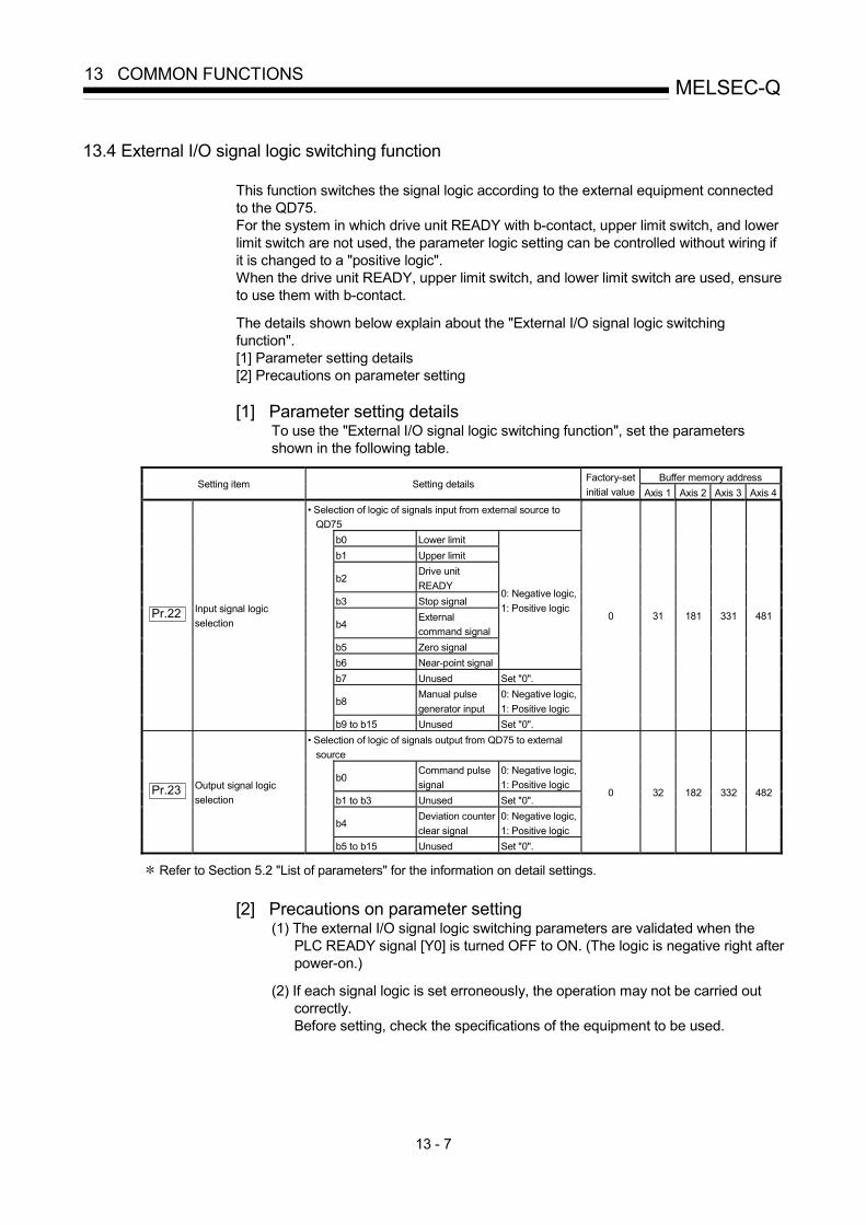
13 - 7
MELSEC-Q13 COMMON FUNCTIONS
13.4 External I/O signal logic switching function
This function switches the signal logic according to the external equipment connected to the QD75. For the system in which drive unit READY with b-contact, upper limit switch, and lower limit switch are not used, the parameter logic setting can be controlled without wiring if it is changed to a "positive logic". When the drive unit READY, upper limit switch, and lower limit switch are used, ensure to use them with b-contact.
The details shown below explain about the "External I/O signal logic switching function". [1] Parameter setting details [2] Precautions on parameter setting
[1] Parameter setting details
To use the "External I/O signal logic switching function", set the parameters shown in the following table.
Buffer memory address Setting item Setting details Factory-set
initial value Axis 1 Axis 2 Axis 3 Axis 4
• Selection of logic of signals input from external source to QD75
b0 Lower limit b1 Upper limit
b2 Drive unit READY
b3 Stop signal
b4 External command signal
b5 Zero signal b6 Near-point signal
0: Negative logic, 1: Positive logic
b7 Unused Set "0".
b8 Manual pulse generator input
0: Negative logic, 1: Positive logic
Pr.22 Input signal logic selection
b9 to b15 Unused Set "0".
0 31 181 331 481
• Selection of logic of signals output from QD75 to external source
b0 Command pulse signal
0: Negative logic, 1: Positive logic
b1 to b3 Unused Set "0".
b4 Deviation counter clear signal
0: Negative logic, 1: Positive logic
Pr.23 Output signal logic selection
b5 to b15 Unused Set "0".
0 32 182 332 482
Refer to Section 5.2 "List of parameters" for the information on detail settings.
[2] Precautions on parameter setting
(1) The external I/O signal logic switching parameters are validated when the PLC READY signal [Y0] is turned OFF to ON. (The logic is negative right after power-on.)
(2) If each signal logic is set erroneously, the operation may not be carried out
correctly. Before setting, check the specifications of the equipment to be used.

13 - 8
MELSEC-Q13 COMMON FUNCTIONS
13.5 External I/O signal monitor function
The "External I/O signal monitor function" monitors the module's information and external I/O signal monitor information in the module's detailed information which can be displayed on the system monitor of GX Developer .
The information that can be monitored are the module's information (same as the QD75 front "RUN", "ERR" LED indicators) and the following external I/O signals. (Set the logic of the external I/O signals in " Pr.22 Input signal logic selection"
and " Pr.23 Output signal logic selection".)
Indicates that Drive unit ready of axis 1 is ON.
0:OFF, 1:ON
Axis-by-axis external I/O signals and module RUN, ERR LEDs
: Use GX Developer of "SW6D5C-GPPW-E or later". Refer to GX Developer Operating Manual for the system monitor of GX Developer.

14 - 1
14
Chapter 14 Dedicated instructions
The QD75 dedicated instructions are explained in this chapter.
These instructions are used to facilitate the programming for the use of the functions of the intelligent function module.Using the dedicated instructions, the programming can be carried out without being aware of the QD75 buffer memory address and interlock signal.
14.1 List of dedicated instructions ...................................................................................14- 2 14.2 Interlock during dedicated instruction is executed..................................................14- 2 14.3 Z.ABRST1, Z.ABRST2, Z.ABRST3, Z.ABRST4 ....................................................14- 3 14.4 ZP.PSTRT1, ZP.PSTRT2, ZP.PSTRT3, ZP.PSTRT4 ...........................................14- 8 14.5 ZP.TEACH1, ZP.TEACH2, ZP.TEACH3, ZP.TEACH4.........................................14- 12 14.6 ZP.PFWRT..............................................................................................................14- 16 14.7 ZP.PINIT .................................................................................................................14- 20
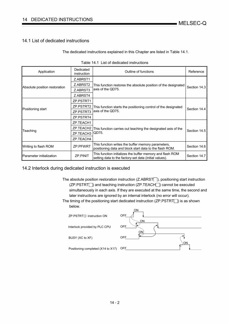
14 - 2
MELSEC-Q14 DEDICATED INSTRUCTIONS
14.1 List of dedicated instructions
The dedicated instructions explained in this Chapter are listed in Table 14.1.
Table 14.1 List of dedicated instructions
Application Dedicated instruction Outline of functions Reference
Z.ABRST1 Z.ABRST2 Z.ABRST3
Absolute position restoration
Z.ABRST4
This function restores the absolute position of the designated axis of the QD75. Section 14.3
ZP.PSTRT1 ZP.PSTRT2 ZP.PSTRT3
Positioning start
ZP.PSTRT4
This function starts the positioning control of the designated axis of the QD75. Section 14.4
ZP.TEACH1 ZP.TEACH2 ZP.TEACH3
Teaching
ZP.TEACH4
This function carries out teaching the designated axis of the QD75. Section 14.5
Writing to flash ROM ZP.PFWRT This function writes the buffer memory parameters, positioning data and block start data to the flash ROM. Section 14.6
Parameter initialization ZP.PINIT This function initializes the buffer memory and flash ROM setting data to the factory-set data (initial values). Section 14.7
14.2 Interlock during dedicated instruction is executed
The absolute position restoration instruction (Z.ABRST ), positioning start instruction (ZP.PSTRT ) and teaching instruction (ZP.TEACH ) cannot be executed simultaneously in each axis. If they are executed at the same time, the second and later instructions are ignored by an internal interlock (no error will occur).
The timing of the positioning start dedicated instruction (ZP.PSTRT ) is as shown below.
ZP.PSTRT instruction ON
Interlock provided by PLC CPU
BUSY (XC to XF)
Positioning completed (X14 to X17)
OFF
OFF
OFF
OFF
ON
ON
ON
ON

14 - 3
MELSEC-Q14 DEDICATED INSTRUCTIONS
14.3 Z.ABRST1, Z.ABRST2, Z.ABRST3, Z.ABRST4
These dedicated instructions restore the absolute position of the designated axis. Usable device
Internal device Link direct device J \ Constant Setting data
Bit Word File
register Bit Word
Intelligent function module U \G
Index register
Zn K, H, $ Others
(S) – – – – (D) – – – –
[Instruction symbol] [Execution condition]
Z.ABRST1 "Un" (S) (D)
Z.ABRST2 "Un" (S) (D)
Z.ABRST3 "Un" (S) (D)
Z.ABRST1
Z.ABRST2
Z.ABRST3
Z.ABRST4 Z.ABRST4 "Un" (S) (D)
When Z.ABRST1, Z.ABRST2, Z.ABRST3, and Z.ABRST4 are common to each other, they are designated as " Z.ABRST ". [Setting data] Setting data Setting details Setting side
( 1) Data type
"Un" QD75 head I/O number (00 to FE: High-order two digits of I/O number expressed in three digits) User BIN 16 bits
(S) Head number of a device in which control data is stored – Device
(D) Head number of a bit device which turns ON the operation by one scan at the time of completion of the instruction. If the instruction is completed abnormally, ((D) + 1) will also be turned ON.
System Bit
Note) The file register of each of the local device and the program cannot be used as a device for setting data.

14 - 4
MELSEC-Q14 DEDICATED INSTRUCTIONS
[Control data]
Device Item Setting data Setting range Setting side
( 1) (S)+0 System area – – –
(S)+1 Complete status The state at the time of completion is stored.
• 0 : Normal completion • Other than 0 : Abnormal completion (error code)( 2)
– System
(S)+2 Signal received from servo amplifier
The following signal states taken in from the servo amplifier to the input module are written.
• b0: ABS data bit 0 • b1: ABS data bit 1 • b2: Transmission data READY flag
b0: 0/1 b1: 0/1 b2: 0/1
User
(S)+3 Signal transmitted to servo amplifier
The ON/OFF states of the following data which are calculated using the dedicated instructions by the "signals received from the servo amplifier" and output to the servo amplifier are stored.
• b0: Servo amplifier ON • b1: ABS transfer mode • b2: ABS request flag
– System
(S)+4 Status
Status of communication with servo amplifier • 0 : Communication completed
(Set by user at communication start) • Other than 0 : During communication (System stores)
0 User/system
(S)+5 to (S)+7 System area – – –
1: The data on the setting side is as follows. • User : Data before the execution of dedicated instructions is stored by user. • System : Data after the execution of dedicated instruction is stored by PLC CPU.
2: Refer to Section 15.2 for error codes at abnormal completion. [Functions]
(1) The positioning data is read from the servo amplifier capable of processing the absolute positions of the axes to be set (See below), and the values converted with respect to a unit are stored in " Md.20 current feed value" and " Md.21 machine
feed value" area of the QD75. • Z.ABRST1: Axis 1 • Z.ABRST2: Axis 2 • Z.ABRST3: Axis 3 • Z.ABRST4: Axis 4 For absolute position detection system, carry out the absolute position restoration operation each time the power is turned ON or PLC CPU is reset.
(S)+0(S)+1(S)+2(S)+3(S)+4(S)+5
(S)+7
Control data
PLC CPU
Current feed valueInput module
Output module
Servo amplifier
QD75
Current value data
Z.ABRST
Machine feed value

14 - 5
MELSEC-Q14 DEDICATED INSTRUCTIONS
(2) An I/O module is used for communication (data read/write) with the servo amplifier
capable of processing the absolute positions. When using the Z.ABRST , prepare the input/output with the following number of points, for each axis, for communication with the servo amplifier. • Input : 3 points • Output : 3 points Refer to Section 12.6 for wiring of I/O signals.
(3) The Z.ABRST instruction completion can be confirmed using the complete
devices ((D)+0) and ((D)+1).
(a) Complete device ((D)+0) This device is turned ON by the END processing of the scan for which Z.ABRST instruction is completed, and turned OFF by the next END processing.
(b) Complete state display device ((D)+1)
This device is turned ON and OFF according to the state in which Z.ABRST instruction is completed. • When completed normally : Kept unchanged at OFF. • When completed abnormally: This device is turned ON by the END
processing of the scan for which Z.ABRST instruction is completed, and turned OFF by the next END processing. (same ON/OFF operation as complete device).
END processing
END processing
END processing
END processing
OFF
OFF
OFF
ON
ON
ON
When completed abnormallyWhen
completed normally
1 scan
Z.ABRST instructionexecution completion
Sequence program
Z.ABRST instruction
Complete device
Complete state display device
The completion of absolute position restoration can be confirmed using the ((S)+4) "status".
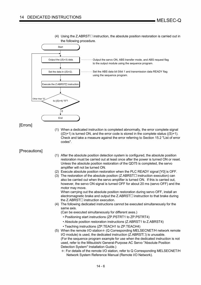
14 - 6
MELSEC-Q14 DEDICATED INSTRUCTIONS
(4) Using the Z.ABRST instruction, the absolute position restoration is carried out in
the following procedure.
End
Output the ((S)+3) data.
Is ((S)+4) "0"?Other than "0"
0
Set the ABS data bit 0/bit 1 and transmission data READY flag using the sequence program.
Output the servo ON, ABS transfer mode, and ABS request flag to the output module using the sequence program.
Start
. . . . . . . . .
. . . . . . . . .
Execute the Z.ABRST instruction.
Set the data in ((S)+2).
[Errors]
(1) When a dedicated instruction is completed abnormally, the error complete signal ((D)+1) is turned ON, and the error code is stored in the complete status ((S)+1). Check and take a measure against the error referring to Section 15.2 "List of error codes".
[Precautions]
(1) After the absolute position detection system is configured, the absolute position restoration must be carried out at least once after the power is turned ON or reset. Unless the absolute position restoration of the QD75 is completed, the servo amplifier will not be turned ON.
(2) Execute absolute position restoration when the PLC READY signal [Y0] is OFF. (3) The restoration of the absolute position (Z.ABRST instruction execution) can
also be carried out when the servo amplifier is turned ON. If this is carried out, however, the servo ON signal is turned OFF for about 20 ms (servo OFF) and the motor may move. When carrying out the absolute position restoration during servo OFF, install an electromagnetic brake and output the Z.ABRST instruction to that brake during the Z.ABRST instruction execution.
(4) The following dedicated instructions cannot be executed simultaneously for the same axis. (Can be executed simultaneously for different axes.) • Positioning start instructions (ZP.PSTRT1 to ZP.PSTRT4) • Absolute position restoration instructions (Z.ABRST1 to Z.ABRST4) • Teaching instructions (ZP.TEACH1 to ZP.TEACH4)
(5) When the remote I/O station (Q Corresponding MELSECNET/H network remote I/O module) is used, the dedicated instruction (Z.ABRST ) is unusable. (For the sequence program example for use when the dedicated instruction is not used, refer to the Mitsubishi General-Purpose AC Servo "Absolute Position Detection System" Installation Guide.)
: For details of the remote I/O station, refer to Q Corresponding MELSECNET/H Network System Reference Manual (Remote I/O Network).

14 - 7
MELSEC-Q14 DEDICATED INSTRUCTIONS
(6) If the Z.ABRST instruction is executed in either of the following cases, an error
"Dedicated instruction error" (error code: 804) will occur and absolute position restoration cannot be carried out. • Any value other than 0 is set to "Status" (device: (S)+4) of the control data. • The instruction for a non-existent axis is specified.
(Example: The Z.ABRST2 instruction is specified when the QD75P1 is used.)
[Program examples] Program to restore the absolute position of axis 1. The X47 to X49 and Y50 to Y52 are used for communication with the servo amplifier.
X47: ABS data bit 0 X48: ABS data bit 1 X49: Transmission data READY flag Y50: Servo ON signal Y51: ABS transfer mode Y52: ABS request flag
No. 23 Absolute position restoration program
(1) Absolute position restoration command acceptance
(2) Setting of transmit data to servo-amplifier and confirmation of absolute position restoration completion Z.ABRST1 instruction completed when M42 is ON and M43 is OFF. Absolute position data restoration completed when status = 0.
(3) ABS data setting and Z.ABRST1 instruction execution
<Status reset>
<Error code transmission to D49>
<ABS data bit 0 ON/OF>
<ABS data bit 1 ON/OF>
<Transmission data preparation complete flag ON/OFF>
<ABRST1 instruction execution>

14 - 8
MELSEC-Q14 DEDICATED INSTRUCTIONS
14.4 ZP.PSTRT1, ZP.PSTRT2, ZP.PSTRT3, ZP.PSTRT4
These dedicated instructions are used to start the positioning of the designated axis. Usable device
Internal device Link direct device J \ Constant Setting data
Bit Word File
register Bit Word
Intelligent function module U \G
Index register
Zn K, H, $ Others
(S) – – – – (D) – – – –
[Instruction symbol] [Execution condition]
ZP.PSTRT1 ZP.PSTRT1 "Un" (S) (D)
ZP.PSTRT2 ZP.PSTRT2 "Un" (S) (D)
ZP.PSTRT3 ZP.PSTRT3 "Un" (S) (D)
ZP.PSTRT4 ZP.PSTRT4 "Un" (S) (D)
When ZP.PSTRT1, ZP.PSTRT2, ZP.PSTRT3, and ZP.PSTRT4 are common to each other, they are designated as " ZP.PSTRT ". [Setting data] Setting data Setting details Setting side
( 1) Data type
"Un" QD75 head I/O number (00 to FE: High-order two digits of I/O number expressed in three digits) User BIN 16 bits
(S) Head number of a device in which control data is stored – Device
(D) Head number of a bit device which turns ON the operation by one scan at the time of completion of the instruction. If the instruction is completed abnormally, ((D) + 1) will also be turned ON.
System Bit
Note) The file register of each of the local device and the program cannot be used as a device for setting data.

14 - 9
MELSEC-Q14 DEDICATED INSTRUCTIONS
[Control data]
Device Item Setting data Setting range Setting side ( 1)
(S)+0 System area – – –
(S)+1 Complete status The state at the time of completion is stored.
• 0 : Normal completion • Other than 0: Abnormal completion (error code)( 2)
– System
(S)+2 Start No.
The following data Nos. to be started by the ZP.PSTRT instruction are designated.
• Positioning data No. : 1 to 600 • Block start : 7000 to 7004 • Machine OPR : 9001 • Fast OPR : 9002 • Current value changing : 9003 • Multiple axes simultaneous start : 9004
1 to 600 7000 to 7004 9000 to 9004
User
1: The data on the setting side is as follows. • User : Data before the execution of dedicated instructions is stored by user. • System: Data after the execution of dedicated instruction is stored by PLC CPU.
2: Refer to Section 15.2 for error codes at abnormal completion. [Functions]
(1) The positioning start of the axes to be processed (See below) is carried out. • ZP.PSTRT1: Axis 1 • ZP.PSTRT2: Axis 2 • ZP.PSTRT3: Axis 3 • ZP.PSTRT4: Axis 4
(2) The block start, OPR start, current value changing, and multiple axes simultaneous
start can be carried out by the setting of "start number" 7000 to 7004/9001 to 9004 in ((S)+2).
(3) The ZP.PSTRT instruction completion can be confirmed using the complete
devices ((D)+0) and ((D)+1).
(a) Complete device ((D)+0) This device is turned ON by the END processing of the scan for which ZP.PSTRT instruction is completed, and turned OFF by the next END processing.
(b) Complete state display device ((D)+1)
This device is turned ON and OFF according to the state in which ZP.PSTRT instruction is completed. • When completed normally : Kept unchanged at OFF. • When completed abnormally: This device is turned ON by the END
processing of the scan for which ZP.PSTRT instruction is completed, and turned OFF by the next END processing. (same ON/OFF operation as complete device).

14 - 10
MELSEC-Q14 DEDICATED INSTRUCTIONS
END
processingEND
processingEND
processingEND
processing
OFF
OFF
OFF
ON
ON
ON
When completed abnormallyWhen
completed normally
1 scan
ZP.PSTRT instructionexecution completion
Sequence program
ZP.PSTRT instruction
Complete device
Complete state display device
[Errors]
(1) When an ZP.PSTRT instruction is completed abnormally, the error complete signal ((D)+1) is turned ON, and the error code is stored in the complete status ((S)+1). Check and take a measure against the error referring to Section 15.2 "List of error codes".
[Precautions]
(1) When positioning is started by the ZP.PSTRT instruction, the positioning start signals (Y10 to Y13) and start complete signals (X10 to X13) will not turn ON. To confirm that positioning control is being executed, use the ZP.PSTRT start command or BUSY signals (XC to XF).
(2) If, after positioning has been started by the ZP.PSTRT instruction, a stop
command is input before positioning is complete, the complete device (D) turns ON one scan and the execution of the ZP.PSTRT instruction is completed.
(3) The following dedicated instructions cannot be executed simultaneously for the
same axis. (Can be executed simultaneously for different axes.) • Positioning start instructions (ZP.PSTRT1 to ZP.PSTRT4) • Absolute position restoration instructions (Z.ABRST1 to Z.ABRST4) • Teaching instructions (ZP.TEACH1 to ZP.TEACH4)
(4) The ZP.PSTRT instruction can only be executed when the QD75 READY signal
(X0) is turned ON. Even if the ZP.PSTRT instruction execution request is given when the QD75 READY signal is turned OFF, the ZP.PSTRT instruction will not be executed. (not processed.) Before executing the ZP.PSTRT instruction, turn ON the PLC READY signal (Y0), and turn ON the QD75 READY signal (X0).
(5) When the remote I/O station (Q Corresponding MELSECNET/H network remote
I/O module) is used, the dedicated instruction (ZP.PSTRT ) is unusable. : For details of the remote I/O station, refer to Q Corresponding MELSECNET/H
Network System Reference Manual (Remote I/O Network).

14 - 11
MELSEC-Q14 DEDICATED INSTRUCTIONS
(6) If the ZP.PSTRT instruction is executed in either of the following cases, an error
"Dedicated instruction error" (error code: 804) will occur and positioning cannot be started. • Any value other than 1 to 600, 7000 to 7004, and 9001 to 9004 is set to
"Starting number" (device: (S)+2) of the control data. • The instruction for a non-existent axis is specified.
(Example: The ZP.PSTRT2 instruction is specified when the QD75P1 is used.) [Program examples]
• The following program executes the positioning start of positioning data No. 1 when X100 turns ON. Use D30 to D32 as the control data devices of positioning data No. 1, and M32 and M33 as the completion devices.
Positioning start program
<Positioning start command pulse>
<Positioning start No. 1 setting>
<Positioning start command hold>
<Positioning start execution>
<Positioning start command storage OFF>
[Program example for use when dedicated instruction is not used]
Positioning start program (when dedicated instruction is not used)
<Positioning start command pulse>
<Positioning start No. 1 setting>
<Positioning start execution>
<Positioning start signal OFF>DX0C

14 - 12
MELSEC-Q14 DEDICATED INSTRUCTIONS
14.5 ZP.TEACH1, ZP.TEACH2, ZP.TEACH3, ZP.TEACH4
These dedicated instructions are used to teach the designated axis. Usable device
Internal device Link direct device J \ Constant Setting data
Bit Word File
register Bit Word
Intelligent function module U \G
Zn K, H, $
Others
(S) – – – – (D) – – – –
[Instruction symbol] [Execution condition]
ZP.TEACH1 ZP.TEACH1 "Un" (S) (D)
ZP.TEACH2 ZP.TEACH2 "Un" (S) (D)
ZP.TEACH3 ZP.TEACH3 "Un" (S) (D)
ZP.TEACH4 ZP.TEACH4 "Un" (S) (D)
When ZP.TEACH1, ZP.TEACH2, ZP.TEACH3, and ZP.TEACH4 are common to each other, they are designated as "ZP.TEACH ". [Setting data]
Setting data Setting details Setting side ( 1) Data type
"Un" QD75 head I/O number (00 to FE: High-order two digits of I/O number expressed in three digits) User BIN 16 bits
(S) Head number of a device in which control data is stored – Device
(D) Head number of a bit device which turns ON the operation by one scan at the time of completion of the instruction. If the instruction is completed abnormally, ((D) + 1) will also be turned ON.
System Bit
Note) The file register of each of the local device and the program cannot be used as a device for setting data.
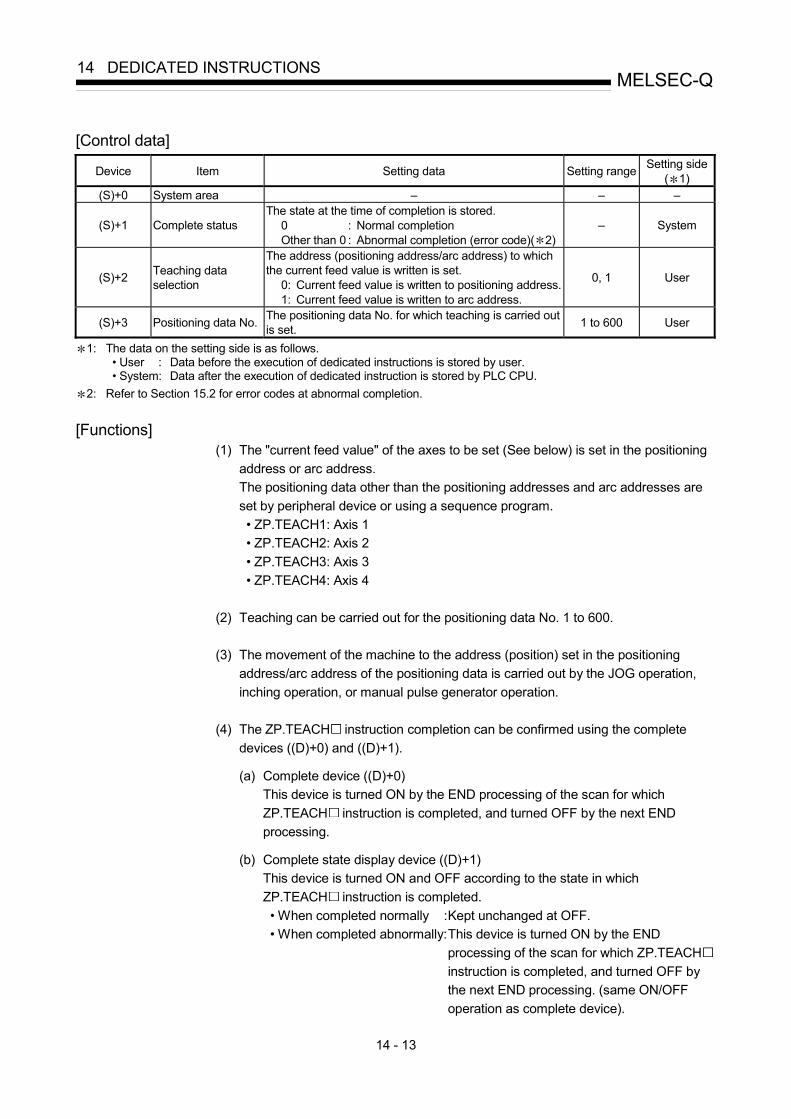
14 - 13
MELSEC-Q14 DEDICATED INSTRUCTIONS
[Control data]
Device Item Setting data Setting range Setting side ( 1)
(S)+0 System area – – –
(S)+1 Complete status The state at the time of completion is stored.
0 : Normal completion Other than 0 : Abnormal completion (error code)( 2)
– System
(S)+2 Teaching data selection
The address (positioning address/arc address) to which the current feed value is written is set.
0: Current feed value is written to positioning address. 1: Current feed value is written to arc address.
0, 1 User
(S)+3 Positioning data No. The positioning data No. for which teaching is carried out is set. 1 to 600 User
1: The data on the setting side is as follows. • User : Data before the execution of dedicated instructions is stored by user. • System: Data after the execution of dedicated instruction is stored by PLC CPU.
2: Refer to Section 15.2 for error codes at abnormal completion. [Functions]
(1) The "current feed value" of the axes to be set (See below) is set in the positioning address or arc address. The positioning data other than the positioning addresses and arc addresses are set by peripheral device or using a sequence program. • ZP.TEACH1: Axis 1 • ZP.TEACH2: Axis 2 • ZP.TEACH3: Axis 3 • ZP.TEACH4: Axis 4
(2) Teaching can be carried out for the positioning data No. 1 to 600.
(3) The movement of the machine to the address (position) set in the positioning
address/arc address of the positioning data is carried out by the JOG operation, inching operation, or manual pulse generator operation.
(4) The ZP.TEACH instruction completion can be confirmed using the complete
devices ((D)+0) and ((D)+1).
(a) Complete device ((D)+0) This device is turned ON by the END processing of the scan for which ZP.TEACH instruction is completed, and turned OFF by the next END processing.
(b) Complete state display device ((D)+1)
This device is turned ON and OFF according to the state in which ZP.TEACH instruction is completed. • When completed normally : Kept unchanged at OFF. • When completed abnormally: This device is turned ON by the END
processing of the scan for which ZP.TEACH instruction is completed, and turned OFF by the next END processing. (same ON/OFF operation as complete device).

14 - 14
MELSEC-Q14 DEDICATED INSTRUCTIONS
END
processingEND
processingEND
processingEND
processing
OFF
OFF
OFF
ON
ON
ON
When completed abnormallyWhen
completed normally
1 scan
ZP.TEACH instructionexecution completion
Sequence program
ZP.TEACH instruction
Complete device
Complete state display device
[Errors]
(1) When a ZP.TEACH instruction is completed abnormally, the error complete signal ((D)+1) is turned ON, and the error code is stored in the complete status (S)+1. Check and take a measure against the error referring to Section 15.2 "List of error codes".
[Precautions]
(1) The following dedicated instructions cannot be executed simultaneously for the same axis. (Can be executed simultaneously for different axes.) • Positioning start instructions (ZP.PSTRT1 to ZP.PSTRT4) • Absolute position restoration instructions (Z.ABRST1 to Z.ABRST4) • Teaching instructions (ZP.TEACH1 to ZP.TEACH4)
(2) The ZP.TEACH instruction can only be executed when the BUSY signal (XC,
XD, XE, XF) is turned OFF. When the BUSY signal is turned ON, the ZP.TEACH instruction will not be executed. (not processed.) Before executing the ZP.PFWRT instruction, make sure that the BUSY signal for the axis to be processed is turned OFF.
(3) When the remote I/O station* (Q Corresponding MELSECNET/H network remote
I/O module) is used, the dedicated instruction (ZP.TEACH ) is unusable. : For details of the remote I/O station, refer to Q Corresponding MELSECNET/H
Network System Reference Manual (Remote I/O Network).
(4) If the ZP.TEACH instruction is executed in any of the following cases, an error "Dedicated instruction error" (error code: 804) will occur and teaching cannot be performed. • Any value other than 0 and 1 is set to "Teaching selection" (device: (S)+2) of the
control data. • Any value other than 1 to 600 is set to "Positioning No." (device: (S)+3) of the
control data. • The instruction for a non-existent axis is specified.
(Example: The ZP.TEACH2 instruction is specified when the QD75P1 is used.)

14 - 15
MELSEC-Q14 DEDICATED INSTRUCTIONS
[Program example]
Program to execute the teaching of the positioning data No. 3 of the axis 1 when X39 is turned ON.
<Teaching command pulse>
<Teaching command hold>
<Teaching data setting>
<Positioning data No. setting>
<Teaching execution>
<Teaching command storage OFF>
No. 20 Teaching program
Positioned manually to target position.
[Program example for use when dedicated instruction is not used]
<Teaching command pulse>
<Teaching command hold>
<Teaching positioning address>
<Sets teaching positioning data No. to 1>
<Turns OFF teaching command storage>
Teaching program (when dedicated instruction is not used)
Positioned manually to target position.

14 - 16
MELSEC-Q14 DEDICATED INSTRUCTIONS
14.6 ZP.PFWRT
These dedicated instructions are used to write the QD75 parameters, positioning data and block start data to the flash ROM.
Usable device Internal device Link direct device J \ Constant Setting
data Bit Word
File register Bit Word
Intelligent function module U \G
Index register
Zn K, H, $ Others
(S) – – – – (D) – – – –
[Instruction symbol] [Execution condition]
ZP.PFWRTZP.PFWRT "Un" (S) (D)
[Setting data] Setting data Setting details Setting side
( 1) Data type
"Un" QD75 head I/O number (00 to FE: High-order two digits of I/O number expressed in three digits) User BIN 16 bits
(S) Head number of a device in which control data is stored – Device
(D) Head number of a bit device which turns ON the operation by one scan at the time of completion of the instruction. If the instruction is completed abnormally, ((D) + 1) will also be turned ON.
System Bit
Note) The file register of each of the local device and the program cannot be used as a device for setting data. [Control data]
Device Item Setting data Setting Range
Setting side ( 1)
(S)+0 System area – – –
(S)+1 Complete status The state at the time of completion is stored.
0 : Normal completion Other than 0 : Abnormal completion (error code)( 2)
– System
1: The data on the setting side is as follows. • User : Data before the execution of dedicated instructions is stored by user. • System: Data after the execution of dedicated instruction is stored by PLC CPU.
2: Refer to Section 15.2 for error codes at abnormal completion.

14 - 17
MELSEC-Q14 DEDICATED INSTRUCTIONS
[Functions]
(1) The ZP.PFWRT instruction completion can be confirmed using the complete devices ((D)+0) and ((D)+1).
(a) Complete device ((D)+0)
This device is turned ON by the END processing of the scan for which ZP.PFWRT instruction is completed, and turned OFF by the next END processing.
(b) Complete state display device ((D)+1)
This device is turned ON and OFF according to the state in which ZP.PFWRT instruction is completed. • When completed normally : Kept unchanged at OFF. • When completed abnormally : This device is turned ON by the END
processing of the scan for which ZP.PFWRT instruction is completed, and turned OFF by the next END processing. (same ON/OFF operation as complete device).
END processing
END processing
END processing
END processing
OFF
OFF
OFF
ON
ON
ON
When completed abnormallyWhen
completed normally
1 scan
ZP.PFWRT instructionexecution completion
Sequence program
ZP.PFWRT instruction
Complete device
Complete state display device
[Instruction symbol] [Execution condition]
ZP.PFWRT ZP.PFWRT "Un" (S) (D)
[Errors]
(1) When a dedicated instruction is completed abnormally, the error complete signal ((D)+1) is turned ON, and the error code is stored in the complete status ((S)+1). Check and take measures against the error referring to Section 15.2 "List of error codes".

14 - 18
MELSEC-Q14 DEDICATED INSTRUCTIONS
[Precautions]
(1) Do not turn ON the power and reset the PLC CPU while parameters, positioning data and block start data are written to the flash ROM using the ZP.PFWRT instruction. A parameter error will occur or normal positioning start will become impossible because the parameters, positioning data and block start data are not written normally to the flash ROM. If this occurs, restart the operation by the method shown below. • For GX Configurator-QP, write the parameters, positioning data and block start
data again to the flash ROM. • For a sequence program, write the parameters, positioning data and block start
data to the QD75 after initializing the parameters (ZP.PINIT instruction execution and others). Then execute the ZP.PFWRT instruction again.
(2) A writing to the flash ROM is up to 100,000 times.
If writing to the flash ROM exceeds 100,000 times, the writing to the flash ROM will become impossible.
(3) After the power ON and PLC CPU reset operation, writing to the flash ROM using
a sequence program is limited to up to 25 times. (Not limited to up to 25 times when writing to the flash ROM is carried out by peripheral device.) If the 26th or more writing is requested after the power ON/PLC CPU reset operation, a flash ROM write number error (error code: 805) will occur, and the writing will be disabled. If a flash ROM write error occurs by one writing to the flash ROM, check and correct the flash ROM writing program. Then reset the error or turn ON the power and reset the PLC CPU again.
(4) The ZP.PFWRT instruction can only be executed when the QD75 READY signal
(X0) is turned OFF. When the QD75 READY signal is turned ON, the ZP.PFWRT instruction cannot be executed. Before executing the ZP.PFWRT instruction, turn OFF the PLC READY signal (Y0) and then turn OFF the QD75 READY signal.
(5) When the remote I/O station (Q Corresponding MELSECNET/H network remote
I/O module) is used, the dedicated instruction (ZP.PFWRT) is unusable. : For details of the remote I/O station, refer to Q Corresponding MELSECNET/H
Network System Reference Manual (Remote I/O Network).

14 - 19
MELSEC-Q14 DEDICATED INSTRUCTIONS
[Program example]
Program used to write the parameters and positioning data stored in the buffer memory to the flash ROM when X3D is turned ON.
No. 26 Flash ROM write program
<Flash ROM write command pulse>
<Flash ROM write command hold>
<PLC READY output to QD75 standby>
<Flash ROM write execution>
<Flash ROM write command storage OFF> [Program example for use when dedicated instruction is not used]
<Flash ROM write command pulse>
<Flash ROM write command hold>
<PLC READY output to QD75 standby>
<Flash ROM write execution>
<Flash ROM write command storage OFF>
Flash ROM write program (when dedicated instruction is not used)

14 - 20
MELSEC-Q14 DEDICATED INSTRUCTIONS
14.7 ZP.PINIT
This dedicated instruction is used to initialize the setting data of the QD75. Usable device
Internal device Link direct device J \ Constant Setting data
Bit Word File
register Bit Word U \G
Index register
Zn K, H, $ Others
(S) – – – – (D) – – – –
[Instruction symbol] [Execution condition]
ZP.PINIT Z.PINIT "Un" (S) (D)
[Setting data] Setting data Setting details Setting side
( 1) Data type
"Un" QD75 head I/O number (00 to FE: High-order two digits of I/O number expressed in three digits) User BIN 16 bits
(S) Head number of a device in which control data is stored – Device
(D) Head number of a bit device which turns ON the operation by one scan at the time of completion of the instruction. If the instruction is completed abnormally, ((D) + 1) will also be turned ON.
System Bit
Note) The file register of each of the local device and the program cannot be used as a device for setting data. [Control data]
Device Item Setting data Setting range Setting side ( 1)
(S)+0 System area – – –
(S)+1 Complete status The state at the time of completion is stored.
0 : Normal completion Other than 0: Abnormal completion (error code)( 2)
– System
1: The data on the setting side is as follows. • User : Data before the execution of dedicated instructions is stored by user. • System: Data after the execution of dedicated instruction is stored by PLC CPU.
2: Refer to Section 15.2 for error codes at abnormal completion.

14 - 21
MELSEC-Q14 DEDICATED INSTRUCTIONS
[Functions]
(1) This dedicated instruction is used to return the setting data set in the QD75 buffer memory and flash ROM to their factory-set data (initial values).
Initialized setting data Parameters ( Pr.1 to Pr.57 , Pr.150 )
Positioning data (No. 1 to No. 600) Block start data (No. 7000 to 7004)
(2) The ZP.PINIT instruction completion can be confirmed using the complete devices ((D)+0) and ((D)+1). (a) Complete device ((D)+0)
This device is turned ON by the END processing of the scan for which ZP.PINIT instruction is completed, and turned OFF by the next END processing.
(b) Complete state display device ((D)+1) This device is turned ON and OFF according to the state in which ZP.PINIT instruction is completed. • When completed normally : Kept unchanged at OFF. • When completed abnormally : This device is turned ON by the END
processing of the scan for which ZP.PINIT instruction is completed, and turned OFF by the next END processing. (same ON/OFF operation as complete device).
END processing
END processing
END processing
END processing
OFF
OFF
OFF
ON
ON
ON
When completed abnormallyWhen
completed normally
1 scan
ZP.PINIT instructionexecution completion
Sequence program
ZP.PINIT instruction
Complete device
Complete state display device
[Errors]
(1) When a dedicated instruction is completed abnormally, the error complete signal ((D)+1) is turned ON, and the error code is stored in the complete status ((S)+1). Check and take measures against the error referring to Section 15.2 "List of error codes".
[Precautions] (1) The ZP.PINIT instruction can only be executed when the QD75 READY signal
(X0) is turned OFF. When the QD75 READY signal is turned ON, the ZP.PINIT instruction cannot be executed. Before executing the ZP.PINIT instruction, turn OFF the PLC READY signal (Y0) and then turn OFF the QD75 READY signal.
(2) When the remote I/O station (Q Corresponding MELSECNET/H network remote I/O module) is used, the dedicated instruction (ZP.PINIT) is unusable.
: For details of the remote I/O station, refer to Q Corresponding MELSECNET/H Network System Reference Manual (Remote I/O Network).

14 - 22
MELSEC-Q14 DEDICATED INSTRUCTIONS
[Program example]
The following program initializes the parameters in buffer memory and flash ROM when X3C turns ON.
No. 25 Parameter initialization program
<Parameter initialization command pulse>
<Parameter initialization command hold>
<PLC READY output to QD75 standby>
<Parameter initialization execution>
<Parameter initialization command storage OFF>
[Program example for use when dedicated instruction is not used]
<Parameter initialization command pulse>
<Parameter initialization command hold>
<PLC READY output to QD75 standby>
<Parameter initialization execution>
<Parameter initialization command storagee OFF>
Parameter initialization program (when dedicated instruction is not used)

15 - 1
15
Chapter 15 Troubleshooting
The "errors" and "warnings" detected by the QD75 are explained in this chapter.
Errors can be confirmed with the QD75 LED display and peripheral devices.When an error or warning is detected, confirm the detection details and carry out the required measures.
15.1 Error and warning details.........................................................................................15- 215.2 List of errors .............................................................................................................15- 615.3 List of warnings .......................................................................................................15- 3215.4 LED display functions .............................................................................................15- 38

15 - 2
MELSEC-Q15 TROUBLESHOOTING
15.1 Error and warning details
[1] Errors
Types of errors Errors detected by the QD75 include parameter setting range errors and errors at the operation start or during operation.
(1) Parameter setting range errors
The parameters are checked when the power is turned ON and at the rising edge (OFF ON) of the PLC READY signal [Y0]. An error will occur if there is a mistake in the parameter setting details at that time. When this kind of error occurs, the QD75 READY signal does not turn ON. To cancel this kind of error, set the correct value in the parameter for which the error occurred, and then turn ON the PLC READY signal [Y0].
(2) Errors at the operation start or during operation These are errors that occur at the operation start or during operation when the positioning control, JOG operation, or inching operation is used. If an axis error occurs during interpolation operation, the error No. will be stored in both the reference axis and the interpolation axis. Note that, in the following cases (a) and (b), the axis error No. will be stored only in the reference axis during analysis of the positioning data set in each point of the positioning start data table. (a) When the interpolation axis is BUSY. (b) When the error occurred in positioning data or parameters unrelated to
interpolation control. If the error occurred at the simultaneous start of a positioning operation, the axis error storage details will differ depending on whether the error occurred before or after the simultaneous start. • If the error occurred before the simultaneous start (illegal axis No., other axis
BUSY, etc.), an "error before simultaneous start" will occur. • If the error occurred after the simultaneous start (positioning data error,
software stroke limit error, etc.), an error code corresponding to the axis in which the error occurred will be stored. Because a simultaneous start cannot be carried out due to this, a "simultaneous start not possible error" error code will be stored in all axes in which an error has not occurred.
The axis operation status will be displayed as "error occurring" for axes in which an error occurred. If an error occurs during operation, any moving axes will deceleration stop, and their operation status will be displayed as "error occurring". All axes will decelerate to a stop during interpolation operations, even if the error occurs in only one axis.
(3) Types of error codes
Error code Error type 001 to 009 Fatal error 100 to 199 Common error 200 to 299 Error at OPR or absolute position restoration
300 to 399 Error during JOG operation or during inching operation
500 to 599 Error during positioning operation 800 to 899 I/F (Interface) error 900 to 999 Error during parameter setting range check

15 - 3
MELSEC-Q15 TROUBLESHOOTING
Error storage When an error occurs, the error detection input turns ON, and the error code corresponding to the error details is stored in the following buffer memory address ( Md.23 Axis error No.) for axis error No. storage. Note that there is a delay of up to 1.8 ms after the error detection signal turns ON until the error code is stored.
Axis No. Error detection signal Buffer memory address 1 X8 806 2 X9 906 3 XA 1006 4 XB 1106
A new error code is stored in the buffer memory address ( Md.23 Axis error No.) for axis error storage every time an error occurs.
[2] Warnings
Types of warnings
(1) Warnings include system warnings and axis warnings.
The types of system warnings are shown below. • System control data setting warnings
An axis warning for axis 1 will occur. • Positioning data setting warnings
An axis warning for each axis will occur. Note that a warning will occur for the reference axis when an interpolation designation or axis setting warning occurs.
(2) Axis warnings occur due to setting warnings from operations such as
positioning operations, JOG operations, manual pulse generator operations, or system errors. They can be canceled by turning ON the " Cd.5 Axis error reset". Note that some warnings cannot be canceled unless the cause of the warning is eliminated. The axis operation status does not change even if an axis warning occurs.
(3) Types of warning codes
Warning code Warning type 100 to 199 Common warning 300 to 399 Warning during JOG operation 400 to 499 Warning during manual pulse generator operation 500 to 599 Warning during positioning operation

15 - 4
MELSEC-Q15 TROUBLESHOOTING
Warning storage (1) When an axis warning occurs, the warning code corresponding to the warning
details is stored in the following buffer memory ( Md.24 Axis warning No.) for axis warning No. storage.
Axis No. Buffer memory address 1 807 2 907 3 1007 4 1107
(2) When an axis warning occurs in a positioning operation, etc., "1" is set in bit 9
(b9) of the following buffer memory ( Md.31 Status) for axis status storage.
Axis No. Buffer memory address 1 817 2 917 3 1017 4 1117
[3] Resetting errors and warnings
An error or warning state is canceled after the following processing has been carried out by setting a "1" in the address [1502 (for axis 1)], [1602 (for axis 2)], [1702 (for axis 3)], and [1802 (for axis 4)] of the buffer memory for axis error resetting ( Cd.5 Axis error reset).
• Axis error detection signal turned OFF • " Md.23 Axis error No." cleared • " Md.24 Axis warning No." cleared • Changing of " Md.26 operation status" from "Error" to "Standby". • " Md.31 Axis warning detection (b9)" turned OFF
[4] Invalid operations
For the following operations, the setting details will be invalidated, and an error or warning will not occur. • Speed change during machine OPR • Speed change before operation
(Speed override change, skip command, continuous operation interruption request, target position change request)
• Axis stop during axis stop • Axis sudden stop during axis stop • Axis stop before axis operation • Axis sudden stop before axis operation
[5] Confirming the error and warning definitions
The error and warning definitions can be confirmed with the error and warning codes. Confirming them requires GX Developer or GX Configurator-QP. For details, refer to GX Developer Operating Manual or GX Configurator-QP Operating Manual. (Refer to Section 15.2 and Section 15.3 for details of the error and warning codes.)

15 - 5
MELSEC-Q15 TROUBLESHOOTING
MEMO

15 - 6
MELSEC-Q15 TROUBLESHOOTING
15.2 List of errors
The following table shows the error details and remedies to be taken when an error occurs.
Classification
of errors Error code Error name Error Operation status at error occurrence
— 000 (Normal status) — — 001 Faults
Fatal errors 002 Internal circuit fault
Hardware is faulty. The system stops.
101 PLC READY OFF during operation
A PLC READY signal (Y0) is turned OFF during operation.
The system stops with the setting (deceleration stop/sudden stop) of the detailed parameter 2 Sudden stop selection (stop group 2). (Note that the deceleration stop only occurs during the manual pulse generator operation.)
102 Drive unit READY OFF
The drive unit READY signal is turned OFF during operation. The system stops immediately.
103 Test mode faults during operation
The personal computer cannot communicate with the CPU unit.
The system stops with the setting (deceleration stop/sudden stop) of the detailed parameter 2 Sudden stop selection (stop group 2). (Note that the deceleration stop only occurs during the manual pulse generator operation.)
104 Hardware stroke limit (+)
The hardware stroke limit (upper limit signal FLS) is turned OFF.
105 Hardware stroke limit (–)
The hardware stroke limit (lower limit signal RLS) is turned OFF.
The system stops with the setting (deceleration stop/sudden stop) of the detailed parameter 2 Sudden stop selection (stop group 1). (Note that the deceleration stop only occurs during the manual pulse generator operation.)
106 Stop signal ON at start
Start is requested when a stop signal is turned ON. The system does not start positioning.
Common
107 READY OFF ON during BUSY
The PLC READY signal is turned from OFF to ON when BUSY signal is turned ON.
The QD75 READY signal (X0) is not turned ON.
OPR 201 Start at OP
When the OPR retry invalid is set, the near-point dog machine OPR is started with the OPR complete flag turned ON.
The machine OPR is not started.

15 - 7
MELSEC-Q15 TROUBLESHOOTING
Related buffer memory address
Axis 1 Axis 2 Axis 3 Axis 4
Set range (Setting with sequence program) Remedy
— — — — — —
— — — — — • Check that there is no influence from noise. • Check hardware for possibility of fault.
— — — — —
• Review the sequence program which turns ON/OFF PLC READY signal (Y0).
• Cancel the error with an axis error reset. (Refer to Section 15.1[3])
— — — — — Check the drive unit power, wiring with the drive unit, and connection of connectors, and cancel the error with an axis error reset. (Refer to Section 15.1[3])
— — — — — Check that there is no error on the personal computer side I/F to which a cable is connected.
— — — — —
After making an axis error reset (refer to [3] in Section 15.1), perform manual control operation (refer to Chapter 11) to move the axis to the other position in order that the upper limit signal (FLS) will not turn OFF.
— — — — —
After making an axis error reset (refer to [3] in Section 15.1), perform manual control operation (refer to Chapter 11) to move the axis to the other position in order that the lower limit signal (RLS) will not turn OFF.
— — — — —
Check whether the stop commands (output signals/external inputs to QD75) are turned ON or OFF. Turn OFF the ON commands. • Output signals to QD75
Axis 1: Y4, Axis 2: Y5, Axis 3: Y6, Axis 4: Y7 • External input
Connectors for external device connection: Stop signals (STOP)
After confirming the stop command status, cancel the error with an axis error reset. Then turn ON a start signal. (Refer to Section 15.1[3])
— — — — — Turn ON the PLC READY signal (Y0) with the BUSY signals of all axes OFF.
78 228 378 528 <OPR retry> 0, 1
• Validate the OPR retry function (set value: 1). (Refer to Section 12.1.1)
• Move the workpiece from the current position (on OP) using the manual control operation (refer to Chapter 11), then carry out a machine OPR again.

15 - 8
MELSEC-Q15 TROUBLESHOOTING
Classification
of errors Error code Error name Error Operation status at error occurrence
203 Dog detection timing fault
The near-point dog signal is turned OFF during the deceleration from an OPR speed to a creep speed by the near-point dog machine OPR.
204 OP detection timing fault
The zero signal is turned OFF during the deceleration from an OPR speed to a creep speed by the stopper method 2)-OPR.
205 Dwell time fault
A dwell time is passed during the deceleration from a creep speed to a OPR speed by the stopper method 1)-OPR.
The system stops with the setting (deceleration stop/sudden stop) of the detailed parameter 2 Sudden stop selection (stop group 3). (Note that the deceleration stop only occurs during the manual pulse generator operation.)
206 Count method movement amount fault
In the count method 1 and 2 machine OPR, a parameter "Setting of movement amount after near-point dog ON" is smaller than a distance necessary for deceleration stop from an OPR speed.
The machine OPR is not started.
207 OPR request ON The OPR request flag is turned ON when a fast-OPR is started (positioning start No. 9002).
The fast OPR is not started.
209 OPR restart not possible
The restart command is turned ON after the machine OPR is stopped using a stop signal.
The restart is not carried out.
213 ABS transmission time
OPR
214 ABS transmission SUM
Communication cannot be carried out with the servo-amplifier using an absolute position restoration instruction.
The absolute position restoration is not carried out.
300 Outside JOG speed range
At the time of JOG starting, the JOG speed comes out of a specified range.
The JOG operation is not carried out when the JOG speed is outside the setting range at the time of JOG start.
JOG inching
301 Inching movement amount error
The inching movement amount exceeds the JOG speed limit.
The inching operation is not carried out when the inching movement amount exceeds a JOG speed limit at the time of inching start.
Positioning operation 500 Illegal condition data
No.
The condition data No. is outside the setting range when a block using the condition data is started by a special starting (conditional start, wait start, simultaneous start, FOR (condition)).(1 Condition data No. 10)
The operation is terminated.

15 - 9
MELSEC-Q15 TROUBLESHOOTING
Related buffer memory address
Axis 1 Axis 2 Axis 3 Axis 4
Set range (Setting with sequence program) Remedy
74 75
224 225
374 375
524 525
• Lower the OPR speed. • Increase the dog signal input time.
(Refer to Section 8.2.3)
74 75
224 225
374 375
524 525
• Lower the OPR speed. • Input external zero signals during the movement at a
creep speed. (Refer to Section 8.2.5)
74 75
224 225
374 375
524 525
<OPR speed> 1 to 1000000 [pulse/s]
1 to 2000000000 [mm/min or others]
79 229 379 529 <OPR dwell time>
0 to 65535
• Lower the OPR speed. • Increase the OPR dwell time.
(Refer to Section 8.2.4)
80 81
230 231
380 381
530 531
<Movement amount setting after near-point dog ON>
0 to 2147483647
74 75
224 225
374 375
524 525
<OPR speed> 1 to 1000000 [pulse/s]
1 to 2000000000 [mm/min]
• Calculate the movement distance using a speed limit, OPR speed, and deceleration time, and set the movement amount after near-point dog ON so that the distance becomes a deceleration distance or longer.
• Lower the OPR speed. • Adjust the near-point dog position so that the
movement amount after near-point dog ON becomes longer. (Refer to Section 8.2.7, 8.2.8)
1500 1600 1700 1800
<Positioning start No.> 1 to 600
7000 to 7004 9001 to 9004
Execute the machine OPR (positioning No. 9001). (Refer to Section 8.2)
1500 1600 1700 1800
<Positioning start No.> 1 to 600
7000 to 7004 9001 to 9004
Start the machine OPR (positioning start No. 9001) again. (Refer to Section 8.2)
— — — — — • Review the wiring. (Refer to Section 12.6) • Review the sequence program.
— — — — —
• Review the wiring. (Refer to Section 12.6) • Review the sequence program. • Review the dedicated instruction parameters.
(Refer to Section 14.3)
1518 1519
1618 1619
1718 1719
1818 1819
<JOG speed> 1 to 1000000 [pulse/s]
1 to 2000000000 [mm/min or others]
Bring the JOG speed into the setting range. (Refer to Section 11.2)
1517 1617 1717 1817 <Inching movement amount> 0 to 65535
Reduce the inching movement amount. (Refer to Section 11.3)
Refer to Section 5.4 "List of block start data"
<Condition data No.> 1 to 10
Review the condition data No. (Refer to Section 5.4 Da.14 )

15 - 10
MELSEC-Q15 TROUBLESHOOTING
Classification
of errors Error code Error name Error Operation status at error occurrence
<When blocks are started simultaneously>
• The partner axis for simultaneous start is BUSY.
501 Error before
simultaneous start
<When multiple axes are started and controlled simultaneously>
• The partner axis for simultaneous start is BUSY.
• The "Simultaneous start axis start data No." of the start axis is 0 or is outside the setting range.
• The "Simultaneous start axis start data No." of those axes other than the start axis is outside the setting range.
At start: The system will not operate. During operation:
The system stops immediately.
502 Illegal data No.
• The positioning data No. tried to be executed is outside the ranges of 1 to 600, 7000 to 7004, and 9001 to 9004.
• The designation of a JUMP destination is executed currently.
• The designation of a JUMP destination is outside the ranges of 1 to 600.
The positioning data is not executed.
Positioning operation
503 No command speed
• At the start of positioning, a current speed (–1) is set for the command speed of the positioning data to be initially executed.
• The current speed is set by speed control.
• The current speed is set for speed-position switching control.
At the start of positioning, operation does not start.

15 - 11
MELSEC-Q15 TROUBLESHOOTING
Related buffer memory address
Axis 1 Axis 2 Axis 3 Axis 4
Set range (Setting with sequence program) Remedy
Refer to Section 5.5 "List of condition data"
<Condition operators> Axis designation:
10H, 20H, 30H, 40H, 50H, 60H, 70H, 80H, 90H, A0H, B0H, C0H, D0H, E0H
Normalize the condition operators. (Refer to Section 5.5 Da.16 )
1540 1640 1740 1840 Axis 1 start data No.
1541 1641 1741 1841 Axis 2 start data No.
1542 1642 1742 1842 Axis 3 start data No.
1543 1643 1743 1843 Axis 4 start data No.
Simultaneous start axis start
data No.
0 to 600
Normalize the simultaneous start axis start data No. (Refer to Section 10.5)
1500 1600 1700 1800
<Positioning start No.> 1 to 600,
7000 to 7004, 9001 to 9004
<JUMP destination> 1 to 600
Normalize the positioning start No., positioning start data (in block start), and positioning data (in JUMP instruction).
Refer to Section 5.3 "List of positioning data"
<Command speed> 1 to 1000000 [pulse/s]
1 to 2000000000 [mm/min or others]Normalize the positioning data.

15 - 12
MELSEC-Q15 TROUBLESHOOTING
Classification
of errors Error code Error name Error Operation status at error occurrence
504 Outside linear movement amount range
• When the parameter "interpolation speed designation method" performs a linear interpolation in setting a "composite speed", the axis movement amount for each positioning data exceeds 1073741824(230).
• The positioning address is –360.00000 or less or 360.00000 or more using INC instruction, where the control unit is set to "degree" and software stroke limit upper limit is not equal to the software stroke limit lower limit.
At start: The system will not operate. During operation:
The system stops immediately.
Positioning operation
506 Large arc error deviation
When an arc is interpolated by the designation of the center point, a difference between a radius of start point-center point and a radius of end point-center point exceeds the parameter "Circular interpolation error allowable limit".
At start: The circular interpolation control by center point designation is not executed.
During operation : The system will stop immediately.

15 - 13
MELSEC-Q15 TROUBLESHOOTING
Related buffer memory address
Axis 1 Axis 2 Axis 3 Axis 4
Set range (Setting with sequence program) Remedy
Review the positioning address.
Refer to Section 5.3 "List of positioning data"
<Positioning address/movement amount>
• ABS unit [mm] [pulse] [inch] –2147483648 to 2147483647 Unit [degree] 0 to 35999999
• INC (When software stroke limits are valid) Unit [degree]: –35999999 to 35999999 Unit [mm], [pulse], [inch]: –2147483648 to 2147483647 (When software stroke limits are invalid) –2147483648 to 2147483647
• Speed-position switching INC mode: 0 to 2147483647 ABS mode: 0 to 35999999
• Position-speed switching 0 to 2147483647
<Arc address> –2147483648 to 2147483647
• Center point address (positioning address) • End address (arc address)
Correct.
60 61
210 211
360 361
510 511
<Circular interpolation error allowable limit> 0 to 1000000
Correct the circular interpolation error allowable limit value.

15 - 14
MELSEC-Q15 TROUBLESHOOTING
Classification
of errors Error code Error name Error Operation status at error occurrence
507 Software stroke limit+
• Positioning is carried out at a position beyond the software stroke limit upper limit.
• The positioning address and new current value exceed the software stroke limit upper limit.
• In the circular interpolation by the designation of the sub points, the sub points exceed the software stroke limit upper limit.
508 Software stroke limit–
• Positioning is carried out at a position beyond the software stroke limit lower limit.
• The positioning address and new current value exceed the software stroke limit lower limit.
• In the circular interpolation by the designation of the sub points, the sub points exceed the software stroke limit lower limit.
At start: The system will not operate. In the analysis of new current value:
Current value is not changed.
During operation: • The system stops
immediately when the positioning address during position control (including position control in speed-position switching control or position-speed switching control) is switched to the data outside the software stroke limit range.
• The system makes a stop at the setting (normal deceleration stop only) of sudden stop selection (stop group 3) in the detailed parameter 2 when the current feed value or machine feed value during speed control (including speed control in speed-position switching control or position-speed switching control) or during manual control falls outside the software stroke limit range.
514 Outside new current value range
The new current address is outside the ranges of 0 to 359.99999, where the control unit is set to "degree".
515 New current value not possible
• The control system sets an operation pattern (continuous path control) using new current positioning data.
• The operation pattern sets a "new current value" in the control system using the data following the "continuous path control" positioning data.
The current value is not changed.
Positioning operation
516 Continuous path control not possible
• The continuous path control is designated using a control system which is not allowed to use for continuous path control such as speed control, speed-position switching control, position-speed switching control, and fixed-feed.
• The previous data such as those on speed control, speed-position switching control, position-speed switching control, and fixed-feed shows a continuous path control.
• The continuous positioning control is designated for speed control or position-speed switching control.
At start, the system will not operate.

15 - 15
MELSEC-Q15 TROUBLESHOOTING
Related buffer memory address
Axis 1 Axis 2 Axis 3 Axis 4
Set range (Setting with sequence program) Remedy
New current value
1506 1507
1606 1607
1706 1707
1806 1807
Software stroke limit upper limit
18 19
168 169
318 319
468 469
Software stroke limit lower limit
20 21
170 171
320 321
470 471
<New current value> <Software stroke upper and lower
limits> • [mm] [inch] [pulse]
–2147483648 to 2147483647 • [degree]
0 to 35999999
At start: Bring the current feed value into the software stroke limit using the manual control operation. (Refer to Chapter 11) Correct the positioning address (Also check the arc address in circular interpolation with sub points designated).
New current value: Bring the new current value into the software stroke limit. (Refer to Section 9.2.19)
During operation: Correct the positioning address. (For the positioning and arc addresses, refer to Da.6 and Da.7 in Section 5.3.)
1506 1507
1606 1607
1706 1707
1806 1807
<New current value> [degree] 0 to 35999999
Bring the new current value into the setting range. (Refer to Section 9.2.19)
• Do not designate a current value changing using the positioning data following the continuous path control.
• Do not designate a "current value changing" using the positioning data following the continuous path control.(Refer to Section 9.2.19)
Refer to Section 5.3 "List of positioning data"
<Control system> 01H to 1EH, 80H to 84H
• 03H, 0CH, 17H, 1CH: 1 to 4 axis fixed-feed control
• 04H, 05H, 13H, 14H, 18H, 19H, 1DH, 1EH: 1 to 4 axis speed control
• 81H: current value changing • Speed-position switching control:
06H, 07H • Position-speed switching control:
08H, 09H <Operation pattern> 00, 01, 11 • 01: Continuous positioning control • 11: Continuous path control
• Do not designate a speed control, fixed-feed, speed-position switching control, and position-speed switching control using the positioning data following the continuous path control data.
• Do not carry out the fixed-feed, speed control, speed-position switching control, and position-speed switching control using the continuous path control operation pattern.
• Do not carry out the speed control and position-speed switching control using the continuous path control operation pattern. (Refer to Chapter 9)

15 - 16
MELSEC-Q15 TROUBLESHOOTING
Classification
of errors Error code Error name Error Operation status at error occurrence
518 Outside operation pattern range
• The operation pattern set value is 2.• A target position change is
requested on those control systems other than ABS1 and INC1.
• A target position change is carried out in continuous path control.
• A changed address is outside the software stroke limit.
• A target position change is carried out during deceleration stop.
519 Interpolation while interpolation axis BUSY
Interpolation is started during the operation of the interpolation axis.
520 Unit group unmatched
The reference and interpolation axis units are different at the parameter "interpolation speed designation method" setting of "composite speed".
521 Illegal interpolation description command
• The number of axes necessary for interpolation operation is not present in the unit.
• In 2-axis interpolation, the axis to be interpolated is the self axis or an axis not present.
522 Command speed setting error
The command speed is outside the setting range. Linear interpolation, circular interpolation: Reference axis is outside the setting range. Speed control interpolation: Either of reference axis and interpolation axis is outside the speed range.
Positioning operation
523 Interpolation mode error
• For starting, a composite speed is designated in the reference axis parameter "Interpolation speed designation method" using the speed interpolation control or 4-axis linear interpolation control.
• For starting, a reference axis speed is designated in the reference axis parameter "Interpolation speed designation method" using the circular interpolation control.
At start: The system will not operate. During operation:
The system stops with the setting (deceleration stop/sudden stop) of the detailed parameter 2 Sudden stop selection (stop group 3).
(Note that the deceleration stop only occurs during the manual pulse generator operation.)

15 - 17
MELSEC-Q15 TROUBLESHOOTING
Related buffer memory address
Axis 1 Axis 2 Axis 3 Axis 4
Set range (Setting with sequence program) Remedy
Correct the operation pattern. (Refer to Section 5.3 Da.1 )
Same as error codes 515 to 516
Correct the control system. (Refer to Section 5.3 Da.2 )
0 150 300 450 <Unit setting> 0, 1, 2, 3
Correct the positioning data or change the parameter "Unit setting" of the axis to be interpolated. (Refer to Section 9.1.6)
Same as error codes 515 to 516
• Correct the control system. (Refer to Section 5.3 Da.2 )
• Correct the axis to be interpolated. (Refer to Section 5.3 Da.5 )
Command speed storage addresses of positioning
data No. 1 to 600
<Command speed> 1 to 1000000 [pulse/s]
1 to 2000000000 [mm/min or others]
Correct the command speed. (Refer to Section 5.3 Da.8 )
29 179 329 479
<Interpolation speed designation method>
0: Composite speed 1: Reference axis speed
Set the "Interpolation speed designation method" correctly. (Refer to Section 9.1.6)

15 - 18
MELSEC-Q15 TROUBLESHOOTING
Classification
of errors Error code Error name Error Operation status at error occurrence
524 Control system setting error
• The control system setting value is outside the specified limit.
• The number of control axes differs from the previous data when continuous positioning control or continuous path control is to be exercised for continuously.
• Machine OPR, fast OPR, or speed-position or position-speed switching control was performed in the wiring-less mode.
• The NOP instruction was set to the control system of positioning data No. 600.
• Any value other than 0 was set at buffer memory address 1906 (use prohibited area).
At start: The system will not operate. During operation:
The system stops with the setting (deceleration stop/sudden stop) of the detail parameter 2 Sudden stop selection (stop group 3).
(Note that the deceleration stop only occurs during the manual pulse generator operation.)
525 Sub point setting error
Either of the following applies in the circular interpolation with sub points designated. • Start point = sub point • End point = sub point • Start point, end point, and sub point
are in line with each other. • Sub point address and center point
address are outside the range of –2147483648 to 2147483647.
526 End point setting error
• Start point is equal to end point in the circular interpolation with sub points designated.
• End point address is outside the range of –2147483648 to 2147483647 in the circular interpolation with auxiliary point designation and center point designation.
At start: The system will not operate. During operation:
The system stops immediately.
527 Center point setting error
Circular interpolation with center point designation applicable to one of the followings. • Start point = Center point • End point = Center point • Center point address is outside the
range of –2147483648 to 2147483647.
At start: The system will not operate. During operation:
The system stops immediately.
530 Outside address range
• In the speed-position switching control and the position-speed switching control, the setting value of a positioning address is negative.
• In ABS1, ABS2, ABS3 and ABS4, the setting value of a positioning address is outside the range of 0 to 359.99999 degrees.
Positioning operation
532 Simultaneous start not possible
Among the axes to be started simultaneously, there is an axis on which an error other than this error occurs.
At start: The system will not operate. During operation:
The system stops immediately with the setting (deceleration stop/sudden stop) of the detailed parameter 2 sudden stop selection (stop group 3).
(Note that the deceleration stop only occurs during the manual pulse generator operation.)

15 - 19
MELSEC-Q15 TROUBLESHOOTING
Related buffer memory address
Axis 1 Axis 2 Axis 3 Axis 4
Set range (Setting with sequence program) Remedy
Same as error codes 515 to 516
• Correct the control system or parameter. (Refer to Section 9.1.6, 9.2.20)
• Do not make setting at buffer memory address 1906 (use prohibited area).
Correct the sub address (arc address). (Refer to Section 9.2.10)
Correct the end address (positioning address). (Refer to Section 9.2.10)
<Positioning address/movement amount>
• unit [mm] [pulse] [inch] –2147483648 to 2147483647 (Unit [degree]) cannot be set.
<Arc address> –2147483648 to 2147483647
Correct the center point address (arc address). (Refer to Section 9.2.11)
Refer to Section 5.3 "List of positioning data"
Same as in error codes 504, 506. Correct the positioning address. (Refer to Section 9.2.16, 9.2.17, 9.2.18)
Refer to Section 5.3 "List of positioning data"
and Section 5.4 "Block start data"
— In the error history, check the axis where the error other than this error occurred, and remove the error factor. Correct the block start data and positioning data.

15 - 20
MELSEC-Q15 TROUBLESHOOTING
Classification
of errors Error code Error name Error Operation status at error occurrence
533 Condition data error
• The condition setting values are not set or outside the setting range.
• The condition operator setting values are not set or outside the setting range.
• The condition operator is a bit operator, and the parameter 1 is 32 or more.
• An unusable condition operator is set for the set condition.
• The conditional operator has been [parameter 1 parameter 2] with 05H (P1 ** P2).
534 Special start instruction error
• The partner axis designation for simultaneous start includes the self-axis.
• No applicable special start instruction is present.
535 Circular interpolation not possible
Circular interpolation is carried out on an axis in the unit of degree.
The operation is terminated.
536 M code ON signal start
The positioning start is carried out when an M code ON signal (X4 to X7) is turned ON.
537 PLC READY OFF start
The positioning start is carried out when the PLC READY signal (Y0) is turned OFF.
538 READY OFF start The positioning start is carried out when the QD75 READY signal (X0) is turned OFF.
543 Outside start No. range
• At the start of positioning, the setting value of the "positioning start No." of the axis control data is outside the ranges of 1 to 600, 7000 to 7004, and 9000 to 9004.
• At a Pre-reading start, the "positioning start No." setting of the axis control data is other than 1 to 600.
At start, the system will not operate.
544 Outside radius range The arc radius exceeds 536870912.
At start: The system will not operate. During operation:
The system stops immediately.
Positioning operation
545 Control system LOOP setting error
A "0" is set in the control system "LOOP". The operation is terminated.

15 - 21
MELSEC-Q15 TROUBLESHOOTING
Related buffer memory address
Axis 1 Axis 2 Axis 3 Axis 4
Set range (Setting with sequence program) Remedy
— Normalize the block start data.
Refer to Section 5.4 "Block start data"
<Special start instruction> 00H to 06H
Correct the instruction code of the special start data. (Refer to Section 5.4 Da.13 )
Refer to Section 5.3 "List of positioning data" — Correct the control system.
(Refer to Section 5.3 Da.2 )
1504 1604 1704 1804 <M code OFF request> 1: M code ON signal is turned OFF
After turning OFF the M code ON signal, start the system. (Refer to Section 12.7.3)
— — — — — Check the sequence program which turns ON/OFF the PLC READY signal (Y0), and turn ON the PLC READY signal. Then start the system.
— — — — — Check the QD75 READY ON signal, and then start the system. (Refer to Section 3.3.2)
1500 1600 1700 1800
<Positioning start No.> 1 to 600,
7000 to 7004, 9001 to 9004
Normalize the positioning start No. (Refer to Section 12.7.8)
<Maximum radius> 536870912
Correct the positioning data. (Refer to Section 9.2.10, 9.2.11)
Refer to Section 5.3 "List of positioning data"
<LOOP to LEND> 1 to 65535 Set 1 to 65535 in LOOP. (Refer to Section 9.2.22)

15 - 22
MELSEC-Q15 TROUBLESHOOTING
Classification
of errors Error code Error name Error Operation status at error occurrence
Positioning operation 546
Illegal setting of ABS direction in unit of degree
The setting value of ABS direction in the unit of degree is as follows. • Set outside the setting range. • A figure other than "0" is set when
the software stroke limit is valid.
At start: The system will not operate. During operation:
The system decelerates to a stop.
(Note that, in the continuous positioning control and continuous path control, the system continues operating with the setting set at the time of start even if the setting is changed during the operation.)
800 Hold error In the PLC CPU unit parameter "Output at error stop", the setting for QD75 is "Hold".
At start: The system will not operate. During operation:
The system stops with the setting (deceleration stop/sudden stop) of the detailed parameter 2 sudden stop selection (stop group 3).
(Note that the deceleration stop only occurs during the manual pulse generator operation.)
801 Flash ROM write error Data is not written to the flash ROM.
802 Flash ROM sum check error
While data is written to the flash ROM, the power is turned OFF.
At start: The system will not operate.
803 PLC CPU error The PLC CPU resulted in an error.
804 Dedicated instruction error
• The Z.ABRST instruction is executed with the status set to other than 0.
• The ZP.PSTRT instruction is executed with the start No. set to other than 10 to 600, 7000 to 7004 and 9001 to 9004.
• The ZP.TEACH instruction is executed with the teaching data selection set to other than 0 and 1.
• The ZP.TEACH instruction is executed with the positioning data No. set to other than 1 to 600.
• The instruction of a non-existent axis is specified by the Z.ABRST , ZP.PSTRT or ZP.TEACH instruction.
At start: The system will not operate. During operation:
The system stops with the setting (deceleration stop/sudden stop) of the detailed parameter 2 sudden stop selection (stop group 3).
(Note that the deceleration stop only occurs during the manual pulse generator operation.)
805 Flash ROM write number error
Data is written to the flash ROM continuously 25 times or more from the sequence program.
I/F
806 Dedicated instruction I/F error
Mismatching occurs between the PLC CPU and QD75.
At start: The system will not operate.
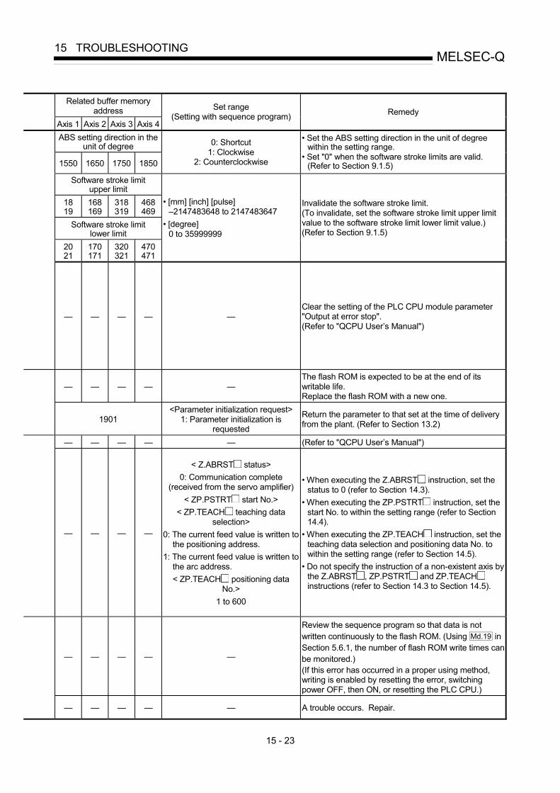
15 - 23
MELSEC-Q15 TROUBLESHOOTING
Related buffer memory address
Axis 1 Axis 2 Axis 3 Axis 4
Set range (Setting with sequence program) Remedy
ABS setting direction in the unit of degree
1550 1650 1750 1850
0: Shortcut 1: Clockwise
2: Counterclockwise
• Set the ABS setting direction in the unit of degree within the setting range.
• Set "0" when the software stroke limits are valid. (Refer to Section 9.1.5)
Software stroke limit upper limit
18 19
168 169
318 319
468 469
Software stroke limit lower limit
20 21
170 171
320 321
470 471
• [mm] [inch] [pulse] –2147483648 to 2147483647
• [degree] 0 to 35999999
Invalidate the software stroke limit. (To invalidate, set the software stroke limit upper limit value to the software stroke limit lower limit value.) (Refer to Section 9.1.5)
— — — — — Clear the setting of the PLC CPU module parameter "Output at error stop". (Refer to "QCPU User’s Manual")
— — — — — The flash ROM is expected to be at the end of its writable life. Replace the flash ROM with a new one.
1901 <Parameter initialization request>
1: Parameter initialization is requested
Return the parameter to that set at the time of delivery from the plant. (Refer to Section 13.2)
— — — — — (Refer to "QCPU User’s Manual")
— — — —
< Z.ABRST status> 0: Communication complete
(received from the servo amplifier) < ZP.PSTRT start No.>
< ZP.TEACH teaching data selection>
0: The current feed value is written to the positioning address.
1: The current feed value is written to the arc address. < ZP.TEACH positioning data
No.> 1 to 600
• When executing the Z.ABRST instruction, set the status to 0 (refer to Section 14.3).
• When executing the ZP.PSTRT instruction, set the start No. to within the setting range (refer to Section 14.4).
• When executing the ZP.TEACH instruction, set the teaching data selection and positioning data No. to within the setting range (refer to Section 14.5).
• Do not specify the instruction of a non-existent axis by the Z.ABRST , ZP.PSTRT and ZP.TEACH instructions (refer to Section 14.3 to Section 14.5).
— — — — —
Review the sequence program so that data is not written continuously to the flash ROM. (Using Md.19 in Section 5.6.1, the number of flash ROM write times can be monitored.) (If this error has occurred in a proper using method, writing is enabled by resetting the error, switching power OFF, then ON, or resetting the PLC CPU.)
— — — — — A trouble occurs. Repair.

15 - 24
MELSEC-Q15 TROUBLESHOOTING
Classification
of errors Error code Error name Error Operation status at error occurrence
900 Outside unit setting range
The set range of the basic parameter 1 "Unit setting" is outside the setting range.
901 Outside pulse number per rotation range
The set range of the basic parameter 1 "No. of pulses per rotation" is outside the setting range.
902 Outside movement amount per rotation range
The set range of the basic parameter 1 "Movement amount per rotation" is outside the setting range.
903 Outside unit magnification range
The set range of the basic parameter 1 "Unit magnification" is outside the setting range.
904 Pulse output mode error
The set range of the basic parameter 1 "Pulse output mode" is outside the setting range.
905 Rotation direction setting error
The set range of the basic parameter 1 "Rotation direction setting" is outside the setting range.
906 Outside bias speed range
• The set range of the basic parameter 1 "Bias speed at start" is outside the setting range.
• The bias speed exceeds the speed limit.
The QD75 READY signal (X0) is not turned ON.
910 Outside speed limit value range
• The set range of the basic parameter 2 "Speed limit value" is outside the setting range.
• The value obtained by the conversion of the speed limit value with respect to the frequency exceeds the maximum output frequency of the unit.
• The speed limit value is smaller than the OPR speed.
911 Outside acceleration time 0 range
The set range of the basic parameter 2 "Acceleration time 0" is outside the setting range.
912 Outside deceleration time 0 range
The set range of the basic parameter 2 "Deceleration time 0" is outside the setting range.
When the power is turned ON or PLC READY signal (Y0) is turned from OFF to ON:
QD75 READY signal (X0) is not turned ON.
At start: The system will not operate.
920 Backlash compensation amount error
The value converted into pulse number using the movement amount per pulse is 256 pulses or more.
Parameter
921 Software stroke limit upper limit
• In the unit of degree, the set value of the detailed parameter 1 "Software stroke limit upper limit value" is outside the setting range.
• In a unit other than degree, the software stroke limit upper limit value is smaller than the software stroke limit lower limit value.
The QD75 READY signal (X0) is not turned ON.

15 - 25
MELSEC-Q15 TROUBLESHOOTING
Related buffer memory address
Axis 1 Axis 2 Axis 3 Axis 4
Set range (Setting with sequence program) Remedy
0 150 300 450 0, 1, 2, 3
1 151 301 451 1 to 65535
2 152 302 452 1 to 65535
3 153 303 453 1, 10, 100, 1000
4 154 304 454 0, 1, 2, 3
5 155 305 455 0, 1
With the setting brought into the setting range, turn the PLC READY signal [Y0] from OFF to ON.
6 7
156 157
306 307
456 457
0 to 1000000 [pulse/s] 0 to 2000000000 [mm/min or others]
Set the bias speed to not more than the speed limit value. With the setting brought into the setting range, turn the PLC READY signal [Y0] from OFF to ON.
10 11
160 161
310 311
460 461
QD75P : 1 to 200000 [pulse/s] 1 to 2000000000 [mm/min or another]
QD75D : 1 to 1000000 [pulse/s] 1 to 2000000000 [mm/min or another]
• The value converted into the frequency should not exceed the maximum output frequency ("maximum output pulse" in Section 3.1) of the module.
• Set a value which is not less than the OPR speed. • With the setting brought into the setting range, turn
the PLC READY signal [Y0] from OFF to ON.
12 13
162 163
312 313
462 463 1 to 8388608
14 15
164 165
314 315
464 465 1 to 8388608
With the setting brought into the setting range, turn the PLC READY signal [Y0] from OFF to ON.
17 167 317 467 0 to 255 Set the value converted into the pulse number using "the movement amount per pulse" to less than 256 pulses. (Refer to Section 12.3.1)
18 19
168 169
318 319
468 469
• [mm] [inch] [pulse] –2147483648 to 2147483647
• [degree] 0 to 35999999
• Bring the setting into the setting range. • In a unit other than degree, set the setting so that the
lower limit value is smaller than the upper limit value.

15 - 26
MELSEC-Q15 TROUBLESHOOTING
Classification
of errors Error code Error name Error Operation status at error
occurrence
922 Software stroke limit lower limit
• In the unit of degree, the set range of the detailed parameter 1 "Software stroke limit lower limit value" is outside the setting range.
• In a unit other than degree, the software stroke limit upper limit value is smaller than the software stroke limit lower limit value.
923 Software stroke limit selection
The set range of the detailed parameter 1 "Software stroke limit selection" is outside the setting range.
924 Software stroke limit valid/invalid setting
The set range of the detailed parameter 1 "Software stroke limit valid/invalid setting" is outside the setting range.
925 Command in-position width
The set range of the detailed parameter 1 "Command in-position width" is outside the setting range.
926 Illegal torque limit setting value
The set range of the detailed parameter 1 "Torque limit setting value" is outside the setting range.
927 M code ON timing error
The set range of the detailed parameter 1 "M code ON signal output timing" is outside the setting range.
928 Speed changeover mode error
The set range of the detailed parameter 1 "Speed changeover mode" is outside the setting range.
929 Interpolation speed designation method error
The set range of the detailed parameter 1 "Interpolation speed designation method" is outside the setting range.
930 Current value update request error
The set range of the detailed parameter 1 "Current feed value during speed control" is outside the setting range.
932 Manual pulse generator input mode error
The set range of the detailed parameter 1 "Manual pulse generator input selection" is outside the setting range.
935 Speed-position function selection error
The detailed parameter 1 "speed-position function selection" is preset to 2 and the following three conditions are not satisfied: 1) Unit is "degree". 2) Software stroke limits are invalid. 3) Update current feed value.
The QD75 READY signal (X0) is not turned ON.
950 Acceleration time 1 setting error
The set range of the detailed parameter 2 "Acceleration time 1" is outside the setting range.
951 Acceleration time 2 setting error
The set range of the detailed parameter 2 "Acceleration time 2" is outside the setting range.
952 Acceleration time 3 setting error
The set range of the detailed parameter 2 "Acceleration time 3" is outside the setting range.
Parameter
953 Deceleration time 1 setting error
The set range of the detailed parameter 2 "Deceleration time 1" is outside the setting range.
At start: The system will not operate.
During operation: The system stops with the setting (deceleration stop/sudden stop) of the detailed parameter 2 sudden stop selection (stop group 3).
(Note that the deceleration stop only occurs during the manual pulse generator operation.)
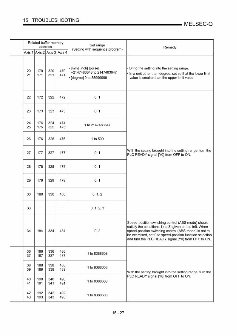
15 - 27
MELSEC-Q15 TROUBLESHOOTING
Related buffer memory address
Axis 1 Axis 2 Axis 3 Axis 4
Set range (Setting with sequence program) Remedy
20 21
170 171
320 321
470 471
• [mm] [inch] [pulse] –2147483648 to 2147483647
• [degree] 0 to 35999999
• Bring the setting into the setting range. • In a unit other than degree, set so that the lower limit
value is smaller than the upper limit value.
22 172 322 472 0, 1
23 173 323 473 0, 1
24 25
174 175
324 325
474 475 1 to 2147483647
26 176 326 476 1 to 500
27 177 327 477 0, 1
28 178 328 478 0, 1
29 179 329 479 0, 1
30 180 330 480 0, 1, 2
33 0, 1, 2, 3
With the setting brought into the setting range, turn the PLC READY signal [Y0] from OFF to ON.
34 184 334 484 0, 2
Speed-position switching control (ABS mode) should satisfy the conditions 1) to 3) given on the left. When speed-position switching control (ABS mode) is not to be exercised, set 0 to speed-position function selection and turn the PLC READY signal (Y0) from OFF to ON.
36 37
186 187
336 337
486 487 1 to 8388608
38 39
188 189
338 339
488 489 1 to 8388608
40 41
190 191
340 341
490 491 1 to 8388608
42 43
192 193
342 343
492 493 1 to 8388608
With the setting brought into the setting range, turn the PLC READY signal [Y0] from OFF to ON.

15 - 28
MELSEC-Q15 TROUBLESHOOTING
Classification
of errors Error code Error name Error Operation status at error occurrence
954 Deceleration time 2 setting error
The set range of the detailed parameter 2 "Deceleration time 2" is outside the setting range.
955 Deceleration time 3 setting error
The set range of the detailed parameter 2 "Deceleration time 3" is outside the setting range.
956 JOG speed limit value error
• The set range of the detailed parameter 2 "JOG speed limit value" is outside the setting range.
• The set range of the detailed parameter 2 "JOG speed limit value" exceeds the speed limit.
957 JOG acceleration time selection setting error
The set range of the detailed parameter 2 "JOG acceleration time selection setting" is outside the setting range.
958 JOG deceleration time selection setting error
The set range of the detailed parameter 2 "JOG deceleration time selection setting" is outside the setting range.
959
Acceleration/ deceleration process selection setting error
The set range of the detailed parameter 2 "Acceleration/deceleration process selection setting" is outside the setting range.
960 S-curve ratio setting error
The set range of the detailed parameter 2 "S-curve ratio" is outside the setting range.
961 Illegal sudden stop deceleration time
The set range of the detailed parameter 2 "Sudden stop deceleration time" is outside the setting range.
962 Stop group 1 sudden stop selection error
The set range of the detailed parameter 2 "Stop group 1 sudden stop selection" is outside the setting range.
963 Stop group 2 sudden stop selection error
The set range of the detailed parameter 2 "Stop group 2 sudden stop selection" is outside the setting range.
964 Stop group 3 sudden stop selection error
The set range of the detailed parameter 2 "Stop group 3 sudden stop selection" is outside the setting range.
966 Outside allowance circular interpolation error width
The set range of the detailed parameter 2 "Allowance circular interpolation error width" is outside the setting range.
967 External command function selection error
The set range of the detailed parameter 2 "External command function selection" is outside the setting range.
At start: The system will not operate.
During operation: The system stops with the setting (deceleration stop/sudden stop) of the detailed parameter 2 Sudden stop selection (stop group 3).
(Note that the deceleration stop only occurs during the manual pulse generator operation.)
Parameter
980 OPR method error The set range of the OPR basic parameter "OPR method" is outside the setting range.
The QD75 READY signal (X0) is not turned ON.

15 - 29
MELSEC-Q15 TROUBLESHOOTING
Related buffer memory
address Axis 1 Axis 2 Axis 3 Axis 4
Set range (Setting with sequence program) Remedy
44 45
194 195
344 345
494 495 1 to 8388608
46 47
196 197
346 347
496 497 1 to 8388608
With the setting brought into the setting range, turn the PLC READY signal [Y0] from OFF to ON.
48 49
198 199
348 349
498 499
QD75P : 1 to 200000 [pulse/s] 1 to 2000000000 [mm/min or another]
QD75D : 1 to 1000000 [pulse/s] 1 to 2000000000 [mm/min or another]
• With the setting brought into the setting range, turn the PLC READY signal [Y0] from OFF to ON.
• Bring the setting into the speed limit value or below.
50 200 350 500 0, 1, 2, 3
51 201 351 501 0, 1, 2, 3
52 202 352 502 0, 1
53 203 353 503 1 to 100
54 55
204 205
354 355
504 505 1 to 8388608
56 206 356 506 0, 1
57 207 357 507 0, 1
58 208 358 508 0, 1
60 61
210 211
360 361
510 511 0 to 10000
62 212 362 512 0, 1, 2, 3
70 220 370 520 0, 1, 2, 3, 4, 5
With the setting brought into the setting range, turn the PLC READY signal [Y0] from OFF to ON.

15 - 30
MELSEC-Q15 TROUBLESHOOTING
Classification
of errors Error code Error name Error Operation status at error occurrence
981 OPR direction error The set range of the OPR basic parameter "OPR direction" is outside the setting range.
982 OP address setting error
The set range of the OPR basic parameter "OP address" is outside the setting range.
983 OPR speed error
• The set range of the OPR basic parameter "OPR speed" is outside the setting range.
• The set range of the OPR basic parameter "OPR speed" is smaller than the bias speed at start.
984 Creep speed error
• The set range of the OPR basic parameter "Creep speed" is outside the setting range.
• The set range of the OPR basic parameter "Creep speed" is larger than the OPR speed.
• The set range of the OPR basic parameter "Creep speed" is smaller than the bias speed at start.
985 OPR retry error The set range of the OPR basic parameter "OPR retry" is outside the setting range.
990 OPR dwell time error The set range of the OPR detailed parameter "OPR dwell time" is outside the setting range.
991
Setting for the movement amount after near-point dog ON error
The set range of the OPR detailed parameter "Setting for the movement amount after near-point dog ON" is outside the setting range.
992 OPR acceleration time selection error
The set range of the OPR detailed parameter "OPR acceleration time selection" is outside the setting range.
993 OPR deceleration time selection error
The set range of the OPR detailed parameter "OPR deceleration time selection" is outside the setting range.
995 OPR torque limit value error
• The set range of the OPR detailed parameter "OPR torque limit value" is outside the setting range.
• The OPR detailed parameter "OPR torque limit value" has exceeded the detailed parameter 1 "Torque limit setting value".
996 Deviation counter clear signal output time setting error
The set range of the OPR detailed parameter "Deviation counter clear signal output time" is outside the setting range.
Parameter
997 Speed designation during OP shift error
The set range of the OPR detailed parameter "Speed designation during OP shift" is outside the setting range.
The QD75 READY signal (X0) is not turned ON.

15 - 31
MELSEC-Q15 TROUBLESHOOTING
Related buffer memory
address Axis 1 Axis 2 Axis 3 Axis 4
Set range (Setting with sequence program) Remedy
71 221 371 521 0, 1
72 73
222 223
372 373
522 523
• [mm] [inch] [pulse] –2147483648 to 2147483647
• [degree] 0 to 35999999
With the setting brought into the setting range, turn the PLC READY signal [Y0] from OFF to ON.
74 75
224 225
374 375
524 525
1 to 1000000 [pulse/s] 1 to 2000000000 [mm/min or others]
• Bring the setting into the setting range. • Set the speed to the bias speed at start or higher.
(Refer to Section 5.2.5)
76 77
226 227
376 377
526 527
1 to 1000000 [pulse/s] 1 to 2000000000 [mm/min or others]
• Bring the setting into the setting range. • Set the speed to that below the OPR speed. • Set the value to the bias speed at start or higher.
(Refer to Section 5.2.5)
78 228 378 528 0, 1
79 229 379 529 0 to 65535
80 81
230 231
380 381
530 531 0 to 2147483647
82 232 382 532 0, 1, 2, 3
83 233 383 533 0, 1, 2, 3
86 236 386 536 1 to 300
87 237 387 537 1 to 65535
88 238 388 538 0, 1
With the setting brought into the setting range, turn the PLC READY signal [Y0] from OFF to ON.

15 - 32
MELSEC-Q15 TROUBLESHOOTING
15.3 List of warnings
The following table shows the warning details and remedies to be taken when a warning occurs.
Classification
of warnings Warning
code Warning name Warning Operation status at warning occurrence
— 000 (Normal status) — —
100 Start during operation
The start request is issued while the axis is BUSY. Continue the operation.
102 Deviation counter clear request
The deviation counter clear request is issued while the axis is BUSY.
The deviation counter clear request is ignored.
104 Restart not possible The restart command is issued when the axis operation status is not "Stopped".
Continue the operation.
109 Teaching in BUSY The teaching request is issued while the axis is BUSY.
The warning is issued for the axis designated at the time of the teaching request.
110 Less than minimum speed The overridden speed becomes “0”. The system is controlled with the
currently executing unit of 1.
111 In PLC READY
The request for writing to the flash ROM is issued when the PLC READY is turned ON (at the time of teaching request).
The warning for axis 1 is issued.
112 Illegal override value
A value other than 1 to 300 is set for the override value.
• Controlled at a setting value of 0 : 100.
• Controlled at a setting value of 301 or over : 300.
113 Outside new torque value range
A value other than 1 to 500 is set for the new torque value. The torque change is not carried out.
Common
114 Below bias speed The command speed is below the bias speed at start. Operate by the bias speed at start.
300 Speed change during deceleration
The speed change request is issued during deceleration stop with JOG start signal OFF.
The speed change is not carried out.
JOG
301 JOG speed limit value
The new speed value exceeds the JOG speed limit value when the speed is changed during operation.
• When the speed exceeds the JOG speed limit, the JOG operation is carried out with the JOG speed limit value.
• While the speed is limited by the JOG speed limit value, the "Speed limiting flag" is turned ON.

15 - 33
MELSEC-Q15 TROUBLESHOOTING
Related buffer memory address
Axis 1 Axis 2 Axis 3 Axis 4
Set range (Setting with sequence program) Remedy
— — — — — — — — — — — Normalize the start request ON timing.
— — — — — Do not carry out the deviation counter clear while the axis is running. (Refer to Chapter 8)
1503 1603 1703 1803 <Restart command> 1: Restart
Normalize the start request ON timing. (Do not issue the restart command when the axis operation is not stopped.)
1548 1549
1648 1649
1748 1749
1848 1849
<Teaching data selection> 0, 1
<Teaching positioning data No.> 1 to 600
Carry out the teaching request when the axis is not BUSY. (Refer to Section 12.7.4)
1513 1613 1713 1813 <Positioning operation speed
override> 1 to 300
Prevent the overridden speed from being reduced to 0.(Refer to Section 12.5.2)
Same as warning code 109 None (If the PLC READY signal (Y0) is turned OFF, respond to the teaching write request).
1513 1613 1713 1813 <Positioning operation speed
override> 1 to 300
1525 1625 1725 1825 <New torque value> 1 to [Torque limit set value]
26 176 326 476 <Torque limit set value> 1 to 500
Set a value within the setting range.
Refer to Section 5.3
"List of positioning data" for command speed
<Command speed> 1 to 1000000 [pulse/s]
1 to 2000000000 [mm/min or another] Bias speed at start
6 7
156 157
306 307
456 457
<Bias speed at start> 0 to 1000000 [pulse/s]
0 to 2000000000 [mm/min or another]
Re-set the command speed/bias speed at start so that the command speed is equal to or larger than the bias speed at start.
1516 1616 1716 1816 <Speed change request> 1: Speed change is requested
Do not carry out the JOG speed change during deceleration with the JOG start signal OFF.
New speed value
1514 1515
1614 1615
1714 1715
1814 1815
0 to 1000000 [pulse/s] 0 to 2000000000 [mm/min or another]
JOG speed limit value
48 49
198 199
348 349
498 499
QD75P : 1 to 200000 [pulse/s] 1 to 2000000000 [mm/min or another]
QD75D : 1 to 1000000 [pulse/s] 1 to 2000000000 [mm/min or another]
Bring the set value into the setting range.

15 - 34
MELSEC-Q15 TROUBLESHOOTING
Classification
of warnings Warning
code Warning name Warning Operation status at warning occurrence
Manual pulse generator 401
Outside manual pulse generator input magnification range
The manual pulse generator 1 pulse input magnification is set at 0 or 101 or higher.
• When input magnification is set at 101 or higher: Re-set to 100.
• When input magnification is set at 0: Re-set to 1.
500 Deceleration/stop speed change
The speed change request is issued during deceleration stop. The speed change is not carried out.
501 Speed limit value over
The new value exceeds the speed limit value when the speed is changed during operation.
• The speed is controlled with the speed limit value.
• The "speed limiting flag" is turned ON.
503 M code ON signal ON start
The M code ON signal is turned ON when the positioning data is executed.
Continue executing the positioning data.
505 No operation termination setting
In the positioning by block starting, the 50th point of the positioning start data is set to CONTINUE.
The operation is terminated.
506 FOR to NEXT nest construction FOR to NEXT is nested.
508
Speed-position switching (during acceleration) signal ON
The switching signal for speed-position switching control (INC mode) is turned ON during acceleration.
The operation is continued.
509 Insufficient remaining distance
• At a continuous operation interrupt request, the distance required deceleration stop is not long enough.
• At a speed change request, the remaining distance is shorter than the distance required for speed change.
• When a command speed is changed: Change to a value as near a new speed value as possible.
• When a target position is changed: Adjust the speed to a value as near the command speed as possible, and then change to a target position.
(When the operation pattern is a continuous path control, ignore the operations stated above.)
511 Step not possible Code 1 is set for the step start information when the step is outside standby.
The step will not start.
512 Illegal external command function
The detailed parameter 2 "External command function selection" setting range is exceeded.
Even if the external command signal is turned ON, the system will not perform anything.
Positioning operation
513 Insufficient movement amount
The movement amount is not large enough for automatic deceleration.
The system stops immediately after it reaches the positioning address.

15 - 35
MELSEC-Q15 TROUBLESHOOTING
Related buffer memory address
Axis 1 Axis 2 Axis 3 Axis 4
Set range (Setting with sequence program) Remedy
1522 1523
1622 1623
1722 1723
1822 1823
<Manual pulse generator 1 pulse input magnification>
1 to 100
Set the manual pulse generator 1 pulse input magnification to within the setting range.
1516 1616 1716 1816 <Speed change request> 1: Speed change is requested
Do not carry out the speed change during deceleration with a stop command, during stoppage, or during automatic deceleration with position control.
New speed value
1514 1515
1614 1615
1714 1715
1814 1815
0 to 1000000 [pulse/s] 0 to 2000000000 [mm/min or another]
Speed limit value
10 11
160 161
310 311
460 461
QD75P : 1 to 200000 [pulse/s] 1 to 2000000000 [mm/min or another]
QD75D : 1 to 1000000 [pulse/s] 1 to 2000000000 [mm/min or another]
Set the new speed value to a range of 0 to "speed limit value".
1504 1604 1704 1804 <M code OFF request> 1: M code ON signal is turned OFF
Normalize the ON and OFF timings of the "M code OFF request". (Refer to Section 12.7.3)
Refer to Section 5.3 "List of positioning data"
<Operation pattern> 00: Positioning complete
01: Continuous positioning control11: Continuous path control
Set the operation termination to the 50th point. (Refer to Chapter 10)
— — — — — Make 1 nest construction for FOR to NEXT.
(Refer to Section 10.3.8)
— — — — — Do not turn ON the speed-position switching signal during acceleration. (Refer to Section 9.2.16)
— — — — — Give a request at the position where there is an enough remaining distance.
1546 1646 1746 1846 <Step start information>
1: Step is continued 2: Re-start is carried out
Do not set a "1" to the step start information when the step is not in standby state. (Refer to Section 12.7.1)
62 212 362 512 <External command function
selection> 0, 1, 2, 3
Set the detailed parameter 2 "External command function selection" to within the setting range.
Refer to Section 5.3 "List of positioning data" — Set a decelerating address or a movement amount to
the positioning data.

15 - 36
MELSEC-Q15 TROUBLESHOOTING
Classification
of warnings Warning
code Warning name Warning Operation status at warning occurrence
514 Outside command speed range
The command speed exceeds the speed limit.
• The command speed is controlled at the "speed limit value".
• The "speed limiting flag" turns ON.
516 Illegal teaching data No.
The positioning data No. is set outside the setting range.
Teaching is not carried out when the set value is 0 or 601 or more. (A "0" is canceled by the QD75 automatically even when a "0" or "601" or more is set.)
517 Illegal teaching data selection
The teaching data selection set value is outside the setting range. Teaching is not carried out.
Positioning operation
518 Target position change not possible
• A target position change request was given for the control system other than ABS1 and INC1.
• The target position change request is turned ON during continuous path control.
• A new target position address is outside the software stroke limit range.
• A target position change request was given during deceleration to a stop.
The target position change is not carried out.

15 - 37
MELSEC-Q15 TROUBLESHOOTING
Related buffer memory address
Axis 1 Axis 2 Axis 3 Axis 4
Set range (Setting with sequence program) Remedy
For command speed, refer to Section 5.3
"List of positioning data"
1 to 1000000 [pulse/s] 1 to 2000000000 [mm/min or another]
Speed limit value
10 11
160 161
310 311
460 461
QD75P : 1 to 200000 [pulse/s] 1 to 2000000000 [mm/min or another]
QD75D : 1 to 1000000 [pulse/s] 1 to 2000000000 [mm/min or another]
Set the command speed to within the setting range.
1549 1649 1749 1849 <Teaching positioning data No.> 1 to 600 Set the positioning data No. to within the setting range.
1548 1648 1748 1848 <Teaching data selection> 0, 1
Set the teaching data selection set value to within the setting range.
1538 1638 1738 1838 <Target position change request
flag> 1: Target position change request
• Do not turn ON the target position change request in the following cases. A control system other than ABS1, and INC1 is used.During deceleration stop. An operating pattern "continuous path control" is used.
• When the target position change address is outside the stroke limit, correct the target position change address. (Refer to Section 12.7.5)
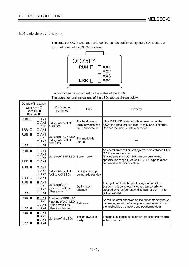
15 - 38
MELSEC-Q15 TROUBLESHOOTING
15.4 LED display functions
The states of QD75 and each axis control can be confirmed by the LEDs located on the front panel of the QD75 main unit.
QD75P4RUN
ERR
AX1AX2AX3AX4
Each axis can be monitored by the states of the LEDs. The operation and indications of the LEDs are as shown below.
Details of indication Goes OFF Goes ON Flashes
Points to be confirmed Error Remedy
RUN
ERR
AX1AX2AX3AX4
Extinguishment of RUN LED
The hardware is faulty or watch dog timer error occurs.
If the RUN LED does not light up even when the power is turned ON, the module may be out of order. Replace the module with a new one.
RUN
ERR
AX1AX2AX3AX4
Lighting of RUN LED, Extinguishment of ERR LED
The module is normal. —
RUN
ERR
AX1AX2AX3AX4
Lighting of ERR LED System error
An operation condition setting error or installation PLC CPU type error occurs. (The setting and PLC CPU type are outside the specification range.) Set the PLC CPU type to a one contained in the specification.
RUN
ERR
AX1AX2AX3AX4
Extinguishment of AX1 to AX4 LEDs
During axis stop, during axis standby —
RUN
ERR
AX1AX2AX3AX4
Lighting of AX1 (Same even if the other axis is lit)
During axis operation
This lights up from the positioning start until the positioning is completed, stopped temporarily, or stopped by error (corresponding at a ratio of 1 : 1 to BUSY signals).
RUN
ERR
AX1AX2AX3AX4
Flashing of ERR LED Flashing of AX1 LED (Same even if the other axis flashes)
Axis error Check the error observed on the buffer memory batch processing monitor of a peripheral device and correct the applicable parameters and positioning data.
RUN
ERR
AX1AX2AX3AX4
Lighting of all LEDs The hardware is faulty
The module comes out of order. Replace the module with a new one.

Appendix - 1
Appen-dices
Appendices
Appendix 1 Version up of the functions .................................................................................Appendix- 2Appendix 1.1 Comparison of functions according to function versions........................Appendix- 2
Appendix 2 Format sheets ....................................................................................................Appendix- 4Appendix 2.1 Positioning Module operation chart ........................................................Appendix- 4Appendix 2.2 Parameter setting value entry table ........................................................Appendix- 6Appendix 2.3 Positioning data setting value entry table .............................................Appendix- 12
Appendix 3 Positioning data (No. 1 to 600) List of buffer memory addresses ....................Appendix- 13Appendix 4 Connection examples with servo amplifiers manufactured by MITSUBISHI Electric Corporation............................................................................................Appendix- 37
Appendix 4.1 Connection example of QD75D and MR-H A(Differential driver) ...........................................................................Appendix- 37
Appendix 4.2 Connection example of QD75D and MR-J2/J2S- A(Differential driver) ...........................................................................Appendix- 38
Appendix 4.3 Connection example of QD75D and MR-C A(Differential driver) ...........................................................................Appendix- 39
Appendix 5 Connection examples with stepping motors manufactured by ORIENTALMOTOR Co., Ltd............................................................................Appendix- 40
Appendix 5.1 Connection example of QD75P and VEXTA UPD(Open collector) ...............................................................................Appendix- 40
Appendix 6 Connection examples with servo amplifiers manufactured by Matsushita Electric Industrial Co., Ltd. ............................................................Appendix- 41
Appendix 6.1 Connection example of QD75D and MINAS-A series(Differential driver) ...........................................................................Appendix- 41
Appendix 7 Connection examples with servo amplifiers manufactured by SANYO DENKI Co., Ltd.....................................................................................Appendix- 42
Appendix 7.1 Connection example of QD75D and PYO series(Differential driver) ...........................................................................Appendix- 42
Appendix 8 Connection examples with servo amplifiers manufactured by YASKAWA Electric Corporation. .......................................................................Appendix- 43
Appendix 8.1 Connection example of QD75D and ∑- series (Differential driver)...................................................................................Appendix- 43Appendix 9 Comparisons with conventional positioning modules.......................................Appendix- 44
Appendix 9.1 Comparisons with A1SD71S2 model.....................................................Appendix- 44Appendix 9.2 Comparisons with A1SD75P1-S3/A1SD75P2-S3/ A1SD75P3-S3
models .............................................................................................Appendix- 45Appendix 10 MELSEC Explanation of positioning terms .....................................................Appendix- 68Appendix 11 Positioning control troubleshooting .................................................................Appendix- 92Appendix 12 List of buffer memory addresses .....................................................................Appendix- 98Appendix 13 External dimension drawing ..........................................................................Appendix- 107

Appendix - 2
MELSEC-QAPPENDICES
Appendix 1 Version up of the functions
Appendix 1.1 Comparison of functions according to function versions
The following tables list the QD75P1/QD75P2/QD75P4/QD75D1/QD75D2/QD75D4
functions compared according to function versions and the buffer memory for their
additional functions.(1) Function comparison
Function versions ofQD75P /QD75DItem
A BReference
Speed-position switching control (ABS mode) Section 9.2.17
Pre-reading start function Section 12.7.8
External I/O signal monitor function 1 Section 13.5
Multiple PLC compatible function 2
Deceleration start flag function 3 3 Section 12.7.9
Stop command processing for decelerationstop function
4 Section 12.7.10
1: Usable on GX Developer of SW6D5C-GPPW-E or later.
2: Compatible with QCPU of function version B.
3: Supported by the module whose first five digits of SERIAL No. are "03042" or later.
4: Supported by the module whose first five digits of SERIAL No. are "05072" or later.
(2) Additional buffer memory
Buffer memory addresses
Axis 1 Axis 2 Axis 3 Axis 4Name Used function
34 184 334 484Speed-position functionselection
Speed-position switchingcontrol
899 999 1099 1199 Deceleration start flag
1905Deceleration start flagvalid
Deceleration start flagfunction
1907Stop command processingfor deceleration stopselection
Stop command processingfor deceleration stopfunction
(3) Additional devices
Device No. Name Used function
Y14 Axis 1
Y15 Axis 2
Y16 Axis 3
Y17 Axis 4
Execution prohibition flag Pre-reading start function

Appendix - 3
MELSEC-QAPPENDICES
MEMO

Appendix - 4
MELSEC-QAPPENDICES
Appendix 2 Format sheets
Appendix 2.1 Positioning Module operation chart
Axi
s add
ress
mm
, in
ch, de
gre
e, pu
lse
Axis addressmm, inch, degree, pulse

Appendix - 5
MELSEC-QAPPENDICES
Axi
s addre
ssm
m,
inch
, deg
ree, pu
lse
Axis addressmm, inch, degree, pulse

Appendix - 6
MELSEC-QAPPENDICES
Appendix 2.2 Parameter setting value entry table
Setting rangeItem
mm inch degree pulse
Pr.1 Unit setting 0 1 2 3
Pr.2 No. of pulses per rotation (Ap) 1 to 65535 pulse
Pr.3 Movement amount per rotation(Al)
1 to 65535 × 10-1μm
1 to 65535 × 10-5inch
1 to 65535 × 10-5degree
1 to 65535 pulse
Pr.4 Unit magnification (Am) 1: 1-fold, 10: 10-fold, 100: 100-fold, 1000: 1000-fold
Pr.5 Pulse output mode 0: PULSE/SIGN mode, 1: CW/CCW mode,2: A phase/B phase (multiple of 4), 3: A phase/B phase (multiple of 1)
Pr.6 Rotation direction setting 0: Current value increment with forward run pulse output1: Current value increment with reverse run pulse output
Basi
c pa
ram
eter
s 1
Pr.7 Bias speed at start 0 to 2000000000 × 10-2mm/min
0 to 2000000000 × 10-3inch/min
0 to 2000000000× 10-3degree/min
0 to 1000000pulse/s
Pr.8 Speed limit value1 to 2000000000 × 10-2mm/min
1 to 2000000000 × 10-3mm/min
1 to 2000000000×10-3degree/min
1 to 1000000/1 to 200000 pulse
Pr.9 Acceleration time 0
Basi
c pa
ram
eter
s2
Pr.10 Deceleration time 01 to 8388608ms
Pr.11 Backlash compensation amount 0 to 65535 × 10-1μm
0 to 65535 × 10-5inch
0 to 65535 × 10-5degree
0 to 65535 pulse
Pr.12 Software stroke limit upper limitvalue
Pr.13 Software stroke limit lower limitvalue
–2147483648 to2147483647 × 10-1μm
–2147483648 to2147483647 × 10-5inch
0 to 35999999 × 10-5degree
–2147483648 to2147483647 pulse
Pr.14 Software stroke limit selection 0: Apply software stroke limit on current feed value1: Apply software stroke limit on machine feed value
Pr.15 Software stroke limit valid/invalidselection
0: Software stroke limit valid during JOG operation, inching operation,and manual pulse generator operation
1: Software stroke limit invalid during JOG operation, inchingoperation, and manual pulse generator operation
Pr.16 Command in-position width1 to 2147483647 × 10-1μm
1 to 2147483647 × 10-5inch
1 to 2147483647 × 10-5degree
1 to 2147483647 pulse
Pr.17 Torque limit setting value 1 to 500%
Pr.18 M code ON signal output timing 0: WITH mode, 1: AFTER mode
Pr.19 Speed switching mode 0: Standard speed switching mode1: Front-loading speed switching mode
Pr.20 Interpolation speed designationmethod 0: Composite speed, 1: Reference axis speed
Det
aile
d pa
ram
eter
s 1
Pr.21 Current feed value during speedcontrol
0: Do not update current feed value, 1: Update current feed value2: Clear current feed value
: "1 to 1000000" for QD75D and "1 to 200000" for QD75P when the unit is "pulse".

Appendix - 7
MELSEC-QAPPENDICES
Initial value Axis 1 Axis 2 Axis 3 Axis 4 Remarks
3
20000
20000
1
1
0
0
20000
1000
1000
0
2147483647
–2147483648
0
0
100
300
0
0
0
0

Appendix - 8
MELSEC-QAPPENDICES
Setting rangeItem
mm inch degree pulse
b0 Lower limit b3 Stop signal b6 Near-point signal
b1 Upper limit b4 Externalcommand
b7, b9to b15 UnusedPr.22 Input signal logic selection
b2 Drive unitREADY b5 Zero signal b8 Manual pulse
generator input
b0 Commandpulse signal b2 Unused b4 Deviation
counter clearPr.23 Output signal logic selection
b1 Unused b3 Unused b5 tob15 Unused
Setting ofeach bit value0: Negative
logic1: Positive
logic("0" is set forunused bit.)
Pr.24 Manual pulse generatorinput selection
0: A phase/B phase multiple of 41: A phase/B phase multiple of 22: A phase/B phase multiple of 13: PULSE/SIGN mode
Det
aile
d pa
ram
eter
s 1
Pr.150 Speed -position functionselection
0: Speed-position switching control (INC mode)2: Speed-position switching control (ABS mode)
Pr.25 Acceleration time 1
Pr.26 Acceleration time 2
Pr.27 Acceleration time 3
Pr.28 Deceleration time 1
Pr.29 Deceleration time 2
Pr.30 Deceleration time 3
1 to 8388608ms
Pr.31 JOG speed limit value1 to2000000000 × 10-2mm/min
1 to 2000000000 × 10-3inch/min
1 to 2000000000×10-3degree/min
1 to 1000000/1 to 200000 pulse
Pr.32 JOG operation accelerationtime selection
Pr.33 JOG operation decelerationtime selection
0 to 3
Pr.34 Acceleration/decelerationprocess selection
0: Automatic trapezoidal acceleration/deceleration process1: S-curve acceleration/deceleration process
Pr.35 S-curve ratio 1 to 100%
Pr.36 Sudden stop decelerationtime 1 to 8388608ms
Pr.37 Stop group 1 sudden stopselection
Pr.38 Stop group 2 sudden stopselection
Pr.39 Stop group 3 sudden stopselection
0: Normal deceleration stop1: Sudden stop
Pr.40 Positioning complete signaloutput time 0 to 65535ms
Pr.41 Allowable circularinterpolation error width
1 to 100000 × 10-1μm
1 to 100000 × 10-5inch
1 to 100000 × 10-5degree
1 to 100000 pulse
Det
aile
d pa
ram
eter
s 2
Pr.42 External command functionselection
0: External positioning start 1: External speed change request2: Speed-position or position-speed switching request3: Skip request
: "1 to 1000000" for QD75D and "1 to 200000" for QD75P when the unit is "pulse".

Appendix - 9
MELSEC-QAPPENDICES
Initial value Axis 1 Axis 2 Axis 3 Axis 4 Remarks
0
0
0
0
1000
1000
1000
1000
1000
1000
20000
0
0
0
100
1000
0
0
0
300
100
0

Appendix - 10
MELSEC-QAPPENDICES
Setting rangeItem
mm inch degree pulse
Pr.43 OPR method
0: Near-point dog method1: Stopper method 1) (By dwell time elapse)2: Stopper method 2) (By OP signal when stopper is hit)3: Stopper method 3) (Without near-point dog method)4: Count method 1) (Use zero signal)5: Count method 2) (Do not use zero signal)
Pr.44 OPR direction0: Positive direction (address increment direction)1: Negative direction (address decrement direction)
Pr.45 OP address–2147483648 to2147483647 × 10-1μm
–2147483648 to2147483647 × 10-5inch
0 to 35999999 × 10-5degree
–2147483648 to2147483647 pulse/s
Pr.46 OPR speed
Pr.47 Creep speed
1 to 2000000000 × 10-2mm/min
1 to 2000000000 × 10-3inch/min
1 to 2000000000×10-3degree/min
1 to 1000000 pulse/s
OPR
bas
ic p
aram
eter
s
Pr.48 OPR retry0: Do not retry OPR with upper/lower limit switch1: Retry OPR with upper/lower limit switch
Pr.49 OPR dwell time 0 to 65535ms
Pr.50 Setting for the movement amountafter near-point dog ON
0 to 2147483647 × 10-1μm
0 to 2147483647 × 10-5inch
0 to 2147483647 × 10-5degree
0 to 2147483647 pulse
Pr.51 OPR acceleration time selection
Pr.52 OPR deceleration time selection0 to 3
Pr.53 OP shift amount–2147483648 to2147483647 × 10-1μm
–2147483648 to2147483647 × 10-5inch
0 to 35999999 × 10-5degree
–2147483648 to2147483647 pulse
Pr.54 OPR torque limit value 0 to 300%
Pr.55 Deviation counter clear signaloutput time 1 to 65535ms
Pr.56 Speed designation during OP shift 0: OPR speed 1: Creep speed
OPR
det
aile
d pa
ram
eter
s
Pr.57 Dwell time during OPR retry 0 to 65535ms
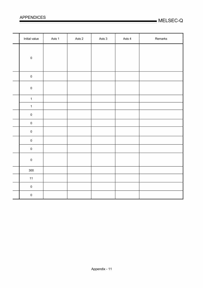
Appendix - 11
MELSEC-QAPPENDICES
Initial value Axis 1 Axis 2 Axis 3 Axis 4 Remarks
0
0
0
1
1
0
0
0
0
0
0
300
11
0
0

Appendix - 12
MELSEC-QAPPENDICES
Appendix 2.3 Positioning data setting value entry table [data No. to ]
Axis
Data
Da.1
Operationpattern
Da.2
Controlsystem
Da.3
Accelera-tion timeNo.
Da.4
Decelera-tion timeNo.
Da.5
Axis to beinterpola-ted
Da.6
Positioningaddress/movementamount
Da.7
Arcaddress
Da.8
Commandspeed
Da.9
Dwelltime
Da.10
M code
12345678901234567890123456789012345678901234567890

Appendix - 13
MELSEC-QAPPENDICES
Appendix 3 Positioning data (No. 1 to 600)List of buffer memory addresses
(1) For axis 1Command
speedPositioning
addressArc data
Commandspeed
Positioningaddress
Arc dataDataNo.
Posi-tioningidenti-
fier
Mcode
Dwelltime Low-
orderHigh-order
Low-order
High-order
Low-order
High-order
DataNo.
Posi-tioningidenti-
fier
Mcode
Dwelltime Low-
orderHigh-order
Low-order
High-order
Low-order
High-order
12345
20002010202020302040
20012011202120312041
20022012202220322042
20042014202420342044
20052015202520352045
20062016202620362046
20072017202720372047
20082018202820382048
20092019202920392049
5152535455
25002510252025302540
25012511252125312541
25022512252225322542
25042514252425342544
25052515252525352545
25062516252625362546
25072517252725372547
25082518252825382548
2509251925295392549
678910
20502060207020802090
20512061207120812091
20522062207220822092
20542064207420842094
20552065207520852095
20562066207620862096
20572067207720872097
20582068207820882098
20592069207920892099
5657585960
25502560257025802590
25512561257125812591
25522562257225822592
25542564257425842594
25552565257525852595
25562566257625862596
25572567257725872597
25582568257825882598
25592569257925892599
11
12
13
14
15
2100
2110
2120
2130
2140
2101
2111
2121
2131
2141
2102
2112
2122
2132
2142
2104
2114
2124
2134
2144
2105
2115
2125
2135
2145
2106
2116
2126
2136
2146
2107
2117
2127
2137
2147
2108
2118
2128
2138
2148
2109
2119
2129
2139
2149
61
62
63
64
65
2600
2610
2620
2630
2640
2601
2611
2621
2631
2641
2602
2612
2622
2632
2642
2604
2614
2624
2634
2644
2605
2615
2625
2635
2645
2606
2616
2626
2636
2646
2607
2617
2627
2637
2647
2608
2618
2628
2638
2648
2609
2619
2629
2639
2649
16
17
18
19
20
2150
2160
2170
2180
2190
2151
2161
2171
2181
2191
2152
2162
2172
2182
2192
2154
2164
2174
2184
2194
2155
2165
2175
2185
2195
2156
2166
2176
2186
2196
2157
2167
2177
2187
2197
2158
2168
2178
2188
2198
2159
2169
2179
2189
2199
66
67
68
69
70
2650
2660
2670
2680
2690
2651
2661
2671
2681
2691
2652
2662
2672
2682
2692
2654
2664
2674
2684
2694
2655
2665
2675
2685
2695
2656
2666
2676
2686
2696
2657
2667
2677
2687
2697
2658
2668
2678
2688
2698
2659
2669
2679
2689
2699
21
22
23
24
25
2200
2210
2220
2230
2240
2201
2211
2221
2231
2241
2202
2212
2222
2232
2242
2204
2214
2224
2234
2244
2205
2215
2225
2235
2245
2206
2216
2226
2236
2246
2207
2217
2227
2237
2247
2208
2218
2228
2238
2248
2209
2219
2229
2239
2249
71
72
73
74
75
2700
2710
2720
2730
2740
2701
2711
2721
2731
2741
2702
2712
2722
2732
2742
2704
2714
2724
2734
2744
2705
2715
2725
2735
2745
2706
2716
2726
2736
2746
2707
2717
2727
2737
2747
2708
2718
2728
2738
2748
2709
2719
2729
2739
2749
26
27
28
29
30
2250
2260
2270
2280
2290
2251
2261
2271
2281
2291
2252
2262
2272
2282
2292
2254
2264
2274
2284
2294
2255
2265
2275
2285
2295
2256
2266
2276
2286
2296
2257
2267
2277
2287
2297
2258
2268
2278
2288
2298
2259
2269
2279
2289
2299
76
77
78
79
80
2750
2760
2770
2780
2790
2751
2761
2771
2781
2791
2752
2762
2772
2782
2792
2754
2764
2774
2784
2794
2755
2765
2775
2785
2795
2756
2766
2776
2786
2796
2757
2767
2777
2787
2797
2758
2768
2778
2788
2798
2759
2769
2779
2789
2799
31
32
33
34
35
2300
2310
2320
2330
2340
2301
2311
2321
2331
2341
2302
2312
2322
2332
2342
2304
2314
2324
2334
2344
2305
2315
2325
2335
2345
2306
2316
2326
2336
2346
2307
2317
2327
2337
2347
2308
2318
2328
2338
2348
2309
2319
2329
2339
2349
81
82
83
84
85
2800
2810
2820
2830
2840
2801
2811
2821
2831
2841
2802
2812
2822
2832
2842
2804
2814
2824
2834
2844
2805
2815
2825
2835
2845
2806
2816
2826
2836
2846
2807
2817
2827
2837
2847
2808
2818
2828
2838
2848
2809
2819
2829
2839
2849
36
37
38
39
40
2350
2360
2370
2380
2390
2351
2361
2371
2381
2391
2352
2362
2372
2382
2392
2354
2364
2374
2384
2394
2355
2365
2375
2385
2395
2356
2366
2376
2386
2396
2357
2367
2377
2387
2397
2358
2368
2378
2388
2398
2359
2369
2379
2389
2399
86
87
88
89
90
2850
2860
2870
2880
2890
2851
2861
2871
2881
2891
2852
2862
2872
2882
2892
2854
2864
2874
2884
2894
2855
2865
2875
2885
2895
2856
2866
2876
2886
2896
2857
2867
2877
2887
2897
2858
2868
2878
2888
2898
2859
2869
2879
2889
2899
41
42
43
44
45
2400
2410
2420
2430
2440
2401
2411
2421
2431
2441
2402
2412
2422
2432
2442
2404
2414
2424
2434
2444
2405
2415
2425
2435
2445
2406
2416
2426
2436
2446
2407
2417
2427
2437
2447
2408
2418
2428
2438
2448
2409
2419
2429
2439
2449
91
92
93
94
95
2900
2910
2920
2930
2940
2901
2911
2921
2931
2941
2902
2912
2922
2932
2942
2904
2914
2924
2934
2944
2905
2915
2925
2935
2945
2906
2916
2926
2936
2946
2907
2917
2927
2937
2947
2908
2918
2928
2938
2948
2909
2919
2929
2939
2949
46
47
48
49
50
2450
2460
2470
2480
2490
2451
2461
2471
2481
2491
2452
2462
2472
2482
2492
2454
2464
2474
2484
2494
2455
2465
2475
2485
2495
2456
2466
2476
2486
2496
2457
2467
2477
2487
2497
2458
2468
2478
2488
2498
2459
2469
2479
2489
2499
96
97
98
99
100
2950
2960
2970
2980
2990
2951
2961
2971
2981
2991
2952
2962
2972
2982
2992
2954
2964
2974
2984
2994
2955
2965
2975
2985
2995
2956
2966
2976
2986
2996
2957
2967
2977
2987
2997
2958
2968
2978
2988
2998
2959
2969
2979
2989
2999

Appendix - 14
MELSEC-QAPPENDICES
(1) For axis 1
Commandspeed
Positioningaddress
Arc dataCommand
speedPositioning
addressArc data
DataNo.
Posi-tioningidenti-
fier
Mcode
Dwelltime Low-
orderHigh-order
Low-order
High-order
Low-order
High-order
DataNo.
Posi-tioningidenti-
fier
Mcode
Dwelltime Low-
orderHigh-order
Low-order
High-order
Low-order
High-order
101
102
103
104
105
3000
3010
3020
3030
3040
3001
3011
3021
3031
3041
3002
3012
3022
3032
3042
3004
3014
3024
3034
3044
3005
3015
3025
3035
3045
3006
3016
3026
3036
3046
3007
3017
3027
3037
3047
3008
3018
3028
3038
3048
3009
3019
3029
3039
3049
151
152
153
154
155
3500
3510
3520
3530
3540
3501
3511
3521
3531
3541
3502
3512
3522
3532
3542
3504
3514
3524
3534
3544
3505
3515
3525
3535
3545
3506
3516
3526
3536
3546
3507
3517
3527
3537
3547
3508
3518
3528
3538
3548
3509
3519
3529
3539
3549
106
107
108
109
110
3050
3060
3070
3080
3090
3051
3061
3071
3081
3091
3052
3062
3072
3082
3092
3054
3064
3074
3084
3094
3055
3065
3075
3085
3095
3056
3066
3076
3086
3096
3057
3067
3077
3087
3097
3058
3068
3078
3088
3098
3059
3069
3079
3089
3099
156
157
158
159
160
3550
3560
3570
3580
3590
3551
3561
3571
3581
3591
3552
3562
3572
3582
3592
3554
3564
3574
3584
3594
3555
3565
3575
3585
3595
3556
3566
3576
3586
3596
3557
3567
3577
3587
3597
3558
3568
3578
3588
3598
3559
3569
3579
3589
3599
111
112
113
114
115
3100
3110
3120
3130
3140
3101
3111
3121
3131
3141
3102
3112
3122
3132
3142
3104
3114
3124
3134
3144
3105
3115
3125
3135
3145
3106
3116
3126
3136
3146
3107
3117
3127
3137
3147
3108
3118
3128
3138
3148
3109
3119
3129
3139
3149
161
162
163
164
165
3600
3610
3620
3630
3640
3601
3611
3621
3631
3641
3602
3612
3622
3632
3642
3604
3614
3624
3634
3644
3605
3615
3625
3635
3645
3606
3616
3626
3636
3646
3607
3617
3627
3637
3647
3608
3618
3628
3638
3648
3609
3619
3629
3639
3649
116
117
118
119
120
3150
3160
3170
3180
3190
3151
3161
3171
3181
3191
3152
3162
3172
3182
3192
3154
3164
3174
3184
3194
3155
3165
3175
3185
3195
3156
3166
3176
3186
3196
3157
3167
3177
3187
3197
3158
3168
3178
3188
3198
3159
3169
3179
3189
3199
166
167
168
169
170
3650
3660
3670
3680
3690
3651
3661
3671
3681
3691
3652
3662
3672
3682
3692
3654
3664
3674
3684
3694
3655
3665
3675
3685
3695
3656
3666
3676
3686
3696
3657
3667
3677
3687
3697
3658
3668
3678
3688
3698
3659
3669
3679
3689
3699
121
122
123
124
125
3200
3210
3220
3230
3240
3201
3211
3221
3231
3241
3202
3212
3222
3232
3242
3204
3214
3224
3234
3244
3205
3215
3225
3235
3245
3206
3216
3226
3236
3246
3207
3217
3227
3237
3247
3208
3218
3228
3238
3248
3209
3219
3229
3239
3249
171
172
173
174
175
3700
3710
3720
3730
3740
3701
3711
3721
3731
3741
3702
3712
3722
3732
3742
3704
3714
3724
3734
3744
3705
3715
3725
3735
3745
3706
3716
3726
3736
3746
3707
3717
3727
3737
3747
3708
3718
3728
3738
3748
3709
3719
3729
3739
3749
126
127
128
129
130
3250
3260
3270
3280
3290
3251
3261
3271
3281
3291
3252
3262
3272
3282
3292
3254
3264
3274
3284
3294
3255
3265
3275
3285
3295
3256
3266
3276
3286
3296
3257
3267
3277
3287
3297
3258
3268
3278
3288
3298
3259
3269
3279
3289
3299
176
177
178
179
180
3750
3760
3770
3780
3790
3751
3761
3771
3781
3791
3752
3762
3772
3782
3792
3754
3764
3774
3784
3794
3755
3765
3775
3785
3795
3756
3766
3776
3786
3796
3757
3767
3777
3787
3797
3758
3768
3778
3788
3798
3759
3769
3779
3789
3799
131
132
133
134
135
3300
3310
3320
3330
3340
3301
3311
3321
3331
3341
3302
3312
3322
3332
3342
3304
3314
3324
3334
3344
3305
3315
3325
3335
3345
3306
3316
3326
3336
3346
3307
3317
3327
3337
3347
3308
3318
3328
3338
3348
3309
3319
3329
3339
3349
181
182
183
184
185
3800
3810
3820
3830
3840
3801
3811
3821
3831
3841
3802
3812
3822
3832
3842
3804
3814
3824
3834
3844
3805
3815
3825
3835
3845
3806
3816
3826
3836
3846
3807
3817
3827
3837
3847
3808
3818
3828
3838
3848
3809
3819
3829
3839
3849
136
137
138
139
140
3350
3360
3370
3380
3390
3351
3361
3371
3381
3391
3352
3362
3372
3382
3392
3354
3364
3374
3384
3394
3355
3365
3375
3385
3395
3356
3366
3376
3386
3396
3357
3367
3377
3387
3397
3358
3368
3378
3388
3398
3359
3369
3379
3389
3399
186
187
188
189
190
3850
3860
3870
3880
3890
3851
3861
3871
3881
3891
3852
3862
3872
3882
3892
3854
3864
3874
3884
3894
3855
3865
3875
3885
3895
3856
3866
3876
3886
3896
3857
3867
3877
3887
3897
3858
3868
3878
3888
3898
3859
3869
3879
3889
3899
141
142
143
144
145
3400
3410
3420
3430
3440
3401
3411
3421
3431
3441
3402
3412
3422
3432
3442
3404
3414
3424
3434
3444
3405
3415
3425
3435
3445
3406
3416
3426
3436
3446
3407
3417
3427
3437
3447
3408
3418
3428
3438
3448
3409
3419
3429
3439
3449
191
192
193
194
195
3900
3910
3920
3930
3940
3901
3911
3921
3931
3941
3902
3912
3922
3932
3942
3904
3914
3924
3934
3944
3905
3915
3925
3935
3945
3906
3916
3926
3936
3946
3907
3917
3927
3937
3947
3908
3918
3928
3938
3948
3909
3919
3929
3939
3949
146
147
148
149
150
3450
3460
3470
3480
3490
3451
3461
3471
3481
3491
3452
3462
3472
3482
3492
3454
3464
3474
3484
3494
3455
3465
3475
3485
3495
3456
3466
3476
3486
3496
3457
3467
3477
3487
3497
3458
3468
3478
3488
3498
3459
3469
3479
3489
3499
196
197
198
199
200
3950
3960
3970
3980
3990
3951
3961
3971
3981
3991
3952
3962
3972
3982
3992
3954
3964
3974
3984
3994
3955
3965
3975
3985
3995
3956
3966
3976
3986
3996
3957
3967
3977
3987
3997
3958
3968
3978
3988
3998
3959
3969
3979
3989
3999

Appendix - 15
MELSEC-QAPPENDICES
(1) For axis 1Command
speedPositioning
addressArc data
Commandspeed
Positioningaddress
Arc dataDataNo.
Posi-tioningidenti-
fier
Mcode
Dwelltime Low-
orderHigh-order
Low-order
High-order
Low-order
High-order
DataNo.
Posi-tioningidenti-
fier
Mcode
Dwelltime Low-
orderHigh-order
Low-order
High-order
Low-order
High-order
201
202
203
204
205
4000
4010
4020
4030
4040
4001
4011
4021
4031
4041
4002
4012
4022
4032
4042
4004
4014
4024
4034
4044
4005
4015
4025
4035
4045
4006
4016
4026
4036
4046
4007
4017
4027
4037
4047
4008
4018
4028
4038
4048
4009
4019
4029
4039
4049
251
252
253
254
255
4500
4510
4520
4530
4540
4501
4511
4521
4531
4541
4502
4512
4522
4532
4542
4504
4514
4524
4534
4544
4505
4515
4525
4535
4545
4506
4516
4526
4536
4546
4507
4517
4527
4537
4547
4508
4518
4528
4538
4548
4509
4519
4529
4539
4549
206
207
208
209
210
4050
4060
4070
4080
4090
4051
4061
4071
4081
4091
4052
4062
4072
4082
4092
4054
4064
4074
4084
4094
4055
4065
4075
4085
4095
4056
4066
4076
4086
4096
4057
4067
4077
4087
4097
4058
4068
4078
4088
4098
4059
4069
4079
4089
4099
256
257
258
259
260
4550
4560
4570
4580
4590
4551
4561
4571
4581
4591
4552
4562
4572
4582
4592
4554
4564
4574
4584
4594
4555
4565
4575
4585
4595
4556
4566
4576
4586
4596
4557
4567
4577
4587
4597
4558
4568
4578
4588
4598
4559
4569
4579
4589
4599
211
212
213
214
215
4100
4110
4120
4130
4140
4101
4111
4121
4131
4141
4102
4112
4122
4132
4142
4104
4114
4124
4134
4144
4105
4115
4125
4135
4145
4106
4116
4126
4136
4146
4107
4117
4127
4137
4147
4108
4118
4128
4138
4148
4109
4119
4129
4139
4149
261
262
263
264
265
4600
4610
4620
4630
4640
4601
4611
4621
4631
4641
4602
4612
4622
4632
4642
4604
4614
4624
4634
4644
4605
4615
4625
4635
4645
4606
4616
4626
4636
4646
4607
4617
4627
4637
4647
4608
4618
4628
4638
4648
4609
4619
4629
4639
4649
216
217
218
219
220
4150
4160
4170
4180
4190
4151
4161
4171
4181
4191
4152
4162
4172
4182
4192
4154
4164
4174
4184
4194
4155
4165
4175
4185
4195
4156
4166
4176
4186
4196
4157
4167
4177
4187
4197
4158
4168
4178
4188
4198
4159
4169
4179
4189
4199
266
267
268
269
270
4650
4660
4670
4680
4690
4651
4661
4671
4681
4691
4652
4662
4672
4682
4692
4654
4664
4674
4684
4694
4655
4665
4675
4685
4695
4656
4666
4676
4686
4696
4657
4667
4677
4687
4697
4658
4668
4678
4688
4698
4659
4669
4679
4689
4699
221
222
223
224
225
4200
4210
4220
4230
4240
4201
4211
4221
4231
4241
4202
4212
4222
4232
4242
4204
4214
4224
4234
4244
4205
4215
4225
4235
4245
4206
4216
4226
4236
4246
4207
4217
4227
4237
4247
4208
4218
4228
4238
4248
4209
4219
4229
4239
4249
271
272
273
274
275
4700
4710
4720
4730
4740
4701
4711
4721
4731
4741
4702
4712
4722
4732
4742
4704
4714
4724
4734
4744
4705
4715
4725
4735
4745
4706
4716
4726
4736
4746
4707
4717
4727
4737
4747
4708
4718
4728
4738
4748
4709
4719
4729
4739
4749
226
227
228
229
230
4250
4260
4270
4280
4290
4251
4261
4271
4281
4291
4252
4262
4272
4282
4292
4254
4264
4274
4284
4294
4255
4265
4275
4285
4295
4256
4266
4276
4286
4296
4257
4267
4277
4287
4297
4258
4268
4278
4288
4298
4259
4269
4279
4289
4299
276
277
278
279
280
4750
4760
4770
4780
4790
4751
4761
4771
4781
4791
4752
4762
4772
4782
4792
4754
4764
4774
4784
4794
4755
4765
4775
4785
4795
4756
4766
4776
4786
4796
4757
4767
4777
4787
4797
4758
4768
4778
4788
4798
4759
4769
4779
4789
4799
231
232
233
234
235
4300
4310
4320
4330
4340
4301
4311
4321
4331
4341
4302
4312
4322
4332
4342
4304
4314
4324
4334
4344
4305
4315
4325
4335
4345
4306
4316
4326
4336
4346
4307
4317
4327
4337
4347
4308
4318
4328
4338
4348
4309
4319
4329
4339
4349
281
282
283
284
285
4800
4810
4820
4830
4840
4801
4811
4821
4831
4841
4802
4812
4822
4832
4842
4804
4814
4824
4834
4844
4805
4815
4825
4835
4845
4806
4816
4826
4836
4846
4807
4817
4827
4837
4847
4808
4818
4828
4838
4848
4809
4819
4829
4839
4849
236
237
238
239
240
4350
4360
4370
4380
4390
4351
4361
4371
4381
4391
4352
4362
4372
4382
4392
4354
4364
4374
4384
4394
4355
4365
4375
4385
4395
4356
4366
4376
4386
4396
4357
4367
4377
4387
4397
4358
4368
4378
4388
4398
3459
4369
4379
4389
4399
286
287
288
289
290
4850
4860
4870
4880
4890
4851
4861
4871
4881
4891
4852
4862
4872
4882
4892
4854
4864
4874
4884
4894
4855
4865
4875
4885
4895
4856
4866
4876
4886
4896
4857
4867
4877
4887
4897
4858
4868
4878
4888
4898
4859
4869
4879
4889
4899
241
242
243
244
245
4400
4410
4420
4430
4440
4401
4411
4421
4431
4441
4402
4412
4422
4432
4442
4404
4414
4424
4434
4444
4405
4415
4425
4435
4445
4406
4416
4426
4436
4446
4407
4417
4427
4437
4447
4408
4418
4428
4438
4448
4409
4419
4429
4439
4449
291
292
293
294
295
4900
4910
4920
4930
4940
4901
4911
4921
4931
4941
4902
4912
4922
4932
4942
4904
4914
4924
4934
4944
4905
4915
4925
4935
4945
4906
4916
4926
4936
4946
4907
4917
4927
4937
4947
4208
4218
4228
4238
4248
4209
4219
4229
4239
4249
246
247
248
249
250
4450
4460
4470
4480
4490
4451
4461
4471
4481
4491
4452
4462
4472
4482
4492
4454
4464
4474
4484
4494
4455
4465
4475
4485
4495
4456
4466
4476
4486
4496
4457
4467
4477
4487
4497
4458
4468
4478
4488
4498
4459
4469
4479
4489
4499
296
297
298
299
300
4950
4960
4970
4980
4990
4951
4961
4971
4981
4991
4952
4962
4972
4982
4992
4954
4964
4974
4984
4994
4955
4965
4975
4985
4995
4956
4966
4976
4986
4996
4957
4967
4977
4987
4997
4958
4968
4978
4988
4998
4959
4969
4979
4989
4999

Appendix - 16
MELSEC-QAPPENDICES
(1) For axis 1Command
speedPositioning
addressArc data
Commandspeed
Positioningaddress
Arc dataDataNo.
Posi-tioningidenti-
fier
Mcode
Dwelltime Low-
orderHigh-order
Low-order
High-order
Low-order
High-order
DataNo.
Posi-tioningidenti-
fier
Mcode
Dwelltime Low-
orderHigh-order
Low-order
High-order
Low-order
High-order
301
302
303
304
305
5000
5010
5020
5030
5040
5001
5011
5021
5031
5041
5002
5012
5022
5032
5042
5004
5014
5024
5034
5044
5005
5015
5025
5035
5045
5006
5016
5026
5036
5046
5007
5017
5027
5037
5047
5008
5018
5028
5038
5048
5009
5019
5029
5039
5049
351
352
353
354
355
5500
5510
5520
5530
5540
5501
5511
5521
5531
5541
5502
5512
5522
5532
5542
5504
5514
5524
5534
5544
5505
5515
5525
5535
5545
5506
5516
5526
5536
5546
5507
5517
5527
5537
5547
5508
5518
5528
5538
5548
5509
5519
5529
5539
5549
306
307
308
309
310
5050
5060
5070
5080
5090
5051
5061
5071
5081
5091
5052
5062
5072
5082
5092
5054
5064
5074
5084
5094
5055
5065
5075
5085
5095
5056
5066
5076
5086
5096
5057
5067
5077
5087
5097
5058
5068
5078
5088
5098
5059
5069
5079
5089
5099
356
357
358
359
360
5550
5560
5570
5580
5590
5551
5561
5571
5581
5591
5552
5562
5572
5582
5592
5554
5564
5574
5584
5594
5555
5565
5575
5585
5595
5556
5566
5576
5586
5596
5557
5567
5577
5587
5597
5558
5568
5578
5588
5598
5559
5569
5579
5589
5599
311
312
313
314
315
5100
5110
5120
5130
5140
5101
5111
5121
5131
5141
5102
5112
5122
5132
5142
5104
5114
5124
5134
5144
5105
5115
5125
5135
5145
5106
5116
5126
5136
5146
5107
5117
5127
5137
5147
5108
5118
5128
5138
5148
5109
5119
5129
5139
5149
361
362
363
364
365
5600
5610
5620
5630
5640
5601
5611
5621
5631
5641
5602
5612
5622
5632
5642
5604
5614
5624
5634
5644
5605
5615
5625
5635
5645
5606
5616
5626
5636
5646
5607
5617
5627
5637
5647
5608
5618
5628
5638
5648
5609
5619
5629
5639
5649
316
317
318
319
320
5150
5160
5170
5180
5190
5151
5161
5171
5181
5191
5152
5162
5172
5182
5192
5154
5164
5174
5184
5194
5155
5165
5175
5185
5195
5156
5166
5176
5186
5196
5157
5167
5177
5187
5197
5158
5168
5178
5188
5198
5159
5169
5179
5189
5199
366
367
368
369
370
5650
5660
5670
5680
5690
5651
5661
5671
5681
5691
5652
5662
5672
5682
5692
5654
5664
5674
5684
5694
5655
5665
5675
5685
5695
5656
5666
5676
5686
5696
5657
5667
5677
5687
5697
5658
5668
5678
5688
5698
5659
5669
5679
5689
5699
321
322
323
324
325
5200
5210
5220
5230
5240
5201
5211
5221
5231
5241
5202
5212
5222
5232
5242
5204
5214
5224
5234
5244
5205
5215
5225
5235
5245
5206
5216
5226
5236
5246
5207
5217
5227
5237
5247
5208
5218
5228
5238
5248
5209
5219
5229
5239
5249
371
372
373
374
375
5700
5710
5720
5730
5740
5701
5711
5721
5731
5741
5702
5712
5722
5732
5742
5704
5714
5724
5734
5744
5705
5715
5725
5735
5745
5706
5716
5726
5736
5746
5707
5717
5727
5737
5747
5708
5718
5728
5738
5748
5709
5719
5729
5739
5749
326
327
328
329
330
5250
5260
5270
5280
5290
5251
5261
5271
5281
5291
5252
5262
5272
5282
5292
5254
5264
5274
5284
5294
5255
5265
5275
5285
5295
5256
5266
5276
5286
5296
5257
5267
5277
5287
5297
5258
5268
5278
5288
5298
5259
5269
5279
5289
5299
376
377
378
379
380
5750
5760
5770
5780
5790
5751
5761
5771
5781
5791
5752
5762
5772
5782
5792
5754
5764
5774
5784
5794
5755
5765
5775
5785
5795
5756
5766
5776
5786
5796
5757
5767
5777
5787
5797
5758
5768
5778
5788
5798
5759
5769
5779
5789
5799
331
332
333
334
335
5300
5310
5320
5330
5340
5301
5311
5321
5331
5341
5302
5312
5322
5332
5342
5304
5314
5324
5334
5344
5305
5315
5325
5335
5345
5306
5316
5326
5336
5346
5307
5317
5327
5337
5347
5308
5318
5328
5338
5348
5309
5319
5329
5339
5349
381
382
383
384
385
5800
5810
5820
5830
5840
5801
5811
5821
5831
5841
5802
5812
5822
5832
5842
5804
5814
5824
5834
5844
5805
5815
5825
5835
5845
5806
5816
5826
5836
5846
5807
5817
5827
5837
5847
5808
5818
5828
5838
5848
5809
5819
5829
5839
5849
336
337
338
339
340
5350
5360
5370
5380
5390
5351
5361
5371
5381
5391
5352
5362
5372
5382
5392
5354
5364
5374
5384
5394
5355
5365
5375
5385
5395
5356
5366
5376
5386
5396
5357
5367
5377
5387
5397
5358
5368
5378
5388
5398
5359
5369
5379
5389
5399
386
387
388
389
390
5850
5860
5870
5880
5890
5851
5861
5871
5881
5891
5852
5862
5872
5882
5892
5854
5864
5874
5884
5894
5855
5865
5875
5885
5895
5856
5866
5876
5886
5896
5857
5867
5877
5887
5897
5858
5868
5878
5888
5898
5859
5869
5879
5889
5899
341
342
343
344
345
5400
5410
5420
5430
5440
5401
5411
5421
5431
5441
5402
5412
5422
5432
5442
5404
5414
5424
5434
5444
5405
5415
5425
5435
5445
5406
5416
5426
5436
5446
5407
5417
5427
5437
5447
5408
5418
5428
5438
5448
5409
5419
5429
5439
5449
391
392
393
394
395
5900
5910
5920
5930
5940
5901
5911
5921
5931
5941
5902
5912
5922
5932
5942
5904
5914
5924
5934
5944
5905
5915
5925
5935
5945
5906
5916
5926
5936
5946
5907
5917
5927
5937
5947
5908
5918
5928
5938
5948
5909
5919
5929
5939
5949
346
347
348
349
350
5450
5460
5470
5480
5490
5451
5461
5471
5481
5491
5452
5462
5472
5482
5492
5454
5464
5474
5484
5494
5455
5465
5475
5485
5495
5456
5466
5476
5486
5496
5457
5467
5477
5487
5497
5458
5468
5478
5488
5498
5459
5469
5479
5489
5499
396
397
398
399
400
5950
5960
5970
5980
5990
5951
5961
5971
5981
5991
5952
5962
5972
5982
5992
5954
5964
5974
5984
5994
5955
5965
5975
5985
5995
5956
5966
5976
5986
5996
5957
5967
5977
5987
5997
5958
5968
5978
5988
5998
5959
5969
5979
5989
5999

Appendix - 17
MELSEC-QAPPENDICES
(1) For axis 1Command
speedPositioning
addressArc data
Commandspeed
Positioningaddress
Arc dataDataNo.
Posi-tioningidenti-
fier
Mcode
Dwelltime Low-
orderHigh-order
Low-order
High-order
Low-order
High-order
DataNo.
Posi-tioningidenti-
fier
Mcode
Dwelltime Low-
orderHigh-order
Low-order
High-order
Low-order
High-order
401
402
403
404
405
6000
6010
6020
6030
6040
6001
6011
6021
6031
6041
6002
6012
6022
6032
6042
6004
6014
6024
6034
6044
6005
6015
6025
6035
6045
6006
6016
6026
6036
6046
6007
6017
6027
6037
6047
6008
6018
6028
6038
6048
6009
6019
6029
6039
6049
451
452
453
454
455
6500
6510
6520
6530
6540
6501
6511
6521
6531
6541
6502
6512
6522
6532
6542
6504
6514
6524
6534
6544
6505
6515
6525
6535
6545
6506
6516
6526
6536
6546
6507
6517
6527
6537
6547
6508
6518
6528
6538
6548
6509
6519
6529
6539
6549
406
407
408
409
410
6050
6060
6070
6080
6090
6051
6061
6071
6081
6091
6052
6062
6072
6082
6092
6054
6064
6074
6084
6094
6055
6065
6075
6085
6095
6056
6066
6076
6086
6096
6057
6067
6077
6087
6097
6058
6068
6078
6088
6098
6059
6069
6079
6089
6099
456
457
458
459
460
6550
6560
6570
6580
6590
6551
6561
6571
6581
6591
6552
6562
6572
6582
6592
6554
6564
6574
6584
6594
6555
6565
6575
6585
6595
6556
6566
6576
6586
6596
6557
6567
6577
6587
6597
6558
6568
6578
6588
6598
6559
6569
6579
6589
6599
411
412
413
414
415
6100
6110
6120
6130
6140
6101
6111
6121
6131
6141
6102
6112
6122
6132
6142
6104
6114
6124
6134
6144
6105
6115
6125
6135
6145
6106
6116
6126
6136
6146
6107
6117
6127
6137
6147
6108
6118
6128
6138
6148
6109
6119
6129
6139
6149
461
462
463
464
465
6600
6610
6620
6630
6640
6601
6611
6621
6631
6641
6602
6612
6622
6632
6642
6604
6614
6624
6634
6644
6605
6615
6625
6635
6645
6606
6616
6626
6636
6646
6607
6617
6627
6637
6647
6608
6618
6628
6638
6648
6609
6619
6629
6639
6649
416
417
418
419
420
6150
6160
6170
6180
6190
6151
6161
6171
6181
6191
6152
6162
6172
6182
6192
6154
6164
6174
6184
6194
6155
6165
6175
6185
6195
6156
6166
6176
6186
6196
6157
6167
6177
6187
6197
6158
6168
6178
6188
6198
6159
6169
6179
6189
6199
466
467
468
469
470
6650
6660
6670
6680
6690
6651
6661
6671
6681
6691
6652
6662
6672
6682
6692
6654
6664
6674
6684
6694
6655
6665
6675
6685
6695
6656
6666
6676
6686
6696
6657
6667
6677
6687
6697
6658
6668
6678
6688
6698
6659
6669
6679
6689
6699
421
422
423
424
425
6200
6210
6220
6230
6240
6201
6211
6221
6231
6241
6202
6212
6222
6232
6242
6204
6214
6224
6234
6244
6205
6215
6225
6235
6245
6206
6216
6226
6236
6246
6207
6217
6227
6237
6247
6208
6218
6228
6238
6248
6209
6219
6229
6239
6249
471
472
473
474
475
6700
6710
6720
6730
6740
6701
6711
6721
6731
6741
6702
6712
6722
6732
6742
6704
6714
6724
6734
6744
6705
6715
6725
6735
6745
6706
6716
6726
6736
6746
6707
6717
6727
6737
6747
6708
6718
6728
6738
6748
6709
6719
6729
6739
6749
426
427
428
429
430
6250
6260
6270
6280
6290
6251
6261
6271
6281
6291
6252
6262
6272
6282
6292
6254
6264
6274
6284
6294
6255
6265
6275
6285
6295
6256
6266
6276
6286
6296
6257
6267
6277
6287
6297
6258
6268
6278
6288
6298
6259
6269
6279
6289
6299
476
477
478
479
480
6750
6760
6770
6780
6790
6751
6761
6771
6781
6791
6752
6762
6772
6782
6792
6754
6764
6774
6784
6794
6755
6765
6775
6785
6795
6756
6766
6776
6786
6796
6757
6767
6777
6787
6797
6758
6768
6778
6788
6798
6759
6769
6779
6789
6799
431
432
433
434
435
6300
6310
6320
6330
6340
6301
6311
6321
6331
6341
6302
6312
6322
6332
6342
6304
6314
6324
6334
6344
6305
6315
6325
6335
6345
6306
6316
6326
6336
6346
6307
6317
6327
6337
6347
6308
6318
6328
6338
6348
6309
6319
6329
6339
6349
481
482
483
484
485
6800
6810
6820
6830
6840
6801
6811
6821
6831
6841
6802
6812
6822
6832
6842
6804
6814
6824
6834
6844
6805
6815
6825
6835
6845
6806
6816
6826
6836
6846
6807
6817
6827
6837
6847
6808
6818
6828
6838
6848
6809
6819
6829
6839
6849
436
437
438
439
440
6350
6360
6370
6380
6390
6351
6361
6371
6381
6391
6352
6362
6372
6382
6392
6354
6364
6374
6384
6394
6355
6365
6375
6385
6395
6356
6366
6376
6386
6396
6357
6367
6377
6387
6397
6358
6368
6378
6388
6398
6359
6369
6379
6389
6399
486
487
488
489
490
6850
6860
6870
6880
6890
6851
6861
6871
6881
6891
6852
6862
6872
6882
6892
6854
6864
6874
6884
6894
6855
6865
6875
6885
6895
6856
6866
6876
6886
6896
6857
6867
6877
6887
6897
6858
6868
6878
6888
6898
6859
6869
6879
6889
6899
441
442
443
444
445
6400
6410
6420
6430
6440
6401
6411
6421
6431
6441
6402
6412
6422
6432
6442
6404
6414
6424
6434
6444
6405
6415
6425
6435
6445
6406
6416
6426
6436
6446
6407
6417
6427
6437
6447
6408
6418
6428
6438
6448
6409
6419
6429
6439
6449
491
492
493
494
495
6900
6910
6920
6930
6940
6901
6911
6921
6931
6941
6902
6912
6922
6932
6942
6904
6914
6924
6934
6944
6905
6915
6925
6935
6945
6906
6916
6926
6936
6946
6907
6917
6927
6937
6947
6908
6918
6928
6938
6948
6909
6919
6929
6939
6949
446
447
448
449
450
6450
6460
6470
6480
6490
6451
6461
6471
6481
6491
6452
6462
6472
6482
6492
6454
6464
6474
6484
6494
6455
6465
6475
6485
6495
6456
6466
6476
6486
6496
6457
6467
6477
6487
6497
6458
6468
6478
6488
6498
6459
6469
6479
6489
6499
496
497
498
499
500
6950
6960
6970
6980
6990
6951
6961
6971
6981
6991
6952
6962
6972
6982
6992
6954
6964
6974
6984
6994
6955
6965
6975
6985
6995
6956
6966
6976
6986
6996
6957
6967
6977
6987
6997
6958
6968
6978
6988
6998
6959
6969
6979
6989
6999

Appendix - 18
MELSEC-QAPPENDICES
(1) For axis 1Command
speedPositioning
addressArc data
Commandspeed
Positioningaddress
Arc dataDataNo.
Posi-tioningidenti-
fier
Mcode
Dwelltime Low-
orderHigh-order
Low-order
High-order
Low-order
High-order
DataNo.
Posi-tioningidenti-
fier
Mcode
Dwelltime Low-
orderHigh-order
Low-order
High-order
Low-order
High-order
501
502
503
504
505
7000
7010
7020
7030
7040
7001
7011
7021
7031
7041
7002
7012
7022
7032
7042
7004
7014
7024
7034
7044
7005
7015
7025
7035
7045
7006
7016
7026
7036
7046
7007
7017
7027
7037
7047
7008
7018
7028
7038
7048
7009
7019
7029
7039
7049
551
552
553
554
555
7500
7510
7520
7530
7540
7501
7511
7521
7531
7541
7502
7512
7522
7532
7542
7504
7514
7524
7534
7544
7505
7515
7525
7535
7545
7506
7516
7526
7536
7546
7507
7517
7527
7537
7547
7508
7518
7528
7538
7548
7509
7519
7529
7539
7549
506
507
508
509
510
7050
7060
7070
7080
7090
7051
7061
7071
7081
7091
7052
7062
7072
7082
7092
7054
7064
7074
7084
7094
7055
7065
7075
7085
7095
7056
7066
7076
7086
7096
7057
7067
7077
7087
7097
7058
7068
7078
7088
7098
7059
7069
7079
7089
7099
556
557
558
559
560
7550
7560
7570
7580
7590
7551
7561
7571
7581
7591
7552
7562
7572
7582
7592
7554
7564
7574
7584
7594
7555
7565
7575
7585
7595
7556
7566
7576
7586
7596
7557
7567
7577
7587
7597
7558
7568
7578
7588
7598
7559
7569
7579
7589
7599
511
512
513
514
515
7100
7110
7120
7130
7140
7101
7111
7121
7131
7141
7102
7112
7122
7132
7142
7104
7114
7124
7134
7144
7105
7115
7125
7135
7145
7106
7116
7126
7136
7146
7107
7117
7127
7137
7147
7108
7118
7128
7138
7148
7109
7119
7129
7139
7149
561
562
563
564
565
7600
7610
7620
7630
7640
7601
7611
7621
7631
7641
7602
7612
7622
7632
7642
7604
7614
7624
7634
7644
7605
7615
7625
7635
7645
7606
7616
7626
7636
7646
7607
7617
7627
7637
7647
7608
7618
7628
7638
7648
7609
7619
7629
7639
7649
516
517
518
519
520
7150
7160
7170
7180
7190
7151
7161
7171
7181
7191
7152
7162
7172
7182
7192
7154
7164
7174
7184
7194
7155
7165
7175
7185
7195
7156
7166
7176
7186
7196
7157
7167
7177
7187
7197
7158
7168
7178
7188
7198
7159
7169
7179
7189
7199
566
567
568
569
570
7650
7660
7670
7680
7690
7651
7661
7671
7681
7691
7652
7662
7672
7682
7692
7654
7664
7674
7684
7694
7655
7665
7675
7685
7695
7656
7666
7676
7686
7696
7657
7667
7677
7687
7697
7658
7668
7678
7688
7698
7659
7669
7679
7689
7699
521
522
523
524
525
7200
7210
7220
7230
7240
7201
7211
7221
7231
7241
7202
7212
7222
7232
7242
7204
7214
7224
7234
7244
7205
7215
7225
7235
7245
7206
7216
7226
7236
7246
7207
7217
7227
7237
7247
7208
7218
7228
7238
7248
7209
7219
7229
7239
7249
571
572
573
574
575
7700
7710
7720
7730
7740
7701
7711
7721
7731
7741
7702
7712
7722
7732
7742
7704
7714
7724
7734
7744
7705
7715
7725
7735
7745
7706
7716
7726
7736
7746
7707
7717
7727
7737
7747
7708
7718
7728
7738
7748
7709
7719
7729
7739
7749
526
527
528
529
530
7250
7260
7270
7280
7290
7251
7261
7271
7281
7291
7252
7262
7272
7282
7292
7254
7264
7274
7284
7294
7255
7265
7275
7285
7295
7256
7266
7276
7286
7296
7257
7267
7277
7287
7297
7258
7268
7278
7288
7298
7259
7269
7279
7289
7299
576
577
578
579
580
7750
7760
7770
7780
7790
7751
7761
7771
7781
7791
7752
7762
7772
7782
7792
7754
7764
7774
7784
7794
7755
7765
7775
7785
7795
7756
7766
7776
7786
7796
7757
7767
7777
7787
7797
7758
7768
7778
7788
7798
7759
7769
7779
7789
7799
531
532
533
534
535
7300
7310
7320
7330
7340
7301
7311
7321
7331
7341
7302
7312
7322
7332
7342
7304
7314
7324
7334
7344
7305
7315
7325
7335
7345
7306
7316
7326
7336
7346
7307
7317
7327
7337
7347
7308
7318
7328
7338
7348
7309
7319
7329
7339
7349
581
582
583
584
585
7800
7810
7820
7830
7840
7801
7811
7821
7831
7841
7802
7812
7822
7832
7842
7804
7814
7824
7834
7844
7805
7815
7825
7835
7845
7806
7816
7826
7836
7846
7807
7817
7827
7837
7847
7808
7818
7828
7838
7848
7809
7819
7829
7839
7849
536
537
538
539
540
7350
7360
7370
7380
7390
7351
7361
7371
7381
7391
7352
7362
7372
7382
7392
7354
7364
7374
7384
7394
7355
7365
7375
7385
7395
7356
7366
7376
7386
7396
7357
7367
7377
7387
7397
7358
7368
7378
7388
7398
7359
7369
7379
7389
7399
586
587
588
589
590
7850
7860
7870
7880
7890
7851
7861
7871
7881
7891
7852
7862
7872
7882
7892
7854
7864
7874
7884
7894
7855
7865
7875
7885
7895
7856
7866
7876
7886
7896
7857
7867
7877
7887
7897
7858
7868
7878
7888
7898
7859
7869
7879
7889
7899
541
542
543
544
545
7400
7410
7420
7430
7440
7401
7411
7421
7431
7441
7402
7412
7422
7432
7442
7404
7414
7424
7434
7444
7405
7415
7425
7435
7445
7406
7416
7426
7436
7446
7407
7417
7427
7437
7447
7408
7418
7428
7438
7448
7409
7419
7429
7439
7449
591
592
593
594
595
7900
7910
7920
7930
7940
7901
7911
7921
7931
7941
7902
7912
7922
7932
7942
7904
7914
7924
7934
7944
7905
7915
7925
7935
7945
7906
7916
7926
7936
7946
7907
7917
7927
7937
7947
7908
7918
7928
7938
7948
7909
7919
7929
7939
7949
546
547
548
549
550
7450
7460
7470
7480
7490
7451
7461
7471
7481
7491
7452
7462
7472
7482
7492
7454
7464
7474
7484
7494
7455
7465
7475
7485
7495
7456
7466
7476
7486
7496
7457
7467
7477
7487
7497
7458
7468
7478
7488
7498
7459
7469
7479
7489
7499
596
597
598
599
600
7950
7960
7970
7980
7990
7951
7961
7971
7981
7991
7952
7962
7972
7982
7992
7954
7964
7974
7984
7994
7955
7965
7975
7985
7995
7956
7966
7976
7986
7996
7957
7967
7977
7987
7997
7958
7968
7978
7988
7998
7959
7969
7979
7989
7999

Appendix - 19
MELSEC-QAPPENDICES
(2) For axis 2Command
speedPositioning
addressArc data
Commandspeed
Positioningaddress
Arc dataDataNo.
Posi-tioningidenti-
fier
Mcode
Dwelltime Low-
orderHigh-order
Low-order
High-order
Low-order
High-order
DataNo.
Posi-tioningidenti-
fier
Mcode
Dwelltime Low-
orderHigh-order
Low-order
High-order
Low-order
High-order
1
2
3
4
5
8000
8010
8020
8030
8040
8001
8011
8021
8031
8041
8002
8012
8022
8032
8042
8004
8014
8024
8034
8044
8005
8015
8025
8035
8045
8006
8016
8026
8036
8046
8007
8017
8027
8037
8047
8008
8018
8028
8038
8048
8009
8019
8029
8039
8049
51
52
53
54
55
8500
8510
8520
8530
8540
8501
8511
8521
8531
8541
8502
8512
8522
8532
8542
8504
8514
8524
8534
8544
8505
8515
8525
8535
8545
8506
8516
8526
8536
8546
8507
8517
8527
8537
8547
8508
8518
8528
8538
8548
8509
8519
8529
8539
8549
6
7
8
9
10
8050
8060
8070
8080
8090
8051
8061
8071
8081
8091
8052
8062
8072
8082
8092
8054
8064
8074
8084
8094
8055
8065
8075
8085
8095
8056
8066
8076
8086
8096
8057
8067
8077
8087
8097
8058
8068
8078
8088
8098
8059
8069
8079
8089
8099
56
57
58
59
60
8550
8560
8570
8580
8590
8551
8561
8571
8581
8591
8552
8562
8572
8582
8592
8554
8564
8574
8584
8594
8555
8565
8575
8585
8595
8556
8566
8576
8586
8596
8557
8567
8577
8587
8597
8558
8568
8578
8588
8598
8559
8569
8579
8589
8599
11
12
13
14
15
8100
8110
8120
8130
8140
8101
8111
8121
8131
8141
8102
8112
8122
8132
8142
8104
8114
8124
8134
8144
8105
8115
8125
8135
8145
8106
8116
8126
8136
8146
8107
8117
8127
8137
8147
8108
8118
8128
8138
8148
8109
8119
8129
8139
8149
61
62
63
64
65
8600
8610
8620
8630
8640
8601
8611
8621
8631
8641
8602
8612
8622
8632
8642
8604
8614
8624
8634
8644
8605
8615
8625
8635
8645
8606
8616
8626
8636
8646
8607
8617
8627
8637
8647
8608
8618
8628
8638
8648
8609
8619
8629
8639
8649
16
17
18
19
20
8150
8160
8170
8180
8190
8151
8161
8171
8181
8191
8152
8162
8172
8182
8192
8154
8164
8174
8184
8194
8155
8165
8175
8185
8195
8156
8166
8176
8186
8196
8157
8167
8177
8187
8197
8158
8168
8178
8188
8198
8159
8169
8179
8189
8199
66
67
68
69
70
8650
8660
8670
8680
8690
8651
8661
8671
8681
8691
8652
8662
8672
8682
8692
8654
8664
8674
8684
8694
8655
8665
8675
8685
8695
8656
8666
8676
8686
8696
8657
8667
8677
8687
8697
8658
8668
8678
8688
8698
8659
8669
8679
8689
8699
21
22
23
24
25
8200
8210
8220
8230
8240
8201
8211
8221
8231
8241
8202
8212
8222
8232
8242
8204
8214
8224
8234
8244
8205
8215
8225
8235
8245
8206
8216
8226
8236
8246
8207
8217
8227
8237
8247
8208
8218
8228
8238
8248
8209
8219
8229
8239
8249
71
72
73
74
75
8700
8710
8720
8730
8740
8701
8711
8721
8731
8741
8702
8712
8722
8732
8742
8704
8714
8724
8734
8744
8705
8715
8725
8735
8745
8706
8716
8726
8736
8746
8707
8717
8727
8737
8747
8708
8718
8728
8738
8748
8709
8719
8729
8739
8749
26
27
28
29
30
8250
8260
8270
8280
8290
8251
8261
8271
8281
8291
8252
8262
8272
8282
8292
8254
8264
8274
8284
8294
8255
8265
8275
8285
8295
8256
8266
8276
8286
8296
8257
8267
8277
8287
8297
8258
8268
8278
8288
8298
8259
8269
8279
8289
8299
76
77
78
79
80
8750
8760
8770
8780
8790
8751
8761
8771
8781
8791
8752
8762
8772
8782
8792
8754
8764
8774
8784
8794
8755
8765
8775
8785
8795
8756
8766
8776
8786
8796
8757
8767
8777
8787
8797
8758
8768
8778
8788
8798
8759
8769
8779
8789
8799
31
32
33
34
35
8300
8310
8320
8330
8340
8301
8311
8321
8331
8341
8302
8312
8322
8332
8342
8304
8314
8324
8334
8344
8305
8315
8325
8335
8345
8306
8316
8326
8336
8346
8307
8317
8327
8337
8347
8308
8318
8328
8338
8348
8309
8319
8329
8339
8349
81
82
83
84
85
8800
8810
8820
8830
8840
8801
8811
8821
8831
8841
8802
8812
8822
8832
8842
8804
8814
8824
8834
8844
8805
8815
8825
8835
8845
8806
8816
8826
8836
8846
8807
8817
8827
8837
8847
8808
8818
8828
8838
8848
8809
8819
8829
8839
8849
36
37
38
39
40
8350
8360
8370
8380
8390
8351
8361
8371
8381
8391
8352
8362
8372
8382
8392
8354
8364
8374
8384
8394
8355
8365
8375
8385
8395
8356
8366
8376
8386
8396
8357
8367
8377
8387
8397
8358
8368
8378
8388
8398
8359
8369
8379
8389
8399
86
87
88
89
90
8850
8860
8870
8880
8890
8851
8861
8871
8881
8891
8852
8862
8872
8882
8892
8854
8864
8874
8884
8894
8855
8865
8875
8885
8895
8856
8866
8876
8886
8896
8857
8867
8877
8887
8897
8858
8868
8878
8888
8898
8859
8869
8879
8889
8899
41
42
43
44
45
8400
8410
8420
8430
8440
8401
8411
8421
8431
8441
8402
8412
8422
8432
8442
8404
8414
8424
8434
8444
8405
8415
8425
8435
8445
8406
8416
8426
8436
8446
8407
8417
8427
8437
8447
8408
8418
8428
8438
8448
8409
8419
8429
8439
8449
91
92
93
94
95
8900
8910
8920
8930
8940
8901
8911
8921
8931
8941
8902
8912
8922
8932
8942
8904
8914
8924
8934
8944
8905
8915
8925
8935
8945
8906
8916
8926
8936
8946
8907
8917
8927
8937
8947
8908
8918
8928
8938
8948
8909
8919
8929
8939
8949
46
47
48
49
50
8450
8460
8470
8480
8490
8451
8461
8471
8481
8491
8452
8462
8472
8482
8492
8454
8464
8474
8484
8494
8455
8465
8475
8485
8495
8456
8466
8476
8486
8496
8457
8467
8477
8487
8497
8458
8468
8478
8488
8498
8459
8469
8479
8489
8499
96
97
98
99
100
8950
8960
8970
8980
8990
8951
8961
8971
8981
8991
8952
8962
8972
8982
8992
8954
8964
8974
8984
8994
8955
8965
8975
8985
8995
8956
8966
8976
8986
8996
8957
8967
8977
8987
8997
8958
8968
8978
8988
8998
8959
8969
8979
8989
8999

Appendix - 20
MELSEC-QAPPENDICES
(2) For axis 2Command
speedPositioning
addressArc data
Commandspeed
Positioningaddress
Arc dataDataNo.
Posi-tioningidenti-
fier
Mcode
Dwelltime Low-
orderHigh-order
Low-order
High-order
Low-order
High-order
DataNo.
Posi-tioningidenti-
fier
Mcode
Dwelltime Low-
orderHigh-order
Low-order
High-order
Low-order
High-order
101
102
103
104
105
9000
9010
9020
9030
9040
9001
9011
9021
9031
9041
9002
9012
9022
9032
9042
9004
9014
9024
9034
9044
9005
9015
9025
9035
9045
9006
9016
9026
9036
9046
9007
9017
9027
9037
9047
9008
9018
9028
9038
9048
9009
9019
9029
9039
9049
151
152
153
154
155
9500
9510
9520
9530
9540
9501
9511
9521
9531
9541
9502
9512
9522
9532
9542
9504
9514
9524
9534
9544
9505
9515
9525
9535
9545
9506
9516
9526
9536
9546
9507
9517
9527
9537
9547
9508
9518
9528
9538
9548
9509
9519
9529
9539
9549
106
107
108
109
110
9050
9060
9070
9080
9090
9051
9061
9071
9081
9091
9052
9062
9072
9082
9092
9054
9064
9074
9084
9094
9055
9065
9075
9085
9095
9056
9066
9076
9086
9096
9057
9067
9077
9087
9097
9058
9068
9078
9088
9098
9059
9069
9079
9089
9099
156
157
158
159
160
9550
9560
9570
9580
9590
9551
9561
9571
9581
9591
9552
9562
9572
9582
9592
9554
9564
9574
9584
9594
9555
9565
9575
9585
9595
9556
9566
9576
9586
9596
9557
9567
9577
9587
9597
9558
9568
9578
9588
9598
9559
9569
9579
9589
9599
111
112
113
114
115
9100
9110
9120
9130
9140
9101
9111
9121
9131
9141
9102
9112
9122
9132
9142
9104
9114
9124
9134
9144
9105
9115
9125
9135
9145
9106
9116
9126
9136
9146
9107
9117
9127
9137
9147
9108
9118
9128
9138
9148
9109
9119
9129
9139
9149
161
162
163
164
165
9600
9610
9620
9630
9640
9601
9611
9621
9631
9641
9602
9612
9622
9632
9642
9604
9614
9624
9634
9644
9605
9615
9625
9635
9645
9606
9616
9626
9636
9646
9607
9617
9627
9637
9647
9608
9618
9628
9638
9648
9609
9619
9629
9639
9649
116
117
118
119
120
9150
9160
9170
9180
9190
9151
9161
9171
9181
9191
9152
9162
9172
9182
9192
9154
9164
9174
9184
9194
9155
9165
9175
9185
9195
9156
9166
9176
9186
9196
9157
9167
9177
9187
9197
9158
9168
9178
9188
9198
9159
9169
9179
9189
9199
166
167
168
169
170
9650
9660
9670
9680
9690
9651
9661
9671
9681
9691
9652
9662
9672
9682
9692
9654
9664
9674
9684
9694
9655
9665
9675
9685
9695
9656
9666
9676
9686
9696
9657
9667
9677
9687
9697
9658
9668
9678
9688
9698
9659
9669
9679
9689
9699
126
127
128
129
130
9250
9260
9270
9280
9290
9251
9261
9271
9281
9291
9252
9262
9272
9282
9292
9254
9264
9274
9284
9294
9255
9265
9275
9285
9295
9256
9266
9276
9286
9296
9257
9267
9277
9287
9297
9258
9268
9278
9288
9298
9259
9269
9279
9289
9299
176
177
178
179
180
9750
9760
9770
9780
9790
9751
9761
9771
9781
9791
9752
9762
9772
9782
9792
9754
9764
9774
9784
9794
9755
9765
9775
9785
9795
9756
9766
9776
9786
9796
9757
9767
9777
9787
9797
9758
9768
9778
9788
9798
9759
9769
9779
9789
9799
131
132
133
134
135
9300
9310
9320
9330
9340
9301
9311
9321
9331
9341
9302
9312
9322
9332
9342
9304
9314
9324
9334
9344
9305
9315
9325
9335
9345
9306
9316
9326
9336
9346
9307
9317
9327
9337
9347
9308
9318
9328
9338
9348
9309
9319
9329
9339
9349
181
182
183
184
185
9800
9810
9820
9830
9840
9801
9811
9821
9831
9841
9802
9812
9822
9832
9842
9804
9814
9824
9834
9844
9805
9815
9825
9835
9845
9806
9816
9826
9836
9846
9807
9817
9827
9837
9847
9808
9818
9828
9838
9848
9809
9819
9829
9839
9849
136
137
138
139
140
9350
9360
9370
9380
9390
9351
9361
9371
9381
9391
9352
9362
9372
9382
9392
9354
9364
9374
9384
9394
9355
9365
9375
9385
9395
9356
9366
9376
9386
9396
9357
9367
9377
9387
9397
9358
9368
9378
9388
9398
9359
9369
9379
9389
9399
186
187
188
189
190
9850
9860
9870
9880
9890
9851
9861
9871
9881
9891
9852
9862
9872
9882
9892
9854
9864
9874
9884
9894
9855
9865
9875
9885
9895
9856
9866
9876
9886
9896
9857
9867
9877
9887
9897
9858
9868
9878
9888
9898
9859
9869
9879
9889
9899
141
142
143
144
145
9400
9410
9420
9430
9440
9401
9411
9421
9431
9441
9402
9412
9422
9432
9442
9404
9414
9424
9434
9444
9405
9415
9425
9435
9445
9406
9416
9426
9436
9446
9407
9417
9427
9437
9447
9408
9418
9428
9438
9448
9409
9419
9429
9439
9449
191
192
193
194
195
9900
9910
9920
9930
9940
9901
9911
9921
9931
9941
9902
9912
9922
9932
9942
9904
9914
9924
9934
9944
9905
9915
9925
9935
9945
9906
9916
9926
9936
9946
9907
9917
9927
9937
9947
9908
9918
9928
9938
9948
9909
9919
9929
9939
9949
146
147
148
149
150
9450
9460
9470
9480
9490
9451
9461
9471
9481
9491
9452
9462
9472
9482
9492
9454
9464
9474
9484
9494
9455
9465
9475
9485
9495
9456
9466
9476
9486
9496
9457
9467
9477
9487
9497
9458
9468
9478
9488
9498
9459
9469
9479
9489
9499
196
197
198
199
200
9950
9960
9970
9980
9990
9951
9961
9971
9981
9991
9952
9962
9972
9982
9992
9954
9964
9974
9984
9994
9955
9965
9975
9985
9995
9956
9966
9976
9986
9996
9957
9967
9977
9987
9997
9958
9968
9978
9988
9998
9959
9969
9979
9989
9999

Appendix - 21
MELSEC-QAPPENDICES
(2) For axis 2Command
speedPositioning
addressArc data
Commandspeed
Positioningaddress
Arc dataDataNo.
Posi-tioningidenti-
fier
Mcode
Dwelltime Low-
orderHigh-order
Low-order
High-order
Low-order
High-order
DataNo.
Posi-tioningidenti-
fier
Mcode
Dwelltime Low-
orderHigh-order
Low-order
High-order
Low-order
High-order
201
202
203
204
205
10000
10010
10020
10030
10040
10001
10011
10021
10031
10041
10002
10012
10022
10032
10042
10004
10014
10024
10034
10044
10005
10015
10025
10035
10045
10006
10016
10026
10036
10046
10007
10017
10027
10037
10047
10008
10018
10028
10038
10048
10009
10019
10029
10039
10049
251
252
253
254
255
10500
10510
10520
10530
10540
10501
10511
10521
10531
10541
10502
10512
10522
10532
10542
10504
10514
10524
10534
10544
10505
10515
10525
10535
10545
10506
10516
10526
10536
10546
10507
10517
10527
10537
10547
10508
10518
10528
10538
10548
10509
10519
10529
10539
10549
206
207
208
209
210
10050
10060
10070
10080
10090
10051
10061
10071
10081
10091
10052
10062
10072
10082
10092
10054
10064
10074
10084
10094
10055
10065
10075
10085
10095
10056
10066
10076
10086
10096
10057
10067
10077
10087
10097
10058
10068
10078
10088
10098
10059
10069
10079
10089
10099
256
257
258
259
260
10550
10560
10570
10580
10590
10551
10561
10571
10581
10591
10552
10562
10572
10582
10592
10554
10564
10574
10584
10594
10555
10565
10575
10585
10595
10556
10566
10576
10586
10596
10557
10567
10577
10587
10597
10558
10568
10578
10588
10598
10559
10569
10579
10589
10599
211
212
213
214
215
10100
10110
10120
10130
10140
10101
10111
10121
10131
10141
10102
10112
10122
10132
10142
10104
10114
10124
10134
10144
10105
10115
10125
10135
10145
10106
10116
10126
10136
10146
10107
10117
10127
10137
10147
10108
10118
10128
10138
10148
10109
10119
10129
10139
10149
261
262
263
264
265
10600
10610
10620
10630
10640
10601
10611
10621
10631
10641
10602
10612
10622
10632
10642
10604
10614
10624
10634
10644
10605
10615
10625
10635
10645
10606
10616
10626
10636
10646
10607
10617
10627
10637
10647
10608
10618
10628
10638
10648
10609
10619
10629
10639
10649
216
217
218
219
220
10150
10160
10170
10180
10190
10151
10161
10171
10181
10191
10152
10162
10172
10182
10192
10154
10164
10174
10184
10194
10155
10165
10175
10185
10195
10156
10166
10176
10186
10196
10157
10167
10177
10187
10197
10158
10168
10178
10188
10198
10159
10169
10179
10189
10199
266
267
268
269
270
10650
10660
10670
10680
10690
10651
10661
10671
10681
10691
10652
10662
10672
10682
10692
10654
10664
10674
10684
10694
10655
10665
10675
10685
10695
10656
10666
10676
10686
10696
10657
10667
10677
10687
10697
10658
10668
10678
10688
10698
10659
10669
10679
10689
10699
221
222
223
224
225
10200
10210
10220
10230
10240
10201
10211
10221
10231
10241
10202
10212
10222
10232
10242
10204
10214
10224
10234
10244
10205
10215
10225
10235
10245
10206
10216
10226
10236
10246
10207
10217
10227
10237
10247
10208
10218
10228
10238
10248
10209
10219
10229
10239
10249
271
272
273
274
275
10700
10710
10720
10730
10740
10701
10711
10721
10731
10741
10702
10712
10722
10732
10742
10704
10714
10724
10734
10744
10705
10715
10725
10735
10745
10706
10716
10726
10736
10746
10707
10717
10727
10737
10747
10708
10718
10728
10738
10748
10709
10719
10729
10739
10749
226
227
228
229
230
10250
10260
10270
10280
10290
10251
10261
10271
10281
10291
10252
10262
10272
10282
10292
10254
10264
10274
10284
10294
10255
10265
10275
10285
10295
10256
10266
10276
10286
10296
10257
10267
10277
10287
10297
10258
10268
10278
10288
10298
10259
10269
10279
10289
10299
276
277
278
279
280
10750
10760
10770
10780
10790
10751
10761
10771
10781
10791
10752
10762
10772
10782
10792
10754
10764
10774
10784
10794
10755
10765
10775
10785
10795
10756
10766
10776
10786
10796
10757
10767
10777
10787
10797
10758
10768
10778
10788
10798
10759
10769
10779
10789
10799
231
232
233
234
235
10300
10310
10320
10330
10340
10301
10311
10321
10331
10341
10302
10312
10322
10332
10342
10304
10314
10324
10334
10344
10305
10315
10325
10335
10345
10306
10316
10326
10336
10346
10307
10317
10327
10337
10347
10308
10318
10328
10338
10348
10309
10319
10329
10339
10349
281
282
283
284
285
10800
10810
10820
10830
10840
10801
10811
10821
10831
10841
10802
10812
10822
10832
10842
10804
10814
10824
10834
10844
10805
10815
10825
10835
10845
10806
10816
10826
10836
10846
10807
10817
10827
10837
10847
10808
10818
10828
10838
10848
10809
10819
10829
10839
10849
236
237
238
239
240
10350
10360
10370
10380
10390
10351
10361
10371
10381
10391
10352
10362
10372
10382
10392
10354
10364
10374
10384
10394
10355
10365
10375
10385
10395
10356
10366
10376
10386
10396
10357
10367
10377
10387
10397
10358
10368
10378
10388
10398
10359
10369
10379
10389
10399
286
287
288
289
290
10850
10860
10870
10880
10890
10851
10861
10871
10881
10891
10852
10862
10872
10882
10892
10854
10864
10874
10884
10894
10855
10865
10875
10885
10895
10856
10866
10876
10886
10896
10857
10867
10877
10887
10897
10858
10868
10878
10888
10898
10859
10869
10879
10889
10899
241
242
243
244
245
10400
10410
10420
10430
10440
10401
10411
10421
10431
10441
10402
10412
10422
10432
10442
10404
10414
10424
10434
10444
10405
10415
10425
10435
10445
10406
10416
10426
10436
10446
10407
10417
10427
10437
10447
10408
10418
10428
10438
10448
10409
10419
10429
10439
10449
291
292
293
294
295
10900
10910
10920
10930
10940
10901
10911
10921
10931
10941
10902
10912
10922
10932
10942
10904
10914
10924
10934
10944
10905
10915
10925
10935
10945
10906
10916
10926
10936
10946
10907
10917
10927
10937
10947
10908
10918
10928
10938
10948
10909
10919
10929
10939
10949
246
247
248
249
250
10450
10460
10470
10480
10490
10451
10461
10471
10481
10491
10452
10462
10472
10482
10492
10454
10464
10474
10484
10494
10455
10465
10475
10485
10495
10456
10466
10476
10486
10496
10457
10467
10477
10487
10497
10458
10468
10478
10488
10498
10459
10469
10479
10489
10499
296
297
298
299
300
10950
10960
10970
10980
10990
10951
10961
10971
10981
10991
10952
10962
10972
10982
10992
10954
10964
10974
10984
10994
10955
10965
10975
10985
10995
10956
10966
10976
10986
10996
10957
10967
10977
10987
10997
10958
10968
10978
10988
10998
10959
10969
10979
10989
10999

Appendix - 22
MELSEC-QAPPENDICES
(2) For axis 2Command
speedPositioning
addressArc data
Commandspeed
Positioningaddress
Arc dataDataNo.
Posi-tioningidenti-
fier
Mcode
Dwelltime Low-
orderHigh-order
Low-order
High-order
Low-order
High-order
DataNo.
Posi-tioningidenti-
fier
Mcode
Dwelltime Low-
orderHigh-order
Low-order
High-order
Low-order
High-order
301
302
303
304
305
11000
11010
11020
11030
11040
11001
11011
11021
11031
11041
11002
11012
11022
11032
11042
11004
11014
11024
11034
11044
11005
11015
11025
11035
11045
11006
11016
11026
11036
11046
11007
11017
11027
11037
11047
11008
11018
11028
11038
11048
11009
11019
11029
11039
11049
351
352
353
354
355
11500
11510
11520
11530
11540
11501
11511
11521
11531
11541
11502
11512
11522
11532
11542
11504
11514
11524
11534
11544
11505
11515
11525
11535
11545
11506
11516
11526
11536
11546
11507
11517
11527
11537
11547
11508
11518
11528
11538
11548
11509
11519
11529
11539
11549
306
307
308
309
310
11050
11060
11070
11080
11090
11051
11061
11071
11081
11091
11052
11062
11072
11082
11092
11054
11064
11074
11084
11094
11055
11065
11075
11085
11095
11056
11066
11076
11086
11096
11057
11067
11077
11087
11097
11058
11068
11078
11088
11098
11059
11069
11079
11089
11099
356
357
358
359
360
11550
11560
11570
11580
11590
11551
11561
11571
11581
11591
11552
11562
11572
11582
11592
11554
11564
11574
11584
11594
11555
11565
11575
11585
11595
11556
11566
11576
11586
11596
11557
11567
11577
11587
11597
11558
11568
11578
11588
11598
11559
11569
11579
11589
11599
311
312
313
314
315
11100
11110
11120
11130
11140
11101
11111
11121
11131
11141
11102
11112
11122
11132
11142
11104
11114
11124
11134
11144
11105
11115
11125
11135
11145
11106
11116
11126
11136
11146
11107
11117
11127
11137
11147
11108
11118
11128
11138
11148
11109
11119
11129
11139
11149
361
362
363
364
365
11600
11610
11620
11630
11640
11601
11611
11621
11631
11641
11602
11612
11622
11632
11642
11604
11614
11624
11634
11644
11605
11615
11625
11635
11645
11606
11616
11626
11636
11646
11607
11617
11627
11637
11647
11608
11618
11628
11638
11648
11609
11619
11629
11639
11649
316
317
318
319
320
11150
11160
11170
11180
11190
11151
11161
11171
11181
11191
11152
11162
11172
11182
11192
11154
11164
11174
11184
11194
11155
11165
11175
11185
11195
11156
11166
11176
11186
11196
11157
11167
11177
11187
11197
11158
11168
11178
11188
11198
11159
11169
11179
11189
11199
366
367
368
369
370
11650
11660
11670
11680
11690
11651
11661
11671
11681
11691
11652
11662
11672
11682
11692
11654
11664
11674
11684
11694
11655
11665
11675
11685
11695
11656
11666
11676
11686
11696
11657
11667
11677
11687
11697
11658
11668
11678
11688
11698
11659
11669
11679
11689
11699
321
322
323
324
325
11200
11210
11220
11230
11240
11201
11211
11221
11231
11241
11202
11212
11222
11232
11242
11204
11214
11224
11234
11244
11205
11215
11225
11235
11245
11206
11216
11226
11236
11246
11207
11217
11227
11237
11247
11208
11218
11228
11238
11248
11209
11219
11229
11239
11249
371
372
373
374
375
11700
11710
11720
11730
11740
11701
11711
11721
11731
11741
11702
11712
11722
11732
11742
11704
11714
11724
11734
11744
11705
11715
11725
11735
11745
11706
11716
11726
11736
11746
11707
11717
11727
11737
11747
11708
11718
11728
11738
11748
11709
11719
11729
11739
11749
326
327
328
329
330
11250
11260
11270
11280
11290
11251
11261
11271
11281
11291
11252
11262
11272
11282
11292
11254
11264
11274
11284
11294
11255
11265
11275
11285
11295
11256
11266
11276
11286
11296
11257
11267
11277
11287
11297
11258
11268
11278
11288
11298
11259
11269
11279
11289
11299
376
377
378
379
380
11750
11760
11770
11780
11790
11751
11761
11771
11781
11791
11752
11762
11772
11782
11792
11754
11764
11774
11784
11794
11755
11765
11775
11785
11795
11756
11766
11776
11786
11796
11757
11767
11777
11787
11797
11758
11768
11778
11788
11798
11759
11769
11779
11789
11799
331
332
333
334
335
11300
11310
11320
11330
11340
11301
11311
11321
11331
11341
11302
11312
11322
11332
11342
11304
11314
11324
11334
11344
11305
11315
11325
11335
11345
11306
11316
11326
11336
11346
11307
11317
11327
11337
11347
11308
11318
11328
11338
11348
11309
11319
11329
11339
11349
381
382
383
384
385
11800
11810
11820
11830
11840
11801
11811
11821
11831
11841
11802
11812
11822
11832
11842
11804
11814
11824
11834
11844
11805
11815
11825
11835
11845
11806
11816
11826
11836
11846
11807
11817
11827
11837
11847
11808
11818
11828
11838
11848
11809
11819
11829
11839
11849
336
337
338
339
340
11350
11360
11370
11380
11390
11351
11361
11371
11381
11391
11352
11362
11372
11382
11392
11354
11364
11374
11384
11394
11355
11365
11375
11385
11395
11356
11366
11376
11386
11396
11357
11367
11377
11387
11397
11358
11368
11378
11388
11398
11359
11369
11379
11389
11399
386
387
388
389
390
11850
11860
11870
11880
11890
11851
11861
11871
11881
11891
11852
11862
11872
11882
11892
11854
11864
11874
11884
11894
11855
11865
11875
11885
11895
11856
11866
11876
11886
11896
11857
11867
11877
11887
11897
11858
11868
11878
11888
11898
11859
11869
11879
11889
11899
341
342
343
344
345
11400
11410
11420
11430
11440
11401
11411
11421
11431
11441
11402
11412
11422
11432
11442
11404
11414
11424
11434
11444
11405
11415
11425
11435
11445
11406
11416
11426
11436
11446
11407
11417
11427
11437
11447
11408
11418
11428
11438
11448
11409
11419
11429
11439
11449
391
392
393
394
395
11900
11910
11920
11930
11940
11901
11911
11921
11931
11941
11902
11912
11922
11932
11942
11904
11914
11924
11934
11944
11905
11915
11925
11935
11945
11906
11916
11926
11936
11946
11907
11917
11927
11937
11947
11908
11918
11928
11938
11948
11909
11919
11929
11939
11949
346
347
348
349
350
11450
11460
11470
11480
11490
11451
11461
11471
11481
11491
11452
11462
11472
11482
11492
11454
11464
11474
11484
11494
11455
11465
11475
11485
11495
11456
11466
11476
11486
11496
11457
11467
11477
11487
11497
11458
11468
11478
11488
11498
11459
11469
11479
11489
11499
396
397
398
399
400
11950
11960
11970
11980
11990
11951
11961
11971
11981
11991
11952
11962
11972
11982
11992
11954
11964
11974
11984
11994
11955
11965
11975
11985
11995
11956
11966
11976
11986
11996
11957
11967
11977
11987
11997
11958
11968
11978
11988
11998
11959
11969
11979
11989
11999

Appendix - 23
MELSEC-QAPPENDICES
(2) For axis 2Command
speedPositioning
addressArc data
Commandspeed
Positioningaddress
Arc dataDataNo.
Posi-tioningidenti-
fier
Mcode
Dwelltime Low-
orderHigh-order
Low-order
High-order
Low-order
High-order
DataNo.
Posi-tioningidenti-
fier
Mcode
Dwelltime Low-
orderHigh-order
Low-order
High-order
Low-order
High-order
401
402
403
404
405
12000
12010
12020
12030
12040
12001
12011
12021
12031
12041
12002
12012
12022
12032
12042
12004
12014
12024
12034
12044
12005
12015
12025
12035
12045
12006
12016
12026
12036
12046
12007
12017
12027
12037
12047
12008
12018
12028
12038
12048
12009
12019
12029
12039
12049
451
452
453
454
455
12500
12510
12520
12530
12540
12501
12511
12521
12531
12541
12502
12512
12522
12532
12542
12504
12514
12524
12534
12544
12505
12515
12525
12535
12545
12506
12516
12526
12536
12546
12507
12517
12527
12537
12547
12508
12518
12528
12538
12548
12509
12519
12529
12539
12549
406
407
408
409
410
12050
12060
12070
12080
12090
12051
12061
12071
12081
12091
12052
12062
12072
12082
12092
12054
12064
12074
12084
12094
12055
12065
12075
12085
12095
12056
12066
12076
12086
12096
12057
12067
12077
12087
12097
12058
12068
12078
12088
12098
12059
12069
12079
12089
12099
456
457
458
459
460
12550
12560
12570
12580
12590
12551
12561
12571
12581
12591
12552
12562
12572
12582
12592
12554
12564
12574
12584
12594
12555
12565
12575
12585
12595
12556
12566
12576
12586
12596
12557
12567
12577
12587
12597
12558
12568
12578
12588
12598
12559
12569
12579
12589
12599
411
412
413
414
415
12100
12110
12120
12130
12140
12101
12111
12121
12131
12141
12102
12112
12122
12132
12142
12104
12114
12124
12134
12144
12105
12115
12125
12135
12145
12106
12116
12126
12136
12146
12107
12117
12127
12137
12147
12108
12118
12128
12138
12148
12109
12119
12129
12139
12149
461
462
463
464
465
12600
12610
12620
12630
12640
12601
12611
12621
12631
12641
12602
12612
12622
12632
12642
12604
12614
12624
12634
12644
12605
12615
12625
12635
12645
12606
12616
12626
12636
12646
12607
12617
12627
12637
12647
12608
12618
12628
12638
12648
12609
12619
12629
12639
12649
416
417
418
419
420
12150
12160
12170
12180
12190
12151
12161
12171
12181
12191
12152
12162
12172
12182
12192
12154
12164
12174
12184
12194
12155
12165
12175
12185
12195
12156
12166
12176
12186
12196
12157
12167
12177
12187
12197
12158
12168
12178
12188
12198
12159
12169
12179
12189
12199
466
467
468
469
470
12650
12660
12670
12680
12690
12651
12661
12671
12681
12691
12652
12662
12672
12682
12692
12654
12664
12674
12684
12694
12655
12665
12675
12685
12695
12656
12666
12676
12686
12696
12657
12667
12677
12687
12697
12658
12668
12678
12688
12698
12659
12669
12679
12689
12699
421
422
423
424
425
12200
12210
12220
12230
12240
12201
12211
12221
12231
12241
12202
12212
12222
12232
12242
12204
12214
12224
12234
12244
12205
12215
12225
12235
12245
12206
12216
12226
12236
12246
12207
12217
12227
12237
12247
12208
12218
12228
12238
12248
12209
12219
12229
12239
12249
471
472
473
474
475
12700
12710
12720
12730
12740
12701
12711
12721
12731
12741
12702
12712
12722
12732
12742
12704
12714
12724
12734
12744
12705
12715
12725
12735
12745
12706
12716
12726
12736
12746
12707
12717
12727
12737
12747
12708
12718
12728
12738
12748
12709
12719
12729
12739
12749
426
427
428
429
430
12250
12260
12270
12280
12290
12251
12261
12271
12281
12291
12252
12262
12272
12282
12292
12254
12264
12274
12284
12294
12255
12265
12275
12285
12295
12256
12266
12276
12286
12296
12257
12267
12277
12287
12297
12258
12268
12278
12288
12298
12259
12269
12279
12289
12299
476
477
478
479
480
12750
12760
12770
12780
12790
12751
12761
12771
12781
12791
12752
12762
12772
12782
12792
12754
12764
12774
12784
12794
12755
12765
12775
12785
12795
12756
12766
12776
12786
12796
12757
12767
12777
12787
12797
12758
12768
12778
12788
12798
12759
12769
12779
12789
12799
431
432
433
434
435
12300
12310
12320
12330
12340
12301
12311
12321
12331
12341
12302
12312
12322
12332
12342
12304
12314
12324
12334
12344
12305
12315
12325
12335
12345
12306
12316
12326
12336
12346
12307
12317
12327
12337
12347
12308
12318
12328
12338
12348
12309
12319
12329
12339
12349
481
482
483
484
485
12800
12810
12820
12830
12840
12801
12811
12821
12831
12841
12802
12812
12822
12832
12842
12804
12814
12824
12834
12844
12805
12815
12825
12835
12845
12806
12816
12826
12836
12846
12807
12817
12827
12837
12847
12808
12818
12828
12838
12848
12809
12819
12829
12839
12849
436
437
438
439
440
12350
12360
12370
12380
12390
12351
12361
12371
12381
12391
12352
12362
12372
12382
12392
12354
12364
12374
12384
12394
12355
12365
12375
12385
12395
12356
12366
12376
12386
12396
12357
12367
12377
12387
12397
12358
12368
12378
12388
12398
12359
12369
12379
12389
12399
486
487
488
489
490
12850
12860
12870
12880
12890
12851
12861
12871
12881
12891
12852
12862
12872
12882
12892
12854
12864
12874
12884
12894
12855
12865
12875
12885
12895
12856
12866
12876
12886
12896
12857
12867
12877
12887
12897
12858
12868
12878
12888
12898
12859
12869
12879
12889
12899
441
442
443
444
445
12400
12410
12420
12430
12440
12401
12411
12421
12431
12441
12402
12412
12422
12432
12442
12404
12414
12424
12434
12444
12405
12415
12425
12435
12445
12406
12416
12426
12436
12446
12407
12417
12427
12437
12447
12408
12418
12428
12438
12448
12409
12419
12429
12439
12449
491
492
493
494
495
12900
12910
12920
12930
12940
12901
12911
12921
12931
12941
12902
12912
12922
12932
12942
12904
12914
12924
12934
12944
12905
12915
12925
12935
12945
12906
12916
12926
12936
12946
12907
12917
12927
12937
12947
12908
12918
12928
12938
12948
12909
12919
12929
12939
12949
446
447
448
449
450
12450
12460
12470
12480
12490
12451
12461
12471
12481
12491
12452
12462
12472
12482
12492
12454
12464
12474
12484
12494
12455
12465
12475
12485
12495
12456
12466
12476
12486
12496
12457
12467
12477
12487
12497
12458
12468
12478
12488
12498
12459
12469
12479
12489
12499
496
497
498
499
500
12950
12960
12970
12980
12990
12951
12961
12971
12981
12991
12952
12962
12972
12982
12992
12954
12964
12974
12984
12994
12955
12965
12975
12985
12995
12956
12966
12976
12986
12996
12957
12967
12977
12987
12997
12958
12968
12978
12988
12998
12959
12969
12979
12989
12999

Appendix - 24
MELSEC-QAPPENDICES
(2) For axis 2Command
speedPositioning
addressArc data
Commandspeed
Positioningaddress
Arc dataDataNo.
Posi-tioningidenti-
fier
Mcode
Dwelltime Low-
orderHigh-order
Low-order
High-order
Low-order
High-order
DataNo.
Posi-tioningidenti-
fier
Mcode
Dwelltime Low-
orderHigh-order
Low-order
High-order
Low-order
High-order
501
502
503
504
505
13000
13010
13020
13030
13040
13001
13011
13021
13031
13041
13002
13012
13022
13032
13042
13004
13014
13024
13034
13044
13005
13015
13025
13035
13045
13006
13016
13026
13036
13046
13007
13017
13027
13037
13047
13008
13018
13028
13038
13048
13009
13019
13029
13039
13049
551
552
553
554
555
13500
13510
13520
13530
13540
13501
13511
13521
13531
13541
13502
13512
13522
13532
13542
13504
13514
13524
13534
13544
13505
13515
13525
13535
13545
13506
13516
13526
13536
13546
13507
13517
13527
13537
13547
13508
13518
13528
13538
13548
13509
13519
13529
13539
13549
506
507
508
509
510
13050
13060
13070
13080
13090
13051
13061
13071
13081
13091
13052
13062
13072
13082
13092
13054
13064
13074
13084
13094
13055
13065
13075
13085
13095
13056
13066
13076
13086
13096
13057
13067
13077
13087
13097
13058
13068
13078
13088
13098
13059
13069
13079
13089
13099
556
557
558
559
560
13550
13560
13570
13580
13590
13551
13561
13571
13581
13591
13552
13562
13572
13582
13592
13554
13564
13574
13584
13594
13555
13565
13575
13585
13595
13556
13566
13576
13586
13596
13557
13567
13577
13587
13597
13558
13568
13578
13588
13598
13559
13569
13579
13589
13599
511
512
513
514
515
13100
13110
13120
13130
13140
13101
13111
13121
13131
13141
13102
13112
13122
13132
13142
13104
13114
13124
13134
13144
13105
13115
13125
13135
13145
13106
13116
13126
13136
13146
13107
13117
13127
13137
13147
13108
13118
13128
13138
13148
13109
13119
13129
13139
13149
561
562
563
564
565
13600
13610
13620
13630
13640
13601
13611
13621
13631
13641
13602
13612
13622
13632
13642
13604
13614
13624
13634
13644
13605
13615
13625
13635
13645
13606
13616
13626
13636
13646
13607
13617
13627
13637
13647
13608
13618
13628
13638
13648
13609
13619
13629
13639
13649
516
517
518
519
520
13150
13160
13170
13180
13190
13151
13161
13171
13181
13191
13152
13162
13172
13182
13192
13154
13164
13174
13184
13194
13155
13165
13175
13185
13195
13156
13166
13176
13186
13196
13157
13167
13177
13187
13197
13158
13168
13178
13188
13198
13159
13169
13179
13189
13199
566
567
568
569
570
13650
13660
13670
13680
13690
13651
13661
13671
13681
13691
13652
13662
13672
13682
13692
13654
13664
13674
13684
13694
13655
13665
13675
13685
13695
13656
13666
13676
13686
13696
13657
13667
13677
13687
13697
13658
13668
13678
13688
13698
13659
13669
13679
13689
13699
521
522
523
524
525
13200
13210
13220
13230
13240
13201
13211
13221
13231
13241
13202
13212
13222
13232
13242
13204
13214
13224
13234
13244
13205
13215
13225
13235
13245
13206
13216
13226
13236
13246
13207
13217
13227
13237
13247
13208
13218
13228
13238
13248
13209
13219
13229
13239
13249
571
572
573
574
575
13700
13710
13720
13730
13740
13701
13711
13721
13731
13741
13702
13712
13722
13732
13742
13704
13714
13724
13734
13744
13705
13715
13725
13735
13745
13706
13716
13726
13736
13746
13707
13717
13727
13737
13747
13708
13718
13728
13738
13748
13709
13719
13729
13739
13749
526
527
528
529
530
13250
13260
13270
13280
13290
13251
13261
13271
13281
13291
13252
13262
13272
13282
13292
13254
13264
13274
13284
13294
13255
13265
13275
13285
13295
13256
13266
13276
13286
13296
13257
13267
13277
13287
13297
13258
13268
13278
13288
13298
13259
13269
13279
13289
13299
576
577
578
579
580
13750
13760
13770
13780
13790
13751
13761
13771
13781
13791
13752
13762
13772
13782
13792
13754
13764
13774
13784
13794
13755
13765
13775
13785
13795
13756
13766
13776
13786
13796
13757
13767
13777
13787
13797
13758
13768
13778
13788
13798
13759
13769
13779
13789
13799
531
532
533
534
535
13300
13310
13320
13330
13340
13301
13311
13321
13331
13341
13302
13312
13322
13332
13342
13304
13314
13324
13334
13344
13305
13315
13325
13335
13345
13306
13316
13326
13336
13346
13307
13317
13327
13337
13347
13308
13318
13328
13338
13348
13309
13319
13329
13339
13349
581
582
583
584
585
13800
13810
13820
13830
13840
13801
13811
13821
13831
13841
13802
13812
13822
13832
13842
13804
13814
13824
13834
13844
13805
13815
13825
13835
13845
13806
13816
13826
13836
13846
13807
13817
13827
13837
13847
13808
13818
13828
13838
13848
13809
13819
13829
13839
13849
536
537
538
539
540
13350
13360
13370
13380
13390
13351
13361
13371
13381
13391
13352
13362
13372
13382
13392
13354
13364
13374
13384
13394
13355
13365
13375
13385
13395
13356
13366
13376
13386
13396
13357
13367
13377
13387
13397
13358
13368
13378
13388
13398
13359
13369
13379
13389
13399
586
587
588
589
590
13850
13860
13870
13880
13890
13851
13861
13871
13881
13891
13852
13862
13872
13882
13892
13854
13864
13874
13884
13894
13855
13865
13875
13885
13895
13856
13866
13876
13886
13896
13857
13867
13877
13887
13897
13858
13868
13878
13888
13898
13859
13869
13879
13889
13899
541
542
543
544
545
13400
13410
13420
13430
13440
13401
13411
13421
13431
13441
13402
13412
13422
13432
13442
13404
13414
13424
13434
13444
13405
13415
13425
13435
13445
13406
13416
13426
13436
13446
13407
13417
13427
13437
13447
13408
13418
13428
13438
13448
13409
13419
13429
13439
13449
591
592
593
594
595
13900
13910
13920
13930
13940
13901
13911
13921
13931
13941
13902
13912
13922
13932
13942
13904
13914
13924
13934
13944
13905
13915
13925
13935
13945
13906
13916
13926
13936
13946
13907
13917
13927
13937
13947
13908
13918
13928
13938
13948
13909
13919
13929
13939
13949
546
547
548
549
550
13450
13460
13470
13480
13490
13451
13461
13471
13481
13491
13452
13462
13472
13482
13492
13454
13464
13474
13484
13494
13455
13465
13475
13485
13495
13456
13466
13476
13486
13496
13457
13467
13477
13487
13497
13458
13468
13478
13488
13498
13459
13469
13479
13489
13499
596
597
598
599
600
13950
13960
13970
13980
13990
13951
13961
13971
13981
13991
13952
13962
13972
13982
13992
13954
13964
13974
13984
13994
13955
13965
13975
13985
13995
13956
13966
13976
13986
13996
13957
13967
13977
13987
13997
13958
13968
13978
13988
13998
13959
13969
13979
13989
13999

Appendix - 25
MELSEC-QAPPENDICES
(3) For axis 3Command
speedPositioning
addressArc data
Commandspeed
Positioningaddress
Arc dataDataNo.
Posi-tioningidenti-
fier
Mcode
Dwelltime Low-
orderHigh-order
Low-order
High-order
Low-order
High-order
DataNo.
Posi-tioningidenti-
fier
Mcode
Dwelltime Low-
orderHigh-order
Low-order
High-order
Low-order
High-order
1
2
3
4
5
14000
14010
14020
14030
14040
14001
14011
14021
14031
14041
14002
14012
14022
14032
14042
14004
14014
14024
14034
14044
14005
14015
14025
14035
14045
14006
14016
14026
14036
14046
14007
14017
14027
14037
14047
14008
14018
14028
14038
14048
14009
14019
14029
14039
14049
51
52
53
54
55
14500
14510
14520
14530
14540
14501
14511
14521
14531
14541
14502
14512
14522
14532
14542
14504
14514
14524
14534
14544
14505
14515
14525
14535
14545
14506
14516
14526
14536
14546
14507
14517
14527
14537
14547
14508
14518
14528
14538
14548
14509
14519
14529
14539
14549
6
7
8
9
10
14050
14060
14070
14080
14090
14051
14061
14071
14081
14091
14052
14062
14072
14082
14092
14054
14064
14074
14084
14094
14055
14065
14075
14085
14095
14056
14066
14076
14086
14096
14057
14067
14077
14087
14097
14058
14068
14078
14088
14098
14059
14069
14079
14089
14099
56
57
58
59
60
14550
14560
14570
14580
14590
14551
14561
14571
14581
14591
14552
14562
14572
14582
14592
14554
14564
14574
14584
14594
14555
14565
14575
14585
14595
14556
14566
14576
14586
14596
14557
14567
14577
14587
14597
14558
14568
14578
14588
14598
14559
14569
14579
14589
14599
11
12
13
14
15
14100
14110
14120
14140
14140
14101
14111
14121
14131
14141
14102
14112
14122
14132
14142
14104
14114
14124
14134
14144
14105
14115
14125
14135
14145
14106
14116
14126
14136
14146
14107
14117
14127
14137
14147
14108
14118
14128
14138
14148
14109
14119
14129
14139
14149
61
62
63
64
65
14600
14610
14620
14630
14640
14601
14611
14621
14631
14641
14602
14612
14622
14632
14642
14604
14614
14624
14634
14644
14605
14615
14625
14635
14645
14606
14616
14626
14636
14646
14607
14617
14627
14637
14647
14608
14618
14628
14638
14648
14609
14619
14629
14639
14649
16
17
18
19
20
14150
14160
14170
14180
14190
14151
14161
14171
14181
14191
14152
14162
14172
14182
14192
14154
14164
14174
14184
14194
14155
14165
14175
14185
14195
14156
14166
14176
14186
14196
14157
14167
14177
14187
14197
14158
14168
14178
14188
14198
14159
14169
14179
14189
14199
66
67
68
69
70
14650
14660
14670
14680
14690
14651
14661
14671
14681
14691
14652
14662
14672
14682
14692
14654
14664
14674
14684
14694
14655
14665
14675
14685
14695
14656
14666
14676
14686
14696
14657
14667
14677
14687
14697
14658
14668
14678
14688
14698
14659
14669
14679
14689
14699
21
22
23
24
25
14200
14210
14220
14230
14240
14201
14211
14221
14231
14241
14202
14212
14222
14232
14242
14204
14214
14224
14234
14244
14205
14215
14225
14235
14245
14206
14216
14226
14236
14246
14207
14217
14227
14237
14247
14208
14218
14228
14238
14248
14209
14219
14229
14239
14249
71
72
73
74
75
14700
14710
14720
14730
14740
14701
14711
14721
14731
14741
14702
14712
14722
14732
14742
14704
14714
14724
14734
14744
14705
14715
14725
14735
14745
14706
14716
14726
14736
14746
14707
14717
14727
14737
14747
14708
14718
14728
14738
14748
14709
14719
14729
14739
14749
26
27
28
29
30
14250
14260
14270
14280
14290
14251
14261
14271
14281
14291
14252
14262
14272
14282
14292
14254
14264
14274
14284
14294
14255
14265
14275
14285
14295
14256
14266
14276
14286
14296
14257
14267
14277
14287
14297
14258
14268
14278
14288
14298
14259
14269
14279
14289
14299
76
77
78
79
80
14750
14760
14770
14780
14790
14751
14761
14771
14781
14791
14752
14762
14772
14782
14792
14754
14764
14774
14784
14794
14755
14765
14775
14785
14795
14756
14766
14776
14786
14796
14757
14767
14777
14787
14797
14758
14768
14778
14788
14798
14759
14769
14779
14789
14799
31
32
33
34
35
14300
14310
14320
14330
14340
14301
14311
14321
14331
14341
14302
14312
14322
14332
14342
14304
14314
14324
14334
14344
14305
14315
14325
14335
14345
14306
14316
14326
14336
14346
14307
14317
14327
14337
14347
14308
14318
14328
14338
14348
14309
14319
14329
14339
14349
81
82
83
84
85
14800
14810
14820
14830
14840
14801
14811
14821
14831
14841
14802
14812
14822
14832
14842
14804
14814
14824
14834
14844
14805
14815
14825
14835
14845
14806
14816
14826
14836
14846
14807
14817
14827
14837
14847
14808
14818
14828
14838
14848
14809
14819
14829
14839
14849
36
37
38
39
40
14350
14360
14370
14380
14390
14351
14361
14371
14381
14391
14352
14362
14372
14382
14392
14354
14364
14374
14384
14394
14355
14365
14375
14385
14395
14356
14366
14376
14386
14396
14357
14367
14377
14387
14397
14358
14368
14378
14388
14398
14359
14369
14379
14389
14399
86
87
88
89
90
14850
14860
14870
14880
14890
14851
14861
14871
14881
14891
14852
14862
14872
14882
14892
14854
14864
14874
14884
14894
14855
14865
14875
14885
14895
14856
14866
14876
14886
14896
14857
14867
14877
14887
14897
14858
14868
14878
14888
14898
14859
14869
14879
14889
14899
41
42
43
44
45
14400
14410
14420
14430
14440
14401
14411
14421
14431
14441
14402
14412
14422
14432
14442
14404
14414
14424
14434
14444
14405
14415
14425
14435
14445
14406
14416
14426
14436
14446
14407
14417
14427
14437
14447
14408
14418
14428
14438
14448
14409
14419
14429
14439
14449
91
92
93
94
95
14900
14910
14920
14930
14940
14901
14911
14921
14931
14941
14902
14912
14922
14932
14942
14904
14914
14924
14934
14944
14905
14915
14925
14935
14945
14906
14916
14926
14936
14946
14907
14917
14927
14937
14947
14908
14918
14928
14938
14948
14909
14919
14929
14939
14949
46
47
48
49
50
14450
14460
14470
14480
14490
14451
14461
14471
14481
14491
14452
14462
14472
14482
14492
14454
14464
14474
14484
14494
14455
14465
14475
14485
14495
14456
14466
14476
14486
14496
14457
14467
14477
14487
14497
14458
14468
14478
14488
14498
14459
14469
14479
14489
14499
96
97
98
99
100
14950
14960
14970
14980
14990
14951
14961
14971
14981
14991
14952
14962
14972
14982
14992
14954
14964
14974
14984
14994
14955
14965
14975
14985
14995
14956
14966
14976
14986
14996
14957
14967
14977
14987
14997
14958
14968
14978
14988
14998
14959
14969
14979
14989
14999

Appendix - 26
MELSEC-QAPPENDICES
(3) For axis 3Command
speedPositioning
addressArc data
Commandspeed
Positioningaddress
Arc dataDataNo.
Posi-tioningidenti-
fier
Mcode
Dwelltime Low-
orderHigh-order
Low-order
High-order
Low-order
High-order
DataNo.
Posi-tioningidenti-
fier
Mcode
Dwelltime Low-
orderHigh-order
Low-order
High-order
Low-order
High-order
101
102
103
104
105
15000
15010
15020
15030
15040
15001
15011
15021
15031
15041
15002
15012
15022
15032
15042
15004
15014
15024
15034
15044
15005
15015
15025
15035
15045
15006
15016
15026
15036
15046
15007
15017
15027
15037
15047
15008
15018
15028
15038
15048
15009
15019
15029
15039
15049
151
152
153
154
155
15500
15510
15520
15530
15540
15501
15511
15521
15531
15541
15502
15512
15522
15532
15542
15504
15514
15524
15534
15544
15505
15515
15525
15535
15545
15506
15516
15526
15536
15546
15507
15517
15527
15537
15547
15508
15518
15528
15538
15548
15509
15519
15529
15539
15549
106
107
108
109
110
15050
15060
15070
15080
15090
15051
15061
15071
15081
15091
15052
15062
15072
15082
15092
15054
15064
15074
15084
15094
15055
15065
15075
15085
15095
15056
15066
15076
15086
15096
15057
15067
15077
15087
15097
15058
15068
15078
15088
15098
15059
15069
15079
15089
15099
156
157
158
159
160
15550
15560
15570
15580
15590
15551
15561
15571
15581
15591
15552
15562
15572
15582
15592
15554
15564
15574
15584
15594
15555
15565
15575
15585
15595
15556
15566
15576
15586
15596
15557
15567
15577
15587
15597
15558
15568
15578
15588
15598
15559
15569
15579
15589
15599
111
112
113
114
115
15100
15110
15120
15130
15140
15101
15111
15121
15131
15141
15102
15112
15122
15132
15142
15104
15114
15124
15134
15144
15105
15115
15125
15135
15145
15106
15116
15126
15136
15146
15107
15117
15127
15137
15147
15108
15118
15128
15138
15148
15109
15119
15129
15139
15149
161
162
163
164
165
15600
15610
15620
15630
15640
15601
15611
15621
15631
15641
15602
15612
15622
15632
15642
15604
15614
15624
15634
15644
15605
15615
15625
15635
15645
15606
15616
15626
15636
15646
15607
15617
15627
15637
15647
15608
15618
15628
15638
15648
15609
15619
15629
15639
15649
116
117
118
119
120
15150
15160
15170
15180
15190
15151
15161
15171
15181
15191
15152
15162
15172
15182
15192
15154
15164
15174
15184
15194
15155
15165
15175
15185
15195
15156
15166
15176
15186
15196
15157
15167
15177
15187
15197
15158
15168
15178
15188
15198
15159
15169
15179
15189
15199
166
167
168
169
170
15650
15660
15670
15680
15690
15651
15661
15671
15681
15691
15652
15662
15672
15682
15692
15654
15664
15674
15684
15694
15655
15665
15675
15685
15695
15656
15666
15676
15686
15696
15657
15667
15677
15687
15697
15658
15668
15678
15688
15698
15659
15669
15679
15689
15699
121
122
123
124
125
15200
15210
15220
15230
15240
15201
15211
15221
15231
15241
15202
15212
15222
15232
15242
15204
15214
15224
15234
15244
15205
15215
15225
15235
15245
15206
15216
15226
15236
15246
15207
15217
15227
15237
15247
15208
15218
15228
15238
15248
15209
15219
15229
15239
15249
171
172
173
174
175
15700
15710
15720
15730
15740
15701
15711
15721
15731
15741
15702
15712
15722
15732
15742
15704
15714
15724
15734
15744
15705
15715
15725
15735
15745
15706
15716
15726
15736
15746
15707
15717
15727
15737
15747
15708
15718
15728
15738
15748
15709
15719
15729
15739
15749
126
127
128
129
130
15250
15260
15270
15280
15290
15251
15261
15271
15281
15291
15252
15262
15272
15282
15292
15254
15264
15274
15284
15294
15255
15265
15275
15285
15295
15256
15266
15276
15286
15296
15257
15267
15277
15287
15297
15258
15268
15278
15288
15298
15259
15269
15279
15289
15299
176
177
178
179
180
15750
15760
15770
15780
15790
15751
15761
15771
15781
15791
15752
15762
15772
15782
15792
15754
15764
15774
15784
15794
15755
15765
15775
15785
15795
15756
15766
15776
15786
15796
15757
15767
15777
15787
15797
15758
15768
15778
15788
15798
15759
15769
15779
15789
15799
131
132
133
134
135
15300
15310
15320
15330
15340
15301
15311
15321
15331
15341
15302
15312
15322
15332
15342
15304
15314
15324
15334
15344
15305
15315
15325
15335
15345
15306
15316
15326
15336
15346
15307
15317
15327
15337
15347
15308
15318
15328
15338
15348
15309
15319
15329
15339
15349
181
182
183
184
185
15800
15810
15820
15830
15840
15801
15811
15821
15831
15841
15802
15812
15822
15832
15842
15804
15814
15824
15834
15844
15805
15815
15825
15835
15845
15806
15816
15826
15836
15846
15807
15817
15827
15837
15847
15808
15818
15828
15838
15848
15809
15819
15829
15839
15849
136
137
138
139
140
15350
15360
15370
15380
15390
15351
15361
15371
15381
15391
15352
15362
15372
15382
15392
15354
15364
15374
15384
15394
15355
15365
15375
15385
15395
15356
15366
15376
15386
15396
15357
15367
15377
15387
15397
15358
15368
15378
15388
15398
15359
15369
15379
15389
15399
186
187
188
189
190
15850
15860
15870
15880
15890
15851
15861
15871
15881
15891
15852
15862
15872
15882
15892
15854
15864
15874
15884
15894
15855
15865
15875
15885
15895
15856
15866
15876
15886
15896
15857
15867
15877
15887
15897
15858
15868
15878
15888
15898
15859
15869
15879
15889
15899
141
142
143
144
145
15400
15410
15420
15430
15440
15401
15411
15421
15431
15441
15402
15412
15422
15432
15442
15404
15414
15424
15434
15444
15405
15415
15425
15435
15445
15406
15416
15426
15436
15446
15407
15417
15427
15437
15447
15408
15418
15428
15438
15448
15409
15419
15429
15439
15449
191
192
193
194
195
15900
15910
15920
15930
15940
15901
15911
15921
15931
15941
15902
15912
15922
15932
15942
15904
15914
15924
15934
15944
15905
15915
15925
15935
15945
15906
15916
15926
15936
15946
15907
15917
15927
15937
15947
15908
15918
15928
15938
15948
15909
15919
15929
15939
15949
146
147
148
149
150
15450
15460
15470
15480
15490
15451
15461
15471
15481
15491
15452
15462
15472
15482
15492
15454
15464
15474
15484
15494
15455
15465
15475
15485
15495
15456
15466
15476
15486
15496
15457
15467
15477
15487
15497
15458
15468
15478
15488
15498
15459
15469
15479
15489
15499
196
197
198
199
200
15950
15960
15970
15980
15990
15951
15961
15971
15981
15991
15952
15962
15972
15982
15992
15954
15964
15974
15984
15994
15955
15965
15975
15985
15995
15956
15966
15976
15986
15996
15957
15967
15977
15987
15997
15958
15968
15978
15988
15998
15959
15969
15979
15989
15999
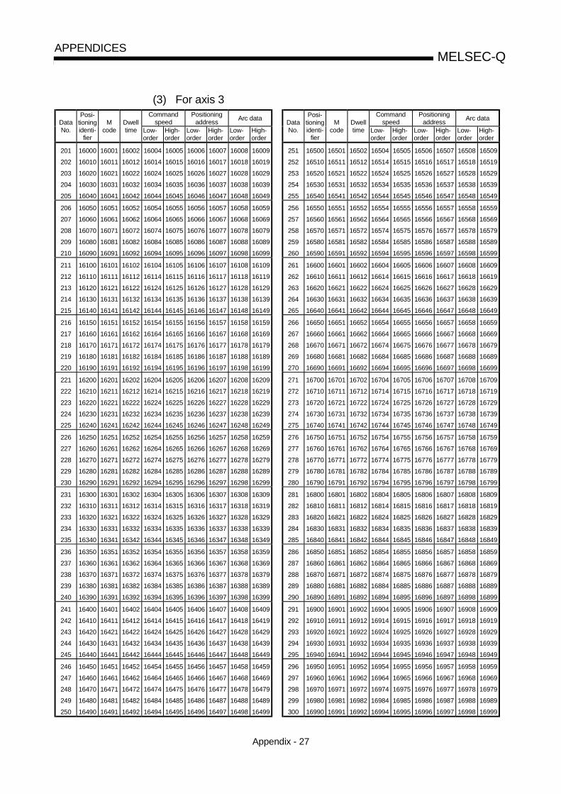
Appendix - 27
MELSEC-QAPPENDICES
(3) For axis 3Command
speedPositioning
addressArc data
Commandspeed
Positioningaddress
Arc dataDataNo.
Posi-tioningidenti-
fier
Mcode
Dwelltime Low-
orderHigh-order
Low-order
High-order
Low-order
High-order
DataNo.
Posi-tioningidenti-
fier
Mcode
Dwelltime Low-
orderHigh-order
Low-order
High-order
Low-order
High-order
201
202
203
204
205
16000
16010
16020
16030
16040
16001
16011
16021
16031
16041
16002
16012
16022
16032
16042
16004
16014
16024
16034
16044
16005
16015
16025
16035
16045
16006
16016
16026
16036
16046
16007
16017
16027
16037
16047
16008
16018
16028
16038
16048
16009
16019
16029
16039
16049
251
252
253
254
255
16500
16510
16520
16530
16540
16501
16511
16521
16531
16541
16502
16512
16522
16532
16542
16504
16514
16524
16534
16544
16505
16515
16525
16535
16545
16506
16516
16526
16536
16546
16507
16517
16527
16537
16547
16508
16518
16528
16538
16548
16509
16519
16529
16539
16549
206
207
208
209
210
16050
16060
16070
16080
16090
16051
16061
16071
16081
16091
16052
16062
16072
16082
16092
16054
16064
16074
16084
16094
16055
16065
16075
16085
16095
16056
16066
16076
16086
16096
16057
16067
16077
16087
16097
16058
16068
16078
16088
16098
16059
16069
16079
16089
16099
256
257
258
259
260
16550
16560
16570
16580
16590
16551
16561
16571
16581
16591
16552
16562
16572
16582
16592
16554
16564
16574
16584
16594
16555
16565
16575
16585
16595
16556
16566
16576
16586
16596
16557
16567
16577
16587
16597
16558
16568
16578
16588
16598
16559
16569
16579
16589
16599
211
212
213
214
215
16100
16110
16120
16130
16140
16101
16111
16121
16131
16141
16102
16112
16122
16132
16142
16104
16114
16124
16134
16144
16105
16115
16125
16135
16145
16106
16116
16126
16136
16146
16107
16117
16127
16137
16147
16108
16118
16128
16138
16148
16109
16119
16129
16139
16149
261
262
263
264
265
16600
16610
16620
16630
16640
16601
16611
16621
16631
16641
16602
16612
16622
16632
16642
16604
16614
16624
16634
16644
16605
16615
16625
16635
16645
16606
16616
16626
16636
16646
16607
16617
16627
16637
16647
16608
16618
16628
16638
16648
16609
16619
16629
16639
16649
216
217
218
219
220
16150
16160
16170
16180
16190
16151
16161
16171
16181
16191
16152
16162
16172
16182
16192
16154
16164
16174
16184
16194
16155
16165
16175
16185
16195
16156
16166
16176
16186
16196
16157
16167
16177
16187
16197
16158
16168
16178
16188
16198
16159
16169
16179
16189
16199
266
267
268
269
270
16650
16660
16670
16680
16690
16651
16661
16671
16681
16691
16652
16662
16672
16682
16692
16654
16664
16674
16684
16694
16655
16665
16675
16685
16695
16656
16666
16676
16686
16696
16657
16667
16677
16687
16697
16658
16668
16678
16688
16698
16659
16669
16679
16689
16699
221
222
223
224
225
16200
16210
16220
16230
16240
16201
16211
16221
16231
16241
16202
16212
16222
16232
16242
16204
16214
16224
16234
16244
16205
16215
16225
16235
16245
16206
16216
16226
16236
16246
16207
16217
16227
16237
16247
16208
16218
16228
16238
16248
16209
16219
16229
16239
16249
271
272
273
274
275
16700
16710
16720
16730
16740
16701
16711
16721
16731
16741
16702
16712
16722
16732
16742
16704
16714
16724
16734
16744
16705
16715
16725
16735
16745
16706
16716
16726
16736
16746
16707
16717
16727
16737
16747
16708
16718
16728
16738
16748
16709
16719
16729
16739
16749
226
227
228
229
230
16250
16260
16270
16280
16290
16251
16261
16271
16281
16291
16252
16262
16272
16282
16292
16254
16264
16274
16284
16294
16255
16265
16275
16285
16295
16256
16266
16276
16286
16296
16257
16267
16277
16287
16297
16258
16268
16278
16288
16298
16259
16269
16279
16289
16299
276
277
278
279
280
16750
16760
16770
16780
16790
16751
16761
16771
16781
16791
16752
16762
16772
16782
16792
16754
16764
16774
16784
16794
16755
16765
16775
16785
16795
16756
16766
16776
16786
16796
16757
16767
16777
16787
16797
16758
16768
16778
16788
16798
16759
16769
16779
16789
16799
231
232
233
234
235
16300
16310
16320
16330
16340
16301
16311
16321
16331
16341
16302
16312
16322
16332
16342
16304
16314
16324
16334
16344
16305
16315
16325
16335
16345
16306
16316
16326
16336
16346
16307
16317
16327
16337
16347
16308
16318
16328
16338
16348
16309
16319
16329
16339
16349
281
282
283
284
285
16800
16810
16820
16830
16840
16801
16811
16821
16831
16841
16802
16812
16822
16832
16842
16804
16814
16824
16834
16844
16805
16815
16825
16835
16845
16806
16816
16826
16836
16846
16807
16817
16827
16837
16847
16808
16818
16828
16838
16848
16809
16819
16829
16839
16849
236
237
238
239
240
16350
16360
16370
16380
16390
16351
16361
16371
16381
16391
16352
16362
16372
16382
16392
16354
16364
16374
16384
16394
16355
16365
16375
16385
16395
16356
16366
16376
16386
16396
16357
16367
16377
16387
16397
16358
16368
16378
16388
16398
16359
16369
16379
16389
16399
286
287
288
289
290
16850
16860
16870
16880
16890
16851
16861
16871
16881
16891
16852
16862
16872
16882
16892
16854
16864
16874
16884
16894
16855
16865
16875
16885
16895
16856
16866
16876
16886
16896
16857
16867
16877
16887
16897
16858
16868
16878
16888
16898
16859
16869
16879
16889
16899
241
242
243
244
245
16400
16410
16420
16430
16440
16401
16411
16421
16431
16441
16402
16412
16422
16432
16442
16404
16414
16424
16434
16444
16405
16415
16425
16435
16445
16406
16416
16426
16436
16446
16407
16417
16427
16437
16447
16408
16418
16428
16438
16448
16409
16419
16429
16439
16449
291
292
293
294
295
16900
16910
16920
16930
16940
16901
16911
16921
16931
16941
16902
16912
16922
16932
16942
16904
16914
16924
16934
16944
16905
16915
16925
16935
16945
16906
16916
16926
16936
16946
16907
16917
16927
16937
16947
16908
16918
16928
16938
16948
16909
16919
16929
16939
16949
246
247
248
249
250
16450
16460
16470
16480
16490
16451
16461
16471
16481
16491
16452
16462
16472
16482
16492
16454
16464
16474
16484
16494
16455
16465
16475
16485
16495
16456
16466
16476
16486
16496
16457
16467
16477
16487
16497
16458
16468
16478
16488
16498
16459
16469
16479
16489
16499
296
297
298
299
300
16950
16960
16970
16980
16990
16951
16961
16971
16981
16991
16952
16962
16972
16982
16992
16954
16964
16974
16984
16994
16955
16965
16975
16985
16995
16956
16966
16976
16986
16996
16957
16967
16977
16987
16997
16958
16968
16978
16988
16998
16959
16969
16979
16989
16999

Appendix - 28
MELSEC-QAPPENDICES
(3) For axis 3Command
speedPositioning
addressArc data
Commandspeed
Positioningaddress
Arc dataDataNo.
Posi-tioningidenti-
fier
Mcode
Dwelltime Low-
orderHigh-order
Low-order
High-order
Low-order
High-order
DataNo.
Posi-tioningidenti-
fier
Mcode
Dwelltime Low-
orderHigh-order
Low-order
High-order
Low-order
High-order
301
302
303
304
305
17000
17010
17020
17030
17040
17001
17011
17021
17031
17041
17002
17012
17022
17032
17042
17004
17014
17024
17034
17044
17005
17015
17025
17035
17045
17006
17016
17026
17036
17046
17007
17017
17027
17037
17047
17008
17018
17028
17038
17048
17009
17019
17029
17039
17049
351
352
353
354
355
17500
17510
17520
17530
17540
17501
17511
17521
17531
17541
17502
17512
17522
17532
17542
17504
17514
17524
17534
17544
17505
17515
17525
17535
17545
17506
17516
17526
17536
17546
17507
17517
17527
17537
17547
17508
17518
17528
17538
17548
17509
17519
17529
17539
17549
306
307
308
309
310
17050
17060
17070
17080
17090
17051
17061
17071
17081
17091
17052
17062
17072
17082
17092
17054
17064
17074
17084
17094
17055
17065
17075
17085
17095
17056
17066
17076
17086
17096
17057
17067
17077
17087
17097
17058
17068
17078
17088
17098
17059
17069
17079
17089
17099
356
357
358
359
360
17550
17560
17570
17580
17590
17551
17561
17571
17581
17591
17552
17562
17572
17582
17592
17554
17564
17574
17584
17594
17555
17565
17575
17585
17595
17556
17566
17576
17586
17596
17557
17567
17577
17587
17597
17558
17568
17578
17588
17598
17559
17569
17579
17589
17599
311
312
313
314
315
17100
17110
17120
17130
17140
17101
17111
17121
17131
17141
17102
17112
17122
17132
17142
17104
17114
17124
17134
17144
17105
17115
17125
17135
17145
17106
17116
17126
17136
17146
17107
17117
17127
17137
17147
17108
17118
17128
17138
17148
17109
17119
17129
17139
17149
361
362
363
364
365
17600
17610
17620
17630
17640
17601
17611
17621
17631
17641
17602
17612
17622
17632
17642
17604
17614
17624
17634
17644
17605
17615
17625
17635
17645
17606
17616
17626
17636
17646
17607
17617
17627
17637
17647
17608
17618
17628
17638
17648
17609
17619
17629
17639
17649
316
317
318
319
320
17150
17160
17170
17180
17190
17151
17161
17171
17181
17191
17152
17162
17172
17182
17192
17154
17164
17174
17184
17194
17155
17165
17175
17185
17195
17156
17166
17176
17186
17196
17157
17167
17177
17187
17197
17158
17168
17178
17188
17198
17159
17169
17179
17189
17199
366
367
368
369
370
17650
17660
17670
17680
17690
17651
17661
17671
17681
17691
17652
17662
17672
17682
17692
17654
17664
17674
17684
17694
17655
17665
17675
17685
17695
17656
17666
17676
17686
17696
17657
17667
17677
17687
17697
17658
17668
17678
17688
17698
17659
17669
17679
17689
17699
321
322
323
324
325
17200
17210
17220
17230
17240
17201
17211
17221
17231
17241
17202
17212
17222
17232
17242
17204
17214
17224
17234
17244
17205
17215
17225
17235
17245
17206
17216
17226
17236
17246
17207
17217
17227
17237
17247
17208
17218
17228
17238
17248
17209
17219
17229
17239
17249
371
372
373
374
375
17700
17710
17720
17730
17740
17701
17711
17721
17731
17741
17702
17712
17722
17732
17742
17704
17714
17724
17734
17744
17705
17715
17725
17735
17745
17706
17716
17726
17736
17746
17707
17717
17727
17737
17747
17708
17718
17728
17738
17748
17709
17719
17729
17739
17749
326
327
328
329
330
17250
17260
17270
17280
17290
17251
17261
17271
17281
17291
17252
17262
17272
17282
17292
17254
17264
17274
17284
17294
17255
17265
17275
17285
17295
17256
17266
17276
17286
17296
17257
17267
17277
17287
17297
17258
17268
17278
17288
17298
17259
17269
17279
17289
17299
376
377
378
379
380
17750
17760
17770
17780
17790
17751
17761
17771
17781
17791
17752
17762
17772
17782
17792
17754
17764
17774
17784
17794
17755
17765
17775
17785
17795
17756
17766
17776
17786
17796
17757
17767
17777
17787
17797
17758
17768
17778
17788
17798
17759
17769
17779
17789
17799
331
332
333
334
335
17300
17310
17320
17330
17340
17301
17311
17321
17331
17341
17302
17312
17322
17332
17342
17304
17314
17324
17334
17344
17305
17315
17325
17335
17345
17306
17316
17326
17336
17346
17307
17317
17327
17337
17347
17308
17318
17328
17338
17348
17309
17319
17329
17339
17349
381
382
383
384
385
17800
17810
17820
17830
17840
17801
17811
17821
17831
17841
17802
17812
17822
17832
17842
17804
17814
17824
17834
17844
17805
17815
17825
17835
17845
17806
17816
17826
17836
17846
17807
17817
17827
17837
17847
17808
17818
17828
17838
17848
17809
17819
17829
17839
17849
336
337
338
339
340
17350
17360
17370
17380
17390
17351
17361
17371
17381
17391
17352
17362
17372
17382
17392
17354
17364
17374
17384
17394
17355
17365
17375
17385
17395
17356
17366
17376
17386
17396
17357
17367
17377
17387
17397
17358
17368
17378
17388
17398
17359
17369
17379
17389
17399
386
387
388
389
390
17850
17860
17870
17880
17890
17851
17861
17871
17881
17891
17852
17862
17872
17882
17892
17854
17864
17874
17884
17894
17855
17865
17875
17885
17895
17856
17866
17876
17886
17896
17857
17867
17877
17887
17897
17858
17868
17878
17888
17898
17859
17869
17879
17889
17899
341
342
343
344
345
17400
17410
17420
17430
17440
17401
17411
17421
17431
17441
17402
17412
17422
17432
17442
17404
17414
17424
17434
17444
17405
17415
17425
17435
17445
17406
17416
17426
17436
17446
17407
17417
17427
17437
17447
17408
17418
17428
17438
17448
17409
17419
17429
17439
17449
391
392
393
394
395
17900
17910
17920
17930
17940
17901
17911
17921
17931
17941
17902
17912
17922
17932
17942
17904
17914
17924
17934
17944
17905
17915
17925
17935
17945
17906
17916
17926
17936
17946
17907
17917
17927
17937
17947
17908
17918
17928
17938
17948
17909
17919
17929
17939
17949
346
347
348
349
350
17450
17460
17470
17480
17490
17451
17461
17471
17481
17491
17452
17462
17472
17482
17492
17454
17464
17474
17484
17494
17455
17465
17475
17485
17495
17456
17466
17476
17486
17496
17457
17467
17477
17487
17497
17458
17468
17478
17488
17498
17459
17469
17479
17489
17499
396
397
398
399
400
17950
17960
17970
17980
17990
17951
17961
17971
17981
17991
17952
17962
17972
17982
17992
17954
17964
17974
17984
17994
17955
17965
17975
17985
17995
17956
17966
17976
17986
17996
17957
17967
17977
17987
17997
17958
17968
17978
17988
17998
17959
17969
17979
17989
17999

Appendix - 29
MELSEC-QAPPENDICES
(3) For axis 3Command
speedPositioning
addressArc data
Commandspeed
Positioningaddress
Arc dataDataNo.
Posi-tioningidenti-
fier
Mcode
Dwelltime Low-
orderHigh-order
Low-order
High-order
Low-order
High-order
DataNo.
Posi-tioningidenti-
fier
Mcode
Dwelltime Low-
orderHigh-order
Low-order
High-order
Low-order
High-order
401
402
403
404
405
18000
18010
18020
18030
18040
18001
18011
18021
18031
18041
18002
18012
18022
18032
18042
18004
18014
18024
18034
18044
18005
18015
18025
18035
18045
18006
18016
18026
18036
18046
18007
18017
18027
18037
18047
18008
18018
18028
18038
18048
18009
18019
18029
18039
18049
451
452
453
454
455
18500
18510
18520
18530
18540
18501
18511
18521
18531
18541
18502
18512
18522
18532
18542
18504
18514
18524
18534
18544
18505
18515
18525
18535
18545
18506
18516
18526
18536
18546
18507
18517
18527
18537
18547
18508
18518
18528
18538
18548
18509
18519
18529
18539
18549
406
407
408
409
410
18050
18060
18070
18080
18090
18051
18061
18071
18081
18091
18052
18062
18072
18082
18092
18054
18064
18074
18084
18094
18055
18065
18075
18085
18095
18056
18066
18076
18086
18096
18057
18067
18077
18087
18097
18058
18068
18078
18088
18098
18059
18069
18079
18089
18099
456
457
458
459
460
18550
18560
18570
18580
18590
18551
18561
18571
18581
18591
18552
18562
18572
18582
18592
18554
18564
18574
18584
18594
18555
18565
18575
18585
18595
18556
18566
18576
18586
18596
18557
18567
18577
18587
18597
18558
18568
18578
18588
18598
18559
18569
18579
18589
18599
411
412
413
414
415
18100
18110
18120
18130
18140
18101
18111
18121
18131
18141
18102
18112
18122
18132
18142
18104
18114
18124
18134
18144
18105
18115
18125
18135
18145
18106
18116
18126
18136
18146
18107
18117
18127
18137
18147
18108
18118
18128
18138
18148
18109
18119
18129
18139
18149
461
462
463
464
465
18600
18610
18620
18630
18640
18601
18611
18621
18631
18641
18602
18612
18622
18632
18642
18604
18614
18624
18634
18644
18605
18615
18625
18635
18645
18606
18616
18626
18636
18646
18607
18617
18627
18637
18647
18608
18618
18628
18638
18648
18609
18619
18629
18639
18649
416
417
418
419
420
18150
18160
18170
18180
18190
18151
18161
18171
18181
18191
18152
18162
18172
18182
18192
18154
18164
18174
18184
18194
18155
18165
18175
18185
18195
18156
18166
18176
18186
18196
18157
18167
18177
18187
18197
18158
18168
18178
18188
18198
18159
18169
18179
18189
18199
466
467
468
469
470
18650
18660
18670
18680
18690
18651
18661
18671
18681
18691
18652
18662
18672
18682
18692
18654
18664
18674
18684
18694
18655
18665
18675
18685
18695
18656
18666
18676
18686
18696
18657
18667
18677
18687
18697
18658
18668
18678
18688
18698
18659
18669
18679
18689
18699
421
422
423
424
425
18200
18210
18220
18230
18240
18201
18211
18221
18231
18241
18202
18212
18222
18232
18242
18204
18214
18224
18234
18244
18205
18215
18225
18235
18245
18206
18216
18226
18236
18246
18207
18217
18227
18237
18247
18208
18218
18228
18238
18248
18209
18219
18229
18239
18249
471
472
473
474
475
18700
18710
18720
18730
18740
18701
18711
18721
18731
18741
18702
18712
18722
18732
18742
18704
18714
18724
18734
18744
18705
18715
18725
18735
18745
18706
18716
18726
18736
18746
18707
18717
18727
18737
18747
18708
18718
18728
18738
18748
18709
18719
18729
18739
18749
426
427
428
429
430
18250
18260
18270
18280
18290
18251
18261
18271
18281
18291
18252
18262
18272
18282
18292
18254
18264
18274
18284
18294
18255
18265
18275
18285
18295
18256
18266
18276
18286
18296
18257
18267
18277
18287
18297
18258
18268
18278
18288
18298
18259
18269
18279
18289
18299
476
477
478
479
480
18750
18760
18770
18780
18790
18751
18761
18771
18781
18791
18752
18762
18772
18782
18792
18754
18764
18774
18784
18794
18755
18765
18775
18785
18795
18756
18766
18776
18786
18796
18757
18767
18777
18787
18797
18758
18768
18778
18788
18798
18759
18769
18779
18789
18799
431
432
433
434
435
18300
18310
18320
18330
18340
18301
18311
18321
18331
18341
18302
18312
18322
18332
18342
18304
18314
18324
18334
18344
18305
18315
18325
18335
18345
18306
18316
18326
18336
18346
18307
18317
18327
18337
18347
18308
18318
18328
18338
18348
18309
18319
18329
18339
18349
481
482
483
484
485
18800
18810
18820
18830
18840
18801
18811
18821
18831
18841
18802
18812
18822
18832
18842
18804
18814
18824
18834
18844
18805
18815
18825
18835
18845
18806
18816
18826
18836
18846
18807
18817
18827
18837
18847
18808
18818
18828
18838
18848
18809
18819
18829
18839
18849
436
437
438
439
440
18350
18360
18370
18380
18390
18351
18361
18371
18381
18391
18352
18362
18372
18382
18392
18354
18364
18374
18384
18394
18355
18365
18375
18385
18395
18356
18366
18376
18386
18396
18357
18367
18377
18387
18397
18358
18368
18378
18388
18398
18359
18369
18379
18389
18399
486
487
488
489
490
18850
18860
18870
18880
18890
18851
18861
18871
18881
18891
18852
18862
18872
18882
18892
18854
18864
18874
18884
18894
18855
18865
18875
18885
18895
18856
18866
18876
18886
18896
18857
18867
18877
18887
18897
18858
18868
18878
18888
18898
18859
18869
18879
18889
18899
441
442
443
444
445
18400
18410
18420
18430
18440
18401
18411
18421
18431
18441
18402
18412
18422
18432
18442
18404
18414
18424
18434
18444
18405
18415
18425
18435
18445
18406
18416
18426
18436
18446
18407
18417
18427
18437
18447
18408
18418
18428
18438
18448
18409
18419
18429
18439
18449
491
492
493
494
495
18900
18910
18920
18930
18940
18901
18911
18921
18931
18941
18902
18912
18922
18932
18942
18904
18914
18924
18934
18944
18905
18915
18925
18935
18945
18906
18916
18926
18936
18946
18907
18917
18927
18937
18947
18908
18918
18928
18938
18948
18909
18919
18929
18939
18949
446
447
448
449
450
18450
18460
18470
18480
18490
18451
18461
18471
18481
18491
18452
18462
18472
18482
18492
18454
18464
18474
18484
18494
18455
18465
18475
18485
18495
18456
18466
18476
18486
18496
18457
18467
18477
18487
18497
18458
18468
18478
18488
18498
18459
18469
18479
18489
18499
496
497
498
499
500
18950
18960
18970
18980
18990
18951
18961
18971
18981
18991
18952
18962
18972
18982
18992
18954
18964
18974
18984
18994
18955
18965
18975
18985
18995
18956
18966
18976
18986
18996
18957
18967
18977
18987
18997
18958
18968
18978
18988
18998
18959
18969
18979
18989
18999

Appendix - 30
MELSEC-QAPPENDICES
(3) For axis 3Command
speedPositioning
addressArc data
Commandspeed
Positioningaddress
Arc dataDataNo.
Posi-tioningidenti-
fier
Mcode
Dwelltime Low-
orderHigh-order
Low-order
High-order
Low-order
High-order
DataNo.
Posi-tioningidenti-
fier
Mcode
Dwelltime Low-
orderHigh-order
Low-order
High-order
Low-order
High-order
501
502
503
504
505
19000
19010
19020
19030
19040
19001
19011
19021
19031
19041
19002
19012
19022
19032
19042
19004
19014
19024
19034
19044
19005
19015
19025
19035
19045
19006
19016
19026
19036
19046
19007
19017
19027
19037
19047
19008
19018
19028
19038
19048
19009
19019
19029
19039
19049
551
552
553
554
555
19500
19510
19520
19530
19540
19501
19511
19521
19531
19541
19502
19512
19522
19532
19542
19504
19514
19524
19534
19544
19505
19515
19525
19535
19545
19506
19516
19526
19536
19546
19507
19517
19527
19537
19547
19508
19518
19528
19538
19548
19509
19519
19529
19539
19549
506
507
508
509
510
19050
19060
19070
19080
19090
19051
19061
19071
19081
19091
19052
19062
19072
19082
19092
19054
19064
19074
19084
19094
19055
19065
19075
19085
19095
19056
19066
19076
19086
19096
19057
19067
19077
19087
19097
19058
19068
19078
19088
19098
19059
19069
19079
19089
19099
556
557
558
559
560
19550
19560
19570
19580
19590
19551
19561
19571
19581
19591
19552
19562
19572
19582
19592
19554
19564
19574
19584
19594
19555
19565
19575
19585
19595
19556
19566
19576
19586
19596
19557
19567
19577
19587
19597
19558
19568
19578
19588
19598
19559
19569
19579
19589
19599
511
512
513
514
515
19100
19110
19120
19130
19140
19101
19111
19121
19131
19141
19102
19112
19122
19132
19142
19104
19114
19124
19134
19144
19105
19115
19125
19135
19145
19106
19116
19126
19136
19146
19107
19117
19127
19137
19147
19108
19118
19128
19138
19148
19109
19119
19129
19139
19149
561
562
563
564
565
19600
19610
19620
19630
19640
19601
19611
19621
19631
19641
19602
19612
19622
19632
19642
19604
19614
19624
19634
19644
19605
19615
19625
19635
19645
19606
19616
19626
19636
19646
19607
19617
19627
19637
19647
19608
19618
19628
19638
19648
19609
19619
19629
19639
19649
516
517
518
519
520
19150
19160
19170
19180
19190
19151
19161
19171
19181
19191
19152
19162
19172
19182
19192
19154
19164
19174
19184
19194
19155
19165
19175
19185
19195
19156
19166
19176
19186
19196
19157
19167
19177
19187
19197
19158
19168
19178
19188
19198
19159
19169
19179
19189
19199
566
567
568
569
570
19650
19660
19670
19680
19690
19651
19661
19671
19681
19691
19652
19662
19672
19682
19692
19654
19664
19674
19684
19694
19655
19665
19675
19685
19695
19656
19666
19676
19686
19696
19657
19667
19677
19687
19697
19658
19668
19678
19688
19698
19659
19669
19679
19689
19699
521
522
523
524
525
19200
19210
19220
19230
19240
19201
19211
19221
19231
19241
19202
19212
19222
19232
19242
19204
19214
19224
19234
19244
19205
19215
19225
19235
19245
19206
19216
19226
19236
19246
19207
19217
19227
19237
19247
19208
19218
19228
19238
19248
19209
19219
19229
19239
19249
571
572
573
574
575
19700
19710
19720
19730
19740
19701
19711
19721
19731
19741
19702
19712
19722
19732
19742
19704
19714
19724
19734
19744
19705
19715
19725
19735
19745
19706
19716
19726
19736
19746
19707
19717
19727
19737
19747
19708
19718
19728
19738
19748
19709
19719
19729
19739
19749
526
527
528
529
530
19250
19260
19270
19280
19290
19251
19261
19271
19281
19291
19252
19262
19272
19282
19292
19254
19264
19274
19284
19294
19255
19265
19275
19285
19295
19256
19266
19276
19286
19296
19257
19267
19277
19287
19297
19258
19268
19278
19288
19298
19259
19269
19279
19289
19299
576
577
578
579
580
19750
19760
19770
19780
19790
19751
19761
19771
19781
19791
19752
19762
19772
19782
19792
19754
19764
19774
19784
19794
19755
19765
19775
19785
19795
19756
19766
19776
19786
19796
19757
19767
19777
19787
19797
19758
19768
19778
19788
19798
19759
19769
19779
19789
19799
531
532
533
534
535
19300
19310
19320
19330
19340
19301
19311
19321
19331
19341
19302
19312
19322
19332
19342
19304
19314
19324
19334
19344
19305
19315
19325
19335
19345
19306
19316
19326
19336
19346
19307
19317
19327
19337
19347
19308
19318
19328
19338
19348
19309
19319
19329
19339
19349
581
582
583
584
585
19800
19810
19820
19830
19840
19801
19811
19821
19831
19841
19802
19812
19822
19832
19842
19804
19814
19824
19834
19844
19805
19815
19825
19835
19845
19806
19816
19826
19836
19846
19807
19817
19827
19837
19847
19808
19818
19828
19838
19848
19809
19819
19829
19839
19849
536
537
538
539
540
19350
19360
19370
19380
19390
19351
19361
19371
19381
19391
19352
19362
19372
19382
19392
19354
19364
19374
19384
19394
19355
19365
19375
19385
19395
19356
19366
19376
19386
19396
19357
19367
19377
19387
19397
19358
19368
19378
19388
19398
19359
19369
19379
19389
19399
586
587
588
589
590
19850
19860
19870
19880
19890
19851
19861
19871
19881
19891
19852
19862
19872
19882
19892
19854
19864
19874
19884
19894
19855
19865
19875
19885
19895
19856
19866
19876
19886
19896
19857
19867
19877
19887
19897
19858
19868
19878
19888
19898
19859
19869
19879
19889
19899
541
542
543
544
545
19400
19410
19420
19430
19440
19401
19411
19421
19431
19441
19402
19412
19422
19432
19442
19404
19414
19424
19434
19444
19405
19415
19425
19435
19445
19406
19416
19426
19436
19446
19407
19417
19427
19437
19447
19408
19418
19428
19438
19448
19409
19419
19429
19439
19449
591
592
593
594
595
19900
19910
19920
19930
19940
19901
19911
19921
19931
19941
19902
19912
19922
19932
19942
19904
19914
19924
19934
19944
19905
19915
19925
19935
19945
19906
19916
19926
19936
19946
19907
19917
19927
19937
19947
19908
19918
19928
19938
19948
19909
19919
19929
19939
19949
546
547
548
549
550
19450
19460
19470
19480
19490
19451
19461
19471
19481
19491
19452
19462
19472
19482
19492
19454
19464
19474
19484
19494
19455
19465
19475
19485
19495
19456
19466
19476
19486
19496
19457
19467
19477
19487
19497
19458
19468
19478
19488
19498
19459
19469
19479
19489
19499
596
597
598
599
600
19950
19960
19970
19980
19990
19951
19961
19971
19981
19991
19952
19962
19972
19982
19992
19954
19964
19974
19984
19994
19955
19965
19975
19985
19995
19956
19966
19976
19986
19996
19957
19967
19977
19987
19997
19958
19968
19978
19988
19998
19959
19969
19979
19989
19999

Appendix - 31
MELSEC-QAPPENDICES
(4) For axis 4Command
speedPositioning
addressArc data
Commandspeed
Positioningaddress
Arc dataDataNo.
Posi-tioningidenti-
fier
Mcode
Dwelltime Low-
orderHigh-order
Low-order
High-order
Low-order
High-order
DataNo.
Posi-tioningidenti-
fier
Mcode
Dwelltime Low-
orderHigh-order
Low-order
High-order
Low-order
High-order
1
2
3
4
5
20000
20010
20020
20030
20040
20001
20011
20021
20031
20041
20002
20012
20022
20032
20042
20004
20014
20024
20034
20044
20005
20015
20025
20035
20045
20006
20016
20026
20036
20046
20007
20017
20027
20037
20047
20008
20018
20028
20038
20048
20009
20019
20029
20039
20049
51
52
53
54
55
20500
20510
20520
20530
20540
20501
20511
20521
20531
20541
20502
20512
20522
20532
20542
20504
20514
20524
20534
20544
20505
20515
20525
20535
20545
20506
20516
20526
20536
20546
20507
20517
20527
20537
20547
20508
20518
20528
20538
20548
20509
20519
20529
20539
20549
6
7
8
9
10
20050
20060
20070
20080
20090
20051
20061
20071
20081
20091
20052
20062
20072
20082
20092
20054
20064
20074
20084
20094
20055
20065
20075
20085
20095
20056
20066
20076
20086
20096
20057
20067
20077
20087
20097
20058
20068
20078
20088
20098
20059
20069
20079
20089
20099
56
57
58
59
60
20550
20560
20570
20580
20590
20551
20561
20571
20581
20591
20552
20562
20572
20582
20592
20554
20564
20574
20584
20594
20555
20565
20575
20585
20595
20556
20566
20576
20586
20596
20557
20567
20577
20587
20597
20558
20568
20578
20588
20598
20559
20569
20579
20589
20599
11
12
13
14
15
20100
20110
20120
20140
20140
20101
20111
20121
20131
20141
20102
20112
20122
20132
20142
20104
20114
20124
20134
20144
20105
20115
20125
20135
20145
20106
20116
20126
20136
20146
20107
20117
20127
20137
20147
20108
20118
20128
20138
20148
20109
20119
20129
20139
20149
61
62
63
64
65
20600
20610
20620
20630
20640
20601
20611
20621
20631
20641
20602
20612
20622
20632
20642
20604
20614
20624
20634
20644
20605
20615
20625
20635
20645
20606
20616
20626
20636
20646
20607
20617
20627
20637
20647
20608
20618
20628
20638
20648
20609
20619
20629
20639
20649
16
17
18
19
20
20150
20160
20170
20180
20190
20151
20161
20171
20181
20191
20152
20162
20172
20182
20192
20154
20164
20174
20184
20194
20155
20165
20175
20185
20195
20156
20166
20176
20186
20196
20157
20167
20177
20187
20197
20158
20168
20178
20188
20198
20159
20169
20179
20189
20199
66
67
68
69
70
20650
20660
20670
20680
20690
20651
20661
20671
20681
20691
20652
20662
20672
20682
20692
20654
20664
20674
20684
20694
20655
20665
20675
20685
20695
20656
20666
20676
20686
20696
20657
20667
20677
20687
20697
20658
20668
20678
20688
20698
20659
20669
20679
20689
20699
21
22
23
24
25
20200
20210
20220
20230
20240
20201
20211
20221
20231
20241
20202
20212
20222
20232
20242
20204
20214
20224
20234
20244
20205
20215
20225
20235
20245
20206
20216
20226
20236
20246
20207
20217
20227
20237
20247
20208
20218
20228
20238
20248
20209
20219
20229
20239
20249
71
72
73
74
75
20700
20710
20720
20730
20740
20701
20711
20721
20731
20741
20702
20712
20722
20732
20742
20704
20714
20724
20734
20744
20705
20715
20725
20735
20745
20706
20716
20726
20736
20746
20707
20717
20727
20737
20747
20708
20718
20728
20738
20748
20709
20719
20729
20739
20749
26
27
28
29
30
20250
20260
20270
20280
20290
20251
20261
20271
20281
20291
20252
20262
20272
20282
20292
20254
20264
20274
20284
20294
20255
20265
20275
20285
20295
20256
20266
20276
20286
20296
20257
20267
20277
20287
20297
20258
20268
20278
20288
20298
20259
20269
20279
20289
20299
76
77
78
79
80
20750
20760
20770
20780
20790
20751
20761
20771
20781
20791
20752
20762
20772
20782
20792
20754
20764
20774
20784
20794
20755
20765
20775
20785
20795
20756
20766
20776
20786
20796
20757
20767
20777
20787
20797
20758
20768
20778
20788
20798
20759
20769
20779
20789
20799
31
32
33
34
35
20300
20310
20320
20330
20340
20301
20311
20321
20331
20341
20302
20312
20322
20332
20342
20304
20314
20324
20334
20344
20305
20315
20325
20335
20345
20306
20316
20326
20336
20346
20307
20317
20327
20337
20347
20308
20318
20328
20338
20348
20309
20319
20329
20339
20349
81
82
83
84
85
20800
20810
20820
20830
20840
20801
20811
20821
20831
20841
20802
20812
20822
20832
20842
20804
20814
20824
20834
20844
20805
20815
20825
20835
20845
20806
20816
20826
20836
20846
20807
20817
20827
20837
20847
20808
20818
20828
20838
20848
20809
20819
20829
20839
20849
36
37
38
39
40
20350
20360
20370
20380
20390
20351
20361
20371
20381
20391
20352
20362
20372
20382
20392
20354
20364
20374
20384
20394
20355
20365
20375
20385
20395
20356
20366
20376
20386
20396
20357
20367
20377
20387
20397
20358
20368
20378
20388
20398
20359
20369
20379
20389
20399
86
87
88
89
90
20850
20860
20870
20880
20890
20851
20861
20871
20881
20891
20852
20862
20872
20882
20892
20854
20864
20874
20884
20894
20855
20865
20875
20885
20895
20856
20866
20876
20886
20896
20857
20867
20877
20887
20897
20858
20868
20878
20888
20898
20859
20869
20879
20889
20899
41
42
43
44
45
20400
20410
20420
20430
20440
20401
20411
20421
20431
20441
20402
20412
20422
20432
20442
20404
20414
20424
20434
20444
20405
20415
20425
20435
20445
20406
20416
20426
20436
20446
20407
20417
20427
20437
20447
20408
20418
20428
20438
20448
20409
20419
20429
20439
20449
91
92
93
94
95
20900
20910
20920
20930
20940
20901
20911
20921
20931
20941
20902
20912
20922
20932
20942
20904
20914
20924
20934
20944
20905
20915
20925
20935
20945
20906
20916
20926
20936
20946
20907
20917
20927
20937
20947
20908
20918
20928
20938
20948
20909
20919
20929
20939
20949
46
47
48
49
50
20450
20460
20470
20480
20490
20451
20461
20471
20481
20491
20452
20462
20472
20482
20492
20454
20464
20474
20484
20494
20455
20465
20475
20485
20495
20456
20466
20476
20486
20496
20457
20467
20477
20487
20497
20458
20468
20478
20488
20498
20459
20469
20479
20489
20499
96
97
98
99
100
20950
20960
20970
20980
20990
20951
20961
20971
20981
20991
20952
20962
20972
20982
20992
20954
20964
20974
20984
20994
20955
20965
20975
20985
20995
20956
20966
20976
20986
20996
20957
20967
20977
20987
20997
20958
20968
20978
20988
20998
20959
20969
20979
20989
20999

Appendix - 32
MELSEC-QAPPENDICES
(4) For axis 4Command
speedPositioning
addressArc data
Commandspeed
Positioningaddress
Arc dataDataNo.
Posi-tioningidenti-
fier
Mcode
Dwelltime Low-
orderHigh-order
Low-order
High-order
Low-order
High-order
DataNo.
Posi-tioningidenti-
fier
Mcode
Dwelltime Low-
orderHigh-order
Low-order
High-order
Low-order
High-order
101
102
103
104
105
21000
21010
21020
21030
21040
21001
21011
21021
21031
21041
21002
21012
21022
21032
21042
21004
21014
21024
21034
21044
21005
21015
21025
21035
21045
21006
21016
21026
21036
21046
21007
21017
21027
21037
21047
21008
21018
21028
21038
21048
21009
21019
21029
21039
21049
151
152
153
154
155
21500
21510
21520
21530
21540
21501
21511
21521
21531
21541
21502
21512
21522
21532
21542
21504
21514
21524
21534
21544
21505
21515
21525
21535
21545
21506
21516
21526
21536
21546
21507
21517
21527
21537
21547
21508
21518
21528
21538
21548
21509
21519
21529
21539
21549
106
107
108
109
110
21050
21060
21070
21080
21090
21051
21061
21071
21081
21091
21052
21062
21072
21082
21092
21054
21064
21074
21084
21094
21055
21065
21075
21085
21095
21056
21066
21076
21086
21096
21057
21067
21077
21087
21097
21058
21068
21078
21088
21098
21059
21069
21079
21089
21099
156
157
158
159
160
21550
21560
21570
21580
21590
21551
21561
21571
21581
21591
21552
21562
21572
21582
21592
21554
21564
21574
21584
21594
21555
21565
21575
21585
21595
21556
21566
21576
21586
21596
21557
21567
21577
21587
21597
21558
21568
21578
21588
21598
21559
21569
21579
21589
21599
111
112
113
114
115
21100
21110
21120
21130
21140
21101
21111
21121
21131
21141
21102
21112
21122
21132
21142
21104
21114
21124
21134
21144
21105
21115
21125
21135
21145
21106
21116
21126
21136
21146
21107
21117
21127
21137
21147
21108
21118
21128
21138
21148
21109
21119
21129
21139
21149
161
162
163
164
165
21600
21610
21620
21630
21640
21601
21611
21621
21631
21641
21602
21612
21622
21632
21642
21604
21614
21624
21634
21644
21605
21615
21625
21635
21645
21606
21616
21626
21636
21646
21607
21617
21627
21637
21647
21608
21618
21628
21638
21648
21609
21619
21629
21639
21649
116
117
118
119
120
21150
21160
21170
21180
21190
21151
21161
21171
21181
21191
21152
21162
21172
21182
21192
21154
21164
21174
21184
21194
21155
21165
21175
21185
21195
21156
21166
21176
21186
21196
21157
21167
21177
21187
21197
21158
21168
21178
21188
21198
21159
21169
21179
21189
21199
166
167
168
169
170
21650
21660
21670
21680
21690
21651
21661
21671
21681
21691
21652
21662
21672
21682
21692
21654
21664
21674
21684
21694
21655
21665
21675
21685
21695
21656
21666
21676
21686
21696
21657
21667
21677
21687
21697
21658
21668
21678
21688
21698
21659
21669
21679
21689
21699
121
122
123
124
125
21200
21210
21220
21230
21240
21201
21211
21221
21231
21241
21202
21212
21222
21232
21242
21204
21214
21224
21234
21244
21205
21215
21225
21235
21245
21206
21216
21226
21236
21246
21207
21217
21227
21237
21247
21208
21218
21228
21238
21248
21209
21219
21229
21239
21249
171
172
173
174
175
21700
21710
21720
21730
21740
21701
21711
21721
21731
21741
21702
21712
21722
21732
21742
21704
21714
21724
21734
21744
21705
21715
21725
21735
21745
21706
21716
21726
21736
21746
21707
21717
21727
21737
21747
21708
21718
21728
21738
21748
21709
21719
21729
21739
21749
126
127
128
129
130
21250
21260
21270
21280
21290
21251
21261
21271
21281
21291
21252
21262
21272
21282
21292
21254
21264
21274
21284
21294
21255
21265
21275
21285
21295
21256
21266
21276
21286
21296
21257
21267
21277
21287
21297
21258
21268
21278
21288
21298
21259
21269
21279
21289
21299
176
177
178
179
180
21750
21760
21770
21780
21790
21751
21761
21771
21781
21791
21752
21762
21772
21782
21792
21754
21764
21774
21784
21794
21755
21765
21775
21785
21795
21756
21766
21776
21786
21796
21757
21767
21777
21787
21797
21758
21768
21778
21788
21798
21759
21769
21779
21789
21799
131
132
133
134
135
21300
21310
21320
21330
21340
21301
21311
21321
21331
21341
21302
21312
21322
21332
21342
21304
21314
21324
21334
21344
21305
21315
21325
21335
21345
21306
21316
21326
21336
21346
21307
21317
21327
21337
21347
21308
21318
21328
21338
21348
21309
21319
21329
21339
21349
181
182
183
184
185
21800
21810
21820
21830
21840
21801
21811
21821
21831
21841
21802
21812
21822
21832
21842
21804
21814
21824
21834
21844
21805
21815
21825
21835
21845
21806
21816
21826
21836
21846
21807
21817
21827
21837
21847
21808
21818
21828
21838
21848
21809
21819
21829
21839
21849
136
137
138
139
140
21350
21360
21370
21380
21390
21351
21361
21371
21381
21391
21352
21362
21372
21382
21392
21354
21364
21374
21384
21394
21355
21365
21375
21385
21395
21356
21366
21376
21386
21396
21357
21367
21377
21387
21397
21358
21368
21378
21388
21398
21359
21369
21379
21389
21399
186
187
188
189
190
21850
21860
21870
21880
21890
21851
21861
21871
21881
21891
21852
21862
21872
21882
21892
21854
21864
21874
21884
21894
21855
21865
21875
21885
21895
21856
21866
21876
21886
21896
21857
21867
21877
21887
21897
21858
21868
21878
21888
21898
21859
21869
21879
21889
21899
141
142
143
144
145
21400
21410
21420
21430
21440
21401
21411
21421
21431
21441
21402
21412
21422
21432
21442
21404
21414
21424
21434
21444
21405
21415
21425
21435
21445
21406
21416
21426
21436
21446
21407
21417
21427
21437
21447
21408
21418
21428
21438
21448
21409
21419
21429
21439
21449
191
192
193
194
195
21900
21910
21920
21930
21940
21901
21911
21921
21931
21941
21902
21912
21922
21932
21942
21904
21914
21924
21934
21944
21905
21915
21925
21935
21945
21906
21916
21926
21936
21946
21907
21917
21927
21937
21947
21908
21918
21928
21938
21948
21909
21919
21929
21939
21949
146
147
148
149
150
21450
21460
21470
21480
21490
21451
21461
21471
21481
21491
21452
21462
21472
21482
21492
21454
21464
21474
21484
21494
21455
21465
21475
21485
21495
21456
21466
21476
21486
21496
21457
21467
21477
21487
21497
21458
21468
21478
21488
21498
21459
21469
21479
21489
21499
196
197
198
199
200
21950
21960
21970
21980
21990
21951
21961
21971
21981
21991
21952
21962
21972
21982
21992
21954
21964
21974
21984
21994
21955
21965
21975
21985
21995
21956
21966
21976
21986
21996
21957
21967
21977
21987
21997
21958
21968
21978
21988
21998
21959
21969
21979
21989
21999
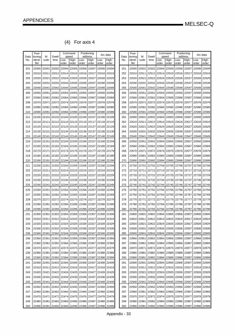
Appendix - 33
MELSEC-QAPPENDICES
(4) For axis 4
Commandspeed
Positioningaddress
Arc dataCommand
speedPositioning
addressArc data
DataNo.
Posi-tioningidenti-
fier
Mcode
Dwelltime Low-
orderHigh-order
Low-order
High-order
Low-order
High-order
DataNo.
Posi-tioningidenti-
fier
Mcode
Dwelltime Low-
orderHigh-order
Low-order
High-order
Low-order
High-order
201
202
203
204
205
22000
22010
22020
22030
22040
22001
22011
22021
22031
22041
22002
22012
22022
22032
22042
22004
22014
22024
22034
22044
22005
22015
22025
22035
22045
22006
22016
22026
22036
22046
22007
22017
22027
22037
22047
22008
22018
22028
22038
22048
22009
22019
22029
22039
22049
251
252
253
254
255
22500
22510
22520
22530
22540
22501
22511
22521
22531
22541
22502
22512
22522
22532
22542
22504
22514
22524
22534
22544
22505
22515
22525
22535
22545
22506
22516
22526
22536
22546
22507
22517
22527
22537
22547
22508
22518
22528
22538
22548
22509
22519
22529
22539
22549
206
207
208
209
210
22050
22060
22070
22080
22090
22051
22061
22071
22081
22091
22052
22062
22072
22082
22092
22054
22064
22074
22084
22094
22055
22065
22075
22085
22095
22056
22066
22076
22086
22096
22057
22067
22077
22087
22097
22058
22068
22078
22088
22098
22059
22069
22079
22089
22099
256
257
258
259
260
22550
22560
22570
22580
22590
22551
22561
22571
22581
22591
22552
22562
22572
22582
22592
22554
22564
22574
22584
22594
22555
22565
22575
22585
22595
22556
22566
22576
22586
22596
22557
22567
22577
22587
22597
22558
22568
22578
22588
22598
22559
22569
22579
22589
22599
211
212
213
214
215
22100
22110
22120
22130
22140
22101
22111
22121
22131
22141
22102
22112
22122
22132
22142
22104
22114
22124
22134
22144
22105
22115
22125
22135
22145
22106
22116
22126
22136
22146
22107
22117
22127
22137
22147
22108
22118
22128
22138
22148
22109
22119
22129
22139
22149
261
262
263
264
265
22600
22610
22620
22630
22640
22601
22611
22621
22631
22641
22602
22612
22622
22632
22642
22604
22614
22624
22634
22644
22605
22615
22625
22635
22645
22606
22616
22626
22636
22646
22607
22617
22627
22637
22647
22608
22618
22628
22638
22648
22609
22619
22629
22639
22649
216
217
218
219
220
22150
22160
22170
22180
22190
22151
22161
22171
22181
22191
22152
22162
22172
22182
22192
22154
22164
22174
22184
22194
22155
22165
22175
22185
22195
22156
22166
22176
22186
22196
22157
22167
22177
22187
22197
22158
22168
22178
22188
22198
22159
22169
22179
22189
22199
266
267
268
269
270
22650
22660
22670
22680
22690
22651
22661
22671
22681
22691
22652
22662
22672
22682
22692
22654
22664
22674
22684
22694
22655
22665
22675
22685
22695
22656
22666
22676
22686
22696
22657
22667
22677
22687
22697
22658
22668
22678
22688
22698
22659
22669
22679
22689
22699
221
222
223
224
225
22200
22210
22220
22230
22240
22201
22211
22221
22231
22241
22202
22212
22222
22232
22242
22204
22214
22224
22234
22244
22205
22215
22225
22235
22245
22206
22216
22226
22236
22246
22207
22217
22227
22237
22247
22208
22218
22228
22238
22248
22209
22219
22229
22239
22249
271
272
273
274
275
22700
22710
22720
22730
22740
22701
22711
22721
22731
22741
22702
22712
22722
22732
22742
22704
22714
22724
22734
22744
22705
22715
22725
22735
22745
22706
22716
22726
22736
22746
22707
22717
22727
22737
22747
22708
22718
22728
22738
22748
22709
22719
22729
22739
22749
226
227
228
229
230
22250
22260
22270
22280
22290
22251
22261
22271
22281
22291
22252
22262
22272
22282
22292
22254
22264
22274
22284
22294
22255
22265
22275
22285
22295
22256
22266
22276
22286
22296
22257
22267
22277
22287
22297
22258
22268
22278
22288
22298
22259
22269
22279
22289
22299
276
277
278
279
280
22750
22760
22770
22780
22790
22751
22761
22771
22781
22791
22752
22762
22772
22782
22792
22754
22764
22774
22784
22794
22755
22765
22775
22785
22795
22756
22766
22776
22786
22796
22757
22767
22777
22787
22797
22758
22768
22778
22788
22798
22759
22769
22779
22789
22799
231
232
233
234
235
22300
22310
22320
22330
22340
22301
22311
22321
22331
22341
22302
22312
22322
22332
22342
22304
22314
22324
22334
22344
22305
22315
22325
22335
22345
22306
22316
22326
22336
22346
22307
22317
22327
22337
22347
22308
22318
22328
22338
22348
22309
22319
22329
22339
22349
281
282
283
284
285
22800
22810
22820
22830
22840
22801
22811
22821
22831
22841
22802
22812
22822
22832
22842
22804
22814
22824
22834
22844
22805
22815
22825
22835
22845
22806
22816
22826
22836
22846
22807
22817
22827
22837
22847
22808
22818
22828
22838
22848
22809
22819
22829
22839
22849
236
237
238
239
240
22350
22360
22370
22380
22390
22351
22361
22371
22381
22391
22352
22362
22372
22382
22392
22354
22364
22374
22384
22394
22355
22365
22375
22385
22395
22356
22366
22376
22386
22396
22357
22367
22377
22387
22397
22358
22368
22378
22388
22398
22359
22369
22379
22389
22399
286
287
288
289
290
22850
22860
22870
22880
22890
22851
22861
22871
22881
22891
22852
22862
22872
22882
22892
22854
22864
22874
22884
22894
22855
22865
22875
22885
22895
22856
22866
22876
22886
22896
22857
22867
22877
22887
22897
22858
22868
22878
22888
22898
22859
22869
22879
22889
22899
241
242
243
244
245
22400
22410
22420
22430
22440
22401
22411
22421
22431
22441
22402
22412
22422
22432
22442
22404
22414
22424
22434
22444
22405
22415
22425
22435
22445
22406
22416
22426
22436
22446
22407
22417
22427
22437
22447
22408
22418
22428
22438
22448
22409
22419
22429
22439
22449
291
292
293
294
295
22900
22910
22920
22930
22940
22901
22911
22921
22931
22941
22902
22912
22922
22932
22942
22904
22914
22924
22934
22944
22905
22915
22925
22935
22945
22906
22916
22926
22936
22946
22907
22917
22927
22937
22947
22908
22918
22928
22938
22948
22909
22919
22929
22939
22949
246
247
248
249
250
22450
22460
22470
22480
22490
22451
22461
22471
22481
22491
22452
22462
22472
22482
22492
22454
22464
22474
22484
22494
22455
22465
22475
22485
22495
22456
22466
22476
22486
22496
22457
22467
22477
22487
22497
22458
22468
22478
22488
22498
22459
22469
22479
22489
22499
296
297
298
299
300
22950
22960
22970
22980
22990
22951
22961
22971
22981
22991
22952
22962
22972
22982
22992
22954
22964
22974
22984
22994
22955
22965
22975
22985
22995
22956
22966
22976
22986
22996
22957
22967
22977
22987
22997
22958
22968
22978
22988
22998
22959
22969
22979
22989
22999

Appendix - 34
MELSEC-QAPPENDICES
(4) For axis 4Command
speedPositioning
addressArc data
Commandspeed
Positioningaddress
Arc dataDataNo.
Posi-tioningidenti-
fier
Mcode
Dwelltime Low-
orderHigh-order
Low-order
High-order
Low-order
High-order
DataNo.
Posi-tioningidenti-
fier
Mcode
Dwelltime Low-
orderHigh-order
Low-order
High-order
Low-order
High-order
301
302
303
304
305
23000
23010
23020
23030
23040
23001
23011
23021
23031
23041
23002
23012
23022
23032
23042
23004
23014
23024
23034
23044
23005
23015
23025
23035
23045
23006
23016
23026
23036
23046
23007
23017
23027
23037
23047
23008
23018
23028
23038
23048
23009
23019
23029
23039
23049
351
352
353
354
355
23500
23510
23520
23530
23540
23501
23511
23521
23531
23541
23502
23512
23522
23532
23542
23504
23514
23524
23534
23544
23505
23515
23525
23535
23545
23506
23516
23526
23536
23546
23507
23517
23527
23537
23547
23508
23518
23528
23538
23548
23509
23519
23529
23539
23549
306
307
308
309
310
23050
23060
23070
23080
23090
23051
23061
23071
23081
23091
23052
23062
23072
23082
23092
23054
23064
23074
23084
23094
23055
23065
23075
23085
23095
23056
23066
23076
23086
23096
23057
23067
23077
23087
23097
23058
23068
23078
23088
23098
23059
23069
23079
23089
23099
356
357
358
359
360
23550
23560
23570
23580
23590
23551
23561
23571
23581
23591
23552
23562
23572
23582
23592
23554
23564
23574
23584
23594
23555
23565
23575
23585
23595
23556
23566
23576
23586
23596
23557
23567
23577
23587
23597
23558
23568
23578
23588
23598
23559
23569
23579
23589
23599
311
312
313
314
315
23100
23110
23120
23130
23140
23101
23111
23121
23131
23141
23102
23112
23122
23132
23142
23104
23114
23124
23134
23144
23105
23115
23125
23135
23145
23106
23116
23126
23136
23146
23107
23117
23127
23137
23147
23108
23118
23128
23138
23148
23109
23119
23129
23139
23149
361
362
363
364
365
23600
23610
23620
23630
23640
23601
23611
23621
23631
23641
23602
23612
23622
23632
23642
23604
23614
23624
23634
23644
23605
23615
23625
23635
23645
23606
23616
23626
23636
23646
23607
23617
23627
23637
23647
23608
23618
23628
23638
23648
23609
23619
23629
23639
23649
316
317
318
319
320
23150
23160
23170
23180
23190
23151
23161
23171
23181
23191
23152
23162
23172
23182
23192
23154
23164
23174
23184
23194
23155
23165
23175
23185
23195
23156
23166
23176
23186
23196
23157
23167
23177
23187
23197
23158
23168
23178
23188
23198
23159
23169
23179
23189
23199
366
367
368
369
370
23650
23660
23670
23680
23690
23651
23661
23671
23681
23691
23652
23662
23672
23682
23692
23654
23664
23674
23684
23694
23655
23665
23675
23685
23695
23656
23666
23676
23686
23696
23657
23667
23677
23687
23697
23658
23668
23678
23688
23698
23659
23669
23679
23689
23699
321
322
323
324
325
23200
23210
23220
23230
23240
23201
23211
23221
23231
23241
23202
23212
23222
23232
23242
23204
23214
23224
23234
23244
23205
23215
23225
23235
23245
23206
23216
23226
23236
23246
23207
23217
23227
23237
23247
23208
23218
23228
23238
23248
23209
23219
23229
23239
23249
371
372
373
374
375
23700
23710
23720
23730
23740
23701
23711
23721
23731
23741
23702
23712
23722
23732
23742
23704
23714
23724
23734
23744
23705
23715
23725
23735
23745
23706
23716
23726
23736
23746
23707
23717
23727
23737
23747
23708
23718
23728
23738
23748
23709
23719
23729
23739
23749
326
327
328
329
330
23250
23260
23270
23280
23290
23251
23261
23271
23281
23291
23252
23262
23272
23282
23292
23254
23264
23274
23284
23294
23255
23265
23275
23285
23295
23256
23266
23276
23286
23296
23257
23267
23277
23287
23297
23258
23268
23278
23288
23298
23259
23269
23279
23289
23299
376
377
378
379
380
23750
23760
23770
23780
23790
23751
23761
23771
23781
23791
23752
23762
23772
23782
23792
23754
23764
23774
23784
23794
23755
23765
23775
23785
23795
23756
23766
23776
23786
23796
23757
23767
23777
23787
23797
23758
23768
23778
23788
23798
23759
23769
23779
23789
23799
331
332
333
334
335
23300
23310
23320
23330
23340
23301
23311
23321
23331
23341
23302
23312
23322
23332
23342
23304
23314
23324
23334
23344
23305
23315
23325
23335
23345
23306
23316
23326
23336
23346
23307
23317
23327
23337
23347
23308
23318
23328
23338
23348
23309
23319
23329
23339
23349
381
382
383
384
385
23800
23810
23820
23830
23840
23801
23811
23821
23831
23841
23802
23812
23822
23832
23842
23804
23814
23824
23834
23844
23805
23815
23825
23835
23845
23806
23816
23826
23836
23846
23807
23817
23827
23837
23847
23808
23818
23828
23838
23848
23809
23819
23829
23839
23849
336
337
338
339
340
23350
23360
23370
23380
23390
23351
23361
23371
23381
23391
23352
23362
23372
23382
23392
23354
23364
23374
23384
23394
23355
23365
23375
23385
23395
23356
23366
23376
23386
23396
23357
23367
23377
23387
23397
23358
23368
23378
23388
23398
23359
23369
23379
23389
23399
386
387
388
389
390
23850
23860
23870
23880
23890
23851
23861
23871
23881
23891
23852
23862
23872
23882
23892
23854
23864
23874
23884
23894
23855
23865
23875
23885
23895
23856
23866
23876
23886
23896
23857
23867
23877
23887
23897
23858
23868
23878
23888
23898
23859
23869
23879
23889
23899
341
342
343
344
345
23400
23410
23420
23430
23440
23401
23411
23421
23431
23441
23402
23412
23422
23432
23442
23404
23414
23424
23434
23444
23405
23415
23425
23435
23445
23406
23416
23426
23436
23446
23407
23417
23427
23437
23447
23408
23418
23428
23438
23448
23409
23419
23429
23439
23449
391
392
393
394
395
23900
23910
23920
23930
23940
23901
23911
23921
23931
23941
23902
23912
23922
23932
23942
23904
23914
23924
23934
23944
23905
23915
23925
23935
23945
23906
23916
23926
23936
23946
23907
23917
23927
23937
23947
23908
23918
23928
23938
23948
23909
23919
23929
23939
23949
346
347
348
349
350
23450
23460
23470
23480
23490
23451
23461
23471
23481
23491
23452
23462
23472
23482
23492
23454
23464
23474
23484
23494
23455
23465
23475
23485
23495
23456
23466
23476
23486
23496
23457
23467
23477
23487
23497
23458
23468
23478
23488
23498
23459
23469
23479
23489
23499
396
397
398
399
400
23950
23960
23970
23980
23990
23951
23961
23971
23981
23991
23952
23962
23972
23982
23992
23954
23964
23974
23984
23994
23955
23965
23975
23985
23995
23956
23966
23976
23986
23996
23957
23967
23977
23987
23997
23958
23968
23978
23988
23998
23959
23969
23979
23989
23999

Appendix - 35
MELSEC-QAPPENDICES
(4) For axis 4Command
speedPositioning
addressArc data
Commandspeed
Positioningaddress
Arc dataDataNo.
Posi-tioningidenti-
fier
Mcode
Dwelltime Low-
orderHigh-order
Low-order
High-order
Low-order
High-order
DataNo.
Posi-tioningidenti-
fier
Mcode
Dwelltime Low-
orderHigh-order
Low-order
High-order
Low-order
High-order
401
402
403
404
405
24000
24010
24020
24030
24040
24001
24011
24021
24031
24041
24002
24012
24022
24032
24042
24004
24014
24024
24034
24044
24005
24015
24025
24035
24045
24006
24016
24026
24036
24046
24007
24017
24027
24037
24047
24008
24018
24028
24038
24048
24009
24019
24029
24039
24049
451
452
453
454
455
24500
24510
24520
24530
24540
24501
24511
24521
24531
24541
24502
24512
24522
24532
24542
24504
24514
24524
24534
24544
24505
24515
24525
24535
24545
24506
24516
24526
24536
24546
24507
24517
24527
24537
24547
24508
24518
24528
24538
24548
24509
24519
24529
24539
24549
406
407
408
409
410
24050
24060
24070
24080
24090
24051
24061
24071
24081
24091
24052
24062
24072
24082
24092
24054
24064
24074
24084
24094
24055
24065
24075
24085
24095
24056
24066
24076
24086
24096
24057
24067
24077
24087
24097
24058
24068
24078
24088
24098
24059
24069
24079
24089
24099
456
457
458
459
460
24550
24560
24570
24580
24590
24551
24561
24571
24581
24591
24552
24562
24572
24582
24592
24554
24564
24574
24584
24594
24555
24565
24575
24585
24595
24556
24566
24576
24586
24596
24557
24567
24577
24587
24597
24558
24568
24578
24588
24598
24559
24569
24579
24589
24599
411
412
413
414
415
24100
24110
24120
24130
24140
24101
24111
24121
24131
24141
24102
24112
24122
24132
24142
24104
24114
24124
24134
24144
24105
24115
24125
24135
24145
24106
24116
24126
24136
24146
24107
24117
24127
24137
24147
24108
24118
24128
24138
24148
24109
24119
24129
24139
24149
461
462
463
464
465
24600
24610
24620
24630
24640
24601
24611
24621
24631
24641
24602
24612
24622
24632
24642
24604
24614
24624
24634
24644
24605
24615
24625
24635
24645
24606
24616
24626
24636
24646
24607
24617
24627
24637
24647
24608
24618
24628
24638
24648
24609
24619
24629
24639
24649
416
417
418
419
420
24150
24160
24170
24180
24190
24151
24161
24171
24181
24191
24152
24162
24172
24182
24192
24154
24164
24174
24184
24194
24155
24165
24175
24185
24195
24156
24166
24176
24186
24196
24157
24167
24177
24187
24197
24158
24168
24178
24188
24198
24159
24169
24179
24189
24199
466
467
468
469
470
24650
24660
24670
24680
24690
24651
24661
24671
24681
24691
24652
24662
24672
24682
24692
24654
24664
24674
24684
24694
24655
24665
24675
24685
24695
24656
24666
24676
24686
24696
24657
24667
24677
24687
24697
24658
24668
24678
24688
24698
24659
24669
24679
24689
24699
421
422
423
424
425
24200
24210
24220
24230
24240
24201
24211
24221
24231
24241
24202
24212
24222
24232
24242
24204
24214
24224
24234
24244
24205
24215
24225
24235
24245
24206
24216
24226
24236
24246
24207
24217
24227
24237
24247
24208
24218
24228
24238
24248
24209
24219
24229
24239
24249
471
472
473
474
475
24700
24710
24720
24730
24740
24701
24711
24721
24731
24741
24702
24712
24722
24732
24742
24704
24714
24724
24734
24744
24705
24715
24725
24735
24745
24706
24716
24726
24736
24746
24707
24717
24727
24737
24747
24708
24718
24728
24738
24748
24709
24719
24729
24739
24749
426
427
428
429
430
24250
24260
24270
24280
24290
24251
24261
24271
24281
24291
24252
24262
24272
24282
24292
24254
24264
24274
24284
24294
24255
24265
24275
24285
24295
24256
24266
24276
24286
24296
24257
24267
24277
24287
24297
24258
24268
24278
24288
24298
24259
24269
24279
24289
24299
476
477
478
479
480
24750
24760
24770
24780
24790
24751
24761
24771
24781
24791
24752
24762
24772
24782
24792
24754
24764
24774
24784
24794
24755
24765
24775
24785
24795
24756
24766
24776
24786
24796
24757
24767
24777
24787
24797
24758
24768
24778
24788
24798
24759
24769
24779
24789
24799
431
432
433
434
435
24300
24310
24320
24330
24340
24301
24311
24321
24331
24341
24302
24312
24322
24332
24342
24304
24314
24324
24334
24344
24305
24315
24325
24335
24345
24306
24316
24326
24336
24346
24307
24317
24327
24337
24347
24308
24318
24328
24338
24348
24309
24319
24329
24339
24349
481
482
483
484
485
24800
24810
24820
24830
24840
24801
24811
24821
24831
24841
24802
24812
24822
24832
24842
24804
24814
24824
24834
24844
24805
24815
24825
24835
24845
24806
24816
24826
24836
24846
24807
24817
24827
24837
24847
24808
24818
24828
24838
24848
24809
24819
24829
24839
24849
436
437
438
439
440
24350
24360
24370
24380
24390
24351
24361
24371
24381
24391
24352
24362
24372
24382
24392
24354
24364
24374
24384
24394
24355
24365
24375
24385
24395
24356
24366
24376
24386
24396
24357
24367
24377
24387
24397
24358
24368
24378
24388
24398
24359
24369
24379
24389
24399
486
487
488
489
490
24850
24860
24870
24880
24890
24851
24861
24871
24881
24891
24852
24862
24872
24882
24892
24854
24864
24874
24884
24894
24855
24865
24875
24885
24895
24856
24866
24876
24886
24896
24857
24867
24877
24887
24897
24858
24868
24878
24888
24898
24859
24869
24879
24889
24899
441
442
443
444
445
24400
24410
24420
24430
24440
24401
24411
24421
24431
24441
24402
24412
24422
24432
24442
24404
24414
24424
24434
24444
24405
24415
24425
24435
24445
24406
24416
24426
24436
24446
24407
24417
24427
24437
24447
24408
24418
24428
24438
24448
24409
24419
24429
24439
24449
491
492
493
494
495
24900
24910
24920
24930
24940
24901
24911
24921
24931
24941
24902
24912
24922
24932
24942
24904
24914
24924
24934
24944
24905
24915
24925
24935
24945
24906
24916
24926
24936
24946
24907
24917
24927
24937
24947
24908
24918
24928
24938
24948
24909
24919
24929
24939
24949
446
447
448
449
450
24450
24460
24470
24480
24490
24451
24461
24471
24481
24491
24452
24462
24472
24482
24492
24454
24464
24474
24484
24494
24455
24465
24475
24485
24495
24456
24466
24476
24486
24496
24457
24467
24477
24487
24497
24458
24468
24478
24488
24498
24459
24469
24479
24489
24499
496
497
498
499
500
24950
24960
24970
24980
24990
24951
24961
24971
24981
24991
24952
24962
24972
24982
24992
24954
24964
24974
24984
24994
24955
24965
24975
24985
24995
24956
24966
24976
24986
24996
24957
24967
24977
24987
24997
24958
24968
24978
24988
24998
24959
24969
24979
24989
24999

Appendix - 36
MELSEC-QAPPENDICES
(4) For axis 4Command
speedPositioning
addressArc data
Commandspeed
Positioningaddress
Arc dataDataNo.
Posi-tioningidenti-
fier
Mcode
Dwelltime Low-
orderHigh-order
Low-order
High-order
Low-order
High-order
DataNo.
Posi-tioningidenti-
fier
Mcode
Dwelltime Low-
orderHigh-order
Low-order
High-order
Low-order
High-order
501
502
503
504
505
25000
25010
25020
25030
25040
25001
25011
25021
25031
25041
25002
25012
25022
25032
25042
25004
25014
25024
25034
25044
25005
25015
25025
25035
25045
25006
25016
25026
25036
25046
25007
25017
25027
25037
25047
25008
25018
25028
25038
25048
25009
25019
25029
25039
25049
551
552
553
554
555
25500
25510
25520
25530
25540
25501
25511
25521
25531
25541
25502
25512
25522
25532
25542
25504
25514
25524
25534
25544
25505
25515
25525
25535
25545
25506
25516
25526
25536
25546
25507
25517
25527
25537
25547
25508
25518
25528
25538
25548
25509
25519
25529
25539
25549
506
507
508
509
510
25050
25060
25070
25080
25090
25051
25061
25071
25081
25091
25052
25062
25072
25082
25092
25054
25064
25074
25084
25094
25055
25065
25075
25085
25095
25056
25066
25076
25086
25096
25057
25067
25077
25087
25097
25058
25068
25078
25088
25098
25059
25069
25079
25089
25099
556
557
558
559
560
25550
25560
25570
25580
25590
25551
25561
25571
25581
25591
25552
25562
25572
25582
25592
25554
25564
25574
25584
25594
25555
25565
25575
25585
25595
25556
25566
25576
25586
25596
25557
25567
25577
25587
25597
25558
25568
25578
25588
25598
25559
25569
25579
25589
25599
511
512
513
514
515
25100
25110
25120
25130
25140
25101
25111
25121
25131
25141
25102
25112
25122
25132
25142
25104
25114
25124
25134
25144
25105
25115
25125
25135
25145
25106
25116
25126
25136
25146
25107
25117
25127
25137
25147
25108
25118
25128
25138
25148
25109
25119
25129
25139
25149
561
562
563
564
565
25600
25610
25620
25630
25640
25601
25611
25621
25631
25641
25602
25612
25622
25632
25642
25604
25614
25624
25634
25644
25605
25615
25625
25635
25645
19606
19616
19626
19636
19646
19607
19617
19627
19637
19647
19608
19618
19628
19638
19648
19609
19619
25629
25639
25649
516
517
518
519
520
25150
25160
25170
25180
25190
25151
25161
25171
25181
25191
25152
25162
25172
25182
25192
25154
25164
25174
25184
25194
25155
25165
25175
25185
25195
25156
25166
25176
25186
25196
25157
25167
25177
25187
25197
25158
25168
25178
25188
25198
25159
25169
25179
25189
25199
566
567
568
569
570
25650
25660
25670
25680
25690
25651
25661
25671
25681
25691
25652
25662
25672
25682
25692
25654
25664
25674
25684
25694
25655
25665
25675
25685
25695
25656
25666
25676
25686
25696
25657
25667
25677
25687
25697
25658
25668
25678
25688
25698
25659
25669
25679
25689
25699
521
522
523
524
525
25200
25210
25220
25230
25240
25201
25211
25221
25231
25241
25202
25212
25222
25232
25242
25204
25214
25224
25234
25244
25205
25215
25225
25235
25245
25206
25216
25226
25236
25246
25207
25217
25227
25237
25247
25208
25218
25228
25238
25248
25209
25219
25229
25239
25249
571
572
573
574
575
25700
25710
25720
25730
25740
25701
25711
25721
25731
25741
25702
25712
25722
25732
25742
25704
25714
25724
25734
25744
25705
25715
25725
25735
25745
25706
25716
25726
25736
25746
25707
25717
25727
25737
25747
25708
25718
25728
25738
25748
25709
25719
25729
25739
25749
526
527
528
529
530
25250
25260
25270
25280
25290
25251
25261
25271
25281
25291
25252
25262
25272
25282
25292
25254
25264
25274
25284
25294
25255
25265
25275
25285
25295
25256
25266
25276
25286
25296
25257
25267
25277
25287
25297
25258
25268
25278
25288
25298
25259
25269
25279
25289
25299
576
577
578
579
580
25750
25760
25770
25780
25790
25751
25761
25771
25781
25791
25752
25762
25772
25782
25792
25754
25764
25774
25784
25794
25755
25765
25775
25785
25795
25756
25766
25776
25786
25796
25757
25767
25777
25787
25797
25758
25768
25778
25788
25798
25759
25769
25779
25789
25799
531
532
533
534
535
25300
25310
25320
25330
25340
25301
25311
25321
25331
25341
25302
25312
25322
25332
25342
25304
25314
25324
25334
25344
25305
25315
25325
25335
25345
25306
25316
25326
25336
25346
25307
25317
25327
25337
25347
25308
25318
25328
25338
25348
25309
25319
25329
25339
25349
581
582
583
584
585
25800
25810
25820
25830
25840
25801
25811
25821
25831
25841
25802
25812
25822
25832
25842
25804
25814
25824
25834
25844
25805
25815
25825
25835
25845
25806
25816
25826
25836
25846
25807
25817
25827
25837
25847
25808
25818
25828
25838
25848
25809
25819
25829
25839
25849
536
537
538
539
540
25350
25360
25370
25380
25390
25351
25361
25371
25381
25391
25352
25362
25372
25382
25392
25354
25364
25374
25384
25394
25355
25365
25375
25385
25395
25356
25366
25376
25386
25396
25357
25367
25377
25387
25397
25358
25368
25378
25388
25398
25359
25369
25379
25389
25399
586
587
588
589
590
25850
25860
25870
25880
25890
25851
25861
25871
25881
25891
25852
25862
25872
25882
25892
25854
25864
25874
25884
25894
25855
25865
25875
25885
25895
25856
25866
25876
25886
25896
25857
25867
25877
25887
25897
25858
25868
25878
25888
25898
25859
25869
25879
25889
25899
541
542
543
544
545
25400
25410
25420
25430
25440
25401
25411
25421
25431
25441
25402
25412
25422
25432
25442
25404
25414
25424
25434
25444
25405
25415
25425
25435
25445
25406
25416
25426
25436
25446
25407
25417
25427
25437
25447
25408
25418
25428
25438
25448
25409
25419
25429
25439
25449
591
592
593
594
595
25900
25910
25920
25930
25940
25901
25911
25921
25931
25941
25902
25912
25922
25932
25942
25904
25914
25924
25934
25944
25905
25915
25925
25935
25945
25906
25916
25926
25936
25946
25907
25917
25927
25937
25947
25908
25918
25928
25938
25948
25909
25919
25929
25939
25949
546
547
548
549
550
25450
25460
25470
25480
25490
25451
25461
25471
25481
25491
25452
25462
25472
25482
25492
25454
25464
25474
25484
25494
25455
25465
25475
25485
25495
25456
25466
25476
25486
25496
25457
25467
25477
25487
25497
25458
25468
25478
25488
25498
25459
25469
25479
25489
25499
596
597
598
599
600
25950
25960
25970
25980
25990
25951
25961
25971
25981
25991
25952
25962
25972
25982
25992
25954
25964
25974
25984
25994
25955
25965
25975
25985
25995
25956
25966
25976
25986
25996
25957
25967
25977
25987
25997
25958
25968
25978
25988
25998
25959
25969
25979
25989
25999

Appendix - 37
MELSEC-QAPPENDICES
Appendix 4 Connection examples with servo amplifiers manufactured by MITSUBISHIElectric Corporation
Appendix 4.1 Connection example of QD75D and MR-H A (Differential driver) 6
DOG 3FLS 1RLS 2STOP 4CHG 5
COM 6COM 7CLEAR 13
PULSE F+ 15161718
PGO5 910
A19B19
PGO COM
PULSER A+PULSER A-PULSER B+PULSER B-
A20B20
QD75D
LZLZR
VDDZSPALM
P15RTLAPLGN15R
LG
89
212348
1272826
30
SGSG
SONRESTLLSPLSNVINVDD
SGPP
NPRRD
1640
12151338392022
1710
36
5VAB
0V
+5V
Manual pulse generatorMR-HDP01
5G
RA1
RA2Fault
Zero speed detection
Analog torque limit command (+)+10V/max. current
Within 2m
1
CN1
Power supply3-phase 200VAC
Configure a sequence to turn OFF the MC at alarms and emergency stops.
NF MCUVW
SM
Servomotor
DetectorCN2
MR-H A
CLEAR COM 14
PULSE F-PULSE R+PULSE R-
11READY12RDY COM
CR 37
PPR 11NP 35
49
TLAN 29
Near-point dogUpper limit 2Lower limit 2StopExternal command
Servo ONResetTorque limit
Forward run stroke endReverse run stroke end
3 3
24VDC
UVWE
Within 50m
RST
N C P
Regeneration option
EMG 46
4
SD 50
Analog torque limit command (-)-10V/max. current
R1S1
4
4 MO131
AMax. 1mA totalTwo-way deviation
Within 2m
A10kMonitor output
MO2MOG
CN3
External emergency stop
Within 10m 5
LG 3
Differential driver common terminal
1516
PULSE FPULSE COMPULSE RPULSE COM
1718
QD75P
When connecting an open collector, make connection as shown below.
1847
PPOSGNPO 19
CN1
REMARK
(1) It is recommended to make differential driver connection since differential driver connection is more excellent thanopen collector connection in max. output pulse and max. connection distance between servos. (Refer to Section3.1 "Performance specifications".)
(2) 1: The logic for each I/O terminal can be changed with " Pr.22 Input signal logic selection" and " Pr.23 Outputsignal logic selection" in detailed parameters 1. (Negative logic is used for all terminals in the example above.)
(3) 2: The QD75D upper limit (FLS) and lower limit (RLS) are used in the OPR retry function. Set these signalsinside the servo amplifier limit switches.
(4) 3: These are limit switches for the servo (for stop).(5) 4: Refer to the specification and handling instruction manual of the servo amplifier MR-H for details on
connection.(6) 5: This indicates the distance between the QD75D and servo amplifier.(7) 6: Use the same logic (positive logic/negative logic) for the QD75D and servo amplifier. The QD75D is
initially set to negative logic.

Appendix - 38
MELSEC-QAPPENDICES
Appendix 4.2 Connection example of QD75D and MR-J2/J2S- A (Differential driver) 5
PULSE F+ 15PULSE F- 16PULSE R+ 17PULSE R- 18CLEAR 13CLEAR COM 14READY 11RDY COM 12
PG05 9PG0 COM 10COM 6COM 7
DOG 3FLS 1
245
A19
RLSSTOPCHGPULSER A+PULSER A-PULSER B+PULSER B-
B19A20B20
QD75D
EMG 15SONRESPCTLLSPLSNSGSGVDDCOMALMZSPTLC
P15RTLALGSD
51489
161710203
1318196
11121
Plate
OPCPPPGNPNGCRSGRDCOM
LZLZR
LGSD
113
132
128
10199
515
1Plate
5VAB
0V
5V
Manual pulse generatorMR-HDP01
5G
33
RA1RA2RA3
FaultZero speed detectionDuring torque limiting
Analog torque limit+10V/max. current
1
CN1A
NF MCL1L2L3
L11L21C TE2DP
CN1B
UVW
PEPE
UVWE
SM
B1
B2
EMG
24VDCCutoff by servo ON signal OFF alarm signal.
HC-MF, HA-FFseries motor
DetectorCN2
MR-J2/MR-J2S- ATE1
1221
115
15
TxDCN3
RxDLGLGLGLG
4 MO13 LG
14 MO213 LG
Plate SD
RDSDGNDGNDRSCSDRER
Commercially available personal computer
A
A
Monitor output
10k
10k
Max. 1mA totalTwo-way deviation
24VDC
Configure a sequence to turn OFF the MC at alarms and emergency stops.
Power supply3-phase 200VAC
Within 10m 4
Near-point dogUpper limit 2Lower limit 2StopExternal command
Servo ONReset
Torque limitForward run stroke endReverse run stroke end
External emergency stop
Proportional control
Within 2m
Electromagnetic brake
Within 2m
1516
PULSE FPULSE COMPULSE RPULSE COM
1718
QD75P
When connecting an open collector, make connection as shown below.
310
PPSGNP 2
CN1
Positioningcomplete
RA4INP 18
REMARK
(1) It is recommended to make differential driver connection since differential driver connection is more excellent thanopen collector connection in max. output pulse and max. connection distance between servos. (Refer to Section3.1 "Performance specifications".)
(2) 1: The logic for each I/O terminal can be changed with " Pr.22 Input signal logic selection" and " Pr.23 Outputsignal logic selection" in detailed parameters 1. (Negative logic is used for all terminals in the example above.)
(3) 2: The QD75D upper limit (FLS) and lower limit (RLS) are used in the OPR retry function. Set these signalsinside the servo amplifier limit switches.
(4) 3: These are limit switches for the servo amplifier (for stop).(5) 4: This indicates the distance between the QD75D and servo amplifier.(6) 5: Use the same logic (positive logic/negative logic) for the QD75D and servo amplifier. The QD75D is
initially set to negative logic.

Appendix - 39
MELSEC-QAPPENDICES
Appendix 4.3 Connection example of QD75D and MR-C A (Differential driver) 5
PULSE F+ 15PULSE F- 16PULSE R+ 17PULSE R- 18CLEAR 13CLEAR COM 14PG024 8PG0 COM 10
DOG 3FLS 1RLS 2STOP 4
COM 7
A19B19A20B20
PULSER A+
QD75D
PPPGNPNGCRSGV+OPSD
LSPLSN
910
78
1312
14
11
1514
Near-point dogUpper limitLower limitStopExternal command
5VAB
0V
+5V
Manual pulse generator MR-HDP01
5G
Servo ON 3 2 3
1 CN1
Power supplySingle-phase 200VAC (A type) or single-phase 100VAC (A1 type)
NF MCL1
L2
UVW
UVWE
SM
EMG
24VDCCutoff by servo ON signal OFF alarm signal.
HC-PQ series motor
DetectorCN2
TE1
READY
CHGCOM
PULSER A-PULSER B+PULSER B-
11
56
SON
ALMV24
220
17
C P
Regenerative resistor is an external option.
Servo READY
2RA1Fault
24V power supply
+
-
24V, 0.2 A or higher
Configure a sequence to turn OFF the MC at alarms and emergency stops.
MR-C A or MR-C A1
Within 10m 4
Forward run stroke endReverse run stroke end
Electromagnetic brake
1516
PULSE FPULSE COMPULSE RPULSE COM
1718
QD75P
When connecting an open collector, make connection as shown below.
912
PPSGNP 7
CN1
RDY COM 12
REMARK
(1) It is recommended to make differential driver connection since differential driver connection is more excellent thanopen collector connection in max. output pulse and max. connection distance between servos. (Refer to Section3.1 "Performance specifications".)
(2) 1: The logic for each I/O terminal can be changed with " Pr.22 Input signal logic selection" and " Pr.23 Outputsignal logic selection" in detailed parameters 1. (Negative logic is used for all terminals in the example above.)
(3) 2: The QD75D upper limit (FLS) and lower limit (RLS) are used in the OPR retry function. Set these signalsinside the servo amplifier limit switches.
(4) 3: These are limit switches for the servo amplifier (for stop).(5) 4: This indicates the distance between the QD75D and servo amplifier.(6) 5: Use the same logic (positive logic/negative logic) for the QD75D and servo amplifier. The QD75D is
initially set to negative logic.

Appendix - 40
MELSEC-QAPPENDICES
Appendix 5 Connection examples with stepping motors manufactured byORIENTALMOTOR Co., Ltd.
Appendix 5.1 Connection example of QD75P and VEXTA UPD (Open collector) 4
PULSE FPULSE COM
PULSE RPULSE COM
PGO24PGO COM
READY
RDY COM
PULSER A+PULSER A-
PULSER B+
PULSER B-
12
A19
B19A20
B20DOG
FLS
RLSSTOP
CHG
COM
COM
3
1
2
4
5
1516
17
18
8
1011
24G
P24V
P5V
5G
VEXTA UPD 3
5V
A
B
0V
+5V
CW+
CCW-
CW-
CCW+
H.OFF+
H.OFF-
TIMING
COM
O.H
2m max 5
Connect when required
5G
2
2
Manual pulse generator MR-HDP01
1QD75P
6
7
Near-point dog
Upper limit 2
Lower limit 2StopExternal command
REMARK
(1) 1: The logic for each I/O terminal can be changed with " Pr.22 Input signal logic selection" and " Pr.23 Output
signal logic selection" in detailed parameters 1. (Negative logic is used for all terminals in the example above.)
(2) 2: The QD75P upper limit (FLS) and lower limit (RLS) are used in the OPR retry function.(3) 3: Refer to the manual of the stepping motor drive for information on the stepping motor drive side wiring and
various signal wire shields not shown above.(4) 4: Use the same logic (positive logic/negative logic) for the QD75P and stepping motor. The QD75P is
initially set to negative logic.(5) 5: This indicates the distance between the QD75P and VEXTA UPD.
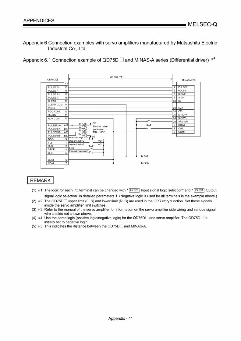
Appendix - 41
MELSEC-QAPPENDICES
Appendix 6 Connection examples with servo amplifiers manufactured by Matsushita ElectricIndustrial Co., Ltd.
Appendix 6.1 Connection example of QD75D and MINAS-A series (Differential driver) 4
PULSE F+
PULSE R+
CLEARCLEAR COM
READY
PULSER A+PULSER A-PULSER B+PULSER B-
B19A20B20
DOGFLSRLSSTOPCHG
COMCOM
31245
15161718
149
24G
P24V
MINAS-A 3
PULSE2
5VAB
0V
+5V
5G
22
1QD75D
4PULSE F-
PULSE R-
RDY COM
10PGO5PGO COM
13
1112
A19
67
PULSE1SIGN2SIGN1CL
OZ+OZ-S-RDY+S-RDY-SRV-QNCCWLCWLCOM+
36530
2324353429987
Manual pulse generator MR-HDP01
2m max 5
Near-point dog
Upper limit 2Lower limit 2StopExternal command
REMARK
(1) 1: The logic for each I/O terminal can be changed with " Pr.22 Input signal logic selection" and " Pr.23 Outputsignal logic selection" in detailed parameters 1. (Negative logic is used for all terminals in the example above.)
(2) 2: The QD75D upper limit (FLS) and lower limit (RLS) are used in the OPR retry function. Set these signalsinside the servo amplifier limit switches.
(3) 3: Refer to the manual of the servo amplifier for information on the servo amplifier side wiring and various signalwire shields not shown above.
(4) 4: Use the same logic (positive logic/negative logic) for the QD75D and servo amplifier. The QD75D isinitially set to negative logic.
(5) 5: This indicates the distance between the QD75D and MINAS-A.

Appendix - 42
MELSEC-QAPPENDICES
Appendix 7 Connection examples with servo amplifiers manufactured by SANYO DENKICo., Ltd.
Appendix 7.1 Connection example of QD75D and PYO series (Differential driver) 4
PULSE F+
PULSE R+
CLEAR
CLEAR COM
READY
PULSER A+PULSER A-
PULSER B+
PULSER B-
B19A20
B20
DOG
FLSRLSSTOP
CHG
COM
COM
3
1
2
4
5
1516
1718
148
24G
P24V
PYO 3
PPC
5V
A
B
0V
+5V
5G
2
2
1
PULSE F-
PULSE R-
RDY COM
10
PGO24
PGO COM
13
11
12
A19
67
PPC
NPC
NPCCLE
SG
COP
SRDY
DOR-24V
NROT
26
27
28
29
34
25
11
41
49SON
PROT
37
32
33
SG24
SG
DC5-24V
13
50
QD75D
SG48
2m max 5
Manual pulse generator MR-HDP01
Differential driver common terminal
Near-point dog
Upper limit 2
Lower limit 2StopExternal command
REMARK
(1) 1: The logic for each I/O terminal can be changed with " Pr.22 Input signal logic selection" and " Pr.23 Output
signal logic selection" in detailed parameters 1. (Negative logic is used for all terminals in the example above.)
(2) 2: The QD75D upper limit (FLS) and lower limit (RLS) are used in the OPR retry function. Set these signalsinside the servo amplifier limit switches.
(3) 3: Refer to the manual of the servo amplifier for information on the servo amplifier side wiring and various signalwire shields not shown above.
(4) 4: Use the same logic (positive logic/negative logic) for the QD75D and servo amplifier. The QD75D isinitially set to negative logic.
(5) 5: This indicates the distance between the QD75D and PYO.

Appendix - 43
MELSEC-QAPPENDICES
Appendix 8 Connection examples with servo amplifiers manufactured by YASKAWA ElectricCorporation
Appendix 8.1 Connection example of QD75D and ∑- series (Differential driver) 4
PULSE F+
PULSE R+
CLEARCLEAR COM
READY
PULSER A+PULSER A-PULSER B+PULSER B-
B19A20B20
DOGFLSRLSSTOPCHG
COMCOM
31245
15161718
149
24G
P24V
32m max
PULS
5
5VAB
0V
+5V
5G2
MR-HDP01
1
PULSE F-
PULSE R-
RDY COM
10PGO5PGO COM
13
1112
A19
67
/PULSSIGN/SIGN/CLR
PCO/PCOS-RDY+S-RDY-
S-ON
81112141
20293015 CLR
PL3184042
SG19
P-OTN-OT43
47
QD75D
7
+24VIN
2
Manual pulse generator
Near-point dog
Upper limit 2
Lower limit 2StopExternal command
REMARK
(1) 1: The logic of each I/O terminal can be changed with " Pr.22 Input signal logic selection" and " Pr.23 Output signallogic selection" in detailed parameters 1. (Negative logic is used for all terminals in the example above.)
(2) 2: The QD75D upper limit (FLS) and lower limit (RLS) are used in the OPR retry function. Set these signalsinside the servo amplifier limit switches.
(3) 3: Refer to the manual of the servo amplifier for information on the servo amplifier side wiring and various signalwire shields not shown above.
(4) 4: Use the same logic (positive logic/negative logic) for the QD75D and servo amplifier. The QD75D isinitially set to negative logic.
(5) 5: This indicates the distance between the QD75D and ∑- .

Appendix - 44
MELSEC-QAPPENDICES
Appendix 9 Comparisons with conventional positioning modules
Appendix 9.1 Comparisons with A1SD71S2 model
The following shows comparisons with the conventional positioning module A1SD71S2, centered on the QD75 specifications.
Model Item
QD75P1 QD75D1
QD75P2 QD75D2
QD75P4 QD75D4
A1SD71S2
No. of control axes 1 2 4 2 No. of positioning data items 600/axis 400/axis
2-axis linear interpolation 3-axis linear interpolation 4-axis linear interpolation
Interpolation functions
2-axis circular interpolation Position control Speed control Speed-position switching control (INC/ABS mode) (Only INC mode)
Positioning systems
Position-speed switching control
Machine OPR function (OPR method) (6 types) (3 types) JOG operation Inching operation Manual pulse generator function
Automatic trapezoidal acceleration/deceleration Acceleration/
deceleration processing S-curve
acceleration/deceleration
Acceleration/deceleration time Acceleration time and deceleration time setting possible (4 patterns each)
Acceleration/deceleration time same
Compensation Electronic gears, backlash compensation Backlash compensation Error display Error LED Error LED History data storage (Start, error, warning) Provided (3 types, 16 items/axis) None
Data storage destination Flash ROM (battery-less backup)
Buffer memory (battery backup)
No. of occupied I/O points 32 48 No. of module occupied slots 1 2
AD71TU AD75TU A6GPP, A6PHP
Peripheral devices (data setting, etc.)
DOS/V personal computer : Possible, : Not possible

Appendix - 45
MELSEC-QAPPENDICES
Appendix 9.2 Comparisons with A1SD75P1-S3/ A1SD75P2-S3/ A1SD75P3-S3 models
The following shows the comparisons between the QD75 and the conventional positioning modules A1SD75P1-S3/A1SD75P2-S3/A1SD75P3-S3.
(1) Comparisons of performance specifications
Model Item
QD75P1 QD75D1
QD75P2 QD75D2
QD75P4 QD75D4
A1SD75P1 -S3
A1SD75P2 -S3
A1SD75P3 -S3
No. of control axes 1 2 4 1 2 3 No. of positioning data items 600/axis 600/axis 1
2-axis linear interpolation
3-axis linear interpolation
4-axis linear interpolation
Position control interpolation functions
2-axis circular interpolation
Position control 1-axis 2-axis linear
interpolation
3-axis linear
interpolation
Speed control
4-axis linear
interpolation
Speed-position switching control
Positioning systems
Position-speed switching control
Positioning range 2
<Absolute system> -214748364.8 to 214748364.7 ( m) -21474.83648 to 21474.83647 (inch) 0 to 359.99999 (degree) -2147483648 to 2147483647 (pulse) <Incremental system > -214748364.8 to 214748364.7 ( m) -21474.83648 to 21474.83647 (inch) -21474.83648 to 21474.83647 (degree) -2147483648 to 2147483647 (pulse) <Speed-position or position-speed switching controls> 0 to 214748364.7 ( m) 0 to 21474.83647 (inch) 0 to 21474.83647 (degree)/ 0 to 359.99999 (degree) 3 0 to 2147483647 (pulse)
<Absolute system > -214748364.8 to 214748364.7 ( m) /-13421772.8 to 13421772.7 ( m) -21474.83648 to 21474.83647 (inch) /-1342.17728 to 1342.17727 (inch) 0 to 359.99999 (degree) /0 to 359.99999 (degree) -2147483648 to 2147483647 (pulse) /-134217728 to 134217727 (pulse) <Incremental system > -214748364.8 to 214748364.7 ( m) /-13421772.8 to 13421772.7 ( m) -21474.83648 to 21474.83647 (inch) /-1342.17728 to 1342.17727 (inch) -21474.83648 to 21474.83647 (degree) /-1342.17728 to 1342.17727 (degree) -2147483648 to 2147483647 (pulse) /-134217728 to 134217727 (pulse) <Speed-position switching control> 0 to 214748364.7 ( m) /0 to 13421772.7 ( m) 0 to 21474.83647 (inch) /0 to 1342.17727 (inch) 0 to 21474.83647 (degree) /0 to 1342.17727 (degree) 0 to 2147483647 (pulse) /0 to 134217727 (pulse)

Appendix - 46
MELSEC-QAPPENDICES
Model
Item QD75P1 QD75D1
QD75P2 QD75D2
QD75P4 QD75D4
A1SD75P1 -S3
A1SD75P2 -S3
A1SD75P3 -S3
Speed command range 2
0.01 to 20000000.00 (mm/min) 0.001 to 2000000.000 (inch/min) 0.001 to 2000000.000 (degree/min) 1 to 1000000 (pulse/s)
0.01 to 6000000.00 (mm/min) /0.01 to 375000.00 (mm/min) 0.001 to 600000.000 (inch/min) /0.001 to 37500.000 (inch/min) 0.001 to 600000.000 (degree/min) /0.001 to 37500.000 (degree/min) 1 to 1000000 (pulse/s) /1 to 62500 (pulse/s)
Machine OPR function (OPR method) (6 types) 4 (6 types)
JOG operation Inching operation Manual pulse generator function 1 generator/module 5 1 generator/axis 6
Automatic trapezoidal acceleration /deceleration
Acceleration /deceleration processing
S-curve acceleration /deceleration
No. of patterns Acceleration time and deceleration time can
be set independently. (4 patterns each) Acceleration time and deceleration time can
be set independently. (4 patterns each) Acceleration/deceleration time
Setting range 1 to 8388608ms 1 to 65535ms/1 to 8388608ms selectable
Compensation Electronic gears, backlash compensation, near pass 6
Electronic gears, backlash compensation, near pass 6
Error display Error LED 17-segment LED History data storage (Start, error, warning) Provided (3 types, 16 items/axis) Provided (4 types, 16 items/axis) Data storage destination Flash ROM (battery-less backup) Flash ROM (battery-less backup)
A6CON1 (Soldering type, sold separately) 10136-3000VE (Soldering type, supplied) A6CON2 (Crimp type, sold separately) 10136-6000EL (Crimp type, sold separately)Connection connector A6CON4 (Soldering type, usable for straight out and diagonal out, sold separately)
A6CON1, A6CON4: 0.3mm2 10136-3000VE: AWG#24 to #30 (Approx. 0.05 to 0.2 SQ) Applicable wire size
A6CON2: AWG#24 10136-6000EL: AWG#28 (Approx. 0.08 SQ)
Command pulse output system QD75P : Open collector QD75D : Differential driver
Both differential driver and open collector available
Max. output pulse
When connected with open collector: 200kpps When connected with differential driver: 1Mpps
When connected with open collector: 200kpps When connected with differential driver: 400kpps
Max. connection distance between servos
When connected with open collector: 2m (6.56ft) When connected with differential driver: 10m(32.79ft)
When connected with open collector: 2m (6.56ft) When connected with differential driver: 10m(32.79ft)
QD75P1: 0.4A
QD75P2: 0.46A
QD75P4: 0.58A Internal current consumption (A) [5VDC]
QD75D1: 0.52A
QD75D2: 0.56A
QD75D4: 0.82A
0.7A or less
Flash ROM write count Max. 100000 times Max. 100000 times No. of occupied I/O points 32 32 No. of module occupied slots 1 1 Outline dimensions (mm (inch)) 98(3.86)(H)×27.4(1.08)(W)×90(3.55)(D) 130(5.12)(H)×34.5(1.36)(W)×93.6(3.69)(D) Weight (kg (lb)) 0.15 (0.33) 0.15 (0.33) 0.16 (0.35) 0.35 (0.77)

Appendix - 47
MELSEC-QAPPENDICES
Model
Item QD75P1 QD75D1
QD75P2 QD75D2
QD75P4 QD75D4
A1SD75P1 -S3
A1SD75P2 -S3
A1SD75P3 -S3
STRT signal (integrated into "CHG") (External start signal)
CHG signal External command signal (External start or speed-position switching selectable with parameters)
Speed-position switching signal
In-position (INP) (for monitor)
I/O signal for external devices
Signal logic switching Command pulse output signal only
Connection with peripheral devices
Connection via PLC CPU, Q Corresponding Serial Communication Module, Q Corresponding MELSEC/H Remote I/O Module
Direct connection
AD71TU AD75TU A6GPP, A6PHP
Peripheral devices (data setting, etc.)
DOS/V personal computer : Possible, : Not possible
1: Up to 100 data items/axis of positioning data (No. 1 to 100) can be set using the buffer memory. The positioning data in the buffer memory is not backed up.
2: Indicates the standard mode/stepping motor mode about A1SD75P -S3. 3: Indicates the INC mode/ABS mode in speed-position switching control. 4: The deviation counter clear signal output time can be set with parameters. 5: The movement amount against the number of pulses input from manual pulsar is as follows: • QD75: Movement amount = "Number of pulses" ×"Unit setting" ×"Manual pulse generator 1 pulse input magnification" (refer to
Section 11.4.1.) • A1SD75: Movement amount = "Number of pulses" ×"Manual pulse generator 1 pulse input magnification"
6: The near pass function is valid only during the continuous path control. (A1SD75: Selected with parameters, QD75: Standard function) (2) Function comparisons
Functions added to those of A1SD75P1-S3/A1SD75P2-S3/A1SD75P3-S3 Added functions Remarks
External I/O signal logic switching function Refer to Section 13.4. Inching operation Refer to Section 11.3. Target position change function Refer to Section 12.7.5. Multiple axes simultaneous start control Refer to Section 10.5.
Control systems
3-axis linear interpolation control 4-axis linear interpolation control 3-axis fixed-feed control 4-axis fixed-feed control 2-axis speed control 3-axis speed control 4-axis speed control Position-speed switching control NOP instruction LOOP instruction, LEND instruction
Refer to Chapter 9.
Dedicated instructions
Absolute position restoration Positioning start Teaching Flash ROM writing Parameter initialization
Refer to Chapter 14.
Automatic refresh of intelligent function modules Refer to GX Configurator-QP Operating Manual.
Output hold/clear parameter setting during PLC CPU error stop Refer to QCPU User's Manual (Function Explanation, Program Fundamentals).
Flash ROM write limit Refer to Section 13.3. Speed-position switching control (ABS mode) Refer to Section 9.2.7. Pre-reading start function Refer to Section 12.7.8. External I/O signal monitor function Refer to Section 13.5. Multiple PLC compatible function Refer to QCPU User's Manual (Multiple CPU System). Deceleration start flag function Refer to Section 12.7.9 Stop command processing for deceleration stop function Refer to Section 12.7.10

Appendix - 48
MELSEC-QAPPENDICES
Functions deleted from those of A1SD75P1-S3/A1SD75P2-S3/A1SD75P3-S3
Deleted functions Remarks
Stepping motor mode – OPR operation error (Error code: 208) – Fast machine OPR – Special start (stop) –
Indirect designation In the QD75, the start block area on the buffer memory is expanded to five blocks (0 to 4). Each start block can be directly designated with positioning start No. (7000 to 7004).
Block transfer
Positioning data I/F
With the A1SD75, this interface is used to set positioning data Nos. 101 to 600 that do not exist on the buffer memory. Since all positioning data can be set in the buffer memory with the QD75, this function is deleted.
Start history storage during error The contents are the same as those of the start history. Therefore, the QD75 stores only the start history.
System monitor data (module type, OS information) These data were deleted because they can be displayed in system monitor "Module's detailed information" of GX Developer. (Refer to GX Developer Operating Manual.)
Functions changed from those of A1SD75P1-S3/A1SD75P2-S3/A1SD75P3-S3
Changed functions Descriptions
Software stroke limit function
1. The limit check of arc address is carried out only when a sub point is designated. It is not carried out when a center point is designated.
2. The software stroke limit check during speed control is carried out in the following cases: • When the software stroke limit is applied to the current feed
value with Pr.14 and the current feed value is updated with
Pr.21 .
• When the software stroke limit is applied to the machine feed value.
3. If an attempt is made to change the current value but the designated address is out of the software stroke limit range, the attempt is considered as an error and the current value is not changed.
4. The conventional models feature three types of software stroke limit error codes for upper limit and lower limit respectively. With the QD75, errors for the software stroke upper limit are integrated into error code 507, and errors for the lower limit are integrated into error code 508. Error codes 509 to 512 are deleted.
Current value changing M code function
1. An error occurs when the designated new current value is out of the software stroke limit range.
2. The M code setting value is valid during the positioning data current value changing instruction.
Acceleration/deceleration control
1. An error occurs when the command frequency value calculated from the speed limit value is out of the maximum command frequency of the positioning module being used.
2. Only two-word type (1 to 8388608ms) can be used as the setting value for the acceleration/deceleration time. (The switch between 1-word type and 2-word type is eliminated.)
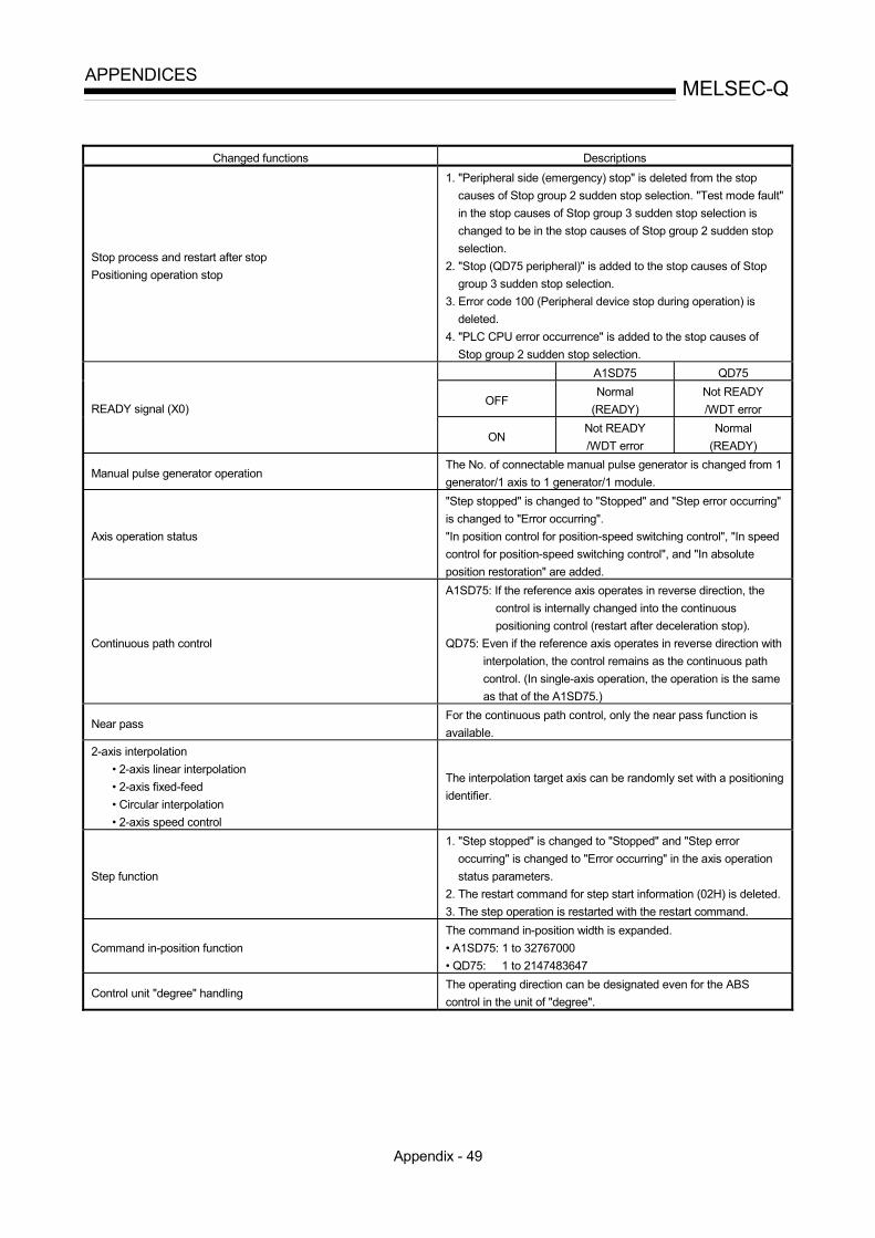
Appendix - 49
MELSEC-QAPPENDICES
Changed functions Descriptions
Stop process and restart after stop Positioning operation stop
1. "Peripheral side (emergency) stop" is deleted from the stop causes of Stop group 2 sudden stop selection. "Test mode fault" in the stop causes of Stop group 3 sudden stop selection is changed to be in the stop causes of Stop group 2 sudden stop selection.
2. "Stop (QD75 peripheral)" is added to the stop causes of Stop group 3 sudden stop selection.
3. Error code 100 (Peripheral device stop during operation) is deleted.
4. "PLC CPU error occurrence" is added to the stop causes of Stop group 2 sudden stop selection.
A1SD75 QD75
OFF Normal
(READY) Not READY /WDT error READY signal (X0)
ON Not READY /WDT error
Normal (READY)
Manual pulse generator operation The No. of connectable manual pulse generator is changed from 1 generator/1 axis to 1 generator/1 module.
Axis operation status
"Step stopped" is changed to "Stopped" and "Step error occurring" is changed to "Error occurring". "In position control for position-speed switching control", "In speed control for position-speed switching control", and "In absolute position restoration" are added.
Continuous path control
A1SD75: If the reference axis operates in reverse direction, the control is internally changed into the continuous positioning control (restart after deceleration stop).
QD75: Even if the reference axis operates in reverse direction with interpolation, the control remains as the continuous path control. (In single-axis operation, the operation is the same as that of the A1SD75.)
Near pass For the continuous path control, only the near pass function is available.
2-axis interpolation • 2-axis linear interpolation • 2-axis fixed-feed • Circular interpolation • 2-axis speed control
The interpolation target axis can be randomly set with a positioning identifier.
Step function
1. "Step stopped" is changed to "Stopped" and "Step error occurring" is changed to "Error occurring" in the axis operation status parameters.
2. The restart command for step start information (02H) is deleted. 3. The step operation is restarted with the restart command.
Command in-position function The command in-position width is expanded. • A1SD75: 1 to 32767000 • QD75: 1 to 2147483647
Control unit "degree" handling The operating direction can be designated even for the ABS control in the unit of "degree".

Appendix - 50
MELSEC-QAPPENDICES
Changed functions Descriptions
Positioning start No. No. 9004 (Multiple axes simultaneous start control) is added. Nos. 7004 to 7010 (block start designation) and 8000 to 8049 (indirect designation) are deleted.
Block start data With the QD75, the number of blocks is changed to 5 (7000 to 7004). (With the A1SD75, this data is called "positioning start information".)
Special start data "Simultaneous start" The simultaneous start is possible up to 4 axes.
List of errors/warnings Refer to the following "Error code comparisons" and "Warning code comparisons".
Start history The configuration of "start information" and "start No." is changed so that the start No. can be directly checked.
Synchronization flag (X1) When the PLC CPU starting method is set to asynchronous, interlock is established with the synchronization flag (X1) signal.
Basic parameter 1 " Pr.5 Pulse output mode" When the PLC is turned ON or the PLC CPU module is reset, the valid value is only the first value after the PLC READY signal (Y0) turns from OFF to ON.
A1SD75 QD75 0 (Factory
setting) Software stroke limits invalid for manual operation
Software stroke limits valid for manual operation
Detailed parameters " Pr.15 Software stroke limit valid/invalid setting"
1 Software stroke limits valid for manual operation
Software stroke limits invalid for manual operation
Error code comparisons
Error code Error name
A1SD75 QD75
Outside bias speed range 913 906
Illegal sudden stop deceleration time 962 961
Stop group 1 sudden stop selection error 963 962
Stop group 2 sudden stop selection error 964 963
Stop group 3 sudden stop selection error 965 964
OPR torque limit value error 991 995
Setting for the movement amount after near-point dog ON error 992 991
OPR acceleration time selection error 993 992
OPR deceleration time selection error 994 993
Error type Added Deleted
Fatal error 002 51, 52 Common – 100, 108 OPR, Absolute position restoration 213, 214 208 JOG/Inching operation 301 – Manual pulse generator operation – – Positioning operation 523, 535, 545, 546 509 to 512 I/F 800 to 806 – Parameter 920, 935, 990, 996 931, 933, 938, 971, 999 Error whose name is changed: Error code 967 A1SD75: External start selection error QD75: External command function selection error

Appendix - 51
MELSEC-QAPPENDICES
Warning code comparisons
Warning type Added Deleted
Fatal warning – 51, 52 Common 110 101, 105 to 108, 115 OPR, Absolute position restoration – – JOG operation/Inching operation – – Manual pulse generator operation – 402 Positioning operation 516, 517, 518 – I/F – – Parameter – 900 Warning whose name is changed: Warning code 512 A1SD75: Illegal external start function QD75: Illegal external command function
: Refer to "Section 15.2 List of errors" and "Section 15.3 List of warnings" for details on error codes and warning codes.
(3) Input/output (X/Y) comparisons Input (X) Output (Y)
Name A1SD75 QD75 Name A1SD75 QD75 (QD75/A1SD75) READY X00 X00 Axis 1 Positioning start Y10 Y10 Axis 1 Start complete X01 X10 Axis 2 Positioning start Y11 Y11 Axis 2 Start complete X02 X11 Axis 3 Positioning start Y12 Y12 Axis 3 Start complete X03 X12 Axis 4 Positioning start – Y13 Axis 4 Start complete – X13 Axis 1 Stop Y13 Y04 Axis 1 BUSY X04 X0C Axis 2 Stop Y14 Y05 Axis 2 BUSY X05 X0D Axis 3 Stop Y1C Y06 Axis 3 BUSY X06 X0E Axis 4 Stop – Y07
Axis 4 BUSY – X0F Axis 1 Forward run JOG start Y16 Y08
Axis 1 Positioning complete X07 X14 Axis 1 Reverse run JOG
start Y17 Y09
Axis 2 Positioning complete X08 X15 Axis 2 Forward run JOG
start Y18 Y0A
Axis 3 Positioning complete X09 X16 Axis 2 Reverse run JOG
start Y19 Y0B
Axis 4 Positioning complete – X17 Axis 3 Forward run JOG
start Y1A Y0C
Axis 1 Error detection X0A X08 Axis 3 Reverse run JOG start Y1B Y0D
Axis 2 Error detection X0B X09 Axis 4 Forward run JOG start – Y0E
Axis 3 Error detection X0C X0A Axis 4 Reverse run JOG start – Y0F
Axis 4 Error detection – X0B PLC READY Y1D Y00
Axis 1 M code ON X0D X04 Axis 1 Execution prohibition flag – Y14
Axis 2 M code ON X0E X05 Axis 2 Execution prohibition flag – Y15
Axis 3 M code ON X0F X06 Axis 3 Execution prohibition flag – Y16
Axis 4 M code ON – X07 Axis 4 Execution prohibition flag – Y13
Synchronization flag – X01 Use prohibited Y00 to Y0F Y1E to Y1F
Y01 to Y03 Y18 to Y1F
Use prohibited X10 to X1F X02, X03 X18 to X1F
: The ON/OFF statuses for READY are different between the QD75 and A1SD75. Not READY/WDT error READY
QD75 OFF ON A1SD75 ON OFF

Appendix - 52
MELSEC-QAPPENDICES
(4) Buffer memory address comparisonsThe following table shows the buffer memory addresses of the QD75 (Axes 1 to3) corresponding to the items of the A1SD75.The shaded area shows the differences between the A1SD75 and QD75.
Buffer memory addressA1SD75 QD75Items of A1SD75
Axis 1 Axis 2 Axis 3 Axis 1 Axis 2 Axis 3Pr.1 Unit setting 0 150 300 0 150 300
Pr.2 No. of pulses per rotation (Ap) 1 151 301 1 151 301
Pr.3 Movement amount per rotation (Al) 2 152 302 2 152 302
Pr.4 Unit magnification (Am) 3 153 303 3 153 303
Pr.5 Pulse output mode 4 154 304 4 154 304
Pr.6 Rotation direction setting 5 155 305 5 155 305
Pr.7 Speed limit value67
156157
306307
1011
160161
310311
Pr.8 Acceleration time 089
158159
308309
1213
162163
312313
Pr.9 Deceleration time 01011
160161
310311
1415
164165
314315
Pr.10 Bias speed at start1213
162163
312313
67
156157
306307
Pr.11 Stepping motor mode selection amount 14 164 314 – – –
Pr.12 Backlash compensation amount 15 165 315 17 167 317
Pr.13 Software stroke limit upper limit value1617
166167
316317
1819
168169
318319
Pr.14 Software stroke limit lower limit value1819
168169
318319
2021
170171
320321
Pr.15 Software stroke limit selection 20 170 320 22 172 322
Pr.16 Software stroke limit valid/invalid setting 21 171 321 23 173 323
Pr.17 Command in-position width2223
172173
322323
2425
174175
324325
Pr.18 Torque limit setting value 24 174 324 26 176 326
Pr.19 M code ON signal output timing 25 175 325 27 177 327
Pr.20 Speed switching mode 26 176 326 28 178 328
Pr.21 Interpolation speed designation method 27 177 327 29 179 329
Pr.22 Current feed value during speed control 28 178 328 30 180 330
Pr.23 Manual pulse generator selection 29 179 329 – – –
Pr.24 Logic selection for pulse output to the drive unit 30 180 330 – – –
Pr.25 Size selection for acceleration/deceleration time 31 181 331 – – –
Pr.26 Acceleration time 13637
186187
336337
3637
186187
336337
Pr.27 Acceleration time 23839
188189
338339
3839
188189
338339

Appendix - 53
MELSEC-QAPPENDICES
Buffer memory addressA1SD75 QD75Items of A1SD75
Axis 1 Axis 2 Axis 3 Axis 1 Axis 2 Axis 3
Pr.28 Acceleration time 34041
190191
340341
4041
190191
340341
Pr.29 Deceleration time 14243
192193
342343
4243
192193
342343
Pr.30 Deceleration time 24445
194195
344345
4445
194195
344345
Pr.31 Deceleration time 34647
196197
346347
4647
196197
346347
Pr.32 JOG speed limit value4849
198199
348349
4849
198199
348349
Pr.33 JOG operation acceleration time selection 50 200 350 50 200 350
Pr.34 JOG operation deceleration time selection 51 201 351 51 201 351
Pr.35 Acceleration/deceleration process selection 52 202 352 52 202 352
Pr.36 S-curve ratio 53 203 353 53 203 353
Pr.37 Sudden stop deceleration time5455
204205
354355
5455
204205
354355
Pr.38 Stop group 1 sudden stop selection 56 206 356 56 206 356
Pr.39 Stop group 2 sudden stop selection 57 207 357 57 207 357
Pr.40 Stop group 3 sudden stop selection 58 208 358 58 208 358
Pr.41 Positioning complete signal output time 59 209 359 59 209 359
Pr.42 Allowable circular interpolation error width6061
210211
360361
6061
210211
360361
Pr.43 External start function selection
(QD75: Pr.42 External command function selection)62 212 362 62 212 362
Pr.44 Near pass mode selection for path control 66 216 366 – – –
Pr.45 OPR method 70 220 370 70 220 370
Pr.46 OPR direction 71 221 371 71 221 371
Pr.47 OP address7273
222223
372373
7273
222223
372373
Pr.48 OPR speed7475
224225
374375
7475
224225
374375
Pr.49 Creep speed7677
226227
376377
7677
226227
376377
Pr.50 OPR retry 78 228 378 78 228 378
Pr.51 OPR dwell time 79 229 379 79 229 379
Pr.52 Setting for the movement amount after near-
point dog ON
8081
230231
380381
8081
230231
380381
Pr.53 OPR acceleration time selection 82 232 382 82 232 382
Pr.54 OPR deceleration time selection 83 233 383 83 233 383
Pr.55 OP shift amount8485
234235
384385
8485
234235
384385
Pr.56 OPR torque limit value 86 236 386 86 236 386
Pr.57 Speed designation during OP shift 88 238 388 88 238 388
Pr.58 Dwell time during OPR retry 89 239 389 89 239 389

Appendix - 54
MELSEC-QAPPENDICES
Buffer memory addressA1SD75 QD75Items of A1SD75
Common for axis 1, 2, 3 Common for axis 1, 2, 3, 4Md.1 In test mode flag 450 1200
Md.2 Module name 451 –
Md.3 OS type452 453454 455
–
Md.4 OS version456457
–
Md.5 Clock data (hour: minute) 460 –
Md.6 Clock data (second: 100 ms) 461 –
(Pointer number) (0) to (15)Md.7 Start axis
(QD75: Md. 3 Start information)462 to 537 1212 to 1287
Md.8 Operation type
(QD75: Md. 4 Start No.)463 to 538 1213 to 1288
Md.9 Start Hour: minute
(QD75: Md. 5 Start Hour)464 to 539 1214 to 1289
Md.10 Start Second: 100 ms
(QD75: Md. 6 Start Minute: second)465 to 540 1215 to 1290
Md.11 Error judgment 466 to 541 1216 to 1291
Md.12 Start history pointer
Starthistory
542 1292
(Pointer number) (0) to (15) –Md.13 Start axis 543 to 618 –
Md.14 Operation type 544 to 619 –
Md.15 Start Hour: minute 545 to 620 –
Md.16 Start Second: 100 ms 546 to 621 –
Md.17 Error judgment 547 to 622 –
Md.18 Start history storage during error
Starthistoryduringerrors
623 –
(Pointer number) (0) to (15)Md.19 Axis in which the error occurred 624 to 684 1293 to 1353
Md.20 Axis error No. 625 to 685 1294 to 1354
Md.21 Axis error occurrence Hour: minute
(QD75: Md. 11 Axis error occurrence (Hour))626 to 686 1295 to 1355
Md.22 Axis error occurrence Second:
100 ms(QD75: Md. 12 Axis error occurrence(Minute: second))
627 to 687 1296 to 1356
Md.23 Error history pointer
Errorhistory
688 1357

Appendix - 55
MELSEC-QAPPENDICES
Buffer memory addressA1SD75 QD75Items of A1SD75
Common for axis 1, 2, 3 Common for axis 1, 2, 3, 4
(Pointer number) (0) to (15)Md.24 Axis in which the warning occurred 689 to 749 1358 to 1418
Md.25 Axis warning No. 690 to 750 1359 to 1419
Md.26 Axis warning occurrence Hour:
minute(QD75: Md. 16 Axis warning occurrence(Hour))
691 to 751 1360 to 1420
Md.27 Axis warning occurrence Second:
100 ms(QD75: Md. 17 Axis warning occurrence(Minute: second))
692 to 752 1361 to 1421
Md.28 Warning history pointer
Warninghistory
753 1422

Appendix - 56
MELSEC-QAPPENDICES
Buffer memory addressA1SD75 QD75Items of A1SD75
Axis 1 Axis 2 Axis 3 Axis 1 Axis 2 Axis 3
Md.29 Current feed value800801
900901
10001001
800801
900901
10001001
Md.30 Machine feed value802803
902903
10021003
802803
902903
10021003
Md.31 Feedrate804805
904905
10041005
804805
904905
10041005
Md.32 Valid M code 806 906 1006 808 908 1008
Md.33 Axis error No. 807 907 1007 806 906 1006
Md.34 Axis warning No. 808 908 1008 807 907 1007
Md.35 Axis operation status 809 909 1009 809 909 1009
Md.36 Current speed810811
910911
10101011
810811
910911
10101011
Md.37 Axis feedrate812813
912913
10121013
812813
912913
10121013
Md.38 Speed-position switching control positioning
amount
814815
914915
10141015
814815
914915
10141015
Md.39 External input/output signal 816 916 1016 816 916 1016
Md.40 Status 817 917 1017 817 917 1017
Md.41 Target value818819
918919
10181019
818819
918919
10181019
Md.42 Target speed820821
920921
10201021
820821
920921
10201021
Md.43 OP absolute position822823
922923
10221023
– – –
Md.44 Movement amount after near-point dog ON824825
924925
10241025
824825
924925
10241025
Md.45 Torque limit stored value 826 926 1026 826 926 1026
Md.46 Special start data instruction code setting value 827 927 1027 827 927 1027
Md.47 Special start data instruction parameter setting
value828 928 1028 828 928 1028
Md.48 Start positioning data No. setting value 829 929 1029 829 929 1029
Md.49 In speed control flag 830 930 1030 830 930 1030
Md.50 In speed change processing flag 831 931 1031 831 931 1031
Md.51 Start data pointer being executed 832 932 1032 834 934 1034
Md.52 Last executed positioning data No. 833 933 1033 837 937 1037
Md.53 Repetition counter
(QD75: Md. 41 Special start repetition counter)834 934 1034 832 932 1032
Md.54 Positioning data No. being executed 835 935 1035 835 935 1035
Md.55 Block No. being executed 836 936 1036 836 936 1036
Md.56 Positioning data being executed 838 to 847 938 to 9471038 to1047
838 to 847 938 to 9471038 to1047

Appendix - 57
MELSEC-QAPPENDICES
Buffer memory addressA1SD75 QD75Items of A1SD75
Axis 1 Axis 2 Axis 3 Axis 1 Axis 2 Axis 3Cd.1 Clock data setting (hour) 1100 –
Cd.2 Clock data setting (minute, second) 1101 –
Cd.3 Clock data writing 1102 –
Cd.4 Target axis 1103 –
Cd.5 Positioning data No. 1104 –
Cd.6 Write pattern 1105 –
Cd.7 Read/write request 1106 –
Cd.8 Read/write positioning data I/F 1108 to 1137 –
Cd.9 Flash ROM write request 1138 1900
Cd.10 Parameter initialization request 1139 1901
Cd.11 Positioning start No. 1150 1200 1250 1500 1600 1700
Cd.12 Axis error reset 1151 1201 1251 1502 1602 1702
Cd.13 Restart command 1152 1202 1252 1503 1603 1703
Cd.14 M code OFF request 1153 1203 1253 1504 1604 1704
Cd.15 New current value11541155
12041205
12541255
15061507
16061607
17061707
Cd.16 New speed value11561157
12061207
12561257
15141515
16141615
17141715
Cd.17 Speed change request 1158 1208 1258 1516 1616 1716
Cd.18 Positioning operation speed override 1159 1209 1259 1513 1613 1713
Cd.19 JOG speed11601161
12101211
12601261
15181519
16181619
17181719
Cd.20 Speed-position switching enable flag 1163 1213 1263 1528 1628 1728
Cd.21 Speed-position switching control movement
amount change register
11641165
12141215
12641265
15261527
16261627
17261727
Cd.22 Manual pulse generator enable flag 1167 1217 1267 1524 1624 1724
Cd.23 Manual pulse generator 1 pulse input
magnification
11681169
12181219
12681269
15221523
16221623
17221723
Cd.24 OPR return request flag OFF request 1170 1220 1270 1521 1621 1721
Cd.25 External start valid
(QD75: Cd. 8 External command valid)1171 1221 1271 1505 1605 1705
Cd.26 Step valid flag 1172 1222 1272 1545 1645 1745
Cd.27 Step mode 1173 1223 1273 1544 1644 1744
Cd.28 Step start information 1174 1224 1274 1546 1646 1746
Cd.29 Skip command 1175 1225 1275 1547 1647 1747
Cd.30 New torque value 1176 1226 1276 1525 1625 1725
Cd.31 Positioning starting point No. 1178 1228 1278 1501 1601 1701
Cd.32 Interrupt request during continuous operation 1181 1231 1281 1520 1620 1720
Cd.33 New acceleration time value11841185
12341235
12841285
15081509
16081609
17081709

Appendix - 58
MELSEC-QAPPENDICES
Buffer memory addressA1SD75 QD75Items of A1SD75
Axis 1 Axis 2 Axis 3 Axis 1 Axis 2 Axis 3
Cd.34 New deceleration time value11861187
12361237
12861287
15101511
16101611
17101711
Cd.35 Acceleration/deceleration time change during
speed change, enable/disable selection1188 1238 1288 1512 1612 1712
Da.1 Operation pattern
Da.2 Control system
Da.3 Acceleration time No.
Da.4 Deceleration time No.
1300 2300 3300 2000 8000 14000
Da.9 M code/condition data 1301 2301 3301 2001 8001 14001
Da.8 Dwell time/JUMP destination
positioning data No.1302 2302 3302 2002 8002 14002
Da.7 Command speed13041305
23042305
33063307
20042005
80048005
1400414005
Da.5 Positioning address/movement
amount
13061307
23062307
33063307
20062007
80068007
1400614007
Da.6 Arc address
No.1
13081309
23082309
33083309
20082009
80088009
1400814009
No.21310 to1319
2320 to2329
3310 to3319
2010 to2019
8010 to8019
14010 to14019
No.31320 to1329
2330 to2339
3320 to3329
2020 to2029
8020 to8029
14020 to14029
to to to to to to to
Posi
tioni
ng d
ata
1
No.1002290 to2299
3290 to3299
4290 to4299
2990 to2999
8990 to8999
14990 to14999
1: With the QD75, the positioning data buffer memory addresses are Nos. 1 to 600.
Refer to Appendix 12 "List of buffer memory addresses" for details.

Appendix - 59
MELSEC-QAPPENDICES
Buffer memory addressA1SD75 QD75Items of A1SD75
Axis 1 Axis 2 Axis 3 Axis 1 Axis 2 Axis 3
Da.10 Shape
Da.11 Start data No.
Da.12 Special start
instructionDa.13 Parameter
1stpoint
4300 4350 4550 4600 4800 4850 26000 26050 27000 27050 28000 28050
2nd point 4301 4351 4551 4601 4801 4851 26001 26051 27001 27051 28001 28051
3rd point 4302 4352 4552 4602 4802 4852 26002 26052 27002 27052 28002 28052
to to to to to to to
Star
t blo
ck d
ata
2
50th point 4349 4399 4599 4649 4849 4899 26049 26099 27049 27099 28049 28099
Da.14 Condition target
Da.15 Condition operator4400 4650 4900 26100 27100 28100
Da.16 Address44024403
46524653
49024903
2610226103
2710227103
2810228103
Da.17 Parameter 144044405
46544655
49044905
2610426105
2710427105
2810428105
Da.18 Parameter 2
No. 1
44064407
46564657
49064907
2610626107
2710627107
2810628107
No. 24410 to4419
4660 to4669
4910 to4919
26110 to26119
27110 to27119
28110 to28119
No. 34420 to4429
4670 to4679
4920 to4929
26120 to26129
27120 to27129
28120 to28129
to to to to to to to
Posi
tioni
ng s
tart
info
rmat
ion
2
Con
ditio
n da
ta
No. 104490 to4499
4740 to4749
4990 to4999
26190 to26199
27190 to27199
28190 to28199
Start No. 8001 4500 4750 5000 – – –Start No. 8002 4501 4751 5001 – – –
to to to to to to to
Posi
tioni
ngst
art
info
rmat
ion
Indirect
specification
Start No. 8050 4549 4799 5049 – – –5050 30000
to toPLC CPU
memo areaCondition judgment target data ofthe condition data
5099 30099Target axis 5100 –Head positioning block No. 5101 –No. of read/write data items 5102 –Read/write request 5103 –Read/write block 5110 to 6109 –
2: With the QD75, it is called "block start data".3: With the QD75, the "block start data" and "condition data" in the shaded area are called "start block 0". There are five start blocks: 0 to
4.
Refer to Appendix 12 "List of buffer memory addresses" for details.

Appendix - 60
MELSEC-QAPPENDICES
(5) Data indication No. comparisonsThe following table shows the comparisons of numbers for each symbols (Pr.,Md., Cd., and Da.) indicating parameters or positioning data items.The shaded sections indicate the added or changed items with the QD75.
Parameters
Item A1SD75 QD75
Unit setting Pr.1
No. of pulses per rotation (Ap) Pr.2
Movement amount per rotation (Al) Pr.3
Unit magnification (Am) Pr.4
Pulse output mode Pr.5
Rotation direction setting Pr.6
Speed limit value Pr.7 Pr.8
Acceleration time 0 Pr.8 Pr.9
Deceleration time 0 Pr.9 Pr.10
Bias speed at start Pr.10 Pr.7
Stepping motor mode selection Pr.11 –
Backlash compensation amount Pr.12 Pr.11
Software stroke limit upper limit value Pr.13 Pr.12
Software stroke limit lower limit value Pr.14 Pr.13
Software stroke limit selection Pr.15 Pr.14
Software stroke limit valid/invalid setting Pr.16 Pr.15
Command in-position width Pr.17 Pr.16
Torque limit setting value Pr.18 Pr.17
M code ON signal output timing Pr.19 Pr.18
Speed switching mode Pr.20 Pr.19
Interpolation speed designation method Pr.21 Pr.20
Current feed value during speed control Pr.22 Pr.21
Manual pulse generator selection Pr.23 –
Logic selection for pulse output to the drive unit Pr.24 –
Input signal logic selection – Pr.22
Output signal logic selection – Pr.23
Manual pulse generator input selection – Pr.24
Size selection for acceleration/deceleration time Pr.25 –
Acceleration time 1 Pr.26 Pr.25
Acceleration time 2 Pr.27 Pr.26

Appendix - 61
MELSEC-QAPPENDICES
Item A1SD75 QD75
Acceleration time 3 Pr.28 Pr.27
Deceleration time 1 Pr.29 Pr.28
Deceleration time 2 Pr.30 Pr.29
Deceleration time 3 Pr.31 Pr.30
JOG speed limit value Pr.32 Pr.31
JOG operation acceleration time selection Pr.33 Pr.32
JOG operation deceleration time selection Pr.34 Pr.33
Acceleration/deceleration process selection Pr.35 Pr.34
S-curve ratio Pr.36 Pr.35
Sudden stop deceleration time Pr.37 Pr.36
Stop group 1 sudden stop selection Pr.38 Pr.37
Stop group 2 sudden stop selection Pr.39 Pr.38
Stop group 3 sudden stop selection Pr.40 Pr.39
Positioning complete signal output time Pr.41 Pr.40
Allowable circular interpolation error width Pr.42 Pr.41
External start function selection(QD75: Pr.42 External command function selection)
Pr.43 Pr.42
Near pass mode selection for path control Pr.44 –
OPR method Pr.45 Pr.43
OPR direction Pr.46 Pr.44
OP address Pr.47 Pr.45
OPR speed Pr.48 Pr.46
Creep speed Pr.49 Pr.47
OPR retry Pr.50 Pr.48
OPR dwell time Pr.51 Pr.49
Setting for the movement amount after near-point dog ON Pr.52 Pr.50
OPR acceleration time selection Pr.53 Pr.51
OPR deceleration time selection Pr.54 Pr.52
OP shift amount Pr.55 Pr.53
OPR torque limit value Pr.56 Pr.54
Deviation counter clear signal output time – Pr.55
Speed designation during OP shift Pr.57 Pr.56
Dwell time during OPR retry Pr.58 Pr.57
Speed-position function selection – Pr.150

Appendix - 62
MELSEC-QAPPENDICES
Monitor data
Item A1SD75 QD75
In test mode flag Md.1
Module name Md.2 –
OS type Md.3 –
OS version Md.4 –
Clock data (hour: minute) Md.5 –
Clock data (second: 100 ms) Md.6 –
Start axis (QD75: Md. 3 Start information) Md.7 Md.3
Operation type (QD75: Md. 4 Start No.) Md.8 Md.4
Start Hour: minute (QD75: Md. 5 Start Hour) Md.9 Md.5
Start Second: 100 ms (QD75: Md. 6 Start Minute: second) Md.10 Md.6
Error judgment Md.11 Md.7
Start history pointer
Start history
Md.12 Md.8
Start axis Md.13 –
Operation type Md.14 –
Start Hour: minute Md.15 –
Start Second: 100 ms Md.16 –
Error judgment Md.17 –
Start history storage during error
Start history duringerrors
Md.18 –
Axis in which the error occurred Md.19 Md.9
Axis error No. Md.20 Md.10
Axis error occurrence Hour: minute(QD75: Md. 11 Axis error occurrence (Hour))
Md.21 Md.11
Axis error occurrence Second: 100ms(QD75: Md. 12 Axis error occurrence (Minute: second))
Md.22 Md.12
Pointer
Error history
Md.23 Md.13
Axis in which the warning occurred Md.24 Md.14
Axis warning No. Md.25 Md.15
Axis warning occurrence Hour: minute(QD75: Md. 16 Axis warning occurrence (Hour))
Md.26 Md.16
Axis warning occurrence Second: 100ms(QD75: Md. 17 Axis warning occurrence (Minute: second))
Md.27 Md.17
Pointer
Warning history
Md.28 Md.18

Appendix - 63
MELSEC-QAPPENDICES
Item A1SD75 QD75
No. of write accesses to flash ROM – Md.19
Current feed value Md.29 Md.20
Machine feed value Md.30 Md.21
Feedrate Md.31 Md.22
Valid M code Md.32 Md.25
Axis error No. Md.33 Md.23
Axis warning No. Md.34 Md.24
Axis operation status Md.35 Md.26
Current speed Md.36 Md.27
Axis feedrate Md.37 Md.28
Speed-position switching control positioning amount Md.38 Md.29
External input/output signal Md.39 Md.30
Status Md.40 Md.31
Target value Md.41 Md.32
Target speed Md.42 Md.33
OP absolute position Md.43 –
Movement amount after near-point dog ON Md.44 Md.34
Torque limit stored value Md.45 Md.35
Special start data instruction code setting value Md.46 Md.36
Special start data instruction parameter setting value Md.47 Md.37
Start positioning data No. setting value Md.48 Md.38
In speed control flag Md.49 Md.39
In speed change processing flag Md.50 Md.40
Start data pointer being executed Md.51 Md.43
Last executed positioning data No. Md.52 Md.46
Repetition counter (QD75: Md. 41 Special start repetition counter) Md.53 Md.41
Control system repetition counter – Md.42
Positioning data No. being executed Md.54 Md.44
Block No. being executed Md.55 Md.45
Positioning data being executed Md.56 Md.47
Deceleration start flag – Md.48

Appendix - 64
MELSEC-QAPPENDICES
Control data
Item A1SD75 QD75
Clock data setting (hour) Cd.1 –
Clock data setting (minute, second) Cd.2 –
Clock data writing Cd.3 –
Target axis Cd.4 –
Positioning data No. Cd.5 –
Write pattern Cd.6 –
Read/write request Cd.7 –
Read/write positioning data I/F Cd.8 –
Flash ROM write request Cd.9 Cd.1
Parameter initialization request Cd.10 Cd.2
Positioning start No. Cd.11 Cd.3
Axis error reset Cd.12 Cd.5
Restart command Cd.13 Cd.6
M code OFF request Cd.14 Cd.7
New current value Cd.15 Cd.9
New speed value Cd.16 Cd.14
Speed change request Cd.17 Cd.15
Positioning operation speed override Cd.18 Cd.13
JOG speed Cd.19 Cd.17
Inching movement amount – Cd.16
Speed-position switching enable flag Cd.20 Cd.24
Speed-position switching control movement amount change register Cd.21 Cd.23
Position-speed switching enable flag – Cd.26
Position-speed switching control speed change register – Cd.25
Target position change request flag – Cd.29
Target position change value (new address) – Cd.27
Target position change value (new speed) – Cd.28
ABS direction in degrees – Cd.40
Manual pulse generator enable flag Cd.22 Cd.21
Manual pulse generator 1 pulse input magnification Cd.23 Cd.20
OPR request flag OFF request Cd.24 Cd.19
External start valid (QD75: Cd. 8 External command valid) Cd.25 Cd.8

Appendix - 65
MELSEC-QAPPENDICES
Item A1SD75 QD75
Step valid flag Cd.26 Cd.35
Step mode Cd.27 Cd.34
Step start information Cd.28 Cd.36
Skip command Cd.29 Cd.37
New torque value Cd.30 Cd.22
Positioning starting point No. Cd.31 Cd.4
Interrupt request during continuous operation Cd.32 Cd.18
Simultaneous starting axis start data No. (Axis 1 start data No.) – Cd.30
Simultaneous starting axis start data No. (Axis 2 start data No.) – Cd.31
Simultaneous starting axis start data No. (Axis 3 start data No.) – Cd.32
Simultaneous starting axis start data No. (Axis 4 start data No.) – Cd.33
Teaching data selection – Cd.38
Teaching positioning data No. – Cd.39
New acceleration time value Cd.33 Cd.10
New deceleration time value Cd.34 Cd.11
Acceleration/deceleration time change during speed change, enable/disable selection Cd.35 Cd.12
Stop command processing for deceleration stop selection – Cd.42
Deceleration start flag valid – Cd.41
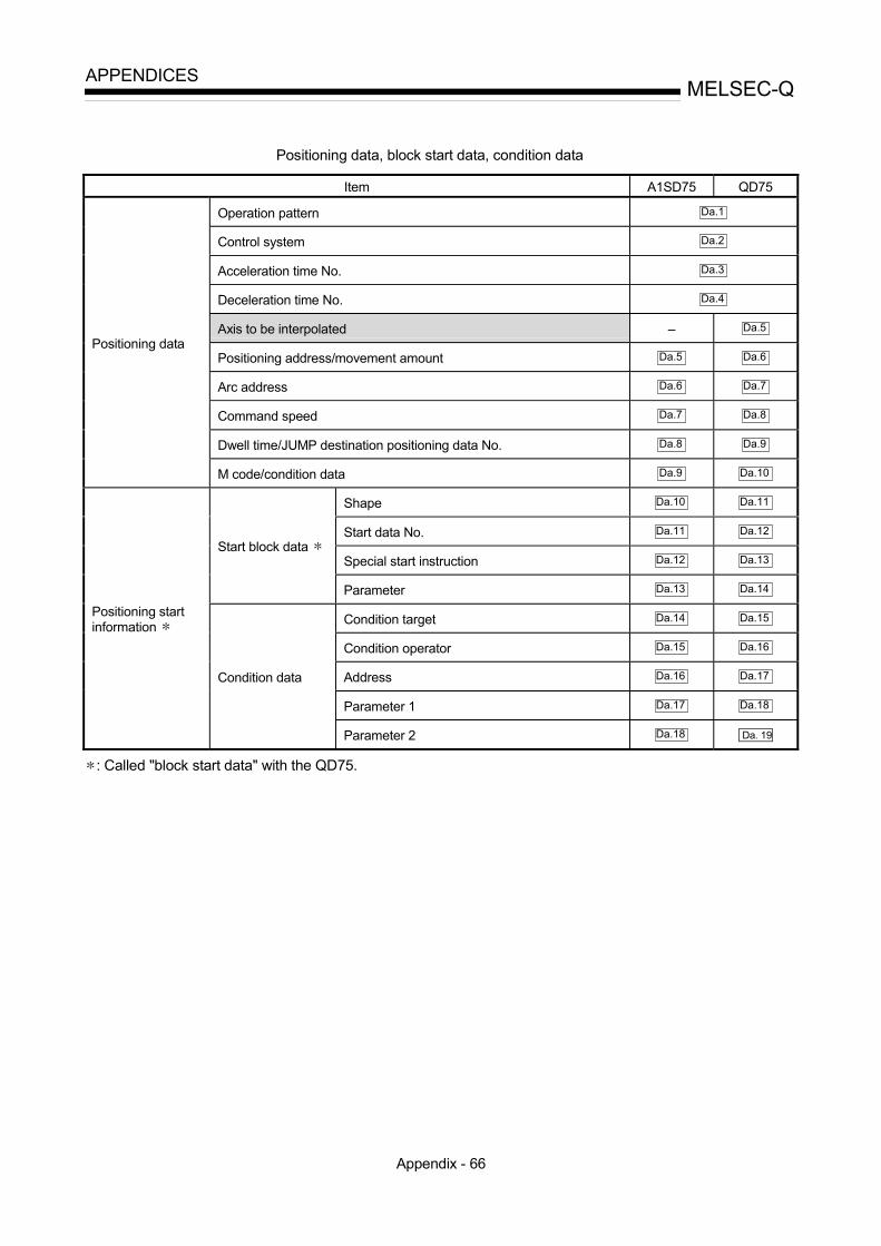
Appendix - 66
MELSEC-QAPPENDICES
Positioning data, block start data, condition data
Item A1SD75 QD75
Operation pattern Da.1
Control system Da.2
Acceleration time No. Da.3
Deceleration time No. Da.4
Axis to be interpolated – Da.5
Positioning address/movement amount Da.5 Da.6
Arc address Da.6 Da.7
Command speed Da.7 Da.8
Dwell time/JUMP destination positioning data No. Da.8 Da.9
Positioning data
M code/condition data Da.9 Da.10
Shape Da.10 Da.11
Start data No. Da.11 Da.12
Special start instruction Da.12 Da.13Start block data
Parameter Da.13 Da.14
Condition target Da.14 Da.15
Condition operator Da.15 Da.16
Address Da.16 Da.17
Parameter 1 Da.17 Da.18
Positioning startinformation
Condition data
Parameter 2 Da.18 Da. 19
: Called "block start data" with the QD75.
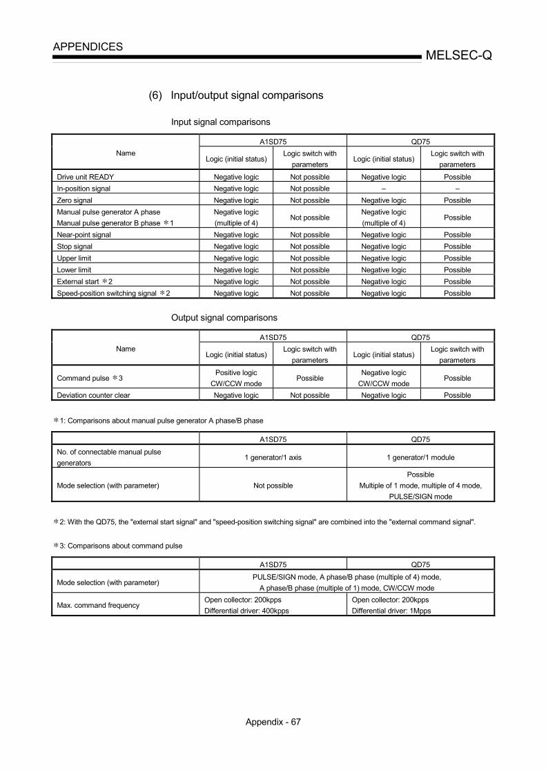
Appendix - 67
MELSEC-QAPPENDICES
(6) Input/output signal comparisons
Input signal comparisons
A1SD75 QD75Name
Logic (initial status)Logic switch with
parametersLogic (initial status)
Logic switch withparameters
Drive unit READY Negative logic Not possible Negative logic PossibleIn-position signal Negative logic Not possible – –Zero signal Negative logic Not possible Negative logic PossibleManual pulse generator A phaseManual pulse generator B phase 1
Negative logic(multiple of 4)
Not possibleNegative logic(multiple of 4)
Possible
Near-point signal Negative logic Not possible Negative logic PossibleStop signal Negative logic Not possible Negative logic PossibleUpper limit Negative logic Not possible Negative logic PossibleLower limit Negative logic Not possible Negative logic PossibleExternal start 2 Negative logic Not possible Negative logic PossibleSpeed-position switching signal 2 Negative logic Not possible Negative logic Possible
Output signal comparisons
A1SD75 QD75Name
Logic (initial status)Logic switch with
parametersLogic (initial status)
Logic switch withparameters
Command pulse 3Positive logic
CW/CCW modePossible
Negative logicCW/CCW mode
Possible
Deviation counter clear Negative logic Not possible Negative logic Possible
1: Comparisons about manual pulse generator A phase/B phase
A1SD75 QD75
No. of connectable manual pulsegenerators
1 generator/1 axis 1 generator/1 module
Mode selection (with parameter) Not possiblePossible
Multiple of 1 mode, multiple of 4 mode,PULSE/SIGN mode
2: With the QD75, the "external start signal" and "speed-position switching signal" are combined into the "external command signal".
3: Comparisons about command pulse
A1SD75 QD75
Mode selection (with parameter)PULSE/SIGN mode, A phase/B phase (multiple of 4) mode,
A phase/B phase (multiple of 1) mode, CW/CCW mode
Max. command frequencyOpen collector: 200kppsDifferential driver: 400kpps
Open collector: 200kppsDifferential driver: 1Mpps

Appendix - 68
MELSEC-QAPPENDICES
Appendix 10 MELSEC Explanation of positioning terms
1-2 PHASE EXCITATION SYSTEMThis is one system for exciting each steppingmotor coil in a determined order. In thissystem, one phase and two phases arealternately excited.
Pulse input
A phase
A phase
B phase
B phase
2-PHASE EXCITATION SYSTEMThis is one system for exciting each steppingmotor coil in a determined order. In thissystem, a current constantly flows to 2 phasesto carry out step feed.
Pulse input
B phase
A phase
A phase
B phase
2-PHASE PULSEAn A phase and B phase double pulse. Thereis a phase difference between the two phases,so that difference can be automatically addedand subtracted in the pulse count. Thestandard phase difference is a 90ø electricalangle.If the B phase were to lag behind the A phasein a forward run (B phase turns ON after the Aphase), the A phase would lag behind the Bphase in a reverse run (A phase turns ON afterthe B phase). In this way the forward andreverse run (addition and subtraction) can beautomatically carried out.
1 2 3 4 5 6 7 8 9 10 11 12 13 14 15 16
90°
A phase
B phase
Pulse countForward run (addition)
Reverse run(subtraction)
2-SPEED TRAPEZOIDAL CONTROLIn this positioning control method, thepositioning pattern, positioning addresses (P1,P2), and positioning speeds (V1, V2) are set inthe sequence program. Positioning is carriedout to positioning address P1 by issuing the 1stpositioning start command. When P1 isreached, the positioning then automaticallychanges to positioning at the V2 speed.
Spe
ed
Positioning speed V1
Positioning speed V2
Time
Positioning address P2
Positioning address P1

Appendix - 69
MELSEC-QAPPENDICES
ABSOLUTE ENCODERThis is a detector that enables the angle datawithin 1 motor rotation to be output to anexternal destination. Absolute encoders aregenerally able to output 360° in 8 to 12 bits.Incremental encoders have a disadvantage inthat the axis position is lost when a powerfailure occurs. However, with absoluteencoders, the axis position is not lost evenwhen a power failure occurs.Various codes such as a binary code and BCDcode can be output.Absolute encoders are more expensive, moreaccurate, and larger than incrementalencoders. Refer to "ENCODER".
22
22
01
34
24
23
22
21
20
Slit disk
Phototransistor
Fixed slitLight-emitting diode
Rotatingaxis
Binary code
ABSOLUTE POSITION DETECTIONSYSTEM
In the absolute position detection system, oncean OPR is carried out at the system startup,the system stores the machine position in thememory and retains the current position evenwhen the power is turned OFF. Mechanicaldeviation will be compensated, so that theOPR is not required after the power is turnedON next time. Configuring this system requiresa motor with an absolute position detector anda servo amplifier and positioning modulecompatible with an absolute position detectionsystem.
ABSOLUTE SYSTEMThis is one system for expressing a positioningaddress.Absolute address system.This system uses 0 as a reference, andexpresses the address as the distance from 0.The direction is automatically determined, evenwhen it is not designated. The other addresssystem is the increment system.
No.10 No.2 No.3
ACCELERATION TIMEThe parameter acceleration time refers to thetime from a stopped state to the time the speedlimit value is reached, so it becomesproportionally shorter as the setting speeddecreases. The acceleration time is determinedby factors such as machine inertia, motortorque, and load resistance torque.
Speed limit value
Setting speed
Speed 0
Acceleration time
Time
ADDRESS1) This is a numerical value to express the
positioning position, designated in mm,inch, angle, or No. of pulse units.
2) The memory address. Many addresses arestored in the memory. An address is reador written after it is designated.
AFTER modeThis is the mode that outputs the M code afterpositioning is complete (after stopping).Clamping can be commanded, drillingdimensions can be selected, etc., with thismode.
OFFON
No.11No.10 Positioning M code (8)
Clamp command

Appendix - 70
MELSEC-QAPPENDICES
AUTO TUNING (Automatic Tuning)Properties such as responsiveness andstability of machines driven with a servomotorare affected by changes in the inertia momentand rigidity due to changes in the machineload, etc.This function automatically adjusts the speedloop gain and position loop gain to match themachine state, so the machine's performancecan be maintained at its optimum state.A real time automatic tuning function should beused for machines having large loadfluctuations.
AUTOMATIC TRAPEZOIDALACCELERATION/DECELERATION
An operation in which a graph of the time andspeed takes a trapezoidal shape.
Acceleration
Speed
Time
Deceleration
BACKLASH COMPENSATIONWhen a forward run operation changes to areverse run operation, there is sometimes play(backlash) in the mesh of the toothed gears.This also occurs when using a worm gear.Because of this backlash, a left feed of 1m(3.28feet) carried out after a right feed of 1m(3.28feet) will not be sufficient to return themachine to its original position. The machinecannot be positioned to its original positionwithout an extra feed equivalent to thebacklash amount. This function compensatesfor that backlash amount.
Backlash
Forward run
1m (3.28feet) (right feed)Machine does notmove.
Backlash1m (3.28feet) (left feed)
(Left feed amount)
BACKUP FUNCTIONBackup functions consist of the following.1) Functions for storing the sequence program
and device statuses stored in the RAMmemory of the PLC CPU, so that they arenot lost during power failures, etc.
2) Functions for storing the current value inabsolute position compatible systems sothat it is not lost during power failures, etc.
3) Functions for reading the PLC CPU data(PLC programs, parameters, positioningdata, etc.) by a peripheral device when theold PLC CPU is replaced, and then write itto the new PLC CPU after the replacementis completed.
BALL SCREWThis is a type of screw, with balls lined up inthe threads like ball bearings. This reducesbacklash, and enables rotation with little force.
Female thread
Male thread

Appendix - 71
MELSEC-QAPPENDICES
BCD (Binary Coded Decimal)1) This is the abbreviation for "binary coded
decimal", more accurately called a BCDcode. Computers, PLCs, etc., use binarynumbers made up of 1 (ON) and 0 (OFF).Because this is difficult for humans tounderstand, decimal digits are expressedby a pattern of binary digits. Many of thedigital switches and digital displays used byhumans use a BCD code. The significanceof the bits is shown in the drawing below.Numbers from 0 to 9,999 can be handledby 16 bits, and numbers from 0 to99,999,999 can be handled by 32 bits.
0B15 B14 B13 B12 B11 B10 B9 B8 B7 B6 B5 B4 B3 B2 B1 B0
4000+1000+800+40+20+10+2 = 5.872
5.8721 0 1 1 0 0 0 0 1 1 1 0 0 1 0
8000
4000
2000
1000
800
400
200
100
80
40
20
10
8
4
2
1
2) BCD commands are commands in which abinary number (BIN) is converted to abinary coded decimal (BCD).They are used to output data from the PLCand display it on the digital display.The following drawing shows a 16-bitexample.
0BIN code167
0 0 0 0 0 0 0 1 0 1 0 0 1 1 1
0BCD code167
0 0 0 0 0 0 1 0 1 1 0 0 1 1 1
Pos
itive
/ne
gativ
e16
384
819
2 4
096
204
8 1
024
5
12
256
1
28
64
3
2
16
8
4
2
1
8000
4000
2000
1000
800
400
200
100
8
0
40
2
0
10
8
4
2
1
BIAS SPEED AT STARTA large amount of torque is required when themachine starts moving, but the torque may beunstable at speed 0 with stepping motors.Therefore, movement can be smoothly carriedout by starting the movement at a given speedfrom the beginning. The bias speed at start isthe speed set at that start.
Full speed
Speed 0Bias speed
BIN (Binary)1) A binary number, more accurately called a
binary code.All values are expressed as a binarynumber in which 1 turns the PLC, etc.,electricity ON, and 0 turns it OFF. Thesignificance of the bits is shown in thedrawing below. In the MELSEC PLC, thehighest order bit (B15) is used to indicatehandling as a positive No. (0), or negativeNo. (1), so the 15 bits from B0 to B14 arevalid.
0B15 B14 B13 B12 B11 B10 B9 B8 B7 B6 B5 B4 B3 B2 B1 B0
128+32+4+2+1=167
1670 0 0 0 0 0 0 1 0 1 0 0 1 1 1
215214213212211 210 29 28 27 26 25 24 23 22 21 20
Pos
itive
/ne
gativ
e16
384=
819
2= 4
096=
204
8= 1
024=
5
12=
2
56=
1
28=
6
4=
32=
1
6=
8
=
4
=
2
=
1
=
2) BIN commands are commands in which abinary coded decimal (BCD) is converted toa binary number (BIN).They are used to input the data shown onthe digital switch to the PLC.The following drawing shows a 16-bitexample.
0BCD code167
0 0 0 0 0 0 1 0 1 1 0 0 1 1 1
0BIN code167
0 0 0 0 0 0 0 1 0 1 0 0 1 1 1
Pos
itive
/ne
gativ
e80
0040
0020
0010
00 8
00 4
00 2
00 1
00
80
4
0
20
1
0
8
4
2
1
1638
4 8
192
409
6 2
048
102
4
512
2
56
128
6
4
32
1
6
8
4
2
1
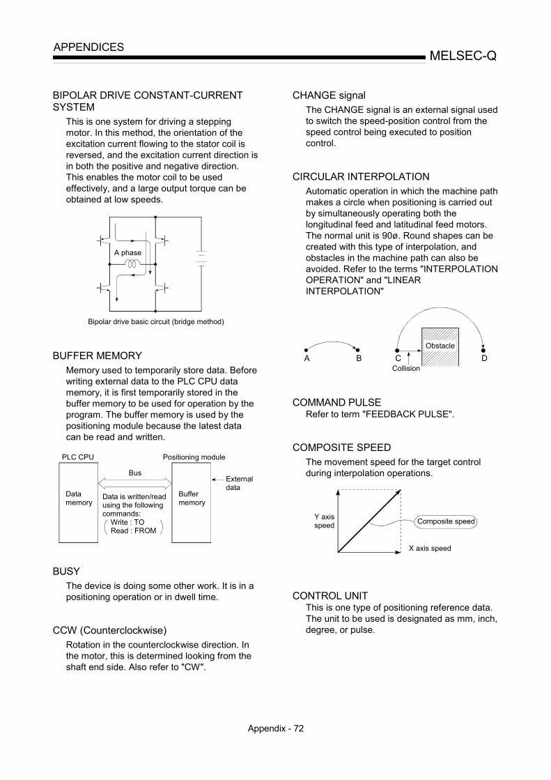
Appendix - 72
MELSEC-QAPPENDICES
BIPOLAR DRIVE CONSTANT-CURRENTSYSTEM
This is one system for driving a steppingmotor. In this method, the orientation of theexcitation current flowing to the stator coil isreversed, and the excitation current direction isin both the positive and negative direction.This enables the motor coil to be usedeffectively, and a large output torque can beobtained at low speeds.
Bipolar drive basic circuit (bridge method)
A phase
BUFFER MEMORYMemory used to temporarily store data. Beforewriting external data to the PLC CPU datamemory, it is first temporarily stored in thebuffer memory to be used for operation by theprogram. The buffer memory is used by thepositioning module because the latest datacan be read and written.
PLC CPU
Data memory
Bus
Positioning module
Buffermemory
Externaldata
Data is written/readusing the following commands: Write : TO Read : FROM
BUSYThe device is doing some other work. It is in apositioning operation or in dwell time.
CCW (Counterclockwise)Rotation in the counterclockwise direction. Inthe motor, this is determined looking from theshaft end side. Also refer to "CW".
CHANGE signalThe CHANGE signal is an external signal usedto switch the speed-position control from thespeed control being executed to positioncontrol.
CIRCULAR INTERPOLATIONAutomatic operation in which the machine pathmakes a circle when positioning is carried outby simultaneously operating both thelongitudinal feed and latitudinal feed motors.The normal unit is 90ø. Round shapes can becreated with this type of interpolation, andobstacles in the machine path can also beavoided. Refer to the terms "INTERPOLATIONOPERATION" and "LINEARINTERPOLATION"
A B C DCollision
Obstacle
COMMAND PULSERefer to term "FEEDBACK PULSE".
COMPOSITE SPEEDThe movement speed for the target controlduring interpolation operations.
Y axisspeed Composite speed
X axis speed
CONTROL UNITThis is one type of positioning reference data.The unit to be used is designated as mm, inch,degree, or pulse.

Appendix - 73
MELSEC-QAPPENDICES
CP CONTROL (Continuous Path Control)Continuous path is a control method in which apath is followed without interrupting such as inuniform speed control.
CREEP SPEEDA speed at which the machine moves veryslowly.It is difficult for the machine to stop accuratelywhen running at high speed, so the movementmust first be changed to the creep speedbefore stopping.Refer to the term "NEAR-POINT DOG".
CURRENT FEED VALUEThe OP address at the completion of themachine OPR is stored.The position currently being executed isstored.This value changes when the current value ischanged.
CURRENT LOOP MODEOne of the servo control modes in positioning.Mode which uses current for torque control.Also called the torque loop mode.Refer to the section of "position loop mode".
CURRENT VALUEThis is the current address (position) whenstopped or during positioning.
CW (Clockwise)Rotation in the clockwise direction. Rotation inthe clockwise direction looking from the motorshaft end side.
D/A CONVERTER (Digital-to-Analogconverter)
A device having a function to convert thedigital value expressing the No. of pulses to ananalog value expressing the voltage (orcurrent).
No. of pulses 0 to 80,000 pulses/second
D/A Voltage 0 to ±10V.
DATA NO.To carry out positioning to 2 or moreaddresses, each position is assigned asequence No. such as No. 1, No. 2, No. 3, etc.The positioning is then carried out followingthis sequence. The QD75 is capable ofpositioning up to No. 600.
No.1
No.2
No.3
No.4
No.5
No.6
DECELERATION RATIOA ratio used when the machine is deceleratedusing a toothed gear. This ratio is a numerallarger than 1.
Input gear speedDecelerationratio = Output gear speed

Appendix - 74
MELSEC-QAPPENDICES
DECELERATION TIMEThe parameter deceleration time is the samevalue as the acceleration time. Decelerationtime refers to the time from the speed limitvalue to a stopped state, so it becomesproportionally shorter as the setting speeddecreases.
Speed limit value
Setting speed
Speed 0
Deceleration time
Time
DEVIATION COUNTERDeviation counters have the following twofunctions.1) To count the command pulses issued from
the QD75, and transmit the count value tothe D/A converter.
2) To subtract the feedback pulses from thecommand pulses, and run the motor by thedeviation value (droop pulse) of thecommand pulses and feedback pulses untilthe command pulses reaches 0.
PLG Encoder
Commandpulses Deviation
counter D/A convertor Motor
Feedback pulses
DIFFERENTIAL OUTPUT TYPEThis is one type of encoder feedback pulseoutput. When one signal is output with thismethod, a companion signal having thereverse polarity is simultaneously output. Thismethod enables high-frequency transfer, andis resistant to noise, etc., so it is also used inhigh-speed signal transfer such as inputtingand outputting of pulse trains. In general, thetransmission side is called the driver, thereception side is called the receiver, and adedicated IC is used.
Commanddevice
Servo amplifier
Driver Receiver
DIGITAL BUS CONNECTIONCommands are generally output from thepositioning module to the servo amplifier as apulse train. Recently, however, devices arebeing digitalized. Accompanying that, aconnection method has appeared in which thebus lines of both the positioning module andthe servo amplifier CPUs are connected. Thishas enabled the construction of higher-accuracy, higher-speed systems.The MELSEC A70D, AD774M, A171SCPU,A273UCPU etc., models employ this digitalbus connection.
DOG SIGNALThe near-point dog of the OPR.
DRIVE UNITThe commands output from the positioningmodule are low-voltage, low-currentcommands with insufficient energy to run themotor.The drive unit increases the width of thesecommands so the motor can be run. It is anaccessory on servomotors and steppingmotors. Also called a servo amplifier.
Positioningmodule
Driveunit
Motor
Power supply
DRIVE UNIT READYThis signal is output when the drive unit for themotor is in a READY state.This signal remains OFF when the drive unitpower is OFF, or during faults, etc.

Appendix - 75
MELSEC-QAPPENDICES
DROOP PULSEBecause of inertia (GD2) in the machine, it willlag behind and not be able to track if thepositioning module speed commands areissued in their normal state.Thus, for a servomotor, a method is used inwhich the speed command pulses are delayedby accumulation in a deviation counter. Theseaccumulated pulses are called the drooppulse.The deviation counter emits all pulses andreturns to 0 when the machine stops.
1,000 pulses
200 pulsesaccumulate in the counter
800 pulses VoltageD/A
DWELL TIMEThis is the time taken immediately after thepositioning is completed to adjust for the drooppulses in the deviation counter. Thepositioning will not be accurate if this time istoo short.
DYNAMIC BRAKEWhen protection circuits operate due to powerfailures, emergency stops (EMG signal) etc.,this function is used to short-circuit betweenservomotor terminals via a resistor, thermallyconsume the rotation energy, and cause asudden stop without allowing coasting of themotor.Braking power is generated byelectromagnetic brakes only when runningmotors with which a large brake torque can beobtained. Because electromagnetic brakeshave no holding power, they are used incombination with mechanical brakes to preventdropping of the vertical axis.
ELECTROMAGNETIC BRAKEThis function is supplied on motors withelectromagnetic brakes. Electromagneticbrakes are used to prevent slipping duringpower failures and faults when driving avertical axis, or as a protective function whenthe machine is stopped.These brakes are activated when not excited.
ELECTRONIC GEARThis function electrically increases/decreasesthe command pulses from the pulse commandmodule by 1/50 to 50-fold. Thus, thepositioning speed and movement amount canbe controlled by the electronic gear ratiomagnification.
EMERGENCY STOPEmergency stops cannot be carried out by theQD75, so a method of shutting OFF the servoside power supply from outside the PLC, etc.,must be considered.
ENCODERThis device turns the input data into a binarycode of 1 (ON) and 0 (OFF). A type of pulsegenerator.
A B
Z
Ball bearing
For the mainsignal
For the zero point signal
Input axis
Code disk
Photoreceptor (phototransistor)
Indexscale
Light source (light-emitting diode)
Rotary encoder
aa
b
zb
Light source(LED) Collimator lens
Main scalePhotoreceptor(photodiode)
Referencezero point Index
scale
Linear encoder

Appendix - 76
MELSEC-QAPPENDICES
ERROR CORRECTIONIf a dimension error occurs in the machine,and that error is actually smaller or larger than1m (3.28feet) in spite of a 1m (3.28feet)command being issued from the QD75, thaterror amount will be compensated. Forexample, when the error is actually smallerthan 1m (3.28feet), the remaining distance to1m (3.28feet) is fed, and the correct 1m(3.28feet) of positioning is carried out.
ERROR RESETThis resets error of axis. Note that if the causeof the error is not eliminated at that time, theerror will occur again.
EXTERNAL REGENERATIVE BRAKERESISTOR
This is also called the regenerative brake.When a machine is moved with a motor, poweris normally supplied to the motor from anamplifier. However, the rotation energy in themotor and machine counterflows (regenerates)to the amplifier when the motor is deceleratingor when driving a descending load.The external regenerative resistor consumesthis regeneration energy with resistance,obtains the regenerative brake torque, andenables the full capacity of the regenerationsystem during stopping.It is used when carrying out highly repetitiveacceleration/deceleration.
FIn the QD75, F is a status where the moduleitself has a fault.[HOLD]
FAST OPRThe axis returns to the machine OP at theOPR speed without detecting the near-pointdog.(This is not validated unless a machine OPRhas been carried out first.)
OP
Dog switch
OPR speed
FEED PULSEThis is a pulse issued from the positioningmodule to a servomotor or stepping motor.Also called a command pulse.
FEED SCREWThis is the basic screw in mechanisms thatposition using screw rotation. Ball screws areoften used to reduce backlash and dimensionerror.
1 rotationby the motor
Positioning feed screw
Lead (feedrate per screw rotation)
FEEDBACK PULSEThis is a method of using a returning pulsetrain to confirm whether the machine faithfullyoperated according to the commands issued inautomatic control. If the machine did notfaithfully operate according to the commands,a correction command is issued. For example,if a command is issued for 10,000 pulses, anda feedback pulse of 10,000 pulses is returned,then the balance becomes 0 and it can bejudged that the command was faithfullyfollowed.Refer to the term "DEVIATION COUNTER".

Appendix - 77
MELSEC-QAPPENDICES
FIXED-FEEDThis is the feeding of a set dimension forcutting sheet and bar workpieces into thedesignated dimensions. Incremental systempositioning is often used. The current value isnot incremented, even when the feedoperation is repeated.
FLASH MEMORYThis battery-less memory can be used to storeparameters and positioning data for backup.Because it is battery-less, battery maintenanceis not required
FLAT TYPE MOTOR (PANCAKE MOTOR)About 100mm shorter in axial dimension thanthe standard motor. Used when theservomotor is installed in a small space.
FLS SIGNAL (forward limit signal)This is the input signal that notifies the userthat the limit switch (b contact configuration,normally ON) installed at the upper limit of thepositioning control enabled range has beenactivated.The positioning operation stops when the FLSsignal turns OFF (non-continuity).
G CODEThese are standardized (coded) 2-digitnumerical values (00 to 99) designatingvarious control functions of the NC module.Also called G functions.Example :G01 Linear interpolationG02 Circular interpolation CW (clockwise)G04 DwellG28 OPRG50 Max. spindle speed setting
GAINThe changing of the ratio between two valueshaving a proportional relation. Seen on agraph, the changing of the incline of thecharacteristics.
13
10
2
10
Raisingthe gain
Output Lowering the gain
Input
For example, when 10 is output for an input of10, the output can be changed to 12, 5, etc.,by changing the gain.
GD2
The inertia moment. The sum total of the mass(dm) of each small area configuring an objectmultiplied by the square of the distance (r) ofeach of those areas from a given straight line.The relation with I = r2dmGD2 is given by 4gI,with "g" being gravitational acceleration.

Appendix - 78
MELSEC-QAPPENDICES
INCREMENTAL ENCODERA device that simply outputs ON/OFF pulsesby the rotation of the axis. 1-phase typesoutput only A pulses, and do not indicate theaxis rotation direction. 2-phase types outputboth A and B pulse trains, and can judge therotation direction. The direction is judged to beforward if the B pulse train turns ON when A isON, and judged to be reverse if A turns ONwhen B is ON. There is also another type ofincremental encoder with a zero signal. Themost commonly used incremental encodersoutput between 100 and 10,000 pulses peraxis rotation. Refer to "ENCODER".
A
B
A
ZB
14
A signal slitB signal slit
Slit diskLight-emitting diode
Phototransistor Zero signal slit
Rotating axis 1 pitch
pitch
Zero signal1 pulse per axis rotation
Output waveform 2-phase + OP output
INCREMENTAL SYSTEMThe current value is 0 in this system. Positionsare expressed by the designated direction anddistance of travel. Also called the relativeaddress system. This system is used in fixed-feed, etc. Compare ABSOLUTE SYSTEM.
No.1 No.2 No.3
0
00
Stop
Left
Right Right No. 2 is several millimetersto the right of No. 1.
INERTIAThe property of an object, when not beingaffected by external forces, where it tries tomaintain its current condition. The inertiamoment.

Appendix - 79
MELSEC-QAPPENDICES
INPUT TERMINALThis is a pin connector wired by the user forinputting data to the QD75 from an externalsource. It is connected to the motor drive unitor machine side.This terminal is used to output the following. • DRIVE UNIT READY signal • START signal • STOP signal, etc.The input No. Xn is not directly related to theprogram, so it is not used.
INTERLOCKIn this condition, the machine is blocked frommoving to the next operation until theoperation in progress is complete. Thisfunction is used to prevent damage to devicesand malfunctioning.
Y1Y0
Y0Y1
Forward run
Reverse run
INTERPOLATION OPERATIONThe simultaneous operation of multiple motorsto carry out a composite operation. Each motorcan be freely set with the positioning distance,acceleration/deceleration time, speed, andother factors, which are combined to move atarget in a straight line, circle, etc. Linearinterpolation and circular interpolation areavailable. (The circular interpolation uses twomotors.)
INVERTERThis refers to a device to change a directcurrent (DC) to an alternating current (AC).The device actually changes the motor speedby changing 50Hz or 60Hz of commercialfrequency to direct current once, thenchanging it again to a 5 to 120Hz alternatingcurrent and controlling the motor speed.
JOGJog. This refers to moving the tool little bylittle. Inching.Parameter setting is required to carry out JOGoperation.
kPPSThis is the abbreviation for "kilopulses persecond". 80kPPS equals 80,000 pulses persecond.
LIMIT SWITCHThis is a switch set to stop a moving object atboth ends, etc., of a movement device forsafety reasons.A circuit is created in which the moving bodyitself presses against the switch to activate thecontact and forcibly shut the power OFF. Forexample, pressing on the actuator in thedrawing below activates the internalmicroswitch. There are various other types.
NC NO COM
Push plunger
Actuator
Rubber capLead Case
Microswitch

Appendix - 80
MELSEC-QAPPENDICES
LINEAR INTERPOLATIONThis automatic operation simultaneouslyoperates two motors for the latitudinal (X) feedand longitudinal (Y) feed to move a target in adiagonal line for positioning. Three or fourmotors can also be operated simultaneously.The QD75 combines the operation of axis 1through 4 for the linear interpolation. The samepositioning data No. must be used for thesetting. Refer to the term "INTERPOLATIONOPERATION".
No.9
No.8 No.1
2
34 5
6
7
Longitudinalfeed
Latitudinal feed
LOAD INERTIA RATIOGDL2/GDM2
Refer to "GD2".
LOW-INERTIA MOTORThis is a motor used when frequentacceleration/deceleration is repeated. Low-inertia motors are longitudinally longer, todecrease the rotor diameter and cover thetorque. This enables their inertia moment to bereduced up to 1/3 that of standard motors. Theideal load inertia ratio is 1 or less.
M CODE (Machine Code)These are sub functions that interlock with thepositioning operation to replace drills, tightenand loosen clamps, raise and lower weldingelectrodes, display various data, etc.Either of two modes can be entered when themachine code turns ON: AFTER or WITH.The machine does not move to the nextpositioning when the machine code is ON. Mcodes are turned OFF by the PLC program.Code Nos. from 1 to 65535 assigned by theuser and used (1: Clamp, 2: Loosen, etc.).Comments can be written after 50 of the Mcodes, and they can be monitored using aperipheral device or displayed on an externaldisplay. Refer to "AFTER MODE" and "WITHMODE".
MACHINE FEED VALUEThe OP address at the completion of themachine OPR is stored.The current position of the machinecoordinates determined by a machine havingthe OP address as a reference.Even if the current value is changed, this valuewill not change.
MANUAL PULSE GENERATORThe handle of this device is manually rotatedto generate pulses. This device is used whenmanually carrying out accurate positioning.
Made by Mitsubishi Electric Corp.(model: MR-HDP01)
MASTER AXISWhen carrying out interpolation operations,this is the side on which the positioning data isexecuted in priority. For example, whenpositioning with the X axis and Y axis, the sidewith the largest movement distance willbecome the master axis, and the speed willfollow that axis. The slave axis speed will beignored.

Appendix - 81
MELSEC-QAPPENDICES
MOVEMENT AMOUNT PER PULSEWhen using mm, inch, or degree units, themovement amount is calculated and outputfrom the machine side showing how much themotor shaft moves per pulse. Positioningaccuracy in smaller units is not possible.On the motor side, the movement amount peraxis rotation is normally designed as areference, so it is calculated as follows.Movement amount per pulse =
P rateNo. of pulses perencoder rotation
×Movement amountper rotation
Amount the motor moves (travel) per pulse.
MULTI-PHASE PULSEA combination of pulses in which 2 or morephases differ.2-phase pulses, etc.
A phase
Phase difference
B phase
Z phase (ZERO signal)
MULTIPLYING RATE SETTINGThe P rate. Refer to the term "P RATE".
NC LANGUAGE (Numerical ControlLanguage)
This is the language punched into the papertape that instructs the machining to the NCmodule.The NC language consists of EIA codes (EIAlanguage), ISO codes (ISO standards), andJIS codes (JIS standards).
NEAR-POINT DOGThis is a switch placed before the OP. Whenthis switch turns ON, the feedrate is changedto the creep speed. Because of that, the timethat this switch is ON must be long enough toallow for the time required for decelerationfrom the feedrate to the creep speed.
ON OFF
Feedrate
Creep speed
TimeNear-point dog
NEW CURRENT VALUE (CURRENT VALUECHANGING)
The QD75 has no way of knowing the currentvalue when the machine is assembled and thepositioning module is connected, so thisfunction is used to teach it a temporaryapproximate value as the current value. Thisfunction can also be used to write a temporarycurrent value when the current value has beenlost due to accidents, etc. If an OPR is carriedout after that, the positioning module willrecognize the zero point.To prevent the accumulated value fromexceeding the stroke limit in fixed-feed, etc.,rewrite the current value to 0 after the fixed-feed. The current value can be changed duringa positioning stop.

Appendix - 82
MELSEC-QAPPENDICES
OPThis is the reference position for positioning.Positioning cannot start without a referencepoint.The OP is normally set to the upper or lowerstroke limit.
OP
This point is the reference.
OP SHIFT FUNCTIONThe OP position can be shifted in the positiveor negative direction by executing a machineOPR and determining the shift amount fromthe machine OPR complete position.An OP can be set at a position besides the OPposition, or outside the dog switch.
OPERATION PATTERNThe kind of operation to be carried out afterexecuting the positioning data is determined.1) If "POSITIONING COMPLETE" is selected,
the operation will stop after the positioningis complete.
2) If "CONTINUOUS POSITIONINGCONTROL" is selected, the next data No.will be automatically executed after thepositioning is complete.
3) If "CONTINUOUS PATH CONTROL" isselected, the positioning will not becompleted. Only the speed will beautomatically changed, and the next dataNo. will be executed.
OPR METHODThe OPR methods are shown below. Themethod used depends on the machinestructure, stopping accuracy, etc.OPR can be carried out when the OPRparameters are written.1) Near-point dog method2) Stopper method3) Count method
OPR PARAMETERThis parameter is required when returning tothe OP. It is determined by the machine sidedesign, so subsequent changes of thisparameter must be accompanied by changesin the machine design.The OP is the reference for positioningoperations, so if the OP is lost due to a powerfailure during positioning, or because thepower is turned OFF and the machine ismoved manually, etc., it can be restored bycarrying out an OPR. When a machine OPRcommand is issued, the machine will move insearch of the near-point dog regardless of thecurrent value, and will stop at the OP. At thistime, the current value will be rewritten to theOP address. Data cannot be written duringpositioning. With the QD75, data is alwayswritten for all axes (from 1 to 4 axes).Refer to the term "NEAR-POINT DOG".

Appendix - 83
MELSEC-QAPPENDICES
OPR REQUESTThis signal turns ON when there is an errorwith the QD75. It will turn ON in the followingsituations.1) When the power is turned ON.2) When the PLC READY signal turns from
OFF to ON.3) When the machine OPR starts.4) When the drive unit READY signal turns
from ON to OFF.The user judges whether to carry out amachine OPR in the above situations.
OUTPUT TERMINALThis is a pin connector for outputting data fromthe QD75 to an external source. It isconnected to the motor drive unit.This terminal is used to output the following. • Feedback pulses for both forward run and
reverse run • Start • Deviation counter clearThe terminal Nos. are determined for eachaxis.The output No. Yn is not directly related to theprogram, so it is not used.
OVERRIDE FUNCTIONWith this function, the speed during positioningoperations (current speed) can be variedbetween 1 and 300%.The speed can also be changed by the samevariable rate for continuous positioning withdiffering designated speeds.
P RATE (Pulse Rate)A coefficient that magnifies the feedbackpulses per motor shaft rotation by 2-fold, 3-fold, 1/2 or 1/3.It is the ratio of the feed pulses and feedbackpulses.For example, when the No. of pulses permotor shaft rotation is set to 2400 pulses, andthe P rate is set to 2, the result will beequivalent to 1200 pulses.The rotation per pulse is 0.15° when 2400pulses per rotation are set, but this becomes0.3° when 1200 pulses. The positioningaccuracy drops as the P rate is increased.
PARAMETERThis is the basic data used in positioning.Parameters are determined by the machineside design, so subsequent changes ofparameters must be accompanied by changesin the machine design.Data cannot be written during positioning. Theinitial parameter values are written by themaker.
PG0 (Pulse Generator Zero)Pronounced "pee-jee-zero". Refer to the term"ZERO SIGNAL".
PG0
Feedbackpulses
1 axis rotation

Appendix - 84
MELSEC-QAPPENDICES
POSITION CONTROLThis is mainly the control of position anddimension, such as in fixed-feed, positioning,numerical control, etc. This is alwayscontrolled with feed pulses. There is alsospeed control.Drive units may differ, even when the samemotor is used.
POSITION DETECTION MODULEThis is an abridged version of positioning.There are two types on MELSEC, theA1S62LS. This module has positioning andlimit switch functions, and can use a total of 16channels. The following drawing shows anexample for 5 channels. A resolver is used inthe positioning detection.
ON
ON
ON ON
ON
ON
0 4095
Limit switch LS1
Positioning High speed
Positioning Low speed
Limit switch LS3
Limit switch LS2
POSITION LOOP GAINThis is the ratio of the deviation counter drooppulses to the command pulse frequency.
Command pulse frequencyPositionloop gain
=Droop pulses
(1/s)
The position loop gain can be set with thedrive unit. Raise the gain to improve thestopping accuracy. However, overshooting willoccur if the position loop gain is raised too far,and the operation will become unstable.If the position loop gain is lowered too far, themachine will stop more smoothly but thestopping error will increase.
POSITION LOOP MODEThis is one servo control mode used inpositioning. It is a mode for carrying outposition control. The other servo controlmodes are the speed loop mode for carryingout speed control, and the torque loop modefor carrying out torque control (current control).
M
PLG
Servo amplifier Servomotor
Pulse train
Droop pulses
Posi-tioncontrol
Speed control
Cur-rent control
Inverter
Current feedback
Speed feedbackPosition feedback Interface
POSITIONINGAccurately moving the machine from a point toa determined point. The distance, direction,speed, etc., for that movement are designatedby the user. Positioning is used in operationssuch as cutting sheets, drilling holes in plates,mounting parts on a PCB, and welding.Positioning is also used with robots.
POSITIONING COMPLETERefer to the term "OPERATION PATTERN".
POSITIONING COMPLETE SIGNALThis is a signal that occurs when thepositioning is complete. A timer set beforehandstarts when this signal is output, and themachine movement stops for that time.When this signal turns ON, the positioningstart signal turns OFF.
Dwell timePositioning complete signal
Positioning Different type of work
Time

Appendix - 85
MELSEC-QAPPENDICES
POSITIONING CONTINUEDRefer to the section of term "operationpattern".
POSITIONING DATAThis is data for the user to carry outpositioning. The No. of points to whichpositioning is carried out (the No. ofaddresses) is designated by the user. In theQD75, these are 600 points.As a principle, positioning is executed in theorder of the data Nos.
POSITIONING PARAMETERThis is basic data for carrying out positioningcontrol. Types of data include control unit,movement amount per pulse, speed limitvalue, upper and lower stroke limit values,acceleration/deceleration time, positioningsystem, etc.Parameters have an initial value, so that valueis changed to match the control conditions.
POSITIONING STARTThis refers the act of designating a target dataNo. and starting the positioning.The operation after the positioning is completefor that data No. is determined by the dataNo.'s positioning pattern.
PTP Control (Point To Point Control)This is a type of positioning control. With thiscontrol method, the points to be passed aredesignated at random locations on the path.Movement only to a given target positioning isrequested. Path control is not required duringmovement from a given point to the next value.
PULSEThe turning ON and OFF of the current(voltage) for short periods. A pulse train is aseries of pulses. The QD75 is the module thatgenerates the pulses.
PULSE GENERATORThis is a device that generates pulses.Examples include devices installed on themotor shaft that create pulses when the shaftrotates, and digital devices.1-phase types output one pulse train. 2-phasetypes output two pulse trains with a phasedifference. From 600 to 1,000,000 pulses canbe output per shaft rotation. Generators with aZERO signal function to output 1 or 2 pulsesper shaft rotation. Abbreviated as PLG.Refer to the term "ENCODER".
PULSE OUTPUT MODEThere are two methods used to issue forwardrun and reverse run commands to theservomotor. The type used differs according tothe machine maker. In type A, the forward runpulses and reverse run pulses are output fromseparate terminals.In type B, the forward run pulses and reverserun pulses are output from the same terminal,and a forward/reverse run identification signalis output from another terminal.
Forward
Reverse
TerminalA type B type
ReverseForward
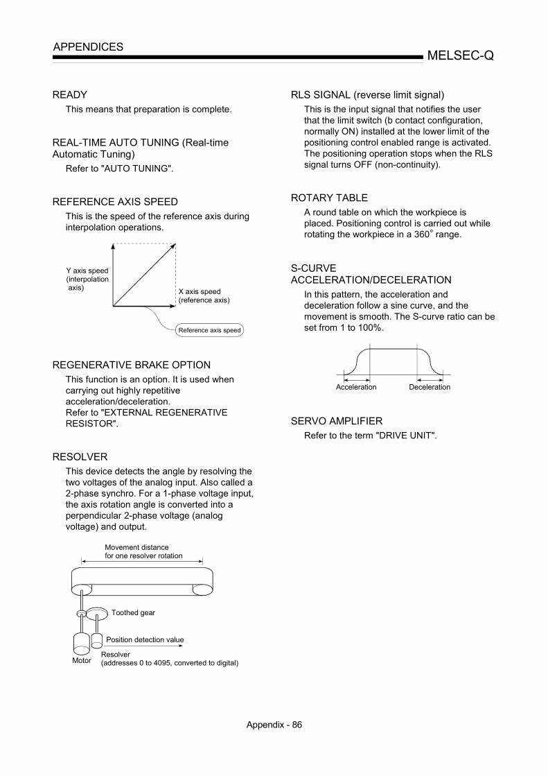
Appendix - 86
MELSEC-QAPPENDICES
READYThis means that preparation is complete.
REAL-TIME AUTO TUNING (Real-timeAutomatic Tuning)
Refer to "AUTO TUNING".
REFERENCE AXIS SPEEDThis is the speed of the reference axis duringinterpolation operations.
Y axis speed (interpolation axis) X axis speed
(reference axis)
Reference axis speed
REGENERATIVE BRAKE OPTIONThis function is an option. It is used whencarrying out highly repetitiveacceleration/deceleration.Refer to "EXTERNAL REGENERATIVERESISTOR".
RESOLVERThis device detects the angle by resolving thetwo voltages of the analog input. Also called a2-phase synchro. For a 1-phase voltage input,the axis rotation angle is converted into aperpendicular 2-phase voltage (analogvoltage) and output.
Movement distance for one resolver rotation
Toothed gear
Motor
Position detection value
Resolver (addresses 0 to 4095, converted to digital)
RLS SIGNAL (reverse limit signal)This is the input signal that notifies the userthat the limit switch (b contact configuration,normally ON) installed at the lower limit of thepositioning control enabled range is activated.The positioning operation stops when the RLSsignal turns OFF (non-continuity).
ROTARY TABLEA round table on which the workpiece isplaced. Positioning control is carried out whilerotating the workpiece in a 360° range.
S-CURVEACCELERATION/DECELERATION
In this pattern, the acceleration anddeceleration follow a sine curve, and themovement is smooth. The S-curve ratio can beset from 1 to 100%.
Acceleration Deceleration
SERVO AMPLIFIERRefer to the term "DRIVE UNIT".

Appendix - 87
MELSEC-QAPPENDICES
SERVO LOCKIn positioning using a servomotor, steppingmotor, etc., working power is required to holdthe machine at the stop position.(The position will be lost if the machine ismoved by external power.)This kind of state is called servo lock or servolock torque.
M
Table
Motor holds the position at the stop position.
SERVO ONThe servo amplifier will not operate if the servoamplifier is in a normal state and this servo ONsignal is OFF.
QD75
PLG
READY Servoamplifier Servo ON
Motor Encoder
SERVOMOTORA motor that rotates true to the command.Servomotors are highly responsive, and cancarry out frequent high-speed and high-accuracy starts and stops.DC and AC types are available, as well aslarge-capacity motors. A pulse generatoraccessory for speed detection is common, andfeedback control is often carried out.
SETTING UNITThis is one setting item of the positioningreference parameters. The unit to be used isdesignated as mm, inch, degree, or pulse.
SFC (Sequential Function Chart)A sequential function chart is a programmingmethod optimally structured for running amachine's automatic control in sequence withthe PLC.
Start preparationStart preparations OK
Execution of advance operation servo program
Positioning completeExecution of extrusionoperation servo program
Execution of retractoperation servo program
Positioning complete
Positioning complete
SKIP FUNCTIONWhen a SKIP signal is input, the positioningbeing executed is interrupted, the motor isdeceleration stopped, and the next positioningis automatically carried out.
SLAVE AXISDuring interpolation operation, the positioningdata is partially ignored on this side. This axisis moved by the master axis data.

Appendix - 88
MELSEC-QAPPENDICES
SPEED CONTROLSpeed control is mainly carried out with theservomotor. It is an application for grindstonerotation, welding speed, feedrate, etc. Speedcontrol differs from position control in that thecurrent position (address) is not controlled.Drive units may differ, even when the samemotor is used.
SPEED INTEGRAL COMPENSATIONThis is one item in the parameters of the servoamplifier, and is used to raise the frequencyresponse during speed control to improvetransient characteristics.When adjusting the speed loop gain, raisingthis value is effective if the overshooting duringacceleration/deceleration remains large.This compensation is set in ms units.
SPEED LIMIT VALUEThis is the max. speed for positioning. Even ifother data is mistakenly set to a higher speedthan this, the positioning will be carried out atthis speed limit value when it is set in theparameters. The acceleration time becomesthe time to accelerate from a stopped state tothe speed limit value, and the decelerationtime becomes the time to decelerate from thespeed limit value to a stopped state.
SPEED LOOP GAINThis is one item in the parameters of the servoamplifier, and expresses the speed of thecontrol response during speed control. Whenthe load inertia moment ratio increases, thecontrol system speed response decreases andthe operation may become unstable. If thishappens, the operation can be improved byraising this setting value.The overshoot will become larger if the speedloop gain is raised too far, and motor vibrationnoise will occur during operation and whenstopped.
SPEED LOOP MODEThis is one servo control mode used inpositioning. It is a mode for carrying out speedcontrol. Refer to "POSITION LOOP MODE".
SPEED-POSITION SWITCHING CONTROLWith this control, positioning is carried out tothe end point of the movement amount whilechanging the speed at the speed switchingpoint during positioning control.
SPEED-POSITION SWITCHING CONTROLMODE
This is one method used for positioning. It isan application for operations such as high-speed movement to a point unrelated topositioning, then set dimension movementfrom the switching signal activation point.
Start Switching signal
High speed Incremental positioning
START COMPLETEThis signal gives an immediate responsenotifying the user that the QD75 that wasstarted is now in a normal state and can startpositioning.
STARTING AXISOne of the QD75 axis system axes (axis 1,axis 2, axis 3, or axis 4) or the reference axisfor the interpolation operation is designated asthe starting axis.
STATUSData showing the state of the machine.Collectively refers to signals that turn ON whenthe battery voltage drops, during OPRrequests, during dwell time, etc.
STEP FUNCTIONWhen the operation is designed so thatseveral positioning data Nos. areconsecutively run, this function can be used tocarry out a test operation for 1 data item at atime.

Appendix - 89
MELSEC-QAPPENDICES
STEP OUTStepping motors rotate in proportion to the No.of pulses (frequency), but the motor's rotationwill deviate if the load is too large for themotor. This is called step out. If step outoccurs, the motor must be replaced by onewith a larger torque. Step out causes thepositioning error to increase.
Motor
Motor torque
Load
STEPPING MOTORA motor that rotates a given angle (example:0.15ø) when 1 pulse is generated.For that reason, a rotation proportional to theNo. of pulses can be obtained. 2-phase to 5-phase stepping motors are available. In the 3-phase type, the rotor rotates in order from A toC when a voltage is applied. Often found incompact motors, stepping motors rotateaccurately without feedback. Be careful of stepout when overloaded.
4) As the excitation phase is continuously changed, the rotor rotates in a clockwise direction.
1) First, the A phase is excited by a pulse.
2) When the B phase is then excited, the force works in the direction shown by the arrows.
3) The nearest tooth to the B phase is attracted, and the rotation stops.
A A
C
CB
B
N S
C
C
AA
N
S
C
C
AA
N
C
CB
BB
B
AA
STOP SETTLING TIMERefer to the term "DWELL TIME".
STOP SIGNALIn positioning control, this is the input signalthat directly stops the operation from anexternal source.The operation stops when the external stopsignal (a-contact) turns ON (continuity).
STOP WITH STOPPERThis is one machine OPR method. With thismethod, a stopper is established at the OP,and the operation is stopped when themachine presses against it.Motor burning would occur or the stopperwould be damaged if the machine were left inthat state. There are two methods to preventthis; a timer can be used to shut OFF themotor after a fixed time, or the motor can bestopped by limiting sudden increase in themotor torque when the machine pressesagainst the stopper.
Machine OPROP
Stopper
STROKEThe stroke is the variation in the operation bythe distance from a stopped state to the nextstopped state after a movement.

Appendix - 90
MELSEC-QAPPENDICES
STROKE LIMITThis is the range in which a positioningoperation is possible, or the range in which themachine can be moved without damageoccurring.(Movement outside this range is possible inthe manual operation.) For operations using aworm gear, the stroke limit is determined bythe length of the screw. For operations using afixed-feed, it is determined by the max.dimension to be cut.The upper and lower limits are set in theparameters, but a separate limit switch shouldbe established and an emergency stop circuitoutside the PLC should be created. Refer tothe term "LIMIT SWITCH".
Lower limit 0
Upper limit
Limit switchfor emergencystop
Positioning possible in a 3m (9.84feet) range
3m (9.84feet)
SUDDEN STOPA stop carried out in a shorter time than thedeceleration time designated in theparameters.
Full speed
Sudden stop
Time
Deceleration time
TEACHINGWhen the positioning address is uncertain, orgauging is required, this function is used bythe user to search for and teach the position tothe machine.For example, complex addresses such asdrawings can be taught by tracing a model,and the positioning operation can bereproduced.
TORQUE CONTROLIn this function, a limit is established for theresistance torque applied to the motor used forpositioning. The power is turned OFF if torqueexceeding that value is applied to the motor.When excessive torque is applied to a motor, itcauses the current to suddenly increase. Motorburning and other stress on the motor occurs,and the life of the motor is shortened.This function utilizes the sudden increase inthe torque when the machine OPR to issue acommand to stop the motor.
TORQUE LOOP MODEAlso called the current loop mode.Refer to "POSITIONING LOOP MODE".
TORQUE RIPPLETorque width variations, deviations in thetorque.
TRACKING FUNCTIONIn this function, positioning is carried out at aspeed relative to a moving target object byinputting the movement amount from anexternal encoder and adding it to the servocommand value.

Appendix - 91
MELSEC-QAPPENDICES
TURNTABLEA rotating table, which is turned using power.The table is used divided from one 360°rotation into the required locations for work.The positioning control unit is "degree".
Rotated by the motor
30°
UNIT SETTINGThis is the setting of the unit for the actualaddress to which positioning is required, or forthe movement amount.The following units can be set: mm, inch,degree and pulse. The initial value in theparameters is a pulse unit.
WARNINGA warning is output as a warning code in whenan abnormality is detected that is not seriousenough to require cancellation or stoppage ofthe positioning operation. Warnings arehandled differently than errors.
WINDOWThese are the selection menus that appear onthe screen when the QD75 is started. • Menu selection window • Mode function selection window • Sub-function selection window • Execution/setting selection window
WITH MODEThis is the mode that outputs the M codebefore the start of the positioning. This modeturns ON at the positioning start, enablingvoltage to be applied to the weldingelectrodes, display of positioning speeds, etc.Refer to the term "AFTER MODE".
XY TABLEThis is a device that moves a table in the X(latitudinal) and Y (longitudinal) directions sothat positioning can be carried out easily.There are also commercially availableproducts.
X tableY table Ball screw
X table
Base table Y axis
X axis
Z PHASEAlso called "PG zero". Refer to "ZEROSIGNAL".
ZERO SIGNALThis refers to PG0 of the pulse generator(encoder) (one detection per shaft rotation). Italso called "Z phase". Refer to the term"PULSE GENERATOR".

Appendix - 92
MELSEC-QAPPENDICES
Appendix 11 Positioning control troubleshooting
Trouble type Questions/Trouble Remedy No.
Display reads "FFFFH" when aparameter is read with GXConfigurator-QP.
The PLC CPU power was turned OFF or the PLC CPUwas reset, etc., during flash ROM writing, which deletedthe data in the flash ROM.Initialize the parameters, and reset the requiredparameters.(Refer to Section 13.2 "Parameter initialization function"for details.)
1
How can the parameters bereturned to their initial values(default values)?
Set the " Cd.2 Parameter initialization request" to "1".(Refer to Section 13.2 "Parameter initialization function"for details.)
2
Parameter
A parameter error occurredalthough the parameter was setcorrectly by GX Configurator-QP.
The parameter may have been overwritten in thesequence program.Review the sequence program.
3
The machine overruns if operatingat high speeds when the hardwarestroke limit range is exceeded.
In the QD75, deceleration stops are executed after themachine exceeds hardware stroke limit range. Because ofthis, more time is required for the deceleration stop as thespeed increases, and the overrun becomes larger.(The deceleration time becomes shorter at lower speeds,so the overrun becomes smaller.)
4
Hardware stroke limitWhen the machine exceeded thehardware stroke limit range,positioning toward inside the rangewas started, but the machine didnot start.
Use a "JOG operation", " Inching operation" or "Manualpulse generator operation" to return the machine to insidethe hardware stroke limit range.(When the hardware stroke limit range is exceeded,positioning will not start toward inside the range evenwhen so commanded. Once the range is exceeded, areturn to inside the range can only be executed using a"JOG operation", "Inching operation" or "Manual pulsegenerator operation".)
5
Degree
Exactly one rotation is required,but the setting range for a "degree"unit setting is "0 to 359.999...".Won't the rotation deviate by"0.00...1"?
Designate "360.000" in the INC control.The motor will make exactly one rotation. 6
Movement amountper pulse
If the "movement amount perpulse" is calculated as written inthe manual, settings smaller thanthe basic parameter setting rangecannot be carried out.
Set "movement amount per pulse" in the QD75 using thethree parameter values of Pr.2 to Pr.4 .Try setting the values following the explanations for eachparameter.
7
Will an override setting valuewritten before starting be valid? It will be valid. 8
During path control, will theoverride still be valid after the pointis passed?
It will still be valid. 9Override
How can the override becanceled?
Set the " Cd.13 Positioning operation speed override" to"100".
10
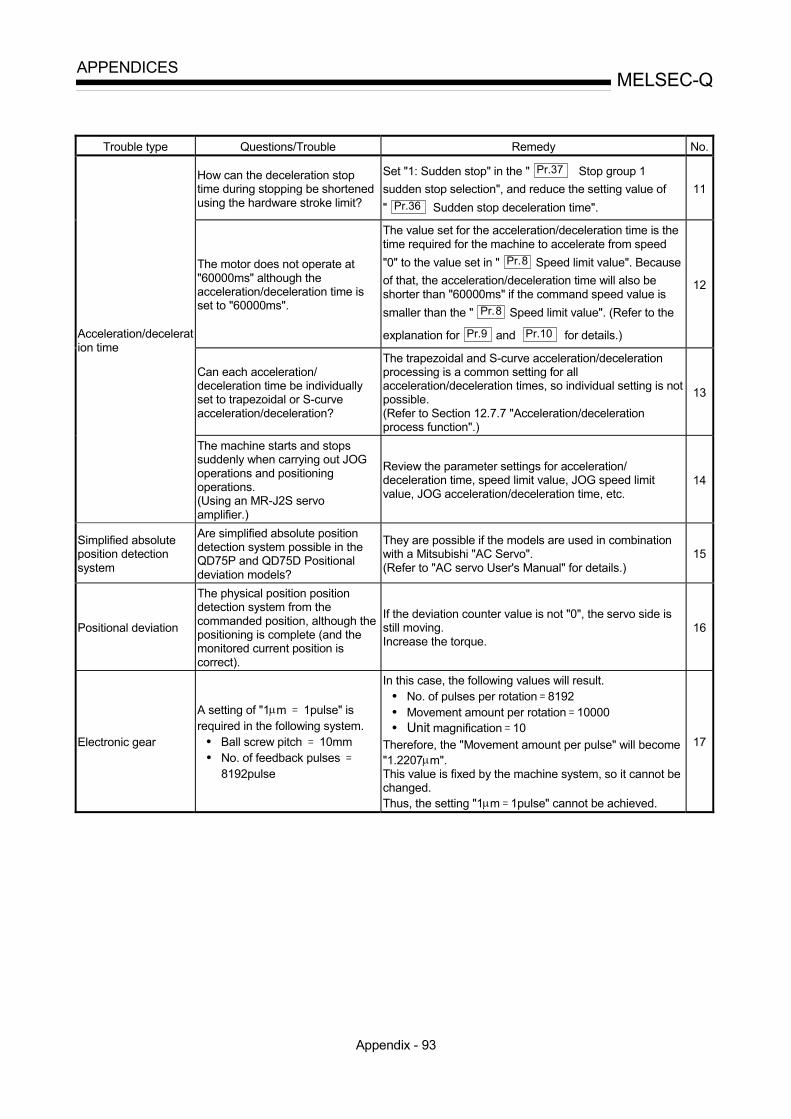
Appendix - 93
MELSEC-QAPPENDICES
Trouble type Questions/Trouble Remedy No.
How can the deceleration stoptime during stopping be shortenedusing the hardware stroke limit?
Set "1: Sudden stop" in the " Pr.37 Stop group 1sudden stop selection", and reduce the setting value of" Pr.36 Sudden stop deceleration time".
11
The motor does not operate at"60000ms" although theacceleration/deceleration time isset to "60000ms".
The value set for the acceleration/deceleration time is thetime required for the machine to accelerate from speed"0" to the value set in " Pr.8 Speed limit value". Becauseof that, the acceleration/deceleration time will also beshorter than "60000ms" if the command speed value issmaller than the " Pr.8 Speed limit value". (Refer to the
explanation for Pr.9 and Pr.10 for details.)
12
Can each acceleration/deceleration time be individuallyset to trapezoidal or S-curveacceleration/deceleration?
The trapezoidal and S-curve acceleration/decelerationprocessing is a common setting for allacceleration/deceleration times, so individual setting is notpossible.(Refer to Section 12.7.7 "Acceleration/decelerationprocess function".)
13
Acceleration/deceleration time
The machine starts and stopssuddenly when carrying out JOGoperations and positioningoperations.(Using an MR-J2S servoamplifier.)
Review the parameter settings for acceleration/deceleration time, speed limit value, JOG speed limitvalue, JOG acceleration/deceleration time, etc.
14
Simplified absoluteposition detectionsystem
Are simplified absolute positiondetection system possible in theQD75P and QD75D Positionaldeviation models?
They are possible if the models are used in combinationwith a Mitsubishi "AC Servo".(Refer to "AC servo User's Manual" for details.)
15
Positional deviation
The physical position positiondetection system from thecommanded position, although thepositioning is complete (and themonitored current position iscorrect).
If the deviation counter value is not "0", the servo side isstill moving.Increase the torque.
16
Electronic gear
A setting of "1μm 1pulse" isrequired in the following system.• Ball screw pitch 10mm• No. of feedback pulses
8192pulse
In this case, the following values will result.• No. of pulses per rotation 8192• Movement amount per rotation 10000• Unit magnification 10
Therefore, the "Movement amount per pulse" will become"1.2207μm".This value is fixed by the machine system, so it cannot bechanged.Thus, the setting "1μm 1pulse" cannot be achieved.
17
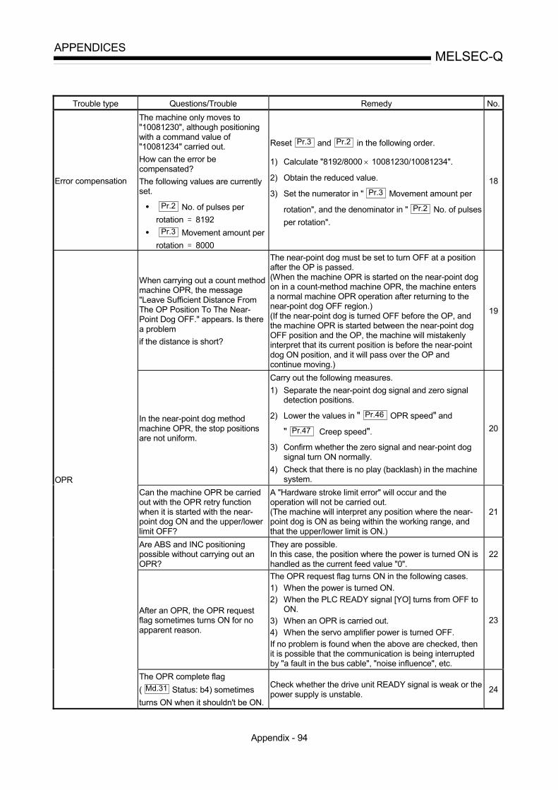
Appendix - 94
MELSEC-QAPPENDICES
Trouble type Questions/Trouble Remedy No.
Error compensation
The machine only moves to"10081230", although positioningwith a command value of"10081234" carried out.How can the error becompensated?The following values are currentlyset.
• Pr.2 No. of pulses perrotation 8192
• Pr.3 Movement amount perrotation 8000
Reset Pr.3 and Pr.2 in the following order.
1) Calculate "8192/8000 × 10081230/10081234".
2) Obtain the reduced value.
3) Set the numerator in " Pr.3 Movement amount per
rotation", and the denominator in " Pr.2 No. of pulsesper rotation".
18
When carrying out a count methodmachine OPR, the message"Leave Sufficient Distance FromThe OP Position To The Near-Point Dog OFF." appears. Is therea problemif the distance is short?
The near-point dog must be set to turn OFF at a positionafter the OP is passed.(When the machine OPR is started on the near-point dogon in a count-method machine OPR, the machine entersa normal machine OPR operation after returning to thenear-point dog OFF region.)(If the near-point dog is turned OFF before the OP, andthe machine OPR is started between the near-point dogOFF position and the OP, the machine will mistakenlyinterpret that its current position is before the near-pointdog ON position, and it will pass over the OP andcontinue moving.)
19
In the near-point dog methodmachine OPR, the stop positionsare not uniform.
Carry out the following measures.1) Separate the near-point dog signal and zero signal
detection positions.
2) Lower the values in " Pr.46 OPR speed" and
" Pr.47 Creep speed".3) Confirm whether the zero signal and near-point dog
signal turn ON normally.4) Check that there is no play (backlash) in the machine
system.
20
Can the machine OPR be carriedout with the OPR retry functionwhen it is started with the near-point dog ON and the upper/lowerlimit OFF?
A "Hardware stroke limit error" will occur and theoperation will not be carried out.(The machine will interpret any position where the near-point dog is ON as being within the working range, andthat the upper/lower limit is ON.)
21
Are ABS and INC positioningpossible without carrying out anOPR?
They are possible.In this case, the position where the power is turned ON ishandled as the current feed value "0".
22
After an OPR, the OPR requestflag sometimes turns ON for noapparent reason.
The OPR request flag turns ON in the following cases.1) When the power is turned ON.2) When the PLC READY signal [YO] turns from OFF to
ON.3) When an OPR is carried out.4) When the servo amplifier power is turned OFF.If no problem is found when the above are checked, thenit is possible that the communication is being interruptedby "a fault in the bus cable", "noise influence", etc.
23
OPR
The OPR complete flag( Md.31 Status: b4) sometimesturns ON when it shouldn't be ON.
Check whether the drive unit READY signal is weak or thepower supply is unstable. 24

Appendix - 95
MELSEC-QAPPENDICES
Trouble type Questions/Trouble Remedy No.The positioning start signal [Y10] iskept ON until the BUSY signal isOFF, but is there any problem withturning it OFF before the BUSYsignal turns OFF?
After the BUSY signal turns ON, there is no problem withturning [Y10] OFF before the BUSY signal turns OFF.(The QD75 detects the rising edge (OFF ON) of thepositioning start signal [Y10].)
25
Start
The operation will not start evenwhen the start signal is turned ON.
Check the " Md.26 axis operation status" and
" Md.23 axis error No".26
How many milliseconds should theaxis stop signal [Y4] be turned ONfor?
The signal should be turned ON at 4ms or more.(If possible, set the signal so it does not turn ON onlymomentarily, but instead stays ON until the BUSY signalturns OFF. This will keep the stop signal from skipping.)
27
How can a sudden stop beselected?
Set "1: Sudden stop" in the parameter from Pr.37 toPr.39 corresponding to the stop group, and reduce the
setting value of " Pr.36 Sudden stop deceleration time".
28
Stop "Normal deceleration stop" wasselected in " Pr.39 Stop group 3sudden stop", and Y stop wasturned ON. If the Pr.39 setting ischanged to "sudden stop" during adeceleration stop, and the Y stopsignal turns from OFF to ON, willthe operation change to a suddenstop from that point?
The operation will not change.Even if the same stop factor is input again during thedeceleration stop, it will be ignored. The samedeceleration stop process used when the stop signal wasfirst input will be continued.(This also applies for Pr.37 and Pr.38 .)
29
Circular interpolation
ABS system circular interpolationoperates normally, but a verticallyoblong circle results when INCsystem circular interpolation iscarried out.
The address designation may be incorrect. When carryingout INC system circular interpolation, designate therelative addresses from the starting point of both thecenter point and end point.
30
Speed-positionswitching control
Can the speed be changed duringspeed control and position controlby speed-position switchingcontrol?
No. The speed for the speed control and position controlcannot be set differently. 31
Even if the JOG start signal isturned ON, the response until itturns ON is sometimes slow.
Either of the following is possible.1) The sequence program may be incorrect. Check by
creating a test program in which the JOG start signalis turned ON only.
2) If the machine is hitting something when the torquesetting is low, it may be trying to move by JOGoperation in the opposite direction. In this case, themachine will start moving only after the internal drooppulses have been reached 0 in the counter, even if theJOG start signal has been turned ON. This makes itseem that the response is slow.
32
JOG operation
The operation is not carried out atthe set JOG speed, although thespeed limit value has not beenreached.
Either of the following is possible.1) The JOG start signal may be chattering. Monitor the
JOG start signal to confirm whether it is chattering.(When using the "BUSY signal" in the JOG operationstart circuit, check the position of the BUSY signal.)
2) The " Pr.31 JOG speed limit value" may not beappropriate. Review the setting value and carry outthe JOG operation again.
33
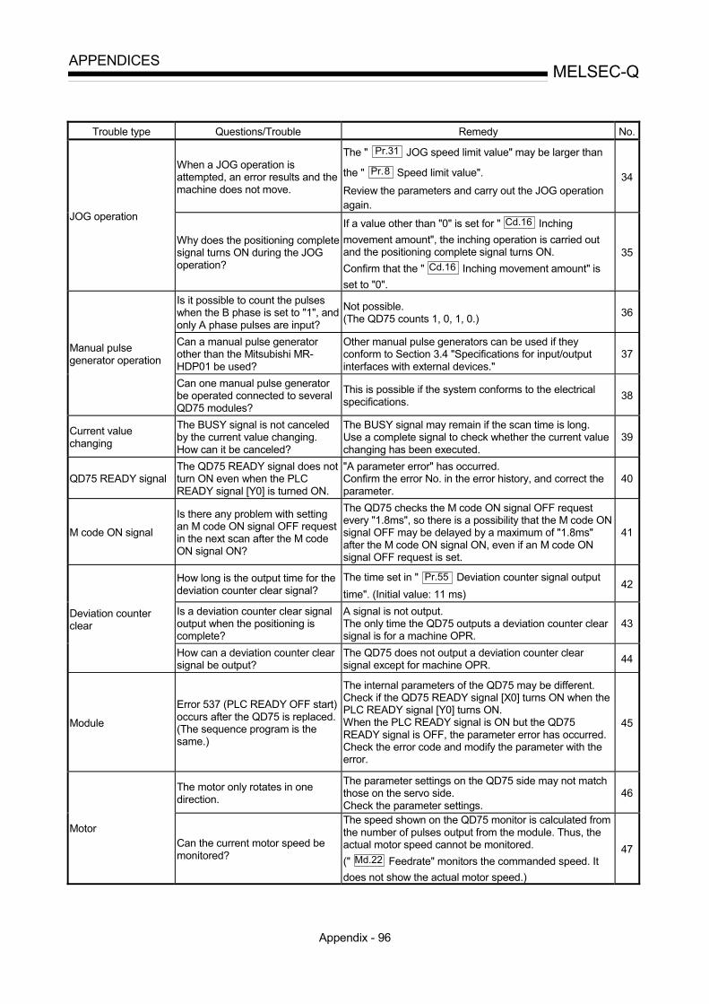
Appendix - 96
MELSEC-QAPPENDICES
Trouble type Questions/Trouble Remedy No.
When a JOG operation isattempted, an error results and themachine does not move.
The " Pr.31 JOG speed limit value" may be larger than
the " Pr.8 Speed limit value".
Review the parameters and carry out the JOG operationagain.
34
JOG operation
Why does the positioning completesignal turns ON during the JOGoperation?
If a value other than "0" is set for " Cd.16 Inchingmovement amount", the inching operation is carried outand the positioning complete signal turns ON.Confirm that the " Cd.16 Inching movement amount" isset to "0".
35
Is it possible to count the pulseswhen the B phase is set to "1", andonly A phase pulses are input?
Not possible.(The QD75 counts 1, 0, 1, 0.) 36
Can a manual pulse generatorother than the Mitsubishi MR-HDP01 be used?
Other manual pulse generators can be used if theyconform to Section 3.4 "Specifications for input/outputinterfaces with external devices."
37Manual pulsegenerator operation
Can one manual pulse generatorbe operated connected to severalQD75 modules?
This is possible if the system conforms to the electricalspecifications. 38
Current valuechanging
The BUSY signal is not canceledby the current value changing.How can it be canceled?
The BUSY signal may remain if the scan time is long.Use a complete signal to check whether the current valuechanging has been executed.
39
QD75 READY signalThe QD75 READY signal does notturn ON even when the PLCREADY signal [Y0] is turned ON.
"A parameter error" has occurred.Confirm the error No. in the error history, and correct theparameter.
40
M code ON signal
Is there any problem with settingan M code ON signal OFF requestin the next scan after the M codeON signal ON?
The QD75 checks the M code ON signal OFF requestevery "1.8ms", so there is a possibility that the M code ONsignal OFF may be delayed by a maximum of "1.8ms"after the M code ON signal ON, even if an M code ONsignal OFF request is set.
41
How long is the output time for thedeviation counter clear signal?
The time set in " Pr.55 Deviation counter signal outputtime". (Initial value: 11 ms)
42
Is a deviation counter clear signaloutput when the positioning iscomplete?
A signal is not output.The only time the QD75 outputs a deviation counter clearsignal is for a machine OPR.
43Deviation counterclear
How can a deviation counter clearsignal be output?
The QD75 does not output a deviation counter clearsignal except for machine OPR. 44
Module
Error 537 (PLC READY OFF start)occurs after the QD75 is replaced.(The sequence program is thesame.)
The internal parameters of the QD75 may be different.Check if the QD75 READY signal [X0] turns ON when thePLC READY signal [Y0] turns ON.When the PLC READY signal is ON but the QD75READY signal is OFF, the parameter error has occurred.Check the error code and modify the parameter with theerror.
45
The motor only rotates in onedirection.
The parameter settings on the QD75 side may not matchthose on the servo side.Check the parameter settings.
46
MotorCan the current motor speed bemonitored?
The speed shown on the QD75 monitor is calculated fromthe number of pulses output from the module. Thus, theactual motor speed cannot be monitored.(" Md.22 Feedrate" monitors the commanded speed. Itdoes not show the actual motor speed.)
47

Appendix - 97
MELSEC-QAPPENDICES
Trouble type Questions/Trouble Remedy No.Backlash compensation value
0 ≤Movement amount per pulse
255
Error 920 (backlash compensationamount error) occurs even whenthe backlash compensation valueis set to "1".
Setting is not possible if the above equation is notsatisfied.Adjust by setting " Pr.4 Unit magnification" to 10-fold (or
100-fold, or 1000-fold), and setting " Pr.2 Movementamount per rotation" to 1/10 (or 1/100, or 1/1000).
48
When a JOG operation isattempted, errors such as error104 (hardware stroke limit+) orerror 105 (hardware stroke limit )occur and the machine does notmove.
The hardware stroke limit wiring has probably not beencarried out.Refer to Section 12.4.4 "Hardware stroke limit function" fordetails, and wire accordingly.
49
Error 997 (Speed selection at OPshift error) appears when the PLCREADY signal [Y0] turns from OFFto ON.
A value besides "0" or "1" may be set in the " Pr.56Speed designation during OP shift".Review the set sequence program, and reset the correctparameters.
50
When the start signal was turnedON immediately after the stopsignal ON, warning 100 (startduring operation) was detected,and the start was ignored.
The QD75 starts the deceleration stop process when thestop signal ON is detected. Thus, the machine interpretsthat "positioning is still being executed" immediately afterthe stop signal ON. Even if the start signal is turned ON atthat time, the start request will be ignored and warning100 will occur.
51
Error/warning
Does warning 500 (decelerationand stop speed change) occuronly during "stop deceleration" and"automatically deceleration"?Is there any problem if theoperation is continued in that statewithout resetting the error?
The warning occurs only at those times mentioned at theleft. Because this is a warning, there is no problem if theoperation can be continued without resetting the error.(When the speed is changed using the override, the newvalue will not be reflected on the data being executed, butwill be reflected from the next start.)
52
Depending on the stop occurrence factor, positioning mayhave not been completed normally.
Check the axis monitor " Md.26 Axis operation status"after the BUSY signal has turned OFF.Stop : The stop signal has turned ON
during positioning.Check the condition under which thestop signal (Y stop, external stop)turns ON.
Error occurrence : An error has occurred duringpositioning.Check the error occurrence factorfrom " Md.23 Axis error No.".
53
Positioning completesignal
Position control was executed butthe positioning complete signaldoes not turn ON.
The setting value of the detailed parameter 2 "Positioningcomplete signal output time" is 0 or shorter than the scantime.Using the sequence program, set the time when the signalcan be detected securely.
54

Appendix - 98
MELSEC-QAPPENDICES
Appendix 12 List of buffer memory addresses
The following shows the relation between the buffer memory addresses and the various items. (Do not use ary address other than listed below. If used, the system may not operate correctly.)
Buffer memory address Axis 1 Axis 2 Axis 3 Axis 4
Item Memory area
0 150 300 450 Pr.1 Unit setting
1 151 301 451 Pr.2 No. of pulses per rotation (Ap)
2 152 302 452 Pr.3 Movement amount per rotation (Al)
3 153 303 453 Pr.4 Unit magnification (Am)
4 154 304 454 Pr.5 Pulse output mode
5 155 305 455 Pr.6 Rotation direction setting
6 7
156 157
306 307
456 457
Pr.7 Bias speed at start
Basi
c pa
ram
eter
s 1
8 9
158 159
308 309
458 459 Not used
10 11
160 161
310 311
460 461
Pr.8 Speed limit value
12 13
162 163
312 313
462 463
Pr.9 Acceleration time 0
14 15
164 165
314 315
464 465
Pr.10 Deceleration time 0 Basi
c pa
ram
eter
s 2
17 167 317 467 Pr.11 Backlash compensation amount
18 19
168 169
318 319
468 469
Pr.12 Software stroke limit upper limit value
20 21
170 171
320 321
470 471
Pr.13 Software stroke limit lower limit value
22 172 322 472 Pr.14 Software stroke limit selection
23 173 323 473 Pr.15 Software stroke limit valid/invalid selection
24 25
174 175
324 325
474 475
Pr.16 Command in-position width
26 176 326 476 Pr.17 Torque limit setting value
27 177 327 477 Pr.18 M code ON signal output timing
28 178 328 478 Pr.19 Speed switching mode
29 179 329 479 Pr.20 Interpolation speed designation method
30 180 330 480 Pr.21 Current feed value during speed control
31 181 331 481 Pr.22 Input signal logic selection
32 182 332 482 Pr.23 Output signal logic selection
33 Pr.24 Manual pulse generator input selection
34 184 334 484 Pr.150 Speed-position function selection
Det
aile
d pa
ram
eter
s 1
35 185 335 485 Not used 36 37
186 187
336 337
486 487
Pr.25 Acceleration time 1
38 39
188 189
338 339
488 489
Pr.26 Acceleration time 2 Det
aile
d pa
ram
eter
s 2
Posi
tioni
ng p
aram
eter
s

Appendix - 99
MELSEC-QAPPENDICES
Buffer memory address
Axis 1 Axis 2 Axis 3 Axis 4 Item Memory area
40 41
190 191
340 341
490 491
Pr.27 Acceleration time 3 42 43
192 193
342 343
492 493 Pr.28 Deceleration time 1
44 45
194 195
344 345
494 495
Pr.29 Deceleration time 2 46 47
196 197
346 347
496 497
Pr.30 Deceleration time 3 48 49
198 199
348 349
498 499
Pr.31 JOG speed limit value
50 200 350 500 Pr.32 JOG operation acceleration time selection
51 201 351 501 Pr.33 JOG operation deceleration time selection
52 202 352 502 Pr.34 Acceleration/deceleration process selection
53 203 353 503 Pr.35 S-curve ratio
54 55
204 205
354 355
504 505
Pr.36 Sudden stop deceleration time
56 206 356 506 Pr.37 Stop group 1 sudden stop selection
57 207 357 507 Pr.38 Stop group 2 sudden stop selection
58 208 358 508 Pr.39 Stop group 3 sudden stop selection
59 209 359 509 Pr.40 Positioning complete signal output time
60 61
210 211
360 361
510 511
Pr.41 Allowable circular interpolation error width
62 212 362 512 Pr.42 External command function selection
Basi
c pa
ram
eter
s 2
Posi
tioni
ng p
aram
eter
s
70 220 370 520 Pr.43 OPR method
71 221 371 521 Pr.44 OPR direction
72 73
222 223
372 373
522 523
Pr.45 OP address
74 75
224 225
374 375
524 525
Pr.46 OPR speed
76 77
226 227
376 377
526 527
Pr.47 Creep speed
78 228 378 528 Pr.48 OPR retry
OPR
bas
ic p
aram
eter
s
79 229 379 529 Pr.49 OPR dwell time
80 81
230 231
380 381
530 531
Pr.50 Setting for the movement amount after near-point dog ON
82 232 382 532 Pr.51 OPR acceleration time selection
83 233 383 533 Pr.52 OPR deceleration time selection
84 85
234 235
384 385
534 535
Pr.53 OP shift amount
86 236 386 536 Pr.54 OPR torque limit value
87 237 387 537 Pr.55 Deviation counter clear signal output time
88 238 388 538 Pr.56 Speed designation during OP shift
89 239 389 539 Pr.57 Dwell time during OPR retry
OPR
det
aile
d pa
ram
eter
s
OPR
par
amet
ers

Appendix - 100
MELSEC-QAPPENDICES
Buffer memory address
Common to axes 1, 2, 3, and 4 Item
Memory area
1200 Md.1 In test mode flag
1201 1202 1203 1204 1205 1206 1207 1208 1209 1210 1211
Not used
(0) (1) (2) (3) (4) (5) (6) (7) (8) (9) (10) (11) (12) (13) (14) (15) (Pointer No.) 1212 1217 1222 1227 1232 1237 1242 1247 1252 1257 1262 1267 1272 1277 1282 1287 Md.3 Start information
1213 1218 1223 1228 1233 1238 1243 1248 1256 1258 1263 1268 1273 1278 1283 1288 Md.4 Start No.
1214 1219 1224 1229 1234 1239 1244 1249 1254 1259 1264 1269 1274 1279 1284 1289 Md.5 Start (Hour)
1215 1220 1225 1230 1235 1240 1245 1250 1255 1260 1265 1270 1275 1280 1285 1290 Md.6 Start (Minute: second)
1216 1221 1226 1231 1236 1241 1246 1251 1256 1261 1266 1271 1276 1281 1286 1291 Md.7 Error judgment
1292 Md.8 Start history pointer
Star
t His
tory
(0) (1) (2) (3) (4) (5) (6) (7) (8) (9) (10) (11) (12) (13) (14) (15) (Pointer No.)
1293 1297 1301 1305 1309 1313 1317 1321 1325 1329 1333 1337 1341 1345 1349 1353Md.9 Axis in which the error
occurred 1294 1298 1302 1306 1310 1314 1318 1322 1326 1330 1334 1338 1342 1346 1350 1354 Md.10 Axis error No.
1295 1299 1303 1307 1311 1315 1319 1323 1327 1331 1335 1339 1343 1347 1351 1355Md.11 Axis error occurrence
(Hour)
1296 1300 1304 1308 1312 1316 1320 1324 1328 1332 1336 1340 1344 1348 1352 1356Md.12 Axis error occurrence
(Minute: second) 1357 Md.13 Error history pointer
Erro
r His
tory
(0) (1) (2) (3) (4) (5) (6) (7) (8) (9) (10) (11) (12) (13) (14) (15) (Pointer No.)
1358 1362 1366 1370 1374 1378 1382 1386 1390 1394 1398 1402 1406 1410 1414 1418Md.14 Axis in which the
warning occurred 1359 1363 1367 1371 1375 1379 1383 1387 1391 1395 1399 1403 1407 1411 1415 1419 Md.15 Axis warning No.
1360 1364 1368 1372 1376 1380 1384 1388 1392 1396 1400 1404 1408 1412 1416 1420Md.16 Axis warning
occurrence (Hour)
1361 1365 1369 1373 1377 1381 1385 1389 1393 1397 1401 1405 1409 1413 1417 1421
Md.17 Axis warning occurrence (Minute: second)
1422 Md.18 Warning history pointer
War
ning
his
tory
1424 1425
Md.19 No. of write accesses to flash ROM
Syst
em m
onito
r dat
a
Mon
itor d
ata

Appendix - 101
MELSEC-QAPPENDICES
Buffer memory address
Axis 1 Axis 2 Axis 3 Axis 4 Item Memory area
800 801
900 901
1000 1001
1100 1101
Md.20 Current feed value
802 803
902 903
1002 1003
1102 1103
Md.21 Machine feed value
804 805
904 905
1004 1005
1104 1105
Md.22 Feedrate
806 906 1006 1106 Md.23 Axis error No.
807 907 1007 1107 Md.24 Axis warning No.
808 908 1008 1108 Md.25 Valid M code
809 909 1009 1109 Md.26 Axis operation status
810 811
910 911
1010 1011
1110 1111
Md.27 Current speed
812 813
912 913
1012 1013
1112 1113
Md.28 Axis feedrate
814 815
914 915
1014 1015
1114 1115
Md.29 Speed-position switching control positioning amount
816 916 1016 1116 Md.30 External input/output signal
817 917 1017 1117 Md.31 Status
818 819
918 919
1018 1019
1118 1119 Md.32
Target value
820 821
920 921
1020 1021
1120 1121
Md.33 Target speed
824 825
924 925
1024 1025
1124 1125
Md.34 Movement amount after near-point dog ON
826 926 1026 1126 Md.35 Torque limit stored value
827 927 1027 1127 Md.36 Special start data instruction parameter
setting value
828 928 1028 1128 Md.37 Special start data instruction No. setting
value 829 929 1029 1129 Md.38 Start positioning data No. setting value.
830 930 1030 1130 Md.39 In speed control flag
831 931 1031 1131 Md.40 In speed change processing flag
832 932 1032 1132 Md.41 Special start repetition counter
833 933 1033 1133 Md.42 Control system repetition counter
834 934 1034 1134 Md.43 Start data pointer being executed
835 935 1035 1135 Md.44 Positioning data No. being executed
836 936 1036 1136 Md.45 Block No. being executed
837 937 1037 1137 Md.46 Last executed positioning data No.
838 to 847 938 to 947 1038 to 1047
1138 to 1147
Md.47 Positioning data being executed
899 999 1099 1199 Md.48 Deceleration start flag
Axis
mon
itor d
ata
Mon
itor d
ata

Appendix - 102
MELSEC-QAPPENDICES
Buffer memory address
Axis 1 Axis 2 Axis 3 Axis 4 Item Memory area
1500 1600 1700 1800 Cd.3 Positioning start No.
1501 1601 1701 1801 Cd.4 Positioning starting point No.
1502 1602 1702 1802 Cd.5 Axis error reset
1503 1603 1703 1803 Cd.6 Restart command
1504 1604 1704 1804 Cd.7 M code OFF request
1505 1605 1705 1805 Cd.8 External command valid
1506 1507
1606 1607
1706 1707
1806 1807
Cd.9 New current value
1508 1509
1608 1609
1708 1709
1808 1809
Cd.10 New acceleration time value
1510 1511
1610 1611
1710 1711
1810 1811
Cd.11 New deceleration time value
1512 1612 1712 1812 Cd.12 Acceleration/deceleration time change
during speed change, enable/disable selection
1513 1613 1713 1813 Cd.13 Positioning operation speed override 1514 1515
1614 1615
1714 1715
1814 1815
Cd.14 New speed value
1516 1616 1716 1816 Cd.15 Speed change request
1517 1617 1717 1817 Cd.16 Inching movement amount 1518 1519
1618 1619
1718 1719
1818 1819
Cd.17 JOG speed
1520 1620 1720 1820 Cd.18 Interrupt request during continuous
operation 1521 1621 1721 1821 Cd.19 OPR request flag OFF request
1522 1523
1622 1623
1722 1723
1822 1823
Cd.20 Manual pulse generator 1 pulse input magnification
1524 1624 1724 1824 Cd.21 Manual pulse generator enable flag
1525 1625 1725 1825 Cd.22 New torque value
1526 1527
1626 1627
1726 1727
1826 1927
Cd.23 Speed-position switching control movement amount change register
1528 1628 1728 1828 Cd.24 Speed-position switching enable flag
1529 1629 1729 1829 Not used 1530 1531
1630 1631
1730 1731
1830 1831
Cd.25 Position-speed switching control speed change register
1532 1632 1732 1832 Cd.26 Position-speed switching enable flag
1533 1633 1733 1833 Not used 1534 1535
1634 1635
1734 1735
1834 1835
Cd.27 Target position change value (new address)
1536 1537
1636 1637
1736 1737
1836 1837
Cd.28 Target position change value (new speed)
1538 1638 1738 1838 Cd.29 Target position change request flag
1539 1639 1739 1839 Not used
1540 1640 1740 1840 Cd.30 Simultaneous starting axis start data No.
(axis 1 start data No.)
Axis
con
trol d
ata
Con
trol d
ata
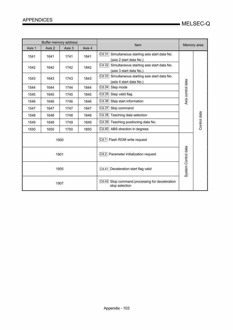
Appendix - 103
MELSEC-QAPPENDICES
Buffer memory address
Axis 1 Axis 2 Axis 3 Axis 4 Item Memory area
1541 1641 1741 1841 Cd.31 Simultaneous starting axis start data No.
(axis 2 start data No.)
1542 1642 1742 1842 Cd.32 Simultaneous starting axis start data No.
(axis 3 start data No.)
1543 1643 1743 1843 Cd.33 Simultaneous starting axis start data No.
(axis 4 start data No.) 1544 1644 1744 1844 Cd.34 Step mode
1545 1645 1745 1845 Cd.35 Step valid flag
1546 1646 1746 1846 Cd.36 Step start information
1547 1647 1747 1847 Cd.37 Skip command
1548 1648 1748 1848 Cd.38 Teaching data selection
1549 1649 1749 1849 Cd.39 Teaching positioning data No.
1550 1650 1750 1850 Cd.40 ABS direction in degrees
Axis
con
trol d
ata
1900 Cd.1 Flash ROM write request
1901 Cd.2 Parameter initialization request
1905 Cd.41 Deceleration start flag valid
1907 Cd.42 Stop command processing for deceleration stop selection
Syst
em C
ontro
l dat
a
Con
trol d
ata
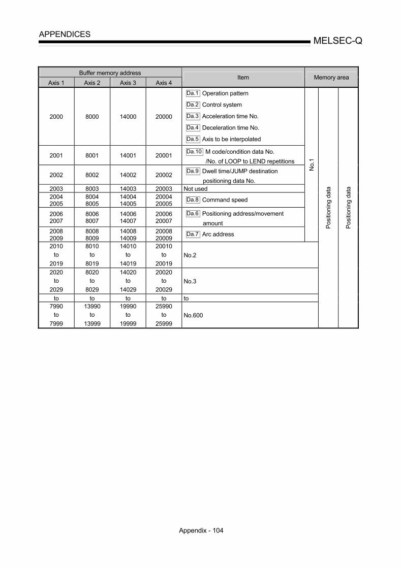
Appendix - 104
MELSEC-QAPPENDICES
Buffer memory address
Axis 1 Axis 2 Axis 3 Axis 4 Item Memory area
2000 8000 14000 20000
Da.1 Operation pattern
Da.2 Control system
Da.3 Acceleration time No.
Da.4 Deceleration time No.
Da.5 Axis to be interpolated
2001 8001 14001 20001 Da.10 M code/condition data No.
/No. of LOOP to LEND repetitions
2002 8002 14002 20002 Da.9 Dwell time/JUMP destination
positioning data No. 2003 8003 14003 20003 Not used 2004 2005
8004 8005
14004 14005
20004 20005
Da.8 Command speed
2006 2007
8006 8007
14006 14007
20006 20007
Da.6 Positioning address/movement amount
2008 2009
8008 8009
14008 14009
20008 20009
Da.7 Arc address
No.
1
2010 to
2019
8010 to
8019
14010 to
14019
20010 to
20019 No.2
2020 to
2029
8020 to
8029
14020 to
14029
20020 to
20029 No.3
to to to to to 7990
to 7999
13990 to
13999
19990 to
19999
25990 to
25999 No.600
Posi
tioni
ng d
ata
Posi
tioni
ng d
ata

Appendix - 105
MELSEC-QAPPENDICES
Buffer memory address
Axis 1 Axis 2 Axis 3 Axis 4 Item
Memory area
26000 26050 27000 27050 28000 28050 29000 29050
Da.11 Shape
Da.12 Start data No.
Da.13 Specilal start instruction
Da.14 Parameter
1st p
oint
26001 26051 27001 27051 28001 28051 29001 29051 2nd point
26002 26052 27002 27052 28002 28052 29002 29052 3rd point
to to to to to
26049 26099 27049 27099 28049 28099 29049 29099 50th point
Bloc
k st
art d
ata
Da.15 Condition target 26100 27100 28100 29100
Da.16 Condition operator
26102 26103
27102 27103
28102 28103
29102 29103
Da.17 Address
26104 26405
27104 27405
28104 28405
29104 29405
Da.18 Parameter 1
26106 26107
27106 27107
28106 28107
29106 29107 Da.19 Parameter 2
No.
1
26110 to 26119 27110 to 27119 28110 to 28119 29110 to 29119 No. 2 26120 to 26129 27120 to 27129 28120 to 28129 29120 to 29129 No. 3
to to to to to 26190 to 26199 27190 to 27199 28190 to 28199 29190 to 29199 No. 10
Con
ditio
n da
ta
Star
ting
bloc
k 0
26200 to 26299 27200 to 27299 28200 to 28299 29200 to 29299 Block start data
26300 to 26399 27300 to 27399 28300 to 28399 29300 to 29399 Condition data St
artin
g bl
ock
1
26400 to 26499 27400 to 27499 28400 to 28499 29400 to 29499 Block start data
26500 to 26599 27500 to 27599 28500 to 28599 29500 to 29599 Condition data
Star
ting
bloc
k 2
26600 to 26699 27600 to 27699 28600 to 28699 29600 to 29699 Block start data
26700 to 26799 27700 to 27799 28700 to 28799 29700 to 29799 Condition data
Star
ting
bloc
k 3
26800 to 26899 27800 to 27899 28800 to 28899 29800 to 29899 Block start data
26900 to 26999 27900 to 27999 28900 to 28999 29900 to 29999 Condition data
Star
ting
bloc
k 4
Posi
tioni
ng d
ata
(Sta
rting
blo
ck d
ata)

Appendix - 106
MELSEC-QAPPENDICES
Buffer memory address
Axis 1 Axis 2 Axis 3 Axis 4 Item Memory area
30000
to
30099
Condition judgement target data of the condition data
PLC
CPU
m
emor
y ar
ea
Posit
ioni
ng d
ata

Appendix - 107
MELSEC-QAPPENDICES
Appendix 13 External dimension drawing
[1] QD75P1/QD75P2/QD75P4
27. 4
23
98
90
4
46 (unit:mm)

Appendix - 108
MELSEC-QAPPENDICES
[2] QD75D1/QD75D2/QD75D4
27. 4
23
90
1298
4
46 (unit:mm)

Index - 1
INDEX
[Number]
1-2 phase excitation system (Explanation of positioning terms) .............................Appendix-68 1-axis fixed-feed control ................................ 9-43 1-axis linear control (ABS linear 1) ............... 9-27 1-axis linear control (INC linear 1) ................ 9-28 1-axis speed control ...................................... 9-67 2-axis circular interpolation control with sub point designation (ABS circular sub) ....................................................................... 9-53 2-axis circular interpolation control with sub point designation (INC circular sub) ....................................................................... 9-56 2-axis circular interpolation control with center point designation (ABS circular right/ABS circular left) ................................................................. 9-61 2-axis circular interpolation control with center point designation (INC circular right/INC circular left) ................................................................. 9-64 2-axis fixed-feed control (interpolation) ....................................................................... 9-45 2-axis linear interpolation control (ABS linear 2) ....................................................................... 9-29 2-axis linear interpolation control (INC linear 2) ....................................................................... 9-31 2-axis speed control ...................................... 9-70 2-phase excitation system (Explanation of positioning terms) .............................Appendix-68 2-phase pulse (Explanation of positioning terms) ..........................................................Appendix-68 2-speed trapezoidal control (Explanation of positioning terms) .............................Appendix-68 3-axis fixed-feed control (interpolation) ....................................................................... 9-47 3-axis linear interpolation control (ABS linear 3) ....................................................................... 9-33 3-axis linear interpolation control (INC linear 3) ....................................................................... 9-36 3-axis speed control ...................................... 9-73 4-axis fixed-feed control (interpolation) ....................................................................... 9-51 4-axis linear interpolation control (ABS linear 4) ....................................................................... 9-39
4-axis linear interpolation control (INC linear 4) ........................................................................9-41 4-axis speed control.......................................9-77
[A]
A phase/B phase mode .................................5-24 ABS direction in degrees ( Cd.40 ) ............5-130 Absolute encoder (Explanation of positioning terms) ............................................... Appendix-69 Absolute position detection system (Explanation of positioning terms)............................. Appendix-69 Absolute position restoration function .........12-50 Absolute system.............................................9-15 Absolute system (Explanation of positioning terms) .......................................................... Appendix-69 Acceleration time (Explanation of positioning terms) ............................................... Appendix-69 Acceleration time 0 ( Pr.9 )..........................5-26
Acceleration time 1 ( Pr.25 )........................5-36
Acceleration time 2 ( Pr.26 )........................5-36
Acceleration time 3 ( Pr.27 )........................5-36
Acceleration time No. ( Da.3 )......................5-60 Acceleration/deceleration process selection ( Pr.34 ) ........................................................5-38
Acceleration/deceleration processing function ......................................................................12-84 Acceleration/deceleration time change during speed change, enable/disable selection ( Cd.12 )
......................................................................5-116 Acceleration/deceleration time change function ......................................................................12-44 Acceleration/deceleration time change program ........................................................................6-20 Actual acceleration/deceleration time ...........5-27 Address ( Da.17 ) .........................................5-83 Address (Explanation of positioning terms) .......................................................... Appendix-69 AFTER mode ...............................................12-67 AFTER mode (Explanation of positioning terms) .......................................................... Appendix-69

Index - 2
Allowable circular interpolation error width ( Pr.41 )........................................................ 5-43 Applicable system ........................................... 2-5 Applicable wire size......................................... 3-3 Arc address ( Da.7 )..................................... 5-68 Auto tuning (Explanation of positioning terms) ..........................................................Appendix-70 Automatic trapezoidal acceleration/deceleration (Explanation of positioning terms) ...Appendix-70 Automatic trapezoidal acceleration/deceleration processing method...................................... 12-85 Axis display LED ............................................. 4-3 Axis error No. ( Md.10 , Md.23 )............... 5-92,96
Axis error occurrence (Hour) ( Md.11 )........ 5-92
Axis error occurrence (Minute: second) ( Md.12 )
....................................................................... 5-92 Axis error reset ( Cd.5 ) ............................. 5-112
Axis feedrate ( Md.28 )............................... 5-100 Axis in which the error occurred ( Md.9 ) .... 5-92 Axis in which the warning occurred ( Md.14 ) ....................................................................... 5-94 Axis monitor data........................................... 5-96 Axis operation status ( Md.26 ) .................... 5-98 Axis stop signal ............................................. 3-16 Axis to be interpolated ( Da.5 ) .................... 5-62 Axis warning detection ................................ 5-102 Axis warning No. ( Md.15 , Md.24 ) ........ 5-94,98
Axis warning occurrence (Hour) ( Md.16 )... 5-94
Axis warning occurrence (Minute: second) ( Md.17 )........................................................ 5-94
[B]
Backlash compensation amount ( Pr.11 ). 5-28
Backlash compensation (Explanation of positioning terms) .............................Appendix-70 Backlash compensation function ................ 12-11 Backup function (Explanation of positioning terms) ..........................................................Appendix-70 Ball screw (Explanation of positioning terms) ..........................................................Appendix-70 Basic parameters 1 ....................................... 5-20 Basic parameters 2 ....................................... 5-26
BCD (Explanation of positioning terms) .......................................................... Appendix-71 Bias speed at start ( Pr.7 ) ..........................5-26 Bias speed at start (Explanation of positioning terms) ............................................... Appendix-71 BIN (Explanation of positioning terms) .......................................................... Appendix-71 Bipolar drive constant-current system (Explanation of positioning terms) ........................ Appendix-72 Block...............................................................10-2 Block No. being executed ( Md.45 ) ...........5-108
Block start (Normal start) ...............................10-8 Block start data ..............................................10-7 Block start data area (Nos. 7000 to 7004) ......7-3 Buffer memory .................................................7-2 Buffer memory (Explanation of positioning terms) .......................................................... Appendix-72 Buffer memory area configuration...................7-5 BUSY (Explanation of positioning terms) .......................................................... Appendix-72 BUSY signal ...................................................3-14
[C]
Cable clamp ...................................................4-11 CCW (Explanation of positioning terms) .......................................................... Appendix-72 CHANGE signal (Explanation of positioning terms) .......................................................... Appendix-72 Circular interpolation (Explanation of positioning terms) ............................................... Appendix-72 Combination of functions ...............................3-12 Combination of main functions and sub functions ........................................................................3-12 Command in-position flag............................5-102 Command in-position function.....................12-81 Command in-position width ( Pr.16 ) ..........5-30
Command pulse (Explanation of positioning terms) .......................................................... Appendix-72 Command pulse frequency ...........................1-11 Command speed ( Da.8 ).............................5-70 Common functions................................. 3-8, 13-2 Communicating signals between QD75 and each module............................................................1-12 Composite speed...........................................5-32 Composite speed (Explanation of positioning terms) ............................................... Appendix-72

Index - 3
Condition data ............................................. 10-16 Condition operator....................................... 10-17 Condition operator ( Da.16 ) ........................ 5-84
Condition start ............................................. 10-10 Condition target ( Da.15 ) ............................ 5-84
Conditional JUMP ....................................... 9-111 Configuration and roles of QD75 memory...... 7-2 Confirming the current value......................... 9-16 Confirming the installation and wiring........... 4-14 Connection confirmation ............................... 4-14 Connector ........................................................ 4-3 Continuous operation interrupt program....... 6-37 Continuous path control .................................. 9-8 Continuous positioning control........................ 9-7 Control data area............................................. 7-3 Control functions ............................................. 3-4 Control system ( Da.2 )................................ 5-60
Control system repetition counter ( Md.42 )
..................................................................... 5-108 Control unit (Explanation of positioning terms) ..........................................................Appendix-72 Count method 1) machine OPR ................... 8-16 Count method 2) machine OPR ................... 8-18 CP control (Explanation of positioning terms) ..........................................................Appendix-73 Creep speed ( Pr.47 ) ................................. 5-50
Creep speed (Explanation of positioning terms) ..........................................................Appendix-73 Current feed value......................................... 9-16 Current feed value ( Md.20 ) ........................ 5-96
Current feed value (Explanation of positioning terms)................................................Appendix-73 Current feed value during speed control ( Pr.21 )
....................................................................... 5-32 Current loop mode (Explanation of positioning terms)................................................Appendix-73 Current speed ( Md.27 ) ............................... 5-98 Current value (Explanation of positioning terms) ..........................................................Appendix-73 CW (Explanation of positioning terms) ..........................................................Appendix-73 CW/CCW mode............................................. 5-23
[D]
D/A converter (Explanation of positioning terms) .......................................................... Appendix-73 Data No. (Explanation of positioning terms) .......................................................... Appendix-73 Data transmission process ..............................7-6 Deceleration curve.......................................12-96 Deceleration curve re-processing ...............12-96 Deceleration curve continuation..................12-96 Deceleration ratio (Explanation of positioning terms) ............................................... Appendix-73 Deceleration start flag ( Md.48 )..................5-108 Deceleration start flag valid ( Cd.41 ) .........5-110 Deceleration stop ...........................................6-43 Deceleration time (Explanation of positioning terms) ............................................... Appendix-74 Deceleration time 0 ( Pr.10 ) .......................5-27
Deceleration time 1 ( Pr.28 ) .......................5-36
Deceleration time 2 ( Pr.29 ) .......................5-36
Deceleration time 3 ( Pr.30 ) .......................5-36
Deceleration time No. ( Da.4 ) .....................5-60 Detailed parameters 1 ...................................5-28 Detailed parameters 2 ...................................5-36 Details of input signals (QD75 PLC CPU) ........................................................................3-15 Details of output signals (PLC CPU QD75) ........................................................................3-16 Deviation counter (Explanation of positioning terms) ............................................... Appendix-74 Deviation counter clear ..................................3-21 Deviation counter clear signal output time ( Pr.55 ) ........................................................5-56 Deviation counter droop pulse amount .........1-11 Differential driver common terminal (SG) ................................................................ 3-24, 4-3 Differential output type (Explanation of positioning terms) ............................................... Appendix-74 Digital bus connection (Explanation of positioning terms) ............................................... Appendix-74 Disposal instructions......................................4-15 DOG signal (Explanation of positioning terms) .......................................................... Appendix-74 DOS/V personal computer ........................... A-15 Drive unit (Explanation of positioning terms) .......................................................... Appendix-74
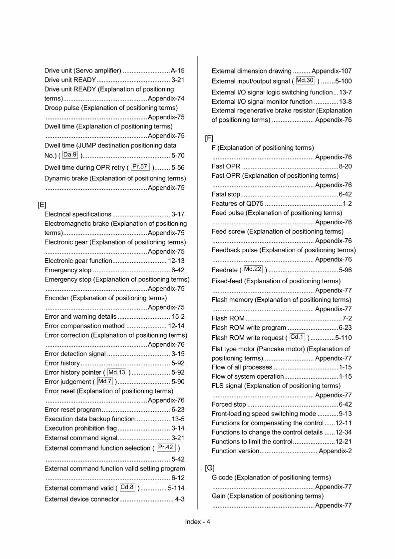
Index - 4
Drive unit (Servo amplifier) ...........................A-15 Drive unit READY.......................................... 3-21 Drive unit READY (Explanation of positioning terms)................................................Appendix-74 Droop pulse (Explanation of positioning terms) ..........................................................Appendix-75 Dwell time (Explanation of positioning terms) ..........................................................Appendix-75 Dwell time (JUMP destination positioning data No.) ( Da.9 ).................................................. 5-70
Dwell time during OPR retry ( Pr.57 )......... 5-56 Dynamic brake (Explanation of positioning terms) ..........................................................Appendix-75
[E]
Electrical specifications ................................. 3-17 Electromagnetic brake (Explanation of positioning terms)................................................Appendix-75 Electronic gear (Explanation of positioning terms) ..........................................................Appendix-75 Electronic gear function............................... 12-13 Emergency stop ............................................ 6-42 Emergency stop (Explanation of positioning terms) ..........................................................Appendix-75 Encoder (Explanation of positioning terms) ..........................................................Appendix-75 Error and warning details .............................. 15-2 Error compensation method ....................... 12-14 Error correction (Explanation of positioning terms) ..........................................................Appendix-76 Error detection signal .................................... 3-15 Error history ................................................... 5-92 Error history pointer ( Md.13 ) ...................... 5-92 Error judgement ( Md.7 ).............................. 5-90 Error reset (Explanation of positioning terms) ..........................................................Appendix-76 Error reset program....................................... 6-23 Execution data backup function.................... 13-5 Execution prohibition flag.............................. 3-14 External command signal.............................. 3-21 External command function selection ( Pr.42 )
....................................................................... 5-42 External command function valid setting program ....................................................................... 6-12 External command valid ( Cd.8 ) ............... 5-114
External device connector............................... 4-3
External dimension drawing .......... Appendix-107 External input/output signal ( Md.30 ) ........5-100
External I/O signal logic switching function...13-7 External I/O signal monitor function ..............13-8 External regenerative brake resistor (Explanation of positioning terms) ........................ Appendix-76
[F]
F (Explanation of positioning terms) .......................................................... Appendix-76 Fast OPR .......................................................8-20 Fast OPR (Explanation of positioning terms).......................................................... Appendix-76 Fatal stop........................................................6-42 Features of QD75 ............................................1-2 Feed pulse (Explanation of positioning terms) .......................................................... Appendix-76 Feed screw (Explanation of positioning terms) .......................................................... Appendix-76 Feedback pulse (Explanation of positioning terms) .......................................................... Appendix-76 Feedrate ( Md.22 ) ........................................5-96
Fixed-feed (Explanation of positioning terms).......................................................... Appendix-77 Flash memory (Explanation of positioning terms) .......................................................... Appendix-77 Flash ROM.......................................................7-2 Flash ROM write program .............................6-23 Flash ROM write request ( Cd.1 ) ..............5-110
Flat type motor (Pancake motor) (Explanation of positioning terms)............................. Appendix-77 Flow of all processes .....................................1-15 Flow of system operation...............................1-15 FLS signal (Explanation of positioning terms) .......................................................... Appendix-77 Forced stop ....................................................6-42 Front-loading speed switching mode ............9-13 Functions for compensating the control ......12-11 Functions to change the control details ......12-34 Functions to limit the control........................12-21 Function version................................. Appendix-2
[G]
G code (Explanation of positioning terms) .......................................................... Appendix-77 Gain (Explanation of positioning terms) .......................................................... Appendix-77

Index - 5
GD2 (Explanation of positioning terms) ..........................................................Appendix-77 General configuration of program................. 6-11 General image of system................................ 2-2 GX Configurator-QP...............................A-15, 2-4 GX Developer................................................A-15
[H]
Handling precautions ...................................... 4-5 Hardware stroke limit function .................... 12-32 High-level positioning control........................ 10-2
[I]
Immediate stop.............................................. 6-43 In speed change processing flag ( Md.40 )
..................................................................... 5-106 In speed control flag.................................... 5-102 In speed control flag ( Md.39 ) ................... 5-106
In test mode flag ( Md.1 ) ............................. 5-86
Inching movement amount ( Cd.16 )......... 5-120 Inching operation setting program ................ 6-19 Inching operation start time chart ............... 11-23 Inching operation timing and processing times ..................................................................... 11-19 Inching operation......................................... 11-17 Incremental encoder (Explanation of positioning terms)................................................Appendix-78 Incremental system ....................................... 9-15 Incremental system (Explanation of positioning terms)................................................Appendix-78 Independent positioning control...................... 9-6 Inertia (Explanation of positioning terms) ..........................................................Appendix-78 Initialization program ..................................... 6-24 Input signal logic selection ( Pr.22 ) ........... 5-32 Input terminal (Explanation of positioning terms) ..........................................................Appendix-79 Input/output interface internal circuit............. 3-22 Intentional stop .............................................. 6-42 Interlock (Explanation of positioning terms) ..........................................................Appendix-79 Internal circuit ................................................ 3-22 Internal current consumption .......................... 3-3 Interpolation axis ........................................... 9-21 Interpolation control....................................... 9-21 Interpolation operation (Explanation of positioning terms)................................................Appendix-79
Interpolation speed designation method ( Pr.20 )
........................................................................5-32 Interruption request during continuous operation ( Cd.18 ) ......................................................5-120 Inverter (Explanation of positioning terms) .......................................................... Appendix-79
[J]
JOG (Explanation of positioning terms) .......................................................... Appendix-79 JOG operation................................................11-4 JOG operation acceleration time selection ( Pr.32 ) ........................................................5-36
JOG operation deceleration time selection ( Pr.33 ) ........................................................5-36
JOG operation setting program.....................6-19 JOG operation start time chart ....................11-11 JOG operation timing and processing times ........................................................................11-6 JOG speed ( Cd.17 ) ..................................5-120
JOG speed limit value ( Pr.31 )...................5-36
JOG start signal .............................................3-16 JUMP instruction..........................................9-111
[K]
kPPS (Explanation of positioning terms) .......................................................... Appendix-79
[L]
Last executed positioning data No. ( Md.46 )
......................................................................5-108 LED display functions ..................................15-38 LEND............................................................9-114 Limit switch (Explanation of positioning terms) .......................................................... Appendix-79 Linear interpolation (Explanation of positioning terms) ............................................... Appendix-80 List of block start data....................................5-74 List of condition data......................................5-80 List of configuration devices ............................2-4 List of control data........................................5-110 List of dedicated instructions .........................14-2 List of devices used .........................................6-5 List of errors ...................................................15-6 List of functions ................................................3-4 List of input/output signal details ...................3-20
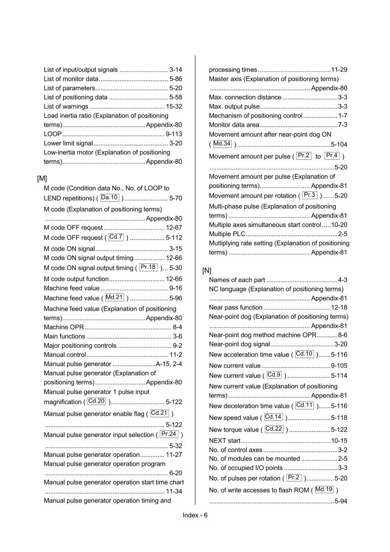
Index - 6
List of input/output signals ............................ 3-14 List of monitor data........................................ 5-86 List of parameters.......................................... 5-20 List of positioning data .................................. 5-58 List of warnings ........................................... 15-32 Load inertia ratio (Explanation of positioning terms)................................................Appendix-80 LOOP........................................................... 9-113 Lower limit signal........................................... 3-20 Low-inertia motor (Explanation of positioning terms)................................................Appendix-80
[M]
M code (Condition data No., No. of LOOP to LEND repetitions) ( Da.10 ) ......................... 5-70
M code (Explanation of positioning terms) ..........................................................Appendix-80 M code OFF request ................................... 12-67 M code OFF request ( Cd.7 ) .................... 5-112
M code ON signal.......................................... 3-15 M code ON signal output timing.................. 12-66 M code ON signal output timing ( Pr.18 )... 5-30
M code output function................................ 12-66 Machine feed value ....................................... 9-16 Machine feed value ( Md.21 ) ...................... 5-96 Machine feed value (Explanation of positioning terms)................................................Appendix-80 Machine OPR.................................................. 8-4 Main functions ................................................. 3-6 Major positioning controls ............................... 9-2 Manual control............................................... 11-2 Manual pulse generator .........................A-15, 2-4 Manual pulse generator (Explanation of positioning terms) .............................Appendix-80 Manual pulse generator 1 pulse input magnification ( Cd.20 )............................... 5-122
Manual pulse generator enable flag ( Cd.21 )
..................................................................... 5-122 Manual pulse generator input selection ( Pr.24 )
....................................................................... 5-32 Manual pulse generator operation.............. 11-27 Manual pulse generator operation program ....................................................................... 6-20 Manual pulse generator operation start time chart ..................................................................... 11-34 Manual pulse generator operation timing and
processing times..........................................11-29 Master axis (Explanation of positioning terms) .......................................................... Appendix-80 Max. connection distance................................3-3 Max. output pulse.............................................3-3 Mechanism of positioning control....................1-7 Monitor data area.............................................7-3 Movement amount after near-point dog ON ( Md.34 ) ......................................................5-104
Movement amount per pulse ( Pr.2 to Pr.4 )
........................................................................5-20 Movement amount per pulse (Explanation of positioning terms)............................. Appendix-81 Movement amount per rotation ( Pr.3 ).......5-20 Multi-phase pulse (Explanation of positioning terms) ............................................... Appendix-81 Multiple axes simultaneous start control .....10-20 Multiple PLC.....................................................2-5 Multiplying rate setting (Explanation of positioning terms) ............................................... Appendix-81
[N]
Names of each part .........................................4-3 NC language (Explanation of positioning terms) .......................................................... Appendix-81 Near pass function.......................................12-18 Near-point dog (Explanation of positioning terms) .......................................................... Appendix-81 Near-point dog method machine OPR............8-6 Near-point dog signal.....................................3-20 New acceleration time value ( Cd.10 ).......5-116
New current value........................................9-105 New current value ( Cd.9 ) .........................5-114 New current value (Explanation of positioning terms) ............................................... Appendix-81 New deceleration time value ( Cd.11 ).......5-116
New speed value ( Cd.14 ).........................5-118
New torque value ( Cd.22 ) ........................5-122
NEXT start....................................................10-15 No. of control axes...........................................3-2 No. of modules can be mounted .....................2-5 No. of occupied I/O points ...............................3-3 No. of pulses per rotation ( Pr.2 )................5-20
No. of write accesses to flash ROM ( Md.19 )
........................................................................5-94

Index - 7
NOP instruction ........................................... 9-110 Normal start ................................................... 10-8
[O]
OP (Explanation of positioning terms) ..........................................................Appendix-82 OP address ( Pr.45 )................................... 5-48
OP shift amount ( Pr.53 )............................ 5-56
OP shift function ............................................ 12-8 OP shift function (Explanation of positioning terms)..........................................................Appendix-82 Operating principle .......................................... 1-7 Operation pattern ( Da.1 )............................ 5-60
Operation pattern (Explanation of positioning terms)................................................Appendix-82 Operation patterns........................................... 9-5 Operation timing and processing time during position-speed switching control................. 9-100 Operation timing and processing time during speed-position switching control (ABS mode) ....................................................................... 9-93 Operation timing and processing time during speed-position switching control (INC mode) ....................................................................... 9-85 Operation timing and processing time of fast OPR....................................................................... 8-21 OPR acceleration time selection ( Pr.51 ).. 5-54
OPR basic parameters.................................. 5-46 OPR complete flag ...................................... 5-102 OPR deceleration time selection ( Pr.52 ).. 5-54
OPR detailed parameters ............................. 5-54 OPR direction ( Pr.44 ) ............................... 5-48
OPR dwell time ( Pr.49 )............................. 5-54
OPR method.................................................... 8-5 OPR method ( Pr.43 ) ................................. 5-46
OPR method (1): Near-point dog method ...... 8-6 OPR method (2): Stopper method 1) ............. 8-8 OPR method (3): Stopper method 2) ........... 8-11 OPR method (4): Stopper method 3) ........... 8-14 OPR method (5): Count method 1) ....................................................................... 8-16 OPR method (6): Count method 2) ....................................................................... 8-18 OPR method (Explanation of positioning terms)..........................................................Appendix-82 OPR request OFF program .......................... 6-12
OPR parameter (Explanation of positioning terms).......................................................... Appendix-82 OPR request ....................................................8-2 OPR request (Explanation of positioning terms).......................................................... Appendix-83 OPR request flag .........................................5-102 OPR request flag OFF request ( Cd.19 )
......................................................................5-122 OPR retry ( Pr.48 ).......................................5-50
OPR retry function .........................................12-4 OPR speed ( Pr.46 )....................................5-48
OPR torque limit value ( Pr.54 )
........................................................................5-56 Order of priority for stop process...................6-44 Outline design of positioning system...............1-9 Outline of installation, wiring and maintenance ..........................................................................4-2 Outline of OPR control.....................................8-2 Outline of restarting........................................1-21 Outline of starting...........................................1-18 Outline of stopping.........................................1-20 Output signal logic selection ( Pr.23 ) .........5-32
Output terminal (Explanation of positioning terms) .......................................................... Appendix-83 Override function..........................................12-41 Override function (Explanation of positioning terms) ............................................... Appendix-83 Override program...........................................6-20
[P]
P rate (Explanation of positioning terms) .......................................................... Appendix-83 Parameter ( Da.14 )......................................5-77
Parameter (Explanation of positioning terms) .......................................................... Appendix-83 Parameter 1 ( Da.18 )...................................5-83 Parameter 2 ( Da.19 ) ...................................5-83 Parameter area ................................................7-3 Parameter initialization program....................6-22 Parameter initialization request ( Cd.2 ) ....5-110
Performance specifications .............................3-2 Peripheral device .......................................... A-15 Personal computer........................................ A-15 PG0 (Explanation of positioning terms) .......................................................... Appendix-83

Index - 8
PLC CPU .......................................................A-15 PLC CPU memo area ..................................... 7-3 PLC CPU module............................................ 2-5 PLC READY signal ....................................... 3-16 PLC READY signal [Y0] ON program .......... 6-12 PULSE/SIGN mode....................................... 5-23 Position control (Explanation of positioning terms) ..........................................................Appendix-84 Position detection module (Explanation of positioning terms) .............................Appendix-84 Position loop gain (Explanation of positioning terms)............................................... Appendix-84 Position loop mode (Explanation of positioning terms)................................................Appendix-84 Position-speed switching control .................. 9-98 Position-speed switching control speed change register ( Cd.25 ) ........................................ 5-124
Position-speed switching control enable flag ( Cd.26 )...................................................... 5-126
Position-speed switching latch flag............. 5-102 Position-speed switching signal.................... 3-21 Positioning (Explanation of positioning terms) ..........................................................Appendix-84 Positioning address/movement amount ( Da.6 )
....................................................................... 5-62 Positioning complete (Explanation of positioning terms)................................................Appendix-84 Positioning complete signal .......................... 3-15 Positioning complete signal (Explanation of positioning terms) .............................Appendix-84 Positioning complete signal output time ( Pr.40 )
....................................................................... 5-42 Positioning continued.......................Appendix-85 Positioning control operation program.......... 6-12 Positioning complete ....................................... 9-6 Positioning data (Explanation of positioning terms) ..........................................................Appendix-85 Positioning data area (Nos. 1 to 600)............. 7-3 Positioning data being executed ( Md.47 )
..................................................................... 5-108 Positioning data No. being executed ( Md.44 )
..................................................................... 5-108 Positioning operation speed override ( Cd.13 )
..................................................................... 5-118 Positioning parameter (Explanation of positioning terms)................................................Appendix-85
Positioning program examples......................6-15 Positioning start (Explanation of positioning terms) .......................................................... Appendix-85 Positioning start No. ( Cd.3 ) ......................5-112
Positioning start No. setting program............6-17 Positioning start program...............................6-13 Positioning start signal...................................3-16 Positioning starting point No. ( Cd.4 ) ........5-112 Precautions
• Disposal instructions................................4-15 • Handling precautions.................................4-5 • Precautions for creating program..............6-2 • Precautions for installation ........................4-7 • Precautions for maintenance...................4-15 • Precautions for using stepping motor .....1-22 • Precautions for wiring ................................4-8
Pre-reading start function ............................12-87 Process time
• Inching operation timing and processing time ...............................................................11-19
• JOG operation timing and processing time .................................................................11-6
• Machine OPR operation timing and process time..........................................................6-34
• Manual pulse generator operation timing and processing times...................................11-29
• Operation timing and processing time during position-speed switching control ..........9-100
• Operation timing and processing time during speed-position switching control (ABS mode) .................................................................9-93
• Operation timing and processing time during speed-position switching control (INC mode) .................................................................9-85
• Operation timing and processing time of fast OPR.........................................................8-21
• Position control operation timing and process time..........................................................6-35
Program details..............................................6-24 Program examples
• Absolute position restoration program ....6-22 • Acceleration/deceleration time change
program...................................................6-20 • Continuous operation interrupt program
.................................................................6-21 • Error reset program .................................6-23

Index - 9
• External command function valid setting
program .................................................. 6-17 • Flash ROM write program....................... 6-23 • Inching operation setting program.......... 6-19 • JOG operation setting program .............. 6-19 • JOG operation/inching operation execution
program .................................................. 6-19 • M code OFF program.............................. 6-19 • Manual pulse generator operation program
................................................................ 6-20 • OPR request OFF program .................... 6-17 • Override program .................................... 6-20 • Parameter initialization program............. 6-22 • PLC READY signal [Y0] ON program .... 6-17 • Positioning start No. setting program ..... 6-17 • Positioning start program........................ 6-18 • Restart program ...................................... 6-22 • Skip program ........................................... 6-21 • Speed change program .......................... 6-20 • Step operation program .......................... 6-21 • Stop program........................................... 6-23 • Target position change program............. 6-21 • Teaching program................................... 6-21 • Torque change program ......................... 6-21
PTP control (Explanation of positioning terms) ..........................................................Appendix-85 Pulse (Explanation of positioning terms) ..........................................................Appendix-85 Pulse generator (Explanation of positioning terms) ..........................................................Appendix-85 Pulse output mode ( Pr.5 ).......................... 5-22 Pulse output mode (Explanation of positioning terms)................................................Appendix-85 Purpose and applications of positioning control ......................................................................... 1-5
[Q]
QD75 .............................................................A-15 QD75 READY signal..................................... 3-15
[R]
READY (Explanation of positioning terms) ..........................................................Appendix-86 Real-time AUTO tuning (Explanation of positioning terms)................................................Appendix-86 Reference axis .............................................. 9-21 Reference axis speed ................................... 5-33
Reference axis speed (Explanation of positioning terms) ............................................... Appendix-86 Regeneration brake option (Explanation of positioning terms)............................. Appendix-86 Relatively safe stop........................................6-42 Repeated start (FOR condition) ..................10-14 Repeated start (FOR loop) ..........................10-13 Resolver (Explanation of positioning terms) .......................................................... Appendix-86 Restart command ( Cd.6 )..........................5-112
Restart operation ...........................................6-39 Restart program.............................................6-39 RLS signal (Explanation of positioning terms) .......................................................... Appendix-86 Rotary table...................................... Appendix-86 Rotation direction setting ( Pr.6 ) ................5-22
[S]
S-curve acceleration/deceleration .......................................................... Appendix-86 SERIAL No. ..............................1-22, Appendix-2 Servo amplifier (Explanation of positioning terms) .......................................................... Appendix-86 Servo lock (Explanation of positioning terms) .......................................................... Appendix-87 Servo ON (Explanation of positioning terms) .......................................................... Appendix-87 Servomotor (Explanation of positioning terms) .......................................................... Appendix-87 Setting data ......................................................5-2 Setting for the movement amount after near-point dog ON ( Pr.50 ) ..........................................5-54
Setting items for block start data ...................5-10 Setting items for condition data .....................5-11 Setting items for OPR parameters ..........................................................................5-6 Setting items for positioning data ....................5-7 Setting items for positioning parameters.........5-4 Setting the positioning data ...........................9-25 Setting the torque limit function ...................12-25 Setting unit (Explanation of positioning terms) .......................................................... Appendix-87 SFC (Explanation of positioning terms) .......................................................... Appendix-87 Shape ( Da.11 ) ............................................5-77

Index - 10
Signal layout of connector............................. 3-19 Signal name................................................... 3-14 Signals
• Axis stop signal ....................................... 3-16 • BUSY signal ............................................ 3-15 • Error detection signal .............................. 3-15 • Execution prohibition flag signal ............. 3-16 • JOG start signal....................................... 3-16 • M code ON signal.................................... 3-15 • PLC READY signal ................................ 3-16 • Positioning complete signal .................... 3-15 • Positioning start signal ............................ 3-16 • QD75 READY signal............................... 3-15 • Start complete signal............................... 3-15 • Synchronization flag signal ..................... 3-15
Simultaneous start....................................... 10-12 Simultaneous starting axis start data No. (Axis 1 start data No.) ( Cd.30 ) ............................. 5-128
Simultaneous starting axis start data No. (Axis 2 start data No.)( Cd.31 ) .............................. 5-128
Simultaneous starting axis start data No. (Axis 3 start data No.)( Cd.32 ) .............................. 5-128
Simultaneous starting axis start data No. (Axis 4 start data No.)( Cd.33 ) .............................. 5-128
Skip command ( Cd.37 )............................ 5-130
Skip function ................................................ 12-63 Skip function (Explanation of positioning terms) ..........................................................Appendix-87 Skip program ................................................. 6-14 Slave axis (Explanation of positioning terms) ..........................................................Appendix-87 Slot................................................................... 2-5 Software stroke limit lower limit value ( Pr.13 ) ....................................................................... 5-28 Software stroke limit selection ( Pr.14 ) ...... 5-28 Software stroke limit upper limit value ( Pr.12 ) ....................................................................... 5-28 Software stroke limit valid/invalid setting ( Pr.15 ) ....................................................................... 5-28 S-curve acceleration/deceleration processing method......................................................... 12-85 S-curve ratio ( Pr.35 ).................................. 5-38
Special start instruction ( Da.13 ) ................ 5-77
Special start data instruction code setting value ( Md.36 )...................................................... 5-106
Special start data instruction parameter setting value ( Md.37 ) ............................................5-106
Special start repetition counter ( Md.41 ) ...5-108
Specifications of input/output interfaces .......3-17 Specifications of input/output signals ............3-14 Speed change 0 flag....................................5-102 Speed change function................................12-34 Speed change program.................................6-20 Speed change request ( Cd.15 )................5-118 Speed control (Explanation of positioning terms) .......................................................... Appendix-88 Speed designation during OP shift ( Pr.56 )
........................................................................5-56 Speed integral compensation (Explanation of positioning terms)............................. Appendix-88 Speed limit function .....................................12-21 Speed limit value ( Pr.8 ).............................5-26
Speed limit value (Explanation of positioning terms) ............................................... Appendix-88 Speed loop gain (Explanation of positioning terms) .......................................................... Appendix-88 Speed loop mode (Explanation of positioning terms) ............................................... Appendix-88 Speed-position function selection ( Pr.150 ) ..5-34 Speed switching mode ( Pr.19 )..................5-32 Speed-position switching control (ABS mode) ........................................................................9-90 Speed-position switching control (INC mode) ........................................................................9-82 Speed–position switching control (Explanation of positioning terms)............................. Appendix-88 Speed-position switching control movement amount change register ( Cd.23 ) ..............5-124
Speed-position switching control positioning amount ( Md.29 ).........................................5-100
Speed-position switching enable flag ( Cd.24 )
......................................................................5-124 Speed-position switching latch flag .............5-102 Speed-position switching signal ....................3-21 Speed-position switching control mode (Explanation of positioning terms)... Appendix-88 Spiral interpolation .........................................9-60 Standard speed switching mode...................9-12 Start Hour ( Md.5 ) ........................................5-88

Index - 11
Start complete (Explanation of positioning terms) ..........................................................Appendix-88 Start complete signal..................................... 3-15 Start data No. ( Da.12 )................................ 5-77
Start data pointer being executed ( Md.43 )
..................................................................... 5-108 Start details setting program......................... 6-25 Start history ................................................... 5-88 Start history pointer ( Md.8 ) ........................ 5-90 Start information ( Md.3 ) ............................. 5-88
Start Minute: second ( Md.6 )....................... 5-88
Start No. ( Md.4 ).......................................... 5-88
Start positioning data No. setting value ( Md.38 )
..................................................................... 5-106 Start program................................................. 6-27 Start program for high-level positioning control ..................................................................... 10-23 Starting axis (Explanation of positioning terms) ..........................................................Appendix-88 Status ( Md.31 ) .......................................... 5-102
Status (Explanation of positioning terms) ..........................................................Appendix-88 Step function................................................ 12-58 Step function (Explanation of positioning terms) ..........................................................Appendix-88 Step mode ................................................... 12-59 Step mode ( Cd.34 )................................... 5-128
Step operation program ................................ 6-21 Step out (Explanation of positioning terms) ..........................................................Appendix-89 Step start information .................................. 12-59 Step start information ( Cd.36 ) ................. 5-130
Step valid flag ( Cd.35 ) ............................. 5-128
Stepping motor (Explanation of positioning terms) ..........................................................Appendix-89 Stop cause..................................................... 6-42 Stop command processing for deceleration stop function ........................................................ 12-96 Stop command processing for deceleration stop selection ( Cd.42 )....................................... 5-110
Stop group 1 sudden stop selection ( Pr.37 )
....................................................................... 5-38 Stop group 2 sudden stop selection ( Pr.38 )
....................................................................... 5-38
Stop group 3 sudden stop selection ( Pr.39 )
........................................................................5-38 Stop process ..................................................6-42 Stop program .................................................6-42 Stop settling time (Explanation of positioning terms) ............................................... Appendix-89 Stop signal .....................................................3-21 STOP signal (Explanation of positioning terms) .......................................................... Appendix-89 Stop with stopper (Explanation of positioning terms) ............................................... Appendix-89 Stopper method 1) machine OPR...................8-8 Stopper method 2) machine OPR.................8-11 Stopper method 3) machine OPR.................8-14 Stroke (Explanation of positioning terms) .......................................................... Appendix-89 Stroke limit (Explanation of positioning terms) .......................................................... Appendix-90 Sub functions .................................................12-2 Sub functions specifically for machine OPR ........................................................................12-4 Sudden stop...................................................6-43 Sudden stop (Explanation of positioning terms) .......................................................... Appendix-90 Sudden stop deceleration time ( Pr.36 ) .....5-38
Synchronization flag (X1) ..............................3-15 System control data .....................................5-110 System monitor data......................................5-86
[T]
Tact time.......................................................12-87 Target position change function ..................12-77 Target position change request flag ( Cd.29 )
......................................................................5-126 Target position change value (new address) ( Cd.27 ) ......................................................5-126
Target position change value (new speed) ( Cd.28 ) ......................................................5-126
Target speed ( Md.33 ) ...............................5-104
Target value ( Md.32 ).................................5-102 Teaching (Explanation of positioning terms) .......................................................... Appendix-90 Teaching data selection ( Cd.38 ) ..............5-130 Teaching function.........................................12-70 Teaching positioning data No. ( Cd.39 ).....5-130

Index - 12
Teaching program ......................................... 6-21 Time chart
• Inching operation start time chart ......... 11-23 • JOG operation start time chart.............. 11-11 • Time chart for changing the speed from the
PLC CPU .............................................. 12-37 • Time chart for changing the speed using an
external command signal ..................... 12-39 • Time chart for changing the speed using the
override function................................... 12-42 • Time chart for restarting.......................... 6-41 • Time chart for starting "fast OPR" .......... 6-31 • Time chart for starting "machine OPR" .. 6-30 • Time chart for starting "major positioning
control".................................................... 6-32 • Time chart for starting "position-speed
switching control".................................... 6-33 • Time chart for starting "speed-position
switching control".................................... 6-32 • Time chart for starting with external command
signal....................................................... 6-36 Torque change function .............................. 12-48 Torque change program ............................... 6-21 Torque control (Explanation of positioning terms) ..........................................................Appendix-90 Torque limit function.................................... 12-23 Torque limit setting value ( Pr.17 ) ............. 5-31
Torque limit stored value ( Md.35 ) ............ 5-104
Torque loop mode (Explanation of positioning terms)................................................Appendix-90 Torque ripple (Explanation of positioning terms) ..........................................................Appendix-90 Tracking function (Explanation of positioning terms)................................................Appendix-90 Turntable (Explanation of positioning terms) ..........................................................Appendix-91 Types and roles of control data .................... 5-16 Types and roles of monitor data ................... 5-12 Types of data................................................... 5-2 Types of errors .............................................. 15-2 Types of stop processes ............................... 6-43 Types of warnings ......................................... 15-3
[U]
Unconditional JUMP.................................... 9-111 Unit magnification ( Pr.4 ) ........................... 5-20
Unit setting ( Pr.1 ) ...................................... 5-20
Unit setting (Explanation of positioning terms) .......................................................... Appendix-91 Upper limit signal ...........................................3-20
[V]
Valid M code ( Md.25 )..................................5-98 [W]
Wait start ......................................................10-11 Warning (Explanation of positioning terms) .......................................................... Appendix-91 Warning history ..............................................5-94 Warning history pointer ( Md.18 ) .................5-94 Window (Explanation of positioning terms) .......................................................... Appendix-91 Writing to the Flash ROM ..............................13-6 WITH mode..................................................12-66 WITH mode (Explanation of positioning terms) .......................................................... Appendix-91 Workpiece ..................................................... A-15
[X]
X0 (QD75 READY) ........................................3-15 X1 (Synchronization flag) ..............................3-15 XY table (Explanation of positioning terms) .......................................................... Appendix-91
[Z]
Z.ABRST1......................................................14-3 Z.ABRST2......................................................14-3 Z.ABRST3......................................................14-3 Z.ABRST4......................................................14-3 Zero signal (Explanation of positioning terms) .......................................................... Appendix-91 ZP.PFWRT.....................................................14-2 ZP.PINIT.........................................................14-2 Z phase (Explanation of positioning terms) .......................................................... Appendix-91 ZP.PSTRT1....................................................14-8 ZP.PSTRT2....................................................14-8 ZP.PSTRT3....................................................14-8 ZP.PSTRT4....................................................14-8

WARRANTY
Please confirm the following product warranty details before using this product. 1. Gratis Warranty Term and Gratis Warranty Range
If any faults or defects (hereinafter "Failure") found to be the responsibility of Mitsubishi occurs during use of the product within the gratis warranty term, the product shall be repaired at no cost via the sales representative or Mitsubishi Service Company. However, if repairs are required onsite at domestic or overseas location, expenses to send an engineer will be solely at the customer’s discretion. Mitsubishi shall not be held responsible for any re-commissioning, maintenance, or testing on-site that involves replacement of the failed module. [Gratis Warranty Term]
The gratis warranty term of the product shall be for one year after the date of purchase or delivery to a designated place. Note that after manufacture and shipment from Mitsubishi, the maximum distribution period shall be six (6) months, and the longest gratis warranty term after manufacturing shall be eighteen (18) months. The gratis warranty term of repair parts shall not exceed the gratis warranty term before repairs.
[Gratis Warranty Range] (1) The range shall be limited to normal use within the usage state, usage methods and usage environment, etc.,
which follow the conditions and precautions, etc., given in the instruction manual, user's manual and caution labels on the product.
(2) Even within the gratis warranty term, repairs shall be charged for in the following cases. 1. Failure occurring from inappropriate storage or handling, carelessness or negligence by the user. Failure caused
by the user's hardware or software design. 2. Failure caused by unapproved modifications, etc., to the product by the user. 3. When the Mitsubishi product is assembled into a user's device, Failure that could have been avoided if functions
or structures, judged as necessary in the legal safety measures the user's device is subject to or as necessary by industry standards, had been provided.
4. Failure that could have been avoided if consumable parts (battery, backlight, fuse, etc.) designated in the instruction manual had been correctly serviced or replaced.
5. Failure caused by external irresistible forces such as fires or abnormal voltages, and Failure caused by force majeure such as earthquakes, lightning, wind and water damage.
6. Failure caused by reasons unpredictable by scientific technology standards at time of shipment from Mitsubishi. 7. Any other failure found not to be the responsibility of Mitsubishi or that admitted not to be so by the user.
2. Onerous repair term after discontinuation of production
(1) Mitsubishi shall accept onerous product repairs for seven (7) years after production of the product is discontinued. Discontinuation of production shall be notified with Mitsubishi Technical Bulletins, etc.
(2) Product supply (including repair parts) is not available after production is discontinued. 3. Overseas service
Overseas, repairs shall be accepted by Mitsubishi's local overseas FA Center. Note that the repair conditions at each FA Center may differ.
4. Exclusion of loss in opportunity and secondary loss from warranty liability
Regardless of the gratis warranty term, Mitsubishi shall not be liable for compensation of damages caused by any cause found not to be the responsibility of Mitsubishi, loss in opportunity, lost profits incurred to the user by Failures of Mitsubishi products, special damages and secondary damages whether foreseeable or not , compensation for accidents, and compensation for damages to products other than Mitsubishi products, replacement by the user, maintenance of on-site equipment, start-up test run and other tasks.
5. Changes in product specifications
The specifications given in the catalogs, manuals or technical documents are subject to change without prior notice. 6. Product application
(1) In using the Mitsubishi MELSEC programmable logic controller, the usage conditions shall be that the application will not lead to a major accident even if any problem or fault should occur in the programmable logic controller device, and that backup and fail-safe functions are systematically provided outside of the device for any problem or fault.
(2) The Mitsubishi programmable logic controller has been designed and manufactured for applications in general industries, etc. Thus, applications in which the public could be affected such as in nuclear power plants and other power plants operated by respective power companies, and applications in which a special quality assurance system is required, such as for Railway companies or Public service purposes shall be excluded from the programmable logic controller applications. In addition, applications in which human life or property that could be greatly affected, such as in aircraft, medical applications, incineration and fuel devices, manned transportation, equipment for recreation and amusement, and safety devices, shall also be excluded from the programmable logic controller range of applications. However, in certain cases, some applications may be possible, providing the user consults their local Mitsubishi representative outlining the special requirements of the project, and providing that all parties concerned agree to the special circumstances, solely at the users discretion.

Microsoft Windows, Windows NT, Windows Vista are registered trademarks of Microsoft Corporation in the United States and other countries. Other company and product names herein may be either trademarks or registered trademarks of their respective owners.
SH (NA)-080058-J