Embed Size (px)
Citation preview

MODULAR VALVES
3/8 Modular Valves
P T B A
Type of Modular Valve
Pre
ssur
e C
ontr
ol V
alve
sF
low
Con
trol
Val
ves
Flo
w C
ontr
ol V
alve
sD
irec
tion
al C
ontr
ol V
alve
sM
odul
ar P
late
s an
d M
ount
ing
Bol
ts
P T B A
Model Numbers Graphic Symbols Page
Cla
ss
Model Numbers Graphic Symbols Page
Cla
ss
Solenoid OperatedDirectional Valve
(S-)DSG-03-***-*-50/5090E-DSG-03-***-D*-50/5090T-DSG-03-***-D24*-50/5090G-DSG-03-***-*-50/5090
Counterbalance Valves (for "A-Line")
MHA-03-*-20Counterbalance Valves
(for "B-Line")MHB-03-*-20
Sequence Valves (for "P-Line")
MHP-03-*-20
Reducing Valves (for "P-Line")
MRP-03-*-30/3090
Reducing Valves for Low Pressure Setting (for "P-Line")
MRLP-03-10/1090Reducing Valves for Low Pressure Setting
(for "A-Line")MRLA-03-10/1090
Reducing Valves for Low Pressure Setting (for "B-Line")
MRLB-03-10/1090
Reducing Valves (for "A-Line")
MRA-03-*-30/3090Reducing Valves
(for "B-Line")MRB-03-*-30/3090
Releif Valves (for "P-Line")
MBP-03-*-30Releif Valves (for "A-Line")
MBA-03-*-30Releif Valves (for "B-Line")
MBB-03-*-30Releif Valves
(for "A&B-Lines")MBW-03-*-30
Throttle and Check Valves (for "A&B-Lines", Metre-in)
MSW-03-Y-40
Throttle and Check Valves (for "A&B-Lines", Metre-out)
MSW-03-X-40
Throttle and Check Valves (for "B-Line", Metre-in)
MSB-03-Y-40
Throttle and Check Valves (for "B-Line", Metre-out)
MSB-03-X-40
Throttle and Check Valves (for "A-Line", Metre-in)
MSA-03-Y-40
Throttle and Check Valves (for "A-Line", Metre-out)
MSA-03-X-40
Check and Throttle Valves (for "P-Line")
MSCP-03-20
Throttle Valves (for "P-Line")MSP-03-30
Temperature Compensated Throttle and Check Valves
(for "A&B-Lines", Metre-out)MSTW-03-X-20
Temperature Compensated Throttle and Check Valves (for "B-Line", Metre-out)
MSTB-03-X-20
Temperature Compensated Throttle and Check Valves (for "A-Line", Metre-out)
MSTA-03-X-20
Flow Control and Check Valves (for "A-Line", Metre-in)
MFA-03-Y-11
Flow Control and Check Valves (for "A-Line", Metre-out)
MFA-03-X-11
Flow Control and Check Valves (for "B-Line", Metre-in)
MFB-03-Y-11
Flow Control and Check Valves (for "B-Line", Metre-out)
MFB-03-X-11
Flow Control and Check Valves (for "A&B-Lines", Metre-in)
MFW-03-Y-11
Flow Control and Check Valves (for "A&B-Lines", Metre-out)
MFW-03-X-11
Flow Control Valves (for "P-Line")MFP-03-11
Check Valves (for "P-Line")
MCP-03-*-10Check Valves (for "A-Line")
MCA-03-*-20Check Valves (for "B-Line")
MCB-03-*-20Check Valves (for "T-Line")
MCT-03-*-10Check Valves
(for "P&T-Lines")MCPT-03-P*-T*-10
Pilot Operated Check Valves (for "A-Line")
MPA-03-*-20/2001
Anti-Cavitation Valves
MAC-03-10
Pilot Operated Check Valves (for "B-Line")
MPB-03-*-20/2001Pilot Operated Check Valves
(for "A&B-Lines")MPW-03-*-20/2001
Connecting Plates
MDS-03-10/1090
Bolt Kits
MBK-03-*-10/1090
Base Plates
MMC-03-T-*-21/2180/2190
End Plates (Blocking Plates)MDC-03-A-10
End Plates (Bypass Plates)
MDC-03-B-10
578
361 378 379 412
578
578
578
581
581
581
584
584
584
588
588
588
591
591
591
591
591
591
591
595
595
598
595
600
602
602
602
602
602
602
605
605
605
605
607
609
610
610
610
613
613
614
615
618
57703 Series Modular Valves
03 Series Modular Valves578
(*-1020)*-7
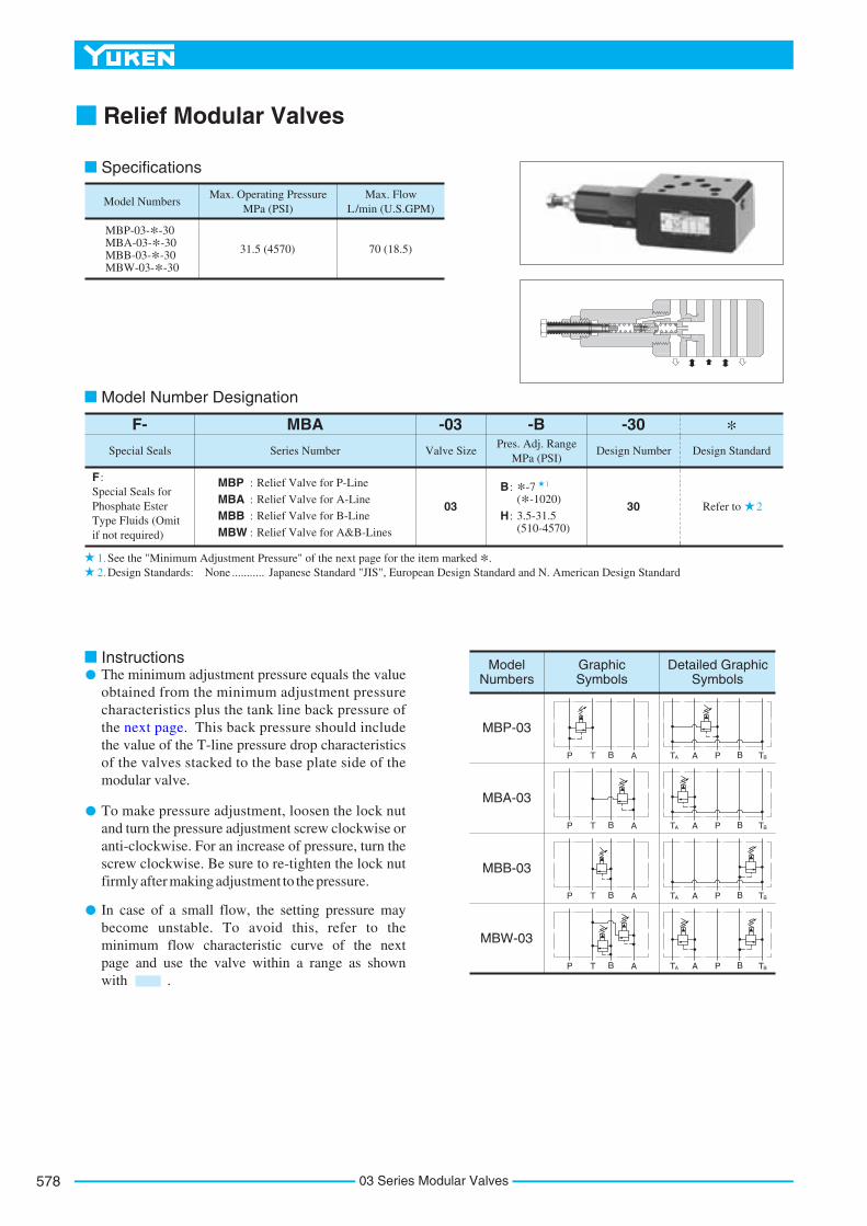
Relief Modular Valves
The minimum adjustment pressure equals the value obtained from the minimum adjustment pressure characteristics plus the tank line back pressure of the next page. This back pressure should include the value of the T-line pressure drop characteristics of the valves stacked to the base plate side of the modular valve.
To make pressure adjustment, loosen the lock nut and turn the pressure adjustment screw clockwise or anti-clockwise. For an increase of pressure, turn the screw clockwise. Be sure to re-tighten the lock nut firmly after making adjustment to the pressure.
2
1
1.2.
P T B A PT BAA TB
P T B A PT BAA TB
P T B A PT BAA TB
P T B A PT BAA TB
Model Numbers
MBP-03-*-30MBA-03-*-30MBB-03-*-30MBW-03-*-30
Max. Operating Pressure MPa (PSI)
Max. Flow L/min (U.S.GPM)
31.5 (4570) 70 (18.5)
Special Seals for Phosphate Ester Type Fluids (Omit if not required)
F : MBP : Relief Valve for P-Line
MBA : Relief Valve for A-Line
-30
Design Number Design Standard
Refer to30
F- MBA -03 -BPres. Adj. Range
MPa (PSI)Valve Size
03
Special Seals Series Number
MBB : Relief Valve for B-Line
B :
H : 3.5-31.5 (510-4570)MBW : Relief Valve for A&B-Lines
Model Numbers
Graphic Symbols
Detailed Graphic Symbols
MBP-03
MBA-03
MBB-03
MBW-03
Specifications
Model Number Designation
See the "Minimum Adjustment Pressure" of the next page for the item marked *.Design Standards: None Japanese Standard "JIS", European Design Standard and N. American Design Standard...........
Instructions
*
In case of a small flow, the setting pressure may become unstable. To avoid this, refer to the minimum flow characteristic curve of the next page and use the valve within a range as shown with .

579
MODULAR VALVES
03S
erie
sM
od
ula
rV
alve
s
F
03 Series Modular Valves
Typical Performance Characteristics
Hydraulic Fluid: Viscosity 35 mm2/s (164 SSU), Specific Gravity 0.850
T-Line: MBP/MBA/ MBW-03
Nominal Override Characteristics
31MPa
Pre
ssur
e
PSI4500
3029
25.024.524.021.020.520.014.013.513.07.06.56.03.53.02.51.00.70.4
440043004200360035503500
3000295029002000195019001000
950900500450400140100
60
L/min
U.S.GPMFlow Rate
0
0 10 20 30 40 50 60 70
5.0 10.0 15.0 17.5
Min. Adjustment Pressure
L/min
U.S.GPM
Flow Rate
0
0
5.0 10.0 15.0 17.5
10 20 30 40 50 60 70
1.2
Min
. Adj
iust
men
t Pre
ssur
e
MPaPSI16012080400
0.8
0.40
Min. Flow vs. Adjustment Pressure
Min
. Flo
w
MPa
PSI
0
0 1000 2000 3000
Pressure
5 10 15 20 25
3500
L/minU.S.GPM61.5
4
2
0
1.0
.5
0
Pressure DropMPaPSI0.5
Pre
ssur
e D
rop
P
70
60
50
40
30
20
10
0
0.4
0.3
0.2
0.1
0
L/min
U.S.GPMFlow Rate
0
0 10 20 30 40 50 60 70
5.0 10.0 15.0 17.5
A-Line: MBP-03
B-Line: MBP-03T-Line: MBB-03 P-Line: MBP-03 P,A&B-Line: MBA/MBB/
MBW-03
03 Series Modular Valves580
Lock Nut14(.55) Hex.
Item
SO-NB-A014
SO-NA-P6
SO-NB-P16
SO-NB-P26
Name of Parts
Part Numbers
Quantity
15
16
17
18
O-Ring
O-Ring
O-Ring
O-Ring
5
1
1
1
Valve Model Numbers Seal kit Numbers
MBP-03
MBA-03
MBB-03
MBW-03
KS-MBP-03-30
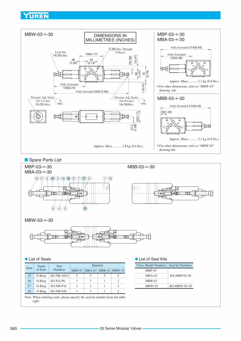
Note: When ordering seals, please specify the seal kit number from the tableright.
MBP-03 MBA-03 MBB-03 MBW-03
5
1
1
1
5
1
1
1
5
2
2
2
KS-MBW-03-30
P
BA
TA TB
P
BA
TA TB
P
BA
TA TB
25(.
98)
320(12.60)Fully Extended
54(2.13)
106(4.17)
27.5
(1.0
8)55
(2.1
7)
Pressure Adj. Screw(for B-Line)14(.55) Hex. INC.
Pressure Adj. Screw(for A-Line)14(.55) Hex.
7(.28) Dia. Through4 Places
INC.
3.8 kg (8.4 lbs.)Approx. Mass............
Fully Extended133(5.24)
46(1
.81)
12(.
47)
70(2
.76)
1.8(
.07)
26(1.02)
214(8.43)Fully Extended
Fully Extended134(5.28)
3.1 kg (6.8 lbs.)Approx. Mass............
For other dimensions, refer to "MBW-03" drawing left.
214(8.43)Fully Extended
26(1.02)
3.1 kg (6.8 lbs.)Approx. Mass............
For other dimensions, refer to "MBW-03" drawing left.
1 1391778181931621112
15546
MBW-03-*-30
Spare Parts List
List of Seals List of Seal Kits
MBP-03-*-30 MBA-03-*-30
MBP-03-*-30MBA-03-*-30
MBB-03-*-30
MBB-03-*-30
MBW-03-*-30
DIMENSIONS IN MILLIMETRES (INCHES)

581
MODULAR VALVES
03S
erie
sM
od
ula
rV
alve
s
F
03 Series Modular Valves
Reducing Modular Valves
The minimum adjustment pressure equals the lower limit of either pressure adjustment range (B, H) plus the tank line back pressure of the next page. This back pressure should include the value of the T-line pressure drop characteristics of the values stacked to the base plate side of the modular valve.
To make pressure adjustment, loosen the lock nut and turn the pressure adjustment screw clockwise or anti-clockwise. For an increase of pressure, turn the screw clockwise. Be sure to re-tighten the lock nut firmly after making adjustment to the pressure.
Special Seals for Phosphate Ester Type Fluids (Omit if not required)
F:MRP : Reducing Valve for P-Line
MRA: Reducing Valve for A-Line
-30Design Number Design Standard
Refer to30
F- MRP -03 -BPres. Adj. Range
MPa (PSI)Valve Size
03
Special Seals Series Number
MRB: Reducing Valve for B-LineH: 3.5-24.5 (510-3550)
Model Number Designation
B: 1-7 (145-1020)
P T B A PT BAA TB
P T B A
P T B A PT BAA TB
PT BAA TB
Model Numbers
MRP-03-*-30/3090MRA-03-*-30/3090MRB-03-*-30/3090
Max. Operating Pressure MPa(PSI)
Max. Flow L/min (U.S.GPM)
25 (3630) 70 (18.5)
Model Numbers
Graphic Symbols
Detailed Graphic Symbols
MRP-03
MRA-03
MRB-03
Specifications
Design Standards: None 90
Japanese Standard "JIS" and European Design Standard N. American Design Standard
........... ...............
Instructions
*
In pressure adjustment range "H", if the pressure in the primary side is set above 20 MPa (2900 PSI) and the pressure in the secondary side is set below 10 MPa (1450 PSI), the maximum flow is limited to 50 L/min (13.2 U.S.GPM).

03 Series Modular Valves582
Typical Performance Characteristics
Hydraulic Fluid: Viscosity 35 mm2/s (164 SSU), Specific Gravity 0.850
Pres. Drop at Spool Fully Open (P-Line)
L/min
U.S.GPM
Flow Rate
0
Pre
ssur
e D
rop
P
MPaPSI
A&B-Line
T-Line
L/min
U.S.GPM
Flow Rate
Pre
ssur
e D
rop
P
MPaPSI
MPaPSI
Pressure Drop
Nominal Override Characteristics
00
010 20 30
0 4 8
0.1
0.2
0.3
10
20
30
40
12 16 18
40 50 60 70
L/min
U.S.GPM
Flow Rate
0 10 20 30
0 4 8 12 16 18
40 50 60 70
Pilot Flow
MPa
PSIDifferential Pressure
0 5 10 15 20 25
0 1000 2000 3000 3500
(Primary pressure - Secondary pressure)
Pil
ot F
low
3 cm /mincu.in./min
80050
600
400
200
0
40
30
20
10
0
Sec
onda
ry P
ress
ure
0
10 20 30 40 50 60 70
0 4 8 12 16 18
0.5
0.4
0.3
0.2
0.1
0
70
60
50
40
30
20
10
0
0.6
0.8
1.02
3
4
5
6
711
12
1317
18
1923
24
25
Primary Pressure 25 MPa (3630 PSI)
: "B": "H"
Pressure Adj. Range
100
140200
400
600
800
1000
1700
1900
2500
2700
3400
3600

583
MODULAR VALVES
03S
erie
sM
od
ula
rV
alve
s
F
03 Series Modular Valves
Lock Nut14(.55) Hex.
Pressure Adj. Screw14(.55) Hex.
INC.
MRP-03-*-30/3090
MRP-03-*-30/3090 MRB-03-*-30/3090
MRB-03-*-30/3090
MRA-03-*-30/3090
MRA-03-*-30/3090Item
SO-NB-A014
SO-NA-P6
SO-NB-P16
SO-NB-P18
SO-NB-P26
Name of Parts Part Numbers Qty.
14
15
16
17
18
O-Ring
O-Ring
O-Ring
O-Ring
O-Ring
5
1
1
1
1
Remarks
Included in Seal Kit Kit No.: KS-MRP-03-30
Model Numbers
MB*-01-*-30
MB*-01-*-3090
Rc 1/4 = 1/4 BSP.Tr
1/4 NPT
Thread Size "C" Thd.P
BA
TA TB
P
BA
TA TB
54(2.13)
92(3.62)
14(.
55)
7(.28) Dia. Through4 Places
Pressure Gauge Connection"C" Thd.
3.3 kg (7.5 lbs.)Approx. Mass............
3.3 kg (7.5 lbs.)Approx. Mass............
19(.75)
Pressure Gauge Connection"C" Thd.
27.5
(1.0
8)
55(2
.17)
12 (.47
)
232.5(9.15)Fully Extended
Fully Extended131(5.16)
46(1
.81)
70(2
.76)
1.8
(.07
)47.5
(1.87)
232.5(9.15)Fully Extended
131791921412161815531011
76 14
Spare Parts List
List of Seals
For other dimensions, refer to "MRP-03" drawing above.
DIMENSIONS IN MILLIMETRES (INCHES)

03 Series Modular Valves584
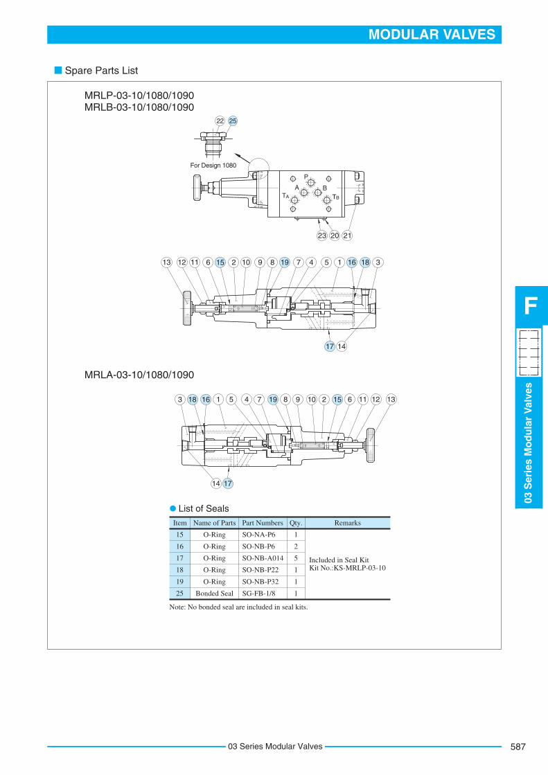
Reducing Modular Valves For Low Pressure Setting
If there is a pressure in drain line, it is added to the secondary setting pressure. Hence, drain line must be connected to tank directly with a low back pressure close to atmospheric pressure.
To make pressure adjustment, loosen the lock nut and turn the pressure adjustment handle clockwise or anti-clockwise. For an increase of pressure, turn the handle clockwise. Be sure to re-tighten the lock nut firmly after making adjustment to the pressure.
PT BAA TBP T B A
V
DR
P T B A
V
DR
P T B A
V
DR
V
DR
PT BAA TB
V
DR
PT BAA TB
V
DR
Model Numbers
MRLP-03-10/1080/1090 MRLA-03-10/1080/1090 MRLB-03-10/1080/1090
7 (1020)
Special Seals for Phosphate Ester Type Fluids (Omit if not required)
F :MRLP : Low Pressure Setting Type
Reducing Valve for P-Line
-10Design Number Design Standard
Refer to10
F- MRLP -03Valve Size
03
Special Seals Series Number
Max. Operating Pressure
MPa (PSI)
0.2-6.5 (29-940)
Pres. Adj. Range
MPa (PSI)
50 (13.2)
Max. FlowL/min
(U.S.GPM)
When pressure setting is less than 0.8 MPa (116 PSI), maximum flow decreases. See "Min. Adjustment Pressure vs. Max. Flow" on the next page for the appropriate range.
MRLA : Low Pressure Setting Type Reducing Valve for A-Line
MRLB : Low Pressure Setting Type Reducing Valve for B-Line
Model Numbers
MRLP-03
MRLA-03
MRLB-03
Graphic Symbols
Detailed Graphic Symbols
Specifications
Model Number Designation
Design Standards: None 80 90
Japanese Standard "JIS" European Design Standard N. American Design Standard
........... ............... ...............
Instructions
*

585
MODULAR VALVES
03S
erie
sM
od
ula
rV
alve
s
F
03 Series Modular Valves
Typical Performance Characteristics
Hydraulic Fluid: Viscosity 35 mm2/s (164 SSU), Specific Gravity 0.850
Pres. Drop at Spool Fully Open (P-Line)
L/min
U.S.GPM
Flow Rate
0
Pre
ssur
e D
rop
P
MPaPSI
0 2.5 5.0 7.5 10.0
010 20 30 40 50
12.5
70
60
50
40
30
20
10
0
0.5
0.4
0.3
0.2
0.1
A&B-Line
T-Line
Pressure Drop
L/min0 10 20 30 40 50
U.S.GPM
Flow Rate
0 2.5 5.0 7.5 10.0 12.5
Pre
ssur
e D
rop
P
MPaPSI
00
0.1
0.2
10
2025
Min. Adjustment Pressure vs. Max. Flow
L/min0 10 20 30 40 50
U.S.GPM
Flow Rate
0 2.5 5.0 7.5 10.0 12.5
00
0.4
0.6
40
140
Min
. Adj
ustm
ent P
res.
MPaPSI
0.2
0.8
1.0120
80

03 Series Modular Valves586
Lock Nut14(.55) Hex.
Pressure Gauge Connection"E" Thd.
7(.28) Dia. Through4 Places
Pressure Gauge Connection"E" Thd.
Model Numbers
MRL*-03-10
MRL*-03-1080
MRL*-03-1090
Rc 1/4
1/4 BSP.F
1/4 NPT
Thread Size
"C" Thd. "D" Thd. "E" Thd.
Rc 1/8
1/8 BSP.F
1/8 NPT
Rc 1/4
1/4 BSP.Tr
1/4 NPT
A
P
B
TA T B
A
P
B
T A T B
259.5(10.22)Fully Extended
54(2.13)
92(3.62)
27.5
(1.0
8)
55
(2.1
7)
4.5 kg (9.9 lbs.)Approx. Mass............
Fully Extended151.5(5.96)
46(1
.81)
70(2
.76)
19(.75)
Pressure Adj. Handle
INC.
1.8
(.07
)
12 (.47
)
53(2.09)
6(.
24)
1080
Des
ign
Onl
y
Vent Port "V""D" Thd.
Vent Port "V""D" Thd.
Drain Port "DR""C" Thd.
45 D
ia.
(1.7
7)
14 (.55
)47
(1.8
5)
4.5 kg (9.9 lbs.)Approx. Mass............
259.5(10.22)Fully Extended
54(2.13)
108(4.25)
MRLP-03-10/1080/1090 MRLB-03-10/1080/1090
MRLA-03-10/1080/1090
For other dimensions, refer to "MRLP-03" drawing above.
DIMENSIONS IN MILLIMETRES (INCHES)
Drain Port "DR""C" Thd.
587
MODULAR VALVES
03S
erie
sM
od
ula
rV
alve
s
F
03 Series Modular Valves
Spare Parts List
Item Name of Parts Part Numbers Qty. Remarks
Included in Seal Kit Kit No.:KS-MRLP-03-10
SO-NA-P6
SO-NB-P6
SO-NB-A014
SO-NB-P22
SO-NB-P32
SG-FB-1/8
15
16
17
18
19
25
O-Ring
O-Ring
O-Ring
O-Ring
O-Ring
Bonded Seal
1
2
5
1
1
1
Note: No bonded seal are included in seal kits.
A
P
BT A T B
22
For Design 1080
25
13 12 11 156 2 10 9 8 19 7
23 20 21
4 5 1 16 18 3
1417
13121115 62109819745116183
14 17
MRLP-03-10/1080/1090 MRLB-03-10/1080/1090
List of Seals
MRLA-03-10/1080/1090

03 Series Modular Valves588
Sequence Modular Valves/Counterbalance Modular Valves
The minimum adjustment pressure equals the value obtained from the minimum adjustment pressure characteristics plus the tank line back pressure of the next page. This back pressure should include the value of the T-line pressure drop characteristics of the valves stacked to the base plate side of the modular valve.
To make pressure adjustment, loosen the lock nut and turn the pressure adjustment screw clockwise or anti-clockwise. For an increase of pressure, turn the screw clockwise. Be sure to re-tighten the lock nut firmly after making adjustment to the pressure.
2
1
1.2.
P T B A PT BAA TB
P T B A PT BAA TB
P T B A PT BAA TB
Model Numbers
MHP-03-*-20
Max. Operating Pressure
25 (3630) 50 (13.2)
MPa (PSI)
MHA-03-*-20 MHB-03-*-20
Max. FlowL/min
(U.S.GPM)
70 (18.5)
Max. Free FlowL/min
(U.S.GPM)
Special Seals for Phosphate Ester Type Fluids (Omit if not required)
F : MHP : Sequence Valve for P-Line
MHA : Counterbalance Valve for A-Line
-20Design Number Design Standard
Refer to20
F- MHA -03 -CPres. Adj. Range
MPa (PSI)
03
Special Seals Series Number
N :A B C
: : :
1.8-3.5 (260-510) *-1.8 (*-260)
3.5-7 (510-1020) 7-14 (1020-2030)
Valve Size
20
MHB : Counterbalance Valve for B-Line
Model Numbers
Graphic Symbols
Detailed Graphic Symbols
MHP-03
MHA-03
MHB-03
MHP-03
MHA/MHB-03
Instructions
Specifications
Model Number Designation
See the "Minimum Adjustment Pressure" of the next page for the item marked *.Design Standards: None Japanese Standard "JIS", European Design Standard and N. American Design Standard...........
*

589
MODULAR VALVES
03S
erie
sM
od
ula
rV
alve
s
F
03 Series Modular Valves
Typical Performance Characteristics
Hydraulic Fluid: Viscosity 35 mm2/s (164 SSU), Specific Gravity 0.850
Min. Adjustment Pressure
MHP/MHA/MHB-03MPa0.8
0.6
0.4
0.2
0
PSI
100
80
60
40
200M
in. A
djus
tmen
t Pre
ssur
e
0 10 20 30 40 50 L/min
0 2.5 5.0 7.5 10.0 12.5 U.S.GPMFlow Rate 0 2.5 5.0 7.5 10.0 12.5 15.0 17.5 U.S.GPM
Flow Rate
10 20 30 40 50 60 700 L/min0
0.1
0.2
0.3
0.4
0
10
20
40
30
50
MPaPSI
Pressure Drop for Free FlowMHA/MHB-03
Pre
ssur
e D
rop
P
Pre
ssur
e D
rop
P
PSI
25
20
10
0
0.1
0
0.2MPa 0.20
0.10
0
MPa
25
20
15
10
5
010 20 30 40 50 60 700
2.50 5.0 10.07.5 12.5 17.515.0
Pre
ssur
e D
rop
P
PSI
Pressure DropMHA/MHB-03
L/min
U.S.GPM
A-Line:MHB-03 B-Line:MHA-03
T-Line:MHA-03P-LineT-Line:MHB-03
Flow Rate
Pressure Drop
MHP-03
100 20 30 40 50
0 2.5 5.0 7.5 10.0 12.5
L/min
U.S.GPMFlow Rate
A,B-Line
T-Line

7(.28) Dia. Through4 Places
MHP-03-*-20
MHP-03-*-20
MHA-03-*-20
MHA-03-*-20
MHA-03-*-20
MHB-03-*-20
Item
SO-NB-A014
SO-NB-P16
SO-NB-P29
SO-NB-P32
Name of Parts Part Numbers Qty.
15
16
17
18
O-Ring
O-Ring
O-Ring
O-Ring
5
1
1
1
Remarks
Included in Seal Kit Kit No.:KS-MHP-03-20
T
AP
BA T B
T A
PB
A T B T A
PB
A T B
13 19 16 18 15 12 14 10 177 6 3 8 2 1 9 5 4
Lock Nut14(.55) Hex.
Pressure Adj. Screw14(.55) Hex.
3.5 kg (7.7 lbs.)Approx. Mass............
242(9.53)Fully Extended
Fully Extended134(5.28)
46(1
.81)
70(2
.76)
1.8
(.07
)
12 (.47
)54(2.13)
92(3.62)
19(.75)
14 (.55
)27
.5(1
.08)
55(2
.17)
3.5 kg (7.7 lbs.)Approx. Mass............ 3.5 kg (7.7 lbs.)Approx. Mass............
228(8.98)Fully Extended
Fully Extended134(5.28)
17 (.67
)
17 (.67
)
228(8.98)Fully Extended
40(1.57)
12 14 16 18 13 17 106 5 3 7 2 9 415 1 8
131916181512141017 763821954
INC.
List of SealsMHP-03, MHA-03
Item
SO-NB-A014
SO-NA-P16
SO-NB-P29
SO-NB-P32
Name of Parts Part Numbers Qty.
15
16
17
18
O-Ring
O-Ring
O-Ring
O-Ring
5
1
1
1
Remarks
Included in Seal Kit Kit No.:KS-MHB-03-20
MHB-03
Spare Parts List
For other dimensions, refer to "MHP-03" drwaing above.
DIMENSIONS IN MILLIMETRES (INCHES)
03 Series Modular Valves590
591
MODULAR VALVES
03S
erie
sM
od
ula
rV
alve
s
F
03 Series Modular Valves
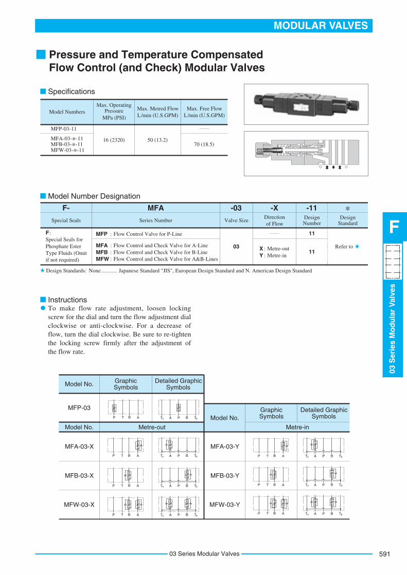
Pressure and Temperature CompensatedFlow Control (and Check) Modular Valves
To make flow rate adjustment, loosen locking screw for the dial and turn the flow adjustment dial clockwise or anti-clockwise. For a decrease of flow, turn the dial clockwise. Be sure to re-tighten the locking screw firmly after the adjustment of the flow rate.
Model Number Designation
P T B A
P T B A PT BAA TB
PT BAA TB
PT BAA TB
PT BAA TBP T B A
P T B A
P T B A PT BAA TB
P T B A PT BAA TB
P T B A PT BAA TB
Model Numbers
MFA-03-*-11MFB-03-*-11MFW-03-*-11
Max. Operating Pressure Max. Metred Flow
L/min (U.S.GPM)
16 (2320) 50 (13.2)
MFP-03-11
MPa (PSI)
Max. Free Flow L/min (U.S.GPM)
70 (18.5)
Special Seals for Phosphate Ester Type Fluids (Omit if not required)
F : MFP : Flow Control Valve for P-Line
F- MFA
Special Seals Series Number
MFA : Flow Control and Check Valve for A-LineMFB : Flow Control and Check Valve for B-LineMFW : Flow Control and Check Valve for A&B-Lines
-11Design Number
Design
Standard
Refer to
11
-03 -XDirection of Flow
Valve Size
03
Y : Metre-inX : Metre-out
11
Model No. Graphic Symbols
MFA-03-X
MFB-03-X
MFW-03-X
Detailed Graphic Symbols
Model No. Metre-out
MFP-03
Model No.Graphic Symbols
MFA-03-Y
MFB-03-Y
MFW-03-Y
Detailed Graphic Symbols
Metre-in
Specifications
Design Standards: None Japanese Standard "JIS", European Design Standard and N. American Design Standard...........
Instructions
*

Typical Performance Characteristics
Hydraulic Fluid: Viscosity 35 mm2/s (164 SSU), Specific Gravity 0.850
Min
. Met
red
Flo
wD
iffe
rent
ial P
ress
ure
Min. Required Pressure Difference
1.2MPaPSI
160
120
80
40
0
0.8
0.4
0
Flow RateU.S.GPM
L/min
13
50
121086420
403020100
MFP-03
MFA B W
-03
Min. Metred Flow
700
3 cm /mincu.in./min
30
600
500
400
200
0100
30020
10
0
40
PSI
MPa
2250
1612840
2000150010005000
Differential Pressure
Metred Flow vs. Dial Position
543210
Turn of Flow Adj. Dial(Fully Open)
5012540
30
20
100
100
75
50
25
0
Flo
w R
ate
Metred Flow vs. Viscosity
504948
20.019.519.00.500.450.40
13.213.012.85.35.25.15.0.13.12.11
L/minU.S.GPM
L/minU.S.GPM
Flo
w R
ate
2 mm /s16012080400
SSU7006004002000Viscosity
5213.8L/minU.S.GPM
50
48
21
20
5.0
19
4.94.8
13.413.012.6
5.50
5.25
5.00
1.321.301.28
Metred Flow vs. Differential Pressure
Flo
w R
ate
Differential PressurePSI20001000
MPa1612840
Pre
ssur
e D
rop
P
Pressure Drop for Free Flow
1.0MPaPSI
140
0.6
0.4
0.2
0
0.8120
80
40
0
U.S.GPM
L/min
17.5
706050403020100
15.010.05.00Flow Rate
Pressure DropP
ress
ure
Dro
p
P
0.4MPaPSI
500.3
0.2
0.1
0
403020
100
U.S.GPM
L/min
17.5
706050403020100
15.010.05.00Flow Rate
T-Line: , P-LineMFB-03A&B-Line: MFP-03
T-Line:MFA B -03
B-Line:MFA-03 A-Line:MFB-03
0
03 Series Modular Valves592

593
MODULAR VALVES
03S
erie
sM
od
ula
rV
alve
s
F
03 Series Modular Valves
Locking Screw2(.08) Hex. Soc.
7(.28) Dia. Through4 Places
7(.28) Dia. Through4 Places
89
12
01
24
53
T A
PB
A T B
T
AP
B
A T B
T
AP
B
A T B T
AP
B
A T B
4.2 kg (9.3 lbs.)Approx. Mass............
INC.
360(14.17)Fully Extended153 (6.02)
Fully Extended
MFW-03-X ------------ 33 (1.30) MFW-03-Y ------------ 22 (.87)
4.1 kg (9.0 lbs.)Approx. Mass............
56(2.20)
Locking Screw2(.08) Hex. Soc.
Flow Adj. Dial
Flow Adj. Dial(for A-Line)
INC.Flow Adj. Dial
(for B-Line)
233(9.17)Fully Extended
Fully Extended160(6.30)
46(1
.81)
70(2
.76)
1.8
(.07
)
12 (.47
)54(2.13)
92(3.62)
19(.75)
15(.
59)
32(1
.26)
Dia
.
33(1
.30)
55(2
.17)
INC.
LOCK
LOCK
1.8
(.07
)
12 (.47
)46
(1.8
1)
70(2
.76)
54(2.13)
92(3.62)
19(.75)
5.2 kg (11.5 lbs.)Approx. Mass............
32(1
.26)
Dia
.
55(2
.17)
21.4
(.84
)
263(10.35)Fully Extended
153 (6.02)Fully Extended
263(10.35)Fully Extended
4.1 kg (9.0 lbs.)Approx. Mass............
MFP-03-11
MFW-03- -11X Y
MFA-03- -11X Y MFB-03- -11X
Y
For other dimensions, refer to "MFW-03" drawing above.
DIMENSIONS IN MILLIMETRES (INCHES)

Note: When ordering seals, please specify the seal kit number from the table right.
List of Seals List of Seal Kits
Item
SO-BB-P6
SO-NA-P6
SO-NB-A014
SO-NB-P28
Name of Parts Part NumbersMFP-03
15
16
17
18
Back Up Ring
O-Ring
O-Ring
O-Ring
1
1
5
1
MFA-03
1
1
5
2
MFB-03
1
1
5
2
MFW-03
2
2
5
2
Quantity
MFP-03
MFA-03
MFB-03
MFW-03
Valve Model Numbers Seal Kit Numbers
KS-MFP-03-10
KS-MFA-03-10
KS-MFW-03-10
21 12 13 15 16 10 4 18 2 3 6 1 2023
8 5 9 197 17
23121315161041823617114
217859
23 12 13 15 16 10 4 18 2 3 6 17 1 14
21 7 8 9 5
23 12 13 15 16 10 4 18 2 3 6 17 1
21 7 8 9 5
Spare Parts List
MFP-03-11
MFA-03- -11X Y
MFW-03- -11X Y
MFB-03- -11X Y
03 Series Modular Valves594

595
MODULAR VALVES
03S
erie
sM
od
ula
rV
alve
s
F
03 Series Modular Valves
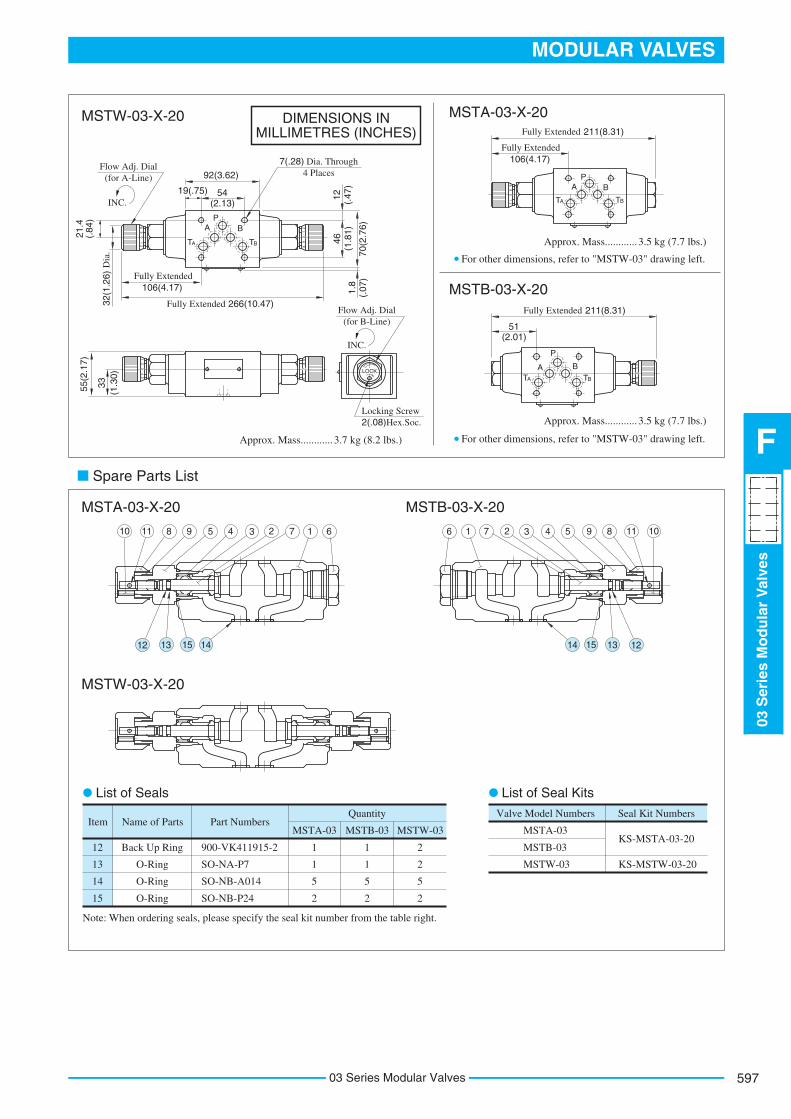
Temperature Compensated Throttle and Check Modular Valves
To make flow rate adjustment, loosen locking screw for the dial and turn the flow adjustment dial clockwise or anti-clockwise. For a decrease of flow, turn the dial clockwise. Be sure to re-tighten the locking screw firmly after the adjustment of the flow rate.
Model Number Designation
P T B A PT BAA TB
P T B A PT BAA TB
P T B A PT BAA TB
Model Numbers
MSTA-03-X-20MSTB-03-X-20MSTW-03-X-20
Max. Operating Pressure
25 (3630)
MPa (PSI)
Max. Differential
Pressure
25 (3630)
MPa (PSI)
Max. Metred Flow
70 (18.5)
L/min (U.S.GPM)
Min. Metred Flow
2 (.53) {1 (.26)}
L/min (U.S.GPM)
Max. Free Flow
70 (18.5)
L/min (U.S.GPM)
Special Seals for Phosphate Ester Type Fluids (Omit if not required)
F
F- MSTA
Special Seals Series Number
MSTA : Temperature Compensated Throttle and Check Valve for A-Line
MSTB : Temperature Compensated Throttle and Check Valve for B-Line
MSTW : Temperature Compensated Throttle and Check Valve for A&B-Lines
-20Design
Standard
Refer to
-03 -X
Direction of FlowValve Size
03 X : Metre-out 20
Design Number
Design Standards: None Japanese Standard "JIS", European Design Standard and N. American Design Standard...........
The figures in parentheses are the values when the differential pressure is less than 3.5 MPa (510 PSI).
:
Model No.
MSTA-03-X
Graphic Symbols
MSTB-03-X
MSTW-03-X
Detailed Graphic Symbols
Metre-out
Specifications
Instructions
*

Typical Performance Characteristics
Hydraulic Fluid: Viscosity 35 mm2/s (164 SSU), Specific Gravity 0.850
P: 25(3630)
U.S.GPMFlow Rate
L/min
0.20
MPaPSIPressure Drop
Pre
ssur
e D
rop
P
30
17.5
B-Line:MSTA-03 A-Line:MSTB-03
0.15
0.10
0.05
0
25
20
15
10
5
0
15.010.05.00
706050403020100
P-Line
T-Line
Throttle Fully Open
Throttle Closed
U.S.GPM
L/min
17.5
70604030 5020100
15.010.05.00Flow Rate
Pressure Drop for Free Flow
0.5MPa
0.4
0.3
0.2
0.1
0
PSI70
60
50
40
30
20
10
0
Pre
ssur
e D
rop
P
Pressure Drop at Throttle Fully Open
1.2MPaPSI
160
Pre
ssur
e D
rop
P 140
120
100
80
60
40
20
0
1.0
0.8
0.6
0.4
0.2
0
U.S.GPM
L/min
17.5
70
Flow Rate15.010.05.00
6050403020100
U.S.GPM
17.5
15.0
12.5
10.0
7.5
5.0
2.5
0
Flo
w R
ate
L/min70
60
50
40
30
20
10
0
0 1 2 3 4 5 6 7 8 9 10Turn of Flow Adj. Dial
P: 0.5(70)
P: 1(145)
P: 2(290)
P: 5(730)
P: 7(1020)
P: 14(2030)
Metred Flow vs. Dial Position
P: Differential Pressure MPa(PSI)
0 40 80 120 160
0 200 400 600 700SSU
2 mm /s
Viscosity
0.91.01.1
1.92.02.1
192021
495051
697071
.24
.26
.28
.52
.56
.50
.54
5.2
5.6
5.0
5.4
13.013.213.4
18.4
18.8
18.2
18.6
Flo
w R
ate
U.S.GPM L/min
Metred Flow vs. Viscosity
(Fully Open)
03 Series Modular Valves596
597
MODULAR VALVES
03S
erie
sM
od
ula
rV
alve
s
F
03 Series Modular Valves
7(.28) Dia. Through4 Places
List of Seals List of Seal Kits
MSTA-03
MSTB-03
MSTW-03
Valve Model Numbers Seal Kit Numbers
KS-MSTA-03-20
KS-MSTW-03-20
Item
900-VK411915-2
SO-NA-P7
SO-NB-A014
SO-NB-P24
Name of Parts Part Numbers
12
13
14
15
Back Up Ring
O-Ring
O-Ring
O-Ring
1
1
5
2
MSTA-03
Quantity
1
1
5
2
MSTB-03
2
2
5
2
MSTW-03
Note: When ordering seals, please specify the seal kit number from the table right.
PA B
LOCK
12
45
38
91
20
89
12
05
68
97
T A T B
PA B
89
12
0
T A T B
89
12
0
P
A BT A T B
Flow Adj. Dial(for A-Line)
INC.
Flow Adj. Dial(for B-Line)
INC.
266(10.47)Fully Extended
Fully Extended106(4.17)
46(1
.81)
70(2
.76)
1.8
(.07
)
12 (.47
)
54(2.13)
92(3.62)
19(.75)
32(1
.26)
Dia
.
21.4
(.84
)
Locking Screw2(.08) Hex. Soc.
55(2
.17)
33(1
.30)
211(8.31)Fully Extended
Fully Extended106(4.17)
211(8.31)Fully Extended
51(2.01)
12 13 15 14
10 11 8 9 5 4 3 2 7 1 6
12131514
1011895432716
3.7 kg (8.2 lbs.)Approx. Mass............
MSTW-03-X-20 MSTA-03-X-20
3.5 kg (7.7 lbs.)Approx. Mass............
For other dimensions, refer to "MSTW-03" drawing left.
MSTB-03-X-20
3.5 kg (7.7 lbs.)Approx. Mass............
For other dimensions, refer to "MSTW-03" drawing left.
MSTA-03-X-20
Spare Parts List
MSTW-03-X-20
MSTB-03-X-20
DIMENSIONS IN MILLIMETRES (INCHES)
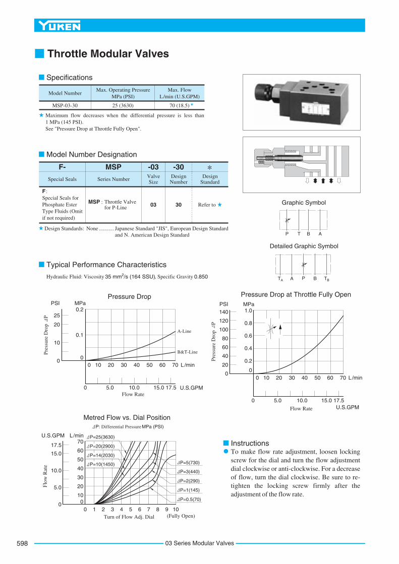
Throttle Modular Valves
To make flow rate adjustment, loosen locking screw for the dial and turn the flow adjustment dial clockwise or anti-clockwise. For a decrease of flow, turn the dial clockwise. Be sure to re-tighten the locking screw firmly after the adjustment of the flow rate.
Pressure Drop at Throttle Fully OpenPressure Drop
A-Line
B&T-Line
L/min
U.S.GPMFlow Rate
0
0 5.0 10.0 15.0 17.5
10 20 30 40 50 60 70
Pre
ssur
e D
rop
P
MPaPSI
250.2
0.1
0
20
10
0
L/min
U.S.GPMFlow Rate
0
0 5.0 10.0 15.0 17.5
10 20 30 40 50 60 70
Pre
ssur
e D
rop
P
MPaPSI1.0
0.8
0.6
0.4
0.2
0
140
120
100
80
60
40
20
0
Metred Flow vs. Dial PositionP: Differential Pressure MPa (PSI)
Flo
w R
ate
U.S.GPM L/min
Turn of Flow Adj. Dial0 1 2 3 4 5 6 7 8 9 10
70
60
50
40
30
20
100
17.5
15.0
10.0
5.0
0
P=25(3630)
P=5(730)
P=20(2900)
P=14(2030)
P=10(1450)
P=3(440)
P=2(290)
P=1(145)
P=0.5(70)
(Fully Open)
Specifications
Model Number
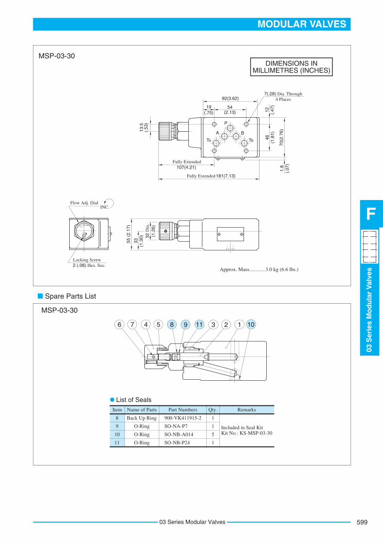
MSP-03-30
Max. Operating Pressure MPa (PSI)
Max. Flow L/min (U.S.GPM)
25 (3630) 70 (18.5)
Maximum flow decreases when the differential pressure is less than 1 MPa (145 PSI). See "Pressure Drop at Throttle Fully Open".
Special Seals for Phosphate Ester Type Fluids (Omit if not required)
F :
MSP : Throttle Valve for P-Line
-30Design Number
Design Standard
Refer to30
F- MSP -03Valve Size
03
Special Seals Series Number
Design Standards: None Japanese Standard "JIS", European Design Standardand N. American Design Standard
...........
Graphic Symbol
P BTBA
AT
P T B A
Detailed Graphic Symbol
Model Number Designation
Typical Performance Characteristics
Hydraulic Fluid: Viscosity 2 35 mm /s (164 SSU), Specific Gravity 0.850
Instructions
*
03 Series Modular Valves598
599
MODULAR VALVES
03S
erie
sM
od
ula
rV
alve
s
F
03 Series Modular Valves
7(.28) Dia. Through4 Places
Item
900-VK411915-2
SO-NA-P7
SO-NB-A014
SO-NB-P24
Name of Parts Part Numbers Qty.
8
9
10
11
Back Up Ring
O-Ring
O-Ring
O-Ring
1
1
5
1
Remarks
Included in Seal Kit Kit No.: KS-MSP-03-30
T
A
P
B
A T B
21
98
0
55 (
2.17
)
3.0 kg (6.6 lbs.)Approx. Mass............
Flow Adj. DialINC.
Locking Screw2 (.08) Hex. Soc.
181(7.13)Fully Extended
Fully Extended107(4.21)
46(1
.81)
70(2
.76)
1.8
(.07
)
12 (.47
)54(2.13)
92(3.62)
13.5
(.53
)
19(.75)
32 D
ia.
(1.2
6)
33(1
.30)
1 102311985476
MSP-03-30
Spare Parts List
MSP-03-30
List of Seals
DIMENSIONS IN MILLIMETRES (INCHES)

Check and Throttle Modular Valves
To make flow rate adjustment, loosen locking screw for the dial and turn the flow adjustment dial clockwise or anti-clockwise. For a decrease of flow, turn the dial clockwise. Be sure to re-tighten the locking screw firmly after the adjustment of the flow rate.
Instructions
Pressure Drop
Pre
ssur
e D
rop
P
MPaPSI0.2
25
0.1
0
20
10
0L/min
U.S.GPMFlow Rate
0
0 5.0 10.0 15.0 17.5
10 20 30 40 50 60 70
A-Line
B-Line
T-Line
Pressure Drop at Throttle Fully Open
Pre
ssur
e D
rop
P
MPaPSI0.8
0.6
0.4
0.2
0
100
80
60
40
20
0L/min
U.S.GPMFlow Rate
0
0 5.0 10.0 15.0 17.5
10 20 30 40 50 60 70
Flo
w R
ate
U.S.GPM L/min
Dial Position
Metred Flow vs. Dial PositionP: Differential Pressure MPa (PSI)
(Fully Open)0 1 2 3 4 5 6 7 8 9 10 11
17.5
15.0
10.0
5.0
00
70
60
50
40
30
20
10
P=25(3630) P=20(2900) P=14(2030)
P=10(1450)
P=5(730)
P=3(440)
P=2(290)
P=1(145)
P=0.5(70)
Specifications
Model Number
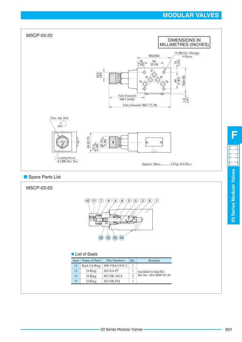
MSCP-03-20
Max. Operating Pressure MPa (PSI)
Max. Flow L/min (U.S.GPM)
25 (3630) 70 (18.5)
Maximum flow decreases when the differential pressure is less than 1 MPa (145 PSI). See "Pressure Drop at Throttle Fully Open".
Special Seals for Phosphate Ester Type Fluids (Omit if not required)
F :
MSCP :Check and Throttle Valve for P-Line
-20Design Number
Design
Standard
Refer to20
F- MSCP -03Valve Size
03
Special Seals Series Number
Design Standards: None Japanese Standard "JIS", European Design Standardand N. American Design Standard
...........
Graphic Symbol
P T B A
BTBA
AT P
Detailed Graphic Symbol
Model Number Designation
Typical Performance CharacteristicsHydraulic Fluid: Viscosity 2 35 mm /s (164 SSU), Specific Gravity 0.850
*
03 Series Modular Valves600
601
MODULAR VALVES
03S
erie
sM
od
ula
rV
alve
s
F
03 Series Modular Valves
7(.28) Dia. Through4 Places
Flow Adj. Dial
Locking Screw2 (.08) Hex. Soc.
Item
900-VK411915-2
SO-NA-P7
SO-NB-A014
SO-NB-P24
Name of Parts Part Numbers Qty.
12
13
14
15
Back Up Ring
O-Ring
O-Ring
O-Ring
1
1
5
1
Remarks
Included in Seal Kit Kit No.: KS-MSP-03-30
21
98
0
T
A
P
B
A T B
LOCK
54
21
3
182.7 (7.19)Fully Extended
109.7 (4.32)Fully Extended
3.0 kg (6.6 lbs.)Approx. Mass............
46(1
.81)
70(2
.76)
1.8
(.07
)
12 (.47
)54(2.13)
92(3.62)
16.5
(.65
)
19(.75)
55 (
2.17
)
INC.
32 D
ia.
(1.2
6)
27.5
(1.0
8)
11 710 8 4 9 3 5 2 6 1
12 13 15 14
MSCP-03-20
Spare Parts List
MSCP-03-20
List of Seals
DIMENSIONS IN MILLIMETRES (INCHES)
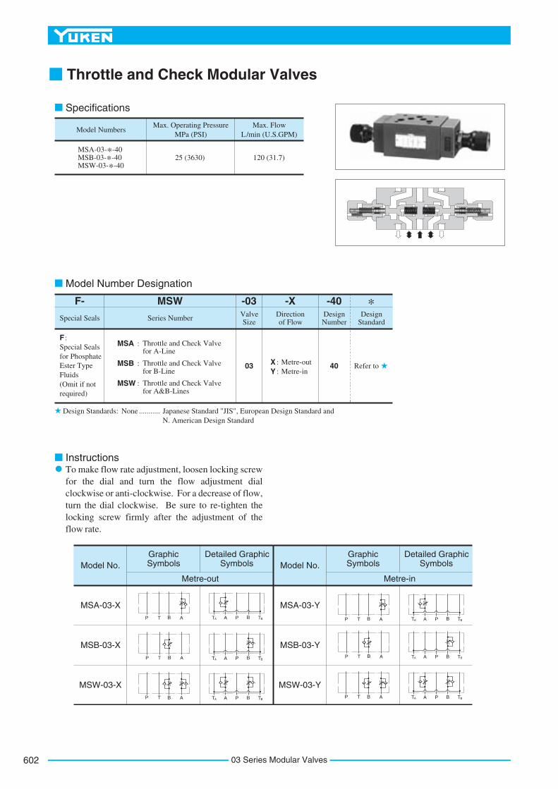
Throttle and Check Modular Valves
To make flow rate adjustment, loosen locking screw for the dial and turn the flow adjustment dial clockwise or anti-clockwise. For a decrease of flow, turn the dial clockwise. Be sure to re-tighten the locking screw firmly after the adjustment of the flow rate.
Model Number Designation
P T B A
P T B A
P T B A
PT BAA TB
PT BAA TB
PT BAA TB
P T B A
P T B A
P T B A
PT BAA TB
PT BAA TB
PT BAA TB
Model Numbers
MSA-03-*-40MSB-03-*-40MSW-03-*-40
Max. Operating Pressure MPa (PSI)
Max. Flow L/min (U.S.GPM)
25 (3630) 120 (31.7)
-40Design Number
Design Standard
Refer to40
-XDirection of Flow
Y : Metre-inX : Metre-out
MSA : Throttle and Check Valve for A-Line
MSW -03Valve Size
03
Series Number
Special Seals for Phosphate Ester Type Fluids (Omit if not required)
F :
F-
Special Seals
MSB : Throttle and Check Valve for B-Line
MSW : Throttle and Check Valve for A&B-Lines
Graphic Symbols
Metre-out
Detailed Graphic SymbolsModel No.
MSA-03-X
MSB-03-X
MSW-03-X
Graphic Symbols
Metre-in
Detailed Graphic SymbolsModel No.
MSA-03-Y
MSB-03-Y
MSW-03-Y
Specifications
Design Standards: None Japanese Standard "JIS", European Design Standard andN. American Design Standard
...........
Instructions
*
03 Series Modular Valves602

603
MODULAR VALVES
03S
erie
sM
od
ula
rV
alve
s
F
03 Series Modular Valves
Typical Performance Characteristics
Hydraulic Fluid: Viscosity 35 mm2/s (164 SSU), Specific Gravity 0.850
Pressure Drop
Pre
ssur
e D
rop
P
Flow Rate
T-Line
A-Line: MSB-03 B-Line: MSA-03
P-Line
Pre
ssur
e D
rop
P
Pressure Drop at Throttle Fully Open
Flow Rate
Metred Flow vs Dial Position
P:7(1020) P:14(2030)
P:25 (3630)
P:30 (4350)
P:5(730) P:2(290)
P:1(145) P:0.5(70)
P: Differential Pressure MPa (PSI)
Flo
w R
ate
Pressure Drop for Free Flow
Throttle Closed
Throttle Fully Open
Pre
ssur
e D
rop
P
Flow Rate
Turn of Flow Adj Dial Fully Open
U.S.GPM30
120 L/min100806040200
20100
1.0MPaPSI
140
0.8
0.6
0.4
0.2
0
120
80
40
0
U.S.GPM30
120 L/min100806040200
20100
1.2MPaPSI
1601.0
0.8
0.6
0.4
0
0.2
120
80
40
0
109876543210
120MPaPSI
30
100
80
60
40
20
0
25
20
15
10
5
0
U.S.GPM30
120 L/min100806040200
20100
1.2MPaPSI
1601.0
0.8
0.6
0.4
0.2
0
120
80
40
0

7(.28) Dia. Through4 Places
Locking Screw2 (.08) Hex. Soc.
Note: When ordering seals, please specify the seal kit number from the table right.
Item
SO-BB-P8
SO-NA-P8
SO-NB-A014
SO-NB-P18
Name of Parts Part NumbersMSA-03
9
10
11
12
Back Up Ring
O-Ring
O-Ring
O-Ring
1
1
5
2
Quantity
MSA-03
MSB-03
MSW-03
Valve Model Numbers Seal Kit Numbers
KS-MSA-03-40
KS-MSW-03-40
MSB-03
1
1
5
2
MSW-03
2
2
5
2
PA B
LOCK
T A T B
PA B
T A T B
PBA
T A T B
9 10 11
13 14 4 6 125 8 2 3 1 7
Flow Adj. Dial(for A-Line)
INC.
Flow Adj. Dial(for B-Line)
INC.
91.5 (3.60)Fully Extended
237 (9.33)Fully Extended
54(2.13)
92(3.62)
19(.75) 12 (.
47)
46(1
.81)
70(2
.76)
1.8
(.07
)
32(1
.26)
Dia
21.4
(.84
)
24 (.94
)
55(2
.17)
193.5 (7.62)Fully Extended
48(1.89)
193.5 (7.62)Fully Extended
91.5 (3.60)Fully Extended
Spare Parts List
MSW-03- -40X Y
MSB-03- -40X Y
List of Seals List of Seal Kits
MSA-03- -40X Y
MSA-03- -40X Y MSB-03- -40X
Y
MSW-03- -40X Y
3.7 kg (8.2 lbs.)Approx. Mass............
3.5 kg (7.7 lbs.)Approx. Mass............
3.5 kg (7.7 lbs.)Approx. Mass............
For other dimensions, refer to "MSW-03" drawing left.
For other dimensions, refer to "MSW-03" drawing left.
DIMENSIONS IN MILLIMETRES (INCHES)
03 Series Modular Valves604

605
MODULAR VALVES
03S
erie
sM
od
ula
rV
alve
s
F
03 Series Modular Valves
Check Modular Valves
Check valve function of MCT-03 is included in TA-Line. Therefore, the tank line for a circuit that uses this valve must be TA-line.
Pressure Drop for Free Flow
0.6MPaPSI
Pre
ssur
e D
rop
P
8580
70
60
40
50
30
10
20
0
0.5
0.4
0.3
0.2
0.1
0
U.S.GPMFlow Rate
70 L/min
17.5
6050403020100
15.010.05.00
-03-2
MCP MCT -03-2
MCP MCT
MCAMCB
-03-0MCAMCB
-03-0
Pressure Drop
0.2MPaPSI
Pre
ssur
e D
rop
P
25
0.1
0
20
10
0
U.S.GPMFlow Rate
70 L/min
17.5
6050403020100
15.010.05.00
A&B-Line: MCP-03
A-Line: MCB/MCT-03 B-Line: MCA-03
T-Line: MCA/MCB-03P-Line: MCA/MCB/MCT-03 B-Line: MCT-03 T-Line: MCP-03
P T B A PAAT B BT
P T B A PAAT B BT
P T B A PAAT B BT
P T B A PAAT B BT
Model Numbers
MCP-03-*-10MCA-03-*-20MCB-03-*-20MCT-03-*-10
Max. Operating Pressure MPa (PSI)
Max. Flow L/min (U.S.GPM)
25 (3630) 70 (18.5)
Design Standards: None Japanese Standard "JIS", European Design Standard and N. American Design Standard...........
-10Design Number Design Standard
F- MCP -03Valve SizeSpecial Seals Series Number
-0
Special Seals for Phosphate Ester Type Fluids (Omit if not required)
F :MCP : Check Valve for P-Line
Refer to20030 : 0.035(5)
Cracking Pressure MPa(PSI)
2 : 0.2(29)
Model Number Designation
MCA : Check Valve for A-LineMCB : Check Valve for B-Line
MCT : Check Valve for T-Line
10
10
MCP-03
Model No.Graphic Symbols
Detailed Graphic Symbols
MCA-03
MCB-03
MCT-03
Specifications
Instructions
Typical Performance Characteristics
Tank Line Used
Hydraulic Fluid: Viscosity 2 35 mm /s (164 SSU), Specific Gravity 0.850
*

1.8
(.07
)
7(.28) Dia. Through4 Places 7(.28) Dia. Through
4 Places
7(.28) Dia. Through4 Places
Item
SO-NB-A014
SO-NB-P24
Name of Parts Part Numbers Qty.
6
7
O-Ring
O-Ring
5
2
Remarks
Included in Seal Kit Kit No.: KS-MCA-03-20
Item
SO-NB-A014
SO-NB-P21
Name of Parts Part Numbers Qty.
7
8
O-Ring
O-Ring
5
1
Remarks
Included in Seal Kit Kit No.: KS-MCP-03-10
Item
SO-NB-A014
SO-NB-P21
Name of Parts Part Numbers Qty.
8
9
O-Ring
O-Ring
5
1
Remarks
Included in Seal Kit Kit No.: KS-MCP-03-10
6 9 2 7 4 3 8 1 5 2 8 4 6 3 1 7
P
BAP
BAT A T BT A T B
P
BAT A T B
2 7 5 3 1 4 6
54(2.13)
92(3.62)
19(.75) 12 (.
47)
46(1
.81)
70(2
.76)
1.8
(.07
)23(.91)
100(3.94)
60(2.36)
55(2
.17)
55(2
.17)
55(2
.17)
54(2.13)
92(3.62)
19 (.75)
12 (.47
)46
(1.8
1)70
(2.7
6)
174(6.85)
44(1.73)
117(4.61)
46(1
.81)
70(2
.76)
1.8
(.07
)
12 (.47
)54(2.13)
92(3.62)
19 (.75)
(Check valve is included)
MCP-03-*-10 MCA-03-*-20MCB-03-*-20
MCT-03-*-10
MCP-03-*-10 MCT-03-*-10
MCA-03-*-20 MCB-03-*-20
Spare Parts List
List of Seals
List of SealsList of Seals
3.5 kg (7.7 lbs.)Approx. Mass............2.5 kg (5.5 lbs.)Approx. Mass............ 2.8 kg (6.2 lbs.)Approx. Mass............
DIMENSIONS IN MILLIMETRES (INCHES)
03 Series Modular Valves606

607
MODULAR VALVES
03S
erie
sM
od
ula
rV
alve
s
F
03 Series Modular Valves
Check Modular Valves For "P&T" Lines
Check valve function of Tank Line is included in TA-Line. Therefore, the tank line for a circuit that uses this valve must be TA-line.
InstructionsTank Line Used
Pressure Drop for Free Flow
0.6MPaPSI
Pre
ssur
e D
rop
P
8580
70
60
40
50
30
10
20
0
0.5
0.4
0.3
0.2
0.1
0
U.S.GPMFlow Rate
70 L/min
17.5
6050403020100
15.010.05.00
Pressure Drop
0.2MPaPSI
Pre
ssur
e D
rop
P
25
0.1
0
20
10
0
U.S.GPMFlow Rate
70 L/min
17.5
6050403020100
15.010.05.00
A,B-Line
MCPT-03-P*-T2
MCPT-03-P2-T*
MCPT-03-P*-T0
MCPT-03-P0-T*
Model NumbersMax. Operating Pressure
MPa (PSI)Max. Flow
L/min (U.S.GPM)
25 (3630) 70 (18.5)
Design Standards: None Japanese Standard "JIS", European Design Standard and N. American Design Standard...........
-10Design Number
Design Standard
F- MCPT -03Valve SizeSpecial Seals Series Number
-P0
Special Seals for Phosphate Ester Type Fluids (Omit if not required)
F :MCPT : Check Valve
for P&T-LinesRefer to03
P0 : 0.035(5)
Cracking Pres. of P-Line MPa(PSI)
P2 : 0.2(29)
Model Number Designation
10
-T0Cracking Pres. of T-Line MPa(PSI)
T0 : 0.035(5)
T2 : 0.2(29)
MCPT-03-P*-T*-10
P T B A
Graphic Symbol
AT A P B
BT
Detailed Graphic Symbol
Specifications
Typical Performance CharacteristicsHydraulic Fluid: Viscosity 2 35 mm /s (164 SSU), Specific Gravity 0.850
*

7(.28) Dia. Through4 Places
Item
SO-NB-A014
SO-NB-P21
Name of Parts Part Numbers Qty.
9
10
O-Ring
O-Ring
5
2
Remarks
Included in Seal Kit Kit No.: KS-MCPT-03-10
Y
Y
8 10 3 6 7 4 91 8 10 3 5 7 4
P
BAT A T B
54(2.13)
92(3.62)
19 (.75)
12 (.47
)46
(1.8
1)
70(2
.76)
1.8
(.07
)60(2.36)
133(5.24)
55(2
.17)
(Check valve is included)
MCPT-03-P*-T*-10
Spare Parts List
List of Seals
MCPT-03-P*-T*-10
Y-Y Section
2.7 kg (6.0 lbs.)Approx. Mass............
DIMENSIONS IN MILLIMETRES (INCHES)
03 Series Modular Valves608

609
MODULAR VALVES
03S
erie
sM
od
ula
rV
alve
s
F
03 Series Modular Valves
Anti-Cavitation Modular Valves
Model Number
MAC-03-10
Max. Operating Pressure MPa (PSI)
Max. Flow L/min (U.S.GPM)
25 (3630) 70 (18.5)
Design Standards: None Japanese Standard "JIS", European Design Standardand N. American Design Standard
...........
-10
Design Number
Design Standard
F- MAC -03
Valve SizeSpecial Seals Series Number
Special Seals for Phosphate Ester Type Fluids (Omit if not required)
F:
MAC: Anti-CavitationValve
Refer to1003
Item
SO-NB-A014
SO-NB-P21
Name of Parts Part Numbers Qty.
10
11
O-Ring
O-Ring
5
2
Remarks
Included in Seal Kit Kit No.: KS-MAC-03-10
P T B A
AT A P B
BT
Pre
ssur
e D
rop
P
MPaPSI0.1
10
050
A&B-Line
L/min
U.S.GPM
0
Flow Rate
10 20 30
17.5
P&T-Line
0 5.0 10.0 15.0
40 50 60 70
Graphic Symbol
P
BAT
Detailed Graphic Symbol
A TB
7(.28) Dia Through4 Places
46(1
.81)
70(2
.76)
19(.75) 54(2.13)
92(3.62)
48(1.89)
55(2
.17)
1.8
(.07
)
9 11 2 5 4 6 1 3 10
3.8 kg (8.4 lbs.)Approx. Mass.........
12 (.47
)
150(5.91)
Specifications
Model Number Designation
Pressure DropHydraulic Fluid: Viscosity 2 35 mm /s (164 SSU), Specific Gravity 0.850
List of Seals
MAC-03-10MAC-03-10
Spare Parts List
DIMENSIONS IN MILLIMETRES (INCHES)
*

Pilot Operated Check Modular Valves
P T B A
P T B A
P T B A
AAT P B BT
A AT P B
BT
A AT P B
BT
Model Numbers
MP*-03-*-20Standard
MP*-03-*-2001Low Pilot Pressure
Control Type
Max. OperatingPressure
MPa (PSI)
Max. Flow
L/min (U.S.GPM)
25 (3630) 70 (18.5)
Design Standards: None Japanese Standard "JIS", European Design Standard andN. American Design Standard
...........
-20
Design Number
Design Standard
F- MPA -03
Valve SizeSpecial Seals Series Number
-2Cracking Pressure
MPa (PSI)
Special Seals for Phosphate Ester Type Fluids (Omit if not required)
F:MPA : Pilot Operated
Check Valve for A-Line
Refer to032 : 0.2 (29)
4 : 0.4 (58)
MPB : Pilot Operated Check Valve for B-Line
MPW : Pilot Operated Check Valve for A&B-Lines
Model No. Graphic Symbols
MPA-03
MPB-03
MPW-03
Detailed Graphic Symbols
Specifications
Model Number Designation
*
(Standard)20
(Low PilotPressureControlType)
2001
03 Series Modular Valves610

611
MODULAR VALVES
03S
erie
sM
od
ula
rV
alve
s
F
03 Series Modular Valves
Typical Performance Characteristics
Hydraulic Fluid: Viscosity 35 mm2/s (164 SSU), Specific Gravity 0.850
U.S.GPMFlow Rate
700 L/min
0.4MPaPSI
Pressure Drop
Pre
ssur
e D
rop
P
0.3
0.2
0.1
001020304050
10 20 30 40 50 60
0 5.0 10.0 15.0 17.5
T-Line
B-Line:MPA-03 A-Line:MPB-03
P-Line Pre
ssur
e D
rop
P 0.4
MPaPSI
0.3
0.2
0.10
50403020100
70 L/min6050403020100
U.S.GPM17.515.010.05.00Flow Rate
Pressure Drop for Reversed Controlled Flow
Pressure Drop for Free Flow
Pre
ssur
e D
rop
P
0.8MPa
0.7
0.6
0.5
0.4
0.3
0.2
0.10
PSI
110100
80
60
40
20
0
U.S.GPMFlow Rate
17.515.010.05.00
70 L/min6050403020100
MP*-03-4
MP*-03-2
12
10
8
6
4
2Min
. Pil
ot P
ress
ure
(PP
)
MPaPSI
MPa
PSI1000 2000 3000 35000
0 5 10 15 20 25
Supply Pressure (P2)
Min. Pilot Pressure
PP P1
P2 MP *-03
-4-2
0
MP *-03
-2-2
0
MP*-03-4-2001
MP*-03-2-2001
0
40
80
120
140

7(.28) Dia. Through4 Places
7 8 5 4 3 2 1 69
7 11 8 5 10 34
P
BAT A T B
54(2.13)
92(3.62)
19(.75) 12 (.
47)
46(1
.81)
70(2
.76)
1.8
(.07
)60(2.36)
55(2
.17)
174(6.85)
Spare Parts List
MPA-03-*-20/2001MPB-03-*-20/2001MPW-03-*-20/2001
MPA-03-*-20 MPB-03-*-20
Item
SO-NB-P24
SO-NB-A014
Name of Parts Part Numbers Qty.
8
9
O-Ring
O-Ring
2
5
Remarks
Included in Seal Kit Kit No.: KS-MPA-03-20
List of Seals
Low Pilot Pressure Control Type(MPA-03-*-2001)
MPW-03-*-20
3.5 kg (7.7 lbs.)Approx. Mass............
DIMENSIONS IN MILLIMETRES (INCHES)
03 Series Modular Valves612
613
MODULAR VALVES
03S
erie
sM
od
ula
rV
alve
s
F
03 Series Modular Valves
7(.28) Dia. Through11 (.43) Dia. Spotface
4 Places
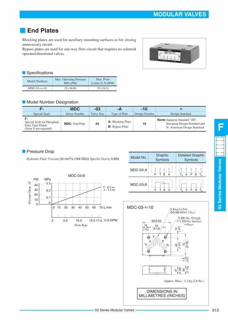
End Plates
Model Numbers
MDC-03-*-10
Max. Operating Pressure MPa (PSI)
Max. Flow L/min (U.S.GPM)
25 (3630) 70 (18.5)
-10Design Number Design Standard
F- MDC -03Valve SizeSpecial Seals Series Number
-A
Special Seals for Phosphate Ester Type Fluids (Omit if not required)
F:
MDC: End Plate 1003A: Blocking Plate
B: Bypass Plate
Type of Plate
None: Japanese Standard "JIS",European Design Standard and
MDC-03-A
MDC-03-B
Model No.Graphic Symbols
Detailed Graphic Symbols
N. American Design Standard
L/min
U.S.GPM
0
Flow Rate
10 20 30 40 50 60 70
Pre
ssur
e D
rop
P
MPaPSI0.3
0.2
0.1
0
40P B-Line A T-Line
0 5.0 10.0 15.0 17.5
30
20
10
0
MDC-03-B P T B A AT A P B
BT
P T B A AT A P B
BT
P
BAT A T B
54(2.13)
92(3.62)
(.75) 12 (.47
)46
(1.8
1)
70
(2.7
6)1.
8(.
07)
19
O-Ring for Port(SO-NB-A014: 5 Pcs.)
28(1
.10)
1.2 kg (2.6 lbs.)Approx. Mass :
27(1
.06)
Specifications
Model Number Designation
Pressure Drop
Hydraulic Fluid: Viscosity 2 35 mm /s (164 SSU), Specific Gravity 0.850
MDC-03-*-10
DIMENSIONS IN MILLIMETRES (INCHES)
*
Blocking plates are used for auxiliary mounting surfaces or for closing unnecessary circuit.Bypass plates are used for one-way flow circuit that requires no solenoid operated directional valves.

Connecting Plates
Model Numbers
MDS-03-10/1090
Max. Operating Pressure MPa (PSI)
Max. Flow L/min (U.S.GPM)
25 (3630) 70 (18.5)
-10Design Number Design Standard
F- MDS -03Valve SizeSpecial Seals Series Number
Special Seals for Phosphate Ester Type Fluids (Omit if not required)
F:MDS : Connecting Plate 1003
Model Numbers
MDS-03-10
MDS-03-1090
Thread Size "C" Thd.
Rc 1/4 = 1/4 BSP.Tr
1/4 NPT
None : Japanese Standard "JIS" and European design Standard
90 : N.American Design Standard
L/min
U.S.GPM
0
Flow Rate
P, A, B&T-Line
Pre
ssur
e D
rop
P MPaPSI
0.1
0.05
0
10
5
010 20 30 40 50 60 70
0 5.0 10.0 15.0 17.5
Graphic Symbol
P
BA
T
Detailed Graphic Symbol
P T B A
AT A P B
BT
A TB
12 (.47
)
1.8
(.07
)
92(3.62)
19(.75)
2.5 kg (5.5 lbs.)Approx. Mass.........
16 (.63
)
35(1
.38)
A-Line PressureGauge Connection
"C" Thd.
O-Ring for Port(SO-NB-A014: 5 Pcs.)
54(2.13)
15(.59)
40(1.57)
TA-Line Pressure Gauge Connection
"C" Thd.
A-Line PressureGauge Connection
"C" Thd.B-Line Pressure
Gauge Connection"C" Thd.
23(.91)
100(3.94)
7(.28) Dia. Through4 Places
10.5
(.41
)
22.5
(.89
)
46(1
.81)
70(2
.76)
55(2.17)
15(.59)
40(1.57)
Specifications
Model Number Designation
Pressure DropViscosity 2 35 mm /s (164 SSU), Specific Gravity 0.850
MDS-03-10/1090
Hydraulic Fluid:
DIMENSIONS IN MILLIMETRES (INCHES)
*
03 Series Modular Valves614

615
MODULAR VALVES
03S
erie
sM
od
ula
rV
alve
s
F
03 Series Modular Valves
Base Plates For Modular Valves
Series Number
MMC
MMC : Base Plate 2103
1: 1 Station
Plate Size
-03Number of Stations
-6
2: 2 Stations
3: 3 Stations
5: 5 Stations
6: 6 Stations
7: 7 Stations
Design Number
-21Design Standard
None: Japanese Standard "JIS"80 : European Design Standard90 : N.American Design Standard
Design Std. "C" Thd.
Japanese Standard "JIS" and European Design Standard
N.American Design Standard
M6
1/4-20 UNC
Type of Connection
-T
T : Threaded Connection
4: 4 Stations
L/min
U.S.GPM
0
Flow Rate
10 20 30 40 50 60 70
0 5.0 10.0 15.0 17.5
P' T' B' A'
PT
PT
B AA A'P P'
T'T
B B'
Pre
ssur
e D
rop
P
MPaPSI
40
30
20
10
0
0.3
0.2
0.1
0
Graphic Symbol
MMC-03-T-1
MMC-03-T-2-7
Graphic Symbol
Detailed Graphic Symbol
(P)T
P(T)
B A
(P)T (T)
P
T A P B
A B
A
(P)T (T)
P
B AB A
11(.43) Dia. (Max.)4 Places
92(3
.62)
19 (.75
)
3.2
(.13
)
"C" Thd.13(.51) Deep
4 Places6.4
(.25)
21.4(.84)
32.5(1.28)
Min. Pitch:75(2.95)
46(1.81)
12(.47)70(2.76)
54(2
.13)
37.3
(1.4
7)
27(1
.06)
16.7
(.66
)
SpecificationsMax. Operating Pressure ------------ 25 MPa (3630 PSI)
Model Number Designation
Pressure Drop
Hydraulic Fluid: Viscosity 2 35 mm /s (164 SSU), Specific Gravity 0.850
Instructions
Mounting Surface Dimensions for 3/8 Modular Valve
DIMENSIONS IN MILLIMETRES (INCHES)
*
Although two ports are provided for both pressure port "P" and tank port "T", either may be used.However, the ports having (P) or (T) in the drawing are normally plugged. Remove the plugs of the ports when they are used. Make sure that the ports that are not currently used are properly plugged.
When the standard base plate (MMC-03) is not used, the following mounting surface must be prepared. Also, the mounting surface must have a good machined finish.
P
B
ATA

Model Numbers
MMC-03-T-1-21
MMC-03-T-1-2190
MMC-03-T-2-21
MMC-03-T-2-2190
MMC-03-T-3-21
MMC-03-T-3-2190
MMC-03-T-4-21
MMC-03-T-4-2190
MMC-03-T-5-21
MMC-03-T-5-2190
MMC-03-T-6-21
MMC-03-T-6-2190
MMC-03-T-7-21
MMC-03-T-7-2190
"C" Thd.
Rc 3/4
3/4 NPT
Rc 3/4
3/4 NPT
Rc 3/4
3/4 NPT
Rc 3/4
3/4 NPT
Rc 3/4
3/4 NPT
Rc 3/4
3/4 NPT
Rc 3/4
3/4 NPT
Thread Size Dimensions mm (Inches)
"E" Thd. FM6
1/4-20 UNC
M6
1/4-20 UNC
M6
1/4-20 UNC
M6
1/4-20 UNC
M6
1/4-20 UNC
M6
1/4-20 UNC
M6
1/4-20 UNC
Approx. Mass kg (lbs.)"D" Thd.
Rc 1/2
1/2 NPT
Rc 1/2
1/2 NPT
Rc 1/2
1/2 NPT
Rc 1/2
1/2 NPT
Rc 1/2
1/2 NPT
Rc 1/2
1/2 NPT
Rc 1/2
1/2 NPT
L1 L2
8.6
22
8.6
22
8.6
22
8.6
22
8.6
22
8.6
22
8.6
22
(.34)
(.87)
(.34)
(.87)
(.34)
(.87)
(.34)
(.87)
(.34)
(.87)
(.34)
(.87)
(.34)
(.87)
185 (7.28)
260 (10.24)
335 (13.19)
410 (16.14)
485 (19.09)
560 (22.05)
165 (6.50)
240 (9.45)
315 (12.40)
390 (15.35)
465 (18.31)
540 (21.26)
8.5 (18.7)
14 (30.9)
19.5 (43.0)
25 (55.1)
30.5 (67.3)
36 (79.4)
41 (90.4)
T(P)
B
A
P(T)
A
PB
A
P
B
(P)
T B
A
B
A
B
A
B
A
B
A
P
(T)
TA
TA
"E" Thd. 13(.51) Deep4 Places
L
32 1854
100(
3.94
)
10
7532
1
L2
11(.43) Dia.4 Places
(.71
)(2
.13)
(1.26)
10 (.39
)
79(3.11)
32(1.26)
95(3
.74)
72.5
(2.8
5)
Cylinder Port "B""D" Thd.
Cylinder Port "A""D" Thd.
(.39)
Threaded Holes 4 Places
Port Holes 4 Places
Pitch(2.95)(1.26)
8.8(.35) Dia. Through14(.55) C' bore "F" Deep
4 Places
110(4.33)
90(3.54)10(.39)
46(1.81)
60(2
.36)
55(2.17)
M10 Thd. 21.6(.86) Deep2 Places For Eye Bolts.
For Above Three Stations Type[MMC-03-T-*-21 Models Only]
Each Station
For other dimensions, refer to above Model MMC-03-T-1.
46(1
.81)
47.5
(1.8
7)
22.5
(.89
)
60(2
.36)
47.5
(1.8
7)
79(3.11)
75(2.95)
100(
3.94
)
10 (.39
)
18 (.71
)
46(1
.81)54
(2.1
3)
75(2.95)
75(2.95)
Pitch55
(2.17)
8.5(.33) Dia. Through14(.55) C' bore "F" Deep
4 Places
32(1.26)
40(1.57)
79(3.11)
60(2
.36)
47.5
(1.8
7)15 (.59
)
15 (.59
)
47.5
(1.8
7)
60(2
.36)
32(1.26)
40(1.57)
79(3.11)3/8-16 UNC Thd. 18(.71) Deep Both Ends For Eye Bolts
For Above Three Stations Type [MMC-03-T-*-2190 Models Only]
95(3
.74)
72.5
(2.8
5)22
.5(.
89)
MMC-03-T-1-21/2190
MMC-03-T-*-21/2190Number of Station
(2-7 Stations)
DIMENSIONS IN MILLIMETRES (INCHES)
Cylinder Port "B" Each Station"D" Thd.
Cylinder Port "A" Each Station"D" Thd.
Pressure Port "P""C" Thd.
Tank Port "T""C" Thd.
Pressure Port "P""C" Thd.
Tank Port "T""C" Thd.
32(1.26)
03 Series Modular Valves616

617
MODULAR VALVES
03S
erie
sM
od
ula
rV
alve
s
F
03 Series Modular Valves
M6 Thd. 13(.51) Deep4 Places
11(.43) Dia.4 Places
Model Numbers
MMC-03-T-2-2180
MMC-03-T-3-2180
MMC-03-T-4-2180
MMC-03-T-5-2180
MMC-03-T-6-2180
MMC-03-T-7-2180
Dimensions mm (Inches) Approx. Mass kg (lbs.)L1 L2
185 (7.28)
260 (10.24)
335 (13.19)
410 (16.14)
485 (19.09)
560 (22.05)
165 (6.50)
240 (9.45)
315 (12.40)
390 (15.35)
465 (18.31)
540 (21.26)
14 (30.9)
19.5 (43.0)
25 (55.1)
30.5 (67.3)
36 (79.4)
41 (90.4)
T
(P)
B
A
P(T)
A
PB
A
P
B
(P)
T B
A
B
A
B
A
B
A
B
A
P
(T)
TA
TA
L
32 1854
100(
3.94
)
7532
1
L2
(.71
)(2
.13)
(1.26)
10 (.39
)
79(3.11)
32(1.26)
95(3
.74)
72.5
(2.8
5)
Tank Port "T"3/4 BSP.F Thd.
Pressure Port "P"3/4 BSP.F Thd.
Pitch(2.95)(1.26)
8.5(.35) Dia. Through14(.55) C' bore 8(.31) Deep
4 Places
110(4.33)
90(3.54)10(.39)
46(1.81)
60(2
.36)
Cylinder Port "A"1/2 BSP.F Thd.
55(2.17)
For other dimensions, refer to above Model MMC-03-T-1.
46(1
.81)
47.5
(1.8
7)
22.5
(.89
)
60(2
.36)
47.5
(1.8
7)
32(1.26)
79(3.11)
75(2.95)
100(
3.94
)
10 (.39
)46
(1.8
1)
18 (.71
)54
(2.1
3)
75(2.95)
75(2.95)
Pitch55
(2.17)
8.5(.33) Dia. Through14(.55) C' bore 8.6(.34) Deep
4 Places
32(1.26)
79(3.11)
60(2
.36)
47.5
(1.8
7)
21 (.83
)
47.5
(1.8
7)
60(2
.36)
32(1.26)
79(3.11)
95(3
.74)
72.5
(2.8
5)22
.5(.
89)
Bonded Seal Part No.SG-FB-3/4
Pipe Plug Part No.900-V33907
10(.39)10(.39)
Pipe Plug 2 Places
10(.39)
10(.39)
M10 Thd. 2 Places For Eye Bolts.For Above Three Stations Type
10(.39)
MMC-03-T-1-2180
MMC-03-T-*-2180Number of Station
(2-7 Stations)
8.5 kg (18.7 lbs.)Approx. Mass :
Detail of Pipe Plug
DIMENSIONS IN MILLIMETRES (INCHES)
Tank Port "T"3/4 BSP.F Thd.
Pressure Port "P"3/4 BSP.F Thd.
Cylinder Port "B"1/2 BSP.F Thd.
Cylinder Port "A" Each Station 1/2 BSP.F Thd.
Cylinder Port "B" Each Station 1/2 BSP.F Thd.
Threaded Holes 4 Places
Port Holes 4 PlacesEach Station

Mounting Bolt Kits For Modular ValvesValves are mounted with four stud bolts. Valve combination varies according to the circuit type. Hence, the mounting bolt kits are available on a combination type basis.When ordering the mounting bolt kit, be sure to give the bolt kit model number from the table below.
Design Standards: None 90
........... ...............
-10Design Number
Design Standard
MBK -03Size of
Modular ValveSeries Number
-04
MBK: Mounting Bolt Kits for Modular Valve
Refer to1003
Bolt Number
Model Numbers
MBK-03-01-10
MBK-03-02-10
MBK-03-03-10
MBK-03-04-10
MBK-03-01-1090
MBK-03-02-1090
MBK-03-03-1090
MBK-03-04-1090
01, 02, 03, 04, 05 (Refer to the
following chart)
Japanese Standard "JIS" and European Design Standard N. American Design Standard
Model Numbers
Solenoid Operated
Directional Valve
(*-DSG-03)
End Plate (MDC-03)
Modular Valve &
Connecting Plate
Approx. Mass
g (lbs.)
Quantity of valves to be stacked
The solenoid operated directional valve comes with mounting bolts.
MBK-03-01-10*
MBK-03-02-10*
MBK-03-03-10*
MBK-03-04-10*
MBK-03-05-10*
1
0
1
0
1
0
1
0
1
0
0
1
0
1
0
1
0
1
0
1
1
2
3
4
0
120(.26)
160(.35)
200(.44)
240(.53)
40(.09)
(
(
(
(
(
(
(
(
103
158
213
268
103
158
213
268
)
)
)
)
)
)
)
)
4.06
6.22
8.39
10.55
4.06
6.22
8.39
10.55
A mm (In.) "B" Thd.
M6
1/4-20 UNC
C
5 (.20)
4.76 (3/16)
"B" Thd.Both Ends
10 D
ia.
(.39
)
12(.47)
A
Stacking Example
Nut
Stud BoltMountingBolt Kit
Solenoid OperatedDirectional Valve
03 SeriesModular Valves
Base Plate
12(.47)
"B" Thd.
13(.51)
22(.87)
MBK-03-05-30: M6 35 Lg. MBK-03-05-3090: 1/4-20 UNC 1-1/2 Lg.
C
Model Number Designation
MBK-03-*-10/1090
Bolt Kit Composition
Note: In case of bolt kit model number having "05", four hexagon socket head cap screws only.
1 Set
Tightening Torque:
Stud Bolt ------ 4 Pcs. Nut ------------- 4 Pcs.
Bolt Kits Selection Chart
MBK-03-05-10/1090
Stud Bolt
Nut
Socket Head Cap Screw
12-15 Nm (106-133 IN. lbs.)
DIMENSIONS IN MILLIMETRES (INCHES)
*
SOL b SOL a
03 Series Modular Valves618