Embed Size (px)
Citation preview

22
General Purpose
TRONIC > General Purpose > A-10
Type A-10 General Purpose Pressure Transmitter
Standard Features
Signal output: 4-20 mA 2-wire or 0-10 V 3-wire Supply voltage: 8-30 DC (14-30 VDC) Process connection: 1/4 NPT male
Electrical connection: DIN EN 175301-803 (DIN 43 650)rotcennoc gulp htiw
Non-linearity: < +/- 0.5% B.F.S.L.
Description Range Part #
4-20 mA 2-wire 0-10 V 3-wire
0 ... 15 psia 50426354 50426737 0 ... 100 psia 50426389 50426761
0 ... 15 psi 50426397 504267700 ... 25 psi 50426401 504267880 ... 50 psi 50426427 504268000 ... 100 psi 5 0372475 504268180 ... 200 psi 50398083 504268340 ... 300 psi 50426460 50426842 0 ... 500 psi 50426478 504268510 ... 1,000 psi 50426486 504268690 ... 1,500 psi 50426494 504268770 ... 2,000 psi 50426508 504268850 ... 3,000 psi 50426516 504268930 ... 5,000 psi 50372483 504269070 ... 10,000 psi 50426532 50426915
NOTE: Standard items shown in bold print . (Subject to prior sale)
For full speci � cations and dimensional drawings, visit www.wika.com to download datasheet A-10
R
Page 1 of 4
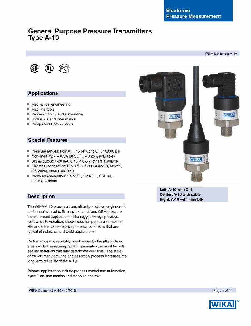
General Purpose Pressure TransmittersType A-10
Left: A-10 with DINCenter: A-10 with cableRight: A-10 with mini DIN
Applications
�� Mechanical�engineering�� Machine�tools�� Process�control�and�automation�� Hydraulics�and�Pneumatics���� Pumps�and�Compressors�
Special Features
�� Pressure�ranges:�from�0�…�15�psi�up�to�0�…�10,000�psi��� Non-linearity:�<�+�0.5%�BFSL�(�<�+�0.25%�available)�� Signal�output:�4-20�mA,�0-10�V,�0-5�V,�others�available�� Electrical�connection:�DIN�175301-803�A�and�C,�M12x1,��6�ft.�cable,�others�available
�� Pressure�connection:�1/4�NPT�,�1/2�NPT�,�SAE�#4,��others�available
Description
The�WIKA�A-10�pressure�transmitter�is�precision�engineered�and�manufactured�to�fit�many�industrial�and�OEM�pressure�measurement�applications.��The�rugged�design�provides��resistance�to�vibration,�shock,�wide�temperature�variations,�RFI�and�other�extreme�environmental�conditions�that�are��typical�of�industrial�and�OEM�applications.
Performance�and�reliability�is�enhanced�by�the�all�stainless�steel�welded�measuring�cell�that�eliminates�the�need�for�soft�sealing�materials�that�may�deteriorate�over�time.��The�state-of-the-art�manufacturing�and�assembly�process�increases�the�long�term�reliability�of�the�A-10.
Primary�applications�include�process�control�and�automation,�hydraulics,�pneumatics�and�machine�controls.
WIKA Datasheet A-10
Electronic Pressure Measurement
WIKA Datasheet A-10 ∙ 12/2010
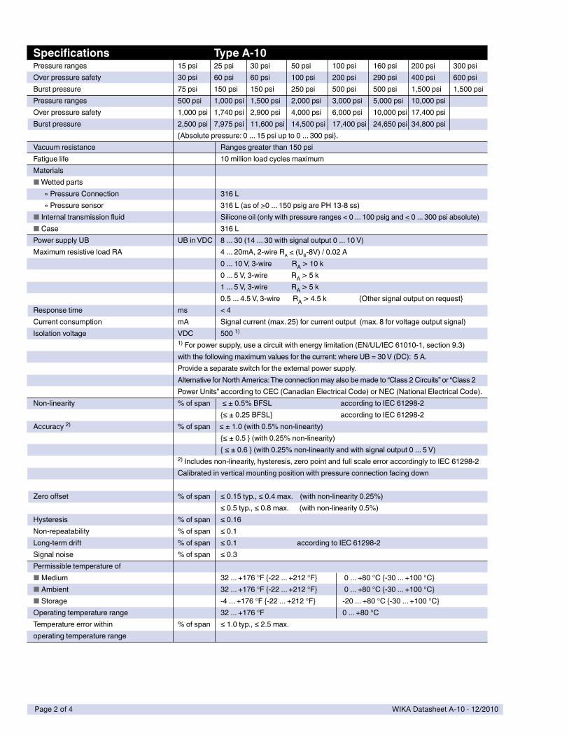
Specifications Type A-10 Pressure�ranges� 15�psi� 25�psi� 30�psi� 50�psi� 100�psi� 160�psi� 200�psi� 300�psiOver�pressure�safety� 30�psi� 60�psi� 60�psi� 100�psi� 200�psi� 290�psi� 400�psi� 600�psiBurst�pressure�� 75�psi� 150�psi� 150�psi� 250�psi� 500�psi� 500�psi� 1,500�psi� 1,500�psiPressure�ranges� 500�psi� 1,000�psi� 1,500�psi� 2,000�psi� 3,000�psi� 5,000�psi� 10,000�psi�Over�pressure�safety� 1,000�psi� 1,740�psi� 2,900�psi� 4,000�psi� 6,000�psi� 10,000�psi� 17,400�psi�Burst�pressure�� 2,500�psi� 7,975�psi� 11,600�psi� 14,500�psi� 17,400�psi� 24,650�psi� 34,800�psi�� � {Absolute�pressure:�0�...�15�psi�up�to�0�...�300�psi}.Vacuum�resistance� � Ranges�greater�than�150�psiFatigue�life� � 10�million�load�cycles�maximum�Materials�� �■�Wetted�parts� �������»�Pressure�Connection� � 316�L������»�Pressure�sensor� � 316�L�(as�of�>0�...�150�psig�are�PH�13-8�ss)�■�Internal�transmission�fluid� � Silicone�oil�(only�with�pressure�ranges�<�0�...�100�psig�and�<�0�...�300�psi�absolute)■�Case� � 316�LPower�supply�UB� UB�in�VDC� 8�...�30�(14�...�30�with�signal�output�0�...�10�V)�Maximum�resistive�load�RA� � 4�...�20mA,�2-wire�RA�<�(UB-8V)�/�0.02�A� � � 0�...�10�V,�3-wire�����������RA�>�10�k�� � � 0�...�5�V,�3-wire�������������RA�>�5�k� � � 1�...�5�V,�3-wire�������������RA�>�5�k� � � 0.5�...�4.5�V,�3-wire�������RA�>�4.5�k������������������{Other�signal�output�on�request}Response�time� ms� <�4Current�consumption� mA� Signal�current�(max.�25)�for�current�output��(max.�8�for�voltage�output�signal)Isolation�voltage� VDC� 500�1)
� � 1)�For�power�supply,�use�a�circuit�with�energy�limitation�(EN/UL/IEC�61010-1,�section�9.3)�� � with�the�following�maximum�values�for�the�current:�where�UB�=�30�V�(DC):��5�A.��� � Provide�a�separate�switch�for�the�external�power�supply.� � Alternative�for�North�America:�The�connection�may�also�be�made�to�“Class�2�Circuits”�or�“Class�2� � Power�Units”�according�to�CEC�(Canadian�Electrical�Code)�or�NEC�(National�Electrical�Code).Non-linearity� %�of�span� �≤�±�0.5%�BFSL� � according�to�IEC�61298-2� � � {≤�±�0.25�BFSL}�� � according�to�IEC�61298-2Accuracy�2)� %�of�span�����≤�±�1.0�(with�0.5%�non-linearity)� � � {≤�±�0.5�}�(with�0.25%�non-linearity)� � �� {�≤�±�0.6�}�(with�0.25%�non-linearity�and�with�signal�output�0�...�5�V)� � 2)�Includes�non-linearity,�hysteresis,�zero�point�and�full�scale�error�accordingly�to�IEC�61298-2�������������������������������
� �� Calibrated�in�vertical�mounting�position�with�pressure�connection�facing�down�����������������������
Zero�offset� %�of�span� ≤�0.15�typ.,�≤�0.4�max.����(with�non-linearity�0.25%)� � � ≤�0.5�typ.,�≤�0.8�max.������(with�non-linearity�0.5%)Hysteresis� %�of�span� ≤�0.16Non-repeatability� %�of�span� ≤�0.1Long-term�drift� %�of�span� ≤�0.1���������������������������������according�to�IEC�61298-2Signal�noise� %�of�span� ≤�0.3Permissible�temperature�of� �■�Medium� � 32�...�+176�°F�{-22�...�+212�°F}� ��0�...�+80�°C�{-30�...�+100�°C}■�Ambient� � 32�...�+176�°F�{-22�...�+212�°F}� ��0�...�+80�°C�{-30�...�+100�°C}■�Storage� � -4�...�+176�°F�{-22�...�+212�°F}� �-20�...�+80�°C�{-30�...�+100�°C}Operating�temperature�range� � 32�...�+176�°F� � �0�...�+80�°CTemperature�error�within� %�of�span� ≤�1.0�typ.,�≤�2.5�max.operating�temperature�range
Page 2 of 4 WIKA Datasheet A-10 ∙ 12/2010

�
Specifications Type A-10 Approvals��� � UL,�CSA,�GOSTRoHS-conformity� � YesCE-conformity� �■�Pressure�equipment�directive� � 97/23/EC■�EMC�directive� � 2004/108/EEC�(Group�1,�Class�B)�and�immunity�according�to�EN�61�326Shock�resistance� g� 500�according�to�IEC�60068-2-27���(mechanical�shock)Vibration�resistance� g� 10�according�to�IEC�60068-2-6�������(vibration�under�resonance)Wiring�protection� � ������■�Overvoltage�protection� VDC� 32;�36�with�4�...�20�mA��■�Short-circuit�protection�� � Sig+�to�UB-■�Reverse�polarity�protection� � UB+�to�UB-Test�reference�conditions� � According�to�IEC�61298-1■�Relative�humidity� %� 45�...�75■�Temperature� %� 59�...�77�°F�(15�...�25�°C)■�Atmospheric�Pressure� KPa� 86�…�106�(25.4…31.3�inhg)Weight� oz.� Approx.�2.8�oz.�(80�g)
Pressure connections 1/2�NPT�MaleOrder�Code:�ND
7/16�-�20�UNFO-ring�bossOrder�Code:�MV
1/4�NPT�MaleOrder�Code:�NB
max. 1.9 (48 mm)
2.4
(60.
8 m
m)
1/4 NPT.51 (13 mm)
1.14 (29 mm)
EN175301-801-C
max. 1.5 (38 mm)
1.06 (27mm)
Dimensions in inches (mm){�}��Items�in�curved�brackets�are�optional�extras�for�additional�price.
DIN�175301-803�AL-connectorconductor�outer�diameter.24"�to�.32"IP�65Order�Code:�AG
DIN�175301-803�CL-connectorconductor�outer�diameter��.18"�to�.24"IP�65Order�Code:�CG
M�12x1,�4�pinIP�67AG
Order�Code:�M4
Cable�with�free�ends,conductor�cross�section�.013�in�2,�conductor�outer�diameter.26",PUR�cable�-�unshielded,�IP�67
Ingress�protection�IP�per�IEC�60529.�The�ingress�protection�classes�specified�only�apply��while�the�pressure�transmitter�is�connected�with�female�connectors�that�provide�the��equivalent�ingress�protection.
For�tapped�holes�and�welding�sockets�please�see�Technical�Information�IN�00.14�for�download�at�www.wika.de
1/4�NPT 1/4�NPT
Order��Code:�DL
Page 3 of 4WIKA Datasheet A-10 ∙ 12/2010

WIKA Instrument Corporation1000 Wiegand BoulevardLawrenceville, GA 30043Tel (770) 513-8200 Toll-free 1-888-WIKA-USAFax (770) 338-5118E-Mail [email protected]
R
Specifications�and�dimensions�given�in�this�datasheet�represent�the�state�of�engineering�at�the�time�of�printing.Modifications�may�take�place�and�materials�specified�may�be�replaced�by�others�without�prior�notice.
Electrical connections
G�1/2�BOrder�Code:�GD
M20�x�1.5with�sealing�ringOrder�Code:�MI
1/4"�NPT�femaleOrder�Code:�NP
Pressure connections
DIN�175301-803�AL-connectorIP�65
brown
blue
brown
blue
black
3-wire2-wire
DIN�175301-803�CL-connectorIP�65
M�12x1,�4-pinwithout�angle�socket�or�female�cable�connectorsIP�67
Cable�with�free�endsIP�67
Page 4 of 4 WIKA Datasheet A-10 ∙ 12/2010