Embed Size (px)
Citation preview

The RS series of burners covers a firing range from 81 to 2290 kW, and they have beendesigned for use in hot or superheater water boilers, hot air or steam generators,diathermic oil boilers.Operation is "two stage"; the burners are fitted with an electronic device STATUS PANEL,which supplies complete diagnostic: hour meter, ignition meter, identification of troubleshooting.Optimisation of sound emissions is guaranteed by the use of fans with forward inclinedblades and sound deadening material incorporated in the air suction circuit.The elevated performance of the fans and combustion head, guarantee flexibility of useand excellent working at all firing rates.The exclusive design ensures reduced dimensions, simple use and maintenance. A widerange of accessories guarantees elevated working flexibility.
TS0046UK00
RS SERIESTWO STAGE GAS BURNERS
RS 28 81/163 ÷ 325 kWRS 38 105/232 ÷ 440 kWRS 50 116/290 ÷ 580 kWRS 70 192/465 ÷ 814 kWRS 100 232/698 ÷ 1163 kWRS 130 372/930 ÷ 1512 kWRS 190 470/1279 ÷ 2290 kW

RS 38
105/232÷440
90/200÷378
10,5/23÷44
12/27÷51
4/9÷17
0,6
0,12
0,42
2,9
11
70
--
RS 50
116/290÷581
100/249÷500
11,6/29÷58
13,5/34÷68
4,5/11÷23
0,75
0,12
0,65
3 - 1,7
13,8 - 8
72
--
CE 0085AP0735
RS 70
192/465÷814
165/400÷700
19/46,5÷81,4
22/54÷95
7,4/18÷32
1,4
0,3
1,1
4,8 - 2,8
25 - 14,6
75
--
CE 0085AP0944
RS 100
232/698÷1163
200/600÷1000
23/70÷116
27/81÷135
9/27÷45
1,8
0,3
1,5
5,9 - 3,4
27,7 - 16
77
--
CE 0085AP0945
3N/50/230-400~(±10%) 3/50/230~(±10%)
SQN90
12
LKS210
15
RS 190
SQN31
15
470/1279÷2290
405/1100÷1970
47/128÷229
55/149÷266
18/50÷89
Straight blades
5,5
1
4,5
15,8 - 9,1
126 - 73
83
--
CE 0085AT0042
RS 130
372/930÷1512
320/800÷1300
37/93÷151
43/108÷176
14,4/36÷59
2,6
0,4
2,2
8,8 - 5,1
57,2 - 33,2
78,5
--
CE 0085AP0946
RS 28
81/163÷325
70/140÷280
8/16÷32
9,4/19÷38
3/6,5÷12,5
0,37
0,12
0,25
2,1
4,8
68
--
CE 0085AP0733
TECHNICAL DATAFu
el /
air
dat
aE
lect
rica
l d
ata
Em
issi
on
sA
ppro
val
Model
Burner operation mode
Modulation ratio to max. output
Type
Run time
Working temperature
Net calorific value gas G20
Density gas G20
Output gas G20
Net calorific value gas G25
Density gas G25
Output gas G25
Net calorific value LPG gas
Density LPG gas
Output LPG gas
Fan
Air temperature
Electrical supply
Auxiliary electrical supply
Control box
Total electrical power
Auxiliary electrical power
Protection level
Motor electrical power
Rated motor current
Motor start current
Motor protection level
Operation
Sound pressure
Sound output
CO Emission
NOx Emission
Directive
Conforming to
Certification
Servo-motor
s
kW
Mcal/h
°C min./max.
kWh/Nmc
kg/Nmc
Nmc/h
kWh/Nmc
kg/Nmc
Nmc/h
kWh/Nmc
kg/Nmc
Nmc/h
Type
Max. °C
Ph/Hz/V
Ph/Hz/V
Type
kW
kW
IP
kW
A
A
IP
V1 - V2
I1 - I2
dBA
W
mg/kWh
mg/kWh
Heat output
Ignitiontransformer
Centrifugal with reverse curve blades
RS 38
105/232÷440
90/200÷378
10,5/23÷44
12/27÷51
4/9÷17
0,56
0,12
0,45
2 - 1,2
9,5 - 5,5
70
--
Two stage
2 ÷ 1
0/40
10
0,71
8,6
0,78
25,8
2,02
60
1/50/230 ~ (±10%)
MMI 813
44
54
230V - 1x8 kV
1A - 20 mA
Intermittent (at least one stop every 24 h)
< 40
< 130
90/396 - 89/336 - 73/23 - 92/42 EEC
EN 676
Since the Company is constantly engaged in the production improvement, the aesthetic and dimensional features, thetechnical data, the equipment and the accessories can be changed.This document contains confidential and proprietary information of RIELLO S.p.A. Unless authorised, this information shallnot be divulged, nor duplicated in whole or in part.
Reference conditions:Temperature: 20°CPressure: 1013.5 mbarAltitude: 100 m a.s.l.Noise measured at a distance of 1 meter.
CE 0085AP0734
1/50/230~(±10%)

FIRING RATES
Useful working field for choosing the burner
1st stage operating range
Test conditions conforming to EN 676:Temperature: 20°CPressure: 1013.5 mbarAltitude: 100 m a.s.l.
0
2
4
6
5
3
1
7
9
8
10
100 kW
0
0
0
20
40
60
50
30
10
70
90
80
100
200 300 400 500 600 700
0
2
4
6
5
3
1
7
9
8
10
11
kW
12
13
14
0
0
0
20
40
60
50
30
10
70
90
80
100
110
120
130
140
15150
100 200 300 400 500 600 700 800 900 1000 1100 1200 1300 1400 1500 1600 1700 1800 1900 2000 2100
RS 50
RS 28
RS 38
RS 70
RS 100
RS 130
RS 190
hP
a (m
bar
)
- 1
mm
H2O
-10
hP
a (m
bar
)
- 1
mm
H2O
-10
Mcal/h100 200 300 400 500 600
Mcal/h
600400200 800 1000 1200 1400 1600 1800 2000 2200 2400

The burners are fitted with a butterfly valve to regulate the fueldelivery on 1st and 2nd stage, controlled by a variable profilecam servomotor.
Fuel can be supplied either from the right orleft hand sides.
The gas train can be selected to best fit systemrequirements depending on the fuel outputand pressure in the supply line.The gas train can be “Multibloc“ type(containing the main components in a singleunit) or “Composed” type (assembly of thesingle components).
1
2
3
4
5
6
7
8
9
10
11
12
13
14
15
P1
P2
P3
L
L1
L L1
MULTIBLOC
9 8
L L1
MULTIBLOC
9 8 3 9 8
GAS TRAINS
FUEL SUPPLY
Example of the variable profile cam on RS 70-100-130 burners.
MULTIBLOC gas train without seal control
MULTIBLOC gas train with seal control
COMPOSED gas train without seal control COMPOSED gas train with seal control
12
P1
11
1015
14 9 8 P2 6 P3
4
3 2 15
P1
11
1015
14 P3
4
3 2 113
12
56P2
7
7
L L1
P1
11
1015
14 2 1
12
P2
7
6 5 P3
4
L L1
P1
11
1015
14 P3
4
3 2 113
12
56P2
7
Gas input pipework
Manual valve
Anti-vibration joint
Pressure gauge with pushbutton cock.
Filter
Pressure regulator (vertical)
Minimum gas pressure switch
VS safety solenoid (vertical)
VR regulation solenoid (vertical)Two settings: - firing output (rapid opening)
- maximum output (slow opening)
Gasket and flange supplied with the burner
Gas adjustment butterfly valve
Burner
Seal control mechanism for valves 8-9. Accordingto standard EN 676, the seal control is compulsoryfor burners with maximum output above 1200 kW.
Gas train-burner adapter.
Maximum gas pressure switch
Combustion head pressure
Pressure downstream from the regulator
Pressure upstream from the filter
Gas train supplied separately, with the code given in the table
Installer’ s responsibility

Gas trains are approved by standard EN 676 together with the burner.
The overall dimensions of the gas train depends on how they are constructed. The following tableshows the maximum dimensions of the gas trains that can be fitted to RS burners, intake and outletdiameters and seal control if fitted.Please note that the seal control can be installed as an accessory, if not already installed on the gastrain.The maximum gas pressure of gas train “Multibloc” type is 300 mbar, and that one of gas train“Composed” type is 500 mbar.
CO
MP
OS
ED
GA
S T
RA
INS
MU
LTIB
LOC
GA
S T
RA
INS
Name
MBD 407
MBD 410
MBD 412
MBD 412 CT
MBD 415
MBD 415 CT
MBD 420
MBD 420 CT
CB 40/1
CB 50/1
CB 50/1 CT
CBF 65/1
CBF 65/1 CT
CBF 80/1
CBF 80/1 CT
CBF 100/1
CBF 100/1 CT
Code
3970076
3970077
3970144
3970197
3970180
3970198
3970181
3970182
3970145
3970146
3970160
3970147
3970161
3970148
3970162
3970149
3970163
Ø i
3/4”
1”
1”1/4
1”1/4
1”1/2
1”1/2
2”
2”
1”1/2
2”
2”
DN 65
DN 65
DN 80
DN 80
DN 100
DN 100
Ø o
3/4”
3/4”
1”1/2
1”1/2
1”1/2
1”1/2
2”
2”
1”1/2
2”
2”
DN 65
DN 65
DN 80
DN 80
DN 100
DN 100
X mm
371
405
433
433
523
523
523
523
891
986
986
874
874
934
934
1054
1054
Y mm
196
217
217
217
250
250
300
300
261
328
328
356
356
416
416
501
501
Z mm
120
145
145
262
100
227
100
227
195
250
320
285
285
285
285
350
350
Seal Control
-
-
-
Incorporated
-
Incorporated
-
Incorporated
-
-
Incorporated
-
Incorporated
-
Incorporated
-
Incorporated
Example of gas train“COMPOSED” typewithout seal control
Y
ZX
Øi
Øo
Example of gas train“MULTIBLOC” typewithout seal control
Y
Z X
Øi
Øo

The diagrams indicate the minimum pressure drop of the burners with the various gas trains thatcan be matched with them; at the value of these pressure drop add the combustion chamberpressure.The value thus calculated represents the minimum required input pressure to the gas train.
RS 28 RS 28
RS 38 RS 38
PRESSURE DROP DIAGRAMS
NATURAL GAS LPG
Gas train
CB 40/1
MBD 415
MBD 415 CT
Code
3970145
3970180
3970198
Adapter
-
-
-
Seal Control
Accessory
Accessory
Incorporated
Gas train
MBD 407
MBD 410
MBD 412
MBD 412 CT
Code
3970076
3970077
3970144
3970197
Adapter
3000824
3000824
-
-
Seal Control
Accessory
Accessory
Accessory
Incorporated
Gas train
MBD 407
MBD 410
MBD 412
MBD 412 CT
CB 40/1
MBD 415
Code
3970076
3970077
3970144
3970197
3970145
3970180
Seal Control
Accessory
Accessory
Accessory
Incorporated
Accessory
Accessory
Gas train
MBD 415 CT
CB 50/1
CB 50/1 CT
MBD 420
MBD 420 CT
Code
3970198
3970146
3970160
3970181
3970182
Adapter
-
3000822
3000822
3000822
3000822
Seal Control
Incorporated
Accessory
Incorporated
Accessory
Incorporated
Adapter
3000824
3000824
-
-
-
-
kcal/h X 1000
10
25
15
20
30
5
0140 150 200 250 280
mb
ar
G25G20
0
5
15
25
30
35
20
10
40
35
40
45
45
50
55
kcal/h X 1000
10
25
15
20
30
5
0140 150 200 250 280
mb
ar
LPG
35
40
45
kW300200 250163 325
kcal/h X 1000
10
25
15
20
30
5
0
200 300250 350 378
mb
ar
G25G20
0
5
15
25
30
35
20
10
40MBD 410
MBD 412 - 412 CT
MBD 415 - 415 CT
MBD 420 - 420 CT
kcal/h X 1000
10
25
15
20
30
5
0
200 300250 350 378
mb
ar
LPG
MBD 410
MBD 412 - 412 CT
MBD 415 - 415 CT - CB 40/1
MBD 420 - 420 CT - CB 50/1 - 50/1 CT
kW300 440400250 350232
400
45
35
40 MBD 407∆P
Com
bust
ion
head
and
gas
tra
inC
ombu
stio
n he
adP
ress
ure
drop
∆P
Com
bust
ion
head
and
gas
tra
inC
ombu
stio
n he
adP
ress
ure
drop
CB 40/1
CB 50/1 - 50/1 CT
MBD 410
MBD 412 - 412 CT
MBD 407
MBD 410
MBD 412 - 412 CT
MBD 407
MBD 415 - 415 CTCB 40/1
kW300200 250163 325
kW300 440400250 350232
∆P
Com
bust
ion
head
and
gas
tra
inC
ombu
stio
n he
adP
ress
ure
drop
∆P
Com
bust
ion
head
and
gas
tra
inC
ombu
stio
n he
adP
ress
ure
drop

RS 50 RS 50
RS 70 RS 70
NATURAL GAS LPG
Gas train
MBD 407
MBD 410
MBD 412
MBD 412 CT
CB 40/1
MBD 415
Code
3970076
3970077
3970144
3970197
3970145
3970180
Adapter
3000824
3000824
-
-
-
-
Seal Control
Accessory
Accessory
Accessory
Incorporated
Accessory
Accessory
Gas train
CB 40/1
MBD 415
MBD 415 CT
CB 50/1
CB 50/1 CT
MBD 420
Code
3970145
3970180
3970198
3970146
3970160
3970181
Adapter
3000843
3000843
3000843
-
-
-
Seal Control
Accessory
Accessory
Incorporated
Accessory
Incorporated
Accessory
Gas train
MBD 415 CT
CB 50/1
CB 50/1 CT
MBD 420
MBD 420 CT
Code
3970198
3970146
3970160
3970181
3970182
Adapter
-
3000822
3000822
3000822
3000822
Seal Control
Incorporated
Accessory
Incorporated
Accessory
Incorporated
Gas train
MBD 420 CT
CBF 65/1
CBF 65/1 CT
CBF 80/1
CBF 80/1 CT
Code
3970182
3970147
3970161
3970148
3970162
Adapter
-
3000825
3000825
3000826
3000826
Seal Control
Incorporated
Accessory
Incorporated
Accessory
Incorporated
10
25
15
20
45
5
0
30
35
40
50
mb
ar
249 300 350 400 450kcal/h X 1000
500
G25G20
0
20
40
50
30
10
60
5
25
45
55
35
15
MBD 410
MBD 412 - 412 CT
MBD 415 - 415 CT
MBD 420 - 420 CT
∆P
10
20
0
30
40
50
mb
ar
249 300 350 400 450kcal/h X 1000
500
LPG
MBD 410
MBD 412 - 412 CT
MBD 415 - 415 CT - CB 40/1
MBD 420 - 420 CT - CB 50/1 - 50/1 CT
∆P
kcal/h X 1000
mb
ar
30
20
40
0
10
50
400 500 600 700
G25G20
0
20
40
50
30
10
60
MBD 415 - 415 CT
MBD 420 - 420 CT
CBF 65/1 - 65/1 CT
∆P
kcal/h X 1000
mb
ar
30
20
40
0
10
50
400 500 600 700
LPG
MBD 420 - 420 CT - CB 50/1 - 50/1 CT
∆P
MBD 415 - 415 CT - CB 40/1
kW400 550500350 450290 581
60
MBD 407
kW600500 700465 814
CBF 80/1 - 80/1 CT
CB 50/1 - 50/1 CT
CB 40/1
CB 50/1 - 50/1 CT
CB 40/1
kW400 550500350 450290 581
kW600500 700465 814
Com
bust
ion
head
and
gas
tra
inC
ombu
stio
n he
adP
ress
ure
drop
Com
bust
ion
head
and
gas
tra
inC
ombu
stio
n he
adP
ress
ure
drop
Com
bust
ion
head
and
gas
tra
inC
ombu
stio
n he
adP
ress
ure
drop
Com
bust
ion
head
and
gas
tra
inC
ombu
stio
n he
adP
ress
ure
drop

RS 100 RS 100
RS 130 RS 130
NATURAL GAS LPG
Gas train
MBD 420 CT
CBF 65/1
CBF 65/1 CT
CBF 80/1
CBF 80/1 CT
Code
3970182
3970147
3970161
3970148
3970162
Adapter
-
3000825
3000825
3000826
3000826
Seal Control
Incorporated
Accessory
Incorporated
Accessory
Incorporated
Gas train
CB 40/1
MBD 415
MBD 415 CT
CB 50/1
CB 50/1 CT
MBD 420
MBD 420 CT
Code
3970145
3970180
3970198
3970146
3970160
3970181
3970182
Adapter
3000843
3000843
3000843
-
-
-
-
Seal Control
Accessory
Accessory
Incorporated
Accessory
Incorporated
Accessory
Incorporated
Gas train
CBF 65/1
CBF 65/1 CT
CBF 80/1
CBF 80/1 CT
CBF 100/1
CBF 100/1 CT
Code
3970147
3970161
3970148
3970162
3970149
3970163
Adapter
3000825
3000825
3000826
3000826
3010223300082630102233000826
Seal Control
Accessory
Incorporated
Accessory
Incorporated
Accessory
Incorporated
Gas train
CB 40/1
MBD 415
MBD 415 CT
CB 50/1
CB 50/1 CT
MBD 420
Code
3970145
3970180
3970198
3970146
3970160
3970181
Adapter
3000843
3000843
3000843
-
-
-
Seal Control
Accessory
Accessory
Incorporated
Accessory
Incorporated
Accessory
kcal/h X 1000
mb
ar
10
20
30
kW
600 900800700 1000
800 900
0
1100700 1000
40
50
1163
G25G20
0
20
40
50
30
10
60
MBD 415 - 415 CT
MBD 420 - 420 CT
CBF 65/1 - 65/1 CT
CBF 80/1 - 80/1 CT
∆P
kcal/h X 1000m
ba
r
10
20
30
kW
600 900800700 1000
800 900
0
1100700 1000
40
50
1163
LPG
MBD 415 - 415 CT - CB 40/1
MBD 420 - 420 CT - CB 50/1 - 50/1 CT
∆P
mb
ar
kW
900800 11001000
1300 140011001000 1200
1200 1300
930 1512
kcal/h X 1000
G25G20∆P
mb
ar
kW
900800 11001000
1300 1400
0
11001000 1200
1200 1300
930 1512
kcal/h X 1000
LPG
MBD 415 - 415 CT - CB 40/1
MBD 420 - 420 CT - CB 50/1 - 50/1 CT
∆P
CBF 65/1 - 65/1 CT
Com
bust
ion
head
and
gas
tra
inC
ombu
stio
n he
adP
ress
ure
drop
Com
bust
ion
head
and
gas
tra
inC
ombu
stio
n he
adP
ress
ure
drop
Com
bust
ion
head
and
gas
tra
inC
ombu
stio
n he
adP
ress
ure
drop
Com
bust
ion
head
and
gas
tra
inC
ombu
stio
n he
adP
ress
ure
drop
10
40
20
30
50
0
60
70
80
90
100
110
0
20
40
50
30
10
60
70
80
90
100
110
120
130
140
MBD 415 - 415 CT
MBD 420 - 420 CT
CBF 65/1 - 65/1 CT
CBF 80/1 - 80/1 CT
CBF 100/1 - 100/1 CT
CB 50/1 - 50/1 CT
CB 40/1
10
40
20
30
50
60
70
80
90
100
110
60
70
70
80
90
CB 50/1 - 50/1 CT
CB 40/1
60
70

Please contact the Riello Burner Technical Office for different pressure levels from thoseabove indicated.
note
RS 190m
ba
r
20
80
40
60
100
kW
11001000 13001200
1700 1800
0
15001400 1600
1400 1500
19001279 2290
G25G20
0
40
80
100
60
20
120
kcal/h X 1000
CBF 65/1 - 65/1 CT
CBF 80/1 - 80/1 CT
MBD 420 - 420 CT
1600 1700 1800 1900
1200 2000 2100
CBF 100/1 - 100/1 CT
2000
RS 190
mb
ar
20
80
40
60
100
kW
11001000 13001200
1700 1800
0
15001400 1600
1400 1500
19001279 2290
LPG
kcal/h X 1000
CBF 65/1 - 65/1 CT
MBD 420 - 420 CT - CB 50/1 - 50/1 CT
1600 1700 1800 1900
1200 2000 2100
2000
NATURAL GAS LPG
140
CF 50/1 - 5
0/1 CT
Gas train
CB 50/1
CB 50/1 CT
MBD 420
MBD 420 CT
CBF 65/1
Code
3970146
3970160
3970181
3970182
3970147
Adapter
3010128
3010128
3010128
3010128
3000831
Seal Control
Accessory
Incorporated
Accessory
Incorporated
Accessory
Gas train
CBF 65/1 CT
CBF 80/1
CBF 80/1 CT
CBF 100/1
CBF 100/1 CT
Code
3970161
3970148
3970162
3970149
3970163
Adapter
3000831
3000832
3000832
3010127
3010127
Seal Control
Incorporated
Accessory
Incorporated
Accessory
Incorporated
∆P
Com
bust
ion
head
and
gas
tra
inC
ombu
stio
n he
adP
ress
ure
drop
∆P
Com
bust
ion
head
and
gas
tra
inC
ombu
stio
n he
adP
ress
ure
drop

SELECTING THE FUEL SUPPLY LINES
0,1 0,2 0,3 0,4 0,5 0,6 0,7 0,8 1 2 3 4 5 106 20
50 60 10080 200 400 800 1000600
3
69
12152230
45 61 76 95 122 152 V
PRESSURE DROP (mbar)
1 2 3 4 5 6 7 8 10 20 30 40
PIPE DIAMETER
1,4
PIPE LENGTH (m)
1/2
3/4
1"
1" 1/2
6"
1" 1/4
4"
3"2" 1/22"
= Gas output Nmc/h
f1 - G20
= 0,62 - G251,18 - G31{
fV
15,34
Figure A
The following diagram enables pressure drop in a pre-existing gas line to be calculated and to select thecorrect gas train.The diagram can also be used to select a new gas line when fuel output and pipe length are known. Thepipe diameter is selected on the basis of the desired pressure drop. The diagram uses methane gas asreference; if another gas is used, conversion coefficient and a simple formula (on the diagram) transformthe gas output to a methane equivalent (refer to figure A). Please note that the gas train dimensions musttake into account the back pressure of the combustion chamber during operations.
Control of the pressure drop in an existing gas line or selecting a new gas supply line.The methane output equivalent is determined by the formula fig. A on the diagram and the conversioncoefficient.
Once the equivalent output has been determined on the delivery scale ( ), shown at the top of thediagram, move vertically downwards until you cross the line that represents the pipe diameter; at thispoint, move horizontally to the left until you meet the line that represents the pipe length.Once this point is established you can verify, by moving vertically downwards, the pipe pressure dropof on the botton scale below (mbar).By subtracting this value from the pressure measured on the gas meter, the correct pressure value willbe found for the choice of gas train.
Example: - gas used G25- gas output 9.51 mc/h- pressure at the gas meter 20 mbar- gas line length 15 m- conversion coefficient 0.62 (see figure A)
- equivalent methane output = 9.51 = 15.34 mc/h0.62
- once the value of 15.34 has been identified on the output scale ( ), moving vertically downwards youcross the line that represents 1" 1/4 (the chosen diameter for the piping);
- from this point, move horizontally to the left until you meet the line that represents the length of 15 mof the piping;
- move vertically downwards to determine a value of 1.4 mbar in the pressure drop botton scale;- subtract the determined pressure drop from the meter pressure, the correct pressure level will be found
for the choice of gas train;
- correct pressure = ( 20-1.4 ) = 18.6 mbar
V
V
V

Different lengths of the combustion head can be chosen for theRS series of burners.
The choice depends on the thickness of thefront panel and the type of boiler.
Depending on the type of generator, check that thepenetration of the head into the combustion chamber iscorrect.
The internal positioning of the combustion head can easilybe adjusted to the maximum defined output by adjustinga screw fixed to the flange.
The ventilation circuit produces low noise levels with highperformance pressure and air output, inspite of the compact
dimensions.
Except for the RS 190 model, the use of reversecurve blades and sound-proofing material keeps noise level verylow. In the RS 190 model, noise has been reduced by the specialdesign of the air suction circuit.
A variable profile cam connects the fuel and air regulations, toobtain a perfect control of combustion during the change ofstage. When the burner is not operating the servomotor closescompletely the air damper to reduce heat dispersion from theboiler.A minimum air pressure switch stops the burner when there isan insufficient quantity of air at the combustion head.
COMBUSTION HEAD
VENTILATION
Example of a RS burner combustion head
Dimensions of the flame
Example of the air damper onRS 28 - 38 - 50 burners
Example:Burner thermal output = 2000 kW;L flame (m) = 2,7 m (medium value);D flame (m) = 0,8 m (medium value)
D
L
Burner output (MW)
3
1
2
4
Len
gh
t o
f th
e fl
ame
(m)
Dia
met
er o
f th
e fl
ame
(m)
0 0
0,5
1
1,5
2
0 21 3 4
D max
D min
L max
L min
time (s)0
RS 28-38-50-70-100-130-190
FIRING
ADJUSTMENT
BURNER OPERATION MODE
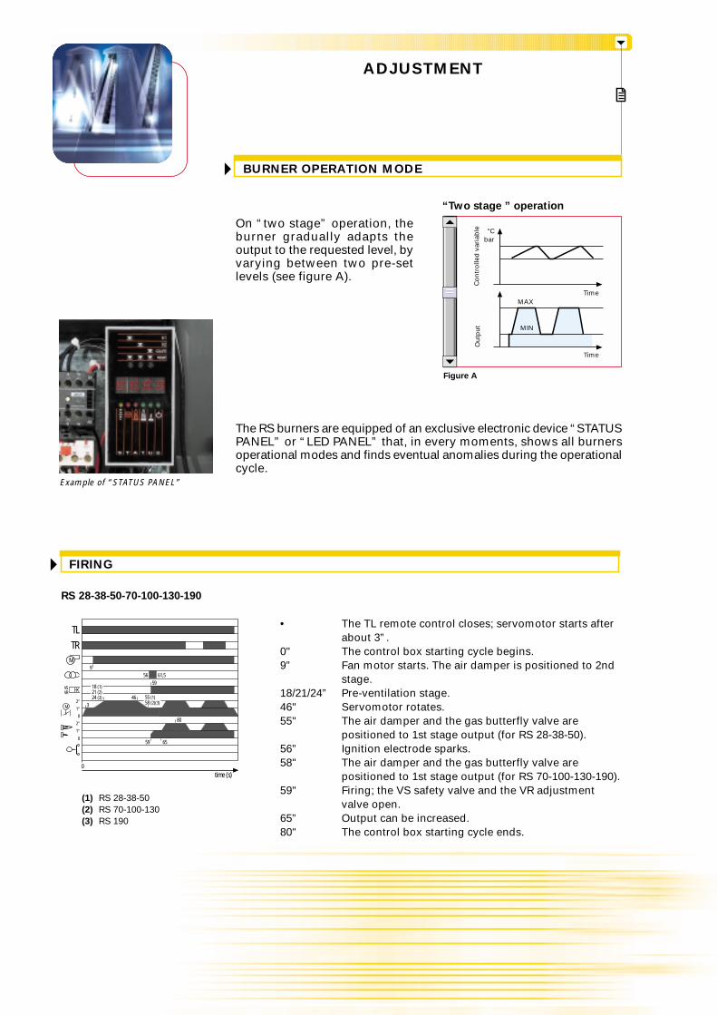
On “two stage” operation, theburner gradually adapts theoutput to the requested level, byvarying between two pre-setlevels (see figure A).
• The TL remote control closes; servomotor starts after about 3”.
0" The control box starting cycle begins.9” Fan motor starts. The air damper is positioned to 2nd
stage.18/21/24” Pre-ventilation stage.46" Servomotor rotates.55" The air damper and the gas butterfly valve are
positioned to 1st stage output (for RS 28-38-50).56” Ignition electrode sparks.58" The air damper and the gas butterfly valve are
positioned to 1st stage output (for RS 70-100-130-190).59" Firing; the VS safety valve and the VR adjustment
valve open.65” Output can be increased.80" The control box starting cycle ends.
56 61,5
(1) RS 28-38-50(2) RS 70-100-130(3) RS 190
TL
0
2°1°
0
M
M
TR
59
3
VSVR
18 (1)21 (2)24 (3) 46
81
9
59
2°1°
55 (1) 58 (2)(3)
65
80
The RS burners are equipped of an exclusive electronic device “STATUSPANEL” or “LED PANEL” that, in every moments, shows all burnersoperational modes and finds eventual anomalies during the operationalcycle.
Example of “STATUS PANEL”
Figure A
bar°C
MAX
MIN
Time
Time
Ou
tpu
tC
on
tro
lled
var
iab
le
“Two stage ” operation

“TWO STAGE” OPERATION - Single-phase power supply
ELECTRICAL CONNECTIONSTo be made by the installer
Electrical connections must bemade by qualified and skilledpersonnel, according to the localregulations.
Example of the terminal board for electricalconnections for the RS 70-100-130-190 models
RS 28-38 - without seal control
RS 38-50 - without seal control RS 38-50 - with seal control
RS 28-38 - with seal control
h1 - Hour meterh2 - Hour meterIN - Manual switchMB - Burner auxiliary terminal boardX4 - 4 pin plugX6 - 6 pin plugX7 - 7 pin plugPG - Minimum gas pressure switchS - External lock-out signalTR - High/low flame setting thermostatTL - Threshold thermostatTS - Safety thermostatVR - Adjustment valveVS - Safety valveT6A - 6A fuse
h1 - Hour meterh2 - Hour meterIN - Manual switchXP - Seal control plugX4 - 4 pin plugX6 - 6 pin plugX7 - 7 pin plugPG - Minimum gas pressure switchS - External lock-out signalS1 - External lock-out signal on the seal controlTR - High/low flame setting thermostatTL - Threshold thermostatTS - Safety thermostatVPS - Seal controlVR - Adjustment valveVS - Safety valveT6A - 6A fuse
“TWO STAGE” OPERATION - Triple-phase power supply
h1 - Hour meterh2 - Hour meterIN - Manual switchMB - Burner auxiliary terminal boardX4 - 4 pin plugX5 - 5 pin plugX6 - 6 pin plugX7 - 7 pin plugPG - Minimum gas pressure switchS - External lock-out signalTR - High/low flame setting thermostatTL - Threshold thermostatTS - Safety thermostatVR - Adjustment valveVS - Safety valveT6A - 6A fuse
h1 - Hour meterh2 - Hour meterIN - Manual switchXP - Seal control plugX4 - 4 pin plugX5 - 5 pin plugX6 - 6 pin plugX7 - 7 pin plugPG - Minimum gas pressure switchS - External lock-out signalS1 - External lock-out signal on the seal controlTR - High/low flame setting thermostatTL - Threshold thermostatTS - Safety thermostatVPS - Seal controlVR - Adjustment valveVS - Safety valveT6A - 6A fuse
T6 T8
PP
P P
N123X6 PhN123X6 Ph N L1L3 L2X5 X7L1
PE N L
S3 T2 T1B4
T6A
TSTL
I N
1,5 mm2
S
N
T6A
PE
1,5 mm2
L1L3 L2
N L1L3 L2X5
T6A
PE
1,5 mm2
L1L3 L2
T8 T7 T6
TR
X7L1X4
PE N L
S3 T2 T1B4
T6A
TSTL
I N
1,5 mm2
S
NB5
N V
VR VS
S1
NT8 T6T7 L1
PG
XP
VPS
B5
PG
N V
VR VSh1
ϑ Pϑ P
ϑ Ph1
ϑ Pϑ P
h2
~50Hz 230V ~50Hz 230V
X7L1
PE N L
S3 T2 T1B4
T6A
TSTL
I N
1,5 mm2
S
N
h1
ϑ Pϑ P
~50Hz 230V
P
P P
N123X6 Ph
PG
N V
VR VS
T8 T7 T6 B5X4
TR
h2
ϑ P
T6 T8
P
T8 T7 T6
TR
X7L1X4
PE N L
S3 T2 T1B4
T6A
TSTL
I N
1,5 mm2
S
NN123X6 Ph B5
N V
VR VS
S1
NT8 T6T7 L1
PG
XP
VPS
B5
ϑ Ph1
ϑ Pϑ P
h2
~50Hz 230V
T8 T7 T6 B5X4
TR
h2
ϑ P
~M3~50Hz 230V3~3N 50Hz 400/230V ~M3~50Hz 230V3
~3N 50Hz 400/230V

EMISSIONS
The emission data has been measured inthe various models at maximum output,according to EN 676 standard.
The following table shows the supply lead sections and the type of fuse to be used.
Table A
RS 70-100-130-190 - without seal control RS 70-100-130-190 - with seal control
MB - Burner terminal boardIN - Manual switchPG - Minimum gas pressure switchS - External lock-out signalTR - High/low flame setting thermostatTL - Threshold thermostatTS - Safety thermostatVR - Adjustment valveVS - Safety valveT6A - 6A fuseF - Fuse (see table A)L - Lead section (see table A)
MB - Burner terminal boardIN - Manual switchXP - Seal control plugPG - Minimum gas pressure switchS - External lock-out signalS1 - External lock-out signal on the seal controlTR - High/low flame setting thermostatTL - Threshold thermostatTS - Safety thermostatVPS - Seal controlVR - Adjustment valveVS - Safety valveT6A - 6A fuseF - Fuse (see table A)L - Lead section (see table A)
RS 28 RS 38 RS 50
230V
T61,5
400V
T61,5
230V
T61,5
400V
T61,5
RS 70 RS 100 RS 130
230V
T101,5
400V
T61,5
230V
T161,5
400V
T101,5
230V
T161,5
400V
T101,5
RS 190
230V
T252,5
400V
T202,5
Model
A
mm2
FL
400V
T61,5
230V
T61,5
RS 38
230V
T61,5
P
L1 L2 L3 N LMB 1 2
PE L1 L2 L3
T6A
N L
TS STL
IN
~50Hz 230V
3
F
7 8 N V
TR
4 5 6T8 T6
S1
NT8 T6T7 L1
PG
XP
VPS
B5
VN
VS VR
~
ϑ Pϑ P ϑ P
~M3~50Hz 230V33N 50Hz 400/230V
L
P
P P
L1 L2 L3 N LMB 1 2
L
PE L1 L2 L3
T6A
N L
TS STL
IN
~50Hz 230V
3
F
~M3
4 5
PG
N V
VRVS
6 7 8 N V
TR
~50Hz 230V3~3N 50Hz 400/230V
ϑ Pϑ P ϑ P
CO EMISSIONS
mg
/kW
h
0
10
20
30
40
50
RS 28 RS 38 RS 50 RS 70 RS 100 RS 130 RS 190
NOISE EMISSIONS
dB
(A)
0
20
40
60
80
100
RS 28 RS 38 RS 50 RS 70 RS 100 RS 130 RS 190
NO2 EMISSIONS
mg
/kW
h
0
50
100
150
75
25
RS 28 RS 38 RS 50 RS 70 RS 100 RS 130 RS 190
125

OVERALL DIMENSIONS (mm)
BURNERS
PACKAGING
RS 70 - 100 - 130
A
D
B C
O - O (1)
X - X (1)
Z
Y
A
D
B C
RS 190
RS 28
RS 38
RS 50
RS 70
RS 100
RS 130
RS 190
RS 28 - 38 - 50
BURNER – BOILER MOUNTING FLANGE
Ø
D2
45°
45°
D1
M8M8M8M12M12M12M16
ØD2160160160185185195230
224224224
275 - 325275 - 325275 - 325325 - 368
D1
Model X - X (1) Y kg
872 - 1007872 - 1007872 - 10071190 - 13251190 - 13251190 - 1325
1250
540540540692692692785
38404170737682
Z
550550550740740740725
Model
(1) “Extended” head model
L
E
I
G - G (1)F
N
M
H
O - O (1)
L
N
E
I
G - G (1)F
H
M
RS 28
RS 38
RS 50
RS 70
RS 100
RS 130
RS 190
O - O (1)
P
A
D
E
GG (1)
H
I
N
ML
F
RS 28
RS 38
RS 50
RS 70
RS 100
RS 130
RS 190
Model A B DC HG - G (1)F O - O (1)I LE M N
---
296312338366
476476476511527553681
352352352430430430430
---
215215215315
580580580840840840856
164164164214214214230
108108108134134134150
474474474555555555555
1”1/21”1/21”1/2 2” 2” 2”
DN80
168168168221221221186
P
140140152179179189222
810810810
1161 - 12961161 - 12961161 - 1296
1312(1) “Extended” head model
216 - 351216 - 351216 - 351250 - 385250 - 385280 - 415
372
719719719
----

INSTALLATION DESCRIPTION
All the burners have slide bars, for easier installationand maintenance.
After drilling the boilerplate, using the supplied gasketas a template, dismantle the blast tube from the burnerand fix it to the boiler.
Adjust the combustion head.
Fit the gas train, choosing this on the basis of themaximum output of the boiler and considering theenclosed diagrams.
Refit the burner casing to the slide bars.
Close the burner, sliding it up to the flange.
Make the electrical connections to the boiler followingthe wiring diagrams included in the instructionhandbook.
Turn the motor to check rotation direction (if it is athree-phase motor).
Perform a first ignition calibration on the gas train.
On start up, check:- Gas pressure at the combustion head (to max. and
min. output)- Combustion quality, in terms of unburned substances
and excess air.
Installation, start up and maintenance must be carriedout by qualified and skilled personnel.All operations must be performed in accordance with thetechnical handbook supplied with the burner.
BURNER SETTING
ELECTRICAL CONNECTIONS AND START UP

ACCESSORIES
Extended heads
“Standard head” burners can be transformed into “extendedhead” versions, by using the special kit. The KITS available forthe various burners, giving the original and the extended lengths,are listed below.
Sound proofing box
If noise emission needs reducing even further, sound-proofing boxes are available, as given in thefollowing table:
RS 28 - 38 - 50RS 70 - 100 - 130 - 190
Burner Box code
3000777
3000778
C2C3
Box type
Spacer kit
If burner head penetration into the combustion chamber needs reducing, varying thickness spacersare available, as given in the following table:
RS 28 - 38 - 50RS 70 - 100 - 130RS 190
Burner Kit code
3010095
3010129
3000722
Continuous ventilation kit
If the burner requires continuous ventilation in the stages without flame, a special kit is available asgiven in the following table:
RS 28 - 38 - 50RS 70 - 100 - 130 - 190
Burner Kit code
3010094
3010094
Kit code
RS 28RS 38RS 50RS 70RS 100RS 130RS 190
Burner
3010076
3010077
3010078
3010117
3010118
3010119
3010196
‘Extended head’length (mm)
351351351385385415530
216216216250250280372
‘Standard head’length (mm)
S
Spacer thickness S (mm)
90135110
Sound proofing box
Head length reduction kit
Continuous ventilation kit
Combustion head extension kits

RS 28RS 38RS 50RS 70RS 100RS 130RS 190
Burner
LPG kit
Kit code for‘extended head’
Kit code for‘standard head’
3010080
3010082
3010084
3010098
3010100
3010102
-
LPG kit
For burning LPG gas, a special kit is available to be fitted to the combustion head on the burner, asgiven in the following table:
3010079
3010081
3010083
3010097
3010099
3010101
3010166

GAS TRAIN ACCESSORIES
Adapters
Adapters
When the diameter of the gas train is different from the set diameter of the burners, an adapter mustbe fitted between the gas train and the burner. The following table lists the adapters for variousburners.
Burner Gas train Dimensions Adapter code
1" 1/2 2"
1" 1/23/4"
DN 80
DN 100
2" 1" 1/2
1" 1/2 2"
1" 1/23/4"
1" 1/23/4"
2" 1" 1/2
1" 1/2 2"
RS 28
RS 38
RS 50
RS 70
RS 100
RS 130
RS 190
MBD 407 - 410
MBD 407 - 410
MBD 420 - CB 50/1
MBD 407 - 410
MBD 420 - CB 50/1
MBD 415 - CB 40/1
CBF 65/1
CBF 80/1
MBD 415 - CB 40/1
CBF 65/1
CBF 80/1
MBD 415 - CB 40/1
CBF 65/1
CBF 80/1
CBF 100/1
MBD 420 - CB 50/1
CBF 65/1
CBF 80/1
CBF 100/1
DN 65
DN 80
DN 80
DN 80
3000824
3000824
3000822
3000824
3000822
3000843
3000825
3000826
3000843
3000825
3000826
3000843
3000825
3000826
3010223
3000826
3010128
3000831
3000832
3010127
DN 100 DN 80
DN 65 2"1/2
2"
1" 1/2
1" 1/2
2"
DN 65 2"1/2
DN 80 2"1/2 2"
2"
DN 80
DN 65 2"1/2
DN 80 2"1/2 2"
1" 1/2
2"
DN 65 2"1/2
DN 80 2"1/2 2"
DN 80 2"1/2 2"

Stabiliser springs
Stabiliser spring
Accessory springs are available to vary the pressure range of the gas train stabilisers. The followingtable shows these accessories with their application range
Please refer to the technical manual for the correct choice of spring.
Gas train CodeSpring
Seal control kit
To test the valve seals on the gas train, a special “seal control kit” is available. The valve seal controldevice is compulsory (EN 676) on gas trains to burners with a maximum output over 1200 kW. Thesealing control is type VPS 504.
RS 28RS 38RS 50RS 70RS 100RS 130RS 190
Burner Kit code
3010123
3010123
3010123
3010123
3010123
3010123
3010123
Seal control kit
Gas train
MBD 407 - 410 - 412 - 415 - CB 40/1MBD 407 - 410 - 412 - 415 - 420 - CB 40/1 - 50/1MBD 407 - 410 - 412 - 415 - 420 - CB 40/1 - 50/1MBD 415 - 420 - CB 40/1 - 50/1 - CBF 65/1 - 80/1MBD 415 - 420 - CB 40/1 - 50/1 - CBF 65/1 - 80/1
MBD 415 - 420 - CB 40/1 - 50/1 - CBF 65/1 - 80/1 - 100/1MBD 420 - CB 50/1 - CBF 65/1 - 80/1 - 100/1
CBF 65/1 - CBF 80/1CBF 100/1CBF 65/1 - CBF 80/1CBF 100/1CBF 65/1 - CBF 80/1CBF 100/1
Red da 25 a 55 mbarRed da 25 a 55 mbar
Black da 60 a 110 mbarBlack da 60 a 110 mbarPink da 90 a 150 mbarPink da 90 a 150 mbar
3010133
3010134
3010135
3010136
3090456
3090489

R S 130 TC FS1 230/50-60
A specific index guides your choice of burner fromthe various models available in the RS series.Below is a clear and detailed specification descriptionof the product.
Size
Fuel : S Natural GasL Light oilLS Light oil/MethaneN Heavy oil
Series : R
SPECIFICATION
ID:Differentialswitch
BASIC DESIGNATION
EXTENDED DESIGNATION
Setting : /1 Single stage... Two stage/M Modulating
Emission : ... Class 1 EN267 - EN676MZ Class 2 EN267 - EN676BLU Class 3 EN267 - EN676
MXClass 1 EN267Class 3 EN676
Head : TC Standard headTL Extended head
Diagnostic : LP Led panelST Status panel
Flame control system: FS1 Standard (1 stop every 24 h)FS2 Continuous working (1 stop every 72 h)
Electrical supply to the system :
DESIGNATION OF SERIES R BURNERS
3/230-400/50
Auxiliary voltage :230/50-60 230V/50-60Hz110/50-60 110V/50-60Hz
1/230/50 1/230V/50Hz3/230/50 3/230V/50Hz3/400/50 3N/400V/50Hz3/230-400/50 3/230V/50Hz - 3N/400V/50Hz3/220/60 3/220V/60Hz3/380/60 3N/380V/60Hz3/220-380/60 3/220/60Hz - 3N/380V/60Hz

LIST OF AVAILABLE MODELS
Other versions are available on request
RS 28 TC LP FS1 1/230/50 230/50-60RS 28 TC LP FS1 1/230/50 230/50-60 IDRS 28 TC ST FS1 1/230/50 230/50-60RS 28 TC ST FS1 1/230/50 230/50-60 IDRS 28 TL LP FS1 1/230/50 230/50-60RS 28 TL LP FS1 1/230/50 230/50-60 IDRS 28 TL ST FS1 1/230/50 230/50-60RS 28 TL ST FS1 1/230/50 230/50-60 ID
RS 38 TC LP FS1 1/230/50 230/50-60RS 38 TC LP FS1 1/230/50 230/50-60 IDRS 38 TC LP FS1 3/230-400/50 230/50-60RS 38 TC LP FS1 3/230-400/50 230/50-60 IDRS 38 TC ST FS1 1/230/50 230/50-60RS 38 TC ST FS1 1/230/50 230/50-60 IDRS 38 TC ST FS1 3/230-400/50 230/50-60RS 38 TC ST FS1 3/230-400/50 230/50-60 IDRS 38 TL LP FS1 1/230/50 230/50-60RS 38 TL LP FS1 1/230/50 230/50-60 IDRS 38 TL LP FS1 3/230-400/50 230/50-60RS 38 TL LP FS1 3/230-400/50 230/50-60 IDRS 38 TL ST FS1 1/230/50 230/50-60RS 38 TL ST FS1 1/230/50 230/50-60 IDRS 38 TL ST FS1 3/230-400/50 230/50-60RS 38 TL ST FS1 3/230-400/50 230/50-60 ID
RS 50 TC LP FS1 3/230-400/50 230/50-60RS 50 TC LP FS1 3/230-400/50 230/50-60 IDRS 50 TC ST FS1 3/230-400/50 230/50-60RS 50 TC ST FS1 3/230-400/50 230/50-60 IDRS 50 TL LP FS1 3/230-400/50 230/50-60RS 50 TL LP FS1 3/230-400/50 230/50-60 IDRS 50 TL ST FS1 3/230-400/50 230/50-60RS 50 TL ST FS1 3/230-400/50 230/50-60 ID
RS 70 TC LP FS1 3/230-400/50 230/50-60RS 70 TC LP FS1 3/230-400/50 230/50-60 IDRS 70 TC ST FS1 3/230-400/50 230/50-60RS 70 TC ST FS1 3/230-400/50 230/50-60 IDRS 70 TL LP FS1 3/230-400/50 230/50-60RS 70 TL LP FS1 3/230-400/50 230/50-60 IDRS 70 TL ST FS1 3/230-400/50 230/50-60RS 70 TL ST FS1 3/230-400/50 230/50-60 ID
RS 100 TC LP FS1 3/230-400/50 230/50-60RS 100 TC LP FS1 3/230-400/50 230/50-60 IDRS 100 TC ST FS1 3/230-400/50 230/50-60RS 100 TC ST FS1 3/230-400/50 230/50-60 IDRS 100 TL LP FS1 3/230-400/50 230/50-60RS 100 TL LP FS1 3/230-400/50 230/50-60 IDRS 100 TL ST FS1 3/230-400/50 230/50-60RS 100 TL ST FS1 3/230-400/50 230/50-60 ID
RS 130 TC LP FS1 3/230-400/50 230/50-60RS 130 TC LP FS1 3/230-400/50 230/50-60 IDRS 130 TC ST FS1 3/230-400/50 230/50-60RS 130 TC ST FS1 3/230-400/50 230/50-60 IDRS 130 TL LP FS1 3/230-400/50 230/50-60RS 130 TL LP FS1 3/230-400/50 230/50-60 IDRS 130 TL ST FS1 3/230-400/50 230/50-60RS 130 TL ST FS1 3/230-400/50 230/50-60 ID
RS 190 TC ST FS1 3/230-400/50 230/50-60RS 190 TC ST FS1 3/230-400/50 230/50-60 ID

Burner:
Monoblock forced draught gas burner with two stage operation, fully automatic, made up of:- Air suction circuit lined with sound-proofing material- Fan with reverse curve blades (straight blades on the 190 model) high performance with low sound
emissions- Air damper for air flow setting and butterfly valve for regulating fuel output on 1st and 2nd stage
controlled by a servomotor with variable cam- Starting motor at 2800 rpm, three-phase 400V with neutral, 50Hz (available also single-phase, 230V,
50Hz for the RS 28 and 38 models)- Combustion head, that can be set on the basis of required output, fitted with:
- stainless steel end cone, resistant to corrosion and high temperatures- ignition electrodes- ionisation probe- gas distributor- flame stability disk
- Minimum air pressure switch stops the burner in case of insufficient air quantity at the combustion head- Flame control panel, with lock-out pilot light and lock-out reset button- Electronic control device: STATUS PANEL or LED PANEL- Burner on/off selection switch- 1st - 2nd stage manual switch- Flame inspection window- Slide bars for easier installation and maintenance- Protection filter against radio interference- IP 44 electric protection level.
Gas trainFuel supply line, in the MULTIBLOC configuration (from a diameter of 3/4” until a diameter 2”) orCOMPOSED configuration (from a diameter of DN 65 until a diameter of DN 100), fitted with:- Filter- Stabiliser- Minimum gas pressure switch- Safety valve- Valve seal control (for output > 1200 kW)- One stage working valve with ignition gas output regulator.
Conforming to:- 89/336/EEC directive (electromagnetic compatibility)- 73/23/EEC directive (low voltage)- 92/42/EEC directive (performance)- 90/396/EEC directive (gas)- EN 676 (gas burners).
Standard equipment:- 1 gas train gasket- 1 flange gasket- 4 screws for fixing the flange- 1 thermal screen- 4 screws for fixing the burner flange to the boiler- Wiring loom fittings for the electrical connection (RS 28 - 38 - 50)- 2 slide bar extensions (for extended head models and RS 190 model)- Instruction handbook for installation, use and maintenance- Spare parts catalogue.
Available accessories to be ordered separately:- Head extension kit- Head length reduction kit- Continuous ventilation kit- Sound-proofing box- LPG kit- Gas train adapter- Seal control kit- Stabiliser spring.
PRODUCT SPECIFICATION

RIELLO S.p.A. - Via degli Alpini, 1 - 37045 LEGNAGO (VR) ItalyTel. ++39.0442630111 - Fax ++39.044221980
Internet: http://www.rielloburners.com - E-mail: [email protected] 9001 Cert. n. 0061
Since the Company is constantly engaged in the production improvement, the aesthetic anddimensional features, the technical data, the equipment and the accessories can be changed.
This document contains confidential and proprietary information of RIELLO S.p.A.Unless authorised, this information shall not be divulged, nor duplicated in whole or in part.
Line
agra
fica


![( f ¡ [ $* Èj€¦ · ]l [ 6¢ " ¢! / g f Ú 8 Ð ! !k !g [1920 - Rs. 1 1940 -Rs. 10](https://img.dokumen.tips/doc/110x75/5f506d44cc9b672d07606ed5/-f-j-l-6-g-f-8-k-g-1920-rs-1-1940-rs.jpg)


