Embed Size (px)
Citation preview

1
Two-Speed Rotorcraft Research Transmission Power-Loss Associated with the
Lubrication and Hydraulic Rotating Feed-Through Design Feature
Mark A. Stevens
Mechanical Engineer
NASA Glenn Research Center
Mark J. Valco
Research Aerospace Engineer
Army Research Laboratory
Kelsen E. LaBerge
Research Mechanical Engineer
Army Research Laboratory
Collocated at NASA, John H. Glenn Research Center (NASA GRC)
Brook Park, Ohio USA
ABSTRACT
An investigation was completed into the power loss associated with a rotating feed-through (RFT) design feature used to
transfer lubrication and a hydraulic control signal from the static reference frame to a rotating reference frame in the NASA
GRC two-speed transmission tests conducted in the Variable-Speed Drive Test Rig. The RFT feature, not commercially
available, was created specifically for this research project and is integral to all two-speed transmission configurations tested,
as well as a variant concept design for a geared variable-speed transmission presented at AHS Forum 71 in 2015. The experimental set-up and results from measurements in the isolated rotating-feed-through (RFT) experiments are presented.
Results were used in an overall power loss assessment for a scaled conceptual 1,000 horsepower inline concentric two-speed
transmission to support a NASA Revolutionary Vertical Lift Technologies (RVLT) Technical Challenge, demonstrating 50%
speed change with less than 2% power loss while maintaining current power-to-weight ratios.
INTRODUCTION
Rotorcraft propulsion is a critical element of the overall
rotorcraft. Unlike fixed wing aircraft, the rotor/propulsion
system provides lift and control as well as forward thrust.
As a result, the rotorcraft engine/gearbox system must be
highly reliable and efficient. Future rotorcraft trends call for
more versatile, efficient, and powerful aircraft, all of which
challenge state-of-the-art propulsion system technologies.
Variable speed rotors have been identified as an enabler or
these new performance goals.
Currently, rotor speed can be varied only a small percentage by adjusting the speed of the engine. This is generally
limited by engine efficiency and stall margin permitting
speed changes limited to approximately 15% of the
maximum operating speed (used in current tilt-rotor
applications).
The NASA Heavy Lift Study (Reference 1) concluded that
variable speed propulsion is necessary for all aircraft
concepts studied. Variable speed propulsion, without loss of
efficiency and torque, is necessary to enable efficient high
speed operation with reduced noise. The heavy lift study suggests that increased speed variations up to 50% will have
a dramatic effect on reducing external noise while increasing
Presented at the AHS International 74th Annual Forum &
Technology Display, May 14-17, 2018, Phoenix, Arizona,
USA. This is a work of the U.S. Government and is not
subject to copyright protection in the U.S.
rotorcraft performance. Previous NASA variable speed
transmission studies concentrated on 15% speed changes
(References 2 and 3). To achieve the greater speed variation
capability for the heavy lift application, advanced
variable/multi-speed transmission system concepts must be developed.
For the purpose of designing scale developmental hardware
to evaluate selected concepts, a 50% speed range was
identified as a notional design objective. Speed changes less
than the above were thought to be more easily realizable. A
relevant maximum input speed of 15,000 rpm, with output
speed of 15,000 rpm (high-range hover mode) and 7,500
rpm (low-range cruise mode) was selected for design.
The test article features a modular design offering the ability of testing two interchangeable simple gear train designs, as
well as three clutch designs. The gear trains and clutches
share common interfaces, allowing assembly of
combinations of either of the two gear trains with either of
the three clutch designs, resulting in the ability to test six
different configurations. The modular approach offers a
highly flexible baseline test article, with the added flexibility
of focused hardware refinement, while allowing for the
retention of hardware not requiring refinement. The result is
a highly exploitable, yet economically alterable, baseline test
article to identify technology challenges, and evaluate design
refinements at the concept demonstration level.
The experimental hardware described in this paper is not
intended to replicate flight quality hardware. Consideration
2
of light weight design yielded to that of a flexible and easily
accessible, easily modifiable design that can be exploited in
the test cell environment, although some limited aspects of
the design are lightweight, such as the gear trains.
This overview includes a review of design requirements and
an overview of cross sections of the four of six possible
modular test transmissions. Four configurations of the six
possible are in various states assembly and experimentation
at NASA GRC to evaluate performance and operational
capability of the concepts.
Current Work
This paper is a follow on to earlier work on the design and
tests of viable concepts for both two-speed and variable
speed transmissions (Ref. 4). This paper overviews the GRC two-speed test transmission and focuses on current research
work, determining the magnitude of component power loss
for a key component that is common to all of the two-speed
transmission configurations, the hydraulic rotating feed-
through (RFT). Shaft speed and torque were measured in
isolated component experiments. This data enabled
determination of the power loss distribution of the existing
transmission configurations and also for future design.
TWO-SPEED TRANSMISSION
DESCRIPTION
The fractional scale research transmission is a development model for an inline concentric transmission arrangement
intended to be an add-on unit, or directly integrated into the
overall design of a propulsion drive system. Figure 1 shows
a representative tilt rotor drive system schematic and the
subject two-speed changer located between the engines and
main combiner gearbox where power transfer is at high-
speed and low-torque.
Figure 1. Propulsion Drive System Schematic.
Identification of Concepts and Down Selection
An earlier study was completed that identified a large
number of possible multi and variable speed transmissions
(Reference 4). The study included a broad number of possible transmission arrangements found in the open
literature and also a number of original concepts. A set of
criteria was established enabling down selection identifying
the top three potential candidates for development and test
(Reference 5). The primary metric for selection was
simplicity, seen to translate to a light weight and robust
design. Three concepts were selected meeting the above.
Based on available funding, the two two-speed transmission
concepts were designed and manufactured. The two
concepts evolved into a modular configuration creating the
ability to test multiple gear and clutch combinations.
Design Requirements
The design requirements are summarized in Table 1 and a
representative aircraft mission cycle is defined in Table 2.
Table 1. Test Article Design Requirements. ==========================================
250 HP nominal (200 HP facility capacity)
Input Speed - 15,000 rpm
Output Speeds - 15,000 rpm (hover), 7,500 rpm (cruise)
Employ straight spur gear geometry (budget consideration) Drive should fail safe to high-speed (hover) mode
a Provide high-speed positive drive locking-element
Lubricant - DOD-PRF-85734A, synthetic ester-based oil
40C 104F 23.0 cSt
100C 212F 4.90-5.40 cSt
-54C -65F pour point
Inline configuration (input-output shafts) b Lightweight rotating components (flight like)
c Housing design (modular, possibility of windage shrouds)
________________________________________________ a requirement dropped due to complexity and budget b requirement dropped due to scope and budget c not an original requirement
Table 2. Mission Cycle: High Speed / Low Speed Ranges.
==================================================================
Operation Time (minutes) Notes _
Taxi 4
Ground check 1 (60% power)
Climb to cruise 25-30
Convert (shift 1:1 2:1) 2 (Period TBD)
Cruise 180
Transfer altitude 20 Final approach 5
Convert (shift 2:1 1:1) 2 (Period TBD)
Vertical landing 1
--
High Speed Operation 60 ~25% (TBD)
Low Speed Operation 180 ~75% (TBD)
________________________________________________
(Adapted from Reference 6.)

3
Concept Schematic
An initial impetus for a simple lightweight transmission was
based on the notional schematic shown in Figure 2.
Figure 2. Initial Concept Schematic.
Two-Speed Transmission Modules & Configurations
Modules. The test article design is comprised of five
modules consisting of two interchangeable gear trains and
three interchangeable clutch systems in a single housing
structure as shown schematically in Figure 3 below.
Figure 3. Modules Schematic.
Hover mode, high-speed 1:1 ratio, is transferred through the
central shafts when the clutch is engaged. Cruise mode,
low-speed ~2:1 reduction ratio output, is transferred through
the gear train, to the low speed shaft, through the sprag,
returning to the output shaft when the clutch is released. All
gear trains employ spur gears for lower cost.
The following sections provide a brief overview of each
module of the overall two-speed transmission. Further detail
on design and early tests is contained in References 7 and 8
respectively. Following the overview of modules, the
subject RFT and related hardware are discussed in detail at
the component and function level.
Offset Compound Gear Train (OCG). The OCG consists of an input gear with external teeth, an output ring gear with
internal teeth, and a cluster gear with internal teeth on the
input end and external teeth on the output end, mating with
the input and output gears, and running on a centerline offset
from the main machine axis. The OCG has two meshes and
four basic bearings, two at the cluster gear and two at the
input shaft. The duplex bearing pair at the input shaft is
considered as one bearing. The OCG is shown in Figure 4.
Figure 4. OCG Gear Train Module.
Dual Star-Idler Planetary Gear Train (DSI). Similar to the
OCG, the DSI consists of an input gear with external teeth, a
ring gear with internal teeth, and the OCG cluster gear is
replaced by three star gear pairs, where the first meshing
gear is a planet gear and the second meshing planet gear
serves as an idler, reversing the direction of rotation of the
ring gear, so that both the input gear and ring gear rotate in
the same direction as shown in Figure 5. Note that the lack
of reverse rotation idler gears was an oversight in the simple
planetary baseline schematic (refer to Figure 2) where the
input and output gears rotate in opposite directions.
Figure 5. DSI Planetary Gear Train Module.

4
Dry-Clutch (DC). The dry-clutch is a commercially
available small diameter high-performance automotive
clutch. Selection was based on prior experience and thought
to be the quickest to integrate into the overall design to make the new research facility operational. A number of design
modifications were made to meet the design requirements.
The dry-clutch arrangement is shown below in Figure 6.
Figure 6. Dry-Clutch Module.
Alternate Dry-Clutch (ADC). The ADC was conceived
based on reconsidering an initial design requirement that
“the drive should fail safe to high-speed (hover) mode”. In
the ADC, operation is opposite to that of the original dry-
clutch, reversing hydraulic-release and mechanical-drive, to
hydraulic-drive and mechanical-release. The ADC retains
the same drive and driven plates but features a new cover
(housing) with an integral annular piston that applies the
drive clamping force. The ADC, with lower required hydraulic pressure due to increased piston area, directly
effects efficiency at the RFT with lower ring seal friction
torque. The ADC arrangement is shown below in Figure 7.
Figure 7. Alternate Dry-Clutch Module.
Wet-Clutch (WC). The wet clutch design is loosely based
on friction/steel drive/driven elements of traditional
automotive automatic transmission design and uses
commercial automotive wet friction/steel drive plates. A significant difference in the design compared to common
automotive applications is that the clutch is controlled in an
opposite manner. Mechanical springs provide clamping
forces to transfer power through the drive plates and
hydraulic pressure is used to release the drive plates. The
above meets the original basic design requirement to fail
safe in the high-speed 1:1 direct drive mode due to a loss of
hydraulic pressure. The wet-clutch is shown in Figure 8.
Figure 8. Wet-Clutch Module.
Transmission Configurations. Elevation cross sections for
each transmission configuration are shown in Appendix A.
Transmission Housing: Stations, Module Interfaces, and
Bearing Locations. The housing consists of a precision
ground base plate with multiple bearing supports. Each
support is horizontally split on the center of rotation to form
a lower saddle and upper cap and includes integral features
for oil jet lubrication and instrumentation. Longitudinal and
transverse rails, both above and below the base plate, add to the stiffness and provide mounting surfaces for side and end
walls. The base and supports are shown in Figure 9.
Figure 9. Housing and Supports.

5
The saddle-cap bearing support arrangement is analogous to
an axial-split housing where the entire rotating assembly is
first assembled and installed within the split housing. The
OCG and DSI gear trains each have a unique support design. The input shaft bearing support, output shaft bearing
support, and RFT, are positioned to common fixed stations.
Axial position of the overall rotating assembly is controlled
at the gear trains as shown in Figure 10. The overall rotating
assembly position is constrained at the input shaft duplex
bearing set. The OCG cluster gear position is controlled by
the cluster duplex bearing set and the DSI carrier frame is
keyed to the support controlling planet gear axial position
and anti-rotation. The output shaft duplex bearings are free
to float axially without changing the bearing axial preloads.
The RFT has no bearings and is non-contacting with the exception of the ring seals.
Figure 10. Axial Constraints.
Most lubrication entry points are located integral in the base.
The RFT and main duplex bearings are supplied through the
aft end wall that are split at the shaft centerline for removal. Commercial non-contacting labyrinth seals, splash shields,
and shaft oil slingers are used at the end walls. Lubricant
drains are machined in the base plate and sump pans are
attached from below where the fluid is scavenged.
ROTATING FEED-THROUGH (RFT)
DESCRIPTION
Clutch Control and Lubrication
Output Shaft (Fluid Passages). The inline concentric two-
speed transmission features a multi-passage shaft to provide
fluid transfer for both sprag and bearing lubrication, as well as to provide hydraulic clutch control. Both the dry-clutch
and the wet-clutch include an output shaft designed with
three co-axial passages. The wet-clutch output shaft is more
complex than the dry-clutch output shaft. Added
complications include increased shaft length and the addition
of a male polygon drive feature for the mating clutch hub.
Differences relative to the dry-clutch output shaft are mainly
due to the use of specific commercial and NASA designed
parts that make up the dry-clutch design, as well as
decomposing the dry-clutch shaft into intermediate and aft sections. For the discussion of fluid passages, the wet-clutch
output shaft is shown in Figure 11.
Figure 11. Output Shaft and Hydraulic Passages (typical
passages; Wet-clutch depicted).
Oil flow passage “A” provides lubrication to the sprag and
aft-support bearing, “B” provides hydraulic pressure to the
clutch release piston, and “C” provides lubrication to
bearings and clutch friction/steel plates and drive teeth. The
flows and drains are also shown. Continuous “bleed” at the
piston chamber is provided by two orifice flow inserts.
The output shaft is a three-piece non-separable assembly
consisting of a gun drilled primary outer shaft and two heat-
shrink interference fit concentric inserts. Following the
above assembly, final machining of the exterior is completed (i.e. grinding bearing journals and polygons). Radial
passages connecting the three annular passageways to the
outside diameter near the aft end of the shaft at the RFT
station are electrical discharge machined (EDM) to preclude
trapping machining chips that may result from conventional
cutting-edge machining. The shaft is dynamically 2-plane
balanced as an individual part.
Rotating Feed-Through (RFT). The RFT is a multi-passage
device used to transfer the fluid from a static non-rotating
reference to the three individual passages in the rotating shaft to lubricate/cool the sprag, provide lubricant to other
areas (wet-clutch only), and to provide the hydraulic clutch
control signal. No commercial product having the above
functionality was identified that met the physical size and
location requirements, and speed requirements. Available
products lacked the required physical size and were
generally speed limited to approximately 5,000 rpm or less.
Products having the required speed capability were typically
both size and passage count limited. To meet the two-speed
transmission requirements, a three-passage design was
developed using ring seals. The higher pressure passages for
6
the hydraulic clutch release signal are positioned at passage
“B” in Figure 11 above (Passage “B” and “C” in the dry-
clutches). Passages providing lower pressure lubrication
flow are positioned outward of the above to reduce the net
pressure differentials across the ring seals. Pressure for the dry-clutch was higher than required for the wet-clutch and
was governed by clutch release force to overcome the
mechanical springs and existing design release piston size.
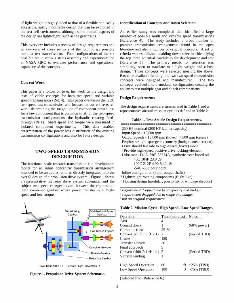
The RFT is comprised of three basic parts, the stator,
mounted in the stationary RFT support, the rotor, mounted
on the rotating shaft, and ring seals, separating and sealing
the passages between the rotor and stator.
The stator is sealed at the exterior with static o-rings and at
the interior with ring-seals. The stator has two anti-rotation
pins that engage in the RFT support housing. The rotor is shaft mounted and includes four external grooves for the
ring seals and three circumferential grooves with six radial
passages to provide uninterrupted flow during rotation. The
three-passage RFT is shown in Figure 12.
Figure 12. Hydraulic RFT and Support.
The shaft mounted RFT rotor sleeve with four ring seals
installed highlighting the three annular fluid grooves and
three of the six radial passages (three are diametrically
opposed) is shown in Figure 13. Aft slinger is not shown.
Figure 13. RFT Shaft Mounted Rotor and Ring Seals.
Rotating Feed-Through and Ring Seal Operation
Pressure forces applied to ring seals, relative to the RFT
stator sleeve and rotating rotor sleeve (mounted on output
shaft), are shown in a simplified image below in Figure 14.
Figure 14. RFT Sealing Arrangement Detail.
P1 is the fluid supply pressure at the RFT housing and P0 is
the pressure on the opposite side the ring seal within the
radial clearance (noted as gap in figure) between the RFT
rotor and stator. P0 may be atmospheric, internal to the
gearbox, or the pressure of an adjoining passage depending
upon its relative position within the multi-passage RFT.
The ring seal outside diameter is close fit mating with the stator bore. The inside diameter of the ring seal is designed
to provide clearance at the circumferential rotor groove. In
addition, the ring seal is narrower than the circumferential
rotor groove. The above geometry allows the ring seal to
move to one side or the other, also applying supply pressure
P1 at the inside diameter of the rings seal and a radial
outward pressure at the outside diameter resulting in the
rings remaining predominately stationary. The opposing
pressure, Po, is only applied to exposed face area of the ring
seal within the clearance. ΔP is applied to the net area of the
face of the ring seal in contact with the rotor at the side of
the circumferential rotor groove (reference: 2 inch nominal ring seal diameter). Note that the contacting area between
the ring seal and rotor is less than the pressurized area on the
opposite side of the ring seal, resulting in a higher net
contact pressure.
Ring Seal Material Usage in Production Automotive
Automatic Transmissions.
Both metal and nonmetallic ring seals are used in automatic
transmissions. A number of nonmetallic seal materials are used in newer applications with changes related to enhanced
performance. Some commercially available nonmetallic ring
seal materials and associated operating points as surveyed
and summarized are shown in Figure 15 (Reference 9).

7
Figure 15 shows a range of materials and their performance
as a function of operational pressure and sliding speed as
used in fifty production multi-speed and variable-speed
automatic automotive transmissions. Two of the materials
are used in the GRC two-speed transmissions. Vespel®, a polyimide, split rings are used in the RFT, and Teflon
(PTFE) solid (non-split) rings are used in the ADC.
Figure 15. Ring Seals in Automotive Applications
(Reference 9.)
Initially metal ring seals were used in the RFT but were
observed to experience high rates of wear. This was partly
due to the high release pressure required for the dry-clutch
as well as the high operating speeds. Vespel® rings seals,
coupled with lower pressures resulting from modifications to
the dry-clutch, and by design in the wet-clutch and alternate dry-clutch, significantly reduced ring wear at the RFT in the
high pressure passage(s) compared to metal ring seals.
Ring Seal Considerations
Contact pressure and sliding speed are two parameters that
influence ring seal performance. The design of other
components that receive the fluid passing through the RFT
can impact ring seal performance. It was pointed out that
the dry-clutch release force was reduced by modifying the
clutch spring stiffness, and has a direct impact on the
pressure within the RFT passage. A further reduction in release pressure could be obtained by increasing release
piston area. This was not possible with the dry-clutch due to
the existing annular piston diameter used in the commercial
hydraulic release bearing. Within the wet-clutch design, the
release piston area is increased to offset a higher clamping
force (higher release pressure) due to lower coefficients of
friction for wet-friction drive materials as compared to dry
friction materials.
In the wet-clutch design, the reduced release pressure is on
the order of twice the bearing lubrication pressure, or 145 psi
(1MPa), resulting in a differential pressure drop across the ring seals nearly equal to that of the pressure drop of the
sprag lubrication passage to atmosphere (gearbox internal
pressure). The above yields a uniform pressure distribution
across all ring seals resulting in improved pressure loads.
The ring seals used for the wet-clutch performed well with
the reduced pressure differentials.
RFT POWER LOSS EXPERIMENT
HARDWARE
An aspect in the development and design of a two-speed rotorcraft transmission is management of power losses
associated with the transmission components. Power loss
leads to increased engine power required and generates heat
that often requires incorporation of appropriately sized heat
exchangers for heat dissipation. The additional power and
heat exchangers add weight to the system. Therefore,
managing and minimizing power loss is an important aspect
in the design of a two-speed rotorcraft transmission.
Based on prior analytical estimates, RFT ring seal torque
was identified as a potential significant contributor to overall system power loss. The RFT warranted experimental
investigation into power loss for the differing operating
requirements associated with the three clutches as well as for
differing operational conditions during hover and cruise.
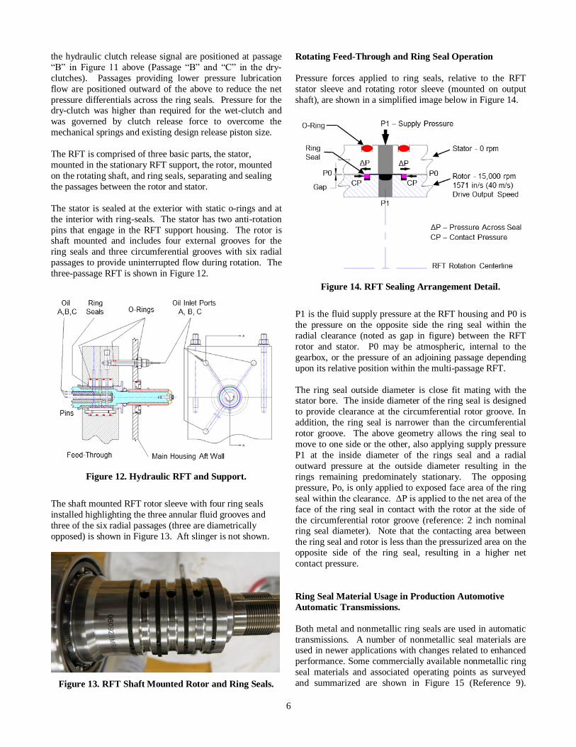
Taking advantage of the two-speed transmissions modular
design, an isolated RFT experiment was set up to measure
ring seal torque. The general RFT ring seal experimental
set-up used to measure ring seal frictional torque in the two-
speed transmissions is shown below in Figure 16.
Figure 16. RFT Torque Measurement Experiment.
The isolated RFT experimental set-up utilizes mostly
existing hardware, the output bearing support, rotating RFT
support, and output shaft. The forward end of the shaft is
capped with a test specific flange with integral machined
passages. Passages A, B, and C are either sealed with plugs
or open orifice jets, to simulate actual conditions for the two-
speed transmission designs and operating conditions. For
this test, the facility output motor (energy absorber), is used
8
to drive the shaft. Initially the RFT is run over the speed
range with no ring seals to obtain the baseline tare torque
associated with the duplex bearings. The ring seals are then
installed straddling passages, A, B, and C. Lubricant
conditions in the passages simulate hover and cruise modes for the two-speed transmission arrangements below:
Configuration 1: OCG / Dry-Clutch (ref. Figure A1*)
Configuration 3: OCG / Wet-Clutch (ref. Figure A3*)
* Two-Speed Configuration are shown in Appendix A.
The above configurations were selected based on prior tests
of the OCG and DSI gear trains with the dry-clutch where it
was concluded that the gear trains had negligible effect on
overall two-speed transmission system operation and that
differences were clutch dominated. The simpler OCG was
then used to test all clutches for direct comparison.
Aspects and Limits of the RFT Experimental Set-Up
The RFT experimental setup minimized overall component
count to simplify the measurement of power loss associated
specifically with the RFT to the extent possible. Torque,
which includes frictional losses from the RFT ring seals and
the duplex bearing support, was measured at the output shaft
torque meter. Power loss was then determined from the
measured torque and shaft speed, with torque equating to the
sum of the torque due duplex bearings and the RFT ring seal
friction torque. The tare duplex bearing torque was measured and subtracted to obtain RFT ring seal power loss.
Unfortunately, operating the shaft supported only by a single
duplex bearing pair and flexible drive coupling connecting
to the drive motor introduced a different set of rotordynamic
conditions than that of a full two-speed transmission. Due
to shaft rotordynamic response, the maximum operating
speed for the RFT experiments was limited to 10,000 rpm.
RFT EXPERIMENTS AND RESULTS
RFT Experimentation and Data Acquired
The experimental setup included sensors to measure and
record shaft speed, torque, lubricant supply flow rates and
pressures, clutch hydraulic passage supply pressure, several
lubricant and coolant temperatures, several accelerations, chip detector, and facility monitoring parameters such as
motor coolant flow and motor coolant supply pressure.
Calculated parameters include: power, angular velocity, and
angular acceleration. To measure the relatively small torque
magnitudes associated with the anticipated low power loss
values for the experimental set-up, the torquemeter was
calibrated with small static weights on a torque arm. Since
steady-state power loss data was being sought, acquired
sensor data was recorded at a rate of 5 Hertz. The facility
has a dedicated external lubrication system that supplies
filtered lubricant (DOD-L-85734 Ref. Table 1) to the
experimental hardware. Heated lubricant from the supply tank is pumped through a heat exchanger to control
temperature. Lubricant is scavenged from the experimental
hardware sumps and recirculated to the supply tank.
The experiments were run with the drive motor in “Speed”
control mode where the operating speed is specified and the facility motor control system provides feedback control to
hold the motor speed at the specified set point.
Lubricant supply pressure conditions to each channel of the
RFT hydraulic passages replicated the RFT operating
conditions for both hover and cruise mode. Experiments
measured total friction torque for the RFT ring seals and the
shaft support duplex bearing. Separate experiments were
performed with the RFT seals removed to measure the
power loss associated with the duplex bearing. Lubrication
to the duplex bearing is independently supplied to static
mounted oil jets and does not contribute to torque associated with the RFT component. For the experiments, hydraulic
pressure to the three separate RFT passages were set
differently depending on the specific transmission
arrangement and operating mode. Friction torque from the
RFT ring seals is related to oil flow for lubrication and
hydraulic pressure for clutch control. Multiple experiments
were conducted to measure RFT torque with fluid passage
supply pressures set for the dry-clutch or wet-clutch
transmission arrangements. The lubricant supply was set at
80 psi and 160 °F and clutch hydraulic pressure was
operated between 0 and 375 psi depending on the transmission clutch and flight mode condition.
The RFT has three separate passages for lubricant pressure
and flow. The center passage shares its ring seals with the
adjacent end passages. The outer ring seal on the outer
passages experience a differential pressure between the outer
passage lubricant pressure and ambient atmospheric
pressure. Power loss friction torque for a ring seal is related
to: 1) the seal sliding due to differential surface velocities for
the stationary RFT stator and the rotating output shaft; and
2) the differential pressure across each ring seal.
The following nomenclature is used to indicate the RFT
passage hydraulic pressure condition used in an experiment:
toward clutch | A | B | C | toward output shaft end
For example, for the Dry-Clutch two-speed rotorcraft
research transmission in cruise mode, the RFT “A” passage,
closest to the clutch assembly, is set at 80 psi pressure, while
the RFT “B” center passage, and the RFT “C” passage,
closest to the output shaft end, are both set at 375 psi
hydraulic pressure. Using the nomenclature convention this
condition is identified as: |80|375|375|.
Data Analysis and Trends
Numerous experiment runs were conducted to capture
steady-state data across a range of shaft speed conditions and
RFT hydraulic pressure conditions to simulate hover mode
and cruise modes for the two-speed rotorcraft research

9
transmissions with both Dry Clutch and Wet-Clutch. The
acquired torque data was processed to isolate steady-state
conditions using the following parameters between time
consecutive data points:
Angular shaft acceleration < /20 | rad/s2
Lube supply pressure change < 0.4 psi/s (nominal 80 psi) Clutch supply pressure change < 1.0 psi/s
The steady-state torque data (less duplex bearing tare torque)
was processed for each RFT hydraulic pressure condition
and the linear least squares method was used to fit an
equation to the data to relate ring seal friction torque to shaft
speed. A plot of the resulting ring seal torque for the Dry-
Clutch and Wet-Clutch configurations are shown in Figure
17 and Figure 18 respectively.
Figure 17. RFT Ring Seal Torque vs. Speed for the Dry-
Clutch Configuration at Indicated Clutch Pressure.
Figure 18. RFT Ring Seal Torque vs. Speed for the Wet-
Clutch Configuration at Indicated Clutch Pressure.
Experimental data linear trend line correlation coefficients, r2
Dry Clutch Engaged r2 = 0.0008; Disengaged r2 = 0.2
Wet Clutch Engaged r2 = 0.9; Disengaged r2 = 0.2
The torque trend line equations were extended to power loss
trend line equations shown below and plotted for the Dry-
Clutch in Figure 19.
Dry-Clutch disengaged (cruise): | 80 psi (sprag) | 375 psi (clutch) | 375 psi (clutch) |
Torque (in-lb) = 1.4E-4 × Ω + 20
Power (hp) = 2.4E-9 × Ω2 + 3.2E-4 × Ω
Torque (N-m) = 1.6E-5 × Ω + 2.3
Power (Watts) = 1.7E-6 × Ω2 + 2.4E-1 × Ω
Dry-Clutch engaged (hover):
| 80 psi (sprag) | 0 psi (clutch) | 0 psi (clutch) |
Torque (in-lb) = 1.2E-5 × Ω + 6.5
Power (hp) = 1.9E-10 × Ω2 + 1.0E-4 × Ω Torque (N-m) = 1.4E-6 × Ω + 0.73
Power (Watts) = 1.4E-7 × Ω2 + 7.7E-2 × Ω
Where Ω is shaft speed in revolutions per minute.
Figure 19. Rotating Feed-Through Power Loss for Dry-
Clutch Configuration.
Similarly the torque and power loss trend line equations are
provided below and plotted for the Wet-Clutch in Figure 20.
Wet-Clutch disengaged (cruise):
| 80 psi (sprag) | 200 psi (clutch) | 80 psi (bearing lube) |
Torque (in-lb) = 2.4E-04 × Ω + 14
Power (hp) = 3.9E-09 × Ω2 + 2.2E-04 × Ω Torque (N-m) = 2.8E-05 × Ω + 1.5
Power (Watts) = 2.9E-06 × Ω2 + 0.16 × Ω
Wet-Clutch engaged (hover):
| 80 psi (sprag) | 0 psi (clutch) | 80 psi (bearing lube) |
Torque (in-lb) = 4.7E-04 × Ω + 4.1
Power (hp) = 7.4E-09 × Ω2 + 6.5E-05 × Ω
Torque (N-m) = 5.3E-05 × Ω + 0.46
Power (Watts) = 5.5E-06 × Ω2 + 4.9E-02 × Ω
Where Ω is shaft speed in revolutions per minute.

10
Figure 20. Rotating Feed-Through Power Loss for Wet
Clutch Configuration.
Generalized Ring Seal Power Loss Equation
Using trend line functions that were fit to the experimental
data for the Dry Clutch and Wet Clutch hydraulic pressure
conditions applied to the RFT, an attempt was made to
develop a generalized equation for ring seal power loss as a
function of shaft speed and differential pressure across a ring
seal. For example the DC |80|0|0| condition was treated as
two ring seals with an 80 psi pressure differential on each ring seal. Similarly, the WC |80|0|80| condition represents
four ring seals with 80 psi pressure differential on each ring
seal. The WC |80|200|80| condition represents two ring seals
with 80 psi pressure differential and two ring seals with 120
psi pressure differential. The same reasoning was applied to
the DC |80|375|375| yielding one seal with 80 psi pressure
differential, one seal with 295 psi pressure differential, and
one seal with 375 psi pressure differential.
The coefficient in each trend line function for each condition
was scaled by the sum total pressure differential within the RFT. For example, for the WC |80|200|80| condition the
scaling was factor was 80+120+120+80 = 400 psi total
differential pressures. After scaling each trend line function
for the two DC and two WC pressure conditions, the
coefficients from the four equations were averaged to
develop the following generalized power loss equations for
one ring seal with a given pressure differential ΔP (in psi or
MPa).
Torque (in-lb) = (5.8E-07 × Ω + 2.8E-02) × ΔP
Power (hp) = (9.2E-12 × Ω2 + 4.5E-07 × Ω) × ΔP
Torque (N-m) = (6.6E-08 × Ω + 3.2E-03) × ΔP Power (W) = (6.9E-09 × Ω2 + 3.4E-04 × Ω) × ΔP
These generalized ring seal power loss equations are
simplifications that can provide broad approximations for
ring seal power loss and in some cases yield considerable
deviations from the experimental measurements. The
generalized ring seal power loss equations were compared
with the trend line power loss estimates for each DC and
WC condition. The percent error deviations between the
trend line equations and the generalized equation are shown
in Table 3 for 1,000 rpm and 7,500 rpm shaft speed.
Table 3. Comparison of Power Loss from Experimental
Data Trend Line Equations with Power Loss Estimates
from the Generalized Ring Seal Power Loss Equation.
Clutch
Drive
Ratio
RFT Passage Pres.
Diff.
ΔPSI
% Error
A
(psi)
B
(psi)
C
(psi)
1,000
Rpm
7,500
rpm
DC 1:1 80 0 0 160 -28 % -20 %
DC 2:1 80 375 375 750 7.8 % 16 %
WC 1:1 80 0 80 320 103 % 34 %
WC 2:1 80 200 80 400 -16 % -15 %
Graphs comparing the power loss between the experimental
data trend line and the generalized power loss equation are
shown in Figure 21 for the Dry-Clutch configuration and in Figure 22 for the Wet-Clutch configuration.
Figure 21. Comparison of RFT Power Loss between the
Experimental Data Trend Line and the Generalized
Power Loss Equation for the Dry Clutch Configuration,
| 80 psi (sprag) | Clutch | Clutch |

11
Figure 22. Comparison of RFT Power Loss between the
Experimental Data Trend Line and the Generalized
Power Loss Equation for the Wet Clutch Configuration,|
80 psi (sprag) | Clutch | 80 psi |
Ring Seals at the Alternate Dry-Clutch (ADC)
In the initial two-speed transmission design, ring seals were only used in the RFT. Derivative RFT designs were
incorporated into other conceptual transmission designs and
the ADC design (overviewed earlier; refer to Figure 7).
The ADC design requires transferring the hydraulic control
from the output shaft to the annular piston contained within
the ADC cover (housing), that is attached to the intermediate
hub that is attached to the aft end of the input shaft. The
above requires a single passage straddled by two ring seals.
In support of the above, additional experiments were
performed using the same hardware as in Figure 16, except that only a single passage was sealed by two solid (non-split)
Teflon ring seals, as employed in the ADC design, to
simulate the actual pressure differentials that the ring seals
experience at the ADC. Solid ring seals were selected to
minimize lubricant from reaching the carbon drive/driven
plates used in the ADC. Test speeds and pressures simulated
design conditions within the ADC clutch. Tests for this area
focused on minimizing leakage, not on power loss.
Ring seals used at the ADC conditions differ from the
original DC, and also differ from those in the RFT. Within the ADC, at 15,000 rpm input design speed, ring seal speed
is limited to a differential speed of 0 rpm to 7,500 rpm. At
hover, the relative differential speed is 0 rpm with a pressure
of 200 psi since the ADC clutch is engaged (hover 1:1, ADC
clutch engaged transferring power and sprag is overrunning).
At cruise, the relative differential speed is 7,500 rpm and a
pressure of 0 psi (cruise 2:1, ADC clutch released and power
transferred through the sprag).
Both of the above steady-state conditions are more benign
on the ring seals than during shifts. The most severe shift is the cruise-to-hover, 2:1 to 1:1 upshift, where pressure is
ramped from 0 psi to 200 psi concurrently with differential
speed decreasing from 7,500 rpm to 0 rpm, as the carbon
drive and driven plates slip and engage when the output
shaft reaches the same rpm as the input shaft. Down shifting
from hover 1:1 to cruise 2:1 is also benign as the ADC
clutch is released, and the output shaft slows until the speed
matches the low speed shaft, and the sprag clutch engages.
As stated earlier, the goal of these tests was to verify
favorable operation of the ADC with no concern of
associated local power loss for these two ring seals. Any significant power loss occurs at the RFT.
RFT EXPERIMENT LESSONS LEARNED
Based on development and experimentation with the RFT, the following observations and enhancements are noted.
The RFT ring seal power loss is a relatively small
contributor to the overall transmission power loss. RFT
power loss does not scale with system power, but is a
function of diameter, speed, and pressure. RFT power loss
increases when the overall transmission design power level
requires larger diameter shafting, and in turn, larger ring
seals, or when speed increases, or passage pressure
differential increases.
The RFT and overall transmission power loss can be reduced by designing any components supplied through the RFT
with low operating pressures (e.g., clutch release, or
application pressure).
The RFT in the two-speed transmission used ring seals that
were standard commercial products as well as the
installation geometry. Due to different operating conditions,
future design should include a detailed design optimization
with respect to operating temperatures and geometry.
The RFT rotor outer diameter can be optimized to increase net area in contact with the face side of the ring seal to
reduce the effective contact pressure, thereby reducing wear,
and improving seal life.
The RFT rotor ring seal width should be widened slightly to
ensure that pressure fluid is at the inside diameter of the ring
seal and is applied radially outward to the RFT stator.
The RFT power loss at nominal 80 psi differential pressure
is found to be low and can be a reasonable option to supply
lubrication at nominal 80 psi internal to a rotating system
within a housing where seals are not required to be leak free.

12
Low wear, high-speed, ring seals such as those made from
polyimide material performed well for the experimental time
accumulated.
RVLT TECHNICAL CHALLENGE
Transmission Power Loss Technical Challenge
Configuration 1: OCG/DC was selected to scale a 1000 HP
rated design using analytical and experimental data and
access the power losses associated with bearings, gear meshes, RFT, overrunning sprag, and windage. RFT power
loss experiments and overrunning sprag power loss
optimization experiments support the above. The exercise
verified a RVLT program milestone technical challenge, that
a two-speed design, combined with lightweight components,
can provide a 50% speed change with less than 2% power
loss and with no increase in weight. A comparison of total
power losses for all three transmissions is shown below in
the upper portion of Figure 23.
Figure 23. Relative power loss comparison
Configurations 1, 3, and 4.
It should be noted in the lower portion of Figure 23 that the
RFT power losses are relatively small and decreased from
2.5 hp to 1.6 hp during cruise and increases from 1.6 hp to
1.8 hp during hover comparing the OCG/DC and OCG/ADC
configurations. This is due to reduced clutch operating
pressure resulting from increased annular piston area and the more strategic reversed operating scheme, where clutch
engagement is released during cruise and is pressurized
during hover.
POTENTIAL RFT ENHANCEMENT In addition to reducing clutch operating pressure, potential
improvements in RFT performance can be obtained with
lower sliding speed. Design speed is usually a fixed
requirement. Ring seals employed in the GRC two-speed
transmission test articles and variable-speed concepts
operate at speeds near, or higher than, recommended. To
take advantage of potential improvements through reduced
sliding speed, a concept was conceived that reduced the
surface sliding speed at the ring seals while maintaining
machine speed. The concept introduces an intermediate rotor sleeve, located between the original rotor sleeve and
stator sleeve, separated by ring seals. This doubles the
number of required ring seals but can reduce the tangential
sliding rubbing speed by nearly 40% for the given RFT.
The intermediate rotor is supported on bearings and operates
at speed below the machine design speed, thereby creating a
reduced relative speed at the ring seals. Within the overall
budget for this transmission project, the concept was not
pursued since seal life was not a near term concern and was
thought as research for others working in seals. The concept
is presented in Appendix B.
OVERRUNING SPRAG POWER LOSS
The sprag clutch is the other component common to all of
the GRC two-speed transmissions. The sprag clutch
overruns during hover 1:1 mode and is engaged during cruise 2:1 mode. A paper describing experiments and results
for power-loss associated with a continuously overrunning
sprag clutch during hover mode is planned for later this year
in a corresponding paper to be titled “Two-Speed Rotorcraft
Research Transmission Power-Loss Associated with a
Continuously Overrunning Sprag Clutch”.
CONCLUDING REMARKS
This paper has summarized the results of isolated
experiments for a RFT design feature that employs simple
ring seals and is a key component in the array of inline
concentric two-speed transmissions designed, manufactured,
and tested at GRC for advanced high-speed rotorcraft.
Lessons learned from the design and experiments with the
RFT in the two-speed transmission test hardware can be
used to guide and aid in the design of an intermediate power version and may be applicable to other designs using similar
components.
Author contact:
Mark A. Stevens [email protected]
Mark J. Valco [email protected]
Kelsen E. LaBerge [email protected]

13
REFERENCES
1. Johnson, W. and Yamauchi, G.K., Watts, M.E., “NASA Heavy Lift Study,” NASA/TP-2005-213467, 2005. 2. Kish, J., “Vertical Lift Drive System Concept Studies Variable Speed/Two-Speed Transmissions”, NASA/CR—2002-211564, ARL–CR–495, 2002. 3. Bossler, R.B. Jr., “Vertical Lift Drive System Concepts Studies,” NASA/CR—2002-211563, 2002. 4. Stevens, M.A., Lewicki, D.G., and Handschuh, R.F., “Variable/Multispeed Rotorcraft Drive System Concepts”, NASA/TM-215456, ARL-TR-4758, 2009. 5. Stevens, M.A., Lewicki, D.G., and Handschuh, R.F., “Concepts for Variable/Multi-Speed Rotorcraft Drive System”, American Helicopter Society 64th Annual Forum Proceedings, Montreal, Canada, April 2008, NASA/TM-215276, ARL-TR-4562, 2008. 6. Snyder, C.A., “Defining Gas Turbine Engine Performance Requirements for the Large Civil TiltRotor (LCTR2), NASA/TM-2013-218101. 7. Stevens, M.A., Lewicki, D.G., and Handschuh, R.F., “Concepts for Multi-Speed Rotorcraft Drive System - Status of Design and Testing at NASA GRC”, American Helicopter Society 71st Annual Forum Proceedings, Virginia Beach, Virginia USA, May 2015. 8. Lewicki D.G. and Stevens, M.A., “Testing of Two-Speed Transmission Configurations for use in Rotorcraft”, NASA/TM-2015-218816, June 2015. 9. Sekiguchi, S., Suzuki, H., Van Ryper, R.G., and Ritchey, D.J., “Development of a new high performance material to improve vehicle efficiency by reducing frictional and parasitic energy losses in transmission components”, Internet: http://www2.dupont.com/Vespel/en_US/assets/downloads/vespel_s/Vespel2515WhitePaperVan_Ryper_Sekiguchi.pdf
APPENDICES
A - Transmission Configurations
B - Reduced Speed Dual Ring Seal Rotating Feed-Through
(RSDRS-RFT) and Ring Seal Operation

14
APPENDIX A
Transmission Configurations
The rotating assemblies for four of six possible two-speed
transmission configurations are shown. The remaining two
configurations are possibilities that were not tested.
Configuration Figure
1: OCG / Dry-Clutch, A1
2: DSI / Dry-Clutch, A2
3 OCG / Wet-Clutch. A3
4: OCG / Alternate-Dry Clutch A4
Figure A1. Configuration 1: OCG Gear / Dry-Clutch
Figure A2. Configuration 2: DSI Planetary / Dry-Clutch
Figure A3. Configuration 3: OCG Gear / Wet-Clutch.
Figure A4. Configuration 4: OCG / Alternate Dry-Clutch
15
APPENDIX B
Reduced Speed Dual Ring Seal Rotating Feed-Through
(RSDRS-RFT) and Ring Seal Operation
Throughout design and test of various configurations of the
GRC two-speed drive, lowering clutch operating pressure
has been a focus to minimize power loss at the RFT. In the
initial commercial dry-clutch used in Configuration 1,
OCG/DC control pressure was lowered by altering the clutch
and removing one of two diaphragm disc springs, thereby
reducing clamping (driving) pressure 50%. Required release
pressure was also high due to the small cross section area piston approximately one square inch in the hydraulic
release bearing (HRB). In designing the wet-clutch, as well
as during the design of the alternate dry-clutch, pressure area
of the annular pistons was significantly increased as there
was no mechanical advantage present as in the diaphragm
disc spring used in the original dry-clutch. During design
evolution, the required hydraulic pressure was reduced twice
by a factor of two. Within geometry constraints pressure
reduction was exploited to the extent possible.
To further improve the ring seal operating conditions and move toward the lower left of the graph previously presented
in Figure 15, the remaining avenue to consider is tangential
sliding speed at the ring seal side face. The objective of
reducing the tangential speed at the ring seal is both
increasing seal life as well as possibly extending the
operating speed of the shaft. For the two-speed transmission
design, improving service life is the goal since the shaft
speed is a design constraint. The concept conceived has the
potential to reduce tangential speed at the ring seal to 60% of
the shaft speed, moving the operating points to the left in
Figure 15. Conversely, machine output shaft speed could be
increased by nearly 167% if the operating point(s) were close to the “not recommended” side of a respective curve.
Lowering tangential speed at the ring seal, was considered
but not designed nor tested. The concept was developed to
the level to test either independently, as in the subject ring
seal component set-up, or to be incorporated as an integral
feature to the existing RFT to test with any of the GRC two-
speed transmissions.
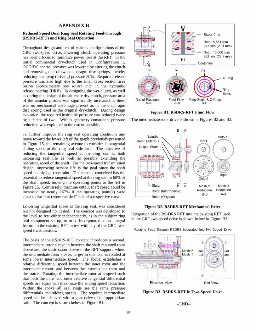
The basis of the RSDRS-RFT concept introduces a second,
intermediate, rotor sleeve in between the shaft mounted rotor sleeve and the static stator sleeve in the RFT support, where
the intermediate rotor sleeve, larger in diameter is rotated at
some lower intermediate speed. The above, establishes a
relative differential speed between the inner rotor and the
intermediate rotor, and between the intermediate rotor and
the stator. Rotating the intermediate rotor at a speed such
that both the inner and outer relative tangential differential
speeds are equal will maximize the sliding speed reduction.
Within the above all seal rings see the same pressure
differentials and sliding speeds. The required intermediate
speed can be achieved with a gear drive of the appropriate
ratio. The concept is shown below in Figure B1.
Figure B1. RSDRS-RFT Fluid Flow
The intermediate rotor drive is shown in Figures B2 and B3.
Figure B2. RSDRS-RFT Mechanical Drive
Integration of the RS-DRS RFT into the existing RFT used
in the GRC two speed drive is shown below in Figure B3.
Figure B3. RSDRS-RFT in Two-Speed Drive
--END--