Embed Size (px)
Citation preview
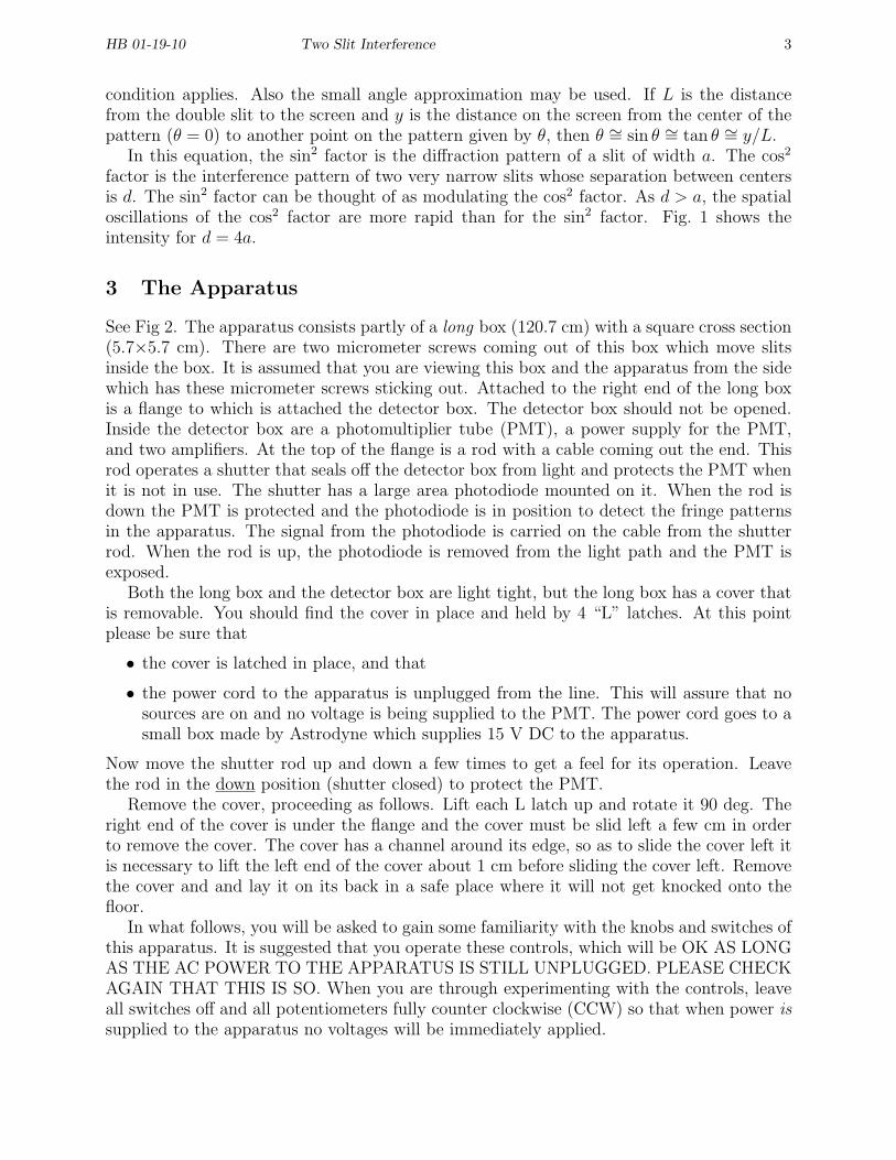
HB 01-19-10 Two Slit Interference 1
Two Slit Interference
Equipment Teach Spin two slit interference apparatus, Teach Spin Cricket, Fluke multimeterwith BNC to banana plug leads, Tektronix TD 1002 scope and manual, 2 BNC to BNC cables,Tenma 72-4095 counter, small mirror, toothpicks, TeachSpin “T” cards for observing lightbeam, plastic alignment jig, flashlight with pencil beam, magnifying glass
MUST Reading “The Feynman Lectures on Physics”, R.P. Feynman, R.B. Leighton, and M.Sands (Addison Wesley 1965) or Vol. I, Ch. 37; Vol. III, ch. 1. These two chapters areessentially identical.
Review Reading From a textbook, one and two slit interference patterns
PRECAUTIONS
1. PHOTOMULTIPLIER TUBE- This tube can be damaged or destroyed if exposed to allbut the weakest light, even if voltage is not applied to the tube. The tube is protectedby a shutter. The shutter is opened by raising a rod at the detector end of the apparatus.The rod has a BNC cable coming out the top of it. This shutter should not be openedunless:
• the cover is on the apparatus and properly secured with the 4 “L” latches.
• the Laser-Off-Bulb switch is in the off position
• the potentiometer controlling the intensity of the bulb source is fully CCW (dial atzero).
• the switch that turns on the photomultiplier tube (PMT) voltage is in the offposition.
• the multi-turn potentiometer controlling the PMT voltage is fully CCW (dial atzero)
• the photomultiplier output is monitored on the scope.
THE LASER SOURCE SHOULD NEVER BE USED WITH THE SHUTTER OPEN.IT’S LIGHT IS FAR TOO INTENSE FOR THE PHOTOMULTIPLIER TUBE.
These instructions will become clear when the apparatus is described.
2. The laser source is modest in power (5 mW). Nevertheless, do not shine it directly inyour eye, and do not use the mirror provided when using the laser source. Use themirror only with the bulb source.
3. There is an interference filter on the end of the bulb source. You will remove this filterfor some of the procedures. Please keep your fingers off this filter.
1 Wave-Particle Duality
Is light a wave or a particle? The Dutch physicist Christiann Huygens (1629-1695) advocatedthat light was a wave. Huygens’ principle is often used to describe how waves in generalpropagate. In 1704 Newton published the first edition of his book Optiks in which he
HB 01-19-10 Two Slit Interference 2
championed the notion that light consisted of particles which we now call photons. ThomasYoung performed a two slit interference experiment in 1801. The dark bands observed byYoung can only be explained by destructive interference, a wave, not a particle, property.Maxwell’s equations, with their wave solutions, also supports a wave theory for light. Onthe other hand in the early 20th century there were phenomena involving light that couldonly be explained by a particle theory. Examples are the photoelectric and Compton effects.Is light a wave or a particle? It is both, but not at the same time. Whether the particleor wave description is used depends on what question is being asked. Questions about thepropagation of light require wave theory. Some questions about the interaction of light withmatter require the particle theory. This is commonly called wave-particle duality. There isnothing in our macroscopic world that corresponds to this duality.
You have seen two slit interference patterns, and may well have observed them in a lab.The interference pattern can only be explained by a wave theory. This experiment is areally good two slit interference experiment with slits that can be controlled by micrometersscrews. The positions of the maxima and minima can be determined quite precisely, andone or the other of the two slits can be blocked off. When you block off one slit there aredetector positions where the light intensity actually increases!
In this apparatus there are two light sources and two detectors of light intensity. By farthe stronger source is a laser diode. For use with this source a photodiode detector is used.This source and detector are very useful for aligning the apparatus and easily getting gooddiffraction patterns.
The other source is an incandescent light bulb equipped with a narrow band interferencefilter. This source is operated at such low power that it is necessary to use a PMT as adetector. It is possible to reduce the intensity of the light so that in the apparatus there isat best one photon in transit at any given time. Nevertheless, if at this low intensity enoughtime is taken to measure the interference pattern the same results for the interference patternare obtained as when higher intensities are used and many photons are in the apparatus atthe same time. How is it possible that an interference pattern is produced when there is atbest only one photon in the apparatus at one time?
Using somewhat the same train of thought, at these low intensities is it possible to askwhich slit a photon went through? The answer is no if you wish to keep the usual two slitinterference pattern. Any measurement sensitive enough to tell you which slit the photonwent through destroys the two slit interference pattern. Read Feynman!
2 Theory
Consider a monochromatic plane wave incident normally on two parallel slits each of widtha and with a distance between their centers of d. Let θ be the angle between the normal tothe plane of the slits and the direction of observation. The intensity I(θ) is given by
I = I0 cos2[πd sin θ/λ]
(sin[πa sin θ/λ]
πa sin θ/λ]
)2
, (1)
where I0 is the intensity in the forward direction (θ = 0) and λ is the wavelength of thelight. For what values of θ is the intensity I is the intensity zero? You may assume that thepattern is observed on a screen so distant from the two slits that the far field or Fraunhofer
HB 01-19-10 Two Slit Interference 3
condition applies. Also the small angle approximation may be used. If L is the distancefrom the double slit to the screen and y is the distance on the screen from the center of thepattern (θ = 0) to another point on the pattern given by θ, then θ ∼= sin θ ∼= tan θ ∼= y/L.
In this equation, the sin2 factor is the diffraction pattern of a slit of width a. The cos2
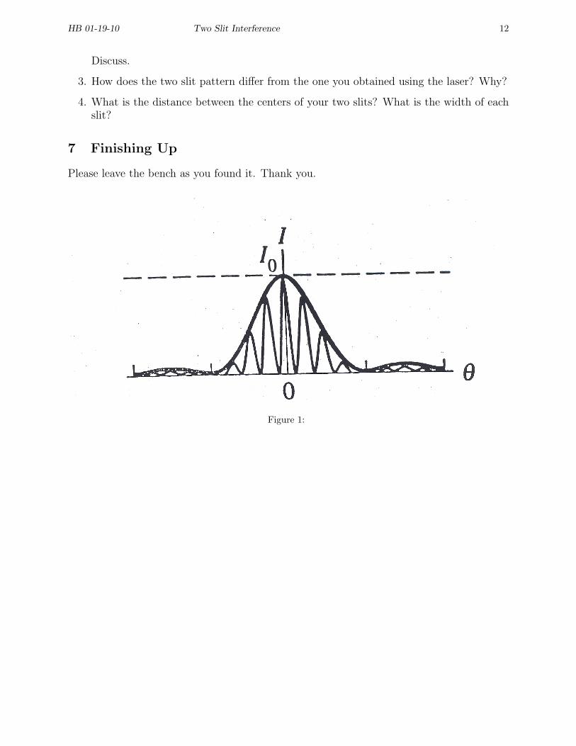
factor is the interference pattern of two very narrow slits whose separation between centersis d. The sin2 factor can be thought of as modulating the cos2 factor. As d > a, the spatialoscillations of the cos2 factor are more rapid than for the sin2 factor. Fig. 1 shows theintensity for d = 4a.
3 The Apparatus
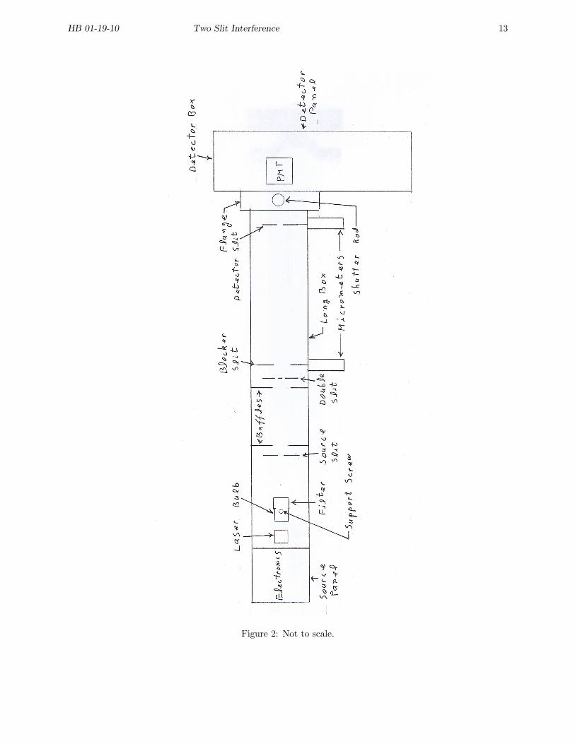
See Fig 2. The apparatus consists partly of a long box (120.7 cm) with a square cross section(5.7×5.7 cm). There are two micrometer screws coming out of this box which move slitsinside the box. It is assumed that you are viewing this box and the apparatus from the sidewhich has these micrometer screws sticking out. Attached to the right end of the long boxis a flange to which is attached the detector box. The detector box should not be opened.Inside the detector box are a photomultiplier tube (PMT), a power supply for the PMT,and two amplifiers. At the top of the flange is a rod with a cable coming out the end. Thisrod operates a shutter that seals off the detector box from light and protects the PMT whenit is not in use. The shutter has a large area photodiode mounted on it. When the rod isdown the PMT is protected and the photodiode is in position to detect the fringe patternsin the apparatus. The signal from the photodiode is carried on the cable from the shutterrod. When the rod is up, the photodiode is removed from the light path and the PMT isexposed.
Both the long box and the detector box are light tight, but the long box has a cover thatis removable. You should find the cover in place and held by 4 “L” latches. At this pointplease be sure that
• the cover is latched in place, and that
• the power cord to the apparatus is unplugged from the line. This will assure that nosources are on and no voltage is being supplied to the PMT. The power cord goes to asmall box made by Astrodyne which supplies 15 V DC to the apparatus.
Now move the shutter rod up and down a few times to get a feel for its operation. Leavethe rod in the down position (shutter closed) to protect the PMT.
Remove the cover, proceeding as follows. Lift each L latch up and rotate it 90 deg. Theright end of the cover is under the flange and the cover must be slid left a few cm in orderto remove the cover. The cover has a channel around its edge, so as to slide the cover left itis necessary to lift the left end of the cover about 1 cm before sliding the cover left. Removethe cover and and lay it on its back in a safe place where it will not get knocked onto thefloor.
In what follows, you will be asked to gain some familiarity with the knobs and switches ofthis apparatus. It is suggested that you operate these controls, which will be OK AS LONGAS THE AC POWER TO THE APPARATUS IS STILL UNPLUGGED. PLEASE CHECKAGAIN THAT THIS IS SO. When you are through experimenting with the controls, leaveall switches off and all potentiometers fully counter clockwise (CCW) so that when power issupplied to the apparatus no voltages will be immediately applied.

HB 01-19-10 Two Slit Interference 4
On the side of the detector box is the detector panel. This panel is divided into 5 areas.
1. Photodiode- There are two BNC connectors. The one marked INPUT should be con-nected to the cable from the shutter rod. When the photodiode is being used, theOUTPUT should be connected to the (Fluke) multimeter by a cable which has a BNCconnector on one end and a double banana plug on the other end.
2. High Voltage- There is an off-on switch which turns the power to the PMT high voltagesupply on and off. A 10 turn potentiometer adjusts the voltage. The numbers on thepotentiometer are not a good measure of the voltage. When the PMT is being used, thetwo monitor jacks should be connected to the multimeter in the DC volts mode. ThePMT voltage is about the multimeter voltage times 1000. Reasonable PMT voltagesbegin at around 540 V, or a multimeter DC voltage of 0.54 V.
3. Photomultiplier- When the PMT is being used, the OUTPUT BNC should be connectedto channel 1 of the scope. This output is actually not the last dynode of the PMT. Itis the output of a charge sensitive pulse amplifier whose input is the PMT. The SMAconnector marked INPUT TEST PULSE allows a test pulse to be applied to the inputof the amplifier. Leave the cover on this connector.
4. Discriminator- The BNC marked OUTPUT TTL (transistor-transistor Logic) shouldbe connected either to channel 2 of the scope or to channel A of the counter. When thediscriminator LEVEL potentiometer is properly adjusted, a TTL pulse is delivered foreach pulse delivered by the PMT. Each of the TTL pulses is a rectangular pulse withone level at ground, the other level at about 4 V, and a duration of about 300 ns.
5. DC Power- Power is provided to the detector box by the connector attached to thispanel. The power comes from the other end of the apparatus.
Facing you at the left end of the long box is the source panel. This contains the followingitems.
• Source Switch- This 3 position switch turns the laser on, the bulb source on, or turnsboth sources off.
• Bulb Power- This potentiometer adjusts the power to the bulb source when when thesource switch is on bulb.
• Laser Mod Input- Allows modulation of the laser source.
• DC Output- Supplies power to the detector box.
• DC Input- Input power for the apparatus supplied by the Astrodyne power supply.
• Alarm- Goes off if power is being supplied to the apparatus and you are doing somethingthat is not good for the PMT.
Looking inside the long box, at the left end are the electronics for the sources. Theelectronics are separated from the rest of the long box by a solid light baffle. There are alsotwo other light baffles inside the long box which you should identify. These baffles have halfinch diameter circular holes to allow the light to travel through the apparatus. The light
HB 01-19-10 Two Slit Interference 5
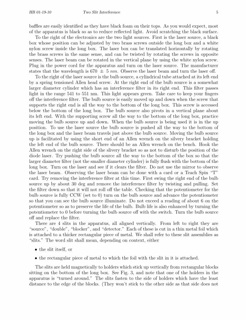
baffles are easily identified as they have black foam on their tops. As you would expect, mostof the apparatus is black so as to reduce reflected light. Avoid scratching the black surface.
To the right of the electronics are the two light sources. First is the laser source, a blackbox whose position can be adjusted by two brass screws outside the long box and a whitenylon screw inside the long box. The laser box can be translated horizontally by rotatingthe brass screws in the same sense, and can be twisted by rotating the screws in oppositesenses. The laser beam can be rotated in the vertical plane by using the white nylon screw.Plug in the power cord for the apparatus and turn on the laser source. The manufacturerstates that the wavelength is 670 ± 5 nm. Observe the laser beam and turn the laser off.
To the right of the laser source is the bulb source, a cylindrical tube attached at its left endby a spring tensioned Allen head screw. At the right end of the bulb source is a somewhatlarger diameter cylinder which has an interference filter in its right end. This filter passeslight in the range 541 to 551 nm. This light appears green. Take care to keep your fingersoff the interference filter. The bulb source is easily moved up and down when the screw thatsupports the right end is all the way to the bottom of the long box. This screw is accessedbelow the bottom of the long box. The bulb source also pivots in a vertical plane aboutits left end. With the supporting screw all the way to the bottom of the long box, practicemoving the bulb source up and down. When the bulb source is being used it is in the upposition. To use the laser source the bulb source is pushed all the way to the bottom ofthe long box and the laser beam travels just above the bulb source. Moving the bulb sourceup is facilitated by using the short end of an Allen wrench on the silvery bracket holdingthe left end of the bulb source. There should be an Allen wrench on the bench. Hook theAllen wrench on the right side of the slivery bracket so as not to disturb the position of thediode laser. Try pushing the bulb source all the way to the bottom of the box so that thelarger diameter filter (not the smaller diameter cylinder) is fully flush with the bottom of thelong box. Turn on the laser and see if it clears the filter. Do not use the mirror to observethe laser beam. Observing the laser beam can be done with a card or a Teach Spin “T”card. Try removing the interference filter at this time. First swing the right end of the bulbsource up by about 30 deg and remove the interference filter by twisting and pulling. Setthe filter down so that it will not roll off the table. Checking that the potentiometer for thebulb source is fully CCW (set to 0) turn on the bulb source and advance the potentiometerso that you can see the bulb source illuminate. Do not exceed a reading of about 6 on thepotentiometer so as to preserve the life of the bulb. Bulb life is also enhanced by turning thepotentiometer to 0 before turning the bulb source off with the switch. Turn the bulb sourceoff and replace the filter.
There are 4 slits in the apparatus, all aligned vertically. From left to right they are“source”, “double”, “blocker”, and “detector.” Each of these is cut in a thin metal foil whichis attached to a thicker rectangular piece of metal. We shall refer to these slit assemblies as“slits.” The word slit shall mean, depending on context, either
• the slit itself, or
• the rectangular piece of metal to which the foil with the slit in it is attached.
The slits are held magnetically to holders which stick up vertically from rectangular blockssitting on the bottom of the long box. See Fig. 3, and note that one of the holders in theapparatus is “turned around.” The slits fasten to the side of holders which have the leastdistance to the edge of the blocks. (They won’t stick to the other side as that side does not
HB 01-19-10 Two Slit Interference 6
have the magnet.) Either side of the slits will stick to the magnetized holder but they willstick better if the foil is away from the holder.
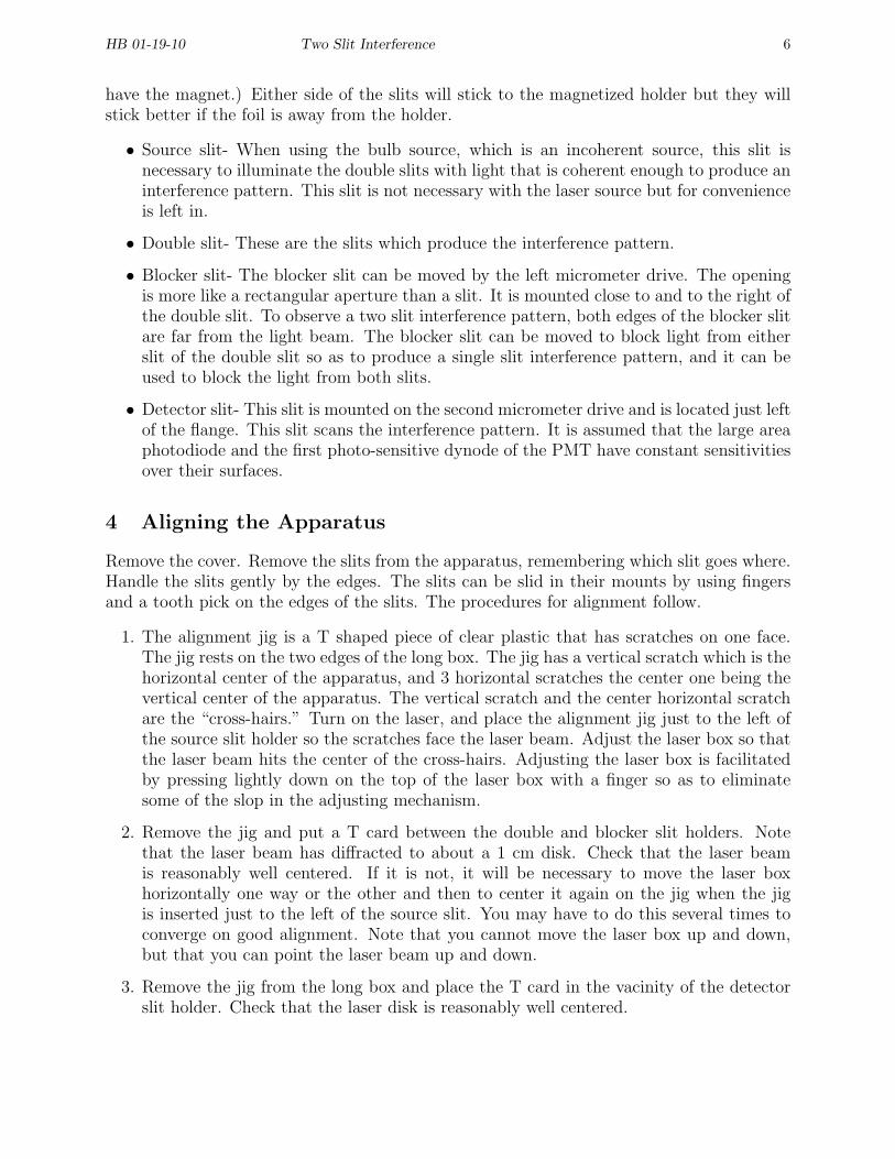
• Source slit- When using the bulb source, which is an incoherent source, this slit isnecessary to illuminate the double slits with light that is coherent enough to produce aninterference pattern. This slit is not necessary with the laser source but for convenienceis left in.
• Double slit- These are the slits which produce the interference pattern.
• Blocker slit- The blocker slit can be moved by the left micrometer drive. The openingis more like a rectangular aperture than a slit. It is mounted close to and to the right ofthe double slit. To observe a two slit interference pattern, both edges of the blocker slitare far from the light beam. The blocker slit can be moved to block light from eitherslit of the double slit so as to produce a single slit interference pattern, and it can beused to block the light from both slits.
• Detector slit- This slit is mounted on the second micrometer drive and is located just leftof the flange. This slit scans the interference pattern. It is assumed that the large areaphotodiode and the first photo-sensitive dynode of the PMT have constant sensitivitiesover their surfaces.
4 Aligning the Apparatus
Remove the cover. Remove the slits from the apparatus, remembering which slit goes where.Handle the slits gently by the edges. The slits can be slid in their mounts by using fingersand a tooth pick on the edges of the slits. The procedures for alignment follow.
1. The alignment jig is a T shaped piece of clear plastic that has scratches on one face.The jig rests on the two edges of the long box. The jig has a vertical scratch which is thehorizontal center of the apparatus, and 3 horizontal scratches the center one being thevertical center of the apparatus. The vertical scratch and the center horizontal scratchare the “cross-hairs.” Turn on the laser, and place the alignment jig just to the left ofthe source slit holder so the scratches face the laser beam. Adjust the laser box so thatthe laser beam hits the center of the cross-hairs. Adjusting the laser box is facilitatedby pressing lightly down on the top of the laser box with a finger so as to eliminatesome of the slop in the adjusting mechanism.
2. Remove the jig and put a T card between the double and blocker slit holders. Notethat the laser beam has diffracted to about a 1 cm disk. Check that the laser beamis reasonably well centered. If it is not, it will be necessary to move the laser boxhorizontally one way or the other and then to center it again on the jig when the jigis inserted just to the left of the source slit. You may have to do this several times toconverge on good alignment. Note that you cannot move the laser box up and down,but that you can point the laser beam up and down.
3. Remove the jig from the long box and place the T card in the vacinity of the detectorslit holder. Check that the laser disk is reasonably well centered.
HB 01-19-10 Two Slit Interference 7
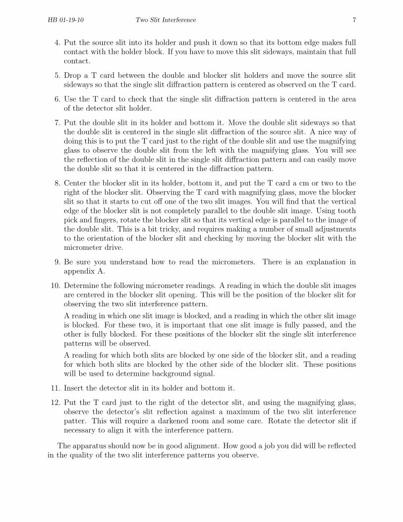
4. Put the source slit into its holder and push it down so that its bottom edge makes fullcontact with the holder block. If you have to move this slit sideways, maintain that fullcontact.
5. Drop a T card between the double and blocker slit holders and move the source slitsideways so that the single slit diffraction pattern is centered as observed on the T card.
6. Use the T card to check that the single slit diffraction pattern is centered in the areaof the detector slit holder.
7. Put the double slit in its holder and bottom it. Move the double slit sideways so thatthe double slit is centered in the single slit diffraction of the source slit. A nice way ofdoing this is to put the T card just to the right of the double slit and use the magnifyingglass to observe the double slit from the left with the magnifying glass. You will seethe reflection of the double slit in the single slit diffraction pattern and can easily movethe double slit so that it is centered in the diffraction pattern.
8. Center the blocker slit in its holder, bottom it, and put the T card a cm or two to theright of the blocker slit. Observing the T card with magnifying glass, move the blockerslit so that it starts to cut off one of the two slit images. You will find that the verticaledge of the blocker slit is not completely parallel to the double slit image. Using toothpick and fingers, rotate the blocker slit so that its vertical edge is parallel to the image ofthe double slit. This is a bit tricky, and requires making a number of small adjustmentsto the orientation of the blocker slit and checking by moving the blocker slit with themicrometer drive.
9. Be sure you understand how to read the micrometers. There is an explanation inappendix A.
10. Determine the following micrometer readings. A reading in which the double slit imagesare centered in the blocker slit opening. This will be the position of the blocker slit forobserving the two slit interference pattern.
A reading in which one slit image is blocked, and a reading in which the other slit imageis blocked. For these two, it is important that one slit image is fully passed, and theother is fully blocked. For these positions of the blocker slit the single slit interferencepatterns will be observed.
A reading for which both slits are blocked by one side of the blocker slit, and a readingfor which both slits are blocked by the other side of the blocker slit. These positionswill be used to determine background signal.
11. Insert the detector slit in its holder and bottom it.
12. Put the T card just to the right of the detector slit, and using the magnifying glass,observe the detector’s slit reflection against a maximum of the two slit interferencepatter. This will require a darkened room and some care. Rotate the detector slit ifnecessary to align it with the interference pattern.
The apparatus should now be in good alignment. How good a job you did will be reflectedin the quality of the two slit interference patterns you observe.
HB 01-19-10 Two Slit Interference 8
5 Experiment Using Laser Source
In this part of the experiment the two slit interference pattern is examined using the lasersource and the photodiode detector. The signal to noise ratio is high and there are lots ofphotons in the apparatus at any given instant of time. Due to the precision of the apparatusand blocker slit, a number of interesting phenomena can be observed.
Adjust the position of the blocker slit so that the light from both slits is passed. Withoutdisturbing the laser, be sure the bulb source is out of the way and at the bottom of the longbox. Put the cover on the long box and latch it. The shutter rod should be down, and itscable connected to the photodiode INPUT connector. Connect the photodiode OUTPUTconnector to the Fluke multimeter using the cable with a BNC connector on one end andtwo banana plugs on the other end. Set the Fluke to DC voltage and turn the laser on. Scanthe detector slit using the micrometer screw and observe the photodiode voltage. At thepeaks in the pattern you should see 0.5 V or more on the Fluke. If the apparatus alignmentis really good, you might see 2.4 V on the Fluke. Momentarily turn the laser off and recorda background voltage reading. This should be subtracted from your voltage readings withthe laser on.
Scan the two slit interference pattern by moving the detector slit with the micrometerscrew. At each position of the detector slit that you choose, record the Fluke voltage. Startby measuring the intensity at all maximums and minimums out to the second minimumson either side of the peak of the single slit pattern. If you have time later you can fill insome extra points. Take some background readings by blocking both slits and subtract thebackground from your data. Plot your results with position on the x-axis and intensity onthe y-axis.
Move the blocker slit so that the light from only one slit is passed, and scan the pattern outto the second minimum. Use your judgment as to where to make measurements. Subtractbackground from your data. Plot these results. Repeat for light from the other slit.
Examine your plots and answer the following questions.
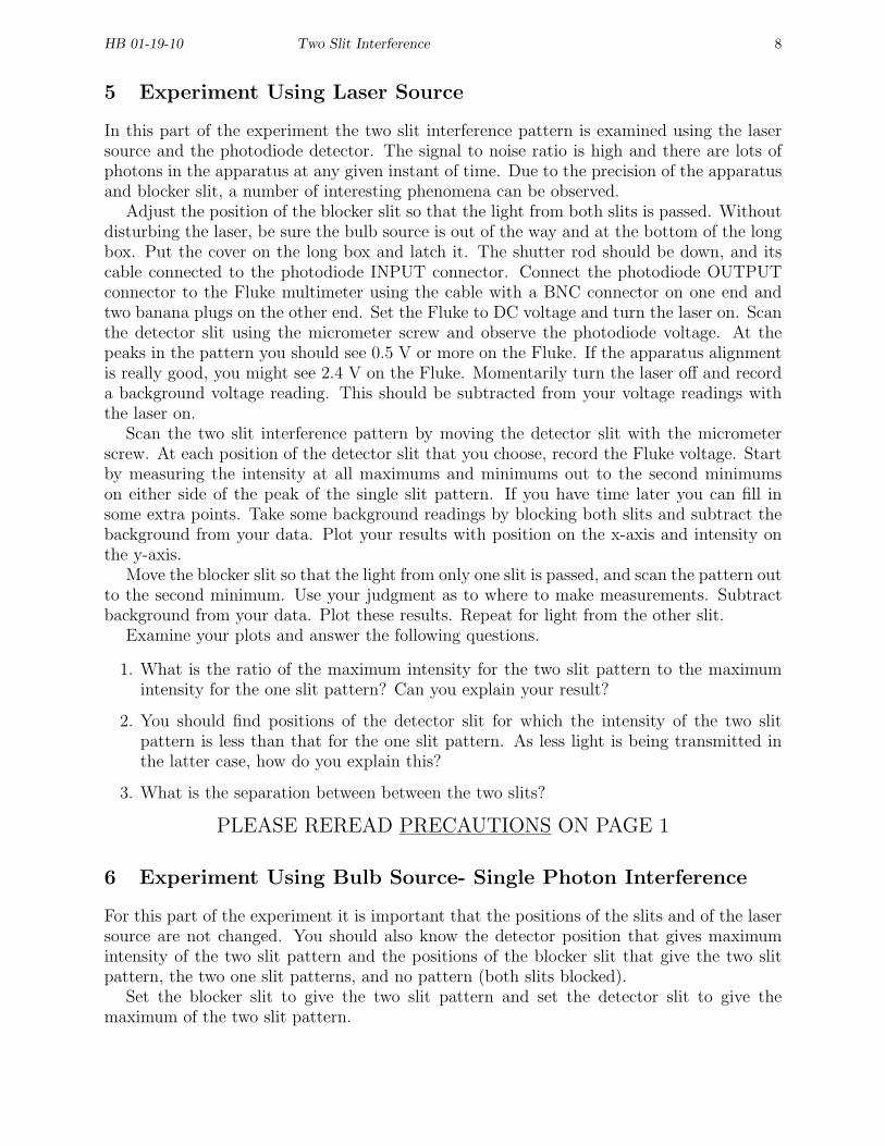
1. What is the ratio of the maximum intensity for the two slit pattern to the maximumintensity for the one slit pattern? Can you explain your result?
2. You should find positions of the detector slit for which the intensity of the two slitpattern is less than that for the one slit pattern. As less light is being transmitted inthe latter case, how do you explain this?
3. What is the separation between between the two slits?
PLEASE REREAD PRECAUTIONS ON PAGE 1
6 Experiment Using Bulb Source- Single Photon Interference
For this part of the experiment it is important that the positions of the slits and of the lasersource are not changed. You should also know the detector position that gives maximumintensity of the two slit pattern and the positions of the blocker slit that give the two slitpattern, the two one slit patterns, and no pattern (both slits blocked).
Set the blocker slit to give the two slit pattern and set the detector slit to give themaximum of the two slit pattern.
HB 01-19-10 Two Slit Interference 9
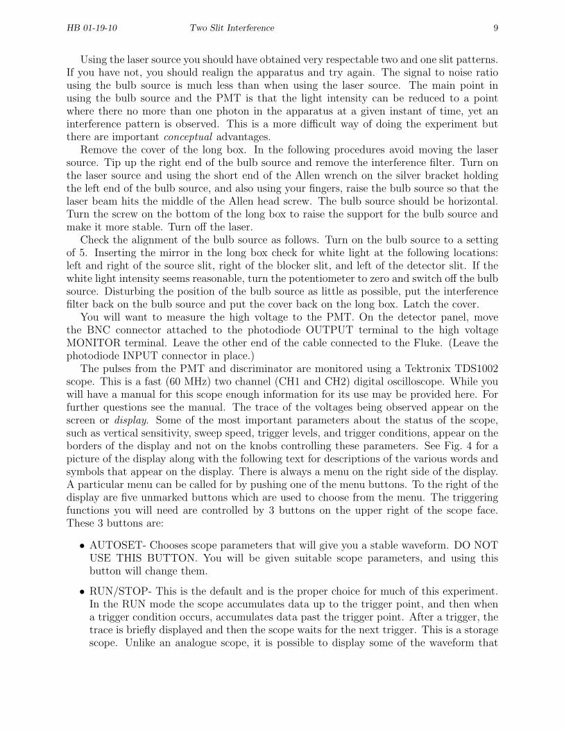
Using the laser source you should have obtained very respectable two and one slit patterns.If you have not, you should realign the apparatus and try again. The signal to noise ratiousing the bulb source is much less than when using the laser source. The main point inusing the bulb source and the PMT is that the light intensity can be reduced to a pointwhere there no more than one photon in the apparatus at a given instant of time, yet aninterference pattern is observed. This is a more difficult way of doing the experiment butthere are important conceptual advantages.
Remove the cover of the long box. In the following procedures avoid moving the lasersource. Tip up the right end of the bulb source and remove the interference filter. Turn onthe laser source and using the short end of the Allen wrench on the silver bracket holdingthe left end of the bulb source, and also using your fingers, raise the bulb source so that thelaser beam hits the middle of the Allen head screw. The bulb source should be horizontal.Turn the screw on the bottom of the long box to raise the support for the bulb source andmake it more stable. Turn off the laser.
Check the alignment of the bulb source as follows. Turn on the bulb source to a settingof 5. Inserting the mirror in the long box check for white light at the following locations:left and right of the source slit, right of the blocker slit, and left of the detector slit. If thewhite light intensity seems reasonable, turn the potentiometer to zero and switch off the bulbsource. Disturbing the position of the bulb source as little as possible, put the interferencefilter back on the bulb source and put the cover back on the long box. Latch the cover.
You will want to measure the high voltage to the PMT. On the detector panel, movethe BNC connector attached to the photodiode OUTPUT terminal to the high voltageMONITOR terminal. Leave the other end of the cable connected to the Fluke. (Leave thephotodiode INPUT connector in place.)
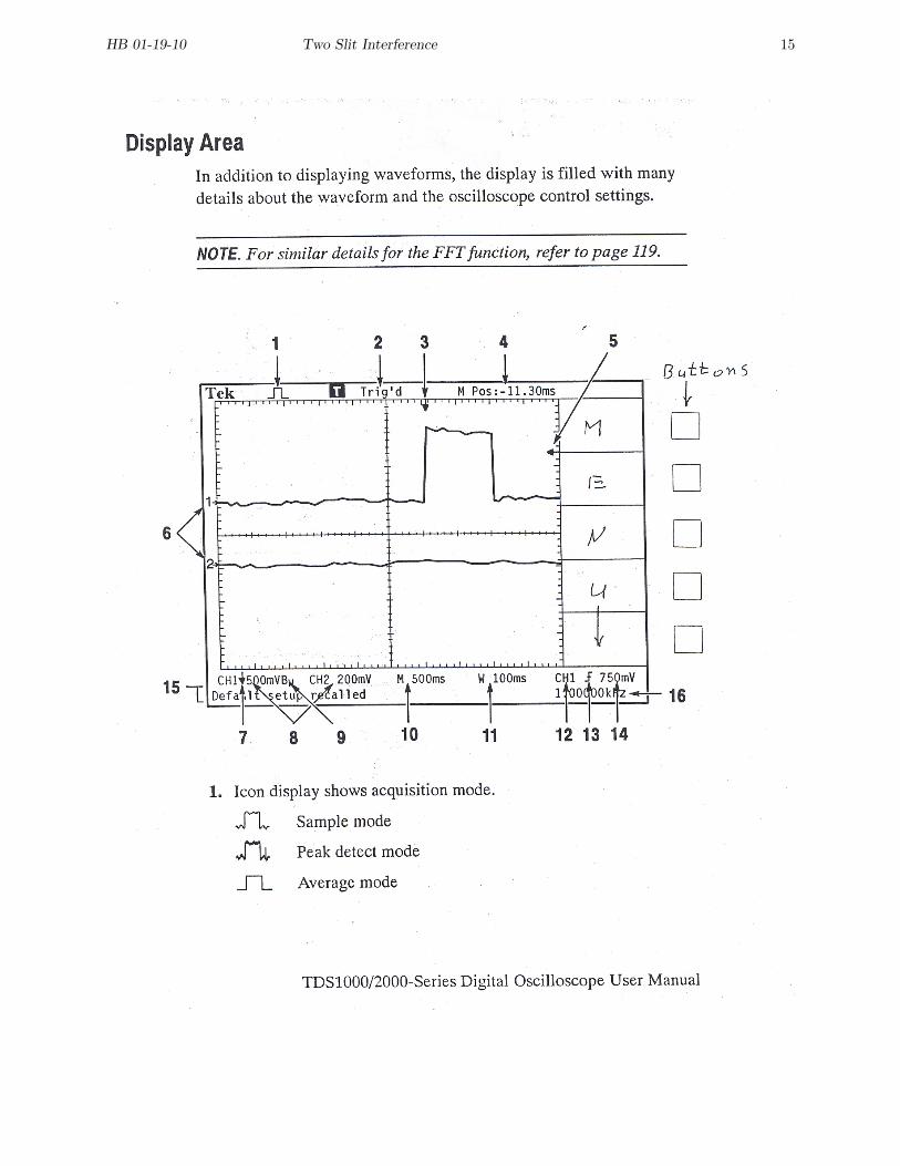
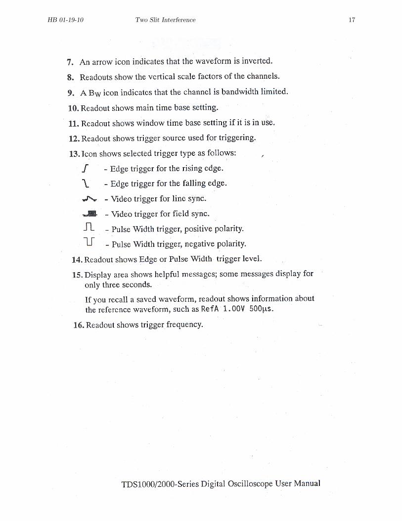
The pulses from the PMT and discriminator are monitored using a Tektronix TDS1002scope. This is a fast (60 MHz) two channel (CH1 and CH2) digital oscilloscope. While youwill have a manual for this scope enough information for its use may be provided here. Forfurther questions see the manual. The trace of the voltages being observed appear on thescreen or display. Some of the most important parameters about the status of the scope,such as vertical sensitivity, sweep speed, trigger levels, and trigger conditions, appear on theborders of the display and not on the knobs controlling these parameters. See Fig. 4 for apicture of the display along with the following text for descriptions of the various words andsymbols that appear on the display. There is always a menu on the right side of the display.A particular menu can be called for by pushing one of the menu buttons. To the right of thedisplay are five unmarked buttons which are used to choose from the menu. The triggeringfunctions you will need are controlled by 3 buttons on the upper right of the scope face.These 3 buttons are:
• AUTOSET- Chooses scope parameters that will give you a stable waveform. DO NOTUSE THIS BUTTON. You will be given suitable scope parameters, and using thisbutton will change them.
• RUN/STOP- This is the default and is the proper choice for much of this experiment.In the RUN mode the scope accumulates data up to the trigger point, and then whena trigger condition occurs, accumulates data past the trigger point. After a trigger, thetrace is briefly displayed and then the scope waits for the next trigger. This is a storagescope. Unlike an analogue scope, it is possible to display some of the waveform that
HB 01-19-10 Two Slit Interference 10
occurs before the trigger. A good position for the horizontal position arrow (See Fig. 4,item 4) is right in the middle which is taken as zero time. (The M stands for MainTime Base.)
In the STOP mode (the RUN/STOP button toggles) the last triggered trace is heldand displayed. If there are a lot of pulses which are not all the same, this enables asingle pulse to be carefully examined.
• SINGLE SEQ- When pushed, a single triggered trace is displayed. In function, this issimilar to the STOP mode. You should try this mode, but for general monitoring goback to the RUN mode.
Turn on the scope using the toggling button on the top and wait 30 s for the self checksto be completed.
• Press the DEFAULT SETUP button. This will assure that many of the parameters willbe as you want them. For example, it will choose CH1 as the trigger source.
• Press the CH1 menu button and choose 1X for the PROBE. You will not be using anattenuating probe and do not want the scope to compensate for such attenuation.
• Press the CH2 menu button. As the default setup does not activate CH2, this will doso. Again, set PROBE at 1X. The traces for CH1 and CH2 will overlap. Move the CH2trace down toward the bottom of the display as it will be overlapping the CH1 trace.
• Set the CH1 vertical sensitivity at 50 mV/Div, the CH2 vertical sensitivity at 2 V/Div,the sweep speed at 250 ns/Div, and the trigger threshold to 20 mV.
• If you are going to be returning to this experiment, you can wait 3 s after making anyadjustments to the scope before turning the scope off. Your settings will be preservedfor when you next turn on the scope and you will not have to readjust the scope.
The PMT pulses are short (∼250 / ns) and proper impedance matching is necessary toavoid reflections. Check that 50 Ω BNC shunts are connected to both the CH1 and CH2inputs to the scope and to the channel A input of the counter. Connect the PMT OUTPUTto CH1 and the discriminator OUTPUT to CH2 using cables with BNC connectors.
Check that the shutter is closed, and the potentiometers for the bulb source, high voltage,and discriminator are set at zero. Plug in the astrodyne power supply and then turn thelaser-off-bulb switch to bulb. (This is the only position for which the high voltage supplyfor the PMT will work.) Turn the Fluke to DC volts. Turn the High Voltage switch to Onand slowly turn the high voltage potentiometer clockwise. Monitor the scope while you dothis, and if at any time there is there a flood of pulses, turn the high voltage to zero andlook for a light leak. Monitoring the PMT voltage on the Fluke, set the Fluke reading to0.6 V which will be a PMT voltage of 600 V. At a PMT voltage of 550-600 V you shouldsee a background pulse from the PMT every few seconds. If you do not, check the scopeparameters and if necessary check with your instructor.
Assuming that you are seeing a few background pulses, press the RUN/STOP buttonto capture a pulse. There are two amplifiers in the detector unit. The PMT directly feedsa charge sensitive amplifier whose output appears on CH1. The charge sensitive amplifierfeeds another amplifier whose output is a rectangular TTL (transistor transistor logic) pulse

HB 01-19-10 Two Slit Interference 11
which has a height of about 4 V and a width of about 300 ns. This TTL pulse appears onCH2. For low level pulses there may not be a TTL pulse, but with a trigger level of 20 mVthere will most likely be a TTL pulse with each PMT pulse. There is coupling between thesetwo amplifiers, and you will see the effect of the sharp edges of the TTL pulses on the PMTpulses. The discriminator potentiometer is actually a gain control. This will be set shortly.Return to continuously monitoring the pulses by pushing the RUN/STOP button again.
In what follows, it is assumed that the blocker slit is adjusted to pass the light from bothslits, and that the detector slit is centered on the interference pattern (maximum intensity).Open the shutter. With no light leaks and the bulb potentiometer at zero there should beno significant increase in pulse arrival rate. Slowly turn the bulb potentiometer up to 2.You should see an increase in pulse rate on the scope. Disconnect the CH2 cable from thescope and connect it to the channel A input to the counter. Turn the counter on, set thecounter GATE to 1.0 s and the leave the FUNC setting at default, which is FREQ/CHA.Increase the bulb brightness so that you get a pulse rate of around 0.5 kHz. The bulbpotentiometer might be between 3 and 4, depending on how well the apparatus is aligned.Turn the discriminator potentiometer up enough so that the count rate plateaus, which isat a value of about 2. (The discriminator is actually a gain control which boosts the pulseheight enough so that most pulses pass through a genuine discriminator.) Adjust the bulbintensity to give a count rate of around 1.0 kHz.
The arrival of the pulses is random. Check out the statistics as follows. Using the HOLDbutton on the counter (which toggles) measure the number of counts in ten 1 s intervals(this is the gate time). Average these counts and calculate the standard deviation σ. Areyou satisfied that most of your counts lie in the range of the average ±σ?
Measure the two slit interference pattern intensity every 0.10 mm for about 2 mm on eachside of the maximum. At each location it is enough to make one 1 s measurement, notingthe statistical uncertainty in your data. Measure the pattern for each slit by itself, usingthe blocker slit to cover one slit at a time. Now make some background measurements bycovering both slits with the blocker slits, first moving the blocker slit in from one side andthen the other side.
Set the blocker slit to pass the light from both slits. Turn the bulb potentiometer downto zero and connect the cable carrying the TTL pulses to the “cricket.” The cricket will givea click for every pulse, and is an interesting way of getting a feel for random events. Turnthe bulb source up a bit to see how this goes for somewhat higher pulse rates.
Turn both potentiometers to zero, set the switches at off, and close the shutter. Turn offthe Fluke, scope, and counter. Unplug the power supply.
Subtract the background from your data and on the same graph plot your 3 intensitydistributions (two slit and two one slit). Intensity should be on the vertical axis and detectorposition on the horizontal axis. Answer the following questions.
1. For the green photons used in this part of the experiment the PMT produces a pulseabout 4% of the time. Calculate the average time between photons and the time onephoton spends in traveling between the source and detector slits. Is there likely to bemore than one photon in the apparatus at any given time? If not, how is it possiblethat a two slit interference pattern is produced? Does it make any sense to ask whichslit the photon goes through?
2. Are there regions where the one slit pattern is more intense than the two slit pattern?
HB 01-19-10 Two Slit Interference 12
Discuss.
3. How does the two slit pattern differ from the one you obtained using the laser? Why?
4. What is the distance between the centers of your two slits? What is the width of eachslit?
7 Finishing Up
Please leave the bench as you found it. Thank you.
Figure 1:
HB 01-19-10 Two Slit Interference 13
Figure 2: Not to scale.

HB 01-19-10 Two Slit Interference 14
Figure 3:
HB 01-19-10 Two Slit Interference 15

HB 01-19-10 Two Slit Interference 16
HB 01-19-10 Two Slit Interference 17
HB 01-19-10 Two Slit Interference 18

HB 01-19-10 Two Slit Interference 19