Embed Size (px)
Citation preview

TWO NOVEL SOLAR SORPTION REFRIGERATORS USING SALT-AMMONIA MIXTURES FOR AIR-CONDITIONING AND ICE
PRODUCTION R. Best1, L.A. Bujedo2, P. Melograno3, N. Velázquez4, I. Pilatowsky1, V.H. Gómez1, O. García-
Valladares1, R. Fedrizzi3, A. Corredera2, J.I. Hernández1, S. Sanz2, N. Ortega1
1 Centro de Investigación en Energía/Universidad Nacional Autónoma de México, Morelos (Mexico) 2 EURAC Research/Institute for Renewable Energy, Bolzano (Italy)
3 Fundación Cartif, Valladolid (Spain) 4 Universidad Autónoma de Baja California (Mexico)
1. Abstract
Within REFSOL project, born in 2009 by an international collaboration between Mexican CONACYT and the European Union, two sorption refrigeration prototypes using salts as sorbents were developed. One continuous chiller using lithium nitrate-ammonia as working pair and able to provide a chilling power of 5kW for air-conditioning purposes at a minimum driving temperature of 100 °C. The other one, based on a thermo-chemical and discontinuous sorption cycle, which uses barium chloride-ammonia as working pair for food storing purposes as well as for ice production at a minimum driving temperature of 60ºC. For both refrigeration systems, the thermal energy supply is provided through two different solar collector systems, which were simulated in TRNSYS ambient for their optimal configuration.
In present document, design concepts, preliminary results, and performance analysis of the two solar refrigerators are presented as a result of the research of this project realized with funds of FONCICYT [1].
2. Introduction
Thermally driven sorption chillers represent an established technology for cold water production. Being the ones using ammonia-water mixtures that reach temperatures below 0°C, suitable for the ice production (food storing) besides air-conditioning purposes. Furthermore, the thermo-physical and thermo-dynamical properties of this working pair allow these chillers to be air-cooled, crucial aspect in areas characterised by high ambient temperature and by a scarce presence of cooling water. However, two issues hamper their wide utilization in solar cooling systems: the high temperatures of the driving heat flux (>150°C); and the need of a rectification column to separate the ammonia from the water produced in the desorber, which is also responsible for the dissipation of thermal energy and for increasing the chillers size.
In order to overcome these problems, an international collaboration between Mexico and the European Union was started in 2009 through a project called “REFSOL” (REFrigeración SOLar) sponsored by FONCICYT (Fund for International Cooperation in Science and Technology) from the Mexican CONACYT and the European Union. The participants of the project are: CIE-UNAM (Centro de Investigación en Energía)of Universidad Nacional Autónoma de Mexico; Univerdidad Autónoma de Baja California (Mexico); the Energy Department of Cartif (Spain) and EURAC (Italia).
The aim was the development of two sorption refrigeration prototypes, capable of producing cold with a heat flux at relatively low temperatures (< 150ºC), (to be able to operate with medium temperature solar thermal energy) and without a rectification column. From here the choice to use salts and not water as sorbent in mixtures using ammonia as refrigerant: lower minimum driving temperature (COP around 0.50 at 90°C as inlet generator temperature); higher COP for application lower than 0°C (ice production and food storing).
Through technological complementarities of the research centres involved, a synergic process was established. CIE-UNAM and UABC (Mexico) were responsible of the design and manufacturing of the two refrigerators; CARTIF and EURAC (Europe) developed and implemented the start up and control of the two systems. Numerical analysis and procedures to test and assess the two chillers under different operating conditions were defined and developed.

3. Prototypes and Experimental equipment
Within REFSOL project, two sorption chillers prototypes, using salts as sorbents, were developed:
• One continuous chiller using lithium nitrate-ammonia as working pair and able to provide a chilling power of 5kW for air-conditioning purposes at a minimum driving temperature of 100 °C;
• One thermo-chemical discontinuous chiller working with barium chloride-ammonia and designed to produce 100kg of ice for food storing purposes at a minimum driving temperature of 60ºC.
Both the prototypes were installed in two different experimental solar cooling plants, each consisting of the three main circuits:
• Solar collector plant, whose design is the result of an optimization made trough numerical simulations;
• Heat rejection circuit, only for the system with the barium chloride-ammonia chiller;
• Chilling/user circuit, able to reproduce several user profiles (chilling demand).
Mathematical models were also developed to allow the preliminary overall analysis as well as the design of the main components of both refrigerating systems.
Below, the schemes and the design parameters of the two prototypes and the circuits connected to them are showed and described separately.
3.1 NH3-LiNO3 Prototype
The NH3-LiNO3 prototype is an air-cooled absorption chiller with 5kW of chilling capacity. At first, it was an air-to-air chiller designed to have a chilling capacity of 10kW. The condenser and the evaporator were both located on the top of the system and air-cooled by the same fan. This configuration was set up in order to have a compact unit to carry to any industry for demonstration purposes without the necessity to connect it to a water or brine loop for the chilling load. Nevertheless the first tests on the machine showed a negative effect of this solution on the overall chiller performances. Therefore, in a second phase, the evaporator was substituted with a water-to-water flat plate heat exchanger and connected to a chilling loop [2].
Table 1 and Figure 1 show the actual scheme and the working design conditions of the NH3-LiNO3 chiller respectively. The prototype consists of five main components: a generator, which is a falling film heat exchanger with horizontal tubes; a condenser, which is a fin tube heat exchanger air-cooled by a fan; a throttling valve for the lamination of the condensed ammonia; a flat plate heat exchanger used as evaporator and connected to a water loop; an absorber, which is a vertical falling film heat exchanger air-cooled; and an economizer (i.e. flat plate heat exchanger) located between the generator and absorber. Two solutions pumps are also installed: one diaphragm pump placed between generator and absorber and having a control of 1% precision on the discharge flow at constant pressure conditions; and one pump used for the recirculation of the solution within the absorber. It facilitates the absorption process, which is critical in the design due to the diffusion and thermal effects which are produced during this process between the ammonia and lithium nitrate.
Table 1 Working design conditions of the NH3‐LiNO3 Prototype
DESIGN OPERATING CONDITIONS RESULTS
TEV = 5 ºC QAB = 8.3 kW ṁR = 0.004675 kg/s
TAB = 40 ºC QGE = 9.2 kW ṁAB = 0.04772 kg/s
TCO = 40 ºC QCO = 5.9 kW ṁGE = 0.04305 kg/s
TGE = 120 ºC COP = 0.546 PCO = 1556 kPa
η=0.8 (COP)C = 1.62 PEV = 515 kPa
QEV = 5 kW CAB = 0.513 kgNH3/kgsol CGE = 0.356 kgNH3/kgsol

The internal operation of the chiller is characterized by the classical four phases: desorption, condensation, evaporation and absorption. In details:
• The thermal heating oil flows into the generator inside the bank of tubes, from the bottom to the top, in four steps. While the NH3-LiNO3 solution flows downwards by gravity (falling) as a continuous film on the tube walls where it is heated and ammonia vapour is generated. The solution is distributed through three liquid feeders in equal parts in order to maintain an even liquid distribution for all tubes along which the solution falls.
• The ammonia vapour produced in the generator is then condensed at high pressure and, through a throttling valve, is carried to a lower pressure level. Here it enters into the evaporator where receives heat from the chilling circuit (load) and evaporates.
• The vapour produced flows to the absorber where it is absorbed by the weak solution. In particular, the solution circulates inside the finned tubes and the ammonia vapour is injected from the bottom of each tube. The produced strong solution is pumped to the generator through a heat exchanger which is used as an economizer between the absorber and generator.
• Once the strong solution is in the generator, it receives heat from the thermal oil and NH3 vapour is produced. Then the weak solution goes back to the absorber through a throttling valve; while the NH3 vapour flows towards the condenser.
Figure 1: a) Scheme of NH3‐LiNO3 Prototype; b) Picture of NH3‐LiNO3 Prototype
As heat sources, two external circuits connected to the prototype’s generator and evaporator are used: the solar heating circuit and the chilling/user circuit.
The solar heating circuit, shown in Figure 2, consists mainly of a solar collectors field whose configuration is the result of a TRNSYS simulation carried out with uncertainties. The need of a large temperature jump (20ºC) in order to operate the generator of the absorption cooler and, at the same time, the necessity to maintain an adequate collector field efficiency, led to a configuration of three rows with six collectors in series each. It provides, indirectly, the generator of the prototype with heat at a minimum temperature of 120°. tank of 500l is used to store the heat produced. An auxiliary electric heater with a maximum heating capacity of 20kW and able to reach 140°C serves as back-up when the temperature at the top of the tank is not high enough. Furthermore, it allows replicating the characteristic loads of different solar collector’s type systems set up in different locations as well as producing heat at constant predefined temperatures for steady state tests. Two 3-way valves are also installed: one between the auxiliary heater and the storage, which allows regulating the inlet temperature at the generator by a PID controller; another one at the outlet of the tank, to give the possibility to install a second tank in series or in parallel with the first one, at a second phase

of solar heating system development. A variable pump is installed to work with different volume flows instead.
The chilling/user circuit is shown in Figure 1. It is a water loop which connects the prototype’s evaporator with a tank equipped with electric resistances used to simulate the chilling load. A 3-way valve, installed just before evaporator and activated by a PID controller, allows regulating the inlet temperature; while a variable pump allows working with different volume flows.
Figure 2 Heating system of NH3‐LiNO3 Prototype
3.2 NH3-BaCl2 Prototype
The NH3-BaCL2 prototype is a water-cooled absorption chiller designed to produce 100kg of ice per day at a temperature of – 10 ºC. Based on the first results obtained in the Refrigeration and Heat Pumps Laboratory of the CIE,UNAM, it can dissociate the ammonia refrigerant at temperatures between 60 and 80 ºC (allowing the coupling with flat plate solar collectors) with a cooling water for the condensation and the absorption process between 30 and 35 ºC.
The core component of the chiller is the thermo-chemical reactor (STIR) which is a special tube and shell heat exchanger consisting of finned tubes where the bi-hydrate barium chloride is located. Inside each tube gas refrigerant distributors are placed. Outside the tubes but inside the shell, the thermal fluid (water) flows in several passes. Depending on the process that is being executed within the reactor, i.e. if the refrigerant is being dissociated (desorption) or if the heat resulting from absorption processes has to be rejected, the thermal fluid will come from the heating and cooling systems which are connected alternatively to the reactor.
The other components installed into the machine, which guarantee the sorption cycle, are: the condenser, which is a flat plate heat exchanger where the vapour of ammonia produced during the desorption phase is condensed; a storage, for collecting the condensed ammonia; the expansion valve, used for the lamination of the ammonia going towards the evaporator; and, finally, the evaporator, which is also a flat plate heat exchanger that evaporates the ammonia by using the heat contained in a mixture of an external circuit (“brine circuit”). A series of motorized 3-way and 2 way valves are also installed with the aim to switch the external
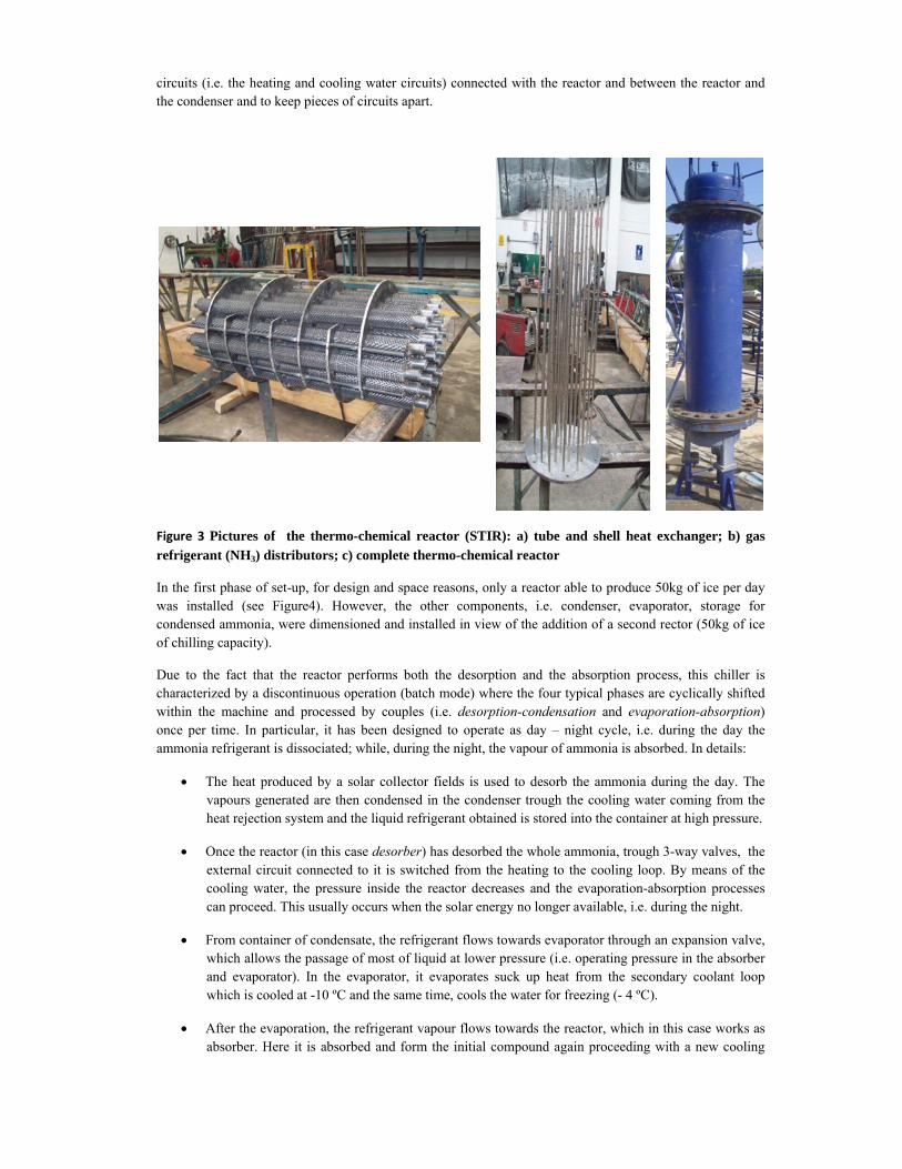
circuits (i.e. the heating and cooling water circuits) connected with the reactor and between the reactor and the condenser and to keep pieces of circuits apart.
Figure 3 Pictures of the thermo-chemical reactor (STIR): a) tube and shell heat exchanger; b) gas refrigerant (NH3) distributors; c) complete thermo-chemical reactor
In the first phase of set-up, for design and space reasons, only a reactor able to produce 50kg of ice per day was installed (see Figure4). However, the other components, i.e. condenser, evaporator, storage for condensed ammonia, were dimensioned and installed in view of the addition of a second rector (50kg of ice of chilling capacity).
Due to the fact that the reactor performs both the desorption and the absorption process, this chiller is characterized by a discontinuous operation (batch mode) where the four typical phases are cyclically shifted within the machine and processed by couples (i.e. desorption-condensation and evaporation-absorption) once per time. In particular, it has been designed to operate as day – night cycle, i.e. during the day the ammonia refrigerant is dissociated; while, during the night, the vapour of ammonia is absorbed. In details:
• The heat produced by a solar collector fields is used to desorb the ammonia during the day. The vapours generated are then condensed in the condenser trough the cooling water coming from the heat rejection system and the liquid refrigerant obtained is stored into the container at high pressure.
• Once the reactor (in this case desorber) has desorbed the whole ammonia, trough 3-way valves, the external circuit connected to it is switched from the heating to the cooling loop. By means of the cooling water, the pressure inside the reactor decreases and the evaporation-absorption processes can proceed. This usually occurs when the solar energy no longer available, i.e. during the night.
• From container of condensate, the refrigerant flows towards evaporator through an expansion valve, which allows the passage of most of liquid at lower pressure (i.e. operating pressure in the absorber and evaporator). In the evaporator, it evaporates suck up heat from the secondary coolant loop which is cooled at -10 ºC and the same time, cools the water for freezing (- 4 ºC).
• After the evaporation, the refrigerant vapour flows towards the reactor, which in this case works as absorber. Here it is absorbed and form the initial compound again proceeding with a new cooling

cycle. The heat generated by the chemical reaction is dissipated by cooling water coming from the heat rejection system .
When the second reactor will be installed, the chiller will be suitable to work in two different working mode: in batch (parallel) mode3], for the ice production, and in discontinuous mode, for the air-conditioning purposes.
Figure 4 Scheme of NH3‐BaCl2 Prototype
In order to test the machine at the real working conditions, the prototype is connected with three external circuits which serve as sink and heat sources respectively. They are: the heating (i.e. solar) circuit, cooling circuit and brine circuit (see Figure 5).
The heating circuit is composed of: a solar field, consisting of three evacuate tube collectors which can be connected in series or in parallel by means of ball valves; an horizontal tank of 500l used to store the solar heat; and a vertical tank, of 500l as well, provided with two electric heaters of 3 kW each to be used as back-up when the temperature at the top of the solar tank is not high enough. These three parts are connected in such a way that, depending on the working temperature conditions, the prototype can be feed directly by the solar field, indirectly by the solar tank and finally by the back-up. This last is used also to test the prototype at steady state conditions. Concerning the solar field, a TRNSYS simulation was carried out with aim to individuate the best configuration of the solar collectors. It was performed using the TMY2 data of Cuernavaca, where the prototype is installed, and the characteristic curves of the collectors installed. The simulation showed that, even if the connection in series allows an higher temperature difference, the connection in parallel is preferable for three reasons: the outlet temperature of the collector field is high enough to feed the prototype, the peak power is higher and the yearly energy is bigger.
The cooling circuit is a water loop connected to a compressor chiller which provide the cool water at the desired temperature to reject the heat produced during the condensation and the absorption process. The brine circuit, instead, consists of a tank full of brine provided with three containers with water for the ice production (see Figure 3). All three circuit are provided with variable pumps and three way valves at the inlets of the prototype for the control of the flow rate and inlet temperatures respectively.

Figure 5 Scheme of the NH3‐BaCl2 system
Furthermore, for the correct working of the prototype and for its start-up as well, other two complementary circuits, which are not represented in the picture, are installed: the circuit for the dehydration of the barium chloride and the circuit to produce the vacuum inside the chiller.
4. Theoretical and Experimental Results
In order to assess the performances of the two prototypes as well as to verify the presence of possible design and operation gaps, a series of tests and numerical simulations have been carried out on them at different working conditions. With this purpose and due to the experimental nature of the prototypes, a large investment on electronic instrumentation was done to obtain all meaningful information about their operation (i.e. temperature sensors, pressure transducers, flow and level meters and weather station).
Since the NH3-BaCl2 chiller is still in the commissioning stage, in the present document, only theoretic results are showed on it. While, the operational protocol and test results obtained for theNH3-LiNO3 prototype are here described and analyzed.
4.1 NH3-LiNO3 Prototype: Operational Protocol
During each test, protocols to start, run at full capacity and stop the NH3-LiNO3 prototype were defined and applied. Before doing this, a preliminary procedure was followed. In particular, it was verified firstly that:
1. All components were in equilibrium with the environment (i.e. at ambient temperature)
2. Within the machine, the two pressure levels were kept. It was done by closing the zone valves between the generator/condenser and evaporator/ absorber.
3. The generator and the condenser were well isolated and in the condenser, a certain quantity of ammonia was stocked in order to speed the start up of the machine.
After these checking, the following steps were executed:
Heating system
Brine container

Start-up procedure
1. The valve between the generator and condenser was opened. In this way the pressure into the generator increased becoming higher than that one into the absorber. This allowed a recirculation of the solution between these two components.
1. After that all valves were opened with the exception of the lamination valve between generator and absorber and the valve at outlet of condenser.
2. The pump in chilling circuit was switched on
3. Once the thermal oil reached the trigger temperature, it flowed within the generator where the temperature and pressure of the ammonia vapour increases quite fast. When the pressure went up 10bar, the solution pump was switched on and the lamination valve between the condenser and absorber was opened. The recirculation between these two components started
4. When the pressure went up 18 bar on high level pressure, the fan was switched on at the maximum speed.
5. When enough ammonia was stored in the condenser, the valve at the outlet of the condenser was opened. In this way, the refrigeration cycle could start and the pump for the recirculation of the solution into the absorber was switched on. This improved the absorption process.
6. The recirculation of solution between absorber and generator was regulated by the solution pump and the lamination valve. At the beginning the pump run at maximum speed in order to have all tubes wet.
7. The expansion valve between the condenser and the evaporator was regulating on the base of the chilling effect desired at the evaporator (i.e. bigger was the quantity of ammonia flowing into the evaporator, bigger was the heat extract from the body to cool down) and of the working conditions.
Running protocol
Once the start-up procedure was ended, the running protocol was applied. It consisted of some tunings of specific actuators made in real time depending on the real time machine’s performance and on the ambient working conditions.
8. The recirculation between generator and absorber was always kept under control. The opening of expansion valve placed between these two components was always adjusted in order to have always solution in the tubes of the absorber.
9. At the same time, for specific expansion valve’s openings, the solution pumps was adjusted in order to have the solution levels in the generator and absorber more or less constant and, in particular, the level within the absorber around the half.
10. The pressure into the condenser was regulated trough the fan speed and trough the thermal oil flow rate at specific inlet temperature.
11. When it is possible, the condensed ammonia quantity was regulated by the condenser fan speed.
12. Depending on the power delivered by the machine, the expansion valve placed between condenser and evaporator
Stop protocol
2. When the test ended, the flux of the thermal oil into the generator was stopped. The valve at inlet of the generator was closed. In this way the pressure and temperature in the machine started decreasing.
3. The valve at outlet of condenser was also closed in order to store the condensed ammonia for the following test (because the following test could start faster)
4. When the pressure into the generator and condenser is around 12 bar, the condenser fan was stopped and the valve between these two components was closed. This procedure in order to have weak solution into the generator.
5. When the pressure goes down 12 bar, the solution pump was stopped, the valves between absorber and generator including the expansion valve were closed (in this way the two pressure level are kept) and the absorber fan was stopped.
6. The pump in the chilling circuit was stopped when the temperature of the ammonia in the refrigerant circuit was around 4°C.
However, the process can be simplified with only some structural changes equally related to the refrigerant and absorbent volumes in the absorber and generator. For the chiller operation a regulating loop can be established between the generator heat and the cooling power in the evaporator, estimated based on the evaporator outlet temperature which should be the selected as the operating temperature. As the system is air cooled the cooling power is dependent on the ambient temperature. This will change the generator and absorber pressures as it varies, and as a consequence it affects the flow through the solution and refrigerant expansion valves. Therefore the regulation of the solution pump is important
4.2 NH3-LiNO3 Prototype: Test and Results
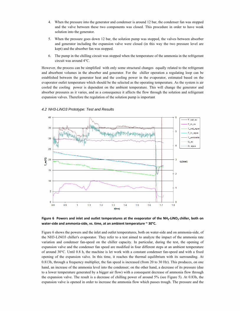
Figure 6 Powers and inlet and outlet temperatures at the evaporator of the NH3‐LiNO3 chiller, both on water‐side and ammonia‐side, vs. time, at an ambient temperature ~ 30°C.
Figure 6 shows the powers and the inlet and outlet temperatures, both on water-side and on ammonia-side, of the NH3-LiNO3 chiller's evaporator. They refer to a test aimed to analyze the impact of the ammonia rate variation and condenser fan-speed on the chiller capacity. In particular, during the test, the opening of expansion valve and the condenser fan speed are modified in four different steps at an ambient temperature of around 30°C. Until 0.8 h, the machine is let work with a constant condenser fan-speed and with a fixed opening of the expansion valve. In this time, it reaches the thermal equilibrium with its surrounding. At 0.813h, through a frequency multiplier, the fan speed is increased (from 20 to 30 Hz). This produces, on one hand, an increase of the ammonia level into the condenser; on the other hand, a decrease of its pressure (due to a lower temperature generated by a bigger air flow) with a consequent decrease of ammonia flow through the expansion valve. The result is a decrease of chilling power of around 5% (see Figure 5). At 0.83h, the expansion valve is opened in order to increase the ammonia flow which passes trough. The pressure and the

temperature of ammonia vapour within the evaporator increase until the equilibrium is reached. At the same time, the chilling powers, both on water and on ammonia side, increase while the evaporator outlet temperatures decrease (chilling effect). At 0.98h, the fan speed is increased again (from 20 to 40 Hz). This causes a reduction of the pressure and temperature within the condenser with a consequent reduction of the ammonia flow through the expansion valve. This results again in a reduction of chilling power but in this case of around 15%. At 1.06 h, the fan speed is increased until its maximum value (60 Hz) and the expansion valve is completely opened. After a first period of stabilization, at 1.18h the machine reaches the equilibrium with a chilling power of about 4.8kW on the water side.
Figure 7 Inlet and outlet temperatures of the thermal oil and of the solution of the NH3‐LiNO3 chiller's generator vs. time at an ambient temperature ~ 30°C.
Figure 7 shows instead the inlet and outlet temperatures of the thermal oil and the solution at the NH3-LiNO3 chiller’s generator. It is possible to observe that, once the thermal oil reaches the desired inlet temperature at the generator, in this case 140°C, the chiller has stabilized rapidly, i.e. after 0.2h. After this period, the solution outlet temperature reaches a temperature of around 110 °C.
Both these two tests show that the machine is quite stable at different working conditions.
4.3 NH3-BaCl2 Prototype: Theoretic results
A mathematical model of the NH3-BaCl2 prototype was developed and used to predict its performance and to support the research team during the design phase. It is based on the equilibrium equations of the chemical reaction between barium chloride and ammonia [4], which is:
3232 88, NHBaClNHBaCl +↔
In details: Equation 1 expresses the relation between the vapour pressure and temperature of the barium chloride:
Equation 1 T
LogP 277905.23 −=

Where P is the pressure in Pascal and T is the temperature in Kelvin. Equation 2 expresses the relation between the vapour pressure and temperature of the ammonia.
Equation 2 T
LogP 50173.29 −=
They are both plotted in the Figure 8.
Figure 8 Thermodynamic equilibrium of barium chloride and ammonia
Through this model, the design parameters and the performances of the chiller , i.e. COP and chilling capacity, at different working conditions were determined. In Table 2a) and in Table 2b) the absorption temperatures and pressures corresponding at different evaporator temperatures are reported; the desorption temperatures and pressures corresponding at different condenser temperatures are listed too.
Table 2 a) Absorption temperatures and pressures Table 2b) Desorption temperatures and at different evaporator temperatures pressure at different condenser temperature
TE (°C) PE=PA (bar) TA (°C) TC (°C) PC=PD (bar)
TD (°C)
-20 1.901 19.47 20 8.574 47.66 -15 2.362 23.23 25 10.031 50.91 -10 2.908 26.91 30 11.669 54.11 -5 3.548 30.52 35 13.504 57.26 0 4.294 34.07 40 15.549 60.35 5 5.158 37.56
In Table 3, the theoretic COP calculated at different condenser and evaporator temperatures are listed.
Table 3 Theoretic COP at different condenser and evaporator temperatures
T condenser TE(-20) TE (-15) TE (-10) TE (-5) TE (0) TE (5) TE (10)
15 0.531 0.537 0.542 0.547 0.552 0.557 0.562 20 0.489 0.494 0.499 0.504 0.508 0.513 0.517 25 0.452 0.456 0.461 0.465 0.469 0.473 0.477 30 0.418 0.422 0.426 0.430 0.434 0.438 0.441 35 0.388 0.392 0.396 0.399 0.403 0.406 0.409 40 0.531 0.537 0.542 0.547 0.552 0.557 0.562
0.00
2.00
4.00
6.00
8.00
10.00
12.00
14.00
16.00
-0.0040 -0.0037 -0.0035 -0.0033 -0.0031 -0.0029
-1/T (K)
log
P (b
ar)
BaCl2NH3

From the Table 2a), it is possible observe that the chiller can produce chilled water suitable for air-conditioning purposes, i.e. TE= 5°C, at high absorption temperatures, i.e. around 40°C (TA=37.56°C). To reach lower evaporation temperatures suitable for food storing instead, it is necessary reduce the absorption temperature (e.g. TE= -20°C; TA=19.47°C). Table 2b) shows the possibility to use solar thermal energy at low- medium temperature (< 150ºC) as driving heat when the absorption/condensation processes use air as heat vector (i.e. TC~ 40°C).
Table 3 shows that, theoretically, it is possible to have acceptable COP values at working conditions which are considered extreme for this kind of machines. These values vary from ~0.4 (worst case) which occurs at evaporator temperature, TE, equal to -20°C and condenser temperature, TC, equal to 35°C, until to 0.57 (best case) which occurs at TE= 10°C and TC= 40°C.
5. Conclusion
Two novel solar sorption chillers have been developed through the technological complementarities and the synergy established among the research centres involved in REFSOL project. Big efforts were done during the designing and construction phases of the two prototypes which were strongly supported by dynamic simulations.
Even if the experimental analysis is just started, the first results obtained, especially those ones related to the NH3-LiNO3 prototype, are encouraging and let hope in future commercial development of these equipments in the solar refrigeration market. In particular, tests carried out on the NH3-LiNO3 prototype have shown that under steady conditions the machine has stabilized rapidly and has good performances in terms of chilling capacity which is around 5kW. Furthermore the tests aimed to analyzed the influence of the fan speed and the opening of expansion valve on the performance chiller have shown that big improvements can be obtained with the internal control strategies. Concerning the NH3-BaCl2 prototype, although only theoretic results obtained through the numerical model are available, they allow being optimistic about its potential.
In the next future, an intensive experimental campaign will be started in order to achieve, on one hand, a map of performance of the two prototypes at different working conditions; on the other hand, the optimization both of their design and of the internal control strategies.
6. Acknowledgments
This document has been produced with the financial support of the European Union and Mexico through project FONCICYT 94256, The contents of the document are the sole responsibility of the participating research institutions and under no circumstance can be regarded as reflecting the position of the European Union and Mexico. The author acknowledge the work done by the following students: Onésimo, Christian, Ulises Llamas for their invaluable work in this project
7. References
[1] http://www.conacyt.mx/Avisos/Paginas/Aviso_Fondos_Cooperacion_Internacional.aspx
[2] Llamas, U., Herrera, J.V., Cuevas, R., Gómez, V., García-Valladares, O., Cerezo,J., Best, R., “Development of a small capacity ammonia-lithium nitrate absorption refrigeration system”, Proceedings 2nd International Conference in Solar Air conditioning and Refrigeration, 470-475, (2007).
[3] Melograno, P.N., Fedrizzi, R., et al “Test Procedures for Sorption Chillers Based on the Working Mode” 2nd International Conference on Solar Heating and Cooling, (2010).
[4] Pilatowsky, I., Best, R., et al “Metodos de Produccion de Frio”, Universidad Nacional Autónoma de México , (1993).