Embed Size (px)
Citation preview

Go Green, Go Online to take your course
Earn2 CE creditsThis course was
written for dentists, dental hygienists,
and assistants.
Publication date: Aug. 2013 Expiration date: July 2016
This educational activity was developed by PennWell’s Dental Group with no commercial support.This course was written for dentists, dental hygienists and assistants, from novice to skilled. Educational Methods: This course is a self-instructional journal and web activity. Provider Disclosure: PennWell does not have a leadership position or a commercial interest in any products or services discussed or shared in this educational activity nor with the commercial supporter. No manufacturer or third party has had any input into the development of course content.Requirements for Successful Completion: To obtain 2 CE credits for this educational activity you must pay the required fee, review the material, complete the course evaluation and obtain a score of at least 70%.CE Planner Disclosure: Heather Hodges, CE Coordinator does not have a leadership or commercial interest with products or services discussed in this educational activity. Heather can be reached at [email protected] Disclaimer: Completing a single continuing education course does not provide enough information to result in the participant being an expert in the field related to the course topic. It is a combination of many educational courses and clinical experience that allows the participant to develop skills and expertise.Image Authenticity Statement: The images in this educational activity have not been altered.Scientific Integrity Statement: Information shared in this CE course is developed from clinical research and represents the most current information available from evidence based dentistry. Known Benefits and Limitations of the Data: The information presented in this educational activity is derived from the data and information contained in reference section. The research data is extensive and provides direct benefit to the patient and improvements in oral health. Registration: The cost of this CE course is $49.00 for 2 CE credits. Cancellation/Refund Policy: Any participant who is not 100% satisfied with this course can request a full refund by contacting PennWell in writing.
Supplement to PennWell Publications
PennWell designates this activity for 2 Continuing Educational Credits
Dental Board of California: Provider 4527, course registration number CA# 02-4527-13080“This course meets the Dental Board of California’s requirements for 2 units of continuing education.”
The PennWell Corporation is designated as an Approved PACE Program Provider by the Academy of General Dentistry. The formal continuing dental education programs of this program provider are accepted by the AGD for Fellowship, Mastership and membership maintenance credit. Approval does not imply acceptance by a state or provincial board of dentistry or AGD endorsement. The current term of approval extends from (11/1/2011) to (10/31/2015) Provider ID# 320452.
AbstractChairside CAD/CAM and cone beam scanners work together to help make dental implants a safe, predictable, efficient procedure for patients and dentists. A CAD/CAM optical scan and crown proposal can aid dentists in many ways. The crown proposal and soft tissue represented in an optically scanned virtual model can aid the doctor in the presurgical planning of implants. The virtual hard and soft tissue model can be combined with a cone beam scan to reduce artifacts created by radiopaque materials. Optical scans of duplicate dentures can aid in the planning of edentulous cases. In some cases an intraoral scan can replace a stone model in the fabrication of a surgical guide. CEREC® guide is a milled surgical guide that allows dentists to place implants via guided surgery chairside. With new advances in both lab and chairside CAD/ CAM systems, dentists now have the ability to fabricate custom abutments, crowns and frameworks.
Educational Objectives:At the conclusion of this educational activity participants will be able to:1. Discuss the different ways that cone beam
and CAD/CAM interact.2. Describe the limitations of CBCT scan
without the aid of optical scan data.3. Describe the benefits of guided implant
surgery with immediate implants.4. Discuss the relative distances between the
implant, other implants, teeth and bone in surgical implant placement.
5. Discuss the options available for digitally manufactured custom abutments, crowns, substructures and overdenture bars.
Author ProfileAugust de Oliveira DDS has been involved in CAD/CAM dentistry since 2004 and lectures nationwide. Dr de Oliveira has written two books on implantology, “Implants Made Easy”, and “Guided Implantology Made Easy.” He currently practices general dentistry in Encino, CA, is a forum moderator for Dentaltown.com. Dr de Oliveira can be reached for ques-tions by email at [email protected]
Author DisclosureDr de Oliveira is a paid speaker for Sirona and Patterson Dental. He lectures for Sirona and Patterson Dental on CEREC, Galileos and Guided Implant Surgery. Dr. Oliveira is co-founder of an online magazine of digital dentistry, DigitalEnamel.com.
Two Great Tastes that Taste Great Together: Chair Side CAD/CAM and Cone Beam Integration in Implantology A Peer-Reviewed Publication Written by August de Oliveira DDS
2 www.ineedce.com
Educational ObjectivesAt the conclusion of this educational activity participants will be able to:1. Discuss the different ways that cone beam and CAD/
CAM interact.2. Describe the limitations of CBCT scan without the aid
of optical scan data.3. Describe the benefits of guided implant surgery with
immediate implants.4. Discuss the relative distances between the implant,
other implants, teeth and bone in surgical implant placement.
5. Discuss the options available for digitally manufac-tured custom abutments, crowns, substructures and overdenture bars.
AbstractChairside CAD/CAM and cone beam scanners work to-gether to help make dental implants a safe, predictable, ef-ficient procedure for patients and dentists. A CAD/CAM optical scan and crown proposal can aid dentists in many ways. The crown proposal and soft tissue represented in an optically scanned virtual model can aid the doctor in the presurgical planning of implants. The virtual hard and soft tissue model can be combined with a cone beam scan to reduce artifacts created by radiopaque materials. Optical scans of duplicate dentures can aid in the planning of edentulous cases. In some cases an intraoral scan can replace a stone model in the fabrication of a surgical guide. CEREC® guide is a milled surgical guide that allows den-tists to place implants via guided surgery chairside. With new advances in both lab and chairside CAD/ CAM systems, dentists now have the ability to fabricate custom abutments, crowns and frameworks.
Conebeam use in dentistry has gained widespread acceptance. One can’t throw a rock at any local dental convention and not hit a booth promoting the use of these scanners. Utilizing a CBCTscan, a dentist can see things that were once only visualized either by laying large flaps or obtaining expensive hospital based CT-scans. Even the best conebeam scan still lacks information that dentists need to treat patients in the most safe, predictable, ef-ficient manner. By combining the benefits of CBCT and chairside CAD/CAM scans, doctors can visualize the final restoration and soft tissue. These technologies can easily see anatomic structures we seek to avoid. Dental profes-sionals can now plan abutments in harmony with the final restoration and contours of the adjacent teeth. Dental pro-fessionals can fabricate surgical guides chairside, or send digital models through the internet for guide fabrication. After implant integration, chairside or lab based CAD/CAM systems can be used for crowns, custom abutments, bridge or hybrid frameworks, and overdenture bars. The
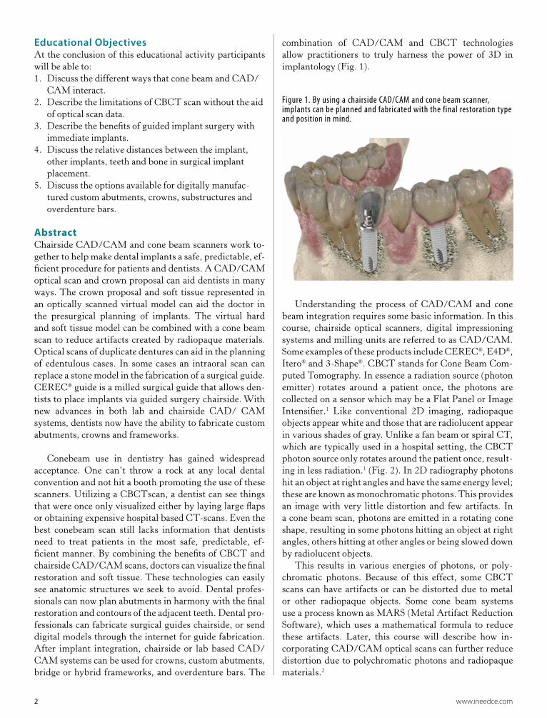
combination of CAD/CAM and CBCT technologies allow practitioners to truly harness the power of 3D in implantology (Fig. 1).
Figure 1. By using a chairside CAD/CAM and cone beam scanner, implants can be planned and fabricated with the final restoration type and position in mind.
Understanding the process of CAD/CAM and cone beam integration requires some basic information. In this course, chairside optical scanners, digital impressioning systems and milling units are referred to as CAD/CAM. Some examples of these products include CEREC®, E4D®, Itero® and 3-Shape®. CBCT stands for Cone Beam Com-puted Tomography. In essence a radiation source (photon emitter) rotates around a patient once, the photons are collected on a sensor which may be a Flat Panel or Image Intensifier.1 Like conventional 2D imaging, radiopaque objects appear white and those that are radiolucent appear in various shades of gray. Unlike a fan beam or spiral CT, which are typically used in a hospital setting, the CBCT photon source only rotates around the patient once, result-ing in less radiation.1 (Fig. 2). In 2D radiography photons hit an object at right angles and have the same energy level; these are known as monochromatic photons. This provides an image with very little distortion and few artifacts. In a cone beam scan, photons are emitted in a rotating cone shape, resulting in some photons hitting an object at right angles, others hitting at other angles or being slowed down by radiolucent objects.
This results in various energies of photons, or poly-chromatic photons. Because of this effect, some CBCT scans can have artifacts or can be distorted due to metal or other radiopaque objects. Some cone beam systems use a process known as MARS (Metal Artifact Reduction Software), which uses a mathematical formula to reduce these artifacts. Later, this course will describe how in-corporating CAD/CAM optical scans can further reduce distortion due to polychromatic photons and radiopaque materials.2

www.ineedce.com 3
Figure 2. A CBCT scanner consists of a photon emitter and a sensor that rotates once around the patient.
Figure 3. The model on the left was made from a scan taken with a CBCT unit that did not utilize MARS. The image on the right was from a scan that utilizes MARS
Figure 4. Implants can be used to support single unit crowns or bridges, to support frameworks for full arch prostheses, bars for over-dentures or retain a removable prosthesis via attachments.
A dental implant is most commonly used to replace a single tooth root to support a crown. Multiple implants are used to either support a framework and restoration or to serve as “anchors” to retain a removable prosthesis, (Fig. 4). A crown may be cemented on an abutment or screwed directly into an implant. Edentulous patients can be restored with conventional crowns and bridges, with a
hybrid restoration, with a removable appliance supported by a bar or with a removable appliance directly attached to implants.3 Implants are incorporated into bone through a process known as osseointegration, (Fig. 5).There are many factors contributing to osseointegration such as the amount of bone surrounding the implant, how the bone is heated or how much stress it is subjected to from torque, or disrup-tion of the blood supply. In addition, retaining a band of attached tissue around the implant can ensure retention of bone around the implant, gingival health and esthetics.
Furthermore, the design and distribution of the im-plants and the occlusal forces generated on the final pros-thesis can affect the health of the bone and surrounding soft tissue.4
Figure 5. An implant restoration may be supported by an abutment or screwed directly into the implant. The implant is incorporated into a patient’s bone via a process known as osseointegration.
Implants can be placed either conventionally or guided. Without guided surgery, a flap is usually laid to visualize the bone in the edentulous site, (Fig. 6). As the osteotomy is prepared, multiple x-rays are taken to ensure proper po-sitioning of the instruments and ultimately, the implants. If the angulation of the drill is not in line with the position of the final osteotomy, subsequent drills can be redirected to be back on course.5 With guided surgery we need three things: A scan of the patient, a model (either digital or stone), and a way of relating the two. After planning the implant placement with implant software, information and model are sent to a surgical guide lab for fabrication. With a specific set of surgical drills and other instruments (pilot sleeves, handles, keys, or drill stops), the implant is placed in the planned location. Because we already know the limitations of the patient’s anatomy, tissue punches or smaller flaps can be used, reducing patient discomfort. Furthermore, because the implant has been planned in advance, the surgery is shorter since there is no need to change the angulation of the osteotomy and no need for radiographic confirmation, (Fig. 7).6

4 www.ineedce.com
Figure 6. In conventional implantology, a flap is usually laid to visual-ize the bone and multiple x-rays are taken throughout the procedure to ensure that the final implant is placed in the proper position.
Figure 7. With guided surgery, large flaps are not usually needed for visualization as the anatomy has already been explored in the scan. Punches or smaller flaps can be used. In this case an implant drill is used with a pilot sleeve.
Figure 8: Most implant programs consists of 5 screens: 3D Panoramic, Axial, Tangential, Cross Sectional, and the 3D Model.
Using the implant planning software is quite easy. Some CBCT systems incorporate scanning software along with an implant planning module. In other systems, CBCT data needs to be either converted to 3D or exported out of the native CBCT software and imported into stand alone implant software in DICOM format. Any CBCT study is
made up of multiple images that can be “sliced” to allow visualization within the bone. The implant planning soft-ware is typically made up of 5 windows, (Fig. 8). The 3D panoramic is similar to a 2D pan and is used to navigate around the patient and to initially place implants. This im-age should not be used to fine tune implant position. The axial view shows the occlusal aspect of the patient. The tangential image is similar to a PA radiograph, showing a mesio-distal view, with the exception that angulation of the slices can be corrected with an adjustment lever. The cross sectional view displays the buccal-lingual aspect of the patient.7 The American Academy of Oral and Maxil-lofacial Radiology (AAOMR) released a position paper stating that this view is very important in the success of placing implants. The cross sectional view provides the most accurate assessment of the size and length of the im-plant to be placed. (Fig. 9).8 Finally, the 3D model allows the doctor to see how the implants relate to the arch and the jaw, (Fig. 10).
Figure 9. The cross sectional view provides the best view for determin-ing the buccolingual thickness of bone as well as the relationship of the implant platform to the crest of the alveolar ridge.
Figure 10. The 3D model best shows how implants relate to each other and the patient’s jaws.

www.ineedce.com 5
The 3D model, also known as the 3D rendering is, in the author’s opinion, one of the most important views in any CBCT implant planning software. The major limita-tion of all CBCT machines is that they have excellent clar-ity for bone and the roots of teeth, but lack clarity when it comes to displaying teeth with restorations or the overlying soft tissue. When planning implants, a balance must be struck between placing the implant in harmony with the roots of the adjacent teeth, yet planning the position of the future abutment or implant platform in the proper relation to the CEJ and contact positions of the neighboring clini-cal crowns. If the adjacent teeth are distorted in the scan due to metal scatter, one cannot predictably place implants supporting a restoration mirroring those contours. Many implant programs have multiple rendering patterns such as Volumetric Mode, Volumetric Mode with Contours, and Surface Mode. Although in Volumetric Mode with Con-tours, the soft tissue outline can be visualized, there is not enough information to adequately predict the contours of the tissue surrounding the future implant, (Fig. 11). CAD/CAM scans provide the missing link in visualizing soft tissue with extreme clarity, and the contours of teeth even with dense radiopaque material, (Fig. 12).
Figure 11. In Volumetric Mode With Contours, the soft tissue can be bet-ter visualized, however it is never clear enough to adequately predict the relationship of the gingiva to the future implant.
Figure 12. In this example distortion is present with the metal artifacts. The CAD/CAM model and proposal allow the user to see the adjacent teeth form and gingival anatomy clearly.
Figure 13. In this example, a chairside CAD/CAM scan is used to obtain a crown proposal for an immediate molar implant. This data is imported into the implant software so a surgical guide can be milled chairside.
CAD/CAM optical scans can be used with a CBCT scan five ways. A simple crown form or scanned wax up and virtual model can be used to place the implant in the proper restorative position, (Figs. 13 and 14).The virtual model can be used instead of displaying the coronal por-tions of teeth, reducing noise. Duplicates of the patient’s dentures or radiographic guides can be scanned, showing the user the proper location of teeth and extent of the denture flange. In the case of a guide fabricated from a vir-tual model, this eliminates the need for a physical model. CAD/CAM works interchangeably with CBCT scans in the planning and production of a CEREC® guide. Both lab and clinic based CAD/CAM systems can be used to not only fabricate a chairside cemented implant crown, but a host of restorations ranging from simple custom abut-ments to hybrid frameworks and overdenture bars.
Figure 14. A mounted diagnostic wax up can be incorporated directly into implant software with minimal design effort.

6 www.ineedce.com
Figure 15. Although using Barium Sulfate containing denture teeth in a scan does provide clues to the final restorative position, there is no way of determining soft tissue depth. With a CAD/ CAM optical scan, one can toggle off the restoration to provide improved visualization of the edentulous ridge and gingiva.
The term “Crown Down Implantology” is almost cli-che presently. More and more dentists are addressing the surgical aspect of implantology as a response to implants that have been placed in unrestorable positions. By using barium sulfate teeth in a scan, one can get a good idea of where the crown will eventually be, but there are two ma-jor drawbacks to this method. First, this involves an extra appointment and additional cost to obtain a radiographic guide containing barium sulfate teeth. Secondly, there is no information regarding the patient’s soft tissue. By obtaining an optical scan the CBCT user has not only a crown form that can be toggled off and on, but a crystal clear representation of the teeth and gingiva, (Fig.15). This “yellow” model allows the user to plan for the height of the soft tissue, and clearly see the adjacent teeth contours which allows one to plan “by the numbers”.
There are a few numeric variables that are necessary in implant planning. A CAD/CAM model and proposal provides the greatest case planning accuracy. An implant should be no closer to the adjacent teeth than 1.5mm. In-dividual implants should be no closer to each other than 3mm, (Fig.16). The implant top or platform, should be on average, 3-4mm apical to the CEJs of the adjacent teeth.
Figure 16. When planning implants in the software, distances can be measured. An implant should be no closer to an adjacent tooth than 1.5mm and no closer to an adjacent implant than 3mm. The implant should have at least 1.8mm of bone on the buccal and lingual.
The platform should be 5mm or less to the most apical extent of the adjacent teeth contacts, (Fig. 17). The implant itself should be smaller in diameter than the root it is re-placing, 2mm below the CEJ of the adjacent teeth.9 In all restorations, the implant abutment should be centered me-siodistally, eliminating the presence of cantilevers. In the anterior, if using a screw retained restoration, the center of the implant and the screw access should be centered in the cingulum. In the posterior, ideally it should be in the cen-tral fissure, (Fig. 18). When planning a hybrid restoration or overdenture bar, 11-14mm of space is required between the bone of the ridge and the occlusal or incisal surfaces of the opposing teeth, (Fig. 19).10 These numbers are easily measured with an optical model and proposal.10 Without, inaccuracy can easily occur.
Figure 17. For proper esthetics and emergence profile in the final restoration, the implant platform should be 3-4mm apical to the CEJ of the adjacent teeth. To achieve interdental papilla formation, the platform should be placed no deeper than 5mm to the most gingival aspect of the adjacent teeth contacts.
Figure 18. For a screw retained implant crown, the screw access should be in the cingulum for anterior teeth and the center of the occlusal table for posterior teeth.
Figure 19. An overdenture bar may require up to 14mm of space be-tween the bone and the opposing teeth to allow for the bar itself and the attachments and denture.

www.ineedce.com 7
Even though some CBCTs have metal artifact reduction software, there still may be some distortion due to radiopaque material in the patient’s mouth. Without the aid of the opti-cal data from CAD/CAM, it can be difficult to adequately predict the shape of the future crown while planning the implant position. By using a process known as “clipping”, distorted portions of teeth in the 3D CBCT model can be cut away and replaced with the clear optical data from a CAD/CAM scanner. With this technique we truly get the best of both worlds. CBCT scans are great for visualizing bone, teeth roots and underlying anatomic structures. Opti-cal scans are great for visualizing the teeth and gingiva, (Fig. 20). The CAD/ CAM model and proposal can be easily toggled off or on to show the underlying scan. When plan-ning an implant, it is beneficial to first spend time making sure the implant is in the correct position mesiodistally and buccolingually in the bone and away from nerves, sinuses or the floor of the nose, only using the CBCT scan. After the position is achieved, the CAD/CAM crown proposals can be toggled back on. The final abutment position and its relationship to the adjacent teeth contacts is addressed by rotating the platform of the implant, while leaving the apex stationary, (Fig. 21).
Figure 20. Due to the large amount of metal restorations in this pa-tient’s mouth coupled with the fact that the patient had a mild tremor, it was difficult to get a scan acceptable for implant planning. However, after applying the CAD/CAM data it’s easy to see where the implant should be placed for an ideal final restoration.
Figure 21. In this case two implants were planned for a surgical guide . Within the implant software there is a function known as “toggling” in which one can turn off either the restorations or the yellow virtual model. Its important to look at the implant and its relationship to the adjacent teeth to have a holistic view as to how the implants fit in the arch, The crown forms can then be toggled back on and the future abut-ments or screw position adjusted.
There is nothing more critical to the success of an edentulous case than the pre-surgical planning. There are many variables that go into an edentulous case such as whether the prosthetics will be fixed or removable, and if removable, what types of attachments are needed and their ultimate position in the bar. In the surgical placement of implants, there are no teeth to stabilize the guide. Stabili-zation pins are used to fix the guide in a stable reproducible position. These pins need to be placed in a tripod pattern and be contained within the flanges of the surgical guide. If the prosthesis is fixed, the amount of interocclusal clear-ance will determine the type of restoration.
Figure 22. The image on the left shows a plan for a mandibular hybrid restoration without consideration of the proper position of the future teeth or stabilization pins used in surgery. The case on the right shows the value of the optical scan data, aiding in pin positions within the flange of the denture (and future guide) as well as the proper distribution of implants within a hybrid restoration.
A hybrid requires at least 11mm of occlusal clearance, while conventional screw retained crowns and bridges only need 6-7mm. In a hybrid prosthesis, the anterior screw access holes have to be lingual to the incisal edges of the denture teeth, while the posterior screw access holes should emerge from the occlusal table, (Fig. 22). If the case is removable, up to 15mm of clearance is required when an underlying bar is used. One also needs to know the amount of cantilever posterior to the most distal implants. The A-P spread is the distance between the most anterior and most posterior implants bilaterally. A bar or fixed prosthesis can be cantilevered 1.5 times the AP spread.12 Promising a patient a fixed restoration but not having enough A-P distance to deliver it is a customer service disaster, but hav-ing a CAD/CAM overlay can easily help one predict this, (Fig. 23, 24).
One criticism of undertaking guided implant cases, is the time to get the surgical guide back from the lab. There can also be distortion when taking full arch impressions without a custom tray. It is inefficient and frustrating to spend time and money obtaining a radiographic and/or surgical guide, set up a room for surgery, block out productive time in your schedule and have a guide not fit. With some surgical guides fabricated from a virtual model, there are no required physical impressions.

8 www.ineedce.com
Figure 23. The concept of the AP-Spread is critical in deciding whether a prosthesis can be fixed or removable. If one measures the distance from the most anterior implants to the most posterior implants, a restoration can be made that is 1.5 times this dimension. If the AP distance is 10mm, a 5mm cantilever can be safely achieved in either a fixed or bar situation.
Figure 24. A hybrid restoration consists of a metal framework that is attached to implants with screws. The placement of the implants is critical as the screw holes cannot be placed buccally for the sake of esthetics.
The patient’s full arch is scanned optically via CAD/ CAM, imported into the implant software and uploaded to a lab after the implant has been planned. A very accu-rate guide can be fabricated and returned to your office in approximately 6 working days with no physical model. If the clincian does not own a chairside scanner or does not wish to scan the arch, a model can be taken and sent to the lab. The model can also be poured in CAD stone, then scanned optically if desired, (Fig 25).
One of the greatest advances in guided implantology, in this authors opinion, is CEREC® guide. CEREC® guide is the only chairside milled CBCT-based surgical guide system at the present time. A criticism of guided surgery is the expense of obtaining a laboratory fabricated surgi-cal guide. CEREC® guide allows the dentist to mill the surgical guide chairside for approximately $60 per guide. Fewer office visits may also be required with chairside
guide fabrication. Furthermore, CEREC® guide allows for a great deal of accuracy and stability in placing immediate implants, (Fig 26).
Figure 25. Optical scans can be taken in the mouth, if there are time constraints. If the doctor wants a physical model, impressions can be taken and the model scanned extraorally with a CAD/CAM scanner.
Figure 26. CEREC® guide allows dentists to fabricate accurate surgical guides chairside. The reference body is milled in CEREC. The reference body makes an indentation that the drill body occupies. The reference body also contains markers known as fiducials that helps the implant software relate the implant to the patient’s jaw.

www.ineedce.com 9
Figure 27. Three items are needed to fabricate a CEREC® guide. Thermosplastic tray material, a CEREC® guide block set, and a set of Sirona® keys specific to the implant and drill system being used.
Three things are needed to fabricate a CEREC® guide.Thermoplastic tray material, a CEREC® guide block set, and a set of keys made by Sirona® for the implant drill system used, (Fig. 27) An alginate impression is taken of the teeth surrounding the edentulous space. The model can be poured in stone, or a polyvinyl die material. The ther-moplastic material is heated in boiling water and shaped around the edentulous space and surrounding teeth. A part known as the reference body does two things. It makes an indentation into the tray material. CEREC guide will make a drill body which is placed into this form. The second use of the reference body is that it has glass beads known as fiducial markers that aid in locating the implant in three dimensional space. The patient is scanned wearing the tray and reference body in the CBCT machine, (Fig 28).
CEREC® data can be imported into the scan to aid in planning the implant with a crown form. Once the implant has been properly planned and CEREC® guide is selected as the sleeve system, the reference body is then located in the software. After the software recognizes the reference body, coordinates can be exported into CEREC® and the drill body milled out, (Fig. 29). The drill body is milled in the MC XL milling unit with specific acrylic blocks. After the part is milled and the sprue removed, a hole is made in the location of the edentulous space on the thermoplastic material and the drill body replaces the reference body. The CEREC® guide is cold sterilized and can then be used for surgery. Utilizing a key system specific to the implant drill kit used, the dentists can drill the osteotomy and place the implant accurately, (Fig. 29).
Figure 28. When planning a CEREC® guide, plan the implant first, then toggle on the restoration to fine tune, then locate the reference body.
Figure 29. After the drill bodies have been milled they are placed into the thermoplast in the indentations made by the reference bodies. Specific Sirona keys are used to guide the implant drills.
Patients are living longer and outliving their teeth, (Fig. 30). Especially in the anterior, thin endodontically treated teeth typically fracture at or below the gumline. Crown length-ening, retreatment of the root canal, and a new post and core and crown may cost the same as implant and final prosthesis which typically have a higher long term success rate. Immedi-ate implants in the anterior and molar sites are extremely diffi-cult to do non-guided. First, a tooth is removed and the socket curretted and irrigated. Due to the sloping nature of most root sockets, a purchase is made 1/3 of the way coronal to the apex of the socket with a sharp bur. Next, the initial implant drill (pilot) engages the purchase, yet needs to be rotated to direct the osteotomy away from the buccal plate. The implant must be planned with the apex at least 3mm apical to the socket, yet the platform of the implant must be placed 1-2mm subcrestal to the extraction socket. At the same time the implant cannot touch the buccal or lingual plates, yet can engage the mesial and distal walls of the socket for stability.12 All of this is very hard to do without a guide, however with a surgical guide the procedure feels almost as easy as a conventional guided

10 www.ineedce.com
case, (Fig. 31). In the case of an immediate molar implant, the osteotomy needs to be centered into the furcal bone. Without a guide there is a tendency to drift into mesial or distal root sockets.13 Using a technique of leaving the tooth roots in the bone until after the pilot drill is used and using CEREC® guide to keep subsequent drills stable without the teeth roots, molar immediates become very easy and very predictable, (Fig. 32).
Figure 30. CEREC® guide allows dentists to place immediate implants just as predictably as conventional implants. In this case #8 had a horizontal fracture mid root, the remaining tooth was extracted and the implant was placed with the aid of CEREC® guide. The final resto-ration shows proper contours of the surrounding soft tissue.
Figure 31. Steps in placing an immediate implant, non guided. A: Extract tooth curette socket. B: Make purchase with a sharp bur at an angle. C: Straighten out osteotomy with pilot drill. D: Place implant at least 3mm past the apex of the socket while not touching the buccal and lingual plates of bone with the platform at least 1-2mm sub subcrestal.
Figure 32. In the case of a molar immediate implant, the osteotomy must be centered in the furcal bone. CEREC® guide allows the dentist to keep the implant drills well centered.
Patients do not come to the dental office for im-plants, they come for teeth! With improvements in CAD/CAM systems and new options for blocks, users can now fabricate custom abutments and screw retained crowns chairside. In some cases, after the implant is integrated, a stock zirconia or titanium abutment can be used and a crown fabricated chairside with CAD/CAM and cemented, (Fig. 33). However, there are indications for the use of a custom abutment or a screw retained restoration. A custom abutment is used to correct an-gulation, to achieve a more hygienic cement line, and to aid in providing an anatomically correct emergence profile in the final restoration.14 Custom abutments can be made out of solid titanium or zirconia on a titanium base, (Fig. 34).
In the near future, manufacturers will provide a lithium disilicate block that will also be cemented on a titanium base. To fabricate a custom abutment or a screw retained implant crown, a Ti-base kit is used by screwing the titanium base either into the implant itself or on an implant analog on a model. A white scan body cap is placed on the base and scanned with either a chairside oral scanner or a lab based model scanner. In CAD/CAM software, the scan body is located and the restoration is either planned as a one piece screw retained crown, or a two piece crown and custom abut-ment. The restoration can then be milled chairside or sent to a lab to be milled and sintered if needed, (Fig. 35). CAD/CAM connected labs will soon be able to mill not only abutments and bridge frameworks in titanium and zirconia, but bars for overdentures and frameworks for hybrids from scans taken chairside, (Fig 36 and 37).
CAD/CAM and cone beam work together to increase the safety, efficiency, and predictability of implants and the final restorations. Beginning with diagnosis, the combination of technologies allow doctors to see more and predict the planned outcome of implants. Through the use of various guides, practitioners can place im-plants in harmony with the underlying anatomy and the adjacent teeth contours.
It is very rewarding to take an edentulous patient from a removable to a fixed appliance. Yet full arch im-plant placement and restoration can be very problematic if the proper placement and number of implants cannot be obtained. By completing edentulous cases guided, doctors can place and restore implants with the final res-toration in mind down to screw position or attachment type. In our current times, being able to achieve “same day dentistry” has been elusive in guided implantology until the advent of the CEREC® guide system. CEREC® guide allows dentists to place implants in conventional and immediate situations with a great deal of ease and accuracy.

www.ineedce.com 11
Figure 33. If the placement of the implant in the available bone is ideal and the tooth root is cylindrical in shape, a stock titanium or zirconia abutment can be used and a CAD/CAM crown milled chairside.
Figure 34. With new developments in CAD/ CAM systems dentists will be able to mill custom abutments and screw retained implant crowns.
Figure 35. Implants can now be scanned intraorally using scan bod-ies. Custom abutments and crowns can be milled chairside or sent to a lab for milling and sintering if needed. Note, the black lines on the abutments are used for orientation and were removed prior to cementation. Abutments were fabricated with a Ti-base kit and Zirconia Block. Crowns were milled in a chairside CAD/CAM system using a low translucency lithium disilicate block.
Figure 36. Labs can offer one piece milled titanium abutments for strength, for use with PFM or gold restorations.
Figure 37. In the near future labs will also be able to provide custom titanium and zirconia bars and frameworks for edentulous cases from intraoral scans.
By using chairside or lab based CAD/CAM systems, practitioners can give their patients implant restorations that look like teeth. Larger cases or custom zirconia or titanium abutments and frameworks can be sent to labs to be pro-cessed. It boggles the mind what we can achieve currently, or what will be possible in the future utilizing these technologies.
Bibliography1. Miles, Dale A., “Color Atlas of Cone Beam Volumetric
Imaging For Dental Applications”. pg 2:13. Hanover Park, IL 2008 Quintessence Publishing.
2. Bechara BB et al. “Metal artifact reduction with cone beam CT: an in vitro study”. Dentomaxillofac Radiol. 2012 Mar;41(3):248-53. doi: 10.1259/dmfr/80899839. Epub 2012 Jan 12.
3. Jacobs, Stuart H et al. “Dental Implant Restoration: Principles and Procedures”. pg 4-5. Suurey, UK. 2011. Quintessence Publishing.
4. Adell et al.”A 15 year study of osseointegrated implants in the treatment of the edentulous jaw”. International Journal of Oral Surgery. 1981. 10(6) pg 387-415.
5. Block, Michael S. “Color Atlas of Dental Implant Surgery: 2nd Edition”. pg 4-13. St. Louis Missouri. 2007. Elsevier Publishing.

12 www.ineedce.com
6. Tardieu, Phillipe B. et al. “The Art of Computer Guided Implantology”. pg 2-3. Hanover Park, Il. 2009. Quintessence Publishing.
7. Zoller, Joachim, et al. “Cone-beam Volumteric Imaging in Dental, Oral and Maxillofacial Medicine: Fundamentals, Diagnostics, and Treatment Planning. pg 17-22. Berlin. 2008. Quintessence Publishing.
8. Tyndall DA et al “Position statement of the American Academy of Oral and Maxillofacial Radiology on selection criteria for the use of radiology in dental implantology with emphasis on cone beam computed tomography”. Oral Surg Oral Med Oral Pathol Oral Radiol. 2012 Jun;113(6):817-26. doi: 10.1016/j.oooo. 2012.03.005.
9. Misch, Carle E. “Contemporary Implant Dentistry: Third Edition”. pg 157-158. Canada 2008. Elsevier.
10. Shafie, Hamid R. “Clinical and Laboratory Manual of Implant Overdentures”. pg 63-76. Ames, IA 2007. Blackwell Publishing.
11. Misch, Carl E. “Dental Implant Prosthetics”. pg 43-52. China. 2005. Elsevier.
12. de Carvalho, BC et al. “Flapless single-tooth immediate implant placement”. Int J Oral Maxillofac Implants. 2013 May-Jun;28(3):783-9. doi: 10.11607/jomi.2140.
13. Tarnow, DP. “Classification of molar extraction sites for immediate dental implant placement: technical note”. Int J Oral Maxillofac Implants. 2013 May-Jun;28(3):911-6. doi: 10.11607/jomi.2627.
14. Drago, Carl. “Implant Restorations: A step by Step Guide”. pg 18-23. Ames, IA 2007. Blackwell Publishing.
Author ProfileAugust de Oliveira DDS has been involved in CAD/CAM dentistry since 2004 and lec-tures nationwide. Dr de Oliveira has written two books on implantology, “Implants Made Easy”, and “Guided Implantology Made
Easy.” He currently practices general dentistry in Encino, CA, is a forum moderator for Dentaltown.com. Dr de Oliveira can be reached for questions by email at [email protected]
Author DisclosureDr de Oliveira is a paid speaker for Sirona and Patterson Dental. He lectures for Sirona and Patterson Dental on CEREC, Galileos and Guided Implant Surgery. Dr. Oliveira is co-founder of an online magazine of digital dentistry, DigitalEnamel.com.
Notes

www.ineedce.com
Questions
Online CompletionUse this page to review the questions and answers. Return to www.ineedce.com and sign in. If you have not previously purchased the program select it from the “Online Courses” listing and complete the online purchase. Once purchased the exam will be added to your Archives page where a Take Exam link will be provided. Click on the “Take Exam” link, complete all the program questions and submit your answers. An immediate grade report will be provided and upon receiving a passing grade your “Verification Form” will be provided immediately for viewing and/or printing. Verification Forms can be viewed and/or printed anytime in the future by returning to the site, sign in and return to your Archives Page.
1. In a CBCT scan how many times does the photon emitter rotate around the patient?a. onceb. twicec. three timesd. never
2. Hospital based CT scanners are known as a:a. Fan Beam CTb. Spiral Centrifugec. MRSAd. Ultrasound
3. In 2D Radiology such as a bitewing, photons emitted from an xray tube are:a. polymorphicb. monozygoticc. ectomorphicd. monochromatic
4. MARS in CBCT imaging software stands for:a. Metal Artifact Reduction Softwareb. Metal Article Refraction Sourcec. Middle Atlantic Roetogen Societyd. None of the above
5. What is an implant NOT used for?a. Supporting a screw retained crownb. Supporting an abutment and cemented restorationc. Supporting a hybrid framework or overdenture bard. Supporting an inlay or onlay
6. What is NOT a factor in osseointegration or maintaing bone around an implant?a. Torque on implant insertionb. Heating of the bone in osteotomy preparationc. Distribution and occlusal forces of the final restorationd. Eating a gluten free diet
7. Which three things are needed to obtain a CBCT generated surgical guide?a. A CBCT scan, a virtual or physical model of the
patient’s teeth, and a way of relating the two.b. A CBCT scan, a facebow, and a fully adjustable
articulator.c. A physical or virtual model, a panoramic x-ray, positive
thinking.d. A CBCT scan, a diagnostic wax up, catgut sutures
8. Which is NOT used to guide drills in guided surgery?a. Half-hollenbecksb. Keysc. Pilot sleevesd. Handles
9. Which of the following statements is true:a. Larger flaps are required in guided surgery to view
anatomy.b. More time is typically needed in guided surgery than
conventional implant placement.c. More pain is usually associated with guided surgery due
to small flaps or punches.d. Smaller flaps or punches can be used in guided surgery
if the patient has a favorable amount of attached tissue.
10. Which of the following statements are not true?a. Some implant software requires the user to export
DICOM files out of the native CBCT imaging software.
b. Other programs may require conversion to a 3D format.c. Some implant software combines the CBCT imaging
software as well as implant planning and guide generat-ing software.
d. CBCT scans require the user to have a pay-per-implant dongle attached to the acquisition PC.
11. What are the correct names of the 5 windows in most implant software?a. Analog, Digital, Teliomere, Axel, Beakerb. Panoramic, Tangential, Cross Sectional, Axial, 3Dc. Tesseract, Skynet, Nolcorp, Cyberdine, Galacticad. Panorama, Triaxis, Cross Conventional, 4D, Axlical
12. What can you NOT see in the cross sectional?a. The buccal plate of boneb. The lingual plate of bonec. The proper bucco-lingual size of implant to be usedd. The tongue
13. Which of the following is false regarding the 5 windows in their mplant software?a. The Tangential is a good view for determining the
mesio-distal diameter of the edentulous space.b. The 3D view shows the planned implants in relation to
the jaws.c. The Axial shows and occlusal view of the sliced CBCT
scan.d. The 3D panoramic is the best view ever for fine tuning
implant placement.
14. The AAOMR’s position paper stated:a. The Cross Sectional view in a CBCT viewer is helpful
in planning dental implants.b. The Axial view in a CBCT viewer is helpful in planning
dental implants.c. The Tangential view in a CBCT viewer is helpful in
planning dental implants.d. The 3D panoramic in a CBCT viewer is helpful in
planning dental implants.
15. Which of the following windows does the author feel is the most important in implant planning?a. The 3D Renderingb. The Panoramicc. The Axiald. The Tangential.
16. What is the major limitation in CBCT scans when it comes to implant planning?a. CBCT is great for soft tissue not hard tissueb. CBCT cannot visualize soft tissue predictably or tooth
contours in the presence of dense radio opaque material.c. Nothing, CBCT is awesome.d. CBCT is better for visualizing metal than enamel or
dentin.
17. Which is the best view for estimating the Mesio-Distal length of the edentulous space?a. Tangentialb. Axialc. 3D Panoramicd. Cross Sectional
18. Which is NOT a rendering mode in the 3D window in implant software?a. Volumetric Modeb. Volumetric Mode with Contoursc. Surface Moded. God Mode
19. Which is NOT a benefit of CAD/CAM and CBCT integration?a. Importing a crown form or waxup.b. Removing metal artifacts through a process known as
“clipping”.c. Fabrication of a CEREC guide.d. 3D printing of STL models.
20. Which is the proper distance between implants?a. .5mmb. 1mmc. 1.5mmd. 3mm
21. In order to obtain good soft tissue formation around implants which is the greatest dimension between the implant platform and the most gingival aspect of the inter dental contact point?a. 12mmb. 30mmc. 5mmd. 15mm
22. In an anterior tooth implant crown, where should the screw access hole be located?a. On the buccal surface for access.b. In the incisal edge for esthetics.c. At right angles to the mammelons.d. In the cingulum.
23. Which if the following statements are true?a. Stabilization pins should be placed in the palate.b. Stabilization pins should be contained within the flange.c. Stabilization pins are never needed for edentulous cases.d. Stabilization pins osseointegrate within hours.
24. How long can a bar be as compared to the AP spread?a. 1 X APb. 2 X APc. 6 X APd. 1.5 X AP
25. Which if the following is false regarding the guides made from a virtual model?a. One can scan with CAD/CAM intra orally to obtain a
model.b. One can scan a stone model.c. One can mail a stone model to Sicat.d. CAD/CAM systems mill out the entire guide in 16
minutes.
26. What three things are needed to use CEREC guide?a. A porcelain block, a size 16 bur, and a redcam.b. Thermoplastic material, CEREC block set, Sirona key
set.c. Aluminum Oxide Powder, scanning liquid, Gel Foam.d. Isolite, Invisalign, Iodoform gauze.
27. Which is not a step in osteotomy preparation in immediate implants?a. Extract remaining tooth or roots.b. Make purchase in socket with sharp bur or drill.c. Lateralize the mandibular nerve.d. Extend the osteotomy at least 3mm past the root apex.
28. In the case of a molar immediate, where should the osteotomy be centered?a. In the cingulum.b. In the mesial root.c. In the distal root.d. In the furcal bone.
29. What can most labs NOT do?a. Mill zirconia abutmentsb. Mill titanium abutmentsc. Mill hybrid frameworksd. Mill implants.
30. Which of the following statements are false regarding custom abutments?a. Can be used to correct angulation.b. Can be used to move the cement line more coronal.c. Can aid in achieving a proper emergence profile.d. Negate the use of cement.

For IMMEDIATE results, go to www.ineedce.com to take tests online.
Answer sheets can be faxed with credit card payment to (440) 845-3447, (216) 398-7922, or (216) 255-6619.
Payment of $49.00 is enclosed. (Checks and credit cards are accepted.)
If paying by credit card, please complete the following: MC Visa AmEx Discover
Acct. Number: ______________________________
Exp. Date: _____________________
Charges on your statement will show up as PennWell
If not taking online, mail completed answer sheet to
Academy of Dental Therapeutics and Stomatology,A Division of PennWell Corp.
P.O. Box 116, Chesterland, OH 44026 or fax to: (440) 845-3447
COURSE EVALUATION and PARTICIPANT FEEDBACKWe encourage participant feedback pertaining to all courses. Please be sure to complete the survey included with the course. Please e-mail all questions to: [email protected].
INSTRUCTIONSAll questions should have only one answer. Grading of this examination is done manually. Participants will receive confirmation of passing by receipt of a verification form. Verification of Participation forms will be mailed within two weeks after taking an examination.
COURSE CREDITS/COSTAll participants scoring at least 70% on the examination will receive a verification form verifying 2 CE credits. The formal continuing education program of this sponsor is accepted by the AGD for Fellowship/Mastership credit. Please contact PennWell for current term of acceptance. Participants are urged to contact their state dental boards for continuing education requirements. PennWell is a California Provider. The California Provider number is 4527. The cost for courses ranges from $20.00 to $110.00.
PROVIDER INFORMATIONPennWell is an ADA CERP Recognized Provider. ADA CERP is a service of the American Dental Association to assist dental professionals in identifying quality providers of continuing dental education. ADA CERP does not approve or endorse individual courses or instructors, nor does it imply acceptance of credit hours by boards of dentistry.
Concerns or complaints about a CE Provider may be directed to the provider or to ADA CERP at www.ada.org/cotocerp/.
The PennWell Corporation is designated as an Approved PACE Program Provider by the Academy of General Dentistry. The formal continuing dental education programs of this program provider are accepted by the AGD for Fellowship, Mastership and membership maintenance credit. Approval does not imply acceptance by a state or provincial board of dentistry or AGD endorsement. The current term of approval extends from (11/1/2011) to (10/31/2015) Provider ID# 320452.
RECORD KEEPINGPennWell maintains records of your successful completion of any exam for a minimum of six years. Please contact our offices for a copy of your continuing education credits report. This report, which will list all credits earned to date, will be generated and mailed to you within five business days of receipt.
Completing a single continuing education course does not provide enough information to give the participant the feeling that s/he is an expert in the field related to the course topic. It is a combination of many educational courses and clinical experience that allows the participant to develop skills and expertise.
CANCELLATION/REFUND POLICYAny participant who is not 100% satisfied with this course can request a full refund by contacting PennWell in writing.
© 2013 by the Academy of Dental Therapeutics and Stomatology, a division of PennWell
AGD Code 615, 616
PLEASE PHOTOCOPY ANSWER SHEET FOR ADDITIONAL PARTICIPANTS.
CB913PAT
Educational Objectives1. Discuss the different ways that cone beam and CAD/CAM interact.
2. Describe the limitations of CBCT scan without the aid of optical scan data.
3. Describe the benefits of guided implant surgery with immediate implants.
4. Discuss the relative distances between the implant, other implants, teeth and bone in surgical implant placement.
5. Discuss the options available for digitally manufactured custom abutments, crowns, substructures and overdenture bars.
Course Evaluation1. Were the individual course objectives met? Objective #1: Yes No Objective #4: Yes No
Objective #2: Yes No Objective #5: Yes No Objective #3: Yes No
Please evaluate this course by responding to the following statements, using a scale of Excellent = 5 to Poor = 0.
2. To what extent were the course objectives accomplished overall? 5 4 3 2 1 0
3. Please rate your personal mastery of the course objectives. 5 4 3 2 1 0
4. How would you rate the objectives and educational methods? 5 4 3 2 1 0
5. How do you rate the author’s grasp of the topic? 5 4 3 2 1 0
6. Please rate the instructor’s effectiveness. 5 4 3 2 1 0
7. Was the overall administration of the course effective? 5 4 3 2 1 0
8. Please rate the usefulness and clinical applicability of this course. 5 4 3 2 1 0
9. Please rate the usefulness of the supplemental webliography. 5 4 3 2 1 0
10. Do you feel that the references were adequate? Yes No
11. Would you participate in a similar program on a different topic? Yes No
12. If any of the continuing education questions were unclear or ambiguous, please list them. ___________________________________________________________________
13. Was there any subject matter you found confusing? Please describe. ___________________________________________________________________ ___________________________________________________________________
14. How long did it take you to complete this course? ___________________________________________________________________ ___________________________________________________________________
15. What additional continuing dental education topics would you like to see? ___________________________________________________________________ ___________________________________________________________________
ANSWER SHEET
Two Great Tastes that Taste Great Together: Chair Side CAD/CAM and Cone Beam Integration in Implantology
Name: Title: Specialty:
Address: E-mail:
City: State: ZIP: Country:
Telephone: Home ( ) Office ( )
Lic. Renewal Date: AGD Member ID:
Requirements for successful completion of the course and to obtain dental continuing education credits: 1) Read the entire course. 2) Complete all information above. 3) Complete answer sheets in either pen or pencil. 4) Mark only one answer for each question. 5) A score of 70% on this test will earn you 2 CE credits. 6) Complete the Course Evaluation below. 7) Make check payable to PennWell Corp. For Questions Call 216.398.7822
www.ineedce.com Customer Service 216.398.7822