Embed Size (px)
Citation preview

CHAOS VOLUME 8, NUMBER 1 MARCH 1998
Two forms of spiral-wave reentry in an ionic model of ischemic ventricularmyocardium
Aoxiang Xu and Michael R. GuevaraDepartment of Physiology and Centre for Nonlinear Dynamics in Physiology and Medicine,McGill University, 3655 Drummond Street, Montre´al, Quebec, H3G 1Y6 Canada
~Received 28 July 1997; accepted for publication 25 November 1997!
It is well known that there is considerable spatial inhomogeneity in the electrical properties of heartmuscle, and that the many interventions that increase this initial degree of inhomogeneity all makeit easier to induce certain cardiac arrhythmias. We consider here the specific example of myocardialischemia, which greatly increases the electrical heterogeneity of ventricular tissue, and often triggerslife-threatening cardiac arrhythmias such as ventricular tachycardia and ventricular fibrillation.There is growing evidence that spiral-wave activity underlies these reentrant arrhythmias. We thusinvestigate whether spiral waves might be induced in a realistic model of inhomogeneousventricular myocardium. We first modify the Luo and Rudy@Circ. Res.68, 1501–1526~1991!#ionic model of cardiac ventricular muscle so as to obtain maintained spiral-wave activity in atwo-dimensional homogeneous sheet of ventricular muscle. Regional ischemia is simulated byraising the external potassium concentration~@K1] o) from its nominal value of 5.4 mM in asubsection of the sheet, thus creating a localized inhomogeneity. Spiral-wave activity is inducedusing a pacing protocol in which the pacing frequency is gradually increased. When@K1#o issufficiently high in the abnormal area~e.g., 20 mM!, there is complete block of propagation of theaction potential into that area, resulting in a free end or wave break as the activation wave frontencounters the abnormal area. As pacing continues, the free end of the activation wave fronttraveling in the normal area increasingly separates or detaches from the border between normal andabnormal tissue, eventually resulting in the formation of a maintained spiral wave, whose core liesentirely within an area of normal tissue lying outside of the abnormal area~‘‘type I’’ spiral wave!.At lower @K1] o ~e.g., 10.5 mM! in the abnormal area, there is no longer complete block ofpropagation into the abnormal area; instead, there is partial entrance block into the abnormal area,as well as exit block out of that area. In this case, a different kind of spiral wave~transient ‘‘typeII’’ spiral wave! can be evoked, whose induction involves retrograde propagation of the actionpotential through the abnormal area. The number of turns made by the type II spiral wave dependson several factors, including the level of@K1#o within the abnormal area and its physical size. If thepacing protocol is changed by adding two additional stimuli, a type I spiral wave is instead producedat @K1] o510.5 mM. When pacing is continued beyond this point, apparently aperiodic multiplespiral-wave activity is seen during pacing. We discuss the relevance of our results forarrythmogenesis in both the ischemic and nonischemic heart. ©1998 American Institute ofPhysics.@S1054-1500~98!02501-4#
n
t
r-
-
s
n-
n
Cardiovascular disease is the leading cause of death ithe industrialized world. In many individuals, death iscaused by a transient disturbance in the normal rhythmof the heartbeat „‘‘cardiac arrhythmia’’ …. The tragic factin many of these cases is that the heart muscle is not yeirreversibly damaged when the arrhythmia starts up—prompt treatment to abolish the arrhythmia soon enoughcan lead to a successful outcome. The two most dangeous arrhythmias encountered are ventricular tachycar-dia, when the ventricles of the heart contract too rapidly,and ventricular fibrillation, when the individual ventricu-lar cells contract in an asynchronous fashion. Both ofthese arrhythmias are almost always due to waves of electrical activity circulating in the ventricular muscle „‘‘re-entry’’ …. It has been suggested recently that spiral waves
1571054-1500/98/8(1)/157/18/$15.00
„‘‘rotors,’’ ‘‘reverberators,’’ ‘‘vortices’’ …, a form of self-sustained reentrant activity that has been described inmany excitable media, might be responsible for these ar-rhythmias. However, experimental and modeling workon spiral waves in cardiac muscle has, so far, largelydealt with homogeneous systems. Since inhomogeneitieare known to play a role in the induction of reentrantrhythms in normal hearts as well as in diseased hearts,we investigate a model of an inhomogeneous sheet of vetricular muscle. We find that two different forms ofspiral-wave activity can be induced. In both cases, thepresence of the inhomogeneity is critical ininitiating thespiral-wave activity. However, in only one of the twocases is the presence of the inhomogeneity crucial imaintaining the spiral-wave activity.
© 1998 American Institute of Physics
anceoso
yinicgintha
thne
en
v-
vd-ed
oli
ceohaa
th
s.ect
ereet
ee-Inth
icaod
i
todefo
c-lot.tex-eredsis,
-ot
tialoncto-al-aysd tone-ge-po-ate
onrelest-e
a-on-
me
m
twoith
slow
d-fer
ing
atrifts-ertheise itic
ionr
158 Chaos, Vol. 8, No. 1, 1998 A. Xu and M. R. Guevara
INTRODUCTION
Cardiac arrhythmias such as ventricular tachycardiaventricular fibrillation can have very serious consequenfor an individual. These malignant arrhythmias are almalways due to self-perpetuating circulating wave frontselectrical activity within the ventricular muscle.1–4 The clas-sic ‘‘head-eat-tail’’ circus movement type of reentry5–8 hashistorically been assumed to be the mechanism underlsuch tachyarrhythmias. In a circus movement, the electractivity basically travels around a one-dimensional rinshaped structure, with the circumference of the ring besufficiently long so that when the wave front encountersstarting point once again, that area will have recovered toextent that allows the wave front to successfully traversearea once again~i.e., ‘‘reenter’’!. In recent years, it has beehypothesized that a different form of reentry—spiral wav~also called rotors, vortices, autowaves, reverberators!—mayinstead be the form of reentrant activity responsible for gerating these arrhythmias.9–15 For example, monomorphicventricular tachycardia might be produced by a spiral wawith a stationary core,9,10,16and polymorphic ventricular tachycardia by a drifting spiral wave.17–19 Ventricular fibrilla-tion might be associated with a single drifting spiral20,21 ormultiple coexisting spiral waves.22–24 There is also nowsome experimental evidence for the existence of spiral wain cardiac tissue.18,20,25–31While there have been many stuies showing that spiral-wave activity is generic in simplifimodels of excitable media~see references in Ref. 32!, therehave been fewer descriptions of spiral-wave activity in twdimensional sheets of ventricular muscle modeled by reatic ionic models.17,19,30,33–42In addition, all of this modelinghas been for homogeneous sheets of muscle: i.e., themaking up the tissue are assumed to be identical and tconnected to one another in a uniform way. However, itbeen known for many years that normal ventricular myocdium is quite inhomogeneous, with large-scale gradientselectrical properties from the apex to the base ofventricles43,44 and from endocardium to epicardium,43,45 aswell as more localized, smaller-scale inhomogeneitie46
There is, in addition, a systematic rotation of the fiber dirtion as the myocardium is traversed from epicardiumendocardium.41 Many of the interventions that make it easito induce ventricular arrhythmias also increase the degreinhomogeneity present—e.g., stimulation of the sympathnervous system,46,47 hypothermia,46,48 prematurestimulation,46 fast pacing,44 and various drugs.46 In fact, it iswidely believed that there is a causal relationship betwthis increased inhomogeneity~‘‘increased dispersion of refractoriness’’! and the increased incidence of arrhythmias.some of these examples, the inhomogeneity is local, insense that it is the dispersion in the electrophysiologproperties of cells within a relatively small neighborhoaround a given point that is increased, and comparablecreases are seen at other points in the ventricle.
Myocardial ischemia occurs when the blood supplythe heart muscle is not sufficient to meet its metabolicmands. Should ischemia be pronounced enough and lastsufficiently long time, heart muscle will die~‘‘myocardial
dstf
gal-gen
at
s
-
e
es
-s-
llsbes
r-ine
-o
ofic
n
el
n-
-r a
infarction’’!. The most common cause of myocardial infartion is the occlusion of a stenosed coronary artery by a cVentricular arrhythmias frequently occur during the acustage of myocardial infarction. There is overwhelming eperimental evidence that these arrhythmias are due to altelectrophysiological properties caused by hypoxia, acidoincreased extracellular potassium concentration~‘‘hyperkale-mia’’ !, etc. ~see Ref. 49 for a review!. These include depolarization of the resting membrane potential, fall in overshopotential and amplitude, shortening of the action potenduration, slowing of the upstroke velocity and conductivelocity, and the appearance of post-repolarization refrariness. Thus the inhomogeneity, which in this case is locized to a very specific area of the ventricle, once again pla leading role in arrhythmogenesis. We therefore decideinvestigate the effect of introducing a localized inhomogeity representing the ischemic area into an otherwise homoneous sheet of ventricular myocardium. The extracellulartassium concentration was raised within that area to crethe inhomogeneity.
METHODS
Choice of ionic model
A fundamental decision to be taken upon embarkingmodeling of reentry is the choice of ionic model, since theare now many ionic models of ventricular muscavailable.50–62The first seven of these papers describe ‘‘firgeneration’’ models, all of which are modifications of thoriginal Beeler–Reuter~BR! model.50 They are much sim-pler that the latter six ‘‘second-generation’’ models. The mjor difference is that the second-generation models have ccentrations of several of the ionic species that vary in ti~rather than stay fixed!, internal Ca11 dynamics~involvingCa11 uptake by and release from sarcoplasmic reticulu!,and Na1–K1 pump and Na1–Ca11 exchange currents. Wedecided against using a second-generation model formain reasons. First, there are problems of flux balance wthe second-generation class of models that can lead todrifts in the concentrations of ions.63 For example, prolongedperiodic stimulation at a BCL of 1000 ms of the secongeneration atrial model64 leads to a continuing depletion ointernal@K1# in time that shows no sign of asymptoting aft1000 s of simulation~Xu and Guevara, unpublished!. Whilethere have been recently a few papers published showreentrant activity in second-generation models,37,39,40,65,66wehave chosen not to work with models that show such driftsthe present time, because of the risk that these slow dmight produce artefactual results~e.g., slow changes in refractory period or in conduction velocity leading to wavfront separation! in long-lasting simulations, such as ouown, in which many beats are involved. Second, sinceinvestigation of reentry in ionic models is relatively new, itperhaps prudent to first investigate simpler models, wherwill be easier to gain insight into the fundamental ionmechanisms involved.
The question now arises of which of the first-generatmodels to use. The original ‘‘first-generation’’ ventricula

a-
-pa
cle
te
rlanlin-
eroicifyro
l
dib
ong.pe
e
ai
d
n
e-
u-
-
go
cal-
on
i-rary
.
ms
se.
o aineder
://g/
159Chaos, Vol. 8, No. 1, 1998 A. Xu and M. R. Guevara
model, the BR model,50 which has been used in several ppers modeling spiral waves19,33,36,38has an upstroke velocityof the action potential of;100 V s21.50,67 Because of theinhomogeneity of the heart, the experimentally reportedinsitu values span a wide range. In one report on guineaventricle, the average value in epicardial muscle w110 V s21, while the average value in endocardial muswas 248 V s21.43 A value as high as;400 V s21 has beenestimated using an optical fluorescence method.68 The BRvalue is thus at the lower end of the experimentally reporrange. The Luo and Rudy~LR! model55 has a maximumupstroke velocity of;300 V s21, which is toward the uppeend of the experimentally reported range. The LR modeamong the more recent of the first-generation models,has thus far been used in about a score of modestudies.29,69,70In addition, it allows for alteration of the external potassium concentration~@K1#o), which is the param-eter we change to simulate the effect of ischemia. We thfore chose the LR model as our basic model in these,first, simulations of reentry in an ionic model of ischemmuscle. To obtain persistent spiral-wave activity, we modthe LR equations by changing three parameters away ftheir standard values~see the Results section!. Unless statedotherwise, we use the nominal value@K1#o55.4 mM used inLuo and Rudy~1991!55 that is close to the physiologicavalue.
While, as noted above, there have been many stupublished using the LR model, there are inconsistenciestween the results presented in Luo and Rudy~1991!55 and theequations given in Table I of that paper. Using the equatiin the table, one does not obtain the results shown in Fiof the paper, showing that there is a discrepancy with resto the inwardly rectifying potassium current (I K1). Since ini-tial conditions were not given, it is not possible to verify thresults shown in the other figures of that paper~with theexception of Fig. 1, which agrees with the results we obtusing the equations in Table 1!. In our work, we have usedthe equations appearing in Table 1 of Luo and Ru~1991!.55
Numerical methods
We simulate a two-dimensional sheet of isotropic vetricular muscle using the cable equations
S ]2V
]x2 1]2V
]y2 D5rSvS Cm
]V
]t1I ionD , ~1!
whereV is the transmembrane potential~mV!, I ion is the totalionic current (mA cm22), t is time ~ms!, x andy are spatialcoordinates in the sheet~cm!, Cm is the specific membrancapacitance (1mF cm22), r is the bulk cytoplasmic resistivity ~0.2 kV cm!, Sv is the surface-to-volume ratio(5000 cm21). An explicit Euler scheme is used for the nmerical integration of Eq.~1!,
igs
d
isdg
e-ur
m
ese-
s2ct
n
y
-
Vi 21,j~ t !22Vi , j~ t !1Vi 11,j~ t !
Dx2
1Vi , j 21~ t !22Vi , j~ t !1Vi , j 11~ t !
Dy2
5rSvCm
Vi , j~ t1Dt !2Vi , j~ t !
Dt1rSvI ion~ t !, ~2!
whereVi j is the voltage of the element located at node (i , j ),Dx andDy are the spatial step sizes, andDt is the temporalstep size. In iterating from timet to time (t1Dt), I ion in Eq.~2! is calculated fromV(t) and the activation and inactivation variablesj i evaluated at timet1Dt,
j i~ t1Dt !5j i~`!2@j i~`!2j i~ t !#e2Dt/t i, ~3!
wherej i(`) is the steady-state or asymptotic value ofj i andt i is the time constant ofj i , both of which are functions ofV. Both j i(`) and t i are stored in a look-up table usinincrements inV of 0.2 mV, and linear interpolation is used tobtain the values on the right-hand side of Eq.~3!. A simpleforward Euler scheme is used to evaluate the internalcium concentration (@Ca11# i),
@Ca11# i~ t1Dt !5@Ca11# i~ t !1d@Ca11# i~ t !
dtDt. ~4!
We use a 1003100 grid, with Dx5Dy50.025cm.29,33,36,38The sheet size is thus 2.5 cm32.5 cm. The spaceconstant~l! here at@K1#o55.4 mM is 0.6 mm, calculatedfrom the formula for a one-dimensional cable@l5(Rm /rSv)1/2, whereRm is the membrane resistance~3.55kV cm2)#. We use an integration step sizeDt of 0.025ms.33,38 With these parameters, the linear stability criterifor the explicit Euler scheme, which is (Dx)2/Dt.4D,whereD5(rSvC)2151023 cm2 ms21 is the diffusion coef-ficient, is satisfied.71 Using our integration scheme, the maxmum upstroke velocity is 300 V s21 for a propagated planawave front in an infinitely rested sheet. Neumann boundconditions~i.e., zero-current flux across edge of sheet! areused. Stimulus pulses are 1 ms in duration, 300mA cm22 inamplitude ~;twice the diastolic threshold!, and applied tothe leftmost column of the sheet, unless otherwise stated
Numerical integration of Eq.~1! using Eqs.~2!–~4! wascarried out on an SGI Indigo-2 workstation using prograwritten in C ~16 significant decimal places!. Data was storedat 5 ms intervals in a disk file, unless indicated otherwiBlack-and-white or colour voltage maps~GIF or PPMformat! were constructed from this data and downloaded tPentium-based PC. The figures shown below were obtaby printing out the black-and-white GIF files on a lasprinter ~1200 dpi!. The PPM files were made intoMPEG-format movies using the programCMPEG ~version1.0!. The original color movies can be obtained from httpwww.physio.mcgill.ca/guevaralab or http://www.aip.orepaps/epaps.html.145

ha
lan-
thc-edis
ie
-n
g
iep
o
s
e ad
g
dy-l
n-R
d
sni-ns,h-
loc--the
-rmsththe
-
n-uli
-ngwetionur
en-lac-ryep-
all
f
ial
160 Chaos, Vol. 8, No. 1, 1998 A. Xu and M. R. Guevara
RESULTS
Modification of LR model
Reentrant motion consistent with spiral-wave reentrybeen described in the intact ventricle18,20,26as well as in thinslices of ventricular muscle a few cm2 in area.27,28,30,72Aswith many other simulations using unmodified ventricumodels,19,33,35,36,38we have not been able to obtain maitained spiral waves in our simulations with a 2.532.5 cmsheet using the standard LR model. This might be due towavelength~the product of conduction velocity and refratory period! being too large~perhaps with respect to thsheet size!, as discussed later. Therefore, we have founnecessary to modify the LR model in order to obtain perstent spiral-wave activity.
Perhaps the major deficiency of the LR model, whicha modification of the BR model, is in its description of thslow inward calcium currentI si , which was carried over unchanged from the BR model. It has been known for a lotime that the time constants of activation (td) and inactiva-tion (t f) are unrealistically long in the BR model, beinmuch larger in the model than in the experiment.73,74 Wethus divide both of these time constants by a factor of 12order to bring them closer to the experimentally describvalues. This strategy has been previously used to obtainsistent spiral-wave activity in models of the BR type.33,35,38,42
The modifiedtd and t f curves @Fig. 1~a!# are then moreconsistent with the experimental data~experiment: td
52 – 5 ms, t f510– 50 ms ~Refs. 74 and 75!; model: td
52.7 ms at235 mV and 1.5 ms at 10 mV,t f511.4 ms at220 mV and 28.3 ms at 10 mV!. However, with this modi-fication, the voltage then ‘‘hangs up’’ in the plateau rangepotentials, so that the action potential duration~APD! re-mains essentially unchanged. To reduce the APD so a
FIG. 1. ~a! Time constants for activation (td) and inactivation (t f) of theslow inward current (I si) in the modified LR model.~b! Steady-statecurrent–voltage~IV ! relationship of total current in original~broken curve!and modified~solid curve! LR models.~c! Steady-state IV relationships oindividual ionic currents in modified LR model.~d! Space-clamped actionpotentials in the original LR model~trace 1! and in our modified LR model~trace 2! from infinite-rest initial conditions. Trace 3 shows action potentin the modified model in steady state at BCL575 ms~41st action potentialshown after the start of the simulation from infinite-rest conditions!. Pulseamplitude550mA cm22, pulse duration51 ms.
s
r
e
it-
s
g
nder-
f
to
allow sustained spiral-wave activity, we are forced to madsecond modification, which is to multiply the backgrouncurrent (I b) by a factor of 1.5, resulting in more repolarizincurrent in the plateau range of potentials@Figs. 1~b! and1~c!#. Further justification for modifyingI b , in particular, atthis stage can be found in the Discussion below. The steastate current voltage~IV ! relationship in the modified mode@the solid curve in Fig. 1~b!# is then not too different fromthat of the unmodified model~broken curve!, resembling thattypical of ventricular muscle.76 Figure 1~d! shows that thespace-clamped action potential from infinite-rest initial coditions is markedly reduced in duration in our modified Lmodel~trace 2! with respect to the original LR model~trace1!.
Restitution, dispersion, and wavelength inhomogeneous sheet
For any sort of sustained reentrant motion~e.g., circusmovement, spiral wave! to exist, it is clear that an activatearea must have time to recover~‘‘come out of refractori-ness’’! before it is invaded once again.5,7,8 In a classic‘‘head-eat-tail’’ circus-movement circuit,7,8,77,78the minimalpathlength that will theoretically allow this to occur is thugiven by the product of the conduction velocity and the mimum time possible between two successive activatiowhich is termed the refractory period. This minimal patlength is called the wavelength~l!. The two most importantparameters controlling reentry are thus the conduction veity and the refractory period.@Note that wavelength as defined here is the wavelength of a planar wave, and notwavelength of a spiral wave~‘‘spiral wavelength’’!.#
It is clear from prior modeling work in simplified excitable media that the circus-movement and spiral-wave foof reentry are related.79 It has been found that the wavelengmeasured during fast pacing is comparable to the size ofreentrant circuit in ‘‘leading-circle’’ reentry,78 which wasinitially described in atrial muscle77 and subsequently identified as spiral wave in origin.14,15,66 Both thecircus-movement80 and spiral-wave~e.g., Ref. 27! forms ofreentry can produce tachycardia. It is well known in vetricular muscle that decreasing the interval between stim~the basic cycle length or BCL! usually results in a fall in theAPD and the refractory period@compare trace 3~BCL575 ms! with trace 2 (BCL5`) in Fig. 1~d!#, as wellas in the conduction velocity.80,81Both of these changes contribute to a fall in wavelength. Since we shall be producispiral waves by systematically decreasing the BCL,therefore made a systematic survey of how APD, conducvelocity, and wavelength are influenced by BCL in omodified LR model.
A homogeneous sheet was first paced at BCL51000 ms.The APD and conduction velocity were measured in the cter of the sheet. The wavelength was then calculated, reping the refractory period with APD, since the two are veclose. The BCL was then systematically lowered in a stwise fashion, until propagation failed at BCL569 ms. Figure2~a! shows the APD restitution curve, Fig. 2~b! shows thevelocity dispersion curve, and Fig. 2~c! shows the wave-length curve. At the shorter BCLs, the curves in Fig. 2 are

p
ona
ieed-
ise
the
m-ofgs.iven.
iald inhe
ininD,y,Per-al-el-f
ousseet,est-
Ineasmicdials,g
hey-
oris
-olt-therib-
all
u-ta-
ics issi-x-
met.itiaet
o
tor
161Chaos, Vol. 8, No. 1, 1998 A. Xu and M. R. Guevara
very close to the curves found in guinea-pig ventricular ecardium at an external calcium concentration~@Ca11#o) of1.25 mM.80
Spiral wave in a homogeneous sheet of muscle
Our modifications to the LR model result in a reductiof APD and wavelength, thus permitting persistent spirwave activity in our 2.5 cm32.5 cm sheet. Figures 3~a!–3~h!show a spiral wave induced by a modified crossed-gradprotocol,15–17in which the left edge of the sheet is stimulatat t50 ms with the first stimulus~S1!, and the entire upperleft quadrant35 is stimulated att5180 ms with a secondstimulus ~S2!. The period of rotation of the spiral wave;75 ms, with the action potential sufficiently away from th
FIG. 2. ~a! Action-potential duration~APD! restitution curve. APD definedas the time from220 mV on the upstroke of an action potential to280 mVon the repolarizing limb of action potential.~b! Velocity dispersion curve.Conduction velocity calculated from the time between the onset of a stilus pulse and crossing of220 mV in the element in the center of the she~c! Wavelength curve. Computed as the product of APD and velocity. Inconditions obtained by setting variables at each element of the shesteady-state values appropriate to a space-clamped cell att521000 ms,and then leaving the sheet to asymptotically approach the steady statethe next 1000 ms. Pacing protocol: BCL51000 ms~three cycles delivered!,800–300 s~two cycles at each BCL!, 200–70~five cycles at each BCL!.Stimuli @current pulses of duration 1 ms and amplitude 300mA cm22
~;twice the diastolic threshold amplitude!# applied to the column of ele-ments at the left edge of the sheet. Data points in this simulation are severy 1.0 ms.
i-
l-
nt
core ~the central area not activated on a given turn ofspiral wave! resembling that shown in Fig. 1~d! ~trace 3!.
While the spiral wave persisted to the end of the coputation (t55000 ms), there was meander in the positionits tip. The position of the tip was estimated by eye, and Fi3~i!–3~l! show the trajectory of the tip for several successturns of the spiral wave midway through the computatioWith the exception of a brief transient probably due to initconditions, the tip stayed in the same general area visiteFig. 3 for the;70 turns that the spiral wave made during t5000 ms simulation.
Type I spiral wave in an inhomogeneous sheet ofmuscle
As mentioned in the Introduction, ischemia resultsdepolarization of the resting membrane potential, fallovershoot potential and amplitude, shortening of the APslowing of the upstroke velocity and conduction velocitand the appearance of post-repolarization refractoriness.haps the single most important factor in producing theseterations in the action potential is the ischemia-inducedevation of @K1#o.82–85 We therefore model the effect oregional ischemia by simply raising@K1#o in a delimitedsubsection of an otherwise homogeneous sheet.
Figure 4 shows the voltage in a resting inhomogenesheet incorporating a 0.75 cm30.75 cm ischemic area. Thisimulated ischemic area is visible at the bottom of the shand is lighter in color than the normal area because the ring potential is depolarized to about250 mV as a conse-quence of@K1#o being set equal to 20 mM in that area.contrast, the resting potential in the normal ar~@K1#o55.4 mM! is 287 mV. We chose 20 mM since this itoward the upper limit of the range measured in the ischearea during the acute phase of experimental myocarischemia.82 Due to the existence of electrotonic interactionwe obtained approximate initial conditions by the followinprocedure: att521000 ms, variables for each element in tnormal ~resp., ischemic! area were set equal to the steadstate space-clamped values appropriate to@K1#o55.4 mM~resp., 20 mM!. The simulation of the sheet was then run f1000 ms, to allow electrotonic interactions to occur. Thproduces a spatially extendedborder zonecentered on thedemarcation line between normal and ischemic tissue~Fig. 4shows the situation att50 ms!. Within this border zone~ef-fectively a few space constants wide!, there is a spatial gradient in the voltage and other variables. The gradient in vage is manifested in the fuzziness of the borders ofischemic area in Fig. 4. The values of the variables descing the state of each element in the sheet att50 ms werethen taken as initial conditions for the simulations we shnow present.
It has been known for a long time that electrical stimlation can be used to provoke tachyarrhythmias such aschycardia and fibrillation in both healthy and ischemhearts. Indeed, there are several protocols by which thiroutinely accomplished in patients undergoing electrophyological investigation of their arrhythmias: e.g., a single etrastimulus~S1–S2 protocol, such as that used in Fig. 3!,multiple extrastimuli~e.g., S1–S2–S3 protocol!, ramp pacing
u-
lto
ver
ed

162 Chaos, Vol. 8, No. 1, 1998 A. Xu and M. R. Guevara
FIG. 3. ~a!–~h! One rotation of a spiral wave in a homogeneous sheet described by modified LR model. Time after the start of the simulation:~a! 910 ms,~b!930 ms,~c! 940 ms,~d! 950 ms,~e! 960 ms,~f! 970 ms,~g! 980 ms, and~h! 990 ms. The spiral wave is induced by a two-pulse (S1–S2) crossed-gradientprotocol, with the first stimulus (S1) delivered to the leftmost column of elements att50 ms, and a second stimulus (S2) delivered to all elements in theupper-left quadrant of the sheet att5180 ms. Stimuli are current pulses of duration 1 ms and amplitude 300mA cm22 ~;twice the diastolic thresholdamplitude!. The same initial conditions are used as in Fig. 2. The gray scale at the bottom gives transmembrane potential.~i!–~l!: Tip trajectory~estimated byhand-and-eye! plotted every 5 ms~filled circles!. First point plotted is fort52000 ms in~i!. The white circle indicated by the arrow in panel~a! aboveindicates estimate of the tip-position. Arrows in each panel indicate starting point and direction of trajectory@data is continuous from~i! through~l!#. Note thatonly a part of the entire sheet is shown.

illLn-
dft
tatof
-
e’’d
th
es
pren
na
an
lyi
e
t of
ont
rderto a
er
eepa-
thesuf-m
er. Itandeet.he
t
on,by
gthe
late
163Chaos, Vol. 8, No. 1, 1998 A. Xu and M. R. Guevara
~gradually decreasing BCL!, decremental pacing~a stepwisedecrease in BCL!, and burst pacing~a few stimuli at a veryshort BCL!. Here we use decremental pacing, which wresult in a progressive reduction in the wavelength as BCdecreased@Fig. 2~c!#, and so promote the induction of reetrant motions.
The resting inhomogeneous sheet of Fig. 4 is periocally paced with a train of current pulses applied to the lehand row of elements in the sheet. The BCL is held consfor 1 to 20 pacing intervals, and then suddenly steppedshorter interval. Figures 5~a!–5~d! show the propagation othe action potential elicited by the first stimulus. The@K1#o
is sufficiently high~20 mM! so that there is block of propagation of the action potential into the ischemic [email protected]~a!#. The activation wave front thus breaks as it encountthe ischemic area, developing a ‘‘free end’’ or ‘‘broken endthat attaches or anchors86 to the border between normal anischemic tissue@Figs. 5~a! and 5~b!#. This free end, whichsomewhat resembles a spiral tip~arrow in Fig. 5~b!#, curvesaround the inexcitable obstacle@Fig. 5~b!# and propagatesout of the bottom of the sheet. Repolarization starts atleft-hand border of the ischemic area@Fig. 5~c!# and the re-polarization wave front then spreads out in a more-or-lradial direction from the ischemic area@Fig. 5~d!#.
The BCL was initially 180 ms, and was reduced stewise to 150, 120, 100, 90, 80, 74, and finally 71 ms. Figu5~e!–5~h! show the propagation of the activation wave froof the third action potential at BCL571 ms. The conductionvelocity is slowed with respect to that of the first actiopotential@Figs. 5~a!–5~d!# because of the presence now ofrather short excitable gap between this action potentialthe immediately preceding one@Figs. 5~e!–5~g!#. As with thefirst action potential@Figs. 5~a! and 5~b!#, the most curvedpart of the wave front—again resembling a spiral tip—firmanchors within the border zone between the normal andchemic areas as the action potential propagates along th
FIG. 4. Resting potential in an inhomogeneous sheet containing simuischemic area with@K1#o520 mM ~the lighter area at the bottom of thsheet!. In the rest of the sheet~‘‘normal area’’!, @K1#o55.4 mM. Initialconditions obtained as described in the text.
is
i--nta
rs
e
s
-st
d
s-top
@Figs. 5~e! and 5~f!# and the right-hand@ Figs. 5~g! and 5~h!#margins of the ischemic area, eventually propagating outhe bottom edge of the sheet. Figures 5~i!–5~l! show thepropagation of the activation wave front of the eighth actipotential at BCL571 ms. Note that the activation wave fronhas now definitely separated or detached from the bozone, and its free-end bears an even closer resemblancespiral tip. The tip then travels in the retrograde direction~i.e.,right to left!, eventually encountering the right-hand bordzone, anchoring therein@resulting in a situation similar tothat depicted in Fig. 5~h!#. As stimulation is continued, theris a progressive beat-to-beat increase in the degree of sration @Figs. 5~m!–5~p! show the ninth beat!, but the tip stillalways eventually anchors along the right-hand border ofischemic area. Finally, the degree of separation becomesficiently great by the 11th beat that there is sufficient roofor the spiral tip to avoid contact with the right-hand bordof the ischemic area as it rotates in the clockwise directionthus avoids becoming anchored within the border zone,instead rotates up into the upper-right quadrant of the shA sustained spiral wave—very similar to that seen in thomogeneous sheet~Fig. 3!—is then formed, with its corelying wholly within the normal tissue in the upper-righquadrant of the sheet. Figures 5~q!–5~t! show the first turn ofthe spiral wave, which lasts until the end of the computatimaking about ten turns. Note that there is no activation
FIG. 5. Type I spiral wave in an inhomogeneous sheet~@K1#o520 mM inthe ischemic area!. Spiral wave~type I! produced by the decremental pacinprotocol. See the text for a further description. Time after the start ofsimulation:~a! 15 ms,~b! 30 ms,~c! 95 ms,~d! 120 ms,~e! 2765 ms,~f!2775 ms,~g! 2785 ms,~h! 2800 ms,~i! 3120 ms,~j! 3145 ms,~k! 3150 ms,~l! 3155 ms,~m! 3190 ms,~n! 3205 ms,~o! 3215 ms,~p! 3225 ms,~q! 3400ms, ~r! 3405 ms,~s! 3430 ms, and~t! 3455 ms.
ed

tae,irae
vanoa
inth
-
oku
ap
han
s-
-tir
ep. A
-
is-gely
L is
llyis-
reofis-ht-
k’’reaby
r oftherea
theee
gthf tt
lrt of
164 Chaos, Vol. 8, No. 1, 1998 A. Xu and M. R. Guevara
the spiral wave of the ischemic area, which remains in a sof complete block. We refer to this type of spiral wavwhose core lies within the normal area, as a type I spwave, to distinguish it from another form of spiral wav~‘‘type II’’ ! that we shall encounter later.
Mechanism of induction of type I spiral wave at†K1
‡o520 mM
Figure 6 shows frames taken at approximately equilent times for eight different action potentials whe@K1#o520 mM in the ischemic area, preceding inductionthe type I spiral wave of Fig. 5. It is clear that there iscomplex beat-to-beat positive feedback process, involvaccumulation of refractoriness, decrease in the width ofexcitable gap~both spatial and temporal!, decrease in conduction velocity, and changes in the shape~especially curva-ture! of activation and repolarization wave fronts~most no-tably in the neighborhood of the upper-right-hand cornerthe ischemic area!. These factors all work to eventual blocpropagation ‘‘around the corner’’ of the ischemic area, bnot in the upward-and-to-the-right direction. This can bepreciated quite nicely in Fig. 6~h! @Figs. 6~b!–6~h! show thelast seven paced action potentials#, where there is virtuallyno excitable gap left between the bulge of the wave front twill become the spiral tip and the repolarization wave froof the immediately preceding action potential.
Type II spiral wave in an inhomogeneous sheet ofmuscle
During the first few minutes of regional myocardial ichemia, there is a gradual rise in@K1#o to levels as high as20 mM.82 Due to the prohibitively large computational requirements, we did not systematically explore the enrange of@K1#o encountered during ischemia~5.4–20 mM!.However, Fig. 7 shows a simulation in which@K1#o is set to10.5 mM in the ischemic area, and the BCL is lowered stwise from 180 ms to 150, 120, 100, 90, 80, 74, and 71 msthis level of @K1#o, the resting potential is268 mV, whichis less depolarized than at@K1#o520 mM, so that the activation
FIG. 6. Events preceding the induction of a type I spiral wave~@K1#o
520 mM in the ischemic area!. Note the beat-to-beat decrease in the lenof the excitable gap and the beat-to-beat increase in the curvature oactivation and repolarization wave fronts.~a! The 19th action potential aBCL574 ms; ~b!–~h! the 5th–11th action potentials at BCL571 ms. Seethe text for a further discussion. Time after the start of the simulation:~a!2485 ms,~b! 2920 ms,~c! 2990 ms,~d! 3060 ms,~e! 3130 ms,~f! 3200 ms,~g! 3270 ms, and~h! 3340 ms.
te
l
-
f
ge
f
t-
tt
e
-t
wave front now propagates successfully through thechemic area for all beats when the BCL is sufficiently lar(>80 ms), although the conduction velocity increasingslows in both the normal and the ischemic areas as BCdecreased. Thus, for the fourth beat at BCL580 ms, a bulgenow appears in this wave front@the arrow in Fig. 7~b!#,where a free end previously appeared when@K1#o was 20mM in the ischemic area@see e.g., Fig. 5~b!#. As when@K1#o520 mM, the repolarization wave spreads out radiafrom the left-hand edge of the ischemic area, but thechemic area itself now repolarizes first@Figs. 7~c! and 7~d!#,since the APD there is shorter than in the normal area~;45vs. ;70 ms!. When BCL is reduced from 80 to 74 ms, thebegins to be block of propagation through the lower partthe ischemic area: not every wave front traveling in thechemic area penetrates all the way through to the lower righand border of the ischemic area. There is thus ‘‘exit blocout of the lower part of the ischemic area. The normal aadjacent to the lower right-hand border is then activatedthe wave front that sweeps around the upper-right cornethe ischemic area. As BCL is stepped from 74 to 71 ms,first action potential propagates through the ischemic a@an activation sequence similar to that shown in Figs. 7~a!–7~d!#, but the second and third beats show exit block. Onfourth beat, for the first time in the simulation, we now s
he
FIG. 7. A type II spiral wave in an inhomogeneous sheet~@K1#o510.5 mMin the ischemic area!. The spiral wave~type II! produced by decrementapacing protocol. See the text for a further description. Time after the stathe simulation:~a! 975 ms,~b! 985 ms,~c! 1010 ms,~d! 1020 ms,~e! 2090ms, ~f! 2095 ms,~g! 2105 ms,~h! 2125 ms,~i! 2380 ms,~j! 2395 ms,~k!2405 ms,~l! 2415 ms,~m! 2475 ms,~n! 2495 ms,~o! 2505 ms,~p! 2510 ms,~q! 2610 ms,~r! 2620 ms,~s! 2630 ms, and~t! 2640 ms.

ne
ar
eth
ana
ethe-
eiseu
ulex
iscar-
eiredioI
r
inIIdi-ol--
ed8
n of
art
o-for
he
he
e
at
R
ed
mu
del:
,
ex-
ather
ifythe
ntsle
edi-
ct
tf th
165Chaos, Vol. 8, No. 1, 1998 A. Xu and M. R. Guevara
entrance block: the middle of the activation wave frobreaks and does not invade the central part of the left edgthe ischemic area~‘‘partial entrance block’’!. On the sixthbeat, there is complete entrance block into the ischemicacross its left boundary@Figs. 7~e! and 7~f!#. The lower partof the ischemic area is, however, now, for the first timpartially invaded by retrograde propagation entering fromtop border@Figs. 7~f! and 7~g!#. On the tenth [email protected]~i!–7~l!# there is complete entrance block across the lefttop borders of the ischemic area. The size of the retrogractivation wave front grows@Figs. 7~j!–7~l!#, with increasingpenetration into the ischemic area, until the point comwhere the 11th and last stimulus results in a wave frontpenetrates the ischemic area completely in the retrogradrection@Figs. 7~m!–7~o!#, emerging into the normal area adjacent to the left-hand border of the ischemic area@Fig. 7~p!#.This spiral wave makes two turns before being extinguishwith the second turn retogradely traveling through thechemic area in a fashion similar to the first turn. Figur7~q!–7~t! show the end of the second turn, which dies oafter the spiral tip collides with the bottom [email protected]~t!#.
In an intact heart, each of the two nondriven beats wobe identified from the electrocardiogram as a ventriculartrasystole or premature ventricular contraction~PVC!, and amapping study would record them as emerging from thechemic area. It is well known that such premature beatsinduce ventricular fibrillation, in which the normal tissue surounding the ischemic area is involved.49 We refer to thisform of spiral wave whose initiation involves retrogradpropagation through the ischemic area as a type II spwave, to distinguish it from the type I spiral wave describearlier, which does not involve such retrograde propagatIt is possible to obtain more than two turns of the typespiral wave~see the Discussion!.
In the computations of Fig. 7~and Fig. 8 below!, thestimulus amplitude is increased to 600mA cm22, becausethe stimulus is not always able to produce a propagatedsponse at our standard value of 300mA cm22.
FIG. 8. Events preceding induction of a type I spiral wave~@K1#o510.5mM in the ischemic area!. ~a!–~h! The 6th–13th action potentials aBCL571 ms. See the text for a further discussion. Time after the start osimulation:~a! 2095 ms,~b! 2170 ms,~c! 2240 ms,~d! 2310 ms,~e! 2380ms, ~f! 2450 ms,~g! 2520 ms,~h! 2590 ms.
tof
ea
,e
dde
satdi-
d,-st
d-
-n
al
n.I
e-
Type I spiral wave at †K1‡o510.5 mM
Should additional stimuli be injected beyond the pointtime at which stimulation was stopped in Fig. 7, the typespiral wave will not be produced, since each of these adtional stimuli produces an anterograde wave front that clides with the retrograde wave front resulting from the immediately preceding stimulus. Instead, with continustimulation, a type I spiral wave eventually forms. Figureshows the sequence of events leading up to the formatiothe type I spiral wave at@K1#o510.5 mM. Once the point intime is passed at which a type II spiral wave would stshould stimulation be stopped~e.g., the wave front shown inFig. 8~f! would form a type II spiral wave!, the anterogradewave fronts traveling in the ischemic area collide with retrgrade wave fronts, producing an area of complete blockthe next beat. In addition, the wave front traveling in tnormal area in Fig. 8~g! is blocked from traveling downwardand to the right by the refractoriness left in the wake of tpreceding action potential~which retrogradely invaded theischemic area!, and so is forced to travel upward and to thright @Fig. 8~h!#. The wave front shown in Fig. 8~h! thusevolves into a type I spiral wave that is similar to that seen@K1#o520 mM @Figs. 5~q!–5~t!#, except that the ischemicarea, which is now no longer inexcitable at@K1#o
510.5 mM, is activated on each turn of the spiral wave.
DISCUSSION
Modifications to LR model
The LR model has three improvements over the Bmodel from which it was modified:~i! a faster, more realis-tic, upstroke velocity due to the incorporation of a revisdescription of the fast inward sodium currentI Na; ~ii ! a moreaccurate description of the inwardly rectifying potassiucurrent I K1 , which involves the introduction of the plateapotassium currentI Kp ; ~iii ! the introduction of@Ko
1] as aparameter.
We changed three parameters in the standard LR mothe time constants for activation (td) and inactivation (t f) ofthe slow inward current (I si) are divided by a factor of 12and the background current (I b) is multiplied by a factor of1.5. As detailed above, the two changes toI si are well justi-fied, based on the results of more recent voltage-clampperiments on the kinetics of the L-type calcium currentI Ca,L.However, this modification on its own results in an APD this too long to support a maintained spiral wave. The otcurrents in the LR model areI Na, I K , I K1 , I Kp , and I b .Since the descriptions ofI Na, I K , I K1 , and I Kp are quiteplausible in the standard LR model, we decided to modI b—which is anyway a composite current representinghodgepodge of other currents left in the cell~e.g., Na–Kpump current! once one takes into account the other curreincluded in the model—to reduce the APD to a workablevel.
The major deficiency in our modified model is in thshape of the action potential. From infinite-rest initial contions, the plateau phase is much depressed@trace 2 of Fig.1~d!#, starting out about 30 mV hyperpolarized with respeto that of the unmodified LR model@trace 1 of Fig. 1~d!#. A
e

od
o
ctRrh
su
-
ri
ng
e-ithioete
gfet a
owtes
eR-
i
f
Mci
f
g-e
e
ults
s-
-
nd
ed
PD
., atm-
is-lockits
le,of
be
twothe
d-
of-
d by.ua-.ndven-
166 Chaos, Vol. 8, No. 1, 1998 A. Xu and M. R. Guevara
triangular action potential morphology with complete lossthe plateau phase, similar to that seen in our modified mo@trace 3 in Fig. 1~d!#, is also seen in some experimental~e.g.,Refs 27, 72! and modeling~e.g., Ref. 36! work on spiralwaves. The existence of a nice plateau phase in the unmfied LR model is largely due to the fact thatI si persists intothat phase, which is, in turn, a consequence of its artefaally slow inactivation, carried over unchanged from the Bmodel. The other first-generation models also have a plonged I si phase that serves to support the plateau. Tsecond-generation models employ either a long-lasting,tained component of the Ca11 current~termedI Ca,L or I Ca,f
instead ofI si! or the Na1–Ca11 exchange currentI NaCa tosustain the plateau phase.87 While action-potential-clamp experiments show a long-lasting component whenI Ca,L isblocked,88 the current revealed by these AP-clamp expements is the sum ofI Ca,L and any Ca11-activated currents~especiallyI NaCa!. There is a pressing need for incorporatia more accurate characterization ofI NaCa and internal Ca11
handling into ionic models.
Spiral waves in ionic models of homogeneouspreparations
Figure 3 shows a spiral wave in a homogeneous shmodeled by our modified form of the LR model. A maintained spiral wave—by which we mean the persistence, wout breakup, of a single spiral wave until the computationterminated—has previously been described in homogenesheets of ventricular muscle using original and modified vsions of four different ionic models: the Beeler and Reu~1977!50 model,19,30,33,36,38the Mogulet al. ~1984!52 model,17
the Drouhard and Roberge~1987!53 ~BRDR! model,34,35,42
and the Nobleet al. ~1991!57 model.37,39,40We are not awareof any published reports using the LR model. We nowthrough a detailed comparison of the results of these difent studies, and compare the strategies used by differenthors to obtain maintained spiral-wave activity.
Unlike the case with the Nobleet al. ~1991! model, theBR and BRDR models have had to be modified to allmaintained spiral-wave activity. One strategy adop~which we have also taken! in the BR and BRDR models habeen to reduce the time constantstd andt f of I si , which hasthe effect of reducing the APD, and thus thwavelength.33,35,38,42The same effect is achieved in the Bmodel by reducinggsi , usually in combination with a reduction of gNa to reduce conduction velocity.19,36 The APD ofthe spiral wave, which typically meanders, is reducedthese cases to 4863—81631 ms ~Ref. 35!; ,100 ms@seeFig. 1~b! of Ref. 36#, and;25– 200 ms~see Figs. 12–14 oRef. 38!. In the work using the Mogulet al. ~1984! model,@K1#o is increased throughout the entire sheet to 7 mwhich reduces the wavelength since both conduction veloand APD would presumably be reduced.17
In one study employing the BRDR model,34 the bulkresistivity @r in Eq. ~1!# was 10–12 kV cm, which is verymuch higher than the nominal value of 0.2 kV cm found inthe literature~which is what we use here!. The conductionvelocity of a plane wave at BCL5500 ms then falls to8.5 cm s21, which is much lower than the value o
fel
di-
u-
o-es-
-
et
-susr-r
or-u-
d
n
,ty
35– 65 cm s21 found in the BR, BRDR, LR and Nobleet al.~1991! models at a more physiological value of couplinresistance29,33,35,37,38,67,69,70,89and in experiments on ventricular muscle.28,29,69,80,81Hence, spiral-wave activity can bseen, even though the APD is quite long~245 ms atBCL5500 ms!, since the low conduction velocity brings thwavelength down to only;2.1 cm at BCL5500 ms. Duringspiral-wave activity, the APD fell to 96.7631.3 ms. Anotherconsideration to be kept in mind when examining the resof this paper is that the high value ofr makes the spaceconstant~l! very small, which in turn then makes the dicretization factor (Dx/l) quite large.90
In two studies where the unmodified Nobleet al. ~1991!model57 has been used,37,39 the APD during spiral-wave activity is again quite small~;100 and;120 ms, resp.!. Theconduction velocity was;0.4– 0.5 m s21 for a solitary wavein the first study, while it was not reported in the secostudy. The APD at a long BCL is;150– 200 ms in thisguinea-pig model~see Fig. 11 of Ref. 57!.
The approximate period of spiral-wave rotation reportin these modeling studies is quite variable:>190 ms~Ref.33!, ;300 ms~Ref. 19!, 200–235 ms~Ref. 38!, 96.7636.8ms ~Ref. 34!, 66–117 ms~Ref. 35!, 100–110 ms~Ref. 37!,;100 ms~Ref. 39!, and 70.5 ms~Ref. 42!. The period ofspiral-wave rotation in our model (;75 ms) thus lies towardthe lower end of these results, presumably because the Ais also lower.
The elements in the spiral core are depolarized: e.gone site within the core there is continuous activity resebling a sine-wave oscillating between270 and240 mV.Similar activity has been seen in other modeling work~e.g.,Refs. 37, 91, and 92! and in experiments~e.g., Ref. 72!. Incontrast, in the core of some atrial rotors, one can find dcrete electrotonic subthreshold events associated with bof propagation into the center of the spiral wave fromperiphery~Fig. 2 of Ref. 77!.
While we have focused above on ventricular muscspiral-wave activity has also been described in modelsatrial muscle,65,66 Purkinje fiber,13 and the sinoatrial node.93
Meander in ionic models of homogeneouspreparations
The tip of a spiral wave can sometimes be found tofollowing a closed circular or elliptical trajectory~‘‘fixedcore’’!. Otherwise the tip meanders. There have beenbasic types of meander described in systematic studies onFitzHugh–Nagumo~FHN! equations: simple meander anhypercomplex meander.32 In simple meander, there is a quasiperiodic motion that arises from a torus bifurcation94,95
with the tip tracing out a nice regular geometric pattern,ten flower-shaped~see, e.g., Figs. 13–15 in Ref. 32!. In hy-permeander, the nice floral patterns are lost, and replacecurves that are much more irregular~see e.g., Fig. 16 of Ref32!. It has been shown that hypermeander in the FHN eqtions is chaotic at one particular set of parameter values96
We know of only two instances in which fixed cores asimple meander have been unambiguously described intricular models: in the BR model when bothgNa andgsi are
.
hfaemb
tivth
aitiobyra
ex
th
ocittaec
itsa-
ree
iann-
irar.a
s
tiouc
m
ac
fiolyntm
eitceesa.l ishised itorer-eo-ll-
in-
alrdialusC–ug
ias
lart
arlri-ne-
alesdued-
uc-
riala-h-11
ued-han
167Chaos, Vol. 8, No. 1, 1998 A. Xu and M. R. Guevara
reduced to approximately half-normal values,19,36 and in theunmodified Nobleet al. ~1991! model39 ~see, however, Ref37!. In the BR model modified so that the kinetics ofI si aremore realistic,33,38 one sees a trajectory similar to that whicwe find ~Figs. 3 ~i!–~l!!, which is somewhat reminiscent othe hypercomplex meander seen in the FHN and Oregonequations.32 The nature of the bifurcations involved in thtransition from fixed core to simple meander to more coplex meander in models of ventricular muscle remains tosorted out, as does the question as to whether chaotic acis present. Finally, it is perhaps of interest to note, incontext of our results involving type I spiral waves, thatrecent study on the FHN equations shows that the transfrom fixed-core motion to simple meander ‘‘is determinedthe same conditions for the transition from wave–tip sepation to attachment of the wave to the end of a thin ... uncitable strip ... .’’97
Spiral waves in experiments on homogeneouspreparations
Based on topological considerations arising fromphase-resetting response of limit cycle oscillators,16,17 Win-free suggested that a crossed-gradient stimulation protshould be capable of inducing spiral-wave activity in excable cardiac tissue. This suggestion was first tested in indog ventricle, using an array of extracellular recording eltrodes to record activation wave fronts.26 Reentrant activity~most probably scroll wave in origin!, which degeneratedinto fibrillation, was indeed produced. The first few circuof reentrant activity followed several of Winfree’s theoreticpredictions~e.g.,re direction of rotation; amplitude and timing characteristics of pair of stimuli!.
The activation sequence of crossed-gradient-inducedentrant activity in thin epicardial preparations has also bmapped, using either a matrix of extracellular electrodes28 orthe voltage-sensitive-dye fluorescence technique.27,30,72 Inaddition, spiral-wave activity has been seen in epicardsheets in which TTX was added to reduce excitability aconduction velocity, when the mechanism of initiation ivolves detachment from an inexcitable obstacle.29 While inthe bulk of these reports it is not clear how long the spwave lasted, in one lab they persisted for up to an hou28
When the spiral wave drifts and eventually anchors toinhomogeneity~e.g., a small artery!, the spiral wave persistfor an indefinite period of time.72
In the most extensive report on the epicardial preparato date,72 the refractory period was 131 ms and the condtion velocity 0.1– 0.4 m s21 at BCL5500 ms~see also Table2 of Ref. 69!, thus leading to a wavelength of about 1–5 cThe core size was about 336 mm ~hemiaxial lengths!, thespiral period 97–250 ms. In our modeling study the refrtory period was considerably shorter~79 ms! and the con-duction velocity at BCL5500 ms larger (60 cm s21), lead-ing to a wavelength~7 cm! that is of about the same order omagnitude as in the experimental work. Our spiral rotatperiod~75 ms! is toward the lower end of the experimentalrecorded range, and thus the APD during spiral-wave reeis considerably shorter. Our core diameter is about 5 mwhich agrees with experiment.
tor
-eitye
n
--
e
ol-ct-
l
e-n
ld
l
n
n-
.
-
n
ry,
Spiral waves in epicardial preparations andventricular arrhythmias
It is not clear to us why a maintained spiral wave, alboften drifting,27,72 can be seen in epicardial sheets, sinelectrical stimulation of the intact ventricle generally inducfibrillation and not monomorphic ventricular tachycardiThis is true even when the crossed-gradient protocoused.26 There are several possible explanations for tdiscrepancy.90,98,99One possibility is that propagation in thepicardial sheets might be essentially two dimensional, anhas been recently shown in modeling work that spiral-scroll-wave breakup, which might be the mechanism undlying the transition from tachycardia to fibrillation, is morlikely in three-dimensional propagation than in twdimensional propagation, for identical cecharacteristics.41,100,101Another possibility is that the epicardial preparations are much more homogeneous than thetact heart~e.g., the apex-base gradient is removed!, thuseliminating inhomogeneity-induced breakup. Drifting spirwaves have been seen in relatively homogeneous epicapreparations,27,72as well as in two much more heterogeneopreparations: pieces of ventricular muscle cooled to 28 °30 °C, with half of each preparation treated with the drquinidine,102 and the intact ventricle cooled to 32 °C.18,20 Ithas been suggested that spiral drift will result in arrhythmresembling polymorphic ventricular tachycardia18,72 or ven-tricular fibrillation.20,21 It is well known that there are globagradients in the electrophysiological properties of the he~e.g., apex-base, endocardium–epicardium! and spiral driftcan be seen in simple models with a global gradient.86,103
One way out of this dilemma is to allow that ventriculfibrillation is actually the result of a single drifting spirawave,20,21 given that most stationary spiral waves in expements with epicardial sheets were anchored to inhomogeities in the preparation, such as ‘‘anatomicdiscontinuities’’27 or ‘‘small arteries or bands of connectivtissue.’’ 72 The stability of spiral waves in the optical studieon perfused epicardial preparations might be artefactual,to inadequate oxygenation~leading to decreased APD anconduction velocity!, or pharmacological effects of the electromechanical uncoupling agent DAM~e.g., making APDsmaller and the APD restitution curve less steep! ~Chialvo,personal communication and Refs. 98, 99!. However, thelast-named eventuality does not explain spiral-wave indtion in one case where DAM was not used.28 Finally, a re-cent study reports that out of a total of 108 episodes of atand ventricular tachycardia and fibrillation recorded in a vriety of preparations using extracellular recording tecniques, meander of one form or another was seen in onlyinstances of the cases where spiral-wave activity continfor more than two cycles.31 In addition, the spiral-wave activity was transient in these cases, producing no more tseven turns before activity was extinguished.
Circus movement versus spiral wave
The diameter of the core of the spiral wave is;5 mm inour model at a spiral period of;75 ms, which is very com-parable with the elliptical core size of 3.135.5 mm ~hemi-

rtha
l
ri-sigavin-
in
u
tho
r
irared
oa
linm
anl
t
epe
em
e,faryin
s-fre
nt o
port
clethealler atpethe
iav–
stncute.
c-ofe-
nd
s toherae.
ksro-t
innen
reed,
y
allsatndftion-
x-nce
e
t-icnt-tlyly
e-
168 Chaos, Vol. 8, No. 1, 1998 A. Xu and M. R. Guevara
axial lengths! reported in epicardial preparations.72 The corecircumference of;1.5 cm in our model is also very similato the expected pathlength of a circus movement inmodel, which can be estimated from the wavelengthBCL575 ms to be;2 cm ~Fig. 2!. Recent experimentawork in guinea-pig ventricle at@Ca11#o51.25 mM showsthat circus movement reentry with a period of 9766.2 mscan be produced around an anatomical obstacle;2.5 cm incircumference80 ~see, however, Ref. 104 for a detailed ctique of this experiment!. The fact that this circumference icomparable in size to that of a spiral core means that it mnot be easy to distinguish circus movement from spiral-wreentry when the grid spacing between measurement pois relatively coarse (;5 – 10 mm), as is common in wholeventricle work~e.g., Ref. 105!. In addition, a nice spiralingout of the activation wave fronts can be seenexperimental80 and modeling92,106 work on circus move-ments. One might also adopt the point of view that a circmovement is a special form of spiral wave, since thereclearly a structure analogous to a spiral tip anchored oncircumference of the obstacle in simulations carried outthe FHN equations.79 It would therefore be incorrect to infethe absence of an anatomical obstacle simply becauseactivation wave fronts far from the center have a spshape. In fact, this observation suggests that it might be perable to use a less ambiguous term, such as rotor, toscribe what we have been calling spiral waves above.
Spiral waves in models of inhomogeneouspreparations
To date, there have been far fewer articles publishedmodeling spiral-wave activity in an excitable medium withlocalized inhomogeneity or heterogeneity than on modethe homogeneous situation. The work on heterogeneousdia in the cardiac context, starting over 30 years agocontinuing up to the present time, has almost uniforminvolved individuals from the former SovieUnion.9–13,29,86,97,106–113Balakhovsky, Krinskii, and Khol-opov elegantly used the simple phenomenological concof conduction velocity, refractory period, and block to comto their conclusions; Petrov and Fel’d and Shcherbunovet al.used electrophysiological models; Reshetilovet al. used aWeiner-type model; and the most recent papers haveployed the FHN equations in two86,97,106,109,110,112,113orthree86,111spatial dimensions.
Type I spiral waves in heterogeneous preparationswith an impenetrable inexcitable obstacle
When @K1#o520 mM, the ischemic area is inexcitabland one can obtain a type I spiral wave in response topacing ~Fig. 5!. Figures 5 and 6 show that there is a vecomplex spatiotemporal feedback process involved in theduction of the type I spiral wave. There are three stageobtaining a type I spiral wave:~i! the wave front must separate or detach from the obstacle so as to produce a ‘‘end’’ or ‘‘wave break’’ ~‘‘wave front separation’’ or ‘‘de-tachment’’!; ~ii ! there must be enough space for this free eto develop into a spiral tip and turn, avoiding reattachmen
et
htets
sisen
thelf-e-
n
ge-d
y
ts
-
st
-in
e
dr
anchoring to the boundary of the ischemic area; and~iii ! thenormal tissue outside of the obstacle must be able to supa maintained spiral wave.
Wave front separation involving an inexcitable obstahas been produced either by fast pacing or by loweringexcitability of the medium surrounding the obstacle. Incases reported to date, there is an extremely sharp cornthe distal end of the obstacle. The extent to which this tyof geometry occurs in cardiac tissue is unclear. Perhapsfirst experimental work showing spiral-wave formation vwave front separation was that carried out in the BelousoZhabotinsky ~BZ! chemical reaction subjected to fapacing.110,114,115Similar activity was later described in thiepicardial preparations of ventricular muscle with a pieceout so as to provide an inexcitable anatomical obstacl29
Pacing at a very rapid rate~BCL590–130 ms, which is atmost 10% above the BCL at which propagation failure ocurred! resulted in spiral waves with a rotation period140619 ms. Modeling studies with the FHN equations rported similar phenomena.106,110
A decrease of excitability promotes separation aspiral-tip formation in the BZ reaction.115 While a decreaseof excitability in the normal area around the obstacle leadseparation and spiral-wave formation in a model of anotchemical reaction~the oxidation of carbon monoxide onplatinum catalyst surface!, separation but not spiral-wavformation was reported in the accompanying experiments116
In the epicardial preparation, addition of TTX, which blocI Na and so reduces excitability and conduction velocity, pmoted separation~and the formation of a spiral wave thamade at least one turn! at a much longer BCL than neededthe absence of TTX.29 While wave front separation was seein the accompanying modeling work on the LR model whexcitability was reduced by decreasinggNa, it is not clearwhether a maintained spiral wave was produced.29 Earlierwork in simple two-variable models of the FHN type, whethe conductance of the fast inward current was reducshowed wave front separation117,118that led to the inductionof a transient spiral wave.117 The mechanism proffered bthese authors, and others working with the BZ reaction,115 isthat separation occurs once the wave front curvature fbeneath the critical value that will support conduction,which point there is a retraction or shrinking of the free e~‘‘lateral instability’’ 119!. More recent work on equations othe FHN type shows that rapid pacing can lead to separaand spiral-tip formation that can be ‘‘chaotic,’’ with the activity ‘‘resembling the initial stages of turbulence.’’120
Quantitative criteria for wave front separation from an inecitable barrier, based on the consideration of charge balain the FHN equations, have been derived,113 with the behav-ior within the ‘‘boundary layer’’ immediately adjacent to thobstacle being of critical importance.112
In our simulations involving a system with normal resing excitability and conduction velocity in the nonischemarea, the three major requirements to obtain wave froseparation-induced spiral-wave formation are a sufficienlow BCL, a sufficiently large obstacle, and a sufficientsharp corner of the obstacle.
The first major effect of fast pacing is to gradually d

to
ont
ghos
tthi-l rtioetcl.
te
ri
-vxn
teu-thra
nt
en
vagof
h
aotlit
iol-
ge
al
y athatre-
re-II
e
er-
ithin
theil-x-nt
iestcednsis
in
i-he
michelesy’’
ngener
peis
vehenc-ge-
erossthat
169Chaos, Vol. 8, No. 1, 1998 A. Xu and M. R. Guevara
crease excitability, thus allowing the activation wave frontdetach from the obstacle.29,72,106,110,114,116,121Two other ma-jor effects of fast pacing, reduction of APD and conductivelocity, are then also crucial in reducing the wavelengtha point that a spiral wave can form—otherwise, one mihave wave front detachment alone. The obstacle must alssufficiently large and have a sufficiently sharp corner so aallow separation and to give the spiral tip sufficient spaceturn and thus avoid reattachment to the boundary ofobstacle.29,106,114,115,121We have not explored these two crteria systematically because of the heavy computationaquirements. However, we do not see wave front separawhen the angle of the upper right-hand corner of the sheincreased from 90° to 135° or when the width of the obsta~extension in the vertical direction! is reduced to 0.25 cmThe influence of the sharpness of the corner~and of anisot-ropy! on the initiation of reentry is discussed in much greadepth in a recent tutorial/review article.104
Type I spiral waves in heterogeneous preparationswith a penetrable inexcitable obstacle
Although the ischemic area is inexcitable in our numecal experiments at@K1#o520 mM ~Figs. 5 and 6!, there isstill flow of current across the ischemic boundary~‘‘pen-etrable’’ obstacle!. Our simulations are thus not exactly comparable with the other works discussed immediately aboall of which use ‘‘impenetrable’’ obstacles with zero-fluNeumann boundary conditions. Use of impenetrable bouary conditions is only appropriate in modeling the lastages of myocardial infarction, following cell-to-cell uncopling, cell death, and fibrosis. If one wishes to simulateacute phase of myocardial ischemia, one must use penetboundary conditions.
We also carried out other simulations, setting impeetrable, rather than penetrable, boundary conditions alongedges of the ischemic area. We find that spiral-wave formtion occurs at a slightly lower BCL~75 ms! than when pen-etrable boundary conditions are used with@K1#o520 mM inthe ischemic area~BCL571 ms!. We are not aware of anyother simulations producing type I spiral waves using a petrable inexcitable obstacle.
There must also be a change in the BCL at which wafront-separation-induced spiral-wave formation will occur@K1#o in the ischemic area is systematically lowered throuvalues below 20 mM, due to the fact that, in the limit@K1#o in the ischemic area approaching@K1#o in the normalarea, wave front separation cannot occur, since one thena perfectly homogeneous medium.
Type I spiral waves in heterogeneous preparationswith an excitable obstacle
A type I spiral wave can also be produced@K1#o510.5 mM, at which level the ischemic area is ncompletely inexcitable, but rather has reduced excitabi~Fig. 8!. Unlike the situation at@K1#o520 mM, wave frontseparation is not involved. We are not aware of any prmodeling work showing this route to the induction of spirawave activity. In one other study on an excitable inhomo
otbetooe
e-nise
r
-
e,
d-r
eble
-hea-
-
esh
as
t
y
r
-
neity, which used the FHN model in a three-dimensiongeometry replicating the geometry of the ventricles,111 atransient spiral wave~more correctly, a scroll ring! that madethree turns and was then extinguished was elicited bS1–S2 protocol. This was a consequence of a wave breakoccurred at the ischemic border, due to the fact that thefractory period of the ischemic area~but not that of the nor-mal tissue! was longer than the S1S2 interval. However, wedo not know if the mechanism involved there bears anysemblance to that involved in generating a type I or typespiral wave at@K1#o510.5 mM in our study.
One fact that we find particularly intriguing about thproduction of a type I spiral wave at@K1#o510.5 mM is thata type II spiral wave will result should two fewer stimuli bdelivered~Fig. 7!. This phenomenon might be one countepart of the well-known fact that ventricular tachycardias wdifferent cycle times and morphologies can be provokedpatients during electrophysiological testing by changingstimulation protocol. One other interesting report of bistabity in a cardiac context involving a spiral wave is the coeistence of a spiral wave with a spiral-like circus movemearound an anatomical obstacle.79
Type II spiral waves in heterogeneous preparations
A type II spiral wave~Fig. 7! by definition occurs onlywhen the obstacle is excitable~and thus penetrable!. This isexactly the condition of the ischemic area during the earlphases of acute myocardial ischemia. Indeed it is the reduexcitability and conduction velocity leading to block withithe ischemic area that is commonly implicated in the geneof ischemic arrhythmias.49,105,122–124Unidirectional block isclearly involved in the induction of the type II spiral waveFig. 7, as in the classic circus movement.
It is well known that extrasystoles or PVCs often orignate either from within the ischemic area itself or from timmediately adjacent normal area.123 Our type II extrasysto-les arise as a consequence of reentry within the ischearea, with activity emerging from the border area into tnormal area. As in experimental work, before extrasystoare seen, one also obtains ‘‘continuous electrical activitthroughout the entire diastolic interval~‘‘diastolicbridging’’!.49,125–127
In our simulations of type II behavior, the activatiowave front must travel along the entire length of the top edof the ischemic area and turn around the upper-right corbefore it can enter the ischemic area@Fig. 7~m!#. The situa-tion is thus similar to that described in a simple Wiener-tymodel, where the refractory period of the inhomogeneitylonger than that of the normal medium around it; the wafront breaks when it encounters the inhomogeneity and tkeeps traveling until the inhomogeneity is out of its refratory period, whereupon the wave front enters the inhomoneity ~see Fig. 1 of Ref. 108!. Similar behavior has beendescribed during ischemia.49,128,129Should the length of theischemic area~extension in the horizontal direction in Fig. 4!be increased, or@K1#o lowered somewhat, or both, onmight expect the wave front to enter the ischemic area acthe top edge before it reaches the upper-right corner. In
tiot bn
nem
rati-
anhe
ldl-
o
venlngch1net aveaI
n
iaCila-
en
beach
ofwnk isble,adehed-ans.
icas.btleof
opedhi-ed-
therof
rner
veto
tepre
bebor-e I
nt
CG
try
doin-
-
ts
Iar
c
as
170 Chaos, Vol. 8, No. 1, 1998 A. Xu and M. R. Guevara
case, a spiral wave similar to that seen in an early simulawith the FHN equations in an inhomogeneous sheet mighproduced, with the spiral tip lying, at least initially, withithe ischemic area~see Fig. 2 of Ref. 109!.
Should the width of the ischemic area~extension in ver-tical direction in Fig. 4! be increased instead, and the zoplaced in the center of the sheet, one can see from a symtry argument that a pair of counter-rotating type II spiwaves might form,14,109 displaying activity resembling whais called ‘‘figure-of-eight’’ reentry commonly seen in expermental ischemia.128,129 In this form of reentry, there is ashared common pathway lying within the ischemic area,the centres of the two spiral waves can lie not much fartapart than the diameter of the spiral-wave core.130 In the caseof the type I spiral wave, with this geometry one wouobtain two counter-rotating spiral waves initially with welseparated cores.106
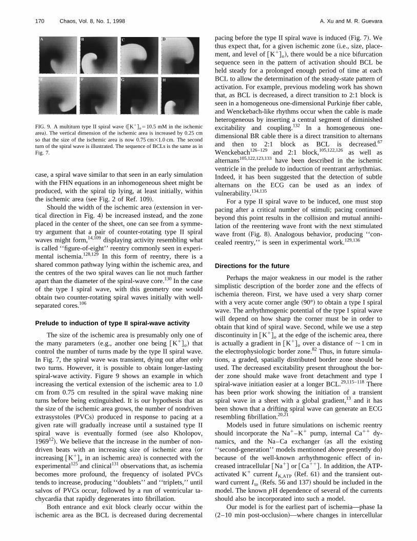
Prelude to induction of type II spiral-wave activity
The size of the ischemic area is presumably only onethe many parameters~e.g., another one being@K1#o! thatcontrol the number of turns made by the type II spiral waIn Fig. 7, the spiral wave was transient, dying out after otwo turns. However, it is possible to obtain longer-lastispiral-wave activity. Figure 9 shows an example in whiincreasing the vertical extension of the ischemic area tocm from 0.75 cm resulted in the spiral wave making niturns before being extinguished. It is our hypothesis thathe size of the ischemic area grows, the number of nondriextrasystoles~PVCs! produced in response to pacing atgiven rate will gradually increase until a sustained typespiral wave is eventually formed~see also Kholopov,196912!. We believe that the increase in the number of nodriven beats with an increasing size of ischemic area~orincreasing@K1#o in an ischemic area! is connected with theexperimental125 and clinical131 observations that, as ischembecomes more profound, the frequency of isolated PVtends to increase, producing ‘‘doublets’’ and ‘‘triplets,’’ untsalvos of PVCs occur, followed by a run of ventricular tchycardia that rapidly degenerates into fibrillation.
Both entrance and exit block clearly occur within thischemic area as the BCL is decreased during decreme
FIG. 9. A multiturn type II spiral wave~@K1#o510.5 mM in the ischemicarea!. The vertical dimension of the ischemic area is increased by 0.25so that the size of the ischemic area is now 0.75 cm31.0 cm. The secondturn of the spiral wave is illustrated. The sequence of BCLs is the sameFig. 7.
ne
e-l
dr
f
.y
.0
sn
I
-
s
tal
pacing before the type II spiral wave is induced~Fig. 7!. Wethus expect that, for a given ischemic zone~i.e., size, place-ment, and level of@K1#o!, there would be a nice bifurcationsequence seen in the pattern of activation should BCLheld steady for a prolonged enough period of time at eBCL to allow the determination of the steady-state patternactivation. For example, previous modeling work has shothat, as BCL is decreased, a direct transition to 2:1 blocseen in a homogeneous one-dimensional Purkinje fiber caand Wenckebach-like rhythms occur when the cable is mheterogeneous by inserting a central segment of diminisexcitability and coupling.132 In a homogeneous onedimensional BR cable there is a direct transition to alternand then to 2:1 block as BCL is decreased67
Wenckebach126–129 and 2:1 block,105,122,126 as well asalternans105,122,123,133have been described in the ischemventricle in the prelude to induction of reentrant arrhythmiIndeed, it has been suggested that the detection of sualternans on the ECG can be used as an indexvulnerability.134,135
For a type II spiral wave to be induced, one must stpacing after a critical number of stimuli; pacing continubeyond this point results in the collision and mutual annilation of the reentering wave front with the next stimulatwave front ~Fig. 8!. Analogous behavior, producing ‘‘concealed reentry,’’ is seen in experimental work.129,136
Directions for the future
Perhaps the major weakness in our model is the rasimplistic description of the border zone and the effectsischemia thereon. First, we have used a very sharp cowith a very acute corner angle~90°! to obtain a type I spiralwave. The arrhythmogenic potential of the type I spiral wawill depend on how sharp the corner must be in orderobtain that kind of spiral wave. Second, while we use a sdiscontinuity in@K1#o at the edge of the ischemic area, theis actually a gradient in@K1#o over a distance of;1 cm inthe electrophysiologic border zone.82 Thus, in future simula-tions, a graded, spatially distributed border zone shouldused. The decreased excitability present throughout theder zone should make wave front detachment and typspiral-wave initiation easier at a longer BCL.29,115–118Therehas been prior work showing the initiation of a transiespiral wave in a sheet with a global gradient,13 and it hasbeen shown that a drifting spiral wave can generate an Eresembling fibrillation.20,21
Models used in future simulations on ischemic reenshould incorporate the Na1–K1 pump, internal Ca11 dy-namics, and the Na–Ca exchanger~as all the existing‘‘second-generation’’ models mentioned above presently!because of the well-known arrhythmogenic effect ofcreased intracellular@Na1# or @Ca11#. In addition, the ATP-activated K1 current I K,ATP ~Ref. 61! and the transient outward currentI to ~Refs. 56 and 137! should be included in themodel. The knownpH dependence of several of the currenshould also be incorporated into such a model.
Our model is for the earliest part of ischemia—phase~2–10 min post-occlusion!—where changes in intercellula
m
in

ionr-
sills
-pein-
r-to
ontoa
irau
ng
ry
ant
hee
dre
-hsenut
man
only
er,m
ut-s
-le:
o,reddap-
e-
os-. 3,
x-
h-de-
ble
inys-
iacm
m-
.
ri-
o,abit
bin,ms,’’
v-ce
f-os
el
-ci.
’’
e-
eld
171Chaos, Vol. 8, No. 1, 1998 A. Xu and M. R. Guevara
coupling do not appear to play a major role in the inductof reentry.138 Modeling of the reentrant arrhythmias occuring in the phase Ib~12–30 min post-occlusion!138 and in thelater phase II ~several hours to several daypost-infarct!126–128stages of acute myocardial infarction wnecessitate incorporation into the model of the changegap–junctional coupling known to take place.138,139 Theslowing of conduction in this setting will facilitate the induction and maintenance of reentrant activity. Anisotropy, escially in the setting of slowed conduction, is importantphase II arrhythmogenesis,140 and so should definitely be included in any model of late arrhythmias@see, however, Win-free ~1997!104#.
In our simulations, the ionic model was modified in oder to lower the APD and thus the wavelength sufficientlyobtain a sustained spiral wave. Increases in computatipower will permit simulations in a sheet large enoughsupport reentrant activity with a longer wavelength. Inmodel with a longer wavelength, the maintained type I spwave we describe here in the normal area might breakinto the more complicated pattern of irregularly circulatimultiple spiral waves, which might be a form of spatiotemporal chaos.23,141,142 Indeed, we have already seen veirregular activity when pacing is continued at@K1#o
510.5 mM beyond the point in time at which a type I spirwave would form~Fig. 10!. There is a continual productioof new activation wave fronts~e.g., a blob along the righmargin of the ischemic area in Fig. 10~b!, which is travellingdownward, is about to pinch off!, with up to four wave frontssimultaneously existing on the sheet@Fig. 10~c!#. Use of alarger sheet will also allow a scaling up of the size of tischemic area, which will then permit observation of the phnomena we describe above, but with a longer APD anlonger spiral-rotation period, both of which would be mocharacteristic of reentry in the canine,122,143 porcine,105 orhuman144 ventricle. This will then open up the door to exploring spontaneous initiation of spiral waves—which migthen rapidly break up26—at a normal heart rate, which ipresumably the mechanism underlying the malignant vtricular arrhythmias seen during the natural history of acmyocardial infarction.
ACKNOWLEDGMENTS
This work was supported by a grant to M. Guevara frothe Medical Research Council of Canada. We wish to th
FIG. 10. Complex spatiotemporal activation pattern~@K1#o510.5 mM inthe ischemic area!. Stimulation at BCL571 ms is continued beyond thpoint in time at which first a type II, and then a type I, spiral wave wouhave been initiated. Ischemic area: 0.75 cm31.0 cm. Stimuli delivered tothe two leftmost columns; stimulus amplitude5300mA cm22.
in
-
al
lp
-
l
-a
t
-e
k
Ali Yehia for much help with computers, and Dr. Josh Lefor providing us with time on his computer, which greatspeeded up our rate of progress.
1P. V. Bayly, B. H. KenKnight, J. M. Rogers, E. E. Johnson, R. E. Idekand W. M. Smith, ‘‘Spatial organization, predictability, and determinisin ventricular fibrillation,’’ Chaos8, 103–115~1998!.
2P.-S. Chen, A. Garfinkel, J. N. Weiss, and H. S. Karagueuzian, ‘‘Comperized mapping of fibrillation in normal ventricular myocardium,’’ Chao8, 127–136~1998!.
3B. H. KenKnight, P. V. Bayly, W. M. Smith, and R. E. Ideker, ‘‘Epicardial activation patterns during regional capture of the fibrillating ventricPotential mechanisms and implications’’~in preparation!.
4F. X. Witkowski, L. J. Leon, P. A. Penkoske, R. B. Clark, M. L. SpanW. L. Ditto, and W. R. Giles, ‘‘A method for visualization of ventriculafibrillation: Design of a cooled fiberoptically coupled image intensifiCCD data acquisition system incorporating wavelet shrinkage based ative filtering,’’ Chaos8, 94–102~1998!.
5W. E. Garrey, ‘‘The nature of fibrillary contraction of the heart.—Its rlation to tissue mass and form,’’ Am. J. Physiol.33, 397–414~1914!.
6A. G. Mayer, ‘‘Rhythmical pulsation inScyphomedusae,’’ Carnegie Inst.Wash. Publ. No. 47, 1906.
7G. R. Mines, ‘‘On dynamic equilibrium in the heart,’’ J. Physiol.~Lon-don! 46, 349–383~1913!.
8G. R. Mines, ‘‘On circulating excitations in heart muscles and their psible relation to tachycardia and fibrillation,’’ Trans. R. Soc. Can. SerSect. IV8, 43–52~1914!.
9I. S. Balakhovskii, ‘‘Several modes of excitation movement in ideal ecitable tissue,’’ Biophysics10, 1175–1179~1965!.
10V. I. Krinskii, ‘‘Spread of excitation in an inhomogeneous medium~statesimilar to cardiac fibrillation!,’’ Biophysics 11, 776–784~1966!.
11A. V. Kholopov, ‘‘Spread of excitation and the formation of closed patways of conduction in a plane medium the refractoriness of whichpends on the period of excitation,’’ Biophysics13, 1231–1243~1967!.
12A. V. Kholopov, ‘‘Effect of the parameters and properties of an excitamedium on the process of fibrillation,’’ Biophysics14, 726–734~1969!.
13A. I. Shcherbunov, N. I. Kukushkin, and M. Y. Sakson, ‘‘Reverberatora system of interrelated fibres described by the Noble equation,’’ Biophics 18, 547–554~1973!.
14A. M. Pertsov and A. K. Grenadier, ‘‘The autowave nature of cardarrhythmias,’’ in Self-Organization: Autowaves and Structures far froEquilibrium, edited by V. I. Krinsky~Springer-Verlag, Berlin, 1984!, pp.184–190.
15A. T. Winfree,When Time Breaks Down. The Three-Dimensional Dynaics of Electrochemical Waves and Cardiac Arrhythmias~Princeton Uni-versity Press, Princeton, 1987!.
16A. T. Winfree, ‘‘Sudden cardiac death: A problem in topology,’’ Sci. Am248„5…, 144–161~1983!.
17A. T. Winfree, ‘‘Electrical instability in cardiac muscle: Phase singulaties and rotors,’’ J. Theor. Biol.138, 353–405~1989!.
18R. A. Gray, J. Jalife, A. Panfilov, W. T. Baxter, C. Cabo, J. M. Davidenkand A. M. Pertsov, ‘‘Nonstationary vortexlike reentrant activity asmechanism of polymorphic ventricular tachycardia in the isolated rabheart,’’ Circulation91, 2454–2469~1995!.
19C. F. Starmer, D. N. Romashko, R. S. Reddy, Y. I. Zilberter, J. StaroA. O. Grant, and V. I. Krinsky, ‘‘Proarrhythmic response to potassiuchannel blockade. Numerical studies of polymorphic tachyarrhythmiaCirculation92, 595–605~1995!.
20R. A. Gray, J. Jalife, A. V. Panfilov, W. T. Baxter, C. Cabo, J. M. Daidenko, and A. M. Pertsov, ‘‘Mechanisms of cardiac fibrillation,’’ Scien270, 1222–1223~1995!.
21J. Jalife, R. A. Gray, G. E. Morley, and J. M. Davidenko, ‘‘Selorganization and the dynamical nature of ventricular fibrillation,’’ Cha8, 79–93~1998!.
22G. K. Moe, W. C. Rheinboldt, and J. A. Abildskov, ‘‘A computer modof atrial fibrillation,’’ Am. Heart J.67, 200–221~1964!.
23A. V. Panfilov and A. V. Holden, ‘‘Spatiotemporal irregularity in a twodimensional model of cardiac tissue,’’ Int. J. Bifurcation Chaos Appl. SEng.1, 219–225~1991!.
24A. V. Panfilov, ‘‘Spiral breakup as a model of ventricular fibrillation,Chaos8, 57–64~1998!.
25M. A. Allessie, F. I. M. Bonke, and F. J. G. Schopman, ‘‘Circus mov

e
,c-t.
lifeac
ge
ndin
l
.
’s
acti
of
alha
sls
inr.
ib
nt’ in
a-
nu,’’
ue
ionne
.ulag,’
J.een
-
ticd
u,’’
l o
la
ned
in–ut.
hear-
n-
ckpa-
tion
o,en-
r
ntsac.
ofof
ofla-
–
nSer.
a
n-ol.
of
f
ndock
t3-
J.ed
-
iac
:
172 Chaos, Vol. 8, No. 1, 1998 A. Xu and M. R. Guevara
ment in rabbit atrial muscle as a mechanism of tachycardia,’’ Circ. R33, 54–62~1973!.
26D. W. Frazier, P. D. Wolf, J. M. Wharton, A. S. L. Tang, W. M. Smithand R. E. Ideker, ‘‘Stimulus-induced critical point: Mechanism for eletrical initiation of reentry in normal canine myocardium,’’ J. Clin. Inves83, 1039–1052~1989!.
27J. M. Davidenko, A. V. Pertsov, R. Salomonsz, W. Baxter, and J. Ja‘‘Stationary and drifting spiral waves of excitation in isolated cardimuscle,’’ Nature~London! 355, 349–351~1992!.
28C. A. Nour, J. L. Leon, M. Vermeulen, R. Cardinal, and F. A. Rober‘‘Mapping of reentry in a thin sheet of canine myocardium,’’17th EMBSConference~IEEE, Montreal, 1995!, Paper 1.1.6.6.
29C. Cabo, A. M. Pertsov, J. M. Davidenko, W. T. Baxter, R. A. Gray, aJ. Jalife, ‘‘Vortex shedding as a precursor of turbulent electrical activitycardiac muscle,’’ Biophys. J.70, 1105–1111~1996!.
30N. V. Thakor and M. G. Fishler, ‘‘Initiation and termination of spirawaves in a two-dimensional bidomain model of cardiac tissue,’’Comput-ers in Cardiology~IEEE Computer Society, Silver Springs, 1996!, pp.229–232.
31D. T. Kim, Y. Kwan, J. J. Lee, T. Ikeda, T. Uchida, K. Kamjoo, Y.-HKim, J. J. C. Ong, C. A. Athill, T.-J. Wuet al., ‘‘Patterns of spiral tipmotion in cardiac tissues,’’ Chaos8, 137–148~1998!.
32A. T. Winfree, ‘‘Varieties of spiral wave behavior: An experimentalistapproach to the theory of excitable media,’’ Chaos1, 303–334~1991!.
33M. Courtemanche and A. T. Winfree, ‘‘Re-entrant rotating waves inBeeler–Reuter based model of two-dimensional cardiac electrical aity,’’ Int. J. Bifurcation Chaos Appl. Sci. Eng.1, 431–444~1991!.
34M. G. Fishler and N. V. Thakor, ‘‘A massively parallel computer modelpropagation through a two-dimensional cardiac syncytium,’’ PACE14,1694–1699~1991!.
35L. J. Leon, F. A. Roberge, and A. Vinet, ‘‘Simulation of two-dimensionanisotropic cardiac reentry: effects of the wavelength on the reentry cacteristics,’’ Ann. Biomed. Eng.22, 592–609~1994!.
36I. R. Efimov, V. I. Krinsky, and J. Jalife, ‘‘Dynamics of rotating vorticein the Beeler–Reuter model of cardiac tissue,’’ Chaos Solitons Fracta5,513–526~1995!.
37V. N. Biktashev and A. V. Holden, ‘‘Re-entrant activity and its controla model of mammalian ventricular tissue,’’ Proc. R. Soc. London, Se263, 1373–1382~1996!.
38M. Courtemanche, ‘‘Complex spiral wave dynamics in a spatially distruted ionic model of cardiac electrical activity,’’ Chaos6, 579–600~1996!.
39L. A. Irvine and R. L. Winslow, ‘‘Numerical studies of use-dependeblock of cardiac sodium channels by quinidine on spiral wave reentry,’Ref. 30, pp. 613–616.
40V. N. Biktashev and A. V. Holden, ‘‘Re-entrant waves and their elimintion in a model of mammalian ventricular tissue,’’ Chaos8, 48–56~1998!.
41F. Fenton and A. Karma, ‘‘Vortex dynamics in three-dimensional contious myocardium with fiber rotation: Filament instability and fibrillationChaos8, 20–47~1998!.
42N. Trayanova, K. Scouibine, and F. Aguel, ‘‘The role of cardiac tissstructure in defibrillation,’’ Chaos8, 221–233~1998!.
43T. Watanabe, P. M. Rautaharju, and T. F. McDonald, ‘‘Ventricular actpotentials, ventricular extracellular potentials, and the ECG of guipig,’’ Circ. Res.57, 362–373~1985!.
44D. S. Rosenbaum, D. T. Kaplan, A. Kanai, L. Jackson, H. Garan, RCohen, and G. Salama, ‘‘Repolarization inhomogeneities in ventricmyocardium change dynamically with abrupt cycle length shorteninCirculation84, 1333–1345~1991!.
45C. Antzelevitch, S. Sicouri, S. H. Litovsky, A. Lukas, S. C. Krishnan,M. Di Diego, G. A. Gintant, and D.-W. Liu, ‘‘Heterogeneity within thventricular wall: Electrophysiology and pharmacology of epicardial,docardial, and M cells,’’ Circ. Res.69, 1427–1449~1991!.
46J. Han and G. K. Moe, ‘‘Nonuniform recovery of excitability in ventricular muscle,’’ Circ. Res.14, 44–60~1964!.
47M. J. Janse, ‘‘Vulnerability to ventricular fibrillation,’’ Chaos~in press!.48C.-S. Kuo, K. Munakata, C. P. Reddy, and B. Surawicz, ‘‘Characteris
and possible mechanism of ventricular arrhythmia dependent on thepersion of action potential durations,’’ Circulation67, 1356–1367~1983!.
49M. J. Janse and A. L. Wit, ‘‘Electrophysiological mechanisms of ventriclar arrhythmias resulting from myocardial ischemia and infarctionPhysiol. Rev.69, 1049–1169~1989!.
50G. W. Beeler and H. Reuter, ‘‘Reconstruction of the action potentiaventricular myocardial fibres,’’ J. Physiol.~London! 268, 177–210~1977!.
51J.-P. Drouhard and F. A. Roberge, ‘‘A simulation study of the ventricu
s.
,
,
v-
r-
B
-
-
a
J.r’
-
sis-
-
f
r
myocardial action potential,’’ IEEE Trans. Biomed. Eng.BME-29, 494–502 ~1982!.
52D. J. Mogul, N. V. Thakor, J. R. McCullough, G. A. Myers, R. E. teEick, and D. H. Singer, ‘‘Modified Beeler–Reuter model yields improvsimulation of myocardial action potentials,’’Computers in Cardiology,~IEEE Computer Society, Silver Springs, 1984!, pp. 159–162.
53J.-P. Drouhard and F. A. Roberge, ‘‘Revised formulation of the HodgkHuxley representation of the sodium current in cardiac cells,’’ CompBiomed. Res.20, 333–350~1987!.
54D. R. Lemieux, F. A. Roberge, and P. Savard, ‘‘A model study of tcontribution of active Na–K transport to membrane repolarization in cdiac cells,’’ J. Theor. Biol.142, 1–33~1990!.
55C. Luo and Y. Rudy, ‘‘A model of the ventricular cardiac action potetial,’’ Circ. Res.68, 1501–1526~1991!.
56A. V. Sahakian, G. A. Mayers, and N. Maglaveras, ‘‘Unidirectional bloin cardiac fibers: Effects of discontinuities in coupling resistance and stial changes in resting membrane potential in a computer simulastudy,’’ IEEE Trans. Biomed. Eng.39, 510–521~1992!.
57D. Noble, S. J. Noble, G. C. L. Bett, Y. E. Earm, W. K. Ho, and I. K. S‘‘The role of sodium–calcium exchange during the cardiac action pottial,’’ Ann. NY Acad. Sci. 639, 334–353~1991!.
58C. Nordin, ‘‘Computer model of membrane current and intracellular Ca11
flux in the isolated guinea pig ventricular myocyte,’’ Am. J. Physiol.265,H2117–H2136~1993!.
59C. H. Luo and Y. Rudy, ‘‘A dynamic model of the cardiac ventriculaaction potential,’’ Circ. Res.74, 1071–1096~1994!.
60J. Zeng, K. R. Laurita, D. S. Rosenbaum, and Y. Rudy, ‘‘Two componeof the delayed rectifier K1 current in ventricular myocytes of the guinepig type. Theoretical formulation and their role in repolarization,’’ CirRes.77, 140–152~1995!.
61J. M. Ferrero, Jr., J. Saiz, J. M. Ferrero, and N. V. Thakor, ‘‘Simulationaction potentials from metabolically impaired cardiac myocytes: roleATP-sensitive K1 current,’’ Circ. Res.79, 208–221~1996!.
62N. Friedman, A. Vinet, and F. A. Roberge, ‘‘A study of a new modelthe cardiac ventricular cell incorporating myoplasmic calcium regution,’’ Proceedings of the 22nd CMBES Conference~IEEE, Montreal,1996!.
63S. Dokos, B. G. Celler, and N. H. Lovell, ‘‘Modification of DiFrancescoNoble equations to simulate the effects of vagal stimulation onin vivomammalian sinoatrial node electrical activity,’’ Ann. Biomed. Eng.21,321–335~1993!.
64Y. E. Earm and D. Noble, ‘‘A model of the single atrial cell: Relatiobetween calcium current and calcium release,’’ Proc. R. Soc. London,B 240, 83–96~1990!.
65V. N. Biktashev and A. V. Holden, ‘‘Control of re-entrant activity inmodel of mammalian atrial tissue,’’ Proc. R. Soc. London, Ser. B260,211–217~1995!.
66A. V. Holden and H. Zhang, ‘‘Characteristics of atrial re-entry and meader computed from a model of a rabbit single atrial cell,’’ J. Theor. Bi175, 545–551~1995!.
67T. J. Lewis and M. R. Guevara, ‘‘Chaotic dynamics in an ionic modelthe propagated cardiac action potential,’’ J. Theor. Biol.146, 407–432~1990!.
68H. Windisch, W. Muller, and H. A. Tritthart, ‘‘Fluorescence monitoring orapid changes in membrane potential in heart muscle,’’ Biophys. J.48,877–884~1985!.
69C. Cabo, A. M. Pertsov, W. T. Baxter, J. M. Davidenko, R. A. Gray, aJ. Jalife, ‘‘Wave-front curvature as a cause of slow conduction and blin isolated cardiac muscle,’’ Circ. Res.75, 1014–1028~1994!.
70V. G. Fast and A. G. Kle´ber, ‘‘Block of impulse propagation at an abruptissue expansion: Evaluation of the critical strand diameter in 2- anddimensional computer models,’’ Cardiovasc. Res.30, 449–459~1995!.
71L. Lapidus and G. F. Pinder,Numerical Solution of Partial DifferentialEquations in Science and Engineering~Wiley, New York, 1982!.
72A. M. Pertsov, J. M. Davidenko, R. Salomonsz, W. T. Baxter, andJalife, ‘‘Spiral waves of excitation underlie reentrant activity in isolatcardiac muscle,’’ Circ. Res.72, 631–650~1993!.
73G. Isenberg and U. Klo¨ckner, ‘‘Calcium currents of isolated bovine ventricular myocytes are fast and of large amplitude,’’ Pflu¨gers Arch. Ges.Physiol. Menschen Tiere395, 30–41~1982!.
74D. Noble, ‘‘The surprising heart: A review of recent progress in cardelectrophysiology,’’ J. Physiol.~London! 353, 1–50~1984!.
75G. Isenberg and U. Klo¨ckner, ‘‘Isolated bovine ventricular myocytes

.
yo
-eaue
keranmi
al
Slar
c-
dela
cutio
aaaniso
learan
. Jain
in
t in
n-he
tio
lar,
ias
o-re
he’ in
n an
ira
he
av
,’’
h–
nal
’’
l
lesro-
arytact
on
ofg a
ed-
s
s
vest–
e-cle’’
dro-
etical
fitical
sky
of
pic
tialis-
er,-ine
173Chaos, Vol. 8, No. 1, 1998 A. Xu and M. R. Guevara
Characterization of the action potential,’’ Pflu¨gers Arch. Ges. PhysiolMenschen Tiere395, 19–29~1982!.
76A. Varro, D. A. Lathrop, S. B. Hester, P. P. Na´nasi, and J. G. Papp, ‘‘Ioniccurrents and action potentials in rabbit, rat, guinea pig ventricular mcytes,’’ Bas. Res. Cardiol.88, 93–102~1993!.
77M. A. Allessie, F. I. M. Bonke, and F. J. G. Schopman, ‘‘Circus movement in rabbit atrial muscle as a mechanism of tachycardia III. The ‘ling circle’ concept: A new model of circus movement in cardiac tisswithout the involvement of an anatomical obstacle,’’ Circ. Res.41, 9–18~1977!.
78J. L. R. M. Smeets, M. A. Allessie, W. J. E. P. Lammers, F. I. M. Bonand J. Hollen, ‘‘The wavelength of the cardiac impulse and reentarrhythmias in isolated rabbit atrium: The role of heart rate, autonotransmitters, temperature, and potassium,’’ Circ. Res.58, 96–108~1986!.
79A. M. Pertsov, E. A. Ermakova, and A. V. Panfilov, ‘‘Rotating spirwaves in a modified Fitz-Hugh–Nagumo model,’’ Physica D14, 117–124~1984!.
80S. D. Girouard, J. M. Pastore, K. R. Laurita, K. W. Gregory, and D.Rosenbaum, ‘‘Optical mapping in a new guinea pig model of ventricutachycardia reveals mechanisms for multiple wavelengths in a singleentrant circuit,’’ Circulation93, 603–613~1996!.
81M. J. Schalij, ‘‘Anisotropic conduction and ventricular tachycardia,’’ Dotoral thesis, University of Limburg, Maastricht, 1988.
82R. Coronel, J. W. Fiolet, F. J. G. Wilms-Schopman, A. F. SchaapherT. A. Johnson, L. S. Gettes, and M. J. Janse, ‘‘Distribution of extracellupotassium and its relation to electrophysiologic changes during amyocardial ischemia in the isolated perfused porcine heart,’’ Circula77, 1125–1138~1988!.
83R. Coronel, J. W. Fiolet, J. G. Wilms-Schopman, T. Opthof, A. F. Schpherder, and M. J. Janse, ‘‘Distribution of extracellular potassiumelectrophysiologic changes during two-stage coronary ligation in thelated, perfused canine heart,’’ Circulation80, 165–177~1989!.
84R. Coronel, F. J. G. Wilms-Schopman, T. Opthof, J. Cinca, J. W. Fioand M. J. Janse, ‘‘Reperfusion arrhythmias in isolated perfused pig heInhomogeneities in extracellular potassium, ST and TQ potentials,transmembrane action potentials,’’ Circ. Res.71, 1131–1142~1992!.
85R. Coronel, F. J. G. Wilms-Schopman, J. W. Fiolet, T. Opthof, and MJanse, ‘‘The relation between extracellular potassium concentrationpH in the border zone during regional ischemia in isolated porchearts,’’ J. Mol. Cell. Cardiol.27, 2069–2073~1995!.
86M. Vinson, A. M. Pertsov, and J. Jalife, ‘‘Anchoring of vortex filaments3D excitable media,’’ Physica D72, 119–134~1993!.
87N. C. Janvier and M. R. Boyett, ‘‘The role of Na–Ca exchange currenthe cardiac action potential,’’ Cardiovasc. Res.32, 69–84~1996!.
88T. Doerr, R. Denger, A. Doerr, and W. Trautwein, ‘‘Ionic currents cotributing to the action potential in single ventricular myocytes of tguinea-pig studied with action potential clamp,’’ Pflu¨gers Arch. Ges.Physiol. Menschen Tiere416, 230–237~1990!.
89G. H. Sharp and R. W. Joyner, ‘‘Simulated propagation of cardiac acpotentials,’’ Biophys. J.31, 403–423~1980!.
90A. T. Winfree. ‘‘How does ventricular tachycardia decay into ventricufibrillation?,’’ in Cardiac Mapping, edited by M. Shenasa, M. Borggrefeand G. Breithardt~Futura, New York, 1993!, pp. 655–682.
91F. J. L. van Capelle and D. Durrer, ‘‘Computer simulation of arrhythmin a network of coupled excitable elements,’’ Circ. Res.47, 454–466~1980!.
92F. J. L. van Capelle and M. A. Allessie, ‘‘Computer simulation of anistropic impulse propagation: Characteristics of action potentials duringentrant arrhythmias,’’ inCell to Cell Signalling: From Experiments toTheoretical Models, edited by A. Goldbeter~Academic, London, 1989!,pp. 577–588.
93M. A. Mercader, D. C. Michaels, and J. Jalife, ‘‘Reentrant activity in tform of spiral waves in mathematical models of the sinoatrial node,’Cardiac Electrophysiology: From Cell to Bedside, edited by D. P. Zipesand J. Jalife, 2nd ed.~Saunders, Philadelphia, 1995!, pp. 389–403.
94D. Barkley, M. Kness, and L. S. Tuckerman, ‘‘Spiral-wave dynamics isimple model of excitable media: The transition from simple to compourotation,’’ Phys. Rev. A42, 2489–2492~1990!.
95D. Barkley and I. G. Kevrekidis, ‘‘A dynamical systems approach to spwave dynamics,’’ Chaos4, 453–460~1994!.
96H. Zhang and A. V. Holden, ‘‘Chaotic meander of spiral waves in tFitzHugh–Nagumo system,’’ Chaos Solitons Fractals5, 661–670~1995!.
97J. M. Starobin and C. F. Starmer, ‘‘Common mechanism links spiral w
-
d-
,tc
.re-
r,rten
-d-
t,ts.d
.nde
n
-
d
l
e
meandering and wave-front–obstacle separation,’’ Phys. Rev. E55,1193–1196~1997!.
98A. T. Winfree, ‘‘Electrical turbulence in three-dimensional heart muscleScience266, 1003–1006~1994!.
99A. T. Winfree, ‘‘Rotors, fibrillation and dimensionality,’’ inComputa-tional Biology of the Heart, edited by A. V. Panfilov and A. V. Holden~J.Wiley, Chichester, 1997!, pp. 101–135.
100A. Panfilov and P. Hogeweg, ‘‘Spiral breakup in a modified FitzHugNagumo model,’’ Phys. Lett. A176, 295–299~1993!.
101A. V. Panfilov and P. Hogeweg, ‘‘Scroll breakup in a three-dimensioexcitable medium,’’ Phys. Rev. E53, 1740–1743~1996!.
102V. G. Fast and A. M. Pertsov, ‘‘Drift of a vortex in the myocardium,Biophysics35, 489–494~1990!.
103A. M. Pertsov and Y. A. Yermakova, ‘‘Mechanism of drift of a helicawave in an inhomogeneous medium,’’ Biophysics33, 364–369~1988!.
104A. T. Winfree, ‘‘Heart muscle as a reaction–diffusion medium: The roof electric potential diffusion, activation front curvature, and anisotpy,’’ Int. J. Bifurcation Chaos Appl. Sci. Eng.7, 487–526~1997!.
105E. Downar, M. J. Janse, and D. Durrer, ‘‘The effect of acute coronartery occlusion on subepicardial transmembrane potentials in the inporcine heart,’’ Circulation56, 217–224~1977!.
106A. V. Panfilov and J. P. Keener, ‘‘Effects of high frequency stimulation cardiac tissue with an inexcitable obstacle,’’ J. Theor. Biol.163, 439–448 ~1993!.
107A. A. Petrov and B. N. Fel’d, ‘‘Analysis of the possible mechanismorigin of the extrasystole in local ischaemia of the myocardium usinmathematical model,’’ Biophysics18, 1145–1150~1973!.
108A. N. Reshetilov, A. M. Pertsov, and V. I. Krinskii, ‘‘Parameters of thmyocardium controlling vulnerability. Analysis of mathematical moels,’’ Biophysics24, 133–139~1979!.
109A. V. Panfilov and B. N. Vasiev, ‘‘Vortex initiation in a heterogeneouexcitable medium,’’ Physica D49, 107–113~1991!.
110K. I. Agladze, ‘‘High-frequency instability of wave fronts,’’ Chaos4,525–529~1994!.
111R. R. Aliev and A. V. Panfilov, ‘‘Modeling of heart excitation patterncaused by a local inhomogeneity,’’ J. Theor. Biol.181, 33–40~1996!.
112J. M. Starobin and C. F. Starmer, ‘‘Boundary-layer analysis of wapropagating in an excitable medium: Medium conditions for wave-fronobstacle separation,’’ Phys. Rev. E54, 430–437~1996!.
113J. M. Starobin, Y. I. Zilberter, E. M. Rusnak, and C. F. Starmer, ‘‘Wavlet formation in excitable cardiac tissue: The role of wavefront–obstainteractions in initiating high-frequency fibrillatory-like arrhythmias,Biophys. J.70, 581–594~1996!.
114K. Agladze, J. P. Keener, S. C. Mu¨ller, and A. Panfilov, ‘‘Rotating spiralwaves created by geometry,’’ Science264, 1746–1748~1994!.
115M. Gomez-Gesteira, J. L. del Castillo, M. E. Va´zquez-Iglesias, V. Pe´rez-Munuzuri, and V. Pe´rez-Villar, ‘‘Influence of the critical curvature onspiral initiation in an excitable medium,’’ Phys. Rev. E50, 4646–4649~1994!.
116M. Bar, A. K. Bangia, I. G. Kevrekidis, G. Haas, H.-H. Rotermund, anG. Ertl, ‘‘Composite catalyst surfaces: Effect of inert and active hetegeneities on pattern formation,’’ J. Phys. Chem.100, 19 106–19 117~1996!.
117A. V. Panfilov and A. M. Pertsov, ‘‘Mechanism of the origin of thhelical waves in active media associated with the phenomenon of cricurvature,’’ Biophysics27, 931–934~1982!.
118A. M. Pertsov, A. V. Panfilov, and F. U. Medvedeva, ‘‘Instability oautowaves in excitable media associated with the phenomenon of crcurvature,’’ Biophysics28, 103–107~1983!.
119Z. Nagy-Ungvarai, A. M. Pertsov, B. Hess, and S. C. Mu¨ller, ‘‘Lateralinstabilities of a wave front in the Ce-catalyzed Belousov–Zhabotinreaction,’’ Physica D61, 205–212~1992!.
120A. M. Pertsov, E. A. Ermakova, and E. E. Shnol, ‘‘On the diffractionautowaves,’’ Physica D44, 178–190~1990!.
121A. V. Panfilov and J. P. Keener, ‘‘Generation of reentry in anisotromyocardium,’’ J. Cardiovasc. Electrophysiol.4, 412–421~1993!.
122D. C. Russell, H. J. Smith, and M. F. Oliver, ‘‘Transmembrane potenchanges and ventricular fibrillation during repetitive myocardialchaemia in the dog,’’ Br. Heart J.42, 88–96~1979!.
123M. J. Janse, F. J. L. van Capelle, H. Morsink, A. G. Kle´ber, F. Wilms-Schopman, R. Cardinal, C. Naumann D’Alnoncourt, and D. Durr‘‘Flow of ‘injury’ current and patterns of excitation during early ventricular arrhythmias in acute regional myocardial ischemia in isolated porc

h
o-er-
il-
ann
anat
nt2l
ofn fary
of
socts
o
ndiatia
fce
kin,lar
ntrsten-
n-
E.
g,’’
, T.el-bit
frder
al
g
en-in
lorour
or
174 Chaos, Vol. 8, No. 1, 1998 A. Xu and M. R. Guevara
and canine hearts. Evidence for two different arrhythmogenic mecnisms,’’ Circ. Res.47, 151–165~1980!.
124R. Coronel, ‘‘Distribution of extracellular potassium during acute mycardial ischemia,’’ Doctoral thesis, University of Amsterdam, Amstdam, 1988.
125A. S. Harris and A. Guevara Rojas, ‘‘The initiation of ventricular fibrlation due to coronary occlusion,’’ Exp. Med. Surg.1, 105–122~1943!.
126N. El-Sherif, B. J. Scherlag, R. Lazzara, and R. R. Hope, ‘‘Re-entrventricular arrhythmias in the late myocardial infarction period: 1. Coduction characteristics in the infarction zone,’’ Circulation55, 686–702~1977!.
127N. El-Sherif, R. R. Hope, B. J. Scherlag, and R. Lazzara, ‘‘Re-entrventricular arrhythmias in the late myocardial infarction period. 2. Pterns of initiation and termination of reentry,’’ Circulation55, 702–719~1977!.
128N. El-Sherif, W. B. Gough, R. H. Zeiler, and R. Hariman, ‘‘Reentraventricular arrhythmias in the late myocardial infarction period. 1Spontaneous versus induced reentry and intramural versus epicardiacuits,’’ J. Am. Coll. Cardiol.6, 124–132~1985!.
129M. A. Habbab and N. El-Sherif, ‘‘Recordings from the slow zonereentry during burst pacing versus programmed premature stimulatioinitiation of reentrant ventricular tachycardia in patients with coronartery disease,’’ Am. J. Cardiol.70, 211–217~1992!.
130E. A. Ermakova, A. M. Pertsov, and E. E. Shnol, ‘‘On the interactionvortices in two-dimensional active media,’’ Physica D40, 185–195~1989!.
131L. E. Hinkle, Jr., D. C. Argyros, J. C. Hayes, T. Robinson, D. R. AlonS. C. Shipman, and M. E. Edwards, ‘‘Pathogenesis of an unexpesudden death: Role of early cycle ventricular premature contractionAm. J. Cardiol.39, 873–879~1977!.
132M. R. Guevara, ‘‘Spatiotemporal patterns of block in an ionic modelcardiac Purkinje fibre,’’ inFrom Chemical to Biological Organization,edited by M. Markus, S. C. Mu¨ller, and G. Nicolis~Springer-Verlag,Berlin, 1988!, pp. 273–281.
133H. Morena, M. J. Janse, J. W. T. Fiolet, W. J. G. Krieger, H. Crijns, aD. Durrer, ‘‘Comparison of the effects of regional ischemia, hypoxhyperkalemia, and acidosis on intracellular and extracellular potenand metabolism in the isolated porcine heart,’’ Circ. Res.46, 634–646~1980!.
a-
t-
t-
.cir-
or
,ed,’’
f
,ls
134B. D. Nearing, A. H. Huang, and R. L. Verrier, ‘‘Dynamic tracking ocardiac vulnerability by complex demodulation of the T wave,’’ Scien252, 437–440~1991!.
135D. S. Rosenbaum, L. E. Jackson, J. M. Smith, H. Garan, J. N. Rusand R. J. Cohen, ‘‘Electrical alternans and vulnerability to ventricuarrhythmias,’’ New England J. Med.330, 235–241~1994!.
136N. El-Sherif, R. Mehra, W. B. Gough, and R. H. Zeiler, ‘‘Reentraventricular arrhythmias in the late myocardial infarction period. II. Bupacing versus multiple premature stimulation in the induction of retry,’’ J. Am. Coll. Cardiol.4, 295–304~1984!.
137A. Ogbaghebriel and A. Shrier, ‘‘Inhibition of metabolism abolishes trasient outward current in rabbit atrial myocytes,’’ Am. J. Physiol.266,H182–H190~1994!.
138W. T. Smith IV, W. F. Fleet, T. A. Johnson, C. L. Engle, and W.Cascio, ‘‘The Ib phase of ventricular arrhythmias in ischemicin situporcine heart is related to changes in cell-to-cell electrical couplinCirculation92, 3051–3060~1995!.
139J. T. Vermeulen, H. L. Tan, H. Rademaker, C. A. Schumacher, P. LohOpthof, R. Coronel, and M. J. Janse, ‘‘Electrophysiologic and extraclular ionic changes during acute ischemia in failing and normal rabmyocardium,’’ J. Mol. Cell. Cardiol.28, 123–131~1996!.
140S. M. Dillon, M. A. Allessie, P. C. Ursell, and A. L. Wit, ‘‘Influences oanisotropic tissue structure on reentrant circuits in the epicardial bozone of subacute canine infarcts,’’ Circ. Res.63, 182–206~1988!.
141I. Aranson, H. Levine, and L. Tsimring, ‘‘Controlling spatiotemporchaos,’’ Phys. Rev. Lett.72, 2561–2564~1994!.
142S. M. Zoldi and H. S. Greenside, ‘‘Karhunen–Loe`ve decomposition ofextensive chaos,’’ Phys. Rev. Lett.78, 1687–1690~1997!.
143T. Akiyama, ‘‘Intracellular recording of in situ ventricular cells durinventricular fibrillation,’’ Am. J. Physiol.240, H465–H471~1981!.
144J. F. Swartz, J. L. Jones, and R. D. Fletcher, ‘‘Characterization of vtricular fibrillation based on monophasic action potential morphologythe human heart,’’ Circulation87, 1907–1914~1993!.
145See AIP Document No. E-PAPS: E-CHAOE-8-025801 for original comovies. E-PAPS document files may be retrieved free of charge fromFTP server~http://www.aip.org/epaps/epaps.html! or from ftp.aip.org inthe directory/epaps/. For further information, e-mail: [email protected]: 516-576-2223.