Embed Size (px)
Citation preview
Spritzbeton-Tagung 2015 Page 1 Prof. Wolfgang Kusterle (Hrsg.)
TWISTED STEEL MICRO REINFORCEMENT (TSMR) FOR SHOTCRETE
VERDRILLTE STAHLFASERN ALS MICROBEWEHRUNG (TSMR) FÜR
SPRITZBETON Luke Pinkerton, Helix Steel, Ann Arbor, MI, USA Hans Hausfeld, Helix Steel, Ann Arbor, MI, USA Steel fibers have been used to reinforce shotcrete, replacing traditional steel wire mesh, for over twenty years. They are added to shotcrete to improve energy absorption, crack re-sistance and provide ductility. All three properties are very important for support systems designed for tunnel and mine conditions. TSMR (Twisted Steel Micro Reinforcement), takes shotcrete reinforcement one step further. The twisted anchorage and yielding properties of these new fibers provide all these benefits and more at much lower dosages than had previously thought possible – 50 % lower than hooked type fibers. Significant improvements in compressive, splitting tensile and flexural strengths have been documented. Stahlfasern als Ersatz für die traditionelle Mattenbewehrung werden bereits seit 20 Jahren für Spritzbeton eingesetzt. Sie werden dem Spritzbeton zugesetzt, um das Energie-absorptionsvermögen und den Widerstand gegen Rissbildung zu verbessern und dem Beton duktilere Eigenschaften zu geben. Alle drei Eigenschaften sind für die Sicherung von Tunnels und Bergwerken von großer Bedeutung. TSMR (Verdrillte Stahl Mikro Bewehrung) bringt die Spritzbetonbewehrung einen Schritt weiter. Die Verdrillung der Verankerung und die Fließeigenschaften dieser neuen Faser ermöglichen diese Vorteile bei deutlich reduzierter Dosierung. 50 % Reduzierung gegenüber Fasern mit Endhaken waren früher nicht vorstellbar. Erhebliche Verbesserungen bezüglich Druckfestig-keit, Spaltzugfestigkeit und Biegezugfestigkeit werden belegt. 1. Introduction Steel fibers have been used to reinforce shotcrete, replacing traditional steel wire mesh, for over twenty years. They are added to shotcrete to improve energy absorption, crack resis-tance and to provide ductility. But do these fibers really perform this function? Or are these improvements simply elaborate marketing tools developed by fiber manufacturers to con-vince engineers to specify their products? Testing and design approaches for fiber reinforced concrete have evolved over time with heavy influence of material manufacturers [1]. The industry is now focused on deflection controlled round panel tests (ASTM C1550/RDP). This configuration measures bi-axial energy absorption (area under load deflection curve) to large deflections / crack widths using closed loop deflection control. Shotcrete design is moving towards an empirical energy based approach that uses results from this type of test [2]. The method favors polymer fibers

Luke Pinkerton, Hans Hausfeld Twisted Steel Micro Reinforcement for Shotcrete
Spritzbeton-Tagung 2015 Page 2 Prof. Wolfgang Kusterle (Hrsg.)
which exert force on the concrete only AFTER large cracks are formed, since their moduli of elasticity are lower than concrete (they stretch like rubber bands). Further, the test machines use sophisticated controllers programed to immediately remove the load when the concrete cracks. This provides a false sense that low modulus fibers provide strength immediately after crack formation. There are three problems with current test and design methods:
1) Current test methods fail to measure properties needed for design directly (tensile resistance) and rely on empirically based assumptions to convert equivalent bending stress (from beam tests) to tensile stress.
2) Current design methods allow (and in many cases encourage) design assuming very large deflections and large crack widths (up to 40 mm deflection and 15 mm cracks) in flexural tests. The cracks are nearly 38 times the maximum code allowed crack width (EN 1992, 0.4 mm) and 72 times the width allowed when water-tightness is required (0.2 mm) [3]. By arguing that large crack widths are acceptable and even desirable, the polymer fiber industry has quietly convinced the industry that it is acceptable to have large cracks in concrete [4, 5].
3) Studies have shown strength variations of as much as 200 % in flexural testing associated with specimen size, preparation, and/or support conditions [6]. This calls in to question the idea of using data from such tests for design purposes.
Twisted Steel Micro Reinforcement (TSMR) Technology is both a product and a design method. The product has a statistically significant effect on the tensile strain capacity and modulus of elasticity of the concrete and it provides stable post crack resistance [7]. Unlike polymer fibers, TSMR provides tensile resistance prior to the development of code maximum cracks allowing for watertight design. This is accomplished via its twisted geometry which provides better anchorage/bond prior to crack formation and because it must actually untwist (provides constant resistance) to pull out of concrete (Figure 4). Unlike polymer fibers, TSMR increases the tensile strength and ductility of concrete prior to cracking and provides significant tensile resistance starting at 0.005 mm crack width. The design approach is unique because it solves the problem of specimen size and geometry by isolating the two primary variables and testing them separately: Force per TSMR and distribution of TSMR. Separating the distribution part of the limit state function allows for less expensive testing with smaller specimens without compromising design. The design approach is based on tensile stress capacity but is restricted by tensile strain (crack width). With cracks held smaller than 0.20 mm, structures remain water-tight and corrosion of steel does not come into play. The strain check also has the benefit of adequately ad-dressing size effect, an issue that plagues standardized fiber testing and design approaches today. 2. Testing and Design Approaches Unlike traditional reinforcement, the performance characterization and design of steel fiber concrete is not uniform throughout the industry. There are many competing test standards (Table 1) and design procedures (Table 2). While direct tensile resistance is the performance measurement needed for design, most test standards involve flexural tests. Tensile re-sistance is derived by assuming a relationship between the flexural stress (which only exists in linear elastic materials and is invalid after a crack forms) and direct tensile stress [8]. A multiplier of 0.37, (which assumes linearly decreasing load as crack width increases) is typically used to relate the flexural stress in beams with large cracks (3.5 mm) to direct

Luke Pinkerton, Hans Hausfeld Twisted Steel Micro Reinforcement for Shotcrete
Spritzbeton-Tagung 2015 Page 3 Prof. Wolfgang Kusterle (Hrsg.)
tensile strength [5]. Beam testing is also plagued with so called “size effect,” the non-scalability of results to larger or smaller sections and/or cross correlation of crack size, fiber length and specimen size on results. [6]
Table 1: Fiber Test Methods
Test Standard Type Control Measurement Single
Operator COV
ASTM C78 Flexural Beam Load Peak only Post crack* 5.7 %
ASTM C1609 Flexural Beam Deflection Peak Post crack
Peak: 8.2 % Post: 17 %
ASTM C1399 Flexural Beam Load Post Peak only 13 % ASTM C1550 RDP
Flexural Round Panel Deflection Peak
Post crack Peak 6.2 % Post 10 %
EFNARC Flexural Square Panel Deflection Peak
Post crack Not reported
EN 14651 Flexural Notched Beam Crack Width Post crack only Not reported
EN 12390-5 Flexural Beam Load Peak only Post crack* Not reported
RILEM TC 162-TDF
Direct Tension Notched Deflection Post crack only Not reported
ASTM C496 EN 12390-6 Splitting Tensile Load Peak
Post crack* 5 %
UES EC 015 Direct Tension Deflection Peak crack
Post crack Peak 6.3 % Post 11 %
*Note: measurable only when post crack strength is higher than first crack strength While the fib Model Code 2010 aims to become the general standard for fiber design in Europe, there are still several competing design approaches and methods (Table 2). The design crack widths are different for different design methods. Some of the more robust approaches, like RILEM TC 162 TF, include some statistical considerations for variations in test results. UES EC 015, is the only method evaluated that employs the Load and Resistance Factor Design (LRFD) method for deriving resistance factors employed by the world’s major design codes. [9, 10] The Papworth 2002 method of design for shotcrete is the only empirical approach evaluated. It uses the relationship between energy (too large deflection) in the round or square panel testing to rock type presented in a prescriptive table instead of a physics-based tensile strength approach [2]. This method favors fibers that behave well at large deflections in the round panel tests. The properties of TSMR reinforced concrete with higher tensile strength could provide benefit to designs using provisions of EN 1992 and ACI 318 for elastic design and plain concrete design. Unlike with conventional non-linear reinforced concrete design, these approaches consider concrete tensile strength in their design.

Luke Pinkerton, Hans Hausfeld Twisted Steel Micro Reinforcement for Shotcrete
Spritzbeton-Tagung 2015 Page 4 Prof. Wolfgang Kusterle (Hrsg.)
Table 2: Steel Fiber Design Methods
Design Approach
Application and Criteria
Design Assumption Test Test vs Design
Stress Model
ACI-360 Slabs only cracked stress
4 mm crack Yield Line
ASTM C1609 Linear, Re3
ACI 506.1R-9 Shotcrete cracked stress 0.5 mm crack ASTM
C1609 Linear, stress at 0.5 mm
RILEM TC 152-TDF
General, cracked stress & strain
1.5 mm 3.5 mm crack EN 14651 Bi-Linear
f1x0.45; f4x0.37
Concrete Society TR-34
Slabs only cracked stress
3.5 mm crack Yield Line EN 14651 Bi-Linear
f4x0.37
Fib Model Code 2010
General, cracked stress
0.5 mm or 2.5 mm crack EN 14651 Bi-Linear
f1x0.45l f3/3
Papworth 2002 [2]
Shotcrete Energy
Energy to 40 or 80 mm
ASTM C1550, RDP
Empirical Table of Energy
EN 1992 General Section 5.4
Elastic Design EN 12390-6 Elastic, MOE,
Tensile Strength UES EC015/ ER 279 Stress & Strain Peak or
1 mm crack EC 015 Not Required
3. Advantages and Disadvantages of Steel vs. Polymer Fibers in Shotcrete While polymers can be engineered to have tensile strengths equal to or greater than mild steel, the primary difference between steel and polymer fibers is modulus of elasticity (stiffness). Figure 1 illustrates the profound difference in modulus of elasticity between concrete, steel and several polymer types commonly used in concrete fibers. Steel is 800 % stiffer than concrete and the best polymer has only 38 % the stiffness of concrete. [11] Even with a very efficient concrete fiber bond, the polymer fibers do not provide tensile resistance prior to the development of cracks and they are stretched enough to provide resistance (they act like a rubber band in relation to the concrete). Direct tension comparing plain, polymer fiber, and TSMR concrete suggest pre-crack tensile is not affected by polymer fibers. This intuitively makes sense given the polymer fibers are nearly inactive until stretched (Figure 2) [12] due to their low elastic modulus. Steel, on the other hand, can provide resistance to concrete prior to crack due to its high elastic modulus and tensile strength relative to plain concrete. Provided these conditions are met and the bond between concrete and steel is adequate, the steel will increase the ductility of the concrete prior by providing alternative load paths of micro-cracking initiates. The testing confirmed the increase in strain at first crack with TSMR versus control is with 99.92 % confidence. TSMR technology is the only fiber type studied – steel or polymer – that exhibits this behavior.

Luke Pinkerton, Hans Hausfeld Twisted Steel Micro Reinforcement for Shotcrete
Spritzbeton-Tagung 2015 Page 5 Prof. Wolfgang Kusterle (Hrsg.)
‐
50
100
150
200
250
30 MPA
Concrete
Grade 500
Rebar
TMSR
Steel Fiber
Polypropylene/Polyethylene
Copolym
er/Polypropylene
Modified
Olefin
Mod
ulus
of E
lascity
(GPa
)
Figure 1: Concrete and Fiber Material Modulus of Elasticity [11]
Figure 2: Pre Crack Direct Tensile Load Vs Displacement [12] Polymer fibers do not begin exerting significant tensile force until after a crack of 0.85 mm wide forms (Figure 3). Once the concrete has developed a dominant crack of this size, the fiber can provide some tensile resistance as the crack increases in size to 3.5 mm and it stretches. Its best performance occurs at 3.5 mm, not coincidentally, the same crack width most of the design methods employ (remember EN 1992 states that the maximum crack width in a low environmental exposure area is 0.4 mm) [3]. The lower stiffness of the TSMR concrete is due to the efficient bond and screw shape of the TSMR product. This unique shape and bond allows the concrete matrix develop micro-cracks but not allow those micro-cracks to localize as quickly when the TSMR is not present. The TSMR is acting similar to a torsion spring, which stretches before the bond is broken and untwisting begins. This response is noticeable in both flexural (ASTM C1609 & C78) and direct tension (UES E015) testing by an increase in the peak (MOR) and deflect-tion/displacement at peak, not seen in steel or polymer fibers or rebar [12, 18, 20]. In fact,

Luke Pinkerton, Hans Hausfeld Twisted Steel Micro Reinforcement for Shotcrete
Spritzbeton-Tagung 2015 Page 6 Prof. Wolfgang Kusterle (Hrsg.)
it accepted that any reinforcement including rebar and wire mesh increase the frequency of cracking thus weakening plain concrete (i.e. EN 1992, ACI 318, 224R-01).
Figure 3: Polymer Fiber Concrete Post Crack Direct Tensile Load Vs. Displacement [12]
4. Geometry, Material and Physical Properties of TMSR
TSMR is made from high carbon, cold-drawn, deformed steel wire complying with ASTM A 820, Type I. The steel wire has a tensile strength of 1850 MPa and can be zinc coated for corrosion protection (also sold without coating). The length is 25 mm and its equivalent diameter is 0.5 mm. Each TSMR has a minimum of one 360-degree twist [13]. The TSMR can be customized in all areas (tensile, length, diameter, twists) for specific structures, designs, test standards or performance requirements.
Twisted Steel Micro Reinforcement (TSMR) is produced with a unique twisted profile (Fig-ure 4) that allows each piece to bond to the matrix over its full length. In addition, the reinforcement must untwist as it pulls out of the concrete. This makes this product significantly different from traditional steel fibers because pullout is governed by untwisting resistance rather than friction. TSMR is active in both the “Proactive Phase” (pre-crack), increasing peak tensile strength, and during the “Reactive Phase” (post-crack) providing ductility and stable tensile resistance to large crack widths.
Figure 4: Twisted Steel Micro Reinforcement

Luke Pinkerton, Hans Hausfeld Twisted Steel Micro Reinforcement for Shotcrete
Spritzbeton-Tagung 2015 Page 7 Prof. Wolfgang Kusterle (Hrsg.)
5. Performance Characterizations and Design of TSMR 5.1 Testing Per UES EC 015 TSMR tension resistance is measured using direct tension testing [14, 15]. The test uses a 150 mm diameter “dogbone” shaped coupon fitted with an adhesive anchor on the top and bottom and three strain measuring devices (Figure 5). These specimens are typically cast, methods of specimen preparation with shotcrete using a nozzle attachment are under development. The machine measures the direct tensile behavior using the procedures outlined in ASTM E111 both before and after a crack forms. The specimen geometry was designed using finite element analysis to assure there are no stress concentrations in the gage length.
Figure 5: Direct Tensile Test Setup
The test method and data analysis method is detailed in Uniform Evaluation Criteria #015. These criteria are an ISO Guide 65 compliant peer reviewed code document, recognized in 99 countries through International Standards Organization Mutual Recognition Agreements.
5.1.1 Test Results – Direct Tensile Before a dominant (localized visible) crack forms, the bond provided by the twisted shape of TSMR in addition to the high modulus allows for force re-distribution into the TSMR. The TSMR concrete has a lower modulus (thus it is more flexible) and requires more energy (area under load deflection curve) to crack (Figure 2). This occurs as result of a small amount of elastic stretching and untwisting that occurs as load is re-distributed into TSMR; the concrete micro-cracks prior to the formation of a dominant crack. The polymer fiber con-crete sample cracked at 1/10th the displacement of the TSMR sample, similar to the control.
After a crack forms, TSMR maintains stable tensile resistance up to a 1 mm crack width at low dosages as it stretches and begins to untwist (Figure 6). The TSMR resistance will decrease as the crack width increases beyond this as the TSMR’s ends begin to move and pull out. The force carried at equal volume fraction compared to polymer fibers is twelve times at 1 mm crack and four times at 3.5 mm crack (Figure 6). Higher dosages of TSMR (>0.5% Vf) are capable of deflection hardening behavior in bending (Figure 8) [18].

Luke Pinkerton, Hans Hausfeld Twisted Steel Micro Reinforcement for Shotcrete
Spritzbeton-Tagung 2015 Page 8 Prof. Wolfgang Kusterle (Hrsg.)
Figure 6: TSMR vs Polymer Fiber: Post Crack Direct Tension [12]
5.1.2 Test Results – Spitting Tensile Splitting tensile strengths with TSMR dosage (Figure 7), further demonstrating its ability to improve the pre-crack properties of the concrete. Similar increases in first crack strength (Modulus of Rupture) occur in beam testing and direct tension testing (Figure 8).
0
1
2
3
4
5
6
7
8
0.00% 0.08% 0.12% 0.52%
Spli
ng Ten
sile
Stress (MPa
)
TSMR Volume Frac on
Figure 7: TSMR Splitting Tensile Strength [17]
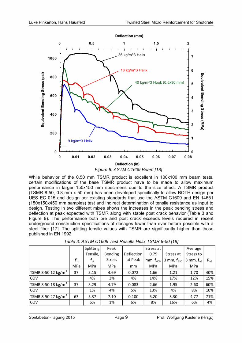
5.1.3 Test Results – Beam Test (without notch) Standard flexural beam testing conducted in accordance with ASTM C1609 (100 mm x 100 mm specimen size) shows that the same level of performance as with a 35 mm, 65 aspect ratio hook fiber can be achieved with 50 % the dosage of TSMR 5-25 (25 mm x 0.50 mm diameter). Further, the data shows that deflection hardening is possible with higher dosages of TSMR (Figure 8).
Luke Pinkerton, Hans Hausfeld Twisted Steel Micro Reinforcement for Shotcrete
Spritzbeton-Tagung 2015 Page 9 Prof. Wolfgang Kusterle (Hrsg.)
0
200
400
600
800
1000
0
1
2
3
4
5
6
7
0 0.01 0.02 0.03 0.04 0.05 0.06 0.07 0.08
0 0.5 1 1.5 2Eq
uiva
lent
Ben
ding
Str
ess
(psi
)
Deflection (in)
Deflection (mm)Equivalent B
ending Stress (MPa)
9 kg/m^3 Helix
18 kg/m^3 Helix
36 kg/m^3 Helix
40 kg/m^3 Hook (0.5x30 mm)
Figure 8: ASTM C1609 Beam [18]
While behavior of the 0.50 mm TSMR product is excellent in 100x100 mm beam tests, certain modifications of the base TSMR product have to be made to allow maximum performance in larger 150x150 mm specimens due to the size effect. A TSMR product (TSMR 8-50, 0.8 mm x 50 mm) has been developed specifically to allow BOTH design per UES EC 015 and design per existing standards that use the ASTM C1609 and EN 14651 (150x150x450 mm samples) test and indirect determination of tensile resistance as input to design. Testing in two different mixes shows the increases in the peak bending stress and deflection at peak expected with TSMR along with stable post crack behavior (Table 3 and Figure 9). The performance both pre and post crack exceeds levels required in recent underground construction specifications at dosages lower than ever before possible with a steel fiber [17]. The splitting tensile values with TSMR are significantly higher than those published in EN 1992.
Table 3: ASTM C1609 Test Results Helix TSMR 8-50 [19]
f'c
Splitting Tensile,
fct
PeakBending Stress
Deflection at Peak
Stress at0.75
mm, f600Stress at 3 mm, f150
AverageStress to 3 mm, fe3 Re3
MPa MPa MPa mm MPa MPa MPaTSMR 8‐50 12 kg/m3 37 3.15 4.69 0.072 1.66 1.21 1.70 40%COV 4% 3% 4% 14% 17% 12% 15%TSMR 8‐50 18 kg/m3 37 3.29 4.79 0.083 2.66 1.95 2.60 60%COV 1% 4% 5% 13% 4% 8% 10%TSMR 8‐50 27 kg/m3 63 5.37 7.10 0.100 5.20 3.30 4.77 71%COV 6% 1% 6% 8% 16% 6% 4%

Luke Pinkerton, Hans Hausfeld Twisted Steel Micro Reinforcement for Shotcrete
Spritzbeton-Tagung 2015 Page 10 Prof. Wolfgang Kusterle (Hrsg.)
Figure 9: TSMR ASTM C1609 Test Results [19]
5.1.4 Test Results – Notched Beam Test Testing indicates that TSMR developed for the EN 14651 test preformed 40 % better than 65-aspect ratio hook ended steel fiber at 3.5 mm crack width with more consistent results (Figure 10 and Table 4). While an evaluation report is pending for this product, testing at Element Labs (Report ESP013997P) against the criteria for TSMR outlined in UES EC 015 confirms an increase in tensile strain at first crack of 19 % over the control (plain concrete) with 98 % confidence (p=0.017) and post crack stable direct tensile behavior.
Table 4: EN 14651 Test Results Helix TSMR 8-50 Vs Hook Fiber 80/60 [20] Dosage Aspect f ct, L f R, 1 f R,2 f R,3 f R, 4
kg/m3 Ratio MPa MPa MPa MPa MPaHelix 8‐50 25 62 5.1 3.8 5.3 5.4 4.8COV 3% 12% 9% 11% 10%Hook 80/60 25 80 5.0 3.2 4.0 4.0 3.4COV 6% 16% 14% 17% 16%Increase vs Hook with TSMR 2% 20% 31% 37% 41%
Product
5.2 Design Per UES EC 015 The TSMR design procedure uses tensile values developed from UES EC 015 direct tension testing. A regression analysis is performed to derive a function for tensile resistance measured with direct tension testing as a function of the number of TSMR spanning the broken cross section and concrete compressive strength (Figure 11).

Luke Pinkerton, Hans Hausfeld Twisted Steel Micro Reinforcement for Shotcrete
Spritzbeton-Tagung 2015 Page 11 Prof. Wolfgang Kusterle (Hrsg.)
Figure 10: TSMR EN 14651 Test Results [21]
Figure 11: Direct Tensile Test Results [22]
Uniform Evaluation Criteria #015, also specifies a tensile “stress block” design method (Figure 12) similar to the method prescribed in RILEM TC 152-TDF and the fib 2010 Model code with a few exceptions:
1) The LRFD method is used to derive limit state equations and appropriate resistance factors used in design using the direct tension testing data that takes into account both the measurement itself and the variation in the measurement [23].

Luke Pinkerton, Hans Hausfeld Twisted Steel Micro Reinforcement for Shotcrete
Spritzbeton-Tagung 2015 Page 12 Prof. Wolfgang Kusterle (Hrsg.)
2) A rectangular, rather than a triangular, stress block is assumed since TSMR provides stable tensile resistance as it untwists.
3) The design method specifically requires the engineer to determine the expected tensile strain based on loading and support conditions. Strain based restrictions and limitations are imposed to ensure the TSMR remains in the pre-cracked region or the stable post crack region (where fibers are stretching, not pulling out). The strain limits adequately address the size effect that occurs as sections become deep and strains (and crack widths) increase because it requires the engineer to compute the strain and ensure TSMR is used only when strains at ultimate are kept below maximums.
Figure 12: TSMR Stress Block Model [14]
Flexural and shear prediction obtained using the design approach were validated against independent test results from 36 different test programs of different size specimens (including both 100x100 mm and 150x150 mm specimens) in different concrete mixes conducted at different labs [24]. Details of the design procedure and validation are in Uniform Evaluation Report 0279 and Evaluation Criteria 015 [13, 14]. 6. Conclusions. Suggested Modifications of Pertinent Clauses in Design Codes
• TSMR has successfully achieved what the fiber industry has been in search of for decades – a fiber that engages the concrete BEFORE it fails. Unfortunately, since other products are unable to engage the concrete prior to its failure due to poor bond and/or low modulus of elasticity, ALL existing design procedures examined in this report completely ignore the pre-crack phase. DON’T GIVE UP ON THE MATRIX!
• Direct tension testing eliminates the need for estimating tensile response from beam tests using relationships that may not be the same for all fibers. Since force is measured on a per fibre basis the test is independent of fiber distribution and there-fore has lower variations.
• Direct tension evaluation of TSMR vs. macro polymer fibers confirms the hypothesis that these fibers, due to their low modulus of elasticity, do not become active until large cracks have already formed.
• Analysis of the pre-crack portion of the direct tension curves suggests that polymer fibers may make the concrete more brittle than plain concrete. More testing needs to be done to confirm this.
• TSMR increases splitting tensile strengths. This may be useful for elastic design.

Luke Pinkerton, Hans Hausfeld Twisted Steel Micro Reinforcement for Shotcrete
Spritzbeton-Tagung 2015 Page 13 Prof. Wolfgang Kusterle (Hrsg.)
• While TSMR can be “tailored” to perform well under standardized testing (by de-signing its length and diameter for the test specimen size), it is not necessary if the engineer uses the TSMR method (UES EC015/ER279). The tension-based design provides appropriate design limitations and resistance factors based on variations of force and distribution resulting in accurate predictions or capacity regardless of thickness/size.
• TSMR should be the product of choice whenever the engineer seeks to limit and control crack sizes to widths consistent with relevant concrete structural codes. Any structure where water infiltration, or visible cracks are a concern are ideal applications as TSMR adds tensile resistance prior to development of visible cracks.
• Engineers should be aware of the consequences of the use of polymer fibers – large cracks are expected prior to the fibers providing any benefit to the concrete.
7. References [1] Bernard, S.:
New Round-Panel Test Evaluates the Performance of Alternative Concrete Reinforcement Systems. ASTM Standardization News, November (2002).
[2] Papworth, F.: Design guidelines for the use of fiber reinforced shotcrete in ground support. 27th Conference on
OUR WORLD IN CONCRETE & STRUCTURES, (2002), 29-30. [3] EN 1992-2004, Eurocode 2: Design of Concrete Structures, European Committee for Standardization, (2004), Table 7.1N. [4] TR-34: Concrete Industrial Ground Floors. The Concrete Society, 4th Addition (2013). [5] TDF 162: Test and design methods for steel fiber reinforced concrete. Materials and Structures, RILEM,
March (2004). [6] Wille, K., Parra-Montesinos, G.: Effect of Beam Size, Casting Method and Support Conditions on Flexural Behavior of Ultra High
Performance Fiber Reinforced Concrete. ACI Materials Journal, May June (2012) 379-388. [7] Pinkerton, L., Stecher, J., Novak, J.: Twisted Steel Micro Reinforcement. Concrete International, Vol 35, No. 10 (2013). [8] Megson, T.H.G.: Structural and Stress Analysis. Second Edition, Elsevier Butterworth-Heinemann, Great Britain,
2005, 744 pp. [9] ACI 318-11: Building Code Requirements for Structural Concrete. American Concrete Institute, (2011). [10] EN 1992-2004, Eurocode 2: Design of Concrete Structures. European Committee for Standardization, (2004). [11] MOE Data Sources: Concrete: ACI 318-11 Section 8.5, 10.2.5; Rebar ACI 318-11 Section 8.5; Helix: Uniform
Evaluation Service (www.iapmoes.org) ER 279, Section 3.1; Steel Fiber: Bekaert Dramix 65/60 Data Sheet (www.bekaert.com), Polypropylene/Polyethylene: Euclid TufStrand Data Sheet (www.euclidchemical.com); Copolymer /Polypropylene: Forta Ferro Data Sheet (www.forta-ferro.com); Modified Olefin: Barchip Data Sheet (www.elastoplastic.com).
[12] Report ESP017071P, Direct Tension Testing of Polypropylene / Polyethylene Fiber. Element St Paul (2014),
Report ESP011215P Direct Tension Testing of TMSR 5-25. Element St Paul (2014), Report ESP010572P Direct Tension Testing of Plain Concrete. Element St Paul (2014). [13] ER-279, Uniform Evaluation Service Evaluation Report #279, Uniform Evaluation Service, 5001
E. Philadelphia St. Ontario, CA 91761 – USA (2014). [14] EC-015, Uniform Evaluation Service Evaluation Criteria #015, Uniform Evaluation Service, 5001
E. Philadelphia St. Ontario, CA 91761 – USA (2014).

Luke Pinkerton, Hans Hausfeld Twisted Steel Micro Reinforcement for Shotcrete
Spritzbeton-Tagung 2015 Page 14 Prof. Wolfgang Kusterle (Hrsg.)
[15] Pinkerton, L., Novak, J.: Twisted Steel Micro Reinforcement Advantages of Microscopic Composites. Concrete Society,
June (2014) 36-37. [16] Novak, J.: Metal Guru. Tunnels and Tunnelling, November (2013), 33-35. [17] Euclid Creek OH, USA, Blue Plains MD,USA, Bay Tunnel, Central Subway, NY, USA,
Construction Specifications for Fiber Concrete in Precast Tunnel Segments. [18] ASTM Bending Test of TMSR 5-25, University of Michigan, DRDA Contract # 04-2678 (2006). [19] Report 14-922, ASTM C1609 Testing of TSMR 8-50, TEC Services Lawrenceville, Georgia, USA
(2014). [20] Report SER-22013-0268L F1404-05A(18-19), SIKA Services AG (2014). [21] Report SER-22013-0268L F1404-05A(18-19), SIKA Services AG (2014) 18 beam 2 and 19
beam 2. [22] Reports ESP010572P, ESP011215P, Direct Tension Testing of TSMR 5-25 Element Labs 3,
Element St Paul (2013). [23] MacGregor, J.: Safety and Limit States Design for Reinforced Concrete. Canadian Journal of Civil Engineering,
V. 3, No. 4, Dec. (1976), pp. 484-513. [24] TMSR 5-25 Calibration Report, A&A Engineering, Toledo, OH (2013), available from Helix Steel
([email protected]). Copies of reports of independent testing cited above, conducted at Element St Paul and TEC Services Lawrenceville, Georgia (both ISO/IEC 17025:2005 accredited laboratory) Sika Services AG and the University of Michigan are available from the authors. Authors Luke Pinkerton, PE, President & Chief Technology Officer, Helix Steel BS Physics Hope College, MS Civil/ Structural Engineering, University of Michigan, MBA Georgia Institute of Technology [email protected] Hans Hausfeld, Underground Sales Manager and Vice President, Helix Steel BSBA University of Phoenix [email protected]