Embed Size (px)
Citation preview
Vol
tage
Time (s)
Traditional TVS
TI Flat-Clamp
2010 30
Product
Folder
Order
Now
Technical
Documents
Tools &
Software
Support &Community
An IMPORTANT NOTICE at the end of this data sheet addresses availability, warranty, changes, use in safety-critical applications,intellectual property matters and other important disclaimers. PRODUCTION DATA.
TVS2700SLVSED6A –DECEMBER 2017–REVISED MARCH 2018
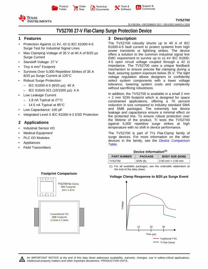
TVS2700 27-V Flat-Clamp Surge Protection Device
1
1 Features1• Protection Against ±1 kV, 42 Ω IEC 61000-4-5
Surge Test for Industrial Signal Lines• Max Clamping Voltage of 35 V at 40 A of 8/20 µs
Surge Current• Standoff Voltage: 27 V• Tiny 4 mm2 Footprint• Survives Over 5,000 Repetitive Strikes of 35 A
8/20 µs Surge Current at 125°C• Robust Surge Protection:
– IEC 61000-4-5 (8/20 µs): 40 A– IEC 61643-321 (10/1000 µs): 4 A
• Low Leakage Current– 1.8 nA Typical at 27°C– 14.5 nA Typical at 85°C
• Low Capacitance: 100 pF• Integrated Level 4 IEC 61000-4-2 ESD Protection
2 Applications• Industrial Sensor I/O• Medical Equipment• PLC I/O Modules• Appliances• Field Transmitters
3 DescriptionThe TVS2700 robustly shunts up to 40 A of IEC61000-4-5 fault current to protect systems from highpower transients or lightning strikes. The deviceoffers a solution to the common industrial signal lineEMC requirement to survive up to ±1 kV IEC 61000-4-5 open circuit voltage coupled through a 42 Ωimpedance. The TVS2700 uses a unique feedbackmechanism to ensure precise flat clamping during afault, assuring system exposure below 35 V. The tightvoltage regulation allows designers to confidentlyselect system components with a lower voltagetolerance, lowering system costs and complexitywithout sacrificing robustness.
In addition, the TVS2700 is available in a small 2 mm× 2 mm SON footprint which is designed for spaceconstrained applications, offering a 70 percentreduction in size compared to industry standard SMAand SMB packages. The extremely low deviceleakage and capacitance ensure a minimal effect onthe protected line. To ensure robust protection overthe lifetime of the product, TI tests the TVS2700against 5,000 repetitive surge strikes at hightemperature with no shift in device performance.
The TVS2700 is part of TI's Flat-Clamp family ofsurge devices. For more information on the otherdevices in the family, see the Device ComparisonTable.
Device Information(1)
PART NUMBER PACKAGE BODY SIZE (NOM)TVS2700 SON (6) 2.00 mm × 2.00 mm
(1) For all available packages, see the orderable addendum atthe end of the data sheet.
Footprint ComparisonVoltage Clamp Response to 8/20 µs Surge Event

2
TVS2700SLVSED6A –DECEMBER 2017–REVISED MARCH 2018 www.ti.com
Product Folder Links: TVS2700
Submit Documentation Feedback Copyright © 2017–2018, Texas Instruments Incorporated
Table of Contents1 Features .................................................................. 12 Applications ........................................................... 13 Description ............................................................. 14 Revision History..................................................... 25 Device Comparison Table ..................................... 36 Pin Configuration and Functions ......................... 47 Specifications......................................................... 5
7.1 Absolute Maximum Ratings ...................................... 57.2 ESD Ratings - JEDEC .............................................. 57.3 ESD Ratings - IEC .................................................... 57.4 Recommended Operating Conditions....................... 57.5 Thermal Information .................................................. 57.6 Electrical Characteristics........................................... 67.7 Typical Characteristics .............................................. 7
8 Detailed Description .............................................. 98.1 Overview ................................................................... 98.2 Functional Block Diagram ......................................... 9
8.3 Feature Description................................................... 98.4 Reliability Testing ...................................................... 98.5 Device Functional Modes........................................ 10
9 Application and Implementation ........................ 119.1 Application Information............................................ 119.2 Typical Application ................................................. 11
10 Power Supply Recommendations ..................... 1211 Layout................................................................... 13
11.1 Layout Guidelines ................................................. 1311.2 Layout Example .................................................... 13
12 Device and Documentation Support ................. 1412.1 Receiving Notification of Documentation Updates 1412.2 Community Resources.......................................... 1412.3 Trademarks ........................................................... 1412.4 Electrostatic Discharge Caution............................ 1412.5 Glossary ................................................................ 14
13 Mechanical, Packaging, and OrderableInformation ........................................................... 14
4 Revision History
Changes from Original (December 2017) to Revision A Page
• Changed product status from Advance Information to Production Data ............................................................................... 1

3
TVS2700www.ti.com SLVSED6A –DECEMBER 2017–REVISED MARCH 2018
Product Folder Links: TVS2700
Submit Documentation FeedbackCopyright © 2017–2018, Texas Instruments Incorporated
5 Device Comparison Table
Device Vrwm Vclamp at Ipp Ipp (8/20 µs) Vrwm leakage(nA) Package Options Polarity
TVS0500 5 9.2 43 0.07 SON UnidirectionalTVS1400 14 18.4 43 2 SON UnidirectionalTVS1800 18 22.8 40 0.5 SON UnidirectionalTVS2200 22 27.7 40 3.2 SON UnidirectionalTVS2700 27 32.5 40 1.7 SON UnidirectionalTVS3300 33 38 35 19 WCSP, SON Unidirectional

IN
IN
GNDGND
GND IN
GND
2
3
1
5
4
6
4
TVS2700SLVSED6A –DECEMBER 2017–REVISED MARCH 2018 www.ti.com
Product Folder Links: TVS2700
Submit Documentation Feedback Copyright © 2017–2018, Texas Instruments Incorporated
6 Pin Configuration and Functions
DRV Package6-Pin SONTop View
Pin FunctionsPIN
TYPE DESCRIPTIONNAME No.
IN 4, 5, 6 I ESD and surge protected channel
GND 1, 2, 3, exposed thermalpad GND Ground

5
TVS2700www.ti.com SLVSED6A –DECEMBER 2017–REVISED MARCH 2018
Product Folder Links: TVS2700
Submit Documentation FeedbackCopyright © 2017–2018, Texas Instruments Incorporated
(1) Stresses beyond those listed under Absolute Maximum Rating may cause permanent damage to the device. These are stress ratingsonly, which do not imply functional operation of the device at these or any other conditions beyond those indicated under RecommendedOperating Condition. Exposure to absolute-maximum-rated conditions for extended periods may affect device reliability.
7 Specifications
7.1 Absolute Maximum RatingsTA = 27°C (unless otherwise noted) (1)
MIN MAX UNIT
MaximumSurge
IEC 61000-4-5 Current (8/20 µs) 40 AIEC 61000-4-5 Power (8/20 µs) 1250 WIEC 61643-321 Current (10/1000 µs) 4 AIEC 61643-321 Power (10/1000 µs) 120 W
MaximumForward Surge
IEC 61000-4-5 Current (8/20 µs) 50 AIEC 61000-4-5 Power (8/20 µs) 80 WIEC 61643-321 Current (10/1000 µs) 23 AIEC 61643-321 Power (10/1000 µs) 60 W
EFT IEC 61000-4-4 EFT Protection 80 AIBR DC Breakdown current 12 mAIF DC Forward Current 500 mATA Ambient Operating Temperature -40 125 °CTstg Storage Temperature -65 150 °C
(1) JEDEC document JEP155 states that 500-V HBM allows safe manufacturing with a standard ESD control process.(2) JEDEC document JEP157 states that 250-V CDM allows safe manufacturing with a standard ESD control process.
7.2 ESD Ratings - JEDECVALUE UNIT
V(ESD) Electrostatic discharge
Human body model (HBM), perANSI/ESDA/JEDEC JS-001, all pins (1) ±2000
VCharged device model (CDM), per JEDECspecification JESD22-C101, all pins (2) ±500
7.3 ESD Ratings - IECVALUE UNIT
V(ESD) Electrostatic dischargeIEC 61000-4-2 contact discharge ±16
kVIEC 61000-4-2 air-gap discharge ±30
7.4 Recommended Operating Conditionsover operating free-air temperature range (unless otherwise noted)
PARAMETER MIN NOM MAX UNITVRWM Reverse Stand-off Voltage 27 V
(1) For more information about traditional and new thermal metrics, see the Semiconductor and IC Package Thermal Metrics applicationreport.
7.5 Thermal Information
THERMAL METRIC (1)TVS2700
UNITDRV (SON)6 PINS
RqJA Junction-to-ambient thermal resistance 70.4 °C/WRqJC(top) Junction-to-case (top) thermal resistance 73.7 °C/WRqJB Junction-to-board thermal resistance 40 °C/WYJT Junction-to-top characterization parameter 2.2 °C/W

6
TVS2700SLVSED6A –DECEMBER 2017–REVISED MARCH 2018 www.ti.com
Product Folder Links: TVS2700
Submit Documentation Feedback Copyright © 2017–2018, Texas Instruments Incorporated
Thermal Information (continued)
THERMAL METRIC (1)TVS2700
UNITDRV (SON)6 PINS
YJB Junction-to-board characterization parameter 40.3 °C/WRqJC(bot) Junction-to-case (bottom) thermal resistance 11 °C/W
7.6 Electrical Characteristicsover operating free-air temperature range (unless otherwise noted)
PARAMETER TEST CONDITIONS MIN TYP MAX UNITVRWM Reverse Stand-off Voltage -0.5 27 V
ILEAK Leakage CurrentMeasured at VIN = VRWM, TA = 27°C 1.8 60 nAMeasured at VIN = VRWM. TA = 85°C 14.5 450 nAMeasured at VIN = VRWM,TA = 105°C 65 1500 nA
VF Forward Voltage IIN = 1 mA from GND to IO 0.25 0.5 0.65 VVBR Break-down Voltage IIN = 1 mA from IO to GND 29.3 31.2 33.9 V
VFCLAMP Forward Clamp Voltage 40 A IEC 61000-4-5 Surge (8/20 µs)from GND to IO, 27°C 1 2 5 V
VCLAMP Clamp Voltage
24 A IEC 61000-4-5 Surge (8/20 µs)from IO to GND, VIN = 0 V before surge,27°C
32.2 33.9 V
40 AIEC 61000-4-5 Surge (8/20 µs) fromIO to GND, VIN = 0 V before surge, 27°C 32.5 34.1 V
35 A IEC 61000-4-5 Surge (8/20 µs)from IO to GND, VIN = Vrwm beforesurge, TA = 125°C
33 35 V
RDYN 8/20 µs surge dynamic resistance Calculated from VCLAMP at .5*Ipp and Ippsurge current levels, 27°C 30 mΩ
CIN Input pin capacitance VIN = VRWM, f = 1 MHz, 30 mVpp, IO toGND 100 pF
SR Maximum Slew Rate 0-VRWM rising edge, sweep rise time andmeasure slew rate when IPK = 1 mA,27°C
2.5 V/µs
0-VRWM rising edge, sweep rise time andmeasure slew rate when IPK = 1 mA,105°C
0.7 V/µs
Voltage (V)
Cur
rent
(m
A)
-5 0 5 10 15 20 25 30 35
0
0.5
1
-0.5
-1
D005
-40qC25qC105qC125qC
Temperature (°C)
Vol
tage
(V
)
-40 -20 0 20 40 60 80 100 120 1400
0.1
0.2
0.3
0.4
0.5
0.6
0.7
D006
Temperature (qC)
Cap
acita
nce
(pF
)
-40 -25 -10 5 20 35 50 65 80 95 110 1250
50
100
150
200
250
300
350
400
450
D003
0 V Bias14 V Bias27 V Bias
Temperature (qC)
Leak
age
(nA
)
-40 -25 -10 5 20 35 50 65 80 95 110 1250
100
200
300
400
500
D004
Time (Ps)
Vol
tage
(V
) / S
urge
Cur
rent
(A
)
-5
0
5
10
15
20
25
30
35
40
45
0 10 20 30 40 50 60
D001
TVS2700 VoltageSurge Current
Time (Ps)
Vol
tage
(V
) / S
urge
Cur
rent
(A
)
-5
0
5
10
15
20
25
30
35
40
0 10 20 30 40 50 60
D002
-40qC25qC105qC125qCCurrent (A)
7
TVS2700www.ti.com SLVSED6A –DECEMBER 2017–REVISED MARCH 2018
Product Folder Links: TVS2700
Submit Documentation FeedbackCopyright © 2017–2018, Texas Instruments Incorporated
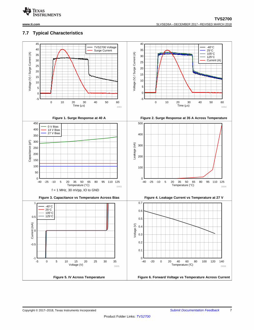
7.7 Typical Characteristics
Figure 1. Surge Response at 40 A Figure 2. Surge Response at 35 A Across Temperature
f = 1 MHz, 30 mVpp, IO to GND
Figure 3. Capacitance vs Temperature Across Bias Figure 4. Leakage Current vs Temperature at 27 V
Figure 5. IV Across Temperature Figure 6. Forward Voltage vs Temperature Across Current

Slew Rate (V/Ps)
Dyn
amic
Lea
kage
(m
A)
0 0.5 1 1.5 2 2.5 30
0.51
1.52
2.53
3.54
4.55
5.56
6.57
7.58
D009
-40qC25qC85qC105qC125qC
Temperature (qC)
Vol
tage
(V
)
-40 -25 -10 5 20 35 50 65 80 95 110 12530
30.25
30.5
30.75
31
31.25
31.5
31.75
32
32.25
32.5
D007Temperature (qC)
I PP (
A)
-40 -25 -10 5 20 35 50 65 80 95 110 1250
5
10
15
20
25
30
35
40
45
D008
8
TVS2700SLVSED6A –DECEMBER 2017–REVISED MARCH 2018 www.ti.com
Product Folder Links: TVS2700
Submit Documentation Feedback Copyright © 2017–2018, Texas Instruments Incorporated
Typical Characteristics (continued)
Figure 7. Breakdown Voltage at 1 mA vs Temperature Figure 8. Max Surge Current (8/20 µs) vs Temperature
Figure 9. Maximum Leakage vs Signal Slew Rate across Temperature

Voltage Level Detection
Power FETDriver
IN
GND
Copyright © 2017, Texas Instruments Incorporated
9
TVS2700www.ti.com SLVSED6A –DECEMBER 2017–REVISED MARCH 2018
Product Folder Links: TVS2700
Submit Documentation FeedbackCopyright © 2017–2018, Texas Instruments Incorporated
8 Detailed Description
8.1 OverviewThe TVS2700 is a precision clamp with a low, flat clamping voltage during transient overvoltage events like surgeand protecting the system with zero voltage overshoot. For a detailed overview of the Flat-Clamp family ofdevices, please reference TI's Flat-Clamp surge protection technology for efficient system protection white paper.This document explains in detail the functional operation of the devices and how they impact and improve systemdesign.
8.2 Functional Block Diagram
8.3 Feature DescriptionThe TVS2700 is a precision clamp that handles 40 A of IEC 61000-4-5 8/20 µs surge pulse. The flat clampingfeature helps keep the clamping voltage very low to keep the downstream circuits from being stressed. The flatclamping feature can also help end-equipment designers save cost by opening up the possibility to use lower-cost lower voltage tolerant downstream ICs. The TVS2700 has minimal leakage under the standoff voltage of 27V, making it an ideal candidate for applications where low leakage and power dissipation is a necessity. IEC61000-4-2 and IEC 61000-4-4 ratings make it a robust protection solution for ESD and EFT events. Wideambient temperature range of –40°C to +125°C makes it a good candidate for most applications. Compactpackages enable it to be used in small devices and save board area.
8.4 Reliability TestingTo ensure device reliability, the TV2700 is characterized against 5000 repetitive pulses of 35 A IEC 61000-4-58/20 µs surge pulses at 125°C. The test is performed with less than 10 seconds between each pulse at hightemperature to simulate worst case scenarios for fault regulation. After each surge pulse, the TVS2700 clampingvoltage, breakdown voltage, and leakage are recorded to ensure that there is no variation or performancedegradation. By ensuring robust, reliable, high temperature protection, the TVS2700 enables fault protection inapplications that must withstand years of continuous operation with no performance change.
10
TVS2700SLVSED6A –DECEMBER 2017–REVISED MARCH 2018 www.ti.com
Product Folder Links: TVS2700
Submit Documentation Feedback Copyright © 2017–2018, Texas Instruments Incorporated
8.5 Device Functional Modes
8.5.1 Protection SpecificationsThe TVS2700 is specified according to both the IEC 61000-4-5 and IEC 61643-321 standards. This enablesusage in systems regardless of which standard is required in relevant product standards or best matchesmeasured fault conditions. The IEC 61000-4-5 standard requires protection against a pulse with a rise time of 8µs and a half length of 20 µs while the IEC 61643-321 standard requires protection against a much longer pulsewith a rise time of 10 µs and a half length of 1000 µs.
The positive and negative surges are imposed to the TVS2700 by a combinational waveform generator (CWG)with a 2-Ω coupling resistor at different peak voltage levels. For powered on transient tests that need powersupply bias, inductances are usually used to decouple the transient stress and protect the power supply. TheTVS2700 is post tested by guaranteeing that there is no shift in device breakdown or leakage at Vrwm.
In addition, the TVS2700 has been tested according to IEC 61000-4-5 to pass a ±1 kV surge test through a 42-Ωcoupling resistor and a 0.5 µF capacitor. This test is a common test requirement for industrial signal I/O lines andthe TVS2700 will serve an ideal protection solution for applications with that requirement.
The TVS2700 also integrates IEC 61000-4-2 Level 4 ESD Protection and 80 A of IEC 61000-4-4 EFT Protection.These combine to ensure that the device can protect against all transient conditions regardless of length or type.
For more information on TI's test methods for Surge, ESD, and EFT testing, reference TI's IEC 61000-4-xTesting Application Note.
8.5.2 Minimal DeratingUnlike traditional diodes the TVS2700 has very little derating of max power dissipation and ensures robustperformance up to 125°C shown in Figure 8 . Traditional TVS diodes lose up to 50% of their current carryingcapability when at high temperatures, so a surge pulse above 85°C ambient can cause failures that are not seenat room temperature. The TVS2700 prevents this and ensures that you will see the same level of protectionregardless of temperature.
8.5.3 Transient PerformanceDuring large transient swings, the TVS2700 will begin clamping the input signal to protect downstreamconditions. While this prevents damage during fault conditions, it can cause leakage when the intended inputsignal has a fast slew rate. In order to keep power dissipation low and remove the chance of signal distortion, itis recommended to keep the slew rate of any input signal on the TVS2700 below 2.5 V/µs at room temperatureand below 0.7 V/µs at 125°C shown in Figure 9. Faster slew rates will cause the device to clamp the input signaland draw current through the device for a few microseconds, increasing the rise time of the signal. This will notcause any harm to the system or to the device, however if the fast input voltage swings occur regularly it cancause device overheating.

11
TVS2700www.ti.com SLVSED6A –DECEMBER 2017–REVISED MARCH 2018
Product Folder Links: TVS2700
Submit Documentation FeedbackCopyright © 2017–2018, Texas Instruments Incorporated
9 Application and Implementation
NOTEInformation in the following applications sections is not part of the TI componentspecification, and TI does not warrant its accuracy or completeness. TI’s customers areresponsible for determining suitability of components for their purposes. Customers shouldvalidate and test their design implementation to confirm system functionality.
9.1 Application InformationThe TVS2700 can be used to protect any power, analog, or digital signal from transient fault conditions causedby the environment or other electrical components.
9.2 Typical Application
Figure 10. TVS2700 Application Schematic
9.2.1 Design RequirementsA typical operation for the TVS2700 would be in a multi-channel PLC protecting an analog input, shown inFigure 10. In this example, a TVS2700 is protecting the input to a MUX36D04, a four channel input multiplexerwith a supply max at 36 V. Without any input protection, if a surge event is caused by lightning, coupling, ringing,or any other fault condition this input voltage will rise to hundreds of volts for multiple microseconds, violating theabsolute maximum input voltage and harming the device. An ideal surge protection diode will maximize theuseable voltage range while still clamping at a safe level for the system, so TI's Flat-Clamp technology providesthe best protection solution.
9.2.2 Detailed Design ProcedureIf the TVS2700 is in place to protect the device, during a surge event the voltage will rise to the breakdown of thediode at 31.2 V, and then the TVS2700 will turn on, shunting the surge current to ground. With the low dynamicresistance of the TVS2700, even large amounts of surge current will have minimal impact on the clampingvoltage. The dynamic resistance of the TVS2700 is around 30 mΩ, which means 40 A of surge current will causea voltage raise of 40 A × 30 mΩ = 1.2 V. Because the device turns on at 31 V, this means the module input willbe exposed to a maximum of 31.2 V + 1.2 V = 33.3 V during surge pulses, well within the MUX36D04 absolutemaximum. This pulse is shown in Figure 11 and ensures robust protection of the circuit.

Time (Ps)
Vol
tage
(V
) / S
urge
Cur
rent
(A
)
-5
0
5
10
15
20
25
30
35
40
45
0 10 20 30 40 50 60
D001
TVS2700 VoltageSurge Current
12
TVS2700SLVSED6A –DECEMBER 2017–REVISED MARCH 2018 www.ti.com
Product Folder Links: TVS2700
Submit Documentation Feedback Copyright © 2017–2018, Texas Instruments Incorporated
Typical Application (continued)Finally, the small size of the device also improves fault protection by lowering the effect of fault current couplingonto neighboring traces. The small form factor of the TVS2700 allows the device to be placed extremely close tothe input connector, lowering the length of the path fault current will take through the system compared to largerprotection solutions.
9.2.3 Application Curves
Figure 11. TVS2700 Surge Response at 40 A
9.2.4 Configuration OptionsThe TVS2700 can be used in either unidirectional or bidirectional configuration. The TVS2700 showsunidirectional usage to protect an input. By placing two TVS2700's in series with reverse orientation, bidirectionaloperation can be utilized which will allow a working voltage of ±27 V. The TVS2700 operation in bidirectional willbe similar to unidirectional operation, with a minor increase in breakdown voltage and clamping voltage. TheTVS3300 bidirectional performance has been characterized in the TVS3300 Configurations Characterization.While the TVS2700 in bidirectional configuration has not specifically been characterized, it will have similarrelative changes to the TVS3300 in bidirectional configuration.
10 Power Supply RecommendationsThe TVS2700 is a clamping device so there is no need to power it. Be careful not to violate the recommendedVIN voltage range (0 V to 27 V) to ensure the device functions properly.

GND Plane
GND
GN
D
GN
D
GN
D
I/O I/O I/OConnectorInput
ProtectedInput
13
TVS2700www.ti.com SLVSED6A –DECEMBER 2017–REVISED MARCH 2018
Product Folder Links: TVS2700
Submit Documentation FeedbackCopyright © 2017–2018, Texas Instruments Incorporated
11 Layout
11.1 Layout GuidelinesThe optimum placement is as close to the connector as possible. EMI during an ESD event can couple from thetrace being struck to other nearby unprotected traces, resulting in early system failures. The PCB designer mustminimize the possibility of EMI coupling by keeping any unprotected traces away from the protected traces whichare between the TVS and the connector.
Route the protected traces as straight as possible.
Eliminate any sharp corners on the protected traces between the TVS2700 and the connector by using roundedcorners with the largest radii possible. Electric fields tend to build up on corners, increasing EMI coupling.
11.2 Layout Example
Figure 12. TVS2700 Layout

14
TVS2700SLVSED6A –DECEMBER 2017–REVISED MARCH 2018 www.ti.com
Product Folder Links: TVS2700
Submit Documentation Feedback Copyright © 2017–2018, Texas Instruments Incorporated
12 Device and Documentation Support
12.1 Receiving Notification of Documentation UpdatesTo receive notification of documentation updates, navigate to the device product folder on ti.com. In the upperright corner, click on Alert me to register and receive a weekly digest of any product information that haschanged. For change details, review the revision history included in any revised document.
12.2 Community ResourcesThe following links connect to TI community resources. Linked contents are provided "AS IS" by the respectivecontributors. They do not constitute TI specifications and do not necessarily reflect TI's views; see TI's Terms ofUse.
TI E2E™ Online Community TI's Engineer-to-Engineer (E2E) Community. Created to foster collaborationamong engineers. At e2e.ti.com, you can ask questions, share knowledge, explore ideas and helpsolve problems with fellow engineers.
Design Support TI's Design Support Quickly find helpful E2E forums along with design support tools andcontact information for technical support.
12.3 TrademarksE2E is a trademark of Texas Instruments.
12.4 Electrostatic Discharge CautionThis integrated circuit can be damaged by ESD. Texas Instruments recommends that all integrated circuits be handled withappropriate precautions. Failure to observe proper handling and installation procedures can cause damage.
ESD damage can range from subtle performance degradation to complete device failure. Precision integrated circuits may be moresusceptible to damage because very small parametric changes could cause the device not to meet its published specifications.
12.5 GlossarySLYZ022 — TI Glossary.
This glossary lists and explains terms, acronyms, and definitions.
13 Mechanical, Packaging, and Orderable InformationThe following pages include mechanical, packaging, and orderable information. This information is the mostcurrent data available for the designated devices. This data is subject to change without notice and revision ofthis document. For browser-based versions of this data sheet, refer to the left-hand navigation.

PACKAGE OPTION ADDENDUM
www.ti.com 11-Apr-2018
Addendum-Page 1
PACKAGING INFORMATION
Orderable Device Status(1)
Package Type PackageDrawing
Pins PackageQty
Eco Plan(2)
Lead/Ball Finish(6)
MSL Peak Temp(3)
Op Temp (°C) Device Marking(4/5)
Samples
TVS2700DRVR ACTIVE WSON DRV 6 3000 Green (RoHS& no Sb/Br)
CU NIPDAU Level-2-260C-1 YEAR -40 to 125 1HTH
(1) The marketing status values are defined as follows:ACTIVE: Product device recommended for new designs.LIFEBUY: TI has announced that the device will be discontinued, and a lifetime-buy period is in effect.NRND: Not recommended for new designs. Device is in production to support existing customers, but TI does not recommend using this part in a new design.PREVIEW: Device has been announced but is not in production. Samples may or may not be available.OBSOLETE: TI has discontinued the production of the device.
(2) RoHS: TI defines "RoHS" to mean semiconductor products that are compliant with the current EU RoHS requirements for all 10 RoHS substances, including the requirement that RoHS substancedo not exceed 0.1% by weight in homogeneous materials. Where designed to be soldered at high temperatures, "RoHS" products are suitable for use in specified lead-free processes. TI mayreference these types of products as "Pb-Free".RoHS Exempt: TI defines "RoHS Exempt" to mean products that contain lead but are compliant with EU RoHS pursuant to a specific EU RoHS exemption.Green: TI defines "Green" to mean the content of Chlorine (Cl) and Bromine (Br) based flame retardants meet JS709B low halogen requirements of <=1000ppm threshold. Antimony trioxide basedflame retardants must also meet the <=1000ppm threshold requirement.
(3) MSL, Peak Temp. - The Moisture Sensitivity Level rating according to the JEDEC industry standard classifications, and peak solder temperature.
(4) There may be additional marking, which relates to the logo, the lot trace code information, or the environmental category on the device.
(5) Multiple Device Markings will be inside parentheses. Only one Device Marking contained in parentheses and separated by a "~" will appear on a device. If a line is indented then it is a continuationof the previous line and the two combined represent the entire Device Marking for that device.
(6) Lead/Ball Finish - Orderable Devices may have multiple material finish options. Finish options are separated by a vertical ruled line. Lead/Ball Finish values may wrap to two lines if the finishvalue exceeds the maximum column width.
Important Information and Disclaimer:The information provided on this page represents TI's knowledge and belief as of the date that it is provided. TI bases its knowledge and belief on informationprovided by third parties, and makes no representation or warranty as to the accuracy of such information. Efforts are underway to better integrate information from third parties. TI has taken andcontinues to take reasonable steps to provide representative and accurate information but may not have conducted destructive testing or chemical analysis on incoming materials and chemicals.TI and TI suppliers consider certain information to be proprietary, and thus CAS numbers and other limited information may not be available for release.
In no event shall TI's liability arising out of such information exceed the total purchase price of the TI part(s) at issue in this document sold by TI to Customer on an annual basis.

TAPE AND REEL INFORMATION
*All dimensions are nominal
Device PackageType
PackageDrawing
Pins SPQ ReelDiameter
(mm)
ReelWidth
W1 (mm)
A0(mm)
B0(mm)
K0(mm)
P1(mm)
W(mm)
Pin1Quadrant
TVS2700DRVR WSON DRV 6 3000 180.0 8.4 2.3 2.3 1.15 4.0 8.0 Q2
PACKAGE MATERIALS INFORMATION
www.ti.com 9-Mar-2018
Pack Materials-Page 1

*All dimensions are nominal
Device Package Type Package Drawing Pins SPQ Length (mm) Width (mm) Height (mm)
TVS2700DRVR WSON DRV 6 3000 210.0 185.0 35.0
PACKAGE MATERIALS INFORMATION
www.ti.com 9-Mar-2018
Pack Materials-Page 2

GENERIC PACKAGE VIEW
Images above are just a representation of the package family, actual package may vary.Refer to the product data sheet for package details.
DRV 6 WSON - 0.8 mm max heightPLASTIC SMALL OUTLINE - NO LEAD
4206925/F

www.ti.com
PACKAGE OUTLINE
C
6X 0.350.25
1.6 0.1
6X 0.30.2
2X1.3
1 0.1
4X 0.65
0.80.7
0.050.00
B 2.11.9
A
2.11.9
(0.2) TYP
WSON - 0.8 mm max heightDRV0006APLASTIC SMALL OUTLINE - NO LEAD
4222173/B 04/2018
PIN 1 INDEX AREA
SEATING PLANE
0.08 C
1
34
6
(OPTIONAL)PIN 1 ID
0.1 C A B0.05 C
THERMAL PADEXPOSED
7
NOTES: 1. All linear dimensions are in millimeters. Any dimensions in parenthesis are for reference only. Dimensioning and tolerancing per ASME Y14.5M. 2. This drawing is subject to change without notice. 3. The package thermal pad must be soldered to the printed circuit board for thermal and mechanical performance.
SCALE 5.500

www.ti.com
EXAMPLE BOARD LAYOUT
0.07 MINALL AROUND
0.07 MAXALL AROUND
(1)
4X (0.65)
(1.95)
6X (0.3)
6X (0.45)
(1.6)
(R0.05) TYP
( 0.2) VIATYP
(1.1)
WSON - 0.8 mm max heightDRV0006APLASTIC SMALL OUTLINE - NO LEAD
4222173/B 04/2018
SYMM
1
34
6
SYMM
LAND PATTERN EXAMPLESCALE:25X
7
NOTES: (continued) 4. This package is designed to be soldered to a thermal pad on the board. For more information, see Texas Instruments literature number SLUA271 (www.ti.com/lit/slua271).5. Vias are optional depending on application, refer to device data sheet. If some or all are implemented, recommended via locations are shown.
SOLDER MASKOPENINGSOLDER MASK
METAL UNDER
SOLDER MASKDEFINED
METALSOLDER MASKOPENING
SOLDER MASK DETAILS
NON SOLDER MASKDEFINED
(PREFERRED)

www.ti.com
EXAMPLE STENCIL DESIGN
6X (0.3)
6X (0.45)
4X (0.65)
(0.7)
(1)
(1.95)
(R0.05) TYP
(0.45)
WSON - 0.8 mm max heightDRV0006APLASTIC SMALL OUTLINE - NO LEAD
4222173/B 04/2018
NOTES: (continued) 6. Laser cutting apertures with trapezoidal walls and rounded corners may offer better paste release. IPC-7525 may have alternate design recommendations.
SOLDER PASTE EXAMPLEBASED ON 0.125 mm THICK STENCIL
EXPOSED PAD #7
88% PRINTED SOLDER COVERAGE BY AREA UNDER PACKAGESCALE:30X
SYMM
1
3 4
6
SYMM
METAL7
IMPORTANT NOTICE
Texas Instruments Incorporated (TI) reserves the right to make corrections, enhancements, improvements and other changes to itssemiconductor products and services per JESD46, latest issue, and to discontinue any product or service per JESD48, latest issue. Buyersshould obtain the latest relevant information before placing orders and should verify that such information is current and complete.TI’s published terms of sale for semiconductor products (http://www.ti.com/sc/docs/stdterms.htm) apply to the sale of packaged integratedcircuit products that TI has qualified and released to market. Additional terms may apply to the use or sale of other types of TI products andservices.Reproduction of significant portions of TI information in TI data sheets is permissible only if reproduction is without alteration and isaccompanied by all associated warranties, conditions, limitations, and notices. TI is not responsible or liable for such reproduceddocumentation. Information of third parties may be subject to additional restrictions. Resale of TI products or services with statementsdifferent from or beyond the parameters stated by TI for that product or service voids all express and any implied warranties for theassociated TI product or service and is an unfair and deceptive business practice. TI is not responsible or liable for any such statements.Buyers and others who are developing systems that incorporate TI products (collectively, “Designers”) understand and agree that Designersremain responsible for using their independent analysis, evaluation and judgment in designing their applications and that Designers havefull and exclusive responsibility to assure the safety of Designers' applications and compliance of their applications (and of all TI productsused in or for Designers’ applications) with all applicable regulations, laws and other applicable requirements. Designer represents that, withrespect to their applications, Designer has all the necessary expertise to create and implement safeguards that (1) anticipate dangerousconsequences of failures, (2) monitor failures and their consequences, and (3) lessen the likelihood of failures that might cause harm andtake appropriate actions. Designer agrees that prior to using or distributing any applications that include TI products, Designer willthoroughly test such applications and the functionality of such TI products as used in such applications.TI’s provision of technical, application or other design advice, quality characterization, reliability data or other services or information,including, but not limited to, reference designs and materials relating to evaluation modules, (collectively, “TI Resources”) are intended toassist designers who are developing applications that incorporate TI products; by downloading, accessing or using TI Resources in anyway, Designer (individually or, if Designer is acting on behalf of a company, Designer’s company) agrees to use any particular TI Resourcesolely for this purpose and subject to the terms of this Notice.TI’s provision of TI Resources does not expand or otherwise alter TI’s applicable published warranties or warranty disclaimers for TIproducts, and no additional obligations or liabilities arise from TI providing such TI Resources. TI reserves the right to make corrections,enhancements, improvements and other changes to its TI Resources. TI has not conducted any testing other than that specificallydescribed in the published documentation for a particular TI Resource.Designer is authorized to use, copy and modify any individual TI Resource only in connection with the development of applications thatinclude the TI product(s) identified in such TI Resource. NO OTHER LICENSE, EXPRESS OR IMPLIED, BY ESTOPPEL OR OTHERWISETO ANY OTHER TI INTELLECTUAL PROPERTY RIGHT, AND NO LICENSE TO ANY TECHNOLOGY OR INTELLECTUAL PROPERTYRIGHT OF TI OR ANY THIRD PARTY IS GRANTED HEREIN, including but not limited to any patent right, copyright, mask work right, orother intellectual property right relating to any combination, machine, or process in which TI products or services are used. Informationregarding or referencing third-party products or services does not constitute a license to use such products or services, or a warranty orendorsement thereof. Use of TI Resources may require a license from a third party under the patents or other intellectual property of thethird party, or a license from TI under the patents or other intellectual property of TI.TI RESOURCES ARE PROVIDED “AS IS” AND WITH ALL FAULTS. TI DISCLAIMS ALL OTHER WARRANTIES ORREPRESENTATIONS, EXPRESS OR IMPLIED, REGARDING RESOURCES OR USE THEREOF, INCLUDING BUT NOT LIMITED TOACCURACY OR COMPLETENESS, TITLE, ANY EPIDEMIC FAILURE WARRANTY AND ANY IMPLIED WARRANTIES OFMERCHANTABILITY, FITNESS FOR A PARTICULAR PURPOSE, AND NON-INFRINGEMENT OF ANY THIRD PARTY INTELLECTUALPROPERTY RIGHTS. TI SHALL NOT BE LIABLE FOR AND SHALL NOT DEFEND OR INDEMNIFY DESIGNER AGAINST ANY CLAIM,INCLUDING BUT NOT LIMITED TO ANY INFRINGEMENT CLAIM THAT RELATES TO OR IS BASED ON ANY COMBINATION OFPRODUCTS EVEN IF DESCRIBED IN TI RESOURCES OR OTHERWISE. IN NO EVENT SHALL TI BE LIABLE FOR ANY ACTUAL,DIRECT, SPECIAL, COLLATERAL, INDIRECT, PUNITIVE, INCIDENTAL, CONSEQUENTIAL OR EXEMPLARY DAMAGES INCONNECTION WITH OR ARISING OUT OF TI RESOURCES OR USE THEREOF, AND REGARDLESS OF WHETHER TI HAS BEENADVISED OF THE POSSIBILITY OF SUCH DAMAGES.Unless TI has explicitly designated an individual product as meeting the requirements of a particular industry standard (e.g., ISO/TS 16949and ISO 26262), TI is not responsible for any failure to meet such industry standard requirements.Where TI specifically promotes products as facilitating functional safety or as compliant with industry functional safety standards, suchproducts are intended to help enable customers to design and create their own applications that meet applicable functional safety standardsand requirements. Using products in an application does not by itself establish any safety features in the application. Designers mustensure compliance with safety-related requirements and standards applicable to their applications. Designer may not use any TI products inlife-critical medical equipment unless authorized officers of the parties have executed a special contract specifically governing such use.Life-critical medical equipment is medical equipment where failure of such equipment would cause serious bodily injury or death (e.g., lifesupport, pacemakers, defibrillators, heart pumps, neurostimulators, and implantables). Such equipment includes, without limitation, allmedical devices identified by the U.S. Food and Drug Administration as Class III devices and equivalent classifications outside the U.S.TI may expressly designate certain products as completing a particular qualification (e.g., Q100, Military Grade, or Enhanced Product).Designers agree that it has the necessary expertise to select the product with the appropriate qualification designation for their applicationsand that proper product selection is at Designers’ own risk. Designers are solely responsible for compliance with all legal and regulatoryrequirements in connection with such selection.Designer will fully indemnify TI and its representatives against any damages, costs, losses, and/or liabilities arising out of Designer’s non-compliance with the terms and provisions of this Notice.
Mailing Address: Texas Instruments, Post Office Box 655303, Dallas, Texas 75265Copyright © 2018, Texas Instruments Incorporated