Embed Size (px)
Citation preview

Page 1 of 68
TVET CERTIFICATE III in FITTING AND WELDING
TECHNICAL DRAWING
WLDTD301 Apply technical drawing
Credits: 8 Learning hours: 80hrs
Sector: Manufacturing.
Sub-sector: Welding
Module Note Issue date: June, 2020
Purpose statement
This general module describes the performance outcomes, skills and knowledge required to
carry out basic technical drawing for an engine mechanic. In order to perform many of
particular competences successfully, a mechanic must apply principles of technical drawing.
Table of Contents
Page 2 of 68
Elements of competence and performance criteria Page No.
Learning Unit Performance Criteria
1. Introduce technical
drawing.
1.1Identification of the different types of drawing
instruments, equipment and materials.
3
1.2 Understanding of graphic language
techniques.
1.3 Classification of different types of drawing.
2.Apply principles of drawing
2.1 Identification of drawing sheets. 18
2.2 Application of drawing scales.
2.3 Use of lines.
2.4 Respect of drawing lettering standard rules.
2.5 Design of sections.
2.6 Application of drawing conventional
representations dimensioning and standard
abbreviations.
Total Number of Pages: 56

Page 3 of 68
Learning Unit 1 – Introduce technical drawing
LO 1.1 – Identify the different types of drawing instruments, equipment and
materials.
Content/Topic 1: Drawing instruments, equipment and materials.
Drawing Instruments are used to prepare neat and accurate Drawings. To a greater extent,
the accuracy of the drawings depends on the quality of instruments used to prepare them.
The following is the list of Drawing Instruments and other materials required:
− Drawing Board
− T-square
− Set Squares
− Protractor
− Drawing Instrument Box
− Drawing Sheet
− Drawing Pencils
A. Drawing Board: Is an essential piece of equipment in technical graphic. Paper will be
attached to the drawing board with the aid of a T-square so that it is kept straight
and still, so that the drawing can be completed with accuracy.
− It is a board or platform rectangular in shape.
− Top surface should be smooth.
− Drawing board is made from strips of well seasoned soft wood generally 25
mm thick.
− It is made of wood.
Size of drawing board need to be larger than that of drawing paper.

Page 4 of 68
Drawing board size: Drawing boards are made in various sizes. The selection of
Drawing board depends on the size of drawing paper used. The sizes of Drawing
board recommended by Bureau of Indian Standards (B.I.S) are given below
The standard size of drawing board according to Indian Standard Institution (I.S.I.) is
given below
The standard size of drawing board according to Indian Standard Institution
(I.S.I.) S,
NO. Designation Size in mm length x width x
thickness
To be used with sheet sizes
1
2
3
4
D0
D1
D2
D3
1500 X 1000 X 25
1000 X 700 X 25
700 X 500 X 15
500 X 350 X 15
A0
A1
A2
A3
B. T-square: Is a key piece of equipment used in Technical Graphics. Its primary
function is to draw horizontal lines on your drawing sheet but it is also used as a
guide for set squares in order to draw vertical or angled lines. It gets its name from
its resemblance of the letter 'T'.
A T-square has two components, the long shaft which is called the 'blade' and the
short shaft called the 'stock' or the 'head'. The 'stock' uses the edge of the drawing
board for support. When using the T-square, the edge must be up against the edge
of the drawing board, otherwise your lines may be inaccurate.
C. The Set Square: There are two types of set squares and they are named according to
the angles present on each.

Page 5 of 68
Set squares are useful for drawing parallel lines and perpendicular lines
i. Drawing Parallel Lines: Lines that lie in the same plane and do not meet one another
are said to be parallel lines. In the accompanying diagram, the line AB is parallel to
the line CD. This is indicated by the similar arrows.
A ruler and set square can be used to draw parallel lines as described below.
- Position an edge of the set square against a ruler and draw a line along one of
the other edges.
- Slide the set square into a new position while keeping the ruler fixed exactly at
the same position.
- Draw a line along the same edge that was used in Step 1.

Page 6 of 68
Example
Use a ruler and set square to draw a line that is parallel to a given line, AB, and passes
through a given point, P.
Solution:
- Position an edge of the set square along the given line, AB.
- Place a ruler against one of the other edges.
- Slide the set square along the ruler until the edge used in Step 1 passes through
the given point P.
- Draw the line CD through P.
The line CD passes through the given point, P, and is parallel to the given line AB.
ii. Drawing Perpendicular Lines: Lines that are at right angles to each other are said to
be perpendicular lines. Note that a vertical line is perpendicular to the horizontal,
where as perpendicular lines can be drawn in any position. Bricklayers use a plumb-
bob to set out vertical lines and a spirit level to set out horizontal lines.
A set square can be used to draw a perpendicular at a point on a given line as
described below.

Page 7 of 68
- Set an edge of the set square on the given line so that the other edge is just in
contact with the point.
- Draw a line that passes through the given point with the help of the set square.
Example: Use a set square to draw a perpendicular to a given line, AB, through a point, P,
not on the line.
Solution:
- Set an edge of the set square on the given line so that the other edge is just in
contact with the point.
- Draw a line that passes through the given point with the help of the set square.
D. Adjustable Set Squares: Are set squares that you can adjust to any angle you want to
between 0 and 90°. They are incredible useful especially when you are working with
drawings that have angles other than the standard set square angles.
E. A protractor: Is a measuring instrument, typically made of transparent plastic or
metal, for measuring angles. Protractor can be flat, circular or semi circular. There
are two types of protractors.
- 180° Protractor used to draw angles from 0 to 180°

Page 8 of 68
- 360° Protractor used to draw angles from 0 to 360°
.
F. Instrument Box: Are useful in geometry and other allied subjects’ projects.
These boxes contain protractor, divider, compass, 2 set angles, sharpener, eraser,
pencil and a 15 cm ruler. The box is designed specifically to fit in all these products
easily.
G. Eraser (Rubber): An Eraser is used to remove unwanted lines form a drawing sheet.
Similar to pencils, eraser can come in hard and soft types. It is key that you get a Soft
eraser. Not only will a hard eraser remove your unwanted line it could possibly tear
your drawing sheet.

Page 9 of 68
H. Erasing Shield: Erasing shield is used to protect the adjacent lines on the drawing
when some part of a line is being erased. It is usually made of thin metal in which
gaps of different widths, curves, small circles, arcs, etc. are cut according to the lines
to be eraser.
I. Pencil: Pencils are used to draw different lines, shapes, symbols and to write texts in
engineering drawing. Based on the hardness of lead pencils are classified in three
major grades as hard, medium and soft.
They are further subdivided and numbered as mentioned in table below:
Pencils of Different Grades
Grades Items arranged ordering harder to softer
Hard 9H> 8H> 7H>6H>5H>4H
Medium 3H>2H>H>F>HB>B
Soft 2B>3B>4B>5B>6B>7B
The following grades are used in engineering drawing:

Page 10 of 68
J. Pencil Sharpener (Topper): Pencil Sharpener is used to sharpen the point of your
pencil before use and during use if you notice the point getting blunt. A good steel
pencil sharpener would achieve a good point.
K. Compass: It is used to draw circles and arcs both in pencil and ink. It consists of two
legs pivoted at the top. One leg is Equipped with a steel needle attached with a
screw, and other shorter leg is, provided with a socket for detachable inserts.
L. Dividers: Used chiefly for transferring distances and occasionally for dividing spaces
into equal parts. I.e. for dividing Curved and straight lines into any number of equal
parts, and for transferring measurements.
M. French curve: It is used to draw irregular curves that are not circle arcs. The shape
varies according to the shape of irregular curve.
N. Drawing Paper: Drawing paper is the paper, on which drawing is to be made. All
engineering drawings are made on sheets of paper of strictly defined sizes, which are
set forth in the respective standards. The use of standard size saves paper and
ensures convenient storage of drawings.
Desirable properties a good drawing paper:
- It should be smooth and uniform in thickness.
Page 11 of 68
- It should be thick, strong and tough.
- Fibers of drawing paper should not be disintegrated when a good eraser is used
on it.
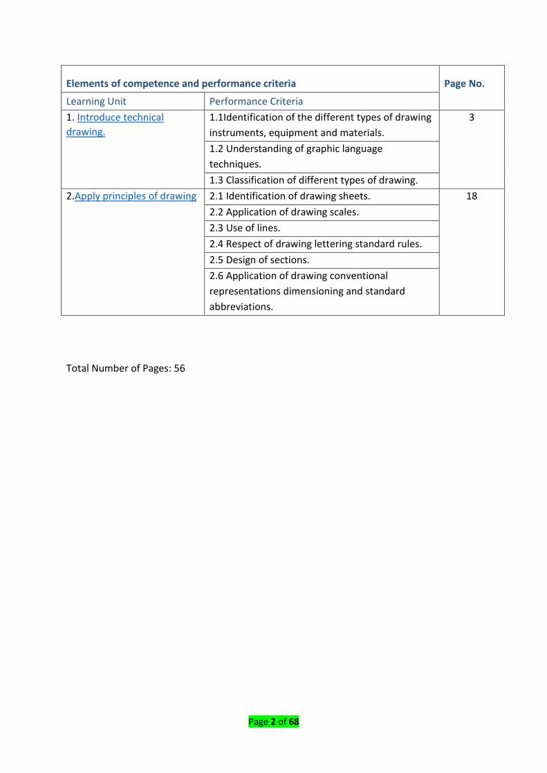
LO 1.2 –Understand the graphic language techniques
Content/Topic 1: Importance of Graphic Language.
You can easily understand that …
- Graphics are visual images or designs on some surface, such as a wall, canvas,
screen, paper, or stone to inform, illustrate, or entertain
- The word languages are inadequate for describing the size, shape and features
completely as well as concisely.
- Composition of Graphic Language: Graphic language in “engineering
application” use lines to represent the surfaces, edges and contours of objects.
-
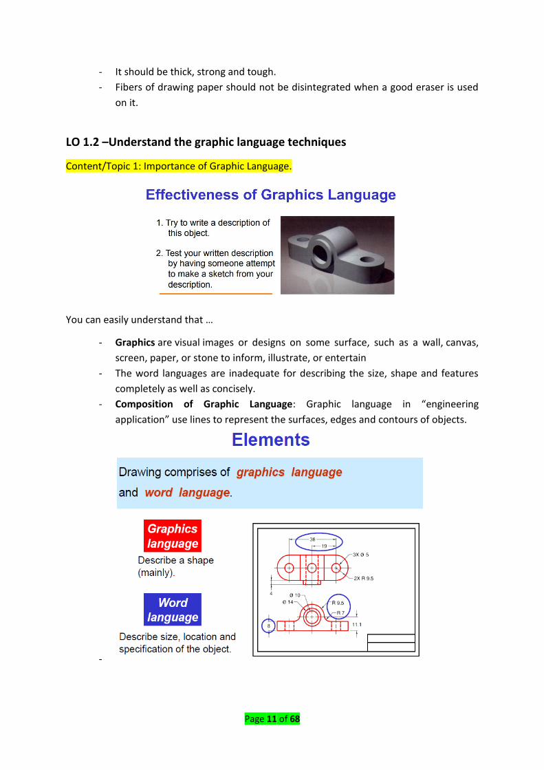
Page 12 of 68
Graphic design is an important tool that enhances how you communicate with other
people. It serves to convey your ideas in a way that is not only effective, but also beautiful.
Here are just a few factors to consider before investing in graphic design.
The graphic language had its existence when it became necessary to build new structures
and create new machines or the like, in addition to representing the existing ones. In the
absence of graphic language, the ideas on technical matters have to be conveyed by speech
or writing, both are unreliable and difficult to understand by the shop floor people for
manufacturing.
This method involves not only lot of time and labour, but also manufacturing errors.
Without engineering drawing, it would have been impossible to produce objects such as
aircrafts, automobiles, locomotives, etc., each requiring thousands of different components.
The language is known as “drawing” or “drafting”. A drawing can be done using freehand,
instruments or computer methods.
A. Freehand drawing: The lines are sketched without using instruments other than
pencils and erasers. Example:
B. Computer drawing: The drawings are usually made by commercial software such as
AutoCAD, solid works etc.

Page 13 of 68
Content/Topic 2: Need for Correct Drawings.
The drawings prepared by any technical person must be clear, unmistakable in meaning and
there should not be any scope for more than one interpretation, or else litigation may arise.
In a number of dealings with contracts, the drawing is an official document and the success
or failure of a structure depends on the clarity of details provided on the drawing. Thus, the
drawings should not give any scope for miss interpretation even by accident.
It would not have been possible to produce the machines/automobiles on a mass scale
where a number of assemblies and sub-assemblies are involved, without clear, correct and
accurate drawings. To achieve this, the technical person must gain a thorough knowledge of
both the principles and conventional practice of drawing. If these are not achieved and or
practiced, the drawings prepared by one may convey different meaning to others, causing
unnecessary delays and expenses in production shops.
Hence, an engineer should posse’s good knowledge, not only in preparing a correct drawing
but also to read the drawing correctly. The course content of this book is expected to meet
these requirements. The study of machine drawing mainly involves learning to sketch
machine parts and to make working and assembly drawings. This involves a study of those
conventions in drawings that are widely adopted in engineering practice.
Content/Topic 3: Drawing Terminology.
A. Lines: Are straight elements that have no width, but are infinite in length
(magnitude), and they can be located by two points which are not on the same spot
but fall along the line. Lines may be straight lines or curved lines
B. Angle: An angle is formed by the intersection of two lines.
C. Technical Drawings: It is the art of representation of an object by systematic lines on
paper. The graphical representation of any object or idea can be termed as drawing.
It is a formal and precise way of communicating information about the shape, size,
features and precision of physical object.A clear, precise language used in the design
process for communicating, solving problems, quickly and accurately visualizing
objects, and conducting analyses

Page 14 of 68
D. Dimensioning: Is the process of specifying part’s information by using of figures,
symbols and notes.
E. Scale: The proportion by which we either reduce or increase the actual size of the
object on a drawing is known as Scale.
F. Projection: Is the process in which the rays of sight are taken in a particular direction
from an object to form an image on a plane.
G. View: The image formed on a picture plane by projecting rays of sight is called a
view.
H. Projector: The lines or rays drawn from the object to the plane are called projectors.
I. Sectioning: It is defined as an imaginary cut made through an object to expose the
interior or to reveal the shape of a portion.
J. Cutting Plane: Cutting plane is a plane that imaginarily cuts the object to reveal the
internal features.
K. Engineers: People who use technical means to solve problems. They design
products, systems, devices, and structures to improve our living conditions.
LO 1.3 – Classify different types of drawing.
Content/Topic 1 Machine drawing.
A. Machine drawing: It is pertaining to machine parts or components. It is presented
through a number of orthographic views, so that the size and shape of the
component is fully understood. Part drawings and assembly drawings belong to this
classification. An example of a machine drawing is given in Fig.

Page 15 of 68
Content/Topic 2: Production drawing.
A. Production drawing: A production drawing, also referred to as working drawing,
should furnish all the dimensions, limits and special finishing processes such as heat
treatment, honing, lapping, surface finish, etc., to guide the craftsman on the shop
floor in producing the component. The title should also mention the material used
for the product, number of parts required for the assembled unit, etc.
Since a craftsman will ordinarily make one component at a time, it is advisable to
prepare the production drawing of each component on a separate sheet. However,
in some cases the drawings of related components may be given on the same sheet.
Figure 1.2 represents an example of a production drawing.
Content/Topic 3: Parts drawing.
Component or part drawing is a detailed drawing of a component to facilitate its
manufacture. All the principles of orthographic projection and the technique of graphic
representation must be followed to communicate the details in a part drawing. A part
drawing with production a detail is rightly called as a production drawing or working
drawing.

Page 16 of 68
Content/Topic 4: Assembly drawing.
A drawing that shows the various parts of a machine in their correct working locations is an
assembly drawing (Fig. 1.3). There are several types of such drawings.
A. Design assembly drawing: When a machine is designed, an assembly drawing or a
design layout is first drawn to clearly visualise the performance, shape and
clearances of various parts comprising the machine.
B. Detailed assembly drawing: It is usually made for simple machines, comprising of a
relatively smaller number of simple parts. All the dimensions and information
necessary for the construction of such parts and for the assembly of the parts are
given directly on the assembly drawing. Separate views of specific parts in
enlargements, showing the fitting of parts together, may also be drawn in addition
to the regular assembly drawing.
C. Sub- assembly drawing: Many assemblies such as an automobile, lathe, etc., are
assembled with many pre-assembled components as well as individual parts. These
pre-assembled units are known as sub-assemblies. A sub-assembly drawing is an
assembly drawing of a group of related parts that form apart in a more complicated
machine. Examples of such drawings are: lathe tail-stock, diesel engine fuel pump,
carburetor, etc.

Page 17 of 68

Page 18 of 68
Learning Unit 2- Apply principles of drawing.
LO 2.1 –Identify drawing sheets.
Standards are set of rules that govern how technical drawings are represented.
Drawing standards are used so that drawings convey the same meaning to everyone who
reads them.
Content/Topic 1: Lines.
Lines: Are straight elements that have no width, but are infinite in length (magnitude), and
they can be located by two points which are not on the same spot but fall along the line.
Lines may be straight lines or curved lines
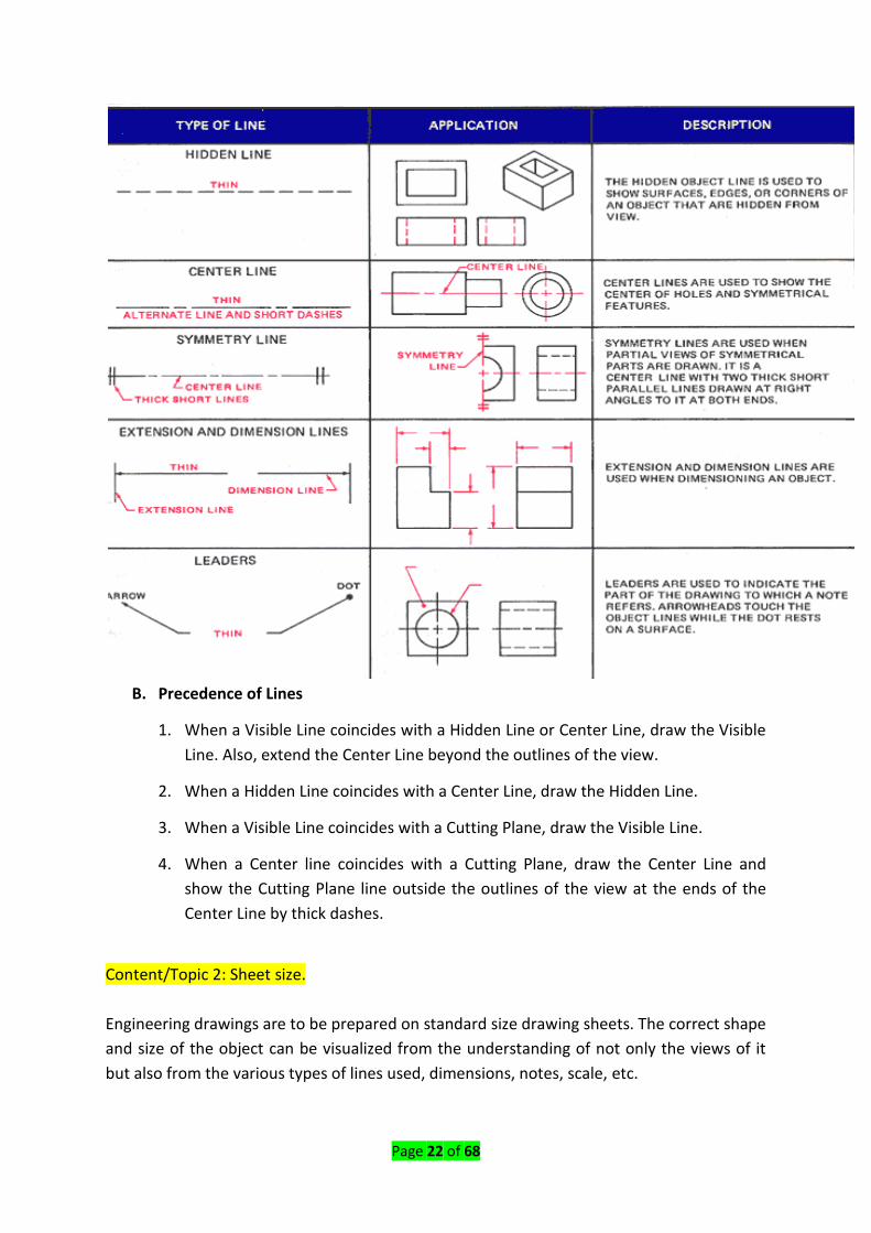
Lines of different types and thicknesses are used for graphical representation of objects. The
types of lines and their applications are shown in Table 2.4. Typical applications of different
types of lines are shown in Figs. 2.5 and 2.6.

Page 19 of 68
Types of lines and their application
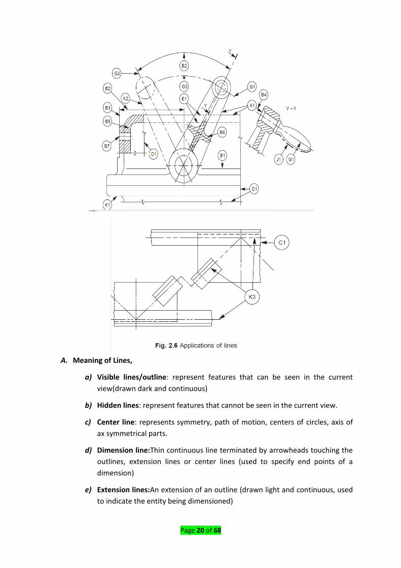
Page 20 of 68
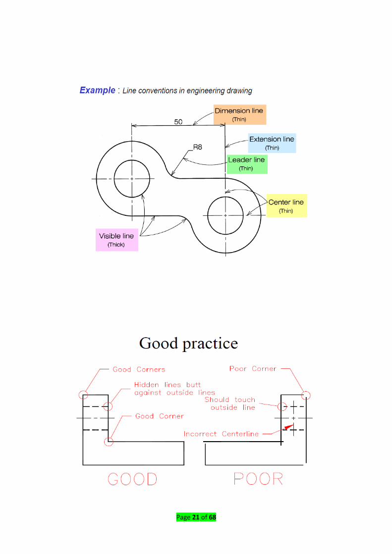
A. Meaning of Lines,
a) Visible lines/outline: represent features that can be seen in the current
view(drawn dark and continuous)
b) Hidden lines: represent features that cannot be seen in the current view.
c) Center line: represents symmetry, path of motion, centers of circles, axis of
ax symmetrical parts.
d) Dimension line:Thin continuous line terminated by arrowheads touching the
outlines, extension lines or center lines (used to specify end points of a
dimension)
e) Extension lines:An extension of an outline (drawn light and continuous, used
to indicate the entity being dimensioned)
Page 21 of 68
Page 22 of 68
B. Precedence of Lines
1. When a Visible Line coincides with a Hidden Line or Center Line, draw the Visible
Line. Also, extend the Center Line beyond the outlines of the view.
2. When a Hidden Line coincides with a Center Line, draw the Hidden Line.
3. When a Visible Line coincides with a Cutting Plane, draw the Visible Line.
4. When a Center line coincides with a Cutting Plane, draw the Center Line and
show the Cutting Plane line outside the outlines of the view at the ends of the
Center Line by thick dashes.
Content/Topic 2: Sheet size.
Engineering drawings are to be prepared on standard size drawing sheets. The correct shape
and size of the object can be visualized from the understanding of not only the views of it
but also from the various types of lines used, dimensions, notes, scale, etc.

Page 23 of 68
To provide the correct information about the drawings to all the people concerned, the
drawings must be prepared, following certain standard practices, as recommended by
Bureau of Indian Standards (BIS).
The basic principles involved in arriving at the sizes of drawing sheets are:
(a) X: Y = 1:2, (b) XY = 1 where X and Y are the sides of the sheet. For a reference size A0
(Table 2.1) having a surface area of 1 m2, X = 841 mm and Y = 1189 mm. The
successive format sizes are obtained either by halving along the length or doubling
along the width, the areas being in the ratio 1:2
Drawing sheet formats
Content /Topic 3: Designation of Sizes.
The original drawing should be made on the smallest sheet, permitting the necessary clarity
and resolution. The preferred sizes according to ISO-A series (First choice) of the drawing
sheets are given in Table 2.1.
When sheets of greater length are needed, special elongated sizes (Second choice) are used
(Table 2.2).
These sizes are obtained by extending the shorter sides of format of the ISO-A series to
lengths that are multiples of the shorter sides of the chosen basic format.

Page 24 of 68
Content /Topic 4: Title block.
The title block should lie within the drawing space such that, the location of it, containing
the identification of the drawing, is at the bottom right hand corner. This must be followed,
both for sheets positioned horizontally or vertically.
The direction of viewing of the title block should correspond in general with that of the
drawing. The title block can have a maximum length of 170 mm. Figure 2.3 shows a typical
title block, providing the following information:
1. Title of the drawing
2. Sheet number
3. Scale
4. Symbol, denoting the method of projection
5. Name of the firm
6. Initials of staff drawn, checked and approved.

Page 25 of 68
NOTE: According to Bureau of Indian Standards, SP-46:1998, ‘‘Engineering Drawing Practice
for Schools and Colleges’’, First angle projection is preferred.
Content /Topic 5: Borders and frames.
Borders enclosed by the edges of the trimmed sheet and the frame, limiting the drawing
space, should be provided with all sheet sizes. It is recommended that these borders have a
minimum width of 20 mm for the sizes A0 and A1 and a minimum width of 10 mm for the
sizes A2, A3 and A4 (Fig. 2.4). A filing margin for taking perforations, may be provided on the
edge, and far left of the title block.
Content/Topic 6 Centering Marks.
Four centering marks may be provided, in order to facilitate positioning of the drawing
when reproduced or microfilmed. Two orientation marks may be provided to indicate the
orientation of the drawing sheet on the drawing board (Fig. 2.4).
Page 26 of 68
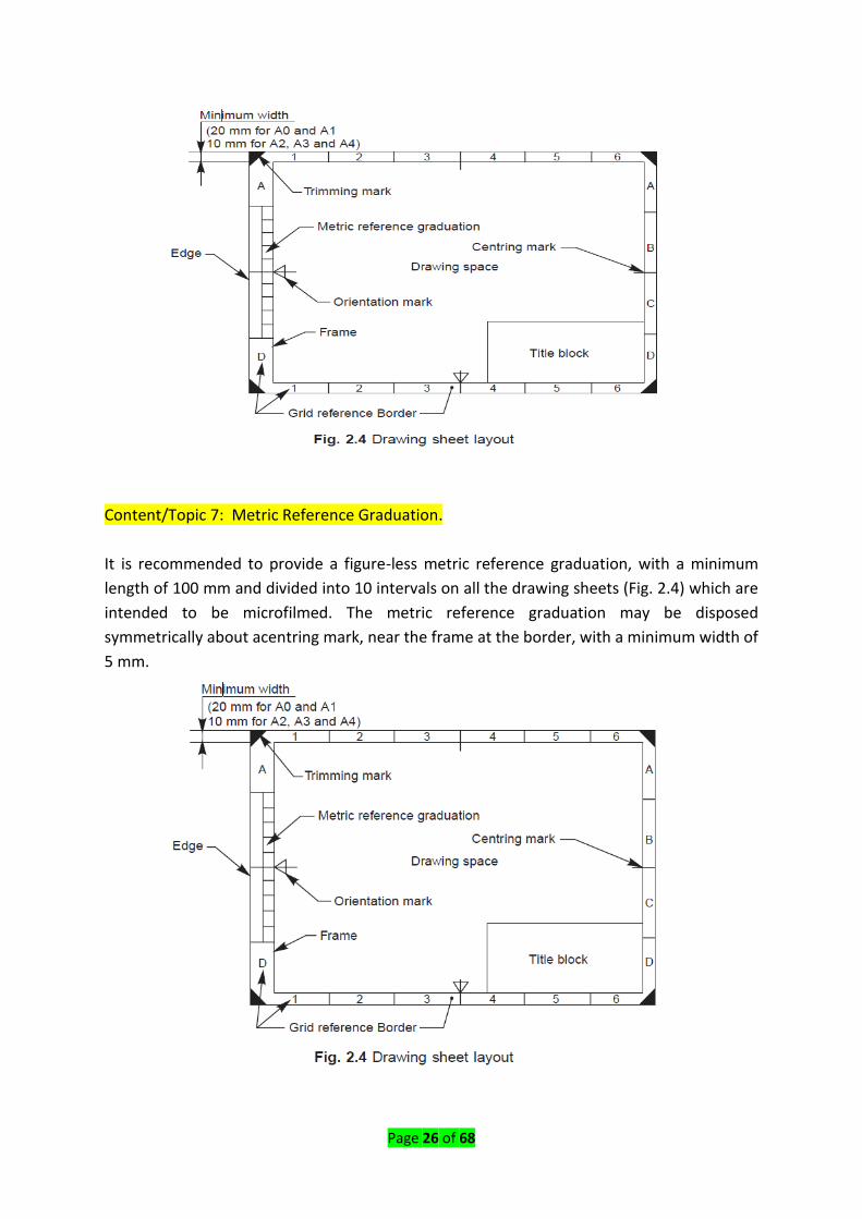
Content/Topic 7: Metric Reference Graduation.
It is recommended to provide a figure-less metric reference graduation, with a minimum
length of 100 mm and divided into 10 intervals on all the drawing sheets (Fig. 2.4) which are
intended to be microfilmed. The metric reference graduation may be disposed
symmetrically about acentring mark, near the frame at the border, with a minimum width of
5 mm.

Page 27 of 68
Content/Topic 8: Grid Reference System (Zoning).
The provision of a grid reference system is recommended for all the sizes, in order to permit
easy location on the drawing of details, additions, modifications, etc. The number of
divisions should be divisible by two and be chosen in relation to the complexity of the
drawing.
It is recommended that the length of any side of the grid should not be less than 25 mm and
not more than 75 mm. The rectangles of the grid should be referenced by means of capital
letters along one edge and numerals along the other edge, as shown in Fig. 2.4. The
numbering direction may start at the sheet corner opposite to the title block and be
repeated on the opposite sides.
Content/Topic 9: Trimming Marks.
Trimming marks may be provided in the borders at the four corners of the sheet, in order to
facilitate trimming. These marks may be in the form of right-angled isosceles triangles or
twoshort strokes at each corner (Fig. 2.4).
LO 2.2 Apply drawing scales
Content/Topic 1 Designation.
The complete designation of a scale should consist of the word Scale, followed by the
indication of its ratio as:

Page 28 of 68
− SCALE 1: 1 for full size,
− SCALE ×: 1 for enlarged scales,
− SCALE 1: × for reduced scales.
The designation of the scale used on the drawing should be shown in the title block.
Content/Topic 2: Recommended Scales.
The recommended scales for use on technical drawings are given in Table 2.3. The scale and
the size of the object in turn, will decide the size of the drawing.

Page 29 of 68
Content/Topic 3: Scale Specification.
If all drawings are made to the same scale, the scale should be indicated in or near the title
block. Where it is necessary to use more than one scale on a drawing, the main scale only
should be shown in the title block and all the other scales, adjacent to the item reference
number of the part concerned or near the drawings.
LO 2.3: Use Lines.
Content/Topic1: Thickness of Lines.
Two thicknesses of lines are used in draughting practice. The ratio of the thick to thin line
should not be less than 2:1. The thickness of lines should be chosen according to the size
and type of the drawing from the following range:
0.18, 0.25, 0.35, 0.5, 0.7, 1, 1.4 and 2
It is recommended that the space between two parallel lines, including hatching, should
never be less than 0.7 mm.
Content/Topic2: Order of Priority of Coinciding Lines.
When two or more lines of different types coincide, the following order of priority should be
observed:
1. Visible outlines and edges (Continuous thick lines, type A),
2. Hidden outlines and edges (Dashed line, type E or F),
3. Cutting planes (Chain thin, thick at ends and changes of cutting planes, type H),
4. Centre lines and lines of symmetry (Chain thin line, type G),
5. Centroidal lines (Chain thin double dashed line, type K),
6. Projection lines (Continuous thin line, type B).
The invisible line technique and axis representation should be followed as per the
recommendations given in Table 2.5.

Page 30 of 68
Table 2.5 Invisible lines

Page 31 of 68
Content/Topic 3: Termination of Leader Lines.
A leader is a line referring to a feature (dimension, object, outline, etc.). Leader lines should
terminate (Fig. 2.7),
a) With a dot, if they end within the outlines of an object,
b) With an arrow head, if they end on the outline of an object,
c) Without dot or arrow head, if they end on a dimension line.
A. Leader lines and notes
− Leader (or pointer) line – Thin continuous line connecting a note or
dimension figure with the feature to which it applies. One end of the leader
terminates in an arrowhead or dot.
− The arrowhead touches the outline while the dot is placed within the object
or on the outline

Page 32 of 68
− The other end of a leader is terminated in a horizontal line underlining the
note
B. Rules for leader lines
- A leader line is never drawn horizontal, vertical or curved
- It is drawn at an angle not less than 30o to the line that it touches
- When pointing to a circle or arc, it is drawn radially
L O 2.4: Respect drawing lettering standard rules
A. LETTER NUMBERING: The art of writing the alphabets A, B, C…Z and numbers such
as 1, 2, 3…0 etc, is known as lettering. It is an important part of drawing and is used
to write letters, dimensions, notes and other necessary information required to
complete execution of machine or structure, etc
I. Feature of lettering.
1. Uniformity
2. Neatness
3. Rapidity and proper spacing

Page 33 of 68
All lettering works are done either by freehand or by using drawing instruments. Skill
and proficiency in freehand lettering can be achieved by the proper selection of
appropriate sizes and style of lettering.
II. Height of letters and numerals: The height of letters and numerals
recommended for use in engineering drawing are 2.5, 3.5, 5, 7, 10, 14 and
20mm. Height of the letters and numerals will be different for different
purposes and may be selected suitably for their purpose.
III. Style of freehand lettering
− Vertical or upright freehand lettering
a) Single stroke vertical freehand lettering
b) Lower case vertical freehand lettering
Single stroke: The lettering in which the alphabets are written with a single
stroke of pencil or pen is called a single stroke.
Double stroke: The lettering in which the alphabets are written by double
stroke of the pencil or pen with uniform spacing in between strokes is called
double – stroke.
− Inclined or Italic freehand lettering
a) Single stroke italic freehand
b) Lower case Italic freehand

Page 34 of 68
a. Spacing of letters: The spacing means the distance which is to be left between the
two adjacent letters in all types of lettering.
Note:
- The space between each word should be kept equal to height of letter
- The space between the two lines should be left equal to twice the height of
letter.
- The space between the two lines should be kept not less than half or more than
one and a half times the height of letter
Legend:
H: Lettering height (capital letters)
C: Height of lower-case letters
A: Spacing between characters
B: Minimum spacing of base line
E: Minimum spacing between words
D: Thickness of lines

Page 35 of 68
Content/Topic 1: Dimensions.
The following specifications are given for the dimensions of letters and numerals:
i. The height of capital letters is taken as the base of dimensioning (Tables 2.6 and 2.7).
ii. The two standard ratios for d/h, 1/14 and 1/10 are the most economical, as they
result in a minimum number of line thicknesses.
iii. The lettering may be inclined at 15° to the right, or may be vertical.
Lettering A (d = h/14)
Characteristic Parameter Ratio Dimensions (mm)
Lettering Height (Height of capitals)
h (14/14)h 2.50 3.50 5.00 7.0 10.0 14 20.0
Height of lower case letters (without stem or tail)
c (10/14)h — 2.50 3.50 5.0 7.0 10 14.0
Spacing between characters a (2/14)h 0.35 0.50 0.70 1.0 1.4 2 2.8
Minimum spacing of base characters
b (20/14)h 3.50 5.00 7.00 10.0 14.0 20 28.0
Minimum spacing between words
e (6/14)h 1.05 1.50 2.10 3.0 4.2 6 8.4
Thickness of lines d (1/14)h 0.18 0.25 0.35 0.5 0.7 1 1.4
Page 36 of 68
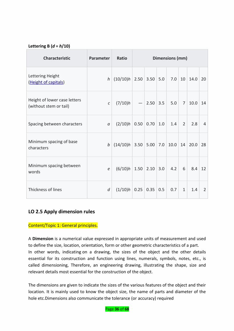
Lettering B (d = h/10)
Characteristic Parameter Ratio Dimensions (mm)
Lettering Height
(Height of capitals) h (10/10)h 2.50 3.50 5.0 7.0 10 14.0 20
Height of lower case letters
(without stem or tail) c (7/10)h — 2.50 3.5 5.0 7 10.0 14
Spacing between characters a (2/10)h 0.50 0.70 1.0 1.4 2 2.8 4
Minimum spacing of base
characters b (14/10)h 3.50 5.00 7.0 10.0 14 20.0 28
Minimum spacing between
words e (6/10)h 1.50 2.10 3.0 4.2 6 8.4 12
Thickness of lines d (1/10)h 0.25 0.35 0.5 0.7 1 1.4 2
LO 2.5 Apply dimension rules
Content/Topic 1: General principles.
A Dimension is a numerical value expressed in appropriate units of measurement and used
to define the size, location, orientation, form or other geometric characteristics of a part.
In other words, indicating on a drawing, the sizes of the object and the other details
essential for its construction and function using lines, numerals, symbols, notes, etc., is
called dimensioning, Therefore, an engineering drawing, illustrating the shape, size and
relevant details most essential for the construction of the object.
The dimensions are given to indicate the sizes of the various features of the object and their
location. It is mainly used to know the object size, the name of parts and diameter of the
hole etc.Dimensions also communicate the tolerance (or accuracy) required

Page 37 of 68
- As far as possible, dimensions should be placed outside the view.
- Dimensions should be taken from visible outlines rather than from hidden lines.
- Dimensioning to a centre line should be avoided except when the centre line
passes through the centre of a hole.
- Each feature should be dimensioned once only on a drawing.
- Dimensions should be placed on the view or section that relates most clearly to
the corresponding features.
- Each drawing should use the same unit for all dimensions, but without showing
the unit symbol.
- No more dimensions than are necessary to define a part should be shown on a
drawing.
- No features of a part should be defined by more than one dimension in any one
direction.
Content/Topic 2: Method of Execution.
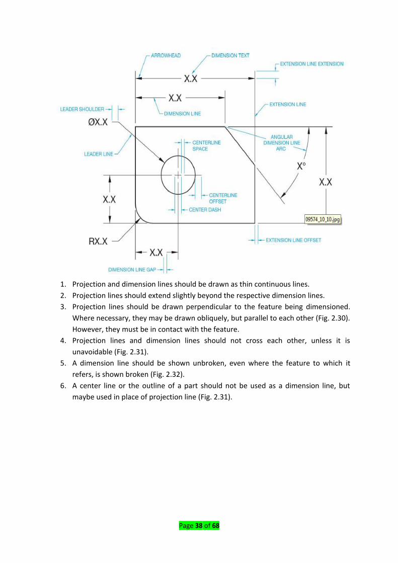
The elements of dimensioning include the projection line, dimension line, leader line,
dimension line termination, the origin indication and the dimension itself.
Page 38 of 68
1. Projection and dimension lines should be drawn as thin continuous lines.
2. Projection lines should extend slightly beyond the respective dimension lines.
3. Projection lines should be drawn perpendicular to the feature being dimensioned.
Where necessary, they may be drawn obliquely, but parallel to each other (Fig. 2.30).
However, they must be in contact with the feature.
4. Projection lines and dimension lines should not cross each other, unless it is
unavoidable (Fig. 2.31).
5. A dimension line should be shown unbroken, even where the feature to which it
refers, is shown broken (Fig. 2.32).
6. A center line or the outline of a part should not be used as a dimension line, but
maybe used in place of projection line (Fig. 2.31).

Page 39 of 68
Content /Topic 3: Termination and Origin Indication.
Dimension lines should show distinct termination, in the form of arrow heads or oblique
strokes or where applicable, an origin indication.
Two-dimension line terminations and an origin indication are shown in Fig. 2.33. In this,
1. The arrow head is drawn as short lines, having an included angle of 15°, which is
closed and filled-in.
2. The oblique stroke is drawn as a short line, inclined at 45°.
3. The origin indication is drawn as a small open circle of approximately 3 mm in
diameter.
The size of the terminations should be proportionate to the size of the drawing on which
they are used. Where space is limited, arrow head termination may be shown outside the
intended limits of the dimension line that is extended for that purpose. In certain other
cases, an oblique stroke or a dot may be substituted (Fig. 2.34).
Where a radius is dimensioned, only one arrow head termination, with its point on the arc
end of the dimension line, should be used (Fig. 2.35). However, the arrow head termination
may be either on the inside or outside of the feature outline, depending upon the size of
feature.

Page 40 of 68
Content/Topic 4: Methods of Indicating Dimensions.
Dimensions should be shown on drawings in characters of sufficient size, to ensure
complete legibility. They should be placed in such a way that they are not crossed or
separated by another line on the drawing. Dimensions should be indicated on a drawing,
according to one of the following two methods. However, only one method should be used
on any one drawing.
METHODS:
1. (Aligned System): Dimensions should be placed parallel to their dimension lines and
preferably near the middle, above and clear-off the dimension line (Fig. 2.36). An
exception may be made where superimposed running dimensions are used (Fig. b)
Dimensions may be written so that they can be read from the bottom or from the right side
of the drawing. Dimensions on oblique dimension lines should be oriented as shown in next
figure

Page 41 of 68
Fig. 2.37. Angular dimensions may be oriented as shown in Fig. 2.38.
2. (Uni-directional System): Dimensions’ should be indicated so that they can be read
from the bottom of the drawing only. On-horizontal dimension lines are interrupted,
preferably near the middle, for insertion of the dimension (Fig. 2.39).Angular
dimensions may be oriented as in Fig. 2.40.
Dimensions can be,
i. Above the extension of the dimension line, beyond one of the terminations, where
space is limited (Fig. 2.34) or
ii. At the end of a leader line, which terminates on a dimension line, that is too short to
permit normal dimension placement (Fig. 2.34) or
iii. Above a horizontal extension of a dimension line, where space does not allow
placement at the interruption of anon-horizontal dimension line (Fig. 2.41).Values of
dimensions, out of scale (except where break lines are used) should be underlined as
shown in Fig. 2.41.

Page 42 of 68
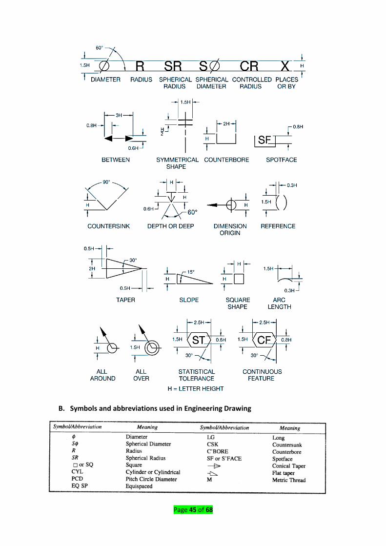
A. Placing of dimension
The following indications (symbols) are used with dimensions to reveal the shape
identification and to improve drawing interpretation. The symbol should precede the
dimensions (Fig. 2.42).

Page 43 of 68

Page 44 of 68
Page 45 of 68
B. Symbols and abbreviations used in Engineering Drawing
Page 46 of 68
Content/Topic 5: Arrangement of Dimensions.
The arrangement of dimensions (Dimensioning techniques) on a drawing must indicate
clearly the design purpose.
- Keep dimensions off the part to be dimensioned where possible.
- Arrange extension lines so the larger dimensions are outside of the smaller
dimensions.
- Stagger the dimension value labels to ensure they are clearly defined.
The following are the ways of arranging the dimensions.
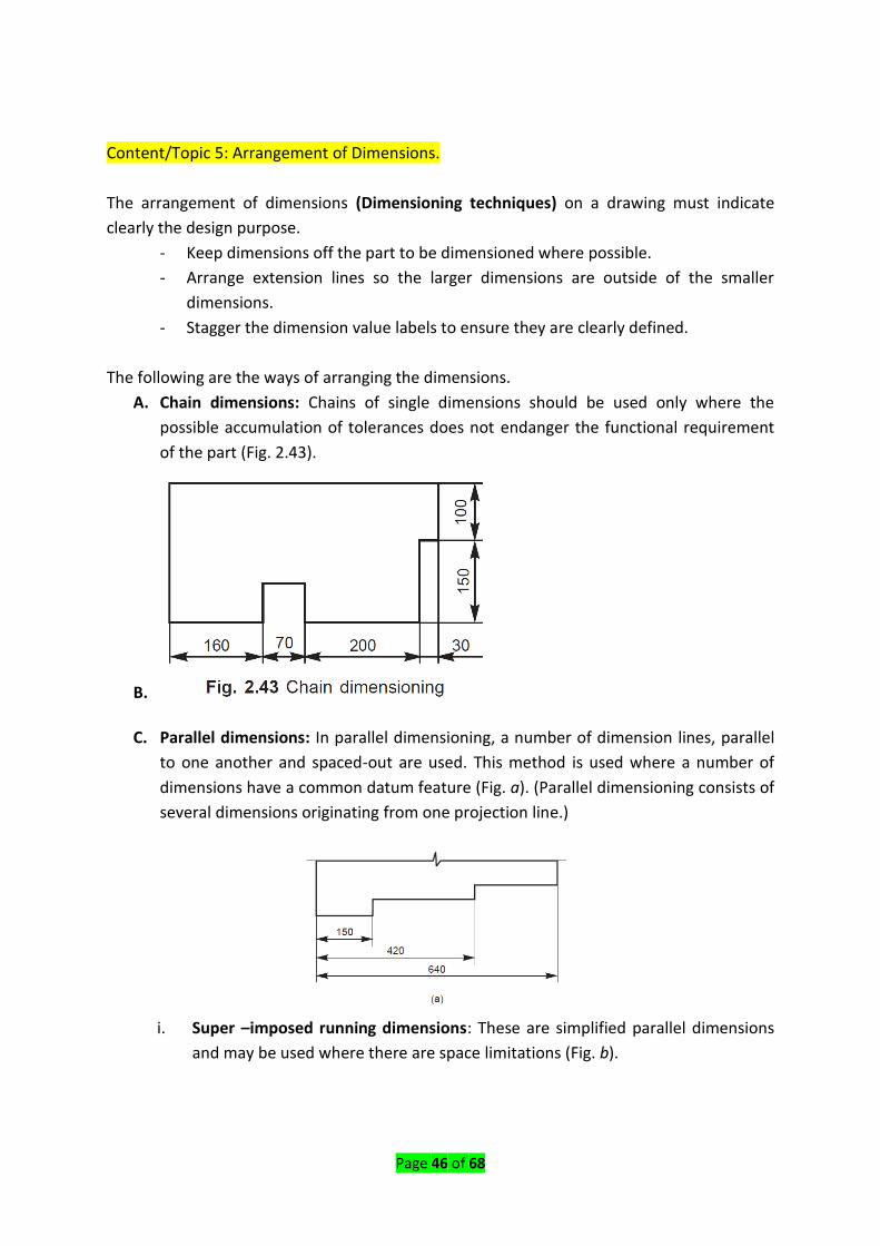
A. Chain dimensions: Chains of single dimensions should be used only where the
possible accumulation of tolerances does not endanger the functional requirement
of the part (Fig. 2.43).
B.
C. Parallel dimensions: In parallel dimensioning, a number of dimension lines, parallel
to one another and spaced-out are used. This method is used where a number of
dimensions have a common datum feature (Fig. a). (Parallel dimensioning consists of
several dimensions originating from one projection line.)
i. Super –imposed running dimensions: These are simplified parallel dimensions
and may be used where there are space limitations (Fig. b).

Page 47 of 68
D. Combined dimensions: These are the result of simultaneous use of chain and
parallel dimensions (Fig. 2.45).
E. Co-ordinate dimensions: The sizes of the holes and their co-ordinates may be
indicated directly on the drawing; or they may be conveniently presented in a
tabular form, as shown in Fig. 2.46.

Page 48 of 68
F. Dimensioning Small Features: When dimensioning small features, placing the
dimension arrow between projection lines may create a drawing which is difficult to
read. In order to clarify dimensions on small features any of the above methods can
be used.
Content /Topic 6 Special Indications
A. Diameters: Diameters should be dimensioned on the most appropriate view to
ensure clarity. All dimensions of circles are preceded by the symbol. There are
several conventions used for dimensioning circles:
i. Shows two common methods of dimensioning a circle. One method dimensions
the circle between two lines projected from two diametrically opposite points.
The second method dimensions the circle internally.
ii. Is used when the circle is too small for the dimension to be easily read if it was
placed inside the circle. A leader line is used to display the dimension.
iii. The final method is to dimension the circle from outside the circle using an arrow
which points directly towards the center of the circle. The dimension value should
be the next figure shows the method of dimensioning diameters.

Page 49 of 68
iv. Chords, Arcs, Angles and Radius: The dimensioning of chords, arcs and
angles should be as shown in Fig. 2.48. Where the centre of an arc falls
outside the limits of the space available, the dimension line of the radius
should be broken or interrupted according to whether or not it is necessary
to locate the centre (Fig.2.35).
Where the size of the radius can be derived from other dimensions, it may be
indicated by a radius arrow and the symbol R, without an indication of the
value (Fig. 2.49).
v. Equidistant features: Linear spacings with equi-distant features may be
dimensioned as shown in Fig.2.50.

Page 50 of 68
vi. Chamfers and countersunk: Chamfers may be dimensioned as shown in Fig.
2.51 and countersunks, as shown in Fig. 2.52.
Page 51 of 68
LO 2.6: Design sections.
The technique of representing an object in a drawn form is referred to as projection.
Projection can be divided into pictorial (3- dimensional) projection and orthographic (2-
dimensional) projection.
- Pictorial projection is further divided into isometric, oblique and perspective
projections; while the
- Orthographic projection is divided into 1st angle and 3rd angle projection.
A. Orthographic projection: Is a means of representing a three-dimensional object in
two dimensions (2D). It uses multiple views of the object, from points of view
rotated about the object's center through increments of 90°.
The projection or view obtained on a plane of projection when the projectors are
parallel to each other, but perpendicular to the plane of projection, is known as
orthographic projection. While drawing the orthographic projections, the following
items should invariably exist:
1) The object to be projected
2) The projector
3) The plane of projections
4) The observer’s eye or station point.
The orthographic projection system is used to represent a 3D object in a 2D plane.
The orthographic projection system utilizes parallel lines, to project 3D object views
onto a 2D plane. According to the rule of orthographic projection. To draw a
projection view of a 3D object on a 2D Plane. The horizontal plane is rotated in the
clockwise direction.
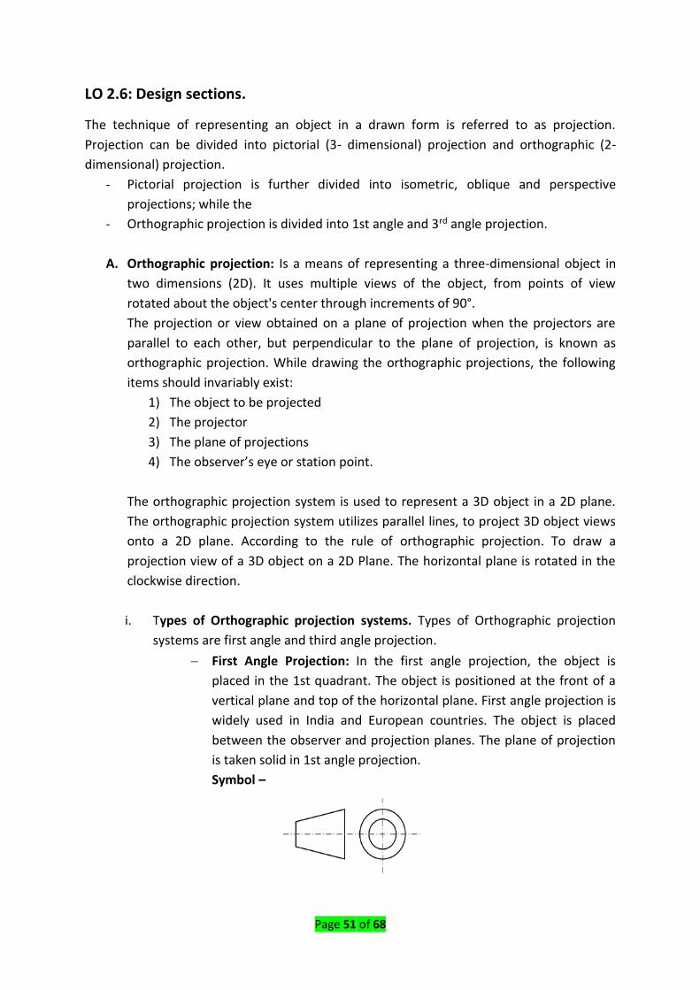
i. Types of Orthographic projection systems. Types of Orthographic projection
systems are first angle and third angle projection.
− First Angle Projection: In the first angle projection, the object is
placed in the 1st quadrant. The object is positioned at the front of a
vertical plane and top of the horizontal plane. First angle projection is
widely used in India and European countries. The object is placed
between the observer and projection planes. The plane of projection
is taken solid in 1st angle projection.
Symbol –

Page 52 of 68
− Third Angle Projection: In the third angle projection, the object is
placed in the third quadrant. The object is placed behind the vertical
planes and bottom of the horizontal plane. Third angle projection is
widely used in the United States. The projection planes come
between the object and observer. The plane of projection is taken as
transparent in 3rd angle projection.
Symbol –
Difference between First Angle Projection and Third Angle Projection:
B. PLANE OF PROJECTION: The plane which is used for the purpose of projection is
called plane of projection, types of projection plane are:
1. REFERENCE PLANE: In general, two planes are employed for projection and are
known as reference planes or principal planes of projection. These planes
intersect at right angle to each other.
2. VERTICAL PLANE (V.P): The plane which is vertical is called vertical plane and is
denoted by V.P. Vertical plane is also known as frontal plane since front view is
projected on this plane

Page 53 of 68
3. HORIZONTAL PLANE (H.P): The plane which is horizontal but at right angle to the
V.P
4. AUXILIARY PLANE (A.P): Any other plane, placed at any angles to the principle
planes
5. PROFILE PLANE (P.P): The plane which is at right angles to the two-principle
plane is called auxiliary vertical plane (A.V.P) PP
C. Principle Views: In orthographic projection there are 6 principle views of an object,
front, top, L side, R side, rear, and back views. The three most commonly views
drawn on a technical drawing are the front, back, and side views most other views
are not needed. Other views may be needed in order for the per-son who is creating
the Part, to better visualize it in order to properly manufacture it. A well viewed
Type of Views.
− Front view or elevation
− Rear view
− Top view or plan
− Bottom view
− Right view
− Left view or Side view or Side elevation or profile view
− Auxiliary view: The object is projected on an auxiliary plane
The views are named as follows:
− F − Front view or main view/elevation
− Sl − Side view from the left or left side view
− T − Top view
− R − Rear view
− Sr − Side view from the right- or right-side view
− B − Bottom view
D. Principle of the first Angle Projection: In first angle projection, the object is
imagined to be positioned in the first quadrant. The view from the front of the object
is obtained by looking at the object from the right side of the quadrant and tracing in
correct sequence, the points of intersection between the projection plane and the
rays of sight extended. The object is between the observer and the plane of
projection (vertical plane). Here, the object is imagined to be transparent and the
projection lines are extended from various points of the object to intersect the
projection plane. Hence, in first angle projection, any view is so placed that it
represents the side of the object away from it.

Page 54 of 68
E. Methods of Obtained Orthographic Views
a) View from the front: The view from the front of an object is defined as the
view that is obtained as projection on the vertical plane by looking at the
object normal to its front surface. It is the usual practice to position the
object such that its view from the front reveals most of the important
features. Figure 3.1 shows the method of obtaining the view from the front
of an object.
b) View from Above: The view from above of an object is defined as the view
that is obtained as projection on the horizontal plane, by looking the object
normal to its top surface. Figure 3.2 shows the method of obtaining the view
from above of an object.
c) View from the side: The view from the side of an object is defined as the
view that is obtained as projection on the profile plane by looking the object,
normal to its side surface. As there are two sides for an object, viz., left side
and right side, two possible views from the side, viz., view from the left and
view from the right may be obtained for any object. Figure 3.3 shows the
method of obtaining the view from the left of an object.
F. Presentation of view: The different views of an object are placed on a drawing sheet
which is a two dimensional one, to reveal all the three dimensions of the object.

Page 55 of 68
For this, the horizontal and profile planes are rotated till they coincide with the vertical
plane. Figure 3.4 shows the relative positions of the views, viz., the view from the front,
above and the left of an object.
G. Designation and relative position of view: An object positioned in space may be
imagined as surrounded by six mutually perpendicular planes. So, for any object, six
different views may be obtained by viewing at it along the six directions, normal to
these planes. Figure 3.5 shows an object with six possible directions to obtain the
different views which are designated as follows:
1) View in the direction a = view from the front
2) View in the direction b = view from above
3) View in the direction c = view from the left
4) View in the direction d = view from the right
5) View in the direction e = view from below
6) View in the direction f = view from the rear

Page 56 of 68
Figure 3.6a shows the relative positions of the above six views in the first angle projection
and Fig.3.6b, the distinguishing symbol of this method of projection. Figure 3.7 a show the
relative position of the views in the third angle projection and Fig. 3.7b, the distinguishing
symbol of this method of projection.
NOTE A comparison of Figs. 3.6 and 3.7 reveals that in both the methods of projection, the
views are identical in shape and detail. Only their location with respect to the view from the
front is different
It is important to understand the significance of the position of the object relative to the
planes of projection.
Page 57 of 68
To get useful information about the object in the orthographic projections, the object may
be imagined to be positioned properly because of the following facts:
1. Any line on an object will show its true length, only when it is parallel to the plane of
projection.
2. Any surface of an object will appear in its true shape, only when it is parallel to the
plane of projection.
In the light of the above, it is necessary that the object is imagined to be positioned such
that its principal surfaces are parallel to the planes of projection.
H. Selection of views: For describing any object completely through its orthographic
projections, it is important to select a number of views. The number of views
required to describe any object will depend upon the extent of complexity involved
in it. The higher the symmetry, the lesser the number of views required.
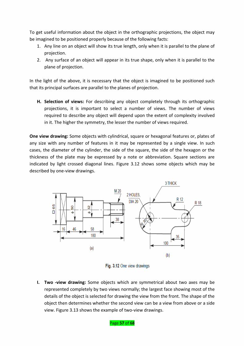
One view drawing: Some objects with cylindrical, square or hexagonal features or, plates of
any size with any number of features in it may be represented by a single view. In such
cases, the diameter of the cylinder, the side of the square, the side of the hexagon or the
thickness of the plate may be expressed by a note or abbreviation. Square sections are
indicated by light crossed diagonal lines. Figure 3.12 shows some objects which may be
described by one-view drawings.
I. Two -view drawing: Some objects which are symmetrical about two axes may be
represented completely by two views normally; the largest face showing most of the
details of the object is selected for drawing the view from the front. The shape of the
object then determines whether the second view can be a view from above or a side
view. Figure 3.13 shows the example of two-view drawings.

Page 58 of 68
J. Three-view drawing: In general, most of the objects consisting of either a single
component or an assembly of a number of components are described with the help
of three views. In such cases, the views normally selected are the views from the
front, above and left or right side. Figure 3.14 shows an object and its three
necessary views.

Page 59 of 68
K. Development of missing view: When two views of an object are given, the third
view may be developed by the use of a miter line. To construct the view from the
left, from the 2 given views-Construction (Fig. 3.15)
1. Draw the views from the front and above.
2. Draw the projection lines to the right of the view from above.
3. Decide the distance, D from the view from the front at which, the side view is
to be drawn.
4. Construct a miter line at 45°.
5. From the points of intersection between the miter line and the projection
lines, draw vertical projection lines.
6. Draw the horizontal projection lines from the view from the front to intersect
the above lines. The figure obtained by joining the points of intersection in
the order is the required view. Figure 3.16 shows the steps to be followed in
constructing the view from above of an object, from the given views from the
front and left.

Page 60 of 68
NOTE These exercises are aimed at improving the practice in reading and
developing the imagination of the student.
Spacing the views
The views of a given object must be positioned on the drawing sheet so as to give a good
and balanced appearance. Keeping in view, (i) number of views, (ii) scale and (iii) space
between the views, the draughtsman should decide about the placement of views on the
drawing sheet. Sufficient space between the views must be provided to facilitate placement
of dimensions, notes, etc., on the drawing without overcrowding.
Content/Topic 1: Hatching of Sections.
Hatching is generally used to show areas of sections. The simplest form of hatching is
generally adequate for the purpose, and may be continuous thin lines (type B) at a
convenient angle, preferably 45°, to the principal outlines or lines of symmetry of the
sections (Fig. 2.11).
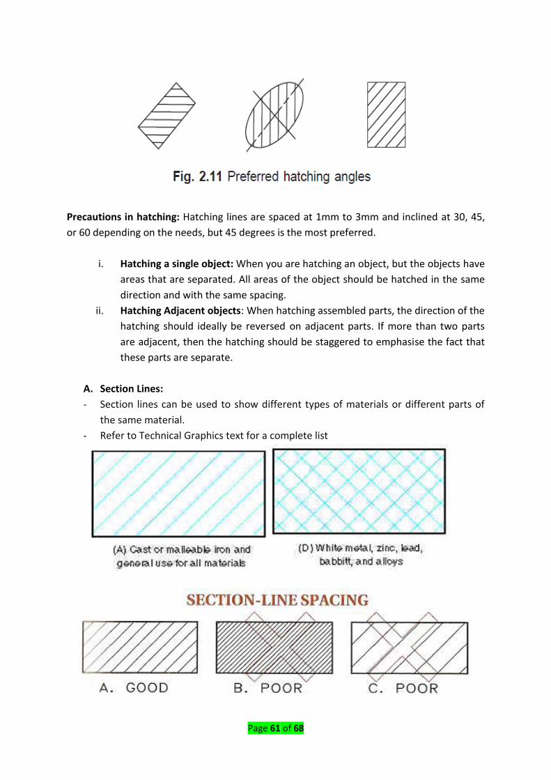
Page 61 of 68
Precautions in hatching: Hatching lines are spaced at 1mm to 3mm and inclined at 30, 45,
or 60 depending on the needs, but 45 degrees is the most preferred.
i. Hatching a single object: When you are hatching an object, but the objects have
areas that are separated. All areas of the object should be hatched in the same
direction and with the same spacing.
ii. Hatching Adjacent objects: When hatching assembled parts, the direction of the
hatching should ideally be reversed on adjacent parts. If more than two parts
are adjacent, then the hatching should be staggered to emphasise the fact that
these parts are separate.
A. Section Lines:
- Section lines can be used to show different types of materials or different parts of
the same material.
- Refer to Technical Graphics text for a complete list

Page 62 of 68
Content/Topic 2: Cutting Plane.
A long chain thick line is used to indicate the cutting plane as well as the direction of view.
On the two ends of this line are indicated a letter which gives the name of the section. This
letter (L-L) in our example below is very important and helps to differentiate among
sections, especially when we have many sections represented on a drawing. The cutting
plane should be identified by capital letters and the direction of viewing should be indicated
by arrows.
For example, on the following drawing they are two sections H-H and G-G. So, each will be
represented apart.
Page 63 of 68
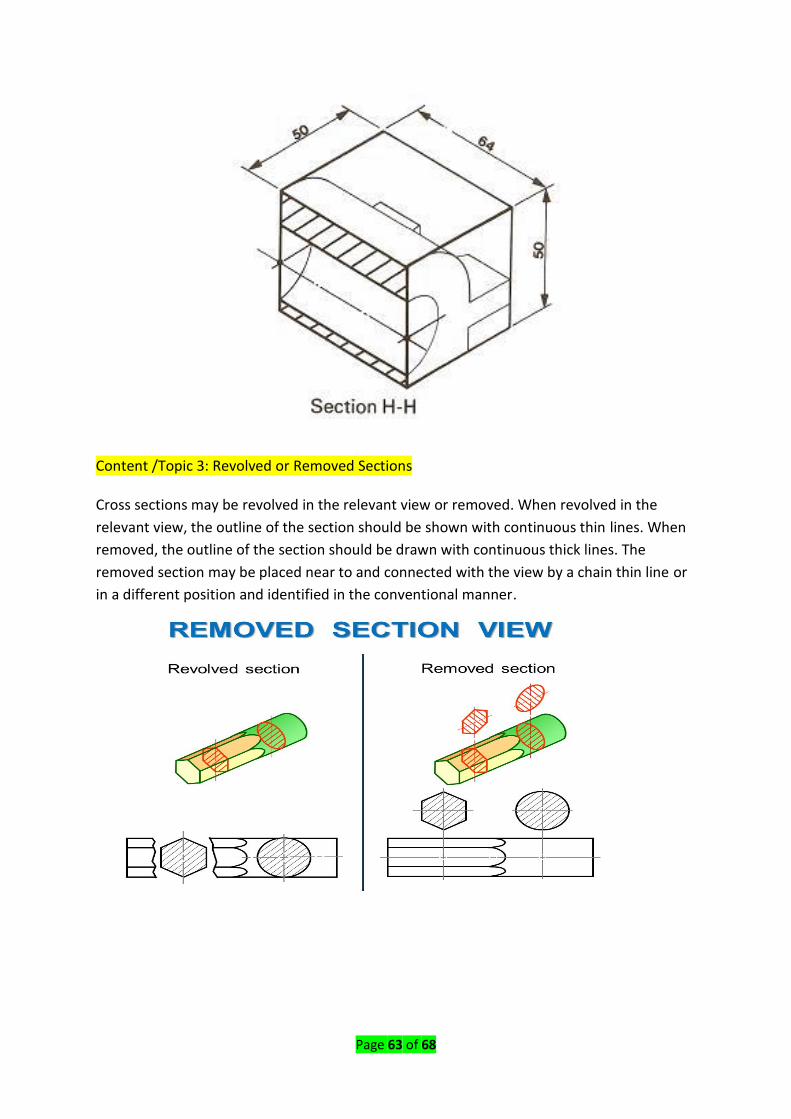
Content /Topic 3: Revolved or Removed Sections Cross sections may be revolved in the relevant view or removed. When revolved in the
relevant view, the outline of the section should be shown with continuous thin lines. When
removed, the outline of the section should be drawn with continuous thick lines. The
removed section may be placed near to and connected with the view by a chain thin line or
in a different position and identified in the conventional manner.

Page 64 of 68
Content/Topic 4: Half section.
A half sectional view is preferred for symmetrical objects. For a half section, the cutting
plane removes only one quarter of an object. For a symmetrical object, a half sectional view
is used to indicate both interior and exterior details in the same view. Even in half sectional
views, it is a good practice to omit the hidden lines. Figure 4.4a shows an object with the
cutting plane in position for obtaining a half sectional view from the front, the top half being
in section. Figure 4.4b shows two parts drawn apart, exposing the inner details in the
sectioned portion. Figure 4.4c shows the half sectional view from the front. It may be noted
that a centre line is used to separate the halves of the half section. Students are also advised
to note the representation of the cutting plane in the view from above, for obtaining the
half sectional view from the front.

Page 65 of 68
Content/Topic 5 local section.
A local section may be drawn if half or full section is not convenient. The local break may be
shown by a continuous thin free hand line (Fig. 2.24).
Content /Topic 6Arrangement of Successive Sections.
LO 2.7: Apply drawing conventional representations dimensioning and
standard abbreviations
Content/Topic 1: Material
Certain draughting conventions are used to represent materials in section and machine
elements in engineering drawings.
A. Material: As a variety of materials are used for machine components in engineering
applications, it is preferable to have different conventions of section lining to
differentiate between variousmaterials. The recommended conventions in use are
shown in next table.

Page 66 of 68
Content/Topic 2 Machine Components.
When the drawing of a component in its true projection involves a lot of time, its
convention may be used to represent the actual component. Figure 2.27 shows typical
examples of conventional representation of various machine components used in
engineering drawing.

Page 67 of 68

Page 68 of 68
Reference(s):
1. DR.K.L. Narayana, (2006). Machine Drawing. INDIAN INSTITUTE OF
TECHNOLOGYCHENNAI-600 036, INDIA: New Age International (P) Ltd
2. Ulrich F, (2008). Mechanical and Metal Trades Handbook. Germany, Media Print
International technologies.