Embed Size (px)
DESCRIPTION
TV Cabling Solution
Citation preview

When it comes to antenna installation, the choice is clear
TV Cabling
Solutions
Catalogue

Part No: 3105TVA
Choosing the Right Antenna
Part No: 3105TVA
The new version of TV Across Australia will include the most up to date planning and implementation of all analogue and digital broadcast TV services throughout the country.It will also include an antenna selection for each transmitter making choosing the right antenna a very simple exercise. You cannot afford to be without this great reference guide.What frequencies are being broadcast in the location of the installation?
• Every TV transmitter Across Australia• Clipsal Antenna part number for every TV transmitter• Location maps for every TV transmitter Across Australia• Analogue and Digital TV channels broadcast from every TV transmitter

4 Terminology
6 MATV basics
10 Antennas
26 Mounting Accessories
38 Splitters
43 Diplexers
44 Drop Taps
46 Coaxial Cable
50 Coaxial Cable Connectors
54 Installation Tips
56 Installation Tools
59 MATV Adaptors
63 Fly Leads
65 TV Mechs
66 Wall Plates
69 Location Guides
Contents

4
TE
RM
IN
OL
OG
Y
Clipsal TV Cabling Solutions
Terminology
Amplification
The increase of signal strength. Amplification does not improve the signal quality received but can improve the picture quality viewed on TV due to low signal strength.
Attenuation
The loss of signal strength. To Attenuate the signal strength is to decrease the level of the signal strength. Attenuation occurs naturally over a length of cable. Refer to cable losses on page 8 for values.
BER
Bit Error Ratio is the number of errors in a Video Broadcast. Typically 2 errors in every 1,000,000 will be acceptable.
Forward Gain
The amount an antenna increases the signal strength in the air.
Front to Back ratio
The difference in signal level received from the front of the antenna verses the back of the antenna. Antennas are designed to reject signals received from the back of the antenna. Good Front to Back ratio reduces the chance of ghosting.
Ghosting
Two images of the same source on the one TV Screen caused by two signals received by the same Antenna from two different directions. Often there is the main signal source and a secondary source reflected off a building or mountain.
Losses
The signal strength is decreased over cable, splitters and connectors. Compensation for losses must be made when designing a MATV system.
RF
Radio Frequency.
Skin effect
TV frequencies travel around the circumference of the copper conductor in a coax cable. It is important to make sure that when terminating coax cable for MATV or Satellite TV applications that a properly designed stripping tool is used. Avoid scoring or ringing the copper conductor as TV frequencies travel on the outside circumference of the copper conductor.
UHF
Ultra High Frequency.UHF channels are broadcast from channel 21-69. Digital and analogue frequencies.
VHF
Very High Frequency. VHF Low are channels 0-5A. analogue frequencies. VHF High are channels 6-12. Digital and Analogue frequencies. Digital TV will only be broadcast on VHF channels 6 and above as well as all UHF channels.

TE
RM
IN
OL
OG
Y
5
Amplifier
An amplifier will increase the signal strength. Amplifiers DO NOT improve the signal quality.
Antenna
Antennas receive TV frequencies broadcast from TV Transmission Towers. They need to be mounted in a location that will receive a good quality signal. There are different types of antennas that are designed for receiving different types of frequencies. Refer to TV Across Australia reference guide for your needs.
Cable
Quality Television Coax Cable is designed to carry the television frequencies from the antenna to the television without any interference to the signal and resultant picture quality. You should only use a good quality cable.
Diplexer
Diplexers combine TV signals fom 2 antennas through 1 coax cable.
Drop Tap
A Drop Tap will decrease the signal level by a set amount over the Tap Leg. If the signal is too high the use of a Drop Tap is an easy way to get the signal to the ideal level.
Fly Lead
A Fly Lead connects the outlet to the television or recording device such as a Digital Video Recorder. A good quality Fly Lead should always be used as it is under the most stress from bending behind television cabinets and induced voltage from cords behind the television.
Mounts
There are various antenna mounts for different applications such as roof mounts, wall mounts, masts and extensions. Get the best possible signal by mounting the antenna properly.
Splitter
A splitter will enable the connection of multiple outlets to 1 antenna. Splitters have losses associated with them. The more splits the greater the losses will be.
Television Outlet
Television outlets are part of the cabling infrastructure and should be of a high quality for sustained signal distribution. F-Type outlets are the industry preferred television outlet due to the quality of connection and performance.
Terminology

6
MA
TV
B
AS
IC
S
Clipsal TV Cabling Solutions
TV Signal Strength
TV signal strength is measured in decibel Micro Volts (dBuV) more commonly known as dB.
The ideal signal strength at the television outlet is 69dBuV. The ideal Signal Range is between 65-72dBuV.
Low signals need to be increased. This can be achieved by using a larger antenna with more gain or by the use of an amplifier.
High signals need to be decreased. This can be achieved by using a drop tap or splitter.
The closer the antenna is to the television transmitter the higher the signal strength is going to be.
The prime reception area is a location that an antenna with minimal gain can be installed to get the ideal signal range or above at the television outlet.
An outer fringe reception area is a location that an antenna with maximum amount of gain must be installed to provide an ideal signal range at the outlet. It is also likely that an amplifier may need to be installed to increase the signal level.
MATV Outlet - 69dBuV Standard Outlet - 240V
By using the same antenna and 20m of RG6 Quad Shield Coax Cable we can classify the Prime, Fringe and Outer Fringe areas by the level of signal received at the outlet. If in a Prime reception area the signal strength will be greater than 69dBuV at the outlet.If in a Fringe reception area the signal strength will be greater than 66dBuV at the outlet.
If in a Outer Fringe Area the signal will be lower than 66dBuV.
To compensate for a Fringe Area reception we can use an antenna with more forward gain to increase the signal strength at the outlet.
Low Signal Acceptable Signal High Signal69dBuV
62dBuV 65dBuV 72dBuV 75dBuV
Acceptable Signal
PRIME FRINGE OUTER FRINGE
69dBuV 66dBuV

MA
TV
B
AS
IC
S
7
Signal Quality
Signal quality is more important than signal strength.
Pixilation or blocking are the result of poor quality digital television signal. When an antenna is installed it must be in a location that has a good quality Digital Television Signal. The difference between quality television reception and annoying pixilation/blocking can be a matter
of a few metres. A site survey can be done prior to antenna installation to make sure that the location of the antenna is suitable for high quality digital television reception.
Take a few minutes to walk along the roof with the antenna and field strength meter to find the ultimate location to mount the antenna.
PIXILATION QUALITY PICTURE

8
MA
TV
B
AS
IC
S
Clipsal TV Cabling Solutions
Signal Loss - Cable
Losses are a part of any MATV System. You may start out with an acceptable signal level at the antenna but due to losses in the cable or splitter may not be acceptable when at the outlet.
Signal Strength is lost over a length of cable. The losses are easy to calculate as losses are consistent per meter.
Losses are calculated separately for VHF and UHF frequencies. The golden rule is the higher the frequency the higher the loss. We need to calculate losses for both VHF and UHF in every TV design to ensure that we have a balanced system.
VHF = Very High Frequency - losses are low. (0.053dB per meter RG6 Quad Shield).
UHF = Ultra High Frequency - losses are high (0.21dB per meter RG6 Quad Shield).
As a general rule of thumb cable runs of up to 50m can be done in RG6. If longer cable runs are required then you would change the cable size to RG11 as the losses on RG11 are much lower.
VHF and UHF losses are an average to cover all frequencies of the VHF and UHF range. This is a guide only. See pages 46-49 for cable losses for frequency ranges.
RG6 Cable Losses Frequency 1m 10m 20m 30m 40m 50m
VHF (0-12) 0.053dB 0.53dB 1.06dB 1.59dB 2.12dB 2.65dB
UHF (21-69) 0.21dB 2.1dB 4.2dB 6.3dB 8.4dB 10.4dB
RG11 Cable Losses Frequency 1m 10m 20m 30m 40m 50m
VHF (0-12) 0.032dB 0.32dB 0.64dB 0.96dB 1.28dB 1.6dB
UHF (21-69) 0.131dB 1.31dB 2.62dB 3.93dB 5.24dB 6.55dB
RG6 Quad Shield Coax CableVHF = 70dBUHF = 70dB
10m
VHF = 69.47dBUHF = 67.9dB
20m 30m 40m 50m
VHF = 68.94dBUHF = 65.8dB
VHF = 68.41dBUHF = 63.7dB
VHF = 67.88dBUHF = 61.6dB
VHF = 67.35dBUHF = 59.6dB
10m 20m 30m 40m 50m
RG6 Quad ShieldVHF = 70dBUHF = 70dBUHF = 70dB

MA
TV
B
AS
IC
S
9
Signal Loss - Splitters
All passive splitters have losses. The signal strength is reduced every time you split the signal. The more ways the signal is split the higher the losses.
When installing or adding to an antenna, the losses for splitters must be taken into account as well as losses over cable.
The example below shows that changing a 2 way splitter for a 4 way splitter can change the signal strength at the outlet and result in poor picture. The example below shows the UHF losses only because these are the highest losses.
Frequency 2 Way 3 Way 4 Way 6 Way 8 Way
46-470MHz VHF <3.5dB <6.1dB <7.5dB <10.2dB <11.2dB
471-860MHz UHF <4.4dB <6.3dB <7.8dB <10.7dB <11.8dB
LOSSES FOR CLIPSAL TERRESTRIAL SPLITTER RANGE
Incoming Signal74 dBuV
Splitter Loss7.8 dB
20m RG6 20m RG6 20m RG6 20m RG6
Lounge62 dB
Master Bedroom62 dB
Bedroom 2 62 dB
Bedroom 362 dB
Incoming Signal74 dBuV
Splitter Loss4.4 dB
Lounge65.4 dB
20m RG620m RG6
Master Bedroom65.4 dB
Cable Loss4.2dB
Cable Loss4.2 dB
Ideal Low
Incoming Signa74 dBuV
Incoming Sign74 dBuV
Low Signal Acceptable Signal High Signal69dBuV
62dBuV 65dBuV 72dBuV 75dBuV
Acceptable Signal

10
AN
TE
NN
AS
-
H
IG
H
PE
RF
OR
MA
NC
E
HIGH PERFORMANCE
Clipsal TV Cabling Solutions
VHF UHF
Channels 1-12 28-50
Forward Gain 8dB 12dB
F/B Ratio >12dB >14dB
Connection F-Type
Balun High Perform. PCB
Reflectors Snap out
U bolt Assembled
Reception Area Prime
VHF UHF
Channels 1-12 28-69
Forward Gain 8dB 12dB
F/B Ratio >12dB >14dB
Connection F-Type
Balun High Perf. PCB
Reflectors Snap out
U bolt Assembled
Reception Area Prime
13 Element Combination 2ANCOM3
13 Element Combination 2ANCOM3WB

11
AN
TE
NN
AS
-
H
IG
H
PE
RF
OR
MA
NC
E
HIGH PERFORMANCE
28 Element Combination 2ANCOM6
VHF UHF
Channels 2-12 28-40
Forward Gain 9dB 12dB
F/B Ratio >12dB >14dB
Connection F-Type
Balun High Perform. PCB
Reflectors Snap out
U bolt Assembled
Reception Area Fringe
VHF UHF
Channels 2-12 28-40
Forward Gain 10dB 15dB
F/B Ratio >16dB >16dB
Connection F-Type
Balun High Perform. PCB
Reflectors Snap out
U bolt Assembled
Reception Area Outer Fringe
17 Element Combination 2ANCOM4

12
AN
TE
NN
AS
-
H
IG
H
PE
RF
OR
MA
NC
E
HIGH PERFORMANCE
Clipsal TV Cabling Solutions
Bunbury Antenna 2ANCOM2SW
VHF UHF
Channels 3 & 5A 28-57
Forward Gain 5dB 13dB
F/B Ratio >17dB >20dB
Connection F-Type
Balun High Perform. PCB
Reflectors Snap out
U bolt Assembled
Reception Area Prime/Fringe
VHF UHF
Channels 3 & 5A 30-40
Forward Gain 5dB 13dB
F/B Ratio >11.5dB >18dB
Connection F-Type
Balun High Perform. PCB
Reflectors Snap out
U bolt Assembled
Reception Area Prime/ Fringe
Newcastle Antenna 2ANCOM2NEW

13
AN
TE
NN
AS
-
H
IG
H
PE
RF
OR
MA
NC
E
HIGH PERFORMANCE
14 Element Combination 2ANCOMD14
VHF UHF
Channels 6-12 28-50
Forward Gain 7.5dB 12dB
F/B Ratio >16dB >16dB
Connection F-Type
Balun High Perform. PCB
Reflectors Snap out
U bolt Assembled
Reception Area Prime/Fringe
14 Element Combination 2ANCOMD14WB
VHF UHF
Channels 6-12 28-69
Forward Gain 7.5dB 12dB
F/B Ratio >16dB >16dB
Connection F-Type
Balun High Perform. PCB
Reflectors Snap out
U bolt Assembled
Reception Area Prime/Fringe
24 Element Combination 2ANCOMD24
VHF UHF
Channels 1-12 28-69
Forward Gain 8dB 15dB
F/B Ratio >16dB >16dB
Connection F-Type
Balun High Perform. PCB
Reflectors Snap out
U bolt Assembled
Reception Area Fringe

AN
TE
NN
AS
-
C
AR
AV
AN
CARAVAN ANTENNA
Clipsal TV Cabling Solutions 14
VHF UHF
Channels 0-12 28-69
Forward Gain 4dB 8dB
F/B Ratio >10dB >14dB
Connection F-Type
Balun F-Type Ferrite Balun
Reflectors None
U bolt Assembled
Reception Area Prime
Caravan Antenna 2ANCOMCAR
VHF HorizontalUHF Vertical
VHF HorizontalUHF Horizontal
VHF VerticalUHF Horizontal
VHF VerticalUHF Horizontal

AN
TE
NN
AS
-
E
CO
NO
MY
M
OD
EL
S
ECONOMY MODELS
15
13 Element Combination Economy 2ANCOMA13
VHF UHF
Channels 2-12 28-36
Forward Gain 5dB 7.5dB
F/B Ratio >8dB >20dB
Connection F-Type
Balun Ferrite Balun
Reflectors None
U bolt Assembled
Reception Area Prime
17 Element Combination Economy 2ANCOMA17
VHF UHF
Channels 2-12 28-36
Forward Gain 6dB 10dB
F/B Ratio >10dB >20dB
Connection F-Type
Balun Ferrite Balun
Reflectors Snap Out
U bolt Assembled
Reception Area Prime/Fringe
32 Element Combination Economy 2ANVULP2
VHF UHF
Channels 6-12 28-69
Forward Gain 8dB 11dB
F/B Ratio >20dB >20dB
Connection F-Type
Balun None
Reflectors None
U bolt Assembled
Reception Area Prime/Fringe

16
AN
TE
NN
AS
-
C
RO
SS
P
OL
AR
IT
Y
HIGH PERFORMANCE CROSS POLARITY
Clipsal TV Cabling Solutions
13 Element Cross Polarity Combination 2ANUV13WB
VHF UHF
Channels 6-12 50-69
Forward Gain 7dB 12dB
F/B Ratio >12dB >14dB
Connection F-Type
Balun High Perform. PCB
Reflectors Snap Out
U bolt Assembled
Reception Area Prime/Fringe
14 Element Cross Polarity Combination 2ANUV14
VHF UHF
Channels 6-12 28-50
Forward Gain 7dB 11dB
F/B Ratio >12dB >16dB
Connection F-Type
Balun High Perform. PCB
Reflectors Snap Out
U bolt Assembled
Reception Area Prime/Fringe
All vertically mounted antennas will require a 2ANVB15 bracket. Refer to page 31.

AN
TE
NN
AS
-
C
RO
SS
P
OL
AR
IT
Y
HIGH PERFORMANCE CROSS POLARITY
17
16 Element Cross Polarity Combination 2ANUV16
VHF UHF
Channels 2-12 28-50
Forward Gain 7dB 12dB
F/B Ratio >12dB >14dB
Connection F-Type
Balun High Perform. PCB
Reflectors Snap Out
U bolt Assembled
Reception Area Prime/Fringe
19 Element Cross Polarity Combination 2ANUV19
VHF UHF
Channels 1-12 28-69
Forward Gain 7dB 12dB
F/B Ratio >12dB >16dB
Connection F-Type
Balun High Perform. PCB
Reflectors Snap Out
U bolt Assembled
Reception Area Prime/Fringe

AN
TE
NN
AS
-
U
HF
Y
AG
I
UHF YAGI
18 Clipsal TV Cabling Solutions
12 Element Yagi 2ANUY12WB
UHF
Channels 28-69
Forward Gain 12.5dB
F/B Ratio >14dB
Connection F-Type
Balun High Perform. PCB
Reflectors Snap Out
U bolt Elevat. Tilt Bracket
Reception Area Prime/Fringe
20 Element Yagi 2ANUY20WB
UHF
Channels 28-69
Forward Gain 14.5dB
F/B Ratio >20dB
Connection F-Type
Balun High Perform. PCB
Reflectors Snap Out
U bolt Elevat. Tilt Bracket
Reception Area Fringe/Outer Fringe
Tilt bracket supplied for UHF Antennas

AN
TE
NN
AS
-
U
HF
Y
AG
I
UHF YAGI
19
10 Element Yagi Band 4 2ANUY10/4
UHF
Channels 28-35
Forward Gain 12.5dB
F/B Ratio >16dB
Connection F-Type
Balun High Perform. PCB
Reflectors Snap Out
U bolt Elevat. Tilt Bracket
Reception Area Prime
18 Element Yagi Band 4 2ANUY18/4
UHF
Channels 28-35
Forward Gain 13.5dB
F/B Ratio >20dB
Connection F-Type
Balun High Perform. PCB
Reflectors Snap Out
U bolt Elevat. Tilt Bracket
Reception Area Fringe
18 Element Yagi Band 5 2ANUY18/5
UHF
Channels 35-69
Forward Gain 14dB
F/B Ratio >20dB
Connection F-Type
Balun High Perform. PCB
Reflectors Snap Out
U bolt Elevat. Tilt Bracket
Reception Area Fringe/Outer Fringe

AN
TE
NN
AS
-
U
HF
P
HA
SE
D
AR
RA
Y
UHF PHASED ARRAY
Clipsal TV Cabling Solutions 20
8 Element Phased Array 2ANUPA1
UHF
Channels 21-69
Forward Gain 8-11dB
F/B Ratio >15dB
Connection F-Type
Balun None
Reflectors Rear X Type
U bolt Assembled
Reception Area Prime
16 Element Phased Array 2ANUPA2
UHF
Channels 21-69
Forward Gain 13.5dB
F/B Ratio >20dB
Connection F-Type
Balun None
Reflectors Rear X Type
U bolt Assembled
Reception Area Outer Fringe

AN
TE
NN
AS
-
U
HF
X
T
YP
E
UHF X TYPE
21
23 Element X Style 2ANUX23
UHF
Channels 21-69
Forward Gain 10dB
F/B Ratio >17dB
Connection F-Type
Balun High Perform. PCB
Reflectors Bolt on
U bolt Elevat. Tilt Bracket
Reception Area Prime
43 Element X Style 2ANUX43
UHF
Channels 21-69
Forward Gain 13dB
F/B Ratio >20dB
Connection F-Type
Balun High Perform. PCB
Reflectors Bolt On
U bolt Elevat. Tilt Bracket
Reception Area Fringe
91 Element X Style 2ANUX91
UHF
Channels 21-69
Forward Gain 15dB
F/B Ratio >20dB
Connection F-Type
Balun High Perform. PCB
Reflectors Bolt On
U bolt Elevat. Tilt Bracket
Reception Area Outer Fringe
AN
TE
NN
AS
-
V
HF
AN
TE
NN
AS
-
V
HF
AN
TE
NN
AS
-
V
HF
Y
AG
I
VHF YAGI
Clipsal TV Cabling Solutions 22
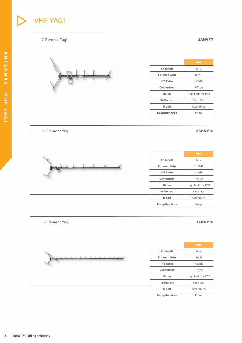
10 Element Yagi 2ANVY10
7 Element Yagi 2ANVY7
VHF
Channels 6-12
Forward Gain 8.8dB
F/B Ratio >16dB
Connection F-Type
Balun High Perform. PCB
Reflectors Snap Out
U bolt Assembled
Reception Area Prime
VHF
Channels 6-12
Forward Gain 11-12dB
F/B Ratio >16dB
Connection F-Type
Balun High Perform. PCB
Reflectors Snap Out
U bolt Assembled
Reception Area Fringe
18 Element Yagi 2ANVY18
VHF
Channels 6-12
Forward Gain 14dB
F/B Ratio >20dB
Connection F-Type
Balun High Perform. PCB
Reflectors Snap Out
U bolt Assembled
Reception Area Prime

AN
TE
NN
AS
-
V
HF
AN
TE
NN
AS
-
U
HF
AN
TE
NN
AS
-
V
HF
L
OG
P
ER
IO
DI
C
VHF LOG PERIODIC
23
8 Element Log Periodic 2ANV2WB
VHF
Channels 0-12
Forward Gain 4-8dB
F/B Ratio >12dB
Connection F-Type
Balun High Perform. PCB
Reflectors None
U bolt Assembled
Reception Area Prime
9 Element Log Periodic 2ANV3WB
VHF
Channels 0-12
Forward Gain 5-11dB
F/B Ratio >15dB
Connection F-Type
Balun High Perform. PCB
Reflectors None
U bolt Assembled
Reception Area Fringe
12 Element Log Periodic 2ANV4WB
VHF
Channels 0-12
Forward Gain 6-12dB
F/B Ratio >15dB
Connection F-Type
Balun High Perform. PCB
Reflectors None
U bolt Assembled
Reception Area Outer Fringe

AN
TE
NN
AS
-
V
HF
P
HA
SE
D
AR
RA
Y
VHF PHASED ARRAY
Clipsal TV Cabling Solutions 24
8 Element Phased Array 2ANVPA1
VHF
Channels 6-12
Forward Gain 7-9.5dB
F/B Ratio >16dB
Connection F-Type
Balun None
Reflectors None
U bolt Assembled
Reception Area Prime/Fringe
16 Element Phased Array 2ANVPA2
VHF
Channels 6-12
Forward Gain 12dB
F/B Ratio >16dB
Connection F-Type
Balun None
Reflectors None
U bolt Assembled
Reception Area Fringe/Outer Fringe

AN
TE
NN
AS
-
F
M
FM
25
3 Element FM 2ANFM3
VHF
Channels 88-108Mhz
Forward Gain 5dB
F/B Ratio >15dB
Connection F-Type
Balun High Perform. PCB
Reflectors None
U bolt Assembled
Reception Area Prime
8 Element FM 2ANFM8
VHF
Channels 88-108Mhz
Forward Gain 10dB
F/B Ratio >17dB
Connection F-Type
Balun High Perform. PCB
Reflectors None
U bolt Assembled
Reception Area Fringe/Outer Fringe

26
MO
UN
TI
NG
A
CC
ES
SO
RI
ES
Clipsal TV Cabling Solutions
Curved Fascia Brackets
1.2m used for smaller antennas - 2ANCFB12
1.5m used for small to medium antennas - 2ANCFB15
1.8m used for small to medium antennas - 2ANCFB18
1.5m used for larger antennas - 2ANCFBHD
• Mounted to the fascia or wall
• Generally used when height of the antenna is not a issue
• Used for small to medium sized antennas
• Stay bars can be used to support the antenna if required.
Curved Fascia Brackets

27
MO
UN
TI
NG
A
CC
ES
SO
RI
ES
Stay Bars
All stay bars require a stay bar collar for mounting.
One end of the stay bar is fixed to the stay bar collar.
The other end of the stay bar is fixed to the roof.
(Drill through tile to screw to baton for tiled roof)
Used to support • Antenna mounts • Curved fascia brackets • Tripod roof mounts • Rafter mounts • Masts.
Stay bar set of 2 x 1200mm (4 foot) - 2ANSB4
Stay bar set of 2 x 1800mm (6 foot) - 2ANSB6
Stay bar set of 2 x 2400mm (8 foot) - 2ANSB8
Stay bar collar - 2ANSBC
Stay Bar Collar
Stay Bar

28
MO
UN
TI
NG
A
CC
ES
SO
RI
ES
Clipsal TV Cabling Solutions
Tripod Roof Mounts
Tripod Roof Mount - METAL - 2ANTRPMTripod Roof Mount - TILE - 2ANTRPT
The easiest way to mount an antenna
2ANTRPT
• Drill through tile to baton for fixing with appropriate anchors • Bend the supports to adjust for any roof angle
2ANTRPM
• Use existing roof screws to fix mount in place • Bend the supports to adjust for any roof angle
29
MO
UN
TI
NG
A
CC
ES
SO
RI
ES
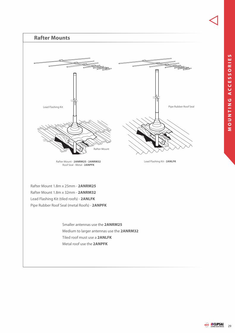
Rafter Mounts
Rafter Mount 1.8m x 25mm - 2ANRM25
Rafter Mount 1.8m x 32mm - 2ANRM32
Lead Flashing Kit (tiled roofs) - 2ANLFK
Pipe Rubber Roof Seal (metal Roofs) - 2ANPFK
Smaller antennas use the 2ANRM25
Medium to larger antennas use the 2ANRM32
Tiled roof must use a 2ANLFK
Metal roof use the 2ANPFK
Rafter Mount
Rafter Mount - 2ANRM25 - 2ANRM32
Roof Seal - Metal - 2ANPFK
Lead Flashing Kit
Lead Flashing Kit - 2ANLFK
Pipe Rubber Roof Seal

30
MO
UN
TI
NG
A
CC
ES
SO
RI
ES
Clipsal TV Cabling Solutions
Wall Mounts/Masts
Wall Mount 230mm (9inch) - 2ANWB09
Wall Mount 280mm (11inch) - 2ANWB11
Wall Mount 690mm (27inch) - 2ANWB27
Wall Mount 1020mm (40inch) - 2ANWB40
Wall Mount 1400mm (55inch) - 2ANWB55
Wall Mount kit (2ANWB9 + 2ANWB27) - 2ANWB17K
Mast 3.0m x 32mm - 2ANGM3032
Mast 4.5m x 32mm - 2ANGM4532
Mast 4.5m x 38mm - 2ANGM4538
V Block offset (used to mount horizontal and vertical poles together) 2ANVBO
Bolt for V Block - 2ANVB
Mast
Used to gain extra height required for better TV reception
Mast extensions available for extra height if required.
V Block offset
Wall Mount

31
MO
UN
TI
NG
A
CC
ES
SO
RI
ES
Used to mount an antenna vertically
All antennas mounted vertically need a stand off bracket
If a stand off bracket is not used signal problems may be encountered.
Vertical Stand Off Bracket
Vertical Stand off Bracket 375mm (15 inch) - 2ANVB15
Vertical Stand off Bracket
All vertically mounted antennas will require a 2ANVB15 bracket.

32
MO
UN
TI
NG
A
CC
ES
SO
RI
ES
Clipsal TV Cabling Solutions
Guy Wire Fixing
2ANGC
Guy Wire Bracket/Cleat
2ANIRM
Iron Roof Mount
Guy ring plate
Lock ringcollar
Guy Wire
Mast
C
ket/Cleat
Turnbuckle
2ANTBS
Thimble
2ANGWC
Guy WireClamp/Grip

33
MO
UN
TI
NG
A
CC
ES
SO
RI
ES
Guy Wire Fixing
Guy Wire 180m reel -2ANGWR
Guy Wire Spool (Coiled) - 2ANGW
Guy ring plate x 32mm (suites 32mm mast) - 2ANGR32
Guy ring plate x 38mm (suites 38mm mast) - 2ANGR38
Lock ring collar x 32mm (suites 32mm mast) - 2ANLR32
Lock ring collar x 38mm (suites 38mm mast) - 2ANLR38
Guy Wire Cleat - 2ANGC
Guy Wire Clamp - 2ANGWC
Turnbuckle x 6mm (1/4 inch) - 2ANTBK6
Turnbuckle x 8mm (5/16 inch) - 2ANTBK8
Thimble - 2ANTBS
Mast Extension
Mount fixing points on roof 3m from base of mast
Mount guy ring 3m above the base of the mast for 4.5m masts
Mount guy ring 2.5m above the base of the mast for 3m masts
Use thimbles to stop the guy wire rubbing against the mount
Use turnbuckles to tighten the guy wire.

34
MO
UN
TI
NG
A
CC
ES
SO
RI
ES
Clipsal TV Cabling Solutions
Mast Extension - 2ANME
Mast Extension Kit - 2ANMEK
Mast 3.0m x 32mm - 2ANGM3032
Mast 4.5m x 32mm - 2ANGM4532
Mast 4.5m x 38mm - 2ANGM4538
V Block offset (used to mount horizontal and vertical poles together) - 2ANVBO
Mast Extensions
Mast
V Block offset
Wall Mounts/Masts
Used to get extra height required for better TV reception
May require some form of support • Guy wire support • Stay bar support

35
MO
UN
TI
NG
A
CC
ES
SO
RI
ES
V Block clamps two poles together such as a mast to a wall/eave bracket.
Mast Extension Kit
Mast Extension
Mast Extension- 2ANME
Mast Extension Kit - 2ANMEK

36
MO
UN
TI
NG
A
CC
ES
SO
RI
ES
Clipsal TV Cabling Solutions
Flat Wall Mount
Metal Fascia
Mast
Wall Bracket
Flat Wall Mount Bracket - 2ANFWM
Metal Fascia - 2ANMFB

37
MO
UN
TI
NG
A
CC
ES
SO
RI
ES
V Block clamps at 90 degrees to the mast. This is ideal for horizontal mounting of antennas.
2ANVB
Block
2ANUBM or 2ANUBL
U Mount
V Block
V Offset Block
V Block - 2ANVB
U Bolt 5 inches - 2ANUBM
U Bolt 7 inches - 2ANUBL
V Offset Block - 2ANVBO
U Bolt 5 inches - 2ANUBM
U Bolt 7 inches - 2ANUBL

SP
LI
TT
ER
S
38 Clipsal TV Cabling Solutions
Losses VHF 46-470MHz <3.5dB
Losses UHF 471-860MHz <4.4dB
Power Pass 1 port
Connection Type F-Type
Mounting Holes 2
Earthing Connection 1
2 Way Terrestrial Splitter 5-1000MHz 3105SPF2
Losses VHF 46-470MHz <6.1dB
Losses UHF 471-860MHz <6.3dB
Power Pass 1 port
Connection Type F-Type
Mounting Holes 2
Earthing Connection 1
3 Way Terrestrial Splitter 5-1000MHz 3105SPF3
Losses VHF 46-470MHz <7.5dB
Losses UHF 471-860MHz <7.8dB
Power Pass 1 port
Connection Type F-Type
Mounting Holes 2
Earthing Connection 1
4 Way Terrestrial Splitter 5-1000MHz 3105SPF4
Not suitable for Satellite Television Transmission
Not suitable for Satellite Television Transmission
Not suitable for Satellite Television Transmission

SP
LI
TT
ER
S
39
Losses VHF 46-470MHz <10.2dB
Losses UHF 471-860MHz <10.7dB
Power Pass 1 port
Connection Type F-Type
Mounting Holes 2
Earthing Connection 1
6 Way Terrestrial Splitter 5-1000MHz 3105SPF6
Losses VHF 46-470MHz <11.2dB
Losses UHF 471-860MHz <11.8dB
Power Pass 1 port
Connection Type F-Type
Mounting Holes 2
Earthing Connection 1
8 Way Terrestrial Splitter 5-1000MHz 3105SPF8
Not suitable for Satellite Television Transmission
Not suitable for Satellite Television Transmission
70dB
54dBuV
11.8dB Splitter Loss
4.2dB 20m Cable Loss
Power Pass
Power Pass
Only UHF losses are shown for illustration purposes

SP
LI
TT
ER
S
40 Clipsal TV Cabling Solutions
Frequency Range37-860Mhz
All Free to Air Channels
Output Ports 4
Input Ports1x Antenna Input
1x Modulated Input
Power Supply 12VDC
3 Power Options
·Local·Remote via Modulator
·Remote via Power Injector
Variable Gain Control
Antenna Input only +3dB Gain
-15dB Attenuation
IR Pass Back No
IR Expansion Port No
Powered Splitter 37-860MHz 3105VDU24T
Powered Splitter 37-860MHz 3105VDU38IRT
Frequency Range37-860Mhz
All Free to Air Channels
Output Ports 8
Input Ports1x Antenna Input
2x Modulated Inputs
Power Supply 12VDC
3 Power Options
·Local·Remote via Modulator
·Remote via Power Injector
Variable Gain Control
Antenna Input only +3dB Gain
-15dB Attenuation
IR Pass Back Yes
IR Expansion Port Yes
70dB
67.8dBuV
Gain Control + 2dB
4.2dB
20m Cable Loss
72dB

SP
LI
TT
ER
S
41
6 Way Powered Splitter 37-860MHz 8072/6VHP
Frequency Range37-860Mhz
All Free to Air Channels
Output Ports 6
Input Ports1x Antenna Input
1x Modulated Input
Power Supply 12VDC
3 Power Options
·Local·Remote via Modulator
·Remote via Power Injector
Variable Gain Control
Antenna Input only +3dB Gain
-15dB Attenuation
IR Pass Back No
IR Expansion Port No
Frequency Range37-860Mhz
All Free to Air Channels
Output Ports 8
Input Ports1x Antenna Input
2x Modulated Inputs
Power Supply 12VDC
3 Power Options
·Local·Remote via Modulator
·Remote via Power Injector
Variable Gain Control
Antenna Input only +3dB Gain
-15dB Attenuation
IR Pass Back Yes
IR Expansion Port Yes
8 Way Powered Splitter 37-860MHz 8073/8VHPIR
70dB
67.8dBuV
Gain Control + 2dB4.2dB
20m Cable Loss
72dB

SP
LI
TT
ER
S
42 Clipsal TV Cabling Solutions
Losses 40-1000MHz <4.6dB
Losses 1000-1750MHz <5.3dB
Losses 1751-2050MHz <6.3dB
Power Pass All ports
Connection Type F-Type
Mounting Holes 2
Earthing Connection 1
Approval Number
Foxtel F10082/C
Austar A01564
Select TV N/A
2 Way Satellite Splitter 5-2400MHz 3105SPFP2
3 Way Satellite Splitter 5-2400MHz 3105SPFP3
4 Way Satellite Splitter 5-2400MHz 3105SPFP4
Losses 40-1000MHz <7.5dB
Losses 1000-1750MHz <9dB
Losses 1751-2050MHz <11.5dB
Power Pass All ports
Connection Type F-Type
Mounting Holes 2
Earthing Connection 1
Approval Number
Foxtel F10082/C
Austar N/A
Select TV N/A
Losses 40-1000MHz <8.5dB
Losses 1000-1750MHz <10.5dB
Losses 1751-2050MHz <11.5dB
Power Pass All ports
Connection Type F-Type
Mounting Holes 2
Earthing Connection 1
Approval Number
Foxtel F10082/C
Austar A01592
Select TV N/A

DI
PL
EX
ER
S
43
Indoor Diplexer 3105DPUV
Outdoor Diplexer 3105DPOUV
Diplexers combine TV signals from 2 antennas through 1 coax cable.

44
DR
OP
T
AP
S
Clipsal TV Cabling Solutions
3105T1/10 3105T1/12 3105T1/15 3105T1/20
Tap Loss 10dB 12dB 15dB 20dB
Through Loss 5-950MHz <2dB <1.9dB <1.3dB <0.9dB
Through Loss 951-2400MHz <3dB <2.7dB <2.2dB <1.7dB
Power Pass 1 Port 1 Port 1 Port 1 Port
Connection Type F-Type F-Type F-Type F-Type
Mounting Holes 2 2 2 2
Earthing Connection 1 1 1 1
Approval Number
Foxtel F10082-85/C F10082-85/C F10082-85/C F10082-85/C
Austar A01536 A01537 A01538 A01539
Select TV Yes Yes Yes Yes
1 Way Drop Tap 5-2400MHz 3105T1/XX
2 Way Drop Tap 5-2400MHz 3105T2/XX
3105T2/10 3105T2/12 3105T2/15 3105T2/20
Tap Loss 10dB 12dB 15dB 20dB
Through Loss 5-950MHz <2dB <1.9dB <1.5dB <1dB
Through Loss 951-2400MHz <3dB <2.7dB <2.3dB <1.9dB
Power Pass 1 Port 1 Port 1 Port 1 Port
Connection Type F-Type F-Type F-Type F-Type
Mounting Holes 2 2 2 2
Earthing Connection 1 1 1 1
Approval Number
Foxtel F10082-85/C F10082-85/C F10082-85/C F10082-85/C
Austar N/A A01541 A01542 A01543
Select TV Yes Yes Yes Yes
3105T4/10 3105T4/12 3105T4/15 3105T4/20
Tap Loss 10dB 12dB 15dB 20dB
Through Loss 5-950MHz <6.5dB <4dB <3dB <1.8dB
Through Loss 951-2400MHz <9dB <4.5dB <4.1dB <1.1dB
Power Pass 1 Port 1 Port 1 Port 1 Port
Connection Type F-Type F-Type F-Type F-Type
Mounting Holes 2 2 2 2
Earthing Connection 1 1 1 1
Approval Number
Foxtel F10082-85/C F10082-85/C F10082-85/C F10082-85/C
Austar A01544 N/A A01545 A01546
Select TV Yes Yes Yes Yes
4 Way Drop Tap 5-2400MHz 3105T4/XX

DR
OP
T
AP
S
45
75 Ohm Terminator 3105FTER
All unused ports of a Drop Tap or Splitter should be terminated with a 75 Ohm Terminator to stop electrical reflections interfering with TVs connected to the system.
Pack of 10.

46
CO
AX
IA
L
CA
BL
E
-
RG
6
RG6
Clipsal TV Cabling Solutions
RG6 Coaxial Tri Shield Cable
Conductor Size (mm) AWG Cond. Type Shield Type Nom. O.D
(mm)Insl. & Core O.D (mm)
1.02 0.03 18 Solid 60% Aluminium Braids 7.06 0.02 4.78 0.13
3105RG6T3B
Catalogue Number Description Pack Size Foxtel
Approval No.Austar
Approval No.
3105RG6T3B RG6 Coax Tri Shield Box 305m Box F10176 N/A
5MHz 55MHz 211MHz 250MHz 270MHz 300MHz 330MHz 350MHz 400MHz 450MHz 500MHz 550MHz 600MHz 750MHz 870MHz 1000MHz 1450MHz 1750MHz 2050MHz
1.90 5.25 10.00 10.82 11.04 11.64 12.26 12.63 13.61 14.43 15.29 16.08 16.73 18.54 20.04 21.49 26.25 28.67 31.04
Attenuation @ 20˚C (dB/100m)
+_ +_ +_
AWG Conductor
PVC Jacket
Gas injected Foam
Aluminium Braid
Foil Tape

CO
AX
IA
L
CA
BL
E
RG6
47
Conductor Size (mm) AWG Cond. Type Shield Type Nom. O.D
(mm)Insl. & Core O.D (mm)
1.02 0.03 18 SolidBCCS
60% & 40% Aluminium
Braids7.54 0.02 4.78 0.13
Catalogue Number Description Pack Size Foxtel
Approval No.Austar
Approval No.
3105RG6Q3R RG6 Coax Quad Shield 305m Reel F10129 P07982
3105RG6Q3B RG6 Coax Quad Shield 305m Box F10129 P07982
3105RG6Q1R RG6 Coax Quad Shield Box 100m Reel F10129 P07982
3105RG6Q3RF RG6 Coax Quad Shield Flooded 305m Reel F30059 P07985
3105RG6QS15R RG6 Coax Quad Shield Siamese 152.5m Reel F30432 P07984
RG6 Coaxial Quad Shield Cable
5MHz 55MHz 211MHz 250MHz 270MHz 300MHz 330MHz 350MHz 400MHz 450MHz 500MHz 550MHz 600MHz 750MHz 870MHz 1000MHz 1450MHz 1750MHz 2050MHz
1.90 5.25 10.00 10.82 11.04 11.64 12.26 12.63 13.61 14.43 15.29 16.08 16.73 18.54 20.04 21.49 26.25 28.67 31.04
Attenuation @ 20˚C (dB/100m)
+_ +_ +_
Siamese Quad Shield
3105RG6Qxxx

CO
AX
IA
L
CA
BL
E
-
RG
11
RG11
48 Clipsal TV Cabling Solutions
Conductor Size (mm) AWG Cond. Type Shield Type Reel Length
(m)Nom. O.D
(mm)Insl. & Core O.D (mm)
1.63 0.03 14 Solid BCCS 60% & 40% Aluminium Braids 305 10.34 0.25 7.32 0.15
Catalogue Number Description Pack Size Foxtel
Approval No.Austar
Approval No.
3105RG11Q3R RG11 Coax Quad Shield Reel 305m Reel F10175 A02629
3105RG11Q3RF RG11 Coax Quad Shield Flooded Reel 305m Reel F30060 P07986
RG11 Coaxial Quad Shield Cable 3105RG11Q3R, 3105RG11Q3RF
5MHz 55MHz 211MHz 250MHz 270MHz 300MHz 330MHz 350MHz 400MHz 450MHz 500MHz 550MHz 600MHz 750MHz 870MHz 1000MHz 1300MHz 1550MHz 1770MHz 2150MHz
1.25 3.15 6.23 6.72 7.00 7.38 7.71 7.94 8.53 9.02 9.51 9.97 10.43 11.97 13.31 14.27 16.00 17.42 19.58 21.61
Attenuation @ 20˚C (dB/100m)
+_ +_ +_

CO
AX
IA
L
CA
BL
E
RG
59
RG59
49
RG59 Coaxial Dual Shield Cable
Conductor Size (mm) AWG Cond. Type Shield Type Nom. O.D
(mm)Insl. & Core O.D
(mm)
0.81 1 20 Solid BCCS 60% Aluminium Braids 6.10 0.2 3.86 0.13
3105RG59D1R, 3105RG59D3B
Catalogue Number Description Pack Size Foxtel
Approval No.Austar
Approval No.
3105RG59D1R RG59 Coax Dual Shield 100m Reel N/A N/A
3105RG59D3B RG59 Coax Dual Shield Box 305m Box N/A N/A
5MHz 55MHz 211MHz 250MHz 270MHz 300MHz 330MHz 350MHz 400MHz 450MHz 500MHz 550MHz 600MHz 750MHz 870MHz 1000MHz
2.82 6.73 12.47 13.45 13.85 14.6 15.29 15.75 16.73 17.72 18.70 19.52 20.34 22.87 24.85 26.64
Attenuation @ 20˚C (dB/100m)
+_ +_ +_

50
CO
AX
IA
L
CA
BL
E
CO
NN
EC
TO
RS
RG6 COMPRESSION
Clipsal TV Cabling Solutions
RG6 Compression Tool 3105CT611C
Easy to use
Swivel Head for RG6 and RG11
For use with the following connectors:
3105RG6FC50 - RG6 (Packet of 50)
3105RG11FC2 - RG11 (Packet of 2)
RG6 Compression Connector 3105RG6FC50
3105RG6FC50 (Packet of 50)
Approval Number
Foxtel F30029
Austar A06948
Select TV Not Required
RG6 & RG59 Cable Stripper
Easy to use - Termination techniques on pages 54-55
Suits RG6 and RG59 cables
3105CS6

CO
AX
IA
L
CA
BL
E
CO
NN
EC
TO
RS
RG11 COMPRESSION
51
RG11 Compression Tool 3105CT611C
Easy to use
Swivel Head for RG6 and RG11
For use with the following connectors:
3105RG6FC50 - RG6
3105RG11FC2 - RG11
RG11 Compression Connector 3105RG11FC2
3105RG11FC2 (Packet of 2)
Approval Number
Foxtel F30360
Austar A06949
Select TV Not Required
RG11 Cable Stripper 3105CS11
Easy to use
Suits RG11 Coax Cables
Easy t
Swive
For us
3105R
3105
Fox
Aus
Sele
RG11 Cable Stripper

CO
AX
IA
L
CA
BL
E
CO
NN
EC
TO
RS
RG6 RADIAL CRIMP
52 Clipsal TV Cabling Solutions
RG6 Radial Crimp Tool 3105CT611
RG6 Crimp Connector 3105RG6F
3105CS6RG6 Cable Stripper
Easy to use
For use with the following connectors:
3105RG59F, 3105BNC6, 3105BNC59
3105RG6F, 3105RG6PM, 3105RG6PF
Easy to use
Suits RG6 and RG59 Cables
3105RG6F (Packet of 10)
For use with Radial Crimp Tool
Approval Number
Foxtel F10179/C
Austar A01509
Select TV Not Required

CO
AX
IA
L
CA
BL
E
CO
NN
EC
TO
RS
RG59 RADIAL CRIMP
53
RG59 Radial Crimp Tool 3105CT611
RG59 Compression Connector 3105RG59F
3105CS6RG59 Cable Stripper
Easy to use
For use with the following connectors:
3105RG59F, 3105BNC6, 3105BNC59
3105RG6F, 3105RG6PM, 3105RG6PF
3105RG59F
Packet of 10
For use with radial Crimp Tool
Easy to use
Suits RG6 and RG59 Cables

IN
ST
AL
LA
TI
ON
T
IP
S
Clipsal TV Cabling Solutions 54
Do’s and Don’ts
Insert coax cable into the stripping tool with the end of the coax level with the lip on the right hand side. Hold the cable close to the tool and spin around a few times. Not enough spins of the stripping tool will leave the coax jacket on and too many spins will cut away
the shielding. Hold the stripping tool by the jaws and pull away from cable without opening the jaws of the stripping tool. The stripped cable will look like the following diagram.
Fold back the first braid then fold back the first foil. Fold back the second braid but DO NOT remove the last foil as this is bonded to the Dielectric. Fold back braid and foil evenly in each direction to ensure the connector slides on easily. A good preparation should look like the following diagram.

IN
ST
AL
LA
TI
ON
T
IP
S
55
A connector slid on at an angle will result in the cable looking like the following diagram.
Once the connector has been installed correctly only then should you use the tool to terminate.
Do’s and Don’ts
Once the connector has been installed correctly only
bl l king like the follow
Slide the connector on straight. DO NOT slide connector at an angle because it will damage the cable. Look at the front of the connector. If
the cable is damaged then remove the connector and start again. DO NOT terminate connector.
Slide the cable up to the base of the connector. A good termination should be level with the base of the connector.
When the cable is inside the connector it will look like the following diagram.

56
IN
ST
AL
LA
TI
ON
T
OO
LS
Clipsal TV Cabling Solutions
Digital Terrestrial Meter 2ANDTM
Features and Benefits
Displays RF level and post BER together with S/N on large display in real time. Run time in excess of five hours on a full charge. Built-in charger with rechargeable NiMH battery.
Specifications
VHF 6-12 UHF 21-69
VHF Band 3 and UHF e.g. 167-862 MHz 7 M Bandwidth
Automatic Constellation and transmitter offset
C/N up to 32dB in 0.5dB steps accuracy +-1dB
RF level 25dBuV to 75dBuV accuracy +-1dB over all bandwidth and under indication
Input range -72dBm-20dBm
Charger 100-240V Ac or 12V Dc
Battery 2.4 Ah NiMH 7.2V 6 cell
BCN - PAL + BCN F-Type adaptors included
2x 10dB attenuators included
This meter is a Digital Field Strength Meter and will not measure any channel below VHF 6.
57
IN
ST
AL
LA
TI
ON
T
OO
LS
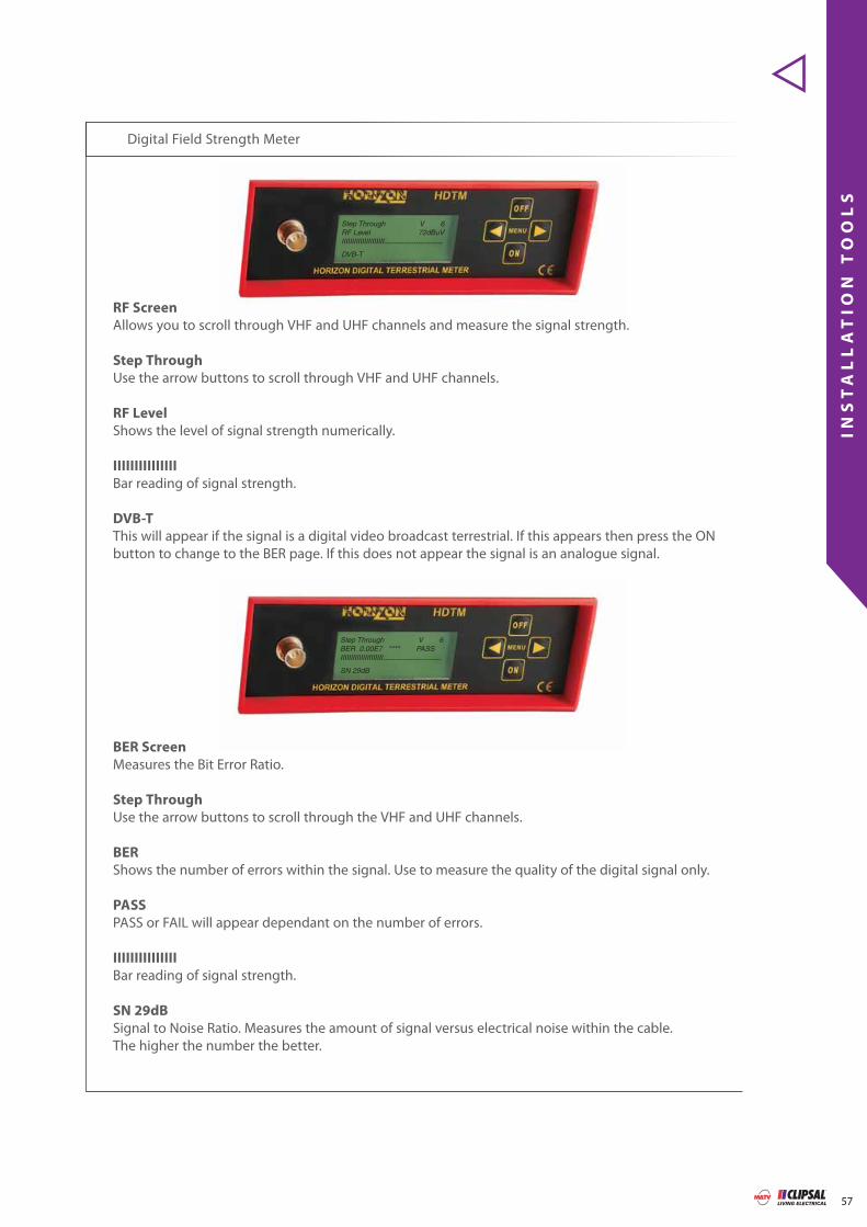
Digital Field Strength Meter
RF Screen
Allows you to scroll through VHF and UHF channels and measure the signal strength.
Step Through
Use the arrow buttons to scroll through VHF and UHF channels.
RF Level
Shows the level of signal strength numerically.
IIIIIIIIIIIIIII
Bar reading of signal strength.
DVB-T
This will appear if the signal is a digital video broadcast terrestrial. If this appears then press the ON button to change to the BER page. If this does not appear the signal is an analogue signal.
BER Screen
Measures the Bit Error Ratio.
Step Through
Use the arrow buttons to scroll through the VHF and UHF channels.
BER
Shows the number of errors within the signal. Use to measure the quality of the digital signal only.
PASS
PASS or FAIL will appear dependant on the number of errors.
IIIIIIIIIIIIIII
Bar reading of signal strength.
SN 29dB
Signal to Noise Ratio. Measures the amount of signal versus electrical noise within the cable. The higher the number the better.
oll through VHF and UHF channels and measure the signal strength
Step Through V 6RF Level 72dBuVIIIIIIIIIIIIIIIIIIIII------------------------
DVB-T
Step Through V 6BER 0.00E7 **** PASSIIIIIIIIIIIIIIIIIIIII------------------------
SN 29dB

58
IN
ST
AL
LA
TI
ON
T
OO
LS
Clipsal TV Cabling Solutions
Clipsal Australia have provided a MATV tool box that has the essentials required to carry out MATV installations. Refer to chart below for the great range of products included.
MATV Tool Box 3105TOOLBOX
Product Cat No. Qty.
Compression Tool 3105CT611C 1
Hex Crimp Tool 3105CT611C 1
Coax Cable Stripper 3105CS6 1
Hex Nut Spanner - 1
Coax Cable Cutters - 1
UTP Cable Stripper - 1
2 Way Splitter Terrestrial 3105SPF2 4
3 Way Splitter Terrestrial 3105SPF3 4
4 Way Splitter Terrestrial 3105SPF4 4
2 Way Splitter Satellite 3105SPFP2 4
3 Way Splitter Satellite 3105SPFP3 4
4 Way Splitter Satellite 3105SPFP4 4
F-Type Compression Connectors 3105RG6FC50 50 Connectors
F-Type Radial Crimp Connectors 3105RG6F 50 Connectors
PAL Crimp Connectors 3105RG6PM 50 Connectors
F-Type to F-Type Adaptors - 20 Adaptors
Cat No. Qty.
3105CT611C 1

MA
TV
A
DA
PT
OR
S
59
Right Angle Adaptor 3105FF-FMRA
Wall mounted Plasma/LCD scenariowith right angle adaptor.
Wall cavity
40 mm
20mm
Rated to 3GHzPack of 10Foxtel approval number: F30356
Wall cavity
40 mm
20mm

F-TYPE ADAPTORS
MA
TV
A
DA
PT
OR
S
-
F-
TY
PE
60 Clipsal TV Cabling Solutions
F-Type to RCA Adaptor 3105FF-RCA
F-Type to RCA Adaptor 3105FF-BNC
F-Type Female to Female Coax Joiner 3105FF-FF
Pack of 1
Pack of 1
Pack of 10

F-TYPE TO PAL ADAPTORS
MA
TV
A
DA
PT
OR
S
-
F-
TY
PE
T
O
PA
L
61
F-Type Female to PAL Male Adaptor 3105PM-FF
F-Type Female to PAL Female Adaptor 3105PF-FF
F-Type Male to PAL Female Adaptor 3105PF-FM
Pack of 10
Pack of 10
Pack of 10

PAL ADAPTORS
MA
TV
A
DA
PT
OR
S
-
PA
L
62 Clipsal TV Cabling Solutions
PAL Male to PAL Male 3105PM-PM
PAL Female to PAL Female Adaptor 3105PF-PF
Pack of 10
Pack of 10

FL
Y
LE
AD
S
63
F-type to PAL Male Fly Lead - RG6 Quad Shield Black 1.8m 3105FL318MBQ
F-type to PAL Male Fly Lead - RG6 Quad Shield White 1.8m 3105FL318MWQ
PAL Male to PAL Male - RG59 white 1.8m 3105FL118MW
PAL Male to PAL Male - RG59 white 5m 3105FL150MW
PAL Male to PAL Female - RG59 white 1.8m 3105FL118FW

64
FL
Y
LE
AD
S
Clipsal TV Cabling Solutions
Scart - 6 RCA Lead 1.8m 3105SC-6RCA
3RCA to 3RCA Lead 1.8m 3105AVL318
Scart - Scart Lead 1.8m 3105SC-SC
3RCA to 3RCA High Quality Lead 1.8m 3105AVL318HQ

TV
M
EC
HS
65
F-Type to PAL TV Outlet Straight 30FFPFMS
F-Type to F-Type TV Outlet 30PFM
F-Type to PAL TV Outlet Angled 30TV75MF
F-Type to PAL TV Outlet AC Isolation 30TV75MACF
Screw Termination to PAL 30TV75MS
To be released late 2007.Not suitable for satellite TV applications
Pay TV approved outlet rated to 3GHz.Foxtel approval number: G135
Not suitable for satellite TV applications
Not suitable for satellite TV applications
Not suitable for satellite TV applications

WA
LL
P
LA
TE
S
66 Clipsal TV Cabling Solutions
Single Gang Wall Plate
This wall plate contains the Clipsal 30PFM TV Mech
C2000 Series C2031/1F
2000 Series 2031/1F
Single Gang Wall Plate
This wall plate contains the Clipsal 30TV75MF TV MechScrew style
Single Gang Wall Plate
This wall plate contains the Clipsal 30TV75MS TV Mech
C2000 Series C2031VTV75
2000 Series 2031VTV75
C2000 Series C2031VTV75F
2000 Series 2031VTV75F
C2031/1F
2031VTV75F
2031VTV75

WA
LL
P
LA
TE
S
67
StarServe Wall Plate
This wall plate is the minimum requirement for Star Serve main entertainment areas.
This wall plate can be made up of the following Clipsal products:
3x 30PFM F-Type TV Mech1x C2033VH 3 Gang Wall Plate
C2033/3F
2033/3F
StarServe Wall PlateC2034RJA5/3F
2034RJA5/3F
StarServe Wall PlateC2034RJA5/2F
2034RJA5/2F
This wall plate can be made up of the following Clipsal products:
3x 30PFM F-Type TV Mech1x 30RJ88SMA5 Cat 5e data outlets1x C2034VH 4 Gang Wall Plate
This smart wired wall plate can be made up of the following Clipsal products:
2x 30PFM F-Type TV Mech2x 30RJ88SMA5 Cat 5e data outlets1x C2034VH 4 Gang Wall Plate
C2033/3F
C2034RJA5/3F
C2034RJA5/2F

WA
LL
P
LA
TE
S
68 Clipsal TV Cabling Solutions
StarServe Wall PlateC032RJA5/1F
2032RJA5/1F
StarServe Wall PlateC033RJA5/1F
2033RJA5/1F
StarServe Wall Plate
This wall plate is ideal for the study.This wall plate can be made up of the following Clipsal products:
1x 30PFM F-Type TV Mech3x 30RJ88SMA5 Cat 5e data outlets1x C2034VH 4 Gang Wall Plate
C034RJA5/1F
2034RJA5/1F
Suggested minimum cabling to all bedrooms.This wall plate can be made up of the following Clipsal products:
1x 30PFM F-Type TV Mech1x 30RJ88SMA5 Cat 5e data outlets1x C2032VH 2 Gang Wall Plate
Suggested minimum cabling to all bedrooms.This wall plate can be made up of the following Clipsal products:
1x 30PFM F-Type TV Mech2x 30RJ88SMA5 Cat 5e data outlets1x C2033VH 3 Gang Wall Plate
C032RJA5/1F
C033RJA5/1F
C034RJA5/1F

69
LO
CA
TI
ON
G
UI
DE
S
ADELAIDE
Virginia
Brighton
Port Noarlunga
Hahndorf
Stirling
Glenelg
Elizabeth
Morphett Vale
Hallett CoveCherry Gardens
ReynellaClarendon
Ethelton
Outer Harbour
St Kilda
Malvern
Skye
Enfield
Paradise
Houghton
Penfield
Parafield
Salisbury
Port Adelaide
Marino
Largs Bay
Woodside
Lynton
One Tree Hill
Greenwith
Montacute
Upper Hermitage
WilliamstownYattalunga
Port Gawler
McLaren Vale
The RangeMaslin Beach
Lobethal
Echunga
Adelaide
2ANCOM3
2ANCOM4 or2ANCOM6
2AN 2ANUY12WB or 2ANUY20WB
(Multiple Outlets)
2ANV2WB +
2ANUY12WB
(Requires Diplexerrefer to page 43)

70
LO
CA
TI
ON
G
UI
DE
S
Clipsal TV Cabling Solutions
MELBOURNE
2ANCOM3
2ANCOM4
2ANUPA2
2ANUY18/5

71
LO
CA
TI
ON
G
UI
DE
S
SYDNEY
2ANCOM3
Inner city Kings Cross translator line-of-sight use
2ANUPA1 or 2ANUX43
2ANCOM4 or 2ANYV10 +2ANUY20WB
(Requires Diplexer refer to page 43)
2ANCOM6 or2ANVY10 + 2ANUX91
(Requires Diplexer refer to page 43)
2ANUY20WB
2ANUPA2

72
LO
CA
TI
ON
G
UI
DE
S
Clipsal TV Cabling Solutions
NEWCASTLE
2ANCOMD14WB
2ANCOMD14WB
+ Masthead Amplifier
2ANCOM2NEW
For Nelson Bay,call Clipsal for options
2ANUY12WB
2ANUY20WB
2ANUPA2

73
LO
CA
TI
ON
G
UI
DE
S
BRISBANE
2ANCOM3
2ANCOM4
2ANCOM6

74
LO
CA
TI
ON
G
UI
DE
S
Clipsal TV Cabling Solutions
SOUTH QUEENSLAND
2ANCOM3 or
2ANCOM4
(Multiple Outlets)
2ANUY12WB or2ANUY20WB
(Multiple Outlets)
2ANUPA2
2ANCOMD14WB or2ANVY10 + 2ANUY20WB
(Requires Diplexer refer to page 43)

75
LO
CA
TI
ON
G
UI
DE
S
PerthPerth
Two Rocks
Bullsbrook
Chidlow
Quinns Rocks
Joondalup
Scarborough
Red HillMalaga
Piesse Brook
Kalamunda Reservoir
Canning Mills
Garden Island
Mt ClaremontPeppermint Grove
Cardup
Oldbury
DawesvilleBlythewood
Wungong
Fremantle
Rockingham
Mandurah
Midland
PERTH
2ANCOM3
2ANCOM4
2ANCOM6

© Clipsal Australia Pty Ltd.
You can fi nd this brochure and many others online in PDF format at: clipsal.comFollow the links off the home page or access the following page directly: clipsal.com/wat_lib_pdf.cfm
Clipsal Australia Pty Ltd reserves the right to change specifi cations, modify designs and dis con tin ue items without incurring obligation and whilst every effort is made to ensure that descriptions, specifi cations and other in for ma tion in this catalogue are correct, no warranty is given in respect thereof and the company shall not be liable for any error therein.
D2-
004
Product of Clipsal Australia Pty LtdA member of the Schneider Electric Group
Head Offi ce12 Park Terrace, Bowden South Australia 5007Telephone (08) 8269 0511Facsimile (08) 8340 1724Internet clipsal.comE-Mail [email protected]
National Customer Service Enquiries:1300 2025 25National Customer Service Facsimile:1300 2025 56
International EnquiriesInternational Sales and MarketingTelephone + 61 8 8269 0587Facsimile + 61 8 8340 7350E-Mail [email protected]
New ZealandClipsal Industries (NZ) LtdTelephone (09) 576 3403Facsimile (09) 576 1015E-Mail headoffi [email protected]
Customer ServiceFree Fax (0508) 250 305Auckland/Mobile Phone (09) 572 0014Free Phone (0508) CLIPSAL 2 5 4 7 7 2 5
O/N 11954CLIPCOM 11954 Aug 2007 The identified trademarks and copyrights are the property of Clipsal Australia Pty Ltd unless otherwise noted.
When it comes to antenna installation, the choice is clear