Embed Size (px)
Citation preview
Tutorial on MIDI and Music SynthesisWritten by Jim Heckroth, Crystal Semiconductor Corp.Used with Permission.
Published by:The MIDI Manufacturers AssociationPOB 3173La Habra CA 90632-3173
Windows is a trademark of Microsoft Corporation. MPU-401, MT-32, LAPC-1 and Sound Canvas aretrademarks of Roland Corporation. Sound Blaster is a trademark of Creative Labs, Inc. All other brandor product names mentioned are trademarks or registered trademarks of their respective holders.
Copyright 1995 MIDI Manufacturers Association. All rights reserved.No part of this document may be reproduced or copied without written permission of thepublisher.
Printed 1995HTML coding by Scott Lehman
Table of Contents
Introduction MIDI vs. Digitized Audio MIDI Basics MIDI Messages MIDI Sequencers and Standard MIDI Files Synthesizer Basics The General MIDI (GM) System Synthesis Technology: FM and Wavetable The PC to MIDI Connection Multimedia PC (MPC) Systems Microsoft Windows Configuration Summary
Introduction
The Musical Instrument Digital Interface (MIDI) protocol has been widely accepted and utilized bymusicians and composers since its conception in the 1982/1983 time frame. MIDI data is a very efficientmethod of representing musical performance information, and this makes MIDI an attractive protocolnot only for composers or performers, but also for computer applications which produce sound, such asmultimedia presentations or computer games. However, the lack of standardization of synthesizercapabilities hindered applications developers and presented new MIDI users with a rather steep learning

curve to overcome.
Fortunately, thanks to the publication of the General MIDI System specification, wide acceptance of themost common PC/MIDI interfaces, support for MIDI in Microsoft WINDOWS and other operatingsystems, and the evolution of low-cost music synthesizers, the MIDI protocol is now seeing widespreaduse in a growing number of applications. This document is an overview of the standards, practices andterminology associated with the generation of sound using the MIDI protocol.
MIDI vs. Digitized Audio
Originally developed to allow musicians to connect synthesizers together, the MIDI protocol is nowfinding widespread use as a delivery medium to replace or supplement digitized audio in games andmultimedia applications. There are several advantages to generating sound with a MIDI synthesizerrather than using sampled audio from disk or CD-ROM. The first advantage is storage space. Data filesused to store digitally sampled audio in PCM format (such as .WAV files) tend to be quite large. This isespecially true for lengthy musical pieces captured in stereo using high sampling rates.
MIDI data files, on the other hand, are extremely small when compared with sampled audio files. Forinstance, files containing high quality stereo sampled audio require about 10 Mbytes of data per minuteof sound, while a typical MIDI sequence might consume less than 10 Kbytes of data per minute ofsound. This is because the MIDI file does not contain the sampled audio data, it contains only theinstructions needed by a synthesizer to play the sounds. These instructions are in the form of MIDImessages, which instruct the synthesizer which sounds to use, which notes to play, and how loud to playeach note. The actual sounds are then generated by the synthesizer.
For computers, the smaller file size also means that less of the PCs bandwidth is utilized in spooling thisdata out to the peripheral which is generating sound. Other advantages of utilizing MIDI to generatesounds include the ability to easily edit the music, and the ability to change the playback speed and thepitch or key of the sounds independently. This last point is particularly important in synthesisapplications such as karaoke equipment, where the musical key and tempo of a song may be selected bythe user.
MIDI Basics
The Musical Instrument Digital Interface (MIDI) protocol provides a standardized and efficient meansof conveying musical performance information as electronic data. MIDI information is transmitted in"MIDI messages", which can be thought of as instructions which tell a music synthesizer how to play apiece of music. The synthesizer receiving the MIDI data must generate the actual sounds. The MIDI 1.0Detailed Specification provides a complete description of the MIDI protocol.
The MIDI data stream is a unidirectional asynchronous bit stream at 31.25 Kbits/sec. with 10 bitstransmitted per byte (a start bit, 8 data bits, and one stop bit). The MIDI interface on a MIDI instrumentwill generally include three different MIDI connectors, labeled IN, OUT, and THRU. The MIDI data
stream is usually originated by a MIDI controller, such as a musical instrument keyboard, or by a MIDIsequencer. A MIDI controller is a device which is played as an instrument, and it translates theperformance into a MIDI data stream in real time (as it is played). A MIDI sequencer is a device whichallows MIDI data sequences to be captured, stored, edited, combined, and replayed. The MIDI dataoutput from a MIDI controller or sequencer is transmitted via the devices’ MIDI OUT connector.
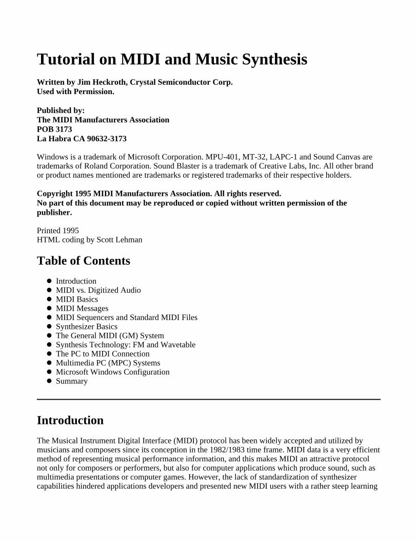
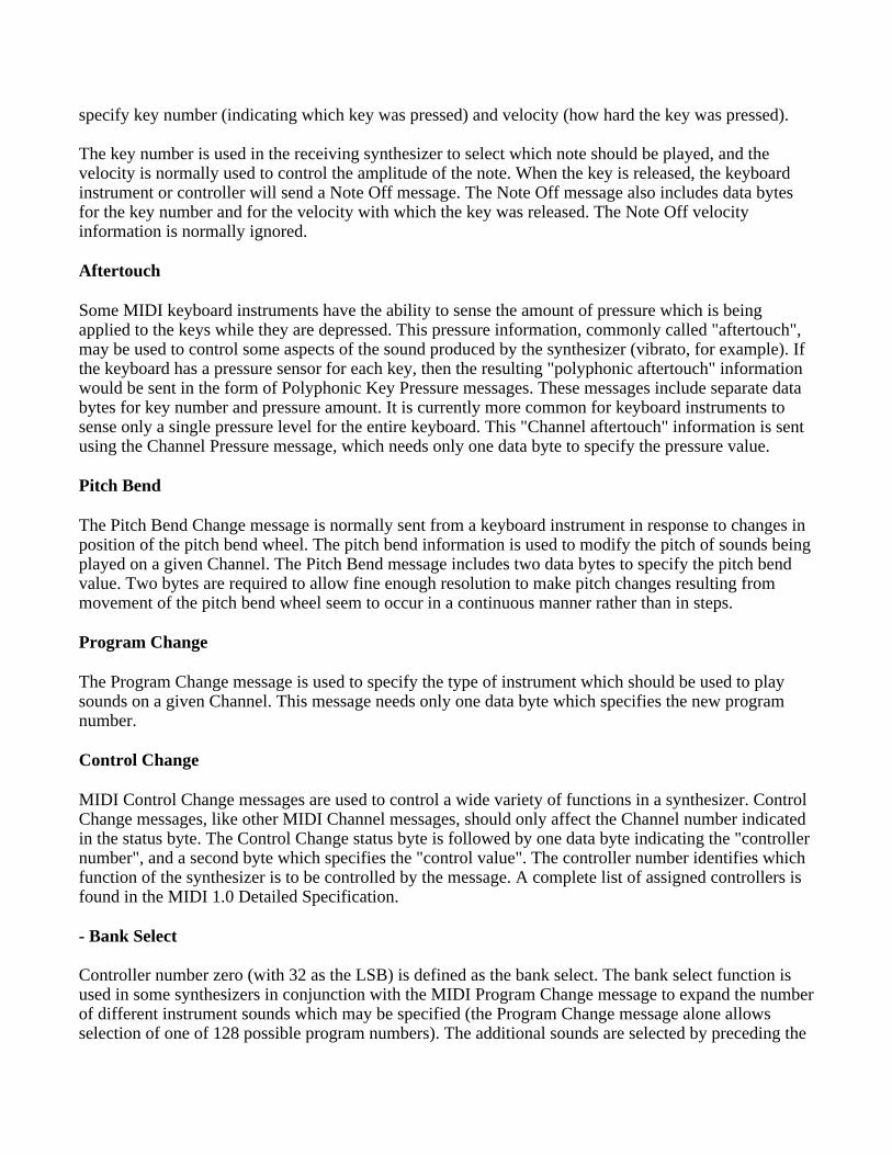
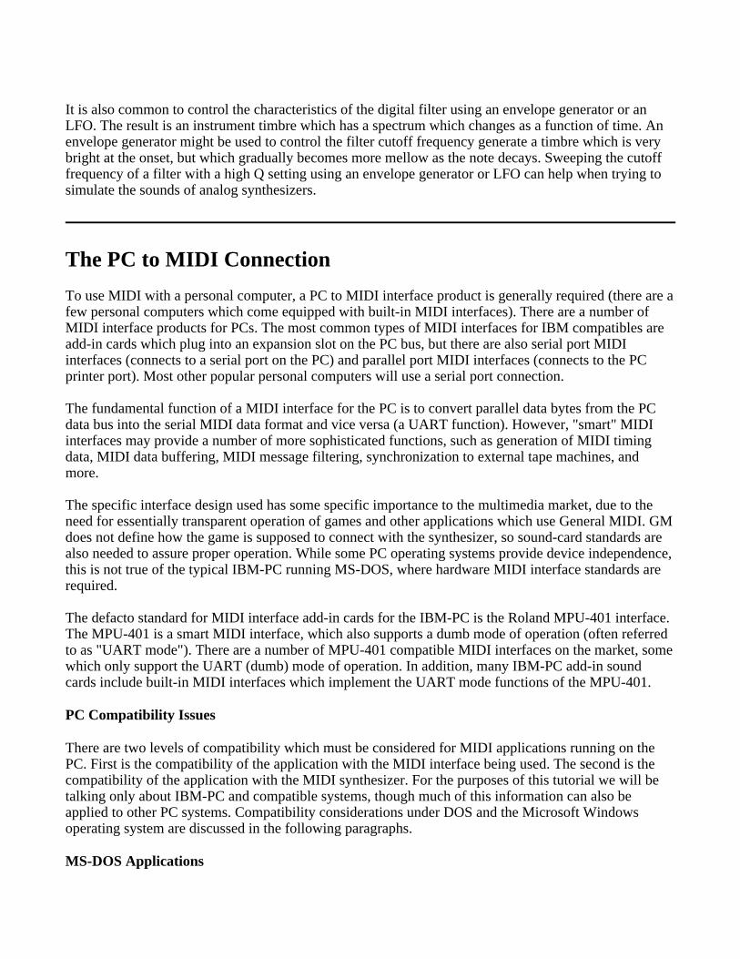
The recipient of this MIDI data stream is commonly a MIDI sound generator or sound module, whichwill receive MIDI messages at its MIDI IN connector, and respond to these messages by playing sounds.Figure 1 shows a simple MIDI system, consisting of a MIDI keyboard controller and a MIDI soundmodule. Note that many MIDI keyboard instruments include both the keyboard controller and the MIDIsound module functions within the same unit. In these units, there is an internal link between thekeyboard and the sound module which may be enabled or disabled by setting the "local control" functionof the instrument to ON or OFF respectively.
The single physical MIDI Channel is divided into 16 logical channels by the inclusion of a 4 bit Channelnumber within many of the MIDI messages. A musical instrument keyboard can generally be set totransmit on any one of the sixteen MIDI channels. A MIDI sound source, or sound module, can be set toreceive on specific MIDI Channel(s). In the system depicted in Figure 1, the sound module would haveto be set to receive the Channel which the keyboard controller is transmitting on in order to play sounds.
Figure 1: A Simple MIDI System
Information received on the MIDI IN connector of a MIDI device is transmitted back out (repeated) atthe devices’ MIDI THRU connector. Several MIDI sound modules can be daisy-chained by connectingthe THRU output of one device to the IN connector of the next device downstream in the chain.
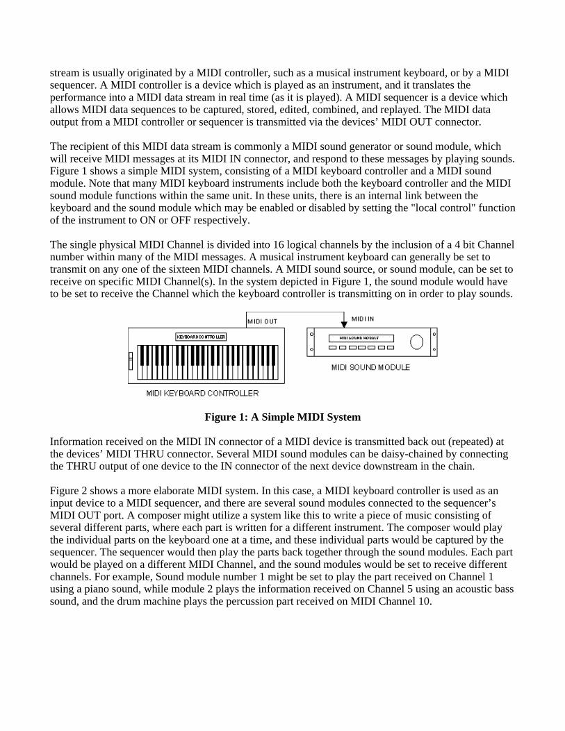
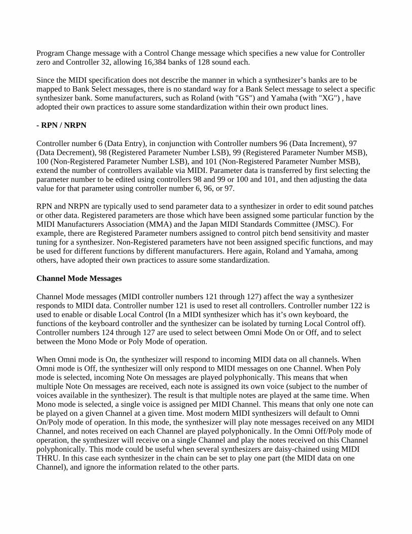
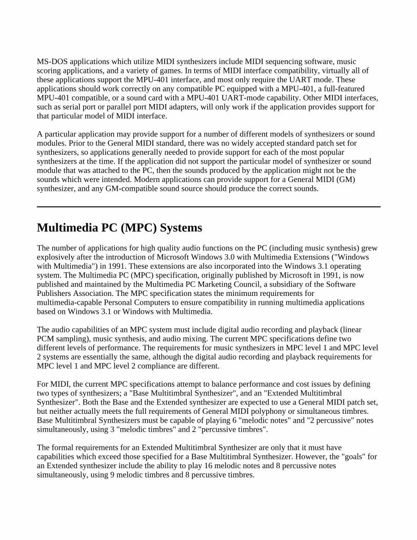
Figure 2 shows a more elaborate MIDI system. In this case, a MIDI keyboard controller is used as aninput device to a MIDI sequencer, and there are several sound modules connected to the sequencer’sMIDI OUT port. A composer might utilize a system like this to write a piece of music consisting ofseveral different parts, where each part is written for a different instrument. The composer would playthe individual parts on the keyboard one at a time, and these individual parts would be captured by thesequencer. The sequencer would then play the parts back together through the sound modules. Each partwould be played on a different MIDI Channel, and the sound modules would be set to receive differentchannels. For example, Sound module number 1 might be set to play the part received on Channel 1using a piano sound, while module 2 plays the information received on Channel 5 using an acoustic basssound, and the drum machine plays the percussion part received on MIDI Channel 10.
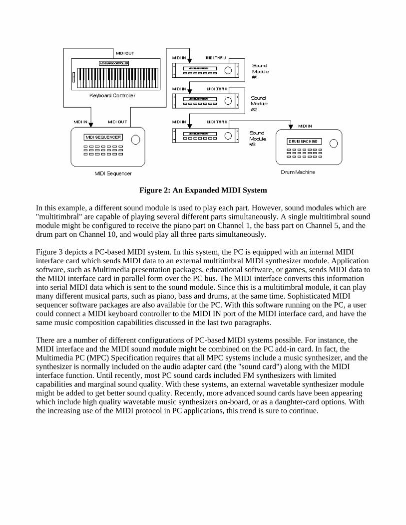
Figure 2: An Expanded MIDI System
In this example, a different sound module is used to play each part. However, sound modules which are"multitimbral" are capable of playing several different parts simultaneously. A single multitimbral soundmodule might be configured to receive the piano part on Channel 1, the bass part on Channel 5, and thedrum part on Channel 10, and would play all three parts simultaneously.
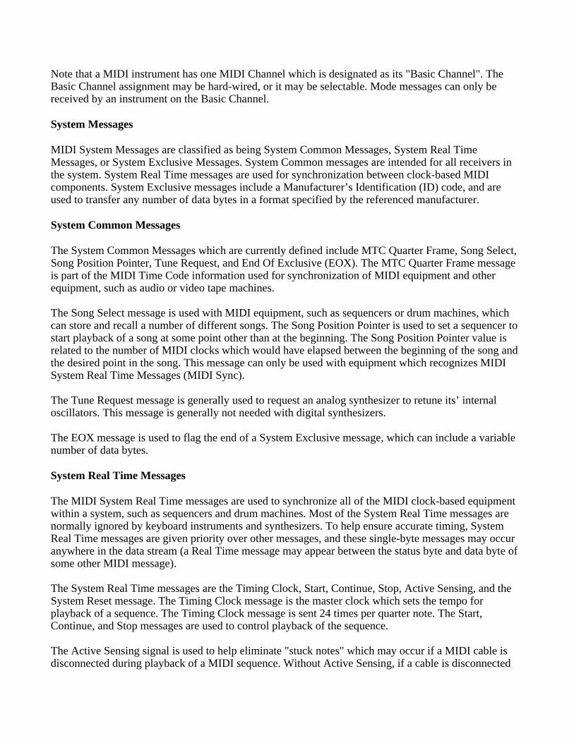
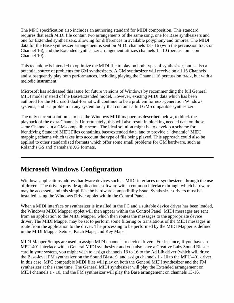
Figure 3 depicts a PC-based MIDI system. In this system, the PC is equipped with an internal MIDIinterface card which sends MIDI data to an external multitimbral MIDI synthesizer module. Applicationsoftware, such as Multimedia presentation packages, educational software, or games, sends MIDI data tothe MIDI interface card in parallel form over the PC bus. The MIDI interface converts this informationinto serial MIDI data which is sent to the sound module. Since this is a multitimbral module, it can playmany different musical parts, such as piano, bass and drums, at the same time. Sophisticated MIDIsequencer software packages are also available for the PC. With this software running on the PC, a usercould connect a MIDI keyboard controller to the MIDI IN port of the MIDI interface card, and have thesame music composition capabilities discussed in the last two paragraphs.
There are a number of different configurations of PC-based MIDI systems possible. For instance, theMIDI interface and the MIDI sound module might be combined on the PC add-in card. In fact, theMultimedia PC (MPC) Specification requires that all MPC systems include a music synthesizer, and thesynthesizer is normally included on the audio adapter card (the "sound card") along with the MIDIinterface function. Until recently, most PC sound cards included FM synthesizers with limitedcapabilities and marginal sound quality. With these systems, an external wavetable synthesizer modulemight be added to get better sound quality. Recently, more advanced sound cards have been appearingwhich include high quality wavetable music synthesizers on-board, or as a daughter-card options. Withthe increasing use of the MIDI protocol in PC applications, this trend is sure to continue.

Figure 3: A PC-Based MIDI System
MIDI Messages
A MIDI message is made up of an eight-bit status byte which is generally followed by one or two databytes. There are a number of different types of MIDI messages. At the highest level, MIDI messages areclassified as being either Channel Messages or System Messages. Channel messages are those whichapply to a specific Channel, and the Channel number is included in the status byte for these messages.System messages are not Channel specific, and no Channel number is indicated in their status bytes.
Channel Messages may be further classified as being either Channel Voice Messages, or ModeMessages. Channel Voice Messages carry musical performance data, and these messages comprise mostof the traffic in a typical MIDI data stream. Channel Mode messages affect the way a receivinginstrument will respond to the Channel Voice messages.
Channel Voice Messages
Channel Voice Messages are used to send musical performance information. The messages in thiscategory are the Note On, Note Off, Polyphonic Key Pressure, Channel Pressure, Pitch Bend Change,Program Change, and the Control Change messages.
Note On / Note Off / Velocity
In MIDI systems, the activation of a particular note and the release of the same note are considered astwo separate events. When a key is pressed on a MIDI keyboard instrument or MIDI keyboardcontroller, the keyboard sends a Note On message on the MIDI OUT port. The keyboard may be set totransmit on any one of the sixteen logical MIDI channels, and the status byte for the Note On messagewill indicate the selected Channel number. The Note On status byte is followed by two data bytes, which
specify key number (indicating which key was pressed) and velocity (how hard the key was pressed).
The key number is used in the receiving synthesizer to select which note should be played, and thevelocity is normally used to control the amplitude of the note. When the key is released, the keyboardinstrument or controller will send a Note Off message. The Note Off message also includes data bytesfor the key number and for the velocity with which the key was released. The Note Off velocityinformation is normally ignored.
Aftertouch
Some MIDI keyboard instruments have the ability to sense the amount of pressure which is beingapplied to the keys while they are depressed. This pressure information, commonly called "aftertouch",may be used to control some aspects of the sound produced by the synthesizer (vibrato, for example). Ifthe keyboard has a pressure sensor for each key, then the resulting "polyphonic aftertouch" informationwould be sent in the form of Polyphonic Key Pressure messages. These messages include separate databytes for key number and pressure amount. It is currently more common for keyboard instruments tosense only a single pressure level for the entire keyboard. This "Channel aftertouch" information is sentusing the Channel Pressure message, which needs only one data byte to specify the pressure value.
Pitch Bend
The Pitch Bend Change message is normally sent from a keyboard instrument in response to changes inposition of the pitch bend wheel. The pitch bend information is used to modify the pitch of sounds beingplayed on a given Channel. The Pitch Bend message includes two data bytes to specify the pitch bendvalue. Two bytes are required to allow fine enough resolution to make pitch changes resulting frommovement of the pitch bend wheel seem to occur in a continuous manner rather than in steps.
Program Change
The Program Change message is used to specify the type of instrument which should be used to playsounds on a given Channel. This message needs only one data byte which specifies the new programnumber.
Control Change
MIDI Control Change messages are used to control a wide variety of functions in a synthesizer. ControlChange messages, like other MIDI Channel messages, should only affect the Channel number indicatedin the status byte. The Control Change status byte is followed by one data byte indicating the "controllernumber", and a second byte which specifies the "control value". The controller number identifies whichfunction of the synthesizer is to be controlled by the message. A complete list of assigned controllers isfound in the MIDI 1.0 Detailed Specification.
- Bank Select
Controller number zero (with 32 as the LSB) is defined as the bank select. The bank select function isused in some synthesizers in conjunction with the MIDI Program Change message to expand the numberof different instrument sounds which may be specified (the Program Change message alone allowsselection of one of 128 possible program numbers). The additional sounds are selected by preceding the
Program Change message with a Control Change message which specifies a new value for Controllerzero and Controller 32, allowing 16,384 banks of 128 sound each.
Since the MIDI specification does not describe the manner in which a synthesizer’s banks are to bemapped to Bank Select messages, there is no standard way for a Bank Select message to select a specificsynthesizer bank. Some manufacturers, such as Roland (with "GS") and Yamaha (with "XG") , haveadopted their own practices to assure some standardization within their own product lines.
- RPN / NRPN
Controller number 6 (Data Entry), in conjunction with Controller numbers 96 (Data Increment), 97(Data Decrement), 98 (Registered Parameter Number LSB), 99 (Registered Parameter Number MSB),100 (Non-Registered Parameter Number LSB), and 101 (Non-Registered Parameter Number MSB),extend the number of controllers available via MIDI. Parameter data is transferred by first selecting theparameter number to be edited using controllers 98 and 99 or 100 and 101, and then adjusting the datavalue for that parameter using controller number 6, 96, or 97.
RPN and NRPN are typically used to send parameter data to a synthesizer in order to edit sound patchesor other data. Registered parameters are those which have been assigned some particular function by theMIDI Manufacturers Association (MMA) and the Japan MIDI Standards Committee (JMSC). Forexample, there are Registered Parameter numbers assigned to control pitch bend sensitivity and mastertuning for a synthesizer. Non-Registered parameters have not been assigned specific functions, and maybe used for different functions by different manufacturers. Here again, Roland and Yamaha, amongothers, have adopted their own practices to assure some standardization.
Channel Mode Messages
Channel Mode messages (MIDI controller numbers 121 through 127) affect the way a synthesizerresponds to MIDI data. Controller number 121 is used to reset all controllers. Controller number 122 isused to enable or disable Local Control (In a MIDI synthesizer which has it’s own keyboard, thefunctions of the keyboard controller and the synthesizer can be isolated by turning Local Control off).Controller numbers 124 through 127 are used to select between Omni Mode On or Off, and to selectbetween the Mono Mode or Poly Mode of operation.
When Omni mode is On, the synthesizer will respond to incoming MIDI data on all channels. WhenOmni mode is Off, the synthesizer will only respond to MIDI messages on one Channel. When Polymode is selected, incoming Note On messages are played polyphonically. This means that whenmultiple Note On messages are received, each note is assigned its own voice (subject to the number ofvoices available in the synthesizer). The result is that multiple notes are played at the same time. WhenMono mode is selected, a single voice is assigned per MIDI Channel. This means that only one note canbe played on a given Channel at a given time. Most modern MIDI synthesizers will default to OmniOn/Poly mode of operation. In this mode, the synthesizer will play note messages received on any MIDIChannel, and notes received on each Channel are played polyphonically. In the Omni Off/Poly mode ofoperation, the synthesizer will receive on a single Channel and play the notes received on this Channelpolyphonically. This mode could be useful when several synthesizers are daisy-chained using MIDITHRU. In this case each synthesizer in the chain can be set to play one part (the MIDI data on oneChannel), and ignore the information related to the other parts.
Note that a MIDI instrument has one MIDI Channel which is designated as its "Basic Channel". TheBasic Channel assignment may be hard-wired, or it may be selectable. Mode messages can only bereceived by an instrument on the Basic Channel.
System Messages
MIDI System Messages are classified as being System Common Messages, System Real TimeMessages, or System Exclusive Messages. System Common messages are intended for all receivers inthe system. System Real Time messages are used for synchronization between clock-based MIDIcomponents. System Exclusive messages include a Manufacturer’s Identification (ID) code, and areused to transfer any number of data bytes in a format specified by the referenced manufacturer.
System Common Messages
The System Common Messages which are currently defined include MTC Quarter Frame, Song Select,Song Position Pointer, Tune Request, and End Of Exclusive (EOX). The MTC Quarter Frame messageis part of the MIDI Time Code information used for synchronization of MIDI equipment and otherequipment, such as audio or video tape machines.
The Song Select message is used with MIDI equipment, such as sequencers or drum machines, whichcan store and recall a number of different songs. The Song Position Pointer is used to set a sequencer tostart playback of a song at some point other than at the beginning. The Song Position Pointer value isrelated to the number of MIDI clocks which would have elapsed between the beginning of the song andthe desired point in the song. This message can only be used with equipment which recognizes MIDISystem Real Time Messages (MIDI Sync).
The Tune Request message is generally used to request an analog synthesizer to retune its’ internaloscillators. This message is generally not needed with digital synthesizers.
The EOX message is used to flag the end of a System Exclusive message, which can include a variablenumber of data bytes.
System Real Time Messages
The MIDI System Real Time messages are used to synchronize all of the MIDI clock-based equipmentwithin a system, such as sequencers and drum machines. Most of the System Real Time messages arenormally ignored by keyboard instruments and synthesizers. To help ensure accurate timing, SystemReal Time messages are given priority over other messages, and these single-byte messages may occuranywhere in the data stream (a Real Time message may appear between the status byte and data byte ofsome other MIDI message).
The System Real Time messages are the Timing Clock, Start, Continue, Stop, Active Sensing, and theSystem Reset message. The Timing Clock message is the master clock which sets the tempo forplayback of a sequence. The Timing Clock message is sent 24 times per quarter note. The Start,Continue, and Stop messages are used to control playback of the sequence.
The Active Sensing signal is used to help eliminate "stuck notes" which may occur if a MIDI cable isdisconnected during playback of a MIDI sequence. Without Active Sensing, if a cable is disconnected

during playback, then some notes may be left playing indefinitely because they have been activated by aNote On message, but the corresponding Note Off message will never be received.
The System Reset message, as the name implies, is used to reset and initialize any equipment whichreceives the message. This message is generally not sent automatically by transmitting devices, and mustbe initiated manually by a user.
System Exclusive Messages
System Exclusive messages may be used to send data such as patch parameters or sample data betweenMIDI devices. Manufacturers of MIDI equipment may define their own formats for System Exclusivedata. Manufacturers are granted unique identification (ID) numbers by the MMA or the JMSC, and themanufacturer ID number is included as part of the System Exclusive message. The manufacturers ID isfollowed by any number of data bytes, and the data transmission is terminated with the EOX message.Manufacturers are required to publish the details of their System Exclusive data formats, and othermanufacturers may freely utilize these formats, provided that they do not alter or utilize the format in away which conflicts with the original manufacturers specifications.
Certain System Exclusive ID numbers are reserved for special protocols. Among these are the MIDISample Dump Standard, which is a System Exclusive data format defined in the MIDI specification forthe transmission of sample data between MIDI devices, as well as MIDI Show Control and MIDIMachine Control.
Running Status
Since MIDI data is transmitted serially, it is possible that musical events which originally occurred at thesame time and must be sent one at a time in the MIDI data stream may not actually be played at exactlythe same time. With a data transmission rate of 31.25 Kbit/s and 10 bits transmitted per byte of MIDIdata, a 3-byte Note On or Note Off message takes about 1 ms to be sent, which is generally short enoughthat the events are perceived as having occurred simultaneously. In fact, for a person playing a MIDIinstrument keyboard, the time skew between playback of notes when 10 keys are pressed simultaneouslyshould not exceed 10 ms, and this would not be perceptible.
However, MIDI data being sent from a sequencer can include a number of different parts. On a givenbeat, there may be a large number of musical events which should occur simultaneously, and the delaysintroduced by serialization of this information might be noticeable. To help reduce the amount of datatransmitted in the MIDI data stream, a technique called "running status" may be employed.
Running status considers the fact that it is very common for a string of consecutive messages to be of thesame message type. For instance, when a chord is played on a keyboard, 10 successive Note Onmessages may be generated, followed by 10 Note Off messages. When running status is used, a statusbyte is sent for a message only when the message is not of the same type as the last message sent on thesame Channel. The status byte for subsequent messages of the same type may be omitted (only the databytes are sent for these subsequent messages).
The effectiveness of running status can be enhanced by sending Note On messages with a velocity ofzero in place of Note Off messages. In this case, long strings of Note On messages will often occur.Changes in some of the MIDI controllers or movement of the pitch bend wheel on a musical instrument
can produce a staggering number of MIDI Channel voice messages, and running status can also help agreat deal in these instances.
MIDI Sequencers and Standard MIDI Files
MIDI messages are received and processed by a MIDI synthesizer in real time. When the synthesizerreceives a MIDI "note on" message it plays the appropriate sound. When the corresponding "note off"message is received, the synthesizer turns the note off. If the source of the MIDI data is a musicalinstrument keyboard, then this data is being generated in real time. When a key is pressed on thekeyboard, a "note on" message is generated in real time. In these real time applications, there is no needfor timing information to be sent along with the MIDI messages.
However, if the MIDI data is to be stored as a data file, and/or edited using a sequencer, then some formof "time-stamping" for the MIDI messages is required. The Standard MIDI Files specification provides astandardized method for handling time-stamped MIDI data. This standardized file format fortime-stamped MIDI data allows different applications, such as sequencers, scoring packages, andmultimedia presentation software, to share MIDI data files.
The specification for Standard MIDI Files defines three formats for MIDI files. MIDI sequencers cangenerally manage multiple MIDI data streams, or "tracks". Standard MIDI files using Format 0 store allof the MIDI sequence data in a single track. Format 1 files store MIDI data as a collection of tracks.Format 2 files can store several independent patterns. Format 2 is generally not used by MIDIsequencers for musical applications. Most sophisticated MIDI sequencers can read either Format 0 orFormat 1 Standard MIDI Files. Format 0 files may be smaller, and thus conserve storage space. Theymay also be transferred using slightly less system bandwidth than Format 1 files. However, Format 1files may be viewed and edited more directly, and are therefore generally preferred.
Synthesizer Basics
Polyphony
The polyphony of a sound generator refers to its ability to play more than one note at a time. Polyphonyis generally measured or specified as a number of notes or voices. Most of the early music synthesizerswere monophonic, meaning that they could only play one note at a time. If you pressed five keyssimultaneously on the keyboard of a monophonic synthesizer, you would only hear one note. Pressingfive keys on the keyboard of a synthesizer which was polyphonic with four voices of polyphony would,in general, produce four notes. If the keyboard had more voices (many modern sound modules have 16,24, or 32 note polyphony), then you would hear all five of the notes.
Sounds
The different sounds that a synthesizer or sound generator can produce are sometimes called "patches","programs", "algorithms", or "timbres". Programmable synthesizers commonly assign "program
numbers" (or patch numbers) to each sound. For instance, a sound module might use patch number 1 forits acoustic piano sound, and patch number 36 for its fretless bass sound. The association of all patchnumbers to all sounds is often referred to as a patch map.
Via MIDI, a Program Change message is used to tell a device receiving on a given Channel to changethe instrument sound being used. For example, a sequencer could set up devices on Channel 4 to playfretless bass sounds by sending a Program Change message for Channel four with a data byte value of36 (this is the General MIDI program number for the fretless bass patch).
Multitimbral Mode
A synthesizer or sound generator is said to be multitimbral if it is capable of producing two or moredifferent instrument sounds simultaneously. If a synthesizer can play five notes simultaneously, and itcan produce a piano sound and an acoustic bass sound at the same time, then it is multitimbral. Withenough notes of polyphony and "parts" (multitimbral) a single synthesizer could produce the entiresound of a band or orchestra.
Multitimbral operation will generally require the use of a sequencer to send the various MIDI messagesrequired. For example, a sequencer could send MIDI messages for a piano part on Channel 1, bass onChannel 2, saxophone on Channel 3, drums on Channel 10, etc. A 16 part multitimbral synthesizer couldreceive a different part on each of MIDI’s 16 logical channels.
The polyphony of a multitimbral synthesizer is usually allocated dynamically among the different parts(timbres) being used. At any given instant five voices might be needed for the piano part, two voices forthe bass, one for the saxophone, plus 6 voices for the drums. Note that some sounds on somesynthesizers actually utilize more than one "voice", so the number of notes which may be producedsimultaneously may be less than the stated polyphony of the synthesizer, depending on which sounds arebeing utilized.
The General MIDI (GM) System
At the beginning of a MIDI sequence, a Program Change message is usually sent on each Channel usedin the piece in order to set up the appropriate instrument sound for each part. The Program Changemessage tells the synthesizer which patch number should be used for a particular MIDI Channel. If thesynthesizer receiving the MIDI sequence uses the same patch map (the assignment of patch numbers tosounds) that was used in the composition of the sequence, then the sounds will be assigned as intended.
Prior to General MIDI, there was no standard for the relationship of patch numbers to specific soundsfor synthesizers. Thus, a MIDI sequence might produce different sounds when played on differentsynthesizers, even though the synthesizers had comparable types of sounds. For example, if thecomposer had selected patch number 5 for Channel 1, intending this to be an electric piano sound, butthe synthesizer playing the MIDI data had a tuba sound mapped at patch number 5, then the notesintended for the piano would be played on the tuba when using this synthesizer (even though thissynthesizer may have a fine electric piano sound available at some other patch number).
The General MIDI (GM) Specification defines a set of general capabilities for General MIDI
Instruments. The General MIDI Specification includes the definition of a General MIDI Sound Set (apatch map), a General MIDI Percussion map (mapping of percussion sounds to note numbers), and a setof General MIDI Performance capabilities (number of voices, types of MIDI messages recognized, etc.).A MIDI sequence which has been generated for use on a General MIDI Instrument should play correctlyon any General MIDI synthesizer or sound module.
The General MIDI system utilizes MIDI Channels 1-9 and 11-16 for chromatic instrument sounds, whileChannel number 10 is utilized for "key-based" percussion sounds. These instrument sounds are groupedinto "sets" of related sounds. For example, program numbers 1-8 are piano sounds, 9-16 are chromaticpercussion sounds, 17-24 are organ sounds, 25-32 are guitar sounds, etc.
For the instrument sounds on channels 1-9 and 11-16, the note number in a Note On message is used toselect the pitch of the sound which will be played. For example if the Vibraphone instrument (programnumber 12) has been selected on Channel 3, then playing note number 60 on Channel 3 would play themiddle C note (this would be the default note to pitch assignment on most instruments), and notenumber 59 on Channel 3 would play B below middle C. Both notes would be played using theVibraphone sound.
The General MIDI percussion sounds are set on Channel 10. For these "key-based" sounds, the notenumber data in a Note On message is used differently. Note numbers on Channel 10 are used to selectwhich drum sound will be played. For example, a Note On message on Channel 10 with note number 60will play a Hi Bongo drum sound. Note number 59 on Channel 10 will play the Ride Cymbal 2 sound.
It should be noted that the General MIDI system specifies sounds using program numbers 1 through128. The MIDI Program Change message used to select these sounds uses an 8-bit byte, whichcorresponds to decimal numbering from 0 through 127, to specify the desired program number. Thus, toselect GM sound number 10, the Glockenspiel, the Program Change message will have a data byte withthe decimal value 9.
The General MIDI system specifies which instrument or sound corresponds with each program/patchnumber, but General MIDI does not specify how these sounds are produced. Thus, program number 1should select the Acoustic Grand Piano sound on any General MIDI instrument. However, the AcousticGrand Piano sound on two General MIDI synthesizers which use different synthesis techniques maysound quite different.
Synthesis Technology: FM and Wavetable
There are a number of different technologies or algorithms used to create sounds in music synthesizers.Two widely used techniques are Frequency Modulation (FM) synthesis and Wavetable synthesis.
FM synthesis techniques generally use one periodic signal (the modulator) to modulate the frequency ofanother signal (the carrier). If the modulating signal is in the audible range, then the result will be asignificant change in the timbre of the carrier signal. Each FM voice requires a minimum of two signalgenerators. These generators are commonly referred to as "operators", and different FM synthesisimplementations have varying degrees of control over the operator parameters.
Sophisticated FM systems may use 4 or 6 operators per voice, and the operators may have adjustableenvelopes which allow adjustment of the attack and decay rates of the signal. Although FM systemswere implemented in the analog domain on early synthesizer keyboards, modern FM synthesisimplementations are done digitally.
FM synthesis techniques are very useful for creating expressive new synthesized sounds. However, ifthe goal of the synthesis system is to recreate the sound of some existing instrument, this can generallybe done more accurately with digital sample-based techniques.
Digital sampling systems store high quality sound samples digitally, and then replay these sounds ondemand. Digital sample-based synthesis systems may employ a variety of special techniques, such assample looping, pitch shifting, mathematical interpolation, and digital filtering, in order to reduce theamount of memory required to store the sound samples (or to get more types of sounds from a givenamount of memory). These sample-based synthesis systems are often called "wavetable" synthesizers(the sample memory in these systems contains a large number of sampled sound segments, and can bethought of as a "table" of sound waveforms which may be looked up and utilized when needed).
Wavetable Synthesis Techniques
The majority of professional synthesizers available today use some form of sampled-sound orWavetable synthesis. The trend for multimedia sound products is also towards wavetable synthesis. Tohelp prospective MIDI developers, a number of the techniques employed in this type of synthesis arediscussed in the following paragraphs.
Looping and Envelope Generation
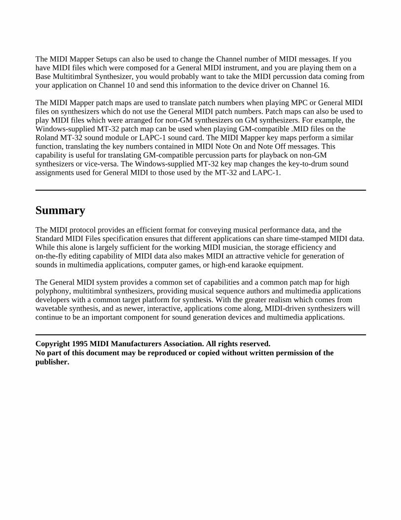
One of the primary techniques used in wavetable synthesizers to conserve sample memory space is thelooping of sampled sound segments. For many instrument sounds, the sound can be modeled asconsisting of two major sections: the attack section and the sustain section. The attack section is theinitial part of the sound, where the amplitude and the spectral characteristics of the sound may bechanging very rapidly. The sustain section of the sound is that part of the sound following the attack,where the characteristics of the sound are changing less dynamically.
Figure 4 shows a waveform with portions which could be considered the attack and the sustain sectionsindicated. In this example, the spectral characteristics of the waveform remain constant throughout thesustain section, while the amplitude is decreasing at a fairly constant rate. This is an exaggeratedexample, in most natural instrument sounds, both the spectral characteristics and the amplitude continueto change through the duration of the sound. The sustain section, if one can be identified, is that sectionfor which the characteristics of the sound are relatively constant.
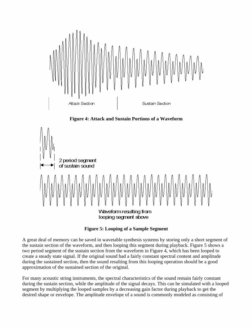
Figure 4: Attack and Sustain Portions of a Waveform
Figure 5: Looping of a Sample Segment
A great deal of memory can be saved in wavetable synthesis systems by storing only a short segment ofthe sustain section of the waveform, and then looping this segment during playback. Figure 5 shows atwo period segment of the sustain section from the waveform in Figure 4, which has been looped tocreate a steady state signal. If the original sound had a fairly constant spectral content and amplitudeduring the sustained section, then the sound resulting from this looping operation should be a goodapproximation of the sustained section of the original.
For many acoustic string instruments, the spectral characteristics of the sound remain fairly constantduring the sustain section, while the amplitude of the signal decays. This can be simulated with a loopedsegment by multiplying the looped samples by a decreasing gain factor during playback to get thedesired shape or envelope. The amplitude envelope of a sound is commonly modeled as consisting of
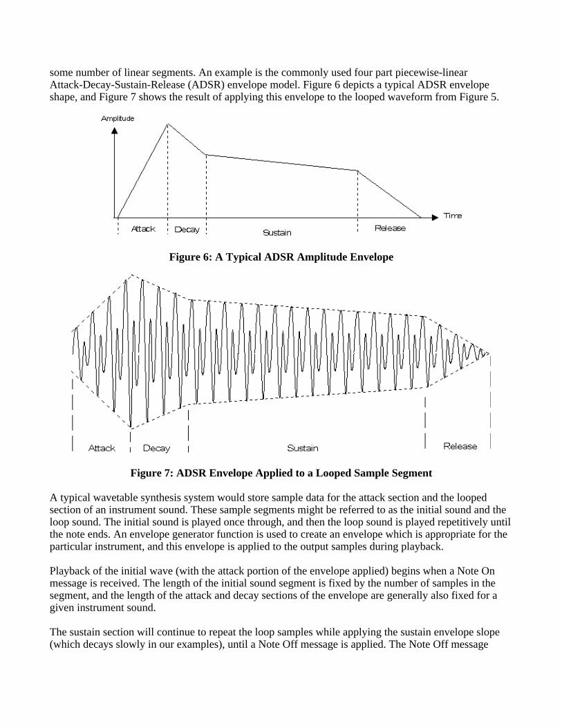
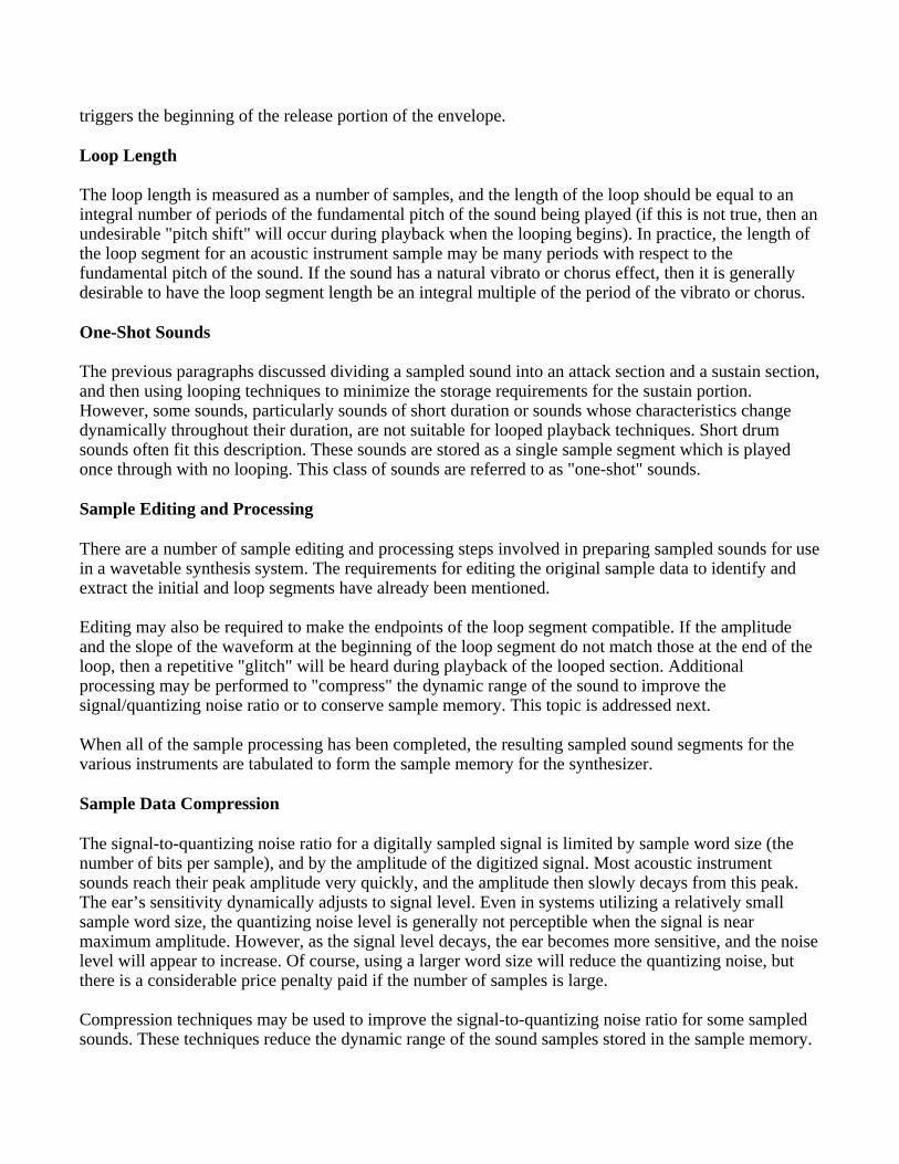
some number of linear segments. An example is the commonly used four part piecewise-linearAttack-Decay-Sustain-Release (ADSR) envelope model. Figure 6 depicts a typical ADSR envelopeshape, and Figure 7 shows the result of applying this envelope to the looped waveform from Figure 5.
Figure 6: A Typical ADSR Amplitude Envelope
Figure 7: ADSR Envelope Applied to a Looped Sample Segment
A typical wavetable synthesis system would store sample data for the attack section and the loopedsection of an instrument sound. These sample segments might be referred to as the initial sound and theloop sound. The initial sound is played once through, and then the loop sound is played repetitively untilthe note ends. An envelope generator function is used to create an envelope which is appropriate for theparticular instrument, and this envelope is applied to the output samples during playback.
Playback of the initial wave (with the attack portion of the envelope applied) begins when a Note Onmessage is received. The length of the initial sound segment is fixed by the number of samples in thesegment, and the length of the attack and decay sections of the envelope are generally also fixed for agiven instrument sound.
The sustain section will continue to repeat the loop samples while applying the sustain envelope slope(which decays slowly in our examples), until a Note Off message is applied. The Note Off message
triggers the beginning of the release portion of the envelope.
Loop Length
The loop length is measured as a number of samples, and the length of the loop should be equal to anintegral number of periods of the fundamental pitch of the sound being played (if this is not true, then anundesirable "pitch shift" will occur during playback when the looping begins). In practice, the length ofthe loop segment for an acoustic instrument sample may be many periods with respect to thefundamental pitch of the sound. If the sound has a natural vibrato or chorus effect, then it is generallydesirable to have the loop segment length be an integral multiple of the period of the vibrato or chorus.
One-Shot Sounds
The previous paragraphs discussed dividing a sampled sound into an attack section and a sustain section,and then using looping techniques to minimize the storage requirements for the sustain portion.However, some sounds, particularly sounds of short duration or sounds whose characteristics changedynamically throughout their duration, are not suitable for looped playback techniques. Short drumsounds often fit this description. These sounds are stored as a single sample segment which is playedonce through with no looping. This class of sounds are referred to as "one-shot" sounds.
Sample Editing and Processing
There are a number of sample editing and processing steps involved in preparing sampled sounds for usein a wavetable synthesis system. The requirements for editing the original sample data to identify andextract the initial and loop segments have already been mentioned.
Editing may also be required to make the endpoints of the loop segment compatible. If the amplitudeand the slope of the waveform at the beginning of the loop segment do not match those at the end of theloop, then a repetitive "glitch" will be heard during playback of the looped section. Additionalprocessing may be performed to "compress" the dynamic range of the sound to improve thesignal/quantizing noise ratio or to conserve sample memory. This topic is addressed next.
When all of the sample processing has been completed, the resulting sampled sound segments for thevarious instruments are tabulated to form the sample memory for the synthesizer.
Sample Data Compression
The signal-to-quantizing noise ratio for a digitally sampled signal is limited by sample word size (thenumber of bits per sample), and by the amplitude of the digitized signal. Most acoustic instrumentsounds reach their peak amplitude very quickly, and the amplitude then slowly decays from this peak.The ear’s sensitivity dynamically adjusts to signal level. Even in systems utilizing a relatively smallsample word size, the quantizing noise level is generally not perceptible when the signal is nearmaximum amplitude. However, as the signal level decays, the ear becomes more sensitive, and the noiselevel will appear to increase. Of course, using a larger word size will reduce the quantizing noise, butthere is a considerable price penalty paid if the number of samples is large.
Compression techniques may be used to improve the signal-to-quantizing noise ratio for some sampledsounds. These techniques reduce the dynamic range of the sound samples stored in the sample memory.
The sample data is decompressed during playback to restore the dynamic range of the signal. Thisallows the use of sample memory with a smaller word size (smaller dynamic range) than is utilized inthe rest of the system. There are a number of different compression techniques which may be used tocompress the dynamic range of a signal.
Note that there is some compression effect inherent in the looping techniques described earlier. If theloop segment is stored at an amplitude level which makes full use of the dynamic range available in thesample memory, and the processor and D/A converters used for playback have a wider dynamic rangethan the sample memory, then the application of a decay envelope during playback will have adecompression effect similar to that described in the previous paragraph.
Pitch Shifting
In order to minimize sample memory requirements, wavetable synthesis systems utilize pitch shifting, orpitch transposition techniques, to generate a number of different notes from a single sound sample of agiven instrument. For example, if the sample memory contains a sample of a middle C note on theacoustic piano, then this same sample data could be used to generate the C# note or D note above middleC using pitch shifting.
Pitch shifting is accomplished by accessing the stored sample data at different rates during playback. Forexample, if a pointer is used to address the sample memory for a sound, and the pointer is incrementedby one after each access, then the samples for this sound would be accessed sequentially, resulting insome particular pitch. If the pointer increment was two rather than one, then only every second samplewould be played, and the resulting pitch would be shifted up by one octave (the frequency would bedoubled).
In the previous example, the sample memory address pointer was incremented by an integer number ofsamples. This allows only a limited set of pitch shifts. In a more general case, the memory pointer wouldconsist of an integer part and a fractional part, and the increment value could be a fractional number ofsamples. The memory pointer is often referred to as a "phase accumulator" and the increment value isthen the "phase increment". The integer part of the phase accumulator is used to address the samplememory, the fractional part is used to maintain frequency accuracy.
For example if the phase increment value was equivalent to 1/2, then the pitch would be shifted down byone octave (the frequency would be halved). A phase increment value of 1.05946 (the twelfth root oftwo) would create a pitch shift of one musical half-step (i.e. from C to C#) compared with an incrementof 1. When non-integer increment values are utilized, the frequency resolution for playback isdetermined by the number of bits used to represent the fractional part of the address pointer and theaddress increment parameter.
Interpolation
When the fractional part of the address pointer is non-zero, then the "desired value" falls betweenavailable data samples. Figure 8 depicts a simplified addressing scheme wherein the Address Pointerand the increment parameter each have a 4-bit integer part and a 4-bit fractional part. In this case, theincrement value is equal to 1 1/2 samples. Very simple systems might simply ignore the fractional partof the address when determining the sample value to be sent to the D/A converter. The data values sentto the D/A converter when using this approach are indicated in the Figure 8, case I.

Figure 8: Sample Memory Addressing and Interpolation
A slightly better approach would be to use the nearest available sample value. More sophisticatedsystems would perform some type of mathematical interpolation between available data points in orderto get a value to be used for playback. Values which might be sent to the D/A when interpolation isemployed are shown as case II. Note that the overall frequency accuracy would be the same for bothcases indicated, but the output is severely distorted in the case where interpolation is not used.
There are a number of different algorithms used for interpolation between sample values. The simplest islinear interpolation. With linear interpolation, interpolated value is simply the weighted average of thetwo nearest samples, with the fractional address used as a weighting constant. For example, if theaddress pointer indicated an address of (n+K), where n is the integer part of the address and K is thefractional part, than the interpolated value can be calculated as s(n+K) = (1-K)s(n) + (K)s(n+1), wheres(n) is the sample data value at address n. More sophisticated interpolation techniques can be utilized tofurther reduce distortion, but these techniques are computationally expensive.

Oversampling
Oversampling of the sound samples may also be used to improve distortion in wavetable synthesissystems. For example, if 4X oversampling were utilized for a particular instrument sound sample, thenan address increment value of 4 would be used for playback with no pitch shift. The data points chosenduring playback will be closer to the "desired values", on the average, than they would be if nooversampling were utilized because of the increased number of data points used to represent thewaveform. Of course, oversampling has a high cost in terms of sample memory requirements.
In many cases, the best approach may be to utilize linear interpolation combined with varying degrees ofoversampling where needed. The linear interpolation technique provides reasonable accuracy for manysounds, without the high penalty in terms of processing power required for more sophisticatedinterpolation methods. For those sounds which need better accuracy, oversampling is employed. Withthis approach, the additional memory required for oversampling is only utilized where it is most needed.The combined effect of linear interpolation and selective oversampling can produce excellent results.
Splits
When the pitch of a sampled sound is changed during playback, the timbre of the sound is changedsomewhat also. The effect is less noticeable for small changes in pitch (up to a few semitones), than it isfor a large pitch shift. To retain a natural sound, a particular sample of an instrument sound will only beuseful for recreating a limited range of notes. To get coverage of the entire instrument range, a numberof different samples, each with a limited range of notes, are used. The resulting instrumentimplementation is often referred to as a "multisampled" instrument. This technique can be thought of assplitting a musical instrument keyboard into a number of ranges of notes, with a different sound sampleused for each range. Each of these ranges is referred to as a split, or key split.
Velocity splits refer to the use of different samples for different note velocities. Using velocity splits,one sample might be utilized if a particular note is played softly, where a different sample would beutilized for the same note of the same instrument when played with a higher velocity. This technique isnot commonly used to produce basic sound samples because of the added memory expense, but both keysplitting and velocity splitting techniques can be utilized as a performance enhancement. For instance, akey split might allow a fretless bass sound on the lower octaves of a keyboard, while the upper octavesplay a vibraphone. Similarly, a velocity split might "layer" strings on top of an acoustic piano soundwhen the keys are hit with higher velocity.
Aliasing Noise
Earlier paragraphs discussed the timbre changes which result from pitch shifting. The resamplingtechniques used to shift the pitch of a stored sound sample can also result in the introduction of aliasingnoise into an instrument sound. The generation of aliasing noise can also limit the amount of pitchshifting which may be effectively applied to a sound sample. Sounds which are rich in upper harmoniccontent will generally have more of a problem with aliasing noise. Low-pass filtering applied afterinterpolation can help eliminate the undesirable effect of aliasing noise. The use of oversampling alsohelps eliminate aliasing noise.
LFOs for Vibrato and Tremolo
Vibrato and tremolo are effects which are often produced by musicians playing acoustic instruments.Vibrato is basically a low-frequency modulation of the pitch of a note, while tremolo is modulation ofthe amplitude of the sound. These effects are simulated in synthesizers by implementing low-frequencyoscillators (LFOs) which are used to modulate the pitch or amplitude of the synthesized sound beingproduced.
Natural vibrato and tremolo effects tend to increase in strength as a note is sustained. This isaccomplished in synthesizers by applying an envelope generator to the LFO. For example, a flute soundmight have a tremolo effect which begins at some point after the note has sounded, and the tremoloeffect gradually increases to some maximum level, where it remains until the note stops sounding.
Layering
Layering refers to a technique in which multiple sounds are utilized for each note played. This techniquecan be used to generate very rich sounds, and may also be useful for increasing the number ofinstrument patches which can be created from a limited sample set. Note that layered sounds generallyutilize more than one voice of polyphony for each note played, and thus the number of voices availableis effectively reduced when these sounds are being used.
Digital Filtering
It was mentioned earlier that low-pass filtering may be used to help eliminate noise which may begenerated during the pitch shifting process. There are also a number of ways in which digital filtering isused in the timbre generation process to improve the resulting instrument sound. In these applications,the digital filter implementation is polyphonic, meaning that a separate filter is implemented for eachvoice being generated, and the filter implementation should have dynamically adjustable cutofffrequency and/or Q.
For many acoustic instruments, the character of the tone which is produced changes dramatically as afunction of the amplitude level at which the instrument is played. For example, the tone of an acousticpiano may be very bright when the instrument is played forcefully, but much more mellow when it isplayed softly. Velocity splits, which utilize different sample segments for different note velocities, canbe implemented to simulate this phenomena.
Another very powerful technique is to implement a digital low-pass filter for each note with a cutofffrequency which varies as a function of the note velocity. This polyphonic digital filter dynamicallyadjusts the output frequency spectrum of the synthesized sound as a function of note velocity, allowing avery effective recreation of the acoustic instrument timbre.
Another important application of digital filtering is in smoothing out the transitions between samples inkey-based splits. At the border between two splits, there will be two adjacent notes which are based ondifferent samples. Normally, one of these samples will have been pitch shifted up to create the requirednote, while the other will have been shifted down in pitch. As a result, the timbre of these two adjacentnotes may be significantly different, making the split obvious. This problem may be alleviated byemploying a digital filter which uses the note number to control the filter characteristics. A table may beconstructed containing the filter characteristics for each note number of a given instrument. The filtercharacteristics are chosen to compensate for the pitch shifting associated with the key splits used for thatinstrument.
It is also common to control the characteristics of the digital filter using an envelope generator or anLFO. The result is an instrument timbre which has a spectrum which changes as a function of time. Anenvelope generator might be used to control the filter cutoff frequency generate a timbre which is verybright at the onset, but which gradually becomes more mellow as the note decays. Sweeping the cutofffrequency of a filter with a high Q setting using an envelope generator or LFO can help when trying tosimulate the sounds of analog synthesizers.
The PC to MIDI Connection
To use MIDI with a personal computer, a PC to MIDI interface product is generally required (there are afew personal computers which come equipped with built-in MIDI interfaces). There are a number ofMIDI interface products for PCs. The most common types of MIDI interfaces for IBM compatibles areadd-in cards which plug into an expansion slot on the PC bus, but there are also serial port MIDIinterfaces (connects to a serial port on the PC) and parallel port MIDI interfaces (connects to the PCprinter port). Most other popular personal computers will use a serial port connection.
The fundamental function of a MIDI interface for the PC is to convert parallel data bytes from the PCdata bus into the serial MIDI data format and vice versa (a UART function). However, "smart" MIDIinterfaces may provide a number of more sophisticated functions, such as generation of MIDI timingdata, MIDI data buffering, MIDI message filtering, synchronization to external tape machines, andmore.
The specific interface design used has some specific importance to the multimedia market, due to theneed for essentially transparent operation of games and other applications which use General MIDI. GMdoes not define how the game is supposed to connect with the synthesizer, so sound-card standards arealso needed to assure proper operation. While some PC operating systems provide device independence,this is not true of the typical IBM-PC running MS-DOS, where hardware MIDI interface standards arerequired.
The defacto standard for MIDI interface add-in cards for the IBM-PC is the Roland MPU-401 interface.The MPU-401 is a smart MIDI interface, which also supports a dumb mode of operation (often referredto as "UART mode"). There are a number of MPU-401 compatible MIDI interfaces on the market, somewhich only support the UART (dumb) mode of operation. In addition, many IBM-PC add-in soundcards include built-in MIDI interfaces which implement the UART mode functions of the MPU-401.
PC Compatibility Issues
There are two levels of compatibility which must be considered for MIDI applications running on thePC. First is the compatibility of the application with the MIDI interface being used. The second is thecompatibility of the application with the MIDI synthesizer. For the purposes of this tutorial we will betalking only about IBM-PC and compatible systems, though much of this information can also beapplied to other PC systems. Compatibility considerations under DOS and the Microsoft Windowsoperating system are discussed in the following paragraphs.
MS-DOS Applications
MS-DOS applications which utilize MIDI synthesizers include MIDI sequencing software, musicscoring applications, and a variety of games. In terms of MIDI interface compatibility, virtually all ofthese applications support the MPU-401 interface, and most only require the UART mode. Theseapplications should work correctly on any compatible PC equipped with a MPU-401, a full-featuredMPU-401 compatible, or a sound card with a MPU-401 UART-mode capability. Other MIDI interfaces,such as serial port or parallel port MIDI adapters, will only work if the application provides support forthat particular model of MIDI interface.
A particular application may provide support for a number of different models of synthesizers or soundmodules. Prior to the General MIDI standard, there was no widely accepted standard patch set forsynthesizers, so applications generally needed to provide support for each of the most popularsynthesizers at the time. If the application did not support the particular model of synthesizer or soundmodule that was attached to the PC, then the sounds produced by the application might not be thesounds which were intended. Modern applications can provide support for a General MIDI (GM)synthesizer, and any GM-compatible sound source should produce the correct sounds.
Multimedia PC (MPC) Systems
The number of applications for high quality audio functions on the PC (including music synthesis) grewexplosively after the introduction of Microsoft Windows 3.0 with Multimedia Extensions ("Windowswith Multimedia") in 1991. These extensions are also incorporated into the Windows 3.1 operatingsystem. The Multimedia PC (MPC) specification, originally published by Microsoft in 1991, is nowpublished and maintained by the Multimedia PC Marketing Council, a subsidiary of the SoftwarePublishers Association. The MPC specification states the minimum requirements formultimedia-capable Personal Computers to ensure compatibility in running multimedia applicationsbased on Windows 3.1 or Windows with Multimedia.
The audio capabilities of an MPC system must include digital audio recording and playback (linearPCM sampling), music synthesis, and audio mixing. The current MPC specifications define twodifferent levels of performance. The requirements for music synthesizers in MPC level 1 and MPC level2 systems are essentially the same, although the digital audio recording and playback requirements forMPC level 1 and MPC level 2 compliance are different.
For MIDI, the current MPC specifications attempt to balance performance and cost issues by definingtwo types of synthesizers; a "Base Multitimbral Synthesizer", and an "Extended MultitimbralSynthesizer". Both the Base and the Extended synthesizer are expected to use a General MIDI patch set,but neither actually meets the full requirements of General MIDI polyphony or simultaneous timbres.Base Multitimbral Synthesizers must be capable of playing 6 "melodic notes" and "2 percussive" notessimultaneously, using 3 "melodic timbres" and 2 "percussive timbres".
The formal requirements for an Extended Multitimbral Synthesizer are only that it must havecapabilities which exceed those specified for a Base Multitimbral Synthesizer. However, the "goals" foran Extended synthesizer include the ability to play 16 melodic notes and 8 percussive notessimultaneously, using 9 melodic timbres and 8 percussive timbres.
The MPC specification also includes an authoring standard for MIDI composition. This standardrequires that each MIDI file contain two arrangements of the same song, one for Base synthesizers andone for Extended synthesizers, allowing for differences in available polyphony and timbres. The MIDIdata for the Base synthesizer arrangement is sent on MIDI channels 13 - 16 (with the percussion track onChannel 16), and the Extended synthesizer arrangement utilizes channels 1 - 10 (percussion is onChannel 10).
This technique is intended to optimize the MIDI file to play on both types of synthesizer, but is also apotential source of problems for GM synthesizers. A GM synthesizer will receive on all 16 Channelsand subsequently play both performances, including playing the Channel 16 percussion track, but with amelodic instrument.
Microsoft has addressed this issue for future versions of Windows by recommending the full GeneralMIDI model instead of the Base/Extended model. However, existing MIDI data which has beenauthored for the Microsoft dual-format will continue to be a problem for next-generation Windowssystems, and is a problem in any system today that contains a full GM-compatible synthesizer.
The only current solution is to use the Windows MIDI mapper, as described below, to block theplayback of the extra Channels. Unfortunately, this will also result in blocking needed data on thosesame Channels in a GM-compatible score. The ideal solution might be to develop a scheme foridentifying Standard MIDI Files containing base/extended data, and to provide a "dynamic" MIDImapping scheme which takes into account the type of file being played. This approach could also beapplied to other standardized formats which offer some small problems for GM hardware, such asRoland’s GS and Yamaha’s XG formats.
Microsoft Windows Configuration
Windows applications address hardware devices such as MIDI interfaces or synthesizers through the useof drivers. The drivers provide applications software with a common interface through which hardwaremay be accessed, and this simplifies the hardware compatibility issue. Synthesizer drivers must beinstalled using the Windows Driver applet within the Control Panel.
When a MIDI interface or synthesizer is installed in the PC and a suitable device driver has been loaded,the Windows MIDI Mapper applet will then appear within the Control Panel. MIDI messages are sentfrom an application to the MIDI Mapper, which then routes the messages to the appropriate devicedriver. The MIDI Mapper may be set to perform some filtering or translations of the MIDI messages inroute from the application to the driver. The processing to be performed by the MIDI Mapper is definedin the MIDI Mapper Setups, Patch Maps, and Key Maps.
MIDI Mapper Setups are used to assign MIDI channels to device drivers. For instance, If you have anMPU-401 interface with a General MIDI synthesizer and you also have a Creative Labs Sound Blastercard in your system, you might wish to assign channels 13 to 16 to the Ad Lib driver (which will drivethe Base-level FM synthesizer on the Sound Blaster), and assign channels 1 - 10 to the MPU-401 driver.In this case, MPC compatible MIDI files will play on both the General MIDI synthesizer and the FMsynthesizer at the same time. The General MIDI synthesizer will play the Extended arrangement onMIDI channels 1 - 10, and the FM synthesizer will play the Base arrangement on channels 13-16.
The MIDI Mapper Setups can also be used to change the Channel number of MIDI messages. If youhave MIDI files which were composed for a General MIDI instrument, and you are playing them on aBase Multitimbral Synthesizer, you would probably want to take the MIDI percussion data coming fromyour application on Channel 10 and send this information to the device driver on Channel 16.
The MIDI Mapper patch maps are used to translate patch numbers when playing MPC or General MIDIfiles on synthesizers which do not use the General MIDI patch numbers. Patch maps can also be used toplay MIDI files which were arranged for non-GM synthesizers on GM synthesizers. For example, theWindows-supplied MT-32 patch map can be used when playing GM-compatible .MID files on theRoland MT-32 sound module or LAPC-1 sound card. The MIDI Mapper key maps perform a similarfunction, translating the key numbers contained in MIDI Note On and Note Off messages. Thiscapability is useful for translating GM-compatible percussion parts for playback on non-GMsynthesizers or vice-versa. The Windows-supplied MT-32 key map changes the key-to-drum soundassignments used for General MIDI to those used by the MT-32 and LAPC-1.
Summary
The MIDI protocol provides an efficient format for conveying musical performance data, and theStandard MIDI Files specification ensures that different applications can share time-stamped MIDI data.While this alone is largely sufficient for the working MIDI musician, the storage efficiency andon-the-fly editing capability of MIDI data also makes MIDI an attractive vehicle for generation ofsounds in multimedia applications, computer games, or high-end karaoke equipment.
The General MIDI system provides a common set of capabilities and a common patch map for highpolyphony, multitimbral synthesizers, providing musical sequence authors and multimedia applicationsdevelopers with a common target platform for synthesis. With the greater realism which comes fromwavetable synthesis, and as newer, interactive, applications come along, MIDI-driven synthesizers willcontinue to be an important component for sound generation devices and multimedia applications.
Copyright 1995 MIDI Manufacturers Association. All rights reserved.No part of this document may be reproduced or copied without written permission of thepublisher.
MIDI (ie, Musical Instrument Digital Interface) consists of both a simple hardware interface, and a moreelaborate transmission protocol.
Hardware
MIDI is an asynchronous serial interface. The baud rate is 31.25 Kbaud (+/- 1%). There is 1 start bit, 8data bits, and 1 stop bit (ie, 10 bits total), for a period of 320 microseconds per serial byte.
The MIDI circuit is current loop, 5 mA. Logic 0 is current ON. One output drives one (and only one)input. To avoid grounding loops and subsequent data errors, the input is opto-isolated. It requires lessthan 5 mA to turn on. The Sharp PC-900 and HP 6N138 optoisolators are satisfactory devices. Rise andfall time for the optoisolator should be less than 2 microseconds.
The standard connector used for MIDI is a 5 pin DIN. Separate jacks (and cable runs) are used for inputand output, clearly marked on a given device (ie, the MIDI IN and OUT are two separate DIN femalepanel mount jacks). 50 feet is the recommended maximum cable length. Cables are shielded twistedpair, with the shield connecting pin 2 at both ends. The pair is pins 4 and 5. Pins 1 and 3 are not used,and should be left unconnected.
A device may also be equipped with a MIDI THRU jack which is used to pass the MIDI IN signal toanother device. The MIDI THRU transmission may not be performed correctly due to the delay time(caused by the response time of the opto-isolator) between the rising and falling edges of the squarewave. These timing errors will tend to add in the "wrong direction" as more devices are daisy-chained toother device’s MIDI THRU jacks. The result is that there is a limit to the number of devices that can bedaisy-chained.
Schematic
A schematic of a MIDI (IN and OUT) interface
Messages
The MIDI protocol is made up of messages. A message consists of a string (ie, series) of 8-bit bytes.MIDI has many such defined messages. Some messages consist of only 1 byte. Other messages have 2bytes. Still others have 3 bytes. One type of MIDI message can even have an unlimited number of bytes.The one thing that all messages have in common is that the first byte of the message is the Status byte.This is a special byte because it’s the only byte that has bit #7 set. Any other following bytes in thatmessage will not have bit #7 set. So, you can always detect the start a MIDI message because that’swhen you receive a byte with bit #7 set. This will be a Status byte in the range 0x80 to 0xFF. Theremaining bytes of the message (ie, the data bytes, if any) will be in the range 0x00 to 0x7F. (Note thatI’m using the C programming language convention of prefacing a value with 0x to indicatehexadecimal).
The Status bytes of 0x80 to 0xEF are for messages that can be broadcast on any one of the 16 MIDIchannels. Because of this, these are called Voice messages. (My own preference is to say that thesemessages belong in the Voice Category). For these Status bytes, you break up the 8-bit byte into 2 4-bit

nibbles. For example, a Status byte of 0x92 can be broken up into 2 nibbles with values of 9 (highnibble) and 2 (low nibble). The high nibble tells you what type of MIDI message this is. Here are thepossible values for the high nibble, and what type of Voice Category message each represents:
8 = Note Off 9 = Note On A = AfterTouch (ie, key pressure) B = Control Change C = Program (patch) change D = Channel Pressure E = Pitch Wheel
So, for our example status of 0x92, we see that its message type is Note On (ie, the high nibble is 9).What’s the low nibble of 2 mean? This means that the message is on MIDI channel 2. There are 16possible (logical) MIDI channels, with 0 being the first. So, this message is a Note On on channel 2.What status byte would specify a Program Change on channel 0? The high nibble would need to be Cfor a Program Change type of message, and the low nibble would need to be 0 for channel 0. Thus, thestatus byte would be 0xC0. How about a Program Change on channel 15 (ie, the last MIDI channel).Again, the high nibble would be C, but the low nibble would be F (ie, the hexademical digit for15).Thus, the status would be 0xCF.
NOTE: Although the MIDI Status byte counts the 16 MIDI channels as numbers 0 to F (ie, 15), allMIDI gear (including computer software) displays a channel number to the musician as 1 to 16. So, aStatus byte sent on MIDI channel 0 is considered to be on "channel 1" as far as the musician isconcerned. This discrepancy between the status byte’s channel number, and what channel the musician"believes" that a MIDI message is on, is accepted because most humans start counting things from 1,rather than 0.
The Status bytes of 0xF0 to 0xFF are for messages that aren’t on any particular channel (and thereforeall daisy-chained MIDI devices always can "hear" and choose to act upon these messages. Contrast thiswith the Voice Category messages, where a MIDI device can be set to respond to those MIDI messagesonly on a specified channel). These status bytes are used for messages that carry information of interestto all MIDI devices, such as syncronizing all playback devices to a particular time. (By contrast, VoiceCategory messages deal with the individual musical parts that each instrument might play, so thechannel nibble scheme allows a device to respond to its own MIDI channel while ignoring the VoiceCategory messages intended for another device on another channel).
These status bytes are further divided into two catagories. Status bytes of 0xF0 to 0xF7 are calledSystem Common messages. Status bytes of 0xF8 to 0xFF are called System Realtime messages. Theimplications of such will be discussed later.
Actually, certain Status bytes within this range are not defined by the MIDI spec to date, and arereserved for future use. For example, Status bytes of 0xF4, 0xF5, 0xF9, and 0xFD are not used. If aMIDI device ever receives such a Status, it should ignore that message. See Ignoring MIDI Messages.
What follows is a description of each message type. The description tells what the message does, whatits status byte is, and whether it has any subsequent data bytes and what information those carry.Generally, these descriptions take the view of a device receiving such messages (ie, what the device
would typically be expected to do when receiving particular messages). When applicable, remarks abouta device that transmits such messages may be made.
Note Off
Category: Voice
Purpose
Indicates that a particular note should be released. Essentially, this means that the note stops sounding,but some patches might have a long VCA release time that needs to slowly fade the sound out.Additionally, the device’s Hold Pedal controller may be on, in which case the note’s release ispostponed until the Hold Pedal is released. In any event, this message either causes the VCA to moveinto the release stage, or if the Hold Pedal is on, indicates that the note should be released (by the deviceautomatically) when the Hold Pedal is turned off. If the device is a MultiTimbral unit, then each one ofits Parts may respond to Note Offs on its own channel. The Part that responds to a particular Note Offmessage is the one assigned to the message’s MIDI channel.
Status
0x80 to 0x8F where the low nibble is the MIDI channel.
Data
Two data bytes follow the Status.
The first data is the note number. There are 128 possible notes on a MIDI device, numbered 0 to 127(where Middle C is note number 60). This indicates which note should be released.
The second data byte is the velocity, a value from 0 to 127. This indicates how quickly the note shouldbe released (where 127 is the fastest). It’s up to a MIDI device how it uses velocity information. Oftenvelocity will be used to tailor the VCA release time. MIDI devices that can generate Note Off messages,but don’t implement velocity features, will transmit Note Off messages with a preset velocity of 64.
Errata
An All Notes Off controller message can be used to turn off all notes for which a device received NoteOn messages (without having received respective Note Off messages).
Note On
Category: Voice

Purpose
Indicates that a particular note should be played. Essentially, this means that the note starts sounding,but some patches might have a long VCA attack time that needs to slowly fade the sound in. In any case,this message indicates that a particular note should start playing (unless the velocity is 0, in which case,you really have a Note Off). If the device is a MultiTimbral unit, then each one of its Parts may soundNote Ons on its own channel. The Part that sounds a particular Note On message is the one assigned tothe message’s MIDI channel.
Status
0x90 to 0x9F where the low nibble is the MIDI channel.
Data
Two data bytes follow the Status.
The first data is the note number. There are 128 possible notes on a MIDI device, numbered 0 to 127(where Middle C is note number 60). This indicates which note should be played.
The second data byte is the velocity, a value from 0 to 127. This indicates with how much force the noteshould be played (where 127 is the most force). It’s up to a MIDI device how it uses velocityinformation. Often velocity is be used to tailor the VCA attack time and/or attack level (and thereforethe overall volume of the note). MIDI devices that can generate Note On messages, but don’t implementvelocity features, will transmit Note On messages with a preset velocity of 64.
A Note On message that has a velocity of 0 is considered to actually be a Note Off message, and therespective note is therefore released. See the Note Off entry for a description of such. This "trick" wascreated in order to take advantage of running status.
A device that recognizes MIDI Note On messages must be able to recognize both a real Note Off aswell as a Note On with 0 velocity (as a Note Off). There are many devices that generate real Note Offs,and many other devices that use Note On with 0 velocity as a substitute.
Errata
In theory, every Note On should eventually be followed by a respective Note Off message (ie, when it’stime to stop the note from sounding). Even if the note’s sound fades out (due to some VCA envelopedecay) before a Note Off for this note is received, at some later point a Note Off should be received. Forexample, if a MIDI device receives the following Note On:
0x90 0x3C 0x40 Note On/chan 0, Middle C, velocity could be anything except 0
Then, a respective Note Off should subsequently be received at some time, as so:
0x80 0x3C 0x40 Note Off/chan 0, Middle C, velocity could be anything
Instead of the above Note Off, a Note On with 0 velocity could be substituted as so:

0x90 0x3C 0x00 Really a Note Off/chan 0, Middle C, velocity must be 0
If a device receives a Note On for a note (number) that is already playing (ie, hasn’t been turned off yet),it is up the device whether to layer another "voice" playing the same pitch, or cut off the voice playingthe preceding note of that same pitch in order to "retrigger" that note.
Aftertouch
Category: Voice
Purpose
While a particular note is playing, pressure can be applied to it. Many electronic keyboards havepressure sensing circuitry that can detect with how much force a musician is holding down a key. Themusician can then vary this pressure, even while he continues to hold down the key (and the notecontinues sounding). The Aftertouch message conveys the amount of pressure on a key at a given point.Since the musician can be continually varying his pressure, devices that generate Aftertouch typicallysend out many such messages while the musician is varying his pressure. Upon receiving Aftertouch,many devices typically use the message to vary a note’s VCA and/or VCF envelope sustain level, orcontrol LFO amount and/or rate being applied to the note’s sound generation circuitry. But, it’s up to thedevice how it chooses to respond to received Aftertouch (if at all). If the device is a MultiTimbral unit,then each one of its Parts may respond differently (or not at all) to Aftertouch. The Part affected by aparticular Aftertouch message is the one assigned to the message’s MIDI channel.
Status
0xA0 to 0xAF where the low nibble is the MIDI channel.
Data
Two data bytes follow the Status.
The first data is the note number. There are 128 possible notes on a MIDI device, numbered 0 to 127(where Middle C is note number 60). This indicates to which note the pressure is being applied.
The second data byte is the pressure amount, a value from 0 to 127 (where 127 is the most pressure).
Errata
See the remarks under Channel Pressure.
Controller
Category: Voice
Purpose
Sets a particular controller’s value. A controller is any switch, slider, knob, etc, that implements somefunction (usually) other than sounding or stopping notes (ie, which are the jobs of the Note On and NoteOff messages respectively). There are 128 possible controllers on a MIDI device. These are numberedfrom 0 to 127. Some of these controller numbers as assigned to particular hardware controls on a MIDIdevice. For example, controller 1 is the Modulation Wheel. Other controller numbers are free to bearbitrarily interpreted by a MIDI device. For example, a drum box may have a slider controlling Tempowhich it arbitrarily assigns to one of these free numbers. Then, when the drum box receives a Controllermessage for that controller number, it can adjust its tempo. A MIDI device need not have an actualphysical control on it in order to respond to a particular controller.For example, even though arack-mount sound module may not have a Mod Wheel on it, the module will likely still respond to andutilize Modulation controller messages to modify its sound. If the device is a MultiTimbral unit, theneach one of its Parts may respond differently (or not at all) to various controller numbers. The Partaffected by a particular controller message is the one assigned to the message’s MIDI channel.
Status
0xB0 to 0xBF where the low nibble is the MIDI channel.
Data
Two data bytes follow the Status.
The first data is the controller number (0 to 127). This indicates which controller is affected by thereceived MIDI message.
The second data byte is the value to which the controller should be set, a value from 0 to 127.
Errata
An All Controllers Off controller message can be used to reset all controllers (that a MIDI deviceimplements) to default values. For example, the Mod Wheel is reset to its "off" position upon receipt ofthis message.
See the list of Defined Controller Numbers for more information about particular controllers.
Program Change
Category: Voice
Purpose
To cause the MIDI device to change to a particular Program (which some devices refer to as Patch, orInstrument, or Preset, or whatever). Most sound modules have a variety of instrumental sounds, such asPiano, and Guitar, and Trumpet, and Flute, etc. Each one of these instruments is contained in a Program.So, changing the Program changes the instrumental sound that the MIDI device uses when it plays NoteOn messages. Of course, other MIDI messages also may modify the current Program’s (ie, instrument’s)sound. But, the Program Change message actually selects which instrument currently plays. There are128 possible program numbers, from 0 to 127. If the device is a MultiTimbral unit, then it usually canplay 16 "Parts" at once, each receiving data upon its own MIDI channel. This message will then changethe instrument sound for only that Part which is set to the message’s MIDI channel.
For MIDI devices that don’t have instrument sounds, such as a Reverb unit which may have severalPreset "room algorithms" stored, the Program Change message is often used to select which Preset touse. As another example, a drum box may use Program Change to select a particular rhythm pattern (ie,drum beat).
Status
0xC0 to 0xCF where the low nibble is the MIDI channel.
Data
One data byte follows the status. It is the program number to change to, a number from 0 to 127.
Errata
On MIDI sound modules (ie, whose Programs are instrumental sounds), it became desirable to define astandard set of Programs in order to make sound modules more compatible. This specification is calledGeneral MIDI Standard.
Just like with MIDI channels 0 to 15 being displayed to a musician as channels 1 to 16, many MIDIdevices display their Program numbers starting from 1 (even though a Program number of 0 in aProgram Change message selects the first program in the device). On the other hand, this approach wasnever standardized, and some devices use vastly different schemes for the musician to select a Program.For example, some devices require the musician to specify a bank of Programs, and then select onewithin the bank (with each bank typically containing 8 to 10 Programs). So, the musician might specifythe first Program as being bank 1, number 1. Nevertheless, a Program Change of number 0 would selectthat first Program.
Channel Pressure
Category: Voice
Purpose
While notes are playing, pressure can be applied to all of them. Many electronic keyboards have

pressure sensing circuitry that can detect with how much force a musician is holding down keys. Themusician can then vary this pressure, even while he continues to hold down the keys (and the notescontinue sounding). The Channel Pressure message conveys the amount of overall pressure on the keysat a given point. Since the musician can be continually varying his pressure, devices that generateChannel Pressure typically send out many such messages while the musician is varying his pressure.Upon receiving Channel Pressure, many devices typically use the message to vary all of the soundingnotes’ VCA and/or VCF envelope sustain levels, or control LFO amount and/or rate being applied to thenotes’ sound generation circuitry. But, it’s up to the device how it chooses to respond to receivedChannel Pressure (if at all). If the device is a MultiTimbral unit, then each one of its Parts may responddifferently (or not at all) to Channel Pressure. The Part affected by a particular Channel Pressuremessage is the one assigned to the message’s MIDI channel.
Status
0xD0 to 0xDF where the low nibble is the MIDI channel.
Data
One data byte follows the Status. It is the pressure amount, a value from 0 to 127 (where 127 is the mostpressure).
Errata
What’s the difference between AfterTouch and Channel Pressure? Well, AfterTouch messages are forindividual keys (ie, an Aftertouch message only affects that one note whose number is in the message).Every key that you press down generates its own AfterTouch messages. If you press on one key harderthan another, then the one key will generate AfterTouch messages with higher values than the other key.The net result is that some effect will be applied to the one key more than the other key. You haveindividual control over each key that you play. With Channel Pressure, one message is sent out for theentire keyboard. So, if you press one key harder than another, the module will average out thedifference, and then just pretend that you’re pressing both keys with the exact same pressure. The netresult is that some effect gets applied to all sounding keys evenly. You don’t have individual control pereach key. A controller normally uses either Channel Pressure or AfterTouch, but usually not both. MostMIDI controllers don’t generate AfterTouch because that requires a pressure sensor for each individualkey on a MIDI keyboard, and this is an expensive feature to implement. For this reason, many cheaperunits implement Channel Pressure instead of Aftertouch, as the former only requires one sensor for theentire keyboard’s pressure. Of course, a device could implement both Aftertouch and Channel Pressure,in which case the Aftertouch messages for each individual key being held are generated, and then theaverage pressure is calculated and sent as Channel Pressure.
Pitch Wheel
Category: Voice
Purpose
To set the Pitch Wheel value. The pitch wheel is used to slide a note’s pitch up or down in cents (ie,fractions of a half-step). If the device is a MultiTimbral unit, then each one of its Parts may responddifferently (or not at all) to Pitch Wheel. The Part affected by a particular Pitch Wheel message is theone assigned to the message’s MIDI channel.
Status
0xE0 to 0xEF where the low nibble is the MIDI channel.
Data
Two data bytes follow the status. The two bytes should be combined together to form a 14-bit value. Thefirst data byte’s bits 0 to 6 are bits 0 to 6 of the 14-bit value. The second data byte’s bits 0 to 6 are reallybits 7 to 13 of the 14-bit value. In other words, assuming that a C program has the first byte in thevariable First and the second data byte in the variable Second, here’s how to combine them into a 14-bitvalue (actually 16-bit since most computer CPUs deal with 16-bit, not 14-bit, integers):
unsigned short CombineBytes(unsigned char First, unsigned char Second) { unsigned short _14bit;
_14bit = (unsigned short)Second; _14bit<<=7; _14bit|=(unsigned short)First; return(_14bit); }
A combined value of 0x2000 is meant to indicate that the Pitch Wheel is centered (ie, the sounding notesaren’t being transposed up or down). Higher values transpose pitch up, and lower values transpose pitchdown.
Errata
The Pitch Wheel range is usually adjustable by the musician on each MIDI device. For example,although 0x2000 is always center position, on one MIDI device, a 0x3000 could transpose the pitch up awhole step, whereas on another device that may result in only a half step up. The GM spec recommendsthat MIDI devices default to using the entire range of possible Pitch Wheel message values (ie, 0x0000to 0x3FFF) as +/- 2 half steps transposition (ie, 4 half-steps total range). The Pitch Wheel Range (orSensitivity) is adjusted via an RPN controller message.
System Exclusive
Category: System Common
Purpose
Used to send some data that is specific to a MIDI device, such as a dump of its patch memory orsequencer data or waveform data. Also, SysEx may be used to transmit information that is particular to adevice. For example, a SysEx message might be used to set the feedback level for an operator in an FMSynthesis device. This information would be useless to a sample playing device. On the other hand,virtually all devices respond to Modulation Wheel control, for example, so it makes sense to have adefined Modulation Controller message that all manufacturers can support for that purpose.
Status
Begins with 0xF0. Ends with a 0xF7 status (ie, after the data bytes).
Data
There can be any number of data bytes inbetween the initial 0xF0 and the final 0xF7. The mostimportant is the first data byte (after the 0xF0), which should be a Manufacturer’s ID.
Errata
Virtually every MIDI device defines the format of its own set of SysEx messages (ie, that only itunderstands). The only common ground between the SysEx messages of various models of MIDIdevices is that all SysEx messages must begin with a 0xF0 status and end with a 0xF7 status.In otherwords, this is the only MIDI message that has 2 Status bytes, one at the start and the other at the end.Inbetween these two status bytes, any number of data bytes (all having bit #7 clear, ie, 0 to 127 value)may be sent. That’s why SysEx needs a 0xF7 status byte at the end; so that a MIDI device will knowwhen the end of the message occurs, even if the data within the message isn’t understood by that device(ie, the device doesn’t know exactly how many data bytes to expect before the 0xF7).
Usually, the first data byte (after the 0xF0) will be a defined Manufacturer’s ID. The IMA has assignedparticular values of the ID byte to various manufacturers, so that a device can determine whether aSysEx message is intended for it. For example, a Roland device expects an ID byte of 0x41. If a Rolanddevice receives a SysEx message whose ID byte isn’t 0x41, then the device ignores all of the rest of thebytes up to and including the final 0xF7 which indicates that the SysEx message is finished.
The purpose of the remaining data bytes, however many there may be, are determined by themanufacturer of a product. Typically, manufacturers follow the Manufacturer ID with a Model NumberID byte so that a device can not only determine that it’s got a SysEx message for the correctmanufacturer, but also has a SysEx message specifically for this model. Then, after the Model ID maybe another byte that the device uses to determine what the SysEx message is supposed to be for, andtherefore, how many more data bytes follow. Some manufacturers have a checksum byte, (usually rightbefore the 0xF7) which is used to check the integrity of the message’s transmission.
The 0xF7 Status byte is dedicated to marking the end of a SysEx message. It should never occur withouta preceding 0xF0 Status. In the event that a device experiences such a condition (ie, maybe the MIDIcable was connected during the transmission of a SysEx message), the device should ignore the 0xF7.
Furthermore, although the 0xF7 is supposed to mark the end of a SysEx message, in fact, any status(except for Realtime Category messages) will cause a SysEx message to be considered "done" (ie,actually "aborted" is a better description since such a scenario indicates an abnormal MIDI condition).
For example, if a 0x90 happened to be sent sometime after a 0xF0 (but before the 0xF7), then the SysExmessage would be considered aborted at that point. It should be noted that, like all System Commonmessages, SysEx cancels any current running status. In other words, the next Voice Category message(after the SysEx message) must begin with a Status.
Here are the assigned Manufacturer ID numbers:
Sequential Circuits 1Big Briar 2Octave / Plateau 3Moog 4Passport Designs 5Lexicon 6Kurzweil 7Fender 8Gulbransen 9Delta Labs 0x0ASound Comp. 0x0BGeneral Electro 0x0CTechmar 0x0DMatthews Research 0x0EOberheim 0x10PAIA 0x11Simmons 0x12DigiDesign 0x13Fairlight 0x14Peavey 0x1BJL Cooper 0x15Lowery 0x16Lin 0x17Emu 0x18Bon Tempi 0x20S.I.E.L. 0x21SyntheAxe 0x23Hohner 0x24Crumar 0x25Solton 0x26Jellinghaus Ms 0x27CTS 0x28PPG 0x29Elka 0x2FCheetah 0x36Waldorf 0x3EKawai 0x40Roland 0x41Korg 0x42Yamaha 0x43Casio 0x44Akai 0x45
The following 2 IDs are dedicated to Universal SysEx messages (ie, SysEx messages that products fromnumerous manufacturers may want to utilize). Since SysEx is the only defined MIDI message that canhave a length longer than 3 bytes, it became a candidate for using to transmit long strings of data. Forexample, many manufacturers make digital samplers. It became desirable for manufacturers to allowexchange of waveform data between each others’ products. So, a standard protocol was developed calledMIDI Sample Dump Standard. (SDS). Of course, since waveforms typically entail large amounts ofdata, SysEx messages (ie, containing over a hundred bytes each) seemed to be the most suitable vehicle
to transmit the data over MIDI. But, it was decided not to use a particular manufacturer’s ID. So, auniversal ID was created. There’s a universal ID meant for realtime messages (ie, ones that need to beresponded to immediately), and one for non-realtime (ie, ones which can be processed when the devicegets around to it).
RealTime ID 0x7FNon-RealTime ID 0x7E
A general template for these two IDs was defined. After the ID byte is a SysEx Channel byte. Thiscould be from 0 to 127 for a total of 128 SysEx channels. So, although "normal" SysEx messages haveno MIDI channel like Voice Category messages do, a Universal SysEx message can be sent on one of128 SysEx channels. This allows the musician to set various devices to ignore certain Universal SysExmessages (ie, if the device allows the musician to set its Base SysEx Channel. Most devices just set theirBase Sysex channel to the same number as the Base Channel for Voice Category messages). On theother hand, a SysEx channel of 127 is actually meant to tell the device to "disregard the channel and payattention to this message regardless". After the SysEx channel, the next two bytes are Sub IDs which tellwhat the SysEx is for.
Microsoft has an oddball manufacturer ID. It consists of 3 bytes, rather than 1 byte, and it is 0x00 0x000x41. Note that the first byte is 0. The MMA sort of reserved the value 0 for the day when it would runout of the maximum 128 IDs available with using a single byte, and would need more bytes to representIDs for new manufacturers.
Besides the SDS messages (covered later in the SDS section), there are two other defined UniversalMessages:
GM System Enable/Disable
This enables or disables the GM Sound module or GM Patch Set in a device. Some devices have built-inGM modules or GM Patch Sets in addition to non-GM Patch Sets or non-GM modes of operation. WhenGM is enabled, it replaces any non-GM Patch Set or non-GM mode. This allows a device to have modesor Patch Sets that go beyond the limits of GM, and yet, still have the capability to be switched into aGM-compliant mode when desirable.
0xF0 SysEx 0x7E Non-Realtime 0x7F The SysEx channel. Could be from 0x00 to 0x7F. Here we set it to "disregard channel". 0x09 Sub-ID -- GM System Enable/Disable 0xNN Sub-ID2 -- NN=00 for disable, NN=01 for enable 0xF7 End of SysEx
Master Volume
This adjusts a device’s master volume. Remember that in a multitimbral device, the Volume controllermessages are used to control the volumes of the individual Parts. So, we need some message to controlMaster Volume. Here it is.
0xF0 SysEx 0x7F Realtime 0x7F The SysEx channel. Could be from 0x00 to 0x7F.

Here we set it to "disregard channel". 0x04 Sub-ID -- Device Control 0x01 Sub-ID2 -- Master Volume 0xLL Bits 0 to 6 of a 14-bit volume 0xMM Bits 7 to 13 of a 14-bit volume 0xF7 End of SysEx
A manufacturer must get a registered ID from the IMA if he wants to define his own SysEx messages, oruse the following:
Educational Use 0x7D
This ID is for educational or development use only, and should never appear in a commercial design.
On the other hand, it is permissible to use another manufacturer’s defined SysEx message(s) in yourown products. For example, if the Roland S-770 has a particular SysEx message that you could useverbatim in your own design, you’re free to use that message (and therefore the Roland ID in it). But,you’re not allowed to transmit a mutated version of any Roland message with a Roland ID. Only Rolandcan develop new messages that contain a Roland ID.
MTC Quarter Frame Message
Category: System Common
Purpose
Some master device that controls sequence playback sends this timing message to keep a slave device insync with the master.
Status
0xF1
Data
One data byte follows the Status. It’s the time code value, a number from 0 to 127.
Errata
This is one of the MIDI Time Code (MTC) series of messages. See MIDI Time Code.
Song Position Pointer

Category: System Common
Purpose
Some master device that controls sequence playback sends this message to force a slave device to cuethe playback to a certain point in the song/sequence. In other words, this message sets the device’s"Song Position". This message doesn’t actually start the playback. It just sets up the device to be "readyto play" at a particular point in the song.
Status
0xF2
Data
Two data bytes follow the status. Just like with the Pitch Wheel, these two bytes are combined into a14-bit value. (See Pitch Wheel remarks). This 14-bit value is the MIDI Beat upon which to start thesong. Songs are always assumed to start on a MIDI Beat of 0. Each MIDI Beat spans 6 MIDI Clocks. Inother words, each MIDI Beat is a 16th note (since there are 24 MIDI Clocks in a quarter note).
Errata
Example: If a Song Position value of 8 is received, then a sequencer (or drum box) should cue playbackto the third quarter note of the song. (8 MIDI beats * 6 MIDI clocks per MIDI beat = 48 MIDI Clocks.Since there are 24 MIDI Clocks in a quarter note, the first quarter occurs on a time of 0 MIDI Clocks,the second quarter note occurs upon the 24th MIDI Clock, and the third quarter note occurs on the 48thMIDI Clock).
Often, the slave device has its playback tempo synced to the master via MIDI Clock. See SyncingSequence Playback.
Song Select
Category: System Common
Purpose
Some master device that controls sequence playback sends this message to force a slave device to set acertain song for playback (ie, sequencing).
Status
0xF3
Data
One data byte follows the status. It’s the song number, a value from 0 to 127.
Errata
Most devices display "song numbers" starting from 1 instead of 0. Some devices even use differentlabeling systems for songs, ie, bank 1, number 1 song. But, a Song Select message with song number 0should always select the first song.
When a device receives a Song Select message, it should cue the new song at MIDI Beat 0 (ie, the verybeginning of the song), unless a subsequent Song Position Pointer message is received for a differentMIDI Beat. In other words, the device resets its "Song Position" to 0.
Often, the slave device has its playback tempo synced to the master via MIDI Clock. See SyncingSequence Playback.
Tune Request
Category: System Common
Purpose
The device receiving this should perform a tuning calibration.
Status
0xF6
Data
None
Errata
Mostly used for sound modules with analog oscillator circuits.
MIDI Clock
Category: System Realtime
Purpose
Some master device that controls sequence playback sends this timing message to keep a slave device insync with the master. A MIDI Clock message is sent at regular intervals (based upon the master’sTempo) in order to accomplish this.
Status
0xF8
Data
None
Errata
There are 24 MIDI Clocks in every quarter note. (12 MIDI Clocks in an eighth note, 6 MIDI Clocks in a16th, etc). Therefore, when a slave device counts down the receipt of 24 MIDI Clock messages, it knowsthat one quarter note has passed. When the slave counts off another 24 MIDI Clock messages, it knowsthat another quarter note has passed. Etc. Of course, the rate that the master sends these messages isbased upon the master’s tempo. For example, for a tempo of 120 BPM (ie, there are 120 quarter notes inevery minute), the master sends a MIDI clock every 20833 microseconds. (ie, There are 1,000,000microseconds in a second. Therefore, there are 60,000,000 microseconds in a minute. At a tempo of 120BPM, there are 120 quarter notes per minute. There are 24 MIDI clocks in each quarter note. Therefore,there should be 24 * 120 MIDI Clocks per minute. So, each MIDI Clock is sent at a rate of60,000,000/(24 * 120) microseconds).
A device might receive a Song Select message to cue a specific song to play (out of several songs), aSong Position Pointer message to cue that song to start on a particular beat, a MIDI Continue in order tostart playback from that beat, periodic MIDI Clocks in order to keep the playback in sync with anothersequencer, and finally a MIDI Stop to halt playback. See Syncing Sequence Playback.
MIDI Start
Category: System Realtime
Purpose
Some master device that controls sequence playback sends this message to make a slave device startplayback of some song/sequence from the beginning (ie, MIDI Beat 0).
Status
0xFA
Data
None
Errata
A MIDI Start always begins playback at MIDI Beat 0 (ie, the very beginning of the song). So, when aslave device receives a MIDI Start, it automatically resets its "Song Position" to 0. If the device needs tostart playback at some other point (either set by a previous Song Position Pointer message, or manuallyby the musician), then MIDI Continue is used instead of MIDI Start.
Often, the slave device has its playback tempo synced to the master via MIDI Clock. See SyncingSequence Playback.
MIDI Continue
Category: System Realtime
Purpose
Some master device that controls sequence playback sends this message to make a slave device resumeplayback from its current "Song Position". The current Song Position is the point when thesong/sequence was previously stopped, or previously cued with a Song Position Pointer message.
Status
0xFB
Data
None
Errata
Often, the slave device has its playback tempo synced to the master via MIDI Clock. See SyncingSequence Playback.
MIDI Stop
Category: System Realtime
Purpose
Some master device that controls sequence playback sends this message to make a slave device stopplayback of a song/sequence.
Status
0xFC
Data
None
Errata
When a device receives a MIDI Stop, it should keep track of the point at which it stopped playback (ie,its stopped "Song Position"), in the anticipation that a MIDI Continue might be received next.
Often, the slave device has its playback tempo synced to the master via MIDI Clock. See SyncingSequence Playback.
Active Sense
Category: System Realtime
Purpose
A device sends out an Active Sense message (at least once) every 300 milliseconds if there has been noother activity on the MIDI buss, to let other devices know that there is still a good MIDI connectionbetween the devices.
Status
0xFE
Data
None
Errata
When a device receives an Active Sense message (from some other device), it should expect to receiveadditional Active Sense messages at a rate of one approximately every 300 milliseconds, whenever thereis no activity on the MIDI buss during that time. (Of course, if there are other MIDI messages happeningat least once every 300 mSec, then Active Sense won’t ever be sent. An Active Sense only gets sent ifthere is a 300 mSec "moment of silence" on the MIDI buss. You could say that a device that sends out
Active Sense "gets nervous" if it has nothing to do for over 300 mSec, and so sends an Active Sense justfor the sake of reassuring other devices that this device still exists). If a message is missed (ie, 0xFE norany other MIDI message is received for over 300 mSec), then a device assumes that the MIDIconnection is broken, and turns off all of its playing notes (which were turned on by incoming Note Onmessages, versus ones played on the local keyboard by a musician). Of course, if a device never receivesan Active Sense message to begin with, it should not expect them at all. So, it takes one "nervous"device to start the process by initially sending out an Active Sense message to the other connecteddevices during a 300 mSec moment of silence on the MIDI bus.
This is an optional feature that only a few devices implement (ie, notably Roland gear). Many devicesdon’t ever initiate this minimal "safety" feature.
Here’s a flowchart for implementing Active Sense. It assumes that the device has a hardware timer thatticks once every millisecond. A variable named Timeout is used to count the passing milliseconds.Another variable named Flag is set when the device receives an Active Sense message from anotherdevice, and therefore expects to receive further Active Sense messages.
The logic for active sense detection
Reset
Category: System Realtime
Purpose
The device receiving this should reset itself to a default state, usually the same state as when the devicewas turned on. Often, this means to turn off all playing notes, turn the local keyboard on, clear runningstatus, set Song Position to 0, stop any timed playback (of a sequence), and perform any other standardsetup unique to the device. Also, a device may choose to kick itself into Omni On, Poly mode if it has nofacilities for allowing the musician to store a default mode.
Status
0xFF
Data
None
Errata
A Reset message should never be sent automatically by any MIDI device. Rather, this should only besent when a musician specifically tells a device to do so.
Controller Numbers
A Controller message has a Status byte of 0xB0 to 0xBF depending upon the MIDI channel. There aretwo more data bytes.
The first data byte is the Controller Number. There are 128 possible controller numbers (ie, 0 to 127).Some numbers are defined for specific purposes. Others are undefined, and reserved for future use.
The second byte is the "value" that the controller is to be set to.
Most controllers implement an effect even while the MIDI device is generating sound, and the effectwill be immediately noticeable. In other words, MIDI controller messages are meant to implementvarious effects by a musician while he’s operating the device.
If the device is a MultiTimbral module, then each one of its Parts may respond differently (or not at all)to a particular controller number. Each Part usually has its own setting for every controller number,and the Part responds only to controller messages on the same channel as that to which the Part isassigned. So, controller messages for one Part do not affect the sound of another Part even while thatother Part is playing.
Some controllers are continuous controllers, which simply means that their value can be set to any valuewithin the range from 0 to 16,384 (for 14-bit coarse/fine resolution) or 0 to 127 (for 7-bit, coarseresolution). Other controllers are switches whose state may be either on or off . Such controllers willusually generate only one of two values; 0 for off, and 127 for on. But, a device should be able torespond to any received switch value from 0 to 127. If the device implements only an "on" and "off"state, then it should regard values of 0 to 63 as off, and any value of 64 to 127 as on.
Many (continuous) controller numbers are coarse adjustments, and have a respective fine adjustmentcontroller number. For example, controller #1 is the coarse adjustment for Modulation Wheel. Using thiscontroller number in a message, a device’s Modulation Wheel can be adjusted in large (coarse)increments (ie, 128 steps). If finer adjustment (from a coarse setting) needs to be made, then controller#33 is the fine adjust for Modulation Wheel. For controllers that have coarse/fine pairs of numbers, thereis thus a 14-bit resolution to the range. In other words, the Modulation Wheel can be set from 0x0000 to0x3FFF (ie, one of 16,384 values). For this 14-bit value, bits 7 to 13 are the coarse adjust, and bits 0 to 6are the fine adjust. For example, to set the Modulation Wheel to 0x2005, first you have to break it upinto 2 bytes (as is done with Pitch Wheel messages). Take bits 0 to 6 and put them in a byte that is thefine adjust. Take bits 7 to 13 and put them right-justified in a byte that is the coarse adjust. Assuming aMIDI channel of 0, here’s the coarse and fine Mod Wheel controller messages that a device wouldreceive (coarse adjust first):
0xB0 0x01 0x40Controller on chan 0, Mod Wheel coarse, bits 7 to 13 of 14-bitvalue right-justified (with high bit clear).
0xB0 0x33 0x05Controller on chan 0, Mod Wheel fine, bits 0 to 6 of 14-bitvalue (with high bit clear).
Some devices do not implement fine adjust counterparts to coarse controllers. For example, some
devices do not implement controller #33 for Mod Wheel fine adjust. Instead the device only recognizesand responds to the Mod Wheel coarse controller number (#1). It is perfectly acceptable for devices toonly respond to the coarse adjustment for a controller if the device desires 7-bit (rather than 14-bit)resolution. The device should ignore that controller’s respective fine adjust message. By the same token,if it’s only desirable to make fine adjustments to the Mod Wheel without changing its current coarsesetting (or vice versa), a device can be sent only a controller #33 message without a preceding controller#1 message (or vice versa). Thus, if a device can respond to both coarse and fine adjustments for aparticular controller (ie, implements the full 14-bit resolution), it should be able to deal with either thecoarse or fine controller message being sent without its counterpart following. The same holds true forother continuous (ie, coarse/fine pairs of) controllers.
Here’s a list of the defined controllers. To the left is the controller number (ie, how the MIDI Controllermessage refers to a particular controller), and on the right is its name (ie, how a human might refer to thecontroller). To get more information about what a particular controller does, click on its controller nameto bring up a description. Each description shows the controller name and number, what the range is forthe third byte of the message (ie, the "value" data byte), and what the controller does. For controllers thathave separate coarse and fine settings, both controller numbers are shown.
MIDI devices should use these controller numbers for their defined purposes, as much as possible. Forexample, if the device is able to respond to Volume controller (coarse adjustment), then it should expectthat to be controller number 7. It should not use Portamento Time controller messages to adjust volume.That wouldn’t make any sense. Other controllers, such as Foot Pedal, are more general purpose. Thatpedal could be controlling the tempo on a drum box, for example. But generally, the Foot Pedalshouldn’t be used for purposes that other controllers already are dedicated to, such as adjusting Panposition. If there is not a defined controller number for a particular, needed purpose, a device can use theGeneral Purpose Sliders and Buttons, or NRPN for device specific purposes. The device should usecontroller numbers 0 to 31 for coarse adjustments, and controller numbers 32 to 63 for the respectivefine adjustments.
Defined Controllers
0 Bank Select1 Modulation Wheel (coarse)2 Breath controller (coarse)4 Foot Pedal (coarse)5 Portamento Time (coarse)6 Data Entry (coarse)7 Volume (coarse)8 Balance (coarse)10 Pan position (coarse)11 Expression (coarse)12 Effect Control 1 (coarse)13 Effect Control 2 (coarse)16 General Purpose Slider 117 General Purpose Slider 218 General Purpose Slider 319 General Purpose Slider 432 Bank Select (fine)33 Modulation Wheel (fine)34 Breath controller (fine)36 Foot Pedal (fine)37 Portamento Time (fine)38 Data Entry (fine)
39 Volume (fine)40 Balance (fine)42 Pan position (fine)43 Expression (fine)44 Effect Control 1 (fine)45 Effect Control 2 (fine)64 Hold Pedal (on/off)65 Portamento (on/off)66 Sustenuto Pedal (on/off)67 Soft Pedal (on/off)68 Legato Pedal (on/off)69 Hold 2 Pedal (on/off)70 Sound Variation71 Sound Timbre72 Sound Release Time73 Sound Attack Time74 Sound Brightness75 Sound Control 676 Sound Control 777 Sound Control 878 Sound Control 979 Sound Control 1080 General Purpose Button 1 (on/off)81 General Purpose Button 2 (on/off)82 General Purpose Button 3 (on/off)83 General Purpose Button 4 (on/off)91 Effects Level92 Tremulo Level93 Chorus Level94 Celeste Level95 Phaser Level96 Data Button increment97 Data Button decrement98 Non-registered Parameter (fine)99 Non-registered Parameter (coarse)100 Registered Parameter (fine)101 Registered Parameter (coarse)120 All Sound Off121 All Controllers Off122 Local Keyboard (on/off)123 All Notes Off124 Omni Mode Off125 Omni Mode On126 Mono Operation127 Poly Operation
Bank Select
Number: 0 (coarse) 32 (fine)
Affects:
Some MIDI devices have more than 128 Programs (ie, Patches, Instruments, Preset, etc). MIDI ProgramChange messages only support switching between 128 programs. So, Bank Select Controller (sometimescalled Bank Switch) is sometimes used to allow switching between groups of 128 programs. Forexample, let’s say that a device has 512 Programs. It may divide these into 4 banks of 128 programs
apiece. So, if you want program #129, that would actually be the first program within the second bank.You would send a Bank Select Controller to switch to the second bank (ie, the first bank is #0), and thenfollow with a Program Change to select the first Program in this bank. If a MultiTimbral device, theneach Part usually can be set to its own Bank/Program.
On MultiTimbral devices that have a Drum Part, the Bank Select is sometimes used to switch between"Drum Kits".
NOTE: When a Bank Select is received, the MIDI module doesn’t actually change to a patch in the newbank. Rather, the Bank Select value is simply stored by the MIDI module without changing the currentpatch. Whenever a subsequent Program Change is received, the stored Bank Select is then utilized toswitch to the specified patch in the new bank. For this reason, Bank Select must be sent before aProgram Change, when you desire changing to a patch in a different bank. (Of course, if you simplywish to change to another patch in the same bank, there is no need to send a Bank Select first).
Value Range:
14-bit coarse/fine resolution. 0x0000 to 0x3FFF.
NOTE: Most devices use the Coarse adjust (#0) alone to switch banks since most devices don’t havemore than 128 banks (of 128 Patches each).
MOD Wheel
Number: 1 (coarse) 33 (fine)
Affects:
Sets the MOD Wheel to a particular value. Usually, MOD Wheel introduces some sort of (LFO) vibratoeffect. If a MultiTimbral device, then each Part usually has its own MOD Wheel setting.
Value Range:
14-bit coarse/fine resolution. 0x0000 to 0x3FFF where 0 is no modulation effect.
Breath Controller
Number: 2 (coarse) 34 (fine)
Affects:
Whatever the musician sets this controller to affect. Often, this is used to control a parameter such aswhat Aftertouch can. After all, breath control is a wind player’s version of how to vary pressure. If aMultiTimbral device, then each Part usually has its own Breath Controller setting.
Value Range:
14-bit coarse/fine resolution. 0x0000 to 0x3FFF where 0 is minimum breath pressure.
Foot Pedal
Number: 4 (coarse) 36 (fine)
Affects:
Whatever the musician sets this controller to affect. Often, this is used to control the a parameter such aswhat Aftertouch can. This foot pedal is a continuous controller (ie, potentiometer). If a MultiTimbraldevice, then each Part usually has its own Foot Pedal value.
Value Range:
14-bit coarse/fine resolution. 0x0000 to 0x3FFF where 0 is minimum effect.
Portamento Time
Number: 5 (coarse) 37 (fine)
Affects:
The rate at which portamento slides the pitch between 2 notes. If a MultiTimbral device, then each Partusually has its own Portamento Time.
Value Range:
14-bit coarse/fine resolution. 0x0000 to 0x3FFF where 0 is slowest rate.
Data Entry Slider
Number: 6 (coarse) 38 (fine)
The value of some Registered or Non-Registered Parameter. Which parameter is affected depends upona preceding RPN or NRPN message (which itself identifies the parameter’s number).
On some devices, this slider may not be used in conjunction with RPN or NRPN messages. Instead themusician can set the slider to control a single parameter directly, often a parameter such as whatAftertouch can control.
If a MultiTimbral device, then each Part usually has its own RPN and NRPN settings, and Data Entryslider setting.
Value Range:
14-bit coarse/fine resolution. 0x0000 to 0x3FFF where 0 is minimum effect.
Volume
Number: 7 (coarse) 39 (fine)
Affects:
The device’s main volume level. If a MultiTimbral device, then each Part has its own volume. In thiscase, a device’s master volume may be controlled by another method such as the Univeral SysEx MasterVolume message, or take its volume from one of the Parts, or be controlled by a General Purpose Slidercontroller.
Expression Controller also may affect the volume.
Value Range:
14-bit coarse/fine resolution. 0x0000 to 0x3FFF where 0 is no volume at all.
NOTE: Most all devices ignore the Fine adjust (#39) for Volume, and just implement Coarse adjust (#7)because 14-bit resolution isn’t needed for this. In this case, maximum is 127 and off is 0.
Balance
Number: 8 (coarse) 40 (fine)
Affects:
The device’s stereo balance (assuming that the device has stereo audio outputs). If a MultiTimbraldevice, then each Part usually has its own Balance. This is generally when Balance becomes useful,because then you can use Pan, Volume, and Balance controllers to internally mix all of the Parts to thedevice’s stereo outputs. Typically, Balance would be used on a Part that had stereo elements (where youwish to adjust the volume of the stereo elements without changing their pan positions), whereas Pan ismore appropriate for a Part that is strictly a "mono instrument".
Value Range:
14-bit coarse/fine resolution. 16,384 possible setting, 0x0000 to 0x3FFF where 0x2000 is centerbalance, 0x0000 emphasizes the left elements mostly, and 0x3FFF emphasizes the right elementsmostly. Some devices only respond to coarse adjust (128 settings) where 64 is center, 0 is leftmostemphsis, and 127 is rightmost emphasis.
NOTE: Most all devices ignore the Fine adjust (#40) for Balance, and just implement Coarse adjust (#8)
because 14-bit resolution isn’t needed for this.
Pan
Number: 10 (coarse) 42 (fine)
Affects:
Where within the stereo field the device’s sound will be placed (assuming that it has stereo audiooutputs). If a MultiTimbral device, then each Part usually has its own pan position. This is generallywhen Pan becomes useful, because then you can use Pan, Volume, and Balance controllers to internallymix all of the Parts to the device’s stereo outputs.
Value Range:
14-bit coarse/fine resolution. 16,384 possible positions, 0x0000 to 0x3FFF where 0x2000 is centerposition, 0x0000 is hard left, and 0x3FFF is hard right. Some devices only respond to coarse adjust (128positions) where 64 is center, 0 is hard left, and 127 is hard right.
NOTE: Most all devices ignore the Fine adjust (#42) for Pan, and just implement Coarse adjust (#10)because 14-bit resolution isn’t needed for this.
Expression
Number: 11 (coarse) 43 (fine)
Affects:
This is a percentage of Volume (ie, as set by Main Volume Controller). In other words, Expressiondivides the current volume into 16,384 steps (or 128 if 8-bit instead of 14-bit resolution is used).Volume Controller is used to set the overall volume of the entire musical part, whereas Expression isused for doing crescendos and decrescendos. By having both a master Volume and sub-Volume (ie,Expression), it makes possible doing crescendos and decrescendos without having to do algebraiccalculations to maintain the relative balance between instruments. When Expression is at 100% (ie, themaximum of 0x3FFF), then the volume represents the true setting of Main Volume Controller. Lowervalues of Expression begin to subtract from the volume. When Expression is 0% (ie, 0x0000), thenvolume is off. When Expression is 50% (ie, 0x1FFF), then the volume is cut in half.
Here’s how Expression is typically used. Let’s assume only the MSB is used (ie, #11) and therefore only128 steps are possible. Set the Expression for every MIDI channel to one initial value, for example 100.This gives you some leeway to increase the expression percentage (ie, up to 127 which is 100%) ordecrease it. Now, set the channel (ie, instrument) "mix" using Main Volume Controllers. Maybe you’llwant the drums louder than the piano, so the former has a Volume Controller value of 110 whereas thelatter has a value of 90, for example. Now if, at some point, you want to drop the volumes of bothinstruments to half of their current Main Volumes, then send Expression values of 64 (ie, 64 represents a
50% volume percentage since 64 is half of 128 steps). This would result in the drums now having aneffective volume of 55 and the piano having an effective volume of 45. If you wanted to drop thevolumes to 25% of their current Main Volumes, then send Expression values of 32. This would result inthe drums now having an effective volume of approximately 27 and the piano having an effectivevolume of approximately 22. And yet, you haven’t had to change their Main Volumes, and therefore stillmaintain that relative mix between the two instruments. So think of Main Volume Controllers as beingthe individual faders upon a mixing console. You set up the instrumental balance (ie, mix) using thesevalues. Then you use Expression Controllers as "group faders", whereby you can increase or decreasethe volumes of one or more tracks without upsetting the relative balance between them.
If a MultiTimbral device, then each Part usually has its own Expression level.
Value Range:
14-bit coarse/fine resolution. 0x0000 to 0x3FFF where 0 is minimum effect.
NOTE: Most all devices ignore the Fine adjust (#43) for Expression, and just implement Coarse adjust(#11) because 14-bit resolution isn’t needed for this.
Effect Control 1
Number: 12 (coarse) 44 (fine)
Affects:
This can control any parameter relating to an effects device, such as the Reverb Decay Time for a reverbunit built into a GM sound module.
NOTE: There are separate controllers for setting the Levels (ie, volumes) of Reverb, Chorus, PhaseShift, and other effects.
If a MultiTimbral device, then each Part usually has its own Effect Control 1.
Value Range:
14-bit coarse/fine resolution. 0x0000 to 0x3FFF where 0 is minimum effect.
Effect Control 2
Number: 13 (coarse) 45 (fine)
Affects:
This can control any parameter relating to an effects device, such as the Reverb Decay Time for a reverbunit built into a GM sound module.
NOTE: There are separate controllers for setting the Levels (ie, volumes) of Reverb, Chorus, PhaseShift, and other effects.
If a MultiTimbral device, then each Part usually has its own Effect Control 2.
Value Range:
14-bit coarse/fine resolution. 0x0000 to 0x3FFF where 0 is minimum effect.
General Purpose Slider
Number: 16, 17, 18, 19
Affects:
Whatever the musician sets this controller to affect. There are 4 General Purpose Sliders, with the abovecontroller numbers. Often, these are used to control parameters such as what Aftertouch can. If aMultiTimbral device, then each Part usually has its own responses to the 4 General Purpose Sliders.Note that these sliders don’t have a fine adjustment.
Value Range:
0x00 to 0x7F where 0 is minimum effect.
Hold Pedal
Number: 64
Affects:
When on, this holds (ie, sustains) notes that are playing, even if the musician releases the notes (ie, theNote Off effect is postponed until the musician switches the Hold Pedal off). If a MultiTimbral device,then each Part usually has its own Hold Pedal setting.
NOTE: When on, this also postpones any All Notes Off controller message on the same channel.
Value Range:
0 (to 63) is off. 127 (to 64) is on.
Portamento
Number: 65
Affects:
Whether the portamento effect is on or off. If a MultiTimbral device, then each Part usually has its ownportamento on/off setting.
NOTE: There is another controller to set the portamento time.
Value Range:
0 (to 63) is off. 127 (to 64) is on.
Sustenuto
Number: 66
Affects:
Like the Hold Pedal controller, except this only sustains notes that are already on (ie, the device hasreceived Note On messages, but the respective Note Offs haven’t yet arrived) when the pedal is turnedon. After the pedal is on, it continues to hold these initial notes all of the while that the pedal is on, butduring that time, all other arriving Note Ons are not held. So, this pedal implements a "chord hold" forthe notes that are sounding when this pedal is turned on. If a MultiTimbral device, then each Part usuallyhas its own Sustenuto setting.
NOTE: When on, this also postpones any All Notes Off controller message on the same channel forthose notes being held.
Value Range:
0 (to 63) is off. 127 (to 64) is on.
Soft Pedal
Number: 67
Affects:
When on, this lowers the volume of any notes played. If a MultiTimbral device, then each Part usuallyhas its own Soft Pedal setting.
Value Range:
0 (to 63) is off. 127 (to 64) is on.
Legato Pedal
Number: 68
Affects:
When on, this causes a legato effect between notes, which is usually achieved by skipping the attackportion of the VCA’s envelope. Use of this controller allows a keyboard player to better simulate thephrasing of wind and brass players, who often play several notes with a single tonguing, or simulateguitar pull-offs and hammer-ons (ie, where secondary notes are not picked). If a MultiTimbral device,then each Part usually has its own Legato Pedal setting.
Value Range:
0 (to 63) is off. 127 (to 64) is on.
Hold 2 Pedal
Number: 69
Affects:
When on, this lengthens the release time of the playing notes’ VCA (ie, makes the note take longer tofade out after it’s released, versus when this pedal is off). Unlike the other Hold Pedal controller, thispedal doesn’t permanently sustain the note’s sound until the musician releases the pedal. Even thoughthe note takes longer to fade out when this pedal is on, the note may eventually fade out despite themusician still holding down the key and this pedal. If a MultiTimbral device, then each Part usually hasits own Hold 2 Pedal setting.
Value Range:
0 (to 63) is off. 127 (to 64) is on.
Sound Variation
Number: 70
Affects:
Any parameter associated with the circuitry that produces sound. For example, if a device uses loopeddigital waveforms to create sound, this controller may adjust the sample rate (ie, playback speed), for a"tuning" control. If a MultiTimbral device, then each Part usually has its own patch with its respectiveVCA, VCF, tuning, sound sources, etc, parameters that can be adjusted with this controller.
NOTE: There are other controllers for adjusting VCA attack and release times, VCF cutoff frequency,
and other generic sound parameters.
Value Range:
0 to 127, with 0 being minimum setting.
Sound Timbre
Number: 71
Affects:
Controls the (VCF) filter’s envelope levels, for a "brightness" control. If a MultiTimbral device, theneach Part usually has its own patch with its respective VCF cutoff frequency that can be adjusted withthis controller.
NOTE: There are other controllers for adjusting VCA attack and release times, and other generic soundparameters.
Value Range:
0 to 127, with 0 being minimum setting.
Sound Release Time
Number: 72
Affects:
Controls the (VCA) amp’s envelope release time, for a control over how long it takes a sound to fadeout. If a MultiTimbral device, then each Part usually has its own patch with its respective VCA envelopethat can be adjusted with this controller.
NOTE: There are other controllers for adjusting VCA attack time, VCF cutoff frequency, and othergeneric sound parameters.
Value Range:
0 to 127, with 0 being minimum setting.
Sound Attack Time
Number: 73
Affects:
Controls the (VCA) amp’s envelope attack time, for a control over how long it takes a sound to fade in.If a MultiTimbral device, then each Part usually has its own patch with its respective VCA envelope thatcan be adjusted with this controller.
NOTE: There are other controllers for adjusting VCA release time, VCF cutoff frequency, and othergeneric sound parameters.
Value Range:
0 to 127, with 0 being minimum setting.
Sound Brightness
Number: 74
Affects:
Controls the (VCF) filter’s cutoff frequency, for a "brightness" control. If a MultiTimbral device, theneach Part usually has its own patch with its respective VCF cutoff frequency that can be adjusted withthis controller.
NOTE: There are other controllers for adjusting VCA attack and release times, and other generic soundparameters.
Value Range:
0 to 127, with 0 being minimum setting.
Sound Control 6, 7, 8, 9, 10
Number: 75, 76, 77, 78, 79
Affects:
These 5 controllers can be used to adjust any parameters associated with the circuitry that producessound. For example, if a device uses looped digital waveforms to create sound, one controller mayadjust the sample rate (ie, playback speed), for a "tuning" control. If a MultiTimbral device, then eachPart usually has its own patch with its respective VCA, VCF, tuning, sound sources, etc, parameters thatcan be adjusted with these controllers.
NOTE: There are other controllers for adjusting VCA attack and release times, and VCF cutofffrequency.

Value Range:
0 to 127, with 0 being minimum setting.
General Purpose Button
Number: 80, 81, 82, 83
Affects:
Whatever the musician sets this controller to affect. There are 4 General Purpose Buttons, with theabove controller numbers. This are either on or off, so they are often used to implement on/off functions,such as a Metronome on/off switch on a sequencer. If a MultiTimbral device, then each Part usually hasits own responses to the 4 General Purpose Buttons.
Value Range:
0 (to 63) is off. 127 (to 64) is on.
Effects Level
Number: 91
Affects:
The effects amount (ie, level) for the device. Often, this is the reverb or delay level. If a MultiTimbraldevice, then each Part usually has its own effects level.
Value Range:
0 to 127, with 0 being no effect applied at all.
Tremulo Level
Number: 92
Affects:
The tremulo amount (ie, level) for the device. If a MultiTimbral device, then each Part Parts usually hasits own tremulo level.
Value Range:
0 to 127, with 0 being no tremulo applied at all.
Chorus Level
Number: 93
Affects:
The chorus effect amount (ie, level) for the device. If a MultiTimbral device, then each Part usually hasits own chorus level.
Value Range:
0 to 127, with 0 being no chorus effect applied at all.
Celeste Level
Number: 94
Affects:
The celeste (detune) amount (ie, level) for the device. If a MultiTimbral device, then each Part usuallyhas its own celeste level.
Value Range:
0 to 127, with 0 being no celeste effect applied at all.
Phaser Level
Number: 95
Affects:
The Phaser effect amount (ie, level) for the device. If a MultiTimbral device, then each Part usually hasits own Phaser level.
Value Range:
0 to 127, with 0 being no phaser effect applied at all.
Data Button increment
Number: 96
Affects:
Causes a Data Button to increment (ie, increase by 1) its current value. Usually, this data button’s valueis being used to set some Registered or Non-Registered Parameter. Which RPN or NRPN parameter isbeing affected depends upon a preceding RPN or NRPN message (which itself identifies the parameter’snumber).
Value Range:
The value byte isn’t used and defaults to 0.
Data Button decrement
Number: 97
Affects:
Causes a Data Buttonto decrement (ie, decrease by 1) its current value. Usually, this data button’s valueis being used to set some Registered or Non-Registered Parameter. Which RPN or NRPN parameter isbeing affected depends upon a preceding RPN or NRPN message (which itself identifies the parameter’snumber).
Value Range:
The value byte isn’t used and defaults to 0.
Registered Parameter Number (RPN)
Number: 101 (coarse) 100 (fine)
Affects:
Which parameter the Data Button Increment, Data Button Decrement, or Data Entry controllers affect.Since RPN has a coarse/fine pair (14-bit), the number of parameters that can be registered is 16,384.That’s a lot of parameters that a MIDI device could allow to be controlled over MIDI. It’s up to the IMAto assign Registered Parameter Numbers to specific functions.
Value Range:
0 to 16,384 where each value stands for a different RPN. Here are the currently registered parameternumbers:
Pitch Bend Range (ie, Sensitivity) 0x0000
NOTE: The coarse adjustment (usually set via Data Entry 6) sets the range in semitones.
The fine adjustment (usually set via Data Entry 38) set the range in cents. For example, toadjust the pitch wheel range to go up/down 2 semitones and 4 cents:
B0 65 00 Controller/chan 0, RPN coarse (101), Pitch Bend RangeB0 64 00 Controller/chan 0, RPN fine (100), Pitch Bend RangeB0 06 02 Controller/chan 0, Data Entry coarse, +/- 2 semitonesB0 26 04 Controller/chan 0, Data Entry fine, +/- 4 cents
Master Fine Tuning (ie, in cents) 0x0001
NOTE: Both the coarse and fine adjustments together form a 14-bit value that sets thetuning in semitones, where 0x2000 is A440 tuning.
Master Coarse Tuning (in half-steps) 0x0002
NOTE: Setting the coarse adjustment adjusts the tuning in semitones, where 0x40 is A440tuning. There is no need to set a fine adjustment.
RPN Reset 0x3FFF
NOTE: No coarse or fine adjustments are applicable. This is a "dummy" parameter.
Here’s the way that you use RPN. First, you decide which RPN you wish to control. Let’s say that wewish to set Master Fine Tuning on a device. That’s RPN 0x0001. We need to send the device the RPNCoarse and RPN Fine controller messages in order to tell it to affect RPN 0x0001. So, we divide the0x0001 into 2 bytes, the fine byte and the coarse byte. The fine byte contains bits 0 to 6 of the 14-bitvalue. The coarse byte contains bits 7 to 13 of the 14-bit value, right-justified. So, here are the RPNCoarse and Fine messages (assuming that the device is responding to MIDI channel 0):
B0 65 00 Controller/chan 0, RPN coarse (101), bits 7 to 13 of 0x0001, right-justified (with high bit clear)B0 64 01 Controller/chan 0, RPN fine (100), bits 0 to 6 of 0x0001, (with high bit clear)
Now, we’ve just told the device that any Data Button Increment, Data Button decrement, or Data Entrycontrollers it receives should affect the Master Fine Tuning. Let’s say that we wish to set this tuning tothe 14-bit value 0x2000 (which happens to be centered tuning). We could use the Data Entry (coarse andfine) controller messages as so to send that 0x2000:
B0 06 40 Controller/chan 0, Data Entry coarse (6), bits 7 to 13 of 0x2000, right-justified (with high bit clear)B0 26 00 Controller/chan 0, Data Entry fine (38), bits 0 to 6 of 0x2000, (with high bit clear)
As a final example, let’s say that we wish to increment the Master Fine Tuning by one (ie, to 0x2001).We could use the Data Entry messages again. Or, we could use the Data Button Increment, whichdoesn’t have a coarse/fine pair of controller numbers like Data Entry.
B0 60 00 Controller/chan 0, Data Button Increment (96), last byte is unused
Of course, if the device receives RPN messages for another parameter, then the Data Button Increment,
Data Button Decrement, and Data Entry controllers will switch to adjusting that parameter.
RPN 0x3FFF (reset) forces the Data Button increment, Data Button decrement, and Data Entrycontrollers to not adjust any RPN (ie, disables those buttons’ adjustment of any RPN).
Non-Registered Parameter Number (NRPN)
Number: 99 (coarse) 98 (fine)
Affects:
Which parameter the Data Button Increment, Data Button Decrement, or Data Entry controllers affect.Since NRPN has a coarse/fine pair (14-bit), the number of parameters that can be registered is 16,384.That’s a lot of parameters that a MIDI device could allow to be controlled over MIDI. It’s entirely up toeach manufacturer which parameter numbers are used for whatever purposes. These don’t have to beregistered with the IMA.
Value Range:
The same scheme is used as per the Registered Parameter controller. Refer to that. By contrast, thecoarse/fine messages for NRPN for the preceding RPN example would be:
B0 63 00B0 62 01
NOTE: Since each device can define a particular NRPN controller number to control anything, it’spossible that 2 devices may interpret the same NRPN number in different manners. Therefore, a deviceshould allow a musician to disable receipt of NRPN, in the event that there is a conflict between theNRPN implementations of 2 daisy-chained devices.
All Controllers Off
Number: 121
Affects:
Resets all controllers to default states. This means that all switches (such as Hold Pedal) are turned off,and all continuous controllers (such as Mod Wheel) are set to minimum positions. If the device isMultiTimbral, this only affects the Part assigned to the MIDI channel upon which this message isreceived.
Value Range:
The value byte isn’t used and defaults to 0.
Local Keyboard on/off
Number: 122
Affects:
Turns the device’s keyboard on or off locally. If off, the keyboard is disconnected from the device’sinternal sound generation circuitry. So when the musician presses keys, the device doesn’t trigger any ofits internal sounds. But, the keyboard still generates Note On, Note Off, Aftertouch, and ChannelPressure messages. In this way, a musician can eliminate a situation where MIDI messages get loopedback (over MIDI cables) to the device that created those messages. Furthermore, if a device is onlygoing to be played remotely via MIDI, then the keyboard may be turned off in order to allow the deviceto concentrate more on dealing with MIDI messages rather than scanning the keyboard for depressednotes and varying pressure.
Value Range:
0 (to 63) is off. 127 (to 64) is on.
All Notes Off
Number: 123
Affects:
Turns off all notes that were turned on by received Note On messages, and which haven’t yet beenturned off by respective Note Off messages. This message is not supposed to turn off any notes that themusician is playing on the local keyboard. So, if a device can’t distinguish between notes played via itsMIDI IN and notes played on the local keyboard, it should not implement All Notes Off. Furthermore, ifa device is in Omni On state, it should ignore this message on any channel.
NOTE: If the device’s Hold Pedal controller is on, the notes aren’t actually released until the HoldPedal is turned off. See All Sound Off controller message for turning off the sound of these notesimmediately.
Value Range:
The value byte isn’t used and defaults to 0.
All Sound Off
Number: 120
Affects:
Mutes all sounding notes that were turned on by received Note On messages, and which haven’t yetbeen turned off by respective Note Off messages. This message is not supposed to mute any notes thatthe musician is playing on the local keyboard. So, if a device can’t distinguish between notes played viaits MIDI IN and notes played on the local keyboard, it should not implement All Sound Off.
NOTE: The difference between this message and All Notes Off is that this message immediately mutesall sound on the device regardless of whether the Hold Pedal is on, and mutes the sound quicklyregardless of any lengthy VCA release times. It’s often used by sequencers to quickly mute all soundwhen the musician presses "Stop" in the middle of a song.
Value Range:
The value byte isn’t used and defaults to 0.
Omni Off
Number: 124
Affects:
Turns Omni off. See the discussion on MIDI Modes.
Value Range:
The value byte isn’t used and defaults to 0.
NOTE: When a device receives an Omni Off message, it should automatically turn off all playing notes.
Omni On
Number: 125
Affects:
Turns Omni on. See the discussion on MIDI Modes.
Value Range:
The value byte isn’t used and defaults to 0.
NOTE: When a device receives an Omni On message, it should automatically turn off all playing notes.
Monophonic Operation
Number: 126
Affects:
Enables Monophonic operation (thus disabling Polyphonic operation). See the discussion on MIDIModes.
Value Range:
If Omni is off, this Value tells how many MIDI channels the device is expected to respond to in Monomode. In other words, if Omni is off, this value is used to select a limited set of the 16 MIDI channels(ie, 1 to 16) to respond to.Conversely, if Omni is on, this Value is ignored completely, and the deviceonly ever plays one note at a time (unless a MultiTimbral device). So, the following discussion is onlyrelevant if Omni Off.
If Value is 0, then the number of MIDI channels that the device will respond to simultaneously will beequal to how many voices the device can sound simultaneously. In other words, if the device can soundat least 16 voices simultaneously, then it can respond to Voice Category messages on all 16 channels. Ofcourse, being Monophonic operation, the device can only sound one note at a time per each MIDIchannel. So, it can sound a note on channel 1 and channel 2 simultaneously, for example, but can’tsound 2 notes both on channel 1 simultaneously.
Of course, MultiTimbral devices completely violate the preceding theory. MultiTimbral devices alwayscan play polyphonically on each MIDI channel. If Value is 0, what this means is that the device can playas many MIDI channels as it has Parts. So, if the device can play 16 of its patches simultaneously, thenit can respond to Voice Category messages on all 16 channels.
If Value is not 0 (ie, 1 to 16), then that’s how many MIDI channels the device is allowed to respond to.For example, a value of 1 would mean that the device would only be able to respond to 1 MIDI channel.Since the device is also limited to sounding only 1 note at a time on that MIDI channel, then the devicewould truly be a Monophonic instrument incapable of sounding more than one note at a time. If a deviceis asked to respond to more MIDI channels than it has voices to accomodate, then it will handle only asmany MIDI channels as it has voices. For example, if an 8-voice synth, on Base Channel 0, receives thevalue 16 in the Mono message, then the synth will play messages on MIDI channels 0 to 7 and ignoremessages on 8 to 15.
Again, MultiTimbral devices violate the above theory. A value of 1 would mean that the device wouldonly be able to respond to 1 MIDI channel (and therefore only play 1 Part), but would do soPolyphonically. If a MultiTimbral device is asked to respond to more MIDI channels than it has Parts toaccomodate, then it will handle only as many MIDI channels as it has Parts. For example, if a device canplay only 5 Patches simultaneously, and receives the value 8 in the Mono message, then the device willplay 5 patches on MIDI channels 0 to 4 and ignore messages on channels 5 to 7.
Most devices capable of Monophonic operation, allow the user to specify a Base Channel. This will bethe lowest MIDI channel that the device responds to. For example, if a Mono message specifies that thedevice is to respond to only 2 channels, and its Base Channel is 2, then the device responds to channels 2and 3.
NOTE: When a device receives a Mono Operation message, it should automatically turn off all playingnotes.
Polyphonic Operation
Number: 127
Affects:
Enables Polyphonic operation (thus disabling Monophonic operation). See the discussion on MIDIModes.
Value Range:
The value byte isn’t used and defaults to 0.
NOTE: When a device receives a Poly Operation message, it should automatically turn off all playingnotes.
MIDI Modes
Some MIDI devices can be switched in and out of Omni state.
When Omni is off, a MIDI device can only respond to Voice Category messages (ie, Status bytes of0x80 to 0xEF) upon a limited number of channels, usually only 1. Typically, the device allows themusician to pick one of the 16 MIDI channels that the device will respond to. This is then referred to asthe device’s Base Channel. So for example, if a device’s Base Channel is set to 1, and a Voice Categorymessage upon channel 2 arrives at the device’s MIDI IN, the device ignores that message.
NOTE: Virtually all modern devices allow the musician to manually choose the Base Channel. A devicemay even define its own SysEx message that can change its Base Channel. Remember that SysExmessages are of the System Common Category, and therefore aren’t (normally) tied to the Base Channelitself.
When Omni is on, a device doesn’t respond to just one MIDI channel, but rather, responds to all 16MIDI channels. The only benefit of Omni On is that, regardless of which channel any message isreceived upon, a device always responds to the message. This mades it very foolproof for a musician tohook up two devices and always have one device respond to the other regardless of any MIDI channeldiscrepancies between the device generating the data (ie, referred to as the transmitter) and the devicereceiving the data (ie, referred to as the receiver). Of course, if the musician daisy-chains another device,and he wants the 2 devices to play different musical parts, then he has to switch Omni Off on bothdevices. Otherwise, a device with Omni On will respond to messages intended for the other device (aswell as messages intended for itself).
NOTE: Omni can be switched on or off with the Omni On and Omni Off controller messages. But thesemessages must be received upon the device’s Base Channel in order for the device to respond to them.What this implies is that even when a device is in Omni On state (ie, capable of responding to all 16channels), it still has a Base Channel for the purpose of turning Omni On or Off.
One might think that MultiTimbral devices employ Omni On. Because you typically may choose (upto)16 different Patches, each playing its own musical part, you need the device to be able to respond tomore than one MIDI channel so that you can assign each Patch to a different MIDI channel. Actually,MultiTimbral devices do not use Omni On for this purpose. Rather, the device regards itself as having16 separate sound modules (ie, Parts) inside of it, with each module in Omni Off mode, and capable ofbeing set to its own Base Channel. Usually, you also have a "master" Base Channel which may end uphaving to be set the same as one of the individual Parts. Most MultiTimbral devices offer the musicianthe choice of which particular channels to use, and which to ignore (if he doesn’t need all 16 patchesplaying simultaneously on different channels). In this way, he can daisy-chain another multitimbraldevice and use any ignored channels (on the first device) with this second device. Unfortunately, theMIDI spec has no specific "MultiTimbral" mode message. So, a little "creative reinterpretation" ofMonophonic mode is employed, as you’ll learn in a moment.
In addition to Omni On or Off, many devices can be switched between Polyphonic or Monophonicoperation.
In Polyphonic operation, a device can respond to more than one Note On upon a given channel. In otherwords, it can play chords on that channel. For example, assume that a device is responding to VoiceCategory messages on channel 1. If the device receives a Note On for middle C on channel 1, it willsound that note. If the device then receives a Note On for high C also on channel 1 (before receiving aNote Off for middle C), the device will sound the high C as well. Both notes will then be soundingsimultaneously.
In Monophonic operation, a device can only respond to one Note On at a time upon a given channel. Itcan’t play chords; only single note "melodies". For example, assume that a device is responding toVoice Category messages on channel 1. If the device receives a Note On for middle C on channel 1, itwill play that note. If the device then receives a Note On for high C (before receiving a Note Off formiddle C), the device will automatically turn off the middle C before playing the high C. So what’s theuse of forcing a device capable of playing chords into such a Monophonic state? Well, there are lots ofMonophonic instruments in the world, for example, most brass and woodwinds. They can only play onenote at a time. If using a Trumpet Patch, a keyboard player might want to force a device intoMonophonic operation in order to better simulate a Trumpet. Some devices have special effects that onlywork in Monophonic operation such as Portamento, and smooth transition between notes (ie, skippingthe VCA attack when moving from one Note On that "overlaps" another Note On -- this is often referredto as legato and makes for a more realistic musical performance for brass and woodwind patches).That’s in theory how Mono operation is supposed to work, but MultiTimbral devices created long afterthe MIDI spec was designed, had to subvert Mono operation into Polyphonic operation in order to comeup with a "MultiTimbral mode", as you’ll learn.
NOTE: A device can be switched between Polyphonic or Monophonic with the Polyphonic andMonophonic controller messages. But these messages must be received upon the device’s Base Channelin order for the device to respond to them.

Of course, a MIDI device could have Omni On and be in Polyphonic state. Or, the device could haveOmni On but be in Monophonic state. Or, the device could have Omni Off and be in Polyphonic state.Or, the device could have Omni Off but be in Monophonic state. There are 4 possible combinationshere, and MIDI refers to these as 4 Modes. For example, Mode 1 is the aforementioned Omni On /Polyphonic state. Here are the 4 Modes:
Mode 1 - Omni On / Poly
The device plays all MIDI data received on all 16 MIDI channels. If a MultiTimbral device, then it oftenrequires the musician to manually select which one Patch to play all 16 channels, and this setting isusually saved in "patch memory".
Mode 2 - Omni On / Mono
The device plays only one note out of all of the MIDI data received on all 16 MIDI channels. This modeis seldom implemented because playing one note out of all the data happening on all 16 channels is notvery useful.
Mode 3 - Omni Off / Poly
The device plays all MIDI data received on 1 specific MIDI channel. The musician usually gets tochoose which channel he wants that to be. If a MultiTimbral device, then it often requires the musicianto manually select which one Patch to play that MIDI channel, and this setting is usually saved in "patchmemory".
Mode 4 - Omni Off / Mono
In theory, the device plays one note at a time on 1 (or more) specific MIDI channels. In practice, themanufacturers of MultiTimbral threw the entire concept of Monophonic out the window, and use this for"MultiTimbral mode". On a MultiTimbral device, this mode means that the device plays polyphonicallyon 1 (or more) specific MIDI channels. The Monophonic controller message has a Value associated withit. This Value is applicable in Mode 4 (whereas it’s ignored in Mode 2), and determines how manyMIDI channels are responded to. If 1, then on a non-MultiTimbral device, this would give you a trulymonophonic instrument. Of course, on a MultiTimbral device, it gives you the same thing as Mode 3. Ifthe Value is 0, then a non-MultiTimbral device uses as many MIDI channels as it has voices. So, for an8 voice synth, it would use 8 MIDI Channels, and each of those channels would play one note at a time.For a MultiTimbral device, if the Value is 0, then the device uses as many MIDI channels as it has Parts.So, if a MultiTimbral device can play only 8 patches simultaneously, then it would use 8 MIDIChannels, and each of those channels could play polyphonically.
Some devices do not support all of these modes. The device should ignore controller messages whichattempt to switch it into an unsupported state, or switch to the next closest mode.
If a device doesn’t have some way of saving the musician’s choice of Mode when the unit is turned off,the device should default to Mode 1 upon the next power up.
On final question arises. If a MultiTimbral device doesn’t implement a true monophonic mode for Mode4, then how do you get one of its Parts to play in that useful Monophonic state (ie, where you have

Portamento and legato features)? Well, many MultiTimbral devices allow a musician to manually enablea "Solo Mode" per each Part. Some devices even use the Legato Pedal controller (or a General PurposeButton controller) to enable/disable that function, so that you can turn it on/off for each Part over MIDI.
NOTE: A device that can both generate MIDI messages (ie, perhaps from an electronic piano keyboard)as well as receive MIDI messages (ie, to be played on its internal sound circuitry), is allowed to have itstransmitter set to a different Mode and MIDI channel than its receiver, if this is desired. In fact, onMultiTimbral devices with a keyboard, the keyboard often has to switch between MIDI channels so thatthe musician can access the Parts one at a time, without upsetting the MIDI channel assignments forthose Parts.
RealTime Category Messages
Each RealTime Category message (ie, Status of 0xF8 to 0xFF) consists of only 1 byte, the Status. Thesemessages are primarily concerned with timing/syncing functions which means that they must be sent andreceived at specific times without any delays. Because of this, MIDI allows a RealTime message to besent at any time, even interspersed within some other MIDI message. For example, a RealTimemessage could be sent inbetween the two data bytes of a Note On message. A device should always beprepared to handle such a situation; processing the 1 byte RealTime message, and then subsequentlyresume processing the previously interrupted message as if the RealTime message had never occurred.
For more information about RealTime, read the sections Running Status, Ignoring MIDI Messages, andSyncing Sequence Playback.
Running Status
The MIDI spec allows for a MIDI message to be sent without its Status byte (ie, just its data bytes aresent) as long as the previous, transmitted message had the same Status. This is referred to as runningstatus. Running status is simply a clever scheme to maximize the efficiency of MIDI transmission (byremoving extraneous Status bytes). The basic philosophy of running status is that a device must alwaysremember the last Status byte that it received (except for RealTime), and if it doesn’t receive a Statusbyte when expected (on subsequent messages), it should assume that it’s dealing with a running statussituation. A device that generates MIDI messages should always remember the last Status byte that itsent (except for RealTime), and if it needs to send another message with the same Status, the Status bytemay be omitted.
Let’s take an example of a device creating a stream of MIDI messages. Assume that the device needs tosend 3 Note On messages (for middle C, E above middle C, and G above middle C) on channel 0. Hereare the 3 MIDI messages to which I’m referring.
0x90 0x3C 0x7F

0x90 0x40 0x7F0x90 0x43 0x7F
Notice that the Status bytes of all 3 messages are the same (ie, Note On, Channel 0). Therefore thedevice could implement running status for the latter 2 messages, sending the following bytes:
0x90 0x3C 0x7F0x40 0x7F0x43 0x7F
This allows the device to save time since there are 2 less bytes to transmit. Indeed, if the message thatthe device sent before these 3 also happened to be a Note On message on channel 0, then the devicecould have omitted the first message’s Status too.
Now let’s take the perspective of a device receiving this above stream. It receives the first message’sStatus (ie, 0x90) and thinks "Here’s a Note On Status on channel 0. I’ll remember this Status byte. Iknow that there are 2 more data bytes in a Note On message. I’ll expect those next". And, it receivesthose 2 data bytes. Then, it receives the data byte of the second message (ie, 0x40). Here’s when thedevice thinks "I didn’t expect another data byte. I expected the Status byte of some message. This mustbe a running status message. The last Status byte that I received was 0x90, so I’ll assume that this is thesame Status. Therefore, this 0x40 is the first data byte of another Note On message on channel 0".
Remember that a Note On message with a velocity of 0 is really considered to be a Note Off. With thisin mind, you could send a whole stream of note messages (ie, turning notes on and off) without needinga Status byte for all but the first message. All of the messages will be Note On status, but the messagesthat really turn notes off will have 0 velocity. For example, here’s how to play and release middle Cutilizing running status:
0x90 0x3C 0x7F0x3C 0x00 <-- This is really a Note Off because of 0 velocity
RealTime Category messages (ie, Status of 0xF8 to 0xFF) do not effect running status in any way.Because a RealTime message consists of only 1 byte, and it may be received at any time, includinginterspersed with another message, it should be handled transparently. For example, if a 0xF8 byte wasreceived inbetween any 2 bytes of the above examples, the 0xF8 should be processed immediately, andthen the device should resume processing the example streams exactly as it would have otherwise.Because RealTime messages only consist of a Status, running status obviously can’t be implemented onRealTime messages.
System Common Category messages (ie, Status of 0xF0 to 0xF7) cancel any running status. In otherwords, the message after a System Common message must begin with a Status byte. System Commonmessages themselves can’t be implemented with running status. For example, if a Song Select messagewas sent immediately after another Song Select, the second message would still need a Status byte.
Running status is only implemented for Voice Category messages (ie, Status is 0x80 to 0xEF).
A recommended approach for a receiving device is to maintain its "running status buffer" as so:
1. Buffer is cleared (ie, set to 0) at power up. 2. Buffer stores the status when a Voice Category Status (ie, 0x80 to 0xEF) is received.

3. Buffer is cleared when a System Common Category Status (ie, 0xF0 to 0xF7) is received. 4. Nothing is done to the buffer when a RealTime Category message is received. 5. Any data bytes are ignored when the buffer is 0.
Syncing Sequence Playback
A sequencer is a software program or hardware unit that "plays" a musical performance complete withappropriate rhythmic and melodic inflections (ie, plays musical notes in the context of a musical beat).
Often, it’s necessary to synchronize a sequencer to some other device that is controlling a timedplayback, such as a drum box playing its internal rhythm patterns, so that both play at the same instantand the same tempo. Several MIDI messages are used to cue devices to start playback at a certain pointin the sequence, make sure that the devices start simultaneously, and then keep the devices in sync untilthey are simultaneously stopped. One device, the master, sends these messages to the other device, theslave. The slave references its playback to these messages.
The message that controls the playback rate (ie, ultimately tempo) is MIDI Clock. This is sent by themaster at a rate dependent upon the master’s tempo. Specifically, the master sends 24 MIDI Clocks,spaced at equal intervals, during every quarter note interval.(12 MIDI Clocks are in an eighth note, 6MIDI Clocks in a 16th, etc). Therefore, when a slave device counts down the receipt of 24 MIDI Clockmessages, it knows that one quarter note has passed. When the slave counts off another 24 MIDI Clockmessages, it knows that another quarter note has passed.
For example, if a master is set at a tempo of 120 BPM (ie, there are 120 quarter notes in every minute),the master sends a MIDI clock every 20833 microseconds. (ie, There are 1,000,000 microseconds in asecond. Therefore, there are 60,000,000 microseconds in a minute. At a tempo of 120 BPM, there are120 quarter notes per minute. There are 24 MIDI clocks in each quarter note. Therefore, there should be24 * 120 MIDI Clocks per minute. So, each MIDI Clock is sent at a rate of 60,000,000/(24 * 120)microseconds).
The master needs to be able to start the slave precisely when the master starts. The master does this bysending a MIDI Start message. The MIDI Start message alerts the slave that, upon receipt of the verynext MIDI Clock message, the slave should start the playback of its sequence. In other words, the MIDIStart puts the slave in "play mode", and the receipt of that first MIDI Clock marks the initial downbeatof the song (ie, MIDI Beat 0). What this means is that (typically) the master sends out that MIDI Clock"downbeat" immediately after the MIDI Start. (In practice, most masters allow a 1 millisecond intervalinbetween the MIDI Start and subsequent MIDI Clock messages in order to give the slave anopportunity to prepare itself for playback). In essense, a MIDI Start is just a warning to let the slaveknow that the next MIDI Clock represents the downbeat, and playback is to start then. Of course, theslave then begins counting off subsequent MIDI Clock messages, with every 6th being a passing 16thnote, every 12th being a passing eighth note, and every 24th being a passing quarter note.
A master stops the slave simultaneously by sending a MIDI Stop message. The master may thencontinue to send MIDI Clocks at the rate of its tempo, but the slave should ignore these, and not advanceits "song position". Of course, the slave may use these continuing MIDI Clocks to ascertain what the

master’s tempo is at all times.
Sometimes, a musician will want to start the playback point somewhere other than at the beginning of asong (ie, he may be recording an overdub in a certain part of the song). The master needs to tell the slavewhat beat to cue playback to. The master does this by sending a Song Position Pointer message. The 2data bytes in a Song Position Pointer are a 14-bit value that determines the MIDI Beat upon which tostart playback. Sequences are always assumed to start on a MIDI Beat of 0 (ie, the downbeat). EachMIDI Beat spans 6 MIDI Clocks. In other words, each MIDI Beat is a 16th note (since there are 24MIDI Clocks in a quarter note, therefore 4 MIDI Beats also fit in a quarter). So, a master can syncplayback to a resolution of any particular 16th note.
For example, if a Song Position value of 8 is received, then a slave should cue playback to the thirdquarter note of the song. (8 MIDI beats * 6 MIDI clocks per MIDI beat = 48 MIDI Clocks. Since thereare 24 MIDI Clocks in a quarter note, the first quarter occurs on a time of 0 MIDI Clocks, the secondquarter note occurs upon the 24th MIDI Clock, and the third quarter note occurs on the 48th MIDIClock).
A Song Position Pointer message should not be sent while the devices are in play. This message shouldonly be sent while devices are stopped. Otherwise, a slave might take too long to cue its new start pointand miss a MIDI Clock that it should be processing.
A MIDI Start always begins playback at MIDI Beat 0 (ie, the very beginning of the song). So, when aslave receives a MIDI Start, it automatically resets its "Song Position" to 0. If the master needs to startplayback at some other point (as set by a Song Position Pointer message), then a MIDI Continuemessage is sent instead of MIDI Start. Like a MIDI Start, the MIDI Continue is immediately followedby a MIDI Clock "downbeat" in order to start playback then. The only difference with MIDI Continue isthat this downbeat won’t necessarily be the very start of the song. The downbeat will be at whicheverpoint the playback was set via a Song Position Pointer message or at the point when a MIDI Stopmessage was sent (whichever message last occurred). What this implies is that a slave must alwaysremember its "current song position" in terms of MIDI Beats. The slave should keep track of the nearestprevious MIDI beat at which it stopped playback (ie, its stopped "Song Position"), in the anticipationthat a MIDI Continue might be received next.
Some playback devices have the capability of containing several sequences. These are usually numberedfrom 0 to however many sequences there are. If 2 such devices are synced, a musician typically may setup the sequences on each to match the other. For example, if the master is a sequencer with a reggaebass line for sequence 0, then a slaved drum box might have a reggae drum beat for sequence 0. Themusician can then select the same sequence number on both devices simultaneously by having themaster send a Song Select message whenever the musician selects that sequence on the master. When aslave receives a Song Select message, it should cue the new song at MIDI Beat 0 (ie, reset its "songposition" to 0). The master should also assume that the newly selected song will start from beat 0. Ofcourse, the master could send a subsequent Song Position Pointer message (after the Song Select) to cuethe slave to a different MIDI Beat.
If a slave receives MIDI Start or MIDI Continue messages while it’s in play, it should ignore thosemessages. Likewise, if it receives MIDI Stop messages while stopped, it ignores those.
Ignoring MIDI Messages
A device should be able to "ignore" all MIDI messages that it doesn’t use, including currently undefinedMIDI messages (ie Status is 0xF4, 0xF5, 0xF9, or 0xFD). In other words, a device is expected to be ableto deal with all MIDI messages that it could possibly be sent, even if it simply ignores those messagesthat aren’t applicable to the device’s functions.
If a MIDI message is not a RealTime Category message, then the way to ignore the message is to throwaway its Status and all data bytes (ie, bit #7 clear) up to the next received, non-RealTime Status byte. Ifa RealTime Category message is received interspersed with this message’s data bytes (remember that allRealTime Category messages consist of only 1 byte, the Status), then the device will have to processthat 1 Status byte, and then return to the process of skipping the initial message. Of course, if the nextreceived, non-RealTime Status byte is for another message that the device doesn’t use, then the "skipprocedure" is repeated.
If the MIDI message is a RealTime Category message, then the way to ignore the message is to simplyignore that one Status byte. All RealTime messages have only 1 byte, the Status. Even the two undefinedRealTime Category Status bytes of 0xF9 and 0xFD should be skipped in this manner. Remember thatRealTime Category messages do not cancel running status and also could be sent interspersed withsome other message, so any data bytes after a RealTime Category message must belong to some othermessage.


![Introduction to MIDI & Music Synthesisgutierre/ctlect08.pdf · Introduction to MIDI & Music Synthesis Lecture. ... 7. MIDI Basics [2] {MIDI ... (Standard MIDI Format) {SMF file stores](https://img.dokumen.tips/doc/110x75/5b8412567f8b9aef498b894e/introduction-to-midi-music-gutierrectlect08pdf-introduction-to-midi-music.jpg)