Embed Size (px)
Citation preview

Tutorial 7. Using a Non-Conformal Mesh
Introduction
Film cooling is a process that is used to protect turbine vanes in a gas turbine engine fromexposure to hot combustion gases. This tutorial illustrates how to set up and solve a filmcooling problem using a non-conformal mesh. The system that is modeled consists ofthree parts: a duct, a hole array, and a plenum. The duct is modeled using a hexahedralmesh, and the plenum and hole regions are modeled using a tetrahedral mesh. These twomeshes are merged together to form a “hybrid” mesh, with a non-conformal interfaceboundary between them.
Due to the symmetry of the hole array, only a portion of the geometry is modeled inANSYS FLUENT, with symmetry applied to the outer boundaries. The duct contains ahigh-velocity fluid in streamwise flow (Figure 7.1). An array of holes intersects the ductat an inclined angle, and a cooler fluid is injected into the holes from a plenum. Thecoolant that moves through the holes acts to cool the surface of the duct, downstream ofthe injection. Both fluids are air, and the flow is classified as turbulent. The velocity andtemperature of the streamwise and cross-flow fluids are known, and ANSYS FLUENT isused to predict the flow and temperature fields that result from convective heat transfer.
This tutorial demonstrates how to do the following:
• Merge hexahedral and tetrahedral meshes to form a hybrid mesh.
• Create a non-conformal mesh interface.
• Model heat transfer across a non-conformal interface with specified temperatureand velocity boundary conditions.
• Calculate a solution using the pressure-based solver.
• Plot temperature profiles on specified isosurfaces.
Prerequisites
This tutorial is written with the assumption that you have completed Tutorial 1, andthat you are familiar with the ANSYS FLUENT navigation pane and menu structure.Some steps in the setup and solution procedure will not be shown explicitly.
Release 12.0 c© ANSYS, Inc. March 12, 2009 7-1
Using a Non-Conformal Mesh
Problem Description
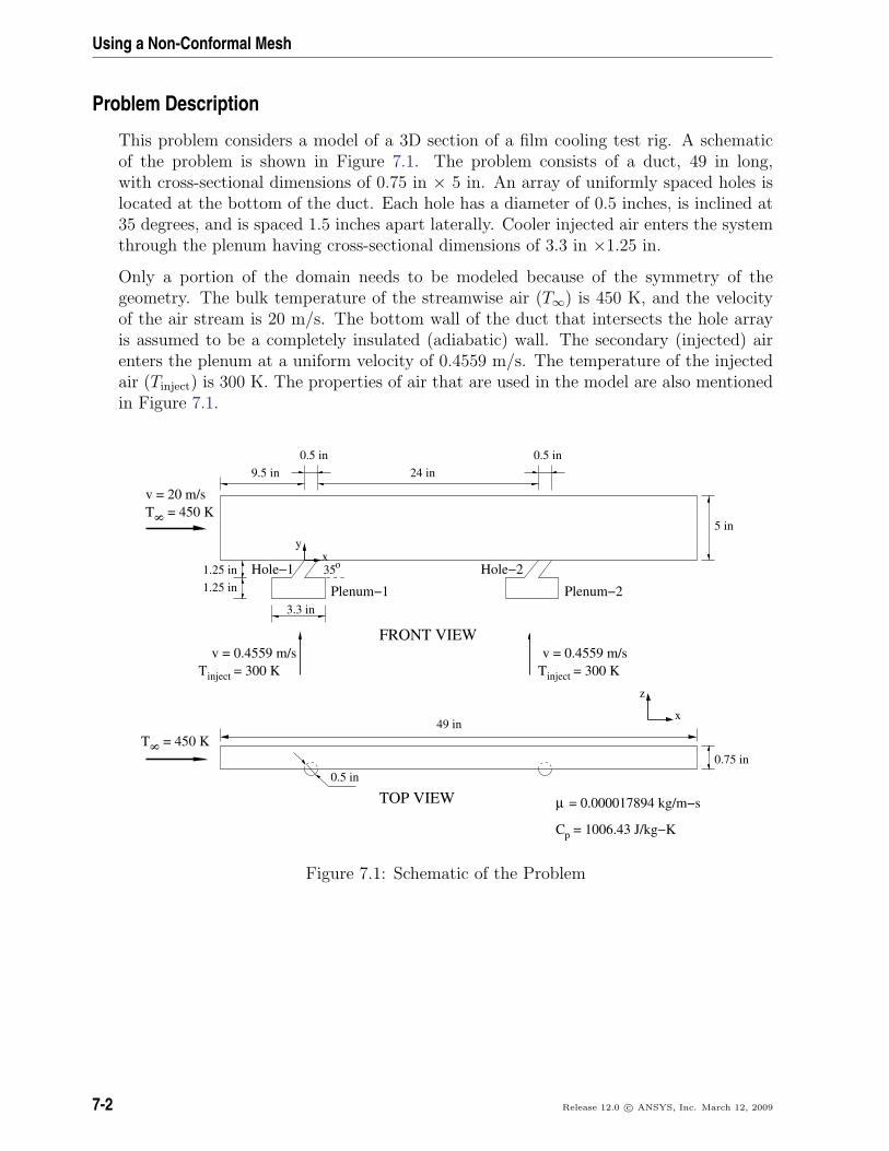
This problem considers a model of a 3D section of a film cooling test rig. A schematicof the problem is shown in Figure 7.1. The problem consists of a duct, 49 in long,with cross-sectional dimensions of 0.75 in × 5 in. An array of uniformly spaced holes islocated at the bottom of the duct. Each hole has a diameter of 0.5 inches, is inclined at35 degrees, and is spaced 1.5 inches apart laterally. Cooler injected air enters the systemthrough the plenum having cross-sectional dimensions of 3.3 in ×1.25 in.
Only a portion of the domain needs to be modeled because of the symmetry of thegeometry. The bulk temperature of the streamwise air (T∞) is 450 K, and the velocityof the air stream is 20 m/s. The bottom wall of the duct that intersects the hole arrayis assumed to be a completely insulated (adiabatic) wall. The secondary (injected) airenters the plenum at a uniform velocity of 0.4559 m/s. The temperature of the injectedair (Tinject) is 300 K. The properties of air that are used in the model are also mentionedin Figure 7.1.
8 = 450 KT
8 = 450 KT
35ο
0.5 in
µ = 0.000017894 kg/m−s
inject = 300 KT
= 1006.43 J/kg−KCp
inject = 300 KT
z
x
Hole−1
Plenum−1
Hole−2
Plenum−2
9.5 in0.5 in 0.5 in
5 in
3.3 in
v = 20 m/s
xy
24 in
0.75 in
TOP VIEW
1.25 in1.25 in
FRONT VIEWv = 0.4559 m/s v = 0.4559 m/s
49 in
Figure 7.1: Schematic of the Problem
7-2 Release 12.0 c© ANSYS, Inc. March 12, 2009
Using a Non-Conformal Mesh
Setup and Solution
Preparation
1. Download non_conformal_mesh.zip from the User Services Center to your workingfolder (as described in Tutorial 1).
2. Unzip non_conformal_mesh.zip.
The files film hex.msh and film tet.msh can be found in the non conformal mesh
folder created after unzipping the file.
3. Use FLUENT Launcher to start the 3D version of ANSYS FLUENT.
For more information about FLUENT Launcher, see Section 1.1.2 in the separateUser’s Guide.
Note: The Display Options are enabled by default. Therefore, once you read in themesh, it will be displayed in the embedded graphics windows.
Step 1: Mesh
1. Read the hex mesh file film hex.msh.
File −→ Read −→Mesh...
2. Append the tet mesh file film tet.msh.
Mesh −→ Zone −→Append Case File...
The Append Case File... functionality allows you to combine two mesh files into onesingle mesh file.
3. Check the mesh.
General −→ Check
ANSYS FLUENT will perform various checks on the mesh and report the progressin the console. Make sure that the reported minimum volume is a positive number.
Release 12.0 c© ANSYS, Inc. March 12, 2009 7-3

Using a Non-Conformal Mesh
4. Scale the mesh and change the unit of length to inches.
General −→ Scale...
(a) Make sure that Convert Units is selected in the Scaling group box.
(b) Select in from the Mesh Was Created In drop-down list by first clicking thedown-arrow button and then clicking the in item from the list that appears.
(c) Click Scale to scale the mesh.
Domain Extents will continue to be reported in the default SI unit of meters.
(d) Select in from the View Length Unit In drop-down list to set inches as theworking unit for length.
(e) Close the Scale Mesh dialog box.
5. Check the mesh.
General −→ Check
Note: It is a good idea to check the mesh after you manipulate it (i.e., scale,convert to polyhedra, merge, separate, fuse, add zones, or smooth and swap.)This will ensure that the quality of the mesh has not been compromised.
6. Display an outline of the 3D mesh.
General −→ Display...
(a) Retain the default selections in the Surfaces list.
(b) Click Display.
(c) Close the Mesh Display dialog box.
7-4 Release 12.0 c© ANSYS, Inc. March 12, 2009

Using a Non-Conformal Mesh
7. Manipulate the mesh display to obtain a front view as shown in Figure 7.2.
Graphics and Animations −→ Views...
(a) Select front in the Views list.
(b) Click Apply.
(c) Close the Views dialog box.
Y
XZ
MeshFLUENT 12.0 (3d, dp, pbns, lam)
Figure 7.2: Hybrid Mesh for Film Cooling Problem
Release 12.0 c© ANSYS, Inc. March 12, 2009 7-5
Using a Non-Conformal Mesh
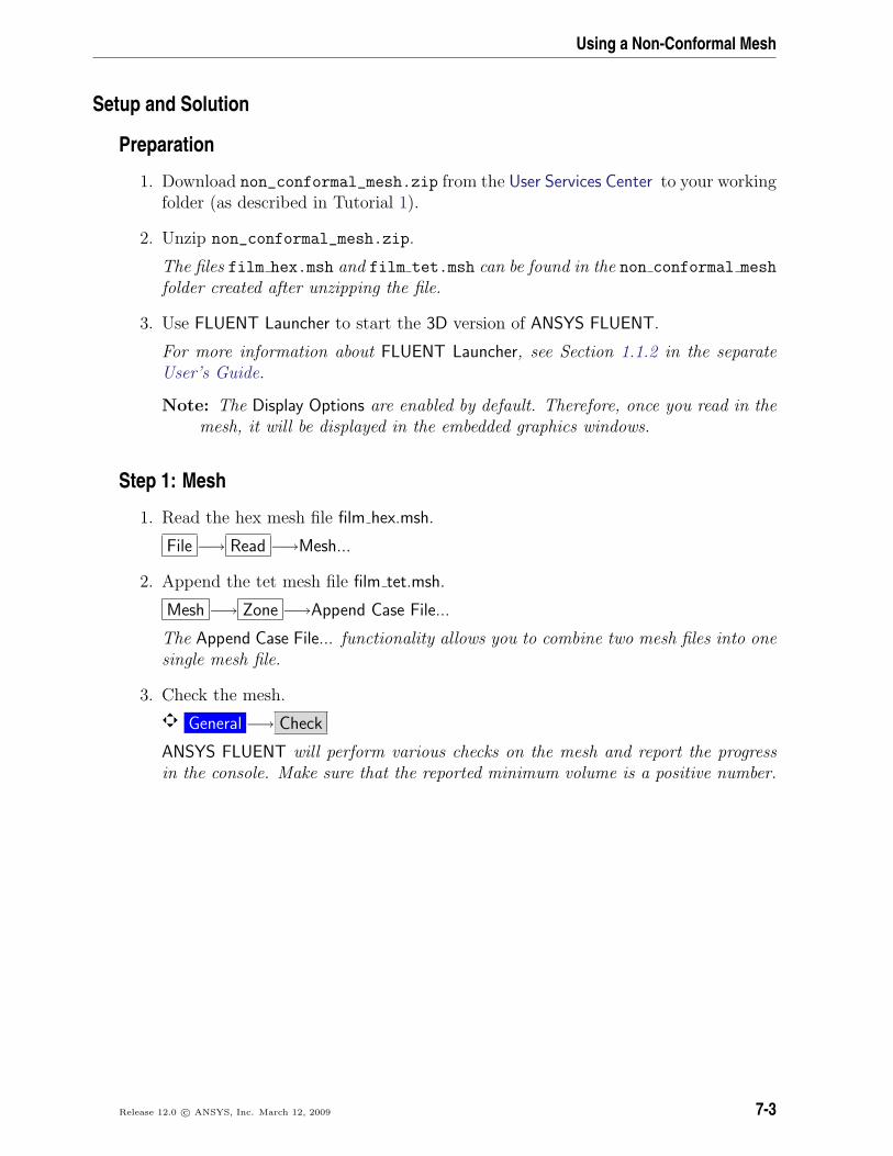
8. Zoom in using the middle mouse button to view the hole and plenum regions(Figure 7.3).
Figure 7.3: Hybrid Mesh (Zoomed-In View)
In Figure 7.3, you can see the quadrilateral faces of the hexahedral cells that areused to model the duct region and the triangular faces of the tetrahedral cells thatare used to model the plenum and hole regions, resulting in a hybrid mesh.
Extra: You can use the right mouse button to check which zone number corre-sponds to each boundary. If you click the right mouse button on one of theboundaries in the graphics window, its zone number, name, and type will beprinted in the ANSYS FLUENT console. This feature is especially useful whenyou have several zones of the same type and you want to distinguish betweenthem quickly.
7-6 Release 12.0 c© ANSYS, Inc. March 12, 2009

Using a Non-Conformal Mesh
Step 2: General Settings
General
1. Retain the default solver settings.
Step 3: Models
Models
1. Enable heat transfer by enabling the energy equation.
Models −→ Energy −→ Edit...
(a) Click OK to close the Energy dialog box.
Release 12.0 c© ANSYS, Inc. March 12, 2009 7-7

Using a Non-Conformal Mesh
2. Enable the standard k-ε turbulence model.
Models −→ Viscous −→ Edit...
(a) Select k-epsilon (2 eqn) in the Model list.
The Viscous Model dialog box will expand to show the additional input optionsfor the k-ε model.
(b) Retain the default settings for the remaining parameters.
(c) Click OK to close the Viscous Model dialog box.
7-8 Release 12.0 c© ANSYS, Inc. March 12, 2009
Using a Non-Conformal Mesh
Step 4: Materials
Materials
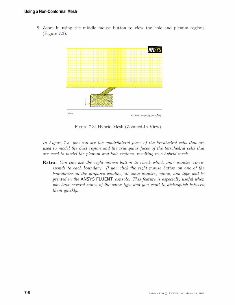
1. Define the material properties.
Materials −→ Fluid −→ Create/Edit...
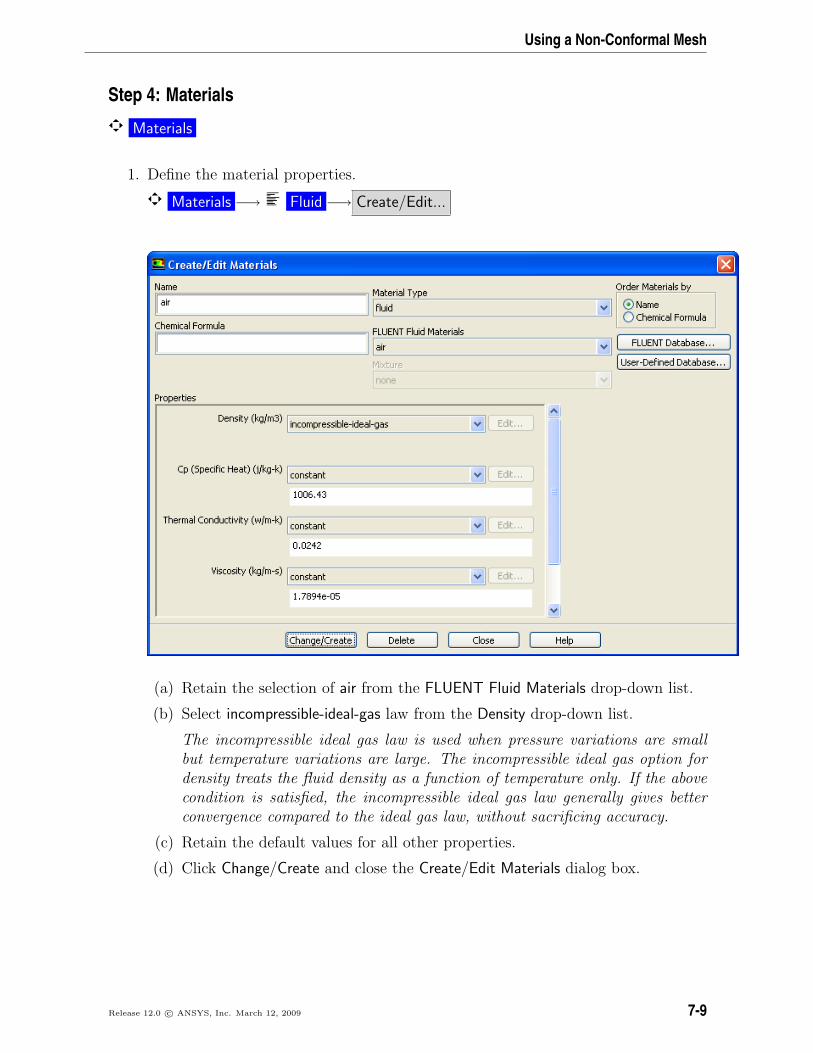
(a) Retain the selection of air from the FLUENT Fluid Materials drop-down list.
(b) Select incompressible-ideal-gas law from the Density drop-down list.
The incompressible ideal gas law is used when pressure variations are smallbut temperature variations are large. The incompressible ideal gas option fordensity treats the fluid density as a function of temperature only. If the abovecondition is satisfied, the incompressible ideal gas law generally gives betterconvergence compared to the ideal gas law, without sacrificing accuracy.
(c) Retain the default values for all other properties.
(d) Click Change/Create and close the Create/Edit Materials dialog box.
Release 12.0 c© ANSYS, Inc. March 12, 2009 7-9
Using a Non-Conformal Mesh
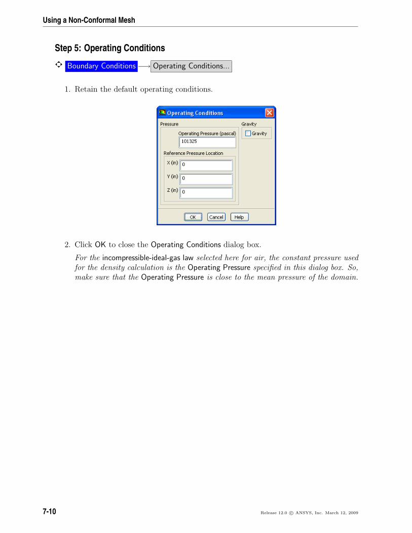
Step 5: Operating Conditions
Boundary Conditions −→ Operating Conditions...
1. Retain the default operating conditions.
2. Click OK to close the Operating Conditions dialog box.
For the incompressible-ideal-gas law selected here for air, the constant pressure usedfor the density calculation is the Operating Pressure specified in this dialog box. So,make sure that the Operating Pressure is close to the mean pressure of the domain.
7-10 Release 12.0 c© ANSYS, Inc. March 12, 2009
Using a Non-Conformal Mesh
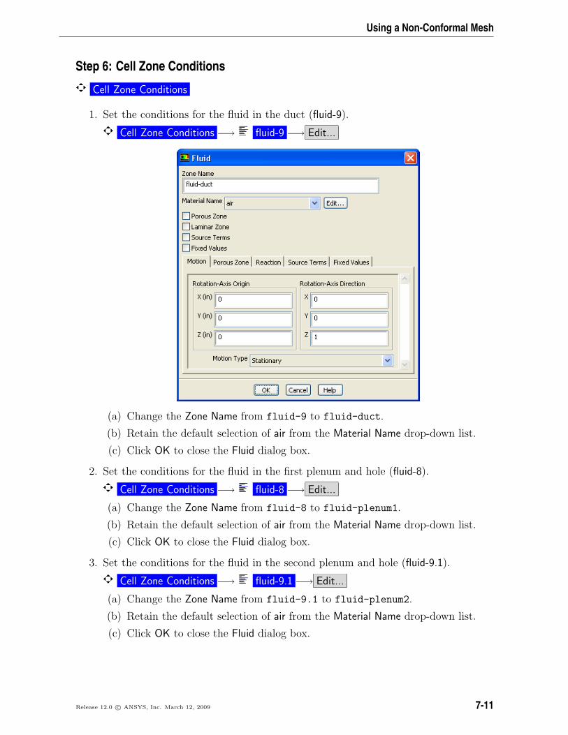
Step 6: Cell Zone Conditions
Cell Zone Conditions
1. Set the conditions for the fluid in the duct (fluid-9).
Cell Zone Conditions −→ fluid-9 −→ Edit...
(a) Change the Zone Name from fluid-9 to fluid-duct.
(b) Retain the default selection of air from the Material Name drop-down list.
(c) Click OK to close the Fluid dialog box.
2. Set the conditions for the fluid in the first plenum and hole (fluid-8).
Cell Zone Conditions −→ fluid-8 −→ Edit...
(a) Change the Zone Name from fluid-8 to fluid-plenum1.
(b) Retain the default selection of air from the Material Name drop-down list.
(c) Click OK to close the Fluid dialog box.
3. Set the conditions for the fluid in the second plenum and hole (fluid-9.1).
Cell Zone Conditions −→ fluid-9.1 −→ Edit...
(a) Change the Zone Name from fluid-9.1 to fluid-plenum2.
(b) Retain the default selection of air from the Material Name drop-down list.
(c) Click OK to close the Fluid dialog box.
Release 12.0 c© ANSYS, Inc. March 12, 2009 7-11
Using a Non-Conformal Mesh
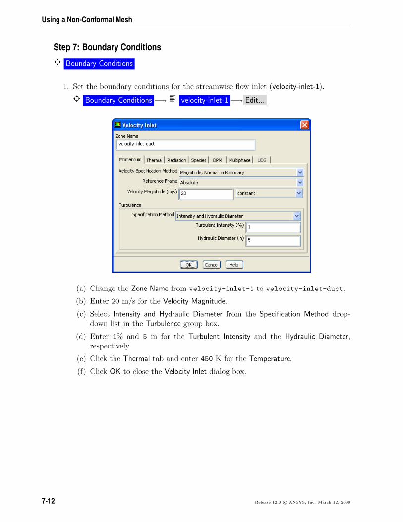
Step 7: Boundary Conditions
Boundary Conditions
1. Set the boundary conditions for the streamwise flow inlet (velocity-inlet-1).
Boundary Conditions −→ velocity-inlet-1 −→ Edit...
(a) Change the Zone Name from velocity-inlet-1 to velocity-inlet-duct.
(b) Enter 20 m/s for the Velocity Magnitude.
(c) Select Intensity and Hydraulic Diameter from the Specification Method drop-down list in the Turbulence group box.
(d) Enter 1% and 5 in for the Turbulent Intensity and the Hydraulic Diameter,respectively.
(e) Click the Thermal tab and enter 450 K for the Temperature.
(f) Click OK to close the Velocity Inlet dialog box.
7-12 Release 12.0 c© ANSYS, Inc. March 12, 2009

Using a Non-Conformal Mesh
2. Set the boundary conditions for the first injected stream inlet (velocity-inlet-5).
Boundary Conditions −→ velocity-inlet-5 −→ Edit...
(a) Change the Zone Name from velocity-inlet-5 to velocity-inlet-plenum1.
(b) Enter 0.4559 m/s for the Velocity Magnitude.
(c) Select Intensity and Viscosity Ratio from the Specification Method drop-downlist in the Turbulence group box.
(d) Enter 1% for Turbulent Intensity and retain the default setting of 10 for Tur-bulent Viscosity Ratio.
(e) Click the Thermal tab and retain the setting of 300 K for Temperature.
(f) Click OK to close the Velocity Inlet dialog box.
In the absence of any identifiable length scale for turbulence, the Intensity and Vis-cosity Ratio method should be used.
For more information about setting the boundary conditions for turbulence, seeChapter 12 in the separate User’s Guide.
Release 12.0 c© ANSYS, Inc. March 12, 2009 7-13
Using a Non-Conformal Mesh
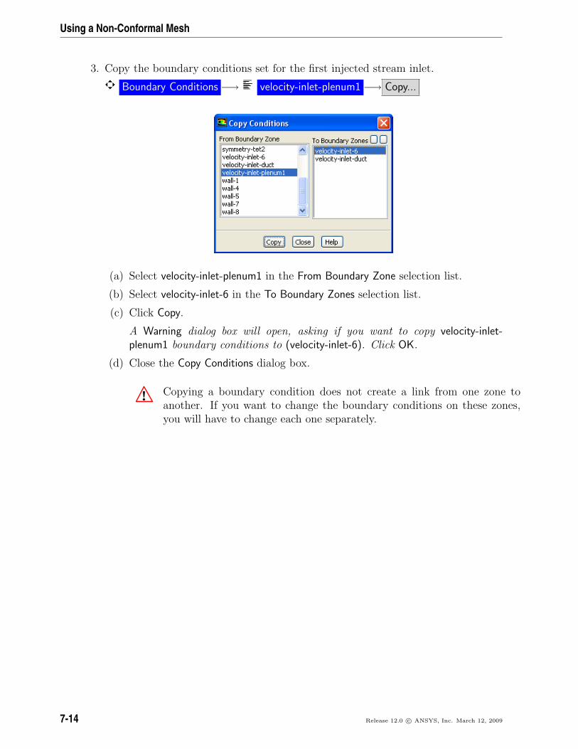
3. Copy the boundary conditions set for the first injected stream inlet.
Boundary Conditions −→ velocity-inlet-plenum1 −→ Copy...
(a) Select velocity-inlet-plenum1 in the From Boundary Zone selection list.
(b) Select velocity-inlet-6 in the To Boundary Zones selection list.
(c) Click Copy.
A Warning dialog box will open, asking if you want to copy velocity-inlet-plenum1 boundary conditions to (velocity-inlet-6). Click OK.
(d) Close the Copy Conditions dialog box.
! Copying a boundary condition does not create a link from one zone toanother. If you want to change the boundary conditions on these zones,you will have to change each one separately.
7-14 Release 12.0 c© ANSYS, Inc. March 12, 2009

Using a Non-Conformal Mesh
4. Set the boundary conditions for the second injected stream inlet (velocity-inlet-6).
Boundary Conditions −→ velocity-inlet-6 −→ Edit...
(a) Change the Zone Name from velocity-inlet-6 to velocity-inlet-plenum2.
(b) Verify that the boundary conditions were copied correctly.
(c) Click OK to close the Velocity Inlet dialog box.
Release 12.0 c© ANSYS, Inc. March 12, 2009 7-15

Using a Non-Conformal Mesh
5. Set the boundary conditions for the flow exit (pressure-outlet-1).
Boundary Conditions −→ pressure-outlet-1 −→ Edit...
(a) Change the Zone Name from pressure-outlet-1 to pressure-outlet-duct.
(b) Retain the default setting of 0 Pa for Gauge Pressure.
(c) Select Intensity and Viscosity Ratio from the Specification Method drop-downlist in the Turbulence group box.
(d) Enter 1% for Backflow Turbulent Intensity and retain the default setting of 10for Backflow Turbulent Viscosity Ratio.
(e) Click the Thermal tab and enter 450 K for Backflow Total Temperature.
(f) Click OK to close the Pressure Outlet dialog box.
7-16 Release 12.0 c© ANSYS, Inc. March 12, 2009

Using a Non-Conformal Mesh
6. Retain the default boundary conditions for the plenum and hole walls (wall-4 andwall-5).
Boundary Conditions −→ wall-4 −→ Edit...
Release 12.0 c© ANSYS, Inc. March 12, 2009 7-17
Using a Non-Conformal Mesh
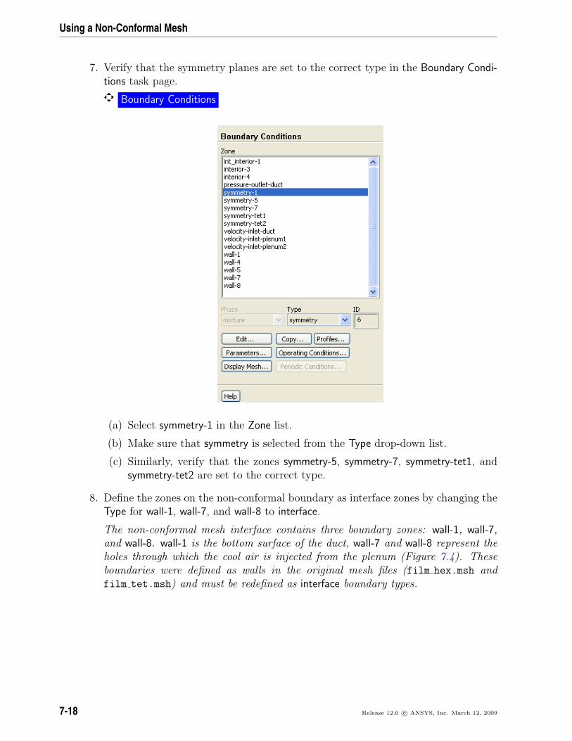
7. Verify that the symmetry planes are set to the correct type in the Boundary Condi-tions task page.
Boundary Conditions
(a) Select symmetry-1 in the Zone list.
(b) Make sure that symmetry is selected from the Type drop-down list.
(c) Similarly, verify that the zones symmetry-5, symmetry-7, symmetry-tet1, andsymmetry-tet2 are set to the correct type.
8. Define the zones on the non-conformal boundary as interface zones by changing theType for wall-1, wall-7, and wall-8 to interface.
The non-conformal mesh interface contains three boundary zones: wall-1, wall-7,and wall-8. wall-1 is the bottom surface of the duct, wall-7 and wall-8 represent theholes through which the cool air is injected from the plenum (Figure 7.4). Theseboundaries were defined as walls in the original mesh files (film hex.msh andfilm tet.msh) and must be redefined as interface boundary types.
7-18 Release 12.0 c© ANSYS, Inc. March 12, 2009

Using a Non-Conformal Mesh
(a) Open the Mesh Display dialog box.
General −→ Display...
i. Select wall-1, wall-7, and wall-8 from the Surfaces selection list.
Use the scroll bar to access the surfaces that are not initially visible in theMesh Display dialog box.
Note: You may need to deselect all surfaces first by selecting the unshadedicon to the far right of Surfaces.
ii. Click Display and close the Mesh Display dialog box.
(b) Display the bottom view.
Graphics and Animations −→ Views...
i. Select bottom in the Views list and click Apply.
ii. Close the Views dialog box.
Zoom in using the middle mouse button. Figure 7.4 shows the mesh forthe wall-1 and wall-7 boundaries (i.e., hole-1). Similarly, you can zoom into see the mesh for the wall-1 and wall-8 boundaries (i.e., hole-2).
Figure 7.4: Mesh for the wall-1 and wall-7 Boundaries
Release 12.0 c© ANSYS, Inc. March 12, 2009 7-19

Using a Non-Conformal Mesh
(a) Select wall-1 in the Zone list and select interface as the new Type.
Boundary Conditions
A Question dialog box will open, asking if it is OK to change the type of wall-1from wall to interface. Click Yes in the Question dialog box.
The Interface dialog box will open and give the default name for the newlycreated interface zone.
i. Change the Zone Name to interface-duct.
ii. Click OK to close the Interface dialog box.
(b) Similarly, convert wall-7 and wall-8 to interface boundary zones, specifyinginterface-hole1 and interface-hole2 for Zone Name, respectively.
7-20 Release 12.0 c© ANSYS, Inc. March 12, 2009
Using a Non-Conformal Mesh
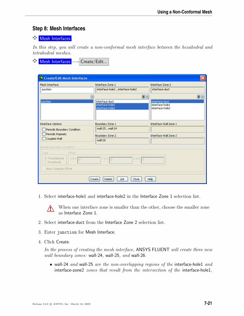
Step 8: Mesh Interfaces
Mesh Interfaces
In this step, you will create a non-conformal mesh interface between the hexahedral andtetrahedral meshes.
Mesh Interfaces −→ Create/Edit...
1. Select interface-hole1 and interface-hole2 in the Interface Zone 1 selection list.
! When one interface zone is smaller than the other, choose the smaller zoneas Interface Zone 1.
2. Select interface-duct from the Interface Zone 2 selection list.
3. Enter junction for Mesh Interface.
4. Click Create.
In the process of creating the mesh interface, ANSYS FLUENT will create three newwall boundary zones: wall-24, wall-25, and wall-26.
• wall-24 and wall-25 are the non-overlapping regions of the interface-hole1 andinterface-zone2 zones that result from the intersection of the interface-hole1,
Release 12.0 c© ANSYS, Inc. March 12, 2009 7-21
Using a Non-Conformal Mesh
interface-hole2, and interface-duct boundary zones. They are listed under Bound-ary Zone 1 in the Create/Edit Mesh Interfaces dialog box. These wall boundariesare empty, since interface-hole1 and interface-hole2 are completely containedwithin the interface-duct boundary.
• wall-26 is the non-overlapping region of the interface-duct zone that results fromthe intersection of the three interface zones, and is listed under Boundary Zone2 in the Create/Edit Mesh Interfaces dialog box.
You will not be able to display these walls.
! You need to set boundary conditions for wall-26 (since it is not empty). Inthis case, the default settings are used.
5. Close the Create/Edit Mesh Interfaces dialog box.
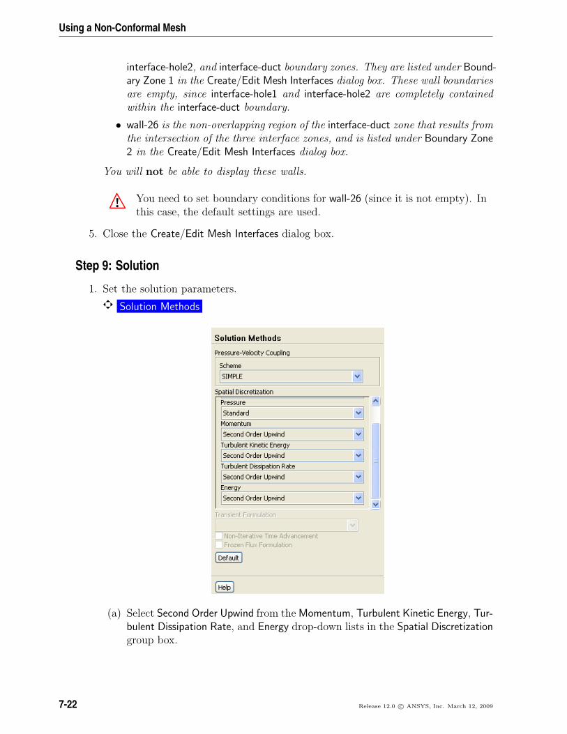
Step 9: Solution
1. Set the solution parameters.
Solution Methods
(a) Select Second Order Upwind from the Momentum, Turbulent Kinetic Energy, Tur-bulent Dissipation Rate, and Energy drop-down lists in the Spatial Discretizationgroup box.
7-22 Release 12.0 c© ANSYS, Inc. March 12, 2009

Using a Non-Conformal Mesh
2. Enable the plotting of residuals.
Monitors −→ Residuals −→ Edit...
(a) Make sure Plot is enabled in the Options group box.
(b) Click OK to close the Residual Monitors panel.
Release 12.0 c© ANSYS, Inc. March 12, 2009 7-23
Using a Non-Conformal Mesh
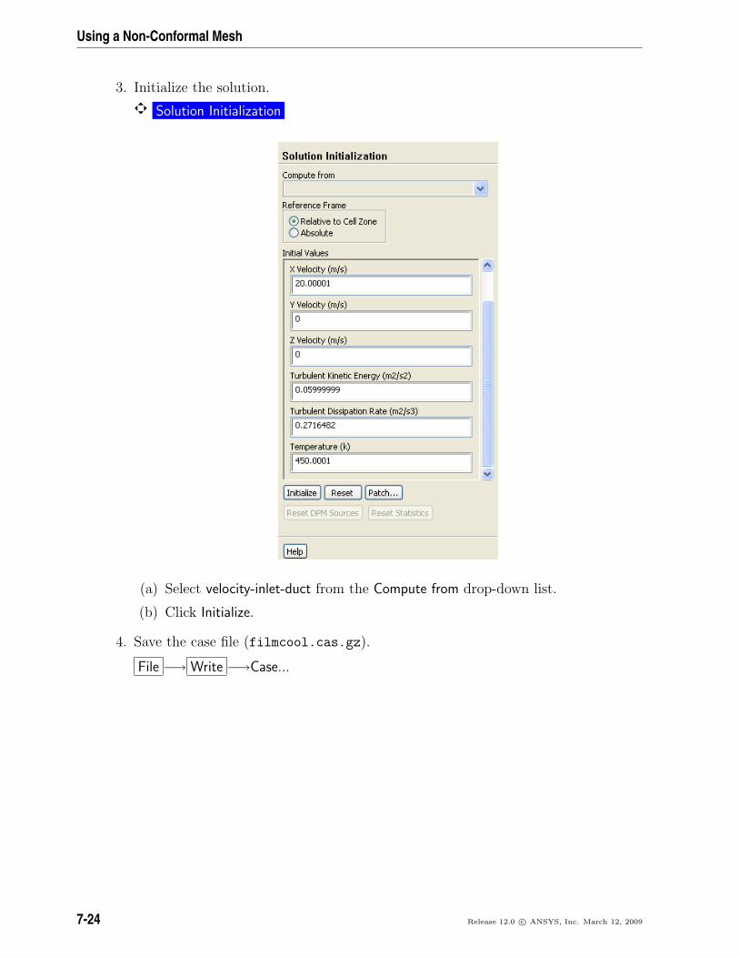
3. Initialize the solution.
Solution Initialization
(a) Select velocity-inlet-duct from the Compute from drop-down list.
(b) Click Initialize.
4. Save the case file (filmcool.cas.gz).
File −→ Write −→Case...
7-24 Release 12.0 c© ANSYS, Inc. March 12, 2009

Using a Non-Conformal Mesh
5. Start the calculation by requesting 250 iterations.
Run Calculation
(a) Enter 250 for the Number of Iterations.
(b) Click Calculate.
Note: During the first few iterations, the console reports that turbulent viscos-ity is limited in a couple of cells. The console should no longer display thismessage as the solution converges and the turbulent viscosity approachesmore reasonable levels.
The solution converges after approximately 125 iterations.
6. Save the case and data files (filmcool.cas.gz and filmcool.dat.gz).
File −→ Write −→Case & Data...
Note: If you choose a file name that already exists in the current folder, ANSYSFLUENT will prompt you for confirmation to overwrite the file.
Release 12.0 c© ANSYS, Inc. March 12, 2009 7-25
Using a Non-Conformal Mesh
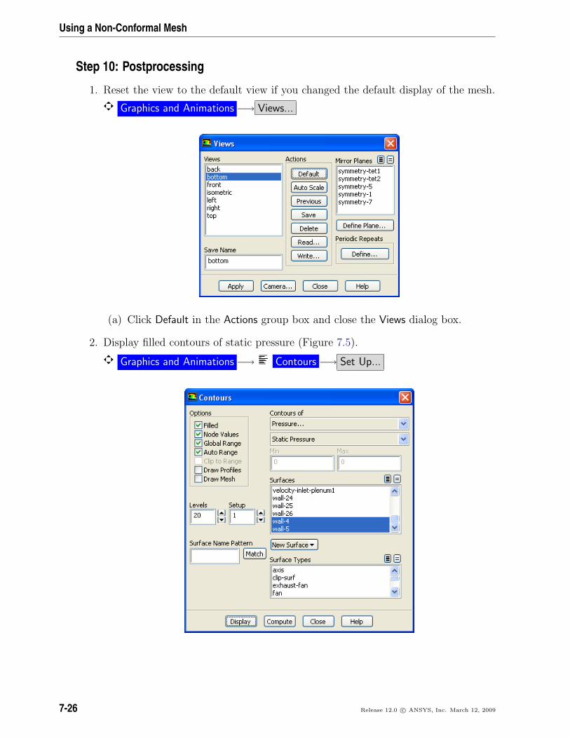
Step 10: Postprocessing
1. Reset the view to the default view if you changed the default display of the mesh.
Graphics and Animations −→ Views...
(a) Click Default in the Actions group box and close the Views dialog box.
2. Display filled contours of static pressure (Figure 7.5).
Graphics and Animations −→ Contours −→ Set Up...
7-26 Release 12.0 c© ANSYS, Inc. March 12, 2009

Using a Non-Conformal Mesh
(a) Enable Filled in the Options group box.
(b) Make sure Pressure... and Static Pressure are selected from the Contours ofdrop-down lists.
(c) Select interface-duct, interface-hole1, interface-hole2, symmetry-1, symmetry-tet1,symmetry-tet2, wall-4, and wall-5 in the Surfaces selection list.
Use the scroll bar to access the surfaces that are not initially visible in theContours dialog box.
(d) Click Display in the Contours dialog box.
Contours of Static Pressure (pascal)FLUENT 12.0 (3d, pbns, ske)
1.69e+021.57e+021.45e+021.33e+021.21e+021.09e+029.72e+018.53e+017.33e+016.13e+014.93e+013.73e+012.54e+011.34e+011.40e+00-1.06e+0-2.26e+0-3.45e+0-4.65e+0-5.85e+0-7.05e+0
Y
XZ
Figure 7.5: Contours of Static Pressure
The maximum pressure change (see Figure 7.5) is only 239 Pa. Compared toa mean pressure of 1.013e5 Pa, the variation is less than 0.3%, and thus theuse of the incompressible ideal gas law is appropriate.
(e) Zoom in on the view to display the contours at the holes (Figures 7.6 and 7.7).
Note the high/low pressure zones on the upstream/downstream sides of thecoolant hole, where the jet first penetrates the primary flow in the duct.
Release 12.0 c© ANSYS, Inc. March 12, 2009 7-27

Using a Non-Conformal Mesh
Figure 7.6: Contours of Static Pressure at the First Hole
Figure 7.7: Contours of Static Pressure at the Second Hole
7-28 Release 12.0 c© ANSYS, Inc. March 12, 2009
Using a Non-Conformal Mesh
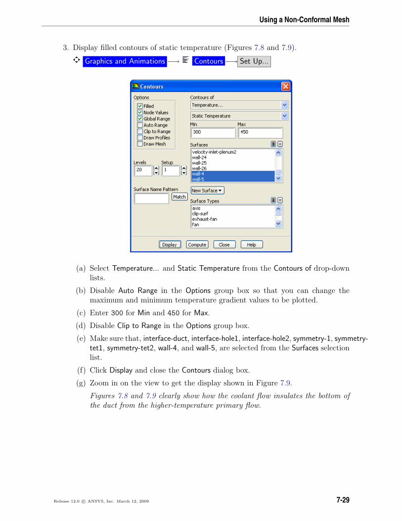
3. Display filled contours of static temperature (Figures 7.8 and 7.9).
Graphics and Animations −→ Contours −→ Set Up...
(a) Select Temperature... and Static Temperature from the Contours of drop-downlists.
(b) Disable Auto Range in the Options group box so that you can change themaximum and minimum temperature gradient values to be plotted.
(c) Enter 300 for Min and 450 for Max.
(d) Disable Clip to Range in the Options group box.
(e) Make sure that, interface-duct, interface-hole1, interface-hole2, symmetry-1, symmetry-tet1, symmetry-tet2, wall-4, and wall-5, are selected from the Surfaces selectionlist.
(f) Click Display and close the Contours dialog box.
(g) Zoom in on the view to get the display shown in Figure 7.9.
Figures 7.8 and 7.9 clearly show how the coolant flow insulates the bottom ofthe duct from the higher-temperature primary flow.
Release 12.0 c© ANSYS, Inc. March 12, 2009 7-29

Using a Non-Conformal Mesh
Figure 7.8: Contours of Static Temperature
Figure 7.9: Contours of Static Temperature (Zoomed-In View)
7-30 Release 12.0 c© ANSYS, Inc. March 12, 2009
Using a Non-Conformal Mesh
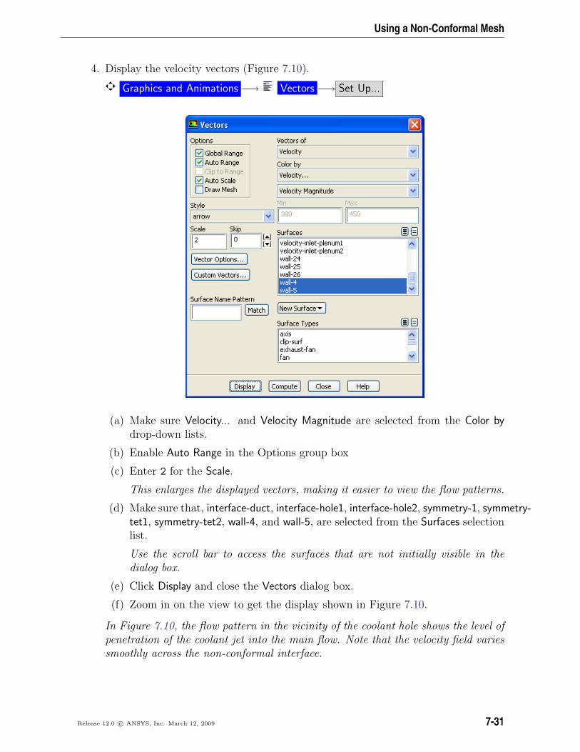
4. Display the velocity vectors (Figure 7.10).
Graphics and Animations −→ Vectors −→ Set Up...
(a) Make sure Velocity... and Velocity Magnitude are selected from the Color bydrop-down lists.
(b) Enable Auto Range in the Options group box
(c) Enter 2 for the Scale.
This enlarges the displayed vectors, making it easier to view the flow patterns.
(d) Make sure that, interface-duct, interface-hole1, interface-hole2, symmetry-1, symmetry-tet1, symmetry-tet2, wall-4, and wall-5, are selected from the Surfaces selectionlist.
Use the scroll bar to access the surfaces that are not initially visible in thedialog box.
(e) Click Display and close the Vectors dialog box.
(f) Zoom in on the view to get the display shown in Figure 7.10.
In Figure 7.10, the flow pattern in the vicinity of the coolant hole shows the level ofpenetration of the coolant jet into the main flow. Note that the velocity field variessmoothly across the non-conformal interface.
Release 12.0 c© ANSYS, Inc. March 12, 2009 7-31

Using a Non-Conformal Mesh
Figure 7.10: Velocity Vectors
5. Create an isosurface along a horizontal cross-section of the duct, 0.1 inches abovethe bottom, at y = 0.1 in.
Surface −→Iso-Surface...
7-32 Release 12.0 c© ANSYS, Inc. March 12, 2009

Using a Non-Conformal Mesh
(a) Select Mesh... and Y-Coordinate from the Surface of Constant drop-down lists.
(b) Enter 0.1 for Iso-Values.
(c) Enter y=0.1in for New Surface Name.
(d) Click Create.
(e) Close the Iso-Surface dialog box.
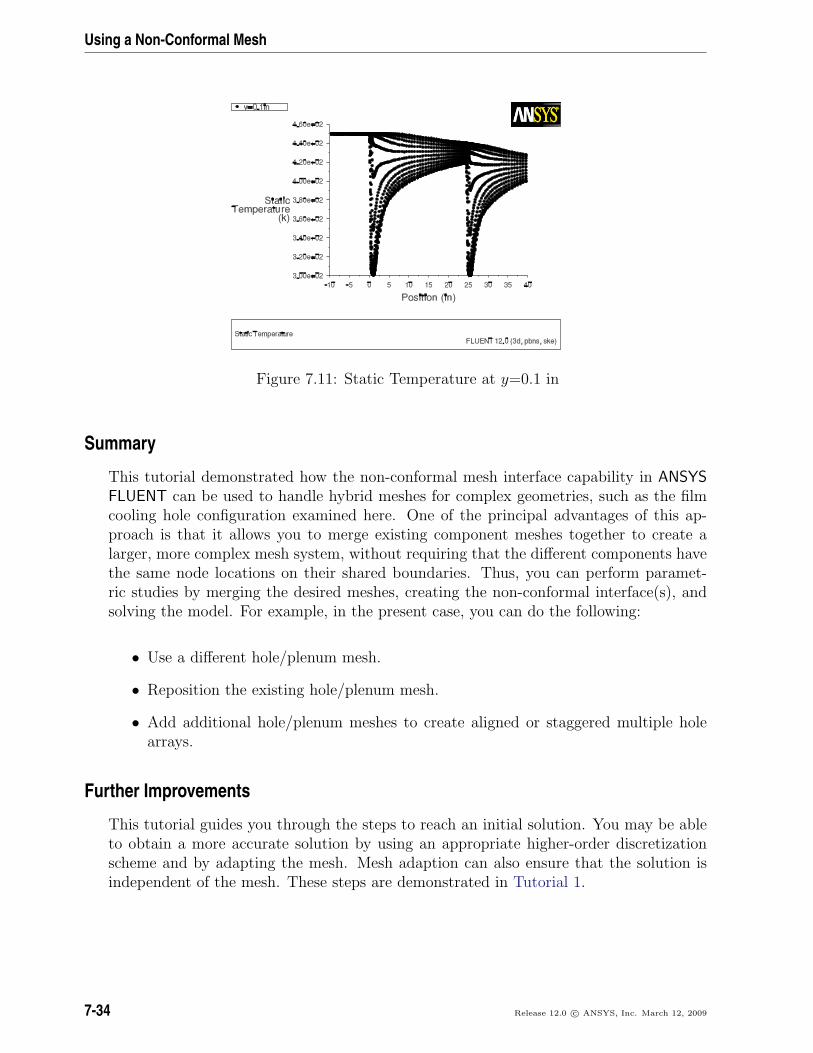
6. Create an XY plot of static temperature on the isosurface created (Figure 7.11).
Plots −→ XY Plot −→ Set Up...
(a) Retain the default values in the Plot Direction group box.
(b) Select Temperature... and Static Temperature from the Y-Axis Function drop-down lists.
(c) Select y=0.1in in the Surfaces selection list.
Scroll down using the scroll bar to access y=0.1in.
(d) Click Plot.
In Figure 7.11, you can see how the temperature of the fluid changes as thecool air from the injection holes mixes with the primary flow. The temperatureis coolest just downstream of the holes. You can also make a similar plot onthe lower wall to examine the wall surface temperature.
(e) Close the Solution XY Plot dialog box.
Release 12.0 c© ANSYS, Inc. March 12, 2009 7-33
Using a Non-Conformal Mesh
Figure 7.11: Static Temperature at y=0.1 in
Summary
This tutorial demonstrated how the non-conformal mesh interface capability in ANSYSFLUENT can be used to handle hybrid meshes for complex geometries, such as the filmcooling hole configuration examined here. One of the principal advantages of this ap-proach is that it allows you to merge existing component meshes together to create alarger, more complex mesh system, without requiring that the different components havethe same node locations on their shared boundaries. Thus, you can perform paramet-ric studies by merging the desired meshes, creating the non-conformal interface(s), andsolving the model. For example, in the present case, you can do the following:
• Use a different hole/plenum mesh.
• Reposition the existing hole/plenum mesh.
• Add additional hole/plenum meshes to create aligned or staggered multiple holearrays.
Further Improvements
This tutorial guides you through the steps to reach an initial solution. You may be ableto obtain a more accurate solution by using an appropriate higher-order discretizationscheme and by adapting the mesh. Mesh adaption can also ensure that the solution isindependent of the mesh. These steps are demonstrated in Tutorial 1.
7-34 Release 12.0 c© ANSYS, Inc. March 12, 2009