Embed Size (px)
Citation preview

8/3/2019 TurboCNC v4Command
http://slidepdf.com/reader/full/turbocnc-v4command 1/131
TURBOCNC V4.01
CNC MACHINERY
CONTROL PROGRAM
© 2005 DAK Engineering. All Rights Reserved
boCNC v4.01 documentation http://www.dakeng.com/man/turbocnc.html
131 10/11/2554 17:39

8/3/2019 TurboCNC v4Command
http://slidepdf.com/reader/full/turbocnc-v4command 2/131
boCNC v4.01 documentation http://www.dakeng.com/man/turbocnc.html
131 10/11/2554 17:39

8/3/2019 TurboCNC v4Command
http://slidepdf.com/reader/full/turbocnc-v4command 3/131
Table of Contents
Table of ContentsPart 1 – Quick Start
Legal NoticeUpgrade Information
InstallationSystem RequirementsProgram InstallationGetting Started
Contact InformationSupportCredits
Part 2 – User’s Guide
IntroductionMenu SystemQuick KeysMotion Keys:FileRunSetupConfigureToolsHelp
Port Monitor Monitor Lockout:Display Monitor:Port to Monitor:Color Scheme:Ignore Contention:Active Mode:Force Full I/O:Control Register Mode:
TurboCNC Configuration FileCommand Line Options
Part 3 – RS 274 Programming GuideIntroductionTurboCNC Parser OpCodes
OperandsConditional Execution
Preparatory Functions (G-Codes)
boCNC v4.01 documentation http://www.dakeng.com/man/turbocnc.html
131 10/11/2554 17:39

8/3/2019 TurboCNC v4Command
http://slidepdf.com/reader/full/turbocnc-v4command 4/131
Supported Preparatory FunctionsG00 Rapid PositioningG01 Linear InterpolationG02 CW circular interpolation (3D)G03 CCW circular interpolation (3D)G04 DwellG16 Set implicit planesG17-19 Set current 2D planeG20 Inch unitsG21 Metric unitsG28 Home all axesG31 Probe moveG32 Probe cycleG33 Single pass threading
G50 Probe hole IDG53 Change to master coordinatesG54-G59 Change fixture offsetG70 Inch modeG71 Metric modeG72 CW helical interpolationG73 CCW helical interpolationG76 Multi-pass threading
G77 Turning/Boring/Milling CycleG78 Peck Motion CycleG80 Cancel drill cycleG81 Drill cycleG82 Drill + Dwell cycleG83 Peck drill cycleG90 Absolute coordinatesG91 Incremental coordinates
G92 Preload of registers/Set machine coordinatesG93 Inverse time feed rateG94 IPM feed rateG95 IPR feed rateG97 Program spindle RPMG178 Speed peck motionG183 Speed peck drill cycle
Miscellaneous Functions (M-Codes)
Supported Miscellaneous FunctionsM00 Automatic haltM01 Optional halt
boCNC v4.01 documentation http://www.dakeng.com/man/turbocnc.html
131 10/11/2554 17:39

8/3/2019 TurboCNC v4Command
http://slidepdf.com/reader/full/turbocnc-v4command 5/131
M02 End of programM03 Spindle on CWM04 Spindle on CCWM05 Spindle off M06 Tool changeM07 Coolant A on (flood)M08 Coolant B on (mist)M09 Coolants off M10 ClampM11 UnclampM13 Spindle CW and coolant A onM14 Spindle CCW and coolant A onM17 Enable drivesM18 Disable drives
M21 Open colletM22 Close colletM30 End of program & rewindM40 – M46: Gear ChangesM48 Restore feed overrideM49 Cancel feed overrideM50 Read spindle speedM60 Jump to subroutine (obsolete function)
M62 Return from subroutine (obsolete function)M70 Set PLC handshake output to inactiveM71 Set PLC handshake output to activeM72 Wait for PLC handshake input to go inactiveM73 Wait for PLC handshake input to go activeM97 JumpM98 Jump to subroutineM99 Return from subroutine
S-Word Handing:Programming ExtensionsExpressionsVariablesSample Code - Using Expressions and VariablesConditional Execution (IF)Simulating Advanced Conditional Execution StructuresInteracting with the Operator
Putting it all Together: The Circle Using Line SegmentsPart 4 – Introduction to CNC
General
boCNC v4.01 documentation http://www.dakeng.com/man/turbocnc.html
131 10/11/2554 17:39
8/3/2019 TurboCNC v4Command
http://slidepdf.com/reader/full/turbocnc-v4command 6/131
The Axes De-Mystified:Axis conventions:The parallel port explained:
Part 5 – Technical DetailsThe Parallel PortSet Up of Step and Direction LinesI/O PointsConfiguring Speed ControlSetting up Windows 9x to boot directly into MS-DOSModify MSDOS.SYSModifying CONFIG.SYSModify AutoEXEC.BAT
Part 1 – Quick Start
Legal Notice
WARNING
!
Various warnings appear throughoutthis manual. Do not take these to beapplicable in all situations, nor tocompletely describe the hazardsinvolved. CNC machines supply thepower to do your work more
effectively. You supply the judgment. Although DAKEngineering does its best to standbehind this product, we won't beliable for damages incurred.
Regular users of TurboCNC are expected to register the program by
paying for it (see contact section). Source code and bugreport/upgrade newsletters are made available to registered users viaemail.
If you're a registered user, you can do anything you want with theprogram and source code to modify it as you see fit, except for redistribution. In your own shop, anything goes.
Upgrade Information
There have been numerous changes to TurboCNC since the major code branh (version 3.X). These include modifications to the codeaccepted to bring it into line with the RS-274 D standard and industry
boCNC v4.01 documentation http://www.dakeng.com/man/turbocnc.html
131 10/11/2554 17:39
8/3/2019 TurboCNC v4Command
http://slidepdf.com/reader/full/turbocnc-v4command 7/131
practices. G16 is no longer supported. Support for G72 and G73 hasbeen dropped, use G02 and G03 with a third axis callout instead toperform helical moves. Similarly, use M98 as a subroutine call, andM99 as a subroutine return instead of the M60 and M62 supported inprevious versions.
New functions in TurboCNC include:· G76 Multi-pass threading
· G93 Inverse time feed mode
· G178 – Speed Peck Motion
· G183 – Speed Peck Drill Cycle
· M97 – Jump
Some of the functions have had their parameters changed. As anexample the '#' is no longer used as a parameter, therefore G04(Dwell) now accepts the 'Q' parameter to specify dwell time.
Programming elements including a means of communicating with theoperator, variables, expressions, and conditional execution, are newto this version of TurboCNC. These additions bring new power andflexibility to your programs.
The format of the turbocnc.ini file is backward compatible, so you canuse your old one to get rolling with this new version right away. InsideTurboCNC, use the “Save configuration” option to re-write theturbocnc.ini file, and you’re now up to date!
Since 4.00, there have been scores of bug fixes, and some dialogchanges to make the software easier to use. Many of the changeshave been “under the hood”.
Support for Peter Homann's DigiSpeed spindle control has been
added. For info on this product go to http://www.homanndesigns.com/.
boCNC v4.01 documentation http://www.dakeng.com/man/turbocnc.html
131 10/11/2554 17:39

8/3/2019 TurboCNC v4Command
http://slidepdf.com/reader/full/turbocnc-v4command 8/131
Installation
System Requirements
486DX2-66 or later PC compatible computer with at least 4MB RAM
and a DOS compatible file systemOpen 25-pin parallel port for control
500k free disk space (7M for source code and development tools).TurboCNC can be run from a floppy disk, but a hard drive installationis generally better
A 66 MHz or faster clock speed is recommended for satisfactoryperformance.
Almost any home or office computer system made after 1993 willmeet these requirements. However, some fairly modern industrialcontrol computers may not. Consult your owner's manuals to be sure.TurboCNC will report if any critical things are missing at startup.
For very old computers or those that don't have a math coprocessor,try using version 3.0f of TurboCNC instead. This is available in theweb archive for download at http://www.dakeng.com/archive.html and
although it lacks many features compared to the later versions, it canand has been used for production grade work on even very old286-10 machines. In some countries these may be the onlycomputers available to private citizens.
A note on Laptops:
Some laptops pose problems to TurboCNC and CNC machines.There are two common problems.
The first is the BIOS may introduce its own interrupts, which caninterfere with the generation of a steady pulse train. This problem cancause lost steps. You can try to eliminate these by booting the systeminto BIOS and resetting the options there.
The second common problem is that some laptops do not switchbetween +5 volts and 0 volts on the pins of the printer port as isrequired by many drivers. A parallel port breakout board of your owndesign or a commercial offering such as the Axxus TechnologiesDB1V2.0 can be used to restore the full 5-volt swing required by manystepper and servo motor drives.
boCNC v4.01 documentation http://www.dakeng.com/man/turbocnc.html
131 10/11/2554 17:39

8/3/2019 TurboCNC v4Command
http://slidepdf.com/reader/full/turbocnc-v4command 9/131
boCNC v4.01 documentation http://www.dakeng.com/man/turbocnc.html
131 10/11/2554 17:39
8/3/2019 TurboCNC v4Command
http://slidepdf.com/reader/full/turbocnc-v4command 10/131
Program Installation
Here's how to get TurboCNC on your computer. Future versions willfeature an installer utility, but for now you have to do this manually.
1.
Download a copy of the program from the web athttp://www.dakeng.com/turbo.html, and save the file somewhereon your machine.
2. Obtain a de-archiving utility that will handle .ZIP files. Our recommendation is WinZip, which has a 30-day demo andintegrates well with Windows – downloadable athttp://www.winzip.com. DOS users can use their beloved PKZIPfrom PKWare or a similar product.
3. Extract the contents of the archive to a convenient folder with ashort name, like C:\TCNC\ or similar. You must respect a limitationof eight characters here thanks to an inherited DOS limitation.
4. All of the program files, and this manual, will be found in the newfolder.
5. If you want to install TurboCNC on a different machine, copy thecontents of the folder to a diskette or transfer it over a network to
the new machine. No registry settings, hidden data, or system filechanges are used.
Getting Started
TurboCNC runs in real-mode DOS for maximum speed and controlover the timing of the parallel ports.
Booting into real mode may be a challenge depending on whatsystem you use currently. Here's how you can get the program startedand working efficiently for you under some of the more popular PCoperating systems.
WARNING
!
If you launch TurboCNC from Windows,you'll have problems when you try tocontrol your machine. Read this sectionand follow the instructions for your operating system.
If you just want to "play" with the
boCNC v4.01 documentation http://www.dakeng.com/man/turbocnc.html
of 131 10/11/2554 17:39

8/3/2019 TurboCNC v4Command
http://slidepdf.com/reader/full/turbocnc-v4command 11/131
program without a machine connected,you can ignore this stuff for now. When itcomes time to make chips you'll needthis information.
NOTE: These directions assume the program has already beeninstalled per the above.
MS-DOS (any version from 3.0 & up)
Modify your CONFIG.SYS file to allow a boot-up configuration inwhich EMM386.EXE, HIMEM.SYS, RAMDRIVE.SYS, and any diskcaching programs are not present.
Alternately, create a boot disk with the FORMAT /S command to bootup in a minimal environment.
Disable DOUBLESPACE if it is enabled.
Change to the directory with turbocnc.exe and execute the program.
Windows 3.1
Edit the WIN line and any drivers from your autoexec.bat andconfig.sys files in order to present a clean boot to DOS.
Run TurboCNC from the DOS prompt. If you're still using Win3.1 thisfar into the 21st century, we assume that you know what you're doinghere. Generally, the instructions are the same as for MS-DOS above.
Windows 95/98
From the desktop, pick Start | Shut-down | Restart in MS-DOS mode
Change to the directory with turbocnc.exe and execute the programusing the DOS commands
CD \TCNC or similar for your system, then TURBOCNC
Alternately, you can hold down the CTRL key (or sometimes F8) whileyour computer boots up. A short text menu will appear with some bootoptions. Pick Command Prompt Only, and run as above. If TurboCNCgives you an EMS/XMS driver warning, do it over and pick CommandPrompt Safe Mode instead.
Windows NT / 2000TurboCNC will not drive your CNC system reliably as direct access tothe hardware is not allowed under these operating systems. You can,however run TurboCNC under the command prompt to familiarize
boCNC v4.01 documentation http://www.dakeng.com/man/turbocnc.html
of 131 10/11/2554 17:39

8/3/2019 TurboCNC v4Command
http://slidepdf.com/reader/full/turbocnc-v4command 12/131
yourself with it, and to 'Dry Verify' parts files. All of the screen shots inthis document were gathered by running Turbo CNC on a Windows2000 system and performing a 'Print Window'.
TurboCNC can run on a dual boot system with DOS. Consider formatting a disk partition with FAT16 rather than running solely from
a floppy disk. On some systems using floppy drives only TurboCNChas had problems due to drive access times.
Windows XP
You'll need to create a real-mode boot disk for TurboCNC Get a blankfloppy disk out.
· From the desktop hit Start | My Computer | Floppy (A) [or other letter as appropriate for your system]
·Insert the disk, then hit File | Format
· Check the box that says "Create MS-DOS boot disk" and hitOK to format
Expand and copy the TurboCNC files to the floppy.
Reboot the computer with the floppy in drive A
Execute TurboCNC at the A:\> prompt.
boCNC v4.01 documentation http://www.dakeng.com/man/turbocnc.html
of 131 10/11/2554 17:39

8/3/2019 TurboCNC v4Command
http://slidepdf.com/reader/full/turbocnc-v4command 13/131
Contact Information
The best way to contact us is via email:
Or if you prefer the normal mail:
DAK Engineering c/o Dave Kowalczyk11032 SE 224 PLKent WA 98031 USA
Registration payments ($60) can be sent through PayPal to our account at [email protected], or by check/money order to the
address above. Make checks payable to DAK Engineering. Includeyour email address so that we can send the source code to you aswell.
Support
Consider joining the Yahoo! TurboCNC User Group athttp://groups.yahoo.com/group/turbocnc/. Many of our members arehighly knowledgeable and willing to help, and several have postedtheir enhancements to TurboCNC.
Don't hesitate to let us know about features you want to see in afuture version. Upgrades are continuous, and most suggestions findtheir way in there eventually.
For bug reporting, please send the problem code and your turbocnc.ini file for the program as a courtesy if appropriate to theissue. It helps enormously in analyzing problems.
CreditsDave Kowalczyk – Lead programmer, original author.
Jerry Jankura - Programming, TUI systems and interfaces.
Tony Groothuizen – Programming, debugging.
George and Andrew Bean - Authors of the TechnoJock Toolkit, whichdrives the menu system.
Terry King - Author of Fkeybit.
Harald Geier - Menu usability, MasterCAM posts.
boCNC v4.01 documentation http://www.dakeng.com/man/turbocnc.html
of 131 10/11/2554 17:39

8/3/2019 TurboCNC v4Command
http://slidepdf.com/reader/full/turbocnc-v4command 14/131
John Johnson - M60/62 (now M98 / M99) and parsing algorithms.
Daniel Barber - Windows XP compatibility testing and bootinstructions.
Alan Matheson - Metric mode testing.
Daniel Brock, Wayne Hill, and Andrew Erwood - G76 cyclespecifications.
We would also like to recognize the registered users and the betatesters especially for their support, suggestions, patience, and themany successes they've enjoyed while using this software.
boCNC v4.01 documentation http://www.dakeng.com/man/turbocnc.html
of 131 10/11/2554 17:39

8/3/2019 TurboCNC v4Command
http://slidepdf.com/reader/full/turbocnc-v4command 15/131
Part 2 – User’s Guide
Introduction
TurboCNC is a machine control interpreter. By loading in “g-code”files and executing them, physical motion of a machine occurs.
Menu System
Here's what you should see when you start the program, after theinitial diagnostic screen:
In many respects this program functions like others you have used,such as the concept of opening and editing files, saving, and in theGUI concept.
Note the black colored window on the right hand side of the screen.This is the Status Window, and it's very special. From top to bottom,the Status Window displays the current machine position, the statusof the spindle and coolants (if installed), which options are currentlyactive, and some information about the machine state. You can't
move this window or get rid of it - it's there permanently.The position of each axis is updated at the end of a move, and "Inmotion..." will be displayed while things are still moving. In previousversions you were allowed to have the position updated each step,but this costs too much CPU time to keep up with. The informationhere is updated just after a block executes.
TurboCNC has been redesigned to allow the use of a mouse. The
mouse is deactivated during motion to prevent interference of themouse driver with the generation of the pulse train. If you experiencelost steps while using the mouse, try booting your system without themouse driver.
boCNC v4.01 documentation http://www.dakeng.com/man/turbocnc.html
of 131 10/11/2554 17:39

8/3/2019 TurboCNC v4Command
http://slidepdf.com/reader/full/turbocnc-v4command 16/131
TIP: Although the menu system is designed to be used with a mouse,there are keyboard shortcuts for every function. For example, Alt-F-Xexits the program. This is usually much faster than using the mouse,especially if you don't have one. In many shops, the amount of dirtand crud around (not to mention the tendency for any horizontalsurface to become occupied), will preclude the use of a mouseanyway.
Quick Keys
The functions most commonly used to set up a job have anassociated function key listed on the status bar at the bottom of thescreen. Other common tasks also have a 'Quick Key' associated withthem. These keys are:
·
ctrl + N Open a new file· ctrl + O Open file in editor
· ctrl + R Run from disk
· alt + num Configuration menu for that axis
Motion Keys:
During motion several keys are checked every 18.2 milliseconds(about 55 times per second). These are:
·Esc Panic Stop (Stops motion immediately)
· increase or decrease feed rate 1%
· shift + <> increase or decrease feed rate 10%
During motion, the result of increasing or decreasing the feed rate willnot be seen on the status display. This is updated at the end of thecurrent move.
File
boCNC v4.01 documentation http://www.dakeng.com/man/turbocnc.html
of 131 10/11/2554 17:39

8/3/2019 TurboCNC v4Command
http://slidepdf.com/reader/full/turbocnc-v4command 17/131
New, Open in editor, Run from file, Close, Save, Save As
These first five options are for accessing and manipulating your collection of g-code files. Note that you can only have one file open atany time. G-code files should be straight ASCII text in CRLF (DOS)format.
Open in editor will load the entire file into memory, and bring up anediting window. This is best for smaller files of 500KB or less.Standard editing keys are available.
· ctrl + c copy
· ctrl + v paste
· ctrl + x cut
· up-arrow move cursor up one line
· ctrl + up-arrow move cursor to top of window
· down-arrow move cursor down one line
· ctrl + down-arrow move cursor to bottom of window
· left-arrow move cursor left one character
boCNC v4.01 documentation http://www.dakeng.com/man/turbocnc.html
of 131 10/11/2554 17:39

8/3/2019 TurboCNC v4Command
http://slidepdf.com/reader/full/turbocnc-v4command 18/131
· ctrl + left-arrow move cursor left one word
· right-arrow move cursor right one character
· ctrl + right-arrow move cursor right one word
· page-up scroll screen up one page
· page-down scroll screen down one page
·home move cursor to beginning of line
· ctrl + home move cursor to beginning of file
· end move cursor to end of line
· ctrl + end move cursor to end of file
· F5 stretch window
· ctrl + f find string
· F3 find again
Run from file is used for large files that won't fit into memory. Editingand scrolling through the file are not implemented in this mode. Aconsole is brought up containing more status information and adisplay of code being executed. The next line to be executed will turnred if execution tries to continue beyond the end of the file. Code thathas been executed will turn gray, pending code is yellow. Mostprogram messaging will occur in the display area of the console,rather than bringing up a separate dialog box in this mode.
Sends the currently open file to the printer.
WARNING
!
Ensure that your printer is connected,and your CNC machine is turned off touse this function. It is possible for thestandard print function to cause
boCNC v4.01 documentation http://www.dakeng.com/man/turbocnc.html
of 131 10/11/2554 17:39
8/3/2019 TurboCNC v4Command
http://slidepdf.com/reader/full/turbocnc-v4command 19/131
movement and turn on your spindle if theport definitions of your CNC machinematch that of a printer.
Load Tooling File
Loads a tool and fixture offset file from disk.
Save Tooling File As…
Saves the current tool and fixture offsets to disk. Expert users will findit generally fastest to edit the tool offset file directly to adjust for tooling changes.
Exit
Exits TurboCNC. You will be prompted for confirmation.
Run
There are a variety of functions to actually do some real work withyour machine located under the Run Menu.
The '<' and '>' keys can be used to adjust the feed rate while the CNCmachine is in motion. Using the Shift key in combination with thesewill yields a finer degree of control.
The 'ESC' key functions as a PANIC STOP, while in this mode.
WARNING
!
A Panic Stop initiated by the operator immediately ceases the generation of step pulses for the motors, and opensthe spindle motor relay (if fitted). Thedrive enable lines (if fitted) are not set tothe disabled state to prevent further
injury or damage which may be causedby motion due to gravity. Coolant statusis not changed to prevent further injurydue to burns caused by hot materials.
After the 'Esc' key has been pressed, or the Emergency-Stop has been activatedthe operator must select 'OK' in the'Confirm Motion Abort' dialog box. He or she must then acknowledge that theprogram has been aborted before takingcontrol of the machine via the MDI mode
boCNC v4.01 documentation http://www.dakeng.com/man/turbocnc.html
of 131 10/11/2554 17:39

8/3/2019 TurboCNC v4Command
http://slidepdf.com/reader/full/turbocnc-v4command 20/131
of operation to change the status of driveenable and coolant states.
NOTE: Panic stop and limit switches are wired to the parallel ports aslogical inputs. This is to get around the keyboard buffer in case of anemergency, and allows for fast polling of the input states. After a panicevent, the options of continuing where machining was interrupted or aborting completely are available. The former option is good for fixing
simple things, like an incompletely tightened tool or something thatwas noticed just before the "rubber met the road", so to speak. Afurther option of jogging the machine is available in the 'Run from disk'mode of operation.
Single Step
Single Step is used to step through a new program line-by-line tocheck for "sticking points". Keep selecting this menu item (or thepress the F7 key) to execute a program one line at a time.
Single Cycle
Runs through your entire program once. This is used to make a singlecopy of a part, usually while proofing out a new program.
Piecework
This option is used to make multiple copies of a part. It pausesbetween parts to allow new blanks to be mounted, and is the usual
method for chucking operations where the operating sequence is oneof "load, run, stop, unload, load" by a human operator. A runningcount of cycles executed is kept in the status window.
Hitting a key starts machining operations from the first line of your parts file again… and again…and again
Automated…
This option is used for fully automated machines that are capable of
changing the work piece. Just enter the desired number of parts andsend it on its way. It will run the parts file over and over again for thespecified number of cycles. This is great if pallet changing, bar pulling,PLCs, or other robotic hardware is available to do the loading and
boCNC v4.01 documentation http://www.dakeng.com/man/turbocnc.html
of 131 10/11/2554 17:39
8/3/2019 TurboCNC v4Command
http://slidepdf.com/reader/full/turbocnc-v4command 21/131
unloading. The G codes to run the robots as other axes must beincluded in the same program with the code used to machine the part.This is partly the reason so many axes of motion are included.
Dry Verify
This option allows you to run through the file without moving your
machine or turning anything on. It is often used to see if there areerrors in the file syntax, and to obtain an estimated running time for the program. The estimated run time will be a bit on the low side asDry Verify uses some approximations for speed.
The Reset File and Go To Block/Cursor options allows the operator to establish the current execution point in a file without cutting or moving anything.
Reset FileThe Reset File option is used to reset the program counter to the firstline in the file.
Go to Block/Cursor
This is very convenient method of setting the program counter to anyline of a parts file. The block may be specified either as the linenumber of the file or the N-Word on the target line. When resuming
machining from a position in the middle of a file, TurboCNC will asksome questions about how to get the machine where it should be if there's a discrepancy in the physical mode or position from what thefile expects.
WARNING
!
Variables are not computed asTurboCNC scans a file to arrive at aspecific block. Subroutine calls and jumps may have altered the sequence of
execution.
TIP: Use 'Manage Variables' under the'Setup' menu or the MDI mode to setvariables to desired values beforecontinuing with program execution.
Set Cycle Count
You can set the cycle count to any number from 0 to 99,999 with thismenu option. This is typically used for keeping track of productionvolume, and in some cases for establishing part serialization.
boCNC v4.01 documentation http://www.dakeng.com/man/turbocnc.html
of 131 10/11/2554 17:39

8/3/2019 TurboCNC v4Command
http://slidepdf.com/reader/full/turbocnc-v4command 22/131
Note that each time a g-code file is run to completion (Single Cycle,Piecework or Automated modes), a “joblog.txt” file is updated in thecurrent directory with the time/date stamp, cycle length, and the filename. Keeps track of your billable machine hours.
Setup
Jog Machine
In Jog Mode, keys are assigned functions that move axes and to turnthe spindle and coolants on and off. This mode is used to zero tools to
the work in preparation for cutting, or for testing the machine.Generally, actual machining is not performed in this mode. All of thetool and work offsets are available while jogging. The Jog Machine
menu is shown below.
TurboCNC’s jog mode offers continuous and discrete jog modes.When in “continuous” mode, pressing a jog motion key causes therespective axis to move at the “slow” jog rate until the key is released.
boCNC v4.01 documentation http://www.dakeng.com/man/turbocnc.html
of 131 10/11/2554 17:39

8/3/2019 TurboCNC v4Command
http://slidepdf.com/reader/full/turbocnc-v4command 23/131
When in the discrete mode, pressing a jog motion key causes therespective axis to move a specified distance and then stop.
The Tab key is used to toggle between continuous and discrete jogmodes. The setting is persistent and is automatically saved in theinitialization file when TurboCNC exits.
Continuous Mode
In the continuous mode, the jog is frequency based, and continues aslong as the jog key is held down. Backlash compensation is applied,if required, and the axis is accelearated, to the step rate specified init's configuration menu when the key is first pressed. Upon releasingthe jog key, the axis is decelerated and stops upon reaching the 'StartVel' in it's configuration menu. Holding down the ALT key selects thefast jog rate.
Discrete Mode
In the discrete mode, tables are used to specify the distance that theaxes should move. The tables are shared between all of the axes.There is a separate increment table for each System of Measurement. A separate index into each table is maintained for every axis. The indicies for all of the axes can be locked together or synchronized. This is indicated by 'Sync' as the active axis, and
results in the same increrment being used for all axes. The indiciesfor each axis can also be locked across all systems of measurement.Depending upon the increment specified increment sizes, this willresult in jog of equal size in both linear systems of measurement.These options are available on the 'General Configuration' menu.
The J and K keys are used to move the increment index up or down.The index will not wrap from the lowest to highest or highest to lowestvalues. The numeric keys (1 – 0) can be used to directly specifyindex 1 through 10 for the active axis without cycling through eachincrement.
The active axis is specified with the <ALT> + AxisNumber keys, if these are not synchronized. While jogging, the active axis isautomatically updated to reflect the last axis moved.
Either the Imperial or Metric tables can be used while working ineither system of measurement. This is initialized to the current
Working System of Measurement when entering jog. The <U> keytoggles the table in use.
A quadrature encoder wheel may be used for input while in the
boCNC v4.01 documentation http://www.dakeng.com/man/turbocnc.html
of 131 10/11/2554 17:39

8/3/2019 TurboCNC v4Command
http://slidepdf.com/reader/full/turbocnc-v4command 24/131
discrete mode. Any move size under .250” will be taken for eachpulse from the wheel. Set the Jog Encoder A and B inputs up under the IO config menu to enable this.
When limit checking is on, you will only able to jog as long as no limitswitches are triggered. Once a limit is reached, disable limit checks to
move again.When probe checking is on, jogging will stop when a probe input istriggered (electronic edge finder).
Notes:
· The direction of the jog for an axis can be reversed using the'Jog Keys Invert' option located on it's Configuration Menu.
· The speed at which TurboCNC homes the axes is configurable
under the Configure / General menu.· Keys are configurable for foreign language keyboards. See the
TurboCNC Configuration File section of this manual for details.
· Several of the commands make use of a “currently active”
axis. You can set the currently active axis by specifying either itsdescription or its number. The “currently active” axis is modal. Itremains active until another axis is set active. An example – tohome the X axis and then set its location to 15 and then move X to
20, you would enter the following sequence:o X
o Alt+H
o Alt+E (and then enter 15 in the dialog box)
o Alt+G (and then enter 20 in the dialog box)
The Y and Z (and any other) axes will remain in their currentlocations; only X will move and have its location changed.
Key Function
Alt+A Toggle Coolant “A” on and off Alt+B Toggle Coolant “B” on and off
A Set Axis “A” as the currently active axisB Set Axis “B” as the currently active axisC Set Axis “C” as the currently active axis
Alt+ESet the current location of the currentlyactive axis to the specified value. Thiscommand uses G92.
FSet the fixture number to its next higher value. If the fixture is at its maximum, set
boCNC v4.01 documentation http://www.dakeng.com/man/turbocnc.html
of 131 10/11/2554 17:39

8/3/2019 TurboCNC v4Command
http://slidepdf.com/reader/full/turbocnc-v4command 25/131
the fixture to “no fixtures”
D
Set the fixture number to its next lower value. If no fixture is currently in use, setthe fixture number to the highestallowable fixture
Alt+GMove the currently active axis to aspecified position. This function is similar to code G00.
Alt+H Home the currently active axis
J
Decrement the index into the activespeed table for the currently active axis,regardless of synchronization. If thecurrent index value is 1, J has no effect.
K
Increment the index into the activespeed table for the currently active axis,regardless of synchronization.. If thecurrent index value is 10, K has noeffect.
L Toggles the Limit switch checkAlt+M Set all axes current position to be 0.
NSets discrete jog velocity to “normal” –the maximum velocity that the jog attainsis set by the “F” code
OWrite current coordinates of all axes topoint file – used when probing an object.
PToggle probing mode. When probing isturned on, sets the velocity for probing.
QSet the axis which will be assigned to the+ and – keys for jogging
RSelects Rapid jog rate when the machineis in jogging mode
Alt+S Toggle the spindle
T
Change tool number to the next tool bin(number). If the tool bin is at itsmaximum value, wrap to the lowest toolbin
R
Change tool number to the previous toolbin (number). If the tool bin is at itsminimum value, wrap to the highest toolbin.
boCNC v4.01 documentation http://www.dakeng.com/man/turbocnc.html
of 131 10/11/2554 17:39

8/3/2019 TurboCNC v4Command
http://slidepdf.com/reader/full/turbocnc-v4command 26/131
Alt+UToggle the active discrete jog tablebetween Imperial and Metric units
USet Axis “U” axis as the currently activeaxis
VSet Axis “V” axis as the currently activeaxis
WSet Axis “W” axis as the currently activeaxis
XSet Axis “X” axis as the currently activeaxis
YSet Axis “Y” axis as the currently activeaxis
Alt+Z Zeroes the specified axis, or all axes
ZSet Axis “Z” axis as the currently activeaxis
<TAB>Toggles between continuous anddiscrete jogging modes.
<ALT> +1-8
Activates the selected axis. After an axisis activated, you may select a jogdistance that the axis will be moved eachtime the associate jog keys aredepressed
1-0
Selects an index into the activeincrement table for the currently activeaxis. If the axes are synchronized, allincrements for the current unit table areupdated. If the unit tables aresynchronized, the appropriate entries inboth tables are updated.
LeftArrow
Moves the tool along its associated axisin a negative direction. When TurboCNCcontrols a mill, this axis is usually the Xaxis.
RightArrow
Moves the tool along its associated axisin a positive direction. When TurboCNCcontrols a mill, this axis is usually the Xaxis.
UpArrow
Moves the tool along its associated axisin a positive direction. When TurboCNCcontrols a mill, this axis is usually the Yaxis.
boCNC v4.01 documentation http://www.dakeng.com/man/turbocnc.html
of 131 10/11/2554 17:39

8/3/2019 TurboCNC v4Command
http://slidepdf.com/reader/full/turbocnc-v4command 27/131
DownArrow
Moves the tool along its associated axisin a negative direction. When TurboCNCcontrols a mill, this axis is usually the Yaxis.
Page Up
Moves the tool along its associated axisin a positive direction. When TurboCNCcontrols a mill, this axis is usually the Zaxis.
PageDown
Moves the tool along its associated axisin a negative direction. When TurboCNCcontrols a mill, this axis is usually the Zaxis.
Plus (+)
Moves the tool along its associated axisin a positive direction. When TurboCNCcontrols a mill, this axis is usually the Aaxis, which is a rotary table.
Minus (-)
Moves the tool along its associated axisin a negative direction. When TurboCNCcontrols a mill, this axis is usually the Aaxis, which is a rotary table.
<ALT>
When jogging in continuous mode,selects the high jog rate for the axis.When in discrete mode, has no effect on jog speed.
MDI Mode
Selects the Manual Data Input mode of operation. RS-274 D code canbe entered and immediately executed. Instructions that alter the order of execution such as subroutine calls (M98) and returns (M99) are not
allowed.
The MDI mode is a convenience that allows you to input single blocksof G-Code and have them executed immediately, without executing afile. This is useful for moving large distances, or to make practicecuts. For some simple parts, you might do all of the cutting in the MDIwindow instead of writing a program.
Everything input in MDI mode is copied to a file called MDI.CNC,
along with a date/time stamp located in the same directory as theTurboCNC executable.
Home Axes
boCNC v4.01 documentation http://www.dakeng.com/man/turbocnc.html
of 131 10/11/2554 17:39
8/3/2019 TurboCNC v4Command
http://slidepdf.com/reader/full/turbocnc-v4command 28/131
The speed at which TurboCNC homes the axes is configurable under the Configure/General menu.
Feed Override Adjust
Changes the feed override value from 10% to 1000%. When the feedoverride is active, an asterisk will be displayed in the Status window
next to the feed rate, which will be adjusted to show the “true” feedrate that is in use. 100% is “no override”, that is, the feed rate will bethe same as programmed.
Adjust the feed override downward to compensate for cuttingconditions like dull tools, hard spots in materials, and poor clamping.Adjust it upward to compensate for melting or burning materials,chatter, or for faster production if conditions otherwise allow.
Toggle Show BacklashShows or hides the backlash direction indicators in the status displayfor all axes that have a backlash configured.
Toggle Optional Breaks (M01)
Enables or disables M01 Optional Breaks depending on its currentstate.
Toggle Marked Blocks (‘/’)
Enables or disables the block delete mode depending on its currentstate.
When enabled TurboCNC will ignore blocks of code that have this asthe first valid character on a line. The block delete character may bepreceded by 'white space' such as space or tab characters andcomments enclosed in brackets.
If this is enabled and the block delete character is encountered after
the first word in a block, TurboCNC will ignore the following word only.
G00 X0 /Y0 Z0 ; y-axis does not move if block
delete is on
/G00 X0 Y0 Z0 ; no movement if block delete is
on
(*** no movement if block delete is on ***) /G00
X0 Y0 Z0
Toggle Working UnitsSwitches the system's working units of measurement from Imperial toMetric or vice versa. This menu item has the same effect as G20/21
boCNC v4.01 documentation http://www.dakeng.com/man/turbocnc.html
of 131 10/11/2554 17:39
8/3/2019 TurboCNC v4Command
http://slidepdf.com/reader/full/turbocnc-v4command 29/131
/70/71. See the 'Switch Native Units to ' section under Configurationfor a discussion of working and native units of measurement.
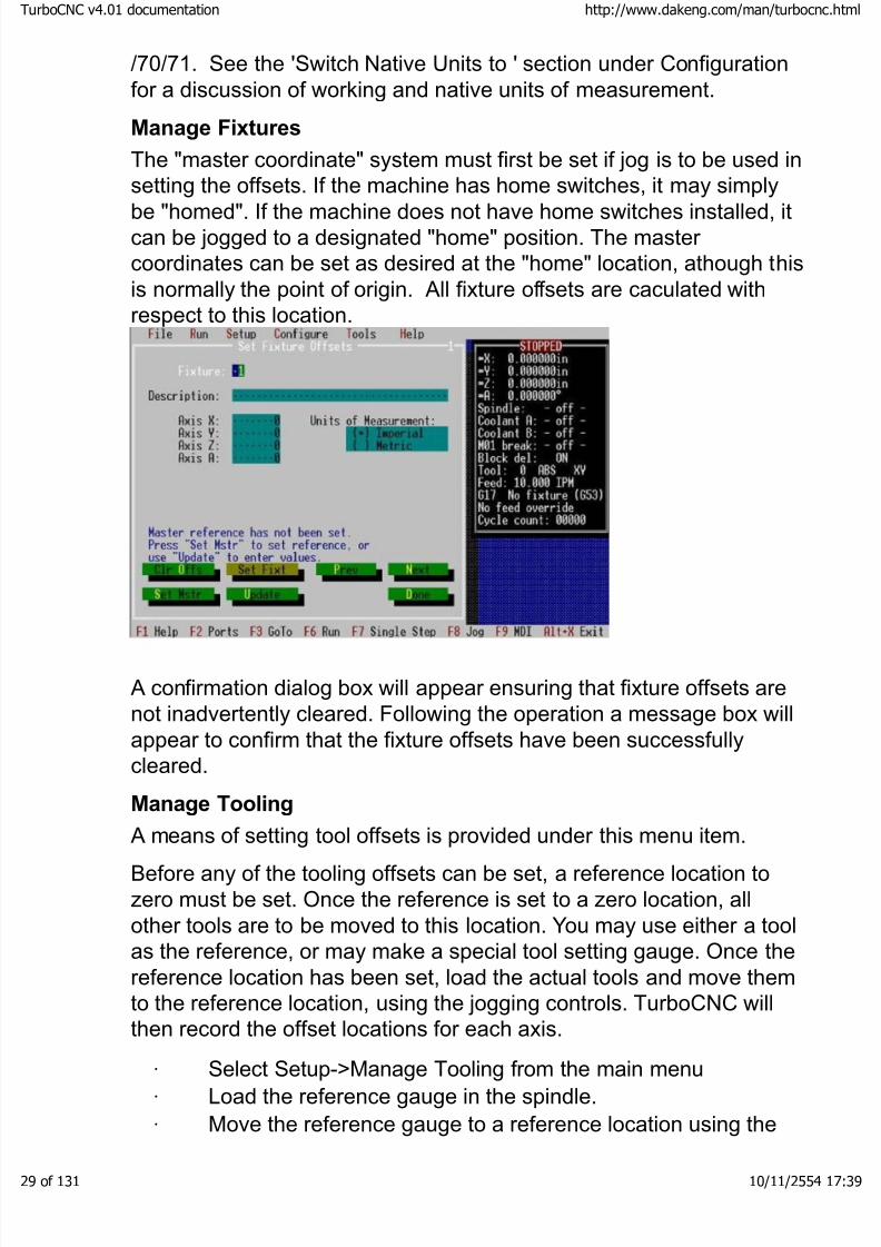
Manage Fixtures
The "master coordinate" system must first be set if jog is to be used insetting the offsets. If the machine has home switches, it may simply
be "homed". If the machine does not have home switches installed, itcan be jogged to a designated "home" position. The master coordinates can be set as desired at the "home" location, athough thisis normally the point of origin. All fixture offsets are caculated withrespect to this location.
A confirmation dialog box will appear ensuring that fixture offsets arenot inadvertently cleared. Following the operation a message box willappear to confirm that the fixture offsets have been successfullycleared.
Manage Tooling
A means of setting tool offsets is provided under this menu item.Before any of the tooling offsets can be set, a reference location tozero must be set. Once the reference is set to a zero location, allother tools are to be moved to this location. You may use either a toolas the reference, or may make a special tool setting gauge. Once thereference location has been set, load the actual tools and move themto the reference location, using the jogging controls. TurboCNC willthen record the offset locations for each axis.
· Select Setup->Manage Tooling from the main menu
· Load the reference gauge in the spindle.
· Move the reference gauge to a reference location using the
boCNC v4.01 documentation http://www.dakeng.com/man/turbocnc.html
of 131 10/11/2554 17:39

8/3/2019 TurboCNC v4Command
http://slidepdf.com/reader/full/turbocnc-v4command 30/131
cursor to jog the reference into place. Either build a gauge toprovide a point to which the reference gauge is moved, or usesome portion. Allow the motors to move the reference. If power tothe motors is cut and the axes manually moved, TurboCNC willnot be able to record the position, and will not accurately set anyof the tooling offsets.
· With the reference gauge in the correct location, press the"Set" button to record the reference coordinates.
Now that the reference location has been set, TurboCNC shows ascreen allowing the offsets for each of the tools to be set. This is doneas follows:
· Use the "prev" and "next" buttons to select the tool for which
the offsets are to be entered.· Enter a description of the tool on the line provided, if desired.
This description is not necessary, but can be used to identify thetool during execution of the CNC program.
· Load the tool into the spindle and jog it to the same referencepoint to which the gauge was set.
· Press the "S" key to set accept the location and calculate thetool reference, or press the "C" key to cancel the function and
revert to the current tool offsets.· TurboCNC will store the offsets in a table, and will
automatically select the next tool in series.
· Tools may be directly edited from this menu.
· Rear Toolpost is not yet active, and has been included for future development.
When all of the tool offsets have been set, press the "done" button to
exit the function. An opportunity to save the new tool offsets will bepresented. The offsets will be stored in a file located in the directoryas specified in the Configure->General dialog.
The screenshot below shows the options prior to 'Set Gage' .
boCNC v4.01 documentation http://www.dakeng.com/man/turbocnc.html
of 131 10/11/2554 17:39

8/3/2019 TurboCNC v4Command
http://slidepdf.com/reader/full/turbocnc-v4command 31/131
A confirmation dialog box will appear ensuring that tool offsets are notinadvertently cleared. Following the operation a message box will
appear to confirm that the tool offsets have been successfully cleared.
Manage Variables:
Provides a means of setting, and inspecting variables without usingRS-274D in MDI or a custom program. Show will bring up a scrolling
list of all variables that are currently storing a value. Clear all willreset all variables to an empty string.
Disable Drives
This option is available only if a drive enable line has beenconfigured. All drive enable lines are set to their inactive states whenthis option is selected.
Enable Drives
This option is available only if a drive enable line has beenconfigured. All drive enable lines are set to their inactive states whenthis option is selected.
boCNC v4.01 documentation http://www.dakeng.com/man/turbocnc.html
of 131 10/11/2554 17:39
8/3/2019 TurboCNC v4Command
http://slidepdf.com/reader/full/turbocnc-v4command 32/131
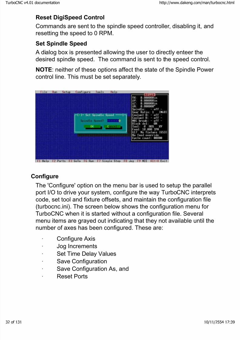
Reset DigiSpeed Control
Commands are sent to the spindle speed controller, disabling it, andresetting the speed to 0 RPM.
Set Spindle Speed
A dialog box is presented allowing the user to directly enteer the
desired spindle speed. The command is sent to the speed control.
NOTE: neither of these options affect the state of the Spindle Power control line. This must be set separately.
Configure
The 'Configure' option on the menu bar is used to setup the parallelport I/O to drive your system, configure the way TurboCNC interpretscode, set tool and fixture offsets, and maintain the configuration file(turbocnc.ini). The screen below shows the configuration menu for TurboCNC when it is started without a configuration file. Severalmenu items are grayed out indicating that they not available until the
number of axes has been configured. These are:· Configure Axis
· Jog Increments
· Set Time Delay Values
· Save Configuration
· Save Configuration As, and
· Reset Ports
boCNC v4.01 documentation http://www.dakeng.com/man/turbocnc.html
of 131 10/11/2554 17:39

8/3/2019 TurboCNC v4Command
http://slidepdf.com/reader/full/turbocnc-v4command 33/131
Number of Axes…
Allows specification of the number of axes on the machine that
TurboCNC will drive. If no axes are specified TurboCNC will not savethe configuration file on exit. The number of axes on the machinecannot be changed while a parts file is open.
boCNC v4.01 documentation http://www.dakeng.com/man/turbocnc.html
of 131 10/11/2554 17:39

8/3/2019 TurboCNC v4Command
http://slidepdf.com/reader/full/turbocnc-v4command 34/131
Configure Axis…
is used to set the parallel port I/O, and specify the motion parametersfor each axis. Upon selection, a dialog box is presented where thefirst axis to be configured can be selected. You will then be taken to
the main configuration screen shown below. This screen is dynamicand will change to reflect your choices. It is recommended that youuse the mouse to navigate this screen, as the design trade off for thedynamics was intuitive keyboard navigation.
Items on the axis configuration menu are:
Axis Name: Assigns a drive letter that is used to select this axis inRS-274 D. Valid selections are A through E and U through Z.
Motion: selects whether the axis is linear or angular. Angular axismeasurements are always in decimal degrees, modulus 360, anddriven the shortest distance to their new position. Linear axes are
measured in either inches or millimeters, depending on the system of measurement in use.
Drive type: selects whether a Step/Direction or Phase scheme isused to control the motor driver. A Step/Direction scheme requiresonly two output pins, while a phase scheme requires a minimum of 4,and up to eight output pins to drive a single motor. Drive typeselection determines whether Step/Direction or Phase definitionconfiguration information is displayed on the menu.
Pulse Width: changes the duration of the step pulse on step/dir controlled axes, as some drives need a few microseconds torecognize that the step line has changed state. The parameter is set
boCNC v4.01 documentation http://www.dakeng.com/man/turbocnc.html
of 131 10/11/2554 17:39
8/3/2019 TurboCNC v4Command
http://slidepdf.com/reader/full/turbocnc-v4command 35/131
directly in integer microseconds. 0 is no explicit delay, which worksout to be between about 2 and 7 µs on most computers.
Port: The parallel port to which the driver is connected is selected bythis option.
Step pin num: sets the output pin on the selected port for step
pulses. Valid values are 2, 3, 4, 5, 6, 7, 8, 9, 1, 14, 16, and 17.
Step pin is: This option is used match TurboCNC to your controller'srequirements. Check you controller documentation, or the files sectionof the TurboCNC newsgroup on Yahoo! to determine the proper setting. (Trial and Terror can also be used.)
Dir pin num: sets the output pin on the selected port for the directionsignal. Valid values are 2, 3, 4, 5, 6, 7, 8, 9, 1, 14, 16, and 17.
Direction pin: selects the polarity required to drive the axis in thepositive direction. Phase wiring of the motor and driver electronicsdetermine this setting. Jog or manually move the axis to a positionwhere you can safely move the axis and use relative movements inMDI to determine if the axis moves in the proper direction. If not,simply toggle this selection and verify that the axis now moves in thecorrect direction, once again using the MDI mode of operation.
Motion Parameters: are used to set various values governing themovement of the axis. Units of measurement will vary to reflect thetype of axis and units of measurement in use by TurboCNC.Acceleration, velocity, and scale effects are reflected below the dataentry area. There is no one-size-fits-all solution. These setting dependon all of the equipment, and the cutting forces to be used. A startingpoint for several systems can be found in the files area of theTurboCNC Yahoo! Group or in the inifiles subdirectory of your
installation. These settings will have to be fine tuned to maximize thesystem's performance.
Scale: is the distance or angle that the axis moves for a single steppulse or phase change. The units can be in inches, millimeters or decimal degrees, depending on axis motion, and the system of measurement in use. A custom calculator is accessable by clicking on'Calc, or pressing 'c'.
Accel: the maximum acceleration of the step pulse train or phasesthat are sent to the driver measured in cycles per second per second.This is purely electronic, and is converted to motion by the motor.Scale is used to convert this value to the linear or angular value
boCNC v4.01 documentation http://www.dakeng.com/man/turbocnc.html
of 131 10/11/2554 17:39

8/3/2019 TurboCNC v4Command
http://slidepdf.com/reader/full/turbocnc-v4command 36/131
displayed below.
Start vel: is the maximum starting / stopping velocity that will be usedby TurboCNC for this axis. Lower values will often be used for interpolated moves. This is measured in cycles per second, andconverted to a distance or angular measurement using Scale and
displayed below as the Start Speed .Max vel: is the maximum velocity that TurboCNC will drive the axis.This is measured in cycles per second, and converted to a distance or angular measurement using Scale and displayed below as the Max
Speed .
Backlash: is the compensation applied whenever the axis changesits direction of movement. It is measured in inches, millimeters, or
degrees depending on the type of motion and system of measurement in use.
Slow jog: This is the speed at which the step pulses are applied, or phase changes occur when Slow jog is engaged. It is measured incycles per second. The value can be converted to a distance or angular measurement by multiplying it by the Scale.
Fast jog: Similar to Slow jog , but allows you to select a higher speed.
Jog Keys: Selection of normal or invert is possible. In the invertedmode the motion of the tool with respect to the work piece is reversedfor the axis.
Select Axis buttons accept the changes to the current axis and allownavigation through the axes to configure them without returning to themain menu and drilling down through the menu system to access thenext axis.
Finished Axis Config buttons are used to exit the axis configurationmenu. 'OK ' accepts the changes, 'Cancel ' exits without saving thechanges. NOTE: The ports must be reset to enable the newconfiguration. The configuration must be saved for it to be availablethe next time that TurboCNC is loaded.
The following screenshot shows the axis configuration menu for aphase driven, linear axis. Note that phase definition information has
replaced the Step and Direction pin configuration parameters.
Set the Last Phase to the number of phases used in your drivescheme. Full, half, and quarter step schemes can be developed for
boCNC v4.01 documentation http://www.dakeng.com/man/turbocnc.html
of 131 10/11/2554 17:39
8/3/2019 TurboCNC v4Command
http://slidepdf.com/reader/full/turbocnc-v4command 37/131
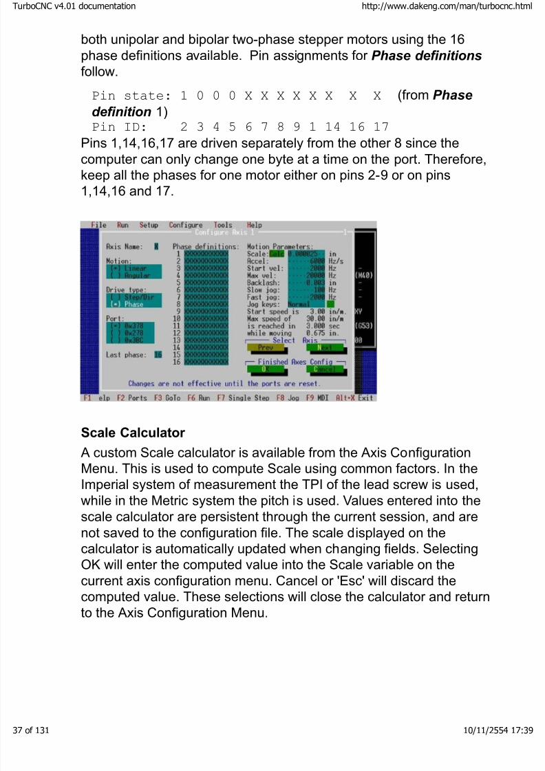
both unipolar and bipolar two-phase stepper motors using the 16phase definitions available. Pin assignments for Phase definitions
follow.
Pin state: 1 0 0 0 X X X X X X X X (from Phase
definition 1)
Pin ID: 2 3 4 5 6 7 8 9 1 14 16 17Pins 1,14,16,17 are driven separately from the other 8 since thecomputer can only change one byte at a time on the port. Therefore,keep all the phases for one motor either on pins 2-9 or on pins1,14,16 and 17.
Scale Calculator
A custom Scale calculator is available from the Axis ConfigurationMenu. This is used to compute Scale using common factors. In theImperial system of measurement the TPI of the lead screw is used,while in the Metric system the pitch is used. Values entered into the
scale calculator are persistent through the current session, and arenot saved to the configuration file. The scale displayed on thecalculator is automatically updated when changing fields. SelectingOK will enter the computed value into the Scale variable on thecurrent axis configuration menu. Cancel or 'Esc' will discard thecomputed value. These selections will close the calculator and returnto the Axis Configuration Menu.
boCNC v4.01 documentation http://www.dakeng.com/man/turbocnc.html
of 131 10/11/2554 17:39

8/3/2019 TurboCNC v4Command
http://slidepdf.com/reader/full/turbocnc-v4command 38/131
boCNC v4.01 documentation http://www.dakeng.com/man/turbocnc.html
of 131 10/11/2554 17:39
8/3/2019 TurboCNC v4Command
http://slidepdf.com/reader/full/turbocnc-v4command 39/131
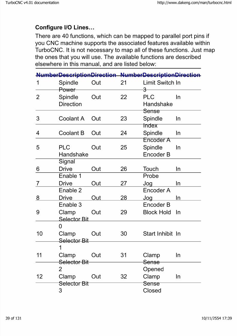
Configure I/O Lines…
There are 40 functions, which can be mapped to parallel port pins if you CNC machine supports the associated features available withinTurboCNC. It is not necessary to map all of these functions. Just map
the ones that you will use. The available functions are describedelsewhere in this manual, and are listed below:
NumberDescriptionDirection NumberDescriptionDirection
1 SpindlePower
Out
21 Limit Switch3
In
2 SpindleDirection
Out
22 PLCHandshake
Sense
In
3 Coolant A Out
23 SpindleIndex
In
4 Coolant B Out
24 SpindleEncoder A
In
5 PLCHandshakeSignal
Out
25 SpindleEncoder B
In
6 DriveEnable 1
Out
26 TouchProbe
In
7 DriveEnable 2
Out
27 JogEncoder A
In
8 DriveEnable 3
Out
28 JogEncoder B
In
9 ClampSelector Bit
0
Out
29 Block Hold In
10 ClampSelector Bit1
Out
30 Start Inhibit In
11 ClampSelector Bit2
Out
31 ClampSenseOpened
In
12 Clamp
Selector Bit3
Out
32 Clamp
SenseClosed
In
boCNC v4.01 documentation http://www.dakeng.com/man/turbocnc.html
of 131 10/11/2554 17:39
8/3/2019 TurboCNC v4Command
http://slidepdf.com/reader/full/turbocnc-v4command 40/131
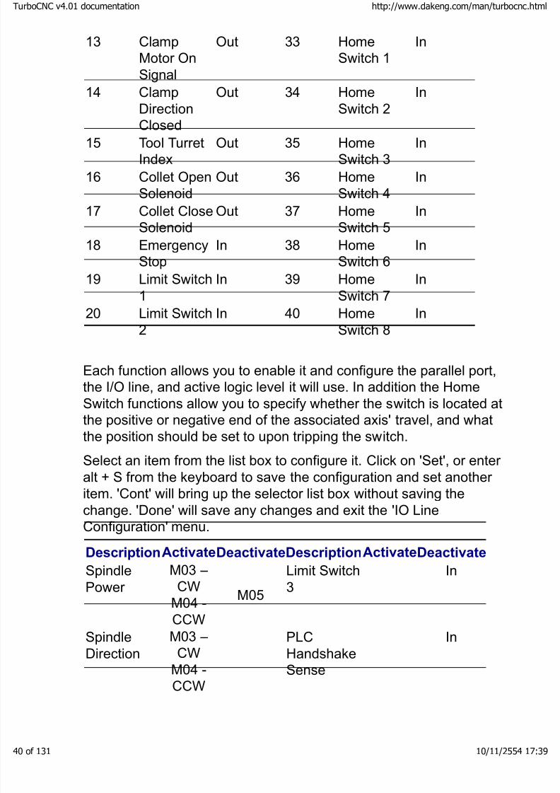
13 ClampMotor OnSignal
Out
33 HomeSwitch 1
In
14 ClampDirectionClosed
Out
34 HomeSwitch 2
In
15 Tool TurretIndex
Out
35 HomeSwitch 3
In
16 Collet OpenSolenoid
Out
36 HomeSwitch 4
In
17 Collet CloseSolenoid
Out
37 HomeSwitch 5
In
18 Emergency
Stop
In
38 Home
Switch 6
In
19 Limit Switch1
In
39 HomeSwitch 7
In
20 Limit Switch2
In
40 HomeSwitch 8
In
Each function allows you to enable it and configure the parallel port,the I/O line, and active logic level it will use. In addition the Home
Switch functions allow you to specify whether the switch is located atthe positive or negative end of the associated axis' travel, and whatthe position should be set to upon tripping the switch.
Select an item from the list box to configure it. Click on 'Set', or enter alt + S from the keyboard to save the configuration and set another item. 'Cont' will bring up the selector list box without saving thechange. 'Done' will save any changes and exit the 'IO LineConfiguration' menu.
DescriptionActivateDeactivateDescriptionActivateDeactivate
SpindlePower
M03 –CW
M04 -CCW
M05
Limit Switch3
In
SpindleDirection
M03 –CW
M04 -CCW
PLCHandshake
Sense
In
boCNC v4.01 documentation http://www.dakeng.com/man/turbocnc.html
of 131 10/11/2554 17:39

8/3/2019 TurboCNC v4Command
http://slidepdf.com/reader/full/turbocnc-v4command 41/131
Coolant AM07 M09
SpindleIndex
In
Coolant BM08 M09
SpindleEncoder A
In
PLC
HandshakeSignal
M70
M71 Out
Spindle
Encoder B
In
DriveEnable 1
M17 M18TouchProbe
In
DriveEnable 2
M17 M18JogEncoder A
In
DriveEnable 3
M17 M18JogEncoder B
In
ClampSelector Bit0
Out Block Hold In
ClampSelector Bit1
OutStart Inhibit In
ClampSelector Bit
2
OutClampSense
Opened
In
ClampSelector Bit3
OutClampSenseClosed
In
ClampMotor OnSignal
OutHomeSwitch 1
In
Clamp
DirectionClosed
Out
Home
Switch 2
In
Tool TurretIndex
OutHomeSwitch 3
In
Collet OpenSolenoid
OutHomeSwitch 4
In
Collet CloseSolenoid
OutHomeSwitch 5
In
EmergencyStop
In HomeSwitch 6
In
boCNC v4.01 documentation http://www.dakeng.com/man/turbocnc.html
of 131 10/11/2554 17:39
8/3/2019 TurboCNC v4Command
http://slidepdf.com/reader/full/turbocnc-v4command 42/131
Limit Switch1
InHomeSwitch 7
In
Limit Switch2
InHomeSwitch 8
In
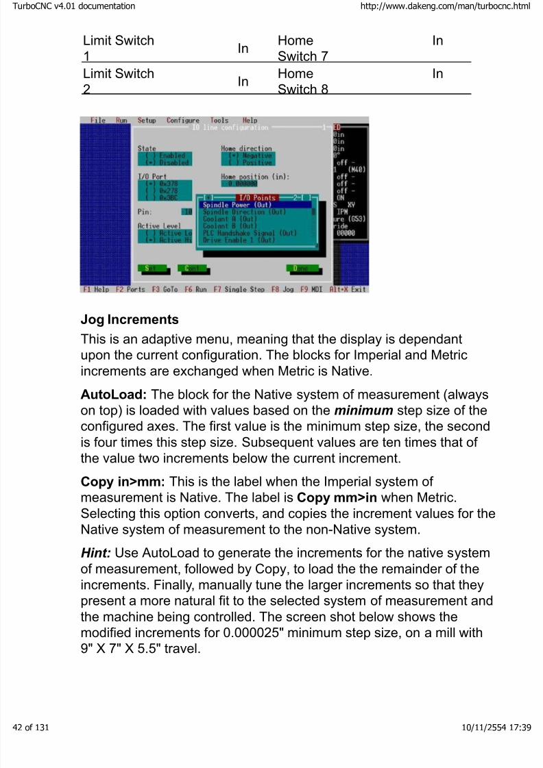
Jog Increments
This is an adaptive menu, meaning that the display is dependantupon the current configuration. The blocks for Imperial and Metricincrements are exchanged when Metric is Native.
AutoLoad: The block for the Native system of measurement (alwayson top) is loaded with values based on the minimum step size of theconfigured axes. The first value is the minimum step size, the secondis four times this step size. Subsequent values are ten times that of the value two increments below the current increment.
Copy in>mm: This is the label when the Imperial system of measurement is Native. The label is Copy mm>in when Metric.
Selecting this option converts, and copies the increment values for theNative system of measurement to the non-Native system.
Hint: Use AutoLoad to generate the increments for the native systemof measurement, followed by Copy, to load the the remainder of theincrements. Finally, manually tune the larger increments so that theypresent a more natural fit to the selected system of measurement andthe machine being controlled. The screen shot below shows themodified increments for 0.000025" minimum step size, on a mill with
9" X 7" X 5.5" travel.
boCNC v4.01 documentation http://www.dakeng.com/man/turbocnc.html
of 131 10/11/2554 17:39

8/3/2019 TurboCNC v4Command
http://slidepdf.com/reader/full/turbocnc-v4command 43/131
Change Native Units to Metric (Imperial)
This menu choice changes dependent upon the system's currentsetting. It's recommended that this setting be chosen based upon thesystem of measurement of the leadscrews fitted to the linear axes of the machine. A confirmation dialog box will appear to ensure that thissetting is not accidentally changed. All internal items stored in the'Native' system of measurement are converted into the selectedsystem. These items are:
· Axes' current position (if linear)
· Axes' Home position (if linear)
· Axes' Scale (if linear)
· Axes' Backlash (if linear)
· Current Feed Rate
· Default Feed Rate
· Home Feed Rate
· All Canned Cycle Parameters
TurboCNC and Systems of Measurement
The TurboCNC core motion routines are no longer tied to any systemof measurement. All positions for the linear axes are converted to the'Native' system of measurement. When the calculations areperformed, the units cancel out and we are left with a number representing the number of steps that must be taken, and the
direction in which they are to be taken. This is referred to as the'Unitless Motion Engine'.
There are now two systems of measurement that must be defined for
boCNC v4.01 documentation http://www.dakeng.com/man/turbocnc.html
of 131 10/11/2554 17:39

8/3/2019 TurboCNC v4Command
http://slidepdf.com/reader/full/turbocnc-v4command 44/131
your machine. The first is it's 'Native' system of measurement definedunder the configuration menu. That is the only place Native units of measurement can be changed. This system should be chosen basedupon the leadscrews used on the linear axes. All configuration itemsremain in this system of measurement. This eliminates the displayidiosyncrasies of TurboCNC V4.00, and the conversion errors that
occurred at the 13th
decimal place.
The second is termed the 'Working' system of measurement. All linear axis positions entered by RS-274D are considered to be in thissystem of measurement. These values can be part of a program or entered through the MDI, or jog interfaces. The 'Working' system of measurement can be changed using G20/21/70/71 or the 'ToggleWorking Units' item under the Setup Menu.
SpeedMap
Selection of SpeedMap displays a dialog box allowing up to four independent Speed Maps to be configured. Maps are selectable fromRS-274D code using the M40 through M43 codes. The standarddefines these codes as those that should be used for gear changes.As each speed map is intended to represent a gear ratio, these wereused.
Ratio:
Used to select a Speed Map or Gear Ratio. Valid values are from 1 to4. The number 1 corresponds to M40, 4 to M43.
Set Gear
This button is used to set the current speed map to that specified inthe Ratio box.
Toggle
boCNC v4.01 documentation http://www.dakeng.com/man/turbocnc.html
of 131 10/11/2554 17:39

8/3/2019 TurboCNC v4Command
http://slidepdf.com/reader/full/turbocnc-v4command 45/131
Spindle Toggle turns the spindle on or off depending on its currentstate.
Value
Used to enter a count value for use with the Set and Add buttonsdescribed below.
RPM
The speed in RPM is entered in this box for use by the Map and Addbuttons described below.
Set
Sets the speed by Value, and turns the spindle on in the clockwisedirection if it was off. This is used to determine the RPM associatedwith a count Value. The RPM corresponding to this value can beentered into the RPM box, and added to the current map by pressingAdd.
Map
Map is used to retrieve the count associated with an RPM from thecurrently selected speed map. RPM values above or below the maplimits will be reported as an error.
Add
Used to enter the specified Value and RPM as a mapping in thecurrently selected map. The high and low RPM limits for the map areadjusted as required.
Calibration
These options have yet to be written.
Edit
Upon opening, the Map Editor sorts the items of the current SpeedMap in ascending order, and validates the map. A local, workingcopy of the map items is made. If the map fails the validation check,'Invalid Map' is displayed in the lower left coner of the form, and thedisplay is indexed to the first offending item. If the validation check ispassed, the display is indexed to the first map item.
boCNC v4.01 documentation http://www.dakeng.com/man/turbocnc.html
of 131 10/11/2554 17:39

8/3/2019 TurboCNC v4Command
http://slidepdf.com/reader/full/turbocnc-v4command 46/131
Value
Moves the Edit Window so that the first count Value is is equal to theTarget. If the Target is not found, the next lower count Value is used.
Note: The Target for both Value and RPM is entered into the boxbetween these buttons.
RPM
Moves the Edit Window so that the first RPM is is equal to the Target.If the Target is not found, the next lower RPM in the speed map isused.
Reload Reloads the local working copy of the Speed Map from the main maparray. The Edit Window is indexed as when the editor first opened.
Prev
Moves the Edit Window 16 items down. If this is below the first item,it shifts the window to the first Item in the map.
Next
Moves the Edit Window up 16 items, or so that 16 blank entries areshown. Next has no effect if all blank items are shown. If this isabove the last item, the last item in the Window will be the last item inthe map.
Cancel
Exits the Map Editor without saving changes.
OK
Uploads the working copy of the map to the main map array. Themap is then validated, and if it is valid exits the editor. If the map failsto validate, the editor will remain open and position the Edit Window
boCNC v4.01 documentation http://www.dakeng.com/man/turbocnc.html
of 131 10/11/2554 17:39
8/3/2019 TurboCNC v4Command
http://slidepdf.com/reader/full/turbocnc-v4command 47/131
to the first invalid item.
Note: If the map does not validate properly it cannot be used to setspindle speed. It must first be corrected within the Editor, or theoriginal values can be reloaded from disk by cancelling out of the MapEditor, and reloading the configuration file.
Clear
Clears all values from the currently selected map, and sets the RPMlimits to default values of 100,000,000 for the low end and 0 for thehigh end limits.
OK
Exits the menu, accepting all changes. To revert to a previousconfiguration, this must be re-loaded from disk. There is no provision
to reject changes made in the menu.
NOTE: The updated configuration must be saved to preserve anychanges between sessions of TurboCNC. Simply exiting TurboCNC,and re-starting it will erase any changes made.
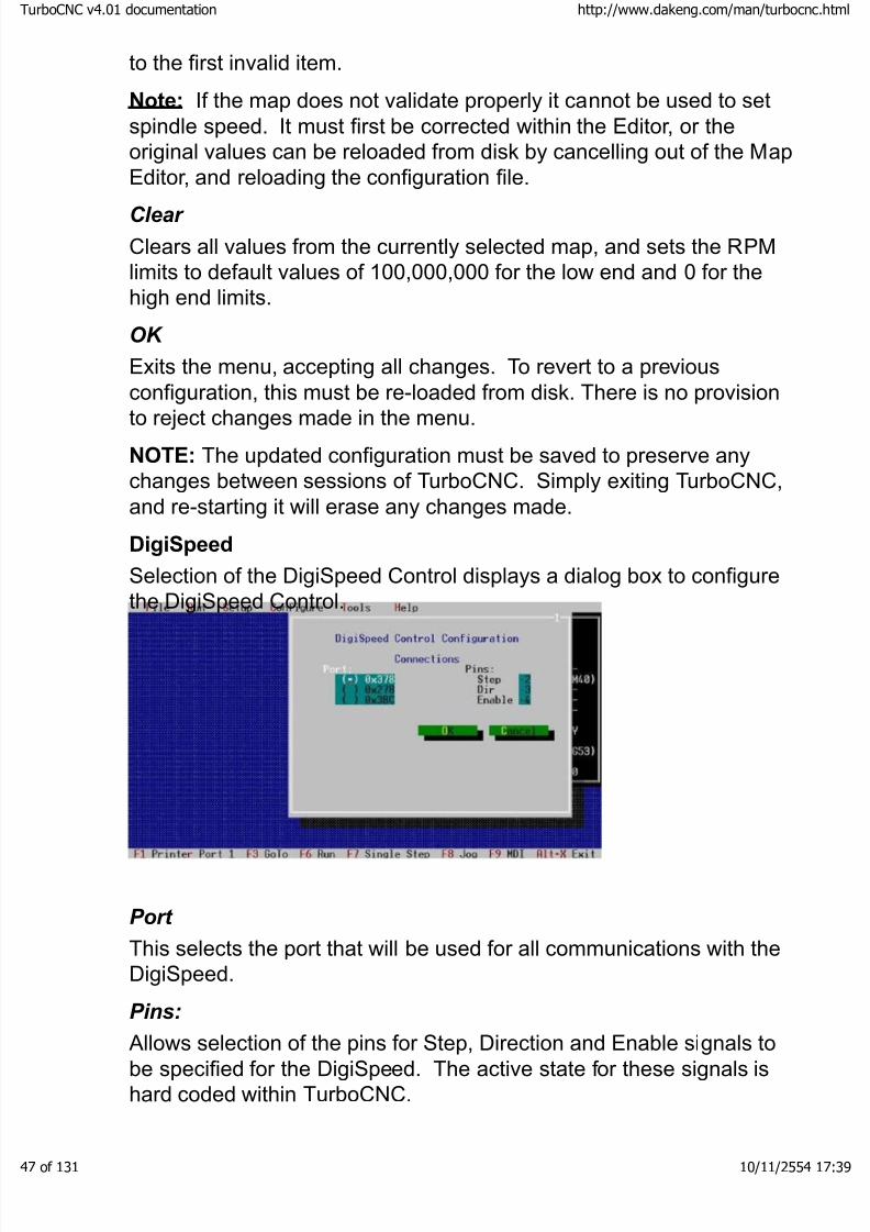
DigiSpeed
Selection of the DigiSpeed Control displays a dialog box to configurethe DigiSpeed Control.
Port
This selects the port that will be used for all communications with theDigiSpeed.
Pins:
Allows selection of the pins for Step, Direction and Enable signals tobe specified for the DigiSpeed. The active state for these signals ishard coded within TurboCNC.
boCNC v4.01 documentation http://www.dakeng.com/man/turbocnc.html
of 131 10/11/2554 17:39
8/3/2019 TurboCNC v4Command
http://slidepdf.com/reader/full/turbocnc-v4command 48/131
General Config…
General configuration items have been gathered on this menu.
Color Menus: Default is to use color menus. When de-selected amonochromatic monitor can be used. Display Mode cannot bechanged while a parts file is open.
Verbose Messages: By default TurboCNC will ask for confirmation of many actions. Turning this option off will substantially reduce thenumber of confirmations required.
Clear MDI Block: Check this box if you want TurboCNC to clear theMDI block that you entered after it executes that block. Clear the boxif you want the edit box to retain the block’s contents after executingthe block.
Mouse Off During Move: The cursor is hidden by default duringmotion to conserve CPU cycles. This can be turned off whenTurboCNC is running on faster computers.
Home Switch is Limit. Enable this option if the Home Switches areto be used as Limit Switches. The Home Switches should be definedonly as such. During Home moves TurboCNC de-couples theseswitches from their Limit function and uses them solely as Home
switches. For all other moves they will function as limit switches.Stop on Illegal G-Code: This option is used to provide the ability toexecute G-Code programs containing instructions which are NOT
IMPLEMENTED in TurboCNC. If you check the box, TurboCNC willstop execution upon encountering an unimplemented code anddisplay an information box indicating the errant code. If you clear thebox, TurboCNC will simply ignore the unimplemented G-Code andcontinue executing your CNC program.
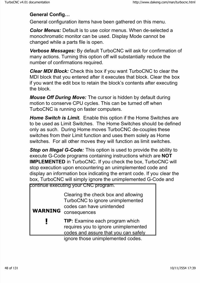
WARNING
!
Clearing the check box and allowingTurboCNC to ignore unimplementedcodes can have unintendedconsequences
TIP: Examine each program whichrequires you to ignore unimplementedcodes and assure that you can safely
ignore those unimplemented codes.
boCNC v4.01 documentation http://www.dakeng.com/man/turbocnc.html
of 131 10/11/2554 17:39

8/3/2019 TurboCNC v4Command
http://slidepdf.com/reader/full/turbocnc-v4command 49/131
Start Inhibit: You may designate an I/O point using Configure I/O
lines which is sensed before a CNC program is allowed to execute.You may either abort the CNC program, or wait until the line returns toits inactive state. The default is to wait until the line returns to itsinactive state.
Block Inhibit: You may designate an I/O point using Configure I/Olines which is sensed before a block in the CNC program is allowedto execute. You may either abort the CNC program, or wait until theline returns to its inactive state. The default is to wait until the linereturns to its inactive state.
Sync Unit Increments: Check this box to direct TurboCNC tosynchronize the indices of the Imperial and Metric tables for thecurrently active axis. For example, assume that you are working with
the Imperial jog table, and that the current index value of the Imperialtable is 5 and that the current index value of the Metric table is 3. If this box is unchecked and you change the Imperial table index to 9,the Metric table index remains at 5. If the box is checked and youchange the Imperial table index to 9, the Metric table index alsobecomes 9.
Note that this check box affects only the 1-0 keys and that the J and K
keys continue to affect ONLY the currently active table so you stillhave a way to change the distance of ONLY the active axis withoutaffecting any of the others.
Sync Axis Increments: Check this box to direct TurboCNC tosynchronize the index of all axes on a given table to the valueselected. Note that ONLY the indices into the active table are set. For example, if X is the active axis, Imperial measure is the active table,and you press the “3” key, only the X index will be changed to 3. If
however, the Sync Axes box is checked, all axis indices into theImperial table are set to 3.
Note that this check box affects only the 1-0 keys and that the J and Kkeys continue to affect ONLY the currently active table so you stillhave a way to change the distance of ONLY the active axis withoutaffecting any of the others.
These boxes work either in concert, or individually, so checking both
boxes will make the jog appear as there is only one index into bothtables.
Autoload Tooling File: Default is not to load Fixture and Tool offsets
boCNC v4.01 documentation http://www.dakeng.com/man/turbocnc.html
of 131 10/11/2554 17:39
8/3/2019 TurboCNC v4Command
http://slidepdf.com/reader/full/turbocnc-v4command 50/131
when TurboCNC starts. Enabling this option will attempt to load atooling file from the Directory specified by Tooloff Dir with the nameTURBOCNC and filename extension specified by Tooloff Ext
whenever TurboCNC is restarted.
Imperial Precision: sets the number of digits to the right of the
decimal point to which the backlash and scale are rounded when thedisplay is set to use Imperial units. Valid values are 0 to 9. A value of 0 will prevent any rounding. This is only used when changing theNative system of Measurement to Imperial.
Metric Precision: sets the number of digits to the right of the decimalpoint to which the backlash and scale are rounded when the display isset to use SI units. Valid values are 0 to 9. A value of 0 will preventany rounding. This is only used when changing the Native system of
Measurement to Metric.
Note: Selection of too coarse a precision can cause axis scale valuerounding to zero. This is checked on entry to and exit from the axisconfiguration menu.
Default Feed Rate: This option provides a method of setting a defaultfeed rate, to be used when TurboCNC is first started.
Home Speed: A custom homing speed can be set using this option.
Reverse Axis Delay: specifies a delay in milliseconds that all axeswill pause before changing direction. Axis delay is used tocompensate for machine inertia. Whenever an axis reverses(backlash, arc quadrant, just plain reversal) the machine drives shouldactually pause for a short time to allow it come to a complete stop.The classic example is a big honkin' gantry machine with the movingmass 6' from the supports.
Arc Factor: This option provides a method of adjusting timing loopsused when cutting an arc to the speed of the computer. Values lessthan one increase the loop speed, those above one decrease it. If younotice lost steps while cutting arcs decrease this value to 0.8 or less.
Machine: Allows be specification of the general type of CNC machinebeing controlled. This setting affects how TurboCNC interpretsRS-274 D Code as follows:
·Radius Lathe: The X axis (cross feed) is used as specified
when processing a move. This default plane is set to G18 atstartup.
boCNC v4.01 documentation http://www.dakeng.com/man/turbocnc.html
of 131 10/11/2554 17:39
8/3/2019 TurboCNC v4Command
http://slidepdf.com/reader/full/turbocnc-v4command 51/131
· Diameter lathe: The X axis (cross feed) is halved internallybefore processing a move. Earlier versions of TurboCNC had acryptic way of setting this via an AxisPreScale parameter in theini file. This default plane is set to G18 at startup.
· Mill / Drill: This default plane is set to G17 at startup.
· Custom: Has been defined for customers wishing toincorporate special setup procedures for their systems.
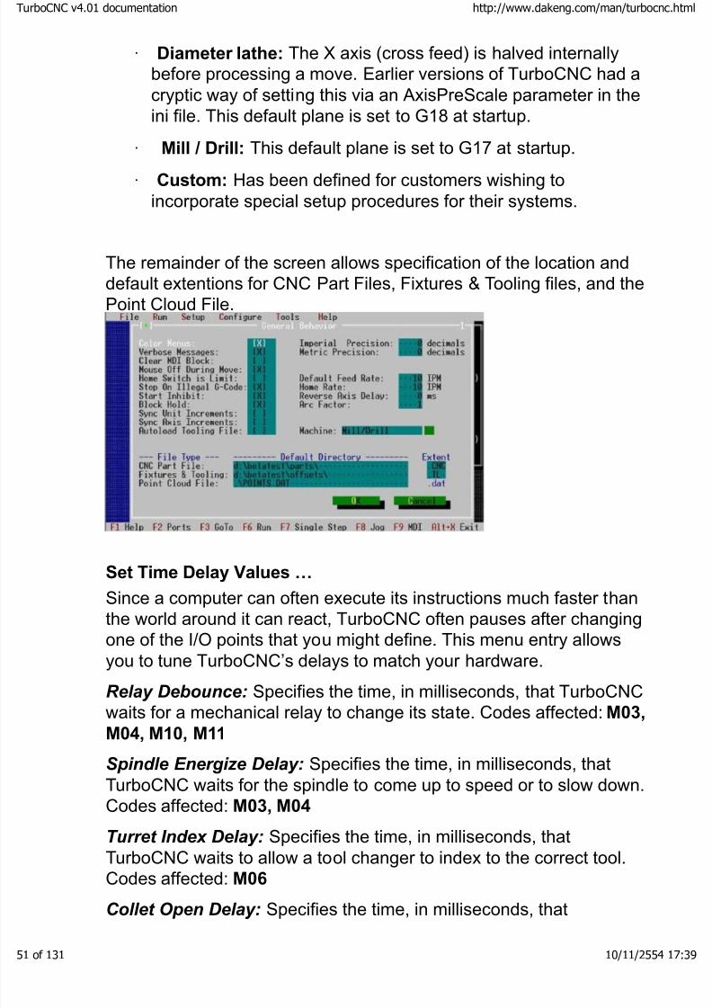
The remainder of the screen allows specification of the location anddefault extentions for CNC Part Files, Fixtures & Tooling files, and thePoint Cloud File.
Set Time Delay Values …
Since a computer can often execute its instructions much faster thanthe world around it can react, TurboCNC often pauses after changingone of the I/O points that you might define. This menu entry allowsyou to tune TurboCNC’s delays to match your hardware.
Relay Debounce: Specifies the time, in milliseconds, that TurboCNCwaits for a mechanical relay to change its state. Codes affected: M03,
M04, M10, M11
Spindle Energize Delay: Specifies the time, in milliseconds, thatTurboCNC waits for the spindle to come up to speed or to slow down.Codes affected: M03, M04
Turret Index Delay: Specifies the time, in milliseconds, thatTurboCNC waits to allow a tool changer to index to the correct tool.Codes affected: M06
Collet Open Delay: Specifies the time, in milliseconds, that
boCNC v4.01 documentation http://www.dakeng.com/man/turbocnc.html
of 131 10/11/2554 17:39
8/3/2019 TurboCNC v4Command
http://slidepdf.com/reader/full/turbocnc-v4command 52/131
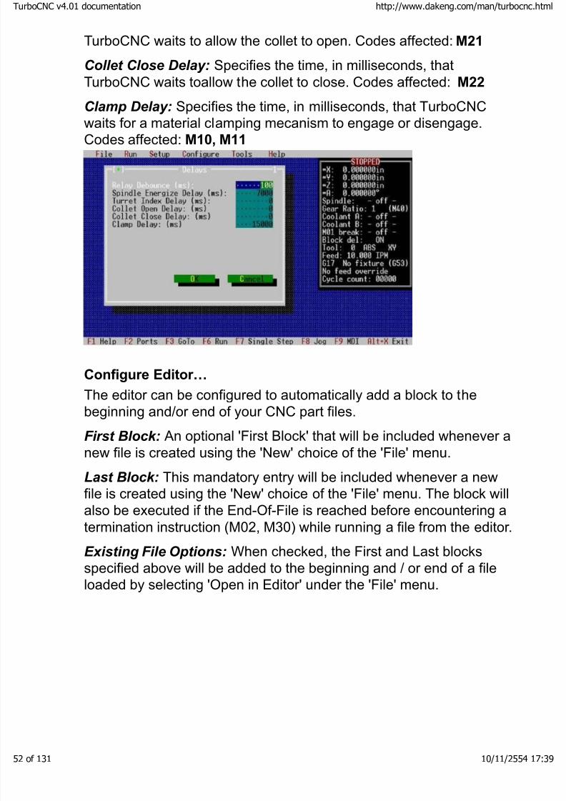
TurboCNC waits to allow the collet to open. Codes affected: M21
Collet Close Delay: Specifies the time, in milliseconds, thatTurboCNC waits toallow the collet to close. Codes affected: M22
Clamp Delay: Specifies the time, in milliseconds, that TurboCNCwaits for a material clamping mecanism to engage or disengage.
Codes affected: M10, M11
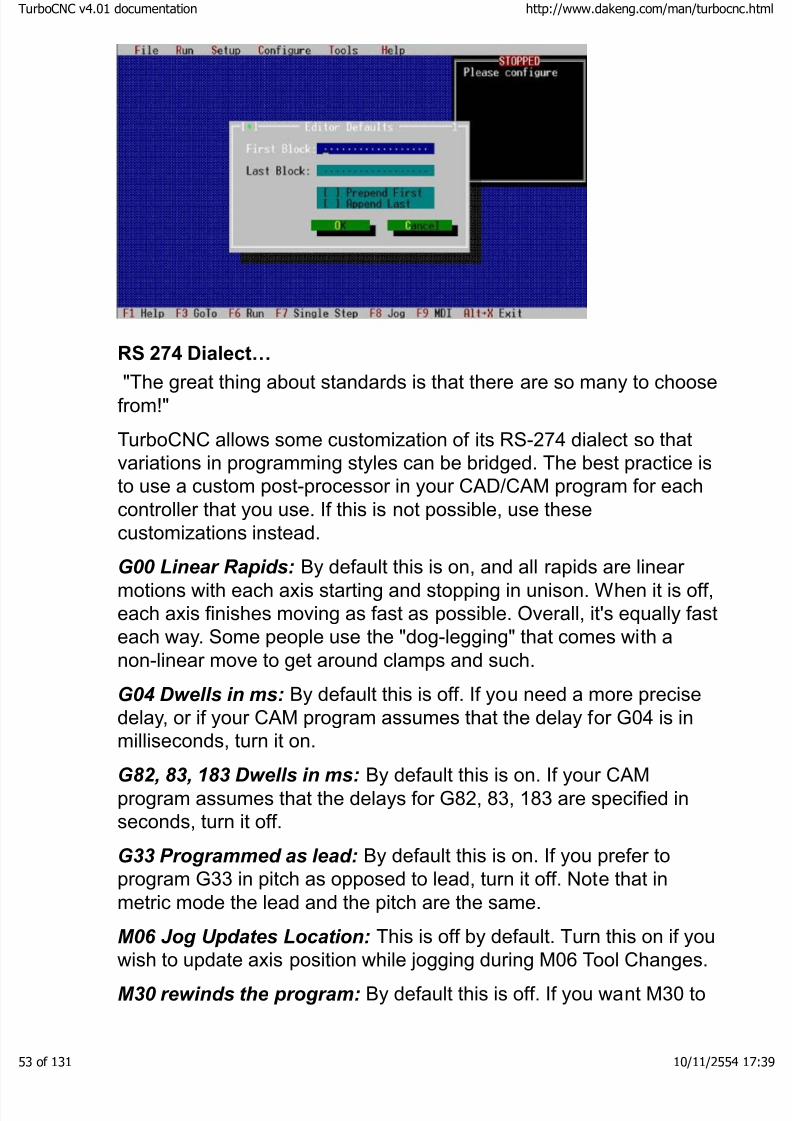
Configure Editor…
The editor can be configured to automatically add a block to thebeginning and/or end of your CNC part files.
First Block: An optional 'First Block' that will be included whenever anew file is created using the 'New' choice of the 'File' menu.
Last Block: This mandatory entry will be included whenever a newfile is created using the 'New' choice of the 'File' menu. The block willalso be executed if the End-Of-File is reached before encountering atermination instruction (M02, M30) while running a file from the editor.
Existing File Options: When checked, the First and Last blocksspecified above will be added to the beginning and / or end of a fileloaded by selecting 'Open in Editor' under the 'File' menu.
boCNC v4.01 documentation http://www.dakeng.com/man/turbocnc.html
of 131 10/11/2554 17:39
8/3/2019 TurboCNC v4Command
http://slidepdf.com/reader/full/turbocnc-v4command 53/131
RS 274 Dialect…
"The great thing about standards is that there are so many to choosefrom!"
TurboCNC allows some customization of its RS-274 dialect so thatvariations in programming styles can be bridged. The best practice isto use a custom post-processor in your CAD/CAM program for eachcontroller that you use. If this is not possible, use thesecustomizations instead.
G00 Linear Rapids: By default this is on, and all rapids are linear motions with each axis starting and stopping in unison. When it is off,each axis finishes moving as fast as possible. Overall, it's equally fasteach way. Some people use the "dog-legging" that comes with anon-linear move to get around clamps and such.
G04 Dwells in ms: By default this is off. If you need a more precisedelay, or if your CAM program assumes that the delay for G04 is inmilliseconds, turn it on.
G82, 83, 183 Dwells in ms: By default this is on. If your CAMprogram assumes that the delays for G82, 83, 183 are specified inseconds, turn it off.
G33 Programmed as lead: By default this is on. If you prefer toprogram G33 in pitch as opposed to lead, turn it off. Note that inmetric mode the lead and the pitch are the same.
M06 Jog Updates Location: This is off by default. Turn this on if youwish to update axis position while jogging during M06 Tool Changes.
M30 rewinds the program: By default this is off. If you want M30 to
boCNC v4.01 documentation http://www.dakeng.com/man/turbocnc.html
of 131 10/11/2554 17:39
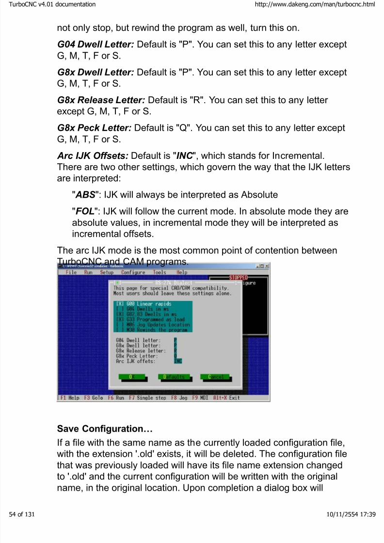
8/3/2019 TurboCNC v4Command
http://slidepdf.com/reader/full/turbocnc-v4command 54/131
not only stop, but rewind the program as well, turn this on.
G04 Dwell Letter: Default is "P". You can set this to any letter exceptG, M, T, F or S.
G8x Dwell Letter: Default is "P". You can set this to any letter exceptG, M, T, F or S.
G8x Release Letter: Default is "R". You can set this to any letter except G, M, T, F or S.
G8x Peck Letter: Default is "Q". You can set this to any letter exceptG, M, T, F or S.
Arc IJK Offsets: Default is "INC ", which stands for Incremental.There are two other settings, which govern the way that the IJK letters
are interpreted:" ABS ": IJK will always be interpreted as Absolute
"FOL": IJK will follow the current mode. In absolute mode they areabsolute values, in incremental mode they will be interpreted asincremental offsets.
The arc IJK mode is the most common point of contention betweenTurboCNC and CAM programs.
Save Configuration…
If a file with the same name as the currently loaded configuration file,
with the extension '.old' exists, it will be deleted. The configuration filethat was previously loaded will have its file name extension changedto '.old' and the current configuration will be written with the originalname, in the original location. Upon completion a dialog box will
boCNC v4.01 documentation http://www.dakeng.com/man/turbocnc.html
of 131 10/11/2554 17:39

8/3/2019 TurboCNC v4Command
http://slidepdf.com/reader/full/turbocnc-v4command 55/131
appear to confirm that the file was successfully saved.
Save Configuration As…
Load New Configuration…
Upon selection a dialog box will open enabling you to select aconfiguration file to load. After the file has loaded a dialog box willappear, verifying that the file was loaded correctly and that the portshave been reset to use the loaded values. The status display is thenupdated to reflect the newly loaded values.
Reset Ports
'Reset Ports' reconfigures the software to use the currently
configured parallel port I/O pin assignments. A dialog box will appear confirming that this has been done and offering the opportunity tosave the current configuration. The same software routine as 'Save
boCNC v4.01 documentation http://www.dakeng.com/man/turbocnc.html
of 131 10/11/2554 17:39

8/3/2019 TurboCNC v4Command
http://slidepdf.com/reader/full/turbocnc-v4command 56/131
Configuration As' is used.
Tools
Calculator
A simple calculator is provided to assist with setup calculations.
Help
There are a few options that provide you with access to criticaldocumentation while you're still in the program. All the information isthe same as what's in this manual - it's there for convenience on DOSmachines that may not be able to read these files.
Introduction…
Provides an introduction to CNC machining and the fundamentals of
the RS-274D language.
G-Code Ref…
A reference of the preparatory functions supported by TurboCNC.
M-Code Ref…
A reference of the miscellaneous functions supported by TurboCNC.
Programming…
Provides a reference on the use of the extended programmingcapabilities of TurboCNC, including variables, expressions (and theimplemented mathematical functions), conditional programming(if…then) and operator interaction (ask/say).
What’s New…
This section provides a quick overview of the new features of thisversion.
Shareware…
This item is a quick review of the principles behind 'Shareware', andinstructions on how to register TurboCNC.
About…
Here's a list of the guilty parties who brought you this release of TurboCNC.
boCNC v4.01 documentation http://www.dakeng.com/man/turbocnc.html
of 131 10/11/2554 17:39
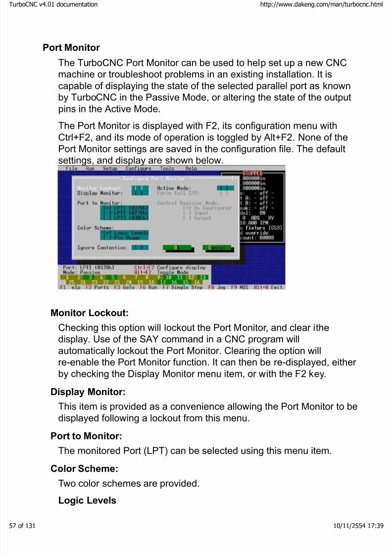
8/3/2019 TurboCNC v4Command
http://slidepdf.com/reader/full/turbocnc-v4command 57/131
Port Monitor
The TurboCNC Port Monitor can be used to help set up a new CNCmachine or troubleshoot problems in an existing installation. It iscapable of displaying the state of the selected parallel port as knownby TurboCNC in the Passive Mode, or altering the state of the outputpins in the Active Mode.
The Port Monitor is displayed with F2, its configuration menu withCtrl+F2, and its mode of operation is toggled by Alt+F2. None of thePort Monitor settings are saved in the configuration file. The defaultsettings, and display are shown below.
Monitor Lockout:
Checking this option will lockout the Port Monitor, and clear ithedisplay. Use of the SAY command in a CNC program willautomatically lockout the Port Monitor. Clearing the option willre-enable the Port Monitor function. It can then be re-displayed, either
by checking the Display Monitor menu item, or with the F2 key.
Display Monitor:
This item is provided as a convenience allowing the Port Monitor to bedisplayed following a lockout from this menu.
Port to Monitor:
The monitored Port (LPT) can be selected using this menu item.
Color Scheme:
Two color schemes are provided.
Logic Levels
boCNC v4.01 documentation http://www.dakeng.com/man/turbocnc.html
of 131 10/11/2554 17:39

8/3/2019 TurboCNC v4Command
http://slidepdf.com/reader/full/turbocnc-v4command 58/131
This scheme indicates the Logic Level through use of thebackground. Green is a high logic level, and brown is a low logic level.Pins that are contended (used for two or more I/O devices) are shownwith a red background. In this case the logic level is indicated by theforeground color as described in Pin Usage.
Pin UsageThe background color is used to indicate the configured use of thepin. Logic levels are indicated with the foreground color. A foregroundcolor of green is a logic high, and white is a logic low. The appropriateI/O point must be enabled to show the pin usage. The following partialscreen-shot shows the scheme:
Background color use is as follows:
· Red – Pin is contended (used for two or more I/Odevices)
· Blue – Pin is configured for use as an output
· Cyan – Pin is configured for use as an input
· Brown – pin is not used
Ignore Contention:
This option 'gets the red out' for those deliberately sharing an I/O pinbetween two or more devices. The scheme precedence for contendedpin will is output (including step / dir, phase, and single point I/Ofunctions) followed by input. If a pin is defined for use with both anoutput and input device it will be shown as an output.
Active Mode:
When checked the Port Monitor is placed in Active Mode. The modecan also be toggled using Alt + F2. Active Mode reads the ports,updating the display every half second, and allows the operator tomodify the output pin state of the selected port as follows:
· keys 1 to 0 toggle pins 1 to 10 respectively
· keys Shift + 1 to Shift + 7 toggle pins 11 through 17
· left-clicking the pin number on the display will toggle that pin
·right-clicking an output pin number sends a slow (1 Hz) pulse
train to that pin
· Ctrl + P will output a slow (1 Hz) pulse train on the last pinthat was toggled
boCNC v4.01 documentation http://www.dakeng.com/man/turbocnc.html
of 131 10/11/2554 17:39

8/3/2019 TurboCNC v4Command
http://slidepdf.com/reader/full/turbocnc-v4command 59/131
Note: Attempting to toggle an input pin results in an error messagedisplayed as follows:
The message will automatically disappear when:
· 10 seconds has elapsed
· an output pin is toggled
· the Port Monitor mode is changed
An output pulse train of 1 Hz is toggled on or off, at the last pin thatwas toggled,.using Ctrl + P. The pulse train can also be sent to an
output pin by right-clicking it. The pulse train is halted by toggling thefunction using Ctrl + P, or toggling another output pin with either thekeyboard or the mouse. This feature can be used for cableidentification, testing relays and indicators, or other fault-findingpurposes. Pulse trains with higher frequencies can be generated inPassive Mode by defining an axis with its step pin set to the desiredoutput, and using MDI to move the axis.
Active Mode is automatically changed to Passive Mode upon any of
the following conditions:
· any attempt is made to execute RS-274 code(including internal codes executed by TurboCNC)
· the Port Monitor is locked out
· the Mode is changed
· the Port Monitor display is turned off
In Passive Mode TurboCNC normally only reads the ports asrequired to execute RS-274 code. Enabling the Port Monitor forcesthe ports to be read every time a block is executed. To force a portread and Monitor update without running a CNC program, bring upthe MDI and hit 'Enter' each time you want to update the display.
When switching to Passive Mode, the ports are set back to their configured states and reset if required.
Force Full I/O:Available only in Active Mode, this option forces TurboCNC to write to,and read all registers on all of the ports. During normal operation, and
boCNC v4.01 documentation http://www.dakeng.com/man/turbocnc.html
of 131 10/11/2554 17:39

8/3/2019 TurboCNC v4Command
http://slidepdf.com/reader/full/turbocnc-v4command 60/131
with the Port Monitor in Passive Mode, TurboCNC reads from andwrites to only the ports and registers within the ports required by thecurrent configuration. When switching to back Passive Mode, thisoption is deselected, and the ports reset if required.
Control Register Mode:
Available only in Active Mode, this option switches the mode of thecontrol register pins (1. 14, 16,17) on all ports to the selected mode.Use caution when changing this option as improper use can damageyour Printer Port or any connected devices. It is highly recommendedthat the CNC machine be physically disconnected from the portbefore changing this option. The background color for the pins willchange to reflect their selected use if the Pin Usage color scheme isactive. When switching to back Passive Mode, the pins routed
through the control register are set back to their configured state, andthe ports reset if required.
WARNING
!
Disconnect your CNC machinebefore changing this option.
Failure to do so can damage your Printer Port or any connecteddevices.
TurboCNC Configuration File
The TurboCNC configuration file, also know as the ini, provides ameans of saving the program's state between runs. As its nameimplies all configuration information is stored in this file.
TurboCNC attempts to load a configuration file from the same
directory as it is in, with the same name as the program. If the name'turbocnc.exe' has not been changed, it will try to load 'turbocnc.ini',but if the name were changed for example to 'tcnc4.exe', it wouldattempt to load 'tcnc4.ini'.
If the configuration file is specified as the first parameter on thecommand line, TurboCNC will attempt to load the file specified. This isvery useful if more than one CNC machine can be connected to thecomputer. Configuration files can be created for a lathe and a mill.The desired configuration can then be loaded by entering 'turbocnclathe.ini' or 'turbocnc mill.ini'.
Although the configuration file can be edited using any text editor,
boCNC v4.01 documentation http://www.dakeng.com/man/turbocnc.html
of 131 10/11/2554 17:39

8/3/2019 TurboCNC v4Command
http://slidepdf.com/reader/full/turbocnc-v4command 61/131
including the file editor built into TurboCNC this is not recommended.The menu system should be used to modify the configuration file. If the currently loaded configuration file is edited, new configurationmust be loaded using the menu item 'Configure / Load NewConfiguration', before exiting or the new values will be overwritten.
There are a few special parameters in the .ini file that are notaccessible through the menu system, mainly obscure commands andsetup options. These are:
UsePentiumTimer=NO Change this to YES to use the Pentium timer mode instructions. This can give you a significant performanceincrease (a factor of 4 in maximum pulse rate is typical) on a Pentiummachine. By default, this is in compatibility mode. Note: The PentiumTimer currently cannot be used if TurboCNC has been compiled in the
'Protected Mode'. If set to 'YES' in the configuration this will be resetto 'NO' during protected mode startup for safety reasons.
[Jog_KeyBoard] Add this section to the cofiguration file if keysshould be mapped to another keycode during jogging. The primarypurpose of this capability is to allow compensation for foreignlanguage keyboards. It can also be used to switch jog functionality toanother key. The labels on the Jog menu are NOT changed through
use of this capability.MappedKey xxx =kkk :ddd is the format for entries under this section.The parameters are:
xxx – a number between 0 and 127, duplicates are notallowed. The
keycode for the pressed key will be substituted when the fileis re-
written (saved).kkk - The key that is pressed. This may be either the name
from the tablebelow, or a numeric keycode between 0 and 127.
ddd - The numeric keycode or name from the tablebelow of the key that is
to be substituted for the pressed key.
Note:
·Parameters kkk and ddd will be changed to the key's name
from the table below if one is available when the configuration fileis saved.
boCNC v4.01 documentation http://www.dakeng.com/man/turbocnc.html
of 131 10/11/2554 17:39

8/3/2019 TurboCNC v4Command
http://slidepdf.com/reader/full/turbocnc-v4command 62/131
· Use the –Debug command line switch to detect invalid keynames. The Keys being mapped will be reported in the debug filealong with any mapping errors.
NameCodeNameCodeName CodeName Code
kyA 30 ky0 11 kyAlt 56 kyLeftArrow 75kyB 48 ky1 2 kyAsterisk 55 kyLShift 42
kyC 46 ky2 3 kyBackSpc 14 kyMinus 12
kyD 32 ky3 4 kyBkSlash 43 kyNumLock 69
kyE 18 ky4 5 kyCalc5 76 kyPeriod 52
kyF 33 ky5 6 kyCapsLock 58 kyPgDn 81
kyG 34 ky6 7 kyColon 39 kyPgUp 73
kyH 35 ky7 8 kyComma 51 kyPlus 13
kyI 23 ky8 9 kyCtrl 29 kyQuote 40kyJ 36 ky9 10 kyDel 83 kyRbracket 27
kyK 37 kyDownArrow80 kyReturn 28
kyL 38 kyEnd 79 kyRightArrow77
kyM 50 kyEsc 1 kyRshift 54
kyN 49 kyFwdSlash 53 kyScrollLock 70
kyO 24 kyGrayMinus 74 kySpacebar 57
kyP 25 kyGrayPlus 78 kyTab 15
kyQ 16 kyF1 59 kyHome 71 kyTilde 41
kyR 19 kyF2 60 kyIns 82 kyUpArrow 72
kyS 31 kyF3 61 kyLBracket 26
kyT 20 kyF4 62
kyU 22 kyF5 63
kyV 47 kyF6 64
kyW 17 kyF7 65
kyX 45 kyF8 66kyY 21 kyF9 67
kyZ 44 kyF1068
boCNC v4.01 documentation http://www.dakeng.com/man/turbocnc.html
of 131 10/11/2554 17:39

8/3/2019 TurboCNC v4Command
http://slidepdf.com/reader/full/turbocnc-v4command 63/131
Command Line Options
The format of TurboCNC's command line is as follows:
turbocnc [inifile] [-tools toolfile] [-run
partfile][-m] [-quick] [-nopos] [-debug]
No options are required on the command line in which caseTurboCNC will attempt to load the default configuration (.ini) file, andthe default tool file (if specified in the configuration file).
The options are:
inifile a valid configuration. TurboCNC will load this file and
configure itself as specified. This is very handy for individualsusing their computers to control several different systems (one atany one time) or with multiple configurations for the same system.The file must have the extension .ini.
-tools toolfile will attempt to load the specified tool file
containing tool and fixture offsets.
-run partfile skips all menus and starts machining the part.
-m starts TurboCNC in the monochrome mode.
-quick skips the wait for keypress at the end of the startup
screen, and proceeds directly to the main menu.
-nopos prevents TurboCNC from saving the positions and
backlash sense of the axes when you exit the program, thus theold positions will be preserved. This is useful for those performing
tests that run the parts file without a machine connected.-debug writes debugging information and error messages to the
debug.txt file located in same directory as TurboCNC.
NOTE: all files can be specified in file name (turbocnc.ini) or path/file (c:\cnc\turbocnc.ini) format. The filenames are limited tothe DOS 8.3 format. See your operating system's instructions for the DOS 8.3 equivalent if you use programs that generate long file
names to prepare your G-Code.
boCNC v4.01 documentation http://www.dakeng.com/man/turbocnc.html
of 131 10/11/2554 17:39
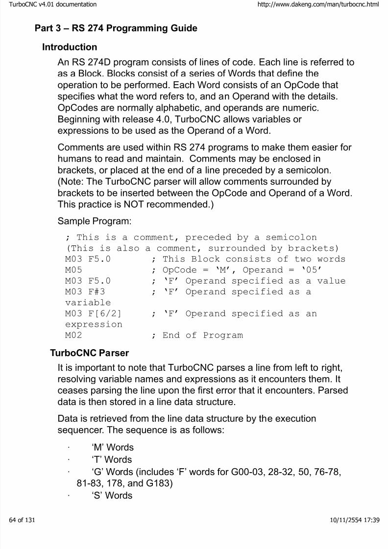
8/3/2019 TurboCNC v4Command
http://slidepdf.com/reader/full/turbocnc-v4command 64/131
Part 3 – RS 274 Programming Guide
Introduction
An RS 274D program consists of lines of code. Each line is referred toas a Block. Blocks consist of a series of Words that define theoperation to be performed. Each Word consists of an OpCode thatspecifies what the word refers to, and an Operand with the details.OpCodes are normally alphabetic, and operands are numeric.Beginning with release 4.0, TurboCNC allows variables or expressions to be used as the Operand of a Word.
Comments are used within RS 274 programs to make them easier for humans to read and maintain. Comments may be enclosed inbrackets, or placed at the end of a line preceded by a semicolon.
(Note: The TurboCNC parser will allow comments surrounded bybrackets to be inserted between the OpCode and Operand of a Word.This practice is NOT recommended.)
Sample Program:
; This is a comment, preceded by a semicolon
(This is also a comment, surrounded by brackets)
M03 F5.0 ; This Block consists of two words
M05 ; OpCode = ‘M’, Operand = ‘05’
M03 F5.0 ; ‘F’ Operand specified as a value
M03 F#3 ; ‘F’ Operand specified as a
variable
M03 F[6/2] ; ‘F’ Operand specified as an
expression
M02 ; End of Program
TurboCNC Parser
It is important to note that TurboCNC parses a line from left to right,resolving variable names and expressions as it encounters them. Itceases parsing the line upon the first error that it encounters. Parseddata is then stored in a line data structure.
Data is retrieved from the line data structure by the executionsequencer. The sequence is as follows:
· ‘M’ Words
·‘T’ Words
· ‘G’ Words (includes ‘F’ words for G00-03, 28-32, 50, 76-78,81-83, 178, and G183)
· ‘S’ Words
boCNC v4.01 documentation http://www.dakeng.com/man/turbocnc.html
of 131 10/11/2554 17:39
8/3/2019 TurboCNC v4Command
http://slidepdf.com/reader/full/turbocnc-v4command 65/131
· ‘F’ WordsAll words in each group are executed in the order received (left toright from the block) prior to moving to the next group.
General rules:
· More than one G or M word per block can be used, as long asthere are no shared parameters.
· N words are ignored except when using jumps or subroutines.
· When using subroutines (see M98, M99), a unique N word isrequired on both the calling line and the return line.
· G, T, and F words are modal in general, with someexceptions.
· I, J, and K words for circular interpolation are incremental by
default. This can be configured if your CAM program requires analternate convention.
· Circular and helical interpolations are called using I, J, and K,or R notation, for any combination of axes. The plane selector (G17-19) should be called beforehand.
All moves involving more than one axis are interpolated, even inrapid. On some mill controls, the Z-axis will always retract first before
moving X and Y. Not so for this program.Angular axes are always driven in degrees modulo 360. For example,if a table is at 10deg and you command it to 350deg, it will go around"the long way". If you commanded it to -10deg instead, it will zip over to -10deg "the short way" and then report the current position as350deg. Commanding a +720deg incremental move will index thetable around two full revs, but the coordinate will remain unchangedsince it is always set to somewhere between 0 and 360 only.
If you use IPR feeds through a G95 call, use the S word to set thespindle speed in RPM from which the feed rate will be calculated first.Alternately, call M50 to read the spindle speed if you have an encoder configured. The code to control the spindle directly from the computer is "empty" - this is so the users can add it themselves.
Metric distances, feeds, etc, are in mm and mm/min or mm/rev asappropriate.
Dwells are programmed in integer seconds by default, using the Pword. This is configurable. Exception: The dwells for G82, G78, andG83 are in milliseconds.
boCNC v4.01 documentation http://www.dakeng.com/man/turbocnc.html
of 131 10/11/2554 17:39

8/3/2019 TurboCNC v4Command
http://slidepdf.com/reader/full/turbocnc-v4command 66/131
The feed rate in an interpolated move is based on the actual distancecovered by each of the linear axes involved. If there are none, thenthe first angular axis on the list is assigned the feed rate(degrees/sec).
If you hit ANY limit switch, the machine won't move again until you
either disable the switch, or use Jog mode to back away. These arefor preventing "going off the rails" only - use the home switches for calibrating the machine.
When block delete is active, a line with a "/" as the first character isskipped. Any word in a line that is preceded by a "/" is not executed.For example
G01 X1.234 F5 /F0.5
In block delete mode, the F5 is read as the feed rate and the secondF word is ignored. In normal mode however, the F0.5 will override F5on this line, and so the feed rate will be much slower.
boCNC v4.01 documentation http://www.dakeng.com/man/turbocnc.html
of 131 10/11/2554 17:39
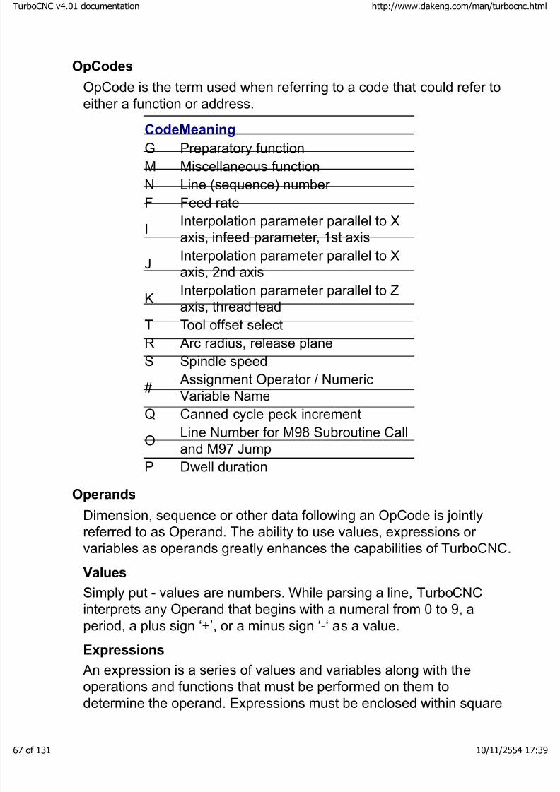
8/3/2019 TurboCNC v4Command
http://slidepdf.com/reader/full/turbocnc-v4command 67/131
OpCodes
OpCode is the term used when referring to a code that could refer toeither a function or address.
CodeMeaningG Preparatory function
M Miscellaneous function
N Line (sequence) number
F Feed rate
IInterpolation parameter parallel to Xaxis, infeed parameter, 1st axis
J
Interpolation parameter parallel to X
axis, 2nd axis
KInterpolation parameter parallel to Zaxis, thread lead
T Tool offset select
R Arc radius, release plane
S Spindle speed
#Assignment Operator / Numeric
Variable NameQ Canned cycle peck increment
OLine Number for M98 Subroutine Calland M97 Jump
P Dwell duration
Operands
Dimension, sequence or other data following an OpCode is jointly
referred to as Operand. The ability to use values, expressions or variables as operands greatly enhances the capabilities of TurboCNC.
Values
Simply put - values are numbers. While parsing a line, TurboCNCinterprets any Operand that begins with a numeral from 0 to 9, aperiod, a plus sign ‘+’, or a minus sign ‘-‘ as a value.
Expressions
An expression is a series of values and variables along with theoperations and functions that must be performed on them todetermine the operand. Expressions must be enclosed within square
boCNC v4.01 documentation http://www.dakeng.com/man/turbocnc.html
of 131 10/11/2554 17:39

8/3/2019 TurboCNC v4Command
http://slidepdf.com/reader/full/turbocnc-v4command 68/131
brackets, and may not be nested. (An expression may not containsub-expressions; instead brackets are used within expressions tochange the order of operations and indicate the parameters to bepassed to a function.
Variables
Variables are values stored by TurboCNC, named with a pound sign‘#’ followed by an Integer from 1 through 9999. Variables with namesof #1 through #999 are persistent, meaning that their values arestored in the configuration file upon exiting TurboCNC and re-loadedwhen TurboCNC is restarted. Variables with names from #1000through #9999 are transient. These values are not restored whenTurboCNC is restarted.
Variable names may be specified as values, variables, or expressions, and are resolved prior to retrieving the value. This allowsadvanced users to implement data structures such as arrays.
NOTE: Expressions and variables are not allowed as operands for the'G', 'M', 'N', or 'T' OpCodes, instead these must be expressed asvalues.
Conditional Execution
The addition of the IF statement to TurboCNC, combined withvariables and expressions has added the rudimentary programmingcapability of RS-274 D. Examples where this ability can be used toadvantage are:
· cutting a contour in multiple passes – until you are throughthe material
· change feed rates when cutting a part out of differentmaterials
·manufacturing the part held by only some of the fixtures of a
complete setup
Preparatory Functions (G-Codes)
Supported Preparatory Functions
Code Function Code Function
G00 Rapid
positioning
G70 Inch units
G01 Linear interpolation
G71 Metric units
boCNC v4.01 documentation http://www.dakeng.com/man/turbocnc.html
of 131 10/11/2554 17:39

8/3/2019 TurboCNC v4Command
http://slidepdf.com/reader/full/turbocnc-v4command 69/131
G02 CW circular interpolation(3D)
G72 CW helicalinterpolation(obsolete)
G03 CCW circular interpolation(3D)
G73 CCW helicalinterpolation(obsolete)
G04 Dwell G76 Multi-passthreading cycle
G16 Set implicitplanes(obsolete)
G77 Turning/Boringcycle
G17 Set XY plane G78 Peck motion(general)
G18 Set XZ plane G80 Cancel cannedcycle
G19 Set YZ plane G81 Drill cycleG20 Inch units G82 Drill cycle with
dwellG21 Metric units G83 Drill cycle with
peckG28 Home all axes G90 Absolute
coordinatesG31 Probe move G91 Incremental
coordinatesG32 Probe cycle G92 Preload of
registersG33 Single pass
threadingG93 Inverse time feed
rateG50 Probe hole ID G94 Inches/mm per
minuteG53 Master
coordinates(fixture 0)
G95 Inches/mm per rev
G54 Fixture offset 1 G97 Set spindle rpmG55 Fixture offset 2 G178 Speed peck
motionG56 Fixture offset 3 G183 Speed peck drill
cycleG57 Fixture offset 4G58 Fixture offset 5G59 Fixture offset 6
boCNC v4.01 documentation http://www.dakeng.com/man/turbocnc.html
of 131 10/11/2554 17:39

8/3/2019 TurboCNC v4Command
http://slidepdf.com/reader/full/turbocnc-v4command 70/131
Table –1 Preparatory Functions, which are or have been supportedby TurboCNC.
boCNC v4.01 documentation http://www.dakeng.com/man/turbocnc.html
of 131 10/11/2554 17:39

8/3/2019 TurboCNC v4Command
http://slidepdf.com/reader/full/turbocnc-v4command 71/131
G00 Rapid Positioning
Function: Moves to a new position as fast as possible.
Syntax: G00 [axis words]
Example:
G00 X1.2 Y0.3 ; Moves to (1.2, 0.3)
Notes:
· Only the axes called out on the line will be moved.
· In a minor departure from the Standard, G00 is interpolatedby default so that axes start and stop in unison and that a straight
line is tracked between both positions. See the configurationsection on how to change this.
· In Absolute Mode the coordinates given are absolute axispositions.
· In Incremental Mode the coordinates given are signeddistances from the current positions.
· The absolute maximum speed is software limited to 2000inches per minute (50 800 mm/min in metric) regardless of the
physical limitations of the machine.· The actual speed and ramping action of motion is chosen so
as not to exceed the least capable moving axis.
G01 Linear Interpolation
Function: Moves to a new position linearly at some feed rate.
Syntax: G01 [axis words] [optional feed word]
Example:G01 X1.2 Y0.3 F3.0 ; Moves to (1.2,0.3) at 3
units/minute
Notes:
The feed rate is calculated as follows by the program:
· A single linear axis feeds in units/minute or units/revolution
depending on active modes. In G93 mode (inverse time feedrate) each move takes a constant amount of time to complete.
· A single angular axis feeds in degrees/second.
boCNC v4.01 documentation http://www.dakeng.com/man/turbocnc.html
of 131 10/11/2554 17:39

8/3/2019 TurboCNC v4Command
http://slidepdf.com/reader/full/turbocnc-v4command 72/131
· Multiple linear axes feed according to the "true distance" of the move in units/rev or units/minute.
· Multiple angular axes feed in deg/sec for the first axis on theline, all others follow such that they start and stop in unison.
· Mixed angular and linear axes follow the rules for linear axes
only, the angular axes will follow such that they start and stop inunison.
· No axis will ever go faster than the max speed established insetup.
· The Feed Rate Override modifies the feed rate, if enabled.
· Feed words are modal. If there is no feed word in the currentblock, the last feed word read will be used.
G02 CW circular interpolation (3D)
Function: Moves to a new position in a clockwise circular arc. The arccenter is specified with signed offsets from the start position or implicitly by the magnitude of the radius.
Syntax 1: G02 [two axis words (optional third)] [interpolationparameters] [optional feed word]
Syntax 2: G02 [two axis words (optional third)] [radius word] [optionalfeed word]
Example 1:
G17 (plane XY specified for clarity)
G00 X0 Y0 (get into start position)
G02 X2 Y0 I1 J0 F4
Moves from the currentpoint to (0,0) in an arc
with its center at thecurrent point + 1 unit inthe X direction at 4units/minute. Absolutemode assumed. The "I"parameter is associatedwith the "X" axis, and the"J" parameter is
associated with the "Y"axis.
boCNC v4.01 documentation http://www.dakeng.com/man/turbocnc.html
of 131 10/11/2554 17:39

8/3/2019 TurboCNC v4Command
http://slidepdf.com/reader/full/turbocnc-v4command 73/131
G17 (plane XY specified for clarity)
G00 X0 Y0 Z0 (get into start position)
G02 X2 Y0 Z1 I1 J0 F4
This generates the same arc as above, but adds linear movementalong the Z-axis thus producing a helical cut.
Example 2:
G17 (plane XY specified for clarity)G00 X0 Y1 (get into start position)G02 X1 Y0 R1 F4
Moves from the currentpoint to (2,0) in a clockwisearc of 1 unit radius less than180 degrees at 4 units per minute. Again, absolutemode is assumed.
G17 (plane XY specified for clarity)
G00 X0 Y1 Z0 (get into start position)
G02 X1 Y0 Z1 R1 F4
This generates the same arc as above, but adds linear movementalong the Z-axis thus producing a helical cut.
Notes:I and J are incremental by default. (NOTE: In rev 3.00g and prior, the Iand J word were absolute in absolute mode, incremental inincremental mode. This is no longer the case. See the dialectcustomizations section above for information on how to change this)
Using a negative radius chooses the arc greater than 180 degreesthat crosses both points, a positive radius takes the arc that is 180
degrees or less. The program will stop with a warning if you have aradius that is impossible. The R form is notoriously inaccurate for arcsvery close to 180 degrees.
boCNC v4.01 documentation http://www.dakeng.com/man/turbocnc.html
of 131 10/11/2554 17:39

8/3/2019 TurboCNC v4Command
http://slidepdf.com/reader/full/turbocnc-v4command 74/131
The sense and 2D plane of the arc is set by the current plane mode.Axis words appropriate to the plane must be included i.e.:
· G17 – XY plane, X and Y [offsets I, J] [linear Z axis]
· G18 – ZX plane, X and Z [offsets I, K] [linear Y axis]
· G19 – ZY plane, Y and Z [offsets J, K] [linear X axis]
The order of parameters on the program line is not important. Use theI word for offset in the X direction, J for offset in Y, and K for offset in Zto describe the relationship of center position from the starting point.See the plane selector information section for more detail.
Start, destination and offset information for arcs can be specifiedusing expressions, For example:
G02 X[3.5 + COS(135)] Y[4.0 + SIN(135)]I[3.5-(2.5 * COS(135))] J[4.0-(2.5 * SIN(135))]
This block assumes absolute mode for IJK, and has been split over two lines on this page. The arc lies on a circle with its center locatedat (3.5, 4.0), has a radius of 2.5 units, and the block will causemovement describing an arc clockwise from the current position to135 degrees.
Full Circles:
If the destination letters are omitted, or, the distance between the startand end points of the arc is less than one full step for each axis onthe plane, a full circle will be described by the tool motion. You mustspecify the move using the IJK form when omitting the axis end pointsfor a full circle move, as the R form is indeterminate for these cases.
Feed rates in an arc:
Feed rates are applied along the helix (i.e.: cutter path) during a threedimensional move.
If the specified feed rate is higher than either the computer, or theCNC machine, is capable of achieving the feed rate will then beclamped at the system's maximum capability. The feed rate isclamped at the lower of that specified by Mav Vel, or that sustainableby the acceleration available at the axes. The formula used to
determine the maximum feed rate based on acceleration isdependent upon the radius of the arc and is computed as follows:
f = sqrt((Accel * Radius) / sqrt(2))
boCNC v4.01 documentation http://www.dakeng.com/man/turbocnc.html
of 131 10/11/2554 17:39

8/3/2019 TurboCNC v4Command
http://slidepdf.com/reader/full/turbocnc-v4command 75/131
Accel is the product of Accel and Scale on the
axis menu
The following chart shows the effect of radius on the maximum feedrate for various accelerations.
G03 CCW circular interpolation (3D)
Function: Moves to a new position in a counter-clockwise circular arc.The arc center is specified with signed offsets from the start position
or implicitly by the magnitude of the radius.
See the section on G02 for general information on this code.
G04 Dwell
Function: Pauses execution for an integer number of seconds
Syntax: G04 [P word]
Example:
G04 P6 ; Six-second pause
Notes:
The P symbol and units of integer seconds are used. See thecustomization section for instructions on how to change the unit of time to milliseconds.
Any delay of more than 2 seconds will show a countdown.Press a key to exit a delay prematurely.
WARNING Never use G04 dwells and your hands as
boCNC v4.01 documentation http://www.dakeng.com/man/turbocnc.html
of 131 10/11/2554 17:39

8/3/2019 TurboCNC v4Command
http://slidepdf.com/reader/full/turbocnc-v4command 76/131
!a tool-changer. It takes longer than youthink... Use M00 or M06 instead.
G16 Set implicit planes
Obsolete Function: Set circular and helical interpolation plane to bedefined implicitly by block
Background:
The original TurboCNC through rev 3.1a allowed an implicit planespecification in which the first two axes called out on a G02/03 linebecame the plane of action for the interpolation. In this mode, only theI and J parameters were used. The "I" offset was applied to the firstaxis on the line, the "J" axis to the second. This affected G02, G03,G72, and G73. For the helical moves, the third axis was always thedirection of linear travel.
The idea here was to allow unusual interpolation schemes to be usedon machines with many axes or non-conventional axis names.
This code is no longer supported! Use the conventional planeselectors (G17 through 19) for defining arc planes in new programs.
G17-19 Set current 2D planeG17 Function: Sets plane for circular and helical interpolation to X-Y.
G18 Function: Sets plane for circular and helical interpolation to Z-X.
G19 Function: Sets plane for circular and helical interpolation to Z-Y.
Syntax: none
Notes:
The rule for planes and howto determine the sense of CW vs. CCW is (from theStandard):
"Arcs shall be CW or CCW
as viewed in the negative
direction of the out-of-
plane axis in a standard right hand axis system."
Translation: For mill users,
boCNC v4.01 documentation http://www.dakeng.com/man/turbocnc.html
of 131 10/11/2554 17:39
8/3/2019 TurboCNC v4Command
http://slidepdf.com/reader/full/turbocnc-v4command 77/131
if +X is rightward and +Y istoward the back of themachine (tool motionrelative to the work!) and+Z is up, then as you lookdown (-Z) at the table inG17 mode, arcs will lookCW or CCW as you'dexpect.
For lathe users, if +Z is away from the headstock, and +X isincreasing diameter, then in G18 mode CW/CCW will look reversed if you look down at the slide. This is because in this right hand system,-Y is looking up.
G20 Inch units
Function: Sets distance unit to inches.
Syntax: none
Notes:
All coordinates and feed rates will be in inches after this command isexecuted.
G20 and G21 are identical to G70 and G71.
Saving the .ini file while in either mode makes it modal on startup.
G21 Metric units
Function: Sets distance unit to mm.
Syntax: none
Notes:
All coordinates and feed rates will be in millimeters after thiscommand is executed.
G20 and G21 are identical to G70 and G71.
Saving the .ini file while in either mode makes it modal on startup.
TurboCNC stores and uses all values in Imperial measure internally.This will cause very small conversion errors (> 0.00001 inch or
0.000004 mm) to show up on the display in Metric mode.
G28 Home all axes
boCNC v4.01 documentation http://www.dakeng.com/man/turbocnc.html
of 131 10/11/2554 17:39
8/3/2019 TurboCNC v4Command
http://slidepdf.com/reader/full/turbocnc-v4command 78/131
Function: Drive each axis with a home switch to re-establish position.
Syntax: G28 [optional feed word]
Notes:
Each axis with a home switch will be driven to the home position
where its coordinates will be reset. G28 is often used to recalibrateyour machine during long cycle times where temperature creep or other position loss sources are a factor.
An axis must have a physical home switch to be "homed" in thiscontext.
The mechanism is as follows:
· Each axis with a home switch moves simultaneously in the
home direction.· As each home switch goes active, each axis will stop
· When they are all on their switches, each axis willsimultaneously move in the opposite direction
· As each home switch goes inactive, each axis will stop again
· Each axis position is re-established as configured in machinecoordinates
The speed of the homing action is set by the modal F word andcurrent feed mode.
It is not necessary to be in machine coordinates to initiate homing.
If no axis has a home switch, an error warning will be issued.
G31 Probe move
Function: Move to a position until the probe input goes active
Syntax: G31 [axis words] [optional feed word]
Example:
G31 Z-4.0 F10
Move to Z -4.0 at 10 IPM, until the probe input goes active.
Notes:
The move works in a similar fashion to G01. If the probe hitssomething, the machines stops and write the position to the filePOINTS.DAT in the same directory as the executable.
boCNC v4.01 documentation http://www.dakeng.com/man/turbocnc.html
of 131 10/11/2554 17:39

8/3/2019 TurboCNC v4Command
http://slidepdf.com/reader/full/turbocnc-v4command 79/131
If nothing is hit, the move ends at the position specified and no datais written.
Use G31 to get off of the part again if you need to, the program onlyaccepts the inactive to active transition as valid input.
WARNING
!
Note that if you move twice in the samedirection with G31 or any other codes,you can smash your probe! Goodpractice is to design your probe with builtin over travel that activates the panicstop input if exceeded.
G32 Probe cycle
Function: Repetitive probing to digitally scan a 2D or 3D surfaceSyntax: G32 [axis bound 1] [bound 2] [optional bound 3][discretization] [optional feed word]
Example:
G00 X0 Y0 Z0 ; get into position
G32 X1 Y1 Z-1 I0.250 F10
Moves X from 0 to 1 by .250 increments, each time moving Y from 0to 1 by 0.250 increments. Z will plunge from 0 to -1 and back to 0again, stopping and writing the position to disk for each probe strikeon the downward stroke. Absolute mode assumed.
Notes:
· This is 2 or 3-axis general, so the last axis cycles the most andthe first axis only once through a number of points determined by
the discretization distance. You need at least two axes moving toscan. Using a single axis will move in the same way as G31.
· The digitizing scheme is of the "bed of nails" variety, e.g.:straight up and down in the last axis on the line.
· The output is written to a scan file in the same directory as theexecutable, with a filename of SURFSCAN.DAT.
WARNING
!
Rounding error may prevent the last row or column from being scanned. Add a smallamount to the bounding distance to avoid this:
boCNC v4.01 documentation http://www.dakeng.com/man/turbocnc.html
of 131 10/11/2554 17:39

8/3/2019 TurboCNC v4Command
http://slidepdf.com/reader/full/turbocnc-v4command 80/131
G32 X1 Y1 Z-1 I0.250 F10 ;X1,Y1
;may or may not be reached
G32 X1.001 Y1.001 Z-1 I0.250 F10
;This is better
G33 Single pass threading
Function: Makes a single threading motion in sync with the spindle.
Syntax: G33 [axis coord] [lead parameter]
Example:
G33 Z-1.25 K0.050
Assuming inches and absolute mode, this threads 20 TPI to ashoulder at Z = -1.25
Notes:
A spindle index pulse must be enabled and present for this to work.See the section on hooking up a spindle encoder for details on how todo this.
The program will time-out after 5 seconds of spindle pulse inactivity.Similarly, the operation will be halted if the speed detected at thespindle is greater than 5000 rpm. This offers a measure of protectionagainst the failure modes of signal noise, signal loss, or stalls.
K is the lead parameter for the Z-axis, I is for X, and J is for Y. See thedialect customization section if you want to specify pitches instead or change K for some other letter.
Multiaxis Operations: You can thread up to three axes simultaneouslyfor tapered threading or unusual machining situations like gear hobbing. The lead and distance should work out to an equal number
of revolutions for each. An axis with no lead specified will move at theregular feed rate.
Allow a few revs of "lead in" for the axis to synchronize. You need alot of acceleration to keep up with the changes in velocity. If the axisfalls behind and can't keep up, the program will stop and warn you.
The synchronization is always from the start point for each pass, sofor multi-start threads, offset the start position by some fraction of the
thread lead. For 30 degree infeed, change the start position on eachpass along a 30 deg vector.
See also G76, multi-pass threading.
boCNC v4.01 documentation http://www.dakeng.com/man/turbocnc.html
of 131 10/11/2554 17:39

8/3/2019 TurboCNC v4Command
http://slidepdf.com/reader/full/turbocnc-v4command 81/131
G50 Probe hole ID
Function: Finds the center of a hole using a touch probe
Syntax: G50 [optional feed word]
Notes:
Put the probe inside the hole approximately in the center, and callG50 from within a program or the MDI window.
This is an orthogonal six hit probing algorithm - clock positions struckare 12,6,9,3,12,6 in the XY plane as you normally view the part on amill. You must have a touch probe installed and the probe inputconfigured for this to work. Hole probing is always in the XY plane.
The speed of G50 probing is given by the modal feed word and mode.
Watch out for keyways and similar things that can throw you off. Usethis command for auto-setting boring operations or fixture locatingwhere some part-to-part variation is expected and you need to locateto a hole center exactly.
G53 Change to master coordinates
Function: Change to master coordinates, also known as fixture 0.
Syntax: none
Notes:
In master coordinate mode, no fixture offset is active. If tool 0 is setas well, you are in Machine Coordinates. These are the coordinatesthat are active while homing, and in setting up feed screw error compensation.
At startup, you are in machine coordinates by default. No offsets are
active in machine coordinate mode.G54-G59 Change fixture offset
Function: Change to a new fixture offset, from 1 (G54) to 6 (G59)
Syntax: none
Notes:
When the fixture offset is changed, all the tool offsets follow.
Machining in a new offset mode is like having "zero" in a new placeon your machine.
The coordinates you see on the screen are the master coordinates +
boCNC v4.01 documentation http://www.dakeng.com/man/turbocnc.html
of 131 10/11/2554 17:39
8/3/2019 TurboCNC v4Command
http://slidepdf.com/reader/full/turbocnc-v4command 82/131
the fixture offset in use + the tool offset in use. Tool 0 is no tool offset,G53 is no fixture offset.
The most common use for these is multiple fixtures on the sametable. For example, home the machine in G53. Your usual 6" vise canbe "zeroed" in G54 mode, and the center of a 5C collet vise, say, can
be zero in G55. Changing modes puts you in a new coordinatesystem painlessly and allows different classes of parts to bemachined on a large table.
G53-59 are modal. A fixture offset stays in effect until a new one iscommanded.
G70 Inch mode
Function: Sets distance unit to inches.
Syntax: none
Notes:
Same as G20.
G71 Metric mode
Function: Sets distance unit to mm.
Syntax: noneNotes:
Same as G21.
G72 CW helical interpolation
Obsolete Function: Was similar to G02, but allowed a third axis totravel linearly as well.
Background:Originally (through version 3.1a), TurboCNC used G02 and G03 asstrictly 2D arc functions, and a separate G word for helicalinterpolation. This was unnecessary, and violated the Standard.
This function is no longer supported. Use G02 with a third axis calloutinstead.
G73 CCW helical interpolation
Obsolete Function: Was similar to G03, but allowed a third axis totravel linearly as well.
This function is no longer supported. Use G03 with a third axis callout
boCNC v4.01 documentation http://www.dakeng.com/man/turbocnc.html
of 131 10/11/2554 17:39

8/3/2019 TurboCNC v4Command
http://slidepdf.com/reader/full/turbocnc-v4command 83/131
instead.
G76 Multi-pass threading
Function: Machines an OD or ID thread completely on a lathe.
Syntax: G76 [X coord] [Z coord] [K height] [D first pass] [F lead] [A tool
nose angle]Example:
G76 X-0.210 Z-1.25 K.040 D0.003 F0.050 A60
Assuming inches and absolute radius mode, this threads 1/2-20 TPIUNF to Z = -1.25 completely.
Notes:
The starting point is returned to after each pass. The X location of thestarting point determines the back out distance after each cut itcomplete.
The A word specifies the included tool nose angle, which iscustomarily 60 degrees for common threads. The tool willautomatically feed on an angle of 1/2 A. If A is not specified, it defaultsto 0, which produces a radial infeed.
K, D and F are always positive, regardless of the actual orientation or "hand" of the thread.
Each successive pass will remove the same area of material as thefirst pass did, in order to equalize the torque load. This is standard,and helps to improve the finish.
G77 Turning/Boring/Milling Cycle
Function: Turning with multiple passes, infeeding by an amount set bythe I word.
Syntax: G77 [repetitive axis] [infeed axis] [feed per pass] [optionalfeed rate]
Example:
G77 Z-1.250 X0.250 I0.050 F5.0
On a radius programmed lathe that cuts to an X coordinate of 0.250,back and forth in Z from current position to -1.250, feeding in 0.050each pass and cutting at 5 units/min. Here's the actual motionsequence for on the above, assuming the tool started at 0,0:
boCNC v4.01 documentation http://www.dakeng.com/man/turbocnc.html
of 131 10/11/2554 17:39

8/3/2019 TurboCNC v4Command
http://slidepdf.com/reader/full/turbocnc-v4command 84/131
X0.050 slowlyZ-1.250 slowlyX-0.025 slowlyZ0 rapidlyX0.100 slowlyZ-1.250 slowlyetc...
Notes:
The order of the operands defines the motion. The back-and-forthaction will occur from the current position of the first axis on the line tothe position specified. The second axis called out will eventually reachthe position specified by feeding in increments of I each pass.
The sign of I is unimportant. Always use I for the infeed, no matter
what other axes are being used.
Infeed is applied to the second axis on the line. Creative use of thiscommand can be made for fly cutting / slab-milling or cutting deepblind slots on mills or trimming the edges of stock.
After each pass, the control "backs off" by 1 1/2 times the infeed. So if you're boring, make sure you have enough clearance for the bar.
If the infeed doesn't divide into an even number of passes, a smallfinishing pass will be taken.
G78 Peck Motion Cycle
Function: Feeds to a position on an axis, incrementally in "pecks" witha full rapid retract.
Syntax: G78 [axis of action] [peck distance] [optional feed word][optional dwell]
Example:
G78 Z-2.000 I0.100 F2.0
Moves from the current position to Z=-2.000 at 2 units/min 0.100 unitsat a time (retracts to original Z each time).
Notes:
The sign of I is unimportant, but this code is always used with I,regardless of the actual letter for the moving axis.
If you put in a dwell parameter with the P operator, a dwell inmilliseconds will be taken at the end of each pass.
boCNC v4.01 documentation http://www.dakeng.com/man/turbocnc.html
of 131 10/11/2554 17:39

8/3/2019 TurboCNC v4Command
http://slidepdf.com/reader/full/turbocnc-v4command 85/131
G78 Z-2.000 I-0.100 F2.0 P100
does the same as the previous example, but with a tenth of a seconddwell at the bottom of the hole. This helps the tool life considerably insome cases. After each peck and retract, the tool will rapid to 10% of the peck increment before the last stop, and then feed in again. The
letter and units used for the dwell are the same as for the G8x cyclesif user configured.
This command is single axis only.
A good use of this code is "peck turning" plastic on a lathe to keep thechips short.
G80 Cancel drill cycle
Function: Cancel canned drill cycleSyntax: none
Notes:
It's good practice, but not strictly necessary, to put this code after aseries of the G81, G82, or G83 drill cycles. It clears the canned cyclevariables from memory.
Some CAM programs automatically generate this code after everyseries of drilled holes.
G81 Drill cycle
Function: Drill a hole on a 3-axis mill
Syntax: G81 [axis words] [release plane] [optional feed word]
Example:
G81 X1 Y1 Z-0.75 F2.0 R0.25
The following will occur. Absolute mode and inch units are assumed.
Rapid to R plane if Z is less than 0.25 absolute
Move the table to the XY position (1,1) specified; holding Z at thepoint it was before.
Feed the Z-axis to -0.75 at 10ipm.
Rapid the Z-axis to 0.25 (the release plane)
Notes:
boCNC v4.01 documentation http://www.dakeng.com/man/turbocnc.html
of 131 10/11/2554 17:39
8/3/2019 TurboCNC v4Command
http://slidepdf.com/reader/full/turbocnc-v4command 86/131
This is the canonical RS-274D drill cycle. Drills a hole at a specific XYposition, to a depth Z at the current feed rate, and retracts to arelease plane "R".
To drill another hole just like the first, just input the XY position on thenext line:
G81 X1.5 Y1.25
This second hole will be done the exact same way was the first, but atthe new position of X=1.5 and Y=1.25.
Release plane: If the R plane is between the current Z position andthe bottom of the hole, the control will rapid to the R plane after moving XY and before drilling. If the R plane is "above" where the drill
is in Z at the start of G81, the control will rapid to the R plane firstbefore moving XY. This affords maximum safety without overlycompromising speed.
Note that R is absolute in absolute mode, incremental in incrementalmode! All the other parameters behave similarly.
All of the coordinates (XYZR) need to be called out on the first G81.These will "stay in effect" thereafter until G80 is called (modality). So,if you have a series of holes that are all to the same depth, you canuse this:
G81 X1 Y1 Z-0.75 F2.0 R0.25 ;First hole
G81 X2 Y2
G81 X3 Y2
X2.5
G80 ;Four holes were drilled at (1,1) (2,2) (3,2)
and (2.5,2)
These cycles ignore the plane selector as per the Standard. Thedrilling always occurs in Z, the positioning in XY.
G82 Drill + Dwell cycle
Function: Drill cycle with dwell at the bottom of the hole
Syntax: Similar to G81, but requires a # parameter for the dwell at thebottom of the hole in milliseconds.
Example:
G82 X0 Y0.5 Z-1 F10 R0.25 P250
boCNC v4.01 documentation http://www.dakeng.com/man/turbocnc.html
of 131 10/11/2554 17:39
8/3/2019 TurboCNC v4Command
http://slidepdf.com/reader/full/turbocnc-v4command 87/131
Drills at coord (0,0.5) to a depth of Z=-1 at 10 IPM. Dwells for aquarter second, and then retracts to Z=0.25.
Notes:
Dwell is in milliseconds for this code by default. This can becustomized to seconds, or some other letter chosen besides P for
CAM compatibility.
G83 Peck drill cycle
Function: Drill with a pecking action and an optional dwell
Syntax: Similar to G81/82, but requires an I parameter for the peckincrement when drilling.
Example:
G83 X0 Y0.5 Z-1 F10 R0.25 Q0.100 P250
This is the same as the G82 example above, but the drill will descendat the 10 IPM feed rate in 0.100 inch pecks with a rapid retract to theoriginal Z. The drill rapids down to 10% of the peck distance abovethe bottom of the hole before feeding again to minimize "air time".
Notes:
The dwell parameter (P) is optional with G83 as a convenientdeparture from the Standard. The above example will dwell a quarter second at the end of each peck. The dwell is in integer millisecondsby default.
The sign of Q is unimportant. The letters P and Q, and the dwell unitsare customizable.
G90 Absolute coordinates
Function: Set coordinates to absolute mode (default).
Syntax: none
Notes:
In absolute mode, all axis words and many parameters refer to anabsolute coordinate position.
G90/91 are modal. Either mode will stay in effect until the other is
called.
G90 is the default mode at startup.
boCNC v4.01 documentation http://www.dakeng.com/man/turbocnc.html
of 131 10/11/2554 17:39

8/3/2019 TurboCNC v4Command
http://slidepdf.com/reader/full/turbocnc-v4command 88/131
G91 Incremental coordinates
Function: Set coordinates to incremental mode (offsets from currentposition)
Syntax: none
Notes:In incremental mode, all axis words and many parameters are asigned offset from the current position.
G90/91 are modal. Either mode will stay in effect until the other iscalled.
G92 Preload of registers/Set machine coordinates
Function: Set position without motion
Syntax: G92 [axis words]
Example:
G92 X0 ;Zeroes X axis
G92 X0 Y0 Z0 ;Zeroes the principle axes on a mill
G92 Z1.234 ;Z is now set to 1.234
Notes:
This code sets the position of any or all axes to a specific value. Usethis to reset the position inside a program. No motion will occur.
In machine coordinate (G53 T0) mode, the machine coordinatesthemselves are updated.
In any fixture offset mode (G54-G59) and T0, the fixture offset isupdated.
In any tool-offset mode (T1-T20), the tool offset is updated.
This code is not modal.
G93 Inverse time feed rate
Function: Set feed rate unit to inverse time ratio
Syntax: none
Example:
G93 F60 ;All G01 blocks will take one second
G93 F120 ;All G01 blocks will take 1/2 second
G93 F0.5 ;All G01 blocks will take 2 minutes
boCNC v4.01 documentation http://www.dakeng.com/man/turbocnc.html
of 131 10/11/2554 17:39

8/3/2019 TurboCNC v4Command
http://slidepdf.com/reader/full/turbocnc-v4command 89/131
Notes:
In this mode, the length of time that each block will take to execute iscontrolled. The unit is the reciprocal of length of time in minutes. (e.g.:60 is 1/60th of a minute or one second).
G93/94/95 are modal to one another. Each mode will stay in effectuntil another is called.
This mode is useful for unusual situations where the feed rate isdifficult to calculate directly, but the overall time to move is known -such as when several axis types are moving simultaneously.
As with the other feed modes, if the commanded feed rate is too fastfor the machine, the motion will be performed at the fastest available
speed.
With arcs, each arc segment is treated as an individual block in thismode.
G94 IPM feed rate
Function: Set feed rate unit to units/min
Syntax: none
Notes:
G93/94/95 are modal to one another. Each mode will stay in effectuntil another is called.
G94 is the default mode at startup.
G95 IPR feed rate
Function: Set feed rate unit to units/rev.
Syntax: G95 [optional S word]
Example:
G95 S1000 F0.002 ; Feed is now 0.002/rev at 1000
rpm
Notes:
Be sure to have set the "S" word for spindle speed when calling thisfunction for the first time before any motion takes place. You can alsoread the spindle speed after engaging G95 mode by using the M50code if you have a spindle encoder on your machine.
boCNC v4.01 documentation http://www.dakeng.com/man/turbocnc.html
of 131 10/11/2554 17:39
8/3/2019 TurboCNC v4Command
http://slidepdf.com/reader/full/turbocnc-v4command 90/131
G93/94/95 are modal to one another. Each mode will stay in effectuntil another is called.
G97 Program spindle RPM
Function: Set spindle RPM
Syntax: G97 [S word]Example:
G97 S1000 ;1000 rpm
Notes:
This function is a "placeholder" in the source code. Registered userscan use it as a starting point to program their own spindle controlroutines into TurboCNC.
If you use units/rev feed rates by calling G95, you must use this codeor otherwise set the S parameter with the spindle speed before tryingto move.
G178 Speed peck motion
Function: Speedy generalized single axis pecking motion
Syntax: G178 [axis of action] [peck distance] [optional feed word]
[optional dwell]Example:
G178 Z-2.000 I0.100 F2.0
Moves from the current position to Z=-2.000 at 2 units/min 0.100 unitsat a time with dwells.
Notes:
This command is single axis only, and is identical to G78, except that
no retracts are made while machining. Only the dwells are taken.
In some cutting situations you can use this to avoid dangerouscontinuous chips while machining, and saving a significant amount of time in the process by not retracting fully.
G183 Speed peck drill cycle
Function: Speedy peck drilling in pecks with dwells
Syntax: Same as G83Notes:
This code operates in exactly the same manner as G83, except that it
boCNC v4.01 documentation http://www.dakeng.com/man/turbocnc.html
of 131 10/11/2554 17:39

8/3/2019 TurboCNC v4Command
http://slidepdf.com/reader/full/turbocnc-v4command 91/131
does not retract at all between each peck. The dwells are taken.
In some cutting situations you can use this to avoid dangerouscontinuous chips while conserving machining time if many holes areto be drilled.
boCNC v4.01 documentation http://www.dakeng.com/man/turbocnc.html
of 131 10/11/2554 17:39
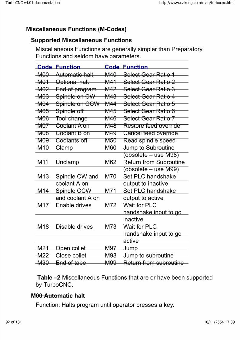
8/3/2019 TurboCNC v4Command
http://slidepdf.com/reader/full/turbocnc-v4command 92/131
Miscellaneous Functions (M-Codes)
Supported Miscellaneous Functions
Miscellaneous Functions are generally simpler than Preparatory
Functions and seldom have parameters.Code Function Code Function
M00 Automatic halt M40 Select Gear Ratio 1M01 Optional halt M41 Select Gear Ratio 2M02 End of program M42 Select Gear Ratio 3M03 Spindle on CW M43 Select Gear Ratio 4M04 Spindle on CCW M44 Select Gear Ratio 5M05 Spindle off M45 Select Gear Ratio 6M06 Tool change M46 Select Gear Ratio 7M07 Coolant A on M48 Restore feed overrideM08 Coolant B on M49 Cancel feed overrideM09 Coolants off M50 Read spindle speedM10 Clamp M60 Jump to Subroutine
(obsolete – use M98)M11 Unclamp M62 Return from Subroutine
(obsolete – use M99)M13 Spindle CW andcoolant A on
M70 Set PLC handshakeoutput to inactive
M14 Spindle CCWand coolant A on
M71 Set PLC handshakeoutput to active
M17 Enable drives M72 Wait for PLChandshake input to goinactive
M18 Disable drives M73 Wait for PLChandshake input to goactive
M21 Open collet M97 JumpM22 Close collet M98 Jump to subroutineM30 End of tape M99 Return from subroutine
Table –2 Miscellaneous Functions that are or have been supported
by TurboCNC.M00 Automatic halt
Function: Halts program until operator presses a key.
boCNC v4.01 documentation http://www.dakeng.com/man/turbocnc.html
of 131 10/11/2554 17:39
8/3/2019 TurboCNC v4Command
http://slidepdf.com/reader/full/turbocnc-v4command 93/131
Notes:
Comments included in the block containing M00 are displayed withinthe prompt that is raised. A vertical bar, '|' can be used to force a newline. This feature is a convenient method of presenting instructions tothe machinist at runtime.
M01 Optional halt
Function: Halts the program only if optional halts are enabled.
Notes:
Similar to M00. Use Optional Halts under the machining options menuto toggle whether these are enabled.
This is commonly used for "first article" type checks while the part is
on machine.
Comments included in the block containing M01 are displayed withinthe prompt that is raised. A vertical bar, '|' can be used to force a newline. This feature is a convenient method of presenting instructions tothe machinist at runtime.
M02 End of program
Function: Stops program execution.
Notes:
This (or M30) must be the last line of a program.
Comments included in the block containing M02 are displayed withinthe prompt that is raised. A vertical bar, '|' can be used to force a newline. This feature is a convenient method of presenting instructions tothe machinist at runtime.
M03 Spindle on CWFunction: Turns on spindle in the clockwise direction.
Notes:
Clockwise is the usual direction for a lathe or mill. If the spindle iscommanded to run forward while it is already on, it will be shut off for 7 seconds and then re-activated in the new direction.
M04 Spindle on CCWFunction: Turns on spindle in the counter-clockwise direction.
Notes:
boCNC v4.01 documentation http://www.dakeng.com/man/turbocnc.html
of 131 10/11/2554 17:39
8/3/2019 TurboCNC v4Command
http://slidepdf.com/reader/full/turbocnc-v4command 94/131
Similar to M03.
Turn the spindle off with M05 before changing directions or callingM03/04. If the spindle is commanded to reverse while it is already on,it will be shut off for 7 seconds and then re-activated in the newdirection.
M05 Spindle off
Function: Turns off spindle
Notes:
Turns off the spindle output line. No braking is assumed. The spindledirection line state is not affected.
M06 Tool change
Function: Halt for tool change
Example:
M06 T1 ; Stops with a prompts for change to tool 1
; and changes to the tool 1 coordinate
offset
Notes:
This is essentially the same as M00, but with a prompt to tell the user which tool is being requested. Registered users may program their own, more sophisticated routines for automated tool changes here.
The T word is required with M06. It may also be placed on anyprogram line to change the tool offset without pausing the program.
If the tool turret index line is enabled, M06 will not prompt the user,but activate the turret index line briefly instead. The default time
period is two seconds, the maximum period is 120 seconds.
The delay period for the turret index line is set in the ini file or theconfiguration menu under the General heading.
Comments included in the block containing M06 are displayed withinthe prompt that is raised. A vertical bar, '|' can be used to force a newline. This feature is a convenient method of presenting instructions tothe machinist at runtime.
M07 Coolant A on (flood)
Function: Turns on relay A
boCNC v4.01 documentation http://www.dakeng.com/man/turbocnc.html
of 131 10/11/2554 17:39

8/3/2019 TurboCNC v4Command
http://slidepdf.com/reader/full/turbocnc-v4command 95/131
Notes:
This code is traditionally associated with flood coolant. It can be usedas a generic output to control anything.
M08 Coolant B on (mist)
Function: Turns on relay B.Notes:
This code is traditionally associated with mist coolant. It can be usedas a generic output to control anything.
M09 Coolants off
Function: Switches off both relay A & B.
Notes:Both coolant outputs (A and B, see M07 and M08) will be set toinactive.
M10 Clamp
Function: Closes a machine clamp
Example:
M10 Q12; Closes clamp twelveNotes:
Use numbers 0-15 for the clamps. If Q is not specified, it defaults toclamp 0.
At a minimum, the clamp drive, direction, and closure sense linesneed to be configured on the machine to use this command.
The clamp address appears on the four clamp select output lines in
binary, if they are configured on the machine. Clamp 0 is all linesinactive; clamp 15 sets all lines active.
You do not need to configure all 4 clamp select lines. For example, if you only have four clamps to control then it is permissible to use thefirst two clamp select lines only.
The clamp will be driven until the closure line goes active, or when 15seconds has elapsed, whichever comes first.
M11 Unclamp
Function: Identical to M10, except that it opens a machine clamp.
boCNC v4.01 documentation http://www.dakeng.com/man/turbocnc.html
of 131 10/11/2554 17:39

8/3/2019 TurboCNC v4Command
http://slidepdf.com/reader/full/turbocnc-v4command 96/131
Notes:
At a minimum, the clamp drive, direction, and open sense lines needto be configured on the machine to use this command.
The clamp will be driven until the open line goes active, or when 15seconds has elapsed, whichever comes first.
M13 Spindle CW and coolant A on
Function: Turns the spindle on in the clockwise direction and activatesthe "A" coolant.
M14 Spindle CCW and coolant A on
Function: Similar to M13, but the spindle will be startedcounterclockwise.
M17 Enable drives
Function: Set drive enable lines active
Notes:
The Stepper World SP3 and some versions of the MAXNC drivesrequire an enable signal in order to operate. After the drive enableoutput lines have been configured in TurboCNC, use this code to turnthem on.
The drives will be disabled automatically when:
· a panic abort occurs during motion
· you exit TurboCNC normally
They will be enabled when:
· a program is started or resumed
· you enter jog mode
· TurboCNC is started
· you input an MDI command
You can also control these manually by using the options under thesetup menu.
M18 Disable drives
Function: Set drive enable lines inactive
Notes:
boCNC v4.01 documentation http://www.dakeng.com/man/turbocnc.html
of 131 10/11/2554 17:39

8/3/2019 TurboCNC v4Command
http://slidepdf.com/reader/full/turbocnc-v4command 97/131
Similar to M17, this turns the drive enable lines off.
M21 Open collet
Function: Opens a collet
Notes:
When this code is executed, the Collet Open line goes active for ashort time, and then returns to the inactive state. The default length of time is two seconds and the maximum is 120. Change the length of time allowed by editing the ColletOpenTime(ms) entry in the ini file.
No feedback is required from the actual machine. This is designed towork with a pneumatic collet closer on a lathe.
The delay periods for M21 and M22 are set in the ini file or the
configuration menu under the General heading.
M22 Close collet
Function: Closes a collet
Notes:
Similar to M21, this code activates the Collet Close output line for some length of time. Two seconds is the default, 120 seconds is the
maximum. Change the length of time allowed by editing theColletCloseTime(ms) entry in the ini file.
M30 End of program & rewind
Function: Stops program execution
Notes:
Functionally identical to M02. Hard disks don't need to be "rewound"of course, but paper tapes used to be! Some CAM programs generate
this code instead of M02 at the end of a program, so it's here for compatibility.
Comments included in the block containing M30 are displayed withinthe prompt that is raised. A vertical bar, '|' can be used to force a newline. This feature is a convenient method of presenting instructions tothe machinist at runtime.
M40 – M46: Gear Changes
Function: Selects the speed map associated with the specified gear.
Notes:
boCNC v4.01 documentation http://www.dakeng.com/man/turbocnc.html
of 131 10/11/2554 17:39

8/3/2019 TurboCNC v4Command
http://slidepdf.com/reader/full/turbocnc-v4command 98/131
Spindle speed control is oriented to the Sherline spindle. As such thedefault compilation only implements M40 through M43. IncreaseMaxRatios in the spdmap unit to 7 to take advantage of the full rangeof codes.
The following mappings are defined:
·M40 – Standard Pulleys, Low Range (45 – 1400 RPM)
· M41 – Standard Pulleys, High Range (70 – 2800 RPM)
· M42 – 10K RPM Pulleys, Low Range (150 – 2200 RPM)
· M43 – 10K RPM Pulleys, High Range (1500 – 10200 RPM)
M48 Restore feed override
Function: Restore feed override
Notes:This brings the feed override back to whatever it was just before themost recent M49 call.
M49 Cancel feed override
Function: Cancel feed override
Notes:
This resets the feed override to 100% "from the inside". Use it beforeentering a critical section of your program that requires an exact feedrate. The feed override can be restored with the M48 code.
M50 Read spindle speed
Function: Set S word with actual spindle speed
Notes:
This reads the spindle speed into the program for use with per revolution feed rates (see G95) by reading the spindle index pulse.
You must have an index pulse enabled to use this code. See thehardware section for details on how to set this up.
The operation will time out if five seconds goes by without a signalfrom the spindle.
An error will be triggered if the spindle appears to be going faster than
5000 rpm.M60 Jump to subroutine (obsolete function)
Function: Jump to a new block saving return
boCNC v4.01 documentation http://www.dakeng.com/man/turbocnc.html
of 131 10/11/2554 17:39
8/3/2019 TurboCNC v4Command
http://slidepdf.com/reader/full/turbocnc-v4command 99/131
Syntax: [N word] M60 [jump target]
Example:
N0010 M60 O0100 ; Jump to subroutine 0100
M05 ; Subroutine returns here –
spindle off
M02 ; End Program
N0100 M03 ; Subroutine to turn spindle on
M62 ; Return from subroutine
Notes:
This function is considered obsolete. Use of M98 is stronglysuggested. It is included as a partial bridge to previous versions of
TurboCNC.
The jump target word is set to 'O' by default. This can be reconfiguredusing the 'Configure/Dialect' menu.
Jumps to the line with the N word identical to the jump target word(N0100 in the example).
The N word of the line with the M98 is saved for the return (10 in the
example). Naturally, this means you should have a different N wordon both the calling line and the target line.
Subroutines can be nested 20 levels deep.
M62 Return from subroutine (obsolete function)
Function: Return to block immediately after the most recent M60 call
Syntax: M62
Example:See M60
Notes:
This function is considered obsolete. Use of M99 is stronglysuggested. It is included as a partial bridge to previous versions of TurboCNC.
The next block to be executed will be found on the line following themost recent M60 call.
See SAMPLE.CNC for a simple nested subroutine example. Pleasenote that when using subroutines, you'll need a unique N code on
boCNC v4.01 documentation http://www.dakeng.com/man/turbocnc.html
of 131 10/11/2554 17:39
8/3/2019 TurboCNC v4Command
http://slidepdf.com/reader/full/turbocnc-v4command 100/131
each calling line so that the program knows where to go back to.
To visualize program execution with subroutines, imagine all the codein the subroutine invisibly pasted in beneath the calling line. None of the modal codes are affected.
M70 Set PLC handshake output to inactive
Function: Set PLC handshake output to inactive
Notes:
Two PLC handshaking lines can be configured in TurboCNC. Theseare for telling external logic, such as an automatic tool changer or what-have-you to do some work. M70 sets the output handshake lineto the inactive state. This can also be used to control extra solenoidsor relays.
M71 Set PLC handshake output to active
Function: Set PLC handshake output to active
Notes:
Similar to M70, M71 sets the output handshake line to the activestate.
M72 Wait for PLC handshake input to go inactiveFunction: Wait for PLC handshake input to go inactive
Notes:
When this code is called, the program stops running and waits for thePLC input line (separate from the output line) to go to the inactivestate. This is intended to be used to synchronize the program withexternal logic that might be loading more stock, or performing some
other function.M73 Wait for PLC handshake input to go active
Function: Wait for PLC handshake input to go active
Notes:
Similar to M72, this pauses until the PLC line goes to the active state.With either of these two codes, the user can press a key to bypassthe wait condition.
M97 Jump
Function: Jump to a new block
boCNC v4.01 documentation http://www.dakeng.com/man/turbocnc.html
of 131 10/11/2554 17:39

8/3/2019 TurboCNC v4Command
http://slidepdf.com/reader/full/turbocnc-v4command 101/131
Syntax: M97 [jump target]
Example:
M97 O0200 ; Jump to block 0200
G00 X1 ; This line is skipped
N0200 M02 ; Jump target – Program End
Notes:
The jump target word is set to 'O' by default. This can be reconfiguredusing the 'Configure/Dialect' menu.
Jumps to the line with the N word identical to the jump target word(N0200 in the example).
Code following an M97 in a block is not executed. M-Codes within ablock are executed first, in the order that they are encountered. Onlythe parameters that follow the M97 for M-Codes encountered earlier in the block will be used. Every other code or parameter is ignored.
The jump function is very useful when combined with 'ConditionalProgramming'
If there is a parsing error in the line containing the jump target, themessage 'Jump Target not Found' will be displayed.
M98 Jump to subroutine
Function: Jump to a new block saving return
Syntax: [N word] M98 [jump target]
Example:
N0010 M98 O0100 ; Jump to subroutine 0100
M05 ; Subroutine returns here –
spindle offM02 ; End Program
N0100 M03 ; Subroutine to turn spindle on
M99 ; Return from subroutine
Notes:
The jump target word is set to 'O' by default. This can be reconfiguredusing the 'Configure/Dialect' menu.
Jumps to the line with the N word identical to the jump target word(N0100 in the example).
boCNC v4.01 documentation http://www.dakeng.com/man/turbocnc.html
of 131 10/11/2554 17:39

8/3/2019 TurboCNC v4Command
http://slidepdf.com/reader/full/turbocnc-v4command 102/131
The N word of the line with the M98 is saved for the return (10 in theexample). Naturally, this means you should have a different N wordon both the calling line and the target line.
Subroutines can be nested 20 levels deep.
Code following an M98 in a block is not executed. M-Codes within a
block are executed first, in the order that they are encountered. Onlythe parameters that follow the M98 for M-Codes encountered earlier in the block will be used. Every other code or parameter is ignored.
If there is a parsing error in the line containing the jump target, themessage 'Jump Target not Found' will be displayed.
M99 Return from subroutine
Function: Return to block immediately after the most recent M98 call
Syntax: M99
Example:
See M98
Notes:
The next block to be executed will be found on the line following the
most recent M98 call.Code following an M99 in a block is not executed. M-Codes within ablock are executed first, in the order that they are encountered. Onlythe parameters that follow the M99 for M-Codes encountered earlier in the block will be used. Every other code or parameter is ignored.
See SAMPLE.CNC for a simple nested subroutine example. Pleasenote that when using subroutines, you'll need a unique N code oneach calling line so that the program knows where to go back to.
To visualize program execution with subroutines, imagine all the codein the subroutine invisibly pasted in beneath the calling line. None of the modal codes are affected.
If there is a parsing error in the line containing the jump target, themessage 'Jump Target not Found' will be displayed.
boCNC v4.01 documentation http://www.dakeng.com/man/turbocnc.html
of 131 10/11/2554 17:39

8/3/2019 TurboCNC v4Command
http://slidepdf.com/reader/full/turbocnc-v4command 103/131
S-Word Handing:
The interpretation of the S-Word has been modified to control theDigiSpeed output. A count of the difference between the currently setcount at the DigiSpeed, and that corresponding to the specified speedis sent to the DigiSpeed changing its output.
Setting a speed of zero will disable the Digispeed. This must bere-enabled with a M03 or M04.
Speeds below the minimum and above the maximum mapped valueswill result in an error report.
Programming Extensions
Expressions
An expression is a mix of values, variables, operators and functions,enclosed in square brackets, which is resolved to a single value thatis substituted for the expression BEFORE the OpCode is executed.The normal rules of mathematics are used in resolving expressions.These are:
· contents of brackets are resolved from the inner most to the
outer most level· functions are resolved to a value
· powers are resolved in the order encountered from left to right
· multiplication and division are resolved in the order encountered from left to right
· addition and subtraction are resolved in the order encounteredfrom left to right
Expressions are resolved as 'real' values accurate to 15 decimalplaces. The result is converted to a 'string' value and handled as if ithad been encountered on the input line instead of the expression.Expressions may be used in the placed of values with the exceptionnoted below.
NOTES:
· Expressions are not allowed as operands for 'G', 'M', 'N', or
'T' OpCodes.· M97, M98, M99 will fail with a 'Target not Found' if there is
an error in the expression
boCNC v4.01 documentation http://www.dakeng.com/man/turbocnc.html
of 131 10/11/2554 17:39
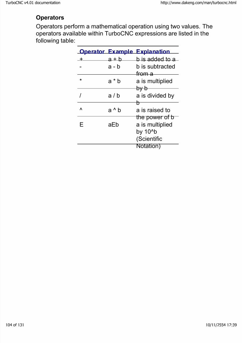
8/3/2019 TurboCNC v4Command
http://slidepdf.com/reader/full/turbocnc-v4command 104/131
Operators
Operators perform a mathematical operation using two values. Theoperators available within TurboCNC expressions are listed in thefollowing table:
Operator Example Explanation
+ a + b b is added to a- a - b b is subtracted
from a* a * b a is multiplied
by b/ a / b a is divided by
b^ a ̂ b a is raised to
the power of bE aEb a is multiplied
by 10^b(ScientificNotation)
boCNC v4.01 documentation http://www.dakeng.com/man/turbocnc.html
of 131 10/11/2554 17:39
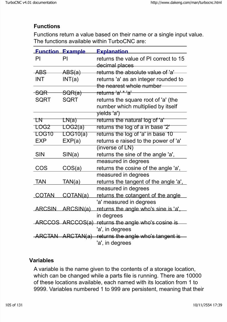
8/3/2019 TurboCNC v4Command
http://slidepdf.com/reader/full/turbocnc-v4command 105/131
Functions
Functions return a value based on their name or a single input value.The functions available within TurboCNC are:
Function Example ExplanationPI PI returns the value of PI correct to 15decimal places
ABS ABS(a) returns the absolute value of 'a'INT INT(a) returns 'a' as an integer rounded to
the nearest whole number SQR SQR(a) returns 'a' * 'a'SQRT SQRT returns the square root of 'a' (the
number which multiplied by itself yields 'a')LN LN(a) returns the natural log of 'a'LOG2 LOG2(a) returns the log of a in base '2'LOG10 LOG10(a) returns the log of 'a' in base 10EXP EXP(a) returns e raised to the power of 'a'
(inverse of LN)SIN SIN(a) returns the sine of the angle 'a',
measured in degreesCOS COS(a) returns the cosine of the angle 'a',
measured in degreesTAN TAN(a) returns the tangent of the angle 'a',
measured in degreesCOTAN COTAN(a) returns the cotangent of the angle
'a' measured in degreesARCSIN ARCSIN(a) returns the angle who's sine is 'a',
in degreesARCCOS ARCCOS(a) returns the angle who's cosine is
'a', in degreesARCTAN ARCTAN(a) returns the angle who's tangent is
'a', in degrees
Variables
A variable is the name given to the contents of a storage location,which can be changed while a parts file is running. There are 10000of these locations available, each named with its location from 1 to9999. Variables numbered 1 to 999 are persistent, meaning that their
boCNC v4.01 documentation http://www.dakeng.com/man/turbocnc.html
of 131 10/11/2554 17:39
8/3/2019 TurboCNC v4Command
http://slidepdf.com/reader/full/turbocnc-v4command 106/131
values are stored in the configuration file upon exiting TurboCNC andre-loaded when TurboCNC is restarted. Variables with names from#1000 through #9999 are transient. These values are not restoredwhen TurboCNC is restarted. Variables that are not set before beingread are given a value of zero.
A value is assigned to a variable by use of the assignment operator (the '=' sign). The assignment may appear anywhere a word can beplaced within the block. For example:
G80 #7 = 2 F10 ; assignment does not have to be
; first in a block
#7 = 4.25 ; assigns the value '4.25' to
variable #7
A variable may be substituted for a value in all but the 'G', 'M', and 'T'code words. The following are legal blocks of code:
G00 x#7 ; Moves the x axis to 4.25
(continuing
; from above)
G00 x[#7 – 4.25] ; Moves the x axis to 0
(expressions
; resolved first)
A variable's name may be given as the contents of another variable,or as an expression.
#1 = 2.05 ; Assign the value 2.05 to variable
#1
#2 = 1 ; Assign the value 1 to variable
#2
G00 x##2 ; Move the x axis to 2.05 (##2 -> #1)
G00 x#[3 - #2] ; Move the x axis to 1 (3 - 1 = 2,#2 = 1)
Recursion of variable names has been tested to 3 levels (ie: ####1)
NOTE: Variables are not allowed as operands for 'G', 'M', 'N' or 'T'OpCodes.
Sample Code - Using Expressions and Variables
This code doesn't do anything especially useful, but it demonstratessome of the valid use of expressions and variables. It is taken fromthe parser test programs.
boCNC v4.01 documentation http://www.dakeng.com/man/turbocnc.html
of 131 10/11/2554 17:39

8/3/2019 TurboCNC v4Command
http://slidepdf.com/reader/full/turbocnc-v4command 107/131
F[1+2] ; Addition
F[1+2*4-3] ; Brackets used to modify
F[(1+2)*(4-3)] ; order of operations
F[LN(10)] ; Natural Log (e)
F[EXP(2.302585)] ; e^n
F[SIN(45)] ; Sin (Trigonometric functions
work)
F[ARCSIN(.707)] ; Arcsin (in decimal degrees)
#0 = [10-10] ; Set variables 0 to 4
#1 = [10-9] ; with values equaling
#2 = [8/4] ; their positions
#3 = [SQRT(9)] ;
#4 = [2*2] ;
#5 = [#2+3] ; Set variables 5 to 9
#6 = [#5+1] ; with values equaling
#7 = [SQRT((#4+#3)^2)] ; their positions
#8 = [#3^#2-#1] ;
#9 = [SQR(#3)] ;
( Wild ones )#0=1 #1=2 #2=3 #3=4 #4=5 #5=99.99 ; Set variables
#6=50 #7=10 #8=0
F1 ; Feed rate = 1
F#[#2+#3] ; Feed rate = 10
F##3 ; Feed rate = 5
F##[####[#7-10] - 2] ; Feed rate = 4
#1=0 #2=0 #3=0 #4=0 #5=0 ; Clear variables
#6=0 #7=0 #8=0 #9=0 #10=0
#999=0
m02 ; end program
Conditional Execution (IF)
Function: The IF statement allows code to be executed if a conditionis met. One good use of this statement is to cut the same contour outof material with varying thickness in multiple passes. Passes are
made until an end condition is reached.
Syntax: IF condition [code]
boCNC v4.01 documentation http://www.dakeng.com/man/turbocnc.html
of 131 10/11/2554 17:39

8/3/2019 TurboCNC v4Command
http://slidepdf.com/reader/full/turbocnc-v4command 108/131
IF = keywordcondition = argument comparator argumentargument = value | variable | expressioncomparator = EQ | LT | LE | GT | GE | NEcode = DAK RS-274 D
Action:
- If the condition is met, the remainder of the block will be executed.
- If the condition is not met the remainder of the block is skipped.
Example:
#1=.500 ; Material thickness
#2=.125 ; Depth of cut per pass
G00 Z2.0 ; Clear Clamps
G00 X0 Y0 ; Move to start coordinate
#3 = #1 F5 ; Set first cut depth & Feed
rate
N0100 #3=[#3-#2] ; Start of loop, compute new
depthG01 Z#3 ; Set new depth
N0200 M98 O1000 ; Jump to contour subroutine
IF #3 GT 0 M97 O0100 ; Jump to start of loop (if
not done)
N0300 M02 ; Program End
; Contour cutting subroutine
N1000 G01 X1 ; 1" square
G01 Y1G01 X0
G01 Y0
M99 ; return from subroutine
WARNING
!
This example is a simplistic view of amachining operation. Further checks toensure that your tool does not descend
into the table should be added.
boCNC v4.01 documentation http://www.dakeng.com/man/turbocnc.html
of 131 10/11/2554 17:39
8/3/2019 TurboCNC v4Command
http://slidepdf.com/reader/full/turbocnc-v4command 109/131
Notes:
· Valid comparators are:EQ - equalsGE - greater than or equalGT - greater thanLE - less than or equalLT - less thanNE - not equal
· Multiple if statements can be cascaded on a line i.e.: M05 F1 ; Preset indicators
IF 2 EQ 3 F2 IF 2 EQ 3 M03; FALSE : FALSE Result=F1,
Spindle OFF
IF 2 EQ 2 F2 IF 2 EQ 3 M03; TRUE : FALSE Result=F2,
Spindle OFF
IF 2 EQ 3 F1 IF 2 EQ 2 M03; FALSE : TRUE Result=F2,
Spindle OFF
IF 2 EQ 2 F1 IF 2 EQ 2 M03; TRUE : TRUE Result=F1,
Spindle ON – CW
Simulating Advanced Conditional Execution Structures
The implemented conditional execution statements allow thesimulation of more advanced conditional structures such as:
· IF - THEN - ELSE
· REPEAT – UNTIL
· WHILE – WEND
· CASE OF – END CASE
IF - THEN – ELSE
Simulation of the IF - THEN – ELSE statement in its classic formrequires a jump to the code to be executed if the condition is met.This should not be omitted, even if the code to be executed will fitwithin the current block, as the parser may execute the required jumpto the remainder of the program before executing the desired code.
(M-Codes are the first executed by the code sequencer).N10000 IF #1 EQ M97 O10100 ; test for condition
N10010 ; code for ELSE
boCNC v4.01 documentation http://www.dakeng.com/man/turbocnc.html
of 131 10/11/2554 17:39

8/3/2019 TurboCNC v4Command
http://slidepdf.com/reader/full/turbocnc-v4command 110/131
N10090 M97 N11000 ; continue program
N10100 ; code for condition
met
N11000 ; program continues
here
REPEAT – UNTIL
N10000 ; start of REPEAT
LOOP
N10980 IF #1 EQ 1 M97 N11000 ; UNTIL condition
test
N10990 M97 N10000 ; repeat loop,
condition not met
N11000 ; program continues
here
WHILE – WEND
N10000 IF #1 EQ 1 M97 N10020 ; test for conditionN10010 M97 N11000 ; exit loop if
false
N10020 ; code executed if
condition met
N10990 M97 N10000 ; END of WHILE loop
N11000 ; program continues
here
CASE OF – END CASE
Simulation of the CASE statement uses an IF to est for eachcondition, followed by a jump to the code to be executed if thecondition has been met (CASE is satisfied). The code to be executedif none of the CASES match may directly follow the last IF statement
as shown , or a jump to the code may be used. The code for everyCASE ends in a jump to the next line to be executed. Although this isnot strictly required for the code of the final case, it's been included tohelp prevent bugs if more CASEs are added later.
boCNC v4.01 documentation http://www.dakeng.com/man/turbocnc.html
of 131 10/11/2554 17:39

8/3/2019 TurboCNC v4Command
http://slidepdf.com/reader/full/turbocnc-v4command 111/131
N10000 IF #1 EQ 1 M97 O10100 ; first case
N10010 IF #1 EQ 2 M97 O10200 ; second case
N10020 ; else
N10090 M97 O11000 ; continue program
N10100 ; code for first caseN10190 M97 O11000 ; continue program
N10200 ; code for second
case
N10290 M97 O11000 ; continue program
N11000 ; program continues
here
These structures have been illustrated using a simple test for equality.Most of the examples could have been simplified by inverting the test,in other words testing for inequality in the examples. This has notbeen done so that an identical structure, with a readily apparentcondition, can be used for every implementation,. The inverseconditions are given in the table below for those wishing to adopt thatform as their standard:
comparator NOT
comparator
LT GELE GTEQ NEGE LTGT LE
Interacting with the Operator
TurboCNC provides two functions that a CNC program can use tointeract with the operator.
ASK
Function: Asks the operator for a value to be stored in a variable. An
optional comment on the line will be used as a prompt.
Syntax: ASK #n ;Comment
boCNC v4.01 documentation http://www.dakeng.com/man/turbocnc.html
of 131 10/11/2554 17:39
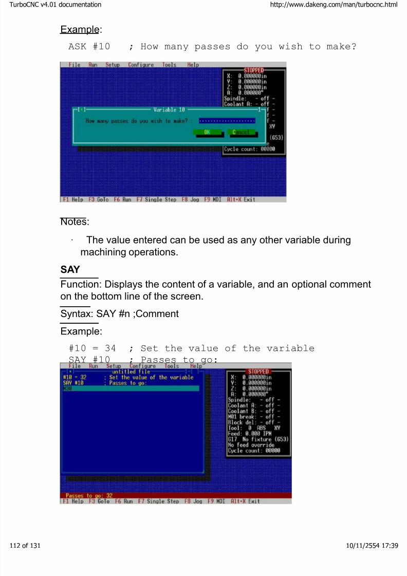
8/3/2019 TurboCNC v4Command
http://slidepdf.com/reader/full/turbocnc-v4command 112/131
Example:
ASK #10 ; How many passes do you wish to make?
Notes:
· The value entered can be used as any other variable duringmachining operations.
SAY
Function: Displays the content of a variable, and an optional commenton the bottom line of the screen.
Syntax: SAY #n ;Comment
Example:
#10 = 34 ; Set the value of the variable
SAY #10 ; Passes to go:
boCNC v4.01 documentation http://www.dakeng.com/man/turbocnc.html
of 131 10/11/2554 17:39
8/3/2019 TurboCNC v4Command
http://slidepdf.com/reader/full/turbocnc-v4command 113/131
Notes:
· SAY will lockout the Port Monitor and clear the Port display (if active).
· SAY #0 will clear the screen
· SAY displays the content of the specified variable when
invoked. The displayed value is not updated when the content of the variable is changed.
· Only one variable can be displayed on the screen.Subsequent calls to say will overwrite the initial display.
Putting it all Together: The Circle Using Line Segments
A program to mill a circle using line segments is used to illustrate bestpractices for the use of variables, expressions and conditional
programming. While this isn’t the most efficient method for cuttingcircles, it can be easily adapted to cut hexagons, octagons, or other regular polygons.
TurboCNC 'Interprets' the code on a line-by-line basis; it does notcompile and optimize the result. It also scans the file to find the targetof a jump function (M97). This takes time depending on how far intothe program the jump's target is located. This is the reason thesubroutines are located first. The subroutines should be ordered such
that those executed most often are located first; then trailing down tothose executed least often. The main part of the program, includinginitialization is therefore located last.
The reason variables #1000 and up were chosen for this example isthat their values do not need to be preserved when TurboCNC exits.Always ensure that you initialize the appropriate variables prior tousing them. Previous programs may have left a value that could
produce disastrous results.
The Program:
; TurboCNC 4.0 program to cut circles
M97 O9000 ;Jump to the main
program
; *** Subroutine to cut the circle ***
N0100 #1005=[#1005+#1004] ;Increment the angle
SAY #1005 ;Current angle (Stop at
boCNC v4.01 documentation http://www.dakeng.com/man/turbocnc.html
of 131 10/11/2554 17:39

8/3/2019 TurboCNC v4Command
http://slidepdf.com/reader/full/turbocnc-v4command 114/131
360):
#1006=[#1000+(#1002/2)*COS(#1005)] ;compute new X
position
#1007=[#1001+(#1002/2)*SIN(#1005)] ;compute new Y
position
G01 X#1006 Y#1007 ;make the cut
IF #1005 LT 360 M97 O0100 ;Jump if circle notcomplete
M99 ;return from subroutine
; *********************************
; * Main Program *
; *********************************
;Parameters for the circle (get the center from
the operator)
N9000 ASK #1000 ; What is the X-coord of
center (inches):
ASK #1001 ; What is the Y-Coord of
center (inches):
#1002=1 ;Diameter of the circle
(inches)
#1003=360 ;# of steps for a full circle
;computed variables
#1004=0 ;delta (angular increment)
#1005=0 ;theta (current angle)
#1006=0 ;next X position
#1007=0 ;next Y position
;setup
F20 ;set feed rate
#1004=[360/#1003] ;compute theta (TurboCNC 4.0
; trig functions are in
degrees)
#1006=[#1000+(#1002/2)*COS(#1005)] ;compute
starting X
; position
#1007=[#1001+(#1002/2)*SIN(#1005)] ;compute
starting Y
; positionG00 X#1006 Y#1007 ;traverse to start position
G01 Z2 ;lower Z-axis to make cut
N9100 M98 O0100 ;jump to cutting subroutine
boCNC v4.01 documentation http://www.dakeng.com/man/turbocnc.html
of 131 10/11/2554 17:39

8/3/2019 TurboCNC v4Command
http://slidepdf.com/reader/full/turbocnc-v4command 115/131
G01 Z4 ;retract Z-Axis
SAY #0 ;clear display
M02 ;End of program – circle.cnc
boCNC v4.01 documentation http://www.dakeng.com/man/turbocnc.html
of 131 10/11/2554 17:39
8/3/2019 TurboCNC v4Command
http://slidepdf.com/reader/full/turbocnc-v4command 116/131
Part 4 – Introduction to CNC
General
If you're reading this section, you're probably a beginner to the CNCworld. That's ok, we all start somewhere. Chances are, you already understand machining. G & M codesprovide a formal language for telling a computer how to do your work in the machine world.When you make a part on a machine tool, say a lathe, and watchwhat you really do - you'll notice that a lot of the game is turning handwheels to make very repetitive and exact motions. CNC involves reducing the motions to codes in a scripting language
that a computer can understand. In principle, if the computer canduplicate the same motions that a human does when machining, itduplicate the machining process. This is important to understand. G &M code only spells out the motions involved in machining. Thecomputer doesn't know anything else, like where the part is, whatkind of tool you're using, or even what kind of machine it's running.Motion only.
G & M code works on a line by line basis using words, left to right andtop to bottom just as you are reading this page. A word has a specialdefinition in this context however. In the RS 274D language, eachword consists of a letter or symbol followed by a number. Here aretwo words as an simple example: G00 X1.000
Each line of code is sometimes called a block. Let's break this blockdown and see what it means to the computer. The first word "G00" (pronounced GEE-zero) is the Rapid
Positioning word. It means move somewhere as fast as you can.Yes, those are zeroes after the G. "'X1.000" is a word which gives a new location for the X axis; 1.000
in this case. If you've used a DRO equipped machine before, youprobably understand coordinate systems. If not, have a look at theAxes De-mystified section and familiarize yourself with the concept.
boCNC v4.01 documentation http://www.dakeng.com/man/turbocnc.html
of 131 10/11/2554 17:39

8/3/2019 TurboCNC v4Command
http://slidepdf.com/reader/full/turbocnc-v4command 117/131
When this block is executed by TurboCNC, one of three things willhappen: 1. In Absolute Mode, the X axis will move to the 1.000 coordinateposition as fast as possible 2. In Incremental Mode, the X axis will move +1.000 units as fast aspossible 3. If there is no X axis to speak of, an error will be produced or theblock will be ignored. Not so bad, right? Just tell the machine what to do. By stringing a
large series of blocks together you can create a script for the
computer to follow. Each time you run the script (G code file), thecomputer performs the machining operation for you. Now run thescript over and over, put in fresh stock each time, and you're inproduction! Here are some general things you need to know about the language:
· It is standardized (pretty much, at least insofar as the basicsare concerned). You can use it just about anywhere.
·G words usually do the actual motion.
· M words usually do miscellaneous functions.
· Spaces don't matter, but line breaks do.
· Read it left to right, top to bottom - just like you're reading thispage.
· If the same word is used in a line as in the line before, itusually doesn't have to be retyped on the second line. This iscalled Modality. The old word is assumed until another one isused. Not all words are modal.
· The computer only does what you tell it to do, and willcheerfully snap a tool or drill through the table at your command.
· Words are also called "codes" in some circles.
· M02 is the word for "End of program" - often interchangeablewith M30 which is "End of tape".
The Axes De-Mystified:
Any machine (lathe, mill, drill, etc) has its major linear axes defined inthe standard orthogonal manner, that is at right angles to each other.The point to remember is that they are defined with respect to 'tool
boCNC v4.01 documentation http://www.dakeng.com/man/turbocnc.html
of 131 10/11/2554 17:39

8/3/2019 TurboCNC v4Command
http://slidepdf.com/reader/full/turbocnc-v4command 118/131
motion', not the actual motion of the axes.
Positive direction is found using the right-hand rule for a mill. Lay your right hand, palm up, on the table of the machine, thumb along theX-Axis, index finger along the Y-Axis, and the middle finger along theZ-Axis. Your fingers and thumb will point in the positive direction of movement for the tool along each axis. For a moving table machinesuch as a Sherline, positive movement along the X-Axis moves thetable to the left, positive movement along the Y- Axis moves the tabletowards the front, away from the column. A gantry style machinemoves the tool, so movement of the gantry will follow the right handrule (exactly the opposite of the moving table).
By convention, rotational axes with their axis of rotation parallel to the
X, Y, and Z axes, are labeled A, B, and C respectively. The directionof positive rotation of these axes is counterclockwise when viewedfrom the positive end of the corresponding orthogonal axis (X, Y, or Z). So, taking the Sherline as an example, with the rotary tablemounted so that its axis of rotation is parallel to the X-Axis, with itstable facing right, when viewed from the direction of the hand-crank(or stepper motor) rotates counterclockwise. In other words the top of the rotary table will turn towards the front of the mill. Something
interesting to note is that the direction of rotation with respect to thesurface of the rotary table will change if you turn it around to mount itfacing left on the mill's table.
With only two axes, the right hand rule returns indeterminate resultswhen used on a lathe. Machinists have adopted the convention thatmovement from the headstock to the tailstock is along the Z-Axis.Movement of the cross slide towards the tailstock is in the positivedirection. In and out movement of the cross-slide is along the X-Axis.Movements of the cross slide, away from the centerline between theheadstock and tailstock are in the positive direction.
The point of origin for the orthogonal axes can be set anywhere that isconvenient. With the exception of a lathe's X-Axis, many machinistsset this is at the point of maximum negative movement along the axesin the machine coordinate system. The machinist will switch to analternate coordinate system for machining, and set a zero relative tothe work piece. For the X-Axis of a lathe, by convention the centerlinebetween the headstock and tailstock is chosen as zero.
boCNC v4.01 documentation http://www.dakeng.com/man/turbocnc.html
of 131 10/11/2554 17:39

8/3/2019 TurboCNC v4Command
http://slidepdf.com/reader/full/turbocnc-v4command 119/131
Axis conventions:
Per the Standard, X, Y and Z should always be linear; A, B, and Cshould always be angular. The XYZ coordinates should beperpendicular, with their directions arranged according to the righthand rule.
On a two-axis lathe, the axes should be named Z and X, arranged asshown below:
On a three axis mill, the axes should be named X, Y and Z - arrangedas shown below. Be aware that this is tool motion relative to the work – typically the table will move opposite the diagram below.
The A, B, and C axis of rotation should be parallel to the X, Y, andZ-axes. U, V, and W should be linear also, and parallel to X, Y, and Zrespectively.
Nothing will stop you from making X an angular axis in TurboCNC; infact this may be the most expedient way to program an operation. Ingeneral you're better off going with the established practices though.
Arc directions (Clockwise vs. Counterclockwise) are explained under
G02. The direction of an arc is taken by looking in the negativedirection on the out of plane axis. For example, on a mill an arc in theXY plane (plane of the table) should look clockwise as looking in –Z(down from above).
boCNC v4.01 documentation http://www.dakeng.com/man/turbocnc.html
of 131 10/11/2554 17:39

8/3/2019 TurboCNC v4Command
http://slidepdf.com/reader/full/turbocnc-v4command 120/131
boCNC v4.01 documentation http://www.dakeng.com/man/turbocnc.html
of 131 10/11/2554 17:39

8/3/2019 TurboCNC v4Command
http://slidepdf.com/reader/full/turbocnc-v4command 121/131
The parallel port explained:
On most PC computers a 25 pin connector called the parallel port isavailable for connection to a printer or other hardware. By sheer
accident of engineering, this port makes a great interface for controlling CNC machines.
The pins on the parallel port have two voltage levels. High is definedas 5V, low is 0V (Strictly speaking, 0-0.8V is low, 2.5-5V is high). Thisis known as TTL for Transistor-Transistor-Logic.
Communicating with an axis on a CNC machine is usually with twooutput pins. One is called the direction pin and sets the direction that
a motor driving that axis is to turn. The other is the step pin, which istoggled each time the motor should rotate by a small amount.
On the parallel port, pins 2-9 are always available for output, whichallows at least 4 axes of motion to be controlled. Pins 1,14,16, and 17can be output also, to control spindles, coolant pumps, and toolchangers.
The parallel port inputs are on pins 10,11,12,13, and 15. These are
TTL level signals as well. Typical uses for these are spindle encoders,limit switches, and extra logic for detecting when you’ve run out of stock.
Pins 18-25 are ground. Use some of these to shield your cables.
TurboCNC can drive up to three parallel ports, at addresses $278,$378, and $3BC. Use the included FKEYBIT utility (a separate .exe)or the built in port monitor (F2 to activate) to test the lines on the port
and provide signals for troubleshooting or proving out your setup.
boCNC v4.01 documentation http://www.dakeng.com/man/turbocnc.html
of 131 10/11/2554 17:39
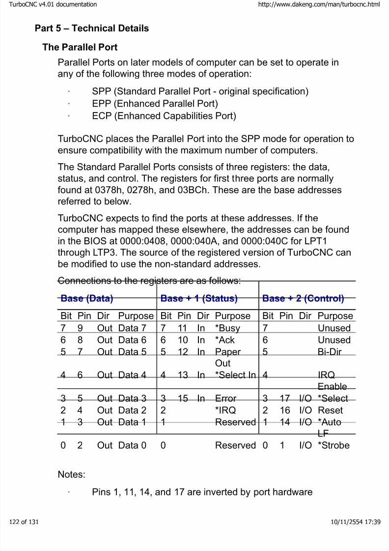
8/3/2019 TurboCNC v4Command
http://slidepdf.com/reader/full/turbocnc-v4command 122/131
Part 5 – Technical Details
The Parallel Port
Parallel Ports on later models of computer can be set to operate inany of the following three modes of operation:
·SPP (Standard Parallel Port - original specification)
· EPP (Enhanced Parallel Port)
· ECP (Enhanced Capabilities Port) TurboCNC places the Parallel Port into the SPP mode for operation toensure compatibility with the maximum number of computers.
The Standard Parallel Ports consists of three registers: the data,status, and control. The registers for first three ports are normallyfound at 0378h, 0278h, and 03BCh. These are the base addressesreferred to below.
TurboCNC expects to find the ports at these addresses. If thecomputer has mapped these elsewhere, the addresses can be foundin the BIOS at 0000:0408, 0000:040A, and 0000:040C for LPT1through LTP3. The source of the registered version of TurboCNC canbe modified to use the non-standard addresses.
Connections to the registers are as follows:
Base (Data) Base + 1 (Status) Base + 2 (Control)
Bit Pin Dir Purpose Bit Pin Dir Purpose Bit Pin Dir Purpose
7 9 Out Data 7 7 11 In *Busy 7 Unused6 8 Out Data 6 6 10 In *Ack 6 Unused5 7 Out Data 5 5 12 In Paper
Out5 Bi-Dir
4 6 Out Data 4 4 13 In *Select In 4 IRQEnable
3 5 Out Data 3 3 15 In Error 3 17 I/O *Select2 4 Out Data 2 2 *IRQ 2 16 I/O Reset1 3 Out Data 1 1 Reserved 1 14 I/O *Auto
LF0 2 Out Data 0 0 Reserved 0 1 I/O *Strobe
Notes:
· Pins 1, 11, 14, and 17 are inverted by port hardware
boCNC v4.01 documentation http://www.dakeng.com/man/turbocnc.html
of 131 10/11/2554 17:39
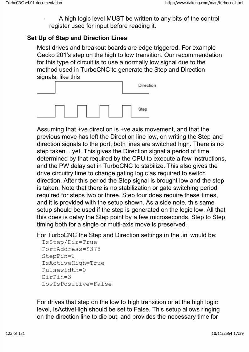
8/3/2019 TurboCNC v4Command
http://slidepdf.com/reader/full/turbocnc-v4command 123/131
· A high logic level MUST be written to any bits of the controlregister used for input before reading it.
Set Up of Step and Direction Lines
Most drives and breakout boards are edge triggered. For exampleGecko 201's step on the high to low transition. Our recommendationfor this type of circuit is to use a normally low signal due to themethod used in TurboCNC to generate the Step and Directionsignals; like this
Assuming that +ve direction is +ve axis movement, and that theprevious move has left the Direction line low, on writing the Step anddirection signals to the port, both lines are switched high. There is nostep taken... yet. This gives the Direction signal a period of timedetermined by that required by the CPU to execute a few instructions,and the PW delay set in TurboCNC to stabilize. This also gives thedrive circuitry time to change gating logic as required to switchdirection. After this period the Step signal is brought low and the stepis taken. Note that there is no stabilization or gate switching periodrequired for steps two or three. Step four does require these times,and it is provided with the setup shown. As a side note, this samesetup should be used if the step is generated on the logic low. All thatthis does is delay the Step point by a few microseconds. Step to Steptiming both for a single or multi-axis move is preserved.
For TurboCNC the Step and Direction settings in the .ini would be:IsStep/Dir=True
PortAddress=$378
StepPin=2
IsActiveHigh=True
Pulsewidth=0
DirPin=3
LowIsPositive=False
For drives that step on the low to high transition or at the high logiclevel, IsActiveHigh should be set to False. This setup allows ringingon the direction line to die out, and provides the necessary time for
boCNC v4.01 documentation http://www.dakeng.com/man/turbocnc.html
of 131 10/11/2554 17:39

8/3/2019 TurboCNC v4Command
http://slidepdf.com/reader/full/turbocnc-v4command 124/131
the direction gates to settle before application of the Step pulse. Thiswill prevent the lost steps which would otherwise occur duringdirection changes.
boCNC v4.01 documentation http://www.dakeng.com/man/turbocnc.html
of 131 10/11/2554 17:39

8/3/2019 TurboCNC v4Command
http://slidepdf.com/reader/full/turbocnc-v4command 125/131
I/O Points
Point Usage
Spindle Power (Output) Drives relay that turnsspindle motor on and off. Couldalso drive spindle brake.
SpindleDirection
(Output) Drives relay that setsspindle direction to clockwise or counter clockwise.
Coolant A (Output) Drives relay thatcontrols flood coolant pump
Coolant B (Output) Drives relay thatcontrols mist coolant pump
PLCHandshakeSignal
(Output) Signal controlled by M70and M71 to provideprogrammatic interface to aProgrammable Logic Controller or other electronics
Drive Enable 1 (Output) Used to enable or disable one or more motor drives.Since some motor drives requireindividual enable lines,TurboCNC provides threeindependent lines which arecontrolled by the same M17/M18
Drive Enable 2 (Output) Used to enable or disable one or more motor drives.Since some motor drives requireindividual enable lines,TurboCNC provides threeindependent lines which arecontrolled by the same M17/M18
Drive Enable 3 (Output) Used to enable or disable one or more motor drives.Since some motor drives requireindividual enable lines,TurboCNC provides threeindependent lines which arecontrolled by the same M17/M18
boCNC v4.01 documentation http://www.dakeng.com/man/turbocnc.html
of 131 10/11/2554 17:39
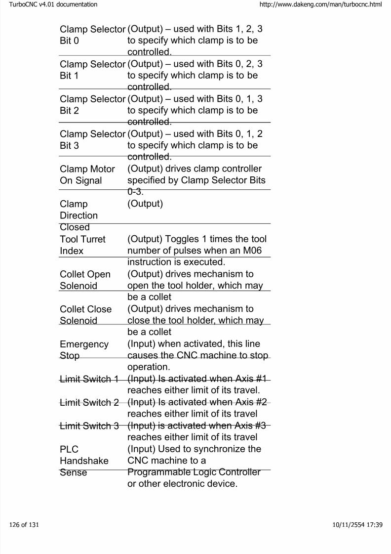
8/3/2019 TurboCNC v4Command
http://slidepdf.com/reader/full/turbocnc-v4command 126/131
Clamp Selector Bit 0
(Output) – used with Bits 1, 2, 3to specify which clamp is to becontrolled.
Clamp Selector Bit 1
(Output) – used with Bits 0, 2, 3to specify which clamp is to becontrolled.
Clamp Selector Bit 2
(Output) – used with Bits 0, 1, 3to specify which clamp is to becontrolled.
Clamp Selector Bit 3
(Output) – used with Bits 0, 1, 2to specify which clamp is to becontrolled.
Clamp Motor On Signal
(Output) drives clamp controller specified by Clamp Selector Bits0-3.
ClampDirectionClosed
(Output)
Tool TurretIndex
(Output) Toggles 1 times the toolnumber of pulses when an M06instruction is executed.
Collet OpenSolenoid
(Output) drives mechanism toopen the tool holder, which maybe a collet
Collet CloseSolenoid
(Output) drives mechanism toclose the tool holder, which maybe a collet
EmergencyStop
(Input) when activated, this linecauses the CNC machine to stopoperation.
Limit Switch 1 (Input) Is activated when Axis #1reaches either limit of its travel.
Limit Switch 2 (Input) Is activated when Axis #2reaches either limit of its travel
Limit Switch 3 (Input) is activated when Axis #3reaches either limit of its travel
PLCHandshakeSense
(Input) Used to synchronize theCNC machine to aProgrammable Logic Controller or other electronic device.
boCNC v4.01 documentation http://www.dakeng.com/man/turbocnc.html
of 131 10/11/2554 17:39
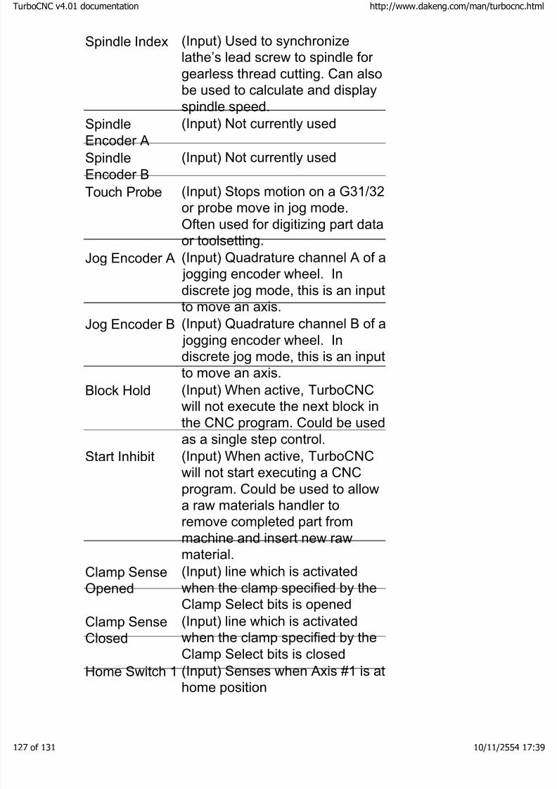
8/3/2019 TurboCNC v4Command
http://slidepdf.com/reader/full/turbocnc-v4command 127/131
Spindle Index (Input) Used to synchronizelathe’s lead screw to spindle for gearless thread cutting. Can alsobe used to calculate and displayspindle speed.
SpindleEncoder A
(Input) Not currently used
SpindleEncoder B
(Input) Not currently used
Touch Probe (Input) Stops motion on a G31/32or probe move in jog mode.Often used for digitizing part dataor toolsetting.
Jog Encoder A (Input) Quadrature channel A of a jogging encoder wheel. Indiscrete jog mode, this is an inputto move an axis.
Jog Encoder B (Input) Quadrature channel B of a jogging encoder wheel. Indiscrete jog mode, this is an inputto move an axis.
Block Hold (Input) When active, TurboCNCwill not execute the next block inthe CNC program. Could be usedas a single step control.
Start Inhibit (Input) When active, TurboCNCwill not start executing a CNCprogram. Could be used to allowa raw materials handler toremove completed part frommachine and insert new rawmaterial.
Clamp SenseOpened
(Input) line which is activatedwhen the clamp specified by theClamp Select bits is opened
Clamp SenseClosed
(Input) line which is activatedwhen the clamp specified by theClamp Select bits is closed
Home Switch 1 (Input) Senses when Axis #1 is athome position
boCNC v4.01 documentation http://www.dakeng.com/man/turbocnc.html
of 131 10/11/2554 17:39

8/3/2019 TurboCNC v4Command
http://slidepdf.com/reader/full/turbocnc-v4command 128/131
Home Switch 2 (Input) Senses when Axis #2 is athome position
Home Switch 3 (Input) Senses when Axis #3 is athome position
Home Switch 4 (Input) Senses when Axis #4 is athome position
Home Switch 5 (Input) Senses when Axis #5 is athome position
Home Switch 6 (Input) Senses when Axis #6 is athome position
Home Switch 7 (Input) Senses when Axis #7 is athome position
Home Switch 8 (Input) Senses when Axis #8 is athome position
Configuring Speed Control
To be deemed valid, a map must contain at least two mappings. Amaximum of 1023 mappings may be specified. Mappings may beentered in any order, but when sorted both the count values and RPMmust increase from mapping to mapping.
A quick method of determining the mappings for the Speed Control isto create a map with a 1:1 relationship of count Values to spindleRPM. The count values can then be directly entered as a spindlespeed, and the actual speed measured with a tachometer. Themappings should be noted and entered as a separate map uponcompletion.
High and low limits are recomputed for the selected map every time amapping is added. This can occur while reading a configuration file or
adding entries using the configuration menus. Clearing the map setsthe RPM limits to default values of 100,000,000 for the low end and 0for the high end.
Setting up Windows 9x to boot directly into MS-DOS
Although Microsoft has advertised Windows 95, 98, and 98-SecondEdition as having a multitasking “native mode,” these operatingenvironments still include a version of MS-DOS and can be
configured to boot directly into MS-DOS.
Modify MSDOS.SYS
If you are running in the windows environment, click on the “start
boCNC v4.01 documentation http://www.dakeng.com/man/turbocnc.html
of 131 10/11/2554 17:39

8/3/2019 TurboCNC v4Command
http://slidepdf.com/reader/full/turbocnc-v4command 129/131
button” in the lower left corner of the screen. From the menu thatappears, select “RUN”
In the dialog box that appears, type
attrib MSDOS.SYS –r –s –h
Next, use notpad or some other ascii text editor to open MSDOS.SYSin an edit window.
MSDOS.SYS is formatted like an initialization file, with a series of sections (e.g. [Options] or [Paths]) followed by a list of variables andthe items to which they are assigned.
Find the line that reads
BootGUI=1
Change it to read
BootGUI=0
This enables your computer to boot directly into DOS. SaveMSDOS.SYS.
Press the “Start” button and select “RUN.”
Enter the command
attrib MSDOS.SYS +r +s +h
Modifying CONFIG.SYS
You can now modify a file named CONFIG.SYS to display a menuwhich allows you either to boot directly into MS-DOS or into theWindows environment.
Press the “Start” button and select “RUN.”Enter the command
attrib CONFIG.SYS -r -s –h
Next, open CONFIG.SYS withNotepad.
Some Windows 9x computers may not use a copy of CONFIG.SYS. If yours does not, use Notepad to create it.
At the beginning of CONFIG.SYS, add the following lines:
MenuItem=WIN, Windows GUIMenuItem=DOS, MS-DOS 7.1 Unadorned
boCNC v4.01 documentation http://www.dakeng.com/man/turbocnc.html
of 131 10/11/2554 17:39

8/3/2019 TurboCNC v4Command
http://slidepdf.com/reader/full/turbocnc-v4command 130/131
MenuDefault=DOS, 10[WIN]
….. The remaining entries of your CONFIG.SYS file are here
At the end of your CONFIG.SYS file add the following lines:
[DOS]DeviceHigh=C:\windows\command\ansi.sysShell=C:\COMMAND.COM C:\ /E:3072 /PFiles=50
This configuration file will display a menu with two items. It will waitten seconds, and then default to the “DOS” selection. During the tensecond wait, you can use the cursor keys to select the Windows GUIinstead. You can also set up CONFIG.SYS to select Windows as its
default. If you want to do this, change the line
MenuDefault=DOS, 10
to
MenuDefault=WIN, 10
Save CONFIG.SYS
Press the “Start” button and select RUN.
Enter the command
attrib CONFIG.SYS +r
Modify AutoEXEC.BAT
Open the Autoexec.bat file using notepad
At the end of the file, add the following lines
IF “%CONFIG%”==”WIN” C:\Windows\Win.COMIF “%CONFIG%”==”DOS” C:\DOS\MOUSE.COM
Save autoexec.bat and exit notepad.
Reboot your system. You should see a menu, with a selectionhighlighted. If DOS is selected, you’ll boot into DOS and can executeTurboCNC.
Assuming that you have a folder in your root directory named DOS
and that the folder contains the executable MOUSE.COM, the last linewill load the mouse driver so you can use a mouse or track ball toaccess TurboCNC’s menu structure.
boCNC v4.01 documentation http://www.dakeng.com/man/turbocnc.html
of 131 10/11/2554 17:39

8/3/2019 TurboCNC v4Command
http://slidepdf.com/reader/full/turbocnc-v4command 131/131
boCNC v4.01 documentation http://www.dakeng.com/man/turbocnc.html