Embed Size (px)
Citation preview

Tunnel Master® Jr.User Manual—Version 4.5

Information in this manual is subject to change without notice. Companies, names and data used in examples within the manual are fictitious unless
otherwise noted. No part of this manual may be reproduced or transmitted in any form or by any means, electronic or mechanical, for any purpose without
the express written permission of Innovative Control Systems, Inc.
Copyright © 2018 Innovative Control Systems, Inc.
Innovative Control Systems, Inc.
1349 Jacobsburg Road
Wind Gap, PA 18091
610-881-8000

ContentsChapter 1:Introduction . . . . . . . . . . . . . . . . . . . . . . . . . . . . . . . . . . . . . . . . . . . . . .11
Version Considerations . . . . . . . . . . . . . . . . . . . . . . . . . . . . . . . . . . . . . . . . . . . . 11
Related Documents . . . . . . . . . . . . . . . . . . . . . . . . . . . . . . . . . . . . . . . . . . . . . . 11
Audience . . . . . . . . . . . . . . . . . . . . . . . . . . . . . . . . . . . . . . . . . . . . . . . . . . . . . 12
Controller Features . . . . . . . . . . . . . . . . . . . . . . . . . . . . . . . . . . . . . . . . . . . . . . 12
Chapter 2: System Hardware and Installation . . . . . . . . . . . . . . . . . . . . . . . . . . . . . . .13
Overview . . . . . . . . . . . . . . . . . . . . . . . . . . . . . . . . . . . . . . . . . . . . . . . . . . . . . 13
Purpose . . . . . . . . . . . . . . . . . . . . . . . . . . . . . . . . . . . . . . . . . . . . . . . . . . . . . . 13
Resetting Default Configuration Settings . . . . . . . . . . . . . . . . . . . . . . . . . . . . . . . . 13
Rules for Installation . . . . . . . . . . . . . . . . . . . . . . . . . . . . . . . . . . . . . . . . . . . . . 15
Warning Marking . . . . . . . . . . . . . . . . . . . . . . . . . . . . . . . . . . . . . . . . . . . . . . . . 15
Output Overview . . . . . . . . . . . . . . . . . . . . . . . . . . . . . . . . . . . . . . . . . . . . . . . . 15
24 Outputs. . . . . . . . . . . . . . . . . . . . . . . . . . . . . . . . . . . 15
Equipment Dimensions . . . . . . . . . . . . . . . . . . . . . . . . . . . . . . . . . . . . . . . . . . . . 17
Relay Box Mounting . . . . . . . . . . . . . . . . . . . . . . . . . . . . . . . . . . . . . . . . . . . . . . 18
Relay Box Wiring . . . . . . . . . . . . . . . . . . . . . . . . . . . . . . . . . . . . . . . . . . . . . . . . 18
Relay Box Interior . . . . . . . . . . . . . . . . . . . . . . . . . . . . . . . . . . . . . . . . . . . . . . . 21
Pulse/Proximity Switch Wiring. . . . . . . . . . . . . . . . . . . . . . . . . . . . . . . . . . . . . . . 22
Pulse/Proximity Switch Wiring. . . . . . . . . . . . . . . . . . . . . . . . . . . . . . . . . . . . . . . 23
Gate Switch (Electric Eye) Wiring. . . . . . . . . . . . . . . . . . . . . . . . . . . . . . . . . . . . . 24
Gate Eye Switch Wiring . . . . . . . . . . . . . . . . . . . . . . . . . . 24
Tire Switch Wiring . . . . . . . . . . . . . . . . . . . . . . . . . . . . . . . . . . . . . . . . . . . . . . . 25
Entrance Management System Wiring . . . . . . . . . . . . . . . . . . . . . . . . . . . . . . . . . . 26
Roller Locator Wiring . . . . . . . . . . . . . . . . . . . . . . . . . . . . . . . . . . . . . . . . . . . . . 27
Conveyor Roller Locator Cross Section Diagram. . . . . . . . . . . 27Roller Locator Wiring . . . . . . . . . . . . . . . . . . . . . . . . . . . . 28
Panic Stop Circuit Wiring . . . . . . . . . . . . . . . . . . . . . . . . . . . . . . . . . . . . . . . . . . 29
Panic Stop Wiring . . . . . . . . . . . . . . . . . . . . . . . . . . . . . . . . . . . . . . . . . . . . . . . 30
Anti-Collision Wiring . . . . . . . . . . . . . . . . . . . . . . . . . . . . . . . . . . . . . . . . . . . . . 31
Anti-Collision Wiring . . . . . . . . . . . . . . . . . . . . . . . . . . . . . . . . . . . . . . . . . . . . . 32
Input Wiring Summary . . . . . . . . . . . . . . . . . . . . . . . . . . . . . . . . . . . . . . . . . . . . 33
Push Button Wiring . . . . . . . . . . . . . . . . . . . . . . . . . . . . . . . . . . . . . . . . . . . . . . 33
Push Button Wiring 1 Row 8 Columns . . . . . . . . . . . . . . . . . 34Push Button Wiring First 8 Buttons . . . . . . . . . . . . . . . . . . . 35Push Button Wiring for Second 8 Buttons . . . . . . . . . . . . . . . 36
Relay Box Jumper Settings . . . . . . . . . . . . . . . . . . . . . . . . . . . . . . . . . . . . . . . . . 37
Tunnel Master® Jr. User Manual 3

DIP Switch Settings. . . . . . . . . . . . . . . . . . . . . . . . . . . . . . . . . . . . . . . . . . . . . . . 39
Tunnel Master® Jr. AC Power Terminations. . . . . . . . . . . . . . . . . . . . . . . . . . . . . . 41
Chapter 3: Operating Procedures . . . . . . . . . . . . . . . . . . . . . . . . . . . . . . . . . . . . . . 43
Operating Procedures . . . . . . . . . . . . . . . . . . . . . . . . . . . . . . . . . . . . . . . . . . . . . 43
Main Wash Menu . . . . . . . . . . . . . . . . . . . . . . . . . . . . . . . . . . . . . . . . . . . . . . . . 43
Wet Down Wash . . . . . . . . . . . . . . . . . . . . . . . . . . . . . . . . . . . . . . . . . . . . . . . . . 43
Chapter 4:Wash Configuration . . . . . . . . . . . . . . . . . . . . . . . . . . . . . . . . . . . . . . . . 45
Relay Box Display Keypad . . . . . . . . . . . . . . . . . . . . . . . . . . . . . . . . . . . . . . . . . . 46
Set Password . . . . . . . . . . . . . . . . . . . . . . . . . . . . . . . . . . . . . . . . . . . . . . . . . . . 47
Access a Password Protected Menu . . . . . . . . . . . . . . . . . . . 49
Configure Wash Menu . . . . . . . . . . . . . . . . . . . . . . . . . . . . . . . . . . . . . . . . . . . . . 50
Wash Setting Descriptions . . . . . . . . . . . . . . . . . . . . . . . . . . . . . . . . . . . . . . . . . . 51
Set Date Time . . . . . . . . . . . . . . . . . . . . . . . . . . . . . . . . . . . . . . . . . . . . . . . . . . 54
Configure Wash Settings . . . . . . . . . . . . . . . . . . . . . . . . . . . . . . . . . . . . . . . . . . . 56
About Countdown Times . . . . . . . . . . . . . . . . . . . . . . . . . . . . . . . . . . . . . . . . . . . 57
Outputs . . . . . . . . . . . . . . . . . . . . . . . . . . . . . . . . . . . . . . . . . . . . . . . . . . . . . . 57
Output Settings . . . . . . . . . . . . . . . . . . . . . . . . . . . . . . . . . . . . . . . . . . . . . . . . . 59
Assign Outputs to Services. . . . . . . . . . . . . . . . . . . . . . . . . . . . . . . . . . . . . . . . . . 64
Chapter 5: Entrance Keypad . . . . . . . . . . . . . . . . . . . . . . . . . . . . . . . . . . . . . . . . . . 65
Entrance Keypad . . . . . . . . . . . . . . . . . . . . . . . . . . . . . . . 65
Entrance Keypad Functions . . . . . . . . . . . . . . . . . . . . . . . . . . . . . . . . . . . . . . . . . 66
Entrance Keypad to Process Vehicles (Non-Stacking). . . . . . . . . . . . . . . . . . . . . . . . 68
Entrance Keypad to Process Vehicles (Stack) . . . . . . . . . . . . . . . . . . . . . . . . . . . . . 69
Change Service and/or Add Retract . . . . . . . . . . . . . . . . . . 70Add a Car to Stack . . . . . . . . . . . . . . . . . . . . . . . . . . . . . . 70Remove a Car from Stack . . . . . . . . . . . . . . . . . . . . . . . . . 70
View Service Counts for the Current Shift . . . . . . . . . . . . . . . . . . . . . . . . . . . . . . . 71
Bump Shift . . . . . . . . . . . . . . . . . . . . . . . . . . . . . . . . . . . . . . . . . . . . . . . . . . . . 71
Bump a Shift or Manually Close Current Shift . . . . . . . . . . . . 72
Chapter 6: Entrance Keypad Installation . . . . . . . . . . . . . . . . . . . . . . . . . . . . . . . . . . 73
Entrance Keypad Mounting and Installation . . . . . . . . . . . . . . . . . . . . . . . . . . . . . . 73
Entrance Keypad Mounting . . . . . . . . . . . . . . . . . . . . . . . . 73Entrance Keypad Wiring . . . . . . . . . . . . . . . . . . . . . . . . . . 73
Second Entrance Keypad Mounting and Installation. . . . . . . . . . . . . . . . . . . . . . . . . 75
Second Entrance Keypad Mounting . . . . . . . . . . . . . . . . . . . 75Second Entrance Keypad Wiring . . . . . . . . . . . . . . . . . . . . . 76
Entrance Keypad Jumper Settings . . . . . . . . . . . . . . . . . . . . . . . . . . . . . . . . . . . . 77
Tunnel Master® Jr. User Manual 4

Entrance Keypad DIP Switch Settings . . . . . . . . . . . . . . . . . . . . . . . . . . . . . . . . . . 78
Chapter 7: Optional Printer Installation . . . . . . . . . . . . . . . . . . . . . . . . . . . . . . . . . . .79
Mounting and Installation of Report/Receipt Printer . . . . . . . . . . . . . . . . . . . . . . . . 79
Report Printer Mounting . . . . . . . . . . . . . . . . . . . . . . . . . . 79
Report Printer Wiring. . . . . . . . . . . . . . . . . . . . . . . . . . . . . . . . . . . . . . . . . . . . . 80
Chapter 8:Trouble Shooting . . . . . . . . . . . . . . . . . . . . . . . . . . . . . . . . . . . . . . . . . . .81
System Diagnosis. . . . . . . . . . . . . . . . . . . . . . . . . . . . . . . 81Entrance Keypad. . . . . . . . . . . . . . . . . . . . . . . . . . . . . . . 81Wash Controller Response. . . . . . . . . . . . . . . . . . . . . . . . . 81Wash Controller Input Check . . . . . . . . . . . . . . . . . . . . . . . 81Entrance Keypad Diagnostics . . . . . . . . . . . . . . . . . . . . . . . 82
Tunnel Master® Jr. User Manual 5

Tunnel Master® Jr. User Manual 6

List of Tables
Table 1. Tunnel Master® Jr. Controller Dimensions, Measurements and Ratings . . . . . . . . . . . . . 17
Table 2. Tunnel Master® Jr. Keypad Dimensions, Measurements, and Ratings . . . . . . . . . . . . . . . 17
Table 3. Relay Box Circuit Descriptions . . . . . . . . . . . . . . . . . . . . . . . . . . . . . . . . . . . . . . . . . . . . . . . . . . . . 38
Table 4. DIP Switch Normal Settings/Functions . . . . . . . . . . . . . . . . . . . . . . . . . . . . . . . . . . . . . . . . . . . . 40
Table 5. Main Wash Menu. . . . . . . . . . . . . . . . . . . . . . . . . . . . . . . . . . . . . . . . . . . . . . . . . . . . . . . . . . . . . . . . . 43
Table 6. Wet Down Wash Instructions . . . . . . . . . . . . . . . . . . . . . . . . . . . . . . . . . . . . . . . . . . . . . . . . . . . . . 44
Table 7. Relay Box Display and Keypad Indicator Light Descriptions . . . . . . . . . . . . . . . . . . . . . . . . 47
Table 8. Change the System Password Instructions . . . . . . . . . . . . . . . . . . . . . . . . . . . . . . . . . . . . . . . . 48
Table 9. Add Password Instructions . . . . . . . . . . . . . . . . . . . . . . . . . . . . . . . . . . . . . . . . . . . . . . . . . . . . . . . 49
Table 10. Configure Wash Menu . . . . . . . . . . . . . . . . . . . . . . . . . . . . . . . . . . . . . . . . . . . . . . . . . . . . . . . . . . 50
Table 11. Wash Settings Menu . . . . . . . . . . . . . . . . . . . . . . . . . . . . . . . . . . . . . . . . . . . . . . . . . . . . . . . . . . . . 51
Table 12. Set Date and Time Instructions . . . . . . . . . . . . . . . . . . . . . . . . . . . . . . . . . . . . . . . . . . . . . . . . . . 55
Table 13. Configure Wash Settings . . . . . . . . . . . . . . . . . . . . . . . . . . . . . . . . . . . . . . . . . . . . . . . . . . . . . . . . 56
Table 14. Outputs Descriptions . . . . . . . . . . . . . . . . . . . . . . . . . . . . . . . . . . . . . . . . . . . . . . . . . . . . . . . . . . . 57
Table 15. Output Settings. . . . . . . . . . . . . . . . . . . . . . . . . . . . . . . . . . . . . . . . . . . . . . . . . . . . . . . . . . . . . . . . . 59
Table 16. Services Menu Item Descriptions . . . . . . . . . . . . . . . . . . . . . . . . . . . . . . . . . . . . . . . . . . . . . . . . 62
Table 17. Change or Set Services Instructions. . . . . . . . . . . . . . . . . . . . . . . . . . . . . . . . . . . . . . . . . . . . . . 62
Table 18. Assign Outputs to Services Instructions . . . . . . . . . . . . . . . . . . . . . . . . . . . . . . . . . . . . . . . . . . 64
Table 19. Entrance Keypad Buttons . . . . . . . . . . . . . . . . . . . . . . . . . . . . . . . . . . . . . . . . . . . . . . . . . . . . . . . 67
Table 20. Process Vehicles (Non-Stacking) . . . . . . . . . . . . . . . . . . . . . . . . . . . . . . . . . . . . . . . . . . . . . . . . . 68
Table 21. Process Vehicles Stack Instructions . . . . . . . . . . . . . . . . . . . . . . . . . . . . . . . . . . . . . . . . . . . . . . 69
Table 22. View Service Counts Instructions . . . . . . . . . . . . . . . . . . . . . . . . . . . . . . . . . . . . . . . . . . . . . . . . 71
Table 23. Manually Close or Bump the Current Shift Instructions . . . . . . . . . . . . . . . . . . . . . . . . . . . 72
Table 24. 120 VAC Terminations . . . . . . . . . . . . . . . . . . . . . . . . . . . . . . . . . . . . . . . . . . . . . . . . . . . . . . . . . . 76
Table 25. Comm Cable Terminations . . . . . . . . . . . . . . . . . . . . . . . . . . . . . . . . . . . . . . . . . . . . . . . . . . . . . . 76
Table 26. Default Jumper Settings. . . . . . . . . . . . . . . . . . . . . . . . . . . . . . . . . . . . . . . . . . . . . . . . . . . . . . . . . 77
Tunnel Master® Jr. User Manual 7

Table 27. DIP Switch Settings. . . . . . . . . . . . . . . . . . . . . . . . . . . . . . . . . . . . . . . . . . . . . . . . . . . . . . . . . . . . . . 78
Table 28. Relay Box Troubleshooting . . . . . . . . . . . . . . . . . . . . . . . . . . . . . . . . . . . . . . . . . . . . . . . . . . . . . . 83
Table 29. Entrance Keypad Troubleshooting . . . . . . . . . . . . . . . . . . . . . . . . . . . . . . . . . . . . . . . . . . . . . . . 83
Table 30. Miscellaneous Troubleshooting. . . . . . . . . . . . . . . . . . . . . . . . . . . . . . . . . . . . . . . . . . . . . . . . . . 84
Tunnel Master® Jr. User Manual 8

List of FiguresFigure 1. DIP Switch 6 On position. . . . . . . . . . . . . . . . . . . . . . . . . . . . . . . . . . . . . . . . . . . . . . . . . . . . . .14
Figure 2. Reset button . . . . . . . . . . . . . . . . . . . . . . . . . . . . . . . . . . . . . . . . . . . . . . . . . . . . . . . . . . . . . . . . .14
Figure 3. Front Panel of the Tunnel Master Jr. . . . . . . . . . . . . . . . . . . . . . . . . . . . . . . . . . . . . . . . . . . .16
Figure 4. Low Voltage Layout Wiring Diagram . . . . . . . . . . . . . . . . . . . . . . . . . . . . . . . . . . . . . . . . . .20
Figure 5. Relay Box Interior Components . . . . . . . . . . . . . . . . . . . . . . . . . . . . . . . . . . . . . . . . . . . . . . .21
Figure 6. Pulse/Proximity Switch Wiring . . . . . . . . . . . . . . . . . . . . . . . . . . . . . . . . . . . . . . . . . . . . . . . .23
Figure 7. Gate Eye (Switch) Wiring . . . . . . . . . . . . . . . . . . . . . . . . . . . . . . . . . . . . . . . . . . . . . . . . . . . . . .24
Figure 8. Tire Switch Wiring . . . . . . . . . . . . . . . . . . . . . . . . . . . . . . . . . . . . . . . . . . . . . . . . . . . . . . . . . . . .25
Figure 9. Entrance Management Overview and Wiring Diagram . . . . . . . . . . . . . . . . . . . . . . . . .26
Figure 10. Roller Locator Cross Section Diagram . . . . . . . . . . . . . . . . . . . . . . . . . . . . . . . . . . . . . . . .27
Figure 11. Roller Locator Wiring . . . . . . . . . . . . . . . . . . . . . . . . . . . . . . . . . . . . . . . . . . . . . . . . . . . . . . . .28
Figure 12. Panic Stop Circuit Wiring . . . . . . . . . . . . . . . . . . . . . . . . . . . . . . . . . . . . . . . . . . . . . . . . . . . .30
Figure 13. Anti-Collision Wiring . . . . . . . . . . . . . . . . . . . . . . . . . . . . . . . . . . . . . . . . . . . . . . . . . . . . . . . .32
Figure 14. Input Wiring . . . . . . . . . . . . . . . . . . . . . . . . . . . . . . . . . . . . . . . . . . . . . . . . . . . . . . . . . . . . . . . .33
Figure 15. Push Button Wiring 1 Row 8 Columns . . . . . . . . . . . . . . . . . . . . . . . . . . . . . . . . . . . . . . . .34
Figure 16. Push Button Wiring First 8 Buttons . . . . . . . . . . . . . . . . . . . . . . . . . . . . . . . . . . . . . . . . . . .35
Figure 17. Push Button Wiring for Second 8 Buttons . . . . . . . . . . . . . . . . . . . . . . . . . . . . . . . . . . . .36
Figure 18. Relay Jumper Box Settings. . . . . . . . . . . . . . . . . . . . . . . . . . . . . . . . . . . . . . . . . . . . . . . . . . .37
Figure 19. DIP Switch located on inside of Relay Box Door. . . . . . . . . . . . . . . . . . . . . . . . . . . . . . .39
Figure 20. AC Power Terminations. . . . . . . . . . . . . . . . . . . . . . . . . . . . . . . . . . . . . . . . . . . . . . . . . . . . . .41
Figure 21. Main Screen Display and Keypad. . . . . . . . . . . . . . . . . . . . . . . . . . . . . . . . . . . . . . . . . . . . .46
Figure 22. Entrance Keypad . . . . . . . . . . . . . . . . . . . . . . . . . . . . . . . . . . . . . . . . . . . . . . . . . . . . . . . . . . . .66
Figure 23. Keypad Connectors (Keypad Board). . . . . . . . . . . . . . . . . . . . . . . . . . . . . . . . . . . . . . . . . .74
Figure 24. Communication Cable Termination Diagram . . . . . . . . . . . . . . . . . . . . . . . . . . . . . . . . .75
Figure 25. Keypad Circuit Board Jumper Settings . . . . . . . . . . . . . . . . . . . . . . . . . . . . . . . . . . . . . . .77
Tunnel Master® Jr. User Manual 9

Figure 26. DIP Switch. . . . . . . . . . . . . . . . . . . . . . . . . . . . . . . . . . . . . . . . . . . . . . . . . . . . . . . . . . . . . . . . . . 78
Figure 27. Epson Dot Matrix Report/Receipt Printer . . . . . . . . . . . . . . . . . . . . . . . . . . . . . . . . . . . . 79
Figure 28. Appendix A - 1 Relay Box/1 Entrance Keypad/1 Receipt Printer . . . . . . . . . . . . . . . 87
Figure 29. Appendix B - 2 Relay Boxes/1 Entrance Keypad/1 Receipt Report Printer . . . . . . 89
Figure 30. Appendix C - 2 Relay Boxes/2 Entrance Keypads/Report Receipt Printer . . . . . . 91
Tunnel Master® Jr. User Manual 10

Tunnel Master® Jr. User Manual 11 Introduction
Chapter 1: Introduction
Welcome, and thank you for purchasing your new Tunnel Master® Jr. car wash controller (also known as the TMJ) from Innovative Control Systems, Inc.
As an ICS customer, you benefit from a thoroughly researched and developed car wash controller system. This manual will enable the operator to have an active part in the control and operation of your car wash facility with the many Tunnel Master® Jr. features.
Version Considerations
This document is Version 4.5 released August 27, 2018, and includes content based on the following ICS software versions:
Tunnel Master® software version 5.30 B2
ICS API 4.2.12.8
WashConnect® software version 1.4.18
Tunnel Master® Jr. software version 7.48
Related Documents
The following documents are available for further reference:
WashConnect® User Manual.

Audience
This document is intended for end-user audiences. No prior experience with the Tunnel Master® Jr. is required. Some familiarity with WashConnect® management software is assumed. ICS developed this manual to:
Provide a comprehensive, easy-to-use system reference guide.
Enable operators and their employees to obtain the maximum value from the system.
Furnish operators with a tool for training their employees on the Car Wash Controller.
After reading this manual, you should be able to:
Install your Tunnel Master® Jr. Controller
Configure your wash settings and features
Process vehicles through your wash
View car counts
View historical information
Track sales
Print reports
Many of the features you will find in the ICS Controller system were integrated at the request of car wash operators. We welcome your feedback and want to assure you that ICS is committed to being the leader in the industry in car wash controller and management systems.
Controller Features
24 programmable, fused outputs, upgradeable to 48, each with two independent circuits for 24 VAC and 120 VAC.
Programmable flashing relay.
Exclusive, patented anti-theft feature to prevent unauthorized processing of car washes.
Input for Pulse, Gate, Tire, Roller Locater, Entrance Management and Panic circuits.
Auto pulse feature allows pulse simulation in the event of pulse switch failure.
Auto Gate feature allows gate switch simulation in the event of gate switch failure.
Exterior indicators for easy troubleshooting.
16 programmable service buttons on the entry keypad, upgradeable to 32.
Automated wet down feature for easy startup.
Optional report and/or receipt printers.
Tunnel Master® Jr. User Manual 12 Introduction

Chapter 2: System Hardware and Installation
Overview
This chapter is intended for installation technicians and electricians. A thorough understanding of electrical wiring, installation, codes, and safety protocols is required. Additionally, some familiarity with car wash tunnel equipment and installation is recommended. No prior experience with the Tunnel Master® Jr. is required. The Tunnel Master® Jr. hardware is designed to withstand the harsh environments and hard use of a busy car wash. This chapter provides a brief description of the hardware components and their function and the tunnel settings wiring diagrams for a new Tunnel Master® Jr. installation.
Purpose
This document is provided to assist you in installing the Tunnel Master® Jr. controller relay box. This guide should be supplied to the electrician prior to the installation of conduit and wiring to ensure the Tunnel Master® Jr. system is installed properly.
Faulty installations are the major cause of system malfunctions. The Tunnel Master® Jr. system must be installed exactly as described in this manual to ensure its reliability and proper operation.
Innovative Control Systems provides a toll-free number for customers and installers who have questions pertaining to the installation:
800-246-3469
Resetting Default Configuration Settings
The Tunnel Master® Jr. is delivered with preloaded settings. You can erase these settings before configuring your own settings. The following procedure shows how to erase the current settings.
NOTE: ICS recommends a complete, first-time erase using DIP switch 6, as described below.
To erase all configuration settings, follow these steps:
1 Open the Tunnel Master Jr. door.
!WARNING: Failure to properly install the Tunnel Master® Jr. system will void the warranty and could result in serious injury or death.
Tunnel Master® Jr. User Manual 13 System Hardware and Installation

2 Remove mother board cover which is located on the inside of the Tunnel Master Jr. door, if nec-essary.
3 Locate DIP switch 6, and then move to the On position. See Figure 1, “DIP Switch 6 On posi-tion.”
Figure 1. DIP Switch 6 On position
4 Press the Reset button located above the battery. See Figure 2, “Reset button.”
Figure 2. Reset button
5 On the Tunnel Master Jr. (TMJ) display, press the Menu button.
6 On the display keypad, press #1.The TMJ display quickly shows the “Initialize Files” message.
7 On the display keypad, press #2.The TMJ display quickly shows the “Clear Memory” message.
8 On the display keypad, press #4 which is the factory reset.
9 After the factory reset, move DIP switch 6 back to the Off position.
10 Press the Reset button.The TMJ display shows the “System Shut Down” message.
11 After completing these instructions, contact ICS Technical Support at 800-246-3469 to clear the “System Shut Down” message.
See “DIP Switch Settings” on page 39.
ON
OFF
Tunnel Master® Jr. User Manual 14 System Hardware and Installation
Rules for Installation
Before you begin, please read this entire manual.
Install permanent connections in accordance with local building/fire codes, all Federal, State, and Local codes.
All wiring must meet the National Electrical Code ANSI/NFPA 70.
Canadian users must also comply with the Canadian Electrical Code CEC, CAN/CSA C22.1 Pt. 1.
High-voltage (AC) and low-voltage (DC) must not be combined in a common conduit, junction box, or wire trough.
Power for the Tunnel Master® Jr. and any peripherals must come from the dedicated UPS, as supplied by ICS.
The Tunnel Master® Jr. and peripheral equipment must be properly grounded.
Test connections in the manual override position prior to system start-up.
Check through packing materials for manuals, cables, connectors, etc. before disposing of cartons.
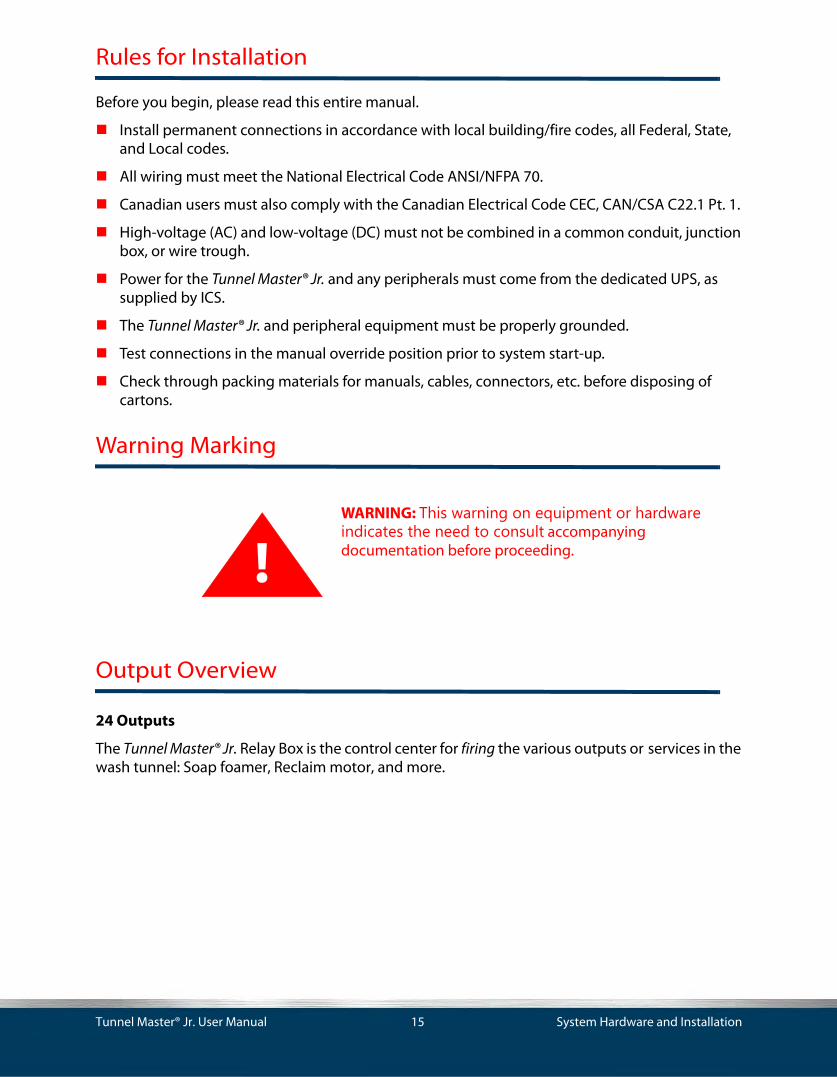
Warning Marking
Output Overview
24 Outputs
The Tunnel Master® Jr. Relay Box is the control center for firing the various outputs or services in the wash tunnel: Soap foamer, Reclaim motor, and more.
!WARNING: This warning on equipment or hardware indicates the need to consult accompanying documentation before proceeding.
Tunnel Master® Jr. User Manual 15 System Hardware and Installation

The Tunnel Master® Jr. Controller relay box provides for automatic, computer controlled, or manual firing of the outputs. The relay box can control up to 24 outputs.
Figure 3. Front Panel of the Tunnel Master Jr.
Each toggle switch controls the operation of one output or service.
The switch has three positions:
UP = Manual Override. Manually turn on output. (This feature can be turned off if desired.)
MIDDLE = Output Off. The output is off and will not fire.
DOWN = Computer controlled on position (normal).
The following instructions will provide detailed information on proper relay box mounting and installation of the Entrance Keypad.
Tunnel Master® Jr. User Manual 16 System Hardware and Installation

Equipment Dimensions
Dimension Amount Notes
Width 27 3/8” —
Height 15 3/8” —
Depth 6 3/8” Includes the plastic face.
Weight 48 lbs. Inclusive of the box, board and door.
Operating Temp. Range
32 °F to 122 °F
0 °C to 50 °C
—
Frequency 60 Hz. —
Supply Voltage 120 VAC —
Max. Amps 6.0 Amps. —
Power Supply 6.0 Amps. Power must come from a dedicated, 6-Amp. breaker.
IP Rating. IP40 The Tunnel Master® Jr. is rated for protection against solid objects up to 1mm diameter and not protected against liquid.
Table 1: Tunnel Master® Jr. Controller Dimensions, Measurements and Ratings
Dimension Amount Notes
Width 9 3/8”'' —
Height 7” —
Depth 2 5/8” Includes the plastic face.
Weight 3 lbs. Inclusive of the box, board and door.
Operating Temp. Range
32 °F to 122 °F
0 °C to 50 °C
—
Frequency 50/60 Hz. —
Supply Voltage 12 VAC —
Max. Amps 20 VA —
Power Supply 20 VA Power must come from a dedicated ICS transformer.
IP Rating IP65 The Tunnel Master® Jr. is rated for total protection against dust and strong jets of water from all directions, limited ingress permitted.
Table 2: Tunnel Master® Jr. Keypad Dimensions, Measurements, and Ratings
Tunnel Master® Jr. User Manual 17 System Hardware and Installation

Relay Box Mounting
All site wiring must be performed by a licensed electrician that must comply with all local and national codes.
The relay box must be securely mounted to the wall in the equipment room of the car wash. The relay box is designed to be located in a dry, non-corrosive environment.
The relay box must be located so that conduit connections can be easily made, and the relays can be readily accessed.
Relay Box Wiring
Install one approved 3/4” conduit from the relay box to the entrance keypad box located near the front of the wash tunnel. All conduit runs should meet all local and national codes. Conduits shall be properly connected and securely fastened to the boxes with Listed conduit hubs, and should be tightened to the torque specs of the manufacturer. Over torquing may cause enclosure breakage.
Electrician must provide a dedicated 120 VAC circuit to power the relay box.
Run a 14-3 cable to the 120 VAC terminal block. It is labeled with L and N for Load and Neutral, respectively. There is a mechanical ground lug located on the back of the box adjacent to the terminal block. It is labeled with the universal ground symbol. Terminations for the shielded cable should be torqued to 35 pound-inches.
Electrician must supply a separate 24 VAC and 120 VAC circuit to the common (C) side of the upper and lower termination points of each relay respectively, then loop the commons together to each relay. This power is to fire the solenoids and equipment.
A separation of 120 VAC and 24 VAC shall be maintained for all field-wiring circuits. All 24 VAC circuits must be supplied by a class 2 transformer.
Tighten all wires on the circuit board in the relay box to 20 pound-inches (2.3 n-m.) Over torquing may cause enclosure breakage.
Relays in the relay box are double pole with independent commons so that each relay can have two circuits running through it. Commons are independent to provide a power source to switch two devices through either the normally open or normally closed circuits.
Relays circuits should be supplied with no greater than 120 VAC 15 amp.
NOTE: This 120 VAC MUST BE A SEPARATE circuit from the dedicated 120 VAC circuit terminated in the lower right corner of the Relay Box.
A 6.3 amp. 250 fuse protects each relay. Four spare fuses along with LED fuse test indicators are located at the center of the relay board. (Fuses should not be replaced with any other device.)
Tunnel Master® Jr. User Manual 18 System Hardware and Installation

Another approved ¾” conduit needs to be run to your motor control center to the relay box and will contain the low voltage wires for clock (Pulse), gate (Entrance switch) and Tire switch functions.
When using a normally open 2-wire pulse switch, use terminals marked CLK SINK and PROX GND.
See Figure 6, “Pulse/Proximity Switch Wiring.”
When using a normally open 3-wire pulse switch, use terminals marked PROX PWR, CLK SINK, and PROX GND.
See Figure 6, “Pulse/Proximity Switch Wiring.”
Gate and Tire inputs require a constant 24 VAC neutral supplied from a class 2 transformer. The load signal would be terminated to the normally open pole of the electric eye (Gate) switch.
See Figure 7, “Gate Eye (Switch) Wiring.”
See Figure 8, “Tire Switch Wiring.”
For Entrance Keypad Installation, See “Entrance Keypad” on page 65.
Tunnel Master® Jr. User Manual 19 System Hardware and Installation

Figure 4. Low Voltage Layout Wiring Diagram
Tunnel Master® Jr. User Manual 20 System Hardware and Installation

Relay Box Interior
Each relay has circuits to control both 24 VAC and/or 120 VAC simultaneously so that a service sign as well as the service solenoid can be operated from the same relay.
Plug in relays for ease of serviceability.
Each relay has 2 fuses.
Built in spare fuses and fuse tester near the center of the box.
Each relay can be programmed to flash, eliminating the need for field installed flashing relays for signs.
Figure 5. Relay Box Interior Components
Termination points for Pulse, Gate, Tire, and Panic Circuits.
Plug in relays for ease of serviceability. Each relay has two fuses (24 VAC and 120 VAC).
Built in spare fuses and fuse tester.
Power In
12 VAC transformer powers the Keypad Power Board only.WARNING: DO NOT Power any other devices from this transformer!
Power Conditioner Board
Comm Cable Terminal Blocks for 16 button Entrance Keypad and other TMJ relay box.
Tunnel Master® Jr. User Manual 21 System Hardware and Installation

Pulse/Proximity Switch Wiring
See wash equipment vendor for location of the switch.
The Controller is designed to accept all commonly used pulse/proximity switches. There are two types that are most commonly used, either a two wire or three wire Sinking (NPN) switch. The drawing below indicates the wiring for these two types of switches.
The other type of switch is defined as a Sourcing (PNP). If it is determined that this type of proximity switch is being used, there are two jumpers located just below the CLK SINK and CLK SRCE terminal blocks (JP1) and (JP2). These jumpers must be moved to the SOURCE jumper position. Some pulse switches vary in the wire color. You should check the pulse/proximity switch manual for proper color codes. The following diagram shows how to wire the pulse/proximity switch into the Relay Box.
!IMPORTANT: The pulse switch is a critical input for the Controller. It signals the system that the conveyor is moving and is the measuring device from which the system knows when to turn equipmentdevices on and off.
Tunnel Master® Jr. User Manual 22 System Hardware and Installation

Pulse/Proximity Switch Wiring
Figure 6. Pulse/Proximity Switch Wiring
Tunnel Master® Jr. User Manual 23 System Hardware and Installation

Gate Switch (Electric Eye) Wiring
See the wash equipment provider for the location of this relay. The following diagram to the Smart Relay Box starts at the control relay for the sensing device being used. The diagram shows how to wire the Gate (electric eye) switch into the Relay Box.
Gate Eye Switch Wiring
Figure 7. Gate Eye (Switch) Wiring
!IMPORTANT: The Gate switch is the second critical input device to the Relay Box. It is usually an electric eye system or some type of vehicle position detector located just before the first piece of wash equipment. This switch signals the Controller that a vehicle is starting through the tunnel. All equipment turn on points are measured from this switch to the particular piece of equipment.
24 VAC SUPPLY (BY OTHERS)
COMMON NORMALLYOPEN
ELECTRIC PHOTO EYEOR OTHER SENSINGDEVICE CONTACTS
L N
TMJ RELAY BOX TERMINAL STRIP (TOP)
Gat
e -
Gat
e +
Alternate symbol for N.O. Switch
Tunnel Master® Jr. User Manual 24 System Hardware and Installation

Tire Switch Wiring
The following diagram shows how to wire the Tire Switch (tire position detection) into the Relay Box.
Figure 8. Tire Switch Wiring
!IMPORTANT: This circuit is used if the customer has purchased a tire position switch from the equipment vendor. The switch enables the Controller software to turn equipment on and off as each of the vehicle's tires pass that piece of equipment. In order for this to work properly, the tire switch should be located in line with the gate switch.
24 VAC SUPPLY (BY OTHERS)
TMJ RELAY BOX TERMINAL STRIP (TOP)
COMMON NORMALLYOPEN
ELECTRIC TIREPOSITION SENSINGDEVICE CONTACTS
L N
TIR
E -
TIR
E +
Alternate symbol for N.O. Switch
Tunnel Master® Jr. User Manual 25 System Hardware and Installation

Entrance Management System Wiring
When a car enters the tunnel, the User Manual will wait to see two signals within 15 seconds of each other from the tire treadle that is wired into Input 10. The first signal represents the front tire, and the second signal represents the rear. Once it sees the second signal, the Tunnel Master® Jr. will fire an optional sign relay followed by a roller relay. The amount of time between the sign firing and the roller is called the Entrance Management Delay in the Wash Settings.The following diagram shows how to wire the treadle switch for the EMS into the Relay Box. Entrance Management System Wiring
Figure 9. Entrance Management Overview and Wiring Diagram
!IMPORTANT: This circuit is used if the customer has purchased a treadle switch from the equipment vendor. The Entrance Management System in the Tunnel Master® Jr. allows a roller to be fired automatically upon seeing a second 24V input on Input 10. At the same time, an output can be set to fire and the roller can be delayed.
24 VAC SUPPLY (BY OTHERS)
COMMON NORMALLYOPEN
TREADLE SWITCHN.O. CONTACTS
L N
TMJ RELAY BOX TERMINAL STRIP (TOP)
Inpu
t 10
-In
put 1
0 +
Tunnel Master® Jr. User Manual 26 System Hardware and Installation

Roller L
Roller Locator Wiring
When a roller locator is used, the Tunnel Master® Jr. will wait to fire a roller until the trailing edge of the signal is detected from a roller locator. There are various devices available to detect the roller and because the Tunnel Master® Jr. reads the trailing edge of the signal either a normally open or normally closed switch can be used.
To set this up two things need to be done:
A roller locator switch needs to be wired into Input 9, and installed on the conveyor. This switch should be positioned so that as soon as a roller passes the switch it will be in a position where it is safe for the roller forks to come up.
Turn the roller locator function on in Wash Settings.
The following diagram shows how to wire the Roller Locator into the Relay Box.
Conveyor Roller Locator Cross Section Diagram
Figure 10. Roller Locator Cross Section Diagram
!IMPORTANT: You can add a roller locator to the Tunnel Master® Jr. to keep your rollers from jamming your conveyor. In order to do this, a roller locator switch must be installed on your conveyor to signal the presence of a roller.
ocator DeviceConveyor Surface
Roller forks in the UP position
Conveyor direction
Roller
Roller forks in the DOWN position
y g
Tunnel Master® Jr. User Manual 27 System Hardware and Installation

Roller Locator Wiring
Figure 11. Roller Locator Wiring
24 VAC SUPPLY (BY OTHERS)
COMMON NORMALLYOPEN
ROLLER LOCATORDEVICE CONTACTS
L N
TMJ RELAY BOX TERMINAL STRIP (TOP)
Inpu
t 9 -
Inpu
t 9 +
Alternate symbol for N.O. Switch
Tunnel Master® Jr. User Manual 28 System Hardware and Installation

Panic Stop Circuit Wiring
The diagram on the next page shows how to wire the Panic Stop circuit into the Controller.
!IMPORTANT: This drawing shows the basic wiring of the panic circuit. The Panic circuit allows for certain software programming that could not be programmed without this circuit in place.
Tunnel Master® Jr. User Manual 29 System Hardware and Installation

Panic Stop Wiring
Figure 12. Panic Stop Circuit Wiring
Tunnel Master® Jr. User Manual 30 System Hardware and Installation

Anti-Collision Wiring
The process consists of two variables in order for the Tunnel Master® Jr. to go into an anti-collision panic. The first variable is for the Tunnel Master® Jr. to validate a car through some sort of sensing device. The second variable is the anti-collision start time in the wash settings on the Tunnel Master® Jr. When a car is in the sensing device and a second car reaches the Anti-collision Start Time, the system will go into a panic until the sensing device is cleared. The system must also have a panic circuit wired in for this function to be able to restart the conveyor.
(See “Panic Stop Circuit Wiring” on page 30.)
The magnetic loop and the photo eye are two examples of anti-collision devices that operate the open contacts that interact with theTunnel Master® Jr. wash controller.
(See “Anti-Collision Wiring” on page 32.)
The following diagram shows how to wire an anti-collision system into the Tunnel Master® Jr.
!IMPORTANT: The anti-collision on the Tunnel Master® Jr. is a function to help prevent cars from running into each other at the exit end of the tunnel. In order for this to work you need an anti-collision device mounted in the tunnel at the spot where you could havea potential collision.
Tunnel Master® Jr. User Manual 31 System Hardware and Installation

Anti-Collision Wiring
Figure 13. Anti-Collision Wiring
24 VAC SUPPLY (BY OTHERS)
COMMON NORMALLYOPEN
ANTI- COLLISIONDEVICE CONTACTS
L N
TMJ RELAY BOX TERMINAL STRIP (TOP)
Inpu
t 11
-In
put 1
1 +
Alternate symbol for N.O. Switch
Tunnel Master® Jr. User Manual 32 System Hardware and Installation

Input Wiring Summary
Figure 14. Input Wiring
Push Button Wiring
If the Tunnel Master® Jr. is going to utilize a Push Button Station as a means of remotely selecting the features of each car wash, refer to one of the following schematic diagrams of how it must be wired to operate correctly with the inputs of the Tunnel Master® Jr.
!IMPORTANT: Please be certain to install it exactly as it is shown in the diagram. Wiring it in any other way would conflict with the designated inputs causing the washes to run incorrectly or not at all.
PRO
X PW
RC
LK S
RC
EC
LK S
INK
PRO
X G
ND
GAT
E +
GAT
E -
TIR
E +
TIR
E -
IN 1
+IN
1 -
IN 2
+IN
2 -
IN 3
+IN
3 -
IN 4
+IN
4 -
PAN
IC +
PAN
IC -
IN 5
+IN
5 -
IN 6
+IN
6 -
IN 7
+IN
7 -
IN 8
+IN
8 -
IN 9
+IN
9 -
IN 1
0 +
IN 1
0 -
IN 1
1 +
IN 1
1 -
IN 1
2 +
IN 1
2 -
External Roller
Anti-Collision
Entrance Mgt. Treadle
Roller locator switchPanic input
Tire detect input
Gate inputProx switch power
Clock sourceClock sink
TMJ Input Designations
24 VAC SUPPLY (BY OTHERS)
L N
Inpu
t -
Inpu
t +
*All input devices must complete a24VAC circuit to the input. A contactclosure alone will NOT toggle the input.
Please refer to the example circuit below .
(Example ;Gate, Anti Collision, Roller detect, etc.)
SIN
K
SOU
RC
E
JP2 JP1
SIN
K
SOU
RC
E
Tunnel Master® Jr. User Manual 33 System Hardware and Installation

Push Button Wiring 1 Row 8 Columns
Figure 15. Push Button Wiring 1 Row 8 Columns
Input 1
PB 1
Service 1
Input 2
PB 2
Service 2
Input 3
PB 3
Service 3
Input 8
PB 4
All Clear
Inputs 1-8Common
24VAC
Tunnel Master® Jr. User Manual 34 System Hardware and Installation

Push Button Wiring First 8 Buttons
Figure 16. Push Button Wiring First 8 Buttons
Input 5
Input 6
Input 6
Input 6
24VAC
Service 1
Service 2
Service 3
Service 4
Service 5
Service 6
Service 7
Service 8
Input 1
Input 2
Inputs 1-8Common
Tunnel Master® Jr. User Manual 35 System Hardware and Installation

Push Button Wiring for Second 8 Buttons
Figure 17. Push Button Wiring for Second 8 Buttons
Input 5
Input 6
Input 6
Input 6
24VAC
Service 9
Service 10
Service 11
Service 12
Service 13
Service 14
Service 15
ALL CLEAR
Input 3
Input 4
Inputs 1-8Common
Tunnel Master® Jr. User Manual 36 System Hardware and Installation

Relay Box Jumper Settings
The following figure and table will explain the location and purpose of the various jumpers, switches, and controls on the Relay Box circuit board. This board is located on the inside of the Relay Box door.
Figure 18. Relay Jumper Box Settings
Contrast Control for front of box LED display
DIP Switch
SW1 Circuit Board Reset Button
JP6
JP2
JP5
JP4
JP3
JP8
JP9
JP7 JP10 JP11
Tunnel Master® Jr. User Manual 37 System Hardware and Installation

Jumper Setting Function
J1 N/A Does not exist.
J2 ON BIAS High (+) set ON for the Main Relay box only.
J3 485 3 position jumper should be on 2 pins to select 485 Communication (Up).
J4 485 3 position jumper should be on 2 pins to select 485 Communication (Up).
J5 ON Transmit terminating resistor. Only ON if first or last device in network.
If you have a 24-output system, this should be ON. If you have a 48-output system, the main relay box should be OFF and the second relay box should be ON.
J6 485 3 position jumper should be on 2 pins to select 485 Communication (Left).
J7 OFF Receive terminating resister.
J8 ON Network Interface Chassis Ground Jumper.
J9 ON Network Interface Signal Ground Jumper.
J10 ON BIAS Low (-) set ON for the Main Relay box only.
J11 ON ON=Enables, OFF=Disables manual override switches on relay box.
Table 3: Relay Box Circuit Descriptions
Tunnel Master® Jr. User Manual 38 System Hardware and Installation

DIP Switch Settings
The following picture and table will show the Relay Box DIP switch and the various settings that may be used.
The ON position is marked with an arrow and is always up. A 24 Output Relay Box will ship as ADDR1. If you were to add a second Relay Box to the system, it should be addressed as ADDR9.
See Figure 18, “Relay Jumper Box Settings.” for various jumpers, switches, and controls.
Figure 19. DIP Switch located on inside of Relay Box Door
Tunnel Master® Jr. User Manual 39 System Hardware and Installation

The following table displays the DIP Switch settings for normal operations.
Switch Setting Function
1 OFF Address Setting: 1, 2, 3, 4 OFF = Address 1
2 OFF Address Setting: 1 ON, 2, 3, 4 OFF = Address 9
3 OFF Address Setting: 1 ON, 2, 3 OFF, 4 ON = Address 10
4 OFF Address Setting: 1 & 3 ON, 2 & 4 OFF 1 ON, 2 OFF, 3, 4 ON
= Address 11
= Address 12
5 OFF Baud Rate: OFF = 9600 ON = 38,400
6 OFF Up position allows access to Initialization Menu options
7 OFF Pulse 7 OFF & 8 ON Normal
8 OFF Pulse Enhancement 7 OFF, 8 ON
7 ON, 8 OFF
7 & 8 ON
2 Times
4 Times
8 Times
Table 4: DIP Switch Normal Settings/Functions
Tunnel Master® Jr. User Manual 40 System Hardware and Installation

Tunnel Master® Jr. AC Power Terminations
Figure 20. AC Power Terminations
GROUNDLUG
120 VAC FROM POWER DISTRIBUTION
PANEL – 14/3 SHIELDED WIRE “E”
+12
VAC
-12
VAC
GN
D
POWER
BLAC
K
BLAC
K
WH
ITE
WH
ITE
SHIELD DRAIN NOT TERMINATED
TMJCONTROLLER
KEYPAD
ELECTRICIAN SUPPLIED 18/2
SHIELDED
SPARE
12 VAC
LIN
E
NEU
TRAL
GR
OU
ND
SUPPLY FOR TMJ KEYPAD INSIDE TMJ RELAY BOX
ELECTRICIAN SUPPLIED 14/3
SHIELDED
Tunnel Master® Jr. User Manual 41 System Hardware and Installation

Tunnel Master® Jr. User Manual 42 System Hardware and Installation

Chapter 3: Operating Procedures
Operating Procedures
The Operating Procedures chapter will provide the user with an explanation of how to operate their Tunnel Controller, process customer vehicles and review operations through the reports available. As in the previous chapters, the instructions will follow a logical trail through a day’s operations beginning with the opening process. Proper operation will ensure operators that they will obtain accurate reports and prevent potential employee errors or possible theft.
Main Wash Menu
After setting up the various wash settings and services, the user is now ready to wash cars. The main wash menu is where many of the day to day activities will be performed. It is important to train personnel in the proper selection of these menu options to ensure accurate shift reporting and to review operations.
The following is a list of menu options in the Main Wash menu and a brief explanation of their function.
Wet Down Wash
The Wet Down process is the first step that the opening person should do to prepare the wash for the first customer. When selected, the process is setup to activate all relays (outputs) which have been designated to turn on during the Wet Down cycle. The cycle time is setup in the Wash Settings menu. By wetting down the cloth equipment and perhaps charging the foaming manifolds in the wash, the wash will be prepared to process the first vehicle, and provide a more consistent wash to the customer.
Item Menu Option Function
1 Bump Shift When selected this menu option will print a report, if a report printer is attached, and ask if the operator wishes to close (Bump) the current shift.
2 Wet Down Wash This option allows the user to activate any equipment outputs, which have been designated to activate whenever the operator chooses this wet down option.
3 Configure Wash Allows user to configure wash settings and services, explained in-depth.See “Wet Down Wash” on page 43.
4 View Counts This menu gives the ability to view counts, number of times the various services have been processed during the current shift.
5 Print Reports From this menu option a user can print various financial reports, if there is an optional report printer attached to the controller.
Table 5: Main Wash Menu
Tunnel Master® Jr. User Manual 43 Operating Procedures

Follow these steps to start a wet down at the Tunnel Master® Jr. display:
Step Action Screen Displays
1 From the Tunnel Master® Jr. display panel, press the Menu button to access the main menu.
NOTE: If a password has been set, it will be necessary to enter the password before the main menu can be accessed.
[1] Bump Shift [4] View Counts
[2] Wet Down Wash [5] Print Reports
[3] Configure Wash
2 From the display panel numeric keypad, press the numeric 2 key to select Wet Down Wash.
NOTE: The relays will be activated and you will be returned to the main display screen. A second to second countdown will start next to the word WETDOWN. This system will continue counting down until it reaches 0 and then shut all of the activated relays off.
ICS Tunnel Controller 10:25:35 PM VER 1 REV 5.1104/15/2002
WETDOWN 085 SECSCARS 0000
Table 6: Wet Down Wash Instructions
Tunnel Master® Jr. User Manual 44 Operating Procedures

Chapter 4: Wash Configuration
This chapter will provide information on how to setup and configure facility specific information and how to use some of the features of your new Tunnel Master® Jr. Car Wash Controller. The Tunnel Master® Jr. Controller contains unique features usually found only in the high-end full-service wash controller systems. Features like ICS copyrighted anti-theft software; integration with a Panic Stop circuit; and for quick morning wash checkouts, use Wet down.
The following topics will be covered in this chapter:
“Relay Box Display Keypad” on page 46.
“Set Password” on page 47.
“Configure Wash Menu” on page 50.
“Set Date Time” on page 55.
“Configure Wash Settings” on page 56.
“Outputs” on page 57.
“Follow these procedures to set or change the settings for the Outputs in the Tunnel Master® Jr. Controller program.” on page 59.
“Assign Outputs to Services” on page 64.
Tunnel Master® Jr. User Manual 45 Wash Configuration

Relay Box Display Keypad
The Relay Box keypad is the primary place from which to program and configure the wash tunnel. If your facility has two relay boxes, one of them will serve as the primary input relay box. From this screen you can:
Setup and configure the wash tunnel outputs and services.
View car count and some sales information.
Print vehicle count and sales information, if optional printer is installed.
Some equipment diagnostics occur at the Relay Box.
Manually process cars and apply services.
Figure 21. Main Screen Display and Keypad
NOTE: In order to utilize the full functionality of the Tunnel Master® Jr. controller, it is very important that the electrician follow the wiring instructions provided with the Relay Box.
IndicatorLights
FunctionButtons Keypad(F1-F4) Menu
Display
Tunnel Master® Jr. User Manual 46 Wash Configuration

Set Password
Set Password will require that the user enter the password that has been setup in order to access menu options.
This feature allows you to restrict access to the menus in theTunnel Master® Jr. system.
Button Function
Indicator Lights:
+5V DC This light should be lit at all times indicating that the input terminal system has good power.
LOGIC This light should be blinking in a steady rapid beat indicating that the system is sending and receiving logic information within the system.
CLOCK When blinking, indicates operation of pulse switch on conveyor.
GATE When on, indicates gate switch (electric eye) is sensing.
TIRE When on, indicates tire switch is sensing.
PANIC When on, indicates panic circuit is activated.
F1 – F4 Function buttons are used during the setup and programming of the wash facility. During setup options will be displayed at the bottom of the display indicating which button to press for the option desired. Options:
F1 = PREV allows user to return to previous screen.
F2 = NEXT allows user to advance to the next screen.
F3 = CLEAR allows user to clear existing entries.
F4 = SAVE allows user to save new settings entered.
Numeric 1-9 Numeric buttons are also used during programming as well as entering passwords etc. When entering a desired letter, press the corresponding numeric key to select the desired number.
Example: When entering the letter C, press the number 1 key three times.
Numeric 0 The 0 button has multiple functionality depending on what is being programmed. In most menu options, the 0 button, when pressed, will allow for a space, a decimal point or zero. When setting service or output features where there is more than one option the 0 button can be pressed to scroll through the various options allowed for that setting.
AC The AC button clears all entries on the current screen.
ENT When pressed during programming allows user to advance to the next option.
Menu The Menu button is used when accessing various menu options in your car wash controller. It is also used as an escape key to exit out of the current screen display or to return to the previous menu.
Table 7: Relay Box Display and Keypad Indicator Light Descriptions
Tunnel Master® Jr. User Manual 47 Wash Configuration

Follow these steps to set or change the system password.
Step Action Screen Display
1 Press the Menu button on the main screen of the Tunnel Master Jr.
[1] Bump Shift [4] View Counts
[2] Wet Down Wash[5] Print Reports
[3] Configure Wash
2 Press the numeric key 3 from the Main Menu to select Configure Wash.
[1] Services[4] Wash Settings
[2] Outputs[5] Set Date Time
[3] Output List[6] Set Password
3 Press the numeric key 6 to select Set Password.
New Password: _
4 Enter in your password.
Example: For the letter L, press the 4 key three times
New Password: _
5 Press the ENT key to save your changes, and return to the Configure Wash Menu.
NOTE: Remember this password.
New Password: ICS _
Table 8: Change the System Password Instructions
Tunnel Master® Jr. User Manual 48 Wash Configuration

Access a Password Protected Menu
Once a password has been set into the system, any access to the menu options will require that the user enter the password that has been setup.
Follow these instructions to set up a password to access the menu options:
Step Action Screen Displays
1 From the main screen, press the Menu key. ICS Tunnel Controller 10:25:35 PM VER 1 REV 5.1104/15/2016
Password _ _ _ _ _ _
ADDR =1CARS 0000
2 Using the numeric keypad, type in the first letter of the password.
ICS Tunnel Controller 10:25:35 PM VER 1 REV 5.1104/15/2016
Password * _ _ _ _ _
ADDR=1CARS 0000
3 Wait until the cursor moves to the next position.
Warning: If you press ENT after entering a letter, what you have entered to that point will be accepted as the password and you will be returned to the main screen display!
ICS Tunnel Controller 10:25:35 PM VER 1 REV 5.1104/15/2016
Password * _ _ _ _ _
ADDR=1CARS 0000
4 Repeat steps 3 & 4 until the entire password is entered.
ICS Tunnel Controller 10:25:35 PM VER 1 REV 5.11 04/15/2016
Password ****_ _
ADDR=1CARS 0000
5 Press the ENT button to accept the password. [1] Bump Shift [4] View Counts
[2] Wet Down Wash [5] Print Reports [3] Configure Wash
Table 9: Add Password Instructions
Tunnel Master® Jr. User Manual 49 Wash Configuration

Configure Wash Menu
Before any washes can be processed, the user must configure the wash. There are many items to be configured including the actual tunnel setup all the way to setting up services. Each item must be configured accurately if the wash is to operate properly.
The following is a list of menu options in the Configure Wash menu and a brief explanation of their function.
NOTE: This manual will take you through the process of setting up a car wash. It will do this in the logical order for the setup, which may not necessarily be the order in which the menu options appear on the screen.
Item Menu Option Function
1 Services In the Services menu option the user will define the various services and wash options they will have at their car wash.
2 Outputs This option is where the user will setup what each output is operating and the various settings for that output.
3 Outputs List This option allows the user to assign what selective outputs will be activated for which services that are available to sell.
4 Wash Settings Wash Settings allows the user to set the various equipment settings that directly relate to their particular equipment. This is where the user will set many of the unique feature of the Tunnel Master® Jr. tunnel controller.
5 Set Date Time This option allows the user to set the date and time the system will recognize.
6 Set Password This option allows you to setup a password to restrict access to the menus on the relay box.
Table 10: Configure Wash Menu
Tunnel Master® Jr. User Manual 50 Wash Configuration

Wash Setting Descriptions
The Wash Settings menu option is where important information about the user’s specific car wash equipment is programmed. Important features such as the anti-theft program and Wet Down option are set in this menu.
The following is a list of menu items within the Wash Settings menu option and a brief explanation of their function.
Wash Setting Field Description
Auto Pulse Period This is the rate in which you want the conveyor to run when in Auto Pulse. You should set this value to 0 when the conveyor is running. Doing this will automatically calibrate this setting based on your conveyor speed. If you change conveyor speeds, you should reset this.
Auto Pulse Enter Y for yes, N for no, if the user wishes the system to simulate a pulse in the event of pulse switch failure. Note: This feature will activate as soon as Y is entered and the user hits save.
Invert Gate Enter Y for yes, N for no, allows operator to decide if logo switch is wired low or high. (Will vehicle break continuous circuit or complete a circuit?)
Auto Gate Delay Enter the length in inches or pulses of estimated chain travel, after a roller button is activated, before a vehicle would normally activate the gate switch. This value must be greater than 0.
Auto Gate Enter Y for yes, N for no. This feature is used as a back up for the Gate input. If the Gate input goes down, you can turn this feature on. This will simulate the measuring of the car. It will set every car length to the value set for Max Car Length.
Roller Control Enter Y for yes, N for no, if one of the outputs will fire the roller solenoid.
Entrance Management Enter Y for yes, N for no, if you have a treadle switch wired into Input 10.
Entrance Mgmt Delay Optional setting to be used with the Entrance Management System. This value is the number of seconds you want the roller output to delay before firing.
Roller Locator Enter Y for yes, N for no. When this option is set to yes, the system will wait to fire the Roller Output until the trailing edge of a signal is detected from Input 9.
Roller Interlock When set to Y, the system will not allow a roller to be fired without a service being selected for that vehicle. Roller Interlock disables the roller-up and gate switch until a valid service is programmed for the vehicle. Since it will not recognize a car, no outputs would be turned on in the tunnel.
When set to N, the system will allow a roller to be fired for a vehicle that is not assigned to a valid service. This will allow that vehicle to be sent into the tunnel and it will receive the Unloaded wash service.
Table 11: Wash Settings Menu
Tunnel Master® Jr. User Manual 51 Wash Configuration

Auto Roller Enter Y for yes, N for no. When this option is set to yes, as soon as you select a base service on a non- stacking system, a roller will fire.
Panic Stop Enter Y for yes if you have the panic stop wired into the system, N for no if a Panic Stop is not installed.
Anti-Collision This is going to be the distance from first gate input to where you want the anti-collision feature to trigger.
See “Panic Stop Circuit Wiring” on page 29. Anti-collision diagram and for a detailed explanation. (Must have Panic Enable Circuit wired in.)
Auto Stop Period Enter the number of seconds after the last car you want the system to automatically shut the conveyor off. You must have an Auto Stop output wired and setup in order for this feature to work.
Wet Down Period Enter the number of seconds you would like to have the wash equipment turned on for the wet down process. A wet down will fire all of the outputs that have Y for the wet down option.
Flash On In 100 mili-seconds increments how long the relay will flash on. This is what the system looks at when you set the output flash to Y.
Flash Off In 100 mili-seconds increments how long the relay will flash off. This is what the system looks at when you set the output flash to Y.
Shift This displays the shift number that the system is currently on.You cannot change this setting.
Auto Shift Enter Y for yes, N for no. If you set this option to Y, the system will automatically close the shift at midnight. This option should be set to Y if you are using the Tunnel Master® Jr. Interface.
Tax Rate 1.0% The percentage rate for the first tax rate charge.
Tax Rate 2.0% The percentage rate for the second tax rate charge.
Stacking Enter Y for yes or N for no. If you set this option to Y, the system will start stacking. This option should be set to N if using the Tunnel Master® Jr. Interface.
Input Device This is set K for keypad, P for push button, C for Computer / Controller, B both keypad and Wash Valet, or W for Wash Valet talking directly to a TMJ. This is used to interface with Tunnel Master® Sr.
Push Button Rows If a push button entry station is being used, enter the number of rows, going across, of buttons on the station. This will tell the system what inputs to accept. If you do not have a push button station, this option is disregarded.
Push Button Cols If a push button entry station is being used, enter the number of columns, going down, of buttons on the station. If you do not have a push button station, this option is disregarded.
Console Debug This is a debug utility that ICS may use to track system activity. This should be set to N if you are using the Tunnel Master® Jr. Interface.
Wash Setting Field Description
Table 11: Wash Settings Menu
Tunnel Master® Jr. User Manual 52 Wash Configuration

Header 1 Enter information desired to display on the first line on the top of reports and receipts. This is usually company information.
Header 2 Enter information desired to display on the second line on the top of reports and receipts. This is usually company information.
Header 3 Enter information desired to display on the third line on the top of reports and receipts. This is usually company information.
Header 4 Enter information desired to display on the fourth line on the top of reports and receipts. This is usually company information.
Footer 1 Enter information desired to display on the first line on the bottom of receipts. This is usually a message to the customer.
Footer 2 Enter information desired to display on the second line on the bottom of receipts. This is usually a message to the customer.
Footer 3 Enter information desired to display on the third line on the bottom of receipts. This is usually a message to the customer.
Footer 4 Enter information desired to display on the fourth line on the bottom of receipts. This is usually a message to the customer.
Display Cars Enter Y for yes, N for no. When this option is set to yes, the daily car count will display on the main display on the relay box.
Car Count Displays the number of cars for the current shift. This is reset when you bump a shift.
Invalid Count This is the number of times in the current shift that the gate input started to sense a car, but it did not measure up to the Min Car Length. This is reset when you bump a shift.
Violation Count This is the number of times in the current shift that the gate sensed a car longer than the Max Car Length.
Cleared Count This is the number of times in the current shift that a service wash cleared. This count is reset when a shift is bumped.
Duplicate Count This is the number of times in the current shift that a duplicate receipt was printed. This count is reset when a shift is bumped.
Relay Address2 This is the address of the Relay box. The DIP switches determine this. If this is a 24 output system, set this to “0”. If it is a 48 output system, set this to “9”.
Key Pad 1 Address This is the address of the first Key Pad. If you are using a push button station, set this to “0”. By default the keypad is set to “5”. If you are using multiple keypads consult the DIP switch settings on the keypad for the proper address.
Key Pad 2 Address This is the address of the second Key Pad. The address of the keypad is based on the DIP switch settings on the keypad.
Wash Setting Field Description
Table 11: Wash Settings Menu
Tunnel Master® Jr. User Manual 53 Wash Configuration

Report Address This is the address in which the report printer is hooked up to. If the report printer is hooked up to the main relay box, then set this to “0”. If the report printer is hooked up to the keypad, set this option to “5”. This is the printer where all of the reports will print out.
Receipt Address This is the address in which the receipt printer is hooked up to. If the receipt printer is hooked up to the main relay box, then set this to “0”. If the receipt printer is hooked up to the keypad, set this option to “5”. All of the reports will print out from this printer.
Net Error Count This displays the number of network errors that have occurred since the system was setup. This is used for troubleshooting purposes only and is not changeable.
Pulse Length Pulse length must be set and will affect the input for Min and Max Car Length as well as Anti Bounce settings. Enter “1” if the user wishes the system to track start stop times in pulses. Enter the number of inches of chain travel for one pulse if the user wishes to set start stop times in inches.
Min Car Length The length in inches or the number of pulses of the minimum size vehicle that may enter the car wash.
This can be as little as 24” but must be greater than the minimum pulse length and greater than the anti- bounce value. This is part of the anti-theft features.
Note: If using inches, when an entry is made the system will round off to the closest setting possible based on the entry made.
Pulse On Input 8 Is the Pulse Wiring installed on Input8? Enter Y for Yes and N for No. Default is set to Y (Yes) on the Mandatory Only Secondary Tunnel Master® Jr.
Max Car Length The length in inches or the number of pulses of the longest vehicle that will enter the car wash before a violation is recorded. This is part of the anti-theft feature.
NOTE: If using inches, when an entry is made the system will round off to the closest setting possible based on the entry made.
Anti-bounce The length in inches or the number of pulses that the system still counts a vehicle if the sensor drops out as car passes the gate switch for less than anti-bounce value and comes back on. Value MUST be less than value set for Min Car Length.
Note: If using inches, when an entry is made the system will round off to the closest setting possible based on the entry made.
ResetCount The number of times the Tunnel Master® Jr. has been reset. For information purposes only.
ExpireDays For ICS use only.
EqptMeasurementInInches
If Y (Yes), the equipment distance measured in inches. If N (No) the equipment distances is measured in pulses.
Wash Setting Field Description
Table 11: Wash Settings Menu
Tunnel Master® Jr. User Manual 54 Wash Configuration

Set Date Time
The first item to program is the correct date and time for the system to recognize. This is menu option #3 in the Configure Wash menu. The time will be important in that other programming options such as when to automatically bump a shift will need the correct time set to accomplish the process at the correct time of day.
Follow these procedures to set or change the correct date and time in the system.
Step Action Screen Displays
1 From the main screen display, press the Menu button.
[1] Bump Shift[4] View Counts
[2] Wet Down Wash [5] Print Reports
[3] Configure Wash
2 Press the numeric key 3 from the Main Menu to select Configure Wash.
[1] Services[4] Wash Settings
[2] Outputs[5] Set Date Time
[3] Output List[6] Set Password
3 Press the numeric key 5 to selectSet Date Time.
Set Date Time
Date: _ _/_ _/_ _ _ _
Time: 10:25:35
AM
Press [Menu] to return
4 Using the numeric keys, type in t h e n umb er co r re s p on d i n g n u m b e r re p re s e nt i n g t h e mo nt h. Fo r exa mpl e, 0 4 = Apr i l .
Press the ENT key after the correct selection is made.
Set Date Time
Date: 04/_ _/_ _ _ _
Time: 10:25:35
AM
Press [Menu] to return
5 Repeat steps 3 and 4 to correctly enter the day, year, hour, minutes, seconds and whether it is AM or PM.
Set Date Time
Date: 04/15/2002 Time: 10:25:35 AM
Press [Menu] to return
6 Press the MENU key to save your changes and return to the Configure Menu.
[1] Services[4] Wash Settings
[2] Outputs[5] Set Date Time
[3] Output List[6] Set Password
Table 12: Set Date and Time Instructions
Tunnel Master® Jr. User Manual 55 Wash Configuration

Configure Wash Settings
Before any washes can be processed, the user must configure the wash. Each item must be configured accurately if the wash is to operate properly.
Step Action Screen Displays
1 From the main screen display, press the MENU button.
[1] Bump Shift[4] View Counts
[2] Wet Down Wash[5] Print Reports
[3] Configure Wash
2 From the numeric keypad, press the 3 key to select the Configure Wash menu option.
[1] Services[4] Wash Settings
[2] Outputs[5] Set Date Time
[3] Outputs Lists[6] Set Password
3 From the numeric keypad, press the numeric 4 key to select the Wash Settings menu option.
PulseLength _ _ _ _ _ _ _ _ _ _
F1=PREV F2=NEXT F3=RESET F4=SAVE
4 Using the numeric key pad, type th e measurement for Pulse Length.
NOTE: Review function buttons on Figure 21, “Main Screen Display and Keypad,” on page 46.
PulseLength 7.75_ _ _ _ _ _
F1=PREV F2=NEXT F3=RESET F4=SAVE
5 From the numeric keypad, press the F4 button to accept and save the entry.
PulseLength 7.75_ _ _ _ _ _
F1=PREV F2=NEXT F3=RESET F4=SAVE
6 Press the F2 button to advance to the next setting to enter.
MinCarLength _ _ _ _ _ _ _ _ _ _
F1=PREV F2=NEXT F3=RESET F4=SAVE
7 Repeat steps 4 – 6 until all settings have been programmed.
MaxCarLength _ _ _ _ _ _ _ _ _ _
F1=PREV F2=NEXT F3=RESET F4=SAVE
8 From the main screen display, press the MENU button to return to the previous menu screen.
[1] Services[4] Wash Settings
[2] Outputs[5] Set Date Time
[3] Outputs Lists[6] Set Password
Table 13: Configure Wash Settings
Tunnel Master® Jr. User Manual 56 Wash Configuration

About Countdown Times
Set the Wet Down Period in the panel to the exact wet down time (e.g., 100). This is the amount of time you want the actual wet down relays to fire and apply water to the equipment.
For example, the Wet Down Period is set to 100, the equipment may only get 90 seconds of water (100 seconds minus the 10 seconds required to sound the horn). The wet down will end when the Tunnel Master® Jr. counts down to zero.
Outputs
The Outputs menu option is where the user will initially setup and later, as needed, edit the wash relays that will be activate for the various was equipment. The basic Tunnel Master® Jr. relay box allows for up to 24 outputs. There is an option to add an additional relay box that will provide for an additional 24 outputs for a total maximum of 48. The available Outputs menu items and a brief description of their function are listed in the following table.
Menu Item Function
Output Enter the relay number corresponding to the relay switch on the outside of the relay box. They are numbered 1-12 down the left side and 13-24 down the right side.
Name The name of the specific equipment controlled by this relay. For example, soap foamer.
Start Enter the number of pulses or inches, depending on the setup choice in Wash Settings, for how far past the gate switch (electric eye) the piece of equipment should turn on.
Type Use the “0” button to advance to select the option desired.
M = Mandatory, relay will activate for any service sold that is set as a Base.
S = Selective, relay will activate only when a service set as an Extra Service is sold along with a Base service.
D = Deselective, relay will NOT activate when a service with this output is selected.
C = Conveyor, relay is activating the motor starter solenoid for the conveyor motor when a Panic circuit is wired to the designated relay.
R = Roller, relay activates the roller up solenoid. Start time entered on Roller output will be how long the roller up cylinder is activated. If you enter an extend time, the system will fire the roller up relay for the start time, then pause for the extend time and then fire for the start time a second time. This is known as an up down up.
A = Auto Stop, relay is tied to a stop circuit for shutting down the car wash after the last vehicle exits the wash or there is no wash activity. In order for this to work, you must set the Auto Stop Period in the Wash Settings.
O = This output is used to start the conveyor once you have a base service selected.
NOTE: YOU MUST HAVE A HORN RELAY SETUP WITH A START TIME IN ORDER FOR THIS RELAY TO FIRE.
H = This output will fire your Horn. The start time for this output is how long, in seconds, that the horn will blow for. The extend time is how long, in seconds, the system will delay starting the conveyor.
Table 14: Outputs Descriptions
Tunnel Master® Jr. User Manual 57 Wash Configuration

Part Use the “0” button to advance to the part of car selection that the piece of equipment turns on.
AC = All of the Car
FH = Front Half of the Vehicle
FB = Front Bumper On
RH = Rear Half of Vehicle
RB = Rear Bumper Only
TA = Activate from a tire switch for tires or wheels. On a Tire Output, The Start Time is Where In The Tunnel The Equipment Is and The Extend Time Is How Long The Output Will Stay On For.
ES = Entrance sign, relay will activate after vehicle is “Loaded” and shut off as vehicle reaches gate switch. An entrance sign can only be a Selective output and cannot be a Mandatory service.
EM = Entrance Management relay will activate after second tire hits the entrance management treadle which is wired into Input 10. This relay will stay activated until Min Car Length is reached.
Flash Enter Y for yes, or N for no if the relay is to flash on and off when it is activated.
Extend Enter the number of pulses or inches, depending on the setup choice in Wash Settings, for how far past the actual length of the vehicle the piece of equipment should stay on.
NOTE: Many outputs must be turned on early in order to be “charged” up before the vehicle gets to it. The Extend feature allows the user to keep the relay activated so that the rear of the vehicle does not get missed.
Look Enter the number of pulses or inches for the system to look back into the wash to see if there is another vehicle approaching. If there is another vehicle within the setting entered the system will leave that relay on to prevent frequent stopping and starting of electric motors which drives up utility charges.
Wet Enter Y for yes, or N for no if the relay should activate during the Wet Down process in the morning which provides a quick and easy way to prepare the wash tunnel for opening. Select Wet Down, option [2] on the main menu and any outputs that were setup to activate at Wet Down will turn on and stay on for the time set in the Wash Setting menu option.
Panic Two settings if a Panic circuit is wired to the system:
For the first setting, use the “0” button to select the desired option.
Y=Turn on the relay if there is a Panic condition.
N=Turn off the relay if there is a Panic condition.
X=Leave the relay in whatever status it was when a Panic condition occurs.
For the second setting, Staggered Start time, enter “0” if the output is to restart when the conveyor restarts, or enter the number of seconds after the release of a Panic condition the user wants the equipment to restart prior to the conveyor restarting.
Menu Item Function
Table 14: Outputs (Continued)Descriptions
Tunnel Master® Jr. User Manual 58 Wash Configuration

Output Settings
Follow these procedures to set or change the settings for the Outputs in the Tunnel Master® Jr. Controller program.
Step Action Screen Displays
1 Press the MENU button from the main screen display.
[1] Bump Shift[4] View Counts
[2] Wet Down Wash[5] Print Reports
[3] Configure Wash
2 Press the number 3 key to select the Configure Wash menu option.
[1] Services[4] Wash Settings
[2] Outputs[5] Set Date Time
[3] Output Lists[6] Set Password
3 Press the number 2 key to select the Outputs menu option.
Output _ _Name _ _ _ _ _ _ _ _ _ _ Start _ _ Type _ Part _ _ Flash _
Extend _ _ _ _ Look _ _ _ Wet _ Panic _ - _ _
F1=PREV F2=NEXT F3=ERASE F4=SAVE
4 From the numeric keypad, type the desired number for the output.
NOTE: See “Wash Configuration” on page 45.
Output 01 Name _ _ _ _ _ _ _ _ _ _ Start _ _ Type _ Part _ _ Flash _
Extend _ _ _ _ Look _ _ _ Wet _ Panic _ -_ _
F1=PREV F2=NEXT F3=ERASE F4=SAVE
5 Press the ENT button on the display keypad to advance to the next setting.
Output 01 Name
Start _ _ Type _ Part _ _ Flash _
Extend _ _ _ _ Look _ _ _ Wet _ Panic _ - _ _
F1=PREV F2=NEXT F3=ERASE F4=SAVE
6 From the numeric buttons, type the number of the Output.
Output 01 Name Roller
Start _ _ Type _ Part _ _ Flash _
Extend _ _ _ _ Look _ _ _ Wet _ Panic _ - _ _
F1=PREV F2=NEXT F3=ERASE F4=SAVE
7 Press the ENT button on the display pad to advance to the next setting.
Output 01 Name Roller
Start _ _ Type _ Part _ _ Flash _
Extend _ _ _ _ Look _ _ _ Wet _ Panic _ - _ _
F1=PREV F2=NEXT F3=ERASE F4=SAVE
8 Using the numeric buttons enter the Start time in inches or pulses depending on the wash setting selection.
Output 01 Name Roller
Start 0084 Type _ Part _ _ Flash _
Extend _ _ _ _ Look _ _ _ Wet _ Panic _ - _ _
F1=PREV F2=NEXT F3=ERASE F4=SAVE
Table 15: Output Settings
Tunnel Master® Jr. User Manual 59 Wash Configuration

Services menu option is where the user will initially setup and edit the wash services that will be available on the system. The basic controller configuration allows for up to 16 services, and the
9 Press the ENT button on the display pad to advance to the next setting.
Output 01 Name Roller
Start 0084 Type _ Part _ _ Flash _
Extend _ _ _ _ Look _ _ _ Wet _ Panic _ - _ _
F1=PREV F2=NEXT F3=ERASE F4=SAVE
10 Repeat steps 8 and 9 until the settings for Type, Part, Flash, Extend, Look and Wet are completed.
NOTE: Review the settings in Table 14 on page 57.
Output 01 Name Roller
Start 0084 Type R Part AC Flash N Extend 000 Look 000 Wet N Panic N - 0
F1=PREV F2=NEXT F3=ERASE F4=SAVE
11 Press the ENT button on the display pad to advance to the Panic setting.
Output 01 Name Roller
Start 0084 Type R Part AC Flash N Extend 000 Look 000 Wet N Panic N - 0
F1=PREV F2=NEXT F3=ERASE F4=SAVE
12 From the 0 button on the numeric keypad, advance to the desired setting, either Y for yes or N for no.
Output 01 Name Roller
Start 0084 Type R Part AC Flash N Extend 000 Look 000 Wet N Panic N - 0
F1=PREV F2=NEXT F3=ERASE F4=SAVE
13 Press the ENT button on the display pad to advance to the second setting in the Panic option.
Output 01 Name Roller
Start 0084 Type R Part AC Flash N Extend 000 Look 000 Wet N Panic N - 0
F1=PREV F2=NEXT F3=ERASE F4=SAVE
14 From the numeric keypad, type the number of seconds of delay for this relay to turn on before the conveyor will restart.
NOTE: If you do not wish this relay to stagger start, enter 0.
Output 01 Name Roller
Start 0084 Type R Part AC Flash N Extend 000 Look 000 Wet N Panic N - 0
F1=PREV F2=NEXT F3=ERASE F4=SAVE
15 Press the F4 button to save the service. Output _ _Name _ _ _ _ _ _ _ _ _ _ Start _ _ Type _ Part _ _ Flash _
Extend _ _ _ _ Look _ _ _ Wet _ Panic _ - _ _
F1=PREV F2=NEXT F3=ERASE F4=SAVE
16 Press the MENU button to return to the previous menu screen.
[1] Services[4] Wash Settings
[2] Outputs[5] Set Date Time
[3] Output Lists[6] Set Password
Step Action Screen Displays
Table 15: Output Settings
Tunnel Master® Jr. User Manual 60 Wash Configuration

roller control as service 17. There is an option to add an additional entrance Keypad that will provide for an additional 16 services for a total maximum of 32 services.
NOTE: YOU MAY NOT MAKE CHANGES TO THE SERVICES WHILE IN A SHIFT. THE CAR COUNT MUST BE 0. YOU MAY BUMP A SHIFT AT THE KEYPAD OR THE RELAY BOX.
See “Bump a Shift or Manually Close Current Shift” on page 72.
Tunnel Master® Jr. User Manual 61 Wash Configuration

The following table is a list of menu items within the Services menu and a brief explanation of their function.
Follow these procedures to set or change the Services in the Tunnel Master® Jr. controller program.
Menu Item Function
Service Enter a numeric value of 01 up to 16. These numbers represent the wash services options that will be available and their location on the Entrance Keypad. The numbers represent a PLU # or Price Look Up for the system to refer to when displaying and printing reports.
Name Use the numeric keys to enter the name of the service to be programmed.
Price Use the numeric keys to enter the price for the service being programmed.
NOTE: To enter a decimal point, press the number 0 key two times.
Type Use the 0 button to advance to the type of service.
B=Basic: The service will include all mandatory outputs be activatedfor when sold.
E=Extra Service: Those services which are sold as add-ons to a basic wash service, i.e., Polish Waxes.
Rate From the numeric buttons, press the 0 button to advance through the available options. Setting the desired tax rate will determine how much and which taxes will be applied to the service when it is sold.
0 = Non Taxable: There will not be any taxes applied to the sale of the service.
1 = Tax Rate 1: The tax rate set in Tax Rate 1 in the wash settings menu.
2 = Tax Rate 2: The tax rate set in Tax Rate 2 in the wash settings menu.
3 = Both 1 & 2: Both Tax Rate 1 and 2 will be applied to the sale of the service.
Table 16: Services Menu Item Descriptions
Step Action Screen Displays
1 Press the MENU button from the main screen display. [1] Bump Shift[4] View Counts
[2] Wet Down Wash [5] Print Reports
[3] Configure Wash
2 Press the numeric key 3 to select the Configure Wash menu option.
[1] Services[4] Wash Settings
[2] Outputs[5] Set Date Time
[3] Output Lists[6] Set Password
3 Press the numeric key 1 to select the Services menu option.
Service _ _ Name PriceType Rate
F1=PREV F2=NEXT F3=ERASE F4=SAVE
4 Using the numeric keypad enter the desired PLU# for the service.
NOTE: Review button functions on page 31.
Service 01 Name PriceType Rate
F1=PREV F2=NEXT F3=ERASE F4=SAVE
Table 17: Change or Set Services Instructions
Tunnel Master® Jr. User Manual 62 Wash Configuration

5 Press the ENT button on the display pad to advance to the next setting.
Service 01 Name _ _ _ _ _ _ _ _ _ _ PriceType Rate
F1=PREV F2=NEXT F3=ERASE F4=SAVE
6 Using the numeric buttons enter in the name of the service.
Service 01 Name GOLD WASH PriceType Rate
F1=PREV F2=NEXT F3=ERASE F4=SAVE
7 Press the ENT button on the display pad to advance to the next setting.
Service 01 Name GOLD WASH Price _ _ _ _ _Type Rate
F1=PREV F2=NEXT F3=ERASE F4=SAVE
8 Using the numeric buttons enter the price of the service. Use the 0 button for a decimal point.
Service 01 Name GOLD WASH Price 9.99Type Rate
F1=PREV F2=NEXT F3=ERASE F4=SAVE
9 Press the ENT button on the display pad to advance to the next setting.
Service 01 Name GOLD WASH Price 9.99Type _Rate
F1=PREV F2=NEXT F3=ERASE F4=SAVE
10 Using the numeric button 0 scroll to the desired type of service, B, for Basic,, E for Extra Service.
Service 01 Name GOLD WASH Price 9.99Type B Rate
F1=PREV F2=NEXT F3=ERASE F4=SAVE
11 Press the ENT button on the display pad to advance to the next setting.
Service 01 Name GOLD WASH Price 9.99Type B Rate _
F1=PREV F2=NEXT F3=ERASE F4=SAVE
12 Using the numeric buttons enter the desired tax rate option, 0, 1, 2, or 3.
Service 01 Name GOLD WASH Price 9.99Type B Rate 1
F1=PREV F2=NEXT F3=ERASE F4=SAVE
13 Press the F4 button to save the service. Service 01 Name GOLD WASH Price 9.99Type B Rate 1
F1=PREV F2=NEXT F3=ERASE F4=SAVE
14 Press the MENU button to return to the previous menu screen.
[1] Services[4] Wash Settings
[2] Outputs[5] Set Date Time
[3] Output Lists[6] Set Password
Step Action Screen Displays
Table 17: Change or Set Services Instructions
Tunnel Master® Jr. User Manual 63 Wash Configuration

Assign Outputs to Services
Follow these procedures to set or change the Outputs that will be activated for the various service options.
Step Action Screen Display
1 Press the MENU button from the main screen display.
[1] Bump Shift[4] View Counts
[2] Wet Down Wash [5] Print Reports
[3] Configure Wash
2 Press the numeric key 3 to select the Configure Wash menu option.
[1] Service[4] Wash Settings
[2] Outputs[5] Set Date Time
[3] Output Lists[6] Set Password
3 Press the numeric key 3 to select the Output Lists menu option.
Service _ _
Outputs
4 Using the numeric keypad enter the PLU# of the service to be programmed.
Service 03
Outputs
5 Press the ENT button on the display pad to advance to the next setting.
Service 03
Outputs _ _
6 Using the numeric buttons enter in the number corresponding to the Selective or Deselective output the user wishes to have activated when this service is processed.
Service 03
Outputs 05
7 Press the ENT button on the display pad to advance to the next setting.
Service 03
Outputs 05,
8 Repeat steps 6 & 7 until all desired outputs have been programmed.
Service 03
Outputs 05, 06
9 Press the F4 button to save the Output List assigned to this service.
NOTE: The input will be saved and the display will be ready to start new input.
Service _ _
Outputs
10 Repeat steps 4 – 9 until all Services, which need outputs assigned in the Output Lists have been programmed.
11 Press the MENU button on the display pad to return to the previous menu.
[1] Service[4] Wash Settings
[2] Outputs[5] Set Date Time
[3] Output Lists[6] Set Password
Table 18: Assign Outputs to Services Instructions
Tunnel Master® Jr. User Manual 64 Wash Configuration

Chapter 5: Entrance Keypad
The Entrance Keypad is the service/output station at the front of the car wash.
Services sold to the customer are entered into the Entrance Keypad.
Vehicles are processed at the front of the wash with Entrance Keypad.
Stack N Control can be managed at the Entrance Keypad.
Some equipment diagnostics occur at the Entrance Keypad.
Entrance Keypad
After the Wet Down has been completed, the operator is now ready to process vehicles. As the vehicles are guided onto the conveyor, the attendant can load the vehicle into the Entrance Keypad at the front of the wash. The process is simple and easy.
Tunnel Master® Jr. User Manual 65 Entrance Keypad

Entrance Keypad Functions
NOTE: In order to utilize the full functionality of the Entrance Keypad, Tunnel Master® Jr. it is very important that the electrician adhere to the wiring instructions provided with the Relay Box.
Figure 22. Entrance Keypad
The up arrow button will bump the current shift, moving the car counts back to 0. Also if a printer is set up, this will print off the reports. This works when the input device is set to either K or C.
After selecting service(s), but before the Roller button, press the $ button and it will act as a confirmation button and prints a receipt (optional printer must be attached).
The Car button is the Roller button.
Power indicator light. When lit, indicates power to Entrance Keypad.
Data indicator light. When lit, indicates data is being sent fromTunnel Master® Jr. to the Entrance Keypad. (Used for troubleshooting.)Logic light indicates active communications between keypad board and the keypad lid.
Numeric buttons (1 - 16) are all programmable and used for entering services or retracts.
The AC button displays the stack with the Tunnel Master® Jr.
Tunnel Master® Jr. User Manual 66 Entrance Keypad

The following buttons are the functions for the Entrance Keypad.
NOTE: All buttons, with the exceptions of the AC, and $ (dollar) buttons, have red indicator lights in the upper left-hand corner of the button. These red indicators will light after the button is selected and stay lit until the vehicle has started through the gate switch and reached minimum car length.
NOTE: To clear a button selected in error, simply press the button again, and the LED light will go out.
You can add services, remove services, select retracts, and remove a car from the stack with the Entrance Keypad. First, setup your Relay Box to Keypad for stacking.
Table 19: Entrance Keypad Buttons
Button Function
After all desired services have been entered, but before the Roller button is pressed, press the $ (dollar) button to confirm services. If optional printer is available, a receipt will print too.
Numeric buttons (1-16) are used to program services or retracts into system prior to processing vehicle.
The car is the Roller button and when selected will activate the roller relay.
In ICS-POS mode, when the AC button is selected, the stack displays in blinking Led lights on the numeric buttons. Number one is the closest to the tunnel entrance. The stack blinks for 5 seconds.
Tunnel Master® Jr. User Manual 67 Entrance Keypad

Entrance Keypad to Process Vehicles (Non-Stacking)
These are the steps to follow for a non-stacking system.
Ste
pNon-Stacking Action Keypad Response
1 On the numeric keypad, press the button associated with the service the customer has purchased.
The red indicator light will light up indicating the input has been accepted.
2 Press any additional extra service buttons for other services the customer may have purchased.
The red indicator light will light up for each additional service button pressed indicating the input has been accepted.
3 Press the Receipt button to print a customer receipt, if there is a receipt printer attached to the Entrance Keypad.
Customer receipt will print out.
4 Once all desired services are “loaded”, press the “Roller” button to start the vehicle through the wash.
NOTE: Once the roller button has been pressed the roller relay will be activated and a roller will come up to process the vehicle through the wash.
The indicator light on the roller button will light up indicating that the input has been accepted.
5 Vehicle will start through the wash breaking the gate switch.
NOTE: All the indicator lights will stay lit until there has been enough chain travel to reach minimum car length set in wash settings.
All indicator lights will go out after the car has reached minimum car length.
Table 20: Process Vehicles (Non-Stacking)
Tunnel Master® Jr. User Manual 68 Entrance Keypad

Entrance Keypad to Process Vehicles (Stack)
For Stack with Keypad Only, these are the steps to follow:
Status Step Stacking Action Keypad Response
Ready 1 Press the numeric button associated with the service that the customer has purchased.
The red indicator light will light up indicating the input has been accepted.
2 Press any additional extra service buttons for other services the customer may have purchased.
The red indicator light will light up for each additional service button pressed indicating the input has been accepted.
3 Press the Receipt button to add the car to the stack.
The number that corresponds to the stack will flash for 5 seconds. Then the light will turn off. If no base wash is selected, this key is ignored. If you want to print a receipt, hit the button a second time.
4 Press the Roller Button to process the next car on the stack.
The Roller light will turn on and the roller will fire. If you have auto roller set to Y, this is not necessary.
5 Vehicle will start through the wash breaking the gate switch.
Once the car reached minimum car length, the car will come off of the stack.
6 To clear any services selected, press the AC button.
This will clear any services if selected. If no services are selected, the AC key will toggle you in and out of the stack pick, if cars are on the stack.
Stack Pick
1 Press the AC button to view the cars on the stack.
You will see the lights on the numbers flashing if there are any cars on the stack. This status will only stay active for 5 seconds of inactivity before it will return you to the Ready status.
2 If you press a flashing number key. This will take you to the stack edit status and the services for that car will display.
3 If you press the Receipt button. This will print the last car added to the stack, if there are cars still on the stack.
Table 21: Process Vehicles Stack Instructions
Tunnel Master® Jr. User Manual 69 Entrance Keypad

Change Service and/or Add Retract
To modify a car’s service in the stack, follow these instructions:
1 On the keypad, press the AC button.The flashing lights indicate how many cars are in the stack. The lights flash for 5 seconds. Number 1 being closest to the tunnel entrance.
2 Press to select the numeric button that represents the car in the stack you would like to modify.The service that is selected for that car will light up on the keypad.
3 If necessary, press to select the numeric button of the service you wish to clear.
4 If necessary, press to select the numeric button of the new wash service or retract you wish to select.
5 Press the $ (dollar) button to confirm the wash selection.The lights will flash again displaying the cars on stack.
NOTE: Setup for Retracts is on the Tunnel Master® Jr. services page.
Add a Car to Stack
To add a new car to the end of the stack, follow these steps:
1 On the keypad, press a numeric button to select a service.
2 Press the $ (dollar) button.LED lights blink for five seconds displaying the cars currently in the stack. The newly added car with the service is added to the end of the stack.
Remove a Car from Stack
Select the car in the stack, remove the service, and then confirm. At that point, the car will no longer be in the stack.
1 On the keypad, press the AC button.
2 Select the lit up buttons or services to clear.The button’s lights will go out.
3 Press to select the $ (dollar) button.The stack will blink and you will no longer see the car you removed light up and the cars move up in the stack. (i.e. if you had three cars on stack in position 1, 2 and 3 shown on the numeric keypad, and you removed the 2nd car. Then only lights 1 and 2 will be lit.)
Tunnel Master® Jr. User Manual 70 Entrance Keypad

View Service Counts for the Current Shift
There will be times during the course of daily operations that management personnel will want to review sales counts. From the View Counts menu, this option allows the user to quickly determine how many of each service option have been processed during the current shift.
If the user did not purchase the optional report printer, the Viewing Counts menu option will be the only way they can track sales during a shift.
Once the shift is either manually closed or automatically bumped by the system, the counts will be cleared back to zero to start the new shift. For this reason, if the user wishes to verify a register report to the controller counts these numbers must be written down at the end of each shift before the shift is closed.
NOTE: To clear a button selected in error, simply press the button again, and the LED light will go out.
Bump Shift
There are two ways to break or close a shift. The first is to go into Wash Settings and select Yes for the Auto Shift menu option. This option will automatically close the shift at midnight each night. The second option is to go to the main display menu and select Bump Shift. This option allows the user to close a shift manually at a time selected by the user. This option would be used by
Step Action Screen Display
1 From the Main Screen display, access the Main Menu by pressing the Menu button.
NOTE: If a password has been set, it will be necessary to enter the password before the main menu can be accessed.
[1] Bump Shift [4] View Counts [2] Wet Down Wash[5] Print Reports[3] Configure Wash
2 Press the numeric 3 key to select View Counts.
Unloaded = Vehicles washed without a service being programmed.
Cars = # of cars washed Violations = Number of times maximum car length exceeded.
00 – UNLOADED 0000 CARS WASHED: 135
VIOLATIONS: 0
Press [ENT] to Continue, [MENU] to Exit
3 Press the ENT button on the display keypad to advance to additional services.
EXTERIOR W 0052 05- POLISH WAX 0023
SILVER WAS 0023 06-CLEAR COAT 0015
GOLD WASH 0015 07-[EMPTY]0000
PLATNUM W 0009 08-[EMPTY]0000
4 Repeat Step 3 to review up to 32 possible services.
NOTE: Any service number skipped in the service setup will display as EMPTY.
5 Press the MENU button on the display pad to return to the Main Menu.
[1] Bump Shift [4] View Counts
[2] Wet Down Wash [5] Print Reports
[3] Configure Wash
Table 22: View Service Counts Instructions
Tunnel Master® Jr. User Manual 71 Entrance Keypad

operators that wish to balance their shifts at the end of the day instead of waiting until the next morning.
It is very important that one of the two options be used each day. Failure to close a shift will result in car and service counts being inaccurate, as they would run multiple days into one shift. You may also close your shift by pressing the up arrow on the entrance keypad
Pressing the up arrow key on the Entrance Keypad will reset your current car count!
Bump a Shift or Manually Close Current Shift
Step Action Screen Displays
1 Access the Main Menu by pressing the “Menu” button on the display pad.
NOTE: If a password has been set it will be necessary to enter the password before the main menu can be accessed.
[1] Bump Shift[4] View Counts
[2] Wet Down Wash [5] Print Reports
[3] Configure Wash
2 Press the numeric key 1 to select Bump Shift.
NOTE: A shift report will print automatically at this point if there is an optional report printer attached.
Bump Shift
Bump Shift (Y/N)?
3 Using the numeric keypad press either Y for yes, or N for no to close the shift at this time.
Bump Shift
Bump Shift (Y/N)? N
4 Press the ENT button on the display pad to enter selection and return to the Main Menu.
[1] Bump Shift[4] View Counts
[2] Wet Down Wash [5] Print Reports
[3] Configure Wash
Table 23: Manually Close or Bump the Current Shift Instructions
Tunnel Master® Jr. User Manual 72 Entrance Keypad

Chapter 6: Entrance Keypad Installation
The following instructions will provide detailed information on proper mounting and installation of the entrance keypad and communication.
Entrance Keypad Mounting and Installation
Entrance Keypad Mounting
The Entrance Keypad should be mounted securely to the wall of the car wash, in the entrance to the tunnel, at approximately chest height.
The keypad is a Type 3 enclosure, which means it is a watertight enclosure, but should not be mounted where it is constantly inundated with water.
The keypad should be mounted away from corrosive chemicals.
Entrance Keypad Wiring
Locate conduit that was run from the Tunnel Master® Jr. relay box.
The conduit shall be secured with a Listed watertight conduit hub, and should be tightened to the torque specs of the manufacturer. Over torquing may cause enclosure breakage.
The conduit will contain the 12 VAC and Communications cable and should enter the opening in the bottom of the keypad enclosure.
Electrician must run 3 - 18 AWG wires, or cable (supplied by customer) through the 3/4” conduit from the e to the Entrance Keypad.
Tunnel Master® Jr. User Manual 73 Entrance Keypad Installation

The following picture shows the connection points for the various components.
Figure 23. Keypad Connectors (Keypad Board)
There is a terminal block (POWER), located on the keypad circuit board labeled with ACH, ACN and GND, for Load, Neutral and Ground, respectively. Terminations for the 3 – 18AWG wires should be torqued to 20 pound-inches (2.3 n-m.) Over torquing may cause enclosure breakage.
The equipped with a 12 VAC transformer, which is to be used to power the Entrance Keypad. If a second transformer is present, the 12 VAC terminations must be made as follows from the separate transformer. If there is only one transformer, terminate power from it.
Electrician must run a single-twisted pair, 24AWG shielded COMM cable (can be purchased from ICS) through 3/4” conduit from the 485 terminal to the Entrance Keypad.
Optional Pole Displayscreen terminationpoints -or-
Communications wiretermination points. You can use eitherterminal block. For asecond keypad, you would use serial.
12 VAC terminationblock
this can also
optional printer isbe where an
hooked up as well.
Tunnel Master® Jr. User Manual 74 Entrance Keypad Installation

Figure 24. Communication Cable Termination Diagram
There is a terminal block (NETWORK 485), located on the keypad circuit board labeled with DT+, DT-, and GND, for Data+, Data- and Ground, respectfully. Terminations for the single-twisted pair Comm wires should be torqued to 20 pound-inches (2.3 n-m.) Over torquing may cause enclosure breakage.
Second Entrance Keypad Mounting and Installation
The following instructions will provide detailed information on proper mounting and installation of the optional second Entrance Keypad.
Second Entrance Keypad Mounting
The second Entrance Keypad should be mounted securely to the wall of the car wash, directly next to the first Entrance Keypad in the entranceto the tunnel.
The keypad is a Type 3 enclosure, which means it is a watertight enclosure, but should not be mounted where it is constantly inundated with water.
The keypad should be mounted away from corrosive chemicals.
Tunnel Master® Jr. User Manual 75 Entrance Keypad Installation

Second Entrance Keypad Wiring
One approved 3/4” conduit must be run between the first and second Keypads. Conduit should originate from the bottom of the first keypad enclosure to the bottom of the second keypad enclosure. All conduits shall be properly connected and securely fastened to the boxes with Listed conduit hubs, and should be tightened to the torque specs of the manufacturer.
The conduit shall be secured with a Listed watertight conduit hub, and should be tightened to the torque specs of the manufacturer. Over torquing may cause enclosure breakage.
The conduit will contain the 12 VAC and Communications cable and should enter the opening in the bottom of the keypad enclosure.
Electrician must run 3 - 18 AWG wires, or cable (supplied by customer) through the 3/4” conduit above from the first Entrance Keypad to the second Entrance Keypad.
There are terminal blocks (POWER), located on each of the keypad circuit boards labeled with ACH, ACN and GND, for Load, Neutral and Ground, respectfully. Terminations for the 3 – 16AWG wires should be torqued to 20 inch pounds (in-lb) (2.3 n-m.) Over torquing may cause enclosure breakage.
Electrician must run a single-twisted pair, 12AWG shielded Comm cable (can be purchased from ICS) through the above 3/4” conduit from the first Entrance Keypad to the second Entrance Keypad.
There is a terminal block (NETWORK 485), located on each of the keypad circuit boards labeled with DT+, DT-, and GND, for Data+, Data- and Ground, respectfully. Terminations for the single-twisted pair Comm wires should be torqued to 20 pound inches (2.3 n-m.) Over torquing may cause enclosure breakage.
Comm cable terminations must be made as in the following table.
First Entrance Keypad Second Entrance Keypad
ACH ACH
ACN ACN
GND GND
Table 24: 120 VAC Terminations
First Entrance Keypad(Either Connector)
Second Entrance Keypad(Either Connector)
DT+ DT+
DT- DT-
GND GND
Table 25: Comm Cable Terminations
Tunnel Master® Jr. User Manual 76 Entrance Keypad Installation

Entrance Keypad Jumper Settings
Figure 25 shows the Entrance Keypad circuit board and location of the various jumpers on the Entrance Keypad circuit board.
Figure 25. Keypad Circuit Board Jumper Settings
In Figure 25, “Keypad Circuit Board Jumper Settings,” the jumper functions are displayed with their normal settings. By default, the keypad is address 5.
There is no reason to change this unless advised by ICS. If you have two keypads, you should address the second as address 6.
Jumper Setting Description
J1 ON Reserved Jumper; ALWAYS ON
J2 ON Reserved Jumper; ALWAYS ON
J3 1 and 2 E-Prom Chip Enable; Jumper Down next to CE
J4 ON Ground Jumper
J5 OFF Biasing Resistor High (+)
J6 OFF Biasing Resistor Low (-)
J7 ON Terminating Resistor. Set to ON if it is the first or last device in the network.
Table 26: Default Jumper Settings
JP7
JP5
JP6
(SW1) CircuitBoard Resetbutton
JP4
JP2
DIP Switch
JP3
JP1
Tunnel Master® Jr. User Manual 77 Entrance Keypad Installation

Entrance Keypad DIP Switch Settings
The following picture and table will show the Entrance Keypad DIP switch and the various settings that may be used.
NOTE: The OFF position is away from the word Config on the circuit board.
Figure 26. DIP Switch
Switch Setting Function
1 OFF Address setting 1, 2 OFF = Address 5
1 OFF, 2 ON = Address 6
2 OFF Address setting 1 ON, 2 OFF = Address 7
1, 2 ON = Address 8
3 OFF Baud Rate OFF = 9600 ON = 38,400
4 OFF Test Mode
Table 27: DIP Switch Settings
Tunnel Master® Jr. User Manual 78 Entrance Keypad Installation

Chapter 7: Optional Printer Installation
The Epson TM-T811 thermal printer is utilized by the Tunnel Master® Jr. System for both the report and receipt printer. These printers can be purchased as an option to the base system or purchased and added to the system after initial installation.
Please refer to the Operator’s Manual supplied with the printer for proper care and maintenance of your printer.
If you are using the Epson Dot Matrix printer, please be sure to check the DIP switch settings of the printer. DSW1 DIP switch 3 should be the only DIP switch set to ON all of the others should be off. The DIP switches are located on the bottom of the printer. You will have to remove the small doorcovering the DIP switches.
Figure 27. Epson Dot Matrix Report/Receipt Printer
Mounting and Installation of Report/Receipt Printer
Report Printer Mounting
The report printer should be set on a shelf, which is securely mounted next to the Relay Box.
The Epson report printer is not moisture resistant or waterproof. It must be located in a dry and non- corrosive environment.
The report printer must be located so that connections can be easily made, and the printed reports can be readily accessed.
Report Printer Wiring
Electrician must provide a dedicated 120 VAC circuit and outlet to power the report printer. This should be on the same dedicated circuit as the Relay Box.
Tunnel Master® Jr. User Manual 79 Optional Printer Installation

Drill and provide access into the Relay Box using a Listed ½” water tight compression connector for a ¼” cable. The connector should be tightened to the torque specs of the manufacturer. Over torquing may cause enclosure breakage.
Insert the cable with the 25-pin RS-232 connector attached (supplied by ICS) into the Relay Box. Allow excess cable outside the Relay Box for easy access to the backside of the report printer so that the RS-232 25-pin connector can be easily attached and removed.
Attach the cable to one of the two RS-232 ports in the Relay Box labeled Gnd, Rxd, Txd and 5v as follows:
Black GndWhite/Black RxdBlack/White Txd
Tighten all wires on the circuit board in the relay box to 20 pound-inches (2.3 n-m.) Over torquing may cause enclosure breakage.
Connect the 120 VAC power supply (provided by ICS) to the dedicated 120 VAC outlet and the report printer.
Connect the 25-pin RS-232 connector to the back of the receipt printer.
Tunnel Master® Jr. User Manual 80 Optional Printer Installation

Chapter 8: Trouble Shooting
System Diagnosis
The following diagnostic procedures are provided for use only when the ICS Tunnel Controller System has stopped responding or is not functioning. If you determine after reviewing the diagnostic procedures the system is malfunctioning, write down the specific conditions and contact ICS technical support:
800-246-3469
Entrance Keypad
Before examining the ICS Tunnel Master® Jr. Relay Box Controller, a test should be performed at the Entrance Keypad to ensure that it is functioning properly. Press the AC (All Clear) key located in the lower right corner of the numeric keyboard two or three times while there are no cars in or near the gate switch. Now press any of the numbered service buttons on the keypad. The indicator light should turn red as soon as the service button is pressed.
Check the Power light in the upper right hand corner of the keypad to verify that it is lit. If the light is not lit then the keypad is not receiving power from the ICS Tunnel Master® Jr. Relay Box Controller.
Check the Logic light in the upper right hand corner of the keypad. This light should be blinking indicating that the system processor is functioning.
Check the Data light in the upper right hand corner of the keypad. This light should be blinking indicating that the keypad is communicating with the ICS Tunnel Master® Jr. Relay Box Controller.
Wash Controller Response
At the Controller Relay Box, verify that there is a read out on the display at the top of the relay box. If not, the relay box may not have power.
Check the +5V DC light located in the upper left corner of the relay box display panel. This light should be lit at all times to verify that the controller has power.
Check the Logic light in the upper left corner of the relay box display panel. This light should be blinking indicating that the system processor is functioning.
Wash Controller Input Check
Check the inputs indicator lights in the upper left corner of the relay box display panel are displaying properly. There are four possible inputs into the Controller that if not functioning could cause the system to not respond properly:
• Clock – With the conveyor running the clock light should be blinking consistently. This insures that the pulse switch is operating properly. If this is not operating properly, you can go into the wash settings and change Auto Pulse to Y. With this option turned on,
Tunnel Master® Jr. User Manual 81 Trouble Shooting

the controller will simulate a pulse count. In order for this to work properly, you must have the Auto Pulse Period correct in the wash settings.
• Gate - With the conveyor running and a vehicle passing through the gate switch (electric eye) the Gate indicator light should stay lit the entire time a vehicle is activating the gate switch. If this function is not operating properly, you can go in to the wash settings and change the Auto Gate to Y. With this option set to Y, the controller will simulate the gate sensor. This will tell the system that every car that goes through the tunnel is the Max Car Length value that is set in the wash settings. In order for this function to work properly, you must set the Auto Gate Delay in the Wash Settings. The Auto Gate Delay is the distance from where the start of the car normally is and the Gate sensor.
• Tire – With the conveyor running and a vehicle passing through the tire switch, the Tire indicator light should stay lit the entire time a vehicle is activating the tire switch.
• Panic – If a Panic circuit has been wired into the controller, anytime a stop switch is activated the Panic indicator light will go out. Once the stop switch or circuit is open again the light will come back on and the conveyor will become operable again.
NOTE: If any of the above inputs are not functioning properly, first check the device. If the device is working properly, then check the wiring to the circuit board in the relay box for loose or disconnected wires to the termination points in the upper left corner of the Relay Box.
NOTE: In some cases, a low oil level switch for the hydraulic power pack may be wired into the panic circuit. As a precaution, always check the oil level in the power pack to be sure there is enough oil.
Entrance Keypad Diagnostics
To test the keypad, there is a diagnostic mode you can put it in to verify its functionality. Remove the four screws and remove the top of the keypad. Flip it over, you will see the DIP switch settings. Turn DIP switch 4 on, and press the reset button to the immediate left of the DIP switches. Now, the number LED’s will be flashing. If you press a number once, it will go solid, if you press it again, it will shut off, if you press it again, it will flash again. Do this for each one of the numbers. The roller button will be off, if you press it once, it will turn on, if you press it again, it will turn off. If you press the AC button, it will toggle all of the number keys. If you press the $ key or the up arrow, the printer will print, “this is a test…,” every time you press either button. If any of these keys do not respond correctly, contact your distributor for a replacement keypad.
Tunnel Master® Jr. User Manual 82 Trouble Shooting

Symptom Cause Remedy
Manual Override not working.
Jumper JP 11 is off. Put Jumper on JP 11.
Ribbon cable is not plugged in. Re-attach Ribbon cable.
Ribbon cable is not correct. Re-attach Ribbon cable.
Panic Condition is present. Disable the panic.
Equipment Problem. Contact your equipment vendor.
Relay not firing. Fuse Blown. Test fuse at bottom of board.
Output not selected for Service PLU# in Outputs List.
Add relay to outputs list for selected service PLU#.
Ribbon cable(s) is incorrectly plugged in.
Re-attach Ribbon cable.
Check position of relaytoggle switch.
Move switch to down position.
No power to Relay Box. Check 120VAC power to relay box.
Pulse / Gate not operating correctly.
See “Wash Controller Input Check” on page 81.
No relays firing. Ribbon cable is loose. Re-attach Ribbon cable.
Panic condition present. Disable panic.
Pulse / Gate not operating. See “Wash Controller Input Check” on page 81.
My display is too dark. Contrast is not set correctly. Adjust contrast dial as needed.
None of my selective outputs are firing.
Unloaded car. If a roller is fired with no services selected, the controller will only fire Mandatory outputs. This is known as an unloaded car.
Table 28: Relay Box Troubleshooting
Symptom Cause Remedy
Keypad not responding. Keypad address not correct. In most circumstances, the keypad address in the wash settings should be 5.
Loss of power to Entrance Keypad. Check Power LED, if voltage present LED will flash.
No power to Tunnel Master® Jr. Reconnect 120VAC to relay box.
Wires and/or plugs loose. Re-connect as necessary.
Jumpers set up incorrectly. Check the proper jumper settings.
Table 29: Entrance Keypad Troubleshooting
Tunnel Master® Jr. User Manual 83 Trouble Shooting

LEDs are coming on randomly.
Jumpers are set up incorrectly Check the proper jumper settings.
Keypad failure Put keypad in diagnostic mode and press each button to ensure proper functionality. See Entrance Keypad diagnostics.
Keypad diagnostic fails. Keypad failure. Contact your distributor for a replacement.
Symptom Cause Remedy
Roller keep coming up. Check the pulse switch. Please refer to“Wash Controller Input Check”
Equipment timing is off. Check the pulse switch. Please refer to “Wash Controller Input Check”
My receipts are not printing.
Printer is turned off. Confirm printer is turned on and error light is off.
Receipt Address is incorrect. Go in to wash settings and verify that the receipt address is correct. If the receipt printer is hooked up to the keypad, it should be address 5. If the receipt printer is hooked up to the relay box, then the address should be 0.
My reports are not printing Printer is turned off. Confirm printer is turned on and error light is off.
Report Address is incorrect. Go in to wash settings and verify that the report address is correct. If the report printer is hooked up to the keypad, it should be address 5. If the report printer is hooked up to the relay box, then the address should be 0.
My Epson Dot Matrix printer is printing gibberish.
Printer DIP switch settings are incorrect.
Turn printer upside down. Loosen the screw to get to the DIP Switch. DSW1 # 3 should be on and everything else should be off.
All of my equipment is shutting off half way through the tunnel.
Faulty Gate Switch. Invalid/Max car violation.
Test your Gate switch. If you have photo eyes, put something in front of them and see if the gate light on the relay box to see if it comes on. If you have a loop, put something metal over the loop and see if the gate light on the relay box comes on. If the gate does not function properly, set Auto Gate to Y. See “Wash Controller Input Check” on page 81.
Min. Car Length set too high. If your Min Car Length is set too high, and a car that is less than the min car length comes through the eye, the system will not register it as a car and the equipment will shut off.
I am getting unloaded cars on my shift reports.
Cars not being loaded properly. Roller is called up manually without a service being loaded.
Anti-bounce is set incorrectly. Your anti bounce should be higher than your pulse length and less than your min car length.
Table 30: Miscellaneous Troubleshooting
Symptom Cause Remedy
Table 29: Entrance Keypad Troubleshooting
Tunnel Master® Jr. User Manual 84 Trouble Shooting

Appendix
The following three appendixes are three different scenarios you might have at your car wash:
Figure A, “1 Relay box, Keypad and Printer.”
Figure B, “2 Relay Boxes, Keypad and Printer.”
Figure C, “2 Relay Boxes, 2 Keypads, 2 Printers.”
Tunnel Master® Jr. User Manual 85

Tunnel Master® Jr. User Manual 86

Appendix A:1 Relay box, Keypad and Printer
Figure 28. Appendix A - 1 Relay Box/1 Entrance Keypad/1 Receipt Printer
Tunnel Master® Jr. User Manual 87 1 Relay box, Keypad and Printer

Tunnel Master® Jr. User Manual 88 1 Relay box, Keypad and Printer

Appendix B: 2 Relay Boxes, Keypad and Printer
Figure 29. Appendix B - 2 Relay Boxes/1 Entrance Keypad/1 Receipt Report Printer
Tunnel Master® Jr. User Manual 89 2 Relay Boxes, Keypad and Printer

Tunnel Master® Jr. User Manual 90 2 Relay Boxes, Keypad and Printer

Appendix C: 2 Relay Boxes, 2 Keypads, 2 Printers
Figure 30. Appendix C - 2 Relay Boxes/2 Entrance Keypads/Report Receipt Printer
Tunnel Master® Jr. User Manual 91 2 Relay Boxes, 2 Keypads, 2 Printers

Tunnel Master® Jr. User Manual 92 2 Relay Boxes, 2 Keypads, 2 Printers

Index
AActions 81Add a Car to Stack 70Add Retract 70Amperage 17Anti 31Anti-Collision Wiring 31, 32Assign Outputs to Services 64Audience 12BBump a Shift or Manually Close Current Shift 72CChange Service and/or add Retract 70Comm cable terminations 75Communications wiring 73Configure Wash Menu 50Conveyor Roller Locator 27DDefault Configuration Settings 13DIP 39DIP Switch Settings 39EElectric Eye Wiring 24End time
timed outputs 57Entrance 26Entrance Keypad DIP Switch Settings 78Entrance Keypad Jumper Settings 77Entrance Keypad Mounting 73Entrance Keypad to Process Vehicles (Non-Stacking) 68Entrance Keypad to Process Vehicles (Stack) 69Entrance Keypad Wiring 73Entrance Management System Wiring 26FFeatures 12Frequency 17GGate inputs 19Gate Switch 24General settings 79IInput 33Input Terminal 65
Input terminalwet down 66
IPX0 rating 17KKeypad Installation 73LLogging in 21OOperating temperature 17Output 15Output overview 15Output Settings 59Outputs
timed outputs 57PPanic 29Panic Stop Circuit Wiring 29Panic Stop Wiring 30Password 47Password Protected Menu 49Power
supply 17Pulse/Proximity Switch Wiring 22Push Button Wiring 33Push Button Wiring 1 Row 8 Columns 34Push Button Wiring First 8 Buttons 35Push Button Wiring for Second 8 Buttons 36RRelated Documents 11Related documents 11Relay 21, 37Relay Box Display Keypad 46Relay Box Jumper Settings 37Relay Box Mounting 18Relay Box Wiring 18Remove a Car from Stack 70Report Printer Wiring 80Reset 13Roller 27, 28Roller Locator Wiring 27, 28RS-232 COM terminal wiring diagram 74RS-485
COM terminal wiring diagrams 75Rules for Installation 15
Tunnel Master® Jr. User Manual 93

SSecond Entrance Keypad Mounting 75Second Entrance Keypad Wiring 76Shift Break 71Start time
timed outputs 57Supply voltage 17TTire 25Tire inputs 19Tire Switch Wiring 25Trouble Shooting
Clock Indicator 81Entrance Keypad 81Entrance Keypad Diagnostics 82Gate Indicator 82Panic Indicator 82Tire Indicator 82Wash Controller Input Check 81Wash Controller Response 81
TroubleshootingMiscellaneous 84Relay Box 83
Truck bed sensor. See Ultrasonic sensorUUltrasonic sensor
wiring 75VVersion 11Version Considerations 11View Service Counts 71WWash Setting Descriptions 51Wet down
input terminal 66Wiring
communications 73
Tunnel Master® Jr. User Manual 94

Change History
Document Version Date Reviewer
Initials Description
1.0 10/8/2010 MR, DP, J.M,JL-S
First release.
2.0 07/31/2015 WLS, BM, ES, SS, WS
Second release.
3.0 02/11/2016 WLS, BM, CB Third release. Updated Communication Cable Termination drawing.
4.0 11/8/2016 WLS, DC, TR, JW, KK
Fourth release. Updated Panic Stop Circuit Wiring and AC Power Terminations. Dimensions.
4.1 WLS, TR, BM Updated Resetting Default Configuration Settings, Figure 3 and 12, and formatting.
4.5 8/22/2016 WLS, BM, TR, NR Updated page 65 and new book graphics
Tunnel Master® Jr. User Manual 95