Embed Size (px)
Citation preview
NASA/TM--1998-206963
Tunable Microwave Components for Ku-and K-Band Satellite Communications
F.A. Miranda, F.W. Van Keuls, and R.R. Romanofsky
Lewis Research Center, Cleveland, Ohio
G. Subramanyam
University of Northern Iowa, Cedar Falls, Iowa
Prepared for the
10th International Symposium on Integrated Ferroelectrics
sponsored by the University of Colorado at Colorado Springs
Monterey, California, March 1-4, 1998
National Aeronautics and
Space Administration
Lewis Research Center
May 1998
https://ntrs.nasa.gov/search.jsp?R=19980197300 2018-05-09T21:43:25+00:00Z

Trade names or manufacturers' names are used in this report for
identification only. This usage does not constitute an official
endorsement, either expressed or implied, by the National
Aeronautics and Space Administration.
NASA Center for Aerospace Information
800 Elkridge Landing Road
Linthicum Heights, MD 21090-2934Price Code: A03
Available from
National Technical Information Service
5287 Port Royal Road
Springfield, VA 22100Price Code: A03
TUNABLE MICROWAVE COMPONENTS FOR Ku- AND
K-BAND SATELLITE COMMUNICATIONS
E A. MIRANDA a, F.W. VAN KEULS a*, R.R. ROMANOFSKY a, and
G. SUBRAMANYAM b
aNASA Lewis Research Center, Cleveland, OH 44135, USA;
bUniversity of Northern Iowa, Cedar Falls, Iowa, 50614, USA
The use of conductor/ferroelectric/dielectric thin film multilayer structures for
frequency and phase agile components at frequencies at and above the Ku-band
will be discussed. Among these components are edge coupled filters,
microstripline ring resonators, and phase shifters. These structures were
implemented using SrTiO 3 (STO) ferroelectric thin films, with gold or
YBa2Cu307_ _ (YBCO) high temperature superconducting (HTS) microstrip lines
deposited by laser ablation on LaA10 3 (LAO) substrates. The performance of
these structures in terms of tunability, operating temperature, frequency, and dc
bias will be presented. Because of their small size, light weight, and low loss,
these tunable microwave components are being studied very intensely at NASA
as well as by the commercial communication industry. An assessment of the
progress made so far, and the issues yet to be solved for the successful integration
of these components into the aforementioned communication systems will be
presented.
Keywords: Ferroelectric thin films; Tunable microwave components; filters;
phase shifters; resonators; Ku- and K-band frequencies; satellite communications
*National Research Council--NASA Research Associate at Lewis Research Center.
NASA/TM- 1998-206963 1

INTRODUCTION
The field of tunable microwave components for communication applications
has been traditionally dominated by mechanically tuned resonant structures (e.g.,
screw-tuned cavity filters), ferrite based components (e.g., ferdte-filled waveguide
phase shifters), or semiconductor-based voltage controlled electronics (e.g., FET,
PIN-diodes and MMIC based phase shifters and VCOs). [1-3] In recent years,
optimization of thin film deposition techniques have enable the growth of high
quality ferroelectric thin films (e.g., SrTiO 3 and BaxSrl_xTiO3) on low loss
dielectric substrates such as lanthanum aluminate (LaA103) and magnesium oxide
(MgO). Values of the relative dielectric constant (er) and dissipation factor (tan_5)
of nearly 5000 and 0.005 respectively, have been measured in STO films at 77 K
and from 10 KHz to 3 GHz using coplanar capacitors and microstripline
resonators.J4,5] Hitherto, the use of conductor/ferroelectric/dielectric (CFD) thin
film multilayered structures for microwave components at cellular and PCS
frequencies has been hindered because of the rather high values of the ferroelectric
film tan_5. However, at higher frequencies (i.e., Ku-band and above) and with the
proper circuit geometry and biasing schemes, the impact of tan_i on circuit
performance could be greatly diminished. Therefore, these structures could enable
the realization of compact, light weight, tunable microwave components critical
to NASA's and commercial communications needs at Ku- and K-band
frequencies.
In this paper we present results on some proof-of-concept (POC) tunable
filters, resonators, and phase shifters. The development stage of these components
in terms of their readiness for insertion in actual working systems as well as
their advantages with respect to technology currently in use will be discussed.
POC OF TUNABLE COMPONENTS
Tunable Filters
One of the most important components for satellite receiver front end sub-
systems is a pre-select filter (usually placed immediately after the antenna
element). This filter should feature low insertion loss and sharp out-of-band
rejection (i.e., steep roll-off) to provide for a low noise figure and to eliminate
band edge spurious effects, respectively) 6,71Besides these two fundamental char-
acteristics, a filter which can also be tuned in frequency will add great versatility
to the receiver since its center frequency can be adjusted so as to pick up the
incoming signal at the middle of its passband to enhance performance in a high
Doppler environment (LEO satellites), frequency agile systems (MILSTAR), or
NASA/TM- 1998-206963 2

frequency division multiple access
systems (Globalstar). For these filters,
tunabilities up to 10% and tuning
times of less than 1 ms are desirable.
Our group at the Lewis Research
Center (LeRC), working in conjunc-
tion with the University of Northern
Iowa, have developed a proof-of-
concept (POC) 2-pole, K-band
tunable microwave bandpass filter. 18j
Figure 1 shows a schematic of such
a filter, while Figs. 2-4 show the mod-
eled and experimental performance,
I" L "1
FIGURE 1 Schematic of a tunable bandpass
filter ciruit. The dimensions are: W = 86.25 i_m,
L = 6.8 mm, S 1 = 100 pm, S 2 = 300 pm,
H = 1.33 mm, w = 12.5 i_m, and r = 200 IJm.
respectively, for the filter implemented using a YBa2Cu307_ d (YBCO)/STO/
LaA103 (LAO) CFD multilayered structure. The modeled filter (shown in
Figure 2) exhibits a minimum insertion loss of 0.7 dB, which barely changed
with Er values from 300 to 3000. Also, the center frequency of the filter changed
from 17.75 GHz for er=3000 to 20.75 GHz for er=300 (i.e., 14% tunability). For
all cases, the return losses were better than 20 dB. Experimentally, the passband
of the filter changed by 1.7 GHz at 77 K and by more than 2 GHz at 24 K, with
the filter passband and bandwidth improving with increasing bias. (see Figures
3 and 4). At 24 K, the filter exhibits non-deembedded insertion losses of nearly
1.5 dB (- a factor of 3 of the modeled result). By the "non-deembedded" term
In -5 _ 300"0 ¢ 1650 '
_.. _, t_ * 3000 ;
"6® -151D ¢
-20
j-25 .
-30-I I
15 16 17
FIGURE 2
STO _ ,,
J
, \ ;5p' ,,
/
¢
18 19 20
Q
'n
I I
21 22
Frequency, GHz
Modeled data for the bandpass filter
generated using Sonnet em® simulator.
$21,0V
_ S21 , +100V
---- $21, _+.200 V
0 - --'-- s21' ±300 V
.... S21, i_00v r_
S_,o_ ,;:," ",,
-10 -
_-20 i II _ t_.IJ s;;', 00v±_d: ------ s
' _b --'-- S_I:: ±300 V:Z -30 ) I I
15 16 17 18 19 20 21
Frequency, GHz
FIGURE 3 Field dependence of $21 and $11 for
the YBCO/STO/LAO bandpass filter at 77 K.
NASA/TM- 1998-206963 3

0 R
d_-10
"6@"O
0
m
_-10i_5@"O
_-20
n;
--3o14
_$21,0VmmS21,_50 V--'-- $21, +100 V_'" $21, :t:200V.... $21, _:300 V
......._, _-._v x-f-,c.,.'Y_,:
2: !'- /,'.." \
_-- $11, +100 V
---- $11.1400 V
_o) I I I15 16 17
\'\ 7• i
\\,'
I I I18 19 20
Frequency, GHz
FIGURE 4 Field dependence of $21 and $11 for
the YBCOISTOILAO bandpass filter at 24 K.
we imply that the data reported are the
"raw" data, and no corrections for the
losses introduced by the SMA launch-
ers, whose effect were not accounted
for during calibration, have been made.
The type of filters discussed here are
designed to operate under bias rather
than at zero volts. At cryogenic temp-
eratures, both the Er and tank of
STO films approach their highest
value. By applying bias, both er and
tank decrease resulting in frequencytuning of the filter and lower insertion
losses, respectively, as well as more
optimized passband and bandwidth due
to better matching. Thus, it is reason-
able to assess the quality of the filter
under the most optimized conditions,
i.e., under bias, instead of at zero volts
dc. Using the expression for the figure
of merit, K, of tunable filters as defined
by Vendik, et 111.191,
K = 2QA f/f (1)
where Af is the tunable bandwidth, f is the frequency of operation, and Q is the
unloaded quality factor, gives K = 34 for this filter at 24 K. Note that this
calculation ignores the zero bias state because the filter is not designed to operate
at zero bias. To illustrate the impact of these results for a typical communication
link, let us consider a LEO-to-ground link at 19 GHz. We assume an antenna
efficiency of 60% and an antenna noise temperature of 50 K. Furthermore, it is
also assumed that the antenna and a feed with a loss of 0.5 dB are kept at 290 K
which is the most probable scenario. Finally, we assume a low noise amplifier
with a gain of 23 dB and a noise figure of 1 dB (e.g., pHEMT LNA). Shown in
Table I is the effect of bandpass filter insertion loss (I.L.) on system noise
temperature and normalized antenna size.
TABLE I Effect of Filter Insertion Loss on Receiver Front End Parameters
Filter Insertion Loss
_dB)O5
15
3.0
System Noise
Temperature (K)319
439
679
Noise Figure
(dB)
32
4.O
52
Normalized
Antenna Area
1.0
1.4
2.1
NASA/TM- 1998-206963 4

In addition, the attributes of this
filter configuration of ease of
fabrication (single stage photo-
lithography), small size (6.8 mm ×
3 mm), and planar geometry (i.e., ease
of insertion into MMIC systems) make
this type of filter technology very
appealing for insertion into satellite
receiver front ends.
pm
(a)
Coupled Microstripline Phase Shiflers
Another area of application of the
technology under discussion is in the
fabrication of compact, low loss phase
shifters. In general, phase shifting
elements can be realized through the
use of ferrite materials, MMICs, and
diodes (e.g., switched line, reflection
and loaded line). Typically, diode or
414 124
lw
124 _---_660(b)
FIGURE 5 (a) Schematic of eight-elements,
50 _ CMPS. S = 7.5 p.m and W = 25 p.m.
(b) Schematic of 25 _ single-element CMPS.
S = 12.7 I_m and W = 76.2 t_m. All otherdimensions are in microns.
MESFET phase shifters are digital with bits of 11.25, 22.5, 45, 90, and 180
degrees. Losses increase with the number of bits (-2 dB/bit), and the discrete
phase shift steps sometimes result in scanning granularity. Unfortunately, MMIC
technology has not yet lived up to its promise of low cost for phased array
applications. Despite the cost, MMICs remain the technology of choice for
K-band and above phased arrays. Therefore, development of a low cost and
reliable alternate solution is desirable. At LeRC, we have demonstrated that the
CFD thin film multilayered structures could enable the development of a low
cost, easy to fabricate, phase shifter technology with continuous phase shifting
capabilities from zero to over 360 degrees. [1°]
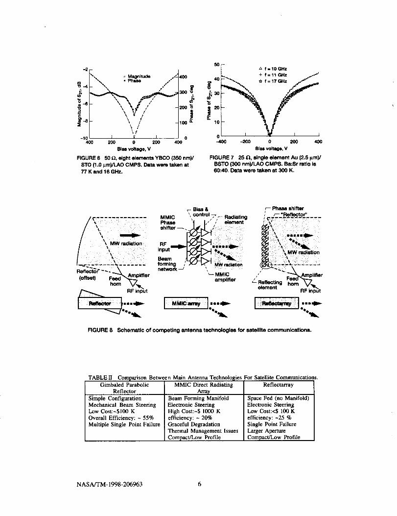
Figure 5(a) shows a schematic of an eight-element, K-band coupled
microstripline phase shifter (CMPS) fabricated with a YBCO (0.35 I.tm thick)/
STO (1.0 _tm thick)/LAO (254 lxm thick) CFD multilayered structure. As shown
in Fig. 6, this configuration allows for insertion phase shifts of more than
400 degrees at dc voltages of 400 V, 77 K, and 16 GHz, with nominal losses
below 6 dB. Details of this CMPS are discussed by Van Keuls, et al. in a parallel
paper presented at this conference. [11] Because of the use of STO this phase
shifter has been demonstrated at cryogenic temperatures. However, room
temperature performance can be attained replacing the STO by BaxSrl_xTiO 3
(BSTO) as shown in Fig. 7 for the single-element, 25 fl CMPS, shown in
Fig. 5(b). Phase array antennas, particularly reflectarrays, will benefit from the
phase shifter technology described herein. Schematics of competing antenna
NASA/'rM- 1998-206963 5
-21"_- o Magnitude ._ 400
300 "_
200 _
V f ,0o [-10 I '\17/ l 0
400 200 0 200 400
Bias voltage, V
FIGURE 6 50 Q, eight elements YBCO (350 nm)/STO (1.0 I_m)/LAO CMPS. Data were taken at77 K and 16 GHz.
50 F z_ f = 10 GHzL_ + f=11GHz /
Jt
-400 -200 0 200 400
Bias voltage, V
FIGURE 7 25 11, single element Au (2.5 _m)/BSTO (300 nm)/LAO CMPS. Ba:Sr ratio is60:40. Data were taken at 300 K.
! ii̧ ii_ i%_...._
_- Bias &
MMIC , control 7 _ RadiatingPhase t I, / element
_o.m,ngx-,_, .w_i.t,_network _
_-- MMICamplifier
I--=_ I:--_
r-- Phase shifterr-- "Reflector"
MW radiation
Amp lifter
element ..... _Z.RF input
FIGURE 8 Schematic of competing antenna technologies for satellite communications.
TABLE II Comparison Between Main Antenna Technolosies For Satellite Communications.Gimbaled Parabolic MMIC Direct Radiating Reflectarray
Reflector
Simple Configuration
Mechanical Beam SteeringLow Cost:~$100 K
Overall Efficiency: ~ 55%
Multiple Single Point Falture
Arra_Beam Forming ManifoldElectronic SteeringHigh Cost:~$1000 K
efficiency: ~ 20%
Graceful Degradation
Thermal Management Issues
Compact/Low Profile
Space Fed (no Manifold)Electronic SteeringLow Cost:<$ I00 K
efficiency: -25 %
Single Point Failure
Larger Aperture
Compact/Low Profile
NASA/TM- 1998-206963 6
technologies for satellite communications are shown in Fig. 8 and a comparison
among them is shown in Table II.
Traditionally, gimbaled configurations are used because of low cost and high
efficiency. When fast and vibration free scanning is required one generally invests
in the MMIC approach, which is the current situation confronting NASA, and
thus prompting investigation of the reflectarray approach. There are speculations
that eventually the cost per element of MMIC arrays will approach $100.00 for large
production volumes. Likewise, the cost of high volume production of the reflectarray
should also track this trend.
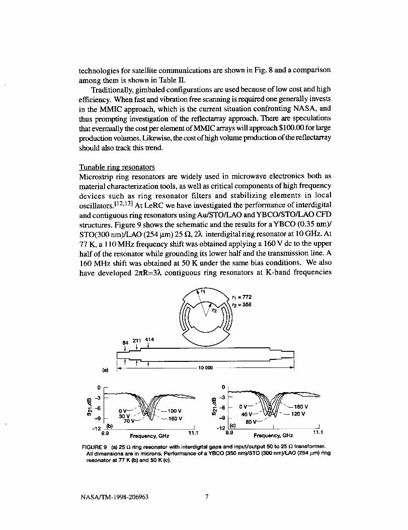
Tunable ring resonators
Microstrip ring resonators are widely used in microwave electronics both as
material characterization tools, as well as critical components of high frequency
devices such as ring resonator filters and stabilizing elements in local
oscillators.[12,13] At LeRC we have investigated the performance of interdigital
and contiguous ring resonators using Au/STO/LAO and YBCO/STO/LAO CFD
structures. Figure 9 shows the schematic and the results for a YBCO (0.35 nm)/
STO(300 nm)/LAO (254 _tm) 25 f_, 2_, interdigital ring resonator at 10 GHz. At
77 K, a 110 MHz frequency shift was obtained applying a 160 V dc to the upper
half of the resonator while grounding its lower half and the transmission line. A
160 MHz shift was obtained at 50 K under the same bias conditions. We also
have developed 2r_R=3_, contiguous ring resonators at K-band frequencies
(a)
84 211 414
r_" \ "N_ 1 = 772r2 = 358
1OOO0
m-3
_-6u_
-9 ___. '_70V_ _ K/ "_160V
-12 I (b) I I9.9 Frequency, GHz 11.1
om--3-oG-6
o0 _9 _ 40V J V_¥J'_120V
-12 I(c) 80 V_ [ I9.9 11.1
Frequency, GHz
FIGURE 9 (at)25 f_ ring resonator with interdigital gaps and input/output 50 to 25 fZ transformer.All dimensions are in microns. Performance of a YBCO (350 nm)/STO (300 nm)/LAO (254 I_m) ringresonator at 77 K (b) and 50 K (c).
NASA/TM- 1998-206963 7
Micm-
stdplin_)-
2 I_m
254gm
1 cm
Top view
_STOAu
EZ] LAO
W
" Iv.14 0 11,2 J.m_
o - - 10.5 22,5--/
et 60.0 79.8 J
-" - 102.5 127.1 _ - i_-_
300 354 ---
AI,--"ilfll
Front view _ 13.2 Frequency, GHz 19.7
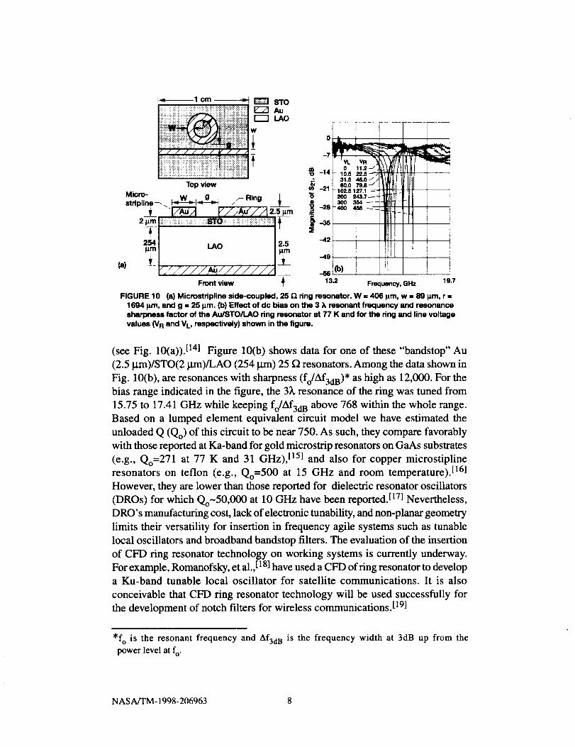
FIGURE 10 (8) Microstdpline side-coupled, 25 _ ring resonator. W = 406 l_m, w = 89 _m, r =1694 )un, and g = 25 I_m. (b) Effect of dc bias on the 3 ;_resonant frequency and resonancesharpness factor of the Au/STO/LAO ring resonator at 77 K and for the ring and line voltage
values (V R and V L, respectively) shown in the figure.
(see Fig. 10(a)). [141 Figure 10(b) shows data for one of these "bandstop" Au
(2.5 lxm)/STO(2 ktm)/LAO (254 _trn) 25 f_ resonators. Among the data shown in
Fig. 10(b), are resonances with sharpness (fo/Af3dB)* as high as 12,000. For the
bias range indicated in the figure, the 3_, resonance of the ring was tuned from
15.75 to 17.41 GHz while keeping fo/Af3dB above 768 within the whole range.
Based on a lumped element equivalent circuit model we have estimated the
unloaded Q (Qo) of this circuit to be near 750. As such, they compare favorably
with those reported at Ka-band for gold microstrip resonators on GaAs substrates
(e.g., Qo=271 at 77 K and 31 GHz), [15] and also for copper microstipline
resonators on teflon (e.g., Qo=500 at 15 GHz and room temperature). [16]
However, they are lower than those reported for dielectric resonator oscillators
(DROs) for which Qo-50,000 at 10 GHz have been reported. [17] Nevertheless,
DRO's manufacturing cost, lack of electronic tunability, and non-planar geometry
limits their versatility for insertion in frequency agile systems such as tunable
local oscillators and broadband bandstop filters. The evaluation of the insertion
of CFD ring resonator technology on working systems is currently underway.
For example, Romanofsky, et al.,[18] have used a CFD of ring resonator to develop
a Ku-band tunable local oscillator for satellite communications. It is also
conceivable that CFD ring resonator technology will be used successfully for
the development of notch filters for wireless communications. [19]
*fo is the resonant frequency and Af3d a is the frequency width at 3dB up from the
power level at fo"
NASA/TM- 1998-206963 8

CONCLUSIONS
We have described several POC of Ku- and K-band, tunable microwave
components fabricated using (gold,YBCO)/STO/LAO conductor/ferroelectric/
dielectric thin film multilayer structures. The attributes of these components of
small size, light weight, and low loss, as well as their demonstrated performance,
suggest that they can be used advantageously, even at the current level of
development, in satellite and wireless communication systems for Ku- and
K-band operation. In the mean time, further optimization of BSTO ferrroelectric
thin films should enable the realization of low cost frequency agile technology
for room temperature applications.
References
[1.] S. K. Koul and B. Bhat, Microwave and Millimeter Wave Phase Shifters,
(Artech House, 1991).
[2.] E. A. Wolff and R. Kaul, Microwave Engineering and Systems Applications,
(John Wiley & Sons, 1988).
[3.] J. M. Budinger, G. Fujikawa, R. P. Kunath, N. T. Nguyen, R. R. Romanofsky,
and R. L. Spence, Direct Data Distribution From Low- Earth Orbit, NASA TM
107438 (1997).
[4.] A. B. Kozyrev, E. K. Hollmann, A. V. Ivanov, O. I. Soldatenkov, T. V. Rivkin,
C. H. Mueller, and G. A. Koepf, Integrated Ferroelectrics, 17, 257 (1997).
[5.] M. J. Dalberth, R. E. Stauber, J. C. Price, C. T. Rogers, and D. Gait, Appl.
Phys. Lett., 72, 507 (1998).
[6.] H. S. Javadi, J. G. Bowen, D. L. Rascoe, R. R. Romanofsky, C. M. Chorey,
and K. B. Bhasin, IEEE Trans. Microwave Theory Techniques, 44, 1279 (1996).
[7.] S. H. Talisa, M. A. Robertson, B. J. Meier, and J. E. Sluz, MTT-S Digest, 977
(1994).
[8.] G. Subramanyam, E W. Van Keuls, and F. A. Miranda, IEEE Microwave
and Guided Wave Lett., 8, 78 (1998).
[9.] O. G. Vendik, L. T. Ter-Martirosyan, A. I. Dedyk, S. E Karmanenko, and R.
A. Chakalov, Ferroelectrics, 144, 33 (1993).
[10.] E W. Van Keuls, R. R. Romanofsky, D. Y. Bohman, M. D. Winters, E A.
Miranda, C. H. Mueller, R. E. Treece, T. V. Rivkin, and D. Gait, Appl. Phys.
Lett., 71, 3075 (1997).
[11.] F. W. Van Keuls, R. R. Romanofsky, D. Y. Bohman, and E A. Miranda,
Several Microstrip-Based Conductor/Ferroelectric Thin Film Phase Shifter
Designs using (YBa2Cu307_6,Au)/SrTiO3/LaAI03 Structures. Presented at the
10 th International Symposium on Integrated Ferroelectrics, March 1-4, 1998,
Monterey, CA.
NASA/TM- 1998-206963 9

[12.] R. M. Knox and E E Toulios, Insular Waveguide Ring Resonator Filter,
United States Patent # 4,097,826; June 27, 1978.
[13.] S-J. Fiedziuszko and J. A. Curtis, Push-Push Ring Resonator Oscillator,
United States Patent # 5,289,139; Feb. 22, 1994.
[14.] E W. Van Keuls, R. R. Romanofsky, D. Y. Bohman, and F. A. Miranda,
Influence of the Biasing Scheme on the Performance of Au/SrTiO_lO 3 Thin
Film Conductor/Ferroelectric Tunable Ring Resonators. Presented at the 10 th
International Symposium on Integrated Ferroelectrics, March 1-4, 1998,
Monterey, CA.
[15.] R. R. Romanofsky, J. C. Martinez, B. J. Viergutz, and K. B. Bhasin,
Microwave Opt. Technol. Lett., 3, 117 (1990).
[16.]R. R. Romanofsky, K. B. Bhasin, G. E. Ponchak, A. N. Downey, and D. J.
Connolly, IEEE MTT-S Digest, 675 (1985).
[17.] A. E S. Khanna, Microwave & RF, 120, (1992).
[18.] R. R. Romanofsky, F. W. Van Keuls, D. Y. Bohman, and F. A. Miranda, A
Microwave Hybrid High-Temperature Superconductor/Ferroelectric Oscillator,
3rd European Workshop on Low Temperature Electronics, Italy, June 24-26, 1998.
[19.] L. Zhu, B. Taylor, and P. Jarmuszewski, RFDesign (Nov. 1996).
NASA/TM- 1998-206963 10


REPORT DOCUMENTATION PAGE Form ApprovedOMB No. 0704-0188
Public reporting burden for this collection of information is estimated to average 1 hour per response, including the time for reviewing instructions, searching existing data souroes,gathering and rnslntainlng the data needed, and completing end reviewing the collection of information. Send comments regarding this burden estimate or any other aspect of thiscollection of information, including suggestions for reducing this burden, to Washington Headquarters Services, Directorate for Information Operations and Reports, 1215 JeffersonDavis Highway, Suite 1204, Arlington, VA 22202-4302, and to the Office of Management end Budget, Paperwork Reduction Project (0704-0188), Washington, DC 20503.
I. AGENCY USE ONLY (Leave blank) 2. REPORT DATE 3. REPORT TYPE AND DATES COVERED
May 1998 Technical Memorandum
4. TITLE AND SUBTITLE
Tunable Microwave Components for Ku- and K-Band Satellite Communications
6. AUTHOR(S)
EA. Miranda, EW. Van Keuls, R.R. Romanofsky, and G. Subramanyam
7. PERFORMING ORGANIZATION NAME(S) AND ADDRESS(ES)
National Aeronautics and Space Administration
Lewis Research Center
Cleveland, Ohio 44135-3191
9. SPONSORING/MONITORING AGENCY NAME(S) AND ADDRESS(ES)
National Aeronautics and Space Administration
Washington, DC 20546- 0001
5. FUNDING NUMBERS
WU-632-50-5D-00
8. PERFORMING ORGANIZATION
REPORT NUMBER
E-11111
10. SPONSORING/MONITORING
AGENCY REPORT NUMBER
NASA TM--1998-206963
11. SUPPLEMENTARY NOTES
Prepared for the 10th International Symposium on Integrated Ferroelectrics sponsored by the University of Colorado
at Colorado Springs, Monterey, California, March 1-4, 1998. EW. Van Keuls, National Research Council--NASA
Research Associate at Lewis Research Center; EA. Miranda and R.R. Romanofsky, NASA Lewis Research Center;
G. Subrarnanyam, University of Northern Iowa, Cedar Falls, Iowa 50614. Responsible person, EA. Miranda, organization
code 5620, (216) 433-6589.
12a. DISTRIBUTION/AVAILABILITY STATEMENT
Unclassified - Unlimited
Subject Categories: 32 and 76 Distribution: Nonstandard
This publication is available from the NASA Center for AeroSpace Information, (301) 621-0390.
12b. DISTRIBUTION CODE
13. ABSTRACT (Maximum 200 words)
The use of conductor/ferroelectric/dielectric thin film multilayer structures for frequency and phase agile components at
frequencies at and above the Ku-band will be discussed. Among these components are edge coupled filters, microstripline
ring resonators, and phase shifters. These structures were implemented using SrTiO 3 (STO) ferroelectric thin films, with
gold or YBa2CU3OT_ d (YBCO) high temperature superconducting (HTS) microstrip lines deposited by laser ablation on
LaAIO 3 (LAO) substrates. The performance of these structures in terms of tunability, operating temperature, frequency,
and dc bias will be presented. Because of their small size, light weight, and low loss, these tunable microwave
components are being studied very intensely at NASA as well as the commercial communication industry. An assessment
of the progress made so far, and the issues yet to be solved for the successful integration of these components into the
aforementioned communication systems will be presented.
14. SUBJECT TERMS
Tunable microwave components; Conductor/ferroelectric multilayered structures; Phase
shifters; Filters; Resonators; Diplexers
17. SECURITY CLASSIFICATION 18. SECURITY CLASSIFICATION
OF REPORT OF THIS PAGE
Unclassified Unclassified
NSN 7540-01-280-5500
15. NUMBER OF PAGES
16116. PRICE CODE
A03
19. SECURITY CLASSIFICATION 20. LIMITATION OF ABSTRACT
OF ABSTRACT
Unclassified
Standard Form 298 (Rev. 2-89)
Prescribed by ANSI Std. Z39-18298 - 102