Embed Size (px)
Citation preview
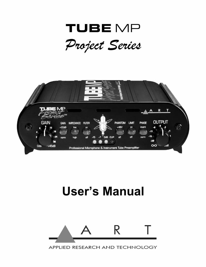
TUBE MP
Project Series
User’s Manual

2

3
IMPORTANT SAFETY INSTRUCTION – READ FIRST
This symbol, whenever it appears, This symbol, wherever it appears, alerts you alerts you to the presence of uninsulated to important operating and maintenance dangerous voltage inside the enclosure-voltage instructions in the accompanying literature. that may be sufficient to constitute a risk of shock. Please read the manual.
Read instructions: Retain these safety and operating instructions for future reference. Heed all warnings printed here and on the equipment. Follow the operating instructions printed in this user manual. Do not open: There are no user serviceable parts inside. Refer any service work to qualified technical personnel only. Power sources: Connect the units power supply to mains power only of the type described in this user manual or marked on the power supply. The power source must provide a good ground connection. Power supply: Use the power supply with sealed mains plug appropriate for your local mains supply as provided with the equipment. If the provided supply does not fit into you outlet consult your service agent. Route the power cord so that it is not likely to be walked on, stretched or pinched by items placed upon or against it. Grounding: Do not defeat the grounding and polarization means of the power supply. Moisture: To reduce the risk of fire or electrical shock do not expose the unit to moisture or use in damp or wet condi-tions. Do not place container of liquid on unit. Heat: Do not locate the unit close to excessive heat or direct sunlight, as this could cause a fire hazard. Locate the unit away from any equipment, which produces heat such as: power supplies, power amplifiers and heaters. Environment: Protect from excessive dirt, dust, heat, and vibration when operating and storing. Avoid tobacco ash, drink spillage and smoke, especially that associated with smoke machines. Handling: Protect the controls from damage during transit. Use adequate padding if you need to ship the unit. To avoid injury to yourself or damage to the equipment, take care when lifting, moving, or carrying the unit. Servicing: Unplug power immediately if equipment is exposed to moisture, the power supply becomes damaged during a lightning storm or if smoke odor or noise is noted. Refer servicing to qualified technical personnel only. Installation: Install the unit in accordance with the instructions printed in the user manual.

4
INTRODUCTION: Thank you for purchasing the ART TUBE MP Project Series preamplifier. Though it is very reliable and easy to use, we ask that you take a moment to read the manual to get the best performance. The Tube MP Project Series is a professional quality audio interface that lets you connect micro-phone, instrument, and line level signals to a mixer or other audio input. This hybrid design is the latest in a long line of ART tube preamps. We took our legendary Tube MP series and updated every aspect of the design, inside and out, while still maintaining a compact, reliable, and cost effective product. From the new all-aluminum stackable chassis to the precision LED level metering circuitry, we have improved virtually every aspect of our already successful Tube MP series. The new ultra low noise discrete microphone preamp front end has an extremely flat and wide fre-quency response and handles a wide range of input signal levels with a minimum of coloration. This gives you a very clean and neutral sound with a wide variety of signal sources. The high impedance ¼” instrument input bypasses the microphone preamp circuitry to maintain a clean signal path. We use a high quality 12AX7A tube inside to add warmth to musical dynamics and the power supply is external to keep AC line noise and hum back at the wall. The input Gain control and switch helps you to maximize your input dynamic range as well as control how hard you are driving the tube. Input impedance is switch selectable to optimize your microphones response right on the front end. These two features are a must when trying to get the most out of a vintage ribbon or studio grade microphone. The switch selectable high pass filter removes very low frequency rumble and wind noise before it has a chance to overload your inputs. The Bessel filter design is set at a low 40Hz to preserve bass tonality and time domain response and it is very effective when tracking or interfacing to your computer based audio workstation. Phantom power is available for the XLR input and is a clean +48 Volts DC from a low noise internal supply that is current limited to prevent damage to your sensitive microphones. A FET Limiter with fast attack and musical release times limits the maximum audio output level to prevent overloading succeeding equipment while still maintaining a clear uncompressed sound. This allows you to maximize the dynamic range of your signal before converting to digital. A Phase Invert switch allows you to switch signal polarity right at the source. This feature is especially handy when you are mixing the signal output with other channels in a mix. The Output control comes after the Tube and Limiter and is used to match the output level to a wide variety of systems. Following it is a new output section that provides high output signal drive capability to both outputs. Key Features include:
• Extremely low noise discrete front end • Up to 70dB of clean musical gain • High output signal drive capability • Fast FET Limiter to prevent overload • Switch selectable input impedance • Precision LED metering • Built-in low noise phantom power supply • Compact stackable all aluminum chassis • XLR and ¼” inputs and outputs • Phase Invert switch • High Cut Filter switch • Variable input and output controls

5
CONNECTIONS:
The female XLR Input jack is used primarily for balanced microphone input. Pin 2 is positive, pin 3 is negative, and pin 1 is ground. +48 Volt phantom power is supplied thru pins 2 and 3. If you are using the XLR input with a balanced line level signal or a microphone that does not require phantom power, make sure that phantom power is turned off. The XLR Input impedance is switch selectable from the front panel. Maximum gain from the XLR Input to the XLR Output is 70dB. This input can handle very hot microphone signals up to +16dBu before clipping. The ¼” Input jack is for instrument or line level unbalanced signals. Its high fixed input impedance is ideal for guitar and other passive instrument pickups. Plugging into this input bypasses the micro-phone preamp circuitry for a cleaner signal path. Make sure you use a mono unbalanced plug with this connection for proper operation. Maximum gain from the ¼” Input to the XLR Output is 50dB. When the Gain control is at minimum, this input can handle hot signals up to +17dBu. The male XLR Output jack is active balanced with pin 2 being positive, pin 3 negative, and pin 1 is ground. With an output impedance of less than 300 Ohms and a maximum output level of +26dBu it can provide a hefty balanced signal for long cable runs. Normally you would use this output to go directly into a power amplifier, recording system or a mixers line input or insert inputs. If you have to go directly into the balanced microphone input on a mixer make sure that phantom power is off at the mixer, the mixers input pad and level controls are at minimum, and that the output control on the TUBE MP Project Series is set at a low enough level to prevent overdriving the mixer. The ¼” Output jack is unbalanced and has an output impedance of 600 Ohms. It can be used to send signals to an amplifier, processor, line input on a computer, or any unbalanced input. The output level is 6dB less than the XLR Output and the slightly higher output impedance makes it a better choice for driving into more sensitive inputs like on an instrument amp. Since it can still put out up to +20dBu, the Output control should be set at lower levels when driving sensitive equipment. Both output jacks can be used at the same time, which is handy when you want to run to a mixer and your instrument amp in a live situation, or when connecting to a computer or recording system and locally monitoring your source. Though the two output signals are isolated they do share a common ground so care should be used to make sure that you don’t create a ground loop in your system. The power connector on the rear should only be hooked up to the power supply that comes with the unit. 10 Volts AC @ 700 milliamps is required. Make sure that you specify AC and not DC. Internal circuitry converts this power to the higher voltages needed for the tube and phantom power sections.

6
CONTROLS and OPERATION:
The Gain Control directly adjusts the input amplifiers giving you control over the dynamic range of your source. You get a 45dB range of control when using the XLR input and a 25dB range when using the ¼” input. Set the control counterclockwise to minimum gain when connecting the inputs. The Gain Switch gives you an additional 20dB of gain between the input stage and the tube to bring up very low-level signals and allow you to drive the tube harder. The Impedance Switch works with the balanced XLR input only. Input impedance is 4.7k Ohms in the high position. This position should be used for most microphones and line level signals to minimize any loading effects on the source. The low position sets the input impedance to 600 Ohms. This position terminates the signal with known low impedance that can flatten and clean up the frequency response of some vintage equipment including ribbon microphones, and various transformer coupled outputs. By doing this at the input you reduce the need for added equalization and the response to percussive audio dynamics is tightened in many cases. The Filter Switch rolls off the response to signals lower than 40Hz. This helps to cut out low fre-quency rumble, wind noise, and all types of low frequency energy before it is amplified. When re-cording, this allows you to get more gain before clipping the preamp, recorder, or computer and in a live situation you get more gain before clipping your amp. The Phantom Power Switch applies +48 Volt phantom power to the XLR input jack for powering your microphone, if needed. It is slow at turning on and off and is current limited to protect sensitive micro-phones and reduce pops. Ideally, when connecting a microphone that requires phantom power, you should first turn down gain, next connect the microphone, next switch on the phantom power, and finally bring gain back up to the desired level. This minimizes pops in your system and stress on the microphone. The Limit Switch engages a fast attack FET limiter at the tube stage. This helps to prevent clipping or overload of any equipment following the preamp. When engaged it limits the maximum signal on the meter to 0dB and maximum output at the XLR output to +6dBu if the Output control is up full. When recording this lets you get the hottest signal before clipping into your computer or recorder. It can limit peaks of over 20dB but should normally be used to protect on overshoots and musical peaks for best results.

7
The Phase Switch allows you to invert or reverse the phase of the output signal. In the normal posi-tion, output signals are in phase with the input signal on all jacks. When engaged, both the XLR and ¼” outputs have their signals changed to 180 degrees out of phase. This function comes in handy to prevent a hollow sound, due to phase cancellations, when using multiple microphones on a single source or when using a combination of direct and microphone pickups on the same source. In a Live Sound application you may be able to get more gain before feedback by reversing the phase of the vocal microphone. The Output Control adjusts overall level just after the tube and metering and before the output ampli-fiers. This allows you to scale the output to the system you are driving. Typically you would set this about mid way for going into a line level input. When directly plugging into an instrument amp or the microphone inputs on another piece of equipment you may find that a 9 o’clock position gives you plenty of output. The LED metering circuitry covers a wide 30dB range and has a fast attack to help indicate any clipping. It is located in the signal chain just after the tube. The Output control comes after the meter so that you can use the meter to set the overall input gain for best dynamic range then trim the output signal level to the system you are driving. The red “Clip” LED comes on just before clipping and should light on extreme musical peaks only. The yellow “0dB” LED is set to 15dB below the “Clip” LED. If the “0dB” LED is on half the time then you have about 15dB of headroom on the average. The green “-7” and “-15” LEDs indicate how far below the nominal “0dB” LED your signal is. They have a long release time. These LEDs should be on much of the time during performance and if not it indicates that your signal or input gain is too low for best results. The FET limiter has its output level set to be at the “0dB” LED point so if the limiter is engaged and the “0dB” LED is on then you are in limiting. This helps in setting output level for your system. To do this you would start with the limiter off, apply a signal and increase the gain until the red “Clip” LED comes on occasionally, then engage the limiter. At this point the signal at the tubes output will be in limiting most of the time. You can then adjust the Output control so you are just below clipping at your A/D, computer, recorder, or amplifiers input. Now you can back off on the Gain control. At this point, as long as the Output control is at the current position, you can use the “0dB” LED to indicate that you are at full signal level for your equipment that follows. Note: All front panel push switches are lit when in the active position to aid in setup and operation. A brief note from customer service: Once in a while a customer will call and say: I think my ART preamp is "noisy". What's wrong? If you experience unwanted "noise" in your system when you use a stand-alone preamp, please consider what your signal is and where you're sending it. Some people send the signal from their preamp to a mic input (they figure, "well, I'm using a mic!") on the board or recorder. This is in fact incorrect and could be the problem. ART preamps are actually intended to output a nice fat LINE LEVEL signal. If you send that line level signal to a recorder or mixer's Mic input, that circuit will usually add more gain to the signal. Gain on top of gain will indeed result in noise. Please treat the output signal as line level and you'll be pleasantly surprised at your new clean and warm sound. The same rule applies for guitar and bass players that use ART preamps as their front end. Send the signal from your preamp to a low gain input on your amp, or even a "loop return" jack which allows you to bypass the amp's solid state preamp altogether.
8
APPLICATIONS: Microphone Pre Amplifier:
The Tube MP PS is a high quality microphone preamplifier suitable for all dynamic, condenser, and ribbon microphones. Most conventional mixers utilize budget minded micro-phone preamps and while very functional, they do not sound all that great. The Tube MP PS serves as a quality upgrade that will give you more flexibility and a more robust tone than the standard preamps.
Simply plug the microphone into the XLR input, determine the impedance of the mic
you selected. Apply phantom power if using a condenser. Then dial up the gain and you are ready to go. Refer to the 4 segment LED on the front for input for a visual measure of input gain, then route the output to a mixer, workstation, or computer interface via the XLR or 1/4” output. The overall output can be adjusted on the face of the unit; you may also choose to use the limit function to protect from any spikes in audio. Once you begin to pass audio through the system, you will have the ability to further dial in the tone a little closer by using the phase invert switch and low filter. These features can be very useful on drums and other areas where multiple microphones are being used.
Phantom Power Supply:
Many mixers, workstations, and computer interface boxes will not supply +48 Volt phantom power on all the microphone inputs. This is a critical feature if you plan to use a con-denser microphone. The Tube MP PS is a perfect solution to this problem, letting you connect any microphone to the existing mixer. Operation is identical to what is covered above.
Instrument DI:
The Tube MP PS will work well as a very functional Tube DI for Bass, Acoustic Guitar and virtually any other instrument with a 1/4” or XLR output. Many people prefer the sound of a tube for responsiveness and warmth instead of the standard DI’s and preamps. You will also enjoy more flexibility and control over a standard DI.
Operation is simple, insert the output of the instrument into the input of the Tube MP PS. Make sure the volume on the bass or guitar is up all the way. If you are using any effects, make sure that the overall output is not greatly increased when the effect is on. Adjust the in-put gain knob and refer to the 4 segment LED on the front for input for a visual measure of input gain. Then route the output to a mixer, workstation or computer interface via the XLR or 1/4” output. The overall output and limiter can be adjusted on the face of the unit. Both out-puts may be used at the same time so the 1/4” can be routed to an amplifier and the XLR to a mixer.
9
WARRANTY INFORMATION: Limited Warranty Applied Research and Technology will provide warranty and service for this unit in accordance with the follow-ing warrants: Applied Research and Technology, (A R T) warrants to the original purchaser that this product and the compo-nents thereof will be free from defects in workmanship and materials for a period of one year from the date of purchase. Applied Research and Technology will, without charge, repair or replace, at its option, defective product or component parts upon prepaid delivery to the factory service department or authorized service center, accompanied by proof of purchase date in the form of a valid sales receipt. Exclusions This warranty does not apply in the event of misuse or abuse of the product or as a result of unauthorized alterations or repairs. This warranty is void if the serial number is altered, defaced, or removed. A R T reserves the right to make changes in design or make additions to or improvements upon this product without any obligation to install the same on products previously manufactured. A R T shall not be liable for any consequential damages, including without limitation damages resulting from loss of use. Some states do not allow limitations of incidental or consequential damages, so the above limita-tion or exclusion may not apply to you. This warranty gives you specific rights and you may have other rights, which vary from state to state. For units purchased outside the United States, an authorized distributor of Applied Research and Technology will provide service. SERVICE: The following information is provided in the unlikely event that your unit requires service. 1) Be sure that the unit is the cause of the problem. Check to make sure the unit has power, all cables are connected correctly, and the cables themselves are in working condition. 2) If you find the unit to be at fault, make sure you can give a complete description of the problem, including how and when it occurs as well as your setup before calling Customer Service. 3) Contact our Customer Service department at (716) 297-2920 for your Return Authorization number or questions regarding technical assistance or repairs. Customer Service hours are 9:30 AM to 5:00 PM Eastern Time, Monday through Friday. 4) Pack the unit in its original carton or a reasonable substitute. The packing box is not recommended as a shipping carton. Put the packaged unit in another box for shipping. Print the RA number clearly on the outside of the shipping box. Print your return shipping address on the outside of the box. 5) Include with your unit: a return shipping address (we cannot ship to a P.O. Box), a copy of your purchase receipt, a daytime phone number, and a description of the problem. 6) Ship only your unit (keep your manual!) to: Yorkville Sound
4625 Witmer Industrial Estates Niagara Falls, New York 14305 ATTN: REPAIR DEPARTMENT RA# ____________________

10
SPECIFICATIONS: Frequency Response: 10Hz –40kHz (+0, -1dB)
Dynamic Range: >100dB (20Hz to 20kHz)
THD: <0.05% (typical)
CMRR: >60dB (typical)
Equivalent Input Noise: -130dB (XLR to XLR ‘A’ weighted)
Maximum Input Level: +16dBu (XLR)
+17dBu (1/4”)
Maximum Output Level: +26dBu (XLR)
+20dBu (1/4”)
Input Connections: ¼” unbalanced (1meg Ohm),
XLR balanced
Output Connection: ¼” unbalanced (600 Ohm),
XLR balanced (<300 Ohm)
Maximum Gain: 70dB (XLR to XLR)
50dB (1/4” to XLR)
Input Gain Switch: 20dB
XLR Input Impedance: 4.7k Ohms / 600 Ohms, Switch selectable
High Pass Filter: -3dB @ 40Hz, Switch selectable
Output Phase: Normal / Invert, Switch selectable
Output Limiter Type: Fast FET limiter, >20dB range, (+6dBu XLR, 0dBu ¼”)
Phantom Power: +48V DC, Filtered, Current limited
Signal Metering: Precise LED array, Fast attack, Musical release
30dB range, -15dB, -7dB, 0dB, Clip(+15dB)
Tube Type: 12AX7A hand selected
Chassis Type: All Aluminum black anodized with integral rubber sides
Power Requirements: 10Volts AC @ 700ma (typical) Dimensions: 1.75”H x 5.9”W x 6.5”D (44.5mm x 150mm x 165mm)
Weight: 2.5 lbs. (1.14 kg)
Note: 0dBu = 0.775Vrms
ART maintains a policy of constant product improvement. Therefore, specifications are subject to change without notice.

11

12
APPLIED RESEARCH & TECHNOLOGY 215 TREMONT STREET
ROCHESTER, NEW YORK 14608 USA
(585) 436-2720 – Voice (585) 436-3942 – Fax
www.artproaudio.com
E-mail: [email protected] Tube MP Project Series 180-5004-100