Embed Size (px)
Citation preview
Tube Fitting
Installation Instruction
Tube Fitting Installation Instruction // pg. 2
TABLE OF CONTENTS
I. Tubing Preparation
1. Tube
II. Tube Fitting Installation Instruction
1. Hy-Lok Tube Fitting Installation
2. Gap Inspection
3. Re-Assembly
III. Pre-Swaging
1. Manual Pre-Swaging
IV. Tube Bending
1. The Minimum Length Between Tube Fitting and Tube Bend
V. Trouble Shooting
1. Tube Fitting Trouble Shooting
pg 11-12
pg 2-3
pg 13
pg 8-10
pg 7
pg 6
pg 4-5
Tube Fitting Installation Instruction // pg. 3
I. Tubing Preparation
1. Tube
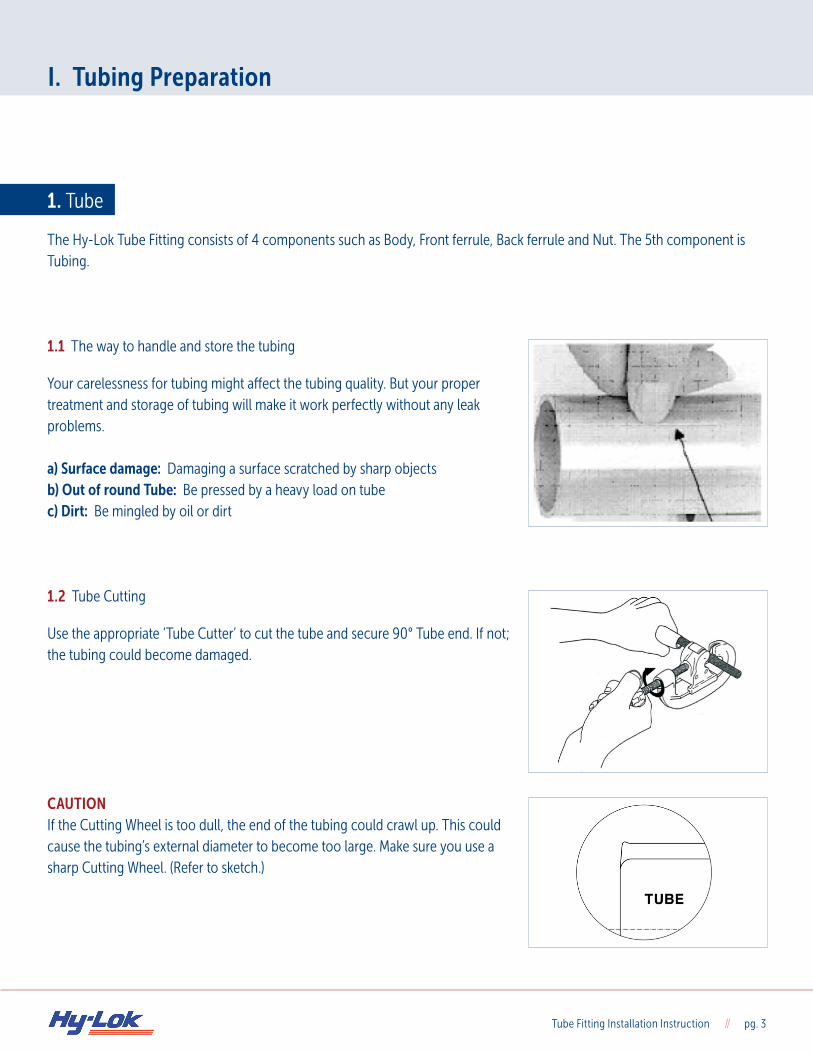
The Hy-Lok Tube Fitting consists of 4 components such as Body, Front ferrule, Back ferrule and Nut. The 5th component is Tubing. 1.1 The way to handle and store the tubing
Your carelessness for tubing might affect the tubing quality. But your proper treatment and storage of tubing will make it work perfectly without any leak problems.
a) Surface damage: Damaging a surface scratched by sharp objects b) Out of round Tube: Be pressed by a heavy load on tube c) Dirt: Be mingled by oil or dirt 1.2 Tube Cutting
Use the appropriate ‘Tube Cutter’ to cut the tube and secure 90° Tube end. If not; the tubing could become damaged. CAUTION If the Cutting Wheel is too dull, the end of the tubing could crawl up. This could cause the tubing’s external diameter to become too large. Make sure you use a sharp Cutting Wheel. (Refer to sketch.)
Tube Fitting Installation Instruction // pg. 4
I. Tubing Preparation
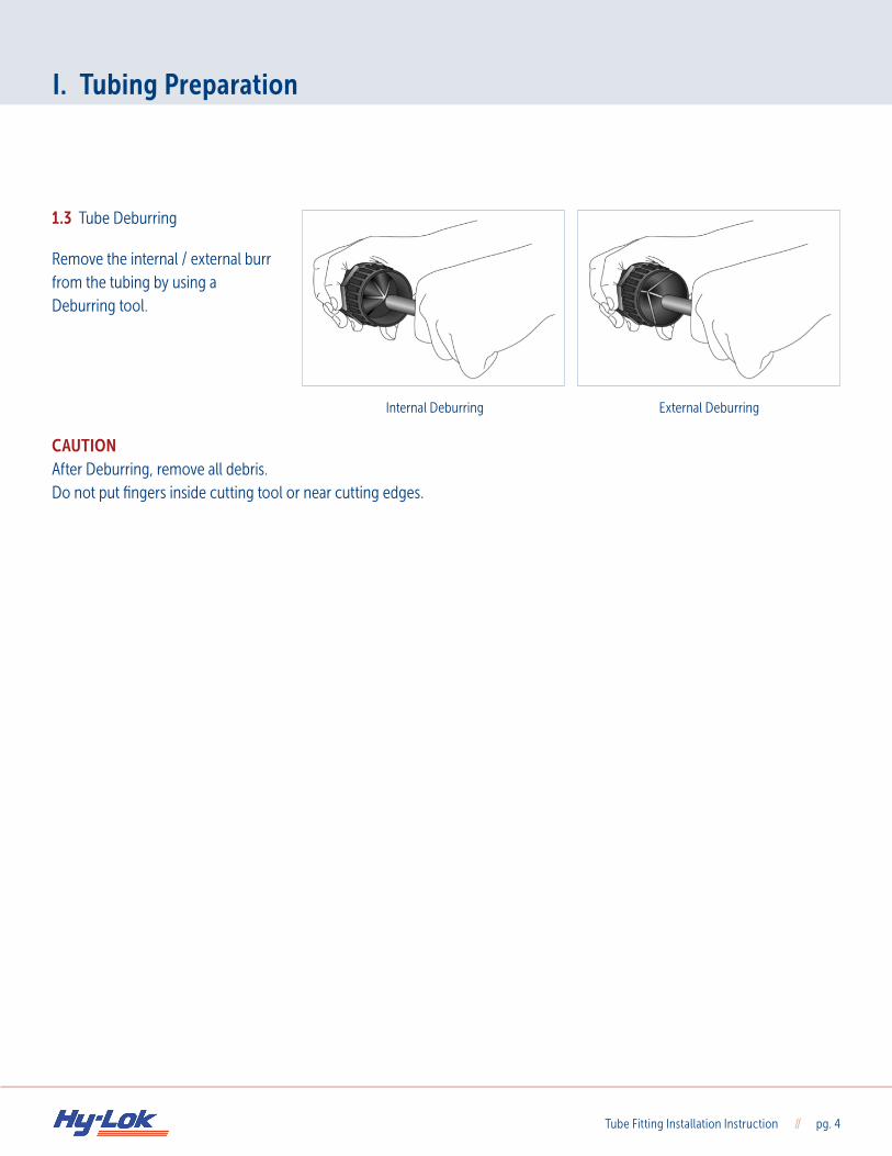
1.3 Tube Deburring
Remove the internal / external burr from the tubing by using a Deburring tool. CAUTION After Deburring, remove all debris.Do not put fingers inside cutting tool or near cutting edges.
Internal Deburring External Deburring
Tube Fitting Installation Instruction // pg. 5
II. Tube Fitting Installation Instruction
1. Hy-Lok Tube Fitting Installation
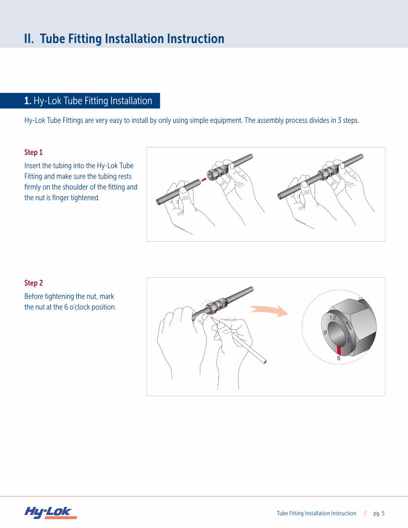
Hy-Lok Tube Fittings are very easy to install by only using simple equipment. The assembly process divides in 3 steps. Step 1
Insert the tubing into the Hy-Lok Tube Fitting and make sure the tubing rests firmly on the shoulder of the fitting and the nut is finger tightened. Step 2
Before tightening the nut, mark the nut at the 6 o’clock position.
Tube Fitting Installation Instruction // pg. 6
II. Tube Fitting Installation Instruction
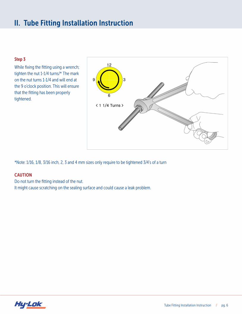
Step 3
While fixing the fitting using a wrench; tighten the nut 1-1/4 turns/* The mark on the nut turns 1-1/4 and will end at the 9 o’clock position. This will ensure that the fitting has been properly tightened. *Note: 1/16, 1/8, 3/16 inch, 2, 3 and 4 mm sizes only require to be tightened 3/4’s of a turn CAUTION Do not turn the fitting instead of the nut.It might cause scratching on the sealing surface and could cause a leak problem.
Tube Fitting Installation Instruction // pg. 7
II. Tube Fitting Installation Instruction
2. Gap Inspection
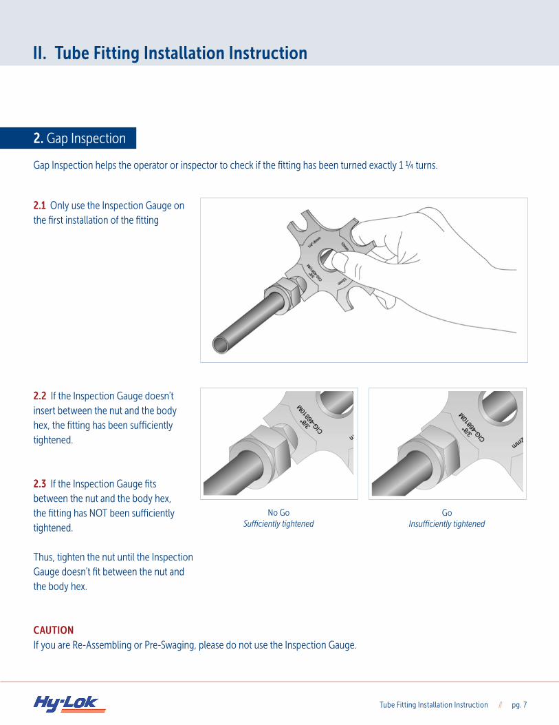
Gap Inspection helps the operator or inspector to check if the fitting has been turned exactly 1 ¼ turns.
2.1 Only use the Inspection Gauge on the first installation of the fitting 2.2 If the Inspection Gauge doesn’t insert between the nut and the body hex, the fitting has been sufficiently tightened. 2.3 If the Inspection Gauge fits between the nut and the body hex, the fitting has NOT been sufficiently tightened. Thus, tighten the nut until the Inspection Gauge doesn’t fit between the nut and the body hex. CAUTION If you are Re-Assembling or Pre-Swaging, please do not use the Inspection Gauge.
No GoSufficiently tightened
GoInsufficiently tightened
Tube Fitting Installation Instruction // pg. 8
II. Tube Fitting Installation Instruction
3. Re-Assembling
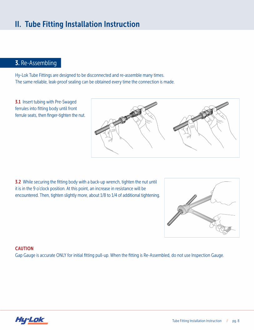
Hy-Lok Tube Fittings are designed to be disconnected and re-assemble many times.The same reliable, leak-proof sealing can be obtained every time the connection is made. 3.1 Insert tubing with Pre-Swaged ferrules into fitting body until front ferrule seats, then finger-tighten the nut. 3.2 While securing the fitting body with a back-up wrench, tighten the nut until it is in the 9 o’clock position. At this point, an increase in resistance will be encountered. Then, tighten slightly more, about 1/8 to 1/4 of additional tightening. CAUTION Gap Gauge is accurate ONLY for initial fitting pull-up. When the fitting is Re-Assembled, do not use Inspection Gauge.
Tube Fitting Installation Instruction // pg. 9
III. Pre-Swaging
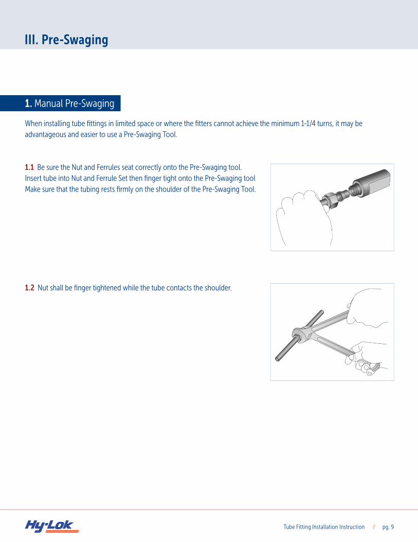
1. Manual Pre-Swaging
When installing tube fittings in limited space or where the fitters cannot achieve the minimum 1-1/4 turns, it may be advantageous and easier to use a Pre-Swaging Tool. 1.1 Be sure the Nut and Ferrules seat correctly onto the Pre-Swaging tool. Insert tube into Nut and Ferrule Set then finger tight onto the Pre-Swaging tool Make sure that the tubing rests firmly on the shoulder of the Pre-Swaging Tool. 1.2 Nut shall be finger tightened while the tube contacts the shoulder.
Tube Fitting Installation Instruction // pg. 10
III. Pre-Swaging
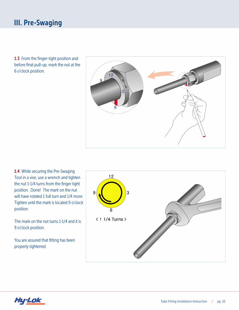
1.3 From the finger-tight position and before final pull-up, mark the nut at the 6 o’clock position. 1.4 While securing the Pre-Swaging Tool in a vise, use a wrench and tighten the nut 1-1/4 turns from the finger tight position. Done! The mark on the nut will have rotated 1 full turn and 1/4 more. Tighten until the mark is located 9 o’clock position. The mark on the nut turns 1-1/4 and it is 9 o’clock position.
You are assured that fitting has been properly tightened.
Tube Fitting Installation Instruction // pg. 11
III. Pre-Swaging
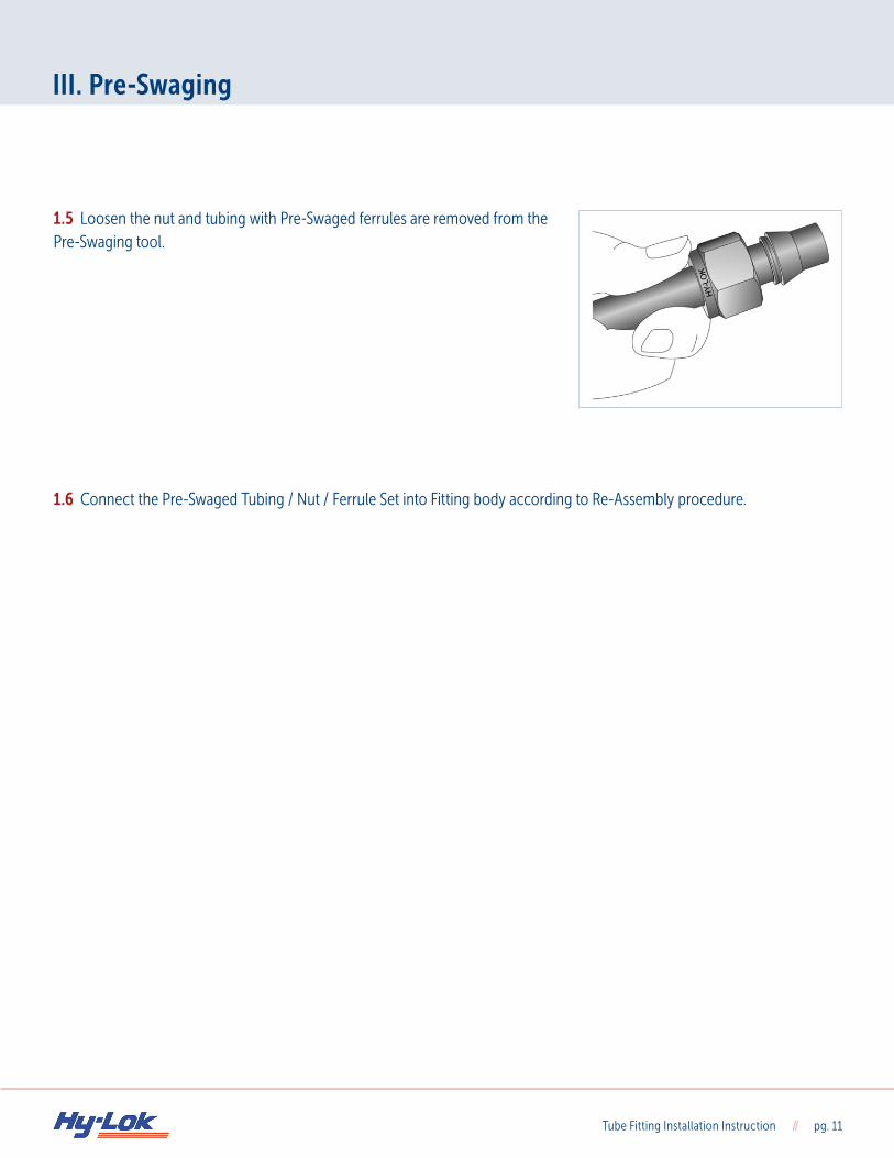
1.5 Loosen the nut and tubing with Pre-Swaged ferrules are removed from the Pre-Swaging tool.
1.6 Connect the Pre-Swaged Tubing / Nut / Ferrule Set into Fitting body according to Re-Assembly procedure.
Tube Fitting Installation Instruction // pg. 12
IV. Tube Bending
1. The Minimum Free Length Between Tube Fitting and Tube Bending
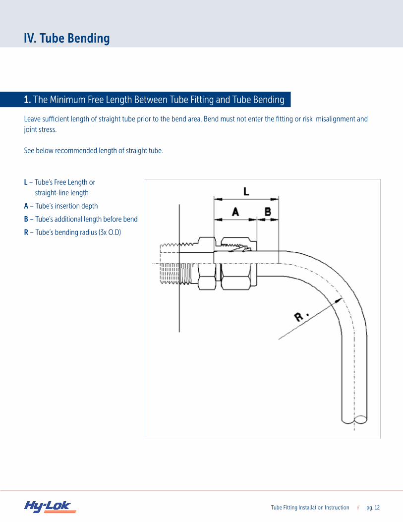
Leave sufficient length of straight tube prior to the bend area. Bend must not enter the fitting or risk misalignment and joint stress. See below recommended length of straight tube. L – Tube’s Free Length or straight-line length
A – Tube’s insertion depth
B – Tube’s additional length before bend
R – Tube’s bending radius (3x O.D)
Tube Fitting Installation Instruction // pg. 13
IV. Tube Bending
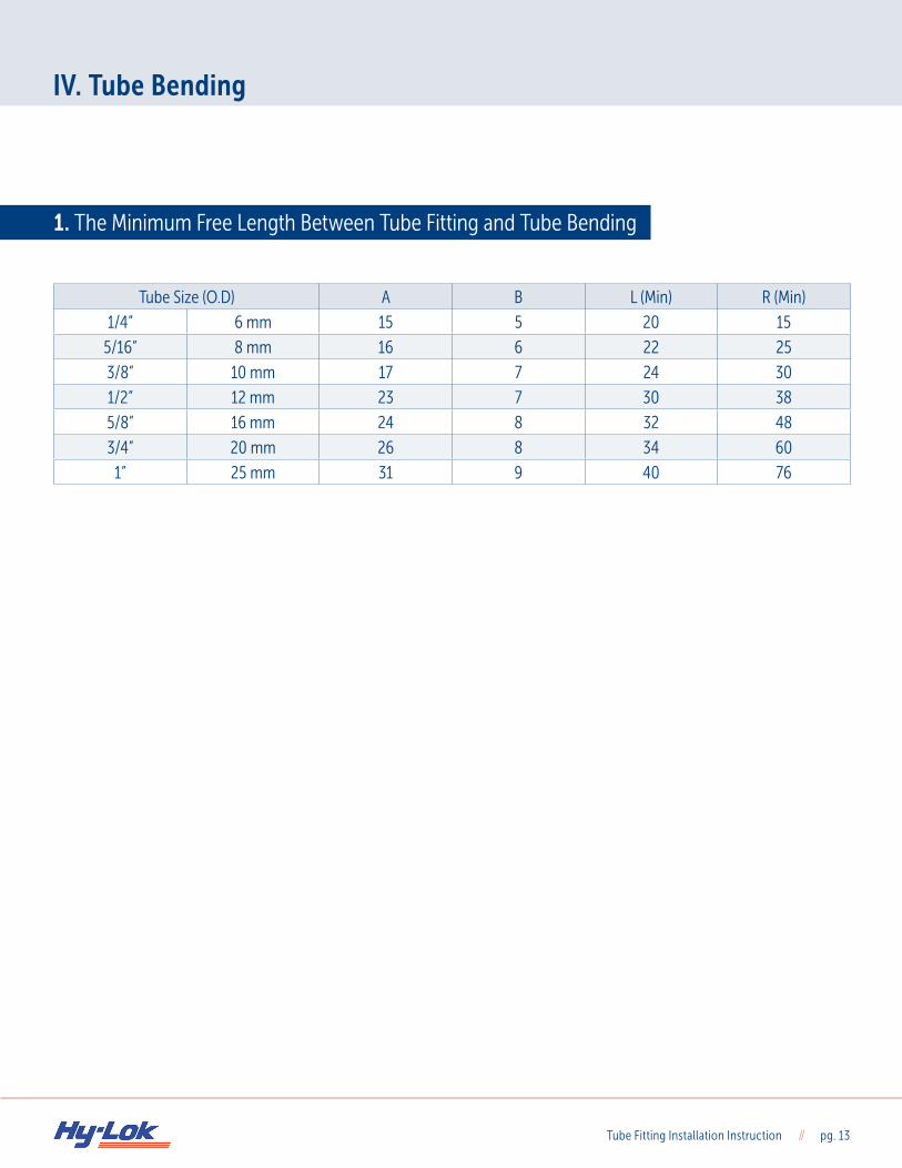
1. The Minimum Free Length Between Tube Fitting and Tube Bending
Tube Size (O.D) A B L (Min) R (Min)
1/4” 6 mm 15 5 20 15
5/16” 8 mm 16 6 22 25
3/8” 10 mm 17 7 24 30
1/2” 12 mm 23 7 30 38
5/8” 16 mm 24 8 32 48
3/4” 20 mm 26 8 34 60
1” 25 mm 31 9 40 76
Tube Fitting Installation Instruction // pg. 14
V. Trouble Shooting
1. Tube Fitting Trouble Shooting
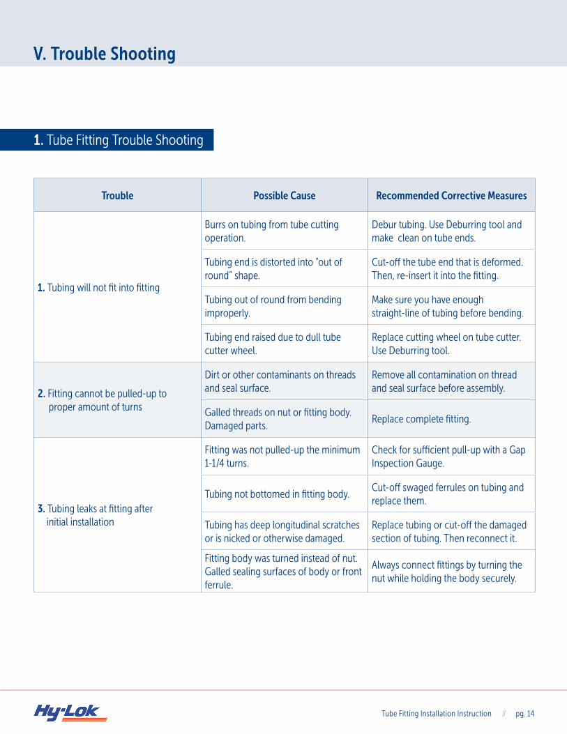
Trouble Possible Cause Recommended Corrective Measures
1. Tubing will not fit into fitting
Burrs on tubing from tube cutting operation.
Debur tubing. Use Deburring tool and make clean on tube ends.
Tubing end is distorted into "out of round” shape.
Cut-off the tube end that is deformed.Then, re-insert it into the fitting.
Tubing out of round from bending improperly.
Make sure you have enoughstraight-line of tubing before bending.
Tubing end raised due to dull tube cutter wheel.
Replace cutting wheel on tube cutter. Use Deburring tool.
2. Fitting cannot be pulled-up to proper amount of turns
Dirt or other contaminants on threads and seal surface.
Remove all contamination on thread and seal surface before assembly.
Galled threads on nut or fitting body. Damaged parts.
Replace complete fitting.
3. Tubing leaks at fitting after initial installation
Fitting was not pulled-up the minimum 1-1/4 turns.
Check for sufficient pull-up with a Gap Inspection Gauge.
Tubing not bottomed in fitting body.Cut-off swaged ferrules on tubing and replace them.
Tubing has deep longitudinal scratches or is nicked or otherwise damaged.
Replace tubing or cut-off the damaged section of tubing. Then reconnect it.
Fitting body was turned instead of nut. Galled sealing surfaces of body or front ferrule.
Always connect fittings by turning the nut while holding the body securely.

Hy-Lok USA, Inc. 14211 Westfair West Dr. Houston, TX 77041, USA Toll-Free // 888.300.5708 Phone // 832.634.2000 Fax // 832.634.2099 Website // www.hylokusa.com Email // [email protected]