Embed Size (px)
Citation preview

7/23/2019 TS6 - Electrical Services
http://slidepdf.com/reader/full/ts6-electrical-services 1/50
Technical SpecificationTS6 – Electrical Services
CBH Engineering Pty Ltd
P | (08) 9236 5350
F | (08) 9236 5370
www.cbh.com.au
7/23/2019 TS6 - Electrical Services
http://slidepdf.com/reader/full/ts6-electrical-services 2/50
TS6 – Electrical Services
DOCS 826980v30 Page 2 of 50
Document ControlDocument owner: Principal Engineer
Change Control Policy
Any amendment to this standard must be recorded in the table below.
If substantial changes are made a new version of the document shall be created to preserve anaudit trail.
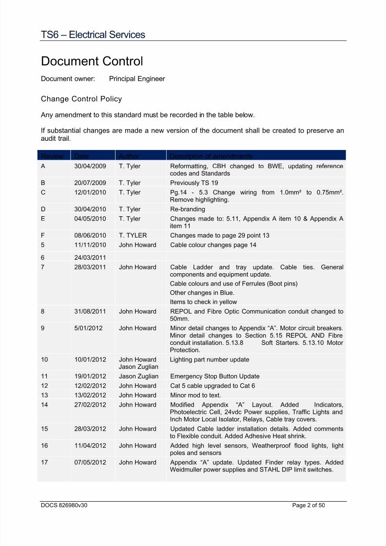
Review Date Author Descripton of amendments
A 30/04/2009 T. Tyler Reformatting, CBH changed to BWE, updating referencecodes and Standards
B 20/07/2009 T. Tyler Previously TS 19
C 12/01/2010 T. Tyler Pg.14 - 5.3 Change wiring from 1.0mm² to 0.75mm².Remove highlighting.
D 30/04/2010 T. Tyler Re-branding
E 04/05/2010 T. Tyler Changes made to: 5.11, Appendix A item 10 & Appendix Aitem 11
F 08/06/2010 T. TYLER Changes made to page 29 point 13
5 11/11/2010 John Howard Cable colour changes page 14
6 24/03/2011
7 28/03/2011 John Howard Cable Ladder and tray update. Cable ties. Generalcomponents and equipment update.
Cable colours and use of Ferrules (Boot pins)Other changes in Blue.
Items to check in yellow
8 31/08/2011 John Howard REPOL and Fibre Optic Communication conduit changed to50mm.
9 5/01/2012 John Howard Minor detail changes to Appendix “A”. Motor circuit breakers.Minor detail changes to Section 5.15 REPOL AND Fibreconduit installation. 5.13.8 Soft Starters. 5.13.10 MotorProtection.
10 10/01/2012 John HowardJason Zuglian
Lighting part number update
11 19/01/2012 Jason Zuglian Emergency Stop Button Update12 12/02/2012 John Howard Cat 5 cable upgraded to Cat 6
13 13/02/2012 John Howard Minor mod to text.
14 27/02/2012 John Howard Modified Appendix “A” Layout. Added Indicators,Photoelectric Cell, 24vdc Power supplies, Traffic Lights andInch Motor Local Isolator, Relays, Cable tray covers.
15 28/03/2012 John Howard Updated Cable ladder installation details. Added commentsto Flexible conduit. Added Adhesive Heat shrink.
16 11/04/2012 John Howard Added high level sensors, Weatherproof flood lights, lightpoles and sensors
17 07/05/2012 John Howard Appendix “A” update. Updated Finder relay types. Added
Weidmuller power supplies and STAHL DIP limit switches.

7/23/2019 TS6 - Electrical Services
http://slidepdf.com/reader/full/ts6-electrical-services 3/50
TS6 – Electrical Services
DOCS 826980v30 Page 3 of 50
18 24/05/2012 John Howard Circuit Breaker updates
19 13/07/2012 Jason Zuglian Schneider circuit breaker and contactor update. Lanyardupdate. 240vac panel wiring change from Red to White. Added Terasaki DIN-T DIN- SAFE circuit breakers.
20 16/07/2012 Jason Zuglian Emergency Stop Button Addition & Area Flood Lights update.
21 17/10/2012 John Howard Added strobe lights. Changed Light Pole type.
22 26/11/2012 John Howard Updated light fittings
23 20/12/2012 John Howard Bird proofing added and document clean up.
24 22/01/2013 John Howard Added timers, changed cables colours, see item 5.3.3.Corrected part number of Low Level Sensor. Minordocument clean up.
03/04/2013 Runi Sugiharti Added headers, fixed lay out of front page as per otherTechnical Specifications. Added file name field in footer -after updating save as “New Version”. Go to Footer and place
cursor on the filename and press F9, this will update theversion number.
25 23/8/2013 John Howard Update Fibre Optic Cable Type & connector type
26 15/01/2014 John Howard Appendix “A” Changed Lanyard type
27 06/02/2014 John Howard Appendix “A” Changed LED indication
28 28/03/2014 John Howard Appendix “A” Changed Cable details.
29 3/06/2014 John Howard Updated Strobe and traffic lights.
30 13/11/2014 J. McMiles Update styling and formatting.

7/23/2019 TS6 - Electrical Services
http://slidepdf.com/reader/full/ts6-electrical-services 4/50
TS6 – Electrical Services
DOCS 826980v30 Page 4 of 50
Contents
1.
Scope 5
2. Definitions 5
3.
Standards 6
4. General requirements 7
5.
Technical requirements 12
6. Appendix A - Electrical Equipment List 28
7.
Appendix B - Electrical Commissioning List 28
8. Appendix C - Motor Inspection and Test Record 28
9.
Appendix D - Test Procedure for Dual REPOL Installation 28

7/23/2019 TS6 - Electrical Services
http://slidepdf.com/reader/full/ts6-electrical-services 5/50
TS6 – Electrical Services
DOCS 826980v30 Page 5 of 50
1. Scope
This technical specification defines the general requirements for electrical services installation,testing and commissioning of grain handling equipment for Co-operative Bulk Handling
Limited.
The enclosed Scope of Work Exhibit C, details the electrical details relating to the particularproject.
2. Definitions
2.1 Hazardous areas
A hazardous area is defined as an area in which an explosive atmosphere is present, or maybe expected to be present, in sufficient quantities to require the installation of specialisedequipment to reduce the risk of fire or explosion.
The areas within and in proximity of grain storage facilities, including elevator towers andworkhouses, boot pits, road and rail discharge grids, conveyor galleries etc, shall be regardedas “HAZARDOUS AREAS”. These areas shall be zoned as 20, 21 or 22 in accordance with AS/NZS 61241.10 : 2005
Switch-rooms shall not be built within these “Hazardous Areas” unless they are pressurizedand comply with AS/NZS 61241.4 : 2002
2.2 Competency standards
AS/NZS 4761 prescribes a level of competency is required for personnel involved in thedesign, construction, maintenance, testing and inspection of equipment within hazardous
areas. It is mandatory that any personnel engaged in such work shall be both competent andaccredited prior to commencement.
The design consultant and electrical construction contractor shall provide documentedevidence of the required competencies.
2.3 Apparatus for combustible dusts
In areas zoned as 20, 21 or 22 in accordance with AS/NZS 61241.10 :2005, Dust IgnitionProtected (DIP) electrical equipment shall be selected and installed in accordance with thecurrent edition of AS/NZS 61241.14 : 2005 practice ‘A’. The maximum surface temperature ofthis equipment shall be Class T4 - 135°C. Consideration shall be given to apparatus installed
in an area where the local ambient temperature is likely to be outside the specified range -20°C to +40°C.
All equipment shall be tested and certified under the AUS Ex or IEC Ex schemes.
Alternative suitable electrical equipment shall only be installed after the written approval of thePrincipal.
2.5 Hazardous area verif ication dossier
A site “Hazardous Area Verification Dossier” shall be commenced by the responsibledesigner(s) showing all areas zoned hazardous, and, the relevant zoning. It shall include
justification of the various zones. This document shall be updated as design and / orconstruction progresses. The dossier shall be in accordance with AS/NZS 61241.14 : 2005.

7/23/2019 TS6 - Electrical Services
http://slidepdf.com/reader/full/ts6-electrical-services 6/50
TS6 – Electrical Services
DOCS 826980v30 Page 6 of 50
2.6 Hazardous area equipment
All electrical equipment and / or apparatus installed within classified hazardous areas shallcomply with either AUS Ex or IEC Ex certification requirements for the classification zone into
which it will be installed in accordance with and AS/NZS 61421. 14 : 2005.
The maximum surface temperature of equipment selected for use within the hazardous areas,zones 20, 21 and 22 shall be Class T4 - 135°C. Consideration shall be given to apparatusinstalled in an area where the local ambient temperature is likely to be outside the specifiedrange -20°C to +40°C.
Test result documentation shall be provided to support this requirement.3. Standards
The principal codes and specifications applicable to this work shall include but not be limited tothe current editions, including all amendments and applicable cross references, of all relevant
Australian Standards as follows:
AS/NZS 4761 Competencies for working with electrical equipment for hazardousareas. (EEHA) Part 1 Competency Standards.
AS/NZS 3000:2007 Electrical Installations (known as the Australian and New Zealand WiringRules)
AS/NZS 61241 Electrical Apparatus for use in the presence of combustible dust.
Part 0. General requirements.
Part 1. Protection by enclosures “tD”
Part 4. Type of protection “pD”
Part 10. Classification of areas where combustible dusts are or may be present.
Part 14. Selection and installation.
Part 11. Protection by intrinsic safety “iD”
Part 18. Protection by encapsulation “mD”
AS 1939 Classification of Degrees of Protection Provided by Enclosures forElectrical Equipment (IP Code).
AS 3947 Low Voltage Switchgear and control gear, Switchgear, Dis-connectors,
Switch-Dis-connectors, and Fuse Combination units.
AS 3008 Cables for Alternating Voltages up to and including 0.6/1kV.
AS 5000.1 Approval and test specifications - Electric Cables - Thermoplasticinsulated for working voltages up to and including 0.6/1kV.
AS 3439 Low Voltage Fuses - Fuses with enclosed fuse-links.
AS 2053 Non Metallic Conduits and Fittings
AS 1554.1 Structural Steel Welding Code.
AS 1795 Sheets and boards for electrical purposes.
AS 1755 Conveyors - Design, construction, installation and operation - Safety

7/23/2019 TS6 - Electrical Services
http://slidepdf.com/reader/full/ts6-electrical-services 7/50
TS6 – Electrical Services
DOCS 826980v30 Page 7 of 50
Requirements.
AS 1202 AC Motor Starters (up to and including 1000 Volts).
ACA TS 009 Installation requirements for Customer Cabling (Wiring Rules).
AS/NZS 3080 Telecommunications installations – Integrated telecommunicationscabling systems for commercial premises.
CBHE TS20 CBH Engineering Technical Specification – Enclosures
CBHE TS21 CBH Engineering Technical Specification – Electric Motors
Where no Australian Standards exist, the relevant IEC Standards shall apply.
The installation shall also conform to the requirements of the Office of Energy WA and theSupply Authority.
4. General requirements
4.1 Enclosures
Enclosures and equipment installed in Hazardous Areas shall comply with the applicablerequirements of AS/NZS 61241.1
For areas not covered by the requirements of AS/NZS 61241.1 the minimum enclosure ratingsshall be IP 52 for internal locations and IP 65 for external positions, as defined in AS 1939.
All enclosures shall be of the type detailed in the equipment schedule or accepted equal. DIP
standards have been specified for some non- hazardous areas, this is done for standardisationand alternative standards shall not be accepted.
All glands and packing used for sealing enclosures shall be non-deteriorating neoprenerubber.
4.2 Temperature rise
All equipment and materials shall be suitable for continuous full load operation in an ambienttemperature range of -20°C to +40°C without exceeding allowable temperature rise.
4.3 Standardisation
All similar equipment, brackets, accessories, etc, shall be of the same make and pattern, andall similar parts shall be jig drilled and interchangeable. Preference shall be given to items of Australian manufacture, particularly in respect of ready availability of replacement parts andmaintenance.

7/23/2019 TS6 - Electrical Services
http://slidepdf.com/reader/full/ts6-electrical-services 8/50
TS6 – Electrical Services
DOCS 826980v30 Page 8 of 50
4.4 Approved equipment
All equipment, accessories, etc used in the work specified herein shall be of the makes andtypes specified in the Equipment Schedule detailed in Appendix A or on the relevant drawings.
Where alternatives are offered that fully comply with the specification complete technicaldetails shall be submitted with the price variation of each alternative.
Before any alternative is used in the installation, written approval shall be obtained from thePrincipal.
4.5 Quality of materials and workmanship
All materials shall be new. Materials and workmanship shall be of the latest and best of theirrespective kinds. Second hand or previously used materials shall not be accepted. If
required, samples of the materials shall be submitted for the inspection and approval of thePrincipal before being used on the work. Only first class tradesmen are to be employed on thework of their respective trades. Any workman who in the opinion of the Principal isincompetent or who is careless in the execution of his work must be removed at the request ofthe Principal. Where work has been badly or incorrectly constructed it shall be replaced orotherwise made good without charge by the Contractor and to the satisfaction of the Principal.
4.6 Welding
All welding shall conform to the applicable section of AS 1554.
The Contractor shall not carry out any welding without the Principal’s approval.
4.7 Fixing, brackets and supports
Any fixings to woodworks shall be by steel screws, coach bolts or bolts nuts and washers.
Fixings to steelwork shall be by approved explosive cartridge type fasteners (Hilti), or tappedor drilled holes with bolts or clamps, nuts and lock-washers. Explosive cartridge typefasteners shall only be used after obtaining written approval from the Principal.
Equipment mounted within steel boot pits shall NOT be fixed to the outer walls of the boot pitstructure.
Fixings to concrete shall be steel screws or bolts into “Loxin” type fixings installed inaccordance with manufacturers’ instructions.
All nuts shall be locked. This clause shall be rigidly enforced.
Accessories, including light fittings, power outlets, welding outlets, lighting switches, controlstations, etc, shall be mounted on a minimum 3mm mild steel equipment mounting platemachine cut, fully dressed and of adequate size for the relevant accessory AND label, andshall have tapped holes for accessory mounting. Alternatively equipment may be mounteddirectly on to structural members, providing the member is not structurally weakened and theequipment does not overhang the member.
Brackets, racks, struts, supports, etc, shall be of adequately sized structural steel members,and shall be installed in a manner which minimises dust accumulation.

7/23/2019 TS6 - Electrical Services
http://slidepdf.com/reader/full/ts6-electrical-services 9/50
TS6 – Electrical Services
DOCS 826980v30 Page 9 of 50
Structural steel supports shall be minimum 6.5mm thick for angles and bars and 10mmdiameter for rods.
All ferrous metalwork shall be robust, machine cut, fully dressed with welds ground to asmooth finish and provided with an anti-corrosive finish as specified in the enclosed TechnicalSpecification TS8.
4.8 Penetrations and making good
The Contractor shall make all penetrations, holes, openings, chases, etc, necessary for theContract work, which shall on completion be dustproof and weatherproof sealed to matchsurrounding finishes, and to the requirements of the Principal. Any conduits or cables whichpenetrate walls shall be weatherproofed with silicone rubber sealant.
4.9 Finishes
All ferrous metalwork and equipment installed shall be anti-corrosive treated and finished inaccordance with the enclosed Technical Specification No. TS8.
All brackets, racks and stays shall be finished in a colour to match surrounding steelworkunless specified otherwise.
Any damage to anti-corrosive finishes on structural steelwork or paintwork on equipmentresulting from application of fastenings, brackets, etc, shall be made good to the satisfaction ofthe Principal.
4.10 Labeling and identi fication
All labeling shall be in accordance with all of the following:
AS/NZS 3000: 2000
Conveyor Code AS 1755
Service and Installation Rules of the Supply Authority
Generally, all apparatus shall have fitted to non-detachable parts of equipment, conspicuouslabels to the acceptance of the Principal and conforming to the following requirements:

7/23/2019 TS6 - Electrical Services
http://slidepdf.com/reader/full/ts6-electrical-services 10/50
TS6 – Electrical Services
DOCS 826980v30 Page 10 of 50
EQUIPMENT TYPE OF LABEL
Relays/Pushbuttons/
Switches
White Traffolyte, Black Lettering
Wire Numbering White bands, Black Lettering. Clip on or adhesive types shall not be
accepted
Control Panels White Traffolyte, Black Lettering
Fuses, Links and Circuit
Breakers
White Traffolyte, Black Lettering indicating circuit identification and
rating
Instruments White Traffolyte, Black Lettering indicating function.
Intrinsically safe barriers. Blue Traffolyte / White Lettering indicating function and sensor
location.
Cable Tags Stamped aluminum or Granolas type cable sheath and core straps
indicating cable number as per cable schedule.
Colors shall be permanent and free from fading. Unless otherwise accepted by the Principal,all designation labels shall be engraved with black lettering on a white background.
Labels shall be securely fixed to the equipment using not less than two fastenings. Label
fixings shall be such as to allow ready replacement without damage to the label or equipment.
‘Danger’ or similar warning labels shall have red lettering on a white background.
Individual items of electrical apparatus installed within hazardous areas shall also be markedin accordance with AS/NZS 61241. 0.
4.11 Documentation
Prior to the time of commissioning of the installation, the Contractor shall complete thefollowing requirements...
The site hazardous area verification dossier shall be completed by the responsible designerand /or installer:
4.11.1 Confirming the location of equipment within the hazardous areas.
4.11.2 Confirming cable and wiring routes and cable and wiring details.
4.11.3 Include the certification documentation of all electrical equipment installed.
4.11.4 As constructed wiring diagrams, schematics, MCC layouts (basic) and IS systemdrawings.
4.11.5 Details of the accredited and responsible designer and / or installer(s).

7/23/2019 TS6 - Electrical Services
http://slidepdf.com/reader/full/ts6-electrical-services 11/50
TS6 – Electrical Services
DOCS 826980v30 Page 11 of 50
4.11.6 This document shall be verified and signed off by the appropriate competent andaccredited responsible person by or on behalf of the designer and / or contractor.
For “Supply and Construct” contracts the Contractor shall neatly mark up, to the Principal’sapproval, two sets of prints in red for any alteration made during the contract period.
One set of prints shall be returned to the Principal so that the original contract drawings maybe altered to the “As Installed” state. The other shall be left on site for maintenance purposes.
For “Design and Construct” contracts the Contractor shall neatly mark up, to the Principal’sapproval, one (1) set of prints in red for any alteration made during the contract period whichshall be left on site for maintenance purposes.
The Contractor shall provide the Principal with an electronic copy, on compact disc, of the “AsConstructed” drawings within 14 days of practical completion of the works. These drawingsshall be in AutoCAD (.dwg).
The drawings are intended to be a final record of the installation and shall contain at least thefollowing information:
a) Site layout showing all underground cable routes not included in the dossiercomplete with dimensioned locations.
b) Final location of all equipment supplied under this Contract not included in thedossier.
c) The actual designation of all equipment as engraved on the labels.
d) Size of all fuses, circuit breakers, conductors, cables, etc, for every circuit installed.
e) Conductor ferrule numbers and conductor colour codes.
f) Schedule of all cables showing: Lengths, core numbers, designations.
g) Terminal layouts with wire numbers for all terminations.
h) The drawing contents shall be in accordance with the “Documentation” clause ofGeneric Electrical Scope of Works.
4.12. Dimensions and Locations.Verify the location of all fittings, limit switches, motors, switchgear, etc, with the Principalbefore proceeding.
The Principal may relocate any power outlet, light switch, limit switch or similar small device upto two metres without altering the cost of the works.
Check all relevant dimensions on site before proceeding with the work. Dimensions shall notbe scaled from the drawings.
4.13. Redundant Plant.
All redundant Co-operative Bulk Handling Limited equipment removed from sites under thiscontract shall be carefully and securely packaged, clearly and indelibly labeled (including sitefrom which it was removed) and returned to Co-operative Bulk Handling Limited as directed by

7/23/2019 TS6 - Electrical Services
http://slidepdf.com/reader/full/ts6-electrical-services 12/50
TS6 – Electrical Services
DOCS 826980v30 Page 12 of 50
the Principal. Any redundant metering equipment which is Western Power Corporationproperty shall be similarly packaged and returned to the respective Western Power DistrictOffice, or at any alternative point which Western Power may require, and the Contractor shallnotify the Principal in writing of all equipment so returned.
4.14. Co-ordination.
Equipment to be supplied under this Contract that forms part of a composite scheme theContractor will be required to co-operate fully with the supplier of associated equipment toensure correct operation of the installation. This shall include close liaison between Civil andMechanical sub-contractors, the Supply Authority and local CBH Engineering DistrictManagers as required ensuring timely completion of the works.
5. Technical requirements
5.1. Electricity supply
5.1.1. General
The supply shall be 415/240 volts, 3 phase, 4 wire, 50 hertz and derived as shown on thedrawings.
5.1.2. Western Power Corporation connections
For installations connected to the Western Power Corporation system, the Contractor shall beresponsible for all liaisons with that organisation regarding the connection. The Contract shallcover the supply, installation and connection of the power supply except for work carried outby the Western Power.
The Contractor shall supply and install all necessary poles, cross arms, pole back stays, pointof attachment - fuses, etc, required for the incoming aerials.
Clearance over roadways shall not be less than seven (7) metres.
Where points of attachments are made direct onto building structures they shall comprisehardwood battens to Western Power Corporation acceptance.
Three (3) spare service fuses shall also be supplied and fitted within the main cubicle to thePrincipal’s acceptance.
5.1.3. Diesel alternator connections
Where shown on the drawings the Principal will provide a diesel alternator set for connectionto the electrical control cubicle. Allowance shall be made for this connection to be made, priorto the commissioning date.
5.1.4. Existing sw itchboard connections
Where shown on the drawings the electrical supply shall be derived from the existingswitchboards. The existing switchgear shall be modified to accommodate the cables andswitchgear nominated on the drawings.
5.2. Earth system
The installation shall be earthed in accordance with the M E N System as described in AS/NZS 3000 Section 5 including telephone system and lightning protection earths. Provide

7/23/2019 TS6 - Electrical Services
http://slidepdf.com/reader/full/ts6-electrical-services 13/50
TS6 – Electrical Services
DOCS 826980v30 Page 13 of 50
all necessary connections and earth electrodes.
The main protective earth electrode shall be copper clad steel and be driven into the ground inan approved location adjacent to the site main switch / metering board.
The electrode shall be a copper sheathed steel cored rod approximately 20mm diameter and 3metres long, driven into the earth at a perpendicular depth of not less than 3.1 metres.
The main earth conductor shall be terminated to the electrode within a 600mm long, 225mmdiameter VITREOUS clay pipe installed flush with finished ground level and fitted with agalvanised chequered plate cap or an approved main earth connection pit.
Where the earth pit is not labeled, as part of the design, provide a brass label adjacent to theearth electrode termination engraved as follows:
DANGER MAIN EARTH
DO NOT DISCONNECT
On completion of the installation the earth loop impedance shall be measured and shall be inaccordance with the requirements of AS/NZS 3000 Appendix B. The results of this test shallbe submitted to the Principal.
5.2.1. Earth bonding
All structural steelwork shall be equipotentially bonded to earth as AS/NZS 3000 regardless ofsheathed conductors being used.
5.3. Cables general
Unless otherwise specified within Australian Standards, site specific Scope of Works or shownon the drawings, all wiring shall be carried out with standard copper conductor with PVCinsulated or PVC insulated PVC sheathed cable.
All conductors shall be of multi-strand construction.
Three phase outlets shall be wired red, white, blue in a clockwise direction from the earth orneutral pin when facing the front of the outlet.
5.3.1. Bird damage protection
Bird damage protection is required above two metre’s on all external structures, galleries andlight poles.
Cable ladder with removable covers is required as cable supports.
PVC covered flexible steel conduit is required where the cables exit the ladder.
Check the Electrical Scope of Works or the site specific Scope of Works for any site specificrequirements.
All conductors shall be colour coded as follows:

7/23/2019 TS6 - Electrical Services
http://slidepdf.com/reader/full/ts6-electrical-services 14/50
TS6 – Electrical Services
DOCS 826980v30 Page 14 of 50
5.3.2. Power circuits (hard wi red)
Phase/Line 1: Red.
Phase/Line 2: White.
Phase/Line 3: Blue.
Neutral, Black.
Earth, Green/Yellow.
5.3.3. Three Phase 3c+E (flexible cables).
Phase/Line 1: Brown.
Phase/Line 2: Black.
Phase/Line 3: Blue.
Earth, Green/Yellow.
Three Phase 4c+E (Flexible Cables).
Phase/Line 1: Brown.
Phase/Line 2: Black.
Phase/Line 3: Grey.
Neutral: Blue
Earth: Green/Yellow.
5.3.4. Control circuits – 110vac & 240vac.
Panel wiring 0.75mm² or 1mm² unless nominated.
110vac Actives - Grey.
110vac Neutrals - Black.
240vac Actives - White
240vac Neutrals - Black.
5.3.5. Control & indication circui ts - extra low voltage (24v & below)
Panel wiring 0.75 mm² or 1 mm² unless nominated.
Positive - Orange.
Negative – Purple (Violet).

7/23/2019 TS6 - Electrical Services
http://slidepdf.com/reader/full/ts6-electrical-services 15/50
TS6 – Electrical Services
DOCS 826980v30 Page 15 of 50
5.3.6. Voltage free circuits.
Pink
5.3.7. Flexible wiringFlexible wiring requires “ferrules” (Boot lace pins) fitted at the termination points.
When looping wiring using use TWO CABLE type “ferrules”.
See Appendix A: “Flexible Wiring” for details.
5.3.8. Intrinsically safe circuits
Control cables for intrinsically safe circuits shall have a blue sheath and be electrically andmechanically segregated from other power and control cables.
5.3.9. Light and power circu its
Minimum sizes shall be 1.5mm² for Lighting and 2.5mm² for power. Where more than onecable is to be routed cable tray or ladder shall be used.
Cables shall only be installed when construction in the area is completed to ensure that thecables are not damaged.
5.4. General cable installation methods
All cables shall be routed in the most economical manner and be parallel with the building or
structural lines in a horizontal or vertical plane.
Each run of cable shall be installed between conductor terminal points, with no joints in anypart of the run unless specified on the drawings.
Cables shall be neatly dressed to the Principal’s acceptance and any modifications deemednecessary by the Principal shall be at the Contractor’s expense.
Cables shall be supplied on the cable manufacturers recommended drums and shall bedelivered to site with labels showing their origin, specification and date of manufacture.
The labels shall be retained by the Contractor and may be inspected by the Principal.
Where single core cables are installed, they shall be installed such that the circulating currentsin gland plates, etc cannot be generated. Gland plates shall be of non-ferrous material.
On completion of installation all cables, conduits, ducts, etc that pass through walls, floors or infloors shall be sealed. The method of sealing shall be to the Principal’s acceptance.
Cables shall be handled with all due care and at no time will twists or kinks be acceptable inthe cable installation. Any twisted or kinked cable shall be removed and replaced with a newcable at the Contractor’s expense.
No plastic insulated or sheathed cables shall be allowed to come into contact with petroleum
products such as grease, oil etc.
The method of terminating Steel Wire Armoured cable shall be to the Principal’s acceptance

7/23/2019 TS6 - Electrical Services
http://slidepdf.com/reader/full/ts6-electrical-services 16/50
TS6 – Electrical Services
DOCS 826980v30 Page 16 of 50
and shall be such that a metal gland securely anchors all the strands of armouring. No cuttingout of armouring strands shall be permitted.
The Steel Wire Armouring shall be continuous and earthed at each termination unlessspecified otherwise.
Any cables and conductors, which have been disconnected from the supply, shall be suitablyterminated, enclosed and labeled at both ends to the Principal’s acceptance.
5.5. Underground cables
Underground cables - and marked as such - shall be installed as per AS 3000 UndergroundWiring System Category B - Buried direct with Polymeric cable cover strip to AS 2053, unlessspecified otherwise.
Where cable routes call for a change of direction the pull shall be made by blocks and rollers
without exceeding the manufacturers recommended radii and tension limits.
Where cables are pulled by mechanical methods then a stocking grip or other methodacceptable to the Principal shall be used.
All underground cable routes shall be indicated by use of Principal approved cable routemarkers:
(a) at ends of each cable;
(b) two markers required at change of direction;
(c) not more than 50 metre intervals.
In general the methods employed shall be as specified in AS 3000 covering the installation ofunderground cables.
The contractor shall take the utmost care to prevent any damage to existing undergroundservices.
All necessary information in regard to existing underground services shall be obtained by thecontractor from the appropriate sources, e.g. Telstra, Water Authority, Local Shire etc, beforethe commencement of any site works. Electronic cable locators or similar shall be employed tolocate existing underground cables. It shall be the responsibility of the contractor to ensurethat any damage to underground services are immediately being repaired and the appropriateCBH Engineering District Superintendent and the CBH Engineering Project Supervisor are
informed about the extent of the damage and the progress of the repairs.
All costs relating to the repair or replacement of damaged underground services shall be to theexpense of the contractor, unless the contractor can provide sufficient proof to the satisfactionof the Principal that all reasonable steps were taken to avoid such damage.
Cables being installed in trenches and or ducts shall be protected from excessive temperaturerise due to solar radiation and vandalism, when stored on site prior to installation.
The Contractor shall allow for all excavation, backfilling and reinstatement (not includingbitumen works) costs for this part of the installation to the Principal’s acceptance.
5.5.1. General trench ing works specifications
The contractor shall inform the Principal three days before the start of any trenching works in
7/23/2019 TS6 - Electrical Services
http://slidepdf.com/reader/full/ts6-electrical-services 17/50
TS6 – Electrical Services
DOCS 826980v30 Page 17 of 50
order that the works can be monitored, tested and commissioned by the Principal’s ElectricalSection or nominated supervisor.
Before laying cables, provide a sand base layer, after all sharp objects have been removedfrom the trench base.
Trenches shall be free of pooled water prior to backfilling and compaction.
The method of backfilling and compacting trenches shall be in accordance with the tablebelow, each layer being well compacted by a mechanical compactor. The first layer of backfill(150mm) shall be with no stones left on a 25mm sieve. General fill above first layer to below450mm shall be with no stones left on a 50mm sieve. The final 450mm (3 layers) shall beclean gravel as nominated by the Principal or nominated supervisor.
Any backfill material that is insufficiently compacted, shall be excavated as directed by thePrincipal or nominated supervisor, re-spread and re-compacted in accordance with the
specification.
All costs involved with the repair of defective trench backfilling shall be to the Contractor’sexpense.
The disposal of excess excavated material shall be, subject to the Principal’s approval,removed from site. All open earth drains shall be kept free of construction materials during thecontract where practical.

7/23/2019 TS6 - Electrical Services
http://slidepdf.com/reader/full/ts6-electrical-services 18/50
TS6 – Electrical Services
DOCS 826980v30 Page 18 of 50
5.5.2. Special trench works specifications
The following additional Specifications in regard to trenching works in particular at roadcrossings, compacted areas, concreted surfaces or any area subject to vehicular traffic shallapply to the contract and the appropriate costs shall be included in the tender price by thecontractor.
All cable trenches shall have the initial 300mm of backfill material placed over the cable(s)and/or wiring enclosure(s) and be compacted in accordance with the compaction table below.Standard Perth Penetrometer reading in cohesionless soils (sand and gravel type soils) shouldread a minimum of 7 blows/300mm or for cohesive soils (clay type soils) obtaining a minimumClegg Hammer reading of 25.
The upper 450mm layer shall be comprised of clean gravel and be free from organicimpurities. The upper fill materials shall also be placed in layers not exceeding 150mm loose
thickness and compacted in accordance with the compaction table below, obtaining aminimum Clegg Hammer reading of 37.
Trenches shall be free of pooled water prior to backfilling and compaction.
Wet trenches shall be backfilled stabilised gravel in the following mix ratio. One (1) cubic metreof gravel plus three (3) bags of General Purpose cement plus two and one half (2.5) bags ofhydrated lime.
The surface level of the trench shall be crowned with a minimum 50mm rise above the existingfinished surface level.
The contractor shall inform the Principal three days before the contractor intends to start thetrenching works in order that this particular work can be monitored, tested and commissionedby the Principal’s Civil Works Section or nominated supervisor.
Compaction Table
Recommended maximum layer thicknesses and minimum number of passes to achieverequired standards of compaction, ensure required compaction as specified above. Ifcompaction levels are readily achievable the Contractor shall advise the Principal ornominated supervisor immediately.

7/23/2019 TS6 - Electrical Services
http://slidepdf.com/reader/full/ts6-electrical-services 19/50
TS6 – Electrical Services
DOCS 826980v30 Page 19 of 50
Equipment Min No.Passes
Cohesionless
Materials (1)
Cohesionless
Materials (2)
Cohesive
Materials
Hand Tamper
Min 15 kg
3 150mm 100mm 100mm
MechanicalTamper
Min 50 kg (3)
3 300mm 250mm 200mm
Vibrating Plate
Min 50 kg
4 150mm Not Suitable Not Suitable
Vibrating Plate
Min 100 kg
4 200mm 100mm Not Suitable
Notes:
1. Free draining materials.
2. Non free draining materials.
3. “Wacker Packer” or similar compactor.
5.6. Underground conduits
The size of each conduit shall be as shown on the drawings and comply with therecommended conduit sizes as specified in AS 3000.
Prior to installing cables in conduits, they shall be cleaned by means of a scraper and/orcylindrical brush to avoid damage to the cable during installation.
Where the tensions are required that exceed those recommended by the manufacturer of thecable then a bond pull shall be used. In these installations the tension of the pull shall betaken by the steel wire rope (or substitute). Where cables have protective screens care shouldbe taken to avoid damage to the over-sheath.
On completion of the cable installation each conduit end shall be sealed between cable and
conduit to avoid the entry of foreign bodies.
Where conduits are used to provide a cable entry into a building, then the conduit shall beinstalled with a slope to prevent the natural flow of water into the building. This requirement isin addition to the sealing of the duct as specified elsewhere.
5.7. Conduits general
Conduits and fittings shall be screwed galvanised steel to AS 2052 or HD rigid and HD flexiblePVC to AS 2053.
Screwed galvanised steel conduits and fittings shall be used throughout unless specifiedotherwise.
Draw in boxes shall be provided as necessary to enable cables to be pulled in at a future date.
7/23/2019 TS6 - Electrical Services
http://slidepdf.com/reader/full/ts6-electrical-services 20/50
TS6 – Electrical Services
DOCS 826980v30 Page 20 of 50
All cables entering conduits, pipes and ducts shall be protected by means of a bush, to avoiddamage due to abrasion.
Conduit shall be supported by spacer bar saddles of the same material as the conduit.
To minimise the collection of dust, conduit supports shall be installed vertically where possible.
Inspection type tees and elbows shall not be used.
All conduit and wiring shall be installed in the ‘loop in’ and ‘draw in’ system with no conductorsinstalled until the conduit installation is completed and permanently fixed.
Light switches, socket outlets, light fittings and the like shall not be used as wiring enclosuresfor non-associated circuits.
Running threads shall not be permitted.
Where conduits cross expansion joints, flexible cable shall be installed in that section.
Conduits shall not interfere with movement or operation of equipment nor limit the access toequipment or access ways.
Conduits shall be kept a minimum of 75mm from any non-electrical pipe work. Wherepotentially hazardous services such as high temperature pipes etc, are present the clearanceshall be increased to permit the safe operation of the electrical installation.
The conduit system shall be designed to minimise the number of parallel runs by grouping thecables where possible.
All conduit runs shall be installed as straight as possible and parallel with the building orstructural lines in a horizontal or vertical plane, unless otherwise approved by the Principal.
All conduits shall be secured with two fixing type saddles, manufactured from the samematerial as the conduit being secured.
Conduit installations shall be fully assembled and secured prior to the drawing in of cables.
The conduit shall not be bent in a manner which appreciably distorts the walls of the conduitfrom their original section or split open the conduit. The radius of any bend or set shall be notless than the conduit manufacturer’s recommendation.
5.8. Flexible condui t
Flexible steel reinforced PVC sheathed liquid tight and/or DIP (as required) conduit shall beprovided between the ends of fixed installations and equipment, such as motors, limitswitches, etc liable to movement or subject to vibration.
Where rigid PVC conduit is used for the fixed installation then the conduit manufacturers’recommended flexible PVC conduit shall be used to connect equipment, such as motors, limitswitches, etc liable to movement or subject to vibration.
The lengths of flexible conduit shall be kept to a minimum as dictated by the equipment being
connected and accepted by the Principal.

7/23/2019 TS6 - Electrical Services
http://slidepdf.com/reader/full/ts6-electrical-services 21/50
TS6 – Electrical Services
DOCS 826980v30 Page 21 of 50
5.9. Cable tray or ladder
5.9.1 General
Cable tray or ladder shall be galvanised steel and be complete with factory fabricated joints,bends, mounting brackets and fittings approved by the manufacturer.
All external cable supports installed two metres above the ground shall Cable Ladder (nottray).
Cable ladder shall be mounted only on a horizontal plane (on its back).
5.9.2 Cable ladder (external)
All external Cable Ladder above two metres from the ground shall be continuous and completewith covers. Horizontally mounted ladder shall have Peak Covers. (the covers are for bird
damage protection).
5.9.3 Cable ladder (mounted on galleries)
Where cable ladder is installed on a gallery it shall be installed on the outside of the hand railsclose to the top so that cables can exit through the bottom.
5.9.4 Cable tray
Cable tray shall be mounted only on a vertical plane. All cable trays shall be installed such thatthe dust accumulation is minimised.
5.9.5 Cable ties exposed to ultra violet light
Cables on a vertical plane of vertical or horizontal mounted cable ladder or tray shall besecured with stainless steel ties.
Cables on a horizontal plane shall be secured with heavy duty Ultra Violet rated cable ties.
5.9.6. Cable ties not exposed to u ltra violet light
All heavy duty rated cable ties.
5.9.7. Cable tie spacing
The fixing intervals of cable ties shall not be more than 300mm for cables mounted on verticalplane and 600mm for cables mounted on a horizontal plane.
5.9.8 Cable ladder or tray capacity
A minimum of 30% spare area must be allowed for.
5.9.9 Cable ladder earth bonding
All CLS cable ladders must be effectively earthed for personal protection. The ladder used onCLS systems is not secured to the conveyor frame. Cable ladder earthing shall consist of16mm2 lugged earth cable link installed between the earth terminal in each of the stackerloader outlet boxes (ever 36metres) and the conveyor frame leg. Use an 8mm bolt minimum.

7/23/2019 TS6 - Electrical Services
http://slidepdf.com/reader/full/ts6-electrical-services 22/50
TS6 – Electrical Services
DOCS 826980v30 Page 22 of 50
Install a 16mm2 lugged earth cable links between the conveyor leg earth bolt and the CableLadder. Use an 8mm bolt minimum.
Install a 16mm2 lugged earth cable links between each length of Cable Ladder. Use an 8mmbolt minimum.
5.10. Marshalling and junction boxes
All marshalling and junction boxes shall have welded or integrally cast in gland sockets forbottom entry, and shall be of robust design, fabricated from a minimum of 2mm sheet metal.
Painting shall be carried out in accordance with Technical Specification TS8.
All paints used shall be compatible with the anticipated working environment.
All exterior marshalling and junction boxes shall be aluminum construction with a brushed
exterior finish.
The Contractor shall submit drawings of proposed marshalling and junction boxes for writtenapproval of the Principal before including them in the installation.
All terminations shall be made using terminals of the type shown in the Equipment Schedule.The ports shall accommodate 2.5mm square with mounting rail, end sections, jumper bars andall necessary standard accessories, in strict accordance with the relevant termination diagram.
Each terminal port shall accommodate not more than one conductor, jumper bars are to beprovided where multiple conductors are to be terminated together.
Top entry to marshalling and junction boxes shall not be permitted in weather exposedlocations.
5.11. Glands
All cable glands and associated fittings shall be supplied and fitted by the contractor.
All cable glands shall be DIP certified for installation within Zone 20 and Zone 21 classifiedareas as required.
All cables shall be terminated using the cable manufacturers recommended cable glandssizes.
The cable gland and locking nuts and rings shall be metal construction and shall becompatible with the termination gland plate or terminating box material.
All glands shall be securely fixed to the gland plate and where locknuts are used as a methodof fixing, then a locking ring shall be installed in addition to the normal locknut.
Cable glands shall be terminated at a position such that the conductors can easily be workedinto their final termination position without damaging the conductor insulation.
Cable glands not meeting these requirements shall be replaced at the contractor’s expense.

7/23/2019 TS6 - Electrical Services
http://slidepdf.com/reader/full/ts6-electrical-services 23/50
TS6 – Electrical Services
DOCS 826980v30 Page 23 of 50
5.12. Power ins tallation
5.12.1 General
Supply and install power outlets and wiring to electrical equipment as shown on the drawings.
Refer to electrical drawings for wiring details.
Final connection to all equipment shall be made through suitable isolators where required by AS 3000.
Where equipment is supplied and fitted by others and connected under this contract, checkwiring details with equipment suppliers BEFORE beginning the installation. If documented details areincorrect notify the Principal and obtain instructions regarding the necessary changes.
All conductors shall be fitted with the appropriate crimped cable lugs.
5.12.2. Motors.
All motors regardless of location in any area of grain handling equipment shall be a minimumIP65 DIP.
All motors shall be site tested with a 1000 volt Insulation Resistance tester and the resultsincluding all Motor Nameplate data submitted in writing to the Principal – refer Appendix C.
Unless otherwise specified all electric motors will be supplied and fitted by others. Provideelectrical connection to these motors.
Before commissioning each motor liaise with the Mechanical Contractor to verify the requiredmotor rotation and verify that the overload settings are correct.
5.13. Control Gear and Accessories.
5.13.1 General
This equipment shall be rated for the anticipated working environment and be in accordancewith the equipment schedule of the Scope of Works.
5.13.2 Fuses and links
Fuse links of the HRC cartridge type complying with AS 3135 shall be supplied.
Carriers and bases shall be of good quality moulded insulating material with fuses of blackmaterial and links of white. Painted bases and/or carriers will not be accepted.
AC control circuits shall have a fuse in the live side and link in the earthed side.
Descriptive labels shall be fitted adjacent to all fuses and links.
5.13.3. Current transformers
Current transformers for the operation of instruments and metering equipment shall comply
with the requirements of AS 1243 and AS 1675. Current transformers for the operation ofprotective equipment shall be suited to the characteristics of the apparatus with which they areassociated.

7/23/2019 TS6 - Electrical Services
http://slidepdf.com/reader/full/ts6-electrical-services 24/50
TS6 – Electrical Services
DOCS 826980v30 Page 24 of 50
Current transformers shall be constructed so as to withstand safely the mechanical andthermal stresses set up by a short circuit equal to the full short circuit rating of the associatedswitchgear.
The method of securing current transformers in position shall be such that no undue pressureis exerted on the windings.
All connections from secondary windings shall be brought out and connected by means ofseparate insulated leads to a terminal board, and each shall be securely braced and soarranged as to prevent accidental contact with main connections due to displacement orbreaking of the leads. Secondary cables greater than 2 metres in length shall be 6 mm².
The Contractor shall state the accuracy, capacity and ratio of the transformers are suitable forthe particular duty with which they are associated.
Protective current transformers shall maintain their ratio to ensure stability of protective
systems under fault conditions.
Magnetisation curves and type test certificates shall be submitted when requested by thePrincipal.
The polarity of the primary and secondary windings of each transformer shall be clearlyindicated in an acceptable manner and labels shall be fitted, in an accessible position, toindicate the duty of each transformer.
5.13.4. Instruments and meters
All indicating instruments shall be to AS 1042 accuracy class 1.5 and have scales in
accordance with BS 3693. They shall have a scale length of not less than 100mm and a scalemovement of approximately 270º, and shall be of the flush mounting type with square bezels.
All instruments and apparatus shall be capable of carrying their full load currents withoutundue heating. They shall not be damaged due to the passage of fault currents up to themaximum fault current of the switchgear. All instruments and apparatus shall be backconnected. Accepted means shall be provided for zero adjustment of instrument withoutdismantling.
All indicating instrument scales shall be clearly divided and indelibly marked, and the pointsshall be of clean outline. Unless otherwise accepted the marking of the main area of the dialsshall be restricted to the scale marking; instrument transformer ratios, maker’s name, accuracy
grades etc shall not appear on the dials, but shall be marked in an accepted position,preferably below the bezel.
Instrument glasses shall be coated with anti-reflective material.
Ammeters may be directly connected in circuits having a rated full load current not exceeding25 amp. Ammeters in circuits having a rated full load current above 25 amp shall be currenttransformer operated. Ammeters shall be checked against actual primary current andadjusted to suit.
Ammeters shall be capable of carrying rated currents continuously without undue heating, besuitable for operation without damage when carrying direct on-line starting currents of motors
and shall withstand the passage of fault currents until operation of the main circuit protectivedevice.

7/23/2019 TS6 - Electrical Services
http://slidepdf.com/reader/full/ts6-electrical-services 25/50
TS6 – Electrical Services
DOCS 826980v30 Page 25 of 50
Ammeter scaling shall be such that normal full load current gives approximately ¾ full scaledeflection.
5.13.5. Limit and proximity switches
Supply and install limit and proximity switches complete with all necessary base plates, strikerarms, cams and brackets as required for the correct operation of the plant. Liaise with theMechanical Contractor to ensure the limit and proximity switches are correctly located. TheElectrical Services Contractor is responsible for the correct operation of all limit and proximityswitches.
Limit switches shall be of metal construction, plastic body types shall not be permitted.
Proximity switches used for level monitoring or for detecting grain shall be fitted into a steelflange to allow for easy testing of the unit.
5.13.6. Lanyard systems
The Contractor shall install and commission lanyard operated emergency stop system asshown on the drawings and complying with AS 1755. Each lanyard system shall be completewith lanyard wires, heavy duty compensating springs, eye bolts, turnbuckles and all fixings tocommission the system. The Contractor shall also install “Conveyor Stop” signs at intervals ofnot more than 30 metres in accordance with AS 1755 clause 3.15.5.2.
Lanyard wires shall be PVC sheathed covered, flexible galvanised steel wire rope, 6 x 19construction, minimum 3.5mm diameter where 5mm is not available. The wires shall extend towithin 1 metre of the end of the conveyor structure and shall be no longer than 120 metres.
The end of each lanyard cable, adjacent to the switch shall be anchored to a rope thimble withclips and a galvanised turnbuckle. The turnbuckle shall be complete with an adjustable screweye bolt and locknut.
Where the lanyard cables changes direction a durable pulley block shall be supplied and fittedunder this contract.
Where two or more lanyard pull switches are installed on one side of equipment, the lanyardsshall not be connected in series through the switches, but each switch lanyard shall haveseparate anchor points.
5.13.7. Auto transformers
Where specified, these units shall be installed such that the heat dissipation does notadversely effect other electrical equipment.
All auto transformers shall be manufactured in accordance with AS 1202 and have class ‘A’insulation. Taps shall be provided at 50, 65 and 80%.
The duty classification shall not be less than 0.1; i.e. 12 starts per hour.
Thermistors shall be incorporated in the windings to provide thermal protection of the autotransformer.

7/23/2019 TS6 - Electrical Services
http://slidepdf.com/reader/full/ts6-electrical-services 26/50
TS6 – Electrical Services
DOCS 826980v30 Page 26 of 50
5.13.8. Soft starters
Where specified shall be of those listed in Appendix A or an approved equivalent if notavailable.
Soft starters shall have external bypass contactors installed where required. The soft startershall be set as per drawing “Soft Starter Parameter Settings”. This may be varied duringcommissioning depending on equipment connected. Fine tuning of the current limit start shallensure that the motor reaches full speed within 15 seconds. If this is not achieved otherparameters may be varied.
5.13.9 Ultrasonic level switches
The Contractor shall install all ultrasonic level switches as specified in the Scope of Work tothe satisfaction of the Principal. The ultrasonic transducer shall be mounted to minimise dustbuild up. The level switch shall be calibrated by the Contractor.
5.13.9. Motor protection
Al l Areas
Thermal Magnetic Motor Circuit Breakers (see Appendix “A” for details).
Motors fitted with a Soft starter to have a Control Panel mounted manual reset push button.
General
Motor overloads shall be rated 10% greater than the manufacturers stated full load current of
the motor.
5.13.10. Year 2000 Compl iance Warranty
The Contractor warrants that where the functioning of any aspect of the Works relies on,incorporates or otherwise utilises a date code the Works have been specifically designed andtested, where applicable, in conjunction with associated software and/or hardware, toaccommodate and implement the transition from the Year 1999 to the Year 2000. John Cairnsto confirm.
This Year 2000 Warranty will survive termination of this Contract and will continue for the lifeof the Works. TBC.
5.14 Modification of existing switchgear
Where modifications to existing switchgear or cubicles in non hazardous areas are specified,the Contractor shall install indicating lamps, push buttons and similar accessories that matchthe existing equipment. The requirements of this clause supersede the information detailed inthe schedule of equipment.
Where existing Mimic Panels are to be modified, the contractor shall remove the existingPanel and have it engraved as shown on the drawings. The contractor shall nominate in hisTender the Engraving sub-contractor.

7/23/2019 TS6 - Electrical Services
http://slidepdf.com/reader/full/ts6-electrical-services 27/50
TS6 – Electrical Services
DOCS 826980v30 Page 27 of 50
Where modifications to existing switchgear or cubicles in hazardous areas are specified, theContractor shall treat the upgrade as a new installation and such shall comply with all currentstandards and industry requirements as specified in Clause 2.0 - Definitions and Clause 3.0 –Standards, of this document.
5.15 Fibre, and REPOLS installation
5.15.1 Fibre cable
The contractor shall install cable (see drawings for number of pairs) in an unbroken (no joints)section between the weighbridge and the sample platform. The cable shall be installed inseparate, continuous and glued 50mm communication conduits in all cases. Install draw-in pitsevery 100 metres and or change of direction. If the pits are likely to be damaged by vehiclesand or machinery the contractor shall install trafficable pits and lids. Terminate using SCconnectors.
Minimum cable radius:
During installation, the cable bends no greater than 20 times the diameter.
After installation, the cable bends no greater than 10 times the diameter.
Storage loops, the cable bends no greater than 30 times the diameter.
See Appendix “A” for cable type.
5.15.2 REPOL cable
The contractor shall install 20 pair cable (or as nominated) in an unbroken (no joints) sectionbetween the weighbridge and the sample platform MDF’s. The cable shall be installed inseparate, continuous and glued 50mm communication conduits in all cases. Install draw-in pitsevery 100 metres and or change of direction. If the pits are likely to be damaged by vehiclesand or machinery the contractor shall install trafficable pits and lids. See Appendix “A” forcable type.
The REPOLS system shall be tested in accordance with Appendix D of this specification.
5.16 Lightning protection
The Contractor shall install a lightning protection system that will prevent damage or injurywhich may be caused by a lightning discharge. The protection system shall be in strictaccordance with AS 1768.
5.17 Testing & commiss ioning
Testing and commissioning shall be in accordance with the Scope of Works. Appendices B, Cand D shall be completed as applicable.
7/23/2019 TS6 - Electrical Services
http://slidepdf.com/reader/full/ts6-electrical-services 28/50
TS6 – Electrical Services
DOCS 826980v30 Page 28 of 50
6. Appendix A - Electrical Equipment List
7. Appendix B - Electrical Commissioning List
8. Appendix C - Motor Inspection and Test Record
9. Appendix D - Test Procedure for Dual REPOL Installation
Equipment & Component short li st:
CBH_DMS_PROD-#1307892-Elect Equipment & Component list

7/23/2019 TS6 - Electrical Services
http://slidepdf.com/reader/full/ts6-electrical-services 29/50
TS6 – Electrical Services
DOCS 826980v30 Page 29of 50
Appendi x A: Elect rical Equ ipment L is t (CBH prefer red equ ipment and components )
C a b l e -
P
o w e r &
C
o n t r o l
CableOlex, V70, V90, XLPE.
C a b l e -
C o m m u n i c
a t i o n
( R E P O L )
Cable – Communication (REPOL)20 Pair Poly/Poly Nylon 1/0.64 (OLEX)
C a b l e -
O p t i c F i b r e
Cable - Optic Fibre Cable12 core Single Mode type 12F SM 9um OS1 UF SERIES YELLOW Code AFCUF112F. Available from “Australian Fibreoptic Communications” (AFC) Belmont WA, 6253 2200.Use “SC” type connectors.
C a b l e P i t s
PVC with a concrete lid 705mm long x 455mm wide x 800mm deep
C a b l e - C a t 6 Cat 6 Communication cable
Blue flexible installed in 50mm White conduit. Segregate from power cables.
C a b l e C a t 6
S o c k e t
CAT 6 Termination socketWeidmuller Code IE-XM-RJ45/IDC part number 8808360000. DIN rail mount 18mm wide.
C a b l e T r a y Cable Tray (Internal and below two metres)
Kounis Metal Industries. Type Light duty complete with rolled edges,Code L.
C a b l e
L a d d e r
Cable LadderKounis Metal Industries. Type 3/50 (NEMA 16A)
C a b l e
L a d
d e r
Cable Ladder (External and installed two metres above the ground).Kounis Metal Industries. Type 3/50 (NEMA 16A), complete with covers.
C i r c u i t
b r e a k e r -
C o n t r o l &
G e n e r a l
Circuit B reakers - Contro l and General.NHP “Terasaki” – DIN-T or DIN SAFE each complete with removable padlocking devicetype LOCKDOG DTLLA

7/23/2019 TS6 - Electrical Services
http://slidepdf.com/reader/full/ts6-electrical-services 30/50
TS6 – Electrical Services
DOCS 826980v30 Page 30of 50
C i r c u i t b r e a k e r -
D i s t r i b u t i o n B o a r d s
Distribution Circu it Breakers - Merlin Gerin Type NSX TM-D Amps Type Over load Type / Rating11-16amp NSX100N TM16D
17-25amp NSX100N TM25D22-32amp NSX100N TM32D28-40amp NSX100N TM40D35-50amp NSX100N TM50D44-63amp NSX100N TM63D56-80amp NSX100N TM80D
70-100amp NSX100NTM100D (Suit Stacker Loader 90amp outlets,Set on 85 amps).
87-125amp NSX160N TM125D112-160amp NSX160N TM160D175-250 amp NSX250N TM250D
Note. If the final sub-circuit supplied via an outlet a 100ma RCD (ELCB) is required.
C i r c u i t
b r e a k e r -
M a i n
S w i t c h
Main Isolator – Distribut ion Board etc.“Schneider” (Merlin Gerin) - Interpact INS series.
C
i r c u i t
b r e a k e r -
M a i n
S
w i t c h
Circuit Breakers – Distribution Board Main Switch.Schneider (Merlin Gerin) – Compact NSX400/630NA, non auto.

7/23/2019 TS6 - Electrical Services
http://slidepdf.com/reader/full/ts6-electrical-services 31/50
TS6 – Electrical Services
DOCS 826980v30 Page 31of 50
C
i r c u i t b r e a k e r -
M o t o r 0 . 3 7 > 1 5 k w
Circuit Breakers - Motors 0.37kw > 15kw 3Ø: DOL.“Schneider ” GV2ME Thermal Magnetic Motor Circuit Breaker. Supply with side and or frontmounted auxiliary contacts as required. Supply complete with locking device GV2V03 (1locking device each for 50% or greater of the number of GV2ME circuit breakers).
Motor Size Current setting Breakingcapacity
Type
0.37kw 0.63-1.0 amp 100kA GV2ME05
0.55kw 1.0-1.6 amp 100kA GV2ME06
0.75kw 1.6-2.5 amp 100kA GV2ME07
1.1kw 2.5-4.0 amp 100kA GV2ME08
2.2kw 4.0-6.3 amp 100kA GV2ME10
4kw 6-10amp 100kA GV2ME14
5.5kw 9-14 amp 15kA GV2ME16
7.5kw 13-16 amp 15kA GV2ME20
9kw 17-23 amp 15kA GV2ME21
11kw 20-25 amp 15kA GV2ME22
15kw 24-32 amp 10kA GV2ME32

7/23/2019 TS6 - Electrical Services
http://slidepdf.com/reader/full/ts6-electrical-services 32/50
TS6 – Electrical Services
DOCS 826980v30 Page 32of 50
C i r c u i t b r e a k e r -
M o t o r 1 8 . 5 k w > 7 5 k w
Circuit Breakers - Motors 18.5kw > 90kw See listing below.“Schneider” (Merlin Gerin) - Compact NSX series, Type N or a Fault Current calculated kArating. Complete with TMD range of overloads, auxiliary contacts.
Motorsize Type Over load Type / Rating
Set thermal on Set magneticon
18.5kw NSX100N TM50D, 35-50amp
35 amp
0.8
22kw NSX100N TM50D, 35-50amp
38 amp
0.8
30kw NSX100N TM63D, 44-63amp
53 amp
0.9
37kw NSX100N TM80D, 56-80amp
61 amp
1
45kw NSX100N TM100D, 70-100amp
73 amp
1
55kw NSX160N TM100D, 70-100amp
81 amp
1
75kw NSX160N TM160D, 112-160amp
115 amp
1
90kw NSX250N TM200D, 140-200amp
141 amp
0.9
C o n d u i t
Flexible - PVC covered metalThomas & Betts. Conduit type HIFLEX HLT, Fittings (glands) must include Nylon Gland
Ring type VJ-…Use ferrules type 02-….on ends that don’t require Fittings (Gland) Available from Thomas & Betts 1300 666 595.
C o n t a c t o r Contactors
Motor Starting AC 4 rating. (also see section Circuit breakers - Motor)1st Choice - Schneider.2nd Choice - NHP Sprecher Schuh. With approval from principle.
E n c l o s u r e s -
N o n D I P
EnclosuresB&R Universal NI General Purpose Enclosures – IP66.
H e a t S h r i n k
Adhes ive Heavy Wall Tub ingType CJS-HWT. Available from Cable Jointing Supplies, Unit1, 45 Burlington St, Naval BaseWA 6165(08) 9437 9355
H o r n
Horns & Warning Sounder (Non DIP)“Klaxon” Nexus 105 part # PNS--0009 (110/240vac). Connect a 6 watt 12k ohm ceramicbleed resistor at the Sounder.

7/23/2019 TS6 - Electrical Services
http://slidepdf.com/reader/full/ts6-electrical-services 33/50
TS6 – Electrical Services
DOCS 826980v30 Page 33of 50
H o r n
Horns & Warning Sounder (Non DIP)“Klaxon” Nexus (110/240vac). Connect a 6 watt 12k ohm ceramic bleed resistor at theSounder.
I n d i c a t o r Indicators - Switchboards and Contro l Panels. RED Ultra Bright, Black Bezel, 14mm& RS203-975
YELLOW Ultra Bright, Black Bezel, 14mm& RS203-868GREEN Ultra Bright, Black Bezel, 14mm& RS203-852(RS means “RS Components)”
J B o x -
D I P
Junct ion / Marshalling Boxes DIPGovan / Crouse Hinds / CCG.
J B o x -
N o n D I P
Junct ion / Marshalling Boxes Non DIPGovan / Crouse Hinds / Clipsal.56 series.
L a n y a r d -
D I P
Lanyard Switches DIP (1st preference)NHP EX55.4.00GWNBB. Lanyards to include matching heavy duty thermal compensationsprings.
L a n y a r d
D I P
Lanyard Switches DIP (2n
preference)NHP EX55.4.00NBB. Lanyards to include matching heavy duty thermal compensationsprings.
L i g h
t i n g -
H a n d
R a i l
S t a u n
c h i n g
m o u n t
e d D I P
DIP Lighting – Hand Rail staunching mounted Lighting.Mount bracket and lights are available from Pacific Automation.DIP 18w Double Fluorescent Light Fittings:
Light. FNB-218-BKSA.Emergency Light. FNB-218-BUSAE.Long Life Tube. Osram: OSRL18W/840XXT.Mount Bracket. SP-W-AU-LMK-CBHCATWALK-HG-KIT c/w mounts bolts and washers.
L i g h t i n g -
H a n d R a i l
S t a u n c h i n g
m o u n t e d N o n D I P
Non DIP Lighting – Hand Rail staunching mounted Lighting .Mount bracket and lights are available from Pacific Automation.Non DIP 18w Double Fluorescent Light Fittings:Light. FHDB-218-BKSUS.Emergency Light. FHDB-218-BKSUE.Long Life Tube. Osram: OSRL18W/840XXT.Mount Bracket. SP-W-AU-LMK-CBHCATWALK-HG-KIT c/w mounts bolts and washers.
L i g h t i n g -
B o o t P i t & C e l l D I P
DIP Lighting – Internal Storage DIP Zones 21 & 22 Appli cation – Boot Pit and CellLighting.
PLEASE NOTE:Ex tD T4 IP65 for use in hazardous areas with a maximum surface temperature 175degrees Centigrade if not T4.
DIP 18w Double Fluorescent Light Fittings:Light. FNB-218-BKSA.Emergency Light “None Maintained” FNB-218-BUSAE.Long Life Tube. Osram: OSRL18W/840XXT.Pacific EX: HDL-CM (Surface Mount Bracket)
DIP 36w Double Fluorescent Light Fittings:Light. FNB-236-BKSA.Emergency Light “None Maintained” FNB-236-BUSAE.
Long Life Tube. Osram: OSRL36W/840XXTPacific EX: HDL-CM (Surface Mount Bracket)

7/23/2019 TS6 - Electrical Services
http://slidepdf.com/reader/full/ts6-electrical-services 34/50
TS6 – Electrical Services
DOCS 826980v30 Page 34of 50
L i g h t i n g -
C a t W a l k ( s w i v e l P o l e ) & S u r f a c e M o
u n t D I P
DIP Light ing – Internal Storage DIP Zones 21 & 22 Application – Cat Walk (sw ivel Pole) & Surface MountPLEASE NOTE:Ex tD T4 IP65 for use in hazardous areas with a maximum surface temperature 175degrees Centigrade if not T4.
DIP 36w Double Fluorescent Light Fitting:Pacific EX: FNB-236-BKSA (Light Fitting)Osram: OSRL36W/840XXT (36w Tube “Long Life”)Pacific EX: SP-LMK3304-40-HG-ATXKIT (Custom Head Frame)ROB Swivel Pole: S11-2400-PS-HG (Pole Mount 2.4mt)ORPacific EX: HDL-CM (Surface Mount Bracket)
DIP 18w Double Fluorescent Light Fitting:Pacific EX: FNB-218-BKSA (Light Fitting)Osram: OSRL18W/840XXT (18w Tube “Long Life”)Pacific EX: SP-LMK3304-40-HG-ATXKIT (Custom Head Frame)ROB Swivel Pole: S11-2400-PS-HG (Pole Mount 2.4mt)
ORPacific EX: HDL-CM (Surface Mount Bracket)
L i g
h t i n g -
C a t W a l k ( s w i v e l P o l e )
& S u r f a c e M o u n t N o n D I P
Non DIP Light ing – External Area NON DIP Zone Application – Cat Walk (swivel Pole )& Surface Mount
Non DIP 36w Double Fluorescent Standard Light Fitting:Pacific EX: FHDB-236-BKSUS (Light Fitting).Osram: OSRL36W/840XXT (36w Tube “Long Life”)Pacific EX: SP-LMK3304-40-HG-ATXKIT (Custom Head Frame)ROB Swivel Pole: S11-2400-PS-HG (Pole Mount 2.4mt)ORPacific EX: HDL-CM (Surface Mount Bracket)
Non DIP 18w Double Fluorescent Standard Light Fitting:Pacific EX: FHDB-218-BKSUS (Light Fitting)Osram: OSRL18W/840XXT (18w Tube “Long Life”)Pacific EX: SP-LMK3304-40-HG-ATXKIT (Custom Head Frame)ROB Swivel Pole: S11-2400-PS-HG (Pole Mount 2.4mt)ORPacific EX: HDL-CM (Surface Mount Bracket)METRO FITTING: “Details to be added”

7/23/2019 TS6 - Electrical Services
http://slidepdf.com/reader/full/ts6-electrical-services 35/50
TS6 – Electrical Services
DOCS 826980v30 Page 35of 50
L i g h t i n g -
E m e r g e n c
y C a t W a l k ( s w i v e l P o l e ) & S u r f a c e M o u n t D I P
DIP Lighting – Internal Storage DIP Zones 21 & 22 Appli cation – Cat Walk (swivelPole) & Surface Mount Emergency Light ing. PLEASE NOTE:Ex tD T4 IP65 for use in hazardous areas with a maximum surface temperature 175
degrees Centigrade if not T4.
DIP 36w Double Fluorescent Emergency Light Fitting “Non Maintained”:Pacific EX: FNB-236-BUSAE (Light Fitting)Osram: OSRL36W/840XXT (36w Tube “Long Life”)Pacific EX: SP-LMK3304-40-HG-ATXKIT (Custom Head Frame)ROB Swivel Pole: S11-2400-PS-HG (Pole Mount 2.4mt)ORPacific EX: HDL-CM (Surface Mount Bracket)
DIP 18w Double Fluorescent Emergency Light Fitting “Non Maintained”:Pacific EX: FNB-218-BUSAE (Light Fitting)Osram: OSRL18W/840XXT (18w Tube “Long Life”)Pacific EX: SP-LMK3304-40-HG-ATXKIT (Custom Head Frame)ROB Swivel Pole: S11-2400-PS-HG (Pole Mount 2.4mt)ORPacific EX: HDL-CM (Surface Mount Bracket)
L i g h t i n g
-
E m e r g e n c y C a t W a l k ( s w i v e l P o l e ) & S u r f a c e
M o u n t , N o n
D I P
Non DIP Lighting – External Area NON DIP Zone Application – Emergency Cat Walk(swivel Pole) & Surface Mount.
Non DIP 36w Double Fluorescent Emergency Light Fitting “Non Maintained”:Pacific EX: FHDB-236-BKSUE (Light Fitting).Osram: OSRL36W/840XXT (36w Tube “Long Life”)Pacific EX: SP-LMK3304-40-HG-ATXKIT (Custom Head Frame)ROB Swivel Pole: S11-2400-PS-HG (Pole Mount 2.4mt)ORPacific EX: HDL-CM (Surface Mount Bracket)Non DIP 18w Double Fluorescent Emergency Light Fitting “Non Maintained”:Pacific EX: FHDB-218-BKSUE (Light Fitting).Osram: OSRL18W/840XXT (18w Tube “Long Life”)Pacific EX: SP-LMK3304-40-HG-ATXKIT (Custom Head Frame)ROB Swivel Pole: S11-2400-PS-HG (Pole Mount 2.4mt)ORPacific EX: HDL-CM (Surface Mount Bracket)

7/23/2019 TS6 - Electrical Services
http://slidepdf.com/reader/full/ts6-electrical-services 36/50
TS6 – Electrical Services
DOCS 826980v30 Page 36of 50
L i g h t i n g -
F l o o d L i g h t i n g , D I P
Light ing – Internal Storage DIP Zones 21 & 22 Appli cation – Flood Lighting / PendantLighting.PLEASE NOTE:Ex tD T4 IP65 for use in hazardous areas with a maximum surface temperature 175
degrees Centigrade if not T4.Flood Light Fitting & Globe:TBC
Pendant Light Fitting & Globe:Pacific EX: HDL-114S24500400E (400w HPS Light Fitting)Pacific EX: HDL-AL10174 (Reflector)Osram: OSRNAVT400WSUPER (400W HPS Tubular)
Pendant Light Pole & Isolator:Pacific EX: F11-H-001-P-HG-AU-NS (Custom Swivel Pole)ROB Swivel Pole: MBK2-2-50HG (Vertical Mounting Bracket)ORPacific EX: ASP-U-BOLT-CBH-310UB (Custom ‘H’ Iron Mount)Pacific EX: SP-TEF-150-001-AU-NS (Teflon Swivel Washer)Pacific EX: SP-JBPK1110-HG-AU-NS (Isolator/Enclosure Bracket)Pacific EX: GO-ES1511-A201 (Isolator & Enclosure)
L i g h t i n g -
F l o o d
L i g h t i n g , N o n
D I P
Light ing – External Area Flood L ights Non DIP Zone Appli cation – Under garner bins& over road / rail gridsWeatherproof IP65 with integral ballast.Philips: Con TEMPO L 400w HPS, RVP350SON-T400S.Thorn: 400w HPS, AP2400HST
L i g h t i n g
-
F l o o d
L i g h t i n g , N
o n
D I P
Light ing – External Area Flood L ights Non DIP Zone Appli cation – Mounted at highlevel on structures or as nominated.Weatherproof IP65 with integral ballast.Sylvania: 2000w, 415v, MH, BLS2000/2000Thorn: 2000w, 415v, MH, MUNC2000DEGMDKITWP
L i g h t i n g -
F l o o d
L i g h t i n g
P o l e s
Poles Suit “ E” & “ V” PitsG & S Industries, 6 metres type F6BM.Cage Bolts to suit above - G & S Industries, 890614, CR16/4/282.Cross arm for two flood lights to suit above – 890213, CA1200T3.
L i g h t i
n g -
P h o t o
E l e c t r
i c C e l l
Photo Electric CellClipsal 56PEDD3
L i g h t s -
S t r o b e L i g h t s , N o n D I P
Strobe Lights – Stacker Loader Run Ligh ts, High Level & Fire Alarm Indicator Lights.RED, LED 10-30vdc, Daylight visible, Vibration proof, IP67, type 155R-LED24V-CBH. AMBER, LED 10-30vdc, Daylight visible, Vibration proof, IP67, type 155Y-LED24V-CBH.GREEN, LED 10-30vdc, Daylight visible, Vibration proof, IP67, type 155G-LED24V-CBH.
RED, LED 240vac, Daylight visible, Vibration proof, IP67, type 155R-LED240V-CBH. Thisunit is mounted on a power supply (240vac to 24vdc) enclosure c/w sun shield and adaptingbase plate. AMBER, LED 240vac, Daylight visible, Vibration proof, IP67, type 155Y-LED240V-CBH.This unit is mounted on a power supply (240vac to 24vdc) enclosure c/w sun shield andadapting base plate.GREEN, LED 240vac, Daylight visible, Vibration proof, IP67, type 155G-LED240V-CBH.This unit is mounted on a power supply (240vac to 24vdc) enclosure c/w sun shield and
adapting base plate.
7/23/2019 TS6 - Electrical Services
http://slidepdf.com/reader/full/ts6-electrical-services 37/50
TS6 – Electrical Services
DOCS 826980v30 Page 37of 50
L i g h t s -
T r a f f i c L i g h t s
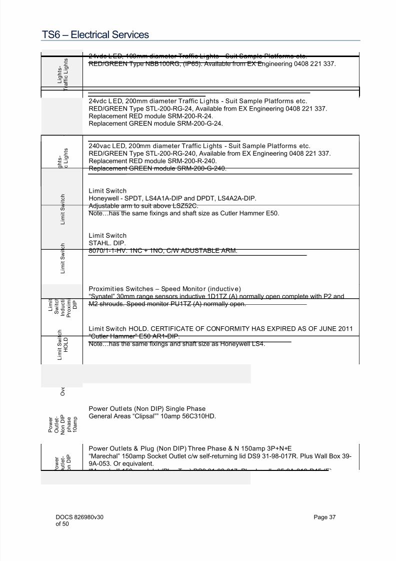
24vdc LED, 100mm diameter Traffic Lights - Suit Sample Platforms etc.RED/GREEN Type NBB100RG, (IP65). Available from EX Engineering 0408 221 337.
L i g h t s -
T r a f f i c L i g h t s
24vdc LED, 200mm diameter Traffic Lights - Suit Sample Platforms etc.RED/GREEN Type STL-200-RG-24, Available from EX Engineering 0408 221 337.Replacement RED module SRM-200-R-24.Replacement GREEN module SRM-200-G-24.
L i g h t s -
T r a f f i c L i g h t s
240vac LED, 200mm diameter Traffic Lights - Suit Sample Platforms etc.RED/GREEN Type STL-200-RG-240, Available from EX Engineering 0408 221 337.Replacement RED module SRM-200-R-240.Replacement GREEN module SRM-200-G-240.
L i m i t S w i t c h Limit SwitchHoneywell - SPDT, LS4A1A-DIP and DPDT, LS4A2A-DIP.
Adjustable arm to suit above LSZ52C.Note…has the same fixings and shaft size as Cutler Hammer E50.
L i m i t S w i t c h
Limit SwitchSTAHL. DIP.8070/1-1-HV. 1NC + 1NO, C/W ADUSTABLE ARM.
L i m i t
S w i t c h -
I n d u c t i v e
P r o x i m i t y ,
D I P
Proximit ies Switches – Speed Monito r (inductive)“Synatel” 30mm range sensors inductive 1D1TZ (A) normally open complete with P2 andM2 shrouds. Speed monitor PU1TZ (A) normally open.
L i m i t S w i t c h
H O L D
Limit Switch HOLD. CERTIFICATE OF CONFORMITY HAS EXPIRED AS OF JUNE 2011“Cutler Hammer” E50 AR1-DIP.Note…has the same fixings and shaft size as Honeywell LS4.
O v e r l o a d
Motor Starting – Motor Protection overloads ≤ 11kw DOL“Schneider” Type TeSys Model D. (MAN/AUTO reset, set on Auto).
NHP Sprecher Schuh suit CA4, CA6 & CA7.
P o w e r
O u t l e t -
N o n D I P
p h a s e
1 0 a m p
Power Outlets (Non DIP) Single PhaseGeneral Areas “Clipsal”” 10amp 56C310HD.
P o w e r
O u t l e t -
N o n D I P
Power Out lets & Plug (Non DIP) Three Phase & N 150amp 3P+N+E“Marechal” 150amp Socket Outlet c/w self-returning lid DS9 31-98-017R. Plus Wall Box 39-9A-053. Or equivalent.“Marechal” 150amp Inlet (Plug Top) DS9 31-98-017. Plus handle 65-9A-013-D45 (E).

7/23/2019 TS6 - Electrical Services
http://slidepdf.com/reader/full/ts6-electrical-services 38/50
TS6 – Electrical Services
DOCS 826980v30 Page 38of 50
P o w e r
O u t l e t -
D I P
Power Out lets (DIP/IECEx) Single Phase16amp single phase outletMarechal TBC
P o w e r
O u t l e t -
D I P
HOLD Power Out lets (DIP/IECEx) Three Phase????????? Marechal???
P o w e r
O u t l e t -
N o n D I P
Power Out lets & Plug (Non DIP) Three Phase 30amp 3P+E“Marechal” 30amp Socket Outlet c/w self-returning lid DS1 31-14-013R. Plus Wall Box 31-1A-053. Or equivalent.“Marechal” 30amp Inlet (Plug Top) DS1 31-18-013. Plus handle 31-1A-013.
P o w e r
O u t l e t -
N o n
D I P
Power Out lets (Non DIP) Three PhaseGeneral Areas “Clipsal” 5 pin 32 amp 56C532
P o w e r
O u t l e t -
N o n D I P
Power Out lets & Plug (Non DIP) Three Phase 50amp 3P+E“Marechal” 50amp Socket Outlet c/w self-returning lid DS3 31-34-013R. Plus Wall Box 31-3A-053. Or equivalent.“Marechal” 50amp Inlet (Plug Top) DS3 31-38-013. Plus handle 31-3A-013.
P o w e r
O u t l e t -
N o n D I P
Power Out lets & Plug (Non DIP) Three Phase 90amp 3P+E“Marechal” 90amp Socket Outlet c/w self-returning lid DS6 31-64-013R. Plus Wall Box 31-6A-053. Or equivalent.“Marechal” 90amp Inlet (Plug Top) DS6 31-68-013. Plus handle 31-6A-013.
P o w e r S u p p l y -
2 4 v d c
Power Supp ly 96-264vac/24vdc.Weidmuller.3 amp, CP M SNT 70W 24vdc 3amp.5 amp, CP M SNT 120W 24vdc 5amp.7.5 amp, CP M SNT 180W 24vdc 7.5amp.10 amp, CP M SNT 250W 24vdc 10amp.
P r o
x i m i t y S e n s o r -
C a p a c i t i v e
High and Alarm Level - for within Grain Storages – Capacitive Proximities IntrinsicallySafeSensor - Pacific EX” Rechner RH-KA0030, 30mm Ø, c/w 6 metres of cable.IS Barrier - Pacific EX” Rechner Single channel 120-240vac N00012.IS Barrier - Pacific EX” Rechner Duel channel 120-240vac N00015.
Extra cable (blue) to suit above Pacific EX” 2 core 0.75mm2 (6.4 dia) part # RH-66200300.
P r o x i m i t y
S e n s o r -
C a p a c i t i v e
Level Monitors for Pits and side walls of Grain Storages and Garners DIP/IECeEx,Capacitive Proximi tiesSensor - Pacific EX” Rechner part number RH-KA0278, description KAS-80-A24-A-StEx-N, 24vdc, 5 wire, n/o & n/c, 30mm Ø, c/w 5 metres of cable.Mechanical Protection Kit (Mounting Kit) to suit above: “ Pacific EX” part No RH-PMI-0001-01, description M30 TF-fm-fit Includes Teflon shroud, s/s flange & 20mm conduit adaptor.

7/23/2019 TS6 - Electrical Services
http://slidepdf.com/reader/full/ts6-electrical-services 39/50
TS6 – Electrical Services
DOCS 826980v30 Page 39of 50
R
e l a y -
C
o n t r o l
Relays Control - Miniature 4 pole plug in . (for general purpose control e.g. Ready, Run,Interlock / Manual etc)
NHP Finder 55 series 4 pole c/o. See plug-in base details below.24vdc.55.34.9. 024.0074. 24vdc, 7amp, 4 pole, c/w LED & built in diode suppression.110vac.55.34.8.110.0054.110vac, 7amp, 4 pole, c/w LED & built in diode suppression.
240vac. 55.34.8.240.0054.240vac, 7amp, 4 pole, c/w LED & built in diode suppression.
Base to suit all above: Type Screw terminal 94.04.
R e l a y -
C o n t r o l
Relays Control – Slimline single pole (for general purpose control).NHP Finder 38 series 1 pole c/o with LED & diode.24vdc. 38.51.7.024.0050. 24vdc, 6amp, 1 pole, c/w LED & built in diode suppression.110vac. 38.51.0.110.0060. 110vac, 6amp, 1 pole, c/w LED & built in diode suppression.240vac. 38.51.0.240.0060. 240vac, 6amp, 1 pole, c/w LED & built in diode suppression.Note. No base required.
R e l a y -
P o w
e r
Relays PowerSchneider.
NHP Sprecher Schuh.Or as specified.
R e l a y -
T i m e r
Relay timersSchneider.NHP Sprecher Schuh.Or as specified.
S o f t S t a r t e r
Motor Starting - Soft Starters 15kW-75kW 3ØRefer Clause 5.13.10 this document.NHP Aucom EMX3 c/w inbuilt by-pass contactor, see list below. Use heavy duty (4xFLC) soft starter of all drives 11kw and above as listed below or specified.
(B* denotes inbuilt by-pass contactor)
kwCurrent(amps) Aucom EMX3
Main Contactor (or asspecified)
11kw 22 EMX3-0043B-V4-C1 (31amp) Schneider LC1D25
15kw 28 EMX3-0043B-V4-C1 (31amp) Schneider LC1D32
18.5kw 38 EMX3-0053B-V4-C1 (46amp) Schneider LC1D38
22kw 44 EMX3-0076B-V4-C1 (55amp) Schneider LC1D5022kw(Augers) 44 EMX3-0076B-V4-C1 (55amp) Schneider LC1D65
30kw 56 EMX3-0097B-V4-C1 (69amp) Schneider LC1D65
37kw 68 EMX3-0100B-V4-C1 (74amp) Schneider LC1D80
45kw 80 EMX3-0105B-V4-C1 (95amp) Schneider LC1D115
55kw 100 EMX3-0145B-V4-C1 (106amp) Schneider LC1D115
75kw 140 EMX3-0200B-V4-C1 (160amp) Schneider LC1F185
90kw 151 EMX3-0200B-V4-C1 (160amp) Schneider LC1F185
S w i t c h -
E m e r g e n c y
Switches –Emergency Stop Station (DIP/IECEx)CSE: DMPB1-4PL Pacific EX: DS1511-3-PLKC
S w i t c h -
E m
e r g e n c y
Switches –Emergency Stop Station (NON DIP)Pacific EX: ???????

7/23/2019 TS6 - Electrical Services
http://slidepdf.com/reader/full/ts6-electrical-services 40/50
TS6 – Electrical Services
DOCS 826980v30 Page 40of 50
S w i t c h -
I s o l a t o r
3 Phase Isolator 20amp (Red & Yellow) Suit Inch drives local isolation etc.Clipsal 56SW320RY
S w i t c h -
L o c a l
C o n t r o l
Switches-Local Control Stations (DIP/IECEx)
Conveyors & Elevators:Pacific EX: DS1511-CA10A178M003DIP.Reversing Conveyors & 2 way valvesPacific EX: CA10-AU00271P.
S w i t c h -
L o c a l
C o n t r o l
Switches-Push Buttons DIP??
S w i t c h -
L o c a l C o n t r o l
Switches-Local Control Stations (NON DIP)Conveyors & Elevators:Pacific EX: ?????????
Reversing Conveyors & 2 way valvesPacific EX: ????
S w i t c h -
L o c a l
C o n t r o l
Switches-Push But tons NON DIP??“Schneider” 22mm XB2 booted (green – start or open; red – stop or close).NHP Sprecher Schuh D7 Metal body.
T e r
m i n a l s -
C o n t r o l w i r i n g
Terminals“Schneider” AB1
T e r m i n a l s
B l o c k -
P o w e r
c o n n e c t i o n s Terminals Blocks - Power
Phoenix Contacts type UHV …, or similar.Separating Plate UHV-TP…. or similar.
T i m e r -
D o u b l e o n - - d e l a y SCHNEIDER Zelio. RE7YA12BU. DOUBLE ON-DELAY,
Type/Function “Qt”, 2 C/O (8amp), 24vdc & 110-240vac)CBH use: For Soft Starter Horn/Start up delay.
T i m e r O N - D E L A Y
&
I N S T A N T A N E O U S SCHNEIDER Zelio. RE7TP13BU. 1 x ON-DELAY contact & 1 x INSTANTANEOUS contact.
Type/Function “A”, 2 C/O (8amp), R1 = ON-DELAY, R2 = INSTANTANEOUS, 24vdc & 110-240vac)CBH use: For Stacker Loader Horn/Start up delay.
T i m e r - O n -
d e l a y
SCHNEIDER Zelio. RE7TL11BU. ON-DELAY,Type/Function “A”, 1 C/O (8amp), 24vdc & 110-240vac)
CBH use: Hydraulic Sample spears.
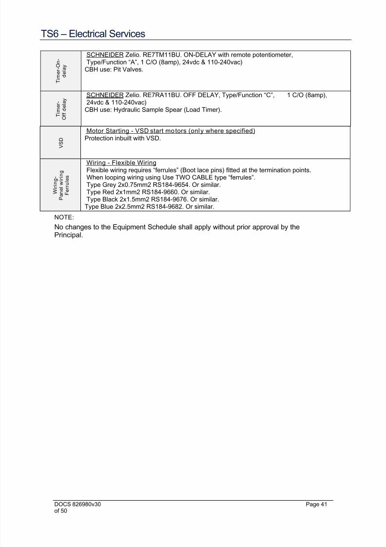
7/23/2019 TS6 - Electrical Services
http://slidepdf.com/reader/full/ts6-electrical-services 41/50
TS6 – Electrical Services
DOCS 826980v30 Page 41of 50
T i m e r - O n -
d e l a y
SCHNEIDER Zelio. RE7TM11BU. ON-DELAY with remote potentiometer,Type/Function “A”, 1 C/O (8amp), 24vdc & 110-240vac)
CBH use: Pit Valves.
T i m e r -
O f f d e l a y SCHNEIDER Zelio. RE7RA11BU. OFF DELAY, Type/Function “C”, 1 C/O (8amp),
24vdc & 110-240vac)CBH use: Hydraulic Sample Spear (Load Timer).
V S D
Motor Starting - VSD start motors (only where specified)Protection inbuilt with VSD.
W i r i n g -
P a n e l w i r i n g
F e r r u l e s
Wiring - Flexible WiringFlexible wiring requires “ferrules” (Boot lace pins) fitted at the termination points.When looping wiring using Use TWO CABLE type “ferrules”.
Type Grey 2x0.75mm2 RS184-9654. Or similar.Type Red 2x1mm2 RS184-9660. Or similar.Type Black 2x1.5mm2 RS184-9676. Or similar.
Type Blue 2x2.5mm2 RS184-9682. Or similar.
NOTE:
No changes to the Equipment Schedule shall apply without prior approval by thePrincipal.

7/23/2019 TS6 - Electrical Services
http://slidepdf.com/reader/full/ts6-electrical-services 42/50
TS6 – Electrical Services
DOCS 826980v30 Page 42of 50
ELEVATORS
Plant Equipment Comments Initials
Elevator Drive Motor Refer Data Sheets
Interlock Start and stop as required
Manual Start, stop and override interlock as required
Cabling Neat, tidy and glanded, terminations tightened
Local Isolators At head and in boot pit
Cubicle Protection Circuit breakers - TM-D trips adjusted
Overloads correct and set to auto reset
Fluid coupling over temperature switch
Indicator Lights Elevator running
Ammeter Operating - red ‘Chinagraph’ mark to indicate FLCInching Drive Motor Refer Data Sheets
Interlock Start and stop as required
Manual Start, stop and override interlock as required
Cabling Neat, tidy and glanded, terminations tightened
Limit Switches Operation and mounting
Road Hopper Valve Motor Refer Data Sheets
Interlock With CLS or conveyor system
Manual Open, close and override interlock as required
Cabling Neat, tidy and glanded
Timing Adjusted at wet commissioning
Cabling Neat, tidy and glanded, terminations tightened
Limit Switches Operation and mounting
Grain Sensors Operation and mounting
Cubicle Indicator Lights Valve open, Valve closed, Grain in pit
Head Valve Motor Refer Data Sheets
Interlock With CLS or conveyor system
Manual Change over and override interlock as required
Cabling Neat, tidy and glanded, terminations tightened
Limit Switches Operation and mounting
Cubicle Indicator Lights Indicate correct feed direction
Labelling Fitted As per drawings and specification
Located where visible
Engraved and legible

7/23/2019 TS6 - Electrical Services
http://slidepdf.com/reader/full/ts6-electrical-services 43/50
TS6 – Electrical Services
DOCS 826980v30 Page 43of 50
E-PITS
Equipment Operation Comments Initials
Auger motors Electrical Refer Data Sheets
Interlock Start and stop as required
Manual Start, stop and override interlock as required
Cabling Neat, tidy and glanded, terminations tightened
Cubicle Protection Circuit breakers, o/loads. And over temp. switches
Indicator Lights Augers running
GROUND CONVEYORS
Equipment Operation Comments Initials
Drive motor Electrical Refer Data Sheets
Interlock Start and stop as required
Manual Start, stop and override interlock as required
Cabling Neat, tidy and glanded, terminations tightened
Cubicle Protection Circuit breakers, overloads. And over temp.switches
Indicator Lights Ready, Forward, Reverse
Isolating Switches Head and Tail Fitted as per drawings
Warning sirens Fitted as per drawings
Lanyard switches Lanyards 120m maximum lengthSet correctly Manufacturers specification
Operation
Cabling Neat, tidy and glanded, terminations tightened
Stacker Outlets Space from ends 9m maximum
Spaces between 36m maximum
Accessibility
Cabling Neat, tidy, glanded, clear of ground, termination
Cubicle Protection Circuit breakers, overloads. and current sensing
Indicator Lights Stacker running
Labelling Fitted As per drawings and specification
Located where visible
Engraved and legible
Cable Ladder Mounting Joints within 300 of trestles or end of ladder
Overhead – 2700 AFL
Fixing Around drive - clear of tripper access and guards
On elevators – tool removable e.g. on Unistrut
Cable spacing 6mm minimum all round to allow grain throughCable fixing Flat on tray - 1000mm: Vert. on tray – each rung

7/23/2019 TS6 - Electrical Services
http://slidepdf.com/reader/full/ts6-electrical-services 44/50
TS6 – Electrical Services
DOCS 826980v30 Page 44of 50
OTHER CONVEYORS
Equipment Operation Comments Initials
Drive motor Electrical Refer Data Sheets
Interlock Start and stop as requiredManual Start and stop as required
Cabling Neat, tidy and glanded, terminationstightened
Cubicle Protection Circuit breakers, o/loads. And over temp.switches
Indicator Lights Ready and running
Lanyard switches Lanyards 120m max length compensating springs fitted
Set correctly
Operation
Cabling
Cable Ladder Mounting Joints within 300 of trestles or end of ladder
Overhead – 2700 AFL
Fixing Around drive - clear of tripper access andguards
On elevators – tool removable e.g. onUnistrut
Cable spacing 6mm minimum all round to allow grain to fallthrough
Cable fixing Flat on tray - 1000mm: Vert. on tray – eachrung
Cable bends Within manufactures specifications
Labelling Fitted As per drawings and specification
Located where visible
Engraved and legible

7/23/2019 TS6 - Electrical Services
http://slidepdf.com/reader/full/ts6-electrical-services 45/50
TS6 – Electrical Services
DOCS 826980v30 Page 45of 50
CONTROL CUBICLE
Equipment Operation Comments Initials
Main switch RatingCircuit breakers Rating Trip settings on motor supplies
Labelling Fitted As per drawings and specification
Not on removable covers
Located where visible
Engraved and legible
Control Panel Layout As per drawings
SystemInterlock
Start and stop as required
Manual Start and stop as required
Wiring Neat, tidy with spare capacity in ducts,terminations tightened
Indicators Lamps Working and visible
General Engraving / labels fixed
Switches Pushbuttons
Rotary
General Engraving / labels fixed
Timers Valve Adjusted at wet commissioning
Sirens Siren to sound seven (7) seconds before beltstart
Current Sensors (1) Time range Set on 1.5 – 30s
(2) Time Three (3) second delay
(3) Hysteresis Set at 25% of current threshold
(4) Current 10 amps on stacker circuit
(5) Contact Set to undercurrent (UI)
Motor overloads Settings Set to auto reset
Cabling / Wiring Incoming Clamping and cable glands
Internal Neat and spare capacity in ducts
Terminations Check for loose terminations
Protection ‘Grommet’ strips on metal edges

7/23/2019 TS6 - Electrical Services
http://slidepdf.com/reader/full/ts6-electrical-services 46/50
TS6 – Electrical Services
DOCS 826980v30 Page 46of 50
Site: ………………………………………………………
Contractor: ………………………………………………………
Plant Area: ………………………………………………………
Equipment: ………………………………………………………
Make: …………………………………… Rated RPM: ……………………………………
Type: …………………………………… Rated kW: ……………………………………
Serial No.: …………………………………… Rated Voltage: ……………………………………
Frame: …………………………………… Rated IFL: ……………………………………
Bearing
Types:
Drive End ……………………… Non D E ……………………………………
InsulationTest:
Use 1000V Insulation Resistance tester, test duration 60s Provide actualreading - infinity not valid
A to E ……….. Megohms B to E ………… Megohms C to E ………… Megohms
Rotor shaft free to rotate:
Rotation direction correct:
Circuit breaker Magnetic setting: ………… AmpsCircuit breaker Thermal setting: ………… Amps
Motor Overload setting: ………… Amps
Start timer setting: ………… Seconds
Transformer tap setting: ………… %
Transformer duty classification: ………… Starts/hour
Actual supply voltage: RW…….. RB…….WB…… Volts
Actual no grain current: ………… Amps
Actual load current: ………… Amps
Remarks:
…………………………………………………………………………………………………………………
…………………………………………………………………………………………………………………
…………………………………………………………………………………………………………………
…………………………………………………………………………………………………………………
…………………………………………………………………………………………………………………
Tested By: …………………………
Signed: ………………………… Date: …../……/……

7/23/2019 TS6 - Electrical Services
http://slidepdf.com/reader/full/ts6-electrical-services 47/50
TS6 – Electrical Services
DOCS 826980v30 Page 47of 50
TEST EQUIPMENT REQUIRED
1. MOD TAP TESTER
2. RAD LBT BIT ERROR RATE TESTER
3. 1 SET OF TWO WAY RADIOS
PROCEDURE FOR TESTING AS FOLLOWS:
a) Visual inspection of fly and patch leads.
b) Test all fly and patch leads for correct operations with Mod Tap Tester.
c) Test all wall socket outlets in Sample Platform No’s 1 to 6 and Patch Panel No’s 1to 6 with Mod Tap Tester for correct numbering and pairs, i.e. Wall Socket outlet 1corresponding with Patch Panel Socket 1.
d) Connect fly lead to Patch Panel in Sampling Platform on Infra 1 and place one halfof the Mod Tap Tester on the end of the fly lead. Place the other half of the ModTap Tester on Infra 1 in the Weighbridge and test for correct pairs correct labelingand that the pairs are reversed. Do the same procedure for the remaining areaInfra 2, Balance 1 & 2 and Term 1 & 2.
NOTE: If only single Repols installation required, Infra 2, Balance 2 and Term 3 are notrequired.
e) When all Mod Tap Testing is completed, record your results on the test sheets.
f) Install RAD Line Drivers on the last point of the installation at the SamplingPlatform, wall socket’s No’s 1 to 6, then at the Weighbridge on Infra 1 & 2, Balance1 & 2 and Term 1 & 2, making sure that all Patch Leads are connected in thePatch Panel in Sampling Platform in the correct positions.
g) Set all RAD Line Drivers to DCE at all locations and connect one of the RAD LBT
Testers to Infra 1 at the Sampling Platform and the other RAD LBT Tester on Infra1 at the weighbridge. Do the same procedure for the remaining area Infra 2,Balance 1 & 2 and Term 1 & 2.
NOTE: If only single Repols installation required, Infra 2, Balance 2 and Term 3 are notrequired.
h) Set both testers to:
ASYNC PATTERN 511 19-2KB BLK512B.
ASYNC PARITY : EVEN 8 BIT BLK512B.
FULL DUPLEX CTS AND CD NOT USED.
Both testers must be started simultaneously. Ensure sync loss at start up is zero
(0). Restart if required.i) The first test should be run for a minimum of 3 minutes. After 3 minutes you
should have approximately 6,000 blocks received. There should be no blockerrors or sync errors with this test.
j) Test No. 2 should be run for a minimum of 5 minutes, during this time you shouldinject no less than 5 error bits into the system. After 5 minutes you should havereceived more than 11,000 blocks and not have a block error rate of more than.0650%. Record all your results on the test sheet.
k) After all tests are completed, make sure RAD Line Drivers are set back to thesettings as per the information on the Repols drawing. Submit all tabulated resultsto Co-operative Bulk Handling Limited with As-Built Drawings.

7/23/2019 TS6 - Electrical Services
http://slidepdf.com/reader/full/ts6-electrical-services 48/50
TS6 – Electrical Services
DOCS 826980v30 Page 48of 50
RAD LBT BIT ERROR RATE TEST SHEET
Without injected errors
RUN TIME
5 minutesminimum
BLOCKERROR RECEIVE
D
BLOCKSCONTAINI
NG
SYNCLOSS
LINEDRIVERSERIAL
No.
LINEDRIVERSERIAL
No.INITIALS
% RATE BLOCKS ERRORSWEIGHBRIDGE
SAMPLEHUT
INFRA 1
TERM 1
BALANCE 1
INFRA 2
TERM 2
BALANCE 2
RAD LBT BIT ERROR RATE TEST SHEET
With injecting 5 errors
INITIALS
RUN TIME
5 minutesminimum
BLOCKERROR RECEIVED
BLOCKSCONTAINING
SYNCLOSS
No. OFERRORS INITIALS
% RATE BLOCKS ERRORS INJECTED
INFRA 1
TERM 1
BALANCE 1
INFRA 2
TERM 2
BALANCE 2
RECIEVAL POINT : DATE:
CONTRACTOR :
NAME OF TECHNICIAN :
TEST COMPLETED : YES / NO
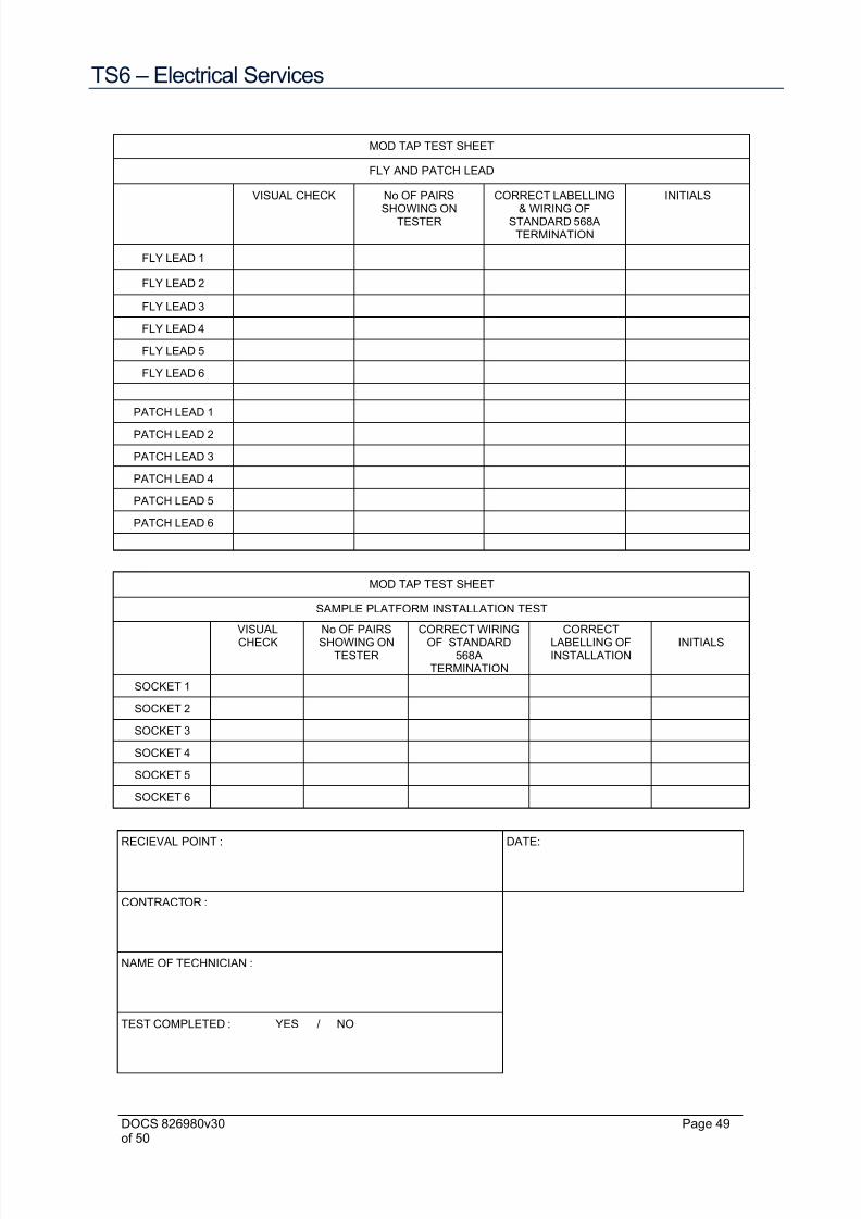
7/23/2019 TS6 - Electrical Services
http://slidepdf.com/reader/full/ts6-electrical-services 49/50
TS6 – Electrical Services
DOCS 826980v30 Page 49of 50
MOD TAP TEST SHEET
FLY AND PATCH LEAD
VISUAL CHECK No OF PAIRS
SHOWING ONTESTER
CORRECT LABELLING
& WIRING OFSTANDARD 568A
TERMINATION
INITIALS
FLY LEAD 1
FLY LEAD 2
FLY LEAD 3
FLY LEAD 4
FLY LEAD 5
FLY LEAD 6
PATCH LEAD 1
PATCH LEAD 2
PATCH LEAD 3
PATCH LEAD 4
PATCH LEAD 5
PATCH LEAD 6
MOD TAP TEST SHEET
SAMPLE PLATFORM INSTALLATION TEST
VISUALCHECK
No OF PAIRSSHOWING ON
TESTER
CORRECT WIRINGOF STANDARD
568ATERMINATION
CORRECTLABELLING OFINSTALLATION
INITIALS
SOCKET 1
SOCKET 2
SOCKET 3
SOCKET 4
SOCKET 5
SOCKET 6
RECIEVAL POINT : DATE:
CONTRACTOR :
NAME OF TECHNICIAN :
TEST COMPLETED : YES / NO

7/23/2019 TS6 - Electrical Services
http://slidepdf.com/reader/full/ts6-electrical-services 50/50
TS6 – Electrical Services
MOD TAP TEST SHEET
SAMPLE PL ATFORM TO WEIGHBRIDGE
VISUAL
CHECK
No OF THE PAIRS
SHOWING ONTESTER
CORRECT LABELLING & WIRING OF
STANDARD 568A TERMINATION INITIALS
INFRA 1
TERM 1
BALANCE 1
INFRA 2
TERM 2
BALANCE 2
RECIEVAL POINT : DATE:
CONTRACTOR :
NAME OF TECHNICIAN :
TEST COMPLETED : YES / NO