Embed Size (px)
Citation preview

H:\0 - Quality Documents\2 Department\Tech Serv\Application tooling\Applicators and Die sets\TS174-00 CMKS-L Manual.doc
CMKS-L INDUSTRY STANDARD APPLICATOR
OPERATION MANUAL

JST CMKS-L INDUSTRY STANDARD APPLICATOR
H:\0 - Quality Documents\2 Department\Tech Serv\Application tooling\Applicators and Die sets\TS174-00 CMKS-L Manual.doc
2
For safe use
• Always switch off the Press at the mains and remove the applicator from the Press before making any adjustments or fitting new parts.
• Always refer to this manual before making any adjustments to JST
Applicators • All JST Applicators are supplied with a Die-construction sheet; please
refer to this document when ordering spare parts. • All JST Industry standard Applicators have been designed to operate in
Industry standard presses with a shut height of 135.78mm. If you have any doubt to whether our applicator is compatible with your Press please do not hesitate to call our Technical Services Department where one of our Engineers will be pleased to advise.
• Do not modify or adapt the applicator without prior consent of JST. • Always ensure that safety guards are fitted to the Press when using your
JST applicator. • To prevent damage to the dies, always ensure that a protective rubber collar
is fitted between the dials and casting of the applicator when it is removed from the press.
• Do not make adjustments to the tooling unless qualified to do so. • When replacement parts are required, use only genuine JST supplied parts.
Die parts that are manufactured using an incorrect heat treatment process can shatter during use.

JST CMKS-L INDUSTRY STANDARD APPLICATOR
H:\0 - Quality Documents\2 Department\Tech Serv\Application tooling\Applicators and Die sets\TS174-00 CMKS-L Manual.doc
3
CONTENTS
Page
1. Ram Slide Section.............................................................................. 4
3. Ejector............................................................................................... 4
4. Upper Die Parts.................................................................................. 5
5. Lower Die Parts.................................................................................. 7
6. Feed Plate Base, Anvil (A) and (B).................................. 8
7. Guide Plates, Feed Plate..................................................................... 9
8. Terminal Feed Pitch........................................................................... 10
9. Pressure Pad Adjustment.................................................................... 11
10. Terminal Feed Position...................................................................... 12
11. Additional Information....................................................................... 13
12. Crimp Height...................................................................................... 14
13. CMKS-L Parts List............................................................................ 15
14. CMKS-L Exploded Diagram............................................................. 16
15. Preventive maintenance..................................................................... 17
16. Crimping specifications..................................................................... 19

JST CMKS-L INDUSTRY STANDARD APPLICATOR
H:\0 - Quality Documents\2 Department\Tech Serv\Application tooling\Applicators and Die sets\TS174-00 CMKS-L Manual.doc
4
1. APPLICATOR RAM SLIDE 1-1 SLIDE ASSEMBLY The conductor dial (108) and the insulation dial (111) are fixed by the shank (112).
To remove the two disks you must first loosen the 4mm grub screw positioned in the main body of the slide, now by loosening the shank you can remove both wire disks. Positioned in the rear of the slide is the cam (119). There are two different cams available for this applicator. The first type is an pre-feed cam, with this cam fitted the terminal is present over the anvil when the press is at top dead centre, this type of cam is commonly used when the applicator is located in a bench press. The other type is a post-feed cam, this operates in the opposite manner, which means the terminal feeds forward as the press travels to bottom dead centre, this type of cam is commonly used when the applicator is located in a fully automatic machine.
1-2 TROUBLE SHOOTING The dials are difficult to turn
1. Dismantle slide assembly as described above and check for any foreign bodies.
2. Ensure 3mm grub screw located in the insulation dial is not excessively tightened.
3. Check condition of the positioning Pin (109).
The dials turn freely but do not locate in position correctly 1. Check the condition of the positioning spring (110) and the positioning pin
(109). The Spring may be broken. 2. Ensure 3mm-grub screw located in the insulation dial is adjusted correctly.
2. EJECTOR 2.1 PURPOSE
After the terminal has been successfully crimped on the wire, the terminal may adhere to the punches; the ejector assures the function of stripping the terminal from the punches.
2.2 ASSEMBLY Place the ejector punch with relevant spring (159) into the corresponding slot of
ejector holder (160) ensuring the ejector slides freely up and down when fixed into position on the front of the crimping punches.

JST CMKS-L INDUSTRY STANDARD APPLICATOR
H:\0 - Quality Documents\2 Department\Tech Serv\Application tooling\Applicators and Die sets\TS174-00 CMKS-L Manual.doc
5
3. UPPER DIE PARTS 3.1 ASSEMBLING UPPER DIE PARTS To ensure the upper die parts are assembled in the correct orientation the engraved
part numbers must always be facing outwards. The parts must be fitted in the correct order as detailed below:
1. Conductor spacer (146) 2. Insulation spacer (148) 3. Block ring (113)
After you have fitted these parts tighten them down with a 5mm-hexagon screw and check that they are not clamped and move up and down freely.
4. Punch spacer (147) 5. Conductor punch (144) 6. Insulation punch (145) 7. (A Spacer & wire spring are sometimes fitted between the two punches). 8. Punch ring spacer (163) 9. Ejector (159)+ (160)
After you have fitted these parts, tighten down with a 6mm-hexagon screw and again check that they are not clamped and punches move up and down freely.
3.2 TROUBLE SHOOTING The punches or spacers do not move freely
1. Dismantle and check for any foreign bodies. 2. Check the sides of the punches for wear / damage or burrs.
3. Check the parts that are fitted, against the relevant die construction sheet.

JST CMKS-L INDUSTRY STANDARD APPLICATOR
H:\0 - Quality Documents\2 Department\Tech Serv\Application tooling\Applicators and Die sets\TS174-00 CMKS-L Manual.doc
6
(112) (108)
(111)
(110)
(109)
(119)
(146)
(107) (147)
(148)
(163)
(113)
(160)
(159)
(144) (145)

JST CMKS-L INDUSTRY STANDARD APPLICATOR
H:\0 - Quality Documents\2 Department\Tech Serv\Application tooling\Applicators and Die sets\TS174-00 CMKS-L Manual.doc
7
4. LOWER DIE PARTS 4.1 ASSEMBLING LOWER DIE PARTS To ensure the lower die parts are assembled in the correct orientation the engraved
part numbers must always be facing outwards. The parts must be fitted in the correct order as detailed below: 1. Die Block (105) 2. Die spacer (149) 3. Conductor anvil (153) 4. Insulation anvil (154) 5. Shear Blade (150) + (151) When all the above are in place, using 2 x 5mm hexagon screws gently tighten the die parts into position. IMPORTANT When these parts are positioned it is essential that they are knocked down flat against the Die plate, preferably using a piece ofnon-ferrous metal (brass) to avoid damaging the anvil parts.
(105) Die block
(150) Shear blade
(151) Shear blade Anvil
(153) Conductor Anvil
(154) Insulation Anvil
(104) Die Plate
Die Spacer (149)

JST CMKS-L INDUSTRY STANDARD APPLICATOR
H:\0 - Quality Documents\2 Department\Tech Serv\Application tooling\Applicators and Die sets\TS174-00 CMKS-L Manual.doc
8
5. Feed Plate Base 5.1 Assembling feed plate base.
IMPORTANT Ensure feed plate base moves freely back and forth within the relevant slot of the die plate. Feed plate base should be screwed into the main casting with relevant M5 screw surrounded by adjustment spring. Base should then be held lightly in place with two M5 screws.
Die Plate (104)
Feed plate base (106)

JST CMKS-L INDUSTRY STANDARD APPLICATOR
H:\0 - Quality Documents\2 Department\Tech Serv\Application tooling\Applicators and Die sets\TS174-00 CMKS-L Manual.doc
9
6. GUIDE PLATE 6.1 POSITIONING OF THE GUIDE PLATES To ensure the correct alignment of the Guide Plates, firstly mount the Feed Plate
onto the Die Block and secure tightly using the 2 x 5mm hexagon screws. Now you can fit the 2 guide plates using the 4 x 4mm hexagon screws (do not fully tighten the large guide plate screws). Insert a strip of the terminals that are compatible with the die set in the applicator, and ensure that the strip moves smoothly between the two guide rails. Now the 2 x 4mm hexagon screws can be carefully tightened on the large guide rail.
Die Plate (104)
Feed plate base (106)
Feed plate (166)
Large Guide Rail (158)
Small Guide Rail (157)

JST CMKS-L INDUSTRY STANDARD APPLICATOR
H:\0 - Quality Documents\2 Department\Tech Serv\Application tooling\Applicators and Die sets\TS174-00 CMKS-L Manual.doc
10
7. TERMINAL FEED PITCH 7.1 When you receive the applicator the pitch will be factory set, however if you do
need to make an adjustment, please ensure that the press is switched off and the applicator is removed from the Press. Note: The function of this nut is to achieve the correct pitch of the feed finger as shown in 8-3 (not to set the final position over the Anvil). 7.2 The pitch of the Feed Finger is adjusted by loosening the Stroke adjustment bearing nut (117) and sliding it either up, to make the stroke longer, or down, to shorten the stroke. After you make this adjustment you will have to adjust the terminal position as described in section 10.
7.3 When adjusting the pitch always feed the terminal on the rectangle hole and not the
round hole that can be viewed through the slot on the top of the small guide rail. (See below)
Small Guide Rail (157)
4 4 4

JST CMKS-L INDUSTRY STANDARD APPLICATOR
H:\0 - Quality Documents\2 Department\Tech Serv\Application tooling\Applicators and Die sets\TS174-00 CMKS-L Manual.doc
11
8. PRESSURE PAD 8.1 The purpose of the Pressure pad is to insure that the Terminal stays in the correct
position over the anvil when the Feed finger is moving backwards, the pressure on the terminal can be adjusted by loosening the 2 x M5 locking nuts and either tightening or loosening the 2 x M5 adjustment screws as shown below.
M5 adjustment Screws
M5 Locking nuts
Pressure Pad (161)
Thumb Screw
JST CMKS-L INDUSTRY STANDARD APPLICATOR
H:\0 - Quality Documents\2 Department\Tech Serv\Application tooling\Applicators and Die sets\TS174-00 CMKS-L Manual.doc
12
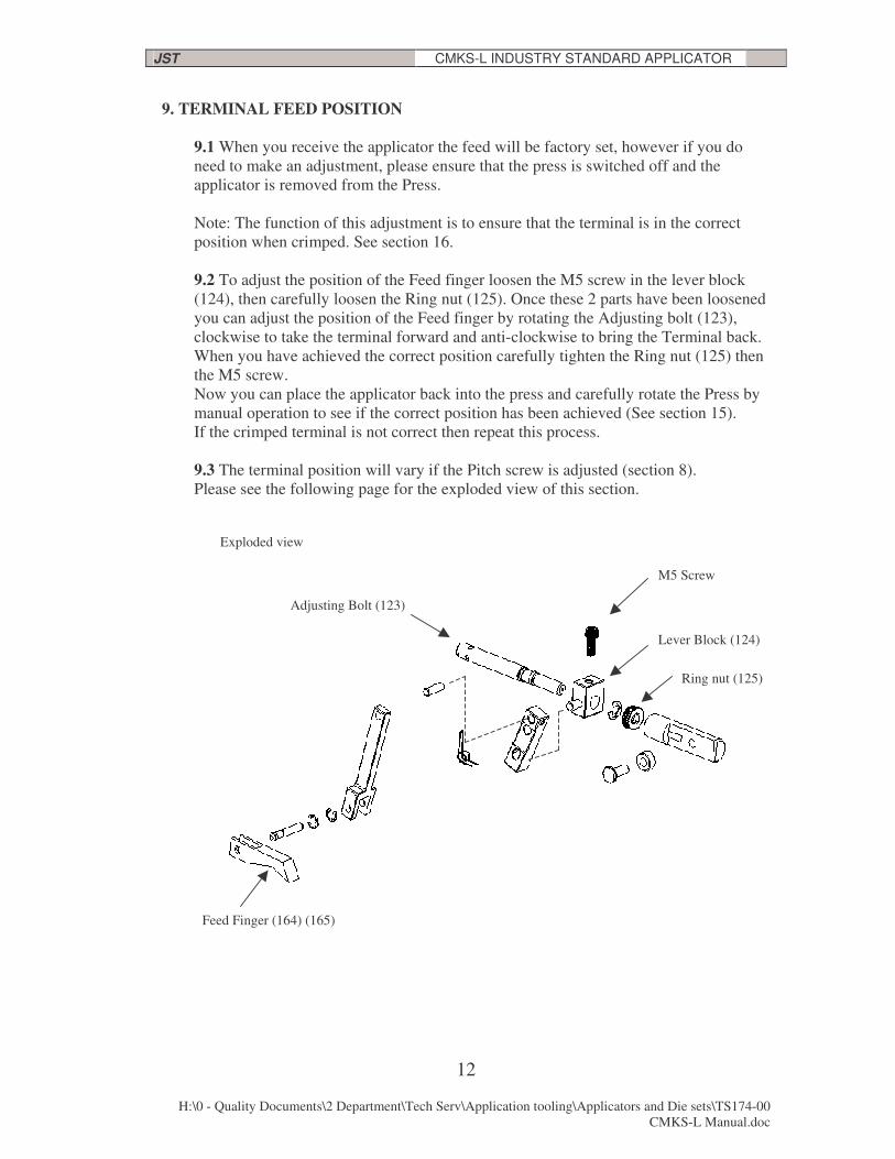
9. TERMINAL FEED POSITION 9.1 When you receive the applicator the feed will be factory set, however if you do
need to make an adjustment, please ensure that the press is switched off and the applicator is removed from the Press. Note: The function of this adjustment is to ensure that the terminal is in the correct position when crimped. See section 16. 9.2 To adjust the position of the Feed finger loosen the M5 screw in the lever block (124), then carefully loosen the Ring nut (125). Once these 2 parts have been loosened you can adjust the position of the Feed finger by rotating the Adjusting bolt (123), clockwise to take the terminal forward and anti-clockwise to bring the Terminal back. When you have achieved the correct position carefully tighten the Ring nut (125) then the M5 screw. Now you can place the applicator back into the press and carefully rotate the Press by manual operation to see if the correct position has been achieved (See section 15). If the crimped terminal is not correct then repeat this process. 9.3 The terminal position will vary if the Pitch screw is adjusted (section 8). Please see the following page for the exploded view of this section.
Feed Finger (164) (165)
Adjusting Bolt (123)
Lever Block (124)
M5 Screw
Ring nut (125)
Exploded view

JST CMKS-L INDUSTRY STANDARD APPLICATOR
H:\0 - Quality Documents\2 Department\Tech Serv\Application tooling\Applicators and Die sets\TS174-00 CMKS-L Manual.doc
13
10. ADDITIONAL INFORMATION 10.1 Wire Stop / Stripper
Depending on which terminal you are processing, a wire stop / stripper is sometimes fitted to the die spacer The purpose of this part is to position the wire correctly prior to crimping and remove the terminal from the crimp punches after the crimping process. CAUTION you must ensure that the stripper is set in a position behind the crimp anvils and punches so that they will not come into contact and cause damage to the tool.
10.2 Cam Roller and Cam Roller shaft The Cam roller’s function is to move a long the Cam which in turn will move the Feed
finger into position, therefore, if there is any wear in this part or this part becomes damaged then it will result in the terminal being positioned incorrectly.
Cam roller
Cam roller shaft
Stripper bracket (156)
Wire stop / Stripper (155)
Die spacer (149)

JST CMKS-L INDUSTRY STANDARD APPLICATOR
H:\0 - Quality Documents\2 Department\Tech Serv\Application tooling\Applicators and Die sets\TS174-00 CMKS-L Manual.doc
14
11. CRIMP HEIGHT 11.1 The 2 dials on the top of the Ram are used to adjust the conductor and Insulation
crimp heights. NOTE: The numbers and letters around these dials should only be used as a reference for a correct crimp, as this will vary depending on the shut height of the press the applicator is used in. The crimp height should be measured with a crimp micrometer. If for any reason you cannot achieve the correct crimp height, please contact our Technical services department. 11.2 Conductor crimp height The top dial, which has the letters from A-H around it, is for adjusting the Conductor crimp height. To adjust the crimp height of the conductor, carefully rotate this dial, the lower the letter (A) the harder the crimp. When making any adjustment it is recommended that you start with the higher letter (H) to avoid any damaged being caused by over crimping. To ensure that you have the correct crimp height, there is a silver label fixed to the side of the applicator, this will have all the crimp heights, for the different gauge wires used with that terminal on it. The steps between each dial setting are 0.05mm increments. For information regarding how to measure the crimp heights please see section 16. 11.3 Insulation crimp height The Lower dial, which has the numbers from 1-8 around it, is for adjusting the Insulation crimp height. To adjust the crimp height of the Insulation, carefully rotate this dial, the lower the number (1) the harder the crimp. When making any adjustment it is recommended that you start with the higher number (8) to avoid any damaged being caused by over crimping. The steps between each dial setting are 0.10mm increments. For information regarding how to ensure that you are using the correct setting please see section 16.
Conductor crimp adjustment
Insulation crimp adjustment

JST CMKS-L INDUSTRY STANDARD APPLICATOR
H:\0 - Quality Documents\2 Department\Tech Serv\Application tooling\Applicators and Die sets\TS174-00 CMKS-L Manual.doc
15
12. Parts list for the applicator CMKS-L
No. Part Name Part No. No. Part Name Part No. 101 Body 4006-2001 132A Return spring 4006-P025
102 Plate (L) 4006-4002
103 Plate (R) 4006-4003
104 Die plate 4006-3004
105 Die block 4006-4005 144 Conductor punch
106 Feed plate base 4006-4006 145 Insulation punch
107 Ram 4006-3007 146 Conductor spacer
108 Conductor dial 4006-4008 147 Punch spacer
109 Positioning pin MA01-213 148 Insulation spacer
110 Positioning spring MA01-214 149 Die spacer
111 Insulation dial 4006-4009 150 Shear blade
112 Shank 4006-4010 151 Shear blade anvil
113 Block ring MA01-225 152 Scrap chute
114 Stroke adjustment plate MA03-330 153 Conductor anvil
115 Stroke adjustment shaft MA01-331 154 Insulation anvil
116 Stroke adjustment bearing MA01-332 155 Wire stop / stripper
117 Stroke adjustment bearing nut MA01-333 156 Wire stop / stripper bracket
118 Stroke adjustment screw MA01-334 157 Small Guide plate
119 Cam 4006-4011 158 Large Guide plate
120 Cam roller MA01-308A 159 Stripper
121 Cam roller shaft MA01-337A 160 Stripper holder
122 Feed shaft MA03-338 161 Pressure plate
123 Adjustment bolt MA03-339 162 Pressure plate springs x 2
124 Lever block MA01-340 163 Punch ring spacer
125 Ring nut MA01-341 164 Feed finger holder
126 Feed lever (A) 4006-4015 165 Feed finger
127 Feed lever support pin MA01-343 166 Feed plate
128 Feed lever pin MA01-344
129 Feed lever (B) 4006-4016-1
130 Feed finger pin AMA03-347
132 Return spring bracket 4006-4012

JST CMKS-L INDUSTRY STANDARD APPLICATOR
H:\0 - Quality Documents\2 Department\Tech Serv\Application tooling\Applicators and Die sets\TS174-00 CMKS-L Manual.doc
16
13. CMKS-L Applicator exploded view
145 144
163
153 154
146 148 113
112
108
111
109
110
118
123
124 125
122
121
120
114
117 116 115
101 107
119
126
129
132A
132
130 164
128
103 102
106 105
104
157 158
166
127
155
156 149
150
151
152
159
160
161
162
147
165

JST CMKS-L INDUSTRY STANDARD APPLICATOR
H:\0 - Quality Documents\2 Department\Tech Serv\Application tooling\Applicators and Die sets\TS174-00 CMKS-L Manual.doc
17
Quality Statement The quality of a finished crimp is dependent on the use of the manufacturers specified application tooling that has been cleaned and maintained in accordance with the following schedule. Daily Care (the ‘weekly care’ checks listed from 2.1 – 2.4 below, should also be applied on a daily basis when using terminals manufactured from steel) 1.1 Turn off the crimping press and isolate from the electricity supply. Remove the safety
covers from the crimping press.
1.2 Clean all wire and terminal scrap from the tooling with the aid of a small paintbrush.
Caution The use of a pneumatic airline to clean the tooling should be avoided. Any debris on the tool will be blown away under great force and could either cause injury to persons nearby or be forced into moving parts of the tooling. 1.3 Visually check the crimping dies, shear section and stripper blade for evidence of wear
or damage. If any parts are damaged, please contact JST to order replacement parts.
1.4 Check that there is a thin film of grease on the bearing surface of the ram, if necessary
apply general-purpose grease to restore the lubrication. Do not over grease the ram, because
the excess grease will either drip onto the tooling or will attract debris.
1.5 Check that the dial settings are aligned correctly over the crimping punches and that
they are correctly set to the pre-determined reference position.
1.6 Check that the safety covers are in a good serviceable condition and replace on the
tooling. Clean the polycarbonate safety cover with a general-purpose aerosol spray cleaner
to restore good visibility.
Weekly care, or when removing the applicator from the press for storage.
In addition to the daily checks, the following maintenance should also be carried out on the
tooling.
2.1 Remove the crimping punches from the ram (part numbers are affixed 63*** or 64***),
please note the sequence of dis-assembly so that the parts can be replaced in the correct
order. Refer to the Dies Construction Sheet supplied with the tooling for the assembly
order.
2.2 Hold each crimping punch in a vice and with the aid of a piece of waste cloth apply a
small amount of a good quality metal polish into the crimp form of the punch.

JST CMKS-L INDUSTRY STANDARD APPLICATOR
H:\0 - Quality Documents\2 Department\Tech Serv\Application tooling\Applicators and Die sets\TS174-00 CMKS-L Manual.doc
18
2.3 Using a sawing motion, polish the form until a brilliant mirror-like finish is restored.
2.4 Replace the crimping punches in the ram ensuring that the punches are free to move in a
lateral axis when the retaining screw is fully tightened.
2.5 Remove the applicator from the crimping press (check the press operation manual for
instructions if you are unsure of how to remove the applicator from the press.)
2.6 Check the security of the fastenings. If any part is loose, tighten with the appropriate
hexagon key or spanner supplied with the crimping press.
2.7 Remove the ram from the main body of the applicator and clean off all the old grease
from the ram, feed cam and the mating surface of the applicator.
Caution If an aerosol degreaser is used to clean the tooling, ensure that all traces of the solvent are removed prior to reassembly.
2.8 Apply a thin smear of general-purpose grease to the bearing surfaces of the ram, feed
cam and cam-roller assembly and replace in the body of the applicator.
2.9 Apply a few drops of light machine oil to each of the pivot points on the feed-arm
mechanism.
2.10 Replace the applicator in the press.
2.11 Replace the safety covers.
2.12 If it is not intended to replace the applicator in the press, please ensure that the rubber
collar supplied with the tooling is placed between the dials and the applicator body. This
action will avoid any damage occurring to the crimping dies due to percussive shock when
the crimping punches make contact with the crimping anvils.
Notes:-
Recommended materials for maintenance:
Recommended grease should be of the general purpose ‘LM’ type.
Recommended oil is general-purpose machine oil, i.e. ‘3-In-One’ oil
Recommended metal polish is of the paste type, i.e. ‘Solvol Autosol’
�J.S.T MFG. CO., LTD. 2005
The contents of this document are subject to revision from time to time. For the latest issue of this leaflet,
please contact J.S.T.

JST CMKS-L INDUSTRY STANDARD APPLICATOR
H:\0 - Quality Documents\2 Department\Tech Serv\Application tooling\Applicators and Die sets\TS174-00 CMKS-L Manual.doc
19
15. Crimping specifications CONTENTS
1. Checks Before Crimping..................................................................20 2. Stripping Wire Insulation.................................................................20 3. Crimping...........................................................................................21 3.1 Precautions regarding crimping........................................................21 3.2 Adjusting the crimp height (CH)......................................................22 3.3 Adjusting the crimp height of the insulation barrel..........................23 3.4 Tensile tests at the crimped section..................................................25 4. Correctly Crimped Conditions................................................................25 4.1 Crimped Appearance........................................................................25 4.2 The crimped cross-section must be correctly finished as shown to the right.........................................................................25 4.3 All conductors must be crimped.......................................................26 4.4 The lance must not be deformed.......................................................26 4.5 The terminal tip and mating part must not be deformed...................26 4.6 The terminal must not be bent or deflected excessively...................26 4.7 The terminal barrel must be properly bell-mouthed.........................27 4.8 The terminal must be cut at the correct position..............................27 4.9 The wire must be crimped at the correct position............................28 5. Check-points for correct Crimping.........................................................29

JST CMKS-L INDUSTRY STANDARD APPLICATOR
H:\0 - Quality Documents\2 Department\Tech Serv\Application tooling\Applicators and Die sets\TS174-00 CMKS-L Manual.doc
20
Preface Since the chain terminals and electric wires to be connected vary greatly in type and usage, it is difficult to provide instructions for all possible crimping combinations and conditions. This manual, therefore, provides one general guideline for your reference. Please contact us if you have any questions regarding the use of special wires, the correct combinations of terminals and wires etc. 1. Checks Before Crimping Check that all wires, terminals and dies to be used are correct. (1) Use stranded wire or cord. (Check the wire size and the insulation colour).
(2) Refer to the applicable wires in the catalogue to determine which terminal type is necessary to match the wires to be used. (Check the model number and appearance). (3) Determine which dies match the terminal. (Check that the dies are free from damage). Note: Contact us first if you wish to use solid wires, solder-plated wires, wires not listed as applicable or other special wires.

JST CMKS-L INDUSTRY STANDARD APPLICATOR
H:\0 - Quality Documents\2 Department\Tech Serv\Application tooling\Applicators and Die sets\TS174-00 CMKS-L Manual.doc
21
2. Stripping Wire Insulation
The wire insulation strip length is determined by referring to the figure over. Set the correct length depending on the terminal used and strip the insulation with a wire stripper, taking care not to damage the wire conductors. Bundle the stripped wires in paper to protect the wire strands from bending or fraying when transported. The wire insulation stripping length is determined by the following equation:
1 = E + A/2 + a
The correct value of a is between 0.5 and 1.0 mm. Precautions: (1) Take care to prevent damage to the wire strands, uneven strip lengths and Insufficient cutting of the insulation. (2) Strip the shielding cable as shown below: (3) Do not excessively twist the conductors.
The end of the outer wire becomes uneven as the wire is twisted. Trim the wire approximately 2 to 3 mm to make it even

JST CMKS-L INDUSTRY STANDARD APPLICATOR
H:\0 - Quality Documents\2 Department\Tech Serv\Application tooling\Applicators and Die sets\TS174-00 CMKS-L Manual.doc
22
3. Crimping 3.1 Precautions regarding crimping At first glance, crimping terminals appears to be very easy. However, crimping involves the use of a press employing 1000 kg (1 ton) of pressure. Sufficient care must be taken to prevent accidents. Please instruct beginners to work safely regardless of how much time such
training requires. Always use safety guards so that an operator’s fingers cannot enter the crimping die area.
Precautions: (1) Turn off the crimping machine whenever the Press is not in use. (2) Turn off the machine at the mains before adjusting the dies and feeder unit. (3) Do not touch the dies unless the machine is switched off. (4) Position the foot switch where it will not be operated by other people or falling objects. (5) Always concentrate on what you are doing. (6) Work in a stable posture. (7) Do not place any unnecessary objects on the die unit. (8) To make sure that the operating conditions are correct, manually cycle the press
before going to automatic operation. After the handle is used, be sure to remove it from the crimping machine.
(9)Always ensure that the safety guard is replaced after adjustment.

JST CMKS-L INDUSTRY STANDARD APPLICATOR
H:\0 - Quality Documents\2 Department\Tech Serv\Application tooling\Applicators and Die sets\TS174-00 CMKS-L Manual.doc
23
3.2 Adjusting the crimp height (CH) After crimping, measure the crimp heights of the crimped terminal with a
micrometer (Contact JST for information on suitable tools) at the centre of the wire barrel and at the centre of the insulation barrel.
Sectional view of the crimped terminal: * Set the crimp height of the wire barrel to the specified dimension. * Determine the crimp height of the insulation barrel in relation to the outer diameter of the wire insulation. (Refer to item 3.3) Notes: 1. After adjusting the crimp height, use a trial sample to conduct a tensile test (refer to item 3.4) in order to examine the strength of the crimped section before going to automatic crimping operation. Occasionally examine the strength of the crimped section not only at the beginning but also during automatic operation to check for any abnormality in crimp height.
2. After the dies are replaced or the crimp height is changed and before trial crimping, rotate the manual handle to make sure that the dies do not interfere with each other. (Even when the crimp height is high, the dies may interfere with each other if the dies are incorrectly aligned. Be sure to place the dies at the correct positions). 3. When the adjustment is completed, check again that all screws are tight.
Cross Sections

JST CMKS-L INDUSTRY STANDARD APPLICATOR
H:\0 - Quality Documents\2 Department\Tech Serv\Application tooling\Applicators and Die sets\TS174-00 CMKS-L Manual.doc
24
3.3 Adjusting the height of the insulation barrel
Crimping the insulation barrel is not as important as the wire crimp , but it performs an important strain-relief function.
However, excessive crimping may cause the conductor to break on the inside. Such breakage cannot be seen. Care must therefore be taken to prevent such damage. Adjust the crimp height of the insulation section as shown in the examples below:-
Insufficient Crimping - The wire insulation is loose and can be moved.
Correct - The barrel edges firmly grip the insulation.
Excessive crimping - The barrel edges cut into the strands.

JST CMKS-L INDUSTRY STANDARD APPLICATOR
H:\0 - Quality Documents\2 Department\Tech Serv\Application tooling\Applicators and Die sets\TS174-00 CMKS-L Manual.doc
25
Checking for correct crimping: Following the items described below to check that the insulation barrel is correctly crimped. (1) Check that the wire insulation does not slip when the wire is bent in the order (1, 2 and 3) shown the right. (2) Cut off the insulation barrel at the (a) portion and cut off the wire at the (b) portion. Remove the wire insulation and check the wire conductors for damage.

JST CMKS-L INDUSTRY STANDARD APPLICATOR
H:\0 - Quality Documents\2 Department\Tech Serv\Application tooling\Applicators and Die sets\TS174-00 CMKS-L Manual.doc
26
3.4 Tensile tests at the crimped section Test a sample crimped in the normal crimping manner using a tensile tester or push-pull gauge. A simple method of suspending a predetermined weight can also be used. Slowly pull the sample so that it receives no abrupt shock. Example: Tensile test with a push-pull gauge 4. Correct Crimped Conditions Crimp the terminal so that it is correctly finished as follows: 4.1 Crimped appearance: 4.2 The crimped cross-section must be correctly finished as shown on the right:

JST CMKS-L INDUSTRY STANDARD APPLICATOR
H:\0 - Quality Documents\2 Department\Tech Serv\Application tooling\Applicators and Die sets\TS174-00 CMKS-L Manual.doc
27
4.3 All conductors must be crimped. Uncrimped conductors are not acceptable. 4.4 The lance must not be deformed.
4.5 The terminal tip and mating part must not be deformed. 4.6 The terminal must not be bent or deflected excessively.
Uncrimped conductors.
Bend Bend Deflection

JST CMKS-L INDUSTRY STANDARD APPLICATOR
H:\0 - Quality Documents\2 Department\Tech Serv\Application tooling\Applicators and Die sets\TS174-00 CMKS-L Manual.doc
28
4.7 The terminal barrel must be correctly bell-mouthed. The (A) portion of the barrel must be bell-mouthed. The (B) portion of the barrel is not necessarily to be bell-mouthed. The (C) portion must be free of cracks.
4.8 The terminal must be cut at the correct position. The projection is too long. The insulation barrel of the subsequent terminal is deformed. The projection should be 0.2 to 0.5 mm.
The mating part is deformed.
Excessive Cutting

JST CMKS-L INDUSTRY STANDARD APPLICATOR
H:\0 - Quality Documents\2 Department\Tech Serv\Application tooling\Applicators and Die sets\TS174-00 CMKS-L Manual.doc
29
4.9 The wire must be crimped at the correct position.
The conductors do not protrude enough. (The wire easily comes off due to incomplete crimping).
The conductors protrude excessively. (The conductors interfere with the tightening nut, preventing the terminal from being installed).
The wire insulation is crimped at the wire barrel. (Poor conduction or breakage due to excessive crimping will occur).
The wire insulation is not completely crimped at the insulation barrel. (The wire insulation easily comes out from the insulation barrel).
The conductors and wire insulation are visible. The conductors must protrude 0.5 to 1.0 mm.

JST CMKS-L INDUSTRY STANDARD APPLICATOR
H:\0 - Quality Documents\2 Department\Tech Serv\Application tooling\Applicators and Die sets\TS174-00 CMKS-L Manual.doc
30
5. Check-points for correct Crimping Be sure to check the following points before beginning work each day.
Check Item
Wire barrel Check that the crimp heights and tensile Strength is correct.
Insulation barrel Check that the crimped shape and the crimp Heights are correct.
Appearance - Check that the wire barrel is correctly bell-mouthed - Check that the wire is crimped at the correct position - Check that the crimped shape is correct - Check that all conductors are crimped - Check that the terminal lance is not deformed - Check that the mating part of the terminal is not deformed - Check that the terminal is not bent or deflected - Check that there is no conspicuous burr. - Check that the terminal is cut at the correct position

JST CMKS-L INDUSTRY STANDARD APPLICATOR
H:\0 - Quality Documents\2 Department\Tech Serv\Application tooling\Applicators and Die sets\TS174-00 CMKS-L Manual.doc
31
[Reference] It is best to make up the Crimping CheckList as shown below for convenient Checking. CRIMPING CHECK LIST
Date Product Name
Terminal Wire CH(A) CH(B) Tensile Strength
Appearance Worker
Example Form