Embed Size (px)
Citation preview

TS 25.331 V-RAN2#8/9 Intermediate (1999-10)Technical Specification
3rd Generation Partnership Project (3GPP);Technical Specification Group (TSG) RAN;
Working Group 2 (WG2);
RRC Protocol Specification
�
The present document has been developed within the 3rd Generation Partnership Project (3GPP TM) and may be further elaborated for the purposes of3GPP.The present document has not been subject to any approval process by the 3GPP Organisational Partners and shall not be implemented.This Specification is provided for future development work within 3GPP only. The Organisational Partners accept no liability for any use of thisSpecification.Specifications and reports for implementation of the 3GPP TM system should be obtained via the 3GPP Organisational Partners' Publications Offices.

TS 25.331 V-RAN2#8/9 Intermediate (1999-10)
3GPP
2RRC Protocol Specification
Reference<Workitem> (<Shortfilename>.PDF)
Keywords<keyword[, keyword]>
3GPP
Postal address
Office address
Individual copies of this deliverablecan be downloaded fromhttp://www.3gpp.org
Copyright Notification
No part may be reproduced except as authorized by written permission.The copyright and the foregoing restriction extend to reproduction in all media.
© 1999, 3GPP Organizational Partners (ARIB, CWTS, ETSI, T1, TTA,TTC).All rights reserved.

TS 25.331 V-RAN2#8/9 Intermediate (1999-10)
3GPP
3RRC Protocol Specification
Contents
1. Scope...................................................................................................................................................... 15
2. References ............................................................................................................................................. 15
3. Definitions, Symbols and abbreviations................................................................................................ 163.1 Definitions ....................................................................................................................................................... 163.2 Abbreviations................................................................................................................................................... 16
4. General................................................................................................................................................... 19
5 RRC Services provided to upper layers................................................................................................ 21
6 Services expected from lower layers .................................................................................................... 216.1 Services expected from Layer 2...................................................................................................................... 216.2 Services expected from Layer 1...................................................................................................................... 21
7 Functions of RRC .................................................................................................................................. 22
8 RRC procedures ........................................................................................................................................... 238.1 RRC Connection Management Procedures...................................................................................................... 238.1.1 Broadcast of system information................................................................................................................ 238.1.1.1 General ................................................................................................................................................. 238.1.1.1.1 System information structure .......................................................................................................... 238.1.1.1.3 Scheduling of system information................................................................................................... 248.1.1.2 Initiation ............................................................................................................................................... 258.1.1.3 Reception of SYSTEM INFORMATION messages by the UE ........................................................... 258.1.1.3.1 Reception of SYSTEM INFORMATION messages broadcast on a BCH transport channel ......... 258.1.1.3.2 Reception of SYSTEM INFORMATION messages broadcast on a FACH transport channel ....... 268.1.1.4 Modification of system information ..................................................................................................... 268.1.1.4.1 Modification of system information blocks using a value tag......................................................... 268.1.1.4.2 Modification of system information blocks containing an expiration time ..................................... 278.1.2 Paging ........................................................................................................................................................ 278.1.2.1 General ................................................................................................................................................. 278.1.2.2 Initiation ............................................................................................................................................... 278.1.2.3 Reception of an PAGING TYPE 1 message by the UE........................................................................ 278.1.3 RRC connection establishment................................................................................................................... 288.1.3.1 General ................................................................................................................................................. 298.1.3.2 Initiation ............................................................................................................................................... 298.1.3.3 Reception of an RRC CONNECTION REQUEST message by the UTRAN....................................... 298.1.3.4 Reception of a RRC CONNECTION SETUP message by the UE....................................................... 298.1.3.5 Physical channel failure or T300 timeout ............................................................................................. 308.1.3.6 Reception of an RRC CONNECTION REJECT message by the UE................................................... 308.1.3.7 Reception of an RRC CONNECTION SETUP COMPLETE message by the UTRAN ...................... 308.1.4 RRC connection release ............................................................................................................................. 308.1.4.1 General ................................................................................................................................................. 318.1.4.2 Initiation ............................................................................................................................................... 318.1.4.3 Reception of an RRC CONNECTION RELEASE message by the UE................................................ 318.1.4.4 Expiry of timer T308 in CELL_DCH state........................................................................................... 318.1.4.5 Successful transmission of the RRC CONNECTION RELEASE COMPLETE message in
CELL_FACT state................................................................................................................................ 318.1.4.6 Reception of an RRC CONNECTION RELEASE COMPLETE message by UTRAN ....................... 328.1.4.7 Unsuccssful transmission of the RRC CONNECTION RELEASE COMPLETE message in
CELL_FACH state ............................................................................................................................... 328.1.4.8 Detection of dedicated physical channel release by UTRAN in CELL_DCH state.............................. 328.1.4.9 No reception of an RRC CONNECTION RELEASE COMPLETE message by UTRAN................... 328.1.5 RRC connection re-establishment .............................................................................................................. 328.1.5.1 General ................................................................................................................................................. 328.1.5.2 Initiation ............................................................................................................................................... 33

TS 25.331 V-RAN2#8/9 Intermediate (1999-10)
3GPP
4RRC Protocol Specification
8.1.5.3 Reception of an RRC CONNECTION RE-ESTABLISHMENT REQUEST message by theUTRAN ................................................................................................................................................ 33
8.1.5.4 Reception of an RRC CONNECTION RE-ESTABLISHMENT message by the UE.......................... 338.1.5.5 T301 timeout or DPCH failure ............................................................................................................. 348.1.5.6 Reception of an RRC CONNECTION RE-ESTABLISHMENT COMPLETE message by the
UTRAN ................................................................................................................................................ 348.1.6 Transmission of UE capability information ............................................................................................... 348.1.6.1 General ................................................................................................................................................. 348.1.6.2 Initiation ............................................................................................................................................... 348.1.6.3 Reception of an UE CAPABILITY INFORMATION message by the UTRAN.................................. 358.1.6.4 Reception of the UE CAPABILITY INFORMATION CONFIRM message by the UE...................... 358.1.6.5 T304 timeout ........................................................................................................................................ 358.1.7 UE capability enquiry................................................................................................................................. 358.1.7.1 General ................................................................................................................................................. 368.1.7.2 Initiation ............................................................................................................................................... 368.1.7.3 Reception of an UE CAPABILITY ENQUIRY message by the UE.................................................... 368.1.8 Direct transfer ............................................................................................................................................ 368.1.8.1 General ................................................................................................................................................. 378.1.8.2 Initiation of direct transfer procedure in the UE................................................................................... 378.1.8.3 Initiation of direct transfer procedure in the UTRAN........................................................................... 378.1.8.4 Reception of DIRECT TRANSFER in message bythe UTRAN .......................................................... 378.1.8.5 Reception of a DIRECT TRANSFER message by the UE................................................................... 378.1.9 UE dedicated paging .................................................................................................................................. 378.1.9.1 General ................................................................................................................................................. 388.1.9.2 Initiation ............................................................................................................................................... 388.1.9.3 Reception of an PAGING TYPE 2 message by the UE........................................................................ 388.1.10 Security mode control ................................................................................................................................ 388.2 Radio Bearer control procedures ..................................................................................................................... 408.2.1 Radio bearer establishment ........................................................................................................................ 408.2.1.1 General ................................................................................................................................................. 408.2.1.2 Initiation ............................................................................................................................................... 408.2.1.3 Reception of a RADIO BEARER SETUP message by the UE ............................................................ 408.2.1.4 Unsupported configuration in the UE................................................................................................... 418.2.1.5 Physical channel failure ........................................................................................................................ 418.2.1.6 Reception of the RADIO BEARER SETUP COMPLETE message by the UTRAN........................... 418.2.1.7 Reception of RADIO BEARER SETUP FAILURE by the UTRAN ................................................... 418.2.2 Radio bearer reconfiguration...................................................................................................................... 428.2.2.1 General ................................................................................................................................................. 428.2.2.2 Initiation ............................................................................................................................................... 428.2.2.3 Reception of RADIO BEARER RECONFIGURATION by the UE in CELL_DCH state .................. 438.2.2.4 Reception of an RADIO BEARER RECONFIGURATION message by the UE in CELL_FACH
state....................................................................................................................................................... 43Upon reception of a RADIO BEARER RECONFIGURATION message in CELL_FACH state, the UE shall
perform actions specified below. .................................................................................................... 438.2.2.5 Reception of a RADIO BEARER RECONFIGURATION COMPLETE message by the UTRAN..... 448.2.2.6 Unsupported configuration in the UE................................................................................................... 448.2.2.7 Physical channel failure ........................................................................................................................ 448.2.2.8 Reception of a RADIO BEARER RECONFIGURATION FAILURE message by the UTRAN......... 458.2.2.9 No response from the UE in CELL DCH_state .................................................................................... 458.2.2.10 No response from the UE in CELL_FACH state.................................................................................. 458.2.2.11 Phyical channel failure during transmition from CELL_DCH to CELL_FACH .................................. 458.2.2.12 Suspension of signalling bearer ............................................................................................................ 458.2.3 Radio bearer release ................................................................................................................................... 458.2.3.1 Purpose ................................................................................................................................................. 468.2.3.2 Initiation ............................................................................................................................................... 468.2.3.3 Reception of RADIO BEARER RELEASE by the UE ........................................................................ 46

TS 25.331 V-RAN2#8/9 Intermediate (1999-10)
3GPP
5RRC Protocol Specification
If the RADIO BEARER RELEASE message is used to initiate a transition from CELL_DCH to CELL_FACHstate, the RADIO BEARER RELEASE COMPLETE message shall be transmitted on the RACHafter the UE has completed the state transition.8.2.3.4
Unsupported configuration in the UE 47
8.2.3.5 Physical channel failure ........................................................................................................................ 478.2.3.6 Reception of the RADIO BEARER RELEASE COMPLETE message by the UTRAN...................... 478.2.3.7 Reception of the RADIO BEARER RELEASE FAILURE message by the UTRAN .......................... 488.2.3.9 Physical channel failure during transition from CELL_DCH to CELL_FACH.................................... 488.2.4 Transport channel reconfiguration ............................................................................................................. 488.2.4.1 General ................................................................................................................................................. 488.2.4.2 Initiation ............................................................................................................................................... 488.2.4.3 Reception of an TRANSPORT CHANNEL RECONFIGURATION message by the UE in
CELL_DCH state ................................................................................................................................. 49Upon reception of a TRANSPORT CHANNEL RECONFIGURATION message in CELL_DCH state, the UE
shall perform the following actions................................................................................................. 498.2.4.4 Reception of an TRANSPORT CHANNEL RECONFIGURATION message by the UE in
CELL_FACH state ............................................................................................................................... 49Upon reception of a TRANSPORT CHANNEL RECONFIGURATION message in CELL_FACH state, the UE
shall perform the following ............................................................................................................. 498.2.4.5 Reception of the TRANSPORT CHANNEL RECONFIGURATION COMPLETE message by
the UTRAN .......................................................................................................................................... 508.2.4.6 Unsupported configuration in the UE................................................................................................... 508.2.4.7 Physical channel failure ........................................................................................................................ 508.2.4.8 Reception of the TRANSPORT CHANNEL RECONFIGURATION FAILURE message by the
UTRAN ................................................................................................................................................ 508.2.4.9 Non-receipt of TRANSPORT CHANNEL CONFIGURATION COMPLETE message and
TRANSPORT CHANNEL RECONFIGURATION FAILURE message in CELL_DCH state ........... 518.2.4.10 Non-receipt of TRANSPORT CHANNEL CONFIGURATION COMPLETE message and
TRANSPORT CHANNEL RECONFIGURATION FAILURE message in CELL_FACH state......... 518.2.4.11 Physical channel failure during transition from CELL_DCH to CELL_FACH.................................... 518.2.5 Transport format combination control........................................................................................................ 518.2.5.1 General ................................................................................................................................................. 518.2.5.2 Initiation ............................................................................................................................................... 518.2.5.3 Reception of a TRANSPORT CHANNEL COMBINATION CONTROL message by the UE........... 528.2.6 Physical channel reconfiguration................................................................................................................ 528.2.6.1 General ................................................................................................................................................. 528.2.6.2 Initiation ............................................................................................................................................... 528.2.6.3 Reception of a PHYSICAL CHANNEL RECONFIGURATION message by the UE in
CELL_DCH state ................................................................................................................................. 53Upon reception of a PHYSICAL CHANNEL RECONFIGURATION message, the UE shall perform the following
actions. ............................................................................................................................................ 538.2.6.4 Reception of PHYSICAL CHANNEL RECONFIGURATION by the UE in CELL_FACH state ...... 538.2.6.5 Reception of a PHYSICAL CHANNEL RECONFIGURATION COMPLETE message by the
UTRAN ................................................................................................................................................ 548.2.6.6 Unsupported configuration in the UE................................................................................................... 548.2.6.7 Physical channel failure ........................................................................................................................ 548.2.6.8 Reception of the PHYSICAL CHANNEL RECONFIGURATION FAILURE message by the
UTRAN ................................................................................................................................................ 548.2.6.9 Non-receipt of PHYSICAL CHANNEL RECONFIGURATION COMPLETE message or
PHYSICL CHANNEL RECONFIGURATION FAILURE message in CELL_DCH state.................. 548.2.6.10 Non-receipt of PHYSICAL CHANNEL RECONFIGURATION COMPLETE message or
PHYSICL CHANNEL RECONFIGURATION FAILURE message in CELL_FACH state ............... 558.2.6.11 Physical channel failure during transition from CELL_DCH to CELL_FACH.................................... 558.2.7 Physical Shared Channel Allocation [TDD only]....................................................................................... 558.2.7.1 General ................................................................................................................................................. 558.2.7.2 Initiation ............................................................................................................................................... 558.2.7.3 Reception of a PHYSICAL SHARED CHANNEL ALLOCATION message by the UE .................... 558.2.8 PUSCH capacity request [TDD only] ........................................................................................................ 568.2.8.1 General ................................................................................................................................................. 56

TS 25.331 V-RAN2#8/9 Intermediate (1999-10)
3GPP
6RRC Protocol Specification
8.2.8.2 Initiation ............................................................................................................................................... 578.2.8.3 Reception of a PUSCH CAPACITY REQUEST message by the UTRAN.......................................... 578.2.8.4 Reception of a PHYSICAL SHARED CHANNEL ALLOCATION message by the UE .................... 578.2.8.5 T310 time out ....................................................................................................................................... 588.2.8.6 Maximum number of re-attempts exceeded.......................................................................................... 588.2.9 Downlink outer loop control ...................................................................................................................... 588.2.9.1 General ................................................................................................................................................. 588.2.9.2 Initiation ............................................................................................................................................... 588.2.9.3 Reception of DOWNLINK OUTER LOOP CONTROL message by the UE ...................................... 588.3 RRC connection mobility procedures .............................................................................................................. 608.3.1 Cell update ................................................................................................................................................. 608.3.1.1 General ................................................................................................................................................. 608.3.1.2 Initiation ............................................................................................................................................... 618.3.1.3 T305 expiry and the UE detects that it is out of service area................................................................ 618.3.1.3.1 Re-entering of service area.............................................................................................................. 618.3.1.3.2 Expiry of timer T307 ...................................................................................................................... 618.3.1.4 Reception of an CELL UPDATE message by the UTRAN.................................................................. 628.3.1.5 Reception of the CELL UPDATE CONFIRM message by the UE...................................................... 628.3.1.6 T302 expiry or cell reselection ............................................................................................................. 638.3.1.7 Reception of the RNTI REALLOCATION COMPLETE message by the UTRAN ............................ 638.3.1.8 Reception of the PHYSICAL CHANNEL RECONFIGURATION COMPLETE message by the
UTRAN ................................................................................................................................................ 63When the UTRAN receives PHYSICAL CHANNEL RECONFIGURATION message, the procedure ends.8.3.2URA update 638.3.2.1 General ................................................................................................................................................. 638.3.2.2 Initiation ............................................................................................................................................... 648.3.2.2.1 URA update due to URA reselection .............................................................................................. 648.3.2.3 T306 expiry and the UE detects that it is out of service area................................................................ 648.3.2.3.1 Re-entering of service area.............................................................................................................. 648.3.2.3.2 Expiry of timer T307 ...................................................................................................................... 648.3.2.5 Reception of an URA UPDATE message by the UTRAN ................................................................... 648.3.2.6 Reception of an URA UPDATE CONFIRM message by the UE......................................................... 658.3.2.7 Confirmation error of URA ID list ....................................................................................................... 658.3.2.8 T303 expiry or URA reselection........................................................................................................... 658.3.2.9 Reception of the RNTI REALLOCATION COMPLETE message by the UTRAN ............................ 668.3.3 RNTI reallocation ...................................................................................................................................... 668.3.3.1 General ................................................................................................................................................. 668.3.3.2 Initiation ............................................................................................................................................... 668.3.3.3Reception of RNTI REALLOCATION message by the UE.................................................................................. 668.3.3.4 Reception of an RNTI REALLOCATION COMPLETE message by the UTRAN ............................. 668.3.4 Active set update in soft handover ............................................................................................................. 668.3.4.2 Initiation ............................................................................................................................................... 678.3.4.2 Reception of an ACTIVE SET UPDATE messages by the UE............................................................ 678.3.4.3 Abnormal case: Unsupported configuration in the UE ......................................................................... 688.3.4.4 Reception of the ACTIVE SET UPDATE COMPLETE message by the UTRAN.............................. 688.3.4.5 Reception of the ACTIVE SET UPDATE FAILURE message by the UTRAN .................................. 688.3.5 Hard handover............................................................................................................................................ 688.3.5.1 General ................................................................................................................................................. 698.3.5.2 Initiation ............................................................................................................................................... 698.3.5.3 Reception of an HANDOVER COMMAND message by the UE ........................................................ 698.3.5.4 Unsupported configuration in the UE................................................................................................... 708.3.5.5 Physical channel failure ........................................................................................................................ 708.3.5.6 Reception of the HANDOVER COMPLETE message by the UTRAN............................................... 708.3.5.7 Reception of the HANDOVER FAILURE message by the UTRAN ................................................... 708.3.6 Inter-system handover to UTRAN ............................................................................................................. 708.3.6.1 General ................................................................................................................................................. 708.3.6.2 Initiation 708.3.6.2.1 Message XXXX contents to set ...................................................................................................... 718.3.6.3 Reception of XXXX message by the UE.............................................................................................. 718.3.6.4 UE fails to perform handover ............................................................................................................... 718.3.6.5 Reception of message HANDOVER COMPLETE by the UTRAN..................................................... 71
TS 25.331 V-RAN2#8/9 Intermediate (1999-10)
3GPP
7RRC Protocol Specification
8.3.7 Inter-system handover from UTRAN......................................................................................................... 728.3.7.1 General ................................................................................................................................................. 728.3.7.2 Initiation ............................................................................................................................................... 728.3.7.3 Reception of an INTER- SYSTEM HANDOVER COMMAND message by the UE.......................... 728.3.7.4 Successful completion of the inter-system handover ............................................................................ 738.3.7.5 UE fails to complete requested handover ............................................................................................. 738.3.7.6 Reception of an INTER-SYSTEM HANDOVER FAILURE message by UTRAN............................. 738.3.8 Inter-system cell reselection to UTRAN .................................................................................................... 738.3.8.1 General ................................................................................................................................................. 738.3.8.2 Initiation ............................................................................................................................................... 738.3.8.3 UE fails to complete an inter-system cell reselection ........................................................................... 738.3.9 Inter-system cell reselection from UTRAN................................................................................................ 738.3.9.1 General ................................................................................................................................................. 738.3.9.2 Initiation ............................................................................................................................................... 738.3.9.3 Successful cell reselection .................................................................................................................... 748.3.9.4 Expiry of timer T309 ............................................................................................................................ 748.4 Measurement procedures ................................................................................................................................. 758.4.1 Measurement control.................................................................................................................................. 768.4.1.1 General ................................................................................................................................................. 778.4.1.2 Initiation ............................................................................................................................................... 778.4.1.3 Reception of MEASUREMENT CONTROL by the UE...................................................................... 778.4.1.4 Unsupported measurement in the UE ................................................................................................... 778.4.1.5 Reception of the MEASUREMENT CONTROL FAILURE message by the UTRAN........................ 788.4.2 Measurement report ................................................................................................................................... 788.4.2.1 General ................................................................................................................................................. 788.4.2.2 Initiation ............................................................................................................................................... 788.4.2.3 Reception of a MEASUREMENT REPORT message by the UTRAN................................................ 788.5 General procedures .......................................................................................................................................... 808.5.1 Selection of initial UE identity................................................................................................................... 808.5.2 Actions when entering idle mode ............................................................................................................... 808.5.3 Actions when entering CELL_DCH state .................................................................................................. 808.5.4 Physical channel establishment criteria ...................................................................................................... 808.5.5 Detection of out of service area.................................................................................................................. 808.5.6 Radio link failure criteria ........................................................................................................................... 808.5.7 Generic actions on receipt of an information element ................................................................................ 808.5.7.1 CN information elements...................................................................................................................... 808.5.7.2 UTRAN mobility information elements ............................................................................................... 808.5.7.3 UE information elements ...................................................................................................................... 808.5.7.3.1 Activation time................................................................................................................................ 808.5.7.3.6 UTRAN DRX Cycle length ............................................................................................................................... 808.5.7.3.7 DRX Indicator ................................................................................................................................................... 818.5.7.3.8 Ciphering mode info .......................................................................................................................................... 818.5.7.4 Radio bearer information elements....................................................................................................... 818.5.7.4.1 RB mapping info............................................................................................................................. 818.5.7.4.2 RLC Info ......................................................................................................................................... 818.5.7.5 Transport channel information elements............................................................................................... 818.5.7.5.1 Transport Format Set ...................................................................................................................... 818.5.7.5.2 Transport format combination set ................................................................................................... 818.5.7.5.3 Transport format combination subset.............................................................................................. 818.5.7.6 Physical channel information elements................................................................................................. 828.5.7.6.1 Frequency info ................................................................................................................................ 828.5.7.6.2 PRACH info.................................................................................................................................... 828.5.7.6.3 Secondary CCPCH info .................................................................................................................. 828.5.7.6.4 Uplink DPCH info .......................................................................................................................... 82release any active uplink physical channels and activate the given physical channels.8.5.7.6.5.........Downlink DPCH info 828.5.7.6.6 Maximum allowed UL TX power...................................................................................................................... 828.5.7.7 Measurement information elements...................................................................................................... 828.5.7.8 Other information elements .................................................................................................................. 828.5.8 Generic state transition rules depending on received information elements............................................... 82

TS 25.331 V-RAN2#8/9 Intermediate (1999-10)
3GPP
8RRC Protocol Specification
9 Protocol states ............................................................................................................................................... 839.1 RRC States and State Transitions including GSM........................................................................................... 839.2 Transition from Idle Mode to UTRAN Connected Mode................................................................................ 849.3 UTRAN Connected Mode States and Transitions ........................................................................................... 849.3.1 CELL_DCH state ....................................................................................................................................... 849.3.1.3 Transition from CELL_DCH to Idle Mode .......................................................................................... 859.3.1.4 Transition from CELL_DCH to CELL_FACH state ............................................................................ 859.3.1.5 Radio Resource Allocation tasks (CELL_DCH) .................................................................................. 859.3.1.6 RRC Connection mobility tasks (CELL_DCH).................................................................................... 859.3.1.7 UE Measurements (CELL_DCH)......................................................................................................... 869.3.1.8 Aquisition of system information (CELL_DCH).................................................................................. 869.3.2 CELL_FACH state ..................................................................................................................................... 869.3.2.1 Transition from CELL_FACH to CELL_DCH state ............................................................................ 879.3.2.2 Transition from CELL_FACH to CELL_PCH state............................................................................. 879.3.2.3 Transition from CELL_FACH to Idle Mode ........................................................................................ 879.3.2.4 Transition from CELL_FACH to URA_PCH State.............................................................................. 879.3.2.5 Radio Resource Allocation Tasks (CELL_FACH)............................................................................... 879.3.2.6 RRC Connection mobility tasks (CELL_FACH).................................................................................. 889.3.2.7 UE Measurements (CELL_FACH)....................................................................................................... 889.3.2.8 Transfer and update of system information (CELL_FACH) ................................................................ 889.3.3 CELL_PCH state........................................................................................................................................ 889.3.3.1 Transition from CELL_PCH to CELL_FACH state............................................................................. 899.3.3.2 Radio Resource Allocation Tasks (CELL_PCH).................................................................................. 899.3.3.3 RRC Connection mobility tasks (CELL_PCH) .................................................................................... 899.3.3.4 UE Measurements (CELL_PCH).................................................................................................... 899.3.3.5 Transfer and update of system information (CELL_PCH).............................................................. 899.3.4 URA_PCH State........................................................................................................................................ 909.3.4.1 Transition from URA_PCH State to Cell_FACH State (URA_PCH) .................................................. 909.3.4.2 Radio Resource Allocation Tasks (URA _PCH) .................................................................................. 909.3.4.3 RRC Connection mobility tasks (URA_PCH) ...................................................................................... 909.3.4.4 UE Measurements (URA_PCH)........................................................................................................... 919.3.4.5 Transfer and update of system information (URA_PCH)..................................................................... 919.4 Inter-system handover with PSTN/ISDN domain services .............................................................................. 919.5 Inter-system handover with IP domain services............................................................................................... 919.6 Inter-system handover with simultaneous IP and PSTN/ISDN domain services ............................................. 919.6.1 Inter-system handover UTRAN to GSM / BSS.......................................................................................... 919.6.2 Inter-system handover GSM / BSS to UTRAN.......................................................................................... 92
10 Message and information element functional definition and content ................................................... 9310.1 Radio Resource Control messages............................................................................................................................ 9310.1.1 RRC Connection Mobility Messages..................................................................................................................... 9310.1.1.1 ACTIVE SET UPDATE (FDD only) ................................................................................................................. 9310.1.1.2 ACTIVE SET UPDATE COMPLETE (FDD only) ........................................................................................... 9510.1.1.3 ACTIVE SET UPDATE FAILURE (FDD only)................................................................................................ 9510.1.1.4 CELL UPDATE ................................................................................................................................................. 9510.1.1.5 CELL UPDATE CONFIRM .............................................................................................................................. 9610.1.1.6 HANDOVER COMMAND................................................................................................................................ 9810.1.1.7 HANDOVER COMPLETE................................................................................................................................ 9910.1.1.8 HANDOVER FAILURE .................................................................................................................................. 10010.1.1.9 INTER-SYSTEM HANDOVER COMMAND ................................................................................................ 10010.1.1.10 INTER-SYSTEM HANDOVER FAILURE................................................................................................... 10010.1.1.11 URA UPDATE............................................................................................................................................... 10110.1.1.12 URA UPDATE CONFIRM............................................................................................................................ 10110.1.1.13 RNTI REALLOCATION ............................................................................................................................... 10210.1.1.14 RNTI REALLOCATION COMPLETE ......................................................................................................... 10310.1.2 Measurement Messages ....................................................................................................................................... 10410.1.2.1 MEASUREMENT CONTROL ........................................................................................................................ 10410.1.2.2 MEASUREMENT CONTROL FAILURE....................................................................................................... 10610.1.2.3 MEASUREMENT REPORT............................................................................................................................ 10710.1.3 Paging Messages.................................................................................................................................................. 10810.1.3.1 PAGING TYPE 1 ............................................................................................................................................. 108

TS 25.331 V-RAN2#8/9 Intermediate (1999-10)
3GPP
9RRC Protocol Specification
10.1.3.2 PAGING TYPE 2 ............................................................................................................................................. 10910.1.4 RRC Connection Establishment and maintenance messages ............................................................................... 10910.1.4.1 RRC CONNECTION RE-ESTABLISHMENT ............................................................................................... 10910.1.4.2 RRC CONNECTION RE-ESTABLISHMENT COMPLETE ......................................................................... 11310.1.4.3 RRC CONNECTION RE-ESTABLISHMENT REQUEST............................................................................. 11310.1.4.4 RRC CONNECTION RELEASE ..................................................................................................................... 11410.1.4.5 RRC CONNECTION RELEASE COMPLETE ............................................................................................... 11410.1.4.6 RRC CONNECTION REQUEST .................................................................................................................... 11410.1.4.7 RRC CONNECTION SETUP .......................................................................................................................... 11510.1.4.8 RRC CONNECTION SETUP COMPLETE .................................................................................................... 11710.1.4.9 RRC CONNECTION REJECT ........................................................................................................................ 11810.1.5 Radio Bearer control messages........................................................................................................................... 11810.1.5.1 PHYSICAL CHANNEL RECONFIGURATION ............................................................................................ 11810.1.5.2 PHYSICAL CHANNEL RECONFIGURATION COMPLETE ...................................................................... 12010.1.5.3 PHYSICAL CHANNEL RECONFIGURATION FAILURE........................................................................... 12010.1.5.4 RADIO BEARER RECONFIGURATION ..................................................................................................... 12110.1.5.5 RADIO BEARER RECONFIGURATION COMPLETE ............................................................................... 12410.1.5.6 RADIO BEARER RECONFIGURATION FAILURE..................................................................................... 12410.1.5.7 RADIO BEARER RELEASE.......................................................................................................................... 12410.1.5.8 RADIO BEARER RELEASE COMPLETE.................................................................................................... 12810.1.5.9 RADIO BEARER RELEASE FAILURE......................................................................................................... 12810.1.5.10 RADIO BEARER SETUP............................................................................................................................. 12810.1.5.11 RADIO BEARER SETUP COMPLETE....................................................................................................... 13210.1.5.12 RADIO BEARER SETUP FAILURE ............................................................................................................ 13210.1.5.13 TRANSPORT CHANNEL RECONFIGURATION ...................................................................................... 13310.1.5.14 TRANSPORT CHANNEL RECONFIGURATION COMPLETE ................................................................ 13610.1.5.15 TRANSPORT CHANNEL RECONFIGURATION FAILURE..................................................................... 13610.1.5.16 TRANSPORT FORMAT COMBINATION CONTROL .............................................................................. 13610.1.5.17 DOWNLINK OUTER LOOP CONTROL..................................................................................................... 13710.1.5.18 PHYSICAL SHARED CHANNEL ALLOCATION (TDD only) .................................................................. 13710.1.5.19 PUSCH CAPACITY REQUEST (TDD only)................................................................................................ 13710.1.6 System Information Messages ............................................................................................................................. 13810.1.6.1 SYSTEM INFORMATION.............................................................................................................................. 13810.1.6.2 First SIB Segment............................................................................................................................... 13910.1.6.3 Subsequent SIB Segment.................................................................................................................... 13910.1.6.4 Last SIB Segment ............................................................................................................................... 14010.1.6.4 Complete SIB ..................................................................................................................................... 14010.1.6.4 System Information Blocks................................................................................................................. 14010.1.6.4.1 SIB Content................................................................................................................................... 14010.1.6.4.2 Master Information Block............................................................................................................. 14110.1.6.4.3 System Information Block type 1.................................................................................................. 14210.1.6.4.4 System Information Block type 2.................................................................................................. 14310.1.6.4.5 System Information Block type 3.................................................................................................. 14310.1.6.4.6 System Information Block type 4.................................................................................................. 14410.1.6.4.7 System Information Block type 5 ....................................................................................................... 14510.1.6.4.8 System Information Block type 6 .................................................................................................................. 14610.1.6.4.9 System Information Block type 7.................................................................................................. 14810.1.6.4.10 System Information Block type 8................................................................................................. 14810.1.6.4.11 System Information Block type 9 (FDD) ...................................................................................... 14910.1.6.4.11 System Information Block type 10 (FDD) .................................................................................... 14910.1.6.4.12 System Information Block type 11 .............................................................................................................. 15010.1.6.4.14 System Information Block type 12................................................................................................ 15210.1.7 Other Messages.................................................................................................................................................... 15410.1.7.1 UE CAPABILITY INFORMATION ............................................................................................................... 15410.1.7.2 UE CAPABILITY INFORMATION CONFIRM ............................................................................................ 15510.1.7.3 UE CAPABILITY ENQUIRY ......................................................................................................................... 15510.1.7.4 DIRECT TRANSFER ...................................................................................................................................... 15510.1.7.5 SECURITY MODE CONTROL COMMAND ................................................................................................ 15610.1.7.6 SECURITY MODE CONTROL COMPLETE ................................................................................................ 15610.2 Information element functional definitions............................................................................................................. 158

TS 25.331 V-RAN2#8/9 Intermediate (1999-10)
3GPP
10RRC Protocol Specification
10.2.1 CN Information elements..................................................................................................................................... 15810.2.1.1 CN domain identity........................................................................................................................................... 15810.2.1.2 NAS binding info.............................................................................................................................................. 15810.2.1.3 NAS message.................................................................................................................................................... 15810.2.1.4 NAS system information................................................................................................................................... 15810.2.1.5 PLMN identity.................................................................................................................................................. 15810.2.1.6 CN DRX cycle length......................................................................................................................... 15810.2.1.7 CN Type ............................................................................................................................................. 15810.2.2 UTRAN mobility Information elements .............................................................................................................. 15810.2.2.1 Cell identity ...................................................................................................................................................... 15810.2.2.2 Cell selection and re-selection info................................................................................................................... 15910.2.2.3 Information for periodic cell and URA update ................................................................................................. 15910.2.2.4 URA identity..................................................................................................................................................... 15910.2.3 UE Information elements..................................................................................................................................... 16010.2.3.1 Uplink access control info ................................................................................................................................ 16010.2.3.2 C-RNTI 16110.2.3.3 U-RNTI 16110.2.3.4 Initial UE identity ............................................................................................................................................. 16110.2.3.5 Activation time ................................................................................................................................................. 16210.2.3.6 Wait time .......................................................................................................................................................... 16210.2.3.7 Paging record.................................................................................................................................................... 16210.2.3.8 Establishment cause.......................................................................................................................................... 16310.2.3.9 Release cause.................................................................................................................................................... 16410.2.3.10 Rejection cause ............................................................................................................................................... 16410.2.3.11 Paging cause ................................................................................................................................................... 16410.2.3.12 Initial UE capability........................................................................................................................................ 16510.2.3.13 Power control capability ................................................................................................................................. 16510.2.3.14 Code resource capability................................................................................................................................. 16510.2.3.15 UE mode capability ........................................................................................................................................ 16610.2.3.16 Transport channel support capability.............................................................................................................. 16610.2.3.17 Ciphering capability........................................................................................................................................ 16610.2.3.18 Macro diversity capability .............................................................................................................................. 16710.2.3.19 Cell update cause ............................................................................................................................................ 16710.2.3.20 URA update cause .......................................................................................................................................... 16710.2.3.21 Number of RRC Message Transmissions ....................................................................................................... 16710.2.3.22 Inter-system handover failure cause................................................................................................................ 16810.2.3.23 Transmission probability ................................................................................................................................ 16810.2.3.24 Maximum bit rate............................................................................................................................................ 16810.2.3.25 Capability Update Requirement...................................................................................................................... 16810.2.3.26 CPCH Parameters ........................................................................................................................................... 16810.2.3.27 UE Timers and Counters................................................................................................................................. 16910.2.3.28 AM_RLC error indication .............................................................................................................................. 16910.2.3.29 RLC re-configuration indicator....................................................................................................................... 17010.2.3.30 Failure cause ................................................................................................................................................... 17010.2.3.31 UTRAN DRX cycle length............................................................................................................................. 17010.2.3.32 DRX Indicator ................................................................................................................................................ 17010.2.3.33 Ciphering hyper frame number ....................................................................................................................... 17010.2.3.34 Ciphering mode info ....................................................................................................................................... 17010.2.3.35 UE radio capability......................................................................................................................................... 17110.2.4 Radio Bearer Information elements .................................................................................................................... 17110.2.4.1 RB identity........................................................................................................................................................ 17110.2.4.2 RLC info ........................................................................................................................................................... 17210.2.4.2.1 Transmission RLC Discard............................................................................................................................ 17310.2.4.2.2 Polling info .................................................................................................................................................... 17410.2.4.2.3 Downlink RLC STATUS info ....................................................................................................................... 17410.2.4.3 Signalling link type ........................................................................................................................................... 17410.2.4.4 RB mapping info............................................................................................................................................... 17410.2.5 Transport CH Information elements .................................................................................................................... 17510.2.5.1 Transport Format Combination Set .................................................................................................................. 17510.2.5.2 Transport Format Combination Subset ............................................................................................................. 176

TS 25.331 V-RAN2#8/9 Intermediate (1999-10)
3GPP
11RRC Protocol Specification
10.2.5.3 Transport channel identity ................................................................................................................................ 17610.2.5.4 Transport Format Set (TFS).............................................................................................................................. 17710.2.5.5 Dynamic Control............................................................................................................................................... 17710.2.5.6 Transmission time validity................................................................................................................................ 17810.2.5.7 Time duration before retry................................................................................................................................ 17810.2.5.8 Silent period duration before release ................................................................................................................ 17810.2.5.9 Transport Format Combination Set Identity ....................................................................................... 17810.5.2.10 Transparent mode signalling info ................................................................................................................... 17810.2.6 Physical CH Information elements ...................................................................................................................... 17910.2.6.1 Frequency info .................................................................................................................................................. 17910.2.6.2 Primary CPICH info (FDD only)...................................................................................................................... 17910.2.6.3 Secondary CPICH info (FDD only).................................................................................................................. 17910.2.6.4 Primary CCPCH info ........................................................................................................................................ 18010.2.6.5 Secondary CCPCH info .................................................................................................................................... 18010.2.6.6 PRACH info (for RACH) ................................................................................................................................. 18110.2.6.8 Uplink DPCH info ............................................................................................................................................ 18310.2.6.9 Uplink DPCH power control info ..................................................................................................................... 18410.2.6.10 Downlink DPCH info ..................................................................................................................................... 18510.2.6.11 FB Mode Transmit Diversity signalling indicator .......................................................................................... 18610.2.6.12 SSDT indicator (FDD only)............................................................................................................................ 18610.2.6.13 SSDT cell identity (FDD only) ....................................................................................................................... 18710.2.6.14 Gated Transmission Control info (FFS) (FDD only) ...................................................................................... 18710.2.6.15 Default DPCH Offset Value (FDD only)........................................................................................................ 18710.2.6.16 RF channel number priority ............................................................................................................................ 18710.2.6.17 AICH Info (FDD only) ................................................................................................................................... 18810.2.6.18 PICH Info ....................................................................................................................................................... 18810.2.6.19 PRACH info (for FAUSCH) (FDD only) ....................................................................................................... 18910.2.6.20 CPCH set info (FDD only) ............................................................................................................................. 18910.2.6.21 CPCH persistency values (FDD only) ............................................................................................................ 19010.2.6.22 Downlink DPCH compressed mode info (FDD only) .................................................................................... 19010.2.6.23 Downlink DPCH power control information .................................................................................................. 19110.2.6.24 Downlink Outer Loop Control........................................................................................................................ 19210.2.6.25 Timing Advance (TDD only) ............................................................................................................. 19210.2.6.26 PSCH Timeslot (TDD only) ............................................................................................................... 19210.2.6.27 ASC Info (TDD only)......................................................................................................................... 19210.2.6.28 PUSCH info (TDD only) .................................................................................................................... 19210.2.6.29 PDSCH info (TDD only) .................................................................................................................... 19310.2.6.30 PUSCH power control info (TDD only)............................................................................................. 19410.2.6.31 Maximum allowed UL TX power....................................................................................................... 19410.2.7 Measurement Information elements..................................................................................................................... 19410.2.7.1 Measurement Identity Number ......................................................................................................................... 19410.2.7.2 Measurement Command ................................................................................................................................... 19410.2.7.3 Measurement Type ........................................................................................................................................... 19410.2.7.4 Reference time difference to cell ...................................................................................................................... 19510.2.7.5 Measured time difference to UTRA cell........................................................................................................... 19510.2.7.6 Measured time difference to GSM cell............................................................................................... 19510.2.7.7 Measurement reporting mode ........................................................................................................................... 19510.2.7.8 Intra-frequency cell info ................................................................................................................................... 19610.2.7.9 Inter-frequency cell info ................................................................................................................................... 19610.2.7.10 Inter-system cell info ...................................................................................................................................... 19610.2.7.11 Traffic volume measurement object................................................................................................................ 19710.2.7.12 Quality measurement object (FFS) ................................................................................................................. 19710.2.7.13 Intra-frequency measurement quantity............................................................................................................ 19710.2.7.14 Inter-frequency measurement quantity (FFS) ................................................................................................. 19810.2.7.15 Inter-system measurement quantity (FFS) ...................................................................................................... 19810.2.7.16 Traffic volume measurement quantity ............................................................................................................ 19810.2.7.17 UE internal measurement quantity.................................................................................................................. 19910.2.7.18 Quality measurement quantity (FFS) .............................................................................................................. 19910.2.7.19 Intra-frequency reporting quantity ................................................................................................................. 19910.2.7.20 Intra-frequency reporting quantity for RACH reporting ................................................................................ 200

TS 25.331 V-RAN2#8/9 Intermediate (1999-10)
3GPP
12RRC Protocol Specification
10.2.7.21 Inter-frequency reporting quantity (FFS)........................................................................................................ 20010.2.7.22 Inter-system reporting quantity (FFS)............................................................................................................. 20010.2.7.23 Traffic volume reporting quantity................................................................................................................... 20010.2.7.24 Quality reporting quantity (FFS)..................................................................................................................... 20110.2.7.25 Intra-frequency measurement reporting criteria.............................................................................................. 20110.2.7.26 Inter-frequency measurement reporting criteria (FFS).................................................................................... 20410.2.7.27 Inter-system measurement reporting criteria (FFS) ........................................................................................ 20410.2.7.28 Traffic volume measurement reporting criteria............................................................................................... 20510.2.7.29 Quality measurement reporting criteria (FFS) ................................................................................................ 20510.2.7.30 UE internal measurement reporting criteria .................................................................................................... 20610.2.7.31 Periodical reporting criteria ............................................................................................................................ 20610.2.7.32 Intra-frequency measurement event results..................................................................................................... 20710.2.7.33 Inter-frequency measurement event results (FFS)........................................................................................... 20710.2.7.34 Inter-system measurement event results (FFS) ............................................................................................... 20710.2.7.35 Traffic volume measurement event results ..................................................................................................... 20710.2.7.36 Quality measurement event results (FFS) ....................................................................................................... 20810.2.7.37 Measured results ............................................................................................................................................. 20810.2.7.38 SFN Measurement Indicator ........................................................................................................................... 21010.2.7.39 Maximum number of reported cells on RACH ............................................................................. 21010.2.7.40 Inter-frequency SET UPDATE (FDD only) ................................................................................................... 21010.2.8 Other Information elements ................................................................................................................................. 21110.2.8.1 BCCH modification info................................................................................................................................... 21110.2.8.2 Inter-system message ........................................................................................................................................ 21110.2.8.3 Segment index .................................................................................................................................... 21110.2.8.4 SIB data .............................................................................................................................................. 21210.2.8.5 SI Padding .......................................................................................................................................... 21210.2.8.6 SIB type.............................................................................................................................................. 21210.2.8.7 Value tag............................................................................................................................................. 21310.2.8.8 Expiration time ................................................................................................................................... 21310.2.8.9 Scheduling information....................................................................................................................... 21310.2.8.10 SEG COUNT...................................................................................................................................... 214
11 Message and Information element abstract syntax (with ASN.1) ............................................................ 215
12 Message transfer syntax............................................................................................................................ 216
13 Protocol timers, counters and other parameters........................................................................................ 21613.1 Timers for UE................................................................................................................................................ 21613.3 Counters for UE............................................................................................................................................. 21713.5 UE constants and parameters ......................................................................................................................... 218
14 Specific functions ..................................................................................................................................... 21914.1 Intra-frequency measurements ................................................................................................................................ 21914.1.1 Intra-frequency measurement quantities .............................................................................................................. 21914.1.2 Intra-frequency reporting events for FDD ........................................................................................................... 21914.1.2.1 Reporting event 1A: A Primary CPICH enters the reporting range .................................................................. 21914.1.2.2 Reporting event 1B: A primary CPICH leaves the reporting range .................................................................. 22014.1.2.3 Reporting event 1C: A non-active primary CPICH becomes better than an active primary CPICH................. 22114.1.2.4 Reporting event 1D: Change of best cell .......................................................................................................... 22114.1.2.5 Reporting event 1E: A Primary CPICH becomes better than an absolute threshold......................................... 22214.1.2.6 Reporting event 1F: A Primary CPICH becomes worse than an absolute threshold ....................................... 22314.1.3 Intra-frequency reporting events for TDD................................................................................................ 22314.1.3.1 Change of best cell ............................................................................................................................. 22314.1.3.2 DL CCTrCH below a certain threshold .............................................................................................. 22414.1.3.3 DL Timeslot ISCP below a certain threshold ..................................................................................... 22414.1.3.4 DL Timeslot ISCP above a certain threshold ..................................................................................... 22414.1.4 Event-triggered periodic intra-frequency measurement reports .......................................................................... 22514.1.4.1 Cell addition failure (FDD only)....................................................................................................................... 22514.1.4.2 Cell replacement failure (FDD only) ................................................................................................................ 22614.1.4.3 Timeslot replacement failure (TDD only) .......................................................................................... 22714.1.5 Mechanisms available for modifying intra-frequency measurement reporting behaviour .................................. 22714.1.5.1 Hysteresis.......................................................................................................................................................... 227

TS 25.331 V-RAN2#8/9 Intermediate (1999-10)
3GPP
13RRC Protocol Specification
14.1.5.2 Time-to-trigger ................................................................................................................................................. 22814.1.5.3 Cell individual offsets ....................................................................................................................................... 22914.1.5.4 Forbid a Primary CPICH to affect the reporting range (FDD only).................................................................. 23114.1.6 Report quantities.................................................................................................................................................. 23114.2 Traffic Volume Measurements ............................................................................................................................... 23214.2.1 Traffic Volume Measurement Quantity ............................................................................................................... 23214.2.2 Traffic Volume reporting events.......................................................................................................................... 23214.2.3 Traffic volume reporting mechanisms ................................................................................................................. 23214.2.4 Interruption of user data transmission.................................................................................................................. 23314.3 UE internal measurements ............................................................................................................................. 23414.3.1 UE internal measurement quantities......................................................................................................... 23414.3.2 UE internal measurement reporting events............................................................................................... 23414.3.2.1 Reporting event 6A: The UE Tx power becomes larger than an absolute threshold .......................... 23414.3.2.2 Reporting event 6B: The UE Tx power becomes less than an absolute threshold.............................. 23414.3.2.3 Reporting event 6C: The UE Tx power reaches its minimum value................................................... 23514.3.2.4 Reporting event 6D: The UE Tx power reaches its maximum value.................................................. 23514.3.2.5 Reporting event 6E: The UE RSSI reaches the UE’s dynamic receiver range ................................... 23514.4 Dynamic Resource Allocation Control of Uplink DCH (FDD only) ............................................................. 23614.5 Downlink outer loop power control ............................................................................................................... 23614.6 Calculated Transport Format Combination.................................................................................................... 23714.7 Provision and reception of RRC Initialisation Information between RNCs................................................... 23714.7.1 RRC Initialisation Information................................................................................................................. 237
15 Primitives between RRC and upper layers .......................................................................................... 241
16 Handling of unknown, unforeseen and erroneous protocol data ......................................................... 241
17 SDL...................................................................................................................................................... 241
18 Appendices: Examples of operation .................................................................................................... 241
History............................................................................................................................................................ 242

TS 25.331 V-RAN2#8/9 Intermediate (1999-10)
3GPP
14RRC Protocol Specification
ForewordThis Technical Specification has been produced by the 3GPP.
The contents of the present document are subject to continuing work within the TSG and may change following formalTSG approval. Should the TSG modify the contents of this TS, it will be re-released by the TSG with an identifyingchange of release date and an increase in version number as follows:
Version 3.y.z
where:
x the first digit:
1 presented to TSG for information;
2 presented to TSG for approval;
3 Indicates TSG approved document under change control.
y the second digit is incremented for all changes of substance, i.e. technical enhancements, corrections, updates,etc.
z the third digit is incremented when editorial only changes have been incorporated in the specification.

TS 25.331 V-RAN2#8/9 Intermediate (1999-10)
3GPP
15RRC Protocol Specification
1. ScopeThe scope of this specification is to describe the Radio Resource Control protocol for the UE-UTRAN radio interface.
The scope of this specification contains also the information to be transported in a transparent container between sourceRNC and target RNC in connection to SRNC relocation as defined in [4].
2. ReferencesReferences may be made to:
a) specific versions of publications (identified by date of publication, edition number, version number, etc.), inwhich case, subsequent revisions to the referenced document do not apply;
b) all versions up to and including the identified version (identified by "up to and including" before the versionidentity);
c) all versions subsequent to and including the identified version (identified by "onwards" following the versionidentity); or
d) publications without mention of a specific version, in which case the latest version applies.
A non-specific reference to an ETS shall also be taken to refer to later versions published as an EN with the samenumber.
[1] 3GPP TR 25.990, “Vocabulary”
[2] 3GPP TS 25.301, “Radio Interface Protocol Architecture”
[3] 3GPP TS 25.303, “Inter-layer procedures in connected mode”
[4] 3GPP TS 25.304, “UE procedures in idle mode”
[5] 3GPP TS 24.008, “Mobile radio interface layer 3 specification, Core Network Protocols - Stage 3”
[6] 3GPP TS 25.103, “RF Parameters in Support of RRM”
[7] 3GPP TS 25.215, “Physical layer – Measurements (FDD)”
[8] 3GPP TS 25.225, “Physical layer – Measurements (TDD)”
[9] 3GPP TS 25.401, “UTRAN overall description”
[10] 3GPP TS 25.402, “Synchronisation in UTRAN, stage 2”

TS 25.331 V-RAN2#8/9 Intermediate (1999-10)
3GPP
16RRC Protocol Specification
3. Definitions, Symbols and abbreviations
3.1 DefinitionsSee [1] for definition of fundamental concepts and vocabulary
3.2 AbbreviationsACK Acknowledgement
AICH Acquisition Indicator CHannel
AM Acknowledged Mode
AS Access Stratum
ASN.1 Abstract Syntax Notation.1
BCCH Broadcast Control Channel
BCFE Broadcast Control Functional Entity
BER Bite Error Rate
BLER BLock Error Rate
BSS Base Station Sub-system
C Conditional
CCPCH Common Control Physical CHannel
CCCH Common Control Channel
CN Core Network
CM Connection Management
CPCH Common Packet CHannel
C-RNTI Cell RNTI
DCA Dynamic Channel Allocation
DCCH Dedicated Control Channel
DCFE Dedicated Control Functional Entity
DCH Dedicated Channel
DC-SAP Dedicated Control SAP
DL Downlink
DRAC Dynamic Resource Allocation Control
DSCH Downlink Shared Channel
DTCH Dedicated Traffic Channel
FACH Forward Access Channel
FAUSCH Fast Uplink Signalling Channel

TS 25.331 V-RAN2#8/9 Intermediate (1999-10)
3GPP
17RRC Protocol Specification
FDD Frequency Division Duplex
FFS For Further Study
GC-SAP General Control SAP
ID Identifier
IMEI International Mobile Equipment Identity
IMSI International Mobile Subscriber Identity
IE Information element
IP Internet Protocol
ISCP Interference on Signal Code Power
LAI Location Area Identity
L1 Layer 1
L2 Layer 2
L3 Layer 3
M Mandatory
MAC Media Access Control
MCC Mobile Country Code
MM Mobility Management
MNC Mobile Network Code
MS Mobile Station
NAS Non Access Stratum
Nt-SAP Notification SAP
NW Network
O Optional
ODMA Opportunity Driven Multiple Access
PCCH Paging Control Channel
PCH Paging Channel
PDSCH Physical Downlink Shared Channel
PDU Protocol Data Unit
PLMN Public Land Mobile Network
PNFE Paging and Notification Control Functional Entity
PRACH Physical Random Access CHannel
P-TMSI Packet Temporary Mobile Subscriber Identity
PUSCH Physical Uplink Shared Channel
QoS Quality of Service

TS 25.331 V-RAN2#8/9 Intermediate (1999-10)
3GPP
18RRC Protocol Specification
RAB Radio access bearer
RB Radio Bearer
RAI Routing Area Identity
RACH Random Access CHannel
RB Radio Bearer
RFE Routing Functional Entity
RL Radio Link
RLC Radio Link Control
RNTI Radio Network Temporary Identifier
RNC Radio Network Controller
RRC Radio Resource Control
RSCP Received Signal Code Power
RSSI Received Signal Strength Indicator
SAP Service Access Point
SCFE Shared Control Function Entity
SF Spreading Factor
SHCCH Shared Control Channel
SIR Signal to Interference Ratio
SSDT Site Selection Diversity Transmission
S-RNTI SRNC - RNTI
tbd to be decided
TDD Time Division Duplex
TF Transport Format
TFCS Transport Format Combination Set
TFS Transport Format Set
TME Transfer Mode Enitity
TMSI Temporary Mobile Subscriber Identity
Tr Transparent
Tx Transmission
UE User Equipment
UL Uplink
UM Unacknowledged Mode
UMTS Universal Mobile Telecommunications System
UNACK Unacknowledgement

TS 25.331 V-RAN2#8/9 Intermediate (1999-10)
3GPP
19RRC Protocol Specification
URA UTRAN Registration Area
U-RNTI UTRAN-RNTI
USCH Uplink Shared Channel
UTRAN UMTS Terrestrial Radio Access Network
4. GeneralThe functional entities of the RRC layer are described below:
• Routing of higher layer messages to different MM/CM entities (UE side) or different core network domains(UTRAN side) is handled by the Routing Function Entity (RFE)
• Broadcast functions are handled in the broadcast control function entity (BCFE). The BCFE is used to deliver theRRC services which are required at the GC-SAP. The BCFE can use the lower layer services provided by the Tr-SAP and UM-SAP.
• Paging of idle mode UE(s) is controlled by the paging and notification control function entity (PNFE). The PNFEis used to deliver the RRC services which are required at the Nt-SAP. The PNFE can use the lower layer servicesprovided by the Tr-SAP and UM-SAP.
• The Dedicated Control Function Entity (DCFE) handles all functions specific to one UE. The DCFE is used todeliver the RRC services which are required at the DC-SAP and can use lower layer services of UM/AM-SAP andTr-SAP depending on the message to be sent and on the current UE service state.
• In TDD mode, the DCFE is assisted by the Shared Control Function Entity (SCFE) location in the C-RNC, whichcontrols the allocation of the PDSCH and PUSCH using lower layers services of UM-SAP and Tr-SAP.
• The Transfer Mode Entity (TME) handles the mapping between the different entities inside the RRC layer and theSAP's provided by RLC.
Logical information exchange is necessary also between the RRC sublayer functional entities. Most of that isimplementation dependent and not necessary to present in detail in a specification.
Figure 1 shows the RRC model for the UE side and Figure 2 shows the RRC model for the UTRAN side.
[Note: Some further clarification in the diagrams may be beneficial to acknowledge the fact that a DC-SAP for examplemight be offered over a dedicated channel (with RRC terminated in SRNC) whereas GC-SAP and Nt-SAP may beoffered over BCCH, PCH respectively in which cases RRC is located in Node B. It could be concluded from the figurethat these channels use the same SAP offered by RLC (Tr-SAP, UM-SAP, AM-SAP) whereas in fact they will usedifferent SAP's, though the SAP type might be the same]

TS 25.331 V-RAN2#8/9 Intermediate (1999-10)
3GPP
20RRC Protocol Specification
RLC
BCFE PNFE DCFE
MAC
MACctrl
AM SAPTr-SAPRLC-ctrl
L1L1-ctrl
UM SAP
RFERFE
NAS
DC-SAPGC-SAP
RRC
Nt-SAP
RFE
NAS
... ... ...
... ... ...GC-SAP GC-SAP Nt-SAP Nt-SAP
DC-SAP DC-SAP
TME
Access Stratum
RRC SAPs
SCFE
Figure 1) UE side model of RRC

TS 25.331 V-RAN2#8/9 Intermediate (1999-10)
3GPP
21RRC Protocol Specification
RLC
BCFE PNFE DCFE
RRC
MAC
MACctrl
AM SAPTr-SAPRLC-ctrl
L1L1-ctrl
UM SAP
RFERFERFE
... ... ...
TME
Access Stratum
RRCSAPs
SCFE
Figure 2) UTRAN side RRC model
5 RRC Services provided to upper layers The RRC offers the following services to upper layers, a description of these services is provided in [2].
• General Control
• Notification
• Dedicated control
6 Services expected from lower layers
6.1 Services expected from Layer 2
6.2 Services expected from Layer 1

TS 25.331 V-RAN2#8/9 Intermediate (1999-10)
3GPP
22RRC Protocol Specification
7 Functions of RRC The RRC performs the functions listed below, a more detailed description of these functions is provided in 25.301:
• Broadcast of information provided by the non-access stratum (Core Network).
• Broadcast of information related to the access stratum.
• Establishment, maintenance and release of an RRC connection between the UE and UTRAN
• Establishment, reconfiguration and release of Radio Bearers
• Assignment, reconfiguration and release of radio resources for the RRC connection
• RRC connection mobility functions
• Routing of higher layer PDU's
• Control of requested QoS.
• UE measurement reporting and control of the reporting.
• Outer loop power control.
• Control of ciphering.
• Slow DCA.
• Broadcast of ODMA relay node neighbour information
• Collation of ODMA relay nodes neighbour lists and gradient information
• Maintenance of number of ODMA relay node neighbours
• Establishment, maintenance and release of a route between ODMA relay nodes
• Interworking between the Gateway ODMA relay node and the UTRAN
• Contention resolution (TDD mode)
• Paging/notification.
• Initial cell selection and re-selection in idle mode.
• Arbitration of radio resoirces on uplink DCH
• RRC message integrity protection
• Timing advance (TDD mode)
The following functions are regarded as further study items:
• Congestion control.
• Arbitration of the radio resource allocation between the cells.

TS 25.331 V-RAN2#8/9 Intermediate (1999-10)
3GPP
23RRC Protocol Specification
8 RRC procedures
8.1 RRC Connection Management Procedures
8.1.1 Broadcast of system information
UE UTRAN
SYSTEM INFORMATION
Figure 3. Broadcast of system information
8.1.1.1 General
The purpose of this procedure is to broadcast system information from the UTRAN to idle mode- and connected modeUEs in a cell.
8.1.1.1.1 System information structure
The system information elements are broadcast in system information blocks. A system information block groupstogether system information elements of the same nature. Different system information blocks may have differentcharacteristics, e.g. regarding their repetition rate and the requirements on UEs to re-read the system information blocks.
The system information is organised as a tree. A master information block gives references to a number of systeminformation blocks in a cell, including scheduling information for those system information blocks. The systeminformation blocks contain the actual system information and/or references to other system information blocks includingscheduling information for those system information blocks.
Figure 4 illustrates the relationship between the master information block and the system information blocks in a cell.

TS 25.331 V-RAN2#8/9 Intermediate (1999-10)
3GPP
24RRC Protocol Specification
…
Masterinformation
block
Systeminformation
block 1
Systeminformation
block 2
Systeminformation
block n
…System
informationblock 2.1
Systeminformationblock 2.m
Figure 4. The overall structure of system information.
8.1.1.1.3 Scheduling of system information
All system information blocks are broadcast on the BCCH using transparent mode. A given BCCH may be mapped ontoeither a BCH transport channel or a FACH transport channel.
The RRC layer in UTRAN performs segmentation of system information blocksinto segments that fits the size of atransport block. When there is space left in a transport block, concatenation of segments belonging to two [or more]different system information blocks into the same transport block may be performed. The RRC layer in the UE shallperform re-assembly of segments.
To allow the mixing of system information blocks with short repetition period and system information blocks withsegmentation over many frames, UTRAN may multiplex segments from different system information blocks.Multiplexing and de-multiplexing shall be performed by the RRC layer.
The scheduling ofeach system information block broadcast on a BCH transport channel is defined by the followingparameters:
• the number of segments (SEG_COUNT).
• the repetition period (SIB_REP). The same value applies to all segments.
• the position (phase) of the first segmentwithin the repetition period (SIB_POS(0))
• Offset of the subsequent segments in ascending index order (SIB_OFF(i), i=1, 2, … SEG_COUNT-1)The position of the subsequent segments are calculated as: SIB_POS(i) = SIB_POS(i-1) + SIB_OFF(i).
The scheduling is based on the Cell System Frame number (SFN). The frame at which a particular segment (i) of asystem information block occurs is defined as follows:

TS 25.331 V-RAN2#8/9 Intermediate (1999-10)
3GPP
25RRC Protocol Specification
SFN mod SIB_REP = SIB_POS(i)
[Note that SIB_POS must be less than SIB_REP for all segments.]
The master information block is scheduled with a fixed pre-defined repetition rate and a fixed pre-defined position. Thelength of the master information block shall not exceed the size of a transport block.
8.1.1.2 Initiation
The system information is continuously repeated on a regular basis in accordance with the scheduling defined for eachsystem information block.
[The UTRAN may temporarily send information blocks other than those scheduled.]
8.1.1.3 Reception of SYSTEM INFORMATION messages by the UE
The UE shall receive SYSTEM INFORMATION messages broadcast on a BCH transport channel in idle mode as wellas in states CELL_FACH, CELL_PCH and URA_PCH. Further, the UE shall receive SYSTEM INFORMATIONmessages broadcast on a FACH transport channel when in CELL_FACH state. In addition, UEs with certain servicecapabilities shall receive system information a FACH transport channel when in CELL_DCH state.
Idle mode- and connected mode UEs may acquire different combinations of system information blocks. Before eachacquisition, the UE should identify which system information blocks that are needed.
The UE may store system information blocks (including their area scope and value tag) for different cells and differentPLMNs, to be used if the UE returns to these cells. This information is valid for a period of [TBD] hours after reception.All stored system information blocks shall be considered as invalid after the UE has been switched off.
When selecting a new PLMN, the UE shall consider all current system information blocks to be invalid. If the UE hasstored valid system information blocks for the selected cell of the new PLMN, the UE may set those as current systeminformation blocks.
8.1.1.3.1 Reception of SYSTEM INFORMATION messages broadcast on a BCH transportchannel
When selecting a new cell, the UE shall read the master information block. The UE may use the pre-defined schedulinginformation to locate the master information block in the cell.
On reception of the master information block, the UE shall
• check the IE “PLMN identity” in the master information block and verify that it is the selected PLMN. store the“value tag” sent in the variable VALUE TAG for the master information block.
• check the IE “value tag” for all system information blocks which are to be used by the UE. If, for any systeminformation blocks, the value tag is different from the value of the variable VALUE_TAG for that systeminformation block or if no corresponding system information block exists, the UE shall read that systeminformation block.
The UE may use the scheduling information given by the master information to locate each system information block tobe acquired.
Upon reception of a system information block, the UE shall
• if the IE “value tag” is present, store the value in the variable VALUE_TAG for that system information block
• if the IE “expiration time” is present, start a timer EXPIRATION_TIMER for that system information block. The

TS 25.331 V-RAN2#8/9 Intermediate (1999-10)
3GPP
26RRC Protocol Specification
timer shall be set to the value indicated by the IE “expiration time”.
• store the remaining IEs in the system information block
• forward non-access stratum system information to upper layers
If the system information contains IEs with scheduling information for other system information blocks, the UE shall acton those IEs as specified for the scheduling information contained within the master information block.
8.1.1.3.2 Reception of SYSTEM INFORMATION messages broadcast on a FACHtransport channel
The master information block is not broadcast regularly on FACH. The master information block on BCH indicates theavailable system information blocks on FACH.
When receiving system information blocks on FACH, the UE shall perform the same action as defined for BCH in8.1.1.3.1.
8.1.1.4 Modification of system information
Different rules apply for the updating of different types of system information blocks. If the system information blockcontains a “value tag”, UTRAN shall indicate when any of the information elements are modified. [Even if the value tagdoes not change, the UE shall consider the system information block to be invalid after a period of [TBD] hours fromreception.] If the system information block contains an expiration time, the UE shall re-readthe system information, ifstill needed, when the timer has expired. All stored system information blocks shall be considered as invalid after the UEhas been switched off.
8.1.1.4.1 Modification of system information blocks using a value tag
When system information is modified, UTRAN shall perform the following actions to indicate the change to the UEs:
• update the actual system information and change the “value tag”in the corresponding system information block.
• start to send the updated system information block on the BCCH instead of the old system information block.
• update the master information blockwith the “value tag” of the modified system information block and change the“value tag” of the master information block.
• send the new master information block on the BCCH mapped on BCH instead of the old master information block.
• send the new master information block on the BCCH mapped on FACH in order to reach all UEs in stateCELL_FACH. UTRAN may repeat the new master information block on the FACH to increase the probability ofproper reception in all UEs needing the information.
• send the PAGING TYPE 1 message on the PCCH in order to reach idle mode UEs as well as connected mode UEsin state CELL_PCH and URA_PCH. In the IE “BCCH Modification Information” in the PAGING TYPE 1message, UTRAN shall indicate the new value tag for the master information block. The PAGING TYPE 1message should be sent in all paging occasions.
On reception of the PAGING TYPE 1 message, the UE shall
• check the “value tag” of the master information block indicated in the IE “BCCH Modification information”. If thevalue tag is different from the value stored in the variable VALUE_TAG for the master information block, the UEshall read the new master information.

TS 25.331 V-RAN2#8/9 Intermediate (1999-10)
3GPP
27RRC Protocol Specification
At reception of the new master information block (received on the BCCH mapped on BCH or FACH), the UE shall:
• store the new “value tag” sent in the variable VALUE_TAG for the master information block.
• check the IE “value tag” for all system information blocks which are used by the UE. The UE shall read eachsystem information block, for which the value tag is different from the value stored in the variable VALUE_TAGfor that syste information block.
8.1.1.4.2 Modification of system information blocks containing an expiration time
When the UE has acquired a system information block containing the IE “expiration time”, a timer shall be started usingthe value indicated in that IE. When the timer expires, the information carried in the system information block isconsidered to be invalid and the UE shall acquire the system information block before the old system informationelements can be used
8.1.2 Paging
UE UTRAN
PAGING TYPE 1
Figure 5. Paging
8.1.2.1 General
This procedure is used to transmit paging information to selected UEs in idle mode, CELL_PCH or URA_PCH stateusing the paging control channel (PCCH). Upper layers in the network may request paging, to e.g. establish a signallingconnection. UTRAN may initiate paging in CELL_PCH or URA_PCH state, to trigger a UE state. In addition, UTRANmay initiate paging in idle mode, CELL_PCH and URA_PCH state to trigger reading of updated system information.
8.1.2.2 Initiation
UTRAN initiates the paging procedure by broadcasting a PAGING TYPE 1 message on an appropriate paging occasionon the PCCH.
UTRAN may repeat paging of a UE in several paging occasions to increase the probability of proper reception of apage.
UTRAN may page several UEs in the same paging occasion by including one IE “Paging record” for each UE in thePAGING TYPE 1 messageUTRAN may also indicate that system information has been updated, by including the valuetag of the master information block in the IE “BCCH modification information” in the PAGING TYPE 1 message. Inthis case, UTRAN may omit the IEs “Paging record”.
UTRAN shall not set more than one IE “Paging record” for same UE in one PAGING TYPE 1 message.
8.1.2.3 Reception of an PAGING TYPE 1 message by the UE
The UE shall in idle mode, CELL_PCH state and URA_PCH state receive the paging information for all its monitored
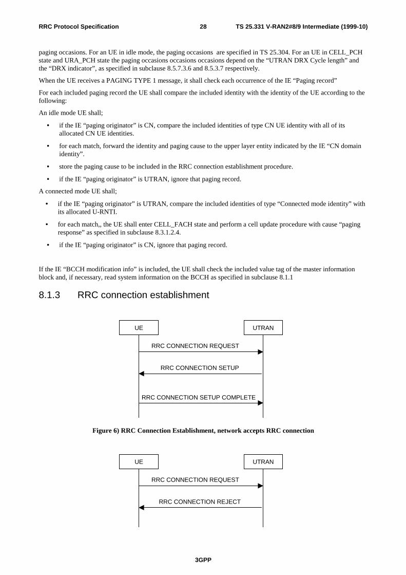
TS 25.331 V-RAN2#8/9 Intermediate (1999-10)
3GPP
28RRC Protocol Specification
paging occasions. For an UE in idle mode, the paging occasions are specified in TS 25.304. For an UE in CELL_PCHstate and URA_PCH state the paging occasions occasions occasions depend on the “UTRAN DRX Cycle length” andthe “DRX indicator”, as specified in subclause 8.5.7.3.6 and 8.5.3.7 respectively.
When the UE receives a PAGING TYPE 1 message, it shall check each occurrence of the IE “Paging record”
For each included paging record the UE shall compare the included identity with the identity of the UE according to thefollowing:
An idle mode UE shall;
• if the IE “paging originator” is CN, compare the included identities of type CN UE identity with all of itsallocated CN UE identities.
• for each match, forward the identity and paging cause to the upper layer entity indicated by the IE “CN domainidentity”.
• store the paging cause to be included in the RRC connection establishment procedure.
• if the IE “paging originator” is UTRAN, ignore that paging record.
A connected mode UE shall;
• if the IE “paging originator” is UTRAN, compare the included identities of type “Connected mode identity” withits allocated U-RNTI.
• for each match,, the UE shall enter CELL_FACH state and perform a cell update procedure with cause “pagingresponse” as specified in subclause 8.3.1.2.4.
• if the IE “paging originator” is CN, ignore that paging record.
If the IE “BCCH modification info” is included, the UE shall check the included value tag of the master informationblock and, if necessary, read system information on the BCCH as specified in subclause 8.1.1
8.1.3 RRC connection establishment
UE UTRAN
RRC CONNECTION REQUEST
RRC CONNECTION SETUP
RRC CONNECTION SETUP COMPLETE
Figure 6) RRC Connection Establishment, network accepts RRC connection
UE UTRAN
RRC CONNECTION REQUEST
RRC CONNECTION REJECT

TS 25.331 V-RAN2#8/9 Intermediate (1999-10)
3GPP
29RRC Protocol Specification
Figure 7) RRC Connection Establishment, network rejects RRC connection
8.1.3.1 General
The purpose with this procedure is to establish an RRC connection.
8.1.3.2 Initiation
The non-access stratum in the UE may request the establishment of at most one RRC connection per UE.
The UE shall transmit an RRC CONNECTION REQUEST message on the uplink CCCH, reset counter V300, and starttimer T300.
The UE shall set the IE “Establishment cause” according to indications from the non-access stratum or according to thepaging cause received from the PAGING TYPE 1 message.
The UE shall set the IE “Initial UE identity” according to subclause 8.5.1
The UE shall indicate its capability in the IE “Initial UE capability”. [Note: Currently this IE is optional. In that casethe condition for including the IE needs to be specified.]
The UE shall include ameasurement report, as specified in the IE “Intra-frequency reporting quantity for RACHreporting” and the IE “Maximum number of reported cells on RACH” in system information block type 11.
8.1.3.3 Reception of an RRC CONNECTION REQUEST message by the UTRAN
UTRAN should either
• transmit an RRC CONNECTION SETUP message on the downlink CCCH or
• transmit an RRC CONNECTION REJECT message on the downlink CCCH. On the UTRAN side, the procedureends and all context information for this UE may be deleted in UTRAN.
8.1.3.4 Reception of a RRC CONNECTION SETUP message by the UE
The UE shall compare the value of the IE “Initial UE identity” in the received RRC CONNECTION SETUP messagewith the value of the IE “Initial UE identity” in the most recent RRC CONNECTION REQUEST message sent by theUE.
• If the values are identical, the UE shall stop timer T300, and perform the following actions.
• If the values are different, the UE shall ignore the rest of the message
The UE shall act upon all received information elements as specified in 8.5.7, unless specified otherwise in thefollowing.
The UE shall
• store the value of the IE “U-RNTI” and
• initiate the signalling link parameters according to the IE “Signalling link type” and the IE “RB mapping info”.
If the IE “C-RNTI” is included, the UE shall
• use that C-RNTI on common transport channels in the current cell.
If neither the IE “PRACH info (for RACH)”,nor the IE “Uplink DPCH info” is included, the UE shall
• let the physical channel of type PRACH that is given in system information to be the default in uplink for RACH
If neither the IE “Secondary CCPCH info”,nor the IE “Downlink DPCH info” is included, the UE shall
• start to receive the physical channel of type Secondary CCPCH that is given in system information to be used asdefault by FACH.
The UE shall enter a state according to 8.5.8.
The UE shall transmit an RRC CONNECTION SETUP COMPLETE message on the uplink DCCH, with contents as

TS 25.331 V-RAN2#8/9 Intermediate (1999-10)
3GPP
30RRC Protocol Specification
specified below.
The UE shall include its capabilities in the IE “UE radio capability” RRC CONNECTION SETUP COMPLETEmessage, according to the IE “Capability update requirement” in system information block type 1.
When the transmission of the RRC CONNECTION SETUP COMPLETE message has been confirmed by RLC the UEshall update its variable UE_CAPABILITY_TRANSFERRED which UE capabilities it has transmitted to the UTRANand the procedure ends.
8.1.3.5 Physical channel failure or T300 timeout
• Upon expiry of timer T300, or
• if the UE failed to establish the physical channel(s) indicated in the RRC CONNECTION SETUP message
the UE shall check the value of V300, and
• if V300 is equal to or smaller than N300, the UE shall transmit a new RRC CONNECTION REQUEST message onthe uplink CCCH, restart timer T300 and increase counter V300. The UE shall set the IEs in the RRCCONNECTION REQUEST message according to subclause 8.1.3.2.1
• If V300 is greater than N300, the UE shall enter idle mode. The procedure ends and a connection failure may beindicated to the non-access stratum. Other actions the UE shall perform when entering idle mode from connectedmode are specified in subclause 8.5.2
8.1.3.6 Reception of an RRC CONNECTION REJECT message by the UE
When the UE receives an RRC CONNECTION REJECT message on the downlink CCCH, it shall compare the value ofthe IE “Initial UE identity” in the received RRC CONNECTION REJECT message with the value of the IE “Initial UEidentity” in the last RRC CONNECTION REQUEST message sent by the UE.
• If the values are identical, the UE shall stop timer T300 and perform the actions in subclause 8.1.3.6.1
• If the values are different, the UE shall ignore the rest of the message
If the IE “wait time” is present, and
• if V300 is equal to or smaller than N300, the UE shall wait at least the time stated in the IE “wait time”, transmit anew RRC CONNECTION REQUEST message on the uplink CCCH, restart timer T300 and increase counter V300.UE shall set the IEs in the RRC CONNECTION REQUEST message according to subclause 8.1.3.2.1
• If V300 is greater than N300 the UE shall enter idle mode. The procedure ends and a connection failure may beindicated to the non-access stratum. Other actions the UE shall perform when entering idle mode from connectedmode are specified in subclause 8.5.2
If the IE “wait time” is not present the UE shall
• enter idle mode. The procedure ends and a connection failure may be indicated to the non-access stratum. Otheractions the UE shall perform when entering idle mode from connected mode are specified in subclause 8.5.2
8.1.3.7 Reception of an RRC CONNECTION SETUP COMPLETE message by theUTRAN
When UTRAN has received the RRC CONNECTION SETUP COMPLETE message, the procedure ends on theUTRAN side.
8.1.4 RRC connection release

TS 25.331 V-RAN2#8/9 Intermediate (1999-10)
3GPP
31RRC Protocol Specification
UE UTRAN
RRC CONNECTION RELEASE
RRC CONNECTION RELEASECOMPLETE
Figure 8. RRC Connection Release procedure
8.1.4.1 General
The purpose with this procedure is to release the RRC connection including the signalling link and all radio bearersbetween the UE and the UTRAN.
8.1.4.2 Initiation
When the UE is in state Cell_DCH or Cell_FACH, the UTRAN can at anytime initiate a RRC connection release bytransmitting an RRC CONNECTION RELEASE message using unacknowledged mode.
UTRAN may transmit several RRC CONNECTION RELEASE messages to increase the probability of proper receptionof the message by the UE. The number of repeated messages and the interval between the messages is a network option.
8.1.4.3 Reception of an RRC CONNECTION RELEASE message by the UE
The UE shall receive and act on an RRC CONNECTION RELEASE message in states Cell_DCH and Cell_FACH.Furthermore this procedure can interrupt any ongoing procedures with the UE in the above listed states.
When the UE receives the first RRC CONNECTION RELEASE message, it shall
• When in state CELL_DCH, transmit an RRC CONNECTION RELEASE COMPLETE message usingunacknowledged mode to the UTRAN and start timer T308.
• When in state CELL_FACH, transmit an RRC CONNECTION RELEASE COMPLETE message usingacknowledged mode to the UTRAN
Any succeeding RRC CONNECTION RELEASE messages that are received by the UE shall be ignored.
A release indication should be given to the non-access stratum.
When in CELL_DCH state, UE shall initialise the counter V308 with the value of the IE “Number of RRC MessageTransmissions” , which indicates the number of times to send the RRC CONNECTION RELEASE COMPLETEmessage.
8.1.4.4 Expiry of timer T308 in CELL_DCH state
When in state CELL_DCH and the timer T308 expires, the UE shall decrease V308 by one. If V308 is greater than zero,the UE shall retransmit the RRC CONNECTION RELEASE COMPLETE message. If V308 is equal to zero, the UEshall release all its radio resources, enter idle mode and the procedure ends on the UE side. Actions the UE shallperform when entering idle mode are given in subclause 8.5.2
8.1.4.5 Successful transmission of the RRC CONNECTION RELEASE COMPLETEmessage in CELL_FACT state
When the UE is in state CELL_FACH and RLC has confirmed the transmission of the RRC CONNECTION RELEASECOMPLETE message it shall release all its radio resources, enter idle mode and the procedure ends on the UE side.Actions the UE shall perform when entering idle mode are given in subclause 8.5.2

TS 25.331 V-RAN2#8/9 Intermediate (1999-10)
3GPP
32RRC Protocol Specification
8.1.4.6 Reception of an RRC CONNECTION RELEASE COMPLETE message byUTRAN
When UTRAN receives a RRC CONNECTION RELEASE COMPLETE message from the UE, it should release all UEdedicated resources and the procedure ends on the UTRAN side.
8.1.4.7 Unsuccssful transmission of the RRC CONNECTION RELEASECOMPLETE message in CELL_FACH state
When the UE is in state CELL_FACH and does not succeed in transmitting the RRC CONNECTION RELEASECOMPLETE message, it shall release all its radio resources, enter idle mode and the procedure ends on the UE side.Actions the UE shall perform when entering idle mode are given in subclause 8.5.2
8.1.4.8 Detection of dedicated physical channel release by UTRAN in CELL_DCHstate
If the release is performed from the state CELL_DCH, and UTRAN detects loss of a the dedicated physical channelaccording to subclause 8.5.6, UTRAN may release all UE dedicated resources, even if no RRC CONNECTIONRELEASE COMPLETE message has been received.
8.1.4.9 No reception of an RRC CONNECTION RELEASE COMPLETE message byUTRAN
If UTRAN does not receive any RRC CONNECTION RELEASE COMPLETE message, it should release all UEdedicated resources.
8.1.5 RRC connection re-establishment
UE UTRAN
RRC CONNECTION RE-ESTABLISHMENT REQUEST
RRC CONNECTION RE-ESTABLISHMENT COMPLETE
RRC CONNECTION RE-ESTABLISHMENT
Figure 9. RRC Connection Re-establishment, successful case
UE UTRAN
RRC CONNECTION RE-ESTABLISHMENT REQUEST
RRC CONNECTION RELEASE COMPLETE
RRC CONNECTION RELEASE
Figure 10. RRC Connection Re-establishment, failure case
8.1.5.1 General
The purpose of this procedure is to re-establish a lost RRC connection.

TS 25.331 V-RAN2#8/9 Intermediate (1999-10)
3GPP
33RRC Protocol Specification
8.1.5.2 Initiation
When a UE loses the radio connection due to e.g. radio link failure (see 8.5.6) in CELL_DCH state, the UE may initiatea new cell selection by transiting to CELL_FACH state and request re-establishment of an RRC connection.
The UE shall transmit an RRC CONNECTION RE-ESTABLISHMENT REQUEST message on the uplink CCCH, resetcounter V301, and start timer T301.
The UE shall
• Set the IE “U-RNTI” to the value stored in the UE.
• Include an IE ”Measured Results”, as specified in the IE “Intra-frequency reporting quantity for RACH reporting”and the IE “Maximum number of reported cells on RACH” in system information block type 12.
8.1.5.3 Reception of an RRC CONNECTION RE-ESTABLISHMENT REQUESTmessage by the UTRAN
UTRAN may either
• Initiate the RRC connection re-establishment procedure and transmit an RRC CONNECTION RE-ESTABLISHMENT message on the downlink DCCH on FACH or
• Initiate the RRC connection release procedure in CELL_FACH state.
8.1.5.4 Reception of an RRC CONNECTION RE-ESTABLISHMENT message by theUE
Upon reception of the RRC CONNECTION RE-ESTABLISHMENT message the UE shall
• Stop timer T301
• Re-establish the RRC connection according to the IEs included in the RRC CONNECTION RE-ESTABLISHMENT message
• Transmit a RRC CONNECTION RE-ESTABLISHMENT COMPLETE message on the uplink DCCH using AMRLC.
The UE shall use the contents of the RRC CONNECTION RE-ESTABLISHMENT message as specified in clause8.5.7, unless specified otherwise in the following.
• For each reconfigured radio bearer use the mapping option applicable for the transport channels used according tothe IE “RB mapping info”.
• Configure MAC multiplexing if that is needed in order to use said transport channel(s).
• Use MAC logical channel priority when selecting TFC in MAC.
If neither the IEs “PRACH info” nor “Uplink DPCH info” is included, the UE shall
• Let the physical channel of type PRACH that is given in system information Block Type 7 be the default in uplink.
If neither the IEs “Secondary CCPCH info” nor “Downlink DPCH info” is included, the UE shall
• Start to receive the physical channel of type Secondary CCPCH that is given in system information.
The UE shall use the transport channel(s) applicable for the physical channel types that is used. If the IE “TFS” isneither included nor previously stored in the UE for that transport channel(s), the UE shall
• Use the TFS given in system information
If none of the TFS stored is compatible with the physical channel, the UE shall
• Delete the stored TFS and use the TFS given in system information
If the IE “New C-RNTI” is included, the UE shall
• Use that C-RNTI when using common transport channels of type RACH, FACH and CPCH in the current cell.
If the the IE "New U-RNTI" is included, the UE shall update its identity.

TS 25.331 V-RAN2#8/9 Intermediate (1999-10)
3GPP
34RRC Protocol Specification
If the IEs “CN domain identity” and “NAS system information” are included, the UE shall
• Forward the content of the IE to the non-access stratum entity of the UE indicated by the IE “CN domain identity”.
The UE shall enter a state according to 8.5.8.
8.1.5.5 T301 timeout or DPCH failure
• Upon expiry of timer T301, or
• if the UE failed to re-establish the RRC Connection indicated in the RRC CONNECTION RE-ESTABLISHMENTmessage
the UE shall check the value of V301, and
• if V301 is equal to or smaller or equal than N301, the UE shall transmit a new RRC CONNECTION RE-ESTABLISHMENT REQUEST message on the uplink CCCH, restart timer T301 and increase counter V301. TheUE shall set the IEs in the RRC CONNECTION RE-ESTABLISHMENT REQUEST message according tosubclause 8.1.5.2.
• If V301 is greater than N301, the UE shall enter idle mode. The procedure ends and a connection failure may beindicated to the non-access stratum. Other actions the UE shall perform when entering idle mode from connectedmode are specified in subclause 8.5.2
8.1.5.6 Reception of an RRC CONNECTION RE-ESTABLISHMENT COMPLETEmessage by the UTRAN
When UTRAN has received the RRC CONNECTION RE-ESTABLISHMENT COMPLETE message, the procedureends on the UTRAN side.
8.1.6 Transmission of UE capability information
UE UTRAN
UE CAPABILITY INFORMATION
UE CAPABILITY INFORMATION CONFIRM
Figure 11. Transmission of UE capability information, normal flow
8.1.6.1 General
The UE capability update procedure is used by the UE to convey UE specific capability information to the UTRAN.
8.1.6.2 Initiation
The UE shall initiate the UE capability update procedure in the following situations:
- After the UE has received a UE CAPABILITY ENQUIRY message from the UTRAN.
- After having performed cell reselection to a cell, and the IE "capability update requirement" in system informationblock type 1 indicates the necessity to transmit capability information which is indicated as previously sent in the

TS 25.331 V-RAN2#8/9 Intermediate (1999-10)
3GPP
35RRC Protocol Specification
variable UE_CAPABILITY TRANSFERRED.
- If UE capabilities change during the RRC connection
The UE transmits the UE CAPABILITY INFORMATION message on the uplink DCCH using AM or UM RLC, startstimer T304 and resets counter V304.
If the UE CAPABILITY INFORMATION message is sent upon establishment of an RRC connection, the UE shall
- set CN specific capability information into the IE "NAS message" and UTRAN specific capability information tothe corresponding information elements according to information stored in the UE.
- include one or more inter-system classmarks into the IEs "inter-system message", according to the requirementgiven in the "Capability update requirement" IE in the SYSTEM INFORMATION message
If the UE CAPABILITY INFORMATION message is sent in response to a UE CAPABILITY ENQUIRY message, theUE shall
- include the UMTS specific UE capability information elements if requsted in the IE “System” in the IE "Capabilityupdate requirement" IE in the UE CAPABILITY ENQUIRY message.
- include one or more inter-system classmarks into the IEs "inter-system message", according to the requirementgiven in the IE “System” in the IE "Capability update requirement" in the UE CAPABILITY ENQUIRY message
8.1.6.3 Reception of an UE CAPABILITY INFORMATION message by the UTRAN
Upon reception of a UE CAPABILITY INFORMATION message, the UTRAN should transmit a UE CAPABILITYINFORMATION CONFIRM message on the downlink DCCH using UM or AM RLC. After the UE CAPABILITYINFORMATION CONFIRM message has been sent, the procedure is complete.
8.1.6.4 Reception of the UE CAPABILITY INFORMATION CONFIRM message bythe UE
Upon reception of a UE CAPABILITY INFORMATION CONFIRM message, the UE shall stop timer T304. It shallthen update its variable UE_CAPABILITY TRANSFERRED which UE capabilities it has transmitted to the UTRANduring the current RRC connection.
8.1.6.5 T304 timeout
Upon expiry of timer T304, the UE the UE shall check the value of V304 and
• If V304 is smaller or equal than N304, the UE shall retransmit a UE CAPABILITY INFORMATION message,restart timer T304 and increase counter V304.
• If V304 is greater than N304, the UE shall assume that radio link failure has occurred and initiate the RRCconnection re-establishment procedure
8.1.7 UE capability enquiry

TS 25.331 V-RAN2#8/9 Intermediate (1999-10)
3GPP
36RRC Protocol Specification
UE UTRAN
UE CAPABILITY ENQUIRY
Figure 12. UE capability enquiry procedure, normal flow
8.1.7.1 General
The UE capability enquiry can be used to request the UE to transmit its capability information related to any radioaccess network that is supported by the UE.
8.1.7.2 Initiation
The UE capability enquiry procedure in initiated byUTRAN by transmitting a UE CAPABILITY ENQUIRY messageon the DCCH using the UM or AM SAP.
8.1.7.3 Reception of an UE CAPABILITY ENQUIRY message by the UE
Upon reception of an UE CAPABILITY ENQUIRY message, the UE shall initiate the transmission of UE capabilityinformation procedure, which is specified in clause 8.1.6
8.1.8 Direct transfer
UE UTRAN
DIRECT TRANSFER
Figure 13. Direct transfer in the downlink, normal flow

TS 25.331 V-RAN2#8/9 Intermediate (1999-10)
3GPP
37RRC Protocol Specification
UE UTRAN
DIRECT TRANSFER
Figure 14. Direct transfer in the uplink, normal flow
8.1.8.1 General
The direct transfer procedure is used in both downlink and uplink to carry all higher layer (NAS) messages over theradio interface. It can also be used to establish and release signalling connections (FFS).
8.1.8.2 Initiation of direct transfer procedure in the UE
In the UE, the direct transfer procedure shall be initiated, when the upper layers request a transfer of a NAS message.The UE shall transmit the DIRECT TRANSFER message on the uplink DCCH using AM RLC.
The UE shall set IE "CN domain identity" to indicate which CN node the NAS message is destined to.
In, CELL_FACH state, the UE shall include IE "Measured results" into the DIRECT TRANSFER message, if themessage is sent to establish a signalling connection and if RACH measurement reporting has been requested in the IE“Intra-frequency reporting quantity for RACH reporting” and the IE “Maximum number of reported cells on RACH” insystem information block type 12.
8.1.8.3 Initiation of direct transfer procedure in the UTRAN
In the UTRAN, the direct transfer procedure shall be initiated, when the upper layers request the transfer of a NASmessage or the release of a signalling connection (FFS) The UTRAN shall transmit the DIRECT TRANSFER messageon the downlink DCCH using AM RLC.
The UTRAN sets the IE "CN domain identity" to indicate, which CN domain the NAS message is originated from.
8.1.8.4 Reception of DIRECT TRANSFER in message bythe UTRAN
Upon reception of the DIRECT TRANSFER message the NAS message should be routed to the correct CN domainusing the IE "CN domain identity".
If the IE "Measured results" is present in the message, the UTRAN shall extract the contents to be used for radioresource control.
8.1.8.5 Reception of a DIRECT TRANSFER message by the UE
Upon reception of the DIRECT TRANSFER message, the UE RRC shall using the IE “CN Domain identity”,
• route the contents of the higher layer PDU, if any, to the correct higher layer entity.
• route the signalling connection release indication, if any, to the correct higher layer entity (FFS).
8.1.9 UE dedicated paging

TS 25.331 V-RAN2#8/9 Intermediate (1999-10)
3GPP
38RRC Protocol Specification
UE UTRAN
PAGING TYPE 2
Figure 15. UE dedicaed paging
8.1.9.1 General
This procedure is used to transmit dedicated paging information to one UE in connected mode in states CELL_DCH andCELL_FACH. Upper layers in the network may request initiation of paging, for e.g. to establish a signallingconnection.
8.1.9.2 Initiation
For an UE in states CELL_DCH or CELL_FACH, UTRAN initiates the procedure by transmitting a PAGING TYPE 2message on the DCCH.
8.1.9.3 Reception of an PAGING TYPE 2 message by the UE
The UE shall indicate paging and forward the paging cause and the paging record type indetifier to the upper layer entityindicated by the CN domain identity.
8.1.10 Security mode control
UEUTRAN
SECURITY MODE COMMAND
SECURITY MODE COMPLETE
Figure 16) Security mode control procedure
8.1.10.1 General
The purpose of this procedure is to trigger the start of ciphering or to command the change of the cipher key, both forthe signalling link and for any of the radio bearers.

TS 25.331 V-RAN2#8/9 Intermediate (1999-10)
3GPP
39RRC Protocol Specification
8.1.10.2 Initiation
The UTRAN sends a SECURITY MODE COMMAND message on the downlink DCCH in AM RLC, using the oldciphering configuration.
For the signalling link, the UTRAN starts to cipher the messages, when the layer 2 acknowledgement for theSECURITY MODE COMMAND is received.
For radio bearers in TM RLC, the UTRAN may set the IE ”Activation Time”, both in uplink and in downlink, in orderto synchronise the time instant at which the cipher key shall be switched.
8.1.10.3 Reception of SECURITY MODE COMMAND message by the UE
For the signalling link, the UE shall start to transmit using the new cipher configuration, and to receive and deciphermessages.
If the IE ”Activation Time” is included for radio bearers in TM RLC, the UE shall switch to the new cipherconfiguration at the specified time.
The UE shall send a SECURITY MODE COMPLETE message on the uplink DCCH in AM RLC, using the new cipherconfiguration. When the transmission of the SECURITY MODE COMPLETE message has been confirmed by RLC, theprocedure ends.
8.1.10.4 Activation time too short
If the time specified by the IE ”Activation Time” has elapsed, the UE shall switch immediately to the new cipherconfiguration.
8.1.10.5 Reception of SECURITY MODE COMPLETE message by the UTRAN
Note : The same procedure can be used for integrity control. But this is FFS.

TS 25.331 V-RAN2#8/9 Intermediate (1999-10)
3GPP
40RRC Protocol Specification
8.2 Radio Bearer control procedures
8.2.1 Radio bearer establishment
UE UTRAN
RADIO BEARER SETUP
RADIO BEARER SETUP COMPLETE
Figure 17. Radio Bearer Establishment, normal case
UE UTRAN
RADIO BEARER SETUP
RADIO BEARER SETUP FAILURE
Figure 18. Radio Bearer Establishment, UE reverts to old configuration
8.2.1.1 General
The purpose with this procedure is to establish new radio bearer(s). The procedure may also be used to establish atransport channel for the transparent transfer of signalling.
8.2.1.2 Initiation
The upper layer in the network may request an establishment of radio bearer(s).
To initiate the procedure, UTRAN transmits a RADIO BEARER SETUP message on the downlink DCCH using AM orUM RLC.
If transport channels are added, reconfigured or deleted in uplink and/or downlink, UTRAN shall
• Set TFCS according to the new transport channel(s)
If the IE “Activation Time” is included, UTRAN should set it to a value taking the UE performance requirements intoaccount.
UTRAN should take the UE capabilities into account when setting the new configuration.
8.2.1.3 Reception of a RADIO BEARER SETUP message by the UE
Upon reception of a RADIO BEARER SETUP message the UE shall perform actions as specified below and transmit aRADIO BEARER SETUP COMPLETE message on the uplink DCCH using AM RLC. When the transmission of theRADIO BEARER SETUP COMPLETE message has been confirmed by RLC the procedure ends.

TS 25.331 V-RAN2#8/9 Intermediate (1999-10)
3GPP
41RRC Protocol Specification
The UE shall act upon all received information elements as specified in 8.5.7, unless specified otherwise in thefollowing.
The UE shall
• For the new radio bearer(s), use the multiplexing option applicable for the transport channels used according to theIE “RB mapping info”
• For radio bearer(s) existing prior to the message, use the multiplexing option applicable for the transport channelsused, according to their IE “RB mapping info” or their previously stored multiplexing options.
• Configure MAC multiplexing if that is needed in order to use said transport channel(s).
• Use MAC logical channel priority when selecting TFC in MAC.
If the IE “New C-RNTI” is included, the UE shall
• Use that C-RNTI when using common transport channels of type RACH, FACH and CPCH in the current cell.
If neither the IE “PRACH info” nor the IE “Uplink DPCH info” is included, the UE shall
• Let the physical channel of type PRACH that is given in system information be the default in uplink.
If neither the IE “Secondary CCPCH info” nor the IE “Downlink DPCH info” is included, the UE shall
• Start to receive the physical channel of type Secondary CCPCH that is given in system information.
The UE shall use the transport channel(s) applicable for the physical channel types that is used. If neither the IE “TFS”is included or previously stored in the UE for that transport channel(s), the UE shall
• Use the TFS given in system information
If none of the TFS stored is compatible with the physical channel, the UE shall
• Delete stored TFS and use the TFS given in system information
The UE shall enter a state according to 8.5.8.
8.2.1.4 Unsupported configuration in the UE
If UTRAN instructs the UE to use a configuration that it does not support, the UE transmit a RADIO BEARER SETUPFAILURE message on the DCCH using AM RLCand set the IE “failure cause” the cause value “configurationunacceptable”.
8.2.1.5 Physical channel failure
If the UE failed to establish the physical channel(s) indicated in the RADIO BEARER SETUP message the UE shall
• Revert to the configuration prior to the reception of the RADIO BEARER SETUP message (old configuration) andtransmit a RADIO BEARER SETUP FAILURE message on the DCCH using AM RLC. The procedure ends andthe UE resumes the normal operation as if no radio bearer establishment attempt had occurred.
A physical channel failure occurs in case the criteria as defined in 8.5.4 are not fulfilled. If the UE is unable to revert tothe old configuration or if used, the activation time has expired, the UE shall
initiate a RRC connection re-establishment procedure according to subclause 8.1and set the IE “failure cause” the causevalue “physical channel failure”.
8.2.1.6 Reception of the RADIO BEARER SETUP COMPLETE message by theUTRAN
When UTRAN has received the RADIO BEARER SETUP COMPLETE message, UTRAN may delete any oldconfiguration and the procedure ends on the UTRAN side.
8.2.1.7 Reception of RADIO BEARER SETUP FAILURE by the UTRAN
When UTRAN has received the RADIO BEARER SETUP FAILURE message, UTRAN may restore the old and deletethe new configuration and the procedure ends on the UTRAN side. Upper layers should be notified of the failure.

TS 25.331 V-RAN2#8/9 Intermediate (1999-10)
3GPP
42RRC Protocol Specification
8.2.2 Radio bearer reconfiguration
UE UTRAN
RADIO BEARER RECONFIGURATION
RADIO BEARERRECONFIGURATION COMPLETE
Figure 19. Radio bearer reconfiguration, normal flow
UE UTRAN
RADIO BEARER RECONFIGURATION
RADIO BEARERRECONFIGURATION FAILURE
Figure 20. Radio bearer reconfiguration, failure case
8.2.2.1 General
The radio bearer reconfiguration procedure is used to reconfigure parameters for a radio bearer or the signalling link toreflect a change in QoS.
8.2.2.2 Initiation
The UTRAN initiates the procedure by transmitting a RADIO BEARER RECONFIGURATION message on thedownlink DCCH using AM or UM RLC.
If transport channels are added, reconfigured or deleted in uplink and/or downlink, the UTRAN shall
• Set TFCS according to the new transport channel(s)
UTRAN should indicate that uplink transmission shall be suspended on certain bearers. Uplink transmission on a radiobearer used by the RRC signalling should not be suspended.
If the IE “Activation Time” is included, UTRAN should set it to a value taking the UE performance requirements intoaccount.
UTRAN should take the UE capabilities into account when setting the new configuration.
If the message is used to initiate a transition from CELL_DCH to CELL_FACH state, the UTRAN may assign acommon channel configuration of a given cell and C-RNTI to be used in that cell to the UE.

TS 25.331 V-RAN2#8/9 Intermediate (1999-10)
3GPP
43RRC Protocol Specification
8.2.2.3 Reception of RADIO BEARER RECONFIGURATION by the UE inCELL_DCH state
Upon reception of a RADIO BEARER RECONFIGURATION message in CELL_DCH state, the UE shall performactions specified below.
The UE shall act upon all received information elements as specified in 8.5.7, unless specified otherwise in thefollowing.
The UE shall
• For each reconfigured radio bearer or signalling link, use the multiplexing option applicable for the transportchannels used according to the IE “RB mapping info”
• Configure MAC multiplexing if that is needed in order to use said transport channel(s).
• Use MAC logical channel priority when selecting TFC in MAC.
• Suspend or resume uplink transmission for each radio bearer, as indicated by the IE "RB suspend/resume"information element.
If neither the IE “PRACH info” nor the IE “Uplink DPCH info” is included, the UE shall
• Let the physical channel of type PRACH that is given in system information be the default in.
If neither the IEs “Secondary CCPCH info” nor “Downlink DPCH info” is included, the UE shall
• Start to receive the physical channel of type Secondary CCPCH that is given in system information.
The UE shall use the transport channel(s) applicable for the physical channel types that is used. If neither the IE “TFS”is included or previously stored in the UE for that transport channel(s), the UE shall
• Use the TFS given in system information
If none of the TFS stored is compatible with the physical channel, the UE shall
• Delete stored TFS and use the TFS given in system information
If the IE “Primary CCPCH info” and the IE “New C-RNTI” are included, the UE shall
• Select the cell indicated by the IE “Primary CCPCH info”.
• Use the given C-RNTI when using common transport channels of type RACH, FACH and CPCH in that given cellafter having completed the transition to that cell.
The UE shall enter a state according to 8.5.8.
The UE shall transmit a RADIO BEARER RECONFIGURATION COMPLETE message on the uplink DCCH usingAM RLC. When the transmission of the RADIO BEARER RECONFIGURATION COMPLETE message has beenconfirmed by RLC, the procedure ends.
If the RADIO BEARER RECONFIGURATION message is used to initiate a transition from CELL_DCH toCELL_FACH state, the RADIO BEARER RECONFIGURATION COMPLETE message shall be transmitted on theRACH after the UE has completed the state transition.
8.2.2.4 Reception of an RADIO BEARER RECONFIGURATION message by the UEin CELL_FACH state
Upon reception of a RADIO BEARER RECONFIGURATION message in CELL_FACH state, theUE shall perform actions specified below.
The UE shall act upon all received information elements as specified in 8.5.7, unless specified otherwise in thefollowing.

TS 25.331 V-RAN2#8/9 Intermediate (1999-10)
3GPP
44RRC Protocol Specification
The UE shall
• For each reconfigured radio bearer or signalling link, use the multiplexing option applicable for the transportchannels used according to the IE “RB mapping info”
• Configure MAC multiplexing if that is needed in order to use said transport channel(s).
• Use MAC logical channel priority when selecting TFC in MAC.
• Suspend or resume uplink transmission for each radio bearer, as indicated by the IE "RB suspend/resume".
If the IE “New C-RNTI” is included, the UE shall
• Use that C-RNTI when using common transport channels of type RACH, FACH and CPCH in the current cell.
If neither the IE “PRACH info” nor the IE “Uplink DPCH info” is included, the UE shall
• Let the physical channel of type PRACH that is given in system information be the default in uplink
If neither the IE “Secondary CCPCH info” nor the IE “Downlink DPCH info” is included, the UE shall
• Start to receive the physical channel of type Secondary CCPCH that is given in system information.
The UE shall use the transport channel(s) applicable for the physical channel types that is used. If neither the IE “TFS”is included or previously stored in the UE for that transport channel(s), the UE shall
• Use the TFS given in system information
If none of the TFS stored is compatible with the physical channel, the UE shall
• Delete stored TFS and use the TFS given in system information
The UE shall enter a state according to 8.5.8.
The UE shall transmit a RADIO BEARER RECONFIGURATION COMPLETE message on the uplink DCCH usingAM RLC. When the transmission of the RADIO BEARER RECONFIGURATION COMPLETE message has beenconfirmed by RLC, the procedure ends.
8.2.2.5 Reception of a RADIO BEARER RECONFIGURATION COMPLETEmessage by the UTRAN
When UTRAN has received the RADIO BEARER RECONFIGURATION COMPLETE message, UTRAN may deletethe old configuration..
8.2.2.6 Unsupported configuration in the UE
If the UTRAN instructs the UE to use a configuration which it does not support, the UE shall
• transmit a RADIO BEARER RECONFIGURATION FAILURE message on the DCCH using AM RLC.
• set the cause value in IE "failure cause" to "configuration unacceptable".
8.2.2.7 Physical channel failure
A physical channel failure occurs in case the criteria as defined in 8.5.4 are not fulfilled.
If the UE failed to establish the physical channel(s) indicated in the RADIO BEARER RECONFIGURATION messagethe UE shall
• Revert to the configuration prior to the reception of the RADIO BEARER RECONFIGURATION message (oldconfiguration)
• transmit a RADIO BEARER RECONFIGURATION FAILURE message on the DCCH using AM RLC.
• set the cause value in IE "failure cause" to "physical channel failure".
• When the transmission of the RADIO BEARER RECONFIGURATION FAILURE message has been confirmed byRLC, the procedure ends and the UE resumes the normal operation as if no radio bearer reconfiguration attempt hadoccurred.

TS 25.331 V-RAN2#8/9 Intermediate (1999-10)
3GPP
45RRC Protocol Specification
If the UE is unable to revert to the old configuration or if used, the activation time has expired, the UE shall
• Initiate a RRC connection re-establishment procedure according to subclause 8.1.5
8.2.2.8 Reception of a RADIO BEARER RECONFIGURATION FAILURE messageby the UTRAN
When UTRAN has received the RADIO BEARER RECONFIGURATION FAILURE message, UTRAN may restorethe old and delete the new configuration. The procedure ends on the UTRAN side. Upper layers should be notified ofthe failure.
8.2.2.9 No response from the UE in CELL DCH_state
If no RADIO BEARER RECONFIGURATION COMPLETE message or RADIO BEARER RECONFIGURATIONFAILURE message has been received, the UTRAN may delete the old and new configuration. If the UE requests a re-establishment of the RRC connection, before all UE dedicated resources have been cleared, the new configuration maybe re-assigned in the re-establishment procedure.
During transition from CELL_DCH to CELL_FACH, the UTRAN may also receive a CELL UPDATE message if theUE cannot use the assigned physical channel.
8.2.2.10 No response from the UE in CELL_FACH state
If no RADIO BEARER RECONFIGURATION COMPLETE message or RADIO BEARER RECONFIGURATIONFAILURE message has been received, the UTRAN may delete the old and new configuration. If the UE makes a cellupdate before all UE dedicated resources have been cleared, the configuration procedure can be restarted.
8.2.2.11 Phyical channel failure during transmition from CELL_DCH to CELL_FACH
If the UE fails to select the cell, which was assigned in the RADIO BEARER RECONFIGURATION message initiatingtransition from CELL_DCH to CELL_FACH, the UE shall perform cell reselection and initiate the cell updateprocedure.
8.2.2.12 Suspension of signalling bearer
If the RADIO BEARER RECONFIGURATION message includes a request to suspend the signalling link with the IE"RB suspend/resume" , the UE shall
• Revert to the configuration prior to the reception of the RADIO BEARER RECONFIGURATION message (oldconfiguration)
• send a RADIO BEARER RECONFIGURATION FAILURE message to the UTRAN.
• set the cause value in IE "failure cause" to "configuration unacceptable".
• When the transmission of the RADIO BEARER RECONFIGURATION FAILURE message has been confirmed byRLC, the procedure ends and the UE shall resume the normal operation as if no radio bearer reconfiguration attempthad occurred.
8.2.3 Radio bearer release

TS 25.331 V-RAN2#8/9 Intermediate (1999-10)
3GPP
46RRC Protocol Specification
UE UTRAN
RADIO BEARER RELEASE
RADIO BEARER RELEASE COMPLETE
Figure 21. Radio Bearer Release, normal case
UE UTRAN
RADIO BEARER RELEASE
RADIO BEARER RELEASE FAILURE
Figure 22. Radio Bearer Release, UE reverts to old configuration
8.2.3.1 Purpose
The purpose of this procedure is to release existing radio bearer(s).
8.2.3.2 Initiation
The upper layer in the network may request a release of radio bearer(s).
To initiate the procedure, UTRAN transmits a RADIO BEARER RELEASE message on the downlink DCCH usingAM or UM RLC.
If transport channels are added, reconfigured or deleted in uplink and/or downlink, UTRAN shall
Set TFCS according to the new transport channel(s)
If the IE “Activation Time” is included, UTRAN should set it to a value taking the UE performance requirements intoaccount.
UTRAN should take the UE capabilities into account when setting the new configuration.
8.2.3.3 Reception of RADIO BEARER RELEASE by the UE
Upon reception of a RADIO BEARER RELEASE message the UE shall perform the following.
The UE shall act upon all received information elements as specified in 8.5.7, unless specified otherwise in thefollowing.
The UE shall
• For the released radio bearer(s), delete all stored multiplexing options
• For all remaining radio bearer(s), use the multiplexing option applicable for the transport channels used accordingto their IE “RB mapping info” or their previously stored multiplexing options.

TS 25.331 V-RAN2#8/9 Intermediate (1999-10)
3GPP
47RRC Protocol Specification
• Configure MAC multiplexing if that is needed in order to use said transport channel(s).
• Use MAC logical channel priority when selecting TFC in MAC.
If the IE “New C-RNTI” is included, the UE shall
• Use that C-RNTI when using common transport channels of type RACH, FACH and CPCH in the current cell.
If neither the IE “PRACH info” nor the IE “Uplink DPCH info” is included, the UE shall
• Let the physical channel of type PRACH that is given in system information be the default in uplink.
If neither the IE “Secondary CCPCH info” nor the IE “Downlink DPCH info” is included, the UE shall
• Start to receive the physical channel of type Secondary CCPCH that is given in system information.
The UE shall use the transport channel(s) applicable for the physical channel types that is used. If neither the IE “TFS”is included or previously stored in the UE for that transport channel(s), the UE shall
• Use the TFS given in system information
If none of the TFS stored is compatible with the physical channel, the UE shall
• Delete stored TFS and use the TFS given in system information
• If the RADIO BEARER RELEASE message is used to initiate a state transition to the CELL_FACH state and if anIE primary CCPCH info and C-RNTI to a given cell is included, the UE shall elect the cell indicated by thePCCPCH info IE.
• Use the C-RNTI when using common transport channels of type RACH, FACH and CPCH in that given cell afterhaving completed the transition to that cell.
The UE shall enter a state according to 8.5.8.
The UE shall transmit a RADIO BEARER RELEASE COMPLETE message on the uplink DCCH using AM RLC.When the transmission of the RADIO BEARER RELEASE COMPLETE message has been confirmed by RLC theprocedure ends.
If the RADIO BEARER RELEASE message is used to initiate a transition from CELL_DCHto CELL_FACH state, the RADIO BEARER RELEASE COMPLETE messageshall be transmitted on the RACH after the UE has completed the statetransition.8.2.3.4 Unsupported configuration in the UE
If UTRAN instructs the UE to use a configuration that it does not support, the UE shall Transmit a RADIO BEARERRELEASE FAILURE message on the DCCH using AM RLCand set the value of the IE “failure cause” to “configurationunacceptable”.
8.2.3.5 Physical channel failure
If the UE failed to establish the physical channel(s) indicated in the RADIO BEARER RELEASE message the UE shall
• Revert to the configuration prior to the reception of the RADIO BEARER RELEASE message (old configuration)and transmit a RADIO BEARER RELEASE FAILURE message on the DCCH using AM RLC and set the value ofthe IE “failure cause” to “physical channel failure”. The procedure ends and the UE resumes the normal operationas if no radio bearer release attempt had occurred.
A physical channel failure occurs in case the criteria as defined in 8.5.4 are not fulfilled . If the UE is unable to revert tothe old configuration or if used, the activation time has expired, the UE shall
• Initiate a RRC connection re-establishment procedure according to subclause 8.1.5
8.2.3.6 Reception of the RADIO BEARER RELEASE COMPLETE message by theUTRAN
When UTRAN has received the RADIO BEARER RELEASE COMPLETE message, UTRAN may delete any oldconfiguration, and the procedure ends on the UTRAN side.

TS 25.331 V-RAN2#8/9 Intermediate (1999-10)
3GPP
48RRC Protocol Specification
8.2.3.7 Reception of the RADIO BEARER RELEASE FAILURE message by theUTRAN
When UTRAN has received the RADIO BEARER RELEASE FAILURE message, UTRAN may restore the old anddelete the new configuration and the procedure ends on the UTRAN side. Upper layers should be notified of the failure.
8.2.3.9 Physical channel failure during transition from CELL_DCH to CELL_FACH
During transition from CELL_DCH to CELL_FACH, the UTRAN may also receive an CELL UPDATE message if theUE cannot use the assigned physical channel.
If the UE fails to select the cell, which was assigned in the RADIO BEARER RELEASE message initiating transitionfrom CELL_DCH to CELL_FACH, the UE shall perform cell reselection and initiate the cell update procedure.
8.2.4 Transport channel reconfiguration
UE UTRAN
TRANSPORT CHANNELRECONFIGURATION
TRANSPORT CHANNELRECONFIGURATION COMPLETE
Figure 23. Transport channel reconfiguration, normal flow
UE UTRAN
TRANSPORT CHANNELRECONFIGURATION
TRANSPORT CHANNELRECONFIGURATION FAILURE
Figure 24. Transport channel reconfiguration, failure case
8.2.4.1 General
The transport channel reconfiguration procedure is used to reconfigure transport channel parameters.
8.2.4.2 Initiation
The UTRAN shall transmit a TRANSPORT CHANNEL RECONFIGURATION message on the downlink DCCH usingAM or UM RLC.

TS 25.331 V-RAN2#8/9 Intermediate (1999-10)
3GPP
49RRC Protocol Specification
If transport channels are added, reconfigured or deleted in uplink and/or downlink, the UTRAN shall
• Set TFCS according to the new transport channel(s)
If the IE “Activation Time” is included, UTRAN should set it to a value taking the UE performance requirements intoaccount.
UTRAN should take the UE capabilities into account when setting the new configuration.
8.2.4.3 Reception of an TRANSPORT CHANNEL RECONFIGURATION messageby the UE in CELL_DCH state
Upon reception of a TRANSPORT CHANNEL RECONFIGURATION message in CELL_DCHstate, the UE shall perform the following actions.
The UE shall act upon all received information elements as specified in 8.5.7, unless specified otherwise in thefollowing.
If neither the IE “PRACH info” nor the IE “Uplink DPCH info” is included, the UE shall
• Let the physical channel of type PRACH that is given in system information be the default in uplink.
If neither the IE “Secondary CCPCH info” nor the IE “Downlink DPCH info” is included, the UE shall
• Start to receive the physical channel of type Secondary CCPCH that is given in system information.
The UE shall use the transport channel(s) applicable for the physical channel types that is used. If the IE “TFS” isneither included nor previously stored in the UE for that transport channel(s), the UE shall
• Use the TFS given in system information
If none of the TFS stored is compatible with the physical channel, the UE shall
• Delete stored TFS and use the TFS given in system information
If the TRANSPORT CHANNEL RECONFIGURATION message is used to initiate a state transition to theCELL_FACH state and if the IE “Primary CCPCH info” and IE “New C-RNTI” to a given cell is included, the UE shall
• Select the cell indicated by the IE “Primary CCPCH info”.
• Use the C-RNTI when using common transport channels of type RACH, FACH and CPCH in that given cell afterhaving completed the transition to that cell.
The UE shall enter a state according to 8.5.8.
The UE shall transmit a TRANSPORT CHANNEL RECONFIGURATION COMPLETE message on the uplink DCCHusing AM RLC. If the TRANSPORT CHANNEL RECONFIGURATION message is used to initiate a transition fromCELL_DCH to CELL_FACH state, the TRANSPORT CHANNEL RECONFIGURATION COMPLETE message shallbe transmitted on the RACH after the UE has completed the state transition. When the transmission of theTRANSPORT CHANNEL RECONFIGURATION COMPLETE message has been confirmed by RLC, the procedureends.
8.2.4.4 Reception of an TRANSPORT CHANNEL RECONFIGURATION messageby the UE in CELL_FACH state
Upon reception of a TRANSPORT CHANNEL RECONFIGURATION message in CELL_FACHstate, the UE shall perform the following
The UE shall act upon all received information elements as specified in 8.5.7, unless specified otherwise in thefollowing.

TS 25.331 V-RAN2#8/9 Intermediate (1999-10)
3GPP
50RRC Protocol Specification
If the IE “New C-RNTI” is included, the UE shall
• Use that C-RNTI when using common transport channels of type RACH, FACH and CPCH in the current cell.
If neither the IE “PRACH info” nor IE “Uplink DPCH info” is included, the UE shall
• Let the physical channel of type PRACH that is given in system information be the default in uplink
If neither the IE “Secondary CCPCH info” nor IE “Downlink DPCH info” is included, the UE shall
• Start to receive the physical channel of type Secondary CCPCH that is given in system information.
The UE shall use the transport channel(s) applicable for the physical channel types that is used. If the IE “TFS” isneither included nor previously stored in the UE for that transport channel(s), the UE shall
• Use the TFS given in system information
If none of the TFS stored is compatible with the physical channel, the UE shall
• Delete stored TFS and use the TFS given in system information
The UE shall enter a state according to 8.5.8.
The UE shall transmit a TRANSPORT CHANNEL RECONFIGURATION COMPLETE message on the uplink DCCHusing AM RLC. When the transmission of the TRANSPORT CHANNEL RECONFIGURATION COMPLETEmessage has been confirmed by RLC, the procedure ends.
8.2.4.5 Reception of the TRANSPORT CHANNEL RECONFIGURATIONCOMPLETE message by the UTRAN
When UTRAN has received the TRANSPORT CHANNEL RECONFIGURATION COMPLETE message, UTRANmay delete any old configuration andthe procedure ends on the UTRAN side.
8.2.4.6 Unsupported configuration in the UE
If the UTRAN instructs the UE to use a configuration which it does not support, the UE shall
- transmit a TRANSPORT CHANNEL RECONFIGURATION FAILURE message on the DCCH using AM RLCand set th cause value in IE “Failure Cause” to “configuration unacceptable”.
8.2.4.7 Physical channel failure
If the UE failed to establish the physical channel(s) indicated in the TRANSPORT CHANNEL RECONFIGURATIONmessage the UE shall
• Revert to the configuration prior to the reception of the TRANSPORT CHANNEL RECONFIGURATION message(old configuration) and transmit a TRANSPORT CHANNEL RECONFIGURATION FAILURE message on theDCCH using AM RLC and set the cause value in IE “Failure Cause” to “physical channel failure”. The procedureends and the UE resumes the normal operation as if no transport channel reconfiguration attempt had occurred.
A physical channel failure occurs in case the criteria as defined in 8.5.4 are not fulfilled.If the UE is unable to revert tothe old configuration or if used, the activation time has expired, the UE shall
• Initiate a RRC connection re-establishment procedure according to subclause 8.1.5
8.2.4.8 Reception of the TRANSPORT CHANNEL RECONFIGURATION FAILUREmessage by the UTRAN
When UTRAN has received the TRANSPORT CHANNELRECONFIGURATION FAILURE message, UTRAN mayrestore the old and delete the new configuration and the procedure ends on the UTRAN side. Upper layers should benotified of the failure.

TS 25.331 V-RAN2#8/9 Intermediate (1999-10)
3GPP
51RRC Protocol Specification
8.2.4.9 Non-receipt of TRANSPORT CHANNEL CONFIGURATION COMPLETEmessage and TRANSPORT CHANNEL RECONFIGURATION FAILUREmessage in CELL_DCH state
If UTRAN does not receive TRANSPORT CHANNEL RECONFIGURATION COMPLETE message or TRANSPORTCHANNEL RECONFIGURATION FAILURE it may delete the old and new configuration. If the UE requests a re-establishment of the RRC connection, before all UE dedicated resources have been cleared, the new configuration maybe re-assigned in the re-establishment procedure.
During transition from CELL_DCH to CELL_FACH, the UTRAN may also receive an CELL UPDATE message if theUE cannot use the assigned physical channel.
8.2.4.10 Non-receipt of TRANSPORT CHANNEL CONFIGURATION COMPLETEmessage and TRANSPORT CHANNEL RECONFIGURATION FAILUREmessage in CELL_FACH state
If UTRAN does not receive TRANSPORT CHANNEL RECONFIGURATION COMPLETE message or TRANSPORTCHANNEL RECONFIGURATION FAILURE message it may delete the old and new configuration. If the UE makes acell update before all UE dedicated resources have been cleared, the configuration procedure can be restarted.
8.2.4.11 Physical channel failure during transition from CELL_DCH to CELL_FACH
If the UE fails to select the cell, which was assigned in the TRANSPORT CHANNEL RECONFIGURATION messageinitiating transition from CELL_DCH to CELL_FACH, the UE shall perform cell and initiate the cell update procedure.
8.2.5 Transport format combination control
UE UTRAN
TRANSPORT FORMATCOMBINATION CONTROL
Figure 25. Transport format combination control, normal flow
8.2.5.1 General
The transport format combination control procedure is used to control the allowed uplink transport format combinationswithin the transport format combination set.
8.2.5.2 Initiation
The UTRAN shall transmit the TRANSPORT FORMAT COMBINATION CONTROL message on the donwlinkDCCH using AM or UM RLC.

TS 25.331 V-RAN2#8/9 Intermediate (1999-10)
3GPP
52RRC Protocol Specification
8.2.5.3 Reception of a TRANSPORT CHANNEL COMBINATION CONTROLmessage by the UE
Upon reception of the TRANSPORT CHANNEL COMBINATION CONTROL message, the UE shall configure theallowed transport format combinations as defined in subclause 8.5.7.5.3
8.2.6 Physical channel reconfiguration
UE UTRAN
PHYSICAL CHANNELRECONFIGURATION
PHYSICAL CHANNELRECONFIGURATION COMPLETE
Figure 26. Physical channel reconfiguration, normal flow
UE UTRAN
PHYSICAL CHANNELRECONFIGURATION
PHYSICAL CHANNELRECONFIGURATION FAILURE
Figure 27. Physical channel reconfiguration, failure case
8.2.6.1 General
The physical channel reconfiguration procedure is used to establish, reconfigure and release physical channels.
8.2.6.2 Initiation
To initiate the procedure, the UTRAN transmits a PHYSICAL CHANNEL RECONFIGURATION message on thedownlink DCCH using AM or UM RLC.
UTRAN should take the UE capabilities into account when setting the new configuration.
If the message is used to initiate a transition from CELL_DCH to CELL_FACH state, the UTRAN may assign acommon channel configuration of a given cell and C-RNTI to be used in that cell to the UE.

TS 25.331 V-RAN2#8/9 Intermediate (1999-10)
3GPP
53RRC Protocol Specification
8.2.6.3 Reception of a PHYSICAL CHANNEL RECONFIGURATION message by theUE in CELL_DCH state
Upon reception of a PHYSICAL CHANNEL RECONFIGURATION message, the UE shall performthe following actions.
The UE shall act upon all received information elements as specified in 8.5.7, unless specified otherwise in thefollowing.
If the IE “New C-RNTI” is included, the UE shall
• Use that C-RNTI when using common physical channels of type RACH, FACH and CPCH in the current cell.
If neither the IE “PRACH info” nor IE “Uplink DPCH info” is included, the UE shall
• Let the physical channel of type PRACH that is given in system information be the default in uplink.
If neither the IE “Secondary CCPCH info” nor IE “Downlink DPCH info” is included, the UE shall
• Start to receive the physical channel of type Secondary CCPCH that is given in system information.
The UE shall use the physical channel(s) applicable for the physical channel types that is used. If IE “TFS” is neitherincluded or previously stored in the UE for that physical channel(s), the UE shall
• Use the TFS given in system information
If none of the TFS stored is compatible with the physical channel, the UE shall
• Delete stored TFS and use the TFS given in system information
If the PHYSICAL CHANNEL RECONFIGURATION message is used to initiate a state transition to the CELL_FACHstate and if an IE “Primary CCPCH info” and IE “New C-RNTI” to a given cell is included, the UE shall
• Select the cell indicated by the IE “Primary CCPCH info”.
• Use the C-RNTI when using common transport channels of type RACH, FACH and CPCH in that given cell afterhaving completed the transition to that cell.
The UE shall enter a state according to 8.5.8.
The UE shall transmit a PHYSICAL CHANNEL RECONFIGURATION COMPLETE message on the uplink DCCHusing AM RLC. When the transmission of the PHYSICAL CHANNEL RECONFIGURATION COMPLETE messagehas been confirmed by RLC, the procedure ends.
If the PHYSICAL CHANNEL RECONFIGURATION message is used to initiate a transition from CELL_DCH toCELL_FACH state, the PHYSICAL CHANNEL RECONFIGURATION COMPLETE message shall be transmitted onthe RACH after the UE has completed the state transition.
8.2.6.4 Reception of PHYSICAL CHANNEL RECONFIGURATION by the UE inCELL_FACH state
The UE shall act upon all received information elements as specified in 8.5.7, unless specified otherwise in thefollowing.
If the IE “New C-RNTI” is included, the UE shall
• Use that C-RNTI when using common physical channels of type RACH, FACH and CPCH in the current cell.
If neither the IE “PRACH info” nor IE “Uplink DPCH info” is included, the UE shall
• Let the physical channel of type PRACH that is given in system information be the default in uplink.
If neither the IE “Secondary CCPCH info” nor nor IE “Downlink DPCH info” is included, the UE shall
• Start to receive the physical channel of type Secondary CCPCH that is given in system information.

TS 25.331 V-RAN2#8/9 Intermediate (1999-10)
3GPP
54RRC Protocol Specification
The UE shall use the physical channel(s) applicable for the physical channel types that is used. If neither the IE “TFS” isincluded or previously stored in the UE for that physical channel(s), the UE shall
• Use the TFS given in system information
If none of the TFS stored is compatible with the physical channel, the UE shall
• Delete stored TFS and use the TFS given in system information
The UE shall transmit a PHYSICAL CHANNEL RECONFIGURATION COMPLETE message on the uplink DCCHusing AM RLC. When the transmission of the PHYSICAL CHANNEL RECONFIGURATION COMPLETE messagehas been confirmed by RLC, the UE shall enter a state according to subclause 8.5.8 applied on the PHYSICALCHANNEL RECONFIGURATION message. If the UE ends up in the CELL_PCH or URA_PCH state, it shall deleteits C-RNTI. The procedure ends.
8.2.6.5 Reception of a PHYSICAL CHANNEL RECONFIGURATION COMPLETEmessage by the UTRAN
When UTRAN has received the PHYSICAL CHANNEL RECONFIGURATION COMPLETE message, UTRAN maydelete any old configuration and the procedure ends on the UTRAN side.
UTRAN may delete the C-RNTI of the UE if the procedure caused the UE to leave the CELL_FACH state.
8.2.6.6 Unsupported configuration in the UE
If the UE instructs the UE to use a configuration which it does not support, the UE shall
- transmit a PHYSICAL CHANNEL RECONFIGURATION FAILURE message on the DCCH using AM RLC andshall set the cause value in IE "failure cause" to "configuration unacceptable".
8.2.6.7 Physical channel failure
If the UE failed to establish the physical channel(s) indicated in the PHYSICAL CHANNEL RECONFIGURATIONmessage the UE shall
• Revert to the configuration prior to the reception of the PHYSICAL CHANNEL RECONFIGURATION message(old configuration) and transmit a PHYSICAL CHANNEL RECONFIGURATION FAILURE message on theDCCH using AM RLC and shall set the cause value in IE "failure cause" to "physical channel failure". Theprocedure ends and the UE resumes the normal operation as if no physical channel reconfiguration attempt hadoccurred.
A physical channel failure occurs in case the criteria as defined in 8.5.4 are not fulfilled . If the UE is unable to revert tothe old configuration or if used, the activation time has expired, the UE shall
• Initiate a RRC connection re-establishment procedure according to subclause 8.1.5
8.2.6.8 Reception of the PHYSICAL CHANNEL RECONFIGURATION FAILUREmessage by the UTRAN
When UTRAN has received the PHYSICAL CHANNEL RECONFIGURATION FAILURE message, UTRAN maydelete the new configuration and the procedure ends on the UTRAN side. Upper layers should be notified of the failure.
8.2.6.9 Non-receipt of PHYSICAL CHANNEL RECONFIGURATION COMPLETEmessage or PHYSICL CHANNEL RECONFIGURATION FAILURE messagein CELL_DCH state
If no PHYSICAL CHANNEL RECONFIGURATION COMPLETE message or PHYSICAL CHANNELRECONFIGURATION FAILURE message has been received, the UTRAN may delete the old and new configuration. Ifthe UE requests a re-establishment of the RRC connection, before all UE dedicated resources have been cleared, thenew configuration may be re-assigned in the re-establishment procedure.

TS 25.331 V-RAN2#8/9 Intermediate (1999-10)
3GPP
55RRC Protocol Specification
During transition from CELL_DCH to CELL_FACH, the UTRAN may also receive an CELL UPDATE message if theUE cannot use the assigned physical channel.
8.2.6.10 Non-receipt of PHYSICAL CHANNEL RECONFIGURATION COMPLETEmessage or PHYSICL CHANNEL RECONFIGURATION FAILURE messagein CELL_FACH state
If no PHYSICAL CHANNEL RECONFIGURATION COMPLETE message or PHYSICAL CHANNELRECONFIGURATION FAILURE message has been received, the UTRAN may delete the old and new configuration. Ifthe UE makes a cell update before all UE dedicated resources have been cleared, the configuration procedure can berestarted.
8.2.6.11 Physical channel failure during transition from CELL_DCH to CELL_FACH
If the UE fails to select the cell, which was assigned in the PHYSICAL CHANNEL RECONFIGURATION messageinitiating transition from CELL_DCH to CELL_FACH, the UE shall perform cell and initiate the cell update procedure.
8.2.7 Physical Shared Channel Allocation [TDD only]
UE UTRAN
PHYSICAL SHARED CHANNEL ALLOCATION
Figure 28: Physical Shared Channel Allocation
8.2.7.1 General
The purpose of this procedure is to allocate physical resources to USCH or DSCH transport channels in TDD mode, fortemporary usage by a UE.
8.2.7.2 Initiation
The UE is in the CELL_FACH or CELL_DCH state, and at least one RB using USCH or DSCH has been established.
The UTRAN sends the “PHYSICAL SHARED CHANNEL RECONFIGURATION” message via the SHCCH , toallocate PUSCH or PDSCH resources to exactly one CCTrCH.
8.2.7.3 Reception of a PHYSICAL SHARED CHANNEL ALLOCATION message bythe UE

TS 25.331 V-RAN2#8/9 Intermediate (1999-10)
3GPP
56RRC Protocol Specification
The UE shall check the C-RNTI to see if the UE is addressed by the message. If so, the UE shall evaluate the messageand use the IEs as specified below.
If the CCTrCH addressed by the TFCS-Id in the PHYSICAL SHARED CHANNEL ALLOCATION message is aCCTrCH for DSCH, the UE shall:
• decode the IE “CCTrCH Activation CFN” and the IE “CCTrCH Duration”, to determine the time interval for whichthe allocation shall be valid;
• configure Layer 1 according to the PDSCH information, for the specified time interval;
• start receiving the PDSCH where the TFCI is included;
• receive the PDSCHs, and decode and demultiplex them into the respective DSCH channels according to the TFCI.
If the CCTrCH addressed by the TFCS-Id in the message PHYSICAL SHARED CHANNEL ALLOCATION is aCCTrCH for USCH, the UE shall:
• decode the IE “CCTrCH Activation CFN” and the IE “CCTrCH Duration”, to determine the time interval for whichthe allocation shall be valid;
• configure Layer 1 according to the PUSCH information, for the specified time interval;
• evaluate and apply the potential Timing Advance value for uplink transmissions;
• determine the TFCS subset and hence the TFCI values which are possible given the PUSCH allocation for thatCCTrCH;
• configure the MAC-sh in the UE with this TFCS restriction if necessary;
• transmit USCH Transport Block Sets as required, within the TFCS limits given by the PUSCH allocation.
In addition, the UE shall evaluate the IE “PUSCH Allocation Pending” parameter: If its value is “pending”, the UEstarts a timer T311. As long as this timer is running, the UE is not allowed to use the RACH for potential USCHcapacity requests. See the USCH CAPACITY REQUEST procedure.
In addition if the message contains an optional IE “Timing Advance Information” the UE shall configure the Layer 1with the new Timing Advance.
Note that the message can also be used to block or enable the UE to issue PUSCH capacity requests, without allocatingPUSCH or PDSCH, as shown in the PUSCH capacity request procedure below. In this case, no TFCS-ID and noPUSCH or PDSCH Information is included.
8.2.8 PUSCH capacity request [TDD only]
UE UTRAN
PUSCH CAPACITY REQUEST
PHYSICAL SHARED CHANNEL ALLOCATION
Figure 29. PUSCH Capacity request procedure
8.2.8.1 General
With this procedure, the UE transmits its request for PUSCH resources to the UTRAN. In the normal case, the UTRAN

TS 25.331 V-RAN2#8/9 Intermediate (1999-10)
3GPP
57RRC Protocol Specification
responds with a PHYSICAL SHARED CHANNEL ALLOCATION message, which either allocates the requestedPUSCH resources, or allocates a PDSCH resource, or may just serve as an acknowledgement, indicating that PUSCHallocation is pending.
With the PUSCH CAPACITY REQUEST message, the UE can request capacity for one or more USCH.
<Note: Triggering of the capacity request is controlled by the measuremnet control procedure. It is FFS whether ameasurement report message can be used instead of the PUSCH capacity request message.>
8.2.8.2 Initiation
The UE is in the CELL_FACH or CELL_DCH state, and at least one RB using USCH has been established. The RRC inthe UE sees the requirement to allocate physical resources (PUSCH) to an USCH channel.
The RRC decides to send a PUSCH capacity request on the SHCCH. This is possible if
• No USCH transmission takes place, where the capacity request for further PUSCH resources could be included, and
• The UE has been informed by the UTRAN that no PUSCH allocation is pending – or the timer T311 has beenexpired.
• The timer T310 (capacity request repetition timer) is not running.
So the UE sends a PUSCH CAPACITY REQUEST message on the uplink SHCCH, resets counter V310, and startstimer T310.
With one PUSCH CAPACITY REQUEST message, capacity for one or more USCH can be requested. It shall includethese information elements:
• C-RNTI to be used as UE identity.
• Radio Bearer ID, for each radio bearer requiring capacity on USCH.
• RLC buffer payload for these radio bearers
As an option, the message may include:
• Intra-frequency measurement report
The object to be measured shall have been configured before. A typical example is the interference in a DL Time Slot.
8.2.8.3 Reception of a PUSCH CAPACITY REQUEST message by the UTRAN
The UTRAN should send a PHYSICAL SHARED CHANNEL ALLOCATION message to the UE, either for allocatingPUSCH or PDSCH resources, or just as an acknowledgement, announcing a pending PUSCH allocation.
8.2.8.4 Reception of a PHYSICAL SHARED CHANNEL ALLOCATION message bythe UE
Once the UE receives this message with the correct C-RNTI included, it shall stop the timer T310 and shall evaluate themessage as described in the Physical Shared Channel Allocation procedure. In particular, it shall take the IE “PUSCHAllocation Pending” into account: If this IE has the value “pending”, the UE shall start the timer T311. As long as thistimer is running, the UE is prohibited to send PUSCH Capacity Requests on the SHCCH.
If the IE “PUSCH Allocation Pending” indicates “not pending”, the UE shall stop the timer T311, and is allowed to sendPUSCH Capacity Requests on the SHCCH again.
If the PUSCH capacity allocated in this message is not sufficient for all the USCH transmission requests which the UEmay have, the RRC in the UE may decide to issue further PUSCH Capacity Requests, either on the USCH or on theSHCCH – provided the SHCCH is available, i.e. timer T311 is not running..

TS 25.331 V-RAN2#8/9 Intermediate (1999-10)
3GPP
58RRC Protocol Specification
8.2.8.5 T310 time out
Upon expiry of timer T310, the UE shall
• If V310 is equal to or smaller than N310, transmit a new PUSCH CAPACITY REQUEST message on the UplinkSHCCH, restart timer T310 and increase counter V310. The UE shall set the IEs in the PUSCH CAPACITYREQUEST message as specified above.
8.2.8.6 Maximum number of re-attempts exceeded
In this case the UE stops the procedure. – It can start another PUSCH capacity request procedure if the UE-RRC seesthe need for it.
8.2.9 Downlink outer loop control
UE UTRAN
DOWNLINK OUTER LOOPCONTROL
Figure 30) Downlink Outer Loop Control , normal flow
8.2.9.1 General
The downlink outer loop control procedure is used to control the downlink outer loop power control running in the UE.
8.2.9.2 Initiation
The UTRAN may transmit the DOWNLINK OUTER LOOP CONTROL message on the downlink DCCH using AM orUM RLC.
To prevent the UE from increasing its DL Eb/No target value above its current value, the UTRAN should set the“Downlink Outer Loop Control” IE to TRUE.
To remove the previous restriction on the downlink outer loop power control, the UTRAN should set the “DownlinkOuter Loop Control” IE to FALSE.
8.2.9.3 Reception of DOWNLINK OUTER LOOP CONTROL message by the UE
Upon reception of the DOWNLINK OUTER LOOP CONTROL message, the UE shall read the IE “Downlink OuterLoop Control”.
If the IE “Downlink Outer Loop Control” is set to TRUE, the UE shall prevent its DL Eb/No target value fromincreasing above the current value.
If the IE “Downlink Outer Loop Control” is set to FALSE, the UE shall remove the above restriction.

TS 25.331 V-RAN2#8/9 Intermediate (1999-10)
3GPP
59RRC Protocol Specification

TS 25.331 V-RAN2#8/9 Intermediate (1999-10)
3GPP
60RRC Protocol Specification
8.3 RRC connection mobility procedures
8.3.1 Cell update
UE UTRAN
CELL UPDATE
CELL UPDATE CONFIRM
Figure 31. Cell update procedure, basic flow
UE UTRAN
CELL UPDATE
CELL UPDATE CONFIRM
RNTI REALLOCATION COMPLETE
Figure 32. Cell update procedure with RNTI reallocation
UE UTRAN
CELL UPDATE
CELL UPDATE CONFIRM
PHYSICAL CHANNEL RECONFIGURATION COMPLETE
Figure 33. Cell update procedure with physical channel reconfiguration
8.3.1.1 General
The main purpose of the cell update procedure is to update UTRAN with the current cell of the UE after cell reselectionin CELL_FACH or CELL_PCH state. It may also be used for supervision of the RRC connection, even if no cellreselection takes place. The cell update procedure can also be used to re-configure the AM RLC entities for thesignalling link. The UE can use a CELL UPDATE message to notify the unrecoverable error in an AM RLC entity forthe signalling link[Note 1].
[Note: PHYSICAL CHANNEL RECONFIGURATION COMPLETE message is only used when common channels areconfigured (doesn't apply to dedicated channels)]

TS 25.331 V-RAN2#8/9 Intermediate (1999-10)
3GPP
61RRC Protocol Specification
8.3.1.2 Initiation
A UE in CELL_FACH, CELL_PCH or URA_PCH state may apply the cell update procedure for a number of purposes.The specific requirements the UE shall take into account for each case are specified in the following:
• In CELL_FACH or CELL_PCH state, the UE shall perform the cell update procedure when selecting another cell(cell reselection)
• In CELL_FACH and CELL_PCH state, the UE shall perform the cell update procedure upon expiry of T305 whilethe UE is in the service area. The UE shall only perform this periodic cell updating if configured by means of the IE“Information for periodical cell and URA update” in System Information Block Type 2. The UE shall initially starttimer T305 upon entering CELL_FACH or CELL_PCH state
• In CELL_PCH state and URA_PCH state, the UE shall initiate the cell update procedure if it wants to transmit ULdata
• In CELL_PCH and URA_PCH state, the UE shall perform the cell update procedure when receiving a PAGINGTYPE 1 message as in subclause 8.1.2.3
• moving to CELL_FACH state, if not already in that state
• delete any C-RNTI and suspend data transmission on any DTCH(s)
• sending a CELL UPDATE message on the uplink CCCH,
• starting timer T302 and resetting counter V302
The IE “cell update cause” shall be used as follows;
• In case of cell reselection: “cell reselection”,
• In case of periodic cell updating: “periodic cell update”,
• In case of UL data transmission: “UL data transmission”,
• In case of paging response: “paging response”.
The IE “AM_RLC error indication” shall be set when the UE detects unrecoverable error in an AM RLC entity for thesignalling link.
The UE shall include an intra-frequency measurement report in the CELL UPDATE message, as specified in the IE“Intra-frequency reporting quantity for RACH reporting” and the IE “Maximum number of reported cells on RACH” insystem information block type 12.
8.3.1.3 T305 expiry and the UE detects that it is out of service area
When the T305 expires and the UE detects that it is out of service area which is specified in subclause 8.5.5, the UEshall
• start timer T307
• search for cell to camp
8.3.1.3.1 Re-entering of service area
When the UE detects that it is no longer out of service area before the expiry of T307, the UE shall
• transmit a CELL UPDATE message on the uplink CCCH
8.3.1.3.2 Expiry of timer T307
When the T307 expires, the UE shall
• move to idle mode
• release all dedicated resources

TS 25.331 V-RAN2#8/9 Intermediate (1999-10)
3GPP
62RRC Protocol Specification
• indicate a RRC connection failure to the non-access stratum
Other actions the UE shall perform when entering idle mode from connected mode are specified in subclause 8.5.2
8.3.1.4 Reception of an CELL UPDATE message by the UTRAN
When the UTRAN receives a CELL UPDATE message, it should transmit a CELL UPDATE CONFIRM message onthe downlink DCCH.
When the UTRAN detects AM_RLC error, it waits for CELL UPDATE message from the UE and when the UTRANreceives it, UTRAN commands the UE to re-configure AM_RLC by sending CELL UPDATE CONFIRM message.This procedure can be used not only in the case of AM_RLC error but also in the case that UTRAN wants to re-configure AM_RLC for other reasons such as in the case when SRNC Relocation is initiated without keeping RLC status(current counters) from old SRNC to new SRNC.
8.3.1.5 Reception of the CELL UPDATE CONFIRM message by the UE
Upon receiving the CELL UPDATE CONFIRM message, the UE shall stop timer T302.
The UE shall act upon all received information elements as specified in 8.5.7, unless specified otherwise in thefollowing.
If the CELL UPDATE CONFIRM message includes the IE “CN domain identity” and the IE “NAS systeminformation”, the UE shall forward the content of the IE “NAS system information” to the non-access stratum entity ofthe UE identified by the IE “CN domain identity”.
If the CELL UPDATE CONFIRM message includes the IE “URA-Id” the UE shall store this URA identity.
If the CELL UPDATE CONFIRM message does not include IE “new C-RNTI”, IE “new U-RNTI”, IE “PRACH info”nor IE “Secondary CCPCH info”, no RRC response message is sent to the UTRAN.
If the CELL UPDATE CONFIRM message includes the IE “newC-RNTI” and optionally the IE “new U-RNTI” butdoes not include IE “PRACH info” or IE “Secondary CCPCH info”, the UE shall update its identities and transmit anRNTI REALLOCATION COMPLETE message on the uplink DCCH using the PRACH indicated in the broadcastedsystem information.
If the CELL UPDATE CONFIRM message includes the IE “PRACH info” and/or the IE “Secondary CCPCH info”, theUE shall
• Perform the actions stated in subclauses 8.5.7.6.2 and 8.5.7.6.3
• update its identities if the CELL UPDATE CONFIRM message includes the IE new C-RNTI” and optionally the IE“newU-RNTI”
• transmit a PHYSICAL CHANNEL RECONFIGURATION COMPLETE message on the uplink DCCH using thePRACH indicated in CELL UPDATE CONFIRM message
The UE shall enter a state according to subclause 8.5.8 applied on the CELL UPDATE CONFIRM message, unlessspecified otherwise below.
If the IE “Cell update cause” in CELL UPDATE message was set to “UL data transmission” or “paging response”, theUE shall remain in CELL_FACH state.
If the IE “Cell update cause” in CELL UPDATE message was set to “periodic cell update” or “cell reselection”, the UEshall return to the state it was in before initiating the cell update procedure.
If the CELL UPDATE CONFIRM message includes the IE “DRX cycle length”, the UE shall update DRX cycle length.
In case none of the above conditions apply, the UE shall return to the state it was in before initiating the cell updateprocedure.
In case the UE ends in CELL_FACH or CELL_PCH state and periodic cell updating is configured, it shall reset timerT305.
In case the UE does not end in CELL_FACH state, it shall delete its C-RNTI.
If the UE remains in CELL_FACH state and the CELL UPDATE CONFIRM message includes the IE “New C-RNTI”the UE shall then resume data transmission on any DTCH(s).

TS 25.331 V-RAN2#8/9 Intermediate (1999-10)
3GPP
63RRC Protocol Specification
8.3.1.6 T302 expiry or cell reselection
• Upon expiry of timer T302, and/or
• upon reselection of another UTRA cell when waiting for the CELL UPDATE CONFIRM message,
the UE shall check the value of V302 and
• If V302 is smaller or equal than N302, the UE shall retransmit a CELL UPDATE message on the uplink CCCH,restart timer T302 and increase counter V302. The IE “Cell update cause” shall be set to the event causing thetransmission of the CELL UPDATE message, see subclauses 8.3.1.2.
• If V302 is greater than N302, the UE shall enter idle mode. The procedure ends and a connection failure may beindicated to the non-access stratum. Other actions the UE shall perform when entering idle mode from connectedmode are specified in subclause 8.5.2
8.3.1.7 Reception of the RNTI REALLOCATION COMPLETE message by theUTRAN
See subclause 8.3.3.4
8.3.1.8 Reception of the PHYSICAL CHANNEL RECONFIGURATION COMPLETEmessage by the UTRAN
When the UTRAN receives PHYSICAL CHANNEL RECONFIGURATIONmessage, the procedure ends.8.3.2 URA update
UE UTRAN
URA UPDATE
URA UPDATE CONFIRM
Figure 34. URA update procedure, basic flow
UE UTRAN
URA UPDATE
URA UPDATE CONFIRM
RNTI REALLOCATION COMPLETE
Figure 35. URA update procedure with RNTI reallocation
8.3.2.1 General
The main purpose of the URA update procedure is to update UTRAN with the current URA of the UE after URAreselection in URA_PCH state. It may also be used for supervision of the RRC connection, even if no URA reselection
TS 25.331 V-RAN2#8/9 Intermediate (1999-10)
3GPP
64RRC Protocol Specification
takes place. UTRAN registration areas may be hierarchical to avoid excessive signalling. This means that several URAidentifiers may be broadcast in one cell and that different UEs in one cell may reside in different URAs. A UE inURA_PCH state shall always have one and only one valid URA. The URA UPDATE CONFIRM message may alsocontain new NAS system information.
8.3.2.2 Initiation
8.3.2.2.1 URA update due to URA reselection
A UE in URA_PCH state may apply the URA update procedure for a number of purposes. The specific requirements theUE shall take into account for each case are specified in the following:
• In URA_PCH state, the UE shall perform the URA update procedure when the current URA assigned to the UE isnot present in the list of URA IDs broadcast in a cell
• In URA_PCH state, the UE shall perform the URA update procedure upon expiry of T306 while the UE is in theservice area. The UE shall only perform this periodic URA updating if configured by means of the IE “Informationfor periodical cell and URA update” in System Information Block Type 2. The UE shall initially start timer T306upon entering URA_PCH state
The UE shall start the URA update procedure by
• temporarily storing the list of URA IDs broadcasted in a cell
• moving to CELL_FACH state
• sending a URA UPDATE message on the uplink CCCH,
• starting timer T303 and reseting counter V303
The IE “URA update cause” shall be set as follows;
• In case of URA reselection, to: “URA reselection”,
• In case of periodic URA updating, to: “periodic URA update”,
8.3.2.3 T306 expiry and the UE detects that it is out of service area
When the T306 expires and the UE detects that it is out of service area, which is specified in subclause 8.5.4, the UEshall
• start timer T307
• search for cell to camp
8.3.2.3.1 Re-entering of service area
When the UE detects that it is no longer out of service area before the expiry of T307, the UE shall
• transmit URA UPDATE message on the uplink CCCH
8.3.2.3.2 Expiry of timer T307
When the T307 expires, the UE shall
• move to idle state.
• release all dedicated resources
• indicate a RRC connection failure to the non-access stratum
Other actions the UE shall perform when entering idle mode from connected mode are specified in subclause 8.5.2
8.3.2.5 Reception of an URA UPDATE message by the UTRAN
When the UTRAN receives a URA UPDATE message, it should transmit a URA UPDATE CONFIRM message on thedownlink CCCH or DCCH.

TS 25.331 V-RAN2#8/9 Intermediate (1999-10)
3GPP
65RRC Protocol Specification
The UTRAN should assign the URA ID to the UE in the URA UPDATE CONFIRM message in a cell where multipleURAs are valid.
8.3.2.6 Reception of an URA UPDATE CONFIRM message by the UE
Upon receiving the URA UPDATE CONFIRM message, the UE shall stop timer T303 and restart timer T306.If theURA UPDATE CONFIRM message includes the IEs “new C-RNTI” and optionally IE “new U-RNTI”, the UE shall
• update its identities and transmit an RNTI REALLOCATION COMPLETE message on the uplink DCCH using thePRACH indicated in the broadcasted system information..
If the URA UPDATE CONFIRM message includes the IE “URA ID”, the UE shall
• confirm whether indicated URA ID is in the list of URA IDs which is temporarily stored in the UE
• update URA ID and store in itself.
If the URA UPDATE CONFIRM message does not include the IE “URA ID”, the UE shall
• confirm whether only one URA ID exists in the list of URA IDs which is temporarily stored in the UE
• update URA ID and stored in itself.
If the URA UPDATE CONFIRM message includes the IEs “CN domain identity” and “NAS system information”, theUE shallforward the content of the IE to the non-access stratum entity of the UE indicated by the IE “CN domainidentity”.
The UE shall enter a state according to subclause 8.5.8 applied on the URA UPDATE CONFIRM message, unless.otherwise specified below.
If the UE does not end up in the CELL_FACH state, the UE shall, after other possible actions:
• retrieve secondary CCPCH info (for PCH) from the SYSTEM INFORMATION broadcasted from the new cell
• delete its C-RNTI and
• The procedure ends.
8.3.2.7 Confirmation error of URA ID list
• When indicated URA ID is not included in the list of URA IDs or
• when the URA ID is not indicated and the list of URA IDs includes more than one URA ID,
the UE shall check the value of V303 and
• If V303 is smaller or equal than N303, the UE shall retransmit a URA UPDATE message on the uplink CCCH,restart timer T303 and increase counter V303. The UE shall set the IEs in the URA UPDATE message according tosubclause 8.3.2.2. If V303 is greater than N303, the UE shall enter idle mode. The procedure ends and a connectionfailure may be indicated to the non-access stratum. Other actions the UE shall perform when entering idle modefrom connected mode are specified in subclause 8.5.2
8.3.2.8 T303 expiry or URA reselection
• Upon expiry of timer T303, and/or
• upon reselection of another UTRA cell when waiting for the URA UPDATE CONFIRM message,
the UE shall check the value of V303 and
• If V303 is smaller or equal than N303, the UE shall retransmit a URA UPDATE message on the uplink CCCH,restart timer T303 and increase counter V303. The UE shall set the IEs in the URA UPDATE message according tosubclause 8.3.2.2.
• If V303 is greater than N303, the UE shall enter idle mode. The procedure ends and a connection failure may beindicated to the non-access stratum. Other actions the UE shall perform when entering idle mode from connectedmode are specified in subclause 8.5.2

TS 25.331 V-RAN2#8/9 Intermediate (1999-10)
3GPP
66RRC Protocol Specification
8.3.2.9 Reception of the RNTI REALLOCATION COMPLETE message by theUTRAN
See subclause 8.3.3.4
8.3.3 RNTI reallocation
UE UTRAN
RNTI REALLOCATION
RNTI REALLOCATION COMPLETE
Figure 36) RNTI reallocation procedure, normal flow
8.3.3.1 General
The purpose of this procedure is to allocate a new C-RNTI and/or U-RNTI to an UE in connected mode.
8.3.3.2 Initiation
To initiate the procedure UTRAN transmits an RNTI REALLOCATION message to the UE on the downlink DCCH.
8.3.3.3Reception of RNTI REALLOCATION message by the UE
When the UE receives an RNTI REALLOCATION message, it shall take thefollowing actions and then transmit anRNTI REALLOCATION COMPLETE message on the uplink DCCH. The procedure ends when the transmission of theRNTI REALLOCATION COMPLETE message has been confirmed by RLC.
If the IE “new U-RNTI” is present, the UE shall store and start to use the values of these IEs as the current U-RNTI.
If the IE ”new C-RNTI” is present, the UE shall store and start to use the value of this IE.
If the IE “CN domain identity” and the IE “NAS system information” are included, the UE shall forward the content ofthe IE to the non-access stratum entity of the UE indicated by the IE “CN domain identity”.
8.3.3.4 Reception of an RNTI REALLOCATION COMPLETE message by theUTRAN
When the network receives RNTI REALLOCATION COMPLETE message, UTRAN may delete any old C-RNTI andold U-RNTI. The procedure ends.
8.3.4 Active set update in soft handover
UE UTRAN
ACTIVE SET UPDATE
ACTIVE SET UPDATE COMPLETE
Figure 37. Active Set Update procedure, successful case

TS 25.331 V-RAN2#8/9 Intermediate (1999-10)
3GPP
67RRC Protocol Specification
UE UTRAN
ACTIVE SET UPDATE
ACTIVE SET UPDATE FAILURE
Figure 38. Active Set Update procedure, failure case
8.3.4.1GeneralThe purpose of the active set update procedure is to update the active set of the connection between theUE and UTRAN. This procedure shall be used in CELL_DCH state. The UE should keep on using the old RLs whileallocating the new RLs. Also the UE should keep on using the transmitter during the reallocation process.
8.3.4.2 Initiation
The procedure is initiated when UTRAN orders a UE in CELL_DCH state, to make the following modifications of theactive set of the connection.
a) Radio link addition
b) Radio link removal
c) Combined radio link addition and removal
In case a) and c), UTRAN should
• prepare new additional radio link(s) in the UTRAN prior to the command to the UE.
In all cases, UTRAN should
• send an ACTIVE SET UPDATE message on downlink DCCH using AM or UM RLC.
UTRAN should include the following information:
• IE “Radio Link Addition Information”: Downlink DPCH information and other optional parameters relevant for theadditional radio links with Primary CCPCH info used for the reference ID to indicate which radio link to add. ThisIE is need in case a) and c).
• IE “Radio Link Removal Information”: Primary CCPCH info used for the reference ID to indicate which radio linkto remove. This IE is need in case b) and c).
If SRNC relocation is performed simultaneously during active set update procedure when all radio links are replacedsimultaneously, the UTRAN shall include the IE "U-RNTI" and IE “CN domain identity” and IE “NAS systeminformation” in the ACTIVE SET UPDATE messages.
8.3.4.2 Reception of an ACTIVE SET UPDATE messages by the UE
• Upon reception of a ACTIVE SET UPDATE message the UE shall 8.3.4.2.1Message ACTIVE SET UPDATEcontents to use
The UE shall
• at first, add the RLs indicated in the IE “Radio Link Addition Information”.
• remove the RLs indicated in the IE “Radio Link Removal Information” . If the UE active set is full or becomes full,an RL, which is indicated to remove, shall be removed before adding RL, which is indicated to add.
• If the ACTIVE SET UPDATE message includes the IE "U-RNTI",update its identity.
• If the ACTIVE SET UPDATE message includes the IE “CN domain identity” and the IE “NAS systeminformation”, the UE shall forward the content of the IE to the non-access stratum entity of the UE indicated by theIE “CN domain identity”.

TS 25.331 V-RAN2#8/9 Intermediate (1999-10)
3GPP
68RRC Protocol Specification
• transmit an ACTIVE SET UPDATE COMPLETE message on the uplink DCCH using AM RLC. When thetransmission of the ACTIVE SET UPDATE COMPLETE message has been confirmed by RLC the procedure endson the UE side.
8.3.4.3 Abnormal case: Unsupported configuration in the UE
If UTRAN instructs the UE to use a configuration that it does not support, the UE shall
• Transmit a ACTIVE SET UPDATE FAILURE message on the DCCH using AM RLC.
• Set the IE “failure cause” to “configuration unacceptable”.
8.3.4.4 Reception of the ACTIVE SET UPDATE COMPLETE message by theUTRAN
When the UTRAN has received the ACTIVE SET UPDATE COMPLETE message,
• the UTRAN may remove radio link(s) which are indicated to remove to the UE in case b) and c)
• and the procedure ends on the UTRAN side.
8.3.4.5 Reception of the ACTIVE SET UPDATE FAILURE message by the UTRAN
When the UTRAN has received the ACTIVE SET UPDATE FAILURE message, the UTRAN may delete radio linkswhich are indicated to add to the UE. The procedure ends on the UTRAN side.
8.3.5 Hard handover
UE UTRAN
HANDOVER COMMAND
HANDOVER COMPLETE
Figure 39. Hard handover, successful case
UE UTRAN
HANDOVER COMMAND
HANDOVER FAILURE
Figure 40. Hard handover, failure case

TS 25.331 V-RAN2#8/9 Intermediate (1999-10)
3GPP
69RRC Protocol Specification
8.3.5.1 General
The purposes of the hard handover procedure are;
• to change the frequency of the connection between the UE and UTRAN
• to change cell in a network that does not support macro diversity, and
• to change the mode between TDD and FDD.
This procedure may be used in CELL_DCH state.
8.3.5.2 Initiation
UTRAN should
• Configure new radio links in new physical configuration and L1 starts TX/RX on the new links immediately.
• Send a HANDOVER COMMAND message on downlink DCCH using AM or UM RLC.
UTRAN should include the following information:
IE “physical CH information elements”: frequency info, uplink radio resources, downlink radio resources and otheroptional parameters relevant for the target physical CH configuration in new physical configuration.
If SRNC relocation is performed simultaneously during active set update, the UTRAN should include the IE "U-RNTI"and IE “CN related information[]”.”CN domain identity” and IE “CN related information[]”.”NAS system information”in the HANDOVER COMMAND message. The IE “PLMN identity” is optional in the message, but the condition forthe presence of this IE is FFS.
8.3.5.3 Reception of an HANDOVER COMMAND message by the UE
• The UE shall act upon all received information elements as specified in 8.5.7, unless specified otherwise in thefollowing:the UE shall perform actions according below and transmit a HANDOVER COMPLETE message on theuplink DCCH using AM RLC. When the transmission of the HANDOVER COMPLETE message has beenconfirmed by RLC the procedure ends.
• The UE shall be able to receive an HANDOVER COMMAND message and perform an hard handover, even if noprior UE measurements have been performed on the target cell and/or frequency
• The UE in CELL_DCH is allowed to release all resources for the old connection before allocation of the newresources. The UE should also turn off the transmitter when the resource reallocation process takes place.
The UE shall
• Release the old physical CH configuration.
• Re-establish the physical CH configuration on new physical configuration according to the IE ”Physical CHInformation Element”.
If the HANDOVER COMMAND message includes the IE "New U-RNTI" , the UE should update its identity.
If the HANDOVER COMMAND message includes the IEs “CN related information[]”.”CN domain identity” and “CNrelated information[]”.”NAS system information”, the UE shall forward the content of the IE to the non-access stratumentity of the UE indicated by the IE “CN domain identity”.
The UE shall transmit an HANDOVER COMPLETE message on the uplink DCCH, with contents as specified below.When the transmission of HANDOVER COMPLETE message has been confirmed by RLC the procedure ends.
UE shall include the following information:
• IE “physical CH information elements”: optional parameters relevant for the target physical CH configuration innew physical configuration.

TS 25.331 V-RAN2#8/9 Intermediate (1999-10)
3GPP
70RRC Protocol Specification
8.3.5.4 Unsupported configuration in the UE
If UTRAN instructs the UE to use a configuration that it does not support, the UE shall
• Transmit a HANDOVER FAILURE message on the DCCH using AM RLC.
UE shall include the following information:
• IE “failure cause” to “configuration unacceptable”.
8.3.5.5 Physical channel failure
If the UE fails to establish the physical channel(s) indicated in the HANDOVER COMMAND message the UE shall
• Revert to the configuration prior to the reception of the HANDOVER COMMAND message (old configuration)and transmit a HANDOVER FAILURE message on the DCCH using AM RLC. The procedure ends and the UEresumes the normal operation as if no hard handover attempt had occurred.
A physical channel failure occurs in case the criteria as defined in 8.5.4 are not fulfilled .If the UE is unable to revertback to the old configuration, the UE shall
• Initiate a RRC connection re-establishment procedure according to subclause 8.1.5
UE shall include the following information:
• IE “failure cause” to “physical channel failure”.
8.3.5.6 Reception of the HANDOVER COMPLETE message by the UTRAN
When the UTRAN has received the HANDOVER COMPLETE message, UTRAN may delete any old configuration.The procedure ends on the UTRAN side.
8.3.5.7 Reception of the HANDOVER FAILURE message by the UTRAN
When the UTRAN has received the HANDOVER FAILURE message, UTRAN may delete any new configuration. Theprocedure ends on the UTRAN side.
8.3.6 Inter-system handover to UTRAN
UE UTRAN
HANDOVER COMPLETE
Figure 41. Inter system handover to UTRAN, successful case
8.3.6.1 General
The purpose of the inter system handover procedure is to , under the control of the network, transfer a connectionbetween the UE and another radio access system (e.g. GSM) to UTRAN.
8.3.6.2 Initiation
The procedure is initiated when the UE is connected to an radio access system other than UTRAN, e.g. GSM, and, usingsystem specific procedures, is ordered by that radio access system to make a handover to UTRAN.
A XXXX message is sent to the UE via the system from which inter- system handover is performed.

TS 25.331 V-RAN2#8/9 Intermediate (1999-10)
3GPP
71RRC Protocol Specification
[Editor´s note: Message XXXX needs to be defined.]
8.3.6.2.1 Message XXXX contents to set
UTRAN should provide the following information to the other system to be included in the XXXX message.
• UE information elements
• RB information elements
• TrCH information elements
• PhyCH information elements
Whether the other radio access system also provide other information is FFS.
8.3.6.3 Reception of XXXX message by the UE
The UE shall act upon all received information elements as specified in 8.5.7, unless specified otherwise in thefollowing:
The UE shall
• Store the value of the IE “New U-RNTI” and
• Initiate the signalling link parameters according to the IEs “Signalling link type” and “RB mapping info”.
If additional RB IEs are included, the UE shall
• use the multiplexing option applicable for the transport channels used according to the IE “RB mapping info”
• Configure MAC multiplexing if that is needed in order to use said transport channel(s).
• Use MAC logical channel priority when selecting TFC in MAC.
If the IE “New C-RNTI” is included, the UE shall
• Use that C-RNTI when using common transport channels of type RACH, FACH and CPCH in the current cell.
If neither the IE “PRACH info” nor the IE “Uplink DPCH info” is included, the UE shall
• Let the physical channel of type PRACH that is given in system information be the default in uplink and enter theCELL_FACH state.
If neither the IE “Secondary CCPCH info” nor the IE “Downlink DPCH info” is included, the UE shall
• Start to receive the physical channel of type Secondary CCPCH that is given in system information.
The UE shall use the transport channel(s) applicable for the physical channel types that is used. If neither the IE “TFS”is included or previously stored in the UE for that transport channel(s), the UE shall
• Use the TFS given in system information
If none of the TFS stored is compatible with the physical channel, the UE shall
• Delete stored TFS and use the TFS given in system information
If the UE succeeds to establish the connection to UTRAN, it shall transmit a HANDOVER COMPLETE message on theuplink DCCH. When the transmission of the HANDOVER COMPLETE message has been confirmed by RLC, theprocedure ends.
8.3.6.4 UE fails to perform handover
If the UE does not succeed to establish the connection to UTRAN, it shall terminate the procedure including release ofthe associated resources and indicate the failure to the other radio access system.
Upon receiving an indication about the failure from the other radio access system, UTRAN should release the associatedresources and the context information concerning this UE.
8.3.6.5 Reception of message HANDOVER COMPLETE by the UTRAN
Upon receiving a HANDOVER COMPLETE message, UTRAN should consider the inter- system handover procedure

TS 25.331 V-RAN2#8/9 Intermediate (1999-10)
3GPP
72RRC Protocol Specification
as completed succesfully and indicate this to the CN.
8.3.7 Inter-system handover from UTRAN
UE UTRAN
INTER- SYSTEM HANDOVER COMMAND
Figure 42. Inter system handover from UTRAN, successful case
UE UTRAN
INTER- SYSTEM HANDOVER COMMAND
INTER- SYSTEM HANDOVER FAILURE
Figure 43. Inter system handover from UTRAN, failure case
8.3.7.1 General
The purpose of the inter system handover procedure is to, controlled by the network, transfer a connection between theUE and UTRAN to another radio access system (e.g. GSM). This procedure may be used in CELL_DCH andCELL_FACH state.
8.3.7.2 Initiation
The procedure is initiated when UTRAN orders a UE in CELL_DCH or CELL_FACH state, to make a handover toanother radio access system than UTRAN, e.g. GSM.
To initiate the procedure, UTRAN sends an INTER- SYSTEM HANDOVER COMMAND message.
8.3.7.3 Reception of an INTER- SYSTEM HANDOVER COMMAND message by theUE
The UE shall take the following actions:
• Establish the connection to the other radio access system, by using the contents of the IE “Inter system message”.This IE contains candidate/ target cell identifier(s) and radio parameters relevant for the other radio access system.
• switch the current connection to the other radio access system
NOTE 1 Requirements concerning the establishment of the radio connection towards the other radio access systemand the signalling procedure are outside the scope of this specification.
NOTE 2 The release of the UMTS radio resources is initiated by the other system.

TS 25.331 V-RAN2#8/9 Intermediate (1999-10)
3GPP
73RRC Protocol Specification
8.3.7.4 Successful completion of the inter-system handover
Upon successfully completing the handover, UTRAN should release the radio connection and remove all contextinformation for the concerned UE.
8.3.7.5 UE fails to complete requested handover
If the UE does not succeed to establish the connection to the other radio access system, it shall
• resume the connection to UTRAN using the resources used before receiving the INTER-SYSTEM HANDOVERCOMMAND message and
• transmit the INTER-SYSTEM HANDOVER FAILURE message. When the transmission of the INTER-SYSTEMFAILURE message has been confirmed by RLC, the procedure ends.
8.3.7.6 Reception of an INTER-SYSTEM HANDOVER FAILURE message byUTRAN
Upon receiving an INTER-SYSTEM HANDOVER FAILURE message, UTRAN may release the resources in the otherradio access system.
8.3.8 Inter-system cell reselection to UTRAN
8.3.8.1 General
The purpose of the inter system cell reselection procedure to UTRAN is to, under the control of the UE and to someextent the other radio access system, transfer a connection between the UE and another radio access system (e.g.GSM/GPRS) to UTRAN.
8.3.8.2 Initiation
When the UE makes an inter-system cell reselection to UTRAN according to the criteria specified in TS 25.304, it shallinitiate this procedure. The inter-system cell reselection made by the UE may use system information broadcast from theother radio access system or UE dedicated information.
The UE shall initiate an RRC connection establishment procedure as specified in subclauses 8.1.3 except that the IE“establishment cause” in the RRC CONNECTION REQUEST message shall be set to “Inter-system cell reselection”.After initiating an RRC connection establishment, the UE shall release all resources specific to the other radio accesssystem.
8.3.8.3 UE fails to complete an inter-system cell reselection
If the inter-system cell reselection fails before the UE has initiated the RRC connection establishment the UE may returnback to the other radio access system.
If the RRC connection establishment fails the UE shall enter idle mode.
8.3.9 Inter-system cell reselection from UTRAN
8.3.9.1 General
The purpose of the inter system cell reselection procedure from UTRAN is to, under the control of the UE and to someextent the network, transfer a connection between the UE and UTRAN to another radio access system (e.g.GSM/GPRS).
8.3.9.2 Initiation
This procedure may be initiated in states CELL_FACH, CELL_PCH or URA_RCH.
When the UE based on received system information makes a cell reselection to anradio access system other thanUTRAN, e.g. GSM/GPRS, according to the criteria specified in TS 25.304, the UE shall.

TS 25.331 V-RAN2#8/9 Intermediate (1999-10)
3GPP
74RRC Protocol Specification
• start timer T309
• initiate the establishment of a connection to the other radio access system according to its specifications
8.3.9.3 Successful cell reselection
When the UE has succeededin reselecting a cell in the other radio access system and has initiated an establishment of aconnection, it shall stop timer T309 and release all UTRAN specific resources.
UTRAN should release all UE dedicated resources upon indication that the UE has completed a connectionestablishment to the other radio access system.
8.3.9.4 Expiry of timer T309
If the timer T309 expires before the UE succeeds to initiate an establishment of a connection to the other radio accesssystem, the UE shall resume the connection to UTRAN using the resources used before initiating the inter system cellreselection procedure.

TS 25.331 V-RAN2#8/9 Intermediate (1999-10)
3GPP
75RRC Protocol Specification
8.4 Measurement proceduresThe UE measurements are grouped into 6 different categories, according to what the UE should measure.
• The different types of measurements are:Intra-frequency measurements: measurements on downlink physicalchannels at the same frequency as the active set. Detailed description is found in subclause 14.1.
• Inter-frequency measurements: measurements on downlink physical channels at frequencies that differ from thefrequency of the active set.
• Inter-system measurements: measurements on downlink physical channels belonging to another radio accesssystem than UTRAN, e.g. PDC or GSM.
• Traffic volume measurements: measurements on uplink traffic volume. Detailed description is found in subclause14.2.
• Quality measurements: Measurements of quality parameters, e.g. downlink transport block error rate.
• Internal measurements: Measurements of UE transmission power and UE received signal level. Detaileddescription is found in subclause 14.3.
The same type of measurements may be used as input to different functions in UTRAN. However, the UE shall supporta number of measurements running in parallel. The UE shall also support that each measurement is controlled andreported independently of every other measurment.
Cells that the UE is monitoring (e.g. for handover measurements) are grouped in the UE into two different categories:
1. Cells, which belong to the active set. User information is sent from all these cells and they are simultaneouslydemodulated and coherently combined. In FDD, these cells are involved in soft handover. In TDD the active setalways comprises of one cell only.
2. Cells, which are not included in the active set, but are monitored belong to the monitored set.
UTRAN may start a measurement in the UE by transmitting a MEASUREMENT CONTROL message. This messageincludes the following measurement control information:
1. Measurement type: One of the types listed above describing what the UE shall measure.
2. Measurement identity number: A reference number that should be used by the UTRAN when modifying orreleasing the measurement and by the UE in the measurement report.
3. Measurement command: One out of three different measurement commands
• Setup: Setup a new measurement.
• Modify: Modify a previously defined measurement, e.g. to change the reporting criteria.
• Release: Stop a measurement and clear all information in the UE that are related to that measurement.
4. Measurement objects: The objects the UE shall measure on, and corresponding object information.
5. Measurement quantity: The quantity the UE shall measure. This also includes the filtering of the measurements.
6. Reporting quantities: The quantities the UE shall include in the report in addition to the quantities that aremandatory to report for the specific event.
7. Measurement reporting criteria: The triggering of the measurement report, e.g. periodical or event-triggeredreporting. The events are described for each measurement type in chapter 14.
8. Reporting mode: This specifies whether the UE shall transmit the measurement report using acknowledged orunacknowledged data transfer of RLC.

TS 25.331 V-RAN2#8/9 Intermediate (1999-10)
3GPP
76RRC Protocol Specification
All these measurement parameters depend on the measurement type and are described in more detail in chapter 14.
When the reporting criteria are fulfilled, i.e. a specified event occurred or the time since last report indicated forperiodical reporting has elapsed, the UE shall send a MEASUREMENT REPORT message to UTRAN.
In idle mode, the UE shall perform measurements according to the measurement control information included in SystemInformation Block Type 11, which is transmitted on the BCCH.
In CELL_FACH, CELL_PCH or URA_PCH state, the UE shall perform measurements according to the measurementcontrol information included in System Information Block Type 12, which is transmitted on the BCCH. If the UE hasnot received System Information Block Type 12, it shall perform measurements according to the measurement controlinformation included in System Information Block Type 11, which is transmitted on the BCCH.
In CELL_DCH state, the UE shall report radio link related measurements to the UTRAN with a MEASUREMENTREPORT message. In order to receive information for the establishment of immediate macrodiversity (FDD) or tosupport the DCA algorithm (TDD), the UTRAN may also request the UE to append radio link related measurementreports to the following messages sent on the RACH:
• RRC CONNECTION REQUEST message sent to establish an RRC connection.
• RRC CONNECTION RE-ESTABLISHMENT REQUEST message sent to re-establish an RRC connection.
• DIRECT TRANSFER message sent uplink to establish a signalling connection.
• CELL UPDATE message sent to respond to a UTRAN originated page.
• MEASUREMENT REPORT message sent to report uplink traffic volume.
• CAPACITY REQUEST message sent to request PUSCH capacity (TDD only)
[Note: Whether or not measured results can be appended to other messages and in other scenarios is FFS.]
8.4.1 Measurement control
UE UTRAN
MEASUREMENT CONTROL
Figure 44. Measurement Control, normal case
UE UTRAN
MEASUREMENT CONTROL
MEASUREMENT CONTROL FAILURE
Figure 45. Measurement Control, UE reverts to old measurements

TS 25.331 V-RAN2#8/9 Intermediate (1999-10)
3GPP
77RRC Protocol Specification
8.4.1.1 General
The purpose of the measurtement control procedure is to Setup, modify or release a measurement in the UE.
8.4.1.2 Initiation
The UTRAN may request a measurement in the UE to be setup, modified or released with a MEASUREMENTCONTROL message, which is transmitted on the downlink DCCH using AM RLC.
When a new measurement is setup, UTRAN should set the IE “Measurement identity number” to a value, which is notused for other measurements.
UTRAN should take the UE capabilities into account when a measurement is assigned to the UE.
8.4.1.3 Reception of MEASUREMENT CONTROL by the UE
Upon reception of a MEASUREMENT CONTROL message the UE shall perform actions specifed in 8.5.7 unlessotherwise specified below.
The UE shall
• Read the IE “Measurement command”
If the IE “measurement command” has the value “setup”, the UE shall
• Store this measurement in the variable MEASUREMENT_IDENTITY according to the IE “measurement identitynumber”
• Store into the variable MEASUREMENT_IDENTITY the control information defined by IE “Measurementobject”, the IE“Measurement quantity”, the IE “Reporting quantity”, the IE “Measurement reporting criteria” andthe IE “Reporting mode”, which are valid for this measurement type and
• Begin measurements according to the stored control information for this measurement identity number
See chapter 14 for detailed description of a measurement object, measurement quantity and measurement reportingcriteria for the different types of measurements.
If the IE “Measurement command” has the value “modify”, the UE shall
• Retrieve the stored measurement information associated with the identity indicated in the IE “measurement identitynumber”
• If any of the IEs “measurement object”, IE “measurement quantity”, IE “reporting quantity”, IE “measurementreporting criteria” or IE “reporting mode” are present in the MEASUREMENT CONTROL message, the controlinformation defined by that IE shall replace the corresponding stored information.
• Store the new set of IEs and associate them with the measurement identity number and
• Resume the measurements according to the new stored measurement control information
If the IE “measurement command has the value “release”, the UE shall
• Terminate the measurement associated with the identity given in the IE “measurement identity number”
• Clear all stored measurement control information related associated to this measurement identity number.
After the above actions have been performed, the procedure is complete.
8.4.1.4 Unsupported measurement in the UE
If UTRAN instructs the UE to perform a measurement that is not supported by the UE, the UE shall
• Retain the measurement configuration that was valid before the MEASUREMENT CONTROL message wasreceived.
• Transmit a MEASUREMENT CONTROL FAILURE message on the DCCH using AM RLC.

TS 25.331 V-RAN2#8/9 Intermediate (1999-10)
3GPP
78RRC Protocol Specification
The UE shall set the cause value in IE “failure cause” to “unsupported measurement”.
8.4.1.5 Reception of the MEASUREMENT CONTROL FAILURE message by theUTRAN
When the UTRAN receives a MEASUREMENT CONTROL FAILURE message the procedure ends.
8.4.2 Measurement report
UE UTRAN
MEASUREMENT REPORT
Figure 46. Measurement report, normal case
8.4.2.1 General
The purpose of the measurement reporting procedure is to transfer measurement results from the UE to UTRAN.
8.4.2.2 Initiation
In CELL_DCH state, the UE shall transmit a MEASUREMENT REPORT message on the uplink DCCH when thereporting criteria stored in variable MEASUREMENT_IDENTITY are fulfilled for any ongoing measurements whichare being performed in the UE.
In CELL_FACH state, the UE shall transmit a MEASUREMENT REPORT message on the uplink DCCH when thereporting criteria stored in variable MEASUREMENT_IDENTITY are fulfilled for an ongoing traffic volumemeasurement which is being performed in the UE.
In CELL_PCH or URA_PCH state, the UE shall first perform the cell update procedure in order to transit toCELL_FACH state and then transmit a MEASUREMENT REPORT message on the uplink DCCH when the reportingcriteria stored in variable MEASUREMENT_IDENTITY are fulfilled for an ongoing traffic volume measurement whichis being performed in the UE.
Criteria are fulfilled if either
• The time indicated in the stored IE “Periodical reporting” has elapsed a given measurement was either initiated orsince the last measurement report related to this measurement was transmitted.
• An event in stored IE “Measurement reporting criteria” was triggered. Events and triggering of reports for differentmeasurement types are described in detail in chapter 14.
The UE shall transmit the MEASUREMENT REPORT message using either AM or UM RLC according to the storedIE “measurement reporting mode” associated with the measurement identity number that triggered the report.
For the measurement, which triggered the MEASUREMENT REPORT message, the UE shall
• Set the IE “measurement identity number “ to the measurement identity number which is associated with thatmeasurement in variable MEASUREMENT_IDENTITY
• Set the IE “measured results” to include measurements according to the IE “reporting quantity“ of that measurementstored in variable MEASUREMENT_IDENTITY
If the MEASUREMENT REPORT message was triggered by an event (i.e. not a periodical report), the UE shall
• Set the measurement event results according to the event that triggered the report
8.4.2.3 Reception of a MEASUREMENT REPORT message by the UTRAN
When the UTRAN receives the MEASUREMENT REPORT message, the measurement reporting procedure ends.

TS 25.331 V-RAN2#8/9 Intermediate (1999-10)
3GPP
79RRC Protocol Specification

TS 25.331 V-RAN2#8/9 Intermediate (1999-10)
3GPP
80RRC Protocol Specification
8.5 General procedures
8.5.1 Selection of initial UE identity
FFS
8.5.2 Actions when entering idle mode
FFS
8.5.3 Actions when entering CELL_DCH state
FFS
8.5.4 Physical channel establishment criteria
FFS
8.5.5 Detection of out of service area
FFS
8.5.6 Radio link failure criteria
FFS
8.5.7 Generic actions on receipt of an information element
8.5.7.1 CN information elements
8.5.7.2 UTRAN mobility information elements
8.5.7.3 UE information elements
8.5.7.3.1 Activation time
If the IE “Activation time” is present, the UE shall
• activate the new configuration present in the same message as this IE at the indicated time.
[Note: The new configuration is typically a dedicated physical channel present in the same message as the “Activationtime” IE.]
8.5.7.3.6 UTRAN DRX Cycle length
The UE may use Discontinuous Reception (DRX) in Cell_PCH or URA_PCH state in order to reduce powerconsumption. When DRX is used the UE needs only to monitor at one PICH Monitoring Occasion within one PagingOccasion per DRX cycle. The UE shall determine its paging occasions in the same way as for Idle Mode, see TS25.304 for further details and definitions. If the IE “UTRAN DRX cycle length is included, the UE shallstore that valueas the current UTRAN DRX Cycle length
TS 25.331 V-RAN2#8/9 Intermediate (1999-10)
3GPP
81RRC Protocol Specification
8.5.7.3.7 DRX Indicator
If the IE "DRX Indicator" is included and set to ‘DRX with cell updating’, the UE shalluse the current UTRAN DRXCycle length as DRX cycle length in the formulas for calculating Paging Occasion and PICH Monitoring Occasion.
If the IE "DRX Indicator" is included and is set to ‘no DRX’ the UE shall stop using DRX.
8.5.7.3.8 Ciphering mode info
If the IE “Ciphering mode info” is present, the UE shall check the IE “Ciphering mode command” as part of the IE“Ciphering mode info”, and perform the following:
• If IE “Ciphering mode command” has the value “start/restart”, the UE shall start or restart ciphering, using theciphering algorithm (UEA [TS 33.102]) indicated by the IE “Ciphering algorithm” at the time indicated by the IE“Ciphering activation time”, both contained in the IE “Ciphering mode info”. If a new ciphering key have beenreceived, the new ciphering key shall be used at a restart.
• If IE “Ciphering mode command” has the value “modify”, the UE shall change to the ciphering algorithm (UEA[TS 33.102]) indicated by the IE “Ciphering algorithm” contained in the IE “Ciphering mode info”.
• If the IE “Ciphering mode command” has the value “stop”, the UE shall stop using ciphering.
If the IE “Ciphering mode info” is not present, the UE shall not change the ciphering configuration.
8.5.7.4 Radio bearer information elements
8.5.7.4.1 RB mapping info
If the IE “RB identity” and the IE “RB mapping info” are included, the UE shall
• If any, delete all previously stored multiplexing options for that radio bearer.
• Store each new multiplexing option for that radio bearer.
8.5.7.4.2 RLC Info
If the IE “RB identity” and the IE “RLC Info” are included, the UE shall
• Configure the transmitting and receiving RLC entities in the UE for that radio bearer accordingly.
8.5.7.5 Transport channel information elements
8.5.7.5.1 Transport Format Set
If the IE “transport channel identity” and the IE “Transport format set” is included, the UE shall
• store the transport format set for that transport channel.
8.5.7.5.2 Transport format combination set
If the IE “Transport format combination set” is included, the UE shall
• start to respect those transport format combinations.
8.5.7.5.3 Transport format combination subset
If the IE “Transport format combination subset” is included, the UE shall
• restrict the transport format combination set to that transport format combination subset. If the transport formatcombination subset indicates the “full transport format combination set” any restriction on transport formatcombination set is released and the UE may use the full transport format combination set.

TS 25.331 V-RAN2#8/9 Intermediate (1999-10)
3GPP
82RRC Protocol Specification
8.5.7.6 Physical channel information elements
8.5.7.6.1 Frequency info
If the IE “Frequency info” is included the UE shall
• Store that frequency as the active frequency and
• Tune to that frequency.
If the IE “Frequency info” is not included and the UE has a stored active frequency, the UE shall
• Continue to use the stored active frequency
If the IE “Frequency info” is not included and the UE has no stored active frequency, it shall
• map any used physical channels on the frequency given in system information as default
8.5.7.6.2 PRACH info
If the IE “PRACH info” is included, the UE shall
• Release any active dedicated physical channels in the uplink and
• let the PRACH be the default in the uplink for RACH
8.5.7.6.3 Secondary CCPCH info
If the IE “Secondary CCPCH info” is included and the IE “PICH info” is not included, the UE shall
start to receive that Secondary CCPCH in the downlink.
8.5.7.6.4 Uplink DPCH info
If the IE “Uplink DPCH info” is included, the UE shall
release any active uplink physical channels and activate the given physical channels.8.5.7.6.5Downlink DPCH info
If the IE “Downlink DPCH info” is included, the UE shall
• Activate the dedicated physical channels indicated by that IE
8.5.7.6.6 Maximum allowed UL TX power
If the IE “Maximum allowed UL TX power” is included, the UE shall
• Keep the UE uplink transmit power below the indicated power value. If the current UE uplink transmit power isabove the indicated power value, the UE shall decrease the power to a level below the power value.
8.5.7.7 Measurement information elements
8.5.7.8 Other information elements
8.5.8 Generic state transition rules depending on received informationelements
The state the UE shall move to depends on the presence of a number of IEs as follows:
IF either IE “Uplink DPCH info” OR IE “Downlink DPCH info” is included THEN

TS 25.331 V-RAN2#8/9 Intermediate (1999-10)
3GPP
83RRC Protocol Specification
The UE shall move to CELL_DCH state
ELSIF “DRX indicator” is included AND set to “DRX with Cell updating” THEN
The UE shall move to CELL_PCH state
ELSIF “DRX indicator” is included AND set to “DRX with URA updating” THEN
The UE shall move to URA_PCH state
ELSE
The UE shall move to CELL_FACH state
END
9 Protocol states
9.1 RRC States and State Transitions including GSM
Figure 47Error! Reference source not found. shows the RRC states in Connected Mode, including transitions betweenUTRAN connected mode and GSM connected mode for PSTN/ISDN domain services, and between UTRAN connectedmode and GSM/GPRS packet modes for IP domain services. It also shows the transitions between Idle Mode andUTRAN Connected Mode and further the transitions within UTRAN connected Mode.
Establish RRCConnection
Release RRCConnection
UTRAN Connected Mode
UTRAN:Inter-SystemHandover
GSM:Handover
Establish RRCConnection
Release RRCConnection
URA_PCH Cell_PCH
Cell_DCH Cell_FACH
GSMConnected
Mode
Establish RRConnection
Release RRConnection
Idle Mode
Camping on a UTRAN cell1 Camping on a GSM / GPRS cell1
GPRS Packet Idle Mode1
GPRSPacket
TransferMode
Initiation oftemporaryblock flow
Release oftemporaryblock flow
Cell reselection
Figure 47: RRC States and State Transitions including GSM
[1: The indicated division within Idle Mode is only included for clarification and shall not be interpreted asstates.]

TS 25.331 V-RAN2#8/9 Intermediate (1999-10)
3GPP
84RRC Protocol Specification
It shall be noted that not all states may be applicable for all UE connections. For a given QoS requirement on the UEconnection, only a subset of the states may be relevant.
After power on, the UE stays in Idle Mode until it transmits a request to establish an RRC Connection. In Idle Mode theconnection of the UE is closed on all layers of the access stratum. In Idle Mode the UE is identified by non-accessstratum identities such as IMSI, TMSI and P-TMSI. In addition, the UTRAN has no own information about theindividual Idle Mode UE:s, and it can only address e.g. all UE:s in a cell or all UE:s monitoring a paging occasion. TheUE behaviour within this mode is described in /4/.
The UTRAN Connected Mode is entered when the RRC Connection is established. The UE is assigned a radio networktemporary identity (RNTI) to be used as UE identity on common transport channels. [Note: The exact definition of RRCconnection needs further refinement.] The RRC states within UTRAN Connected Mode reflect the level of UEconnection and which transport channels that can be used by the UE.
For inactive stationary data users the UE may fall back to PCH on both the Cell or URA levels. That is, upon the needfor paging, the UTRAN shall check the current level of connection of the given UE, and decide whether the pagingmessage shall be sent within the URA, or should it be sent via a specific cell.
9.2 Transition from Idle Mode to UTRAN Connected ModeThe transition to the UTRAN Connected Mode from the Idle Mode can only be initiated by the UE by transmitting arequest for an RRC Connection. The event is triggered either by a paging request from the network or by a request fromupper layers in the UE.
When the UE receives a message from the network that confirms the RRC connection establishment, the UE enters theCELL_FACH or CELL_DCH state of UTRAN Connected Mode.
In the case of a failure to establish the RRC Connection the UE goes back to Idle Mode. Possible causes are radio linkfailure, a received reject response from the network or lack of response from the network (timeout).
9.3 UTRAN Connected Mode States and Transitions
9.3.1 CELL_DCH state
The CELL_DCH state is characterized by
• A dedicated physical channel is allocated to the UE in uplink and downlink.
• The UE is known on cell level according to its current active set.
• Dedicated transport channels, downlink and uplink (TDD ) shared transport channels, and a combination of thesetransport channels can be used by the UE.
The CELL_DCH-state is entered from the Idle Mode through the setup of an RRC connection, or by establishing adedicated physical channel from the CELL_FACH state.

TS 25.331 V-RAN2#8/9 Intermediate (1999-10)
3GPP
85RRC Protocol Specification
A PDSCH may be assigned to the UE in this state, to be used for a DSCH. In TDD a PUSCH may also be assigned tothe UE in this state, to be used for a USCH.
9.3.1.3 Transition from CELL_DCH to Idle Mode
Transition to Idle Mode is realised through the release of the RRC connection.
9.3.1.4 Transition from CELL_DCH to CELL_FACH state
Transition to CELL_FACH state occurs when all dedicated channels have been released, which may be
a) via explicit signalling.
at the end of the time period for which the dedicated channel was allocated (TDD)
9.3.1.5 Radio Resource Allocation tasks (CELL_DCH)
For the DCH, several physical channel allocation strategies may be applied. The allocations can be either permanent(needing a DCH release message) or based on time or amount-of-data.
Resource allocation can be done separately for each packet burst with fast signalling on the DCH
For each radio frame the UE and the network indicate the current data rate (in uplink and downlink respectively) usingthe transport format combination indicator (TFCI). However, in TDD, DCH and DSCH or USCH may be mapped ondifferent CCTrCHs, their TFCI are totally independent. DCH transmission is not modified by the simultaneous existenceof DSCH/USCH. If the configured set of combinations (i.e. transport format set for one transport channel) are found tobe insufficient to retain the QoS requirements for a transport channel, the network initiates a reconfiguration of thetransport format set (TFS) for that transport channel. This reconfiguration can be done during or in between datatransmission. Further, the network can reconfigure the physical channel allowing an increase or decrease of the peakdata rate.
For the uplink data transmission, the UE reports the observed traffic volume to the network in order for the network tore-evaluate the current allocation of resources. This report contains e.g. the amount of data to be transmitted or thebuffer status in the UE.
For codecs that support variable-rate operation the UE can be allowed by RRC in UTRAN to reduce transmission rateindependently without requesting a new codec mode from the NW side within the limits defined by the NW in thecurrent TFS for the impacted radio bearer.
The codec mode adaptation in the UE may be initialised e.g. when the maximum power level has been reached, or it isotherwise preferable from the UE point of view to decrease the power consumption by decreasing the data rate. Thenew Codec mode selected by the UE is signalled to the NW by means of the TFCI.
9.3.1.6 RRC Connection mobility tasks (CELL_DCH)
Depending on the amount and frequency of data macrodiversity (soft handover) may or may not be applied.
The RRC Connection mobility is handled by measurement reporting, soft handover and hard handover procedures.

TS 25.331 V-RAN2#8/9 Intermediate (1999-10)
3GPP
86RRC Protocol Specification
9.3.1.7 UE Measurements (CELL_DCH)
The UE shall perform measurements and transmit measurement reports according to the measurement controlinformation.
The UE shall use the connected mode measurement control information received in other states until new measurementcontrol information has been assigned to the UE.
9.3.1.8 Aquisition of system information (CELL_DCH)
UEs with certain capabilities shall read system information broadcast on FACH.
9.3.2 CELL_FACH state
The CELL_FACH state is characterised by:
• No dedicated physical channel is allocated to the UE.
• The UE continuously monitors a FACH in the downlink
• The UE is assigned a default common or shared transport channel in the uplink (e.g. RACH) that it can use anytimeaccording to the access procedure for that transport channel
• The position of the UE is known by UTRAN on cell level according to the cell where the UE last made a cellupdate.
• In TDD mode, one or several USCH or DSCH transport channels may have been established.
In the CELL_FACH substate the UE shall perform the following actions:
• listens to an FACH
• listens to the BCH transport channel of the serving cell for the decoding of system information messages
• initiates a cell update procedure on cell change of another UTRA cell
• Use C-RNTI assigned in the current cell as the UE identity on common transport channels except for when a newcell is selected
• transmits uplink control signals and small data packets on the RACH.
• In FDD mode, transmits uplink control signals and larger data packets on CPCH when resources are allocated to celland UE is assigned use of those CPCH resources.
• In TDD mode, transmits signalling messages or user data in the uplink and/or the downlink using USCH and/orDSCH when resources are allocated to the cell and the UE is assigned use of those USCH/DSCH resources

TS 25.331 V-RAN2#8/9 Intermediate (1999-10)
3GPP
87RRC Protocol Specification
• In TDDmode, transmits measurement reports in the uplink using USCH when resouces are allocated to it in order totrigger a handover procedure in the UTRAN
9.3.2.1 Transition from CELL_FACH to CELL_DCH state
A transition occurs, when a dedicated physical channel is established via explicit signalling.
9.3.2.2 Transition from CELL_FACH to CELL_PCH state
The transition occurs when UTRAN orders the UE to move to CELL_PCH state, which is done via explicit signalling..
9.3.2.3 Transition from CELL_FACH to Idle Mode
Upon release of the RRC connection,the UE moves to the idle mode.
9.3.2.4 Transition from CELL_FACH to URA_PCH State
The transition occurs when UTRAN orders the UE to move to URA _PCH state, which is done via explicit signallinge.g. Upon completion of the URA update procedure.
9.3.2.5 Radio Resource Allocation Tasks (CELL_FACH)
In the CELL_ FACH state the UE will monitor an FACH. It is enabled to transmit uplink control signals and it may beable to transmit small data packets on the RACH.
The network can assign the UE transport channel parameters (e.g. transport format sets) in advance, to be used when aDCH is used. Upon assignment of the physical channel for DCH, the UE shall move to CELL_DCH state and use thepre-assigned TFS for the DCH.
If no UE dedicated physical channel or transport channel channel configuration has been assigned, the UE shall use thecommon physical channel and transport channel configuration according to the system information.
For the uplink data transmission, the UE reports the observed traffic volume to the network in order for the network tore-evaluate the current allocation of resources. This report contains e.g. the amount of data to be transmitted or thebuffer status in the UE.
When there is either user or control data to transmit, a selection procedure determines whether the data should betransmitted on a common transport channel, or if a transition to CELL_DCH should be executed. The selection isdynamic and depends on e.g. traffic parameters (amount of data, packet burst frequency).
In FDD mode, the UTRAN can assign CPCH resources to the UE in CELL_FACH state. When CPCH resources areassigned, the UE will continue to monitor FACHs. The UE may use the RACH to transmit uplink control signals andsmall data packets. The UE also may choose to transmit data packets, larger than those carried on the RACH, on theCPCH channel. The UE selects either the RACH or one of the CPCH channels to make maximum use of the capacityavailable on that channel.
In FDD mode, the UE provides the UTRAN with CPCH measurement data which includes data queue depth (currentsize of data buffers), average access time for each CPCH channel used, and average traffic volume on each CPCHchannel used. With these measurands, the UTRAN can reallocate network resources on a periodic basis. The UTRAN

TS 25.331 V-RAN2#8/9 Intermediate (1999-10)
3GPP
88RRC Protocol Specification
allocates CPCH Sets to each cell and assigns UEs to one of the cell’s CPCH Sets. The UEs can dynamically access theCPCH resources without further UTRAN control.
In the TDD mode, the UTRAN can assign USCH / DSCH resources to the UE in CELL_FACH state. When USCH /DSCH resources are assigned, the UE will continue to monitor FACHs, depending on the UE capability. The UE mayuse the USCH / DSCH to transmit signalling messages or user data in the uplink and / or the downlink using USCH and/ or DSCH when resources are allocated to cell and UE is assigned use of those USCH / DSCH.
For the uplink data transmission on USCH the UE reports to the network the traffic volume (current size of RLC databuffers), The UTRAN can use these measurement reports to re-evaluate the current allocation of the USCH / DSCHresources.
9.3.2.6 RRC Connection mobility tasks (CELL_FACH)
In this state the location of the UE is known on cell level. A cell update procedure is used to report to the UTRAN, whenthe UE selects a new cell to observe the common downlink channels of a new cell. Downlink data transmission on theFACH can be started without prior paging.
The UE monitors the broadcast channel and system information on BCCH of its own and neighbour cells and from thisthe need for the updating of cell location is identified.
The UE shall perform cell reselection and upon selecting a new UTRA cell, it shall initiate a cell update procedure.Upon selecting a new cell belonging to another radio access system than UTRA, the UE shall enter idle mode and makean access to that system according to its specifications.
9.3.2.7 UE Measurements (CELL_FACH)
The UE shall perform measurements and transmit measurement reports according to the measurement controlinformation.
By default, the UE shall use the measurement control information broadcast within the system information. However,for measurements for which the network also provides measurement control information within a MEASUREMENTCONTROL message, the latter information takes precedence.
9.3.2.8 Transfer and update of system information (CELL_FACH)
The UE shall read the BCH to acquire valid system information. For each acquisition, the UE may need differentcombinations of system information broadcast on BCH. The scheduling on the broadcast channel is done in such waythat the UE knows when the requested information can be found.
When the system information is modified, the scheduling information is updated to reflect the changes in systeminformation transmitted on BCH. The new scheduling information is broadcast on FACH in order to inform UEs aboutthe changes. If the changes are applicable for the UE, the modified system information is read on BCH.
9.3.3 CELL_PCH state
The CELL_PCH state is characterised by:
• No dedicated physical channel is allocated to the UE
• The UE uses DRX for monitoring a PCH via an allocated PICH.

TS 25.331 V-RAN2#8/9 Intermediate (1999-10)
3GPP
89RRC Protocol Specification
• No uplink activity is possible.
• The position of the UE is known by UTRAN on cell level according to the cell where the UE last made a cellupdate in CELL_FACH state.
In this state the UE shall perform the following actions:
• monitor the paging occasions according to the DRX cycle and receive paging information on the PCH
• listens to the BCH transport channel of the serving cell for the decoding of system information messages
• initiates a cell update procedure on cell change.
The DCCH logical channel cannot be used in this sub. If the network wants to initiate any activity, it needs to make apaging request on the PCCH logical channel in the known cell to initiate any downlink activity.
9.3.3.1 Transition from CELL_PCH to CELL_FACH state
The UE is transferred to CELL_FACH state either by paging from UTRAN or through any uplink access.
9.3.3.2 Radio Resource Allocation Tasks (CELL_PCH)
In CELL_PCH state no resources have been granted for data transmission. For this purpose, a transition to another statehas to be executed.
The UE may use Discontinuous Reception (DRX) in order to reduce power consumption. When DRX is used the UEneeds only to receive at one paging occasion per DRX cycle. The UE may be instructed to use a specific DRX cyclelength by the network. The UE shall determine its paging occasions in the same way as for Idle Mode, see [4].
9.3.3.3 RRC Connection mobility tasks (CELL_PCH)
In the CELL_PCH state, the UE mobility is performed through cell reselection procedures, which may differ from theone defined in [4].
The UE shall perform cell reselection and upon selecting a new UTRA cell, it shall move to CELL_FACH state andinitiate a cell update procedure in the new cell. After the cell update procedure has been performed, the UE shall changeits state back to CELL_PCH state if neither the UE nor the network has any more data to transmit.
Upon selecting a new cell belonging to another radio access system than UTRA, the UE shall enter idle mode and makean access to that system according to its specifications.
In case of low UE activity, UTRAN may want to reduce the cell updating overhead by ordering the UE to move to theURA_PCH State. This transition is made via the CELL_FACH state. UTRAN may apply an inactivity timer, andoptionally, a counter, which counts the number of cell updates e.g. UTRAN orders the UE to move to URA_PCH whenthe number of cell updates has exceeded certain limits (network parameter).
9.3.3.4 UE Measurements (CELL_PCH)
The UE shall perform measurements and transmit measurement reports according to the measurement controlinformation.
The UE shall use the measurement control information according to the system information when no UE dedicatedmeasurement control information has been assigned.
9.3.3.5 Transfer and update of system information (CELL_PCH)
The UE shall read the BCH to acquire valid system information. For each acquisition, the UE may need differentcombinations of system information broadcast on BCH. The scheduling on the broadcast channel is done in such way

TS 25.331 V-RAN2#8/9 Intermediate (1999-10)
3GPP
90RRC Protocol Specification
that the UE knows when the requested information can be found.
9.3.4 URA_PCH State
The URA_PCH state is characterised by:
• No dedicated channel is allocated to the UE
• The UE uses DRX for monitoring a PCH via an allocated PICH.
• No uplink activity is possible
• The location of the UE is known on UTRAN Registration area level according to the URA assigned to the UEduring the last URA update in CELL_FACH state.
In this state the UE performs the following actions:
• monitor the paging occasions according to the DRX cycle and receive paging information on the PCH
•
• listens to the BCH transport channel of the serving cell for the decoding of system information messages
• initiates a URA updating procedure on URA change.
The DCCH logical channel cannot be used in this state. If the network wants to initiate any activity, it needs to make apaging request on the PCCH logical channel within the URA where the location of the UE is known. If the UE needs totransmit anything to the network, it goes to the CELL_FACH state. The transition to URA_PCH State can be controlledwith an inactivity timer, and optionally, with a counter which counts the number of cell updates. When the number ofcell updates has exceeded certain limits (a network parameter), then the UE changes to the URA_PCH State.
URA updating is initiated by the UE which, upon the detection of the Registration area, sends the network theRegistration area update information on the RACH of the new cell.
9.3.4.1 Transition from URA_PCH State to Cell_FACH State (URA_PCH)
Any activity causes the UE to be transferred to CELL_ FACH State. Uplink access is performed by RACH .
Note that the release of an RRC connection is not possible in the URA_PCH State. The UE will first move toCell_FACH State to perform the release signalling.
9.3.4.2 Radio Resource Allocation Tasks (URA _PCH)
In URA_PCH State no resources have been granted for data transmission. For this purpose, a transition to CellFACHState has to be executed.
The UE may use Discontinuous Reception (DRX) in order to reduce power consumption. When DRX is used the UEneeds only to receive at one paging occasion per DRX cycle. The UE may be instructed to use a specific DRX cyclelength by the network. The UE shall determine its paging occasions in the same way as for Idle Mode, see [4].
9.3.4.3 RRC Connection mobility tasks (URA_PCH)
In URA_PCH State the location of a UE is known on UTRAN Registration area level.
In this state, the UE mobility is performed through URA reselection procedures, which may differ from the definitions inS2.04. The UE shall perform cell reselection and upon selecting a new UTRA cell belonging to an URA which does notmatch the URA used by the UE, the UE shall move to CELL_FACH state and initiates a URA update towards thenetwork. After the URA update procedure has been performed, the UE shall change its state back to URA_PCH state ifneither the UE nor the network has any more data to transmit.

TS 25.331 V-RAN2#8/9 Intermediate (1999-10)
3GPP
91RRC Protocol Specification
Upon selecting a new cell belonging to another radio access system than UTRA, the UE shall enter idle mode and makean access to that system according to its specifications (FFS).
9.3.4.4 UE Measurements (URA_PCH)
The UE shall perform measurements and transmit measurement reports according to the measurement controlinformation.
The UE shall use the measurement control information according to the system information when no UE dedicatedmeasurement control information has been assigned.
9.3.4.5 Transfer and update of system information (URA_PCH)
The same mechanisms to transfer and update system information as for state CELL_PCH are applicable for UEs inURA_PCH state, see section Error! Reference source not found..
9.4 Inter-system handover with PSTN/ISDN domain servicesWhen using PSTN / ISDN domain services, UTRAN is using an Inter-Radio access system Handover Procedure andGSM is using a Handover procedure for the transition from UTRAN Connected Mode to GSM Connected Mode.
9.5 Inter-system handover with IP domain servicesWhen using IP domain services, the UE initiates cell reselection from a GSM/GPRS cell to a UTRAN cell and then usesthe RRC Connection Establishment procedure for the transition to UTRAN Connected mode.
When the RRC Connection is established from Idle Mode (GPRS Packet Idle Mode) the RRC CONNECTIONREQUEST message contains an indication, that UTRAN needs to continue an already established GPRS UE contextfrom the CN. This indication allows UTRAN to e.g. prioritize the RRC CONNECTION REQUEST from the UE.
In UTRAN connected mode UTRAN is using UE or network initiated cell reselection to change from a UTRAN cell toa GSM/GPRS cell. If the cell reselection was successful the UE enters Idle Mode (GPRS Packet Idle Mode). The UEsends a packet channel request from Idle Mode (GPRS Packet Idle mode) to establish a Temporary Block flow and enterGPRS Packet Transfer Mode. In the GPRS Packet Transfer Mode the UE sends a RA Update request message. The RAUpdate Request message sent from the UE contains an indication that GSM/GPRS need to continue an alreadyestablished UTRAN UE context from the CN. This means that the RA Update request is always sent for the transitionfrom UTRAN Connected Mode to GSM/GPRS regardless if the RA is changed or not.
[Note: The reason for using RA update instead of a new message is to reduce the impact on the existing GSM/GPRSspecification.]
9.6 Inter-system handover with simultaneous IP andPSTN/ISDN domain services
[Note: This is an initial assumption that needs to be seen by SMG2 and requiring checking by SMG2, when the work onthis item has progressed.]
9.6.1 Inter-system handover UTRAN to GSM / BSS
For a UE in CELL_DCH state using both PSTN / ISDN and IP Domain services the Inter-system handover procedure isbased on measurement reports from the UE but initiated from UTRAN.
The UE performs the Inter-system handover from UTRAN Connected Mode to GSM Connected Mode first. When theUE has sent handover complete message to GSM / BSS the UE initiates a temporary block flow towards GPRS andsends a RA update request.
If the Inter-system handover from UTRAN Connected Mode to GSM Connected Mode was successful the handover isconsidered as successful regardless if the UE was able to establish a temporary block flow or not towards GPRS.

TS 25.331 V-RAN2#8/9 Intermediate (1999-10)
3GPP
92RRC Protocol Specification
In case of Inter-system handover failure the UE has the possibility to go back to UTRAN Connected Mode and re-establish the connection in the state it originated from without attempting to establish a temporary block flow. If the UEhas the option to try to establish a temporary block flow towards GSM / GPRS after Inter-system handover failure isFFS.
9.6.2 Inter-system handover GSM / BSS to UTRAN
For a UE in GSM Connected Mode using both PSTN / ISDN and IP domain services the Inter-system handoverprocedure is based on measurement reports from the UE but initiated from GSM / BSS.
The UE performs the Inter-system handover from GSM Connected Mode to UTRAN Connected Mode.
In UTRAN Connected Mode both services are established in parallel.
If the Inter-System handover from GSM Connected mode to UTRAN Connected Mode was successful the handover isconsidered as successful.
In case of Inter-system handover failure the UE has the possibility to go back to GSM Connected Mode and re-establishthe connection in the state it originated from.

TS 25.331 V-RAN2#8/9 Intermediate (1999-10)
3GPP
93RRC Protocol Specification
10 Message and information element functionaldefinition and content
The function of each Radio Resource Control message together with message contents in the form of a list ofinformation elements is defined in subclause 10.1.
Functional definitions of the information elements are then described in subclause 10.2.Information elements aremarked as either M- mandatory, O - Optional or C -conditional (see Table 1).
Abbreviation Meaning
M IE's marked as Mandatory (M) will always be included inthe message.
O IE's marked as Optional (O) may or may not be includedin the message.
C IE's marked as Conditional (C) will be included in amessage only if the condition is satisfied otherwise the IEis not included.
Table 1) meaning of abbreviations used in RRC messages and information elements
10.1 Radio Resource Control messages
10.1.1 RRC Connection Mobility Messages
10.1.1.1 ACTIVE SET UPDATE (FDD only)
<Functional description of this message to be included here>
RLC-SAP: AM
Logical channel: DCCH
Direction: UTRAN → UE
Information Element Presence Range IE type andreference
Semantics description
Message Type MUE information elements U-RNTI O New U-RNTI

TS 25.331 V-RAN2#8/9 Intermediate (1999-10)
3GPP
94RRC Protocol Specification
Activation time O Ciphering mode info OCN information elements PLMN identity O (Note3) CN related information 0 to
<MaxNoCNdomains>
CN related information to beprovided for each CN domain
CN domain identity O (Note3) NAS system info O (Note3)
Phy CH information elementsMaximum allowed UL TX power ORadio link addition information 0 to
<MaxAddRLcount>
Radio link addition informationrequired for each RL to add
Primary CCPCH info M Note 1 SSDT cell identity C - ifSSDT Downlink DPCH info MRadio link removal information 0 to
<MaxDelRLcount>
Radio link removal informationrequired for each RL toremove
Primary CCPCH info M Note 1Gated Transmission Control Info O FFS, Note 2SSDT indicator O
Condition Explanation
IfSSDT This IE is only sent when SSDT is being used and anew radio link is added
Range bound Explanation
MaxAddRLcount Maximum number of radio links which can be added
MaxDelRLcount Maximum number of radio links which can beremoved/deleted
Note 1: If it is assumed that primary CCPCH downlink scrambling code is always allocated with sufficient reusedistances, primary CCPCH downlink scrambling code will be enough for designating the different radio links.
Note 2: The activation time should be present when the Gated Transmission control info is present in thismessage.Note3: Necessity of PLMN is FFS and for CN domain identity and NAS system information, the confirmationin SA WG2 is needed.

TS 25.331 V-RAN2#8/9 Intermediate (1999-10)
3GPP
95RRC Protocol Specification
10.1.1.2 ACTIVE SET UPDATE COMPLETE (FDD only)
<Functional description of this message to be included here>
RLC-SAP: AM
Logical channel: DCCH
Direction: UE→UTRAN
Information Element Presence Range IE type andreference
Semantics description
Message Type MPhy CH information elementsSSDT indicator O
10.1.1.3 ACTIVE SET UPDATE FAILURE (FDD only)
<Functional description of this message to be included here>
RLC-SAP: AM
Logical channel: DCCH
Direction: UE→UTRAN
Information Element Presence Range IE type andreference
Semantics description
Message Type MUE information elementsFailure cause M
10.1.1.4 CELL UPDATE
This message is used by the UE to initiate a cell update procedure.
RLC-SAP: TM
Logical channel: CCCH
Direction: UE→UTRAN

TS 25.331 V-RAN2#8/9 Intermediate (1999-10)
3GPP
96RRC Protocol Specification
Information Element Presence Range IE type andreference
Semantics description
Message Type MUE information elements U-RNTI M Cell update cause MAM_RLC error indication O Indicates AM_RLC
unrecoverable error occurredon c-plane in the UE
Measurement informationelements Measurement identity number Measured results
Intra-frequency measurementrelated report
10.1.1.5 CELL UPDATE CONFIRM
This message confirms the cell update procedure and can be used to reallocate new RNTI informationfor the UE valid in the new cell.
RLC-SAP: UM
Logical channel: DCCH
Direction: UTRAN→UE
Information Element Presence Range IE type andreference
Semantics description
Message Type MUE information elements New U-RNTI O New C-RNTI O RLC re-configuration indicator C-
AM_RLC_recon
UTRAN DRX cycle length ODRX Indicator OCiphering mode info OUTRAN mobility informationelements
URA identifier OCN information elementsPLMN identity O (Note1,2)CN related information 0 to
<MaxNoCNdomains>
CN related information to beprovided for each CN domain
CN domain identity O (Note1,2) NAS system info O (Note1,2)

TS 25.331 V-RAN2#8/9 Intermediate (1999-10)
3GPP
97RRC Protocol Specification
Physical CH informationelements (FFS Note 5)Frequency info O (FFS)Uplink radio resources Uplink DPCH power control info O (FFS) CHOICE channel requirement Uplink DPCH info O (FFS) PRACH info (for RACH) O (FFS) CHOICE mode FDD PRACH info (for FAUSCH) O (FFS)
Downlink radio resources DL information per radio link 0 to
<maxNoRLs>
Primary CCPCH info O (FFS) Downlink DPCH info O (FFS) Secondary CCPCH info O (FFS)
Note 3CHOICE mode FDD SSDT indicator O (FFS) CPCH SET Info O (FFS) UL/DL radio resource for CPCH
control (Note4) Gated Transmission Control info
O (FFS)
Default DPCH Offset Value O (FFS)
CHOICE channel requirement Condition under which the given channelrequirement is chosen
Uplink DPCH info
PRACH info (for RACH)
PRACH info (for FAUSCH)
Range Bound Explanation
MaxNoRLs Maximum number of radio links
MaxNoCN domains Maximum number of CN domains
Condition Explanation
AM_RLC_recon This IE is only sent when the UTRAN requests AMRLC re-configuration

TS 25.331 V-RAN2#8/9 Intermediate (1999-10)
3GPP
98RRC Protocol Specification
[Note1: It depends on the length of these information whether this message can be used to notify these information toUE.]
[Note2: Necessity of PLMN is FFS and for CN domain identity and NAS system information, the confirmation in SAWG2 is needed.]
Note 3: It is assumed that the DL timeslot configuration is the same for all radio links, whether or not macro-diversity issupported for TDD.
Note 4: How to map UL and DL radio resource in the message is FFS.
Note 5: The inclusion of any physical channel information elements requires further study
10.1.1.6 HANDOVER COMMAND
<Functional description of this message to be included here>
RLC-SAP: AM
Logical channel: DCCH
Direction: UTRAN → UE
Information Element Presence Range IE type andreference
Semantics description
Message Type MUE information elements New U-RNTI O CHOICE mode TDD New C-RNTICiphering mode info OCN information elements OPLMN identity O (Note2)CN related information 0 to
<MaxNoCNdomains>
CN related information to beprovided for each CN domain
CN domain identity O (Note2) NAS system info O (Note2)

TS 25.331 V-RAN2#8/9 Intermediate (1999-10)
3GPP
99RRC Protocol Specification
Phy CH information elementsFrequency info MMaximum allowed UL TX power OUplink radio resources UL DPCH power control info M UL DPCH info M Downlink radio resources Link specific information 1 to
<MaxHoRLcount>
Provide information for eachDL radio link. (Note 1)
Primary CCPCH info M DL DPCH info M
CHOICE mode FDD SSDT indicator O SSDT Cell ID C ifSSDT FFS TDD Uplink Timing Advance O
Condition Explanation
IfSSDT This IE is only sent when SSDT is used
Range Bound Explanation
MaxHoRLcount Maximum number of DL radio links which can beestablished on handover
Note1: The possibility to request the establishment of several radio links simultaneously with this message is FFS.
Note2: Necessity of PLMN is FFS and for CN domain identity and NAS system information, the confirmation in SAWG2 is needed.
10.1.1.7 HANDOVER COMPLETE
<Functional description of this message to be included here>
RLC-SAP: AM
Logical channel: DCCH
Direction: UE → UTRAN

TS 25.331 V-RAN2#8/9 Intermediate (1999-10)
3GPP
100RRC Protocol Specification
Information Element Presence Range IE type andreference
Semantics description
Message Type MPhy CH information elementsCHOICE mode TDD SSDT indicator O
10.1.1.8 HANDOVER FAILURE
<Functional description of this message to be included here>
RLC-SAP: AM
Logical channel: DCCH
Direction: UE→UTRAN
Information Element Presence Range IE type andreference
Semantics description
Message Type MUE information elementsFailure cause M
10.1.1.9 INTER-SYSTEM HANDOVER COMMAND
This message is used for handover from UMTS to another system e.g. GSM. One or several messages from the othersystem can be included in the Inter-System message information element in this message. These messages are structuredand coded according to that systems specification.
RLC-SAP: AM
Logical channel: DCCH
Direction: UTRAN→UE
Information Element Presence Range IE type andreference
Semantics description
Message Type MUE information elementsActivation time OOther informationElementsInter-System message M
10.1.1.10 INTER-SYSTEM HANDOVER FAILURE

TS 25.331 V-RAN2#8/9 Intermediate (1999-10)
3GPP
101RRC Protocol Specification
This message is sent on the RRC connection used before the Inter-System Handover was executed. Themessage indicates that the UE has failed to seize the new channel in the other system.
RLC-SAP: AM
Logical channel: DCCH
Direction: UE→UTRAN
Information Element Presence Range IE type andreference
Semantics description
Message Type MUE information elementsInter-System handover failurecause
O FFS
Other InformationElementsInter-System message O
10.1.1.11 URA UPDATE
This message is used by the UE to initiate a URA update procedure.
RLC-SAP: TM
Logical channel: CCCH
Direction: UE→UTRAN
Information Element Presence Range IE type andreference
Semantics description
Message Type MUE information elements
U-RNTI MURA update cause M
10.1.1.12 URA UPDATE CONFIRM
This message confirms the URA update procedure and can be used to reallocate new RNTI informationfor the UE valid after the URA update.
RLC-SAP: UM
Logical channel: CCCH or DCCH
Direction: UTRAN→UE

TS 25.331 V-RAN2#8/9 Intermediate (1999-10)
3GPP
102RRC Protocol Specification
Information Element Presence Range IE type andreference
Semantics description
Message Type MUE information elements
U-RNTI C-CCCH
New U-RNTI ONew C-RNTI OUTRAN DRX cycle length ODRX Indicator OCiphering mode info OUTRAN mobility informationelementsURA identifier OCN information elementsPLMN identity O (Note1,2)CN related information 0 to
<MaxNoCNdomains>
CN related information to beprovided for each CN domain
CN domain identity O (Note1,2) NAS system info O (Note1,2)
Range Bound Explanation
MaxNoCN domains Maximum number of CN domains
Condition Explanation
CCCH This IE is only sent when CCCH is used
[Note1: It depends on the length of these information whether this message can be used to notify these information toUE.]
[Note2: Necessity of PLMN is FFS and for CN domain identity and NAS system information, the confirmation in SAWG2 is needed.]
10.1.1.13 RNTI REALLOCATION
<Functional description of this message to be included here>
RLC-SAP: AM or UM

TS 25.331 V-RAN2#8/9 Intermediate (1999-10)
3GPP
103RRC Protocol Specification
Logical channel: DCCH
Direction: UTRAN→UE
Information Element Presence Range IE type andreference
Semantics description
Message Type MUE information elements
New U-RNTI O
New C-RNTI OCiphering mode info OCN information elementsPLMN identity O (Note1,2)CN related information 0 to
<MaxNoCNdomains>
CN related information to beprovided for each CN domain
CN domain identity O (Note1,2) NAS system info O (Note1,2)
Range Bound Explanation
MaxNoCN domains Maximum number of CN domains
[Note1: It depends on the length of these information whether this message can be used to notify these information toUE.]
[Note2: Necessity of PLMN is FFS and for CN domain identity and NAS system information, the confirmation in SAWG2 is needed.]
10.1.1.14 RNTI REALLOCATION COMPLETE
This message is used to confirm the new RNTI information for the UE.
RLC-SAP: AMt.b.d.
Logical channel: DCCH
Direction: UE→UTRAN
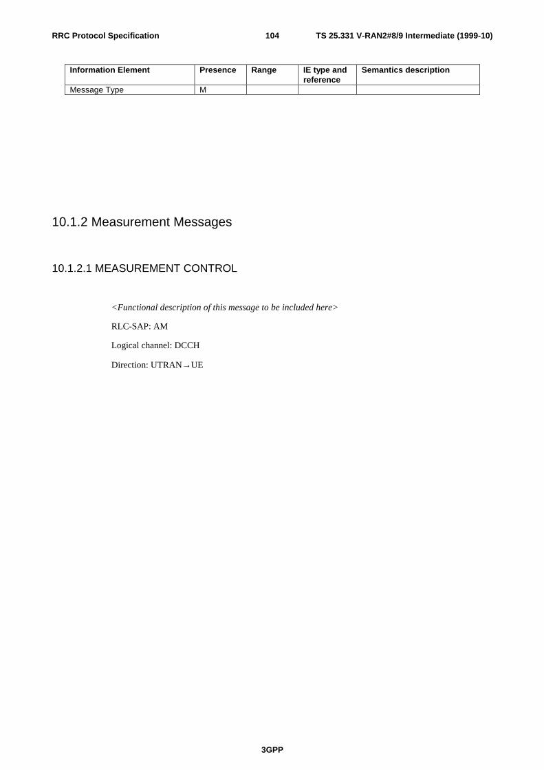
TS 25.331 V-RAN2#8/9 Intermediate (1999-10)
3GPP
104RRC Protocol Specification
Information Element Presence Range IE type andreference
Semantics description
Message Type M
10.1.2 Measurement Messages
10.1.2.1 MEASUREMENT CONTROL
<Functional description of this message to be included here>
RLC-SAP: AM
Logical channel: DCCH
Direction: UTRAN→UE

TS 25.331 V-RAN2#8/9 Intermediate (1999-10)
3GPP
105RRC Protocol Specification
Information Element Presence Range IE type andreference
Semantics description
Message Type MMeasurement InformationelementsMeasurement Identity Number MMeasurement Command MMeasurement Type OMeasurement Reporting Mode OCHOICE Measurement Intra-frequency Intra-frequency cell info Measurement object Intra-frequency measurement quantity
C eventtrigger
Intra-frequency measurement reporting quantity
O Note 1
CHOICE report criteria Intra-frequency measurement reporting criteria Periodical reporting Inter-frequency Inter-frequency cell info Measurement object Inter-frequency measurement quantity
C eventtrigger
Inter-frequency measurement reporting quantity
O Note 1
Inter-frequency set Update CHOICE report criteria Intra-frequency measurement reporting criteria Inter-frequency measurement reporting criteria Periodical reporting Inter-system Inter-system cell info Measurement object Inter-system measurement quantity
C eventtrigger
Inter-system measurement reporting quantity
O Note 1
CHOICE report criteria Inter-system measurement reporting criteria Periodical reporting Traffic Volume Traffic volume measurement Object Traffic volume measurement quantity
C eventtrigger
Traffic volume measurement reporting quantity
O Note 1
CHOICE report criteria Traffic volume measurement reporting criteria Periodical reporting Quality Quality measurement Object Quality measurement quantity
C eventtrigger
Quality measurement reporting quantity
O Note 1
CHOICE report criteria Quality measurement

TS 25.331 V-RAN2#8/9 Intermediate (1999-10)
3GPP
106RRC Protocol Specification
reporting criteria Periodical reporting UE internal UE internal measurement quantity
C eventtrigger
UE internal measurement reporting quantity
O Note 1
CHOICE report criteria UE internal measurement reporting criteria Periodical reporting
Condition Explanation
event trigger This element is only included in the message which issent in event trigger reporting mode.
CHOICE Measurement Condition under which the given Measurement ischosen
intra-frequency if measurement type=Intra-frequency measurement
inter-frequency if measurement type=Inter-frequency measurement
inter-system if measurement type=Intra-system measurement
traffic volume if measurement type=traffic volume measurement
Quality if measurement type=Quality measurement
UE internal if measurement type=UE internal measurement
CHOICE reporting criteria Condition under which the given reporting criteriais chosen
******* measurement reporting criteria Chosen when event triggering is required
periodical reporting Chosen when periodical reporting is required
Note 1: It is FFS whether it is necessary to separate the reporting quantity for each type.
Note 2: The network may order the UE to report other measurements when UE internal measurements are reported
10.1.2.2 MEASUREMENT CONTROL FAILURE
<Functional description of this message to be included here>
RLC-SAP: AM

TS 25.331 V-RAN2#8/9 Intermediate (1999-10)
3GPP
107RRC Protocol Specification
Logical channel: DCCH
Direction: UE→UTRAN
Information Element Presence Range IE type andreference
Semantics description
Message Type MUE information elementsFailure cause M
10.1.2.3 MEASUREMENT REPORT
<Functional description of this message to be included here>
RLC-SAP: AM or UM
Logical channel: DCCH
Direction: UE→UTRAN
Information Element Presence Range IE type andreference
Semantics description
Message Type MMeasurement InformationElementsMeasurement report information 1 to
<maxMeasRepCount>
Send Measurement Reportinformation for eachmeasurement report in themessage (Note 1)
Measurement identity number M Measured Results C MR
required CHOICE event result C event
triggerNote 1,2
Intra-frequency measurement event results Inter-frequency measurement event results Inter-system measurement event results Traffic volume measurement event results Quality measurement event results
Condition Explanation
event trigger This element is only included in the message which issent in event trigger reporting mode.
MR required This information element is included by the senderonly if indicated optionally by Reporting Quantity inMeasurement Control

TS 25.331 V-RAN2#8/9 Intermediate (1999-10)
3GPP
108RRC Protocol Specification
Range Bound Explanation
MaxMeasRepCount Maximum number of Measurement reports in amessage
CHOICE event result Condition under which the given event result ischosen
intra-frequency measurement event results
inter-frequency measurement event results
inter-system measurement event results
traffic volume measurement event results
Quality measurement event results
Note 1: Whether it is possible to send multiple measurement results that are identified by different measurement identitynumbers in the same Measurement Report is FFS. An alternative solution is to allowt only one measurement identitynumber per Measurement Report and concatenate different Measurement Reports in the RLC layer instead.
Note 2: If it is possible to send many measurement results that are identified by different events in the sameMeasurement Report is FFS.
10.1.3 Paging Messages
10.1.3.1 PAGING TYPE 1
This message is used to send information on the paging channel. One or several UEs, in idle orconnected mode,can be paged in one message, which also can contain other information.
RLC-SAP: TM
Logical channel: PCCH
Direction: UTRAN → UE
Information Element Presence Range IE type andreference
Semantics description
Message Type MUE Information elementsPaging record 0 to <Page
Count>
Other information elementsBCCH modification info O

TS 25.331 V-RAN2#8/9 Intermediate (1999-10)
3GPP
109RRC Protocol Specification
Range Bound Explanation
Page Count Number of UE's paged in the Paging Type 1 message
10.1.3.2 PAGING TYPE 2
This message is used to page an UE in connected mode, when using the DCCH for CN originatedpaging.
RLC-SAP: AM
Logical channel: DCCH
Direction: UTRAN → UE
Information Element Presence Range IE type andreference
Semantics description
Message Type MCN Information elementsCN domain identity MPaging Record Type Identifier M Enumerated
(IMSI, TMSI/P-TMSI)
UE Information elements
Paging cause M
10.1.4 RRC Connection Establishment and maintenance messages
10.1.4.1 RRC CONNECTION RE-ESTABLISHMENT
<Functional description of this message to be included here>
RLC-SAP: UM
Logical channel: CCCH, DCCH
Direction: UTRAN → UE

TS 25.331 V-RAN2#8/9 Intermediate (1999-10)
3GPP
110RRC Protocol Specification
Information Element Presence Range IE type andreference
Semantics description
Message Type MUE information elementsNew U-RNTI ONew C-RNTI OActivation time OCN information elementsPLMN identity O (Note1)CN related information 0 to
<MaxNoCNdomains>
CN related information to beprovided for each CN domain
CN domain identity O (Note1) NAS system info O (Note1)

TS 25.331 V-RAN2#8/9 Intermediate (1999-10)
3GPP
111RRC Protocol Specification
RB information elements RB information 0 to
<MaxRBcount>
RB information is sent foreach RB affected by thismessage
RB identity M RLC info O FFS RB multiplexing info MTransport ChannelInformation ElementsTFCS O For uplink TFCSsTFCS O For downlink TFCSsCHOICE mode TDD TFCS Identity O Uplink TFCS TFCS Identity O Downlink TFCSTFC subset O For TFCSs in uplinkUplink transport channels Transport channel identity 0 to
<MaxDelTrCH>
Reconfigured TrCH information
0 to<MaxReconAddTrCH>
Transport channel identity M TFS M DRAC information C DRAC 1 to
<MaxReconAddTrCH>
Dynamic Control Transmission time validity Time duration before retry Silent period duration before releaseDownlink transport channels Transport channel identity 0 to
<MaxDelTrCH>
Reconfigured TrCH information
0 to<MaxReconAddTrCH>
Transport channel identity M TFS MPhyCH information elementsFrequency info OMaximum allowed UL TX power OUplink DPCH power control info OUplink radio resourceinformation CHOICE channel requirement
O
Uplink DPDCH info PRACH infoDownlink radio resourceinformation Downlink information 0 to <Max
Rlcount>Send downlink information foreach radio link to be set-up
Primary CCPCH info Downlink DPDCH info Secondary CCPCH infoCHOICE mode FDD SSDT indicator O FFS SSDT Cell ID C ifSSDT FFS CPCH SET info O UL/DL radio resource for

TS 25.331 V-RAN2#8/9 Intermediate (1999-10)
3GPP
112RRC Protocol Specification
CPCH control (Note3) Gated Transmission Controlinfo
O FFS
Default DPCH Offset Value O TDD Uplink Timing Advance O
[Note1: Necessity of PLMN is FFS and for CN domain identity and NAS system information, the confirmation in SAWG2 is needed.]
[Note 3: How to map UL and DL radio resource in the message is FFS.]
Condition Explanation
DRAC These information elements are only sent fortransport channels which use the DRAC procedure
IfSSDT This IE is sent only when SSDT is to be used
CHOICE channel requirement Condition under which the given channelrequirement is chosen
Uplink DPCH info
PRACH info
Range Bound Explanation
MaxNoCN domains Maximum number of CN domains

TS 25.331 V-RAN2#8/9 Intermediate (1999-10)
3GPP
113RRC Protocol Specification
MaxRBcount Maximum number of RBs to be reconfigured
MaxDelTrCHcount Maximum number of Transport CHannels to beremoved
MaxReconAddTrCH Maximum number of transport channels to add andreconfigure
MaxRLcount Maximum number of radio links
10.1.4.2 RRC CONNECTION RE-ESTABLISHMENT COMPLETE
<Functional description of this message to be included here>
RLC-SAP: AM
Logical channel: DCCH
Direction: UE → UTRAN
Information Element Presence Range IE type andreference
Semantics description
Message Type M
10.1.4.3 RRC CONNECTION RE-ESTABLISHMENT REQUEST
<Functional description of this message to be included here>
RLC-SAP: TM
Logical channel: CCCH
Direction: UE → UTRAN
Information Element Presence Range IE type andreference
Semantics description
Message Type MUE information elements
U-RNTI MMeasurement informationelementsMeasurement information 1 to
<MeasRepCount>
Send Measurementinformation for eachmeasurement report in themessage
Measurement identity number M Refers to system information.Note 1
Measured results M
Note 1: The necessity and usage of Measurement identity number in this message is FFS.

TS 25.331 V-RAN2#8/9 Intermediate (1999-10)
3GPP
114RRC Protocol Specification
Range Bound Explanation
MeasRepCount Number of measurement reports in the message
10.1.4.4 RRC CONNECTION RELEASE
<Functional description of this message to be included here>
RLC-SAP: UM
Logical channel: DCCH
Direction: UTRAN→UE
Information Element Presence Range IE type andreference
Semantics description
Message Type MUE information elementsRelease cause MNumber of RRC MessageTransmissions
M
10.1.4.5 RRC CONNECTION RELEASE COMPLETE
<Functional description of this message to be included here>
RLC-SAP: AM or UM
Logical channel: DCCH
Direction: UE → UTRAN
Information Element Presence Range IE type andreference
Semantics description
Message Type M
10.1.4.6 RRC CONNECTION REQUEST
RRC Connection Request is the first message transmitted by the UE when setting up an RRCConnection to the network.

TS 25.331 V-RAN2#8/9 Intermediate (1999-10)
3GPP
115RRC Protocol Specification
RLC-SAP: TM
Logical channel: CCCH
Direction: UE → UTRAN
Information Element Presence Range IE type andreference
Semantics description
Message Type MUE information elementsInitial UE identity MEstablishment cause MInitial UE capability O Necessity is FFSMeasurement informationelementsMeasurement information 1 to
<MeasRepCount>
Send Measurementinformation for eachmeasurement report in themessage
Measurement identity number M Refers to system information.Note 1
Measured results M
Note 1: The necessity and usage of Measurement identity number in this message is FFS.
Range Bound Explanation
MeasRepCoun Number of measurement reports in the message
10.1.4.7 RRC CONNECTION SETUP
This message is used by the network to accept the establishment of an RRC connection for an UE,including assignment of signalling link information, transport channel information and optionallyphysical channel information.
RLC-SAP: UM
Logical channel: CCCH
Direction: UTRAN → UE

TS 25.331 V-RAN2#8/9 Intermediate (1999-10)
3GPP
116RRC Protocol Specification
Information Element Presence Range IE type andreference
Semantics description
Message Type MUE information elementsInitial UE identity MU-RNTI M
C-RNTI O Only if assigned to a commontransport channel
Activation time OUTRAN DRX cycle length ODRX Indicator ORB information elementsRB identity M Indicates the signalling linkSignalling link type MRB mapping info M For the signalling linkTrCH information elementsTFCS O Uplink TFCSTFCS O Downlink TFCSCHOICE mode TDD TFCS Identity O Uplink TFCS TFCS Identity O Downlink TFCSTFC subset OUplink transport channelinformation
0 to<MaxULTrCHCount>
Send transport channelinformation for each newUplink transport channel
Transport channel identity M TFS MDownlink transport channelinformation
0 to<MaxDLTrCHCount>
Send transport channelinformation for each newdownlink transport channel
Transport channel identity M TFS M Transparent mode signallinginfo
C ifTM_DCH
0 or 1
PhyCH information elementsFrequency info OMaximum allowed UL TX power OUplink DPCH power control info OUplink radio resourceinformation
CHOICE channel requirement
O
Uplink DPCH info PRACH info (for RACH)Downlink radio resourceinformation Downlink DPCH power control info
O
CHOICE mode FDD Downlink DPCH compressed mode info
O
Downlink information 0 to <MaxRLcount>
Send downlink information foreach radio link to be set-up
Primary CCPCH info Downlink DPCH info Secondary CCPCH info
CHOICE mode FDD
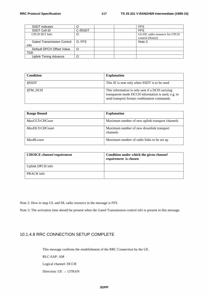
TS 25.331 V-RAN2#8/9 Intermediate (1999-10)
3GPP
117RRC Protocol Specification
SSDT indicator O FFS SSDT Cell ID C ifSSDT FFS CPCH SET Info O UL/DL radio resource for CPCH
control (Note2) Gated Transmission Controlinfo
O, FFS Note 3
Default DPCH Offset Value OTDD Uplink Timing Advance O
Condition Explanation
IfSSDT This IE is sent only when SSDT is to be used
IfTM_DCH This information is only sent if a DCH carryingtransparent mode DCCH information is used, e.g. tosend transport format combination commands.
Range Bound Explanation
MaxULTrCHCoun Maximum number of new uplink transport channels
MaxDLTrCHCount Maximum number of new downlink transportchannels
MaxRLcoun Maximum number of radio links to be set up
CHOICE channel requirement Condition under which the given channelrequirement is chosen
Uplink DPCH info
PRACH info
Note 2: How to map UL and DL radio resource in the message is FFS.
Note 3: The activation time should be present when the Gated Transmission control info is present in this message.
10.1.4.8 RRC CONNECTION SETUP COMPLETE
This message confirms the establishment of the RRC Connection by the UE.
RLC-SAP: AM
Logical channel: DCCH
Direction: UE → UTRAN

TS 25.331 V-RAN2#8/9 Intermediate (1999-10)
3GPP
118RRC Protocol Specification
Information Element Presence Range IE type andreference
Semantics description
Message Type MUE information elementsCiphering hyperframe number MUE radio capability MPhy CH information elementsCHOICE mode FDD SSDT indicator O FFS
10.1.4.9 RRC CONNECTION REJECT
This message is transmitted by the network when the requested RRC connection cannot be accepted.
RLC-SAP: UM
Logical channel: CCCH
Direction: UTRAN → UE
Information Element Presence Range IE type andreference
Semantics description
Message Type MUE information elementsInitial UE identity MRejection cause MWait time O
10.1.5 Radio Bearer control messages
10.1.5.1 PHYSICAL CHANNEL RECONFIGURATION
This message is used by UTRAN to assign, replace or release a set of physical channels used by a UE.
RLC-SAP: AM or UM
Logical channel: DCCH
Direction: UTRAN → UE

TS 25.331 V-RAN2#8/9 Intermediate (1999-10)
3GPP
119RRC Protocol Specification
Information Element Presence Range IE type andreference
Semantics description
Message Type MUE Information elementsActivation time ONew C-RNTI C -
RACH/FACH
C-RNTI
UTRAN DRX cycle length ODRX Indicator O
Physical Channel informationelementsFrequency info OMaximum allowed UL TX power OUplink DPCH power control info OUplink radio resourceinformation CHOICE channel requirement
O
Uplink DPCH info PRACH Info (for RACH) CHOICE mode FDD PRACH info (forFAUSCH)
Downlink radio resourceinformation Downlink DPCH power control info
O
CHOICE mode FDD Downlink DPCH compressed mode info
O
Downlink information 0 to <MaxRLcount>
Send downlink information foreach radio link
Primary CCPCH info Downlink DPCH info Secondary CCPCH info For FACH
CHOICE mode FDD SSDT indicator O FFS SSDT Cell ID C ifSSDT FFS CPCH SET Info O UL/DL radio resource for CPCH
control (Note2) Default DPCH Offset Value O TDD Uplink Timing Advance O
Condition Explanation
IfSSDT This IE is only sent when SSDT is used and when anew DCH is being activated

TS 25.331 V-RAN2#8/9 Intermediate (1999-10)
3GPP
120RRC Protocol Specification
RACH/FACH This information element is only included in the sentmessage when using RACH/FACH
Range Bound Explanation
MaxRLcount Maximum number of radio links to be set up
CHOICE channel requirement Condition under which the given channelrequirement is chosen
Uplink DPCH info
PRACH info (for FAUSCH)
PRACH info (for RACH)
Note 2: How to map UL and DL radio resource in the message is FFS.
10.1.5.2 PHYSICAL CHANNEL RECONFIGURATION COMPLETE
This message is sent from the UE when a physical channel reconfiguration has been done.
RLC-SAP: AM
Logical channel: DCCH
Direction: UE → UTRAN
Information Element Presence Range IE type andreference
Semantics description
Message Type MPhy CH information elementsCHOICE mode FDD SSDT indicator O Necessity is FFS
10.1.5.3 PHYSICAL CHANNEL RECONFIGURATION FAILURE
<Functional description of this message to be included here>
RLC-SAP: AM
Logical channel: DCCH

TS 25.331 V-RAN2#8/9 Intermediate (1999-10)
3GPP
121RRC Protocol Specification
Direction: UE→UTRAN
Information Element Presence Range IE type andreference
Semantics description
Message Type MUE information elementsFailure cause M
10.1.5.4 RADIO BEARER RECONFIGURATION
This message is sent from UTRAN to reconfigure parameters related to a change of QoS. Thisprocedure can also change the multiplexing of MAC, reconfigure transport channels and physicalchannels.
RLC-SAP: AM or UM
Logical channel: DCCH
Direction: UTRAN → UE

TS 25.331 V-RAN2#8/9 Intermediate (1999-10)
3GPP
122RRC Protocol Specification
Information Element Presence Range IE type andreference
Semantics description
Message Type MUE Information elementsActivation time ONew C-RNTI C -
RACH/FACH
UTRAN DRX cycle length ODRX Indicator ORB information elements RB information 0 to
<MaxRBcount>
RB information is sent foreach RB affected by thismessage
RB identity M RLC info O FFS RB mapping info O RB suspend/resume O Not applicable to the signalling
bearer.Transport ChannelInformation ElementsTFCS O for uplink TFCSTFCS O for downlink TFCSCHOICE mode TDD TFCS Identity O Uplink TFCS TFCS Identity O Downlink TFCSTFC subset O for TFCSs in uplinkUplink transport channels Transport channel identity 0 to
<MaxDelTrCH>
Reconfigured TrCH information
0 to<MaxReconAddTrCH>
Transport channel identity M TFS M DRAC information C DRAC 1 to
<MaxReconAddTrCH>
Dynamic Control Transmission time validity Time duration before retry Silent period duration before releaseDownlink transport channels Transport channel identity 0 to
<MaxDelTrCH>
Reconfigured TrCH information
0 to<MaxReconAddTrCH>
Transport channel identity M TFS MPhysical Channel informationelementsFrequency info OMaximum allowed UL TX power OUplink DPCH power control info
O
Uplink radio resourceinformation
O
CHOICE channel requirement
O

TS 25.331 V-RAN2#8/9 Intermediate (1999-10)
3GPP
123RRC Protocol Specification
Uplink DPCH info PRACH info (for RACH) CHOICE mode FDD PRACH info (forFAUSCH)
Downlink radio resource information Downlink DPCH power control info
O
Downlink DPCH compressed mode info
O
Downlink information 0 to <MaxRLcount>
Send downlink information foreach radio link
Primary CCPCH info Downlink DPCH info Secondary CCPCH info
CHOICE mode FDD SSDT indicator O FFS CPCH SET Info O UL/DL radio resource for CPCH
control (Note2) Gated Transmission Controlinfo
O FFS, Note 3
Default DPCH Offset Value O TDD Uplink Timing Advance O
Condition Explanation
RACH/FACH This information element is only sent when usingRACH/FACH
DRAC These information elements are only sent fortransport channels which use the DRAC procedure
Range Bound Explanation
MaxRLcount Maximum number of radio links
MaxRBcount Maximum number of RBs to be reconfigured
MaxDelTrCHcount Maximum number of Transport CHannels to beremoved
MaxReconAddTrCH Maximum number of transport channels to add andreconfigure
CHOICE channel requirement Condition under which the given channelrequirement is chosen
Uplink DPCH info
PRACH info (for RACH)
PRACH info (for FAUSCH)

TS 25.331 V-RAN2#8/9 Intermediate (1999-10)
3GPP
124RRC Protocol Specification
Note 2: How to map UL and DL radio resource in the message is FFS.
Note 3: The activation time should be present when the Gated Transmission control info is present in this message.
10.1.5.5 RADIO BEARER RECONFIGURATION COMPLETE
This message is sent from the UE when a RB and signalling link reconfiguration has been done.
RLC-SAP: AM
Logical channel: DCCH
Direction: UE → UTRAN
Information Element Presence Range IE type andreference
Semantics description
Message Type MPhy CH information elementsCHOICE mode FDD SSDT indicator O FFS
10.1.5.6 RADIO BEARER RECONFIGURATION FAILURE
<Functional description of this message to be included here>
RLC-SAP: AM
Logical channel: DCCH
Direction: UE→UTRAN
Information Element Presence Range IE type andreference
Semantics description
Message Type MUE information elementsFailure cause M
10.1.5.7 RADIO BEARER RELEASE
<Functional description of this message to be included here>
RLC-SAP: AM or UM

TS 25.331 V-RAN2#8/9 Intermediate (1999-10)
3GPP
125RRC Protocol Specification
Logical channel: DCCH
Direction: UTRAN → UE

TS 25.331 V-RAN2#8/9 Intermediate (1999-10)
3GPP
126RRC Protocol Specification
Information Element Presence Range IE type andreference
Semantics description
Message Type MUE Information elementsActivation time ONew C-RNTI C -
RACH/FACH
C-RNTI
UTRAN DRX cycle length ODRX Indicator ORB information elementsRB identity 1 to
<MaxRelRBcount>
RB identity 0 to<MaxOtherRBcount>
RB mapping info OTransport ChannelInformation ElementsTFCS O for uplink TFCSTFCS O for downlink TFCSCHOICE mode TDD TFCS Identity O Uplink TFCS TFCS Identity O Downlink TFCSTFC subset O for DCHs in uplinkUplink transport channels Transport channel identity 0 to
<MaxDelTrCH>
Reconfigured TrCH information
0 to<MaxReconAddFFSTrCH>
Transport channel identity M TFS M DRAC information C DRAC 1 to
<MaxReconAddFFSTrCH>
Dynamic Control Transmission time validity Time duration before retry Silent period duration before releaseDownlink transport channels Transport channel identity 0 to
<MaxDelTrCH>
Reconfigured TrCH information
0 to<MaxReconAddTrCH>
Editor : this limit shouldprobably also beMaxReconAddFFSTrCH
Transport channel identity M TFS MPhysical Channel informationelementsFrequency info OMaximum allowed UL TX power OUplink DPCH power control info
O
Uplink radio resourceinformation
O
CHOICE mode FDD Gated Transmission Control O, FFS Note 3

TS 25.331 V-RAN2#8/9 Intermediate (1999-10)
3GPP
127RRC Protocol Specification
info CPCH SET Info O UL/DL radio resource for CPCH
control (Note2) TDD Uplink Timing Advance O CHOICE channel requirement
O
Uplink DPCH info CHOICE mode FDD PRACH info (forFAUSCH) PRACH info (for RACH)
Downlink radio resource information Downlink information 0 to <Max
RLcount>Send downlink information foreach radio link to be set-up
Primary CCPCH info Downlink DPCH info Secondary CCPCH info
Condition Explanation
RACH/FACH This information element is only sent when usingRACH/FACH
DRAC These information elements are only sent fortransport channels which use the DRAC procedure
Range Bound Explanation
MaxRLcount Maximum number of radio links
MaxDelRBcount Maximum number of RBs to be released/deleted
MaxOtherRBcount
Maximum number of Other RBs (ie RB's not beingreleased) affected by the procedure
MaxDelTrCHcount Maximum number of Transport CHannels to beremoved
MaxReconAddFFSTrCH
Maximum number of transport channels to add (FFS)and reconfigure
CHOICE channel requirement Condition under which the given channelrequirement is chosen
Uplink DPCH info

TS 25.331 V-RAN2#8/9 Intermediate (1999-10)
3GPP
128RRC Protocol Specification
PRACH Info (for RACH)
PRACH info (for FAUSCH)
Note 2: How to map UL and DL radio resource in the message is FFS.
Note 3: The activation time should be present when the Gated Transmission control info is present in this message.
10.1.5.8 RADIO BEARER RELEASE COMPLETE
<Functional description of this message to be included here>
RLC-SAP: AM
Logical channel: DCCH
Direction: UE → UTRAN
Information Element Presence Range IE type andreference
Semantics description
Message Type M
10.1.5.9 RADIO BEARER RELEASE FAILURE
<Functional description of this message to be included here>
RLC-SAP: AM
Logical channel: DCCH
Direction: UE→UTRAN
Information Element Presence Range IE type andreference
Semantics description
Message Type MUE information elementsFailure cause M
10.1.5.10 RADIO BEARER SETUP
<Functional description of this message to be included here>
RLC-SAP: AM or UM
Logical channel: DCCH

TS 25.331 V-RAN2#8/9 Intermediate (1999-10)
3GPP
129RRC Protocol Specification
Direction: UTRAN → UE

TS 25.331 V-RAN2#8/9 Intermediate (1999-10)
3GPP
130RRC Protocol Specification
Information Element Presence Range IE type andreference
Semantics description
Message Type MCN information elementsNAS binding info MCN domain identityUE Information elementsActivation time ONew C-RNTI C –
RACH/FACH
C-RNTI
UTRAN DRX cycle length ODRX Indicator ORB information elementsInformation for new RBs 1 to
<MaxNewRBcount>
RB identity M RLC info M RB mapping info MInformation for other RB'saffected by this message
0 to<MaxOtherRBcount>
RB identity M RB mapping info MTransport ChannelInformation ElementsTFCS O for uplink TFCSTFCS O for downlink TFCSCHOICE mode TDD TFCS Identity O Uplink TFCS TFCS Identity O Downlink TFCSTFC subset O for DCHs in uplinkUplink transport channels Transport channel identity 0 to
<MaxDelTrCH>
editor should this be FFSalso?
Reconfigured TrCH information
0 to<MaxReconAddTrCH>
Transport channel identity M TFS M DRAC information C DRAC 1 to
<MaxReconAddTrCH>
Dynamic Control Transmission time validity Time duration before retry Silent period duration before releaseDownlink transport channels Transport channel identity 0 to
<MaxDelTrCH>
FFS
Reconfigured TrCH information
0 to<MaxReconAddTrCH>
Transport channel identity M TFS MPhysical Channel informationelementsFrequency info OMaximum allowed UL TX power O

TS 25.331 V-RAN2#8/9 Intermediate (1999-10)
3GPP
131RRC Protocol Specification
Uplink DPCH power control info
O
Uplink radio resourceinformation
O
CHOICE mode FDD CPCH SET Info O UL/DL radio resource for CPCH
control (Note2) CHOICE channel requirement
O
Uplink DPCH info PRACH Info (for RACH) CHOICE mode FDD PRACH info (forFAUSCH)
Downlink radio resource information Downlink DPCH power control info
O
CHOICE mode FDD Downlink DPCHcompressed mode info
O
Downlink information 0 to <MaxRLcount>
Send downlink information foreach radio link
Primary CCPCH info Downlink DPCH info Secondary CCPCH info
CHOICE mode FDD SSDT indicator O FFS SSDT Cell ID C ifSSDT FFS Gated Transmission Controlinfo
O FFS
Default DPCH Offset Value O TDD Uplink Timing Advance O
Condition Explanation
RACH/FACH This information element is only sent when usingRACH/FACH
IfSSDT
This IE is only sent when SSDT is used and when anew DCH is being activated
Range Bound Explanation
MaxRLcount Maximum number of radio links

TS 25.331 V-RAN2#8/9 Intermediate (1999-10)
3GPP
132RRC Protocol Specification
MaxDelTrCHcount Maximum number of Transport CHannels to beremoved
MaxReconAddcount Maximum number of Transport CHannelsreconfigured or added
MaxNewRBcount Maximum number of RBs that could be setup withthis message
MaxOtherRBcount
Maximum number of Other RBs (ie RB's not beingreleased) affected by the procedure
CHOICE channel requirement Condition under which the given channelrequirement is chosen
Uplink DPCH info
PRACH info (for FAUSCH)
PRACH info (for RACH)
Note 2: How to map UL and DL radio resource in the message is FFS.
Note 3: The activation time should be present when the Gated Transmission control info is present in this message.
10.1.5.11 RADIO BEARER SETUP COMPLETE
<Functional description of this message to be included here>
RLC-SAP: AM
Logical channel: DCCH
Direction: UE → UTRAN
Information Element Presence Range IE type andreference
Semantics description
Message Type MPhy CH information elementsCHOICE mode FDD SSDT indicator O FFS
10.1.5.12 RADIO BEARER SETUP FAILURE
<Functional description of this message to be included here>
RLC-SAP: AM
Logical channel: DCCH
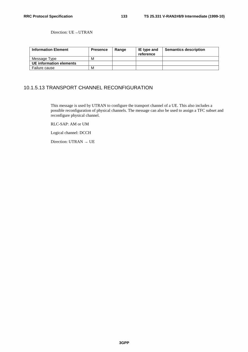
TS 25.331 V-RAN2#8/9 Intermediate (1999-10)
3GPP
133RRC Protocol Specification
Direction: UE→UTRAN
Information Element Presence Range IE type andreference
Semantics description
Message Type MUE information elementsFailure cause M
10.1.5.13 TRANSPORT CHANNEL RECONFIGURATION
This message is used by UTRAN to configure the transport channel of a UE. This also includes apossible reconfiguration of physical channels. The message can also be used to assign a TFC subset andreconfigure physical channel.
RLC-SAP: AM or UM
Logical channel: DCCH
Direction: UTRAN → UE

TS 25.331 V-RAN2#8/9 Intermediate (1999-10)
3GPP
134RRC Protocol Specification
Information Element Presence Range IE type andreference
Semantics description
Message Type MUE Information elementsActivation time ONew C-RNTI C -
RACH/FACH
C-RNTI
UTRAN DRX cycle length ODRX Indicator O
Transport ChannelInformation ElementsTFCS O for uplink TFCSTFCS O for downlink TFCSCHOICE mode TDD TFCS Identity O Uplink TFCS TFCS Identity O Downlink TFCSTFC subset O for DCHs in uplinkUplink transport channels Reconfigured TrCH information
0 to<MaxReconTrCH>
Transport channel identity TFS DRAC information C DRAC 1 to
<MaxReconTrCHDRAC>
Dynamic Control Transmission time validity Time duration before retry Silent period duration before releaseDownlink transport channels Reconfigured TrCH information
0 to<MaxReconTrCH>
Transport channel identity TFSPhysical Channel informationelementsFrequency info OMaximum allowed UL TX power OUplink DPCH power control info
O
Uplink radio resourceinformationCPCH SET Info O UL/DL radio resource for CPCH
control (Note2) CHOICE channel requirement
O
Uplink DPCH info CHOICE mode FDD PRACH info (forFAUSCH) PRACH info (for RACH)
ODownlink radio resource information Downlink DPCH power control info
O
CHOICE mode FDD Downlink DPCH O

TS 25.331 V-RAN2#8/9 Intermediate (1999-10)
3GPP
135RRC Protocol Specification
compressed mode info Downlink information 0 to <Max
RLcount>Send downlink information foreach radio link
Primary CCPCH info Downlink DPCH info Secondary CCPCH info
CHOICE mode FDD SSDT indicator O FFS SSDT Cell ID C ifSSDT FFS Gated Transmission Controlinfo
O FFS, Note 3
Default DPCH Offset Value O TDD Uplink Timing Advance O
Condition Explanation
IfSSDT This IE is only sent when SSDT is used and when anew DCH is being activated
RACH/FACH
This information element is only sent when usingRACH/FACH
Range Bound Explanation
MaxRLcount Maximum number of radio links to be set up
MaxReconcount Maximum number of Transport CHannelsreconfigured
MaxReconTrCHDRAC
Maximum number of Transport CHannels which arecontrolled by DRAC and which are reconfigured
CHOICE channel requirement Condition under which the given channelrequirement is chosen
Uplink DPCH info
PRACH info (for RACH)
PRACH info (for FAUSCH)
Note 2: How to map UL and DL radio resource in the message is FFS.
Note 3: The activation time should be present when the Gated Transmission control info is present in this message.

TS 25.331 V-RAN2#8/9 Intermediate (1999-10)
3GPP
136RRC Protocol Specification
10.1.5.14 TRANSPORT CHANNEL RECONFIGURATION COMPLETE
This message is sent from the UE when a transport channel reconfiguration has been done.
RLC-SAP: AM
Logical channel: DCCH
Direction: UE → UTRAN
Information Element Presence Range IE type andreference
Semantics description
Message Type MPhy CH information elementsCHOICE mode FDD SSDT indicator O FFS
Note: The usage of this message for indicating the cell the UE will select in the DCH->RACH/FACH case, is FFS.
10.1.5.15 TRANSPORT CHANNEL RECONFIGURATION FAILURE
<Functional description of this message to be included here>
RLC-SAP: AM
Logical channel: DCCH
Direction: UE→UTRAN
Information Element Presence Range IE type andreference
Semantics description
Message Type MUE information elementsFailure cause M
10.1.5.16 TRANSPORT FORMAT COMBINATION CONTROL
<Functional description of this message to be included here>
RLC-SAP: TM, AM or UM
Logical channel: DCCH
Direction: UTRAN→UE
Information Element Presence Range IE type andreference
Semantics description
Message Type C-notTMTrCH information elementsTFC subset M For uplink TFCS

TS 25.331 V-RAN2#8/9 Intermediate (1999-10)
3GPP
137RRC Protocol Specification
Condition Explanation
NotTM The message type is not included when transmitting themessage on the transparent mode signalling DCCH
10.1.5.17 DOWNLINK OUTER LOOP CONTROL
<Functional description of this message to be included here>
RLC-SAP: AM or UM
Logical channel: DCCH
Direction: UTRAN→UE
Information Element Presence Range IE type andreference
Semantics description
Message Type MPhyCH information elementsDownlink Outer Loop Control M Indicates whether the UE is
allowed or not to increase itsEb/No target value above itscurrent value
10.1.5.18 PHYSICAL SHARED CHANNEL ALLOCATION (TDD only)
This message is used by UTRAN to assign physical resources to USCH/DSCH transport channels inTDD, for temporary usage by the UE.
RLC-SAP: TM or AM
Logical channel: SHCCH
Direction: UTRAN → UE
Information Element Presence Range IE type andreference
Semantics description
Message Type MUE Information elementsC-RNTI MPUSCH allocation pending OTransport Channelinformation elementsTFCS identity OPhysical Channel informationelementsPUSCH power control info OUplink timing advance info OPUSCH info OPDSCH info O
10.1.5.19 PUSCH CAPACITY REQUEST (TDD only)

TS 25.331 V-RAN2#8/9 Intermediate (1999-10)
3GPP
138RRC Protocol Specification
This message is used by the UE for request of PUSCH resources to the UTRAN.
RLC-SAP: t.b.d.
Logical channel: SHCCH
Direction: UE → UTRAN
Information Element Presence Range IE type andreference
Semantics description
Message Type MUE information elementsC-RNTI MMeasurement informationelementsTraffic amount information 1 to
<RABCount>
Send traffic amountinformation for each RadioAccess Bearer in the message
RB ID M RLC buffer payload MMeasurement information 0 to
<MeasRepCount>
Send Measurementinformation for eachmeasurement report in themessage
Measurement identity number M Refers to system information Measured results M
Range Bound Explanation
RABCount Number of traffic amount informations in themessage
MeasRepCoun Number of measurement reports in the message
10.1.6 System Information Messages
10.1.6.1 SYSTEM INFORMATION

TS 25.331 V-RAN2#8/9 Intermediate (1999-10)
3GPP
139RRC Protocol Specification
Information Element Presence Range IE type andreference
Semantics description
Message type C channelCHOICE> First SIB Segment First SIB
Segment> Subsequent SIB Segment Subsequent
SIBSegment
> Parts>> Last SIB Segment C number Last SIB
Segment>> Complete SIB C number 0..indefinit
eCompleteSIB
Condition Explanation
Channel The message type is mandatory on the FACH, andabsent on the BCH
Number If 'parts' is present, then
a) There shall be 0 or 1 'Last SIB segment;
c) 'Parts' shall not be empty.
10.1.6.2 First SIB Segment
This segment type is used to transfer the first segment of a segmented system information block.
RLC_SAP: TM
Logical channel: BCCH
Direction: UTRAN -> UE
Information Element Presence Range IE type andreference
Semantics description
Segment Type MOther information elementsSIB type MSEG_COUNT MSIB data M
10.1.6.3 Subsequent SIB Segment
This segment type is used to transfer a subsequent segment of a segmented system information block.
RLC_SAP: TM
Logical channel: BCCH
Direction: UTRAN -> UE

TS 25.331 V-RAN2#8/9 Intermediate (1999-10)
3GPP
140RRC Protocol Specification
Information Element Presence Range IE type andreference
Semantics description
Segment type MOther information elementsSIB type MSegment index MSIB data M
10.1.6.4 Last SIB Segment
This segment type is used to transfer the last segment of a segmented system information block.
RLC_SAP: TM
Logical channel: BCCH
Direction: UTRAN -> UE
Information Element Presence Range IE type andreference
Semantics description
Segment type MOther information elementsSIB type MSegment index MSIB data M
10.1.6.4 Complete SIB
This segment type is used to transfer a non-segmented system information block.
RLC_SAP: TM
Logical channel: BCCH
Direction: UTRAN -> UE
Information Element Presence Range IE type andreference
Semantics description
Segment type MOther information elementsSIB type MSIB content M
10.1.6.4 System Information Blocks
10.1.6.4.1 SIB Content
SIB Segments are the result of the segmentation of a 'SIB Content' IE. The SIB content IE is developed hereafter :

TS 25.331 V-RAN2#8/9 Intermediate (1999-10)
3GPP
141RRC Protocol Specification
Information Element Presence Range IE type andreference
Semantics description
CHOICE SIB type M> Master information block> System information block type1> System information block type2> System information block type3> System information block type4> System information block type5> System information block type6> System information block type7> System information block type8> System information block type9> System information block type10> System information block type11> System information block type12SI Padding C filling
Condition Explanation
SIB Type The common value of the 'SIB type' field in thesegment(s).
filling It is an acceptable constraint that, when the lastsegment of the SIB is the last IE of a SystemInformation message, the padding is constrained to besuch that it fills the transport block.
10.1.6.4.2 Master Information Block
Area scope: Cell
UE mode: Idle mode and connected mode

TS 25.331 V-RAN2#8/9 Intermediate (1999-10)
3GPP
142RRC Protocol Specification
Information Element Presence Range IE type andreference
Semantics description
Other information elementsValue tag MReferences to other systeminformation blocks
1 ..<maxSysInfoBlockcount>
Scheduling information MCN information elementsCN Type MPLMN Identity M
Condition Explanation
Blocktype The presence of this IE depends on the value of thepreceding SIB type. This IE is mandatory if thespecification of the SIB of that SIB type includes asfirst IE a Value tag IE.
Range Bound Explanation
MaxSysInfoBlockcount Maximum number of references to other systeminformation blocks.
10.1.6.4.3 System Information Block type 1
The system information block type 1 contains NAS system information as well as UE timers and counters to be used inidle mode.
Area scope: PLMN
UE mode: idle mode
Information Element Presence Range IE type andreference
Semantics description
Other information elementsValue tag MCN information elementsCN information 1 to
<maxCNdomains>
Send CN information for eachCN domain.
CN domain identity M NAS system information M CN DRX cycle length MUE informationUE Timers and counters M Note: Only timers and
counters used in idle modeCapability update requirement O

TS 25.331 V-RAN2#8/9 Intermediate (1999-10)
3GPP
143RRC Protocol Specification
Range Bound Explanation
MaxCNdomains Maximum number of CN domains
10.1.6.4.4 System Information Block type 2
The system information block type 2 contains the URA identity and information for periodic cell and URA update. Italso includes the UE timers and counters to be used in connected mode.
Area scope: PLMN
UE mode: connected mode
Information Element Presence Range IE type andreference
Semantics description
Other information elementsValue tag MUTRAN mobility informationelementsURA identity 1
..<maxURAcount>
Information for periodic cell andURA update
M
UE informationUE Timers and counters M Note: Only timers and
counters used in connectedmode
Range Bound Explanation
MaxURAcount Maximum number of URA's in a cell
10.1.6.4.5 System Information Block type 3
The system information block type 3 contains parameters for cell selection and re-selection. The block may also containscheduling information for other system information blocks.
Area scope: cell
UE mode: idle mode (and connected mode)

TS 25.331 V-RAN2#8/9 Intermediate (1999-10)
3GPP
144RRC Protocol Specification
Information Element Presence Range IE type andreference
Semantics description
Other information elementsValue tag MReferences to other systeminformation blocks
0 ..<maxSysInfoBlockcount>
Scheduling information MUTRAN mobility informationelementsCell identity M The necessity and usage of
cell identity is FFS.Cell selection and re-selectioninfo
M
Range Bound Explanation
MaxSysInfoBlockcount Maximum number of references to other systeminformation blocks.
10.1.6.4.6 System Information Block type 4
The system information block type 4 contains parameters for cell selection and re-selection to be used in connectedmode. The block may also contain scheduling information for other system information blocks. The block is optional.When not sent, the MS the MS shall apply in connected mode the values of the similar information indicated for idlemode.
Area scope: cell
UE mode: connected mode
Information Element Presence Range IE type andreference
Semantics description
Other information elementsValue tag MReferences to other systeminformation blocks
0 ..<maxSysInfoBlockcount>
Scheduling information MUTRAN mobility informationelementsCell identity M The necessity and usage of
cell identity is FFS.Cell selection and re-selectioninfo
M
Range Bound Explanation
MaxSysInfoBlockcount Maximum number of references to other system

TS 25.331 V-RAN2#8/9 Intermediate (1999-10)
3GPP
145RRC Protocol Specification
information blocks.
10.1.6.4.7 System Information Block type 5
The system information block type 5 contains parameters for the configuration of the common physical channels in thecell. The block may also contain scheduling information for other system information blocks.
Area scope: cell
UE mode: idle mode (and connected mode)
Information Element Presence Range IE type andreference
Semantics description
Other information elementsValue tag MReferences to other systeminformation blocks
0 ..<maxSysInfoBlockcount>
Scheduling information MPhyCH information elementsFrequency info OMaximum allowed UL TX power OCHOICE mode TDD PSCH Time slot FDD Secondary CPICH info O Note 2Primary CCPCH info O Note 1PRACH information 1 ..
<maxPRACHcount>
PRACH info M TFS M CHOICE mode FDD AICH info M TDD ASC info OSecondary CCPCH information 1 ..
<maxSCCPCHcount>
Secondary CCPCH info M TFCS M For FACHs and PCH FACH information 1 ..
<maxFACHcount>
TFS For each FACHs and PCH PICH info C-Pich Maximum allowed UL TXpowerUE Information elements UTRAN_DRX_cycle length

TS 25.331 V-RAN2#8/9 Intermediate (1999-10)
3GPP
146RRC Protocol Specification
Note 1: DL scrambling code of the Primary CCPCH is the same as the one for Primary CPICH.
Note 2: This parameter is needed in case of using adaptive array antenna.
Condition Explanation
Pich PICH info is present only when PCH is multiplexedon Secondary CCPCH
Range Bound Explanation
MaxPRACHcount Maximum number of PRACH’s
MaxSCCPCHcount Maximum number of secondary CCPCH’s
MaxFACHcount
Maximum number of FACH's mapped ontosecondary CCPCH's
MaxPCHcount
Maximum number of PCH's mapped onto secondaryCCPCH's
MaxSysInfoBlockcount Maximum number of references to other systeminformation blocks.
10.1.6.4.8 System Information Block type 6
The system information block type 6 contains parameters for the configuration of the common physical channels to beused in connected mode. The block may also contain scheduling information for other system information blocks. Theblock is optional. When not sent, the MS the MS shall apply in connected mode the values of the similar informationindicated for idle mode.
Area scope: cell
UE mode: connected mode

TS 25.331 V-RAN2#8/9 Intermediate (1999-10)
3GPP
147RRC Protocol Specification
Information Element Presence Range IE type andreference
Semantics description
Other information elementsValue tag MReferences to other systeminformation blocks
0 ..<maxSysInfoBlockcount>
Scheduling information MPhyCH information elementsFrequency info OMaximum allowed UL TX power OPrimary CCPCH info O Note 1CHOICE mode FDD Secondary CPICH info O Note 2PRACH information 0 ..
<maxPRACHcount>
PRACH info M TFS M CHOICE mode FDD AICH info MSecondary CCPCH information 0 ..
<maxSCCPCHcount>
Secondary CCPCH info M TFCS M For FACHs and PCH FACH information 1 ..
<maxFACHcount>
TFS For each FACHs and PCH PICH info C-Pich Maximum allowed UL TXpowerUE Information elements UTRAN_DRX_cycle length
Note 1: DL scrambling code of the Primary CCPCH is the same as the one for Primary CPICH.
Note 2: This parameter is needed in case of using adaptive array antenna.
Condition Explanation
Pich PICH info is present only when PCH is multiplexedon Secondary CCPCH
Range Bound Explanation
MaxPRACHcount Maximum number of PRACH's
MaxSCCPCHcount Maximum number of secondary CCPCH’s
MaxFACHcount Maximum number of FACH's mapped ontosecondary CCPCH's

TS 25.331 V-RAN2#8/9 Intermediate (1999-10)
3GPP
148RRC Protocol Specification
MaxPCHcount
Maximum number of PCH's mapped onto secondaryCCPCH's
MaxSysInfoBlockcount Maximum number of references to other systeminformation blocks.
10.1.6.4.9 System Information Block type 7
The system information block type 7 contains the uplink access control parameters and the PRACH power controlinformation to be used in the cell.
Area scope: cell
UE mode: idle mode (and connected mode)
Information Element Presence Range IE type andreference
Semantics description
Other information elementsExpiration time M The expiration time specifies
how long time the values ofthe information elementsincluded this systeminformation block are valid.
UE informationUplink access control info MPhyCH information elementsPRACH information 1 ..
<maxPRACHcount>
PRACH power control inform. M
Range Bound Explanation
MaxPRACHcount Maximum number of PRACH's
10.1.6.4.10 System Information Block type 8
The system information block type 8 contains the uplink access control parameters and the PRACH power controlinformation to be used in connected mode. The block is optional. When not sent, the MS shall apply in connected modethe values of the similar information indicated for idle mode.
Area scope: cell
UE mode: connected mode

TS 25.331 V-RAN2#8/9 Intermediate (1999-10)
3GPP
149RRC Protocol Specification
Information Element Presence Range IE type andreference
Semantics description
Other information elementsExpiration time M The expiration time specifies
how long time the values ofthe information elementsincluded in this systeminformation block are valid.
UE informationUplink access control info OPhyCH information elementsPRACH information 0 to
<maxPRACHcount>
PRACH power control inform. M
Range Bound Explanation
MaxPRACHcount Maximum number of PRACH's
10.1.6.4.11 System Information Block type 9 (FDD)
The system information block type 9 contains CPCH information to be used in the cell.
Area scope: cell
UE mode: connected mode
Information Element Presence Range IE type andreference
Semantics description
Other information elementsExpiration time M The expiration time specifies
how long time the values ofthe information elementsincluded in this systeminformation block are valid.
UE informationCPCH parameters MPhyCH information elementsCPCH SET info MCPCH set persistency value M
10.1.6.4.11 System Information Block type 10 (FDD)
The system information block type 10 contains information to be used by UEs having their DCH controlled by a DRACprocedure. The system information block is optional. That the SIB is not sent indicates that the DRAC procedures donot apply in this cell.
Area scope: cell
UE mode: connected mode

TS 25.331 V-RAN2#8/9 Intermediate (1999-10)
3GPP
150RRC Protocol Specification
Information Element Presence Range IE type andreference
Semantics description
Other information elementsExpiration time M The expiration time specifies
how long time the values ofthe information elementsincluded in this systeminformation block are valid.
UE informationDRAC information 1 ..
<maxDRACclasses>
DRAC information is sent foreach class of terminal
Transmission probability M Maximum bit rate M
Range Bound Explanation
MaxDRACclasses Maximum number of UE classes which would requiredifferent DRAC parameters
10.1.6.4.12 System Information Block type 11
The system information block type 11 contains measurement control information to be used in idle mode. The valuesmay also be used in connected mode if the corresponding IEs are not specified in System information block type 12. Theblock may also contain scheduling information for other system information blocks.
Area scope: cell
UE mode: idle mode (and connected mode)

TS 25.331 V-RAN2#8/9 Intermediate (1999-10)
3GPP
151RRC Protocol Specification
Information Element Presence Range IE type andreference
Semantics description
Other information elementsValue tag MReferences to other systeminformation blocks
0 ..<maxSysInfoBlockcount>
Scheduling information MMeasurement informationelementsMeasurment control information 1 ..
<maxMeasurementTypecount>
Measurement type M CHOICE Measurement C –
Intrafreq Intra-frequency Intra-frequency cell info M Intra-frequency Measurement quantity
M
Intra-frequency reporting Quantity for RACH Reporting
M
Maximum number of Reported cells on RACH
M
Intra-frequency reporting criteria Intra-frequency reporting Quantity
O
Inter-frequency C –Interfreq
Inter-frequency cell info M Inter-frequency Measurement quantity
M
Inter-system C –Intersys
Inter-system cell info M Inter-system measurement Quantity
M
Condition Explanation
Measurement The choice shall be consistent (same name) with thevalue of the 'Measurement type' IE
Intersys Measurement type = Inter system measurement
Interfreq Measurement type = Inter frequency measurement
Intrafreq Measurement type = Intra frequency measurement
Blocktype The presence of this IE depends on the definition ofthe system information block type.
Range Bound Explanation
MaxMeasTypeCount Maximum number of measurement types
MaxSysInfoBlockcount Maximum number of references to other system
TS 25.331 V-RAN2#8/9 Intermediate (1999-10)
3GPP
152RRC Protocol Specification
information blocks.
10.1.6.4.14 System Information Block type 12
The system information block type 12 contains measurement control information to be used in connected mode.
Area scope: cell
UE mode: connected mode

TS 25.331 V-RAN2#8/9 Intermediate (1999-10)
3GPP
153RRC Protocol Specification
Information Element Presence Range IE type andreference
Semantics description
Other information elementsValue tag MReferences to other systeminformation blocks
0 ..<maxSysInfoBlockcount>
SIB type M Value tag C –
Blocktype Scheduling information MMeasurement informationelementsMeasurment control information 1 ..
<maxMeasurementTypecount>
Measurement Identity Number M Measurement Type M CHOICE Measurement Intra-frequency C –
Intrafreq Intra-frequency cell info O Intra-frequency Measurement quantity
O
Intra-frequency Reporting quantity for RACH reporting
O
Maximum number of Reported cells on RACH
O
Intra-frequency reporting Quantity
O
Inter-frequency C -Interfreq
Inter-frequency cell Info
O
Inter-frequency Measurement quantity
O
Inter-system C -Intersys
Inter-system cell info O Inter-system measurement quantity
O
Traffic volume Traffic volume measurement objects
M
Traffic volume measurement quantity
M
UE Internal UE internal measurement quantity
M
Condition Explanation
Measurement The choice shall be consistent (same name) with thevalue of the 'Measurement type' IE
Intersys Measurement type = Inter system measurement
Interfreq Measurement type = Inter frequency measurement
Intrafreq Measurement type = Intra frequency measurement
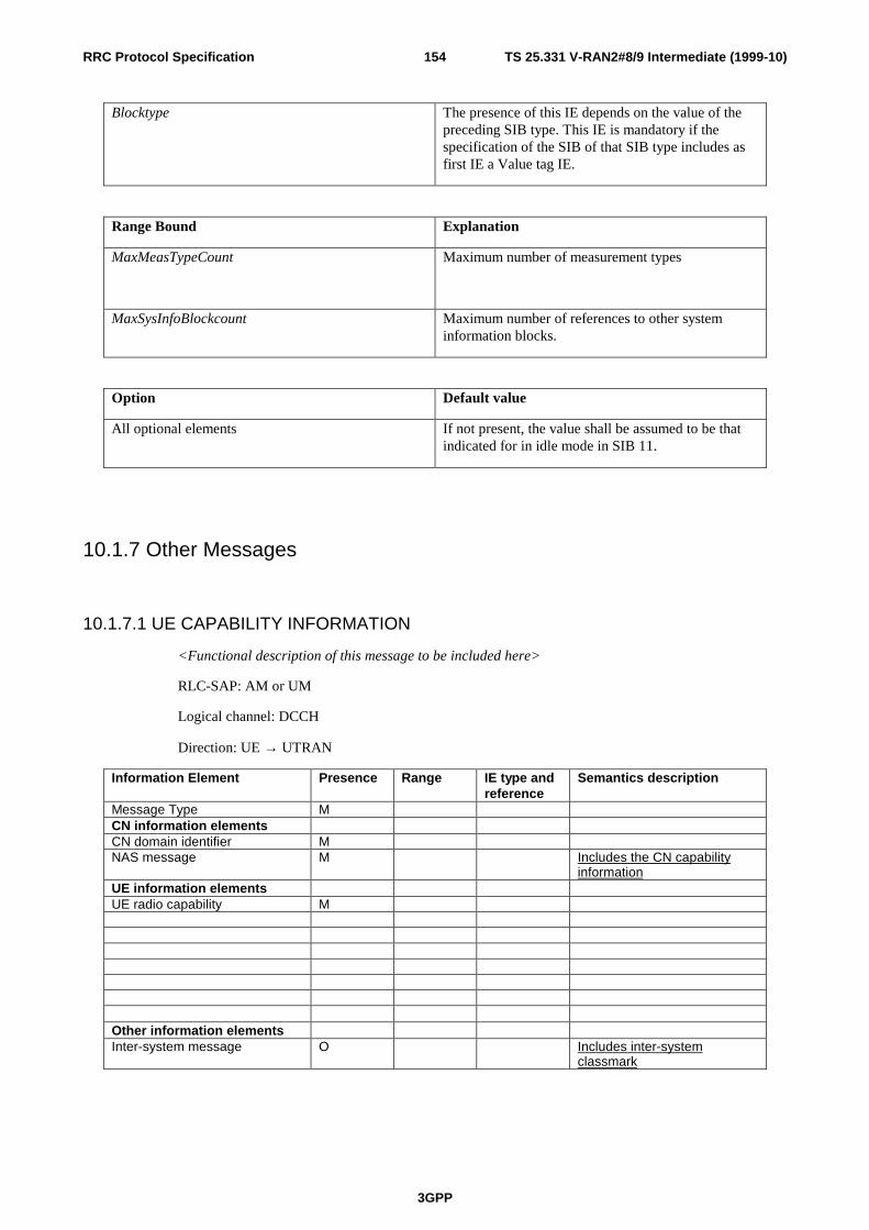
TS 25.331 V-RAN2#8/9 Intermediate (1999-10)
3GPP
154RRC Protocol Specification
Blocktype The presence of this IE depends on the value of thepreceding SIB type. This IE is mandatory if thespecification of the SIB of that SIB type includes asfirst IE a Value tag IE.
Range Bound Explanation
MaxMeasTypeCount Maximum number of measurement types
MaxSysInfoBlockcount Maximum number of references to other systeminformation blocks.
Option Default value
All optional elements If not present, the value shall be assumed to be thatindicated for in idle mode in SIB 11.
10.1.7 Other Messages
10.1.7.1 UE CAPABILITY INFORMATION
<Functional description of this message to be included here>
RLC-SAP: AM or UM
Logical channel: DCCH
Direction: UE → UTRAN
Information Element Presence Range IE type andreference
Semantics description
Message Type MCN information elementsCN domain identifier MNAS message M Includes the CN capability
informationUE information elementsUE radio capability M
Other information elementsInter-system message O Includes inter-system
classmark

TS 25.331 V-RAN2#8/9 Intermediate (1999-10)
3GPP
155RRC Protocol Specification
10.1.7.2 UE CAPABILITY INFORMATION CONFIRM
<Functional description of this message to be included here>
RLC-SAP: UM
Logical channel: DCCH
Direction: UTRAN → UE
Information Element Presence Range IE type andreference
Semantics description
Message Type M
10.1.7.3 UE CAPABILITY ENQUIRY
The UE CAPABILITY ENQUIRY is used by the UTRAN to enquire inter-system classmarks from theUE.
RLC-SAP: t.b.d.
Logical channel: DCCH
Direction: UTRAN → UE
Information Element Presence Range IE type andreference
Semantics description
Message Type MUE information elementsSystem M Enumerated
(GSM,..)
10.1.7.4 DIRECT TRANSFER
<Functional description of this message to be included here>
RLC-SAP: AM
Logical channel: DCCH
Direction: both

TS 25.331 V-RAN2#8/9 Intermediate (1999-10)
3GPP
156RRC Protocol Specification
Information Element Presence Range IE type andreference
Semantics description
Message Type MCN information elementsCN domain identity MNAS message MMeasurement informationelementsMeasured results O
10.1.7.5 SECURITY MODE CONTROL COMMAND
RLC-SAP: AM
Logical channel: DCCH
Direction: UTRAN to UE
Information Element Presence Range IE type andreference
Semantics description
Message Type MCN Information elementsCN domain identity M Indicates which cipher key is
Applicable
UE information elementsCiphering mode info O Only present if ciphering shall
be controlled
Range Bound Explanation
MaxReconRBs For each radio bearer that is reconfigured
10.1.7.6 SECURITY MODE CONTROL COMPLETE
RLC-SAP: AM
Logical channel: DCCH
Direction: UE to UTRAN

TS 25.331 V-RAN2#8/9 Intermediate (1999-10)
3GPP
157RRC Protocol Specification
Information Element Presence Range IE type andreference
Semantics description
Message Type MRB Information elementsRadio bearer identity 1 to
<maxReconRBs>
Radio bearer identity 0indicates the signalling linkand is always present
UE information elementsDownlink activation Time O Activation
time
Range Bound Explanation
MaxReconRBs For each radio bearer that is reconfigured

TS 25.331 V-RAN2#8/9 Intermediate (1999-10)
3GPP
158RRC Protocol Specification
10.2 Information element functional definitions
10.2.1 CN Information elements
10.2.1.1 CN domain identity
Points out the core network domain (e.g. IP or PSTN/ISDN CN domain).
10.2.1.2 NAS binding info
A field with non-access stratum information to bind a RB to the non-access stratum. This information is transparent toRRC.
10.2.1.3 NAS message
A non-access stratum message to be transferred transparently through UTRAN.
10.2.1.4 NAS system information
System information that belongs to the non-access stratum (e.g. LAC, RA code etc). This information is transparent toRRC.
10.2.1.5 PLMN identity
Information Element/Groupname
Presence Range IE type andreference
Semantics description
MCC, Mobile Country Code MMNC, Mobile Network Code M
10.2.1.6 CN DRX cycle length
Indicates the time interval between monitoring paging occasions to be used by a UE when attached to a specific CoreNetwork.
10.2.1.7 CN Type
Information Element/Groupname
Presence Range IE type andreference
Semantics description
CN Type M Enumerated(GSM-MAP,ANSI-41)
Identifies the type of corenetwork. This IE shall be usedto control the interpretation ofnetwork dependent messagesand information elements inthe RRC protocol.
10.2.2 UTRAN mobility Information elements
10.2.2.1 Cell identity

TS 25.331 V-RAN2#8/9 Intermediate (1999-10)
3GPP
159RRC Protocol Specification
This information element identifies a cell unambiguously within a PLMN.
Information Element/Groupname
Presence Range IE type andreference
Semantics description
Cell identity M Integer(0..268 435455)
10.2.2.2 Cell selection and re-selection info
Information Element/Groupname
Presence Range IE type andreference
Semantics description
Standby allowed reception level(dBm)
M The usage of theseparameters needs clarificationFFS.
Standby prohibited receptionlevel (dBm)
M
Threshold for Cell Re-selection(dB)
M
Allowed reception SIR (dB) MRadio link timeout
10.2.2.3 Information for periodic cell and URA update
This information element indicates information to support mechanisms for periodical cell/URA update procedures. It ismapped on System Information message.
Information Element/Groupname
Presence Range IE type andreference
Semantics description
T_periodical_cell_update M Enumerated(Noupdating,1..1023)
Designate the time periodbetween updating in minutes,or if no periodical updatingshould be done.
T_periodical_ura_update M Enumerated(Noupdating,1..1023)
Designate the time periodbetween updating in minutes,or if no periodical updatingshould be done.
10.2.2.4 URA identity
Gives the identity of the UTRAN Registration Area. It can be used to indicate to the UE which URA it shall use in caseof overlapping URAs.
Information Element/Groupname
Presence Range IE type andreference
Semantics description
URA identity Enumerated(0..65 535)

TS 25.331 V-RAN2#8/9 Intermediate (1999-10)
3GPP
160RRC Protocol Specification
10.2.3 UE Information elements
10.2.3.1 Uplink access control info
Information Element/Groupname
Presence Range IE type andreference
Semantics description
Access Service class M 1 to 8 PRACH partitioning M Mapping to a subset of the
available access slots andsignatures
Available signature StartIndex
Integer(0..15)
Available signature EndIndex
Integer(0..15)
Available sub-channel StartIndex
Integer(0..11)
Available sub-channel EndIndex
Integer(0..11)
Dynamic persistence level M FFS
PRACH partitioning:
The list of available signatures is renumbered from signature index 0 to signature index N-1, where N is the number ofavailable signatures, starting with the lowest available signature number and continuing in sequence, in the order ofincreasing signature numbers.
- List of available signatures : 16 or less signatures are available.
Ex : only signatures 0, 5, 10 and 15 are available, then :
Signature 0 is : available signature index 0
Signature 5 is : available signature index 1
Signature 10 is : available signature index 2
Signature 15 is : available signature index 3
The list of available access-slot sub-channels is renumbered from access-slot sub-channel index 0 to access-slot sub-channel index M-1, where M is the number of available access-slot sub-channels, starting with the lowest availableaccess-slot sub-channel number and continuing in sequence, in the order of increasing access-slot sub-channel numbers.
- List of available Access Slot channels : 12 or less sub-channels are available.
Ex : only sub-channels 0,1 ; 4,5 ; 8,9 are present, then :
Sub-channel 0 is : available sub-channel index 0
Sub-channel 1 is : available sub-channel index 1
Sub-channel 4 is : available sub-channel index 2
Sub-channel 5 is : available sub-channel index 3
Sub-channel 8 is : available sub-channel index 4

TS 25.331 V-RAN2#8/9 Intermediate (1999-10)
3GPP
161RRC Protocol Specification
Sub-channel 9 is : available sub-channel index 5
One ASC has access to all the access-slot sub-channels between the Available sub-channel Start Index and the Availablesub-channel End Index, and to all the signatures between the Available signature Start Index and the Available signatureEnd Index.
<Note: The above text may eventually be moved to a more appropriate location>
10.2.3.2 C-RNTI
The cell RNTI (C-RNTI) identifies an UE having a RRC connection within a cell.
Information Element/Groupname
Presence Range IE type andreference
Semantics description
C-RNTI Integer(0..65535)
10.2.3.3 U-RNTI
The U-RNTI (UTRAN Radio Network Temporary Identity) is allocated to an UE having a RRC connection andidentifies the UE within UTRAN.
Information Element/Groupname
Presence Range IE type andreference
Semantics description
SRNC identity M Integer(0..4095)
S-RNTI M Integer(0..1048575)
10.2.3.4 Initial UE identity
This information element identifies the UE at a request of an RRC connection.
Information Element/Groupname
Presence Range IE type andreference
Semantics description
CHOICE UE id type M IMSI TS 24.008 TMSI TS 24.008 P-TMSI TS 24.008 IMEI TS 24.008LAI C newLA TS 24.008RAI C newRA TS 24.008
CHOICE UE Id Type Condition under which the given UE Id Type isused
IMSI See section 8.5.1
TMSI See section 8.5.1
P-TMSI See section 8.5.1

TS 25.331 V-RAN2#8/9 Intermediate (1999-10)
3GPP
162RRC Protocol Specification
IMEI See section 8.5.1
Condition Explanation
NewLA See section 8.5.1
NewRA See section 8.5.1
.
10.2.3.5 Activation time
Activation Time defines the CFN (Connection Frame Number) in which the operation/changes caused by the relatedmessage should be executed.
Information Element/Groupname
Presence Range IE type andreference
Semantics description
Activation time Integer(0..255)
CFN [TS 25.402]
10.2.3.6 Wait time
Wait time defines the time period the UE has to wait before repeating the rejected procedure.
Information Element/Groupname
Presence Range IE type andreference
Semantics description
Wait time Integer(1..16)
Wait time in seconds
10.2.3.7 Paging record
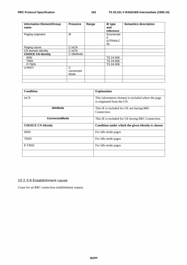
TS 25.331 V-RAN2#8/9 Intermediate (1999-10)
3GPP
163RRC Protocol Specification
Information Element/Groupname
Presence Range IE typeandreference
Semantics description
Paging originator M Enumerated(UTRAN,CN)
Paging cause C isCNCN domain identity C isCNCHOICE CN Identity C idleMode IMSI TS 24.008 TMSI TS 24.008 P-TMSI TS 24.008U-RNTI C
connectedMode
Condition Explanation
IsCN This information element is included where the pageis originated from the CN.
IdleMode This IE is included for UE not having RRCConnection.
ConnectedMode This IE is included for UE having RRC Connection.
CHOICE CN Identity Condition under which the given Identity is chosen
IMSI For idle mode pages
TMSI For idle mode pages
P-TMSI For idle mode pages
10.2.3.8 Establishment cause
Cause for an RRC connection establishment request.

TS 25.331 V-RAN2#8/9 Intermediate (1999-10)
3GPP
164RRC Protocol Specification
Information Element/Groupname
Presence Range IE type and reference Semanticsdescription
Establishment cause M Enumerated(
Originating Speech Call,
Originating CS Data Call,
Originating PS Data Call,
Terminating Speech Call,
Terminating CS Data Call,
Terminating PS Data Call,
Emergency Call,
Inter-system cell re-selection,
Location Update (LAU &RAU),
IMSI Detach,
SMS,
Other)
Note: These causes shall be aligned with causes received from higher layers.
10.2.3.9 Release cause
Cause for release of RRC connection.
10.2.3.10 Rejection cause
Cause for rejection of RRC connection establishment request.
10.2.3.11 Paging cause
Cause for a CN originated page.

TS 25.331 V-RAN2#8/9 Intermediate (1999-10)
3GPP
165RRC Protocol Specification
Information Element/Groupname
Presence Range IE type and reference Semanticsdescription
Paging cause M Enumerated(
Terminating Speech Call,
Terminating CS Data Call,
Terminating PS Data Call,
SMS,
Other)
Note: These causes shall be aligned with causes received from higher layers.
10.2.3.12 Initial UE capability
This is the UE capability information given in the RRC connection request message. The exact type of information isFFS.
Information Element/Groupname
Presence Range IE type andreference
Semantics description
Support for Transport CH O Indicates which transportchannels are supported
10.2.3.13 Power control capability
Information Element/Groupname
Presence Range IE type andreference
Semantics description
Transmission power capability M
Note: The WG1 and WG4 discussion should be concluded before the contents of this IE can be finalized.
10.2.3.14 Code resource capability
Information Element/Groupname
Presence Range IE type andreference
Semantics description
DL multi-code capabilityUL multi-code capabilityDL Spreading factor capabilityUL Spreading factor capability
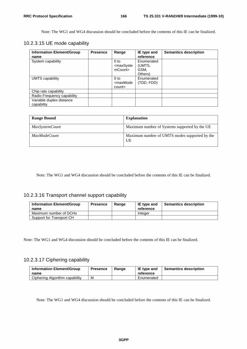
TS 25.331 V-RAN2#8/9 Intermediate (1999-10)
3GPP
166RRC Protocol Specification
Note: The WG1 and WG4 discussion should be concluded before the contents of this IE can be finalized.
10.2.3.15 UE mode capability
Information Element/Groupname
Presence Range IE type andreference
Semantics description
System capability 0 to<maxSystemCount>
Enumerated(UMTS,GSM,Others)
UMTS capability 0 to<maxModecount>
Enumerated(TDD, FDD)
Chip rate capabilityRadio Frequency capabilityVariable duplex distancecapability
Range Bound Explanation
MaxSystemCount Maximum number of Systems supported by the UE
MaxModeCount Maximum number of UMTS modes supported by theUE
Note: The WG1 and WG4 discussion should be concluded before the contents of this IE can be finalized.
10.2.3.16 Transport channel support capability
Information Element/Groupname
Presence Range IE type andreference
Semantics description
Maximum number of DCHs IntegerSupport for Transport CH
Note: The WG1 and WG4 discussion should be concluded before the contents of this IE can be finalized.
10.2.3.17 Ciphering capability
Information Element/Groupname
Presence Range IE type andreference
Semantics description
Ciphering Algorithm capability M Enumerated
Note: The WG1 and WG4 discussion should be concluded before the contents of this IE can be finalized.

TS 25.331 V-RAN2#8/9 Intermediate (1999-10)
3GPP
167RRC Protocol Specification
10.2.3.18 Macro diversity capability
Information Element/Groupname
Presence Range IE type andreference
Semantics description
Maximum number of RLs M Integer
Parameters REFERENCE TYPE NOTE Maximum number of RLs M
Note: The WG1 and WG4 discussion should be concluded before the contents of this IE can be finalized.
10.2.3.19 Cell update cause
Indicates the cause for s cell update.
Information Element/Groupname
Presence Range IE type andreference
Semantics description
Cell update cause Enumerated(cellreselection,periodic cellupdate, ULdatatransmission, pagingresponse,RB controlresponse)
10.2.3.20 URA update cause
Indicates the cause for s URA update. Examples of causes are change of URA and periodic URA update.
10.2.3.21 Number of RRC Message Transmissions
This IE indicates how many times the receiver of a message containing this IE shall transmit the RRC response message.
Information Element/Groupname
Presence Range IE type andreference
Semantics description
Number of RRC MessageTransmissions
Integer(1..8)

TS 25.331 V-RAN2#8/9 Intermediate (1999-10)
3GPP
168RRC Protocol Specification
10.2.3.22 Inter-system handover failure cause
The purpose of this IE is to provide a reason for the failure of the Inter-system handover.
10.2.3.23 Transmission probability
Indicates the probability for a mobile to be allowed to transmit on a DCH controlled by DRAC procedure.
10.2.3.24 Maximum bit rate
Indicates the maximum user bit rate allowed on a DCH controlled by DRAC procedure for the transmission period(Transmission time validity).
10.2.3.25 Capability Update Requirement
This IE indicates to the UE, which is capable of inter-system handover, whether it should send a complete update of itscapabilities in the given system (e.g. GSM) immediately after having established an RRC connection.
Information Element/Groupname
Presence Range IE type andreference
Semantics description
System M Enumerated(GSM,..)
Early Capability Update M Boolean
10.2.3.26 CPCH Parameters
These parameters are used by any UE using any CPCH set allocated to the Node B which is broadcasting this systeminformation.

TS 25.331 V-RAN2#8/9 Intermediate (1999-10)
3GPP
169RRC Protocol Specification
Information Element/Groupname
Presence Range IE typeandreference
Semantics description
NS_IP M Number of slots for initial delayfor given priority level
Priority level MBackoff control parameters N_ap_retrans_max M Max number of AP transmissions
without AP-AICH response(access cycle), a PHY parameter.
N_access_fails M Max number of access cycleswithout AP-AICH response forlink failure, a MAC parameter.
NS_bo_no aich M Max number of slots for UEbackoff after N ap_retrans_max
unsuccessful AP access attempts,a MAC parameter.
NF_bo_busy M Max number of frames for UEbackoff after access attempt tobusy CPCH, a MAC parameter.
NF_bo_all_busy M Max number of frames for UEbackoff after access attempt tolast busy CPCH, a MACparameter.
NF_bo_collision M Max number of frames for UEbackoff after collision on CPCH,a MAC parameter.
T_CPCH M CPCH channel timing -Numberof slots used to determine Tauvalues for CPCH channel timing
Note: The WG1 and WG2 discussion should be concluded before the contents of these IEs can be finalized. All of theIEs may be considered optional (O) if the UE is programmed with default values for each IE.
10.2.3.27 UE Timers and Counters
This information element indicates timers and maximum values of each counter used in UE.
Information Element/Groupname
Presence Range IE typeandreference
Semantics description
T300 MN300 M
T307 MT302 MT303 MN303 MN303 M
10.2.3.28 AM_RLC error indication

TS 25.331 V-RAN2#8/9 Intermediate (1999-10)
3GPP
170RRC Protocol Specification
Indicates AM_RLC unrecoverable error occurred on c-plane in the UE.
10.2.3.29 RLC re-configuration indicator
This IE is used to re-configure AM RLC on c-plane.
10.2.3.30 Failure cause
Cause for failure to perform the requested procedure.
Information Element/Groupname
Presence Range IE type andreference
Semantics description
Failure cause Enumerated(Configurationunacceptable,physical channelfailure)
10.2.3.31 UTRAN DRX cycle length
Indicates the time interval between monitoring paging occasions to be used by a specific UE in UTRAN Connectedmode.
10.2.3.32 DRX Indicator
Indicates to a UE if DRX shall be used with Cell updating or URA updating or if no DRX at all shall be used.
10.2.3.33 Ciphering hyper frame number
This hyper frame number (HFN) is used to initialise the ciphering algorithm.
For ciphering, HFN is the most significant bits of COUNT. When the COUNT is initialized: COUNT = HFN (the LSBpart of COUNT is set to zero).
Information Element/Groupname
Presence Range IE type andreference
Semantics description
Ciphering HFN M Start value for uplink anddownlink COUNT
10.2.3.34 Ciphering mode info
This information element contains the ciphering specific security mode control information.
Information Element/Groupname
Presence Range IE type andreference
Semantics description
Ciphering mode command M Enumerated(start/restart,modify, stop)
Ciphering algorithm C-notStop UEA [TS33.102]
Ciphering activation time C-start/restart
Activationtime

TS 25.331 V-RAN2#8/9 Intermediate (1999-10)
3GPP
171RRC Protocol Specification
Condition Explanation
notStop The IE is present only when the IE “Ciphering modecommand” has the values “start/restart” or “modify”.
Start/restart The IE is present only when the IE “Ciphering modecommand” has the value “start/restart”.
10.2.3.35 UE radio capability
Information Element/Groupname
Presence Range IE type andreference
Semantics description
Power control capability MCode resource capability MUE mode capability MTransport CH support capability OCiphering capability MMacro diversity capability MFAUSCH usage support O Indicates true/false for “DCH
allocation function”, “USCHcapability request function”.
Note: The overall discussion on UE capability parameters should be concluded before the contents of thisinformation element can be finalized.
10.2.4 Radio Bearer Information elements
10.2.4.1 RB identity
An identification number for the RB affected by a certain message.

TS 25.331 V-RAN2#8/9 Intermediate (1999-10)
3GPP
172RRC Protocol Specification
10.2.4.2 RLC info
Information Element/Groupname
Presence Range IE type andreference
Semantics description
Uplink RLC info RLC mode M enumerated
(Acknowledged,NonAcknowledged,Transparent)
Note 1
PU size O Integer Transmission RLC discard C-
NonTrOp Transmission window size C-ACK Integer(1,8,16,3
2,128,256,512,768,1024,1536,2048,2560,3072,3584,4096)
Maximum number of RLCPUs sent without getting themacknowledged. This parameteris needed if acknowledgedmode is used.
Polling info C-ACKOp
Downlink RLC info RLC mode M enumerated
(Acknowledged,NonAcknowledged,Transparent )
Indicates if Acknowledged,Unacknowledged orTransparent mode RLC shouldbe used.Note 1
In-sequence delivery M Boolean Indication if RLC shouldpreserve the order of higherlayer PDUs when these aredelivered.
PU Size ) Integer Indicates the size of RLCPayload Units.
Reception RLC discard timer C-timer Elapsed time before a SDU isdiscarded. Only present iftimer based discard modewithout explicit signalling ischosen.
Receiving window size (FFS –Note 2)
C-ACK Integer(1,8,16,32,128,256,512,768,1024,1536,2048,2560,3072,3584,4096)
Maximum number of RLC PUsallowed to be received. Thisparameter is needed ifacknowledged mode isused.(Necessity is FFS.)
Downlink RLC status Info C-ACKOp
Condition Explanation
Timer This IE is only sent if timer based discard is usedwithout explicit signalling
NonTrOp This IE is optional for UTRAN to send if IE “RLCmode” is “acknowledged” or “non-acknowledged”
AckOp This IE is optional for UTRAN to send if IE “RLCmode” is “acknowledged”
Ack This IE is only present if IE “RLC mode” is“acknowledged mode”

TS 25.331 V-RAN2#8/9 Intermediate (1999-10)
3GPP
173RRC Protocol Specification
Note 1: It is FFS if this IE always includes the same parameter values for both uplink and downlink RLC.
Note 2:It is FFS whether “Receiving window size” is necessary or not.
10.2.4.2.1 Transmission RLC Discard
Information Element/Groupname
Presence Range IE type andreference
Semantics description
SDU Discard Mode M Enumerated(Timer basedexplicit,Timer basedno explicit,Max_DATretransmissions,No_discard)
Different modes for discharge theRLC buffer on the transmitterside; Timer based with explicitsignalling, Timer based withoutexplicit signalling or Discard afterMax_DAT retransmissions.For unacknowledged mode onlyTimer based without explicitsignalling is applicable.
Timer_discard C-timer Elapsed time before a SDU isdiscarded.
Max_DAT C-discard Number of retransmissions of aPU before a SDU is discarded.
Max_RST C-no_discard
The muximum number ofretransmission of RESET PDU.
Condition Explanation
Timer This IE is only sent if timer based discard is usedwithout explicit signalling
Discard This IE is only sent when the SDU discard techniqueis to discard SDU’s after a given number of PU re-transmissions
No_discard This IE is only sent when the SDU discard is notused.

TS 25.331 V-RAN2#8/9 Intermediate (1999-10)
3GPP
174RRC Protocol Specification
10.2.4.2.2 Polling info
Information Element/Groupname
Presence Range IE type andreference
Semantics description
Timer_poll_prohibit O Minimum time between pollsTimer_poll O Started when poll is transmitted.
New poll when timer expires andno STATUS received.
Poll_PU O Enumerated(1,2,4,8,16,32,64,128)
Poll at every Poll_PU PU
Poll_SDU O Enumerated(1,4,16,64)
Poll at every Poll_SDU SDU
Last transmission PU poll M Boolean Indicates if poll at last PU intransmission buffer
Last retransmission PU poll M Boolean Indicates if poll at last PU inretransmission buffer
Poll_Window O Enumerated(50,60,70,80,85,90,95,100)
Poll at Poll_Window % oftransmission window
Timer_poll_periodic O Timer for periodic polling
Note: At least one or more parameters are necessary when polling info is sent.
10.2.4.2.3 Downlink RLC STATUS info
Information Element/Groupname
Presence Range IE type andreference
Semantics description
Timer_Status_Prohibit O Minimum time between STATUSreports
Timer_EPC O Timer for EPCMissing PU Indicator M Boolean Indicates if UE should send a
STATUS report for each missingPU that is detected
Timer_STAUS_periodic O Timer for periodic STATUSreports
10.2.4.3 Signalling link type
The purpose of the Signalling Link Type information element is to indicate the RLC parameters needed for thesignalling link.
Each possible value of Signalling Link Type information element refers to a predefined set of parameters. Details FFS.
10.2.4.4 RB mapping info
A multiplexing option for each possible transport channel this RB can be multiplexed on.

TS 25.331 V-RAN2#8/9 Intermediate (1999-10)
3GPP
175RRC Protocol Specification
Information Element/Groupname
Presence Range IE type andreference
Semantics description
Information for each multiplexingoption
1 to<maxMuxOptionsCount>
Number of RLC logicalchannels
1 to 2 1 or 2 logical channels perRLC entity or radio bearer
Uplink transport channeltype
M Enumerated(DCH,RACH,CPCH,USCH)
CPCH is FDD onlyUSCH is TDD only
Transport channel identity M Integer(0..maxTrChNum)
This is the ID of a transportchannel that this RB could bemapped onto.
Logical channel identity O Integer(1..16)
This parameter is used todistinguish logical channelsmultiplexed by MAC on atransport channel.
MAC logical channel priority O This includes both prioritybetween different users trafficwhen using a common orshared channel, and betweendifferent RBs (or logicalchannels) traffic for a certainuser. Different priorities forone users´ RBs are mapped(through the MAC´s T andC/T MUXes) to the TFCselection algorithm.
[Note: Usage and precisemeaning of this is FFS.]
Number of RLC logicalchannels
1 to 2 1 or 2 logical channels perRLC entity or radio bearer
Downlink transport channeltype
Enumerated(DCH,FACH,DSCH)
Transport channel identity O Integer(0..maxTrChNum)
Logical channel identity O Integer(1..16)
Range Bound Explanation
MaxMuxOpitonsCount Maximum number of allowed multiplexing optionsthat can be sent
Note: The necessity of dividing RB multiplexing into in uplink and downlink is FFS.
10.2.5 Transport CH Information elements
10.2.5.1 Transport Format Combination Set
Indicates the allowed combinations of already defined Transport formats.

TS 25.331 V-RAN2#8/9 Intermediate (1999-10)
3GPP
176RRC Protocol Specification
Information Element/Groupname
Presence Range IE type andreference
Semantics description
Transport format combination 1 to 1024 The first instance of theparameter Transport formatcombination correspond toTransport format combination0, the second to transportformat combination 1 and soon.
CTFC Integer(0..MaxCTFC-1)
Integer number calculatedaccording to clause 14.
Range Bound Explanation
MaxCTFC Maximum number of the CTFC value is calclulatedaccording to the following:
( )∑=
−I
iii PL
1
1
with the notation according to clause 14.
10.2.5.2 Transport Format Combination Subset
Indicates which Transport format combinations in the already defined Transport format combination set that areallowed.
Information Element/Groupname
Presence Range IE type andreference
Semantics description
CHOICE Subset representation M Minimum allowed Transportformat combination number
Integer(0..MaxTFCValue-1)
The integer number is areference to the Transportformat combination, thatarrived at that position in theTransport Format CombinationSet.
Transport format combination 1 to<maxTFCcount>
Integer(0..MaxTFCValue-1)
The integer number(s) is areference to the Transportformat combination, thatarrived at that position in theTransport Format CombinationSet.
Range Bound Explanation
MaxTFCcount Maximum number of Transport Format Combinationsthat could be sent as the limited set that the UE isallowed to use.
MaxTFCValue The max value of the Transport Format Combinationsthat currently is defined for this UE.
10.2.5.3 Transport channel identity
This information element is used to distinguish transport channels (both common and dedicated transport channels).

TS 25.331 V-RAN2#8/9 Intermediate (1999-10)
3GPP
177RRC Protocol Specification
10.2.5.4 Transport Format Set (TFS)
Information Element/Groupname
Presence Range IE type andreference
Semantics description
Dynamic Transport FormatInformation
1 tomaxTFcount
The first instance of theparameter Dynamic transportformat information correspondto Transport format 0 for thistransport channel, the secondto transport format 1 and soon.
Number f Transport blocks M Integer(0..4095)
Transport Block Size Integer(1..128),Integer(160..40..2040),Integer(2120..80..5000)
Semi-static Transport FormatInformation Transmission time interval Enumerated(
10, 20, 40,80)
Type of channel coding Enumerated(No coding,Convolutional, Turbo)
Coding Rate C-Coding Enumerated(1/2, 1/3)
Rate matching attribute Integer(1..maxRM)
CRC size M Enumerated(0, 8, 16, 24)
Condition Explanation
Blocks This IE is only present if IE “Number of TransportBlocks” is greater than 0.
Coding This IE is only present if IE “Type of channelcoding” is “Convolutional” or “Turbo”
Range Bound Explanation
MaxTFcount Maximum number of different transport formats thatcan be included in the Transport format set for onetransport channel is 32.
MaxRM Maximum number that could be set as rate matchingattribute for a transport channel.
<Note: The parameter “rate matching attribute” is in line with the RAN WG1 specifications. However, it is not currentlyin line with the description in 25.302.>
10.2.5.5 Dynamic Control

TS 25.331 V-RAN2#8/9 Intermediate (1999-10)
3GPP
178RRC Protocol Specification
Indicates if this transport channel is controlled by DRAC procedure or not.
10.2.5.6 Transmission time validity
Indicates the duration for which permission is granted on a DCH controlled by DRAC procedure.
10.2.5.7 Time duration before retry
Indicates the time duration before retrying to get the transmission permission on a DCH controlled by DRAC procedure,in case permission has not been granted.
10.2.5.8 Silent period duration before release
Indicates the maximum silent period duration before releasing the resource. This parameter may be merged with theFkp-b parameter defined in the ‘Transmission stop and resumption control’ procedure defined in [1].
(Note: [1] RAN/WG1 S1.14 document)
10.2.5.9 Transport Format Combination Set Identity
Indicates the identity of every TFCS within a UE (TDD only)
10.5.2.10 Transparent mode signalling info
This information element points out a transport channel that is used for transparent mode signalling, and which type ofmessage that is sent on the DCCH mapped on that channel.
Information Element Presence Range IE type andreference
Semantics description
Transport channel identity Transport channel used fortransparent mode signallingDCCH
Message type Enumerated(TRANSPORTFORMATCOMBINATIONCONTROL)
Indicates which type ofmessage sent on thetransparent mode signallingDCCH

TS 25.331 V-RAN2#8/9 Intermediate (1999-10)
3GPP
179RRC Protocol Specification
10.2.6 Physical CH Information elements
10.2.6.1 Frequency info
Information Element/Groupname
Presence Range IE typeandreference
Semantics description
UTRA RF Channel Number M A unique identifier for thechannel raster and itsassociated parameters (asdescribed by the otherparameters within this infoelement)
Raster Position O Provided to enable thedefinition of permitted carrierfrequency associated to thespecific UTRA RF ChannelNumber parameter
CHOICE mode FDD Duplex distance OChip rate ORF Channel Type O enumerated
(TDD, FDD)Identifies whether the UTRARF Channel Numbercorresponds to FDD/ TDD/uplink/ downlink only
10.2.6.2 Primary CPICH info (FDD only)
Information Element/Groupname
Presence Range IE type andreference
Semantics description
Primary scrambling code M Integer(0..511)
10.2.6.3 Secondary CPICH info (FDD only)
Information Element/Groupname
Presence Range IE type andreference
Semantics description
DL scrambling code C-PrimCPICH
Channelization code M
Condition Explanation
PrimCPICH This IE is only included if the DL scrambling code isdifferent to that of the primary CPICH

TS 25.331 V-RAN2#8/9 Intermediate (1999-10)
3GPP
180RRC Protocol Specification
10.2.6.4 Primary CCPCH info
Information Element/Groupname
Presence Range IE type andreference
Semantics description
CHOICE mode FDD
STTD indicator O TDD Timeslot M The PSCH timeslot (the value
k) Midamble type O Long or short midamble Cell parameters ID M For the cell parameter table Sync case M Case 1,2, or 3
10.2.6.5 Secondary CCPCH info
Information Element/Groupname
Presence Range IE type andreference
Semantics description
CHOICE mode FDD Secondary scrambling code O Integer
(0..14) STTD indicator O
Spreading factor M Enumerated(4, 16, 32, 64,128, 256)
Code number M Integer(0..maxCodeNum)
Pilot symbol existence M Boolean TFCI existence M Boolean Fixed or Flexible Position M Enumerated
(Fixed,Flexible)
Timing Offset O Time difference betweenPCCPCH
TDD Channelization code M Time slot M Timeslot of the Secondary
CCPCH Midamble type O Long or short midamble for
each time slot Midamble shift M Midamble shift of Secondary
CCPCH for each timeslot Superframe offset M Offset of the first CCPCH
transmission in a 72superframe
Repetition period M Repetition period of theCCPCH in the 72 superframe
Repetition length M Length of the allocation foreach repetition

TS 25.331 V-RAN2#8/9 Intermediate (1999-10)
3GPP
181RRC Protocol Specification
Condition Explanation
Range Bound Explanation
MaxCodeNum Maximum number of codes for one spreading factor(SF) is equal to SF-1.
10.2.6.6 PRACH info (for RACH)
Information Element/Groupname
Presence Range IE type andreference
Semantics description
CHOICE mode FDD Available Signature 1 to
<maxSigNum>
Signature M Enumerated(0,1.2…..15)
Available SF 1 to<maxSf>
SF M Enumerated(32,64,128,256 chip/sym)
Scrambling code wordnumber
M Enumerated(0,1.2…..255)
Puncturing Limit M Available Sub Channelnumber
1 to <maxSubChNum >
Sub Channel number M Enumerated(0,1,2,….11)
Persistence factor N M ffs 0-1 step ffs
TDD Spreading factor M Spreading factor 8 or 16 are
possible Timeslot M Channelisation code M 1:1 mapping between
spreading code and midambleshift
Midamble O Basic midamble code forPRACH (two different codespossible)
Range Bound Explanation
MaxSubChNum Maximum number of available sub channels MaxSigNum Maximum number of available signatures
MaxSf Maximum number of available SF

TS 25.331 V-RAN2#8/9 Intermediate (1999-10)
3GPP
182RRC Protocol Specification
10.2.6.7 PRACH power control infoInformation Element/Groupname
Presence Range IE type andreference
Semantics description
CHOICE mode FDD
Primary CPICH DL TXpower
M
UL interference M Constant value M
Power offset• • P0 M Power step when noacquisition indicator isreceived
Power offset• • P1 M Power step when negativeacquisition is received
Power offset• • Pp-m M Power offset betweenpreamble and the messagepart
TDD
NOTE: The usage of these parameters needs clarification and are also dependent on the WG1 RACH discussions.

TS 25.331 V-RAN2#8/9 Intermediate (1999-10)
3GPP
183RRC Protocol Specification
10.2.6.8 Uplink DPCH info
Information Element/Groupname
Presence Range IE type andreference
Semantics description
CHOICE mode FDD UL scrambling code What short or long uplink
scrambling code a certain UEshould use
Scrambling code type M Enumerated(short, long)
Scrambling code number M Integer(0..16777215)
(24 bits)
Number of DPDCH M Integer(1..maxDPDCHcount)
DPDCH channelizationcode
C-Single Enumerated(4, 8, 16, 32,64, 128,256)
SF of the channelization codefor data part
TFCI existence M Boolean Number of FBI bits O Enumerated
(1, 2 bits)If neither SSDT nor FB ModeTransmit Diversity Signalling issupported, this parameter isnot needed and the number ofFBI bits is set to “0”.
Puncturing Limit M TDD Scrambling code type M Enumerated(
short, long) Scrambling code number M Integer(0..16
777215)(24 bits)
DPCH Activation Time O Farme number start ofallocation period (theSuperframe offset can bederived)
Duration O Total number of frames Repetition period O Repetition period of the DPCH
in the 72 Superframe Repetition length O Length of the allocation for
each repetition TFCI presence O Coding for a TFCI field in a
DPCH DPCH channelisation code M SF of the channelisation code
of the data part for eachDPCH
Timeslot M Timeslot of DPCH for eachDPCH
Midamble type O Short or long, for each timeslot, for each DPCH
Midamble shift M Midamble shift for eachtimeslot for each DPCH
DPCH activation time O Frame number start ofallocation (the SuperframeOFFset can be derived) foreach timeslot for each DPCH
Condition Explanation
Single This IE is included if IE “Number of DPDCH” is “1”

TS 25.331 V-RAN2#8/9 Intermediate (1999-10)
3GPP
184RRC Protocol Specification
Range Bound Explanation
MaxDPDCHcount Maximum number of DPDCH's
10.2.6.9 Uplink DPCH power control info
Parameters used by UE to set DPCH initial output power and to use for closed-loop power control.
Information Element/Groupname
Presence Range IE type andreference
Semantics description
CHOICE mode FDD Constant value Necessity is ffs UL interference Necessity is ffs TPC step size M Enumerated
(1dB, 2dB) TDD UL target SIR M

TS 25.331 V-RAN2#8/9 Intermediate (1999-10)
3GPP
185RRC Protocol Specification
10.2.6.10 Downlink DPCH info
Information Element/Groupname
Presence Range IE type andreference
Semantics description
CHOICE mode FDD Secondary scrambling code O Integer
(0..14) DL channelization code 1 to
<maxChancount>
Channelization codes to beused in the downlink for DPCH
Spreading factor M Enumerated(4, 16, 32, 64,128, 256,512)
Code number M Integer(0..maxCodeNum)
Fixed or Flexible Position M Enumerated(Fixed,Flexible)
TFCI existence M Boolean Number of bits for Pilot bits C-SF Enumerated
(2,4,8 bits) STTD Indicator C-STTD TDD DPCH Activation Time O Farme number start of
allocation period (theSuperframe offset can bederived)
Duration O Total number of frames Repetition period O Repetition period of the DPCH
in the 72 Superframe Repetition length O Length of the allocation for
each repetition TFCI presence O Coding for a TFCI field in a
DPCH DPCH channelisation code M SF of the channelisation code
of the data part for eachDPCH
Timeslot M Timeslot of DPCH for eachDPCH
Midamble type O Short or long, for each timeslot, for each DPCH
Midamble shift M Midamble shift for eachtimeslot for each DPCH
DPCH activation time O Frame number start ofallocation (the SuperframeOFFset can be derived) foreach timeslot for each DPCH
Condition Explanation
STTD This IE is only sent if STTD is applied
SF This IE is only sent if SF=128 or 256 is applied.If SF=256, value is 2,4 or 8 If SF=128, value is 4 or 8
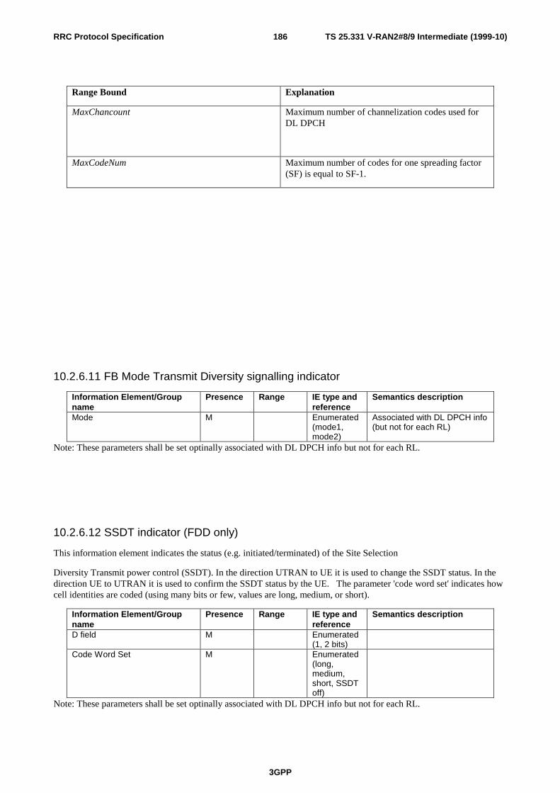
TS 25.331 V-RAN2#8/9 Intermediate (1999-10)
3GPP
186RRC Protocol Specification
Range Bound Explanation
MaxChancount Maximum number of channelization codes used forDL DPCH
MaxCodeNum Maximum number of codes for one spreading factor(SF) is equal to SF-1.
10.2.6.11 FB Mode Transmit Diversity signalling indicator
Information Element/Groupname
Presence Range IE type andreference
Semantics description
Mode M Enumerated(mode1,mode2)
Associated with DL DPCH info(but not for each RL)
Note: These parameters shall be set optinally associated with DL DPCH info but not for each RL.
10.2.6.12 SSDT indicator (FDD only)
This information element indicates the status (e.g. initiated/terminated) of the Site Selection
Diversity Transmit power control (SSDT). In the direction UTRAN to UE it is used to change the SSDT status. In thedirection UE to UTRAN it is used to confirm the SSDT status by the UE. The parameter 'code word set' indicates howcell identities are coded (using many bits or few, values are long, medium, or short).
Information Element/Groupname
Presence Range IE type andreference
Semantics description
D field M Enumerated(1, 2 bits)
Code Word Set M Enumerated(long,medium,short, SSDToff)
Note: These parameters shall be set optinally associated with DL DPCH info but not for each RL.

TS 25.331 V-RAN2#8/9 Intermediate (1999-10)
3GPP
187RRC Protocol Specification
10.2.6.13 SSDT cell identity (FDD only)
This IE is used to associate a cell identity with a given radio link
Information Element/Groupname
Presence Range IE type andreference
Semantics description
Temporary id M
10.2.6.14 Gated Transmission Control info (FFS) (FDD only)
Information Element/Groupname
Presence Range IE type andreference
Semantics description
Gating pattern M Enumerated(periodic,random-(FFS))
Gating rate M Enumerated(Full rate,1/3, 1/5 or 0
Indicates gated transmissionrate
10.2.6.15 Default DPCH Offset Value (FDD only)
Indicates the default offset value within interleaving size at a resolution of 512chip (1/5 slot) to offset CFN in the UE.This is used to distribute discontinuous transmission periods in time and also to distribute NodeB-RNC transmissiontraffics in time. Even though the CFN is offset by DOFF, the start timing of the interleaving will be the timing that “CFNmod (interleaving size)”=0 (e.g. interleaving size: 2,4,8) in both UE and SRNC.
10.2.6.16 RF channel number priority
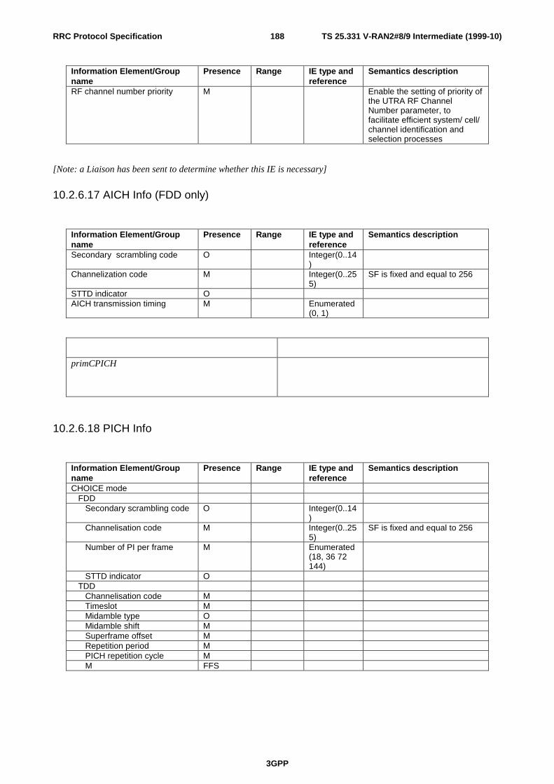
TS 25.331 V-RAN2#8/9 Intermediate (1999-10)
3GPP
188RRC Protocol Specification
Information Element/Groupname
Presence Range IE type andreference
Semantics description
RF channel number priority M Enable the setting of priority ofthe UTRA RF ChannelNumber parameter, tofacilitate efficient system/ cell/channel identification andselection processes
[Note: a Liaison has been sent to determine whether this IE is necessary]
10.2.6.17 AICH Info (FDD only)
Information Element/Groupname
Presence Range IE type andreference
Semantics description
Secondary scrambling code O Integer(0..14)
Channelization code M Integer(0..255)
SF is fixed and equal to 256
STTD indicator OAICH transmission timing M Enumerated
(0, 1)
primCPICH
10.2.6.18 PICH Info
Information Element/Groupname
Presence Range IE type andreference
Semantics description
CHOICE mode FDD Secondary scrambling code O Integer(0..14
) Channelisation code M Integer(0..25
5)SF is fixed and equal to 256
Number of PI per frame M Enumerated(18, 36 72144)
STTD indicator O TDD Channelisation code M Timeslot M Midamble type O Midamble shift M Superframe offset M Repetition period M PICH repetition cycle M M FFS

TS 25.331 V-RAN2#8/9 Intermediate (1999-10)
3GPP
189RRC Protocol Specification
10.2.6.19 PRACH info (for FAUSCH) (FDD only)
Information Element/Groupname
Presence Range IE type andreference
Semantics description
Fast access slot 1 to<maxAS>
Preamble spreading code 1 to<maxPreambleSC>
Preamble signature 1 to<maxPreambleSigs>
FAUSCH usage Indicates true/false for “use forDCH allocation”, “use forUSCH capability request”.
Range Bound Explanation
MaxAS Number of access slots for the preambles (Every 16chips)
MaxPreambleSC Number of preamble spreading codes
MaxPreambleSigs Number of allowed preamble signatures
10.2.6.20 CPCH set info (FDD only)
This IE may be broadcast in the System Information message or assigned by SRNC. It is pseudo-static in a cell.
Information Element/Groupname
Presence Range IE type andreference
Semantics description
CPCH set ID C Indicates the ID number for aparticular CPCH set allocated to acell.Necessity is FFS.
AP preamble code O 256 chip preamble code for AP inUL
AP-AICH channelisation code O 256 chip channelisation code forAP-AICH in DL
CD preamble code O 256 chip preamble code for CD inUL
CD-AICH channelisation code O 256 chip channelisation code forCD-AICH in DL
Signature code N O Signature code for CPCH channelselection in UL. 16 signatures,16 bits each, N from 1-16.
CPCH channel info 0 to<maxCPCHs>
UL scrambling code O UL channelisation code O DL channelisation code O NF_max (Max packet length in frames)
O
Signature pointer (maps to set of signatures for this channel)
O

TS 25.331 V-RAN2#8/9 Intermediate (1999-10)
3GPP
190RRC Protocol Specification
Range Bound Explanation
MaxCPCHs Maximum number of CPCH channels in a CPCH set(max=16 with 1 signature per channel)
Note: Whether several CPCH Set Info with different QoS can be set in a cell is FFS.
10.2.6.21 CPCH persistency values (FDD only)
This IE is dynamic and is used by RNC for load balancing and congestion control. This is broadcast often in the systeminformation message.
Information Element/Groupname
Presence Range IE type andreference
Semantics description
CPCH set ID M Identifier for CPCH set info.PV_CPCHn M Persistency value for CPCHn.
One PV for each CPCH channelin this CPCH set.
10.2.6.22 Downlink DPCH compressed mode info (FDD only)
This information element indicates the parameters of the downlink compressed mode to be used by the UE in order toperform inter-frequency measurements.

TS 25.331 V-RAN2#8/9 Intermediate (1999-10)
3GPP
191RRC Protocol Specification
Information Element/Groupname
Presence Range IE type andreference
Semantics description
TGL M Transmission Gap lengthexpressed in number of slots
CFN M Connection Frame Numberwhen the first compressedframe starts
SN M Slot number when thetransmission gap starts (withinthe CFN)
TGP M Transmission Gap Periodindicates the number foframes between two sets ofconsecutive compressedframes containing up to 2transmission gaps
TGD M Transmission Gap distanceindicates the number offrames between twoconsecutive transmission gapswithin a transmission gapperiod.
PD M Total number of TGPsPCM M Power control mode during the
frame after the compressedframe. Indicates whethernormal PC mode orcompressed PC mode isapplied
DeltaEb/No M Delta in DL Eb/No target valueto be set in the UE during thecompressed frames (Note 1)
DeltaEb/Noafter M Delta in DL Eb/No target valueto be set in the UE one frameafter the compressed frames(Note 1)
[Editors Note 1: The current assumptions is that the delta will be zero or positive]
10.2.6.23 Downlink DPCH power control information
This information element indicates the range of Eb/No target values and the initial Eb/No target value to be set in theUE on this physical, channel for the downlink closed loop power control.
Information Element/Groupname
Presence Range IE type andreference
Semantics description
DPC Mode M Enumerated(mode0,mode1)
Initial Eb/No target value M Initial Eb/No value to be usedfor the DL closed loop powercontrol.
Min Eb/No target value M Minimum Eb/No value that canbe set by the DL closed looppower control.
Max Eb/No target value M Maximum Eb/No value thatcan be set by the DL closedloop power control.

TS 25.331 V-RAN2#8/9 Intermediate (1999-10)
3GPP
192RRC Protocol Specification
10.2.6.24 Downlink Outer Loop Control
This information element indicates whether the UE is allowed or not to increase its downlink Eb/No target value abovethe current value.
10.2.6.25 Timing Advance (TDD only)
Information Element/Groupname
Presence Range IE type andreference
Semantics description
UL Timing Advance M
10.2.6.26 PSCH Timeslot (TDD only)
Information Element/Groupname
Presence Range IE type andreference
Semantics description
PSCH information M
10.2.6.27 ASC Info (TDD only)
Information Element/Groupname
Presence Range IE type andreference
Semantics description
Access Service Class 1 Support O Each PRACH info IE inSystem Information isassociated with an ASC infoIE. Any one RACH cansupport multiple ASCs.
Access Service Class 2 Support OAccess Service Class 3 Support O
10.2.6.28 PUSCH info (TDD only)

TS 25.331 V-RAN2#8/9 Intermediate (1999-10)
3GPP
193RRC Protocol Specification
Information Element/Groupname
Presence Range IE type andreference
Semantics description
UL scrambling code M What short or long uplinkscrambling code a certain UEshould use
PUSCH activation time M Frame number start ofallocation period (theSuperframe Offset can bederived)
Duration M Total number of framesRepetition Period O Repetition period of the
PUSCH in the 72 SuperframeRepetition length O Length of the allocation for
each repetitionTFCI presence O List of timeslots in which a
TFCI field is codedIndividual PUSCH info 1 to
<maxPUSCHcount>
Different for each PUSCH
PDCH channelization code M SF of the channelization code Timeslot M Timeslot number Midamble Type O Short or long midamble Midamble Shift M Midamble shift of the PUSCH
Range Bound Explanation
MaxPUSCHcount Maximum number of PUSCH’s
10.2.6.29 PDSCH info (TDD only)
Information Element/Groupname
Presence Range IE type andreference
Semantics description
PDSCH activation time M Frame number start ofallocation period (theSuperframe Offset can bederived)
Duration M Total number of framesRepetition Period O Repetition period of the
DDSCH in the 72 SuperframeRepetition length O Length of the allocation for
each repetitionTFCI presence O List of timeslots in which a
TFCI field is codedIndividual PDSCH info 1 to
<maxPDSCHcount>
Different for each PDSCH
PDCH channelization codes M List of channelization codesused in the downlink forPUSCH
Timeslot M Timeslot number Midamble Type O Short or long midamble Midamble Shift M Midamble shift of the PUSCH

TS 25.331 V-RAN2#8/9 Intermediate (1999-10)
3GPP
194RRC Protocol Specification
Range Bound Explanation
MaxPDSCHcount Maximum number of PDSCH’s
10.2.6.30 PUSCH power control info (TDD only)
Interference level measured for a frequency at the UTRAN access point used by UE to set PUSCH outputpower.
Information Element/Groupname
Presence Range IE type andreference
Semantics description
UL target SIR M
10.2.6.31 Maximum allowed UL TX power
This information element indicates the maximum allowed uplink transmit power.
Information Element Presence Range IE type andreference
Semantics description
Maximum allowed UL TX power
10.2.7 Measurement Information elements
10.2.7.1 Measurement Identity Number
A reference number that is used by the UTRAN at modification and release of the measurement, and by the UE in themeasurement report.
10.2.7.2 Measurement Command
One out of three different measurement commands
• Setup: Setup a new measurement.
• Modify: Modify a previously specified measurement, e.g. change the reporting criteria.
• Release: Stop a measurement and clear all information in the UE that are related to that measurement.
10.2.7.3 Measurement Type
One of the types from a predefined list where each type describes what the UE shall measure. The types are:
• Intra-frequency measurements

TS 25.331 V-RAN2#8/9 Intermediate (1999-10)
3GPP
195RRC Protocol Specification
• Inter-frequency measurements
• Inter-system measurements
• Traffic volume measurements
• Quality measurements
• UE internal measurement
10.2.7.4 Reference time difference to cell
The reference time difference to cell indicates the time difference between the primary CCPCH of the current cell andthe primary CCPCH of a neighbouring cell. It is notified to UE by System Information or Measurement Controlmessage.
In case of macro-diversity the reference is the primary CCPCH of one the cells used in the active set.
Editors note: Exactly how the reference cell is pointed out in this case in the messages is FFS.
10.2.7.5 Measured time difference to UTRA cell
For FDD: The measured time difference to cell indicates the time difference which is measured by UE between CFN in the UE andthe SFN of the target neighbouring cell. It is notified to SRNC by Measurement Report message or Measurement InformationElement in other RRC messages.
For TDD: This is the relative time difference in the frame timing between the serving and the target cell measured at theUE.
10.2.7.6 Measured time difference to GSM cell
(Note: Only the section is made.)
10.2.7.7 Measurement reporting mode
Contains the type of Measurement Report transfer mode and the indication of periodical/event trigger.

TS 25.331 V-RAN2#8/9 Intermediate (1999-10)
3GPP
196RRC Protocol Specification
Information Element/Groupname
Presence Range IE type andreference
Semanticsdescription
Measurement Report TransferMode
M enumerated(Acknowledged /Unacknowledged)
Periodical Reporting / EventTrigger Reporting Mode
M enumerated(Periodicalreporting / Eventtrigger)
10.2.7.8 Intra-frequency cell info
Contains the measurement object information for an intra-frequency measurement.
Information Element/Groupname
Presence Range IE type andreference
Semantics description
Primary CCPCH info MPrimary CCPCH DL TX power OUL load O FFSSFN Measurement Indicator MDL CCTrCH info O List of TFCS ID’s to measureDL Timeslot info O List of timeslots to measure
10.2.7.9 Inter-frequency cell info
Contains the measurement object information for an inter-frequency measurement.
Information Element/Groupname
Presence Range IE type andreference
Semantics description
Frequency info MPrimary CCPCH info MPrimary CCPCH DL TX power O FFSUL load O FFSReference time difference to cell O FFS
10.2.7.10 Inter-system cell info
Contains the measurement object information for an inter-system measurement.

TS 25.331 V-RAN2#8/9 Intermediate (1999-10)
3GPP
197RRC Protocol Specification
Information Element/Groupname
Presence Range IE type andreference
Semantics description
System type M enumerated(GSM,..)
System specific measurementinfo
enumerated(frequency,timeslot, colourcode, outputpower.)
10.2.7.11 Traffic volume measurement object
Contains the measurement object information for a traffic volume measurement.
Information Element/Groupname
Presence Range IE type andreference
Semantics description
Target Transport CH ID M
10.2.7.12 Quality measurement object (FFS)
(Note: Only the section is made.)
10.2.7.13 Intra-frequency measurement quantity
The quantity the UE shall measure in case of intra-frequency measurement. It also includes the filtering of themeasurements.
Information Element/Groupname
Presence Range IE type andreference
Semantics description
Primary CCPCH RX Ec/I0 OPrimary CCPCH RX SIR(RSCP/ISCP)
O FFS
Primary CCPCH RX power(RSCP)
O FFS
Path loss O FFSPath loss plus UL load O FFS
One of these is mandatory
CHOICE mode TDD DL CCTrCH SIR O DL Timeslot ISCP O
(Note: Above measurements except for Ec/Io are not concluded in WG1)

TS 25.331 V-RAN2#8/9 Intermediate (1999-10)
3GPP
198RRC Protocol Specification
10.2.7.14 Inter-frequency measurement quantity (FFS)
The quantity the UE shall measure in case of inter-frequency measurement. It also includes the filtering of themeasurements.
Information Element/Groupname
Presence Range IE type andreference
Semantics description
Ec/I0 O FFSDL Path loss O FFSSIR O FFSDL path loss plus ULinterference
O FFS
Received signal code power(RSCP)
O FFS
One of these is mandatory
10.2.7.15 Inter-system measurement quantity (FFS)
The quantity the UE shall measure in case of inter-system measurement. It also includes the filtering of themeasurements.
Information Element/Groupname
Presence Range IE type andreference
Semantics description
Ec/I0 O FFSSignal strength OPath loss O FFS
One of these is mandatory
Colour code C - GSM
Condition Explanation
GSM This information element is only sent when thesystem being measured is a GSM system
10.2.7.16 Traffic volume measurement quantity
Contains the measurement quantity information for a traffic volume measurement.
Information Element/Groupname
Presence Range IE type andreference
Semantics description
RLC buffer payload MAverage RLC buffer payload OVariance of RLC buffer payload O
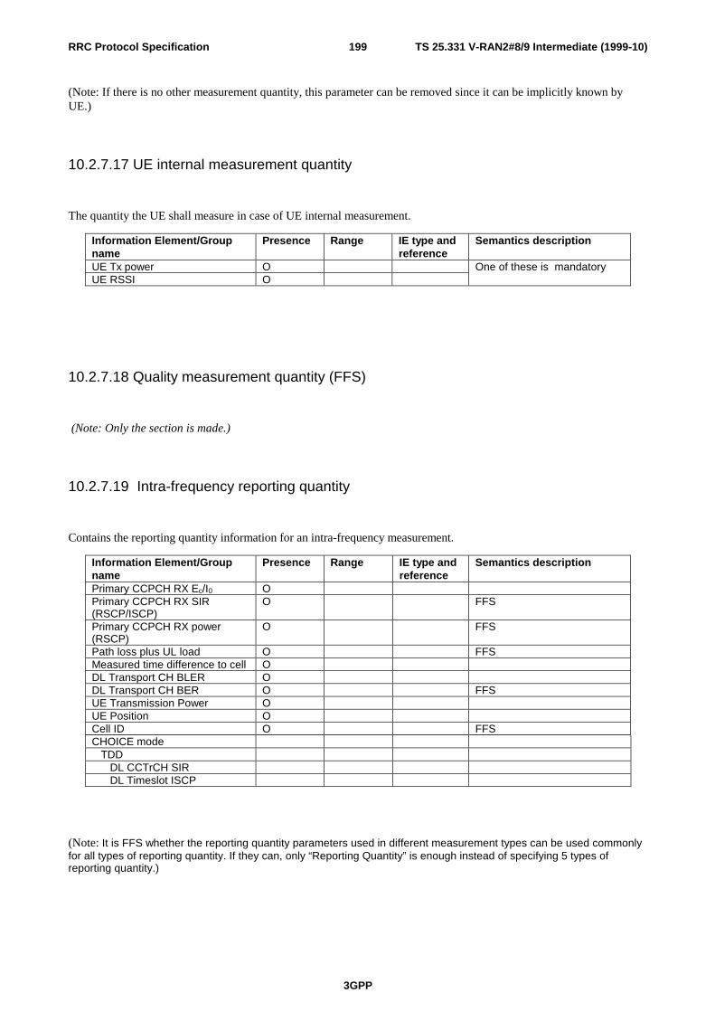
TS 25.331 V-RAN2#8/9 Intermediate (1999-10)
3GPP
199RRC Protocol Specification
(Note: If there is no other measurement quantity, this parameter can be removed since it can be implicitly known byUE.)
10.2.7.17 UE internal measurement quantity
The quantity the UE shall measure in case of UE internal measurement.
Information Element/Groupname
Presence Range IE type andreference
Semantics description
UE Tx power OUE RSSI O
One of these is mandatory
10.2.7.18 Quality measurement quantity (FFS)
(Note: Only the section is made.)
10.2.7.19 Intra-frequency reporting quantity
Contains the reporting quantity information for an intra-frequency measurement.
Information Element/Groupname
Presence Range IE type andreference
Semantics description
Primary CCPCH RX Ec/I0 OPrimary CCPCH RX SIR(RSCP/ISCP)
O FFS
Primary CCPCH RX power(RSCP)
O FFS
Path loss plus UL load O FFSMeasured time difference to cell ODL Transport CH BLER ODL Transport CH BER O FFSUE Transmission Power OUE Position OCell ID O FFSCHOICE mode TDD DL CCTrCH SIR DL Timeslot ISCP
(Note: It is FFS whether the reporting quantity parameters used in different measurement types can be used commonlyfor all types of reporting quantity. If they can, only “Reporting Quantity” is enough instead of specifying 5 types ofreporting quantity.)

TS 25.331 V-RAN2#8/9 Intermediate (1999-10)
3GPP
200RRC Protocol Specification
10.2.7.20 Intra-frequency reporting quantity for RACH reporting
Contains the reporting quantity information for an intra-frequency measurement report, which is sent on the RACH.
Information Element/Groupname
Presence Range IE type andreference
Semantics description
Primary CCPCH RX Ec/I0 OPrimary CCPCH RX SIR(RSCP/ISCP)
O FFS
Primary CCPCH RX power(RSCP)
O FFS
Path loss plus UL load O FFSMeasured time difference to cell ODL Transport CH BLER O FFSDL Transport CH BER O FFSUE Transmission Power O FFSUE Position O FFSCell ID O FFSCHOICE mode TDD DL Timeslot ISCP
10.2.7.21 Inter-frequency reporting quantity (FFS)
Information Element/Groupname
Presence Range IE type andreference
Semantics description
Measured time difference to cell OPrimary CCPCH Rx RSCP OEc/N0 of Primary CCPCH O
10.2.7.22 Inter-system reporting quantity (FFS)
Information Element/Groupname
Presence Range IE type andreference
Semantics description
Observed time difference toGSM cellRSS I on BCCH carrier
10.2.7.23 Traffic volume reporting quantity
Contains the reporting quantity information for a traffic volume measurement.

TS 25.331 V-RAN2#8/9 Intermediate (1999-10)
3GPP
201RRC Protocol Specification
Information Element/Groupname
Presence Range IE type andreference
Semantics description
RLC buffer payload for each RB OAverage RLC buffer payload foreach RAB
O
Variance of RLC buffer payloadfor each RAB
O
Event type on each Transportchannel
O Indicates overflow orunderflow
DL Transport CH BLER ODL Transport CH BER O FFSUE Transmission Power OUE Position OCell ID O FFS
(Note: It is FFS whether the reporting quantity parameters used in different measurement types can be used commonlyfor all types of reporting quantity. If they can, only “Reporting Quantity” is enough instead of specifying 5 types ofreporting quantity.
10.2.7.24 Quality reporting quantity (FFS)
(Note: Only the section is made.)
10.2.7.25 Intra-frequency measurement reporting criteria
The triggering of the event-triggered reporting for an intra-frequency measurement. All events concerning intra-frequency measurements are labeled 1x where x is a, b, c….
Event 1a: A Primary CPICH enters the Reporting Range [Note1](FDD only)
Event 1b: A Primary CPICH leaves the Reporting Range [Note2] (FDD only)
Event 1c: A Non-active Primary CPICH becomes better than an active Primary CPICH [Note3](FDD only)
Event 1d: Change of best cell [Note4, 5] (FDD ony)
Event 1e: Other types of ranking of Primary CPICHs (FFS) (FDD only)
Event 1f: A Primary CCPCH becomes worse than an absolute threshold (FDD only)
Event 1g: Change of best cell in TDD
Event 1h: DL CCTrCH below a certain threshold (TDD only)
Event 1i: DL Timeslot ISCP below a certain threshold (TDD only)
TS 25.331 V-RAN2#8/9 Intermediate (1999-10)
3GPP
202RRC Protocol Specification
Event 1j: DL Timeslot ISCP above a certain threshold (TDD only)

TS 25.331 V-RAN2#8/9 Intermediate (1999-10)
3GPP
203RRC Protocol Specification
Information Element/Groupname
Presence Range IE type andreference
Semantics description
Max number of reporting cells O Common parameter for allevents
RACH measurement reportingparameters
Group name
Maximum number of reported cells on RACH
O
Parameters required for eachevent
0 to<maxEventcount>
Event ID M 1a, 1b, 1c, 1d, 1e, 1f, 1g, 1h,1I, 1j
Triggering condition C - clause0
enumerated Indicates whether event shallbe triggered by:
-Active set cells only
-Monitored set cells only
-Both active set cells andmonitored set cells
Reporting Range C - clause1
In event 1a,1b
S C – clause1
In event 1a,1b
Hysteresis C & O -clause 2
In event 1a, 1b, 1c,1d, 1g, 1h,1i or 1j
Reporting deactivation threshold
C - clause3
In event 1a
Indicates the maximumnumber of cells allowed in theactive set in order for event 1ato occur.
Value 0 indicates "notapplicable".
Replacement activation threshold
C - clause4
In event 1c
Indicates the minimumnumber of cells allowed in theactive set in order for event 1cto occur.
Value 0 indicates "notapplicable".
Time to trigger M Indicates the period of timebetween the timing of eventdetection and the timing ofsending Measurement Report.
Amount of reporting M Measurement for the indicatedTransport CH ID is “released”after the indicated amount ofreporting from the UE itself.
FFS Reporting interval M Indicates the interval of
periodical reporting when suchreporting is triggered by anevent. A zero value indicatesthat event triggered periodicalreporting shall not be applied.

TS 25.331 V-RAN2#8/9 Intermediate (1999-10)
3GPP
204RRC Protocol Specification
Condition Explanation
Clause 0 This parameter is only sent in event 1a,1b, 1e, 1f
Clause 1 This parameter is only sent in event 1a,1b
Clause 2 This parameter is only sent in event 1a,1b, 1c,1d, 1g,1h, 1i, 1j
Clause 3 This parameter is only sent in event 1a
Clause 4 This parameter is only sent in event 1c
[Note1: whether or not PCCPCH can be active is FFS]
[Note2: whether or not PCCPCH can be non-active is FFS]
[Note3: Details are FFS: It has been suggested to divide this event into two cases; I) a non-active PCCPCH exceeds theweakest active PCCPCH, II) a non-active PCCPCH exceeds the strongest active PCCPCH]
[Note4: When best PCCPCH in active set changes, all active cells are reported.]
[Note5: Whether this event can result in the reporting of non-active cells in addition to active cells is FFS.]
10.2.7.26 Inter-frequency measurement reporting criteria (FFS)
The triggering of the measurement report, e.g. periodical, event-triggered or immediate reporting for an inter-frequencymeasurement. Here is also specified if the measurement report should be transmitted using either acknowledged orunacknowledged data transfer on the DCCH.
Information Element/Groupname
Presence Range IE type andreference
Semantics description
10.2.7.27 Inter-system measurement reporting criteria (FFS)
The triggering of the measurement report, e.g. periodical, event-triggered or immediate reporting for aninter-system measurement. Here is also specified if the measurement report should be transmitted usingeither acknowledged or unacknowledged data transfer on the DCCH.

TS 25.331 V-RAN2#8/9 Intermediate (1999-10)
3GPP
205RRC Protocol Specification
10.2.7.28 Traffic volume measurement reporting criteria
Contains the measurement reporting criteria information for a traffic volume measurement.
Information Element/Groupname
Presence Range IE type andreference
Semantics description
Parameters sent for eachtransport channel
1 to<maxTrCHcount>
Transport CH ID M Upper Threshold M Lower Threshold OTime to trigger M Indicates the period of time
between the timing of eventdetection and the timing ofsending Measurement Report.
Pending time after trigger M Indicates the period of timeduring which it is forbidden tosend any new measurementreports with the samemeasurement ID even if thetriggering condition is fulfilledagain.
Tx interruption after trigger M Indicates whether or not theUE shall block DTCHtransmissions on the RACHafter a measurement report istriggered.
Amount of reporting M Measurement for the indicatedTransport CH ID is “released”after the indicated amount ofreporting from the UE itself.
FFSReporting interval M Indicates the interval of periodical
report during the event is in thedetected state
FFS
Range Bound Explanation
MaxTrCHcount Maximum number of transport channels
10.2.7.29 Quality measurement reporting criteria (FFS)
(Note: Only the section is made.)
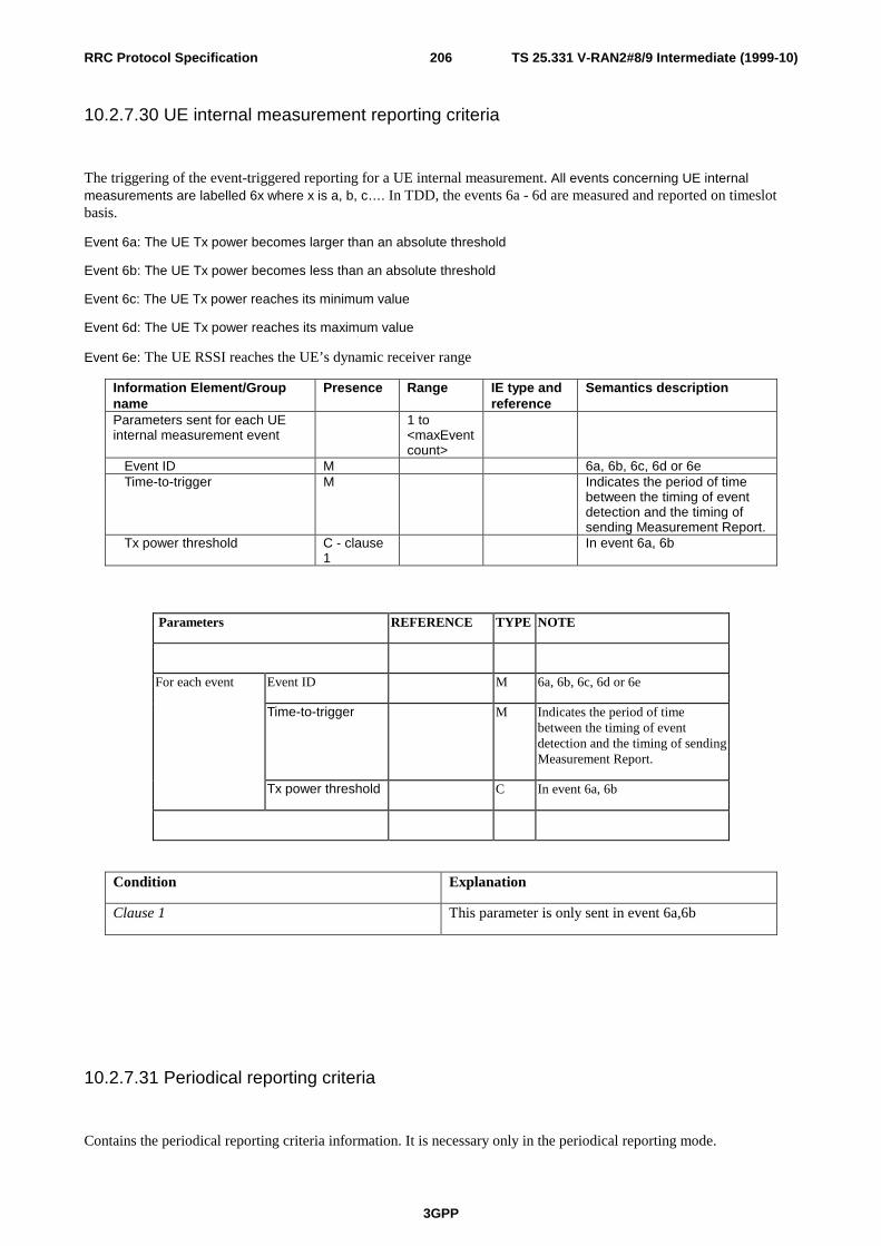
TS 25.331 V-RAN2#8/9 Intermediate (1999-10)
3GPP
206RRC Protocol Specification
10.2.7.30 UE internal measurement reporting criteria
The triggering of the event-triggered reporting for a UE internal measurement. All events concerning UE internalmeasurements are labelled 6x where x is a, b, c…. In TDD, the events 6a - 6d are measured and reported on timeslotbasis.
Event 6a: The UE Tx power becomes larger than an absolute threshold
Event 6b: The UE Tx power becomes less than an absolute threshold
Event 6c: The UE Tx power reaches its minimum value
Event 6d: The UE Tx power reaches its maximum value
Event 6e: The UE RSSI reaches the UE’s dynamic receiver range
Information Element/Groupname
Presence Range IE type andreference
Semantics description
Parameters sent for each UEinternal measurement event
1 to<maxEventcount>
Event ID M 6a, 6b, 6c, 6d or 6e Time-to-trigger M Indicates the period of time
between the timing of eventdetection and the timing ofsending Measurement Report.
Tx power threshold C - clause1
In event 6a, 6b
Parameters REFERENCE TYPE NOTE
Event ID M 6a, 6b, 6c, 6d or 6e
Time-to-trigger M Indicates the period of timebetween the timing of eventdetection and the timing of sendingMeasurement Report.
For each event
Tx power threshold C In event 6a, 6b
Condition Explanation
Clause 1 This parameter is only sent in event 6a,6b
10.2.7.31 Periodical reporting criteria
Contains the periodical reporting criteria information. It is necessary only in the periodical reporting mode.

TS 25.331 V-RAN2#8/9 Intermediate (1999-10)
3GPP
207RRC Protocol Specification
Information Element/Groupname
Presence Range IE type andreference
Semantics description
Max number of reporting cells O Indicates the maximumnumber of cells to report.
Amount of reporting O Measurement is “released”after the indicated amount ofreporting from the UE itself
Reporting interval O Indicates the interval ofperiodical report.
10.2.7.32 Intra-frequency measurement event results
This IE contains the measurement event results that are reported to UTRAN for intra-frequency measurements.
Information Element/Groupname
Presence Range IE type andreference
Semantics description
Event ID MPrimary CCPCH info OCHOICE mode TDD DL CCTrCH SIR O DL Timeslot ISCP O
10.2.7.33 Inter-frequency measurement event results (FFS)
This IE contains the measurement event results that are reported to UTRAN for inter-frequency measurements.
The further division of this IE into parameters is FFS.
10.2.7.34 Inter-system measurement event results (FFS)
This IE contains the measurement event results that are reported to UTRAN for inter-system measurements.
The further division of this IE into parameters is FFS.
10.2.7.35 Traffic volume measurement event results
Contains the event result for a traffic volume measurement.

TS 25.331 V-RAN2#8/9 Intermediate (1999-10)
3GPP
208RRC Protocol Specification
Information Element/Groupname
Presence Range IE type andreference
Semantics description
Transport CH ID M
10.2.7.36 Quality measurement event results (FFS)
(Note: Only the section is made.)
10.2.7.37 Measured results
Contains the measured results of the quantity indicated optionally by Reporting Quantity in Measurement Control."Measured results" can be used for both event trigger mode and periodical reporting mode.

TS 25.331 V-RAN2#8/9 Intermediate (1999-10)
3GPP
209RRC Protocol Specification
Information Element/Groupname
Presence Range IE type andreference
Semantics description
RB ID+ RLC buffers payload
O
PCCPCH Info+ Primary CCPCH RX Ec/I0
O
PCCPCH Info+ Primary CCPCH RX SIR(RSCP/ISCP)
O FFS
PCCPCH Info+ Primary CCPCH RX power(RSCP)
O FFS
PCCPCH Info+ Path loss
O FFS
PCCPCH Info+ Path loss plus UL load
O FFS
PCCPCH Info+ Measured time difference to cell
O
DL Transport CH BLER ODL Transport CH BER O FFSUE Transmission Power O UE transmission power (FDD)
Tx Power O 0 to<maxUsedUplTScount
>
UE transmission power foreach used timeslot (TDD)
UE Position OCell ID O FFSGSM Cell ID+ measured time difference to cell
O
GSM Cell ID+ RSSI on BCCH carrierCHOICE mode TDD DL CCTrCH SIR 0 to
<maxCCTrCHcount>
SIR measurements for eachDL CCTrCH
Timeslot 0 to<maxTS
perCCTrCHcount
All timeslots on which theCCTrCH is mapped on
Rx ISCP O Rx RSCP O
DL Timeslot ISCP 0 to<maxTS
toMEASURE count>
ISCP measurements for eachtimeslot indicated by theUTRAN
Rx ISCP O
Range BoundExplanation
MaxCCTrCHcount Maximum number of DL CCTrCH allocated to an UE
MaxTSperCCTrCHcount Maximum number of TS on which a single DLCCTrCH is mapped on
maxTStoMEASUREcount Maximum number of TS on which the UE has tomeasure
maxUsedUplTScount Maximum number of TS used for UL transmissions

TS 25.331 V-RAN2#8/9 Intermediate (1999-10)
3GPP
210RRC Protocol Specification
10.2.7.38 SFN Measurement Indicator
Indicates whether the UE should read cell SFN of the target neighbour cell or not.
10.2.7.39 Maximum number of reported cells on RACH
Information Element/Groupname
Presence Range IE type andreference
Semantics description
Number of reported cells M Enumerated(no report,current cell,current cell +bestneighbour,currentcell+2 bestneighbours,…, currentcell+6 bestneighbours)
10.2.7.40 Inter-frequency SET UPDATE (FDD only)
Contains the changes of the active set associated with a non-used frequency. This information makes it possible to useevents defined for Intra-frequency measurement within the same non-used frequency for Inter-frequency measurementreporting criteria.
Information Element/groupname
Presence Range IE type andreference
Semantics description
Radio link addition information 0 to<MaxAddRLcount>
Radio link addition informationrequired for each RL to add
CPICH info M Note 1Radio link removal information 0 to
<MaxDelRLcount>
Radio link removal informationrequired for each RL toremove
CPICH info M Note 1
Range bound Explanation
MaxAddRLcount Maximum number of radio links which can be added
MaxDelRLcount Maximum number of radio links which can beremoved/deleted

TS 25.331 V-RAN2#8/9 Intermediate (1999-10)
3GPP
211RRC Protocol Specification
Note 1: If it is assumed that CPICH downlink scrambling code is always allocated with sufficient reuse distances,CPICH downlink scrambling code will be enough for designating the different radio links.
10.2.8 Other Information elements
10.2.8.1 BCCH modification info
Indicates modification of the System Information on BCCH.
Information Element/Groupname
Presence Range IE type andreference
Semantics description
MIB Value tag M Value tag
10.2.8.2 Inter-system message
This Information Element contains one or several messages that are structured and coded according to the specificationused for the system type indicated by the first parameter.
Information Element/Groupname
Presence Range IE type andreference
Semantics description
System type M Enumerated(GSM,1..15)
Message(s) M 1..<maxInterSysMessages>
Bitstring(1..512)
Formatted and codedaccording to specification forthe indicated system type.
Range Bound Explanation
MaxInterSysMessages(=4) Maximum number of Inter System Messages to send
10.2.8.3 Segment index
Each system information segment has an individual segment index.
Information Element/Groupname
Presence Range IE type andreference
Semantics description
Segment index M Integer(0..31)
Segments of a systeminformation block arenumbered starting with 0 forthe first part.

TS 25.331 V-RAN2#8/9 Intermediate (1999-10)
3GPP
212RRC Protocol Specification
10.2.8.4 SIB data
Contains the result of the IE 'SIB Content' after segmentation.
Information Element/Groupname
Presence Range IE type andreference
Semantics description
SIB data M Bit string(size(1..MaxLength))
It is an acceptable constraint that the 'SIB data' fills always the transport block when appearing as the last IE in atransport block.
10.2.8.5 SI Padding
Information Element/Groupname
Presence Range IE type andreference
Semantics description
Padding M Bit string(size(1..MaxLength))
All the bits of the 'SI Padding' IE shall be set to a fixed value in emission. However, it is not an error for the receiver toreceive any other value for those bits.
10.2.8.6 SIB type
The SIB type identifies a specific system information block.
Information Element/Groupname
Presence Range IE type andreference
Semantics description
SIB type M Enumerated
The list of value to encode are :
Master information block,
System Information Type 1,
System Information Type 2,
System Information Type 3,
System Information Type 4,

TS 25.331 V-RAN2#8/9 Intermediate (1999-10)
3GPP
213RRC Protocol Specification
System Information Type 5,
System Information Type 6,
System Information Type 7
System Information Type 8,
System Information Type 9,
System Information Type 10,
System Information Type 11,
System Information Type 12
10.2.8.7 Value tag
Information Element/Groupname
Presence Range IE type andreference
Semantics description
Value tag M Enumerated(1..256)
10.2.8.8 Expiration time
Information Element/Groupname
Presence Range IE type andreference
Semantics description
Expiration time M Integer(0..31)
The time is expressed inseconds. Expiration time ofzero means the UE has to re-read the information uponeach usage occasion.
10.2.8.9 Scheduling information

TS 25.331 V-RAN2#8/9 Intermediate (1999-10)
3GPP
214RRC Protocol Specification
Information Element/Groupname
Presence Range IE type andreference
Semantics description
SIB type MValue tag C -
BlocktypeThe value of the 'value tag' IEin the 'scheduling information'IE indicates the value of the'value tag' IE of the nextoccurrence of the SIB of SIBtype the value of the 'SIB type'IE within the area scope ofthat SIB.
Scheduling O> SEG_COUNT O SEG_COUN
T> SIB_REP M Integer (16,
32, 64, 128,.. 2048)
Repetition period for the SIB inframes
> SIB_POS M Integer(0…Rep-1)
Position of the first segment
> SIB_POS offset info O > > SIB_OFF M Segcount-
1Integer(1..32)
Offset of subsequentsegments
Condition Explanation
Blocktype The presence of this IE depends on the value of thepreceding SIB type. This IE is mandatory if thespecification of the SIB of that SIB type includes asfirst IE a Value tag IE.
Option Default value
SIB_POS offset info If the SIB_POS offset info is not present, the receivershall understand that all segments are consecutive,i.e., that the SIB_OFF would have been 0, 1, 2, …
SEG_COUNT If not present, the number of segments is one.
Scheduling If not present, the SIB is not sent in the area scope.
Range Bound Explanation
Segcount The value of the SEG_COUNT IE
Rep The value of the SIB_REP IE
10.2.8.10 SEG COUNT
SEG_COUNT M Integer(1..32)
Number of segments in thesystem information block

TS 25.331 V-RAN2#8/9 Intermediate (1999-10)
3GPP
215RRC Protocol Specification
11 Message and Information element abstract syntax (withASN.1)
This chapter contains definitions for RRC PDUs and IEs using a subset of ASN.1 as specified in I2.01.PDU and IE definitions are grouped into separate ASN.1 modules.
Note that the proposal is to keep both chapter 10 and 11 (at least until all messages and informationelements are fully discussed and agreed by 3GPP RAN WG2). Chapter 10 is intended to give anabstract description (in English) of the messages and information elements whereas chapter 11 shouldcontain the exact normative definitions with all necessary details.

TS 25.331 V-RAN2#8/9 Intermediate (1999-10)
3GPP
216RRC Protocol Specification
12 Message transfer syntaxTransfer syntax for RRC PDUs is derived from their abstract syntax definitions by use of encodingrules.
13 Protocol timers, counters and other parameters
13.1 Timers for UE
Timer ValueRange(seconds)
Relations Start Stop At expiry
T300 Transmission of RRCCONNECTION REQUEST
Reception of RRCCONNECTION SETUP
Retransmit RRCCONNECTIONREQUEST ifV300 =< N300,else go to Idlemode
T301 Transmission of RRCCONNECTIONREESTABLISHMENTREQUEST
Reception of RRCCONNECTIONREESTABLISHMENT
Retransmit RRCCONNECTIONREESTABLISHREQUEST ifV301 =< N301,else go to Idlemode
T302 Transmission of CELLUPDATE
Reception of CELLUPDATE CONFIRM
Retransmit CELLUPDATE if V302=< N302, else, goto Idle mode
T303 Transmission of URAUPDATE
Reception of URA UPDATECONFIRM
Retransmit URAUPDATE if V303=< N303, else goto Idle mode
T304 Transmission of UECAPABILITYINFORMATION
Reception of UECAPABILITYINFORMATIONCONFIRM
Retransmit UECAPABILITYINFORMATIONif V304 =< N304,else initiate RRCconnectionreestablishment

TS 25.331 V-RAN2#8/9 Intermediate (1999-10)
3GPP
217RRC Protocol Specification
Timer ValueRange(seconds)
Relations Start Stop At expiry
T305 Entering CELL_FACH orCELL_PCH state. Receptionof CELL UDPATECONFIRM.
Entering another state. Transmit CELLUPDATE.
T306 Entering URA_PCH state.Reception of URA UDPATECONFIRM.
Entering another state. Transmit URAUPDATE.
T307 When the timer T305 or T306has expired and the UE detectsthat it is out of service area.
When the UE detects that itis no longer out of servicearea.
Initiate cell update or URAupdate procedure dependingon state
Transit to idlemode
T308 Transmission of RRCCONNECTION RELEASECOMPLETE
Not stopped Transmit RRCCONNECTIONRELEASECOMPLETE ifV308 =< N308,else go to idlemode.
T309 Upon reselection of a cellbelonging to another radioaccess system from connectedmode
Successful establishment ofa connection in the new cell
Resume theconnection toUTRAN
T310 Transmission of PUSCHCAPACITY REQUEST
Reception of PHYSICALSHARED CHANNELALLOCATION
Transmit PUSCHCAPACITYREQUEST ifV310 =< N310,else procedurestops.
T311 Reception of PHYSICALSHARED CHANNELALLOCATION message withthe parameter “PUSCHAllocation Pending” set to“pending”.
Reception of PHYSICALSHARED CHANNELALLOCATION messagewith parameter “PUSCHAllocation Pending” set to“not pending”.
UE may initiate aPUSCH capacityrequest procedure.
13.3 Counters for UECounter Reset Incremented When reaching max value
V300 When initiating theprocedure RRCconnectionestablishment
Upon expiry of T300. When V300 > N300, the UE enters idle mode.

TS 25.331 V-RAN2#8/9 Intermediate (1999-10)
3GPP
218RRC Protocol Specification
Counter Reset Incremented When reaching max value
V301 When initiating theprocedure RRCconnectionreestablishment
Upon expiry of T301. When V301 > N301, the UE enters idle mode.
V302 When initiating theprocedure Cell update
Upon expiry of T302 When V302 > N302 the UE enters idle mode.
V303 When initiating theprocedure URAupdate
Upon expiry of T303 When V302 > N303 the UE enters idle mode.
V304 When sending thefirst UECAPABILITYINFORMATIONmessage.
Upon expiry of T304 When V304 > N304 the UE initiates the RRCconnection re-establishment procedure
Counter Reset Decremented When reaching zero
V308 When sending thefirst RRCCONNECTIONRELEASECOMPLETEmessage in a RRCconnection releaseprocedure.
Upon expiry of T308 When V308 =0 the UE stops re-transmittingthe RRC CONNECTION RELEASECOMPLETE message.
Counter Reset Incremented When reaching max value
V310 When sending thefirst PUSCHCAPACITYREQUEST messagein a PUSCH capacityreqest procedure
Upon expiry of T310 When V310 > N310 the UE stops re-transmitting the PUSCH CAPACITYREQUEST message.
13.5 UE constants and parametersConstant Value Usage
N300 Maximum number of retransmissions of the RRC CONNECTION REQUESTmessage
N301 Maximum number of retransmissions of the RRC CONNECTIONREESTABLISHMENT REQUEST message
N302 Maximum number of retransmissions of the CELL UPDATE message
N303 Maximum number of retransmissions of the URA UPDATE message
N304 Maximum number of retransmissions of the UE CAPABILITY INFORMATIONmessage
N310 Maximum number of retransmission of the PUSCH CAPACITY REQUEST message

TS 25.331 V-RAN2#8/9 Intermediate (1999-10)
3GPP
219RRC Protocol Specification
14 Specific functions
14.1 Intra-frequency measurements
14.1.1 Intra-frequency measurement quantities
1. Downlink Ec/I0 (chip energy per total received channel power density)
2. Downlink path loss. (FFS)
3. Downlink received signal code power (RSCP) after despreading. (FFS)
4. Downlink signal-to-interference ratio (SIR) after despreading on a specific DL physical channel(RSCP/ISCP).(FFS)
5. Averaged signal-to-interference ratio (SIR) for all DL codes belonging to one TS and to one CCTrCH
6. ISCP measured on Timeslot basis
14.1.2 Intra-frequency reporting events for FDD
Within the measurement reporting criteria field in the Measurement Control message the UTRAN notifies the UE whichevents should trigger a measurement report. Examples of intra-frequency reporting events that would be useful for intra-frequency handover evaluation are given below. Note that normally the UEs do not need to report all these events. Thelisted events are the toolbox from which the UTRAN can choose the reporting events that are needed for theimplemented handover evaluation function, or other radio network functions.
All the illustrated events are measured with respect to any of the measurement quantities given in section 14.1.1. Themeasurement objects are the monitored primary common pilot channels (CPICH). The reporting events are marked withvertical arrows in the figures below.
[Note: The events below are numbered 1A, 1B, 1C,… since all intra-frequency reporting events would be labeled 1X,inter-frequency reporting events would be labeled 2X, and so on for the other measurement types.]
14.1.2.1 Reporting event 1A: A Primary CPICH enters the reporting range
When event 1A is ordered by UTRAN in a measurement control message, the UE shall send a measurement report whena primary CPICH enters the reporting range as defined by the following formula:
),(10)1(1010 11
aBest
N
iiNew HRLogMSMLogSLogM
A
+−⋅⋅−+
⋅⋅≥⋅ ∑
=

TS 25.331 V-RAN2#8/9 Intermediate (1999-10)
3GPP
220RRC Protocol Specification
The variables in the formula are defined as follows:
MNew is the measurement result of the cell entering the reporting range.
Mi is a measurement result of a cell in the active set.
NA is the number of cells in the current active set.
MBest is the measurement result of the strongest cell in the active set.
S is a parameter sent from UTRAN to UE.
R is the reporting range
H1a is the hysteresis parameter for the event 1a.
The addition window of cells in event 1A is configured with the reporting range parameter (R) common to manyreporting events and an optional hysteresis parameter (H1a), which can be used to distinguish the addition window fromreporting windows related to other measurement events.
The occurrence of event 1A is conditional on a report deactivation threshold parameter. This parameter indicates themaximum number of cells allowed in the active set for measurement reports to be triggered by event 1A to betransmitted.
Event 1A may be enhanced with an addition timer, which is configured with the time-to-trigger parameter (see section14.1.4.2). If a time-to-trigger value is used, a cell must continuously stay within the reporting range for the given timeperiod, before the UE shall send a measurement report.
[Note: It is FFS, whether the cells triggering event 1A may be in the active set.]
14.1.2.2 Reporting event 1B: A primary CPICH leaves the reporting range
When this event is ordered by UTRAN in a measurement control message, the UE shall send a measurement reportwhen a primary CPICH leaves the reporting range as defined by the following formula:
),(10)1(1010 11
bBest
N
iiOld HRLogMSMLogSLogM
A
+−⋅⋅−+
⋅⋅≤⋅ ∑
=
The variables in the formula are defined as follows:
MOld is the measurement result of the cell leaving the reporting range.
Mi is a measurement result of a cell in the active set.
NA is the number of cells in the current active set.
MBest is the measurement result of the strongest cell in the active set.
S is a parameter sent from UTRAN to UE.
R is the reporting range
H1b is the hysteresis parameter for the event 1b.
The drop window of cells in event 1B is configured with the reporting range parameter (R) common to many reportingevents and an optional hysteresis parameter (H1b), which can be used to distinguish the drop window from reportingwindows related to other measurement events.
Event 1B may be enhanced with a drop timer, which is configured with the time-to-trigger parameter. If the timer isused, the weakening cell must continuously stay below the reporting range for the given time period before the UE maysend a measurement report.
[Note: It is FFS whether cells triggering event 1B may belong to the monitored set cells, which are currently not in theactive set]

TS 25.331 V-RAN2#8/9 Intermediate (1999-10)
3GPP
221RRC Protocol Specification
14.1.2.3 Reporting event 1C: A non-active primary CPICH becomes better than an activeprimary CPICH
Reportingevent 1C
Reportingevent 1C
Measurementquantity
Time
P CPICH 2
P CPICH 1
P CPICH 3
P CPICH 4
Figure 48 A primary CPICH that is not included in the active set becomes better than a primary CPICH that isin the active set.
In this example the cells belonging to primary CPICH 1, 2 and 3 are supposed to be in the active set, but the celltransmitting primary CPICH 4 is not (yet) in the active set.
If a primary CPICH that is not included in the active set becomes better than a primary CPICH that is in the active set,and event 1C has been ordered by UTRAN, this event shall trigger a report to be sent from the UE.
This event may be used for replacing cells in the active set. It is activated if the number of active cells is equal to orgreater than a replacement activation threshold parameter that UTRAN signals to the UE in the MEASUREMENTCONTROL message. This parameter indicates the minimum number of cells required in the active set for measurementreports triggered by event 1C to be transmitted.
14.1.2.4 Reporting event 1D: Change of best cell
Reportingevent 1D
Measurementquantity
Time
P CPICH 2
P CPICH 1
P CPICH3
Figure 49 A primary CPICH becomes better than the previously best primary CPICH.
If any of the primary CPICHs within the reporting range becomes better than the previously best primary CPICH, and

TS 25.331 V-RAN2#8/9 Intermediate (1999-10)
3GPP
222RRC Protocol Specification
event 1D has been ordered by UTRAN then this event shall trigger a report to be sent from the UE. The correspondingreport contains (at least) the new best primary CPICH.
14.1.2.5 Reporting event 1E: A Primary CPICH becomes better than an absolutethreshold
Absolutethreshold
Reportingevent 1E
Measurementquantity
Time
P CPICH 1
P CPICH 2
P CPICH 3
Figure 50 Event-triggered report when a Primary CPICH becomes better than an absolute threshold.
When this event is ordered by UTRAN in a measurement control message the UE shall send a report when theMeasurement quantity of a Primary CPICH becomes better than an absolute threshold. The corresponding reportcontains (at least) the involved Primary CPICH.

TS 25.331 V-RAN2#8/9 Intermediate (1999-10)
3GPP
223RRC Protocol Specification
14.1.2.6 Reporting event 1F: A Primary CPICH becomes worse than an absolutethreshold
Absolutethreshold
Reportingevent 1F
Measurementquantity
Time
P CPICH 1
P CPICH 2
P CPICH 3
Figure 51 Event-triggered report when a Primary CPICH becomes worse than an absolute threshold.
When this event is ordered by the UTRAN in a measurement control message the UE shall send a report when a primaryCPICH becomes worse than an absolute threshold. The corresponding report contains (at least) the involved PrimaryCPICH.
14.1.3 Intra-frequency reporting events for TDD
14.1.3.1 Change of best cell
ReportingEvent 1G
Measurementquantity
Time
P CCPCH 2
P CCPCH 1
Figure 52 A primary CCPCH becomes better than the prevous best primary CCPCH
If any of the primary CCPCHs becomes better than the previously best primary CCPCH, and event 1G has been orderedby UTRAN then this event shall trigger a report to be sent from the UE. The corresponding report contains (at least) the

TS 25.331 V-RAN2#8/9 Intermediate (1999-10)
3GPP
224RRC Protocol Specification
new best primary CCPCH.
14.1.3.2 DL CCTrCH below a certain threshold
ReportingEvent 1H
DL CCTrCH SIR
Time
TS 2
TS 1
SIRThreshold
Figure 53 A SIR value of a timeslot becomes worse than an adsolute threshold
14.1.3.3 DL Timeslot ISCP below a certain threshold
DL Timeslot ISCP
ReportingEvent 1I
Time
TS 1
ISCPThreshold
Figure 54 A ISCP value of a timeslot becomes worse than an absolute threshold
14.1.3.4 DL Timeslot ISCP above a certain threshold

TS 25.331 V-RAN2#8/9 Intermediate (1999-10)
3GPP
225RRC Protocol Specification
DL Timeslot ISCP
ReportingEvent 1J
Time
TS 1
ISCPThreshold
Figure 55 A ISCP value of a timeslot becomes better than a certain threshold
14.1.4 Event-triggered periodic intra-frequency measurement reports
14.1.4.1 Cell addition failure (FDD only)
Event- t r iggeredreport
P C C P C H 3
P C C P C H 1
P C C P C H 2
Per iodicreport
Per iodicreport
Report ingrange
Report ingterminated
Figure 56 Periodic reporting triggered by event 1A
When a cell enters the reporting range and triggers event 1A, the UE shall transmit a MEASUREMENT REPORT to theUTRAN and typically this may result in an update of the active set. However, in some situations the UTRAN may beunable to add a strong cell to the active set typically due to capacity shortage for example.
The UE shall continue reporting after the initial report by reverting to periodical measurement reporting if the reportedcell is not added to the active set. This is illustrated in Figure 56. During periodic reporting the UE shall transmitMEASUREMENT REPORT messages to the UTRAN at predefined intervals. The reports shall include reportinginformation of the cells in the current active set and of the monitored cell(s) in the reporting range.

TS 25.331 V-RAN2#8/9 Intermediate (1999-10)
3GPP
226RRC Protocol Specification
Event-triggered periodic measurement reporting shall be terminated either when there are no longer any monitoredcell(s) within the reporting range or when the UTRAN has added cells to the active set so that it includes the maximumnumber of cells (defined by the reporting deactivation threshold parameter), which are allowed for event 1A to betriggered.
The reporting period is assigned by the UTRAN. If the reporting period is set to zero event-triggered measurementreporting shall not be applied.
[Note: The figure should be updated to reflect that the measurements are made on the CPICH rather than PCCPCH]
14.1.4.2 Cell replacement failure (FDD only)
PCCPCH 1
Event-tr iggeredreport
Periodicreport
PCCPCH 4
PCCPCH 2
Periodicreport
Report ingterminated
PCCPCH 3
Figure 57 Periodic reporting triggered by event 1C
When a cell enters the replacement range and triggers event 1C, the UE shall transmit a MEASUREMENT REPORT tothe UTRAN and typically this may result in the replacement of the weakest active cell. If the UTRAN is unable toreplace the cell due to for example capacity shortage, it is beneficial to receive continuous reports in this case as well.
The UE shall revert to periodical measurement reporting if the UTRAN does not update the active set after thetransmission of the measurement report. This is illustrated in Figure 57. During periodic reporting the UE shall transmitMEASUREMENT REPORT messages to the UTRAN at predefined intervals. The reports shall include reportinginformation of the cells in the current active set and of the monitored cell(s) in the replacement range.
Event-triggered periodic measurement reporting shall be terminated either when there are no longer any monitoredcell(s) within the replacement range or when the UTRAN has removed cells from the active set so that there are nolonger the minimum amount of active cells for event 1C to be triggered (as defined by the replacement activationthreshold parameter).
The reporting period is assigned by the UTRAN. If the reporting period is set to zero, event-triggered measurementreporting shall not be applied.
[Note: The figure should be updated to reflect that the measurements are made on the CPICH rather than PCCPCH]

TS 25.331 V-RAN2#8/9 Intermediate (1999-10)
3GPP
227RRC Protocol Specification
14.1.4.3 Timeslot replacement failure (TDD only)
Reportingterminated
DL CCTrCH SIR
Event – triggeredreport 1H
Time
TS 1
SIRThreshold
Periodical Reports
Figure 58 Periodic reporting triggered by event 1H
When the averaged SIR value of one timeslot belonging to a DL CCTrCH triggers event 1H, the UE shall transmit aMEASUREMENT REPORT to the UTRAN and typically this may result to a change of the used downlink timeslots.However, in some situations the DCA algorithm in the UTRAN can not change the timeslots due to capacity shortagefor example.
The UE shall continue reporting after the initial report by reverting to periodical measurements reporting, see Figure 5.During periodic reporting the UE shall transmit MEASUREMENT REPORT messages to UTRAN at predefinedintervals. The report shall include interference measurements of selected downlink timeslots of the current cell tosupport the DCA algorithm.
The event-triggered periodic measurement reporting shall be terminated either when the DCA algorithm has replaced theworse downlink timeslot or when the reason for the event 1H, which has triggered the periodical measurement reporting,are not given anymore.
The reporting period is assigned by the UTRAN. IF the reporting period is set to zero event-triggered periodicmeasurements reporting shall not be applied.
14.1.5 Mechanisms available for modifying intra-frequency measurementreporting behaviour
14.1.5.1 Hysteresis

TS 25.331 V-RAN2#8/9 Intermediate (1999-10)
3GPP
228RRC Protocol Specification
To limit the amount of event-triggered reports, a hysteresis parameter may be connected with each reporting event givenabove. The value of the hysteresis is given to the UE in the Reporting criteria field of the Measurement Controlmessage.
In the example in Figure 59, the hysteresis ensures that the event 1D (FDD) or IG(TDD) (primaryCPICH(FDD)/CCPCH(TDD) 2 becomes the best cell) is not reported until the difference is equal to the hysteresis value.The fact that primary CPICH(FDD)/CCPCH(TDD) 1 becomes best afterwards is not reported at all in the example sincethe primary CPICH(FDD)/CCPCH(TDD) 1 does not become sufficiently better than the primaryCPICH(FDD)/CCPCH(TDD) 2.
Hysteresis
Reportingevent 1D
Hysteresis
Measurementquantity
Time
P CCPCH 1
P CCPCH 2
Figure 59 Hysteresis limits the amount of measurement reports.
14.1.5.2 Time-to-trigger
To limit the measurement signalling load, a time-to-trigger parameter could be connected with each reporting eventgiven above. The value of the time-to-trigger is given to the UE in the Reporting criteria field of the MeasurementControl message.
The effect of the time-to-trigger is that the report is triggered only after the conditions for the event have existed for thespecified time-to-trigger. In the following FDD example in Figure 60, the use of time-to-trigger means that the event(primary CPICH 3 enters the reporting range) is not reported until is has been within the range for the time given by thetime-to-trigger parameter.

TS 25.331 V-RAN2#8/9 Intermediate (1999-10)
3GPP
229RRC Protocol Specification
Reportingevent 1A
Measurementquantity
Time
Time-to-trigger
P CPICH 1Reportingrange
P CPICH 2
P CPICH 3
Figure 60 Time-to-trigger limits the amount of measurement reports.
In the following TDD example in Figure 61, the use of time-to-trigger means that the event (DL Timeslot ISCP uponcertain threshold) is not reported until it has been upon the threshold for the time given by the time-to trigger parameter.
Time-to-trigger
DL Timeslot ISCP
ReportingEvent 1J
Time
TS 1
SIRThreshold
Figure 61 Time-to-trigger limits the amount of measrement reports.
Note that the time-to-trigger could be combined with hysteresis, i.e. a hysteresis value is added to the measurementquantity before evaluating if the time-to-trigger timer should be started.
14.1.5.3 Cell individual offsets
For each cell that is monitored, an offset can be assigned with inband signalling. The offset can be either positive ornegative. The offset is added to the measurement quantity before the UE evaluates if an event has occurred. The UEreceives the cell individual offsets for each primary CPICH(FDD)/CCPCH(TDD) in the measurement object field of theMEASUREMENT CONTROL message.
For the FDD example, in Figure 62, since an offset is added to primary CPICH 3, it is the dotted curve that is used to

TS 25.331 V-RAN2#8/9 Intermediate (1999-10)
3GPP
230RRC Protocol Specification
evaluate if an event occurs. Hence, this means that measurement reports from UE to UTRAN are triggered whenprimary CPICH plus the corresponding offset, i.e. the dotted curve, leaves and enters the reporting range and when itgets better than primary CPICH 1 (if these events have been ordered by UTRAN). This offset mechanism provides thenetwork with an efficient tool to change the reporting of an individual primary CPICH.
By applying a positive offset, as in Figure 62, the UE will send measurement reports as if the primary CPICH is offset xdB better than what it really is. This could be useful if the operator knows that a specific cell is interesting to monitormore carefully, even though it is not so good for the moment. In the example in Figure 62, the operator might know byexperience that in this area primary CPICH 3 can become good very quickly (e.g. due to street corners) and thereforethat it is worth reporting more intensively. Depending on the implemented handover evaluation algorithm, this mayresult in the cell with primary CPICH 3 being included in the active set earlier than would have been the case withoutthe positive offset.
Reportingevent 1A
Reportingevent 1B
Offset forP CPICH 3
Measurementquantity
Time
P CPICH 1
P CPICH 2
P CPICH 3
Reportingrange
Figure 62 A positive offset is applied to primary CPICH 3 before event evaluation in the UE.
For the TDD example, in Figure 63, an offset is added to primary CCPCH2, it is the dotted curve that is used to evaluateif the primary CCPCH2 becomes better than primary CCPCH1 (ordered by the UTRAN).
Offset forPCCPCH 2
ReportingEvent 1G
Measurementquantity
Time
PCCPCH 1
Figure 63 Apositive offset is applied to primary CCPCH 2.
Correspondingly, the operator can choose to apply a negative offset to a primary CCPCH. Then the reporting on thatprimary CCPCH is limited and the corresponding cell may be, at least temporarily excluded from the active set or as atarget cell for handover.

TS 25.331 V-RAN2#8/9 Intermediate (1999-10)
3GPP
231RRC Protocol Specification
The cell individual offset can be seen as a tool to move the cell border. It is important to note that the offset is addedbefore triggering events, i.e. the offset is added by the UE before evaluating if a measurement report should be sent asopposed to offsets that are applied in the network and used for the actual handover evaluation.
14.1.5.4 Forbid a Primary CPICH to affect the reporting range (FDD only)
The reporting range affects the reporting events 1A and 1B presented above. The reporting range is defined relative tothe best Primary CPICH. However, there could be cases where it is good to forbid a specific Primary CPICH to affectthe reporting range. For example in Figure 64 the network has requested the UE to not let Primary CPICH 3 affect thereporting range. This mechanism could be effective if the operator knows by experience that the quality of PrimaryCPICH 3 is very unstable in a specific area and therefore should not affect the reporting of the other Primary CPICHs.
Reportingrange
Measurementquantity
Time
P CPICH 1
P CPICH 2
P CPICH 3
Reportingrange
Figure 64 Primary CPICH 3 is forbidden to affect the reporting range.
14.1.6 Report quantities
In the event-triggered measurement reports, mandatory information connected to the events is always reported. Forinstance, at the event “a primary CPICH(FDD)/CCPCH(TDD) enters the reporting range” the corresponding reportidentifies the primary CPICH(FDD)/CCPCH(TDD) that entered the range.
However, besides this mandatory information, UTRAN should be able to optionally require additional measurementinformation in the report to support the radio network functions in UTRAN. Furthermore, it will allow the UTRAN touse the UE as a general tool for radio network optimisation if necessary.
Examples of report quantities that may be appended to the measurement reports are:[Note: This list is general and does also apply for reports of other measurement types than the intra-frequency type.The list is not final.]
• Downlink transport channel block error rate
• Downlink transport channel bit error rate
• Downlink Ec/I0 on primary CPICH(FDD)/CCPCH(TDD) (e.g. used for initial DL power setting on new radiolinks.)
• Time difference between the received primary CPICH(FDD)/CCPCH(TDD) frame-timing from the target cell andthe earliest received existing DPCH path. [Note: This measurement is identified in 25.211 [2] (denoted Tm inchapter 7)]
• UE transmit power
• UE position (FFS)
• Downlink SIR (RSCP/ISCP) on the traffic channels after RAKE combining (FFS)
• Downlink SIR (RSCP/ISCP) on primary CPICH(FDD)/CCPCH(TDD) (e.g. used for initial DL power setting onnew radio links.)(FFS)

TS 25.331 V-RAN2#8/9 Intermediate (1999-10)
3GPP
232RRC Protocol Specification
14.2 Traffic Volume Measurements
14.2.1 Traffic Volume Measurement Quantity
For traffic volume measurements in the UE only one quantity is measured. This quantity is RLC buffer payload innumber of bytes. In order to support a large variation of bit rates and RLC buffer size capabilities, a non-linear scaleshould be used [Note: details are FFS]. Since, the expected traffic includes both new and retransmitted RLC payloadunits all these should be included in the payload measure. It should also be noted that traffic volume measurements areonly applicable for acknowledged and unacknowledged mode.
According to what is stated in the Measurement Control message, the UE should support measuring of buffer payloadfor a specific RB, RBs multiplexed onto the same Transport channel and the total UE buffer payload (the same as onetransport channel for a UE that uses RACH).
14.2.2 Traffic Volume reporting events
Traffic volume can be reported in two different ways, periodical and event triggered. For periodical reporting the UEsimply measures the number of bytes for the transport channel (i.e. the RLC buffers of the RBs multiplexed onto thattransport channel) stated in the measurement control message and reports the traffic volume at the given time instants.Event triggered reporting is performed when a threshold is exceeded.
The reporting quantities which should be included in the report is stated in the measurement control message. This couldfor example be which RBs or RLC buffers to include when sending the payload to the network.
14.2.2.1 Reporting event 4 A: RLC buffer payload exceeds an absolute threshold
Threshold
Payload
Reportingevent 4A
Time
Reportingevent 4A
Figure 65 Event triggered report when RLC buffer payload exceeds a certain threshold.
If the monitored payload exceeds an absolute threshold, this is an event that could trigger a report. The correspondingreport contains at least which transport channel triggered the report.
14.2.3 Traffic volume reporting mechanisms
Traffic volume measurement triggering could be associated with both a time-to-trigger and a pending time after trigger.The time-to-trigger is used to get time domain hysteresis, i.e. the condition must be fulfilled during the time-to-trigger

TS 25.331 V-RAN2#8/9 Intermediate (1999-10)
3GPP
233RRC Protocol Specification
time before a report is sent. Pending time after trigger is used to limit consecutive reports when one traffic volumemeasurement report already has been sent. This is described in detail below.
14.2.3.1 Pending time after trigger
This timer is started in the UE when a measurement report has been triggered. The UE is then forbidden to send anynew measurement reports with the same measurement ID during this time period even when the triggering condition isfulfilled again. Instead the UE waits until the timer has suspended. If the payload is still above the threshold when thetimer has expired the UE sends a new measurement report. Otherwise it waits for a new triggering.
Threshold
Payload
Report 1
Time
Report 2
Threshold
Payload
Report 1
Time
No Report
Short pendingtime after trigger
Long pendingtime after trigger
Pending time after trigger Pending time after trigger
Figure 66 Pending time after trigger limits the amount of consecutive measurement reports.
Figure 66 shows that by increasing the pending time after trigger a triggered second event does not result in ameasurement report.
14.2.4 Interruption of user data transmission
A UE in CELL_FACH substate may be instructed by the UTRAN to cease transmission of user data on the RACH aftera measurement report has been triggered. Before resuming transmission of user data,
• the UE shall receive from the UTRAN either a message allocating a dedicated physical channel, and make atransition to CELL_DCH state, OR
• the UE shall receive an individually assigned measurement control message indicating that interruption of user datatransmission is not be applied.
The transmission of signalling messages on the signalling bearer shall not be interrupted.

TS 25.331 V-RAN2#8/9 Intermediate (1999-10)
3GPP
234RRC Protocol Specification
14.3 UE internal measurements
14.3.1 UE internal measurement quantities
For UE internal measurements the following measurement quantities exist:
1. UE transmission (Tx) power, for TDD measured on a timeslot basis.
2. UE received signal strength power (RSSI)
14.3.2 UE internal measurement reporting events
In the Measurement reporting criteria field in the Measurement Control messages, the UTRAN notifies the UE of whichevents should trigger a measurement report. UE internal measurement reporting events that can trigger a report are givenbelow. The reporting events are marked with vertical arrows in the figures below. All events can be combined with time-to-trigger. In that case, the measurement report is only sent if the condition for the event has been fulfilled for the timegiven by the time-to-trigger parameter
[Note: The reporting events are numbered 6A, 6B, 6C,.. where 6 denotes that the event belongs to the type UE internalmeasurements.]
14.3.2.1 Reporting event 6A: The UE Tx power becomes larger than an absolutethreshold
When this event is ordered by UTRAN in a measurement control message, the UE shall send a measurement reportwhen the UE transmission power (for TDD within a single TS) becomes larger than a predefined threshold. Thecorresponding report identifies the threshold that was exceeded.
14.3.2.2 Reporting event 6B: The UE Tx power becomes less than an absolutethreshold
When this event is ordered by UTRAN in a measurement control message, the UE shall send a measurement reportwhen the UE transmission power (for TDD within a single TS) becomes less than a predefined threshold. Thecorresponding report identifies the threshold that the UE Tx power went below.
Tx powerthreshold 6A1
Tx powerthreshold 6B1
Tx powerthreshold 6A2
Tx powerthreshold 6B2
Reportingevent 6A
Reportingevent 6B
Reportingevent 6A
Reportingevent 6B
UE Tx power
Time
Figure 67 Event-triggered measurement reports when the UE Tx power becomes larger or less than absolutethresholds.

TS 25.331 V-RAN2#8/9 Intermediate (1999-10)
3GPP
235RRC Protocol Specification
14.3.2.3 Reporting event 6C: The UE Tx power reaches its minimum value
When this event is ordered by UTRAN in a measurement control message, the UE shall send a measurement reportwhen the UE Tx power reaches its minimum value, for TDD its minimum value on a single timeslot.
MinimumUE Tx power
Reportingevent 6C
UE Tx power
Time
Figure 68 Event-triggered measurement report when the UE Tx power reaches its minimum value.
14.3.2.4 Reporting event 6D: The UE Tx power reaches its maximum value
When this event is ordered by UTRAN in a measurement control message, the UE shall send a measurement reportwhen the UE Tx power reaches its maximum value, for TDD its maximum value on a single timslot.
MaximumUE Tx power
Reportingevent 6D
UE Tx power
Time
Figure 69 Event-triggered report when the UE Tx power reaches its maximum value.
14.3.2.5 Reporting event 6E: The UE RSSI reaches the UE’s dynamic receiver range
When this event is ordered by UTRAN in a measurement control message, the UE shall send a measurement reportwhen the UE RSSI reaches the UE’s dynamic receiver range.

TS 25.331 V-RAN2#8/9 Intermediate (1999-10)
3GPP
236RRC Protocol Specification
14.4 Dynamic Resource Allocation Control of Uplink DCH (FDDonly)
The network uses this procedure to dynamically control the allocation of resources on an uplink DCH, this is achievedby sending transmission probability and maximum data rate information elements.
This procedure is initiated with a SYSTEM INFORMATION message from the NW RRC and applies to all UEs havinguplink DCH's that are dynamically controlled by this procedure. Such uplink DCH's could be established through RBestablishment procedure, RB reconfiguration procedure, RB release procedure or Transport Channel Reconfigurationprocedure by using a ‘Dynamic Control’ parameter to indicate that the DCH is controlled by the DRAC procedure.
This function is launched by UE upon reception of a SYSTEM INFORMATION message comprising DRACparameters (ptr, Max. bit rate).
1. The UE randomly selects p � [0,1].
2. The UE then checks its permission: if p<ptr the permission is granted for Tvalidity frames, otherwise the UE waits forTretry frames before re-attempting access.
3. A new subset of TFCS is sent to MAC, according to the permission result and to maximum bit rate granted. Thissubset of TFCS shall only affect DCH that are controlled by this procedure.
Transmission time validity, Time duration before retry and Silent period duration before release are indicated to the UEtogether with the “Dynamic Control’ parameter (i.e. at the establishment of a DCH controlled by this procedure) andmay eventually be changed through RB reconfiguration.
When the UE is in soft handover, the UE may have to listen to the CCCH system information of 1 or several cells in theActive Set in order to react to the most stringent parameters, e.g. the lowest product ptr*max bit rate. In case of conflictin the reception of multiple FACH, the UE shall listen to the FACH with a priority order corresponding to the rank ofcells in its Active Set (i.e. the FACH of the best received cells should be listened to first).
Whether the support for DRAC function is dependent on the UE capability or UE service capability is FFS
14.5 Downlink outer loop power controlThis function is implemented in the UE in order to set the Eb/No target value used for the downlink closed loop powercontrol. This Eb/No value is set according to some quality measurements performed in the UE, in order to maintain thequality requirements (FER or BER).
The UE shall set the Eb/No within the range allocated by the RNC when the physical channel has been set up orreconfigured. It shall not increase the Eb/No target value before the closed loop power control has converged on thecurrent value. The UE may estimate whether the closed loop power control has converged on the current value, bycomparing the averaged measured Eb/No to the Eb/No target value.

TS 25.331 V-RAN2#8/9 Intermediate (1999-10)
3GPP
237RRC Protocol Specification
If the UE has received a DL outer loop control message from UTRAN indicating that the Eb/No target value shall not beincreased above the current value, it shall record the current value as the maximum allowed value for the outer looppower control function, until it receives a new DL outer loop control message from UTRAN indicating that therestriction is removed.
14.6 Calculated Transport Format CombinationThe Calculated Transport Format Combination (CTFC) is a tool for efficient signalling of transport formatcombinations.
Let I be the number of transport channels that are included in the transport format combination. Each transport channelTrCHi, i = 1, 2, …, I, has Li transport formats, i.e. the transport format indicator TFIi can take Li values,
}1,...,2,1,0{ −∈ ii LTFI .
Define ∏−
=
=1
0
i
jji LP , where i = 1, 2, …, I, and L0 = 1.
Let TFC(TFI1, TFI2, …, TFII) be the transport format combination for which TrCH1 has transport format TFI1, TrCH2
has transport format TFI2, etc. The corresponding CTFC(TFI1, TFI2, …, TFII) is then computed as:
i
I
iiI PTFITFITFITFICTFC ⋅= ∑
=121 ),,,( � .
14.7 Provision and reception of RRC Initialisation Informationbetween RNCs
When relocation of SRNS is decided to be executed, the RRC shall build the state information, which contains theRRC, RLC and MAC related RRC message information elements, which currently specify the state of the RRC. ThisRRC INITIALISATION INFORMATION shall be sent by the source RNC to the target RNC to enable transparentrelocation of the RRC and lower layer protocols. Correspondingly, the RRC in the target RNC shall receive the RRCINITIALISATION INFORMATION and update its state parameters accordingly to facilitate a transparent relocation ofSRNS for the UE.
14.7.1 RRC Initialisation Information

TS 25.331 V-RAN2#8/9 Intermediate (1999-10)
3GPP
238RRC Protocol Specification
Information Element Presence Range IE type andreference
Semantics description
UE Information elements
U-RNTI
C-RNTI
Power Control Capability
Code Resource Capability
UE Mode Capability
Transport CH support capability
Ciphering Capability
Macro Diversity Capability
FAUSCH usage support
Inter System message (intersystem classmark)
UTRAN Mobility InformationelementsURA Identifier
CN Information Elements
CN Domain Identity
NAS System Info

TS 25.331 V-RAN2#8/9 Intermediate (1999-10)
3GPP
239RRC Protocol Specification
Measurement RelatedInformation elementsFor each ongoing measurementreportingMeasurement Identity NumberMeasurement CommandMeasurement TypeMeasurement Reporting ModeCHOICE Measurement Intra-frequency Intra-frequency cell info Intra-frequency measurement quantity Intra-frequency measurement reporting quantity CHOICE report criteria Intra-frequency measurement reporting criteria Periodical reporting Inter-frequency Inter-frequency cell info Inter-frequency measurement quantity Inter-frequency measurement reporting quantity CHOICE report criteria Inter-frequency measurement reporting criteria Periodical reporting Inter-system Inter-system cell info Inter-system measurement quantity Inter-system measurement reporting quantity CHOICE report criteria Inter-system measurement reporting criteria Periodical reporting Traffic Volume Traffic volume measurement Object Traffic volume measurement quantity Traffic volume measurement reporting quantity CHOICE report criteria Traffic volume measurement reporting criteria Periodical reporting Quality Quality measurement Object Quality measurement quantity Quality measurement reporting quantity CHOICE report criteria Quality measurement reporting criteria Periodical reporting UE internal UE internal measurement quantity UE internal measurement

TS 25.331 V-RAN2#8/9 Intermediate (1999-10)
3GPP
240RRC Protocol Specification
reporting quantity CHOICE report criteria UE internal measurement reporting criteria Periodical reporting Radio Bearer InformationElements For each Radio BearerRB Identity
RLC Info
RB mapping info
Transport Channel InformationElementsTFCS (UL DCHs)
TFCS (DL DCHs)
TFC subset (UL DCHs)
For each uplink transportchannel
Transport channel identity
TFS
DRAC Information
Dynamic Control
Transmission Time validity
Time duartion before retry
Silent Period duration beforerelease
For each downlink transportchannel
Transport channel identity
TFS
Physical Channel InformationElementsFrequency info
Uplink DPCH power control info
SSDT Indicator FFS
CPCH SET info
Gated Transmission Control info FFS
Default DPCH Offset value
Uplink radio resourceinformation
Choice channel requirement

TS 25.331 V-RAN2#8/9 Intermediate (1999-10)
3GPP
241RRC Protocol Specification
Uplink DPCH info
PRACH info (for RACH)
PRACH info (for FAUSCH)
Uplink Timeslot info
Downlink Radio ResourceInformation
Downlink DPCH power controlinfo
Downlink DPCH compressedmode info
Downlink Information
Primary CCPCH Info
Downlink DPCH info
Secondary CCPCH info
Downlink Timeslot info
15 Primitives between RRC and upper layers
16 Handling of unknown, unforeseen and erroneousprotocol data
This section specifies procedures for the handling of unknown, unforeseen, and erroneous protocol databy the receiving entity. These procedures are called "error handling procedures".
17 SDLThis section describes the functionality of the protocol in descriptive SDL.
18 Appendices: Examples of operation

3GPP
History
Document history
Date Version Comment
October 1999 3.0.0 Approved by TSG-RAN#5
November 1999 RAN2#8/9 Intermediate Intermediate version produced between RAN2#8 andRAN2#9. Based on v3.0.0 with the following CRs included:CR001 (R2-99f81), CR018 (R2-99e67), CR025 (R2-99f20),CR028 (R2-99f23), CR038 (R2-99e44), CR039 (R2-99f73),CR050 (R2-99g35), CR017 (R2-99e65).
Rapporteur for TS 25.331 is:
Richard BurbidgeMotorola, UK
Tel: +44 1256 790663Fax: +44 1256 790190Email: [email protected]
This document is written using Microsoft Word 97.