Embed Size (px)
Citation preview

ETSI TS 143 055 V12.0.0 (2014-10)
Digital cellular telecommunications system (Phase 2+); Dual Transfer Mode (DTM);
Stage 2 (3GPP TS 43.055 version 12.0.0 Release 12)
GLOBAL SYSTEM FOR MOBILE COMMUNICATIONS
R
TECHNICAL SPECIFICATION

ETSI
ETSI TS 143 055 V12.0.0 (2014-10)13GPP TS 43.055 version 12.0.0 Release 12
Reference RTS/TSGG-0143055vc00
Keywords GSM
ETSI
650 Route des Lucioles F-06921 Sophia Antipolis Cedex - FRANCE
Tel.: +33 4 92 94 42 00 Fax: +33 4 93 65 47 16
Siret N° 348 623 562 00017 - NAF 742 C
Association à but non lucratif enregistrée à la Sous-Préfecture de Grasse (06) N° 7803/88
Important notice
The present document can be downloaded from: http://www.etsi.org
The present document may be made available in electronic versions and/or in print. The content of any electronic and/or print versions of the present document shall not be modified without the prior written authorization of ETSI. In case of any
existing or perceived difference in contents between such versions and/or in print, the only prevailing document is the print of the Portable Document Format (PDF) version kept on a specific network drive within ETSI Secretariat.
Users of the present document should be aware that the document may be subject to revision or change of status. Information on the current status of this and other ETSI documents is available at
http://portal.etsi.org/tb/status/status.asp
If you find errors in the present document, please send your comment to one of the following services: http://portal.etsi.org/chaircor/ETSI_support.asp
Copyright Notification
No part may be reproduced or utilized in any form or by any means, electronic or mechanical, including photocopying and microfilm except as authorized by written permission of ETSI.
The content of the PDF version shall not be modified without the written authorization of ETSI. The copyright and the foregoing restriction extend to reproduction in all media.
© European Telecommunications Standards Institute 2014.
All rights reserved.
DECTTM, PLUGTESTSTM, UMTSTM and the ETSI logo are Trade Marks of ETSI registered for the benefit of its Members. 3GPPTM and LTE™ are Trade Marks of ETSI registered for the benefit of its Members and
of the 3GPP Organizational Partners. GSM® and the GSM logo are Trade Marks registered and owned by the GSM Association.

ETSI
ETSI TS 143 055 V12.0.0 (2014-10)23GPP TS 43.055 version 12.0.0 Release 12
Intellectual Property Rights IPRs essential or potentially essential to the present document may have been declared to ETSI. The information pertaining to these essential IPRs, if any, is publicly available for ETSI members and non-members, and can be found in ETSI SR 000 314: "Intellectual Property Rights (IPRs); Essential, or potentially Essential, IPRs notified to ETSI in respect of ETSI standards", which is available from the ETSI Secretariat. Latest updates are available on the ETSI Web server (http://ipr.etsi.org).
Pursuant to the ETSI IPR Policy, no investigation, including IPR searches, has been carried out by ETSI. No guarantee can be given as to the existence of other IPRs not referenced in ETSI SR 000 314 (or the updates on the ETSI Web server) which are, or may be, or may become, essential to the present document.
Foreword This Technical Specification (TS) has been produced by ETSI 3rd Generation Partnership Project (3GPP).
The present document may refer to technical specifications or reports using their 3GPP identities, UMTS identities or GSM identities. These should be interpreted as being references to the corresponding ETSI deliverables.
The cross reference between GSM, UMTS, 3GPP and ETSI identities can be found under http://webapp.etsi.org/key/queryform.asp.
Modal verbs terminology In the present document "shall", "shall not", "should", "should not", "may", "may not", "need", "need not", "will", "will not", "can" and "cannot" are to be interpreted as described in clause 3.2 of the ETSI Drafting Rules (Verbal forms for the expression of provisions).
"must" and "must not" are NOT allowed in ETSI deliverables except when used in direct citation.

ETSI
ETSI TS 143 055 V12.0.0 (2014-10)33GPP TS 43.055 version 12.0.0 Release 12
Contents
Intellectual Property Rights ................................................................................................................................ 2
Foreword ............................................................................................................................................................. 2
Modal verbs terminology .................................................................................................................................... 2
Foreword ............................................................................................................................................................. 5
Introduction ........................................................................................................................................................ 5
Motivation ........................................................................................................................................................................... 5
Concept basis ...................................................................................................................................................................... 5
Class A mode of operation .................................................................................................................................................. 6
1 Scope ........................................................................................................................................................ 7
2 References ................................................................................................................................................ 7
3 Definitions and abbreviations ................................................................................................................... 8
3.1 Definitions .......................................................................................................................................................... 8
3.2 Abbreviations ..................................................................................................................................................... 8
4 Class A capabilities .................................................................................................................................. 9
4.1 Main DCCH with SAPI=0 ................................................................................................................................. 9
4.1.1 General .......................................................................................................................................................... 9
4.1.2 MS-SGSN tunnelling .................................................................................................................................... 9
4.2 Single slot operation ......................................................................................................................................... 10
4.2.1 General ........................................................................................................................................................ 10
4.2.2 TCH/H + PDCH/H ..................................................................................................................................... 10
4.3 Multislot operation ........................................................................................................................................... 11
4.3.1 General ........................................................................................................................................................ 11
4.3.2 Shared PDCH.............................................................................................................................................. 11
4.3.3 Exclusive use of PDCH/H .......................................................................................................................... 11
4.3.4 TCH/H + PDCH/F ...................................................................................................................................... 11
4.3.5 Dual Carrier in the Downlink ..................................................................................................................... 11
4.4 Bearer capability............................................................................................................................................... 12
4.5 Indication of the DTM capabilities supported by the MS ................................................................................ 12
4.5.1 Definition of MS DTM classes ................................................................................................................... 12
4.5.1.1 MS DTM classes ................................................................................................................................... 12
4.5.1.2 Use of full and half rate ......................................................................................................................... 12
4.5.1.3 Incremental support ............................................................................................................................... 13
4.5.2 Options ........................................................................................................................................................ 13
4.6 Indication of the capabilities ............................................................................................................................ 13
4.7 Compatibility issues ......................................................................................................................................... 14
5 Layer 1 .................................................................................................................................................... 14
5.1 Timing advance ................................................................................................................................................ 14
5.2 Measurement reporting ..................................................................................................................................... 15
5.3 Power control in multislot operation ................................................................................................................ 15
5.3.1 General ........................................................................................................................................................ 15
5.3.2 Uplink multislot power control ................................................................................................................... 15
5.3.3 Downlink multislot power control .............................................................................................................. 15
6 Signalling procedures ............................................................................................................................. 15
6.1 Establishment ................................................................................................................................................... 15
6.1.1 General ........................................................................................................................................................ 15
6.1.2 PS establishment while in dedicated mode ................................................................................................. 16
6.1.2.1 Principles ............................................................................................................................................... 16
6.1.2.2 MO session: packet request procedure .................................................................................................. 16
6.1.2.3 MT session ............................................................................................................................................ 18
6.1.2.3.1 Ready state: packet downlink assignment ....................................................................................... 18
6.1.2.3.2 Standby state: packet notification .................................................................................................... 18

ETSI
ETSI TS 143 055 V12.0.0 (2014-10)43GPP TS 43.055 version 12.0.0 Release 12
6.1.3 CS establishment while in packet transfer mode ........................................................................................ 19
6.1.4 PS establishment while in dual transfer mode ............................................................................................ 22
6.2 Release ............................................................................................................................................................. 22
6.2.1 Release of packet resources ........................................................................................................................ 22
6.2.2 Release of CS resources .............................................................................................................................. 22
6.3 Handover .......................................................................................................................................................... 23
6.3.1 General ........................................................................................................................................................ 23
6.3.1a DTM Handover – General .......................................................................................................................... 24
6.3.2 Internal handover ........................................................................................................................................ 24
6.3.2a Intra-BSS DTM Handover .......................................................................................................................... 25
6.3.2a.1 General .................................................................................................................................................. 25
6.3.2a.2 Preparation Phase – using Optimized PS Handover procedure and without MSC involved ................. 26
6.3.2a.3 Preparation Phase – using Non-Optimized PS Handover procedure and with MSC involved.............. 26
6.3.2a.4 Execution Phase .................................................................................................................................... 26
6.3.3 External handover ....................................................................................................................................... 28
6.3.3a Inter-BSS DTM Handover .......................................................................................................................... 29
6.3.3a.1 General .................................................................................................................................................. 29
6.3.3a.2 Preparation Phase .................................................................................................................................. 29
6.3.3a.3 Execution Phase .................................................................................................................................... 30
6.3.4 Inter-RAT DTM Handover ......................................................................................................................... 32
6.3.4.1 General .................................................................................................................................................. 32
6.3.4.2 Inter-RAT DTM Handover from GERAN A/Gb mode to UTRAN ...................................................... 34
6.3.4.3 Inter-RAT DTM Handover from UTRAN to GERAN A/Gb mode ....................................................... 36
6.4 Location management ...................................................................................................................................... 37
6.4.1 General ........................................................................................................................................................ 37
6.4.2 Cell update .................................................................................................................................................. 38
6.4.3 Routeing Area update ................................................................................................................................. 39
6.4.4 Location update .......................................................................................................................................... 40
6.4.4.1 Change of Location Area in dedicated mode ........................................................................................ 40
6.4.4.2 Simultaneous Location Area and Routeing Area update procedures .................................................... 41
6.5 Provision of the IMSI to the BSC ..................................................................................................................... 42
6.5.1 General ........................................................................................................................................................ 42
6.5.2 Call establishment ....................................................................................................................................... 42
6.5.3 Session establishment ................................................................................................................................. 42
6.5.3.1 Downlink session establishment ........................................................................................................... 42
6.5.3.2 Uplink session establishment ................................................................................................................ 43
6.5.4 External handover ....................................................................................................................................... 43
6.6 In-band parameters ........................................................................................................................................... 43
6.7 MS behaviour in heterogeneous networks ....................................................................................................... 44
6.7.1 General ........................................................................................................................................................ 44
6.7.1 Suspension procedure ................................................................................................................................. 45
6.7.2 Resume procedure....................................................................................................................................... 45
7 DTM operation ....................................................................................................................................... 46
8 GPRS attach procedure while in dedicated mode and packet idle mode ............................................... 46
9 Security................................................................................................................................................... 46
10 Header and Data Compression ............................................................................................................... 46
Annex A (informative): Possible improvements for future releases .................................................. 47
Annex B (normative): Incremental support of extended DTM multislot classes ........................... 48
Annex C (informative): Change history ............................................................................................... 49
History .............................................................................................................................................................. 50
ETSI
ETSI TS 143 055 V12.0.0 (2014-10)53GPP TS 43.055 version 12.0.0 Release 12
Foreword This Technical Specification has been produced by the 3rd Generation Partnership Project (3GPP).
The contents of the present document are subject to continuing work within the TSG and may change following formal TSG approval. Should the TSG modify the contents of the present document, it will be re-released by the TSG with an identifying change of release date and an increase in version number as follows:
Version x.y.z
where:
x the first digit:
1 presented to TSG for information;
2 presented to TSG for approval;
3 or greater indicates TSG approved document under change control.
y the second digit is incremented for all changes of substance, i.e. technical enhancements, corrections, updates, etc.
z the third digit is incremented when editorial only changes have been incorporated in the document.
Introduction
Motivation The definition of GPRS class A mode of operation in Release 97 assumes a total independence between the CS and PS domains. Thus the direct implementation of the existent standards for class A would result in mobile stations that are required to operate in two different frequencies either in the same timeslot, in timeslots n and n + 3 or their adjacent ones. This complicates enormously the internal architecture of the ME, resulting in a very high development cost, which both operators and manufacturers would prefer to avoid.
Nevertheless, operators have expressed their need for this type of mobiles, since they want to offer services that demand the simultaneous existence of a CS connection and a PS session. This is particularly important during the coexistence of GSM/GPRS with UMTS, as these capabilities will exist in UMTS. However, UMTS coverage may not be available in some areas where there is GSM/GPRS coverage (e.g. deep inside buildings or when roaming to a 2G network). As coverage is a vital service, in order for an operator to be able to sell "UMTS class A services" it is necessary to be able to imitate class A services in areas of only GSM coverage. On the other hand, the provision of class A services with GERAN technology is also essential for operators without UMTS coverage.
Concept basis A constant aim throughout this document is to reuse the existing functionality when possible, in order to minimise the impact on current implementations. In general, the changes proposed have little impact on the core network elements (i.e. MSC and SGSN) and 3G TS 24.008 [11].
The solution outlined in this document overcomes the restrictions mentioned above and makes possible to have simultaneous CS and PS active connections. This is achieved by sending PS data (signalling and user data)
• on the timeslot use by the CS connection
• on timeslot(s) not used by the CS connection

ETSI
ETSI TS 143 055 V12.0.0 (2014-10)63GPP TS 43.055 version 12.0.0 Release 12
The possible timeslot configurations are based on two restrictions in Release 99:
• the number of timeslots allocated to the CS connection is limited to one;
• the timeslots allocated in each direction are contiguous.
More flexible proposals are left for further study. In addition, for the definition of DTM multislot classes, the restrictions in 3G TS 45.002 [6] for multislot capabilities shall apply.
Figure 1 shows an example of a multislot configuration (2 uplink, 3 downlink).
0 1 2 3 4 5 6 7
Rx
Tx
f1
f2
0 1 2 3 4 5 6 7 0 1 2
0 1 2 3 4 5 6 7 0 1 2 3 4 5 6 75 6 7
CS PS Measurements
Figure 1: Example of multislot configuration of a GPRS simple class A mobile station in dual transfer mode.
In a similar manner to UMTS, the A interface is modified so that the BSC knows the IMSI associated with each SCCP connection to the MSC. This means that the BSC is able to ensure that 'packet paging' messages can be delivered to mobile stations which have a connection to the MSC. The same functionality can be reused to deliver MSC originated pages to mobiles in packet transfer mode while the network is in mode of operation II (i.e. no Gs interface).
Mobility management is basically the same as is specified in 3GPP TS 23.060 [9] for class A mobiles, but using the same techniques as UMTS for control of "in connection" cell, routeing area and location area updates (e.g. System Information 6 message is extended to contain the Routing Area Code).
If GPRS signalling needs to be sent during a standalone voice call, then it is proposed that these LLC frames can be sent on the main DCCH (FACCH or SDCCH) with layer 2 SAPI 0. This uses a new Protocol Discriminator in 3GPP TS 24.007 for LLC: GTTP (GPRS Transparent Transport Protocol). The use of the main DCCH for GPRS signalling is subject to certain restrictions to reduce the harm to the speech quality.
Inter-BSC handover is planned to be controlled by A interface signalling. The Old BSS to New BSS information element is used to indicate to the target BSC that the mobile station is in DTM.
DTM Handover procedure is realized by utilizing in parallel the handover procedures that are defined in 3GPP TS43.129 [13] for the PS domain and in 3GPP TS 23.009 [14] for the CS domain.
Class A mode of operation For paging, the behaviour of the mobile station is as in class B mode of operation: the PCH takes priority to PPCH, and both to CBCH.
The implementation described in this document also applies the restriction that the mobile station shall not be required to operate in two different frequencies in the same moment in time. However, GSM CS and GSM GPRS services will be still supported simultaneously. Thus, the feature here described is a subset of the GPRS class A capabilities.
The mentioned subset will be referred as DTM.
The specification of an unrestricted class A mode of operation that requires the mobile station to operate in different frequencies simultaneously shall not be forbidden.

ETSI
ETSI TS 143 055 V12.0.0 (2014-10)73GPP TS 43.055 version 12.0.0 Release 12
1 Scope The present document is a description of the practical implementation of GSM-GPRS class A mobiles and a basis for discussion on the changes and additions to the current specifications.
This work is part of the Release 99 Work Item "BSS co-ordination of Radio Resource allocation for class A GPRS services - GSM Radio Access (R99)" for which M Mouly of Nortel Networks is rapporteur. This work item was supported by Nortel, Motorola, Vodafone and Lucent.
In the following, GPRS refers to EGPRS, EGPRS2 and GPRS unless explicitly stated otherwise.
2 References The following documents contain provisions which, through reference in this text, constitute provisions of the present document.
• References are either specific (identified by date of publication, edition number, version number, etc.) or non-specific.
• For a specific reference, subsequent revisions do not apply.
• For a non-specific reference, the latest version applies. In the case of a reference to a 3GPP document (including a GSM document), a non-specific reference implicitly refers to the latest version of that document in the same Release as the present document.
[1] 3GPP TR 21.905: " Vocabulary for 3GPP Specifications ".
[2] 3GPP TS 22.060: "General Packet Radio Service (GPRS); Service description; Stage 1".
[3] 3GPP TS 44.013: "Performance requirements on the mobile radio interface".
[4] 3GPP TS 44.018: "Mobile radio interface layer 3 specification, Radio Resource Control Protocol".
[5] 3GPP TS 44.060: "General Packet Radio Service (GPRS); Mobile Station (MS) - Base Station System (BSS) interface; Radio Link Control/ Medium Access Control (RLC/MAC) protocol".
[6] 3GPP TS 45.002: "Multiplexing and multiple access on the radio path".
[7] 3GPP TS 45.008: "Radio subsystem link control".
[8] 3GPP TS 45.010: "Radio subsystem synchronization".
[9] 3GPP TS 23.060: "3rd Generation Partnership Project; Technical Specification Group Services and System Aspects; General Packet Radio Service (GPRS); Service description; Stage 2".
[10] 3GPP TS 23.121: "3rd Generation Partnership Project; Technical Specification Group Services and Systems Aspects; Architectural Requirements for Release 1999".
[11] 3GPP TS 24.007: "3rd Generation Partnership Project; Technical Specification Group Core Network; Mobile radio interface signalling layer 3; General aspects".
[12] 3GPP TS 24.008: "3rd Generation Partnership Project; Universal Mobile Telecommunications System; Mobile radio interface layer 3 specification, Core Network Protocols - Stage 3".
[13] 3GPP TS 43.129: "3rd Generation Partnership Project; Packet-switched handover for GERAN A/Gb mode; Stage 2".
[14] 3GPP TS 23.009: "3rd Generation Partnership Project; Technical Specification Group Core Network and Terminals; Handover procedures; Stage 2".
[15] 3GPP TS 25.331: "3rd Generation Partnership Project; Technical Specification Group Radio Access Network; Radio Resource Control (RRC); Protocol Specification".
ETSI
ETSI TS 143 055 V12.0.0 (2014-10)83GPP TS 43.055 version 12.0.0 Release 12
[16] 3GPP TS 25.413: "3rd Generation Partnership Project; Technical Specification Group Radio Access Network; UTRAN Iu interface RANAP signaling".
[17] 3GPP TS 48.008: "3rd Generation Partnership Project; Technical Specification Group GSM/EDGE Radio Access Network; Mobile Switching Centre - Base Station System (MSC-BSS) interface; Layer 3 specification".
[18] 3GPP TS 48.018: "3rd Generation Partnership Project; Technical Specification Group GSM/EDGE Radio Access Network; General Packet Radio Service (GPRS); Base Station System (BSS) - Serving GPRS Support Node (SGSN); BSS GPRS Protocol (BSSGP)".
[19] 3GPP TS 23.216: 'Single Radio Voice Call Continuity (SRVCC);Stage 2'
[20] 3GPP TS 23.251: "Network Sharing; Architecture and functional description".
3 Definitions and abbreviations
3.1 Definitions For the purposes of the present document, the following terms and definitions apply:
Dual transfer mode: It is only applicable for a mobile station that supports GPRS. A mobile station in dual transfer mode has resources for an RR connection and is simultaneously1 allocated resources for one or more TBFs, provided that the BSS co-ordinates its allocation of radio resources. DTM is optional both for the mobile station and the network. A DTM mobile is a class A mobile. Hence all specifications/requirements for class A apply to this mobile unless specifically altered by the present document. The procedures specified for dedicated and packet transfer modes apply to a mobile station in dual transfer mode unless specifically altered by the present document.
Class A/class B: In the present document "class A" and "class B" is used as a short form of "class A mode of operation" and "class B mode of operation", respectively.
DTM Handover: DTM handover is introduced in order to support the parallel handover of circuit-switched and packet-switched domains of a mobile station in dual transfer mode or RRC connected mode, from a source cell to a target cell. The procedures specified for circuit-switched handover (see 3GPP TS 23.009 [14]) and packet-switched handover (see 3GPP TS 43.129 [13]) apply to DTM handover unless specifically altered by the present document.
Network sharing: network sharing is an optional feature that allows different core network operators to connect to the same shared radio access network (see 3GPP TS 23.251 [20]). When network sharing is in use within a given cell, the network broadcasts within system information the PLMN identities of the PLMNs sharing the cell. A mobile station supporting network sharing uses this information for its PLMN (re)selection processes and indicates the selected PLMN to the BSS. When GERAN specifications have statements referring to network sharing support/non-support, this refers to whether or not the MS supports GERAN network sharing and (unless specified otherwise) are not related to support of network sharing on other RATs.
3.2 Abbreviations For the purposes of the present document, the following abbreviations apply:
CS Circuit Switched CN Core Network DTM Dual Transfer Mode PS Packet Switched RAT Radio Access Technology
1 The term "simultaneous" is used in the present document with the same meaning as in 22.060. Different services or connections may happen simultaneously and be multiplexed at lower layers so that they e.g. different TDMA time slots in the same carrier.

ETSI
ETSI TS 143 055 V12.0.0 (2014-10)93GPP TS 43.055 version 12.0.0 Release 12
4 Class A capabilities
4.1 Main DCCH with SAPI=0
4.1.1 General
The main DCCH (with layer 2 SAPI=0) is used for GSM signalling. GPRS signalling shall be able to use this resource. User data shall not be sent on the main DCCH.
The use of the main DCCH is only allowed when the mobile station is in dedicated mode. In dual transfer mode (i.e. the mobile station has resources allocated for an RR connection and for one or more TBFs), the main DCCH shall not be used and the current procedures described in 3GPP TS 44.060 [5] apply.
When upper layers request to send a message uplink, the mobile station shall send the message on the main DCCH if:
- the mobile station is in dedicated mode;
- the information contained in the message is signalling; and
- the number of LAPDm frames is smaller than a certain value specified by the network. When the parameter defining the maximum number of LAPDm frames has not been received by the MS in the serving cell (e.g. immediately after a handover), the MS assumes the default value defined in 3GPP TS 44.018
Otherwise, the mobile station shall request an uplink TBF as specified in 3GPP TS 44.018 [4]. Even though the mobile station shall not send messages on the main DCCH in dual transfer mode, the network shall not reject the received messages.
NOTE: This is needed to prevent erroneous cases caused by race conditions (e.g. if an uplink message sent on the main DCCH is not completely acknowledged on layer 2 level by the network before the mobile station leaves the dedicated mode and enters the dual transfer mode, the network would reject the message).
On the other hand, the network should not use the main DCCH to send messages that exceed the maximum length specified for the uplink. The mobile station, however, shall not reject messages that exceed the maximum length. Similarly, the network should not use the main DCCH when the mobile station is in dual transfer mode, although the mobile station shall not reject the received messages.
NOTE: This is needed to prevent erroneous cases caused by race conditions (e.g. if the mobile station leaves the dedicated mode and enters the dual transfer mode at the same time as the network sends a downlink message on the main DCCH, the mobile station would reject the message).
4.1.2 MS-SGSN tunnelling
The GPRS information from upper layers (i.e. GMM or SM) is always sent inside an LLC frame. This LLC frame can now be passed down:
- to RLC and transmitted on a TBF; or
- to RR, if the MS is in dedicated mode, and transmitted on the main DCCH.
The procedures for the transmission of an LLC frame via RLC are defined in 3GPP TS 44.060 [5]. The procedures for the transmission of an LLC frame on the main DCCH are defined in 3GPP TS 44.018 [4]. The new tunnelling mechanism for the transmission of the LLC frame is shown graphically in figure 2.

ETSI
ETSI TS 143 055 V12.0.0 (2014-10)103GPP TS 43.055 version 12.0.0 Release 12
GSM RF
RR/GTTP
L2
LLC
GSM RF
RR/GTTP
L2
L1 bis
BSSGP
NS
L1 bis
BSSGP
NS
Relay
LLC
LLC PDU
BSSGP PDU
LLC PDU
GTTP PDU
L2 L2
LLC PDU
MS BSS SGSN
GMM/SM GMM/SMMsg Msg
Figure 2: Transmission of an LLC PDU on the main DCCH
In the uplink, the LLC PDU is inserted in a new Layer 3 message2. This Layer 3 message is sent to the BSC on the main DCCH, with the existing Layer 2 mechanisms. The BTS re-assemblies the Layer 3 message and sends it to the BSC. The BSC extracts the TLLI and the LLC PDU, which are then put into a BSSGP UL-UNITDATA.
In the downlink, when the BSS receives a downlink BSSGP PDU, it can identify:
- if the PDU contains signalling information ("T bit" in the QoS profile IE);
- if the length of the LLC PDU meets the requirements; and
- if it has an RR connection to the addressed MS (with the IMSI);
in which case, it sends the LLC using the same procedure as described above. If any of the conditions above is not met, the BSC sends the information on a downlink TBF.
4.2 Single slot operation
4.2.1 General
A mobile station in dual transfer mode has one timeslot allocated for the CS services. It is possible to reuse the same timeslot for the transmission of GPRS signalling and user data.
It is desirable to be able to use the same timeslot as the CS connection for GPRS data, due to the impossibility for the network to allocate a TBF in some circumstances (e.g. congested cell, multislot capabilities not supported in the serving cell).
The proposed solution for single timeslot operation is the "TCH/H + PDCH/H" configuration (see 3GPP TS 45.002 [6]).
4.2.2 TCH/H + PDCH/H
A "TCH/H + PDCH/H" configuration implies the multiplexing of CS information and RLC/MAC blocks in the same timeslot of the TDMA frame. Which domain uses each half shall be flexible and indicated in the assignment command.
On the 'TCH/H' part, the support of AMR as the speech codec is mandatory. Support of other circuit switched half rate traffic channels are indicated in the bearer capability IE (see 3GPP TS 24.008).
The PDCH/H is a resource dedicated to the mobile station in both directions. For instance, if an uplink TBF is established, the network may send a control message in any of the downlink blocks. No downlink data, however, shall be sent without a previous downlink assignment.
2 This message is sent with a new Protocol Discriminator (GTTP) so that the BSC identifies the tunnelling mechanism without the need to analyse the Message Type. This helps reduce the processor load in the BSC.

ETSI
ETSI TS 143 055 V12.0.0 (2014-10)113GPP TS 43.055 version 12.0.0 Release 12
The existent RLC/MAC block format is used. In the downlink, the mobile station shall only pass to upper layers those blocks with the TFI indicated in the assignment message. In the uplink, the mobile station may transmit in any of the blocks of the PDCH/H, irrespective of the USF in the previous blocks in the dynamic allocation case, if the USF was present in the (uplink) assignment message. The mobile station, however, stores the USF for possible multislot configurations where dynamic allocation is supported.
The PDCH/H can be used for both GPRS signalling and user data. A PDCH/H shall not be assigned to a DTM capable mobile station in packet transfer mode.
Apart from the different mapping onto physical resources, the PDCH/H has the same characteristics as a PDCH/F. A PDCH/H is always used in exclusive allocation.
If a mobile station and the network support multiple TBF procedures (see 3GPP TS 44.060) and the mobile station is DTM capable, the network may establish multiple downlink TBFs using the PDCH/H. Only one uplink TBF may be established on a PDCH/H since exclusive allocation is used.
4.3 Multislot operation
4.3.1 General
In multislot operation, the packet data is sent on one or more PDCHs. The number of timeslots (i.e. PDCHs) used to carry packet data is decided by the network after taking into account the DTM multislot capabilities supported by the mobile station.
4.3.2 Shared PDCH
The PDCH/F may be shared with other GPRS mobile stations. The existent procedures in 3GPP TS 44.060 [5] apply. In the case of GPRS, EGPRS and EGPRS2 MSs multiplexed on the same PDCH, the same restrictions as described in 3GPP TS 44.060 [5] shall apply.
If a mobile station and the network support multiple TBF procedures (see 3GPP TS 44.060) and the mobile station is DTM capable, the network may establish multiple downlink TBFs for that mobile station using one or more shared PDCHs. In this case the mobile station may request the establishment of multiple uplink TBFs and the network may allocate uplink TBF resources on one or more shared PDCHs.
4.3.3 Exclusive use of PDCH/H
The PDCH/H shall not be shared with other GPRS mobile stations. An uplink PDCH/H shall be assigned in exclusive mode, where the correspondent mobile station is always granted the right to transmit. The existent RLC/MAC block structure shall be kept. The procedures specified in 3GPP TS 44.060 [5] shall apply.
Despite the dedicated characteristics of the uplink PDCH/H, the network shall allocate and use a valid USF, in order to satisfy the signalling requirements defined in 3GPP TS 44.060 [5].
4.3.4 TCH/H + PDCH/F
For this configuration, on the 'TCH/H' part the support of AMR as the speech codec is mandatory. Support of other circuit switched half rate traffic channels is indicated in the Bearer Capability IE (see 3GPP TS 24.008).
4.3.5 Dual Carrier in the Downlink
DTM configurations which use two radio frequency channels in the downlink shall obey the following restrictions:
- Uplink PDCHs shall be assigned on the same radio frequency channel as the uplink CS timeslot.
- Only EGPRS or EGPRS2 TBFs shall be assigned to the packet resources.

ETSI
ETSI TS 143 055 V12.0.0 (2014-10)123GPP TS 43.055 version 12.0.0 Release 12
4.4 Bearer capability The decision of which of the class A capabilities shall be used shall be always made by the network after considering:
• the supported capabilities (by both the network and the mobile station);
• the type of data to be sent;
• the length of the data; and
• the requested QoS parameters;
shows the GPRS data supported by the different class A capabilities.
Table 1: Support of GPRS data by the different class A capabilities
Bearer GPRS data
Main DCCH with SAPI 0
Single slot
operation
Multislot operation
GPRS signalling
Short frames Yes
Yes Yes Long frames No
User data No
NOTE: The use of the main DCCH with SAPI 0 has the following properties:
- it delays RR commands;
- it harms speech quality;
- it places load onto the A-bis LAPD signalling links;
- it has a maximum length of 251 bytes.
4.5 Indication of the DTM capabilities supported by the MS
4.5.1 Definition of MS DTM classes
4.5.1.1 MS DTM classes
Different mobile stations may support different DTM capabilities and thus they need to be communicated to the network so that they can be taken into account for the allocation of radio resources. The DTM multislot capabilities are independent from the currently defined 3GPP TS 45.002 multislot capabilities. When EGPRS is supported, DTM multislot capability for EGPRS operation (applicable also to EGPRS2 operation if supported) is indicated independently from DTM multislot capability for GPRS operation.
DTM multislot classes 5, 6, 9, 10, 11, 31 to 33, 36 to 38 and 41 to 44 are defined in this release (see 3GPP TS 45.002 [6]). Classes 31 to 33, 36 to 38 and 41 to 44 are supported only by mobile stations supporting DTM High Multislot Class capability.
4.5.1.2 Use of full and half rate
The mix of full and half rate packet data channels is not allowed in the uplink. This mix is only defined for the downlink direction and only supported by mobile stations indicating support for Extended GPRS DTM Multi Slot Class or Extended EGPRS DTM Multi Slot Class respectively (See 3GPP TS 24.008). The half rate packet data channel is only allowed on the same time slot as the circuit switched channel. Due to the different rate of the full and half rate channels used for GPRS during DTM, the network shall take care that the RLC/MAC blocks are sent in such an order that the reception is in sequence when using RLC unacknowledged mode.
ETSI
ETSI TS 143 055 V12.0.0 (2014-10)133GPP TS 43.055 version 12.0.0 Release 12
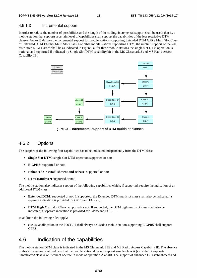
4.5.1.3 Incremental support
In order to reduce the number of possibilities and the length of the coding, incremental support shall be used; that is, a mobile station that supports a certain level of capabilities shall support the capabilities of the less restrictive DTM classes. Annex B defines the incremental support for mobile stations supporting Extended DTM GPRS Multi Slot Class or Extended DTM EGPRS Multi Slot Class. For other mobile stations supporting DTM, the implicit support of the less restrictive DTM classes shall be as indicated in Figure 2a; for these mobile stations the single slot DTM operation is optional and supported if indicated by Single Slot DTM capability bit in the MS Classmark 3 and MS Radio Access Capability IEs.
Class
Rx+Tx=Sum
Class 5 2+2=4
Class 9 3+2=5
Class 11 4+3=5
Class 33 or 38 5+4=6
Class 44 6+5=7
Class 32 or 37 5+3=6
Class 31 or 36 5+2=6
Class 42 6+3=7
Class43 6+4=7
Class 41 6+2=7
Figure 2a – Incremental support of DTM multislot classes
4.5.2 Options
The support of the following four capabilities has to be indicated independently from the DTM class:
• Single Slot DTM: single slot DTM operation supported or not;
• E-GPRS: supported or not;
• Enhanced CS establishment and release: supported or not;
• DTM Handover: supported or not.
The mobile station also indicates support of the following capabilities which, if supported, require the indication of an additional DTM class:
• Extended DTM: supported or not. If supported, the Extended DTM multislot class shall also be indicated; a separate indication is provided for GPRS and EGPRS;
• DTM High Multislot Class: supported or not. If supported, the DTM high multislot class shall also be indicated; a separate indication is provided for GPRS and EGPRS.
In addition the following rules apply:
• exclusive allocation in the PDCH/H shall always be used; a mobile station supporting E-GPRS shall support GPRS.
4.6 Indication of the capabilities The mobile station DTM class is indicated in the MS Classmark 3 IE and MS Radio Access Capability IE. The absence of this information shall indicate that the mobile station does not support simple class A (i.e. either it supports unrestricted class A or it cannot operate in mode of operation A at all). The support of enhanced CS establishment and

ETSI
ETSI TS 143 055 V12.0.0 (2014-10)143GPP TS 43.055 version 12.0.0 Release 12
release is indicated in the MS Classmark 3 and MS Radio Access Capability IEs. For mobile stations supporting DTM High Multislot Class capability, the mobile station DTM high multislot class is indicated in the MS Classmark 3 and MS Radio Access Capability IEs. The support of DTM handover is indicated in the MS Radio Access Capability and MS Classmark 3 IEs.
4.7 Compatibility issues The mobile station shall indicate in its capabilities whether it is DTM capable or not and if so whether it supports enhanced CS establishment and release or not. The mobile station shall indicate in the MS Radio Access Capability and MS Classmark 3 IEs whether or not it supports DTM Handover. The network shall not allocate resources for DTM operation unless the mobile is DTM capable. The network shall not use enhanced CS establishment (respectively release) unless the mobile supports it. The network shall not use DTM Handover procedures unless the mobile station also supports it. The resources allocated by the network shall meet the requirements imposed by the classmark.
The network indicates on the BCCH or PBCCH whether or not the cell supports DTM and if so whether or not it supports enhanced CS establishment and release. It shall also indicate it on the SACCH for DTM capable mobile stations in dedicated mode or dual transfer mode. It may also indicate it on the PACCH for DTM capable mobile stations in packet transfer mode. A cell level indication is needed because adjacent BTSs may be in the same RA and LA but may be parented by different BSCs (from different vendors or different releases). The indication in the SACCH is needed to enable/suppress the transmission of packet resource requests when the mobile is in dedicated mode and cannot read the BCCH data. A mobile station shall not attempt to enter the DTM unless DTM is supported in the cell.
The network shall allocate resources taking into account the capabilities commonly supported with the mobile station. In order to avoid situations where both the mobile station and the network are DTM capable but no class A capabilities are shared, a core set of capabilities has been defined and shall be supported by the mobile station and the network, consisting of:
• the main DCCH with SAPI 0 for GPRS signalling, with a length restriction controlled by the network;
• the TCH/F + PDCH/F configuration (DTM multislot class 5).
In addition, the mobile station supporting DTM shall support TCH/H + PDCH/F configuration with AMR-HR.
5 Layer 1 Some modifications or extra requirements affect layer 1 areas:
1. Timing advance;
2. Measurement reporting;
3. Power control.
These issues are dealt with in the following clauses.
5.1 Timing advance A mobile station in DTM shall disable the timing advance features for the GPRS side:
• the mobile station shall inhibit the transmission of timing advance access bursts;
• the mobile station shall ignore the reception of GPRS timing advance messages, if any.
The reporting period and the SACCH message block shall be the same as though the mobile station was in dedicated mode.

ETSI
ETSI TS 143 055 V12.0.0 (2014-10)153GPP TS 43.055 version 12.0.0 Release 12
5.2 Measurement reporting The mobile station shall continue to send measurement reports for the circuit switched part, but GPRS measurement reports shall not be sent. The mobile station shall be able to send extended measurement reports when commanded by the network.
5.3 Power control in multislot operation
5.3.1 General
The difference of C/I requirements and the possibility of using different coding schemes in both domains may result in a difference in the power used in adjacent timeslots. This difference in power needs further consideration, which it is done in the following clauses.
5.3.2 Uplink multislot power control
On the network side, there is no restriction for the difference of power received in adjacent timeslots.
On the mobile station side, the power control in different timeslots shall be independent and with no restriction for the difference of power transmitted in adjacent timeslots.
The MS shall measure the signal strength of each radio block monitored by the MS. The C value used for the uplink power control is achieved by filtering the signal strength with a running average filter. Upon the change from one RR mode to another, the filtering shall be restarted if there is no valid C value available. In case the mobile station and the network support enhanced DTM CS establishment procedure, when entering DTM from packet transfer mode, the filtering shall continue from the C value obtained during packet transfer mode (see 3GPP TS 45.008[7]).
In single timeslot operation, the power control for both domains is performed on the SACCH.
5.3.3 Downlink multislot power control
On the network side, there is no restriction for the difference of power transmitted in adjacent timeslots.
As in normal GPRS power control and in addition to the cells present in SI5, the mobile station shall also perform measurements of the serving cell if the FH sequence does not include the BCCH carrier.
In DTM multislot configurations, if the BTS output power for the CS timeslot is not within the range from the maximum downlink power allowed for the MS on the PS timeslot(s) to a power level 10 dB lower, the MS is not required to fulfil the requirements in 3GPP TS 45.005 on the CS timeslot and/or the PS timeslot(s).
6 Signalling procedures
6.1 Establishment
6.1.1 General
The existent establishment procedures for class A mode of operation rely on the capability of the mobile station to be able to operate in different frequencies in the same timeslot, e.g. to listen to the (P)BCCH while in dedicated mode. New procedures need to be added to the specifications to allow mobile stations without such capabilities to be able to enter the dual transfer mode.
ETSI
ETSI TS 143 055 V12.0.0 (2014-10)163GPP TS 43.055 version 12.0.0 Release 12
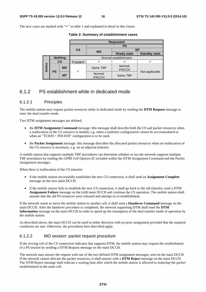
The new cases are marked with "�" in table 1 and explained in detail in this clause.
Table 2: Summary of establishment cases
Requested
CS PS
MO
MT Ready state Standby state
Act
ive
Nothing Normal establishment CS Engaged � � �
PS MO
� Same TBF Normal:
PACCH Not applicable
MT Normal: PACCH
Same TBF
6.1.2 PS establishment while in dedicated mode
6.1.2.1 Principles
The mobile station may request packet resources while in dedicated mode by sending the DTM Request message to enter the dual transfer mode.
Two DTM assignment messages are defined:
• the DTM Assignment Command message: this message shall describe both the CS and packet resources when a reallocation of the CS resource is needed, e.g. when a multislot configuration cannot be accommodated or when an "TCH/H + PDCH/H" configuration is to be used.
• the Packet Assignment message: this message describes the allocated packet resources when no reallocation of the CS resource is necessary, e.g. on an adjacent timeslot.
A mobile station that supports multiple TBF procedures can determine whether or not the network supports multiple TBF procedures by reading the GPRS Cell Options IE included within the DTM Assignment Command and the Packet Assignment messages.
When there is reallocation of the CS timeslot:
• if the mobile station successfully establishes the new CS connection, it shall send an Assignment Complete message on the new main DCCH.
• if the mobile station fails to establish the new CS connection, it shall go back to the old timeslot, send a DTM Assignment Failure message on the (old) main DCCH and continue the CS operation. The mobile station shall assume that the old PS resources were released and attempt its re-establishment.
If the network wants to move the mobile station to another cell, it shall send a Handover Command message on the main DCCH. After the handover procedure is completed, the network supporting DTM shall send the DTM Information message on the main DCCH in order to speed up the resumption of the dual transfer mode of operation by the mobile station.
As described above, the main DCCH can be used in either direction with no prior assignment provided that the required conditions are met. Otherwise, the procedures here described apply.
6.1.2.2 MO session: packet request procedure
If the serving cell of the CS connection indicates that supports DTM, the mobile station may request the establishment of a PS session by sending a DTM Request message on the main DCCH.
The network may answer the request with one of the two defined DTM assignment messages, sent on the main DCCH. If the network cannot allocate the packet resources, it shall answer with a DTM Reject message on the main DCCH. The DTM Reject message shall indicate a waiting time after which the mobile station is allowed to reattempt the packet establishment in the same cell.

ETSI
ETSI TS 143 055 V12.0.0 (2014-10)173GPP TS 43.055 version 12.0.0 Release 12
Figure 3 shows the successful case of the allocation of an uplink TBF when the reallocation of the CS timeslot is needed. The mobile station informs the network about the correct seizure of the new CS resource by sending an Assignment Complete message on the main DCCH of the new resource.
SGSNMS BSS MSC
DTM Request
Assignment Complete
DTM Assignment Command
UL-Unitdata
CS dedicated mode
RLC block(s)
[Old main DCCH]
[Old main DCCH]
[New main DCCH]
[Uplink TBF]
Figure 3: Establishment of a MO PS session while in dedicated mode with reallocation of the CS resource; successful case
Figure 4 shows one failure case. If there is an error when establishing the main signalling link in the new timeslot, the mobile station shall send a DTM Assignment Failure message on the old main DCCH and then it may re-attempt the establishment of the packet session. The timers in the assignment procedure are reused.
SGSN MS BSS MSC
DTM Request
DTM Assignment Failure
DTM Assignment Command
CS dedicated mode
[Old main DCCH]
[Old main DCCH]
[Old main DCCH]
DTM Request [Old main DCCH]
Figure 4: Establishment of a MO PS session while in dedicated mode with reallocation of the CS resource; failure case
In figure 5, the packet resource is mapped onto adjacent timeslot(s) and thus the Packet Assignment message is used. There is no release/re-establishment of the main signalling link, successful and failure messages are not needed. The successful and failure cases for the establishment of the TBF are determined as in normal GPRS (see 3G TS 04.60 [5]).
SGSNMS BSS MSC
DTM Request
Packet Assignment
UL-Unitdata
CS dedicated mode
RLC block(s)
[Old main DCCH]
[Old main DCCH]
[Uplink TBF]
Figure 5: Establishment of a MO PS session in multislot configuration while in dedicated mode; successful case
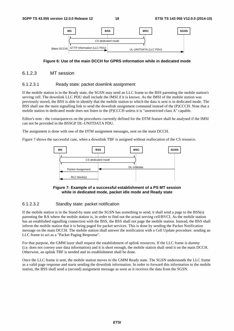
Figure 6 shows the case of the main DCCH being used as the uplink resource.
ETSI
ETSI TS 143 055 V12.0.0 (2014-10)183GPP TS 43.055 version 12.0.0 Release 12
SGSNMS BSS MSC
GTTP Information (LLC PDU)UL-UNITDATA (LLC PDU)
CS dedicated mode
[Main DCCH]
Figure 6: Use of the main DCCH for GPRS information while in dedicated mode
6.1.2.3 MT session
6.1.2.3.1 Ready state: packet downlink assignment
If the mobile station is in the Ready state, the SGSN may send an LLC frame to the BSS parenting the mobile station's serving cell. The downlink LLC PDU shall include the IMSI if it is known. As the IMSI of the mobile station was previously stored, the BSS is able to identify that the mobile station to which the data is sent is in dedicated mode. The BSS shall use the main signalling link to send the downlink assignment command instead of the (P)CCCH. Note that a mobile station in dedicated mode does not listen to the (P)CCCH unless it is "unrestricted class A" capable.
Editor's note : the consequences on the procedures currently defined for the DTM feature shall be analysed if the IMSI can not be provided in the BSSGP DL-UNITDATA PDU.
The assignment is done with one of the DTM assignment messages, sent on the main DCCH.
Figure 7 shows the successful case, when a downlink TBF is assigned without reallocation of the CS resource.
SGSNMS BSS MSC
RLC block(s)
Packet AssignmentDL-Unitdata
CS dedicated mode
Figure 7: Example of a successful establishment of a PS MT session while in dedicated mode, packet idle mode and Ready state
6.1.2.3.2 Standby state: packet notification
If the mobile station is in the Stand-by state and the SGSN has something to send, it shall send a page to the BSS(s) parenting the RA where the mobile station is, in order to find out the actual serving cell/BVCI. As the mobile station has an established signalling connection with the BSS, the BSS shall not page the mobile station. Instead, the BSS shall inform the mobile station that it is being paged for packet services. This is done by sending the Packet Notification message on the main DCCH. The mobile station shall answer the notification with a Cell Update procedure: sending an LLC frame to act as a "Packet Paging Response".
For that purpose, the GMM layer shall request the establishment of uplink resources. If the LLC frame is dummy (i.e. does not convey user data information) and it is short enough, the mobile station shall send it on the main DCCH. Otherwise, an uplink TBF is needed and its establishment shall be done.
Once the LLC frame is sent, the mobile station moves to the GMM Ready state. The SGSN understands the LLC frame as a valid page response and starts sending the downlink information. In order to forward this information to the mobile station, the BSS shall send a (second) assignment message as soon as it receives the data from the SGSN.

ETSI
ETSI TS 143 055 V12.0.0 (2014-10)193GPP TS 43.055 version 12.0.0 Release 12
The procedure is shown in figure 8.
LLC frame
DL-Unitdata
SGSNMS BSS MSC
Packet Assignment
Packet NotificationPaging PS
CS dedicated mode
RLC block(s)
DTM Request
Packet Assignment
Figure 8: Example of a successful establishment of a PS MT session while in dedicated mode, packet idle mode and Standby state
6.1.3 CS establishment while in packet transfer mode
When in packet transfer mode, either the mobile station or the network may initiate a CS connection establishment. In both cases, the packet session may be aborted and the establishment of the CS connection is initiated.
When the establishment of the CS connection is initiated by the network, the CS paging message may come directly from the MSC or via the SGSN if the Gs interface is present. The BSS shall be able to verify in both cases if the paged mobile station is in packet transfer mode and shall send the CS page on the PACCH.
NOTE 1: This paging co-ordination can be reused for GPRS mobile stations in mode of operation B, so that the mobile station does not need to listen to the PCH.
NOTE 2: This feature breaks the link between the presence of the Gs interface and the network capability to perform paging co-ordination. Alignment of 3G TS 23.060 is needed.
Once on the DCCH, the mobile station may request the re-establishment of the packet resources by sending a DTM Request message. The procedure to re-establish an aborted uplink TBF shall be identical to the MO session request. The procedure to re-establish an aborted downlink TBF shall be identical to the MT session request.
Figure 9 shows this procedure graphically.

ETSI
ETSI TS 143 055 V12.0.0 (2014-10)203GPP TS 43.055 version 12.0.0 Release 12
MT only
Authentication, Security and Call Control Procedures
Paging CS PDU
Channel Request
Immediate Assignment
Paging Response (MT) or CM Service Request (MO)
Channel Mode Modify
Channel Mode Modify Ack.
MS BSS SGSN MSC
BSSAP+ Paging Request
Abort PS session
Paging Packet Paging Request
SCCP Connection Request
SCCP Connection Confirm ( ) Classmark Change
DTM Assignment Command
PS Session
Assignment Request
DTM Request
Assignment Complete
Dedicated mode (speech + signalling)
Dedicated mode (signalling mode)
PS session in progress
Assignment Complete
Classmark Update Common ID (IMSI)
NOTE: The IMSI is sent when available at the MSC and if the BSS supports the DTM feature.
Figure 9: Successful establishment of a CS connection while in packet transfer mode
Upon receiving the ASSIGNMENT REQUEST message from the MSC, the BSS may send one of the following messages to the MS:
• CHANNEL MODE MODIFY message to modify the existing CS channel"s mode, as shown in Figure 9.
• DTM ASSIGNMENT COMMAND message to reallocate the CS resource and maintain some PS resources.
• ASSIGNMENT COMMAND message to reallocate the CS resource and drop the PS resources.
Figure 10: void (deleted)
If the mobile station and the network support enhanced CS establishment a CS connection may be established while in packet transfer mode, without release of the packet resources.
A mobile station that supports enhanced CS establishment can determine whether or not the network supports enhanced CS establishment by reading the GPRS Cell Options IE included within system information messages (see 3GPP TS 44.018 and 44.060).
In the mobile-originated case, the MS requests a CS connection by sending the PACKET CS REQUEST message on PACCH to the network.

ETSI
ETSI TS 143 055 V12.0.0 (2014-10)213GPP TS 43.055 version 12.0.0 Release 12
If the contention resolution is not solved, the mobile station shall delay the transmission of the PACKET CS REQUEST message until contention resolution is solved.
If the countdown procedure has been started on all the ongoing uplink TBFs, none of those TBFs is operating in extended uplink TBF mode and there is no downlink TBF in progress, the mobile station may either send the PACKET CS REQUEST message, or may immediately release the ongoing TBF(s) and start an RR connection establishment as specified in 3GPP TS 44.018.
Upon receipt of the PACKET CS REQUEST message, the network replies to the MS with a PACKET CS COMMAND message on PACCH that encapsulates one of (RR) DTM ASSIGNMENT COMMAND, IMMEDIATE ASSIGNMENT, IMMEDIATE ASSIGNMENT REJECT messages as defined below:
- The network may allocate both PS and CS resources to the MS by sending a (RR) DTM ASSIGNMENT COMMAND message. When the MS receives this message it starts CS connection establishment and enters dual transfer mode. The network may also reallocate PS resources in the DTM ASSIGNMENT COMMAND message. In this case the resulting channel combination must be TCH + PDTCH, SDCCH + PDTCH is not allowed. By omitting the PS resource description in the DTM ASSIGNMENT COMMAND, the network indicates that the current PS Resources are maintained.
- The network allocates only CS resources to the MS and orders the release of PS resources by sending an (RR) IMMEDIATE ASSIGNMENT message. When the MS receives this message it releases the PS connection and establishes the CS connection. When in dedicated mode the MS may request PS resources by using the procedures specified in 3GPP TS 44.018.
- The network rejects the CS request by sending an (RR) IMMEDIATE ASSIGNMENT REJECT message. When the MS receives this message it continues in packet transfer mode normally. The mobile station may later reinitiate the CS connection request.
- If the PS resources have been dropped before the network has a chance to respond to the PACKET CS REQUEST, the network shall abort the current DTM procedure. If the mobile station does not receive a PACKET CS COMMAND message after it has sent a corresponding PACKET CS REQUEST message, the mobile station will drop any PS resources and start CS access procedures on the RACH.
If the network and mobile both support the extended RLC/MAC control message segmentation, the network may send the PACKET CS COMMAND message in more than two radio blocks, see 3GPP TS 44.060. If not, the network is responsible for ensuring that the PACKET CS COMMAND does not exceed two radio blocks in length.
Figure 10a illustrates succesful MS originated RR connection request procedure.
Packet CS command
MS BSS MSCSGSN
CS dedicated mode
PS session in progress
[PACCH]
Packet CS request[PACCH]
Figure 10a: MS originated RR connection request procedure
In the mobile-terminated case the BSS sends to the mobile station a PACKET CS COMMAND message on PACCH when receiving a CS paging message from the core network. The PACKET CS COMMAND message encapsulates one of (RR) DTM ASSIGNMENT COMMAND, IMMEDIATE ASSIGNMENT messages as defined below:
− The network may allocate both PS and CS resources to the MS by sending a (RR) DTM ASSIGNMENT COMMAND message. The network may also reallocate PS resources in the DTM ASSIGNMENT COMMAND message. In this case the resulting channel combination must be TCH + PDTCH, SDCCH + PDTCH is not allowed. By omitting the PS resource description in the DTM ASSIGNMENT COMMAND, the network indicates that the current PS Resources are maintained.
ETSI
ETSI TS 143 055 V12.0.0 (2014-10)223GPP TS 43.055 version 12.0.0 Release 12
− The network allocates only CS resources to the MS and orders the release of PS resources by sending an (RR) IMMEDIATE ASSIGNMENT message. When the MS receives this message it releases the PS connection and establishes the CS connection. When in dedicated mode the MS may request PS resources by using the procedures specified in 3GPP TS 44.018.
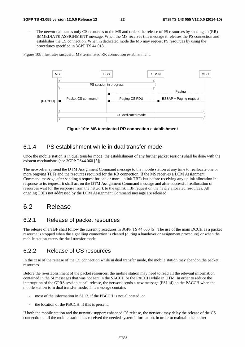
Figure 10b illustrates succesful MS terminated RR connection establishment.
Packet CS command
MS BSS MSCSGSN
CS dedicated mode
PS session in progress
[PACCH]
Paging
Paging CS PDU BSSAP + Paging request
Figure 10b: MS terminated RR connection establishment
6.1.4 PS establishment while in dual transfer mode
Once the mobile station is in dual transfer mode, the establishment of any further packet sessions shall be done with the existent mechanisms (see 3GPP TS44.060 [5]).
The network may send the DTM Assignment Command message to the mobile station at any time to reallocate one or more ongoing TBFs and the resources required for the RR connection. If the MS receives a DTM Assignment Command message after sending a request for one or more uplink TBFs but before receiving any uplink allocation in response to its request, it shall act on the DTM Assignment Command message and after successful reallocation of resources wait for the response from the network to the uplink TBF request on the newly allocated resources. All ongoing TBFs not addressed by the DTM Assignment Command message are released.
6.2 Release
6.2.1 Release of packet resources
The release of a TBF shall follow the current procedures in 3GPP TS 44.060 [5]. The use of the main DCCH as a packet resource is stopped when the signalling connection is cleared (during a handover or assignment procedure) or when the mobile station enters the dual transfer mode.
6.2.2 Release of CS resources
In the case of the release of the CS connection while in dual transfer mode, the mobile station may abandon the packet resources.
Before the re-establishment of the packet resources, the mobile station may need to read all the relevant information contained in the SI messages that was not sent in the SACCH or the PACCH while in DTM. In order to reduce the interruption of the GPRS session at call release, the network sends a new message (PSI 14) on the PACCH when the mobile station is in dual transfer mode. This message contains
- most of the information in SI 13, if the PBCCH is not allocated; or
- the location of the PBCCH, if this is present.
If both the mobile station and the network support enhanced CS release, the network may delay the release of the CS connection until the mobile station has received the needed system information, in order to maintain the packet

ETSI
ETSI TS 143 055 V12.0.0 (2014-10)233GPP TS 43.055 version 12.0.0 Release 12
resources after release of the CS connection. The network shall initiate enhanced CS release by sending PACKET CS RELEASE INDICATION message. System information is provided to the mobile station with PACKET SERVING CELL SI message on the PACCH. Packet system information messages can also be sent as such on PACCH. The MS shall use PACKET SI STATUS or PACKET PSI STATUS message to indicate which messages have been received correctly. When the mobile station has received the required set of a system information it informs the network which in turn sends a CS connection release message to the mobile station. Upon release of the CS connection the mobile station enters packet transfer mode.
If the network is not able to use enhanced CS release (e.g. due to scarce radio resources, no support for enhanced CS release or no possibility to send missing system information) it shall send a CS connection release message to the mobile station indicating the mobile station shall abandon the packet resources after the release of the CS connection. Figure 10c shows the exchange of messages when a CS connection is released and the MS maintains PS resources.
Clear command
Packet serving cell SI
Packet (P)SI status
PSI messages
Channel release
MS BSS MSCSGSN
CS dedicated mode
PS session in progress
CS call control signalling (e.g. disconnect a call)
PS session in progress
[PACCH]
[PACCH]
[PACCH]
[PACCH]
[PACCH]
[Main DCCH]
Packet CS release indication
Packet Controlacknowledgement
PSI messages *
Optional. If packet controlchannel is supported.
[PACCH]
Packet (P)SI status[PACCH]
Figure 10c: Release of CS connection and maintaining PS resources
6.3 Handover
6.3.1 General
Another group of procedures that are affected by the definition a new GPRS class A mode of operation are those related to the change of the serving cell when the mobile station is in dual transfer mode. The term handover in this document refers to the network initiated change of serving cell for both domains, unless explicit reference to the CS domain is made. The handover and the cell change of the CS and PS domains respectively need to be performed at the same time. As 3GPP TS 45.008 [7] states, the serving cell for a class A mobile station while it is in dedicated mode "is determined by the network according to the handover procedures", irrespective of the Network Control measuring report mode (NC).
The Handover Command message sent from the network to the mobile station shall describe the CS resources in the target cell.
The RAI, Cell Identity and information whether DTM is allowed or not shall be sent to a DTM capable mobile station after handover in SI6 and/or the DTM Information message. The RAI needs also to be included in the SI 6 message sent to a DTM capable mobile station that is not in DTM so that it can detect a change of the RA.

ETSI
ETSI TS 143 055 V12.0.0 (2014-10)243GPP TS 43.055 version 12.0.0 Release 12
Handover failure cases are determined only from the CS timeslot. In the event of a handover failure, the mobile station shall return to the CS resource in the old cell and send a Handover Failure message on the main DCCH. If the mobile station is in GMM Ready state, it shall then perform the Cell Update procedure in order to notify the SGSN that downlink data flows can be continued in the source cell. The mobile station shall assume that all the packet resources were released during the handover and it shall try to re-establish the uplink resources if there is uplink data ready to be sent.
Once the main DCCH is established in the cell, the network sends the DTM Information message. This message contains:
- the RAI and Cell Identity of the new cell: to detect changes of RA or cell without waiting for the SI 6 message;
- the length limitation for the use of the main DCCH.
Then the mobile station or the network may re-establish the packet resource(s).
6.3.1a DTM Handover – General
The term DTM Handover in this document always refers to the network initiated change of serving cell for both CS and PS domains, using DTM Handover procedures.
The source and target cells may be managed by either the same BSS (Intra-BSS) or different BSSs (Inter-BSS) within the same MSC (Intra-MSC) and the same SGSN (Intra SGSN) or different SGSNs (Inter SGSN) or different MSCs (Inter-MSC) and the same or different SGSNs.The DTM Handover in A/Gb mode makes use of existing CS handover procedures and PS Handover procedures. Unless explicitly stated in the present document, the behaviour of the core network entities is as specified for the respective handover procedures. The DTM Handover procedure is controlled by the RR protocol.
The DTM Handover procedure is divided into:
- a preparation phase including the allocation of CS and PS resources in the target cell, consisting of parallel CS handover preparation phase as described in 3GPP TS 23.009 [14] and PS handover preparation phase as described in 3GPP TS 43.129 [13]; and
- an execution phase which includes the sending of the (RR) DTM HANDOVER COMMAND message from the network to the mobile station on PACCH. The (RR) DTM HANDOVER COMMAND message shall describe both the CS and the PS resources in the target cell.
In the case of a DTM Handover into a network sharing supporting target cell by a MS supporting network sharing, the DTM HANDOVER COMMAND shall include PLMN index information which, upon arriving in the target cell, the MS uses as described in 3GPP TS 44.018 [5].
6.3.2 Internal handover
The network may send a Handover Command message requesting the mobile station to switch to a different cell parented by the same BSC. Prior to that, the BSC shall activate the channels in the target cell. At the receipt of the Handover Command message the mobile station shall abandon the packet session and initiate the access on the target cell, obeying the handover time requirements of 3GPP TS 45.010 [8] clause 6 and 3GPP TS 44.013 [3] clause 5.2.6.
The re-establishment of the CS connection shall continue as a CS only handover. When concluded, the BSC shall release the channels in the old cell.
The network immediately sends the DTM Information message, with information needed to resume the GPRS operation in the new cell. Once the mobile station has the necessary information, it shall perform a cell update or RA update procedure.
If the mobile station also needs to (re-)establish an uplink packet session in the new cell, the GMM signalling procedure shall take precedence and shall be performed first. Once the update procedure is performed, the (re-)establishment of the packet session may continue.
Figure 11 shows the exchange of messages in a successful internal handover.

ETSI
ETSI TS 143 055 V12.0.0 (2014-10)253GPP TS 43.055 version 12.0.0 Release 12
Packet Assignment
RF Channel Release
Physical Information
Handover Command
MS Old BTS New BTS BSC MSC
Handover Access
SGSN
Channel Activation Channel Activation Ack
Handover Complete Handover Complete Handover Performed
RF Channel Release Ack
DTM Request
Cell Update or RA Update procedure
PS Session
CS Call SI 6 / DTM Information
CS Call
PS Session
Channel Activation Channel Activation Ack
RF Channel Release
RF Channel Release Ack
Signalling link establishment
Figure 11: Successful internal, dual handover procedure
6.3.2a Intra-BSS DTM Handover
6.3.2a.1 General
The Intra-BSS DTM Handover procedure covers the scenarios where the source and target cells are managed by the same BSS, the same MSC and the same SGSN. The Intra-BSS with MSC involved or MSC not involved DTM Handover procedures may use the optimized PS Handover procedure (see 3GPP TS 43.129) if allowed.
The Intra-BSS inter-cell DTM Handover using optimized PS Handover procedure and MSC non-involved case and Intra-BSS inter-cell DTM Handover using non-optimized PS Handover procedure and MSC involved case are described in sub-clauses 6.3.2a.2, 6.3.2a.3 and 6.3.2a.4.
The Intra-BSS inter-cell DTM Handover using optimized PS Handover procedure and MSC involved case and Intra-BSS inter-cell DTM Handover using non-optimized PS Handover procedure and MSC not involved case are not explicitly described in the current document as they are considered to be implicitly covered by the cases that are described.

ETSI
ETSI TS 143 055 V12.0.0 (2014-10)263GPP TS 43.055 version 12.0.0 Release 12
6.3.2a.2 Preparation Phase – using Optimized PS Handover procedure and without MSC involved
The preparation phase consists of the BSS allocating CS and PS resources in the target cell. The BSS shall select the same unique target cell for both the CS and the PS domains. The BSS shall activate the DTM channel configurations (CS channel and PS resources) in the target cell.
6.3.2a.3 Preparation Phase – using Non-Optimized PS Handover procedure and with MSC involved
The preparation phase consists of the BSS sending a (BSSMAP) HANDOVER REQUIRED message to the MSC and a (BSSGP) PS HANDOVER REQUIRED PDU to the SGSN and allocating CS and PS resources in the target cell upon receiving a (BSSMAP) HANDOVER REQUEST message from the MSC and a (BSSGP) PS HANDOVER REQUEST PDU from the SGSN. The BSS shall select the same unique target cell for both the CS and the PS domains. The handling of the messages between BSS and CN is largely based on the Inter-BSS DTM Handover as described in section 6.3.3a.
6.3.2a.4 Execution Phase
In case of Intra-BSS DTM Handover using the optimised PS Handover procedure and without the MSC involved, the BSS may start the execution phase by sending a (RLC/MAC) DTM HANDOVER COMMAND message to the mobile station on the PACCH requesting it to perform a DTM Handover and switch to a different cell managed by the same BSS.
In case of Intra-BSS DTM Handover using the non-optimised PS Handover procedure and with the MSC involved, the BSS may start the execution phase after receiving the (BSSMAP) HANDOVER COMMAND message from the MSC and the (BSSGP) PS HANDOVER REQUIRED ACK PDU from the SGSN.
At the receipt of the (RLC/MAC) DTM HANDOVER COMMAND message the mobile station switches to the new configuration and initiates the access on the target cell using the existing CS handover access procedures.
After successful establishment of the main signalling link in the target cell, the mobile station sends the (RR) HANDOVER COMPLETE message to the BSS which in turns sends either a (BSSMAP) HANDOVER PERFORMED message (in case of MSC not involved) or a (BSSMAP) HANDOVER COMPLETE message (in case of MSC involved) to the MSC and a (BSSGP) PS HANDOVER COMPLETE PDU to the SGSN (regardless of whether or not optimised PS Handover was used) to indicate the completion of the Intra-BSS DTM Handover. Upon successful completion of the Intra-BSS DTM Handover, the BSS releases the DTM channel configurations (i.e. CS channel and PS resources) in the old cell.
During Intra-BSS with MSC involved DTM Handover using non-optimized PS Handover procedures, the mobile station shall start the Cell/RA Update procedure immediately after sending the (RR) HANDOVER COMPLETE message to the network.
If the mobile station is not able to act on or decode the (RLC/MAC) DTM HANDOVER COMMAND message, it sends a (RR) HANDOVER FAILURE message to the network on the main DCCH of the source cell.
If the mobile station acts on the (RLC/MAC) DTM HANDOVER COMMAND message but fails to establish the main signalling link in the target cell, the MS returns to the old channels in the source cell and sends a (RR) HANDOVER FAILURE message to the network on the main DCCH.
In case the responses received by the BSS do not consist of the combination of both a (BSSMAP) HANDOVER COMMAND message and a (BSSGP) PS HANDOVER REQUIRED ACK PDU, the Intra-BSS DTM Handover using non-optimized PS handover and with MSC involved fails and the BSS and the mobile station proceed as per the Inter-BSS DTM Handover described in section 6.3.3a.3
Figure 11a shows the exchange of messages in a successful inter-cell Intra-BSS DTM Handover using optimized PS Handover procedure and MSC not involved case.
Figure 11b and Figure 11c show the exchange of messages in a successful inter-cell Intra-BSS DTM Handover using non-optimized PS Handover procedure and MSC involved scenario.

ETSI
ETSI TS 143 055 V12.0.0 (2014-10)273GPP TS 43.055 version 12.0.0 Release 12
DTM HANDOVER COMMAND
MS Old BTS New BTS BSC MSC SGSN
HANDOVER COMPLETE HANDOVER PERFORMED
CS and PS Sessions continue
CS Call
PS Session
Access in the target cell
PS HANDOVER COMPLETE
Signaling link establishment
Channel Release
First RLC/MAC data block
BSS determines if the new cell is part of
the same NSE and same RA
Channel Activation
CS and PS resources
allocation
Figure 11a: Intra-BSS with MSC not involved DTM Handover using optimized PS Handover procedures
Figure 11b: Intra-BSS with MSC involved DTM Handover using non-optimized PS Handover procedures, preparation phase

ETSI
ETSI TS 143 055 V12.0.0 (2014-10)283GPP TS 43.055 version 12.0.0 Release 12
Figure 11c: Intra-BSS with MSC involved DTM Handover using non-optimized PS Handover procedures, execution phase
6.3.3 External handover
In the case of an external handover, the target BSS:
- shall be provided with the IMSI of the mobile station;
- shall be provided with information about the nature of the packet resources in the serving cell, so that the CS resource is compatible with the packet resources that are going to be requested in the new cell (e.g. transceiver supporting AMR or EDGE, timeslot with a free, adjacent one). This information is conveyed in the Old BSS to New BSS Information IE.
NOTE: This indication that the MS is in DTM in the source cell is also included in the handover to GERAN from another RAT when the MS has resouces in the source cell allocated towards the CS and PS domains simultaneously.
No changes are foreseen for an inter-MSC handover. Current implementations are expected to be able to carry the extended Old BSS to New BSS Information IE without modifications to 3GPP TS 49.008.
No changes are foreseen for an inter-SGSN handover. The mobile shall perform a Routing Area Update procedure in the new cell. This may be as a result of the SI 6 contents (RAC is now added) or caused by information contained in the DTM INFORMATION message.

ETSI
ETSI TS 143 055 V12.0.0 (2014-10)293GPP TS 43.055 version 12.0.0 Release 12
6.3.3a Inter-BSS DTM Handover
6.3.3a.1 General
The Inter-BSS DTM Handover procedure covers the scenarios where the source and target cells are managed by different BSSs. All four cases of Intra-/Inter-MSC and Intra-/Inter-SGSN handovers use these procedures.
The Inter-BSS DTM Handover is initiated by the source BSS sending a (BSSMAP) HANDOVER REQUIRED message and a (BSSGP) PS HANDOVER REQUIRED PDU to the MSC and the SGSN respectively. The Inter-BSS DTM Handover requires synchronization of the handovers in the CS and the PS domains in both the source BSS and the target BSS through:
- Selection of the same unique target cell for both the CS and the PS domains. In the preparation phase the source BSS selects the same target cell ID for both the CS and the PS domains and indicates it to the MSC and the SGSN in the (BSSMAP) HANDOVER REQUIRED message and (BSSGP) PS HANDOVER REQUIRED PDU respectively.
- Indications to the target BSS that the CS (respectively PS) handover is ongoing at the same time as the PS (respectively CS) handover for the same mobile station (see Figure 11d). These indications require the target BSS to wait for both the (BSSMAP) HANDOVER REQUEST message and (BSSGP) PS HANDOVER REQUEST PDU.
- PS Indication IE is sent in the (BSSMAP) HANDOVER REQUIRED message and (BSSMAP) HANDOVER REQUEST message within the Old BSS to New BSS information.
- CS Indication IE is sent in the (BSSGP) PS HANDOVER REQUIRED PDU and (BSSGP) PS HANDOVER REQUEST PDU within the Source BSS to Target BSS transparent container.
- Management of synchronization timers in both the source BSS and the target BSS that ensure the target receives both PS and CS domain resource allocation requests and the source BSS receives both PS and CS domain resource allocation responses from the target BSS before proceeding with the Inter-BSS DTM Handover.
6.3.3a.2 Preparation Phase
The Inter-BSS DTM Handover is initiated by the source BSS by sending a (BSSMAP) HANDOVER REQUIRED message and a (BSSGP) PS HANDOVER REQUIRED PDU to the MSC and the SGSN respectively.
The target BSS, upon reception of a (BSSMAP) HANDOVER REQUEST message (respectively (BSSGP) PS HANDOVER REQUEST PDU) containing an indication of an ongoing PS handover (respectively CS handover) as described in sub-clause 6.3.3a.1, waits for reception of the corresponding (BSSGP) PS HANDOVER REQUEST PDU (respectively (BSSMAP) HANDOVER REQUEST message).
If the target BSS receives a (BSSMAP) HANDOVER REQUEST message containing an indication of an ongoing PS handover, but does not receive a corresponding (BSSGP) PS HANDOVER REQUEST PDU within the expected time frame, the target BSS may proceed with allocating a CS resource only, in which case it returns a (BSSMAP) HANDOVER REQUEST ACKNOWLEDGE message containing a (RR) HANDOVER COMMAND message (within the L3 Information IE). Otherwise, if target BSS decides not to continue with the handover of a CS resource it returns a (BSSMAP) HANDOVER FAILURE message to the MSC. If the target BSS receives the corresponding (BSSGP) PS HANDOVER REQUEST PDU containing an indication of an ongoing CS handover after the expected time frame, it shall return a (BSSGP) PS HANDOVER REQUEST NACK PDU to the SGSN.
If the target BSS receives a (BSSGP) PS HANDOVER REQUEST PDU containing an indication of an ongoing CS handover, but does not receive a corresponding (BSSMAP) HANDOVER REQUEST message within the expected time frame, it shall return a (BSSGP) PS HANDOVER REQUEST NACK PDU to the SGSN and abort the DTM Handover. If the target BSS receives the corresponding (BSSMAP) HANDOVER REQUEST message containing an indication of an ongoing PS handover after the expected time frame, it shall return a (BSSMAP) HANDOVER FAILURE message to the MSC.
If the target BSS receives both a (BSSGP) PS HANDOVER REQUEST PDU and a (BSSMAP) HANDOVER REQUEST message within the expected time frame and is able to allocate both the CS and PS resources, it returns a (BSSMAP) HANDOVER REQUEST ACKNOWLEDGE message to the MSC and a (BSSGP) PS HANDOVER REQUEST ACK PDU to the SGSN. Both these messages contain the same (RLC/MAC) DTM HANDOVER COMMAND message.

ETSI
ETSI TS 143 055 V12.0.0 (2014-10)303GPP TS 43.055 version 12.0.0 Release 12
If the target BSS receives both a (BSSGP) PS HANDOVER REQUEST PDU and a (BSSMAP) HANDOVER REQUEST message within the expected time frame and allocates a CS resource but is unable to or chooses not to allocate any of the corresponding PS resources, it returns a (BSSGP) PS HANDOVER REQUEST NACK PDU to the SGSN. The target BSS may continue with the CS handover in which case it returns a (BSSMAP) HANDOVER REQUEST ACKNOWLEDGE message containing a (RR) HANDOVER COMMAND message (within the L3 Information IE). Otherwise, if the target BSS decides not to continue with the CS handover it returns a (BSSMAP) HANDOVER FAILURE message to the MSC.
If the target BSS receives both a (BSSGP) PS HANDOVER REQUEST PDU and a (BSSMAP) HANDOVER REQUEST message within the expected time frame but is unable to or chooses not to allocate a CS resource, it shall not allocate the corresponding PS resources. The target BSS returns a (BSSMAP) HANDOVER FAILURE message and a (BSSGP) PS HANDOVER REQUEST NACK PDU to the MSC and the SGSN respectively.
Figure 11d shows the exchange of messages in a successful Inter-BSS Intra-MSC Intra-SGSN DTM Handover, preparation phase. The same procedures are also used for an Inter-BSS Inter-MSC handover and/or Inter-SGSN DTM Handover.
Figure 11d: Inter-BSS DTM Handover, preparation phase
6.3.3a.3 Execution Phase
If the source BSS receives both a (BSSGP) PS HANDOVER REQUIRED ACK PDU and a (BSSMAP) HANDOVER COMMAND message within the expected time frame, it sends the (RLC/MAC) DTM HANDOVER COMMAND message to the mobile station.
The source BSS may instead send the (RLC/MAC) DTM HANDOVER COMMAND message to the mobile station as soon as it has received a (BSSMAP) HANDOVER COMMAND message which contains the (RLC/MAC) DTM HANDOVER COMMAND message.
NOTE: In this case, it is possible that the PS resources in the target cell which are described in the (RLC/MAC) DTM HANDOVER COMMAND message will not be valid when the MS performs access in the target cell.
If the source BSS receives from the MSC a (BSSMAP) HANDOVER COMMAND message containing a (RR) HANDOVER COMMAND message it may choose to proceed with the CS handover immediately by stopping the synchronisation timer and sending the contents of the L3 Information IE (i.e. the (RR) HANDOVER COMMAND

ETSI
ETSI TS 143 055 V12.0.0 (2014-10)313GPP TS 43.055 version 12.0.0 Release 12
message) to the mobile station. If the source BSS chooses not to proceed with the CS handover, it sends a (BSSMAP) HANDOVER FAILURE message to the MSC and nothing is sent to the mobile station.
If the source BSS receives a (BSSMAP) HANDOVER COMMAND message containing a (RLC/MAC) DTM HANDOVER COMMAND message and a (BSSGP) PS HANDOVER REQUIRED NACK PDU within the expected time frame, and the failure cause in (BSSGP) PS HANDOVER REQUIRED NACK PDU indicates an SGSN failure, the source BSS shall abort both the CS and PS handovers and send a (BSSMAP) HANDOVER FAILURE message to the MSC and nothing is sent to the mobile station.
If the source BSS receives a (BSSMAP) HANDOVER REQUIRED REJECT message and a (BSSGP) PS HANDOVER REQUIRED ACK PDU within the expected time frame, it shall abort the PS handover by sending a (BSSGP) PS HANDOVER CANCEL PDU to the SGSN and nothing is sent to the mobile station.
If the source BSS receives both a (BSSMAP) HANDOVER REQUIRED REJECT message and a (BSSGP) PS HANDOVER REQUIRED NACK PDU then the DTM Handover fails and nothing is sent to the mobile station.
On the receipt of the (RLC/MAC) DTM HANDOVER COMMAND message the mobile station switches to the new configuration and initiates the access on the target cell using the existing CS handover access procedures. After successful establishment of the main signalling link in the target cell, the mobile station sends the (RR) HANDOVER COMPLETE message to the target BSS which in turns sends both a (BSSMAP) HANDOVER COMPLETE message to the MSC and a (BSSGP) PS HANDOVER COMPLETE PDU to the SGSN to indicate the completion of the handover. Thereafter the release of the old DTM channel configurations (CS channel and PS resources) is initiated by the MSC and the SGSN respectively.
The mobile station shall start the Cell/RA Update procedure immediately after sending the (RR) HANDOVER COMPLETE message to the network.
If the mobile station is not able to act on or decode the (RLC/MAC) DTM HANDOVER COMMAND message, it sends a (RR) HANDOVER FAILURE message to the network on the main DCCH of the source cell.
If the mobile station fails to establish the main signalling link in the target cell, the MS returns to the old channels in the source cell and sends a (RR) HANDOVER FAILURE message to the network on the main DCCH.
If the source BSS receives a (RR) HANDOVER FAILURE message from the mobile station, it cancels the current DTM Handover by sending a (BSSMAP) HANDOVER FAILURE message and a (BSSGP) PS HANDOVER CANCEL PDU to the MSC and SGSN respectively.
Figure 11e shows the exchange of messages in a successful Inter-BSS Intra-MSC Intra-SGSN DTM Handover, execution phase. The same procedures are also used for an inter-MSC handover and/or inter-SGSN DTM Handover.
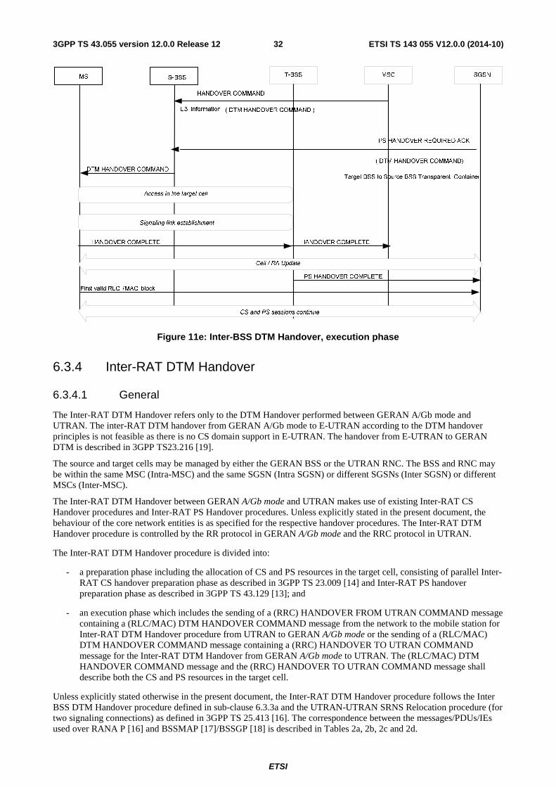
ETSI
ETSI TS 143 055 V12.0.0 (2014-10)323GPP TS 43.055 version 12.0.0 Release 12
Figure 11e: Inter-BSS DTM Handover, execution phase
6.3.4 Inter-RAT DTM Handover
6.3.4.1 General
The Inter-RAT DTM Handover refers only to the DTM Handover performed between GERAN A/Gb mode and UTRAN. The inter-RAT DTM handover from GERAN A/Gb mode to E-UTRAN according to the DTM handover principles is not feasible as there is no CS domain support in E-UTRAN. The handover from E-UTRAN to GERAN DTM is described in 3GPP TS23.216 [19].
The source and target cells may be managed by either the GERAN BSS or the UTRAN RNC. The BSS and RNC may be within the same MSC (Intra-MSC) and the same SGSN (Intra SGSN) or different SGSNs (Inter SGSN) or different MSCs (Inter-MSC).
The Inter-RAT DTM Handover between GERAN A/Gb mode and UTRAN makes use of existing Inter-RAT CS Handover procedures and Inter-RAT PS Handover procedures. Unless explicitly stated in the present document, the behaviour of the core network entities is as specified for the respective handover procedures. The Inter-RAT DTM Handover procedure is controlled by the RR protocol in GERAN A/Gb mode and the RRC protocol in UTRAN.
The Inter-RAT DTM Handover procedure is divided into:
- a preparation phase including the allocation of CS and PS resources in the target cell, consisting of parallel Inter-RAT CS handover preparation phase as described in 3GPP TS 23.009 [14] and Inter-RAT PS handover preparation phase as described in 3GPP TS 43.129 [13]; and
- an execution phase which includes the sending of a (RRC) HANDOVER FROM UTRAN COMMAND message containing a (RLC/MAC) DTM HANDOVER COMMAND message from the network to the mobile station for Inter-RAT DTM Handover procedure from UTRAN to GERAN A/Gb mode or the sending of a (RLC/MAC) DTM HANDOVER COMMAND message containing a (RRC) HANDOVER TO UTRAN COMMAND message for the Inter-RAT DTM Handover from GERAN A/Gb mode to UTRAN. The (RLC/MAC) DTM HANDOVER COMMAND message and the (RRC) HANDOVER TO UTRAN COMMAND message shall describe both the CS and PS resources in the target cell.
Unless explicitly stated otherwise in the present document, the Inter-RAT DTM Handover procedure follows the Inter BSS DTM Handover procedure defined in sub-clause 6.3.3a and the UTRAN-UTRAN SRNS Relocation procedure (for two signaling connections) as defined in 3GPP TS 25.413 [16]. The correspondence between the messages/PDUs/IEs used over RANA P [16] and BSSMAP [17]/BSSGP [18] is described in Tables 2a, 2b, 2c and 2d.

ETSI
ETSI TS 143 055 V12.0.0 (2014-10)333GPP TS 43.055 version 12.0.0 Release 12
Table 2a. Messages/PDUs/IEs exchanged between network nodes in the direction from the source
BSS/RNC to the target BSS/RNC
→ Target BSS Target RNC MSC SGSN
Source BSS
CS Old BSS to New
BSS Information IE (see Note 1) Source RNC to
Target RNC Transparent
Container (see Note 1)
Handover Required N/A
PS
Source BSS to Target BSS Transparent
Container IE (see Note 1)
N/A PS Handover Required
MSC CS Handover Request Relocation Request N/A N/A
SGSN PS PS Handover Request
Relocation Request N/A N/A
Source RNC
CS Old BSS to New
BSS Information IE (see Note 1) Source RNC to
Target RNC Transparent
Container (See Note 1)
Relocation Required N/A
PS
Source BSS to Target BSS Transparent
Container IE (see Note 1)
N/A Relocation Required
NOTE 1: This is an Information Element exchanged between a source BSS/RNC and a target BSS/RNC through the Core Network
Table 2b. Messages/PDUs/IEs exchanged between network nodes in the direction from the target
BSS/RNC to the source BSS/RNC
→ Source BSS Source RNC MSC SGSN
Target BSS
CS Layer 3 Information IE (see Note 1) Handover Request
Acknowledge N/A N/A Handover Failure
PS
Target BSS to Source BSS Transparent Container IE (see Note 1)
N/A
PS Handover Request ACK
N/A PS Handover Request NACK
MSC CS
Handover Command
Relocation Command
N/A N/A Handover
Required Reject Relocation
Preparation Failure
SGSN PS
PS Handover Required ACK
Relocation Command
N/A N/A PS Handover
Required NACK Relocation
Preparation Failure
Target RNC
CS Target RNC to Source RNC
Transparent Container IE (see Note 1)
Relocation Request
Acknowledge N/A
N/A Relocation Failure
PS Target RNC to Source RNC
Transparent Container IE (see Note 1) N/A
Relocation Request
Acknowledge N/A Relocation Failure
NOTE 1: This is an Information Element exchanged between a target BSS/RNC and a source BSS/RNC through the Core Network

ETSI
ETSI TS 143 055 V12.0.0 (2014-10)343GPP TS 43.055 version 12.0.0 Release 12
Table 2c. Messages/PDUs exchanged between the target BSS/RNC and the core network upon
successful handover
→ MSC SGSN Target BSS
Handover Complete PS Handover Complete
Target RNC
Relocation Complete Relocation Complete
Table 2d. Messages/PDUs exchanged between the source BSS/RNC and the core network upon unsuccessful handovers
→ MSC SGSN Source
BSS Handover Failure PS Handover Cancel
Source RNC Relocation Cancel Relocation Cancel
6.3.4.2 Inter-RAT DTM Handover from GERAN A/Gb mode to UTRAN
For the Inter-RAT DTM handover from GERAN A/Gb mode to UTRAN procedure, the behaviour of the source BSS (and the MS in the source cell) is as specified for the Inter-BSS DTM Handover procedure described in sub-clause 6.3.3a and the behaviour of the target RNC is as specified for the UTRAN-UTRAN SRNS Relocation procedure (with two signaling connections) as defined in 3GPP TS 25.413 [16], using the messages/IEs/PDUs defined in tables 2a-2d above, with the following exceptions:
- Number of Iu instances IE (set equal to 2) is used to indicate to the target RNC that the CS (respectively PS) handover is ongoing at the same time as the PS (respectively CS) handover for the same mobile station.
- The (RLC/MAC) DTM HANDOVER COMMAND message sent to the MS containing the (RRC) HANDOVER TO UTRAN COMMAND message.
- If the mobile station fails to access the target cell, the MS shall return to the old channel in the source cell and send a (RR) HANDOVER FAILURE message to the network.
Figure 11f shows the exchange of messages in a successful Inter-RAT Intra-MSC Intra-SGSN DTM Handover from GERAN A/Gb mode to UTRAN, preparation phase. The same procedures are also used for an Inter-RAT Inter-MSC or Inter-SGSN DTM Handover from GERAN A/Gb mode to UTRAN. .
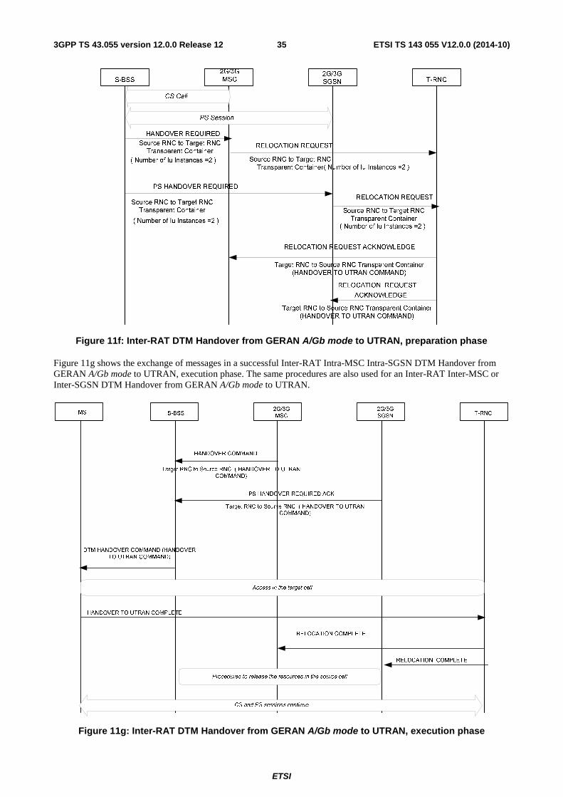
ETSI
ETSI TS 143 055 V12.0.0 (2014-10)353GPP TS 43.055 version 12.0.0 Release 12
Figure 11f: Inter-RAT DTM Handover from GERAN A/Gb mode to UTRAN, preparation phase
Figure 11g shows the exchange of messages in a successful Inter-RAT Intra-MSC Intra-SGSN DTM Handover from GERAN A/Gb mode to UTRAN, execution phase. The same procedures are also used for an Inter-RAT Inter-MSC or Inter-SGSN DTM Handover from GERAN A/Gb mode to UTRAN.
Figure 11g: Inter-RAT DTM Handover from GERAN A/Gb mode to UTRAN, execution phase

ETSI
ETSI TS 143 055 V12.0.0 (2014-10)363GPP TS 43.055 version 12.0.0 Release 12
6.3.4.3 Inter-RAT DTM Handover from UTRAN to GERAN A/Gb mode
For the Inter-RAT DTM handover from UTRAN to GERAN A/Gb mode, the behaviour of the source RNC is as specified for the UTRAN-UTRAN SRNS Relocation procedure (with two signaling connections) as defined in 3GPP TS 25.413 [16], and the behaviour of the target BSS (and MS on performing access in the target cell) is as specified for the Inter-BSS DTM Handover procedure described in sub-clause 6.3.3a, using the messages/IEs/PDUs defined in tables 2a-2d above, with the following exception:
- The (RRC) HANDOVER FROM UTRAN COMMAND message sent to the MS contains the (RLC/MAC) DTM HANDOVER COMMAND message.
- If the mobile station fails to access the target cell, the MS shall return to the old channel in the source cell and send a (RRC) HANDOVER FROM UTRAN FAILURE message to the network.
Figure 11h shows the exchange of messages in a successful Inter-RAT Intra-MSC Intra-SGSN DTM Handover, preparation phase. The same procedures are also used for an Inter-RAT Inter-MSC or Inter-SGSN DTM Handover from UTRAN to GERAN A/Gb mode.
S-RNC3G/2G MSC 3G/2GSGSN
T-BSS
RELOCATION REQUIRED
Old BSS to New BSS Information
( PS Indication IE)
HANDOVER REQUEST
Old BSS to New BSS Informaiton
RELOCATION REQUIRED
Source BSS to Target BSS Transparent Container
(CS Indication IE)
PS HANDOVER REQUEST
Layer3 Information (DTM HANDOVER COMMAND)
HANDOVER REQUESTACKNOWLEDGE
PS HANDOVER REQUEST
ACKNOWLEDGETarget BSS to Source BSS Transparent Container
CS Call
PS Session
( PS Indication IE)
Source BSS to Target BSS
Transparent Container
(CS Indication IE)
(DTM HANDOVER COMMAND)
Figure 11h: Inter-RAT DTM Handover from UTRAN to GERAN A/Gb mode, preparation phase
Figure 11i shows the exchange of messages in a successful Inter-RAT Intra-MSC Intra-SGSN DTM Handover from UTRAN to GERAN A/Gb mode, execution phase. The same procedures are also used for an Inter-RAT Inter-MSC or Inter-SGSN DTM Handover from UTRAN to GERAN A/Gb mode.

ETSI
ETSI TS 143 055 V12.0.0 (2014-10)373GPP TS 43.055 version 12.0.0 Release 12
Figure 11i: Inter-RAT DTM Handover from UTRAN to GERAN A/Gb mode, execution phase
6.4 Location management
6.4.1 General
The behaviour of a mobile station in idle mode shall be the same as when operating in class B, except that a GPRS simple class A mobile in idle mode can perform the RA update procedure in a DCCH. When the mobile station is in dedicated mode, the change of serving cell may trigger location procedures that require both domains of the mobile station to become active.
In dedicated mode the mobile station shall check the roaming restrictions (i.e. the LAI or the PLMN identity of the current cell is not contained in any of the lists of "forbidden LAs for roaming", "forbidden LAs for regional provision of service", "forbidden PLMNs for GPRS service" or "forbidden PLMNs" respectively, see 3GPP TS 23.122 and 3GPP TS 24.008).
Table 3 contains a summary of the procedures to be carried out by a GPRS mobile station operating in Class A when crossing a boundary.

ETSI
ETSI TS 143 055 V12.0.0 (2014-10)383GPP TS 43.055 version 12.0.0 Release 12
Table 3: Location update procedures for a GPRS mobile station operating in class A
Mode CS idle CS dedicated Boundary PS stand-by PS ready PS stand-by PS ready
Cell; same RA Nothing Cell Update Nothing Cell Update
RA; same
LA NM
O I Combined RA/LA update
RA update. When the CS connection ends in a RA different than the original,
a combined RA/LA update with IMSI attach is performed
II, III RA Update
LA
NM
O I Combined RA/LA update
RA update. When the CS connection ends in a LA different than the original, a combined RA/LA update with IMSI
attach is performed
II, III Parallel RA and LA updates
RA update. When the CS connection ends in a LA different than the original
an LA update is performed. The request from GMM to perform a location management procedure may trigger the request of packet resources, as described above. The contents of the request message (e.g. DTM Request) should help the BSS decide the resources to be allocated.
RA update and LA update procedures shall be supported in parallel in the main DCCH with SAPI 0. This helps reduce the congestion caused by GPRS signalling on GPRS TCHs that naturally exists in cells on the border of a RA or RA/LA without noticeably affecting the QoS of the CS connection.
In addition to crossing cell boundaries, a DTM capable mobile station in GMM Ready state shall perform a Cell Update procedure each time that it enters dedicated mode from packet idle mode in a cell that supports dual transfer mode.
The following clauses clarify how the mobile station performs the cell update and location/routeing area update procedures while in dedicated mode. As previously indicated, the request of the establishment of dual transfer mode may trigger a change of the RR resources in the cell or a change of the serving cell. To simplify the diagrams below, possible assignment or handover procedures are ignored.
The following diagrams consider the worst case (no packet resources allocated) as it requires the establishment of uplink and -for RA Update- downlink TBFs. If an uplink TBF already exists, the initial steps leading to the uplink TBF establishment are not necessary. If a downlink TBF already exists, the uplink TBF can also be established as currently by sending the Channel Request Description information element in the Packet Downlink Ack/Nack message on the PACCH; see 3GPP TS 44.060 [5].
In case of DTM Handover the cell update or (non-combined, as a CS connection exists) RA update procedure is defined as in 3GPP TS 43.129 [13] and 3GPP TS 23.009 [14].
6.4.2 Cell update
Figure 12 and figure 13 show the exchange of messages involved in a Cell Update procedure when the mobile station is in dedicated mode, packet idle mode and Ready state. The mobile station shall request uplink resources, indicating "Cell Update". Typically, the BSS will command the MS to perform the Cell Update procedure in single timeslot operation (figure 12), although it may allocate an uplink TBF on a different time slot (figure 13) if the LLC frame contains user data. In the latter case, a change of the radio resources as was described in the previous clauses may happen before the MS sends the LLC frame on the TBF.
SGSNMS BSS MSC
GTTP Information (LLC PDU) UL-UNITDATA (LLC PDU)
CS dedicated mode
[Main DCCH]
Figure 12: Cell Update procedure in dedicated mode, packet idle mode and Ready state; performed on the main DCCH

ETSI
ETSI TS 143 055 V12.0.0 (2014-10)393GPP TS 43.055 version 12.0.0 Release 12
SGSN MS BSS MSC
DTM Request Packet Assignment
UL- Unitdata
CS dedicated mode
[Uplink TBF] RLC/MAC block(s)
Figure 13: Cell Update procedure in dedicated mode, packet idle mode and Ready state; performed ion a TBF
6.4.3 Routeing Area update
Figure 14 and figure 15 show the message flow during the Routeing Area Update procedure under the same conditions (the MS in CS dedicated mode, packet idle mode and Ready state). Figure 14 shows the procedures when the main DCCH is allowed, whereas two TBFs are used in figure 15. In this case, the uplink TBF is created to send the Routeing Area Update Request. The Routeing Area Update Accept from the SGSN needs the previous establishment of a downlink TBF.
It should be noted that the steps performed after the RA Update Complete message in Figure 15 are optional since it is not a requirement to move the TCH/F back to its original position.
BSSGP (RA Update Request)
SGSNMS BTS MSC
GTTP(RA Update Request)
CS dedicated mode (TCH/F)
GTTP(RA Update Accept) BSSGP (RA Update Accept)
BSSGP (RA Update Complete)GTTP(RA Update Complete)
BSC
[Main DCCH]
[Main DCCH]
[Main DCCH]
Figure 14: Routeing Area Update procedure in dedicated mode, packet idle mode and Ready state; performed on the main DCCH

ETSI
ETSI TS 143 055 V12.0.0 (2014-10)403GPP TS 43.055 version 12.0.0 Release 12
BSSGP PDU(RA Update Request)
SGSN MS BTS MSC
DTM Request
RA Update Request
DTM Assignment Command
CS dedicated mode (TCH/F)
Packet Assignment
RA Update Accept
BSSGP PDU(RA Update Accept)
[Uplink TBF]
[Main DCCH]
[Downlink TBF]
BSSGP PDU(RA Update Complete)
DTM Request
RA Update Complete
Packet Assignment
[Uplink TBF]
[Main DCCH]
[Main DCCH]
[Main DCCH]
[Main DCCH]
Assignment Complete [Main DCCH]
BSC
Channel Activation
Channel Activation Ack
SABM
UA
RF Channel Release
RF Channel Release Ack
Assignment Command [Main DCCH]
Assignment Complete [Main DCCH]
Channel Activation Channel Activation Ack
SABM
UA
RF Channel Release
RF Channel Release Ack
Figure 15: Routeing Area Update procedure in dedicated mode, packet idle mode and Ready state; performed on TBFs
6.4.4 Location update
6.4.4.1 Change of Location Area in dedicated mode
Figure 16 shows the exchange of messages when changing location area while in dedicated mode. It is identical to the Routeing Area Update procedure except for the final group of messages. As the CS domain is not updated in the MSC while the MS is in a CS connection, a Location Area Update procedure is initiated when the CS connection ends to align the MM contexts in the MSC and the SGSN. This procedure consists of a Combined RA/LA Update with IMSI attach when the network is in mode I or a Location Area Update for modes II and III.
If the MS and the network in mode I support enhanced DTM CS release procedure and the location area of the MS has changed while in dual transfer mode, the MS shall send an indication to the network that in this case the enhanced DTM CS release procedure shall not be used. This indication is sent in the PACKET SI STATUS or PACKET PSI STATUS message. After the receipt of the indication the network shall release the RR connection and PS resources. Upon receipt of a CHANNEL RELEASE message the MS shall initiate the Combined RA/LA Update procedure with update type combined RA/LA updating with IMSI attach.
If the MS and the network in mode II or III support enhanced DTM CS release procedure and the location area of the MS has changed while in dual transfer mode, the MS may perform the enhanced DTM CS release procedure and, after

ETSI
ETSI TS 143 055 V12.0.0 (2014-10)413GPP TS 43.055 version 12.0.0 Release 12
the release of the RR connection, request CS resources via the enhanced DTM CS Establishment procedure for performing the Location Area Update procedure.
SGSNMS BSS MSC
CS dedicated mode
CS Connection ends
b) LAU procedure
a) Combined RA/LA Update procedure
RAU procedure while CS dedicated mode
a) for Network Mode of Operation I; b) for Network Mode of Operation II and III.
Figure 16: LA Update and RA Update procedures in CS dedicated mode, packet idle mode and Ready state
6.4.4.2 Simultaneous Location Area and Routeing Area update procedures
When the mobile station is in idle mode and crosses a LA boundary, and hence an RA boundary, the mobile station can perform both location procedures (LA and RA update) on the main DCCH. Figure 17 shows the case of the RAU procedure finishing before the LAU. If the LAU procedure finishes before the RAU procedure does, the SDCCH is released and the RAU is completed on standalone TBF(s), as shown in figure 18.
NOTE: Alternatively, the BSC may hold the DCCH for a few seconds until the RAU is finished. This is an improvement of the implementation and has not been standardised.
BSSGP PDU(RA Update Request)
MS BSC SGSN
Location Updating Request
Location Updating Accept
Channel Release
BSSGP PDU(RA Update Accept)
[Main DCCH]
MSC
[Main DCCH]
[Main DCCH]
Channel Request[RACH]
Immediate Assignment[AGCH]
GTTP(RAU Request)[Main DCCH]
GTTP(RAU Accept)[Main DCCH]
Clear Command
Figure 17: Parallel LA and RA Update procedures: the RAU finishes first
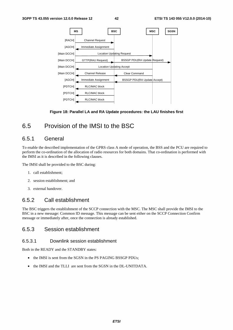
ETSI
ETSI TS 143 055 V12.0.0 (2014-10)423GPP TS 43.055 version 12.0.0 Release 12
BSSGP PDU(RA Update Request)
MS BSC SGSN
Location Updating Request
Location Updating Accept
Channel Release
BSSGP PDU(RA Update Accept)
[Main DCCH]
MSC
[Main DCCH]
[Main DCCH]
Channel Request[RACH]
Immediate Assignment[AGCH]
GTTP(RAU Request)[Main DCCH]
Clear Command
Immediate Assignment[AGCH]
RLC/MAC block[PDTCH]
RLC/MAC block[PDTCH]
RLC/MAC block[PDTCH]
Figure 18: Parallel LA and RA Update procedures: the LAU finishes first
6.5 Provision of the IMSI to the BSC
6.5.1 General
To enable the described implementation of the GPRS class A mode of operation, the BSS and the PCU are required to perform the co-ordination of the allocation of radio resources for both domains. That co-ordination is performed with the IMSI as it is described in the following clauses.
The IMSI shall be provided to the BSC during:
1. call establishment;
2. session establishment; and
3. external handover.
6.5.2 Call establishment
The BSC triggers the establishment of the SCCP connection with the MSC. The MSC shall provide the IMSI to the BSC in a new message: Common ID message. This message can be sent either on the SCCP Connection Confirm message or immediately after, once the connection is already established.
6.5.3 Session establishment
6.5.3.1 Downlink session establishment
Both in the READY and the STANDBY states:
• the IMSI is sent from the SGSN in the PS PAGING BSSGP PDUs;
• the IMSI and the TLLI are sent from the SGSN in the DL-UNITDATA.
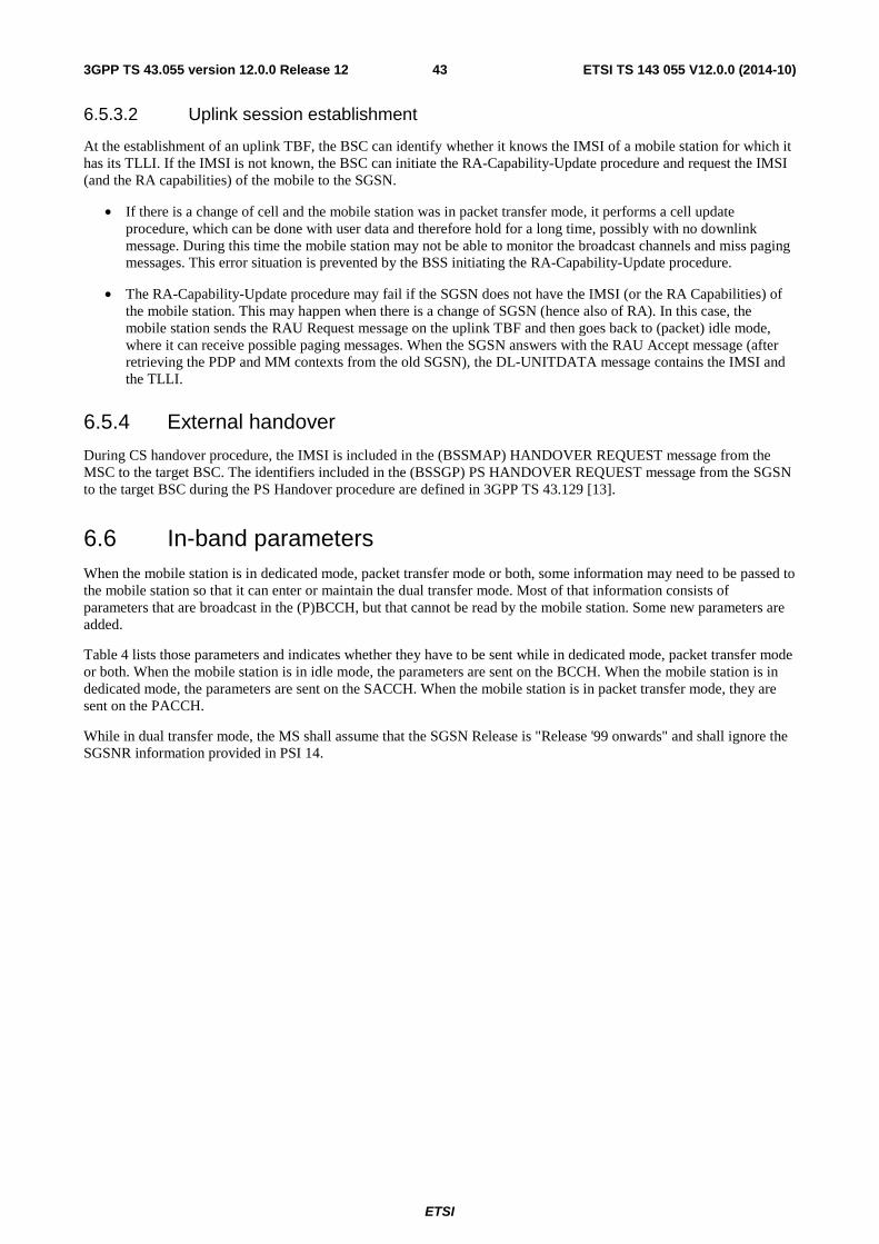
ETSI
ETSI TS 143 055 V12.0.0 (2014-10)433GPP TS 43.055 version 12.0.0 Release 12
6.5.3.2 Uplink session establishment
At the establishment of an uplink TBF, the BSC can identify whether it knows the IMSI of a mobile station for which it has its TLLI. If the IMSI is not known, the BSC can initiate the RA-Capability-Update procedure and request the IMSI (and the RA capabilities) of the mobile to the SGSN.
• If there is a change of cell and the mobile station was in packet transfer mode, it performs a cell update procedure, which can be done with user data and therefore hold for a long time, possibly with no downlink message. During this time the mobile station may not be able to monitor the broadcast channels and miss paging messages. This error situation is prevented by the BSS initiating the RA-Capability-Update procedure.
• The RA-Capability-Update procedure may fail if the SGSN does not have the IMSI (or the RA Capabilities) of the mobile station. This may happen when there is a change of SGSN (hence also of RA). In this case, the mobile station sends the RAU Request message on the uplink TBF and then goes back to (packet) idle mode, where it can receive possible paging messages. When the SGSN answers with the RAU Accept message (after retrieving the PDP and MM contexts from the old SGSN), the DL-UNITDATA message contains the IMSI and the TLLI.
6.5.4 External handover
During CS handover procedure, the IMSI is included in the (BSSMAP) HANDOVER REQUEST message from the MSC to the target BSC. The identifiers included in the (BSSGP) PS HANDOVER REQUEST message from the SGSN to the target BSC during the PS Handover procedure are defined in 3GPP TS 43.129 [13].
6.6 In-band parameters When the mobile station is in dedicated mode, packet transfer mode or both, some information may need to be passed to the mobile station so that it can enter or maintain the dual transfer mode. Most of that information consists of parameters that are broadcast in the (P)BCCH, but that cannot be read by the mobile station. Some new parameters are added.
Table 4 lists those parameters and indicates whether they have to be sent while in dedicated mode, packet transfer mode or both. When the mobile station is in idle mode, the parameters are sent on the BCCH. When the mobile station is in dedicated mode, the parameters are sent on the SACCH. When the mobile station is in packet transfer mode, they are sent on the PACCH.
While in dual transfer mode, the MS shall assume that the SGSN Release is "Release '99 onwards" and shall ignore the SGSNR information provided in PSI 14.
ETSI
ETSI TS 143 055 V12.0.0 (2014-10)443GPP TS 43.055 version 12.0.0 Release 12
Table 4: List of parameters to be passed in-band to the mobile station
(P)BCCH FACCH SACCH PACCH Parameter Description
� � �
DTM: bit(1) DTM support in the cell. (P)BCCH: to enable a quick resumption of the GPRS session in the transition from dual transfer mode to packet transfer mode; t enable the LA and RA Update procedures to be performed in parallel on an SDCCH. FACCH: immediately after a handover procedure when the MS was in DTM, in order to enable the packet session to be resume without long interruptions. [DTM Information] SACCH: to enable the packet request procedures while in dedicated mode. [SI 6]
� � RAI : bit(48) Routeing Area Identity. It is needed to enable the MS to
detect changes of routeing area during a handover in dedicated mode [DTM Information, SI6]
� � Cell Identity : bit(16)
Cell Identity. It is needed to enable the MS to detect changes of cell after a handover in dedicated mode [DTM Information, SI 6]
� �
MAX_LAPDm : bit(3)
Maximum number of LAPDm frames. To limit the use of the main DCCH when the MS in dedicated mode FACCH: immediately after a handover procedure when the MS was in DTM, in order to enable the packet session to be resume without long interruptions. [DTM Information] SACCH: to enable the packet request procedures while in dedicated mode. [SI 6]
� GPRS Cell Options
GPRS Cell Options. Sent on the DTM assignment message (DTM ASSIGNMENT COMMAND or PACKET ASSIGNMENT)
� GPRS Power Control Parameters
GPRS Power Control Parameters. Sent on the DTM assignment message (DTM ASSIGNMENT COMMAND or PACKET ASSIGNMENT)
� (P)SI 13 Information
(P)SI 13 Information: this information is sent so that the mobile station needs not read SI 13 at call release during dual transfer mode
� �
Dedicated Mode MBMS Notification Support Indication
Dedicated Mode MBMS Notification Support Indication. to enable the mobile station to participate in MBMS procedures while in dedicated mode (DTM ASSIGNMENT COMMAND, PACKET ASSIGNMENT or DTM INFORMATION, SI 6)
6.7 MS behaviour in heterogeneous networks
6.7.1 General
The support of DTM in a network is not likely to be homogeneous. Network operators normally have more that one infrastructure supplier and different manufacturers will support DTM with different time scales. In addition, the rollout of a product release from a certain manufacturer is not performed simultaneously across the network.
It is therefore difficult to avoid the fact that some cells in a network support DTM whereas others do not, making necessary to ensure a consistent behaviour of a DTM mobile station in such scenario. The existing GPRS Suspension and Resume procedures are reused for this purpose.
Table 5 contains the four possible combinations when the mobile station is handed over between two cells, where each of them may or not support DTM.

ETSI
ETSI TS 143 055 V12.0.0 (2014-10)453GPP TS 43.055 version 12.0.0 Release 12
Table 5: Modification to CS handover to ensure a correct DTM behaviour when DTM is not always supported
Support of DTM in new cell
No Yes
Su
pp
ort
of
DT
M in
old
cel
l
No
The MS waits for the reception of the SI 6 message indicating whether the cell supports DTM. If DTM is supported, the same message contains the RAC.
Normal CS handover.
When the SI6 message is received, the MS performs the Resume procedure: it performs the RR Packet Request procedure for the GMM RA Update procedure.
Yes
MS in
DM The MS waits until the reception of the SI 6 message indicating that the cell does not support DTM. Then, if GPRS is supported, the MS performs the GPRS suspension procedure.
The MS waits for the reception of the SI 6 message indicating that the cell supports DTM and containing the RAC. When the SI6 message is received, the MS performs the Cell Update (MS in READY), the RA Update procedure (change of RA) or none of both (MS in STANDBY and both cells in the same RA).
MS in
DTM
The network sends the DTM Information message (implicitly implying the support of DTM) containing the RAC and any other information needed to perform the Packet Request procedure.
6.7.1 Suspension procedure
The GPRS Suspension procedure is defined in the standards to be used when a mobile station in mode of operation B and in packet transfer mode is paged for circuit switched services.
The GPRS Suspension procedure can be used without modifications when:
• a DTM mobile in dedicated or dual transfer mode is handed over from a cell that supports DTM to one that does not; or
• a DTM mobile in packet transfer mode on a cell that does not support DTM is paged for circuit switched services.
The GPRS Suspension procedure is initiated by the mobile station by sending a GPRS SUSPENSION REQUEST message to the BSS after it has entered dedicated mode.
6.7.2 Resume procedure
The Resume procedure is used for the resumption of GPRS service when the conditions for suspension have disappeared (e.g. a suspended class B mobile station has cleared the resources allocated for the circuit switched service). The procedure is initiated:
a) by the BSS, when it detects the change of conditions: the BSS indicates the resumption to the SGSN and then the mobile station;
b) by the mobile station, when it detects the change of conditions and the BSS has not resumed GPRS: the mobile station performs a RA Update procedure that resumes GPRS with the SGSN.
For the two new causes for GPRS suspension, there is no message from the BSS to the mobile station and, thus, the Resume procedure is initiated by the mobile station (b).

ETSI
ETSI TS 143 055 V12.0.0 (2014-10)463GPP TS 43.055 version 12.0.0 Release 12
7 DTM operation Once the mobile stations enters the DTM, the existent RLC/MAC procedures apply, with the exception of the case of an exclusive allocation of an uplink PDCH (including the PDCH/H of a "TCH/H + PDCH/H" configuration). In that case, the mobile station is always granted the transmission of uplink RLC/MAC blocks, which keep the current format. Thus, the mobile station shall ignore the USF mechanism for dynamic allocation.
Other exceptions to the existent RLC/MAC procedures are:
• The mobile station shall not accept a packet assignment command (addressed to it on the PACCH) that changes the frequency definition of the PDCH. Such change shall be done by means of a DTM Assignment Command message on the main DCCH (changing both TCH and PDCH configurations). A modification of the timeslot allocation may occur by means of a Packet Assignment message. Any violation of the frequency restrictions or the multislot class of the mobile station (taking both TCH and PDCH resources into account) shall be treated as an abnormal case and the TBF(s) shall then be aborted.
NOTE 1: the PCU should know that the mobile station is in dual transfer mode and therefore format the messages correctly.
• When all TBFs have been released (or aborted), the mobile station returns to dedicated mode.
• When the mobile station is in dual transfer mode, it shall ignore a Packet Cell Change Order or a RR-Cell Change Order message and shall remain in dual transfer mode.
NOTE 2: the PCU should know that the mobile station is in dual transfer mode and therefore not send these messages.
• When a mobile station in dual transfer mode receives a valid RRBP field in a downlink RLC/MAC block , if it has been assigned PDCH/H, where the exclusive allocation is required, the mobile station shall use normal bursts and not access bursts, irrespective of the value of the CONTROL_ACK_TYPE field received in the DTM Assignment Command message or Packet Assignment message. If the mobile station has not been assigned PDCH/H, it shall either use normal bursts or access bursts to transmit the Packet Control Acknowledgement message depending on the value of CONTROL_ACK_TYPE received in the DTM Assignment Command message or Packet Assignment message.
The mobile station remains in DTM until the CS connection or all the TBFs are released.
8 GPRS attach procedure while in dedicated mode and packet idle mode
In this procedure, the mobile station sends a (non-combined) GPRS Attach Request message to the SGSN. The sequence of messages is very similar to the Routeing Area Update procedure, shown in figure 14 and figure 15.
9 Security The current procedures apply.
NOTE: LLC frames containing GPRS signalling messages and sent on the main DCCH are therefore ciphered twice, but that has been confirmed by SMG10 not to be a security problem. In "TCH/H + PDCH/H" and other multislot configurations, current GPRS ciphering is kept.
10 Header and Data Compression Because this is done at SNDCP layer, there is assumed to be no impact.

ETSI
ETSI TS 143 055 V12.0.0 (2014-10)473GPP TS 43.055 version 12.0.0 Release 12
Annex A (informative): Possible improvements for future releases
No. Description 1 New 3G TS 04.60 procedure for the establishment of a CS connection without interruption of the packet
services 2 Support of multislot operation comprising single timeslot operation and additional PDCH(s) in the same
direction in the uplink 3 Multislot configurations where the CS connection is using more than one timeslot 4 Multislot configurations where the timeslots allocated to the PS session are not contiguous 5 Power control for EGPRS while in DTM

ETSI
ETSI TS 143 055 V12.0.0 (2014-10)483GPP TS 43.055 version 12.0.0 Release 12
Annex B (normative): Incremental support of extended DTM multislot classes As for other DTM multislot classes, for extended DTM multislot classes incremental support (see subclause 4.5.1.3) shall apply: the MS only indicates the support of one multislot class and the support of less restrictive classes is also assumed by the network. This is depicted for mobile stations supporting Extended DTM GPRS Multi Slot Class or Extended DTM EGPRS Multi Slot Class, in Figure 19.
Mobile stations not supporting high multislot classes may indicate support only for the Extended DTM GPRS Multi Slot Classes or Extended DTM EGPRS Multi Slot Classes 5, 6, 9, 10 and 11 (indicated by solid boxes on the left of the dashed line in Figure 19).
NOTE: High multislot classes are multislot classes 30-45 (see 3GPP TS 45.002 [6]).
For mobile stations supporting high multislot classes, the Extended DTM GPRS Multi Slot Class shall always be the same as the DTM GPRS Multi Slot Class and the Extended DTM EGPRS Multi Slot Class shall always be the same as the DTM EGPRS Multi Slot Class (indicated by solid boxes on the right of the dashed line in Figure 19). The support of the mix of full and half rate packet data channels is indicated by the presence of the Extended DTM GPRS Multi Slot Class field and, where applicable, the Extended DTM EGPRS Multi Slot Class field in the MS Classmark 3 and MS Radio Access Capability IEs, regardless of the value of these fields.
Class 1 1+1=2
Class 2 2+1=3
Class Rx+Tx=Sum
Class 3 2+2=3
Class 4 3+1=4
Class 8 4+1=5
Class 5 2+2=4
Class 6 3+2=4
Class 7 3+3=4
Class 9 3+2=5
Class 10 4+2=5
Class 11 4+3=5
Class 33 or 38 5+4=6
Class 44 6+5=7
Class 32 or 37 5+3=6
Class 31 or 36 5+2=6
Class 42 6+3=7
Class43 6+4=7
Class 41 6+2=7
5+1=6 Class 30
6+1=7 Class 40
Class 12 4+4=5
Class 39 5+5=6
Figure 19 – Incremental support of extended DTM multislot classes.

ETSI
ETSI TS 143 055 V12.0.0 (2014-10)493GPP TS 43.055 version 12.0.0 Release 12
Annex C (informative): Change history
Change history Date TSG # TSG Doc. CR Rev Subject/Comment Old New 10 Nov 00 G02 GP-000705 New specification approved by TSG-GERAN 2.0.0 8.0.0 2001-04 G04 Version for Release 4 4.0.0 2001-06 G05 GP-011311 001 1 Definition of new DTM multislot classes 4.0.0 4.1.0 2002-06 G10 Version for Release 5 5.0.0 2003-02 G13 GP-030268 002 Clarification of the inclusion of DTM information in handover from
3G to 2G 5.0.0 6.0.0
2003-02 G13 GP-030405 003 2 Clarification on the use of basic HR in DTM single slot configuration 5.0.0 6.0.0 2003-02 G13 GP-030406 004 2 Clarification on the default value of MAX_LAPDm parameter 5.0.0 6.0.0 2003-04 G14 GP-030974 007 1 Corrections for DTM multislot configurations and DTM capability
indication 6.0.0 6.1.0
2003-08 G16 GP-032133 010 4 Change of DTM core capability 6.1.0 6.2.0 2003-11 G17 GP-032697 011 1 Introducing MTBF Support 6.2.0 6.3.0 2004-02 G18 GP-040429 014 1 Clarifications and corrections to the DTM procedures 6.3.0 6.4.0 2004-06 G20 GP-041680 016 1 Addition of DTM enhancements 6.4.0 6.5.0 2004-06 G20 GP-041696 017 2 Conditions for the NAS registration procedures 6.4.0 6.5.0 2004-06 G20 GP-041474 018 Usage of main DCCH in DTM 6.4.0 6.5.0 2004-08 G21 GP-042113 024 1 Correction of the possible burst format used for PACKET
CONTROL ACKNOWLEDGEMENT in DTM mode 6.5.0 6.6.0
2004-08 G21 GP-042204 025 1 Handling of Assignment Request in BSS 6.5.0 6.6.0 2004-08 G21 GP-042278 027 2 Addition of combined RAU or LAU procedure pending indication 6.5.0 6.6.0 2004-11 G22 GP-042450 019 5 Correction to downlink power control for DTM 6.6.0 6.7.0 2004-11 G22 GP-042363 026 3 Alignment of stage 2 with stage 3 for DTM 6.6.0 6.7.0 2004-11 G22 GP-042446 028 Clarification on speech codec for TCH/H in case of multislot
configurations 6.6.0 6.7.0
2005-01 G23 GP-050583 034 2 Missing cell identity in DTM Information message 6.7.0 6.8.0 2005-01 G23 GP-050449 035 1 PS roaming while in DTM 6.7.0 6.8.0 2005-04 G24 GP-050625 031 3 Extension of DTM to higher multislot classes 6.8.0 6.9.0 2005-04 G24 GP-050632 036 Corrections due to removal of fixed allocation 6.8.0 6.9.0 2005-04 G24 GP-050950 037 Cell Update for DTM capable MS when moving from Packet Idle to
Dedicated Mode whilst in GMM Ready and in case of DTM Handover Failure
6.8.0 6.9.0
2005-06 G25 GP-051702 038 1 Clarifications on DTM high multislot class capability 6.9.0 6.10.0 2005-06 G25 GP-051703 039 1 Miscellaneous corrections 6.9.0 6.10.0 2005-09 G26 GP-052315 0041 2 Alignment of DTM stage 2 with stage 3 6.10.0 6.11.0 2005-11 G27 GP-052843 0043 1 Provision of MBMS parameters in 'GPRS cell options' inband to CS
connected DTM capable MS 6.11.0 6.12.0
2005-11 G27 GP-052528 0044 RR connection establishment using enhanced DTM CS establishment in response to an encapsulated DTM ASSIGNMENT message
6.11.0 6.12.0
2005-11 G27 GP-052636 0046 Sending DTM Information after Handover 6.11.0 6.12.0 2005-11 G27 GP-052804 0042 1 DTM stage 2 alignments with stage 3 6.12.0 7.0.0 2005-11 G27 GP-052818 0047 1 SGSNR during DTM 6.12.0 7.0.0 2006-01 G28 GP-060402 0045 3 Introduction of the DTM HANDOVER 7.0.0 7.1.0 2006-04 G29 GP-060718 0048 Corrections to DTM Handover procedures 7.1.0 7.2.0 2006-06 G30 GP-061511 0051 4 C value calculation in case there is a transition of the mode 7.2.0 7.3.0 2006-06 G30 GP-061458 0052 3 Introduction of Inter-RAT DTM Handover 7.2.0 7.3.0 2006-06 G30 GP-061180 0054 1 Alignment of DTM Handover procedures 7.2.0 7.3.0 2006-09 G31 GP-061778 0056 1 Conditions for the transmission of the Packet CS Request message 7.3.0 7.4.0 2006-09 G31 GP-061913 0057 3 Introduction of Downlink Dual Carrier for DTM 7.3.0 7.4.0 2007-02 G33 GP-070438 0054 3 Fast sending of DTM Handover Command 7.4.0 7.5.0 2007-02 G33 GP-070254 0061 Enhanced DTM CS Release 7.4.0 7.5.0 2007-08 G35 GP-071144 0062 Indication of a waiting time in DTM REJECT message 7.5.0 7.6.0 2007-08 G35 GP-071551 0063 Introduction of EGPRS2 7.5.0 7.6.0 2008-08 G39 GP-081184 0064 Introduction of inter-RAT DTM handover with E-UTRAN 7.6.0 8.0.0 2009-02 G41 GP-090354 0067 1 Correction to Routing Area Updating type 8.0.0 8.1.0 2009-12 G44 Version for Release 9 8.1.0 9.0.0 2011-03 G49 Version for Release 10 9.0.0 10.0.0 2012-09 G55 Version for Release 11 10.0.0 11.0.0 2013-03 G57 GP-130251 0068 2 PLMN Index in the DTM handover procedure into shared GERAN 11.0.0 11.1.0 2014-09 G63 Version for Release 12 (frozen at SP-65) 11.1.0 12.0.0

ETSI
ETSI TS 143 055 V12.0.0 (2014-10)503GPP TS 43.055 version 12.0.0 Release 12
History
Document history
V12.0.0 October 2014 Publication