Embed Size (px)
Citation preview

ETSI TS 136 104 V15.3.0 (2018-07)
LTE; Evolved Universal Terrestrial Radio Access (E-UTRA);
Base Station (BS) radio transmission and reception (3GPP TS 36.104 version 15.3.0 Release 15)
TECHNICAL SPECIFICATION

ETSI
ETSI TS 136 104 V15.3.0 (2018-07)13GPP TS 36.104 version 15.3.0 Release 15
Reference RTS/TSGR-0436104vf30
Keywords LTE
ETSI
650 Route des Lucioles F-06921 Sophia Antipolis Cedex - FRANCE
Tel.: +33 4 92 94 42 00 Fax: +33 4 93 65 47 16
Siret N° 348 623 562 00017 - NAF 742 C
Association à but non lucratif enregistrée à la Sous-Préfecture de Grasse (06) N° 7803/88
Important notice
The present document can be downloaded from: http://www.etsi.org/standards-search
The present document may be made available in electronic versions and/or in print. The content of any electronic and/or print versions of the present document shall not be modified without the prior written authorization of ETSI. In case of any
existing or perceived difference in contents between such versions and/or in print, the only prevailing document is the print of the Portable Document Format (PDF) version kept on a specific network drive within ETSI Secretariat.
Users of the present document should be aware that the document may be subject to revision or change of status. Information on the current status of this and other ETSI documents is available at
https://portal.etsi.org/TB/ETSIDeliverableStatus.aspx
If you find errors in the present document, please send your comment to one of the following services: https://portal.etsi.org/People/CommiteeSupportStaff.aspx
Copyright Notification
No part may be reproduced or utilized in any form or by any means, electronic or mechanical, including photocopying and microfilm except as authorized by written permission of ETSI.
The content of the PDF version shall not be modified without the written authorization of ETSI. The copyright and the foregoing restriction extend to reproduction in all media.
© ETSI 2018.
All rights reserved.
DECTTM, PLUGTESTSTM, UMTSTM and the ETSI logo are trademarks of ETSI registered for the benefit of its Members. 3GPPTM and LTETM are trademarks of ETSI registered for the benefit of its Members and
of the 3GPP Organizational Partners. oneM2M logo is protected for the benefit of its Members.
GSM® and the GSM logo are trademarks registered and owned by the GSM Association.
ETSI
ETSI TS 136 104 V15.3.0 (2018-07)23GPP TS 36.104 version 15.3.0 Release 15
Intellectual Property Rights Essential patents
IPRs essential or potentially essential to normative deliverables may have been declared to ETSI. The information pertaining to these essential IPRs, if any, is publicly available for ETSI members and non-members, and can be found in ETSI SR 000 314: "Intellectual Property Rights (IPRs); Essential, or potentially Essential, IPRs notified to ETSI in respect of ETSI standards", which is available from the ETSI Secretariat. Latest updates are available on the ETSI Web server (https://ipr.etsi.org/).
Pursuant to the ETSI IPR Policy, no investigation, including IPR searches, has been carried out by ETSI. No guarantee can be given as to the existence of other IPRs not referenced in ETSI SR 000 314 (or the updates on the ETSI Web server) which are, or may be, or may become, essential to the present document.
Trademarks
The present document may include trademarks and/or tradenames which are asserted and/or registered by their owners. ETSI claims no ownership of these except for any which are indicated as being the property of ETSI, and conveys no right to use or reproduce any trademark and/or tradename. Mention of those trademarks in the present document does not constitute an endorsement by ETSI of products, services or organizations associated with those trademarks.
Foreword This Technical Specification (TS) has been produced by ETSI 3rd Generation Partnership Project (3GPP).
The present document may refer to technical specifications or reports using their 3GPP identities, UMTS identities or GSM identities. These should be interpreted as being references to the corresponding ETSI deliverables.
The cross reference between GSM, UMTS, 3GPP and ETSI identities can be found under http://webapp.etsi.org/key/queryform.asp.
Modal verbs terminology In the present document "shall", "shall not", "should", "should not", "may", "need not", "will", "will not", "can" and "cannot" are to be interpreted as described in clause 3.2 of the ETSI Drafting Rules (Verbal forms for the expression of provisions).
"must" and "must not" are NOT allowed in ETSI deliverables except when used in direct citation.

ETSI
ETSI TS 136 104 V15.3.0 (2018-07)33GPP TS 36.104 version 15.3.0 Release 15
Contents Intellectual Property Rights ................................................................................................................................ 2
Foreword ............................................................................................................................................................. 2
Modal verbs terminology .................................................................................................................................... 2
Foreword ............................................................................................................................................................. 8
1 Scope ........................................................................................................................................................ 9
2 References ................................................................................................................................................ 9
3 Definitions, symbols and abbreviations ................................................................................................. 10
3.1 Definitions ........................................................................................................................................................ 10
3.2 Symbols ............................................................................................................................................................ 13
3.3 Abbreviations ................................................................................................................................................... 14
4 General ................................................................................................................................................... 16
4.1 Relationship between minimum requirements and test requirements .............................................................. 16
4.2 Base station classes .......................................................................................................................................... 16
4.3 Regional requirements ...................................................................................................................................... 16
4.4 Applicability of requirements ........................................................................................................................... 17
4.5 Requirements for BS capable of multi-band operation .................................................................................... 18
5 Operating bands and channel arrangement ............................................................................................. 18
5.1 General ............................................................................................................................................................. 18
5.2 Void .................................................................................................................................................................. 19
5.3 Void .................................................................................................................................................................. 19
5.4 Void .................................................................................................................................................................. 19
5.5 Operating bands ................................................................................................................................................ 19
5.6 Channel bandwidth ........................................................................................................................................... 52
5.7 Channel arrangement ........................................................................................................................................ 56
5.7.1 Channel spacing .......................................................................................................................................... 56
5.7.1A CA Channel spacing ................................................................................................................................... 56
5.7.2 Channel raster ............................................................................................................................................. 57
5.7.3 Carrier frequency and EARFCN ................................................................................................................. 57
5.7.4 EARFCN sets for uplink transmissions on multiple Scells configured in Band 46 .................................... 60
5.8 Requirements for contiguous and non-contiguous spectrum ............................................................................ 60
6 Transmitter characteristics ..................................................................................................................... 61
6.1 General ............................................................................................................................................................. 61
6.2 Base station output power ................................................................................................................................ 61
6.2.1 Minimum requirement ................................................................................................................................ 62
6.2.2 Additional requirement (regional) .............................................................................................................. 62
6.2.3 Home BS output power for adjacent UTRA channel protection................................................................. 63
6.2.4 Home BS output power for adjacent E-UTRA channel protection ............................................................. 63
6.2.5 Home BS Output Power for co-channel E-UTRA protection ..................................................................... 64
6.3 Output power dynamics .................................................................................................................................... 66
6.3.1 RE Power control dynamic range ............................................................................................................... 66
6.3.1.1 Minimum requirements ......................................................................................................................... 66
6.3.2 Total power dynamic range ........................................................................................................................ 66
6.3.2.1 Minimum requirements ......................................................................................................................... 66
6.3.3 NB-IoT RB power dynamic range for in-band or guard band operation .................................................... 67
6.3.3.1 Minimum Requirement ......................................................................................................................... 67
6.4 Transmit ON/OFF power ................................................................................................................................. 67
6.4.1 Transmitter OFF power .............................................................................................................................. 67
6.4.1.1 Minimum Requirement ......................................................................................................................... 67
6.4.2 Transmitter transient period ........................................................................................................................ 67
6.4.2.1 Minimum requirements ......................................................................................................................... 68
6.5 Transmitted signal quality ................................................................................................................................ 68
6.5.1 Frequency error ........................................................................................................................................... 68
6.5.1.1 Minimum requirement .......................................................................................................................... 68

ETSI
ETSI TS 136 104 V15.3.0 (2018-07)43GPP TS 36.104 version 15.3.0 Release 15
6.5.2 Error Vector Magnitude .............................................................................................................................. 69
6.5.3 Time alignment error .................................................................................................................................. 69
6.5.3.1 Minimum Requirement ......................................................................................................................... 69
6.5.4 DL RS power .............................................................................................................................................. 70
6.5.4.1 Minimum requirements ......................................................................................................................... 70
6.6 Unwanted emissions ......................................................................................................................................... 70
6.6.1 Occupied bandwidth ................................................................................................................................... 70
6.6.1.1 Minimum requirement .......................................................................................................................... 71
6.6.2 Adjacent Channel Leakage power Ratio (ACLR) ...................................................................................... 71
6.6.2.1 Minimum requirement .......................................................................................................................... 71
6.6.2.2 Cumulative ACLR requirement in non-contiguous spectrum ............................................................... 73
6.6.3 Operating band unwanted emissions .......................................................................................................... 75
6.6.3.1 Minimum requirements for Wide Area BS (Category A) ..................................................................... 77
6.6.3.2 Minimum requirements for Wide Area BS (Category B) ..................................................................... 79
6.6.3.2.1 Category B requirements (Option 1) ............................................................................................... 79
6.6.3.2.2 Category B (Option 2) ........................................................................................................................... 83
6.6.3.2A Minimum requirements for Local Area BS (Category A and B) .......................................................... 85
6.6.3.2B Minimum requirements for Home BS (Category A and B) .................................................................. 86
6.6.3.2C Minimum requirements for Medium Range BS (Category A and B) ................................................... 87
6.6.3.2D Minimum requirements for Local Area and Medium Range BS in Band 46 (Category A and B) ........ 89
6.6.3.2E Minimum requirements for standalone NB-IoT Wide Area BS ............................................................ 90
6.6.3.2F Minimum requirements for standalone NB-IoT Local Area BS ........................................................... 90
6.6.3.2G Minimum requirements for standalone NB-IoT Home BS (Category A and B) ................................... 91
6.6.3.2H Minimum requirements for standalone NB-IoT Medium Range BS .................................................... 92
6.6.3.3 Additional requirements ........................................................................................................................ 93
6.6.4 Transmitter spurious emissions ................................................................................................................... 97
6.6.4.1 Mandatory Requirements ...................................................................................................................... 98
6.6.4.1.1 Spurious emissions (Category A) .................................................................................................... 98
6.6.4.1.2 Spurious emissions (Category B) .................................................................................................... 99
6.6.4.2 Protection of the BS receiver of own or different BS ........................................................................... 99
6.6.4.2.1 Minimum Requirement ................................................................................................................... 99
6.6.4.3 Additional spurious emissions requirements ......................................................................................... 99
6.6.4.3.1 Minimum Requirement ................................................................................................................... 99
6.6.4.4 Co-location with other base stations ................................................................................................... 113
6.6.4.4.1 Minimum Requirement ................................................................................................................. 113
6.7 Transmitter intermodulation ........................................................................................................................... 124
6.7.1 Minimum requirement .............................................................................................................................. 124
6.7.2 Additional requirement for Band 41 ......................................................................................................... 126
7 Receiver characteristics ........................................................................................................................ 126
7.1 General ........................................................................................................................................................... 126
7.2 Reference sensitivity level .............................................................................................................................. 127
7.2.1 Minimum requirement .............................................................................................................................. 127
7.3 Dynamic range ............................................................................................................................................... 131
7.3.1 Minimum requirement .............................................................................................................................. 131
7.4 In-channel selectivity ..................................................................................................................................... 137
7.4.1 Minimum requirement .............................................................................................................................. 137
7.5 Adjacent Channel Selectivity (ACS) and narrow-band blocking ................................................................... 144
7.5.1 Minimum requirement .............................................................................................................................. 144
7.6 Blocking ......................................................................................................................................................... 155
7.6.1 General blocking requirement................................................................................................................... 155
7.6.1.1 Minimum requirement ........................................................................................................................ 155
7.6.2 Co-location with other base stations ......................................................................................................... 169
7.6.2.1 Minimum requirement ........................................................................................................................ 169
7.6.3 Additional requirement (regional) ............................................................................................................ 178
7.7 Receiver spurious emissions........................................................................................................................... 178
7.7.1 Minimum requirement .............................................................................................................................. 179
7.8 Receiver intermodulation ............................................................................................................................... 179
7.8.1 Minimum requirement .............................................................................................................................. 179
8 Performance requirement ..................................................................................................................... 194
8.1 General ........................................................................................................................................................... 194

ETSI
ETSI TS 136 104 V15.3.0 (2018-07)53GPP TS 36.104 version 15.3.0 Release 15
8.2 Performance requirements for PUSCH .......................................................................................................... 194
8.2.1 Requirements in multipath fading propagation conditions ....................................................................... 194
8.2.1.1 Minimum requirements ....................................................................................................................... 195
8.2.2 Requirements for UL timing adjustment .................................................................................................. 214
8.2.2.1 Minimum requirements ....................................................................................................................... 215
8.2.3 Requirements for high speed train ............................................................................................................ 215
8.2.3.1 Minimum requirements ....................................................................................................................... 216
8.2.4 Requirements for HARQ-ACK multiplexed on PUSCH .......................................................................... 216
8.2.4.1 Minimum requirement ........................................................................................................................ 217
8.2.5 Requirements for PUSCH with TTI bundling and enhanced HARQ pattern ........................................... 217
8.2.5.1 Minimum requirements ....................................................................................................................... 218
8.2.6 Enhanced performance requirement type A in multipath fading propagation conditions with synchronous interference .......................................................................................................................... 218
8.2.6.1 Minimum requirements ....................................................................................................................... 219
8.2.6A Enhanced performance requirement type A in multipath fading propagation conditions with asynchronous interference ........................................................................................................................ 221
8.2.6A.1 Minimum requirements ....................................................................................................................... 222
8.2.7 Requirements for PUSCH supporting coverage enhancement ................................................................. 223
8.2.8 Requirements for PUSCH of Frame structure type 3 ................................................................................ 225
8.2.9 Enhanced performance requirement type B in multipath fading propagation conditions ......................... 226
8.2.9.1 Minimum requirements ....................................................................................................................... 228
8.3 Performance requirements for PUCCH .......................................................................................................... 230
8.3.1 DTX to ACK performance ....................................................................................................................... 230
8.3.1.1 Minimum requirement ........................................................................................................................ 230
8.3.2 ACK missed detection requirements for single user PUCCH format 1a .................................................. 231
8.3.2.1 Minimum requirements ....................................................................................................................... 231
8.3.3 CQI performance requirements for PUCCH format 2 .............................................................................. 231
8.3.3.1 Minimum requirements ....................................................................................................................... 232
8.3.4 ACK missed detection requirements for multi user PUCCH format 1a ................................................... 232
8.3.4.1 Minimum requirement ........................................................................................................................ 232
8.3.5 ACK missed detection requirements for PUCCH format 1b with Channel Selection .............................. 232
8.3.5.1 Minimum requirements ....................................................................................................................... 233
8.3.6 ACK missed detection requirements for PUCCH format 3 ...................................................................... 233
8.3.6.1 Minimum requirements ....................................................................................................................... 233
8.3.7 NACK to ACK requirements for PUCCH format 3 ................................................................................. 234
8.3.7.1 Minimum requirement ........................................................................................................................ 234
8.3.8 CQI performance requirements for PUCCH format 2 with DTX detection ............................................. 234
8.3.8.1 Minimum requirements ....................................................................................................................... 235
8.3.9 PUCCH performance requirements for coverage enhancement ............................................................... 235
8.3.9.1 DTX to ACK performance .................................................................................................................. 235
8.3.9.1.1 Minimum requirement ................................................................................................................... 235
8.3.9.2 ACK missed detection requirements for single user PUCCH format 1a ............................................. 235
8.3.9.2.1 Minimum requirements ................................................................................................................. 235
8.3.9.3 CQI performance requirements for PUCCH format 2 ........................................................................ 236
8.3.9.3.1 Minimum requirements ................................................................................................................. 236
8.3.10 ACK missed detection requirements for PUCCH format 4 ...................................................................... 236
8.3.10.1 Minimum requirements ....................................................................................................................... 236
8.3.11 ACK missed detection requirements for PUCCH format 5 ...................................................................... 237
8.3.11.1 Minimum requirements ....................................................................................................................... 237
8.4 Performance requirements for PRACH .......................................................................................................... 238
8.4.1 PRACH False alarm probability ............................................................................................................... 238
8.4.1.1 Minimum requirement ........................................................................................................................ 238
8.4.2 PRACH detection requirements ................................................................................................................ 238
8.4.2.1 Minimum requirements ....................................................................................................................... 238
8.5 Performance requirements for Narrowband IoT ............................................................................................. 240
8.5.1 Requirements for NPUSCH format 1 ....................................................................................................... 240
8.5.1.1 Requirements ...................................................................................................................................... 240
8.5.1.1.1 Minimum requirements ................................................................................................................. 240
8.5.2 Performance requirements for NPUSCH format 2 ................................................................................... 241
8.5.2.1 DTX to ACK performance .................................................................................................................. 241
8.5.2.1.1 Minimum requirement ................................................................................................................... 241
8.5.2.2 ACK missed detection requirements ................................................................................................... 242
ETSI
ETSI TS 136 104 V15.3.0 (2018-07)63GPP TS 36.104 version 15.3.0 Release 15
8.5.2.2.1 Minimum requirements ................................................................................................................. 242
8.5.3 Performance requirements for NPRACH ................................................................................................. 242
8.5.3.1 NPRACH False alarm probability ....................................................................................................... 242
8.5.3.1.1 Minimum requirement ................................................................................................................... 242
8.5.3.2 NPRACH detection requirements ....................................................................................................... 242
8.5.3.2.1 Minimum requirements ................................................................................................................. 243
9 Void ...................................................................................................................................................... 244
Annex A (normative): Reference measurement channels ........................................................................ 245
A.1 Fixed Reference Channels for reference sensitivity and in-channel selectivity (QPSK, R=1/3) ......... 246
A.2 Fixed Reference Channels for dynamic range (16QAM, R=2/3) ......................................................... 247
A.3 Fixed Reference Channels for performance requirements (QPSK 1/3) ............................................... 247
A.4 Fixed Reference Channels for performance requirements (16QAM 3/4) ............................................ 248
A.5 Fixed Reference Channels for performance requirements (64QAM 5/6) ............................................ 248
A.6 PRACH Test preambles ....................................................................................................................... 248
A.7 Fixed Reference Channels for UL timing adjustment (Scenario 1) ..................................................... 249
A.8 Fixed Reference Channels for UL timing adjustment (Scenario 2) ..................................................... 250
A.9 Multi user PUCCH test......................................................................................................................... 250
A.10 PUCCH transmission on two antenna ports test ................................................................................... 250
A.11 Fixed Reference Channel for PUSCH with TTI bundling and enhanced HARQ pattern .................... 251
A.12 Fixed Reference Channels for performance requirements (QPSK 0.36) ............................................. 251
A.13 Fixed Reference Channels for performance requirements (16QAM 1/2) ............................................ 252
A.14 Fixed Reference Channels for NB-IOT reference sensitivity (π/2 BPSK, R=1/3) ............................... 252
A.15 Fixed Reference Channels for NB-IoT dynamic range (π/4 QPSK, R=2/3) ........................................ 252
A.16 Fixed Reference Channels for NB-IoT NPUSCH format 1 ................................................................. 253
A.16.1 One PRB ......................................................................................................................................................... 253
A.17 Fixed Reference Channels for performance requirements (256QAM 5/6) .......................................... 254
A.18 Fixed Reference Channels for PUSCH transmission in UpPTS (16QAM 0.65) ................................. 254
A.19 Fixed Reference Channels for PUSCH transmission in UpPTS (256QAM 0.69) ............................... 255
A.20 Fixed Reference Channels for PUSCH of Frame structure type 3 ........................................................ 255
A.21 Fixed Reference Channels for performance requirements (QPSK 3/5) ............................................... 256
A.22 Fixed Reference Channels for performance requirements (64QAM 1/2) ............................................ 257
Annex B (normative): Propagation conditions ................................................................................ 258
B.1 Static propagation condition ................................................................................................................. 258
B.2 Multi-path fading propagation conditions ............................................................................................ 258
B.3 High speed train condition ................................................................................................................... 259
B.4 Moving propagation conditions ............................................................................................................ 260
B.5 Multi-Antenna channel models ............................................................................................................ 261
B.5.1 Definition of MIMO Correlation Matrices ..................................................................................................... 261
B.5.2 MIMO Correlation Matrices at High, Medium and Low Level ..................................................................... 262
B.5A Multi-Antenna channel models using cross polarized antennas ........................................................... 264
B.5A.1 Definition of MIMO Correlation Matrices using cross polarized antennas.................................................... 265
B.5A.2 Spatial Correlation Matrices at UE and eNB sides ......................................................................................... 265

ETSI
ETSI TS 136 104 V15.3.0 (2018-07)73GPP TS 36.104 version 15.3.0 Release 15
B.5A.2.1 Spatial Correlation Matrices at UE side .................................................................................................... 265
B.5A.2.2 Spatial Correlation Matrices at eNB side .................................................................................................. 266
B.5A.3 MIMO Correlation Matrices using cross polarized antennas ......................................................................... 266
B.6 Interference model for enhanced performance requirements type A and type B ................................. 266
B.6.1 Dominant interferer proportion ...................................................................................................................... 266
B.6.2 Interference model for synchronous scenario ................................................................................................. 267
B.6.3 Interference model for asynchronous scenario ............................................................................................... 267
Annex C (normative): Characteristics of the interfering signals ................................................... 268
Annex D (normative): Environmental requirements for the BS equipment ................................ 269
Annex E (normative): Error Vector Magnitude ............................................................................. 270
E.1 Reference point for measurement ......................................................................................................... 270
E.2 Basic unit of measurement ................................................................................................................... 270
E.3 Modified signal under test .................................................................................................................... 271
E.4 Estimation of frequency offset ............................................................................................................. 271
E.5 Estimation of time offset ...................................................................................................................... 271
E.5.1 Window length ............................................................................................................................................... 272
E.6 Estimation of TX chain amplitude and frequency response parameters .............................................. 273
E.7 Averaged EVM .................................................................................................................................... 274
Annex F (Informative): Unwanted emission requirements for multi-carrier BS ........................... 276
F.1 General ................................................................................................................................................. 276
F.2 Multi-carrier BS of different E-UTRA channel bandwidths ................................................................ 276
F.3 Multi-carrier BS of E-UTRA and UTRA ............................................................................................. 276
Annex G (Informative): Regional requirement for protection of DTT ............................................ 277
G.1 Regional requirement for protection of DTT ....................................................................................... 277
G.2 Regional requirement for Public Safety LTE BS in Korea .................................................................. 277
Annex H (Informative): Calculation of EIRP based on manufacturer declarations and site specific conditions ........................................................................................ 280
H.1 Calculation of EIRP based on manufacturer declarations and site specific conditions ........................ 280
Annex I (Informative): Change history ............................................................................................. 281
History ............................................................................................................................................................ 294

ETSI
ETSI TS 136 104 V15.3.0 (2018-07)83GPP TS 36.104 version 15.3.0 Release 15
Foreword This Technical Specification has been produced by the 3rd Generation Partnership Project (3GPP).
The contents of the present document are subject to continuing work within the TSG and may change following formal TSG approval. Should the TSG modify the contents of the present document, it will be re-released by the TSG with an identifying change of release date and an increase in version number as follows:
Version x.y.z
where:
x the first digit:
1 presented to TSG for information;
2 presented to TSG for approval;
3 or greater indicates TSG approved document under change control.
y the second digit is incremented for all changes of substance, i.e. technical enhancements, corrections, updates, etc.
z the third digit is incremented when editorial only changes have been incorporated in the document.

ETSI
ETSI TS 136 104 V15.3.0 (2018-07)93GPP TS 36.104 version 15.3.0 Release 15
1 Scope The present document establishes the minimum RF characteristics and minimum performance requirements of E-UTRA, E-UTRA with NB-IoT or NB-IoT Base Station (BS).
2 References The following documents contain provisions which, through reference in this text, constitute provisions of the present document.
- References are either specific (identified by date of publication, edition number, version number, etc.) or non-specific.
- For a specific reference, subsequent revisions do not apply.
- For a non-specific reference, the latest version applies. In the case of a reference to a 3GPP document (including a GSM document), a non-specific reference implicitly refers to the latest version of that document in the same Release as the present document.
[1] 3GPP TR 21.905: "Vocabulary for 3GPP Specifications".
[2] ITU-R Recommendation SM.329: "Unwanted emissions in the spurious domain".
[3] ITU-R Recommendation M.1545: "Measurement uncertainty as it applies to test limits for the terrestrial component of International Mobile Telecommunications-2000".
[4] 3GPP TS 36.141: "Evolved Universal Terrestrial Radio Access (E-UTRA); Base Station (BS) conformance testing".
[5] ITU-R recommendation SM.328: "Spectra and bandwidth of emissions".
[6] 3GPP TS 25.104: "Base Station (BS) radio transmission and reception (FDD)".
[7] 3GPP TS 25.105: "Base Station (BS) radio transmission and reception (TDD)".
[8] 3GPP TR 25.942: "RF system scenarios".
[9] 3GPP TR 36.942: "E-UTRA RF system scenarios".
[10] 3GPP TS 36.211: "Evolved Universal Terrestrial Radio Access (E-UTRA); Physical Channels and Modulation".
[11] 3GPP TS 36.213: "Evolved Universal Terrestrial Radio Access (E-UTRA); Physical layer procedures".
[12] ECC/DEC/(09)03 “Harmonised conditions for MFCN in the band 790-862 MHz”, 30 Oct. 2009
[13] IEC 60721-3-3 (2002): "Classification of environmental conditions - Part 3: Classification of groups of environmental parameters and their severities - Section 3: Stationary use at weather protected locations".
[14] IEC 60721-3-4 (1995): "Classification of environmental conditions - Part 3: Classification of groups of environmental parameters and their severities - Section 4: Stationary use at non-weather protected locations".
[15] 3GPP TS 37.104: "E-UTRA, UTRA and GSM/EDGE; Multi-Standard Radio (MSR) Base Station (BS) radio transmission and reception ".
[16] CEPT ECC Decision (13)03, "The harmonised use of the frequency band 1452-1492 MHz for Mobile/Fixed Communications Networks Supplemental Downlink (MFCN SDL)".
[17] 3GPP TS 36.211: "Evolved Universal Terrestrial Radio Access (E-UTRA); Physical channels and modulation".

ETSI
ETSI TS 136 104 V15.3.0 (2018-07)103GPP TS 36.104 version 15.3.0 Release 15
[18] 3GPP TS 36.213: "Evolved Universal Terrestrial Radio Access (E-UTRA); Physical layer procedures".
[19] CEPT ECC Decision (17)06, “The harmonised use of the frequency bands 1427-1452 MHz and 1492-1518 MHz for Mobile/Fixed Communications Networks Supplemental Downlink (MFCN SDL)”.
3 Definitions, symbols and abbreviations
3.1 Definitions For the purposes of the present document, the terms and definitions given in TR 21.905 [1] and the following apply. A term defined in the present document takes precedence over the definition of the same term, if any, in TR 21.905 [1].
Aggregated Channel Bandwidth: RF bandwidth in which a base station transmits and/or receives multiple contiguously aggregated carriers.
NOTE: The Aggregated Channel Bandwidth is measured in MHz.
Base station receive period: time during which the base station is receiving data subframes or UpPTS.
Base Station RF Bandwidth: RF bandwidth in which a base station transmits and/or receives single or multiple carrier(s) within a supported operating band.
NOTE: In single E-UTRA carrier operation, the Base Station RF Bandwidth is equal to the channel bandwidth.
Base Station RF Bandwidth edge: frequency of one of the edges of the Base Station RF Bandwidth.
Carrier: modulated waveform conveying the E-UTRA or UTRA physical channels
Carrier aggregation: aggregation of two or more component carriers in order to support wider transmission bandwidths
Carrier aggregation band: a set of one or more operating bands across which multiple carriers are aggregated with a specific set of technical requirements.
NOTE: Carrier aggregation band(s) for an E-UTRA BS is declared by the manufacturer according to the designations in Tables 5.5-2 to 5.5-4.
Channel bandwidth: RF bandwidth supporting a single E-UTRA RF carrier with the transmission bandwidth configured in the uplink or downlink of a cell.
NOTE: The channel bandwidth is measured in MHz and is used as a reference for transmitter and receiver RF requirements.
Channel edge: lowest or highest frequency of the E-UTRA carrier, separated by the channel bandwidth.
Contiguous carriers: set of two or more carriers configured in a spectrum block where there are no RF requirements based on co-existence for un-coordinated operation within the spectrum block.
Contiguous spectrum: spectrum consisting of a contiguous block of spectrum with no sub-block gap(s).
DL RS power: resource element power of Downlink Reference Symbol.
DL NRS power: resource element power of Downlink Narrowband Reference Signal.
Downlink operating band: part of the operating band designated for downlink.
Enhanced performance requirements type A: This defines performance requirements assuming baseline receiver as demodulation reference signal based linear minimum mean square error interference rejection combining.
Enhanced performance requirements type B: This defines performance requirements assuming baseline receiver as code word level interference cancellation for intra-cell inter-user interference plus demodulation reference signal based linear minimum mean square error interference rejection combining for inter-cell interference.

ETSI
ETSI TS 136 104 V15.3.0 (2018-07)113GPP TS 36.104 version 15.3.0 Release 15
Highest carrier: carrier with the highest carrier centre frequency transmitted/received in a specified operating band.
Inter RF Bandwidth gap: frequency gap between two consecutive Base Station RF Bandwidths that are placed within two supported operating bands.
Inter-band carrier aggregation: carrier aggregation of component carriers in different operating bands.
NOTE: Carriers aggregated in each band can be contiguous or non-contiguous.
Inter-band gap: The frequency gap between two supported consecutive operating bands.
Intra-band contiguous carrier aggregation: contiguous carriers aggregated in the same operating band.
Intra-band non-contiguous carrier aggregation: non-contiguous carriers aggregated in the same operating band.
Lower sub-block edge: frequency at the lower edge of one sub-block.
NOTE: It is used as a frequency reference point for both transmitter and receiver requirements.
Lowest carrier: carrier with the lowest carrier centre frequency transmitted/received in a specified operating band.
Maximum output power: mean power level per carrier of the base station measured at the antenna connector in a specified reference condition.
Maximum throughput: maximum achievable throughput for a reference measurement channel.
Mean power: power measured in the channel bandwidth of the carrier.
NOTE: The period of measurement shall be at least one subframe (1ms), unless otherwise stated.
Measurement bandwidth: RF bandwidth in which an emission level is specified.
Multi-band base station: base station characterized by the ability of its transmitter and/or receiver to process two or more carriers in common active RF components simultaneously, where at least one carrier is configured at a different operating band (which is not a sub-band or superseding-band of another supported operating band) than the other carrier(s).
Multi-band transmitter: transmitter characterized by the ability to process two or more carriers in common active RF components simultaneously, where at least one carrier is configured at a different operating band (which is not a sub-band or superseding-band of another supported operating band) than the other carrier(s).
Multi-band receiver: receiver characterized by the ability to process two or more carriers in common active RF components simultaneously, where at least one carrier is configured at a different operating band (which is not a sub-band or superseding-band of another supported operating band) than the other carrier(s).
Multi-carrier transmission configuration: set of one or more contiguous or non-contiguous carriers that a BS is able to transmit simultaneously according to the manufacturer’s specification.
NB-IoT In-band operation: NB-IoT is operating in-band when it utilizes the resource block(s) within a normal E-UTRA carrier
NB-IoT guard band operation: NB-IoT is operating in guard band when it utilizes the unused resource block(s) within a E-UTRA carrier’s guard-band.
NB-IoT standalone operation: NB-IoT is operating standalone when it utilizes its own spectrum, for example the spectrum currently being used by GERAN systems as a replacement of one or more GSM carriers, as well as scattered spectrum for potential IoT deployment.
Non-contiguous spectrum: spectrum consisting of two or more sub-blocks separated by sub-block gap(s).
Occupied bandwidth: width of a frequency band such that, below the lower and above the upper frequency limits, the mean powers emitted are each equal to a specified percentage β/2 of the total mean power of a given emission.
Operating band: frequency range in which E-UTRA operates (paired or unpaired), that is defined with a specific set of technical requirements.

ETSI
ETSI TS 136 104 V15.3.0 (2018-07)123GPP TS 36.104 version 15.3.0 Release 15
NOTE: The operating band(s) for an E-UTRA BS is declared by the manufacturer according to the designations in table 5.5-1.
Output power: mean power of one carrier of the base station, delivered to a load with resistance equal to the nominal load impedance of the transmitter.
Radio Bandwidth: frequency difference between the upper edge of the highest used carrier and the lower edge of the lowest used carrier.
Rated output power: mean power level per carrier that the manufacturer has declared to be available at the antenna connector during the transmitter ON period.
RE power control dynamic range: difference between the power of a RE and the average RE power for a BS at maximum output power for a specified reference condition.
RRC filtered mean power: mean power of an UTRA carrier as measured through a root raised cosine filter with roll-off factor α and a bandwidth equal to the chip rate of the radio access mode.
NOTE 1: The RRC filtered mean power of a perfectly modulated UTRA signal is 0.246 dB lower than the mean power of the same signal.
sTTI: A transmission time interval (TTI) of either one slot or one subslot as defined in [10] on either uplink or downlink.
Sub-band: A sub-band of an operating band contains a part of the uplink and downlink frequency range of the operating band.
Sub-block: one contiguous allocated block of spectrum for transmission and reception by the same base station.
NOTE: There may be multiple instances of sub-blocks within aBase Station RF Bandwidth.
Sub-block bandwidth: bandwidth of one sub-block.
Sub-block gap: frequency gap between two consecutive sub-blocks within a Bae Station RF Bandwidth, where the RF requirements in the gap are based on co-existence for un-coordinated operation.
Superseding-band: A superseding-band of an operating band includes the whole of the uplink and downlink frequency range of the operating band.
Synchronized operation: operation of TDD in two different systems, where no simultaneous uplink and downlink occur.
Throughput: number of payload bits successfully received per second for a reference measurement channel in a specified reference condition.
Total power dynamic range: difference between the maximum and the minimum transmit power of an OFDM symbol for a specified reference condition.
Transmission bandwidth: RF Bandwidth of an instantaneous transmission from a UE or BS, measured in resource block units.
Transmission bandwidth configuration: highest transmission bandwidth allowed for uplink or downlink in a given channel bandwidth, measured in resource block units.
Transmitter ON period: time period during which the BS transmitter is transmitting data and/or reference symbols, i.e. data subframes or DwPTS.
Transmitter OFF period: time period during which the BS transmitter is not allowed to transmit.
Transmitter transient period: time period during which the transmitter is changing from the OFF period to the ON period or vice versa.
Unsynchronized operation: operation of TDD in two different systems, where the conditions for synchronized operation are not met.
Uplink operating band: part of the operating band designated for uplink.

ETSI
ETSI TS 136 104 V15.3.0 (2018-07)133GPP TS 36.104 version 15.3.0 Release 15
Upper sub-block edge: frequency at the upper edge of one sub-block.
NOTE: It is used as a frequency reference point for both transmitter and receiver requirements.
3.2 Symbols For the purposes of the present document, the following symbols apply:
α Roll-off factor β Percentage of the mean transmitted power emitted outside the occupied bandwidth on the assigned
channel BW Bandwidth BWChannel Channel bandwidth BWChannel_CA Aggregated Channel Bandwidth, expressed in MHz. BWChannel_CA= Fedge_high- Fedge_low. BWChannel,block Sub-block bandwidth, expressed in MHz. BWChannel,block= Fedge,block,high- Fedge,block,low. BWConfig Transmission bandwidth configuration, expressed in MHz, where BWConfig = NRB x 180 kHz in the
uplink and BWConfig = 15 kHz + NRB x 180 kHz in the downlink. CA_X Intra-band contiguous CA of component carriers in one sub-block within band X where X is the
applicable E-UTRA operating band CA_X-X Intra-band non-contiguous CA of component carriers in two sub-blocks within band X where X is
the applicable E-UTRA operating band CA_X-Y Inter-band CA of component carrier(s) in one sub-block within band X and component carrier(s)
in one sub-block within Band Y where X and Y are the applicable E-UTRA operating bands CA_X-X-Y CA of component carriers in two sub-blocks within Band X and component carrier(s) in one sub-
block within Band Y where X and Y are the applicable E-UTRA operating bands f Frequency Δf Separation between the channel edge frequency and the nominal -3dB point of the measuring filter
closest to the carrier frequency Δfmax The largest value of Δf used for defining the requirement FC Carrier centre frequency FC,block, high Centre frequency of the highest transmitted/received carrier in a sub-block. FC,block, low Centre frequency of the lowest transmitted/received carrier in a sub-block. FC_low The carrier centre frequency of the lowest carrier, expressed in MHz. FC_high The carrier centre frequency of the highest carrier, expressed in MHz. Fedge_low The lower edge of Aggregated Channel Bandwidth, expressed in MHz. Fedge_low = FC_low - Foffset. Fedge_high The upper edge of Aggregated Channel Bandwidth, expressed in MHz. Fedge_high = FC_high + Foffset.
Fedge,block,low The lower sub-block edge, where Fedge,block,low = FC,block,low - Foffset. Fedge,block,high The upper sub-block edge, where Fedge,block,high = FC,block,high + Foffset. Foffset Frequency offset from FC_high to the upper Base Station RF Bandwidth edge, or from F C,block, high to
the upper sub-block edge, or FC_low to the lower Base Station RF Bandwidth edge, or from FC,block,
low to the lower sub-block edge. Ffilter Filter centre frequency f_offset Separation between the channel edge frequency and the centre of the measuring filter f_offsetmax The maximum value of f_offset used for defining the requirement FDL_low The lowest frequency of the downlink operating band FDL_high The highest frequency of the downlink operating band FUL_low The lowest frequency of the uplink operating band FUL_high The highest frequency of the uplink operating band Gant Net antenna gain MDL Offset of NB-IoT Downlink channel number to Downlink EARFCN MUL Offset of NB-IoT Uplink channel number to Uplink EARFCN Nant Number of transmitter antennas NDL Downlink EARFCN NOffs-DL Offset used for calculating downlink EARFCN NOffs-UL Offset used for calculating uplink EARFCN NCS Number of Cyclic shifts for preamble generation in PRACH NRB Transmission bandwidth configuration, expressed in units of resource blocks NUL Uplink EARFCN P10MHz Maximum output Power within 10 MHz PEIRP,N EIRP level for channel N

ETSI
ETSI TS 136 104 V15.3.0 (2018-07)143GPP TS 36.104 version 15.3.0 Release 15
PEIRP,N,MAX Maximum EIRP level for channel N PEM,N Declared emission level for channel N PEM,B32,B75,B76,ind Declared emission level in Band 32, Band 75 and Band 76, ind=a, b, c PEM,B32,ind Declared emission level in Band 32, ind=d, e PEM,B50,B74,B75,ind Declared emission level for Band 50, Band 74 and Band 75, ind=a,b Pmax,c Maximum carrier output power Pout Output power (per carrier) Prated,c Rated output power (per carrier) PREFSENS Reference Sensitivity power level TA Timing advance command, as defined in [11]
sT Basic time unit, as defined in [10]
Wgap Sub-block gap or Inter RF Bandwidth gap size
3.3 Abbreviations For the purposes of the present document, the abbreviations given in TR 21.905 [1] and the following apply. An abbreviation defined in the present document takes precedence over the definition of the same abbreviation, if any, in TR 21.905 [1].
ACLR Adjacent Channel Leakage Ratio ACK Acknowledgement (in HARQ protocols) ACS Adjacent Channel Selectivity AWGN Additive White Gaussian Noise BS Base Station CA Carrier Aggregation CACLR Cumulative ACLR CP Cyclic prefix CRC Cyclic Redundancy Check CW Continuous Wave DC Direct Current DFT Discrete Fourier Transformation DIP Dominant Interferer Proportion DTT Digital Terrestrial Television DTX Discontinuous Transmission DwPTS Downlink part of the special subframe (for TDD operation) EARFCN E-UTRA Absolute Radio Frequency Channel Number EIRP Effective Isotropic Radiated Power EPA Extended Pedestrian A model ETU Extended Typical Urban model E-UTRA Evolved UTRA EVA Extended Vehicular A model EVM Error Vector Magnitude FDD Frequency Division Duplex FFT Fast Fourier Transformation FRC Fixed Reference Channel GP Guard Period (for TDD operation) GSM Global System for Mobile communications HARQ Hybrid Automatic Repeat Request ICS In-Channel Selectivity ITU-R Radiocommunication Sector of the ITU LA Local Area LNA Low Noise Amplifier MCS Modulation and Coding Scheme MFCN Mobile/Fixed Communications Network MR Medium Range NB-IoT Narrowband – Internet of Things NPDSCH Narrowband Physical Downlink Shared Channel NPUSCH Narrowband Physical Uplink Shared Channel NRS Narrowband Refernce Signal OFDM Orthogonal Frequency Division Multiplex

ETSI
ETSI TS 136 104 V15.3.0 (2018-07)153GPP TS 36.104 version 15.3.0 Release 15
OOB Out-of-band PA Power Amplifier PBCH Physical Broadcast Channel PDCCH Physical Downlink Control Channel PDSCH Physical Downlink Shared Channel PUSCH Physical Uplink Shared Channel PUCCH Physical Uplink Control Channel PRACH Physical Random Access Channel QAM Quadrature Amplitude Modulation QPSK Quadrature Phase-Shift Keying RAT Radio Access Technology RB Resource Block RE Resource Element RF Radio Frequency RMS Root Mean Square (value) RS Reference Symbol RX Receiver RRC Root Raised Cosine SINR Signal-to-Interference-and-Noise Ratio SNR Signal-to-Noise Ratio sPDCCH shortened Physical Downlink Control Channel sPDSCH shortened Physical Downlink Shared Channel TA Timing Advance TDD Time Division Duplex TX Transmitter UE User Equipment WA Wide Area

ETSI
ETSI TS 136 104 V15.3.0 (2018-07)163GPP TS 36.104 version 15.3.0 Release 15
4 General
4.1 Relationship between minimum requirements and test requirements
The Minimum Requirements given in this specification make no allowance for measurement uncertainty. The test specification TS 36.141 [4] Annex G defines Test Tolerances. These Test Tolerances are individually calculated for each test. The Test Tolerances are used to relax the Minimum Requirements in this specification to create Test Requirements.
The measurement results returned by the Test System are compared - without any modification - against the Test Requirements as defined by the shared risk principle.
The Shared Risk principle is defined in ITU-R M.1545 [3].
4.2 Base station classes The requirements in this specification apply to Wide Area Base Stations, Medium Range Base Stations, Local Area Base Stations and Home Base Stations unless otherwise stated.
Wide Area Base Stations are characterised by requirements derived from Macro Cell scenarios with a BS to UE minimum coupling loss equal to 70 dB. The Wide Area Base Station class has the same requirements as the base station for General Purpose application in Release 8.
Medium Range Base Stations are characterised by requirements derived from Micro Cell scenarios with a BS to UE minimum coupling loss equal to 53 dB.
Local Area Base Stations are characterised by requirements derived from Pico Cell scenarios with a BS to UE minimum coupling loss equal to 45 dB.
Home Base Stations are characterised by requirements derived from Femto Cell scenarios.
4.3 Regional requirements Some requirements in the present document may only apply in certain regions either as optional requirements or set by local and regional regulation as mandatory requirements. It is normally not stated in the 3GPP specifications under what exact circumstances that the requirements apply, since this is defined by local or regional regulation.
Table 4.3-1 lists all requirements that may be applied differently in different regions.

ETSI
ETSI TS 136 104 V15.3.0 (2018-07)173GPP TS 36.104 version 15.3.0 Release 15
Table 4.3-1: List of regional requirements
Clause number
Requirement Comments
5.5 Operating bands Some bands may be applied regionally. 5.6 Channel bandwidth Some channel bandwidths may be applied regionally. 5.7 Channel arrangement The requirement is applied according to what operating bands in clause 5.5
that are supported by the BS. 6.2 Base station maximum
output power In certain regions, the minimum requirement for normal conditions may apply also for some conditions outside the range of conditions defined as normal.
6.2.2 Additional requirement (regional)
For Band 34 and Band 41 operation in certain regions, the rated output power declared by the manufacturer shall be less than or equal to the values specified in Table 6.2.2-1 and 6.2.2-2, respectively. In addition for Band 46 operation, the BS may have to comply with the applicable BS power limits established regionally, when deployed in regions where those limits apply and under the conditions declared by the manufacturer.
6.6.1.1 Occupied bandwidth For Band 46 operation in certain regions, the occupied bandwidth for each 20MHz channel bandwidth E-UTRA carrier shall be less than or equal to 19MHz or 19.7MHz.
6.6.3.1 Operating band unwanted emissions (Category A)
This requirement is mandatory for regions where Category A limits for spurious emissions, as defined in ITU-R Recommendation SM.329 [2] apply.
6.6.3.2 Operating band unwanted emissions (Category B)
This requirement is mandatory for regions where Category B limits for spurious emissions, as defined in ITU-R Recommendation SM.329 [2], apply.
6.6.3.3 Additional requirements These requirements may apply in certain regions as additional Operating band unwanted emission limits. In addition for Band 46 operation, the BS may have to comply with the applicable operating band unwanted emission limits established regionally, when deployed in regions where those limits apply and under the conditions declared by the manufacturer.
6.6.4.1.1 Spurious emissions (Category A)
This requirement is mandatory for regions where Category A limits for spurious emissions, as defined in ITU-R Recommendation SM.329 [2] apply.
6.6.4.1.2 Spurious emissions (Category B)
This requirement is mandatory for regions where Category B limits for spurious emissions, as defined in ITU-R Recommendation SM.329 [2], apply.
6.6.4.3 Additional spurious emission requirements
These requirements may be applied for the protection of system operating in frequency ranges other than the E-UTRA BS operating band. In addition for Band 46 operation, the BS may have to comply with the applicable spurious emission limits established regionally, when deployed in regions where those limits apply and under the conditions declared by the manufacturer.
6.6.4.4 Co-location with other base stations
These requirements may be applied for the protection of other BS receivers when a BS operating in another frequency band is co-located with an E-UTRA BS.
6.7.2 Additional requirements These requirements may apply in certain regions. 7.6.2 Co-location with other
base stations These requirements may be applied for the protection of the BS receiver when a BS operating in another frequency band is co-located with an E-UTRA BS.
4.4 Applicability of requirements For BS that is E-UTRA (single-RAT), E-UTRA with NB-IoT (in band and/or guard band) or standalone NB-IoT capable only, MBMS (including 15 kHz, 7.5 kHz and 1.25 kHz subcarrier spacing), the requirements in the present document are applicable and additional conformance to TS 37.104 [15] is optional. For a BS additionally conforming to TS 37.104 [15], conformance to some of the RF requirements in the present document can be demonstrated through the corresponding requirements in TS 37.104 [15] as listed in Table 4.4-1.

ETSI
ETSI TS 136 104 V15.3.0 (2018-07)183GPP TS 36.104 version 15.3.0 Release 15
Table 4.4-1: Alternative RF minimum requirements for a BS additionally conforming to TS 37.104 [15]
RF requirement Clause in the present document
Alternative clause in TS 37.104 [15]
Base station output power 6.2.1 6.2.2
6.2.1 6.2.2
Transmit ON/OFF power 6.4 6.4 Unwanted emissions Transmitter spurious emissions 6.6.4 6.6.1 (except for 6.6.1.1.3)
Operating band unwanted emissions
6.6.3.1, 6.6.3.2 (NOTE 1)
6.6.2 (except for 6.6.2.3 and 6.6.2.4)
Transmitter intermodulation 6.7 6.7.1 Narrowband blocking 7.5.1 7.4.2 Blocking 7.6.1.1 7.4.1 Out-of-band blocking 7.6.1.1 7.5.1 Co-location with other base stations 7.6.2.1 7.5.2 Receiver spurious emissions 7.7.1 7.6.1 Intermodulation 7.8.1 7.7.1 Narrowband intermodulation 7.8.1 7.7.2 NOTE 1: This does not apply when the lowest or highest carrier frequency is configured as 1.4 or
3 MHz carrier in bands of Band Category 1 or 3 according to clause 4.5 in TS 37.104 [15].
4.5 Requirements for BS capable of multi-band operation For BS capable of multi-band operation, the RF requirements in clause 6 and 7 apply for each supported operating band unless otherwise stated. For some requirements it is explicitly stated that specific additions or exclusions to the requirement apply for BS capable of multi-band operation.
For BS capable of multi-band operation, various structures in terms of combinations of different transmitter and receiver implementations (multi-band or single band) with mapping of transceivers to one or more antenna port(s) in different ways are possible. In the case where multiple bands are mapped on an antenna connector, the exclusions or provisions for multi-band capable BS are applicable to this antenna connector. In the case where a single band is mapped on an antenna connector, the following applies:
- Single-band ACLR, operating band unwanted emissions, transmitter spurious emissions, transmitter intermodulation and receiver spurious emissions requirements apply to this antenna connector that is mapped to single-band.
- If the BS is configured for single-band operation, single-band requirements shall apply to this antenna connector configured for single-band operation and no exclusions or provisions for multi-band capable BS are applicable. Single-band requirements are tested separately at the antenna connector configured for single-band operation, with all other antenna connectors terminated.
For a band supported by a Base Station where the transmitted carriers are not processed in active RF components together with carriers in any other band, single-band transmitter requirements shall apply. For a band supported by a Base Station where the received carriers are not processed in active RF components together with carriers in any other band, single-band receiver requirements shall apply.
For a BS capable of multi-band operation supporting bands for TDD, the RF requirements in the present specification assume synchronized operation, where no simultaneous uplink and downlink occur between the supported operating bands.
The RF requirements in the present specification are FFS for multi-band operation supporting bands for both FDD and TDD.
5 Operating bands and channel arrangement
5.1 General The channel arrangements presented in this clause are based on the operating bands and channel bandwidths defined in the present release of specifications.

ETSI
ETSI TS 136 104 V15.3.0 (2018-07)193GPP TS 36.104 version 15.3.0 Release 15
NOTE: Other operating bands and channel bandwidths may be considered in future releases.
5.2 Void
5.3 Void
5.4 Void
5.5 Operating bands E-UTRA is designed to operate in the operating bands defined in Table 5.5-1. Unless stated otherwise, requirements specified for the TDD duplex mode apply for downlink and uplink operations in Frame Structure Type 2 [4].
NB-IoT is designed to operate in the E-UTRA operating bands 1, 2, 3, 4, 5, 8, 11, 12, 13, 14, 17, 18, 19, 20, 21, 25, 26, 28, 31, 41, 66, 70, 71, 72, 73, 74, 85 which are defined in Table 5.5-1.
Table 5.5-1 E-UTRA frequency bands
E-UTRA Operating Band
Uplink (UL) operating band BS receive UE transmit
Downlink (DL) operating band
BS transmit UE receive
Duplex Mode
FUL_low – FUL_high FDL_low – FDL_high 1 1920 MHz – 1980 MHz 2110 MHz – 2170 MHz FDD 2 1850 MHz – 1910 MHz 1930 MHz – 1990 MHz FDD 3 1710 MHz – 1785 MHz 1805 MHz – 1880 MHz FDD 4 1710 MHz – 1755 MHz 2110 MHz – 2155 MHz FDD 5 824 MHz – 849 MHz 869 MHz – 894MHz FDD 6
(NOTE 1) 830 MHz – 840 MHz 875 MHz – 885 MHz FDD
7 2500 MHz – 2570 MHz 2620 MHz – 2690 MHz FDD 8 880 MHz – 915 MHz 925 MHz – 960 MHz FDD
9 1749.9 MHz
– 1784.9 MHz 1844.9 MHz
– 1879.9 MHz
FDD
10 1710 MHz – 1770 MHz 2110 MHz – 2170 MHz FDD
11 1427.9 MHz
– 1447.9 MHz 1475.9 MHz
– 1495.9 MHz
FDD
12 699 MHz – 716 MHz 729 MHz – 746 MHz FDD 13 777 MHz – 787 MHz 746 MHz – 756 MHz FDD 14 788 MHz – 798 MHz 758 MHz – 768 MHz FDD 15 Reserved Reserved FDD 16 Reserved Reserved FDD 17 704 MHz – 716 MHz 734 MHz – 746 MHz FDD 18 815 MHz – 830 MHz 860 MHz – 875 MHz FDD 19 830 MHz – 845 MHz 875 MHz – 890 MHz FDD 20 832 MHz – 862 MHz 791 MHz – 821 MHz
21 1447.9 MHz
– 1462.9 MHz 1495.9 MHz
– 1510.9 MHz
FDD
22 3410 MHz – 3490 MHz 3510 MHz – 3590 MHz FDD 231 2000 MHz – 2020 MHz 2180 MHz – 2200 MHz FDD
24 1626.5 MHz
– 1660.5 MHz 1525 MHz – 1559 MHz FDD
25 1850 MHz – 1915 MHz 1930 MHz – 1995 MHz FDD 26 814 MHz – 849 MHz 859 MHz – 894 MHz FDD 27 807 MHz – 824 MHz 852 MHz – 869 MHz FDD 28 703 MHz – 748 MHz 758 MHz – 803 MHz FDD
29 N/A 717 MHz – 728 MHz FDD
(NOTE 2) 30 2305 MHz – 2315 MHz 2350 MHz – 2360 MHz FDD 31 452.5 MHz – 457.5 MHz 462.5 MHz – 467.5 MHz FDD
32 N/A 1452 MHz – 1496 MHz FDD
(NOTE 2) 33 1900 MHz – 1920 MHz 1900 MHz – 1920 MHz TDD 34 2010 MHz – 2025 MHz 2010 MHz – 2025 MHz TDD

ETSI
ETSI TS 136 104 V15.3.0 (2018-07)203GPP TS 36.104 version 15.3.0 Release 15
35 1850 MHz – 1910 MHz 1850 MHz – 1910 MHz TDD 36 1930 MHz – 1990 MHz 1930 MHz – 1990 MHz TDD 37 1910 MHz – 1930 MHz 1910 MHz – 1930 MHz TDD 38 2570 MHz – 2620 MHz 2570 MHz – 2620 MHz TDD 39 1880 MHz – 1920 MHz 1880 MHz – 1920 MHz TDD 40 2300 MHz – 2400 MHz 2300 MHz – 2400 MHz TDD 41 2496 MHz – 2690 MHz 2496 MHz – 2690 MHz TDD 42 3400 MHz – 3600 MHz 3400 MHz – 3600 MHz TDD 43 3600 MHz – 3800 MHz 3600 MHz – 3800 MHz TDD 44 703 MHz – 803 MHz 703 MHz – 803 MHz TDD 45 1447 MHz – 1467 MHz 1447 MHz – 1467 MHz TDD 46 5150 MHz – 5925 MHz 5150 MHz – 5925 MHz TDD
(NOTE 3, NOTE 4)
47 5855 MHz – 5925 MHz 5855 MHz – 5925 MHz TDD 48 3550 MHz – 3700 MHz 3550 MHz – 3700 MHz TDD 49 3550 MHz – 3700 MHz 3550 MHz – 3700 MHz TDD
(NOTE 8) 50 1432 MHz - 1517 MHz 1432 MHz - 1517 MHz TDD 51 1427 MHz - 1432 MHz 1427 MHz - 1432 MHz TDD 52 3300 MHz - 3400 MHz 3300 MHz - 3400 MHz TDD 65 1920 MHz – 2010 MHz 2110 MHz – 2200 MHz FDD 66 1710 MHz – 1780 MHz 2110 MHz – 2200 MHz FDD
(NOTE 5) 67 N/A 738 MHz – 758 MHz FDD
(NOTE 2) 68 698 MHz – 728 MHz 753 MHz – 783 MHz FDD 69 N/A 2570 MHz – 2620 MHz FDD
(NOTE 2) 70 1695 MHz – 1710 MHz 1995 MHz – 2020 MHz FDD6 71 663 MHz – 698 MHz 617 MHz – 652 MHz FDD 72 451 MHz – 456 MHz 461 MHz – 466 MHz FDD 73 450 MHz – 455 MHz 460 MHz – 465 MHz FDD 74 1427 MHz – 1470 MHz 1475 MHz – 1518 MHz FDD 75 N/A 1432 MHz – 1517 MHz FDD
(NOTE 2) 76 N/A 1427 MHz – 1432 MHz FDD
(NOTE 2) 85 698 MHz – 716 MHz 728 MHz – 746 MHz FDD
NOTE 1: Band 6, 23 are not applicable. NOTE 2: Restricted to E-UTRA operation when carrier aggregation is configured. The
downlink operating band is paired with the uplink operating band (external) of the carrier aggregation configuration that is supporting the configured Pcell.
NOTE 3: This band is an unlicensed band restricted to licensed-assisted operation using Frame Structure Type 3.
NOTE 4: Band 46 is divided into four sub-bands as in Table 5.5-1A. NOTE 5: The range 2180 – 2200 MHz of the DL operating band is restricted to E-UTRA
operation when carrier aggregation is configured. NOTE 6: The range 2010-2020 MHz of the DL operating band is restricted to E-UTRA
operation when carrier aggregation is configured and TX-RX separation is 300 MHz. The range 2005-2020 MHz of the DL operating band is restricted to E-UTRA operation when carrier aggregation is configured and TX-RX separation is 295 MHz.
NOTE 7: Void NOTE 8: This band is restricted to licensed-assisted operation using Frame Structure
Type 3.
ETSI
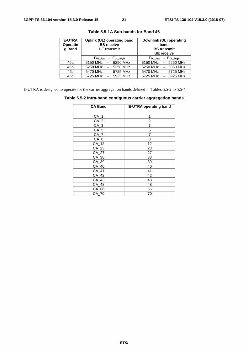
ETSI TS 136 104 V15.3.0 (2018-07)213GPP TS 36.104 version 15.3.0 Release 15
Table 5.5-1A Sub-bands for Band 46
E-UTRA Operating Band
Uplink (UL) operating band BS receive UE transmit
Downlink (DL) operating band
BS transmit UE receive
FUL_low – FUL_high FDL_low – FDL_high 46a 5150 MHz – 5250 MHz 5150 MHz – 5250 MHz 46b 5250 MHz – 5350 MHz 5250 MHz – 5350 MHz 46c 5470 MHz – 5725 MHz 5470 MHz – 5725 MHz 46d 5725 MHz – 5925 MHz 5725 MHz – 5925 MHz
E-UTRA is designed to operate for the carrier aggregation bands defined in Tables 5.5-2 to 5.5-4.
Table 5.5-2 Intra-band contiguous carrier aggregation bands
CA Band E-UTRA operating band
CA_1 1 CA_2 2 CA_3 3 CA_5 5 CA_7 7 CA_8 8 CA_12 12 CA_23 23 CA_27 27 CA_38 38 CA_39 39 CA_40 40 CA_41 41 CA_42 42 CA_43 43 CA_48 48 CA_66 66 CA_70 70

ETSI
ETSI TS 136 104 V15.3.0 (2018-07)223GPP TS 36.104 version 15.3.0 Release 15
Table 5.5-3. Inter-band carrier aggregation bands (two bands)

ETSI
ETSI TS 136 104 V15.3.0 (2018-07)233GPP TS 36.104 version 15.3.0 Release 15
CA Band E-UTRA operating bands
CA_1-3 1 3
CA_1-1-3 1 3
CA_1-3-3 1 3
CA_1-5 1 5
CA_1-1-5 1 5
CA_1-1-7 1 7
CA_1-7 1 7
CA_1-7-7 1 7
CA_1-8 1 8
CA_1-11 1 11
CA_1-18 1 18
CA_1-19 1 19
CA_1-20 1 20
CA_1-21 1 21
CA_1-26 1 26
CA_1-28 1 28
CA_1-1-28 1 28
CA_1-32 1 32
CA_1-38 1 38
CA_1-40 1 40
CA_1-41 1 41
CA_1-42 1 42
CA_1-42-42 1 42
CA_1-43 1 43
CA_1-46 1 46
CA_2-4 2 4
CA_2-2-4 2 4
CA_2-2-4-4 2 4
CA_2-4-4 2 4
CA_2-5 2 5
CA_2-2-5 2 5
CA_2-7 2

ETSI
ETSI TS 136 104 V15.3.0 (2018-07)243GPP TS 36.104 version 15.3.0 Release 15
7 CA_2-2-7 2
7 CA_2-7-7 2
7 CA_2-12 2
12 CA_2-2-12 2
12 CA_2-2-12-12 2
12 CA_2-12-12 2
12 CA_2-13 2
13 CA_2-2-13 2
13 CA_2-14 2
14
CA_2-2-14 2 14
CA_2-17 2 17
CA_2-28 2 28
CA_2-29 2 29
CA_2-2-29 2 29
CA_2-30 2 30
CA_2-2-30 2 30
CA_2-46 2 46
CA_2-2-46 2 46
CA_2-46-46 2 46
CA_2-48 2 48
CA_2-48-48 2 48
CA_2-49 2 49
CA_2-66 2 66
CA_2-2-66 2 66
CA_2-2-66-66 2 66
CA_2-66-66 2 66
CA_2-66-66-66 2 66
CA_2-71 2 71
CA_2-2-71 2 71
CA_3-5 3 5
CA_3-7 3 7
CA_3-3-7 3 7

ETSI
ETSI TS 136 104 V15.3.0 (2018-07)253GPP TS 36.104 version 15.3.0 Release 15
CA_3-3-7-7 3 7
CA_3-7-7 3 7
CA_3-8 3 8
CA_3-3-8 3 8
CA_3-11 3 11
CA_3-18 3 18
CA_3-19 3 19
CA_3-3-19 3 19
CA_3-20 3 20
CA_3-3-20 3 20
CA_3-21 3 21
CA_3-3-21 3 21
CA_3-26 3 26
CA_3-27 3 27
CA_3-28 3 28
CA_3-3-28 3 28
CA_3-31 3 31
CA_3-32 3 32
CA_3-38 3 38
CA_3-40 3 40
CA_3-40-40 3 40
CA_3-41 3 41
CA_3-3-41 3 41
CA_3-3-42 3 42
CA_3-42 3 42
CA_3-42-42 3 42
CA_3-43 3 43
CA_3-46 3 46
CA_3-3-46 3 46
CA_3-69 3 69
CA_4-5 4 5
CA_4-4-5 4 5
CA_4-7 4
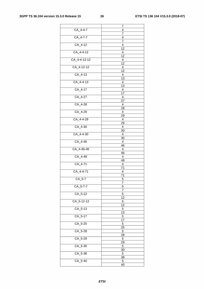
ETSI
ETSI TS 136 104 V15.3.0 (2018-07)263GPP TS 36.104 version 15.3.0 Release 15
7 CA_4-4-7 4
7 CA_4-7-7 4
7 CA_4-12 4
12 CA_4-4-12 4
12 CA_4-4-12-12 4
12 CA_4-12-12 4
12 CA_4-13 4
13 CA_4-4-13 4
13 CA_4-17 4
17 CA_4-27 4
27 CA_4-28 4
28 CA_4-29 4
29 CA_4-4-29 4
29 CA_4-30 4
30 CA_4-4-30 4
30 CA_4-46 4
46 CA_4-46-46 4
46 CA_4-48 4
48 CA_4-71 4
71 CA_4-4-71 4
71 CA_5-7 5
7 CA_5-7-7 5
7 CA_5-12 5
12 CA_5-12-12 5
12 CA_5-13 5
13 CA_5-17 5
17 CA_5-25 5
25 CA_5-28 5
28 CA_5-29 5
29 CA_5-30 5
30 CA_5-38 5
38 CA_5-40 5
40

ETSI
ETSI TS 136 104 V15.3.0 (2018-07)273GPP TS 36.104 version 15.3.0 Release 15
CA_5-5-40 5 40
CA_5-40-40 5 40
CA_5-41 5 41
CA_5-46 5 46
CA_5-48 5 48
CA_5-66 5 66
CA_5-5-66 5 66
CA_5-5-66-66 5 66
CA_5-66-66 5 66
CA_7-8 7 8
CA_7-7-8 7 8
CA_7-12 7 12
CA_7-20 7 20
CA_7-22 7 22
CA_7-26 7 26
CA_7-7-26 7 26
CA_7-28 7 28
CA_7-30 7 30
CA_7-32 7 32
CA_7-40 7 40
CA_7-42 7 42
CA_7-42-42 7 42
CA_7-46 7 46
CA_7-7-46 7 46
CA_7-66 7 66
CA_7-7-66 7 66
CA_7-66-66 7 66
CA_7-7-66-66 7 66
CA_8-11 8 11
CA_8-20 8 20
CA_8-27 8 27
CA_8-28 8 28
CA_8-32 8

ETSI
ETSI TS 136 104 V15.3.0 (2018-07)283GPP TS 36.104 version 15.3.0 Release 15
32 CA_8-38 8
38 CA_8-39 8
39 CA_8-40 8
40 CA_8-41 8
41 CA_8-42 8
42 CA_8-46 8
46 CA_11-18 11
18 CA_11-26 11
26 CA_11-28 11
28 CA_11-41 11
41 CA_11-42 11
42 CA_11-46 11
46 CA_12-25 12
25 CA_12-30 12
30 CA_12-46 12
46 CA_12-48 12
48 CA_12-66 12
66 CA_12-66-66 12
66 CA_13-46 13
46 CA_13-48 13
48 CA_13-48-48 13
48 CA_13-66 13
66 CA_13-66-66 13
66 CA_14-66 14
66 CA_14-66-66 14
66 CA_14-66-66-66 14
66 CA_14-30 14
30 CA_18-28 18
28 CA_19-21 19
21 CA_19-28 19
28 CA_19-42 19
42 CA_19-46 19
46
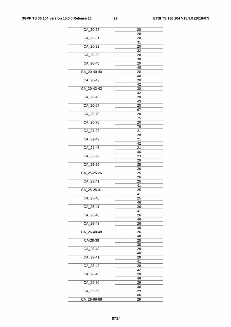
ETSI
ETSI TS 136 104 V15.3.0 (2018-07)293GPP TS 36.104 version 15.3.0 Release 15
CA_20-28 20 28
CA_20-31 20 31
CA_20-32 20 32
CA_20-38 20 38
CA_20-40 20 40
CA_20-40-40 20 40
CA_20-42 20 42
CA_20-42-42 20 42
CA_20-43 20 43
CA_20-67 20 67
CA_20-75 20 75
CA_20-76 20 76
CA_21-28 21 28
CA_21-42 21 42
CA_21-46 21 46
CA_23-29 23 29
CA_25-26 25 26
CA_25-25-26 25 26
CA_25-41 25 41
CA_25-25-41 25 41
CA_25-46 25 46
CA_26-41 26 41
CA_26-46 26 46
CA_26-48 26 48
CA_26-48-48 26 48
CA-28-38 28 38
CA_28-40 28 40
CA_28-41 28 41
CA_28-42 28 42
CA_28-46 28 46
CA_29-30 29 30
CA_29-66 29 66
CA_29-66-66 29

ETSI
ETSI TS 136 104 V15.3.0 (2018-07)303GPP TS 36.104 version 15.3.0 Release 15
66 CA_29-70 29
70 CA_30-66 30
66
CA_30-66-66 30 66
CA_32-42 32 42
CA_32-43 32 43
CA_34-39 34 39
CA_34-41 34 41
CA_38-40 38 40
CA_38-40-40 38 40
CA_39-40 39 40
CA_39-41 39 41
CA_39-42 39 42
CA_39-46 39 46
CA_40-41 40 41
CA_40-42 40 42
CA_40A-43A 40 43
CA_40-46 40 46
CA_41-42 41 42
CA_41-46 41 46
CA_41-48 41 48
CA_42-43 42 43
CA_42-46 42 46
CA_46-48 46 48
CA_46-66 46 66
CA_46-46-66 46 66
CA_46-48 46 48
CA_46-48-48 46 48
CA_46-66-66 46 66
CA_46-70 46 70
CA_46-71 46 71
CA_48-66 48 66
CA_48-66-66 48 66
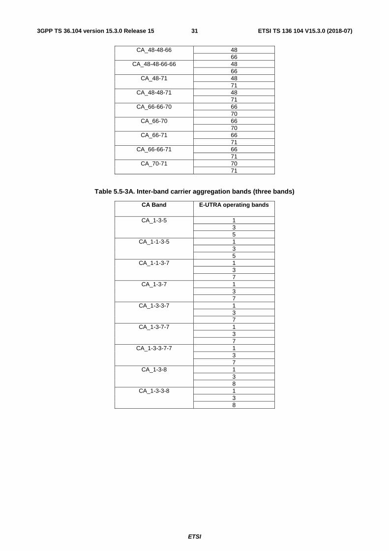
ETSI
ETSI TS 136 104 V15.3.0 (2018-07)313GPP TS 36.104 version 15.3.0 Release 15
CA_48-48-66 48 66
CA_48-48-66-66 48 66
CA_48-71 48 71
CA_48-48-71 48 71
CA_66-66-70 66 70
CA_66-70 66 70
CA_66-71 66 71
CA_66-66-71 66 71
CA_70-71 70 71
Table 5.5-3A. Inter-band carrier aggregation bands (three bands)
CA Band E-UTRA operating bands
CA_1-3-5 1 3 5
CA_1-1-3-5 1 3 5
CA_1-1-3-7 1 3 7
CA_1-3-7 1 3 7
CA_1-3-3-7 1 3 7
CA_1-3-7-7 1 3 7
CA_1-3-3-7-7 1 3 7
CA_1-3-8 1 3 8
CA_1-3-3-8 1 3 8
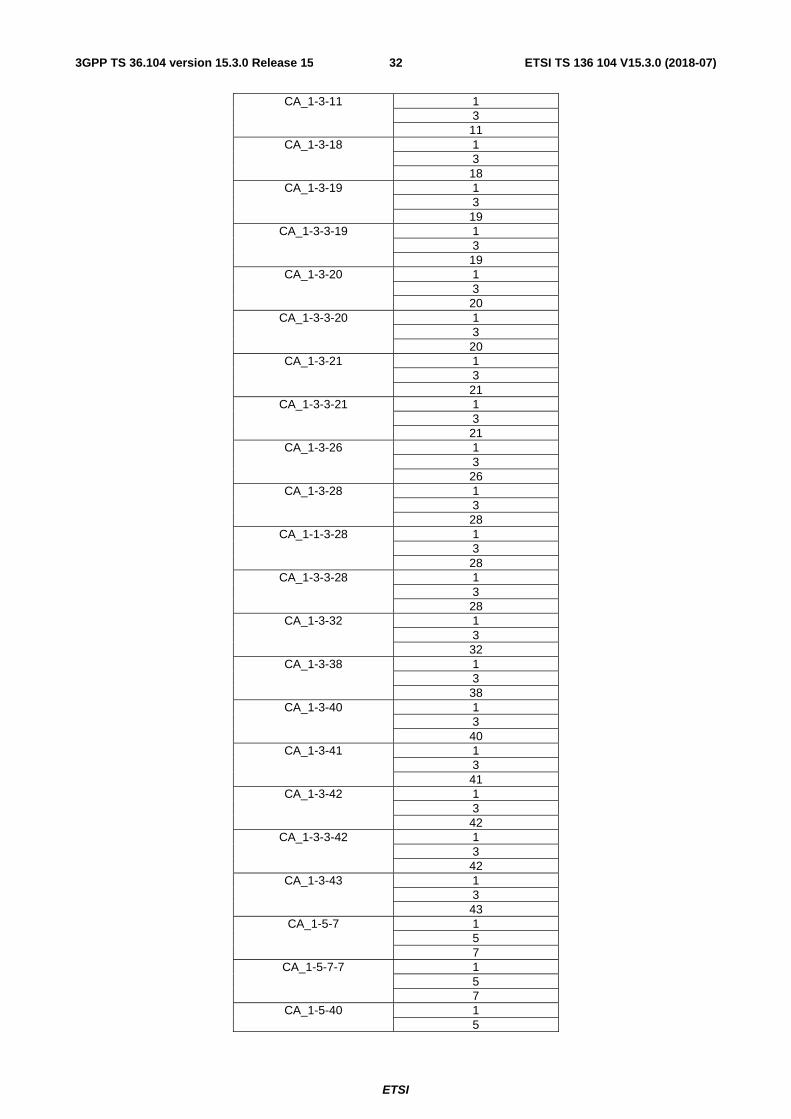
ETSI
ETSI TS 136 104 V15.3.0 (2018-07)323GPP TS 36.104 version 15.3.0 Release 15
CA_1-3-11 1 3 11
CA_1-3-18 1 3 18
CA_1-3-19 1 3 19
CA_1-3-3-19 1 3 19
CA_1-3-20 1 3 20
CA_1-3-3-20 1 3 20
CA_1-3-21 1 3 21
CA_1-3-3-21 1 3 21
CA_1-3-26 1 3 26
CA_1-3-28 1 3 28
CA_1-1-3-28 1 3 28
CA_1-3-3-28 1 3 28
CA_1-3-32 1 3 32
CA_1-3-38 1 3 38
CA_1-3-40 1 3 40
CA_1-3-41 1 3 41
CA_1-3-42 1 3 42
CA_1-3-3-42 1 3 42
CA_1-3-43 1 3 43
CA_1-5-7 1 5 7
CA_1-5-7-7 1 5 7
CA_1-5-40 1 5

ETSI
ETSI TS 136 104 V15.3.0 (2018-07)333GPP TS 36.104 version 15.3.0 Release 15
40 CA_1-5-41 1
5 41
CA_1-5-46 1 5 46
CA_1-7-8 1 7 8
CA_1-7-7-8 1 7 8
CA_1-7-20 1 7 20
CA_1-7-26 1 7 26
CA_1-7-7-26 1 7 26

ETSI
ETSI TS 136 104 V15.3.0 (2018-07)343GPP TS 36.104 version 15.3.0 Release 15
CA_1-7-28 1 7 28
CA_1-7-32 1 7 32
CA_1-7-40 1 7 40
CA_1-7-42 1 7 42
CA_1-7-46 1 7 46
CA_1-8-11 1 8 11
CA_1-8-20 1 8 20
CA_1-8-28 1 8 28
CA_1-8-38 1 8 38
CA_1-8-40 1 8 40
CA_1-11-18 1 11 18
CA_1-11-28 1 11 28
CA_1-18-28 1 18 28
CA_1-19-21 1 19 21
CA_1-19-28 1 19 28
CA_1-19-42 1 19 42
CA_1-20-28 1 20 28
CA_1-20-32 1 20 32
CA_1-20-42 1 20 42
CA_1-20-43 1 20 43
CA_1-21-28 1 21 28
CA_1-21-42 1 21

ETSI
ETSI TS 136 104 V15.3.0 (2018-07)353GPP TS 36.104 version 15.3.0 Release 15
42 CA_1-28-42 1
28 42
CA_1-32-42 1 32 42
CA_1-32-43 1 32 43
CA_1-41-42 1 41 42
CA_1-42-43 1 42 43
CA_2-4-5 2 4 5
CA_2-2-4-5 2 4 5
CA_2-4-4-5 2 4 5
CA_2-4-7 2 4 7
CA_2-4-7-7 2 4 7
CA_2-4-12 2 4 12
CA_2-2-4-12 2 4 12
CA_2-4-4-12 2 4 12
CA_2-4-12-12 2 4 12
CA_2-4-13 2 4 13
CA_2-4-28 2 4 28
CA_2-4-29 2 4 29
CA_2-4-30 2 4 30
CA_2-4-71 2 4 71
CA_2-2-4-71 2 4 71
CA_2-5-12 2 5 12
CA_2-2-5-12 2

ETSI
ETSI TS 136 104 V15.3.0 (2018-07)363GPP TS 36.104 version 15.3.0 Release 15
5 12
CA_2-5-12-12 2 5 12
CA_2-2-5-30 2 5 30
CA_2-2-12-30 2 12 30
CA_2-2-12-66 2 12 66
CA_2-2-12-66-66 2 12 66
CA_2-13-48-48 2 13 48
CA_2-2-14-66-66 2 14 66
CA_2-14-66-66-66 2 14 66
CA_2-2-30-66 2 30 66
CA_2-5-7 2 5 7
CA_2-5-13 2 5 13
CA_2-5-28 2 5 28
CA_2-5-29 2 5 29
CA_2-5-30 2 5 30
CA_2-5-46 2 5 46
CA_2-2-5-66 2 5 66
CA_2-2-5-66-66 2 5 66

ETSI
ETSI TS 136 104 V15.3.0 (2018-07)373GPP TS 36.104 version 15.3.0 Release 15
CA_2-5-66 2 5 66
CA_2-5-66-66 2 5 66
CA_2-7-12 2 7 12
CA_2-2-7-12 2 7 12
CA_2-7-28 2 7 28
CA_2-7-30 2 7 30
CA_2-7-46 2 7 46
CA_2-7-66 2 7 66
CA_2-2-7-66 2 7 66
CA_2-7-7-66 2 7 66
CA_2-7-66-66 2 7 66
CA_2-12-30 2 12 30
CA_2-12-66 2 12 66
CA_2-12-66-66 2 12 66
CA_2-2-13-66 2 13 66
CA_2-13-46 2 13 46
CA_2-13-48 2 13 48
CA_2-13-66 2 13 66
CA_2-13-66-66 2 13 66
CA_2-14-30 2 14 30
CA_2-2-14-30 2 14 30
CA_2-14-66 2 14

ETSI
ETSI TS 136 104 V15.3.0 (2018-07)383GPP TS 36.104 version 15.3.0 Release 15
66 CA_2-2-14-66 2
14 66
CA_2-14-66-66 2 14 66
CA_2-2-29-30 2 29 30
CA_2-29-30 2 29 30
CA_2-29-66 2 29 66
CA_2-30-66 2 30 66
CA_2-30-66-66 2 30 66
CA_2-46-48 2 46 48
CA_2-46-66 2 46 66
CA_2-46-46-66 2 46 66
CA_2-48-66 2 48 66
CA_2-48-48-66 2 48 66

ETSI
ETSI TS 136 104 V15.3.0 (2018-07)393GPP TS 36.104 version 15.3.0 Release 15
CA_2-66-71 2 66 71
CA_2-2-66-71 2 66 71
CA_3-5-7 3 5 7
CA_3-5-7-7 3 5 7
CA_3-5-40 3 5 40
CA_3-5-40-40 3 5 40
CA_3-5-41 3 5 41
CA_3-3-7-8 3 7 8
CA_3-7-7-8 3 7 8
CA_3-7-8 3 7 8
CA_3-3-7-7-8 3 7 8
CA_3-7-20 3 7 20
CA_3-3-7-20 3 7 20
CA_3-7-26 3 7 26
CA_3-7-7-26 3 7 26

ETSI
ETSI TS 136 104 V15.3.0 (2018-07)403GPP TS 36.104 version 15.3.0 Release 15
CA_3-7-28 3 7 28
CA_3-3-7-28 3 7 28
CA_3-7-32 3 7 32
CA_3-7-38 3 7 38
CA_3-7-40 3 7 40
CA_3-7-42 3 7 42
CA_3-7-46 3 7 46
CA_3-8-11 3 8 11
CA_3-8-20 3 8 20
CA_3-8-28 3 8 28
CA_3-8-32 3 8 32
CA_3-8-38 3 8 38
CA_3-8-40 3 8 40
CA_3-11-18 3 11 18
CA_3-11-26 3 11 26
CA_3-11-28 3 11 28
CA_3-19-21 3 19 21
CA_3-3-19-21 3 19 21
CA_3-19-42 3 19 42
CA_3-20-28 3 20 28
CA_3-3-20-28 3 20 28
CA_3-20-32 3 20
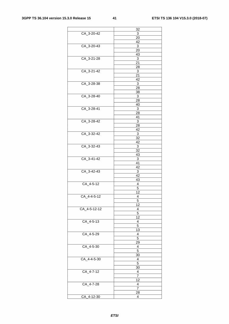
ETSI
ETSI TS 136 104 V15.3.0 (2018-07)413GPP TS 36.104 version 15.3.0 Release 15
32 CA_3-20-42 3
20 42
CA_3-20-43 3 20 43
CA_3-21-28 3 21 28
CA_3-21-42 3 21 42
CA_3-28-38 3 28 38
CA_3-28-40 3 28 40
CA_3-28-41 3 28 41
CA_3-28-42 3 28 42
CA_3-32-42 3 32 42
CA_3-32-43 3 32 43
CA_3-41-42 3 41 42
CA_3-42-43 3 42 43
CA_4-5-12 4 5 12
CA_4-4-5-12 4 5 12
CA_4-5-12-12 4 5 12
CA_4-5-13 4 5 13
CA_4-5-29 4 5 29
CA_4-5-30 4 5 30
CA_4-4-5-30 4 5 30
CA_4-7-12 4 7 12
CA_4-7-28 4 7 28
CA_4-12-30 4

ETSI
ETSI TS 136 104 V15.3.0 (2018-07)423GPP TS 36.104 version 15.3.0 Release 15
12 30
CA_4-4-12-30 4 12 30
CA_4-29-30 4 29 30
CA_4-4-29-30 4 29 30
CA_5-7-28 5 7 28
CA_5-7-46 5 7 46
CA_5-12-46 5 12 46
CA_5-12-48 5 12 48
CA_5-12-66 5 12 66
CA_5-30-66 5 30 66
CA_5-30-66-66 5 30 66
CA_5-40-41 5 40 41
CA_5-46-66 5 46 66
CA_7-8-20 7 8 20
CA_7-8-38 7 8 38
CA_7-8-40 7 8 40
CA_7-12-66 7 12 66
CA_7-20-28 7 20 28
CA_7-20-32 7 20 32
CA_7-20-38 7 20 38
CA_7-20-42 7 20 42
CA_7-28-38 7 28 38

ETSI
ETSI TS 136 104 V15.3.0 (2018-07)433GPP TS 36.104 version 15.3.0 Release 15
CA_7-30-66 7 30 66
CA_7-46-66 7 46 66
CA_8-11-28 8 11 28
CA_8-20-28 8 20 28
CA_8-28-41 8 28 41
CA_8-39-41 8 39 41
CA_12-30-66 12 30 66
CA_12-30-66-66 12 30 66
CA_13-46-66 13 46 66
CA_13-48-66 13 48 66
CA_13-48-48-66 13 48 66
CA_14-30-66 14 30 66
CA_14-30-66-66 14 30 66
CA_19-21-42 19 21 42
CA_20-32-42 20 32 42
CA_20-38-40 20 38 40
CA_20-38-40-40 20 38 40
CA_21-28-42 21 28 42
CA_25-26-41 25 26 41
CA_25-25-26-41 25 26 41
CA_28-41-42 28 41 42
CA_29-30-66 29 30
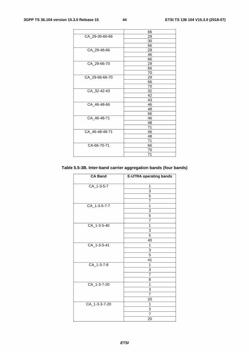
ETSI
ETSI TS 136 104 V15.3.0 (2018-07)443GPP TS 36.104 version 15.3.0 Release 15
66 CA_29-30-66-66 29
30 66
CA_29-46-66 29 46 66
CA_29-66-70 29 66 70
CA_29-66-66-70 29 66 70
CA_32-42-43 32 42 43
CA_46-48-66 46 48 66
CA_46-48-71 46 48 71
CA_46-48-48-71 46 48 71
CA-66-70-71 66 70 71
Table 5.5-3B. Inter-band carrier aggregation bands (four bands)
CA Band E-UTRA operating bands
CA_1-3-5-7 1 3 5 7
CA_1-3-5-7-7 1 3 5 7
CA_1-3-5-40 1 3 5 40
CA_1-3-5-41 1 3 5 41
CA_1-3-7-8 1 3 7 8
CA_1-3-7-20 1 3 7 20
CA_1-3-3-7-20 1 3 7 20
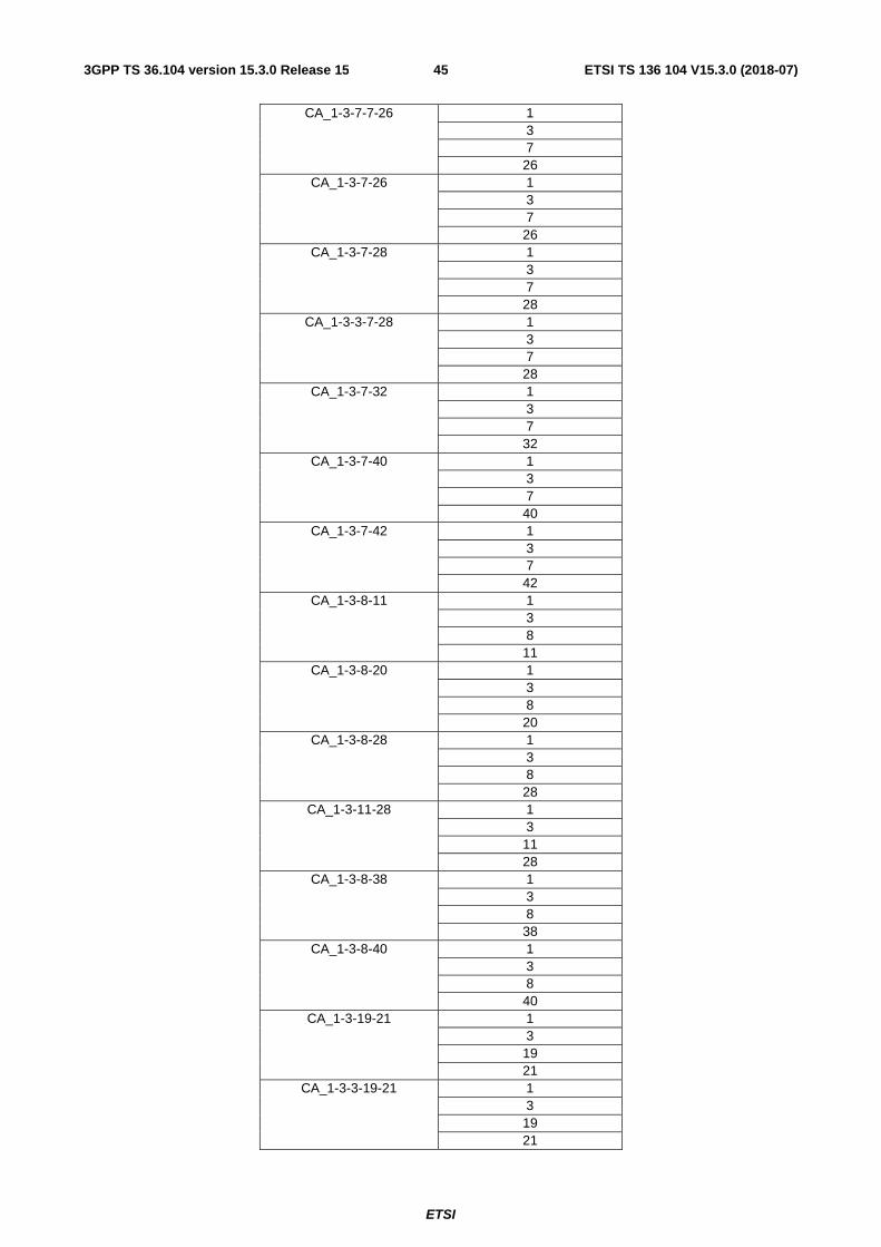
ETSI
ETSI TS 136 104 V15.3.0 (2018-07)453GPP TS 36.104 version 15.3.0 Release 15
CA_1-3-7-7-26 1 3 7 26
CA_1-3-7-26 1 3 7 26
CA_1-3-7-28 1 3 7 28
CA_1-3-3-7-28 1 3 7 28
CA_1-3-7-32 1 3 7 32
CA_1-3-7-40 1 3 7 40
CA_1-3-7-42 1 3 7 42
CA_1-3-8-11 1 3 8 11
CA_1-3-8-20 1 3 8 20
CA_1-3-8-28 1 3 8 28
CA_1-3-11-28 1 3 11 28
CA_1-3-8-38 1 3 8 38
CA_1-3-8-40 1 3 8 40
CA_1-3-19-21 1 3 19 21
CA_1-3-3-19-21 1 3 19 21

ETSI
ETSI TS 136 104 V15.3.0 (2018-07)463GPP TS 36.104 version 15.3.0 Release 15
CA_1-3-19-42 1 3 19 42
CA_1-3-20-28 1 3 20 28
CA_1-3-3-20-28 1 3 20 28
CA_1-3-20-32 1 3 20 32
CA_1-3-20-42 1 3 20 42
CA_1-3-20-43 1 3 20 43
CA_1-3-21-28 1 3 21 28
CA_1-3-21-42 1 3 21 42
CA_1-3-28-42 1 3 28 42
CA_1-3-32-42 1 3 32 42
CA_1-3-32-43 1 3 32 43
CA_1-3-42-43 1 3 42 43
CA_1-5-7-46 1 5 7 46
CA_1-7-8-20 1 7 8 20
CA_1-7-8-40 1 7 8 40

ETSI
ETSI TS 136 104 V15.3.0 (2018-07)473GPP TS 36.104 version 15.3.0 Release 15
CA_1-7-20-28 1 7 20 28
CA_1-7-20-32 1 7 20 32
CA_1-7-20-42 1 7 20 42
CA_1-8-11-28 1 8 11 28
CA_1-8-20-28 1 8 20 28
CA_1-19-21-42 1 19 21 42
CA_1-20-32-42 1 20 32 42
CA_1-20-32-43 1 20 32 43
CA_1-21-28-42 1 21 28 42
CA_1-32-42-43 1 32 42 43
CA_2-4-5-12 2 4 5 12
CA_2-4-5-29 2 4 5 29
CA_2-4-5-30 2 4 5 30
CA_2-4-7-12 2 4 7 12
CA_2-4-12-30 2 4 12 30
CA_2-4-29-30 2
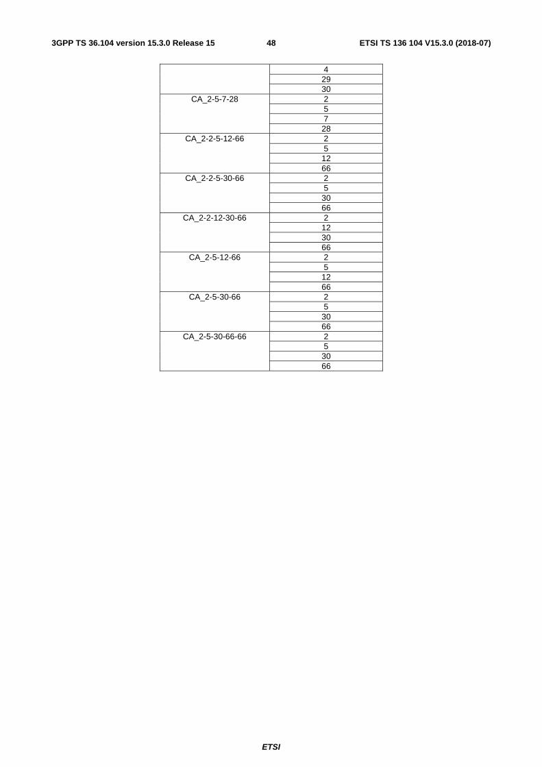
ETSI
ETSI TS 136 104 V15.3.0 (2018-07)483GPP TS 36.104 version 15.3.0 Release 15
4 29 30
CA_2-5-7-28 2 5 7 28
CA_2-2-5-12-66 2 5 12 66
CA_2-2-5-30-66 2 5 30 66
CA_2-2-12-30-66 2 12 30 66
CA_2-5-12-66 2 5 12 66
CA_2-5-30-66 2 5 30 66
CA_2-5-30-66-66 2 5 30 66

ETSI
ETSI TS 136 104 V15.3.0 (2018-07)493GPP TS 36.104 version 15.3.0 Release 15
CA_2-7-12-66 2 7 12 66
CA_2-2-7-12-66 2 7 12 66
CA_2-7-46-66 2 7 46 66
CA_2-12-30-66 2 12 30 66
CA_2-12-30-66-66 2 12 30 66
CA_2-13-48-66 2 13 48 66
CA_2-13-48-48-66 2 13 48 66
CA_2-14-30-66 2 14 30 66
CA_2-2-14-30-66 2 14 30 66
CA_2-14-30-66-66 2 14 30 66
CA_2-29-30-66 2 29 30 66
CA_2-46-48-66 2 46 48 66
CA_3-7-8-20 3 7 8 20
CA_3-7-8-40 3 7 8 40
CA_3-7-20-28 3 7 20 28
CA_3-7-20-32 3 7 20 32
CA_3-7-20-42 3

ETSI
ETSI TS 136 104 V15.3.0 (2018-07)503GPP TS 36.104 version 15.3.0 Release 15
7 20 42
CA_3-7-8-38 3 7 8 38
CA_3-7-28-38 3 7 28 38
CA_3-8-11-28 3 8 11 28
CA_3-8-20-28 3 8 20 28
CA_3-19-21-42 3 19 21 42
CA_3-20-32-42 3 20 32 42
CA_3-20-32-43 3 20 32 43
CA_3-21-28-42 3 21 28 42
CA_3-28-41-42 3 28 41 42
CA_3-32-42-43 3 32 42 43
Table 5.5-3C. Inter-band carrier aggregation bands (five bands)
CA Band E-UTRA operating bands

ETSI
ETSI TS 136 104 V15.3.0 (2018-07)513GPP TS 36.104 version 15.3.0 Release 15
CA_1-3-7-20-28 1 3 7 20 28
CA_1-3-7-20-42 1 3 7 20 42
CA_1-3-8-11-28 1 3 8 11 28
CA_1-3-20-32-42 1 3 20 32 42
CA_1-3-20-32-43 1 3 20 32 43
CA_1-3-32-42-43 1 3 32 42 43
Table 5.5-4. Intra-band non-contiguous carrier aggregation bands (with two sub-blocks)
CA Band E-UTRA operating band
CA_1-1 1 CA_2-2 2 CA_3-3 3 CA_4-4 4 CA_5-5 5 CA_7-7 7
CA_12-12 12 CA_23-23 23 CA_25-25 25 CA_40-40 40 CA_41-41 41 CA_42-42 42 CA_43-43 43 CA_48-48 48 CA_66-66 66
Table 5.5-5. Intra-band non-contiguous carrier aggregation bands (with three sub-blocks)
CA Band E-UTRA operating band
CA_25-25-25 25 CA_41-41-41 41 CA_48-48-48 48 CA_66-66-66 66
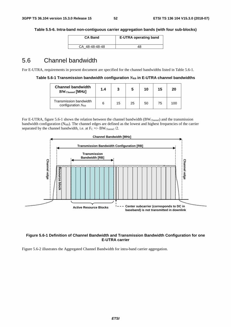
ETSI
ETSI TS 136 104 V15.3.0 (2018-07)523GPP TS 36.104 version 15.3.0 Release 15
Table 5.5-6. Intra-band non-contiguous carrier aggregation bands (with four sub-blocks)
CA Band E-UTRA operating band
CA_48-48-48-48 48
5.6 Channel bandwidth For E-UTRA, requirements in present document are specified for the channel bandwidths listed in Table 5.6-1.
Table 5.6-1 Transmission bandwidth configuration NRB in E-UTRA channel bandwidths
Channel bandwidth BWChannel [MHz] 1.4 3 5 10 15 20
Transmission bandwidth configuration NRB 6 15 25 50 75 100
For E-UTRA, figure 5.6-1 shows the relation between the channel bandwidth (BWChannel) and the transmission bandwidth configuration (NRB). The channel edges are defined as the lowest and highest frequencies of the carrier separated by the channel bandwidth, i.e. at FC +/- BWChannel /2.
Figure 5.6-1 Definition of Channel Bandwidth and Transmission Bandwidth Configuration for one E-UTRA carrier
Figure 5.6-2 illustrates the Aggregated Channel Bandwidth for intra-band carrier aggregation.
TransmissionBandwidth [RB]
Transmission Bandwidth Configuration [RB]
Channel Bandwidth [MHz]
Center subcarrier (corresponds to DC in baseband) is not transmitted in downlink
Active Resource Blocks
Ch
ann
el edg
e
Ch
ann
el edg
e
Reso
urce b
lock

ETSI
ETSI TS 136 104 V15.3.0 (2018-07)533GPP TS 36.104 version 15.3.0 Release 15
Figure 5.6-2 Definition of Aggregated Channel Bandwidth for intra-band carrier aggregation
The lower edge of the Aggregated Channel Bandwidth (BWChannel_CA) is defined as Fedge_low = FC_low - Foffset. The upper edge of the Aggregated Channel Bandwidth is defined as Fedge_high = FC_high + Foffset. The Aggregated Channel Bandwidth, BWChannel_CA, is defined as follows:
BWChannel_CA = Fedge_high - Fedge_low [MHz]
Figure 5.6-3 illustrates the sub-block bandwidth for a BS operating in non-contiguous spectrum
Figure 5.6-3 Definition of sub-block bandwidth for intra-band non-contiguous spectrum
The lower sub-block edge of the sub-block bandwidth (BWChannel,block) is defined as Fedge,block, low = FC,block,low - Foffset. The upper sub-block edge of the sub-block bandwidth is defined as Fedge,block,high = FC,block,high + Foffset. The sub-block bandwidth, BWChannel,block, is defined as follows:
BWChannel,block = Fedge,block,high - Fedge,block,low [MHz]
Foffset is defined in Table 5.6-2 below where BWChannel is defined in Table 5.6-1.
FC_low
Lo
wer E
dg
e
Up
per E
dg
e
Lowest Carrier Transmission Bandwidth
Configuration [RB]
FC_high
Foffset
Highest Carrier Transmission Bandwidth
Configuration [RB]
Reso
urce b
lock
Aggregated Channel Bandwidth, BWchannel_CA [MHz]
Fedge_low Fedge_high For each carrier, the center sub carrier (corresponds to DC in baseband) is not transmitted in downlink
Foffset
FC,block 1,low
... L
ow
er Su
b-blo
ck Edg
e
Up
per S
ub-b
lock E
dge
Transmission Bandwidth
Configuration of the lowest carrier in a sub-
block [RB]
Foffset
Transmission Bandwidth
Configuration of the highest carrier in a
sub-block [RB]
Reso
urce b
lock
Sub-block Bandwidth, BWChannel,block [MHz]
Fedge,block 1, low Fedge,block 1,high For each carrier, the center sub carrier (corresponds to DC in
baseband) is not transmitted in downlink
Foffset
Sub block n Sub block 1
Base Station RF Bandwidth
FC,block n,low
Lo
wer S
ub
-blo
ck Ed
ge
Up
per S
ub
-blo
ck Edg
e
Transmission Bandwidth
Configuration of the lowest carrier in a
sub-block [RB]
FC,block n,high Foffset
Transmission Bandwidth
Configuration of the highest carrier in a
sub-block [RB]
Res
ou
rce blo
ck
Sub-block Bandwidth, BWChannel,block [MHz]
Fedge,block n,high For each carrier, the center sub
carrier (corresponds to DC in baseband) is not transmitted in
downlink
Foffset

ETSI
ETSI TS 136 104 V15.3.0 (2018-07)543GPP TS 36.104 version 15.3.0 Release 15
Table 5.6-2: Definition of Foffset
Channel Bandwidth of the Lowest or Highest Carrier: BWChannel[MHz]
Foffset[MHz]
5, 10, 15, 20 BWChannel/2
NOTE 1: Foffset is calculated separately for each Base Station RF Bandwidth edge / sub-block edge.
NOTE 2: The values of BWChannel_CA/BWChannel,block for UE and BS are the same if the channel bandwidths of lowest and the highest component carriers are identical.
For NB-IoT, requirements in present document are specified for the channel bandwidths listed in Table 5.6-3.
Table 5.6-3: Transmission bandwidth configuration NRB, Ntone 15kHz and Ntone 3.75kHz in NB-IoT channel bandwidth
NB-IoT Standalone In-band Guard Band
Channel bandwidth BWChannel [kHz] 200
E-UTRA channel bandwidth in Table
5.6-1 for BWChannel>1.4MHz
E-UTRA channel bandwidth in Table 5.6-1 for BWChannel
>3MHz
Transmission bandwidth configuration NRB 1 1 1
Transmission bandwidth configuration Ntone 15kHz
12 12 12
Transmission bandwidth configuration Ntone 3.75kHz
48 48 48
For NB-IoT standalone operation, figure 5.6-4 shows the relation between the channel bandwidth (BWChannel) and the transmission bandwidth configuration (NRB, Ntone 15kHz and Ntone 3.75kHz) for NB-IoT standalone operation. The channel edges are defined as the lowest and highest frequencies of the carrier separated by the channel bandwidth, i.e. at FC +/- BWChannel /2.
For NB-IoT standalone operation, NB-IoT requirements for receiver and transmitter shall apply with a frequency offset Foffset as defined in Table 5.6-3A.
Table 5.6-3A: Foffset for NB-IoT standalone operation
Lowest or Highest Carrier Foffset Standalone NB-IoT 200 kHz

ETSI
ETSI TS 136 104 V15.3.0 (2018-07)553GPP TS 36.104 version 15.3.0 Release 15
Figure 5.6-4 Definition of Channel Bandwidth and Transmission Bandwidth Configuration for NB-IoT standalone operation
For NB-IoT in-band operation, figure 5.6-5 shows the relation between the channel bandwidth (BWChannel) and the transmission bandwidth configuration (NRB, Ntone 15kHz and Ntone 3.75kHz) . The channel edges are defined as the lowest and highest frequencies of the carrier separated by the channel bandwidth, i.e. at FC +/- BWChannel /2.
Figure 5.6-5 Definition of Channel Bandwidth and Transmission Bandwidth Configuration for NB-IoT in-band operation
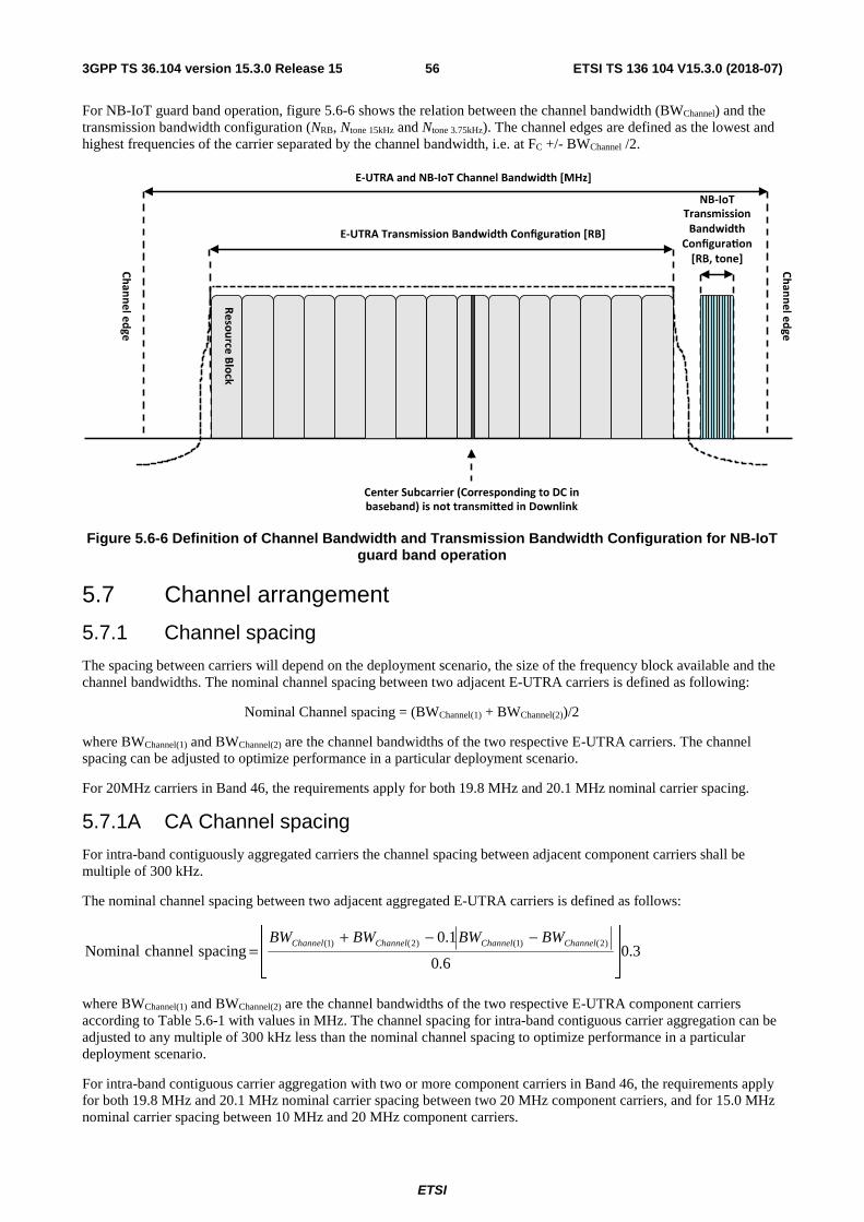
ETSI
ETSI TS 136 104 V15.3.0 (2018-07)563GPP TS 36.104 version 15.3.0 Release 15
For NB-IoT guard band operation, figure 5.6-6 shows the relation between the channel bandwidth (BWChannel) and the transmission bandwidth configuration (NRB, Ntone 15kHz and Ntone 3.75kHz). The channel edges are defined as the lowest and highest frequencies of the carrier separated by the channel bandwidth, i.e. at FC +/- BWChannel /2.
Figure 5.6-6 Definition of Channel Bandwidth and Transmission Bandwidth Configuration for NB-IoT guard band operation
5.7 Channel arrangement
5.7.1 Channel spacing
The spacing between carriers will depend on the deployment scenario, the size of the frequency block available and the channel bandwidths. The nominal channel spacing between two adjacent E-UTRA carriers is defined as following:
Nominal Channel spacing = (BWChannel(1) + BWChannel(2))/2
where BWChannel(1) and BWChannel(2) are the channel bandwidths of the two respective E-UTRA carriers. The channel spacing can be adjusted to optimize performance in a particular deployment scenario.
For 20MHz carriers in Band 46, the requirements apply for both 19.8 MHz and 20.1 MHz nominal carrier spacing.
5.7.1A CA Channel spacing
For intra-band contiguously aggregated carriers the channel spacing between adjacent component carriers shall be multiple of 300 kHz.
The nominal channel spacing between two adjacent aggregated E-UTRA carriers is defined as follows:
3.06.0
1.0 spacingchannelNominal
)2()1()2()1(
−−+= ChannelChannelChannelChannel BWBWBWBW
where BWChannel(1) and BWChannel(2) are the channel bandwidths of the two respective E-UTRA component carriers according to Table 5.6-1 with values in MHz. The channel spacing for intra-band contiguous carrier aggregation can be adjusted to any multiple of 300 kHz less than the nominal channel spacing to optimize performance in a particular deployment scenario.
For intra-band contiguous carrier aggregation with two or more component carriers in Band 46, the requirements apply for both 19.8 MHz and 20.1 MHz nominal carrier spacing between two 20 MHz component carriers, and for 15.0 MHz nominal carrier spacing between 10 MHz and 20 MHz component carriers.

ETSI
ETSI TS 136 104 V15.3.0 (2018-07)573GPP TS 36.104 version 15.3.0 Release 15
5.7.2 Channel raster
The channel raster is 100 kHz for all bands, which means that the carrier centre frequency must be an integer multiple of 100 kHz.
5.7.3 Carrier frequency and EARFCN
The carrier frequency in the uplink and downlink is designated by the E-UTRA Absolute Radio Frequency Channel Number (EARFCN) in the range 0 - 262143. The relation between EARFCN and the carrier frequency in MHz for the downlink is given by the following equation, where FDL_low and NOffs-DL are given in table 5.7.3-1 and NDL is the downlink EARFCN.
FDL = FDL_low + 0.1(NDL – NOffs-DL)
The relation between EARFCN and the carrier frequency in MHz for the uplink is given by the following equation where FUL_low and NOffs-UL are given in table 5.7.3-1 and NUL is the uplink EARFCN.
FUL = FUL_low + 0.1(NUL – NOffs-UL)
The carrier frequency of NB-IoT in the downlink is designated by the E-UTRA Absolute Radio Frequency Channel Number (EARFCN) in the range 0 – 262143 and the Offset of NB-IoT Channel Number to EARFCN in the range {-10,-9,-8,-7,-6,-5,-4,-3,-2,-1,-0.5,0,1,2,3,4,5,6,7,8,9}. The relation between EARFCN, Offset of NB-IoT Channel Number to EARFCN and the carrier frequency in MHz for the downlink is given by the following equation, where FDL is the downlink carrier frequency of NB-IoT, FDL_low and NOffs-DL are given in table 5.7.3-1, NDL is the downlink EARFCN, MDL is the Offset of NB-IoT Channel Number to downlink EARFCN.
FDL = FDL_low + 0.1(NDL – NOffs-DL) + 0.0025*(2MDL+1)
The carrier frequency of NB-IoT in the uplink is designated by the E-UTRA Absolute Radio Frequency Channel Number (EARFCN) in the range 0 –262143 and the Offset of NB-IoT Channel Number to EARFCN in the range {-10,-9,-8,-7,-6,-5,-4,-3,-2,-1,0,1,2,3,4,5,6,7,8,9}. The relation between EARFCN, Offset of NB-IoT Channel Number to EARFCN and the carrier frequency in MHz for the uplink is given by the following equation, where FUL is the uplink carrier frequency of NB-IoT, FUL_low and NOffs-UL are given in table 5.7.3-1, NUL is the uplink EARFCN, MUL is the Offset of NB-IoT Channel Number to uplink EARFCN.
FUL = FUL_low + 0.1(NUL – NOffs-UL) + 0.0025*(2MUL)
NOTE 1: For NB-IoT, NDL or NUL is different than the value of EARFCN that corresponds to E-UTRA downlink or uplink carrier frequency for in-band and guard band operation.
NOTE 2: MDL = -0.5 is not applicable for in-band and guard band operation.
NOTE 3: For the carrier including NPSS/NSSS for in-band and guard band operation, MDL is selected from {-2,-1,0,1}.
NOTE 4: For the carrier including NPSS/NSSS for stand-alone operation, MDL = -0.5.
ETSI
ETSI TS 136 104 V15.3.0 (2018-07)583GPP TS 36.104 version 15.3.0 Release 15
Table 5.7.3-1: E-UTRA channel numbers

ETSI
ETSI TS 136 104 V15.3.0 (2018-07)593GPP TS 36.104 version 15.3.0 Release 15
E-UTRA Operating
Band
Downlink Uplink FDL_low [MHz] NOffs-DL Range of NDL FUL_low [MHz] NOffs-UL Range of NUL
1 2110 0 0 – 599 1920 18000 18000 – 18599 2 1930 600 600 − 1199 1850 18600 18600 – 19199 3 1805 1200 1200 – 1949 1710 19200 19200 – 19949 4 2110 1950 1950 – 2399 1710 19950 19950 – 20399 5 869 2400 2400 – 2649 824 20400 20400 – 20649 6 875 2650 2650 – 2749 830 20650 20650 – 20749 7 2620 2750 2750 – 3449 2500 20750 20750 – 21449 8 925 3450 3450 – 3799 880 21450 21450 – 21799 9 1844.9 3800 3800 – 4149 1749.9 21800 21800 – 22149 10 2110 4150 4150 – 4749 1710 22150 22150 – 22749 11 1475.9 4750 4750 – 4949 1427.9 22750 22750 – 22949 12 729 5010 5010 – 5179 699 23010 23010 – 23179 13 746 5180 5180 – 5279 777 23180 23180 – 23279 14 758 5280 5280 – 5379 788 23280 23280 – 23379 … 17 734 5730 5730 – 5849 704 23730 23730 – 23849 18 860 5850 5850 – 5999 815 23850 23850 – 23999 19 875 6000 6000 – 6149 830 24000 24000 – 24149 20 791 6150 6150 - 6449 832 24150 24150 - 24449 21 1495.9 6450 6450 – 6599 1447.9 24450 24450 – 24599 22 3510 6600 6600-7399 3410 24600 24600-25399 23 2180 7500 7500 – 7699 2000 25500 25500 – 25699 24 1525 7700 7700 – 8039 1626.5 25700 25700 – 26039 25 1930 8040 8040 - 8689 1850 26040 26040 - 26689 26 859 8690 8690 – 9039 814 26690 26690 - 27039 27 852 9040 9040 – 9209 807 27040 27040 – 27209 28 758 9210 9210 – 9659 703 27210 27210 – 27659 29
(NOTE 2) 717 9660 9660 – 9769 N/A
30 2350 9770 9770 – 9869 2305 27660 27660 – 27759 31 462.5 9870 9870 – 9919 452.5 27760 27760 – 27809 32
(NOTE 2) 1452 9920 9920 – 10359 N/A
33 1900 36000 36000 – 36199 1900 36000 36000 – 36199 34 2010 36200 36200 – 36349 2010 36200 36200 – 36349 35 1850 36350 36350 – 36949 1850 36350 36350 – 36949 36 1930 36950 36950 – 37549 1930 36950 36950 – 37549 37 1910 37550 37550 – 37749 1910 37550 37550 – 37749 38 2570 37750 37750 – 38249 2570 37750 37750 – 38249 39 1880 38250 38250 – 38649 1880 38250 38250 – 38649 40 2300 38650 38650 – 39649 2300 38650 38650 – 39649 41 2496 39650 39650 – 41589 2496 39650 39650 – 41589 42 3400 41590 41590 – 43589 3400 41590 41590 – 43589 43 3600 43590 43590 – 45589 3600 43590 43590 – 45589 44 703 45590 45590 – 46589 703 45590 45590 – 46589 45 1447 46590 46590 – 46789 1447 46590 46590 – 46789 46
(NOTE 3) 5150 46790 46790 – 54539 5150 46790 46790 – 54539
47 5855 54540 54540 – 55239 5855 54540 54540 – 55239 48 3550 55240 55240 – 56739 3550 55240 55240 – 56739 49 3550 56740 56740 – 58239 3550 56740 56740 – 58239 50 1432 58240 58240 - 59089 1432 58240 58240 - 59089 51 1427 59090 59090 - 59139 1427 59090 59090 - 59139 52 3300 59140 59140 - 60139 3300 59140 59140 - 60139 65 2110 65536 65536 – 66435 1920 131072 131072 –
131971 66
(NOTE 4) 2110 66436 66436 – 67335 1710 131972 131972 –
132671 67
(NOTE 2) 738 67336 67336 - 67535 N/A
68 753 67536 67536 - 67835 698 132672 132672 - 132971

ETSI
ETSI TS 136 104 V15.3.0 (2018-07)603GPP TS 36.104 version 15.3.0 Release 15
69 (NOTE 2)
2570 67836 67836 - 68335 N/A
70 (NOTE 5)
1995 68336 68336 - 68585 1695 132972 132972 - 133121
71 617 68586 68586-68935 663 133122 133122-133471 72 461 68936 68936-68985 451 133472 133472-133521 73 460 68986 68986-69035 450 133522 133522-133571 74 1475 69036 69036 - 69465 1427 133572 133572 -
134001 75
(NOTE 2) 1432 69466 69466 - 70315 N/A
76
(NOTE 2) 1427 70316 70316 - 70365 N/A
85 728 70366 70366 - 70545 698 134002 134002 -
134181 NOTE 1: The channel numbers that designate carrier frequencies so close to the operating band edges that the
carrier extends beyond the operating band edge shall not be used. This implies that the first 7, 15, 25, 50, 75 and 100 channel numbers at the lower operating band edge and the last 6, 14, 24, 49, 74 and 99 channel numbers at the upper operating band edge shall not be used for channel bandwidths of 1.4, 3, 5, 10, 15 and 20 MHz respectively.
NOTE 2: Restricted to E-UTRA operation when carrier aggregation is configured. NOTE 3: The following NDL and NUL are allowed for operation in Band 46 assuming 20MHz channel bandwidth:
NDL =NUL = {n-2, n-1, n, n+1, n+2 | n = 46890 (5160 MHz), 47090 (5180 MHz), 47290 (5200 MHz), 47490 (5220 MHz), 47690 (5240 MHz), 47890 (5260 MHz), 48090 (5280 MHz), 48290 (5300 MHz), 48490 (5320 MHz), 48690 (5340 MHz), 50090 (5480 MHz), 50290 (5500 MHz), 50490 (5520 MHz), 50690 (5540 MHz), 50890 (5560 MHz), 51090 (5580 MHz), 51290 (5600 MHz), 51490 (5620 MHz), 51690 (5640 MHz), 51890 (5660 MHz), 52090 (5680 MHz), 52290 (5700 MHz), 52490 (5720 MHz), 52740 (5745 MHz), 52940 (5765 MHz), 53140 (5785 MHz), 53340 (5805 MHz), 53540 (5825 MHz), 53740 (5845 MHz), 53940 (5865 MHz), 54140 (5885 MHz), 54340 (5905 MHz)}. And the following NDL and NUL are allowed for operation in Band 46 assuming 10MHz channel bandwidth: NDL =NUL = {n-2, n-1, n, n+1, n+2 | n = 52590 (5730 MHz), 53590 (5830 MHz)}. 10 MHz channel bandwidth shall only apply in certain regions where the absence of non 3GPP technologies can be guaranteed on a long term basis in this version of specification.
NOTE 4: Downlink frequency range 2180 – 2200 MHz is restricted to E-UTRA operation when carrier aggregation is configured.
NOTE 5: The range 2010-2020 MHz of the DL operating band is restricted to E-UTRA operation when carrier aggregation is configured and TX-RX separation is 300 MHz. The range 2005-2020 MHz of the DL operating band is restricted to E-UTRA operation when carrier aggregation is configured and TX-RX separation is 295 MHz.
5.7.4 EARFCN sets for uplink transmissions on multiple Scells configured in Band 46
On a configured set of carriers with carrier frequencies that are a subset of any of the following sets of EARFCN, if the eNB schedules a UE to transmit in a subframe on the configured set of carriers, and if the UL grants scheduling PUSCH transmissions on any of the said set of carriers indicate Type 1 channel access procedure, and if the same ‘PUSCH starting position’ is indicated for all carriers, transmissions in accordance with the conditions for Type 2 channel access specified in clause 15.2.1 of [11] are allowed:
- for sets of two Scells: {47090, 47290}, {47490, 47690}, {47890, 48090}, {48290, 48490}, {50290, 50490}, {50690, 50890}, {51090, 51290}, {51490, 51690}, {51890, 52090}
- for sets of four Scells: {47090, 47290, 47490, 47690}, {47890, 48090, 48290, 48490}, {50290, 50490, 50690, 50890}, {51090, 51290, 51490, 51690}
- [for sets of eight Scells: {47090, 47290, 47490, 47690, 47890, 48090, 48290, 48490}, {50290, 50490, 50690, 50890, 51090, 51290, 51490, 51690}]
5.8 Requirements for contiguous and non-contiguous spectrum A spectrum allocation where the BS operates can either be contiguous or non-contiguous. Unless otherwise stated, the requirements in the present specification apply for BS configured for both contiguous spectrum operation and non-contiguous spectrum operation.

ETSI
ETSI TS 136 104 V15.3.0 (2018-07)613GPP TS 36.104 version 15.3.0 Release 15
For BS operation in non-contiguous spectrum, some requirements apply also inside the sub-block gaps. For each such requirement, it is stated how the limits apply relative to the sub-block edges.
6 Transmitter characteristics
6.1 General Unless otherwise stated, the requirements in clause 6 are expressed for a single transmitter antenna connector. In case of multi-carrier transmission with one or multiple transmitter antenna connectors, transmit diversity or MIMO transmission, the requirements apply for each transmitter antenna connector.
Unless otherwise stated, the transmitter characteristics are specified at the BS antenna connector (test port A) with a full complement of transceivers for the configuration in normal operating conditions. If any external apparatus such as a TX amplifier, a filter or the combination of such devices is used, requirements apply at the far end antenna connector (port B).
Unless otherwise stated the requirements in clause 6 applies at all times, i.e. during the Transmitter ON period, the Transmitter OFF period and the Transmitter transient period.
Unless otherwise stated the requirements for NB-IoT in clause 6 applies for all operation modes (In-band operation, Guard-band operation and Stand-alone operation).
Figure 6.1-1: Transmitter test ports
6.2 Base station output power Output power, Pout, of the base station is the mean power of one carrier delivered to a load with resistance equal to the nominal load impedance of the transmitter.
Rated total output power of the base station is the mean power for BS operating in single carrier, multi-carrier, or carrier aggregation configurations that the manufacturer has declared to be available at the antenna connector during the transmitter ON period.
Maximum output power (Pmax,c) of the base station is the mean power level per carrier measured at the antenna connector during the transmitter ON period in a specified reference condition.
Rated output power, Prated,c, of the base station is the mean power level per carrier for BS operating in single carrier, multi-carrier, or carrier aggregation configurations that the manufacturer has declared to be available at the antenna connector during the transmitter ON period.
NOTE: Different Prated,c may be declared for different configurations.
NOTE: For NB-IoT in-band and guard band operation, the LTE carrier and NB-IoT carrier shall be seen as a single carrier occupied LTE channel bandwidth, the output power over this carrier is shared between LTE and NB-IoT. This note is applied for Pout, Rated total output power, Pmax,c and Prated,c.
The rated output power, Prated,c, of the BS shall be as specified in Table 6.2-1.
BS
cabinet
Test port A Test port B
External device
e.g. TX filter
(if any)
External PA
(if any)
Towards antenna connector

ETSI
ETSI TS 136 104 V15.3.0 (2018-07)623GPP TS 36.104 version 15.3.0 Release 15
Table 6.2-1: Base Station rated output power
BS class Prated,c Wide Area BS - (note)
Medium Range BS < + 38 dBm
Local Area BS < + 24 dBm Home BS < + 20 dBm (for one transmit
antenna port) < + 17 dBm (for two transmit
antenna ports) < + 14dBm (for four transmit
antenna ports) < + 11dBm (for eight transmit
antenna ports) NOTE: There is no upper limit for the rated output power of the Wide Area
Base Station.
In addition for Band 46 operation, the BS may have to comply with the applicable BS power limits established regionally, when deployed in regions where those limits apply and under the conditions declared by the manufacturer. The regional requirements may be in the form of conducted power, power spectral density, EIRP and other types of limits. In case of regulatory limits based on EIRP, assessment of the EIRP level is described in Annex H.
In addition for Band 49 operation in US, the BS EIRP power limit established by FCC for Category A CBSDs (Citizens Broadband Radio Service Devices) applies. Assessment of the EIRP level is described in Annex H.
In addition for Band 85 NB-IoT standalone operation, the BS rated output power limit of 43 dBm applies over the NB-IoT carriers in the range 728-729 MHz of the DL operating band. The BS output power limit of 43 dBm shall be considered as shared among all NB-IoT carriers in the 728-729 MHz frequency range or as the maximum value per NB-IoT carrier in the case where only one NB-IoT carrier is deployed in 728-729 MHz frequency range.
6.2.1 Minimum requirement
In normal conditions, the base station maximum output power, Pmax,c, shall remain within +2 dB and -2 dB of the rated output power, Prated,c, declared by the manufacturer.
In extreme conditions, the base station maximum output power, Pmax,c, shall remain within +2.5 dB and -2.5 dB of the rated output power, Prated,c, declared by the manufacturer.
In certain regions, the minimum requirement for normal conditions may apply also for some conditions outside the range of conditions defined as normal.
6.2.2 Additional requirement (regional)
For Band 34 operation in Japan, the rated output power, Prated,c, declared by the manufacturer shall be less than or equal to the values specified in Table 6.2.2-1.
Table 6.2.2-1: Regional requirements for Band 34 for rated output power declared by the manufacturer.
Channel bandwidth BWChannel [MHz] 1.4 3 5 10 15 20
Maximum output power Pmax,c [W]
N/A N/A 20 40 60 N/A
For Band 41 operation in Japan, the rated output power, Prated,c, per BS declared by the manufacturer shall be less than or equal to the values specified in Table 6.2.2-2.
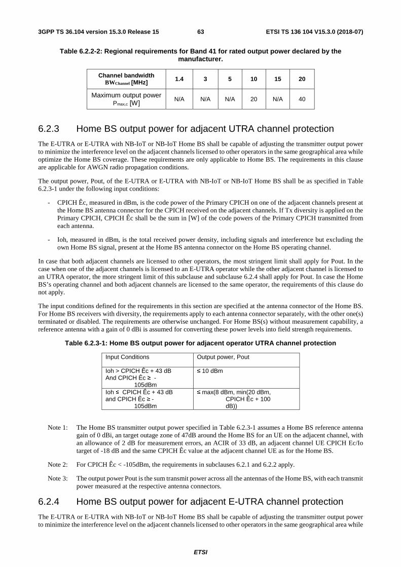
ETSI
ETSI TS 136 104 V15.3.0 (2018-07)633GPP TS 36.104 version 15.3.0 Release 15
Table 6.2.2-2: Regional requirements for Band 41 for rated output power declared by the manufacturer.
Channel bandwidth BWChannel [MHz] 1.4 3 5 10 15 20
Maximum output power Pmax,c [W]
N/A N/A N/A 20 N/A 40
6.2.3 Home BS output power for adjacent UTRA channel protection
The E-UTRA or E-UTRA with NB-IoT or NB-IoT Home BS shall be capable of adjusting the transmitter output power to minimize the interference level on the adjacent channels licensed to other operators in the same geographical area while optimize the Home BS coverage. These requirements are only applicable to Home BS. The requirements in this clause are applicable for AWGN radio propagation conditions.
The output power, Pout, of the E-UTRA or E-UTRA with NB-IoT or NB-IoT Home BS shall be as specified in Table 6.2.3-1 under the following input conditions:
- CPICH Êc, measured in dBm, is the code power of the Primary CPICH on one of the adjacent channels present at the Home BS antenna connector for the CPICH received on the adjacent channels. If Tx diversity is applied on the Primary CPICH, CPICH Êc shall be the sum in [W] of the code powers of the Primary CPICH transmitted from each antenna.
- Ioh, measured in dBm, is the total received power density, including signals and interference but excluding the own Home BS signal, present at the Home BS antenna connector on the Home BS operating channel.
In case that both adjacent channels are licensed to other operators, the most stringent limit shall apply for Pout. In the case when one of the adjacent channels is licensed to an E-UTRA operator while the other adjacent channel is licensed to an UTRA operator, the more stringent limit of this subclause and subclause 6.2.4 shall apply for Pout. In case the Home BS’s operating channel and both adjacent channels are licensed to the same operator, the requirements of this clause do not apply.
The input conditions defined for the requirements in this section are specified at the antenna connector of the Home BS. For Home BS receivers with diversity, the requirements apply to each antenna connector separately, with the other one(s) terminated or disabled. The requirements are otherwise unchanged. For Home BS(s) without measurement capability, a reference antenna with a gain of 0 dBi is assumed for converting these power levels into field strength requirements.
Table 6.2.3-1: Home BS output power for adjacent operator UTRA channel protection
Input Conditions Output power, Pout
Ioh > CPICH Êc + 43 dB And CPICH Êc ≥ -
105dBm
≤ 10 dBm
Ioh ≤ CPICH Êc + 43 dB and CPICH Êc ≥ -
105dBm
≤ max(8 dBm, min(20 dBm, CPICH Êc + 100 dB))
Note 1: The Home BS transmitter output power specified in Table 6.2.3-1 assumes a Home BS reference antenna gain of 0 dBi, an target outage zone of 47dB around the Home BS for an UE on the adjacent channel, with an allowance of 2 dB for measurement errors, an ACIR of 33 dB, an adjacent channel UE CPICH Ec/Io target of -18 dB and the same CPICH Êc value at the adjacent channel UE as for the Home BS.
Note 2: For CPICH Êc < -105dBm, the requirements in subclauses 6.2.1 and 6.2.2 apply.
Note 3: The output power Pout is the sum transmit power across all the antennas of the Home BS, with each transmit power measured at the respective antenna connectors.
6.2.4 Home BS output power for adjacent E-UTRA channel protection
The E-UTRA or E-UTRA with NB-IoT or NB-IoT Home BS shall be capable of adjusting the transmitter output power to minimize the interference level on the adjacent channels licensed to other operators in the same geographical area while

ETSI
ETSI TS 136 104 V15.3.0 (2018-07)643GPP TS 36.104 version 15.3.0 Release 15
optimize the Home BS coverage. These requirements are only applicable to Home BS. The requirements in this clause are applicable for AWGN radio propagation conditions.
The output power, Pout, of the E-UTRA or E-UTRA with NB-IoT or NB-IoT Home BS shall be as specified in Table 6.2. 4-1 under the following input conditions:
- CRS Ês, measured in dBm, is the Reference Signal Received Power per resource element on one of the adjacent channels present at the Home BS antenna connector for the Reference Signal received on the adjacent channels. For CRS Ês determination, the cell-specific reference signal R0 according TS 36.211 [3] shall be used. If the Home BS can reliably detect that multiple TX antennas are used for transmission on the adjacent channel, it may use the average in [W] of the CRS Ês on all detected antennas.
- Ioh, measured in dBm, is the total received power density, including signals and interference but excluding the own Home BS signal, present at the Home BS antenna connector on the Home BS operating channel.
In case that both adjacent channels are licensed to other operators, the most stringent limit shall apply for Pout. In the case when one of the adjacent channels is licensed to an E-UTRA operator while the other adjacent channel is licensed to an UTRA operator, the more stringent limit of this subclause and subclause 6.2.3 shall apply for Pout. In case the E-UTRA or E-UTRA with NB-IoT or NB-IoT Home BS’s operating channel and both adjacent channels are licensed to the same operator, the requirements of this clause do not apply.
The input conditions defined for the requirements in this section are specified at the antenna connector of the Home BS. For E-UTRA or E-UTRA with NB-IoT or NB-IoT Home BS receivers with diversity, the requirements apply to each antenna connector separately, with the other one(s) terminated or disabled. The requirements are otherwise unchanged. For Home BS(s) without measurement capability, a reference antenna with a gain of 0 dBi is assumed for converting these power levels into field strength requirements.
Table 6.2. 4-1: Home BS output power for adjacent operator E-UTRA channel protection
Input Conditions Output power, Pout
Ioh > CRS Ês +
( )RBsc
DLRB NN ⋅⋅ 10log10
+ 30 dB and CRS Ês ≥ -127dBm
≤ 10 dBm
Ioh ≤ CRS Ês +
( )RBsc
DLRB NN ⋅⋅ 10log10
+ 30 dB and CRS Ês ≥ -127dBm
≤ max(8 dBm, min(20 dBm, CRS Ês +
( )RBsc
DLRB NN ⋅⋅ 10log10
+ 85 dB))
Note 1: The E-UTRA or E-UTRA with NB-IoT or NB-IoT Home BS transmitter output power specified in Table 6.2. 4-1 assumes a Home BS reference antenna gain of 0 dBi, an target outage zone of 47dB around the Home BS for an UE on the adjacent channel, with an allowance of 2 dB for measurement errors, an ACIR of 30 dB, an adjacent channel UE Ês/Iot target of -6 dB and the same CRS Ês value at the adjacent channel UE as for the Home BS.
Note 2: For CRS Ês < -127dBm, the requirements in subclauses 6.2.1 and 6.2.2 apply.
Note 3: The output power Pout is the sum transmit power across all the antennas of the Home BS, with each transmit power measured at the respective antenna connectors.
Note 4: DLRBN is the number of downlink resource blocks in the own E-UTRA or E-UTRA with NB-IoT or NB-IoT
Home BS channel.
Note 5: RBscN is the number of subcarriers in a resource block, 12=RB
scN .
6.2.5 Home BS Output Power for co-channel E-UTRA protection
To minimize the co-channel DL interference to non-CSG macro UEs operating in close proximity while optimizing the CSG Home BS coverage, E-UTRA or E-UTRA with NB-IoT or NB-IoT Home BS may adjust its output power according to the requirements set out in this clause. These requirements are only applicable to E-UTRA or E-UTRA

ETSI
ETSI TS 136 104 V15.3.0 (2018-07)653GPP TS 36.104 version 15.3.0 Release 15
with NB-IoT or NB-IoT Home BS. The requirements in this clause are applicable for AWGN radio propagation conditions.
For E-UTRA or E-UTRA with NB-IoT or NB-IoT Home BS that supports the requirements in this clause, the output power, Pout, of the Home BS shall be as specified in Table 6.2.5-1 under the following input conditions:
- CRS Ês, measured in dBm, is the Reference Signal Received Power per resource element present at the Home BS antenna connector received from the co-channel Wide Area BS. For CRS Ês determination, the cell-specific reference signal R0 according TS 36.211 [10] shall be used. If the Home BS can reliably detect that multiple TX antenna ports are used for transmission by the co-channel Wide Area Base Station, it may use the average in [W] of the CRS Ês on all detected TX antenna ports, including R0.
- Ioh, measured in dBm, is the total received DL power, including all interference but excluding the own Home BS signal, present at the Home BS antenna connector on the Home BS operating channel.
- Iob, measured in dBm, is the uplink received interference power, including thermal noise, within one physical
resource block’s bandwidth of RBscN resource elements as defined in TS 36.214, present at the Home BS antenna
connector on the Home BS operating channel.
The input conditions defined for the requirements in this section are specified at the antenna connector of the Home BS. For E-UTRA or E-UTRA with NB-IoT or NB-IoT Home BS receivers with diversity, the requirements apply to each antenna connector separately, with the other one(s) terminated or disabled. The requirements are otherwise unchanged. For E-UTRA or E-UTRA with NB-IoT or NB-IoT Home BS(s) without measurement capability, a reference antenna with a gain of 0 dBi is assumed for converting these power levels into field strength requirements.
Table 6.2.5-1: Home BS output power for co-channel E-UTRA channel protection
Input Conditions Output power, Pout
Ioh (DL) > CRS Ês + 10log10( DLRBN RB
scN ) + 30 dB
and Option 1: CRS Ês ≥ -127 dBm or Option 2: CRS Ês ≥ -127 dBm and Iob > -103 dBm
≤ 10 dBm
Ioh (DL) ≤ CRS Ês + 10log10( DLRBN RB
scN ) + 30 dB
and Option 1: CRS Ês ≥ -127 dBm or Option 2. CRS Ês ≥ -127 dBm and Iob > -103 dBm
≤ max (Pmin, min (Pmax,c CRS Ês +
10log10( DLRBN RB
scN ) + X ))
30 dB ≤ X ≤ 70 dB Pmin = - 10 dBm
Note 1: Only the option supported by the E-UTRA or E-UTRA with NB-IoT or NB-IoT Home BS shall be tested.
Note 2: For CRS Ês < -127dBm, or Iob ≤ -103 dBm when Option 2 is supported, the requirements in sub-clauses 6.2.1 and 6.2.2 apply.
Note 3: The output power, Pout, is the sum of transmits power across all the antennas of the Home BS, with each transmit power measured at the respective antenna connectors.
Note 4: DLRBN is the number of downlink resource blocks in the own E-UTRA or E-UTRA with NB-IoT or NB-
IoT Home BS channel.
Note 5: RBscN is the number of subcarriers in a resource block, 12=RB
scN .
Note 6: X is a network configurable parameter.
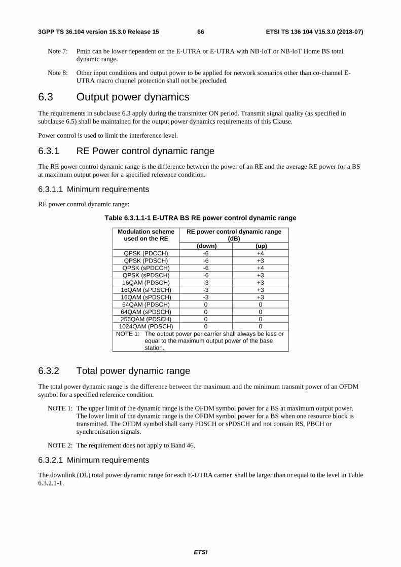
ETSI
ETSI TS 136 104 V15.3.0 (2018-07)663GPP TS 36.104 version 15.3.0 Release 15
Note 7: Pmin can be lower dependent on the E-UTRA or E-UTRA with NB-IoT or NB-IoT Home BS total dynamic range.
Note 8: Other input conditions and output power to be applied for network scenarios other than co-channel E-UTRA macro channel protection shall not be precluded.
6.3 Output power dynamics The requirements in subclause 6.3 apply during the transmitter ON period. Transmit signal quality (as specified in subclause 6.5) shall be maintained for the output power dynamics requirements of this Clause.
Power control is used to limit the interference level.
6.3.1 RE Power control dynamic range
The RE power control dynamic range is the difference between the power of an RE and the average RE power for a BS at maximum output power for a specified reference condition.
6.3.1.1 Minimum requirements
RE power control dynamic range:
Table 6.3.1.1-1 E-UTRA BS RE power control dynamic range
Modulation scheme used on the RE
RE power control dynamic range (dB)
(down) (up) QPSK (PDCCH) -6 +4 QPSK (PDSCH) -6 +3 QPSK (sPDCCH) -6 +4 QPSK (sPDSCH) -6 +3 16QAM (PDSCH) -3 +3 16QAM (sPDSCH) -3 +3 16QAM (sPDSCH) -3 +3 64QAM (PDSCH) 0 0 64QAM (sPDSCH) 0 0 256QAM (PDSCH) 0 0
1024QAM (PDSCH) 0 0 NOTE 1: The output power per carrier shall always be less or
equal to the maximum output power of the base station.
6.3.2 Total power dynamic range
The total power dynamic range is the difference between the maximum and the minimum transmit power of an OFDM symbol for a specified reference condition.
NOTE 1: The upper limit of the dynamic range is the OFDM symbol power for a BS at maximum output power. The lower limit of the dynamic range is the OFDM symbol power for a BS when one resource block is transmitted. The OFDM symbol shall carry PDSCH or sPDSCH and not contain RS, PBCH or synchronisation signals.
NOTE 2: The requirement does not apply to Band 46.
6.3.2.1 Minimum requirements
The downlink (DL) total power dynamic range for each E-UTRA carrier shall be larger than or equal to the level in Table 6.3.2.1-1.
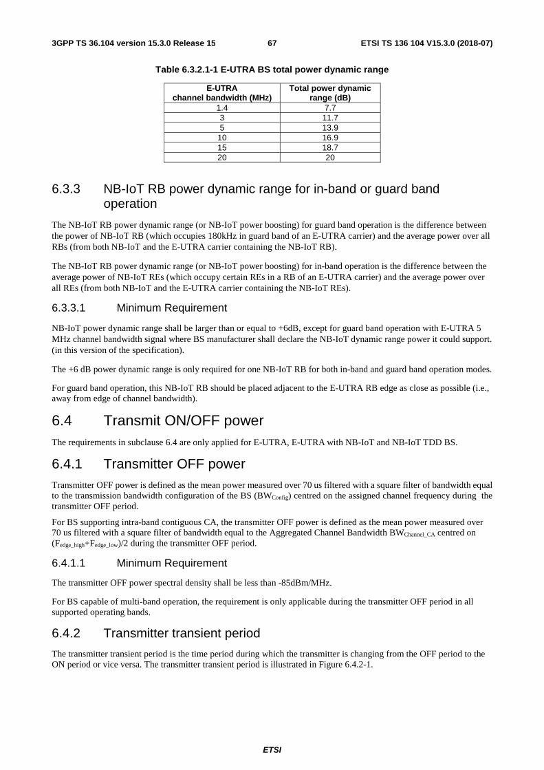
ETSI
ETSI TS 136 104 V15.3.0 (2018-07)673GPP TS 36.104 version 15.3.0 Release 15
Table 6.3.2.1-1 E-UTRA BS total power dynamic range
E-UTRA channel bandwidth (MHz)
Total power dynamic range (dB)
1.4 7.7 3 11.7 5 13.9
10 16.9 15 18.7 20 20
6.3.3 NB-IoT RB power dynamic range for in-band or guard band operation
The NB-IoT RB power dynamic range (or NB-IoT power boosting) for guard band operation is the difference between the power of NB-IoT RB (which occupies 180kHz in guard band of an E-UTRA carrier) and the average power over all RBs (from both NB-IoT and the E-UTRA carrier containing the NB-IoT RB).
The NB-IoT RB power dynamic range (or NB-IoT power boosting) for in-band operation is the difference between the average power of NB-IoT REs (which occupy certain REs in a RB of an E-UTRA carrier) and the average power over all REs (from both NB-IoT and the E-UTRA carrier containing the NB-IoT REs).
6.3.3.1 Minimum Requirement
NB-IoT power dynamic range shall be larger than or equal to +6dB, except for guard band operation with E-UTRA 5 MHz channel bandwidth signal where BS manufacturer shall declare the NB-IoT dynamic range power it could support. (in this version of the specification).
The +6 dB power dynamic range is only required for one NB-IoT RB for both in-band and guard band operation modes.
For guard band operation, this NB-IoT RB should be placed adjacent to the E-UTRA RB edge as close as possible (i.e., away from edge of channel bandwidth).
6.4 Transmit ON/OFF power The requirements in subclause 6.4 are only applied for E-UTRA, E-UTRA with NB-IoT and NB-IoT TDD BS.
6.4.1 Transmitter OFF power Transmitter OFF power is defined as the mean power measured over 70 us filtered with a square filter of bandwidth equal to the transmission bandwidth configuration of the BS (BWConfig) centred on the assigned channel frequency during the transmitter OFF period.
For BS supporting intra-band contiguous CA, the transmitter OFF power is defined as the mean power measured over 70 us filtered with a square filter of bandwidth equal to the Aggregated Channel Bandwidth BWChannel_CA centred on (Fedge_high+Fedge_low)/2 during the transmitter OFF period.
6.4.1.1 Minimum Requirement
The transmitter OFF power spectral density shall be less than -85dBm/MHz.
For BS capable of multi-band operation, the requirement is only applicable during the transmitter OFF period in all supported operating bands.
6.4.2 Transmitter transient period
The transmitter transient period is the time period during which the transmitter is changing from the OFF period to the ON period or vice versa. The transmitter transient period is illustrated in Figure 6.4.2-1.
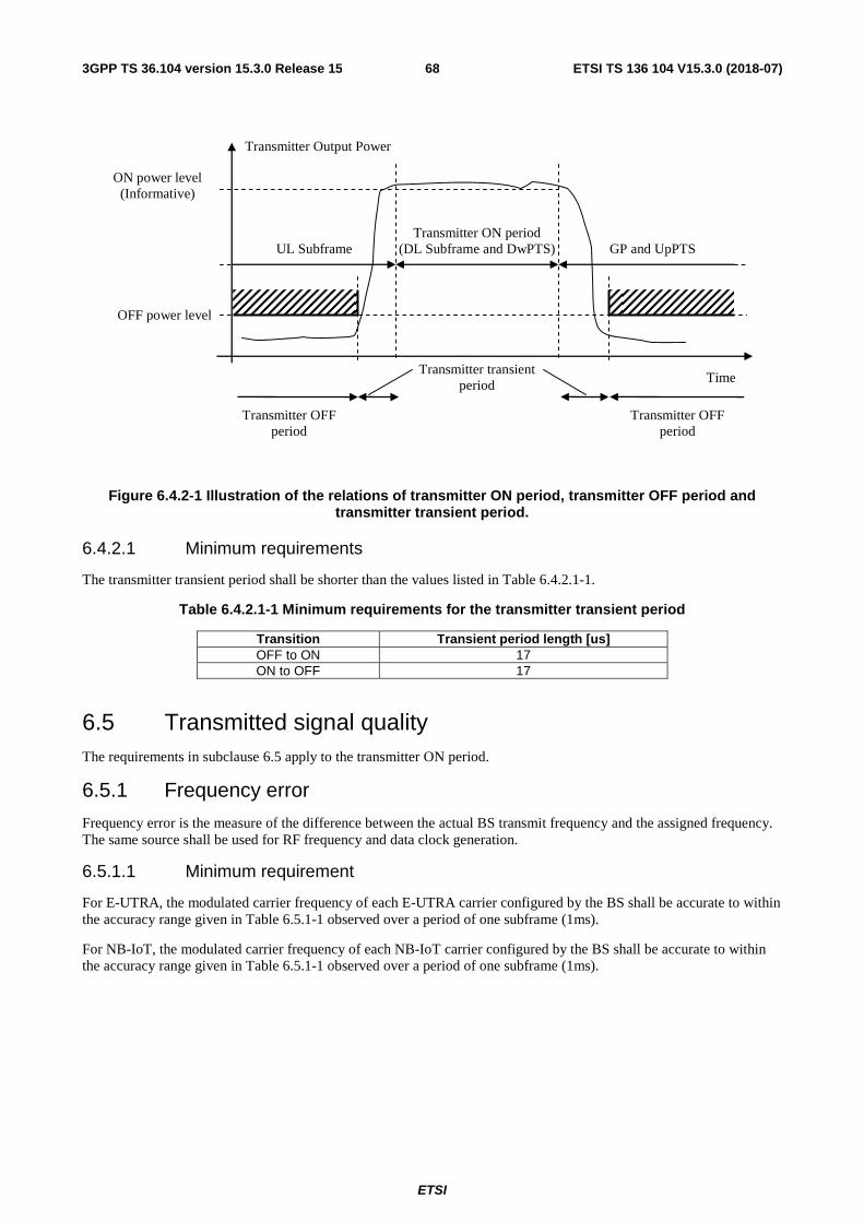
ETSI
ETSI TS 136 104 V15.3.0 (2018-07)683GPP TS 36.104 version 15.3.0 Release 15
Figure 6.4.2-1 Illustration of the relations of transmitter ON period, transmitter OFF period and transmitter transient period.
6.4.2.1 Minimum requirements
The transmitter transient period shall be shorter than the values listed in Table 6.4.2.1-1.
Table 6.4.2.1-1 Minimum requirements for the transmitter transient period
Transition Transient period length [us] OFF to ON 17 ON to OFF 17
6.5 Transmitted signal quality The requirements in subclause 6.5 apply to the transmitter ON period.
6.5.1 Frequency error
Frequency error is the measure of the difference between the actual BS transmit frequency and the assigned frequency. The same source shall be used for RF frequency and data clock generation.
6.5.1.1 Minimum requirement
For E-UTRA, the modulated carrier frequency of each E-UTRA carrier configured by the BS shall be accurate to within the accuracy range given in Table 6.5.1-1 observed over a period of one subframe (1ms).
For NB-IoT, the modulated carrier frequency of each NB-IoT carrier configured by the BS shall be accurate to within the accuracy range given in Table 6.5.1-1 observed over a period of one subframe (1ms).
Transmitter Output Power
Time
Transmitter ON period (DL Subframe and DwPTS)
Transmitter OFF period
Transmitter OFF period
Transmitter transient period
OFF power level
ON power level (Informative)
UL Subframe
GP and UpPTS

ETSI
ETSI TS 136 104 V15.3.0 (2018-07)693GPP TS 36.104 version 15.3.0 Release 15
Table 6.5.1-1: Frequency error minimum requirement
BS class Accuracy
Wide Area BS ±0.05 ppm
Medium Range BS ±0.1 ppm
Local Area BS ±0.1 ppm
Home BS ±0.25 ppm
6.5.2 Error Vector Magnitude
The Error Vector Magnitude is a measure of the difference between the ideal symbols and the measured symbols after the equalization. This difference is called the error vector. The equaliser parameters are estimated as defined in Annex E. The EVM result is defined as the square root of the ratio of the mean error vector power to the mean reference power expressed in percent.
For E-UTRA, for all bandwidths, the EVM measurement shall be performed for each E-UTRA carrier over all allocated resource blocks and downlink subframes within 10ms measurement periods for subframe TTI, and over all allocated resource blocks and downlink sTTIs within 10ms measurement periods for sTTI. The boundaries of the EVM measurement periods need not be aligned with radio frame boundaries. The EVM value is then calculated as the mean square root of the measured values. The EVM of each E-UTRA carrier for different modulation schemes on PDSCH or sPDSCH shall be better than the limits in table 6.5.2-1:
Table 6.5.2-1: EVM requirements for E-UTRA carrier
Modulation scheme for PDSCH or sPDSCH
Required EVM [%]
QPSK 17.5 % 16QAM 12.5 % 64QAM 8 %
256QAM 3.5 % 1024QAM 2.5 %
For NB-IoT, for all bandwidths, the EVM measurement shall be performed for each NB-IoT carrier over all allocated resource and downlink subframes within 10ms measurement periods. The boundaries of the EVM measurement periods need not be aligned with radio frame boundaries. The EVM value is then calculated as the mean square root of the measured values. The EVM of each NB-IoT carrier on NB-PDSCH shall be better than the limits in Table 6.5.2-2:
Table 6.5.2-2: EVM requirements for NB-IoT carrier
Modulation scheme for NB-PDSCH Required EVM [%] QPSK 17.5 %
6.5.3 Time alignment error
This requirement applies to frame timing in TX diversity, MIMO transmission, carrier aggregation and their combinations.
Frames of the LTE signals present at the BS transmitter antenna port(s) are not perfectly aligned in time. In relation to each other, the RF signals present at the BS transmitter antenna port(s) experience certain timing differences.
For a specific set of signals/transmitter configuration/transmission mode, time alignment error (TAE) is defined as the largest timing difference between any two signals.
6.5.3.1 Minimum Requirement
For E-UTRA:
- For MIMO or TX diversity transmissions, at each carrier frequency, TAE shall not exceed 65 ns.

ETSI
ETSI TS 136 104 V15.3.0 (2018-07)703GPP TS 36.104 version 15.3.0 Release 15
- For intra-band contiguous carrier aggregation, with or without MIMO or TX diversity, TAE shall not exceed 130 ns.
- For intra-band non-contiguous carrier aggregation, with or without MIMO or TX diversity, TAE shall not exceed 260 ns.
- For inter-band carrier aggregation, with or without MIMO or TX diversity, TAE shall not exceed 260ns.
For NB-IoT:
- For TX diversity transmissions, at each carrier frequency, TAE shall not exceed 65 ns.
6.5.4 DL RS power
For E-UTRA, DL RS power is the resource element power of the Downlink Reference Symbol.
The absolute DL RS power is indicated on the DL-SCH. The absolute accuracy is defined as the maximum deviation between the DL RS power indicated on the DL-SCH and the DL RS power of each E-UTRA carrier at the BS antenna connector.
For NB-IoT, DL NRS power is the resource element power of the Downlink Narrow-band Reference Signal.
The absolute DL NRS power is indicated on the DL-SCH. The absolute accuracy is defined as the maximum deviation between the DL NRS power indicated on the DL-SCH and the DL NRS power of each NB-IoT carrier at the BS antenna connector.
6.5.4.1 Minimum requirements
For E-UTRA, DL RS power of each E-UTRA carrier shall be within ± 2.1 dB of the DL RS power indicated on the DL-SCH.
For NB-IoT, DL NRS power of each NB-IoT carrier shall be within ± 2.1 dB of the DL NRS power indicated on the DL-SCH.
6.6 Unwanted emissions Unwanted emissions consist of out-of-band emissions and spurious emissions [2]. Out of band emissions are unwanted emissions immediately outside the channel bandwidth resulting from the modulation process and non-linearity in the transmitter but excluding spurious emissions. Spurious emissions are emissions which are caused by unwanted transmitter effects such as harmonics emission, parasitic emission, intermodulation products and frequency conversion products, but exclude out of band emissions.
The out-of-band emissions requirement for the BS transmitter is specified both in terms of Adjacent Channel Leakage power Ratio (ACLR) and Operating band unwanted emissions. The Operating band unwanted emissions define all unwanted emissions in each supported downlink operating band plus the frequency ranges 10 MHz above and 10 MHz below each band. Unwanted emissions outside of this frequency range are limited by a spurious emissions requirement.
For a BS supporting multi-carrier or intra-band contiguous CA, the unwanted emissions requirements apply to channel bandwidths of the outermost carrier larger than or equal to 5 MHz.
There is in addition a requirement for occupied bandwidth.
6.6.1 Occupied bandwidth
The occupied bandwidth is the width of a frequency band such that, below the lower and above the upper frequency limits, the mean powers emitted are each equal to a specified percentage β/2 of the total mean transmitted power. See also ITU-R Recommendation SM.328 [5].
The value of β/2 shall be taken as 0.5%.
The requirement applies during the transmitter ON period.

ETSI
ETSI TS 136 104 V15.3.0 (2018-07)713GPP TS 36.104 version 15.3.0 Release 15
6.6.1.1 Minimum requirement
For E-UTRA, the occupied bandwidth for each E-UTRA carrier shall be less than the channel bandwidth as defined in Table 5.6-1. For intra-band contiguous CA, the occupied bandwidth shall be less than or equal to the Aggregated Channel Bandwidth as defined in subclause 5.6. For Band 46 operation in Japan, the occupied bandwidth for each 20MHz channel bandwidth E-UTRA carrier assigned within 5150-5350 MHz and 5470-5725 MHz shall be less than or equal to 19 MHz and 19.7MHz respectively.
For NB-IoT in-band operation, the occupied bandwidth for each E-UTRA carrier with NB-IoT shall be less than the channel bandwidth as defined in Table 5.6-1.
For NB-IoT guard band operation, the occupied bandwidth for each E-UTRA carrier with NB-IoT shall be less than the channel bandwidth as defined in Table 5.6-1 for channel bandwidth larger than or equal to 5 MHz.
For NB-IoT standalone operation, the occupied bandwidth for each NB-IoT carrier shall be less than the channel bandwidth as defined in Table 5.6-3.
6.6.2 Adjacent Channel Leakage power Ratio (ACLR)
Adjacent Channel Leakage power Ratio (ACLR) is the ratio of the filtered mean power centred on the assigned channel frequency to the filtered mean power centred on an adjacent channel frequency.
The requirements shall apply outside the Base Station RF Bandwidth or Radio Bandwidth whatever the type of transmitter considered (single carrier or multi-carrier) and for all transmission modes foreseen by the manufacturer's specification.
For a E-UTRA or E-UTRA with NB-IoT (in-band and/or guard band) BS operating in non-contiguous spectrum, the ACLR also applies for the first adjacent channel inside any sub-block gap with a gap size Wgap ≥ 15MHz or Wgap ≥ 60MHz for Band 46. The ACLR requirement for the second adjacent channel applies inside any sub-block gap with a gap size Wgap ≥ 20 MHz or Wgap ≥ 80MHz for Band 46. The CACLR requirement in subclause 6.6.2.2 applies in sub block gaps for the frequency ranges defined in Table 6.6.2.2-1/2/2a.
For a E-UTRA or E-UTRA with NB-IoT (in-band and/or guard band) BS operating in multiple bands, where multiple bands are mapped onto the same antenna connector, the ACLR also applies for the first adjacent channel inside any Inter RF Bandwidth gap with a gap size Wgap ≥ 15MHz. The ACLR requirement for the second adjacent channel applies inside any Inter RF Bandwidth gap with a gap size Wgap ≥ 20 MHz. The CACLR requirement in subclause 6.6.2.2 applies in Inter RF Bandwidth gaps for the frequency ranges defined in Table 6.6.2.2-1/2.
The requirement applies during the transmitter ON period.
6.6.2.1 Minimum requirement
The ACLR is defined with a square filter of bandwidth equal to the transmission bandwidth configuration of the transmitted signal (BWConfig) centred on the assigned channel frequency and a filter centred on the adjacent channel frequency according to the tables below.
For Category A Wide Area BS, either the ACLR limits in the tables below or the absolute limit of -13dBm/MHz shall apply, whichever is less stringent.
For Category B Wide Area BS, either the ACLR limits in the tables below or the absolute limit of -15dBm/MHz shall apply, whichever is less stringent.
For Medium Range BS, either the ACLR limits in the tables below or the absolute limit of -25 dBm/MHz shall apply, whichever is less stringent.
For Local Area BS, either the ACLR limits in the tables below or the absolute limit of -32dBm/MHz shall apply, whichever is less stringent.
For Home BS, either the ACLR limits in the tables below or the absolute limit of -50dBm/MHz shall apply, whichever is less stringent.
The ACLR requirements in Tables 6.6.2.1-1 to 6.6.2.1-4 (except Table 6.6.2.1-2b) apply to BS that supports E-UTRA or E-UTRA with NB-IoT (in-band and/or guard band), in any operating band except for Band 46. The ACLR requirements for Band 46 are in Table 6.6.2.1-2a and 6.6.2.1-5. The ACLR requirements in Table 6.6.2.1-2b and 6.6.2.1-6 apply to BS that supports standalone NB-IoT.
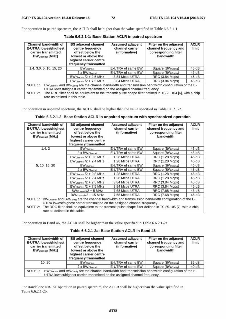
ETSI
ETSI TS 136 104 V15.3.0 (2018-07)723GPP TS 36.104 version 15.3.0 Release 15
For operation in paired spectrum, the ACLR shall be higher than the value specified in Table 6.6.2.1-1.
Table 6.6.2.1-1: Base Station ACLR in paired spectrum
Channel bandwidth of E-UTRA lowest/highest
carrier transmitted BWChannel [MHz]
BS adjacent channel centre frequency offset below the
lowest or above the highest carrier centre frequency transmitted
Assumed adjacent channel carrier
(informative)
Filter on the adjacent channel frequency and
corresponding filter bandwidth
ACLR limit
1.4, 3.0, 5, 10, 15, 20 BWChannel E-UTRA of same BW Square (BWConfig) 45 dB 2 x BWChannel E-UTRA of same BW Square (BWConfig) 45 dB
BWChannel /2 + 2.5 MHz 3.84 Mcps UTRA RRC (3.84 Mcps) 45 dB BWChannel /2 + 7.5 MHz 3.84 Mcps UTRA RRC (3.84 Mcps) 45 dB
NOTE 1: BWChannel and BWConfig are the channel bandwidth and transmission bandwidth configuration of the E-UTRA lowest/highest carrier transmitted on the assigned channel frequency.
NOTE 2: The RRC filter shall be equivalent to the transmit pulse shape filter defined in TS 25.104 [6], with a chip rate as defined in this table.
For operation in unpaired spectrum, the ACLR shall be higher than the value specified in Table 6.6.2.1-2.
Table 6.6.2.1-2: Base Station ACLR in unpaired spectrum with synchronized operation
Channel bandwidth of E-UTRA lowest/highest
carrier transmitted BWChannel [MHz]
BS adjacent channel centre frequency offset below the
lowest or above the highest carrier centre frequency transmitted
Assumed adjacent channel carrier
(informative)
Filter on the adjacent channel frequency and
corresponding filter bandwidth
ACLR limit
1.4, 3 BWChannel E-UTRA of same BW Square (BWConfig) 45 dB 2 x BWChannel E-UTRA of same BW Square (BWConfig) 45 dB
BWChannel /2 + 0.8 MHz 1.28 Mcps UTRA RRC (1.28 Mcps) 45 dB BWChannel /2 + 2.4 MHz 1.28 Mcps UTRA RRC (1.28 Mcps) 45 dB
5, 10, 15, 20 BWChannel E-UTRA of same BW Square (BWConfig) 45 dB 2 x BWChannel E-UTRA of same BW Square (BWConfig) 45 dB
BWChannel /2 + 0.8 MHz 1.28 Mcps UTRA RRC (1.28 Mcps) 45 dB BWChannel /2 + 2.4 MHz 1.28 Mcps UTRA RRC (1.28 Mcps) 45 dB BWChannel /2 + 2.5 MHz 3.84 Mcps UTRA RRC (3.84 Mcps) 45 dB BWChannel /2 + 7.5 MHz 3.84 Mcps UTRA RRC (3.84 Mcps) 45 dB BWChannel /2 + 5 MHz 7.68 Mcps UTRA RRC (7.68 Mcps) 45 dB BWChannel /2 + 15 MHz 7.68 Mcps UTRA RRC (7.68 Mcps) 45 dB
NOTE 1: BWChannel and BWConfig are the channel bandwidth and transmission bandwidth configuration of the E-UTRA lowest/highest carrier transmitted on the assigned channel frequency.
NOTE 2: The RRC filter shall be equivalent to the transmit pulse shape filter defined in TS 25.105 [7], with a chip rate as defined in this table.
For operation in Band 46, the ACLR shall be higher than the value specified in Table 6.6.2.1-2a.
Table 6.6.2.1-2a: Base Station ACLR in Band 46
Channel bandwidth of E-UTRA lowest/highest
carrier transmitted BWChannel [MHz]
BS adjacent channel centre frequency offset below the
lowest or above the highest carrier centre frequency transmitted
Assumed adjacent channel carrier
(informative)
Filter on the adjacent channel frequency and
corresponding filter bandwidth
ACLR limit
10, 20 BWChannel E-UTRA of same BW Square (BWConfig) 35 dB 2 x BWChannel E-UTRA of same BW Square (BWConfig) 40 dB
NOTE 1: BWChannel and BWConfig are the channel bandwidth and transmission bandwidth configuration of the E-UTRA lowest/highest carrier transmitted on the assigned channel frequency.
For standalone NB-IoT operation in paired spectrum, the ACLR shall be higher than the value specified in Table 6.6.2.1-2b.

ETSI
ETSI TS 136 104 V15.3.0 (2018-07)733GPP TS 36.104 version 15.3.0 Release 15
Table 6.6.2.1-2b: Base Station ACLR for standalone NB-IoT operation in paired spectrum
Channel bandwidth of NB-IoT lowest/highest
carrier transmitted BWChannel [kHz]
BS adjacent channel centre frequency offset below the
lowest or above the highest carrier centre frequency transmitted
Assumed adjacent channel carrier
(informative)
Filter on the adjacent channel frequency and
corresponding filter bandwidth
ACLR limit
200 300 kHz Standalone NB-IoT Square (180 kHz) 40 dB 500 kHz Standalone NB-IoT Square (180 kHz) 50 dB
For operation in non-contiguous paired spectrum or multiple bands, the ACLR shall be higher than the value specified in Table 6.6.2.1-3.
Table 6.6.2.1-3: Base Station ACLR in non-contiguous paired spectrum or multiple bands
Sub-block or Inter RF
Bandwidth gap size (Wgap)
where the limit applies
BS adjacent channel centre frequency
offset below or above the sub-block edge or the Base Station RF
Bandwidth edge (inside the gap)
Assumed adjacent channel carrier
(informative)
Filter on the adjacent channel frequency and
corresponding filter bandwidth
ACLR limit
Wgap ≥ 15 MHz 2.5 MHz 3.84 Mcps UTRA RRC (3.84 Mcps) 45 dB Wgap ≥ 20 MHz 7.5 MHz 3.84 Mcps UTRA RRC (3.84 Mcps) 45 dB
NOTE: The RRC filter shall be equivalent to the transmit pulse shape filter defined in TS 25.104 [6], with a chip rate as defined in this table.
For operation in non-contiguous unpaired spectrum or multiple bands, the ACLR shall be higher than the value specified in Table 6.6.2.1-4.
Table 6.6.2.1-4: Base Station ACLR in non-contiguous unpaired spectrum or multiple bands
Sub-block or Inter RF
Bandwidth gap size (Wgap)
where the limit applies
BS adjacent channel centre frequency
offset below or above the sub-block edge or the Base Station RF
Bandwidth edge (inside the gap)
Assumed adjacent channel carrier
(informative)
Filter on the adjacent channel frequency and
corresponding filter bandwidth
ACLR limit
Wgap ≥ 15 MHz 2.5 MHz 5MHz E-UTRA carrier
Square (BWConfig) 45 dB
Wgap ≥ 20 MHz 7.5 MHz 5MHz E-UTRA carrier
Square (BWConfig) 45 dB
For operation in non-contiguous spectrum in Band 46, the ACLR shall be higher than the value specified in Table 6.6.2.1-5.
Table 6.6.2.1-5: Base Station ACLR in non-contiguous spectrum in Band 46
Sub-block gap size (Wgap)
where the limit applies
BS adjacent channel centre frequency
offset below or above the sub-block edge
(inside the gap)
Assumed adjacent channel carrier
(informative)
Filter on the adjacent channel frequency and
corresponding filter bandwidth
ACLR limit
Wgap ≥ 60 MHz 10 MHz 20MHz E-UTRA carrier
Square (BWConfig) 35 dB
Wgap ≥ 80 MHz 30 MHz 20MHz E-UTRA carrier
Square (BWConfig) 40 dB
6.6.2.2 Cumulative ACLR requirement in non-contiguous spectrum
The following requirement applies for the sub-block or Inter RF Bandwidth gap sizes listed in Table 6.6.2.2-1/2/2a,

ETSI
ETSI TS 136 104 V15.3.0 (2018-07)743GPP TS 36.104 version 15.3.0 Release 15
- Inside a sub-block gap within an operating band for a BS operating in non-contiguous spectrum.
- Inside an Inter RF Bandwidth gap for a BS operating in multiple bands, where multiple bands are mapped on the same antenna connector.
The Cumulative Adjacent Channel Leakage power Ratio (CACLR) in a sub-block gap or the Inter RF Bandwidth gap is the ratio of:
a) the sum of the filtered mean power centred on the assigned channel frequencies for the two carriers adjacent to each side of the sub-block gap or the Inter RF Bandwidth gap, and
b) the filtered mean power centred on a frequency channel adjacent to one of the respective sub-block edges or Base Station RF Bandwidth edges.
The assumed filter for the adjacent channel frequency is defined in Table 6.6.2.2-1/2/2a and the filters on the assigned channels are defined in Table 6.6.2.2-3.
For Wide Area Category A BS, either the CACLR limits in Table 6.6.2.2-1/2 or the absolute limit of -13dBm/MHz shall apply, whichever is less stringent.
For Wide Area Category B BS, either the CACLR limits in Table 6.6.2.2-1/2 or the absolute limit of -15dBm/MHz shall apply, whichever is less stringent.
For Medium Range BS, either the CACLR limits in Table 6.6.2.2-1/2/2a or the absolute limit of -25 dBm/MHz shall apply, whichever is less stringent.
For Local Area BS, either the CACLR limits in Table 6.6.2.2-1/2/2a or the absolute limit of -32 dBm/MHz shall apply, whichever is less stringent.
The ACLR requirements in Tables 6.6.2.2-1 and 6.6.2.2-2 apply to BS that supports E-UTRA, in any operating band except for Band 46. The ACLR requirements for Band 46 are in Table 6.6.2.2-2a.
For operation in non-contiguous spectrum or multiple bands, the CACLR for E-UTRA carriers located on either side of the sub-block gap or the Inter RF Bandwidth gap shall be higher than the value specified in Table 6.6.2.2-1/2.
Table 6.6.2.2-1: Base Station CACLR in non-contiguous paired spectrum or multiple bands
Sub-block or Inter RF
Bandwidth gap size (Wgap)
where the limit applies
BS adjacent channel centre frequency
offset below or above the sub-block edge or the Base Station RF
Bandwidth edge (inside the gap)
Assumed adjacent channel carrier
(informative)
Filter on the adjacent channel frequency and
corresponding filter bandwidth
CACLR limit
5 MHz ≤ Wgap < 15 MHz
2.5 MHz 3.84 Mcps UTRA RRC (3.84 Mcps) 45 dB
10 MHz < Wgap < 20 MHz
7.5 MHz 3.84 Mcps UTRA RRC (3.84 Mcps) 45 dB
NOTE: The RRC filter shall be equivalent to the transmit pulse shape filter defined in TS 25.104 [6], with a chip rate as defined in this table.
Table 6.6.2.2-2: Base Station CACLR in non-contiguous unpaired spectrum or multiple bands
Sub-block or Inter RF
Bandwidth gap size (Wgap)
where the limit applies
BS adjacent channel centre frequency
offset below or above the sub-block edge or the Base Station RF
Bandwidth edge (inside the gap)
Assumed adjacent channel carrier
(informative)
Filter on the adjacent channel frequency and
corresponding filter bandwidth
CACLR limit
5 MHz ≤ Wgap < 15 MHz
2.5 MHz 5MHz E-UTRA carrier
Square (BWConfig) 45 dB
10 MHz < Wgap < 20 MHz
7.5 MHz 5MHz E-UTRA carrier
Square (BWConfig) 45 dB

ETSI
ETSI TS 136 104 V15.3.0 (2018-07)753GPP TS 36.104 version 15.3.0 Release 15
For operation in non-contiguous spectrum in Band 46, the CACLR for E-UTRA carriers located on either side of the sub-block gap shall be higher than the value specified in Table 6.6.2.2-2a.
Table 6.6.2.2-2a: Base Station CACLR in non-contiguous spectrum in Band 46
Sub-block gap size (Wgap)
where the limit applies
BS adjacent channel centre frequency
offset below or above the sub-block edge
(inside the gap)
Assumed adjacent channel carrier
(informative)
Filter on the adjacent channel frequency and
corresponding filter bandwidth
CACLR limit
20 MHz ≤ Wgap < 60 MHz
10 MHz 20MHz E-UTRA carrier
Square (BWConfig) 35 dB
40 MHz < Wgap < 80 MHz
30 MHz 20MHz E-UTRA carrier
Square (BWConfig) 35 dB
Table 6.6.2.2-3: Filter parameters for the assigned channel
RAT of the carrier adjacent to the sub-block or Inter RF
Bandwidth gap
Filter on the assigned channel frequency and corresponding filter bandwidth
E-UTRA E-UTRA of same bandwidth
6.6.3 Operating band unwanted emissions
Unless otherwise stated, the Operating band unwanted emission limits are defined from 10 MHz below the lowest frequency of each supported downlink operating band up to 10 MHz above the highest frequency of each supported downlink operating band.
The requirements shall apply whatever the type of transmitter considered (single carrier or multi-carrier) and for all transmission modes foreseen by the manufacturer's specification. In addition, for a BS operating in non-contiguous spectrum, the requirements apply inside any sub-block gap. In addition, for a BS operating in multiple bands, the requirements apply inside any Inter RF Bandwidth gap.
For BS capable of multi-band operation where multiple bands are mapped on separate antenna connectors, the single-band requirements apply and the cumulative evaluation of the emission limit in the Inter RF Bandwidth gap are not applicable.
For a BS supporting E-UTRA with NB-IoT guard band operation, the Operating band unwanted emissions requirements apply to E-UTRA carrier with channel bandwidth larger than or equal to 5 MHz.
The unwanted emission limits in the part of the downlink operating band that falls in the spurious domain are consistent with ITU-R Recommendation SM.329 [2].
Emissions shall not exceed the maximum levels specified in the tables below, where:
- Δf is the separation between the Base Station RF Bandwidth edge frequency and the nominal -3dB point of the measuring filter closest to the carrier frequency.
- f_offset is the separation between the Base Station RF Bandwidth edge frequency and the centre of the measuring filter.
- f_offsetmax is the offset to the frequency 10 MHz outside the downlink operating band.
- Δfmax is equal to f_offsetmax minus half of the bandwidth of the measuring filter.
For E-UTRA or E-UTRA with NB-IoT (in-band and/or guard band) BS operating in multiple bands, inside any Inter RF Bandwidth gaps with Wgap < 20 MHz, emissions shall not exceed the cumulative sum of the minimum requirements specified at the Base Station RF Bandwidth edges on each side of the Inter RF Bandwidth gap. The minimum requirement for Base Station RF Bandwidth edge is specified in Tables 6.6.3.1-1 to 6.6.3.3-3 below, where in this case:
- Δf is the separation between the Base Station RF Bandwidth edge frequency and the nominal -3 dB point of the measuring filter closest to the Base Station RF Bandwidth edge.

ETSI
ETSI TS 136 104 V15.3.0 (2018-07)763GPP TS 36.104 version 15.3.0 Release 15
- f_offset is the separation between the Base Station RF Bandwidth edge frequency and the centre of the measuring filter.
- f_offsetmax is equal to the Inter RF Bandwidth gap minus half of the bandwidth of the measuring filter.
- Δfmax is equal to f_offsetmax minus half of the bandwidth of the measuring filter.
For BS capable of multi-band operation where multiple bands are mapped on the same antenna connector, the operating band unwanted emission limits apply also in a supported operating band without any carrier transmitted, in the case where there are carrier(s) transmitted in other supported operating band(s). In this case where there is no carrier transmitted in an operating band, the operating band unwanted emission limit, as defined in the tables of the present subclause for the largest frequency offset (Δfmax), of a band where there is no carrier transmitted shall apply from 10 MHz below the lowest frequency, up to 10 MHz above the highest frequency of the supported downlink operating band without any carrier transmitted. And no cumulative limit is applied in the inter-band gap between a supported downlink operating band with carrier(s) transmitted and a supported downlink operating band without any carrier transmitted.
For a multicarrier E-UTRA BS or BS configured for intra-band contiguous or non-contiguous carrier aggregation the definitions above apply to the lower edge of the carrier transmitted at the lowest carrier frequency and the upper edge of the carrier transmitted at the highest carrier frequency within a specified frequency band.
In addition inside any sub-block gap for a BS operating in non-contiguous spectrum, emissions shall not exceed the cumulative sum of the minimum requirements specified for the adjacent sub blocks on each side of the sub block gap. The minimum requirement for each sub block is specified in Tables 6.6.3.1-1 to 6.6.3.3-3 below, where in this case:
- Δf is the separation between the sub block edge frequency and the nominal -3 dB point of the measuring filter closest to the sub block edge.
- f_offset is the separation between the sub block edge frequency and the centre of the measuring filter.
- f_offsetmax is equal to the sub block gap bandwidth minus half of the bandwidth of the measuring filter.
- Δfmax is equal to f_offsetmax minus half of the bandwidth of the measuring filter.
For Wide Area BS, the requirements of either subclause 6.6.3.1 (Category A limits) or subclause 6.6.3.2 (Category B limits) shall apply.
For Local Area BS, the requirements of subclause 6.6.3.2A shall apply (Category A and B).
For Home BS, the requirements of subclause 6.6.3.2B shall apply (Category A and B).
For Medium Range BS, the requirements in subclause 6.6.3.2C shall apply (Category A and B).
The application of either Category A or Category B limits shall be the same as for Transmitter spurious emissions (Mandatory Requirements) in subclause 6.6.4.1.
The requirements of subclauses 6.6.3.1 and 6.6.3.2 apply to Wide Area BS that supports E-UTRA or E-UTRA with NB-IoT (in-band and/or guard band). The requirements for Wide Area BS that supports NB-IoT standalone are in subclause 6.6.3.2E.
The requirements of subclauses 6.6.3.2A apply to Local Area BS that supports E-UTRA or E-UTRA with NB-IoT (in-band and/or guard band). The requirements for Local Area BS that supports NB-IoT standalone are in subclause 6.6.3.2F.
The requirements of subclauses 6.6.3.2B apply to Home BS that supports E-UTRA or E-UTRA with NB-IoT (in-band and/or guard band). The requirements for Home BS that supports NB-IoT standalone are in subclause 6.6.3.2G.
The requirements of subclauses 6.6.3.2C apply to Medium Range BS that supports E-UTRA or E-UTRA with NB-IoT (in-band and/or guard band). The requirements for Medium Range BS that supports NB-IoT standalone are in subclause 6.6.3.2H.

ETSI
ETSI TS 136 104 V15.3.0 (2018-07)773GPP TS 36.104 version 15.3.0 Release 15
6.6.3.1 Minimum requirements for Wide Area BS (Category A)
For E-UTRA BS operating in Bands 5, 6, 8, 12, 13, 14, 17, 18, 19, 26, 27, 28, 29, 31, 44, 68, 71, 72, 73, 85 emissions shall not exceed the maximum levels specified in Tables 6.6.3.1-1 to 6.6.3.1-3.
Table 6.6.3.1-1: Wide Area BS operating band unwanted emission limits for 1.4 MHz channel bandwidth (E-UTRA bands <1GHz) for Category A
Frequency offset of measurement
filter -3dB point, Δf
Frequency offset of measurement filter centre
frequency, f_offset
Minimum requirement (Note 1, 2) Measurement bandwidth
(Note 8)
0 MHz ≤ Δf < 1.4 MHz
0.05 MHz ≤ f_offset < 1.45 MHz 100 kHz
1.4 MHz ≤ Δf < 2.8 MHz
1.45 MHz ≤ f_offset < 2.85 MHz -11 dBm 100 kHz
2.8 MHz ≤ Δf ≤ Δfmax 2.85 MHz ≤ f_offset < f_offsetmax -13 dBm 100 kHz NOTE 1: For a BS supporting non-contiguous spectrum operation within any operating band, the minimum requirement
within sub-block gaps is calculated as a cumulative sum of contributions from adjacent sub blocks on each side of the sub block gap. Exception is Δf ≥ 10MHz from both adjacent sub blocks on each side of the sub-block gap, where the minimum requirement within sub-block gaps shall be -13dBm/100kHz.
NOTE 2: For BS supporting multi-band operation with Inter RF Bandwidth gap < 20MHz the minimum requirement within the Inter RF Bandwidth gaps is calculated as a cumulative sum of contributions from adjacent sub-blocks or RF Bandwidth on each side of the Inter RF Bandwidth gap.
Table 6.6.3.1-2: Wide Area BS operating band unwanted emission limits for 3 MHz channel bandwidth (E-UTRA bands <1GHz) for Category A
Frequency offset of measurement
filter -3dB point, Δf
Frequency offset of measurement filter centre
frequency, f_offset
Minimum requirement (Note 1, 2) Measurement bandwidth
(Note 8)
0 MHz ≤ Δf < 3 MHz 0.05 MHz ≤ f_offset < 3.05 MHz 100 kHz
3 MHz ≤ Δf < 6 MHz 3.05 MHz ≤ f_offset < 6.05 MHz -15 dBm 100 kHz 6 MHz ≤ Δf ≤ Δfmax 6.05 MHz ≤ f_offset < f_offsetmax -13 dBm 100 kHz
NOTE 1: For a BS supporting non-contiguous spectrum operation within any operating band, the minimum requirement within sub-block gaps is calculated as a cumulative sum of contributions from adjacent sub blocks on each side of the sub block gap. Exception is Δf ≥ 10MHz from both adjacent sub blocks on each side of the sub-block gap, where the minimum requirement within sub-block gaps shall be -13dBm/100kHz.
NOTE 2: For BS supporting multi-band operation with Inter RF Bandwidth gap < 20MHz the minimum requirement within the Inter RF Bandwidth gaps is calculated as a cumulative sum of contributions from adjacent sub-blocks or RF Bandwidth on each side of the Inter RF Bandwidth gap.
Table 6.6.3.1-3: Wide Area BS operating band unwanted emission limits for 5, 10, 15 and 20 MHz channel bandwidth (E-UTRA bands <1GHz) for Category A
Frequency offset of measurement
filter -3dB point, Δf
Frequency offset of measurement filter centre
frequency, f_offset
Minimum requirement (Note 1, 2) Measurement bandwidth
(Note 8) 0 MHz ≤ Δf < 5 MHz 0.05 MHz ≤ f_offset < 5.05 MHz
100 kHz
5 MHz ≤ Δf < min(10 MHz, Δfmax)
5.05 MHz ≤ f_offset < min(10.05 MHz, f_offsetmax)
-14 dBm 100 kHz
10 MHz ≤ Δf ≤ Δfmax 10.05 MHz ≤ f_offset < f_offsetmax -13 dBm (Note 10) 100 kHz NOTE 1: For a BS supporting non-contiguous spectrum operation within any operating band, the minimum requirement
within sub-block gaps is calculated as a cumulative sum of contributions from adjacent sub blocks on each side of the sub block gap. Exception is Δf ≥ 10MHz from both adjacent sub blocks on each side of the sub-block gap, where the minimum requirement within sub-block gaps shall be -13dBm/100kHz.
NOTE 2: For BS supporting multi-band operation with Inter RF Bandwidth gap < 20MHz the minimum requirement within the Inter RF Bandwidth gaps is calculated as a cumulative sum of contributions from adjacent sub-blocks or RF Bandwidth on each side of the Inter RF Bandwidth gap.
dBMHz
offsetfdBm
−⋅−− 05.0_
4.1
101
dBMHz
offsetfdBm
−⋅−− 05.0_
3
105
dBMHz
offsetfdBm
−⋅−− 05.0_
5
77

ETSI
ETSI TS 136 104 V15.3.0 (2018-07)783GPP TS 36.104 version 15.3.0 Release 15
For E-UTRA BS operating in Bands 1, 2, 3, 4, 7, 9, 10, 11, 21, 22, 23, 24, 25, 30, 32, 33, 34, 35, 36, 37, 38, 39, 40, 41, 42, 43, 45, 48, 50, 52, 65, 66, 69, 70, 74, 75 emissions shall not exceed the maximum levels specified in Tables 6.6.3.1-4 to 6.6.3.1-6:
Table 6.6.3.1-4: Wide Area BS operating band unwanted emission limits for 1.4 MHz channel bandwidth (E-UTRA bands >1GHz) for Category A
Frequency offset of measurement
filter -3dB point, Δf
Frequency offset of measurement filter centre
frequency, f_offset
Minimum requirement (Note 1, 2) Measurement bandwidth
(Note 8)
0 MHz ≤ Δf < 1.4 MHz 0.05 MHz ≤ f_offset < 1.45 MHz
100 kHz
1.4 MHz ≤ Δf < 2.8 MHz
1.45 MHz ≤ f_offset < 2.85 MHz -11 dBm 100 kHz
2.8 MHz ≤ Δf ≤ Δfmax 3.3 MHz ≤ f_offset < f_offsetmax -13 dBm 1MHz NOTE 1: For a BS supporting non-contiguous spectrum operation within any operating band, the minimum requirement
within sub-block gaps is calculated as a cumulative sum of contributions from adjacent sub blocks on each side of the sub block gap, where the contribution from the far-end sub-block shall be scaled according to the measurement bandwidth of the near-end sub-block. Exception is Δf ≥ 10MHz from both adjacent sub blocks on each side of the sub-block gap, where the minimum requirement within sub-block gaps shall be -13dBm/1MHz.
NOTE 2: For BS supporting multi-band operation with Inter RF Bandwidth gap < 20MHz the minimum requirement within the Inter RF Bandwidth gaps is calculated as a cumulative sum of contributions from adjacent sub-blocks or RF Bandwidth on each side of the Inter RF Bandwidth gap, where the contribution from the far-end sub-block or RF Bandwidth shall be scaled according to the measurement bandwidth of the near-end sub-block or RF Bandwidth.
Table 6.6.3.1-5: Wide Area BS operating band unwanted emission limits for 3 MHz channel bandwidth (E-UTRA bands >1GHz) for Category A
Frequency offset of measurement
filter -3dB point, Δf
Frequency offset of measurement filter centre
frequency, f_offset
Minimum requirement (Note 1, 2) Measurement bandwidth
(Note 8)
0 MHz ≤ Δf < 3 MHz 0.05 MHz ≤ f_offset < 3.05 MHz 100 kHz
3 MHz ≤ Δf < 6 MHz 3.05 MHz ≤ f_offset < 6.05 MHz -15 dBm 100 kHz 6 MHz ≤ Δf ≤ Δfmax 6.5 MHz ≤ f_offset < f_offsetmax -13 dBm 1MHz
NOTE 1: For a BS supporting non-contiguous spectrum operation within any operating band, the minimum requirement within sub-block gaps is calculated as a cumulative sum of contributions from adjacent sub blocks on each side of the sub block gap, where the contribution from the far-end sub-block shall be scaled according to the measurement bandwidth of the near-end sub-block. Exception is Δf ≥ 10MHz from both adjacent sub blocks on each side of the sub-block gap, where the minimum requirement within sub-block gaps shall be -13dBm/1MHz.
NOTE 2: For BS supporting multi-band operation with Inter RF Bandwidth gap < 20MHz the minimum requirement within the Inter RF Bandwidth gaps is calculated as a cumulative sum of contributions from adjacent sub-blocks or RF Bandwidth on each side of the Inter RF Bandwidth gap, where the contribution from the far-end sub-block or RF Bandwidth shall be scaled according to the measurement bandwidth of the near-end sub-block or RF Bandwidth.
dBMHz
offsetfdBm
−⋅−− 05.0_
4.1
101
dBMHz
offsetfdBm
−⋅−− 05.0_
3
105

ETSI
ETSI TS 136 104 V15.3.0 (2018-07)793GPP TS 36.104 version 15.3.0 Release 15
Table 6.6.3.1-6: Wide Area BS operating band unwanted emission limits for 5, 10, 15 and 20 MHz channel bandwidth (E-UTRA bands >1GHz) for Category A
Frequency offset of measurement
filter -3dB point, Δf
Frequency offset of measurement filter centre
frequency, f_offset
Minimum requirement (Note 1, 2) Measurement bandwidth
(Note 8) 0 MHz ≤ Δf < 5 MHz 0.05 MHz ≤ f_offset < 5.05 MHz
100 kHz
5 MHz ≤ Δf < min(10 MHz, Δfmax)
5.05 MHz ≤ f_offset < min(10.05 MHz, f_offsetmax)
-14 dBm 100 kHz
10 MHz ≤ Δf ≤ Δfmax 10.5 MHz ≤ f_offset < f_offsetmax -13 dBm (Note 10) 1MHz NOTE 1: For a BS supporting non-contiguous spectrum operation within any operating band, the minimum requirement
within sub-block gaps is calculated as a cumulative sum of contributions from adjacent sub blocks on each side of the sub block gap, where the contribution from the far-end sub-block shall be scaled according to the measurement bandwidth of the near-end sub-block. Exception is Δf ≥ 10MHz from both adjacent sub blocks on each side of the sub-block gap, where the minimum requirement within sub-block gaps shall be -13dBm/1MHz.
NOTE 2: For BS supporting multi-band operation with Inter RF Bandwidth gap < 20MHz the minimum requirement within the Inter RF Bandwidth gaps is calculated as a cumulative sum of contributions from adjacent sub-blocks or RF Bandwidth on each side of the Inter RF Bandwidth gap, where the contribution from the far-end sub-block or RF Bandwidth shall be scaled according to the measurement bandwidth of the near-end sub-block or RF Bandwidth.
6.6.3.2 Minimum requirements for Wide Area BS (Category B)
For Category B Operating band unwanted emissions, there are two options for the limits that may be applied regionally. Either the limits in subclause 6.6.3.2.1 or subclause 6.6.3.2.2 shall be applied.
6.6.3.2.1 Category B requirements (Option 1)
For E-UTRA BS operating in Bands 5, 8, 12, 13, 14, 17, 20, 26, 27, 28, 29, 31, 44, 68, 67, 71, 72, 73, 85 emissions shall not exceed the maximum levels specified in Tables 6.6.3.2.1-1 to 6.6.3.2.1-3:
Table 6.6.3.2.1-1: Wide Area BS operating band unwanted emission limits for 1.4 MHz channel bandwidth (E-UTRA bands <1GHz) for Category B
Frequency offset of measurement
filter -3dB point, Δf
Frequency offset of measurement filter centre
frequency, f_offset
Minimum requirement (Note 1, 2) Measurement bandwidth
(Note 8)
0 MHz ≤ Δf < 1.4 MHz
0.05 MHz ≤ f_offset < 1.45 MHz 100 kHz
1.4 MHz ≤ Δf < 2.8 MHz
1.45 MHz ≤ f_offset < 2.85 MHz -11 dBm 100 kHz
2.8 MHz ≤ Δf ≤ Δfmax 2.85 MHz ≤ f_offset < f_offsetmax -16 dBm 100 kHz NOTE 1: For a BS supporting non-contiguous spectrum operation within any operating band, the minimum requirement
within sub-block gaps is calculated as a cumulative sum of contributions from adjacent sub blocks on each side of the sub block gap. Exception is Δf ≥ 10MHz from both adjacent sub blocks on each side of the sub-block gap, where the minimum requirement within sub-block gaps shall be -16dBm/100kHz.
NOTE 2: For BS supporting multi-band operation with Inter RF Bandwidth gap < 20MHz the minimum requirement within the Inter RF Bandwidth gaps is calculated as a cumulative sum of contributions from adjacent sub-blocks or RF Bandwidth on each side of the Inter RF Bandwidth gap.
dBMHz
offsetfdBm
−⋅−− 05.0_
5
77
dBMHz
offsetfdBm
−⋅−− 05.0_
4.1
101

ETSI
ETSI TS 136 104 V15.3.0 (2018-07)803GPP TS 36.104 version 15.3.0 Release 15
Table 6.6.3.2.1-2: Wide Area BS operating band unwanted emission limits for 3 MHz channel bandwidth (E-UTRA bands <1GHz) for Category B
Frequency offset of measurement
filter -3dB point, Δf
Frequency offset of measurement filter centre
frequency, f_offset
Minimum requirement (Note 1, 2) Measurement bandwidth
(Note 8)
0 MHz ≤ Δf < 3 MHz 0.05 MHz ≤ f_offset < 3.05 MHz 100 kHz
3 MHz ≤ Δf < 6 MHz 3.05 MHz ≤ f_offset < 6.05 MHz -15 dBm 100 kHz 6 MHz ≤ Δf ≤ Δfmax 6.05 MHz ≤ f_offset < f_offsetmax -16 dBm 100 kHz
NOTE 1: For a BS supporting non-contiguous spectrum operation within any operating band, the minimum requirement within sub-block gaps is calculated as a cumulative sum of contributions from adjacent sub blocks on each side of the sub block gap. Exception is Δf ≥ 10MHz from both adjacent sub blocks on each side of the sub-block gap, where the minimum requirement within sub-block gaps shall be -16dBm/100kHz.
NOTE 2: For BS supporting multi-band operation with Inter RF Bandwidth gap < 20MHz the minimum requirement within the Inter RF Bandwidth gaps is calculated as a cumulative sum of contributions from adjacent sub-blocks or RF Bandwidth on each side of the Inter RF Bandwidth gap.
Table 6.6.3.2.1-3: Wide Area BS operating band unwanted emission limits for 5, 10, 15 and 20 MHz channel bandwidth (E-UTRA bands <1GHz) for Category B
Frequency offset of measurement
filter -3dB point, Δf
Frequency offset of measurement filter centre
frequency, f_offset
Minimum requirement (Note 1, 2) Measurement bandwidth
(Note 8) 0 MHz ≤ Δf < 5 MHz 0.05 MHz ≤ f_offset < 5.05 MHz
100 kHz
5 MHz ≤ Δf < min(10 MHz, Δfmax)
5.05 MHz ≤ f_offset < min(10.05 MHz, f_offsetmax)
-14 dBm 100 kHz
10 MHz ≤ Δf ≤ Δfmax 10.05 MHz ≤ f_offset < f_offsetmax -16 dBm (Note 10) 100 kHz NOTE 1: For a BS supporting non-contiguous spectrum operation within any operating band, the minimum requirement
within sub-block gaps is calculated as a cumulative sum of contributions from adjacent sub blocks on each side of the sub block gap. Exception is Δf ≥ 10MHz from both adjacent sub blocks on each side of the sub-block gap, where the minimum requirement within sub-block gaps shall be -16dBm/100kHz.
NOTE 2: For BS supporting multi-band operation with Inter RF Bandwidth gap < 20MHz the minimum requirement within the Inter RF Bandwidth gaps is calculated as a cumulative sum of contributions from adjacent sub-blocks or RF Bandwidth on each side of the Inter RF Bandwidth gap.
dBMHz
offsetfdBm
−⋅−− 05.0_
3
105
dBMHz
offsetfdBm
−⋅−− 05.0_
5
77

ETSI
ETSI TS 136 104 V15.3.0 (2018-07)813GPP TS 36.104 version 15.3.0 Release 15
For E-UTRA BS operating in Bands 1, 2, 3, 4, 7, 10, 22, 25, 30, 33, 34, 35, 36, 37, 38, 39, 40, 41, 42, 43, 45, 48, 50, 52, 65, 66, 69, 70, 75 emissions shall not exceed the maximum levels specified in Tables 6.6.3.2.1-4 to 6.6.3.2.1-6:
Table 6.6.3.2.1-4: Wide Area BS operating band unwanted emission limits for 1.4 MHz channel bandwidth (E-UTRA bands >1GHz) for Category B
Frequency offset of measurement
filter -3dB point, Δf
Frequency offset of measurement filter centre
frequency, f_offset
Minimum requirement (Note 1, 2) Measurement bandwidth
(Note 8)
0 MHz ≤ Δf < 1.4 MHz
0.05 MHz ≤ f_offset < 1.45 MHz 100 kHz
1.4 MHz ≤ Δf < 2.8 MHz
1.45 MHz ≤ f_offset < 2.85 MHz -11 dBm 100 kHz
2.8 MHz ≤ Δf ≤ Δfmax 3.3 MHz ≤ f_offset < f_offsetmax -15 dBm 1MHz NOTE 1: For a BS supporting non-contiguous spectrum operation within any operating band, the minimum requirement
within sub-block gaps is calculated as a cumulative sum of contributions from adjacent sub blocks on each side of the sub block gap, where the contribution from the far-end sub-block shall be scaled according to the measurement bandwidth of the near-end sub-block. Exception is Δf ≥ 10MHz from both adjacent sub blocks on each side of the sub-block gap, where the minimum requirement within sub-block gaps shall be -15dBm/1MHz.
NOTE 2: For BS supporting multi-band operation with Inter RF Bandwidth gap < 20MHz the minimum requirement within the Inter RF Bandwidth gaps is calculated as a cumulative sum of contributions from adjacent sub-blocks or RF Bandwidth on each side of the Inter RF Bandwidth gap, where the contribution from the far-end sub-block or RF Bandwidth shall be scaled according to the measurement bandwidth of the near-end sub-block or RF Bandwidth.
Table 6.6.3.2.1-5: Wide Area BS operating band unwanted emission limits for 3 MHz channel bandwidth (E-UTRA bands >1GHz) for Category B
Frequency offset of measurement
filter -3dB point, Δf
Frequency offset of measurement filter centre
frequency, f_offset
Minimum requirement (Note 1, 2) Measurement bandwidth
(Note 8)
0 MHz ≤ Δf < 3 MHz 0.05 MHz ≤ f_offset < 3.05 MHz 100 kHz
3 MHz ≤ Δf < 6 MHz 3.05 MHz ≤ f_offset < 6.05 MHz -15 dBm 100 kHz 6 MHz ≤ Δf ≤ Δfmax 6.5 MHz ≤ f_offset < f_offsetmax -15 dBm 1MHz
NOTE 1: For a BS supporting non-contiguous spectrum operation within any operating band, the minimum requirement within sub-block gaps is calculated as a cumulative sum of contributions from adjacent sub blocks on each side of the sub block gap, where the contribution from the far-end sub-block shall be scaled according to the measurement bandwidth of the near-end sub-block. Exception is Δf ≥ 10MHz from both adjacent sub blocks on each side of the sub-block gap, where the minimum requirement within sub-block gaps shall be -15dBm/1MHz.
NOTE 2: For BS supporting multi-band operation with Inter RF Bandwidth gap < 20MHz the minimum requirement within the Inter RF Bandwidth gaps is calculated as a cumulative sum of contributions from adjacent sub-blocks or RF Bandwidth on each side of the Inter RF Bandwidth gap, where the contribution from the far-end sub-block or RF Bandwidth shall be scaled according to the measurement bandwidth of the near-end sub-block or RF Bandwidth.
dBMHz
offsetfdBm
−⋅−− 05.0_
4.1
101
dBMHz
offsetfdBm
−⋅−− 05.0_
3
105

ETSI
ETSI TS 136 104 V15.3.0 (2018-07)823GPP TS 36.104 version 15.3.0 Release 15
Table 6.6.3.2.1-6: Wide Area BS operating band unwanted emission limits for 5, 10, 15 and 20 MHz channel bandwidth (E-UTRA bands >1GHz) for Category B
Frequency offset of measurement
filter -3dB point, Δf
Frequency offset of measurement filter centre
frequency, f_offset
Minimum requirement (Note 1, 2) Measurement bandwidth
(Note 8) 0 MHz ≤ Δf < 5 MHz 0.05 MHz ≤ f_offset < 5.05 MHz
100 kHz
5 MHz ≤ Δf < min(10 MHz, Δfmax)
5.05 MHz ≤ f_offset < min(10.05 MHz, f_offsetmax)
-14 dBm 100 kHz
10 MHz ≤ Δf ≤ Δfmax 10.5 MHz ≤ f_offset < f_offsetmax -15 dBm (Note 10) 1MHz NOTE 1: For a BS supporting non-contiguous spectrum operation within any operating band, the minimum requirement
within sub-block gaps is calculated as a cumulative sum of contributions from adjacent sub blocks on each side of the sub block gap, where the contribution from the far-end sub-block shall be scaled according to the measurement bandwidth of the near-end sub-block. Exception is Δf ≥ 10MHz from both adjacent sub blocks on each side of the sub-block gap, where the minimum requirement within sub-block gaps shall be -15dBm/1MHz.
NOTE 2: For BS supporting multi-band operation with Inter RF Bandwidth gap < 20MHz the minimum requirement within the Inter RF Bandwidth gaps is calculated as a cumulative sum of contributions from adjacent sub-blocks or RF Bandwidth on each side of the Inter RF Bandwidth gap, where the contribution from the far-end sub-block or RF Bandwidth shall be scaled according to the measurement bandwidth of the near-end sub-block or RF Bandwidth.
dBMHz
offsetfdBm
−⋅−− 05.0_
5
77

ETSI
ETSI TS 136 104 V15.3.0 (2018-07)833GPP TS 36.104 version 15.3.0 Release 15
6.6.3.2.2 Category B (Option 2)
The limits in this subclause are intended for Europe and may be applied regionally for BS operating in band 1, 3, 8, 32, 33, 34 or 65.
For a BS operating in band 1, 3, 8, 32, 33, 34 or 65 emissions shall not exceed the maximum levels specified in Table 6.6.3.2.2-1 below for 5, 10, 15 and 20 MHz channel bandwidth:
Table 6.6.3.2.2-1: Regional Wide Area BS operating band unwanted emission limits in band 1, 3, 8, 32, 33, 34 or 65 for 5, 10, 15 and 20 MHz channel bandwidth for Category B
Frequency offset of measurement
filter -3dB point, Δf
Frequency offset of measurement filter centre
frequency, f_offset
Minimum requirement (Note 1, 2) Measurement bandwidth
(Note 8) 0 MHz ≤ Δf < 0.2 MHz 0.015MHz ≤ f_offset < 0.215MHz -14 dBm 30 kHz 0.2 MHz ≤ Δf < 1 MHz 0.215MHz ≤ f_offset < 1.015MHz
dBMHz
offsetfdBm
−⋅−− 215.0_
1514 30 kHz
(Note 9) 1.015MHz ≤ f_offset < 1.5 MHz -26 dBm 30 kHz 1 MHz ≤ Δf ≤
min( 10 MHz, Δfmax) 1.5 MHz ≤ f_offset <
min(10.5 MHz, f_offsetmax) -13 dBm 1 MHz
10 MHz ≤ Δf ≤ Δfmax 10.5 MHz ≤ f_offset < f_offsetmax -15 dBm (Note 10) 1 MHz NOTE 1: For a BS supporting non-contiguous spectrum operation within any operating band, the minimum requirement
within sub-block gaps is calculated as a cumulative sum of contributions from adjacent sub blocks on each side of the sub block gap, where the contribution from the far-end sub-block shall be scaled according to the measurement bandwidth of the near-end sub-block. Exception is Δf ≥ 10MHz from both adjacent sub blocks on each side of the sub-block gap, where the minimum requirement within sub-block gaps shall be -15dBm/1MHz.
NOTE 2: For BS supporting multi-band operation with Inter RF Bandwidth gap < 20MHz the minimum requirement within the Inter RF Bandwidth gaps is calculated as a cumulative sum of contributions from adjacent sub-blocks or RF Bandwidth on each side of the Inter RF Bandwidth gap, where the contribution from the far-end sub-block or RF Bandwidth shall be scaled according to the measurement bandwidth of the near-end sub-block or RF Bandwidth.
For a BS operating in band 3, 8 or 65, emissions shall not exceed the maximum levels specified in Table 6.6.3.2.2-2 below for 3 MHz channel bandwidth:
Table 6.6.3.2.2-2: Regional Wide Area BS operating band unwanted emission limits in band 3, 8 or 65 for 3 MHz channel bandwidth for Category B
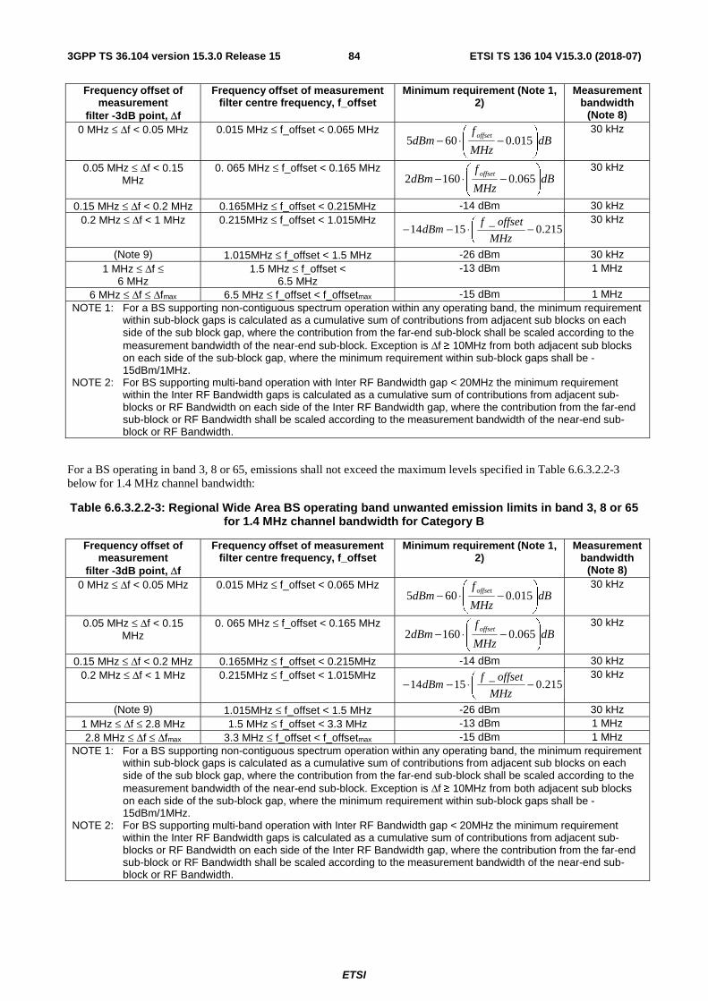
ETSI
ETSI TS 136 104 V15.3.0 (2018-07)843GPP TS 36.104 version 15.3.0 Release 15
Frequency offset of measurement
filter -3dB point, Δf
Frequency offset of measurement filter centre frequency, f_offset
Minimum requirement (Note 1, 2)
Measurement bandwidth
(Note 8) 0 MHz ≤ Δf < 0.05 MHz 0.015 MHz ≤ f_offset < 0.065 MHz
dBMHz
fdBm
offset
−⋅− 015.0605
30 kHz
0.05 MHz ≤ Δf < 0.15 MHz
0. 065 MHz ≤ f_offset < 0.165 MHz dB
MHz
fdBm
offset
−⋅− 065.01602
30 kHz
0.15 MHz ≤ Δf < 0.2 MHz 0.165MHz ≤ f_offset < 0.215MHz -14 dBm 30 kHz 0.2 MHz ≤ Δf < 1 MHz 0.215MHz ≤ f_offset < 1.015MHz
MHz
offsetfdBm
−⋅−− 215.0_
151430 kHz
(Note 9) 1.015MHz ≤ f_offset < 1.5 MHz -26 dBm 30 kHz 1 MHz ≤ Δf ≤
6 MHz 1.5 MHz ≤ f_offset <
6.5 MHz -13 dBm 1 MHz
6 MHz ≤ Δf ≤ Δfmax 6.5 MHz ≤ f_offset < f_offsetmax -15 dBm 1 MHz NOTE 1: For a BS supporting non-contiguous spectrum operation within any operating band, the minimum requirement
within sub-block gaps is calculated as a cumulative sum of contributions from adjacent sub blocks on each side of the sub block gap, where the contribution from the far-end sub-block shall be scaled according to the measurement bandwidth of the near-end sub-block. Exception is Δf ≥ 10MHz from both adjacent sub blocks on each side of the sub-block gap, where the minimum requirement within sub-block gaps shall be -15dBm/1MHz.
NOTE 2: For BS supporting multi-band operation with Inter RF Bandwidth gap < 20MHz the minimum requirement within the Inter RF Bandwidth gaps is calculated as a cumulative sum of contributions from adjacent sub-blocks or RF Bandwidth on each side of the Inter RF Bandwidth gap, where the contribution from the far-end sub-block or RF Bandwidth shall be scaled according to the measurement bandwidth of the near-end sub-block or RF Bandwidth.
For a BS operating in band 3, 8 or 65, emissions shall not exceed the maximum levels specified in Table 6.6.3.2.2-3 below for 1.4 MHz channel bandwidth:
Table 6.6.3.2.2-3: Regional Wide Area BS operating band unwanted emission limits in band 3, 8 or 65 for 1.4 MHz channel bandwidth for Category B
Frequency offset of measurement
filter -3dB point, Δf
Frequency offset of measurement filter centre frequency, f_offset
Minimum requirement (Note 1, 2)
Measurement bandwidth
(Note 8) 0 MHz ≤ Δf < 0.05 MHz 0.015 MHz ≤ f_offset < 0.065 MHz
dBMHz
fdBm
offset
−⋅− 015.0605
30 kHz
0.05 MHz ≤ Δf < 0.15 MHz
0. 065 MHz ≤ f_offset < 0.165 MHz dB
MHz
fdBm
offset
−⋅− 065.01602
30 kHz
0.15 MHz ≤ Δf < 0.2 MHz 0.165MHz ≤ f_offset < 0.215MHz -14 dBm 30 kHz 0.2 MHz ≤ Δf < 1 MHz 0.215MHz ≤ f_offset < 1.015MHz
MHz
offsetfdBm
−⋅−− 215.0_
151430 kHz
(Note 9) 1.015MHz ≤ f_offset < 1.5 MHz -26 dBm 30 kHz 1 MHz ≤ Δf ≤ 2.8 MHz 1.5 MHz ≤ f_offset < 3.3 MHz -13 dBm 1 MHz 2.8 MHz ≤ Δf ≤ Δfmax 3.3 MHz ≤ f_offset < f_offsetmax -15 dBm 1 MHz
NOTE 1: For a BS supporting non-contiguous spectrum operation within any operating band, the minimum requirement within sub-block gaps is calculated as a cumulative sum of contributions from adjacent sub blocks on each side of the sub block gap, where the contribution from the far-end sub-block shall be scaled according to the measurement bandwidth of the near-end sub-block. Exception is Δf ≥ 10MHz from both adjacent sub blocks on each side of the sub-block gap, where the minimum requirement within sub-block gaps shall be -15dBm/1MHz.
NOTE 2: For BS supporting multi-band operation with Inter RF Bandwidth gap < 20MHz the minimum requirement within the Inter RF Bandwidth gaps is calculated as a cumulative sum of contributions from adjacent sub-blocks or RF Bandwidth on each side of the Inter RF Bandwidth gap, where the contribution from the far-end sub-block or RF Bandwidth shall be scaled according to the measurement bandwidth of the near-end sub-block or RF Bandwidth.

ETSI
ETSI TS 136 104 V15.3.0 (2018-07)853GPP TS 36.104 version 15.3.0 Release 15
6.6.3.2A Minimum requirements for Local Area BS (Category A and B)
For Local Area BS, emissions shall not exceed the maximum levels specified in Tables 6.6.3.2A-1 to 6.6.3.2A-3.
Table 6.6.3.2A-1: Local Area BS operating band unwanted emission limits for 1.4 MHz channel bandwidth
Frequency offset of measurement
filter -3dB point, Δf
Frequency offset of measurement filter centre
frequency, f_offset
Minimum requirement (Note 1, 2) Measurement bandwidth
(Note 8)
0 MHz ≤ Δf < 1.4 MHz
0.05 MHz ≤ f_offset < 1.45 MHz 10 _
21 0.051.4
f offsetdBm dB
MHz − − −
100 kHz
1.4 MHz ≤ Δf < 2.8 MHz
1.45 MHz ≤ f_offset < 2.85 MHz -31 dBm 100 kHz
2.8 MHz ≤ Δf ≤ Δfmax 2.85 MHz ≤ f_offset < f_offsetmax -31 dBm 100 kHz NOTE 1: For a BS supporting non-contiguous spectrum operation within any operating band the minimum requirement
within sub-block gaps is calculated as a cumulative sum of contributions from adjacent sub blocks on each side of the sub block gap. Exception is Δf ≥ 10MHz from both adjacent sub blocks on each side of the sub-block gap, where the minimum requirement within sub-block gaps shall be -31dBm/100kHz.
NOTE 2: For BS supporting multi-band operation with Inter RF Bandwidth gap < 20MHz the minimum requirement within the Inter RF Bandwidth gaps is calculated as a cumulative sum of contributions from adjacent sub-blocks or RF Bandwidth on each side of the Inter RF Bandwidth gap.
Table 6.6.3.2A-2: Local Area BS operating band unwanted emission limits for 3 MHz channel bandwidth
Frequency offset of measurement
filter -3dB point, Δf
Frequency offset of measurement filter centre
frequency, f_offset
Minimum requirement (Note 1, 2) Measurement bandwidth
(Note 8)
0 MHz ≤ Δf < 3 MHz 0.05 MHz ≤ f_offset < 3.05 MHz dBMHz
offsetfdBm
−−− 05.0_
3
1025
100 kHz
3 MHz ≤ Δf < 6 MHz 3.05 MHz ≤ f_offset < 6.05 MHz -35 dBm 100 kHz 6 MHz ≤ Δf ≤ Δfmax 6.05 MHz ≤ f_offset < f_offsetmax -35 dBm 100 kHz
NOTE 1: For a BS supporting non-contiguous spectrum operation within any operating band the minimum requirement within sub-block gaps is calculated as a cumulative sum of contributions from adjacent sub blocks on each side of the sub block gap. Exception is Δf ≥ 10MHz from both adjacent sub blocks on each side of the sub-block gap, where the minimum requirement within sub-block gaps shall be -35dBm/100kHz.
NOTE 2: For BS supporting multi-band operation with Inter RF Bandwidth gap < 20MHz the minimum requirement within the Inter RF Bandwidth gaps is calculated as a cumulative sum of contributions from adjacent sub-blocks or RF Bandwidth on each side of the Inter RF Bandwidth gap.
Table 6.6.3.2A-3: Local Area BS operating band unwanted emission limits for 5, 10, 15 and 20 MHz channel bandwidth
Frequency offset of measurement
filter -3dB point, Δf
Frequency offset of measurement filter centre
frequency, f_offset
Minimum requirement (Note 1, 2)) Measurement bandwidth
(Note 8) 0 MHz ≤ Δf < 5 MHz 0.05 MHz ≤ f_offset < 5.05 MHz
dBMHz
offsetfdBm
−−− 05.0_
5
730
100 kHz
5 MHz ≤ Δf < min(10 MHz, Δfmax)
5.05 MHz ≤ f_offset < min(10.05 MHz, f_offsetmax)
-37 dBm 100 kHz
10 MHz ≤ Δf ≤ Δfmax 10.05 MHz ≤ f_offset < f_offsetmax -37 dBm (Note 10) 100 kHz NOTE 1: For a BS supporting non-contiguous spectrum operation within any operating band the minimum requirement
within sub-block gaps is calculated as a cumulative sum of contributions from adjacent sub blocks on each side of the sub block gap. Exception is Δf ≥ 10MHz from both adjacent sub blocks on each side of the sub-block gap, where the minimum requirement within sub-block gaps shall be -37dBm/100kHz.
NOTE 2: For BS supporting multi-band operation with Inter RF Bandwidth gap < 20MHz the minimum requirement within the Inter RF Bandwidth gaps is calculated as a cumulative sum of contributions from adjacent sub-blocks or RF Bandwidth on each side of the Inter RF Bandwidth gap.

ETSI
ETSI TS 136 104 V15.3.0 (2018-07)863GPP TS 36.104 version 15.3.0 Release 15
6.6.3.2B Minimum requirements for Home BS (Category A and B)
For Home BS, emissions shall not exceed the maximum levels specified in Tables 6.6.3.2B-1 to 6.6.3.2B-3.
Table 6.6.3.2B-1: Home BS operating band unwanted emission limits for 1.4 MHz channel bandwidth
Frequency offset of measurement
filter -3dB point, Δf
Frequency offset of measurement filter centre
frequency, f_offset
Minimum requirement Measurement bandwidth
(Note 8)
0 MHz ≤ Δf < 1.4 MHz 0.05 MHz ≤ f_offset < 1.45 MHz 6 _
30 0.051.4
f offsetdBm dB
MHz− − −
100 kHz
1.4 MHz ≤ Δf < 2.8 MHz 1.45 MHz ≤ f_offset < 2.85 MHz -36 dBm 100 kHz 2.8 MHz ≤ Δf ≤ Δfmax 3.3 MHz ≤ f_offset < f_offsetmax 52 , 2dBm 20dBm
50 , P<2dBm
P dB P
dBm
− ≤ ≤−
(Note 11)
1MHz
Table 6.6.3.2B-2: Home BS operating band unwanted emission limits for 3 MHz channel bandwidth
Frequency offset of measurement
filter -3dB point, Δf
Frequency offset of measurement filter centre
frequency, f_offset
Minimum requirement Measurement bandwidth
(Note 8)
0 MHz ≤ Δf < 3 MHz 0.05 MHz ≤ f_offset < 3.05 MHz _
34 2 0.05f offset
dBm dBMHz
− − −
100 kHz
3 MHz ≤ Δf < 6 MHz 3.05 MHz ≤ f_offset < 6.05 MHz -40 dBm 100 kHz 6 MHz ≤ Δf ≤ Δfmax 6.5 MHz ≤ f_offset < f_offsetmax 52 , 2dBm 20dBm
50 , P<2dBm
P dB P
dBm
− ≤ ≤−
(Note 11)
1MHz
Table 6.6.3.2B-3: Home BS operating band unwanted emission limits for 5, 10, 15 and 20 MHz channel bandwidth
Frequency offset of measurement
filter -3dB point, Δf
Frequency offset of measurement filter centre
frequency, f_offset
Minimum requirement Measurement bandwidth
(Note 8) 0 MHz ≤ Δf < 5 MHz 0.05 MHz ≤ f_offset < 5.05 MHz 6 _
36 0.055
f offsetdBm dB
MHz− − −
100 kHz
5 MHz ≤ Δf < min(10 MHz, Δfmax)
5.05 MHz ≤ f_offset < min(10.05 MHz, f_offsetmax)
-42 dBm 100 kHz
10 MHz ≤ Δf ≤ Δfmax 10.5 MHz ≤ f_offset < f_offsetmax 52 , 2dBm 20dBm
50 , P<2dBm
P dB P
dBm
− ≤ ≤−
(Note 10, Note 11)
1MHz
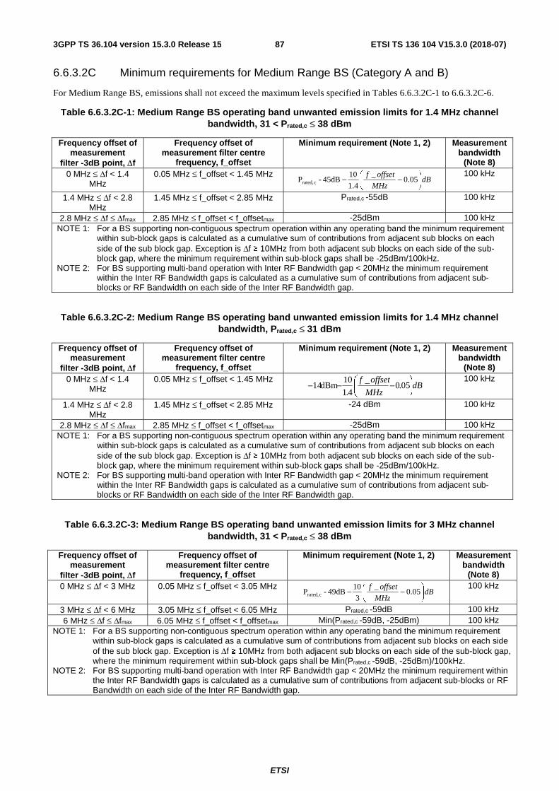
ETSI
ETSI TS 136 104 V15.3.0 (2018-07)873GPP TS 36.104 version 15.3.0 Release 15
6.6.3.2C Minimum requirements for Medium Range BS (Category A and B)
For Medium Range BS, emissions shall not exceed the maximum levels specified in Tables 6.6.3.2C-1 to 6.6.3.2C-6.
Table 6.6.3.2C-1: Medium Range BS operating band unwanted emission limits for 1.4 MHz channel bandwidth, 31 < Prated,c ≤ 38 dBm
Frequency offset of measurement
filter -3dB point, Δf
Frequency offset of measurement filter centre
frequency, f_offset
Minimum requirement (Note 1, 2) Measurement bandwidth
(Note 8) 0 MHz ≤ Δf < 1.4
MHz 0.05 MHz ≤ f_offset < 1.45 MHz
dBMHz
offsetf
−− 05.0_
4.1
1045dB-P crated,
100 kHz
1.4 MHz ≤ Δf < 2.8 MHz
1.45 MHz ≤ f_offset < 2.85 MHz Prated,c -55dB 100 kHz
2.8 MHz ≤ Δf ≤ Δfmax 2.85 MHz ≤ f_offset < f_offsetmax -25dBm 100 kHz NOTE 1: For a BS supporting non-contiguous spectrum operation within any operating band the minimum requirement
within sub-block gaps is calculated as a cumulative sum of contributions from adjacent sub blocks on each side of the sub block gap. Exception is Δf ≥ 10MHz from both adjacent sub blocks on each side of the sub-block gap, where the minimum requirement within sub-block gaps shall be -25dBm/100kHz.
NOTE 2: For BS supporting multi-band operation with Inter RF Bandwidth gap < 20MHz the minimum requirement within the Inter RF Bandwidth gaps is calculated as a cumulative sum of contributions from adjacent sub-blocks or RF Bandwidth on each side of the Inter RF Bandwidth gap.
Table 6.6.3.2C-2: Medium Range BS operating band unwanted emission limits for 1.4 MHz channel bandwidth, Prated,c ≤ 31 dBm
Frequency offset of measurement
filter -3dB point, Δf
Frequency offset of measurement filter centre
frequency, f_offset
Minimum requirement (Note 1, 2) Measurement bandwidth
(Note 8) 0 MHz ≤ Δf < 1.4
MHz 0.05 MHz ≤ f_offset < 1.45 MHz
dBMHz
offsetf
−−− 05.0_
4.1
10dBm14 100 kHz
1.4 MHz ≤ Δf < 2.8 MHz
1.45 MHz ≤ f_offset < 2.85 MHz -24 dBm 100 kHz
2.8 MHz ≤ Δf ≤ Δfmax 2.85 MHz ≤ f_offset < f_offsetmax -25dBm 100 kHz NOTE 1: For a BS supporting non-contiguous spectrum operation within any operating band the minimum requirement
within sub-block gaps is calculated as a cumulative sum of contributions from adjacent sub blocks on each side of the sub block gap. Exception is Δf ≥ 10MHz from both adjacent sub blocks on each side of the sub-block gap, where the minimum requirement within sub-block gaps shall be -25dBm/100kHz.
NOTE 2: For BS supporting multi-band operation with Inter RF Bandwidth gap < 20MHz the minimum requirement within the Inter RF Bandwidth gaps is calculated as a cumulative sum of contributions from adjacent sub-blocks or RF Bandwidth on each side of the Inter RF Bandwidth gap.
Table 6.6.3.2C-3: Medium Range BS operating band unwanted emission limits for 3 MHz channel bandwidth, 31 < Prated,c ≤ 38 dBm
Frequency offset of measurement
filter -3dB point, Δf
Frequency offset of measurement filter centre
frequency, f_offset
Minimum requirement (Note 1, 2) Measurement bandwidth
(Note 8) 0 MHz ≤ Δf < 3 MHz 0.05 MHz ≤ f_offset < 3.05 MHz
dBMHz
offsetf
−− 05.0_
3
1049dB-P crated,
100 kHz
3 MHz ≤ Δf < 6 MHz 3.05 MHz ≤ f_offset < 6.05 MHz Prated,c -59dB 100 kHz 6 MHz ≤ Δf ≤ Δfmax 6.05 MHz ≤ f_offset < f_offsetmax Min(Prated,c -59dB, -25dBm) 100 kHz
NOTE 1: For a BS supporting non-contiguous spectrum operation within any operating band the minimum requirement within sub-block gaps is calculated as a cumulative sum of contributions from adjacent sub blocks on each side of the sub block gap. Exception is Δf ≥ 10MHz from both adjacent sub blocks on each side of the sub-block gap, where the minimum requirement within sub-block gaps shall be Min(Prated,c -59dB, -25dBm)/100kHz.
NOTE 2: For BS supporting multi-band operation with Inter RF Bandwidth gap < 20MHz the minimum requirement within the Inter RF Bandwidth gaps is calculated as a cumulative sum of contributions from adjacent sub-blocks or RF Bandwidth on each side of the Inter RF Bandwidth gap.
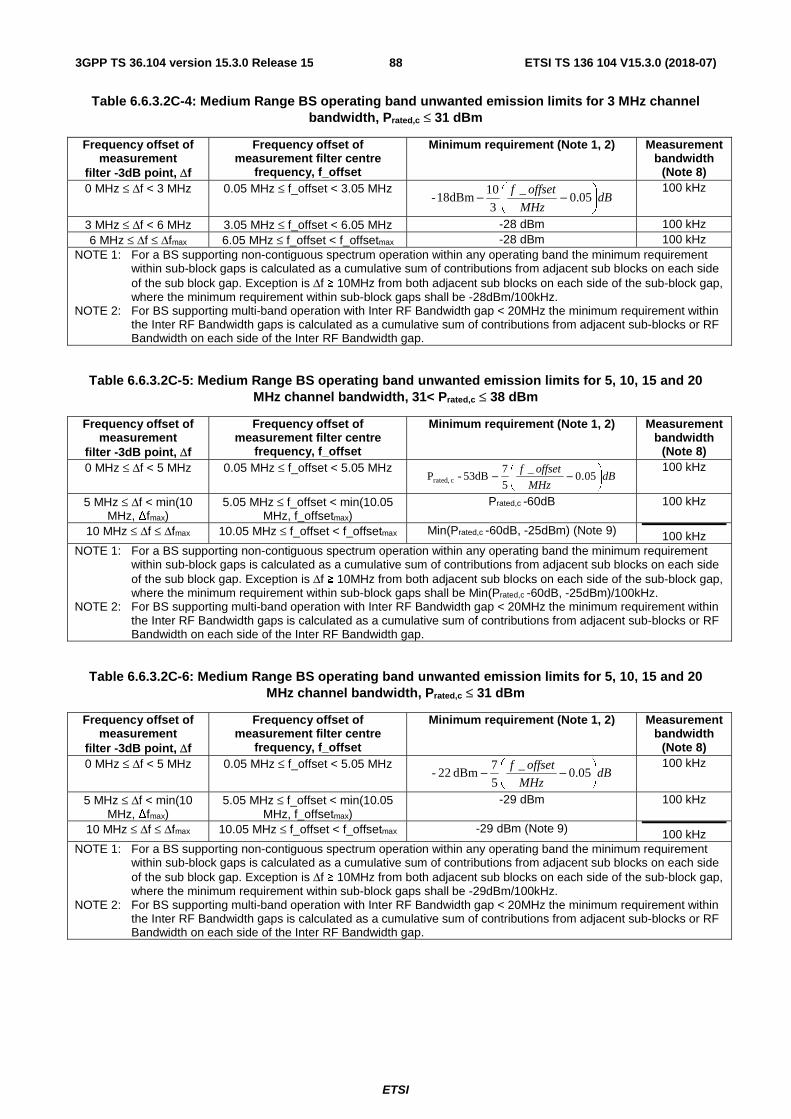
ETSI
ETSI TS 136 104 V15.3.0 (2018-07)883GPP TS 36.104 version 15.3.0 Release 15
Table 6.6.3.2C-4: Medium Range BS operating band unwanted emission limits for 3 MHz channel bandwidth, Prated,c ≤ 31 dBm
Frequency offset of measurement
filter -3dB point, Δf
Frequency offset of measurement filter centre
frequency, f_offset
Minimum requirement (Note 1, 2) Measurement bandwidth
(Note 8) 0 MHz ≤ Δf < 3 MHz 0.05 MHz ≤ f_offset < 3.05 MHz
dBMHz
offsetf
−− 05.0_
3
1018dBm- 100 kHz
3 MHz ≤ Δf < 6 MHz 3.05 MHz ≤ f_offset < 6.05 MHz -28 dBm 100 kHz 6 MHz ≤ Δf ≤ Δfmax 6.05 MHz ≤ f_offset < f_offsetmax -28 dBm 100 kHz
NOTE 1: For a BS supporting non-contiguous spectrum operation within any operating band the minimum requirement within sub-block gaps is calculated as a cumulative sum of contributions from adjacent sub blocks on each side of the sub block gap. Exception is Δf ≥ 10MHz from both adjacent sub blocks on each side of the sub-block gap, where the minimum requirement within sub-block gaps shall be -28dBm/100kHz.
NOTE 2: For BS supporting multi-band operation with Inter RF Bandwidth gap < 20MHz the minimum requirement within the Inter RF Bandwidth gaps is calculated as a cumulative sum of contributions from adjacent sub-blocks or RF Bandwidth on each side of the Inter RF Bandwidth gap.
Table 6.6.3.2C-5: Medium Range BS operating band unwanted emission limits for 5, 10, 15 and 20 MHz channel bandwidth, 31< Prated,c ≤ 38 dBm
Frequency offset of measurement
filter -3dB point, Δf
Frequency offset of measurement filter centre
frequency, f_offset
Minimum requirement (Note 1, 2) Measurement bandwidth
(Note 8) 0 MHz ≤ Δf < 5 MHz 0.05 MHz ≤ f_offset < 5.05 MHz
dBMHz
offsetf
−− 05.0_
5
753dB-P crated,
100 kHz
5 MHz ≤ Δf < min(10 MHz, Δfmax)
5.05 MHz ≤ f_offset < min(10.05 MHz, f_offsetmax)
Prated,c -60dB 100 kHz
10 MHz ≤ Δf ≤ Δfmax 10.05 MHz ≤ f_offset < f_offsetmax Min(Prated,c -60dB, -25dBm) (Note 9) 100 kHz NOTE 1: For a BS supporting non-contiguous spectrum operation within any operating band the minimum requirement
within sub-block gaps is calculated as a cumulative sum of contributions from adjacent sub blocks on each side of the sub block gap. Exception is Δf ≥ 10MHz from both adjacent sub blocks on each side of the sub-block gap, where the minimum requirement within sub-block gaps shall be Min(Prated,c -60dB, -25dBm)/100kHz.
NOTE 2: For BS supporting multi-band operation with Inter RF Bandwidth gap < 20MHz the minimum requirement within the Inter RF Bandwidth gaps is calculated as a cumulative sum of contributions from adjacent sub-blocks or RF Bandwidth on each side of the Inter RF Bandwidth gap.
Table 6.6.3.2C-6: Medium Range BS operating band unwanted emission limits for 5, 10, 15 and 20 MHz channel bandwidth, Prated,c ≤ 31 dBm
Frequency offset of measurement
filter -3dB point, Δf
Frequency offset of measurement filter centre
frequency, f_offset
Minimum requirement (Note 1, 2) Measurement bandwidth
(Note 8) 0 MHz ≤ Δf < 5 MHz 0.05 MHz ≤ f_offset < 5.05 MHz
dBMHz
offsetf
−− 05.0_
5
7dBm 22- 100 kHz
5 MHz ≤ Δf < min(10 MHz, Δfmax)
5.05 MHz ≤ f_offset < min(10.05 MHz, f_offsetmax)
-29 dBm 100 kHz
10 MHz ≤ Δf ≤ Δfmax 10.05 MHz ≤ f_offset < f_offsetmax -29 dBm (Note 9) 100 kHz NOTE 1: For a BS supporting non-contiguous spectrum operation within any operating band the minimum requirement
within sub-block gaps is calculated as a cumulative sum of contributions from adjacent sub blocks on each side of the sub block gap. Exception is Δf ≥ 10MHz from both adjacent sub blocks on each side of the sub-block gap, where the minimum requirement within sub-block gaps shall be -29dBm/100kHz.
NOTE 2: For BS supporting multi-band operation with Inter RF Bandwidth gap < 20MHz the minimum requirement within the Inter RF Bandwidth gaps is calculated as a cumulative sum of contributions from adjacent sub-blocks or RF Bandwidth on each side of the Inter RF Bandwidth gap.

ETSI
ETSI TS 136 104 V15.3.0 (2018-07)893GPP TS 36.104 version 15.3.0 Release 15
6.6.3.2D Minimum requirements for Local Area and Medium Range BS in Band 46 (Category A and B)
For Local Area and Medium Range BS operating in Band 46, emissions shall not exceed the maximum levels specified in Tables 6.6.3.2D-1 and Tables 6.6.3.2D-2.
Table 6.6.3.2D-1: Local Area and Medium Range BS operating band unwanted emission limits in Band 46 for 20MHz channel bandwidth
Frequency offset of measurement
filter -3dB point, Δf
Frequency offset of measurement filter centre
frequency, f_offset
Minimum requirement (Note 1) Measurement bandwidth
(Note 8) 0 MHz ≤ Δf < 1 MHz 0.05 MHz ≤ f_offset < 1.05 MHz
dBMHz
offsetf
−− 05.0_
1032.6dB-P c rated, 100 kHz
1 MHz ≤ Δf < min(10 MHz, Δfmax)
1.05 MHz ≤ f_offset < min(10.05 MHz, f_offsetmax) dB
MHz
offsetf
−− 05.1_
9
842.6dB-P c rated,
100 kHz
10 MHz ≤ Δf < min(20 MHz, Δfmax)
10.05 MHz ≤ f_offset < min(20.05 MHz, f_offsetmax) dB
MHz
offsetf
−− 05.10_
10
1250.6dB-P crated,
100 kHz
20 MHz ≤ Δf < min(170 MHz, Δfmax)
20.05 MHz ≤ f_offset < min(170.05 MHz, f_offsetmax)
Max(Prated,c - 62.6dB, -40dBm) 100 kHz
170 MHz ≤ Δf < min(206 MHz, Δfmax)
170.05 MHz ≤ f_offset < min(206.05 MHz, f_offsetmax)
Max(Prated,c - 64.6dB, -40dBm) 100 kHz
206 MHz ≤ Δf ≤ Δfmax 206.05 MHz ≤ f_offset < f_offsetmax
Max(Prated,c - 69.6dB, -40dBm) 100 kHz
NOTE 1: For a BS supporting non-contiguous spectrum operation within any operating band, the minimum requirement within sub-block gaps is calculated as a cumulative sum of contributions from adjacent sub blocks on each side of the sub block gap. Exception is Δf ≥ 20 MHz from both adjacent sub blocks on each side of the sub-block gap, where the minimum requirement within sub-block gaps shall be Max(Prated,c - 62.6dB, -40 dBm)/100kHz.
Table 6.6.3.2D-2: Local Area and Medium Range BS operating band unwanted emission limits in Band 46 for 10MHz channel bandwidth
Frequency offset of measurement
filter -3dB point, Δf
Frequency offset of measurement filter centre
frequency, f_offset
Minimum requirement (Note 1) Measurement bandwidth
(Note 8) 0 MHz ≤ Δf < 0.5 MHz 0.05 MHz ≤ f_offset < 0.55 MHz
dBMHz
offsetf
−− 05.0_
2029.5dB-P crated, 100 kHz
0.5 MHz ≤ Δf < 5 MHz 0.55 MHz ≤ f_offset < min(5.05 MHz, f_offsetmax) dB
MHz
offsetf
−− 55.0_
9
1639.5dB-P crated,
100 kHz
5 MHz ≤ Δf < min(10 MHz, Δfmax)
5.05 MHz ≤ f_offset < min(10.05 MHz, f_offsetmax) dB
MHz
offsetf
−− 05.5_
5
1247.5dB-P crated,
100 kHz
10 MHz ≤ Δf < min(85 MHz, Δfmax)
10.05 MHz ≤ f_offset < min(85.05 MHz, f_offsetmax)
Max(Prated,c – 59.5dB, -40dBm) 100 kHz
85 MHz ≤ Δf < min(103 MHz, Δfmax)
85.05 MHz ≤ f_offset < min(103.05 MHz, f_offsetmax)
Max(Prated,c – 61.5dB, -40dBm) 100 kHz
103 MHz ≤ Δf ≤ Δfmax 103.05 MHz ≤ f_offset < f_offsetmax
Max(Prated,c – 66.5dB, -40dBm) 100 kHz
NOTE 1: For a BS supporting non-contiguous spectrum operation within any operating band, the minimum requirement within sub-block gaps is calculated as a cumulative sum of contributions from adjacent sub blocks on each side of the sub block gap. Exception is Δf ≥ 10 MHz from both adjacent sub blocks on each side of the sub-block gap, where the minimum requirement within sub-block gaps shall be Max (Prated,c – 59.5dB, -40 dBm)/100kHz.

ETSI
ETSI TS 136 104 V15.3.0 (2018-07)903GPP TS 36.104 version 15.3.0 Release 15
6.6.3.2E Minimum requirements for standalone NB-IoT Wide Area BS
For standalone NB-IoT BS, emissions shall not exceed the maximum levels specified in Tables 6.6.3.2E-1.
Table 6.6.3.2E-1: Standalone NB-IoT BS operating band unwanted emission limits
Frequency offset of measurement
filter -3dB point, Δf
Frequency offset of measurement filter centre
frequency, f_offset
Minimum requirement (Note 1, 2, 3, 4, 5) Measurement bandwidth
(Note 8) 0 MHz ≤ Δf < 0.05
MHz 0.015 MHz ≤ f_offset <
0.065 MHz
)14
,015.0605(
dBm
XdBdBMHz
fdBmMax
offset
−
+
−⋅−
30 kHz
0.05 MHz ≤ Δf < 0.15 MHz
0.065 MHz ≤ f_offset < 0.165 MHz
)14
,065.01602(
dBm
XdBdBMHz
fdBmMax
offset
−
+
−⋅−
30 kHz
0.15 MHz ≤ Δf < 0.2 MHz
0.165 MHz ≤ f_offset < 0.215 MHz
-14 dBm 30 kHz
0.2 MHz ≤ Δf < 1 MHz
0.215 MHz ≤ f_offset < 1.015 MHz dB
MHz
offsetfdBm
−⋅−− 215.0_
1514
30 kHz
(Note 9) 1.015 MHz ≤ f_offset < 1.5 MHz
-26 dBm 30 kHz
1 MHz ≤ Δf ≤ min(Δfmax, 10 MHz)
1.5 MHz ≤ f_offset < min(f_offsetmax, 10.5 MHz)
-13 dBm 1 MHz
10 MHz ≤ Δf ≤ Δfmax 10.5 MHz ≤ f_offset < f_offsetmax
-15 dBm (Note 10) 1 MHz
NOTE 1: The limits in this table only apply for operation with a NB-IoT carrier adjacent to the Base Station RF Bandwidth edge.
NOTE 2: For a BS supporting non-contiguous spectrum operation within any operating band the minimum requirement within sub-block gaps is calculated as a cumulative sum of contributions from adjacent sub blocks on each side of the sub block gap.
NOTE 3: For a BS supporting multi-band operation with Inter RF Bandwidth gap < 20MHz the minimum requirement within the Inter RF Bandwidth gaps is calculated as a cumulative sum of contributions from adjacent sub-blocks or RF Bandwidth on each side of the Inter RF Bandwidth gap.]
NOTE 4: In case the carrier adjacent to the RF bandwidth edge is a NB-IoT carrier, the value of X = PNB-IoTcarrier – 43, where PNB-IoTcarrier is the power level of the NB-IoT carrier adjacent to the RF bandwidth edge. In other cases, X = 0.
NOTE 5: For BS that only support E-UTRA and NB-IoT multi-carrier operation, the requirements in this table do not apply to an E-UTRA BS from Release 8, which is upgraded to support E-UTRA and NB-IoT multi-carrier operation, where the upgrade does not affect existing RF parts of the radio unit related to the requirements in this table. In this case, the requirements in subclauses 6.6.3.1 and 6.6.3.2 shall apply.
6.6.3.2F Minimum requirements for standalone NB-IoT Local Area BS
For standalone NB-IoT local area BS, emissions shall not exceed the maximum levels specified in Tables 6.6.3.2H-1.
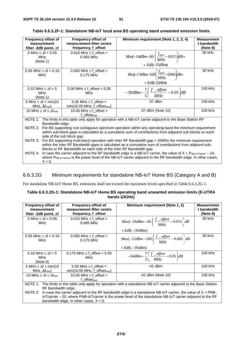
ETSI
ETSI TS 136 104 V15.3.0 (2018-07)913GPP TS 36.104 version 15.3.0 Release 15
Table 6.6.3.2F-1: Standalone NB-IoT local area BS operating band unwanted emission limits
Frequency offset of measurement
filter -3dB point, Δf
Frequency offset of measurement filter centre
frequency, f_offset
Minimum requirement (Note 1, 2, 3, 4) Measurement bandwidth
(Note 8) 0 MHz ≤ Δf < 0.05
MHz (Note 1)
0.015 MHz ≤ f_offset < 0.065 MHz
)35,
015.06014(
dBmXdB
dBMHz
fdBmMax offset
−+
+
−⋅−−
30 kHz
0.05 MHz ≤ Δf < 0.16 MHz
0.065 MHz ≤ f_offset < 0.175 MHz
)35,
065.016017(
dBmXdB
dBMHz
fdBmMax offset
−+
+
−⋅−−
30 kHz
0.15 MHz ≤ Δf < 5 MHz
(Note 1)
0.05 MHz ≤ f_offset < 5.05 MHz dB
MHz
offsetfdBm
−−− 05.0_
5
730
100 kHz
5 MHz ≤ Δf < min(10 MHz, Δfmax)
5.05 MHz ≤ f_offset < min(10.05 MHz, f_offsetmax)
-37 dBm 100 kHz
10 MHz ≤ Δf ≤ Δfmax 10.05 MHz ≤ f_offset < f_offsetmax
-37 dBm (Note 10) 100 kHz
NOTE 1: The limits in this table only apply for operation with a NB-IoT carrier adjacent to the Base Station RF Bandwidth edge.
NOTE 2: For BS supporting non-contiguous spectrum operation within any operating band the minimum requirement within sub-block gaps is calculated as a cumulative sum of contributions from adjacent sub blocks on each side of the sub block gap.
NOTE 3: For BS supporting multi-band operation with Inter RF Bandwidth gap < 20MHz the minimum requirement within the Inter RF Bandwidth gaps is calculated as a cumulative sum of contributions from adjacent sub-blocks or RF Bandwidth on each side of the Inter RF Bandwidth gap.
NOTE 4: In case the carrier adjacent to the RF bandwidth edge is a NB-IoT carrier, the value of X = PNB-IoTcarrier – 24, where PNB-IoTcarrier is the power level of the NB-IoT carrier adjacent to the RF bandwidth edge. In other cases, X = 0.
6.6.3.2G Minimum requirements for standalone NB-IoT Home BS (Category A and B)
For standalone NB-IoT Home BS, emissions shall not exceed the maximum levels specified in Table 6.6.3.2G-1.
Table 6.6.3.2G-1: Standalone NB-IoT Home BS operating band unwanted emission limits (E-UTRA bands ≤3GHz)
Frequency offset of measurement
filter -3dB point, Δf
Frequency offset of measurement filter centre
frequency, f_offset
Minimum requirement (Note 1, 2) Measurement bandwidth
(Note 8) 0 MHz ≤ Δf < 0.05
MHz 0.015 MHz ≤ f_offset <
0.065 MHz _
( 18 60. 0.015
, 39 )
f offsetMax dBm dB
MHz
XdB dBm
− − −
+ −
30 kHz
0.05 MHz ≤ Δf < 0.16 MHz
0.065 MHz ≤ f_offset < 0.175 MHz
_( 21 160. 0.065
, 39 )
f offsetMax dBm dB
MHz
XdB dBm
− − −
+ −
30 kHz
0.16 MHz ≤ Δf < 5 MHz
(Note 8)
0.175 MHz ≤ f_offset < 5.05 MHz
7 _34 0.05
5
f offsetdBm dB
MHz − − −
100 kHz
5 MHz ≤ Δf < min(10 MHz, Δfmax)
5.05 MHz ≤ f_offset < min(10.05 MHz, f_offsetmax)
-41 dBm 100 kHz
10 MHz ≤ Δf ≤ Δfmax 10.05 MHz ≤ f_offset < f_offsetmax
-41 dBm (Note 10) 100 kHz
NOTE 1: The limits in this table only apply for operation with a standalone NB-IoT carrier adjacent to the Base Station RF Bandwidth edge.
NOTE 2: In case the carrier adjacent to the RF bandwidth edge is a standalone NB-IoT carrier, the value of X = PNB-IoTcarrier – 20, where PNB-IoTcarrier is the power level of the standalone NB-IoT carrier adjacent to the RF bandwidth edge. In other cases, X = 0.
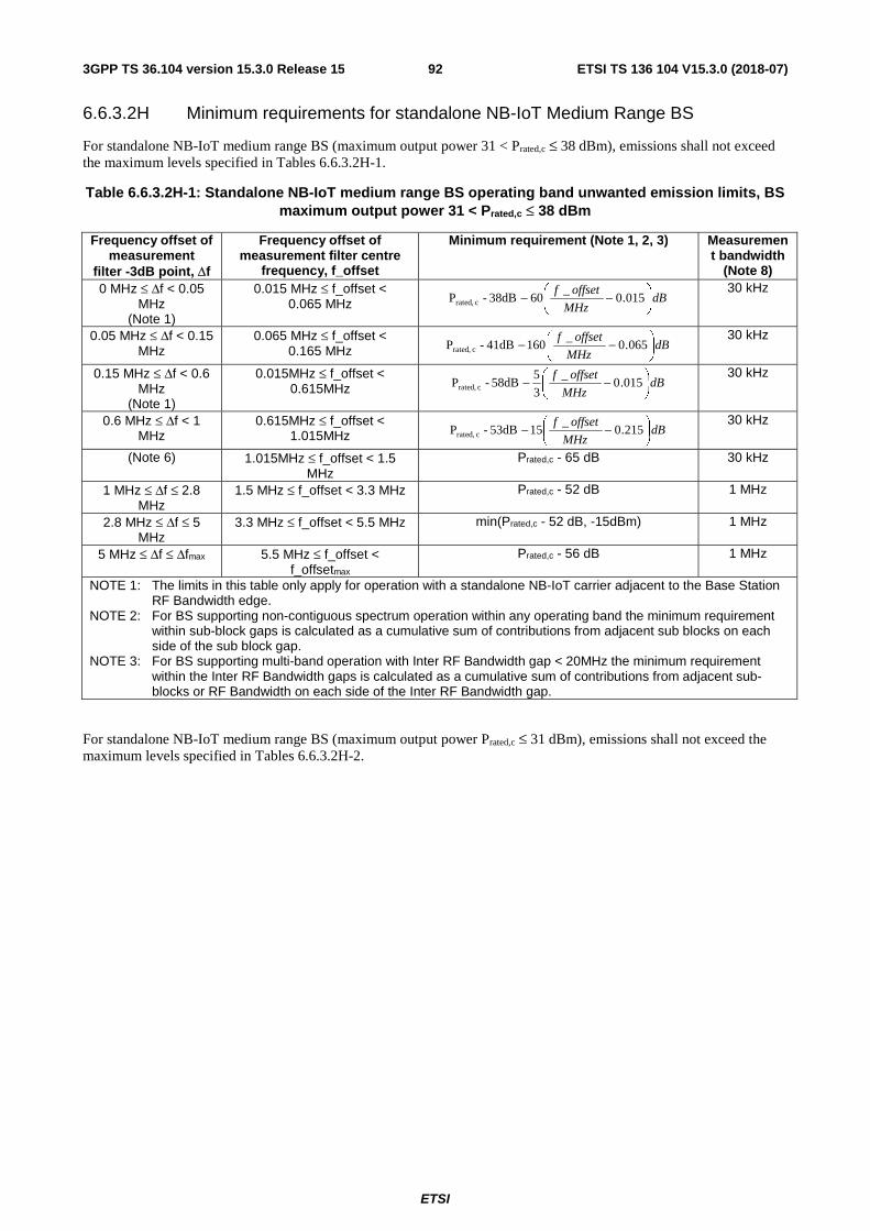
ETSI
ETSI TS 136 104 V15.3.0 (2018-07)923GPP TS 36.104 version 15.3.0 Release 15
6.6.3.2H Minimum requirements for standalone NB-IoT Medium Range BS
For standalone NB-IoT medium range BS (maximum output power 31 < Prated,c ≤ 38 dBm), emissions shall not exceed the maximum levels specified in Tables 6.6.3.2H-1.
Table 6.6.3.2H-1: Standalone NB-IoT medium range BS operating band unwanted emission limits, BS maximum output power 31 < Prated,c ≤ 38 dBm
Frequency offset of measurement
filter -3dB point, Δf
Frequency offset of measurement filter centre
frequency, f_offset
Minimum requirement (Note 1, 2, 3) Measurement bandwidth
(Note 8) 0 MHz ≤ Δf < 0.05
MHz (Note 1)
0.015 MHz ≤ f_offset < 0.065 MHz dB
MHz
offsetf
−− 015.0_
6038dB-P crated, 30 kHz
0.05 MHz ≤ Δf < 0.15 MHz
0.065 MHz ≤ f_offset < 0.165 MHz dB
MHz
offsetf
−− 065.0_
16041dB-P crated, 30 kHz
0.15 MHz ≤ Δf < 0.6 MHz
(Note 1)
0.015MHz ≤ f_offset < 0.615MHz dB
MHz
offsetf
−− 015.0_
3
558dB-P crated,
30 kHz
0.6 MHz ≤ Δf < 1 MHz
0.615MHz ≤ f_offset < 1.015MHz dB
MHz
offsetf
−− 215.0_
1553dB-P crated, 30 kHz
(Note 6) 1.015MHz ≤ f_offset < 1.5 MHz
Prated,c - 65 dB 30 kHz
1 MHz ≤ Δf ≤ 2.8 MHz
1.5 MHz ≤ f_offset < 3.3 MHz Prated,c - 52 dB 1 MHz
2.8 MHz ≤ Δf ≤ 5 MHz
3.3 MHz ≤ f_offset < 5.5 MHz min(Prated,c - 52 dB, -15dBm) 1 MHz
5 MHz ≤ Δf ≤ Δfmax 5.5 MHz ≤ f_offset < f_offsetmax
Prated,c - 56 dB 1 MHz
NOTE 1: The limits in this table only apply for operation with a standalone NB-IoT carrier adjacent to the Base Station RF Bandwidth edge.
NOTE 2: For BS supporting non-contiguous spectrum operation within any operating band the minimum requirement within sub-block gaps is calculated as a cumulative sum of contributions from adjacent sub blocks on each side of the sub block gap.
NOTE 3: For BS supporting multi-band operation with Inter RF Bandwidth gap < 20MHz the minimum requirement within the Inter RF Bandwidth gaps is calculated as a cumulative sum of contributions from adjacent sub-blocks or RF Bandwidth on each side of the Inter RF Bandwidth gap.
For standalone NB-IoT medium range BS (maximum output power Prated,c ≤ 31 dBm), emissions shall not exceed the maximum levels specified in Tables 6.6.3.2H-2.

ETSI
ETSI TS 136 104 V15.3.0 (2018-07)933GPP TS 36.104 version 15.3.0 Release 15
Table 6.6.3.2H-2: Standalone NB-IoT medium range BS operating band unwanted emission limits, BS maximum output power Prated,c ≤ 31 dBm
Frequency offset of measurement
filter -3dB point, Δf
Frequency offset of measurement filter centre
frequency, f_offset
Minimum requirement (Note 1, 2, 3, 4) Measurement bandwidth
(Note 8) 0 MHz ≤ Δf < 0.05
MHz (Note 1)
0.015 MHz ≤ f_offset < 0.065 MHz
)27,
015.0607(
dBmXdB
dBMHz
fdBmMax
offset
−+
+
−⋅−−
30 kHz
0.05 MHz ≤ Δf < 0.15 MHz
0.065 MHz ≤ f_offset < 0.165 MHz
)27,
065.016010(
dBmXdB
dBMHz
fdBmMax
offset
−+
+
−⋅−−
30 kHz
0.15 MHz ≤ Δf < 0.6 MHz
(Note 1)
0.015MHz ≤ f_offset < 0.615MHz
5 _27 0.015
3
f offsetdBm dB
MHz − − −
30 kHz
0.6 MHz ≤ Δf < 1 MHz
0.615MHz ≤ f_offset < 1.015MHz
_22 15 0.215
f offsetdBm dB
MHz − − ⋅ −
30 kHz
(Note 6) 1.015MHz ≤ f_offset < 1.5 MHz
-34 dBm 30 kHz
1 MHz ≤ Δf ≤ 5 MHz 1.5 MHz ≤ f_offset < 5.5 MHz -21 dBm 1 MHz 5 MHz ≤ Δf ≤ Δfmax 5.5 MHz ≤ f_offset <
f_offsetmax -25 dBm 1 MHz
NOTE 1: The limits in this table only apply for operation with a NB-IoT carrier adjacent to the Base Station RF Bandwidth edge.
NOTE 2: For BS supporting non-contiguous spectrum operation within any operating band the minimum requirement within sub-block gaps is calculated as a cumulative sum of contributions from adjacent sub blocks on each side of the sub block gap.
NOTE 3: For BS supporting multi-band operation with Inter RF Bandwidth gap < 20MHz the minimum requirement within the Inter RF Bandwidth gaps is calculated as a cumulative sum of contributions from adjacent sub-blocks or RF Bandwidth on each side of the Inter RF Bandwidth gap.
NOTE 4: In case the carrier adjacent to the RF bandwidth edge is a NB-IoT carrier, the value of X = PNB-IoTcarrier – 31, where PNB-IoTcarrier is the power level of the NB-IoT carrier adjacent to the RF bandwidth edge. In other cases, X = 0.
6.6.3.3 Additional requirements
These requirements may be applied for the protection of other systems operating inside or near each supported E-UTRA, E-UTRA with NB-IoT and NB-IoT BS downlink operating band. The limits may apply as an optional protection of such systems that are deployed in the same geographical area as the E-UTRA, E-UTRA with NB-IoT and NB-IoT BS, or they may be set by local or regional regulation as a mandatory requirement for an E-UTRA operating band. It is in some cases not stated in the present document whether a requirement is mandatory or under what exact circumstances that a limit applies, since this is set by local or regional regulation. An overview of regional requirements in the present document is given in subclause 4.3.
In certain regions the following requirement may apply. For E-UTRA, E-UTRA with NB-IoT and NB-IoT BS operating in Bands 5, 26, 27 or 28, emissions shall not exceed the maximum levels specified in Tables 6.6.3.3-1.
Table 6.6.3.3-1: Additional operating band unwanted emission limits for E-UTRA bands <1GHz
Channel bandwidth
Frequency offset of measurement
filter -3dB point, Δf
Frequency offset of measurement filter centre
frequency, f_offset
Minimum requirement
Measurement bandwidth
(Note 8) 200 kHz 0 MHz ≤ Δf < 1 MHz 0.005 MHz ≤ f_offset < 0.995 MHz -6 dBm 10 kHz 1.4 MHz 0 MHz ≤ Δf < 1 MHz 0.005 MHz ≤ f_offset < 0.995 MHz -14 dBm 10 kHz 3 MHz 0 MHz ≤ Δf < 1 MHz 0.015 MHz ≤ f_offset < 0.985 MHz -13 dBm 30 kHz 5 MHz 0 MHz ≤ Δf < 1 MHz 0.015 MHz ≤ f_offset < 0.985 MHz -15 dBm 30 kHz 10 MHz 0 MHz ≤ Δf < 1 MHz 0.05 MHz ≤ f_offset < 0.95 MHz -13 dBm 100 kHz 15 MHz 0 MHz ≤ Δf < 1 MHz 0.05 MHz ≤ f_offset < 0.95 MHz -13 dBm 100 kHz 20 MHz 0 MHz ≤ Δf < 1 MHz 0.05 MHz ≤ f_offset < 0.95 MHz -13 dBm 100 kHz
All 1 MHz ≤ Δf < Δfmax 1.05 MHz ≤ f_offset < f_offsetmax -13 dBm 100 kHz
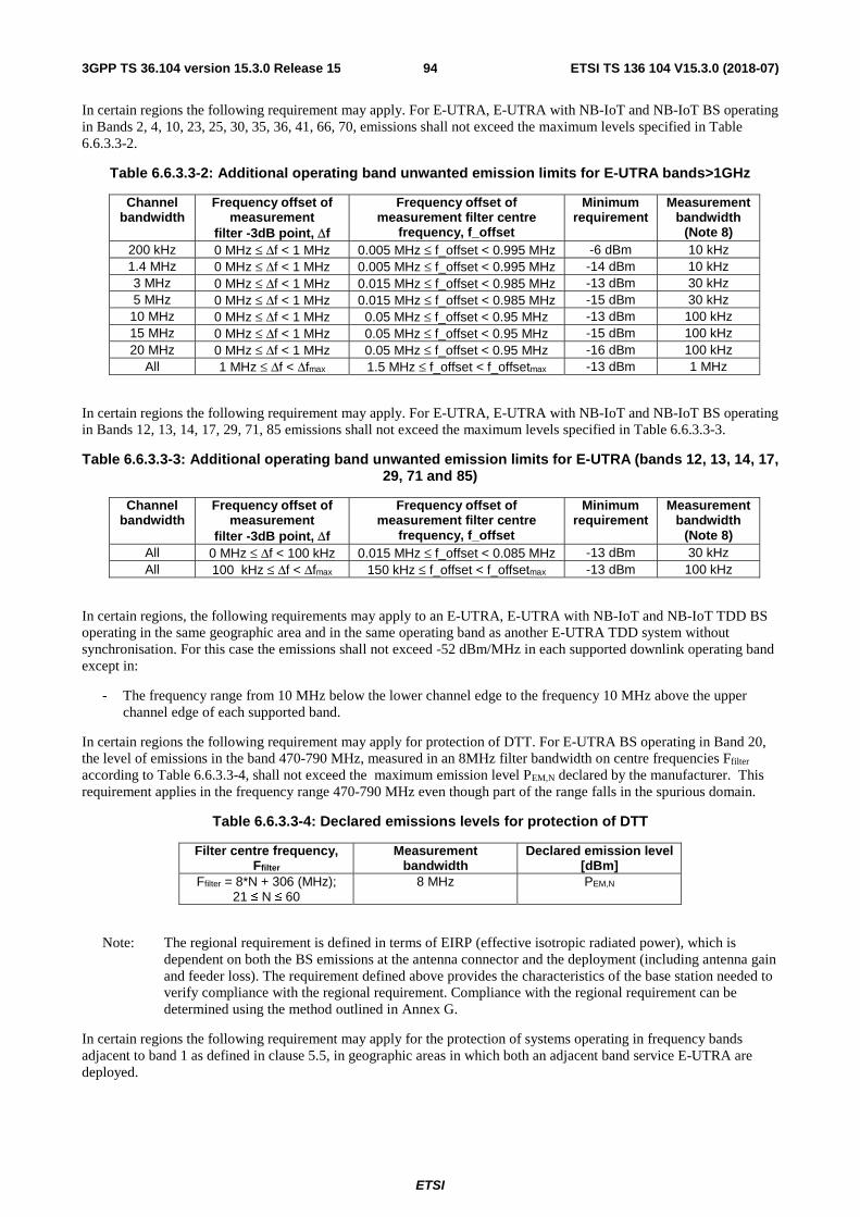
ETSI
ETSI TS 136 104 V15.3.0 (2018-07)943GPP TS 36.104 version 15.3.0 Release 15
In certain regions the following requirement may apply. For E-UTRA, E-UTRA with NB-IoT and NB-IoT BS operating in Bands 2, 4, 10, 23, 25, 30, 35, 36, 41, 66, 70, emissions shall not exceed the maximum levels specified in Table 6.6.3.3-2.
Table 6.6.3.3-2: Additional operating band unwanted emission limits for E-UTRA bands>1GHz
Channel bandwidth
Frequency offset of measurement
filter -3dB point, Δf
Frequency offset of measurement filter centre
frequency, f_offset
Minimum requirement
Measurement bandwidth
(Note 8) 200 kHz 0 MHz ≤ Δf < 1 MHz 0.005 MHz ≤ f_offset < 0.995 MHz -6 dBm 10 kHz 1.4 MHz 0 MHz ≤ Δf < 1 MHz 0.005 MHz ≤ f_offset < 0.995 MHz -14 dBm 10 kHz 3 MHz 0 MHz ≤ Δf < 1 MHz 0.015 MHz ≤ f_offset < 0.985 MHz -13 dBm 30 kHz 5 MHz 0 MHz ≤ Δf < 1 MHz 0.015 MHz ≤ f_offset < 0.985 MHz -15 dBm 30 kHz 10 MHz 0 MHz ≤ Δf < 1 MHz 0.05 MHz ≤ f_offset < 0.95 MHz -13 dBm 100 kHz 15 MHz 0 MHz ≤ Δf < 1 MHz 0.05 MHz ≤ f_offset < 0.95 MHz -15 dBm 100 kHz 20 MHz 0 MHz ≤ Δf < 1 MHz 0.05 MHz ≤ f_offset < 0.95 MHz -16 dBm 100 kHz
All 1 MHz ≤ Δf < Δfmax 1.5 MHz ≤ f_offset < f_offsetmax -13 dBm 1 MHz
In certain regions the following requirement may apply. For E-UTRA, E-UTRA with NB-IoT and NB-IoT BS operating in Bands 12, 13, 14, 17, 29, 71, 85 emissions shall not exceed the maximum levels specified in Table 6.6.3.3-3.
Table 6.6.3.3-3: Additional operating band unwanted emission limits for E-UTRA (bands 12, 13, 14, 17, 29, 71 and 85)
Channel bandwidth
Frequency offset of measurement
filter -3dB point, Δf
Frequency offset of measurement filter centre
frequency, f_offset
Minimum requirement
Measurement bandwidth
(Note 8) All 0 MHz ≤ Δf < 100 kHz 0.015 MHz ≤ f_offset < 0.085 MHz -13 dBm 30 kHz All 100 kHz ≤ Δf < Δfmax 150 kHz ≤ f_offset < f_offsetmax -13 dBm 100 kHz
In certain regions, the following requirements may apply to an E-UTRA, E-UTRA with NB-IoT and NB-IoT TDD BS operating in the same geographic area and in the same operating band as another E-UTRA TDD system without synchronisation. For this case the emissions shall not exceed -52 dBm/MHz in each supported downlink operating band except in:
- The frequency range from 10 MHz below the lower channel edge to the frequency 10 MHz above the upper channel edge of each supported band.
In certain regions the following requirement may apply for protection of DTT. For E-UTRA BS operating in Band 20, the level of emissions in the band 470-790 MHz, measured in an 8MHz filter bandwidth on centre frequencies Ffilter according to Table 6.6.3.3-4, shall not exceed the maximum emission level PEM,N declared by the manufacturer. This requirement applies in the frequency range 470-790 MHz even though part of the range falls in the spurious domain.
Table 6.6.3.3-4: Declared emissions levels for protection of DTT
Filter centre frequency, Ffilter
Measurement bandwidth
Declared emission level [dBm]
Ffilter = 8*N + 306 (MHz); 21 ≤ N ≤ 60
8 MHz PEM,N
Note: The regional requirement is defined in terms of EIRP (effective isotropic radiated power), which is dependent on both the BS emissions at the antenna connector and the deployment (including antenna gain and feeder loss). The requirement defined above provides the characteristics of the base station needed to verify compliance with the regional requirement. Compliance with the regional requirement can be determined using the method outlined in Annex G.
In certain regions the following requirement may apply for the protection of systems operating in frequency bands adjacent to band 1 as defined in clause 5.5, in geographic areas in which both an adjacent band service E-UTRA are deployed.

ETSI
ETSI TS 136 104 V15.3.0 (2018-07)953GPP TS 36.104 version 15.3.0 Release 15
The power of any spurious emission shall not exceed:
Table 6.6.3.3-5: Emissions limits for protection of adjacent band services
Operating Band
Frequency range Maximum Level Measurement Bandwidth
1 2100-2105 MHz -30 + 3.4 ⋅ (f - 2100 MHz) dBm 1 MHz 2175-2180 MHz -30 + 3.4 ⋅ (2180 MHz - f) dBm 1 MHz
In regions where FCC regulation applies, requirements for protection of GPS according to FCC Order DA 10-534 applies for operation in Band 24. The following normative requirement covers the base station, to be used together with other information about the site installation to verify compliance with the requirement in FCC Order DA 10-534. The requirement applies to BS operating in Band 24 to ensure that appropriate interference protection is provided to the 1559 – 1610 MHz band. This requirement applies to the frequency range 1559-1610 MHz, even though part of this range falls within the spurious domain.
The level of emissions in the 1559 – 1610 MHz band, measured in measurement bandwidth according to Table 6.6.3.3-6 shall not exceed the maximum emission levels PE_1MHz and PE_1kHz declared by the manufacturer.
Table 6.6.3.3-6: Declared emissions levels for protection of the 1559-1610 MHz band
Operating Band Frequency range Declared emission level [dBW]
(Measurement bandwidth = 1 MHz)
Declared emission level [dBW] of
discrete emissions of less than 700 Hz
bandwidth (Measurement
bandwidth = 1 kHz) 24 1559 - 1610 MHz PE_1MHz PE_1kHz
Note: The regional requirement in FCC Order DA 10-534 is defined in terms of EIRP (effective isotropic radiated power), which is dependent on both the BS emissions at the antenna connector and the deployment (including antenna gain and feeder loss). The EIRP level is calculated using: PEIRP = PE + Gant where PE denotes the BS unwanted emission level at the antenna connector, Gant equals the BS antenna gain minus feeder loss. The requirement defined above provides the characteristics of the base station needed to verify compliance with the regional requirement.
The following requirement may apply to E-UTRA, E-UTRA with NB-IoT and NB-IoT BS operating in Band 41 in certain regions. Emissions shall not exceed the maximum levels specified in Table 6.6.3.3-7.
Table 6.6.3.3-7: Additional operating band unwanted emission limits for Band 41
Channel bandwidth
Frequency offset of measurement
filter -3dB point, Δf
Frequency offset of measurement filter centre
frequency, f_offset
Minimum requirement
Measurement bandwidth
(Note 8) 10 MHz 10 MHz ≤ Δf < 20 MHz 10.5 MHz ≤ f_offset < 19.5 MHz -22 dBm 1 MHz 20 MHz 20 MHz ≤ Δf < 40 MHz 20.5 MHz ≤ f_offset < 39.5 MHz -22 dBm 1 MHz
NOTE: This requirement applies for carriers allocated within 2545-2575MHz or 2595-2645MHz.
In certain regions, the following requirements may apply to E-UTRA BS operating in Band 32 within 1452-1492 MHz, in Band 75 within 1432-1517 MHz and in Band 76 within 1427-1432 MHz. The level of operating band unwanted emissions, measured on centre frequencies f_offset with filter bandwidth, according to Table 6.6.3.3-8, shall neither exceed the maximum emission level PEM,B32,B75,B76,a , PEM,B32,B75,B76,b nor PEM,B32,B75,B76,c declared by the manufacturer.
For Band 32, this requirement applies in the frequency range 1452-1492 MHz when non-Mobile/Fixed Communications Network (MFCN) services are deployed in adjacent frequency ranges, while it applies also within 1427-1452 MHz and/or 1492-1517 MHz when MFCN services are deployed in such frequency ranges, even though part of the ranges falls in the spurious domain. For Band 75, this requirement applies in the frequency range 1427-1517 MHz. For Band 76, this requirement applies in the frequency range 1432-1517 MHz even though part of the range falls in the spurious domain.

ETSI
ETSI TS 136 104 V15.3.0 (2018-07)963GPP TS 36.104 version 15.3.0 Release 15
Table 6.6.3.3-8: Declared operating band 32, 75 and 76 unwanted emission within 1427-1517 MHz
Frequency offset of measurement filter centre frequency, f_offset
Declared emission level [dBm]
Measurement bandwidth
2.5 MHz PEM,B32,B75,B76,a 5 MHz 7.5 MHz PEM,B32,B75,B76,b 5 MHz
12.5 MHz ≤ f_offset ≤ f_offsetmax PEM,B32,B75,B76,c 5 MHz NOTE: For Band 32, when non-MFCN services are deployed in the adjacent
bands, f_offsetmax denotes the frequency difference between the lower channel edge and 1454.5 MHz, and the frequency difference between the upper channel edge and 1489.5 MHz for the set channel position. For Band 32, when MFCN services are deployed in the adjacent frequencies, Band 75 and Band 76, f_offsetmax denotes the frequency difference between the lower channel edge and 1429.5 MHz, and the frequency difference between the upper channel edge and 1514.5 MHz for the set channel position.
NOTE: The regional requirement, included in [19], is defined in terms of EIRP per antenna, which is dependent on both the BS emissions at the antenna connector and the deployment (including antenna gain and feeder loss). The requirement defined above provides the characteristics of the base station needed to verify compliance with the regional requirement. The assessment of the EIRP level is described in Annex H.
In certain regions, the following requirement may apply to E-UTRA BS operating in Band 32 within 1452-1492 MHz for the protection of non-MFCN services in spectrum adjacent to the frequency range 1452-1492 MHz. The level of emissions, measured on centre frequencies Ffilter with filter bandwidth according to Table 6.6.3.3-9, shall neither exceed the maximum emission level PEM,B32,d nor PEM,B32,e declared by the manufacturer. This requirement applies in the frequency range 1429-1518MHz even though part of the range falls in the spurious domain.
Table 6.6.3.3-9: Operating band 32 declared emission outside 1452-1492 MHz
Filter centre frequency, Ffilter Declared emission level [dBm]
Measurement bandwidth
1429.5 MHz ≤ Ffilter ≤ 1448.5 MHz PEM,B32,d 1 MHz Ffilter = 1450.5 MHz PEM,B32,e 3 MHz Ffilter = 1493.5 MHz PEM,B32,e 3 MHz
1495.5 MHz ≤ Ffilter ≤ 1517.5 MHz PEM,B32,d 1 MHz
NOTE: The regional requirement, included in [16], is defined in terms of EIRP, which is dependent on both the BS emissions at the antenna connector and the deployment (including antenna gain and feeder loss). The requirement defined above provides the characteristics of the base station needed to verify compliance with the regional requirement. The assessment of the EIRP level is described in Annex H.
In certain regions, the following requirement may apply to BS operating in Band 50 and Band 75 within 1492-1517 MHz and in Band 74 within 1492-1518 MHz. The level of emissions, measured on centre frequencies Ffilter with filter bandwidth according to Table 6.6.3.3-9A, shall neither exceed the maximum emission level PEM,B50,B74,B75,a nor PEM,B50,B74,B75,b declared by the manufacturer.
Table 6.6.3.3-9A: Operating band 50, 74 and 75 declared emission above 1518 MHz
Filter centre frequency, Ffilter Declared emission level [dBm]
Measurement bandwidth
1518.5 MHz ≤ Ffilter ≤ 1519.5 MHz PEM,B50,B74,B75,a 1 MHz 1520.5 MHz ≤ Ffilter ≤ 1558.5 MHz PEM,B50,B74,B75,b 1 MHz
NOTE: The regional requirement, included in [19], is defined in terms of EIRP, which is dependent on both the BS emissions at the antenna connector and the deployment (including antenna gain and feeder loss). The requirement defined above provides the characteristics of the base station needed to verify compliance with the regional requirement. The assessment of the EIRP level is described in Annex H.
In certain regions, the following requirement may apply to E-UTRA BS operating in Band 50 and Band 75 within 1432-1452 MHz, and in Band 51 and Band 76. Emissions shall not exceed the maximum levels specified in Table 6.6.3.3-9B.

ETSI
ETSI TS 136 104 V15.3.0 (2018-07)973GPP TS 36.104 version 15.3.0 Release 15
Table 6.6.3.3-9B: Additional operating band unwanted emission limits for BS operating in Band 50 and 75 within 1432-1452 MHz, and in Band 51 and 76
Filter centre frequency, Ffilter Maximum Level [dBm]
Measurement Bandwidth
Ffilter = 1413.5 MHz -42 27 MHz
In addition for Band 46 operation, the BS may have to comply with the applicable operating band unwanted emission limits established regionally, when deployed in regions where those limits apply and under the conditions declared by the manufacturer. The regional requirements may be in the form of conducted power, power spectral density, EIRP and other types of limits. In case of regulatory limits based on EIRP, assessment of the EIRP level is described in Annex H.
In certain regions the following requirement may apply to E-UTRA BS operating in Band 45. Emissions shall not exceed the maximum levels specified in Table 6.6.3.3-10.
Table 6.6.3.3-10: Emissions limits for protection of adjacent band services
Operating Band
Filter centre frequency, Ffilter Maximum Level [dBm]
Measurement Bandwidth
45 Ffilter = 1467.5 -20 1 MHz Ffilter = 1468.5 -23 1 MHz Ffilter = 1469.5 -26 1 MHz Ffilter = 1470.5 -33 1 MHz Ffilter = 1471.5 -40 1 MHz
1472.5 MHz ≤ Ffilter ≤ 1491.5 MHz -47 1 MHz
The following requirement may apply to E-UTRA BS operating in Band 48 and Band 49 in certain regions. Emissions shall not exceed the maximum levels specified in Table 6.6.3.3-11.
Table 6.6.3.3-11: Additional operating band unwanted emission limits for Band 48 and Band 49
Channel bandwidth
Frequency offset of measurement
filter -3dB point, Δf
Frequency offset of measurement filter centre
frequency, f_offset
Minimum requirement
Measurement bandwidth
(Note 8) All 0 MHz ≤ Δf < 10 MHz 0.5 MHz ≤ f_offset < 9.5 MHz -13 dBm 1 MHz
The following notes are common to all subclauses in 6.6.3:
NOTE 6: Local or regional regulations may specify another excluded frequency range, which may include frequencies where synchronised E-UTRA TDD systems operate.
NOTE 7: E-UTRA TDD base stations that are synchronized can transmit without these additional co-existence requirements.
NOTE 8: As a general rule for the requirements in subclause 6.6.3, the resolution bandwidth of the measuring equipment should be equal to the measurement bandwidth. However, to improve measurement accuracy, sensitivity and efficiency, the resolution bandwidth may be smaller than the measurement bandwidth. When the resolution bandwidth is smaller than the measurement bandwidth, the result should be integrated over the measurement bandwidth in order to obtain the equivalent noise bandwidth of the measurement bandwidth.
NOTE 9: This frequency range ensures that the range of values of f_offset is continuous.
NOTE 10: The requirement is not applicable when Δfmax < 10 MHz.
NOTE 11: For Home BS, the parameter P is defined as the aggregated maximum output power of all transmit antenna connectors of Home BS.
6.6.4 Transmitter spurious emissions
The transmitter spurious emission limits apply from 9 kHz to 12.75 GHz, excluding the frequency range from 10 MHz below the lowest frequency of the downlink operating band up to 10 MHz above the highest frequency of the downlink operating band. For BS capable of multi-band operation where multiple bands are mapped on the same antenna
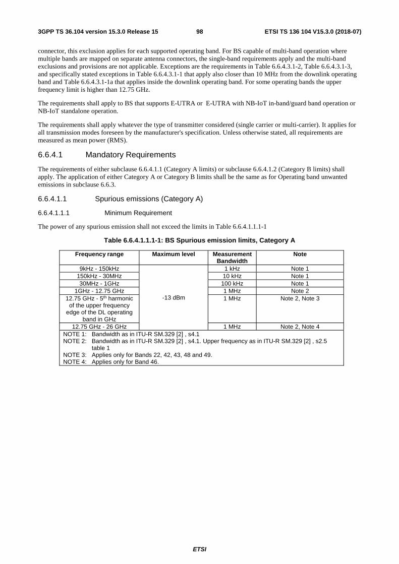
ETSI
ETSI TS 136 104 V15.3.0 (2018-07)983GPP TS 36.104 version 15.3.0 Release 15
connector, this exclusion applies for each supported operating band. For BS capable of multi-band operation where multiple bands are mapped on separate antenna connectors, the single-band requirements apply and the multi-band exclusions and provisions are not applicable. Exceptions are the requirements in Table 6.6.4.3.1-2, Table 6.6.4.3.1-3, and specifically stated exceptions in Table 6.6.4.3.1-1 that apply also closer than 10 MHz from the downlink operating band and Table 6.6.4.3.1-1a that applies inside the downlink operating band. For some operating bands the upper frequency limit is higher than 12.75 GHz.
The requirements shall apply to BS that supports E-UTRA or E-UTRA with NB-IoT in-band/guard band operation or NB-IoT standalone operation.
The requirements shall apply whatever the type of transmitter considered (single carrier or multi-carrier). It applies for all transmission modes foreseen by the manufacturer's specification. Unless otherwise stated, all requirements are measured as mean power (RMS).
6.6.4.1 Mandatory Requirements
The requirements of either subclause 6.6.4.1.1 (Category A limits) or subclause 6.6.4.1.2 (Category B limits) shall apply. The application of either Category A or Category B limits shall be the same as for Operating band unwanted emissions in subclause 6.6.3.
6.6.4.1.1 Spurious emissions (Category A)
6.6.4.1.1.1 Minimum Requirement
The power of any spurious emission shall not exceed the limits in Table 6.6.4.1.1.1-1
Table 6.6.4.1.1.1-1: BS Spurious emission limits, Category A
Frequency range Maximum level Measurement Bandwidth
Note
9kHz - 150kHz
-13 dBm
1 kHz Note 1 150kHz - 30MHz 10 kHz Note 1 30MHz - 1GHz 100 kHz Note 1
1GHz - 12.75 GHz 1 MHz Note 2 12.75 GHz - 5th harmonic
of the upper frequency edge of the DL operating
band in GHz
1 MHz Note 2, Note 3
12.75 GHz - 26 GHz 1 MHz Note 2, Note 4 NOTE 1: Bandwidth as in ITU-R SM.329 [2] , s4.1 NOTE 2: Bandwidth as in ITU-R SM.329 [2] , s4.1. Upper frequency as in ITU-R SM.329 [2] , s2.5
table 1 NOTE 3: Applies only for Bands 22, 42, 43, 48 and 49. NOTE 4: Applies only for Band 46.
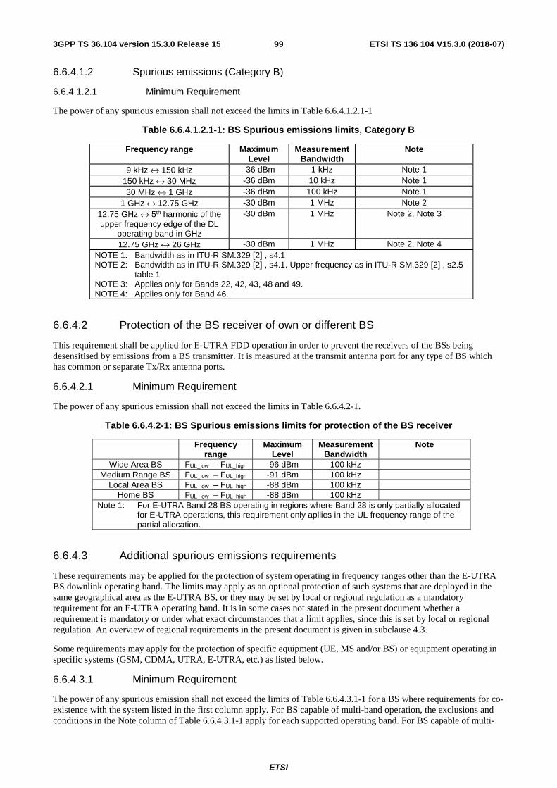
ETSI
ETSI TS 136 104 V15.3.0 (2018-07)993GPP TS 36.104 version 15.3.0 Release 15
6.6.4.1.2 Spurious emissions (Category B)
6.6.4.1.2.1 Minimum Requirement
The power of any spurious emission shall not exceed the limits in Table 6.6.4.1.2.1-1
Table 6.6.4.1.2.1-1: BS Spurious emissions limits, Category B
Frequency range Maximum Level
Measurement Bandwidth
Note
9 kHz ↔ 150 kHz -36 dBm 1 kHz Note 1 150 kHz ↔ 30 MHz -36 dBm 10 kHz Note 1 30 MHz ↔ 1 GHz -36 dBm 100 kHz Note 1
1 GHz ↔ 12.75 GHz -30 dBm 1 MHz Note 2 12.75 GHz ↔ 5th harmonic of the upper frequency edge of the DL
operating band in GHz
-30 dBm 1 MHz Note 2, Note 3
12.75 GHz ↔ 26 GHz -30 dBm 1 MHz Note 2, Note 4 NOTE 1: Bandwidth as in ITU-R SM.329 [2] , s4.1 NOTE 2: Bandwidth as in ITU-R SM.329 [2] , s4.1. Upper frequency as in ITU-R SM.329 [2] , s2.5
table 1 NOTE 3: Applies only for Bands 22, 42, 43, 48 and 49. NOTE 4: Applies only for Band 46.
6.6.4.2 Protection of the BS receiver of own or different BS
This requirement shall be applied for E-UTRA FDD operation in order to prevent the receivers of the BSs being desensitised by emissions from a BS transmitter. It is measured at the transmit antenna port for any type of BS which has common or separate Tx/Rx antenna ports.
6.6.4.2.1 Minimum Requirement
The power of any spurious emission shall not exceed the limits in Table 6.6.4.2-1.
Table 6.6.4.2-1: BS Spurious emissions limits for protection of the BS receiver
Frequency range
Maximum Level
Measurement Bandwidth
Note
Wide Area BS FUL_low – FUL_high -96 dBm 100 kHz Medium Range BS FUL_low – FUL_high -91 dBm 100 kHz
Local Area BS FUL_low – FUL_high -88 dBm 100 kHz Home BS FUL_low – FUL_high -88 dBm 100 kHz
Note 1: For E-UTRA Band 28 BS operating in regions where Band 28 is only partially allocated for E-UTRA operations, this requirement only apllies in the UL frequency range of the partial allocation.
6.6.4.3 Additional spurious emissions requirements
These requirements may be applied for the protection of system operating in frequency ranges other than the E-UTRA BS downlink operating band. The limits may apply as an optional protection of such systems that are deployed in the same geographical area as the E-UTRA BS, or they may be set by local or regional regulation as a mandatory requirement for an E-UTRA operating band. It is in some cases not stated in the present document whether a requirement is mandatory or under what exact circumstances that a limit applies, since this is set by local or regional regulation. An overview of regional requirements in the present document is given in subclause 4.3.
Some requirements may apply for the protection of specific equipment (UE, MS and/or BS) or equipment operating in specific systems (GSM, CDMA, UTRA, E-UTRA, etc.) as listed below.
6.6.4.3.1 Minimum Requirement
The power of any spurious emission shall not exceed the limits of Table 6.6.4.3.1-1 for a BS where requirements for co-existence with the system listed in the first column apply. For BS capable of multi-band operation, the exclusions and conditions in the Note column of Table 6.6.4.3.1-1 apply for each supported operating band. For BS capable of multi-

ETSI
ETSI TS 136 104 V15.3.0 (2018-07)1003GPP TS 36.104 version 15.3.0 Release 15
band operation where multiple bands are mapped on separate antenna connectors, the exclusions and conditions in the Note column of Table 6.6.4.3.1-1 apply for the operating band supported at that antenna connector.
Table 6.6.4.3.1-1: BS Spurious emissions limits for E-UTRA BS for co-existence with systems operating in other frequency bands
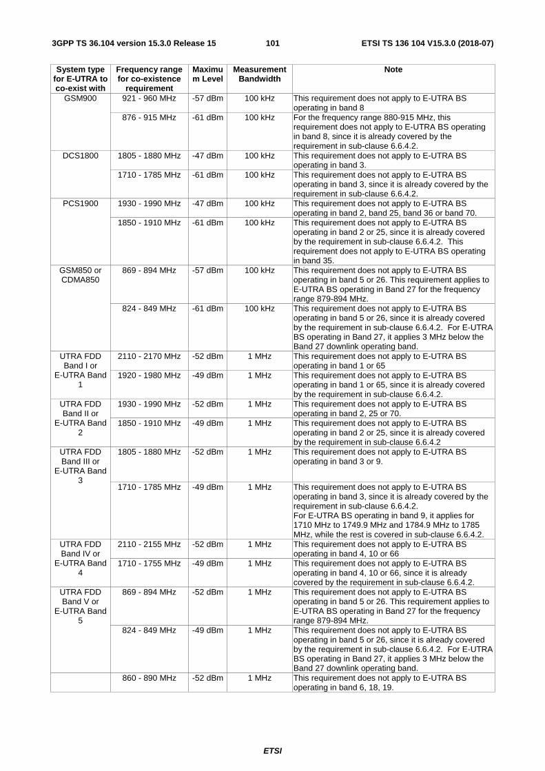
ETSI
ETSI TS 136 104 V15.3.0 (2018-07)1013GPP TS 36.104 version 15.3.0 Release 15
System type for E-UTRA to co-exist with
Frequency range for co-existence
requirement
Maximum Level
Measurement Bandwidth
Note
GSM900 921 - 960 MHz -57 dBm 100 kHz This requirement does not apply to E-UTRA BS operating in band 8
876 - 915 MHz -61 dBm 100 kHz For the frequency range 880-915 MHz, this requirement does not apply to E-UTRA BS operating in band 8, since it is already covered by the requirement in sub-clause 6.6.4.2.
DCS1800 1805 - 1880 MHz -47 dBm 100 kHz This requirement does not apply to E-UTRA BS operating in band 3.
1710 - 1785 MHz -61 dBm 100 kHz This requirement does not apply to E-UTRA BS operating in band 3, since it is already covered by the requirement in sub-clause 6.6.4.2.
PCS1900 1930 - 1990 MHz
-47 dBm 100 kHz This requirement does not apply to E-UTRA BS operating in band 2, band 25, band 36 or band 70.
1850 - 1910 MHz
-61 dBm 100 kHz This requirement does not apply to E-UTRA BS operating in band 2 or 25, since it is already covered by the requirement in sub-clause 6.6.4.2. This requirement does not apply to E-UTRA BS operating in band 35.
GSM850 or CDMA850
869 - 894 MHz -57 dBm 100 kHz This requirement does not apply to E-UTRA BS operating in band 5 or 26. This requirement applies to E-UTRA BS operating in Band 27 for the frequency range 879-894 MHz.
824 - 849 MHz -61 dBm 100 kHz This requirement does not apply to E-UTRA BS operating in band 5 or 26, since it is already covered by the requirement in sub-clause 6.6.4.2. For E-UTRA BS operating in Band 27, it applies 3 MHz below the Band 27 downlink operating band.
UTRA FDD Band I or
E-UTRA Band 1
2110 - 2170 MHz -52 dBm 1 MHz This requirement does not apply to E-UTRA BS operating in band 1 or 65
1920 - 1980 MHz
-49 dBm 1 MHz This requirement does not apply to E-UTRA BS operating in band 1 or 65, since it is already covered by the requirement in sub-clause 6.6.4.2.
UTRA FDD Band II or
E-UTRA Band 2
1930 - 1990 MHz
-52 dBm 1 MHz This requirement does not apply to E-UTRA BS operating in band 2, 25 or 70.
1850 - 1910 MHz
-49 dBm 1 MHz This requirement does not apply to E-UTRA BS operating in band 2 or 25, since it is already covered by the requirement in sub-clause 6.6.4.2
UTRA FDD Band III or
E-UTRA Band 3
1805 - 1880 MHz
-52 dBm 1 MHz This requirement does not apply to E-UTRA BS operating in band 3 or 9.
1710 - 1785 MHz -49 dBm 1 MHz This requirement does not apply to E-UTRA BS operating in band 3, since it is already covered by the requirement in sub-clause 6.6.4.2. For E-UTRA BS operating in band 9, it applies for 1710 MHz to 1749.9 MHz and 1784.9 MHz to 1785 MHz, while the rest is covered in sub-clause 6.6.4.2.
UTRA FDD Band IV or
E-UTRA Band 4
2110 - 2155 MHz -52 dBm 1 MHz This requirement does not apply to E-UTRA BS operating in band 4, 10 or 66
1710 - 1755 MHz -49 dBm 1 MHz This requirement does not apply to E-UTRA BS operating in band 4, 10 or 66, since it is already covered by the requirement in sub-clause 6.6.4.2.
UTRA FDD Band V or
E-UTRA Band 5
869 - 894 MHz -52 dBm 1 MHz This requirement does not apply to E-UTRA BS operating in band 5 or 26. This requirement applies to E-UTRA BS operating in Band 27 for the frequency range 879-894 MHz.
824 - 849 MHz -49 dBm 1 MHz This requirement does not apply to E-UTRA BS operating in band 5 or 26, since it is already covered by the requirement in sub-clause 6.6.4.2. For E-UTRA BS operating in Band 27, it applies 3 MHz below the Band 27 downlink operating band.
860 - 890 MHz -52 dBm 1 MHz This requirement does not apply to E-UTRA BS operating in band 6, 18, 19.
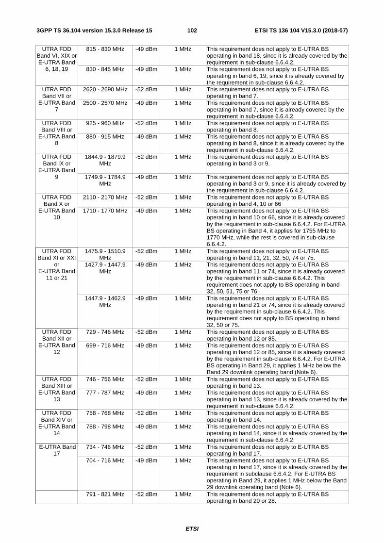
ETSI
ETSI TS 136 104 V15.3.0 (2018-07)1023GPP TS 36.104 version 15.3.0 Release 15
UTRA FDD Band VI, XIX or E-UTRA Band
6, 18, 19
815 - 830 MHz -49 dBm 1 MHz This requirement does not apply to E-UTRA BS operating in band 18, since it is already covered by the requirement in sub-clause 6.6.4.2.
830 - 845 MHz -49 dBm 1 MHz This requirement does not apply to E-UTRA BS operating in band 6, 19, since it is already covered by the requirement in sub-clause 6.6.4.2.
UTRA FDD Band VII or
E-UTRA Band 7
2620 - 2690 MHz -52 dBm 1 MHz This requirement does not apply to E-UTRA BS operating in band 7.
2500 - 2570 MHz -49 dBm 1 MHz This requirement does not apply to E-UTRA BS operating in band 7, since it is already covered by the requirement in sub-clause 6.6.4.2.
UTRA FDD Band VIII or
E-UTRA Band 8
925 - 960 MHz -52 dBm 1 MHz This requirement does not apply to E-UTRA BS operating in band 8.
880 - 915 MHz -49 dBm 1 MHz This requirement does not apply to E-UTRA BS operating in band 8, since it is already covered by the requirement in sub-clause 6.6.4.2.
UTRA FDD Band IX or
E-UTRA Band 9
1844.9 - 1879.9 MHz
-52 dBm 1 MHz This requirement does not apply to E-UTRA BS operating in band 3 or 9.
1749.9 - 1784.9 MHz
-49 dBm 1 MHz This requirement does not apply to E-UTRA BS operating in band 3 or 9, since it is already covered by the requirement in sub-clause 6.6.4.2.
UTRA FDD Band X or
E-UTRA Band 10
2110 - 2170 MHz -52 dBm 1 MHz This requirement does not apply to E-UTRA BS operating in band 4, 10 or 66
1710 - 1770 MHz -49 dBm 1 MHz This requirement does not apply to E-UTRA BS operating in band 10 or 66, since it is already covered by the requirement in sub-clause 6.6.4.2. For E-UTRA BS operating in Band 4, it applies for 1755 MHz to 1770 MHz, while the rest is covered in sub-clause 6.6.4.2.
UTRA FDD Band XI or XXI
or E-UTRA Band
11 or 21
1475.9 - 1510.9 MHz
-52 dBm 1 MHz This requirement does not apply to E-UTRA BS operating in band 11, 21, 32, 50, 74 or 75.
1427.9 - 1447.9 MHz
-49 dBm 1 MHz This requirement does not apply to E-UTRA BS operating in band 11 or 74, since it is already covered by the requirement in sub-clause 6.6.4.2. This requirement does not apply to BS operating in band 32, 50, 51, 75 or 76.
1447.9 - 1462.9 MHz
-49 dBm 1 MHz This requirement does not apply to E-UTRA BS operating in band 21 or 74, since it is already covered by the requirement in sub-clause 6.6.4.2. This requirement does not apply to BS operating in band 32, 50 or 75.
UTRA FDD Band XII or
E-UTRA Band 12
729 - 746 MHz -52 dBm 1 MHz This requirement does not apply to E-UTRA BS operating in band 12 or 85.
699 - 716 MHz -49 dBm 1 MHz This requirement does not apply to E-UTRA BS operating in band 12 or 85, since it is already covered by the requirement in sub-clause 6.6.4.2. For E-UTRA BS operating in Band 29, it applies 1 MHz below the Band 29 downlink operating band (Note 6).
UTRA FDD Band XIII or
E-UTRA Band 13
746 - 756 MHz -52 dBm 1 MHz This requirement does not apply to E-UTRA BS operating in band 13.
777 - 787 MHz -49 dBm 1 MHz This requirement does not apply to E-UTRA BS operating in band 13, since it is already covered by the requirement in sub-clause 6.6.4.2.
UTRA FDD Band XIV or
E-UTRA Band 14
758 - 768 MHz -52 dBm 1 MHz This requirement does not apply to E-UTRA BS operating in band 14.
788 - 798 MHz -49 dBm 1 MHz This requirement does not apply to E-UTRA BS operating in band 14, since it is already covered by the requirement in sub-clause 6.6.4.2.
E-UTRA Band 17
734 - 746 MHz -52 dBm 1 MHz This requirement does not apply to E-UTRA BS operating in band 17.
704 - 716 MHz -49 dBm 1 MHz This requirement does not apply to E-UTRA BS operating in band 17, since it is already covered by the requirement in subclause 6.6.4.2. For E-UTRA BS operating in Band 29, it applies 1 MHz below the Band 29 downlink operating band (Note 6).
791 - 821 MHz -52 dBm 1 MHz This requirement does not apply to E-UTRA BS operating in band 20 or 28.

ETSI
ETSI TS 136 104 V15.3.0 (2018-07)1033GPP TS 36.104 version 15.3.0 Release 15
UTRA FDD Band XX or E-UTRA Band 20
832 - 862 MHz -49 dBm 1 MHz This requirement does not apply to E-UTRA BS operating in band 20, since it is already covered by the requirement in subclause 6.6.4.2.
UTRA FDD Band XXII or
E-UTRA Band 22
3510 – 3590 MHz -52 dBm 1 MHz This requirement does not apply to E-UTRA BS operating in band 22, 42, 48 or 49.
3410 – 3490 MHz -49 dBm 1 MHz This requirement does not apply to E-UTRA BS operating in band 22, since it is already covered by the requirement in subclause 6.6.4.2. This requirement does not apply to E-UTRA BS operating in Band 42
E-UTRA Band 24
1525 – 1559 MHz -52 dBm 1 MHz This requirement does not apply to E-UTRA BS operating in band 24.
1626.5 – 1660.5 MHz
-49 dBm 1 MHz This requirement does not apply to E-UTRA BS operating in band 24, since it is already covered by the requirement in subclause 6.6.4.2.
UTRA FDD Band XXV or E-UTRA Band
25
1930 – 1995 MHz -52 dBm 1 MHz This requirement does not apply to E-UTRA BS operating in band 2, 25 or 70.
1850 – 1915 MHz -49 dBm 1 MHz This requirement does not apply to E-UTRA BS operating in band 25, since it is already covered by the requirement in subclause 6.6.4.2. For E-UTRA BS operating in Band 2, it applies for 1910 MHz to 1915 MHz, while the rest is covered in sub-clause 6.6.4.2
UTRA FDD Band XXVI or E-UTRA Band
26
859 – 894 MHz -52 dBm 1 MHz This requirement does not apply to E-UTRA BS operating in band 5 or 26. This requirement applies to E-UTRA BS operating in Band 27 for the frequency range 879-894 MHz.
814 – 849 MHz -49 dBm 1 MHz This requirement does not apply to E-UTRA BS operating in band 26, since it is already covered by the requirement in subclause 6.6.4.2. For E-UTRA BS operating in Band 5, it applies for 814 MHz to 824 MHz, while the rest is covered in sub-clause 6.6.4.2. For E-UTRA BS operating in Band 27, it applies 3 MHz below the Band 27 downlink operating band.
E-UTRA Band 27
852 – 869 MHz -52 dBm 1 MHz This requirement does not apply to E-UTRA BS operating in Band 5, 26 or 27.
807 – 824 MHz -49 dBm 1 MHz This requirement does not apply to E-UTRA BS operating in Band 27, since it is already covered by the requirement in subclause 6.6.4.2. For E-UTRA BS operating in Band 26, it applies for 807 MHz to 814 MHz, while the rest is covered in sub-clause 6.6.4.2. This requirement also applies to E-UTRA BS operating in Band 28, starting 4 MHz above the Band 28 downlink operating band (Note 5).
E-UTRA Band 28
758 - 803 MHz -52 dBm 1 MHz This requirement does not apply to E-UTRA BS operating in band 20, 28, 44, 67 or 68.
703 - 748 MHz -49 dBm 1 MHz This requirement does not apply to E-UTRA BS operating in band 28, since it is already covered by the requirement in subclause 6.6.4.2. This requirement does not apply to E-UTRA BS operating in Band 44. For E-UTRA BS operating in Band 67, it applies for 703 MHz to 736 MHz. For E-UTRA BS operating in Band 68, it applies for 728MHz to 733MHz.
E-UTRA Band 29
717 – 728 MHz -52 dBm 1 MHz This requirement does not apply to E-UTRA BS operating in Band 29 or 85.
E-UTRA Band 30
2350 – 2360 MHz -52 dBm 1 MHz This requirement does not apply to E-UTRA BS operating in band 30 or 40.
2305 – 2315 MHz -49 dBm 1 MHz This requirement does not apply to E-UTRA BS operating in band 30, since it is already covered by the requirement in subclause 6.6.4.2. This requirement does not apply to E-UTRA BS operating in Band 40.
E-UTRA Band 31
462.5 -467.5 MHz -52 dBm 1 MHz This requirement does not apply to E-UTRA BS operating in band 31, 72 or 73.
452.5 -457.5 MHz -49 dBm 1 MHz This requirement does not apply to E-UTRA BS operating in band 31, since it is already covered by the requirement in subclause 6.6.4.2. This requirement does not apply to E-UTRA BS operating in band 72 or 73.
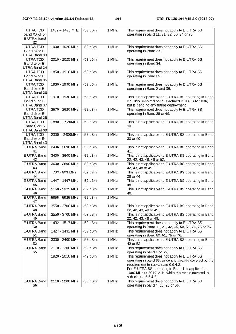
ETSI
ETSI TS 136 104 V15.3.0 (2018-07)1043GPP TS 36.104 version 15.3.0 Release 15
UTRA FDD band XXXII or E-UTRA band
32
1452 – 1496 MHz -52 dBm 1 MHz This requirement does not apply to E-UTRA BS operating in band 11, 21, 32, 50, 74 or 75.
UTRA TDD Band a) or E-
UTRA Band 33
1900 - 1920 MHz
-52 dBm 1 MHz This requirement does not apply to E-UTRA BS operating in Band 33.
UTRA TDD Band a) or E-
UTRA Band 34
2010 - 2025 MHz -52 dBm 1 MHz This requirement does not apply to E-UTRA BS operating in Band 34.
UTRA TDD Band b) or E-
UTRA Band 35
1850 - 1910 MHz
-52 dBm 1 MHz This requirement does not apply to E-UTRA BS operating in Band 35.
UTRA TDD Band b) or E-
UTRA Band 36
1930 - 1990 MHz -52 dBm 1 MHz This requirement does not apply to E-UTRA BS operating in Band 2 and 36.
UTRA TDD Band c) or E-
UTRA Band 37
1910 - 1930 MHz -52 dBm 1 MHz This is not applicable to E-UTRA BS operating in Band 37. This unpaired band is defined in ITU-R M.1036, but is pending any future deployment.
UTRA TDD Band d) or E-
UTRA Band 38
2570 - 2620 MHz -52 dBm 1 MHz This requirement does not apply to E-UTRA BS operating in Band 38 or 69.
UTRA TDD Band f) or E-
UTRA Band 39
1880 - 1920MHz -52 dBm 1 MHz This is not applicable to E-UTRA BS operating in Band 39.
UTRA TDD Band e) or E-
UTRA Band 40
2300 - 2400MHz -52 dBm 1 MHz This is not applicable to E-UTRA BS operating in Band 30 or 40.
E-UTRA Band 41
2496 - 2690 MHz -52 dBm 1 MHz This is not applicable to E-UTRA BS operating in Band 41.
E-UTRA Band 42
3400 - 3600 MHz -52 dBm 1 MHz This is not applicable to E-UTRA BS operating in Band 22, 42, 43, 48, 49 or 52.
E-UTRA Band 43
3600 - 3800 MHz -52 dBm 1 MHz This is not applicable to E-UTRA BS operating in Band 42, 43, 48 or 49.
E-UTRA Band 44
703 - 803 MHz -52 dBm 1 MHz This is not applicable to E-UTRA BS operating in Band 28 or 44.
E-UTRA Band 45
1447 - 1467 MHz -52 dBm 1 MHz This is not applicable to E-UTRA BS operating in Band 45.
E-UTRA Band 46
5150 - 5925 MHz -52 dBm 1 MHz This is not applicable to E-UTRA BS operating in Band 46.
E-UTRA Band 47
5855 - 5925 MHz -52 dBm 1 MHz
E-UTRA Band 48
3550 - 3700 MHz -52 dBm 1 MHz This is not applicable to E-UTRA BS operating in Band 22, 42, 43, 48 or 49.
E-UTRA Band 49
3550 - 3700 MHz -52 dBm 1 MHz This is not applicable to E-UTRA BS operating in Band 22, 42, 43, 48 or 49.
E-UTRA Band 50
1432 - 1517 MHz -52 dBm 1 MHz This requirement does not apply to E-UTRA BS operating in Band 11, 21, 32, 45, 50, 51, 74, 75 or 76.
E-UTRA Band 51
1427 - 1432 MHz -52 dBm 1 MHz This requirement does not apply to E-UTRA BS operating in Band 50, 51, 75 or 76.
E-UTRA Band 52
3300 - 3400 MHz -52 dBm 1 MHz This is not applicable to E-UTRA BS operating in Band 42 or 52.
E-UTRA Band 65
2110 - 2200 MHz -52 dBm 1 MHz This requirement does not apply to E-UTRA BS operating in band 1 or 65,
1920 - 2010 MHz -49 dBm 1 MHz This requirement does not apply to E-UTRA BS operating in band 65, since it is already covered by the requirement in sub-clause 6.6.4.2. For E-UTRA BS operating in Band 1, it applies for 1980 MHz to 2010 MHz, while the rest is covered in sub-clause 6.6.4.2.
E-UTRA Band 66
2110 - 2200 MHz -52 dBm 1 MHz This requirement does not apply to E-UTRA BS operating in band 4, 10, 23 or 66.
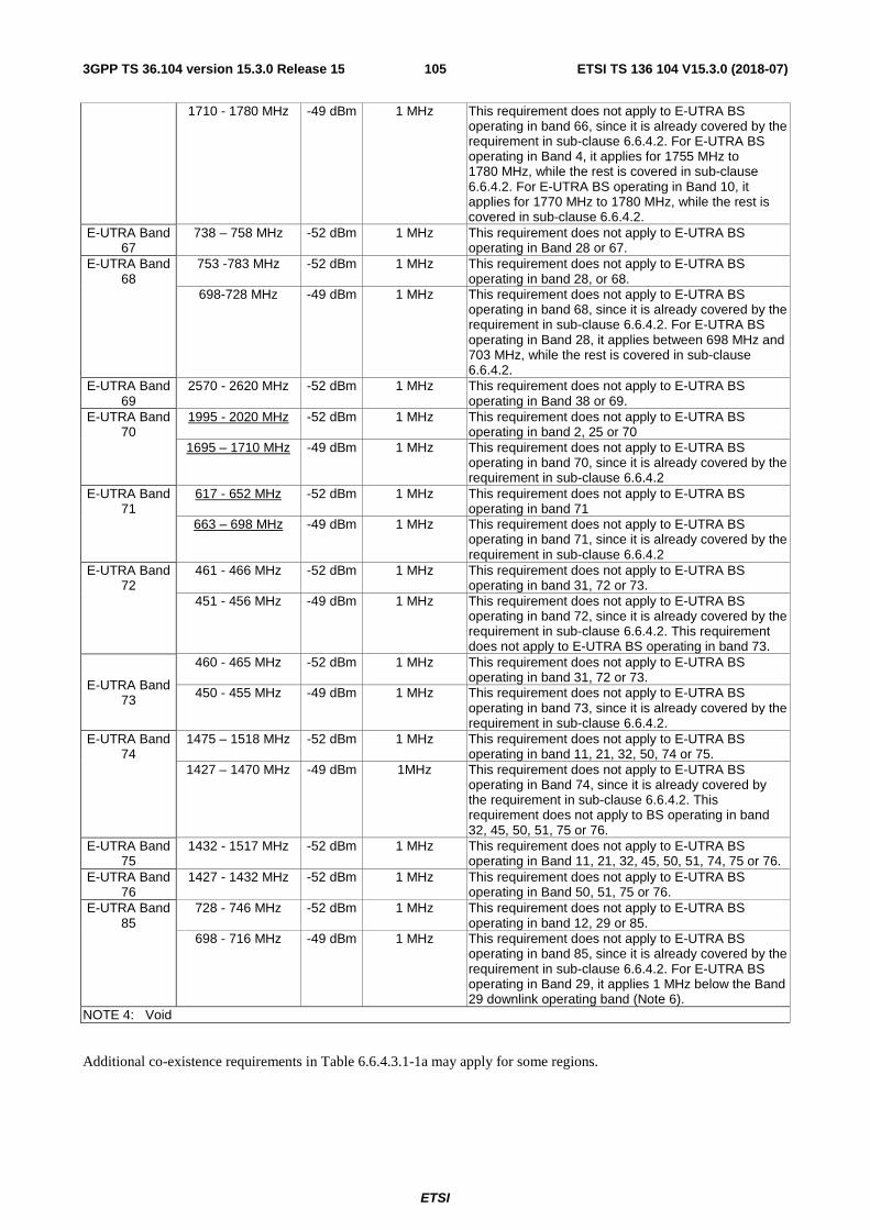
ETSI
ETSI TS 136 104 V15.3.0 (2018-07)1053GPP TS 36.104 version 15.3.0 Release 15
1710 - 1780 MHz -49 dBm 1 MHz This requirement does not apply to E-UTRA BS operating in band 66, since it is already covered by the requirement in sub-clause 6.6.4.2. For E-UTRA BS operating in Band 4, it applies for 1755 MHz to 1780 MHz, while the rest is covered in sub-clause 6.6.4.2. For E-UTRA BS operating in Band 10, it applies for 1770 MHz to 1780 MHz, while the rest is covered in sub-clause 6.6.4.2.
E-UTRA Band 67
738 – 758 MHz -52 dBm 1 MHz This requirement does not apply to E-UTRA BS operating in Band 28 or 67.
E-UTRA Band 68
753 -783 MHz -52 dBm 1 MHz This requirement does not apply to E-UTRA BS operating in band 28, or 68.
698-728 MHz -49 dBm 1 MHz This requirement does not apply to E-UTRA BS operating in band 68, since it is already covered by the requirement in sub-clause 6.6.4.2. For E-UTRA BS operating in Band 28, it applies between 698 MHz and 703 MHz, while the rest is covered in sub-clause 6.6.4.2.
E-UTRA Band 69
2570 - 2620 MHz -52 dBm 1 MHz This requirement does not apply to E-UTRA BS operating in Band 38 or 69.
E-UTRA Band 70
1995 - 2020 MHz -52 dBm 1 MHz This requirement does not apply to E-UTRA BS operating in band 2, 25 or 70
1695 – 1710 MHz -49 dBm 1 MHz This requirement does not apply to E-UTRA BS operating in band 70, since it is already covered by the requirement in sub-clause 6.6.4.2
E-UTRA Band 71
617 - 652 MHz -52 dBm 1 MHz This requirement does not apply to E-UTRA BS operating in band 71
663 – 698 MHz -49 dBm 1 MHz This requirement does not apply to E-UTRA BS operating in band 71, since it is already covered by the requirement in sub-clause 6.6.4.2
E-UTRA Band 72
461 - 466 MHz -52 dBm 1 MHz This requirement does not apply to E-UTRA BS operating in band 31, 72 or 73.
451 - 456 MHz -49 dBm 1 MHz This requirement does not apply to E-UTRA BS operating in band 72, since it is already covered by the requirement in sub-clause 6.6.4.2. This requirement does not apply to E-UTRA BS operating in band 73.
E-UTRA Band 73
460 - 465 MHz -52 dBm 1 MHz This requirement does not apply to E-UTRA BS operating in band 31, 72 or 73.
450 - 455 MHz -49 dBm 1 MHz This requirement does not apply to E-UTRA BS operating in band 73, since it is already covered by the requirement in sub-clause 6.6.4.2.
E-UTRA Band 74
1475 – 1518 MHz -52 dBm 1 MHz This requirement does not apply to E-UTRA BS operating in band 11, 21, 32, 50, 74 or 75.
1427 – 1470 MHz -49 dBm 1MHz This requirement does not apply to E-UTRA BS operating in Band 74, since it is already covered by the requirement in sub-clause 6.6.4.2. This requirement does not apply to BS operating in band 32, 45, 50, 51, 75 or 76.
E-UTRA Band 75
1432 - 1517 MHz -52 dBm 1 MHz This requirement does not apply to E-UTRA BS operating in Band 11, 21, 32, 45, 50, 51, 74, 75 or 76.
E-UTRA Band 76
1427 - 1432 MHz -52 dBm 1 MHz This requirement does not apply to E-UTRA BS operating in Band 50, 51, 75 or 76.
E-UTRA Band 85
728 - 746 MHz -52 dBm 1 MHz This requirement does not apply to E-UTRA BS operating in band 12, 29 or 85.
698 - 716 MHz -49 dBm 1 MHz This requirement does not apply to E-UTRA BS operating in band 85, since it is already covered by the requirement in sub-clause 6.6.4.2. For E-UTRA BS operating in Band 29, it applies 1 MHz below the Band 29 downlink operating band (Note 6).
NOTE 4: Void
Additional co-existence requirements in Table 6.6.4.3.1-1a may apply for some regions.

ETSI
ETSI TS 136 104 V15.3.0 (2018-07)1063GPP TS 36.104 version 15.3.0 Release 15
Table 6.6.4.3.1-1a: BS Spurious emissions limits for E-UTRA BS for co-existence with systems operating in Band 46
System type for E-UTRA to co-exist with
Frequency range for co-existence
requirement
Maximum Level
Measurement Bandwidth
Note
E-UTRA Band 46a
5150 - 5250 MHz -40 dBm 1 MHz This is only applicable to E-UTRA BS operating in Band 46c or 46d.
E-UTRA Band 46b
5250 - 5350 MHz -40 dBm 1 MHz This is only applicable to E-UTRA BS operating in Band 46c or 46d.
E-UTRA Band 46c
5470 - 5725 MHz -40 dBm 1 MHz This is only applicable to E-UTRA BS operating in Band 46a or 46b.
E-UTRA Band 46d
5725 - 5925 MHz -40 dBm 1 MHz This is only applicable to E-UTRA BS operating in Band 46a or 46b.
NOTE 1: This requirement may apply to E-UTRA BS operating in certain regions.
NOTE 1: As defined in the scope for spurious emissions in this clause, except for the cases where the noted requirements apply to a BS operating in Band 25, Band 27, Band 28 or Band 29, the co-existence requirements in Table 6.6.4.3.1-1 do not apply for the 10 MHz frequency range immediately outside the downlink operating band (see Table 5.5-1). Emission limits for this excluded frequency range may be covered by local or regional requirements.
NOTE 2: Table 6.6.4.3.1-1 assumes that two operating bands, where the frequency ranges in Table 5.5-1 would be overlapping, are not deployed in the same geographical area. For such a case of operation with overlapping frequency arrangements in the same geographical area, special co-existence requirements may apply that are not covered by the 3GPP specifications.
NOTE 3: TDD base stations deployed in the same geographical area, that are synchronized and use the same or adjacent operating bands can transmit without additional co-existence requirements. For unsynchronized base stations (except in Band 46), special co-existence requirements may apply that are not covered by the 3GPP specifications.
NOTE 5: For E-UTRA Band 28 BS, specific solutions may be required to fulfil the spurious emissions limits for E-UTRA BS for co-existence with E-UTRA Band 27 UL operating band.
NOTE 6: For E-UTRA Band 29 BS, specific solutions may be required to fulfil the spurious emissions limits for E-UTRA BS for co-existence with UTRA Band XII or E-UTRA Band 12 UL operating band, E-UTRA Band 17 UL operating band or E-UTRA Band 85 UL operating band.

ETSI
ETSI TS 136 104 V15.3.0 (2018-07)1073GPP TS 36.104 version 15.3.0 Release 15
The power of any spurious emission shall not exceed the limits of Table 6.6.4.3.1-1A for a Home BS where requirements for co-existence with a Home BS type listed in the first column apply.
Table 6.6.4.3.1-1A: Home BS Spurious emissions limits for co-existence with Home BS operating in other frequency bands

ETSI
ETSI TS 136 104 V15.3.0 (2018-07)1083GPP TS 36.104 version 15.3.0 Release 15
Type of coexistence BS Frequency range for co-location
requirement
Maximum Level
Measurement Bandwidth
Note
UTRA FDD Band I or E-UTRA Band 1
1920 - 1980 MHz
-71 dBm 100 kHz This requirement does not apply to Home BS operating in band 1 or 65, since it is already covered by the requirement in sub-clause 6.6.4.2.
UTRA FDD Band II or E-UTRA Band 2
1850 - 1910 MHz
-71 dBm 100 kHz This requirement does not apply to Home BS operating in band 2 or 25, since it is already covered by the requirement in sub-clause 6.6.4.2.
UTRA FDD Band III or E-UTRA Band 3
1710 - 1785 MHz -71 dBm 100 kHz This requirement does not apply to Home BS operating in band 3, since it is already covered by the requirement in sub-clause 6.6.4.2. For Home BS operating in band 9, it applies for 1710 MHz to 1749.9 MHz and 1784.9 MHz to 1785 MHz, while the rest is covered in sub-clause 6.6.4.2.
UTRA FDD Band IV or E-UTRA Band 4
1710 - 1755 MHz -71 dBm 100 kHz This requirement does not apply to Home BS operating in band 4, 10 or 66, since it is already covered by the requirement in sub-clause 6.6.4.2.
UTRA FDD Band V or E-UTRA Band 5
824 - 849 MHz -71 dBm 100 kHz This requirement does not apply to Home BS operating in band 5 or 26, since it is already covered by the requirement in sub-clause 6.6.4.2. For E-UTRA BS operating in Band 27, it applies 3 MHz below the Band 27 downlink operating band.
UTRA FDD Band VI, XIX or E-UTRA Band 6, 18,
19
815 - 830 MHz -71 dBm 100 kHz This requirement does not apply to Home BS operating in band 18, since it is already covered by the requirement in sub-clause 6.6.4.2.
830 - 845 MHz -71 dBm 100 kHz This requirement does not apply to Home BS operating in band 6, 19, since it is already covered by the requirement in sub-clause 6.6.4.2.
UTRA FDD Band VII or E-UTRA Band 7
2500 - 2570 MHz -71 dBm 100 kHz This requirement does not apply to Home BS operating in band 7, since it is already covered by the requirement in sub-clause 6.6.4.2.
UTRA FDD Band VIII or E-UTRA Band 8
880 - 915 MHz -71 dBm 100 kHz This requirement does not apply to Home BS operating in band 8, since it is already covered by the requirement in sub-clause 6.6.4.2.
UTRA FDD Band IX or E-UTRA Band 9
1749.9 - 1784.9 MHz
-71 dBm 100 kHz This requirement does not apply to Home BS operating in band 3 or 9, since it is already covered by the requirement in sub-clause 6.6.4.2.
UTRA FDD Band X or E-UTRA Band 10
1710 - 1770 MHz -71 dBm 100 kHz This requirement does not apply to Home BS operating in band 10 or 66, since it is already covered by the requirement in sub-clause 6.6.4.2. For Home BS operating in Band 4, it applies for 1755 MHz to 1770 MHz, while the rest is covered in sub-clause 6.6.4.2.

ETSI
ETSI TS 136 104 V15.3.0 (2018-07)1093GPP TS 36.104 version 15.3.0 Release 15
UTRA FDD Band XI, XXI or E-UTRA Band 11, 21
1427.9 - 1447.9 MHz
-71 dBm 100 kHz This requirement does not apply to Home BS operating in band 11 or 74, since it is already covered by the requirement in sub-clause 6.6.4.2. This requirement does not apply to Home BS operating in band 32, 50, 51, 75 or 76.
1447.9 - 1462.9 MHz
-71 dBm 100 kHz This requirement does not apply to Home BS operating in band 21 or 74, since it is already covered by the requirement in sub-clause 6.6.4.2. This requirement does not apply to Home BS operating in band 32, 50 or 75.
UTRA FDD Band XII or E-UTRA Band 12
699 - 716 MHz -71 dBm 100 kHz This requirement does not apply to Home BS operating in band 12 or 85, since it is already covered by the requirement in sub-clause 6.6.4.2. For Home BS operating in Band 29, it applies 1 MHz below the Band 29 downlink operating band (Note 5)
UTRA FDD Band XIII or E-UTRA Band 13
777 - 787 MHz -71 dBm 100 kHz This requirement does not apply to Home BS operating in band 13, since it is already covered by the requirement in sub-clause 6.6.4.2.
UTRA FDD Band XIV or E-UTRA Band 14
788 - 798 MHz -71 dBm 100 kHz This requirement does not apply to Home BS operating in band 14, since it is already covered by the requirement in sub-clause 6.6.4.2.
E-UTRA Band 17 704 - 716 MHz -71 dBm 100 kHz This requirement does not apply to Home BS operating in band 17, since it is already covered by the requirement in sub-clause 6.6.4.2. For Home BS operating in Band 29, it applies 1 MHz below the Band 29 downlink operating band (Note 5)
UTRA FDD Band XX or E-UTRA Band 20
832 - 862 MHz -71 dBm 100 kHz This requirement does not apply to Home BS operating in band 20, since it is already covered by the requirement in sub-clause 6.6.4.2.
UTRA FDD Band XXII or E-UTRA Band 22
3410 - 3490 MHz -71 dBm 100 kHz This requirement does not apply to Home BS operating in band 22, since it is already covered by the requirement in sub-clause 6.6.4.2. This requirement does not apply to Home BS operating in Band 42
E-UTRA Band 24 1626.5 – 1660.5 MHz
-71 dBm 100 kHz This requirement does not apply to Home BS operating in band 24, since it is already covered by the requirement in sub-clause 6.6.4.2.
UTRA FDD Band XXV or E-UTRA Band 25
1850 - 1915 MHz -71 dBm 100 kHz This requirement does not apply to Home BS operating in band 25, since it is already covered by the requirement in sub-clause 6.6.4.2
UTRA FDD Band XXVI or E-UTRA Band 26
814 - 849 MHz -71 dBm 100 kHz This requirement does not apply to Home BS operating in band 26, since it is already covered by the requirement in sub-clause 6.6.4.2. For Home BS operating in Band 5, it applies for 814 MHz to 824 MHz, while the rest is covered in sub-clause 6.6.4.2. For E-UTRA BS operating in Band 27, it applies 3 MHz below the Band 27 downlink operating band.

ETSI
ETSI TS 136 104 V15.3.0 (2018-07)1103GPP TS 36.104 version 15.3.0 Release 15
E-UTRA Band 27 807 - 824 MHz -71 dBm 100 kHz This requirement does not apply to E-UTRA BS operating in Band 27, since it is already covered by the requirement in subclause 6.6.4.2. For E-UTRA BS operating in Band 26, it applies for 807 MHz to 814 MHz, while the rest is covered in sub-clause 6.6.4.2. This requirement also applies to E-UTRA BS operating in Band 28, starting 4 MHz above the Band 28 downlink operating band (Note 4).
E-UTRA Band 28 703 – 748 MHz -71 dBm 100 kHz This requirement does not apply to Home BS operating in band 28, since it is already covered by the requirement in sub-clause 6.6.4.2. This requirement does not apply to Home BS operating in Band 44. For E-UTRA BS operating in Band 67, it applies for 703 MHz to 736 MHz. For E-UTRA BS operating in Band 68, it applies for 728MHz to 733MHz.
E-UTRA Band 30 2305 – 2315 MHz -71 dBm 100 kHz This requirement does not apply to Home BS operating in band 30, since it is already covered by the requirement in sub-clause 6.6.4.2. This requirement does not apply to Home BS operating in Band 40.
UTRA TDD Band a) or E-UTRA Band 33
1900 - 1920 MHz
-71 dBm 100 kHz This requirement does not apply to Home BS operating in Band 33
UTRA TDD Band a) or E-UTRA Band 34
2010 - 2025 MHz -71 dBm 100 kHz This requirement does not apply to Home BS operating in Band 34
UTRA TDD Band b) or E-UTRA Band 35
1850 – 1910 MHz
-71 dBm 100 kHz This requirement does not apply to Home BS operating in Band 35
UTRA TDD Band b) or E-UTRA Band 36
1930 - 1990 MHz -71 dBm 100 kHz This requirement does not apply to Home BS operating in Band 2 and 36
UTRA TDD Band c) or E-UTRA Band 37
1910 - 1930 MHz -71 dBm 100 kHz This is not applicable to Home BS operating in Band 37. This unpaired band is defined in ITU-R M.1036, but is pending any future deployment.
UTRA TDD Band d) or E-UTRA Band 38
2570 - 2620 MHz -71 dBm 100 kHz This requirement does not apply to Home BS operating in Band 38.
UTRA TDD Band f) or E-UTRA Band 39
1880 - 1920MHz -71 dBm 100 kHz This is not applicable to Home BS operating in Band 39
UTRA TDD Band e) or E-UTRA Band 40
2300 - 2400MHz -71 dBm 100 kHz This is not applicable to Home BS operating in Band 30 or 40
E-UTRA Band 41 2496 – 2690 MHz -71 dBm 100 kHz This is not applicable to Home BS operating in Band 41
E-UTRA Band 42 3400 - 3600 MHz -71 dBm 100 kHz This is not applicable to Home BS operating in Band 22, 42, 43, 48 or 52.
E-UTRA Band 43 3600 - 3800 MHz -71 dBm 100 kHz This is not applicable to Home BS operating in Band 42, 43 or 48.
E-UTRA Band 44 703 - 803 MHz -71 dBm 100 kHz This is not applicable to Home BS operating in Band 28 or 44
E-UTRA Band 48 3550 - 3700 MHz -71 dBm 100 kHz This is not applicable to Home BS operating in Band 22, 42, 43 or 48.
E-UTRA Band 50 1432 - 1517 MHz -71 dBm 100 kHz This requirement does not apply to Home BS operating in Band 11, 21, 32, 50, 51, 74, 75 or 76.
E-UTRA Band 51 1427 - 1432 MHz -71 dBm 100 kHz This requirement does not apply to Home BS operating in Band 50, 51, 75 or 76.
E-UTRA Band 52 3300 - 3400 MHz -71 dBm 100 kHz This is not applicable to Home BS operating in Band 42 or 52.

ETSI
ETSI TS 136 104 V15.3.0 (2018-07)1113GPP TS 36.104 version 15.3.0 Release 15
E-UTRA Band 65 1920 - 2010 MHz -71 dBm 100 kHz This requirement does not apply to Home BS operating in band 65, since it is already covered by the requirement in sub-clause 6.6.4.2. For Home BS operating in Band 1, it applies for 1980 MHz to 2010 MHz, while the rest is covered in sub-clause 6.6.4.2.
E-UTRA Band 66 1710 - 1780 MHz -71 dBm 100 kHz This requirement does not apply to Home BS operating in band 66, since it is already covered by the requirement in sub-clause 6.6.4.2. For Home BS operating in Band 4, it applies for 1755 MHz to 1780 MHz, while the rest is covered in sub-clause 6.6.4.2. For Home BS operating in Band 10, it applies for 1770 MHz to 1780 MHz, while the rest is covered in sub-clause 6.6.4.2.
E-UTRA Band 68 698-728 MHz -71 dBm 100 kHz This requirement does not apply to Home BS operating in band 68, since it is already covered by the requirement in sub-clause 6.6.4.2. For Home BS operating in Band 28, it applies between 698 MHz and 703 MHz, while the rest is covered in sub-clause 6.6.4.2.
E-UTRA Band 70 1695 - 1710 MHz -71 dBm 100 kHz This requirement does not apply to Home BS operating in band 70, since it is already covered by the requirement in sub-clause 6.6.4.2.
E-UTRA Band 71 663 – 698 MHz -71 dBm 100 kHz This requirement does not apply to Home BS operating in band 71, since it is already covered by the requirement in sub-clause 6.6.4.2.
E-UTRA Band 74 1427 – 1470 MHz -71 dBm 100 kHz This requirement does not apply to Home BS operating in Band 74, since it is already covered by the requirement in sub-clause 6.6.4.2. This requirement does not apply to BS operating in band 32, 50, 51, 75 or 76.
E-UTRA Band 85 698 - 716 MHz -71 dBm 100 kHz This requirement does not apply to Home BS operating in band 85, since it is already covered by the requirement in sub-clause 6.6.4.2. For Home BS operating in Band 29, it applies 1 MHz below the Band 29 downlink operating band (Note 5).
NOTE 1: As defined in the scope for spurious emissions in this clause, except for the cases where the noted requirements apply to a BS operating in Band 27, Band 28 or Band 29, the coexistence requirements in Table 6.6.4.3.1-1A do not apply for the 10 MHz frequency range immediately outside the Home BS transmit frequency range of a downlink operating band (see Table 5.5-1). Emission limits for this excluded frequency range may be covered by local or regional requirements.
NOTE 2: Table 6.6.4.3.1-1A assumes that two operating bands, where the frequency ranges in Table 5.5-1 would be overlapping, are not deployed in the same geographical area. For such a case of operation with overlapping frequency arrangements in the same geographical area, special co-existence requirements may apply that are not covered by the 3GPP specifications.

ETSI
ETSI TS 136 104 V15.3.0 (2018-07)1123GPP TS 36.104 version 15.3.0 Release 15
NOTE 3: TDD base stations deployed in the same geographical area, that are synchronized and use the same or adjacent operating bands can transmit without additional co-existence requirements. For unsynchronized base stations, special co-existence requirements may apply that are not covered by the 3GPP specifications.
NOTE 4: For E-UTRA Band 28 BS, specific solutions may be required to fulfil the spurious emissions limits for E-UTRA BS for co-existence with E-UTRA Band 27 UL operating band.
NOTE 5: For E-UTRA Band 29 BS, specific solutions may be required to fulfil the spurious emissions limits for E-UTRA BS for co-existence with UTRA Band XII or E-UTRA Band 12 UL operating band, E-UTRA Band 17 UL operating band or E-UTRA Band 85 UL operating band.
The following requirement may be applied for the protection of PHS. This requirement is also applicable at specified frequencies falling between 10 MHz below the lowest BS transmitter frequency of the downlink operating band and 10 MHz above the highest BS transmitter frequency of the downlink operating band.
The power of any spurious emission shall not exceed:
Table 6.6.4.3.1-2: E-UTRA BS Spurious emissions limits for BS for co-existence with PHS
Frequency range Maximum Level
Measurement Bandwidth
Note
1884.5 - 1915.7 MHz -41 dBm 300 kHz Applicable when co-existence with PHS system operating in 1884.5-1915.7MHz
The following requirement shall be applied to BS operating in Bands 13 and 14 to ensure that appropriate interference protection is provided to 700 MHz public safety operations. This requirement is also applicable at the frequency range from 10 MHz below the lowest frequency of the BS downlink operating band up to 10 MHz above the highest frequency of the BS downlink operating band.
The power of any spurious emission shall not exceed:
Table 6.6.4.3.1-3: BS Spurious emissions limits for protection of 700 MHz public safety operations
Operating Band Frequency range Maximum Level
Measurement Bandwidth
Note
13 763 - 775 MHz -46 dBm 6.25 kHz 13 793 - 805 MHz -46 dBm 6.25 kHz 14 769 - 775 MHz -46 dBm 6.25 kHz 14 799 - 805 MHz -46 dBm 6.25 kHz
Table 6.6.4.3.1-4: Void
The following requirement shall be applied to BS operating in Band 26 to ensure that appropriate interference protection is provided to 800 MHz public safety operations. This requirement is also applicable at the frequency range from 10 MHz below the lowest frequency of the BS downlink operating band up to 10 MHz above the highest frequency of the BS downlink operating band.
The power of any spurious emission shall not exceed:
Table 6.6.4.3.1-5: BS Spurious emissions limits for protection of 800 MHz public safety operations
Operating Band Frequency range Maximum Level
Measurement Bandwidth
Note
26 851 - 859 MHz -13 dBm 100 kHz Applicable for offsets > 37.5kHz from the
channel edge
The following requirement may apply to E-UTRA BS operating in Band 41 in certain regions. This requirement is also applicable at the frequency range from 10 MHz below the lowest frequency of the BS downlink operating band up to 10 MHz above the highest frequency of the BS downlink operating band.
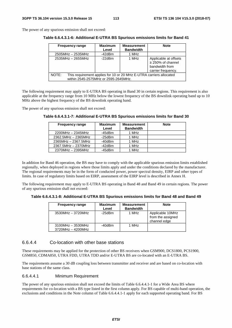
ETSI
ETSI TS 136 104 V15.3.0 (2018-07)1133GPP TS 36.104 version 15.3.0 Release 15
The power of any spurious emission shall not exceed:
Table 6.6.4.3.1-6: Additional E-UTRA BS Spurious emissions limits for Band 41
Frequency range Maximum Level
Measurement Bandwidth
Note
2505MHz – 2535MHz -42dBm 1 MHz 2535MHz – 2655MHz -22dBm 1 MHz Applicable at offsets
≥ 250% of channel bandwidth from carrier frequency.
NOTE: This requirement applies for 10 or 20 MHz E-UTRA carriers allocated within 2545-2575MHz or 2595-2645MHz.
The following requirement may apply to E-UTRA BS operating in Band 30 in certain regions. This requirement is also applicable at the frequency range from 10 MHz below the lowest frequency of the BS downlink operating band up to 10 MHz above the highest frequency of the BS downlink operating band.
The power of any spurious emission shall not exceed:
Table 6.6.4.3.1-7: Additional E-UTRA BS Spurious emissions limits for Band 30
Frequency range Maximum Level
Measurement Bandwidth
Note
2200MHz – 2345MHz -45dBm 1 MHz 2362.5MHz – 2365MHz -25dBm 1 MHz 2365MHz – 2367.5MHz -40dBm 1 MHz 2367.5MHz – 2370MHz -42dBm 1 MHz 2370MHz – 2395MHz -45dBm 1 MHz
In addition for Band 46 operation, the BS may have to comply with the applicable spurious emission limits established regionally, when deployed in regions where those limits apply and under the conditions declared by the manufacturer. The regional requirements may be in the form of conducted power, power spectral density, EIRP and other types of limits. In case of regulatory limits based on EIRP, assessment of the EIRP level is described in Annex H.
The following requirement may apply to E-UTRA BS operating in Band 48 and Band 49 in certain regions. The power of any spurious emission shall not exceed:
Table 6.6.4.3.1-8: Additional E-UTRA BS Spurious emissions limits for Band 48 and Band 49
Frequency range Maximum Level
Measurement Bandwidth
Note
3530MHz – 3720MHz -25dBm 1 MHz Applicable 10MHz from the assigned channel edge
3100MHz – 3530MHz 3720MHz – 4200MHz
-40dBm 1 MHz
6.6.4.4 Co-location with other base stations
These requirements may be applied for the protection of other BS receivers when GSM900, DCS1800, PCS1900, GSM850, CDMA850, UTRA FDD, UTRA TDD and/or E-UTRA BS are co-located with an E-UTRA BS.
The requirements assume a 30 dB coupling loss between transmitter and receiver and are based on co-location with base stations of the same class.
6.6.4.4.1 Minimum Requirement
The power of any spurious emission shall not exceed the limits of Table 6.6.4.4.1-1 for a Wide Area BS where requirements for co-location with a BS type listed in the first column apply. For BS capable of multi-band operation, the exclusions and conditions in the Note column of Table 6.6.4.4.1-1 apply for each supported operating band. For BS

ETSI
ETSI TS 136 104 V15.3.0 (2018-07)1143GPP TS 36.104 version 15.3.0 Release 15
capable of multi-band operation where multiple bands are mapped on separate antenna connectors, the exclusions and conditions in the Note column of Table 6.6.4.4.1-1 apply for the operating band supported at that antenna connector.
Table 6.6.4.4.1-1: BS Spurious emissions limits for Wide Area BS co-located with another BS

ETSI
ETSI TS 136 104 V15.3.0 (2018-07)1153GPP TS 36.104 version 15.3.0 Release 15
Type of co-located BS Frequency range for co-location requirement
Maximum Level
Measurement Bandwidth
Note
Macro GSM900 876-915 MHz -98 dBm 100 kHz Macro DCS1800 1710 - 1785 MHz -98 dBm 100 kHz Macro PCS1900 1850 - 1910 MHz -98 dBm 100 kHz
Macro GSM850 or CDMA850
824 - 849 MHz -98 dBm 100 kHz
WA UTRA FDD Band I or E-UTRA Band 1
1920 - 1980 MHz
-96 dBm 100 kHz
WA UTRA FDD Band II or E-UTRA Band 2
1850 - 1910 MHz
-96 dBm 100 kHz
WA UTRA FDD Band III or E-UTRA Band 3
1710 - 1785 MHz -96 dBm 100 kHz
WA UTRA FDD Band IV or E-UTRA Band 4
1710 - 1755 MHz -96 dBm 100 kHz
WA UTRA FDD Band V or E-UTRA Band 5
824 - 849 MHz -96 dBm 100 kHz
WA UTRA FDD Band VI, XIX or E-UTRA Band 6,
19
830 - 845 MHz -96 dBm 100 kHz
WA UTRA FDD Band VII or E-UTRA Band 7
2500 - 2570 MHz -96 dBm 100 kHz
WA UTRA FDD Band VIII or E-UTRA Band 8
880 - 915 MHz -96 dBm 100 kHz
WA UTRA FDD Band IX or E-UTRA Band 9
1749.9 - 1784.9 MHz -96 dBm 100 kHz
WA UTRA FDD Band X or E-UTRA Band 10
1710 - 1770 MHz -96 dBm 100 kHz
WA UTRA FDD Band XI or E-UTRA Band 11
1427.9 –1447.9 MHz -96 dBm 100 kHz This is not applicable to E-
UTRA BS operating in Band 50 or 75
WA UTRA FDD Band XII or
E-UTRA Band 12
699 - 716 MHz -96 dBm 100 kHz
WA UTRA FDD Band XIII or
E-UTRA Band 13
777 - 787 MHz -96 dBm 100 kHz
WA UTRA FDD Band XIV or
E-UTRA Band 14
788 - 798 MHz -96 dBm 100 kHz
WA E-UTRA Band 17 704 - 716 MHz -96 dBm 100 kHz WA E-UTRA Band 18 815 - 830 MHz -96 dBm 100 kHz
WA UTRA FDD Band XX or E-UTRA Band 20
832 - 862 MHz -96 dBm 100 kHz
WA UTRA FDD Band XXI or E-UTRA Band 21
1447.9 – 1462.9 MHz -96 dBm 100 kHz This is not applicable to E-
UTRA BS operating in Band 32, 50 or 75
WA UTRA FDD Band XXII or E-UTRA Band 22
3410 – 3490 MHz -96 dBm 100 kHz This is not applicable to E-
UTRA BS operating in Band 42
WA E-UTRA Band 23 2000 - 2020 MHz -96 dBm 100 kHz WA E-UTRA Band 24 1626.5 – 1660.5 MHz -96 dBm 100 kHz WA UTRA FDD Band
XXV or E-UTRA Band 25
1850 – 1915 MHz -96 dBm 100 kHz
WA UTRA FDD Band XXVI or
E-UTRA Band 26
814 – 849 MHz -96 dBm 100 kHz
WA E-UTRA Band 27 807 - 824 MHz -96 dBm 100 kHz WA E-UTRA Band 28 703 – 748 MHz -96 dBm 100 kHz This is not
applicable to E-UTRA BS operating
in Band 44

ETSI
ETSI TS 136 104 V15.3.0 (2018-07)1163GPP TS 36.104 version 15.3.0 Release 15
WA E-UTRA Band 30 2305 – 2315 MHz -96 dBm 100 kHz This is not applicable to E-
UTRA BS operating in Band 40
WA E-UTRA Band 31 452.5 -457.5 MHz -96 dBm 100 kHz WA UTRA TDD Band a)
or E-UTRA Band 33 1900 - 1920 MHz
-96 dBm 100 kHz This is not
applicable to E-UTRA BS operating
in Band 33 WA UTRA TDD Band a)
or E-UTRA Band 34 2010 - 2025 MHz -96 dBm 100 kHz This is not
applicable to E-UTRA BS operating
in Band 34 WA UTRA TDD Band b)
or E-UTRA Band 35 1850 – 1910 MHz
-96 dBm 100 kHz This is not
applicable to E-UTRA BS operating
in Band 35 WA UTRA TDD Band b)
or E-UTRA Band 36 1930 - 1990 MHz -96 dBm 100 kHz This is not
applicable to E-UTRA BS operating
in Band 2 and 36 WA UTRA TDD Band c)
or E-UTRA Band 37 1910 - 1930 MHz -96 dBm 100 kHz This is not
applicable to E-UTRA BS operating
in Band 37. This unpaired band is defined in ITU-R M.1036, but is
pending any future deployment.
WA UTRA TDD Band d) or E-UTRA Band 38
2570 – 2620 MHz -96 dBm 100 kHz This is not applicable to E-
UTRA BS operating in Band 38.
WA UTRA TDD Band f) or E-UTRA Band 39
1880 – 1920MHz -96 dBm 100 kHz This is not applicable to E-
UTRA BS operating in Band 33 and 39
WA UTRA TDD Band e) or E-UTRA Band 40
2300 – 2400MHz -96 dBm 100 kHz This is not applicable to E-
UTRA BS operating in Band 30 or 40
WA E-UTRA Band 41 2496 – 2690 MHz -96 dBm 100 kHz This is not applicable to E-
UTRA BS operating in Band 41
WA E-UTRA Band 42 3400 – 3600 MHz -96 dBm 100 kHz This is not applicable to E-
UTRA BS operating in Band 22, 42, 43,
48 or 52 WA E-UTRA Band 43 3600 – 3800 MHz -96 dBm 100 kHz This is not
applicable to E-UTRA BS operating in Band 42, 43 or 48
WA E-UTRA Band 44 703 – 803 MHz -96 dBm 100 kHz This is not applicable to E-
UTRA BS operating in Band 28 or 44
WA E-UTRA Band 45 1447 – 1467 MHz -96 dBm 100 kHz This is not applicable to E-
UTRA BS operating in Band 45
WA E-UTRA Band 48 3550 – 3700 MHz -96 dBm 100 kHz This is not applicable to E-
UTRA BS operating in Band 42, 43 or 48

ETSI
ETSI TS 136 104 V15.3.0 (2018-07)1173GPP TS 36.104 version 15.3.0 Release 15
WA E-UTRA Band 50 1432 – 1517 MHz -96 dBm 100 kHz This is not applicable to E-
UTRA BS operating in Band 11, 21, 32,
74 or 75 WA E-UTRA Band 52 3300 – 3400 MHz -96 dBm 100 kHz This is not
applicable to E-UTRA BS operating
in Band 42 or 52 WA E-UTRA Band 65 1920 - 2010 MHz -96 dBm 100 kHz WA E-UTRA Band 66 1710 - 1780 MHz -96 dBm 100 kHz WA E-UTRA Band 68 698 - 728 MHz -96 dBm 100 kHz WA E-UTRA Band 70 1695 - 1710 MHz -96 dBm 100 kHz WA E-UTRA Band 71 663 - 698 MHz -96 dBm 100 kHz WA E-UTRA Band 72 451 - 456 MHz -96 dBm 100 kHz WA E-UTRA Band 73 450 - 455 MHz -96 dBm 100 kHz WA E-UTRA Band 74 1427 – 1470 MHz -96 dBm 100 kHz This is not
applicabe to E-UTRA BS operating
in Band 50 WA E-UTRA Band 85 698 - 716 MHz -96 dBm 100 kHz
The power of any spurious emission shall not exceed the limits of Table 6.6.4.4.1-2 for a Local Area BS where requirements for co-location with a BS type listed in the first column apply. For BS capable of multi-band operation, the exclusions and conditions in the Note column of Table 6.6.4.4.1-2 apply for each supported operating band. For BS

ETSI
ETSI TS 136 104 V15.3.0 (2018-07)1183GPP TS 36.104 version 15.3.0 Release 15
capable of multi-band operation where multiple bands are mapped on separate antenna connectors, the exclusions and conditions in the Note column of Table 6.6.4.4.1-2 apply for the operating band supported at that antenna connector.
Table 6.6.4.4.1-2: BS Spurious emissions limits for Local Area BS co-located with another BS

ETSI
ETSI TS 136 104 V15.3.0 (2018-07)1193GPP TS 36.104 version 15.3.0 Release 15
Type of co-located BS Frequency range for co-location requirement
Maximum Level
Measurement Bandwidth
Note
Pico GSM900 876-915 MHz -70 dBm 100 kHz Pico DCS1800 1710 - 1785 MHz -80 dBm 100 kHz Pico PCS1900 1850 - 1910 MHz -80 dBm 100 kHz Pico GSM850 824 - 849 MHz -70 dBm 100 kHz
LA UTRA FDD Band I or E-UTRA Band 1
1920 - 1980 MHz
-88 dBm 100 kHz
LA UTRA FDD Band II or E-UTRA Band 2
1850 - 1910 MHz
-88 dBm 100 kHz
LA UTRA FDD Band III or E-UTRA Band 3
1710 - 1785 MHz -88 dBm 100 kHz
LA UTRA FDD Band IV or E-UTRA Band 4
1710 - 1755 MHz -88 dBm 100 kHz
LA UTRA FDD Band V or E-UTRA Band 5
824 - 849 MHz -88 dBm 100 kHz
LA UTRA FDD Band VI, XIX or E-UTRA Band 6, 19
830 - 845 MHz -88 dBm 100 kHz
LA UTRA FDD Band VII or E-UTRA Band 7
2500 - 2570 MHz -88 dBm 100 kHz
LA UTRA FDD Band VIII or E-UTRA Band 8
880 - 915 MHz -88 dBm 100 kHz
LA UTRA FDD Band IX or E-UTRA Band 9
1749.9 - 1784.9 MHz -88 dBm 100 kHz
LA UTRA FDD Band X or E-UTRA Band 10
1710 - 1770 MHz -88 dBm 100 kHz
LA UTRA FDD Band XI or E-UTRA Band 11
1427.9 - 1447.9 MHz -88 dBm 100 kHz This is not applicable to E-
UTRA BS operating in Band 50, 51, 75
or 76 LA UTRA FDD Band XII or E-UTRA Band 12
699 - 716 MHz -88 dBm 100 kHz
LA UTRA FDD Band XIII or E-UTRA Band 13
777 - 787 MHz -88 dBm 100 kHz
LA UTRA FDD Band XIV or E-UTRA Band 14
788 - 798 MHz -88 dBm 100 kHz
LA E-UTRA Band 17 704 - 716 MHz -88 dBm 100 kHz LA E-UTRA Band 18 815 - 830 MHz -88 dBm 100 kHz
LA UTRA FDD Band XX or E-UTRA Band 20
832 - 862 MHz -88 dBm 100 kHz
LA UTRA FDD Band XXI or E-UTRA Band 21
1447.9 - 1462.9 MHz -88 dBm 100 kHz This is not applicable to E-
UTRA BS operating in Band 32, 50 or 75
LA UTRA FDD Band XXII or E-UTRA Band 22
3410 – 3490 MHz -88 dBm 100 kHz This is not applicable to E-
UTRA BS operating in Band 42
LA E-UTRA Band 23 2000 - 2020 MHz -88 dBm 100 kHz LA E-UTRA Band 24 1626.5 – 1660.5 MHz -88 dBm 100 kHz LA UTRA FDD Band
XXV or E-UTRA Band 25 1850 – 1915 MHz -88 dBm 100 kHz
LA UTRA FDD Band XXVI or
E-UTRA Band 26
814 – 849 MHz -88 dBm 100 kHz
LA E-UTRA Band 27 807 - 824 MHz -88 dBm 100 kHz LA E-UTRA Band 28 703 – 748 MHz -88 dBm 100 KHz This is not
applicable to E-UTRA BS operating
in Band 44 LA E-UTRA Band 30 2305 – 2315 MHz -88 dBm 100 kHz This is not
applicable to E-UTRA BS operating
in Band 40 LA E-UTRA Band 31 452.5 – 457.5 MHz -88 dBm 100 KHz

ETSI
ETSI TS 136 104 V15.3.0 (2018-07)1203GPP TS 36.104 version 15.3.0 Release 15
LA UTRA TDD Band a) or E-UTRA Band 33
1900 - 1920 MHz
-88 dBm 100 kHz This is not applicable to E-
UTRA BS operating in Band 33
LA UTRA TDD Band a) or E-UTRA Band 34
2010 - 2025 MHz -88 dBm 100 kHz This is not applicable to E-
UTRA BS operating in Band 34
LA UTRA TDD Band b) or E-UTRA Band 35
1850 – 1910 MHz
-88 dBm 100 kHz This is not applicable to E-
UTRA BS operating in Band 35
LA UTRA TDD Band b) or E-UTRA Band 36
1930 - 1990 MHz -88 dBm 100 kHz This is not applicable to E-
UTRA BS operating in Band 2 and 36
LA UTRA TDD Band c) or E-UTRA Band 37
1910 - 1930 MHz -88 dBm 100 kHz This is not applicable to E-
UTRA BS operating in Band 37. This unpaired band is defined in ITU-R M.1036, but is
pending any future deployment.
LA UTRA TDD Band d) or E-UTRA Band 38
2570 – 2620 MHz -88 dBm 100 kHz This is not applicable to E-
UTRA BS operating in Band 38.
LA LUTRA TDD Band f) or E-UTRA Band 39
1880 – 1920MHz -88 dBm 100 kHz This is not applicable to E-
UTRA BS operating in Band 33 and 39
LA UTRA TDD Band e) or E-UTRA Band 40
2300 – 2400MHz -88 dBm 100 kHz This is not applicable to E-
UTRA BS operating in Band 30 or 40
LA E-UTRA Band 41 2496 – 2690 MHz -88 dBm 100 kHz This is not applicable to E-
UTRA BS operating in Band 41
LA E-UTRA Band 42 3400 – 3600 MHz -88 dBm 100 kHz This is not applicable to E-
UTRA BS operating in Band 22, 42, 43,
48, 49 or 52 LA E-UTRA Band 43 3600 – 3800 MHz -88 dBm 100 kHz This is not
applicable to E-UTRA BS operating in Band 42, 43, 48
or 49 LA E-UTRA Band 44 703 – 803 MHz -88 dBm 100 kHz This is not
applicable to E-UTRA BS operating
in Band 28 or 44 LA E-UTRA Band 45 1447 – 1467 MHz -88 dBm 100 kHz This is not
applicable to E-UTRA BS operating
in Band 45 LA E-UTRA Band 46 5150 – 5925 MHz -88 dBm 100 kHz This is not
applicable to E-UTRA BS operating
in Band 46 LA E-UTRA Band 48 3550 – 3700 MHz -88 dBm 100 kHz This is not
applicable to E-UTRA BS operating in Band 42, 43, 48
or 49
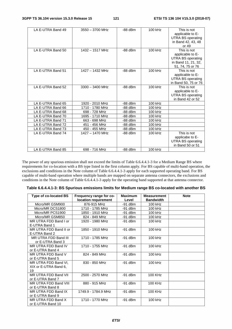
ETSI
ETSI TS 136 104 V15.3.0 (2018-07)1213GPP TS 36.104 version 15.3.0 Release 15
LA E-UTRA Band 49 3550 – 3700 MHz -88 dBm 100 kHz This is not applicable to E-
UTRA BS operating in Band 42, 43, 48
or 49 LA E-UTRA Band 50 1432 – 1517 MHz -88 dBm 100 kHz This is not
applicable to E-UTRA BS operating in Band 11, 21, 32,
51, 74, 75 or 76 LA E-UTRA Band 51 1427 – 1432 MHz -88 dBm 100 kHz This is not
applicable to E-UTRA BS operating in Band 50, 75 or 76
LA E-UTRA Band 52 3300 – 3400 MHz -88 dBm 100 kHz This is not applicable to E-
UTRA BS operating in Band 42 or 52
LA E-UTRA Band 65 1920 - 2010 MHz -88 dBm 100 kHz LA E-UTRA Band 66 1710 - 1780 MHz -88 dBm 100 kHz LA E-UTRA Band 68 698 - 728 MHz -88 dBm 100 kHz LA E-UTRA Band 70 1695 - 1710 MHz -88 dBm 100 kHz LA E-UTRA Band 71 663 - 698 MHz -88 dBm 100 kHz LA E-UTRA Band 72 451 - 456 MHz -88 dBm 100 kHz LA E-UTRA Band 73 450 - 455 MHz -88 dBm 100 kHz LA E-UTRA Band 74 1427 – 1470 MHz -88 dBm 100 kHz This is not
applicabe to E-UTRA BS operating
in Band 50 or 51 LA E-UTRA Band 85 698 - 716 MHz -88 dBm 100 kHz
The power of any spurious emission shall not exceed the limits of Table 6.6.4.4.1-3 for a Medium Range BS where requirements for co-location with a BS type listed in the first column apply. For BS capable of multi-band operation, the exclusions and conditions in the Note column of Table 6.6.4.4.1-3 apply for each supported operating band. For BS capable of multi-band operation where multiple bands are mapped on separate antenna connectors, the exclusions and conditions in the Note column of Table 6.6.4.4.1-3 apply for the operating band supported at that antenna connector.
Table 6.6.4.4.1-3: BS Spurious emissions limits for Medium range BS co-located with another BS
Type of co-located BS Frequency range for co-location requirement
Maximum Level
Measurement Bandwidth
Note
Micro/MR GSM900 876-915 MHz -91 dBm 100 kHz Micro/MR DCS1800 1710 - 1785 MHz -91 dBm 100 kHz Micro/MR PCS1900 1850 - 1910 MHz -91 dBm 100 kHz Micro/MR GSM850 824 - 849 MHz -91 dBm 100 kHz
MR UTRA FDD Band I or E-UTRA Band 1
1920 - 1980 MHz
-91 dBm 100 kHz
MR UTRA FDD Band II or E-UTRA Band 2
1850 - 1910 MHz
-91 dBm 100 kHz
MR UTRA FDD Band III or E-UTRA Band 3
1710 - 1785 MHz -91 dBm 100 kHz
MR UTRA FDD Band IV or E-UTRA Band 4
1710 - 1755 MHz -91 dBm 100 kHz
MR UTRA FDD Band V or E-UTRA Band 5
824 - 849 MHz -91 dBm 100 kHz
MR UTRA FDD Band VI, XIX or E-UTRA Band 6, 19
830 - 850 MHz -91 dBm 100 kHz
MR UTRA FDD Band VII or E-UTRA Band 7
2500 - 2570 MHz -91 dBm 100 KHz
MR UTRA FDD Band VIII or E-UTRA Band 8
880 - 915 MHz -91 dBm 100 KHz
MR UTRA FDD Band IX or E-UTRA Band 9
1749.9 - 1784.9 MHz -91 dBm 100 KHz
MR UTRA FDD Band X or E-UTRA Band 10
1710 - 1770 MHz -91 dBm 100 kHz
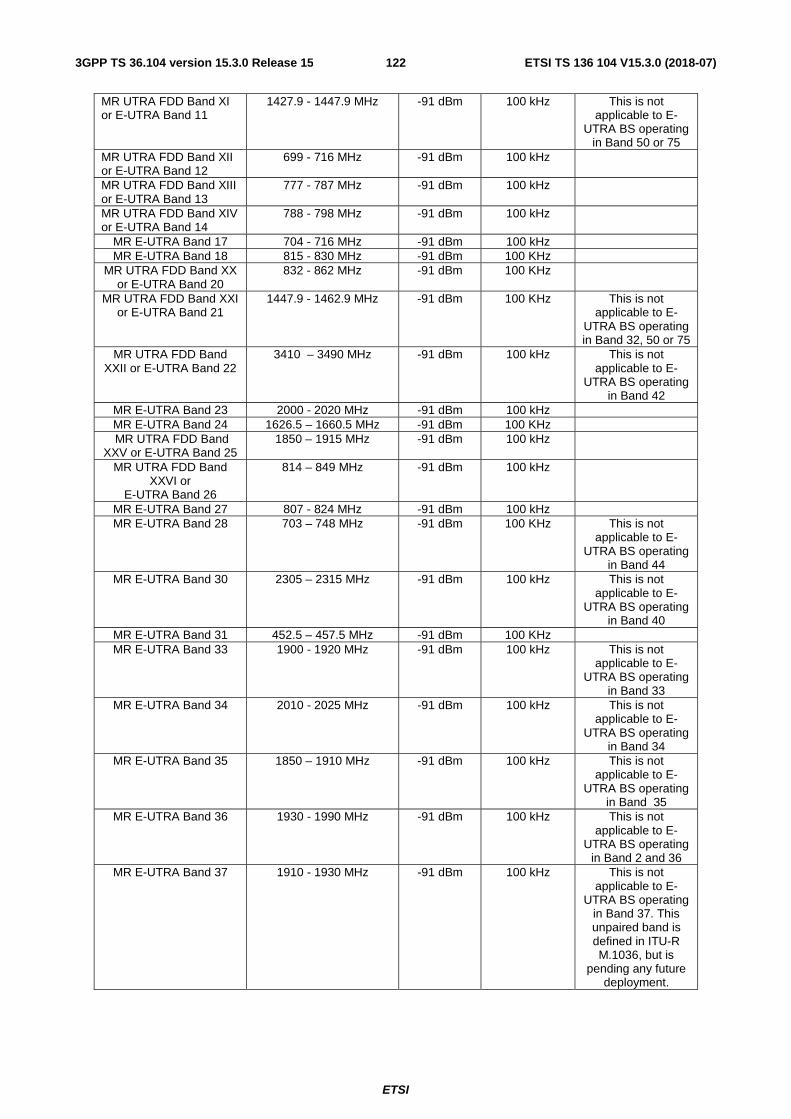
ETSI
ETSI TS 136 104 V15.3.0 (2018-07)1223GPP TS 36.104 version 15.3.0 Release 15
MR UTRA FDD Band XI or E-UTRA Band 11
1427.9 - 1447.9 MHz -91 dBm 100 kHz This is not applicable to E-
UTRA BS operating in Band 50 or 75
MR UTRA FDD Band XII or E-UTRA Band 12
699 - 716 MHz -91 dBm 100 kHz
MR UTRA FDD Band XIII or E-UTRA Band 13
777 - 787 MHz -91 dBm 100 kHz
MR UTRA FDD Band XIV or E-UTRA Band 14
788 - 798 MHz -91 dBm 100 kHz
MR E-UTRA Band 17 704 - 716 MHz -91 dBm 100 kHz MR E-UTRA Band 18 815 - 830 MHz -91 dBm 100 KHz
MR UTRA FDD Band XX or E-UTRA Band 20
832 - 862 MHz -91 dBm 100 KHz
MR UTRA FDD Band XXI or E-UTRA Band 21
1447.9 - 1462.9 MHz -91 dBm 100 KHz This is not applicable to E-
UTRA BS operating in Band 32, 50 or 75
MR UTRA FDD Band XXII or E-UTRA Band 22
3410 – 3490 MHz -91 dBm 100 kHz This is not applicable to E-
UTRA BS operating in Band 42
MR E-UTRA Band 23 2000 - 2020 MHz -91 dBm 100 kHz MR E-UTRA Band 24 1626.5 – 1660.5 MHz -91 dBm 100 KHz MR UTRA FDD Band
XXV or E-UTRA Band 25 1850 – 1915 MHz -91 dBm 100 kHz
MR UTRA FDD Band XXVI or
E-UTRA Band 26
814 – 849 MHz -91 dBm 100 kHz
MR E-UTRA Band 27 807 - 824 MHz -91 dBm 100 kHz MR E-UTRA Band 28 703 – 748 MHz -91 dBm 100 KHz This is not
applicable to E-UTRA BS operating
in Band 44 MR E-UTRA Band 30 2305 – 2315 MHz -91 dBm 100 kHz This is not
applicable to E-UTRA BS operating
in Band 40 MR E-UTRA Band 31 452.5 – 457.5 MHz -91 dBm 100 KHz MR E-UTRA Band 33 1900 - 1920 MHz
-91 dBm 100 kHz This is not
applicable to E-UTRA BS operating
in Band 33 MR E-UTRA Band 34 2010 - 2025 MHz -91 dBm 100 kHz This is not
applicable to E-UTRA BS operating
in Band 34 MR E-UTRA Band 35 1850 – 1910 MHz
-91 dBm 100 kHz This is not
applicable to E-UTRA BS operating
in Band 35 MR E-UTRA Band 36 1930 - 1990 MHz -91 dBm 100 kHz This is not
applicable to E-UTRA BS operating
in Band 2 and 36 MR E-UTRA Band 37 1910 - 1930 MHz -91 dBm 100 kHz This is not
applicable to E-UTRA BS operating
in Band 37. This unpaired band is defined in ITU-R M.1036, but is
pending any future deployment.
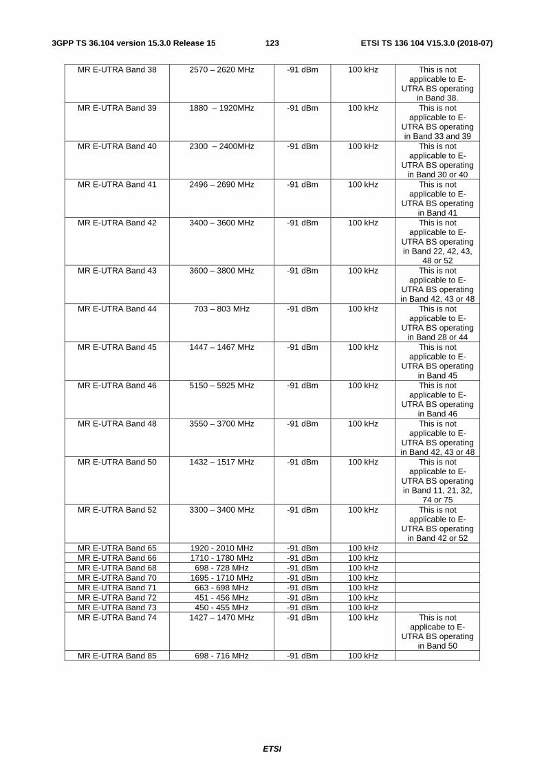
ETSI
ETSI TS 136 104 V15.3.0 (2018-07)1233GPP TS 36.104 version 15.3.0 Release 15
MR E-UTRA Band 38 2570 – 2620 MHz -91 dBm 100 kHz This is not applicable to E-
UTRA BS operating in Band 38.
MR E-UTRA Band 39 1880 – 1920MHz -91 dBm 100 kHz This is not applicable to E-
UTRA BS operating in Band 33 and 39
MR E-UTRA Band 40 2300 – 2400MHz -91 dBm 100 kHz This is not applicable to E-
UTRA BS operating in Band 30 or 40
MR E-UTRA Band 41 2496 – 2690 MHz -91 dBm 100 kHz This is not applicable to E-
UTRA BS operating in Band 41
MR E-UTRA Band 42 3400 – 3600 MHz -91 dBm 100 kHz This is not applicable to E-
UTRA BS operating in Band 22, 42, 43,
48 or 52 MR E-UTRA Band 43 3600 – 3800 MHz -91 dBm 100 kHz This is not
applicable to E-UTRA BS operating in Band 42, 43 or 48
MR E-UTRA Band 44 703 – 803 MHz -91 dBm 100 kHz This is not applicable to E-
UTRA BS operating in Band 28 or 44
MR E-UTRA Band 45 1447 – 1467 MHz -91 dBm 100 kHz This is not applicable to E-
UTRA BS operating in Band 45
MR E-UTRA Band 46 5150 – 5925 MHz -91 dBm 100 kHz This is not applicable to E-
UTRA BS operating in Band 46
MR E-UTRA Band 48 3550 – 3700 MHz -91 dBm 100 kHz This is not applicable to E-
UTRA BS operating in Band 42, 43 or 48
MR E-UTRA Band 50 1432 – 1517 MHz -91 dBm 100 kHz This is not applicable to E-
UTRA BS operating in Band 11, 21, 32,
74 or 75 MR E-UTRA Band 52 3300 – 3400 MHz -91 dBm 100 kHz This is not
applicable to E-UTRA BS operating
in Band 42 or 52 MR E-UTRA Band 65 1920 - 2010 MHz -91 dBm 100 kHz MR E-UTRA Band 66 1710 - 1780 MHz -91 dBm 100 kHz MR E-UTRA Band 68 698 - 728 MHz -91 dBm 100 kHz MR E-UTRA Band 70 1695 - 1710 MHz -91 dBm 100 kHz MR E-UTRA Band 71 663 - 698 MHz -91 dBm 100 kHz MR E-UTRA Band 72 451 - 456 MHz -91 dBm 100 kHz MR E-UTRA Band 73 450 - 455 MHz -91 dBm 100 kHz MR E-UTRA Band 74 1427 – 1470 MHz -91 dBm 100 kHz This is not
applicabe to E-UTRA BS operating
in Band 50 MR E-UTRA Band 85 698 - 716 MHz -91 dBm 100 kHz
ETSI
ETSI TS 136 104 V15.3.0 (2018-07)1243GPP TS 36.104 version 15.3.0 Release 15
NOTE 1: As defined in the scope for spurious emissions in this clause, the co-location requirements in Table 6.6.4.4.1-1 to Table 6.6.4.4.1-3 do not apply for the 10 MHz frequency range immediately outside the BS transmit frequency range of a downlink operating band (see Table 5.5-1). The current state-of-the-art technology does not allow a single generic solution for co-location with other system on adjacent frequencies for 30dB BS-BS minimum coupling loss. However, there are certain site-engineering solutions that can be used. These techniques are addressed in TR 25.942 [8].
NOTE 2: Table 6.6.4.4.1-1 to Table 6.6.4.4.1-3 assume that two operating bands, where the corresponding BS transmit and receive frequency ranges in Table 5.5-1 would be overlapping, are not deployed in the same geographical area. For such a case of operation with overlapping frequency arrangements in the same geographical area, special co-location requirements may apply that are not covered by the 3GPP specifications.
NOTE 3: Co-located TDD base stations that are synchronized and using the same or adjacent operating band can transmit without special co-locations requirements. For unsynchronized base stations (except in Band 46), special co-location requirements may apply that are not covered by the 3GPP specifications.
6.7 Transmitter intermodulation The transmit intermodulation requirement is a measure of the capability of the transmitter to inhibit the generation of signals in its non linear elements caused by presence of the wanted signal and an interfering signal reaching the transmitter via the antenna. The requirement applies during the transmitter ON period and the transmitter transient period.
For BS capable of multi-band operation where multiple bands are mapped on separate antenna connectors, the single-band requirements apply regardless of the interfering signals position relative to the Inter RF Bandwidth gap.
6.7.1 Minimum requirement
The transmitter intermodulation level is the power of the intermodulation products when an E-UTRA signal of channel bandwidth 5 MHz as an interfering signal is injected into the antenna connector.
The transmitter intermodulation level shall not exceed the unwanted emission limits in subclauses 6.6.2, 6.6.3 and 6.6.4 in the presence of an E-UTRA interfering signal according to Table 6.7.1-1, Table 6.7.1-2 and Table 6.7.1-3.
The requirement is applicable outside the Base Station RF Bandwidth or Radio Bandwidth. The interfering signal offset is defined relative to the Base Station RF Bandwidth edges or Radio Bandwidth edges.
For a BS operating in non-contiguous spectrum, the requirement is also applicable inside a sub-block gap for interfering signal offsets where the interfering signal falls completely within the sub-block gap. The interfering signal offset is defined relative to the sub-block edges.
For a BS capable of multi-band operation, the requirement applies relative to the Base Station RF Bandwidth edges of each supported operating band. In case the Inter RF Bandwidth gap is less than 15 MHz, the requirement in the gap applies only for interfering signal offsets where the interfering signal falls completely within the Inter RF Bandwidth gap.
For E-UTRA, the wanted signal and interfering signal centre frequency offset shall be as in Table 6.7.1-1.

ETSI
ETSI TS 136 104 V15.3.0 (2018-07)1253GPP TS 36.104 version 15.3.0 Release 15
Table 6.7.1-1 Interfering and wanted signals for the Transmitter intermodulation requirement for E-UTRA
Parameter Value Wanted signal E-UTRA single carrier, or multi-carrier, or multiple intra-band
contiguously or non-contiguously aggregated carriers Interfering signal type E-UTRA signal of channel bandwidth 5 MHz Interfering signal level Rated total output power in the operating band – 30 dB Interfering signal centre frequency offset from the lower/upper edge of the wanted signal or edge of sub-block inside a sub-block gap
± 2.5 MHz ± 7.5 MHz ± 12.5 MHz
NOTE1: Interfering signal positions that are partially or completely outside of any downlink operating band of the base station are excluded from the requirement, unless the interfering signal positions fall within the frequency range of adjacent downlink operating bands in the same geographical area. In case that none of the interfering signal positions fall completely within the frequency range of the downlink operating band, TS 36.141 [4] provides further guidance regarding appropriate test requirements.
NOTE2: In certain regions, NOTE1 is not applied in Band 1, 3, 8, 9, 11, 18, 19, 21, 28, 32 operating within 1475.9-1495.9MHz, 34, 74.
For NB-IoT in-band and guard band operation, the wanted signal and interfering signal centre frequency offset shall be as in Table 6.7.1-2.
Table 6.7.1-2 Interfering and wanted signals for the Transmitter intermodulation requirement for NB-IoT in-band and guard band operations
Parameter Value Wanted signal E-UTRA single carrier, or multi-carrier, or multiple intra-band
contiguously or non-contiguously aggregated carriers with NB-IoT in-band and/or guard band operation
Interfering signal type E-UTRA signal of channel bandwidth 5 MHz Interfering signal level Rated total output power in the operating band – 30 dB Interfering signal centre frequency offset from the lower/upper edge of the wanted signal or edge of sub-block inside a sub-block gap
± 2.5 MHz ± 7.5 MHz ± 12.5 MHz
NOTE1: Interfering signal positions that are partially or completely outside of any downlink operating band of the base station are excluded from the requirement, unless the interfering signal positions fall within the frequency range of adjacent downlink operating bands in the same geographical area. In case that none of the interfering signal positions fall completely within the frequency range of the downlink operating band, TS 36.141 [4] provides further guidance regarding appropriate test requirements.
NOTE2: In certain regions, NOTE1 is not applied in Band 1, 3, 8, 9, 11, 18, 19, 21, 28, 32 operating within 1475.9-1495.9MHz, 34, 74.
For NB-IoT standalone operation, the wanted signal and interfering signal centre frequency offset shall be as in Table 6.7.1-3.
Table 6.7.1-3 Interfering and wanted signals for the Transmitter intermodulation requirement for standalone NB-IoT
Parameter Value Wanted signal Standalone NB-IoT carrier Interfering signal type E-UTRA signal of channel bandwidth 5 MHz Interfering signal level Rated total output power in the operating band – 30 dB Interfering signal centre frequency offset from the lower/upper edge of the wanted signal or edge of sub-block inside a sub-block gap
± 2.5 MHz ± 7.5 MHz ± 12.5 MHz
NOTE1: Interfering signal positions that are partially or completely outside of any downlink operating band of the base station are excluded from the requirement, unless the interfering signal positions fall within the frequency range of adjacent downlink operating bands in the same geographical area. In case that none of the interfering signal positions fall completely within the frequency range of the downlink operating band, TS 36.141 [4] provides further guidance regarding appropriate test requirements.
NOTE2: In certain regions, NOTE1 is not applied in Band 1, 3, 8, 9, 11, 18, 19, 21, 28, 32 operating within 1475.9-1495.9MHz, 34, 74.

ETSI
ETSI TS 136 104 V15.3.0 (2018-07)1263GPP TS 36.104 version 15.3.0 Release 15
6.7.2 Additional requirement for Band 41
In certain regions the following requirement may apply. For E-UTRA BS operating in Band 41, the transmitter intermodulation level shall not exceed the maximum levels specified in Table 6.6.2.1-2 with a square filter in the first adjacent channel, Table 6.6.3.3-7 and Table 6.6.4.3.1-6 in the presence of an interfering signal according to Table 6.7.2-1.
Table 6.7.2-1 Interfering and wanted signals for the additional transmitter intermodulation requirement for Band 41
Parameter Value Wanted signal E-UTRA single carrier (NOTE) Interfering signal type E-UTRA signal of the same channel bandwidth as the wanted
signal Interfering signal level Rated total output power in the operating band – 30 dB Interfering signal centre frequency offset from the lower/upper carrier centre frequency of the wanted signal
± BWChannel ± 2 x BWChannel
NOTE: This requirement applies for 10 or 20 MHz E-UTRA carriers allocated within 2545-2575MHz or 2595-2645MHz.
7 Receiver characteristics
7.1 General The requirements in clause 7 are expressed for a single receiver antenna connector. For receivers with antenna diversity, the requirements apply for each receiver antenna connector.
Unless otherwise stated, the receiver characteristics are specified at the BS antenna connector (test port A) with a full complement of transceivers for the configuration in normal operating conditions. For FDD operation the requirements in clause 7 shall be met with the transmitter(s) on. If any external apparatus such as a RX amplifier, a filter or the combination of such devices is used, requirements apply at the far end antenna connector (port B).
NOTE: In normal operating conditions the BS in FDD operation is configured to transmit and receive at the same time. The transmitter may be off for some of the tests as specifed in 36.141 [4].
Unless otherwise stated the requirements in clause 7 apply during the base station receive period.
Figure 7.1: Receiver test ports
The throughput requirements defined for the receiver characteristics in this clause do not assume HARQ retransmissions.
When the BS is configured to receive multiple carriers, all the throughput requirements are applicable for each received carrier. For ACS, blocking and intermodulation characteristics, the negative offsets of the interfering signal apply relative to the lower Base Station RF Bandwidth edge and positive offsets of the interfering signal apply relative to the upper Base Station RF Bandwidth edge.
NOTE: Requirements may only be supported for certain frequency ranges within the operating band(s). These frequency ranges could be different for NB.-IoT comparing to E-UTRA.
BS
cabinet
Test port A Test port B
External device
e.g. RX filter
(if any)
External LNA
(if any)
From antenna connector
⇐
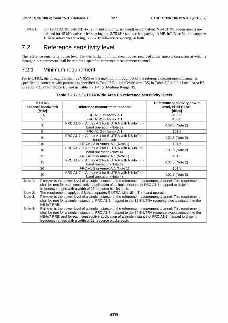
ETSI
ETSI TS 136 104 V15.3.0 (2018-07)1273GPP TS 36.104 version 15.3.0 Release 15
NOTE: For E-UTRA BS with NB-IoT (in band and/or guard band) or standalone NB-IoT BS, requirements are defined for 15 kHz sub-carrier spacing and 3.75 kHz sub-carrier spacing. A NB-IoT Base Station supports 15 kHz sub-carrier spacing, 3.75 kHz sub-carrier spacing, or both.
7.2 Reference sensitivity level The reference sensitivity power level PREFSENS is the minimum mean power received at the antenna connector at which a throughput requirement shall be met for a specified reference measurement channel.
7.2.1 Minimum requirement
For E-UTRA, the throughput shall be ≥ 95% of the maximum throughput of the reference measurement channel as specified in Annex A with parameters specified in Table 7.2.1-1 for Wide Area BS, in Table 7.2.1-2 for Local Area BS, in Table 7.2.1-3 for Home BS and in Table 7.2.1-4 for Medium Range BS.
Table 7.2.1-1: E-UTRA Wide Area BS reference sensitivity levels
E-UTRA channel bandwidth
[MHz] Reference measurement channel
Reference sensitivity power level, PREFSENS
[dBm] 1.4 FRC A1-1 in Annex A.1 -106.8 3 FRC A1-2 in Annex A.1 -103.0
3 FRC A1-6 in Annex A.1 for E-UTRA with NB-IoT in-band operation (Note 3) -103.0 (Note 2)
5 FRC A1-3 in Annex A.1 -101.5
5 FRC A1-7 in Annex A.1 for E-UTRA with NB-IoT in-band operation
-101.5 (Note 2)
10 FRC A1-3 in Annex A.1 (Note 1) -101.5
10 FRC A1-7 in Annex A.1 for E-UTRA with NB-IoT in-band operation (Note 4)
-101.5 (Note 2)
15 FRC A1-3 in Annex A.1 (Note 1) -101.5
15 FRC A1-7 in Annex A.1 for E-UTRA with NB-IoT in-
band operation (Note 4) -101.5 (Note 2)
20 FRC A1-3 in Annex A.1 (Note 1) -101.5
20 FRC A1-7 in Annex A.1 for E-UTRA with NB-IoT in-
band operation (Note 4) -101.5 (Note 2)
Note 1: PREFSENS is the power level of a single instance of the reference measurement channel. This requirement shall be met for each consecutive application of a single instance of FRC A1-3 mapped to disjoint frequency ranges with a width of 25 resource blocks each.
Note 2: The requirements apply to BS that supports E-UTRA with NB-IoT in-band operation. Note 3: PREFSENS is the power level of a single instance of the reference measurement channel. This requirement
shall be met for a single instance of FRC A1-6 mapped to the 12 E-UTRA resource blocks adjacent to the NB-IoT PRB.
Note 4: PREFSENS is the power level of a single instance of the reference measurement channel. This requirement shall be met for a single instance of FRC A1-7 mapped to the 24 E-UTRA resource blocks adjacent to the NB-IoT PRB, and for each consecutive application of a single instance of FRC A1-3 mapped to disjoint frequency ranges with a width of 25 resource blocks each.

ETSI
ETSI TS 136 104 V15.3.0 (2018-07)1283GPP TS 36.104 version 15.3.0 Release 15
Table 7.2.1-2: E-UTRA Local Area BS reference sensitivity levels
E-UTRA channel bandwidth
[MHz] Reference measurement channel
Reference sensitivity power level, PREFSENS
[dBm] 1.4 FRC A1-1 in Annex A.1 -98.8 3 FRC A1-2 in Annex A.1 -95.0
3 FRC A1-6 in Annex A.1 for E-UTRA with NB-IoT in-band operation (Note 4) -95.0 (Note 3)
5 FRC A1-3 in Annex A.1 -93.5
5 FRC A1-7 in Annex A.1 for E-UTRA with NB-IoT in-band operation -93.5 (Note 3)
10 FRC A1-3 in Annex A.1 (Note 1) FRC A1-8 in Annex A.1 (Note 2)
-93.5 -96.2
10 FRC A1-7 in Annex A.1 for E-UTRA with NB-IoT in-
band operation (Note 5) -93.5 (Note 3)
15 FRC A1-3 in Annex A.1 (Note 1) -93.5
15 FRC A1-7 in Annex A.1 for E-UTRA with NB-IoT in-band operation(Note 5) -93.5 (Note 3)
20 FRC A1-3 in Annex A.1(Note 1) FRC A1-9 in Annex A.1 (Note 2)
-93.5 -96.2
20 FRC A1-7 in Annex A.1 for E-UTRA with NB-IoT in-band operation (Note 5) -93.5 (Note 3)
Note 1: PREFSENS is the power level of a single instance of the reference measurement channel. This requirement shall be met for each consecutive application of a single instance of FRC A1-3 mapped to disjoint frequency ranges with a width of 25 resource blocks each. This reference measurement channel is not applied for Band 46 and Band 49.
Note 2: PREFSENS is the power level of a single instance of the reference measurement channel. This requirement shall be met for each single interlace of FRC A1-8 and A1-9. This reference measurement channel is only applied for Band 46 and Band 49.
Note 3: The requirements apply to BS that supports E-UTRA with NB-IoT in-band operation. Note 4: PREFSENS is the power level of a single instance of the reference measurement channel. This requirement
shall be met for a single instance of FRC A1-6 mapped to the 12 E-UTRA resource blocks adjacent to the NB-IoT PRB.
Note 5: PREFSENS is the power level of a single instance of the reference measurement channel. This requirement shall be met for a single instance of FRC A1-7 mapped to the 24 E-UTRA resource blocks adjacent to the NB-IoT PRB, and for each consecutive application of a single instance of FRC A1-3 mapped to disjoint frequency ranges with a width of 25 resource blocks each.

ETSI
ETSI TS 136 104 V15.3.0 (2018-07)1293GPP TS 36.104 version 15.3.0 Release 15
Table 7.2.1-3: E-UTRA Home BS reference sensitivity levels
E-UTRA channel bandwidth
[MHz] Reference measurement channel
Reference sensitivity power level, PREFSENS
[dBm] 1.4 FRC A1-1 in Annex A.1 -98.8 3 FRC A1-2 in Annex A.1 -95.0
3 FRC A1-6 in Annex A.1 1 for E-UTRA with NB-IoT in-band operation (Note 3) -95.0 (Note 2)
5 FRC A1-3 in Annex A.1 -93.5
5 FRC A1-7 in Annex A.1 for E-UTRA with NB-IoT in-band operation -93.5 (Note 2)
10 FRC A1-3 in Annex A.1 (Note) -93.5
10 FRC A1-7 in Annex A.1 for E-UTRA with NB-IoT in-band operation (Note 4) -93.5 (Note 2)
15 FRC A1-3 in Annex A.1 (Note) -93.5
15 FRC A1-7 in Annex A.1 for E-UTRA4with NB-IoT in-band operation (Note 4)
-93.5 (Note 2)
20 FRC A1-3 in Annex A.1 (Note) -93.5
20 FRC A1-7 in Annex A.1 for E-UTRA with NB-IoT in-band operation (Note 4)
-93.5 (Note 2)
Note 1: PREFSENS is the power level of a single instance of the reference measurement channel. This requirement shall be met for each consecutive application of a single instance of FRC A1-3 mapped to disjoint frequency ranges with a width of 25 resource blocks each
Note 2: The requirements apply to BS that supports E-UTRA with NB-IoT in-band operation. Note 3: PREFSENS is the power level of a single instance of the reference measurement channel. This requirement
shall be met for a single instance of FRC A1-6 mapped to the 12 E-UTRA resource blocks adjacent to the NB-IoT PRB.
Note 4: PREFSENS is the power level of a single instance of the reference measurement channel. This requirement shall be met for a single instance of FRC A1-7 mapped to the 24 E-UTRA resource blocks adjacent to the NB-IoT PRB, and for each consecutive application of a single instance of FRC A1-3 mapped to disjoint frequency ranges with a width of 25 resource blocks each.

ETSI
ETSI TS 136 104 V15.3.0 (2018-07)1303GPP TS 36.104 version 15.3.0 Release 15
Table 7.2.1-4: E-UTRA Medium Range BS reference sensitivity levels
E-UTRA channel bandwidth
[MHz] Reference measurement channel
Reference sensitivity power level, PREFSENS
[dBm] 1.4 FRC A1-1 in Annex A.1 -101.8 3 FRC A1-2 in Annex A.1 -98.0
3 FRC A1-6 in Annex A.1 1 for E-UTRA with NB-IoT in-band operation (Note 4) -98.0 (Note 3)
5 FRC A1-3 in Annex A.1 -96.5
5 FRC A1-7 in Annex A.1 for E-UTRA with NB-IoT in-band operation -96.5 (Note 3)
10 FRC A1-3 in Annex A.1 (Note 1) FRC A1-8 in Annex A.1 (Note 2)
-96.5 -99.2
10 FRC A1-7 in Annex A.1 for E-UTRA with NB-IoT in-
band operation (Note 5) -96.5 (Note 3)
15 FRC A1-3 in Annex A.1 (Note 1) -96.5
15 FRC A1-7 in Annex A.1 for E-UTRA with NB-IoT in-band operation (Note 5) -96.5 (Note 3)
20 FRC A1-3 in Annex A.1 (Note 1) FRC A1-9 in Annex A.1 (Note 2)
-96.5 -99.2
20 FRC A1-7 in Annex A.1 for E-UTRA with NB-IoT in-band operation (Note 5) -96.5 (Note 3)
Note 1: PREFSENS is the power level of a single instance of the reference measurement channel. This requirement shall be met for each consecutive application of a single instance of FRC A1-3 mapped to disjoint frequency ranges with a width of 25 resource blocks each. This reference measurement channel is not applied for Band 46.
Note 2: PREFSENS is the power level of a single instance of the reference measurement channel. This requirement shall be met for each single interlace of FRC A1-8 and A1-9. This reference measurement channel is only applied for Band 46.
Note 3: The requirements apply to BS that supports E-UTRA with NB-IoT in-band operation. Note 4: PREFSENS is the power level of a single instance of the reference measurement channel. This requirement
shall be met for a single instance of FRC A1-6 mapped to the 12 E-UTRA resource blocks adjacent to the NB-IoT PRB.
Note 5: PREFSENS is the power level of a single instance of the reference measurement channel. This requirement shall be met for a single instance of FRC A1-7 mapped to the 24 E-UTRA resource blocks adjacent to the NB-IoT PRB, and for each consecutive application of a single instance of FRC A1-3 mapped to disjoint frequency ranges with a width of 25 resource blocks each.
For NB-IoT standalone BS or E-UTRA BS with NB-IoT (in-band and/or guard band), NB-IoT throughput shall be ≥ 95% of the maximum throughput of the reference measurement channel as specified in Annex A with parameters specified in Table 7.2.1-5 for Wide Area BS, in Table 7.2.1-5a for Local Area BS, in Table 7.2.1-5b for Home BS and in Table 7.2.1-5c for Medium Range BS.
Table 7.2.1-5: NB-IoT Wide Area BS reference sensitivity levels
NB-IoT channel bandwidth
[kHz]
NB-IoT Sub-carrier spacing
[kHz]
Reference measurement channel
Reference sensitivity power level, PREFSENS
[dBm] 200 15 FRC A14-1 in Annex A.14 -127.3 200 3.75 FRC A14-2 in Annex A.14 -133.3
Table 7.2.1-5a: NB-IoT Local Area BS reference sensitivity levels
NB-IoT channel bandwidth
[kHz]
NB-IoT Sub-carrier spacing
[kHz]
Reference measurement channel
Reference sensitivity power level, PREFSENS
[dBm] 200 15 FRC A14-1 in Annex A.14 -119.3 200 3.75 FRC A14-2 in Annex A.14 -125.3

ETSI
ETSI TS 136 104 V15.3.0 (2018-07)1313GPP TS 36.104 version 15.3.0 Release 15
Table 7.2.1-5b: NB-IoT Home BS reference sensitivity levels
NB-IoT channel bandwidth
[kHz]
NB-IoT Sub-carrier spacing
[kHz]
Reference measurement channel
Reference sensitivity power level, PREFSENS
[dBm] 200 15 FRC A14-1 in Annex A.14 -119.3 200 3.75 FRC A14-2 in Annex A.14 -125.3
Table 7.2.1-5c: NB-IoT Medium Range BS reference sensitivity levels
NB-IoT channel bandwidth
[kHz]
NB-IoT Sub-carrier spacing
[kHz]
Reference measurement channel
Reference sensitivity power level, PREFSENS
[dBm] 200 15 FRC A14-1 in Annex A.14 -122.3 200 3.75 FRC A14-2 in Annex A.14 -128.3
Table 7.2.1-6: Void
7.3 Dynamic range The dynamic range is specified as a measure of the capability of the receiver to receive a wanted signal in the presence of an interfering signal inside the received channel bandwidth. In this condition a throughput requirement shall be met for a specified reference measurement channel. The interfering signal for the dynamic range requirement is an AWGN signal.
7.3.1 Minimum requirement
For E-UTRA, the throughput shall be ≥ 95% of the maximum throughput of the reference measurement channel as specified in Annex A with parameters specified in Table 7.3.1-1 for Wide Area BS, in Table 7.3.1-2 for Local Area BS, in Table 7.3.1-3 for Home BS and in Table 7.3.1-4 for Medium Range BS.
Table 7.3.1-1: Wide Area BS dynamic range for E-UTRA carrier
E-UTRA channel
bandwidth [MHz]
Reference measurement
channel
Wanted signal mean power
[dBm]
Interfering signal mean
power [dBm] / BWConfig
Type of interfering
signal
1.4 FRC A2-1 in Annex A.2 -76.3 -88.7 AWGN
3 FRC A2-2 in Annex A.2
-72.4 -84.7 AWGN
5 FRC A2-3 in Annex A.2 -70.2 -82.5 AWGN
10 FRC A2-3 in Annex A.2* -70.2 -79.5 AWGN
15 FRC A2-3 in Annex A.2*
-70.2 -77.7 AWGN
20 FRC A2-3 in Annex A.2* -70.2 -76.4 AWGN
Note*: The wanted signal mean power is the power level of a single instance of the reference measurement channel. This requirement shall be met for each consecutive application of a single instance of FRC A2-3 mapped to disjoint frequency ranges with a width of 25 resource blocks each.
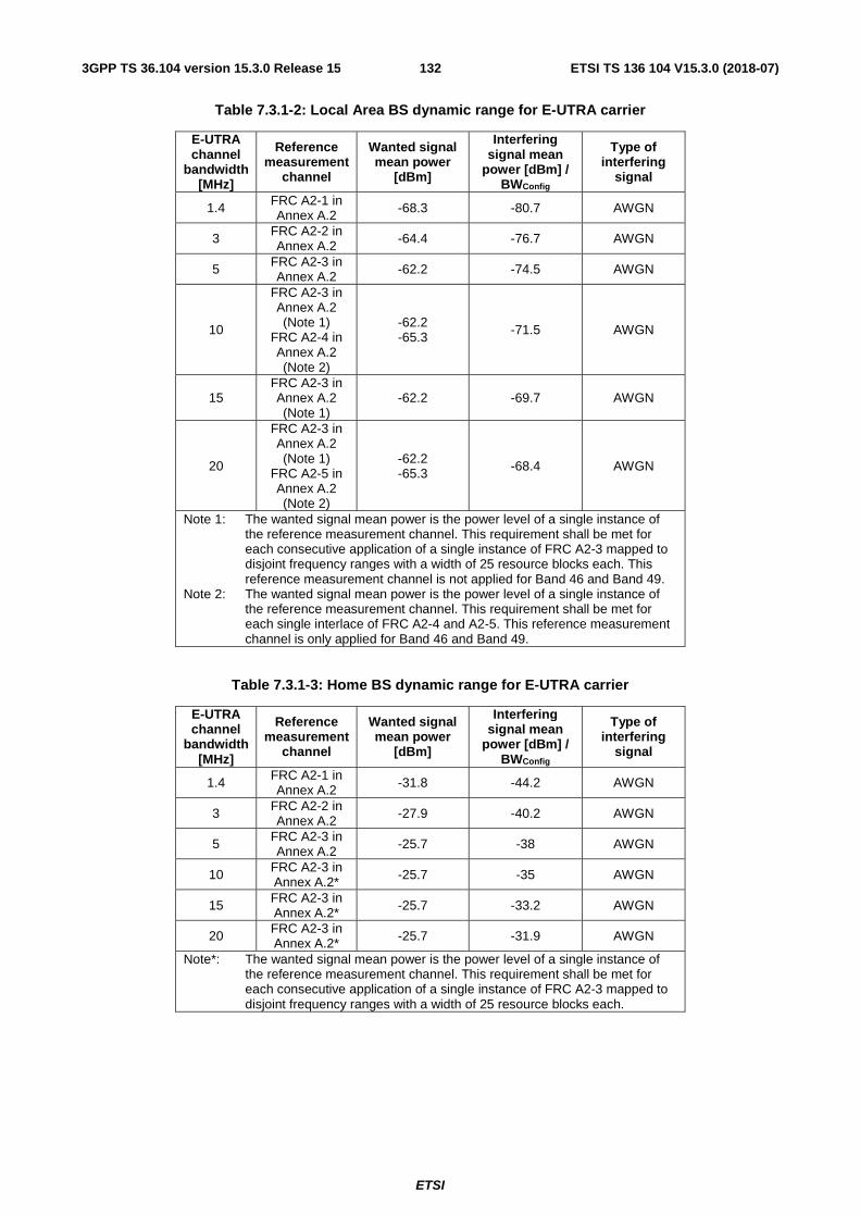
ETSI
ETSI TS 136 104 V15.3.0 (2018-07)1323GPP TS 36.104 version 15.3.0 Release 15
Table 7.3.1-2: Local Area BS dynamic range for E-UTRA carrier
E-UTRA channel
bandwidth [MHz]
Reference measurement
channel
Wanted signal mean power
[dBm]
Interfering signal mean
power [dBm] / BWConfig
Type of interfering
signal
1.4 FRC A2-1 in Annex A.2 -68.3 -80.7 AWGN
3 FRC A2-2 in Annex A.2 -64.4 -76.7 AWGN
5 FRC A2-3 in Annex A.2 -62.2 -74.5 AWGN
10
FRC A2-3 in Annex A.2 (Note 1)
FRC A2-4 in Annex A.2 (Note 2)
-62.2 -65.3 -71.5 AWGN
15 FRC A2-3 in Annex A.2 (Note 1)
-62.2 -69.7 AWGN
20
FRC A2-3 in Annex A.2 (Note 1)
FRC A2-5 in Annex A.2 (Note 2)
-62.2 -65.3 -68.4 AWGN
Note 1: The wanted signal mean power is the power level of a single instance of the reference measurement channel. This requirement shall be met for each consecutive application of a single instance of FRC A2-3 mapped to disjoint frequency ranges with a width of 25 resource blocks each. This reference measurement channel is not applied for Band 46 and Band 49.
Note 2: The wanted signal mean power is the power level of a single instance of the reference measurement channel. This requirement shall be met for each single interlace of FRC A2-4 and A2-5. This reference measurement channel is only applied for Band 46 and Band 49.
Table 7.3.1-3: Home BS dynamic range for E-UTRA carrier
E-UTRA channel
bandwidth [MHz]
Reference measurement
channel
Wanted signal mean power
[dBm]
Interfering signal mean
power [dBm] / BWConfig
Type of interfering
signal
1.4 FRC A2-1 in Annex A.2 -31.8 -44.2 AWGN
3 FRC A2-2 in Annex A.2 -27.9 -40.2 AWGN
5 FRC A2-3 in Annex A.2 -25.7 -38 AWGN
10 FRC A2-3 in Annex A.2* -25.7 -35 AWGN
15 FRC A2-3 in Annex A.2* -25.7 -33.2 AWGN
20 FRC A2-3 in Annex A.2* -25.7 -31.9 AWGN
Note*: The wanted signal mean power is the power level of a single instance of the reference measurement channel. This requirement shall be met for each consecutive application of a single instance of FRC A2-3 mapped to disjoint frequency ranges with a width of 25 resource blocks each.

ETSI
ETSI TS 136 104 V15.3.0 (2018-07)1333GPP TS 36.104 version 15.3.0 Release 15
Table 7.3.1-4: Medium Range BS dynamic range for E-UTRA carrier
E-UTRA channel
bandwidth [MHz]
Reference measurement
channel
Wanted signal mean power
[dBm]
Interfering signal mean
power [dBm] / BWConfig
Type of interfering
signal
1.4 FRC A2-1 in Annex A.2 -71.3 -83.7 AWGN
3 FRC A2-2 in Annex A.2 -67.4 -79.7 AWGN
5 FRC A2-3 in Annex A.2 -65.2 -77.5 AWGN
10
FRC A2-3 in Annex A.2 (Note 1)
FRC A2-4 in Annex A.2 (Note 2)
-65.2 -68.3 -74.5 AWGN
15 FRC A2-3 in Annex A.2 (Note 1)
-65.2 -72.7 AWGN
20
FRC A2-3 in Annex A.2 (Note 1)
FRC A2-5 in Annex A.2 (Note 2)
-65.2 -68.3 -71.4 AWGN
Note 1: The wanted signal mean power is the power level of a single instance of the reference measurement channel. This requirement shall be met for each consecutive application of a single instance of FRC A2-3 mapped to disjoint frequency ranges with a width of 25 resource blocks each. This reference measurement channel is not applied for Band 46.
Note 2: The wanted signal mean power is the power level of a single instance of the reference measurement channel. This requirement shall be met for each single interlace of FRC A2-4 and A2-5. This reference measurement channel is only applied for Band 46.
For NB-IoT standalone operation, the throughput shall be ≥ 95% of the maximum throughput of the reference measurement channel as specified in Annex A with parameters specified in Table 7.3.1-5 for Wide Area BS.
Table 7.3.1-5: Wide Area BS dynamic range for NB-IoT standalone operation
NB-IoT channel
bandwidth [kHz]
Reference measurement
channel
Wanted signal mean power
[dBm]
Interfering signal mean
power [dBm] / BWChannel
Type of interfering
signal
200 FRC A15-1 in Annex A.15 -99.7 -96 AWGN
200 FRC A15-2 in Annex A.15 -105.6 -96 AWGN
For NB-IoT in-band or guard band operation, the throughput shall be ≥ 95% of the maximum throughput of the reference measurement channel as specified in Annex A with parameters specified in Table 7.3.1-6 for Wide Area BS.

ETSI
ETSI TS 136 104 V15.3.0 (2018-07)1343GPP TS 36.104 version 15.3.0 Release 15
Table 7.3.1-6: Wide Area BS dynamic range for NB-IoT in-band or guard band operation
NB-IoT channel
bandwidth [MHz]
Reference measurement
channel
Wanted signal mean power
[dBm]
Interfering signal mean
power [dBm] / BWChannel
Type of interfering
signal
3*
FRC A15-1 in Annex A.15 -99.7
-84.2 AWGN FRC A15-2 in Annex A.15 -105.6
5
FRC A15-1 in Annex A.15 -99.7
-82.0 AWGN FRC A15-2 in Annex A.15 -105.6
10
FRC A15-1 in Annex A.15 -99.7
-79.0 AWGN FRC A15-2 in Annex A.15 -105.6
15
FRC A15-1 in Annex A.15 -99.7
-77.2 AWGN FRC A15-2 in Annex A.15 -105.6
20
FRC A15-1 in Annex A.15 -99.7
-76.0 AWGN FRC A15-2 in Annex A.15 -105.6
Note*: 3 MHz channel bandwidth is not applicable to guard band operation.
For NB-IoT standalone operation, the throughput shall be ≥ 95% of the maximum throughput of the reference measurement channel as specified in Annex A with parameters specified in Table 7.3.1-7 for Local Area BS
Table 7.3.1-7: Local Area BS dynamic range for NB-IoT standalone operation
NB-IoT channel
bandwidth [kHz]
Reference measurement
channel
Wanted signal mean power
[dBm]
Interfering signal mean
power [dBm] / BWChannel
Type of interfering
signal
200 FRC A15-1 in Annex A.15 -91.7 -88 AWGN
200 FRC A15-2 in Annex A.15 -97.6 -88 AWGN
For NB-IoT in-band or guard band operation, the throughput shall be ≥ 95% of the maximum throughput of the reference measurement channel as specified in Annex A with parameters specified in Table 7.3.1-8 for Local Area BS.

ETSI
ETSI TS 136 104 V15.3.0 (2018-07)1353GPP TS 36.104 version 15.3.0 Release 15
Table 7.3.1-8: Local Area BS dynamic range for NB-IoT in-band or guard band operation
NB-IoT channel
bandwidth [MHz]
Reference measurement
channel
Wanted signal mean power
[dBm]
Interfering signal mean
power [dBm] / BWChannel
Type of interfering
signal
3 (Note 1)
FRC A15-1 in Annex A.15 -91.7
-76.2 AWGN FRC A15-2 in Annex A.15 -97.6
5
FRC A15-1 in Annex A.15 -91.7
-74.0 AWGN FRC A15-2 in Annex A.15 -97.6
10
FRC A15-1 in Annex A.15 -91.7
-71.0 AWGN FRC A15-2 in Annex A.15 -97.6
15
FRC A15-1 in Annex A.15 -91.7
-69.2 AWGN FRC A15-2 in Annex A.15 -97.6
20
FRC A15-1 in Annex A.15 -91.7
-68.0 AWGN FRC A15-2 in Annex A.15 -97.6
Note 1: 3 MHz channel bandwidth is not applicable to guard band operation.
For NB-IoT standalone operation, the throughput shall be ≥ 95% of the maximum throughput of the reference measurement channel as specified in Annex A with parameters specified in Table 7.3.1-9 for Home BS
Table 7.3.1-9: Home BS dynamic range for NB-IoT standalone operation
NB-IoT channel
bandwidth [kHz]
Reference measurement
channel
Wanted signal mean power
[dBm]
Interfering signal mean
power [dBm] / BWChannel
Type of interfering
signal
200 FRC A15-1 in Annex A.15 -55.2 -51.5 AWGN
200 FRC A15-2 in Annex A.15 -61.1 -51.5 AWGN
For NB-IoT in-band or guard band operation, the throughput shall be ≥ 95% of the maximum throughput of the reference measurement channel as specified in Annex A with parameters specified in Table 7.3.1-10 for Home BS.

ETSI
ETSI TS 136 104 V15.3.0 (2018-07)1363GPP TS 36.104 version 15.3.0 Release 15
Table 7.3.1-10: Home BS dynamic range for NB-IoT in-band or guard band operation
NB-IoT channel
bandwidth [MHz]
Reference measurement
channel
Wanted signal mean power
[dBm]
Interfering signal mean
power [dBm] / BWChannel
Type of interfering
signal
3
(Note 1)
FRC A15-1 in Annex A.15 -55.2
-39.7 AWGN FRC A15-2 in Annex A.15 -61.1
5
FRC A15-1 in Annex A.15 -55.2
-37.5 AWGN FRC A15-2 in Annex A.15 -61.1
10
FRC A15-1 in Annex A.15 -55.2
-34.5 AWGN FRC A15-2 in Annex A.15 -61.1
15
FRC A15-1 in Annex A.15 -55.2
-32.7 AWGN FRC A15-2 in Annex A.15 -61.1
20
FRC A15-1 in Annex A.15 -55.2
-31.5 AWGN FRC A15-2 in Annex A.15 -61.1
Note 1: 3 MHz channel bandwidth is not applicable to guard band operation.
For NB-IoT standalone operation, the throughput shall be ≥ 95% of the maximum throughput of the reference measurement channel as specified in Annex A with parameters specified in Table 7.3.1-11 for Medium Range BS
Table 7.3.1-11: Medium Range BS dynamic range for NB-IoT standalone operation
NB-IoT channel
bandwidth [kHz]
Reference measurement
channel
Wanted signal mean power
[dBm]
Interfering signal mean
power [dBm] / BWChannel
Type of interfering
signal
200 FRC A15-1 in Annex A.15 -94.7 -91 AWGN
200 FRC A15-2 in Annex A.15 -100.6 -91 AWGN
For NB-IoT in-band or guard band operation, the throughput shall be ≥ 95% of the maximum throughput of the reference measurement channel as specified in Annex A with parameters specified in Table 7.3.1-12 for Medium Range BS.

ETSI
ETSI TS 136 104 V15.3.0 (2018-07)1373GPP TS 36.104 version 15.3.0 Release 15
Table 7.3.1-12: Medium Range BS dynamic range for NB-IoT in-band or guard band operation
NB-IoT channel
bandwidth [MHz]
Reference measurement
channel
Wanted signal mean power
[dBm]
Interfering signal mean
power [dBm] / BWChannel
Type of interfering
signal
3
(Note 1)
FRC A15-1 in Annex A.15 -94.7
-79.2 AWGN FRC A15-2 in Annex A.15 -100.6
5
FRC A15-1 in Annex A.15 -94.7
-77.0 AWGN FRC A15-2 in Annex A.15 -100.6
10
FRC A15-1 in Annex A.15 -94.7
-74.0 AWGN FRC A15-2 in Annex A.15 -100.6
15
FRC A15-1 in Annex A.15 -94.7
-72.2 AWGN FRC A15-2 in Annex A.15 -100.6
20
FRC A15-1 in Annex A.15 -94.7
-71.0 AWGN FRC A15-2 in Annex A.15 -100.6
Note 1: 3 MHz channel bandwidth is not applicable to guard band operation.
7.4 In-channel selectivity In-channel selectivity (ICS) is a measure of the receiver ability to receive a wanted signal at its assigned resource block locations in the presence of an interfering signal received at a larger power spectral density. In this condition a throughput requirement shall be met for a specified reference measurement channel. The interfering signal shall be an E-UTRA signal as specified in Annex C and shall be time aligned with the wanted signal.
7.4.1 Minimum requirement
For E-UTRA, the throughput shall be ≥ 95% of the maximum throughput of the reference measurement channel as specified in Annex A with parameters specified in Table 7.4.1-1 for Wide Area BS, in Table 7.4.1-2 for Local Area BS, in Table 7.4.1-3 for Home BS and in Table 7.4.1-4 for Medium Range BS.
Table 7.4.1-1 Wide Area BS in-channel selectivity for E-UTRA
E-UTRA channel
bandwidth (MHz)
Reference measurement
channel
Wanted signal mean power
[dBm]
Interfering signal mean power [dBm]
Type of interfering signal
1.4 A1-4 in Annex A.1 -106.9 -87 1.4 MHz E-UTRA
signal, 3 RBs
3 A1-5 in Annex A.1
-102.1 -84 3 MHz E-UTRA signal, 6 RBs
5 A1-2 in Annex A.1 -100.0 -81 5 MHz E-UTRA
signal, 10 RBs
10 A1-3 in Annex A.1 -98.5 -77 10 MHz E-UTRA
signal, 25 RBs
15 A1-3 in Annex
A.1 (Note) -98.5 -77 15 MHz E-UTRA signal, 25 RBs
(Note)
20 A1-3 in Annex A.1 (Note)
-98.5 -77 20 MHz E-UTRA signal, 25 RBs
(Note) Note: Wanted and interfering signal are placed adjacently around Fc

ETSI
ETSI TS 136 104 V15.3.0 (2018-07)1383GPP TS 36.104 version 15.3.0 Release 15
Table 7.4.1-2 Local Area BS in-channel selectivity for E-UTRA
E-UTRA channel
bandwidth (MHz)
Reference measurement
channel
Wanted signal mean power
[dBm]
Interfering signal mean power [dBm]
Type of interfering signal
1.4 A1-4 in Annex A.1 -98.9 -79 1.4 MHz E-UTRA
signal, 3 RBs
3 A1-5 in Annex A.1 -94.1 -76 3 MHz E-UTRA
signal, 6 RBs
5 A1-2 in Annex A.1 -92.0 -73 5 MHz E-UTRA
signal, 10 RBs
10
A1-3 in Annex A.1 (Note 3)
A1-8 in Annex A.1 (Note 2)
-90.5 -93.2
-69 -71.8
10 MHz E-UTRA signal, 25 RBs (Note
3) 10 MHz E-UTRA
interlace signal, 10 RBs (Note 2)
15 A1-3 in Annex A.1 (Note 1) -90.5 -69
15 MHz E-UTRA signal, 25 RBs (Note
1)
20
A1-3 in Annex A.1 (Note 1)
A1-9 in Annex A.1 (Note 2)
-90.5 -93.2
-69 -71.8
20 MHz E-UTRA signal, 25 RBs (Note
1) 20 MHz E-UTRA
interlace signal, 10 RBs (Note 2)
Note 1: Wanted and interfering signal are placed adjacently around Fc, this reference measurement channel and interfering signal are not applied for Band 46 and Band 49.
Note 2: Wanted and interfering signal interlaces are mirrored around Fc, this reference measurement channel and interfering signal are only applied for Band 46 and Band 49.
Note 3: This reference measurement channel and interfering signal are not applied for Band 46 and Band 49.
Table 7.4.1-3 Home BS in-channel selectivity for E-UTRA
E-UTRA channel
bandwidth (MHz)
Reference measurement
channel
Wanted signal mean power
[dBm]
Interfering signal mean power [dBm]
Type of interfering signal
1.4 A1-4 in Annex A.1 -98.9 -79 1.4 MHz E-UTRA
signal, 3 RBs
3 A1-5 in Annex A.1
-94.1 -76 3 MHz E-UTRA signal, 6 RBs
5 A1-2 in Annex A.1 -92.0 -73 5 MHz E-UTRA
signal, 10 RBs
10 A1-3 in Annex A.1 -90.5 -69 10 MHz E-UTRA
signal, 25 RBs
15 A1-3 in Annex
A.1 (Note) -90.5 -69 15 MHz E-UTRA signal, 25 RBs
(Note)
20 A1-3 in Annex A.1 (Note)
-90.5 -69 20 MHz E-UTRA signal, 25 RBs
(Note) Note: Wanted and interfering signal are placed adjacently around Fc

ETSI
ETSI TS 136 104 V15.3.0 (2018-07)1393GPP TS 36.104 version 15.3.0 Release 15
Table 7.4.1-4 Medium Range BS in-channel selectivity for E-UTRA
E-UTRA channel
bandwidth (MHz)
Reference measurement
channel
Wanted signal mean power
[dBm]
Interfering signal mean power [dBm]
Type of interfering signal
1.4 A1-4 in Annex A.1 -101.9 -82 1.4 MHz E-UTRA
signal, 3 RBs
3 A1-5 in Annex A.1 -97.1 -79 3 MHz E-UTRA
signal, 6 RBs
5 A1-2 in Annex A.1 -95.0 -76 5 MHz E-UTRA
signal, 10 RBs
10
A1-3 in Annex A.1 (Note 3)
A1-8 in Annex A.1 (Note 2)
-93.5 -96.2
-72 -74.8
10 MHz E-UTRA signal, 25 RBs (Note
3) 10 MHz E-UTRA
interlace signal, 10 RBs (Note 2)
15 A1-3 in Annex A.1 (Note 1) -93.5 -72
15 MHz E-UTRA signal, 25 RBs (Note
1)
20
A1-3 in Annex A.1 (Note 1)
A1-9 in Annex A.1 (Note 2)
-93.5 -96.2
-72 -74.8
20 MHz E-UTRA signal, 25 RBs (Note
1) 20 MHz E-UTRA
interlace signal, 10 RBs (Note 2)
Note 1: Wanted and interfering signal are placed adjacently around Fc, this reference measurement channel and interfering signal are not applied for Band 46.
Note 2: Wanted and interfering signal interlaces are mirrored around Fc, this reference measurement channel and interfering signal are only applied for Band 46.
Note 3: This reference measurement channel and interfering signal are not applied for Band 46.

ETSI
ETSI TS 136 104 V15.3.0 (2018-07)1403GPP TS 36.104 version 15.3.0 Release 15
For NB-IoT in-band operation, the throughput shall be ≥ 95% of the maximum throughput of the reference measurement channel as specified in Annex A with parameters specified in Table 7.4.1-5 and Table 7.4.1-6 for Wide Area BS.
Table 7.4.1-5 Wide Area BS in-channel selectivity for NB-IoT in-band operation with 15kHz channel spacing
E-UTRA channel
bandwidth (MHz)
Reference measurement
channel
Wanted signal mean power
[dBm]
Interfering signal mean power [dBm]
Type of interfering signal
3 FRC A14-1 in Annex A.14 -124.3 -84
3 MHz E-UTRA signal, 6 RBs (Note
2)
5 FRC A14-1 in Annex A.14 -124.3 -81
5 MHz E-UTRA signal, 10 RBs (Note
1)
10 FRC A14-1 in Annex A.14 -124.3 -77
10 MHz E-UTRA signal, 25 RBs (Note
1)
15 FRC A14-1 in Annex A.14 -124.3 -77
15 MHz E-UTRA signal, 25 RBs (Note
1)
20 FRC A14-1 in Annex A.14 -124.3 -77
20 MHz E-UTRA signal, 25 RBs (Note
1) Note 1: Interfering signal is placed in one side of the Fc, while the NB-IoT PRB is placed
on the other side. Both interfering signal and NB-IoT PRB are placed at the middle of the available PRB locations. The wanted NB-IoT tone is placed at the centre of this NB-IoT PRB.
Note 2: Interfering signal is placed from the edge of BWConfig, while the NB-IoT PRB is placed at the middle of the remaining PRB locations. The wanted NB-IoT tone is placed at the centre of this NB-IoT PRB.
Table 7.4.1-6 Wide Area BS in-channel selectivity for NB-IoT in-band operation with 3.75kHz channel spacing
E-UTRA channel
bandwidth (MHz)
Reference measurement
channel
Wanted signal mean power
[dBm]
Interfering signal mean power [dBm]
Type of interfering signal
3 FRC A14-2 in Annex A.14 -133.2+[3] -84
3 MHz E-UTRA signal, 6 RBs (Note
2)
5 FRC A14-2 in Annex A.14 -133.2+[3] -81
5 MHz E-UTRA signal, 10 RBs (Note
1)
10 FRC A14-2 in Annex A.14 -133.2+[3] -77
10 MHz E-UTRA signal, 25 RBs (Note
1)
15 FRC A14-2 in Annex A.14 -133.2+[3] -77
15 MHz E-UTRA signal, 25 RBs (Note
1)
20 FRC A14-2 in Annex A.14 -133.2+[3] -77
20 MHz E-UTRA signal, 25 RBs (Note
1) Note 1: Interfering signal is placed in one side of the Fc, while the NB-IoT PRB is placed
on the other side. Both interfering signal and NB-IoT PRB are placed at the middle of the available PRB locations. The wanted NB-IoT tone is placed at the centre of this NB-IoT PRB.
Note 2: Interfering signal is placed from the edge of BWConfig, while the NB-IoT PRB is placed at the middle of the remaining PRB locations. The wanted NB-IoT tone is placed at the centre of this NB-IoT PRB.

ETSI
ETSI TS 136 104 V15.3.0 (2018-07)1413GPP TS 36.104 version 15.3.0 Release 15
For NB-IoT in-band operation, the throughput shall be ≥ 95% of the maximum throughput of the reference measurement channel as specified in Annex A with parameters specified in Table 7.4.1-7 and Table 7.4.1-8 for Local Area BS.
Table 7.4.1-7 Local Area BS in-channel selectivity for NB-IoT in-band operation with 15kHz channel spacing
E-UTRA channel
bandwidth (MHz)
Reference measurement
channel
Wanted signal mean power
[dBm]
Interfering signal mean power [dBm]
Type of interfering signal
3 FRC A14-1 in Annex A.14 -116.3 -76
3 MHz E-UTRA signal, 6 RBs (Note
2)
5 FRC A14-1 in Annex A.14 -116.3 -73
5 MHz E-UTRA signal, 10 RBs (Note
1)
10 FRC A14-1 in Annex A.14 -116.3 -69
10 MHz E-UTRA signal, 25 RBs (Note
1)
15 FRC A14-1 in Annex A.14 -116.3 -69
15 MHz E-UTRA signal, 25 RBs (Note
1)
20 FRC A14-1 in Annex A.14 -116.3 -69
20 MHz E-UTRA signal, 25 RBs (Note
1) Note 1: Interfering signal is placed in one side of the Fc, while the NB-IoT PRB is placed
on the other side. Both interfering signal and NB-IoT PRB are placed at the middle of the available PRB locations. The wanted NB-IoT tone is placed at the centre of this NB-IoT PRB.
Note 2: Interfering signal is placed from the edge of BWConfig, while the NB-IoT PRB is placed at the middle of the remaining PRB locations. The wanted NB-IoT tone is placed at the centre of this NB-IoT PRB.
Table 7.4.1-8 Local Area BS in-channel selectivity for NB-IoT in-band operation with 3.75kHz channel spacing
E-UTRA channel
bandwidth (MHz)
Reference measurement
channel
Wanted signal mean power
[dBm]
Interfering signal mean power [dBm]
Type of interfering signal
3 FRC A14-2 in Annex A.14 -122.2 -76
3 MHz E-UTRA signal, 6 RBs (Note
2)
5 FRC A14-2 in Annex A.14 -122.2 -73
5 MHz E-UTRA signal, 10 RBs (Note
1)
10 FRC A14-2 in Annex A.14 -122.2 -69
10 MHz E-UTRA signal, 25 RBs (Note
1)
15 FRC A14-2 in Annex A.14 -122.2 -69
15 MHz E-UTRA signal, 25 RBs (Note
1)
20 FRC A14-2 in Annex A.14 -122.2 -69
20 MHz E-UTRA signal, 25 RBs (Note
1) Note 1: Interfering signal is placed in one side of the Fc, while the NB-IoT PRB is placed
on the other side. Both interfering signal and NB-IoT PRB are placed at the middle of the available PRB locations. The wanted NB-IoT tone is placed at the centre of this NB-IoT PRB.
Note 2: Interfering signal is placed from the edge of BWConfig, while the NB-IoT PRB is placed at the middle of the remaining PRB locations. The wanted NB-IoT tone is placed at the centre of this NB-IoT PRB.

ETSI
ETSI TS 136 104 V15.3.0 (2018-07)1423GPP TS 36.104 version 15.3.0 Release 15
For NB-IoT in-band operation, the throughput shall be ≥ 95% of the maximum throughput of the reference measurement channel as specified in Annex A with parameters specified in Table 7.4.1-9 and Table 7.4.1-10 for Home BS.
Table 7.4.1-9 Home BS in-channel selectivity for NB-IoT in-band operation with 15kHz channel spacing
E-UTRA channel
bandwidth (MHz)
Reference measurement
channel
Wanted signal mean power
[dBm]
Interfering signal mean power [dBm]
Type of interfering signal
3 FRC A14-1 in Annex A.14 -116.3 -76
3 MHz E-UTRA signal, 6 RBs (Note
2)
5 FRC A14-1 in Annex A.14 -116.3 -73
5 MHz E-UTRA signal, 10 RBs (Note
1)
10 FRC A14-1 in Annex A.14 -116.3 -69
10 MHz E-UTRA signal, 25 RBs (Note
1)
15 FRC A14-1 in Annex A.14 -116.3 -69
15 MHz E-UTRA signal, 25 RBs (Note
1)
20 FRC A14-1 in Annex A.14 -116.3 -69
20 MHz E-UTRA signal, 25 RBs (Note
1) Note 1: Interfering signal is placed in one side of the Fc, while the NB-IoT PRB is placed
on the other side. Both interfering signal and NB-IoT PRB are placed at the middle of the available PRB locations. The wanted NB-IoT tone is placed at the centre of this NB-IoT PRB.
Note 2: Interfering signal is placed from the edge of BWConfig, while the NB-IoT PRB is placed at the middle of the remaining PRB locations. The wanted NB-IoT tone is placed at the centre of this NB-IoT PRB.
Table 7.4.1-10 Home BS in-channel selectivity for NB-IoT in-band operation with 3.75kHz channel spacing
E-UTRA channel
bandwidth (MHz)
Reference measurement
channel
Wanted signal mean power
[dBm]
Interfering signal mean power [dBm]
Type of interfering signal
3 FRC A14-2 in Annex A.14 -122.2 -76
3 MHz E-UTRA signal, 6 RBs (Note
2)
5 FRC A14-2 in Annex A.14 -122.2 -73
5 MHz E-UTRA signal, 10 RBs (Note
1)
10 FRC A14-2 in Annex A.14 -122.2 -69
10 MHz E-UTRA signal, 25 RBs (Note
1)
15 FRC A14-2 in Annex A.14 -122.2 -69
15 MHz E-UTRA signal, 25 RBs (Note
1)
20 FRC A14-2 in Annex A.14 -122.2 -69
20 MHz E-UTRA signal, 25 RBs (Note
1) Note 1: Interfering signal is placed in one side of the Fc, while the NB-IoT PRB is placed
on the other side. Both interfering signal and NB-IoT PRB are placed at the middle of the available PRB locations. The wanted NB-IoT tone is placed at the centre of this NB-IoT PRB.
Note 2: Interfering signal is placed from the edge of BWConfig, while the NB-IoT PRB is placed at the middle of the remaining PRB locations. The wanted NB-IoT tone is placed at the centre of this NB-IoT PRB.

ETSI
ETSI TS 136 104 V15.3.0 (2018-07)1433GPP TS 36.104 version 15.3.0 Release 15
For NB-IoT in-band operation, the throughput shall be ≥ 95% of the maximum throughput of the reference measurement channel as specified in Annex A with parameters specified in Table 7.4.1-11 and Table 7.4.1-12 for Medium Range BS.
Table 7.4.1-11 Medium Range BS in-channel selectivity for NB-IoT in-band operation with 15kHz channel spacing
E-UTRA channel
bandwidth (MHz)
Reference measurement
channel
Wanted signal mean power
[dBm]
Interfering signal mean power [dBm]
Type of interfering signal
3 FRC A14-1 in Annex A.14 -119.3 -79
3 MHz E-UTRA signal, 6 RBs (Note
2)
5 FRC A14-1 in Annex A.14 -119.3 -76
5 MHz E-UTRA signal, 10 RBs (Note
1)
10 FRC A14-1 in Annex A.14 -119.3 -72
10 MHz E-UTRA signal, 25 RBs (Note
1)
15 FRC A14-1 in Annex A.14 -119.3 -72
15 MHz E-UTRA signal, 25 RBs (Note
1)
20 FRC A14-1 in Annex A.14 -119.3 -72
20 MHz E-UTRA signal, 25 RBs (Note
1) Note 1: Interfering signal is placed in one side of the Fc, while the NB-IoT PRB is placed
on the other side. Both interfering signal and NB-IoT PRB are placed at the middle of the available PRB locations. The wanted NB-IoT tone is placed at the centre of this NB-IoT PRB.
Note 2: Interfering signal is placed from the edge of BWConfig, while the NB-IoT PRB is placed at the middle of the remaining PRB locations. The wanted NB-IoT tone is placed at the centre of this NB-IoT PRB.
Table 7.4.1-12 Medium Range BS in-channel selectivity for NB-IoT in-band operation with 3.75kHz channel spacing
E-UTRA channel
bandwidth (MHz)
Reference measurement
channel
Wanted signal mean power
[dBm]
Interfering signal mean power [dBm]
Type of interfering signal
3 FRC A14-2 in Annex A.14 -125.2 -79
3 MHz E-UTRA signal, 6 RBs (Note
2)
5 FRC A14-2 in Annex A.14 -125.2 -76
5 MHz E-UTRA signal, 10 RBs (Note
1)
10 FRC A14-2 in Annex A.14 -125.2 -72
10 MHz E-UTRA signal, 25 RBs (Note
1)
15 FRC A14-2 in Annex A.14 -125.2 -72
15 MHz E-UTRA signal, 25 RBs (Note
1)
20 FRC A14-2 in Annex A.14 -125.2 -72
20 MHz E-UTRA signal, 25 RBs (Note
1) Note 1: Interfering signal is placed in one side of the Fc, while the NB-IoT PRB is placed
on the other side. Both interfering signal and NB-IoT PRB are placed at the middle of the available PRB locations. The wanted NB-IoT tone is placed at the centre of this NB-IoT PRB.
Note 2: Interfering signal is placed from the edge of BWConfig, while the NB-IoT PRB is placed at the middle of the remaining PRB locations. The wanted NB-IoT tone is placed at the centre of this NB-IoT PRB.

ETSI
ETSI TS 136 104 V15.3.0 (2018-07)1443GPP TS 36.104 version 15.3.0 Release 15
7.5 Adjacent Channel Selectivity (ACS) and narrow-band blocking
Adjacent channel selectivity (ACS) is a measure of the receiver ability to receive a wanted signal at its assigned channel frequency in the presence of an adjacent channel signal with a specified centre frequency offset of the interfering signal to the band edge of a victim system. For E-UTRA or E-UTRA with NB-IoT (in-band and/or guard band operation) BS, the interfering signal shall be an E-UTRA signal as specified in Annex C. For NB-IoT standalone BS, the interfering signal shall be a NB-IoT signal as specified in Annex C.
7.5.1 Minimum requirement
The throughput shall be ≥ 95% of the maximum throughput of the reference measurement channel.
For E-UTRA Wide Area BS, the wanted and the interfering signal coupled to the BS antenna input are specified in Tables 7.5.1-1 and 7.5.1-2 for narrowband blocking and in Table 7.5.1-3 for ACS. The reference measurement channel for the wanted signal is identified in Table 7.2.1-1 for each channel bandwidth and further specified in Annex A.
For E-UTRA Medium Range BS, the wanted and the interfering signal coupled to the BS antenna input are specified in Tables 7.5.1-1 and 7.5.1-2 for narrowband blocking and in Table 7.5.1-6 for ACS. Narrowband blocking requirements are not applied for Band 46. The reference measurement channel for the wanted signal is identified in Table 7.2.1-4 for each channel bandwidth and further specified in Annex A.
For E-UTRA Local Area BS, the wanted and the interfering signal coupled to the BS antenna input are specified in Tables 7.5.1-1 and 7.5.1-2 for narrowband blocking and in Table 7.5.1-4 for ACS. Narrowband blocking requirements are not applied for Band 46. The reference measurement channel for the wanted signal is identified in Table 7.2.1-2 for each channel bandwidth and further specified in Annex A.
For E-UTRA Home BS, the wanted and the interfering signal coupled to the BS antenna input are specified in Tables 7.5.1-1 and 7.5.1-2 for narrowband blocking and in Table 7.5.1-5 for ACS. The reference measurement channel for the wanted signal is identified in Table 7.2.1-3 for each channel bandwidth and further specified in Annex A.
For NB-IoT in-band operation Wide Area BS, the wanted signal and the interfering signal coupled to the BS antenna input are specified in Tables 7.5.1-1a and 7.5.1-2 for narrowband blocking and in Table 7.5.1-3a for ACS. The reference measurement channel for the NB-IoT wanted signal is identified in Table 7.2.1-5 for each sub-carrier spacing and further specified in Annex A.
For NB-IoT guard band operation Wide Area BS, the wanted signal and the interfering signal coupled to the BS antenna input are specified in Tables 7.5.1-1b and 7.5.1-2 for narrowband blocking and in Table 7.5.1-3b for ACS. The reference measurement channel for the NB-IoT wanted signal is identified in Table 7.2.1-5 for each sub-carrier spacing and further specified in Annex A.
For NB-IoT standalone operation Wide Area BS, the wanted signal and the interfering signal coupled to the BS antenna input are specified in Tables 7.5.1-1c and 7.5.1-2a for narrowband blocking and in Table 7.5.1-3c for ACS. The reference measurement channel for the NB-IoT wanted signal is identified in Table 7.2.1-5 for each sub-carrier spacing and further specified in Annex A.
For NB-IoT in-band operation Local Area BS, the wanted signal and the interfering signal coupled to the BS antenna input are specified in Tables 7.5.1-1a and 7.5.1-2 for narrowband blocking and in Table 7.5.1-4a for ACS. The reference measurement channel for the NB-IoT wanted signal is identified in Table 7.2.1-5a for each sub-carrier spacing and further specified in Annex A.
For NB-IoT guard band operation Local Area BS, the wanted signal and the interfering signal coupled to the BS antenna input are specified in Tables 7.5.1-1b and 7.5.1-2 for narrowband blocking and in Table 7.5.1-4b for ACS. The reference measurement channel for the NB-IoT wanted signal is identified in Table 7.2.1-5a for each sub-carrier spacing and further specified in Annex A.
For NB-IoT standalone operation Loca Area BS, the wanted signal and the interfering signal coupled to the BS antenna input are specified in Tables 7.5.1-1c and 7.5.1-2a for narrowband blocking and in Table 7.5.1-4c for ACS. The reference measurement channel for the NB-IoT wanted signal is identified in Table 7.2.1-5a for each sub-carrier spacing and further specified in Annex A.
For NB-IoT in-band operation Medium Range BS, the wanted signal and the interfering signal coupled to the BS antenna input are specified in Tables 7.5.1-1a and 7.5.1-2 for narrowband blocking and in Table 7.5.1-5a for ACS. The
ETSI
ETSI TS 136 104 V15.3.0 (2018-07)1453GPP TS 36.104 version 15.3.0 Release 15
reference measurement channel for the NB-IoT wanted signal is identified in Table 7.2.1-5b for each sub-carrier spacing and further specified in Annex A.
For NB-IoT guard band operation Medium Range BS, the wanted signal and the interfering signal coupled to the BS antenna input are specified in Tables 7.5.1-1b and 7.5.1-2 for narrowband blocking and in Table 7.5.1-5b for ACS. The reference measurement channel for the NB-IoT wanted signal is identified in Table 7.2.1-5c for each sub-carrier spacing and further specified in Annex A.
For NB-IoT standalone operation Medium Range BS, the wanted signal and the interfering signal coupled to the BS antenna input are specified in Tables 7.5.1-1c and 7.5.1-2a for narrowband blocking and in Table 7.5.1-5c for ACS. The reference measurement channel for the NB-IoT wanted signal is identified in Table 7.2.1-5c for each sub-carrier spacing and further specified in Annex A.
For NB-IoT in-band operation Home BS, the wanted signal and the interfering signal coupled to the BS antenna input are specified in Tables 7.5.1-1a and 7.5.1-2 for narrowband blocking and in Table 7.5.1-5a for ACS. The reference measurement channel for the NB-IoT wanted signal is identified in Table 7.2.1-5c for each sub-carrier spacing and further specified in Annex A.
For NB-IoT guard band operation Home BS, the wanted signal and the interfering signal coupled to the BS antenna input are specified in Tables 7.5.1-1b and 7.5.1-2 for narrowband blocking and in Table 7.5.1-5b for ACS. The reference measurement channel for the NB-IoT wanted signal is identified in Table 7.2.1-5b for each sub-carrier spacing and further specified in Annex A.
For NB-IoT standalone operation Home BS, the wanted signal and the interfering signal coupled to the BS antenna input are specified in Tables 7.5.1-1c and 7.5.1-2a for narrowband blocking and in Table 7.5.1-5c for ACS. The reference measurement channel for the NB-IoT wanted signal is identified in Table 7.2.1-5b for each sub-carrier spacing and further specified in Annex A.
The ACS and narrowband blocking requirement is applicable outside the Base Station RF Bandwidth or Radio Bandwidth. The interfering signal offset is defined relative to the Base station RF Bandwidth edges or Radio Bandwidth edges.
For a E-UTRA BS operating in non-contiguous spectrum within any operating band, the ACS requirement applies in addition inside any sub-block gap, in case the sub-block gap size is at least as wide as the E-UTRA interfering signal in Table 7.5.1-3, 7.5.1-4 and 7.5.1-6. The interfering signal offset is defined relative to the sub-block edges inside the sub-block gap.
For a E-UTRA BS capable of multi-band operation, the ACS requirement applies in addition inside any Inter RF Bandwidth gap, in case the Inter RF Bandwidth gap size is at least as wide as the E-UTRA interfering signal in Tables 7.5.1-3, 7.5.1-4 and 7.5.1-6. The interfering signal offset is defined relative to the Base Station RF Bandwidth edges inside the Inter RF Bandwidth gap.
For a E-UTRA BS operating in non-contiguous spectrum within any operating band, the narrowband blocking requirement applies in addition inside any sub-block gap, in case the sub-block gap size is at least as wide as the channel bandwidth of the E-UTRA interfering signal in Table 7.5.1-2. The interfering signal offset is defined relative to the sub-block edges inside the sub-block gap.
For a E-UTRA BS capable of multi-band operation, the narrowband blocking requirement applies in addition inside any Inter RF Bandwidth gap, in case the Inter RF Bandwidth gap size is at least as wide as the E-UTRA interfering signal in Table 7.5.1-2. The interfering signal offset is defined relative to the Base Station RF Bandwidth edges inside the Inter RF Bandwidth gap.
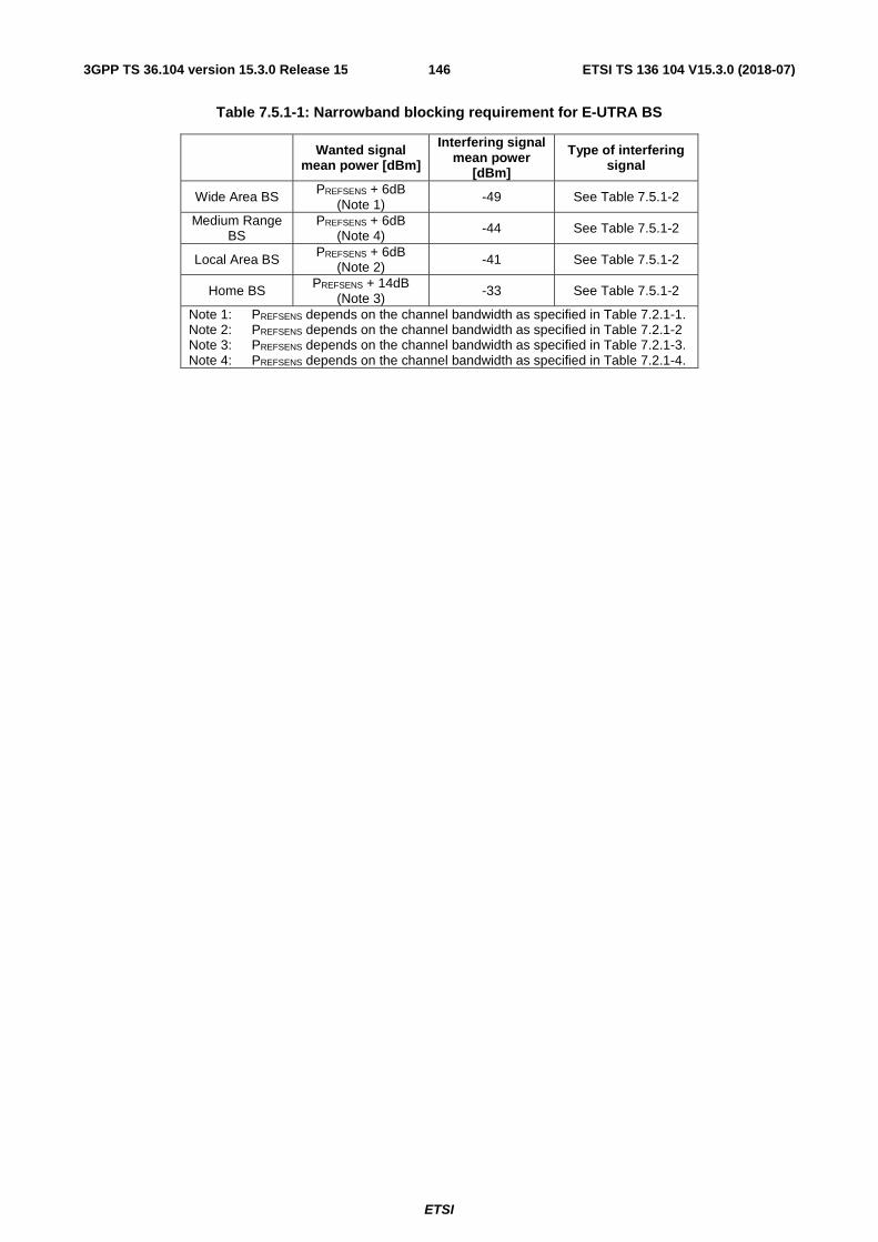
ETSI
ETSI TS 136 104 V15.3.0 (2018-07)1463GPP TS 36.104 version 15.3.0 Release 15
Table 7.5.1-1: Narrowband blocking requirement for E-UTRA BS
Wanted signal mean power [dBm]
Interfering signal mean power
[dBm]
Type of interfering signal
Wide Area BS PREFSENS + 6dB (Note 1)
-49 See Table 7.5.1-2
Medium Range BS
PREFSENS + 6dB (Note 4) -44 See Table 7.5.1-2
Local Area BS PREFSENS + 6dB (Note 2) -41 See Table 7.5.1-2
Home BS PREFSENS + 14dB (Note 3)
-33 See Table 7.5.1-2
Note 1: PREFSENS depends on the channel bandwidth as specified in Table 7.2.1-1. Note 2: PREFSENS depends on the channel bandwidth as specified in Table 7.2.1-2 Note 3: PREFSENS depends on the channel bandwidth as specified in Table 7.2.1-3. Note 4: PREFSENS depends on the channel bandwidth as specified in Table 7.2.1-4.
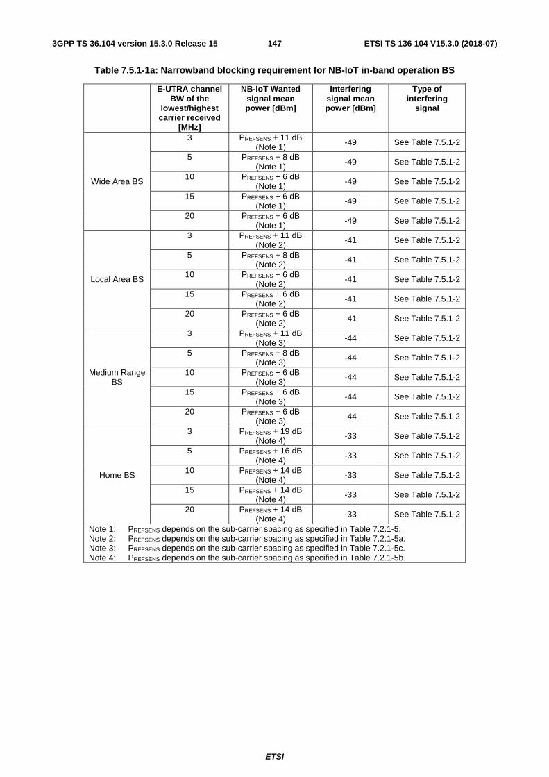
ETSI
ETSI TS 136 104 V15.3.0 (2018-07)1473GPP TS 36.104 version 15.3.0 Release 15
Table 7.5.1-1a: Narrowband blocking requirement for NB-IoT in-band operation BS
E-UTRA channel BW of the
lowest/highest carrier received
[MHz]
NB-IoT Wanted signal mean power [dBm]
Interfering signal mean power [dBm]
Type of interfering
signal
Wide Area BS
3 PREFSENS + 11 dB (Note 1) -49 See Table 7.5.1-2
5 PREFSENS + 8 dB (Note 1) -49 See Table 7.5.1-2
10 PREFSENS + 6 dB (Note 1) -49 See Table 7.5.1-2
15 PREFSENS + 6 dB (Note 1) -49 See Table 7.5.1-2
20 PREFSENS + 6 dB (Note 1) -49 See Table 7.5.1-2
Local Area BS
3 PREFSENS + 11 dB (Note 2) -41 See Table 7.5.1-2
5 PREFSENS + 8 dB (Note 2) -41 See Table 7.5.1-2
10 PREFSENS + 6 dB (Note 2)
-41 See Table 7.5.1-2
15 PREFSENS + 6 dB (Note 2) -41 See Table 7.5.1-2
20 PREFSENS + 6 dB (Note 2) -41 See Table 7.5.1-2
Medium Range BS
3 PREFSENS + 11 dB (Note 3)
-44 See Table 7.5.1-2
5 PREFSENS + 8 dB (Note 3) -44 See Table 7.5.1-2
10 PREFSENS + 6 dB (Note 3) -44 See Table 7.5.1-2
15 PREFSENS + 6 dB (Note 3)
-44 See Table 7.5.1-2
20 PREFSENS + 6 dB (Note 3) -44 See Table 7.5.1-2
Home BS
3 PREFSENS + 19 dB (Note 4) -33 See Table 7.5.1-2
5 PREFSENS + 16 dB (Note 4) -33 See Table 7.5.1-2
10 PREFSENS + 14 dB (Note 4) -33 See Table 7.5.1-2
15 PREFSENS + 14 dB (Note 4) -33 See Table 7.5.1-2
20 PREFSENS + 14 dB (Note 4) -33 See Table 7.5.1-2
Note 1: PREFSENS depends on the sub-carrier spacing as specified in Table 7.2.1-5. Note 2: PREFSENS depends on the sub-carrier spacing as specified in Table 7.2.1-5a. Note 3: PREFSENS depends on the sub-carrier spacing as specified in Table 7.2.1-5c. Note 4: PREFSENS depends on the sub-carrier spacing as specified in Table 7.2.1-5b.

ETSI
ETSI TS 136 104 V15.3.0 (2018-07)1483GPP TS 36.104 version 15.3.0 Release 15
Table 7.5.1-1b: Narrowband blocking requirement for NB-IoT guard band operation BS
E-UTRA channel BW of the
lowest/highest carrier received
[MHz]
NB-IoT Wanted signal mean power
[dBm]
Interfering signal mean power [dBm]
Type of interfering signal
Wide Area BS
5 PREFSENS + 11 dB (Note 1)
-49 See Table 7.5.1-2
10 PREFSENS + 6 dB (Note 1)
-49 See Table 7.5.1-2
15 PREFSENS + 6 dB (Note 1)
-49 See Table 7.5.1-2
20 PREFSENS + 6 dB (Note 1)
-49 See Table 7.5.1-2
Local Area BS
5 PREFSENS + 11 dB (Note 2) -41 See Table 7.5.1-2
10 PREFSENS + 6 dB (Note 2) -41 See Table 7.5.1-2
15 PREFSENS + 6 dB (Note 2) -41 See Table 7.5.1-2
20 PREFSENS + 6 dB (Note 2)
-41 See Table 7.5.1-2
Medium Range BS
5 PREFSENS + 11 dB (Note 3) -44 See Table 7.5.1-2
10 PREFSENS + 6 dB (Note 3) -44 See Table 7.5.1-2
15 PREFSENS + 6 dB (Note 3)
-44 See Table 7.5.1-2
20 PREFSENS + 6 dB (Note 3) -44 See Table 7.5.1-2
Home BS
3 PREFSENS + 19 dB (Note 4) -33 See Table 7.5.1-2
5 PREFSENS + 16 dB (Note 4)
-33 See Table 7.5.1-2
10 PREFSENS + 14 dB (Note 4) -33 See Table 7.5.1-2
15 PREFSENS + 14 dB (Note 4) -33 See Table 7.5.1-2
20 PREFSENS + 14 dB (Note 4) -33 See Table 7.5.1-2
Note: The mentioned desens values consider only one NB-IoT PRB in the guard band, which is placed adjacent to the E-UTRA PRB edge as close as possible (i.e., away from edge of channel bandwidth).
Note 1: PREFSENS depends on the sub-carrier spacing as specified in Table 7.2.1-5. Note 2: PREFSENS depends on the sub-carrier spacing as specified in Table 7.2.1-5a. Note 3: PREFSENS depends on the sub-carrier spacing as specified in Table 7.2.1-5c. Note 4: PREFSENS depends on the sub-carrier spacing as specified in Table 7.2.1-5b.

ETSI
ETSI TS 136 104 V15.3.0 (2018-07)1493GPP TS 36.104 version 15.3.0 Release 15
Table 7.5.1-1c: Narrowband blocking requirement for NB-IoT standalone
NB-IoT channel bandwidth of
the lowest/highest carrier received [kHz]
Wanted signal mean power
[dBm]
Interfering signal mean
power [dBm]
Type of interfering signal
Wide Area BS 200 PREFSENS + 12 dB (Note 1) -49 See Table 7.5.1-2a
Local Area BS 200 PREFSENS + 12 dB (Note 2) -41 See Table 7.5.1-2a
Medium Range BS 200 PREFSENS + 12
dB (Note 3) -44 See Table 7.5.1-2a
Home BS 200 PREFSENS + 20 dB (Note 4) -33 See Table 7.5.1-2a
Note 1: PREFSENS depends on the sub-carrier spacing as specified in Table 7.2.1-5. Note 2: PREFSENS depends on the sub-carrier spacing as specified in Table 7.2.1-5a. Note 3: PREFSENS depends on the sub-carrier spacing as specified in Table 7.2.1-5c. Note 4: PREFSENS depends on the sub-carrier spacing as specified in Table 7.2.1-5b.
Table 7.5.1-2: Interfering signal for Narrowband blocking requirement for E-UTRA BS
E-UTRA channel BW of the
lowest/highest carrier received
[MHz]
Interfering RB centre frequency
offset to the lower/upper Base
Station RF Bandwdith edge or
sub-block edge inside a sub-block
gap [kHz]
Type of interfering signal
1.4 ±(252.5+m*180), m=0, 1, 2, 3, 4, 5 1.4 MHz E-UTRA signal, 1 RB*
3 ±(247.5+m*180),
m=0, 1, 2, 3, 4, 7, 10, 13
3 MHz E-UTRA signal, 1 RB*
5 ±(342.5+m*180),
m=0, 1, 2, 3, 4, 9, 14, 19, 24
5 MHz E-UTRA signal, 1 RB*
10 ±(347.5+m*180),
m=0, 1, 2, 3, 4, 9, 14, 19, 24
5 MHz E-UTRA signal, 1 RB*
15 ±(352.5+m*180),
m=0, 1, 2, 3, 4, 9, 14, 19, 24
5 MHz E-UTRA signal, 1 RB*
20 ±(342.5+m*180),
m=0, 1, 2, 3, 4, 9, 14, 19, 24
5 MHz E-UTRA signal, 1 RB*
Note*: Interfering signal consisting of one resource block is positioned at the stated offset, the channel bandwidth of the interfering signal is located adjacently to the lower/upper Base Station RF Bandwidth edge.
Table 7.5.1-2a: Interfering signal for Narrowband blocking requirement for NB-IoT standalone operation BS
NB-IoT channel bandwidth
of the lowest/highest carrier received
[kHz]
Interfering RB centre frequency
offset to the lower/upper Base
Station RF Bandwdith edge or
sub-block edge inside a sub-block
gap [kHz]
Type of interfering signal
200 ±(240 +m*180),
m=0, 1, 2, 3, 4, 9, 14 3 MHz E-UTRA signal, 1 RB*
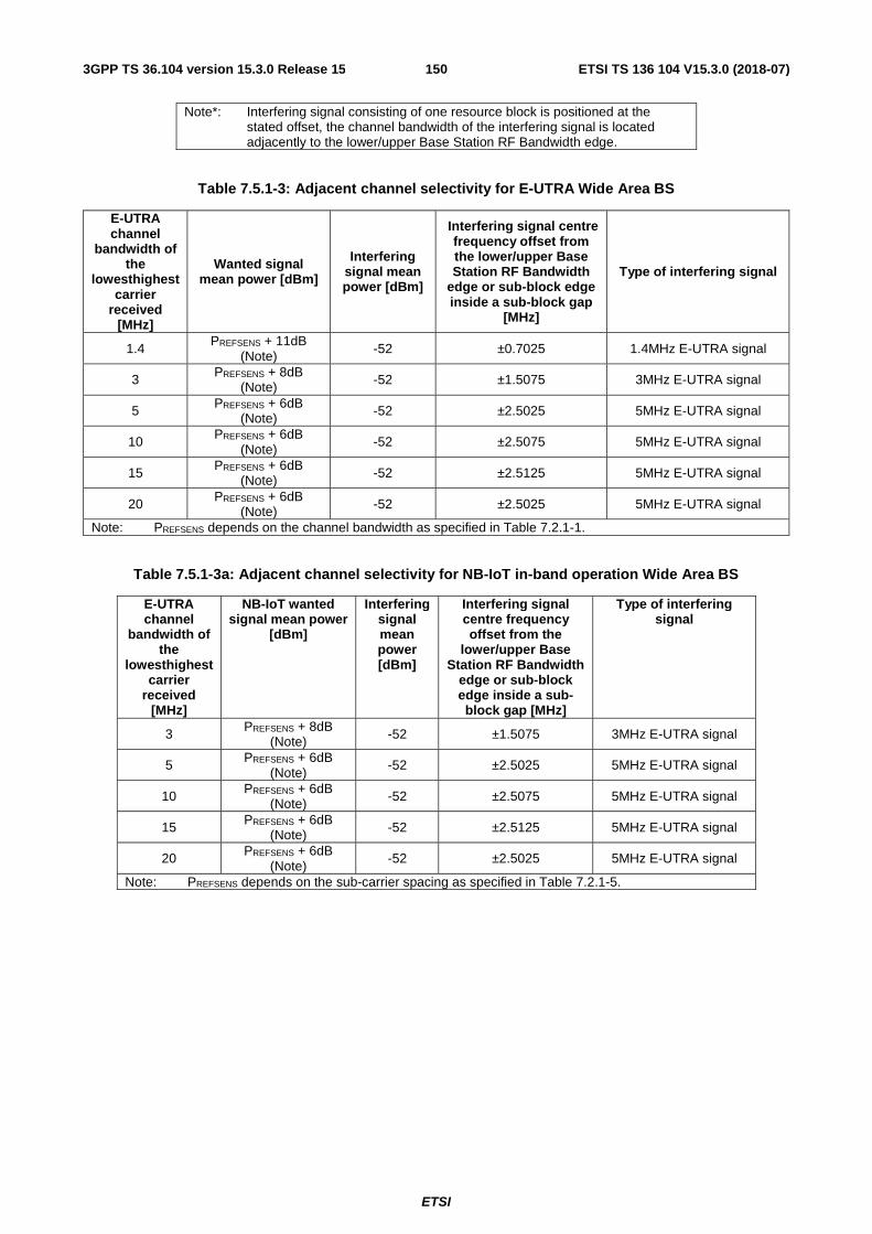
ETSI
ETSI TS 136 104 V15.3.0 (2018-07)1503GPP TS 36.104 version 15.3.0 Release 15
Note*: Interfering signal consisting of one resource block is positioned at the stated offset, the channel bandwidth of the interfering signal is located adjacently to the lower/upper Base Station RF Bandwidth edge.
Table 7.5.1-3: Adjacent channel selectivity for E-UTRA Wide Area BS
E-UTRA channel
bandwidth of the
lowesthighest carrier
received [MHz]
Wanted signal mean power [dBm]
Interfering signal mean power [dBm]
Interfering signal centre frequency offset from the lower/upper Base Station RF Bandwidth
edge or sub-block edge inside a sub-block gap
[MHz]
Type of interfering signal
1.4 PREFSENS + 11dB
(Note) -52 ±0.7025 1.4MHz E-UTRA signal
3 PREFSENS + 8dB (Note) -52 ±1.5075 3MHz E-UTRA signal
5 PREFSENS + 6dB (Note) -52 ±2.5025 5MHz E-UTRA signal
10 PREFSENS + 6dB (Note)
-52 ±2.5075 5MHz E-UTRA signal
15 PREFSENS + 6dB (Note) -52 ±2.5125 5MHz E-UTRA signal
20 PREFSENS + 6dB (Note) -52 ±2.5025 5MHz E-UTRA signal
Note: PREFSENS depends on the channel bandwidth as specified in Table 7.2.1-1.
Table 7.5.1-3a: Adjacent channel selectivity for NB-IoT in-band operation Wide Area BS
E-UTRA channel
bandwidth of the
lowesthighest carrier
received [MHz]
NB-IoT wanted signal mean power
[dBm]
Interfering signal mean power [dBm]
Interfering signal centre frequency offset from the
lower/upper Base Station RF Bandwidth
edge or sub-block edge inside a sub-block gap [MHz]
Type of interfering signal
3 PREFSENS + 8dB (Note) -52 ±1.5075 3MHz E-UTRA signal
5 PREFSENS + 6dB (Note)
-52 ±2.5025 5MHz E-UTRA signal
10 PREFSENS + 6dB (Note) -52 ±2.5075 5MHz E-UTRA signal
15 PREFSENS + 6dB (Note) -52 ±2.5125 5MHz E-UTRA signal
20 PREFSENS + 6dB (Note)
-52 ±2.5025 5MHz E-UTRA signal
Note: PREFSENS depends on the sub-carrier spacing as specified in Table 7.2.1-5.

ETSI
ETSI TS 136 104 V15.3.0 (2018-07)1513GPP TS 36.104 version 15.3.0 Release 15
Table 7.5.1-3b: Adjacent channel selectivity NB-IoT guard band operation Wide Area BS
E-UTRA channel
bandwidth of the
lowesthighest carrier
received [MHz]
NB-IoT wanted signal mean power
[dBm]
Interfering signal mean power [dBm]
Interfering signal centre frequency offset from the
lower/upper Base Station RF Bandwidth
edge or sub-block edge inside a sub-block gap [MHz]
Type of interfering signal
5 PREFSENS + 10 dB (Note) -52 ±2.5025 5MHz E-UTRA signal
10 PREFSENS + 8 dB (Note) -52 ±2.5075 5MHz E-UTRA signal
15 PREFSENS + 6 dB (Note) -52 ±2.5125 5MHz E-UTRA signal
20 PREFSENS + 6 dB
(Note) -52 ±2.5025 5MHz E-UTRA signal
Note: PREFSENS depends on the sub-carrier spacing as specified in Table 7.2.1-5.
Table 7.5.1-3c: Adjacent channel selectivity for NB-IoT standalone Wide Area BS
NB-IoT channel
bandwidth of the
lowest/highest carrier
received [kHz]
Wanted signal mean power [dBm]
Interfering signal mean power [dBm]
Interfering signal centre frequency offset to the
lower/upper Base Station RF Bandwidth
edge or sub-block edge inside a sub-block gap
[kHz]
Type of interfering signal
200 PREFSENS + 19.5dB (Note) -52 ±100 180 kHz NB-IoT signal
Note: PREFSENS depends on the sub-carrier spacing as specified in Table 7.2.1-5.
Table 7.5.1-4: Adjacent channel selectivity for E-UTRA Local Area BS
E-UTRA channel
bandwidth of the
lowest/highest carrier
received [MHz]
Wanted signal mean power [dBm]
Interfering signal mean power [dBm]
Interfering signal centre frequency offset from the lower/upper Base Station RF Bandwidth
edge or sub-block edge inside a sub-block gap
[MHz]
Type of interfering signal
1.4 PREFSENS + 11dB (Note 1) -44 ±0.7025 1.4MHz E-UTRA signal
3 PREFSENS + 8dB (Note 1) -44 ±1.5075 3MHz E-UTRA signal
5 PREFSENS + 6dB (Note 1) -44 ±2.5025 5MHz E-UTRA signal
10 PREFSENS + 6dB (Note
1) -44 ±2.5075 ±10.0175
5MHz E-UTRA signal (Note 2)
20 MHz E-UTRA signal (Note 3)
15 PREFSENS + 6dB (Note 1)
-44 ±2.5125 5MHz E-UTRA signal
20 PREFSENS + 6dB (Note 1) -44 ±2.5025
±10.0175
5MHz E-UTRA signal (Note 2)
20 MHz E-UTRA signal (Note 3)
Note 1: PREFSENS depends on the channel bandwidth as specified in Table 7.2.1-2. Note 2: This type of interfering signal is not applied for Band 46. Note 3: This type of interfering signal is only applied for Band 46.

ETSI
ETSI TS 136 104 V15.3.0 (2018-07)1523GPP TS 36.104 version 15.3.0 Release 15
Table 7.5.1-4a: Adjacent channel selectivity for NB-IoT in-band operation Local Area BS
E-UTRA channel
bandwidth of the
lowesthighest carrier
received [MHz]
NB-IoT wanted signal mean power
[dBm]
Interfering signal mean power [dBm]
Interfering signal centre frequency offset from the
lower/upper Base Station RF Bandwidth
edge or sub-block edge inside a sub-block gap [MHz]
Type of interfering signal
3 PREFSENS + 8dB (Note) -44 ±1.5075 3MHz E-UTRA signal
5 PREFSENS + 6dB (Note) -44 ±2.5025 5MHz E-UTRA signal
10 PREFSENS + 6dB (Note) -44 ±2.5075 5MHz E-UTRA signal
15 PREFSENS + 6dB
(Note) -44 ±2.5125 5MHz E-UTRA signal
20 PREFSENS + 6dB (Note) -44 ±2.5025 5MHz E-UTRA signal
Note: PREFSENS depends on the sub-carrier spacing as specified in Table 7.2.1-5a.
Table 7.5.1-4b: Adjacent channel selectivity NB-IoT guard band operation Local Area BS
E-UTRA channel
bandwidth of the
lowesthighest carrier
received [MHz]
NB-IoT wanted signal mean power
[dBm]
Interfering signal mean power [dBm]
Interfering signal centre frequency offset from the
lower/upper Base Station RF Bandwidth
edge or sub-block edge inside a sub-block gap [MHz]
Type of interfering signal
5 PREFSENS + 10 dB (Note) -44 ±2.5025 5MHz E-UTRA signal
10 PREFSENS + 8 dB (Note) -44 ±2.5075 5MHz E-UTRA signal
15 PREFSENS + 6 dB
(Note) -44 ±2.5125 5MHz E-UTRA signal
20 PREFSENS + 6 dB (Note) -44 ±2.5025 5MHz E-UTRA signal
Note: PREFSENS depends on the sub-carrier spacing as specified in Table 7.2.1-5a.
Table 7.5.1-4c: Adjacent channel selectivity for NB-IoT standalone Local Area BS
NB-IoT channel
bandwidth of the
lowest/highest carrier
received [kHz]
Wanted signal mean power [dBm]
Interfering signal mean power [dBm]
Interfering signal centre frequency offset to the
lower/upper Base Station RF Bandwidth
edge or sub-block edge inside a sub-block gap
[kHz]
Type of interfering signal
200 PREFSENS + 19.5dB (Note) -44 ±100 180 kHz NB-IoT signal
Note: PREFSENS depends on the sub-carrier spacing as specified in Table 7.2.1-5a.
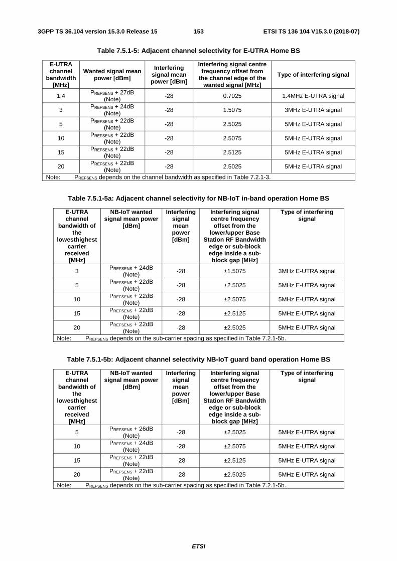
ETSI
ETSI TS 136 104 V15.3.0 (2018-07)1533GPP TS 36.104 version 15.3.0 Release 15
Table 7.5.1-5: Adjacent channel selectivity for E-UTRA Home BS
E-UTRA channel
bandwidth [MHz]
Wanted signal mean power [dBm]
Interfering signal mean power [dBm]
Interfering signal centre frequency offset from
the channel edge of the wanted signal [MHz]
Type of interfering signal
1.4 PREFSENS + 27dB (Note) -28 0.7025 1.4MHz E-UTRA signal
3 PREFSENS + 24dB (Note) -28 1.5075 3MHz E-UTRA signal
5 PREFSENS + 22dB (Note) -28 2.5025 5MHz E-UTRA signal
10 PREFSENS + 22dB (Note) -28 2.5075 5MHz E-UTRA signal
15 PREFSENS + 22dB (Note) -28 2.5125 5MHz E-UTRA signal
20 PREFSENS + 22dB (Note) -28 2.5025 5MHz E-UTRA signal
Note: PREFSENS depends on the channel bandwidth as specified in Table 7.2.1-3.
Table 7.5.1-5a: Adjacent channel selectivity for NB-IoT in-band operation Home BS
E-UTRA channel
bandwidth of the
lowesthighest carrier
received [MHz]
NB-IoT wanted signal mean power
[dBm]
Interfering signal mean power [dBm]
Interfering signal centre frequency offset from the
lower/upper Base Station RF Bandwidth
edge or sub-block edge inside a sub-block gap [MHz]
Type of interfering signal
3 PREFSENS + 24dB (Note) -28 ±1.5075 3MHz E-UTRA signal
5 PREFSENS + 22dB
(Note) -28 ±2.5025 5MHz E-UTRA signal
10 PREFSENS + 22dB (Note) -28 ±2.5075 5MHz E-UTRA signal
15 PREFSENS + 22dB (Note) -28 ±2.5125 5MHz E-UTRA signal
20 PREFSENS + 22dB
(Note) -28 ±2.5025 5MHz E-UTRA signal
Note: PREFSENS depends on the sub-carrier spacing as specified in Table 7.2.1-5b.
Table 7.5.1-5b: Adjacent channel selectivity NB-IoT guard band operation Home BS
E-UTRA channel
bandwidth of the
lowesthighest carrier
received [MHz]
NB-IoT wanted signal mean power
[dBm]
Interfering signal mean power [dBm]
Interfering signal centre frequency offset from the
lower/upper Base Station RF Bandwidth
edge or sub-block edge inside a sub-block gap [MHz]
Type of interfering signal
5 PREFSENS + 26dB
(Note) -28 ±2.5025 5MHz E-UTRA signal
10 PREFSENS + 24dB (Note) -28 ±2.5075 5MHz E-UTRA signal
15 PREFSENS + 22dB (Note) -28 ±2.5125 5MHz E-UTRA signal
20 PREFSENS + 22dB (Note)
-28 ±2.5025 5MHz E-UTRA signal
Note: PREFSENS depends on the sub-carrier spacing as specified in Table 7.2.1-5b.

ETSI
ETSI TS 136 104 V15.3.0 (2018-07)1543GPP TS 36.104 version 15.3.0 Release 15
Table 7.5.1-5c: Adjacent channel selectivity for NB-IoT standalone Home BS
NB-IoT channel
bandwidth of the
lowest/highest carrier
received [kHz]
Wanted signal mean power [dBm]
Interfering signal mean power [dBm]
Interfering signal centre frequency offset to the
lower/upper Base Station RF Bandwidth
edge or sub-block edge inside a sub-block gap
[kHz]
Type of interfering signal
200 PREFSENS + 35.5dB (Note)
-28 ±100 180 kHz NB-IoT signal
Note: PREFSENS depends on the sub-carrier spacing as specified in Table 7.2.1-5b.
Table 7.5.1-6: Adjacent channel selectivity for E-UTRA Medium Range BS
E-UTRA channel
bandwidth of the
lowest/highest carrier
received [MHz]
Wanted signal mean power [dBm]
Interfering signal mean power [dBm]
Interfering signal centre frequency offset to the
lower/upper Base Station RF Bandwidth
edge or sub-block edge inside a sub-block gap
[MHz]
Type of interfering signal
1.4 PREFSENS + 11dB (Note 1)
-47 ±0.7025 1.4MHz E-UTRA signal
3 PREFSENS + 8dB (Note 1) -47 ±1.5075 3MHz E-UTRA signal
5 PREFSENS + 6dB (Note 1) -47 ±2.5025 5MHz E-UTRA signal
10 PREFSENS + 6dB (Note
1) -47 ±2.5075 ±10.0175
5MHz E-UTRA signal (Note 2)
20 MHz E-UTRA signal (Note 3)
15 PREFSENS + 6dB (Note 1)
-47 ±2.5125 5MHz E-UTRA signal
20 PREFSENS + 6dB (Note 1) -47 ±2.5025
±10.0175
5MHz E-UTRA signal (Note 2)
20 MHz E-UTRA signa (Note 3)
Note 1: PREFSENS depends on the channel bandwidth as specified in Table 7.2.1-4. Note 2: This type of interfering signal is not applied for Band 46. Note 3: This type of interfering signal is only applied for Band 46.
Table 7.5.1-6a: Adjacent channel selectivity for NB-IoT in-band operation Medium Range BS
E-UTRA channel
bandwidth of the
lowesthighest carrier
received [MHz]
NB-IoT wanted signal mean power
[dBm]
Interfering signal mean power [dBm]
Interfering signal centre frequency offset from the
lower/upper Base Station RF Bandwidth
edge or sub-block edge inside a sub-block gap [MHz]
Type of interfering signal
3 PREFSENS + 8dB (Note) -47 ±1.5075 3MHz E-UTRA signal
5 PREFSENS + 6dB (Note) -47 ±2.5025 5MHz E-UTRA signal
10 PREFSENS + 6dB (Note)
-47 ±2.5075 5MHz E-UTRA signal
15 PREFSENS + 6dB (Note) -47 ±2.5125 5MHz E-UTRA signal
20 PREFSENS + 6dB (Note) -47 ±2.5025 5MHz E-UTRA signal
Note: PREFSENS depends on the sub-carrier spacing as specified in Table 7.2.1-5c.
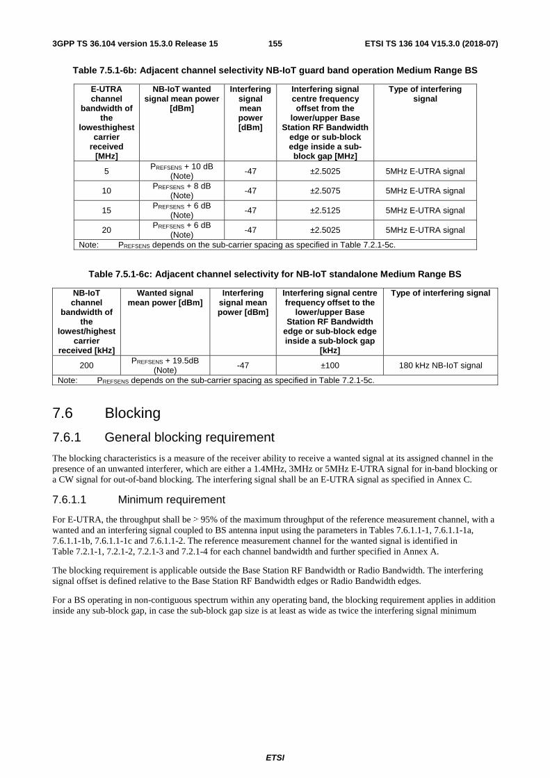
ETSI
ETSI TS 136 104 V15.3.0 (2018-07)1553GPP TS 36.104 version 15.3.0 Release 15
Table 7.5.1-6b: Adjacent channel selectivity NB-IoT guard band operation Medium Range BS
E-UTRA channel
bandwidth of the
lowesthighest carrier
received [MHz]
NB-IoT wanted signal mean power
[dBm]
Interfering signal mean power [dBm]
Interfering signal centre frequency offset from the
lower/upper Base Station RF Bandwidth
edge or sub-block edge inside a sub-block gap [MHz]
Type of interfering signal
5 PREFSENS + 10 dB (Note) -47 ±2.5025 5MHz E-UTRA signal
10 PREFSENS + 8 dB (Note) -47 ±2.5075 5MHz E-UTRA signal
15 PREFSENS + 6 dB (Note) -47 ±2.5125 5MHz E-UTRA signal
20 PREFSENS + 6 dB
(Note) -47 ±2.5025 5MHz E-UTRA signal
Note: PREFSENS depends on the sub-carrier spacing as specified in Table 7.2.1-5c.
Table 7.5.1-6c: Adjacent channel selectivity for NB-IoT standalone Medium Range BS
NB-IoT channel
bandwidth of the
lowest/highest carrier
received [kHz]
Wanted signal mean power [dBm]
Interfering signal mean power [dBm]
Interfering signal centre frequency offset to the
lower/upper Base Station RF Bandwidth
edge or sub-block edge inside a sub-block gap
[kHz]
Type of interfering signal
200 PREFSENS + 19.5dB (Note) -47 ±100 180 kHz NB-IoT signal
Note: PREFSENS depends on the sub-carrier spacing as specified in Table 7.2.1-5c.
7.6 Blocking
7.6.1 General blocking requirement
The blocking characteristics is a measure of the receiver ability to receive a wanted signal at its assigned channel in the presence of an unwanted interferer, which are either a 1.4MHz, 3MHz or 5MHz E-UTRA signal for in-band blocking or a CW signal for out-of-band blocking. The interfering signal shall be an E-UTRA signal as specified in Annex C.
7.6.1.1 Minimum requirement
For E-UTRA, the throughput shall be ≥ 95% of the maximum throughput of the reference measurement channel, with a wanted and an interfering signal coupled to BS antenna input using the parameters in Tables 7.6.1.1-1, 7.6.1.1-1a, 7.6.1.1-1b, 7.6.1.1-1c and 7.6.1.1-2. The reference measurement channel for the wanted signal is identified in Table 7.2.1-1, 7.2.1-2, 7.2.1-3 and 7.2.1-4 for each channel bandwidth and further specified in Annex A.
The blocking requirement is applicable outside the Base Station RF Bandwidth or Radio Bandwidth. The interfering signal offset is defined relative to the Base Station RF Bandwidth edges or Radio Bandwidth edges.
For a BS operating in non-contiguous spectrum within any operating band, the blocking requirement applies in addition inside any sub-block gap, in case the sub-block gap size is at least as wide as twice the interfering signal minimum

ETSI
ETSI TS 136 104 V15.3.0 (2018-07)1563GPP TS 36.104 version 15.3.0 Release 15
offset in Table 7.6.1.1-2. The interfering signal offset is defined relative to the sub-block edges inside the sub-block gap.
For a BS capable of multi-band operation, the requirement in the in-band blocking frequency ranges applies for each supported operating band. The requirement applies in addition inside any Inter RF Bandwidth gap, in case the Inter RF Bandwidth gap size is at least as wide as twice the interfering signal minimum offset in Table 7.6.1.1-2.
For a BS capable of multi-band operation, the requirement in the out-of-band blocking frequency ranges apply for each operating band, with the exception that the in-band blocking frequency ranges of all supported operating bands according to Tables 7.6.1.1-1, 7.6.1.1-1a and 7.6.1.1-1c shall be excluded from the out-of-band blocking requirement.
Table 7.6.1.1-1: Blocking performance requirement for Wide Area BS for E-UTRA
Operating Band
Centre Frequency of Interfering Signal [MHz]
Interfering Signal
mean power [dBm]
Wanted Signal mean power
[dBm]
Interfering signal centre frequency
minimum frequency offset
from the lower/upper
Base Station RF Bandwidth edge
or sub-block edge inside a sub-block gap
[MHz]
Type of Interfering
Signal
1-7, 9-11, 13, 14,
18,19, 21-23, 24, 27, 30, 33-45, 48, 50, 52, 65, 66, 68,
70
(FUL_low -20) to (FUL_high +20) -43 PREFSENS +6dB (Note 1)
See table 7.6.1.1-2
See table 7.6.1.1-2
1 (FUL_high +20)
to to
(FUL_low -20) 12750
-15 PREFSENS +6dB (Note 1)
⎯ CW carrier
8, 26, 28 (FUL_low -20) to (FUL_high +10) -43 PREFSENS +6dB (Note 1)
See table 7.6.1.1-2
See table 7.6.1.1-2
1 (FUL_high +10)
to to
(FUL_low -20) 12750
-15 PREFSENS +6dB (Note 1)
⎯ CW carrier
12 (FUL_low -20) to (FUL_high +13) -43 PREFSENS +6dB (Note 1)
See table 7.6.1.1-2
See table 7.6.1.1-2
1 (FUL_high +13)
to to
(FUL_low -20) 12750
-15 PREFSENS +6dB (Note 1)
⎯ CW carrier
17 (FUL_low -20) to (FUL_high +18) -43 PREFSENS +6dB (Note 1)
See table 7.6.1.1-2
See table 7.6.1.1-2
1 (FUL_high +18)
to to
(FUL_low -20) 12750
-15 PREFSENS +6dB (Note 1)
⎯ CW carrier
20, 71 (FUL_low -11) to (FUL_high +20) -43 PREFSENS +6dB (Note 1)
See table 7.6.1.1-2
See table 7.6.1.1-2
1 (FUL_high +20)
to to
(FUL_low -11) 12750
-15 PREFSENS +6dB (Note 1)
⎯ CW carrier
25 (FUL_low -20) to (FUL_high +15) -43 PREFSENS +6dB (Note 1)
See table 7.6.1.1-2
See table 7.6.1.1-2
1 (FUL_high +15)
to to
(FUL_low -20) 12750
-15 PREFSENS +6dB (Note 1)
⎯ CW carrier
31, 72, 73, 74
(FUL_low -20) to (FUL_high +5) -43 PREFSENS +6dB (Note 1)
See table 7.6.1.1-2
See table 7.6.1.1-2
1 (FUL_high +5)
to to
(FUL_low -20) 12750
-15 PREFSENS +6dB (Note 1)
⎯ CW carrier
85 (FUL_low -20) to (FUL_high +12) -43 PREFSENS +6dB (Note 1)
See table 7.6.1.1-2
See table 7.6.1.1-2
1 (FUL_high +12)
to to
(FUL_low -20) 12750
-15 PREFSENS +6dB (Note 1)
⎯ CW carrier
Note 1: PREFSENS depends on the channel bandwidth as specified in Table 7.2.1-1. Note 2: For a BS capable of multiband operation, in case of interfering signal that is not in the in-band blocking
frequency range of the operating band where the wanted signal is present, and not in an adjacent or overlapping band, the wanted signal mean power is equal to PREFSENS + 1.4 dB.

ETSI
ETSI TS 136 104 V15.3.0 (2018-07)1573GPP TS 36.104 version 15.3.0 Release 15
NOTE: Table 7.6.1.1-1 assumes that two operating bands, where the downlink operating band (see Table 5.5-1) of one band would be within the in-band blocking region of the other band, are not deployed in the same geographical area.
Table 7.6.1.1-1a: Blocking performance requirement for Local Area BS for E-UTRA
Operating Band
Centre Frequency of Interfering Signal [MHz]
Interfering Signal
mean power [dBm]
Wanted Signal mean power
[dBm]
Interfering signal centre frequency
minimum frequency offset
from the lower/upper
Base Station RF Bandwidth edge
or sub-block edge inside a sub-block gap
[MHz]
Type of Interfering
Signal
1-7, 9-11, 13-14,
18,19, 21-23, 24, 27, 30, 33-45, 48-52, 65, 66, 68, 70
(FUL_low -20) to (FUL_high +20) -35 PREFSENS +6dB (Note 1)
See table 7.6.1.1-2
See table 7.6.1.1-2
1 (FUL_high +20)
to to
(FUL_low -20) 12750
-15 PREFSENS +6dB (Note 1)
⎯ CW carrier
8, 26, 28 (FUL_low -20) to (FUL_high +10) -35 PREFSENS +6dB (Note 1)
See table 7.6.1.1-2
See table 7.6.1.1-2
1 (FUL_high +10)
to to
(FUL_low -20) 12750
-15 PREFSENS +6dB (Note 1)
⎯ CW carrier
12 (FUL_low -20) to (FUL_high +13) -35 PREFSENS +6dB (Note 1)
See table 7.6.1.1-2
See table 7.6.1.1-2
1 (FUL_high +13)
to to
(FUL_low -20) 12750
-15 PREFSENS +6dB (Note 1)
⎯ CW carrier
17 (FUL_low -20) to (FUL_high +18) -35 PREFSENS +6dB (Note 1)
See table 7.6.1. 1-2
See table 7.6.1.1-2
1 (FUL_high +18)
to to
(FUL_low -20) 12750
-15 PREFSENS +6dB (Note 1)
⎯ CW carrier
20, 71 (FUL_low -11) to (FUL_high +20) -35 PREFSENS +6dB (Note 1)
See table 7.6.1. 1-2
See table 7.6.1.1-2
1 to (FUL_low -11) 12750
-15 PREFSENS +6dB (Note 1)
⎯ CW carrier (FUL_high +20) to
25 (FUL_low -20) to (FUL_high +15) -35 PREFSENS +6dB (Note 1)
See table 7.6.1. 1-2
See table 7.6.1.1-2
1 (FUL_high +15)
to to
(FUL_low -20) 12750
-15 PREFSENS +6dB (Note 1)
⎯ CW carrier
31, 72, 73, 74
(FUL_low -20) to (FUL_high +5) -35 PREFSENS +6dB (Note 1)
See table 7.6.1.1-2
See table 7.6.1.1-2
1 (FUL_high +5)
to to
(FUL_low -20) 12750
-15 PREFSENS +6dB (Note 1)
⎯ CW carrier
46 (FUL_low -20) to (FUL_high +20) -35 PREFSENS +6dB (Note 1)
See table 7.6.1.1-2
See table 7.6.1.1-2
(FUL_low -500)
(FUL_high +20)
to to
(FUL_low -20) (FUL_high
+500)
-35 PREFSENS +6dB (Note 1)
⎯ CW carrier
1 (FUL_high
+500)
to to
(FUL_low -500) 12750
-15 PREFSENS +6dB (Note 1)
⎯ CW carrier
85 (FUL_low -20)
to (FUL_high +12) -35 PREFSENS +6dB (Note 1)
See table 7.6.1. 1-2
See table 7.6.1.1-2
1 (FUL_high
+12)
to to
(FUL_low -20) 12750
-15 PREFSENS +6dB (Note 1)
⎯ CW carrier
Note 1: PREFSENS depends on the channel bandwidth as specified in Table 7.2.1-2 Note 2: For a BS capable of multiband operation, in case of interfering signal that is not in the in-band blocking
frequency range of the operating band where the wanted signal is present, and not in an adjacent or overlapping band, the wanted signal mean power is equal to PREFSENS + 1.4 dB.
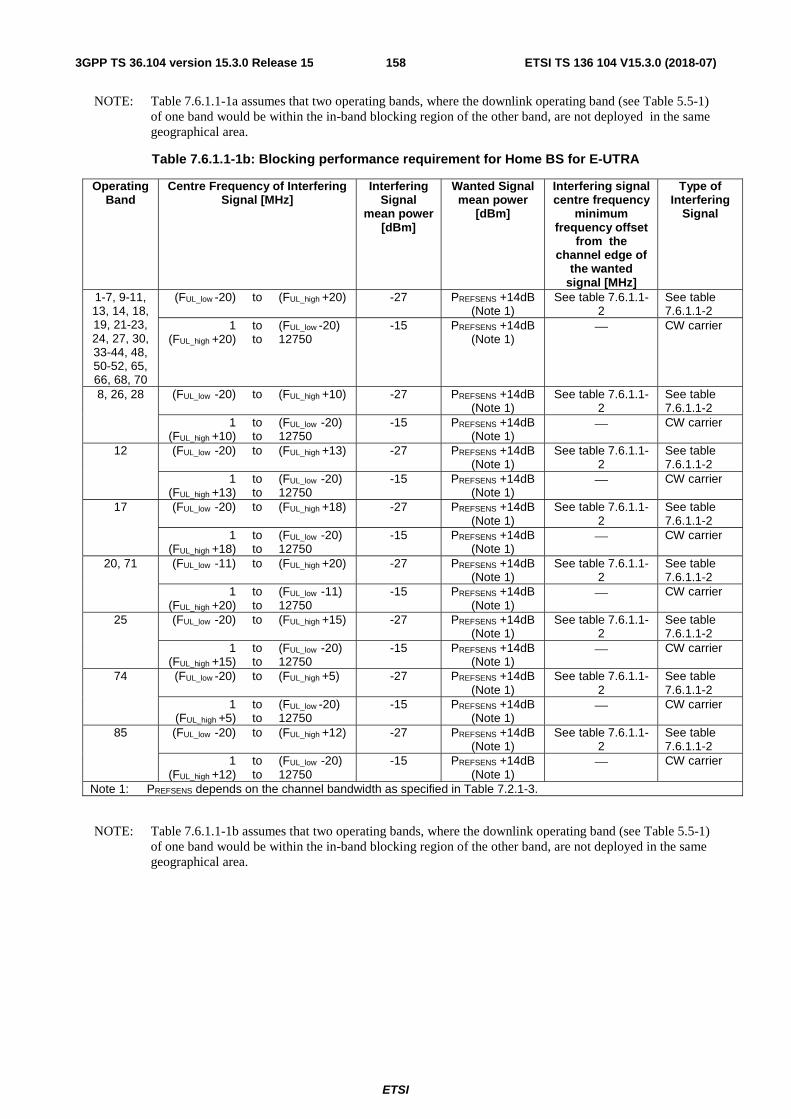
ETSI
ETSI TS 136 104 V15.3.0 (2018-07)1583GPP TS 36.104 version 15.3.0 Release 15
NOTE: Table 7.6.1.1-1a assumes that two operating bands, where the downlink operating band (see Table 5.5-1) of one band would be within the in-band blocking region of the other band, are not deployed in the same geographical area.
Table 7.6.1.1-1b: Blocking performance requirement for Home BS for E-UTRA
Operating Band
Centre Frequency of Interfering Signal [MHz]
Interfering Signal
mean power [dBm]
Wanted Signal mean power
[dBm]
Interfering signal centre frequency
minimum frequency offset
from the channel edge of
the wanted signal [MHz]
Type of Interfering
Signal
1-7, 9-11, 13, 14, 18, 19, 21-23, 24, 27, 30, 33-44, 48, 50-52, 65, 66, 68, 70
(FUL_low -20) to (FUL_high +20) -27 PREFSENS +14dB (Note 1)
See table 7.6.1.1-2
See table 7.6.1.1-2
1 (FUL_high +20)
to to
(FUL_low -20) 12750
-15 PREFSENS +14dB (Note 1)
⎯ CW carrier
8, 26, 28 (FUL_low -20) to (FUL_high +10) -27 PREFSENS +14dB (Note 1)
See table 7.6.1.1-2
See table 7.6.1.1-2
1 (FUL_high +10)
to to
(FUL_low -20) 12750
-15 PREFSENS +14dB (Note 1)
⎯ CW carrier
12 (FUL_low -20) to (FUL_high +13) -27 PREFSENS +14dB (Note 1)
See table 7.6.1.1-2
See table 7.6.1.1-2
1 (FUL_high +13)
to to
(FUL_low -20) 12750
-15 PREFSENS +14dB (Note 1)
⎯ CW carrier
17 (FUL_low -20) to (FUL_high +18) -27 PREFSENS +14dB (Note 1)
See table 7.6.1.1-2
See table 7.6.1.1-2
1 (FUL_high +18)
to to
(FUL_low -20) 12750
-15 PREFSENS +14dB (Note 1)
⎯ CW carrier
20, 71 (FUL_low -11) to (FUL_high +20) -27 PREFSENS +14dB (Note 1)
See table 7.6.1.1-2
See table 7.6.1.1-2
1 (FUL_high +20)
to to
(FUL_low -11) 12750
-15 PREFSENS +14dB (Note 1)
⎯ CW carrier
25 (FUL_low -20) to (FUL_high +15) -27 PREFSENS +14dB (Note 1)
See table 7.6.1.1-2
See table 7.6.1.1-2
1 (FUL_high +15)
to to
(FUL_low -20) 12750
-15 PREFSENS +14dB (Note 1)
⎯ CW carrier
74 (FUL_low -20) to (FUL_high +5) -27 PREFSENS +14dB (Note 1)
See table 7.6.1.1-2
See table 7.6.1.1-2
1 (FUL_high +5)
to to
(FUL_low -20) 12750
-15 PREFSENS +14dB (Note 1)
⎯ CW carrier
85 (FUL_low -20) to (FUL_high +12) -27 PREFSENS +14dB (Note 1)
See table 7.6.1.1-2
See table 7.6.1.1-2
1 (FUL_high +12)
to to
(FUL_low -20) 12750
-15 PREFSENS +14dB (Note 1)
⎯ CW carrier
Note 1: PREFSENS depends on the channel bandwidth as specified in Table 7.2.1-3.
NOTE: Table 7.6.1.1-1b assumes that two operating bands, where the downlink operating band (see Table 5.5-1) of one band would be within the in-band blocking region of the other band, are not deployed in the same geographical area.
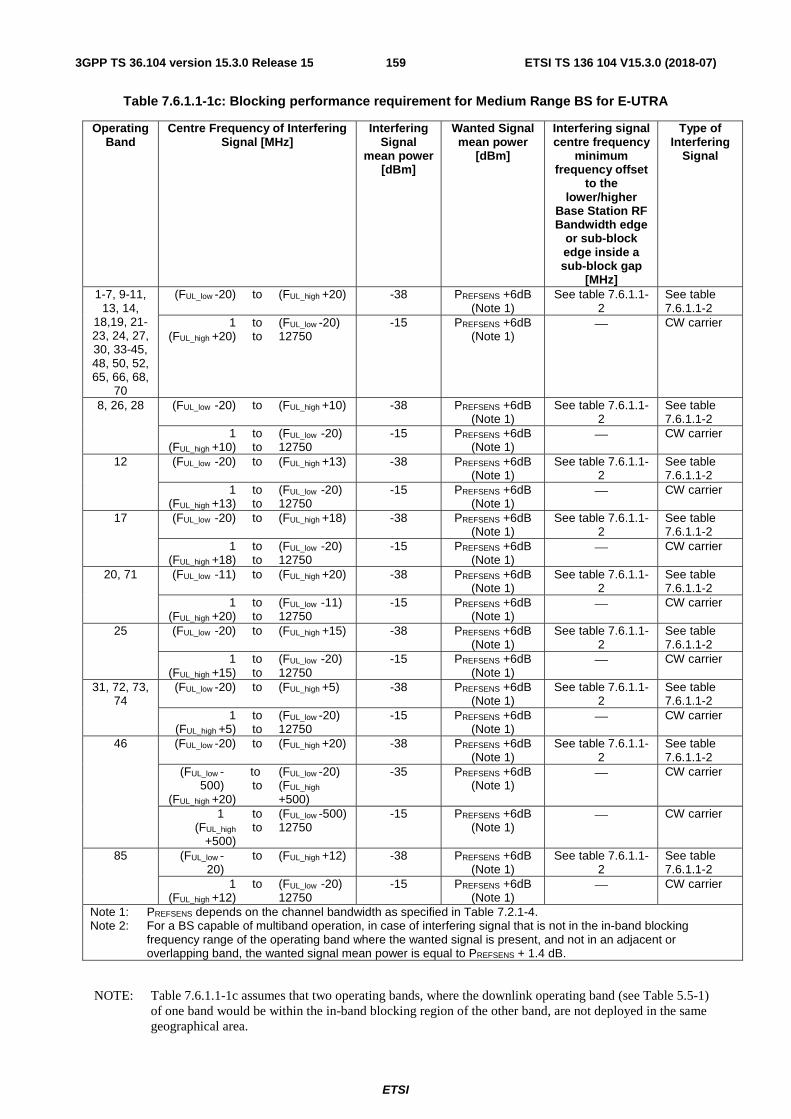
ETSI
ETSI TS 136 104 V15.3.0 (2018-07)1593GPP TS 36.104 version 15.3.0 Release 15
Table 7.6.1.1-1c: Blocking performance requirement for Medium Range BS for E-UTRA
Operating Band
Centre Frequency of Interfering Signal [MHz]
Interfering Signal
mean power [dBm]
Wanted Signal mean power
[dBm]
Interfering signal centre frequency
minimum frequency offset
to the lower/higher
Base Station RF Bandwidth edge
or sub-block edge inside a sub-block gap
[MHz]
Type of Interfering
Signal
1-7, 9-11, 13, 14,
18,19, 21-23, 24, 27, 30, 33-45, 48, 50, 52, 65, 66, 68,
70
(FUL_low -20) to (FUL_high +20) -38 PREFSENS +6dB (Note 1)
See table 7.6.1.1-2
See table 7.6.1.1-2
1 (FUL_high +20)
to to
(FUL_low -20) 12750
-15 PREFSENS +6dB (Note 1)
⎯ CW carrier
8, 26, 28 (FUL_low -20) to (FUL_high +10) -38 PREFSENS +6dB (Note 1)
See table 7.6.1.1-2
See table 7.6.1.1-2
1 (FUL_high +10)
to to
(FUL_low -20) 12750
-15 PREFSENS +6dB (Note 1)
⎯ CW carrier
12 (FUL_low -20) to (FUL_high +13) -38 PREFSENS +6dB (Note 1)
See table 7.6.1.1-2
See table 7.6.1.1-2
1 (FUL_high +13)
to to
(FUL_low -20) 12750
-15 PREFSENS +6dB (Note 1)
⎯ CW carrier
17 (FUL_low -20) to (FUL_high +18) -38 PREFSENS +6dB (Note 1)
See table 7.6.1.1-2
See table 7.6.1.1-2
1 (FUL_high +18)
to to
(FUL_low -20) 12750
-15 PREFSENS +6dB (Note 1)
⎯ CW carrier
20, 71 (FUL_low -11) to (FUL_high +20) -38 PREFSENS +6dB (Note 1)
See table 7.6.1.1-2
See table 7.6.1.1-2
1 (FUL_high +20)
to to
(FUL_low -11) 12750
-15 PREFSENS +6dB (Note 1)
⎯ CW carrier
25 (FUL_low -20) to (FUL_high +15) -38 PREFSENS +6dB (Note 1)
See table 7.6.1.1-2
See table 7.6.1.1-2
1 (FUL_high +15)
to to
(FUL_low -20) 12750
-15 PREFSENS +6dB (Note 1)
⎯ CW carrier
31, 72, 73, 74
(FUL_low -20) to (FUL_high +5) -38 PREFSENS +6dB (Note 1)
See table 7.6.1.1-2
See table 7.6.1.1-2
1 (FUL_high +5)
to to
(FUL_low -20) 12750
-15 PREFSENS +6dB (Note 1)
⎯ CW carrier
46 (FUL_low -20) to (FUL_high +20) -38 PREFSENS +6dB (Note 1)
See table 7.6.1.1-2
See table 7.6.1.1-2
(FUL_low -500)
(FUL_high +20)
to to
(FUL_low -20) (FUL_high
+500)
-35 PREFSENS +6dB (Note 1)
⎯ CW carrier
1 (FUL_high
+500)
to to
(FUL_low -500) 12750
-15 PREFSENS +6dB (Note 1)
⎯ CW carrier
85 (FUL_low -20)
to (FUL_high +12) -38 PREFSENS +6dB (Note 1)
See table 7.6.1.1-2
See table 7.6.1.1-2
1 (FUL_high +12)
to (FUL_low -20) 12750
-15 PREFSENS +6dB (Note 1)
⎯ CW carrier
Note 1: PREFSENS depends on the channel bandwidth as specified in Table 7.2.1-4. Note 2: For a BS capable of multiband operation, in case of interfering signal that is not in the in-band blocking
frequency range of the operating band where the wanted signal is present, and not in an adjacent or overlapping band, the wanted signal mean power is equal to PREFSENS + 1.4 dB.
NOTE: Table 7.6.1.1-1c assumes that two operating bands, where the downlink operating band (see Table 5.5-1) of one band would be within the in-band blocking region of the other band, are not deployed in the same geographical area.

ETSI
ETSI TS 136 104 V15.3.0 (2018-07)1603GPP TS 36.104 version 15.3.0 Release 15
Table 7.6.1.1-2: Interfering signals for blocking performance requirement
E-UTRA channel BW of
the lowest/highest
carrier received
[MHz]
Interfering signal centre frequency
minimum offset to the lower/upper Base Station RF
Bandwidth edge or sub-block edge
inside a sub-block gap [MHz]
Type of interfering signal
1.4 ±2.1 1.4 MHz E-UTRA signal 3 ±4.5 3 MHz E-UTRA signal 5 ±7.5 5 MHz E-UTRA signal 10 ±7.5 5 MHz E-UTRA signal 15 ±7.5 5 MHz E-UTRA signal
20 ±7.5 5 MHz E-UTRA signal (Note 1)
20 ±30 20 MHz E-UTRA signal
(Note 2) Note 1: This type of interfering signal is not applied for Band 46. Note 2: This type of interfering signal is only applied for Band 46.
For NB-IoT standalone operation, the throughput shall be ≥ 95% of the maximum throughput of the reference measurement channel, with a wanted and an interfering signal coupled to BS antenna input using the parameters in

ETSI
ETSI TS 136 104 V15.3.0 (2018-07)1613GPP TS 36.104 version 15.3.0 Release 15
Tables 7.6.1.1-3, 7.6.1.1-3a, 7.6.1.1-3b, 7.6.1.1-3c and 7.6.1.1-4. The reference measurement channel for the wanted signal is identified in Table 7.2.1-5, 7.2.1-5a, 7.2.1-5b and 7.2.1-5c and further specified in Annex A.
The blocking requirement is applicable outside the Base Station RF Bandwidth or Radio Bandwidth. The interfering signal offset is defined relative to the Base Station RF Bandwidth edges or Radio Bandwidth edges.
Table 7.6.1.1-3: Blocking performance requirement for Wide Area BS for NB-IoT standalone operation
Operating Band
Centre Frequency of Interfering Signal [MHz]
Interfering Signal
mean power [dBm]
Wanted Signal mean power
[dBm]
Interfering signal centre frequency
minimum frequency offset
from the lower/upper
Base Station RF Bandwidth edge
or sub-block edge inside a sub-block gap
[MHz]
Type of Interfering
Signal
1-5, 11, 13-
14,18,19, 21, 66, 70
(FUL_low -20) to (FUL_high +20) -43 PREFSENS +6dB (Note 1)
See table 7.6.1.1-4
See table 7.6.1.1-4
1 (FUL_high +20)
to to
(FUL_low -20) 12750
-15 (Note 2) PREFSENS +6dB (Note 1)
⎯ CW carrier
8, 26, 28 (FUL_low -20) to (FUL_high +10) -43 PREFSENS +6dB (Note 1)
See table 7.6.1.1-4
See table 7.6.1.1-4
1 (FUL_high +10)
to to
(FUL_low -20) 12750
-15 (Note 2) PREFSENS +6dB (Note 1)
⎯ CW carrier
12 (FUL_low -20) to (FUL_high +13) -43 PREFSENS +6dB (Note 1)
See table 7.6.1.1-4
See table 7.6.1.1-4
1 (FUL_high +13)
to to
(FUL_low -20) 12750
-15 (Note 2) PREFSENS +6dB (Note 1)
⎯ CW carrier
17 (FUL_low -20) to (FUL_high +18) -43 PREFSENS +6dB (Note 1)
See table 7.6.1.1-4
See table 7.6.1.1-4
1 (FUL_high +18)
to to
(FUL_low -20) 12750
-15 (Note 2) PREFSENS +6dB (Note 1)
⎯ CW carrier
20, 71 (FUL_low -11) to (FUL_high +20) -43 PREFSENS +6dB (Note 1)
See table 7.6.1.1-4
See table 7.6.1.1-4
1 (FUL_high +20)
to to
(FUL_low -11) 12750
-15 (Note 2) PREFSENS +6dB (Note 1)
⎯ CW carrier
25 (FUL_low -20) to (FUL_high +15) -43 PREFSENS +6dB (Note 1)
See table 7.6.1.1-4
See table 7.6.1.1-4
1 (FUL_high +15)
to to
(FUL_low -20) 12750
-15 (Note 2) PREFSENS +6dB (Note 1)
⎯ CW carrier
31, 72, 73, 74
(FUL_low -20) to (FUL_high +5) -43 PREFSENS +6dB (Note 1)
See table 7.6.1.1-4
See table 7.6.1.1-4
1 (FUL_high +5)
to to
(FUL_low -20) 12750
-15 (Note 2) PREFSENS +6dB (Note 1)
⎯ CW carrier
85 (FUL_low -20) to (FUL_high +12) -43 PREFSENS +6dB (Note 1)
See table 7.6.1.1-4
See table 7.6.1.1-4
1 (FUL_high +12)
to to
(FUL_low -20) 12750
-15 (Note 2) PREFSENS +6dB (Note 1)
⎯ CW carrier
Note 1: PREFSENS is specified in Table 7.2.1-5. Note 2: Up to 24 exceptions are allowed for spurious response frequencies in each wanted signal frequency when
measured using a 1MHz step size. For these exceptions the above throughput requirement shall be met when the blocking signal is set to a level of -40 dBm for 15 kHz subcarrier spacing and -46 dBm for 3.75 kHz subcarrier spacing. In addition, each group of exceptions shall not exceed three contiguous measurements using a 1MHz step size.

ETSI
ETSI TS 136 104 V15.3.0 (2018-07)1623GPP TS 36.104 version 15.3.0 Release 15
Table 7.6.1.1-3a: Blocking performance requirement for Local Area BS for NB-IoT standalone operation
Operating Band
Centre Frequency of Interfering Signal [MHz]
Interfering Signal
mean power [dBm]
Wanted Signal mean power
[dBm]
Interfering signal centre frequency
minimum frequency offset
from the lower/upper
Base Station RF Bandwidth edge
or sub-block edge inside a sub-block gap
[MHz]
Type of Interfering
Signal
1-5, 11, 13-
14,18,19, 21, 66, 70
(FUL_low -20) to (FUL_high +20) -35 PREFSENS +6dB (Note 1)
See table 7.6.1.1-4
See table 7.6.1.1-4
1 (FUL_high +20)
to to
(FUL_low -20) 12750
-15 (Note 2) PREFSENS +6dB (Note 1)
⎯ CW carrier
8, 26, 28 (FUL_low -20) to (FUL_high +10) -35 PREFSENS +6dB (Note 1)
See table 7.6.1.1-4
See table 7.6.1.1-4
1 (FUL_high +10)
to to
(FUL_low -20) 12750
-15 (Note 2) PREFSENS +6dB (Note 1)
⎯ CW carrier
12 (FUL_low -20) to (FUL_high +13) -35 PREFSENS +6dB (Note 1)
See table 7.6.1.1-4
See table 7.6.1.1-4
1 (FUL_high +13)
to to
(FUL_low -20) 12750
-15 (Note 2) PREFSENS +6dB (Note 1)
⎯ CW carrier
17 (FUL_low -20) to (FUL_high +18) -35 PREFSENS +6dB (Note 1)
See table 7.6.1.1-4
See table 7.6.1.1-4
1 (FUL_high +18)
to to
(FUL_low -20) 12750
-15 (Note 2) PREFSENS +6dB (Note 1)
⎯ CW carrier
20, 71 (FUL_low -11) to (FUL_high +20) -35 PREFSENS +6dB (Note 1)
See table 7.6.1.1-4
See table 7.6.1.1-4
1 (FUL_high +20)
to to
(FUL_low -11) 12750
-15 (Note 2) PREFSENS +6dB (Note 1)
⎯ CW carrier
25 (FUL_low -20) to (FUL_high +15) -35 PREFSENS +6dB (Note 2)
See table 7.6.1.1-4
See table 7.6.1.1-4
1 (FUL_high +15)
to to
(FUL_low -20) 12750
-15 (Note 2) PREFSENS +6dB (Note 2)
⎯ CW carrier
31, 72, 74 (FUL_low -20) to (FUL_high +5) -35 PREFSENS +6dB (Note 2)
See table 7.6.1.1-4
See table 7.6.1.1-4
1 (FUL_high +5)
to to
(FUL_low -20) 12750
-15 (Note 2) PREFSENS +6dB (Note 2)
⎯ CW carrier
85 (FUL_low -20) to (FUL_high +12) -35 PREFSENS +6dB (Note 2)
See table 7.6.1.1-4
See table 7.6.1.1-4
1 (FUL_high +12)
to to
(FUL_low -20) 12750
-15 (Note 2) PREFSENS +6dB (Note 2)
⎯ CW carrier
Note 1: PREFSENS is specified in Table 7.2.1-5a. Note 2: Up to 24 exceptions are allowed for spurious response frequencies in each wanted signal frequency when
measured using a 1MHz step size. For these exceptions the above throughput requirement shall be met when the blocking signal is set to a level of -40 dBm for 15 kHz subcarrier spacing and -46 dBm for 3.75 kHz subcarrier spacing. In addition, each group of exceptions shall not exceed three contiguous measurements using a 1MHz step size.

ETSI
ETSI TS 136 104 V15.3.0 (2018-07)1633GPP TS 36.104 version 15.3.0 Release 15
Table 7.6.1.1-3b: Blocking performance requirement for Home BS for NB-IoT standalone operation
Operating Band
Centre Frequency of Interfering Signal [MHz]
Interfering Signal
mean power [dBm]
Wanted Signal mean power
[dBm]
Interfering signal centre frequency
minimum frequency offset
from the lower/upper
Base Station RF Bandwidth edge
or sub-block edge inside a sub-block gap
[MHz]
Type of Interfering
Signal
1-5, 11, 13-
14,18,19, 21, 66, 70
(FUL_low -20) to (FUL_high +20) -27 PREFSENS +14dB (Note 1)
See table 7.6.1.1-4
See table 7.6.1.1-4
1 (FUL_high +20)
to to
(FUL_low -20) 12750
-15 (Note 2) PREFSENS +14dB (Note 1)
⎯ CW carrier
8, 26, 28 (FUL_low -20) to (FUL_high +10) -27 PREFSENS +14dB (Note 1)
See table 7.6.1.1-4
See table 7.6.1.1-4
1 (FUL_high +10)
to to
(FUL_low -20) 12750
-15 (Note 2) PREFSENS +14dB (Note 1)
⎯ CW carrier
12 (FUL_low -20) to (FUL_high +13) -27 PREFSENS +14dB (Note 1)
See table 7.6.1.1-4
See table 7.6.1.1-4
1 (FUL_high +13)
to to
(FUL_low -20) 12750
-15 (Note 2) PREFSENS +14dB (Note 1)
⎯ CW carrier
17 (FUL_low -20) to (FUL_high +18) -27 PREFSENS +14dB (Note 1)
See table 7.6.1.1-4
See table 7.6.1.1-4
1 (FUL_high +18)
to to
(FUL_low -20) 12750
-15 (Note 2) PREFSENS +14dB (Note 1)
⎯ CW carrier
20, 71 (FUL_low -11) to (FUL_high +20) -27 PREFSENS +14dB (Note 1)
See table 7.6.1.1-4
See table 7.6.1.1-4
1 (FUL_high +20)
to to
(FUL_low -11) 12750
-15 (Note 2) PREFSENS +14dB (Note 1)
⎯ CW carrier
25 (FUL_low -20) to (FUL_high +15) -27 PREFSENS +14dB (Note 1)
See table 7.6.1.1-4
See table 7.6.1.1-4
1 (FUL_high +15)
to to
(FUL_low -20) 12750
-15 (Note 2) PREFSENS +14dB (Note 1)
⎯ CW carrier
31, 72, 74 (FUL_low -20) to (FUL_high +5) -27 PREFSENS +14dB (Note 1)
See table 7.6.1.1-4
See table 7.6.1.1-4
1 (FUL_high +5)
to to
(FUL_low -20) 12750
-15 (Note 2) PREFSENS +14dB (Note 1)
⎯ CW carrier
85 (FUL_low -20) to (FUL_high +12) -27 PREFSENS +14dB (Note 1)
See table 7.6.1.1-4
See table 7.6.1.1-4
1 (FUL_high +12)
to to
(FUL_low -20) 12750
-15 (Note 2) PREFSENS +14dB (Note 1)
⎯ CW carrier
Note 1: PREFSENS is specified in Table 7.2.1-5b. Note 2: Up to 24 exceptions are allowed for spurious response frequencies in each wanted signal frequency when
measured using a 1MHz step size. For these exceptions the above throughput requirement shall be met when the blocking signal is set to a level of -40 dBm for 15 kHz subcarrier spacing and -46 dBm for 3.75 kHz subcarrier spacing. In addition, each group of exceptions shall not exceed three contiguous measurements using a 1MHz step size.
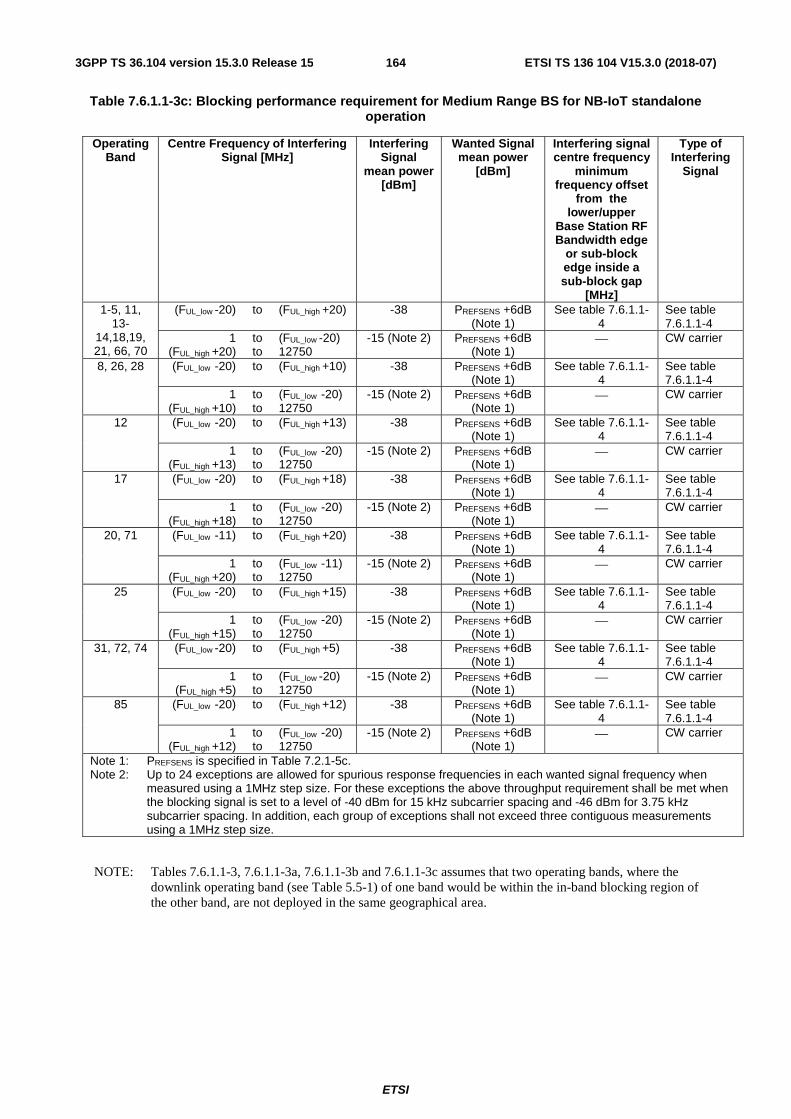
ETSI
ETSI TS 136 104 V15.3.0 (2018-07)1643GPP TS 36.104 version 15.3.0 Release 15
Table 7.6.1.1-3c: Blocking performance requirement for Medium Range BS for NB-IoT standalone operation
Operating Band
Centre Frequency of Interfering Signal [MHz]
Interfering Signal
mean power [dBm]
Wanted Signal mean power
[dBm]
Interfering signal centre frequency
minimum frequency offset
from the lower/upper
Base Station RF Bandwidth edge
or sub-block edge inside a sub-block gap
[MHz]
Type of Interfering
Signal
1-5, 11, 13-
14,18,19, 21, 66, 70
(FUL_low -20) to (FUL_high +20) -38 PREFSENS +6dB (Note 1)
See table 7.6.1.1-4
See table 7.6.1.1-4
1 (FUL_high +20)
to to
(FUL_low -20) 12750
-15 (Note 2) PREFSENS +6dB (Note 1)
⎯ CW carrier
8, 26, 28 (FUL_low -20) to (FUL_high +10) -38 PREFSENS +6dB (Note 1)
See table 7.6.1.1-4
See table 7.6.1.1-4
1 (FUL_high +10)
to to
(FUL_low -20) 12750
-15 (Note 2) PREFSENS +6dB (Note 1)
⎯ CW carrier
12 (FUL_low -20) to (FUL_high +13) -38 PREFSENS +6dB (Note 1)
See table 7.6.1.1-4
See table 7.6.1.1-4
1 (FUL_high +13)
to to
(FUL_low -20) 12750
-15 (Note 2) PREFSENS +6dB (Note 1)
⎯ CW carrier
17 (FUL_low -20) to (FUL_high +18) -38 PREFSENS +6dB (Note 1)
See table 7.6.1.1-4
See table 7.6.1.1-4
1 (FUL_high +18)
to to
(FUL_low -20) 12750
-15 (Note 2) PREFSENS +6dB (Note 1)
⎯ CW carrier
20, 71 (FUL_low -11) to (FUL_high +20) -38 PREFSENS +6dB (Note 1)
See table 7.6.1.1-4
See table 7.6.1.1-4
1 (FUL_high +20)
to to
(FUL_low -11) 12750
-15 (Note 2) PREFSENS +6dB (Note 1)
⎯ CW carrier
25 (FUL_low -20) to (FUL_high +15) -38 PREFSENS +6dB (Note 1)
See table 7.6.1.1-4
See table 7.6.1.1-4
1 (FUL_high +15)
to to
(FUL_low -20) 12750
-15 (Note 2) PREFSENS +6dB (Note 1)
⎯ CW carrier
31, 72, 74 (FUL_low -20) to (FUL_high +5) -38 PREFSENS +6dB (Note 1)
See table 7.6.1.1-4
See table 7.6.1.1-4
1 (FUL_high +5)
to to
(FUL_low -20) 12750
-15 (Note 2) PREFSENS +6dB (Note 1)
⎯ CW carrier
85 (FUL_low -20) to (FUL_high +12) -38 PREFSENS +6dB (Note 1)
See table 7.6.1.1-4
See table 7.6.1.1-4
1 (FUL_high +12)
to to
(FUL_low -20) 12750
-15 (Note 2) PREFSENS +6dB (Note 1)
⎯ CW carrier
Note 1: PREFSENS is specified in Table 7.2.1-5c. Note 2: Up to 24 exceptions are allowed for spurious response frequencies in each wanted signal frequency when
measured using a 1MHz step size. For these exceptions the above throughput requirement shall be met when the blocking signal is set to a level of -40 dBm for 15 kHz subcarrier spacing and -46 dBm for 3.75 kHz subcarrier spacing. In addition, each group of exceptions shall not exceed three contiguous measurements using a 1MHz step size.
NOTE: Tables 7.6.1.1-3, 7.6.1.1-3a, 7.6.1.1-3b and 7.6.1.1-3c assumes that two operating bands, where the downlink operating band (see Table 5.5-1) of one band would be within the in-band blocking region of the other band, are not deployed in the same geographical area.
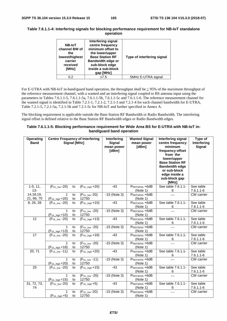
ETSI
ETSI TS 136 104 V15.3.0 (2018-07)1653GPP TS 36.104 version 15.3.0 Release 15
Table 7.6.1.1-4: Interfering signals for blocking performance requirement for NB-IoT standalone operation
NB-IoT channel BW of
the lowest/highest
carrier received
[MHz]
Interfering signal centre frequency
minimum offset to the lower/upper Base Station RF
Bandwidth edge or sub-block edge
inside a sub-block gap [MHz]
Type of interfering signal
0.2 ±7.5 5MHz E-UTRA signal
For E-UTRA with NB-IoT in-band/guard band operation, the throughput shall be ≥ 95% of the maximum throughput of the reference measurement channel, with a wanted and an interfering signal coupled to BS antenna input using the parameters in Tables 7.6.1.1-5, 7.6.1.1-5a, 7.6.1.1-5b, 7.6.1.1-5c and 7.6.1.1-6. The reference measurement channel for the wanted signal is identified in Table 7.2.1-1, 7.2.1-2, 7.2.1-3 and 7.2.1-4 for each channel bandwidth for E-UTRA, Table 7.2.1-5, 7.2.1-5a, 7.2.1-5b and 7.2.1-5c for NB-IoT and further specified in Annex A.
The blocking requirement is applicable outside the Base Station RF Bandwidth or Radio Bandwidth. The interfering signal offset is defined relative to the Base Station RF Bandwidth edges or Radio Bandwidth edges.
Table 7.6.1.1-5: Blocking performance requirement for Wide Area BS for E-UTRA with NB-IoT in-band/guard band operation
Operating Band
Centre Frequency of Interfering Signal [MHz]
Interfering Signal
mean power [dBm]
Wanted Signal mean power
[dBm]
Interfering signal centre frequency
minimum frequency offset
from the lower/upper
Base Station RF Bandwidth edge
or sub-block edge inside a sub-block gap
[MHz]
Type of Interfering
Signal
1-5, 11, 13-
14,18,19, 21, 66, 70
(FUL_low -20) to (FUL_high +20) -43 PREFSENS +6dB (Note 1)
See table 7.6.1.1-6
See table 7.6.1.1-6
1 (FUL_high +20)
to to
(FUL_low -20) 12750
-15 (Note 3) PREFSENS +6dB (Note 1)
⎯ CW carrier
8, 26, 28 (FUL_low -20) to (FUL_high +10) -43 PREFSENS +6dB (Note 1)
See table 7.6.1.1-6
See table 7.6.1.1-6
1 (FUL_high +10)
to to
(FUL_low -20) 12750
-15 (Note 3) PREFSENS +6dB (Note 1)
⎯ CW carrier
12 (FUL_low -20) to (FUL_high +13) -43 PREFSENS +6dB (Note 1)
See table 7.6.1.1-6
See table 7.6.1.1-6
1 (FUL_high +13)
to to
(FUL_low -20) 12750
-15 (Note 3) PREFSENS +6dB (Note 1)
⎯ CW carrier
17 (FUL_low -20) to (FUL_high +18) -43 PREFSENS +6dB (Note 1)
See table 7.6.1.1-6
See table 7.6.1.1-6
1 (FUL_high +18)
to to
(FUL_low -20) 12750
-15 (Note 3) PREFSENS +6dB (Note 1)
⎯ CW carrier
20, 71 (FUL_low -11) to (FUL_high +20) -43 PREFSENS +6dB (Note 1)
See table 7.6.1.1-6
See table 7.6.1.1-6
1 (FUL_high +20)
to to
(FUL_low -11) 12750
-15 (Note 3) PREFSENS +6dB (Note 1)
⎯ CW carrier
25 (FUL_low -20) to (FUL_high +15) -43 PREFSENS +6dB (Note 1)
See table 7.6.1.1-6
See table 7.6.1.1-6
1 (FUL_high +15)
to to
(FUL_low -20) 12750
-15 (Note 3) PREFSENS +6dB (Note 1)
⎯ CW carrier
31, 72, 73, 74
(FUL_low -20) to (FUL_high +5) -43 PREFSENS +6dB (Note 1)
See table 7.6.1.1-6
See table 7.6.1.1-6
1 (FUL_high +5)
to to
(FUL_low -20) 12750
-15 (Note 3) PREFSENS +6dB (Note 1)
⎯ CW carrier
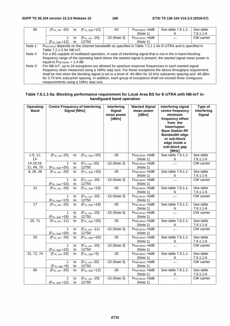
ETSI
ETSI TS 136 104 V15.3.0 (2018-07)1663GPP TS 36.104 version 15.3.0 Release 15
85 (FUL_low -20) to (FUL_high +12) -43 PREFSENS +6dB (Note 1)
See table 7.6.1.1-6
See table 7.6.1.1-6
1 (FUL_high +12)
to to
(FUL_low -20) 12750
-15 (Note 3) PREFSENS +6dB (Note 1)
⎯ CW carrier
Note 1: PREFSENS depends on the channel bandwidth as specified in Table 7.2.1-1 for E-UTRA and is specified in Table 7.2.1-5 for NB-IoT.
Note 2: For a BS capable of multiband operation, in case of interfering signal that is not in the in-band blocking frequency range of the operating band where the wanted signal is present, the wanted signal mean power is equal to PREFSENS + 1.4 dB.
Note 3: For NB-IoT, up to 24 exceptions are allowed for spurious response frequencies in each wanted signal frequency when measured using a 1MHz step size. For these exceptions the above throughput requirement shall be met when the blocking signal is set to a level of -40 dBm for 15 kHz subcarrier spacing and -46 dBm for 3.75 kHz subcarrier spacing. In addition, each group of exceptions shall not exceed three contiguous measurements using a 1MHz step size.
Table 7.6.1.1-5a: Blocking performance requirement for Local Area BS for E-UTRA with NB-IoT in-band/guard band operation
Operating Band
Centre Frequency of Interfering Signal [MHz]
Interfering Signal
mean power [dBm]
Wanted Signal mean power
[dBm]
Interfering signal centre frequency
minimum frequency offset
from the lower/upper
Base Station RF Bandwidth edge
or sub-block edge inside a sub-block gap
[MHz]
Type of Interfering
Signal
1-5, 11, 13-
14,18,19, 21, 66, 70
(FUL_low -20) to (FUL_high +20) -35 PREFSENS +6dB (Note 1)
See table 7.6.1.1-6
See table 7.6.1.1-6
1 (FUL_high +20)
to to
(FUL_low -20) 12750
-15 (Note 3) PREFSENS +6dB (Note 1)
⎯ CW carrier
8, 26, 28 (FUL_low -20) to (FUL_high +10) -35 PREFSENS +6dB (Note 1)
See table 7.6.1.1-6
See table 7.6.1.1-6
1 (FUL_high +10)
to to
(FUL_low -20) 12750
-15 (Note 3) PREFSENS +6dB (Note 1)
⎯ CW carrier
12 (FUL_low -20) to (FUL_high +13) -35 PREFSENS +6dB (Note 1)
See table 7.6.1.1-6
See table 7.6.1.1-6
1 (FUL_high +13)
to to
(FUL_low -20) 12750
-15 (Note 3) PREFSENS +6dB (Note 1)
⎯ CW carrier
17 (FUL_low -20) to (FUL_high +18) -35 PREFSENS +6dB (Note 1)
See table 7.6.1.1-6
See table 7.6.1.1-6
1 (FUL_high +18)
to to
(FUL_low -20) 12750
-15 (Note 3) PREFSENS +6dB (Note 1)
⎯ CW carrier
20, 71 (FUL_low -11) to (FUL_high +20) -35 PREFSENS +6dB (Note 1)
See table 7.6.1.1-6
See table 7.6.1.1-6
1 (FUL_high +20)
to to
(FUL_low -11) 12750
-15 (Note 3) PREFSENS +6dB (Note 1)
⎯ CW carrier
25 (FUL_low -20) to (FUL_high +15) -35 PREFSENS +6dB (Note 1)
See table 7.6.1.1-6
See table 7.6.1.1-6
1 (FUL_high +15)
to to
(FUL_low -20) 12750
-15 (Note 3) PREFSENS +6dB (Note 1)
⎯ CW carrier
31, 72, 74 (FUL_low -20) to (FUL_high +5) -35 PREFSENS +6dB (Note 1)
See table 7.6.1.1-6
See table 7.6.1.1-6
1 (FUL_high +5)
to to
(FUL_low -20) 12750
-15 (Note 3) PREFSENS +6dB (Note 1)
⎯ CW carrier
85 (FUL_low -20) to (FUL_high +12) -35 PREFSENS +6dB (Note 1)
See table 7.6.1.1-6
See table 7.6.1.1-6
1 (FUL_high +12)
to to
(FUL_low -20) 12750
-15 (Note 3) PREFSENS +6dB (Note 1)
⎯ CW carrier

ETSI
ETSI TS 136 104 V15.3.0 (2018-07)1673GPP TS 36.104 version 15.3.0 Release 15
Note 1: PREFSENS depends on the channel bandwidth as specified in Table 7.2.1-1 for E-UTRA and is specified in Table 7.2.1-5a for NB-IoT.
Note 2: For a BS capable of multiband operation, in case of interfering signal that is not in the in-band blocking frequency range of the operating band where the wanted signal is present, the wanted signal mean power is equal to PREFSENS + 1.4 dB.
Note 3: For NB-IoT, up to 24 exceptions are allowed for spurious response frequencies in each wanted signal frequency when measured using a 1MHz step size. For these exceptions the above throughput requirement shall be met when the blocking signal is set to a level of -40 dBm for 15 kHz subcarrier spacing and -46 dBm for 3.75 kHz subcarrier spacing. In addition, each group of exceptions shall not exceed three contiguous measurements using a 1MHz step size.
Table 7.6.1.1-5b: Blocking performance requirement for Home BS for E-UTRA with NB-IoT in-band/guard band operation
Operating Band
Centre Frequency of Interfering Signal [MHz]
Interfering Signal
mean power [dBm]
Wanted Signal mean power
[dBm]
Interfering signal centre frequency
minimum frequency offset
from the lower/upper
Base Station RF Bandwidth edge
or sub-block edge inside a sub-block gap
[MHz]
Type of Interfering
Signal
1-5, 11, 13-
14,18,19, 21, 66, 70
(FUL_low -20) to (FUL_high +20) -27 PREFSENS +14dB (Note 1)
See table 7.6.1.1-6
See table 7.6.1.1-6
1 (FUL_high +20)
to to
(FUL_low -20) 12750
-15 (Note 3) PREFSENS +14dB (Note 1)
⎯ CW carrier
8, 26, 28 (FUL_low -20) to (FUL_high +10) -27 PREFSENS +14dB (Note 1)
See table 7.6.1.1-6
See table 7.6.1.1-6
1 (FUL_high +10)
to to
(FUL_low -20) 12750
-15 (Note 3) PREFSENS +14dB (Note 1)
⎯ CW carrier
12 (FUL_low -20) to (FUL_high +13) -27 PREFSENS +14dB (Note 1)
See table 7.6.1.1-6
See table 7.6.1.1-6
1 (FUL_high +13)
to to
(FUL_low -20) 12750
-15 (Note 3) PREFSENS +14dB (Note 1)
⎯ CW carrier
17 (FUL_low -20) to (FUL_high +18) -27 PREFSENS +14dB (Note 1)
See table 7.6.1.1-6
See table 7.6.1.1-6
1 (FUL_high +18)
to to
(FUL_low -20) 12750
-15 (Note 3) PREFSENS +14dB (Note 1)
⎯ CW carrier
20, 71 (FUL_low -11) to (FUL_high +20) -27 PREFSENS +14dB (Note 1)
See table 7.6.1.1-6
See table 7.6.1.1-6
1 (FUL_high +20)
to to
(FUL_low -11) 12750
-15 (Note 3) PREFSENS +14dB (Note 1)
⎯ CW carrier
25 (FUL_low -20) to (FUL_high +15) -27 PREFSENS +14dB (Note 1)
See table 7.6.1.1-6
See table 7.6.1.1-6
1 (FUL_high +15)
to to
(FUL_low -20) 12750
-15 (Note 3) PREFSENS +14dB (Note 1)
⎯ CW carrier
31, 72, 74 (FUL_low -20) to (FUL_high +5) -27 PREFSENS +14dB (Note 1)
See table 7.6.1.1-6
See table 7.6.1.1-6
1 (FUL_high +5)
to to
(FUL_low -20) 12750
-15 (Note 3) PREFSENS +14dB (Note 1)
⎯ CW carrier
85 (FUL_low -20) to (FUL_high +12) -27 PREFSENS +14dB (Note 1)
See table 7.6.1.1-6
See table 7.6.1.1-6
1 (FUL_high +12)
to to
(FUL_low -20) 12750
-15 (Note 3) PREFSENS +14dB (Note 1)
⎯ CW carrier

ETSI
ETSI TS 136 104 V15.3.0 (2018-07)1683GPP TS 36.104 version 15.3.0 Release 15
Note 1: PREFSENS depends on the channel bandwidth as specified in Table 7.2.1-1 for E-UTRA and is specified in Table 7.2.1-5b for NB-IoT.
Note 2: For a BS capable of multiband operation, in case of interfering signal that is not in the in-band blocking frequency range of the operating band where the wanted signal is present, the wanted signal mean power is equal to PREFSENS + 1.4 dB.
Note 3: For NB-IoT, up to 24 exceptions are allowed for spurious response frequencies in each wanted signal frequency when measured using a 1MHz step size. For these exceptions the above throughput requirement shall be met when the blocking signal is set to a level of -40 dBm for 15 kHz subcarrier spacing and -46 dBm for 3.75 kHz subcarrier spacing. In addition, each group of exceptions shall not exceed three contiguous measurements using a 1MHz step size.
Table 7.6.1.1-5c: Blocking performance requirement for Medium Range BS for E-UTRA with NB-IoT in-band/guard band operation
Operating Band
Centre Frequency of Interfering Signal [MHz]
Interfering Signal
mean power [dBm]
Wanted Signal mean power
[dBm]
Interfering signal centre frequency
minimum frequency offset
from the lower/upper
Base Station RF Bandwidth edge
or sub-block edge inside a sub-block gap
[MHz]
Type of Interfering
Signal
1-5, 11, 13-
14,18,19, 21, 66, 70
(FUL_low -20) to (FUL_high +20) -38 PREFSENS +6dB (Note 1)
See table 7.6.1.1-6
See table 7.6.1.1-6
1 (FUL_high +20)
to to
(FUL_low -20) 12750
-15 (Note 3) PREFSENS +6dB (Note 1)
⎯ CW carrier
8, 26, 28 (FUL_low -20) to (FUL_high +10) -38 PREFSENS +6dB (Note 1)
See table 7.6.1.1-6
See table 7.6.1.1-6
1 (FUL_high +10)
to to
(FUL_low -20) 12750
-15 (Note 3) PREFSENS +6dB (Note 1)
⎯ CW carrier
12 (FUL_low -20) to (FUL_high +13) -38 PREFSENS +6dB (Note 1)
See table 7.6.1.1-6
See table 7.6.1.1-6
1 (FUL_high +13)
to to
(FUL_low -20) 12750
-15 (Note 3) PREFSENS +6dB (Note 1)
⎯ CW carrier
17 (FUL_low -20) to (FUL_high +18) -38 PREFSENS +6dB (Note 1)
See table 7.6.1.1-6
See table 7.6.1.1-6
1 (FUL_high +18)
to to
(FUL_low -20) 12750
-15 (Note 3) PREFSENS +6dB (Note 1)
⎯ CW carrier
20, 71 (FUL_low -11) to (FUL_high +20) -38 PREFSENS +6dB (Note 1)
See table 7.6.1.1-6
See table 7.6.1.1-6
1 (FUL_high +20)
to to
(FUL_low -11) 12750
-15 (Note 3) PREFSENS +6dB (Note 1)
⎯ CW carrier
25 (FUL_low -20) to (FUL_high +15) -38 PREFSENS +6dB (Note 1)
See table 7.6.1.1-6
See table 7.6.1.1-6
1 (FUL_high +15)
to to
(FUL_low -20) 12750
-15 (Note 3) PREFSENS +6dB (Note 1)
⎯ CW carrier
31, 72, 74 (FUL_low -20) to (FUL_high +5) -38 PREFSENS +6dB (Note 1)
See table 7.6.1.1-6
See table 7.6.1.1-6
1 (FUL_high +5)
to to
(FUL_low -20) 12750
-15 (Note 3) PREFSENS +6dB (Note 1)
⎯ CW carrier
85 (FUL_low -20) to (FUL_high +12) -38 PREFSENS +6dB (Note 1)
See table 7.6.1.1-6
See table 7.6.1.1-6
1 (FUL_high +12)
to to
(FUL_low -20) 12750
-15 (Note 3) PREFSENS +6dB (Note 1)
⎯ CW carrier
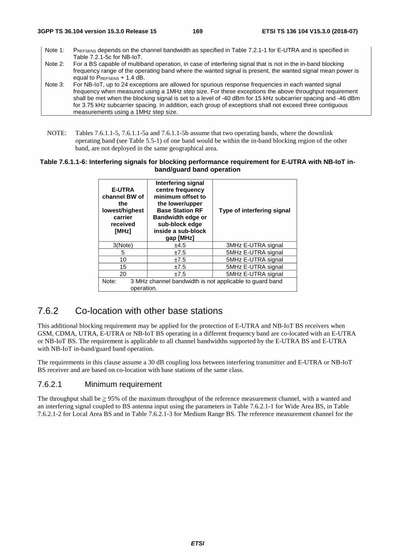
ETSI
ETSI TS 136 104 V15.3.0 (2018-07)1693GPP TS 36.104 version 15.3.0 Release 15
Note 1: PREFSENS depends on the channel bandwidth as specified in Table 7.2.1-1 for E-UTRA and is specified in Table 7.2.1-5c for NB-IoT.
Note 2: For a BS capable of multiband operation, in case of interfering signal that is not in the in-band blocking frequency range of the operating band where the wanted signal is present, the wanted signal mean power is equal to PREFSENS + 1.4 dB.
Note 3: For NB-IoT, up to 24 exceptions are allowed for spurious response frequencies in each wanted signal frequency when measured using a 1MHz step size. For these exceptions the above throughput requirement shall be met when the blocking signal is set to a level of -40 dBm for 15 kHz subcarrier spacing and -46 dBm for 3.75 kHz subcarrier spacing. In addition, each group of exceptions shall not exceed three contiguous measurements using a 1MHz step size.
NOTE: Tables 7.6.1.1-5, 7.6.1.1-5a and 7.6.1.1-5b assume that two operating bands, where the downlink operating band (see Table 5.5-1) of one band would be within the in-band blocking region of the other band, are not deployed in the same geographical area.
Table 7.6.1.1-6: Interfering signals for blocking performance requirement for E-UTRA with NB-IoT in-band/guard band operation
E-UTRA channel BW of
the lowest/highest
carrier received
[MHz]
Interfering signal centre frequency
minimum offset to the lower/upper Base Station RF
Bandwidth edge or sub-block edge
inside a sub-block gap [MHz]
Type of interfering signal
3(Note) ±4.5 3MHz E-UTRA signal 5 ±7.5 5MHz E-UTRA signal 10 ±7.5 5MHz E-UTRA signal 15 ±7.5 5MHz E-UTRA signal 20 ±7.5 5MHz E-UTRA signal
Note: 3 MHz channel bandwidth is not applicable to guard band operation.
7.6.2 Co-location with other base stations
This additional blocking requirement may be applied for the protection of E-UTRA and NB-IoT BS receivers when GSM, CDMA, UTRA, E-UTRA or NB-IoT BS operating in a different frequency band are co-located with an E-UTRA or NB-IoT BS. The requirement is applicable to all channel bandwidths supported by the E-UTRA BS and E-UTRA with NB-IoT in-band/guard band operation.
The requirements in this clause assume a 30 dB coupling loss between interfering transmitter and E-UTRA or NB-IoT BS receiver and are based on co-location with base stations of the same class.
7.6.2.1 Minimum requirement
The throughput shall be ≥ 95% of the maximum throughput of the reference measurement channel, with a wanted and an interfering signal coupled to BS antenna input using the parameters in Table 7.6.2.1-1 for Wide Area BS, in Table 7.6.2.1-2 for Local Area BS and in Table 7.6.2.1-3 for Medium Range BS. The reference measurement channel for the

ETSI
ETSI TS 136 104 V15.3.0 (2018-07)1703GPP TS 36.104 version 15.3.0 Release 15
wanted signal is identified in Tables 7.2.1-1, 7.2.1-2 and 7.2.1-4 for each channel bandwidth for E-UTRA, Table 7.2.1-5 for NB-IoT and further specified in Annex A.
Table 7.6.2.1-1: Blocking performance requirement for E-UTRA and NB-IoT Wide Area BS when co-located with BS in other frequency bands.

ETSI
ETSI TS 136 104 V15.3.0 (2018-07)1713GPP TS 36.104 version 15.3.0 Release 15
Co-located BS type Centre Frequency of
Interfering Signal (MHz)
Interfering Signal mean
power (dBm)
Wanted Signal mean power (dBm)
Type of Interfering
Signal
Macro GSM850 or CDMA850 869 – 894 +16** PREFSENS + 6dB* CW carrier
Macro GSM900 921 – 960 +16** PREFSENS + 6dB* CW carrier Macro DCS1800 1805 – 1880 +16** PREFSENS + 6dB* CW carrier Macro PCS1900 1930 – 1990 +16** PREFSENS + 6dB* CW carrier WA UTRA FDD Band I or E-UTRA Band 1 2110 – 2170 +16** PREFSENS + 6dB* CW carrier
WA UTRA FDD Band II or E-UTRA Band 2 1930 – 1990 +16** PREFSENS + 6dB* CW carrier
WA UTRA FDD Band III or E-UTRA Band 3 1805 – 1880 +16** PREFSENS + 6dB* CW carrier
WA UTRA FDD Band IV or E-UTRA Band 4 2110 – 2155 +16** PREFSENS + 6dB* CW carrier
WA UTRA FDD Band V or E-UTRA Band 5 869 – 894 +16** PREFSENS + 6dB* CW carrier
WA UTRA FDD Band VI or E-UTRA Band 6 875 – 885 +16** PREFSENS + 6dB* CW carrier
WA UTRA FDD Band VII or E-UTRA Band 7 2620 – 2690 +16** PREFSENS + 6dB* CW carrier
WA UTRA FDD Band VIII or E-UTRA Band 8 925 – 960 +16** PREFSENS + 6dB* CW carrier
WA UTRA FDD Band IX or E-UTRA Band 9 1844.9 – 1879.9 +16** PREFSENS + 6dB* CW carrier
WA UTRA FDD Band X or E-UTRA Band 10 2110 – 2170 +16** PREFSENS + 6dB* CW carrier
WA UTRA FDD Band XI or E-UTRA Band 11 1475.9 –1495.9 +16** PREFSENS + 6dB* CW carrier
WA UTRA FDD Band XII or E-UTRA Band 12 729 - 746 +16** PREFSENS + 6dB* CW carrier
WA UTRA FDD Band XIIII or E-UTRA Band 13 746 - 756 +16** PREFSENS + 6dB* CW carrier
WA UTRA FDD Band XIV or E-UTRA Band 14 758 - 768 +16** PREFSENS + 6dB* CW carrier
WA E-UTRA Band 17 734 - 746 +16** PREFSENS + 6dB* CW carrier WA E-UTRA Band 18 860 - 875 +16** PREFSENS + 6dB* CW carrier WA UTRA FDD Band XIX or E-UTRA Band 19 875 - 890 +16** PREFSENS + 6dB* CW carrier
WA UTRA FDD Band XX or E-UTRA Band 20 791 - 821 +16** PREFSENS + 6dB* CW carrier
WA UTRA FDD Band XXI or E-UTRA Band 21 1495.9 – 1510.9 +16** PREFSENS + 6dB* CW carrier
WA UTRA FDD Band XXII or E-UTRA Band 22 3510 – 3590 +16** PREFSENS + 6dB* CW carrier
WA E-UTRA Band 23 2180 - 2200 +16** PREFSENS + 6dB* CW carrier WA E-UTRA Band 24 1525 – 1559 +16** PREFSENS + 6dB* CW carrier WA UTRA FDD Band XXV or E-UTRA Band 25 1930 – 1995 +16** PREFSENS + 6dB* CW carrier
WA UTRA FDD Band XXVI or E-UTRA Band 26 859 – 894 +16** PREFSENS + 6dB* CW carrier
WA E-UTRA Band 27 852 - 869 +16** PREFSENS + 6dB* CW carrier WA E-UTRA Band 28 758 – 803 +16** PREFSENS + 6dB* CW carrier WA E-UTRA Band 29 717-728 +16** PREFSENS + 6dB* CW carrier WA E-UTRA Band 30 2350 – 2360 +16** PREFSENS + 6dB* CW carrier WA E-UTRA Band 31 462.5-467.5 +16** PREFSENS + 6dB* CW carrier WA UTRA FDD Band XXXII or E-UTRA Band 32
1452-1496 (NOTE 3)
+16** PREFSENS + 6dB* CW carrier
WA UTRA TDD Band a) or E-UTRA Band 33 1900-1920 +16** PREFSENS + 6dB* CW carrier
WA UTRA TDD Band a) or E-UTRA Band 34 2010-2025 +16** PREFSENS + 6dB* CW carrier
WA UTRA TDD Band b) or E-UTRA Band 35
1850-1910
+16** PREFSENS + 6dB* CW carrier

ETSI
ETSI TS 136 104 V15.3.0 (2018-07)1723GPP TS 36.104 version 15.3.0 Release 15
WA UTRA TDD Band b) or E-UTRA Band 36 1930-1990 +16** PREFSENS + 6dB* CW carrier
WA UTRA TDD Band c) or E-UTRA Band 37 1910-1930 +16** PREFSENS + 6dB* CW carrier
WA UTRA TDD Band d) or E-UTRA Band 38 2570-2620 +16** PREFSENS + 6dB* CW carrier
WA UTRA TDD Band f) or E-UTRA Band 39 1880-1920 +16** PREFSENS + 6dB* CW carrier
WA UTRA TDD Band e) or E-UTRA Band 40 2300-2400 +16** PREFSENS + 6dB* CW carrier
WA E-UTRA Band 41 2496 - 2690 +16** PREFSENS + 6dB* CW carrier WA E-UTRA Band 42 3400-3600 +16** PREFSENS + 6dB* CW carrier WA E-UTRA Band 43 3600-3800 +16** PREFSENS + 6dB* CW carrier WA E-UTRA Band 44 703-803 +16** PREFSENS + 6dB* CW carrier WA E-UTRA Band 45 1447-1467 +16** PREFSENS + 6dB* CW carrier WA E-UTRA Band 48 3550-3700 +16** PREFSENS + 6dB* CW carrier WA E-UTRA Band 50 1432 – 1517 +16** PREFSENS + 6dB* CW carrier WA E-UTRA Band 52 3300-3400 +16** PREFSENS + 6dB* CW carrier WA E-UTRA Band 65 2110 – 2200 +16** PREFSENS + 6dB* CW carrier WA E-UTRA Band 66 2110 – 2200 +16** PREFSENS + 6dB* CW carrier WA E-UTRA Band 67 738-758 +16** PREFSENS + 6dB* CW carrier WA E-UTRA Band 68 753-783 +16** PREFSENS + 6dB* CW carrier WA E-UTRA Band 69 2570-2620 +16** PREFSENS + 6dB* CW carrier WA E-UTRA Band 70 1995 – 2020 +16** PREFSENS + 6dB* CW carrier WA E-UTRA Band 71 617 – 652 +16** PREFSENS + 6dB* CW carrier WA E-UTRA Band 72 461 – 466 +16** PREFSENS + 6dB* CW carrier WA E-UTRA Band 73 460 – 465 +16** PREFSENS + 6dB* CW carrier WA E-UTRA Band 74 1475 - 1518 +16** PREFSENS + 6dB* CW carrier WA E-UTRA Band 75 1432 – 1517 +16** PREFSENS + 6dB* CW carrier WA E-UTRA Band 85 728 - 746 +16** PREFSENS + 6dB* CW carrier Note*: PREFSENS depends on the channel bandwidth as specified in Table 7.2.1-1 for E-UTRA and
is specified in Table 7.2.1-5 for NB-IoT. Note**: For NB-IoT, up to 24 exceptions are allowed for spurious response frequencies in each
wanted signal frequency when measured using a 1MHz step size. For these exceptions the above throughput requirement shall be met when the blocking signal is set to a level of -40 dBm for 15 kHz subcarrier spacing and -46 dBm for 3.75 kHz subcarrier spacing. In addition, each group of exceptions shall not exceed three contiguous measurements using a 1MHz step size.
NOTE 1: Except for a BS operating in Band 13, these requirements do not apply when the interfering signal falls within any of the supported uplink operating band or in the 10 MHz immediately outside any of the supported uplink operating band. For a BS operating in band 13 the requirements do not apply when the interfering signal falls within the frequency range 768-797 MHz.
NOTE 2: Some combinations of bands may not be possible to co-site based on the requirements above. The current state-of-the-art technology does not allow a single generic solution for co-location of UTRA TDD or E-UTRA TDD with E-UTRA FDD on adjacent frequencies for 30dB BS-BS minimum coupling loss. However, there are certain site-engineering solutions that can be used. These techniques are addressed in TR 25.942 [8].
NOTE 3: For a BS operating in band 11, 21 or 74, the requirement for co-location with Band 32 applies for interfering signal within the frequency range 1475.9-1495.9 MHz.
NOTE 4: Co-located TDD base stations that are synchronized and using the same or adjacent operating band can receive without special co-location requirements. For unsynchronized base stations, special co-location requirements may apply that are not covered by the 3GPP specifications.

ETSI
ETSI TS 136 104 V15.3.0 (2018-07)1733GPP TS 36.104 version 15.3.0 Release 15
Table 7.6.2.1-2: Blocking performance requirement for E-UTRA and NB-IoT Local Area BS when co-located with BS in other frequency bands.
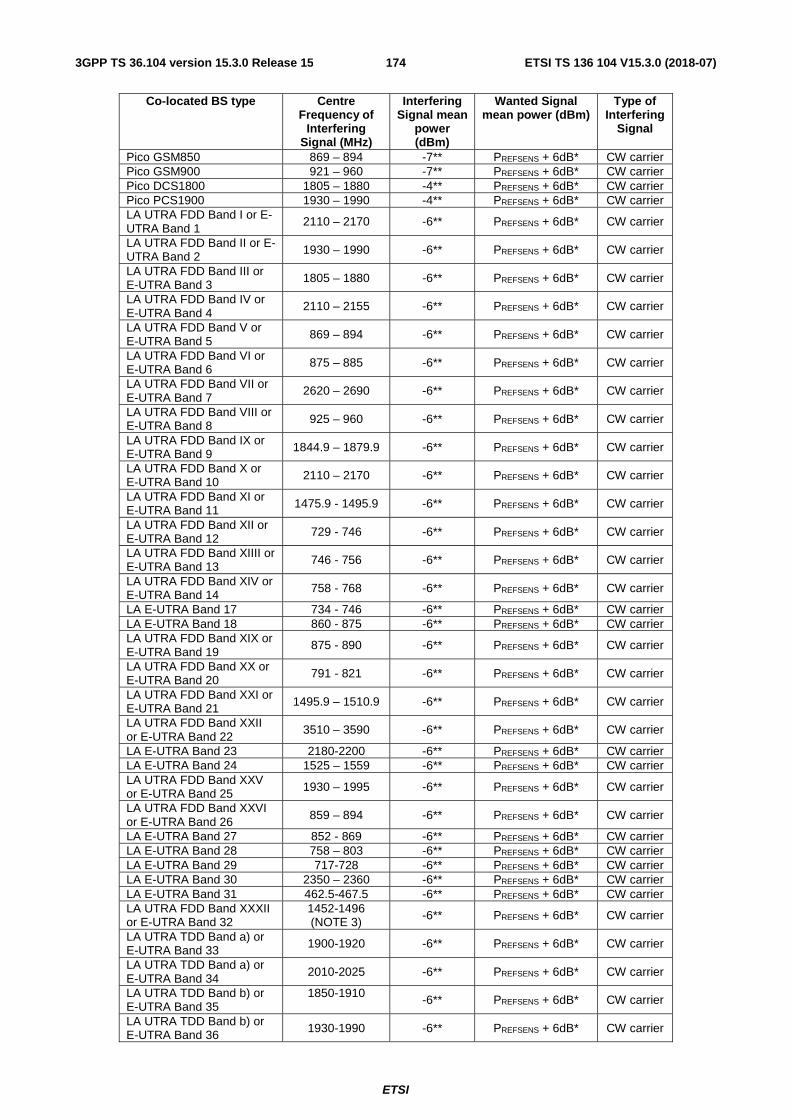
ETSI
ETSI TS 136 104 V15.3.0 (2018-07)1743GPP TS 36.104 version 15.3.0 Release 15
Co-located BS type Centre Frequency of
Interfering Signal (MHz)
Interfering Signal mean
power (dBm)
Wanted Signal mean power (dBm)
Type of Interfering
Signal
Pico GSM850 869 – 894 -7** PREFSENS + 6dB* CW carrier Pico GSM900 921 – 960 -7** PREFSENS + 6dB* CW carrier Pico DCS1800 1805 – 1880 -4** PREFSENS + 6dB* CW carrier Pico PCS1900 1930 – 1990 -4** PREFSENS + 6dB* CW carrier LA UTRA FDD Band I or E-UTRA Band 1
2110 – 2170 -6** PREFSENS + 6dB* CW carrier
LA UTRA FDD Band II or E-UTRA Band 2 1930 – 1990 -6** PREFSENS + 6dB* CW carrier
LA UTRA FDD Band III or E-UTRA Band 3 1805 – 1880 -6** PREFSENS + 6dB* CW carrier
LA UTRA FDD Band IV or E-UTRA Band 4
2110 – 2155 -6** PREFSENS + 6dB* CW carrier
LA UTRA FDD Band V or E-UTRA Band 5 869 – 894 -6** PREFSENS + 6dB* CW carrier
LA UTRA FDD Band VI or E-UTRA Band 6 875 – 885 -6** PREFSENS + 6dB* CW carrier
LA UTRA FDD Band VII or E-UTRA Band 7
2620 – 2690 -6** PREFSENS + 6dB* CW carrier
LA UTRA FDD Band VIII or E-UTRA Band 8 925 – 960 -6** PREFSENS + 6dB* CW carrier
LA UTRA FDD Band IX or E-UTRA Band 9 1844.9 – 1879.9 -6** PREFSENS + 6dB* CW carrier
LA UTRA FDD Band X or E-UTRA Band 10 2110 – 2170 -6** PREFSENS + 6dB* CW carrier
LA UTRA FDD Band XI or E-UTRA Band 11 1475.9 - 1495.9 -6** PREFSENS + 6dB* CW carrier
LA UTRA FDD Band XII or E-UTRA Band 12 729 - 746 -6** PREFSENS + 6dB* CW carrier
LA UTRA FDD Band XIIII or E-UTRA Band 13 746 - 756 -6** PREFSENS + 6dB* CW carrier
LA UTRA FDD Band XIV or E-UTRA Band 14 758 - 768 -6** PREFSENS + 6dB* CW carrier
LA E-UTRA Band 17 734 - 746 -6** PREFSENS + 6dB* CW carrier LA E-UTRA Band 18 860 - 875 -6** PREFSENS + 6dB* CW carrier LA UTRA FDD Band XIX or E-UTRA Band 19
875 - 890 -6** PREFSENS + 6dB* CW carrier
LA UTRA FDD Band XX or E-UTRA Band 20 791 - 821 -6** PREFSENS + 6dB* CW carrier
LA UTRA FDD Band XXI or E-UTRA Band 21 1495.9 – 1510.9 -6** PREFSENS + 6dB* CW carrier
LA UTRA FDD Band XXII or E-UTRA Band 22
3510 – 3590 -6** PREFSENS + 6dB* CW carrier
LA E-UTRA Band 23 2180-2200 -6** PREFSENS + 6dB* CW carrier LA E-UTRA Band 24 1525 – 1559 -6** PREFSENS + 6dB* CW carrier LA UTRA FDD Band XXV or E-UTRA Band 25 1930 – 1995 -6** PREFSENS + 6dB* CW carrier
LA UTRA FDD Band XXVI or E-UTRA Band 26 859 – 894 -6** PREFSENS + 6dB* CW carrier
LA E-UTRA Band 27 852 - 869 -6** PREFSENS + 6dB* CW carrier LA E-UTRA Band 28 758 – 803 -6** PREFSENS + 6dB* CW carrier LA E-UTRA Band 29 717-728 -6** PREFSENS + 6dB* CW carrier LA E-UTRA Band 30 2350 – 2360 -6** PREFSENS + 6dB* CW carrier LA E-UTRA Band 31 462.5-467.5 -6** PREFSENS + 6dB* CW carrier LA UTRA FDD Band XXXII or E-UTRA Band 32
1452-1496 (NOTE 3) -6** PREFSENS + 6dB* CW carrier
LA UTRA TDD Band a) or E-UTRA Band 33 1900-1920 -6** PREFSENS + 6dB* CW carrier
LA UTRA TDD Band a) or E-UTRA Band 34 2010-2025 -6** PREFSENS + 6dB* CW carrier
LA UTRA TDD Band b) or E-UTRA Band 35
1850-1910 -6** PREFSENS + 6dB* CW carrier
LA UTRA TDD Band b) or E-UTRA Band 36 1930-1990 -6** PREFSENS + 6dB* CW carrier

ETSI
ETSI TS 136 104 V15.3.0 (2018-07)1753GPP TS 36.104 version 15.3.0 Release 15
LA UTRA TDD Band c) or E-UTRA Band 37 1910-1930 -6** PREFSENS + 6dB* CW carrier
LA UTRA TDD Band d) or E-UTRA Band 38 2570-2620 -6** PREFSENS + 6dB* CW carrier
LA UTRA TDD Band f) or E-UTRA Band 39 1880-1920 -6** PREFSENS + 6dB* CW carrier
LA E-UTRA UTRA TDD Band e) or Band 40 2300-2400 -6** PREFSENS + 6dB* CW carrier
LA E-UTRA Band 41 2496 - 2690 -6** PREFSENS + 6dB* CW carrier LA E-UTRA Band 42 3400-3600 -6** PREFSENS + 6dB* CW carrier LA E-UTRA Band 43 3600-3800 -6** PREFSENS + 6dB* CW carrier LA E-UTRA Band 44 703-803 -6** PREFSENS + 6dB* CW carrier LA E-UTRA Band 45 1447-1467 -6** PREFSENS + 6dB* CW carrier LA E-UTRA Band 46 5150-5925 -6** PREFSENS + 6dB* CW carrier LA E-UTRA Band 48 3550-3700 -6** PREFSENS + 6dB* CW carrier LA E-UTRA Band 49 3550-3700 -6** PREFSENS + 6dB* CW carrier LA E-UTRA Band 50 1432 – 1517 -6** PREFSENS + 6dB* CW carrier LA E-UTRA Band 51 1427 – 1432 -6** PREFSENS + 6dB* CW carrier LA E-UTRA Band 52 3300-3400 -6** PREFSENS + 6dB* CW carrier LA E-UTRA Band 65 2110 – 2200 -6** PREFSENS + 6dB* CW carrier LA E-UTRA Band 66 2110 – 2200 -6** PREFSENS + 6dB* CW carrier LA E-UTRA Band 67 738-758 -6** PREFSENS + 6dB* CW carrier LA E-UTRA Band 68 753-783 -6** PREFSENS + 6dB* CW carrier LA E-UTRA Band 69 2570-2620 -6** PREFSENS + 6dB* CW carrier LA E-UTRA Band 70 1995 – 2020 -6** PREFSENS + 6dB* CW carrier LA E-UTRA Band 71 617 – 652 -6** PREFSENS + 6dB* CW carrier LA E-UTRA Band 72 461 – 466 -6** PREFSENS + 6dB* CW carrier LA E-UTRA Band 73 460 – 465 -6** PREFSENS + 6dB* CW carrier LA E-UTRA Band 74 1475 - 1518 -6** PREFSENS + 6dB* CW carrier LA E-UTRA Band 75 1432 – 1517 -6** PREFSENS + 6dB* CW carrier LA E-UTRA Band 76 1427 – 1432 -6** PREFSENS + 6dB* CW carrier LA E-UTRA Band 85 728 - 746 -6** PREFSENS + 6dB* CW carrier Note*: PREFSENS depends on the channel bandwidth as specified in Table 7.2.1-2. Note**: For NB-IoT, up to 24 exceptions are allowed for spurious response frequencies in each
wanted signal frequency when measured using a 1MHz step size. For these exceptions the above throughput requirement shall be met when the blocking signal is set to a level of -40 dBm for 15 kHz subcarrier spacing and -46 dBm for 3.75 kHz subcarrier spacing. In addition, each group of exceptions shall not exceed three contiguous measurements using a 1MHz step size.
NOTE 1: Except for a BS operating in Band 13, these requirements do not apply when the interfering signal falls within any of the supported uplink operating band or in the 10 MHz immediately outside any of the supported uplink operating band. For a BS operating in band 13 the requirements do not apply when the interfering signal falls within the frequency range 768-797 MHz.
NOTE 2: Some combinations of bands may not be possible to co-site based on the requirements above. The current state-of-the-art technology does not allow a single generic solution for co-location of UTRA TDD or E-UTRA TDD with E-UTRA FDD on adjacent frequencies for 30dB BS-BS minimum coupling loss. However, there are certain site-engineering solutions that can be used. These techniques are addressed in TR 25.942 [8].
NOTE 3: For a BS operating in band 11, 21 or 74, the requirement for co-location with Band 32 applies for interfering signal within the frequency range 1475.9-1495.9 MHz.
NOTE 4: Co-located TDD base stations that are synchronized and using the same or adjacent operating band can receive without special co-location requirements. For unsynchronized base stations (except in Band 46), special co-location requirements may apply that are not covered by the 3GPP specifications.

ETSI
ETSI TS 136 104 V15.3.0 (2018-07)1763GPP TS 36.104 version 15.3.0 Release 15
Table 7.6.2.1-3: Blocking performance requirement for E-UTRA and NB-IoT Medium Range BS when co-located with BS in other frequency bands.

ETSI
ETSI TS 136 104 V15.3.0 (2018-07)1773GPP TS 36.104 version 15.3.0 Release 15
Co-located BS type Centre Frequency of
Interfering Signal (MHz)
Interfering Signal mean
power (dBm)
Wanted Signal mean power (dBm)
Type of Interfering
Signal
Micro/MR GSM850 869 – 894 +8** PREFSENS + 6dB* CW carrier Micro/MR GSM900 921 – 960 +8** PREFSENS + 6dB* CW carrier Micro/MR DCS1800 1805 – 1880 +8** PREFSENS + 6dB* CW carrier Micro/MR PCS1900 1930 – 1990 +8** PREFSENS + 6dB* CW carrier MR UTRA FDD Band I or E-UTRA Band 1
2110 – 2170 +8** PREFSENS + 6dB* CW carrier
MR UTRA FDD Band II or E-UTRA Band 2 1930 – 1990 +8** PREFSENS + 6dB* CW carrier
MR UTRA FDD Band III or E-UTRA Band 3 1805 – 1880 +8** PREFSENS + 6dB* CW carrier
MR UTRA FDD Band IV or E-UTRA Band 4
2110 – 2155 +8** PREFSENS + 6dB* CW carrier
MR UTRA FDD Band V or E-UTRA Band 5 869 – 894 +8** PREFSENS + 6dB* CW carrier
MR UTRA FDD Band VI or E-UTRA Band 6 875 – 885 +8** PREFSENS + 6dB* CW carrier
MR UTRA FDD Band VII or E-UTRA Band 7
2620 – 2690 +8** PREFSENS + 6dB* CW carrier
MR UTRA FDD Band VIII or E-UTRA Band 8 925 – 960 +8** PREFSENS + 6dB* CW carrier
MR UTRA FDD Band IX or E-UTRA Band 9 1844.9 – 1879.9 +8** PREFSENS + 6dB* CW carrier
MR UTRA FDD Band X or E-UTRA Band 10 2110 – 2170 +8** PREFSENS + 6dB* CW carrier
MR UTRA FDD Band XI or E-UTRA Band 11 1475.9 –1495.9 +8** PREFSENS + 6dB* CW carrier
MR UTRA FDD Band XII or E-UTRA Band 12 729 – 746 +8** PREFSENS + 6dB* CW carrier
MR UTRA FDD Band XIIII or E-UTRA Band 13 746 – 756 +8** PREFSENS + 6dB* CW carrier
MR UTRA FDD Band XIV or E-UTRA Band 14 758 – 768 +8** PREFSENS + 6dB* CW carrier
MR E-UTRA Band 17 734 – 746 +8** PREFSENS + 6dB* CW carrier MR E-UTRA Band 18 860 – 875 +8** PREFSENS + 6dB* CW carrier MR UTRA FDD Band XIX or E-UTRA Band 19
875 – 890 +8** PREFSENS + 6dB* CW carrier
MR UTRA FDD Band XX or E-UTRA Band 20 791 – 821 +8** PREFSENS + 6dB* CW carrier
MR UTRA FDD Band XXI or E-UTRA Band 21 1495.9 – 1510.9 +8** PREFSENS + 6dB* CW carrier
MR UTRA FDD Band XXII or E-UTRA Band 22
3510 – 3590 +8** PREFSENS + 6dB* CW carrier
MR E-UTRA Band 23 2180 – 2200 +8** PREFSENS + 6dB* CW carrier MR E-UTRA Band 24 1525 – 1559 +8** PREFSENS + 6dB* CW carrier MR UTRA FDD Band XXV or E-UTRA Band 25 1930 – 1995 +8** PREFSENS + 6dB* CW carrier
MR UTRA FDD Band XXVI or E-UTRA Band 26 859 – 894 +8** PREFSENS + 6dB* CW carrier
MR E-UTRA Band 27 852 – 869 +8** PREFSENS + 6dB* CW carrier MR E-UTRA Band 28 758 – 803 +8** PREFSENS + 6dB* CW carrier MR E-UTRA Band 29 717 – 728 +8** PREFSENS + 6dB* CW carrier MR E-UTRA Band 30 2350 – 2360 +8** PREFSENS + 6dB* CW carrier MR E-UTRA Band 31 462.5 – 467.5 +8** PREFSENS + 6dB* CW carrier MR UTRA FDD Band XXXII or E-UTRA Band 32
1452-1496 (NOTE 3) +8** PREFSENS + 6dB* CW carrier
MR E-UTRA Band 33 1900 – 1920 +8** PREFSENS + 6dB* CW carrier MR E-UTRA Band 34 2010 – 2025 +8** PREFSENS + 6dB* CW carrier MR E-UTRA Band 35 1850 – 1910
+8** PREFSENS + 6dB* CW carrier
MR E-UTRA Band 36 1930 – 1990 +8** PREFSENS + 6dB* CW carrier MR E-UTRA Band 37 1910 – 1930 +8** PREFSENS + 6dB* CW carrier MR E-UTRA Band 38 2570 – 2620 +8** PREFSENS + 6dB* CW carrier

ETSI
ETSI TS 136 104 V15.3.0 (2018-07)1783GPP TS 36.104 version 15.3.0 Release 15
MR E-UTRA Band 39 1880 – 1920 +8** PREFSENS + 6dB* CW carrier MR E-UTRA Band 40 2300 – 2400 +8** PREFSENS + 6dB* CW carrier MR E-UTRA Band 41 2496 – 2690 +8** PREFSENS + 6dB* CW carrier MR E-UTRA Band 42 3400 – 3600 +8** PREFSENS + 6dB* CW carrier MR E-UTRA Band 43 3600 – 3800 +8** PREFSENS + 6dB* CW carrier MR E-UTRA Band 44 703 – 803 +8** PREFSENS + 6dB* CW carrier MR E-UTRA Band 45 1447 – 1467 +8** PREFSENS + 6dB* CW carrier MR E-UTRA Band 46 5150 – 5925 +8** PREFSENS + 6dB* CW carrier MR E-UTRA Band 48 3550-3700 +8** PREFSENS + 6dB* CW carrier MR E-UTRA Band 50 1432 – 1517 +8** PREFSENS + 6dB* CW carrier MR E-UTRA Band 52 3300 – 3400 +8** PREFSENS + 6dB* CW carrier MR E-UTRA Band 65 2110 – 2200 +8** PREFSENS + 6dB* CW carrier MR E-UTRA Band 66 2110 – 2200 +8** PREFSENS + 6dB* CW carrier MR E-UTRA Band 67 738-758 +8** PREFSENS + 6dB* CW carrier MR E-UTRA Band 68 753-783 +8** PREFSENS + 6dB* CW carrier MR E-UTRA Band 69 2570-2620 +8** PREFSENS + 6dB* CW carrier MR E-UTRA Band 70 1995 – 2020 +8** PREFSENS + 6dB* CW carrier MR E-UTRA Band 71 617 – 652 +8** PREFSENS + 6dB* CW carrier MR E-UTRA Band 72 461 – 466 +8** PREFSENS + 6dB* CW carrier MR E-UTRA Band 73 460 – 465 +8** PREFSENS + 6dB* CW carrier MR E-UTRA Band 74 1475 - 1518 +8** PREFSENS + 6dB* CW carrier MR E-UTRA Band 75 1432 – 1517 +8** PREFSENS + 6dB* CW carrier MR E-UTRA Band 85 728 - 746 +8** PREFSENS + 6dB* CW carrier Note*: PREFSENS depends on the channel bandwidth as specified in Table 7.2.1-4. Note**: For NB-IoT, up to 24 exceptions are allowed for spurious response frequencies in each
wanted signal frequency when measured using a 1MHz step size. For these exceptions the above throughput requirement shall be met when the blocking signal is set to a level of -40 dBm for 15 kHz subcarrier spacing and -46 dBm for 3.75 kHz subcarrier spacing. In addition, each group of exceptions shall not exceed three contiguous measurements using a 1MHz step size.
NOTE 1: Except for a BS operating in Band 13, these requirements do not apply when the interfering signal falls within any of the supported uplink operating band or in the 10 MHz immediately outside any of the supported uplink operating band. For a BS operating in band 13 the requirements do not apply when the interfering signal falls within the frequency range 768-797 MHz.
NOTE 2: Some combinations of bands may not be possible to co-site based on the requirements above. The current state-of-the-art technology does not allow a single generic solution for co-location of UTRA TDD or E-UTRA TDD with E-UTRA FDD on adjacent frequencies for 30dB BS-BS minimum coupling loss. However, there are certain site-engineering solutions that can be used. These techniques are addressed in TR 25.942 [8].
NOTE 3: For a BS operating in band 11, 21 or 74, the requirement for co-location with Band 32 applies for interfering signal within the frequency range 1475.9-1495.9 MHz.
NOTE 4: Co-located TDD base stations that are synchronized and using the same or adjacent operating band can receive without special co-location requirements. For unsynchronized base stations (except in Band 46), special co-location requirements may apply that are not covered by the 3GPP specifications.
7.6.3 Additional requirement (regional)
For the Public Safety LTE BS in Korea from 718 to 728 MHz in band 28, the wanted and the interfering signal coupled to the BS antenna input are specified in Tables G-2.2, G-2.3, G-2.4 and G-2.5 for the blocking requirements. The reference measurement channel for the wanted signal is A.1-3 for 10 MHz channel bandwidth and further specified in Annex A.
7.7 Receiver spurious emissions The spurious emissions power is the power of emissions generated or amplified in a receiver that appear at the BS receiver antenna connector. The requirements apply to all BS with separate RX and TX antenna ports. In this case for FDD BS the test shall be performed when both TX and RX are on, with the TX port terminated.
For TDD BS with common RX and TX antenna port the requirement applies during the Transmitter OFF period. For FDD BS with common RX and TX antenna port the transmitter spurious emission as specified in clause 6.6.4 is valid.

ETSI
ETSI TS 136 104 V15.3.0 (2018-07)1793GPP TS 36.104 version 15.3.0 Release 15
For BS capable of multi-band operation where multiple bands are mapped on separate antenna connectors, the single-band requirements apply and the excluded frequency range is only applicable for the operating band supported on each antenna connector.
The requirements shall apply to BS that supports E-UTRA or E-UTRA with NB-IoT in-band/guard band operation or NB-IoT standalone operation.
7.7.1 Minimum requirement
The power of any spurious emission shall not exceed the levels in Table 7.7.1-1:
Table 7.7.1-1: General spurious emission minimum requirement
Frequency range Maximum level
Measurement Bandwidth
Note
30MHz - 1 GHz -57 dBm 100 kHz 1 GHz – 12.75 GHz -47 dBm 1 MHz
12.75 GHz - 5th harmonic of the upper frequency
edge of the UL operating band in GHz
-47 dBm 1 MHz Applies only for Bands 22, 42, 43, 48 or 49.
12.75 GHz - 26 GHz -47 dBm 1 MHz Applies only for Band 46 NOTE: The frequency range between 2.5 * BWChannel below the first carrier frequency and
2.5 * BWChannel above the last carrier frequency transmitted by the BS, where BWChannel is the channel bandwidth according to Table 5.6-1, may be excluded from the requirement. However, frequencies that are more than 10 MHz below the lowest frequency of any of the BS supported downlink operating band or more than 10 MHz above the highest frequency of any of the BS supported downlink operating band shall not be excluded from the requirement. For BS capable of multiband operation, the exclusion applies for all supported operating bands. For BS capable of multi-band operation where multiple bands are mapped on separate antenna connectors, the single-band requirements apply and the excluded frequency range is only applicable for the operating band supported on each antenna connector.
In addition to the requirements in Table 7.7.1-1, the power of any spurious emission shall not exceed the levels specified for Protection of the E-UTRA FDD BS receiver of own or different BS in subclause 6.6.4.2 and for Co-existence with other systems in the same geographical area in subclause 6.6.4.3. In addition, the co-existence requirements for co-located base stations specified in subclause 6.6.4.4 may also be applied.
7.8 Receiver intermodulation Third and higher order mixing of the two interfering RF signals can produce an interfering signal in the band of the desired channel. Intermodulation response rejection is a measure of the capability of the receiver to receive a wanted signal on its assigned channel frequency in the presence of two interfering signals which have a specific frequency relationship to the wanted signal. Interfering signals shall be a CW signal and an E-UTRA signal as specified in Annex C.
7.8.1 Minimum requirement
For E-UTRA, the throughput shall be ≥ 95% of the maximum throughput of the reference measurement channel, with a wanted signal at the assigned channel frequency and two interfering signals coupled to the BS antenna input, with the conditions specified in Tables 7.8.1-1 and 7.8.1-2 for intermodulation performance and in Tables 7.8.1-3, 7.8.1-4, 7.8.1-5 and 7.8.1-6 for narrowband intermodulation performance. Narrowband intermodulation requirements are not applied for Band 46. The reference measurement channel for the wanted signal is identified in Table 7.2.1-1, Table 7.2.1-2, Table 7.2.1-3 and Table 7.2.1-4 for each channel bandwidth and further specified in Annex A.
For NB-IoT in-band operation, the throughput shall be ≥ 95% of the maximum throughput of the reference measurement channel, with a wanted signal at the assigned channel frequency and two interfering signals coupled to the BS antenna input, with the conditions specified in Tables 7.8.1-1a and 7.8.1-2 for intermodulation performance and in Tables 7.8.1-3a, 7.8.1-4a, 7.8.1-5a and 7.8.1-6a for narrowband intermodulation performance. The reference measurement channel for the wanted signal is identified in Tables 7.2.1-5, 7.2.1-5a, 7.2.1-5b and 7.2.1-5c and further specified in Annex A.

ETSI
ETSI TS 136 104 V15.3.0 (2018-07)1803GPP TS 36.104 version 15.3.0 Release 15
For NB-IoT guard band operation, the throughput shall be ≥ 95% of the maximum throughput of the reference measurement channel, with a wanted signal at the assigned channel frequency and two interfering signals coupled to the BS antenna input, with the conditions specified in Tables 7.8.1-1b and 7.8.1-2 for intermodulation performance and in Tables 7.8.1-3b, 7.8.1-4b, 7.8.1-5b and 7.8.1-6b for narrowband intermodulation performance. The reference measurement channel for the wanted signal is identified in Tables 7.2.1-5, 7.2.1-5a, 7.2.1-5b and 7.2.1-5c and further specified in Annex A.
For NB-IoT standalone operation, the throughput shall be ≥ 95% of the maximum throughput of the reference measurement channel, with a wanted signal at the assigned channel frequency and two interfering signals coupled to the BS antenna input, with the conditions specified in Tables 7.8.1-1c and 7.8.1-2a for intermodulation performance and in Tables 7.8.1-3c, 7.8.1-4c, 7.8.1-5c and 7.8.1-6c for narrowband intermodulation performance. The reference measurement channel for the wanted signal is identified in Tables 7.2.1-5, 7.2.1-5a and 7.2.1-5c and further specified in Annex A.
The receiver intermodulation requirement is applicable outside the Base Station RF Bandwidth or Radio Bandwidth edges. The interfering signal offset is defined relative to the Base Station RF Bandwidth edges or Radio Bandwidth edges.
For a BS operating in non-contiguous spectrum within any operating band, the narrowband intermodulation requirement applies in addition inside any sub-block gap in case the sub-block gap is at least as wide as the channel bandwidth of the E-UTRA interfering signal in Table 7.8.1-3. The interfering signal offset is defined relative to the sub-block edges inside the sub-block gap.
For a BS capable of multi-band operation, the intermodulation requirement applies in addition inside any Inter RF Bandwidth gap, in case the gap size is at least twice as wide as the E-UTRA interfering signal centre frequency offset from the Base Station RF Bandwidth edge.
For a BS capable of multi-band operation, the narrowband intermodulation requirement applies in addition inside any Inter RF Bandwidth gap in case the gap size is at least as wide as the E-UTRA interfering signal in Tables 7.8.1-3, 7.8.1-4 and 7.8.1-6. The interfering signal offset is defined relative to the Base Station RF Bandwidth edges inside the Inter RF Bandwidth gap.
Table 7.8.1-1: Intermodulation performance requirement for E-UTRA
BS type Wanted signal mean power [dBm]
Interfering signal mean power [dBm] Type of interfering signal
Wide Area BS PREFSENS + 6dB* -52
See Table 7.8.1-2 Medium Range BS PREFSENS + 6dB** -47
Local Area BS PREFSENS + 6dB*** -44 Home BS PREFSENS + 14dB**** -36
Note*: PREFSENS depends on the channel bandwidth as specified in Table 7.2.1-1. Note**: PREFSENS depends on the channel bandwidth as specified in Table 7.2.1-4. Note*** PREFSENS depends on the channel bandwidth as specified in Table 7.2.1-2. Note**** PREFSENS depends on the channel bandwidth as specified in Table 7.2.1-3.
Table 7.8.1-1a: Intermodulation performance requirement for E-UTRA with NB-IoT in-band operation BS
BS type Wanted signal mean power [dBm]
Interfering signal mean power [dBm]
Type of interfering signal
Wide Area BS PREFSENS + 6dB* -52
See Table 7.8.1-2 Medium Range BS PREFSENS + 6dB** -47
Local Area BS PREFSENS + 6dB*** -44 Home BS PREFSENS + 14dB**** -36
Note*: PREFSENS depends on the sub-carrier spacing as specified in Table 7.2.1-5. Note**: PREFSENS depends on the sub-carrier spacing as specified in Table 7.2.1-5c. Note***: PREFSENS depends on the sub-carrier spacing as specified in Table 7.2.1-5a. Note****: PREFSENS depends on the sub-carrier spacing as specified in Table 7.2.1-5b.

ETSI
ETSI TS 136 104 V15.3.0 (2018-07)1813GPP TS 36.104 version 15.3.0 Release 15
Table 7.8.1-1b: Intermodulation performance requirement for E-UTRA with NB-IoT guard band operation BS
BS type Wanted signal mean power [dBm]
Interfering signal mean power [dBm]
Type of interfering signal
Wide Area BS PREFSENS + 6dB* -52
See Table 7.8.1-2 Medium Area BS PREFSENS + 6dB** -47
Local Area BS PREFSENS + 6dB**** -44 Home BS PREFSENS + 14dB**** -36
Note*: PREFSENS depends on the sub-carrier spacing as specified in Table 7.2.1-5. Note**: PREFSENS depends on the sub-carrier spacing as specified in Table 7.2.1-5c. Note***: PREFSENS depends on the sub-carrier spacing as specified in Table 7.2.1-5a. Note****: PREFSENS depends on the sub-carrier spacing as specified in Table 7.2.1-5b.
Table 7.8.1-1c: Intermodulation performance requirement for NB-IoT standalone
NB-IoT channel
bandwidth of the
lowest/highest carrier
received [kHz]
Wanted signal mean power
[dBm]
Interfering signal mean power [dBm]
Type of interfering signal
Wide Area BS 200 PREFSENS + 6 dB* -52
See Table 7.8.1-2a
Medium Area BS 200 PREFSENS + 6dB** -47
Local Area BS 200 PREFSENS + 6dB**** -44
Home BS 200 PREFSENS + 14dB**** -36
Note*: PREFSENS depends on the sub-carrier spacing as specified in Table 7.2.1-5. Note**: PREFSENS depends on the sub-carrier spacing as specified in Table 7.2.1-5c. Note***: PREFSENS depends on the sub-carrier spacing as specified in Table 7.2.1-5a. Note****: PREFSENS depends on the sub-carrier spacing as specified in Table 7.2.1-5b.
Table 7.8.1-2: Interfering signal for Intermodulation performance requirement for E-UTRA or E-UTRA with NB-IoT in-band/guard band operation BS
E-UTRA channel
bandwidth of the
lowest/highest carrier
received [MHz]
Interfering signal centre frequency offset from the
lower/upper Base Station RF
Bandwidth edge [MHz]
Type of interfering signal
3 ±4.5 CW
±10.5 3 MHz E-UTRA signal (Note 3)
5 ±7.5 CW
±17.5 5 MHz E-UTRA signal
10 ±7.375 CW ±17.5 5 MHz E-UTRA signal
15 ±7.25 CW ±17.5 5 MHz E-UTRA signal
20 ±7.125 CW
±17.5 5 MHz E-UTRA signal (Note 1)
20 ±7.125 CW
±24 20 MHz E-UTRA signal (Note 2)
Note 1: This type of interfering signal is not applied for Band 46. Note 2: This type of interfering signal is only applied for Band 46. Note 3: 3 MHz channel bandwidth is not applicable to guard band
operation.

ETSI
ETSI TS 136 104 V15.3.0 (2018-07)1823GPP TS 36.104 version 15.3.0 Release 15
Table 7.8.1-2a: Interfering signal for Intermodulation performance requirement for NB-IoT standalone operation BS
Channel bandwidth of
the lowest/highest
carrier received
[MHz]
Interfering signal centre frequency offset from the
lower/upper Base Station RF
Bandwidth edge [MHz]
Type of interfering signal
0.2 ±7.575 CW ±17.5 5 MHz E-UTRA signal
Table 7.8.1-3: Narrowband intermodulation performance requirement for Wide Area BS for E-UTRA
E-UTRA channel
bandwidth of the
lowest/highest carrier
received [MHz]
Wanted signal mean power [dBm]
Interfering signal mean power
[dBm]
Interfering RB centre frequency offset from the
lower/upper Base Station RF
Bandwidth edge or sub-block edge inside a sub-block
gap [kHz]
Type of interfering signal
1.4 PREFSENS + 6dB* -52 ±270 CW
-52 ±790 1.4 MHz E-UTRA signal, 1
RB**
3 PREFSENS + 6dB* -52 ±270 CW
-52 ±780 3.0 MHz E-UTRA signal, 1 RB**
5 PREFSENS + 6dB* -52 ±360 CW
-52 ±1060 5 MHz E-UTRA signal, 1 RB**
10 PREFSENS + 6dB*
(***)
-52 ±325 CW
-52 ±1240 5 MHz E-UTRA signal, 1 RB**
15 PREFSENS + 6dB* (***)
-52 ±380 CW
-52 ±1600 5MHz E-UTRA signal, 1 RB**
20 PREFSENS + 6dB* (***)
-52 ±345 CW
-52 ±1780 5MHz E-UTRA signal, 1 RB**
Note*: PREFSENS is related to the channel bandwidth as specified in Table 7.2.1-1. Note**: Interfering signal consisting of one resource block positioned at the stated offset, the channel bandwidth of
the interfering signal is located adjacently to the lower/upper Base Station RF Bandwidth edge. Note***: This requirement shall apply only for a FRC A1-3 mapped to the frequency range at the channel edge
adjacent to the interfering signals

ETSI
ETSI TS 136 104 V15.3.0 (2018-07)1833GPP TS 36.104 version 15.3.0 Release 15
Table 7.8.1-3a: Narrowband intermodulation performance requirement for Wide Area BS for E-UTRA with NB-IoT in-band operation BS
E-UTRA channel
bandwidth of the
lowest/highest carrier
received [MHz]
Wanted signal mean power [dBm]
Interfering signal mean power
[dBm]
Interfering RB centre frequency offset from the
lower/upper Base Station RF
Bandwidth edge or sub-block edge inside a sub-block
gap [kHz]
Type of interfering signal
3 PREFSENS + 6dB* -52 ±270 CW
-52 ±780 3.0 MHz E-UTRA signal, 1 RB**
5 PREFSENS + 6dB* -52 ±360**** CW
-52 ±1060 5 MHz E-UTRA signal, 1 RB**
10 PREFSENS + 6dB* (***)
-52 ±325**** CW
-52 ±1240 5 MHz E-UTRA signal, 1 RB**
15 PREFSENS + 6dB* (***)
-52 ±380**** CW
-52 ±1600 5MHz E-UTRA signal, 1 RB**
20 PREFSENS + 6dB* (***)
-52 ±345**** CW
-52 ±1780 5MHz E-UTRA signal, 1 RB**
Note*: PREFSENS depends on the sub-carrier spacing as specified in Table 7.2.1-5. Note**: Interfering signal consisting of one resource block positioned at the stated offset, the channel bandwidth of
the interfering signal is located adjacently to the lower/upper Base Station RF Bandwidth edge. Note***: This requirement shall apply only for a FRC A1-3 mapped to the frequency range at the channel edge
adjacent to the interfering signals. Note****: The frequency offset shall be adjusted to accommodate the IMD product to fall in the NB-IoT RB for NB-IoT
in-band operation. Note*****: If a BS RF receiver fails the test of the requirement, the test shall be performed with the CW interfering
signal frequency shifted away from the wanted signal by 180 kHz and the E-UTRA interfering signal frequency shifted away from the wanted signal by 360 kHz. If the BS RF receiver still fails the test after the frequency shift, then the BS RF receiver shall be deemed to fail the requirement.

ETSI
ETSI TS 136 104 V15.3.0 (2018-07)1843GPP TS 36.104 version 15.3.0 Release 15
Table 7.8.1-3b: Narrowband intermodulation performance requirement for Wide Area BS for E-UTRA with NB-IoT guard band operation BS
E-UTRA channel
bandwidth of the
lowest/highest carrier
received [MHz]
Wanted signal mean power [dBm]
Interfering signal mean power
[dBm]
Interfering RB centre frequency offset from the
lower/upper Base Station RF
Bandwidth edge or sub-block edge inside a sub-block
gap [kHz]
Type of interfering signal
5 PREFSENS + 6dB* -52 ±360**** CW
-52 ±1060 5 MHz E-UTRA signal, 1 RB**
10 PREFSENS + 6dB* (***)
-52 ±325**** CW
-52 ±1240 5 MHz E-UTRA signal, 1 RB**
15 PREFSENS + 6dB* (***)
-52 ±380**** CW
-52 ±1600 5MHz E-UTRA signal, 1 RB**
20 PREFSENS + 6dB* (***)
-52 ±345**** CW
-52 ±1780 5MHz E-UTRA signal, 1 RB**
Note*: PREFSENS depends on the sub-carrier spacing as specified in Table 7.2.1-5. Note**: Interfering signal consisting of one resource block positioned at the stated offset, the channel bandwidth of
the interfering signal is located adjacently to the lower/upper Base Station RF Bandwidth edge. Note***: This requirement shall apply only for a FRC A1-3 mapped to the frequency range at the channel edge
adjacent to the interfering signals. Note****: The frequency offset shall be adjusted to accommodate the IMD product to fall in the NB-IoT RB for NB-IoT
guard band operation. Note*****: If a BS RF receiver fails the test of the requirement, the test shall be performed with the CW interfering
signal frequency shifted away from the wanted signal by 180 kHz and the E-UTRA interfering signal frequency shifted away from the wanted signal by 360 kHz. If the BS RF receiver still fails the test after the frequency shift, then the BS RF receiver shall be deemed to fail the requirement.
Table 7.8.1-3c: Narrowband intermodulation performance requirement for Wide Area BS for NB-IoT standalone
Channel bandwidth of
the lowest/highest
carrier received
[MHz]
Wanted signal mean power [dBm]
Interfering signal mean power
[dBm]
Interfering RB centre frequency offset from the
lower/upper Base Station RF
Bandwidth edge or sub-block edge inside a sub-block
gap [kHz]
Type of interfering signal
0.2 PREFSENS + 6dB* -52 ±340 CW
-52 ±880 5MHz E-UTRA signal, 1 RB**
Note*: PREFSENS depends on the sub-carrier spacing as specified in Table 7.2.1-5. Note**: Interfering signal consisting of one resource block positioned at the stated offset, the channel bandwidth of
the interfering signal is located adjacently to the lower/upper Base Station RF Bandwidth edge. Note***: If a BS RF receiver fails the test of the requirement, the test shall be performed with the CW interfering
signal frequency shifted away from the wanted signal by 180 kHz and the E-UTRA interfering signal frequency shifted away from the wanted signal by 360 kHz. If the BS RF receiver still fails the test after the frequency shift, then the BS RF receiver shall be deemed to fail the requirement.

ETSI
ETSI TS 136 104 V15.3.0 (2018-07)1853GPP TS 36.104 version 15.3.0 Release 15
Table 7.8.1-4: Narrowband intermodulation performance requirement for Local Area BS for E-UTRA
E-UTRA channel
bandwidth of the
lowest/highest carrier
received [MHz]
Wanted signal mean power [dBm]
Interfering signal mean power
[dBm]
Interfering RB centre frequency offset from the
lower/upper Base Station RF
Bandwidth edge or sub-block edge inside a sub-block
[kHz]
Type of interfering signal
1.4 PREFSENS + 6dB* -44 ±270 CW
-44 ±790 1.4 MHz E-UTRA signal, 1 RB**
3 PREFSENS + 6dB* -44 ±270 CW
-44 ±780 3.0 MHz E-UTRA signal, 1 RB**
5 PREFSENS + 6dB* -44 ±360 CW
-44 ±1060 5 MHz E-UTRA signal, 1 RB**
10 PREFSENS + 6dB* (***)
-44 ±325 CW
-44 ±1240 5 MHz E-UTRA signal, 1 RB**
15 PREFSENS + 6dB* (***)
-44 ±380 CW
-44 ±1600 5MHz E-UTRA signal, 1
RB**
20 PREFSENS + 6dB* (***)
-44 ±345 CW
-44 ±1780 5MHz E-UTRA signal, 1
RB** Note*: PREFSENS is related to the channel bandwidth as specified in Table 7.2.1-2. Note**: Interfering signal consisting of one resource block positioned at the stated offset, the channel bandwidth of
the interfering signal is located adjacently to the lower/upper Base Station RF Bandwidth edge. Note***: This requirement shall apply only for a FRC A1-3 mapped to the frequency range at the channel edge
adjacent to the interfering signals.

ETSI
ETSI TS 136 104 V15.3.0 (2018-07)1863GPP TS 36.104 version 15.3.0 Release 15
Table 7.8.1-4a: Narrowband intermodulation performance requirement for Local Area BS for E-UTRA with NB-IoT in-band operation BS
E-UTRA channel
bandwidth of the
lowest/highest carrier
received [MHz]
Wanted signal mean power [dBm]
Interfering signal mean power
[dBm]
Interfering RB centre frequency offset from the
lower/upper Base Station RF
Bandwidth edge or sub-block edge inside a sub-block
gap [kHz]
Type of interfering signal
3 PREFSENS + 6dB* -44 ±270 CW
-44 ±780 3.0 MHz E-UTRA signal, 1 RB**
5 PREFSENS + 6dB* -44 ±360**** CW
-44 ±1060 5 MHz E-UTRA signal, 1 RB**
10 PREFSENS + 6dB* (***)
-44 ±325**** CW
-44 ±1240 5 MHz E-UTRA signal, 1 RB**
15 PREFSENS + 6dB* (***)
-44 ±380**** CW
-44 ±1600 5MHz E-UTRA signal, 1 RB**
20 PREFSENS + 6dB* (***)
-44 ±345**** CW
-44 ±1780 5MHz E-UTRA signal, 1 RB**
Note*: PREFSENS depends on the sub-carrier spacing as specified in Table 7.2.1-5a. Note**: Interfering signal consisting of one resource block positioned at the stated offset, the channel bandwidth of
the interfering signal is located adjacently to the lower/upper Base Station RF Bandwidth edge. Note***: This requirement shall apply only for a FRC A1-3 mapped to the frequency range at the channel edge
adjacent to the interfering signals. Note****: The frequency offset shall be adjusted to accommodate the IMD product to fall in the NB-IoT RB for NB-IoT
in-band operation. Note*****: If a BS RF receiver fails the test of the requirement, the test shall be performed with the CW interfering
signal frequency shifted away from the wanted signal by 180 kHz and the E-UTRA interfering signal frequency shifted away from the wanted signal by 360 kHz. If the BS RF receiver still fails the test after the frequency shift, then the BS RF receiver shall be deemed to fail the requirement.

ETSI
ETSI TS 136 104 V15.3.0 (2018-07)1873GPP TS 36.104 version 15.3.0 Release 15
Table 7.8.1-4b: Narrowband intermodulation performance requirement for Local Area BS for E-UTRA with NB-IoT guard band operation BS
E-UTRA channel
bandwidth of the
lowest/highest carrier
received [MHz]
Wanted signal mean power [dBm]
Interfering signal mean power
[dBm]
Interfering RB centre frequency offset from the
lower/upper Base Station RF
Bandwidth edge or sub-block edge inside a sub-block
gap [kHz]
Type of interfering signal
5 PREFSENS + 6dB* -44 ±360**** CW
-44 ±1060 5 MHz E-UTRA signal, 1 RB**
10 PREFSENS + 6dB* (***)
-44 ±325**** CW
-44 ±1240 5 MHz E-UTRA signal, 1 RB**
15 PREFSENS + 6dB* (***)
-44 ±380**** CW
-44 ±1600 5MHz E-UTRA signal, 1 RB**
20 PREFSENS + 6dB* (***)
-44 ±345**** CW
-44 ±1780 5MHz E-UTRA signal, 1 RB**
Note*: PREFSENS depends on the sub-carrier spacing as specified in Table 7.2.1-5a. Note**: Interfering signal consisting of one resource block positioned at the stated offset, the channel bandwidth of
the interfering signal is located adjacently to the lower/upper Base Station RF Bandwidth edge. Note***: This requirement shall apply only for a FRC A1-3 mapped to the frequency range at the channel edge
adjacent to the interfering signals. Note****: The frequency offset shall be adjusted to accommodate the IMD product to fall in the NB-IoT RB for NB-IoT
guard band operation. Note*****: If a BS RF receiver fails the test of the requirement, the test shall be performed with the CW interfering
signal frequency shifted away from the wanted signal by 180 kHz and the E-UTRA interfering signal frequency shifted away from the wanted signal by 360 kHz. If the BS RF receiver still fails the test after the frequency shift, then the BS RF receiver shall be deemed to fail the requirement.
Table 7.8.1-4c: Narrowband intermodulation performance requirement for Local Area BS for NB-IoT standalone
Channel bandwidth of
the lowest/highest
carrier received
[MHz]
Wanted signal mean power [dBm]
Interfering signal mean power
[dBm]
Interfering RB centre frequency offset from the
lower/upper Base Station RF
Bandwidth edge or sub-block edge inside a sub-block
gap [kHz]
Type of interfering signal
0.2 PREFSENS + 6dB* -44 ±340 CW
-44 ±880 5MHz E-UTRA signal, 1 RB**
Note*: PREFSENS depends on the sub-carrier spacing as specified in Table 7.2.1-5a. Note**: Interfering signal consisting of one resource block positioned at the stated offset, the channel bandwidth of
the interfering signal is located adjacently to the lower/upper Base Station RF Bandwidth edge. Note***: If a BS RF receiver fails the test of the requirement, the test shall be performed with the CW interfering
signal frequency shifted away from the wanted signal by 180 kHz and the E-UTRA interfering signal frequency shifted away from the wanted signal by 360 kHz. If the BS RF receiver still fails the test after the frequency shift, then the BS RF receiver shall be deemed to fail the requirement.

ETSI
ETSI TS 136 104 V15.3.0 (2018-07)1883GPP TS 36.104 version 15.3.0 Release 15
Table 7.8.1-5: Narrowband intermodulation performance requirement for Home BS for E-UTRA
E-UTRA channel
bandwidth [MHz]
Wanted signal mean power [dBm]
Interfering signal mean power [dBm]
Interfering RB centre frequency offset from the
channel edge of the wanted signal
[kHz]
Type of interfering signal
1.4 PREFSENS + 14dB* -36 270 CW
-36 790 1.4 MHz E-UTRA signal, 1
RB**
3 PREFSENS + 14dB* -36 270 CW
-36 780 3.0 MHz E-UTRA signal, 1 RB**
5 PREFSENS + 14dB* -36 360 CW
-36 1060 5 MHz E-UTRA signal, 1 RB**
10 PREFSENS + 14dB*
(***)
-36 325 CW
-36 1240 5 MHz E-UTRA signal, 1 RB**
15 PREFSENS + 14dB*
(***)
-36 380 CW
-36 1600 5MHz E-UTRA signal, 1 RB**
20 PREFSENS + 14dB* (***)
-36 345 CW
-36 1780 5MHz E-UTRA signal, 1 RB**
Note*: PREFSENS is related to the channel bandwidth as specified in Table 7.2.1-3. Note**: Interfering signal consisting of one resource block positioned at the stated offset, the channel bandwidth of
the interfering signal is located adjacently to the channel edge of the wanted signal. Note***: This requirement shall apply only for a FRC A1-3 mapped to the frequency range at the channel edge
adjacent to the interfering signals.

ETSI
ETSI TS 136 104 V15.3.0 (2018-07)1893GPP TS 36.104 version 15.3.0 Release 15
Table 7.8.1-5a: Narrowband intermodulation performance requirement for Home BS for E-UTRA with NB-IoT in-band operation BS
E-UTRA channel
bandwidth of the
lowest/highest carrier
received [MHz]
Wanted signal mean power [dBm]
Interfering signal mean power
[dBm]
Interfering RB centre frequency offset from the
lower/upper Base Station RF
Bandwidth edge or sub-block edge inside a sub-block
gap [kHz]
Type of interfering signal
3 PREFSENS + 14dB* -36 ±270 CW
-36 ±780 3.0 MHz E-UTRA signal, 1 RB**
5 PREFSENS + 14dB* -36 ±360**** CW
-36 ±1060 5 MHz E-UTRA signal, 1 RB**
10 PREFSENS + 14dB* (***)
-36 ±325**** CW
-36 ±1240 5 MHz E-UTRA signal, 1 RB**
15 PREFSENS + 14dB* (***)
-36 ±380**** CW
-36 ±1600 5MHz E-UTRA signal, 1 RB**
20 PREFSENS + 14dB* (***)
-36 ±345**** CW
-36 ±1780 5MHz E-UTRA signal, 1 RB**
Note*: PREFSENS depends on the sub-carrier spacing as specified in Table 7.2.1-5c. Note**: Interfering signal consisting of one resource block positioned at the stated offset, the channel bandwidth of
the interfering signal is located adjacently to the lower/upper Base Station RF Bandwidth edge. Note***: This requirement shall apply only for a FRC A1-3 mapped to the frequency range at the channel edge
adjacent to the interfering signals. Note****: The frequency offset shall be adjusted to accommodate the IMD product to fall in the NB-IoT RB for NB-IoT
in-band operation. Note*****: If a BS RF receiver fails the test of the requirement, the test shall be performed with the CW interfering
signal frequency shifted away from the wanted signal by 180 kHz and the E-UTRA interfering signal frequency shifted away from the wanted signal by 360 kHz. If the BS RF receiver still fails the test after the frequency shift, then the BS RF receiver shall be deemed to fail the requirement.

ETSI
ETSI TS 136 104 V15.3.0 (2018-07)1903GPP TS 36.104 version 15.3.0 Release 15
Table 7.8.1-5b: Narrowband intermodulation performance requirement for Home BS for E-UTRA with NB-IoT guard band operation BS
E-UTRA channel
bandwidth of the
lowest/highest carrier
received [MHz]
Wanted signal mean power [dBm]
Interfering signal mean power
[dBm]
Interfering RB centre frequency offset from the
lower/upper Base Station RF
Bandwidth edge or sub-block edge inside a sub-block
gap [kHz]
Type of interfering signal
5 PREFSENS + 14dB* -36 ±360**** CW
-36 ±1060 5 MHz E-UTRA signal, 1 RB**
10 PREFSENS + 14dB* (***)
-36 ±325**** CW
-36 ±1240 5 MHz E-UTRA signal, 1 RB**
15 PREFSENS + 14dB* (***)
-36 ±380**** CW
-36 ±1600 5MHz E-UTRA signal, 1 RB**
20 PREFSENS + 14dB* (***)
-36 ±345**** CW
-36 ±1780 5MHz E-UTRA signal, 1 RB**
Note*: PREFSENS depends on the sub-carrier spacing as specified in Table 7.2.1-5c. Note**: Interfering signal consisting of one resource block positioned at the stated offset, the channel bandwidth of
the interfering signal is located adjacently to the lower/upper Base Station RF Bandwidth edge. Note***: This requirement shall apply only for a FRC A1-3 mapped to the frequency range at the channel edge
adjacent to the interfering signals. Note****: The frequency offset shall be adjusted to accommodate the IMD product to fall in the NB-IoT RB for NB-IoT
guard band operation. Note*****: If a BS RF receiver fails the test of the requirement, the test shall be performed with the CW interfering
signal frequency shifted away from the wanted signal by 180 kHz and the E-UTRA interfering signal frequency shifted away from the wanted signal by 360 kHz. If the BS RF receiver still fails the test after the frequency shift, then the BS RF receiver shall be deemed to fail the requirement.
Table 7.8.1-5c: Narrowband intermodulation performance requirement for Home BS for NB-IoT standalone
Channel bandwidth of
the lowest/highest
carrier received
[MHz]
Wanted signal mean power [dBm]
Interfering signal mean power
[dBm]
Interfering RB centre frequency offset from the
lower/upper Base Station RF
Bandwidth edge or sub-block edge inside a sub-block
gap [kHz]
Type of interfering signal
0.2 PREFSENS + 14dB* -36 ±340 CW
-36 ±880 5MHz E-UTRA signal, 1 RB**
Note*: PREFSENS depends on the sub-carrier spacing as specified in Table 7.2.1-5c. Note**: Interfering signal consisting of one resource block positioned at the stated offset, the channel bandwidth of
the interfering signal is located adjacently to the lower/upper Base Station RF Bandwidth edge. Note***: If a BS RF receiver fails the test of the requirement, the test shall be performed with the CW interfering
signal frequency shifted away from the wanted signal by 180 kHz and the E-UTRA interfering signal frequency shifted away from the wanted signal by 360 kHz. If the BS RF receiver still fails the test after the frequency shift, then the BS RF receiver shall be deemed to fail the requirement.

ETSI
ETSI TS 136 104 V15.3.0 (2018-07)1913GPP TS 36.104 version 15.3.0 Release 15
Table 7.8.1-6: Narrowband intermodulation performance requirement for Medium Range BS for E-UTRA
E-UTRA channel
bandwidth of the
lowest/highest carrier
received [MHz]
Wanted signal mean power [dBm]
Interfering signal mean power
[dBm]
Interfering RB centre frequency
offset to the lower/higher Base
Station RF Bandwidth edge or
sub-block edge inside a sub-block
gap [kHz]
Type of interfering signal
1.4 PREFSENS + 6dB* −47 ±270 CW
−47 ±790 1.4 MHz E-UTRA signal, 1 RB**
3 PREFSENS + 6dB* −47 ±270 CW
−47 ±780 3.0 MHz E-UTRA signal, 1 RB**
5 PREFSENS + 6dB* −47 ±360 CW
−47 ±1060 5 MHz E-UTRA signal, 1 RB**
10 PREFSENS + 6dB* (***)
−47 ±325 CW
−47 ±1240 5 MHz E-UTRA signal, 1 RB**
15 PREFSENS + 6dB* (***)
−47 ±380 CW
−47 ±1600 5MHz E-UTRA signal, 1 RB**
20 PREFSENS + 6dB* (***)
−47 ±345 CW
−47 ±1780 5MHz E-UTRA signal, 1 RB**
Note*: PREFSENS is related to the channel bandwidth as specified in Table 7.2.1-4. Note**: Interfering signal consisting of one resource block positioned at the stated offset, the channel bandwidth of
the interfering signal is located adjacently to the lower/upper Base Station RF Bandwidth edge. Note***: This requirement shall apply only for a FRC A1-3 mapped to the frequency range at the channel edge
adjacent to the interfering signals.

ETSI
ETSI TS 136 104 V15.3.0 (2018-07)1923GPP TS 36.104 version 15.3.0 Release 15
Table 7.8.1-6a: Narrowband intermodulation performance requirement for Medium Range BS for E-UTRA with NB-IoT in-band operation BS
E-UTRA channel
bandwidth of the
lowest/highest carrier
received [MHz]
Wanted signal mean power [dBm]
Interfering signal mean power
[dBm]
Interfering RB centre frequency offset from the
lower/upper Base Station RF
Bandwidth edge or sub-block edge inside a sub-block
gap [kHz]
Type of interfering signal
3 PREFSENS + 6dB* -47 ±270 CW
-47 ±780 3.0 MHz E-UTRA signal, 1 RB**
5 PREFSENS + 6dB* -47 ±360**** CW
-47 ±1060 5 MHz E-UTRA signal, 1 RB**
10 PREFSENS + 6dB* (***)
-47 ±325**** CW
-47 ±1240 5 MHz E-UTRA signal, 1 RB**
15 PREFSENS + 6dB* (***)
-47 ±380**** CW
-47 ±1600 5MHz E-UTRA signal, 1 RB**
20 PREFSENS + 6dB* (***)
-47 ±345**** CW
-47 ±1780 5MHz E-UTRA signal, 1 RB**
Note*: PREFSENS depends on the sub-carrier spacing as specified in Table 7.2.1-5c. Note**: Interfering signal consisting of one resource block positioned at the stated offset, the channel bandwidth of
the interfering signal is located adjacently to the lower/upper Base Station RF Bandwidth edge. Note***: This requirement shall apply only for a FRC A1-3 mapped to the frequency range at the channel edge
adjacent to the interfering signals. Note****: The frequency offset shall be adjusted to accommodate the IMD product to fall in the NB-IoT RB for NB-IoT
in-band operation. Note*****: If a BS RF receiver fails the test of the requirement, the test shall be performed with the CW interfering
signal frequency shifted away from the wanted signal by 180 kHz and the E-UTRA interfering signal frequency shifted away from the wanted signal by 360 kHz. If the BS RF receiver still fails the test after the frequency shift, then the BS RF receiver shall be deemed to fail the requirement.
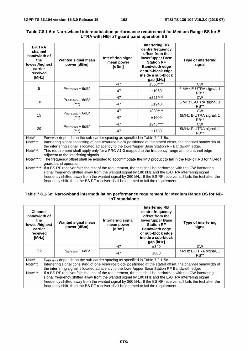
ETSI
ETSI TS 136 104 V15.3.0 (2018-07)1933GPP TS 36.104 version 15.3.0 Release 15
Table 7.8.1-6b: Narrowband intermodulation performance requirement for Medium Range BS for E-UTRA with NB-IoT guard band operation BS
E-UTRA channel
bandwidth of the
lowest/highest carrier
received [MHz]
Wanted signal mean power [dBm]
Interfering signal mean power
[dBm]
Interfering RB centre frequency offset from the
lower/upper Base Station RF
Bandwidth edge or sub-block edge inside a sub-block
gap [kHz]
Type of interfering signal
5 PREFSENS + 6dB* -47 ±360**** CW
-47 ±1060 5 MHz E-UTRA signal, 1 RB**
10 PREFSENS + 6dB* (***)
-47 ±325**** CW
-47 ±1240 5 MHz E-UTRA signal, 1 RB**
15 PREFSENS + 6dB* (***)
-47 ±380**** CW
-47 ±1600 5MHz E-UTRA signal, 1 RB**
20 PREFSENS + 6dB* (***)
-47 ±345**** CW
-47 ±1780 5MHz E-UTRA signal, 1 RB**
Note*: PREFSENS depends on the sub-carrier spacing as specified in Table 7.2.1-5c. Note**: Interfering signal consisting of one resource block positioned at the stated offset, the channel bandwidth of
the interfering signal is located adjacently to the lower/upper Base Station RF Bandwidth edge. Note***: This requirement shall apply only for a FRC A1-3 mapped to the frequency range at the channel edge
adjacent to the interfering signals. Note****: The frequency offset shall be adjusted to accommodate the IMD product to fall in the NB-IoT RB for NB-IoT
guard band operation. Note*****: If a BS RF receiver fails the test of the requirement, the test shall be performed with the CW interfering
signal frequency shifted away from the wanted signal by 180 kHz and the E-UTRA interfering signal frequency shifted away from the wanted signal by 360 kHz. If the BS RF receiver still fails the test after the frequency shift, then the BS RF receiver shall be deemed to fail the requirement.
Table 7.8.1-6c: Narrowband intermodulation performance requirement for Medium Range BS for NB-IoT standalone
Channel bandwidth of
the lowest/highest
carrier received
[MHz]
Wanted signal mean power [dBm]
Interfering signal mean power
[dBm]
Interfering RB centre frequency offset from the
lower/upper Base Station RF
Bandwidth edge or sub-block edge inside a sub-block
gap [kHz]
Type of interfering signal
0.2 PREFSENS + 6dB* -47 ±340 CW
-47 ±880 5MHz E-UTRA signal, 1 RB**
Note*: PREFSENS depends on the sub-carrier spacing as specified in Table 7.2.1-5c. Note**: Interfering signal consisting of one resource block positioned at the stated offset, the channel bandwidth of
the interfering signal is located adjacently to the lower/upper Base Station RF Bandwidth edge. Note***: If a BS RF receiver fails the test of the requirement, the test shall be performed with the CW interfering
signal frequency shifted away from the wanted signal by 180 kHz and the E-UTRA interfering signal frequency shifted away from the wanted signal by 360 kHz. If the BS RF receiver still fails the test after the frequency shift, then the BS RF receiver shall be deemed to fail the requirement.

ETSI
ETSI TS 136 104 V15.3.0 (2018-07)1943GPP TS 36.104 version 15.3.0 Release 15
8 Performance requirement
8.1 General Performance requirements for the BS are specified for the fixed reference channels defined in Annex A and the propagation conditions in Annex B. The requirements only apply to those FRCs that are supported by the base station.
Unless stated otherwise, performance requirements apply for a single carrier only. Performance requirements for a BS supporting carrier aggregation are defined in terms of single carrier requirements. For FDD operation the requirements in clause 8 shall be met with the transmitter(s) on.
NOTE: In normal operating conditions the BS in FDD operation is configured to transmit and receive at the same time. The transmitter may be off for some of the tests as specifed in 36.141 [4].
The SNR used in this clause is specified based on a single carrier and defined as:
SNR = S / N
Where:
S is the total signal energy in the subframe on a single antenna port.
N is the noise energy in a bandwidth corresponding to the transmission bandwidth over the duration of a subframe.
For enhanced performance requirements type A and type B, the SINR used in this clause is specified based on a single carrier and defined as:
´SINR S N=
Where:
S is the total signal energy of one intra-cell UE in the subframe on a single antenna port.
´N is the summation of the received energy of the strongest inter-cell interferers explicitly defined in a test procedure plus the white noise energy N, in a bandwidth corresponding to the transmission bandwidth over the duration of a subframe on a single antenna port. The respective energy of each inter-cell interferer relative to
´N is defined by its associated DIP value.
8.2 Performance requirements for PUSCH
8.2.1 Requirements in multipath fading propagation conditions
The performance requirement of PUSCH is determined by a minimum required throughput for a given SNR. The required throughput is expressed as a fraction of maximum throughput for the FRCs listed in Annex A. The performance requirements assume HARQ retransmissions. For 2Tx test the HARQ retransmissions for two codewords are independent. The requirements defined based on FRC in Annex A.17 apply to the BS supporting PUSCH with 256QAM. The requirements defined based on FRC in Annex A.18 apply to the BS supporting PUSCH transmission in UpPTS. The requirements defined based on FRC in Annex A.19 apply to the BS supporting both PUSCH transmission in UpPTS and PUSCH with 256QAM. For PUSCH transmission in UpPTS, the special subframe configuration is 10 as specified in 36.211 [10] Table 4.2-1, and during the test only special subframe is scheduled.
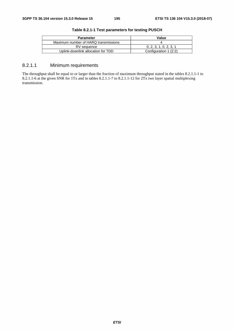
ETSI
ETSI TS 136 104 V15.3.0 (2018-07)1953GPP TS 36.104 version 15.3.0 Release 15
Table 8.2.1-1 Test parameters for testing PUSCH
Parameter Value Maximum number of HARQ transmissions 4
RV sequence 0, 2, 3, 1, 0, 2, 3, 1 Uplink-downlink allocation for TDD Configuration 1 (2:2)
8.2.1.1 Minimum requirements
The throughput shall be equal to or larger than the fraction of maximum throughput stated in the tables 8.2.1.1-1 to 8.2.1.1-6 at the given SNR for 1Tx and in tables 8.2.1.1-7 to 8.2.1.1-12 for 2Tx two layer spatial multiplexing transmission.

ETSI
ETSI TS 136 104 V15.3.0 (2018-07)1963GPP TS 36.104 version 15.3.0 Release 15
Table 8.2.1.1-1 Minimum requirements for PUSCH, 1.4 MHz Channel Bandwidth, 1Tx

ETSI
ETSI TS 136 104 V15.3.0 (2018-07)1973GPP TS 36.104 version 15.3.0 Release 15
Number of TX antennas
Number of RX antennas
Cyclic prefix Propagation conditions
and correlation
matrix (Annex B)
FRC (Annex A)
Fraction of maximum
throughput
SNR [dB]
1 2 Normal EPA 5Hz Low A3-2 30% -4.1 70% 0.1
A4-3 70% 10.6 A5-2 70% 17.7
A17-1 70% 21.4 A18-1 70% [7.4] A19-1 70% [18.1]
EVA 5Hz Low A3-1 30% -2.7 70% 1.8
A4-1 30% 4.4 70% 11.3
A5-1 70% 18.6 EVA 70Hz Low
A3-2 30% -3.9 70% 0.7
A4-3 30% 4.0 70% 11.9
ETU 70Hz* Low
A3-1 30% -2.4 70% 2.4
ETU 300Hz* Low
A3-1 30% -2.2 70% 2.9
Extended ETU 70Hz* Low
A4-2 30% 4.8 70% 13.5
4 Normal EPA 5Hz Low A3-2 30% -6.6 70% -3.1
A4-3 70% 7.1 A5-2 70% 14.4
A17-1 70% 18.2 A18-1 70% [4.1] A19-1 70% [14.7]
EVA 5Hz Low A3-1 30% -5.0 70% -1.3
A4-1 30% 1.3 70% 7.8
A5-1 70% 15.4 EVA 70Hz Low
A3-2 30% -6.3 70% -2.7
A4-3 30% 0.8 70% 8.3
ETU 70Hz* Low
A3-1 30% -4.8 70% -1.0
ETU 300Hz* Low
A3-1 30% -4.6 70% -0.6
ETU 600Hz** Low
A13-1 30% -0.9 70% 6.1
Extended ETU 70Hz* Low
A4-2 30% 1.6 70% 9.9
8 Normal EPA 5Hz Low A3-2 30% -9.4 70% -6.4
A4-3 70% 4.0 A5-2 70% 10.9
A17-1 70% 15.1 A18-1 70% [1.1] A19-1 70% [11.6]
EVA 5Hz Low A3-1 30% -7.2 70% -3.8
A4-1 30% -1.7 70% 4.6
A5-1 70% 11.7 EVA 70Hz Low
A3-2 30% -9.0 70% -5.8

ETSI
ETSI TS 136 104 V15.3.0 (2018-07)1983GPP TS 36.104 version 15.3.0 Release 15
A4-3 30% -2.5 70% 4.8
ETU 70Hz* Low
A3-1 30% -6.8 70% -3.6
ETU 300Hz* Low
A3-1 30% -6.7 70% -3.3
Extended ETU 70Hz* Low
A4-2 30% -1.1 70% 6.4
Note*: Not applicable for Local Area BS and Home BS. Note**: Not applicable for Local Area BS and Home BS, and only applicable for BS supporting ETU600.

ETSI
ETSI TS 136 104 V15.3.0 (2018-07)1993GPP TS 36.104 version 15.3.0 Release 15
Table 8.2.1.1-2 Minimum requirements for PUSCH, 3 MHz Channel Bandwidth, 1Tx

ETSI
ETSI TS 136 104 V15.3.0 (2018-07)2003GPP TS 36.104 version 15.3.0 Release 15
Number of TX antennas
Number of RX antennas
Cyclic prefix Propagation conditions
and correlation
matrix (Annex B)
FRC (Annex A)
Fraction of maximum
throughput
SNR [dB]
1 2 Normal EPA 5Hz Low A3-3 30% -4.1 70% 0.1
A4-4 70% 10.9 A5-3 70% 18.1
A17-2 70% 22.0 A18-2 70% [7.4] A19-2 70% [17.9]
EVA 5Hz Low A3-1 30% -2.8 70% 1.8
A4-1 30% 4.3 70% 11.5
A5-1 70% 18.8 EVA 70Hz Low
A3-3 30% -4.0 70% 0.6
A4-4 30% 4.7 70% 12.5
ETU 70Hz* Low
A3-1 30% -2.5 70% 2.4
ETU 300Hz* Low
A3-1 30% -2.2 70% 2.9
Extended ETU 70Hz* Low
A4-2 30% 4.7 70% 13.5
4 Normal EPA 5Hz Low A3-3 30% -6.8 70% -3.4
A4-4 70% 7.7 A5-3 70% 14.4
A17-2 70% 18.7 A18-2 70% [4.0] A19-2 70% [14.0]
EVA 5Hz Low A3-1 30% -5.0 70% -1.3
A4-1 30% 1.2 70% 7.8
A5-1 70% 15.4 EVA 70Hz Low
A3-3 30% -6.5 70% -2.9
A4-4 30% 1.6 70% 8.7
ETU 70Hz* Low
A3-1 30% -4.8 70% -0.9
ETU 300Hz* Low
A3-1 30% -4.6 70% -0.6
ETU 600Hz** Low
A13-2 30% -1.1 70% 5.8
Extended ETU 70Hz* Low
A4-2 30% 1.5 70% 9.9
8 Normal EPA 5Hz Low A3-3 30% -9.6 70% -6.6
A4-4 70% 4.1 A5-3 70% 11.1
A17-2 70% 15.6 A18-2 70% [1.3] A19-2 70% [11.0]
EVA 5Hz Low A3-1 30% -7.1 70% -4.0
A4-1 30% -1.6 70% 4.4
A5-1 70% 11.7 EVA 70Hz Low
A3-3 30% -9.3 70% -5.9
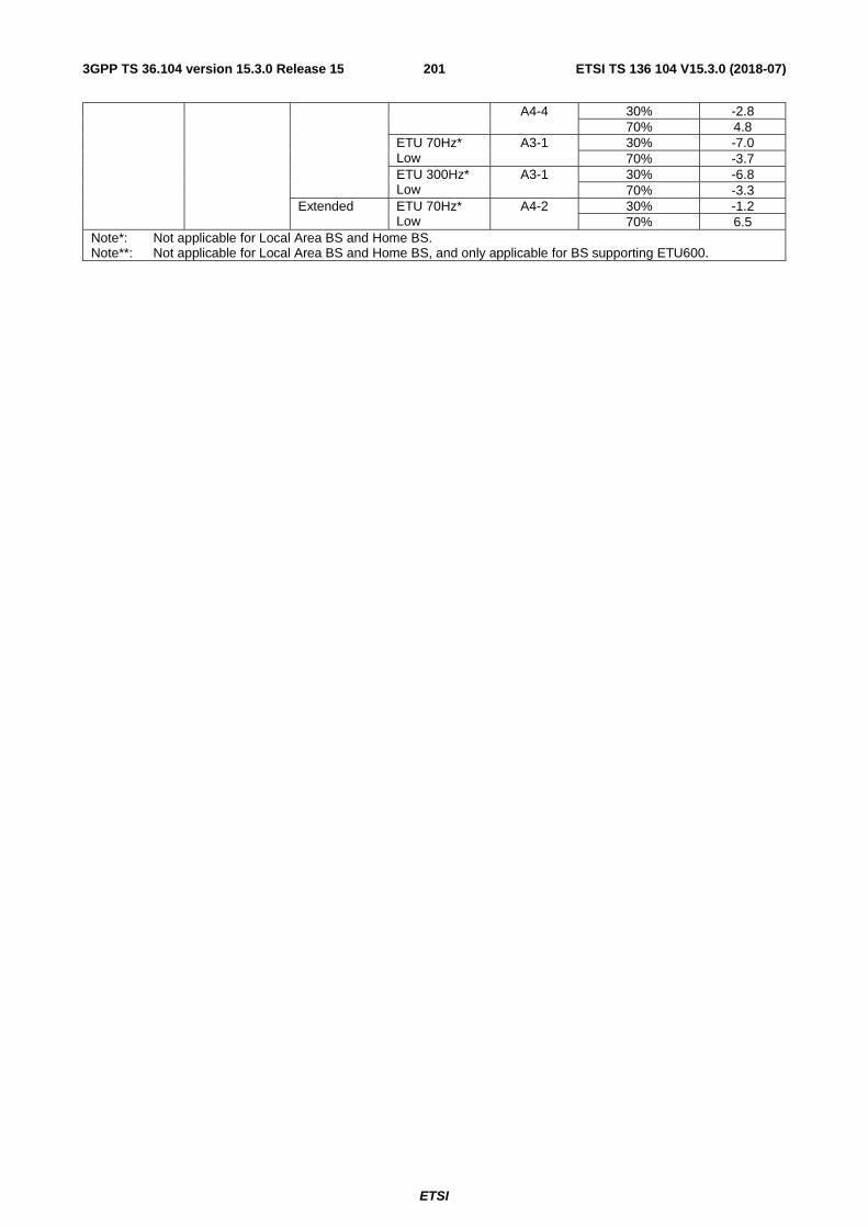
ETSI
ETSI TS 136 104 V15.3.0 (2018-07)2013GPP TS 36.104 version 15.3.0 Release 15
A4-4 30% -2.8 70% 4.8
ETU 70Hz* Low
A3-1 30% -7.0 70% -3.7
ETU 300Hz* Low
A3-1 30% -6.8 70% -3.3
Extended ETU 70Hz* Low
A4-2 30% -1.2 70% 6.5
Note*: Not applicable for Local Area BS and Home BS. Note**: Not applicable for Local Area BS and Home BS, and only applicable for BS supporting ETU600.
ETSI
ETSI TS 136 104 V15.3.0 (2018-07)2023GPP TS 36.104 version 15.3.0 Release 15
Table 8.2.1.1-3 Minimum requirements for PUSCH, 5 MHz Channel Bandwidth, 1Tx

ETSI
ETSI TS 136 104 V15.3.0 (2018-07)2033GPP TS 36.104 version 15.3.0 Release 15
Number of TX antennas
Number of RX antennas
Cyclic prefix Propagation conditions a
and correlation
matrix (Annex B)
FRC (Annex A)
Fraction of maximum
throughput
SNR [dB]
1 2 Normal EPA 5Hz Low A3-4 30% -4.7 70% -0.7
A4-5 70% 10.4 A5-4 70% 18.0
A17-3 70% 21.9 A18-3 70% [8.3] A19-3 70% [19.4]
EVA 5Hz Low A3-1 30% -2.7 70% 1.8
A4-1 30% 4.3 70% 11.5
A5-1 70% 18.6 EVA 70Hz Low
A3-4 30% -4.5 70% -0.1
A4-5 30% 4.3 70% 12.3
ETU 70Hz* Low
A3-1 30% -2.5 70% 2.4
ETU 300Hz* Low
A3-1 30% -2.2 70% 2.9
Extended ETU 70Hz* Low
A4-2 30% 4.8 70% 13.5
4 Normal EPA 5Hz Low A3-4 30% -7.1 70% -3.8
A4-5 70% 7.6 A5-4 70% 14.4
A17-3 70% 18.5 A18-3 70% [5.1] A19-3 70% [15.8]
EVA 5Hz Low A3-1 30% -5.1 70% -1.4
A4-1 30% 1.2 70% 7.9
A5-1 70% 15.5 EVA 70Hz Low
A3-4 30% -6.9 70% -3.3
A4-5 30% 1.2 70% 8.3
ETU 70Hz* Low
A3-1 30% -4.8 70% -0.9
ETU 300Hz* Low
A3-1 30% -4.6 70% -0.6
ETU 600Hz** Low
A13-3 30% -0.9 70% 6.1
Extended ETU 70Hz* Low
A4-2 30% 1.6 70% 9.9
8 Normal EPA 5Hz Low A3-4 30% -10.1 70% -7.2
A4-5 70% 4.0 A5-4 70% 11.3
A17-3 70% 15.3 A18-3 70% [2.0] A19-3 70% [12.5]
EVA 5Hz Low A3-1 30% -7.1 70% -3.9
A4-1 30% -1.9 70% 4.4
A5-1 70% 11.7 EVA 70Hz Low
A3-4 30% -9.9 70% -6.7

ETSI
ETSI TS 136 104 V15.3.0 (2018-07)2043GPP TS 36.104 version 15.3.0 Release 15
A4-5 30% -2.5 70% 4.6
ETU 70Hz* Low
A3-1 30% -6.9 70% -3.4
ETU 300Hz* Low
A3-1 30% -6.9 70% -3.3
Extended ETU 70Hz* Low
A4-2 30% -1.2 70% 6.4
Note*: Not applicable for Local Area BS and Home BS. Note**: Not applicable for Local Area BS and Home BS, and only applicable for BS supporting ETU600.

ETSI
ETSI TS 136 104 V15.3.0 (2018-07)2053GPP TS 36.104 version 15.3.0 Release 15
Table 8.2.1.1-4 Minimum requirements for PUSCH, 10 MHz Channel Bandwidth, 1Tx

ETSI
ETSI TS 136 104 V15.3.0 (2018-07)2063GPP TS 36.104 version 15.3.0 Release 15
Number of TX antennas
Number of RX antennas
Cyclic prefix Propagation conditions
and correlation
matrix (Annex B)
FRC (Annex A)
Fraction of maximum
throughput
SNR [dB]
1 2 Normal EPA 5Hz Low A3-5 30% -4.2 70% -0.4
A4-6 70% 10.8 A5-5 70% 18.3
A17-4 70% 22.6 A18-4 70% [8.5] A19-4 70% [19.5]
EVA 5Hz Low A3-1 30% -2.7 70% 1.9
A4-1 30% 4.3 70% 11.4
A5-1 70% 18.8 EVA 70Hz Low
A3-5 30% -4.1 70% 0.1
A4-6 30% 4.5 70% 12.6
ETU 70Hz* Low
A3-1 30% -2.5 70% 2.4
ETU 300Hz* Low
A3-1 30% -2.2 70% 2.9
Extended ETU 70Hz* Low
A4-2 30% 4.8 70% 13.6
4 Normal EPA 5Hz Low A3-5 30% -6.8 70% -3.5
A4-6 70% 7.5 A5-5 70% 14.7
A17-4 70% 19.2 A18-4 70% [5.3] A19-4 70% [15.8]
EVA 5Hz Low A3-1 30% -5.0 70% -1.2
A4-1 30% 1.2 70% 7.9
A5-1 70% 15.5 EVA 70Hz Low
A3-5 30% -6.7 70% -2.9
A4-6 30% 0.7 70% 8.0
ETU 70Hz* Low
A3-1 30% -4.8 70% -0.9
ETU 300Hz* Low
A3-1 30% -4.6 70% -0.6
ETU 600Hz** Low
A13-4 30% -1.0 70% 6.2
Extended ETU 70Hz* Low
A4-2 30% 1.7 70% 10.3
8 Normal EPA 5Hz Low A3-5 30% -9.8 70% -6.7
A4-6 70% 4.2 A5-5 70% 11.5
A17-4 70% 15.9 A18-4 70% [2.1] A19-4 70% [12.5]
EVA 5Hz Low A3-1 30% -6.9 70% -3.8
A4-1 30% -1.7 70% 4.5
A5-1 70% 11.9 EVA 70Hz Low
A3-5 30% -9.7 70% -6.2

ETSI
ETSI TS 136 104 V15.3.0 (2018-07)2073GPP TS 36.104 version 15.3.0 Release 15
A4-6 30% -2.6 70% 4.7
ETU 70Hz* Low
A3-1 30% -6.8 70% -3.6
ETU 300Hz* Low
A3-1 30% -6.8 70% -3.3
Extended ETU 70Hz* Low
A4-2 30% -1.1 70% 6.5
Note*: Not applicable for Local Area BS and Home BS. Note**: Not applicable for Local Area BS and Home BS, and only applicable for BS supporting ETU600.

ETSI
ETSI TS 136 104 V15.3.0 (2018-07)2083GPP TS 36.104 version 15.3.0 Release 15
Table 8.2.1.1-5 Minimum requirements for PUSCH, 15 MHz Channel Bandwidth, 1Tx
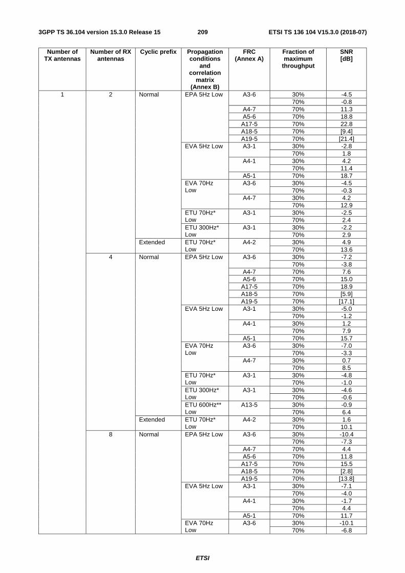
ETSI
ETSI TS 136 104 V15.3.0 (2018-07)2093GPP TS 36.104 version 15.3.0 Release 15
Number of TX antennas
Number of RX antennas
Cyclic prefix Propagation conditions
and correlation
matrix (Annex B)
FRC (Annex A)
Fraction of maximum
throughput
SNR [dB]
1 2 Normal EPA 5Hz Low A3-6 30% -4.5 70% -0.8
A4-7 70% 11.3 A5-6 70% 18.8
A17-5 70% 22.8 A18-5 70% [9.4] A19-5 70% [21.4]
EVA 5Hz Low A3-1 30% -2.8 70% 1.8
A4-1 30% 4.2 70% 11.4
A5-1 70% 18.7 EVA 70Hz Low
A3-6 30% -4.5 70% -0.3
A4-7 30% 4.2 70% 12.9
ETU 70Hz* Low
A3-1 30% -2.5 70% 2.4
ETU 300Hz* Low
A3-1 30% -2.2 70% 2.9
Extended ETU 70Hz* Low
A4-2 30% 4.9 70% 13.6
4 Normal EPA 5Hz Low A3-6 30% -7.2 70% -3.8
A4-7 70% 7.6 A5-6 70% 15.0
A17-5 70% 18.9 A18-5 70% [5.9] A19-5 70% [17.1]
EVA 5Hz Low A3-1 30% -5.0 70% -1.2
A4-1 30% 1.2 70% 7.9
A5-1 70% 15.7 EVA 70Hz Low
A3-6 30% -7.0 70% -3.3
A4-7 30% 0.7 70% 8.5
ETU 70Hz* Low
A3-1 30% -4.8 70% -1.0
ETU 300Hz* Low
A3-1 30% -4.6 70% -0.6
ETU 600Hz** Low
A13-5 30% -0.9 70% 6.4
Extended ETU 70Hz* Low
A4-2 30% 1.6 70% 10.1
8 Normal EPA 5Hz Low A3-6 30% -10.4 70% -7.3
A4-7 70% 4.4 A5-6 70% 11.8
A17-5 70% 15.5 A18-5 70% [2.8] A19-5 70% [13.8]
EVA 5Hz Low A3-1 30% -7.1 70% -4.0
A4-1 30% -1.7 70% 4.4
A5-1 70% 11.7 EVA 70Hz Low
A3-6 30% -10.1 70% -6.8

ETSI
ETSI TS 136 104 V15.3.0 (2018-07)2103GPP TS 36.104 version 15.3.0 Release 15
A4-7 30% -2.5 70% 5.0
ETU 70Hz* Low
A3-1 30% -7.0 70% -3.6
ETU 300Hz* Low
A3-1 30% -6.9 70% -3.3
Extended ETU 70Hz* Low
A4-2 30% -1.1 70% 6.7
Note*: Not applicable for Local Area BS and Home BS. Note**: Not applicable for Local Area BS and Home BS, and only applicable for BS supporting ETU600.

ETSI
ETSI TS 136 104 V15.3.0 (2018-07)2113GPP TS 36.104 version 15.3.0 Release 15
Table 8.2.1.1-6 Minimum requirements for PUSCH, 20 MHz Channel Bandwidth, 1Tx

ETSI
ETSI TS 136 104 V15.3.0 (2018-07)2123GPP TS 36.104 version 15.3.0 Release 15
Number of TX antennas
Number of RX antennas
Cyclic prefix Propagation conditions
and correlation
matrix (Annex B)
FRC (Annex A)
Fraction of maximum
throughput
SNR [dB]
1 2 Normal EPA 5Hz Low A3-7 30% -4.2 70% -0.4
A4-8 70% 11.5 A5-7 70% 19.7
A17-6 70% 23.7 A18-6 70% [9.3] A19-6 70% [21.0]
EVA 5Hz Low A3-1 30% -2.7 70% 1.8
A4-1 30% 4.3 70% 11.5
A5-1 70% 18.7 EVA 70Hz Low
A3-7 30% -4.1 70% 0.2
A4-8 30% 4.2 70% 13.0
ETU 70Hz* Low
A3-1 30% -2.4 70% 2.4
ETU 300Hz* Low
A3-1 30% -2.1 70% 2.9
Extended ETU 70Hz* Low
A4-2 30% 4.7 70% 13.6
4 Normal EPA 5Hz Low A3-7 30% -6.8 70% -3.5
A4-8 70% 7.5 A5-7 70% 15.9
A17-6 70% 19.8 A18-6 70% [5.7] A19-6 70% [16.6]
EVA 5Hz Low A3-1 30% -5.1 70% -1.3
A4-1 30% 1.2 70% 7.9
A5-1 70% 15.6 EVA 70Hz Low
A3-7 30% -6.7 70% -2.9
A4-8 30% 0.7 70% 8.6
ETU 70Hz* Low
A3-1 30% -4.4 70% -0.9
ETU 300Hz* Low
A3-1 30% -4.6 70% -0.7
ETU 600Hz** Low
A13-6 30% -0.9 70% 6.4
Extended ETU 70Hz* Low
A4-2 30% 1.6 70% 10.0
8 Normal EPA 5Hz Low A3-7 30% -9.7 70% -6.7
A4-8 70% 4.3 A5-7 70% 12.5
A17-6 70% 16.3 A18-6 70% [2.6] A19-6 70% [13.2]
EVA 5Hz Low A3-1 30% -7.0 70% -3.9
A4-1 30% -1.7 70% 4.6
A5-1 70% 12.0 EVA 70Hz Low
A3-7 30% -9.7 70% -6.1
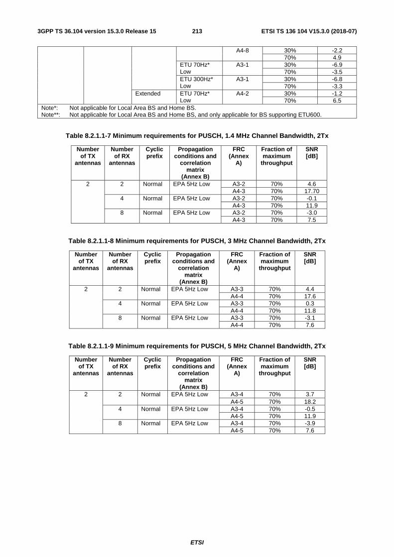
ETSI
ETSI TS 136 104 V15.3.0 (2018-07)2133GPP TS 36.104 version 15.3.0 Release 15
A4-8 30% -2.2 70% 4.9
ETU 70Hz* Low
A3-1 30% -6.9 70% -3.5
ETU 300Hz* Low
A3-1 30% -6.8 70% -3.3
Extended ETU 70Hz* Low
A4-2 30% -1.2 70% 6.5
Note*: Not applicable for Local Area BS and Home BS. Note**: Not applicable for Local Area BS and Home BS, and only applicable for BS supporting ETU600.
Table 8.2.1.1-7 Minimum requirements for PUSCH, 1.4 MHz Channel Bandwidth, 2Tx
Number of TX
antennas
Number of RX
antennas
Cyclic prefix
Propagation conditions and
correlation matrix
(Annex B)
FRC (Annex
A)
Fraction of maximum
throughput
SNR [dB]
2 2 Normal EPA 5Hz Low A3-2 70% 4.6 A4-3 70% 17.70
4 Normal EPA 5Hz Low A3-2 70% -0.1 A4-3 70% 11.9
8 Normal EPA 5Hz Low A3-2 70% -3.0 A4-3 70% 7.5
Table 8.2.1.1-8 Minimum requirements for PUSCH, 3 MHz Channel Bandwidth, 2Tx
Number of TX
antennas
Number of RX
antennas
Cyclic prefix
Propagation conditions and
correlation matrix
(Annex B)
FRC (Annex
A)
Fraction of maximum
throughput
SNR [dB]
2 2 Normal EPA 5Hz Low A3-3 70% 4.4 A4-4 70% 17.6
4 Normal EPA 5Hz Low A3-3 70% 0.3 A4-4 70% 11.8
8 Normal EPA 5Hz Low A3-3 70% -3.1 A4-4 70% 7.6
Table 8.2.1.1-9 Minimum requirements for PUSCH, 5 MHz Channel Bandwidth, 2Tx
Number of TX
antennas
Number of RX
antennas
Cyclic prefix
Propagation conditions and
correlation matrix
(Annex B)
FRC (Annex
A)
Fraction of maximum
throughput
SNR [dB]
2 2 Normal EPA 5Hz Low A3-4 70% 3.7 A4-5 70% 18.2
4 Normal EPA 5Hz Low A3-4 70% -0.5 A4-5 70% 11.9
8 Normal EPA 5Hz Low A3-4 70% -3.9 A4-5 70% 7.6
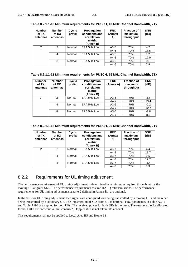
ETSI
ETSI TS 136 104 V15.3.0 (2018-07)2143GPP TS 36.104 version 15.3.0 Release 15
Table 8.2.1.1-10 Minimum requirements for PUSCH, 10 MHz Channel Bandwidth, 2Tx
Number of TX
antennas
Number of RX
antennas
Cyclic prefix
Propagation conditions and
correlation matrix
(Annex B)
FRC (Annex
A)
Fraction of maximum
throughput
SNR [dB]
2 2 Normal EPA 5Hz Low A3-5 70% 4.2 A4-6 70% 18.6
4 Normal EPA 5Hz Low A3-5 70% 0.2 A4-6 70% 12.0
8 Normal EPA 5Hz Low A3-5 70% -3.3 A4-6 70% 7.9
Table 8.2.1.1-11 Minimum requirements for PUSCH, 15 MHz Channel Bandwidth, 2Tx
Number of TX
antennas
Number of RX
antennas
Cyclic prefix
Propagation conditions and
correlation matrix
(Annex B)
FRC (Annex A)
Fraction of maximum
throughput
SNR [dB]
2 2 Normal EPA 5Hz Low A3-6 70% 3.7 A4-7 70% 19.4
4 Normal EPA 5Hz Low A3-6 70% -0.2 A4-7 70% 12.7
8 Normal EPA 5Hz Low A3-6 70% -3.8 A4-7 70% 8.3
Table 8.2.1.1-12 Minimum requirements for PUSCH, 20 MHz Channel Bandwidth, 2Tx
Number of TX
antennas
Number of RX
antennas
Cyclic prefix
Propagation conditions and
correlation matrix
(Annex B)
FRC (Annex
A)
Fraction of maximum
throughput
SNR [dB]
2 2 Normal EPA 5Hz Low A3-7 70% 4.4 A4-8 70% 19.7
4 Normal EPA 5Hz Low A3-7 70% 0.5 A4-8 70% 12.7
8 Normal EPA 5Hz Low A3-7 70% -3.4 A4-8 70% 8.3
8.2.2 Requirements for UL timing adjustment
The performance requirement of UL timing adjustment is determined by a minimum required throughput for the moving UE at given SNR. The performance requirements assume HARQ retransmissions. The performance requirements for UL timing adjustment scenario 2 defined in Annex B.4 are optional.
In the tests for UL timing adjustment, two signals are configured, one being transmitted by a moving UE and the other being transmitted by a stationary UE. The transmission of SRS from UE is optional. FRC parameters in Table A.7-1 and Table A.8-1 are applied for both UEs. The received power for both UEs is the same. The resource blocks allocated for both UEs are consecutive. In Scenario 2, Doppler shift is not taken into account.
This requirement shall not be applied to Local Area BS and Home BS.

ETSI
ETSI TS 136 104 V15.3.0 (2018-07)2153GPP TS 36.104 version 15.3.0 Release 15
Table 8.2.2-1 Test parameters for testing UL timing adjustment
Parameter Value Maximum number of HARQ transmissions 4 RV sequence 0, 2, 3, 1, 0, 2, 3, 1 Uplink-downlink allocation for TDD Configuration 1 (2:2) Subframes in which PUSCH is transmitted For FDD: subframe #0, #2, #4, #6,
and #8 in radio frames For TDD: subframe #2, #3, #7 and #8 in radio frames
Subframes in which sounding RS is transmitted (Note 1)
For FDD: subframe #1 in radio frames For TDD: UpPTS in subframe #1 in radio frames
Note 1. The transmission of SRS is optional.
8.2.2.1 Minimum requirements
The throughput shall be ≥ 70% of the maximum throughput of the reference measurement channel as specified in Annex A for the moving UE at the SNR given in table 8.2.2.1-1.
Table 8.2.2.1-1 Minimum requirements for UL timing adjustment
Number of TX antennas
Number of RX antennas Cyclic prefix
Channel Bandwidth
[MHz]
Moving propagation
conditions and correlation
matrix (Annex B)
FRC (Annex A)
SNR [dB]
1 2 Normal
1.4 Scenario 1 Low A7-1 13.1 Scenario 2 Low A8-1 -1.9
3 Scenario 1 Low A7-2 13.4 Scenario 2 Low A8-2 -1.5
5 Scenario 1 Low A7-3 13.2 Scenario 2 Low A8-3 -1.6
10 Scenario 1 Low A7-4 13.8 Scenario 2 Low A8-4 -1.8
15 Scenario 1 Low A7-5 14.0 Scenario 2 Low A8-5 -1.8
20 Scenario 1 Low A7-6 13.9 Scenario 2 Low A8-6 -1.8
8.2.3 Requirements for high speed train
The performance requirement of PUSCH for high speed train is determined by a minimum required throughput for a given SNR. The required throughput is expressed as a fraction of maximum throughput for the FRCs listed in Annex A. The performance requirements assume HARQ retransmissions. The performance requirements for high speed train are optional.
This requirement shall not be applied to Local Area BS and Home BS.

ETSI
ETSI TS 136 104 V15.3.0 (2018-07)2163GPP TS 36.104 version 15.3.0 Release 15
Table 8.2.3-1 Test parameters for high speed train
Parameter Value Maximum number of HARQ transmissions 4 RV sequence 0, 2, 3, 1, 0, 2, 3, 1 Uplink-downlink allocation for TDD Configuration 1 (2:2) Subframes in which PUSCH is transmitted
For FDD: subframe #0 and #8 in radio frames for which SFN mod 4 = 0 subframe #6 in radio frames for which SFN mod 4 = 1 subframe #4 in radio frames for which SFN mod 4 = 2 subframe #2 in radio frames for which SFN mod 4 = 3 For TDD: subframe #2 in each radio frame
Subframes in which PUCCH is transmitted (Note 1, Note 2)
For FDD: subframe #5 in radio frames For TDD: subframe #3 in each radio frame
Note 1: The configuration of PUCCH (format 2) is optional. Note 2: The SNR values per antenna shall be set to -4.5 dB and -1.5 dB for Scenario 1 and 3, respectively.
8.2.3.1 Minimum requirements
The throughput shall be equal to or larger than the fraction of maximum throughput stated in table 8.2.3.1-1 at the given SNR.
Table 8.2.3.1-1 Minimum requirements of PUSCH for high speed train
Channel Bandwidth
[MHz]
Cyclic prefix
FRC (Annex A)
Number of TX
antennas
Number of RX
antennas
Propagation conditions and
correlation matrix (Annex B)
Fraction of maximum
throughput
SNR [dB]
1.4 Normal A3-2 1 1 HST Scenario 3 30% -1.5 70% 1.9
2 HST Scenario 1 Low 30% -3.9 70% -0.6
3 Normal A3-3 1 HST Scenario 3 30% -2.1 70% 1.6
2 HST Scenario 1 Low 30% -4.5 70% -1.0
5 Normal A3-4 1 HST Scenario 3 30% -2.6 70% 1.3
2 HST Scenario 1 Low 30% -5.1 70% -1.4
10 Normal A3-5 1 HST Scenario 3 30% -2.7 70% 1.2
2 HST Scenario 1 Low 30% -5.4 70% -1.5
15 Normal A3-6 1 HST Scenario 3 30% -2.7 70% 1.2
2 HST Scenario 1 Low 30% -5.2 70% -1.4
20 Normal A3-7 1 HST Scenario 3 30% -2.7 70% 1.2
2 HST Scenario 1 Low 30% -5.3 70% -1.4
8.2.4 Requirements for HARQ-ACK multiplexed on PUSCH
Two performance requirements are defined for HARQ-ACK multiplexed on PUSCH: ACK false detection and ACK missed detection requirements.

ETSI
ETSI TS 136 104 V15.3.0 (2018-07)2173GPP TS 36.104 version 15.3.0 Release 15
The ACK false detection probability for PUSCH is the probability that ACK is detected when data only is sent on symbols where HARQ-ACK information can be allocated (i.e. by puncturing data).
The ACK missed detection probability for HARQ-ACK multiplexed on PUSCH is the conditional probability of not detecting an ACK when it was sent on PUSCH resources.
In the tests for ACK missed detection on PUSCH, data is punctured by the control information (i.e. ACK/NACK) in both slots within subframe on symbols as specified in 36.212.
In both tests none of CQI, RI nor SRS is transmitted. Tests are to be performed for one bit HARQ-ACK information (O = 1).
8.2.4.1 Minimum requirement
The ACK false detection probability as well as the ACK missed detection probability for HARQ-ACK multiplexed on PUSCH shall not exceed 1% at PUSCH power settings presented in table 8.2.4.1-1.
Table 8.2.4.1-1 Minimum requirements for HARQ-ACK multiplexed on PUSCH
Number of TX
antennas
Number of RX
antennas
Cyclic Prefix
Propagation conditions
and correlation matrix (Annex B)
Channel Bandwidth
[MHz]
FRC (Annex A)
SNR [dB]
1 2
Normal EVA 5* Low 1.4 A.3-1 8 6.8 A.4-3 5 13.6
3 A.3-1 8 6.8 A.4-4 5 13.1
5 A.3-1 8 6.9 A.4-5 5 12.4
10 A.3-1 8 6.8 A.4-6 5 12.4
15 A.3-1 8 6.8 A.4-7 5 12.0
20 A.3-1 8 6.8 A.4-8 5 11.9
ETU70** Low 1.4 A.3-1 8 6.6 A.4-3 5 13.8
3 A.3-1 8 6.6 A.4-4 5 12.9
5 A.3-1 8 6.5 A.4-5 5 12.5
10 A.3-1 8 6.6 A.4-6 5 12.3
15 A.3-1 8 6.7 A.4-7 5 12.1
20 A.3-1 8 6.5 A.4-8 5 12
Note*: Not applicable for Wide Area BS and Medium Range BS. Note**: Not applicable for Local Area BS and Home BS.
8.2.5 Requirements for PUSCH with TTI bundling and enhanced HARQ pattern
The performance requirement of PUSCH configured with TTI bundling and enhanced HARQ pattern, as specified in 36.213 [11] clause 8 and 8.0, is determined by residual block error probability (BLER) after HARQ retransmission. The performance is measured by the required SNR at residual BLER of 2% for the FRCs listed in Annex A.11. The residual BLER is defined as follows:
residual
ABLER
B=
where:
- A is the number of incorrectly decoded transport blocks after HARQ retransmission.
ACKHARQoffsetI −
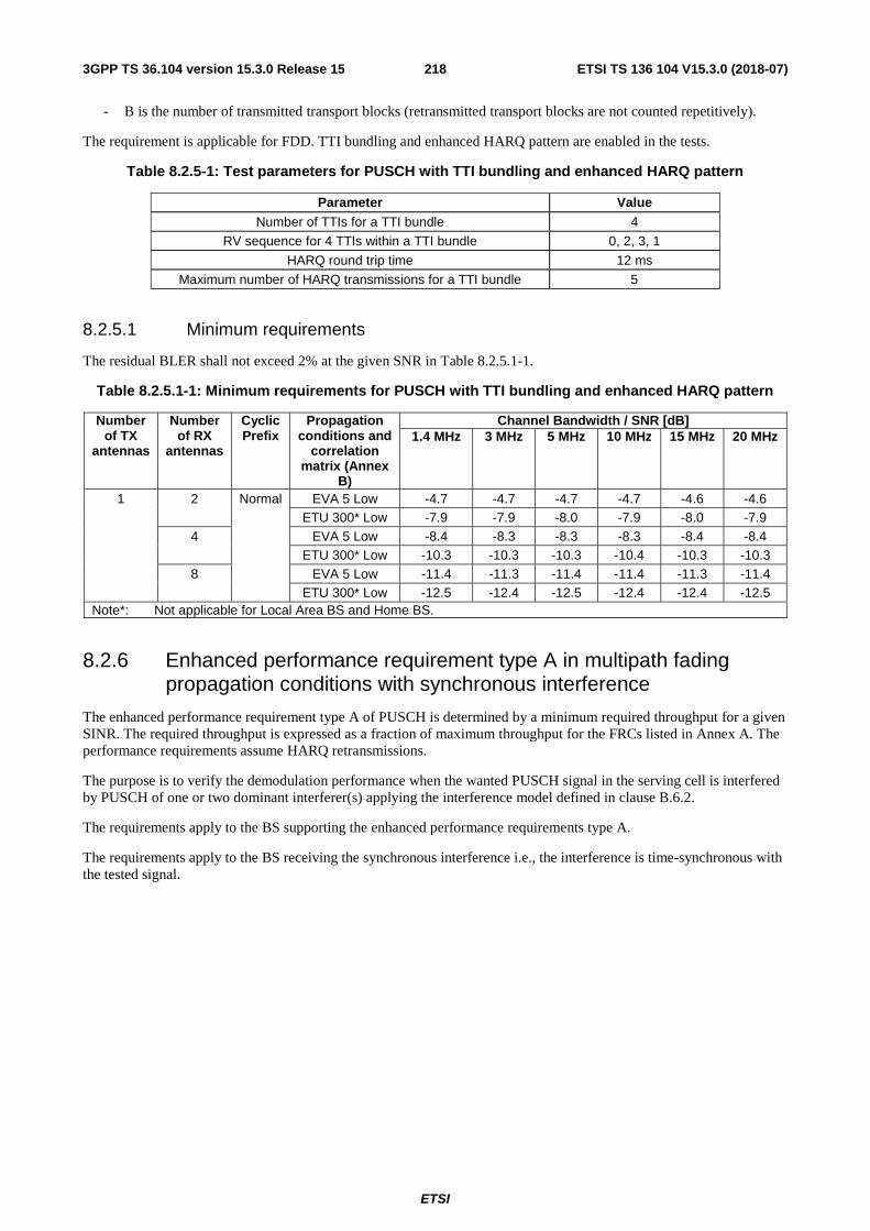
ETSI
ETSI TS 136 104 V15.3.0 (2018-07)2183GPP TS 36.104 version 15.3.0 Release 15
- B is the number of transmitted transport blocks (retransmitted transport blocks are not counted repetitively).
The requirement is applicable for FDD. TTI bundling and enhanced HARQ pattern are enabled in the tests.
Table 8.2.5-1: Test parameters for PUSCH with TTI bundling and enhanced HARQ pattern
Parameter Value Number of TTIs for a TTI bundle 4
RV sequence for 4 TTIs within a TTI bundle 0, 2, 3, 1
HARQ round trip time 12 ms
Maximum number of HARQ transmissions for a TTI bundle 5
8.2.5.1 Minimum requirements
The residual BLER shall not exceed 2% at the given SNR in Table 8.2.5.1-1.
Table 8.2.5.1-1: Minimum requirements for PUSCH with TTI bundling and enhanced HARQ pattern
Number of TX
antennas
Number of RX
antennas
Cyclic Prefix
Propagation conditions and
correlation matrix (Annex
B)
Channel Bandwidth / SNR [dB] 1.4 MHz 3 MHz 5 MHz 10 MHz 15 MHz 20 MHz
1 2 Normal EVA 5 Low -4.7 -4.7 -4.7 -4.7 -4.6 -4.6 ETU 300* Low -7.9 -7.9 -8.0 -7.9 -8.0 -7.9
4 EVA 5 Low -8.4 -8.3 -8.3 -8.3 -8.4 -8.4 ETU 300* Low -10.3 -10.3 -10.3 -10.4 -10.3 -10.3
8 EVA 5 Low -11.4 -11.3 -11.4 -11.4 -11.3 -11.4 ETU 300* Low -12.5 -12.4 -12.5 -12.4 -12.4 -12.5
Note*: Not applicable for Local Area BS and Home BS.
8.2.6 Enhanced performance requirement type A in multipath fading propagation conditions with synchronous interference
The enhanced performance requirement type A of PUSCH is determined by a minimum required throughput for a given SINR. The required throughput is expressed as a fraction of maximum throughput for the FRCs listed in Annex A. The performance requirements assume HARQ retransmissions.
The purpose is to verify the demodulation performance when the wanted PUSCH signal in the serving cell is interfered by PUSCH of one or two dominant interferer(s) applying the interference model defined in clause B.6.2.
The requirements apply to the BS supporting the enhanced performance requirements type A.
The requirements apply to the BS receiving the synchronous interference i.e., the interference is time-synchronous with the tested signal.

ETSI
ETSI TS 136 104 V15.3.0 (2018-07)2193GPP TS 36.104 version 15.3.0 Release 15
Table 8.2.6-1: Test parameters for enhanced performance requirement type A
Parameter Unit Tested signal Interferer 1 (Note 1)
Interferer 2 (Note 1)
Maximum number of HARQ transmissions 4 N/A N/A
RV sequence 0, 2, 3, 1, 0, 2, 3, 1 N/A N/A
DIP (Note 2) Set 1 dB N/A -1.11 -10.91
Set 2 dB N/A -0.43 -13.78
Cell Id 0 1 2
Interference model N/A As specified in clause B.6.2
As specified in clause B.6.2
Cyclic Prefix Normal Uplink-downlink allocation for TDD Configuration 1 (2:2)
Demodulation reference signal for PUSCH ssΔ =0, (1)
DMRSn =0, (2)DMRS,0n =0
Group hopping and sequence hopping are disabled. Note 1: One explicit interferer, i.e., interferer 1, is modelled for tests with 2 RX antennas. Two explicit
interferers are modelled for tests with 4 or 8 RX antennas. Note 2: The respective received energy of each interferer relative to ´N is defined by its associated DIP
value as specified in clause B.6.1. DIP set 1 and set 2 are derived respectively in homogeneous and heterogeneous network scenarios.
Note 3: All cells are time-synchronous.
8.2.6.1 Minimum requirements
The throughput shall be equal to or larger than the fraction of maximum throughput stated in the tables 8.2.6.1-1 to 8.2.6.1-6 at the given SINR.
Table 8.2.6.1-1: Enhanced performance requirement type A for PUSCH, 1.4 MHz Channel Bandwidth
Number of TX
antennas (Note 1)
Number of RX
antennas (Note 1)
Propagation conditions and correlation matrix (Annex B) (Note 2)
DIP set
FRC (Annex
A)
Fraction of maximum
throughput
SINR [dB]
(Note 3) Tested signal
Interferer 1 Interferer 2
1 2 EPA 5 Low ETU 5 Low N/A Set 2 A12-1 70% -4.8 EVA 70 Low ETU 70 Low N/A Set 1* A12-1 70% -2.0
4 EPA 5 Low ETU 5 Low ETU 5 Low Set 2 A13-1 70% -4.1 EVA 70 Low ETU 70 Low ETU 70 Low Set 1* A13-1 70% -0.1
8 EPA 5 Low ETU 5 Low ETU 5 Low Set 2 A4-3 70% -4.7 EVA 70 Low ETU 70 Low ETU 70 Low Set 1* A4-3 70% 0.0
Note*: Not applicable for Local Area BS and Home BS. Note 1: Antenna configuration applies for each of the tested signal, interferer 1 and interferer 2. Note 2: The propagation conditions for the tested signal, interferer 1 and interferer 2 are statistically independent.
Note 3: SINR corresponds to ´S N of the tested signal as defined in clause 8.1.
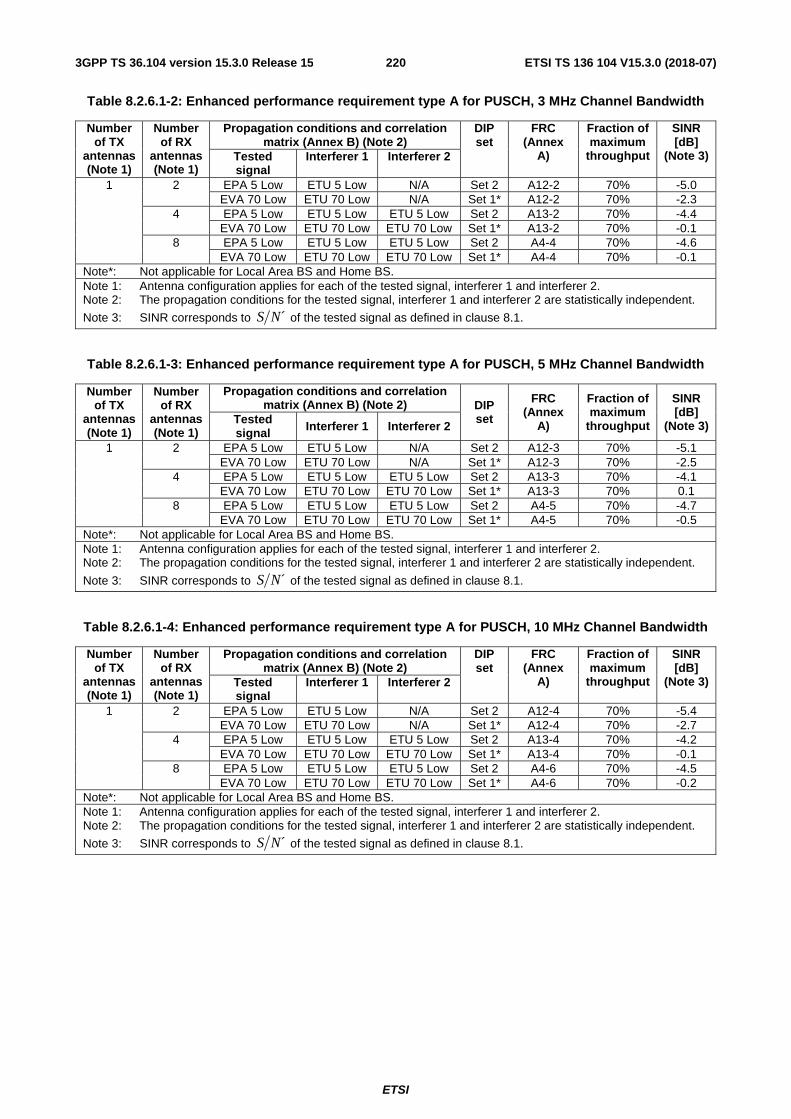
ETSI
ETSI TS 136 104 V15.3.0 (2018-07)2203GPP TS 36.104 version 15.3.0 Release 15
Table 8.2.6.1-2: Enhanced performance requirement type A for PUSCH, 3 MHz Channel Bandwidth
Number of TX
antennas (Note 1)
Number of RX
antennas (Note 1)
Propagation conditions and correlation matrix (Annex B) (Note 2)
DIP set
FRC (Annex
A)
Fraction of maximum
throughput
SINR [dB]
(Note 3) Tested signal
Interferer 1 Interferer 2
1 2 EPA 5 Low ETU 5 Low N/A Set 2 A12-2 70% -5.0 EVA 70 Low ETU 70 Low N/A Set 1* A12-2 70% -2.3
4 EPA 5 Low ETU 5 Low ETU 5 Low Set 2 A13-2 70% -4.4 EVA 70 Low ETU 70 Low ETU 70 Low Set 1* A13-2 70% -0.1
8 EPA 5 Low ETU 5 Low ETU 5 Low Set 2 A4-4 70% -4.6 EVA 70 Low ETU 70 Low ETU 70 Low Set 1* A4-4 70% -0.1
Note*: Not applicable for Local Area BS and Home BS. Note 1: Antenna configuration applies for each of the tested signal, interferer 1 and interferer 2. Note 2: The propagation conditions for the tested signal, interferer 1 and interferer 2 are statistically independent.
Note 3: SINR corresponds to ´S N of the tested signal as defined in clause 8.1.
Table 8.2.6.1-3: Enhanced performance requirement type A for PUSCH, 5 MHz Channel Bandwidth
Number of TX
antennas (Note 1)
Number of RX
antennas (Note 1)
Propagation conditions and correlation matrix (Annex B) (Note 2) DIP
set
FRC (Annex
A)
Fraction of maximum
throughput
SINR [dB]
(Note 3) Tested signal Interferer 1 Interferer 2
1 2 EPA 5 Low ETU 5 Low N/A Set 2 A12-3 70% -5.1 EVA 70 Low ETU 70 Low N/A Set 1* A12-3 70% -2.5
4 EPA 5 Low ETU 5 Low ETU 5 Low Set 2 A13-3 70% -4.1 EVA 70 Low ETU 70 Low ETU 70 Low Set 1* A13-3 70% 0.1
8 EPA 5 Low ETU 5 Low ETU 5 Low Set 2 A4-5 70% -4.7 EVA 70 Low ETU 70 Low ETU 70 Low Set 1* A4-5 70% -0.5
Note*: Not applicable for Local Area BS and Home BS. Note 1: Antenna configuration applies for each of the tested signal, interferer 1 and interferer 2. Note 2: The propagation conditions for the tested signal, interferer 1 and interferer 2 are statistically independent.
Note 3: SINR corresponds to ´S N of the tested signal as defined in clause 8.1.
Table 8.2.6.1-4: Enhanced performance requirement type A for PUSCH, 10 MHz Channel Bandwidth
Number of TX
antennas (Note 1)
Number of RX
antennas (Note 1)
Propagation conditions and correlation matrix (Annex B) (Note 2)
DIP set
FRC (Annex
A)
Fraction of maximum
throughput
SINR [dB]
(Note 3) Tested signal
Interferer 1 Interferer 2
1 2 EPA 5 Low ETU 5 Low N/A Set 2 A12-4 70% -5.4 EVA 70 Low ETU 70 Low N/A Set 1* A12-4 70% -2.7
4 EPA 5 Low ETU 5 Low ETU 5 Low Set 2 A13-4 70% -4.2 EVA 70 Low ETU 70 Low ETU 70 Low Set 1* A13-4 70% -0.1
8 EPA 5 Low ETU 5 Low ETU 5 Low Set 2 A4-6 70% -4.5 EVA 70 Low ETU 70 Low ETU 70 Low Set 1* A4-6 70% -0.2
Note*: Not applicable for Local Area BS and Home BS. Note 1: Antenna configuration applies for each of the tested signal, interferer 1 and interferer 2. Note 2: The propagation conditions for the tested signal, interferer 1 and interferer 2 are statistically independent.
Note 3: SINR corresponds to ´S N of the tested signal as defined in clause 8.1.
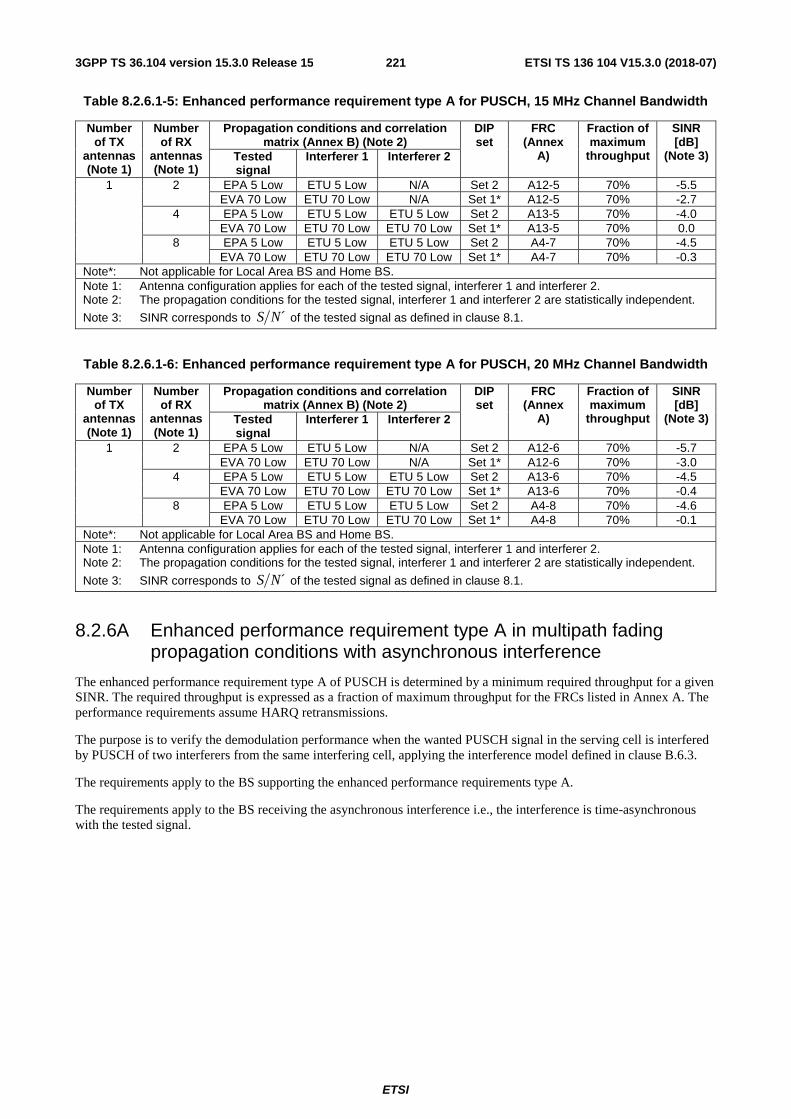
ETSI
ETSI TS 136 104 V15.3.0 (2018-07)2213GPP TS 36.104 version 15.3.0 Release 15
Table 8.2.6.1-5: Enhanced performance requirement type A for PUSCH, 15 MHz Channel Bandwidth
Number of TX
antennas (Note 1)
Number of RX
antennas (Note 1)
Propagation conditions and correlation matrix (Annex B) (Note 2)
DIP set
FRC (Annex
A)
Fraction of maximum
throughput
SINR [dB]
(Note 3) Tested signal
Interferer 1 Interferer 2
1 2 EPA 5 Low ETU 5 Low N/A Set 2 A12-5 70% -5.5 EVA 70 Low ETU 70 Low N/A Set 1* A12-5 70% -2.7
4 EPA 5 Low ETU 5 Low ETU 5 Low Set 2 A13-5 70% -4.0 EVA 70 Low ETU 70 Low ETU 70 Low Set 1* A13-5 70% 0.0
8 EPA 5 Low ETU 5 Low ETU 5 Low Set 2 A4-7 70% -4.5 EVA 70 Low ETU 70 Low ETU 70 Low Set 1* A4-7 70% -0.3
Note*: Not applicable for Local Area BS and Home BS. Note 1: Antenna configuration applies for each of the tested signal, interferer 1 and interferer 2. Note 2: The propagation conditions for the tested signal, interferer 1 and interferer 2 are statistically independent.
Note 3: SINR corresponds to ´S N of the tested signal as defined in clause 8.1.
Table 8.2.6.1-6: Enhanced performance requirement type A for PUSCH, 20 MHz Channel Bandwidth
Number of TX
antennas (Note 1)
Number of RX
antennas (Note 1)
Propagation conditions and correlation matrix (Annex B) (Note 2)
DIP set
FRC (Annex
A)
Fraction of maximum
throughput
SINR [dB]
(Note 3) Tested signal
Interferer 1 Interferer 2
1 2 EPA 5 Low ETU 5 Low N/A Set 2 A12-6 70% -5.7 EVA 70 Low ETU 70 Low N/A Set 1* A12-6 70% -3.0
4 EPA 5 Low ETU 5 Low ETU 5 Low Set 2 A13-6 70% -4.5 EVA 70 Low ETU 70 Low ETU 70 Low Set 1* A13-6 70% -0.4
8 EPA 5 Low ETU 5 Low ETU 5 Low Set 2 A4-8 70% -4.6 EVA 70 Low ETU 70 Low ETU 70 Low Set 1* A4-8 70% -0.1
Note*: Not applicable for Local Area BS and Home BS. Note 1: Antenna configuration applies for each of the tested signal, interferer 1 and interferer 2. Note 2: The propagation conditions for the tested signal, interferer 1 and interferer 2 are statistically independent.
Note 3: SINR corresponds to ´S N of the tested signal as defined in clause 8.1.
8.2.6A Enhanced performance requirement type A in multipath fading propagation conditions with asynchronous interference
The enhanced performance requirement type A of PUSCH is determined by a minimum required throughput for a given SINR. The required throughput is expressed as a fraction of maximum throughput for the FRCs listed in Annex A. The performance requirements assume HARQ retransmissions.
The purpose is to verify the demodulation performance when the wanted PUSCH signal in the serving cell is interfered by PUSCH of two interferers from the same interfering cell, applying the interference model defined in clause B.6.3.
The requirements apply to the BS supporting the enhanced performance requirements type A.
The requirements apply to the BS receiving the asynchronous interference i.e., the interference is time-asynchronous with the tested signal.

ETSI
ETSI TS 136 104 V15.3.0 (2018-07)2223GPP TS 36.104 version 15.3.0 Release 15
Table 8.2.6A-1: Test parameters for enhanced performance requirement type A
Parameter Unit Tested signal Interferer 1-1 (Note 1)
Interferer 1-2 (Note 1)
Maximum number of HARQ transmissions 4 N/A N/A
RV sequence 0, 2, 3, 1, 0, 2, 3, 1 N/A N/A
DIP (Note 2) dB N/A -0.43 -0.43
Cell Id 0 1 1
Interference model N/A As specified in clause B.6.3
As specified in clause B.6.3
Cyclic Prefix Normal
Demodulation reference signal for PUSCH ssΔ =0, (1)
DMRSn =0, (2)DMRS,0n =0
Group hopping and sequence hopping are disabled. Note 1: Interferer 1-1 and interferer 1-2 are connected to the same cell and configured to transmit
respectively in the even subframes and odd subframes. Note 2: The respective received energy of each interferer relative to ´N is defined by its associated DIP
value as specified in clause B.6.1. Note 3: The transmissions of both interferer 1-1 and interferer 1-2 are delayed with respect to the tested
signal by 0.33 ms.
8.2.6A.1 Minimum requirements
The throughput shall be equal to or larger than the fraction of maximum throughput stated in the tables 8.2.6A.1-1 to 8.2.6A.1-6 at the given SINR.
Table 8.2.6A.1-1 Enhanced performance requirement type A for PUSCH, 1.4 MHz Channel Bandwidth
Number of TX
antennas (Note 1)
Number of RX
antennas (Note 1)
Propagation conditions and correlation matrix (Annex B) (Note 2)
FRC (Annex A)
Fraction of maximum
throughput
SINR [dB]
(Note 3) Tested signal Interferer 1-1 Interferer 1-2
1 2 EPA 5 Low ETU 5 Low ETU 5 Low A12-1 70% -2.3 4 EPA 5 Low ETU 5 Low ETU 5 Low A13-1 70% -1.4] 8 EPA 5 Low ETU 5 Low ETU 5 Low A4-3 70% -2.2
Note 1: Antenna configuration applies for each of the tested signal, interferer 1-1 and interferer 1-2. Note 2: The propagation conditions for the tested signal, interferer 1-1 and interferer 1-2 are statistically
independent.
Note 3: SINR corresponds to ´S N of the tested signal as defined in clause 8.1.
Table 8.2.6A.1-2 Enhanced performance requirement type A for PUSCH, 3 MHz Channel Bandwidth
Number of TX
antennas (Note 1)
Number of RX
antennas (Note 1)
Propagation conditions and correlation matrix (Annex B) (Note 2)
FRC (Annex A)
Fraction of maximum
throughput
SINR [dB]
(Note 3) Tested signal Interferer 1-1 Interferer 1-2
1 2 EPA 5 Low ETU 5 Low ETU 5 Low A12-2 70% -2.5 4 EPA 5 Low ETU 5 Low ETU 5 Low A13-2 70% -1.6 8 EPA 5 Low ETU 5 Low ETU 5 Low A4-4 70% -2.2
Note 1: Antenna configuration applies for each of the tested signal, interferer 1-1 and interferer 1-2. Note 2: The propagation conditions for the tested signal, interferer 1-1 and interferer 1-2 are statistically
independent.
Note 3: SINR corresponds to ´S N of the tested signal as defined in clause 8.1.

ETSI
ETSI TS 136 104 V15.3.0 (2018-07)2233GPP TS 36.104 version 15.3.0 Release 15
Table 8.2.6A.1-3 Enhanced performance requirement type A for PUSCH, 5 MHz Channel Bandwidth
Number of TX
antennas (Note 1)
Number of RX
antennas (Note 1)
Propagation conditions and correlation matrix (Annex B) (Note 2)
FRC (Annex A)
Fraction of maximum
throughput
SINR [dB]
(Note 3) Tested signal Interferer 1-1 Interferer 1-2
1 2 EPA 5 Low ETU 5 Low ETU 5 Low A12-3 70% -2.6 4 EPA 5 Low ETU 5 Low ETU 5 Low A13-3 70% -1.3 8 EPA 5 Low ETU 5 Low ETU 5 Low A4-5 70% -2.1
Note 1: Antenna configuration applies for each of the tested signal, interferer 1-1 and interferer 1-2. Note 2: The propagation conditions for the tested signal, interferer 1-1 and interferer 1-2 are statistically
independent.
Note 3: SINR corresponds to ´S N of the tested signal as defined in clause 8.1.
Table 8.2.6A.1-4: Enhanced performance requirement type A for PUSCH, 10 MHz Channel Bandwidth
Number of TX
antennas (Note 1)
Number of RX
antennas (Note 1)
Propagation conditions and correlation matrix (Annex B) (Note 2)
FRC (Annex A)
Fraction of maximum
throughput
SINR [dB]
(Note 3) Tested signal Interferer 1-1 Interferer 1-2
1 2 EPA 5 Low ETU 5 Low ETU 5 Low A12-4 70% -2.8 4 EPA 5 Low ETU 5 Low ETU 5 Low A13-4 70% -1.3 8 EPA 5 Low ETU 5 Low ETU 5 Low A4-6 70% -1.9
Note 1: Antenna configuration applies for each of the tested signal, interferer 1-1 and interferer 1-2. Note 2: The propagation conditions for the tested signal, interferer 1-1 and interferer 1-2 are statistically
independent.
Note 3: SINR corresponds to ´S N of the tested signal as defined in clause 8.1.
Table 8.2.6A.1-5: Enhanced performance requirement type A for PUSCH, 15 MHz Channel Bandwidth
Number of TX
antennas (Note 1)
Number of RX
antennas (Note 1)
Propagation conditions and correlation matrix (Annex B) (Note 2)
FRC (Annex A)
Fraction of maximum
throughput
SINR [dB]
(Note 3) Tested signal Interferer 1-1 Interferer 1-2
1 2 EPA 5 Low ETU 5 Low ETU 5 Low A12-5 70% -2.7 4 EPA 5 Low ETU 5 Low ETU 5 Low A13-5 70% -1.1 8 EPA 5 Low ETU 5 Low ETU 5 Low A4-7 70% -1.4
Note 1: Antenna configuration applies for each of the tested signal, interferer 1-1 and interferer 1-2. Note 2: The propagation conditions for the tested signal, interferer 1-1 and interferer 1-2 are statistically
independent.
Note 3: SINR corresponds to ´S N of the tested signal as defined in clause 8.1.
Table 8.2.6A.1-6: Enhanced performance requirement type A for PUSCH, 20 MHz Channel Bandwidth
Number of TX
antennas (Note 1)
Number of RX
antennas (Note 1)
Propagation conditions and correlation matrix (Annex B) (Note 2)
FRC (Annex A)
Fraction of maximum
throughput
SINR [dB]
(Note 3) Tested signal Interferer 1-1 Interferer 1-2
1 2 EPA 5 Low ETU 5 Low ETU 5 Low A12-6 70% -2.9 4 EPA 5 Low ETU 5 Low ETU 5 Low A13-6 70% -1.1 8 EPA 5 Low ETU 5 Low ETU 5 Low A4-8 70% -1.3
Note 1: Antenna configuration applies for each of the tested signal, interferer 1-1 and interferer 1-2. Note 2: The propagation conditions for the tested signal, interferer 1-1 and interferer 1-2 are statistically
independent.
Note 3: SINR corresponds to ´S N of the tested signal as defined in clause 8.1.
8.2.7 Requirements for PUSCH supporting coverage enhancement
For the parameters specified in Table 8.2.7-1 the throughput shall be equal to or larger than the fraction of maximum throughput stated in the tables8.2.7-2 to 8.2.7-11 at the given SNR.

ETSI
ETSI TS 136 104 V15.3.0 (2018-07)2243GPP TS 36.104 version 15.3.0 Release 15
Table 8.2.7-1 Test Parameters for PUSCH
Parameter unit Mode A Mode B
Maximum number of HARQ transmissions
4 2
RV sequences
0, 2, 3, 1, 0, 2, 3, 1 FDD: 0, 0, 0, 0, 2, 2, 2, 2, 3, 3, 3, 3, 1, 1, 1, 1 TDD: 0, 0, 0, 0, 0, 2, 2, 2, 2, 2, 3, 3, 3, 3, 3, 1, 1, 1, 1,1
Number of PUSCH repetitions 8 256 Frequency hopping ON ON
Frequency hopping interval subframes 4: FDD 5: TDD
4: FDD 5: TDD
Note 1: Guard period shall be created according to TS36.211, 5.2.5 [12]
Table 8.2.7-2 Minimum requirements for PUSCH, 3 MHz Channel Bandwidth for Mode A, 1Tx
Number of TX antennas
Number of RX antennas
CE Mode Propagation conditions and
correlation matrix (Annex B)
FRC (Annex A)
Fraction of maximum
throughput
SNR [dB]
1 2 Mode A EPA 5Hz Low A3-2 70% -6.2
Table 8.2.7-3 Minimum requirements for PUSCH, 5 MHz Channel Bandwidth for Mode A, 1Tx
Number of TX antennas
Number of RX antennas
CE Mode Propagation conditions and
correlation matrix (Annex B)
FRC (Annex A)
Fraction of maximum
throughput
SNR [dB]
1 2 Mode A EPA 5Hz Low A3-2 70% -6.6
Table 8.2.7-4 Minimum requirements for PUSCH, 10 MHz Channel Bandwidth for Mode A, 1Tx
Number of TX antennas
Number of RX antennas
CE Mode Propagation conditions and
correlation matrix (Annex B)
FRC (Annex A)
Fraction of maximum
throughput
SNR [dB]
1 2 Mode A EPA 5Hz Low A3-2 70% -6.9
Table 8.2.7-5 Minimum requirements for PUSCH, 15 MHz Channel Bandwidth for Mode A, 1Tx
Number of TX antennas
Number of RX antennas
CE Mode Propagation conditions and
correlation matrix (Annex B)
FRC (Annex A)
Fraction of maximum
throughput
SNR [dB]
1 2 Mode A EPA 5Hz Low A3-2 70% -6.9
Table 8.2.7-6 Minimum requirements for PUSCH, 20 MHz Channel Bandwidth for Mode A, 1Tx
Number of TX antennas
Number of RX antennas
CE Mode Propagation conditions and
correlation matrix (Annex B)
FRC (Annex A)
Fraction of maximum
throughput
SNR [dB]
1 2 Mode A EPA 5Hz Low A3-2 70% -7.0

ETSI
ETSI TS 136 104 V15.3.0 (2018-07)2253GPP TS 36.104 version 15.3.0 Release 15
Table 8.2.7-7 Minimum requirements for PUSCH, 3 MHz Channel Bandwidth for Mode B, 1Tx
Number of TX antennas
Number of RX antennas
CE Mode Propagation conditions and
correlation matrix (Annex B)
FRC (Annex A)
Fraction of maximum
throughput
SNR [dB]
1 2 Mode B ETU 1Hz Low A3-1 70% -15.0
Table 8.2.7-8 Minimum requirements for PUSCH, 5 MHz Channel Bandwidth for Mode B, 1Tx
Number of TX antennas
Number of RX antennas
CE Mode Propagation conditions and
correlation matrix (Annex B)
FRC (Annex A)
Fraction of maximum
throughput
SNR [dB]
1 2 Mode B ETU 1Hz Low A3-1 70% -15.2
Table 8.2.7-9 Minimum requirements for PUSCH, 10 MHz Channel Bandwidth for Mode B, 1Tx
Number of TX antennas
Number of RX antennas
CE Mode Propagation conditions and
correlation matrix (Annex B)
FRC (Annex A)
Fraction of maximum
throughput
SNR [dB]
1 2 Mode B ETU 1Hz Low A3-1 70% -15.3
Table 8.2.7-10 Minimum requirements for PUSCH, 15 MHz Channel Bandwidth for Mode B, 1Tx
Number of TX antennas
Number of RX antennas
CE Mode Propagation conditions and
correlation matrix (Annex B)
FRC (Annex A)
Fraction of maximum
throughput
SNR [dB]
1 2 Mode B ETU 1Hz Low A3-1 70% -15.1
Table 8.2.7-11 Minimum requirements for PUSCH, 20 MHz Channel Bandwidth for Mode B, 1Tx
Number of TX antennas
Number of RX antennas
CE Mode Propagation conditions and
correlation matrix (Annex B)
FRC (Annex A)
Fraction of maximum
throughput
SNR [dB]
1 2 Mode B ETU 1Hz Low A3-1 70% -15.2
8.2.8 Requirements for PUSCH of Frame structure type 3
For the parameters specified in Table 8.2.8-1 the throughput shall be equal to or larger than the fraction of maximum throughput stated in the tables 8.2.8-2 at the given SNR when the PUSCH is transmitted with Frame structure type 3.

ETSI
ETSI TS 136 104 V15.3.0 (2018-07)2263GPP TS 36.104 version 15.3.0 Release 15
Table 8.2.8-1: Test Parameters for PUSCH with frame structure type 3
Parameter Unit Value (NOTE 1) Maximum number of HARQ
transmissions 4
RV sequences [0 ,2, 0, 2] PUSCH starting position
(NOTE 2) ‘01’
PUSCH ending symbol (NOTE 3)
‘0’
NOTE 1: PUSCH scheduling pattern is defined as the bitmap {1111000000} with the periodicity of 10ms. Value 1 in the bitmap indicates there is PUSCH data transmission on the corresponding subrames; Value 0 indicates that there is no PUSCH data transmission on the corresponding subframes.
NOTE 2: The PUSCH starting position is applicable to only the first PUSCH transmission subframe indicated in the bitmap. For other transmission subframes indicated in the bitmap, PUSCH starting position is at symbol 0.
NOTE 3: The PUSCH ending symbol value indicates the configuration of the last symbol of the last PUSCH transmission subframe indicated in the bitmap.
Table 8.2.8-2: Minimum requirements for PUSCH, 20 MHz Channel Bandwidth, 1Tx
Number of TX antennas
Number of RX antennas
Cyclic prefix Propagation conditions
and correlation
matrix (Annex B)
FRC (Annex A)
Fraction of nominal
maximum throughput (NOTE 1)
SNR [dB]
1 2 Normal EPA 5Hz Low A20-1 70% -0.2 A20-2 70% 12.1
4 Normal EPA 5Hz Low A20-1 70% -3.2 A20-2 70% 8.3
NOTE1: Fraction of nominal maximum throughput is calculated based on the actual transmitted PUSCH
8.2.9 Enhanced performance requirement type B in multipath fading propagation conditions
The purpose is to verify the demodulation performance when there are multiple co-scheduled intra-cell UEs in the serving cell and one inter-cell interfering UE in the negiboring cell. The PUSCH of all the intra-cell UEs are wanted signal for the BS.
The enhanced performance requirement type B of PUSCH is determined by a minimum required throughput for a given SINR. The required throughput is expressed as a fraction of maximum sum throughput of all the intra-cell UEs for the FRCs listed in Annex A. The performance requirements assume HARQ retransmissions.
The requirements apply to the BS supporting the enhanced performance requirements type B.

ETSI
ETSI TS 136 104 V15.3.0 (2018-07)2273GPP TS 36.104 version 15.3.0 Release 15
Table 8.2.9-1: Test parameters for enhanced performance requirement type B, 2 RX antennas
Parameter Unit Wanted intra-cell UEs (Note 1) Inter-cell interfering UE UE1 UE2
Cyclic Prefix Normal Uplink-downlink allocation for TDD Configuration 1 (2:2)
Maximum number of HARQ transmissions 4 N/A
RV sequence 0, 2, 3, 1, 0, 2, 3, 1 N/A
Cell Id 0 1
Inter-cell interference model N/A As specified in clause B.6.2
DIP (Note 2) Set 1 dB N/A -5.45
Set 2 dB N/A -0.43
Relative power of intra-cell UEs (Note 3)
Set 1 dB 0 0 N/A
Set 2 dB 0 3 N/A
Time offset us -1 1 0 Frequency offset Hz -200 200 0
Demodulation reference signal for
PUSCH
(1)DMRSn 0 6 0
ssΔ , (2)DMRS,0n ssΔ =0, (2)
DMRS,0n =0
Group hopping and sequence hopping are disabled. Note 1: Two intra-cell UEs, i.e., UE1 and UE2, are configured for tests with 2 RX antennas. Note 2: The respective received energy of each inter-cell interferer relative to ´N is defined by its
associated DIP value as specified in clause B.6.1. DIP set 1 and set 2 are derived respectively in homogeneous and heterogeneous network scenarios.
Note 3: For set 1, equal average received signal energy is configured for the intra-cell UEs, while short-term variation remains. For set 2, the average received signal energy of UE2 is 3 dB higher than that of UE1.

ETSI
ETSI TS 136 104 V15.3.0 (2018-07)2283GPP TS 36.104 version 15.3.0 Release 15
Table 8.2.9-2: Test parameters for enhanced performance requirement type B, 4 RX antennas
Parameter Unit Wanted intra-cell UEs (Note 1) Inter-cell
interfering UE UE1 UE2 UE3 UE4 Cyclic Prefix Normal
Uplink-downlink allocation for TDD Configuration 1 (2:2) Maximum number of HARQ
transmissions 4 N/A
RV sequence 0, 2, 3, 1, 0, 2, 3, 1 N/A
Cell Id 0 1
Inter-cell interference model N/A As specified in clause B.6.2
DIP (Note 2) Set 1 dB N/A -5.45
Set 2 dB N/A -0.43
Relative power of intra-cell UEs (Note 3)
Set 1 dB 0 0 0 0 N/A Set 2 dB 0 3 0 3 N/A
Time offset us -1 -0.5 0.5 1 0 Frequency offset Hz -200 -100 100 200 0
Demodulation reference signal for
PUSCH
(1)DMRSn 0 3 6 9 0
ssΔ , (2)DMRS,0n ssΔ =0, (2)
DMRS,0n =0
Group hopping and sequence hopping are disabled.
Note 1: Four intra-cell UEs, i.e., UE1, UE2, UE3 and UE4, are configured for tests with 4 RX antennas. Note 2: The respective received energy of each inter-cell interferer relative to ´N is defined by its
associated DIP value as specified in clause B.6.1. DIP set 1 and set 2 are derived respectively in homogeneous and heterogeneous network scenarios.
Note 3: For set 1, equal average received signal energy is configured for the intra-cell UEs, while short-term variation remains. For set 2, the average received signal energy of UE1 and UE3 is the same, the average received signal energy of UE2 and UE4 is the same, and the average received signal energy of UE2 is 3 dB higher than that of UE1.
8.2.9.1 Minimum requirements
The throughput shall be equal to or larger than the fraction of maximum throughput stated in the tables 8.2.9.1-1 to 8.2.9.1-6 at the given SINR.
Table 8.2.9.1-1: Enhanced performance requirement type B for PUSCH, 1.4 MHz Channel Bandwidth
Number of TX
antennas (Note 1)
Number of RX
antennas (Note 1)
Propagation conditions and correlation matrix
(Annex B) (Note 2)
DIP set
Relative power of intra-cell
UEs
FRC (Annex A)
Fraction of maximum
sum throughput
of all the intra-cell
UEs
UE1’s SINR [dB]
(Note 3)
Wanted intra-cell
UEs
Inter-cell interfering
UE
UE1, UE3
UE2, UE4
1 2 EPA 5 Low ETU 5 Low Set 2 Set 1 A22-1 A22-1 80% 15.4 EVA 70 Low ETU 70 Low Set 1* Set 2 A13-1 A13-1 80% 11.3
4 EVA 70 Low ETU 70 Low Set 1* Set 1 A13-1 A13-1 80% 10.3 EPA 5 Low ETU 5 Low Set 2 Set 2 A21-1 A13-1 80% 0.6
Note*: Not applicable for Local Area BS and Home BS. Note 1: Antenna configuration applies for each of the intra-cell and inter-cell UEs. Note 2: The propagation conditions for the intra-cell and inter-cell UEs are statistically independent.
Note 3: SINR corresponds to ´S N of UE1 as defined in clause 8.1.

ETSI
ETSI TS 136 104 V15.3.0 (2018-07)2293GPP TS 36.104 version 15.3.0 Release 15
Table 8.2.9.1-2: Enhanced performance requirement type B for PUSCH, 3 MHz Channel Bandwidth
Number of TX
antennas (Note 1)
Number of RX
antennas (Note 1)
Propagation conditions and correlation matrix
(Annex B) (Note 2)
DIP set
Relative power of intra-cell
UEs
FRC (Annex A)
Fraction of maximum
sum throughput
of all the intra-cell
UEs
UE1’s SINR [dB]
(Note 3)
Wanted intra-cell
UEs
Inter-cell interfering
UE
UE1, UE3
UE2, UE4
1 2 EPA 5 Low ETU 5 Low Set 2 Set 1 A22--2
A22--2
80% 15.5
EVA 70 Low ETU 70 Low Set 1* Set 2 A13-2 A13-2 80% 10.7 4 EVA 70 Low ETU 70 Low Set 1* Set 1 A13-2 A13-2 80% 9.9
EPA 5 Low ETU 5 Low Set 2 Set 2 A21--2
A13-2 80% 0.1
Note*: Not applicable for Local Area BS and Home BS. Note 1: Antenna configuration applies for each of the intra-cell and inter-cell UEs. Note 2: The propagation conditions for the intra-cell and inter-cell UEs are statistically independent.
Note 3: SINR corresponds to ´S N of UE1 as defined in clause 8.1.
Table 8.2.9.1-3: Enhanced performance requirement type B for PUSCH, 5 MHz Channel Bandwidth
Number of TX
antennas (Note 1)
Number of RX
antennas (Note 1)
Propagation conditions and correlation matrix
(Annex B) (Note 2)
DIP set
Relative power of intra-cell
UEs
FRC (Annex A)
Fraction of maximum
sum throughput
of all the intra-cell
UEs
UE1’s SINR [dB]
(Note 3)
Wanted intra-cell
UEs
Inter-cell interfering
UE
UE1, UE3
UE2, UE4
1 2 EPA 5 Low ETU 5 Low Set 2 Set 1 A22--3
A22--3
80% 16.1
EVA 70 Low ETU 70 Low Set 1* Set 2 A13-3 A13-3 80% 11.0 4 EVA 70 Low ETU 70 Low Set 1* Set 1 A13-3 A13-3 80% 10.4
EPA 5 Low ETU 5 Low Set 2 Set 2 A21--3
A13-3 80% 0.4
Note*: Not applicable for Local Area BS and Home BS. Note 1: Antenna configuration applies for each of the intra-cell and inter-cell UEs. Note 2: The propagation conditions for the intra-cell and inter-cell UEs are statistically independent.
Note 3: SINR corresponds to ´S N of UE1 as defined in clause 8.1.
Table 8.2.9.1-4: Enhanced performance requirement type B for PUSCH, 10 MHz Channel Bandwidth
Number of TX
antennas (Note 1)
Number of RX
antennas (Note 1)
Propagation conditions and correlation matrix
(Annex B) (Note 2)
DIP set
Relative power of intra-cell
UEs
FRC (Annex A)
Fraction of maximum
sum throughput
of all the intra-cell
UEs
UE1’s SINR [dB]
(Note 3)
Wanted intra-cell
UEs
Inter-cell interfering
UE
UE1, UE3
UE2, UE4
1 2 EPA 5 Low ETU 5 Low Set 2 Set 1 A22--4
A22--4
80% 16.2
EVA 70 Low ETU 70 Low Set 1* Set 2 A13-4 A13-4 80% 10.5 4 EVA 70 Low ETU 70 Low Set 1* Set 1 A13-4 A13-4 80% 10.0
EPA 5 Low ETU 5 Low Set 2 Set 2 A21--4
A13-4 80% 0.2
Note*: Not applicable for Local Area BS and Home BS. Note 1: Antenna configuration applies for each of the intra-cell and inter-cell UEs. Note 2: The propagation conditions for the intra-cell and inter-cell UEs are statistically independent.
Note 3: SINR corresponds to ´S N of UE1 as defined in clause 8.1.

ETSI
ETSI TS 136 104 V15.3.0 (2018-07)2303GPP TS 36.104 version 15.3.0 Release 15
Table 8.2.9.1-5: Enhanced performance requirement type B for PUSCH, 15 MHz Channel Bandwidth
Number of TX
antennas (Note 1)
Number of RX
antennas (Note 1)
Propagation conditions and correlation matrix
(Annex B) (Note 2)
DIP set
Relative power of intra-cell
UEs
FRC (Annex A)
Fraction of maximum
sum throughput
of all the intra-cell
UEs
UE1’s SINR [dB]
(Note 3)
Wanted intra-cell
UEs
Inter-cell interfering
UE
UE1, UE3
UE2, UE4
1 2 EPA 5 Low ETU 5 Low Set 2 Set 1 A22--4
A22--4
80% 16.2
EVA 70 Low ETU 70 Low Set 1* Set 2 A13-5 A13-5 80% 10.6 4 EVA 70 Low ETU 70 Low Set 1* Set 1 A13-5 A13-5 80% 10.3
EPA 5 Low ETU 5 Low Set 2 Set 2 A21--5
A13-5 80% 0.5
Note*: Not applicable for Local Area BS and Home BS. Note 1: Antenna configuration applies for each of the intra-cell and inter-cell UEs. Note 2: The propagation conditions for the intra-cell and inter-cell UEs are statistically independent.
Note 3: SINR corresponds to ´S N of UE1 as defined in clause 8.1.
Table 8.2.9.1-6: Enhanced performance requirement type B for PUSCH, 20 MHz Channel Bandwidth
Number of TX
antennas (Note 1)
Number of RX
antennas (Note 1)
Propagation conditions and correlation matrix
(Annex B) (Note 2)
DIP set
Relative power of intra-cell
UEs
FRC (Annex A)
Fraction of maximum
sum throughput
of all the intra-cell
UEs
UE1’s SINR [dB]
(Note 3)
Wanted intra-cell
UEs
Inter-cell interfering
UE
UE1, UE3
UE2, UE4
1 2 EPA 5 Low ETU 5 Low Set 2 Set 1 A22--4
A22--4
80% 16.3
EVA 70 Low ETU 70 Low Set 1* Set 2 A13-6 A13-6 80% 10.6 4 EVA 70 Low ETU 70 Low Set 1* Set 1 A13-6 A13-6 80% 10.3
EPA 5 Low ETU 5 Low Set 2 Set 2 A21--6
A13-6 80% 0.6
Note*: Not applicable for Local Area BS and Home BS. Note 1: Antenna configuration applies for each of the intra-cell and inter-cell UEs. Note 2: The propagation conditions for the intra-cell and inter-cell UEs are statistically independent.
Note 3: SINR corresponds to ´S N of UE1 as defined in clause 8.1.
8.3 Performance requirements for PUCCH
8.3.1 DTX to ACK performance
The DTX to ACK requirement is valid for any number of receive antennas, for all frame structures and for any channel bandwidth.
The DTX to ACK probability for multi user PUCCH case denotes the probability that ACK is detected when nothing is sent on the wanted signal and the interfering signals are present.
8.3.1.1 Minimum requirement
The DTX to ACK probability, i.e. the probability that ACK is detected when nothing was sent, shall not exceed 1%, where the performance measure definition is as follows:
,
where:
● #(false ACK bits) denotes the number of detected ACK bits.
( )( )
210bits)ACK/NAK (# DTX PUCCH#
bitsACK false# bits)ACK DTX Prob(PUCCH −≤
×=→

ETSI
ETSI TS 136 104 V15.3.0 (2018-07)2313GPP TS 36.104 version 15.3.0 Release 15
● #(ACK/NACK bits) denotes the number of encoded bits per sub-frame
● #(PUCCH DTX) denotes the number of DTX occasions
8.3.2 ACK missed detection requirements for single user PUCCH format 1a
The ACK missed detection probability is the probability of not detecting an ACK when an ACK was sent.
ACK/NACK repetitions are disabled for PUCCH transmission.
Test parameters for PUCCH transmission on two antenna ports are presented in Annex A.10.
8.3.2.1 Minimum requirements
The ACK missed detection probability shall not exceed 1% at the SNR given in table 8.3.2.1-1 for 1Tx and in table 8.3.2.1-2 for 2Tx case.
Table 8.3.2.1-1 Minimum requirements for single user PUCCH format 1a, 1Tx
Number of TX
antennas
Number of RX
antennas
Cyclic Prefix
Propagation conditions
and correlation
matrix (Annex B)
Channel Bandwidth / SNR [dB] 1.4 MHz 3 MHz 5 MHz 10
MHz 15
MHz 20 MHz
1 2 Normal EPA 5 Low -2.5 -3.9 -4.8 -5.4 -5.3 -5.1 EVA 5 Low -4.5 -5.1 -5.1 -5.0 -5.1 -5.1
EVA 70 Low -4.9 -5.2 -5.2 -5.1 -5.2 -5.1 ETU 300* Low -5.0 -5.1 -4.9 -5.0 -5.2 -5.2
Extended ETU 70* Low -4.2 -4.3 -4.1 -4.3 -4.2 -4.3 4 Normal EPA 5 Low -7.9 -8.4 -8.7 -8.9 -8.9 -9.0
EVA 5 Low -8.8 -9.1 -9.1 -8.8 -8.9 -8.9 EVA 70 Low -8.9 -9.0 -9.0 -8.8 -9.0 -8.8
ETU 300* Low -8.7 -8.9 -8.7 -8.7 -8.9 -8.8 Extended ETU 70* Low -7.9 -8.1 -7.9 -8.1 -8.0 -8.0
8 Normal EPA 5 Low -11.2 -11.5 -12.2 -12.3 -12.3 -12.3 EVA 5 Low -12.0 -12.0 -12.1 -12.1 -12.3 -12.2
EVA 70 Low -12.0 -12.1 -12.2 -12.1 -12.3 -12.1 ETU 300* Low -11.6 -11.6 -11.6 -11.8 -11.6 -11.8
Extended ETU 70* Low -10.5 -10.7 -10.6 -10.7 -10.6 -10.6 Note*: Not applicable for Local Area BS and Home BS.
Table 8.3.2.1-2 Minimum requirements for single user PUCCH format 1a, 2Tx
Number of TX
antennas
Number of RX
antennas
Cyclic Prefix
Propagation conditions
and correlation
matrix (Annex B)
Channel Bandwidth / SNR [dB] 1.4
MHz 3 MHz 5 MHz 10 MHz 15 MHz 20 MHz
2 2 Normal EPA 5 Low -4.6 -4.9 -6.4 -6.5 -6.5 -6.7 EVA 70 Low -5.8 -5.9 -6.4 -5.9 -6.4 -6.4
4 Normal EPA 5 Low -8.5 -8.5 -9.3 -9.5 -9.5 -9.5 EVA 70 Low -9.0 -9.2 -9.3 -9.3 -9.4 -9.5
2 8 Normal EPA 5 Low -11.4 -11.5 -11.9 -12.0 -11.9 -12.0 EVA 70 Low -11.7 -11.8 -11.8 -11.8 -11.8 -11.8
8.3.3 CQI performance requirements for PUCCH format 2
The CQI block error probability (BLER) is defined as the conditional probability of incorrectly decoding the CQI information when the CQI information is sent. All CQI information shall be decoded (no exclusion due to DTX).

ETSI
ETSI TS 136 104 V15.3.0 (2018-07)2323GPP TS 36.104 version 15.3.0 Release 15
The CQI information bit payload per sub-frame is equal to 4 bits.
Test parameters for PUCCH transmission on two antenna ports are presented in Annex A.10.
8.3.3.1 Minimum requirements
The CQI block error probability shall not exceed 1% at the SNR given in table 8.3.3.1-1 for 1Tx and in table 8.3.3.1-2 for 2Tx case.
Table 8.3.3.1-1 Minimum requirements for PUCCH format 2, 1Tx
Number of TX
antennas
Number of RX
antennas
Cyclic Prefix
Propagation conditions and
correlation matrix (Annex
B)
Channel Bandwidth / SNR [dB]
1.4 MHz 3 MHz 5 MHz 10 MHz
15 MHz
20 MHz
1 2 Normal EVA 5* Low -3.7 -4.1 -4.4 -4.0 -4.2 -4.2
ETU 70** Low -3.9 -4.4 -4.2 -4.4 -4.4 -4.4 Note*: Not applicable for Wide Area BS and Medium Range BS. Note**: Not applicable for Local Area BS and Home BS.
Table 8.3.3.1-2 Minimum requirements for PUCCH format 2, 2Tx
Number of TX
antennas
Number of RX
antennas
Cyclic Prefix
Propagation conditions
and correlation
matrix (Annex B)
Channel Bandwidth / SNR [dB] 1.4 MHz 3 MHz 5 MHz 10 MHz 15 MHz 20 MHz
2 2 Normal EVA 5 Low -5.7 -5.6 -5.9 -5.8 -5.9 -5.9
8.3.4 ACK missed detection requirements for multi user PUCCH format 1a
The ACK missed detection probability is the conditional probability of not detecting an ACK on the wanted signal in the presence of the wanted signal and the interfering signals.
Test parameters for multi user PUCCH case are presented in Annex A.9.
ACK/NACK repetitions are disabled for PUCCH transmission.
8.3.4.1 Minimum requirement
The ACK missed detection probability for multi user PUCCH case shall not exceed 1% at the SNR given in table 8.3.4.1-1.
Table 8.3.4.1-1 Minimum requirements for multi user PUCCH case
Number of TX
antennas
Number of RX
antennas
Cyclic Prefix
Propagation conditions
and correlation
matrix (Annex B)
Channel Bandwidth / SNR [dB] 1.4 MHz 3 MHz 5 MHz 10 MHz 15 MHz 20 MHz
1 2 Normal ETU 70* Low -4.1 -4.4 -4.4 -4.6 -4.6 -4.4 Note*: Not applicable for Local Area BS and Home BS.
8.3.5 ACK missed detection requirements for PUCCH format 1b with Channel Selection
The ACK missed detection probability is the probability of not detecting an ACK bit when an ACK bit was sent on particular channel, with each missed ACK bit counted as one error.

ETSI
ETSI TS 136 104 V15.3.0 (2018-07)2333GPP TS 36.104 version 15.3.0 Release 15
The number of encoded ACK bits per sub-frame is equal to 4 bits (AAAA),
ACK/NACK repetitions are disabled for PUCCH transmission.
This requirement is applicable for FDD and TDD.
8.3.5.1 Minimum requirements
The ACK missed detection probability shall not exceed 1% at the SNR given in table 8.3.5.1-1.
Table 8.3.5.1-1 Minimum requirements for PUCCH format 1b with Channel Selection
Number of Tx
antennas
Number of RX
antennas
Cyclic Prefix
Propagation Conditions
and correlation
matrix (Annex B)
Channel Bandwidth / SNR [dB]
1.4MHz 3MHz 5MHz 10 MHz 15MHz 20MHz
1 2 Normal EPA 5 Low - - - -4.5 -4.6 -4.6 EVA70 Low - - - -4.3 -4.5 -4.5
4 Normal EPA 5 Low - - - -8.4 -8.5 -8.6 EVA70 Low - - - -8.3 -8.5 -8.5
8 Normal EPA 5 Low - - - -11.7 -11.8 -11.8 EVA70 Low - - - -11.5 -11.7 -11.6
8.3.6 ACK missed detection requirements for PUCCH format 3
The ACK missed detection probability is the probability of not detecting an ACK bit when an ACK bit was sent on the particular bit position, with each missed ACK bit being accounted as one error.
The number of encoded ACK/NACK bits per sub-frame is defined for two cases as presented below:
● 4AN bits: applicable for FDD and TDD
● 16AN bits : applicable for TDD
ACK/NACK repetitions are disabled for PUCCH transmission. Random codeword selection is assumed.
8.3.6.1 Minimum requirements
The ACK missed detection probability shall not exceed 1% at the SNR given in table 8.3.6.1-1 and table 8.3.6.1-2, for 4 and 16 AN bits per sub-frame, respectively.
Table 8.3.6.1-1 Minimum requirements for PUCCH format 3, 4AN bits
Number of Tx
antennas
Number of RX
antennas
Cyclic Prefix
Propagation Conditions
and correlation
matrix (Annex B)
Channel Bandwidth / SNR [dB]
1.4MHz 3MHz 5MHz 10 MHz 15MHz 20MHz
1 2 Normal EPA 5 Low - - - -3.7 -3.8 -3.8 EVA70 Low - - - -3.5 -3.6 -3.7
4 Normal EPA 5 Low - - - -7.3 -7.4 -7.5 EVA70 Low - - - -7.2 -7.3 -7.3
8 Normal EPA 5 Low - - - -11.1 -10.9 -11.1 EVA70 Low - - - -10.9 -11.0 -11.0

ETSI
ETSI TS 136 104 V15.3.0 (2018-07)2343GPP TS 36.104 version 15.3.0 Release 15
Table 8.3.6.1-2 Minimum requirements for PUCCH format 3, 16AN bits
Number of Tx
antennas
Number of RX
antennas
Cyclic Prefix
Propagation Conditions
and correlation
matrix (Annex B)
Channel Bandwidth / SNR [dB]
1.4MHz 3MHz 5MHz 10 MHz 15MHz 20MHz
1 2 Normal EPA 5 Low - - - -1.3 -1.2 -1.2 EVA70 Low - - - -0.8 -0.9 -0.9
4 Normal EPA 5 Low - - - -5.3 -5.3 -5.4 EVA70 Low - - - -5.0 -5.1 -5.1
8 Normal EPA 5 Low - - - -8.8 -8.8 -8.9 EVA70 Low - - - -8.7 -8.8 -8.7
8.3.7 NACK to ACK requirements for PUCCH format 3
The NACK to ACK detection probability is the probability that an ACK bit is falsely detected when an NACK bit was sent on the particular bit position, where the NACK to ACK detection probability is defined as follows:
,
where:
● denotes the total number of NACK bits transmitted
● denotes the number of NACK bits decoded as ACK bits at the receiver, i.e.
the number of received ACK bits
● NACK bits in the definition do not contain the NACK bits which are mapped from DTX, i.e. NACK bits received when DTX is sent should not be considered.
ACK/NACK repetitions are disabled for PUCCH transmission. Random codeword selection is assumed.
Note: NACK to ACK requirement only applies to the PUCCH format3 16AN bits cases.
8.3.7.1 Minimum requirement
The NACK to ACK probability shall not exceed 0,1% at the SNR given in table 8.3.7.1-1 for 16 AN bits.
Table 8.3.7.1-1 Minimum requirements for PUCCH format 3, 16AN bits
Number of Tx
antennas
Number of RX
antennas
Cyclic Prefix
Propagation Conditions
and correlation
matrix (Annex B)
Channel Bandwidth / SNR [dB]
1.4MHz 3MHz 5MHz 10 MHz 15MHz 20MHz
1 2 Normal EPA 5 Low - - - 1.4 1.6 1.5 EVA70 Low - - - 2.1 1.9 1.9
4 Normal EPA 5 Low - - - -3.1 -3.3 -3.5 EVA70 Low - - - -2.9 -3.1 -3.2
8 Normal EPA 5 Low - - - -7.3 -7.3 -7.3 EVA70 Low - - - -7.0 -7.1 -7.2
8.3.8 CQI performance requirements for PUCCH format 2 with DTX detection
The requirements in this subclause apply to a BS supporting PUCCH format 2 with DTX. It is optional for a BS to support PUCCH format 2 with DTX.
( )bits)NACK Total(#
bitsACK as decoded bitsNACK # bits)ACK NACK Prob(PUCCH =→
bits)NACK Total(#
( )bitsACK as decoded bitsNACK #

ETSI
ETSI TS 136 104 V15.3.0 (2018-07)2353GPP TS 36.104 version 15.3.0 Release 15
A BS may meet the PUCCH format 2 requirements specified in Section 8.3.8.1 instead of requirements specified in Section 8.3.3.1.
The CQI block error probability (BLER) is defined as the sum of the:
- conditional probability of incorrectly decoding the CQI information when the CQI information is sent and
- conditional probability of detecting UE transmission as DTX, when the CQI information is sent.
The CQI false alarm probability is defined as the conditional probability of false detecting the CQI information transmitted from UE when no CQI information is sent.
The CQI information bit payload per sub-frame is equal to 4 bits.
Test parameters for PUCCH transmission on two antenna ports are presented in Annex A.10.
8.3.8.1 Minimum requirements
The CQI false alarm probability and the CQI block error probability shall not exceed 10% and 1%, respectively, at the SNR given in table 8.3.8.1-1.
Table 8.3.8.1-1 Minimum requirements for PUCCH format 2 with DTX detection
Number of TX
antennas
Number of RX
antennas
Cyclic Prefix
Propagation conditions and
correlation matrix (Annex
B)
Channel Bandwidth / SNR [dB] 1.4 MHz 3 MHz 5 MHz 10
MHz 15
MHz 20 MHz
1 2 Normal EVA 5* Low -3.7 -4.0 -4.4 -4.0 -4.2 -4.2 ETU 70** Low -3.7 -4.0 -3.7 -4.1 -3.9 -4.1
2 2 Normal EVA 5 Low -5.3 -5.2 -5.5 -5.4 -5.3 -5.5 Note*: Not applicable for Wide Area BS and Medium Range BS. Note**: Not applicable for Local Area BS and Home BS.
8.3.9 PUCCH performance requirements for coverage enhancement
8.3.9.1 DTX to ACK performance
The DTX to ACK requirement is valid for any number of receive antennas, for all frame structures and for any channel bandwidth.
8.3.9.1.1 Minimum requirement
The DTX to ACK probability, i.e. the probability that ACK is detected when nothing is sent per PUCCH transmission, shall not exceed 1% per PUCCH transmission. A PUCCH transmission may take multiple subframes due to PUCCH transmission repetition. The performance measure is defined as follows:
,
where:
- #(false ACK bits) denotes the number of detected ACK bits per PUCCH transmission.
- #(ACK/NACK bits) denotes the number of encoded bits per PUCCH transmission.
- #(PUCCH DTX) denotes the number of DTX occasions per PUCCH transmission.
8.3.9.2 ACK missed detection requirements for single user PUCCH format 1a
The ACK missed detection probability is the probability of not detecting an ACK when an ACK is sent.
8.3.9.2.1 Minimum requirements
The ACK missed detection probability shall not exceed 1% at the SNR given in table 8.3.9.2.1-1 for 1Tx.
( )( )
210bits)ACK/NAK (# DTX PUCCH#
bitsACK false# bits)ACK DTX Prob(PUCCH −≤
×=→
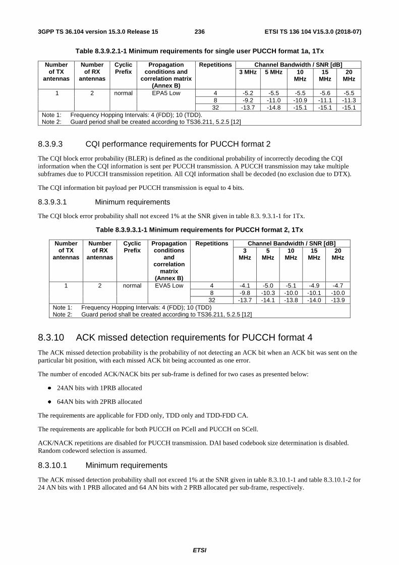
ETSI
ETSI TS 136 104 V15.3.0 (2018-07)2363GPP TS 36.104 version 15.3.0 Release 15
Table 8.3.9.2.1-1 Minimum requirements for single user PUCCH format 1a, 1Tx
Number of TX
antennas
Number of RX
antennas
Cyclic Prefix
Propagation conditions and
correlation matrix (Annex B)
Repetitions Channel Bandwidth / SNR [dB] 3 MHz 5 MHz 10
MHz 15
MHz 20
MHz
1 2 normal EPA5 Low 4 -5.2 -5.5 -5.5 -5.6 -5.5 8 -9.2 -11.0 -10.9 -11.1 -11.3 32 -13.7 -14.8 -15.1 -15.1 -15.1
Note 1: Frequency Hopping Intervals: 4 (FDD); 10 (TDD). Note 2: Guard period shall be created according to TS36.211, 5.2.5 [12]
8.3.9.3 CQI performance requirements for PUCCH format 2
The CQI block error probability (BLER) is defined as the conditional probability of incorrectly decoding the CQI information when the CQI information is sent per PUCCH transmission. A PUCCH transmission may take multiple subframes due to PUCCH transmission repetition. All CQI information shall be decoded (no exclusion due to DTX).
The CQI information bit payload per PUCCH transmission is equal to 4 bits.
8.3.9.3.1 Minimum requirements
The CQI block error probability shall not exceed 1% at the SNR given in table 8.3. 9.3.1-1 for 1Tx.
Table 8.3.9.3.1-1 Minimum requirements for PUCCH format 2, 1Tx
Number of TX
antennas
Number of RX
antennas
Cyclic Prefix
Propagation conditions
and correlation
matrix (Annex B)
Repetitions Channel Bandwidth / SNR [dB] 3
MHz 5
MHz 10
MHz 15
MHz 20
MHz
1 2 normal EVA5 Low 4 -4.1 -5.0 -5.1 -4.9 -4.7 8 -9.8 -10.3 -10.0 -10.1 -10.0 32 -13.7 -14.1 -13.8 -14.0 -13.9
Note 1: Frequency Hopping Intervals: 4 (FDD); 10 (TDD) Note 2: Guard period shall be created according to TS36.211, 5.2.5 [12]
8.3.10 ACK missed detection requirements for PUCCH format 4
The ACK missed detection probability is the probability of not detecting an ACK bit when an ACK bit was sent on the particular bit position, with each missed ACK bit being accounted as one error.
The number of encoded ACK/NACK bits per sub-frame is defined for two cases as presented below:
● 24AN bits with 1PRB allocated
● 64AN bits with 2PRB allocated
The requirements are applicable for FDD only, TDD only and TDD-FDD CA.
The requirements are applicable for both PUCCH on PCell and PUCCH on SCell.
ACK/NACK repetitions are disabled for PUCCH transmission. DAI based codebook size determination is disabled. Random codeword selection is assumed.
8.3.10.1 Minimum requirements
The ACK missed detection probability shall not exceed 1% at the SNR given in table 8.3.10.1-1 and table 8.3.10.1-2 for 24 AN bits with 1 PRB allocated and 64 AN bits with 2 PRB allocated per sub-frame, respectively.

ETSI
ETSI TS 136 104 V15.3.0 (2018-07)2373GPP TS 36.104 version 15.3.0 Release 15
Table 8.3.10.1-1 Minimum requirements for PUCCH format 4, 24AN bits with 1 PRB allocated
Number of TX
antennas
Number of RX
antennas
Cyclic Prefix
Propagation conditions
and correlation
matrix (Annex B)
Channel Bandwidth / SNR [dB] 1.4 MHz 3 MHz 5 MHz 10
MHz 15
MHz 20 MHz
1
2 Normal EPA 5 Low - - - 1.2 1.1 1.0
EVA 70 Low - - - 1.4 1.2 1.2
4 Normal EPA 5 Low - - - -3.0 -2.8 -2.9
EVA 70 Low - - - -2.6 -3.0 -3.0
8 Normal EPA 5 Low - - - -6.1 -6.1 -6.1
EVA 70 Low - - - -6.0 -6.0 -6.1
Table 8.3.10.1-2 Minimum requirements for PUCCH format 4, 64AN bits with 2 PRB allocated
Number of TX
antennas
Number of RX
antennas
Cyclic Prefix
Propagation conditions
and correlation
matrix (Annex B)
Channel Bandwidth / SNR [dB] 1.4 MHz 3 MHz 5 MHz 10
MHz 15
MHz 20 MHz
1
2 Normal EPA 5 Low - - - 1.7 1.5 1.5
EVA 70 Low - - - 2.1 2.0 1.9
4 Normal EPA 5 Low - - - -3.0 -2.9 -2.9
EVA 70 Low - - - -2.5 -2.7 -2.7
8 Normal EPA 5 Low - - - -6.3 -6.3 -6.4
EVA 70 Low - - - -6.0 -6.2 -6.2
8.3.11 ACK missed detection requirements for PUCCH format 5
The ACK missed detection probability is the probability of not detecting an ACK bit when an ACK bit was sent on the particular bit position, with each missed ACK bit being accounted as one error.
The number of encoded ACK/NACK bits per sub-frame is equal to 24 bits.
The requirement is applicable for FDD only, TDD only and TDD-FDD CA. The requirement is applicable for both PUCCH on PCell and PUCCH on SCell.
ACK/NACK repetitions are disabled for PUCCH transmission. DAI based codebook size determination is disabled. Random codeword selection is assumed.
8.3.11.1 Minimum requirements
The ACK missed detection probability shall not exceed 1% at the SNR given in table 8.3.11.1-1.
Table 8.3.11.1-1 Minimum requirements for PUCCH format 5
Number of Tx
antennas
Number of RX
antennas
Cyclic Prefix
Propagation Conditions
and correlation
matrix (Annex B)
Channel Bandwidth / SNR [dB]
1.4MHz 3MHz 5MHz 10 MHz 15MHz 20MHz
1 2 Normal EPA 5 Low - - - 1.6 1.3 1.3 EVA70 Low - - - 1.6 1.5 1.5
4 Normal EPA 5 Low - - - -2.9 -2.8 -2.8 EVA70 Low - - - -2.5 -2.8 -2.7
8 Normal EPA 5 Low - - - -6.0 -5.9 -6.0 EVA70 Low - - - -5.8 -5.9 -6.0
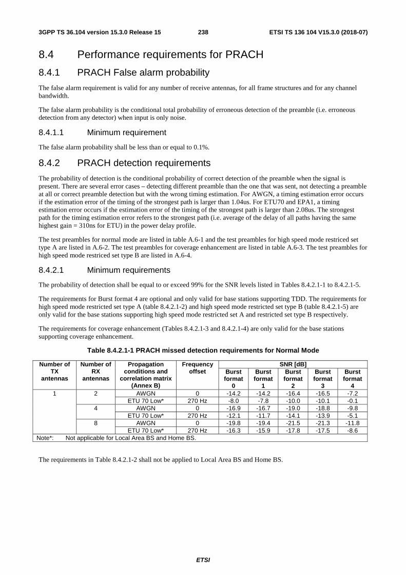
ETSI
ETSI TS 136 104 V15.3.0 (2018-07)2383GPP TS 36.104 version 15.3.0 Release 15
8.4 Performance requirements for PRACH
8.4.1 PRACH False alarm probability
The false alarm requirement is valid for any number of receive antennas, for all frame structures and for any channel bandwidth.
The false alarm probability is the conditional total probability of erroneous detection of the preamble (i.e. erroneous detection from any detector) when input is only noise.
8.4.1.1 Minimum requirement
The false alarm probability shall be less than or equal to 0.1%.
8.4.2 PRACH detection requirements
The probability of detection is the conditional probability of correct detection of the preamble when the signal is present. There are several error cases – detecting different preamble than the one that was sent, not detecting a preamble at all or correct preamble detection but with the wrong timing estimation. For AWGN, a timing estimation error occurs if the estimation error of the timing of the strongest path is larger than 1.04us. For ETU70 and EPA1, a timing estimation error occurs if the estimation error of the timing of the strongest path is larger than 2.08us. The strongest path for the timing estimation error refers to the strongest path (i.e. average of the delay of all paths having the same highest gain = 310ns for ETU) in the power delay profile.
The test preambles for normal mode are listed in table A.6-1 and the test preambles for high speed mode restriced set type A are listed in A.6-2. The test preambles for coverage enhancement are listed in table A.6-3. The test preambles for high speed mode restriced set type B are listed in A.6-4.
8.4.2.1 Minimum requirements
The probability of detection shall be equal to or exceed 99% for the SNR levels listed in Tables 8.4.2.1-1 to 8.4.2.1-5.
The requirements for Burst format 4 are optional and only valid for base stations supporting TDD. The requirements for high speed mode restricted set type A (table 8.4.2.1-2) and high speed mode restricted set type B (table 8.4.2.1-5) are only valid for the base stations supporting high speed mode restricted set A and restricted set type B respectively.
The requirements for coverage enhancement (Tables 8.4.2.1-3 and 8.4.2.1-4) are only valid for the base stations supporting coverage enhancement.
Table 8.4.2.1-1 PRACH missed detection requirements for Normal Mode
Number of TX
antennas
Number of RX
antennas
Propagation conditions and
correlation matrix (Annex B)
Frequency offset
SNR [dB] Burst format
0
Burst format
1
Burst format
2
Burst format
3
Burst format
4 1 2 AWGN 0 -14.2 -14.2 -16.4 -16.5 -7.2
ETU 70 Low* 270 Hz -8.0 -7.8 -10.0 -10.1 -0.1 4 AWGN 0 -16.9 -16.7 -19.0 -18.8 -9.8
ETU 70 Low* 270 Hz -12.1 -11.7 -14.1 -13.9 -5.1 8 AWGN 0 -19.8 -19.4 -21.5 -21.3 -11.8
ETU 70 Low* 270 Hz -16.3 -15.9 -17.8 -17.5 -8.6 Note*: Not applicable for Local Area BS and Home BS.
The requirements in Table 8.4.2.1-2 shall not be applied to Local Area BS and Home BS.

ETSI
ETSI TS 136 104 V15.3.0 (2018-07)2393GPP TS 36.104 version 15.3.0 Release 15
Table 8.4.2.1-2 PRACH missed detection requirements for High speed Mode restricted set type A
Number of TX antennas
Number of RX antennas
Propagation conditions and
correlation matrix (Annex B)
Frequency offset
SNR [dB] Burst
format 0 Burst
format 1 Burst
format 2 Burst
format 3
1 2 AWGN 0 -14.1 -14.2 -16.3 -16.6 ETU 70 Low 270 Hz -7.4 -7.3 -9.3 -9.5
AWGN 625 Hz -12.4 -12.3 -14.4 -14.4 AWGN 1340 Hz -13.4 -13.5 -15.5 -15.7
4 AWGN 0 -16.9 -16.6 -18.9 -18.8 ETU 70 Low 270 Hz -11.8 -11.4 -13.7 -13.7
AWGN 625 Hz -14.9 -14.6 -16.8 -16.8 AWGN 1340 Hz -15.9 -15.5 -17.8 -17.8
8 AWGN 0 -19.3 -19.1 -20.9 -21.0 ETU 70 Low 270 Hz -15.6 -15.1 -17.0 -17.0
AWGN 625 Hz -17.7 -17.4 -19.3 -19.4 AWGN 1340 Hz -18.7 -18.4 -20.5 -20.5
Table 8.4.2.1-3 PRACH missed detection requirements for coverage enhancement (PRACH frequency hopping OFF)
Number of TX
antennas
Number of RX
antennas
Propagation conditions and
correlation matrix (Annex B)
Frequency offset
Number of Repetitions
SNR [dB] Burst format
0
Burst format
1
Burst format
2
Burst format
3 1 2 AWGN 0 4 - - -21.3 -21.1
8 -21.7 -21.3 - - 16 - - -25.1 -25.0 32 -25.6 -25.3 - -
EPA1 Low 270 Hz 4 - - -12.1 -11.7 8 -13.0 -12.3 - - 16 - - -17.2 -17.2 32 -19.0 -18.6 - -
Note 1: Under fading channels, the PRACH detection performance may be significantly different with different PRACH Configuration Indexes. The requirements in this table are defined based on the simulation results with PRACH Configuration Indexes (3, 19, 35, 51) for Format 0, Format 1, Format 2, and Format 3 respectively.
Table 8.4.2.1-4 PRACH missed detection requirements for coverage enhancement (PRACH frequency hopping ON)
Number of TX
antennas
Number of RX
antennas
Propagation conditions and
correlation matrix (Annex
B)
Frequency offset
Number of Repetitions
SNR [dB] Burst format
0
Burst format
1
Burst format
2
Burst format
3
1 2 EPA1 Low 270 Hz 4 - - -15.5 -15.3 8 -16.2 -15.8 - - 16 - - -20.1 -20.2 32 -21.3 -21.1 - -
Note 1: Under fading channels, the PRACH detection performance may be significantly different with different PRACH Configuration Indexes. The requirements in this table are defined based on the simulation results with PRACH Configuration Indexes (3, 19, 35, 51) for Format 0, Format 1, Format 2, and Format 3 respectively.
Note 2: The requirements in this table are defined under the assumption that UE RF tuning during PRACH frequency hopping has no impact on the symbols in PRACH subframes and thus all symbols in PRACH subframes are available for the transmission of PRACH preambles.
Note 3: The requirements in this table are defined under the assumption that the PRACH frequency offset (prach-
FreqOffset-r13) is 0 and frequency hopping offset is -6, where is defined in TS36.211 [12].
Note 4: The requirements in this table apply for channel bandwidth of 5MHz, 10MHz, 15MHz or 20MHz. For channel bandwidth of 3MHz, the requirements in Table 8.4.2.1-3 apply.
ULRBN UL
RBN

ETSI
ETSI TS 136 104 V15.3.0 (2018-07)2403GPP TS 36.104 version 15.3.0 Release 15
Table 8.4.2.1-5 PRACH missed detection requirements for High speed Mode restricted set type B
Number of TX antennas
Number of RX antennas
Propagation conditions and
correlation matrix (Annex B)
Frequency offset
SNR [dB] Burst
format 0 Burst
format 1 Burst
format 2 Burst
format 3
1 2 AWGN 0 -14.5 -14.1 -16.7 -16.8 AWGN 625 -12.0 -11.7 -13.9 -13.9
ETU 70 Low 270 Hz -7.3 -6.9 -9.1 -9.2 AWGN 1875 Hz -11.8 -11.4 -13.8 -14.0
4 AWGN 0 -17.1 -16.6 -19.1 -19.1 AWGN 625 -14.4 -14.1 -16.1 -16.2
ETU 70 Low 270 Hz -11.8 -11.3 -13.5 -13.4 AWGN 1875 Hz -14.2 -13.8 -15.9 -16.3
8 AWGN 0 -19.6 -19.1 -21.2 -21.2 AWGN 625 -16.4 -16.3 -18.1 -18.2
ETU 70 Low 270 Hz -15.3 -15.1 -17.1 -17.5 AWGN 1875 Hz -16.3 -16.0 -18.0 -18.4
8.5 Performance requirements for Narrowband IoT
8.5.1 Requirements for NPUSCH format 1
8.5.1.1 Requirements
The performance requirement of NPUSCH format 1 is determined by a minimum required throughput for a given SNR. The required throughput is expressed as a fraction of maximum throughput for the FRCs listed in Annex A16. The performance requirements assume HARQ retransmissions.
An NB-IoT Base Station supports 15 kHz subcarrier spacing requirements, or 3.75 kHz subcarrier spacing requirements, or both.
For 15kHz subcarrier spacing single-subcarrier/multi-subcarrier, the demodulation requirements apply for the supported number of subcarriers.
Table 8.5.1.1-1: Test parameters
Parameter Value Maximum number of HARQ transmissions 4
RV sequence RV0, RV2
8.5.1.1.1 Minimum requirements
The throughput shall be equal to or larger than the fraction of maximum throughput stated in table 8.5.1.1.1-1 for the single-subcarrier of 3.75KHz subcarrier spacing, in table 8.5.1.1.1-2 for 15KHz subcarrier spacing at the given SNR for 1Tx, and in table 8.5.1.1.1-3 for multi-subcarrier of 15KHz subcarrier spacing at the given SNR for 1Tx.
Table 8.5.1.1.1-1: Minimum requirements for NPUSCH format 1, 200KHz Channel Bandwidth, 3.75KHz subcarrier spacing, 1Tx
Number of TX
antennas
Number of RX
antennas
Subcarrier spacing
Number of allocated
subcarriers
Propagation conditions
and correlation
matrix (Annex B)
FRC (Annex
A)
Repetition number
Fraction of maximum
throughput
SNR [dB]
1 2 3.75KHz 1 ETU 1Hz
Low A16-1
1 70% -1.9 16 70% -9.2
64 70% -12.2

ETSI
ETSI TS 136 104 V15.3.0 (2018-07)2413GPP TS 36.104 version 15.3.0 Release 15
Table 8.5.1.1.1-2: Minimum requirements for NPUSCH format 1, 200KHz Channel Bandwidth, 15KHz subcarrier spacing, single subcarrier, 1Tx
Number of TX
antennas
Number of RX
antennas
Subcarrier spacing
Number of allocated
subcarriers
Propagation conditions
and correlation
matrix (Annex B)
FRC (Annex
A)
Repetition number
Fraction of maximum
throughput
SNR [dB]
1 2 15KHz 1 ETU 1Hz Low
A16-2
1 70% -2.1 16 70% -8.8
64 70% -12.6
Table 8.5.1.1.1-3: Minimum requirements for NPUSCH format 1, 200KHz Channel Bandwidth, 15KHz subcarrier spacing, multiple subcarriers, 1Tx
Number of TX
antennas
Number of RX
antennas
Subcarrier spacing
Number of allocated
subcarriers
Propagation conditions
and correlation
matrix (Annex B)
FRC (Annex
A)
Repetition number
Fraction of maximum
throughput
SNR [dB]
1 2 15KHz
3 ETU 1Hz Low A16-3
2 70% -3.0 16 70% -8.1
64 70% -
11.4
6 ETU 1Hz
Low A16-4
2 70% -0.6 16 70% -6.8
64 70% -10.5
12 ETU 1Hz Low A16-5
2 70% -0.7 16 70% -6.4 64 70% -
10.1
8.5.2 Performance requirements for NPUSCH format 2
8.5.2.1 DTX to ACK performance
The DTX to ACK probability for NPUSCH format 2 case denotes the probability that ACK is detected when nothing is sent on the wanted signal and only the noise is present per NPUSCH format 2 transmission.
An NB-IoT Base Station supports 15 KHz sub-carrier spacing requirements, or 3.75 KHz sub-carrier spacing requirements, or both.
8.5.2.1.1 Minimum requirement
The DTX to ACK probability, i.e. the probability that ACK is detected when nothing was sent, shall not exceed 1% per NPUSCH format 2 transmission. Where the performance measure definition is as follows:
( )
2#(false ACK bits)Prob(NPUSCH format 2 DTX ACK bits) 10
# NPUSCH format 2 DTX #(ACK/NAK bits)
−→ = ≤×
where:
- #(false ACK bits) denotes the number of detected ACK bits.
- #(ACK/NACK bits) denotes the number of HARQ-ACK information bit per NPUSCH format 2 transmission.
- #( NPUSCH format 2 DTX) denotes the number of DTX occasions.

ETSI
ETSI TS 136 104 V15.3.0 (2018-07)2423GPP TS 36.104 version 15.3.0 Release 15
8.5.2.2 ACK missed detection requirements
The ACK missed detection probability is the probability of not detecting an ACK when an ACK was sent per NPUSCH format 2 transmission.
8.5.2.2.1 Minimum requirements
The ACK missed detection probability shall not exceed 1% at the SNR given in table 8.5.2.2.1-1 and table 8.5.2.2.1-2 for 1Tx case.
Table 8.5.2.2.1-1: Minimum requirements for NPUSCH format 2, 200KHz Channel Bandwidth, 3.75KHz subcarrier spacing, 1Tx
Number of TX
antennas
Number of RX
antennas
Propagation conditions
and correlation
matrix (Annex B)
Number of allocated
subcarriers
Subcarrier spacing
Repetition number
SNR [dB]
1 2 EPA 5 Low 1 3.75KHz 1 7.0 16 -5.3 64 -10.9
Table 8.5.2.2.1-2: Minimum requirements for NPUSCH format 2, 200KHz Channel Bandwidth, 15KHz subcarrier spacing, 1Tx
Number of TX
antennas
Number of RX
antennas
Propagation conditions
and correlation
matrix (Annex B)
Number of allocated
subcarriers
Subcarrier spacing
Repetition number
SNR [dB]
1 2 EPA 5 Low 1 15KHz 1 6.3
16 -3.9 64 -9.5
8.5.3 Performance requirements for NPRACH
8.5.3.1 NPRACH False alarm probability
The false alarm requirement is valid for any number of receive antennas, for all repetition numbers and for any number of subcarriers.
The false alarm probability is the conditional total probability of erroneous detection of the preamble (i.e. erroneous detection from any detector) when input is only noise.
8.5.3.1.1 Minimum requirement
The false alarm probability shall be less than or equal to 0.1%.
8.5.3.2 NPRACH detection requirements
The probability of detection is the conditional probability of correct detection of the preamble when the signal is present. There are several error cases – detecting different preamble than the one that was sent, not detecting a preamble at all or correct preamble detection but with the wrong timing estimation. A timing estimation error occurs if the estimation error of the timing of the strongest path is larger than 3.646us. The strongest path for the timing estimation error refers to the strongest path in the power delay profile.

ETSI
ETSI TS 136 104 V15.3.0 (2018-07)2433GPP TS 36.104 version 15.3.0 Release 15
Table 8.5.3.2-1 Test preambles for NPRACH
Parameter Value Narrowband physical
layer cell identity 0
Initial subcarrier index 0
8.5.3.2.1 Minimum requirements
The probability of detection shall be equal to or exceed 99% for the SNR levels listed in table 8.5.3.2.1-1.
Table 8.5.3.2.1-1 NPRACH missed detection requirements
Number of TX antennas
Number of RX antennas
Repetition number
Propagation conditions and
correlation matrix (Annex B)
Frequency offset
SNR[dB] Preamble format 0
Preamble format 1
1 2 8 AWGN 0 -2.1 -2.1 EPA1 Low 200 Hz 6.1 6.1
32 AWGN 0 -6.8 -6.8 EPA1 Low 200 Hz 0.5 0.5

ETSI
ETSI TS 136 104 V15.3.0 (2018-07)2443GPP TS 36.104 version 15.3.0 Release 15
9 Void
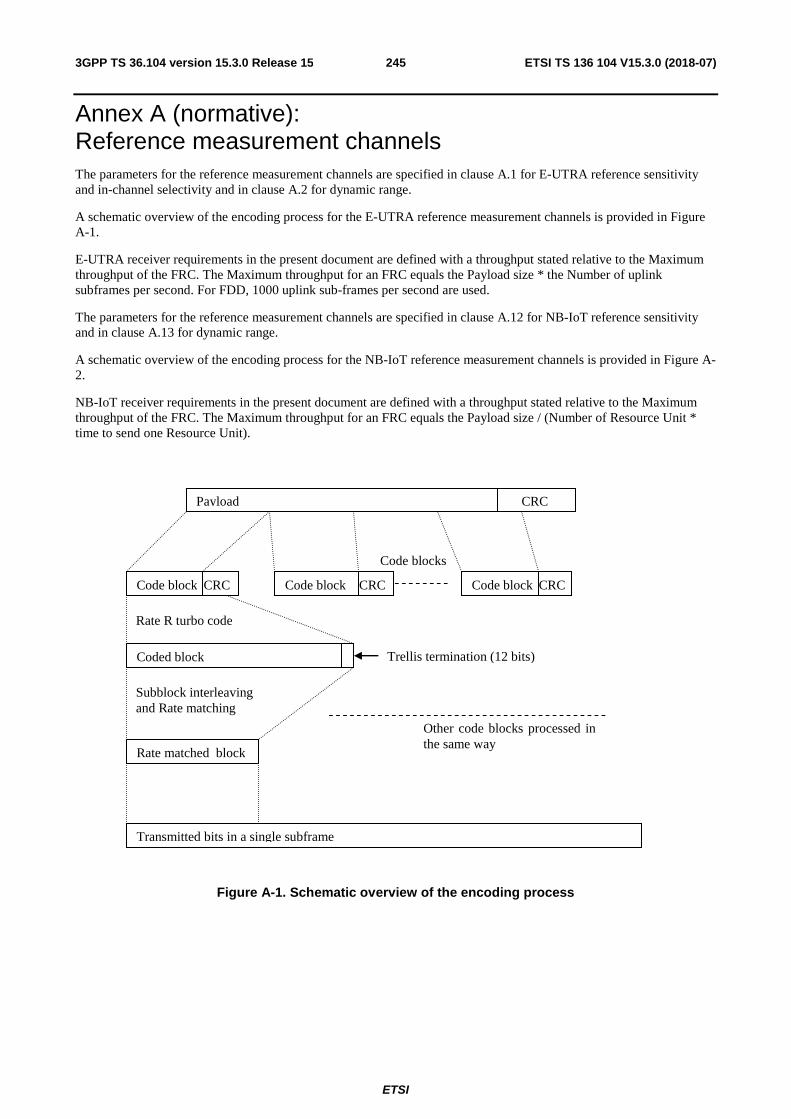
ETSI
ETSI TS 136 104 V15.3.0 (2018-07)2453GPP TS 36.104 version 15.3.0 Release 15
Annex A (normative): Reference measurement channels The parameters for the reference measurement channels are specified in clause A.1 for E-UTRA reference sensitivity and in-channel selectivity and in clause A.2 for dynamic range.
A schematic overview of the encoding process for the E-UTRA reference measurement channels is provided in Figure A-1.
E-UTRA receiver requirements in the present document are defined with a throughput stated relative to the Maximum throughput of the FRC. The Maximum throughput for an FRC equals the Payload size * the Number of uplink subframes per second. For FDD, 1000 uplink sub-frames per second are used.
The parameters for the reference measurement channels are specified in clause A.12 for NB-IoT reference sensitivity and in clause A.13 for dynamic range.
A schematic overview of the encoding process for the NB-IoT reference measurement channels is provided in Figure A-2.
NB-IoT receiver requirements in the present document are defined with a throughput stated relative to the Maximum throughput of the FRC. The Maximum throughput for an FRC equals the Payload size / (Number of Resource Unit * time to send one Resource Unit).
Payload
Code block
Transmitted bits in a single subframe
Code block
Coded block Trellis termination (12 bits)
Rate matched block
Rate R turbo code
Code blocks
Subblock interleaving and Rate matching
Code block
CRC
Other code blocks processed in the same way
CRC CRC CRC
Figure A-1. Schematic overview of the encoding process
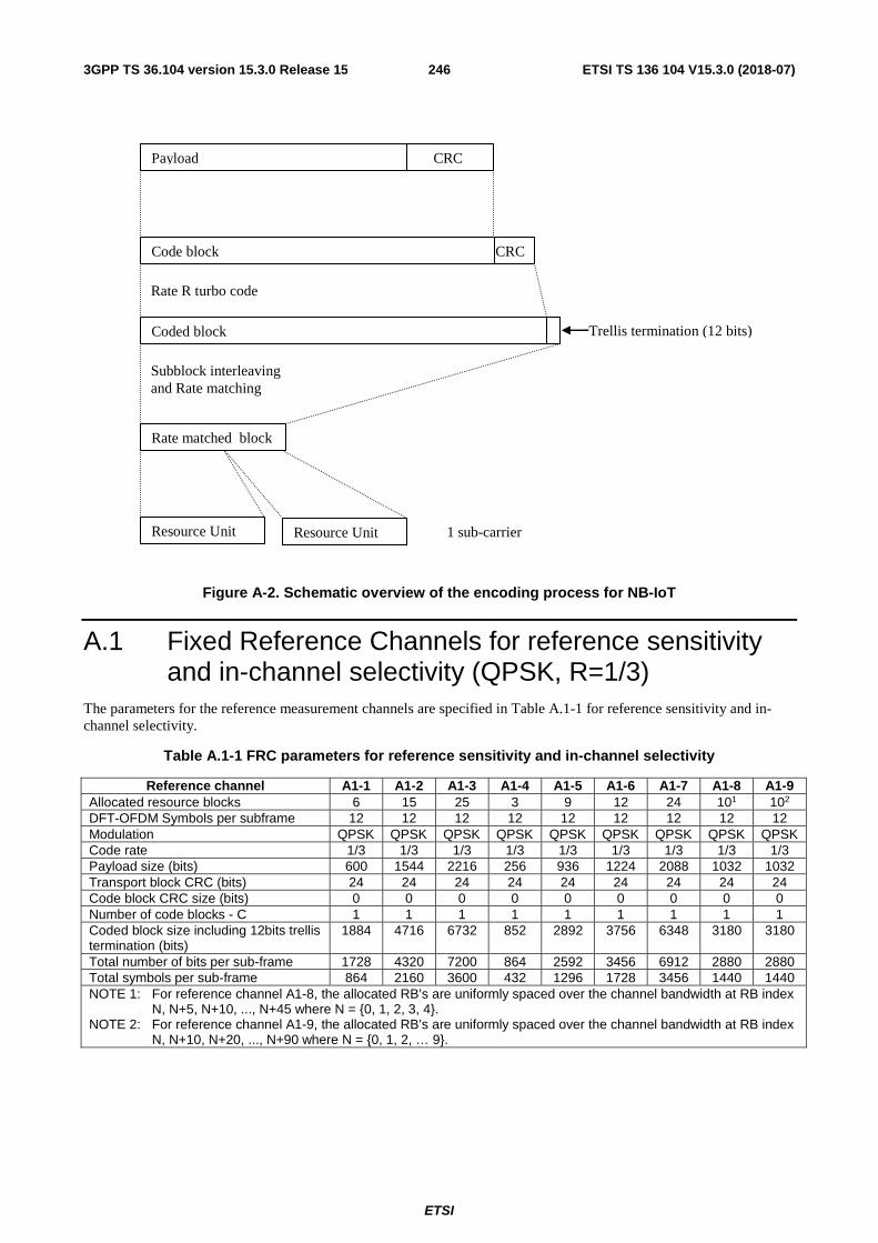
ETSI
ETSI TS 136 104 V15.3.0 (2018-07)2463GPP TS 36.104 version 15.3.0 Release 15
Payload
Code block
Resource Unit
Coded block Trellis termination (12 bits)
Rate matched block
Rate R turbo code
Subblock interleaving and Rate matching
CRC
CRC
Resource Unit 1 sub-carrier
Figure A-2. Schematic overview of the encoding process for NB-IoT
A.1 Fixed Reference Channels for reference sensitivity and in-channel selectivity (QPSK, R=1/3)
The parameters for the reference measurement channels are specified in Table A.1-1 for reference sensitivity and in-channel selectivity.
Table A.1-1 FRC parameters for reference sensitivity and in-channel selectivity
Reference channel A1-1 A1-2 A1-3 A1-4 A1-5 A1-6 A1-7 A1-8 A1-9 Allocated resource blocks 6 15 25 3 9 12 24 101 102 DFT-OFDM Symbols per subframe 12 12 12 12 12 12 12 12 12 Modulation QPSK QPSK QPSK QPSK QPSK QPSK QPSK QPSK QPSK Code rate 1/3 1/3 1/3 1/3 1/3 1/3 1/3 1/3 1/3 Payload size (bits) 600 1544 2216 256 936 1224 2088 1032 1032 Transport block CRC (bits) 24 24 24 24 24 24 24 24 24 Code block CRC size (bits) 0 0 0 0 0 0 0 0 0 Number of code blocks - C 1 1 1 1 1 1 1 1 1 Coded block size including 12bits trellis termination (bits)
1884 4716 6732 852 2892 3756 6348 3180 3180
Total number of bits per sub-frame 1728 4320 7200 864 2592 3456 6912 2880 2880 Total symbols per sub-frame 864 2160 3600 432 1296 1728 3456 1440 1440 NOTE 1: For reference channel A1-8, the allocated RB’s are uniformly spaced over the channel bandwidth at RB index
N, N+5, N+10, ..., N+45 where N = {0, 1, 2, 3, 4}. NOTE 2: For reference channel A1-9, the allocated RB’s are uniformly spaced over the channel bandwidth at RB index
N, N+10, N+20, ..., N+90 where N = {0, 1, 2, … 9}.

ETSI
ETSI TS 136 104 V15.3.0 (2018-07)2473GPP TS 36.104 version 15.3.0 Release 15
A.2 Fixed Reference Channels for dynamic range (16QAM, R=2/3)
The parameters for the reference measurement channels are specified in Table A.2-1 for dynamic range.
Table A.2-1 FRC parameters for dynamic range
Reference channel A2-1 A2-2 A2-3 A2-4 A2-5 Allocated resource blocks 6 15 25 101 102 DFT-OFDM Symbols per subframe 12 12 12 12 12 Modulation 16QAM 16QAM 16QAM 16QAM 16QAM Code rate 2/3 2/3 2/3 2/3 2/3 Payload size (bits) 2344 5992 9912 4008 4008 Transport block CRC (bits) 24 24 24 24 24 Code block CRC size (bits) 0 0 24 0 0 Number of code blocks - C 1 1 2 1 1 Coded block size including 12bits trellis termination (bits)
7116 18060 14988 12108 12108
Total number of bits per sub-frame 3456 8640 14400 5760 5760 Total symbols per sub-frame 864 2160 3600 1440 1440 NOTE 1: For reference channel A2-4, the allocated RB’s are uniformly spaced over the
channel bandwidth at RB index N, N+5, N+10, ..., N+45 where N = {0, 1, 2, 3, 4}. NOTE 2: For reference channel A2-5, the allocated RB’s are uniformly spaced over the
channel bandwidth at RB index N, N+10, N+20, ..., N+90 where N = {0, 1, 2, … 9}.
A.3 Fixed Reference Channels for performance requirements (QPSK 1/3)
Table A.3-1 FRC parameters for performance requirements (QPSK 1/3)
Reference channel A3-1 A3-2 A3-3 A3-4 A3-5 A3-6 A3-7 Allocated resource blocks 1 6 15 25 50 75 100 DFT-OFDM Symbols per subframe 12 12 12 12 12 12 12 Modulation QPSK QPSK QPSK QPSK QPSK QPSK QPSK Code rate 1/3 1/3 1/3 1/3 1/3 1/3 1/3 Payload size (bits) 104 600 1544 2216 5160 6712 10296 Transport block CRC (bits) 24 24 24 24 24 24 24 Code block CRC size (bits) 0 0 0 0 0 24 24 Number of code blocks - C 1 1 1 1 1 2 2 Coded block size including 12bits trellis termination (bits)
396 1884 4716 6732 15564 10188 15564
Total number of bits per sub-frame 288 1728 4320 7200 14400 21600 28800 Total symbols per sub-frame 144 864 2160 3600 7200 10800 14400

ETSI
ETSI TS 136 104 V15.3.0 (2018-07)2483GPP TS 36.104 version 15.3.0 Release 15
A.4 Fixed Reference Channels for performance requirements (16QAM 3/4)
Table A.4-1 FRC parameters for performance requirements (16QAM 3/4)
Reference channel A4-1 A4-2 A4-3 A4-4 A4-5 A4-6 A4-7 A4-8 Allocated resource blocks 1 1 6 15 25 50 75 100 DFT-OFDM Symbols per subframe
12 10 12 12 12 12 12 12
Modulation 16QAM 16QAM 16QAM 16QAM 16QAM 16QAM 16QAM 16QAM Code rate 3/4 3/4 3/4 3/4 3/4 3/4 3/4 3/4 Payload size (bits) 408 376 2600 6456 10680 21384 32856 43816 Transport block CRC (bits) 24 24 24 24 24 24 24 24 Code block CRC size (bits) 0 0 0 24 24 24 24 24 Number of code blocks - C 1 1 1 2 2 4 6 8 Coded block size including 12bits trellis termination (bits)
1308 1212 7884 9804 16140 16140 16524 16524
Total number of bits per sub-frame
576 480 3456 8640 14400 28800 43200 57600
Total symbols per sub-frame
144 120 864 2160 3600 7200 10800 14400
A.5 Fixed Reference Channels for performance requirements (64QAM 5/6)
Table A.5-1 FRC parameters for performance requirements (64QAM 5/6)
Reference channel A5-1 A5-2 A5-3 A5-4 A5-5 A5-6 A5-7 Allocated resource blocks 1 6 15 25 50 75 100 DFT-OFDM Symbols per subframe 12 12 12 12 12 12 12 Modulation 64QAM 64QAM 64QAM 64QAM 64QAM 64QAM 64QAM Code rate 5/6 5/6 5/6 5/6 5/6 5/6 5/6 Payload size (bits) 712 4392 11064 18336 36696 55056 75376 Transport block CRC (bits) 24 24 24 24 24 24 24 Code block CRC size (bits) 0 0 24 24 24 24 24 Number of code blocks - C 1 1 2 3 6 9 13 Coded block size including 12bits trellis termination (bits)
2220 13260 16716 18444 18444 18444 17484
Total number of bits per sub-frame 864 5184 12960 21600 43200 64800 86400 Total symbols per sub-frame 144 864 2160 3600 7200 10800 14400
A.6 PRACH Test preambles Table A.6-1 Test preambles for Normal Mode
Burst format Ncs Logical sequence index v 0 13 22 32 1 167 22 2 2 167 22 0 3 0 22 0 4 10 0 0

ETSI
ETSI TS 136 104 V15.3.0 (2018-07)2493GPP TS 36.104 version 15.3.0 Release 15
Table A.6-2 Test preambles for High speed Mode restricted set type A
Burst format Ncs Logical sequence index v 0 15 384 0 1 202 384 0 2 202 384 0 3 237 384 0
Table A.6-3 Test preambles for coverage enhancement
Burst format Ncs Logical sequence index v 0 13 22 32 1 167 22 2 2 167 22 0 3 0 22 0
Table A.6-4 Test preambles for High speed Mode restricted set type B
Burst format Ncs Logical sequence index v 0 15 30 30 1 100 168 20 2 118 204 10 3 137 264 0
A.7 Fixed Reference Channels for UL timing adjustment (Scenario 1)
Table A.7-1 FRC parameters for UL timing adjustment (Scenario 1)
Reference channel A7-1 A7-2 A7-3 A7-4 A7-5 A7-6 Allocated resource blocks 3 6 12 25 25 25 DFT-OFDM Symbols per subframe 12 12 12 12 12 12 Modulation 16QAM 16QAM 16QAM 16QAM 16QAM 16QAM Code rate 3/4 3/4 3/4 3/4 3/4 3/4 Payload size (bits) 1288 2600 5160 10680 10680 10680 Transport block CRC (bits) 24 24 24 24 24 24 Code block CRC size (bits) 0 0 0 24 24 24 Number of code blocks - C 1 1 1 2 2 2 Coded block size including 12bits trellis termination (bits)
3948 7884 15564 16140 16140 16140
Total number of bits per sub-frame 1728 3456 6912 14400 14400 14400 Total symbols per sub-frame 432 864 1728 3600 3600 3600 SRS bandwidth configuration (See TS 36.211, 5.5.3) (Note 1)
7 5 3 2 5 2
SRS-Bandwidth b (See TS 36.211, 5.5.3) (Note 1, 2) 0 0 0 0 0 1 NOTE 1. The transmission of SRS is optional NOTE 2. PUSCH resource blocks shall be included in SRS resource blocks

ETSI
ETSI TS 136 104 V15.3.0 (2018-07)2503GPP TS 36.104 version 15.3.0 Release 15
A.8 Fixed Reference Channels for UL timing adjustment (Scenario 2)
Table A.8-1 FRC parameters for UL timing adjustment (Scenario 2)
Reference channel A8-1 A8-2 A8-3 A8-4 A8-5 A8-6 Allocated resource blocks 3 6 12 25 25 25 DFT-OFDM Symbols per subframe 12 12 12 12 12 12 Modulation QPSK QPSK QPSK QPSK QPSK QPSK Code rate 1/3 1/3 1/3 1/3 1/3 1/3 Payload size (bits) 256 600 1224 2216 2216 2216 Transport block CRC (bits) 24 24 24 24 24 24 Code block CRC size (bits) 0 0 0 0 0 0 Number of code blocks - C 1 1 1 1 1 1 Coded block size including 12bits trellis termination (bits) 852 1884 3756 6732 6732 6732 Total number of bits per sub-frame 864 1728 3456 7200 7200 7200 Total symbols per sub-frame 432 864 1728 3600 3600 3600 SRS bandwidth configuration (See TS 36.211, 5.5.3) (Note 1) 7 5 3 2 5 2 SRS-Bandwidth b (See TS 36.211, 5.5.3) (Note 1, 2) 0 0 0 0 0 1 NOTE 1. The transmission of SRS is optional NOTE 2. PUSCH resource blocks shall be included in SRS resource blocks
A.9 Multi user PUCCH test
Table A.9-1 Test parameters for multi user PUCCH case
Resource index for PUCCH formats 1/1a/1b
(1)PUCCHn
Relative power [dB]
Relative timing [ns]
Tested signal 2 - -
Interferer 1 1 0 0
Interferer 2 7 -3
Interferer 3 14 3
NOTE1: The following parameters shall be used 150cellID =N , 0(1)
cs =N and 2PUCCHshift =Δ .
NOTE2: All above listed signals are transmitted on the same PUCCH resource block, with different PUCCH resource indices as presented above.
A.10 PUCCH transmission on two antenna ports test Table A.10-1 Test parameters for PUCCH transmission on two antenna ports case
PUCCH format Resource indices for two antenna ports
Format 1a 0(1, )PUCCH 1p pn = =
,1(1, )
PUCCH 2p pn = =
Format 2 0(2, )PUCCH 1p pn = =
,1(2, )
PUCCH 2p pn = =
NOTE1: The following parameters shall be used 150cellID =N , 0(1)
cs =N . For PUCCH format 1a, 2PUCCH
shift =Δ is
assumed. NOTE2: The signals transmitted on two antenna ports are in the same PUCCH resource block with different
resource indices as presented above.

ETSI
ETSI TS 136 104 V15.3.0 (2018-07)2513GPP TS 36.104 version 15.3.0 Release 15
A.11 Fixed Reference Channel for PUSCH with TTI bundling and enhanced HARQ pattern
Table A.11-1 FRC parameters for PUSCH with TTI bundling and enhanced HARQ pattern
Reference channel A11-1 Allocated resource blocks 3 DFT-OFDM Symbols per subframe 12 Modulation QPSK Code rate 11/27* Payload size (bits) 328 Transport block CRC (bits) 24 Code block CRC size (bits) 0 Number of code blocks - C 1 Coded block size including 12bits trellis termination (bits) 1068 Total number of bits per sub-frame 864 Total symbols per sub-frame 432 Note *: code rate per TTI
A.12 Fixed Reference Channels for performance requirements (QPSK 0.36)
Table A.12-1 FRC parameters for performance requirements (QPSK 0.36)
Reference channel A12-1 A12-2 A12-3 A12-4 A12-5 A12-6 Allocated resource blocks 6 15 25 50 75 100 DFT-OFDM Symbols per subframe 12 12 12 12 12 12 Modulation QPSK QPSK QPSK QPSK QPSK QPSK Code rate 0.36 0.36 0.36 0.36 0.36 0.36 MCS index 6 6 6 6 6 6 Payload size (bits) 600 1544 2600 5160 7736 10296 Transport block CRC (bits) 24 24 24 24 24 24 Code block CRC size (bits) 0 0 0 0 24 24 Number of code blocks - C 1 1 1 1 2 2 Coded block size including 12bits trellis termination (bits)
1884 4716 7884 15564 11724 15564
Total number of bits per sub-frame 1728 4320 7200 14400 21600 28800 Total symbols per sub-frame 864 2160 3600 7200 10800 14400 NOTE 1: FRC A12-1, A12-2, A12-4, A12-6 are identical to A3-2, A3-3, A3-5, A3-7 respectively.

ETSI
ETSI TS 136 104 V15.3.0 (2018-07)2523GPP TS 36.104 version 15.3.0 Release 15
A.13 Fixed Reference Channels for performance requirements (16QAM 1/2)
Table A.13-1 FRC parameters for performance requirements (16QAM 1/2)
Reference channel A13-1 A13-2 A13-3 A13-4 A13-5 A13-6 Allocated resource blocks 6 15 25 50 75 100 DFT-OFDM Symbols per subframe 12 12 12 12 12 12 Modulation 16QAM 16QAM 16QAM 16QAM 16QAM 16QAM Code rate 0.51 0. 50 0.50 0.49 0.50 0.49 MCS index 15 15 15 15 15 15 Payload size (bits) 1736 4264 7224 14112 21384 28336 Transport block CRC (bits) 24 24 24 24 24 24 Code block CRC size (bits) 0 0 24 24 24 24 Number of code blocks - C 1 1 2 3 4 5 Coded block size including 12bits trellis termination (bits)
5292 12876 10956 14220 16140 17100
Total number of bits per sub-frame 3456 8640 14400 28800 43200 57600 Total symbols per sub-frame 864 2160 3600 7200 10800 14400
A.14 Fixed Reference Channels for NB-IOT reference sensitivity (π/2 BPSK, R=1/3)
The parameters for the reference measurement channels are specified in Table A.14-1 for reference sensitivity.
Table A.14-1 FRC parameters for reference sensitivity and in-channel selectivity
Reference channel A14-1 A14-2 Sub-carrier spacing (kHz) 15 3.75 Number of tone 1 1 Diversity No No Modulation π/2 BPSK π/2 BPSK Frequency offset 0 0 Channel estimation length (ms) Note 1 4 16 Number of NPUSCH repetition 1 1 IMCS / TBS 0 / 0 0 / 0 Payload size (bits) 32 32 Allocated resource unit 2 2 Code rate (target) 1/3 1/3 Code rate (effective) 0.29 0.29 Transport block CRC (bits) 24 24 Code block CRC size (bits) 0 0 Number of code blocks - C 1 1 Total number of bits per resource unit 96 96 Total symbols per resource unit 96 96 Tx time (ms) 16 64 Note 1: Channel estimation lengths are included in the table for
information only.
A.15 Fixed Reference Channels for NB-IoT dynamic range (π/4 QPSK, R=2/3)
The parameters for the reference measurement channels are specified in Table A.15-1 for NB-IoT dynamic range.

ETSI
ETSI TS 136 104 V15.3.0 (2018-07)2533GPP TS 36.104 version 15.3.0 Release 15
Table A.15-1 FRC parameters for NB-IoT dynamic range
Reference channel A15-1 A15-2 Sub carrier spacing (kHz) 15 3.75 Number of tone 1 1 Modulation π/4 QPSK π/4 QPSK Diversity No No Frequency offset 0 0 IMCS / ITBS 7 / 7 7 / 7 Payload size (bits) 104 104 Allocated resource units 1 1 Transport block CRC (bits) 24 24 Coding rate (target) 2/3 2/3 Coding Rate 0.67 0.67 Code block CRC size (bits) 0 0 Number of code blocks – C 1 1 Total symbols per resource unit 96 96 Total number of bits per resource unit 192 192 Tx time (ms) 8 32 Frequency offset 0 0 Channel estimation length (ms) Note 1 4 16 Note 1: Channel estimation lengths are included in the table for
information only.
A.16 Fixed Reference Channels for NB-IoT NPUSCH format 1
A.16.1 One PRB Table A.16.1-1: FRC parameters for NB-IoT NPUSCH format 1
Reference channel A16-1 A16-2 A16-3 A16-4 A16-5 Subcarrier spacing (kHz) 3.75 15 15 15 15 Number of allocated subcarriers 1 1 3 6 12 Diversity No No No No No Modulation BPSK BPSK QPSK QPSK QPSK ITBS / IRU 0 / 1 0 / 1 3 / 0 7 / 0 9 / 0 Payload size (bits) 32 32 40 104 136 Allocated resource unit 2 2 1 1 1 Code rate (target) 1/3 1/3 1/3 1/3 2/3 Code rate (effective) 0.29 0.29 0.22 0.44 0.56
Transport block CRC (bits) 24 24 24 24 24 Code block CRC size (bits) 0 0 0 0 0 Number of code blocks - C 1 1 1 1 1 Total number of bits per resource unit 96 96 288 288 288
Total symbols per resource unit 96 96 144 144 144 Channel estimation length (ms) Note 1 16 4 4 4 2 (when repetition = 2)
4 (when repetition > 2) Note 1: Channel estimation lengths are included in the table for information only.

ETSI
ETSI TS 136 104 V15.3.0 (2018-07)2543GPP TS 36.104 version 15.3.0 Release 15
A.17 Fixed Reference Channels for performance requirements (256QAM 5/6)
Table A.17-1 FRC parameters for performance requirements (256QAM 5/6)
Reference channel A17-1 A17-2 A17-3 A17-4 A17-5 A17-6 Allocated resource blocks 6 15 25 50 75 100 DFT-OFDM Symbols per subframe 12 12 12 12 12 12 Modulation 256QAM 256QAM 256QAM 256QAM 256QAM 256QAM Code rate 5/6 5/6 5/6 5/6 5/6 5/6 Payload size (bits) 5544 14112 22920 46888 68808 93800 Transport block CRC (bits) 24 24 24 24 24 24 Code block CRC size (bits) 0 24 24 24 24 24 Number of code blocks - C 1 3 4 8 12 16 Coded block size including 12bits trellis termination (bits)
16716 14220 17292 17676 17292 17676
Total number of bits per sub-frame 6912 17280 28800 57600 86400 115200 Total symbols per sub-frame 864 2160 3600 7200 10800 14400
A.18 Fixed Reference Channels for PUSCH transmission in UpPTS (16QAM 0.65)
Table A.18-1: FRC parameters for PUSCH transmission in UpPTS (16QAM 0.65)
Reference channel A18-1 A18-2 A18-3 A18-4 A18-5 A18-6 Allocated resource blocks 6 15 25 50 75 100 DFT-OFDM Symbols in UpPTS 5 5 5 5 5 5 Modulation 16QAM 16QAM 16QAM 16QAM 16QAM 16QAM Code rate 0.65 0.65 0.65 0.65 0.65 0.65 Payload size (bits) (Note 1) 840 2152 3880 7736 12216 15840 Transport block CRC (bits) 24 24 24 24 24 24 Code block CRC size (bits) 0 0 24 24 24 24 Number of code blocks - C 1 1 1 2 2 3 Coded block size including 12bits trellis termination (bits)
2604 6540 17724 11724 18516 15948
Total number of bits in UpPTS 1440 3600 6000 12000 18000 24000 Total symbols in UpPTS 360 900 1500 3000 4500 6000 Note 1: for special subframe configuration with more than 3 UpPTS SC-FDMA data symbols, the UE shall
determine the TBS using { }1,375.0max ×PRBN .

ETSI
ETSI TS 136 104 V15.3.0 (2018-07)2553GPP TS 36.104 version 15.3.0 Release 15
A.19 Fixed Reference Channels for PUSCH transmission in UpPTS (256QAM 0.69)
Table A.19-1: FRC parameters for PUSCH transmission in UpPTS (256QAM 0.69)
Reference channel A19-1 A19-2 A19-3 A19-4 A19-5 A19-6 Allocated resource blocks 6 15 25 50 75 100 DFT-OFDM Symbols in UpPTS 5 5 5 5 5 5 Modulation 256QAM 256QAM 256QAM 256QAM 256QAM 256QAM Code rate 0.69 0.69 0.69 0.69 0.69 0.69 Payload size (bits) 1864 4584 8248 16416 26416 34008 Transport block CRC (bits) 24 24 24 24 24 24 Code block CRC size (bits) 0 0 24 24 24 24 Number of code blocks - C 1 1 2 3 5 6 Coded block size including 12bits trellis termination (bits)
5767 13836 12492 16524 15948 17100
Total number of bits in UpPTS 2880 7200 12000 24000 36000 48000 Total symbols in UpPTS 360 900 1500 3000 4500 6000 Note 1: for special subframe configuration with more than 3 UpPTS SC-FDMA data symbols, the UE shall
determine the TBS using { }1,375.0max ×PRBN .
A.20 Fixed Reference Channels for PUSCH of Frame structure type 3
Table A.20-1: FRC parameters for performance requirements (QPSK 1/3)
Reference channel A20-1 Uplink resource allocation type 3 Allocated resource blocks 50 DFT-OFDM Symbols per subframe 11 Modulation QPSK Code rate 1/3 Payload size (bits) 4392 Transport block CRC (bits) 24 Code block CRC size (bits) 0 Number of code blocks – C 1 Coded block size including 12bits trellis termination (bits)
13260
Total number of bits per sub-frame with the PUSCH starting position at 25µs in symbol 0
13200
Total number of bits per sub-frame with the PUSCH starting position at symbol 0
14400
Total symbols per sub-frame with the PUSCH starting position at 25µs in symbol 0
6600
Total symbols per sub-frame with the PUSCH starting position at symbol 0
7200
NOTE1: The PUSCH ending symbol for all scheduled subframes is the last symbol.

ETSI
ETSI TS 136 104 V15.3.0 (2018-07)2563GPP TS 36.104 version 15.3.0 Release 15
Table A.20-2 FRC parameters for performance requirements (16QAM 3/4)
Reference channel A20-2 Uplink resource allocation type 3 Allocated resource blocks 50 DFT-OFDM Symbols per subframe 11 Modulation 16QAM Code rate ¾ Payload size (bits) 19848 Transport block CRC (bits) 24 Code block CRC size (bits) 24 Number of code blocks – C 4 Coded block size including 12bits trellis termination (bits)
14988
Total number of bits per the sub-frame with the PUSCH starting position at 25µs in symbol 0
26400
Total number of bits per the sub-frame with the PUSCH starting position at symbol 0
28800
Total symbols per the sub-frame with the PUSCH starting positon at 25µs in symbol 0
6600
Total symbols per the sub-frame with the PUSCH starting positon at symbol 0
7200
NOTE1: The PUSCH ending symbol for all scheduled subframes is the last symbol.
A.21 Fixed Reference Channels for performance requirements (QPSK 3/5)
Table A.21-1 FRC parameters for performance requirements (QPSK 3/5)
Reference channel A21-1 A21-2 A21-3 A21-4 A21-5 A21-6 Allocated resource blocks 6 15 25 50 75 100 DFT-OFDM Symbols per subframe 12 12 12 12 12 12 Modulation QPSK QPSK QPSK QPSK QPSK QPSK Code rate 0.61 0.62 0.61 0.61 0.60 0.61 MCS index 10 10 10 10 10 10 Payload size (bits) 1032 2664 4392 8760 12960 17568 Transport block CRC (bits) 24 24 24 24 24 24 Code block CRC size (bits) 0 0 0 24 24 24 Number of code blocks - C 1 1 1 2 3 3 Coded block size including 12bits trellis termination (bits) 3180 8076 13260 13260 13068 17676
Total number of bits per sub-frame 1728 4320 7200 14400 21600 28800 Total symbols per sub-frame 864 2160 3600 7200 10800 14400

ETSI
ETSI TS 136 104 V15.3.0 (2018-07)2573GPP TS 36.104 version 15.3.0 Release 15
A.22 Fixed Reference Channels for performance requirements (64QAM 1/2)
Table A.22-1 FRC parameters for performance requirements (64QAM 1/2)
Reference channel A22-1 A22-2 A22-3 A22-4 Allocated resource blocks 6 15 25 50 DFT-OFDM Symbols per subframe 12 12 12 12 Modulation 64QAM 64QAM 64QAM 64QAM Code rate 0.51 0.50 0.50 0.50 MCS index 21 21 21 21 Payload size (bits) 2600 6456 10680 21384 Transport block CRC (bits) 24 24 24 24 Code block CRC size (bits) 0 24 24 24 Number of code blocks - C 1 2 2 4 Coded block size including 12bits trellis termination (bits) 7884 9804 16140 16140
Total number of bits per sub-frame 5184 12960 21600 43200 Total symbols per sub-frame 864 2160 3600 7200

ETSI
ETSI TS 136 104 V15.3.0 (2018-07)2583GPP TS 36.104 version 15.3.0 Release 15
Annex B (normative): Propagation conditions
B.1 Static propagation condition The propagation for the static performance measurement is an Additive White Gaussian Noise (AWGN) environment. No fading or multi-paths exist for this propagation model.
B.2 Multi-path fading propagation conditions Tables B.2-1 – B.2-3 show multi-path delay profiles that are used for the performance measurements in multi-path fading environment. All taps have classical Doppler spectrum, defined as:
(CLASS) for f ∈ -fD, fD.
Table B.2-1 Extended Pedestrian A model (EPA)
Excess tap delay [ns]
Relative power [dB]
0 0.0 30 -1.0 70 -2.0 90 -3.0
110 -8.0 190 -17.2 410 -20.8
Table B.2-2 Extended Vehicular A model (EVA)
Excess tap delay [ns]
Relative power [dB]
0 0.0 30 -1.5
150 -1.4 310 -3.6 370 -0.6 710 -9.1
1090 -7.0 1730 -12.0 2510 -16.9
Table B.2-3 Extended Typical Urban model (ETU)
Excess tap delay [ns]
Relative power [dB]
0 -1.0 50 -1.0
120 -1.0 200 0.0 230 0.0 500 0.0
1600 -3.0 2300 -5.0 5000 -7.0
A multipath fading propagation condition is defined by a combination of a multi-path delay profile and a maximum Doppler frequency fD which is either 5, 70 or 300 Hz. In addidion, 200 Hz Doppler frequency is specified for UL timing adjustment performance requirement.
5.02 ))/(1/(1)( DfffS −∝

ETSI
ETSI TS 136 104 V15.3.0 (2018-07)2593GPP TS 36.104 version 15.3.0 Release 15
For carrier aggregation requirements, the fading of the signals for each carrier shall be independent.
B.3 High speed train condition High speed train conditions are as follows:
Scenario 1: Open space
Scenario 3: Tunnel for multi-antennas
The high speed train conditions for the test of the baseband performance are two non-fading propagation channels in both scenarios. For BS with Rx diversity defined in scenario 1, the Doppler shift variation is the same between antennas.
Doppler shift for both scenarios is given by:
( ) ( )tftf ds θcos= (B.3.1)
where ( )tf s is the Doppler shift and df is the maximum Doppler frequency. The cosine of angle ( )tθ is given by:
( )( )22
min 2
2cos
vtDD
vtDt
s
s
−+
−=θ , vDt s≤≤0 (B.3.2)
( )( )22
min 5.1
5.1cos
vtDD
vtDt
s
s
+−+
+−=θ , vDtvD ss 2≤< (B.3.3)
( ) ( ))2( mod coscos vDtt sθθ = , vDt s2> (B.3.4)
where 2sD is the initial distance of the train from BS, and minD is BS-Railway track distance, both in meters; v is
the velocity of the train in m/s, t is time in seconds.
Doppler shift and cosine angle is given by equation B.3.1 and B.3.2-B.3.4 respectively, where the required input parameters listed in table B.3-1 and the resulting Doppler shift shown in Figure B.3-1 and B.3-2 are applied for all frequency bands.
Table B.3-1: Parameters for high speed train conditions
Parameter Value Scenario 1 Scenario 3
sD 1000 m 300 m
minD 50 m 2 m
v 350 km/h 300 km/h
df 1340 Hz 1150 Hz
NOTE1: Parameters for HST conditions in table B.3-1 including df and Doppler shift trajectories presented on
figures B.3-1 and B.3-2 were derived from Band1 and are applied for performance verification in all frequency bands.

ETSI
ETSI TS 136 104 V15.3.0 (2018-07)2603GPP TS 36.104 version 15.3.0 Release 15
Figure B.3-1: Doppler shift trajectory for scenario 1
Figure B.3-2: Doppler shift trajectory for scenario 3
B.4 Moving propagation conditions Figure B.4-1 illustrates the moving propagation conditions for the test of the UL timing adjustment performance. The time difference between the reference timing and the first tap is according Equation (B.4-1). The timing difference between moving UE and stationary UE is equal to Δτ - (TA −31)×16Ts. The relative timing among all taps is fixed. The parameters for the moving propagation conditions are shown in Table B.4-1.
-1500
-1000
-500
0
500
1000
1500
0 10 20 30 40 50
Time (sec)
Dop
pler
Shi
ft (H
z)
-1500
-1000
-500
0
500
1000
1500
0 5 10 15 20
Time (sec)
Dop
pler
Shi
ft (H
z)

ETSI
ETSI TS 136 104 V15.3.0 (2018-07)2613GPP TS 36.104 version 15.3.0 Release 15
t 1
P 1
Δ τ
R e f
t 0
Figure B.4-1: Moving propagation conditions
)sin(2
tA ⋅Δ⋅=Δ ωτ (B.4-1)
Table B.4-1: Parameters for UL timing adjustment
Parameter Scenario 1 Scenario 2 Channel model Stationary UE: AWGN
Moving UE: ETU200 AWGN
UE speed 120 km/h 350 km/h CP length Normal Normal
A 10 μs 10 μs Δω 0.04 s-1 0.13 s-1
NOTE 1: Multipath fading propagation conditions for Scenario 1 were derived for Band 1 with additional rounding applied to the Doppler frequency calculated for the specified UE speed.
NOTE 2: In Scenario 2, Doppler shift is not taken into account.
B.5 Multi-Antenna channel models The MIMO channel correlation matrices defined in B.5 apply for the antenna configuration using uniform linear arrays at both UE and eNodeB.
B.5.1 Definition of MIMO Correlation Matrices
Table B.5.1-1 defines the correlation matrix for the eNodeB:
Table B.5.1-1 eNodeB correlation matrix
One antenna Two antennas Four antennas
eNode B Correlation 1=eNBR
=
∗ 1
αα1
eNBR
=
1
1
1
1
*9
1*9
4*
91*
91*
94
94
91*
91
94
91
ααα
ααα
ααα
ααα
eNBR
Table B.5.1-2 defines the correlation matrix for the UE:

ETSI
ETSI TS 136 104 V15.3.0 (2018-07)2623GPP TS 36.104 version 15.3.0 Release 15
Table B.5.1-2 UE correlation matrix
One antenna Two antennas Four antennas
UE Correlation 1=UER
=
∗ 1
ββ1
UER
=
1
1
1
1
*9
1*9
4*
91*
91*
94
94
91*
91
94
91
βββ
βββ
βββ
βββ
UER
Table B.5.1-3 defines the channel spatial correlation matrix . The parameters α and β in Table B.5.1-3 defines the
spatial correlation between the antennas at the eNodeB and UE respectively.
Table B.5.1-3: correlation matrices
1x2 case 1
1spat eNBR R
αα ∗
= =
2x2 case
* *
* * * *
* * * *
1
1 1 1
1 1 1
1
spat UE eNBR R R
α β βαβ α α βα β
β α β β α αβ α β α
= ⊗ = ⊗ =
2x4 case
*
* *
* *
1 49 9
1 1 49 9 9
* 4 1 19 9 9
4 1* 9 9
1
11
1 1
1
spat UE eNBR R R
α α α
α α αββ α α α
α α α
= ⊗ = ⊗
4x4 case
*
* *
* *
1 41 4 9 99 9
1 1 41 1 4* 9 9 99 9 9
4 1 1 4 1 1* *9 9 9 9 9 9
4 1 4 1* * *9 9 * 9 9
11
11
1 1
1 1
spat UE eNBR R R
α α αβ β β
α α αβ β β
β β β α α α
β β β α α α
= ⊗ = ⊗
For cases with more antennas at either eNodeB or UE or both, the channel spatial correlation matrix can still be
expressed as the Kronecker product of and according to spat UE eNBR R R= ⊗ .
B.5.2 MIMO Correlation Matrices at High, Medium and Low Level
The and for different correlation types are given in Table B.5.2-1.
Table B.5.2-1 Correlation for High Medium and Low Level
Low correlation Medium Correlation High Correlation α β α β α β 0 0 0.9 0.3 0.9 0.9
spatR
spatR
UER eNBR
α β

ETSI
ETSI TS 136 104 V15.3.0 (2018-07)2633GPP TS 36.104 version 15.3.0 Release 15
The correlation matrices for high, medium and low correlation are defined in Table B.5.2-2, B.5.2-3 and B.5.2-4 as below.
The values in Table B.5.2-2 have been adjusted for the 2x4 and 4x4 high correlation cases to insure the correlation matrix is positive semi-definite after round-off to 4 digit precision. This is done using the equation:
)1/(][ aaI nspatialhigh ++= RR
Where the value “a” is a scaling factor such that the smallest value is used to obtain a positive semi-definite result. For the 2x4 high correlation case, a=0.00010. For the 4x4 high correlation case, a=0.00012.
The same method is used to adjust the 4x4 medium correlation matrix in Table B.5.2-3 to insure the correlation matrix is positive semi-definite after round-off to 4 digit precision with a =0.00012.
Table B.5.2-2: MIMO correlation matrices for high correlation
1x2 case
=
19.0
9.01highR
2x2 case
=
19.09.081.0
9.0181.09.0
9.081.019.0
81.09.09.01
highR
2x4 case
1.0000 0.9883 0.9542 0.8999 0.8999 0.8894 0.8587 0.8099 0.9883 1.0000 0.9883 0.9542 0.8894 0.8999 0.8894 0.8587 0.9542 0.9883 1.0000 0.9883
highR = 0.8587 0.8894 0.8999 0.8894
0.8999 0.9542 0.9883 1.0000 0.8099 0.8587 0.8894 0.8999 0.8999 0.8894 0.8587 0.8099 1.0000 0.9883 0.9542 0.8999 0.8894 0.8999 0.8894 0.8587 0.9883 1.0000 0.9883 0.9542 0.8587 0.8894 0.8999 0.8894 0.9542 0.9883 1.0000 0.9883 0.8099 0.8587 0.8894 0.8999 0.8999 0.9542 0.9883 1.0000
4x4 case
=
1.0000 0.9882 0.9541 0.8999 0.9882 0.9767 0.9430 0.8894 0.9541 0.9430 0.9105 0.8587 0.8999 0.8894 0.8587 0.8099
0.9882 1.0000 0.9882 0.9541 0.9767 0.9882 0.9767 0.9430 0.9430 0.9541 0.9430 0.9105 0.8894 0.8999 0.8894 0.8587
0.9541 0.9882 1.0000 0.9882 0.9430 0.9767 0.9882 0.9767 0.9105 0.9430 0.9541 0.9430 0.8587 0.8894 0.8999 0.8894
0.8999 0.9541 0.9882 1.0000 0.8894 0.9430 0.9767 0.9882 0.8587 0.9105 0.9430 0.9541 0.8099 0.8587 0.8894 0.8999
0.9882 0.9767 0.9430 0.8894 1.0000 0.9882 0.9541 0.8999 0.9882 0.9767 0.9430 0.8894 0.9541 0.9430 0.9105 0.8587
0.9767 0.9882 0.9767 0.9430 0.9882 1.0000 0.9882 0.9541 0.9767 0.9882 0.9767 0.9430 0.9430 0.9541 0.9430 0.9105
0.9430 0.9767 0.9882 0.9767 0.9541 0.9882 1.0000 0.9882 0.9430 0.9767 0.9882 0.9767 0.9105 0.9430 0.9541 0.9430
0.8894 0.9430 0.9767 0.9882 0.8999 0.9541 0.9882 1.0000 0.8894 0.9430 0.9767 0.9882 0.8587 0.9105 0.9430 0.9541
0.9541 0.9430 0.9105 0.8587 0.9882 0.9767 0.9430 0.8894 1.0000 0.9882 0.9541 0.8999 0.9882 0.9767 0.9430 0.8894
0.9430 0.9541 0.9430 0.9105 0.9767 0.9882 0.9767 0.9430 0.9882 1.0000 0.9882 0.9541 0.9767 0.9882 0.9767 0.9430
0.9105 0.9430 0.9541 0.9430 0.9430 0.9767 0.9882 0.9767 0.9541 0.9882 1.0000 0.9882 0.9430 0.9767 0.9882 0.9767
0.8587 0.9105 0.9430 0.9541 0.8894 0.9430 0.9767 0.9882 0.8999 0.9541 0.9882 1.0000 0.8894 0.9430 0.9767 0.9882
0.8999 0.8894 0.8587 0.8099 0.9541 0.9430 0.9105 0.8587 0.9882 0.9767 0.9430 0.8894 1.0000 0.9882 0.9541 0.8999
0.8894 0.8999 0.8894 0.8587 0.9430 0.9541 0.9430 0.9105 0.9767 0.9882 0.9767 0.9430 0.9882 1.0000 0.9882 0.9541
0.8587 0.8894 0.8999 0.8894 0.9105 0.9430 0.9541 0.9430 0.9430 0.9767 0.9882 0.9767 0.9541 0.9882 1.0000 0.9882
0.8099 0.8587 0.8894 0.8999 0.8587 0.9105 0.9430 0.9541 0.8894 0.9430 0.9767 0.9882 0.8999 0.9541 0.9882 1.0000
highR

ETSI
ETSI TS 136 104 V15.3.0 (2018-07)2643GPP TS 36.104 version 15.3.0 Release 15
Table B.5.2-3: MIMO correlation matrices for medium correlation
1x2 case [N/A]
2x2 case [
1.0000 0.9000 0.3000 0.27000.9000 1.0000 0.2700 0.30000.3000 0.2700 1.0000 0.90000.2700 0.3000 0.9000 1.0000
mediumR
=
]
2x4 case [
1.0000 0.9884 0.9543 0.9000 0.3000 0.2965 0.2863 0.2700 0.9884 1.0000 0.9884 0.9543 0.2965 0.3000 0.2965 0.2863 0.9543 0.9884 1.0000 0
mediumR =
.9884 0.2863 0.2965 0.3000 0.2965 0.9000 0.9543 0.9884 1.0000 0.2700 0.2863 0.2965 0.3000 0.3000 0.2965 0.2863 0.2700 1.0000 0.9884 0.9543 0.9000 0.2965 0.3000 0.2965 0.2863 0.9884 1.0000 0.9884 0.9543 0.2863 0.2965 0.3000 0.2965 0.9543 0.9884 1.0000 0.9884 0.2700 0.2863 0.2965 0.3000 0.9000 0.9543 0.9884 1.0000
]
4x4 case
[
1.0000 0.9882 0.9541 0.8999 0.8747 0.8645 0.8347 0.7872 0.5855 0.5787 0.5588 0.5270 0.3000 0.2965 0.2862 0.2700 0.9882 1.0000 0.9882 0.
mediumR =
9541 0.8645 0.8747 0.8645 0.8347 0.5787 0.5855 0.5787 0.5588 0.2965 0.3000 0.2965 0.2862 0.9541 0.9882 1.0000 0.9882 0.8347 0.8645 0.8747 0.8645 0.5588 0.5787 0.5855 0.5787 0.2862 0.2965 0.3000 0.2965 0.8999 0.9541 0.9882 1.0000 0.7872 0.8347 0.8645 0.8747 0.5270 0.5588 0.5787 0.5855 0.2700 0.2862 0.2965 0.3000 0.8747 0.8645 0.8347 0.7872 1.0000 0.9882 0.9541 0.8999 0.8747 0.8645 0.8347 0.7872 0.5855 0.5787 0.5588 0.5270 0.8645 0.8747 0.8645 0.8347 0.9882 1.0000 0.9882 0.9541 0.8645 0.8747 0.8645 0.8347 0.5787 0.5855 0.5787 0.5588 0.8347 0.8645 0.8747 0.8645 0.9541 0.9882 1.0000 0.9882 0.8347 0.8645 0.8747 0.8645 0.5588 0.5787 0.5855 0.5787 0.7872 0.8347 0.8645 0.8747 0.8999 0.9541 0.9882 1.0000 0.7872 0.8347 0.8645 0.8747 0.5270 0.5588 0.5787 0.5855 0.5855 0.5787 0.5588 0.5270 0.8747 0.8645 0.8347 0.7872 1.0000 0.9882 0.9541 0.8999 0.8747 0.8645 0.8347 0.7872 0.5787 0.5855 0.5787 0.5588 0.8645 0.8747 0.8645 0.8347 0.9882 1.0000 0.9882 0.9541 0.8645 0.8747 0.8645 0.8347 0.5588 0.5787 0.5855 0.5787 0.8347 0.8645 0.8747 0.8645 0.9541 0.9882 1.0000 0.9882 0.8347 0.8645 0.8747 0.8645 0.5270 0.5588 0.5787 0.5855 0.7872 0.8347 0.8645 0.8747 0.8999 0.9541 0.9882 1.0000 0.7872 0.8347 0.8645 0.8747 0.3000 0.2965 0.2862 0.2700 0.5855 0.5787 0.5588 0.5270 0.8747 0.8645 0.8347 0.7872 1.0000 0.9882 0.9541 0.8999 0.2965 0.3000 0.2965 0.2862 0.5787 0.5855 0.5787 0.5588 0.8645 0.8747 0.8645 0.8347 0.9882 1.0000 0.9882 0.9541 0.2862 0.2965 0.3000 0.2965 0.5588 0.5787 0.5855 0.5787 0.8347 0.8645 0.8747 0.8645 0.9541 0.9882 1.0000 0.9882 0.2700 0.2862 0.2965 0.3000 0.5270 0.5588 0.5787 0.5855 0.7872 0.8347 0.8645 0.8747 0.8999 0.9541 0.9882 1.0000
]
Table B.5.2-4: MIMO correlation matrices for low correlation
1x2 case 2I=lowR
1x4 case 4I=lowR
2x2 case 4I=lowR
2x4 case 8I=lowR
4x4 case 16I=lowR
In Table B.5.2-4, dI is a dd × identity matrix.
NOTE: For completeness, the 1x2 cases were defined for high, medium and low correlation but for Rel-8 onwards for 1Tx, performance requirements exist only for low correlation.
B.5A Multi-Antenna channel models using cross polarized antennas
The MIMO channel correlation matrices defined in B.5A apply to two cases as presented below:
- One TX antenna and multiple RX antennas case, with cross polarized antennas used at eNodeB
- Multiple TX antennas and multiple RX antennas case, with cross polarized antennas used at both UE and eNodeB
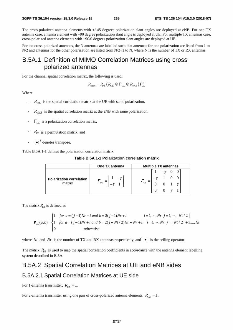
ETSI
ETSI TS 136 104 V15.3.0 (2018-07)2653GPP TS 36.104 version 15.3.0 Release 15
The cross-polarized antenna elements with +/-45 degrees polarization slant angles are deployed at eNB. For one TX antenna case, antenna element with +90 degree polarization slant angle is deployed at UE. For multiple TX antennas case, cross-polarized antenna elements with +90/0 degrees polarization slant angles are deployed at UE.
For the cross-polarized antennas, the N antennas are labelled such that antennas for one polarization are listed from 1 to N/2 and antennas for the other polarization are listed from N/2+1 to N, where N is the number of TX or RX antennas.
B.5A.1 Definition of MIMO Correlation Matrices using cross polarized antennas
For the channel spatial correlation matrix, the following is used:
( ) TSpat UL UE UL eNB ULR P R R P= ⊗ Γ ⊗
Where
- is the spatial correlation matrix at the UE with same polarization,
- is the spatial correlation matrix at the eNB with same polarization,
- ULΓ is a polarization correlation matrix,
- ULP is a permutation matrix, and
- denotes transpose.
Table B.5A.1-1 defines the polarization correlation matrix.
Table B.5A.1-1 Polarization correlation matrix
One TX antenna Multiple TX antennas
Polarization correlation matrix
1
1ULΓγ
γ−
= −
1 0 0
1 0 0
0 0 1
0 0 1
ULΓ
γγ
γγ
− − =
The matrix ULP is defined as
1 ( 1) 2( 1) , 1, , , 1, , / 2
( , ) 1 ( 1) 2( / 2) , 1, , , / 2 1,...,
0UL
for a j Nr i and b j Nr i i Nr j Nt
a b for a j Nr i and b j Nt Nr Nr i i Nr j Nt Nt
otherwise
= − + = − + = =
= = − + = − − + = = +
P
L L
L
where Nt and Nr is the number of TX and RX antennas respectively, and • is the ceiling operator.
The matrix ULP is used to map the spatial correlation coefficients in accordance with the antenna element labelling
system described in B.5A.
B.5A.2 Spatial Correlation Matrices at UE and eNB sides
B.5A.2.1 Spatial Correlation Matrices at UE side
For 1-antenna transmitter, 1UER = .
For 2-antenna transmitter using one pair of cross-polarized antenna elements, 1UER = .
UER
eNBR
T)(•

ETSI
ETSI TS 136 104 V15.3.0 (2018-07)2663GPP TS 36.104 version 15.3.0 Release 15
For 4-antenna transmitter using two pairs of cross-polarized antenna elements, *
1
1UER
ββ
=
.
B.5A.2.2 Spatial Correlation Matrices at eNB side
For 2-antenna receiver using one pair of cross-polarized antenna elements, 1eNBR = .
For 4-antenna receiver using two pairs of cross-polarized antenna elements, *
1
1eNBR
αα
=
.
For 8-antenna receiver using four pairs of cross-polarized antenna elements,
1/9 4/9
1/9* 1/9 4/9
4/9* 1/9* 1/9
* 4/9* 1/9*
11
11
eNBR
α α αα α αα α αα α α
=
.
B.5A.3 MIMO Correlation Matrices using cross polarized antennas The values for parameters α, β and γ for low spatial correlation are given in Table B.5A.3-1.
Table B.5A.3-1 Values for parameters α, β and γ
Low spatial correlation α β γ
0 0 0 Note 1: Value of α applies when more than one pair of cross-polarized antenna elements at eNB side. Note 2: Value of β applies when more than one pair of cross-polarized antenna elements at UE side.
The correlation matrices for low spatial correlation are defined in Table B.5A.3-2 as below.
Table B.5A.3-2 MIMO correlation matrices for low spatial correlation
1x8 case 8lowR = I
2x8 case 16lowR = I
In Table B.5A.3-2, is a identity matrix.
B.6 Interference model for enhanced performance requirements type A and type B
This clause provides a description for the modelling of inter-cell interfering UE transmissions for enhanced performance requirements type A and type B, including: definition of dominant interferer proportion, interference model for synchronous scenario and interference model for asynchronous scenario.
B.6.1 Dominant interferer proportion Each inter-cell interferer involved in enhanced performance requirements type A and type B is characterized by its associated dominant interferer proportion (DIP) value:
( )ˆ
´or i
i
IDIP
N= ( i = 1,…, M )
dI dd ×

ETSI
ETSI TS 136 104 V15.3.0 (2018-07)2673GPP TS 36.104 version 15.3.0 Release 15
where ( )ˆor iI is the received energy from the i-th strongest inter-cell interferer involved in the requirement scenario and
( )1
ˆ´M
or jj
N I N=
= + where N is the the energy of the white noise source consistent with the definition provided in
subclause 8.1 and M is the total number of simultaneously transmitted inter-cell interferers involved in a given requirement scenario.
B.6.2 Interference model for synchronous scenario This subclause provides interference modelling for each explicitly modelled inter-cell interferer in the requirement scenario where the inter-cell interferer(s) are time-synchronous with the tested signal.
In each subframe, each interferer shall transmit 16QAM randomly modulated data over the entire PUSCH region and the same resource blocks as the tested signal. Demodulation reference signal, configured according to Table 8.2.6-1 for enhanced performance requirements type A, and Table 8.2.9-1 to Table 8.2.9-2 for enhanced performance requirements type B, is transmitted associated with the transmission of PUSCH.
B.6.3 Interference model for asynchronous scenario This subclause provides interference modelling for each explicitly modelled inter-cell interferer in the requirement scenario where the inter-cell interferer(s) are time-asynchronous with the tested signal.
Two interfering UEs from the same interfering cell, named interferer 1-1 and interferer 1-2, are modelled. Interferer 1-1 and interferer 1-2 shall transmit 16QAM randomly modulated data over the entire PUSCH region and the same resource blocks as the tested signal, respectively in the even subframes and odd subframes, as illustrated in Figure B.6.3-1. Demodulation reference signal, configured according to Table 8.2.6A-1, is transmitted associated with the transmission of PUSCH. The transmissions of both interferer 1-1 and interferer 1-2 are delayed with respect to the tested signal by 0.33 ms.
Figure B.6.3-1: Configuration of asynchronous interferers

ETSI
ETSI TS 136 104 V15.3.0 (2018-07)2683GPP TS 36.104 version 15.3.0 Release 15
Annex C (normative): Characteristics of the interfering signals For E-UTRA or E-UTRA with NB-IoT (in-band and/or guard band operation) BS, the interfering signal shall be a PUSCH containing data and reference symbols. Normal cyclic prefix is used. The data content shall be uncorrelated to the wanted signal and modulated according to clause 5 of TS36.211. Mapping of PUSCH modulation to receiver requirement are specified in table C-1.1.
Table C-1: Modulation of the interfering signal
Receiver requirement Modulation In-channel selectivity 16QAM Adjacent channel selectivity and narrow-band blocking
QPSK
Blocking QPSK Receiver intermodulation QPSK
For NB-IoT standalone BS, the interfering signal shall be a NPUSCH containing data and reference symbols. Normal cyclic prefix is used. The data content shall be uncorrelated to the wanted signal and modulated according to clause 10.1 of TS36.211. Mapping of NPUSCH modulation to receiver requirement are specified in table C-2.
Table C-2: Modulation of the interfering signal – NB-IoT
Receiver requirement Modulation Adjacent channel selectivity and narrow-band blocking
π/4 QPSK
Blocking π/4 QPSK Receiver intermodulation π/4 QPSK

ETSI
ETSI TS 136 104 V15.3.0 (2018-07)2693GPP TS 36.104 version 15.3.0 Release 15
Annex D (normative): Environmental requirements for the BS equipment The BS equipment shall fulfil all the requirements in the full range of environmental conditions for the relevant environmental class from the relevant IEC specifications listed below
60 721-3-3 "Stationary use at weather protected locations" [13]
60 721-3-4 "Stationary use at non weather protected locations" [14]
Normally it should be sufficient for all tests to be conducted using normal test conditions except where otherwise stated. For guidance on the use of test conditions to be used in order to show compliance refer to TS 36.141.

ETSI
ETSI TS 136 104 V15.3.0 (2018-07)2703GPP TS 36.104 version 15.3.0 Release 15
Annex E (normative): Error Vector Magnitude
E.1 Reference point for measurement The EVM shall be measured at the point after the FFT and a zero-forcing (ZF) equalizer in the receiver, as depicted in Figure E.1-1 below.
BS TX Remove CP
FFT Per-subcarrier Amplitude/phase correction
Symbol detection /decoding
Reference point for EVM measurement
Pre-/post FFT time / frequency synchronization
Figure E.1-1: Reference point for EVM measurement
E.2 Basic unit of measurement The basic unit of EVM measurement is defined over one subframe (1ms) for subframe TTI and over one sTTI when
supporting sTTI feature in the time domain and RBBWN subcarriers (180kHz) in the frequency domain:
∈ ∈
∈ ∈−
=
Tt tFf
Tt tFf
ftI
ftIftZ
EVM
)(
2
)(
2
),(
),(),('
where
T is the set of symbols with the considered modulation scheme being active within the subframe or within the sTTI,
)(tF is the set of subcarriers within the RBBWN subcarriers with the considered modulation scheme being active in
symbol t,
),( ftI is the ideal signal reconstructed by the measurement equipment in accordance with relevant Tx models,
),(' ftZ is the modified signal under test defined in E.3.
Note: Although the basic unit of measurement is one subframe or one sTTI, the equalizer is calculated over 10 subframe measurement periods to reduce the impact of noise in the reference symbols. The boundaries of the 10 subframe measurement periods need not be aligned with radio frame boundaries.
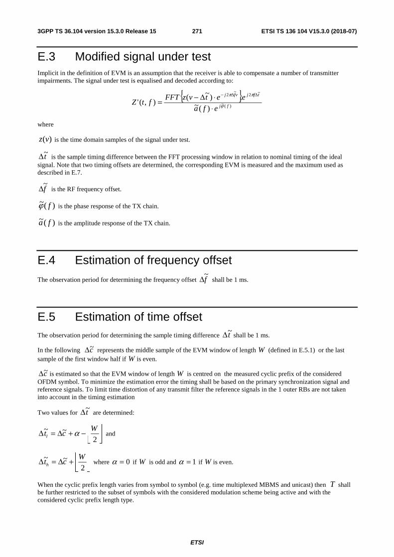
ETSI
ETSI TS 136 104 V15.3.0 (2018-07)2713GPP TS 36.104 version 15.3.0 Release 15
E.3 Modified signal under test Implicit in the definition of EVM is an assumption that the receiver is able to compensate a number of transmitter impairments. The signal under test is equalised and decoded according to:
{ })(~
~2~
2
)(~.)~(
),('fj
tfjvfj
efa
eetvzFFTftZ ϕ
ππ
⋅⋅Δ−=
ΔΔ−
where
)(vz is the time domain samples of the signal under test.
t~Δ is the sample timing difference between the FFT processing window in relation to nominal timing of the ideal signal. Note that two timing offsets are determined, the corresponding EVM is measured and the maximum used as described in E.7.
f~Δ is the RF frequency offset.
)(~ fϕ is the phase response of the TX chain.
)(~ fa is the amplitude response of the TX chain.
E.4 Estimation of frequency offset
The observation period for determining the frequency offset f~Δ shall be 1 ms.
E.5 Estimation of time offset The observation period for determining the sample timing difference t~Δ shall be 1 ms.
In the following c~Δ represents the middle sample of the EVM window of length W (defined in E.5.1) or the last sample of the first window half if W is even.
c~Δ is estimated so that the EVM window of length W is centred on the measured cyclic prefix of the considered OFDM symbol. To minimize the estimation error the timing shall be based on the primary synchronization signal and reference signals. To limit time distortion of any transmit filter the reference signals in the 1 outer RBs are not taken into account in the timing estimation
Two values for t~Δ are determined:
−+Δ=Δ2
~~ Wctl α and
+Δ=Δ2
~~ Wcth where 0=α if W is odd and 1=α if W is even.
When the cyclic prefix length varies from symbol to symbol (e.g. time multiplexed MBMS and unicast) then T shall be further restricted to the subset of symbols with the considered modulation scheme being active and with the considered cyclic prefix length type.

ETSI
ETSI TS 136 104 V15.3.0 (2018-07)2723GPP TS 36.104 version 15.3.0 Release 15
E.5.1 Window length Table E.5.1-1 and Table E.5.1-1a below specify EVM window length (W) for normal CP, the cyclic prefix length cpN is
160 for symbols 0 and 144 for symbols 1-6.
Table E.5.1-2, Table E.5.1-2a and Table E.5.1-2b specify the EVM window length (W) for extended CP for 15 kHz, 7.5 kHz and 1.25 kHz sub-carrier spacing, the cyclic prefix length cpN is 512, 1024 and 6144 respectively.
Table E.5.1-1: EVM window length for normal CP for E-UTRA
Channel Bandwidth
MHz FFT size
Cyclic prefix length for
symbols 0 in FFT samples
Cyclic prefix
length for symbols
1-6 in FFT samples
EVM window length W
Ratio of W to total CP
for symbols 1-6(Note 1)
[%] 1.4 128 10 9 5 55.6 3 256 20 18 12 66.7 5 512 40 36 32 88.9 10 1024 80 72 66 91.7 15 1536 120 108 102 94.4 20 2048 160 144 136 94.4
Note 1: These percentages are informative and apply to symbols 1 through 6. Symbol 0 has a longer CP and therefore a lower percentage.
Table E.5.1-1a: EVM window length for normal CP for NB-IoT
FFT size
Cyclic prefix length for
symbols 0 in FFT samples
Cyclic prefix
length for symbols
1-6 in FFT samples
EVM window length W
Ratio of W to total CP
for symbols 1-6(Note 1)
[%] 128 10 9 3 33.3
Note 1: These percentages are informative and apply to symbols 1 through 6. Symbol 0 has a longer CP and therefore a lower percentage.
Table E.5.1-2 EVM window length for extended CP for 15 kHz sub-carrier spacing
Channel Bandwidth
[MHz] FFT size
Cyclic prefix in FFT
samples
EVM window length W
Ratio of W to total CP (Note 1)
[%] 1.4 128 32 28 87.5 3 256 64 58 90.6 5 512 128 124 96.9 10 1024 256 250 97.7 15 1536 384 378 98.4 20 2048 512 504 98.4
Note 1: These percentages are informative.

ETSI
ETSI TS 136 104 V15.3.0 (2018-07)2733GPP TS 36.104 version 15.3.0 Release 15
Table E.5.1-2a EVM window length for extended CP for 7.5 kHz sub-carrier spacing
Channel Bandwidth
[MHz] FFT size
Cyclic prefix in FFT
samples
EVM window length W
Ratio of W to total CP (Note 1)
[%] 1.4 256 64 56 87.5 3 512 128 116 90.6 5 1024 256 248 96.9 10 2048 512 500 97.7 15 3072 768 756 98.4 20 4096 1024 1008 98.4
Note 1: These percentages are informative.
Table E.5.1-2b EVM window length for extended CP for 1.25 kHz sub-carrier spacing
Channel Bandwidth
[MHz] FFT size
Cyclic prefix in FFT
samples
EVM window length W
Ratio of W to total CP (Note 1)
[%] 1.4 1536 384 336 87.5 3 3072 768 696 90.6 5 6144 1536 1488 96.9 10 12288 3072 3000 97.7 15 18432 4608 4536 98.4 20 24576 6144 6048 98.4
Note 1: These percentages are informative.
E.6 Estimation of TX chain amplitude and frequency response parameters
The equalizer coefficients )(~ fa and )(~ fϕ are determined as follows:
1. Calculate the complex ratios (amplitude and phase) of the post-FFT acquired signal ),(' ftZ and the post-FFT
Ideal signal ),(2 ftI , for each reference symbol, over 10 subframes. This process creates a set of complex
ratios:
),(
),(').,(
2
),(
ftI
ftZefta ftj =ϕ
Where the post-FFT Ideal signal ),(2 ftI is constructed by the measuring equipment according to the relevant TX
specifications, using the following parameters: restricted content: i.e. nominal Reference Symbols and the Primary Synchronisation Channel, (all other modulation symbols are set to 0 V), nominal carrier frequency, nominal amplitude and phase for each applicable subcarrier, nominal timing.
2. Perform time averaging at each reference signal subcarrier of the complex ratios, the time-averaging length is 10
subframes. Prior to the averaging of the phases ( )fti ,ϕ an unwrap operation must be performed according to
the following definition: The unwrap operation corrects the radian phase angles of ( )fti ,ϕ by adding multiples
of 2*PI when absolute phase jumps between consecutive time instances ti are greater then or equal to the jump tolerance of PI radians. This process creates an average amplitude and phase for each reference signal subcarrier (i.e. every third subcarrier with the exception of the reference subcarrier spacing across the DC subcarrier).
( )N
ftafa
N
ii
== 1
,)(
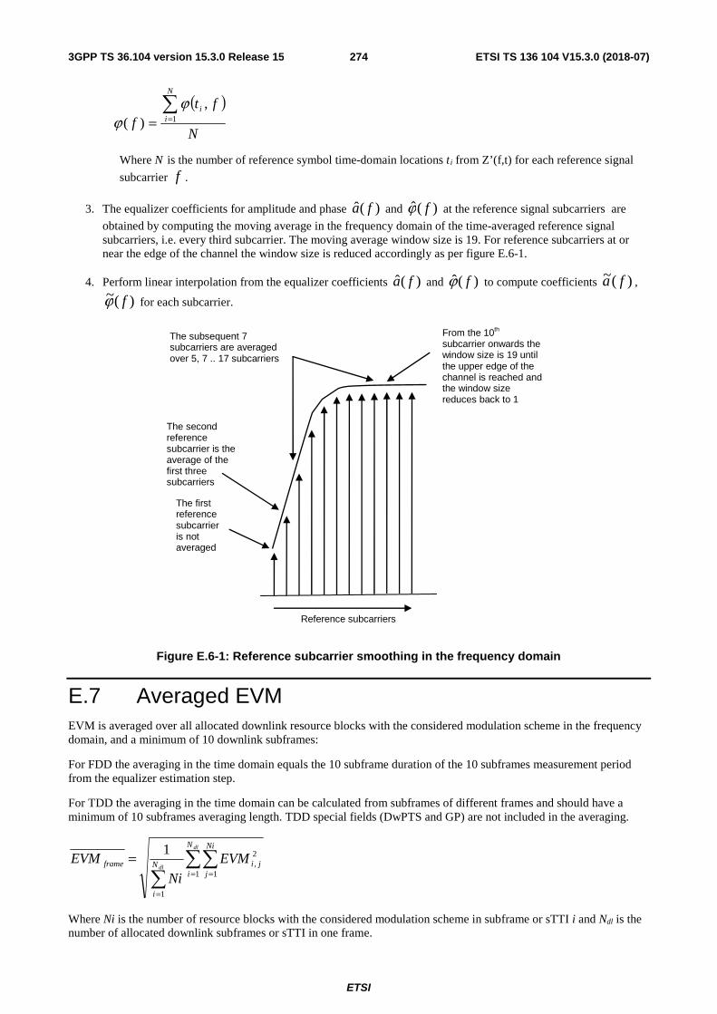
ETSI
ETSI TS 136 104 V15.3.0 (2018-07)2743GPP TS 36.104 version 15.3.0 Release 15
( )N
ftf
N
ii
== 1
,)(
ϕϕ
Where N is the number of reference symbol time-domain locations ti from Z’(f,t) for each reference signal
subcarrier f .
3. The equalizer coefficients for amplitude and phase )(ˆ fa and )(ˆ fϕ at the reference signal subcarriers are
obtained by computing the moving average in the frequency domain of the time-averaged reference signal subcarriers, i.e. every third subcarrier. The moving average window size is 19. For reference subcarriers at or near the edge of the channel the window size is reduced accordingly as per figure E.6-1.
4. Perform linear interpolation from the equalizer coefficients )(ˆ fa and )(ˆ fϕ to compute coefficients )(~ fa ,
)(~ fϕ for each subcarrier.
The subsequent 7 subcarriers are averaged over 5, 7 .. 17 subcarriers
From the 10th subcarrier onwards the window size is 19 until the upper edge of the channel is reached and the window size reduces back to 1
The first reference subcarrier is not averaged
The second reference subcarrier is the average of the first three subcarriers
Reference subcarriers
Figure E.6-1: Reference subcarrier smoothing in the frequency domain
E.7 Averaged EVM EVM is averaged over all allocated downlink resource blocks with the considered modulation scheme in the frequency domain, and a minimum of 10 downlink subframes:
For FDD the averaging in the time domain equals the 10 subframe duration of the 10 subframes measurement period from the equalizer estimation step.
For TDD the averaging in the time domain can be calculated from subframes of different frames and should have a minimum of 10 subframes averaging length. TDD special fields (DwPTS and GP) are not included in the averaging.
= =
=
=dl
dl
N
i
Ni
jjiN
i
frame EVM
Ni
EVM1 1
2,
1
1
Where Ni is the number of resource blocks with the considered modulation scheme in subframe or sTTI i and Ndl is the number of allocated downlink subframes or sTTI in one frame.
ETSI
ETSI TS 136 104 V15.3.0 (2018-07)2753GPP TS 36.104 version 15.3.0 Release 15
The EVM requirements shall be tested against the maximum of the RMS average at the window W extremities of the EVM measurements:
Thus l frame,EVM is calculated using ltt ~~ Δ=Δ in the expressions above and hframe,EVM is calculated using
htt ~~ Δ=Δ in the frameEVM calculation.
Thus we get:
)EVM ,EVMmax( ,l frame, hframeframeEVM =
The averaged EVM with the minimum averaging length of at least 10 subframes is then achieved by further averaging
of the frameEVM results
=
=frameN
kkframe
frame
EVMN
EVM1
2,
1,
=
dlframe N
N10

ETSI
ETSI TS 136 104 V15.3.0 (2018-07)2763GPP TS 36.104 version 15.3.0 Release 15
Annex F (Informative): Unwanted emission requirements for multi-carrier BS
F.1 General In subclause 6.6, unwanted emission requirements for single carrier or multi-carrier BS are specified. This multi-carrier BS corresponds to a multi-carrier BS for E-UTRA, or a BS supporting intra-band contiguous CA. The following two pragmatic scenarios are considered in this annex:
- multi-carrier BS of different E-UTRA channel bandwidths, covering all scenarios except the channel bandwidth of the outermost carrier less than 5 MHz
- multi-carrier BS of E-UTRA and UTRA, covering all scenarios except the channel bandwidth of the outermost carrier less than 5 MHz.
All scenarios for channel bandwidths of the outermost carrier less than 5 MHz are for further study. The guidelines below assumes that the power spectral density of the multiple carriers is the same. All other combinations of multiple carriers are ffs.
Note 1: Further information and analysis for these scenarios can be found in TR 36.942 [9].
F.2 Multi-carrier BS of different E-UTRA channel bandwidths
For a multi-carrier E-UTRA BS transmitting a group of carriers of different channel bandwidths, the channel bandwidth of the outermost carriers (≥5 MHz) should be considered for ACLR and Operating band unwanted emission requirements. That is, the corresponding requirements for the channel bandwidth of each of the outermost carriers should be applied at the respective side of the group of transmitted carriers.
F.3 Multi-carrier BS of E-UTRA and UTRA For a multi-carrier BS transmitting a group of carriers of E-UTRA and UTRA, the RAT being used on the outermost carriers (≥5 MHz) should be considered for ACLR and Operating band unwanted emission requirements. That is, the corresponding requirements for the RAT being used on each of the outermost carriers should be applied at the respective side of the group of transmitted carriers.

ETSI
ETSI TS 136 104 V15.3.0 (2018-07)2773GPP TS 36.104 version 15.3.0 Release 15
Annex G (Informative): Regional requirement for protection of DTT
G.1 Regional requirement for protection of DTT The European Communications Committee (ECC) has adopted the “ECC Decision on harmonised conditions for Mobile/Fixed Communications Networks operating in the band 790-862 MHz” [12] applicable for BS operating in band 20. The decision defines a requirement for “Out-of-block BEM baseline requirements for ‘mobile/fixed communications network’ (MFCN) base stations within the spectrum allocated to the broadcasting (DTT) service”, where three different cases A, B, and C for protecting broadcasting DTT are defined. These cases can be applied on a per-channel and/or per-region basis, i.e. for the same channel different cases can be applied in different geographic areas (e.g. area related to DTT coverage) and different cases can be applied to different channels in the same geographic area.
For band 20, compliance with the regulatory requirements in Europe referenced above can be assessed based on the manufacturer’s declaration of PEM,N specified in subclause 6.6.3.3, together with the deployment characteristics. Maximum output Power in 10 MHz (P10MHz) is also declared by the manufacturer. The parameters Gant and Nant are deployment specific parameters related to the deployment of the BS, where Gant is the antenna gain and Nant is the number of antennas.
For each channel (N) the EIRP level is calculated using: PEIRP,N = PEM,N + Gant + 10*log(Nant ). The regulatory requirement in [12] limits the EIRP level to the Maximum level in Table G-1 for the protection case(s) defined in the regulation.
Table G-1: EIRP limits for protection of broadcasting (DTT) service
Case Measurement filter centre frequency
Condition on BS maximum aggregate
EIRP / 10 MHz, PEIRP_10MHz
(Note)
Maximum Level PEIRP,N,MAX
Measurement Bandwidth
A: for DTT frequencies where broadcasting is protected
N*8 + 306 MHz, 21 ≤ N ≤ 60
PEIRP_10MHz ≥ 59 dBm 0 dBm 8 MHz
N*8 + 306 MHz, 21 ≤ N ≤ 60
36 ≤ PEIRP_10MHz < 59 dBm
PEIRP_10MHz – 59 dBm 8 MHz
N*8 + 306 MHz, 21 ≤ N ≤ 60
PEIRP_10MHz < 36 dBm -23 dBm 8 MHz
B: for DTT frequencies where broadcasting is subject to an intermediate level of protection
N*8 + 306 MHz, 21 ≤ N ≤ 60
PEIRP_10MHz ≥ 59 dBm 10 dBm 8 MHz
N*8 + 306 MHz, 21 ≤ N ≤ 60
36 ≤ PEIRP_10MHz < 59 dBm
PEIRP_10MHz – 49 dBm 8 MHz
N*8 + 306 MHz, 21 ≤ N ≤ 60
PEIRP_10MHz < 36 dBm -13 dBm 8 MHz
C: for DTT frequencies where broadcasting is not protected
N*8 + 306 MHz, 21 ≤ N ≤ 60
N.A. 22 dBm 8 MHz
NOTE: PEIRP_10MHz (dBm) is defined by the expression PEIRP_10MHz = P10MHz + Gant + 10*log10(Nant )
G.2 Regional requirement for Public Safety LTE BS in Korea
Public Safety LTE (PS-LTE) service, commercial mobile service and Broadcasting are closely allocated for Band 28 in Korea. By making more strong blocking requirements, it provides more flexible site selection to locate for the PS-LTE BS and also it protects the uplink performance degradation. RRA (National Radio Research Agency) Announce 2015-
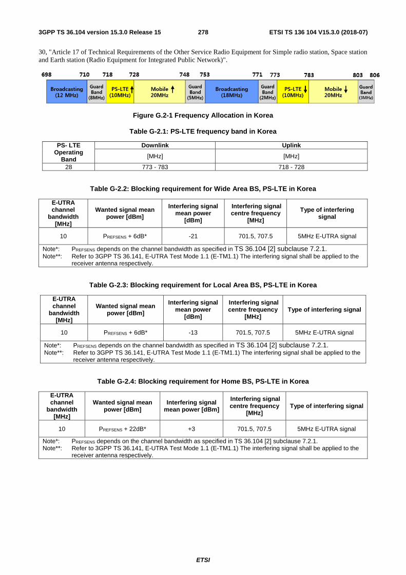
ETSI
ETSI TS 136 104 V15.3.0 (2018-07)2783GPP TS 36.104 version 15.3.0 Release 15
30, "Article 17 of Technical Requirements of the Other Service Radio Equipment for Simple radio station, Space station and Earth station (Radio Equipment for Integrated Public Network)".
Figure G.2-1 Frequency Allocation in Korea
Table G-2.1: PS-LTE frequency band in Korea
PS- LTE Operating
Band
Downlink Uplink
[MHz] [MHz]
28 773 - 783 718 - 728
Table G-2.2: Blocking requirement for Wide Area BS, PS-LTE in Korea
E-UTRA channel
bandwidth [MHz]
Wanted signal mean power [dBm]
Interfering signal mean power
[dBm]
Interfering signal centre frequency
[MHz]
Type of interfering signal
10 PREFSENS + 6dB* -21 701.5, 707.5 5MHz E-UTRA signal
Note*: PREFSENS depends on the channel bandwidth as specified in TS 36.104 [2] subclause 7.2.1. Note**: Refer to 3GPP TS 36.141, E-UTRA Test Mode 1.1 (E-TM1.1) The interfering signal shall be applied to the
receiver antenna respectively.
Table G-2.3: Blocking requirement for Local Area BS, PS-LTE in Korea
E-UTRA channel
bandwidth [MHz]
Wanted signal mean power [dBm]
Interfering signal mean power
[dBm]
Interfering signal centre frequency
[MHz] Type of interfering signal
10 PREFSENS + 6dB* -13 701.5, 707.5 5MHz E-UTRA signal
Note*: PREFSENS depends on the channel bandwidth as specified in TS 36.104 [2] subclause 7.2.1. Note**: Refer to 3GPP TS 36.141, E-UTRA Test Mode 1.1 (E-TM1.1) The interfering signal shall be applied to the
receiver antenna respectively.
Table G-2.4: Blocking requirement for Home BS, PS-LTE in Korea
E-UTRA channel
bandwidth [MHz]
Wanted signal mean power [dBm]
Interfering signal mean power [dBm]
Interfering signal centre frequency
[MHz] Type of interfering signal
10 PREFSENS + 22dB* +3 701.5, 707.5 5MHz E-UTRA signal
Note*: PREFSENS depends on the channel bandwidth as specified in TS 36.104 [2] subclause 7.2.1. Note**: Refer to 3GPP TS 36.141, E-UTRA Test Mode 1.1 (E-TM1.1) The interfering signal shall be applied to the
receiver antenna respectively.

ETSI
ETSI TS 136 104 V15.3.0 (2018-07)2793GPP TS 36.104 version 15.3.0 Release 15
Table G-2.5: Blocking requirement for E-UTRA Medium Range BS, PS-LTE in Korea
E-UTRA channel
bandwidth [MHz]
Wanted signal mean power [dBm]
Interfering signal mean power [dBm]
Interfering signal centre Type of interfering signal
10 PREFSENS +1dB* -21 701.5, 707.5 5MHz E-UTRA signal Note*: PREFSENS depends on the channel bandwidth as specified in Table 7.2.1-4. Note**: Refer to 3GPP TS 36.141, E-UTRA Test Mode 1.1 (E-TM1.1) The interfering signal shall be applied to the
receiver antenna respectively.

ETSI
ETSI TS 136 104 V15.3.0 (2018-07)2803GPP TS 36.104 version 15.3.0 Release 15
Annex H (Informative): Calculation of EIRP based on manufacturer declarations and site specific conditions
H.1 Calculation of EIRP based on manufacturer declarations and site specific conditions
Some regional requirements are defined per effective isotropic radiated power (EIRP), which is a combination of the transmitted power (or in some cases spectral density) and the effective antenna gain which is a site specific condition. Such requirements may be applied per antenna, per cell, or per base station. It shall be noted that the definition of BS or cell may differ between regulations. Where the regulator prescribes a method for EIRP calculation, that method supersedes the proposed assessment in this annex.
The 3GPP specifications mandate manufacturer declarations of the (conducted) output power or power spectral density per connector for the base station under the reference conditions stated as a way to accommodate the referred regional requirements without putting requirements on the local site conditions.
For the case when the base station manufacturer maximum output power or unwanted emission declarations apply per antenna connector, the maximum EIRP can be estimated using the following formulas:
EIRP per antenna: PEIRP = PTx + GAnt
EIRP per cell or per BS: PEIRPcell =10 * log (∑10PEIRPn/10)
In case the EIRP requirement is set per polarisation, the summation shall be made per polarisation.
"PEIRP" is the resulting effective isotropic radiated power (or radiated power spectral density) resulting from the power (or power spectral density) declared by the manufacturer in dBm (or dBm/measurement BW).
"PTx" is the conducted power or power spectral density declared by the manufacturer in dBm (or dBm/measurement BW)
"GAnt" is the effective antenna gain, calculated as the antenna gain (dBi) minus the loss of the site infrastructure connecting the BS antenna connector with the antenna (dB) for the applied frequency. The antenna nominal gain is only applicable within a certain frequency range.
"n" is the index number of the co-located antennas illuminating the same cell. PEIRPn is the PEIRP of the n:th antenna.
"Cell" is in this annex used in the sense that it is the limited geographical area covered by the carrier transmitted from one site.

ETSI
ETSI TS 136 104 V15.3.0 (2018-07)2813GPP TS 36.104 version 15.3.0 Release 15
Annex I (Informative): Change history
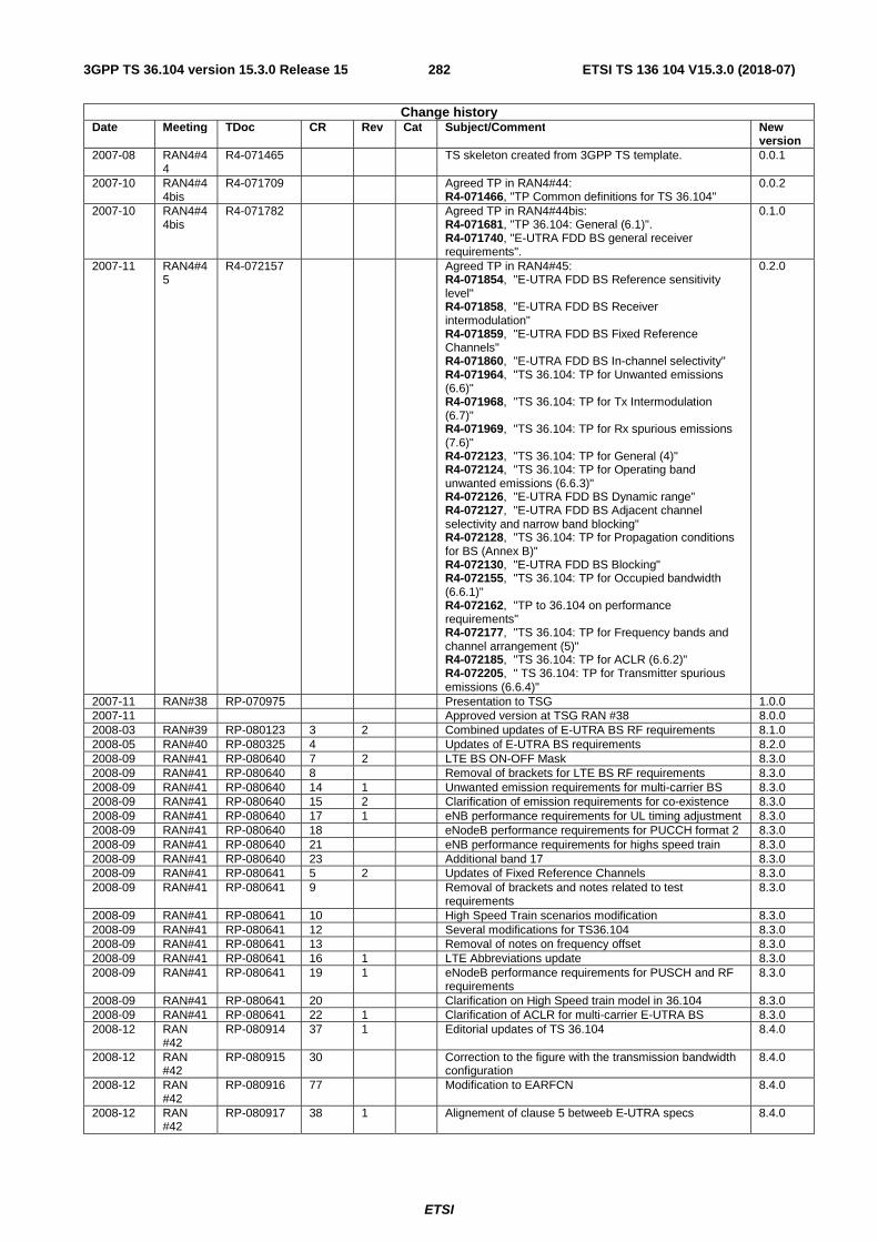
ETSI
ETSI TS 136 104 V15.3.0 (2018-07)2823GPP TS 36.104 version 15.3.0 Release 15
Change history Date Meeting TDoc CR Rev Cat Subject/Comment New
version 2007-08 RAN4#4
4 R4-071465 TS skeleton created from 3GPP TS template. 0.0.1
2007-10 RAN4#44bis
R4-071709 Agreed TP in RAN4#44: R4-071466, "TP Common definitions for TS 36.104"
0.0.2
2007-10 RAN4#44bis
R4-071782 Agreed TP in RAN4#44bis: R4-071681, "TP 36.104: General (6.1)". R4-071740, "E-UTRA FDD BS general receiver requirements".
0.1.0
2007-11 RAN4#45
R4-072157 Agreed TP in RAN4#45: R4-071854, "E-UTRA FDD BS Reference sensitivity level" R4-071858, "E-UTRA FDD BS Receiver intermodulation" R4-071859, "E-UTRA FDD BS Fixed Reference Channels" R4-071860, "E-UTRA FDD BS In-channel selectivity" R4-071964, "TS 36.104: TP for Unwanted emissions (6.6)" R4-071968, "TS 36.104: TP for Tx Intermodulation (6.7)" R4-071969, "TS 36.104: TP for Rx spurious emissions (7.6)" R4-072123, "TS 36.104: TP for General (4)" R4-072124, "TS 36.104: TP for Operating band unwanted emissions (6.6.3)" R4-072126, "E-UTRA FDD BS Dynamic range" R4-072127, "E-UTRA FDD BS Adjacent channel selectivity and narrow band blocking" R4-072128, "TS 36.104: TP for Propagation conditions for BS (Annex B)" R4-072130, "E-UTRA FDD BS Blocking" R4-072155, "TS 36.104: TP for Occupied bandwidth (6.6.1)" R4-072162, "TP to 36.104 on performance requirements" R4-072177, "TS 36.104: TP for Frequency bands and channel arrangement (5)" R4-072185, "TS 36.104: TP for ACLR (6.6.2)" R4-072205, " TS 36.104: TP for Transmitter spurious emissions (6.6.4)"
0.2.0
2007-11 RAN#38 RP-070975 Presentation to TSG 1.0.0 2007-11 Approved version at TSG RAN #38 8.0.0 2008-03 RAN#39 RP-080123 3 2 Combined updates of E-UTRA BS RF requirements 8.1.0 2008-05 RAN#40 RP-080325 4 Updates of E-UTRA BS requirements 8.2.0 2008-09 RAN#41 RP-080640 7 2 LTE BS ON-OFF Mask 8.3.0 2008-09 RAN#41 RP-080640 8 Removal of brackets for LTE BS RF requirements 8.3.0 2008-09 RAN#41 RP-080640 14 1 Unwanted emission requirements for multi-carrier BS 8.3.0 2008-09 RAN#41 RP-080640 15 2 Clarification of emission requirements for co-existence 8.3.0 2008-09 RAN#41 RP-080640 17 1 eNB performance requirements for UL timing adjustment 8.3.0 2008-09 RAN#41 RP-080640 18 eNodeB performance requirements for PUCCH format 2 8.3.0 2008-09 RAN#41 RP-080640 21 eNB performance requirements for highs speed train 8.3.0 2008-09 RAN#41 RP-080640 23 Additional band 17 8.3.0 2008-09 RAN#41 RP-080641 5 2 Updates of Fixed Reference Channels 8.3.0 2008-09 RAN#41 RP-080641 9 Removal of brackets and notes related to test
requirements 8.3.0
2008-09 RAN#41 RP-080641 10 High Speed Train scenarios modification 8.3.0 2008-09 RAN#41 RP-080641 12 Several modifications for TS36.104 8.3.0 2008-09 RAN#41 RP-080641 13 Removal of notes on frequency offset 8.3.0 2008-09 RAN#41 RP-080641 16 1 LTE Abbreviations update 8.3.0 2008-09 RAN#41 RP-080641 19 1 eNodeB performance requirements for PUSCH and RF
requirements 8.3.0
2008-09 RAN#41 RP-080641 20 Clarification on High Speed train model in 36.104 8.3.0 2008-09 RAN#41 RP-080641 22 1 Clarification of ACLR for multi-carrier E-UTRA BS 8.3.0 2008-12 RAN
#42 RP-080914 37 1 Editorial updates of TS 36.104 8.4.0
2008-12 RAN #42
RP-080915 30 Correction to the figure with the transmission bandwidth configuration
8.4.0
2008-12 RAN #42
RP-080916 77 Modification to EARFCN 8.4.0
2008-12 RAN #42
RP-080917 38 1 Alignement of clause 5 betweeb E-UTRA specs 8.4.0

ETSI
ETSI TS 136 104 V15.3.0 (2018-07)2833GPP TS 36.104 version 15.3.0 Release 15
2008-12 RAN #42
RP-080918 26 Correction of output power dynamics requirement 8.4.0
2008-12 RAN #42
RP-080918 27 LTE BS ON-OFF Mask 8.4.0
2008-12 RAN #42
RP-080918 28 Correction to RE power control dynamic range 8.4.0
2008-12 RAN #42
RP-080919 29 1 BS RF requirements for Band 17 8.4.0
2008-12 RAN #42
RP-080920 41 Update of total dynamic range limits 8.4.0
2008-12 RAN #42
RP-080921 39 1 Update of TDD-FDD coexistance requirements 8.4.0
2008-12 RAN #42
RP-080922 33 1 eNB performance requirements for Multi User PUCCH 8.4.0
2008-12 RAN #42
RP-080922 42 PRACH demodulation requirements update 8.4.0
2008-12 RAN #42
RP-080922 25 1 Updates of Fized Reference Channels and requirements for UL timing adjustment and PUCCH format 2
8.4.0
2008-12 RAN #42
RP-080922 44 eNB performance requirements for HARQ-ACK multiplexed on PUSCH
8.4.0
2008-12 RAN #42
RP-080923 43 General updates to Clause 8 and appendix A 8.4.0
2008-12 RAN #42
RP-080925 24 LTE TDD Update for Annex E of 36.104 8.4.0
2008-12 RAN #42
RP-080927 32 1 Clarification of eNB HST propagation conditions 8.4.0
2008-12 RAN #42
RP-080927 31 Corrections of eNB performance requirements for high speed train
8.4.0
2009-03 RAN #43
RP-090173 53 1 Clarification of EARFCN 8.5.0
2009-03 RAN #43
RP-090175 60 1 Regional requirement on maximum rated power for Band 34
8.5.0
2009-03 RAN #43
RP-090176 45 Correction to additional requirements for operating band unwanted emissions
8.5.0
2009-03 RAN #43
RP-090176 48 Clarification of PHS band including the future plan 8.5.0
2009-03 RAN #43
RP-090176 49 Unsynchronized TDD coexistence requirements 8.5.0
2009-03 RAN #43
RP-090176 54 eNB transmitter transient period 8.5.0
2009-03 RAN #43
RP-090176 56 1 eNB ACS frequency offset 8.5.0
2009-03 RAN #43
RP-090176 57 Correction to unwanted emission limit for 3MHz(E-UTRA bands < 1GHz) for Category A
8.5.0
2009-03 RAN #43
RP-090177 46 Modifications on UL timing adjustment test case 8.5.0
2009-03 RAN #43
RP-090177 47 1 Modifications on PUSCH high speed train test case 8.5.0
2009-03 RAN #43
RP-090177 50 Clarification on PUCCH ACK/NAK repetitions for BS performance tests
8.5.0
2009-03 RAN #43
RP-090177 52 PUSCH ACK/NAK simulation assumptions finalization for simulations with implementation margins
8.5.0
2009-03 RAN #43
RP-090177 59 HARQ-ACK multiplexed on PUSCH performance requirement results
8.5.0
2009-05 RAN #44
RP-090544 63 Clarification of requirements for multicarrier BS. (Technically Endorsed CR in R4-50bis - R4-091375)
8.6.0
2009-05 RAN #44
RP-090545 62 CR ACS frequency offset. (Technically Endorsed CR in R4-50bis - R4-091329)
8.6.0
2009-05 RAN #44
RP-090545 67 Correction to DL RS power 8.6.0
2009-05 RAN #44
RP-090545 69 Correction to Receiver Dynamic Range minimum requirements
8.6.0
2009-05 RAN #44
RP-090545 64 UL timing adjustment performance requirement clarifications. (Technically Endorsed CR in R4-50bis - R4-091437)
8.6.0
2009-05 RAN #44
RP-090559 61 Introduction of Extended LTE800 requirements. (Technically Endorsed CR in R4-50bis - R4-091060)
9.0.0
2009-09 RAN #45
RP-090953 71 Clarification of the UL timing adjustment performance determination
9.1.0
2009-09 RAN #45
RP-090953 73 Corrections to E-UTRA Rx requirements 9.1.0
2009-09 RAN #45
RP-090953 78 Clarifications on testing UL timing adjustment requirements
9.1.0
2009-09 RAN #45
RP-090953 90 Correction on Table A.3-1 FRC parameters for performance requirements (QPSK 1/3) of Annex 3
9.1.0

ETSI
ETSI TS 136 104 V15.3.0 (2018-07)2843GPP TS 36.104 version 15.3.0 Release 15
2009-09 RAN #45
RP-090954 86 2 LTE operating band unwanted emissions revision 9.1.0
2009-09 RAN #45
RP-090826 74 Correction of spurious emission requirements for LTE800
9.1.0
2009-12 RP-46 RP-091286 093 Introduction of Extended LTE1500 requirements for TS36.104 (Technically endorsed at RAN 4 52bis in R4-093633)
9.2.0
2009-12 RP-46 RP-091265 095 Correction to ICS requirement (Technically endorsed at RAN 4 52bis in R4-093639)
9.2.0
2009-12 RP-46 RP-091265 097 CR eNB FDD EVM (Technically endorsed at RAN 4 52bis in R4-093713)
9.2.0
2009-12 RP-46 RP-091265 099 Correction on terminology for noise bandwidth (Technically endorsed at RAN 4 52bis in R4-093740)
9.2.0
2009-12 RP-46 RP-091266 101 LTE operating band unwanted emissions correction (Technically endorsed at RAN 4 52bis in R4-093801)
9.2.0
2009-12 RP-46 RP-091266 103 Multi-path fading propagation conditions reference correction (Technically endorsed at RAN 4 52bis in R4-093927)
9.2.0
2009-12 RP-46 RP-091266 105 Clarification on Spurious emissions limits for BS co-existed with another BS (Technically endorsed at RAN 4 52bis in R4-094011)
9.2.0
2009-12 RP-46 RP-091266 106 Correction to the transmitter intermodulation (Technically endorsed at RAN 4 52bis in R4-094084)
9.2.0
2009-12 RP-46 RP-091270 109 1 Clarification on PRACH False alarm probability 9.2.0 2009-12 RP-46 RP-091295 110 1 E-UTRA BS classification 9.2.0 2009-12 RP-46 RP-091295 111 1 Home eNode B maximum output power 9.2.0 2009-12 RP-46 RP-091295 112 1 Home eNode B in-channel selectivity requirement 9.2.0 2009-12 RP-46 RP-091295 113 1 Home eNode B receiver intermodulation requirement 9.2.0 2009-12 RP-46 RP-091293 114 2 Demodulation requirements of Pico NodeB 9.2.0 2009-12 RP-46 RP-091269 116 UL Timing Adjustment test clarifications 9.2.0 2009-12 RP-46 RP-091265 118 Corrections on frequency range of unwanted emissions
requirements 9.2.0
2009-12 RP-46 RP-091276 122 Testing in case of Rx diversity, Tx diversity and MIMO 9.2.0 2009-12 RP-46 RP-091265 124 Table reference correction 9.2.0 2009-12 RP-46 RP-091295 125 1 Home eNode B ACLR requirement 9.2.0 2009-12 RP-46 RP-091295 126 1 Home eNode B ACS and narrow band blocking
requirement 9.2.0
2009-12 RP-46 RP-091295 127 1 Home eNode B Blocking requirement 9.2.0 2009-12 RP-46 RP-091294 128 1 Home eNode B dynamic range requirement 9.2.0 2009-12 RP-46 RP-091294 129 1 Home eNode B frequency error requirement 9.2.0 2009-12 RP-46 RP-091294 130 2 Home eNode B performance requirement 9.2.0 2009-12 RP-46 RP-091294 131 1 Home eNode B operating band unwanted emissions
requirement 9.2.0
2009-12 RP-46 RP-091294 132 1 Home eNode B reference sensitivity level requirement 9.2.0 2009-12 RP-46 RP-091294 133 2 Home eNode B spurious emission requirement 9.2.0 2009-12 RP-46 RP-091284 135 1 Inclusion of Band 20 BS RF parameters 9.2.0 2009-12 RP-46 RP-091265 139 Corrections on blocking performance requirement for
Band 17 9.2.0
2009-12 RP-46 RP-091294 140 CR-Protection of Adjacent Channels Owned by Other Operators
9.2.0
2009-12 RP-46 RP-091293 141 Introduction of LTE Pico NodeB class 9.2.0 2010-03 RP-47 RP-100252
155 Correction of the frequency range for unwanted emmissions limits (cat-B/option 2/BW 3MHz)
9.3.0
2010-03 RP-47 RP-100252 152 Correction of Band 4 and 10 co-existence requirement 9.3.0 2010-03 RP-47 RP-100262 160 Adding missing references 9.3.0 2010-03 RP-47 RP-100275 145 1 Corrections of operating band unwanted emissions for
Local Area BS 9.3.0
2010-03 RP-47 RP-100275 146 1 Editorial correction in TS36.104 for Pico NodeB 9.3.0 2010-03 RP-47 RP-100263 153 Correction of DTT protection requirement 9.3.0 2010-03 RP-47 RP-100266
144 Corrections of operating band unwanted emissions for Home BS
9.3.0
2010-03 RP-47 RP-100266 156
Corrections on Home BS operating band unwanted emission limits
9.3.0
2010-03 RP-47 RP-100266 147
Corrections of additional spurious emissions and blocking requirements for HeNB
9.3.0
2010-03 RP-47 RP-100266 150
Corrections on Home BS Output Power for Adjacent Channel Protection
9.3.0
2010-03 RP-47 RP-100274 157
Requirements for HARQ-ACK multiplexed on PUSCH for E-UTRA LA and Home BS
9.3.0
2010-03 RP-47 RP-100274 158
CQI missed detection requirements for PUCCH format 2 for E-UTRA LA and Home BS
9.3.0
2010-03 RP-47 RP-100274 149 1 Corrections to the receiver intermodulation requirements 9.3.0 2010-06 RP-48 RP-100621 164 Clarification on narrowband blocking requirements 9.4.0
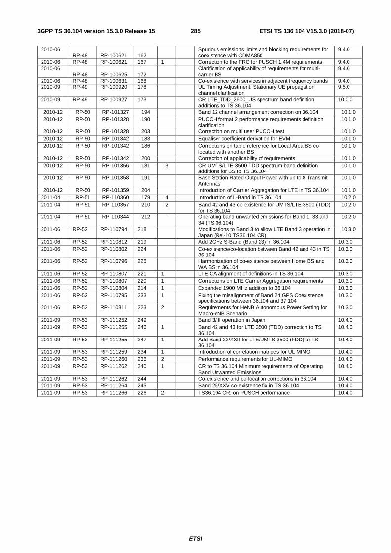
ETSI
ETSI TS 136 104 V15.3.0 (2018-07)2853GPP TS 36.104 version 15.3.0 Release 15
2010-06 RP-48 RP-100621 162
Spurious emissions limits and blocking requirements for coexistence with CDMA850
9.4.0
2010-06 RP-48 RP-100621 167 1 Correction to the FRC for PUSCH 1.4M requirements 9.4.0 2010-06
RP-48 RP-100625 172
Clarification of applicability of requirements for multi-carrier BS
9.4.0
2010-06 RP-48 RP-100631 168 Co-existence with services in adjacent frequency bands 9.4.0 2010-09 RP-49 RP-100920 178 UL Timing Adjustment: Stationary UE propagation
channel clarification 9.5.0
2010-09 RP-49 RP-100927 173 CR LTE_TDD_2600_US spectrum band definition additions to TS 36.104
10.0.0
2010-12 RP-50 RP-101327 194 Band 12 channel arrangement correction on 36.104 10.1.0 2010-12 RP-50 RP-101328 190 PUCCH format 2 performance requirements definition
clarification 10.1.0
2010-12 RP-50 RP-101328 203 Correction on multi user PUCCH test 10.1.0 2010-12 RP-50 RP-101342 183 Equaliser coefficient derivation for EVM 10.1.0 2010-12 RP-50 RP-101342 186 Corrections on table reference for Local Area BS co-
located with another BS 10.1.0
2010-12 RP-50 RP-101342 200 Correction of applicability of requirements 10.1.0 2010-12 RP-50 RP-101356 181 3 CR UMTS/LTE-3500 TDD spectrum band definition
additions for BS to TS 36.104 10.1.0
2010-12 RP-50 RP-101358 191 Base Station Rated Output Power with up to 8 Transmit Antennas
10.1.0
2010-12 RP-50 RP-101359 204 Introduction of Carrier Aggregation for LTE in TS 36.104 10.1.0 2011-04 RP-51 RP-110360 179 4 Introduction of L-Band in TS 36.104 10.2.0 2011-04 RP-51 RP-110357 210 2 Band 42 and 43 co-existence for UMTS/LTE 3500 (TDD)
for TS 36.104 10.2.0
2011-04 RP-51 RP-110344 212 - Operating band unwanted emissions for Band 1, 33 and 34 (TS 36.104)
10.2.0
2011-06 RP-52 RP-110794 218 Modifications to Band 3 to allow LTE Band 3 operation in Japan (Rel-10 TS36.104 CR)
10.3.0
2011-06 RP-52 RP-110812 219 Add 2GHz S-Band (Band 23) in 36.104 10.3.0 2011-06 RP-52 RP-110802 224 Co-existence/co-location between Band 42 and 43 in TS
36.104 10.3.0
2011-06 RP-52 RP-110796 225 Harmonization of co-existence between Home BS and WA BS in 36.104
10.3.0
2011-06 RP-52 RP-110807 221 1 LTE CA alignment of definitions in TS 36.104 10.3.0 2011-06 RP-52 RP-110807 220 1 Corrections on LTE Carrier Aggregation requirements 10.3.0 2011-06 RP-52 RP-110804 214 1 Expanded 1900 MHz addition to 36.104 10.3.0 2011-06 RP-52 RP-110795 233 1 Fixing the misalignment of Band 24 GPS Coexistence
specifications between 36.104 and 37.104 10.3.0
2011-06 RP-52 RP-110811 223 2 Requirements for HeNB Autonomous Power Setting for Macro-eNB Scenario
10.3.0
2011-09 RP-53 RP-111252 249 Band 3/III operation in Japan 10.4.0 2011-09 RP-53 RP-111255 246 1 Band 42 and 43 for LTE 3500 (TDD) correction to TS
36.104 10.4.0
2011-09 RP-53 RP-111255 247 1 Add Band 22/XXII for LTE/UMTS 3500 (FDD) to TS 36.104
10.4.0
2011-09 RP-53 RP-111259 234 1 Introduction of correlation matrices for UL MIMO 10.4.0 2011-09 RP-53 RP-111260 236 2 Performance requirements for UL-MIMO 10.4.0 2011-09 RP-53 RP-111262 240 1 CR to TS 36.104 Minimum requirements of Operating
Band Unwanted Emissions 10.4.0
2011-09 RP-53 RP-111262 244 Co-existence and co-location corrections in 36.104 10.4.0 2011-09 RP-53 RP-111264 245 Band 25/XXV co-existence fix in TS 36.104 10.4.0 2011-09 RP-53 RP-111266 226 2 TS36.104 CR: on PUSCH performance 10.4.0
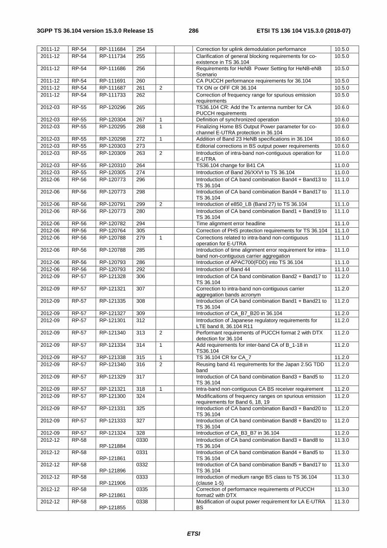
ETSI
ETSI TS 136 104 V15.3.0 (2018-07)2863GPP TS 36.104 version 15.3.0 Release 15
2011-12 RP-54 RP-111684 254 Correction for uplink demodulation performance 10.5.0 2011-12 RP-54 RP-111734 255 Clarification of general blocking requirements for co-
existence in TS 36.104 10.5.0
2011-12 RP-54 RP-111686 256 Requirements for HeNB Power Setting for HeNB-eNB Scenario
10.5.0
2011-12 RP-54 RP-111691 260 CA PUCCH performance requirements for 36.104 10.5.0 2011-12 RP-54 RP-111687 261 2 TX ON or OFF CR 36.104 10.5.0 2011-12 RP-54 RP-111733 262 Correction of frequency range for spurious emission
requirements 10.5.0
2012-03 RP-55 RP-120296 265 TS36.104 CR: Add the Tx antenna number for CA PUCCH requirements
10.6.0
2012-03 RP-55 RP-120304 267 1 Definition of synchronized operation 10.6.0 2012-03 RP-55 RP-120295 268 1 Finalizing Home BS Output Power parameter for co-
channel E-UTRA protection in 36.104 10.6.0
2012-03 RP-55 RP-120298 272 1 Addition of Band 23 HeNB specifications in 36.104 10.6.0 2012-03 RP-55 RP-120303 273 Editorial corrections in BS output power requirements 10.6.0 2012-03 RP-55 RP-120309 263 2 Introduction of intra-band non-contiguous operation for
E-UTRA 11.0.0
2012-03 RP-55 RP-120310 264 TS36.104 change for B41 CA 11.0.0 2012-03 RP-55 RP-120305 274 Introduction of Band 26/XXVI to TS 36.104 11.0.0 2012-06 RP-56 RP-120773 296 Introduction of CA band combination Band4 + Band13 to
TS 36.104 11.1.0
2012-06 RP-56 RP-120773 298 Introduction of CA band combination Band4 + Band17 to TS 36.104
11.1.0
2012-06 RP-56 RP-120791 299 2 Introduction of e850_LB (Band 27) to TS 36.104 11.1.0 2012-06 RP-56 RP-120773 280 Introduction of CA band combination Band1 + Band19 to
TS 36.104 11.1.0
2012-06 RP-56 RP-120782 294 Time alignment error headline 11.1.0 2012-06 RP-56 RP-120764 305 Correction of PHS protection requirements for TS 36.104 11.1.0 2012-06 RP-56 RP-120788 279 1 Corrections related to intra-band non-contiguous
operation for E-UTRA 11.1.0
2012-06 RP-56 RP-120788 285 Introduction of time alignment error requirement for intra-band non-contiguous carrier aggregation
11.1.0
2012-06 RP-56 RP-120793 286 Introduction of APAC700(FDD) into TS 36.104 11.1.0 2012-06 RP-56 RP-120793 292 Introduction of Band 44 11.1.0 2012-09 RP-57 RP-121328 306 Introduction of CA band combination Band2 + Band17 to
TS 36.104 11.2.0
2012-09 RP-57 RP-121321 307 Correction to intra-band non-contiguous carrier aggregation bands acronym
11.2.0
2012-09 RP-57 RP-121335 308 Introduction of CA band combination Band1 + Band21 to TS 36.104
11.2.0
2012-09 RP-57 RP-121327 309 Introduction of CA_B7_B20 in 36.104 11.2.0 2012-09 RP-57 RP-121301 312 Introduction of Japanese regulatory requirements for
LTE band 8, 36.104 R11 11.2.0
2012-09 RP-57 RP-121340 313 2 Performant requirements of PUCCH format 2 with DTX detection for 36.104
11.2.0
2012-09 RP-57 RP-121334 314 1 Add requirements for inter-band CA of B_1-18 in TS36.104
11.2.0
2012-09 RP-57 RP-121338 315 1 TS 36.104 CR for CA_7 11.2.0 2012-09 RP-57 RP-121340 316 2 Reusing band 41 requirements for the Japan 2.5G TDD
band 11.2.0
2012-09 RP-57 RP-121329 317 Introduction of CA band combination Band3 + Band5 to TS 36.104
11.2.0
2012-09 RP-57 RP-121321 318 1 Intra-band non-contiguous CA BS receiver requirement 11.2.0 2012-09 RP-57 RP-121300 324 Modificaitions of frequency ranges on spurious emission
requirements for Band 6, 18, 19 11.2.0
2012-09 RP-57 RP-121331 325 Introduction of CA band combination Band3 + Band20 to TS 36.104
11.2.0
2012-09 RP-57 RP-121333 327 Introduction of CA band combination Band8 + Band20 to TS 36.104
11.2.0
2012-09 RP-57 RP-121324 328 Introduction of CA_B3_B7 in 36.104 11.2.0 2012-12 RP-58
RP-121884 0330 Introduction of CA band combination Band3 + Band8 to
TS 36.104 11.3.0
2012-12 RP-58 RP-121861
0331 Introduction of CA band combination Band4 + Band5 to TS 36.104
11.3.0
2012-12 RP-58 RP-121896
0332 Introduction of CA band combination Band5 + Band17 to TS 36.104
11.3.0
2012-12 RP-58 RP-121906
0333 Introduction of medium range BS class to TS 36.104 (clause 1-5)
11.3.0
2012-12 RP-58 RP-121861
0335 Correction of performance requirements of PUCCH format2 with DTX
11.3.0
2012-12 RP-58 RP-121855
0338 Modification of ouput power requirement for LA E-UTRA BS
11.3.0

ETSI
ETSI TS 136 104 V15.3.0 (2018-07)2873GPP TS 36.104 version 15.3.0 Release 15
2012-12 RP-58 RP-121861 0340 Correction on BS demodulation performance 11.3.0 2012-12 RP-58 RP-121867 0343 Clean up of specification R11 11.3.0 2012-12 RP-58 RP-121911 0344 1 Modification on E-UTRA BS transmitter requriements 11.3.0 2012-12 RP-58 RP-121899 0348 1 Implementing NC CA in LTE LA 11.3.0 2012-12 RP-58 RP-121894 0349 Introduction of CA_B5_B12 in 36.104 11.3.0 2012-12 RP-58
RP-121899 0351 Correction to intra-band non-contiguous carrier
aggregation bands acronym 11.3.0
2012-12 RP-58 RP-121906
0352 2 Transmitter characteristics (Clause 6) due to introduction of Medium Range BS
11.3.0
2012-12 RP-58 RP-121906 0353 1 E-UTRA MR BS receiver requirements 11.3.0 2012-12 RP-58 RP-121899 0354 1 Further corrections for NC CA in LTE LA BS 11.3.0 2012-12 RP-58 RP-121887 0355 Introduction of inter-band CA_4-12 into TS 36.104 11.3.0 2012-12 RP-58 RP-121882 0356 Introduction of inter-band CA_11-18 into TS 36.104 11.3.0 2012-12 RP-58
RP-121907 0357 Introduction of new BS classes to E-UTRA core
specification (performance part) 11.3.0
2012-12 RP-58 RP-121863 0362 Removal of brackets around medium correlation in table 11.3.0 2012-12 RP-58 RP-121892 0363 Introduction of inter-band CA_4-7 into TS 36.104 11.3.0 2012-12 RP-58 RP-121901 0364 Introduction of Band 29 11.3.0 2012-12 RP-58 Editorial Corrections 11.3.1 2013-03 RP-59 RP-130307 0290 1 TS 36.104 CR for CA_38 11.4.0 2013-03 RP-59 RP-130365 0336 3 CR 36.104: Performant requirements of PUCCH format
2 with DTX detection 11.4.0
2013-03 RP-59 RP-130266 368 Correction of BS performance requirements 11.4.0 2013-03 RP-59 RP-130273 371 1 Supplement some note information for MR BS in TS
36.104 11.4.0
2013-03 RP-59 RP-130273 372 1 Correction of UEM requirements in TS 36.104 11.4.0 2013-03 RP-59 RP-130273 373 Correction to LTE BS classes core requirements 11.4.0 2013-03 RP-59 RP-130284 375 1 Alignment of terminology for intra-band non-contiguous
CA requirement 11.4.0
2013-03 RP-59 RP-130287 376 Band 41 requirements for operation in Japan 11.4.0 2013-03 RP-59 RP-130287 377 CR 36.104: Performance requirements of PUCCH
format 2 with DTX detection and removal of brackets. 11.4.0
2013-06 RP-60 RP-130769 0378 Correct the interfering signal offsets for ACS requirement for Medium range BS
11.5.0
2013-06 RP-60 RP-130765 0380 1 Editorial correction for the UL-MIMO channel model 11.5.0 2013-06 RP-60 RP-130766 0387 CR on TAE for inter-band CA 11.5.0 2013-06 RP-60 RP-130766 0388 1 Editorial correction of inter band CA table to TS 36.104 11.5.0 2013-06 RP-60 RP-130770 0389 Addidtion of Bands for intra-band non-contiguous CA for
36.104 11.5.0
2013-06 RP-60 RP-130761 0390 Modification on co-location spurious emission requirement for Medium Range BS
11.5.0
2013-06 RP-60 RP-130769 0391 1 Modification on co-location blocking requirement for E-UTRA Medium Range BS
11.5.0
2013-06 RP-60 RP-130769 0394 1 Introduction of multi-band BS to TS 36.104 11.5.0 2013-06 RP-60 RP-130770 0396 1 Editorial: Figure 5.6-3 Definition of Sub-block Bandwidth
for intra-band non-contiguous spectrum. 11.5.0
2013-06 RP-60 RP-130765 0400 CR for UL-MIMO performance requirements 11.5.0 2013-06 RP-60 RP-130771 0366 1 Introduction of CA 1+8 into TS36.104(Rel-12) 12.0.0 2013-06 RP-60 RP-130781 0374 1 Introduction of LTE Advanced inter-band Carrier
Aggregation of Band 3 and Band 28 to TS 36.104 12.0.0
2013-06 RP-60 RP-130785 0381 Introduction of LTE Advanced inter-band Carrier Aggregation of Band 23 and Band 29 to TS 36.104
12.0.0
2013-06 RP-60 RP-130779 0383 Introduction of LTE Advanced inter-band carrier aggregation of Band 3 and Band 26 into TS36.104 (Rel-12)
12.0.0
2013-06 RP-60 RP-130777 0384 Introduction of CA band combination Band3 + Band19 to TS 36.104
12.0.0
2013-06 RP-60 RP-130783 0385 Introduction of CA band combination Band19 + Band21 to TS 36.104
12.0.0
2013-06 RP-60 RP-130773 0392 Introduction of inter-band CA combination for Band 2 and Band 4
12.0.0
2013-06 RP-60 RP-130787 0393 Introduction of intra-band non-contiguous CA combination for Band 4
12.0.0
2013-06 RP-60 RP-130791 0395 1 Introduction of US WCS Band (Band 30) to TS 36.104 12.0.0 2013-06 RP-60 RP-130790 0397 Introduction of LTE 450 in Brazil into TS 36.104 12.0.0 2013-06 RP-60 RP-130775 0399 1 Introduction of LTE Advanced Inter-Band Carrier
Aggregation of Band 2 and Band 13 to TS36.104 12.0.0
09-2013 RP-61 RP-131300 0401 36.104 CR for LTE_CA_C_B3 12.1.0 09-2013 RP-61 RP-131283 0403 Correction of rated output power of MR BS for E-UTRA
(R12) 12.1.0
09-2013 RP-61 RP-131289 0405 Clarification on single-band operation of multi-band BS 12.1.0
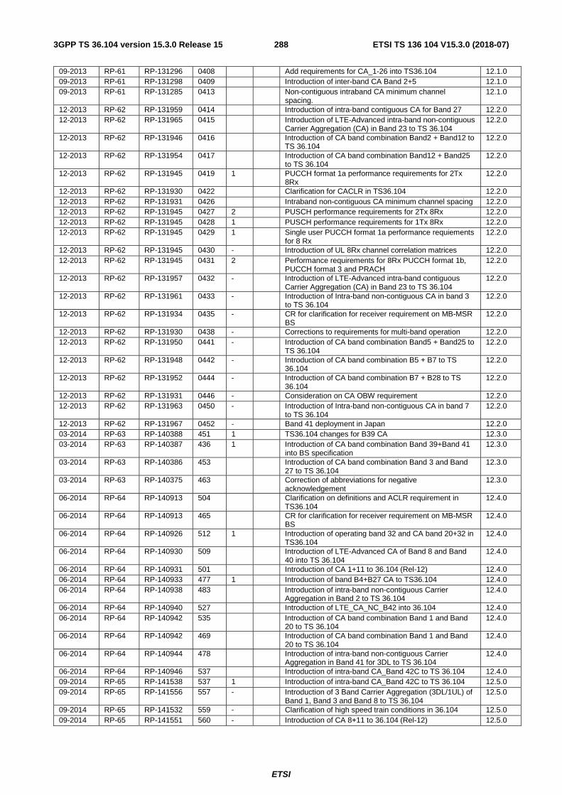
ETSI
ETSI TS 136 104 V15.3.0 (2018-07)2883GPP TS 36.104 version 15.3.0 Release 15
09-2013 RP-61 RP-131296 0408 Add requirements for CA_1-26 into TS36.104 12.1.0 09-2013 RP-61 RP-131298 0409 Introduction of inter-band CA Band 2+5 12.1.0 09-2013 RP-61 RP-131285 0413 Non-contiguous intraband CA minimum channel
spacing. 12.1.0
12-2013 RP-62 RP-131959 0414 Introduction of intra-band contiguous CA for Band 27 12.2.0 12-2013 RP-62 RP-131965 0415 Introduction of LTE-Advanced intra-band non-contiguous
Carrier Aggregation (CA) in Band 23 to TS 36.104 12.2.0
12-2013 RP-62 RP-131946 0416 Introduction of CA band combination Band2 + Band12 to TS 36.104
12.2.0
12-2013 RP-62 RP-131954 0417 Introduction of CA band combination Band12 + Band25 to TS 36.104
12.2.0
12-2013 RP-62 RP-131945 0419 1 PUCCH format 1a performance requirements for 2Tx 8Rx
12.2.0
12-2013 RP-62 RP-131930 0422 Clarification for CACLR in TS36.104 12.2.0 12-2013 RP-62 RP-131931 0426 Intraband non-contiguous CA minimum channel spacing 12.2.0 12-2013 RP-62 RP-131945 0427 2 PUSCH performance requirements for 2Tx 8Rx 12.2.0 12-2013 RP-62 RP-131945 0428 1 PUSCH performance requirements for 1Tx 8Rx 12.2.0 12-2013 RP-62 RP-131945 0429 1 Single user PUCCH format 1a performance requiements
for 8 Rx 12.2.0
12-2013 RP-62 RP-131945 0430 - Introduction of UL 8Rx channel correlation matrices 12.2.0 12-2013 RP-62 RP-131945 0431 2 Performance requirements for 8Rx PUCCH format 1b,
PUCCH format 3 and PRACH 12.2.0
12-2013 RP-62 RP-131957 0432 - Introduction of LTE-Advanced intra-band contiguous Carrier Aggregation (CA) in Band 23 to TS 36.104
12.2.0
12-2013 RP-62 RP-131961 0433 - Introduction of Intra-band non-contiguous CA in band 3 to TS 36.104
12.2.0
12-2013 RP-62 RP-131934 0435 - CR for clarification for receiver requirement on MB-MSR BS
12.2.0
12-2013 RP-62 RP-131930 0438 - Corrections to requirements for multi-band operation 12.2.0 12-2013 RP-62 RP-131950 0441 - Introduction of CA band combination Band5 + Band25 to
TS 36.104 12.2.0
12-2013 RP-62 RP-131948 0442 - Introduction of CA band combination B5 + B7 to TS 36.104
12.2.0
12-2013 RP-62 RP-131952 0444 - Introduction of CA band combination B7 + B28 to TS 36.104
12.2.0
12-2013 RP-62 RP-131931 0446 - Consideration on CA OBW requirement 12.2.0 12-2013 RP-62 RP-131963 0450 - Introduction of Intra-band non-contiguous CA in band 7
to TS 36.104 12.2.0
12-2013 RP-62 RP-131967 0452 - Band 41 deployment in Japan 12.2.0 03-2014 RP-63 RP-140388 451 1 TS36.104 changes for B39 CA 12.3.0 03-2014 RP-63 RP-140387 436 1 Introduction of CA band combination Band 39+Band 41
into BS specification 12.3.0
03-2014 RP-63 RP-140386 453 Introduction of CA band combination Band 3 and Band 27 to TS 36.104
12.3.0
03-2014 RP-63 RP-140375 463 Correction of abbreviations for negative acknowledgement
12.3.0
06-2014 RP-64 RP-140913 504 Clarification on definitions and ACLR requirement in TS36.104
12.4.0
06-2014 RP-64 RP-140913 465 CR for clarification for receiver requirement on MB-MSR BS
12.4.0
06-2014 RP-64 RP-140926 512 1 Introduction of operating band 32 and CA band 20+32 in TS36.104
12.4.0
06-2014 RP-64 RP-140930 509 Introduction of LTE-Advanced CA of Band 8 and Band 40 into TS 36.104
12.4.0
06-2014 RP-64 RP-140931 501 Introduction of CA 1+11 to 36.104 (Rel-12) 12.4.0 06-2014 RP-64 RP-140933 477 1 Introduction of band B4+B27 CA to TS36.104 12.4.0 06-2014 RP-64 RP-140938 483 Introduction of intra-band non-contiguous Carrier
Aggregation in Band 2 to TS 36.104 12.4.0
06-2014 RP-64 RP-140940 527 Introduction of LTE_CA_NC_B42 into 36.104 12.4.0 06-2014 RP-64 RP-140942 535 Introduction of CA band combination Band 1 and Band
20 to TS 36.104 12.4.0
06-2014 RP-64 RP-140942 469 Introduction of CA band combination Band 1 and Band 20 to TS 36.104
12.4.0
06-2014 RP-64 RP-140944 478 Introduction of intra-band non-contiguous Carrier Aggregation in Band 41 for 3DL to TS 36.104
12.4.0
06-2014 RP-64 RP-140946 537 Introduction of intra-band CA_Band 42C to TS 36.104 12.4.0 09-2014 RP-65 RP-141538 537 1 Introduction of intra-band CA_Band 42C to TS 36.104 12.5.0 09-2014 RP-65 RP-141556 557 - Introduction of 3 Band Carrier Aggregation (3DL/1UL) of
Band 1, Band 3 and Band 8 to TS 36.104 12.5.0
09-2014 RP-65 RP-141532 559 - Clarification of high speed train conditions in 36.104 12.5.0 09-2014 RP-65 RP-141551 560 - Introduction of CA 8+11 to 36.104 (Rel-12) 12.5.0

ETSI
ETSI TS 136 104 V15.3.0 (2018-07)2893GPP TS 36.104 version 15.3.0 Release 15
09-2014 RP-65 RP-141548 562 - Introduction of CA band combination Band1 + Band3 to TS 36.104
12.5.0
09-2014 RP-65 RP-141201 563 1 Introduction of CA band combination Band1 + Band3 + Band19 to TS 36.104
12.5.0
09-2014 RP-65 RP-141557 564 - Introduction of CA band combination Band19 + Band42 to TS 36.104
12.5.0
09-2014 RP-65 RP-141559 565 - Introduction of CA band combination Band1 + Band42 to TS 36.104
12.5.0
09-2014 RP-65 RP-141446 567 1 Introduction of CA band combination B1+B7 and B1+B5+B7 to TS 36.104 Rel-12
12.5.0
09-2014 RP-65 RP-141706 569 1 Introduction of 3 Band Carrier Aggregation of Band 1,Band 3 and Band 5 to TS 36.104
12.5.0
09-2014 RP-65 RP-141108 571 1 Introduction of inter-band CA_18-28 into TS36.104 12.5.0 09-2014 RP-65 RP-141558 577 - Introduction of CA band combination Band 1, Band 3
and Band 20 to TS 36.104 12.5.0
09-2014 RP-65 RP-141528 589 - Correction on UEM related to multi-band operation in TS36.104
12.5.0
09-2014 RP-65 RP-141554 591 1 Introduction of CA combinations 12.5.0 09-2014 RP-65 RP-141562 592 - Update of definitions to support supplemental DL in
TS36.104 12.5.0
09-2014 RP-65 RP-141463 595 - Introduction of CA band combination Band 1, Band 7 and Band 20 to TS 36.104
12.5.0
12-2014 RP-66 RP-142175 599 1 FRC for PUSCH with TTI bundling and enhanced HARQ pattern
12.6.0
12-2014 RP-66 RP-142154 593 2 Introduction of annex H and references in TS36.104 12.6.0 12-2014 RP-66 RP-142182 614 Introduction of inter-band CA_1-28 into TS36.104 12.6.0 12-2014 RP-66 RP-142149 618 Correction on transmitter intermodulation requirement 12.6.0 12-2014 RP-66 RP-142189 624 CR for TR 36.104: LTE_CA_B5_B13 12.6.0 12-2014 RP-66 RP-142175 615 1 Performance requirements for PUSCH with TTI bundling
and enhanced HARQ pattern 12.6.0
12-2014 RP-66 RP-142179 619 1 CR on RF requirements for 256QAM 12.6.0 12-2014 RP-66 RP-142190 609 2 Introduction of 3DL CA combinations 12.6.0 03-2015 RP-67 RP-150382 627 Co-location between Band 42 and Band 43 in TS 36.104 12.7.0 03-2015 RP-67 RP-150391 629 Introduction of CA_3A-42A and CA_3A-42C into 36.104 12.7.0 03-2015 RP-67 RP-150388 636 MB and TDD+FDD 12.7.0 07-2015 RP-68 RP-150955 647 Clarification of parameter P for emission requirements 12.8.0 07-2015 RP-68 RP-150955 658 Some corrections related to single carrier requirements 12.8.0 07-2015 RP-68 RP-150968 630 4 Introduction of 2DL CA combinations 13.0.0 07-2015 RP-68 RP-150972 631 4 Introduction of 3DL CA combinations 13.0.0 07-2015 RP-68 RP-150974 651 1 Introduction of 4DL CA combinations 13.0.0 07-2015 RP-68 RP-150669 664 Introduction of CA_3A-40A to TS 36.104 13.0.0 09-2015 RP-69 RP-151476 667 BS Spec improvements: TS 36.104 Corrections 13.1.0 09-2015 RP-69 RP-151506 678 CR on core requirements for support of 256QAM in wide
area BS 13.1.0
09-2015 RP-69 RP-151499 680 Introduction of 3DL CA combinations 13.1.0 09-2015 RP-69 RP-151501 681 Introduction of 4DL CA combinations 13.1.0 09-2015 RP-69 RP-151204 682 Introduction of CA_7A-40A and CA_7A-40C to TS
36.104 13.1.0
12-2015 RP-70 RP-152168 0686 - Introduction of intra-band CA_8B to TS 36.104 13.2.0 12-2015 RP-70 RP-152171 0700 - Introduction of E-UTRA band 65 to TS36.104 13.2.0 12-2015 RP-70 RP-152132 0703 - Clarification on the transmitter intermodulation
requirement in TS36.104 13.2.0
12-2015 RP-70 RP-152157 0705 1 Introduction of Band 67 and CA_20-67 to 36.104 13.2.0 12-2015 RP-70 RP-152167 0708 - Introduction of CA_5B to TS 36.104 13.2.0 12-2015 RP-70 RP-152169 0709 - Introduction of intra-band NC CA_5A-5A to TS 36.104 13.2.0 12-2015 RP-70 RP-152173 0711 - Introduction of 1447-1467MHz Band into 36.104 13.2.0 12-2015 RP-70 RP-152132 0714 - Correction on UEM requirement for MB-MSR 13.2.0 12-2015 RP-70 RP-152148 0715 2 Introduction of LAA in TS 36.104 13.2.0 12-2015 RP-70 RP-152132 0718 - BS Spec improvements: TS 36.104 Corrections 13.2.0 12-2015 RP-70 RP-152132 0721 - Corrections on definition of f_offsetmax for BS operating
in multiple bands or non-contiguous spectrum 13.2.0
12-2015 RP-70 RP-152172 0729 - Introduction of Band 66 to 36.104 13.2.0 12-2015 RP-70 RP-152156 0731 - Introduction of 2DL CA combinations 13.2.0 12-2015 RP-70 RP-152161 0732 - Introduction of 3DL CA combinations 13.2.0 12-2015 RP-70 RP-152162 0733 - Introduction of 4DL CA combinations 13.2.0 03/2016 RP-71 RP-160480 0753 B Introduction of 3DL CA combinations 13.3.0 03/2016 RP-71 RP-160481 0754 B Introduction of 4DL CA combinations 13.3.0 03/2016 RP-71 RP-160482 0752 B Introduction of 5DL CA combinations 13.3.0 03/2016 RP-71 RP-160483 0737 2 B Introduction of Band 68 into 36.104 13.3.0

ETSI
ETSI TS 136 104 V15.3.0 (2018-07)2903GPP TS 36.104 version 15.3.0 Release 15
03/2016 RP-71 RP-160488 0747 A Band 20 and Band 28 BS co-existence 13.3.0 03/2016 RP-71 RP-160489 0739 A Corrections to BS spurious emissions requirements for
band 22 and 42 in TS36.104 (Rel-13) 13.3.0
03/2016 RP-71 RP-160490 0748 F Correction of BS RF requirements in TS 36.104 13.3.0 06/2016 RP-72 RP-161131 0760 B 36.104 CR for BS MMSE-IRC receiver - Definitions 13.4.0 06/2016 RP-72 RP-161131 0761 1 B 36.104 CR for BS MMSE-IRC receiver - Demodulation
tests in synchronous interference scneario 13.4.0
06/2016 RP-72 RP-161131 0762 1 B 36.104 CR for BS MMSE-IRC receiver - Demodulation tests in asynchronous interference scneario
13.4.0
06/2016 RP-72 RP-161131 0763 1 B 36.104 CR for BS MMSE-IRC receiver - FRC definitions 13.4.0 06/2016 RP-72 RP-161131 0764 B 36.104 CR for BS MMSE-IRC receiver - Interference
model for synchronous and asynchronous scnearios 13.4.0
06/2016 RP-72 RP-161128 0765 3 B CR: Cat-M1 PRACH Performance Requirements 13.4.0 06/2016 RP-72 RP-161128 0766 2 B CR: Cat-M1 PUCCH Performance Requirements 13.4.0 06/2016 RP-72 RP-161142 0773 1 F Correction on co-existence and co-location emssion
requirement for LAA 13.4.0
06/2016 RP-72 RP-161142 0780 F Band 46 sub-bands indication 13.4.0 06/2016 RP-72 RP-161142 0781 F Band 46 channel access procedures requirements 13.4.0 06/2016 RP-72 RP-116131 0783 B Performance requirements for BS MMSE-IRC receiver in
asynchronous interference scneario 13.4.0
2016/06 RP-72 RP-161129 0784 1 B CR: Performance requirements for PUCCH format 4 (Rel-13)
13.5.0
2016/06 RP-72 RP-161128 0785 1 B CR for eMTC PUSCH performance requirements 13.5.0 06/2016 RP-72 RP-161129 0788 1 B CR for PUCCH format 5 performance requirements for
36.104 13.4.0
06/2016 RP-72 RP-161142 0789 1 F Correction related to band 65 13.4.0 06/2016 RP-72 RP-161140 0795 1 F Corrections on definition of multi-band definition and
blocking 13.4.0
06/2016 RP-72 RP-116142 0799 F Correction to BS spurious emissions for co-location with Band 46
13.4.0
06/2016 RP-72 RP-161126 0800 B CR to TS36.104 for NB-IoT feature introduction 13.4.0 06/2016 RP-72 RP-161125 782 - B Introduction of Band 70 to 36.104 14.0.0 06/2016 RP-72 RP-161119 790 - B Introduction of additional band combinations for 4DL
inter-band CA 14.0.0
06/2016 RP-72 RP-161117 792 - B Introduction of completed R14 2DL band combinations to TS 36.104
14.0.0
06/2016 RP-72 RP-161118 794 1 B Introduction of completed R14 3DL band combination to TS 36.104
14.0.0
06/2016 RP-72 RP-161124 798 - B Introduction of Band 69 and CA_3-69 to 36.104 14.0.0 09/2016 RP-73 RP-161623 802 B Introduction of completed R14 3DL band combination to
TS 36.104 14.1.0
09/2016 RP-73 RP-161637 804 A Corrections on NB-IoT BS unwanted emissions requirements
14.1.0
09/2016 RP-73 RP-161622 805 B Introduction of completed R14 2DL band combinations to TS 36.104
14.1.0
09/2016 RP-73 RP-161636 807 A correction CR for 36.104(Rel-14) NB-IoT In-channel selectivity
14.1.0
09/2016 RP-73 RP-161786 809 A 36.104 CR on bracket removal for BS IRC receiver 14.1.0 09/2016 RP-73 RP-161782 811 A CR for eMTC PUCCH performance requirements (Rel-
14) 14.1.0
09/2016 RP-73 RP-161782 813 A CR for eMTC PUSCH performance requirements(Rel-14)
14.1.0
09/2016 RP-73 RP-161780 815 A CR: Demodulation requirements for NPUSCH format 1 (Rel-14)
14.1.0
09/2016 RP-73 RP-161780 817 A CR: Demodulation requirements for NPUSCH format 2 (Rel-14)
14.1.0
09/2016 RP-73 RP-161782 820 A CR: Add Test tolerances for eMTC BS demodulation performance requirements
14.1.0
09/2016 RP-73 RP-161640 824 A Corrections to operating band unwanted emissions in TS36.104 (Rel-14)
14.1.0
09/2016 RP-73 RP-161624 825 B Introduction of additional band combinations for 4DL inter-band CA
14.1.0
09/2016 RP-73 RP-161629 835 F Corrections of CA operating band tables 14.1.0 09/2016 RP-73 RP-161636 840 A CR to section 7.8 Receiver intermodulation 14.1.0 09/2016 RP-73 RP-161637 841 A CR to section 7.8 Receiver intermodulation 14.1.0 09/2016 RP-73 RP-161636 845 A Clarification on EARFCN 14.1.0 09/2016 RP-73 RP-161637 847 A Correction on ACS for standalone NB-IoT BS in TS
36.104 14.1.0
09/2016 RP-73 RP-161636 849 A Correction on FRC for EUTRA with in-band NB-IoT in TS 36.104
14.1.0
09/2016 RP-73 RP-161625 850 B Introduction of 5DL CA combinations 14.1.0

ETSI
ETSI TS 136 104 V15.3.0 (2018-07)2913GPP TS 36.104 version 15.3.0 Release 15
09/2016 RP-73 RP-161786 852 A Maintenance for BS MMSE-IRC receiver requirements(Rel-13)
14.1.0
09/2016 RP-73 RP-161618 818 1 B CR on ETU600 PUSCH test for 36.104 14.1.0 09/2016 RP-73 RP-161617 828 1 B Introduction of V2V bands 14.1.0 09/2016 RP-73 RP-161635 822 1 A Introduction of Korea regulatory requirements for PS-
LTE BS, band 28, 36.104 14.1.0
09/2016 RP-73 RP-161638 857 A LAA BS unwanted emission mask requirements in 36.104
14.1.0
12/2016 RP-74 RP-162384 0862 A CR for Rel-14 eMTC PRACH performance requirements 14.2.0 12/2016 RP-74 RP-162388 0863 1 F Maintenance for PUSCH ETU600 requirements 14.2.0 12/2016 RP-74 RP-162428 0864 A Update of the Total Power Dynamic Range requirement
for Band 46 14.2.0
12/2016 RP-74 RP-162407 0879 1 B Addition of new operating bands for NB-IoT 14.2.0 12/2016 RP-74 RP-162434 0881 A Interfering signal bandwidth for NB-IoT BS receiver
dynamic range requirements 14.2.0
12/2016 RP-74 RP-162434 0882 A Spurious responses for NB-IoT BS receiver blocking requirements
14.2.0
12/2016 RP-74 RP-162457 0883 B Introduction of additional band combinations for 4DL inter-band CA
14.2.0
12/2016 RP-74 RP-162398 0884 B Introduction of additional band combinations for Intra-band CA
14.2.0
12/2016 RP-74 RP-162379 0888 A CR: Correction of Fixed Reference Channels for NPUSCH format 1 (Rel-14, 36.104)
14.2.0
12/2016 RP-74 RP-162379 0891 A CR: Demodulation requirements for NPRACH (Rel-14) 14.2.0 12/2016 RP-74 RP-162379 0893 A CR: Updates to demodulation requirements for NPUSCH
format 1 (Rel-14) 14.2.0
12/2016 RP-74 RP-162456 0895 1 A CR: Updates to demodulation requirements for NPUSCH format 2 (Rel-14)
14.2.0
12/2016 RP-74 RP-162382 0897 A CR on cleaning up Rel-14 eMTC PUSCH performance requirements
14.2.0
12/2016 RP-74 RP-162399 0898 B Introduction of completed R14 2DL band combinations to TS 36.104
14.2.0
12/2016 RP-74 RP-162433 0900 A Correction to interfering signal for Narrowband blocking requirement for NB-IOT (Rel-14)
14.2.0
12/2016 RP-74 RP-162400 0901 B Introduction of completed R14 3DL band combinations to TS 36.104
14.2.0
12/2016 RP-74 RP-162387 0902 1 F Sets of EARFCN for multiple Scell operation in Band 46 14.2.0 12/2016 RP-74 RP-162433 0904 A Correction of Fixed Reference Channels for NB-IOT
reference sensitivity and dynamic range 14.2.0
12/2016 RP-74 RP-162395 0905 1 B Necessary changes to the core requirements for Multi-Band Base Station testing with three or more bands
14.2.0
12/2016 RP-74 RP-162402 0906 B Introduction of 5DL CA combinations 14.2.0 12/2016 RP-74 RP-162405 0907 B Introduction of Band 48 14.2.0 12/2016 RP-74 RP-162413 0914 1 A Correction to dynamic range requirement 14.2.0 03/2017 RP-75 RP-170568 0915 B Introduction of additional band combinations for 4DL
inter-band CA 14.3.0
03/2017 RP-75 RP-170565 0916 2 B Introduction of additional band combinations for Intra-band CA
14.3.0
03/2017 RP-75 RP-170567 0917 F Correction of completed 2DL and 3DL CAs 14.3.0 03/2017 RP-75 RP-170569 0918 B Introduction of 5DL CA combinations 14.3.0 03/2017 RP-75 RP-170593 0922 A CR to 36.104 for correction of performance requirements
for BS MMSE-IRC receiver 14.3.0
03/2017 RP-75 RP-170573 0924 1 A CR to 36.104: Addition of 1.4 and 3 MHz channel bandwidths for Band 65
14.3.0
03/2017 RP-75 RP-170600 0926 A CR:Cleanup for NB-IoT BS demod performance requirements(R14)
14.3.0
03/2017 RP-75 RP-170596 0928 A CR for PRACH requirements (Rel-14) 14.3.0 03/2017 RP-75 RP-170553 0931 1 B CR on eLAA BS for TS 36.104 14.3.0 03/2017 RP-75 RP-170598 0933 A Correction on FRC for NB-IoT in TS 36.104 14.3.0 03/2017 RP-75 RP-170567 0934 B Introduction of completed R14 3DL band combinations
to TS 36.104 14.3.0
03/2017 RP-75 RP-170595 0936 A Correction CR on PUSCH and PUCCH supporting Cat-M1 considering guard period in 36.104
14.3.0
03/2017 RP-75 RP-170598 0938 A Corrections on NB-IoT narrowband intermodulation performance requirement
14.3.0
03/2017 RP-75 RP-170577 0939 F B70 Carrier Frequency and EARFCN Correction 14.3.0 03/2017 RP-75 RP-170566 0941 B Introduction of completed R14 2DL band combinations
to TS 36.104 14.3.0
06/2017 RP-76 RP-171282 0322 1 F CR on BS for protection of V2X UE in TS 36.104 14.4.0 06/2017 RP-76 RP-171279 0944 1 B Intorduction of new bands for NB-IoT in 36.104 14.4.0 06/2017 RP-76 RP-171301 0973 A Updates to performance requirements for NPUSCH
format 2 14.4.0

ETSI
ETSI TS 136 104 V15.3.0 (2018-07)2923GPP TS 36.104 version 15.3.0 Release 15
06/2017 RP-76 RP-171310 0975 A clean up eMTC PUCCH requirements(Rel-14) 14.4.0 06/2017 RP-76 RP-171257 0976 3 B CR for new PRACH performance requirements 14.4.0 06/2017 RP-76 RP-171261 4667 1 B CR to 36.104: Introduction of FeMBMS numerologies 14.4.0 06/2017 RP-76 RP-171276 4668 1 B Introduction of 5DL CA combinations to 36.104 14.4.0 06/2017 RP-76 RP-171272 4671 1 B Introduction of additional band combinations for Intra-
band CA 14.4.0
06/2017 RP-76 RP-171275 4672 2 B Introduction of Rel-14 4DL/1UL combinations in 36.104 14.4.0 06/2017 RP-76 RP-171273 4673 B Introduction of completed R14 2DL band combinations
to TS 36.104 14.4.0
06/2017 RP-76 RP-171274 4674 B Introduction of completed R14 3DL band combinations to TS 36.104
14.4.0
06/2017 RP-76 RP-171260 4676 1 B Introduction of BS performance requirements for 256QAM in 36.104
14.4.0
06/2017 RP-76 RP-171299 4678 F Channel Raster For Multiple Standalone NB-IoT Carriers (TS 36.104)
14.4.0
06/2017 RP-76 RP-171299 4680 A Narrowband blocking requirement for NB-IoT guard band operation (TS 36.104)
14.4.0
06/2017 RP-76 RP-171300 4682 A Intermodulation performance requirement for NB-IoT operation (TS 36.104)
14.4.0
06/2017 RP-76 RP-171299 4684 A Note on BS in-channel selectivity for NB-IoT 14.4.0 06/2017 RP-76 RP-171300 4686 A Clarification on 1.4 MHz for in-band operation 14.4.0 09/2017 RP-77 RP-171972 4691 A NB-IoT PRB position in Refsens for >5 MHz E-UTRA in-
band operation (TS 36.104) 14.5.0
09/2017 RP-77 RP-171971 4698 A CR on eMTC BS PRACH requirements R14 14.5.0 09/2017 RP-77 RP-171934 4703 B Removal of brackets of perfromance requirements for
256QAM. 14.5.0
09/2017 RP-77 RP-171934 4705 B Introduction of perfromance requirements for PUSCH transmission in UpPTS
14.5.0
09/2017 RP-77 RP-171968 4709 A CR to 36.104: Correction to LA BS spurious emissions limits table
14.5.0
09/2017 RP-77 RP-171933 4712 1 B Introduce test case for eLAA PUSCH 14.5.0 09/2017 RP-77 RP-171972 4713 F Correction on NB-IoT BS standalone UEM 14.5.0 09/2017 RP-77 RP-171942 4715 F Maintance CR for HST PRACH enhancement
requirements 14.5.0
09/2017 RP-77 RP-171945 4692 1 B 36.104 CR for BS IC receiver - Definitions 15.0.0 09/2017 RP-77 RP-171945 4693 1 B 36.104 CR for BS IC receiver - Demodulation tests 15.0.0 09/2017 RP-77 RP-171945 4694 B 36.104 CR for BS IC receiver - FRC definitions 15.0.0 09/2017 RP-77 RP-171955 4695 1 B Introduction of Rel-15 LTE Intra-band combinations in
36.104 15.0.0
09/2017 RP-77 RP-171958 4696 B Introduction of Rel-15 LTE 4DL/1UL combinations in 36.104
15.0.0
09/2017 RP-77 RP-171948 4699 2 B Introduction of the FDD L-band (Band 74) into TS 36.104 15.0.0 09/2017 RP-77 RP-171959 4700 1 B Introduction of 5DL CA combinations 15.0.0 09/2017 RP-77 RP-171952 4701 B CR to 36.104: Introduction of Band 71 15.0.0 09/2017 RP-77 RP-171946 4702 B CR to 36.104: Introduction of Band 72 15.0.0 09/2017 RP-77 RP-171957 4704 B Introduction of completed R15 3DL band combinations
to TS 36.104 15.0.0
09/2017 RP-77 RP-171950 4707 1 B CR to 36.104: Introduction of B75 and B76 15.0.0 09/2017 RP-77 RP-171956 4711 3 B Introduction of completed combination to 36.104 15.0.0 09/2017 RP-77 RP-171949 4714 2 B Introduction of TDD L-band into TS 36.104 15.0.0 09/2017 RP-77 RP-172048 4717 B CR to 36.104: Support of NB-IoT for Bands 4, 14 and 71 15.0.0 12/2017 RP-78 RP-172600 4720 F 36.104 CR on bracket removal for BS IC receiver 15.1.0 12/2017 RP-78 RP-172609 4723 A Correction on NB-IoT RB power dynamic range 15.1.0 12/2017 RP-78 RP-172613 4727 A CR to 36.104: BS Spurious emissions limits for
protection of the BS receiver for B28 in Europe 15.1.0
12/2017 RP-78 RP-172593 4731 B CR to 36.104: Introduction of Band 73 15.1.0 12/2017 RP-78 RP-172596 4733 B CR for 36104 15.1.0 12/2017 RP-78 RP-172595 4734 B Introduction of additional band combinations for Intra-
band CA 15.1.0
12/2017 RP-78 RP-172704 4735 B Introduction of Rel-15 LTE 4DL/1UL combinations in 36.104
15.1.0
12/2017 RP-78 RP-172586 4737 A Correction of channel spacing for band 46 intraband CA band combinations with 10 MHz bandwidth
15.1.0
12/2017 RP-78 RP-172584 4739 A CR to 36.104: Corrections to co-location tables for B48 15.1.0 12/2017 RP-78 RP-172594 4740 1 B CR to 36.104: Introduction of Band 49 15.1.0 12/2017 RP-78 RP-172588 4741 2 B Addition of NB-IoT small cells support 15.1.0 12/2017 RP-78 RP-172611 4746 A Removal of BS repetition sensitivity 15.1.0 12/2017 RP-78 RP-172597 4747 B Introduction of completed R15 3DL band combinations
to TS 36.104 15.1.0
12/2017 RP-78 RP-172586 4750 A Introduce burst model for eLAA PUSCH demodualtion 15.1.0

ETSI
ETSI TS 136 104 V15.3.0 (2018-07)2933GPP TS 36.104 version 15.3.0 Release 15
12/2017 RP-78 RP-172598 4751 B Introduction of 5DL CA combinations to 36.104 15.1.0 12/2017 RP-78 RP-172587 4752 B Introduction on sTTI for TS 36.104 15.1.0 12/2017 RP-78 RP-172550 4753 B Introduction of missing 3DL fallbacks to 4DL
combinations 15.1.0
2018-03 RAN#79 RP-180265 4754 1 B CR on BS RF requirments for DL 1024QAM in TS 36.104
15.2.0
2018-03 RAN#79 RP-180272 4755 B Introduction of completed R15 3DL/1UL band combinations to TS 36.104
15.2.0
2018-03 RAN#79 RP-180273 4757 B Introduction of Rel-15 LTE 4DL/1UL combinations in 36.104
15.2.0
2018-03 RAN#79 RP-180274 4758 B Introduction of 5DL CA combinations to 36.104 15.2.0 2018-03 RAN#79 RP-180281 4759 1 B CR to 36.104: Introduction of new additional unwanted
emission limit for L-Band 15.2.0
2018-03 RAN#79 RP-180279 4760 B CR to 36.104: Introduction of Band 85 (B12-extended) 15.2.0 2018-03 RAN#79 RP-180266 4761 F Removing Section 9 from 36.104 15.2.0 2018-03 RAN#79 RP-180293 4764 A CR on clarifications of NB-IoT RB power dynamic range
for in-band or guard band operation (TS 36.104) 15.2.0
2018-03 RAN#79 RP-180267 4765 F CR on corrections of tables for NB-IoT small cell support (TS 36.104)
15.2.0
2018-03 RAN#79 RP-180271 4766 B CR for 36.104 15.2.0 2018-03 RAN#79 RP-180278 4767 B Introduction of TDD 3.3-3.4GHz band (band 52) 15.2.0 2018-06 RAN#80 RP-181112 4770 A Clarifcation on Base Station RF Bandwidth for stand-
alone NB-IoT operation (36.104) 15.3.0
2018-06 RAN#80 RP-181091 4772 B Introduction of Rel-15 LTE 4DL/1UL combinations in 36.104 (This CR was superseded by CR#4786)
15.3.0
2018-06 RAN#80 RP-181089 4776 B CR to add new 2DL1UL CA combos to 36104 15.3.0 2018-06 RAN#80 RP-181090 4777 B Introduction of Rel-15 LTE 3DL/1UL combinations in
36.104 (This CR was superseded by CR#4788)
15.3.0
2018-06 RAN#80 RP-181089 4780 1 B CR for 36.104 to update 2DL1UL basket items 15.3.0 2018-06 RAN#80 RP-181102 4781 F Correction on FRC indices for enhanced performance
requirement type B 15.3.0
2018-06 RAN#80 RP-181084 4782 B NB-IoT: Adding TDD support in TS 36.104 15.3.0 2018-06 RAN#80 RP-181100 4783 F CR to TS 36.104: Correct Pmax,c to Prated,c for UEM
requirements 15.3.0
2018-06 RAN#80 RP-181088 4785 B Introduction of Rel-15 LTE Intra-band combinations in 36.104
15.3.0
2018-06 RAN#80 RP-181091 4786 B Introduction of Rel-15 LTE 4DL/1UL combinations in 36.104
15.3.0
2018-06 RAN#80 RP-181090 4788 B Introduction of completed R15 3DL/1UL band combinations to TS 36.104
15.3.0
2018-06 RAN#80 RP-181092 4789 B Introduction of 5DL CA combinations to 36.104 15.3.0

ETSI
ETSI TS 136 104 V15.3.0 (2018-07)2943GPP TS 36.104 version 15.3.0 Release 15
History
Document history
V15.3.0 July 2018 Publication