Embed Size (px)
Citation preview

ETSI TS 132 250 V6.3.0 (2005-09)
Technical Specification
Universal Mobile Telecommunications System (UMTS);Telecommunication management;
Charging management;Circuit Switched (CS) domain charging
(3GPP TS 32.250 version 6.3.0 Release 6)

ETSI
ETSI TS 132 250 V6.3.0 (2005-09) 1 3GPP TS 32.250 version 6.3.0 Release 6
Reference RTS/TSGS-0532250v630
Keywords UMTS
ETSI
650 Route des Lucioles F-06921 Sophia Antipolis Cedex - FRANCE
Tel.: +33 4 92 94 42 00 Fax: +33 4 93 65 47 16
Siret N° 348 623 562 00017 - NAF 742 C
Association à but non lucratif enregistrée à la Sous-Préfecture de Grasse (06) N° 7803/88
Important notice
Individual copies of the present document can be downloaded from: http://www.etsi.org
The present document may be made available in more than one electronic version or in print. In any case of existing or perceived difference in contents between such versions, the reference version is the Portable Document Format (PDF).
In case of dispute, the reference shall be the printing on ETSI printers of the PDF version kept on a specific network drive within ETSI Secretariat.
Users of the present document should be aware that the document may be subject to revision or change of status. Information on the current status of this and other ETSI documents is available at
http://portal.etsi.org/tb/status/status.asp
If you find errors in the present document, please send your comment to one of the following services: http://portal.etsi.org/chaircor/ETSI_support.asp
Copyright Notification
No part may be reproduced except as authorized by written permission. The copyright and the foregoing restriction extend to reproduction in all media.
© European Telecommunications Standards Institute 2005.
All rights reserved.
DECTTM, PLUGTESTSTM and UMTSTM are Trade Marks of ETSI registered for the benefit of its Members. TIPHONTM and the TIPHON logo are Trade Marks currently being registered by ETSI for the benefit of its Members. 3GPPTM is a Trade Mark of ETSI registered for the benefit of its Members and of the 3GPP Organizational Partners.

ETSI
ETSI TS 132 250 V6.3.0 (2005-09) 2 3GPP TS 32.250 version 6.3.0 Release 6
Intellectual Property Rights IPRs essential or potentially essential to the present document may have been declared to ETSI. The information pertaining to these essential IPRs, if any, is publicly available for ETSI members and non-members, and can be found in ETSI SR 000 314: "Intellectual Property Rights (IPRs); Essential, or potentially Essential, IPRs notified to ETSI in respect of ETSI standards", which is available from the ETSI Secretariat. Latest updates are available on the ETSI Web server (http://webapp.etsi.org/IPR/home.asp).
Pursuant to the ETSI IPR Policy, no investigation, including IPR searches, has been carried out by ETSI. No guarantee can be given as to the existence of other IPRs not referenced in ETSI SR 000 314 (or the updates on the ETSI Web server) which are, or may be, or may become, essential to the present document.
Foreword This Technical Specification (TS) has been produced by ETSI 3rd Generation Partnership Project (3GPP).
The present document may refer to technical specifications or reports using their 3GPP identities, UMTS identities or GSM identities. These should be interpreted as being references to the corresponding ETSI deliverables.
The cross reference between GSM, UMTS, 3GPP and ETSI identities can be found under http://webapp.etsi.org/key/queryform.asp .

ETSI
ETSI TS 132 250 V6.3.0 (2005-09) 3 3GPP TS 32.250 version 6.3.0 Release 6
Contents Intellectual Property Rights ................................................................................................................................2 Foreword.............................................................................................................................................................2 Foreword.............................................................................................................................................................5 1 Scope ........................................................................................................................................................6 2 References ................................................................................................................................................6 3 Definitions, abbreviations and symbols ...................................................................................................8 3.1 Definitions..........................................................................................................................................................8 3.2 Abbreviations .....................................................................................................................................................9 3.3 Symbols............................................................................................................................................................10 4 Architecture considerations....................................................................................................................12 4.1 High level CS domain architecture...................................................................................................................12 4.2 CS domain offline charging architecture..........................................................................................................13 4.3 CS domain online charging architecture ..........................................................................................................14 5 CS domain charging principles and scenarios........................................................................................14 5.1 CS domain charging principles ........................................................................................................................14 5.1.1 General aspects of Charging Data...............................................................................................................15 5.1.2 Charging information..................................................................................................................................15 5.1.2.1 Subscriber billing ..................................................................................................................................15 5.1.2.2 Settlements of Charges..........................................................................................................................16 5.1.2.2.1 Inter-PLMN accounting...................................................................................................................16 5.1.2.2.2 "Visitors" from other PLMNs..........................................................................................................16 5.1.2.2.3 "Home" subscribers roaming in other PLMNs ................................................................................16 5.1.2.2.4 Settlement with other networks .......................................................................................................16 5.1.2.3 Service Information...............................................................................................................................17 5.1.3 Special cases and considerations ................................................................................................................17 5.1.3.1 AoC service...........................................................................................................................................17 5.1.3.2 CAMEL services...................................................................................................................................17 5.1.3.3 Use of supplementary services..............................................................................................................17 5.1.3.4 Use of call forwarding...........................................................................................................................18 5.1.3.5 Use of call hold and multi-party services ..............................................................................................18 5.1.3.6 Partial records .......................................................................................................................................19 5.1.3.7 Use of circuit-switched data services ....................................................................................................20 5.1.3.8 Inter-MSC server handover...................................................................................................................20 5.1.3.9 Call re-establishment.............................................................................................................................20 5.1.3.10 Restricted directory numbers ................................................................................................................20 5.1.3.11 IMEI Observation .................................................................................................................................20 5.1.3.12 Triggers for LCS-MT-CDR, LCS-MO-CDR and LCS-NI-CDR Charging Information Collection.....21 5.1.3.13 BS30 Accounting ..................................................................................................................................21 5.1.3.14 CAMEL Call Party Handling service....................................................................................................21 5.2 CS domain offline charging scenarios..............................................................................................................22 5.2.1 Basic principles...........................................................................................................................................22 5.2.1.1 Mobile to land (outgoing) call...............................................................................................................24 5.2.1.2 Land to mobile (incoming) call .............................................................................................................25 5.2.1.3 Mobile to mobile call within the same network ....................................................................................26 5.2.1.4 Incoming call to a roaming subscriber ..................................................................................................27 5.2.1.5 Incoming call to a PLMN service centre...............................................................................................28 5.2.1.6 Call forwarding unconditional ..............................................................................................................29 5.2.1.7 Call forwarding conditional (on busy) ..................................................................................................30 5.2.1.8 Delivery of a mobile terminated short message ....................................................................................31 5.2.1.9 Call hold and multi-party service ..........................................................................................................32 5.2.1.10 Outgoing call handled by CAMEL .......................................................................................................33 5.2.1.11 Incoming call handled by CAMEL without redirection........................................................................35 5.2.1.12 Incoming call to a roaming subscriber handled by CAMEL.................................................................37 5.2.1.13 Incoming call handled by CAMEL with redirection decided and forwarding leg handled by
CAMEL.................................................................................................................................................39

ETSI
ETSI TS 132 250 V6.3.0 (2005-09) 4 3GPP TS 32.250 version 6.3.0 Release 6
5.2.1.14 Incoming call handled by CAMEL without redirection and forwarded early using GSM SS but controlled by CAMEL...........................................................................................................................41
5.2.1.15 Incoming call handled by CAMEL without redirection and forwarded late using GSM SS but controlled by CAMEL...........................................................................................................................43
5.2.1.16 Early forwarded call controlled by CAMEL.........................................................................................45 5.2.1.17 Late forwarded call controlled by CAMEL ..........................................................................................47 5.2.1.18 Incoming call handled by CAMEL with redirection initiated by CAMEL feature ...............................49 5.2.1.19 CAMEL Scenario for Visiting Terminator Trigger Calls .....................................................................51 5.2.1.20 Outgoing call handled by CAMEL with Dialled CSI Trigger...............................................................53 5.2.1.21 Incoming call handled by CAMEL with redirection decided and forwarding leg handled by
CAMEL with Dialled CSI Trigger........................................................................................................55 5.2.1.22 Mobile terminated location request.......................................................................................................57 5.2.1.23 gsmSCF initiated wake-up call handled by CAMEL CPH ...................................................................58 5.2.1.24 Three party conference handled by CAMEL CPH................................................................................59 5.2.2 Diameter message flows .............................................................................................................................61 5.2.3 CDR generation ..........................................................................................................................................61 5.2.4 GTP' record transfer flows..........................................................................................................................61 5.2.5 BC CDR file transfer ...................................................................................................................................62 5.3 CS domain online charging scenarios ..............................................................................................................62 5.3.1 Basic principles...........................................................................................................................................62 5.3.2 Diameter message flows .............................................................................................................................62 6 Definition of charging information ........................................................................................................63 6.1 Data description for CS domain offline charging.............................................................................................63 6.1.1 Diameter message contents.........................................................................................................................63 6.1.2 GTP' message contents ...............................................................................................................................63 6.1.3 CDR description on the Bc reference point .................................................................................................63 6.1.3.1 Mobile originated call attempt ..............................................................................................................64 6.1.3.2 Mobile originated emergency call attempt ............................................................................................67 6.1.3.3 Mobile originated call forwarding attempt............................................................................................68 6.1.3.4 Mobile terminated call attempt .............................................................................................................70 6.1.3.5 Roaming call attempt ............................................................................................................................72 6.1.3.6 Incoming gateway call attempt .............................................................................................................73 6.1.3.7 Outgoing gateway call attempt..............................................................................................................74 6.1.3.8 Transit call attempt................................................................................................................................75 6.1.3.9 Supplementary service actions ..............................................................................................................76 6.1.3.10 HLR interrogation .................................................................................................................................77 6.1.3.11 Location update (VLR) .........................................................................................................................77 6.1.3.12 Location update (HLR) .........................................................................................................................78 6.1.3.13 Short message service, mobile originated .............................................................................................78 6.1.3.14 Short message service, mobile terminated ............................................................................................79 6.1.3.15 SMS-MO interworking record ..............................................................................................................79 6.1.3.16 SMS-MT gateway record......................................................................................................................79 6.1.3.17 Common equipment usage record.........................................................................................................80 6.1.3.18 Terminating CAMEL call attempt ........................................................................................................81 6.1.3.19 IMEI observation ticket.........................................................................................................................82 6.1.3.20 Mobile terminated location request (MT-LR).......................................................................................83 6.1.3.21 Mobile originated location request (MO-LR) .......................................................................................84 6.1.3.22 Network induced location request (NI-LR)...........................................................................................85 6.1.3.23 Mobile originated call attempt (CAMEL CPH adapted version) ..........................................................86 6.1.3.24 gsmSCF initiated CAMEL CPH call attempt........................................................................................89 6.1.3.25 New Call Segment in a MO, CF and MT CAMEL Dialogue ...............................................................91 6.1.3.26 Mobile originated call forwarding attempt (CAMEL CPH adapted version) .......................................93 6.1.3.27 Terminating CAMEL call attempt (CAMEL CPH adapted version) ....................................................95 6.2 Data description for CS domain online charging .............................................................................................96 6.2.1 Diameter message contents.........................................................................................................................96
Annex A (informative): CDR File Transfer compliant with earlier 3GPP releases .........................97
Annex B (informative): Bibliography...................................................................................................98
Annex C (informative): Change history ...............................................................................................99 History ............................................................................................................................................................100

ETSI
ETSI TS 132 250 V6.3.0 (2005-09) 5 3GPP TS 32.250 version 6.3.0 Release 6
Foreword This Technical Specification has been produced by the 3rd Generation Partnership Project (3GPP).
The contents of the present document are subject to continuing work within the TSG and may change following formal TSG approval. Should the TSG modify the contents of the present document, it will be re-released by the TSG with an identifying change of release date and an increase in version number as follows:
Version x.y.z
where:
x the first digit:
1 presented to TSG for information;
2 presented to TSG for approval;
3 or greater indicates TSG approved document under change control.
y the second digit is incremented for all changes of substance, i.e. technical enhancements, corrections, updates, etc.
z the third digit is incremented when editorial only changes have been incorporated in the document.

ETSI
ETSI TS 132 250 V6.3.0 (2005-09) 6 3GPP TS 32.250 version 6.3.0 Release 6
1 Scope The present document is part of a series of documents that specify charging functionality and charging management in GSM/UMTS networks. The GSM/UMTS core network charging architecture and principles are specified in 3GPP TS 32.240 [1], which provides an umbrella for other charging management TSs that specify:
• the content of the CDRs per domain and subsystem (offline charging);
• the content of real-time charging messages per domain / subsystem (online charging);
• the functionality of online and offline charging for those domains and subsystems;
• the interfaces that are used in the charging framework to transfer the charging information (i.e. CDRs or charging events).
The complete document structure for these TSs is defined in 3GPP TS 32.240 [1].
The present document specifies the Offline Charging description for the 3GPP Circuit Switched domain, based on the functional descriptions of the 3GPP bearer-, tele- and supplementary services in 3GPP TS 22.002 [200], 3GPP TS 22.003 [201] and 3PP TS 22.004 [202], respectively. This charging description includes the offline charging architecture and scenarios specific to the CS domain, as well as the mapping of the common charging architecture specified in 3GPP TS 32.240 [1] onto the CS domain. It further specifies the structure and content of the CDRs for offline charging. The present document is related to other 3GPP charging TSs as follows:
• The common 3GPP charging architecture is specified in 3GPP TS 32.240 [1];
• The parameters, abstract syntax and encoding rules for these CDR types are specified in 3GPP TS 32.298 [51].
• The file based mechanism used to transfer the CDRs from the network to the operator's billing domain (e.g. the billing system or a mediation device) is specified in 3GPP TS 32.297 [52].
Note that online charging for the CS domain is solely based on CAMEL (3GPP TS 23.078 [207] and 3GPP TS 29.078 [213]) and therefore outside the scope of the 32 series of charging specifications.
All terms, definitions and abbreviationsused in the present document, that are common across 3GPP TSs, are defined in 3GPP TR 21.905 [100]. Those that are common across charging management in GSM/UMTS domains,services or subsystems are provided in the umbrella document 3GPP TS 32.240 [1] and are copied into clause 3 of the present document for ease of reading. Finally, those items that are specific to the present document are defined exclusively in the present document.
Furthermore, requirements that govern the charging work are specified in 3GPP TS 22.115 [102].
2 References The following documents contain provisions which, through reference in this text, constitute provisions of the present document.
• References are either specific (identified by date of publication, edition number, version number, etc.) or non-specific.
• For a specific reference, subsequent revisions do not apply.
• For a non-specific reference, the latest version applies. In the case of a reference to a 3GPP document (including a GSM document), a non-specific reference implicitly refers to the latest version of that document in the same Release as the present document.
[1] 3GPP TS 32.240: "Telecommunication management; Charging management; Charging architecture and principles".
[2]-[22] Void.

ETSI
ETSI TS 132 250 V6.3.0 (2005-09) 7 3GPP TS 32.250 version 6.3.0 Release 6
[23] 3GPP TS 24.086: "Advice of Charge (AoC) Supplementary Service; Stage 3".
[24]-[49] Void.
[50] 3GPP TS 32.299: "Telecommunication management; Charging management; Diameter charging application".
[51] 3GPP TS 32.298: "Telecommunication management; Charging management; Charging Data Record (CDR) encoding rules description".
[52] 3GPP TS 32.297: "Telecommunication management; Charging management; Charging Data Records (CDR) file format and transfer".
[53] Void.
[54] 3GPP TS 32.295: "Telecommunication management; Charging management; Charging Data Record (CDR) transfer".
[55]-[99] Void.
[100] 3GPP TR 21.905: "Vocabulary for 3GPP Specifications".
[101] Void.
[102] 3GPP TS 22.115: "Service aspects; Charging and billing".
[103] 3GPP TS 23.002: "Network architecture".
[104]-[199] Void.
[200] 3GPP TS 22.002: "Circuit Bearer Services (BS) supported by a Public Land Mobile Network (PLMN)".
[201] 3GPP TS 22.003: "Circuit Teleservices supported by a Public Land Mobile Network (PLMN)".
[202] 3GPP TS 22.004: "General on supplementary services".
[203] 3GPP TS 22.024: "Description of Charge Advice Information (CAI)".
[204] 3GPP TS 22.086: "Advice of Charge (AoC) supplementary services; Stage 1".
[205]-[206] Void.
[207] 3GPP TS 23.078: "Customized Applications for Mobile network Enhanced Logic (CAMEL); Stage 2".
[208] 3GPP TS 24.008: "Mobile radio interface Layer 3 specification; Core Network protocols; Stage 3".
[209]-[211] Void.
[212] 3GPP TS 29.078: "Customized Applications for Mobile network Enhanced Logic (CAMEL); CAMEL Application Part (CAP) specification".
[213] 3GPP TS 29.007: "General requirements on interworking between the Public Land Mobile Network (PLMN) and the Integrated Services Digital Network (ISDN) or Public Switched Telephone Network (PSTN)".
[214]-[299] Void.
[300] ITU-T Recommendation D.93: "Charging and accounting in the international land mobile telephone service (provided via cellular radio systems)".
[301]-[399] Void.
[400] IETF RFC 0959 (1985): "File Transfer Protocol".
[401] Void.

ETSI
ETSI TS 132 250 V6.3.0 (2005-09) 8 3GPP TS 32.250 version 6.3.0 Release 6
[402] Void.
[403] IETF RFC 01350: "TFTP Protocol".
[404] Void.
[405] GSM 12.01: "Network Management (NM); Part 2: Common aspects of GSM/DCS 1800 network management".
3 Definitions, abbreviations and symbols
3.1 Definitions For the purposes of the present document, the terms and definitions given in 3GPP TR 21.905 [50], 3GPP TS 32.240 [1] and the following apply:
accounting: process of apportioning charges between the Home Environment, Serving Network and User
advice of charge: real-time display of the network utilization charges incurred by the Mobile Station The charges are displayed in the form of charging units. If a unit price is stored by the MS then the display may also include the equivalent charge in the home currency.
Advice of Charge (AoC) service: combination of one or more services, both basic and supplementary, together with a number of other charging relevant parameters to define a customized service for the purpose of Advice of Charge
billing: function whereby CDRs generated by the charging function are transformed into bills requiring payment
Billing Domain: part of the operator network, which is outside the core network, that receives and processes charging information from the core network charging functions It includes functions that can provide billing mediation and billing end applications.
CAMEL: network feature that provides the mechanisms to support operator specific services even when roaming outside HPLMN
CAMEL subscription information: identifies a subscriber as having CAMEL services
CDR field categories: Defined in 3GPP TS 32.250. They are divided into the following categories:
• Mandatory: field that shall be present in the CDR.
• Conditional: field that shall be present in a CDR if certain conditions are met.
• Operator Provisionable: Mandatory: A field that operators have provisioned to be included in the CDR for all conditions.
• Operator Provisionable: Conditional: A field that operators have provisioned to be included in the CDR if certain conditions are met.
Charging Data Record (CDR): record generated by a network element for the purpose of billing a subscriber for the provided service It includes fields identifying the user, the session and the network elements as well as information on the network resources and services used to support a subscriber session. In the traditional circuit domain, CDR has been used to denote "Call Detail Record", which is subsumed by "Charging Data Record" hereafter.
charged party: user involved in a chargeable event who has to pay parts or the whole charges of the chargeable event, or a third party paying the charges caused by one or all users involved in the chargeable event, or a network operator
charging: function whereby information related to a chargeable event is formatted and transferred in order to make it possible to determine usage for which the charged party may be billed
charging destination: also referred to as a destination for charging, this is a nominal reference defining the point of termination of a connection for charging purposes
charging origin: nominal reference defining the point of origin of a connection for charging purposes

ETSI
ETSI TS 132 250 V6.3.0 (2005-09) 9 3GPP TS 32.250 version 6.3.0 Release 6
circuit switched domain: domain within UMTS in which information is transferred in circuit mode
GSM only: indicates that this clause or paragraph applies only to a GSM system For multi-system cases this is determined by the current serving radio access network.
inter-system change: change of radio access between different radio access technologies such as GSM and UMTS
in GSM,...: qualifier indicating that this paragraph applies only to GSM System
in UMTS,...: qualifier indicating that this paragraph applies only to UMTS System
near real time: near real time charging and billing information is to be generated, processed, and transported to a desired conclusion in less than 1 minute
observed IMEI ticket: record used to describe an EIR relevant event e.g. a blacklisted IMEI
offline charging: charging mechanism where charging information does not affect, in real-time, the service rendered
online charging: charging mechanism where charging information can affect, in real-time, the service rendered and therefore a direct interaction of the charging mechanism with session/service control is required
real time: real time charging and billing information is to be generated, processed, and transported to a desired conclusion in less than 1 s
successful call: connection that reaches the communication or data transfer phase e.g. the "answered" state for speech connections All other connection attempts are regarded as unsuccessful.
tariff period: part of one (calendar) day during which a particular tariff is applied Defined by the time at which the period commences (the switch-over time) and the tariff to be applied after switch-over.
tariff: set of parameters defining the network utilization charges for the use of a particular service
UMTS only: indicates that this clause or paragraph applies only to a UMTS system For multi-system cases this is determined by the current serving radio access network.
3.2 Abbreviations For the purposes of the present document, the abbreviations given in 3GPP TR 21.905 [50], 3GPP TS 32.240 [1] and the following apply:
3G 3rd Generation 3GPP 3rd Generation Partnership Project AoC Advice of Charge BD Billing Domain BS Billing System CAI Charge Advice Information CAMEL Customized Applications for Mobile network Enhanced Logic CCF Charging Collection Function CDF Charging Data Function CDR Charging Data Record CGF Charging Gateway Function CPH Call Party Handling CS Circuit Switched CTF Charging Trigger Function DP Detection Point EDP Event Detection Point EIR Equipment Identity Register EMS-Digits North American Emergency Service Routing Digits EMS-Key North American Emergency Service Routing Key FCI Furnish Charging Information FTAM File Transfer, Access and Management GMSC Gateway MSC gsmSCF GSM Service Control Function gsmSSF GSM Service Switching Function
ETSI
ETSI TS 132 250 V6.3.0 (2005-09) 103GPP TS 32.250 version 6.3.0 Release 6
HLR Home Location Register HPLMN Home PLMN HSCSD High Speed Circuit Switched Data ICA Initiate Call Attempt IMEI International Mobile Equipment Identity IMSI International Mobile Subscriber Identity ISDN Integrated Services Digital Network ITU-T International Telecommunication Union - Telecommunications standardization sector JIP Jurisdiction Information Parameter LAC Location Area Code LCS LoCation Service LR Location Request LRN Location Routing Number MAP Mobile Application Part MLC Mobile Location Center MOC Mobile Originated Call (attempt) MO-LR Mobile Originated - Location Request MS Mobile Station MSC Mobile Switching Centre MSRN Mobile Station Roaming Number MTC Mobile Terminated Call (attempt) MT-LR Mobile Terminated - Location Request NE Network Element NI-LR Network Induced - Location Request OCS Online Charging System O-CSI Originating - CAMEL Subscription Information PLMN Public Land Mobile Network PSTN Public Switched Telephony Network RNC Radio Network Controller SAC Service Area Code SCF Service Control Function SCI Subscriber Controlled Input SCI Send Charging Information SMS Short Message Service SRF Specialised Recource Function T-CSI Terminating - CAMEL Subscription Information TDP Trigger Detection Point UI User Interation UMTS Universal Mobile Telecommunications System USSD Unstructured Supplementary Service Data UTRAN Universal Terrestrial Radio Access Network VAS Value Added Service VLR Visitor Location Register VMSC Visited MSC VPLMN Visited PLMN VT-CSI Visited Terminating - CAMEL Subscription Information
3.3 Symbols For the purposes of the present document, the following symbols apply:
A Interface between an MSC and a BSC Bc Reference point for the CDR file transfer from the Circuit Switched CGF to the BD. Gd Interface between an SMS-GMSC and an SGSN, and between a SMS-IWMSC and an SGSN Gs Interface between an SGSN and an MSC/VLR. Iu Interface between the RNS and the core network. It is also considered as a reference point kbit/s Kilobits per second. 1 kbit/s = 210 bits per second. Mbit/s Megabits per second. 1 Mbit/s = 220 bits per second. Mc Interface between the MGW and (G)MSC server R Reference point between a non-ISDN compatible TE and MT. Typically this reference point
supports a standard serial interface.

ETSI
ETSI TS 132 250 V6.3.0 (2005-09) 113GPP TS 32.250 version 6.3.0 Release 6
Um Interface between the Mobile Station (MS) and the GSM fixed network part. Uu Interface between the Mobile Station (MS) and the UMTS fixed network part. PS Packet Switched TAP Transferred Account Procedure CFB Call Forwarding on Busy CFNRY Call Forwarding on No ReplY ANM ANswer Message

ETSI
ETSI TS 132 250 V6.3.0 (2005-09) 123GPP TS 32.250 version 6.3.0 Release 6
4 Architecture considerations
4.1 High level CS domain architecture Figure 4.1 shows the 3G logical architecture as described in 3GPP TS 23.002 [103]. Refer to 3GPP TS 23.002 [103] for a description of the reference points not covered in the present document.
BSS
BSC
RNS
RNC
CN
Node B Node B
IuCS IuPS
Iur
Iub
USIM
ME
MS
Cu
Uu
MSC server SGSN
Gs
GGSN GMSC server
Gn HSS (HLR,AuC)
Gr
Gc C
D
E
EIR
F Gf
Gi PSTN
IuCS IuPS
VLR B
Gp
VLR G
BTS BTS
Um
RNC
Abis
SIM
SIM-ME i/f or
MSC server
B
PSTN
cell
CS-MGW CS-MGW
CS-MGW
Nb
Mc Mc
Nb
PSTN PSTN
Nc
Mc
A Gb
Nc
PDF Go
Gq Go*
CRF Gx
Rx
Figure 4.1: Overview of the 3G CS and PS logical architecture

ETSI
ETSI TS 132 250 V6.3.0 (2005-09) 133GPP TS 32.250 version 6.3.0 Release 6
The 3rd Generation Mobile system is logically implemented on the GSM/GPRS structure through the addition of a new air interface supported by two network nodes, the RNC and the Node B. No inference should be drawn about the physical configuration on an interface from figure 4.1.
The CAMEL entities are not shown in figure 4.1. For the relationship ship of the CAMEL entities to the core network entities illustrated above, refer to3GPP TS 23.002 [103].
4.2 CS domain offline charging architecture Figure 4.2.1 illustrates the 3rd Generation charging logical architecture, which is subdivided by the two transmission planes, the Circuit Switched (CS) domain and the Packet Switched (PS) domain. The entities of the CS domain are encircled by the related box on the left hand side of the figure.
Gn Billing System
GGSN
VMSC Server
SGSN
CS Domain PS Domain
CDR
CDR
CDR
Ga
CGF
MGW
GMSC Server
MGW
HLR
SCF
CDR
Mc
Mc
MMS Relay Server
Gn Billing System
GGSN
VMSC Server
SGSN
PS Domain
CDR
CDR
CDR
Ga
Ga
CGF
MGW
GMSC Server
MGW
HLR
SCF
CDR
Mc
Mc
MMS Relay Server
CDR
CAP
CAP
CDR
Service Domain
Gn Billing System
GGSN
VMSC Server
SGSN
PS Domain
CDR
CDR
CDR
Ga
CGF
MGW
GMSC Server
MGW
HLR
SCF
CDR
Mc
Mc
MMS Relay Server
Gn Billing System
GGSN
VMSC Server
SGSN
PS Domain
CDR
CDR
CDR
Ga
Ga
CGF
MGW
GMSC Server
MGW
HLR
SCF
CDR
Mc
Mc
MMS Relay Server
CDR
CAP
CAP
CDR
Service Domain
Gr
C
D
Gc
IuPS IuCS A IuPS IuCS Gb Gb A
Gp
Gn Billing System
GGSN
VMSC Server
SGSN
PS Domain
CDR
CDR
CDR
Ga
CGF
MGW
GMSC Server
MGW
HLR
SCF
CDR
Mc
Mc
MMS Relay Server
Gn Billing System
GGSN
VMSC Server
SGSN
PS Domain
CDR
CDR
CDR
Ga
Ga
CGF
MGW
GMSC Server
MGW
HLR
SCF
CDR
Mc
Mc
MMS Relay Server
CDR
CAP
CAP
CDR
Service Domain
Gn Billing System
GGSN
VMSC Server
SGSN
PS Domain
CDR
CDR
CDR
Ga
CGF
MGW
GMSC Server
MGW
HLR
CDR
Mc
Mc
MMS Relay Server
Gn
Gi PSTN
Billing System
GGSN
VMSC Server
SGSN
PS Domain
CDR
CDR
CDR
Ga
Ga
CGF
MGW
GMSC Server
MGW
HLR
gsm SCF
CDR
Mc
Mc
MMS Relay Server
CDR
CAP
CAP
CAP
CDR
Service Domain
Gr
C Gc
IuPS IuCS A IuPS IuCS A
Gp
gsm SSF
gprs SSF
gsm SSF
Figure 4.2.1 : 3G charging logical architecture
The components grouped in the grey boxes constitute what was referred to as the "MSC" prior to 3GPP Release 4. The boxes which show red lines are those that are relevant for CS domain charging. While not shown explicitly in figure 4.2.1, the VLR may also generate CDRs (cf. figure 4.1 for the relationship between VLR and MSC server). In addition, the gsmSCF may also produce CDRs, however, these are not subject to 3GPP standardization.
Figure 4.2.2 specifies the mapping of the 3GPP common charging architecture, as laid down in 3GPP TS 32.240 [1], onto the CS domain.

ETSI
ETSI TS 132 250 V6.3.0 (2005-09) 143GPP TS 32.250 version 6.3.0 Release 6
As depicted in figure 4.2.2, all charging functions (CTF, CDF and CGF) reside within each CS Network Element (i.e. the MSC server, the VLR, and the HLR). Thus, the CS nodes are connected directly to the Billing Domain via the Bc reference point. This implies that there exists no separate CDF and CGF for the CS domain, and no corresponding open interfaces between any such functions, within the 3GPP standards.
However, vendors may choose to implement separate CDF and CGF for the CS domain. In that case, the interfaces between these functions should comply with the definition of the Rf and Ga reference points (3GPP TS 32.299 [50] and 3GPP TS 32.295 [54], respectively) as much as possible.
Figure 4.2.2: CS offline charging architecture
4.3 CS domain online charging architecture CS domain online charging is implemented by CAMEL techniques as described in 3GPP TS 23.078 [207] and 3GPP TS 29.078 [212], i.e. outside the scope of the 32 series of charging TSs.
NOTE: that the CDRs described in the present document do contain CAMEL information. This is because some of that information is relevant to offline charging in case of CAMEL control of (part of) the call, and thus needs to be captured in the offline charging information. However, this is not related to the online charging functions for the CS domain.
5 CS domain charging principles and scenarios
5.1 CS domain charging principles The following high-level requirements summarize the more detailed requirements of 3GPP TS 22.115 [102].
1. to provide a CDR for all charges incurred and requiring settlement between the different commercial roles;
2. to allow itemized billing for all services (including CAMEL) charged to each subscription, including voice and data calls, and services offered by home environments, taking into account:
- information provided by the user (including authentication parameters, etc.);
- information provided by the serving network (including Serving Network Id, timestamps, etc.);
- information provided by the service (including charged party, long calling, multimedia, etc.).
3. to allow fraud control by the Home Environment and the Serving network.
BD CS-NE Bc CDF/CGF CTF/CDF/CGF

ETSI
ETSI TS 132 250 V6.3.0 (2005-09) 153GPP TS 32.250 version 6.3.0 Release 6
5.1.1 General aspects of Charging Data
Charging Data Record (CDR) generation and contents should be flexible and unnecessary redundancy in data should be avoided. Charging data are collected for successful and selected unsuccessful subscriber transactions. The subscriber transaction is seen as being successful in the MSC server (where the CDR is generated) either if a call is answered or if the Short Message Service Centre has confirmed the successful receipt of a mobile originated short message.
Unsuccessful call attempts are recorded in the case of partial record generation due to CAMEL FollowOnCalls. If in such a call constellation the answer state is reached at least once, subsequent unsuccessful set-up of a connection configuration is also recorded in order to provide a complete sequence of FIRST, INTERMEDIATE and LAST records.
At termination of the subscriber transaction these data are formatted into CDRs. These records are forwarded onto MSC server's CGF which constitutes the source for further transportation of that data to the Billing Domain via the Bc reference point, see 3GPP TS 32.297 [52]. For the purpose of the present document, the CDRs are considered to be collected, in near real-time, by the following network elements: the MSC servers, MGWs, and location registers (VLR/HLR).
The data collected by the network elements are sent to ("pushed"), or collected by ("pulled"), the Billing Domain for storage and further processing. The CDR transfer across the Bc reference point is specified in detail in 3GPP TS 32.297 [52].
Similarly, the tariff data required by the network elements to provide on-line charging information are distributed by the appropriate management system. This function, however, is outside the scope of 3GPP standardization.
5.1.2 Charging information
The MSC server and Gateway MSC server are responsible for the collection of all charging relevant information for each MS and PSTN connection and for the storage of this information in the form of CDRs.
Circuit switched calls can be charged in one MSC server (the anchor MSC server) where all relevant data is available. That is guaranteed by routing all signalling information though the anchor MSC server even if the traffic channel of a call is routed through another MSC server due to handover.
The Gateway MSC server acts as a gateway into other PLMNs or fixed networks. Within the PLMN, the GMSC server is responsible for the generation of CDRs for calls routed from or into other networks.
If subscribed CAMEL services apply to MS, the (G)MSC servers contain CAMEL subscription data providing the information required for invocation of the CAMEL dialogues for controlling the MS terminating and MS originating calls. Charging data record parameters resulting from the CAMEL treatment applying to MS calls is derived from the CAMEL subscription data.
In addition to user subscribed services, specific dialled CAMEL services might be invoked which also influence existing records or even trigger the generation of separate records steered by service logic.
Each CDR captures all charging information relevant to the call, or in case of partial CDRs (see subclause 5.1.3.6), the portion of a call that the CDR covers. Depending on the type of CDR and the node producing it, this includes information on tele- and bearer services (which may include radio resource usage) and supplementary service invocation / termination. As far as tele- and bearer services are concerned, all service information is embedded in the appropriate CS CDR, i.e. there are no specific "service CDRs" in the CS domain. For Supplementary Services, the exact treatment is specified in subclause 5.1.3.3.
In addition to the information collected from the network elements, network management functions are required for the administration of on-line charging data stored in the MSC servers. This data is employed to drive the charge display in the Mobile Station (MS) as required by the Advice of Charge (AoC) service and defined by 3GPP TS 22.086 [204] and 3GPP TS 22.024 [203].
5.1.2.1 Subscriber billing
The charging data collected from the HPLMN, interrogating PLMN, and/or VPLMN network elements is employed to determine the network utilization charges for the basic and supplementary services utilized by the home subscribers of the PLMN. The charges calculated are then combined with the network access (subscription) charges and billed to those customers directly serviced by the PLMN.

ETSI
ETSI TS 132 250 V6.3.0 (2005-09) 163GPP TS 32.250 version 6.3.0 Release 6
For those subscribers handled by Service Providers, the billing information is employed for both wholesale (Network Operator to Service Provider) and retail (Service Provider to Subscriber) billing. Consequently, having been processed by the PLMN Billing System, the charging data collected from the network elements may also be sent to the Service Provider for further processing.
5.1.2.2 Settlements of Charges
5.1.2.2.1 Inter-PLMN accounting
Inter-PLMN accounts for roaming traffic are determined in accordance with ITU-T principles (see ITU-T Recommendation D.93 [300]) and are settled by means of the GSM Association's Transferred Account Procedure (TAP).
5.1.2.2.2 "Visitors" from other PLMNs
The CDRs collected from the network also include details of the services employed by visiting (roaming) subscribers. The charges for Mobile Originated Calls (MOCs) and for supplementary services used are calculated as for home subscribers, converted to an agreed accounting currency and included in the CDRs for the TAP. Even if Mobile Terminated Calls (MTCs) are zero-priced in the visited network (VPLMN), in the absence of "optimized routing" the MTC TAP records are still required by the home network (HPLMN) in order to determine the re-routing charges from the HPLMN to the VPLMN.
The TAP records generated are exchanged with each HPLMN on a regular basis. These TAP records form the basis of the invoice submitted by the VPLMN for the traffic carried.
5.1.2.2.3 "Home" subscribers roaming in other PLMNs
The HPLMN receives TAP records from each VPLMN for services employed by home subscribers whilst roaming. These records are employed to verify the invoices from the VPLMN and to bill the home subscribers for the services used. The charges contained in the TAP records are converted from the accounting currency to the local currency and a handling surcharge (mark-up) is added if required. The TAP records are subsequently passed to the subscriber billing process described in subclause 5.1.2.1.
5.1.2.2.4 Settlement with other networks
The settlement of accounts with the operators of other networks (fixed / mobile) for traffic carried, is generally performed on a bulk basis according to the principles outlined in the ITU-T Recommendations D-series.
The traffic accounted for in this manner may include:
- outgoing (Mobile to Mobile/Land) traffic;
- incoming (Land/Mobile to Mobile) traffic;
- transit traffic, carried by intermediate networks;
- signalling (MAP/SCCP, CAP/SCCP) traffic such as location updates.
Accounting information may also be required for the use of services provided by other operators such as short message service centres and other Value Added Service (VAS) providers.
The charges for the various traffic shares may be determined on the basis of the CDRs generated by the network elements or on the basis of bulk counters (accounting meter records) in the gateway MSC servers (GMSC servers). For the purpose of the present document, the management information required is assumed to be derived from CDRs. The management of accounting meters is outside the scope of the present document.
In GSM, the radio resources used for various connection types are roughly identical, hence no differentiation of the connection types is needed for the purpose of inter-network accounting. In UMTS, however, the radio bandwidth allocated to a connection may be much higher compared to GSM, even though the connection looks identical from the perspective of the gateway MSC server. Therefore it is necessary that the gateway CDRs capture the cases where "higher-than-normal" radio bandwidth is occupied. An example of a narrow band radio connection is the standard AMR

ETSI
ETSI TS 132 250 V6.3.0 (2005-09) 173GPP TS 32.250 version 6.3.0 Release 6
voice call. An example of a wideband service, using the same landline channel but much more radio resources, is the use of BS30 for video telephony.
Given that - in contrast to the serving MSC server - the gateway MSC server cannot distinguish the cases described above, the serving MSC server is capable of returning information on the bearer capability back to the GMSC server so that this information can be added to the gateway CDR for incoming connections. For further details of this functionality, refer to 3GPP TS 29.007 [213].
5.1.2.3 Service Information
The charging data collected from the network elements may be used to provide statistical information concerning the use of services, by both home and visiting subscribers, within the network. In addition, the introduction of new services and / or modifications to the tariffs of existing services may also require the distribution of the appropriate tariff information to the network elements for Advice of Charge purposes.
5.1.3 Special cases and considerations
The following subclauses provide detailed consideration on CS domain specific items and topics.
5.1.3.1 AoC service
In addition to the information collected from these Network Elements, network management functions are required for the administration of on-line charging data stored in the MSC server. Two levels of AoC service are available: information level and charging level. The information level is used only to provide AoC information to the user. For the charging level, if no approval of the AoC information by the MS is received in the MSC server, the call is released immediately.
This data is employed to drive the charge display in the Mobile Station (MS) as required by the advice of charge (AoC) service and defined by 3GPP TS 22.086 [64] and 3GPP TS 22.024 [63]. Information used by the AoC service shall include a combination of the following:
- one or more basic services; and/or
- one or more supplementary services; and/or
- one or more network specific services; and/or
- one or more power capability classes (MS classmark); and/or
- the type of radio traffic channel used/ requested;
- the transparency mode of the basic service employed (transparent/non-transparent);
- the type of call or connection (e.g. MOC/MTC).
This list may also be extended to include additional network specific parameters.
Parameters sent to the mobile station during the operation of the AoC service are recorded in the appropriate CDRs.
5.1.3.2 CAMEL services
A CAMEL service can be activated for originating, forwarded and terminated calls and originating SMS. Several fields describing CAMEL subscription and free format data are recorded to appropriate CDR. For originating and forwarded calls two different CAMEL services can be active and part of stored information is different depending on the CAMEL call model and which triggers occur. CAMEL fields describing usage level of service, CAMEL modified parameters and CAMEL initiated call forwarding include information for one call leg including impacts on all CAMEL services.
5.1.3.3 Use of supplementary services
The recording of supplementary service usage permits the Billing Domain (BD) to specify the supplementary service actions (invocation, registration, etc.).

ETSI
ETSI TS 132 250 V6.3.0 (2005-09) 183GPP TS 32.250 version 6.3.0 Release 6
In addition to specifying the actions to be recorded, the BD may also determine how these events are to be recorded. Non-call related events, such as the administration of supplementary services by the subscriber via the MMI of the MS, shall result in the production of supplementary service action records. Call related events (e.g. invocation of supplementary services) shall be recorded "in-line" in the appropriate CDR and / or in a separate SS-action record depending on the configuration specified by the BD.
Where the use of a supplementary service results in the production of further connections (e.g. call forwarding, multi-party service etc.) additional CDRs shall be produced to describe the relevant connections. The use of such services is described in more detail both in this subclause and in the example scenarios.
5.1.3.4 Use of call forwarding
When one of the call forwarding services is used, the charging function of the MSC server that forwards the call, shall produce the MOC record for the forwarded part of the call.
For further information concerning the recording of call forwarding services see the example scenarios in subclauses 5.2.1.6 and 5.2.1.7.
5.1.3.5 Use of call hold and multi-party services
The use of the call hold service shall be recorded either in-line in the appropriate CDR or in a separate supplementary service "invocation" record as described above. The duration for which the call is held, i.e. is inactive, is not recorded.
The use of the multi-party service requires a minimum of 3 subscribers and the use of a conference circuit. For the purpose of the following description the subscriber invoking the service is referred to as the conference originator ("A") and the conference call is regarded as consisting of a number of individual "legs" between the conference originator and the other parties ("B", "C", etc.) in the call.
Normal MOC and MTC CDRs shall be generated for each party and each leg of the call. In addition, if common equipment records are enabled, a common equipment record shall be produced for the conference originator in order to record the use of a conference bridge and to record the total duration of the conference connection.
EXAMPLE: Subscriber "C" calls subscriber "A". Subscriber "A" places the call from "C" on hold and makes a second call to subscriber "B". Subscriber "A" then invokes the multi-party service in order to set-up a conference call with "B" and "C".
Assuming that the appropriate types of record are enabled, the following CDRs shall be produced:
- An MOC record for subscriber "C" and the "C"->"A" leg of the call;
- An MTC record for subscriber "A" and the "C"->"A" leg of the call;
- An MOC record for subscriber "A" and the "A"->"B" leg of the call;
- An SS-Action record for the invocation of the call hold service by subscriber "A";
- An MTC record for subscriber "B" and the "A"->"B" leg of the call;
- An SS-Action record for the invocation of the multi-party service by subscriber "A";
- A common equipment record for the use of the conference bridge by subscriber "A".
Each of the MOC/MTC records for the conference originator ("A") shall include the supplementary service code for the multi-party service.
Any subsequent action affecting only one leg of the connection shall be recorded either in a separate supplementary service action record or in-line in the appropriate CDR. Any action affecting the conference as a whole e.g. the originator holding the conference shall be recorded either in a separate supplementary service action record or in the common equipment usage record.
For further information concerning the recording of multi-party services see the example scenario in subclause 5.2.1.9.

ETSI
ETSI TS 132 250 V6.3.0 (2005-09) 193GPP TS 32.250 version 6.3.0 Release 6
5.1.3.6 Partial records
In order to increase the security of the recording process and to simplify post-processing, it may be desirable to generate a sequence of CDRs to describe a single connection or transaction.
In case of connections of extended duration, the loss of a single CDR may result in an unacceptable loss of revenue. If the connection is, for example, recorded in a number of consecutive partial records generated at say hourly intervals, then the maximum loss of revenue is the equivalent of a one hour continuous connection.
Most modern billing systems employ some form of cumulative credit-limit checking based on the stream of input CDRs. If however, a CDR is only produced at the end of the connection then a subscriber may avoid such credit checking by employing a connection for days, weeks or even months without a single CDR being produced.
All of the records defined in the present document are of variable length and some at least are potentially unlimited in size (SET OF, SEQUENCE OF, etc.). However, the storage capacity of the internal records within the network element is normally subject to strict size limitations. Under such conditions a partial record may be required in order to circumvent internal resource limitations. For example, if an internal MOC record can only support the use of four supplementary service invocations then the use of a fifth may result in the generation of a partial record.
Alternatively, for those manufacturers whose systems are based on fixed length records, partial records may be employed instead of the various lists contained within the present document definitions. In such cases a partial record will be produced each time one of the key fields alters during the connection.
Finally, in case of radio link failure and subsequent call re-establishment partial records shall be generated to record the duration of the call prior to the radio link failure and the subsequent duration of the call once the call has been re-established.
To summarize, the following events may result in the generation of a partial record:
- expiry of the partial record timer;
- change of basic service during a connection;
- change of location (LAC or Cell Id. or the Service Access Code, for UMTS) during a connection;
- change of MS classmark during a connection;
- change of AoC Parameters during a call;
- change of Radio Channel Type (full/half rate) during a call;
- radio link failure and subsequent call re-establishment;
- change of HSCSD Parameters (for GSM only) during a call;
- change of CAMEL destination (CAMEL controlled/initiated) during a call;
- CAMEL CPH operations on call legs.
All partial records for the same connection shall contain the same call reference and shall be ordered via a running sequence number. The time stamps involved shall apply to the individual partial records rather than the connection as a whole i.e. the "end" time stamp (duration) of one record shall, in general, coincide with the "start" time stamp (answer time) of the next. Each time a new partial record is created the cause for termination field of the previous record shall contain the value "partial record". The cause for termination of the final partial record shall contain the true cause for termination of the connection.
It should be noted that the records produced in case of call re-establishment are not contiguous and that the value of the cause for term field in the record that is closed on radio link failure contains the value "partial record call re-establishment".
The partial records generated may repeat each of the non-varying fields contained in the original record. Alternatively, a form of reduced partial record may be generated which includes only those fields required to identify the original record together with the field(s) that actually change.
ETSI
ETSI TS 132 250 V6.3.0 (2005-09) 203GPP TS 32.250 version 6.3.0 Release 6
5.1.3.7 Use of circuit-switched data services
If data services are employed in conjunction with a Packet-Switched Public Data Network (PSPDN) then an MOC/MTC CDR may be produced in the originating/terminating MSC server and a gateway record in the gateway/interworking MSC server. If the packet volume is not available within the PLMN then this information may also be provided in the form of a CDR from the PSPDN. In such cases the Billing System is responsible for the correlation of the various records describing the connection. The definition of such PSPDN CDRs is outside the scope of the present document.
5.1.3.8 Inter-MSC server handover
In the case of an inter-MSC server handover the controlling MSC server, as defined by 3GPP TS 23.009 [65], remains in control of the connection and shall therefore, produce the CDR. For the avoidance of doubt, it is not necessary to produce CDRs in the subsequent MSC server(s).
5.1.3.9 Call re-establishment
In case of radio link failure as described in 3GPP TS 24.008 [68], the MS may attempt to re-establish the call using the procedures described in 3GPP TS 24.008 [68].
For the time period between the detection of the radio link failure by the mobile station and the successful re-establishment of the call, the advice of charge function in the MS is suspended as described in 3GPP TS 24.086 [23]. In order to minimize the difference in charges between the on-line calculations performed by the MS and the off-line processing on the basis of the CDRs, it is necessary to exclude the time taken for the re-establishment phase from the chargeable duration stored in the CDRs.
If the re-establishment attempt fails then an ordinary CDR (MOC/MTC) shall be produced with the cause for termination value "stable call abnormal termination". The chargeable duration stored in this record covers the time period from "Answer" to the detection of the radio link failure by the MSC server.
If, the attempt to re-establish the call succeeds then the current CDR shall be closed with the cause for termination value "partial record call re-establishment" and a new partial record shall be opened for the re-established call. The chargeable duration stored in the original record is once again the time period from "answer" to detection of the radio link failure by the MSC server. Both the "seizure" and "answer" times of the subsequent partial record correspond to the time at which the new traffic channel is allocated for the re-established call.
Further radio link failures during the re-established call may result in the generation of additional partial records as described above. All of the partial records belonging to the same connection are identified by the same call reference and a running sequence number.
NOTE: As the MS and MSC server may detect the radio link failure at different points in time, it is not possible to guarantee that the duration used for the AOC display corresponds to that recorded in the CDRs. The purpose of the above procedure is merely to minimize any discrepancies that may occur.
5.1.3.10 Restricted directory numbers
In addition to the information pertaining to the served mobile subscriber (IMSI, MSISDN, etc.), the CDRs defined in the present document also contain the directory numbers of other parties involved in the recorded connections or transactions. In order to comply with data protection legislation, it is necessary to distinguish between those numbers that may be passed on to third parties and those that needs to be handled confidentially. As a result, each of the number fields (e.g. calling/connected number) contains the presentation and screening information defined in both TS 24.008 [68] and ISUP signalling. If this information is supported by the network, then even restricted numbers may be included in the appropriate records and suppressed off-line by the administration or billing system. If this information is not supported then the entire directory number shall be suppressed by the MSC server/VLR.
5.1.3.11 IMEI Observation
In order to provide the data required by the mobile equipment management activities outlined in the previous subclauses, the MSC server shall be capable of producing IMEI tickets for each of the following events:
• usage of a blacklisted IMEI;

ETSI
ETSI TS 132 250 V6.3.0 (2005-09) 213GPP TS 32.250 version 6.3.0 Release 6
• usage of a greylisted IMEI;
• usage of an IMEI not found on the white list.
An observed IMEI ticket is generated whenever greylisted, blacklisted or non-white listed mobile equipment is detected during an IMEI check. The purpose of the ticket is to link the mobile equipment under observation with its current user (IMSI). The ticket also includes information describing when and where the equipment was used to enable the tracking of such equipment. Finally, if the ticket was triggered by a call attempt, a call reference is provided in order to locate the corresponding CDR.
The IMEI tickets are generated by the MSC server performing the IMEI check.
5.1.3.12 Triggers for LCS-MT-CDR, LCS-MO-CDR and LCS-NI-CDR Charging Information Collection
The LCS CDRs (LCS-MT-CDR, LCS-MO-CDR and LCS-NI-CDR) are used to collect charging information related to the LCS features that the PLMN provides in the Packet-Switched domain.
These records include details such as Record Type, Served IMSI, Sequence Number etc. The LCS records are generated based on the following trigger conditions:
• the LCS-MO-CDR, when the MSC receives the RANAP "Location report" message from the RNC;
• the LCS-MT-CDR, when the MSC receives the RANAP "Location report" message from the RNC;
• the LCS-NI-CDR, when the MSC receives the RANAP "Location report" message from the RNC.
5.1.3.13 BS30 Accounting
BS30 is an example where the serving network may use a substantially higher radio bandwidth than for a standard voice call. While the invocation of this service, including the used radio resources, can be captured in the serving MSC server, this is not possible in the GMSC server. However, if the inter-network accounting is done based on GMSC CDRs, this information is needed by the GMSC server in order to provide the required CDR information. To that end, the serving MSC server can provide this information back to the GMSC server. See subclause 5.1.2.2.4 for further details.
5.1.3.14 CAMEL Call Party Handling service
The following applies to MSCs that are capable of CAMEL Call Party Handling (CPH):
For calls where CAMEL Call Party Handling (CPH) is involved, one separate record is generated per call segment. The CAMEL CPH service may be applied to originating, forwarded and terminated calls as well as SCP initiated calls.
For MO, MT and CF call attempts, the fields related to the incoming leg are recorded in the main body. The fields related to the outgoing legs of that call segment are recorded in the respective grouped field (CAMEL call leg information) per outgoing leg. User Interactions (UI) are recorded in a separate grouped field like outgoing legs.
Records for gsmSCF initiated call attempts differ to MO, MT and CF records in the following way: no leg information shall be recorded in the main body.
Where the use of CPH result in the creation of further call legs in one call segment, additional grouped fields shall be added to the respective CDR.
Where the use of CPH result in the creation of further call legs in a new call segment, a further CDR shall be generated.
A CDR is closed when the last leg of the call segment disappeared (moved out, disconnected, etc. ) from the call segment.
When a call leg is moved from one call segment to another, the grouped field for that call leg is closed in the respective CDR and a new grouped field is opened in the CDR of the call segment the call leg was moved to.
When the incoming leg (recorded in the main body), is moved from one call segment to another, the grouped field(s) for the outgoing call leg(s) is/are aligned to reflect the new call constellation.

ETSI
ETSI TS 132 250 V6.3.0 (2005-09) 223GPP TS 32.250 version 6.3.0 Release 6
User interactions (announcements etc.) are recorded in the CDR of the related call segment as a separate grouped field similar to call legs.
The leg specific fields listed below shall be recorded in the grouped field 'CAMEL Call Leg Information' instead of using the counterpart in the main body. The counterparts of those fields in the main body are maintained for compatibility reasons to earlier releases.
- CAMEL Destination Number
- Translated Number
- Connected Number
- Roaming Number
- Outgoing TKGP (in 'CAMLEL Call Leg Information' this item is called MSC outgoing TKGP)
- Additional Chg. Info
- Default call handling 2
- GsmSCF address 2
- Service key 2
- Free format data 2 (in 'CAMEL Call Leg Information' this item is called Free format data incoming 2)
- Free format data append indicator 2 (in 'CAMEL Call Leg Information' this item is called Free format data append incoming 2)
Editor"s note: both parameters from the second FCI operation should be clarified, also in the CDR table
- Location Routing Number (LRN)
- LRN Source Indicator
- LRN Query Status Indicator
- JIP Parameter
- JIP Source Indicator
- JIP Query Status Indicator
5.2 CS domain offline charging scenarios
5.2.1 Basic principles
This subclause contains a number of example scenarios illustrating the purpose and practical usage of the various types of records defined in the previous subclauses. These examples are by no means exhaustive.
For the purpose of these examples, the following assumptions have been made:
• that the MSC server and VLR are co-located;
• that the records are sent to a post-processing system;
• that the generation of all of the record types described in this subclause has been enabled;
• that the HLR interrogation records are produced in the HLR and not the interrogating MSC server;

ETSI
ETSI TS 132 250 V6.3.0 (2005-09) 233GPP TS 32.250 version 6.3.0 Release 6
• that supplementary service actions are recorded in separate CDRs.
The following conventions have been used for the figures contained within this subclause:
1) Network connections and signalling transactions are illustrated by means of solid lines and referenced by number e.g. (1);
2) Operation & Maintenance actions, such as the transfer of CDRs, are represented by means of dotted lines and referenced by letter e.g. (A);
3) The Billing System has been included in some, but not all, of the examples. The only reason for this decision is to simplify the resulting figures. The presence of a Billing System is assumed even if not explicitly included.
The following examples are included:
1) Mobile to Land (outgoing) call;
2) Land to Mobile (incoming) call;
3) Mobile to Mobile call within the same network;
4) Incoming call to a roaming subscriber;
5) Incoming call to a PLMN Service Centre;
6) Call Forwarding Unconditional;
7) Call Forwarding conditional (on Busy);
8) Delivery of a Mobile Terminated Short Message;
9) Call Hold and Multi-party services;
10) Outgoing call handled by CAMEL;
11) Incoming call handled by CAMEL without redirection;
12) Incoming call to a roaming subscriber handled by CAMEL;
13) Incoming call handled by CAMEL with redirection decided and forwarding leg handled by CAMEL;
14) Incoming call handled by CAMEL without redirection and forwarded early using GSM SS but controlled by CAMEL;
15) Incoming call handled by CAMEL without redirection and forwarded late using GSM SS but controlled by CAMEL;
16) Early forwarded call controlled by CAMEL;
17) Late forwarded call controlled by CAMEL;
18) Incoming call handled by CAMEL with redirection initiated by CAMEL feature;
19) Incoming call handled by CAMEL in MSC Server without redirection;
20) Outgoing call handled by CAMEL Dialled CSI Trigger;
21) Incoming call handled by CAMEL with redirection decided and forwarding leg handled by CAMEL;
22) gsmSCF initiated wake-up call handled by CAMEL CPH;
23) Three party conference handled by CAMEL CPH;
24) Mobile terminated location request.

ETSI
ETSI TS 132 250 V6.3.0 (2005-09) 243GPP TS 32.250 version 6.3.0 Release 6
5.2.1.1 Mobile to land (outgoing) call
Figure 5.2.1.1 illustrates a simple outgoing call from a PLMN subscriber "A" to a fixed network subscriber "B" (1).
The originating MSC server (MSC-A) shall generate an MOC record for subscriber "A".
The GMSC server shall create an outgoing gateway record for accounting with the fixed network including details of the point at which the call left the PLMN i.e. the GMSC server id. and outgoing trunk group. This record also includes time stamps to determine both the holding time of the outgoing trunk and the duration of the conversation.
Even if the MSC server and GMSC server are co-located both records shall be produced.
The records generated are subsequently transferred to the Billing System of the PLMN (A).
B
1
1
A
ISDN/PSTN
HPLMN
GMSC
MSC-A
HLR
BillingSystem
1
BA
B
1
1
A
ISDN/PSTN
HPLMN
GMSCGMSC
MSC-AMSC-A
HLRHLR
BillingSystemBilling
System
1
BBA
Figure 5.2.1.1: Mobile to land (outgoing) call

ETSI
ETSI TS 132 250 V6.3.0 (2005-09) 253GPP TS 32.250 version 6.3.0 Release 6
5.2.1.2 Land to mobile (incoming) call
Figure 5.2.1.2 illustrates a simple incoming call from a fixed network subscriber "A" to a PLMN subscriber "B".
The incoming call is first routed to a GMSC server (1). The GMSC server shall create an incoming gateway record for fixed network accounting purposes to record the point at which the call entered the network together with the time stamps required to calculate the holding time of the incoming trunk and the conversation duration. This gateway record shall contain the IMSI of the called subscriber.
The GMSC server interrogates the HLR of the called subscriber in order to determine his current location (2). The HLR shall create an HLR interrogation CDR.
The GMSC server routes the call to the MSC server at which the subscriber is currently registered (3). This terminating MSC server (MSC-B) shall create an MTC record for subscriber "B".
Even if the MSC server and GMSC server are co-located both the MTC and gateway records shall be produced.
The records generated are subsequently transferred to the Billing System of the PLMN (A).
A
3
1
A
ISDN/PSTN
HPLMN
GMSC
MSC-A
HLR
BillingSystem
1
BB
A
2
A
3
1
A
ISDN/PSTN
HPLMN
GMSCGMSC
MSC-AMSC-A
HLRHLR
BillingSystemBilling
System
1
BBB
A
2
Figure 5.2.1.2: Land to mobile (incoming) call

ETSI
ETSI TS 132 250 V6.3.0 (2005-09) 263GPP TS 32.250 version 6.3.0 Release 6
5.2.1.3 Mobile to mobile call within the same network
Figure 5.2.1.3 illustrates a simple mobile to mobile call from subscriber "A" to subscriber "B" both within the same PLMN.
The originating MSC server (MSC-A) shall produce an MOC record for the call to subscriber "B".
Having received a set-up request from subscriber "A" (1), MSC-A interrogates the HLR of the called subscriber in order to determine his current location (2). The HLR shall create an HLR interrogation CDR.
MSC-A routes the call to the MSC server at which subscriber is currently registered (3). This terminating MSC server (MSC-B) shall create an MTC record for subscriber "B". If MSC-A and MSC-B are co-located, then both the MOC and the MTC records shall be produced in the same MSC for this call.
The records generated are subsequently transferred to the Billing System of the PLMN.
3
A
HPLMN
TMSC
MSC-A
HLR
BillingSystem
BA
AMSC-B
BB
2A
3
1 3
3
A
HPLMN
TMSCTMSC
MSC-AMSC-A
HLRHLR
BillingSystemBilling
System
BBA
AMSC-BMSC-B
BBB
2A
3
1 3
Figure 5.2.1.3: Mobile to mobile call

ETSI
ETSI TS 132 250 V6.3.0 (2005-09) 273GPP TS 32.250 version 6.3.0 Release 6
5.2.1.4 Incoming call to a roaming subscriber
Figure 5.2.1.4 illustrates an incoming call from a fixed network subscriber "A" to a PLMN subscriber "B" who is currently roaming in another PLMN.
The call is first routed to a GMSC server (1) and the GMSC server shall create an incoming gateway record for accounting purposes as described in subclause 5.2.1.2. The GMSC server interrogates the HLR of the called subscriber in order to determine his current location (2). The HLR shall create an Interrogation event record.
The GMSC server routes the call to the VPLMN in which subscriber "B" is currently located (3). The GMSC server shall create an outgoing gateway record for accounting purposes. The GMSC server shall also create a roaming record. This record includes the IMSI of the "B" subscriber and may be used as a cross-check for the TAP information received from the VPLMN.
The call is then routed by the VPLMN to the MSC server at which the subscriber is currently located (4). The GMSC server of the VPLMN shall produce an incoming gateway record and the terminating MSC server shall create an MTC record for the call to "B".
The records generated are subsequently transferred to the Billing System of the appropriate PLMN (A). The MTC record generated by the terminating MSC server shall be employed to create the appropriate MTC TAP record. The TAP records shall be included in a TAP file and transmitted to the HPLMN (B).
HPLMN
GMSC HLR
BillingSystem
A
2
3
4
A
VPLMN
GMSC
MSC-BBilling
System
BB
4
A
1
ISDN/PSTN
1
4
AB
HPLMN
GMSCGMSC HLRHLR
BillingSystemBilling
System
A
2
3
4
A
VPLMN
GMSCGMSC
MSC-BMSC-BBilling
SystemBilling
System
BBB
4
A
1
ISDN/PSTN
1
4
AB
Figure 5.2.1.4: Incoming call to a roaming subscriber

ETSI
ETSI TS 132 250 V6.3.0 (2005-09) 283GPP TS 32.250 version 6.3.0 Release 6
5.2.1.5 Incoming call to a PLMN service centre
Figure 5.2.1.5 illustrates an incoming call from a fixed network subscriber "A" to a Service Centre directly connected to an MSC server within a PLMN network. Examples for services provided by such a Service Centre include Voice Mail services, Operator services, etc.
The call is routed to a GMSC server within the PLMN (1). The GMSC server analyses the dialled digits and routes the call directly to the MSC server to which the Service Centre is connected (2).
As HLR interrogation is not required, there will be no HLR Interrogation record. The GMSC server shall however, create an incoming gateway record based on the point at which the call entered the network and the destination (Service Centre) of the call.
The MSC server then connects the calling subscriber to the service centre. As no mobile subscriber is involved, the MSC server will not create an MTC record, however, the MSC server shall create a transit record describing the destination of the call.
The records generated are subsequently transferred to the Billing System of the PLMN (A).
It should be noted that without the transit record, the MSC server would not generate a record for this connection.
A
1
ISDN/PSTN
HPLMN
GMSCTransitMSC
BillingSystem
1
2 ServiceCenter
A
2
A
A
1
ISDN/PSTN
HPLMN
GMSCGMSCTransitMSC
BillingSystemBilling
System
1
2 ServiceCenterServiceCenter
A
2
A
Figure 5.2.1.5: Incoming call to a PLMN service centre
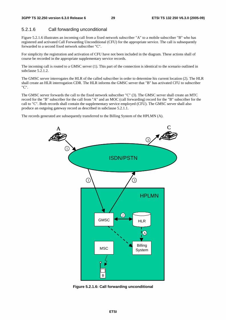
ETSI
ETSI TS 132 250 V6.3.0 (2005-09) 293GPP TS 32.250 version 6.3.0 Release 6
5.2.1.6 Call forwarding unconditional
Figure 5.2.1.6 illustrates an incoming call from a fixed network subscriber "A" to a mobile subscriber "B" who has registered and activated Call Forwarding Unconditional (CFU) for the appropriate service. The call is subsequently forwarded to a second fixed network subscriber "C".
For simplicity the registration and activation of CFU have not been included in the diagram. These actions shall of course be recorded in the appropriate supplementary service records.
The incoming call is routed to a GMSC server (1). This part of the connection is identical to the scenario outlined in subclause 5.2.1.2.
The GMSC server interrogates the HLR of the called subscriber in order to determine his current location (2). The HLR shall create an HLR interrogation CDR. The HLR informs the GMSC server that "B" has activated CFU to subscriber "C".
The GMSC server forwards the call to the fixed network subscriber "C" (3). The GMSC server shall create an MTC record for the "B" subscriber for the call from "A" and an MOC (call forwarding) record for the "B" subscriber for the call to "C". Both records shall contain the supplementary service employed (CFU). The GMSC server shall also produce an outgoing gateway record as described in subclause 5.2.1.1.
The records generated are subsequently transferred to the Billing System of the HPLMN (A).
A
1
ISDN/PSTN
HPLMN
GMSC
MSC
HLR
BillingSystem
1
BB
A
2
3
C
3
A
1
ISDN/PSTN
HPLMN
GMSCGMSC
MSCMSC
HLRHLR
BillingSystemBilling
System
1
BBB
A
2
3
C
3
Figure 5.2.1.6: Call forwarding unconditional

ETSI
ETSI TS 132 250 V6.3.0 (2005-09) 303GPP TS 32.250 version 6.3.0 Release 6
5.2.1.7 Call forwarding conditional (on busy)
Figure 5.2.1.7 illustrates a mobile originated call from subscriber "A" to a second mobile subscriber "B" who has registered and activated Call Forwarding on Busy (CFB) for the appropriate service. The call is subsequently forwarded to a third mobile subscriber "C". In this example, all three subscribers are currently located within the same (the home) network.
For simplicity the registration and activation of CFB have not been included in the diagram.
Having received a set-up request from subscriber "A" (1), the originating MSC server (MSC-A) interrogates the HLR of subscriber "B" in order to determine his current location (1a). The call is then routed to MSC-B (2).
MSC-A shall create an MOC record for subscriber "A" containing details of the call to "B". The HLR shall produce an HLR interrogation record.
On determining that subscriber "B" is busy and that CFB is active, the forwarding MSC server/VLR (MSC-B) interrogates the HLR of subscriber "C" to determine his current location (2a) and forwards the call accordingly (3).
MSC-B shall produce an MTC record for the "B" subscriber for the call from "A" and an MOC record for the "B" subscriber for the call to "C". Both records shall include the supplementary service employed (CFB). The HLR shall produce an Interrogation record.
The terminating MSC server (MSC-C) shall create a normal MTC record for subscriber "C".
The records generated are subsequently transferred to the Billing System of the PLMN.
2
HPLMN
MSC-B
MSC-A HLR
BA
MSC-C
1
3
BB BC“busy”
3
2a
1a
2
HPLMN
MSC-BMSC-B
MSC-AMSC-A HLRHLR
BBA
MSC-CMSC-C
1
3
BBB BBC“busy”
3
2a
1a
Figure 5.2.1.7: Call forwarding conditional (busy)

ETSI
ETSI TS 132 250 V6.3.0 (2005-09) 313GPP TS 32.250 version 6.3.0 Release 6
5.2.1.8 Delivery of a mobile terminated short message
Figure 5.2.1.8 illustrates the delivery of a short message to a mobile subscriber.
The short message service centre delivers the message to a GMSC server or gateway function (1). The GMSC server shall create an SMS gateway MT record.
The GMSC server then interrogates the HLR of the subscriber to determine his current location (2). The HLR shall create an HLR interrogation record.
The message is subsequently transmitted to the MSC server serving the mobile subscriber and finally to the mobile station of that subscriber (3). The MSC server shall create an SMS MT record.
The records generated are subsequently transferred to the post-processing system of the HPLMN (A).
HPLMN
SMS-GMSC
MSC-B
HLR
BillingSystem
BB
A
2
SMS-SC
1
3
A
HPLMN
SMS-GMSC
MSC-BMSC-B
HLRHLR
BillingSystemBilling
System
BBB
A
2
SMS-SCSMS-SC
1
3
A
Figure 5.2.1.8: Delivery of a short message to a mobile subscriber

ETSI
ETSI TS 132 250 V6.3.0 (2005-09) 323GPP TS 32.250 version 6.3.0 Release 6
5.2.1.9 Call hold and multi-party service
Figure 5.2.1.9 illustrates the use of the call hold and multi-party services.
A mobile subscriber ("A") sets up an outgoing call (1) to an ISDN subscriber ("B"). This call is recorded as outlined in subclause 5.2.1.1.
Subscriber "A" then invokes the call hold service. MSC-A shall produce a supplementary service action record for the invocation.
Subscriber "A" then sets up a side-call (2) to a second mobile subscriber ("C") within the same network. This call is recorded as outlined in subclause 5.2.1.3.
Subscriber "A" subsequently invokes the multi-party service in order to set up a three-party conference with "B" and "C". MSC-A shall produce a common equipment record for the use of a conference circuit by subscriber "A". This record shall record the duration of the whole conference irrespective of the number of parties subsequently added to, or removed from the conference connection.
Note that the MOC records produced by MSC-A for both the A -> B and A -> C legs of the conference shall contain the supplementary service code for multi-party.
1
A
HPLMN
GMSC
MSC-ABilling
System
BA
AMSC-C
BC
1 2
B
1
ISDN/PSTN
1
2
1
A
HPLMN
GMSCGMSC
MSC-AMSC-ABilling
SystemBilling
System
BBA
AMSC-CMSC-C
BBC
1 2
B
1
ISDN/PSTN
1
2
Figure 5.2.1.9: Call hold and multi-party service
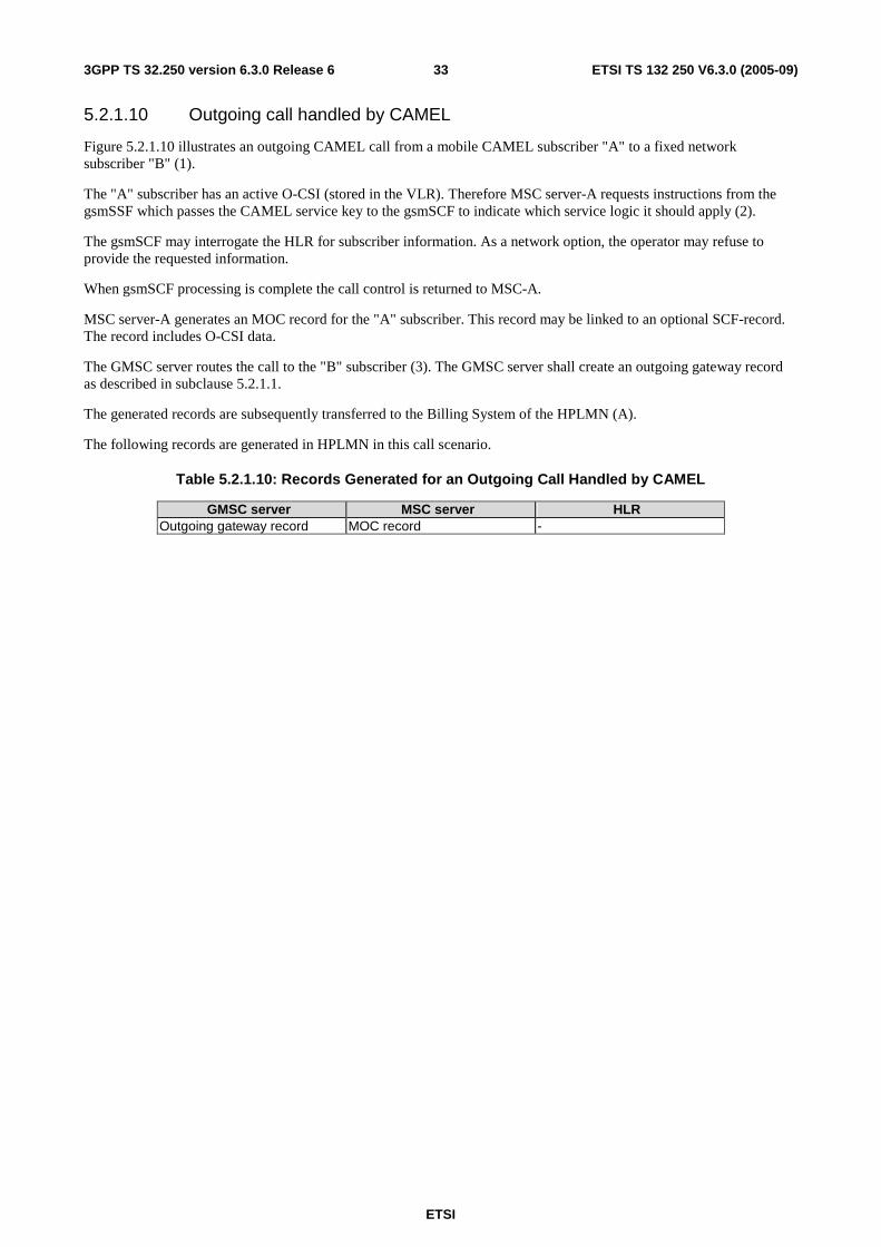
ETSI
ETSI TS 132 250 V6.3.0 (2005-09) 333GPP TS 32.250 version 6.3.0 Release 6
5.2.1.10 Outgoing call handled by CAMEL
Figure 5.2.1.10 illustrates an outgoing CAMEL call from a mobile CAMEL subscriber "A" to a fixed network subscriber "B" (1).
The "A" subscriber has an active O-CSI (stored in the VLR). Therefore MSC server-A requests instructions from the gsmSSF which passes the CAMEL service key to the gsmSCF to indicate which service logic it should apply (2).
The gsmSCF may interrogate the HLR for subscriber information. As a network option, the operator may refuse to provide the requested information.
When gsmSCF processing is complete the call control is returned to MSC-A.
MSC server-A generates an MOC record for the "A" subscriber. This record may be linked to an optional SCF-record. The record includes O-CSI data.
The GMSC server routes the call to the "B" subscriber (3). The GMSC server shall create an outgoing gateway record as described in subclause 5.2.1.1.
The generated records are subsequently transferred to the Billing System of the HPLMN (A).
The following records are generated in HPLMN in this call scenario.
Table 5.2.1.10: Records Generated for an Outgoing Call Handled by CAMEL
GMSC server MSC server HLR Outgoing gateway record MOC record -

ETSI
ETSI TS 132 250 V6.3.0 (2005-09) 343GPP TS 32.250 version 6.3.0 Release 6
ISDN/PSTN
A
MSC-A/gsmSSF
GMSC/gsmSSFgsmSCF
B
Billing System
A
1
2
3
O-CSI(A-B)
3
HPLMN
HLR
ISDN/PSTN
A
MSC-A/gsmSSF
GMSC/gsmSSFgsmSCF
B
Billing System
A
1
2
3
O-CSI(A-B)
3
HPLMN
HLR
Figure 5.2.1.10: Outgoing call handled by CAMEL

ETSI
ETSI TS 132 250 V6.3.0 (2005-09) 353GPP TS 32.250 version 6.3.0 Release 6
5.2.1.11 Incoming call handled by CAMEL without redirection
Figure 5.2.1.11 illustrates an incoming call from a fixed network subscriber "A" to a mobile CAMEL subscriber "B".
The incoming call is first routed to the GMSC server (1). The GMSC server shall create an incoming gateway record for fixed network accounting purposes.
The GMSC server interrogates the HLR of the called subscriber in order to fetch the T-CSI (2). The HLR shall create an HLR interrogation record.
The "B" subscriber has an active T-CSI. Therefore the GMSC server requests instructions from the gsmSSF which passes the CAMEL service key to a gsmSCF to indicate which service logic it should apply (3).
The gsmSCF may interrogate the HLR for subscriber information. As a network option, the operator may refuse to provide the requested information.
When gsmSCF processing is complete the call control is returned to the GMSC server. The GMSC server shall generate a terminating CAMEL record which contains T-CSI data.
The GMSC server interrogates the HLR in order to determine his current location (4). The HLR shall create an HLR interrogation record.
The call is routed to MSC-B (5). An MTC record shall be generated.
For avoidance of doubt, even if the MSC server and GMSC server are co-located both the MTC and gateway records shall be produced.
The generated records are subsequently transferred to the Billing System of the HPLMN (A).
The following records are generated in HPLMN in this call scenario.
Table 5.2.1.11: Records Generated for an Incoming Call Handled by CAMEL without Re-direction
GMSC server MSC server HLR Incoming gateway record MTC record HLR interrogation record Terminating CAMEL record

ETSI
ETSI TS 132 250 V6.3.0 (2005-09) 363GPP TS 32.250 version 6.3.0 Release 6
ISDN/PSTN
B
MSC-B/gsmSSF
GMSC/gsmSSFgsmSCF
A
Billing System
A
1
2
5
T-CSI(A-B)
3
1
6
4HLR
ISDN/PSTN
B
MSC-B/gsmSSF
GMSC/gsmSSFgsmSCF
A
Billing System
A
1
2
5
T-CSI(A-B)
3
1
6
4HLR
Figure 5.2.1.11: Incoming call handled by CAMEL without redirection
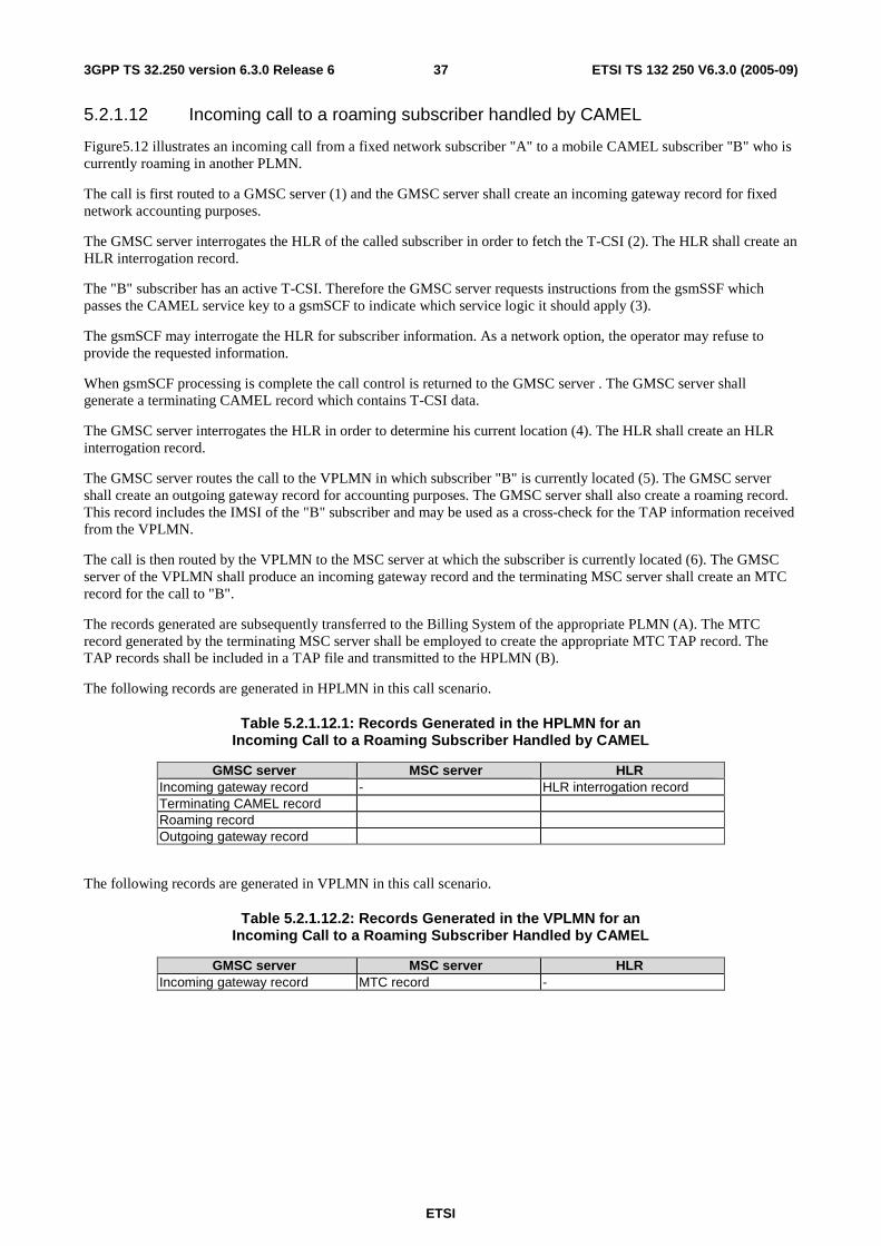
ETSI
ETSI TS 132 250 V6.3.0 (2005-09) 373GPP TS 32.250 version 6.3.0 Release 6
5.2.1.12 Incoming call to a roaming subscriber handled by CAMEL
Figure5.12 illustrates an incoming call from a fixed network subscriber "A" to a mobile CAMEL subscriber "B" who is currently roaming in another PLMN.
The call is first routed to a GMSC server (1) and the GMSC server shall create an incoming gateway record for fixed network accounting purposes.
The GMSC server interrogates the HLR of the called subscriber in order to fetch the T-CSI (2). The HLR shall create an HLR interrogation record.
The "B" subscriber has an active T-CSI. Therefore the GMSC server requests instructions from the gsmSSF which passes the CAMEL service key to a gsmSCF to indicate which service logic it should apply (3).
The gsmSCF may interrogate the HLR for subscriber information. As a network option, the operator may refuse to provide the requested information.
When gsmSCF processing is complete the call control is returned to the GMSC server . The GMSC server shall generate a terminating CAMEL record which contains T-CSI data.
The GMSC server interrogates the HLR in order to determine his current location (4). The HLR shall create an HLR interrogation record.
The GMSC server routes the call to the VPLMN in which subscriber "B" is currently located (5). The GMSC server shall create an outgoing gateway record for accounting purposes. The GMSC server shall also create a roaming record. This record includes the IMSI of the "B" subscriber and may be used as a cross-check for the TAP information received from the VPLMN.
The call is then routed by the VPLMN to the MSC server at which the subscriber is currently located (6). The GMSC server of the VPLMN shall produce an incoming gateway record and the terminating MSC server shall create an MTC record for the call to "B".
The records generated are subsequently transferred to the Billing System of the appropriate PLMN (A). The MTC record generated by the terminating MSC server shall be employed to create the appropriate MTC TAP record. The TAP records shall be included in a TAP file and transmitted to the HPLMN (B).
The following records are generated in HPLMN in this call scenario.
Table 5.2.1.12.1: Records Generated in the HPLMN for an Incoming Call to a Roaming Subscriber Handled by CAMEL
GMSC server MSC server HLR Incoming gateway record - HLR interrogation record Terminating CAMEL record Roaming record Outgoing gateway record
The following records are generated in VPLMN in this call scenario.
Table 5.2.1.12.2: Records Generated in the VPLMN for an Incoming Call to a Roaming Subscriber Handled by CAMEL
GMSC server MSC server HLR Incoming gateway record MTC record -

ETSI
ETSI TS 132 250 V6.3.0 (2005-09) 383GPP TS 32.250 version 6.3.0 Release 6
ISDN/PSTN
B
GMSC/gsmSSFgsmSCF
A
Billing System
A
1
2
5
T-CSI(A -B)
3
1
6
4
GMSC/gsmSSF
MSC-B/gsmSSF
Billing System
gsmSCF
5
6
B A
HPLMN VPLMN
HLR
ISDN/PSTN
B
GMSC/gsmSSFgsmSCF
A
Billing System
A
1
2
5
T-CSI(A -B)
3
1
6
4
GMSC/gsmSSF
MSC-B/gsmSSF
Billing System
gsmSCF
5
6
B A
HPLMN VPLMN
HLR
Figure 5.2.1.12: Incoming call to a roaming subscriber handled by CAMEL

ETSI
ETSI TS 132 250 V6.3.0 (2005-09) 393GPP TS 32.250 version 6.3.0 Release 6
5.2.1.13 Incoming call handled by CAMEL with redirection decided and forwarding leg handled by CAMEL
Figure 5.2.1.13 illustrates an incoming call from a fixed network subscriber "A" to a mobile CAMEL subscriber "B". The call is subsequently forwarded to a second fixed network subscriber "C" by CAMEL initiated Call Forwarding.
The incoming call is routed to the GMSC server (1). The GMSC server shall create an incoming gateway record for fixed network accounting purposes.
The GMSC server interrogates the HLR of the called subscriber in order to fetch the T-CSI and O-CSI (2).
The "B" subscriber has an active T-CSI. Therefore the GMSC server requests instructions from the gsmSSF which passes the CAMEL service key to a gsmSCF to indicate which service logic it should apply (3).
The gsmSCF may interrogate the HLR for subscriber information. As a network option, the operator may refuse to provide the requested information.
The gsmSCF modifies the Called Party number and sets the CAP parameter "Apply O-CSI'. When gsmSCF processing is complete the call control is returned to the GMSC server. The GMSC server shall generate a terminating CAMEL record which contains T-CSI data.
The "B" subscriber has an active O-CSI. Therefore the GMSC server requests instructions from the gsmSSF which passes the CAMEL service key to a gsmSCF to indicate which service logic it should apply (4).
The gsmSCF may interrogate the HLR for subscriber information. As a network option, the operator may refuse to provide the requested information.
When gsmSCF processing is complete the call control is returned to the GMSC server.
The GMSC server redirects the call to the fixed network subscriber "C" (5). The GMSC server shall generate an MTC record for the "B" subscriber for the call from "A" and an MOC (call forwarding) record for the "B" subscriber for the call to "C". The MOC record includes O-CSI data and the parameter "CAMEL initiated CF indicator'. The GMSC server shall also produce an outgoing gateway record as described in subclause 5.2.1.1.
The generated records are subsequently transferred to the Billing System of the HPLMN (A).
The following records are generated in HPLMN in this call scenario.
Table 5.2.1.13: Records Generated in the Incoming Call with Redirection Decided and Forwarded Leg Handled by CAMEL
GMSC server MSC server HLR Incoming gateway record - HLR interrogation record Terminating CAMEL record MTC record MOC (CF) record Outgoing gateway record

ETSI
ETSI TS 132 250 V6.3.0 (2005-09) 403GPP TS 32.250 version 6.3.0 Release 6
ISDN/PSTN
B
MSC-B/gsmSSF
GMSC/gsmSSFgsmSCF
A
Billing System
A
1
23
4
T-CSI(A-B)O-CSI(B-C)
C5
1 5
HPLMN
HLR
ISDN/PSTN
B
MSC-B/gsmSSF
GMSC/gsmSSFgsmSCF
A
Billing System
A
1
23
4
T-CSI(A-B)O-CSI(B-C)
C5
1 5
HPLMN
HLR
Figure 5.2.1.13: Incoming call handled by CAMEL with redirection decided and forwarding leg handled by CAMEL

ETSI
ETSI TS 132 250 V6.3.0 (2005-09) 413GPP TS 32.250 version 6.3.0 Release 6
5.2.1.14 Incoming call handled by CAMEL without redirection and forwarded early using GSM SS but controlled by CAMEL
Figure 5.2.1.14 illustrates an incoming call from a fixed network subscriber "A" to a mobile CAMEL subscriber "B". The call is subsequently forwarded to a second fixed network subscriber "C" by GSM SS Call Forwarding Unconditional (CFU) but controlled by CAMEL.
For simplicity the activation and registration of CFU have not been included in the diagram. These actions shall of course be registered in the appropriate supplementary service records.
The incoming call is routed to the GMSC server (1). The GMSC server shall create an incoming gateway record for fixed network accounting purposes.
The GMSC server interrogates the HLR of the called subscriber in order to fetch the T-CSI and O-CSI (2). The HLR shall create an HLR interrogation record. The HLR informs the GMSC server that "B" has activated CFU.
The "B" subscriber has an active T-CSI. Therefore the GMSC server requests instructions from the gsmSSF which passes the CAMEL service key to a gsmSCF to indicate which service logic it should apply (3).
The gsmSCF may interrogate the HLR for subscriber information. As a network option, the operator may refuse to provide the requested information.
When gsmSCF processing is complete the call control is returned to the GMSC server. The GMSC server shall generate a terminating CAMEL interrogation record which contains T-CSI data.
The "B" subscriber has an active O-CSI. Because the "B" subscriber has activated CFU he acts as the originating party for the forwarded leg. Therefore the GMSC server requests instructions from the gsmSSF which passes the CAMEL service key to a gsmSCF to indicate which service logic it should apply (5).
The gsmSCF may interrogate the HLR for subscriber information. As a network option, the operator may refuse to provide the requested information.
When gsmSCF processing is complete the call control is returned to the GMSC server.
The GMSC server redirects the call to the fixed network subscriber "C" (6). The GMSC server shall generate an MTC record for the "B" subscriber for the call from "A" and an MOC (call forwarding) record for the "B" subscriber for the call to "C". The MOC record includes O-CSI data. The GMSC server shall also produce an outgoing gateway record as described in subclause 5.2.1.1.
If the B-subscriber do not have an active O-CSI the call is forwarded to the "C" subscriber after the first gsmSCF invocation.
The generated records are subsequently transferred to the Billing System of the HPLMN (A).
The following records are generated in HPLMN in this call scenario.
Table 5.2.1.14: Records Generated in the Incoming call handled by CAMEL without redirection and forwarded early using GSM SS but controlled by CAMEL
GMSC server MSC server HLR Incoming gateway record - HLR interrogation record Terminating CAMEL record MTC record MOC (CF) record Outgoing gateway record

ETSI
ETSI TS 132 250 V6.3.0 (2005-09) 423GPP TS 32.250 version 6.3.0 Release 6
ISDN/PSTN
B
MSC-B/gsmSSF
GMSC/gsmSSFgsmSCF-A
A
Billing System
A
1
23
T-CSI(A-B)O-CSI(B-C)
4
C5
1 5
“CFU activated”
HPLMN
HLR
ISDN/PSTN
B
MSC-B/gsmSSF
GMSC/gsmSSFgsmSCF-A
A
Billing System
A
1
23
T-CSI(A-B)O-CSI(B-C)
4
C5
1 5
“CFU activated”
HPLMN
HLR
Figure 5.2.1.14: Incoming call handled by CAMEL without redirection and forwarded early using GSM SS but controlled by CAMEL
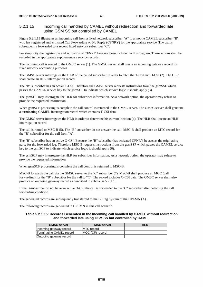
ETSI
ETSI TS 132 250 V6.3.0 (2005-09) 433GPP TS 32.250 version 6.3.0 Release 6
5.2.1.15 Incoming call handled by CAMEL without redirection and forwarded late using GSM SS but controlled by CAMEL
Figure 5.2.1.15 illustrates an incoming call from a fixed network subscriber "A" to a mobile CAMEL subscriber "B" who has registered and activated Call Forwarding on No Reply (CFNRY) for the appropriate service. The call is subsequently forwarded to a second fixed network subscriber "C".
For simplicity the registration and activation of CFNRY have not been included in this diagram. These actions shall be recorded in the appropriate supplementary service records.
The incoming call is routed to the GMSC server (1). The GMSC server shall create an incoming gateway record for fixed network accounting purposes.
The GMSC server interrogates the HLR of the called subscriber in order to fetch the T-CSI and O-CSI (2). The HLR shall create an HLR interrogation record.
The "B" subscriber has an active T-CSI. Therefore the GMSC server requests instructions from the gsmSSF which passes the CAMEL service key to the gsmSCF to indicate which service logic it should apply (3).
The gsmSCF may interrogate the HLR for subscriber information. As a network option, the operator may refuse to provide the requested information.
When gsmSCF processing is complete the call control is returned to the GMSC server. The GMSC server shall generate a terminating CAMEL interrogation record which contains T-CSI data.
The GMSC server interrogates the HLR in order to determine his current location (4). The HLR shall create an HLR interrogation record.
The call is routed to MSC-B (5). The "B" subscriber do not answer the call. MSC-B shall produce an MTC record for the "B" subscriber for the call from "A".
The "B" subscriber has an active O-CSI. Because the "B" subscriber has activated CFNRY he acts as the originating party for the forwarded leg. Therefore MSC-B requests instructions from the gsmSSF which passes the CAMEL service key to the gsmSCF to indicate which service logic it should apply (6).
The gsmSCF may interrogate the HLR for subscriber information. As a network option, the operator may refuse to provide the requested information.
When gsmSCF processing is complete the call control is returned to MSC-B.
MSC-B forwards the call via the GMSC server to the "C" subscriber (7). MSC-B shall produce an MOC (call forwarding) for the "B" subscriber for the call to "C". The record includes O-CSI data. The GMSC server shall also produce an outgoing gateway record as described in subclause 5.2.1.1.
If the B-subscriber do not have an active O-CSI the call is forwarded to the "C" subscriber after detecting the call forwarding condition.
The generated records are subsequently transferred to the Billing System of the HPLMN (A).
The following records are generated in HPLMN in this call scenario.
Table 5.2.1.15: Records Generated in the Incoming call handled by CAMEL without redirection and forwarded late using GSM SS but controlled by CAMEL
GMSC server MSC server HLR Incoming gateway record MTC record - Terminating CAMEL record MOC (CF) record Outgoing gateway record

ETSI
ETSI TS 132 250 V6.3.0 (2005-09) 443GPP TS 32.250 version 6.3.0 Release 6
ISDN/PSTN
B
MSC-B/gsmSSF
GMSC/gsmSSFgsmSCF
A
Billing System
A
1
23
4
T-CSI(A-B)O-CSI(B-C)
C
56
1
“CFNRY Activated”
7
Call attempt
7
7
HPLMN
HLR
ISDN/PSTN
B
MSC-B/gsmSSF
GMSC/gsmSSFgsmSCF
A
Billing System
A
1
23
4
T-CSI(A-B)O-CSI(B-C)
C
56
1
“CFNRY Activated”
7
Call attempt
7
7
HPLMN
HLR
Figure 5.2.1.15: Incoming call handled by CAMEL without redirection and forwarded late using GSM SS but controlled by CAMEL

ETSI
ETSI TS 132 250 V6.3.0 (2005-09) 453GPP TS 32.250 version 6.3.0 Release 6
5.2.1.16 Early forwarded call controlled by CAMEL
Figure 5.2.1.16 illustrates an incoming call from a fixed network subscriber "A" to a mobile CAMEL subscriber "B". The call is subsequently forwarded to a second fixed network subscriber "C" by GSM SS Call Forwarding Unconditional (CFU) but controlled by CAMEL.
For simplicity the activation and registration of CFU have not been included in the diagram. These actions shall of course be registered in the appropriate supplementary service records.
The incoming call is routed to the GMSC server (1). The GMSC server shall create an incoming gateway record for fixed network accounting purposes.
The GMSC server interrogates the HLR of the called subscriber in order to fetch the O-CSI (2). The HLR shall create an HLR interrogation record. The HLR informs the GMSC server that "B" has activated CFU.
The "B" subscriber has an active O-CSI. Because the "B" subscriber has activated CFU he acts as the originating party for the forwarded leg. Therefore the GMSC server requests instructions from the gsmSSF which passes the CAMEL service key to a gsmSCF to indicate which service logic it should apply (3).
The gsmSCF may interrogate the HLR for subscriber information. As a network option, the operator may refuse to provide the requested information.
When gsmSCF processing is complete the call control is returned to the GMSC server.
The GMSC server redirects the call to the fixed network subscriber "C" (5). The GMSC server shall generate an MTC record for the "B" subscriber for the call from "A" and an MOC (call forwarding) record for the "B" subscriber for the call to "C". The MOC record includes O-CSI data. The GMSC server shall also produce an outgoing gateway record as described in subclause 5.2.1.1.
The generated records are subsequently transferred to the Billing System of the HPLMN (A).
The following records are generated in HPLMN in this call scenario.
Table 5.2.1.16: Records Generated in the Early forwarded call controlled by CAMEL
GMSC server MSC server HLR Incoming gateway record - HLR interrogation record MTC record MOC (CF) record Outgoing gateway record
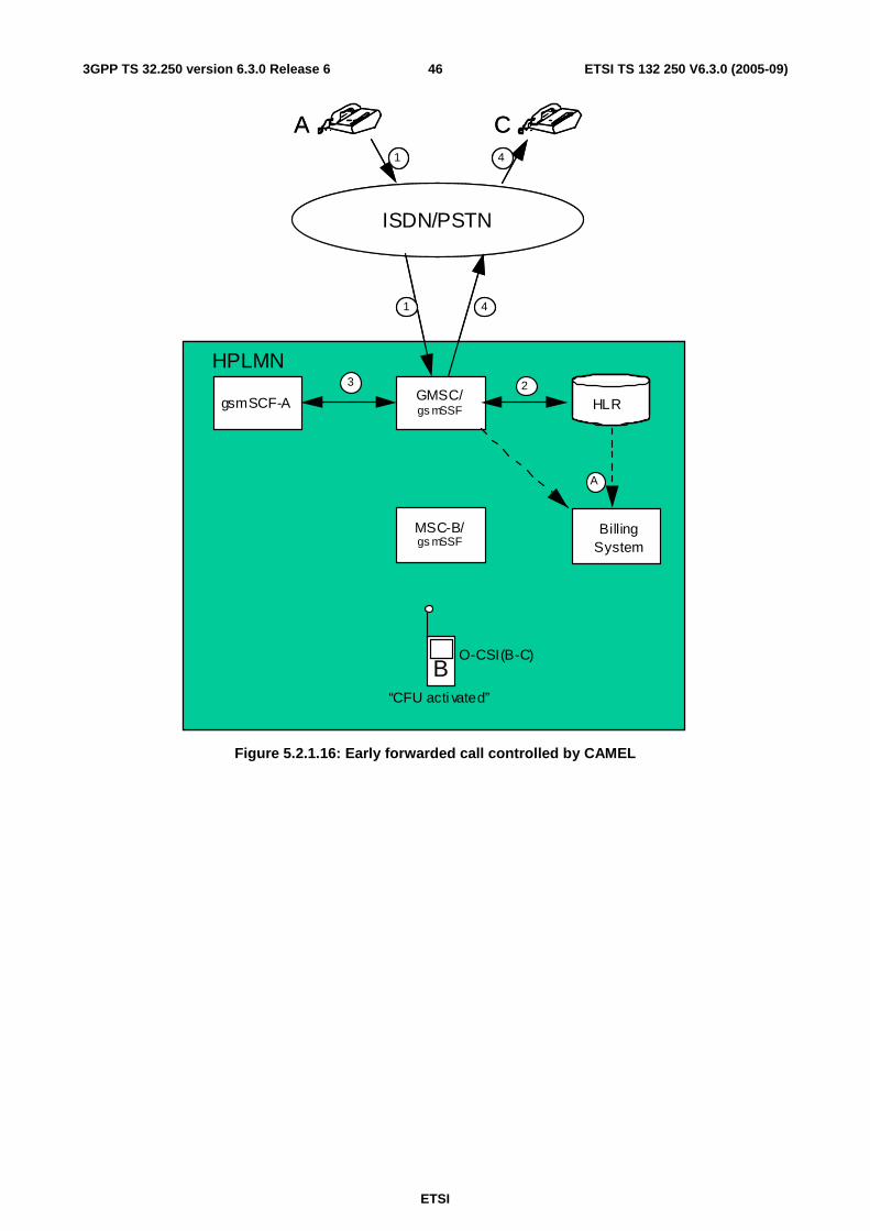
ETSI
ETSI TS 132 250 V6.3.0 (2005-09) 463GPP TS 32.250 version 6.3.0 Release 6
ISDN/PSTN
B
MSC-B/gs mSSF
GMSC/gs mSSFgsmSCF-A
A
Billing System
A
1
23
O-CSI(B-C)
C4
1 4
“CFU acti vated”
HPLMN
HLR
ISDN/PSTN
B
MSC-B/gs mSSF
GMSC/gs mSSFgsmSCF-A
A
Billing System
A
1
23
O-CSI(B-C)
C4
1 4
“CFU acti vated”
HPLMN
HLR
Figure 5.2.1.16: Early forwarded call controlled by CAMEL

ETSI
ETSI TS 132 250 V6.3.0 (2005-09) 473GPP TS 32.250 version 6.3.0 Release 6
5.2.1.17 Late forwarded call controlled by CAMEL
Figure 5.2.1.17 illustrates an incoming call from a fixed network subscriber "A" to a mobile CAMEL subscriber "B" who has registered and activated Call Forwarding on No Reply (CFNRY) for the appropriate service. The call is subsequently forwarded to a second fixed network subscriber "C".
For simplicity the registration and activation of CFNRY have not been included in this diagram. These actions shall be recorded in the appropriate supplementary service records.
The incoming call is routed to the GMSC server (1). The GMSC server shall create an incoming gateway record for fixed network accounting purposes.
The GMSC server interrogates the HLR of the called subscriber in order to determine the current location (2). The HLR shall create an HLR interrogation record.
The call is routed to MSC-B (3). The "B" subscriber do not answer the call. MSC-B shall produce an MTC record for the "B" subscriber for the call from "A".
The "B" subscriber has an active O-CSI. Because the "B" subscriber has activated CFNRY he acts as the originating party for the forwarded leg. Therefore MSC-B requests instructions from the gsmSSF which passes the CAMEL service key to gsmSCF-B to indicate which service logic it should apply (4).
The gsmSCF may interrogate the HLR for subscriber information. As a network option, the operator may refuse to provide the requested information.
When gsmSCF processing is complete the call control is returned to MSC-B.
MSC-B forwards the call via the GMSC server to the "C" subscriber (5). MSC-B shall produce an MOC (call forwarding) for the "B" subscriber for the call to "C". The record includes O-CSI data. The GMSC server shall also produce an outgoing gateway record as described in subclause 5.2.1.1.
The generated records are subsequently transferred to the Billing System of the HPLMN (A).
The following records are generated in HPLMN in this call scenario.
Table 5.2.1.17: Records Generated in the Late forwarded call controlled by CAMEL
GMSC server MSC server HLR Incoming gateway record MTC record HLR interrogation record Outgoing gateway record MOC (CF) record

ETSI
ETSI TS 132 250 V6.3.0 (2005-09) 483GPP TS 32.250 version 6.3.0 Release 6
ISDN/PSTN
B
MSC-B/gsmSSF
GMSC/gsmSSFgsmSCF
A
Billing System
A
1
2
43
O-CSI(B-C)
C5
1 5
“CFNRY activated”
5
Call attempt
HPLMN
HLR
ISDN/PSTN
B
MSC-B/gsmSSF
GMSC/gsmSSFgsmSCF
A
Billing System
A
1
2
43
O-CSI(B-C)
C5
1 5
“CFNRY activated”
5
Call attempt
HPLMN
HLR
Figure 5.2.1.17: Late forwarded call controlled by CAMEL

ETSI
ETSI TS 132 250 V6.3.0 (2005-09) 493GPP TS 32.250 version 6.3.0 Release 6
5.2.1.18 Incoming call handled by CAMEL with redirection initiated by CAMEL feature
Figure 5.2.1.18 illustrates an incoming call from a fixed network subscriber "A" to a mobile CAMEL subscriber "B". The call is subsequently redirected to a second fixed network subscriber "C" by CAMEL initiated redirection.
The incoming call is routed to the GMSC server (1). The GMSC server shall create an incoming gateway record for fixed network accounting purposes.
The GMSC server interrogates the HLR of the called subscriber in order to fetch the T-CSI (2) and the O-CSI (2). The HLR shall create an HLR interrogation record.
Since subscriber "B" has an active T-CSI and the trigger criteria are met the GMSC server requests instructions from the gsmSSF which passes the CAMEL service key to a gsmSCF to indicate which service logic it should apply (3). A terminating CAMEL interrogation record is generated in the GMSC server for invoking the terminating CAMEL call handling.
The gsmSCF may interrogate the HLR for subscriber information. As a network option, the operator may refuse to provide the requested information.
The gsmSCF returns a modified destination routing address to the GMSC server (without the option "apply O-CSI"). Therefore for the redirection leg (B-C) the CAMEL feature is not invoked.
The GMSC server redirects the call to the fixed network subscriber "C" (4). For fixed network accounting purposes the GMSC server shall generate an outgoing gateway record as described in subclause 5.2.1.1.
The generated records are subsequently transferred to the Billing System of the HPLMN (A).
The following records are generated in HPLMN in this call scenario.
Table 5.2.1.18: Records Generated in the Incoming call handled by CAMEL with redirection initiated by CAMEL feature
GMSC server MSC server HLR Incoming gateway record HLR interrogation record Terminating CAMEL interrogation record
Outgoing gateway record

ETSI
ETSI TS 132 250 V6.3.0 (2005-09) 503GPP TS 32.250 version 6.3.0 Release 6
ISDN/PSTN
B
MSC-B/gsmSSF
GMSC/gsmSSFgsmSCF-A
A
Billing System
A
1
23
T-CSI(A-B)
C4
1 4
HPLMN
HLR
O-CSI(B-C)
ISDN/PSTN
B
MSC-B/gsmSSF
GMSC/gsmSSFgsmSCF-A
A
Billing System
A
1
23
T-CSI(A-B)T-CSI(A-B)
C4
1 4
HPLMN
HLR
4
1 4
HPLMN
HLR
4
1 4
HPLMN
HLR
1 4
HPLMN
HLR
4
HPLMN
HLRHLRHLRHLR
O-CSI(B-C)O-CSI(B-C)
Figure 5.2.1.18: Incoming call handled by CAMEL with redirection initiated and by CAMEL feature

ETSI
ETSI TS 132 250 V6.3.0 (2005-09) 513GPP TS 32.250 version 6.3.0 Release 6
5.2.1.19 CAMEL Scenario for Visiting Terminator Trigger Calls
Figure 5.2.1.19 illustrates an incoming call from a fixed network subscriber "A" to a mobile CAMEL subscriber "B".
The incoming call is first routed to the GMSC (1). The GMSC shall create an incoming gateway record for fixed network accounting purposes.
The GMSC interrogates the HLR (2) of the called subscriber. The HLR shall create an HLR interrogation record. The call is routed to MSC-B(3). An MTC record shall be generated in MSC-B.
The "B" subscriber has an active VT-CSI (stored in the VLR). For avoidance of doubt in this scenario, the "B" subscriber does not have an active T-CSI in the HLR. Therefore MSC-B requests instructions from the gsmSSF which passes the CAMEL service key to the gsmSCF to indicate which service logic it should apply (4).
The gsmSCF may interrogate the HLR for subscriber information. As a network option, the operator may refuse to provide the requested information.
When gsmSCF processing is complete the call control is returned to the MSC-B. The MSC-B shall generate a terminating CAMEL (TCR) record which contains VT-CSI data.
The MSC-B routes the call to the "B" subscriber (5).
For avoidance of doubt, even if the MSC and GMSC are co-located both the MTC/TCR and gateway records shall be produced.
The generated records are subsequently transferred to the OS (A) either as event reports following the release of the connection or when collected by the OS.
The following records are generated in HPLMN in this call scenario.
Table 5.2.1.19: Records Generated for Visiting Terminating Trigger Calls
GMSC MSC-B HLR Incoming gateway record MTC record HLR interrogation record Terminating CAMEL record

ETSI
ETSI TS 132 250 V6.3.0 (2005-09) 523GPP TS 32.250 version 6.3.0 Release 6
ISDN/PSTN
B
MSC-B/gsmSSF
GMSC/gsmSSF
gsmSCF
A
ADC/BCA
1
2
5
VT-CSI(A-B)
3
1
4
HLR
Figure 5.2.1.19: Incoming call handled by CAMEL in MSC Server without redirection

ETSI
ETSI TS 132 250 V6.3.0 (2005-09) 533GPP TS 32.250 version 6.3.0 Release 6
5.2.1.20 Outgoing call handled by CAMEL with Dialled CSI Trigger
Figure 5.2.1.20 illustrates an outgoing CAMEL call from a mobile CAMEL subscriber "A" to a fixed network subscriber "B" (1).
The "A" subscriber has an active D-CSI (stored in the VLR and modified Called Party number matches D-CSI). Therefore MSC server-A requests instructions from the gsmSSF which passes the CAMEL service key to the gsmSCF to indicate which service logic it should apply (2).
The gsmSCF may interrogate the HLR for subscriber information. As a network option, the operator may refuse to provide the requested information.
When gsmSCF processing is complete the call control is returned to MSC-A.
MSC server-A generates an MOC record for the "A" subscriber which contains D-CSI data. This record may be linked to an optional SCF-record.
The GMSC server routes the call to the "B" subscriber (3). The GMSC server shall create an outgoing gateway record as described in subclause 5.2.1.1.
The generated records are subsequently transferred to the post-processing system (A) either as event reports following the release of the connection or when collected by the post-processing system.
The following records are generated in HPLMN in this call scenario.
Table 5.2.1.20: Records Generated for an Outgoing Call Handled by CAMEL
GMSC server MSC server HLR Outgoing gateway record MOC record -

ETSI
ETSI TS 132 250 V6.3.0 (2005-09) 543GPP TS 32.250 version 6.3.0 Release 6
ISDN/PSTN
A
MSC-A/gsmSSF
GMSCgsmSSFgsmSCF
B
BillingSystem
A
1
2
3
3
HPLMN
HLR
ISDN/PSTN
A
MSC-A/gsmSSF
GMSCgsmSSFgsmSCF
B
BillingSystem
A
1
2
3
D-CSI(A-B)
3
HPLMN
HLR
Figure 5.2.1.20: Outgoing call handled by CAMEL with Dialled CSI Trigger

ETSI
ETSI TS 132 250 V6.3.0 (2005-09) 553GPP TS 32.250 version 6.3.0 Release 6
5.2.1.21 Incoming call handled by CAMEL with redirection decided and forwarding leg handled by CAMEL with Dialled CSI Trigger
Figure 5.2.1.21 illustrates an incoming call from a fixed network subscriber "A" to a mobile CAMEL subscriber "B". The call is subsequently forwarded to a second fixed network subscriber "C" by CAMEL initiated Call Forwarding.
The incoming call is routed to the GMSC server (1). The GMSC server shall create an incoming gateway record for fixed network accounting purposes.
The GMSC server interrogates the HLR of the called subscriber in order to fetch the T-CSI, O-CSI and D-CSI (2).
The "B" subscriber has an active T-CSI. Therefore the GMSC server requests instructions from the gsmSSF which passes the CAMEL service key to a gsmSCF to indicate which service logic it should apply (3).
The gsmSCF may interrogate the HLR for subscriber information. As a network option, the operator may refuse to provide the requested information.
The gsmSCF modifies the Called Party number and sets the CAP parameter "Apply O-CSI'. When gsmSCF processing is complete the call control is returned to the GMSC server. The GMSC server shall generate a terminating CAMEL interrogation record which contains T-CSI data.
The "B" subscriber has an active O-CSI. Therefore the GMSC server requests instructions from the gsmSSF which passes the CAMEL service key to a gsmSCF to indicate which service logic it should apply (4).
The gsmSCF may interrogate the HLR for subscriber information. As a network option, the operator may refuse to provide the requested information.
The gsmSCF modifies the Called Party number. When gsmSCF processing is complete the call control is returned to the GMSC server.
The "B" subscriber has an active D-CSI (modified Called Party number matches D-CSI). Therefore the GMSC server requests instructions from the gsmSSF which passes the CAMEL service key to a gsmSCF to indicate which service logic it should apply (5).
The gsmSCF may interrogate the HLR for subscriber information. As a network option, the operator may refuse to provide the requested information. When gsmSCF processing is complete the call control is returned to the GMSC server.
The GMSC server redirects the call to the fixed network subscriber "C" (6). The GMSC server shall generate an MTC record for the "B" subscriber for the call from "A" and an MOC (call forwarding) record for the "B" subscriber for the call to "C". The MOC record includes O-CSI data, the parameter "CAMEL initiated CF indicator' and D-CSI data. The GMSC server shall also produce an outgoing gateway record as described in subclause 5.2.1.1.
The generated records are subsequently transferred to the post-processing system (A) either as event reports following the release of the connection or when collected by the post-processing system.
The following records are generated in HPLMN in this call scenario.
Table 5.2.1.21: Records Generated in the Incoming Call with Redirection Decided and Forwarded Leg Handled by CAMEL
GMSC server MSC server HLR Incoming gateway record - HLR interrogation record Terminating CAMEL record MTC record MOC (CF) record Outgoing gateway record

ETSI
ETSI TS 132 250 V6.3.0 (2005-09) 563GPP TS 32.250 version 6.3.0 Release 6
ISDN/PSTN
B
MSC-B/gsmSSF
GMSCgsmSSFgsmSCF
A
BillingSystem
A
1
23
4
T-CSI( -B)O-CSI(B-C)
C5
1 5
HPLMN
HLR
ISDN/PSTN
B
MSC-B/gsmSSF
GMSCgsmSSFgsmSCF
A
BillingSystem
A
1
23
4
T-CSI(A-B)
C6
1 6
HPLMN
HLR55
O-CSI(B-C)D-CSI(B-C)
Figure 5.2.1.21: Incoming call handled by CAMEL with redirection decided and forwarding leg handled by CAMEL with Dialled CSI Trigger

ETSI
ETSI TS 132 250 V6.3.0 (2005-09) 573GPP TS 32.250 version 6.3.0 Release 6
5.2.1.22 Mobile terminated location request
Figure 5.2.1.22 illustrates general network positioning for LCS clients external to the PLMN.
An external LCS client requests the current location of a target UE from a GMLC (1). In this release the GMLC shall not create any LCS record.
The GMLC server then interrogates the HLR of the target UE to be located to determine his current location (2). The HLR shall create an HLR interrogation record.
The GMLC sends the location service request to the MSC indicated by the HLR. The MSC sends a Location Request message to RAN that initiates the positioning procedure (3). The MSC shall create an LCS-MT record.
The records generated are subsequently transferred to the Billing System of the PLMN (A).
HPLMN
SM - GMS
MS - B
HLR
BillinSyste
B B
A
2
SM - SC
1
3
A
HPLMN
GMLC
MS - B MSC
HLR HLR
BillinSysteBilling System
B B B
A
2
SM - SC LCS client
1
3
A
Figure 5.2.1.22: Mobile terminated location request

ETSI
ETSI TS 132 250 V6.3.0 (2005-09) 583GPP TS 32.250 version 6.3.0 Release 6
5.2.1.23 gsmSCF initiated wake-up call handled by CAMEL CPH
Figure 5.2.1.23 illustrates a wake-up call initiated by gsmSCF to a mobile CAMEL subscriber "A".
gsmSCF interrogates the HLR in order to determine the current location of subscriber "A" (1). The HLR provides the 'Roaming Number'. The HLR shall create an interrogation record.
gsmSCF initiates set-up of an outgoing leg towards mobile CAMEL subscriber "A" (2). The MSC shall create an adapted version of MOC and MTC record for that call leg.
The user interaction (UI), in this scenario an announcement from the Specialised Resource Function (SRF), is connected to mobile CAMEL subscriber "A" (3). The MSC shall update the MOC record to reflect the UI.
The following records are generated in HPLMN in this call scenario.
Table 5.2.1.23: Records Generated for an Wake-up Call Handled by CAMEL CPH
MSC HLR MOC record HLR interrogation record MTC record
BA
gsmSCF
BillingSystem
22
1
gsmSSF
MSC/
A
A
HLR
SRF
23
22 23
Figure 5.2.1.23: Wake-up call handled by CAMEL CPH

ETSI
ETSI TS 132 250 V6.3.0 (2005-09) 593GPP TS 32.250 version 6.3.0 Release 6
5.2.1.24 Three party conference handled by CAMEL CPH
Figure 5.2.1.24 illustrates one example for establishment of a three party conference via CAMEL CPH..
A mobile CAMEL subscriber "A" sets up an outgoing call (1) to an ISDN subscriber ("B"). This call is recorded as outlined in subclause 5.2.1.1.
gsmSCF then invokes CPH operation 'initiate call attempt' (2). A new call segment (CS#2) with an outgoing leg "C" is created in MSC-A.
MSC-A interrogates the HLR in order to determine the current location of subscriber "C" (3). The HLR shall create an interrogation record.
MSC-A initiates set-up of an outgoing leg towards mobile subscriber "C" (4). MSC-A shall create an MOC record for the leg towards mobile subscriber "C". MSC-C shall create a MTC record for subscriber "C".
gsmSCF then invokes CPH operation 'MoveLeg' to join all three legs in one call segment (5). MSC-A shall close the MOC record for call segment CS#2 to outgoing leg "C". The MOC record for the outgoing call of the mobile CAMEL subscriber "A" to ISDN subscriber "B" shall be updated to cover the additional outgoing CAMEL call leg "C".
The following records are generated in HPLMN in this call scenario.
Table 5.2.1.24: Records Generated for an Wake-up Call Handled by CAMEL CPH
GMSC server MSC-A MSC-C HLR outgoing gateway record MOC record ("A", "B", "C") MTC record HLR interrogation record MOC record ("C")

ETSI
ETSI TS 132 250 V6.3.0 (2005-09) 603GPP TS 32.250 version 6.3.0 Release 6
BA
BillingSystem
22
1
3
gsmSSF
MSC-A /A
A
4
HLR
MSC-C
BC
ISDN/PSTN
B
1
1
1
GMSCgsmSCF
4
25
Figure 5.2.1.24: Three Party Conference handled by CAMEL CPH

ETSI
ETSI TS 132 250 V6.3.0 (2005-09) 613GPP TS 32.250 version 6.3.0 Release 6
5.2.2 Diameter message flows
Not applicable, as the separation of the CTF and CDF is not in the scope of the CS domain charging standards. Refer to subclause 4.2 for further information.
Vendors may nevertheless implement a separate CDCF and CCF for CS domain charging. In this case, the approach chosen shall conform to the principles and protocol applications specified in 3GPP TS 32.299 [50].
5.2.3 CDR generation
In order to provide the data required for the management activities outlined in the previous subclauses (billing, accounting, statistics, etc.), the CGF of the MSC server and/or Location Registers shall be able to produce a charging data record for each of the following:
• Mobile originated call attempt;
• Mobile originated emergency call attempt;
• Mobile originated, call forwarding attempt;
• Mobile terminated call attempt;
• Roaming call attempt in a gateway MSC server;
• Incoming call attempt in a gateway MSC server;
• Outgoing call attempt from a gateway MSC server;
• Transit call attempt;
• Terminating CAMEL call attempt;
• CAMEL CPH call attempts/call modifications;
• Supplementary service actions;
• HLR interrogation;
• Location updating (HLR and VLR);
• Short message service (point-to-point), mobile originated;
• Short message service (point-to-point), mobile terminated;
• Short message service (point-to-point), mobile originated interworking MSC server;
• Short message service (point-to-point), mobile terminated gateway MSC server;
• Common equipment usage;
• Mobile terminated location request;
• Mobile originated location request;
• Network induced location request.
A more detailed description of the records is found in subclause 6.1. The detailed formal description of the data defined in the present document is to be found in 3GPP TS 32.298 [51].
5.2.4 GTP' record transfer flows
Not applicable, as the separation of the CDF and CGF is not in the scope of the CS domain charging standards. Refer to subclause 4.2 for further information.

ETSI
ETSI TS 132 250 V6.3.0 (2005-09) 623GPP TS 32.250 version 6.3.0 Release 6
Vendors may nevertheless implement a separate CCF and CGF for CS domain charging. In this case, the approach chosen shall conform to the principles and protocol applications specified in 3GPP TS 32.295 [54].
5.2.5 BC CDR file transfer
There are two options for the transfer of the above CDRs to the Billing domain:
1) use the file based interface specified in earlier 3GPP releases, as documented in annex A of the present document;
2) apply the Rel-6 file based interface, Bc, as specified in 3GPP TS 32.297 [52].
It is left to operator and vendor choice which one (or both) of the above interfaces to implement.
5.3 CS domain online charging scenarios CS domain charging is implemented by CAMEL techniques as described in 3GPP TS 23.078 [207] and 3GPP TS 29.078 [212], i.e. outside the scope of the 32 series of charging TSs.
5.3.1 Basic principles
Void. Refer to subclause 5.3.
5.3.2 Diameter message flows
Void. Refer to subclause 5.3.

ETSI
ETSI TS 132 250 V6.3.0 (2005-09) 633GPP TS 32.250 version 6.3.0 Release 6
6 Definition of charging information This clause provides Stage 3 specifications of the CDR type and content for the 3GPP CS domain. For each of the CDR types listed in subclause 5.2.3, a parameter table, which gives a short description of the parameters, is provided. The detailed specification of the CDR parameters and their encoding is contained in 3GPP TS 32.298 [51], while annex A and 3GPP TS 32.297 [52] specify the details of the CDR file transfer to the BD.
6.1 Data description for CS domain offline charging
6.1.1 Diameter message contents
Not applicable. Refer to subclause 5.2.2 for further information.
6.1.2 GTP' message contents
Not applicable. Refer to subclause 5.2.4 for further information.
6.1.3 CDR description on the Bc reference point
Dedicated types of CDRs can be generated in the CS domain, as specified in subclause 5.2.3. The content of each CDR type is defined in one of the tables that are part of this subclause. For each CDR type the parameter definition includes the parameter name, description and category.
Editor's note: align the following text with 3GPP TS 32.240 [1].
Equipment vendors shall be able to provide all of the parameters listed in the CDR content table in order to claim compliance with the present document. However, since CDR processing and transport consume network resources, operators may opt to eliminate some of the parameters that are not essential for their operation. This operator provisionable reduction is specified by the parameter category.
A parameter category can have one of two primary values:
M This parameter is Mandatory and shall always be present in the CDR;
C This parameter shall be present in the CDR only when certain Conditions are met. These Conditions are specified as part of the parameter definition.
Some of these parameters are designated as Operator (O) provisionable. Using TMN management functions or specific tools provided by an equipment vendor, operators may choose, if they wish, to include or omit the parameter from the CDR. Once omitted, this parameter is not generated in a CDR. To avoid any potential ambiguity, a CDR generating element MUST be able to provide all these parameters. Only an operator can choose whether or not these parameters should be generated in its system.
Those parameters that the operator may configure to be present or absent are further qualified with the "Operator provisionable" indicator as follows:
OM This is a parameter that, if provisioned by the operator to be present, shall always be included in the CDRs. In other words, a OM parameter that is provisioned to be present is a mandatory parameter;
OC This is a parameter that, if provisioned by the operator to be present, shall be included in the CDRs when the required conditions are met. In other words, a OC parameter that is configured to be present is a conditional parameter.
The CS nodes shall be able to provide the CDRs at the Billing System interface in the format and content described in the present document. Additional CDR formats and contents, generated by the CS nodes, may be available at the interface to the billing system to meet the requirements of the billing system, these are outside of the scope of 3GPP standardization.
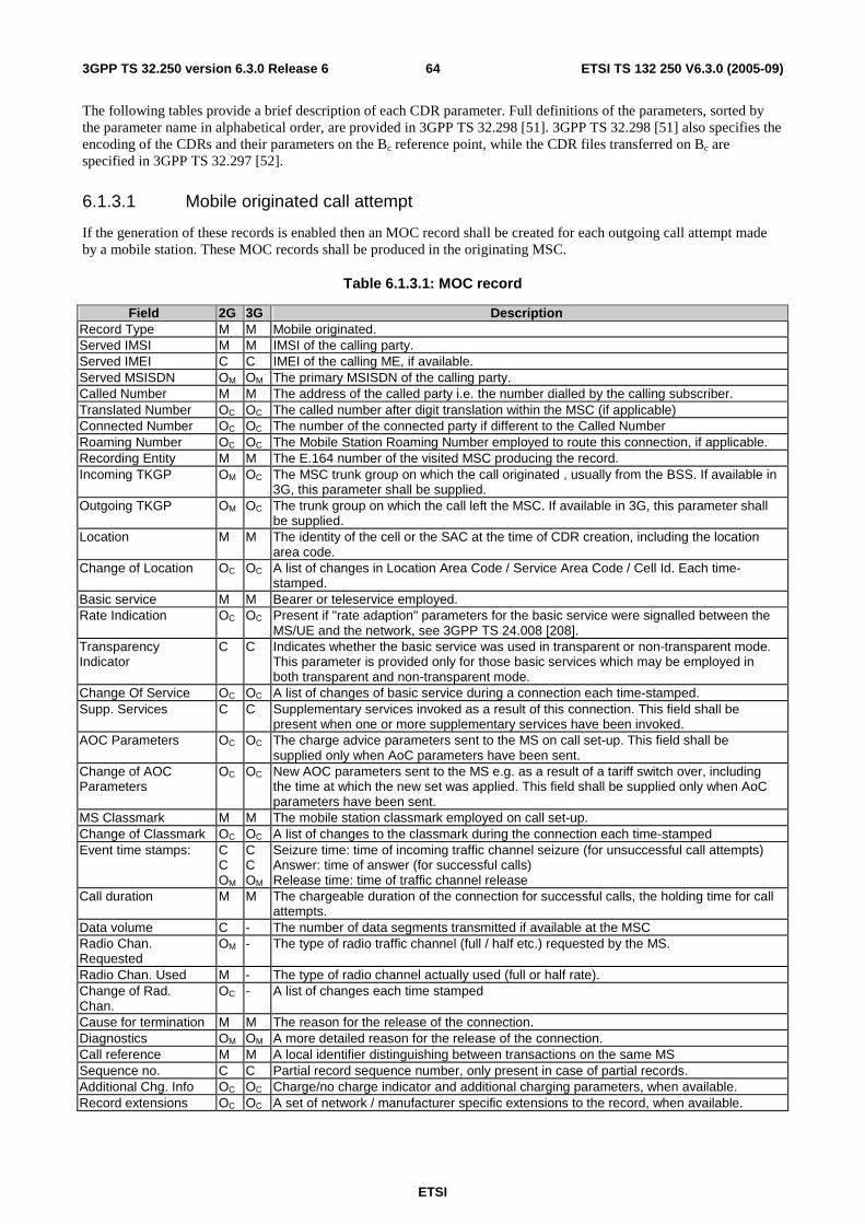
ETSI
ETSI TS 132 250 V6.3.0 (2005-09) 643GPP TS 32.250 version 6.3.0 Release 6
The following tables provide a brief description of each CDR parameter. Full definitions of the parameters, sorted by the parameter name in alphabetical order, are provided in 3GPP TS 32.298 [51]. 3GPP TS 32.298 [51] also specifies the encoding of the CDRs and their parameters on the Bc reference point, while the CDR files transferred on Bc are specified in 3GPP TS 32.297 [52].
6.1.3.1 Mobile originated call attempt
If the generation of these records is enabled then an MOC record shall be created for each outgoing call attempt made by a mobile station. These MOC records shall be produced in the originating MSC.
Table 6.1.3.1: MOC record
Field 2G 3G Description Record Type M M Mobile originated. Served IMSI M M IMSI of the calling party. Served IMEI C C IMEI of the calling ME, if available. Served MSISDN OM OM The primary MSISDN of the calling party. Called Number M M The address of the called party i.e. the number dialled by the calling subscriber. Translated Number OC OC The called number after digit translation within the MSC (if applicable) Connected Number OC OC The number of the connected party if different to the Called Number Roaming Number OC OC The Mobile Station Roaming Number employed to route this connection, if applicable. Recording Entity M M The E.164 number of the visited MSC producing the record. Incoming TKGP OM OC The MSC trunk group on which the call originated , usually from the BSS. If available in
3G, this parameter shall be supplied. Outgoing TKGP OM OC The trunk group on which the call left the MSC. If available in 3G, this parameter shall
be supplied. Location M M The identity of the cell or the SAC at the time of CDR creation, including the location
area code. Change of Location OC OC A list of changes in Location Area Code / Service Area Code / Cell Id. Each time-
stamped. Basic service M M Bearer or teleservice employed. Rate Indication OC OC Present if "rate adaption" parameters for the basic service were signalled between the
MS/UE and the network, see 3GPP TS 24.008 [208]. Transparency Indicator
C C Indicates whether the basic service was used in transparent or non-transparent mode. This parameter is provided only for those basic services which may be employed in both transparent and non-transparent mode.
Change Of Service OC OC A list of changes of basic service during a connection each time-stamped. Supp. Services C C Supplementary services invoked as a result of this connection. This field shall be
present when one or more supplementary services have been invoked. AOC Parameters OC OC The charge advice parameters sent to the MS on call set-up. This field shall be
supplied only when AoC parameters have been sent. Change of AOC Parameters
OC OC New AOC parameters sent to the MS e.g. as a result of a tariff switch over, including the time at which the new set was applied. This field shall be supplied only when AoC parameters have been sent.
MS Classmark M M The mobile station classmark employed on call set-up. Change of Classmark OC OC A list of changes to the classmark during the connection each time-stamped Event time stamps: C
C OM
C C OM
Seizure time: time of incoming traffic channel seizure (for unsuccessful call attempts) Answer: time of answer (for successful calls) Release time: time of traffic channel release
Call duration M M The chargeable duration of the connection for successful calls, the holding time for call attempts.
Data volume C - The number of data segments transmitted if available at the MSC Radio Chan. Requested
OM - The type of radio traffic channel (full / half etc.) requested by the MS.
Radio Chan. Used M - The type of radio channel actually used (full or half rate). Change of Rad. Chan.
OC - A list of changes each time stamped
Cause for termination M M The reason for the release of the connection. Diagnostics OM OM A more detailed reason for the release of the connection. Call reference M M A local identifier distinguishing between transactions on the same MS Sequence no. C C Partial record sequence number, only present in case of partial records. Additional Chg. Info OC OC Charge/no charge indicator and additional charging parameters, when available. Record extensions OC OC A set of network / manufacturer specific extensions to the record, when available.

ETSI
ETSI TS 132 250 V6.3.0 (2005-09) 653GPP TS 32.250 version 6.3.0 Release 6
Field 2G 3G Description GsmSCF address C C Identifies the CAMEL server serving the subscriber. Shall be present only if CAMEL is
applied. Service key C C The CAMEL service logic to be applied. Shall be present only if CAMEL is applied. Network call reference
C C An identifier to correlate transactions on the same call taking place in different network nodes, shall be present if CAMEL is applied.
MSC Address C C This field contains the E.164 number assigned to the MSC that generated the network call reference. Shall be present only if CAMEL is applied.
Default call handling OC OC Indicates whether or not a CAMEL call encountered default call handling. This field shall be present only if default call handling has been applied.
Number of HSCSD Channels Requested
C - The maximum number of HSCSD channels requested as received from the MS at call set-up. Shall only be present for HSCSD connections.
Number of HSCSD Channels Allocated
C - The number of HSCSD channels allocated to the MS at call set-up. Shall only be present for HSCSD connections.
Change of HSCSD Parameters
C - A list of network or user initiated changes of number of HSCSD channels during a connection each time-stamped. Shall only be present in case of an HSCSD call, if the basic HSCSD parameters are modified due the user or network initiated modification procedure.
Fixed Network User Rate
OC OC Indicates the user data rate applied for the connection in the fixed network. Shall only be present for 2G HSCSD connections and for UMTS data connections.
Air Interface User Rate Requested
C - The total Air Interface User Rate Requested by the MS at call set-up. Shall only be present for non-transparent HSCSD connections.
Channel Coding Accepted
C - A list of the traffic channels codings accepted by the MS. Shall only be present for HSCSD connections.
Channel Coding Used C - The traffic channels codings negotiated between the MS and the network at call set-up. Shall only be present for HSCSD connections.
Guaranteed bit rate - Oc Describes the bit-rate the UMTS bearer service shall guarantee to the user or application. Guaranteed Bit Rate may be used to facilitate admission control based on available resources, and for resource allocation within UMTS. Shall only be present for UMTS data connections.
Maximum bit rate - Oc Maximum Bit Rate can be used to make code reservations in the downlink of the radio interface. Its purpose is: 1) to limit the delivered bit-rate to applications or external networks with such limitations, 2) to allow maximum wanted user bit-rate to be defined for applications able to operate with different rates (e.g. applications with adapting codecs). Shall only be present for UMTS data connections.
Speech Version Supported
OM - Speech version supported by the MS with highest priority indicated by MS
Speech Version Used OM - Speech version used for that call Number of DP encountered
OC OC Number that counts how often armed detection points (TDP and EDP) were encountered. Shall be present only if CAMEL is applied.
Level of CAMEL service
OC OC Indicator for the complexity of the CAMEL feature used. Shall be present only if CAMEL is applied.
Free format Data C C This field contains data sent by the gsmSCF in the Furnish Charging Information (FCI) message(s). The data can be sent either in one FCI message or several FCI messages with append indicator. Shall be present only if CAMEL is applied.
CAMEL call leg information
C C Set of CAMEL information IEs. Each of these IEs contains information related to one outgoing CAMEL call leg. Shall be present only if CAMEL is applied.
Free format data append indicator
C C Indicator if free format data from this CDR is to be appended to free format data in previous partial CDR. Shall be present only if CAMEL is applied.
Default call handling 2 OC OC Indicates whether or not a CAMEL call encountered default call handling for 2nd service such as dialled service. This field shall be present only if default call handling has been applied.
GsmSCF address 2 C C Identifies the CAMEL server serving the subscriber for 2nd service such as dialled service. Shall be present only if CAMEL is applied for 2nd service.
Service key 2 C C The CAMEL service logic to be applied for 2nd service such as dialled service. Shall be present only if CAMEL is applied for 2nd service.
Free format Data 2 C C This field contains data sent by the gsmSCF in the FCI message(s) for 2nd service such as dialled service. The data can be sent either in one FCI message or several FCI messages with append indicator. Shall be present only if CAMEL is applied for 2nd service.
Free format data append indicator 2
C C Indicator if free format data for 2nd service from this CDR is to be appended to free format data in previous partial CDR. Shall be present only if CAMEL is applied for 2nd service.

ETSI
ETSI TS 132 250 V6.3.0 (2005-09) 663GPP TS 32.250 version 6.3.0 Release 6
Field 2G 3G Description System Type - M This field indicates the use of GERAN, UTRAN (or a value of unknown). This field is
present when either the UTRAN or GERAN air-interface is used on call set-up. For an open CDR in a 2G NE (responsible for the CDR), the field is not present (even if the call is handed off to a 3G air interface). For a CDR in a 3G NE (responsible for the CDR), the value unknown shall be used after handover.
Location Routing Number (LRN)
- OC Location Routing Number for Number Portability feature
LRN Source Indicator - OC LRN Source Indicator tells the source of the LRN LRN Query Status Indicator
- OC Status of Number Portability query.
JIP Parameter - OC Jurisdiction Information Parameter JIP Source Indicator - OC JIP Source Indicator tells the source of the JIP JIP Query Status Indicator
- OC Status of Number Portability query.
Partial Record Type - OC Indicates the event (time limit etc.) that caused the generation of a partial record. Redial Attempt OC OC Indicates to the network that a call is the result of a redial attempt to switch from speech
to multimedia or vice-versa

ETSI
ETSI TS 132 250 V6.3.0 (2005-09) 673GPP TS 32.250 version 6.3.0 Release 6
6.1.3.2 Mobile originated emergency call attempt
If the generation of MOC records is enabled then an MOC emergency record shall be created for each outgoing emergency call attempt made by a mobile station. These records shall be produced in the originating MSC.
Table 6.1.3.2: MOC emergency record
Field 2G 3G Description Record Type M M Mobile originated. Served IMSI C C IMSI of the calling party in case of an emergency call with a SIM card. Served IMEI C C IMEI of the calling mobile equipment if available. Served MSISDN OC OC The primary MSISDN of the calling party, if supplied by the UE. Translated Number OC OC The called number after digit translation within the MSC (if applicable) Recording Entity M M The E.164 number of the visited MSC producing the record. Incoming TKGP OM OC The MSC trunk group on which the call originated, usually from the BSS. If available in
3G, this parameter shall be supplied. Outgoing TKGP OM OC The trunk group on which the call left the MSC. If available in 3G, this parameter shall
be supplied. Location M M The identity of the cell or the SAC in which the call originated including the location
area code. Change of Location OC OC A list of changes in Location Area Code / Service Area Code / Cell Id. Each time-
stamped. Basic service M M Teleservice 'emergency call'. AOC Parameters OC OC The charge advice parameters sent to the MS on call set-up. This field shall be
supplied only when AoC parameters have been sent. Change of AOC Parameters
OC OC New AOC parameters sent to the MS e.g. as a result of a tariff switch over, including the time at which the new set was applied. This field shall be supplied only when AoC parameters have been sent.
MS Classmark M M The mobile station classmark employed on call set-up. Change of classmark OC OC A list of changes to the classmark during the connection each time-stamped Event time stamps: C C Seizure time: time of incoming traffic channel seizure (for unsuccessful call attempts) C C Answer time: time of answer (for successful calls) OM OM Release time: time of traffic channel release Call duration M M The chargeable duration of the connection for successful calls, the holding time for call
attempts. Radio Chan. Requested
OM - The type of radio traffic channel (full / half etc.) requested by the MS.
Radio Chan. Used M - The type of radio channel used (full or half rate). Change of Rad. Chan. OC - A list of changes each time stamped Cause for termination M M The reason for the release of the connection. Diagnostics OM OM A more detailed reason for the release of the connection. Call reference M M A local identifier distinguishing between transactions on the same MS Sequence no. C C Partial record sequence number, only present in case of partial records. Record extensions OC OC A set of network/ manufacturer specific extensions to the record, when available. System Type - M This field indicates the use of GERAN, UTRAN (or a value of unknown). This field is
present when either the UTRAN or GERAN air-interface is used on call set-up. For an open CDR in a 2G NE (responsible for the CDR), the field is not present (even if the call is handed off to a 3G air interface). For a CDR in a 3G NE (responsible for the CDR), the value unknown shall be used after handover.
Partial Record Type - OC Indicates the event (time limit etc.) that caused the generation of a partial record.

ETSI
ETSI TS 132 250 V6.3.0 (2005-09) 683GPP TS 32.250 version 6.3.0 Release 6
6.1.3.3 Mobile originated call forwarding attempt
If the generation of MOC records is enabled in the forwarding MSC then the forwarding MSC shall produce an MOC record for the forwarded-leg of the call.
Table 6.1.3.3: MOC, call forwarding record
Field 2G 3G Description Record Type M M Mobile originated. Served IMSI M M IMSI of the calling party. Served MSISDN OM OM The MSISDN of the forwarding party. Calling Number OM OM The address of the calling party. Called Number M M The address of the "forwarded-to" party. Translated Number OC OC The called number after digit translation within the MSC (if applicable) Connected Number OC OC The number of the connected party if different to the Called Number Roaming Number OC OC The Mobile Station Roaming Number employed to route this connection,
if applicable. Recording Entity M M The E.164 number of the forwarding MSC Incoming TKGP OM OM The MSC trunk group on which the call originated at the forwarding MSC. Outgoing TKGP OM OM The trunk group on which the call left the forwarding MSC Basic service C C Bearer or teleservice employed, not always available e.g. in case of call forwarding
unconditional. Rate Adaptation OC OC Present if "rate adaption" parameters for the basic service were signalled between the
MS/UE and the network, see 3GPP TS 24.008 [208]. May not always be available in this CDR type.
Transparency Indicator C C Indicates whether the basic service was used in transparent or non-transparent mode. This parameter is provided only for those basic services which may be employed in both transparent and non-transparent mode.
Fixed Network User Rate
OC OC Indicates the user data rate applied for the connection in the fixed network. Shall only be present for 2G HSCSD connections and for UMTS data connections.
ChangeOfService OC OC A list of changes of basic service during a connection each time-stamped. Supplementary Services
C C Supplementary services invoked as a result of this connection, if this information is available to the forwarding node. This field shall be present when one or more supplementary services have been invoked.
Event time stamps: C C OM
C C OM
Seizure time: time of incoming traffic channel seizure (for unsuccessful call attempts) Answer time: time of answer (for successful calls) Release time: time of traffic channel release
Call duration M M The chargeable duration of the connection for successful calls, the holding time of call attempts.
Data volume C - The number of data segments transmitted if available at the MSC Cause for termination M M The reason for the release of the connection. Diagnostics OM OM A more detailed reason for the release of the connection. Call reference M M A local identifier distinguishing between transactions on the same MS Sequence no. C C Partial record sequence number, only present in case of partial records. Additional Chg. Info OC O Charge/no charge indicator and additional charging parameters, when available. Record extensions OC OC A set of network/ manufacturer specific extensions to the record, when available. GsmSCF address C C Identifies the CAMEL server serving the subscriber. Shall be present only if CAMEL is
applied. Service key C C The CAMEL service logic to be applied. Shall be present only if CAMEL is applied. Network call reference C C An identifier to correlate transactions on the same call taking place in different network
nodes, shall be present if CAMEL is applied. MSC Address C C This field contains the E.164 number assigned to the MSC that generated the network
call reference. Shall be present only if CAMEL is applied. CAMEL initiated CF indicator
C C Indicates that the CAMEL server initiated call forwarding. Shall be present only if CAMEL is applied.
Default call handling OC OC Indicates whether or not a CAMEL call encountered default call handling. This field shall be present only if default call handling has been applied.
Number of DP encountered
OC OC Number that counts how often armed detection points (TDP and EDP) were encountered. Shall be present only if CAMEL is applied.
Level of CAMEL service
OC OC Indicator of the complexity of the CAMEL feature used. Shall be present only if CAMEL is applied.
Free format Data C C This field contains data sent by the gsmSCF in the Furnish Charging Information (FCI) messages. The data can be sent either in one FCI message or several FCI messages with append indicator. Shall be present only if CAMEL is applied.

ETSI
ETSI TS 132 250 V6.3.0 (2005-09) 693GPP TS 32.250 version 6.3.0 Release 6
Field 2G 3G Description CAMEL call leg information
C C Set of CAMEL information IEs. Each of these IEs contains information related to one outgoing CAMEL call leg. Shall be present only if CAMEL is applied.
Free format data append indicator
C C Indicator if free format data from this CDR is to be appended to free format data in previous partial CDR. Shall be present only if CAMEL is applied.
Default call handling 2 OC OC Indicates whether or not a CAMEL call encountered default call handling for 2nd service such as dialled service. This field shall be present only if default call handling has been applied.
GsmSCF address 2 C C Identifies the CAMEL server serving the subscriber for 2nd service such as dialled service. Shall be present only if CAMEL is applied for 2nd service.
Service key 2 C C The CAMEL service logic to be applied for 2nd service such as dialled service. Shall be present only if CAMEL is applied for 2nd service.
Free format Data 2 C C This field contains data sent by the gsmSCF in the FCI message(s) for 2nd service such as dialled service. The data can be sent either in one FCI message or several FCI messages with append indicator. Shall be present only if CAMEL is applied for 2nd service.
Free format data append indicator 2
C C Indicator if free format data for 2nd service from this CDR is to be appended to free format data in previous partial CDR. Shall be present only if CAMEL is applied for 2nd service.
Location Routing Number (LRN)
- Oc Location Routing Number for Number Portability feature
LRN Source Indicator - OC LRN Source Indicator tells the source of the LRN LRN Query Status Indicator
- OC Status of Number Portability query.
JIP Parameter - OC Jurisdiction Information Parameter JIP Source Indicator - OC JIP Source Indicator tells the source of the JIP JIP Query Status Indicator
- OC Status of Number Portability query.
Partial Record Type - OC Indicates the event (time limit etc.) that caused the generation of a partial record.

ETSI
ETSI TS 132 250 V6.3.0 (2005-09) 703GPP TS 32.250 version 6.3.0 Release 6
6.1.3.4 Mobile terminated call attempt
If the generation of these records is enabled, then an MTC record shall be created for each incoming call attempt made for a mobile station. The MTC records shall be produced in the terminating MSC.
Table 6.1.3.4: MTC record
Field 2G 3G Description Record Type M M Mobile Terminated. Served IMSI M M IMSI of the called party. Served IMEI C C IMEI of the called ME, if available. Served MSISDN OM OM The MSISDN of the called party. Calling Number C C The number of the calling party if available. Connected Number OC OC Only relevant in case of call forwarding where the "forwarded-to" number is
recorded. Recording Entity M M The E.164 number of the visited (terminating) MSC Incoming TKGP OM OM The MSC trunk group on which the call originated. Outgoing TKGP OM OC The trunk group on which the call left the MSC, usually to the BSS. If available in
3G, this parameter shall be supplied. Location C C The identity of the cell or the SAC occupied by the called party when the call was set
up, including the location area code. Change of Location OC OC A list of changes in Location Area Code / Service Area Code / Cell Id. Each time-
stamped. Basic Service M M Bearer or teleservice employed Rate Adaptation OC OC Present if "rate adaption" parameters for the basic service were signalled between
the MS/UE and the network, see 3GPP TS 24.008 [208]. Transparency Indicator C C Indicates whether the basic service was used in transparent or non-transparent
mode. This parameter is provided only for those basic services which may be employed in both transparent and non-transparent mode.
Change of Service OC OC A list of changes of basic service during a connection each time-stamped. Supplementary services
C C Supplementary services invoked as a result of this connection. This field shall be present when one or more supplementary services have been invoked.
AOC Parameters OC OC The charge advice parameters sent to the MS on call set-up. This field shall be supplied only when AoC parameters have been sent.
Change of AOC Parameters.
OC OC New AOC parameters sent to the MS e.g. as a result of a tariff switch-over, including the time at which the new set was applied. This field shall be supplied only when AoC parameters have been sent.
MS Classmark M M The mobile station class mark. Change of Classmark OC OC A list of changes to the classmark during the connection each time-stamped Event time stamps: C
C OM
C C OM
Seizure time: time of traffic channel seizure for unsuccessful call attempts Answer time: time of answer for successful calls Release time: time of traffic channel release
Call duration M M The chargeable duration of the connection if successful, the holding time of the call if unsuccessful.
Data volume C - The number of data segments transmitted, if available at the MSC Radio Chan. Requested
OM - The type of radio traffic channel (full / half etc.) requested by the MS.
Radio Chan. Used M - The type of radio channel used (full or half rate). Change of Rad. Chan OC - A list of changes each time stamped Cause for termination M M The reason for the release of the call. Diagnostics OM OM A more detailed reason for the release of the connection. Call reference M M A local identifier distinguishing between transactions at the same MS Sequence no. C C Partial record sequence number, only present in case of partial records. Additional Chg. Info OC OC Charge/no charge indicator and additional charging parameters, when available. Record extensions OC OC A set of network/ manufacturer specific extensions to the record, when available. Network call reference C C An identifier to correlate transactions on the same call taking place in different
network nodes, shall be present if CAMEL is applied. MSC Address C C This field contains the E.164 number assigned to the MSC that generated the
network call reference. Shall be present only if CAMEL is applied. Number of HSCSD Channels Requested
OC - The maximum number of HSCSD channels requested as received from the MS at call set-up. Shall only be present for HSCSD connections.
Number of HSCSD Channels Allocated
OC - The number of HSCSD channels allocated to the MS at call set-up. Shall only be present for HSCSD connections.

ETSI
ETSI TS 132 250 V6.3.0 (2005-09) 713GPP TS 32.250 version 6.3.0 Release 6
Field 2G 3G Description Change of HSCSD Parameters
OC - A list of network or user initiated changes of number of HSCSD channels during a connection each time-stamped. Shall only be present in case of an HSCSD call, if the basic HSCSD parameters are modified due the user or network initiated modification procedure.
Fixed Network User Rate
OC - Indicates the user data rate applied for the connection in the fixed network. Shall only be present for 2G HSCSD connections and for UMTS data connections.
Air Interface User Rate Requested
C C The total Air Interface User Rate Requested by the MS at call set-up. Shall only be present for non-transparent HSCSD connections.
Channel Coding Accepted
C - A list of the traffic channels codings accepted by the MS. Shall only be present for HSCSD connections.
Channel Coding Used C - The traffic channels codings negotiated between the MS and the network at call set-up. Shall only be present for HSCSD connections.
Guaranteed bit rate - Oc Describes the bit-rate the UMTS bearer service shall guarantee to the user or application. Guaranteed Bit Rate may be used to facilitate admission control based on available resources, and for resource allocation within UMTS. Shall only be present for UMTS data connections.
Maximum bit rate - Oc Maximum Bit Rate can be used to make code reservations in the downlink of the radio interface. Its purpose is: 1) to limit the delivered bit-rate to applications or external networks with such limitations; 2) to allow maximum wanted user bit-rate to be defined for applications able to operate with different rates (e.g. applications with adapting codecs). Shall only be present for UMTS data connections.
Speech Version Used OM - Speech version used for that call Speech Version Supported
OM - Speech version supported by the MS with highest priority indicated by MS.
System Type - M This field indicates the use of GERAN, UTRAN (or a value of unknown). This field is present when either the UTRAN or GERAN air-interface is used on call set-up. For an open CDR in a 2G NE (responsible for the CDR), the field is not present (even if the call is handed off to a 3G air interface). For a CDR in a 3G NE (responsible for the CDR), the value unknown shall be used after handover.
Location Routing Number (LRN)
- OC Location Routing Number for Number Portability feature.
LRN Source Indicator - OC LRN Source Indicator tells the source of the LRN. LRN Query Status Indicator
- OC Status of Number Portability query.
JIP Parameter - OC Jurisdiction Information Parameter JIP Source Indicator - OC
JIP Source Indicator tells the source of the JIP.
JIP Query Status Indicator
- OC Status of Number Portability query.
Partial Record Type - OC Indicates the event (time limit, etc.) that caused the generation of a partial record.

ETSI
ETSI TS 132 250 V6.3.0 (2005-09) 723GPP TS 32.250 version 6.3.0 Release 6
6.1.3.5 Roaming call attempt
If the generation of these records is enabled then, a roaming record shall be created for each call redirected to a mobile subscriber roaming outside the HPLMN. These roaming records shall be produced in the GMSC of the roaming subscriber's HPLMN.
Table 6.1.3.5: Roaming record
Field 2G 3G Description Record Type M M Roaming record. Served IMSI M M IMSI of the called (roaming) party. Served MSISDN OM OM The MSISDN of the called (roaming) party. Calling Number C C The address of the calling party, if available. Roaming Number M M The Mobile Station Roaming Number employed to route this connection. Recording Entity M M The E.164 number of the GMSC Incoming TKGP OM OM The GMSC trunk group on which the call originated. Outgoing TKGP OM OM The trunk group on which the call left the GMSC Basic service M M Bearer or teleservice employed. Transparency Indicator
C C Indicates whether the basic service was used in transparent or non-transparent mode. This parameter is provided only for those basic services which may be employed in both transparent and non-transparent mode.
ChangeOfService OC OC A list of changes of basic service during a connection each time-stamped. Supplementary Services
C C Supplementary services invoked as a result of this connection. This field shall be present when one or more supplementary services have been invoked.
Event time stamps C C
OM
C C
OM
Seizure time: time of incoming traffic channel seizure (for unsuccessful call attempts) Answer time: time of answer (for successful calls) Release time: time of traffic channel release
Call duration M M The chargeable duration of the connection for successful calls, the holding time of call attempts.
Data volume C C The number of data segments transmitted if available at the GMSC Cause for termination M M The reason for the release of the connection. Diagnostics OM OM A more detailed reason for the release of the connection. Call reference M M A local identifier distinguishing between transactions on the same MS Sequence no. C C Partial record sequence number, only present in case of partial records. Record extensions OC OC A set of network/ manufacturer specific extensions to the record, when available. Network call reference C C An identifier to correlate transactions on the same call taking place in different network
nodes, shall be present if CAMEL is applied. MSC Address C C This field contains the E.164 number assigned to the MSC that generated the network
call reference. Shall be present only if CAMEL is applied. Location Routing Number (LRN)
- OC Location Routing Number for Number Portability feature
LRN Source Indicator - OC LRN Source Indicator tells the source of the LRN LRN Query Status Indicator
- OC Status of Number Portability query.
JIP Parameter - OC Jurisdiction Information Parameter JIP Source Indicator - OC JIP Source Indicator tells the source of the JIP JIP Query Status Indicator
- OC Status of Number Portability query.
Partial Record Type - OC Indicates the event (time limit, etc.) that caused the generation of a partial record.

ETSI
ETSI TS 132 250 V6.3.0 (2005-09) 733GPP TS 32.250 version 6.3.0 Release 6
6.1.3.6 Incoming gateway call attempt
If generation of these records is enabled, an incoming gateway record shall be created for each incoming call attempt received by a gateway MSC from another network. These records, produced in the gateway MSC, may be used to settle accounts with other networks. The generation of gateway records shall not be influenced by the production of MTC records i.e. even if the GMSC and terminating MSC are co-located a gateway record shall still be produced.
Table 6.1.3.6: Incoming gateway record
Field 2G 3G Description Record Type M M Incoming gateway record Calling Number C C The number of the calling party if available at this node. Called Number M M The address of the called party as seen by the GMSC. This is the number employed
by the GMSC for routing. Recording Entity M M The E.164 number of the GMSC Incoming TKGP M M The incoming GMSC trunk group on which the call originated. Outgoing TKGP OM OC The trunk group on which the call left the GMSC. If available in 3G, this parameter
shall be supplied. Event time stamps: M
C OM
M C
OM
Seizure time: time of incoming trunk seizure Answer time: time of answer (successful calls only) Release time: time of incoming trunk release
Call duration M M The accountable duration (answer -> release of incoming trunk) of the connection if successful, the call holding time of the incoming trunk for call attempts.
Data Volume C - If applicable and known at the GMSC ISDN Bearer Capability OC OC Present if this parameter is signalled back from the VMSC to the GMSC in the
access transport parameter of the Answer Message (ANM), see 3GPP TS 29.007 [213].
Low Layer Compatibility OC OC Present if this parameter is signalled back from the VMSC to the GMSC in the access transport parameter of the Answer Message (ANM), see 3GPP TS 29.007 [213].
High Layer Compatibility
OC OC Present if this parameter is signalled back from the VMSC to the GMSC in the access transport parameter of the Answer Message (ANM), see 3GPP TS 29.007 [213].
Cause for termination M M The reason for the release of the connection. Diagnostics OM OM A more detailed reason for the release of the connection. Call Reference M M A local identifier distinguishing between transactions. Sequence no. C C Partial record sequence number, if applicable. Record extensions OC OC A set of network/ manufacturer specific extensions to the record, when available. Location Routing Number (LRN)
- OC Location Routing Number for Number Portability feature
LRN Source Indicator - OC LRN Source Indicator tells the source of the LRN LRN Query Status Indicator
- OC Status of Number Portability query.
JIP Parameter - OC Jurisdiction Information Parameter JIP Source Indicator - OC JIP Source Indicator tells the source of the JIP JIP Query Status Indicator
- OC Status of Number Portability query.
Partial Record Type - OC Indicates the event (time limit, etc.) that caused the generation of a partial record.

ETSI
ETSI TS 132 250 V6.3.0 (2005-09) 743GPP TS 32.250 version 6.3.0 Release 6
6.1.3.7 Outgoing gateway call attempt
If generation of these records is enabled, an outgoing gateway record shall be created for each outgoing call attempt from a gateway MSC to another network. These records, produced in the gateway MSC, may be used to settle accounts with other networks. The generation of gateway records shall not be influenced by the production of MOC records i.e. even if the GMSC and originating MSC are co-located a gateway record shall still be produced.
Table 6.1.3.7: Outgoing gateway record
Field 2G 3G Description Record Type M M Outgoing gateway record Calling Number C C The number of the calling party if available at this node. Called Number M M The address of the called party as seen by the GMSC. This is the number employed by
the GMSC for routing. Recording Entity M M The E.164 number of the GMSC Incoming TKGP OM OC The incoming GMSC trunk group on which the call originated. If available in 3G, this
parameter shall be supplied. Outgoing TKGP M M The trunk group on which the call left the GMSC. Event time stamps: M
C OM
M C OM
Seizure time: time of outgoing trunk seizure Answer time: time of answer (successful calls only) Release time: time of outgoing trunk release
Call duration M M The accountable duration (answer -> release of outgoing trunk) of the connection if successful, the call holding time of the outgoing trunk for call attempts.
Data Volume C - If applicable and known at the GMSC Cause for termination M M The reason for the release of the connection. Diagnostics OM OM A more detailed reason for the release of the connection. Call Reference M M A local identifier distinguishing between transactions. Sequence no. C C Partial record sequence number, if applicable. Record extensions OC OC A set of network/ manufacturer specific extensions to the record, when available. Location Routing Number (LRN)
- OC Location Routing Number for Number Portability feature
LRN Source Indicator - OC LRN Source Indicator tells the source of the LRN LRN Query Status Indicator
- OC Status of Number Portability query.
JIP Parameter - OC Jurisdiction Information Parameter JIP Source Indicator - OC JIP Source Indicator tells the source of the JIP JIP Query Status Indicator
- OC Status of Number Portability query.
Partial Record Type - OC Indicates the event (time limit, etc.) that caused the generation of a partial record.

ETSI
ETSI TS 132 250 V6.3.0 (2005-09) 753GPP TS 32.250 version 6.3.0 Release 6
6.1.3.8 Transit call attempt
If generation of these records is enabled then a transit record may be generated for each incoming call attempt received by a Transit MSC i.e. neither originating nor terminating. For the avoidance of doubt, a transit record shall only be produced if no MOC or MTC record is produced for this call attempt by this MSC. The transit records, produced in the TMSC, may be used to record traffic from particular origins or to particular destinations.
Table 6.1.3.8: Transit record
Field 2G 3G Description Record Type M M Transit. Recording Entity M M The E.164 number of the transit MSC Incoming TKGP M M The TMSC trunk group on which the call originated. Outgoing TKGP M M The trunk group on which the call left the TMSC. Calling Number C C The number of the calling party if available at this node. Called Number M M The address of the called party as seen by the TMSC. ISDN Basic Service OM OM The ISDN basic service employed Event time stamps: C
C OM
C C OM
Seizure time: time of incoming trunk seizure for unsuccessful call attempts Answer time: time of answer (successful calls only) Release time: time of traffic channel release
Call duration M M The chargeable duration of the connection if successful, the call holding time for call attempts.
Data Volume C - If applicable and known at the transit MSC Cause for term. M M The reason for the release of the connection. Diagnostics OM OM A more detailed reason for the release of the connection. Call Reference M M A local identifier distinguishing between transactions. Sequence no. C C Partial record sequence number, if applicable. Record extensions OC OC A set of network/ manufacturer specific extensions to the record, when available. Location Routing Number (LRN)
- OC Location Routing Number for Number Portability feature
LRN Source Indicator - OC LRN Source Indicator tells the source of the LRN LRN Query Status Indicator - OC Status of Number Portability query. JIP Parameter - OC Jurisdiction Information Parameter JIP Source Indicator - OC JIP Source Indicator tells the source of the JIP JIP Query Status Indicator - OC Status of Number Portability query. Partial Record Type - OC Indicates the event (time limit, etc.) that caused the generation of a partial
record.

ETSI
ETSI TS 132 250 V6.3.0 (2005-09) 763GPP TS 32.250 version 6.3.0 Release 6
6.1.3.9 Supplementary service actions
A supplementary service record may be produced in the NEF of the appropriate MSC or HLR for each supplementary service action (activation, deactivation, invocation etc.) performed or initiated by the subscriber.
• There are two fundamental types of SS-actions: Call related i.e. as a result of a connection e.g. Invocation of CLIP / CLIR / AoC, etc.
• Non-call related i.e. as a result of Subscriber Controlled Input (SCI) e.g. Registration of call forwarding.
Each supplementary service action shall be performed on one or more basic service groups. If the action applies to all teleservices and all bearer services (i.e. to all basic services) then the basic services field shall be omitted.
SCI actions may be recorded in individual SS-action records. Call related actions may be recorded in either the appropriate call record (MOC/MTC) or in separate SS-action records.
Additional non-standard supplementary service actions may be made available within some networks in the form of Unstructured Supplementary Service Data (USSD). These actions may also be recorded in SS-action records. However, as these actions are non-standard they may not include an appropriate action type, supplementary service code or basic service code.
Table 6.1.3.9: SS-action record
Field 2G 3G Description Record Type M M Supplementary service action. Served IMSI M M The IMSI of the MS performing the action. Served IMEI OC OC The IMEI of the ME performing the action. Served MSISDN OM OM The primary MSISDN of the party performing the action. MS Classmark M M The mobile station classmark. Recording Entity M M The E.164 number of the visited MSC / HLR. Location OM OM The identity of the cell or the SAC, including the location area code, from which the
request originated. Basic Services C C The basic service group(s) to which the supplementary service applies. This field is
not provided if the action applies to all basic services. Supplementary Service
C C The supplementary service or group of supplementary services for which the request was made. May not be available in case of USSD.
SS Action C C Activation, deactivation, interrogation etc. May not be available in case of USSD. SS Action time stamp M M The time at which the action was requested. SS Parameters C C Service dependent parameters or unstructured supplementary service data, if defined
for the SS action recorded in this CDR. SS Action Result C C Result of the requested transaction if unsuccessful. Call Reference M M A local identifier distinguishing between transactions at the same MS. Record extensions OC OC A set of network/ manufacturer specific extensions to the record, when available. System Type - M This field is present when either the UTRAN or GERAN air-interface is used. It is
omitted when the service is provided by a GSM air interface

ETSI
ETSI TS 132 250 V6.3.0 (2005-09) 773GPP TS 32.250 version 6.3.0 Release 6
6.1.3.10 HLR interrogation
If enabled, a HLR interrogation record shall be created for each interrogation performed for a mobile subscriber. These records may be produced in either the HLR itself or the interrogating MSC.
Table 6.1.3.10: HLR interrogation record
Field 2G 3G Description Record Type M M HLR interrogation. Served IMSI C C The IMSI of the party being interrogated, if successful Served MSISDN M M The MSISDN of the subscriber being interrogated. Recording Entity M M The E.164 Number of the HLR / MSC. Basic Service OC OC Only for teleservice 21 (SMS-MT). Routing Number C C Routing number (MSRN, forwarding no.) provided by the HLR if the interrogation was
successful. Interrogation time stamp
M M Time at which the interrogation was invoked.
Number of Forwarding C C The number of times the call has been forwarded if provided by ISUP. Interrogation Result C C The result of the interrogation request if unsuccessful. Record extensions OC OC A set of network/ manufacturer specific extensions to the record, when available.
6.1.3.11 Location update (VLR)
If enabled, a VLR location update record shall be produced in the VLR for each location registration or location update received by the VLR for a mobile subscriber.
Table 6.1.3.11: Location update (VLR) record
Field 2G 3G Description Record Type M M Location update. Served IMSI M M IMSI of the served MS. Served MSISDN OM OM The primary MSISDN of the party performing the location update Recording Entity M M The E.164 number of the entity (VLR or MSC/VLR) generating the record. Old location
C C
C C
Not present for registration: VMSC E.164 Number Location Area Code
New location M M OM
M M OM
VMSC E.164 Number Location Area Code Cell Identification or Service Area Code
MS Classmark M M The mobile station classmark. Update time stamp M M Time at which the update was invoked. Update Result C C The result of the location update if unsuccessful. Record extensions OC OC A set of network/ manufacturer specific extensions to the record, when available.

ETSI
ETSI TS 132 250 V6.3.0 (2005-09) 783GPP TS 32.250 version 6.3.0 Release 6
6.1.3.12 Location update (HLR)
If enabled, an HLR location update record shall be produced in the HLR for each location registration or location update received by the HLR for a mobile subscriber including location updates received from subscribers roaming in foreign PLMNs.
Table 6.1.3.12: Location Update (HLR) record
Field 2G 3G Description Record Type M M Location update. Served IMSI M M IMSI of the served MS. Recording Entity M M The E.164 Number of the HLR. Old location OC
OC
OC
OC VMSC E.164 Number VLR E.164 Number
New location M M
M M
VMSC E.164 Number VLR E.164 Number
Update time stamp M M Time at which the update was invoked. Update Result C C The result of the location update if unsuccessful. Record extensions OC OC A set of network/ manufacturer specific extensions to the record, when available.
6.1.3.13 Short message service, mobile originated
If enabled, an SMS-MO record shall be produced, within the originating MSC, for each short message sent by a mobile subscriber.
Table 6.1.3.13: SMS-MO record
Field 2G 3G Description Record Type M M SMS-Mobile originated. Served IMSI M M The IMSI of the subscriber sending the short message. Served IMEI OC OC The IMEI of the ME sending the message, if available. Served MSISDN OM OM The primary MSISDN of the subscriber sending the message. MS Classmark M M The mobile station classmark. Service Centre M M The address (E.164) of the SMS-service centre. Recording Entity M M The E.164 number of the visited MSC Location OM OM The Location Area Code and Cell Identity / Service Area Code from which the
message originated. Event Time stamp M M Origination time: The time at which the message was received by the MSC from the
subscriber. Message Reference M M A reference, provided by the MS uniquely identifying this message. SMS Result C C The result of the attempted delivery if unsuccessful. Record extensions OC OC A set of network/ manufacturer specific extensions to the record, when available. Destination number OM OM The destination number dialled by the MS sending the short message. CAMELSMSInformation C C Set of CAMEL information IEs. Each of these IEs contains information related to
CAMEL call leg related for the SMS. Shall be present only if CAMEL is applied. System Type - M This field indicates the use of GERAN, UTRAN (or a value of unknown). This field is
present when either the UTRAN or GERAN air-interface is used on call set-up. For an open CDR in a 2G NE (responsible for the CDR), the field is not present (even if the call is handed off to a 3G air interface). For a CDR in a 3G NE (responsible for the CDR), the value unknown shall be used after handover.

ETSI
ETSI TS 132 250 V6.3.0 (2005-09) 793GPP TS 32.250 version 6.3.0 Release 6
6.1.3.14 Short message service, mobile terminated
If enabled, an SMS-MT record shall be produced, within the terminating MSC, for each short message received by a mobile subscriber.
Table 6.1.3.14: SMS-MT record
Field 2G 3G Description Record Type M M SMS-Mobile Terminated. Service Centre M M The E.164 address of the SMS centre. Served IMSI M M The IMSI of the receiving party. Served IMEI OC OC The IMEI of the receiving party, if available. Served MSISDN OM OM The MSISDN of the receiving party. MS Classmark M C The mobile station classmark. Recording Entity M M The E.164 number of the visited MSC. Location OM OM The Location Area Code and Cell Identity /Service Area Code to which the message
was delivered. Event time stamp M M Delivery time: time at which message was sent to the MS by the MSC. SMS Result C C The result of the attempted delivery if unsuccessful. Record extensions OC OC A set of network/ manufacturer specific extensions to the record, when available. System Type C M This field is present when either the UTRAN or GERAN air-interface is used. It is
omitted when the service is provided by a GSM air interface CAMELSMSInformation C C Set of CAMEL information IEs. Each of these IEs contains information related to
CAMEL call leg related for the SMS. Shall be present only if CAMEL is applied.
6.1.3.15 SMS-MO interworking record
If enabled, an SMS-MO interworking record shall be produced, within the interworking MSC, for each short message generated by a mobile subscriber. These records may be used to settle accounts between PLMNs and SMS service centres. Where the Interworking MSC is also the originating MSC, an SMS-MO CDR will also be generated.
Table 6.1.3.15: SMS-MO interworking record
Field 2G 3G Description Record Type M M SMS-MO interworking record. Service Centre M M The E.164 address of the SMS service centre. Served IMSI M M The IMSI of the sending party. Recording Entity M M The E.164 number of the visited MSC. Event Time stamp M M The time at which the message was received by the interworking function. SMS Result C C The result of the attempted delivery if unsuccessful, when available. Record extensions OC OC A set of network/ manufacturer specific extensions to the record.
6.1.3.16 SMS-MT gateway record
If enabled, an SMS-MT gateway record shall be produced, within the gateway MSC, for each short message sent to a mobile subscriber. Where the Gateway MSC is also the terminating MSC, an SMS-MT CDR will also be generated.
Table 6.1.3.16: SMS-MT gateway record
Field 2G 3G Description Record Type M M SMS-MT gateway record. Service Centre M M The E.164 address of the SMS service centre. Served IMSI M M The IMSI of the receiving party. Served MSISDN OM OM The MSISDN of the receiving party. Recording Entity M M The E.164 number of the visited MSC. Event Time stamp M M The time at which the message was received by the gateway. SMS Result C C The result of the attempted delivery if unsuccessful. Record extensions OC OC A set of network/ manufacturer specific extensions to the record, when available.

ETSI
ETSI TS 132 250 V6.3.0 (2005-09) 803GPP TS 32.250 version 6.3.0 Release 6
6.1.3.17 Common equipment usage record
If enabled, a common equipment usage record shall be created in the VMSC to record the usage (duration) of common equipment, e.g. conference circuits, employed by a mobile subscriber.
Table 6.1.3.17: Common equipment usage record
Field 2G 3G Description Record Type M M Common equipment usage record. Equipment type M M e.g. Conference circuit. Equipment Id. C C The local id. Of the equipment employed. Served IMSI M M The IMSI of the party responsible for the seizure of the equipment.. Served MSISDN OM OM The primary MSISDN of the served party.. Recording Entity M M The E.164 number of the MSC in which the equipment is located. Basic service C C Bearer or teleservice employed, if appropriate. Rate Adaptation OC OC Present if "rate adaption" parameters for the basic service were signalled between the
MS/UE and the network, see 3GPP TS 24.008 [208]. Fixed Network User Rate
OC OC Indicates the user data rate applied for the connection in the fixed network. Shall only be present for 2G HSCSD connections and for UMTS data connections.
ChangeOfService OC OC A list of changes of basic service during a connection each time-stamped. Supp. Services C C Supplementary services invoked in connection with this equipment. Event Time Stamp M
OM M OM
Seizure time: the time at which the equipment was seized. Release time: the time at which the equipment was released.
Call Duration M M The total duration of the usage of the equipment. Call Reference M M A local identifier distinguishing between transactions. Sequence no. C C Partial record sequence number if applicable. Record extensions OC OC A set of network/ manufacturer specific extensions to the record, when available. System Type - M This field indicates the use of GERAN, UTRAN (or a value of unknown). This field is
present when either the UTRAN or GERAN air-interface is used on call set-up. For an open CDR in a 2G NE (responsible for the CDR), the field is not present (even if the call is handed off to a 3G air interface). For a CDR in a 3G NE (responsible for the CDR), the value unknown shall be used after handover.
Partial Record Type
- OC Indicates the event (time limit etc.) that caused the generation of a partial record.

ETSI
ETSI TS 132 250 V6.3.0 (2005-09) 813GPP TS 32.250 version 6.3.0 Release 6
6.1.3.18 Terminating CAMEL call attempt
If the generation of these records is enabled, a terminating CAMEL call attempt record shall be generated for each call toward a subscriber with a T-CSI or VT-CSI and if the terminating trigger criteria are met. The record is generated in the GMSC/gsmSSF carrying out the terminating CAMEL call handling and in the MSC server/gsmSSF carrying out the visited terminating CAMEL call attempt.
Table 6.1.3.18: Terminating CAMEL record
Field 2G 3G Description Record Type M M Terminating CAMEL interrogation. Served IMSI M M IMSI of the called party Served MSISDN OM OM The MSISDN of the called party. Recording Entity M M The E.164 number of the GMSC. Interrogation time stamp
M M Time at which the interrogation was invoked.
CAMEL Destination Number
M M The number available for routing after the CAMEL server enquiry.
GsmSCF Address M M The CAMEL server serving the subscriber. Service key M M The CAMEL service logic to be applied. Network call reference
M M An identifier to correlate transactions on the same call taking place in different network nodes.
MSC Address M M This field contains the E.164 number assigned to the MSC that generated the network call reference.
Default call handling
OC OC Indicates whether or not a CAMEL call encountered default call handling. This field shall be present only if default call handling has been applied.
Record extensions OC OC A set of network/ manufacturer specific extensions to the record, when available. Called Number M M The address of the called party as received by the GMSC/gsmSSF. Calling Number C C The address of the calling party, if available. Incoming TKGP OM OC The GMSC trunk group on which the call originated. If available in 3G, this parameter
shall be supplied. Outgoing TKGP OM OC The trunk group on which the call left the GMSC. If available in 3G, this parameter shall
be supplied. Event time stamps: C
C OM
C C OM
Seizure time: time of incoming traffic channel seizure (for unsuccessful call attempts) Answer time: time of answer (for successful calls) Release time: time of traffic channel release
Call duration M M The chargeable duration of the connection for successful calls, the holding time of call attempts.
Data volume C - The number of data segments transmitted if available at the GMSC Cause for termination
M M The reason for the release of the connection.
Diagnostics OM OM A more detailed reason for the release of the connection. Call reference M M A local identifier distinguishing between transactions on the same MS Sequence no. C C Partial record sequence number, only present in case of partial records. Number of DP encountered
OC OC Number that counts how often armed detection points (TDP and EDP) were encountered.
Level of CAMEL service
OC OC Indicator of the complexity of the CAMEL feature used.
Free format Data C C This field contains data sent by the gsmSCF in the Furnish Charging Information (FCI) message(s). The data can be sent either in one FCI message or several FCI messages with append indicator.
CAMEL call leg information
C C Set of CAMEL information IEs. Each of these IEs contains information related to one outgoing CAMEL call leg.
Free format data append indicator
C C Indicator if free format data from this CDR is to be appended to free format data in previous partial CDR.
MSC server indication
C C Indication if the CAMEL call handling is active in the MSC server.
Default call handling 2
OC OC Indicates whether or not a CAMEL call encountered default call handling for 2nd service such as dialled service. This field shall be present only if default call handling has been applied.
GsmSCF address 2 C C Identifies the CAMEL server serving the subscriber for 2nd service such as dialled service. Shall be present only if CAMEL is applied for 2nd service.
Service key 2 C C The CAMEL service logic to be applied for 2nd service such as dialled service. Shall be present only if CAMEL is applied for 2nd service.

ETSI
ETSI TS 132 250 V6.3.0 (2005-09) 823GPP TS 32.250 version 6.3.0 Release 6
Field 2G 3G Description Free format Data 2 C C This field contains data sent by the gsmSCF in the FCI message(s) for 2nd service such
as dialled service. The data can be sent either in one FCI message or several FCI messages with append indicator. Shall be present only if CAMEL is applied for 2nd service.
Free format data append indicator 2
C C Indicator if free format data for 2nd service from this CDR is to be appended to free format data in previous partial CDR. Shall be present only if CAMEL is applied for 2nd service.
Location Routing Number (LRN)
- Oc Location Routing Number for Number Portability feature
LRN Source Indicator
- OC LRN Source Indicator tells the source of the LRN
LRN Query Status Indicator
- OC Status of Number Portability query.
JIP Parameter - OC Jurisdiction Information Parameter JIP Source Indicator
- OC JIP Source Indicator tells the source of the JIP
JIP Query Status Indicator
- OC Status of Number Portability query.
Partial Record Type - OC Indicates the event (time limit etc.) that caused the generation of a partial record.
6.1.3.19 IMEI observation ticket
An observed IMEI ticket is generated whenever greylisted, blacklisted or non-white listed mobile equipment is detected during an IMEI check. The purpose of the ticket is to link the mobile equipment under observation with its current user (IMSI). The ticket also includes information describing when and where the equipment was used to enable the tracking of such equipment. Finally, if the ticket was triggered by a call attempt, a call reference is provided in order to locate the corresponding call record.
The IMEI tickets are generated by the NEF of the MSC performing the IMEI check.
Table 6.1.3.19: IMEI ticket
Field 2G 3G Description Served IMEI M M IMEI of the observed mobile equipment IMEI Status M M The result of the IMEI check e.g. blacklisted, greylisted, unknown. Served IMSI M M The IMSI of the subscriber currently using the mobile equipment. Served MSISDN C C The MSISDN of the subscriber currently using the observed mobile equipment, only
available if the event that triggered the IMEI check was an MOC, MTC, SMS-MO or SMS-MT
Recording Entity M M The E.164 number of the recording MSC. Event Time Stamp M M The time at which the IMEI check was performed. Location M M The location area code and cell identity of the cell from which the mobile equipment
was used. IMEI Check Event OM OM The event that caused IMEI checking to take place Call Reference OC OC Only available if the IMEI check was related to an MOC or MTC Record extensions OC OC A set of network/ manufacturer specific extensions to the record, when available.

ETSI
ETSI TS 132 250 V6.3.0 (2005-09) 833GPP TS 32.250 version 6.3.0 Release 6
6.1.3.20 Mobile terminated location request (MT-LR)
If enabled, an LCS-MT record shall be produced, within the visited MSC, for each mobile a terminated location request is performed for.
Table 6.1.3.20: LCS-MT record
Field 2G 3G Description Record Type M M LCS-MT record. Recording Entity M M The E.164 number of the visited MSC producing the record. LCS Client Type M M The type of the LCS client that invoked the LR. LCS Client Identity M M Further identification of the LCS client . Served IMSI M M The IMSI of the subscriber the LR is invoked for. Served MSISDN OM OM The MSISDN of the subscriber the LR is invoked for. Location Type M M The type of the location request. LCS QoS C C QoS of the LR, if available. LCS Priority C C Priority of the LR, if available. MLC Number M M The E.164 address of the requesting GMLC. Event Time Stamp M M The time at which the LR was received by the MSC. MeasureDuration OM OM The duration of proceeding the location request . Notification To MS User
C C The privacy notification to MS user that was applicable when the LR was invoked, if available.
Privacy Override C C This parameter indicates if MS privacy was overridden by the LCS client, if available. Location OM - The LAC and CI when the LR is received. Location Estimate OC OC The location estimate for the subscriber if contained in geographic position and the LR
was successful. Positioning Data C C The positioning method used or attempted, if available. LCS Cause OC OC The result of the LR if any failure or partial success happened as known at the radio
interface. Cause for Termination
M M The reason for the termination of the location service.
Diagnostics C C A more detailed information about the Cause for Termination if any failure or partial success happened.
System Type - M This field indicates the use of GERAN or UTRAN at the time of the LCS request. This field is present when either the UTRAN or GERAN air-interface is used on call set-up.
Record extensions OC OC A set of network/ manufacturer specific extensions to the record.

ETSI
ETSI TS 132 250 V6.3.0 (2005-09) 843GPP TS 32.250 version 6.3.0 Release 6
6.1.3.21 Mobile originated location request (MO-LR)
If enabled, an LCS-MO record shall be produced, within the visited MSC, for each mobile an originated location request is performed for.
Table 6.1.3.21: LCS-MO record
Field 2G 3G Description Record Type M M LCS-MO record. Recording Entity M M The E.164 number of the visited MSC producing the record. LCS Client Type C C The type of the LCS client that invoked the LR, if available. LCS Client Identity C C Further identification of the LCS client, if available. Served IMSI M M The IMSI of the subscriber the LR is invoked for. Served MSISDN OM OM The MSISDN of the subscriber the LR is invoked for. MOLR Type M M The type of the LR. LCS QoS C C QoS of the LR, if available. LCS Priority OC OC Priority of the LR, if available. MLC Number C C The E.164 address of the involved GMLC, if available. Event Time Stamp M M The time at which the LR was received by the MSC. MeasureDuration OM OM The duration of proceeding the location request . Location Estimate OC OC The location estimate for the subscriber if contained in geographic position and the LR
was successful. Positioning Data C C The positioning method used or attempted, if available. LCS Cause C C The result of the LR if any failure or partial success happened as known at the radio
interface. Cause for Termination
M M The reason for the termination of the location service.
Diagnostics C C A more detailed information about the Cause for Termination if any failure or partial success happened.
System Type - M This field indicates the use of GERAN or UTRAN at the time of the LCS request. This field is present when either the UTRAN or GERAN air-interface is used on call set-up.
Record extensions OC OC A set of network/ manufacturer specific extensions to the record.

ETSI
ETSI TS 132 250 V6.3.0 (2005-09) 853GPP TS 32.250 version 6.3.0 Release 6
6.1.3.22 Network induced location request (NI-LR)
If enabled, an LCS-NI record shall be produced, within the visited MSC, for each network induced location request performed for a MS e.g. in case of emergency call.
Table 6.1.3.22: LCS-NI record
Field 2G 3G Description Record Type M M LCS-NI record. Recording Entity M M The E.164 number of the visited MSC producing the record. LCS Client Type C C The type of the LCS client that invoked the LR, if available. LCS Client Identity C C Further identification of the LCS client, if available. Served IMSI C C The IMSI of the calling party the LR is executed for if supplied by the UE. Served MSISDN C C The MSISDN of the calling party the LR is executed for if supplied by the UE. Served IMEI C C The IMEI of the calling party the LR is executed for if available. EMS-Digits OC OC The emergency service routing digits, if emergency call. EMS-Key OC OC The emergency service routing key, if emergency call. LCS QoS C C QoS of the LR, if available. LCS Priority C C Priority of the LR, if available. MLC Number C C The E.164 address of the involved GMLC, if available. Event Time Stamp M M The time at which the LR was received by the MSC. MeasureDuration OM OM The duration of proceeding the location request . Location Estimate OC OC The location estimate for the subscriber if contained in geographic position and the LR
was successful. Positioning Data C C The positioning method used or attempted, if available. LCS Cause C C The result of the LR if any failure or partial success happened as known at the radio
interface. Cause for Termination
M M The reason for the termination of the location service.
Diagnostics C C A more detailed information about the Cause for Termination if any failure or partial success happened.
System Type - M This field indicates the use of GERAN or UTRAN at the time of the LCS request. This field is present when either the UTRAN or GERAN air-interface is used on call set-up.
Record extensions OC OC A set of network/ manufacturer specific extensions to the record.

ETSI
ETSI TS 132 250 V6.3.0 (2005-09) 863GPP TS 32.250 version 6.3.0 Release 6
6.1.3.23 Mobile originated call attempt (CAMEL CPH adapted version)
If the MSC / gsmSCF is able to provide CAMEL CPH services, this kind of record shall replace records according to section 6.1.3.1 Mobile originated call attempt. This applies to all mobile originated call attempts, even if no CPH operations are used in the individual call. Record fields that are specific to individual outgoing legs are recorded in the grouped field "Camel Call Leg Information".
If the generation of this kind of record is enabled then the MSC shall produce one MOC record. The incoming leg is recorded in the main body. Whenever there is a CAMEL dialogue, outgoing legs of the same call segment are recorded in the grouped field "CAMEL call leg information". Further legs in new call segments are recorded in CDRs of type '6.1.3.25 New Call Segment in a MO, CF or MT CAMEL Dialogue'.
Examples for call situations where this type of record applies are the following:
- Mobile originating call without CPH being involved,
- Mobile originating call continuing after disconnect of the incoming leg in case of no partial record generation. When partial records are generated, they are of type'6.1.3.25 New Call Segment in a MO, CF or MT CAMEL Dialogue',
- Mobile originating call with more than one outgoing leg on this call segment,
- Mobile originating call in which the original outgoing leg has been disconnected by gsmSCF.
Disconnect of the incoming leg is recorded by filling the related record fields in the main body of the record. Optionally a partial record may be generated. This partial record is of type '6.1.3.24 gsmSSF initiated CAMEL CPH call attempt'.
Disappearing (DisconnectLeg, SplitLeg, etc.) of an outgoing leg is recorded by filling the related record fields in the "Camel Call Leg Information" field for the disappearing leg. Optionally a partial record may be generated. This partial record does not contain information of the leg that disappeared, i.e. it does not contain a "Camel Call Leg Information" field for that leg.
Connection of a further leg to this call segment is recorded by adding a further field 'Camel Call Leg Information'. Optionally a partial record may be generated.
Table 6.1.3.23: MOC record (CAMEL CPH adapted version)
Field 2G
3G
Description
Record Type M M Mobile originated. Served IMSI M M IMSI of the calling party. Served IMEI C C IMEI of the calling ME, if available. Served MSISDN O
M OM
The primary MSISDN of the calling party.
Called Number M M The address of the called party i.e. the number dialled by the calling subscriber. Recording Entity M M The E.164 number of the visited MSC producing the record. Incoming TKGP O
M OC
The MSC trunk group on which the call originated, usually from the BSS. If available in 3G, this parameter shall be supplied.
Location M M The identity of the cell or the SAC at the time of CDR creation, including the location area code.
Change of Location OC
OC
A list of changes in Location Area Code / Service Area Code / Cell Id. Each time-stamped.
Basic service M M Bearer or teleservice employed. 'speech' in case of CAMEL CPH calls. Supp. Services C C Supplementary services invoked as a result of this connection. This field shall be
present when one or more supplementary services have been invoked. AOC Parameters O
C OC
The charge advice parameters sent to the MS on call set-up. This field shall be supplied only when AoC parameters have been sent.
Change of AOC Parameters
OC
OC
New AOC parameters sent to the MS e.g. as a result of a tariff switch over, including the time at which the new set was applied. This field shall be supplied only when AoC parameters have been sent.
MS Classmark M M The mobile station classmark employed on call set-up. Change of Classmark O
C OC
A list of changes to the classmark during the connection each time-stamped.

ETSI
ETSI TS 132 250 V6.3.0 (2005-09) 873GPP TS 32.250 version 6.3.0 Release 6
Field 2G
3G
Description
Event time stamps: C C OM
C C OM
Seizure time: time of incoming traffic channel seizure (for unsuccessful call attempts) Answer: time of answer (for successful calls) Release time: time of traffic channel release for the incoming leg.
Call duration C C The chargeable duration of the connection of the incoming leg for successful calls, the holding time of the incoming leg for call attempts.
Radio Chan. Requested OM
- The type of radio traffic channel (full / half etc.) requested by the MS.
Radio Chan. Used M - The type of radio channel actually used (full or half rate). Change of Rad. Chan. O
C - A list of changes each time stamped.
Cause for termination M M The reason for the release of the connection. Diagnostics O
M OM
A more detailed reason for the release of the connection.
Call reference M M A local identifier distinguishing between transactions on the same MS Sequence no. C C Partial record sequence number, only present in case of partial records. Record extensions O
C OC
A set of network / manufacturer specific extensions to the record, when available.
GsmSCF address M M Identifies the CAMEL server serving the subscriber. Service key C C The CAMEL service logic to be applied. Network call reference M M An identifier to correlate transactions on the same call taking place in different
network nodes. MSC Address M M This field contains the E.164 number assigned to the MSC that generated the
network call reference. Default call handling O
C OC
Indicates whether or not a CAMEL call encountered default call handling. This field shall be present only if default call handling has been applied.
Speech Version Supported
OM
- Speech version supported by the MS with highest priority indicated by MS
Speech Version Used OM
- Speech version used for that call
Number of DP encountered
OM
OM
Number that counts how often armed detection points (TDP and EDP) were encountered. Sum of all DPs encountered in this call.
Level of CAMEL service OM
OM
Indicator for the complexity of the CAMEL feature used.
Free format Data C C This field contains data sent by the gsmSCF in the Furnish Charging Information (FCI) message(s). The data can be sent either in one FCI message or several FCI messages with append indicator.
CAMEL call leg information
C C Set of CAMEL information IEs. Each of these IEs contains information related to one outgoing CAMEL call leg.
CAMEL Destination Number
Destination modified by camel service.
Translated Number Called number after digit translation within the MSC. Connected Number Number of connected party if different from 'CAMEL Destination Number'. Roaming Number MSRN to route this leg (if applicable). MSC outgoing TKGP Trunk on which the leg leaves the MSC. Seizure Time Time of traffic channel seizure for this leg. Answer Time Time when the answer message is received for this leg. Release Time Time when the leg is released or moved into another call segment. Call Duration Time between answer and release timestamp of this leg. Additional Chg. Info Charge/no charge indicator and additional charging parameters, when available. Free Format Data If received in the FCI message from SCF. Free Format Data Append
If received in the FCI message from SCF.
Free Format Data 2 If provided in the FCI message for a 2nd service. Free Format Data Append 2
If provided in the FCI message for a 2nd service.
Diagnostics Detailed reason for disappearing of the leg in this call segment. Cause for Termination The reason for disappearing of the leg in this call segment. Default Call Handling 2 Present if a 2nd service (DP3) is triggered. gsm-SCF Address 2 Present if a 2nd service (DP3) is triggered. Service Key 2 Present if a 2nd service (DP3) is triggered. Free Format Data Incoming 2
If provided in the FCI message for a 2nd service.

ETSI
ETSI TS 132 250 V6.3.0 (2005-09) 883GPP TS 32.250 version 6.3.0 Release 6
Field 2G
3G
Description
Free Format Data Append Incoming 2
If provided in the FCI message for a 2nd service.
Location Routing Number (LRN)
For Number Portability feature, not available in 2G records.
LRN Source Indicator Source of the LRN, not available in 2G records. LRN Query Status Indicator
Status of Number Portability query, not available in 2G records.
JIP Parameter Jurisdiction Information Parameter, not available in 2G records. JIP Source Indicator The source of the JIP, not available in 2G records. JIP Query Status Indicator
Status of Number Portability query, not available in 2G records.
Free Format Data Append Indicator
C C Indicator if free format data from this CDR is to be appended to free format data in previous partial CDR. Shall be present only if CAMEL id applied.
System Type - M This field indicates the use of GERAN, UTRAN (or a value of unknown) of the incoming leg. This field is present when either the UTRAN or GERAN air-interface is used on call set-up. For an open CDR in a 2G NE (responsible for the CDR), the field is not present (even if the call is handed off to a 3G air interface).For a CDR in a 3G NE (responsible for the CDR), the value unknown shall be used after handover.
Partial Record Type - OC
Indicates the event (time limit etc.) that caused the generation of a partial record.
Redial Attempt OC
OC
Indicates to the network that a call is the result of a redial attempt to switch from speech to multimedia or vice-versa

ETSI
ETSI TS 132 250 V6.3.0 (2005-09) 893GPP TS 32.250 version 6.3.0 Release 6
6.1.3.24 gsmSCF initiated CAMEL CPH call attempt
If the generation of these records is enabled then an MOC record shall be created for each gsmSCF initiated call attempt and for new parties in new call segments, which are created in a new call dialogue. Examples for call situations where this type of record applies are the following:
- gsmSCF initiated call segment association (new call): There is only one call segment. It contains the outgoing leg, which is created via CPH initiate call attempt operation (ICA).
– This outgoing leg can be connected to an SRF, which is recorded in the same record in the field 'Camel Call Leg Information'.
- gsmSCF initiated new party in an already established gsmSCF initiated CAP dialogue (new leg): In a new call dialogue a further call leg in a new call segment is initiated via ICA operation.
– This call segment contains one outgoing leg, which can be connected to an SRF. This leg and if used the SRF are recorded in the record for this call segment in the field 'Camel Call Leg Information'.
– This leg can be connected to the other outgoing leg. This would terminate the call segment and thus the call record. The 'Cause for Termination' indicates the reason for disappearing of the leg in this call segment. The Timestamps ('Call Duration', 'Release Time', etc.) are filled in. The record of the call segment the leg is moved to records the leg in a further field 'Camel Call Leg Information'.
– The other leg could be connected to this leg which is recorded by adding a further field 'Camel Call Leg Information'.
Record fields for an incoming leg do not exist, because there is no incoming leg in the call segment this record is created for.
Table 6.1.3.24: MOC CPH record (gsmSCF initiated)
Field 2G
3G
Description
Record Type M M Mobile originated. Served MSISDN O
M OM
The number of the initiating party. 'Calling Party Number' as received in the ICA operation.
Called Number M M The address of the called party. Recording Entity M M The E.164 number of the visited MSC producing the record. Basic service M M Bearer or teleservice employed. 'speech' in case of CAMEL CPH calls. Cause for termination M M The reason for the release of the connection. Diagnostics O
M OM
A more detailed reason for the release of the connection.
Call reference M M A local identifier distinguishing between transactions on the same MS Sequence no. C C Partial record sequence number, only present in case of partial records. Record extensions O
C OC
A set of network / manufacturer specific extensions to the record, when available.
GsmSCF address C C Identifies the CAMEL server serving the subscriber (network call reference). Network call reference M M An identifier to correlate transactions on the same call taking place in different
network nodes. MSC Address M M
This field contains the E.164 number assigned to the MSC that generated the record.
Number of DP encountered
OC
OC
Number that counts how often armed detection points (TDP and EDP) were encountered. Sum of all DPs encountered in this call.
Level of CAMEL service OC
OC
Indicator for the complexity of the CAMEL feature used.
CAMEL call leg information
C C Set of CAMEL information IEs. Each of these IEs contains information related to one outgoing CAMEL call leg.
CAMEL Destination Number
Destination as received in the ICA operation.
Translated Number Called number after digit translation within the MSC. Connected Number Number of connected party if different from 'CAMEL Destination Number'. Roaming Number MSRN to route this leg (if applicable). MSC outgoing TKGP Trunk on which the leg leaves the MSC. Seizure Time Time of traffic channel seizure for this leg. Answer Time Time when the answer message is received for this leg.

ETSI
ETSI TS 132 250 V6.3.0 (2005-09) 903GPP TS 32.250 version 6.3.0 Release 6
Field 2G
3G
Description
Release Time Time when the leg is released or moved into another call segment. Call Duration Time between answer and release timestamp of this leg. Additional Chg. Info Charge/no charge indicator and additional charging parameters, when available. Free Format Data If received in the FCI message from SCF. Free Format Data Append
If received in the FCI message from SCF.
Free Format Data 2 If provided in the FCI message for a 2nd service. Free Format Data Append 2
If provided in the FCI message for a 2nd service.
Diagnostics Detailed reason for disappearing of the leg in this call segment. Cause for Termination The reason for disappearing of the leg in this call segment. Default Call Handling 2 Present if a 2nd service (DP3) is triggered. gsm-SCF Address 2 Present if a 2nd service (DP3) is triggered. Service Key 2 Present if a 2nd service (DP3) is triggered. Free Format Data Incoming 2
If provided in the FCI message for a 2nd service.
Free Format Data Append Incoming 2
If provided in the FCI message for a 2nd service.
Location Routing Number (LRN)
For Number Portability feature, not available in 2G records.
LRN Source Indicator Source of the LRN, not available in 2G records. LRN Query Status Indicator
Status of Number Portability query, not available in 2G records.
JIP Parameter Jurisdiction Information Parameter, not available in 2G records. JIP Source Indicator The source of the JIP, not available in 2G records. JIP Query Status Indicator
Status of Number Portability query, not available in 2G records.
Partial Record Type - OC
Indicates the event (time limit etc.) that caused the generation of a partial record.

ETSI
ETSI TS 132 250 V6.3.0 (2005-09) 913GPP TS 32.250 version 6.3.0 Release 6
6.1.3.25 New Call Segment in a MO, CF and MT CAMEL Dialogue
If the generation of these records is enabled then an MOC record shall be created for call segments without incoming leg, generated by a CAMEL dialogue for mobile originated, call forwarding or mobile terminating call attempts. Examples for call situations where this type of record applies are the following:
- Additional call segment, which is created by means of a "SplitLeg" operation or ICA (new party) operation.
– This call segment contains one outgoing leg, which can be connected to an SRF. This leg and if used the SRF are recorded in the record for this call segment in the field 'Camel Call Leg Information'.
– This leg can be connected to the other outgoing leg. This would terminate the call segment and thus the call record. The 'Cause for Termination' indicates the reason for disappearing of the leg in this call segment. The Timestamps ('Call Duration', 'Release Time', etc.) are filled in. The record of the call segment the leg is moved to records the leg in a further field 'Camel Call Leg Information'.
– The other leg could be connected to this leg which is recorded by adding a further field 'Camel Call Leg Information'.
- Call segment where the incoming leg disappeared (e.g. due to SplitLeg or DisconnectLeg operation). A record of this type is generated if partial records are generated.
Although an incoming leg does not exists, the 'IMSI', the 'IMEI' and the 'Service Key' is recorded in the main body.
Table 6.1.3.25: MOC CPH record (new call segment)
Field 2G
3G
Description
Record Type M M Mobile originated. Served IMSI M M IMSI of the served party ("calling party" in case of MOC, "forwarding party" in case
of call forwarding respectively "called party" in case of MTC). Served IMEI C C IMEI of the served ME, if available ("calling party" in case of MOC, "forwarding
party" in case of call forwarding respectively "called party" in case of MTC). Served MSISDN O
M OM
The MSISDN of the served party ("calling party" in case of MOC, "forwarding party" in case of call forwarding respectively "called party" in case of MTC).
Called Number M M The address of the called party. Recording Entity M M The E.164 number of the visited MSC producing the record. Basic service M M Bearer or teleservice employed. 'speech' in case of CAMEL CPH calls. Supp. Services C C Supplementary services invoked as a result of this connection. This field shall be
present when one or more supplementary services have been invoked. Cause for termination M M The reason for the release of the connection. Diagnostics O
M OM
A more detailed reason for the release of the connection.
Call reference M M A local identifier distinguishing between transactions on the same MS Sequence no. C C Partial record sequence number, only present in case of partial records. Record extensions O
C OC
A set of network / manufacturer specific extensions to the record, when available.
GsmSCF address C C Identifies the CAMEL server serving the subscriber. Service Key C C The CAMEL service logic to be applied. Network call reference M M An identifier to correlate transactions on the same call taking place in different
network nodes. MSC Address M M This field contains the E.164 number assigned to the MSC that generated the
network call reference. Default call handling O
C OC
Indicates whether or not a CAMEL call encountered default call handling. This field shall be present only if default call handling has been applied.
Number of DP encountered
OC
OC
Number that counts how often armed detection points (TDP and EDP) were encountered. Sum of all DPs encountered in this call.
Level of CAMEL service OC
OC
Indicator for the complexity of the CAMEL feature used.

ETSI
ETSI TS 132 250 V6.3.0 (2005-09) 923GPP TS 32.250 version 6.3.0 Release 6
Field 2G
3G
Description
CAMEL call leg information
C C Set of CAMEL information IEs. Each of these IEs contains information related to one outgoing CAMEL call leg.
CAMEL Destination Number
Destination as received in the ICA operation.
Translated Number Called number after digit translation within the MSC. Connected Number Number of connected party if different from 'CAMEL Destination Number'.
Roaming Number MSRN to route this leg (if applicable). MSC outgoing TKGP Trunk on which the leg leaves the MSC.
Seizure Time Time of traffic channel seizure for this leg. Answer Time Time when the answer message is received for this leg.
Release Time Time when the leg is released or moved into another call segment. Call Duration Time between answer and release timestamp of this leg.
Additional Chg. Info Charge/no charge indicator and additional charging parameters, when available. Free Format Data If received in the FCI message from SCF. Free Format Data
Append If received in the FCI message from SCF.
Free Format Data 2 If provided in the FCI message for a 2nd service. Free Format Data
Append 2 If provided in the FCI message for a 2nd service.
Diagnostics Detailed reason for disappearing of the leg in this call segment. Cause for Termination The reason for disappearing of the leg in this call segment.
Default Call Handling 2 Present if a 2nd service (DP3) is triggered. gsm-SCF Address 2 Present if a 2nd service (DP3) is triggered.
Service Key 2 Present if a 2nd service (DP3) is triggered. Free Format Data
Incoming 2 If provided in the FCI message for a 2nd service.
Free Format Data Append Incoming 2
If provided in the FCI message for a 2nd service.
Location Routing Number (LRN)
For Number Portability feature, not available in 2G records.
LRN Source Indicator Source of the LRN, not available in 2G records. LRN Query Status
Indicator Status of Number Portability query, not available in 2G records.
JIP Parameter Jurisdiction Information Parameter, not available in 2G records. JIP Source Indicator The source of the JIP, not available in 2G records.
JIP Query Status Indicator
Status of Number Portability query, not available in 2G records.
Partial Record Type - OC
Indicates the event (time limit etc.) that caused the generation of a partial record.

ETSI
ETSI TS 132 250 V6.3.0 (2005-09) 933GPP TS 32.250 version 6.3.0 Release 6
6.1.3.26 Mobile originated call forwarding attempt (CAMEL CPH adapted version)
If the MSC / gsmSCF is able to provide CAMEL CPH services, this kind of record shall replace records according to section '6.1.3.3 Mobile originated call forwarding attempt'. This applies to all mobile originated call forwarding attempts, even if no CPH operations are used in the individual call.
If the generation of MOC records is enabled in the forwarding MSC then the forwarding MSC shall produce an MOC record for the forwarded-leg of the call.
If further legs in new call segments are generated by this CAMEL dialogue, they are recorded in CDRs of type '6.1.3.25 New Call Segment in a MO, CF or MT CAMEL Dialogue'.
Connection of a further leg to this call segment is recorded by adding a further field 'Camel Call Leg Information'. Optionally a partial record may be generated.
Table 6.1.3.26: MOC, call forwarding record (CAMEL CPH adapted version)
Field 2G
3G
Description
Record Type M M Mobile originated. Served IMSI M M IMSI of the forwarding party. Served MSISDN O
M OM
The MSISDN of the forwarding party.
Calling Number OM
OM
The address of the calling party.
Called Number M M The address of the 'forwarded-to' party. Recording Entity M M The E.164 number of the forwarding MSC Incoming TKGP O
M OM
The MSC trunk group on which the call originated at the forwarding MSC.
Basic service C C 'speech' in case of CAMEL CPH, not always available e.g. in case of call forwarding unconditional.
Supplementary Services
C C Supplementary services invoked as a result of this connection, if this information is available to the forwarding node. This field shall be present when one or more supplementary services have been invoked.
Event time stamps: C C OM
C C OM
Seizure time: time of incoming traffic channel seizure (for unsuccessful call attempts) Answer time: time of answer (for successful calls) Release time: time of traffic channel release
Call duration C C The chargeable duration of the connection for successful calls, the holding time of call attempts.
Cause for termination M M The reason for the release of the connection. Diagnostics O
M OM
A more detailed reason for the release of the connection.
Call reference M M A local identifier distinguishing between transactions on the same MS Sequence no. C C Partial record sequence number, only present in case of partial records. Record extensions O
C OC
A set of network/ manufacturer specific extensions to the record, when available.
GsmSCF address C C Identifies the CAMEL server serving the subscriber. Service key C C The CAMEL service logic to be applied. Network call reference C C An identifier to correlate transactions on the same call taking place in different
network nodes. MSC Address C C This field contains the E.164 number assigned to the MSC that generated the
network call reference. CAMEL initiated CF indicator
OC
OC
Indicates that the CAMEL server initiated call forwarding. Not available in case of gsm call forwarding.
Default call handling OC
OC
Indicates whether or not a CAMEL call encountered default call handling. This field shall be present only if default call handling has been applied.
Number of DP encountered
OC
OC
Number that counts how often armed detection points (TDP and EDP) were encountered. Sum of all DPs encountered in this call.
Level of CAMEL service OC
OC
Indicator of the complexity of the CAMEL feature used.
Free format Data C C This field contains data sent by the gsmSCF in the Furnish Charging Information (FCI) messages. The data can be sent either in one FCI message or several FCI messages with append indicator.

ETSI
ETSI TS 132 250 V6.3.0 (2005-09) 943GPP TS 32.250 version 6.3.0 Release 6
Field 2G
3G
Description
CAMEL call leg information
C C Set of CAMEL information IEs. Each of these IEs contains information related to one outgoing CAMEL call leg.
CAMEL Destination Number
Destination modified by CAMEL service.
Translated Number Called number after digit translation within the MSC. Connected Number Number of connected party if different from 'CAMEL Destination Number'.
Roaming Number MSRN to route this leg (if applicable). MSC outgoing TKGP Trunk on which the leg leaves the MSC.
Seizure Time Time of traffic channel seizure for this leg. Answer Time Time when the answer message is received for this leg.
Release Time Time when the leg is released or moved into another call segment. Call Duration Time between answer and release timestamp of this leg.
Additional Chg. Info Charge/no charge indicator and additional charging parameters, when available. Free Format Data If received in the FCI message from SCF. Free Format Data
Append If received in the FCI message from SCF.
Free Format Data 2 If provided in the FCI message for a 2nd service. Free Format Data
Append 2 If provided in the FCI message for a 2nd service.
Diagnostics Detailed reason for disappearing of the leg in this call segment. Cause for Termination The reason for disappearing of the leg in this call segment.
Default Call Handling 2 Present if a 2nd service (DP3) is triggered. gsm-SCF Address 2 Present if a 2nd service (DP3) is triggered.
Service Key 2 Present if a 2nd service (DP3) is triggered. Free Format Data
Incoming 2 If provided in the FCI message for a 2nd service.
Free Format Data Append Incoming 2
If provided in the FCI message for a 2nd service.
Location Routing Number (LRN)
For Number Portability feature, not available in 2G records.
LRN Source Indicator Source of the LRN, not available in 2G records. LRN Query Status
Indicator Status of Number Portability query, not available in 2G records.
JIP Parameter Jurisdiction Information Parameter, not available in 2G records. JIP Source Indicator The source of the JIP, not available in 2G records.
JIP Query Status Indicator
Status of Number Portability query, not available in 2G records.
Free format data append indicator
C C Indicator if free format data from this CDR is to be appended to free format data in previous partial CDR. Shall be present only if CAMEL is applied.
Partial Record Type - OC
Indicates the event (time limit etc.) that caused the generation of a partial record.

ETSI
ETSI TS 132 250 V6.3.0 (2005-09) 953GPP TS 32.250 version 6.3.0 Release 6
6.1.3.27 Terminating CAMEL call attempt (CAMEL CPH adapted version)
If the MSC / gsmSCF is able to provide CAMEL CPH services, this kind of record shall replace records according to section '6.1.3.18 Terminating CAMEL call attempt'. This applies to all terminating CAMEL call attempts, even if no CPH operations are used in the individual call.
If the generation of these records is enabled, a terminating CAMEL call attempt record shall be generated for each call involving CAMEL CPH operations. The record is generated in the GMSC/gsmSSF carrying out the terminating CAMEL call handling and in the MSC server/gsmSSF carrying out the visited terminating CAMEL call attempt.
If further legs in new call segments are generated by this CAMEL dialogue, they are recorded in CDRs of type '6.1.3.25 New Call Segment in a MO, CF or MT CAMEL Dialogue'.
Table 6.1.3.27: Terminating CAMEL record (CPH adapted version)
Field 2G
3G
Description
Record Type M M Terminating CAMEL interrogation. Served IMSI M M IMSI of the called party Served MSISDN O
M OM
The MSISDN of the called party.
Recording Entity M M The E.164 number of the GMSC. Interrogation time stamp
M M Time at which the interrogation was invoked.
GsmSCF Address M M The CAMEL server serving the subscriber. Service key M M The CAMEL service logic to be applied. Network call reference M M An identifier to correlate transactions on the same call taking place in different
network nodes. MSC Address M M This field contains the E.164 number assigned to the MSC that generated the
network call reference. Default call handling O
C OC
Indicates whether or not a CAMEL call encountered default call handling. This field shall be present only if default call handling has been applied.
Record extensions OC
OC
A set of network/ manufacturer specific extensions to the record, when available.
Called Number M M The address of the called party as received by the GMSC/gsmSSF. Calling Number C C The address of the calling party, if available. Incoming TKGP O
M OC
The GMSC trunk group on which the call originated. If available in 3G, this parameter shall be supplied.
Event time stamps: C C OM
C C OM
Seizure time: time of incoming traffic channel seizure (for unsuccessful call attempts) Answer time: time of answer (for successful calls) Release time: time of traffic channel release
Call duration C C The chargeable duration of the connection for successful calls, the holding time of call attempts.
Cause for termination M M The reason for the release of the connection. Diagnostics O
M OM
A more detailed reason for the release of the connection.
Call reference M M A local identifier distinguishing between transactions on the same MS Sequence no. C C Partial record sequence number, only present in case of partial records. Number of DP encountered
OC
OC
Number that counts how often armed detection points (TDP and EDP) were encountered. Sum of all DPs encountered in this call.
Level of CAMEL service OC
OC
Indicator of the complexity of the CAMEL feature used.
Free format Data C C This field contains data sent by the gsmSCF in the Furnish Charging Information (FCI) message(s). The data can be sent either in one FCI message or several FCI messages with append indicator.
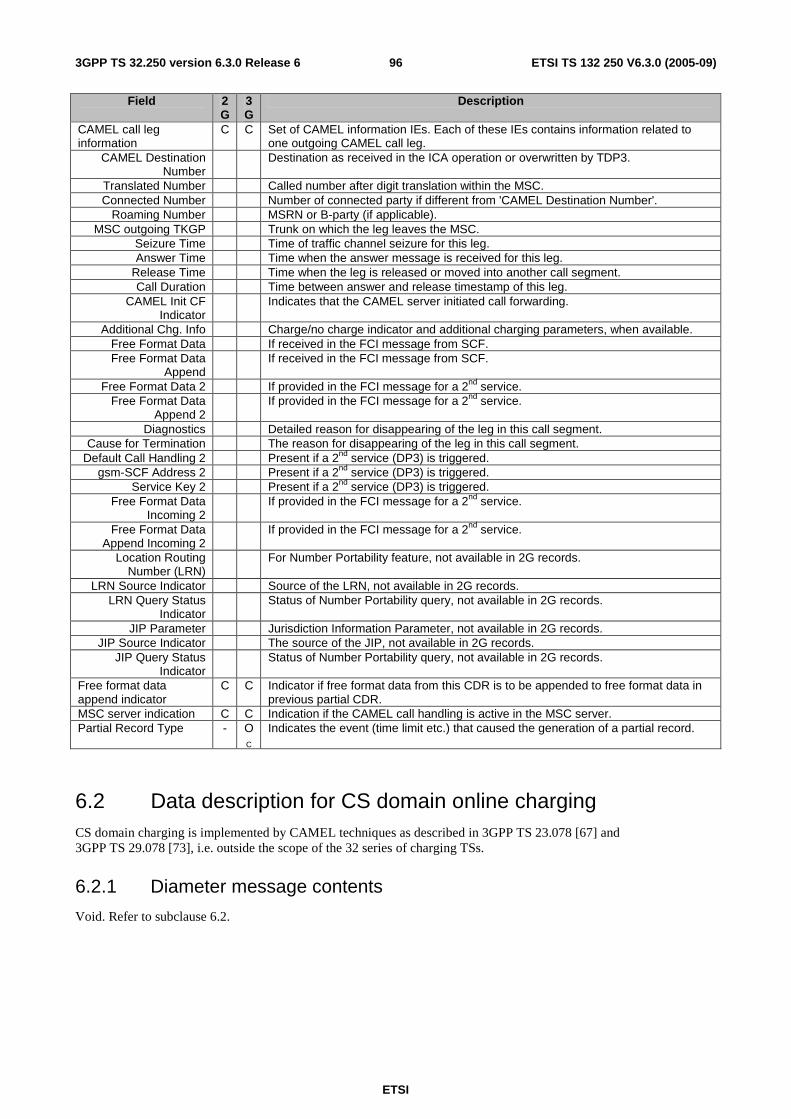
ETSI
ETSI TS 132 250 V6.3.0 (2005-09) 963GPP TS 32.250 version 6.3.0 Release 6
Field 2G
3G
Description
CAMEL call leg information
C C Set of CAMEL information IEs. Each of these IEs contains information related to one outgoing CAMEL call leg.
CAMEL Destination Number
Destination as received in the ICA operation or overwritten by TDP3.
Translated Number Called number after digit translation within the MSC. Connected Number Number of connected party if different from 'CAMEL Destination Number'.
Roaming Number MSRN or B-party (if applicable). MSC outgoing TKGP Trunk on which the leg leaves the MSC.
Seizure Time Time of traffic channel seizure for this leg. Answer Time Time when the answer message is received for this leg.
Release Time Time when the leg is released or moved into another call segment. Call Duration Time between answer and release timestamp of this leg.
CAMEL Init CF Indicator
Indicates that the CAMEL server initiated call forwarding.
Additional Chg. Info Charge/no charge indicator and additional charging parameters, when available. Free Format Data If received in the FCI message from SCF. Free Format Data
Append If received in the FCI message from SCF.
Free Format Data 2 If provided in the FCI message for a 2nd service. Free Format Data
Append 2 If provided in the FCI message for a 2nd service.
Diagnostics Detailed reason for disappearing of the leg in this call segment. Cause for Termination The reason for disappearing of the leg in this call segment.
Default Call Handling 2 Present if a 2nd service (DP3) is triggered. gsm-SCF Address 2 Present if a 2nd service (DP3) is triggered.
Service Key 2 Present if a 2nd service (DP3) is triggered. Free Format Data
Incoming 2 If provided in the FCI message for a 2nd service.
Free Format Data Append Incoming 2
If provided in the FCI message for a 2nd service.
Location Routing Number (LRN)
For Number Portability feature, not available in 2G records.
LRN Source Indicator Source of the LRN, not available in 2G records. LRN Query Status
Indicator Status of Number Portability query, not available in 2G records.
JIP Parameter Jurisdiction Information Parameter, not available in 2G records. JIP Source Indicator The source of the JIP, not available in 2G records.
JIP Query Status Indicator
Status of Number Portability query, not available in 2G records.
Free format data append indicator
C C Indicator if free format data from this CDR is to be appended to free format data in previous partial CDR.
MSC server indication C C Indication if the CAMEL call handling is active in the MSC server. Partial Record Type - O
C Indicates the event (time limit etc.) that caused the generation of a partial record.
6.2 Data description for CS domain online charging CS domain charging is implemented by CAMEL techniques as described in 3GPP TS 23.078 [67] and 3GPP TS 29.078 [73], i.e. outside the scope of the 32 series of charging TSs.
6.2.1 Diameter message contents
Void. Refer to subclause 6.2.

ETSI
ETSI TS 132 250 V6.3.0 (2005-09) 973GPP TS 32.250 version 6.3.0 Release 6
Annex A (informative): CDR File Transfer compliant with earlier 3GPP releases This group of TMN functions is concerned with the bulk transfer of call and event records from the NEF record filestore to the NEF.
The call and event records shall be transferred from the NEF to the OSF by the use of FTAM protocol on X.25 or TCP/IP, and FTP or TFTP over TCP/IP. For further details of the use of FTAM see GSM 12.01 [405] and of the use of FTP see RFC 959 [400] and TFTP see [403].
In addition to the simple file transfer services provided by FTAM, peer-to-peer application process communication may be also be supported. The use of CMIS services for the uploading of files from the NEF to the OSF is specified in GSM 12.00 [406].

ETSI
ETSI TS 132 250 V6.3.0 (2005-09) 983GPP TS 32.250 version 6.3.0 Release 6
Annex B (informative): Bibliography
a) The 3GPP charging specifications
- 3GPP TS 32.251: "Telecommunication management; Charging management; Packet Switched (PS) domain charging".
- 3GPP TS 32.252: "Telecommunication management; Charging management; Wireless Local Area Network (WLAN) charging".
- 3GPP TS 32.260: "Telecommunication management; Charging management; IP Multimedia Subsystem (IMS) charging".
- 3GPP TS 32.270: "Telecommunication management; Charging management; Multimedia Messaging Service (MMS) charging".
- 3GPP TS 32.271: "Telecommunication management; Charging management; Location Services (LCS) charging".
- 3GPP TS 32.296: "Telecommunication management; Charging management; On-line Charging System (OCS) applications and interfaces".
b) other charging specifications
-
c) Common 3GPP specifications
- 3GPP TS 22.101: "Service aspects; Service principles".
- 3GPP TS 23.003: "Numbering, addressing and identification".
- 3GPP TS 27.001: "General on Terminal Adaptation Functions (TAF) for Mobile Stations (MS)".
d) other Domain and Service specific 3GPP / ETSI specifications
- 3GPP TS 23.009: "Handover procedures".
- 3GPP TS 23.040: "Technical realization of the Short Message Service (SMS)".
- 3GPP TS 24.080: "Mobile radio Layer 3 supplementary service specification; Formats and coding".
- 3GPP TS 49.031: "Location Services (LCS); Base Station System Application Part LCS Extension (BSSAP-LE)".
- 3GPP TS 29.002: "Mobile Application Part (MAP) specification".
e) Relevant ITU Recommendations
- ITU-T Recommendation E.164: "The international public telecommunication numbering plan".
- ITU-T Recommendation Q.767: "Application of the ISDN user part of CCITT Signalling System No.7 for international ISDN interconnections".
- ITU-T Recommendation X.25: "Interface between Data Terminal Equipment (DTE) and Data Circuit-terminating Equipment (DCE) for terminals operating in the packet mode and connected to public data networks by dedicated circuit".
- ITU-T Recommendation X.121: "International numbering plan for public data networks".
- GSM 12.00: "Network Management (NM); Part 1: Objectives and structure of network management".
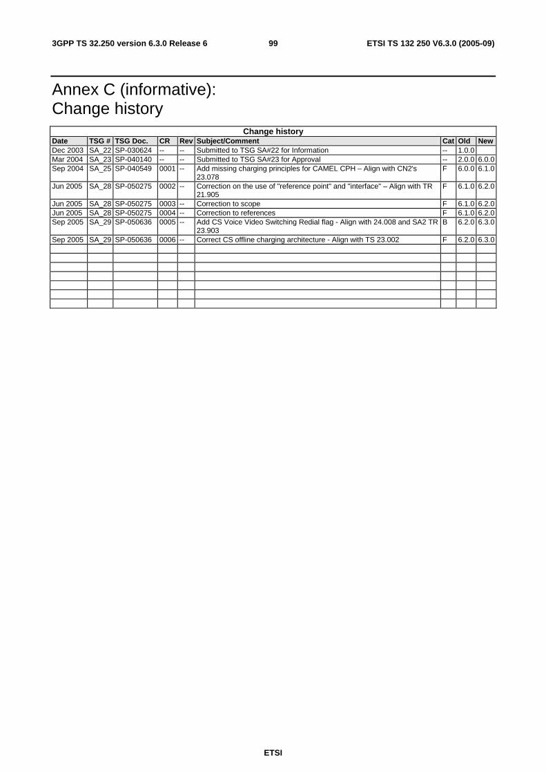
ETSI
ETSI TS 132 250 V6.3.0 (2005-09) 993GPP TS 32.250 version 6.3.0 Release 6
Annex C (informative): Change history
Change history Date TSG # TSG Doc. CR Rev Subject/Comment Cat Old New Dec 2003 SA_22 SP-030624 -- -- Submitted to TSG SA#22 for Information -- 1.0.0 Mar 2004 SA_23 SP-040140 -- -- Submitted to TSG SA#23 for Approval -- 2.0.0 6.0.0 Sep 2004 SA_25 SP-040549 0001 -- Add missing charging principles for CAMEL CPH – Align with CN2's
23.078 F 6.0.0 6.1.0
Jun 2005 SA_28 SP-050275 0002 -- Correction on the use of "reference point" and "interface" – Align with TR 21.905
F 6.1.0 6.2.0
Jun 2005 SA_28 SP-050275 0003 -- Correction to scope F 6.1.0 6.2.0 Jun 2005 SA_28 SP-050275 0004 -- Correction to references F 6.1.0 6.2.0 Sep 2005 SA_29 SP-050636 0005 -- Add CS Voice Video Switching Redial flag - Align with 24.008 and SA2 TR
23.903 B 6.2.0 6.3.0
Sep 2005 SA_29 SP-050636 0006 -- Correct CS offline charging architecture - Align with TS 23.002 F 6.2.0 6.3.0

ETSI
ETSI TS 132 250 V6.3.0 (2005-09) 1003GPP TS 32.250 version 6.3.0 Release 6
History
Document history
V6.0.0 December 2004 Publication
V6.1.0 June 2005 Publication
V6.3.0 September 2005 Publication