Embed Size (px)
Citation preview

ETSI TS 103 357 V1.1.1 (2018-06)
Short Range Devices; Low Throughput Networks (LTN);
Protocols for radio interface A
TECHNICAL SPECIFICATION
ETSI
ETSI TS 103 357 V1.1.1 (2018-06)2
Reference DTS/ERM-TG28-503
Keywords interface, LTN, OSSS, protocol, radio, SRD, UNB
ETSI
650 Route des Lucioles F-06921 Sophia Antipolis Cedex - FRANCE
Tel.: +33 4 92 94 42 00 Fax: +33 4 93 65 47 16
Siret N° 348 623 562 00017 - NAF 742 C
Association à but non lucratif enregistrée à la Sous-Préfecture de Grasse (06) N° 7803/88
Important notice
The present document can be downloaded from: http://www.etsi.org/standards-search
The present document may be made available in electronic versions and/or in print. The content of any electronic and/or print versions of the present document shall not be modified without the prior written authorization of ETSI. In case of any
existing or perceived difference in contents between such versions and/or in print, the only prevailing document is the print of the Portable Document Format (PDF) version kept on a specific network drive within ETSI Secretariat.
Users of the present document should be aware that the document may be subject to revision or change of status. Information on the current status of this and other ETSI documents is available at
https://portal.etsi.org/TB/ETSIDeliverableStatus.aspx
If you find errors in the present document, please send your comment to one of the following services: https://portal.etsi.org/People/CommiteeSupportStaff.aspx
Copyright Notification
No part may be reproduced or utilized in any form or by any means, electronic or mechanical, including photocopying and microfilm except as authorized by written permission of ETSI.
The content of the PDF version shall not be modified without the written authorization of ETSI. The copyright and the foregoing restriction extend to reproduction in all media.
© ETSI 2018.
All rights reserved.
DECTTM, PLUGTESTSTM, UMTSTM and the ETSI logo are trademarks of ETSI registered for the benefit of its Members. 3GPPTM and LTETM are trademarks of ETSI registered for the benefit of its Members and
of the 3GPP Organizational Partners. oneM2M logo is protected for the benefit of its Members.
GSM® and the GSM logo are trademarks registered and owned by the GSM Association.
ETSI
ETSI TS 103 357 V1.1.1 (2018-06)3
Contents
Intellectual Property Rights ................................................................................................................................ 9
Foreword ............................................................................................................................................................. 9
Modal verbs terminology .................................................................................................................................... 9
1 Scope ...................................................................................................................................................... 10
2 References .............................................................................................................................................. 10
2.1 Normative references ....................................................................................................................................... 10
2.2 Informative references ...................................................................................................................................... 10
3 Definitions, symbols and abbreviations ................................................................................................. 11
3.1 Definitions ........................................................................................................................................................ 11
3.2 Symbols ............................................................................................................................................................ 12
3.3 Abbreviations ................................................................................................................................................... 12
4 General description................................................................................................................................. 15
5 Lfour family ........................................................................................................................................... 15
5.1 Overview .......................................................................................................................................................... 15
5.2 MAC layer description ..................................................................................................................................... 17
5.2.1 Overview .................................................................................................................................................... 17
5.2.2 MAC format in UL ..................................................................................................................................... 18
5.2.3 MAC function in UL................................................................................................................................... 18
5.2.3.1 Assembling of MSDU ........................................................................................................................... 18
5.2.3.2 Assembling of Header Field .................................................................................................................. 18
5.2.3.3 Insertion of Check Sum ......................................................................................................................... 18
5.2.3.4 Provisioning of PHY Parameter ............................................................................................................ 18
5.2.3.4.1 PHY Mode ....................................................................................................................................... 18
5.2.3.4.2 Repetitions ....................................................................................................................................... 18
5.2.3.4.3 Encryption Parameters ..................................................................................................................... 19
5.2.3.4.4 PHY Parameters .............................................................................................................................. 19
5.2.3.4.5 Operation Band ................................................................................................................................ 19
5.2.3.4.6 Channel Access ............................................................................................................................... 19
5.2.3.4.7 Transmission Frame ........................................................................................................................ 19
5.2.4 MAC procedures ......................................................................................................................................... 20
5.2.4.1 Overview ............................................................................................................................................... 20
5.2.4.2 End-point Operation .............................................................................................................................. 20
5.2.4.2.1 Overview ......................................................................................................................................... 20
5.2.4.2.2 Repetition Procedure ....................................................................................................................... 20
5.2.4.2.3 Frequency Selection Procedure ....................................................................................................... 20
5.2.4.2.4 Transmission Start Time Selection Procedure ................................................................................. 21
5.2.4.2.5 Channel Assessment Procedure ....................................................................................................... 21
5.3 PHY layer description ...................................................................................................................................... 22
5.3.1 Overview .................................................................................................................................................... 22
5.3.2 PHY format in UL ...................................................................................................................................... 23
5.3.3 PHY function in UL .................................................................................................................................... 23
5.3.3.1 Forward Error Correction ...................................................................................................................... 23
5.3.3.2 Rate Matching ....................................................................................................................................... 24
5.3.3.3 Encryption ............................................................................................................................................. 26
5.3.3.4 Synchronization Signal Insertion .......................................................................................................... 27
5.3.3.5 Interleaving ........................................................................................................................................... 28
5.3.3.5.1 Mode A Interleaver .......................................................................................................................... 28
5.3.3.5.2 Mode B and C Interleaver ............................................................................................................... 28
5.3.3.6 Scrambling ............................................................................................................................................ 29
5.3.3.7 Modulation ............................................................................................................................................ 29
5.3.3.7.1 Introduction ..................................................................................................................................... 29
5.3.3.7.2 Primary Modulation ......................................................................................................................... 29
5.3.3.7.3 Secondary Modulation ..................................................................................................................... 30
5.3.4 PHY Procedures .......................................................................................................................................... 30
ETSI
ETSI TS 103 357 V1.1.1 (2018-06)4
5.3.4.1 Overview ............................................................................................................................................... 30
5.3.4.2 Synchronous Pattern-1 .......................................................................................................................... 30
5.3.4.2.1 Frame structure ................................................................................................................................ 30
5.3.4.2.2 Time and frequency hopping ........................................................................................................... 31
5.3.4.2.3 Pseudo-random seed generation ...................................................................................................... 33
5.4 Radio characteristics......................................................................................................................................... 34
5.4.1 Overview .................................................................................................................................................... 34
5.4.2 Band-plan .................................................................................................................................................... 34
6 Telegram splitting ultra narrow band (TS-UNB) family ........................................................................ 35
6.1 Overview .......................................................................................................................................................... 35
6.1.1 General description ..................................................................................................................................... 35
6.1.2 Modes of operation ..................................................................................................................................... 37
6.2 Link Layer ........................................................................................................................................................ 38
6.2.1 Link Layer Overview .................................................................................................................................. 38
6.2.2 Link Layer Format ...................................................................................................................................... 38
6.2.2.1 Link Layer Protocol Data Unit (LPDU) ................................................................................................ 38
6.2.2.2 Control Segment ................................................................................................................................... 39
6.2.2.2.1 Overview ......................................................................................................................................... 39
6.2.2.2.2 Attach Request................................................................................................................................. 39
6.2.2.2.3 Attach Accept .................................................................................................................................. 39
6.2.2.2.4 Detach Request ................................................................................................................................ 40
6.2.2.2.5 Detach Accept ................................................................................................................................. 40
6.2.2.2.6 DLRX Status Query ........................................................................................................................ 40
6.2.2.2.7 DLRX Status Response ................................................................................................................... 40
6.2.2.2.8 Link Adaptation Request ................................................................................................................. 41
6.2.2.2.9 Link Adaptation Confirm ................................................................................................................ 41
6.2.2.3 End-point Info Field .............................................................................................................................. 41
6.2.3 Link Layer Procedures ................................................................................................................................ 42
6.2.3.1 End-point Attachment ........................................................................................................................... 42
6.2.3.1.1 Introduction ..................................................................................................................................... 42
6.2.3.1.2 End-point Configuration .................................................................................................................. 42
6.2.3.1.3 Class Z end-point Attachment ......................................................................................................... 42
6.2.3.1.4 Class A end-point Attachment ......................................................................................................... 43
6.2.3.2 End-point Detachment .......................................................................................................................... 43
6.3 MAC Layer ...................................................................................................................................................... 44
6.3.1 Byte and Processing Order ......................................................................................................................... 44
6.3.2 Fixed MAC Mode ....................................................................................................................................... 44
6.3.2.1 Overview ............................................................................................................................................... 44
6.3.2.2 MAC Formats in UL ............................................................................................................................. 45
6.3.2.2.1 MAC Protocol Data Unit (MPDU) .................................................................................................. 45
6.3.2.2.2 MAC Header ................................................................................................................................... 46
6.3.2.2.3 Address ............................................................................................................................................ 46
6.3.2.2.4 MPDUCNT ..................................................................................................................................... 46
6.3.2.2.5 MAC Payload Format (MPF) .......................................................................................................... 46
6.3.2.2.6 MAC Payload .................................................................................................................................. 46
6.3.2.2.7 SIGN ................................................................................................................................................ 46
6.3.2.3 MAC Formats in DL ............................................................................................................................. 47
6.3.2.3.1 MAC Protocol Data Unit (MPDU) .................................................................................................. 47
6.3.2.3.2 MAC Header ................................................................................................................................... 47
6.3.2.3.3 MAC Payload Format (MPF) .......................................................................................................... 47
6.3.2.3.4 MAC Payload .................................................................................................................................. 47
6.3.2.3.5 SIGN ................................................................................................................................................ 47
6.3.2.4 MAC Functions in UL .......................................................................................................................... 47
6.3.2.4.1 Addressing ....................................................................................................................................... 47
6.3.2.4.2 Packet Counter................................................................................................................................. 48
6.3.2.4.3 Attachment Counter ......................................................................................................................... 48
6.3.2.4.4 Payload Encryption ......................................................................................................................... 48
6.3.2.4.5 Authentication ................................................................................................................................. 48
6.3.2.5 MAC Functions in DL .......................................................................................................................... 48
6.3.2.5.1 Addressing ....................................................................................................................................... 48
6.3.2.5.2 Packet Counter................................................................................................................................. 49

ETSI
ETSI TS 103 357 V1.1.1 (2018-06)5
6.3.2.5.3 Payload Encryption ......................................................................................................................... 49
6.3.2.5.4 Authentication ................................................................................................................................. 49
6.3.2.6 Common MAC function ....................................................................................................................... 49
6.3.2.6.1 Encryption ....................................................................................................................................... 49
6.3.2.6.2 CMAC generation ........................................................................................................................... 50
6.3.2.7 MAC Procedures ................................................................................................................................... 50
6.3.2.7.1 Scheduling ....................................................................................................................................... 50
6.3.2.7.2 Transmission Acknowledgment ...................................................................................................... 51
6.3.3 Variable MAC mode ................................................................................................................................... 51
6.3.3.1 Overview ............................................................................................................................................... 51
6.3.3.2 MPDU Format ....................................................................................................................................... 52
6.3.4 MAC Types ................................................................................................................................................ 52
6.3.4.1 MAC type WMBUS .............................................................................................................................. 52
6.3.4.1.1 Overview ......................................................................................................................................... 52
6.3.4.1.2 MAC Formats .................................................................................................................................. 52
6.3.4.1.3 MAC functions ................................................................................................................................ 53
6.3.4.1.4 MAC procedures ............................................................................................................................. 53
6.4 PHY Layer........................................................................................................................................................ 53
6.4.1 PHY Overview ............................................................................................................................................ 53
6.4.2 PHY Formats in UL .................................................................................................................................... 53
6.4.2.1 Radio-burst ............................................................................................................................................ 53
6.4.2.1.1 Burst Data Unit (BDU) .................................................................................................................... 53
6.4.2.1.2 Sync-burst Data Unit (SBDU) ......................................................................................................... 53
6.4.2.2 Radio Frame .......................................................................................................................................... 54
6.4.2.2.1 Overview ......................................................................................................................................... 54
6.4.2.2.2 Core frame ....................................................................................................................................... 54
6.4.2.2.3 Extension frame ............................................................................................................................... 54
6.4.2.3 PHY Payload ......................................................................................................................................... 54
6.4.2.3.1 Introduction ..................................................................................................................................... 54
6.4.2.3.2 Header CRC .................................................................................................................................... 55
6.4.2.3.3 Payload CRC ................................................................................................................................... 55
6.4.2.3.4 Packet Size Indicator (PSI) .............................................................................................................. 55
6.4.2.3.5 PHY Service Data Unit (PSDU) ...................................................................................................... 55
6.4.2.3.6 MMode ............................................................................................................................................ 55
6.4.3 PHY Formats in DL .................................................................................................................................... 55
6.4.3.1 Radio-burst ............................................................................................................................................ 55
6.4.3.1.1 DL-SB Mode ................................................................................................................................... 55
6.4.3.1.2 DL-TS Mode ................................................................................................................................... 56
6.4.3.2 Radio frame ........................................................................................................................................... 57
6.4.3.2.1 Core frame ....................................................................................................................................... 57
6.4.3.2.2 Extension frame ............................................................................................................................... 57
6.4.3.3 PHY Payload ......................................................................................................................................... 58
6.4.3.3.1 Core frame ....................................................................................................................................... 58
6.4.3.3.2 Extension frame ............................................................................................................................... 59
6.4.4 PHY Functions in UL ................................................................................................................................. 59
6.4.4.1 Modulation ............................................................................................................................................ 59
6.4.4.2 Symbol mapping ................................................................................................................................... 59
6.4.4.2.1 Overview ......................................................................................................................................... 59
6.4.4.2.2 UL-ULP Symbol rate ...................................................................................................................... 60
6.4.4.2.3 UL-ER Symbol rate ......................................................................................................................... 60
6.4.4.3 Data Whitening ..................................................................................................................................... 60
6.4.4.4 CRC....................................................................................................................................................... 60
6.4.4.4.0 General ............................................................................................................................................ 60
6.4.4.4.1 Payload CRC ................................................................................................................................... 60
6.4.4.4.2 Header CRC .................................................................................................................................... 60
6.4.4.5 Forward Error Correction ...................................................................................................................... 61
6.4.4.6 Interleaving ........................................................................................................................................... 61
6.4.4.6.1 Introduction ..................................................................................................................................... 61
6.4.4.6.2 Bit assignment to sub-packets ......................................................................................................... 61
6.4.4.6.3 Bit placing within Burst Data Unit .................................................................................................. 62
6.4.5 PHY Functions in DL ................................................................................................................................. 63
6.4.5.1 Modulation ............................................................................................................................................ 63

ETSI
ETSI TS 103 357 V1.1.1 (2018-06)6
6.4.5.1.1 DL-SB Mode ................................................................................................................................... 63
6.4.5.1.2 DL-TS Mode ................................................................................................................................... 63
6.4.5.2 Data Whitening ..................................................................................................................................... 63
6.4.5.2.1 Core frame ....................................................................................................................................... 63
6.4.5.2.2 Extension frame ............................................................................................................................... 63
6.4.5.3 CRC....................................................................................................................................................... 63
6.4.5.3.1 Core frame ....................................................................................................................................... 63
6.4.5.3.2 Extension frame ............................................................................................................................... 63
6.4.5.4 Forward Error Correction ...................................................................................................................... 63
6.4.5.4.1 DL-SB Mode ................................................................................................................................... 63
6.4.5.4.2 DL-TS Mode ................................................................................................................................... 64
6.4.5.5 Interleaving ........................................................................................................................................... 64
6.4.5.5.1 DL-SB Mode ................................................................................................................................... 64
6.4.5.5.2 DL-TS Mode ................................................................................................................................... 64
6.4.6 Commonly used PHY Functions ................................................................................................................ 66
6.4.6.1 Introduction ........................................................................................................................................... 66
6.4.6.2 CRC....................................................................................................................................................... 67
6.4.6.3 FEC ....................................................................................................................................................... 67
6.4.7 PHY Procedures .......................................................................................................................................... 67
6.4.7.1 TSMA Schemes .................................................................................................................................... 67
6.4.7.1.1 Overview ......................................................................................................................................... 67
6.4.7.1.2 Frame Repetition ............................................................................................................................. 69
6.4.7.1.3 Downlink repetition ......................................................................................................................... 70
6.4.7.1.4 Radio burst time .............................................................................................................................. 70
6.4.7.1.5 Frame time and frequency offset ..................................................................................................... 71
6.4.7.1.6 Uplink TSMA Pattern ...................................................................................................................... 72
6.4.7.1.7 Downlink TSMA pattern ................................................................................................................. 75
6.5 Radio Characteristics ........................................................................................................................................ 76
6.5.1 Spectrum Use .............................................................................................................................................. 76
6.5.2 Channel access ............................................................................................................................................ 76
6.5.3 End-point .................................................................................................................................................... 77
6.5.3.1 Carrier Frequency Tolerance ................................................................................................................. 77
6.5.4 Base station ................................................................................................................................................. 77
6.5.4.1 Carrier Frequency Tolerance ................................................................................................................. 77
6.5.4.2 Receiver ................................................................................................................................................ 77
6.5.4.2.1 Receiver Bandwidth ........................................................................................................................ 77
7 Dynamic Downlink Ultra Narrow Band (DD-UNB) family .................................................................. 77
7.1 System overview .............................................................................................................................................. 77
7.1.1 System elements ......................................................................................................................................... 77
7.1.1.1 Architecture ........................................................................................................................................... 77
7.1.1.2 Service Centre ....................................................................................................................................... 77
7.1.1.3 Base station ........................................................................................................................................... 78
7.1.1.4 End-points ............................................................................................................................................. 78
7.1.2 Protocol Overview ...................................................................................................................................... 78
7.1.2.1 Introduction ........................................................................................................................................... 78
7.1.2.2 Protocol Termination Points.................................................................................................................. 78
7.1.2.3 System Addressing and Identities ......................................................................................................... 80
7.1.3 Upper Layer Principles ............................................................................................................................... 80
7.1.4 Layer 3 (NET) Overview ............................................................................................................................ 80
7.1.5 Layer 2 (DLL) Overview ............................................................................................................................ 81
7.1.5.1 Overview ............................................................................................................................................... 81
7.1.5.2 MAC Sublayer ...................................................................................................................................... 81
7.1.6 Layer 1 (PHY) Overview ............................................................................................................................ 81
7.1.6.1 Frequency use ....................................................................................................................................... 81
7.1.6.2 A-interface Downlink and Uplink timing ............................................................................................. 81
7.1.6.3 A"-Interface (Relay Operation) timing ................................................................................................. 83
7.1.6.4 Frequency and Time Synchronization ................................................................................................... 83
7.2 Network Layer .................................................................................................................................................. 83
7.3 Data Link Layer ............................................................................................................................................... 83
7.3.1 DLL introduction ........................................................................................................................................ 83
7.3.2 MAC sub-layer ........................................................................................................................................... 83
ETSI
ETSI TS 103 357 V1.1.1 (2018-06)7
7.3.2.1 MAC on A-interface UL - Data Subframe ............................................................................................ 83
7.3.2.1.1 General ............................................................................................................................................ 83
7.3.2.1.2 UL throttle ....................................................................................................................................... 83
7.3.2.1.3 Time domain .................................................................................................................................... 83
7.3.2.1.4 Frequency domain ........................................................................................................................... 84
7.3.2.2 MAC on A-interface UL - Ack Subframe ............................................................................................. 84
7.3.2.2.1 General ............................................................................................................................................ 84
7.3.2.2.2 Time domain .................................................................................................................................... 84
7.3.2.2.3 Frequency domain ........................................................................................................................... 84
7.3.2.3 MAC on A"-interface UL...................................................................................................................... 84
7.3.2.3.1 General ............................................................................................................................................ 84
7.3.2.3.2 Time domain .................................................................................................................................... 85
7.3.3 Encryption and Authentication ................................................................................................................... 85
7.4 Physical Layer .................................................................................................................................................. 85
7.4.1 PHY Format ................................................................................................................................................ 85
7.4.1.1 Timing and Frame Formats ................................................................................................................... 85
7.4.1.1.1 Introduction ..................................................................................................................................... 85
7.4.1.1.2 A-interface Frame Formats .............................................................................................................. 87
7.4.1.1.3 A"-interface Subframe Formats ....................................................................................................... 87
7.4.1.1.4 Synchronization and Frame Offset .................................................................................................. 87
7.4.1.1.5 Battery saving .................................................................................................................................. 88
7.4.1.2 Physical Channels ................................................................................................................................. 88
7.4.2 L1 PDUs and SDUs .................................................................................................................................... 89
7.4.2.1 Overview ............................................................................................................................................... 89
7.4.2.2 Sync PDU .............................................................................................................................................. 90
7.4.2.3 Broadcast PDU ...................................................................................................................................... 91
7.4.2.4 Wakeup PDU ........................................................................................................................................ 92
7.4.2.5 Multicast L1 SDU and PDU.................................................................................................................. 92
7.4.2.6 Control L1 SDU and PDU .................................................................................................................... 93
7.4.2.6.1 Overview ......................................................................................................................................... 93
7.4.2.6.2 A-interface Downlink and A"-interface........................................................................................... 93
7.4.2.6.3 A-interface Uplink ........................................................................................................................... 94
7.4.2.7 Connection L1 SDU and PDU .............................................................................................................. 94
7.4.2.7.1 Connection L1 SDU ........................................................................................................................ 94
7.4.2.7.2 A-interface Downlink and A"-interface........................................................................................... 95
7.4.2.7.3 A-interface Uplink ........................................................................................................................... 95
7.4.2.8 Acknowledge L1 SDU .......................................................................................................................... 95
7.4.2.8.1 Ack Message Format ....................................................................................................................... 95
7.4.2.8.2 Acknowledge on A"-interface and A-interface DL ......................................................................... 96
7.4.2.8.3 Acknowledge on A-interface UL..................................................................................................... 97
7.4.3 PHY Functions ............................................................................................................................................ 98
7.4.3.1 Channel Processing ............................................................................................................................... 98
7.4.3.2 Channel Coding ................................................................................................................................... 100
7.4.3.3 Data-Burst Building ............................................................................................................................ 101
7.4.3.3.1 Introduction ................................................................................................................................... 101
7.4.3.3.2 A-interface DL............................................................................................................................... 101
7.4.3.3.3 A-interface UL Data ...................................................................................................................... 102
7.4.3.3.4 A-interface UL Ack ....................................................................................................................... 102
7.4.3.3.5 A"-interface DL ............................................................................................................................. 102
7.4.3.3.6 A"-interface UL Data data-burst.................................................................................................... 102
7.4.3.3.7 A"-interface UL Ack data-burst .................................................................................................... 103
7.4.3.3.8 Bit order ......................................................................................................................................... 103
7.4.3.4 Power Control ..................................................................................................................................... 103
7.4.3.5 High Interference Mode ...................................................................................................................... 104
7.4.4 PHY Procedures ........................................................................................................................................ 104
7.4.4.1 Synchronization and Frequency Scanning .......................................................................................... 104
7.4.4.2 Base Selection ..................................................................................................................................... 104
7.4.4.3 Transmit Duty-Cycle Control.............................................................................................................. 104
7.4.4.4 A-interface Downlink Transmission Control - Frame Structure ......................................................... 104
7.4.4.5 A"-interface Downlink Transmission Control - Subframe Structure .................................................. 104
7.4.4.6 Uplink Transmission Control .............................................................................................................. 104
7.4.4.7 PHY Measurements ............................................................................................................................ 104

ETSI
ETSI TS 103 357 V1.1.1 (2018-06)8
7.4.4.8 Noise Measurement ............................................................................................................................. 104
7.4.4.9 Base-System Group (BSGP) ............................................................................................................... 105
7.5 Radio characteristics....................................................................................................................................... 105
7.5.1 Frequency Structure - Radio Mode 0 ........................................................................................................ 105
7.5.2 Modulation - Radio Mode 0 ...................................................................................................................... 106
7.5.2.1 General ................................................................................................................................................ 106
7.5.2.2 A-interface DL and A"-interface (UL and DL) modulation ................................................................ 106
7.5.2.3 A-interface UL modulation ................................................................................................................. 106
7.5.3 Radio-Burst Power Ramping .................................................................................................................... 107
Annex A (informative): Generic end-point system block diagram .................................................. 108
A.1 Overview .............................................................................................................................................. 108
A.2 uC ......................................................................................................................................................... 108
A.3 Baseband Processor .............................................................................................................................. 109
A.4 TCXO ................................................................................................................................................... 109
A.5 Timing Sequencer & Controller ........................................................................................................... 109
A.6 Modulation Filter .................................................................................................................................. 109
A.7 PLL ....................................................................................................................................................... 109
A.8 Power Amplifier ................................................................................................................................... 109
A.9 Demodulator ......................................................................................................................................... 109
A.10 Summary .............................................................................................................................................. 109
Annex B (informative): TS-UNB Profiles ........................................................................................... 110
B.1 Overview .............................................................................................................................................. 110
B.2 EU0 Profile ........................................................................................................................................... 110
B.2.1 Spectrum Use ................................................................................................................................................. 110
B.2.2 Mode of operation .......................................................................................................................................... 110
B.3 EU1 Profile ........................................................................................................................................... 111
B.3.1 Spectrum Use ................................................................................................................................................. 111
B.3.2 Mode of operation .......................................................................................................................................... 111
B.4 EU2 Profile ........................................................................................................................................... 111
B.4.1 Spectrum Use ................................................................................................................................................. 111
B.4.2 Mode of operation .......................................................................................................................................... 112
B.5 US0 Profile ........................................................................................................................................... 112
B.5.1 Spectrum Use ................................................................................................................................................. 112
B.5.2 Mode of operation .......................................................................................................................................... 112
History ............................................................................................................................................................ 113
ETSI
ETSI TS 103 357 V1.1.1 (2018-06)9
Intellectual Property Rights
Essential patents
IPRs essential or potentially essential to normative deliverables may have been declared to ETSI. The information pertaining to these essential IPRs, if any, is publicly available for ETSI members and non-members, and can be found in ETSI SR 000 314: "Intellectual Property Rights (IPRs); Essential, or potentially Essential, IPRs notified to ETSI in respect of ETSI standards", which is available from the ETSI Secretariat. Latest updates are available on the ETSI Web server (https://ipr.etsi.org/).
Pursuant to the ETSI IPR Policy, no investigation, including IPR searches, has been carried out by ETSI. No guarantee can be given as to the existence of other IPRs not referenced in ETSI SR 000 314 (or the updates on the ETSI Web server) which are, or may be, or may become, essential to the present document.
Trademarks
The present document may include trademarks and/or tradenames which are asserted and/or registered by their owners. ETSI claims no ownership of these except for any which are indicated as being the property of ETSI, and conveys no right to use or reproduce any trademark and/or tradename. Mention of those trademarks in the present document does not constitute an endorsement by ETSI of products, services or organizations associated with those trademarks.
Foreword This Technical Specification (TS) has been produced by ETSI Technical Committee Electromagnetic compatibility and Radio spectrum Matters (ERM).
Modal verbs terminology In the present document "shall", "shall not", "should", "should not", "may", "need not", "will", "will not", "can" and "cannot" are to be interpreted as described in clause 3.2 of the ETSI Drafting Rules (Verbal forms for the expression of provisions).
"must" and "must not" are NOT allowed in ETSI deliverables except when used in direct citation.
ETSI
ETSI TS 103 357 V1.1.1 (2018-06)10
1 Scope The present document specifies the radio protocols of three radio technologies, referred to as "families". It contains an implementable description of physical and MAC/link protocol layers. It concludes with a section on implementation commonalities between the three LTN families.
NOTE 1: ETSI TR 103 249 [i.8] describes LTN use cases and system characteristics.
NOTE 2: ETSI TS 103 358 [i.9] specifies the architecture of LTN systems.
NOTE 3: Based on the above documents, radio technologies have been developed with a focus on different subsets of applications, where the optimal balance of technical parameters differs.
2 References
2.1 Normative references References are either specific (identified by date of publication and/or edition number or version number) or non-specific. For specific references, only the cited version applies. For non-specific references, the latest version of the referenced document (including any amendments) applies.
Referenced documents which are not found to be publicly available in the expected location might be found at https://docbox.etsi.org/Reference/.
NOTE: While any hyperlinks included in this clause were valid at the time of publication, ETSI cannot guarantee their long term validity.
The following referenced documents are necessary for the application of the present document.
[1] IEEE™ Std 802.15.4-2011: "IEEE Standard for Local and metropolitan area networks; Part 15.4: Low-Rate Wireless Personal Area Networks (LR-WPANs)".
[2] Publication 197 (2001): "Specification for the Advanced Encryption Standard (AES)", NIST Processing Standards".
NOTE: Available at: http://nvlpubs.nist.gov/nistpubs/FIPS/NIST.FIPS.197.pdf.
[3] NIST Special Publication 800-38B (2005): "Recommendation for Block Cipher Modes of Operation: "the CMAC Mode for Authentication".
NOTE: Available at: https://csrc.nist.gov/publications/detail/sp/800-38b/final.
[4] ISO/IEC 29192-2:2012: "Information technology - Security techniques - Lightweight cryptography - Part 2: Block ciphers".
[5] CEN EN 13757-4:2013: "Communication systems for meters and remote reading of meters - Part 4: Wireless meter readout (Radio meter reading for operation in SRD bands)".
[6] IEEE™ Guidelines for Use of Extended Unique Identifier (EUI), Organizationally Unique Identifier (OUI), and Company ID (CID).
NOTE: Available at: http://standards.ieee.org/develop/regauth/tut/eui.pdf.
2.2 Informative references References are either specific (identified by date of publication and/or edition number or version number) or non-specific. For specific references, only the cited version applies. For non-specific references, the latest version of the referenced document (including any amendments) applies.

ETSI
ETSI TS 103 357 V1.1.1 (2018-06)11
NOTE: While any hyperlinks included in this clause were valid at the time of publication, ETSI cannot guarantee their long term validity.
The following referenced documents are not necessary for the application of the present document but they assist the user with regard to a particular subject area.
[i.1] ERC Recommendation 70-03 (Tromsø 1997 and subsequent amendments): "Relating to the use of short range devices (SRD)", Recommendation adopted by the Frequency Management, Regulatory Affairs and Spectrum Engineering Working Groups, Version of 21 October 2016.
[i.2] ETSI EN 300 220-1 (V2.4.1) (05-2012): "Electromagnetic compatibility and Radio spectrum Matters (ERM); Short Range Devices (SRD); Radio equipment to be used in the 25 MHz to 1 000 MHz frequency range with power levels ranging up to 500 mW; Part 1: Technical characteristics and test methods".
[i.3] CFR Title 47 Part 15 section 15.247: "Operation within the bands 902-928 MHz, 2400-2483.5 MHz, and 5725-5850 MHz".
[i.4] ARIB STD-T108: "920 MHz-Band Telemeter, Telecontrol and data transmission radio equipment", Version 1.0 of February 14th 2012.
[i.5] Recommendation for Block Cipher Modes of Operation (Methods and Techniques), Morris Dworkin, NIST Special Publication 800-38A, Edition 2001.
NOTE: Available at: http://nvlpubs.nist.gov/nistpubs/Legacy/SP/nistspecialpublication800-38A.pdf.
[i.6] IETF RFC 4493: "The AES-CMAC Algorithm", 2006.
NOTE: Available at: https://tools.ietf.org/html/rfc4493.
[i.7] CEN EN 13757-7:2018: "Communication systems for meters - Part 7: Transport and security services".
[i.8] ETSI TR 103 249 (V1.1.1) (10-2017): "Low Throughput Network (LTN); Use Cases and System Characteristics".
[i.9] ETSI TS 103 358 (V1.1.1) (06-2018): "Short range devices; Low Throughput Networks (LTN) Architecture; LTN Architecture".
3 Definitions, symbols and abbreviations
3.1 Definitions For the purposes of the present document, the following terms and definitions apply:
CLEFIA: A lightweight block cipher defined in ISO/IEC 29192-2 [4].
data-burst: sequence of consecutive radio bursts transmitted by an LTN entity
network element: term used to refer to a node in the DD-UNB system. It can refer to an EP, RP, OEP, BS, or SC
orphan end-point: EP which is connected through a relay point
radio-burst: radio transmission over the air which starts with a ramp up, finishes with a ramp down and which has a continuous centre frequency and constant transmission power (apart from modulation)
radio-frame: area in time and frequency plane containing all radio bursts belonging to one packet
sub-packet: fragment of a packet after telegram splitting
subframe: portion of the basic 24 s frame which is allocated to a specific link, direction and content (i.e. A or A"-interface with DL, UL data or UL Ack)

ETSI
ETSI TS 103 357 V1.1.1 (2018-06)12
superframe: set of 64 consecutive frames
TSMA carrier: transmission carrier within the LTN channel on which a radio burst is transmitted
TSMA pattern: time and frequency transmission scheme of a radio frame
3.2 Symbols For the purposes of the present document, the following symbols apply:
Δfslowchirp Frequency difference between the start and end of secondary modulated PPDU as a result of chirp
ΔT Symbol duration Bc Carrier spacing
BWUL-Ch Bandwidth of UL channel used by EP in band of operation
CRB Radio-burst carrier number of TSMA pattern
Coffset Carrier offset of radio frame
dB decibel f0 Start frequency of a radio frame
fc Channel centre frequency
fh Frequency of high tone
fl Frequency of low tone
foffset Additional pseudorandom radio frequency offset to the centre frequency
fRB Carrier frequency of a radio burst
nb Number of PSDU data bytes
Nrepetitions Number of repetitions of a PPDU
nts Timeslot offset of radio frame
pTSDL Downlink TSMA pattern number
PTX Transmission power
STOTAL Total number of sub-packets in a radio frame
SC Number of sub-packets in core frame
SE Number of sub-packets in extension frame
SRF Timeslot offset of radio frame
T0 Start time of the radio frame transmission
TDN DL Interblock Distance
TPPDU PPDU duration in seconds
TRB Time difference between two consecutive radio bursts in number of symbols
TSB Sync-burst time
Ttx-gap Repetition gap between PPDUs in seconds
3.3 Abbreviations For the purposes of the present document, the following abbreviations apply:
AC Acknowledge Codeword ACK Acknowledge AES Advanced Encryption Standard BC Broadcast BCH Bose–Chaudhuri–Hocquenghem code BDU Block Data Unit BFSK Binary Frequency Shift Keying BPSK Binary Phase Shift Keying BS Base Station BSGP Base-System Group BSID Base Station ID BT Bandwidth-bit period product

ETSI
ETSI TS 103 357 V1.1.1 (2018-06)13
BW Bandwidth CC Control Codeword CI Control Information CMAC Cipher-based Message Authentication Code CPU Central Processing Unit CRC Cyclic Redundancy Check DAPCH Downlink Acknowledge Physical Channel DATA_A Data field A of a TS burst DATA_B Data field B of a TS burst DATA_C Data field C of a TS burst DBPCH Downlink Broadcast Physical Channel DC Duty Cycle DCPCH Downlink Control Physical Channel DD-UNB Dynamic Downlink Ultra Narrowband DL Downlink DL-ER Downlink, Extended Reach for TS-UNB DLL Data Link Layer DLRX Downlink Receive (status) DL-SB Downlink Single Burst (Basic profile) DMPCH Downlink Multicast Physical Channel DPG Downlink Pattern Group DSP Digital Signal Processing DSPCH Downlink Sync Physical Channel DWPCH Downlink Wakeup Physical Channel DXPCH Downlink Connection Physical Channel EFI Extension Frame Indicator EP End-Point EPID End-Point Identifier ER Extended Reach EUI Extended Unique Identifier FEC Forward Error Correction FMAC Frequency Medium Access Control FSK Frequency Shift Keying GFSK Gaussian Frequency Shift Keying GMSK Gaussian Minimum Shift Keying GP Grid Position GPS Global Positioning System IC Integrated Circuit IEC International Electrotechnical Commission IEEE Institute of Electrical and Electronics Engineers IETF Internet Engineering Task Force IPv6 Internet Protocol version 6 ISO International Organization for Standardization IV Initialization Vector (payload encryption) LAPCH Local Acknowledge Physical Channel LBPCH Local Downlink Broadcast Physical Channel LBT Listen Before Talk LCPCH Local Control Physical Channel LDPC Low Density Parity Check LFSR Linear Feedback Shift Register LMPCH Local Multicast Physical Channel LPDU Link Layer Protocol Data Unit LSB Least Significant Bit LSPCH Local Sync Physical Channel LTN Low Throughput Network LWPCH Local Wakeup Physical Channel LXPCH Local Connection Physical Channel MAC Medium Access Control MC Multicast MCL Minimum Coupling Loss MMODE MAC MODE MPDU MAC Protocol Data Unit

ETSI
ETSI TS 103 357 V1.1.1 (2018-06)14
MPF MAC Payload Format MSB Most Significant Bit MSDU MAC Service Data Unit MSK Minimum Shift Keying NET Network layer NIST National Institute of Standards and Technology OEP Orphan End-Point OFB Output Feedback OSI Open System Interconnection P Power PA Power Amplifier PDU Protocol Data Unit PHR PHY Header PHY Physical layer PLL Phase Locked Loop PN9 Pseudo Noise sequence of length 9 PPDU PHY Protocol Data Unit PRN Pseudo-Random Number PS Pilot Sequence PS_A Pilot Sequence A PS_B Pilot Sequence B PS_DA Pilot Sequence field A of a TS DL burst PS_DB Pilot Sequence field B of a TS DL burst PS_DS Pilot Sequence field of a DL Sync burst PS_US Pilot Sequence field of a UL Sync burst PSDU PHY Service Data Unit PSI Packet Size Indicator RF Radio Frequency RFC Request For Comments RFS Random Frequency Selection ROS Relay Outstation RP Relay Point RSSI Received Signal Strength Indication RX Receiver SBDU Sync-Burst Data Unit SC Service Centre SCC Strong Control Codeword SDU Service Data Unit SE Secure Element SFEC Strong Forward Error Correction SIF Sync-burst Info Field SIGN Signature field of TS burst SRD Short Range Device SSID Short System ID SXC Strong Connection Codeword Sym Symbols Sync Synchronization TCXO Temperature Compensated Crystal Oscillator TDD Time Division Duplex TS Telegram Splitting TSI Transmission Start-time Indicator TSMA Telegram Splitting Multiple Access TS-UNB Telegram Splitting Ultra Narrow Band TX Transmitter UAPCH Uplink Acknowledge Physical Channel UDPCH Uplink Data Physical Channel UL Uplink ULP Ultra Low Power UNB Ultra Narrowband WAC Weak Acknowledge Codeword WMBUS Wireless M-BUS WMC Weak Multicast Codeword
ETSI
ETSI TS 103 357 V1.1.1 (2018-06)15
WU Wakeup XC Connection Codeword XOR logic eXclusive OR
4 General description A LTN system according to the architecture document shall support one or more of the three protocol families described in the present document. The protocol families are designed to operate effectively in sub-GHz frequency bands. The protocol description offers particular mechanism to allow the operation of the LTN system under different national or regional radio spectrum regulations (e.g. [i.1], [i.2], [i.3], [i.4]).
5 Lfour family
5.1 Overview If a LTN System supports LFour family, the following protocol description shall apply. The Lfour LTN family is a low power, wideband technology and supports star network topology in radio access network. The Lfour air interface description applies to A-interface between Class Z EP and one or more BSs.
The Lfour LTN family has several key characteristics:
• Uni-directional link aiming to achieve the lowest power consumption with simple architecture.
• Three different modes of operation to choose from depending on likelihood of interference, regulation, and sensitivity requirements.
• Ability to coherently add re-transmitted packet(s) to enhance transmission range and/or combat with interference.
• LDPC forward error coding to achieve best sensitivity and mobility performance.
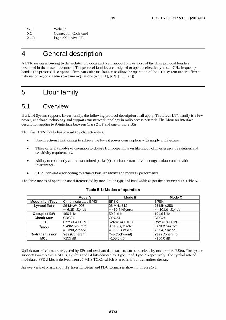
The three modes of operation are differentiated by modulation type and bandwidth as per the parameters in Table 5-1.
Table 5-1: Modes of operation
Mode A Mode B Mode C Modulation Type Chirp modulated BPSK BPSK BPSK
Symbol Rate 26 MHz/4 096 =~6,35 kSym/s
26 MHz/512 = ~50,8 kSym/s
26 MHz/256 = ~101,6 kSym/s
Occupied BW 160 kHz 50,8 kHz 101,6 kHz Check Sum CRC24 CRC24 CRC24
FEC Rate=1/4 LDPC Rate=1/4 LDPC Rate=1/4 LDPC TPPDU 2 496/Sym rate
= ~393,2 msec 9 616/Sym rate = ~189,4 msec
9 616/Sym rate = ~94,7 msec
Re-transmission Yes (Coherent) Yes (Coherent) Yes (Coherent) MCL >155 dB >150,6 dB >150,6 dB
Uplink transmissions are triggered by EPs and resultant data packets can be received by one or more BS(s). The system supports two sizes of MSDUs, 128 bits and 64 bits denoted by Type 1 and Type 2 respectively. The symbol rate of modulated PPDU bits is derived from 26 MHz TCXO which is used in Lfour transmitter design.
An overview of MAC and PHY layer functions and PDU formats is shown in Figure 5-1.

ETSI
ETSI TS 103 357 V1.1.1 (2018-06)16
Figure 5-1: Overview of MAC and PHY flow and PDU format
Lfour system makes use of time, frequency and code space domains for multiple access to accommodate large number of devices requesting service in a coverage area as shown in Figure 5-2 and Figure 5-3. Lfour may use auxiliary time synchronization methods (e.g. GPS) to reduce the complexity of the receiver in BS.
Figure 5-2: Multi-user Access Overview for Mode A Operation

ETSI
ETSI TS 103 357 V1.1.1 (2018-06)17
Figure 5-3: Multi-user Access Overview for Mode B/C Operation
5.2 MAC layer description
5.2.1 Overview
MAC sub-layer specification applies to UL only as Lfour is an UL system.
The MAC sub-layer for LTN air-interface provides following services:
• Passing and Receiving User Plane Data to and from higher layer entity
• Assembling and Disassembling of MSDU
• Assembling and Disassembling of MAC Header Information
• Assembling and Disassembling of CRC
• Passing and Receiving MPDU to and from PHY layer
• Provision of re-transmission parameters
• Provision of Encryption parameters
• Provision of PHY parameters
Figure 5-4 denotes MAC services for an EP transmitter. Reverse procedure applies at corresponding BS receiver.
Figure 5-4: MAC Functional Overview

ETSI
ETSI TS 103 357 V1.1.1 (2018-06)18
5.2.2 MAC format in UL
MPDU shall be of fixed length of 184-bit and composed as shown in Figure 5-5. MSDU lengths of 128-bit (Type 1) and 64-bit (Type 2) shall be supported.
Figure 5-5: MPDU format
5.2.3 MAC function in UL
5.2.3.1 Assembling of MSDU
A 128-bit fixed length MSDU shall be formed from byte aligned MSDU of size less than or equal to 128-bits. If MSDU payload size is less than 128-bits, then it shall be padded with zero (0) to form 128-bit MSDU. The payload size is pre-configured for an EP and known to the BS(s).
5.2.3.2 Assembling of Header Field
A 32-bit header comprising entirely of address field shall be concatenated to the start of zero-padded MSDU payload.
5.2.3.3 Insertion of Check Sum
24-bit CRC shall be generated using following polynomial and initial state set to all one's (0xFFFFFF).
���� � ��24 ��23 ��18 ��17 ��14 ��11 ��10 ��7 ��6 ��5 ��4 ��3 ��1 1
The CRC shall be concatenated to the end of zero-padded MSDU payload.
5.2.3.4 Provisioning of PHY Parameter
5.2.3.4.1 PHY Mode
The PHY Mode of operation for an EP shall be set to one of Mode A, B, or C. This is pre-configured for the EP and known to the BS(s).
5.2.3.4.2 Repetitions
The value of ����������� shall be provided and set as below. This value is pre-configured for an EP and known to the BS(s).
0 � ����������� � 31

ETSI
ETSI TS 103 357 V1.1.1 (2018-06)19
5.2.3.4.3 Encryption Parameters
The parameters for encryption control and operation shall be provided as in Table 5-2. These parameters are pre-configured for an EP and known to the BS(s).
Table 5-2: Encryption Parameters
Parameter provided to PHY Type AES128 or ISO/IEC 29192-2 [4] CLEFIA Key 128-bit sequence
Pseudo random number
128-bit sequence
Control MSDU Type, PHY Mode, Encryption_on
5.2.3.4.4 PHY Parameters
Parameters used in pseudo-random code generation for synchronization and scrambling shall be provided. These parameters are pre-configured for an EP and known to the BS(s).
5.2.3.4.5 Operation Band
Operational frequency band(s) for EP UL operation shall be provided. This parameter is preconfigured for an EP and known to the BS(s).
5.2.3.4.6 Channel Access
Parameters used to access channel for EP UL operation shall be provided. These parameters are pre-provisioned for an EP and known to BS(s).
Table 5-3: Channel Access Parameters
Parameter Value Description Access Type
(NAccess) 0-7 (integer) 0: Access Type is duty-cycle (DC)
1-6: Access Type is Listen-before-talk (LBT) and integer value represents number of channel assessment attempts (if channel not found clear) before Abort 7: Reserved
Transmission Type 0-255 (integer) 0: Asynchronous 1: Synchronous Pattern-1 2-255: Reserved
5.2.3.4.7 Transmission Frame
Parameters used to calculate time of transmission for initial and repetition PPDUs as defined in Table 5-4 shall be provided. These parameters are pre-provisioned for an EP and known to BS(s).
Table 5-4: Transmission Frame Parameters
Parameter Value Description Frame Duration
(Ttx-frame) 0-15 (integer) 0: 5 s (Mode A), 0,3 s (Mode B), 0,2 s (Mode C)
1-15: Reserved
Slot Duration (Ttx-slot)
0-15 (integer) 0: 8 ms (Mode A), 10 ms (Mode B), 8 ms (Mode C) 1-15: Reserved
UL Data Slots 0-15 (Integer) 0: 570 (Mode A), 10 (Mode B), 12 (Mode C) 1-15: Reserved
NOTE: Frame parameters vary according to PHY Mode; therefore each parameter value corresponds to three different settings. Only one setting shall apply depending on PHY Mode.
ETSI
ETSI TS 103 357 V1.1.1 (2018-06)20
5.2.4 MAC procedures
5.2.4.1 Overview
As Lfour is an UL-only system, medium access is defined for EP, but not for BS. While MAC processing is the same for each PHY Mode, operational parameters related to time and frequency are dependent on the following pre-provisioned parameters:
• PHY Mode, see clause 5.2.3.4.1
• Operation Band see clause 5.2.3.4.5
• Channel Access see clause 5.2.3.4.6
5.2.4.2 End-point Operation
5.2.4.2.1 Overview
The EP operation for channel access shall apply to initial transmission and repetition of PPDUs and comprises of frequency selection, time selection and channel assessment procedures respectively.
5.2.4.2.2 Repetition Procedure
An EP shall make Nrepetitions repetitions of a PPDU following its initial transmission, value of which is defined in
clause 5.2.3.4.2.
5.2.4.2.3 Frequency Selection Procedure
Upon initiating the transmission of initial PPDU or repetition PPDU, frequency selection shall be performed by EP in two step procedure:
Step 1: Centre frequency
Channel Centre frequency (fc) shall be determined as follows:
If "Transmission Type" is set to "0", then fc shall be centre frequency of randomly selected channel from available set
of channels in the "Operation Band" as defined in clause 5.2.3.4.5.
If "Transmission Type" is set to "1", then fc shall be centre frequency of the channel corresponding to initial or
repetition PPDU using procedure specified in clause 5.3.4.2.
Step 2: Transmit frequency
PPDU transmit frequency shall be determined as follows:
If PHY Mode as defined in clause 5.2.3.4.1 is Mode A:
• Transmit frequency shall be fc - Δfslowchirp/2 and sweep upward toward fc + Δfslowchirp/2 across PPDU as per
chirp parameters defined in clause 5.3.3.7.3.
• Frequency error shall be less than or equal to ±100 Hz.
If PHY Mode as defined in clause 5.2.3.4.1 is Mode B or Mode C:
• Transmit frequency shall be (fc) and remain constant over PPDU.
• Frequency error shall be less than or equal to ±100 Hz.
ETSI
ETSI TS 103 357 V1.1.1 (2018-06)21
5.2.4.2.4 Transmission Start Time Selection Procedure
The transmission start time t0 of initial PPDU shall be determined based on pre-configured Channel Access Parameters
in Table 5-3.
If "Transmission Type" is set to "0", transmission time t0 shall be selected at random.
If "Transmission Type" is set to "1", transmission start time selection shall be performed by an EP in two step procedure:
Step 1: Time slot based on "Transmission Frame" parameters defined in clause 5.2.3.4.7.
A time-slot tslot referenced by index GP derived using procedure in clause 5.3.4.2 shall be selected.
Step 2: Transmission start time
Transmission start time t0 of initial PPDU shall be aligned to the start of tslot with permissible error of ±300 µs.
The transmission start time of a repetition PPDU shall be after a fixed time interval Ttx-frame calculated from the start of
previous transmission (PPDU0 or PPDUi, where i = 1, 2, …, Nrepetition-1). The value of Ttx-frame shall be as defined in
Table 5-4.
Additionally, an EP shall comply with duty cycle parameters applicable to "Operation Band" defined in clause 5.4.2 if Channel Access Parameter "Access Type" is set to "0".
5.2.4.2.5 Channel Assessment Procedure
Channel assessment procedure shall apply to initial and repetition PPDU if Channel Access Parameter "Access Type" in Table 5-3 is set to a value between 1 and 6. A flow chart depicting steps is shown in Figure 5-6.
Assume counter i = 1:
• Carrier Sense
Presence of signal shall be assessed over UL channel of operation BWUL-Ch for duration of at least tlisten prior
to transmission. Back-off procedure shall be applied if a signal of strength more than SSthreshold is detected at
the EP receiver antenna input. Otherwise, transmission of PPDU shall be executed.
• Back-off
If maximum attempts of carrier sense as defined in Table 5-3 has not been reached, then following steps shall be carried out.
Select new centre frequency fc(i) = fc (i) + Δf (wrap around if exceeds the upper channel) where
Δf = 2 × BWUL-Ch.
Select new transmission time t(i) = t(i) + tback-off
Increment counter value "i" by 1.
• Abort
Abort transmission if channel is found busy after "Access Type" attempts at carrier sense.
The values of tlisten, tback-off and SSthreshold shall be set so as to comply with regulation as applies to "Operation Band".

ETSI
ETSI TS 103 357 V1.1.1 (2018-06)22
Figure 5-6: LBT procedure
5.3 PHY layer description
5.3.1 Overview
Figure 5-7: PHY Functional Overview
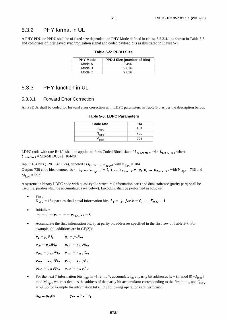
ETSI
ETSI TS 103 357 V1.1.1 (2018-06)23
5.3.2 PHY format in UL
A PHY PDU or PPDU shall be of fixed size dependant on PHY Mode defined in clause 5.2.3.4.1 as shown in Table 5-5 and comprises of interleaved synchronization signal and coded payload bits as illustrated in Figure 5-7.
Table 5-5: PPDU Size
PHY Mode PPDU Size (number of bits) Mode A 2 496 Mode B 9 616 Mode C 9 616
5.3.3 PHY function in UL
5.3.3.1 Forward Error Correction
All PSDUs shall be coded for forward error correction with LDPC parameters in Table 5-6 as per the description below.
Table 5-6: LDPC Parameters
Code rate 1/4 Kldpc 184
Nldpc 736
Mldpc 552
LDPC code with rate R=1/4 shall be applied to form Coded Block size of �����������=4 × ���������� where ����������= SizeMPDU, i.e. 184-bit.
Input: 184 bits (128 + 32 + 24), denoted as ��, �, … , ������ with Kldpc = 184
Output: 736 code bits, denoted as ��, �, … , ������� = ��, �, … , ������, ��, �, � , … , ������� , with Nldpc = 736 and
Mldpc = 552
A systematic binary LDPC code with quasi-cyclic structure (information part) and dual staircase (parity part) shall be used, i.e. parities shall be accumulated (see below). Encoding shall be performed as follows:
• First: Kldpc = 184 parities shall equal information bits: �� = �� , ��� � = 0,1, … ,���� − 1
• Initialize: �� = � = � = ⋯ = �������
= 0
• Accumulate the first information bit, i0, at parity bit addresses specified in the first row of Table 5-7. For
example, (all additions are in GF(2)):
� = ���� �� = �����
��� = ������ �� = �� ���
� �� = � ����� ���� = �������
��� = ������ �� � = �� ����
���� = ������� ���� = �������
• For the next 7 information bits, im, m =1, 2, ..., 7, accumulate im at parity bit addresses [x + (m mod 8)×Qldpc]
mod Mldpc, where x denotes the address of the parity bit accumulator corresponding to the first bit i0, and Qldpc
= 69. So for example for information bit i1, the following operations are performed:
��� = ����� ��� = �����

ETSI
ETSI TS 103 357 V1.1.1 (2018-06)24
��� = ����� � � = � ���
� �� = � ���� �� � = �� ���
���� = ������ ���� = ������
�� = ���� �� = ����
• For the 9th information bit i8, the addresses of the parity bit accumulators are given in the second row of
Table 5-7. In a similar manner the addresses of the parity bit accumulators for the following 7 information bits im, m = 9, 10, ..., 15 are obtained using the formula [ x + (m mod 8)×Qldpc] mod Mldpc, where x denotes the
address of the parity bit accumulator corresponding to the information bit i8, i.e. the entries in the second row
of Table 5-7.
• In a similar manner, for every group of 8 new information bits, a new row from the Table 5-7 is used to find the addresses of the parity bit accumulators.
After all of the information bits are exhausted, the final parity bits shall be obtained by accumulation as follows:
• Sequentially perform the following operations starting with i = 1:
�� = ������ ��� � = 1, 2, …, Mldpc -1
• Final content of pi , i = 0, 1,.., Mldpc -1 is equal to the parity bit pi.
Table 5-7: Parity bit addresses for LDPC code
Row and col index 1 2 3 4 5 6 7 8 9 10 1 1 7 90 172 209 359 401 420 483 487 2 57 164 192 197 284 307 174 356 408 425 3 22 50 191 379 385 396 427 445 480 543 4 32 49 71 234 255 286 297 312 537 550 5 30 70 88 111 176 201 283 322 419 499 6 86 94 177 193 266 368 373 389 475 529 7 134 223 242 254 285 319 403 496 503 534 8 18 84 106 165 170 199 321 355 386 410 9 129 158 226 269 288 316 397 413 444 549
10 33 113 133 194 256 305 318 380 507 11 317 354 402 12 53 64 374 13 83 314 378 14 162 259 280 15 166 281 486 16 185 439 489 17 119 156 224 18 26 62 244 19 8 246 482 20 15 72 91 21 43 69 390 22 127 186 506 23 55 81 412
5.3.3.2 Rate Matching
The output from FEC, coded block of size �����������, shall follow the Rate matching procedure based on parameters defined in Table 5-8 and as per steps illustrated in Figure 5-8 and described below.

ETSI
ETSI TS 103 357 V1.1.1 (2018-06)25
Figure 5-8: Rate match procedure
Table 5-8: Rate match parameters
Size (bits) Mode A Mode B Mode C ����������� 736 ��������� 1 656 4 800 �� �� �� 3 7 ������ 4
Output from FEC shall be repeated �������� times, where:
�������� � ��������� �������
����������
Excessive bits shall be removed to match PPDU payload size ���� ������� by applying puncturing to Nth coded block as described below.
For PHY Mode A, puncturing shall be performed such that only every 4th bit of coded block remains. This is depicted in Figure 5-9.
For PHY Mode B and PHY Mode C, puncturing shall be performed in steps:
• Remove 1st 184 bits from coded block N
• Partition remaining block into 24 sub-blocks of length 23 bits each
• Apply puncturing such that only 16 out of 23 bit remains from each sub-block
This is depicted in Figure 5-10.
Figure 5-9: Puncturing for PHY Mode A
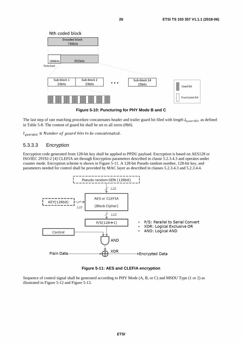
ETSI
ETSI TS 103 357 V1.1.1 (2018-06)26
Figure 5-10: Puncturing for PHY Mode B and C
The last step of rate matching procedure concatenates header and trailer guard bit filed with length �� ������ as defined in Table 5-8. The content of guard bit shall be set to all zeros (0b0).
�� ������ ≡ ������� !�"�#��$%$���&�'&"$�'"$�#.
5.3.3.3 Encryption
Encryption code generated from 128-bit key shall be applied to PPDU payload. Encryption is based on AES128 or ISO/IEC 29192-2 [4] CLEFIA set through Encryption parameters described in clause 5.2.3.4.3 and operates under counter mode. Encryption scheme is shown in Figure 5-11. A 128-bit Pseudo random number, 128-bit key, and parameters needed for control shall be provided by MAC layer as described in clauses 5.2.3.4.3 and 5.2.3.4.4.
Figure 5-11: AES and CLEFIA encryption
Sequence of control signal shall be generated according to PHY Mode (A, B, or C) and MSDU Type (1 or 2) as illustrated in Figure 5-12 and Figure 5-13.

ETSI
ETSI TS 103 357 V1.1.1 (2018-06)27
Figure 5-12: Output of control signal for PHY Mode A
Figure 5-13: Output of control signal for PHY Mode B and C
5.3.3.4 Synchronization Signal Insertion
The rate matched PPDU payload including the guard bits shall be concatenated with a synchronization signal of length ���� where:
Lsync= 832 bits (Mode A) and 4 808 bits (Mode B and C)
Synchronization signal shall be a truncated gold code with polynomials as follows:
M-Sequence 1: p1(x) = x[25] + x[3] + 1
M-Sequence 2: p2(x) = x[25] + x[3] + x[2] + x[1] + 1
This is shown in Figure 5-14.
Initial state of generator polynomials shall be set to a value as per clause 5.2.3.4.4. The states of polynomials shall be initialized to the value of PPDU.
Figure 5-14: Synchronization Signal Generator
M-Sequence 1
p1(x)=x[25]+x[3]+1
M-Sequence 2
p2(x)=x[25]+x[3]+x[2]+x[1]+1
XOR

ETSI
ETSI TS 103 357 V1.1.1 (2018-06)28
5.3.3.5 Interleaving
5.3.3.5.1 Mode A Interleaver
The input to interleaver comprises of:
• 832 synchronization signal bits denoted by bs0, bs1…bs831
• 8 guard bits denoted by bg0, bg1…bg7
• 1 656 encoded bits denoted by be0, be1…be1655
The interleaver shall follow below procedure:
• First two synchronization signal bits are each followed by two guard bits in order, i.e. bs0 bg0 bg1 bs1 bg2 bg3
• The next 828 synchronization signal bits are each followed by two encoded bits in order, i.e. bs2 be0 be1 bs3 be2
be3…. bs828 be1652 be1653 bs829 be1654 be1655
• The last two synchronization signal bits are each followed by two guard bits in order, i.e. bs830 bg4 bg5 bs831
bg6 bg7
The resultant interleaving pattern is illustrated in Figure 5-15.
Figure 5-15: Interleave pattern, Mode A
5.3.3.5.2 Mode B and C Interleaver
The input to interleaver comprises of:
• 4 808 synchronization signal bits denoted by bs0, bs1…bs4807
• 8 guard bits denoted by bg0, bg1…bg7
• 4 800 encoded bits denoted by be0, be1…be4799
The interleaver shall follow below procedure:
• First four synchronization signal bits are each followed by one guard bit in order, i.e. bs0 bg0 bs1 bg1 …bs3 bg3
• The next 4 800 synchronization signal bits are each followed by one encoded bit in order, i.e. bs4 be0 bs5 be1
…. bs4803 be4799
• The last four synchronization signal bits are each followed by one guard bit in order, i.e. bs4804 bg4 bs4805 bg5
…bs4807 bg7
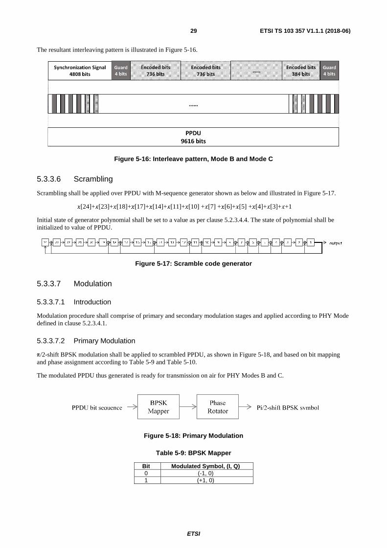
ETSI
ETSI TS 103 357 V1.1.1 (2018-06)29
The resultant interleaving pattern is illustrated in Figure 5-16.
Figure 5-16: Interleave pattern, Mode B and Mode C
5.3.3.6 Scrambling
Scrambling shall be applied over PPDU with M-sequence generator shown as below and illustrated in Figure 5-17.
�[24]+�[23]+�[18]+�[17]+�[14]+�[11]+�[10] +�[7] +�[6]+�[5] +�[4]+�[3]+�+1
Initial state of generator polynomial shall be set to a value as per clause 5.2.3.4.4. The state of polynomial shall be initialized to value of PPDU.
Figure 5-17: Scramble code generator
5.3.3.7 Modulation
5.3.3.7.1 Introduction
Modulation procedure shall comprise of primary and secondary modulation stages and applied according to PHY Mode defined in clause 5.2.3.4.1.
5.3.3.7.2 Primary Modulation
π/2-shift BPSK modulation shall be applied to scrambled PPDU, as shown in Figure 5-18, and based on bit mapping and phase assignment according to Table 5-9 and Table 5-10.
The modulated PPDU thus generated is ready for transmission on air for PHY Modes B and C.
Figure 5-18: Primary Modulation
Table 5-9: BPSK Mapper
Bit Modulated Symbol, (I, Q) 0 (-1, 0) 1 (+1, 0)
24 23 22 21 20 19 18 17 16 15 14 13 12 11 10 9 8 7 6 5 4 3 2 1 outputX X X X X X X X XXXX

ETSI
ETSI TS 103 357 V1.1.1 (2018-06)30
Table 5-10: Phase Rotator
b[n], Mod(n,4) Radian 0 +π × (0/2) 1 +π × (1/2) 2 +π × (2/2) 3 +π × (3/2)
5.3.3.7.3 Secondary Modulation
If PHY Mode is set to Mode A in clause 5.2.3.4.1, then secondary modulation shall be applied to primary modulated PPDU.
Secondary modulation shall be a linear chirp sequence derived from chirp rate β = 387,430 kHz/s and applied over π/2-shift BPSK modulated signal.
The resultant sweep frequency is defined as:
∆��������� � � � ���
The value of TPPDU is defined in Table 5-1.
Figure 5-19: Chirp Modulation
5.3.4 PHY Procedures
5.3.4.1 Overview
The UL physical layer uses randomization in time and frequency for PPDU transmissions to achieve high system capacity. Channel Access parameters defined in clause 5.2.3.4.6 determines if transmission is asynchronous or synchronous. While time synchronization may be achieved using various methods, "Synchronous Pattern-1" relies on GPS time. "Transmission Type" parameter in Table 5-4 has reserved values to allow other synchronous patterns and methods in future.
5.3.4.2 Synchronous Pattern-1
5.3.4.2.1 Frame structure
If "Transmission Type" in Table 5-3 is set to "1", then transmission of PPDUs shall be carried out by EPs in a synchronous manner according to procedure specified in this clause.

ETSI
ETSI TS 103 357 V1.1.1 (2018-06)31
In time domain, a frame structure is employed as per parameters "Frame Duration" and "Slot Duration" in Table 5-4. A resultant frame with a grid structure is illustrated in Figure 5-20 for Mode A. For example, a 5 s frame with 8 ms slot duration leads to 625 slots. Each such slot is indexed using parameter called Grid Position (GP). All or some of the slots within frame may be used for UL data transmission. This is determined by parameter "UL Data Slots" in Table 5-4.
Similar frame structure is employed for Modes B and C using parameters in Table 5-4.
The start of a PPDU transmission shall be aligned to start of one of the available data slots which is selected together with a transmit frequency according to hopping procedure specified in clause 5.3.4.2.2.
Figure 5-20: Lfour Transmission Frame Example - Mode A
5.3.4.2.2 Time and frequency hopping
Lfour enabled EPs shall perform frequency hopping for initial and repetition PPDUs and time-slot hopping within defined frame for initial PPDU as a function of following parameters:
• FH_RNG denotes available number of channels in the "Operation Band" as defined in clause 5.2.3.4.5.
• GP_RNG denotes available number of grid positions indicated by parameter "UL Data Slots" in Table 5-4.
• TXID denotes 32-bit address used as MAC header as defined in clause 5.2.3.2.
• GPSTIME denotes 32-bit GPS time of transmission composed of 12-bit MSBs of GPS weeks (GPSW) followed by 20-bit LSBs of GPS week-seconds (GPSWS).
Where:
- GPSW = floor(AccumulatedSeconds / 60 × 60 × 24 × 7);
- GPSWS = modulo(AccumulatedSeconds, 60 × 60 × 24 × 7); and
- AccumulatedSeconds is duration in seconds since date 1980/1/6 00:00:00.
The frequency channel index (CH) and GP shall be determined for initial and repetition PPDUs using following steps:
• Calculate size of pseudo-random seed PRN_BW as:
PRN_BW = ceil(log2(MPATH))
Where:
MPATH = GP_RNG × (FH_RNG ^ (Nrepetitions+1))

ETSI
ETSI TS 103 357 V1.1.1 (2018-06)32
• Calculate scaling factor α as:
α = ceil( (MPATH/ (POWER2 - 1)) × 64) / 64
Where:
POWER2 = 2 ^ (PRN_BW)
• Calculate seed MSEEDraw of size "PRN_BW" bits using procedure specified in clause 5.3.4.2.3.
• Derive candidate MSEEDcand as follows:
MSEEDcand = floor(MSEEDraw × α)
• If MSEEDcand<MPATH, then MSEED = MSEEDcand; else, repeat process to derive MSEEDcand from
regenerated MSEEDraw until MSEEDcand<MPATH or up to four attempts, whichever condition is satisfied
first.
• If MSEEDcand<MPATH, then MSEED = MSEEDcand; else MSEED = MSEEDcand/2.
• Derive GP using divmod moderator as follows:
Divmod(MSEED, GP_RNG) = {GP, QUO[0]}
The GP shall be used for transmission start time of initial PPDU and repeated PPDUs.
• Derive CH0, CH1…CHn where n=Nrepetitions using divmod operator iteratively as follows:
Divmod(QUO[0], FH_RNG) = {CH0, QUO[1]},
Divmod(QUO[1], FH_RNG) = {CH1, QUO[2]} and so on up to
Divmod(QUO[n], FH_RNG) = {CHn, QUO[1]}
The CH0 shall be used for transmission frequency of initial PPDU and CH1…CHn for that of repeated PPDUs
respectively.
This process is illustrated in Figure 5-21.

ETSI
ETSI TS 103 357 V1.1.1 (2018-06)33
Figure 5-21: Determination of time-slot and frequency channel for transmission
5.3.4.2.3 Pseudo-random seed generation
A PRN generator comprises of two LFSRs, LFSR1 and LFSR2 respectively, where:
LFSR1 uses 32-bit shift register initialized to polynomial TXID as defined in clause 5.3.4.2.2 and with polynomial P(x) in its feedback path:
P(x) = x[32] + x[7] + x[5] + x[3] + x[2] + x[1] + 1
LFSR2 uses 32-bit shift register initialized to polynomial GPSTIME as defined in clause 5.3.4.2.2 and with polynomial Q(x) in its feedback path:
Q(x) = x[32] + x[30] + x[17] + x[12] + x[3] + x[1] + 1
A bit-wise XOR is performed on outputs of LFSR1 and LFSR2 to generate unique PRN seeds denoted by "MSEEDraw"
of size "PRN_BW" iteratively.

ETSI
ETSI TS 103 357 V1.1.1 (2018-06)34
This process is illustrated in Figure 5-22.
Figure 5-22: PRN Generator for Synchronous Pattern-1
5.4 Radio characteristics
5.4.1 Overview
Lfour enabled EP shall be configured to comply with the regional harmonized or global regulations applicable to spectrum of use. An EP may be configured to operate in more than one, i.e. non-contiguous frequency bands.
5.4.2 Band-plan
Lfour UL operation requires frequency spectrum of at least 200 kHz for Access Type "0" and at least 600 kHz for Access Type values "1..6", where Access Type refers to parameter defined in clause 5.2.3.4.6.
If total bandwidth of Operation Band(s) defined in clause 5.2.3.4.5 is more than 200 kHz, then the band(s) are split evenly in channels of 200 kHz each and frequency of operation fc, shall be defined at centre frequency of each channel.
A channel of operation is denoted by BWUL-Ch. This channelization shall apply to all PHY modes.

ETSI
ETSI TS 103 357 V1.1.1 (2018-06)35
6 Telegram splitting ultra narrow band (TS-UNB) family
6.1 Overview
6.1.1 General description
The TS-UNB family is a low power wide area network with star topology based on an UNB approach using Telegram Splitting Multiple Access (TSMA). TSMA is a random channel access method wherein the radio transmission of a packet is divided into several short radio-bursts, which are sent discontiguous over the radio channel with transmission-free time intervals in between. The radio-bursts are pseudo-randomly distributed over time and frequency within a radio frame. This method offers high interference resilience against radio transmissions of other radio devices, either from own or foreign radio systems, since only a part of the radio-bursts need to be received by the base station to decode the transmitted payload.
Randomness is achieved by crystal reference tolerance, additional message dependant frequency offset and random channel access in time due to the asynchronous mode of system operation. The start of communication is initiated by the end-point at any time transmission data is available. No network synchronization is needed. The protocol supports Class Z (uplink only) and Class A (bidirectional) end-points. The downlink communication is triggered by an uplink transmission. After the reception of an uplink transmission, the base station may send a downlink transmission after a defined period of time.
To further keep transmission duration short, especially for battery or energy harvesting operated end-points, channel coding together with coherent MSK or GMSK demodulation is used to increase the sensitivity in the receiver to a level of -139 dBm without narrowing the signal bandwidth too much. Hence for the transmission of application data with a size of 10 bytes, the accumulated on air radio transmission time is less than 400 ms. Therefore TS-UNB offers ultra-low power consumption down to 10 µWh per message in the end-point and can be operated also in a low-duty cycle band (DC=0,1 %). Due to the ultra-narrowband and short-time transmission as well as the high interference resilience TS-UNB can reliably handle a network capacity of more than one million messages per day and per base station within a 200 kHz spectrum.
The TS-UNB family is capable of handling variable application data with a length of up to 245 bytes in uplink and up to 250 bytes in downlink. The protocol is optimized for an application data length of 10 bytes, which builds the core frame of the TS-UNB protocol. Data is encrypted with AES128. For authentication and integrity check a 32 Bit Cipher-based Message Authentication Code (CMAC) is added to the MAC Protocol Data Unit. A 24 bit packet counter is used for replay protection. An optional variable MAC mode can be used for user specific MAC functionalities.
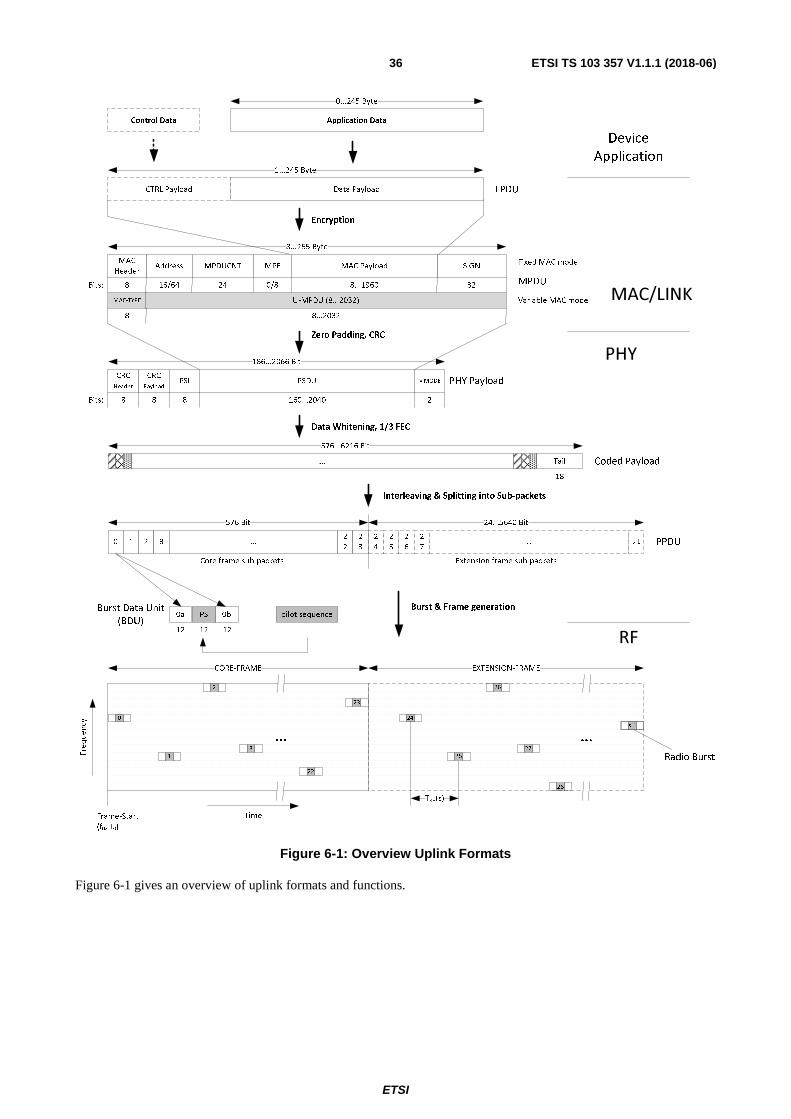
ETSI
ETSI TS 103 357 V1.1.1 (2018-06)36
Figure 6-1: Overview Uplink Formats
Figure 6-1 gives an overview of uplink formats and functions.
0a 0bPSBurst Data Unit
(BDU)
0 1 2 3 ...2
2
2
3
Core frame sub-packets
1
2
3
Frame-Start
(f0, T0)
23
0
CORE-FRAME
22
...
PSDU
186...2066 Bit
CRC
Header
CRC
PayloadPSI MMODE
8 8 8 2160...2040
576...6216 Bit
...
Interleaving & Splitting into Sub-packets
pilot sequenceBurst & Frame generation
12 12 12
8...255 Byte
Address MPDUCNT
16/64 24
SIGN
32
MAC
Header
8
Data Payload
1...245 Byte
25
26
27
24
EXTENSION-FRAME
28
TRB(s)
2
4
2
5
2
6
2
7... s-1
MAC Payload
Data Whitening, 1/3 FEC
8...1960
MAC/LINK
PHY
Time
s-1
Encryption
CTRL Payload
Application Data
0...245 Byte
Tail
18
Extension frame sub-packets
576 Bit 24...5640 Bit
LPDU
MPDU
PHY Payload
Zero Padding, CRC
...
PPDU
Coded Payload
RF
Radio Burst
Control Data
Device
Application
MPF
0/8
MAC-TYPE U-MPDU (8...2032)
Fixed MAC mode
Bits:
Bits:
Variable MAC mode
8 8...2032

ETSI
ETSI TS 103 357 V1.1.1 (2018-06)37
Figure 6-2: Overview Downlink Formats
Figure 6-2 gives an overview of the DL-TS and DL-SB formats and functions.
6.1.2 Modes of operation
The TS-UNB protocol offers several modes of operation in up- and downlink. If a LTN System is using TS-UNB protocol, it shall implement one subset of the different modes of operation according to Table 6-1. Some recommended sets of modes called profiles can be found in the annex A. The input data at the end-point for uplink communication according to the TS-UNB protocol (see clause 6.3.2) shall be the application data from a device application (e.g. sensor data sensed or generated by a sensor of the end-point). A LTN System using TS-UNB protocol shall support uplink only communication (class Z devices) and may optionally also support bidirectional communication with uplink triggered downlink (class A devices). In uplink a LTN system using TS-UNB protocol shall support UL-ULP symbol rate and may optionally also support UL-ER symbol rate. In downlink either telegram splitting (DL-TS mode) or single burst transmission (DL-SB mode) may be used. No support of relay points is foreseen in the TS-UNB protocol.
0A0
8 12
B0
8
252 Bit
...
Interleaving & Splitting in Sub-packets
TSI
78 Bit
CRCPSI
Tail
8 414
SYNC
48
...
Frame-Start
(f0, T0)
CORE-FRAME
...
EXTENSION-FRAME
...
Frequency
Time
0b 0aPS
Radio Burst
pilot sequence
8 12
PS
8
0c
0..12 0..11
E
F
I
1
Data Payload
1...250 Byte
CTRL Payload
Application Data
0...250 Byte
Data Whitening, 1/3 FEC
0 1 2 3
Core frame sub-packets
4 5 6 7 8
BPSDU-0
66...202 Bit
CRCR
8256...192
6...255 Byte
SIGN
32
MAC
Header
8
MAC Payload
Encryption
216...624 Bit
...
Interleaving & Splitting in Sub-packets
Data Whitening, 1/3 FEC
0 1 2 3 ... 17
Extension frame sub-packets
...
Tail
Radio BurstBurst & Frame generation
1818
BPSDU-1
66...202 Bit
CRCR
8296...192
BPSDU-b
66...202 Bit
CRCR
82...192
PSI = MPDU size
BLOCK 0 BLOCK b
17
0
1
2
3
0
1
2
9
8
Burst & Frame generation
PHY Payload
Blocks
MPDU
LPDU
Block slicing &CRC
...
17
0
1
2
MAC/LINK
PHY
R
1
DL-TS Profile only
PPDU PPDU
BDU
RF
...
8...2000
PPDU-0
Radio
Burst
Control Data Device
Application
MPF
0/8
2
M
TSIPSI R PSDUE
F
I
MMODE
81 114 2
PHY Payload
Zero Padding
56...2040
Bits:
MAC-TYPE U-MPDU
Fixed MAC mode
Variable MAC mode
Bits:
Bits:
8 8...2032
Bits:

ETSI
ETSI TS 103 357 V1.1.1 (2018-06)38
Table 6-1: TS-UNB Modes of operation
Uplink Downlink MAC Mode Fixed MAC
Variable MAC (e.g. MAC-TYPE=WMBUS) PHY Mode Telegram Splitting (TS) Single Burst Modulation (G)MSK (G)MSK GFSK Symbolrate ULP: 2 380,371 Sym/s (MCL: 153 dB)
ER: 396,729 Sym/s (MCL: 164 dB) DL-TS-ULP: 2 380,371 Sym/s
(MCL: 161 dB) DL-SB: 600 Sym/s
(MCL: 152 dB) TSMA Mode Narrow (Carrier spacing: 396,729 Hz)
Standard (Carrier spacing: 2 380,371 Hz) Wide (Carrier spacing: 28 564,453 Hz)
None
Sync Burst on/off off Retransmission on/off off
Channels Single Channel Dual Channel
NOTE 1: Uplink MCL based on transmit power of PTX = 14 dBm and Noise figure of 4 dB. NOTE 2: Downlink MCL based on transmit power of PTX = 27 dBm and Noise figure of 8 dB.
6.2 Link Layer
6.2.1 Link Layer Overview
The Link Layer shall handle control procedures required to establish and maintain a connection between an end-point and a base station. The Link Layer definition shall be applied to the fixed MAC mode and can also be applied to the variable MAC mode of the present document.
Figure 6-3: Link Layer interfaces with adjacent layers on the Base Station
6.2.2 Link Layer Format
6.2.2.1 Link Layer Protocol Data Unit (LPDU)
Table 6-2: Link Layer Protocol Data Unit (LPDU) Format
Bytes: 1 1 Variable 1 Variable Variable (0 to 245) Control Length
Control Segment 1 Control Segment n Data Payload Control
Header 1 Control Body1
… Control Header n
Control Body n
Control Payload; Only present if MAC Header Control flag = 1

ETSI
ETSI TS 103 357 V1.1.1 (2018-06)39
The control flag in the MAC Header (see clause 6.3.2.2.2) shall determine whether a control payload is present in the packet or not. The control payload of the LPDU shall comprise the control length field and one or more control segments. The control length field shall specify the total length in bytes of all control segments of the control payload.
6.2.2.2 Control Segment
6.2.2.2.1 Overview
The control segments shall consist of the control header and the control body. The control header specifies the type and the size of the control segment. The control header values according to Table 6-3 shall be used for the fixed MAC mode of the TS-UNB protocol.
Table 6-3: Link Layer Control Segments
Control Header
Direction Control Segment Name Control Segment Size
0x10 UL Attach Request 11 Bytes 0x11 UL Attach Request IPv6 19 Bytes 0x14 DL Attach Accept 5 Bytes 0x18 UL,DL Detach Request 5 Bytes 0x1C DL,UL Detach Accept 5 Bytes 0x20 DL DLRX-Status Query 1 Byte 0x21 UL DLRX-Status Response 3 Bytes 0x24 DL Link Adaptation Request 3 Bytes 0x25 UL Link Adaptation Confirm 1 Byte
0xC0-0xFF UL,DL User specific control segments User specific Others Reserved
6.2.2.2.2 Attach Request
The attach request control segment shall be used to attach the end-point to the base station. The following format shall be used, if an end-point does not support IPv6 addressing.
Table 6-4: Attach Request Control Segment Format
Bytes: 1 2 4 4 Control Header Control Body
0x10 End-point Info Nonce User Signature
If the end-point can handle IPv6 addressing, it may use the IPv6 attach request control segment according to Table 6-5 to transmit the IPv6 subnet information to the base station.
Table 6-5: Attach Request IPv6 Control Segment Format
Bytes: 1 2 8 4 4 Control Header Control Body
0x11 End-point Info IPv6 Subnet Nonce User Signature
Nonce and user signature fields are user specific and should be used in the application layer to derive the network key in the end-point and the service centre from the pre-shared private key.
The end-point info field signals the end-point capabilities to the base station. The end-point info field shall have the format according to Table 6-13 in clause 6.2.2.3.
6.2.2.2.3 Attach Accept
The base station shall send a message with an attach accept control segment to answer the attach request received from the end-point. The attach accept control segment shall have the format according to Table 6-6.

ETSI
ETSI TS 103 357 V1.1.1 (2018-06)40
Table 6-6: Attach Accept Control Segment Format
Bytes: 1 2 2 Control Header Control Body
0x14 End-point Info short address
The end-point info field is used by the base station to select the actual capabilities to use from the capabilities advertised by the end-point in the attach request control segment. The bit positions are according to Table 6-13. The short address is a 16 bit address, which shall be assigned by the base station to the end-point.
6.2.2.2.4 Detach Request
If an end-point needs to disconnect from the network, the end-point shall send a message with a detach request control segment according to Table 6-7 to the base station. A base station may also send a detach request to an end-point to disconnect the end-point from the network.
Table 6-7: Detach Request Control Segment Format
Bytes: 1 4 Control Header Control Body
0x18 User Signature
The user signature field may be used by the application to authenticate the detach request and may not be processed within the domain of the base station.
6.2.2.2.5 Detach Accept
A detach request from an end-point shall be answered with a detach accept control segment by the base station. A detach request from a base station shall be answered with a detach accept control segment by the end-point. The detach accept control segment shall have the format according to Table 6-8.
Table 6-8: Detach Accept Control Segment Format
Bytes: 1 4 Control Header Control Body
0x1C User Signature
The user signature field may be used by the application to authenticate the detach request and may not be processed within the domain of the base station.
6.2.2.2.6 DLRX Status Query
The DLRX Status Query can be sent from the base station to an EP to request a DLRX Status Response from the EP.
Table 6-9: DLRX Status Query Control Segment Format
Bytes: 1 Control Header
0x20
6.2.2.2.7 DLRX Status Response
The DLRX Status Response is sent by an EP after receiving a DLRX Status Query from the base station.
Table 6-10: DLRX Status Response Control Segment Format
Bytes: 1 1 1 Control Header Control Body
0x21 RSSI Signal to noise ratio

ETSI
ETSI TS 103 357 V1.1.1 (2018-06)41
The RSSI is provided as unsigned fixed point with a least significant bit value of 1dBm and an offset of -174 dBm.
The signal to noise ratio is provided as signed fixed point with a least significant bit value of 0,5 dB.
6.2.2.2.8 Link Adaptation Request
If the base station needs to change the configuration of the connection with an end-point, it shall send a Link Adaptation Request control segment. The requested configuration shall conform to the end-point capabilities announced during the attachment procedure.
Table 6-11: Link Adaptation Control Segment Format
Bytes: 1 2 Control Header Control Body
0x24 End-point Info
6.2.2.2.9 Link Adaptation Confirm
If an end-point receives a Link adaptation request control segment from a base station, it shall respond with a Link adaptation confirm control segment.
Table 6-12: Link Adaptation Confirm Control Segment Format
Bytes: 1 Control Header
0x25
6.2.2.3 End-point Info Field
The end-point info field is used to negotiate TS-UNB protocol settings between end-point and base station. In the attach request control segment, this field shall indicate the end-point capabilities to the base station. In the attach accept control segment the base station shall announce the configuration of the connection to the end-point via end-point info field. The end-point info field shall be formatted according to Table 6-13.
Table 6-13: End-Point Info Field Format
Bit Function Direction Description 0 Channel Use UL 0: Single channel
1: Dual channel 1 Repetition UL 0: Repetitions not used
1: Repetitions used 2 Carrier Offset value UL 0: nco = 3
1: nco = 11
3 DL Interblock Distance
DL 0: short (TDN = 512) 1: long (TDN = 7 168)
4 UL-TS-ULP UL 0: UL-TS-ULP data rate not supported 1: UL-TS-ULP data rate supported
5 UL-TS-ER UL 0: UL-TS-ER data rate not supported 1: UL-TS-ER data rate supported
6 DL-SB DL 0: DL-SB Mode not supported 1: DL-SB Mode supported
7 DL-TS-ULP DL 0: DL-TS mode with ULP data rate not supported 1: DL-TS mode with ULP data rate supported
8-15 Reserved - Reserved for future use, set to zero

ETSI
ETSI TS 103 357 V1.1.1 (2018-06)42
6.2.3 Link Layer Procedures
6.2.3.1 End-point Attachment
6.2.3.1.1 Introduction
Before an end-point and a base station exchange data, the end-point shall be attached to the base station. The end-point attachment procedure provides a base station with information about an end-point required for servicing the end-point and provides the end-point with a short address. Bidirectional end-points may initiate an over-the-air attachment procedure. Unidirectional end-points are pre-attached by the service centre associated with the end-point.
During the attach procedure the end-point shall be configured to the following protocol settings until it is reconfigured by the base station via end-point info field.
Table 6-14: End-point protocol settings during attach procedure
Parameter Setting Channel Use Single channel use
Repetition Repetition off carrier offset value ��� = 3
DL Interblock Distance May be short or long UL-ULP data rate on UL-ER data rate off
6.2.3.1.2 End-point Configuration
The end-point capabilities are advertised to the base station during the attachment procedure. The base station can then select the operational mode to be used from the advertised capabilities. For class Z devices the configuration is static, class A devices can negotiate the configuration during an over-the-air attachment procedure.
6.2.3.1.3 Class Z end-point Attachment
Class Z devices are unidirectional devices and shall be pre-attached to a LTN System during manufacturing of the device. In the pre-attachment procedure the network key, the short address and the end-point info field shall be programmed in the end-point and stored in the service centre.
Figure 6-4: Service centre based attachment procedure (Class Z devices)
The service centre shall provide the base station with the preconfigured network key, short address and end-point info of the end-point.

ETSI
ETSI TS 103 357 V1.1.1 (2018-06)43
6.2.3.1.4 Class A end-point Attachment
Class A devices may be attached over-the air to allow dynamic configuration by the base station.
Figure 6-5: Over-the-air attachment procedure for class A devices
The over-the-air attachment procedure shall start with a message from the end-point to the base station containing an attach request control segment according to clause 6.2.2.2.2. The base station shall forward the attach request from the end-point to the service centre allowing the service centre to verify the end-point identity and to generate the network key. After successful verification the service centre shall provide the network key to the base station. The base station shall then assign a short address to the end-point and shall send a message containing an attach accept control segment to the end-point using the acquired network key for encryption. Further messages from the end-point may use the reduced addressing mode with the assigned short address and shall be encrypted with the network key.
6.2.3.2 End-point Detachment
The over-the-air end-point detachment procedure allows an end-point to deregister from a base station in a controlled manor. It allows the base station to remove end-points from the address resolution and to inform the service centre about the end-point detachment.
Figure 6-6: Over-the-air detachment procedure for class A devices
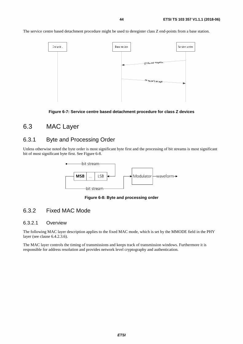
ETSI
ETSI TS 103 357 V1.1.1 (2018-06)44
The service centre based detachment procedure might be used to deregister class Z end-points from a base station.
Figure 6-7: Service centre based detachment procedure for class Z devices
6.3 MAC Layer
6.3.1 Byte and Processing Order
Unless otherwise noted the byte order is most significant byte first and the processing of bit streams is most significant bit of most significant byte first. See Figure 6-8.
Figure 6-8: Byte and processing order
6.3.2 Fixed MAC Mode
6.3.2.1 Overview
The following MAC layer description applies to the fixed MAC mode, which is set by the MMODE field in the PHY layer (see clause 6.4.2.3.6).
The MAC layer controls the timing of transmissions and keeps track of transmission windows. Furthermore it is responsible for address resolution and provides network level cryptography and authentication.

ETSI
ETSI TS 103 357 V1.1.1 (2018-06)45
Figure 6-9: MAC layer interfaces with adjacent layers on the Base Station
In RX direction the MAC layer accepts the MPDU and associated meta information from the PHY layer. The meta information comprises the time of reception, signal quality information and a set of RX parameters. After address resolution and decryption of the LPDU, a set of flags, the end-point EUI and the packet counter are extracted from the MPDU and passed on to the link layer. The signal quality information is also forwarded to the link layer.
In TX direction the MAC layer is provided with the LPDU and associated meta information from the Link layer. The LPDU is combined with flags and addressing information and network level encryption is applied to form the MPDU. The MPDU is passed to the PHY layer with the according transmission time and the set of RX parameters of the associated uplink message. Additionally the message priority is passed through from the link layer to the PHY layer.
Figure 6-10: MAC Layer interfaces with adjacent layers on the end-point
6.3.2.2 MAC Formats in UL
6.3.2.2.1 MAC Protocol Data Unit (MPDU)
If the LTN system using the TS-UNB protocol is operated in the fixed MAC mode, the uplink MPDU format according to Table 6-15 shall be used.
Table 6-15: Uplink MPDU Format of fixed MAC mode
Bytes: 1 2 or 8 3 0/1 Variable (1 to 245) 4 MAC Header Address MPDUCNT MPF MAC Payload SIGN
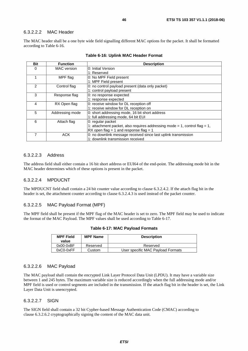
ETSI
ETSI TS 103 357 V1.1.1 (2018-06)46
6.3.2.2.2 MAC Header
The MAC header shall be a one byte wide field signalling different MAC options for the packet. It shall be formatted according to Table 6-16.
Table 6-16: Uplink MAC Header Format
Bit Function Description 0 MAC version 0: Initial Version
1: Reserved 1 MPF flag 0: No MPF Field present
1: MPF Field present 2 Control flag 0: no control payload present (data only packet)
1: control payload present 3 Response flag 0: no response expected
1: response expected 4 RX Open flag 0: receive window for DL reception off
1: receive window for DL reception on 5 Addressing mode 0: short addressing mode, 16 bit short address
1: full addressing mode, 64 bit EUI 6 Attach flag 0: regular packet
1: attachment packet, also requires addressing mode = 1, control flag = 1, RX open flag = 1 and response flag = 1
7 ACK 0: no downlink message received since last uplink transmission 1: downlink transmission received
6.3.2.2.3 Address
The address field shall either contain a 16 bit short address or EUI64 of the end-point. The addressing mode bit in the MAC header determines which of these options is present in the packet.
6.3.2.2.4 MPDUCNT
The MPDUCNT field shall contain a 24 bit counter value according to clause 6.3.2.4.2. If the attach flag bit in the header is set, the attachment counter according to clause 6.3.2.4.3 is used instead of the packet counter.
6.3.2.2.5 MAC Payload Format (MPF)
The MPF field shall be present if the MPF flag of the MAC header is set to zero. The MPF field may be used to indicate the format of the MAC Payload. The MPF values shall be used according to Table 6-17.
Table 6-17: MAC Payload Formats
MPF Field value
MPF Name Description
0x00-0xBF Reserved Reserved 0xC0-0xFF Custom User specific MAC Payload Formats
6.3.2.2.6 MAC Payload
The MAC payload shall contain the encrypted Link Layer Protocol Data Unit (LPDU). It may have a variable size between 1 and 245 bytes. The maximum variable size is reduced accordingly when the full addressing mode and/or MPF field is used or control segments are included in the transmission. If the attach flag bit in the header is set, the Link Layer Data Unit is unencrypted.
6.3.2.2.7 SIGN
The SIGN field shall contain a 32 bit Cypher-based Message Authentication Code (CMAC) according to clause 6.3.2.6.2 cryptographically signing the content of the MAC data unit.
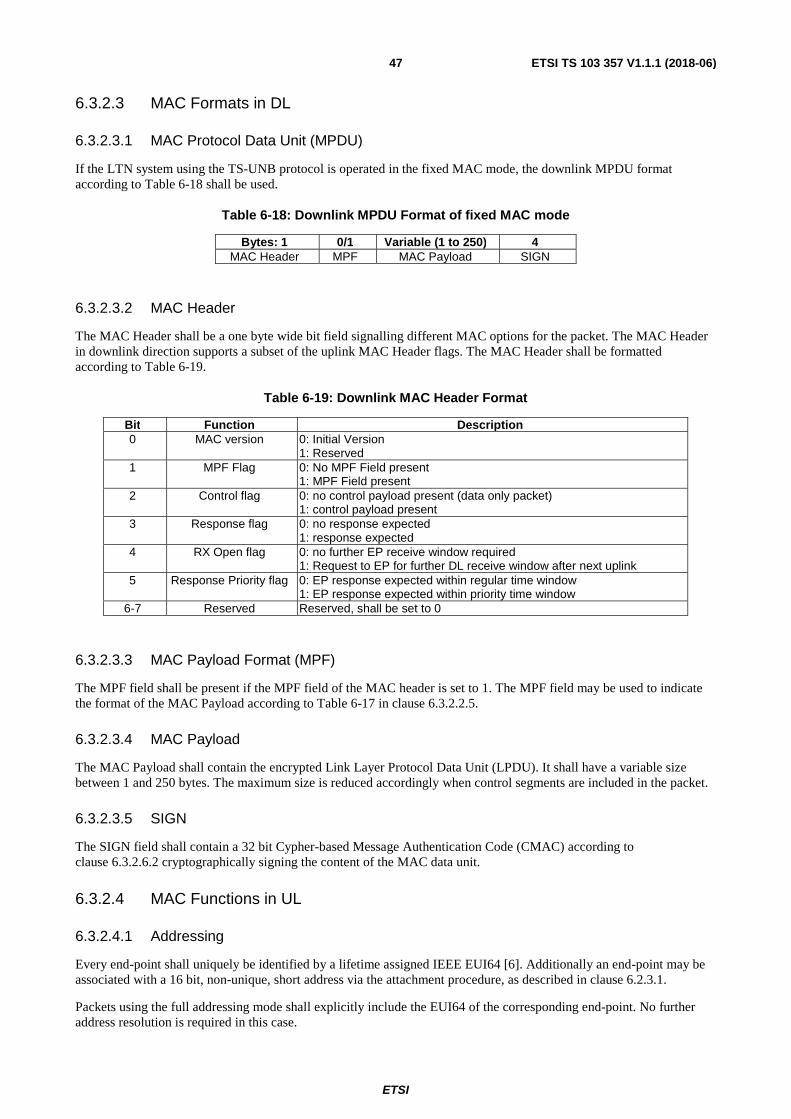
ETSI
ETSI TS 103 357 V1.1.1 (2018-06)47
6.3.2.3 MAC Formats in DL
6.3.2.3.1 MAC Protocol Data Unit (MPDU)
If the LTN system using the TS-UNB protocol is operated in the fixed MAC mode, the downlink MPDU format according to Table 6-18 shall be used.
Table 6-18: Downlink MPDU Format of fixed MAC mode
Bytes: 1 0/1 Variable (1 to 250) 4 MAC Header MPF MAC Payload SIGN
6.3.2.3.2 MAC Header
The MAC Header shall be a one byte wide bit field signalling different MAC options for the packet. The MAC Header in downlink direction supports a subset of the uplink MAC Header flags. The MAC Header shall be formatted according to Table 6-19.
Table 6-19: Downlink MAC Header Format
Bit Function Description 0 MAC version 0: Initial Version
1: Reserved 1 MPF Flag 0: No MPF Field present
1: MPF Field present 2 Control flag 0: no control payload present (data only packet)
1: control payload present 3 Response flag 0: no response expected
1: response expected 4 RX Open flag 0: no further EP receive window required
1: Request to EP for further DL receive window after next uplink 5 Response Priority flag 0: EP response expected within regular time window
1: EP response expected within priority time window 6-7 Reserved Reserved, shall be set to 0
6.3.2.3.3 MAC Payload Format (MPF)
The MPF field shall be present if the MPF field of the MAC header is set to 1. The MPF field may be used to indicate the format of the MAC Payload according to Table 6-17 in clause 6.3.2.2.5.
6.3.2.3.4 MAC Payload
The MAC Payload shall contain the encrypted Link Layer Protocol Data Unit (LPDU). It shall have a variable size between 1 and 250 bytes. The maximum size is reduced accordingly when control segments are included in the packet.
6.3.2.3.5 SIGN
The SIGN field shall contain a 32 bit Cypher-based Message Authentication Code (CMAC) according to clause 6.3.2.6.2 cryptographically signing the content of the MAC data unit.
6.3.2.4 MAC Functions in UL
6.3.2.4.1 Addressing
Every end-point shall uniquely be identified by a lifetime assigned IEEE EUI64 [6]. Additionally an end-point may be associated with a 16 bit, non-unique, short address via the attachment procedure, as described in clause 6.2.3.1.
Packets using the full addressing mode shall explicitly include the EUI64 of the corresponding end-point. No further address resolution is required in this case.

ETSI
ETSI TS 103 357 V1.1.1 (2018-06)48
The reduced addressing mode shall be based on 16 bit explicit addressing using the short address assigned by the base station and 32 bit implicit addressing via the CMAC. Hence packets using the reduced addressing mode require the end-point identity to be derived from the included short address and the cryptographic signature contained in the CMAC.
6.3.2.4.2 Packet Counter
A 32 bit packet counter shall be used to the track the number of transmitted uplink packets in the end-point and the base station.
Table 6-20: Packet Counter Format
Bit 0 to 7 Bit 8 to 31 Extended Counter value MPDUCNT value
(transmitted) Packet Counter (32 Bit)
Every uplink packet except attachment packets shall contain the 24 least significant bits of the packet counter in the MPDUCNT field. The packet counter shall only be reset when a new network key is issued by the service centre during the attachment procedure and shall be incremented after each packet transmission.
6.3.2.4.3 Attachment Counter
A 24 bit attachment counter shall be used in the end-point and service centre to count the number of attachment procedures initiated by the end-point. The attach counter shall be incremented after each attach request message by the end-point. The MPDUCNT field of the MPDU shall be filled with the attach counter in attach request packets. The packet counter is therefore assumed 0 for attach request packets.
6.3.2.4.4 Payload Encryption
The MAC payload and the optional MPF field in uplink shall be encrypted according to clause 6.3.2.6.1.
6.3.2.4.5 Authentication
A CMAC according to clause 6.3.2.6.2 shall be used to authenticate the MAC payload in uplink. The CMAC shall be generated over the MPDU fields MAC Header, Address, MPDUCNT, the optional MPF field, if available and the MAC payload after encrypting the MAC payload as well as the optional MPF field (encrypt then MAC). It shall be preceded with the payload encryption initialization vector IV described in clause 6.3.2.6.2.
Table 6-21: Input Data of CMAC generation in uplink (SIGN field)
Bytes: 8 1 2/8 3 0/1 1 to 245 IV MAC Header Address MPDUCNT MPF MAC Payload
6.3.2.5 MAC Functions in DL
6.3.2.5.1 Addressing
Downlink addressing is done implicitly via the time of transmission and the CMAC included in the Sync field of the downlink core frame. The end-point shall only accept transmissions at the defined time offset ∆��� after the previous uplink transmission, as described in clause 6.3.2.7.1. The comparison of the contained CMAC against the expected CMAC of the end- point rejects packets for other end-points accidentally transmitted simultaneously. Before transmission, the base station shall ensure that a CMAC in a downlink transmission is not considered valid by any other end-points than the intended one with simultaneously opened downlink windows.

ETSI
ETSI TS 103 357 V1.1.1 (2018-06)49
6.3.2.5.2 Packet Counter
The packet counter of the associated uplink shall be implicitly used as packet counter in the downlink transmission. If the associated uplink uses the attach format and therefore includes the attach counter instead of the packet counter, the packet counter for encryption and signature generation shall be assumed 0.
6.3.2.5.3 Payload Encryption
The MAC payload and the optional MPF field in downlink shall be encrypted according to clause 6.3.2.6.1.
6.3.2.5.4 Authentication
A CMAC according to clause 6.3.2.6.2 shall be used to authenticate the MAC payload in downlink. The CMAC shall be generated over the MPDU fields MAC Header, the optional MPF field if available and the MAC payload after encrypting the MAC payload as well as the optional MPF field (encrypt then MAC) and shall be preceded with the payload encryption initialization vector described in clause 6.3.2.6.2.
Table 6-22: Input Data for CMAC Generation in downlink
Bytes: 8 1 0/1 1 to 250 IV MAC Header MPF MAC Payload
6.3.2.6 Common MAC function
6.3.2.6.1 Encryption
The MAC layer handles the network level encryption of the MAC payload. The network level encryption shall be used for all packets except the attach request packet. Network level cryptography shall be based on the 128 bit network key provided through the attachment procedure described in clause 6.2.3.1 and the AES128 algorithm in counter mode of operation [2] and [i.5]. The initialization vector for each block shall be derived from the packet counter, the end-point EUI and the data direction (uplink/downlink).
Table 6-23: Payload encryption initialization vector format
Bytes: 8 1 1 4 2 EUI64 0x00 Data direction Packet counter Block counter
The block counter shall be reset to 0 at the beginning of every packet and shall be incremented for every consecutive 16 byte AES128 block within the packet. Each initialization vector shall only be used once to ensure the security of the encrypted data. Thus the extended counter value increases the usable initialization vector range before a new network key is required due to a counter wrap. The extended counter needs to be synchronized between base station and end-point. If no extended counter is tracked the extended counter field shall be set to 0. The 24 bit packet counter grants a resynchronization window of 16 777 216 packets. Within this window the extended counter shall be implicitly resynchronized at reception. If the number of consecutively lost packets exceeds the window length, the synchronization between end-point and base station shall be recovered. Recovery should be achieved via probing a range of extended counters against the packet authentication. In the case of bidirectional end-points a reattachment, resetting the packet counter and extended counter, also recovers synchronization.
The data direction field shall be set to 0x00 for uplink transmissions and 0x01 for downlink transmissions to allow reusing uplink packet counters in the downlink.
The initialization vector �� shall be AES encrypted with the end-point's network key. The encrypted initialization vector ��∗ shall be truncated to the payload length if the remaining block is shorter than 16 bytes. The payload plaintext block P shall be combined with the encrypted and truncated initialization vector via an exclusive or operation to create the payload cipher text C. ��∗ = ���128���� = ��∗ ⨁

ETSI
ETSI TS 103 357 V1.1.1 (2018-06)50
The procedure shall be repeated after incrementing the block counter within the initialization vector until the entire MAC payload has been processed.
6.3.2.6.2 CMAC generation
A cypher-based Message Authentication Code (CMAC) [3] and [i.6] shall be used to verify the integrity and authenticity of an uplink or downlink packet. AES128 shall be employed as the block cipher algorithm required within the CMAC procedure. The network key provided through the attachment procedure (see clause 6.2.3.1) shall be used as the cryptographic key for the AES128 algorithm to authenticate messages. If the attachment flag is set in the MAC header, the network key shall be substituted with all zeros. The function of the CMAC is then reduced to verification of the packet integrity. The CMAC initialization vector ������ shall formatted according to Table 6-24.
Table 6-24: CMAC initialization vector format
Bytes: 8 1 1 4 2 EUI64 0x00 Data direction Packet counter 0xFFFF
The data direction field shall be set to 0x00 for uplink transmissions and 0x01 for downlink transmissions to allow reusing uplink packet counters in the downlink.
After processing the input data with the CMAC generation procedure the resulting value shall be truncated according to the description in clauses 6.3.2.4.5, 6.3.2.5.4 and 6.4.3.1.1.3.
Verification by the recipient shall be done by generating the CMAC for the received packet with the expected initialization vector and cryptographic key and comparing it against the CMAC transmitted with the packet.
6.3.2.7 MAC Procedures
6.3.2.7.1 Scheduling
In downlink data shall only be transmitted after the reception of an uplink transmission. Hence every downlink transmission needs to be preceded by an uplink transmission of an end-point. After sending an uplink packet to the base station, an end-point may open a downlink window for the reception of a downlink transmission from the base station. The downlink transmission shall start after a predefined time of 16 384 symbols after reception of the uplink transmission. The time is defined as the time between last radio-burst of last transmitted radio frame of the uplink transmission to the first radio-burst of the downlink transmission and is measured from the middle of the pilot sequence of the two radio-bursts.
The downlink window shall be announced in the preceding uplink telegram via the response flag in the MAC Header (see clause 6.3.2.2.2). The MAC layer shall track the time of arrival for uplink transmissions and schedule the according downlink response to meet a time offset according to Table 6-25.
Figure 6-11: Uplink/Downlink Scheduling
Table 6-25 gives the time intervals for the uplink/downlink scheduling.

ETSI
ETSI TS 103 357 V1.1.1 (2018-06)51
Table 6-25: Uplink/downlink time intervals
Parameter Range of values Default Value Description ∆��� 16 384 (±2)
Symbols Time interval between UL and DL transmission in number of symbol time periods
∆��� 512 or 7 168 512 Time interval between blocks of extension frame in number of symbol time periods
∆���� 84…65 532 384 Time interval between core frame and extension frame in number of symbol time periods (4x TSI Value; see clause 6.4.3.3.1.5)
∆��� 5…1 024 120 Maximum time window for a high priority uplink response (Response priority flag = 1) in seconds
NOTE: The symbol time period is based on a symbol rate of 2 380,371 Sym/s.
The time reference shall be the end-point time starting with the transmission of the first radio burst at T0. The base
station estimates the symbol rate offset of the end-point based on the received carrier frequency offset:
∆���~�,�� − �, �� � ��, �� � �
or based on the timing offset of the received radio bursts. Based on the estimated symbol rate offset the downlink symbol rate and carrier frequency shall be adapted.
If the base station expects an uplink message (e.g. for acknowledgment of downlink) it shall set the response flag in the MAC header (see clause 6.3.2.3.2) of the downlink transmission. If the base station expects the end-point uplink response within a limited time, it shall set the response priority flag in the MAC header of the downlink transmission.
If an end-point is ready to receive a downlink transmission from the base station, the end-point shall set the RX open flag in the MAC header field (see clause 6.3.2.3.2). After the predefined time ∆��� after the UL frame (see clause 6.3.2.7.1), the end-point shall open its receive window for the reception of a DL frame from the base station.
If a base station needs to transmit further downlink messages to the end-point, it shall set the RX open flag in the MAC header of the downlink transmission to indicate to the end-point that it shall open its receive window after the next uplink transmission.
6.3.2.7.2 Transmission Acknowledgment
6.3.2.7.2.1 Uplink Message ACK
If an end-point requires a downlink response from the base station after its uplink communication, e.g. for acknowledgment of the uplink message, it shall set the response flag in the MAC header field. Due to the limited duty cycle in the base station transmission, the base station may refuse the downlink transmission.
6.3.2.7.2.2 Downlink Message ACK
If a base station expects an acknowledgment of its downlink transmission, the base station shall set the response flag of the MAC header field in downlink. The end-point then shall send a separate uplink transmission to acknowledge the reception of the preceding downlink transmission. If the base station sets the response priority flag of the MAC header, it expects the uplink response message from the end-point within a time window of ∆���.
6.3.3 Variable MAC mode
6.3.3.1 Overview
A LTN system using TS-UNB protocol can run user specific MAC/LINK layer, when operated in the variable MAC mode. If a LTN system using TS-UNB protocol is operated in variable MAC mode the MMODE field in the PHY layer shall be set according to clause 6.4.2.3.6.
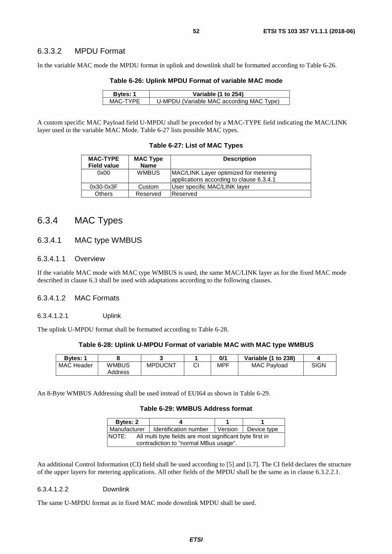
ETSI
ETSI TS 103 357 V1.1.1 (2018-06)52
6.3.3.2 MPDU Format
In the variable MAC mode the MPDU format in uplink and downlink shall be formatted according to Table 6-26.
Table 6-26: Uplink MPDU Format of variable MAC mode
Bytes: 1 Variable (1 to 254) MAC-TYPE U-MPDU (Variable MAC according MAC Type)
A custom specific MAC Payload field U-MPDU shall be preceded by a MAC-TYPE field indicating the MAC/LINK layer used in the variable MAC Mode. Table 6-27 lists possible MAC types.
Table 6-27: List of MAC Types
MAC-TYPE Field value
MAC Type Name
Description
0x00 WMBUS MAC/LINK Layer optimized for metering applications according to clause 6.3.4.1
0x30-0x3F Custom User specific MAC/LINK layer Others Reserved Reserved
6.3.4 MAC Types
6.3.4.1 MAC type WMBUS
6.3.4.1.1 Overview
If the variable MAC mode with MAC type WMBUS is used, the same MAC/LINK layer as for the fixed MAC mode described in clause 6.3 shall be used with adaptations according to the following clauses.
6.3.4.1.2 MAC Formats
6.3.4.1.2.1 Uplink
The uplink U-MPDU format shall be formatted according to Table 6-28.
Table 6-28: Uplink U-MPDU Format of variable MAC with MAC type WMBUS
Bytes: 1 8 3 1 0/1 Variable (1 to 238) 4 MAC Header WMBUS
Address MPDUCNT CI MPF MAC Payload SIGN
An 8-Byte WMBUS Addressing shall be used instead of EUI64 as shown in Table 6-29.
Table 6-29: WMBUS Address format
Bytes: 2 4 1 1 Manufacturer Identification number Version Device type NOTE: All multi byte fields are most significant byte first in
contradiction to "normal MBus usage".
An additional Control Information (CI) field shall be used according to [5] and [i.7]. The CI field declares the structure of the upper layers for metering applications. All other fields of the MPDU shall be the same as in clause 6.3.2.2.1.
6.3.4.1.2.2 Downlink
The same U-MPDU format as in fixed MAC mode downlink MPDU shall be used.
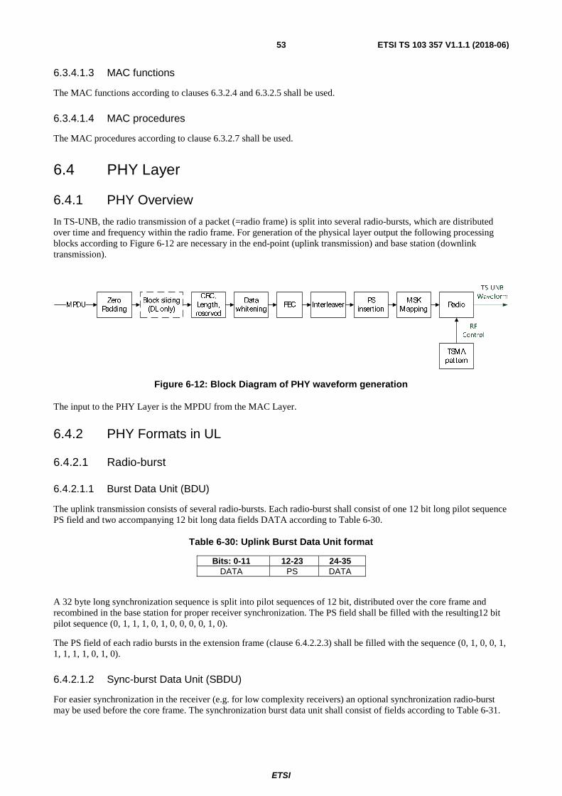
ETSI
ETSI TS 103 357 V1.1.1 (2018-06)53
6.3.4.1.3 MAC functions
The MAC functions according to clauses 6.3.2.4 and 6.3.2.5 shall be used.
6.3.4.1.4 MAC procedures
The MAC procedures according to clause 6.3.2.7 shall be used.
6.4 PHY Layer
6.4.1 PHY Overview
In TS-UNB, the radio transmission of a packet (=radio frame) is split into several radio-bursts, which are distributed over time and frequency within the radio frame. For generation of the physical layer output the following processing blocks according to Figure 6-12 are necessary in the end-point (uplink transmission) and base station (downlink transmission).
Figure 6-12: Block Diagram of PHY waveform generation
The input to the PHY Layer is the MPDU from the MAC Layer.
6.4.2 PHY Formats in UL
6.4.2.1 Radio-burst
6.4.2.1.1 Burst Data Unit (BDU)
The uplink transmission consists of several radio-bursts. Each radio-burst shall consist of one 12 bit long pilot sequence PS field and two accompanying 12 bit long data fields DATA according to Table 6-30.
Table 6-30: Uplink Burst Data Unit format
Bits: 0-11 12-23 24-35 DATA PS DATA
A 32 byte long synchronization sequence is split into pilot sequences of 12 bit, distributed over the core frame and recombined in the base station for proper receiver synchronization. The PS field shall be filled with the resulting12 bit pilot sequence (0, 1, 1, 1, 0, 1, 0, 0, 0, 0, 1, 0).
The PS field of each radio bursts in the extension frame (clause 6.4.2.2.3) shall be filled with the sequence (0, 1, 0, 0, 1, 1, 1, 1, 1, 0, 1, 0).
6.4.2.1.2 Sync-burst Data Unit (SBDU)
For easier synchronization in the receiver (e.g. for low complexity receivers) an optional synchronization radio-burst may be used before the core frame. The synchronization burst data unit shall consist of fields according to Table 6-31.

ETSI
ETSI TS 103 357 V1.1.1 (2018-06)54
Table 6-31: Uplink Sync-Burst Data Unit format
Bits: 0-11 12-19 20 21-23 24-31 32-33 34-35 Preamble_S PS_US Reserved Uplink TSMA
Pattern Number LSB Short Address
Uplink TSMA Pattern Group
Sync CRC
SIF (Sync-burst Info Field)
The fields are defined as:
• The Preamble_S field shall be filled with (0, 0, 1, 1, 0, 0, 1, 1, 0, 0, 1, 1).
• The pilot sequence field PS_US shall be filled with (1, 1, 0, 1, 0, 0, 1, 1).
• The Reserved field is reserved for future use and shall be set to (0).
• The Uplink TSMA Pattern Number shall indicate the TSMA pattern number � used for this transmission.
• The LSB Short Address shall be the eight least significant bits of the short address as described in clause 6.2.3.1.
• The uplink TSMA Pattern Group shall indicate the TSMA pattern group used for this transmission as described in Table 6-32.
Table 6-32: Uplink TSMA Pattern Group
Name Abbreviation Pattern Uplink TSMA Pattern Group 1 UPG1 (0, 0) Uplink TSMA Pattern Group 2 UPG2 (0, 1) Uplink TSMA Pattern Group 3 UPG3 (1, 0)
• Sync CRC shall be 2 bit and calculated over the bits 20 to 33 of the SBDU according to clause 6.4.6.2.
6.4.2.2 Radio Frame
6.4.2.2.1 Overview
The uplink transmission shall consist of a core frame and shall comprise an additional extension frame, if the PHY payload length exceeds 186 bits.
6.4.2.2.2 Core frame
The uplink core frame shall consist of 24 radio-bursts.
6.4.2.2.3 Extension frame
The uplink extension frame structure shall be derived from the information of the core frame according to clause 6.4.7.1.6.2. For each additional byte in the PHY payload, the frame shall be extended by one radio-burst.
6.4.2.3 PHY Payload
6.4.2.3.1 Introduction
The PHY Payload in uplink shall consist of the following fields.
Table 6-33: UL-ULP PHY Payload
Bits: 8 8 8 Variable (160 to 2 040) 2 Header CRC Payload CRC PSI PSDU MMode
PHR

ETSI
ETSI TS 103 357 V1.1.1 (2018-06)55
Header CRC, Payload CRC and PSI form the PHY Header (PHR) based on which the radio burst transmission time and frequency of the extension frame is determined.
6.4.2.3.2 Header CRC
The Header CRC shall be 8 Bit and calculated according to clause 6.4.4.4.1.
6.4.2.3.3 Payload CRC
The Payload CRC shall be 8 Bit and calculated according to clause 6.4.4.4.2.
6.4.2.3.4 Packet Size Indicator (PSI)
The Packet Size Indicator (PSI) field shall be 8 bit long and shall indicate the length of the PSDU before zero padding in byte. Valid values range from 1 to 245 bytes.
6.4.2.3.5 PHY Service Data Unit (PSDU)
The physical layer service data unit (PSDU) may hold a variable length of up to 255 bytes of data. The minimum PSDU length shall be 20 bytes and shall be covered by the core frame.
The PSDU shall be filled with the MAC Protocol Data Unit (MPDU). If the MPDU size is below 20 bytes the PSDU shall be filled to 20 bytes by zero padding behind the actual PSDU. Therefore a minimum number of 20 bytes is always transmitted, regardless of the actual MPDU size. For CRC calculation, the padded zeroes shall be omitted.
6.4.2.3.6 MMode
The 2 bit long field MMODE shall indicate if fixed MAC or variable MAC is used. The MMODE field shall be formatted according to Table 6-34.
Table 6-34: MMODE field format
Bit Function Description 0/1 MMode 00: Fixed MAC Mode (see clause 6.3)
01: Variable MAC (customer specific MAC/LINK layer see clause 6.3.3) Others: Reserved
6.4.3 PHY Formats in DL
6.4.3.1 Radio-burst
6.4.3.1.1 DL-SB Mode
6.4.3.1.1.1 Overview
In DL-SB Mode, telegram splitting shall not be used. Therefore the PHY payload of one block shall be transmitted in one continuous radio-burst. The length of the radio-burst depends on the length of the PSDU of the PHY payload, which shall be a fixed length of 78 symbols for the core frame and variable length between 66 and 202 symbols for the PHY payload blocks in the extension frame.
Table 6-35: Burst Data Unit format of DL-SB Mode
Symbols: 32 32 78 / 66…202 Preamble Sync PHY Payload
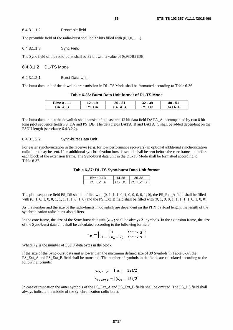
ETSI
ETSI TS 103 357 V1.1.1 (2018-06)56
6.4.3.1.1.2 Preamble field
The preamble field of the radio-burst shall be 32 bits filled with (0,1,0,1….).
6.4.3.1.1.3 Sync Field
The Sync field of the radio-burst shall be 32 bit with a value of 0x930B51DE.
6.4.3.1.2 DL-TS Mode
6.4.3.1.2.1 Burst Data Unit
The burst data unit of the downlink transmission in DL-TS Mode shall be formatted according to Table 6-36.
Table 6-36: Burst Data Unit format of DL-TS Mode
Bits: 0 - 11 12 - 19 20 - 31 32 - 39 40 - 51 DATA_B PS_DA DATA_A PS_DB DATA_C
The burst data unit in the downlink shall consist of at least one 12 bit data field DATA_A, accompanied by two 8 bit long pilot sequence fields PS_DA and PS_DB. The data fields DATA_B and DATA_C shall be added dependant on the PSDU length (see clause 6.4.3.2.2).
6.4.3.1.2.2 Sync-burst Data Unit
For easier synchronization in the receiver (e. g. for low performance receivers) an optional additional synchronization radio-burst may be sent. If an additional synchronization burst is sent, it shall be sent before the core frame and before each block of the extension frame. The Sync-burst data unit in the DL-TS Mode shall be formatted according to Table 6-37.
Table 6-37: DL-TS Sync-burst Data Unit format
Bits: 0-13 14-25 26-38 PS_Ext_A PS_DS PS_Ext_B
The pilot sequence field PS_DS shall be filled with (0, 1, 1, 1, 0, 1, 0, 0, 0, 0, 1, 0), the PS_Ext_A field shall be filled with (0, 1, 0, 1, 0, 0, 1, 1, 1, 1, 1, 0, 1, 0) and the PS_Ext_B field shall be filled with (0, 1, 0, 0, 1, 1, 1, 1, 1, 0, 1, 0, 0).
As the number and the size of the radio-bursts in downlink are dependent on the PHY payload length, the length of the synchronization radio-burst also differs.
In the core frame, the size of the Sync-burst data unit ( ��) shall be always 21 symbols. In the extension frame, the size of the Sync-burst data unit shall be calculated according to the following formula:
�� = � 21 ��� � ≤ 7
21 + ( � − 7) ��� � > 7
Where � is the number of PSDU data bytes in the block.
If the size of the Sync-burst data unit is lower than the maximum defined size of 39 Symbols in Table 6-37, the PS_Ext_A and PS_Ext_B field shall be truncated. The number of symbols in the fields are calculated according to the following formula: ��_���_� = �( �� − 12)/2� ��_���_� = �( �� − 12)/2� In case of truncation the outer symbols of the PS_Ext_A and PS_Ext_B fields shall be omitted. The PS_DS field shall always indicate the middle of the synchronization radio-burst.

ETSI
ETSI TS 103 357 V1.1.1 (2018-06)57
6.4.3.2 Radio frame
6.4.3.2.1 Core frame
The core frame is used as authenticated wakeup and acknowledgment of the previous end-point uplink transmission. Every downlink transmission shall consist of a core frame and may be followed by an optional extension frame. The succeeding extension frame shall be indicated in the core frame.
The core frame shall consist of 9 radio-bursts according to the structure described in clause 6.4.3.1, which may be repeated to fill the 18 radio-bursts of the downlink TSMA pattern. The base station should decide upon the signal strength of the uplink transmission if the same core frame is repeated. Pilot sequence field PS_DA and pilot sequence PS_DB of each radio-burst in the core frame shall be filled with symbols derived from the channel coded core PHY Payload. The optional DATA_B and DATA_C fields shall not be used for transmission of the core frame.
For synchronization purpose an additional Sync-burst may be transmitted before the start of the core frame. If an additional Sync-burst is used in front of the core frame an additional Sync-burst shall also be used in front of each block of the extension frame.
6.4.3.2.2 Extension frame
The extension frame is an optional transmission frame to transmit user data. The extension frame may contain a maximum of 250 bytes of PSDU data. The PSDU contains the MPDU data with additional zero padding if needed. The extension frame shall be split into blocks of at most 24 bytes of PSDU data per block. If the overall PSDU size is more than 24 bytes, multiple blocks shall be used for transmission. Each block of the extension frame shall comprise 18 radio-bursts according to clause 6.4.3.1. If an additional Sync-burst is used in the core frame, then an additional Sync-burst shall be transmitted also for each block of the extension frame.
The burst data unit of the extension frame shall use the pilot sequences defined in Table 6-38 for all radio-bursts except the Sync-burst.
Table 6-38: DL-TS extension frame pilot sequences
Pilot Sequence A Pilot Sequence B (0, 1, 0, 0, 0, 0, 1, 0) (1, 1, 1, 0, 1, 0, 0, 0)]
The number of optional data symbols in data fields DATA_B and DATA_C utilized for data transmission is dependent on the number of symbols transmitted in the respective block of the extension frame.
The PSDU data shall be spread byte-wise evenly over the number of extension frame blocks required to accommodate for the whole packet.
The number of blocks B that shall be used for the transmission shall be determined according to the following formula:
� = � 24
�,
Where ∈ {1,2 … 250}, shall be the PSDU size in byte.
The extension frame blocks shall be numbered in ascending order to their respective transmission time. Block � = 1 shall be the block directly transmitted after the core frame, block � + 1 shall be transmitted after block �.
The number of PSDU data bytes � assigned to one block is a result of spreading the data evenly over all blocks. In
case the number of bytes is not a multiple of the number of blocks, the remaining bytes � = − ���� ∗ � shall be
assigned to the blocks in ascending order.
� = ���� , ��� � > ���� + 1, ��� � ≤ � .

ETSI
ETSI TS 103 357 V1.1.1 (2018-06)58
The data bits assigned to one block shall be spread over the radio-bursts by filling the field DATA_A of all bursts first and then consecutively filling the optional data fields DATA_B and DATA_C of all radio-bursts evenly. The procedure is described in detail in clause 6.4.5.5.2.2.
6.4.3.3 PHY Payload
6.4.3.3.1 Core frame
6.4.3.3.1.1 Introduction
The same core frame PHY Payload format shall be used for DL-SB and DL-TS Mode. The core frame PHY Payload shall have the format according to Table 6-39.
Table 6-39: PHY Payload of the DL-TS Core frame
Bits: 0-47 48 49-56 57-70 71-72 73 74-77 Sync EFI PSI TSI MMODE Reserved CRC
6.4.3.3.1.2 Sync
If fixed MAC mode is used, the Sync field shall contain a 48 bit cypher-based Message Authentication Code (CMAC) cryptographically signing the counter of the uplink MAC Data Unit received from the end-point. The CMAC is generated according to clause 6.3.2.6.2 with the CMAC initialization vector ������ for downlink direction as input data.
Table 6-40: Input Data for Sync CMAC Generation
Bytes: 8 IV
The 48 most significant bits of the result of the CMAC generation shall be used as Sync field.
If the variable MAC mode of the TS-UNB protocol is used the Sync field shall be filled with the pilot sequences PS_A and PS_B of the extension frame radio burst (Table 6-38) according to Table 6-41.
Table 6-41: Signature field in variable MAC mode
Bits: 0-7 8-15 16-23 24-31 32-39 40-47 PS_A PS_B PS_A PS_B PS_A PS_B
6.4.3.3.1.3 Extension frame Indicator (EFI)
The Extension Frame Indicator (EFI) field indicates, if the core frame is followed by an extension frame. EFI shall be set to one, if an extension frame follows. If EFI is set to one PSI, TSI and MMODE fields shall be used. If EFI is zero, PSI, TSI and MMODE are reserved and shall be set to (0).
6.4.3.3.1.4 Packet Size Indicator (PSI)
The packet size indicator (PSI) shall indicate the size of the downlink PSDU of the extension frame before zero padding in bytes. Valid values range from 1 to 250 bytes.
6.4.3.3.1.5 Transmission Start Time Indicator (TSI)
The transmission start time indicator (TSI) indicates the time interval between core frame and extension frame. The time interval is measured from the last radio-burst of the repeated core frame to the first radio-burst of the first block of the extension frame and is measured from the middle of the pilot sequence of the two radio-bursts. The time offset shall be calculated from the TSI value (Table 6-25 in clause 6.3.2.7.1) according to the following formula:
∆���� = ��� ∗ 4����� ! ∗ ∆�
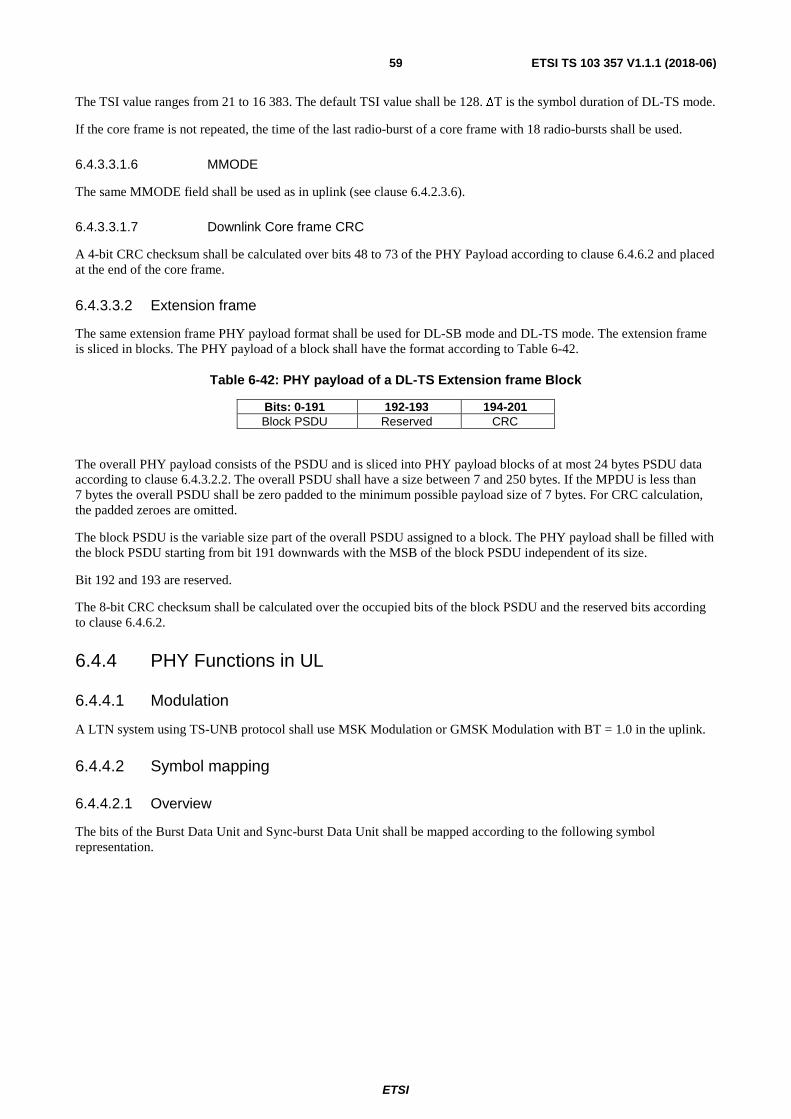
ETSI
ETSI TS 103 357 V1.1.1 (2018-06)59
The TSI value ranges from 21 to 16 383. The default TSI value shall be 128. ∆T is the symbol duration of DL-TS mode.
If the core frame is not repeated, the time of the last radio-burst of a core frame with 18 radio-bursts shall be used.
6.4.3.3.1.6 MMODE
The same MMODE field shall be used as in uplink (see clause 6.4.2.3.6).
6.4.3.3.1.7 Downlink Core frame CRC
A 4-bit CRC checksum shall be calculated over bits 48 to 73 of the PHY Payload according to clause 6.4.6.2 and placed at the end of the core frame.
6.4.3.3.2 Extension frame
The same extension frame PHY payload format shall be used for DL-SB mode and DL-TS mode. The extension frame is sliced in blocks. The PHY payload of a block shall have the format according to Table 6-42.
Table 6-42: PHY payload of a DL-TS Extension frame Block
Bits: 0-191 192-193 194-201 Block PSDU Reserved CRC
The overall PHY payload consists of the PSDU and is sliced into PHY payload blocks of at most 24 bytes PSDU data according to clause 6.4.3.2.2. The overall PSDU shall have a size between 7 and 250 bytes. If the MPDU is less than 7 bytes the overall PSDU shall be zero padded to the minimum possible payload size of 7 bytes. For CRC calculation, the padded zeroes are omitted.
The block PSDU is the variable size part of the overall PSDU assigned to a block. The PHY payload shall be filled with the block PSDU starting from bit 191 downwards with the MSB of the block PSDU independent of its size.
Bit 192 and 193 are reserved.
The 8-bit CRC checksum shall be calculated over the occupied bits of the block PSDU and the reserved bits according to clause 6.4.6.2.
6.4.4 PHY Functions in UL
6.4.4.1 Modulation
A LTN system using TS-UNB protocol shall use MSK Modulation or GMSK Modulation with BT = 1.0 in the uplink.
6.4.4.2 Symbol mapping
6.4.4.2.1 Overview
The bits of the Burst Data Unit and Sync-burst Data Unit shall be mapped according to the following symbol representation.

ETSI
ETSI TS 103 357 V1.1.1 (2018-06)60
Figure 6-13: Symbol mapping for MSK/GMSK with absolute phase
The representation shall be repeated after 4 symbols. �� is the start time of the PHY transmission with a symbol duration of ��.
6.4.4.2.2 UL-ULP Symbol rate
The symbol rate of the (G)MSK modulation in the UL-ULP mode shall be 2 380,371 sym/s (preferably derived from 26 MHz reference frequency). The tolerance of the symbol rate shall be kept within a range of ±0,1 % during one radio-burst.
6.4.4.2.3 UL-ER Symbol rate
The symbol rate of the (G)MSK modulation in the UL-ER mode shall be 396,729 sym/s (preferably derived from 26 MHz reference frequency). The tolerance of the symbol rate shall be kept within a range of ±0,1 % during one radio-burst.
6.4.4.3 Data Whitening
The complete PHY Payload (see Table 6-33 and Figure 6-12) shall be whitened using the PN9 sequence defined in IEEE 802.15.4 [1].
6.4.4.4 CRC
6.4.4.4.0 General
An 8-bit cyclic redundancy check (CRC) according to clause 6.4.6.2 shall be used.
6.4.4.4.1 Payload CRC
The payload CRC shall be calculated over MPDU and MMODE field according to clause 6.4.6.2. In Case of zero padding the padded zeros shall be omitted for the CRC calculation.
Figure 6-14: Calculation of Payload CRC
6.4.4.4.2 Header CRC
The additional Header CRC shall be calculated over Payload CRC and PSI according to clause 6.4.6.2.
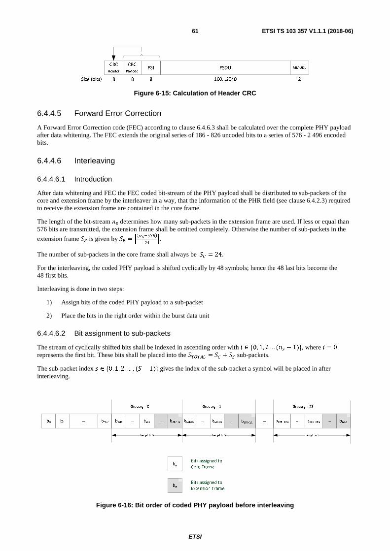
ETSI
ETSI TS 103 357 V1.1.1 (2018-06)61
Figure 6-15: Calculation of Header CRC
6.4.4.5 Forward Error Correction
A Forward Error Correction code (FEC) according to clause 6.4.6.3 shall be calculated over the complete PHY payload after data whitening. The FEC extends the original series of 186 - 826 uncoded bits to a series of 576 - 2 496 encoded bits.
6.4.4.6 Interleaving
6.4.4.6.1 Introduction
After data whitening and FEC the FEC coded bit-stream of the PHY payload shall be distributed to sub-packets of the core and extension frame by the interleaver in a way, that the information of the PHR field (see clause 6.4.2.3) required to receive the extension frame are contained in the core frame.
The length of the bit-stream � determines how many sub-packets in the extension frame are used. If less or equal than 576 bits are transmitted, the extension frame shall be omitted completely. Otherwise the number of sub-packets in the
extension frame �� is given by �� = "�������� !
#. The number of sub-packets in the core frame shall always be �� = 24.
For the interleaving, the coded PHY payload is shifted cyclically by 48 symbols; hence the 48 last bits become the 48 first bits.
Interleaving is done in two steps:
1) Assign bits of the coded PHY payload to a sub-packet
2) Place the bits in the right order within the burst data unit
6.4.4.6.2 Bit assignment to sub-packets
The stream of cyclically shifted bits shall be indexed in ascending order with $ ∈ {0, 1, 2 … ( � − 1)}, where $ = 0 represents the first bit. These bits shall be placed into the ��"��# = �� + �� sub-packets.
The sub-packet index ! ∈ {0, 1, 2, … , (� − 1)} gives the index of the sub-packet a symbol will be placed in after interleaving.
Figure 6-16: Bit order of coded PHY payload before interleaving
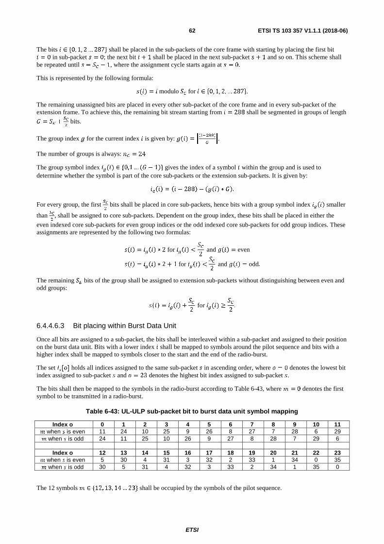
ETSI
ETSI TS 103 357 V1.1.1 (2018-06)62
The bits $ ∈ {0, 1, 2 … 287} shall be placed in the sub-packets of the core frame with starting by placing the first bit $ = 0 in sub-packet ! = 0; the next bit $ + 1 shall be placed in the next sub-packet ! + 1 and so on. This scheme shall be repeated until ! = �� − 1, where the assignment cycle starts again at ! = 0.
This is represented by the following formula: !($) = $ modulo �� for $ ∈ %0, 1, 2, … 287&.
The remaining unassigned bits are placed in every other sub-packet of the core frame and in every sub-packet of the extension frame. To achieve this, the remaining bit stream starting from $ = 288 shall be segmented in groups of length ' = �� +
��
bits.
The group index ( for the current index $ is given by: (($) = ��$� %%�&
�. The number of groups is always: & = 24
The group symbol index $'($) ∈ {0,1 … �' − 1�} gives the index of a symbol $ within the group and is used to determine whether the symbol is part of the core sub-packets or the extension sub-packets. It is given by: $'�$� = �$ − 288� − �(�$� ∗ '�.
For every group, the first ��
bits shall be placed in core sub-packets, hence bits with a group symbol index $'�$� smaller
than ��
, shall be assigned to core sub-packets. Dependent on the group index, these bits shall be placed in either the
even indexed core sub-packets for even group indices or the odd indexed core sub-packets for odd group indices. These assignments are represented by the following two formulas:
!�$� = $'�$� ∗ 2 for $'�$� <��2
and (�$� = even
!�$� = $'�$� ∗ 2 + 1 for $'�$� <��2
and (�$� = odd.
The remaining �� bits of the group shall be assigned to extension sub-packets without distinguishing between even and odd groups:
!�$� = $'�$� +��2
for $'($) ≥��2
.
6.4.4.6.3 Bit placing within Burst Data Unit
Once all bits are assigned to a sub-packet, the bits shall be interleaved within a sub-packet and assigned to their position on the burst data unit. Bits with a lower index $ shall be mapped to symbols around the pilot sequence and bits with a higher index shall be mapped to symbols closer to the start and the end of the radio-burst.
The set ��[�] holds all indices assigned to the same sub-packet � in ascending order, where � = 0 denotes the lowest bit index assigned to sub-packet � and � = 23 denotes the highest bit index assigned to sub-packet �.
The bits shall then be mapped to the symbols in the radio-burst according to Table 6-43, where � = 0 denotes the first symbol to be transmitted in a radio-burst.
Table 6-43: UL-ULP sub-packet bit to burst data unit symbol mapping
Index o 0 1 2 3 4 5 6 7 8 9 10 11 � when � is even 11 24 10 25 9 26 8 27 7 28 6 29 � when � is odd 24 11 25 10 26 9 27 8 28 7 29 6
Index o 12 13 14 15 16 17 18 19 20 21 22 23
� when � is even 5 30 4 31 3 32 2 33 1 34 0 35 � when � is odd 30 5 31 4 32 3 33 2 34 1 35 0
The 12 symbols � ∈ {12, 13, 14 … 23} shall be occupied by the symbols of the pilot sequence.

ETSI
ETSI TS 103 357 V1.1.1 (2018-06)63
6.4.5 PHY Functions in DL
6.4.5.1 Modulation
6.4.5.1.1 DL-SB Mode
For the DL-SB Mode of the TS-UNB protocol a GFSK modulation with a symbol rate of 600 sym/s and modulation index h=1 (deviation 300 Hz) shall be used.
6.4.5.1.2 DL-TS Mode
6.4.5.1.2.1 Modulation Type
If the DL-TS Mode of the TS-UNB protocol is used a MSK Modulation or GMSK Modulation with BT = 1,0 shall be used.
6.4.5.1.2.2 Symbol mapping
The same symbol mapping as in uplink shall be used.
6.4.5.1.2.3 Symbol rate
The symbol rate of the (G)MSK Modulation in the DL-TS Mode shall be 2 380,371 sym/s. The tolerance of the symbol rate shall be kept within a range of ±0,1 % during one radio-burst.
6.4.5.2 Data Whitening
6.4.5.2.1 Core frame
The complete PHY payload of DL-TS Core frame (see Table 6-39) shall be whitened using the PN9 sequence defined in IEEE 802.15.4 [1].
6.4.5.2.2 Extension frame
The PHY payload of DL-ER Extension frame block (see Table 6-42) shall be whitened using the PN9 sequence defined in IEEE 802.15.4 [1].
6.4.5.3 CRC
6.4.5.3.1 Core frame
A 4-bit CRC, according to clause 6.4.6.2, shall be used for the downlink core frame. The same CRC shall be used for DL-SB and DL-TS Mode.
6.4.5.3.2 Extension frame
An 8-bit CRC, according to clause 6.4.6.2, shall be used for the downlink extension frame. The same CRC shall be used for DL-SB and DL-TS Mode.
6.4.5.4 Forward Error Correction
6.4.5.4.1 DL-SB Mode
No forward error correction shall be used in DL-SB Mode.
ETSI
ETSI TS 103 357 V1.1.1 (2018-06)64
6.4.5.4.2 DL-TS Mode
6.4.5.4.2.1 Core frame
A forward error correction, calculated according to clause 6.4.6.3, shall be used to protect the PHY payload of the downlink core frame.
The FEC shall be calculated over all bits of the core frame PHY payload after data whitening. After FEC the sequence of 78 bits results in 252 encoded bits.
6.4.5.4.2.2 Extension frame
A forward error correction, calculated according to clause 6.4.6.3, shall be used to protect the PHY payload of the downlink extension frame block. Each PHY payload block shall be encoded separately.
The FEC shall be calculated over all bits of the PHY payload of the extension frame block after data whitening. One block can transmit 66 to 202 uncoded bits, which results in 216 to 624 encoded bits after the FEC.
6.4.5.5 Interleaving
6.4.5.5.1 DL-SB Mode
No interleaving is used in DL-SB Mode.
6.4.5.5.2 DL-TS Mode
6.4.5.5.2.1 Core frame
The coded PHY payload shall be interleaved according to Table 6-44, whereas:
• s = sub-packet index 0 … S-1
• m = symbol index in radio-burst
• the numbers in the table represent the bit number of the PHY payload of the core frame
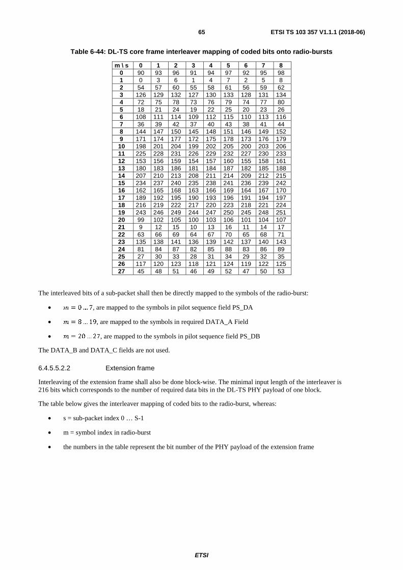
ETSI
ETSI TS 103 357 V1.1.1 (2018-06)65
Table 6-44: DL-TS core frame interleaver mapping of coded bits onto radio-bursts
m \ s 0 1 2 3 4 5 6 7 8 0 90 93 96 91 94 97 92 95 98 1 0 3 6 1 4 7 2 5 8 2 54 57 60 55 58 61 56 59 62 3 126 129 132 127 130 133 128 131 134 4 72 75 78 73 76 79 74 77 80 5 18 21 24 19 22 25 20 23 26 6 108 111 114 109 112 115 110 113 116 7 36 39 42 37 40 43 38 41 44 8 144 147 150 145 148 151 146 149 152 9 171 174 177 172 175 178 173 176 179 10 198 201 204 199 202 205 200 203 206 11 225 228 231 226 229 232 227 230 233 12 153 156 159 154 157 160 155 158 161 13 180 183 186 181 184 187 182 185 188 14 207 210 213 208 211 214 209 212 215 15 234 237 240 235 238 241 236 239 242 16 162 165 168 163 166 169 164 167 170 17 189 192 195 190 193 196 191 194 197 18 216 219 222 217 220 223 218 221 224 19 243 246 249 244 247 250 245 248 251 20 99 102 105 100 103 106 101 104 107 21 9 12 15 10 13 16 11 14 17 22 63 66 69 64 67 70 65 68 71 23 135 138 141 136 139 142 137 140 143 24 81 84 87 82 85 88 83 86 89 25 27 30 33 28 31 34 29 32 35 26 117 120 123 118 121 124 119 122 125 27 45 48 51 46 49 52 47 50 53
The interleaved bits of a sub-packet shall then be directly mapped to the symbols of the radio-burst:
• � = 0 … 7, are mapped to the symbols in pilot sequence field PS_DA
• � = 8 … 19, are mapped to the symbols in required DATA_A Field
• � = 20 … 27, are mapped to the symbols in pilot sequence field PS_DB
The DATA_B and DATA_C fields are not used.
6.4.5.5.2.2 Extension frame
Interleaving of the extension frame shall also be done block-wise. The minimal input length of the interleaver is 216 bits which corresponds to the number of required data bits in the DL-TS PHY payload of one block.
The table below gives the interleaver mapping of coded bits to the radio-burst, whereas:
• s = sub-packet index 0 … S-1
• m = symbol index in radio-burst
• the numbers in the table represent the bit number of the PHY payload of the extension frame

ETSI
ETSI TS 103 357 V1.1.1 (2018-06)66
Table 6-45: DL-TS extension frame interleaver symbol mapping
m\s 0 1 2 3 4 5 6 7 8 9 10 11 12 13 14 15 16 17 0 612 615 618 621 624 627 613 616 619 622 625 628 614 617 620 623 626 629 1 576 579 582 585 588 591 577 580 583 586 589 592 578 581 584 587 590 593 2 540 543 546 549 552 555 541 544 547 550 553 556 542 545 548 551 554 557 3 504 507 510 513 516 519 505 508 511 514 517 520 506 509 512 515 518 521 4 468 471 474 477 480 483 469 472 475 478 481 484 470 473 476 479 482 485 5 432 435 438 441 444 447 433 436 439 442 445 448 434 437 440 443 446 449 6 396 399 402 405 408 411 397 400 403 406 409 412 398 401 404 407 410 413 7 360 363 366 369 372 375 361 364 367 370 373 376 362 365 368 371 374 377 8 324 327 330 333 336 339 325 328 331 334 337 340 326 329 332 335 338 341 9 288 291 294 297 300 303 289 292 295 298 301 304 290 293 296 299 302 305 10 252 255 258 261 264 267 253 256 259 262 265 268 254 257 260 263 266 269 11 216 219 222 225 228 231 217 220 223 226 229 232 218 221 224 227 230 233
12 … 19 pilot sequence field PS_DA 20 0 3 6 9 12 15 1 4 7 10 13 16 2 5 8 11 14 17 21 36 39 42 45 48 51 37 40 43 46 49 52 38 41 44 47 50 53 22 72 75 78 81 84 87 73 76 79 82 85 88 74 77 80 83 86 89 23 108 111 114 117 120 123 109 112 115 118 121 124 110 113 116 119 122 125 24 144 147 150 153 156 159 145 148 151 154 157 160 146 149 152 155 158 161 25 180 183 186 189 192 195 181 184 187 190 193 196 182 185 188 191 194 197 26 198 201 204 207 210 213 199 202 205 208 211 214 200 203 206 209 212 215 27 162 165 168 171 174 177 163 166 169 172 175 178 164 167 170 173 176 179 28 126 129 132 135 138 141 127 130 133 136 139 142 128 131 134 137 140 143 29 90 93 96 99 102 105 91 94 97 100 103 106 92 95 98 101 104 107 30 54 57 60 63 66 69 55 58 61 64 67 70 56 59 62 65 68 71 31 18 21 24 27 30 33 19 22 25 28 31 34 20 23 26 29 32 35
32 … 39 pilot sequence field PS_DB 40 234 237 240 243 246 249 235 238 241 244 247 250 236 239 242 245 248 251 41 270 273 276 279 282 285 271 274 277 280 283 286 272 275 278 281 284 287 42 306 309 312 315 318 321 307 310 313 316 319 322 308 311 314 317 320 323 43 342 345 348 351 354 357 343 346 349 352 355 358 344 347 350 353 356 359 44 378 381 384 387 390 393 379 382 385 388 391 394 380 383 386 389 392 395 45 414 417 420 423 426 429 415 418 421 424 427 430 416 419 422 425 428 431 46 450 453 456 459 462 465 451 454 457 460 463 466 452 455 458 461 464 467 47 486 489 492 495 498 501 487 490 493 496 499 502 488 491 494 497 500 503 48 522 525 528 531 534 537 523 526 529 532 535 538 524 527 530 533 536 539 49 558 561 564 567 570 573 559 562 565 568 571 574 560 563 566 569 572 575 50 594 597 600 603 606 609 595 598 601 604 607 610 596 599 602 605 608 611 51 630 633 636 639 642 645 631 634 637 640 643 646 632 635 638 641 644 647
The interleaved bits of a sub-packet shall then be directly mapped to the symbols of the radio-burst:
• � = 0 … 11, are mapped to the symbols in data field DATA_B
• � = 12 … 19, are mapped to the symbols in required pilot sequence field PS_DA
• � = 20 … 31, are mapped to the symbols in data field DATA_A
• � = 32 … 39, are mapped to the symbols in required pilot sequence field PS_DB
• � = 40 … 51, are mapped to the symbols in data field DATA_C
If the number of bits is not a multiple of the number of sub-packets in the block, the sizes of the sub-packets differ inside of one block.
6.4.6 Commonly used PHY Functions
6.4.6.1 Introduction
There are common PHY functions which are used in different sections of the physical layer. They are described here to be referenced in the appropriate sections.

ETSI
ETSI TS 103 357 V1.1.1 (2018-06)67
6.4.6.2 CRC
All 2-bit CRCs shall be calculated with the following parameters:
• 2 bit length (CRC-2)
• Polynomial: 0x3
• Initial value: 0x3
• No XOR
All 4-bit CRCs shall be calculated with the following parameters:
• 4 bit length (CRC-4)
• Polynomial: 0x3
• Initial value: 0xF
• No XOR
All 8-bit CRCs shall be calculated with the following parameters:
• 8 bit length (CRC-8)
• Polynomial: 0x9B
• Initial value for calculation: 0xFF
• No XOR
6.4.6.3 FEC
All FECs shall be calculated with the following parameters:
• Convolutional code
• Rate: 1/3
• Polynomials (0155, 0123, 0137) (octal), (0x6D, 0x53, 0x5F)) (hex)
• Constraint length: 7
• Zero-tailing
6.4.7 PHY Procedures
6.4.7.1 TSMA Schemes
6.4.7.1.1 Overview
In the TS-UNB protocol the application message is not transmitted in one radio-burst. The PPDU of the TS-UNB protocol in uplink and downlink DL-TS mode shall be split into several radio-bursts, which are distributed over time and frequency. The set of radio-bursts belonging to one message are called radio-frame. A radio frame is further divided into a core frame and an extension frame. The radio bursts within a radio-frame are spread over 24 or 25 carriers with a carrier spacing step size of ��.
In the uplink core frame and the downlink core and extension frame the way the radio-bursts are distributed over time and frequency is called TSMA pattern. A TSMA pattern consists of a set of carrier numbers and time spacings defining the transmission time and frequency of the radio-bursts within the radio-frame. The carrier numbers are chosen from a set of 24 carriers (C=0…23) with a carrier spacing of �� . Carrier number C=24 shall be used only for the transmission of an optional Sync-Burst in front of the radio frames.
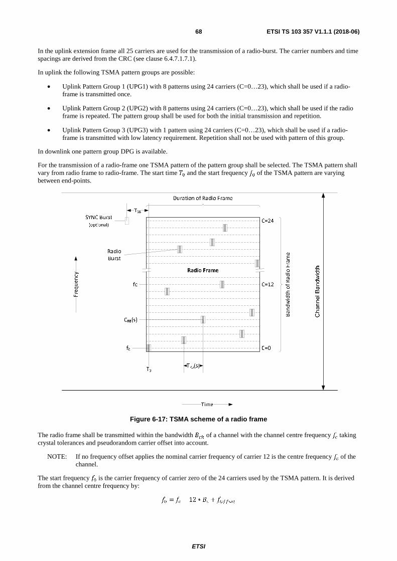
ETSI
ETSI TS 103 357 V1.1.1 (2018-06)68
In the uplink extension frame all 25 carriers are used for the transmission of a radio-burst. The carrier numbers and time spacings are derived from the CRC (see clause 6.4.7.1.7.1).
In uplink the following TSMA pattern groups are possible:
• Uplink Pattern Group 1 (UPG1) with 8 patterns using 24 carriers (C=0…23), which shall be used if a radio-frame is transmitted once.
• Uplink Pattern Group 2 (UPG2) with 8 patterns using 24 carriers (C=0…23), which shall be used if the radio frame is repeated. The pattern group shall be used for both the initial transmission and repetition.
• Uplink Pattern Group 3 (UPG3) with 1 pattern using 24 carriers (C=0…23), which shall be used if a radio-frame is transmitted with low latency requirement. Repetition shall not be used with pattern of this group.
In downlink one pattern group DPG is available.
For the transmission of a radio-frame one TSMA pattern of the pattern group shall be selected. The TSMA pattern shall vary from radio frame to radio-frame. The start time �� and the start frequency �� of the TSMA pattern are varying between end-points.
Figure 6-17: TSMA scheme of a radio frame
The radio frame shall be transmitted within the bandwidth ��� of a channel with the channel centre frequency �� taking crystal tolerances and pseudorandom carrier offset into account.
NOTE: If no frequency offset applies the nominal carrier frequency of carrier 12 is the centre frequency �� of the channel.
The start frequency �� is the carrier frequency of carrier zero of the 24 carriers used by the TSMA pattern. It is derived from the channel centre frequency by:
�� = �� − 12 ∗ �� + ������
Channel Bandwidth
Frequency
Bandwidth of Radio Frame

ETSI
ETSI TS 103 357 V1.1.1 (2018-06)69
The frequency offset ����� is a variable radio-frame offset, which is calculated according to the following formula:
����� = ��� ∗ ���
where: ��� is the frequency offset step of 2.380,371 Hz ;
��� is an additional frequency offset in number of frequency offset steps ��� selected by the end-point and set for every radio-frame depending on the payload CRC.
The transmission frequency �� of a radio-burst (Radio-burst Frequency) is defined as:
�� (�) = �� + �� (�) ∗ ��
where: �� is the radio-burst carrier number according to the TSMA pattern chosen for the transmission of the radio-frame;
�� is the actual carrier spacing step size.
Three different carrier spacing step sizes �� according to Table 6-58 in clause 6.5.1 are available to address different radio regulations. The carrier spacing step size �� of the standard TSMA mode used for one 100 kHz channel shall be 2 380,371 Hz. The carrier spacing accuracy shall be ±5,0 Hz across all radio-bursts within one radio-frame.
If two radio channels A and B are used, the frame transmissions shall be alternated between the two channels. The channel to be used for transmission shall be derived from the least significant bit of the payload CRC according to Table 6-48.
6.4.7.1.2 Frame Repetition
6.4.7.1.2.1 Uplink repetition
For performance improvement a radio frame may be repeated. The repeated radio frame rFRAME shall have the identical data format as the initial radio frame iFRAME. Both transmissions, iFRAME and rFRAME shall use the same TSMA pattern of the uplink TSMA pattern group UPG2 with a timeslot offset ��� .
Figure 6-18: Frame transmission and repetition
Repetitions may be used in single and dual channel transmission mode. The repeated frame rFRAME shall have a fixed frequency offset ∆��� and a variable time offset ∆�� according to clause 6.4.7.1.5 from the initial frame transmission. If single channel transmission is used ∆��� shall be (0).

ETSI
ETSI TS 103 357 V1.1.1 (2018-06)70
If dual channel mode is used, the repetition shall always be transmitted in the frequency channel opposite to the initial iFRAME transmission with a frequency offset of:
∆��� = �� ∗ ��
where: ��is the number of carrier frequency offset steps and is adjusted to the radio regulations (see profiles in annex A).
The base station may configure the end-point to repetition mode when attaching the end-point to the LTN network.
6.4.7.1.3 Downlink repetition
In downlink TS-Mode, only the core frame may be repeated. The downlink extension frame shall not be repeated. The repetition of the downlink core frame uses the second half of the downlink TSMA pattern.
6.4.7.1.4 Radio burst time
The start time �� of the first radio-burst s=0 of a radio frame is randomly chosen by the end-point and defined as the middle of the pilot sequence of the radio-burst. The transmission time of a radio-burst (Radio-burst Time) �� (�) is defined as the time difference between two radio-bursts from the middle of the pilot sequence of radio-burst s to the middle of the pilot sequence of the previous radio-burst s-1 in number of symbol durations as illustrated in Figure 6-19.
Figure 6-19: Definition of Radio-burst Time ���(�)
The end-point shall keep the radio-burst timing within a tolerance of ± ∆�
� over the complete radio frame period from the
first radio-burst to the last radio-burst, whereas ∆� is the duration of one modulated symbol.
Figure 6-20: Definition of Sync-burst Time ���

ETSI
ETSI TS 103 357 V1.1.1 (2018-06)71
If an additional Sync-burst is used, it shall be transmitted one carrier spacing above the highest carrier (C=24) of the carrier group and TSB symbols before radio-burst 0 of the uplink and downlink core frame as well as before radio-burst
0 of each block of the downlink extension frame. The time spacings TUPG1-3 according to Table 6-46 shall be used for
TSB.
Table 6-46: Time spacings of Uplink Pattern Groups
Name Time spacing Uplink Pattern Group 1 TUPG1 = 337 symbols
Uplink Pattern Group 2 TUPG2 = 337 symbols
Uplink Pattern Group 3 TUPG3 = 66 symbols
The time spacing in Table 6-46 shall also be used for the calculation of radio-burst time in the uplink extension frame (see clause 6.4.7.1.6.2).
6.4.7.1.5 Frame time and frequency offset
A pseudorandom offset in frequency and time derived from the Header and Payload CRC shall be added to the selected TSMA pattern start frequency and start time according to Figure 6-21.
Figure 6-21: Definition of frame start offset parameter
The timeslot offset is only used for repetitions. The timeslot offset � is given in number of timeslots. The duration of a timeslot is 42 symbols. For the initial frame transmission the timeslot offset shall be 0. The shifted start time of the first radio-burst of the repetition shall be then:
��� = �� + � ∗ 42 ∗ ∆�
The timeslot offset n� is derived from the header CRC (Table 6-47). The timeslot offset � is calculated in the following way:
� = �� + 2
Table 6-47: Bit representation of Header CRC
Header CRC Value Used as Bit 0-1 0…3 Timeslot offset value ��� Bit 2-3 Reserved for future use Bit 4-7 0…15 Downlink TSMA Pattern selection value �����
f0
T0
Timeslot Offset SRF
+3
+2
+1
-1
-2
-3
+2 +3 +4 +5
42 Symbols
Radio
Burst 0
Radio
Burst 1
Min. 319 Symbols
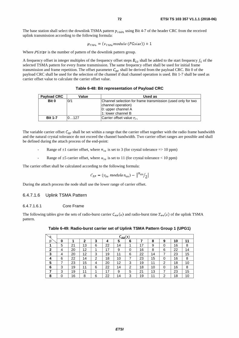
ETSI
ETSI TS 103 357 V1.1.1 (2018-06)72
The base station shall select the downlink TSMA pattern ����� using Bit 4-7 of the header CRC from the received uplink transmission according to the following formula:
����� = ������������ (�������) + 1
Where ������ is the number of pattern of the downlink pattern group.
A frequency offset in integer multiples of the frequency offset steps ��� shall be added to the start frequency �� of the selected TSMA pattern for every frame transmission. The same frequency offset shall be used for initial frame transmission and frame repetition. The offset parameter ��� shall be derived from the payload CRC. Bit 0 of the payload CRC shall be used for the selection of the channel if dual channel operation is used. Bit 1-7 shall be used as carrier offset value to calculate the carrier offset value.
Table 6-48: Bit representation of Payload CRC
Payload CRC Value Used as Bit 0 0/1 Channel selection for frame transmission (used only for two
channel operation) 0: upper channel A 1: lower channel B
Bit 1-7 0…127 Carrier offset value ���
The variable carrier offset ��� shall be set within a range that the carrier offset together with the radio frame bandwidth and the natural crystal tolerance do not exceed the channel bandwidth. Two carrier offset ranges are possible and shall be defined during the attach process of the end-point:
- Range of ±1 carrier offset, where � is set to 3 (for crystal tolerance => 10 ppm)
- Range of ±5 carrier offset, where � is set to 11 (for crystal tolerance < 10 ppm)
The carrier offset shall be calculated according to the following formula:
��� = ��� modulo �� − � � 2� �
During the attach process the node shall use the lower range of carrier offset.
6.4.7.1.6 Uplink TSMA Pattern
6.4.7.1.6.1 Core Frame
The following tables give the sets of radio-burst carrier �� ��� and radio-burst time �� ��� of the uplink TSMA pattern.
Table 6-49: Radio-burst carrier set of Uplink TSMA Pattern Group 1 (UPG1)
s p
�(�) 0 1 2 3 4 5 6 7 8 9 10 11
1 5 21 13 6 22 14 1 17 9 0 16 8 2 4 20 12 1 17 9 0 16 8 6 22 14 3 4 20 12 3 19 11 6 22 14 7 23 15 4 6 22 14 2 18 10 7 23 15 0 16 8 5 7 23 15 4 20 12 3 19 11 2 18 10 6 3 19 11 6 22 14 2 18 10 0 16 8 7 3 19 11 1 17 9 5 21 13 7 23 15 8 0 16 8 6 22 14 3 19 11 2 18 10

ETSI
ETSI TS 103 357 V1.1.1 (2018-06)73
s p
�(�) 12 13 14 15 16 17 18 19 20 21 22 23
1 7 23 15 4 20 12 3 19 11 2 18 10 2 7 23 15 2 18 10 5 21 13 3 19 11 3 0 16 8 5 21 13 2 18 10 1 17 9 4 1 17 9 4 20 12 5 21 13 3 19 11 5 6 22 14 0 16 8 1 17 9 5 21 13 6 7 23 15 1 17 9 4 20 12 5 21 13 7 0 16 8 2 18 10 6 22 14 4 20 12 8 4 20 12 7 23 15 5 21 13 1 17 9
Table 6-50: Radio-burst time set of Uplink TSMA Pattern Group 1 (UPG1)
s p
�(�) 1 2 3 4 5 6 7 8 9 10 11 12
1 330 387 388 330 387 354 330 387 356 330 387 432 2 330 387 435 330 387 409 330 387 398 330 387 370 3 330 387 356 330 387 439 330 387 413 330 387 352 4 330 387 352 330 387 382 330 387 381 330 387 365 5 330 387 380 330 387 634 330 387 360 330 387 393 6 330 387 364 330 387 375 330 387 474 330 387 355 7 330 387 472 330 387 546 330 387 501 330 387 356 8 330 387 391 330 387 468 330 387 512 330 387 543 s p
�(�) 13 14 15 16 17 18 19 20 21 22 23
1 330 387 352 330 387 467 330 387 620 330 387 2 330 387 361 330 387 472 330 387 522 330 387 3 330 387 485 330 387 397 330 387 444 330 387 4 330 387 595 330 387 604 330 387 352 330 387 5 330 387 352 330 387 373 330 387 490 330 387 6 330 387 478 330 387 464 330 387 513 330 387 7 330 387 359 330 387 359 330 387 364 330 387 8 330 387 354 330 387 391 330 387 368 330 387
Table 6-51: Radio-burst carrier set of Uplink TSMA Pattern Group 2 (UPG2)
s p
�(�) 0 1 2 3 4 5 6 7 8 9 10 11
1 4 20 12 0 16 8 3 19 11 5 21 13 2 3 19 11 7 23 15 2 18 10 5 21 13 3 6 22 14 0 16 8 1 17 9 4 20 12 4 3 19 11 1 17 9 4 20 12 5 21 13 5 5 21 13 2 18 10 0 16 8 6 22 14 6 1 17 9 3 19 11 4 20 12 6 22 14 7 5 21 13 1 17 9 2 18 10 4 20 12 8 3 19 11 6 22 14 5 21 13 1 17 9 s p
�(�) 12 13 14 15 16 17 18 19 20 21 22 23
1 1 17 9 7 23 15 2 18 10 6 22 14 2 4 20 12 0 16 8 1 17 9 6 22 14 3 3 19 11 5 21 13 2 18 10 7 23 15 4 2 18 10 7 23 15 6 22 14 0 16 8 5 7 23 15 1 17 9 4 20 12 3 19 11 6 7 23 15 5 21 13 2 18 10 0 16 8 7 3 19 11 0 16 8 6 22 14 7 23 15 8 7 23 15 2 18 10 0 16 8 4 20 12
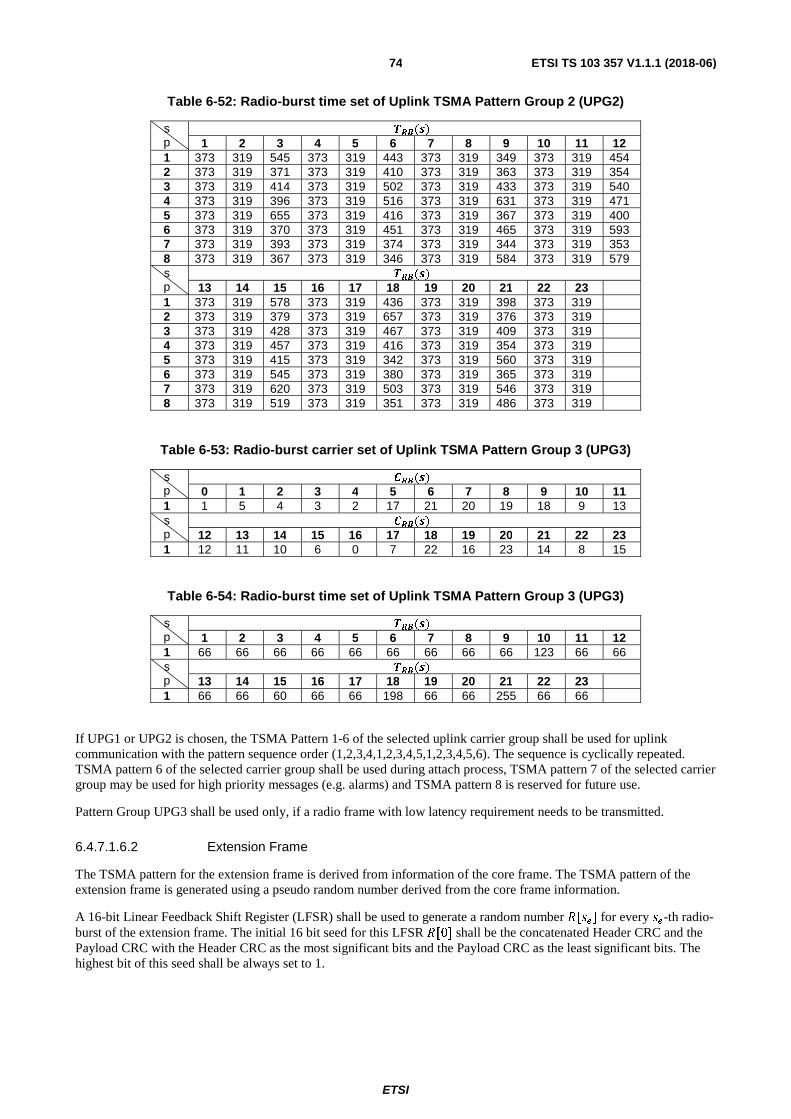
ETSI
ETSI TS 103 357 V1.1.1 (2018-06)74
Table 6-52: Radio-burst time set of Uplink TSMA Pattern Group 2 (UPG2)
s p
�(�) 1 2 3 4 5 6 7 8 9 10 11 12
1 373 319 545 373 319 443 373 319 349 373 319 454 2 373 319 371 373 319 410 373 319 363 373 319 354 3 373 319 414 373 319 502 373 319 433 373 319 540 4 373 319 396 373 319 516 373 319 631 373 319 471 5 373 319 655 373 319 416 373 319 367 373 319 400 6 373 319 370 373 319 451 373 319 465 373 319 593 7 373 319 393 373 319 374 373 319 344 373 319 353 8 373 319 367 373 319 346 373 319 584 373 319 579 s p
�(�) 13 14 15 16 17 18 19 20 21 22 23
1 373 319 578 373 319 436 373 319 398 373 319 2 373 319 379 373 319 657 373 319 376 373 319 3 373 319 428 373 319 467 373 319 409 373 319 4 373 319 457 373 319 416 373 319 354 373 319 5 373 319 415 373 319 342 373 319 560 373 319 6 373 319 545 373 319 380 373 319 365 373 319 7 373 319 620 373 319 503 373 319 546 373 319 8 373 319 519 373 319 351 373 319 486 373 319
Table 6-53: Radio-burst carrier set of Uplink TSMA Pattern Group 3 (UPG3)
s p
�(�) 0 1 2 3 4 5 6 7 8 9 10 11
1 1 5 4 3 2 17 21 20 19 18 9 13 s p
�(�) 12 13 14 15 16 17 18 19 20 21 22 23
1 12 11 10 6 0 7 22 16 23 14 8 15
Table 6-54: Radio-burst time set of Uplink TSMA Pattern Group 3 (UPG3)
s p
�(�) 1 2 3 4 5 6 7 8 9 10 11 12
1 66 66 66 66 66 66 66 66 66 123 66 66 s p
�(�) 13 14 15 16 17 18 19 20 21 22 23
1 66 66 60 66 66 198 66 66 255 66 66
If UPG1 or UPG2 is chosen, the TSMA Pattern 1-6 of the selected uplink carrier group shall be used for uplink communication with the pattern sequence order (1,2,3,4,1,2,3,4,5,1,2,3,4,5,6). The sequence is cyclically repeated. TSMA pattern 6 of the selected carrier group shall be used during attach process, TSMA pattern 7 of the selected carrier group may be used for high priority messages (e.g. alarms) and TSMA pattern 8 is reserved for future use.
Pattern Group UPG3 shall be used only, if a radio frame with low latency requirement needs to be transmitted.
6.4.7.1.6.2 Extension Frame
The TSMA pattern for the extension frame is derived from information of the core frame. The TSMA pattern of the extension frame is generated using a pseudo random number derived from the core frame information.
A 16-bit Linear Feedback Shift Register (LFSR) shall be used to generate a random number �[��] for every ��-th radio-burst of the extension frame. The initial 16 bit seed for this LFSR �[0] shall be the concatenated Header CRC and the Payload CRC with the Header CRC as the most significant bits and the Payload CRC as the least significant bits. The highest bit of this seed shall be always set to 1.

ETSI
ETSI TS 103 357 V1.1.1 (2018-06)75
Table 6-55: LFSR Seed R[0]
Bits: 15 14-8 7-0 1 Header CRC [6-0] Payload CRC [7-0]
The polynomial for the Galois-LFSR in hexadecimal notation shall be (0xB4F3). For every radio-burst of the extension frame, the LFSR shall be applied to derive the next 16 bit number. For radio-burst �� of the extension frame, the number is given by:
����� = !��(���� − 1�)
Where �� shall be (1) for the first radio-burst of the extension frame. The radio-burst time of radio-burst �� in the extension frame shall be calculated by:
�� ���� = ������ + (����� modulo 128)� ∗ ����������
where: ����� shall be the time spacing of the selected uplink pattern group x the transmitted core was part of according to Table 6-46.
For the first radio-burst in the extension frame, this time denotes the delay between the centre of the pilot symbols of the last radio-burst of the core frame and the centre of the pilot symbols of the first radio-burst of the extension frame. The radio-burst carrier number for deriving the transmission frequency of the radio-burst of the extension frame shall be calculated by:
�� ���� = "(�����/256)# modulo 25
For repetition the same values are used for initial transmission and repetition of the frame.
6.4.7.1.7 Downlink TSMA pattern
6.4.7.1.7.1 DL-TS Mode
In downlink a radio frame shall consist of 18 radio-bursts. Therefore TSMA pattern sets with 18 parameters according to the following tables shall be used.
Table 6-56: Radio-burst carrier set of TSMA Pattern Group in downlink (DPG)
s p
�(�) 0 1 2 3 4 5 6 7 8 9 10 11 12 13 14 15 16 17
1 19 18 12 21 15 14 22 2 5 10 17 6 8 4 7 20 13 0 2 10 4 1 7 23 6 3 8 17 2 18 9 22 14 11 16 5 21 3 0 16 11 20 9 13 23 21 2 19 1 15 3 7 12 4 22 6 4 14 9 0 15 7 5 8 18 1 12 19 23 17 16 10 2 13 11 5 6 12 19 10 4 22 13 17 11 5 23 3 1 8 14 0 9 20 6 16 20 3 5 21 10 17 1 12 18 15 11 0 9 2 14 6 8 7 15 0 8 18 9 23 11 20 14 3 16 22 19 13 7 21 12 4 8 4 7 16 22 13 19 2 3 6 15 10 20 23 5 21 17 18 1
Table 6-57: Radio-burst time set of TSMA Pattern Group in downlink (DPG)
s p
�(�) TRB(s) 1 2 3 4 5 6 7 8 9 10 11 12 13 14 15 16 17
1 471 595 594 496 545 445 440 535 601 522 430 545 519 439 484 438 605 2 512 424 649 447 550 611 624 418 501 464 606 509 636 443 465 434 431 3 625 548 540 434 520 559 488 531 501 465 459 428 444 459 505 459 633 4 457 489 612 450 457 440 567 538 516 514 540 474 592 445 577 444 493 5 488 643 626 541 560 550 450 475 520 456 618 447 455 440 455 510 477 6 548 444 459 529 453 525 440 553 583 527 520 461 575 457 464 533 421 7 461 607 501 534 505 569 561 472 509 450 555 440 423 494 448 525 485 8 577 611 464 552 451 508 478 438 443 507 420 553 520 576 580 564 404
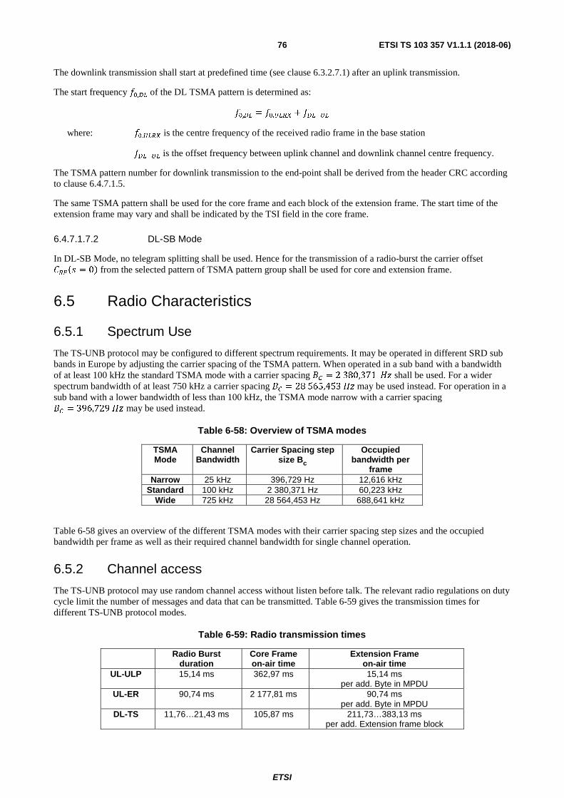
ETSI
ETSI TS 103 357 V1.1.1 (2018-06)76
The downlink transmission shall start at predefined time (see clause 6.3.2.7.1) after an uplink transmission.
The start frequency ��,�� of the DL TSMA pattern is determined as:
��,�� = ��,���� + ������
where: ��,���� is the centre frequency of the received radio frame in the base station
������ is the offset frequency between uplink channel and downlink channel centre frequency.
The TSMA pattern number for downlink transmission to the end-point shall be derived from the header CRC according to clause 6.4.7.1.5.
The same TSMA pattern shall be used for the core frame and each block of the extension frame. The start time of the extension frame may vary and shall be indicated by the TSI field in the core frame.
6.4.7.1.7.2 DL-SB Mode
In DL-SB Mode, no telegram splitting shall be used. Hence for the transmission of a radio-burst the carrier offset ����� = 0� from the selected pattern of TSMA pattern group shall be used for core and extension frame.
6.5 Radio Characteristics
6.5.1 Spectrum Use
The TS-UNB protocol may be configured to different spectrum requirements. It may be operated in different SRD sub bands in Europe by adjusting the carrier spacing of the TSMA pattern. When operated in a sub band with a bandwidth of at least 100 kHz the standard TSMA mode with a carrier spacing �� = 2 380,371 $� shall be used. For a wider spectrum bandwidth of at least 750 kHz a carrier spacing �� = 28 565,453 $� may be used instead. For operation in a sub band with a lower bandwidth of less than 100 kHz, the TSMA mode narrow with a carrier spacing �� = 396,729 $� may be used instead.
Table 6-58: Overview of TSMA modes
TSMA Mode
Channel Bandwidth
Carrier Spacing step size Bc
Occupied bandwidth per
frame Narrow 25 kHz 396,729 Hz 12,616 kHz
Standard 100 kHz 2 380,371 Hz 60,223 kHz Wide 725 kHz 28 564,453 Hz 688,641 kHz
Table 6-58 gives an overview of the different TSMA modes with their carrier spacing step sizes and the occupied bandwidth per frame as well as their required channel bandwidth for single channel operation.
6.5.2 Channel access
The TS-UNB protocol may use random channel access without listen before talk. The relevant radio regulations on duty cycle limit the number of messages and data that can be transmitted. Table 6-59 gives the transmission times for different TS-UNB protocol modes.
Table 6-59: Radio transmission times
Radio Burst duration
Core Frame on-air time
Extension Frame on-air time
UL-ULP 15,14 ms 362,97 ms 15,14 ms per add. Byte in MPDU
UL-ER 90,74 ms 2 177,81 ms 90,74 ms per add. Byte in MPDU
DL-TS 11,76…21,43 ms 105,87 ms 211,73…383,13 ms per add. Extension frame block

ETSI
ETSI TS 103 357 V1.1.1 (2018-06)77
In the TSMA scheme, a radio burst is always followed by a radio transmission pause, thus implementing a certain duty cycle according to the TSMA pattern used. The transmission time of the uplink extension frame is extended by one radio burst per additional byte user data. The transmission time of the downlink extension frame with a fixed number of radio bursts varies depending on the payload to be transmitted.
6.5.3 End-point
6.5.3.1 Carrier Frequency Tolerance
In the end-point symbol time and carrier frequency generation shall be derived from a common reference oscillator (preferable with a frequency of 26 MHz) with a tolerance below ±20 ppm.
6.5.4 Base station
6.5.4.1 Carrier Frequency Tolerance
The base station RF frequency tolerance shall be better than ±5 ppm.
6.5.4.2 Receiver
6.5.4.2.1 Receiver Bandwidth
The receiver bandwidth depends on the system mode of operation and shall be set accordingly.
7 Dynamic Downlink Ultra Narrow Band (DD-UNB) family
7.1 System overview
7.1.1 System elements
7.1.1.1 Architecture
A LTN system running DD-UNB protocol comprises a Service Centre (SC), a number of Base Stations (BS), and many End-points (EP). Some EP may not be in the coverage area of a BS (referred to as Orphaned End-points or OEP). OEP can be connected to the network using a relay link through another EP (called Relay Point or RP).
LTN systems are based on the architecture described in ETSI TS 103 358 [i.9] (Low Throughput Networks (LTN) Architecture). In the case of the DD-UNB system the A-interface protocol supports communication over the A-interface, i.e. between a Base Station (BS) and an End-point (EP); the same protocol provides communication between BS and RP over the A"-interface (typically an EP can be configured to act also as a RP).
The A"-interface is the DD-UNB air interface for the bidirectional relay link between OEP and RP.
The B-interface is the backhaul access network interface (e.g. over cellular) used for communication between BS and SC; backhaul link protocol is out of the scope of the present document.
7.1.1.2 Service Centre
The present document describes a DD-UNB system with a single SC. It is possible to have multiple linked Service Centres to increase capacity for very large systems, but such an arrangement is implementation-specific and out of scope of the present document.

ETSI
ETSI TS 103 357 V1.1.1 (2018-06)78
7.1.1.3 Base station
A DD-UNB BS includes a transmitter and a receiver. The receiver typically has an analogue bandwidth greater than 15 kHz and digital signal processing (DSP) which can receive multiple concurrent DD-UNB signals on different frequencies within that bandwidth. The transmitter typically operates at higher power levels (500 mW erp) than EP with a higher gain antenna. The downlink data rate is 8 times that of the uplink.
BSs are connected to the Service Centre using backhaul transmission links (over B interface).
7.1.1.4 End-points
An EP can receive a single DL transmission or transmit a single UL signal on a single frequency at any one time; this can be on the A or A"-interface.
The A"-interface is used by an EP to communicate with a BS via another EP acting as a relay point (RP). The DD-UNB system is not designed to operate as a multi-hop mesh system and allows only one such "extra" hop for each connection.
7.1.2 Protocol Overview
7.1.2.1 Introduction
The DD-UNB protocol is based on the OSI reference model. A typical implementation of DD-UNB is illustrated in Figure 7-1 (for downlink). Physical layer (PHY) and Medium Access Control (part of layer 2 - Data link layer (DLL)) are described in the present document. The remainder of DLL and higher layers are implementation-dependent.
Figure 7-1: DD-UNB Protocol Layers (Downlink) in example implementation
DD-UNB is designed as an efficient means of meeting, within severely constrained resources, the requirements of applications served by LTN systems, and provides a means of transferring 14-byte application messages between a service centre and end-points. While the basic OSI layering model is used, the inherently-limited resources and the benefits of reducing overheads result in the removal of some opacity between the layers of the DD-UNB system. This applies particularly to addressing where a single addressing scheme is assumed at all layers of the DD-UNB protocol. Layers use common sets of parameters as much as possible, for example the "block number" associated with each connection data unit at layer 3 is also used by lower layers to reduce overhead.
The Medium Access Control (MAC) is treated as part of DLL and used only in uplink direction.
7.1.2.2 Protocol Termination Points
The present document specifies behaviour of PHY and MAC. A typical implementation of DD-UNB provides functionality at higher layers and this clause describes how protocols at those layers might be terminated to provide support for typical applications.

ETSI
ETSI TS 103 357 V1.1.1 (2018-06)79
Figure 7-2 describes the A-interface protocol DL termination points. Note that all Layer 3 downlink services initiated from SC are supported (Figure 7-2 (a)). In addition, Multicast service may be initiated from BS (Figure 7-2 (b)) where this meets application needs.
Figure 7-2: Protocol Termination (A-interface Downlink)
A-interface protocol UL termination points are shown in Figure 7-3.
Figure 7-3: Protocol Termination (A-interface Uplink)
In cases where a relay node is used, Figure 7-4 and Figure 7-5 illustrate protocol termination points in A" downlink. All Layer 3 A" downlink services are initiated from SC; Multicast service may also be initiated from BS.
Figure 7-4: Protocol Termination (A" Downlink - SC initiated App)
Figure 7-5: Protocol Termination (A" Downlink - BS initiated App)

ETSI
ETSI TS 103 357 V1.1.1 (2018-06)80
Figure 7-6 illustrates protocol termination points for A" uplink.
Figure 7-6: Protocol Termination (A"-interface Uplink)
7.1.2.3 System Addressing and Identities
Several address types are used by DD-UNB protocol to address different entities in each system:
• A unique 10 bit Short System ID (SSID) is used to identify the system.
• End-point ID (EPID) is a unique 32 bit BSGP allocated for each EP in the system.
• Base Station ID (BSID) is a unique 13 bit identifier allocated for each BS in the system.
• Connection ID (ConID) is a 14 bit identifier which is unique for each connection within a cell but may be reused in other cells. ConID value 0x0 is reserved for use in A" UL management (see clause 7.3.2.3 and Table 7-6).
In addition a EUI-64 identifier is used for globally-unique identification of End-points.
7.1.3 Upper Layer Principles
DD-UNB provides the L1 / MAC mechanisms to support the implementation of a guaranteed delivery mechanism for streams of Data PDUs (or a definite indication of failure and, in this case, an indication of which blocks have been delivered). Acknowledge PDUs can be used by both L2 and L3 to provide acknowledgement, repetition and flow control for connections on a hop-by-hop and end-to-end basis respectively. Layers above L1 / MAC are implementation-dependent.
Connection-oriented links are anticipated to dominate communications between application entities in a DD-UNB system.
In order to identify each EP uniquely, a 32 bit EP identifier is used (about 4 billion differs). Since a typical system would have a much smaller EP population, DD-UNB uses connection identifiers, reducing overheads.
Connections are made between specific "ports" of application entities. Up to 16 ports can be associated with one EP. A RP can relay as many connections as required although there will typically be implementation restrictions.
Connections are managed with Control PDUs, which can be sent connectionless, and if necessary routed through a multi-hop path using only the information which they themselves contain. Control PDUs are resent if lost.
7.1.4 Layer 3 (NET) Overview
Layer 3 is implementation-dependent. In a DD-UNB implementation many connections are typically "semi-permanent": a connection is set up when an EP begins operation and not removed unless one or both ends of the connection cease operation. However this is not mandated.
ETSI
ETSI TS 103 357 V1.1.1 (2018-06)81
7.1.5 Layer 2 (DLL) Overview
7.1.5.1 Overview
DD-UNB Layer 1 is designed to support a range of Layer 2 implementations, but this specification details the MAC sub-layer employed in DD-UNB.
DD-UNB Layer 2 is also designed to support message encryption and authentication of application messages, although other approaches to encryption may be implemented if required for certain applications.
7.1.5.2 MAC Sublayer
Medium Access Control (MAC) is considered as a DLL sublayer.
Medium access in the downlink and A" downlink is based upon the spectrum access rules including regulatory duty cycle limitation. However, in the Uplink and A" Uplink there is potential for multiple EP to transmit simultaneously, therefore MAC is employed to manage UL transmission collision. The MAC procedure (based on slotted ALOHA in time) is described in clause 7.3.2.
7.1.6 Layer 1 (PHY) Overview
7.1.6.1 Frequency use
A-interface Downlink and Uplink frequencies may or may not be the same; regulatory constraints suggest they will typically be different. Frequency planning may be employed to manage interference between cells.
A"-interface Downlink and Uplink transmissions are intended for reception by EP (i.e. by OEP, and by EP configured to act as a RP respectively) and therefore frequencies used should reflect EP receiver implementation. Therefore A"-interface typically uses a frequency close to that of the A-interface Downlink.
Frequency hopping is optional. In a hopping system the BS (and RP on A"-interface) transmissions hop in a pre-determined pattern, with one timeslot per hop.
7.1.6.2 A-interface Downlink and Uplink timing
The UL and DL physical layer operates using TDD with a frame of 60 timeslots, each of length 400 ms. A frame comprises Downlink, Uplink and Uplink Acknowledge subframes, as illustrated in Figure 7-7. The allocation of timeslots to these subframes is variable and is broadcast by the BS for each frame. For relay operation a variable-length A"-interface subframe (during the A-interface UL subframe) is assigned for traffic between the RP and the OEP.
The frame number is a 6-bit number that cycles modulo 64, giving a "superframe" of 64 frames.

ETSI
ETSI TS 103 357 V1.1.1 (2018-06)82
Figure 7-7: Example Frame and Subframe Timings
The downlink data-burst accommodates the L1 PDUs from the following physical channels (if present) in the order listed:
• A "Sync channel" used to synchronize EP with the frame and, if used, the frequency hopping sequence. Sync channel does not carry any upper-layer SDU.
• A "Broadcast channel" defines the format of the downlink data-burst that is to follow. Broadcast channel carries no upper-layer SDU.
• A "Multicast channel" carries Multicast data addressed to all EP in the cell.
• A "Control channel" carries signalling information mainly used in the set-up and control of layer 3 connections and other procedures.
• A "Wakeup channel" carries the connection identifiers for those connections for which Connection PDUs are being sent in the current frame.
• An "Acknowledge channel" carries acknowledgments for the UL Connection (Data) PDUs previously received.
• A "Connection channel" carries Connection (Data) PDUs destined for individual connections, as indicated in the Wakeup channel.
This order allows EP for which there is no connection data to switch off as soon as possible during the data-burst to preserve power.
L1 PDUs are typically BCH codewords of differing strength reflecting differing importance of error-free reception and the use, or not, of acknowledgement.
A-interface UL protocol implements Slotted Aloha MAC: each EP transmits its UL data and UL Acknowledge data-bursts with random (slotted) timing within the appropriate subframes. UL data and UL Acknowledge data-bursts are sent on a random frequency within the allocation.

ETSI
ETSI TS 103 357 V1.1.1 (2018-06)83
7.1.6.3 A"-Interface (Relay Operation) timing
An EP which cannot successfully receive a base station is called an Orphan EP (OEP). An OEP may communicate with a BS via a Relay EP (RP) if the radio path permits; EP to RP communication uses the A"-interface. In normal circumstances OEP are avoided by careful deployment planning, however relay operation provides an option in exceptional circumstances. One or more OEP may be served by a RP. Enabling EP to act as RP is part of system planning and configuration activity.
The RP retransmits any required part of a DL data-burst on the A"-interface in a format similar to that of the DL. Transmissions from OEP (i.e. A" Uplink) then follow in the same A" subframe. A MAC procedure is employed in A" uplink which is described in clause 7.3.2.3. Transmissions in both directions on the A"-interface take place at the same data rate as the main downlink.
7.1.6.4 Frequency and Time Synchronization
An EP typically has a low-stability frequency reference. It establishes and maintains frequency and time synchronization by receiving and decoding transmissions from a BS.
7.2 Network Layer The DD-UNB Layer 3 is implementation-dependent.
7.3 Data Link Layer
7.3.1 DLL introduction
The DD-UNB DLL is implementation-dependent and a range of DLL implementations can be used to take advantage of the features supported by the DD-UNB PHY, in particular the logical channels provided. However MAC sub-layer functionality is closely related to the PHY constraints of UNB (and DD-UNB specifics) and shall be implemented as described in the present document.
7.3.2 MAC sub-layer
7.3.2.1 MAC on A-interface UL - Data Subframe
7.3.2.1.1 General
The A-interface UL protocol MAC procedure is based on the "Aloha" approach randomized in both time (slotted Aloha) and frequency. The MAC procedure randomizes the timing of the transmission of data-bursts subject to avoiding unnecessary delays in sending data and subject to constraints arising from selected frame formats.
7.3.2.1.2 UL throttle
The BS shall transmit (as part of its broadcast channel, see Table 7-7) a number between 0 and 7 related to the degree of overall uplink congestion it is experiencing. This number is called "uplink throttle value". If the uplink throttle value is not zero, then independently for each current or attempted connection (i.e. each active port) an EP shall generate in each frame a random number "Rand" between 1 and 127 (inclusive) and shall only transmit, in that frame, UL data-bursts related to that port if the following condition is met:
�% � ≥ 128 − 2( �!"#$%& ��#� '(#!�)
This allows the BS to influence the population of EPs transmitting, providing a measure of UL medium access control. Any data-bursts not transmitted shall be deferred to the following frame (and the same process repeated if applicable).
7.3.2.1.3 Time domain
The random selection of timing of UL transmissions is strongly influenced by current physical layer configuration (including frame format) and constraints on the handling of data-bursts to be transmitted.

ETSI
ETSI TS 103 357 V1.1.1 (2018-06)84
A number of UL transmission time windows are available to an EP in the UL Data subframe, each is of 8 timeslots duration (starting with the first timeslot of the UL Data subframe). UL data-bursts occupy 1 or 2 such windows (see clause 7.4.3.3.3). The number of such windows available in an UL subframe is defined by the selected frame format; however in the case of a RP some of the windows may be assigned to the A" UL subframe and thus be unavailable to the A-interface UL.
UL data-bursts for transmission in a given frame shall be assigned randomly for transmission in available windows (subject also to the constraints of clause 7.4.3.3.3), the seed for the randomization shall be assigned randomly to each EP/RP. Any data-bursts which cannot be accommodated shall be deferred to the following frame.
7.3.2.1.4 Frequency domain
If an EP has one or more data-bursts to send during the UL subframe, MAC shall select, at random and independently for each data-burst, a UL sub-channel on which to transmit the data-burst (a value FMAC is provided to PHY, see clause 7.3.2.2.3); an exception is described in clause 7.4.3.3.3 for strongly-coded PDUs.
7.3.2.2 MAC on A-interface UL - Ack Subframe
7.3.2.2.1 General
The A-interface UL protocol MAC procedure is based on the "Aloha" approach randomized in both time (slotted Aloha) and frequency.
7.3.2.2.2 Time domain
The random selection of timing of UL transmissions is strongly influenced by current physical layer configuration (including frame format) and constraints on the handling of data-bursts to be transmitted.
A number of UL transmission time windows are available to an EP in the UL Ack subframe, each is of 4 timeslots duration (starting with the first timeslot of the UL Ack subframe). Each UL data-burst occupies one such window (see clause 7.4.3.3.4). The number of such windows available in an UL subframe is defined by the selected frame format.
UL data-bursts for transmission in a given frame shall be assigned randomly for transmission in available windows, the seed for the randomization shall be assigned randomly to each EP/RP. Any data-bursts which cannot be accommodated shall be deferred to the following frame.
7.3.2.2.3 Frequency domain
If an EP has one or more data-bursts to send during the UL Ack subframe, MAC shall select, at random and independently for each data-burst, a UL sub-channel on which to transmit the data-burst (a value FMAC is provided to PHY, see clause 7.3.2).
7.3.2.3 MAC on A"-interface UL
7.3.2.3.1 General
The DD-UNB A" UL supports randomization in the time domain but not the frequency domain.
In the A"-interface DL for each frame, an RP shall indicate to attached OEP (see clause 7.4.2.3) that the current A"-interface subframe is either "open" or "closed":
• In an open A"-interface subframe any attached OEP may transmit.
• In a closed A"-interface subframe the RP indicates that a particular OEP, and only that OEP, may transmit during the current subframe. Closed frames are mainly intended for the transmission of data and Ack PDUs, although Control PDUs may also be sent.
• An OEP may request a closed subframe by sending an uplink data-burst to the ROS containing only a Sync PDU (see Table 7-6).
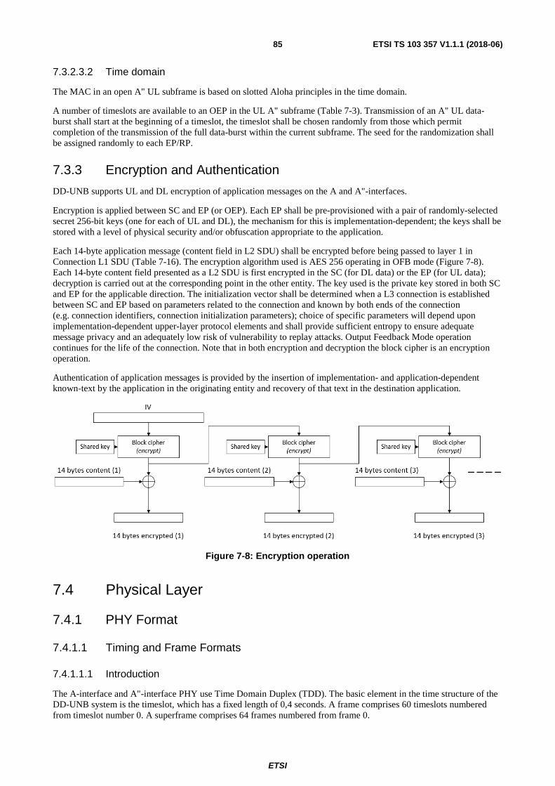
ETSI
ETSI TS 103 357 V1.1.1 (2018-06)85
7.3.2.3.2 Time domain
The MAC in an open A" UL subframe is based on slotted Aloha principles in the time domain.
A number of timeslots are available to an OEP in the UL A" subframe (Table 7-3). Transmission of an A" UL data-burst shall start at the beginning of a timeslot, the timeslot shall be chosen randomly from those which permit completion of the transmission of the full data-burst within the current subframe. The seed for the randomization shall be assigned randomly to each EP/RP.
7.3.3 Encryption and Authentication
DD-UNB supports UL and DL encryption of application messages on the A and A"-interfaces.
Encryption is applied between SC and EP (or OEP). Each EP shall be pre-provisioned with a pair of randomly-selected secret 256-bit keys (one for each of UL and DL), the mechanism for this is implementation-dependent; the keys shall be stored with a level of physical security and/or obfuscation appropriate to the application.
Each 14-byte application message (content field in L2 SDU) shall be encrypted before being passed to layer 1 in Connection L1 SDU (Table 7-16). The encryption algorithm used is AES 256 operating in OFB mode (Figure 7-8). Each 14-byte content field presented as a L2 SDU is first encrypted in the SC (for DL data) or the EP (for UL data); decryption is carried out at the corresponding point in the other entity. The key used is the private key stored in both SC and EP for the applicable direction. The initialization vector shall be determined when a L3 connection is established between SC and EP based on parameters related to the connection and known by both ends of the connection (e.g. connection identifiers, connection initialization parameters); choice of specific parameters will depend upon implementation-dependent upper-layer protocol elements and shall provide sufficient entropy to ensure adequate message privacy and an adequately low risk of vulnerability to replay attacks. Output Feedback Mode operation continues for the life of the connection. Note that in both encryption and decryption the block cipher is an encryption operation.
Authentication of application messages is provided by the insertion of implementation- and application-dependent known-text by the application in the originating entity and recovery of that text in the destination application.
Figure 7-8: Encryption operation
7.4 Physical Layer
7.4.1 PHY Format
7.4.1.1 Timing and Frame Formats
7.4.1.1.1 Introduction
The A-interface and A"-interface PHY use Time Domain Duplex (TDD). The basic element in the time structure of the DD-UNB system is the timeslot, which has a fixed length of 0,4 seconds. A frame comprises 60 timeslots numbered from timeslot number 0. A superframe comprises 64 frames numbered from frame 0.

ETSI
ETSI TS 103 357 V1.1.1 (2018-06)86
Each DD-UNB data-burst shall comprise a sequence of (one or more) radio-bursts in consecutive timeslots; its duration is determined by the number and length of the relevant PDUs to be transmitted.
Each radio-burst is divided into an active period (384 ms) and a guard period (16 ms), the latter is provided at the end of each timeslot and is the period during which frequency changes can take place to support optional frequency hopping as described in clause 7.5.1. Transmit power shall be reduced between radio-bursts as described in clause 7.5.3. Data is transmitted during the active part of each timeslot. When all data in a data-burst has been transmitted, transmission of the data-burst shall cease.
Each frame is divided into variable-length subframes allocated to carry specific Physical Channels (see clause 7.4.1.2); the order of subframes is as shown in Table 7-1. Data-bursts shall be transmitted as determined by the MAC layer in the indicated subframe. In the DL a DD-UNB BS shall transmit no more than one data-burst in each subframe of a given frame; transmission of each DL data-burst starts in the first timeslot of the related subframe. In the UL more than one data-burst may be transmitted under the control of the MAC procedure (see clause 7.3.2.3).
If the assigned frame format means a given subframe cannot accommodate all the PDUs to be transmitted, remaining PDUs shall be transmitted in the next such subframe available (i.e. in the next frame).
Table 7-1: Subframe types
Used for A-interface
DL subframe DL Physical Channels UL data subframe Uplink Data Physical Channel (UDPCH) UL Acknowledge subframe Uplink Acknowledge Physical Channel
(UAPCH) A"-interface
A" DL subframe Local Downlink Physical Channels A" UL data/ack subframe Local Uplink Physical Channels
The valid frame formats for the DD-UNB system are listed in Table 7-2 and Table 7-3. Figure 7-9 shows an example frame timing for A-interface format 0 and A"-interface format 1.
The start of the A" subframe within the frame is fixed (starting in timeslot 19) for all frame formats.
Timeslot 55 is reserved (no transmissions shall be made on any interface) in all frame formats.
Figure 7-9: Example Frame Structure

ETSI
ETSI TS 103 357 V1.1.1 (2018-06)87
7.4.1.1.2 A-interface Frame Formats
There are 8 frame formats defined for the A-interface of a DD-UNB system, the number of timeslots in each subframe are shown in Table 7-2; the timeslots are allocated to subframes within the frame in the order shown. The choice of A-interface frame format shall be made by the BS on a per-frame basis and should take into account the traffic expected by the BS.
The example in Figure 7-9 includes A-interface format 0.
Table 7-2: A-interface Frame Formats - No. of timeslots in each subframe
Frame Format Index
DL Noise Measurement UL Data UL Ack
Synchronization Other DL
0 1 6 0 48 4 1 1 10 0 40 8 2 1 14 0 40 4 3 1 18 0 32 8 4 1 6 12 32 8 5 1 10 8 32 8 6 1 14 4 32 8 7 1 17 1 32 8
8-15 Reserved
7.4.1.1.3 A"-interface Subframe Formats
There are 5 frame formats defined for the A"-interface of a DD-UNB system, the number of timeslots in each subframe is shown in Table 7-3; timeslots are allocated to subframes within the A"-interface subframe in the order shown. The choice of A"-interface format shall be made by the RP on a per-frame basis and should take into account the traffic expected by the RP.
The example in Figure 7-9 includes A"-interface format 1.
Table 7-3: A"-interface Subframe Formats
Frame Format Index
DL UL Data/Ack
Synchronization Other DL
0 1 1 5 1 1 5 5 2 1 9 5 3 1 13 5 4 1 17 5
5-14 Reserved
7.4.1.1.4 Synchronization and Frame Offset
BS in a DD-UNB system may be synchronized to a common timing of timeslot 0 of frame 0 (i.e. start of a superframe) with a maximum error of ±8 ms; such synchronization allows management of inter-BS interference. The method of maintaining synchronization is implementation-dependent.
As described in Table 7-2, the DD-UNB DL is active in the first part of each frame. In order to distribute DL transmissions from multiple synchronized BS more evenly in time, an optional frame offset may be applied to the timing in a specific cell: the value of offset shall be 0, 20 or 40 timeslots. The timing offset used in a cell is signalled in the Downlink Sync pre-coding block as Frame Offset.

ETSI
ETSI TS 103 357 V1.1.1 (2018-06)88
7.4.1.1.5 Battery saving
7.4.1.1.5.1 Battery saving in DD-UNB
DD-UNB supports three classes of EP operation. Class(es) supported by a specific EP are implementation-dependent as below. In battery-save mode an EP/RP does not support air-interface activity; it shall exit battery-save mode in time to operate as described below.
Further battery-saving mechanisms are possible, including different EP to be active in different frames / superframes in Class B (to support a greater number of battery-saving EP); these mechanisms are for further study.
All battery-saving classes are applicable only after an EP has established a connection with a BS.
7.4.1.1.5.2 Class C
An EP operating in Class C listens in every frame for BS and/or RP DL transmissions. It may enter battery-save mode (i.e. stop A-interface reception) as soon as it has received any data intended for it or has received an indication that there is no such data in the current frame (clause 7.4.2.4).
A RP may also support Class C, but shall complete any activity required on the A"-interface before entering battery-save mode.
7.4.1.1.5.3 Class B
An EP/RP operating in Class B operates as specified for Class A except that the air interface is only active in frame 0 of each superframe, unless the result of activity in frame 0 indicates a requirement for ongoing activity in subsequent frame(s). As soon as such activity is completed the EP/RP may enter battery-save mode.
Management of Class B battery-saving is implementation-dependent and requires that the associated BS is aware of any EP/RP in Class B operation and schedules DL activity accordingly.
7.4.1.1.5.4 Class A
An EP in Class A operation is normally inactive on the air interface; however it may maintain an implementation-dependent level of synchronization with the DD-UNB network. If the application in the EP determines that an A-interface transmission is required the EP shall re-establish full synchronization with its associated BS and initiate UL communication in the normal way. The EP shall then continue to monitor (and respond to) the A-interface in Class C for one superframe cycle (including the frame corresponding to that in which the EP transmission was initiated) after which it may re-enter battery save mode if such ongoing activity has been completed.
Management of Class A battery-saving is implementation-dependent and requires that the associated BS and/or any application is aware of any EP/RP in Class A operation to ensure DL activity is timed accordingly.
7.4.1.2 Physical Channels
For the Downlink and A" downlink, each logical channel transferring data from higher layers corresponds to a physical channel, with three additional physical channels: the Sync Physical Channel, the Broadcast Physical Channel and the Wakeup Physical Channel.
For the Uplink, two of the logical channels (the Uplink DLL Control channel and the Uplink DLL Connection Channel) are multiplexed into one physical channel (Uplink Physical Data Channel).
DL physical channels are:
• Downlink Sync Physical Channel (DSPCH): carries Sync PDUs that are generated at BS physical layer (i.e. there is no Sync SDU required).
• Downlink Broadcast Physical Channel (DBPCH): carries Broadcast PDUs that are generated at BS physical layer (i.e. there is no Broadcast SDU required).
• Downlink Multicast Physical Channel (DMPCH): carries Multicast L1 PDUs, which BS physical layer has received via Multicast L1 SDUs, to all EP in the cell.
ETSI
ETSI TS 103 357 V1.1.1 (2018-06)89
• Downlink Control Physical Channel (DCPCH): carries Control L1 PDUs which BS physical layer has received via Control L1 SDUs, targeted to a specific EP for a specific connection.
• Downlink Wakeup Physical Channel (DWPCH): carries Wakeup PDUs that are generated at BS L1 (i.e. there is no Wakeup SDU required) which it extracts from connection data information.
• Downlink Acknowledge Physical Channel (DAPCH): carries Acknowledge L1 PDUs which BS physical layer has received from upper layers via Acknowledge SDUs, confirming associated uplink Data PDUs sent in previous frame, were received successfully.
• Downlink Connection Physical Channel (DXPCH): carries Connection L1 PDUs which BS physical layer has received via Connection L1 SDUs, targeted to a specific EP for a specific connection, that are being transported along the established connection.
UL physical channels are:
• Uplink Data Physical Channel (UDPCH): carries data PDUs which EP physical layer has received via either Control L1 SDUs or Connection L1 SDUs.
• Uplink Acknowledge Physical Channel (UAPCH): carries Acknowledge L1 PDUs which EP physical layer has received in upper layers' Acknowledge SDUs. These confirm that associated downlink Connection PDUs sent in this frame, and destined to this EP for a specific connection, were received successfully.
A" physical channels are:
• Local Sync Physical Channel (LSPCH) which is the A" equivalent of DSPCH.
• Local Downlink Broadcast Physical Channel (LBPCH) which is the A" equivalent of DBPCH.
• Local Multicast Physical Channel (LMPCH) which is the A"-interface equivalent of DMPCH.
• Local Control Physical Channel (LCPCH) which is the A"-interface equivalent of DCPCH.
• Local Wakeup Physical Channel (LWPCH) which is the A"-interface equivalent of DWPCH.
• Local Acknowledge Physical Channel (LAPCH) which is the A"-interface equivalent of DAPCH.
• Local Connection Physical Channel (LXPCH) which is the A"-interface equivalent of DXPCH.
• Local Uplink Descriptor Physical Channel (LUDSPCH) which is the A"-interface Uplink equivalent of DSPCH and DBPCH combined.
• Local Uplink Control Physical Channel (LUCPCH) which is the A"-interface Uplink equivalent of DCPCH.
• Local Uplink Wakeup Physical Channel (LUWPCH) which is the A"-interface Uplink equivalent of DWPCH.
• Local Uplink Acknowledge Physical Channel (LUAPCH) which is the A"-interface Uplink equivalent of DAPCH.
• Local Uplink Connection Physical Channel (LUXPCH) which is the A"-interface Uplink equivalent of DXPCH.
7.4.2 L1 PDUs and SDUs
7.4.2.1 Overview
Figure 7-10 shows how information is passed to/from Physical layer (downlink example), using L1 PDUs and SDUs.

ETSI
ETSI TS 103 357 V1.1.1 (2018-06)90
Figure 7-10: PHY PDUs and SDUs (Downlink)
L1 PDUs and SDUs shall be constructed as described below.
7.4.2.2 Sync PDU
Sync PDU is created at L1 and is formed by combining an uncoded Sync Header with a Sync Codeword (i.e. SC codeword, see Table 7-26 and Table 7-28) which is the result of BCH coding of Sync pre-coding block.
Sync Header is defined as follows:
Table 7-4: Sync Header
Type Preamble Sequence Sync Word Downlink / A" Downlink
"0101… 0101" (48 bits) followed by "1010… 1010" (16 bits)
"0xB0E2" (16 bits)
A" Uplink "0x470D" (16 bits)
Uplink / Uplink Ack
(0 bits)
"0xB8D0" (16 bits) When used for sending normal data/control and Ack "0x0B1D" (16 bits) When used for sending strongly-coded (double) data/control
For A-interface downlink and A" downlink, the Sync pre-coding block has a length of 49 bits, see Table 7-5.
Table 7-5: Downlink and A"-interface Downlink Sync pre-coding block
Field Length (bits) Notes SSID 10 Short system ID BSID 13 Base Station ID
Frame Offset 2 0x0: Frame timing in this cell synchronized with system reference time 0x1: Frame timing in this cell delayed 20 timeslots from system reference time 0x2: Frame timing in this cell delayed 40 timeslots from system reference time
DL Hopping flag 1 0x0 = single DL frequency used 0x1 = DL hopping used
Hop Phase Offset 5 If DL Hopping Flag = 0x0: Reserved (set to 0) If DL Hopping Flag = 0x1: Value to be added to index used to look up centre frequency in each timeslot
Frame Number 6 (0 - 63) frame number Slot Number 8 Timeslot number of slot in which this PDU is transmitted
Frame Format 4 Frame format index
For A" uplink, the Sync pre-coding block is called "A" UL Descriptor" (and the codeword used is called DC, see Table 7-28). It has a length of 49 bits and contains Sync and other information describing the current A" UL data-burst, see Table 7-6.

ETSI
ETSI TS 103 357 V1.1.1 (2018-06)91
Table 7-6: A" Uplink Sync pre-coding block (A" UL Descriptor)
Field Length (bits) Notes Reserved 3 Reserved field (set to 0) NumStrongCntlCw 2 Number of Strong Control PDUs SSID 10 Short system ID BSID 13 Base Station ID ConID 14 Request closed frame for connection ID (0x0
means no request) NumCntlCw 3 Number of Control PDUs NumWakeupCw 2 Number of Wakeup PDUs NumAckCw 2 Number of Ack PDUs
In A-interface Uplink, Sync PDU does not exist; the Sync header (16 bits, see Table 7-4) is transmitted at the beginning of each UL or UL Acknowledge data-burst and indicates the strength of the coding used for the rest of the data-burst. For other links, length of Sync PDU is 192 bits.
7.4.2.3 Broadcast PDU
Broadcast PDU contains information describing the structure of the DL data-burst. The Broadcast PDU has different formats for the downlink and A" downlink.
The Broadcast PDU is a broadcast codeword of length 175 bits.
For the A-interface downlink, the Broadcast pre-coding block has length 51 bits, see Table 7-7.
Table 7-7: A-interface Downlink Broadcast pre-coding block
Field Length (bits) Notes Reserved 1 Reserved field (set to 0) Multicast Repeat 1 Multicast repeat flag NumWeakAckCw 3 Number of Weak Ack PDUs UL frequency 6 UL_Chan_Freq (note) Reserved 6 Reserved field (set to 0) UL throttle 3 UL throttle value BC BSGP 4 Broadcasted BSGP Reserved 2 Reserved field (set to 0) NumStrongCntlCw 5 Number of Strong Control PDUs NumMulticastCw 4 Number of Multicast PDUs NumCntlCw 5 Number of Control PDUs NumWakeupCw 5 Number of Wakeup PDUs NumAckCw 5 Number of Ack PDUs Fast reconnect 1 0 = use normal reconnection,
1 = use fast reconnection (see "Fast Find" in clause 7.4.4.1)
NOTE: This field contains the value n which defines the UL_Chan_Freq selected for the cell, see clause 7.5.2.3.
For A" downlink, the Broadcast pre-coding block is of length 51 bits, see Table 7-8.

ETSI
ETSI TS 103 357 V1.1.1 (2018-06)92
Table 7-8: A" Downlink Broadcast pre-coding block
Field Length (bits) Notes Reserved 8 Reserved field (set to 0) Multicast Repeat 1 Multicast repeat flag NumStrongCntlCw 5 Number of Strong Control PDUs Tx Power 2 A" Transmit Power level Reservation protocol 1 0 = don't use reservation (MAC) protocol ConID 14 A" reserved connection ID (0x0 means not
reserved i.e. "Open") NumMulticastCw 4 Number of Multicast PDUs NumCntlCw 5 Number of Control PDUs NumWakeupCw 5 Number of Wakeup PDUs NumAckCw 5 Number of Ack PDUs Fast reconnect 1 0 = use slow reconnection,
1 = use fast reconnection (see "Fast Find" in clause 7.4.4.1)
7.4.2.4 Wakeup PDU
Each Wakeup PDU contains 2 wakeup messages. Each wakeup message is 18 bits long which is evaluated and filled at physical layer, according to what is going to be transmitted on the data channel so that relevant EP stay up and anticipate, whereas others go to sleep and save power.
Each wakeup message contains 14 bits Connection ID which is extracted from Connection L1 SDU. Wakeup PDU is a Codeword which is the result of BCH coding of wakeup pre-coding block (i.e. WU codeword in Table 7-26 and Table 7-28). Wakeup PDU is 175 bits long.
The Wakeup pre-coding block is 51 bits long, see Table 7-9.
Table 7-9: Wakeup pre-coding block
Field Length (bits)
Content
Reserved 15 Reserved field (set to 0) Wakeup message 1
18 Field Length (bits) Notes High Interference
1 SFEC Flag indicating strong coding is used or not
Blkcount 3 Number of Connection PDUs to be sent this frame
ConID 14 1st Connection ID Wakeup message 2
18 Field Length (bits) Notes High Interference
1 SFEC Flag indicating strong coding is used or not
Blkcount 3 Number of Connection PDUs to be sent this frame
ConID 14 2nd Connection ID or 0x0 if no further messages indicated
7.4.2.5 Multicast L1 SDU and PDU
Multicast L1 SDU can have two different lengths (51 bits and 139 bits).
The Multicast Short L1 pre-coding block is identical to the Multicast Short L1 SDU and therefore is 51 bits.
The Multicast Long L1 pre-coding block is described in Table 7-10.
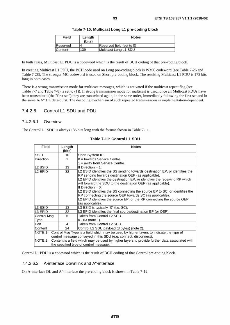
ETSI
ETSI TS 103 357 V1.1.1 (2018-06)93
Table 7-10: Multicast Long L1 pre-coding block
Field Length (bits)
Notes
Reserved 4 Reserved field (set to 0) Content 139 Multicast Long L1 SDU
In both cases, Multicast L1 PDU is a codeword which is the result of BCH coding of that pre-coding block.
In creating Multicast L1 PDU, the BCH code used on Long pre-coding block is WMC codeword (see Table 7-26 and Table 7-28). The stronger MC codeword is used on Short pre-coding block. The resulting Multicast L1 PDU is 175 bits long in both cases.
There is a strong transmission mode for multicast messages, which is activated if the multicast repeat flag (see Table 7-7 and Table 7-8) is set to (1)). If strong transmission mode for multicast is used, once all Multicast PDUs have been transmitted (the "first set") they are transmitted again, in the same order, immediately following the first set and in the same A/A" DL data-burst. The decoding mechanism of such repeated transmissions is implementation-dependent.
7.4.2.6 Control L1 SDU and PDU
7.4.2.6.1 Overview
The Control L1 SDU is always 135 bits long with the format shown in Table 7-11.
Table 7-11: Control L1 SDU
Field Length (bits)
Notes
SSID 10 Short System ID. Direction 1 0 = towards Service Centre.
1 = away from Service Centre. L2 BSID 13 If Direction = 1:
L2 BSID identifies the BS sending towards destination EP, or identifies the RP sending towards destination OEP (as applicable). L2 EPID identifies the destination EP, or identifies the receiving RP which will forward the SDU to the destination OEP (as applicable). If Direction = 0: L2 BSID identifies the BS connecting the source EP to SC, or identifies the RP connecting the source OEP towards SC (as applicable). L2 EPID identifies the source EP, or the RP connecting the source OEP (as applicable).
L2 EPID 32
L3 BSID 13 L3 BSID is typically "0" (i.e. SC). L3 EPID identifies the final source/destination EP (or OEP). L3 EPID 32
Control Msg Type
6 Taken from Control L2 SDU. 0 - 63 (note 1).
Port 4 Taken from Control L2 SDU. Content 24 Control L2 SDU payload (3 bytes) (note 2). NOTE 1: Control Msg Type is a field which may be used by higher layers to indicate the type of
control message conveyed in this SDU (e.g. connect, disconnect). NOTE 2: Content is a field which may be used by higher layers to provide further data associated with
the specified type of control message.
Control L1 PDU is a codeword which is the result of BCH coding of that Control pre-coding block.
7.4.2.6.2 A-interface Downlink and A"-interface
On A-interface DL and A"-interface the pre-coding block is shown in Table 7-12.

ETSI
ETSI TS 103 357 V1.1.1 (2018-06)94
Table 7-12: Downlink/A" Control L1 pre-coding block
Field Length (bits)
Notes
Reserved 1 Reserved field (set to 0) Content 135 Control L1 SDU
In this case Control L1 PDU is 168 bits if normal coding (i.e. CC codeword, see Table 7-26 and Table 7-28) is used, and 252 bits if strong coding (i.e. SCC codeword, see Table 7-26 and Table 7-28) is used.
7.4.2.6.3 A-interface Uplink
In UL there is only one physical channel (UDPCH) to carry both control and connection data, the corresponding PDU is called Data L1 PDU. For normal coding strength see Table 7-13.
Table 7-13: Uplink Data L1 pre-coding block - normal strength coding
Field Length (bits)
Notes
Content Type 1 = 0 for Control Content 135 Control L1 SDU
The resulting Data L1 PDU after coding is 176 bits long (i.e. CC codeword in Table 7-27).
In circumstances where Uplink faces high interference, an entity may use double codeword format Data PDUs see Table 7-14 and Table 7-15.
Table 7-14: Uplink Data L1 pre-coding block, first half
Field Length (bits)
Notes
Flag 1 = 0 for first half content 75 First 75 bits out of 136 from Table 7-13
Table 7-15: Uplink Data L1 pre-coding block, second half
Field Length (bits)
Notes
Flag 1 = 1 for second half CRC 14 CRC calculated across all data in the
Control L1 SDU content 61 Last 61 bits out of 136 from Table 7-13
The two resulting strongly coded Data L1 PDUs (176 bits each, see SCC codeword in Table 7-27) carrying a single Control L1 SDU shall be transmitted consecutively (sent as one UL data-burst, occupying 16 timeslots).
The CRC shall be the bitwise inverse of that calculated according to the following polynomial:
x14 + x10 + x6 + x1 + x0
Initialization value: 0x3fff
7.4.2.7 Connection L1 SDU and PDU
7.4.2.7.1 Connection L1 SDU
Connection L1 SDU is 131 bits long as described in Table 7-16.

ETSI
ETSI TS 103 357 V1.1.1 (2018-06)95
Table 7-16: Connection L1 SDU
Field Length (bits)
Notes
ConID 14 Connection ID BlkNum 5 PDU block number allocated by layer 3 Content 112 payload (14 bytes)
7.4.2.7.2 A-interface Downlink and A"-interface
PHY extracts Connection ID (14 bits) from the Connection L1 SDU and puts it in Wakeup PDU as explained in clause 7.4.2.4. The Connection L1 pre-coding block is shown in Table 7-17.
Table 7-17: A-interface Downlink/A" Connection L1 pre-coding block
Field Length (bits)
Notes
Reserved 7 Reserved field (set to 0) Content 117 Connection L1 SDU without its
Connection ID field
PHY creates the Connection L1 PDU which is simply a codeword as the result of BCH coding of the pre-coding block.
Connection L1 PDU can be 168 bits long if normal coding (i.e. XC codeword, see Table 7-26 and Table 7-28) is used, or 252 bits long if strong coding (i.e. SXC codeword, see Table 7-26 and Table 7-28) is used. Connection L1 PDUs for the same connection in the same data-burst shall be transmitted in order and consecutively.
7.4.2.7.3 A-interface Uplink
In this case, the pre-coding block contains Connection L1 SDU (including its ConID field) plus 5 bits header added by PHY, so the pre-coding block is 136 bits:
Table 7-18: Uplink Data L1 pre-coding block - normal strength coding
Field Length (bits)
Notes
Content Type 1 =1 for Connection (i.e. data) XC BSGP 4 BSGP used for UL data Content 131 Connection L1 SDU for uplink
(For details of the XC BSGP field, refer to clause 7.4.4.9.)
The resulting L1 Data PDU after coding is 176 bits long (i.e. XC codeword in Table 7-27).
In a high interference situation an entity may use double codeword format Data PDUs (e.g. SXC codeword, see Table 7-27), in the way described in clause 7.4.3.5. PHY creates two L1 Data PDUs as the result of BCH coding of the first half and second half of the pre-coding block, carrying a single Connection L1 SDU, which shall be transmitted consecutively (in one data-burst, occupying 16 timeslots).
Note that EP may transmit more than one UL data-burst in a single frame.
Data L1 PDUs for the same connection shall be transmitted in order. Received Data L1 PDUs with incorrect (out of sequence) numbers may be discarded.
7.4.2.8 Acknowledge L1 SDU
7.4.2.8.1 Ack Message Format
Acknowledge L1 SDU comprises a number of Ack messages declaring Connection PDUs that are successfully received on the opposite (Up/Down)link, plus some L1-specific control parameters.

ETSI
ETSI TS 103 357 V1.1.1 (2018-06)96
The format of an Ack message is described in Table 7-19.
Table 7-19: Ack Message Format
Field Length (bits)
Notes
ConID 14 Connection ID Ack type 2 The type of acknowledge, see Table 7-20 BlkNum 5 the block number of acknowledged uplink Data PDU, interpretation
depends on the Ack type.
The Ack type field is defined in Table 7-20.
Table 7-20: Ack Types
Type Value Interpretation L2,L3 combined
0 Combined L2 and L3 Acknowledged, hence the same block number
L2 only 1 Acknowledge at L2 only, block number is for L2 L3 only 2 Acknowledge at L3 only, block number is for L3 L3 ack confirm
3 Confirmation of L3 acknowledge, block number is for the last correctly received L3 Ack block number
7.4.2.8.2 Acknowledge on A"-interface and A-interface DL
For downlink, A" downlink and A" uplink, Acknowledge L1 SDU can have two different lengths, see Table 7-21 and Table 7-22. PHY adds some L1 control fields and creates long Ack L1 pre-coding block (143 bits) or short Ack L1 pre-coding block (51 bits), which are then coded using the WAC or AC codeword respectively. The resulting Acknowledge L1 PDU is always 175 bits long.
Long Acknowledge L1 SDU is 126 bits long, and has the format described in Table 7-21.
Table 7-21: Long Acknowledge L1 SDU (Downlink)
Field Number of fields
Length of each field (bits)
Notes
Ack messages 6 21 6 Ack messages, see Table 7-19
Short Acknowledge L1 SDU is 42 bits long, and has the format described in Table 7-22.
Table 7-22: Short Acknowledge L1 SDU (A-interface Downlink/A")
Field Number of fields
Length of each field (bits)
Notes
Ack messages 2 21 2 Ack messages, see Table 7-19
Long Acknowledge L1 pre-coding block is described in Table 7-23.

ETSI
ETSI TS 103 357 V1.1.1 (2018-06)97
Table 7-23: Long Ack L1 pre-coding block (A-interface Downlink/A"-interface)
Field Number of fields
Length of each field
(bits)
Content of each field
Reserved 1 5 Reserved field (set to 0) Ack messages + L1 Control parameters
6 23 Field Length (bits)
Notes
One Ack message (extracted from Ack L1 SDU)
21 See Table 7-19
Too Loud Note 1
1 UL power control flag (significant on A-interface DL only). =1 EP should lower its transmit power. =0 EP should increase its transmit power. Reserved on A" (set to 0)
High Interference Note 2
1 UL high interference flag (significant on A-interface DL only). =1 means the EP should transmit (or continue to) in High Interference mode (i.e. using double codewords). =0 means it should transmit in Normal mode. Reserved on A" (set to 0)
NOTE 1: Setting of Too Loud flag is implementation-dependent and typically reflects RSSI at BS. Power limits shall be observed.
NOTE 2: Decision to set High Interference flag is implementation-dependent.
Short Acknowledge L1 pre-coding block is 51 bits long, see Table 7-24.
Table 7-24: Short Ack L1 pre-coding block (Downlink/A")
Field Number of fields
Length of each field
(bits)
Content of each field
Reserved 1 5 Reserved field (set to 0) Ack message + L1 Control parameters
2 23 Field Length (bits)
Notes
One Ack message (extracted from Ack L1 SDU)
21 As indicated in Table 7-23
Too Loud 1 High Interference
1
7.4.2.8.3 Acknowledge on A-interface UL
For A-interface uplink, Acknowledge L1 SDU is always 21 bits long. PHY creates Uplink Ack L1 pre-coding block which is 31 bits long as Table 7-25.

ETSI
ETSI TS 103 357 V1.1.1 (2018-06)98
Table 7-25: Uplink Ack L1 pre-coding block
Field Length (bits)
Notes
Reserved 1 Reserved field (set to (0)) AC BSGP 4 BSGP used for UL Ack Reserved 4 Reserved field (set to (0)) High Interference 1 DL high interference flag
(significant on A-interface UL only). =1 means the BS should transmit (or continue to) in High Interference mode (i.e. using double codewords). =0 means BS should transmit in Normal mode. Reserved on A" (set to (0))
Ack message 21 See Table 7-19
The BCH code used on uplink Ack L1 pre-coding block is AC codeword which results in Acknowledge L1 PDU which is 80 bits long.
7.4.3 PHY Functions
7.4.3.1 Channel Processing
Figure 7-11 illustrates the channel processing applied in the physical layer for the A-interface Downlink transmission.
L2 PDUs are passed to the PHY through logical channels (which is then called L1 SDU). L1 SDUs are passed as described in clause 7.4.2 as pre-coding blocks to PHY channel coding function which performs BCH coding on them according to the information type, pre-coding block size and coding strength (see Figure 7-11 for downlink example).
The resulting BCH codewords are named as Sync Codeword (SC), Broadcast Codeword (BC), Multicast Codeword (MC), Weak Multicast Codeword (WMC), Control Codeword (CC), Strong Control Codeword (SCC), Wake Up (WU), Acknowledge Codeword (AC), Weak Acknowledge Codeword (WAC), Connection data Codeword (XC), and Strong Connection data Codeword (SXC). Details of each BCH codeword format is provided in clause 7.4.3.2.
PHY shall treat these BCH codewords as L1 PDUs without any modification (except Sync PDU as below) and pass them through relevant physical channels.
The Sync PDU shall be formed by concatenating the uncoded Sync header with the Sync Codeword (SC).

ETSI
ETSI TS 103 357 V1.1.1 (2018-06)99
Figure 7-11: PHY Channel Processing in A-interface Downlink
Figure 7-12 illustrates the channel processing applied in the physical layer for the A-interface Uplink transmission. Selection of the slot "U" in which transmission of the burst starts is described in clause 7.4.4.6.
Normal or strong coding may be used as shown in Figure 7-12.
Figure 7-12: Channel processing and example scheduling in A-interface Uplink / Uplink Ack
Figure 7-13 and Figure 7-14 illustrate the channel processing applied in the physical layer for the A" Downlink and Uplink transmission respectively.
A" channel processing for both uplink and downlink is similar to that of normal downlink but with the introduction of Descriptor Codeword (DC) replacing SC and BC.

ETSI
ETSI TS 103 357 V1.1.1 (2018-06)100
Selection of the slot "LU" or "LA" in which transmission of the A" UL data-burst starts is described in clause 7.4.4.6.
Figure 7-13: Channel processing in A" Downlink
Figure 7-14: Channel processing in A" Uplink
7.4.3.2 Channel Coding
All data transmitted by either Base Station or End-point shall be encoded using shortened BCH cyclic codes as described in Table 7-26, Table 7-27 and Table 7-28.
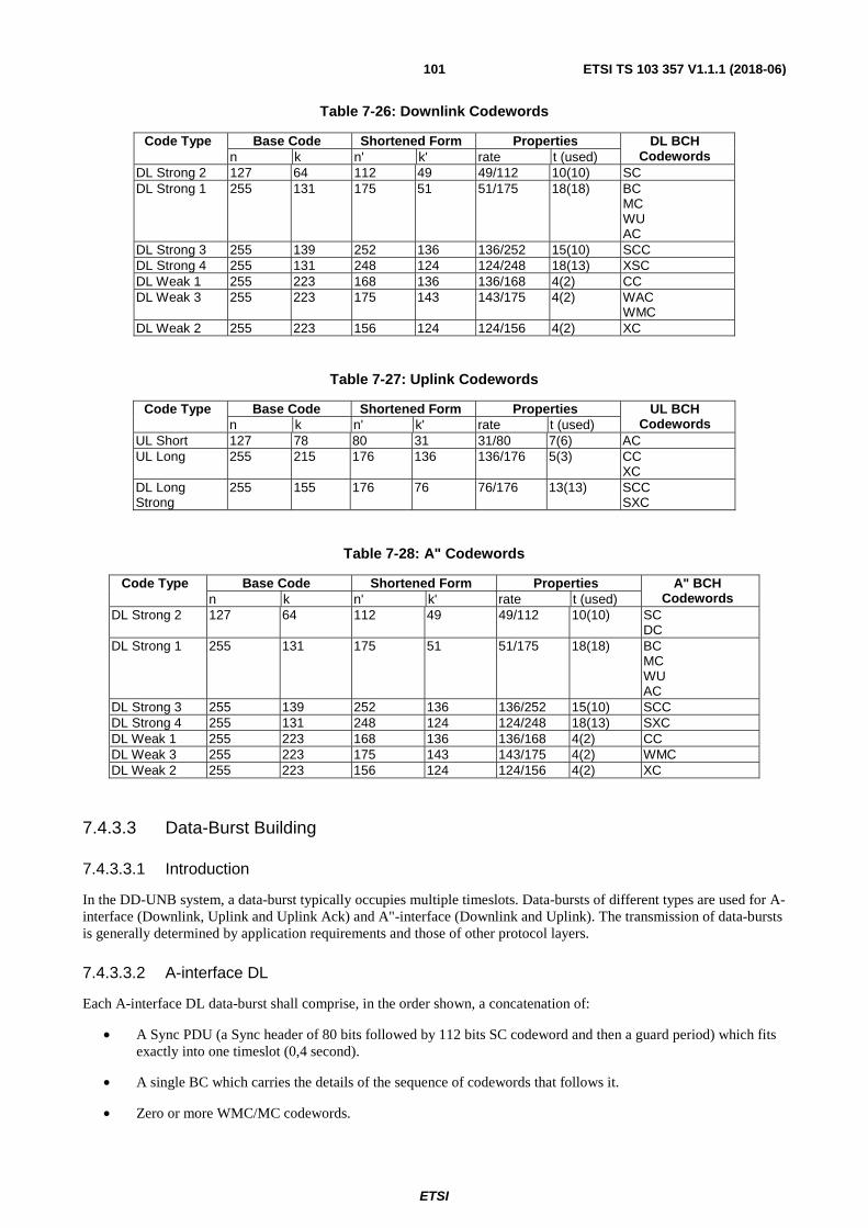
ETSI
ETSI TS 103 357 V1.1.1 (2018-06)101
Table 7-26: Downlink Codewords
Code Type Base Code Shortened Form Properties DL BCH Codewords n k n' k' rate t (used)
DL Strong 2 127 64 112 49 49/112 10(10) SC DL Strong 1 255 131 175 51 51/175 18(18) BC
MC WU AC
DL Strong 3 255 139 252 136 136/252 15(10) SCC DL Strong 4 255 131 248 124 124/248 18(13) XSC DL Weak 1 255 223 168 136 136/168 4(2) CC DL Weak 3 255 223 175 143 143/175 4(2) WAC
WMC DL Weak 2 255 223 156 124 124/156 4(2) XC
Table 7-27: Uplink Codewords
Code Type Base Code Shortened Form Properties UL BCH Codewords n k n' k' rate t (used)
UL Short 127 78 80 31 31/80 7(6) AC UL Long 255 215 176 136 136/176 5(3) CC
XC DL Long Strong
255 155 176 76 76/176 13(13) SCC SXC
Table 7-28: A" Codewords
Code Type Base Code Shortened Form Properties A" BCH Codewords n k n' k' rate t (used)
DL Strong 2 127 64 112 49 49/112 10(10) SC DC
DL Strong 1 255 131 175 51 51/175 18(18) BC MC WU AC
DL Strong 3 255 139 252 136 136/252 15(10) SCC DL Strong 4 255 131 248 124 124/248 18(13) SXC DL Weak 1 255 223 168 136 136/168 4(2) CC DL Weak 3 255 223 175 143 143/175 4(2) WMC DL Weak 2 255 223 156 124 124/156 4(2) XC
7.4.3.3 Data-Burst Building
7.4.3.3.1 Introduction
In the DD-UNB system, a data-burst typically occupies multiple timeslots. Data-bursts of different types are used for A-interface (Downlink, Uplink and Uplink Ack) and A"-interface (Downlink and Uplink). The transmission of data-bursts is generally determined by application requirements and those of other protocol layers.
7.4.3.3.2 A-interface DL
Each A-interface DL data-burst shall comprise, in the order shown, a concatenation of:
• A Sync PDU (a Sync header of 80 bits followed by 112 bits SC codeword and then a guard period) which fits exactly into one timeslot (0,4 second).
• A single BC which carries the details of the sequence of codewords that follows it.
• Zero or more WMC/MC codewords.

ETSI
ETSI TS 103 357 V1.1.1 (2018-06)102
• Zero or more CC/SCC codewords.
• Zero or more WU codewords.
• Zero or more WAC/AC codewords.
• Zero or more XC/SXC codewords, in the order indicated by the contents of WU PDU transmitted in the current frame.
• The content of the data-burst shall be consistent with the DL subframe duration as indicated by the current frame format.
• A BS shall transmit a single such data-burst in each frame, see Figure 7-11.
7.4.3.3.3 A-interface UL Data
Each A-interface UL Data data-burst shall comprise a Sync header of 16 bits (see Table 7-4) followed by a CC/XC codeword (176 bits) or a double SCC/XCC codeword (352 bits), occupying 8 or 16 timeslots. A resulting 16-slot data-burst shall be divided into a first and second sequential (but not necessarily contiguous) 8-slot data-bursts for separate scheduling by MAC for the purpose of fitting it into timeslots available (given the constraints of the current frame and subframe formats).
Zero or more UL Data data-bursts may be transmitted by an EP/RP in each UL subframe, see Figure 7-12, subject to frame and subframe format constraints.
7.4.3.3.4 A-interface UL Ack
Each A-interface Uplink Ack data-burst shall comprise a Sync header of 16 bits (see Table 7-4) followed by a single AC codeword (80 bits), occupying 4 timeslots.
Zero or more UL Ack data-bursts may be transmitted by an EP/RP in each UL subframe, see Figure 7-12, subject to frame and subframe format constraints. Timing is determined by MAC.
7.4.3.3.5 A"-interface DL
Each A"-interface DL data-burst shall comprise, in the order shown, a concatenation of:
• A Sync PDU (a Sync header of 80 bits followed by 112 bits SC codeword and then a guard period) which fits exactly into one timeslot (0,4 second).
• A single BC which carries the details of the sequence of codewords that follows it.
• Zero or more WMC/MC codewords.
• Zero or more CC/SCC codewords.
• Zero or more WU codewords.
• Zero or more WAC/AC codewords.
• Zero or more XC/SXC codewords, in the order indicated by the contents of WU PDU transmitted in the current frame.
• The content of the data-burst shall be consistent with the current A"-interface subframe format.
• A RP shall transmit a single such data-burst in each A"-interface DL subframe, see Figure 7-13.
7.4.3.3.6 A"-interface UL Data data-burst
Each A"-interface UL data-burst shall comprise, in the order shown, a concatenation of:
• A Sync PDU (a Sync header of 80 bits followed by 112 bits DC codeword and then a guard period) which fits exactly into one timeslot (0,4 second).

ETSI
ETSI TS 103 357 V1.1.1 (2018-06)103
• Zero or more CC/SCC codewords.
• Zero or more WU codewords.
• Zero or more WAC/AC codewords.
• Zero or more XC/SXC codewords, in the order indicated by the contents of WU PDU transmitted in the current frame.
• The content of the data-burst shall be consistent with the current A"-interface subframe format.
An OEP shall transmit no more than one such data-burst in each A"-interface UL subframe, see Figure 7-14, subject to frame and subframe format constraints.
In a closed A" UL subframe, transmission starts in the first available timeslot.
In an open A" UL subframe, timing is determined by MAC.
7.4.3.3.7 A"-interface UL Ack data-burst
A"-interface Uplink Ack data-burst shall always start with a specific Sync header of 16 bits (as in Table 7-4). The remainder of the data-burst consists of a single AC codeword (80 bits).
A RP shall transmit no more than one such data-burst in each A"-interface UL subframe, subject to frame and subframe format constraints.
In a closed A" UL subframe, transmission shall start in the first available timeslot.
In an open A" UL subframe, timing is determined by MAC.
7.4.3.3.8 Bit order
Each pre-coding block shall be packed with the last entry in its pre-coding block table in the least significant location of the PDU (without changing bit order) and then each preceding entry shall be added in more significant locations (in the same bit order). The packed and coded PDU is transmitted least significant bit, of least significant byte, first.
Figure 7-15 is an example for the Sync PDU (clause 7.4.2.2).
Figure 7-15: Example bit order - Sync PDU
7.4.3.4 Power Control
Power control is used in A-interface Uplink transmission by EP. Provision is made in PHY to control transmit power level using "Too Loud" flag. When the received RSSI at the BS is higher than an implementation-dependent defined threshold, BS may indicate "Too Loud" (see Table 7-23) in which case the EP shall reduce its transmit power by 2 dB from its current level when it next transmits. If "Too Loud" is not indicated, the EP shall increase its transmit power by 2 dB from its current level when it next transmits (up to its maximum level).
ETSI
ETSI TS 103 357 V1.1.1 (2018-06)104
If the EP is in high interference mode (and is therefore sending double codeword format Data PDUs) (see clause 7.4.2.6), it shall ignore the "Too Loud" flag and set the transmit power level to its maximum level.
7.4.3.5 High Interference Mode
As described in this specification, strong and weak coding is available for a range of PDUs. The choice of coding scheme shall be made by the related entity and shall be signalled as described (e.g. Table 7-9). Choice of algorithm by which to determine whether to use High Interference Mode is implementation dependent, however specified control mechanisms shall be supported (see Table 7-23, Table 7-24, Table 7-25 and clause 7.4.3.4).
7.4.4 PHY Procedures
7.4.4.1 Synchronization and Frequency Scanning
Layer 1 supports frequency scanning and synchronization processes to detect available BS and RP. This process is implementation-dependent.
7.4.4.2 Base Selection
The process by which an EP selects a BS / RP with which to attempt connection is implementation-dependent.
7.4.4.3 Transmit Duty-Cycle Control
DD-UNB implementations are typically subject to regulatory limits on transmitter duty cycle. It is an implementation issue to ensure such limits are not exceeded.
7.4.4.4 A-interface Downlink Transmission Control - Frame Structure
Before the start of each frame, BS shall determine the frame format to use for that frame as described in clause 7.4.1.1. This process is implementation-dependent. Transmission of DL data-bursts shall commence in the first timeslot allocated to the related subframe, see Table 7-1.
7.4.4.5 A"-interface Downlink Transmission Control - Subframe Structure
Before the start of each A"-interface subframe, RP shall determine the format to use for that subframe as described in clause 7.4.1.1. This process is implementation-dependent.
7.4.4.6 Uplink Transmission Control
BS transmissions are the reference for both the time and the frequency of EP and RP transmissions. No allowance for propagation delays is required in the timing of uplink transmissions.
7.4.4.7 PHY Measurements
PHY measurements are implementation-dependent and may include:
• the average power (RSSI) of the Sync Word in a data-burst;
• the number of corrected bits in each received codeword;
or other measurements.
Such measurements may be used to support "too loud" indication (clause 7.4.3.4).
7.4.4.8 Noise Measurement
Some A-interface frame formats allocate "noise measurement" timeslots during which no system elements transmit. These may be used to measure noise and/or interference levels; such measurements, and the use of the results, are implementation-dependent.

ETSI
ETSI TS 103 357 V1.1.1 (2018-06)105
7.4.4.9 Base-System Group (BSGP)
To enable the BS to distinguish reception of a local EP's (intended) transmissions from distant EP's (unintended) transmissions (in the case that block numbers coincide), "Uplink Connection Base-System Group" (XC BSGP) is included in each Data L1 PDU on the A-interface UL, see Table 7-18.
XC BSGP (see Table 7-18) has the same value as BC BSGP (see Table 7-7) which is broadcast in every frame. Received Uplink Data PDUs at the BS side with incorrect XC BSGP shall be ignored.
Similarly, AC BSGP (see Table 7-25) is used to prevent the same problem happening for Uplink Acknowledgements. AC BSGP has the same value as BC BSGP which is broadcast in every frame. Received Uplink Ack PDUs at the BS side with incorrect AC BSGP shall be ignored.
7.5 Radio characteristics
7.5.1 Frequency Structure - Radio Mode 0
Clause 7.5.1 and any subclauses describe DD-UNB operation in Radio Mode 0; other modes are for further study.
Table 7-29: Radio Mode definition
Radio Mode
Downlink / A" Uplink Bit-rate (bps)
Symbol-rate (Hz)
Deviation Δf (Hz)
Bit-rate (bps)
Symbol-rate (Hz)
Deviation Δf (Hz)
0 500 500 ±250 62,5 62,5 ±250 Other Reserved
Frequency domain separation of uplink and downlink transmissions may be used for network planning purposes and/or to reflect regulatory constraints, but this is not essential to achieve full-duplex operation.
The operating frequency band(s) to be used for DL and UL, and whether to use frequency hopping for the DL and A"-interface, are selected when a system is planned and shall be known to all entities; the selection is applicable to both A and A"-interfaces. The spectrum used for each interface in a given direction shall be contiguous. In a non-hopping system each cell operates on one of N planned DL and UL channels (UL/DL_Chan_Freq(n), n ∈ {0, … , N-1}; the spacing of the centre frequencies of these channels within the respective operating band is 15 kHz in the UL and 25 kHz in the DL (Figure 7-16).
If DL hopping, the frequencies in the hop set (selected within the DL band as described above for a non-hopping system) shall be arranged in pseudorandom order in a Frequency Hopping Sequence, each element of which defines a DL centre frequency. The Physical Layer maintains a Frequency Hopping Index that shall be initialized (see below) for timeslot 0 of each frame and incremented for each subsequent timeslot within the frame, modulo the size of the table, and used to look up the DL frequency to be used in the timeslot. The initial value in each frame shall be determined by the Hop Phase Offset selected when a system is planned and allows nearby cells to reduce or avoid the simultaneous use of the same DL frequency by the use of different Hop Phase Offset values. The Hop Phase Offset shall be signalled in the DL Sync PDU to enable an EP to ascertain system time (see Table 7-5).
Figure 7-16: Channel numbering

ETSI
ETSI TS 103 357 V1.1.1 (2018-06)106
7.5.2 Modulation - Radio Mode 0
7.5.2.1 General
Clause 7.5.2 and subclauses describe DD-UNB operation in Radio Mode 0; other modes are for further study and may, for example, include the generation of more than one modulated carrier within the identified channel on one or more interfaces or alternative modulation schemes.
The DD-UNB modulation uses Binary Frequency Shift Keying (BFSK) for UL on A"-interface and for DL on both A-interface and A"-interface. It uses a combination of BFSK and Random Frequency Selection (RFS) for UL on A-interface. Use of Continuous Phase FSK is mandatory for the base station but optional for the End-point. BS transmit frequencies are determined in network planning.
In Radio Mode 0, in all interfaces, the information bits are represented by two tones offset in frequency by Δf = 250 Hz from a selected carrier frequency. A "1" corresponds to transmission of the higher frequency tone (fh).
7.5.2.2 A-interface DL and A"-interface (UL and DL) modulation
Within the selected 25 kHz channel a number of nominal carrier frequencies spaced at 500 Hz intervals are identified (as FDM_fc(n)) as depicted in Figure 7-17. For Radio Mode 0 A-interface DL a modulated carrier is generated at
FDM_fc(10) or FDM_fc(40); the choice between these values of FDM_fc is made in network planning.
For A"-interface (UL and DL) FDM_fc(25) is used.
Figure 7-17: A-interface (DL) and A"-interface (UL and DL) frequencies
In Radio Mode 0 a DL (A and A") receiver shall receive any signal or signals within the selected 25 kHz channel. Such a receiver typically employs digital techniques to filter and demodulate those signals.
7.5.2.3 A-interface UL modulation
Uplink modulation is implemented based on a combination of BFSK and Random Frequency Selection (RFS).
In Radio Mode 0 the UL operating channel width is 15 kHz. Each EP/RP shall perform RFS independently for each data-burst (except as described in clause 7.4.3.3.3 for strongly-coded PDUs where each pair of data-bursts shall be transmitted on the same frequency) and shall choose its BFSK centre frequency (RFS_fc) within the UL channel (see
Figure 7-18) as determined by MAC, such that:
RFS_fc = UL_Chan_Freq - (RFS_range / 2) + (FMAC × Fgran)
and where:
• UL_Chan_Freq is the centre frequency of the UL channel (see Table 7-7).
• RFS_range is the difference between the lowest and highest permitted values of RFS_fc (14 kHz for Radio
Mode 0).

ETSI
ETSI TS 103 357 V1.1.1 (2018-06)107
• FMAC is an integer value generated by MAC (value from 0 to (RFS_range/ Fgran)).
• Fgran is the granularity of RFS selection (implementation dependent).
Figure 7-18: A-interface UL modulation
7.5.3 Radio-Burst Power Ramping
A guard period of 16 ms is provided for power-ramping and optional frequency hopping between radio-bursts; when transmitting, transmit power shall be reduced during the guard period in all entities (whether or not frequency-hopping). Transmit power shall rise or fall by ≥60 dB within 500 µs of the start or end (respectively) of the radio-burst, any frequency changes shall take place when the power is at that reduced level. The power shall be within ±1 dB of the average radio-burst transmit power for the active part of the radio-burst (see Figure 7-19). Any emissions arising from such ramping and frequency changes shall be within regulatory limits.
During the guard period a sequence of alternating "1"s and "0"s at the bit rate, beginning with a "1", is inserted in the modulation bit-stream.
Figure 7-19: Power Ramping and Frequency Switching

ETSI
ETSI TS 103 357 V1.1.1 (2018-06)108
Annex A (informative): Generic end-point system block diagram
A.1 Overview The BS and the RP are network elements that are specific to each family.
To maximize the economy of scale, this section proposes an example of a generic EP transceiver implementation that supports all LTN families.
Figure A-1 shows an example implementation of an EP.
The EP can be designed with sensors and/or control/data ports for external sensors.
The EP can be designed with or without a host CPU - for instance, the microcontroller embedded in the transceiver may have sufficient functionality and performance to undertake the role of host CPU for some applications.
The EP can additionally have a Secure Element (SE) to hold secret data for payload encryption for example. While it is possible to embed the SE into the transceiver IC, an external SE is likely to provide more flexibility and potentially offers a more future-proof design.
Figure A-1: System overview of EP
The following clauses provide some implementation detail about some of the key blocks within the EP transceiver.
A.2 uC A microcontroller that is optimized for small size and low-power consumption while being able to handle functions such as; manipulation of payload data, communication with the SE and the set up the Timing Sequencer & Controller.
uC
Modulation
FilterPLL PA
X LNA Filters +
ADCDemod
Timing Sequencer & Controller
Baseband
Processor
uCBPF
+
Switch
TCXO
Ramp
control
TX/Rx
centre
freq
Mode,
Tx symbol
rate
Gain control
Secure
Element
ETSI LTN EP Transceiver
Host
CPU
Sensor(s)
ETSI LTN EP
+ +
Chirp
Timing and frequency correction

ETSI
ETSI TS 103 357 V1.1.1 (2018-06)109
A.3 Baseband Processor The uplink functions are; CRC calculation, FEC, Interleaving, Encryption.
The downlink functions are; Decryption, de-interleaving, error correction (convolutional, LDPC), CRC check.
A hardware DSP function is likely to provide the optimal trade-off of size, power consumption and cost.
A.4 TCXO It is possible to use a 26 MHz reference clock for all families. However, with detailed analysis, a more suitable clock frequency may be found that will ease the design of the sequencers, state machines, modulator and demodulator.
The TCXO is likely to be a function integrated into the transceiver IC.
A.5 Timing Sequencer & Controller This block is likely to be a collection of Finite State Machines and sequencers implemented in hardware. The configuration will be undertaken by software running on the microcontroller. Functions will include; set modulation/demodulation mode, set the Tx and Rx symbol rate, set the Tx and Rx centre frequency, chirp control and PA ramp control.
A.6 Modulation Filter Modulation function is provided by a configurable filter supporting the following modulations; BPSK, Pi/2 BPSK, BFSK and GMSK.
A.7 PLL A fractional-N type PLL with performance to meet the local RF requirements is used.
A single PLL design is shown in Figure A-1, however a dual-PLL design (one for Tx and one for Rx) may offer performance advantages.
A.8 Power Amplifier A suitable Power Amplifier (PA) is provided for the desired frequency band of operation and the regulations that are in force locally.
A.9 Demodulator The demodulator could be implemented using a matched filter.
A.10 Summary An implementation example has been shown for a generic EP transceiver that can support all three families that make up LTN. Based on knowledge of the requirements of the families and the use-cases for LTN, some high-level guidance has been included for some of the blocks to aid the design trade-offs, particularly between performance and cost. Other approaches can be followed in implementing each of these functional blocks.

ETSI
ETSI TS 103 357 V1.1.1 (2018-06)110
Annex B (informative): TS-UNB Profiles
B.1 Overview The TS-UNB profiles define standard TS-UNB protocol settings for interoperability of end-points and base stations operating in a TS-UNB based LTN network. The profiles are a recommendation and can be extended in the future.
B.2 EU0 Profile
B.2.1 Spectrum Use
Table B-1: UL channel Frequencies
Channel Centre Frequency fc
Channel Bandwidth
Primary Channel A 868,180 MHz 100 kHz
Table B-2: DL channel Frequencies
Channel Centre Frequency fc
Channel Bandwidth
Primary Channel A 869,575 MHz 100 kHz
The frequency offset between uplink and downlink is ������ = 1,395 ���.
B.2.2 Mode of operation
Table B-3: Mode of operation of EU0 profile
Uplink Downlink (Optional)
PHY Mode Telegram Splitting (TS) Modulation (G)MSK (G)MSK Symbolrate ULP: 2 380,371 Sym/s ULP: 2 380,371 Sym/s TSMA Mode Wide (Carrier spacing: 2 380,371 Hz) Sync Burst off Repetition off Channels Single Channel

ETSI
ETSI TS 103 357 V1.1.1 (2018-06)111
B.3 EU1 Profile
B.3.1 Spectrum Use
Table B-4: UL channel frequencies
Channel Centre Frequency fc
Channel Bandwidth
Primary Channel A 868,180 MHz 100 kHz Secondary Channel B 868,080 MHz 100 kHz
Table B-5: DL channel frequencies
Channel Centre Frequency fc
Channel Bandwidth
Primary Channel A 869,575 MHz 100 kHz Secondary Channel B 869,475 MHz 100 kHz
The frequency offset between uplink and downlink is ������ = 1,395 ���. For frame repetition in dual channel mode a carrier frequency offset step ��� = 42 is used.
B.3.2 Mode of operation
Table B-6: Mode of operation of EU1 profile
Uplink Downlink (Optional)
PHY Mode Telegram Splitting (TS) Modulation (G)MSK (G)MSK Symbolrate ULP: 2 380,371 Sym/s ULP: 2 380,371 Sym/s TSMA Mode Wide (Carrier spacing: 2 380,371 Hz) Sync Burst off Repetition off/on Channels Dual Channel
B.4 EU2 Profile
B.4.1 Spectrum Use
Table B-7: Channel Frequencies
Channel Centre Frequency fc
Channel Bandwidth
Primary Channel A 867,625 MHz 750 kHz Secondary Channel B 866,911 MHz 750 kHz
Both channels are overlapping resulting in an overall channel bandwidth of 1,46 MHz. For frame repetition in dual channel mode a carrier frequency offset step ��� = 25 is used.
The same channel is used in uplink and downlink. The frequency offset between uplink and downlink is ������ = 0 ��.

ETSI
ETSI TS 103 357 V1.1.1 (2018-06)112
B.4.2 Mode of operation
Table B-8: Mode of operation of EU2 profile
Uplink Downlink (Optional)
PHY Mode Telegram Splitting (TS) Modulation (G)MSK (G)MSK Symbolrate ULP: 2 380,371 Sym/s ULP: 2 380,371 Sym/s TSMA Mode Wide (Carrier spacing: 28 564,453 Hz) Sync Burst on/off Repetition on/off Channels Dual Channel
B.5 US0 Profile
B.5.1 Spectrum Use
Table B-9: UL channel Frequencies
Channel Centre Frequency fc
Channel Bandwidth
Primary Channel A 916,357 MHz 750 kHz Secondary Channel B 915,643 MHz 750 kHz
Both channels are overlapping resulting in an overall channel bandwidth of 1,46 MHz. For frame repetition in dual channel mode a carrier frequency offset step ��� = 25 is used.
The same channel is used for uplink and downlink. The frequency offset between uplink and downlink is ������ = 0 ��.
B.5.2 Mode of operation
Table B-10: Mode of operation of US0 profile
Uplink Downlink (Optional)
PHY Mode Telegram Splitting (TS) Modulation (G)MSK (G)MSK Symbolrate ULP: 2 380,371 Sym/s ULP: 2 380,371 Sym/s TSMA Mode Wide (Carrier spacing: 28 564,453 Hz) Sync Burst on Repetition on/off Channels Dual Channel

ETSI
ETSI TS 103 357 V1.1.1 (2018-06)113
History
Document history
V1.1.1 June 2018 Publication