Embed Size (px)
Citation preview

ETSI TS 101 376-4-8 V3.4.1 (2015-10)
GEO-Mobile Radio Interface Specifications (Release 3); Third Generation Satellite Packet Radio Service; Part 4: Radio interface protocol specifications;
Sub-part 8: Mobile Radio Interface Layer 3 Specifications; GMR-1 3G 44.008
TECHNICAL SPECIFICATION

ETSI
ETSI TS 101 376-4-8 V3.4.1 (2015-10) 2GMR-1 3G 44.008
Reference RTS/SES-00374-4-8
Keywords 3G, GMPRS, GMR, GPRS, GSM, GSO,
interface, layer 3, management, MES, MMSS, mobile, mobility, MSS, radio, satellite, S-PCN
ETSI
650 Route des Lucioles F-06921 Sophia Antipolis Cedex - FRANCE
Tel.: +33 4 92 94 42 00 Fax: +33 4 93 65 47 16
Siret N° 348 623 562 00017 - NAF 742 C
Association à but non lucratif enregistrée à la Sous-Préfecture de Grasse (06) N° 7803/88
Important notice
The present document can be downloaded from: http://www.etsi.org/standards-search
The present document may be made available in electronic versions and/or in print. The content of any electronic and/or print versions of the present document shall not be modified without the prior written authorization of ETSI. In case of any
existing or perceived difference in contents between such versions and/or in print, the only prevailing document is the print of the Portable Document Format (PDF) version kept on a specific network drive within ETSI Secretariat.
Users of the present document should be aware that the document may be subject to revision or change of status. Information on the current status of this and other ETSI documents is available at
http://portal.etsi.org/tb/status/status.asp
If you find errors in the present document, please send your comment to one of the following services: https://portal.etsi.org/People/CommiteeSupportStaff.aspx
Copyright Notification
No part may be reproduced or utilized in any form or by any means, electronic or mechanical, including photocopying and microfilm except as authorized by written permission of ETSI.
The content of the PDF version shall not be modified without the written authorization of ETSI. The copyright and the foregoing restriction extend to reproduction in all media.
© European Telecommunications Standards Institute 2015.
All rights reserved.
DECTTM, PLUGTESTSTM, UMTSTM and the ETSI logo are Trade Marks of ETSI registered for the benefit of its Members. 3GPPTM and LTE™ are Trade Marks of ETSI registered for the benefit of its Members and
of the 3GPP Organizational Partners. GSM® and the GSM logo are Trade Marks registered and owned by the GSM Association.

ETSI
ETSI TS 101 376-4-8 V3.4.1 (2015-10) 3GMR-1 3G 44.008
Contents Intellectual Property Rights .............................................................................................................................. 14
Foreword ........................................................................................................................................................... 14
Modal verbs terminology .................................................................................................................................. 15
Introduction ...................................................................................................................................................... 15
1 Scope ...................................................................................................................................................... 17
1.1 Scope of the present document ......................................................................................................................... 17
1.2 Application to the interface structures .............................................................................................................. 17
1.3 Structure of Layer 3 procedures ....................................................................................................................... 17
1.4 Use of logical channels ..................................................................................................................................... 17
1.5 Overview of control procedures ....................................................................................................................... 18
1.5.1 List of procedures ....................................................................................................................................... 18
1.6 Applicability of implementations ..................................................................................................................... 20
1.6.1 Packet services ............................................................................................................................................ 20
2 References .............................................................................................................................................. 21
2.1 Normative references ....................................................................................................................................... 21
2.2 Informative references ...................................................................................................................................... 23
3 Definitions and abbreviations ................................................................................................................. 24
3.1 Definitions ........................................................................................................................................................ 24
3.2 Abbreviations ................................................................................................................................................... 25
3.3 Random values ................................................................................................................................................. 25
4 Radio resource management procedures ................................................................................................ 25
4.1 Overview/general ............................................................................................................................................. 25
4.1.0 General ........................................................................................................................................................ 25
4.1.1 General (A/Gb mode only) ......................................................................................................................... 25
4.1.2 Services provided to upper layers ............................................................................................................... 26
4.1.2.1 Idle mode .............................................................................................................................................. 26
4.1.2.2 Establishment and release of an RR connection.................................................................................... 26
4.1.2.3 RR connected mode .............................................................................................................................. 26
4.1.2.4 Packet idle mode (A/Gb mode only) ..................................................................................................... 26
4.1.2.5 Packet transfer mode (A/Gb mode only) ............................................................................................... 26
4.1.3 Services required from data link and physical layers .................................................................................. 26
4.1.4 RR states ..................................................................................................................................................... 26
4.1.5 Change of dedicated channels ..................................................................................................................... 26
4.1.6 Procedure for service request and contention resolution ............................................................................ 26
4.2 Idle mode procedures ....................................................................................................................................... 26
4.2.1 Mobile Earth Station (MES) side ................................................................................................................ 26
4.2.2 Network side ............................................................................................................................................... 27
4.2.2.1 System information broadcasting .......................................................................................................... 27
4.2.2.1.0 General ............................................................................................................................................ 27
4.2.2.1.1 Classes and segments ...................................................................................................................... 27
4.2.2.1.2 Transmission schedules ................................................................................................................... 28
4.2.2.1.3 Change information ......................................................................................................................... 28
4.2.2.1.4 Encoding and decoding rules ........................................................................................................... 29
4.2.2.1.5 Future extensions ............................................................................................................................. 31
4.2.2.1.6 Anchored(A) and Temporary(T) BCCH (A/Gb mode only) ........................................................... 32
4.2.2.1.7 Multiplexing of CCCH and PCCCH (A/Gb mode only) ................................................................. 32
4.2.2.1.7a Multiplexing of CCCH and PCCCH (Iu mode only) ...................................................................... 32
4.2.2.2 GPS satellite ephemeris data broadcasting ............................................................................................ 33
4.2.2.2.0 General ............................................................................................................................................ 33
4.2.2.2.1 GPS satellite ephemeris Earth Centered Earth fixed coordinates on GBCH ................................... 33
4.2.2.2.2 GPS satellite ephemeris Earth Centered Earth fixed coordinates on GBCH3 ................................. 34
4.2.2.2.3 GPS satellite ephemeris Keplerian Coordinates on GBCH3 ........................................................... 35
4.2.2.3 GPS almanac data transmission ............................................................................................................ 36
4.3 RR connection establishment ........................................................................................................................... 36
ETSI
ETSI TS 101 376-4-8 V3.4.1 (2015-10) 4GMR-1 3G 44.008
4.3.1 RR connection establishment initiated by the Mobile Earth Station (MES): immediate assignment procedure .................................................................................................................................................... 36
4.3.1.0 General .................................................................................................................................................. 36
4.3.1.1 Spot beam selection to access the network ........................................................................................... 36
4.3.1.2 Permission to access the network .......................................................................................................... 37
4.3.1.3 Initiation of the immediate assignment procedure (A/Gb mode only) .................................................. 37
4.3.1.3a Initiation of the immediate assignment procedure (Iu mode only)........................................................ 38
4.3.1.4 Answer from the network ...................................................................................................................... 39
4.3.1.4.1 On receipt of a CHANNEL REQUEST message (A/Gb mode only) .............................................. 39
4.3.1.4.2 IMMEDIATE ASSIGNMENT from network for MES requesting circuit service (A/Gb mode only) ................................................................................................................................................ 39
4.3.1.4.3 Immediate Assignment from network for MES requesting packet service ..................................... 40
4.3.1.4.4 Assignment rejection (IMMEDIATE ASSIGNMENT REJECT from network) (A/Gb mode only) ................................................................................................................................................ 40
4.3.1.4.4a Assignment rejection (IMMEDIATE ASSIGNMENT REJECT from network) (Iu mode only) ................................................................................................................................................ 40
4.3.1.4.5 Extended immediate assignment procedure (A/Gb mode) .............................................................. 43
4.3.1.4.6 Position verification procedure (A/Gb mode only) ......................................................................... 44
4.3.1.4.6a Position verification procedure (Iu mode only) ............................................................................... 44
4.3.1.5 Assignment procedure completion (A/Gb mode only).......................................................................... 45
4.3.1.6 Abnormal cases (A/Gb mode only) ....................................................................................................... 45
4.3.2 RR connection establishment initiation by the network: paging procedure ................................................ 45
4.4 RR connection transfer phase (A/Gb mode only) ............................................................................................. 45
4.5 RR connection release procedure (A/Gb mode only) ....................................................................................... 45
4.6 Receiving an RR STATUS message by an RR entity ...................................................................................... 45
4.7 RR procedures on CCCH related to temporary block flow establishment ....................................................... 45
4.7.0 General ........................................................................................................................................................ 45
4.7.1 Packet paging procedure using CCCH........................................................................................................ 45
4.7.1.0 General .................................................................................................................................................. 45
4.7.1.1 Packet paging initiation by the network ................................................................................................ 45
4.7.1.1a Packet paging initiation by the network (Iu Mode only) ....................................................................... 46
4.7.1.2 On receipt of a packet paging request ................................................................................................... 47
4.7.1.3 Alerting initiation by the network (Iu mode only) ................................................................................ 47
4.7.1.4 Page response by the MES due to alerting (Iu mode only) ................................................................... 47
4.7.2 Packet access procedure using CCCH ........................................................................................................ 48
4.7.2.0 General .................................................................................................................................................. 48
4.7.2.1 Entering the packet transfer mode: packet access procedure ................................................................ 48
4.7.2.1.0 General ............................................................................................................................................ 48
4.7.2.1.1 Permission to access the network .................................................................................................... 48
4.7.2.1.2 Initiation of the packet access procedure: channel request (A/Gb mode only) ................................ 48
4.7.2.1.2a Initiation of the packet access procedure: channel request (Iu mode only) ..................................... 48
4.7.2.1.3 Packet immediate assignment .......................................................................................................... 49
4.7.2.1.4 Packet access completion ................................................................................................................ 51
4.7.2.1.5 Abnormal cases ............................................................................................................................... 51
4.7.2.2 Sending an RLC/MAC control message: single block packet access procedure .................................. 51
4.7.3 Packet downlink assignment procedure using CCCH (A/Gb mode only) .................................................. 52
4.7.3.0 General .................................................................................................................................................. 52
4.7.3.1 Entering the packet transfer mode: packet downlink assignment procedure ......................................... 52
4.7.3.1.1 General ............................................................................................................................................ 52
4.7.3.1.2 Initiation of the packet downlink assignment procedure ................................................................. 52
4.7.3.1.3 Packet downlink assignment completion ......................................................................................... 53
4.7.3.1.4 Abnormal cases ............................................................................................................................... 53
4.7.3.2 Sending an RLC/MAC control message: single block packet downlink assignment procedure ........... 53
4.8 GMPRS suspend procedure on CCCH (A/Gb mode only) ............................................................................... 53
4.8.0 General ........................................................................................................................................................ 53
4.8.1 Initiation of GMPRS suspend procedure .................................................................................................... 54
4.8.2 Completion of GMPRS suspend procedure ................................................................................................ 54
4.8.3 Abnormal cases ........................................................................................................................................... 54
4.9 GMPRS resume procedure on CCCH (A/Gb mode only) ................................................................................ 54
4.9.0 General ........................................................................................................................................................ 54
4.9.1 Initiation of GMPRS resume procedure ...................................................................................................... 54
4.9.2 Completion of GMPRS resume procedure ................................................................................................. 55

ETSI
ETSI TS 101 376-4-8 V3.4.1 (2015-10) 5GMR-1 3G 44.008
4.9.3 Abnormal cases ........................................................................................................................................... 55
5 Elementary procedures for mobility management ................................................................................. 55
5.1 General ............................................................................................................................................................. 55
5.1.0 Common ..................................................................................................................................................... 55
5.1.1 MM and GMM procedures ......................................................................................................................... 55
5.1.1.1 Types of MM and GMM procedures .................................................................................................... 55
5.1.1.1.0 General ............................................................................................................................................ 55
5.1.1.1.1 Integrity Checking of Signalling Messages in the Mobile Station (Iu mode only) .......................... 55
5.1.1.1.1a Integrity protection for emergency call (Iu mode only) ................................................................... 55
5.1.1.2 MM-GMM co-ordination for GMPRS MESs (A/Gb mode only) ......................................................... 56
5.1.1.2.1 GMPRS MS operating in mode A or B in a network that operates in mode I ................................. 56
5.1.1.2.2 GPRS MS operating in mode A or B in a network that operates in mode II or III .......................... 56
5.1.1.3 Core Network System Information for MM (Iu mode only) ................................................................. 56
5.1.1.4 Core Network System Information for GMM (Iu mode only) .............................................................. 56
5.1.2 MM sublayer states ..................................................................................................................................... 56
5.1.3 GPRS mobility management (GMM) sublayer states ................................................................................. 56
5.1.3.0 General .................................................................................................................................................. 56
5.1.3.1 GMM states in the MES ........................................................................................................................ 56
5.1.3.1.0 General ............................................................................................................................................ 56
5.1.3.1.1 Main states ....................................................................................................................................... 56
5.1.3.1.2 Substates of state GMM-DEREGISTERED.................................................................................... 57
5.1.3.1.3 Substates of state GMM-REGISTERED ......................................................................................... 58
5.1.3.2 GPRS update status ............................................................................................................................... 60
5.1.3.3 GMM mobility management states on the network side ....................................................................... 61
5.1.3.3.0 General ............................................................................................................................................ 61
5.1.3.3.1 Main States ...................................................................................................................................... 61
5.1.3.3.2 Substates of state GMM-REGISTERED ......................................................................................... 61
5.2 Behaviour of the MES in MM idle state, GMM-DEREGISTERED state and GMM-REGISTERED state .... 62
5.2.0 General ........................................................................................................................................................ 62
5.2.1 Primary service state selection .................................................................................................................... 62
5.2.1.1 Selection of the service state after power-on ......................................................................................... 62
5.2.1.2 Other cases ............................................................................................................................................ 62
5.2.2 Detailed description of MES behaviour in MM idle state (A/Gb mode only) ........................................... 62
5.2.3 Service state when back to state MM idle from another state (A/Gb mode only) ..................................... 63
5.2.4 Service state after position verification ....................................................................................................... 63
5.2.5 Behaviour in state GMM-DEREGISTERED.............................................................................................. 63
5.2.5.0 General .................................................................................................................................................. 63
5.2.5.1 Primary substate selection ..................................................................................................................... 63
5.2.5.1.1 Selection of the substate after power on or enabling the MESs GMPRS capability ....................... 63
5.2.5.1.2 Other cases ...................................................................................................................................... 64
5.2.5.2 Detailed description of the MES behaviour in state GMM-DEREGISTERED .................................... 64
5.2.5.2.0 General ............................................................................................................................................ 64
5.2.5.2.1 Substate, NORMAL-SERVICE ...................................................................................................... 64
5.2.5.2.2 Substate, ATTEMPTING-TO-ATTACH ........................................................................................ 64
5.2.5.2.3 Substate, LIMITED-SERVICE ....................................................................................................... 64
5.2.5.2.4 Substate, NO-IMSI .......................................................................................................................... 64
5.2.5.2.5 Substate, NO-CELL ........................................................................................................................ 64
5.2.5.2.6 Substate, PLMN-SEARCH ............................................................................................................. 64
5.2.5.2.7 Substate, ATTACH-NEEDED ........................................................................................................ 64
5.2.5.2.8 Substate, SUSPENDED (A/Gb mode only) .................................................................................... 65
5.2.5.2.9 Substate, INVALID-POSITION (A/Gb mode only) ....................................................................... 65
5.2.5.2.10 Substate, NORMAL-SERVICE-DARK-BEAM (A/Gb mode only) ............................................... 65
5.2.5.3 Substate when back to state GMM-DEREGISTERED from another GMM state ................................ 65
5.2.6 Behaviour in state GMM-REGISTERED ................................................................................................... 66
5.2.6.0 General .................................................................................................................................................. 66
5.2.6.1 Detailed description of the MES behaviour in state GMM-REGISTERED ......................................... 66
5.2.6.1.0 General ............................................................................................................................................ 66
5.2.6.1.1 Substate, NORMAL-SERVICE ...................................................................................................... 66
5.2.6.1.2 Substate, SUSPENDED (A/Gb mode only) .................................................................................... 66
5.2.6.1.3 Substate, UPDATE-NEEDED ......................................................................................................... 66
5.2.6.1.4 Substate, ATTEMPTING-TO-UPDATE ........................................................................................ 67

ETSI
ETSI TS 101 376-4-8 V3.4.1 (2015-10) 6GMR-1 3G 44.008
5.2.6.1.5 Substate, NO-CELL-AVAILABLE ................................................................................................ 67
5.2.6.1.6 Substate, LIMITED-SERVICE ....................................................................................................... 67
5.2.6.1.7 Substate, ATTEMPTING-TO-UPDATE-MM ................................................................................ 67
5.2.6.1.8 Substate, NORMAL-SERVICE-DARK-BEAM (A/Gb mode only) ............................................... 67
5.2.6.1.9 Substate, NORMAL-SERVICE-ILLUMINATION-INITIATED (A/Gb mode only) .................... 67
5.2.6.1.10 Substate, ROUTING-AREA-UPDATE-DARK-BEAM (A/Gb mode only) ................................... 67
5.2.6.1.11 Substate, ROUTING-AREA-UPDATE-ILLUMINATION-INITIATED (A/Gb mode only) ......... 67
5.3 MM common procedures ................................................................................................................................. 68
5.3.1 TMSI reallocation procedure (A/Gb mode only) ........................................................................................ 68
5.3.2 Authentication procedure ............................................................................................................................ 68
5.3.3 Identification procedure .............................................................................................................................. 68
5.3.4 IMSI detach procedure (A/Gb mode only) ................................................................................................. 68
5.3.5 Abort procedure (A/Gb mode only) ............................................................................................................ 68
5.3.6 MM information procedure (A/Gb mode only) .......................................................................................... 68
5.4 MM specific procedures (A/Gb mode only) ..................................................................................................... 68
5.5 Connection management sublayer service provision (A/Gb mode only) ......................................................... 68
5.5.1 MM connection establishment .................................................................................................................... 68
5.5.1.0 General .................................................................................................................................................. 68
5.5.1.1 MM connection establishment initiated by the MES ............................................................................ 68
5.5.1.2 Abnormal cases ..................................................................................................................................... 68
5.5.1.3 MM connection establishment initiated by the network ....................................................................... 68
5.5.1.4 Abnormal cases ..................................................................................................................................... 68
5.5.1.5 MM connection establishment for emergency calls .............................................................................. 68
5.5.1.6 Call reestablishment .............................................................................................................................. 68
5.5.1.7 Forced release during MO MM connection establishment ................................................................... 69
5.5.1.8 Optimal routing ..................................................................................................................................... 69
5.5.2 MM connection information transfer phase ................................................................................................ 69
5.5.3 MM connection release ............................................................................................................................... 69
5.6 Receiving an MM STATUS message by an MM entity ................................................................................... 70
5.7 Elementary mobility management procedures for GMPRS services................................................................ 70
5.7.1 General ........................................................................................................................................................ 70
5.7.1.0 Common ................................................................................................................................................ 70
5.7.1.1 Lower layer failure ................................................................................................................................ 70
5.7.1.2 Ciphering of messages (A/Gb mode only) ............................................................................................ 70
5.7.1.3 P-TMSI signature .................................................................................................................................. 70
5.7.1.4 Radio resource sublayer address handling ............................................................................................ 70
5.7.1.4.0 General ............................................................................................................................................ 70
5.7.1.4.1 Radio resource sublayer address handling (A/Gb mode only) ........................................................ 70
5.7.1.5 P-TMSI handling ................................................................................................................................... 70
5.7.1.6 Change of network mode of operation .................................................................................................. 70
5.7.1.7 Intersystem change between A/Gb mode and Iu mode ......................................................................... 70
5.7.1.8 List of forbidden PLMNs for GPRS service ......................................................................................... 70
5.7.2 GPRS Mobility management timers and UMTS PS signalling connection control .................................... 71
5.7.2.1 READY timer behaviour ....................................................................................................................... 71
5.7.2.1.1 READY timer behaviour (A/Gb mode only) ................................................................................... 71
5.7.2.1.2 READY timer behaviour (Iu mode only) ........................................................................................ 71
5.7.2.2 Periodic routing area updating .............................................................................................................. 71
5.7.2.3 PMM-IDLE mode and PMM-CONNECTED mode (Iu mode only) .................................................... 72
5.7.2.4 Handling of Force to standby in Iu mode (Iu mode only)..................................................................... 72
5.7.2.5 RA Update procedure for Signalling Connection Re-establishment (Iu mode only) ............................ 72
5.7.2.6 Cell Update triggered by low layers ...................................................................................................... 72
5.7.3 GPRS attach procedure ............................................................................................................................... 72
5.7.3.0 General .................................................................................................................................................. 72
5.7.3.1 GPRS attach procedure for GMPRS services ....................................................................................... 73
5.7.3.1.0 General ............................................................................................................................................ 73
5.7.3.1.1 GPRS attach procedure initiation .................................................................................................... 73
5.7.3.1.2 GMM common procedure initiation ................................................................................................ 73
5.7.3.1.3 GPRS attach accepted by the network ............................................................................................. 73
5.7.3.1.4 GPRS attach not accepted by the network ....................................................................................... 73
5.7.3.1.5 Abnormal cases in the MES ............................................................................................................ 74
5.7.3.1.6 Abnormal cases on the network side ............................................................................................... 74
5.7.3.2 Combined GPRS attach procedure for GMPRS and non-GMPRS services (A/Gb mode only) ........... 75

ETSI
ETSI TS 101 376-4-8 V3.4.1 (2015-10) 7GMR-1 3G 44.008
5.7.4 GPRS detach procedure .............................................................................................................................. 75
5.7.4.0 General .................................................................................................................................................. 75
5.7.4.1 MES initiated GPRS detach procedure ................................................................................................. 75
5.7.4.1.1 MES initiated GPRS detach procedure initiation ............................................................................ 75
5.7.4.1.2 MES initiated GPRS detach procedure completion for GMPRS services only ............................... 75
5.7.4.1.3 MES initiated combined GPRS detach procedure completion ........................................................ 75
5.7.4.1.4 Abnormal cases in the MES ............................................................................................................ 75
5.7.4.2 Network initiated GMPRS detach procedure ........................................................................................ 75
5.7.4.2.1 Network initiated GMPRS detach procedure initiation ................................................................... 75
5.7.4.2.2 Network initiated GMPRS detach procedure completion by the MES ........................................... 75
5.7.4.2.3 Network initiated GMPRS detach procedure completion by the network ....................................... 76
5.7.4.2.4 Abnormal cases on the network side ............................................................................................... 76
5.7.5 Routing area updating procedure ................................................................................................................ 77
5.7.5.0 General .................................................................................................................................................. 77
5.7.5.1 Normal and periodic routing area updating procedure .......................................................................... 78
5.7.5.1.0 General ............................................................................................................................................ 78
5.7.5.1.1 Normal and periodic routing area updating procedure initiation ..................................................... 78
5.7.5.1.2 GMM Common procedure initiation ............................................................................................... 78
5.7.5.1.3 Normal and periodic routing area updating procedure accepted by the network ............................. 78
5.7.5.1.4 Normal and periodic routing area updating procedure not accepted by the network....................... 78
5.7.5.1.5 Abnormal cases in the MES ............................................................................................................ 79
5.7.5.1.6 Abnormal cases on the network side ............................................................................................... 80
5.7.5.2 Combined routing area updating procedure .......................................................................................... 80
5.7.6 P-TMSI reallocation procedure ................................................................................................................... 80
5.7.7 Authentication and ciphering procedure ..................................................................................................... 80
5.7.8 Identification procedure .............................................................................................................................. 80
5.7.9 Paging procedure ........................................................................................................................................ 80
5.7.9.1 Paging for GMPRS services .................................................................................................................. 80
5.7.9.1.0 General ............................................................................................................................................ 80
5.7.9.1.1 Paging for packet services using P-TMSI........................................................................................ 80
5.7.9.1.2 Paging for packet services using IMSI ............................................................................................ 80
5.7.9.2 Paging for non-GMPRS services .......................................................................................................... 81
5.7.10 Receiving a GMM STATUS message by a GMM entity ........................................................................... 81
5.7.11 Void ............................................................................................................................................................ 81
5.7.12 GMM Information procedure ..................................................................................................................... 81
5.7.13 Service Request procedure (Iu mode only) ................................................................................................. 81
6 Elementary procedures for circuit-switched call control (A/Gb mode only) ......................................... 81
7 Support of packet services ...................................................................................................................... 81
8 Examples of structured procedures ........................................................................................................ 81
8.0 Common ........................................................................................................................................................... 81
8.1 General ............................................................................................................................................................. 81
8.1.0 Common ..................................................................................................................................................... 81
8.1.1 Paging and alert request .............................................................................................................................. 82
8.1.2 Immediate assignment ................................................................................................................................ 82
8.1.3 Service request and contention resolution .................................................................................................. 82
8.1.4 Authentication ............................................................................................................................................. 82
8.1.5 Ciphering mode setting (A/Gb mode only) ................................................................................................. 82
8.1.6 Transaction phase (A/Gb mode only) ......................................................................................................... 82
8.1.7 Channel release (A/Gb mode only) ............................................................................................................. 82
8.2 Abnormal cases (A/Gb mode only) .................................................................................................................. 82
8.3 Selected examples (A/Gb mode only) .............................................................................................................. 82
8.3.0 General ........................................................................................................................................................ 82
8.3.1 Location updating ....................................................................................................................................... 82
8.3.2 Mobile originating call establishment ......................................................................................................... 82
8.3.3 Mobile terminating call establishment ........................................................................................................ 82
8.3.4 Call clearing ................................................................................................................................................ 82
8.3.5 DTMF protocol control ............................................................................................................................... 82
8.3.6 Handover .................................................................................................................................................... 82
8.3.7 In-call modification..................................................................................................................................... 83
8.3.8 Call reestablishment .................................................................................................................................... 83

ETSI
ETSI TS 101 376-4-8 V3.4.1 (2015-10) 8GMR-1 3G 44.008
8.3.9 Mobile-to-mobile call establishment .......................................................................................................... 83
8.3.10 Multisatellite optimal routing for call establishment .................................................................................. 83
9 Handling of unknown, unforeseen, and erroneous protocol data ........................................................... 83
10 Message functional definitions and contents .......................................................................................... 83
10.0 General ............................................................................................................................................................. 83
10.1 Messages for radio resources management ...................................................................................................... 84
10.1.0 General ........................................................................................................................................................ 84
10.1.1 Additional assignment (A/Gb mode only) .................................................................................................. 85
10.1.2 Assignment command 1 and assignment command 2 (A/Gb mode only) ................................................. 85
10.1.2.1 Assignment command 1 ........................................................................................................................ 85
10.1.2.2 Assignment command 2 ........................................................................................................................ 85
10.1.3 Assignment complete (A/Gb mode only) ................................................................................................... 85
10.1.4 Assignment failure (A/Gb mode only)........................................................................................................ 85
10.1.5 Channel mode modify (A/Gb mode only) .................................................................................................. 85
10.1.6 Channel mode modify acknowledge (A/Gb mode only) ............................................................................ 86
10.1.7 Channel release (A/Gb mode only) ............................................................................................................. 86
10.1.8 Channel request .......................................................................................................................................... 86
10.1.8.0 General .................................................................................................................................................. 86
10.1.8.1 Extended channel request (A/Gb mode only) ....................................................................................... 86
10.1.8.2 Channel request Type 1 (A/Gb mode only) .......................................................................................... 86
10.1.8.3 Channel request Type 2 (A/Gb mode only) .......................................................................................... 90
10.1.8.4 Channel Request Type 3 (Iu mode only) ............................................................................................... 92
10.1.9 Ciphering mode command (A/Gb mode only) ........................................................................................... 95
10.1.10 Ciphering mode complete (A/Gb mode only) ............................................................................................. 95
10.1.11 Classmark change (A/Gb mode only) ......................................................................................................... 95
10.1.12 Classmark enquiry (A/Gb mode only) ........................................................................................................ 95
10.1.13 Frequency redefinition (A/Gb mode only) .................................................................................................. 96
10.1.14 Handover access (A/Gb mode only) ........................................................................................................... 96
10.1.15 Handover command (A/Gb mode only)...................................................................................................... 96
10.1.16 Handover complete (A/Gb mode only) ....................................................................................................... 96
10.1.17 Handover failure (A/Gb mode only) ........................................................................................................... 96
10.1.18 Immediate assignment ................................................................................................................................ 96
10.1.18.1 Immediate assignment (A/Gb mode only) ............................................................................................ 96
10.1.18.2 Extended immediate assignment (A/Gb mode only) ............................................................................. 96
10.1.18.3 Immediate assignment Type 2 (A/Gb mode only) ................................................................................ 96
10.1.18.3.0 General ............................................................................................................................................ 96
10.1.18.3.1 USF .................................................................................................................................................. 97
10.1.18.3.2 TLLI ................................................................................................................................................ 97
10.1.18.3.3 Packet Power Control Parameters ................................................................................................... 97
10.1.18.3.4 Timing Advance Index (TAI) .......................................................................................................... 97
10.1.18.4 Immediate Assignment Type 3 (A/Gb mode only) ............................................................................... 97
10.1.18.4.0 General ............................................................................................................................................ 97
10.1.18.4.1 Page Mode ....................................................................................................................................... 98
10.1.18.4.2 Persistence Level ............................................................................................................................. 98
10.1.18.4.3 TLLI ................................................................................................................................................ 98
10.1.18.4.4 Packet Power Control Parameters ................................................................................................... 98
10.1.18.4.5 Timing Advance Index .................................................................................................................... 98
10.1.18.5 Immediate Assignment Type 4 (Iu mode only) ..................................................................................... 98
10.1.18.5.0 General ............................................................................................................................................ 98
10.1.18.5.1 S-RNTI ............................................................................................................................................ 99
10.1.18.5.2 Packet Immediate Assignment Type 4 Parameters .......................................................................... 99
10.1.18.6 Immediate Assignment Type 5 (Iu mode only) ..................................................................................... 99
10.1.18.6.0 General ............................................................................................................................................ 99
10.1.18.6.1 S-RNTI .......................................................................................................................................... 100
10.1.18.6.2 Packet Immediate Assignment Type 5 Parameters ........................................................................ 100
10.1.19 Immediate assignment extended (A/Gb mode only) ................................................................................. 100
10.1.20 Immediate assignment reject..................................................................................................................... 100
10.1.20.1 Immediate assignment reject type 1 .................................................................................................... 100
10.1.20.2 Immediate assignment reject type 2 .................................................................................................... 100
10.1.20.3 Extended immediate assignment reject (A/Gb mode only) ................................................................. 100

ETSI
ETSI TS 101 376-4-8 V3.4.1 (2015-10) 9GMR-1 3G 44.008
10.1.20.4 Position verification notify (A/Gb mode only) ................................................................................... 100
10.1.20.4a Position verification notify Type 2 (Iu mode only) ............................................................................. 100
10.1.20.4a.0 General .......................................................................................................................................... 100
10.1.20.4a.1 S-RNTI .......................................................................................................................................... 101
10.1.20.4a.2 Position Verification Notify Type2 Parameters ............................................................................. 101
10.1.20.5 Immediate Assignment Reject Type 3 ................................................................................................ 101
10.1.20.5.0 General .......................................................................................................................................... 101
10.1.20.5.1 Packet BCCH Carrier .................................................................................................................... 101
10.1.20.5.2 Illumination Retry Timer ............................................................................................................... 101
10.1.20.5.3 Pause Timer ................................................................................................................................... 102
10.1.20.6 Immediate Assignment Reject Type 4 (Iu mode only)........................................................................ 102
10.1.20.6.0 General .......................................................................................................................................... 102
10.1.20.6.1 BCCH Carrier ................................................................................................................................ 102
10.1.20.6.2 Illumination Retry Timer ............................................................................................................... 102
10.1.20.6.3 Pause Timer ................................................................................................................................... 103
10.1.20.6.4 CN Information Info ...................................................................................................................... 103
10.1.21 Measurement report (A/Gb mode only) .................................................................................................... 103
10.1.22 Paging request type 1 ................................................................................................................................ 103
10.1.23 Paging request type 2 ................................................................................................................................ 103
10.1.24 Paging request type 3 ................................................................................................................................ 103
10.1.25 Paging response (A/Gb mode only) .......................................................................................................... 103
10.1.26 Partial release (A/Gb mode only) ............................................................................................................. 103
10.1.27 Partial release complete (A/Gb mode only) .............................................................................................. 103
10.1.28 Physical information (A/Gb mode only) ................................................................................................... 103
10.1.29 RR status (A/Gb mode only)..................................................................................................................... 103
10.1.30 Synchronization channel information (A/Gb mode only) ......................................................................... 103
10.1.31 System information type 1 ........................................................................................................................ 104
10.1.32 System information type 2 ........................................................................................................................ 104
10.1.33 System information type 2bis (Iu mode only) .......................................................................................... 104
10.1.34 System information type 2ter .................................................................................................................... 104
10.1.35 System information type 3 ........................................................................................................................ 104
10.1.36 System information type 4 ........................................................................................................................ 104
10.1.37 System information type 5 ........................................................................................................................ 104
10.1.38 System information type 5bis ................................................................................................................... 104
10.1.39 System information type 5ter .................................................................................................................... 104
10.1.40 System information type 6 ........................................................................................................................ 104
10.1.41 System information type 7 ........................................................................................................................ 104
10.1.42 System information type 8 ........................................................................................................................ 104
10.1.43 Alert request.............................................................................................................................................. 105
10.1.43.0 General ................................................................................................................................................ 105
10.1.43.1 Mobile Identity .................................................................................................................................... 105
10.1.44 Position update request (A/Gb mode only) ............................................................................................... 105
10.1.45 Position update accept (A/Gb mode only) ................................................................................................ 105
10.1.46 GBCH information ................................................................................................................................... 105
10.1.46a GBCH3 ECEF information ....................................................................................................................... 105
10.1.46b GBCH3 Keplerian Coordinate information .............................................................................................. 122
10.1.47 Guard time violation (A/Gb mode only) ................................................................................................... 125
10.1.48 Link correction (A/Gb mode only) ........................................................................................................... 125
10.1.49 Power control parameters update (A/Gb mode only) ............................................................................... 125
10.1.50 TtT signalling link failure (A/Gb mode only) ........................................................................................... 125
10.1.51 Information request (A/Gb mode only) .................................................................................................... 125
10.1.52 Information response version (A/Gb mode only) ..................................................................................... 125
10.1.53 Information response spot beam selection (A/Gb mode only) .................................................................. 125
10.1.54 Information response current beam (A/Gb mode only) ............................................................................ 125
10.1.55 Information response power control (A/Gb mode only) ........................................................................... 125
10.1.56 Information response position (A/Gb mode only) .................................................................................... 125
10.1.57 Information response vendor specific (A/Gb mode only) ......................................................................... 125
10.1.58 Information response error (A/Gb mode only) ......................................................................................... 126
10.1.59 DTMF tone generate request (A/Gb mode only) ...................................................................................... 126
10.1.60 DTMF tone generate acknowledge (A/Gb mode only) ............................................................................. 126
10.1.61 GMPRS Resume Response (A/Gb mode only) ........................................................................................ 126
10.1.61.0 General ................................................................................................................................................ 126

ETSI
ETSI TS 101 376-4-8 V3.4.1 (2015-10) 10GMR-1 3G 44.008
10.1.61.1 TLLI .................................................................................................................................................... 126
10.1.62 Paging Request Type 4 (Iu mode) ............................................................................................................ 126
10.1.62.0 General ................................................................................................................................................ 126
10.1.62.1 Page Mode........................................................................................................................................... 127
10.1.62.2 Paging Request Type 4 Parameters ..................................................................................................... 127
10.2 Messages for mobility management ............................................................................................................... 127
10.3 Messages for circuit-switched call control (A/Gb mode only) ....................................................................... 127
10.4 GPRS Mobility Management messages ......................................................................................................... 127
10.5 GPRS Session Management messages ........................................................................................................... 127
10.5.0 General ...................................................................................................................................................... 127
10.5.1 Streaming service (A/Gb mode only) ....................................................................................................... 127
11 General message format and information elements coding.................................................................. 128
11.0 General ........................................................................................................................................................... 128
11.1 Overview ........................................................................................................................................................ 128
11.2 Protocol discriminator .................................................................................................................................... 128
11.3 Skip indicator and transaction identifier ......................................................................................................... 128
11.3.1 Skip indicator ............................................................................................................................................ 128
11.3.2 Transaction identifier ................................................................................................................................ 128
11.4 Message type .................................................................................................................................................. 128
11.4.0 General ...................................................................................................................................................... 128
11.4.1 Radio resource management message types ............................................................................................. 128
11.4.2 DTRS message types ................................................................................................................................ 129
11.5 Other information elements ............................................................................................................................ 129
11.5.0 General ...................................................................................................................................................... 129
11.5.1 Common information elements ................................................................................................................. 129
11.5.1.1 Cell identity ......................................................................................................................................... 129
11.5.1.2 Ciphering key sequence number ......................................................................................................... 129
11.5.1.3 Location area identification ................................................................................................................. 130
11.5.1.4 Mobile identity .................................................................................................................................... 130
11.5.1.5 Mobile Earth Station (MES) classmark 1 (A/Gb mode only) ............................................................. 130
11.5.1.6 Mobile Earth Station (MES) classmark 2 (A/Gb mode only) ............................................................. 131
11.5.1.7 Mobile Earth Station (MES) classmark 3 (A/Gb mode only) ............................................................. 131
11.5.1.8 Spare half octet .................................................................................................................................... 131
11.5.2 Radio resource management IEs ............................................................................................................... 131
11.5.2.1 BA range ............................................................................................................................................. 131
11.5.2.2 Cell description ................................................................................................................................... 131
11.5.2.3 Cell options (BCCH) ........................................................................................................................... 131
11.5.2.4 Cell selection parameters .................................................................................................................... 131
11.5.2.5 Channel description ............................................................................................................................. 132
11.5.2.6 Channel mode ..................................................................................................................................... 132
11.5.2.7 Channel mode 2 .................................................................................................................................. 132
11.5.2.8 Channel needed ................................................................................................................................... 132
11.5.2.9 Cipher mode setting (A/Gb mode only) .............................................................................................. 132
11.5.2.10 Cipher response (A/Gb mode only) .................................................................................................... 132
11.5.2.11 Control channel description ................................................................................................................ 132
11.5.2.12 Frequency channel sequence ............................................................................................................... 132
11.5.2.13 Frequency list ...................................................................................................................................... 132
11.5.2.14 Frequency short list ............................................................................................................................. 132
11.5.2.15 Handover reference ............................................................................................................................. 132
11.5.2.16 IA rest octets ....................................................................................................................................... 132
11.5.2.17 IAR rest octets ..................................................................................................................................... 133
11.5.2.18 IAX rest octets .................................................................................................................................... 133
11.5.2.19 L2 pseudo length ................................................................................................................................. 133
11.5.2.20 Measurement results............................................................................................................................ 133
11.5.2.21 Mobile allocation ................................................................................................................................ 133
11.5.2.22 Neighbour cells description ................................................................................................................. 133
11.5.2.23 P1 rest octets ....................................................................................................................................... 133
11.5.2.24 P2 rest octets ....................................................................................................................................... 133
11.5.2.25 P3 rest octets ....................................................................................................................................... 133
11.5.2.26 Page mode ........................................................................................................................................... 133
11.5.2.27 NCC permitted .................................................................................................................................... 133

ETSI
ETSI TS 101 376-4-8 V3.4.1 (2015-10) 11GMR-1 3G 44.008
11.5.2.28 Power command .................................................................................................................................. 134
11.5.2.29 RACH control parameters ................................................................................................................... 134
11.5.2.30 Request Reference ............................................................................................................................... 134
11.5.2.31 RR cause ............................................................................................................................................. 135
11.5.2.32 SI 1 rest octets ..................................................................................................................................... 135
11.5.2.33 SI 2bis rest octets ................................................................................................................................ 135
11.5.2.34 SI 3 rest octets ..................................................................................................................................... 135
11.5.2.35 SI 4 rest octets ..................................................................................................................................... 135
11.5.2.36 SI 7 rest octets ..................................................................................................................................... 135
11.5.2.37 SI 8 rest octets ..................................................................................................................................... 135
11.5.2.38 Starting time ........................................................................................................................................ 136
11.5.2.39 Synchronization indication .................................................................................................................. 136
11.5.2.40 Timing offset ....................................................................................................................................... 136
11.5.2.41 Time difference ................................................................................................................................... 136
11.5.2.42 TMSI ................................................................................................................................................... 136
11.5.2.43 Wait indication .................................................................................................................................... 136
11.5.2.44 MES information flag (A/Gb mode only) ........................................................................................... 136
11.5.2.45 TTCH channel description (A/Gb mode only) .................................................................................... 136
11.5.2.46 MES configuration (A/Gb mode only) ................................................................................................ 136
11.5.2.47 TtT common cipher key (A/Gb mode only) ........................................................................................ 136
11.5.2.48 Access information (A/Gb mode only) ............................................................................................... 136
11.5.2.49 Frequency offset .................................................................................................................................. 136
11.5.2.50 Extended power class (A/Gb mode only) ............................................................................................ 136
11.5.2.51 Paging Information.............................................................................................................................. 137
11.5.2.52 Position display ................................................................................................................................... 137
11.5.2.53 GPS position ....................................................................................................................................... 137
11.5.2.54 Idle or dedicated mode position update information ........................................................................... 137
11.5.2.55 BCCH carrier ...................................................................................................................................... 137
11.5.2.56 Reject Cause ........................................................................................................................................ 138
11.5.2.57 GPS timestamp .................................................................................................................................... 138
11.5.2.58 Timing correction ................................................................................................................................ 138
11.5.2.59 MES information 2 flag ...................................................................................................................... 138
11.5.2.60 Power control parameters .................................................................................................................... 139
11.5.2.61 DTMF digits (A/Gb mode only) ......................................................................................................... 139
11.5.2.62 TMSI availability mask ....................................................................................................................... 139
11.5.2.63 GPS almanac data ............................................................................................................................... 139
11.5.2.64 Frequency correction ........................................................................................................................... 139
11.5.2.65 Alerting information............................................................................................................................ 139
11.5.2.66 Segment 1A ......................................................................................................................................... 139
11.5.2.67 Void..................................................................................................................................................... 140
11.5.2.68 Segment 2Abis .................................................................................................................................... 140
11.5.2.69 Void..................................................................................................................................................... 142
11.5.2.70 Segment 2Bbis .................................................................................................................................... 142
11.5.2.71 Segment 3A ......................................................................................................................................... 142
11.5.2.72 Void..................................................................................................................................................... 143
11.5.2.73 Segment 3Bbis .................................................................................................................................... 143
11.5.2.74 Segment 3C ......................................................................................................................................... 144
11.5.2.75 Segment 3D ......................................................................................................................................... 144
11.5.2.76 Void..................................................................................................................................................... 145
11.5.2.77 Segment 3Ebis ..................................................................................................................................... 145
11.5.2.78 Segment 3F ......................................................................................................................................... 145
11.5.2.79 Void..................................................................................................................................................... 146
11.5.2.80 Segment 3Gbis .................................................................................................................................... 146
11.5.2.81 Segment 3H (A/Gb Mode) .................................................................................................................. 147
11.5.2.82 Segment 3I .......................................................................................................................................... 147
11.5.2.83 Void..................................................................................................................................................... 148
11.5.2.84 Segment 3Jbis ..................................................................................................................................... 148
11.5.2.84a Segment 3Kbis (Iu Mode) ................................................................................................................... 149
11.5.2.84b Segment 3L (Iu Mode) ........................................................................................................................ 151
11.5.2.84c Segment 3M (Iu Mode) ....................................................................................................................... 151
11.5.2.85 Segment 4A ......................................................................................................................................... 152
11.5.2.86 Segment 4B ......................................................................................................................................... 152

ETSI
ETSI TS 101 376-4-8 V3.4.1 (2015-10) 12GMR-1 3G 44.008
11.5.2.87 Segment 4C ......................................................................................................................................... 152
11.5.2.88 Segment 4D ......................................................................................................................................... 153
11.5.2.89 Segment 4E ......................................................................................................................................... 153
11.5.2.90 Segment 4F ......................................................................................................................................... 153
11.5.2.90a Segment 4G (Iu mode only) ................................................................................................................ 154
11.5.2.90b Segment 4H (Iu mode only) ................................................................................................................ 154
11.5.2.90c Segment 4I (Iu mode only) ................................................................................................................. 154
11.5.2.90d Segment 4J (Iu mode only) ................................................................................................................. 154
11.5.2.90e Segment 4K (Iu mode only) ................................................................................................................ 155
11.5.2.91 Disconnection indication (A/Gb mode only) ...................................................................................... 155
11.5.2.92 Handover parameter (A/Gb mode only) .............................................................................................. 155
11.5.2.93 Information request code (A/Gb mode only) ...................................................................................... 155
11.5.2.94 Last spot beams information (A/Gb mode only) ................................................................................. 155
11.5.2.95 Current spot beam information (A/Gb mode only) ............................................................................. 155
11.5.2.96 Power control information (A/Gb mode only) .................................................................................... 155
11.5.2.97 Version information (A/Gb mode only) .............................................................................................. 155
11.5.2.98 Information response error code (A/Gb mode only) ........................................................................... 155
11.5.2.99 Vendor specific subcommand (A/Gb mode only) ............................................................................... 155
11.5.2.100 MSC ID (A/Gb mode only) ................................................................................................................. 155
11.5.2.101 GPS discriminator ............................................................................................................................... 156
11.5.2.102 Current timing offset (A/Gb mode only) ............................................................................................. 156
11.5.2.103 Pause Timer......................................................................................................................................... 156
11.5.2.104 Packet BCCH carrier ........................................................................................................................... 156
11.5.2.105 Packet Immediate Assignment Type 3 Parameters (A/Gb mode only) ............................................... 157
11.5.2.106 Packet Frequency Parameters (A/Gb mode only) ............................................................................... 157
11.5.2.107 Packet Immediate Assignment Type 2 Parameters (A/Gb mode only) ............................................... 158
11.5.2.108 Illumination Retry Timer (A/Gb mode only) ...................................................................................... 159
11.5.2.109 Packet Control Channel Definition (A/Gb mode only) ....................................................................... 160
11.5.2.109a Packet Control Channel Definition (Iu Mode Only) ........................................................................... 160
11.5.2.109b Packet Control Channel Definition (Iu Mode Only) ........................................................................... 161
11.5.2.110 USF ..................................................................................................................................................... 161
11.5.2.111 GMPRS BCCH options (A/Gb mode only) ........................................................................................ 162
11.5.2.111a GMPRS BCCH options (Iu mode only) .............................................................................................. 164
11.5.2.112 Uplink PRACH channels (A/Gb mode only) ...................................................................................... 165
11.5.2.113 Void..................................................................................................................................................... 165
11.5.2.114 Void..................................................................................................................................................... 165
11.5.2.115 Void..................................................................................................................................................... 165
11.5.2.116 Void..................................................................................................................................................... 165
11.5.2.117 Void..................................................................................................................................................... 165
11.5.2.118 PRACH overlay (A/Gb mode only) .................................................................................................... 165
11.5.2.119 Uplink PRACH ARFCN (A/Gb mode only) ....................................................................................... 166
11.5.2.120 Uplink PRACH MAC Slots Indicator (A/Gb mode only) ................................................................... 166
11.5.2.121 GMPRS Resume Result (A/Gb mode only) ........................................................................................ 166
11.5.2.122 GMPRS Resume Response Rest Octets (A/Gb mode only)................................................................ 166
11.5.2.123 Uplink PRACH Frequency Distance (A/Gb mode only) .................................................................... 167
11.5.2.124 PRACH Frame Periodicity (A/Gb mode only) ................................................................................... 167
11.5.2.125 Packet Immediate Assignment Type 4 Parameters (Iu mode only) .................................................... 167
11.5.2.126 3G Neighbour Cell Description (Iu mode only) .................................................................................. 169
11.5.2.127 Paging Request Type 4 Parameters (Iu mode only) ............................................................................ 169
11.5.2.128 Position Verification Notify Type 2 Parameters (Iu mode only) ........................................................ 170
11.5.2.129 Directed RAC (Iu mode only) ............................................................................................................. 171
11.5.2.130 Packet Immediate Assignment Type 5 Parameters (Iu mode only) .................................................... 171
11.5.2.131 CN Information Info ........................................................................................................................... 172
11.5.3 Mobility management IEs ......................................................................................................................... 172
11.5.4 Call control IEs (A/Gb mode only) ........................................................................................................... 172
11.5.5 GMM IEs .................................................................................................................................................. 172
11.5.5.1 Attach request ..................................................................................................................................... 172
11.5.5.2 Attach type .......................................................................................................................................... 172
11.5.5.3 Ciphering algorithm ............................................................................................................................ 172
11.5.5.4 Void..................................................................................................................................................... 172
11.5.5.5 Detach type ......................................................................................................................................... 172
11.5.5.6 DRX parameter ................................................................................................................................... 172
ETSI
ETSI TS 101 376-4-8 V3.4.1 (2015-10) 13GMR-1 3G 44.008
11.5.5.7 Force to standby .................................................................................................................................. 173
11.5.5.8 PTMSI signature ................................................................................................................................. 173
11.5.5.9 Identity type 2 ..................................................................................................................................... 173
11.5.5.10 IMEISV request .................................................................................................................................. 173
11.5.5.11 Receive N-PDU Numbers list ............................................................................................................. 173
11.5.5.12 MS network capability ........................................................................................................................ 173
11.5.5.12a MS Radio Access capability (A/Gb mode only) ................................................................................. 173
11.5.5.13 Void..................................................................................................................................................... 174
11.5.5.14 GMM cause ......................................................................................................................................... 174
11.5.5.15 Routing Area Identification (RAI) ...................................................................................................... 175
11.5.5.16 Void..................................................................................................................................................... 175
11.5.5.17 Update result ....................................................................................................................................... 175
11.5.5.18 Update type ......................................................................................................................................... 175
11.5.5.19 A&C reference number ....................................................................................................................... 175
11.5.6 SM IEs ...................................................................................................................................................... 175
11.5.7 GPRS Common Information Elements ..................................................................................................... 175
12 List of system parameters ..................................................................................................................... 175
12.0 General ........................................................................................................................................................... 175
12.1 Timers and counters for radio resource management ..................................................................................... 175
12.1.1 Timers on the MES side ............................................................................................................................ 175
12.1.2 Timers on the network side ....................................................................................................................... 177
12.1.3 Other parameters ....................................................................................................................................... 177
12.2 Timers of mobility management .................................................................................................................... 178
12.2.0 General ...................................................................................................................................................... 178
12.2.1 Timer T3240 ............................................................................................................................................. 178
12.2.2 Timers of GPRS mobility management .................................................................................................... 178
12.2.3 Timers of GPRS session management ...................................................................................................... 180
12.3 Timers of circuit-switched call control ........................................................................................................... 180
Annex A (informative): Example of subaddress information element coding ................................ 181
Annex B (informative): Void ............................................................................................................... 182
Annex C (informative): Void ............................................................................................................... 183
Annex D (informative): Void ............................................................................................................... 184
Annex E (informative): Void ............................................................................................................... 185
Annex F (informative): GMR specific cause values for radio resource management ................... 186
Annex G (informative): GMR specific cause values for session management ................................ 187
Annex H (informative): Bibliography ................................................................................................. 188
History ............................................................................................................................................................ 189

ETSI
ETSI TS 101 376-4-8 V3.4.1 (2015-10) 14GMR-1 3G 44.008
Intellectual Property Rights IPRs essential or potentially essential to the present document may have been declared to ETSI. The information pertaining to these essential IPRs, if any, is publicly available for ETSI members and non-members, and can be found in ETSI SR 000 314: "Intellectual Property Rights (IPRs); Essential, or potentially Essential, IPRs notified to ETSI in respect of ETSI standards", which is available from the ETSI Secretariat. Latest updates are available on the ETSI Web server (http://ipr.etsi.org).
Pursuant to the ETSI IPR Policy, no investigation, including IPR searches, has been carried out by ETSI. No guarantee can be given as to the existence of other IPRs not referenced in ETSI SR 000 314 (or the updates on the ETSI Web server) which are, or may be, or may become, essential to the present document.
Foreword This Technical Specification (TS) has been produced by ETSI Technical Committee Satellite Earth Stations and Systems (SES).
The contents of the present document are subject to continuing work within TC-SES and may change following formal TC-SES approval. Should TC-SES modify the contents of the present document it will then be republished by ETSI with an identifying change of release date and an increase in version number as follows:
Version 3.m.n
where:
• the third digit (n) is incremented when editorial only changes have been incorporated in the specification;
• the second digit (m) is incremented for all other types of changes, i.e. technical enhancements, corrections, updates, etc.
The present document is part 4, sub-part 8 of a multi-part deliverable covering the GEO-Mobile Radio Interface Specifications (Release 3); Third Generation Satellite Packet Radio Service, as identified below:
Part 1: "General specifications";
Part 2: "Service specifications";
Part 3: "Network specifications";
Part 4: "Radio interface protocol specifications":
Sub-part 1: "Mobile Earth Station-Gateway Station System (MES-GSS) Interface; GMR-1 04.001";
Sub-part 2: "GMR-1 Satellite Network Access Reference Configuration; GMR-1 04.002";
Sub-part 3: "Channel Structures and Access Capabilities; GMR-1 04.003";
Sub-part 4: "Layer 1 General Requirements; GMR-1 3G 44.004";
Sub-part 5: "Data Link Layer General Aspects; GMR-1 04.005";
Sub-part 6: "Mobile earth Station-Gateway Station Interface Data Link Layer Specifications; GMR-1 04.006";
Sub-part 7: "Mobile Radio Interface Signalling Layer 3 General Aspects; GMR-1 3G 24.007";
Sub-part 8: "Mobile Radio Interface Layer 3 Specifications; GMR-1 3G 44.008";
Sub-part 9: "Performance Requirements on the Mobile Radio Interface; GMR-1 04.013";
Sub-part 10: "Rate Adaptation on the Access Terminal-Gateway Station Subsystem (MES-GSS) Interface; GMR-1 04.021";
Sub-part 11: "Radio Link Protocol (RLP) for Data Services; GMR-1 04.022";

ETSI
ETSI TS 101 376-4-8 V3.4.1 (2015-10) 15GMR-1 3G 44.008
Sub-part 12: "Mobile Earth Station (MES) - Base Station System (BSS) interface; Radio Link Control/Medium Access Control (RLC/MAC) protocol; GMR-1 3G 44.060";
Sub-part 13: "Radio Resource Control (RRC) protocol; Iu Mode; GMR-1 3G 44.118";
Sub-part 14: "Mobile Earth Station (MES) - Base Station System (BSS) interface; Radio Link Control/Medium Access Control (RLC/MAC) protocol; Iu Mode; GMR-1 3G 44.160";
Sub-part 15: "Packet Data Convergence Protocol (PDCP) specification; GMR-1 3G 25.323";
Part 5: "Radio interface physical layer specifications";
Part 6: "Speech coding specifications";
Part 7: "Terminal adaptor specifications".
Modal verbs terminology In the present document "shall", "shall not", "should", "should not", "may", "need not", "will", "will not", "can" and "cannot" are to be interpreted as described in clause 3.2 of the ETSI Drafting Rules (Verbal forms for the expression of provisions).
"must" and "must not" are NOT allowed in ETSI deliverables except when used in direct citation.
Introduction GMR stands for GEO (Geostationary Earth Orbit) Mobile Radio interface, which is used for Mobile Satellite Services (MSS) utilizing geostationary satellite(s). GMR is derived from the terrestrial digital cellular standard GSM and supports access to GSM core networks.
The present document is part of the GMR Release 3 specifications. Release 3 specifications are identified in the title and can also be identified by the version number:
• Release 1 specifications have a GMR 1 prefix in the title and a version number starting with "1" (V1.x.x).
• Release 2 specifications have a GMPRS 1 prefix in the title and a version number starting with "2" (V2.x.x).
• Release 3 specifications have a GMR-1 3G prefix in the title and a version number starting with "3" (V3.x.x).
The GMR release 1 specifications introduce the GEO-Mobile Radio interface specifications for circuit mode Mobile Satellite Services (MSS) utilizing geostationary satellite(s). GMR release 1 is derived from the terrestrial digital cellular standard GSM (phase 2) and it supports access to GSM core networks.
The GMR release 2 specifications add packet mode services to GMR release 1. The GMR release 2 specifications introduce the GEO-Mobile Packet Radio Service (GMPRS). GMPRS is derived from the terrestrial digital cellular standard GPRS (included in GSM Phase 2+) and it supports access to GSM/GPRS core networks.
The GMR release 3 specifications evolve packet mode services of GMR release 2 to 3rd generation UMTS compatible services. The GMR release 3 specifications introduce the GEO-Mobile Radio Third Generation (GMR-1 3G) service. Where applicable, GMR-1 3G is derived from the terrestrial digital cellular standard 3GPP and it supports access to 3GPP core networks.
Due to the differences between terrestrial and satellite channels, some modifications to the GSM or 3GPP standard are necessary. Some GSM and 3GPP specifications are directly applicable, whereas others are applicable with modifications. Similarly, some GSM and 3GPP specifications do not apply, while some GMR specifications have no corresponding GSM or 3GPP specification.
Since GMR is derived from GSM and 3GPP, the organization of the GMR specifications closely follows that of GSM or 3GPP as appropriate. The GMR numbers have been designed to correspond to the GSM and 3GPP numbering system. All GMR specifications are allocated a unique GMR number. This GMR number has a different prefix for Release 2 and Release 3 specifications as follows:
• Release 1: GMR n xx.zyy.

ETSI
ETSI TS 101 376-4-8 V3.4.1 (2015-10) 16GMR-1 3G 44.008
• Release 2: GMPRS n xx.zyy.
• Release 3: GMR-1 3G xx.zyy.
where:
- xx.0yy (z = 0) is used for GMR specifications that have a corresponding GSM or 3GPP specification. In this case, the numbers xx and yy correspond to the GSM or 3GPP numbering scheme.
- xx.2yy (z = 2) is used for GMR specifications that do not correspond to a GSM or 3GPP specification. In this case, only the number xx corresponds to the GSM or 3GPP numbering scheme and the number yy is allocated by GMR.
- n denotes the first (n = 1) or second (n = 2) family of GMR specifications.
A GMR system is defined by the combination of a family of GMR specifications and GSM and 3GPP specifications as follows:
• If a GMR specification exists it takes precedence over the corresponding GSM or 3GPP specification (if any). This precedence rule applies to any references in the corresponding GSM or 3GPP specifications.
NOTE: Any references to GSM or 3GPP specifications within the GMR specifications are not subject to this precedence rule. For example, a GMR specification may contain specific references to the corresponding GSM or 3GPP specification.
• If a GMR specification does not exist, the corresponding GSM or 3GPP specification may or may not apply. The applicability of the GSM or 3GPP specifications is defined in ETSI TS 101 376-1-2 [2].
The clause numbering and the table numbering and figure numbering in the present document are aligned to the corresponding numbering of ETSI TS 101 376-4-8 (Release 1) [19] as far as possible. In several places, this means that the table numbering and figure numbering is non-continuous in the present document in order to maintain this alignment, the following rules apply:
• A table that uses the same table number replaces the corresponding table in ETSI TS 101 376-4-8 (Release 1) [19].
• A table that uses a different table number is a new additional table.

ETSI
ETSI TS 101 376-4-8 V3.4.1 (2015-10) 17GMR-1 3G 44.008
1 Scope
1.1 Scope of the present document The present document describes the procedures used at the radio interface (Reference point Um, see ETSI TS 101 376-4-2 [6]) for Call Control (CC), of circuit switched services, Session Management (SM) for GMPRS services and Mobility Management (MM), and Radio Resource (RR) management for circuit switched and GMPRS services. These procedures are described in terms of messages exchanged over the control channels of the radio interface in the GMR-1 system. The control channels are described in ETSI TS 101 376-4-3 [7].
The structured functions and procedures of this protocol and the relationship with other layers and entities are described in general terms in ETSI TS 101 376-4-7 [11].
The present document does not cover the complete specifications but only describes where it differs from ETSI TS 101 376-4-8 (Release 1) [19] for circuit switched services and ETSI TS 124 008 [18] for packet services.
In the present document the clause numbering is based on the clause numbering in ETSI TS 101 376-4-8 (Release 1) [19]. When a clause of ETSI TS 101 376-4-8 (Release 1) [19] is not used, the GSM heading is retained and the words "This function is not currently supported in GMR-1" are inserted to maintain the numbering in subsequent clauses.
The messages and information elements defined in the present document are based on the GSM messages and information elements as defined in ETSI TS 101 376-4-8 (Release 1) [19]. In all cases, if a GMR-1 message or information element is defined, this GMR-1 definition takes precedence over the GSM definition. This precedence rule operates independently for messages and information elements and the GMR-1 defined information elements take precedence over the corresponding GSM definitions for all messages, including messages that have the same structure as GSM. For example, if a GMR-1 message is defined to be the same as the corresponding GSM message, this does not imply that all the information elements are the same as GSM.
The present document is based on ETSI TS 101 376-4-8 (Release 1) [19].
1.2 Application to the interface structures The Layer 3 (L3) procedures apply to the interface structure provided by Layer 2 (L2), which is defined in ETSI TS 101 376-4-4 [8], ETSI TS 101 376-4-5 [9] and ETSI TS 101 376-4-6 [10]. ETSI TS 101 376-4-7 [11] gives a general description of L3, including procedures, message formats, and error handling.
1.3 Structure of Layer 3 procedures Same as clause 1.3 of ETSI TS 101 376-4-8 (Release 1) [19].
1.4 Use of logical channels The logical control channels are defined in ETSI TS 101 376-5-2 [12]. In the following list, control channels that carry signalling information or specific types of user packet information are considered:
a) Broadcast Control Channel (BCCH): downlink only, used to broadcast cell-specific information;
b) GPS Broadcast Channel (GBCH): downlink only, used to broadcast the ephemeris data of the Global Positioning System (GPS) satellites;
c) Paging Channel (PCH): downlink only, used to send page requests and GPS Almanac Data to MESs;
d) Random Access Channel (RACH): uplink only, used to request a DCCH (Dedicated Control Channel);
e) Access Grant Channel (AGCH): downlink only, used to allocate a DCCH;
f) Standalone Dedicated Control Channel (SDCCH): bidirectional;
g) Fast Associated Control Channel (FACCH): bidirectional, associated with a Traffic Channel (TCH);
h) Slow Associated Control Channel (SACCH): bidirectional, associated with a TCH;

ETSI
ETSI TS 101 376-4-8 V3.4.1 (2015-10) 18GMR-1 3G 44.008
i) Terminal-to-terminal Associated Control Channel (TACCH): downlink only, used to provide signalling from a Gateway Station (GS) to an MES during a Terminal-to-Terminal (TtT) call;
j) Cell Broadcast Channel (CBCH): downlink only, used for general (not point-to-point) short message information;
k) Broadcast Alerting Channel (BACH): downlink only, used to send alert requests to MESs.
Three service access points that are determined by their Service Access Point Identifiers (SAPIs) (see ETSI TS 101 376-4-6 [10]) are defined on signalling L2:
1) SAPI = 0: supports the transfer of signalling information including user-user information;
2) SAPI = 2: supports the transfer of signalling information between MESs during a TtT call;
3) SAPI = 3: supports the transfer of user Short Messages Service (SMS).
L3 selects the service access point, the logical control channel, and the mode of operation of L2 (acknowledged, unacknowledged, or random access, see ETSI TS 101 376-4-5 [9] and ETSI TS 101 376-4-6 [10]), as required for each individual message.
1.5 Overview of control procedures
1.5.1 List of procedures
The following procedures are addressed in the present document.
Clause 4 specifies elementary procedures for RR management:
1) Contention resolution (before and during link establishment).
2) System Information (SI) and GPS ephemeris data broadcasting.
3) RR connection establishment:
- Immediate assignment procedure;
- Paging and Alerting procedure.
4) RR connection transfer phase:
- Position-reporting procedure;
- Intracell change of channels;
- Channel mode change procedure;
- Ciphering mode setting procedure;
- Classmark update procedure;
- Power Control parameter update procedure;
- Dual-Tone Multifrequency (DTMF) transmission and reception procedures;
- Link correction procedures;
- Guard time violation reporting procedure;
- Diagnostic information reporting procedure;
- Channel parameter reporting procedure.
5) Radio resources connection release.

ETSI
ETSI TS 101 376-4-8 V3.4.1 (2015-10) 19GMR-1 3G 44.008
6) RR procedures on CCCH related to temporary block flow establishment:
- Packet paging using CCCH;
- Packet access using CCCH;
- Packet Downlink Assignment using CCCH.
7) RR procedures on CCCH to support dark beam operations.
Clause 5 specifies elementary procedures for MM:
1) MM common procedures:
- Temporary Mobile Subscriber Identity (TMSI) reallocation procedure;
- Authentication procedure;
- Identification procedure;
- International Mobile Subscriber Identity (IMSI) detach procedure;
- Abort procedure.
2) MM-specific procedures:
- Generic location-updating procedure;
- Location-updating procedure;
- Periodic updating;
- IMSI attach procedure;
- Connection management sublayer service provision;
- MM connection establishment;
- MM connection information transfer phase;
- MM connection release.
3) GMM common procedures:
- GPRS P-TMSI reallocation procedure;
- GPRS authentication and ciphering procedure;
- GPRS identification procedure.
4) GMM specific procedures:
- GPRS attach procedure;
- GPRS detach procedure;
- GPRS routing area updating procedure.
Clause 6 specifies elementary procedures for circuit-switched CC comprising the following elementary procedures:
1) Mobile-originating call establishment.
2) Mobile-terminating call establishment.

ETSI
ETSI TS 101 376-4-8 V3.4.1 (2015-10) 20GMR-1 3G 44.008
3) Signalling procedures during the Active state:
- User notification procedure;
- Call rearrangements;
- In-call modification.
4) Call clearing initiated by the mobile earth station.
5) Call clearing initiated by the network.
6) Miscellaneous procedures:
- In-band tones and announcements;
- Status enquiry procedure;
- Call reestablishment procedure.
Clause 7 specifies elementary procedures for GPRS session management:
1) GPRS session management procedures:
- PDP context activation;
- PDP context modification;
- PDP context deactivation.
Elementary procedures can be combined to form structured procedures. Examples of such structured procedures are given in clause 8. This part of the present document is provided only to guide in assisting implementations.
Clause 9 specifies actions to be taken for various error conditions.
1.6 Applicability of implementations
1.6.1 Packet services
For mobile earth stations supporting packet services, it is explicitly mentioned throughout the present document if a certain procedure is applicable only for such a service and, if necessary, how mobile earth stations not supporting such a service behave.
A MES may only operate in the following MES operations mode:
• MES operation mode B; or
• MES operation mode C.
The MES operation mode depends on the services that the MES is attached to, i.e. only packet services or both packet and circuit switch services, and upon the MESs capabilities to operate packet and other circuit switched services simultaneously. Mobile earth stations that are capable of operating in packet services are referred to as GMPRS MESs.
NOTE: Other GMPRS technical specifications may refer to the MES operation modes B and C as GMPRS class-B MES and GMPRS class-C MES.

ETSI
ETSI TS 101 376-4-8 V3.4.1 (2015-10) 21GMR-1 3G 44.008
2 References
2.1 Normative references References are either specific (identified by date of publication and/or edition number or version number) or non-specific. For specific references, only the cited version applies. For non-specific references, the latest version of the reference document (including any amendments) applies.
Referenced documents which are not found to be publicly available in the expected location might be found at http://docbox.etsi.org/Reference.
NOTE: While any hyperlinks included in this clause were valid at the time of publication ETSI cannot guarantee their long term validity.
The following referenced documents are necessary for the application of the present document.
In the case of a reference to a 3GPP document (including a GSM document), a non-specific reference implicitly refers to the latest version of that document in Release 7 or to the latest version of that document in the latest release less than 7.
In the case of a reference to a GMR-1 3G document, a non-specific reference implicitly refers to the latest version of that document in the same Release as the present document.
[1] ETSI TS 101 376-1-1: "GEO-Mobile Radio Interface Specifications (Release 2) General Packet Radio Service; Part 1: General specifications; Sub-part 1: Abbreviations and acronyms; GMPRS-1 01.004".
NOTE: This is a reference to a GMR-1 Release 2 specification. See the introduction for more details.
[2] ETSI TS 101 376-1-2: "GEO-Mobile Radio Interface Specifications (Release 3); Third Generation Satellite Packet Radio Service; Part 1: General specifications; Sub-part 2: Introduction to the GMR-1 family; GMR-1 3G 41.201".
[3] ETSI TS 101 376-3-3: "GEO-Mobile Radio Interface Specifications (Release 3); Third Generation Satellite Packet Radio Service; Part 3: Network specifications; Sub-part 3: Numbering, addressing and identification; GMR-1 3G 23.003".
[4] ETSI TS 101 376-3-10: "GEO-Mobile Radio Interface Specifications (Release 3); Third Generation Satellite Packet Radio Service; Part 3: Network specifications; Sub-part 10: Functions related to Mobile Earth Station (MES) in idle mode; GMR-1 3G 43.022".
[5] ETSI TS 101 376-3-19: "GEO-Mobile Radio Interface Specifications (Release 2) General Packet Radio Service; Part 3: Network specifications; Sub-part 19: Optimal Routing technical realization; GMPRS-1 03.297".
NOTE: This is a reference to a GMR-1 Release 2 specification. See the introduction for more details.
[6] ETSI TS 101 376-4-2: "GEO-Mobile Radio Interface Specifications; Part 4: Radio interface protocol specifications; Sub-part 2: GMR-1 Satellite Network Access Reference Configuration; GMR-1 04.002".
NOTE: This is a reference to a GMR-1 Release 1 specification. See the introduction for more details.
[7] ETSI TS 101 376-4-3: "GEO-Mobile Radio Interface Specifications; Part 4: Radio interface protocol specifications; Sub-part 3: Channel Structures and Access Capabilities; GMR-1 04.003".
NOTE: This is a reference to a GMR-1 Release 1 specification. See the introduction for more details.
[8] ETSI TS 101 376-4-4: "GEO-Mobile Radio Interface Specifications (Release 3); Third Generation Satellite Packet Radio Service; Part 4: Radio interface protocol specifications; Sub-part 4: Layer 1 General Requirements; GMR-1 3G 44.004".

ETSI
ETSI TS 101 376-4-8 V3.4.1 (2015-10) 22GMR-1 3G 44.008
[9] ETSI TS 101 376-4-5: "GEO-Mobile Radio Interface Specifications; Part 4: Radio interface protocol specifications; Sub-part 5: Data Link Layer General Aspects; GMR-1 04.005".
NOTE: This is a reference to a GMR-1 Release 1 specification. See the introduction for more details.
[10] ETSI TS 101 376-4-6: "GEO-Mobile Radio Interface Specifications; Part 4: Radio interface protocol specifications; Sub-part 6: Mobile earth Station-Gateway Station Interface Data Link Layer Specifications; GMR-1 04.006".
NOTE: This is a reference to a GMR-1 Release 1 specification. See the introduction for more details.
[11] ETSI TS 101 376-4-7: "GEO-Mobile Radio Interface Specifications (Release 3); Third Generation Satellite Packet Radio Service; Part 4: Radio interface protocol specifications; Sub-part 7: Mobile Radio Interface Signalling Layer 3 General Aspects; GMR-1 3G 24.007".
[12] ETSI TS 101 376-5-2: "GEO-Mobile Radio Interface Specifications (Release 3); Third Generation Satellite Packet Radio Service; Part 5: Radio interface physical layer specifications; Sub-part 2: Multiplexing and Multiple Access; Stage 2 Service Description; GMR-1 3G 45.002".
[13] ETSI TS 101 376-5-3: "GEO-Mobile Radio Interface Specifications (Release 3); Third Generation Satellite Packet Radio Service; Part 5: Radio interface physical layer specifications; Sub-part 3: Channel Coding; GMR-1 3G 45.003".
[14] ETSI TS 101 376-5-5: "GEO-Mobile Radio Interface Specifications (Release 3); Third Generation Satellite Packet Radio Service; Part 5: Radio interface physical layer specifications; Sub-part 5: Radio Transmission and Reception; GMR-1 3G 45.005".
[15] ETSI TS 101 376-5-6: "GEO-Mobile Radio Interface Specifications (Release 3); Third Generation Satellite Packet Radio Service; Part 5: Radio interface physical layer specifications; Sub-part 6: Radio Subsystem Link Control; GMR-1 3G 45.008".
[16] ETSI TS 101 376-5-7: "GEO-Mobile Radio Interface Specifications (Release 3); Third Generation Satellite Packet Radio Service; Part 5: Radio interface physical layer specifications; Sub-part 7: Radio Subsystem Synchronization; GMR-1 3G 45.010".
[17] ETSI TS 144 018: "Digital cellular telecommunications system (Phase 2+); Mobile radio interface layer 3 specification; Radio Resource Control (RRC) protocol (3GPP TS 44.018 Release 7)".
[18] ETSI TS 124 008: "Digital cellular telecommunications system (Phase 2+); Universal Mobile Telecommunications System (UMTS); Mobile radio interface Layer 3 specification; Core network protocols; Stage 3 (3GPP TS 24.008 Release 7)".
[19] ETSI TS 101 376-4-8: "GEO-Mobile Radio Interface Specifications (Release 1); Part 4: Radio interface protocol specifications; Sub-part 8: Mobile Radio Interface Layer 3 Specifications; GMR-1 04.008".
NOTE: This is a reference to a GMR-1 Release 1 specification. See the introduction for more details.
[20] ETSI TS 101 376-4-12: "GEO-Mobile Radio Interface Specifications (Release 3); Third Generation Satellite Packet Radio Service; Part 4: Radio interface protocol specifications; Sub-part 12: Mobile Earth Station (MES) - Base Station System (BSS) interface; Radio Link Control/Medium Access Control (RLC/MAC) protocol; GMR-1 3G 44.060".
[21] Void.
[22] Void.
[23] ETSI TS 101 376-3-22: "GEO-Mobile Radio Interface Specifications (Release 3); Third Generation Satellite Packet Radio Service; Part 3: Network specifications; Sub-part 22: Overall description of the GMPRS radio interface; Stage 2; GMR-1 3G 43.064".
[24] ETSI TS 123 060: "Digital cellular telecommunications system (Phase 2+); Universal Mobile Telecommunications System (UMTS); General Packet Radio Service (GPRS); Service description; Stage 2 (3GPP TS 23.060 Release 7)".

ETSI
ETSI TS 101 376-4-8 V3.4.1 (2015-10) 23GMR-1 3G 44.008
[25] ETSI TS 101 376-4-13: "GEO-Mobile Radio Interface Specifications (Release 3); Third Generation Satellite Packet Radio Service; Part 4: Radio interface protocol specifications; Sub-part 13: Radio Resource Control (RRC) protocol; Iu Mode; GMR-1 3G 44.118".
[26] ETSI TS 124 007: "Digital cellular telecommunications system (Phase 2+); Universal Mobile Telecommunications System (UMTS); Mobile radio interface signalling layer 3; General Aspects (3GPP TS 124 007 Release 7)".
[27] ETSI TS 101 376-4-14: "GEO-Mobile Radio Interface Specifications (Release 3); Third Generation Satellite Packet Radio Service; Part 4: Radio interface protocol specifications; Sub-part 14: Mobile Earth Station (MES) - Base Station System (BSS) interface; Radio Link Control/Medium Access Control (RLC/MAC) protocol; Iu Mode; GMR-1 3G 44.160".
[28] ETSI TS 123 003: "Digital cellular telecommunications system (Phase 2+); Universal Mobile Telecommunications System (UMTS); LTE; Numbering, addressing and identification (3GPP TS 23.003 Release 7)".
[29] GPS Interface Specification IS-GPS-200: "NAVSTAR GPS Space Segment/Navigation User Interfaces".
[30] ETSI TS 123 246: "Universal Mobile Telecommunications System (UMTS); Multimedia Broadcast/Multicast Service (MBMS); Architecture and functional description (3GPP TS 23.246 Release 7)".
[31] ETSI TS 125 413: "Universal Mobile Telecommunications System (UMTS); UTRAN Iu interface Radio Access Network Application Part (RANAP) signalling (3GPP TS 25.413 Release 7)".
[32] ETSI TS 125 304: "Universal Mobile Telecommunications System (UMTS); User Equipment (UE) procedures in idle mode and procedures for cell reselection in connected mode (3GPP TS 25.304 Release 7)".
[33] ETSI TS 148 018: "Digital cellular telecommunications system (Phase 2+); General Packet Radio Service (GPRS); Base Station System (BSS) - Serving GPRS Support Node (SGSN); BSS GPRS protocol (BSSGP) (3GPP TS 48.018 Release 7)".
[34] Recommendation ITU-T E.212: "The international identification plan for public networks and subscriptions".
[35] ETSI TS 144 060: "Digital cellular telecommunications system (Phase 2+); General Packet Radio Service (GPRS); Mobile Station (MS) - Base Station System (BSS) interface; Radio Link Control / Medium Access Control (RLC/MAC) protocol (3GPP TS 44.060 Release 7)".
[36] ETSI TS 101 376-3-21: "GEO-Mobile Radio Interface Specifications; Part 3: Network specifications; Sub-part 21: Position Reporting services; Stage 2 Service description; GMR-1 03.299".
NOTE: This is a reference to a GMR-1 Release 1 specification. See the introduction for more details.
2.2 Informative references References are either specific (identified by date of publication and/or edition number or version number) or non-specific. For specific references, only the cited version applies. For non-specific references, the latest version of the reference document (including any amendments) applies.
NOTE: While any hyperlinks included in this clause were valid at the time of publication ETSI cannot guarantee their long term validity.
The following referenced documents are not necessary for the application of the present document but they assist the user with regard to a particular subject area.
Not applicable.

ETSI
ETSI TS 101 376-4-8 V3.4.1 (2015-10) 24GMR-1 3G 44.008
3 Definitions and abbreviations
3.1 Definitions For the purposes of the present document, the terms and definitions given in GMR-1 04.008 [19] and the following apply when operating in A/Gb mode and Iu mode:
A/Gb mode: indicates this paragraph applies only to a system which operates in A/Gb mode
NOTE: For multi system case this is determined by the current serving radio access network.
A/Gb mode and GERAN Iu mode: indicates this paragraph applies only to a system which operates in A/Gb mode or GERAN Iu mode
NOTE: For multi system case this is determined by the current serving radio access network.
GMM context: established when a GPRS attach procedure is successfully completed
Iu mode: indicates this paragraph applies only to a system which operates in Iu mode
NOTE: The Iu mode includes both UTRAN Iu mode and Iu mode. For multi system case this is determined by the current serving radio access network.
label (A/Gb mode only): indicates this clause or paragraph applies only to a system which operates in A/Gb mode, i.e. with a functional division that is in accordance with the use of an A or a Gb interface between the radio access network and the core network
NOTE: For multi system case this is determined by the current serving radio access network.
label (Iu mode only): indicates this clause or paragraph applies only to a system which operates in Iu mode
NOTE: The Iu mode includes UTRAN and GERAN Iu modes, i.e. with a functional division that is in accordance with the use of an Iu-CS or Iu-PS interface between the radio access network and the core network. For multi system case this is determined by the current serving radio access network.
MAC Idle state: applicable when the system is operating in Iu mode
NOTE: In this state, mobile earth station is not allocated any radio resource on a packet data physical channel; it listens to the BCCH, GBCH and CCCH. In MAC Idle state, the RRC can be in RRC-Idle mode or RRC Connected mode RRC-GRA_PCH state.
Network operation mode:
• In Iu mode, two different network operation modes I, II are defined in ETSI TS 123 060 [24].
• The network operation mode is indicated as system information. For proper operation, the network operation mode should be the same in each cell of one routing area.
PS signalling connection: peer to peer Iu mode connection between MS and CN packet domain node
RRC: Radio Resource Control plane protocol for radio resource management that is used when a mobile earth station is operating in Iu mode
RRC-Connected mode: MES has an established RRC connection
NOTE: If the MES has physical resources allocated for transfer of signalling or user data then the RRC can be in RRC-Cell_Shared or RRC-Cell_Dedicated state. If no physical resources are allocated, then the RRC is in RRC-GRA_PCH state.
RRC Connection: point-to-point bi-directional connection between RRC peer entities in the MES and the GERAN characterized by the allocation of a G-RNTI. An MES has either zero or one RRC connection

ETSI
ETSI TS 101 376-4-8 V3.4.1 (2015-10) 25GMR-1 3G 44.008
RRC-Idle mode: MES has no established RRC connection
NOTE: The MES listens to the Common Control Channel (CCCH), GBCH, and the BCCH; in alert mode, it listens to BACH only.
Temporary Block Flow (TBF): physical connection used by the two RRC peer entities to support the uni-directional transfer of LLC PDUs on dedicated or shared physical channels, see ETSI TS 101 376-4-12 [20]
UTRAN Iu mode: indicates this paragraph applies only to a system which operates in UTRAN Iu mode
NOTE: For multi system case this is determined by the current serving radio access network.
3.2 Abbreviations For the purposes of the present document, the abbreviations given in GMPRS-1 01.004 [1], GMR-1 04.008 [19] and the following apply:
GU GPRS Update MES Mobile Earth Station
NOTE: The present document makes no distinction between MES and UE.
RAU Routing Area Update SIM Subscriber Identity Module USIM Universal Subscriber Identity Module
A number of concepts and abbreviations are borrowed from GSM. The mapping in table 3.1 could be useful for proper association of GSM to GMR-1 abbreviations.
Table 3.1: Mapping of GSM terms to GMR-1 terms
Usage in GSM Usage in GMR-1 MS (Mobile Station) MES (Mobile Earth Station) BS (Base Station) GS (Gateway Station) Dm (D channel for GSM) Sat (Satellite channel for GMR-1) GSM nn.nn (for reference) GMR-1 nn.nnn (if reference exists) 3GPP nn.nnn (for reference) GMR-1 3G nn.nnn (if reference exists)
3.3 Random values Same as clause 3.3 of GMR-1 04.008 [19].
4 Radio resource management procedures
4.1 Overview/general
4.1.0 General
In Iu-Mode, the Radio resource management procedures excluding system information broadcasting and procedures on CCCH, are specified in ETSI TS 101 376-4-13 [25].
4.1.1 General (A/Gb mode only)
Same as clause 4.1.1 of ETSI TS 101 376-4-8 (Release 1) [19].
If packet point-to-point procedures are supported, the radio resource management procedures includes functions related to the management of transmission resources on packet data physical channels. This includes the broadcast of system information to support a mobile earth station in packet idle and packet transfer modes, see ETSI TS 101 376-4-12 [20].

ETSI
ETSI TS 101 376-4-8 V3.4.1 (2015-10) 26GMR-1 3G 44.008
4.1.2 Services provided to upper layers
4.1.2.1 Idle mode
Same as clause 4.1.2.1 of ETSI TS 101 376-4-8 (Release 1) [19].
4.1.2.2 Establishment and release of an RR connection
Same as clause 4.1.2.2 of ETSI TS 101 376-4-8 (Release 1) [19].
4.1.2.3 RR connected mode
Same as clause 4.1.2.3 of ETSI TS 101 376-4-8 (Release 1) [19].
4.1.2.4 Packet idle mode (A/Gb mode only)
Only applicable for mobile earth stations supporting packet services.
In packet idle mode, no temporary block flow exists. Upper layers may require the transfer of a LLC PDU, which implicitly triggers the establishment of a temporary block flow.
The RR sublayer also provides GMPRS suspension and resumption services to the MM sublayer.
4.1.2.5 Packet transfer mode (A/Gb mode only)
Only applicable for mobile earth stations supporting packet services.
In packet transfer mode, the mobile earth station is allocated radio resource providing a temporary block flow on one or more packet data physical channels. The RR sublayer provides the following services:
• Transfer of LLC PDUs in acknowledged mode.
• Transfer of LLC PDUs in unacknowledged mode.
Depending on the mode of operation (class B), the mobile earth station may leave both packet idle mode and packet transfer mode before entering dedicated mode.
4.1.3 Services required from data link and physical layers
Same as clause 4.1.3 of ETSI TS 101 376-4-8 (Release 1) [19].
4.1.4 RR states
Same as clause 4.1.4 of ETSI TS 101 376-4-8 (Release 1) [19].
4.1.5 Change of dedicated channels
Same as clause 4.1.5 of ETSI TS 101 376-4-8 (Release 1) [19].
4.1.6 Procedure for service request and contention resolution
Same as clause 4.1.6 of ETSI TS 101 376-4-8 (Release 1) [19].
4.2 Idle mode procedures
4.2.1 Mobile Earth Station (MES) side
Same as clause 4.2.1 of ETSI TS 101 376-4-8 (Release 1) [19].

ETSI
ETSI TS 101 376-4-8 V3.4.1 (2015-10) 27GMR-1 3G 44.008
4.2.2 Network side
4.2.2.1 System information broadcasting
4.2.2.1.0 General
SYSTEM INFORMATION messages that are types 1 or 2 are regularly broadcast by the network on BCCH. Each type of SI contains a predetermined set of information from one or more classes. The different classes of information are broadcast at different periodicities, depending on the nature of the information in a particular class. Based on this information, the MES is able to decide whether and how it may gain access to the system via the current cell.
The basic unit for transmission of SI is a block. A block (corresponding to a single BCCH burst) is a 192-bit buffer in which system information may be packed. Each block contains two segments of system information as described in clauses 4.2.2.1.2 and 4.2.2.1.3.
Each iteration of the complete transmission schedule for a particular class is henceforth referred to as a "class rotation". A class rotation may include just one block or as many as 120 BCCH bursts.
The block has an 8-bit header that contains the system information format version and other identification.
4.2.2.1.1 Classes and segments
4.2.2.1.1.0 General
The system information has been subdivided into several classes. The subdivision is on the basis of periodicity requirements, i.e. information belonging to a particular class shall be repeated within a fixed number of blocks (specific to that particular class).
The information broadcast may be grouped as in the following.
4.2.2.1.1.1 Class 1
This class contains information pertaining to the RACH/PRACH access procedure, which changes very fast and also shall be acquired by the MES prior to a RACH/PRACH attempt. A full cycle of this information should be transmitted on every BCCH burst (BCCH bursts occur at 320 ms intervals).
4.2.2.1.1.2 Class 2
This class currently contains information pertaining to spot beam and camping on procedures. This class also contains information which indicates if GMPRS related parameters are carried on other segments or not. A full cycle of this information should be transmitted at least once every eight BCCH bursts.
4.2.2.1.1.3 Class 3
This class contains information pertaining to the PLMN selection, initial spot beam selection, packet related GMPRS flags, GMPRS BCCH options, PCCCH Organization and frequency parameters. This class includes information on Normal CCCH, AGCH/CCCH available in the spot beam along with the corresponding RACH frequencies. A full cycle of this information should be transmitted at least once every 16 BCCH bursts.
4.2.2.1.1.4 Class 4
This class contains information for which it is permissible to use stored values while receiving current System Information values.
A maximum cycle time of 120 BCCH bursts shall be allowable for Class 4 information, including all segments that may be added in the future.
4.2.2.1.1.5 Segment
Since it is not possible to transmit a given class in its entirety in a single block (because of size and transmission constraints), the classes are broken up into segments. A segment contains a fixed set of information within a class in a fixed format; it is uniquely identified (except in the case of Class 1, which has only one segment) by its segment type. Knowing the segment type, an MES can identify and decode each field inside the segment.
Each segment (except for segment 1A) has a segment header, identifying the segment type and the class to which the segment belongs.

ETSI
ETSI TS 101 376-4-8 V3.4.1 (2015-10) 28GMR-1 3G 44.008
4.2.2.1.2 Transmission schedules
4.2.2.1.2.0 General
A transmission schedule is a list of blocks for transmission that contain all information segments, including the periodicity of the classes and segments.
4.2.2.1.2.1 Normal Transmission Schedule
The system information transmission schedule is shown in table 4.2. In this pattern, up to 20 normal CCCHs and up to 25 AGCH/CCCHs can be supported. The Class 1 information is transmitted once in each block, thus occurring once in 320 ms.
Table 4.2: Normal transmission schedule (see note 1)
System Information Block System Information Type Contains Segments 1 1 1A, 4n (see note 2) 2 1 1A, 2Abis 3 1 1A, 3A 4 1 1A, 3Bbis 5 1 1A, 3C 6 1 1A, 2Bbis 7 1 1A, 3D 8 1 1A, 3Ebis 9 1 1A, 4n (see note 2) 10 1 1A, 2Abis 11 1 1A, 3F 12 1 1A, 3Gbis 13 1 1A, 3H or 3K (see note 3) 14 1 1A, 2Bbis 15 1 1A, 3I 16 1 1A, 3Jbis
NOTE 1: The position of the segment inside a block is as shown in the respective table. The entries in the table show the order from the start of the block. There are no gaps between the end of the first segment and the start of the next segment.
NOTE 2: Class 4 information is transmitted in the first block of each transmission schedule. The schedule is as follows: 4A, 4B, 4C, 4D, 4E, 4F. In the future, the class 4 cycle may be extended by adding more blocks to the end of the class 4 cycle. Each block contains the number of blocks till the next start of the class 4 cycle.
NOTE 3 A/Gb systems shall use the 3H segment and Iu Mode systems shall use the 3Kbis segment.
4.2.2.1.2.2 Extended Transmission Schedule (Iu Mode Only)
Class 3 system Information segments described in clauses 11.5.2.71 to 11.5.2.84 have variable length. The message structure can support up to 2 MHz of bandwidth within a spot beam using the normal transmission schedule. In order to accommodate beams serving high traffic areas which may have an allocation greater than what can be supported using fast transmission, the network shall employ extended transmission schedule. Such system information shall be broadcast using system information 2bis format. Segment 2B bis shall indicate the presence of extended system information. The ARFCN used for extended system information shall be the first ARFCN in the SA_AGCH_ LIST.
4.2.2.1.3 Change information
Segment 1A contains the current version number for the Class 2 and Class 3 information cycles, as 3-bit and 4-bit numbers, respectively. The GS changes the corresponding version number when the Class 2 or Class 3 information is modified.
The change information for Class 4 information is carried as a 3-bit string in Segment 2Abis. The GS changes the version number when Class 4 information is changed.
It should be noted that a change in Class 4 information causes a change in the corresponding version number for Segment 2Abis. The updated version number is a change in Class 2 information that shall be reflected in the Class 2 version number present in Segment 1A.
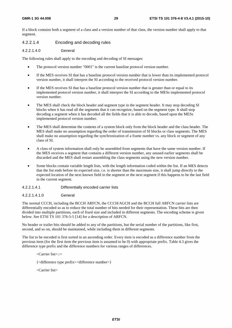
ETSI
ETSI TS 101 376-4-8 V3.4.1 (2015-10) 29GMR-1 3G 44.008
If a block contains both a segment of a class and a version number of that class, the version number shall apply to that segment.
4.2.2.1.4 Encoding and decoding rules
4.2.2.1.4.0 General
The following rules shall apply to the encoding and decoding of SI messages:
• The protocol version number "0001" is the current baseline protocol version number.
• If the MES receives SI that has a baseline protocol version number that is lower than its implemented protocol version number, it shall interpret the SI according to the received protocol version number.
• If the MES receives SI that has a baseline protocol version number that is greater than or equal to its implemented protocol version number, it shall interpret the SI according to the MESs implemented protocol version number.
• The MES shall check the block header and segment type in the segment header. It may stop decoding SI blocks when it has read all the segments that it can recognize, based on the segment type. It shall stop decoding a segment when it has decoded all the fields that it is able to decode, based upon the MESs implemented protocol version number.
• The MES shall determine the contents of a system block only from the block header and the class header. The MES shall make no assumption regarding the order of transmission of SI blocks or class segments. The MES shall make no assumption regarding the synchronization of a frame number vs. any block or segment of any class of SI.
• A class of system information shall only be assembled from segments that have the same version number. If the MES receives a segment that contains a different version number, any unused earlier segments shall be discarded and the MES shall restart assembling the class segments using the new version number.
• Some blocks contain variable length lists, with the length information coded within the list. If an MES detects that the list ends before its expected size, i.e. is shorter than the maximum size, it shall jump directly to the expected location of the next known field in the segment or the next segment if this happens to be the last field in the current segment.
4.2.2.1.4.1 Differentially encoded carrier lists
4.2.2.1.4.1.0 General
The normal CCCH, including the BCCH ARFCN, the CCCH/AGCH and the BCCH full ARFCN carrier lists are differentially encoded so as to reduce the total number of bits needed for their representation. These bits are then divided into multiple partitions, each of fixed size and included in different segments. The encoding scheme is given below. See ETSI TS 101 376-5-5 [14] for a description of ARFCN.
No header or trailer bits should be added to any of the partitions, but the serial number of the partitions, like first, second, and so on, should be maintained, while including them in different segments.
The list to be encoded is first sorted in an ascending order. Every item is encoded as a difference number from the previous item (for the first item the previous item is assumed to be 0) with appropriate prefix. Table 4.3 gives the difference type prefix and the difference numbers for various ranges of differences.
<Carrier list>::=
<difference type prefix><difference number>
<Carrier list>

ETSI
ETSI TS 101 376-4-8 V3.4.1 (2015-10) 30GMR-1 3G 44.008
Table 4.3: Encoding of difference values
Difference Range
Difference Type Prefix
Difference Number
Encoded Value
1 - 16 00 0 - 15 <00><bitstring(4)> 17 - 48 01 0 - 31 <01><bitstring(5)> 49 - 112 10 0 - 63 <10><bitstring(6)>
113 - 240 110 0 - 127 <110><bitstring(7)> 241 - 1 087 111 0 - 846 <111><bitstring(10)>
The MES shall concatenate all the partitions of the list received in different segments in correct order and extract the carrier specifications. No carrier specification shall have value greater than 1 087. The MES shall stop processing the list if a carrier specification greater than 1 087 is decoded. The MES shall stop processing the list when the total number of entries, as given in the corresponding SI parameter, has been extracted. The GS should fill any subsequent bits beyond the end of the list with 0s. The MES shall ignore any subsequent bits beyond the end of the list.
4.2.2.1.4.1.1 RACH carrier lists (Iu mode only)
In addition to differentially encoded BCCH and CCCH lists specified in clause 4.2.2.1.4.1, the network may also include a RACH list in the system information. Availability of the RACH list shall be indicated in Segment 2Abis.
The SA_RACH _LIST shall contain the RACH ARFCNs corresponding to Normal CCCH ARFCNs and AGCH/CCCH ARFCNs, listed in the same order in which the Normal CCCHs and AGCH/CCCHs are listed in the SA_CCCH_LIST and SA_AGCH_LIST respectively (see ETSI TS 101 376-5-2 [12] for definition of Normal CCCH and AGCH/CCCH). The SA_RACH_LIST shares the bit space used by SA_CCCH_LIST and SA_AGCH_LIST. The total number of entries in SA_RACH_LIST is equal to the sum of SA_CCCH_CHANS and SA_AGCH_CHANS.
The order in which the RACH ARFCNs are listed in SA_RACH_LIST shall correspond to one-to-one with Normal CCCH ARFCNs followed by AGCH/CCCH ARFCNs. The MES shall read interpret the SA_RACH_LIST only after forming the SA_CCCH_LIST and SA_AGCH_LIST.
NOTE: SA_RACH_LIST is not differentially encoded.
4.2.2.1.4.2 Concurrent BCCH list
Same as clause 4.2.2.1.4.2 of ETSI TS 101 376-4-8 (Release 1) [19].
4.2.2.1.4.2a Concurrent BCCH list (Iu mode)
The list of the concurrent BCCH information is encoded so as to reduce the total number of bits needed for their representation. These bits are then divided into two partitions each of fixed size and included in different segments. The encoding scheme is given below:
<concurrent BCCH information list>::= <concurrent BCCH information> Number of BCCH
<concurrent BCCH information>::= <header: bitstring(3)> <ARFCN: bitstring(11)> <Satellite Id: bitstring(2)> - presence is indicated in the header <MCC: bitstring(10)> - presence is indicated in the header <MNC: bitstring(10)> - presence is indicated in the header <header: bitstring(3)> - three bits b3 b2 b1 to indicate - b1 = 0: Satellite Id of BCCH same as previous element - b1 = 1: Satellite Id of BCCH differs from previous element - b2 = 0: MCC same as the previous element in the list - b2 = 1: MCC differs from the previous element - b3 = 0: MNC same as the previous element in the list - b3 = 1: MNC differs from the previous element <Satellite Id: bitstring(2)> - This is omitted if the Satellite Id of the BCCH carrier - is unchanged from the previous element. <ARFCN: bitstring(11)> - ARFCN value corresponding to the BCCH carrier <MCC: bitstring(10)> - valid range 0 to 999. This is omitted if MCC is unchanged
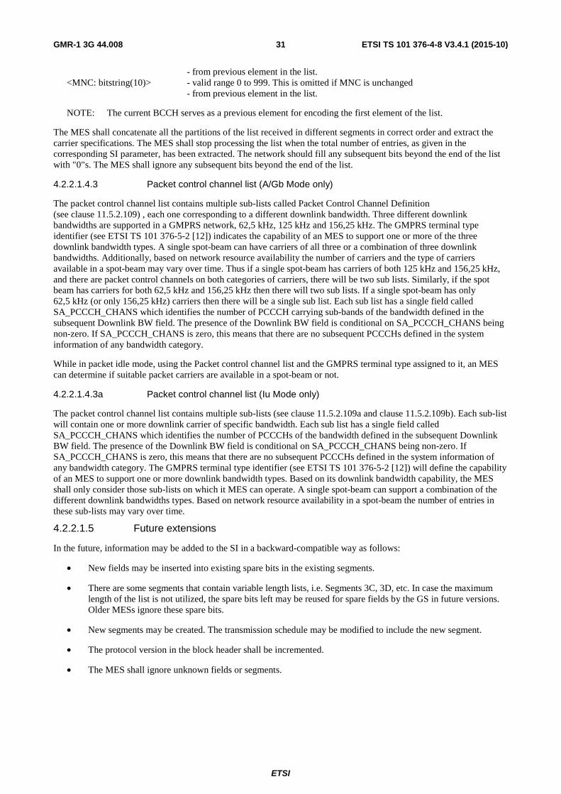
ETSI
ETSI TS 101 376-4-8 V3.4.1 (2015-10) 31GMR-1 3G 44.008
- from previous element in the list. <MNC: bitstring(10)> - valid range 0 to 999. This is omitted if MNC is unchanged - from previous element in the list.
NOTE: The current BCCH serves as a previous element for encoding the first element of the list.
The MES shall concatenate all the partitions of the list received in different segments in correct order and extract the carrier specifications. The MES shall stop processing the list when the total number of entries, as given in the corresponding SI parameter, has been extracted. The network should fill any subsequent bits beyond the end of the list with "0"s. The MES shall ignore any subsequent bits beyond the end of the list.
4.2.2.1.4.3 Packet control channel list (A/Gb Mode only)
The packet control channel list contains multiple sub-lists called Packet Control Channel Definition (see clause 11.5.2.109) , each one corresponding to a different downlink bandwidth. Three different downlink bandwidths are supported in a GMPRS network, 62,5 kHz, 125 kHz and 156,25 kHz. The GMPRS terminal type identifier (see ETSI TS 101 376-5-2 [12]) indicates the capability of an MES to support one or more of the three downlink bandwidth types. A single spot-beam can have carriers of all three or a combination of three downlink bandwidths. Additionally, based on network resource availability the number of carriers and the type of carriers available in a spot-beam may vary over time. Thus if a single spot-beam has carriers of both 125 kHz and 156,25 kHz, and there are packet control channels on both categories of carriers, there will be two sub lists. Similarly, if the spot beam has carriers for both 62,5 kHz and 156,25 kHz then there will two sub lists. If a single spot-beam has only 62,5 kHz (or only 156,25 kHz) carriers then there will be a single sub list. Each sub list has a single field called SA_PCCCH_CHANS which identifies the number of PCCCH carrying sub-bands of the bandwidth defined in the subsequent Downlink BW field. The presence of the Downlink BW field is conditional on SA_PCCCH_CHANS being non-zero. If SA_PCCCH_CHANS is zero, this means that there are no subsequent PCCCHs defined in the system information of any bandwidth category.
While in packet idle mode, using the Packet control channel list and the GMPRS terminal type assigned to it, an MES can determine if suitable packet carriers are available in a spot-beam or not.
4.2.2.1.4.3a Packet control channel list (Iu Mode only)
The packet control channel list contains multiple sub-lists (see clause 11.5.2.109a and clause 11.5.2.109b). Each sub-list will contain one or more downlink carrier of specific bandwidth. Each sub list has a single field called SA_PCCCH_CHANS which identifies the number of PCCCHs of the bandwidth defined in the subsequent Downlink BW field. The presence of the Downlink BW field is conditional on SA_PCCCH_CHANS being non-zero. If SA_PCCCH_CHANS is zero, this means that there are no subsequent PCCCHs defined in the system information of any bandwidth category. The GMPRS terminal type identifier (see ETSI TS 101 376-5-2 [12]) will define the capability of an MES to support one or more downlink bandwidth types. Based on its downlink bandwidth capability, the MES shall only consider those sub-lists on which it MES can operate. A single spot-beam can support a combination of the different downlink bandwidths types. Based on network resource availability in a spot-beam the number of entries in these sub-lists may vary over time.
4.2.2.1.5 Future extensions
In the future, information may be added to the SI in a backward-compatible way as follows:
• New fields may be inserted into existing spare bits in the existing segments.
• There are some segments that contain variable length lists, i.e. Segments 3C, 3D, etc. In case the maximum length of the list is not utilized, the spare bits left may be reused for spare fields by the GS in future versions. Older MESs ignore these spare bits.
• New segments may be created. The transmission schedule may be modified to include the new segment.
• The protocol version in the block header shall be incremented.
• The MES shall ignore unknown fields or segments.

ETSI
ETSI TS 101 376-4-8 V3.4.1 (2015-10) 32GMR-1 3G 44.008
4.2.2.1.6 Anchored(A) and Temporary(T) BCCH (A/Gb mode only)
Refer to ETSI TS 101 376-5-6 [15] for definition of A-BCCH and T-BCCH. The distribution of A-BCCH and T-BCCH in BCCH neighbour lists and concurrent BCCH system information is as follows:
• BCCH neighbour lists in A-BCCHs and T-BCCHs shall only contain A-BCCHs.
• If T-BCCH is present all A-BCCHs shall contain T-BCCHs in the concurrent BCCH information.
• All T-BCCHs shall contain A-BCCHs in the concurrent BCCH information.
4.2.2.1.7 Multiplexing of CCCH and PCCCH (A/Gb mode only)
PCCCH and CCCH (both normal CCCH and CCCH/AGCH) may coexist in a spot-beam. The PCCCH description is provided in a variable size list, which shares the class 3 segments with the CCCH normal or the CCCH/AGCH.
In segments 3C, 3D, 3E and 3E bis, the PCCCH and the normal CCCH lists share the same bitspace. In segments 3F, 3G, 3G bis and 3H, the PCCCH and the CCCH/AGCH lists share the same bitspace. Note that each segment contains a part of the CCCH list and then a part of the PCCCH list.
To find the PCCCH list and decode it, the terminal may do the following:
• Read the parameter SA_CCCH_CHANS to determine the number of normal CCCHs and SA_AGCH_CHANS to determine the number of CCCH/AGCH in the appropriate segments.
• In each segment where the normal CCCH is present, it starts decoding the normal CCCH list. For each decoded CCCH an internal variable corresponding to the number of normal decoded CCCHs is incremented. It stops decoding the CCCH list for that segment when the internal variable reaches the value of SA_CCCH_CHANS or the maximum number of bits allocated for CCCH in that segment is reached. The PCCCH list, if present is immediately after this. The presence or absence of the PCCCH list is determined by the parameter SA_PCCCH_CHANS at the head of the Packet Control Channel Definition IE, which indicates how many PCCCHs of the bandwidth specified in the following field are present. Note that if a given SA_PCCCH_CHANS reads zero, it indicates that there are no PCCCH elements behind it.
• The same procedure is used for the segments containing CCCH/AGCH. Note that the PCCCH definitions may run through multiple segments so that the start is in segment 3C and end in 3D, 3E/3Ebis, 3F, 3G/3Gbis or 3H. In other words, there is no demarcation of segments as in the case of normal CCCH and CCCH/AGCH.
• The SA_AGCH_CHANS, SA_CCCH_CHANS variables indicate the total number of CCCHs of a given category for the entire system information cycle, not just in a particular segment. Thus the internal variable is not reset across segments.
• The SA_PCCCH_CHANS variable indicates the total number of PCCCHs of a supported bandwidth category and may occur more than once in a system information cycle if different bandwidths are supported.
4.2.2.1.7a Multiplexing of CCCH and PCCCH (Iu mode only)
PCCCH and CCCHs (normal CCCH. AGCH/CCCH and the associated RACHs) may coexist in a spot-beam. The PCCCH description is provided in a variable size list, which shares the class 3 segments with the CCCH list.
In segments 3C, 3D and 3E bis, the PCCCH list, the normal CCCH list and the optional RACH list share the same bitspace. In segments 3F and 3G bis the PCCCH list, the AGCH/CCCH list and the optional RACH list share the same bitspace. Note that each segment contains a part of the CCCH list and then a part of the PCCCH list.
To find the PCCCH list and decode it, the terminal may do the following:
• Read the parameter SA_CCCH_CHANS to determine the number of normal CCCHs and SA_AGCH_CHANS to determine the number of AGCH/CCCHs in the appropriate segments.
• The number of entries in the optional RACH list is given by sum of SA_CCCH_CHANS and SA_AGCH_CHANS.

ETSI
ETSI TS 101 376-4-8 V3.4.1 (2015-10) 33GMR-1 3G 44.008
• In each segment where the normal CCCH is present, it starts decoding the normal CCCH list. For each decoded CCCH an internal variable corresponding to the number of normal decoded CCCHs is incremented. It stops decoding the CCCH list for that segment when the internal variable reaches the value of SA_CCCH_CHANS or the maximum number of bits allocated for CCCH in that segment is reached. If the internal variable reaches the value of SA_CCCH_CHANS, then the optional RACH list will start and occupy the remaining bits allocated for CCCH in that segment. The PCCCH list, if present is immediately after this. The number of entries within a PCCCH sub-list is determined by the parameter SA_PCCCH_CHANS.
• The same procedure is used for the segments containing AGCH/CCCH. Note that the PCCCH definitions may run through multiple segments so that the start is in segment 3C and end in 3D, 3Ebis, 3F or 3Gbis. In other words, there is no demarcation of segments as in the case of normal CCCH and CCCH/AGCH.
The SA_AGCH_CHANS, SA_CCCH_CHANS variables indicate the total number of CCCHs of a given category for the entire system information cycle, not just in a particular segment. Thus the internal variable is not reset across segments.
4.2.2.2 GPS satellite ephemeris data broadcasting
4.2.2.2.0 General
Ephemeris data of up to 12 GPS satellites probably visible to MESs in the spot beam are continuously transmitted by the network on the GBCH or the GBCH3. This data allows a mobile to quickly calculate its position in terms of latitude and longitude based upon the signals received from the GPS satellites. Other supporting information such as current time and satellite Doppler estimates are also transmitted.
The presence of GPS ephemeris information on either the GBCH or GBCH3 is indicated in the system information segment 1A by the GBCH present information element.
4.2.2.2.1 GPS satellite ephemeris Earth Centered Earth fixed coordinates on GBCH
The GBCH INFORMATION Messages shall be broadcast in a GBCH information cycle that consists of up to 32 GBCH messages. A GBCH information cycle shall be completed in a maximum of 64 frames.
Each message contains a message header containing the message number. The messages shall be broadcast in sequence. Up to 12 satellites may be identified via the VISIBILITY_LIST. Nominally, two other messages exist in the GBCH information cycle for each of the 12 entries of the VISIBILITY_LIST. Satellites may be repeated in the VISIBILITY_LIST if there are less than 12 visible GPS satellites. Alternatively, if there are less than 12 satellites, satellite Ids of "0" may be put into the VISIBILITY_LIST. If done, the GBCH information cycle is not required to contain the GBCH Messages with Type 8 and Type 9 data for the satellites with Ids set to "0". If the GBCH information cycle contains messages for satellites, for which the VISIBILITY_LIST contained a satellite ID of "0", then the contents of those messages shall be discarded.
The full GBCH information cycle is shown in table 4.4.

ETSI
ETSI TS 101 376-4-8 V3.4.1 (2015-10) 34GMR-1 3G 44.008
Table 4.4: GBCH information schedule
GBCH Message Number GBCH Information Type 0 Type 1 1 Type 2 2 Type 4 3 Type 5 4 Type 8 - Sat 1 5 Type 9 - Sat 1 6 Type 8 - Sat 2 7 Type 9 - Sat 2 8 Type 8 - Sat 3 9 Type 9 - Sat 3 10 Type 8 - Sat 4 11 Type 9 - Sat 4 12 Type 8 - Sat 5 13 Type 9 - Sat 5 14 Type 8 - Sat 6 15 Type 8 - Sat 6 16 Type 1 17 Type 3 18 Type 6 19 Type 7 20 Type 8 - Sat 7 21 Type 9 - Sat 7 22 Type 8 - Sat 8 23 Type 9 - Sat 8 24 Type 8 - Sat 9 25 Type 9 - Sat 9 26 Type 8 - Sat 10 27 Type 9 - Sat 10 28 Type 8 - Sat 11 29 Type 9 - Sat 11 30 Type 8 - Sat 12 31 Type 9 - Sat 12
Each GBCH information cycle has a GBCH sequence number associated with it. All messages within a GBCH information cycle shall have the same sequence number and shall be consistent with one another. All messages with the same message number and sequence number shall be constant, with the exception of Doppler. Any change of information content, with the exception of Doppler, shall require a change of sequence number. Doppler information may change without a change of sequence number. Following a change of sequence number, the old sequence number shall not be reused for at least two minutes.
4.2.2.2.2 GPS satellite ephemeris Earth Centered Earth fixed coordinates on GBCH3
Optionally, Ephemeris data using Earth Centered Earth Fixed (ECEF) coordinates of up to 12 GPS satellites probably visible to MESs in the spot beam may be continuously transmitted by the network on the GBCH3. This data allows a mobile to quickly calculate its position in terms of latitude and longitude based upon the signals received from the GPS satellites. Other supporting information such as current time and satellite Doppler estimates are also transmitted.
GBCH3 INFORMATION Messages are transmitted in the GBCH3. When ECEF coordinates are broadcast, the GBCH3 INFORMATION Messages shall be broadcast in a GBCH3 information cycle that consists of up to 17 GBCH3 messages.
Each message contains a message header containing the message number. The messages shall be broadcast in sequence. Up to 12 satellites may be identified. If there are less than 12 satellites, satellite IDs of "0" shall be used. If the GBCH3 information cycle contains messages for satellites, with the satellite ID of "0", then the contents of those information elements following these satellite IDs shall be discarded up to the next non-zero satellite ID.
The full GBCH3 ECEF information cycle is shown in table 4.5. The GBCH3 ECEF message number is binary coded in the GBCH3 message header.

ETSI
ETSI TS 101 376-4-8 V3.4.1 (2015-10) 35GMR-1 3G 44.008
Table 4.5: GBCH3 ECEF information schedule
GBCH3 ECEF Message Number GBCH3 ECEF Information Type 0 Type 1 1 Type 2 2 Type 3 3 Type 4 4 Type 5 5 Type 6 6 Type 7 7 Type 8 8 Type 9 9 Type 10 10 Type 11 11 Type 12 12 Type 13 13 Type 14 14 Type 15 15 Type 16 16 Type 17
Each GBCH3 information cycle has a GBCH3 sequence number associated with it. All messages within a GBCH3 information cycle shall have the same sequence number and shall be consistent with one another. All messages with the same message number and sequence number shall be constant, with the exception of Doppler. Any change of information content, with the exception of Doppler, shall require a change of sequence number. Doppler information may change without a change of sequence number. Following a change of sequence number, the old sequence number shall not be reused for at least two minutes.
4.2.2.2.3 GPS satellite ephemeris Keplerian Coordinates on GBCH3
The GBCH3 may optionally be used to broadcast the GPS satellite ephemeris using Keplerian Coordinates (KC) instead of ECEF coordinates as described above. GBCH3 KC message Type 1 contains information for up to 12 GPS satellite vehicles (SVs). This segment is broadcast once at the start of the GBCH information cycle and contains the number of SV for which ephemeris is broadcast.
GBCH3 KC message Type 2 contains information for up to two satellites identified by the GPS SV number defined in IS-GPS-200 [29]. If this message contains information for only 1 satellite, the second satellite ID is "0".
GBCH3 KC message Type 3 and Type 4 contain information for GPS SV 1 listed in the prior Type 2 message.
GBCH3 KC message Type 5 and 6 contain information for the GPS SV 2 listed in the prior Type 2 message. If the second satellite ID in the prior Type 2 message was "0" then the Type 5 and Type 6 message are not transmitted.
An example of the GBCH3 KC information schedule is shown in table 4.6 for the case where the number of SV for which ephemeris is being broadcast is 7.

ETSI
ETSI TS 101 376-4-8 V3.4.1 (2015-10) 36GMR-1 3G 44.008
Table 4.6: Example of GBCH3 KC information schedule for Keplerian Coordinate Ephemeris for 7 SV
GBCH3 KC Message Number GBCH3 KC Information Type 17 Type 1 (Number of SV = 7) 18 Type 2 (for #1 and #2) 19 Type 3 20 Type 4 21 Type 5 22 Type 6 18 Type 2 (for #3 and #4) 19 Type 3 20 Type 4 21 Type 5 22 Type 6 18 Type 2 (for #5 and #6) 19 Type 3 20 Type 4 21 Type 5 22 Type 6 18 Type 2 (for #7) 19 Type 3 20 Type 4
4.2.2.3 GPS almanac data transmission
The network will broadcast the GPS Almanac Data via the unused TMSI slots in the PAGING REQUEST 2 and PAGING REQUEST 3 messages. The data shall be independently transmitted for each paging subchannel. The Almanac Present flag in the system information segment 3I indicates whether the almanac data is present on the PCH channel. During paging reorganization, the MES shall resynchronize with the new paging subchannel to obtain this almanac data.
The rate of transmission depends on the paging load of the particular subchannel. Transmission of the GPS Almanac Data will not be affected by paging reorganization. Under conditions of very light paging traffic, the network shall maintain a minimum paging transmission rate, such that, on an average, in each second at least one page shall be transmitted, with one paging slot being used for GPS Almanac Data transmission.
The cutover bit in the GPS Almanac Data Information Elements (IEs) is used by the MESs to determine whether new GPS Almanac Data is being transmitted. From the network, each cycle of the data uses the value "0" or "1" in this bit alternately. The MES shall monitor this bit. A change in this bit's value indicates that a new cycle has started.
4.3 RR connection establishment
4.3.1 RR connection establishment initiated by the Mobile Earth Station (MES): immediate assignment procedure
4.3.1.0 General
Same as clause 4.3.1 of ETSI TS 101 376-4-8 (Release 1) [19].
4.3.1.1 Spot beam selection to access the network
The RR entity at the MES side interacts with the physical layer for a suitable spot beam (see ETSI TS 101 376-5-6 [15], and ETSI TS 101 376-3-10 [4]). Upon camping on a suitable spot beam, the physical layer entity informs the RR layer of the availability of the spot beam. The MES performs LAI selection within the available spot beams and then camps onto the control channels of the suitable cell (i.e. the LAI within the spot beam). The MES requesting packet services acquires a BCCH to determine whether it is offering packet services. If so, it acquires the BCCH and camps on the control channels that are advertised in the BCCH. If no packet services are available, the MES will go through the concurrent list till it finds a BCCH which is offering packet services. If no BCCH is available which is offering packet services MES will execute the dark-beam camping procedure as given in ETSI TS 101 376-3-10 [4].

ETSI
ETSI TS 101 376-4-8 V3.4.1 (2015-10) 37GMR-1 3G 44.008
4.3.1.2 Permission to access the network
Same as clause of 4.3.1.2 of ETSI TS 101 376-4-8 (Release 1) [19].
4.3.1.3 Initiation of the immediate assignment procedure (A/Gb mode only)
The MES shall attempt to obtain the current GPS position before sending a CHANNEL REQUEST message on the RACH. A position shall be current if less than Page GPS Position Age (Mobile Terminated (MT) calls) or GPS Position Age (other accesses) time has elapsed since it was measured. If the last measured position is not current, the MES shall start the RACH Position timer and initiate GPS position calculation. If the position calculation is successful, the timer shall be stopped and the newly calculated position is used. If the timer expires, the last available position (if any) shall be used. If no position information is available, an access attempt shall be made without position information.
The Page Response Current GPS flag indicates the importance of responding to an MT call with a current position in order to ensure that the call can be completed. If the Page Response Current GPS flag is set to 1, the RACH Position timer shall not be used for MT calls. Instead, the page timer (in response to paging) or alert timer (in response to alerting) shall be used in its place in the procedure described in the preceding paragraph.
If T3119 expires while the GPS calculation is being done, T3119 is restarted and no further action needs to be taken in response to this event.
A GMPRS Class-B MES requesting circuit-switched services shall first check if GMPRS service is already suspended. If not already suspended, then GMPRS Class-B MES shall request suspension of GMPRS service as specified in clause 4.8. If the GMPRS service was already suspended (e.g. due to previous attempt), then GMPRS Class-B MES shall proceed as specified in the following paragraphs.
If the MES requesting circuit services sends position information in the CHANNEL REQUEST message, it shall send the timestamp in CIPHER MODE COMPLETE message. When the establishment cause is "position verification", the MES shall send only the CHANNEL REQUEST message with the new GPS position. If new position is not available, no CHANNEL REQUEST message will be sent If the MES is requesting packet services with establishment cause Packet Routing Area Update/Attach request it shall include the timestamp in the CHANNEL REQUEST TYPE 1 message. If the establishment cause is Packet TBF Establishment the MES shall not include the timestamp in the CHANNEL REQUEST TYPE 1 message.
If the MES is accessing the home PLMN, it shall send the Service Provider Identification (SP ID) in the CHANNEL REQUEST message. While accessing any network other than the home PLMN, the MES shall send the Home Public Land Mobile Network Identification (HPLMN-ID).
For MES requesting circuit services the RR entity shall indicate the terminal priority in the CHANNEL REQUEST message. For certain types of terminals, this value is stored in the non-volatile memory. If the terminal is not equipped with this information, the default value (value 0) shall be sent by the MES.
Under certain circumstances the MES requesting circuit services will resend a CHANNEL REQUEST message for Call Establishment as part of the optimal routing procedures described in ETSI TS 101 376-3-19 [5]. The O and R bits are used in these procedures. The MES may resend a CHANNEL REQUEST message on the original RACH following an attempt at optimal routing that failed due to inability to register on the optimal GS. The MES shall resend a CHANNEL REQUEST message to the new RACH on the new satellite following an IMMEDIATE ASSIGNMENT REJECT message or EXTENDED IMMEDIATE ASSIGNMENT REJECT message with reject cause, "redirect to the new satellite". The MES shall resend a CHANNEL REQUEST message to the old BCCH on the old satellite following an optimal routing failure on the new satellite which occurs before the MES receives an IMMEDIATE ASSIGNMENT message or IMMEDIATE ASSIGNMENT REJECT message from the new satellite.
The MES requesting circuit services shall not resend a CHANNEL REQUEST message more than once in a single-satellite optimal routing case. The MES requesting circuit services shall not send a CHANNEL REQUEST message more than once on the second satellite nor resend it more than once on the first satellite in a two-satellite optimal routing case.
As long as the MES is continuing an immediate assignment procedure for the same service connection, it shall continue to use the same establishment cause until it is terminated.
The RR entity shall read Class 1 system information and the SI block header immediately prior to transmission of a CHANNEL REQUEST message and verify the RACH_CONTROL_PARAMETERS in combination with the Access Control Class elementary file in the Subscriber Identity Module (SIM). The MES shall not utilize the RACH if not allowed by any parameter in the RACH_CONTROL_PARAMETERS.

ETSI
ETSI TS 101 376-4-8 V3.4.1 (2015-10) 38GMR-1 3G 44.008
The RR entity of the MES shall initiate the immediate assignment procedure by scheduling sending on the RACH (of the CHANNEL REQUEST message) with maximum power and leaving the idle mode (in particular, the MES will ignore the PAGING REQUEST messages).
To schedule the transmission of the CHANNEL REQUEST, the RR entity randomly selects a RACH out of the total available contention channels in the LAI as broadcast in the BCCH. The MES then chooses a frame <n> counting from the current frame, to send the CHANNEL REQUEST. The value of <n> is randomly chosen from a sequence 0, 1, …, <m>, where the value of <m> is defined by the RANDOMIZATION PERIOD in the header of the system information block from which the Class 1 information was read.
After sending the CHANNEL REQUEST message on the RACH, the RR entity at the MES shall start timer T3126. At expiry of this timer, the RR entity shall increment the value of the retransmit counter, which maintains a count of the total number of retransmission attempts since the initiation of the Immediate Assignment procedure. If this value exceeds M (M is the value of the "max retrans" broadcast over BCCH), the Immediate Assignment procedure shall be aborted; if the Immediate Assignment procedure was triggered by a request from the MM sublayer, a random access failure shall be indicated to the MM/GMM sublayer.
For MES requesting circuit services, if the establishment cause is "position verification", and there is a pending establishment request from the MM layer or a request from the RR layer to service a received PAGE REQUEST/ALERT REQUEST message, the RR layer shall not retry the channel establishment for position verification procedure, even if the retry count does not exceed M. Instead, it shall reset the retry counter and attempt to establish a fresh radio-channel connection to service the pending establishment request from the MM or RR sublayer itself.
If the maximum retransmission value is not achieved, the RR entity at the MES shall repeat the transmission of the CHANNEL REQUEST messages over the random access channel with a new random reference (drawn randomly from a uniform probability distribution) each time. The retransmission of the CHANNEL REQUEST is delayed by n frames, following the expiration of the timeout, where n is a random number between 1 and Sk. The value of Sk is obtained
from Sk = 4 × 2k-1, where k is the value of the retransmission count.
While timer T3126 is running after sending the CHANNEL REQUEST message, the MES shall continuously monitor the corresponding downlink CCCH (as the AGCH/RACH are paired, the corresponding downlink CCCH refers to the one paired with the RACH on which the request was sent) for AGCH messages.
For MES requesting packet services using CHANNEL REQUEST TYPE 1 will follow the retransmission procedure as described in clause 4.7.2.1.2.
4.3.1.3a Initiation of the immediate assignment procedure (Iu mode only)
The MES shall attempt to obtain its current GPS position before sending a CHANNEL REQUEST TYPE 3 message on the RACH. A position shall be current if Page GPS Position Age (Mobile Terminated (MT) calls) or GPS Position Age (other accesses) time has not elapsed since it was measured. If the last measured position is not current, the MES shall start the RACH Position timer and initiate GPS position calculation. If the position calculation is successful, the timer shall be stopped and the newly calculated position is used. If the timer expires, the last available position (if any) shall be used in the channel request message. If no position information is available, an access attempt shall be made without position information.
The Page Response Current GPS flag in System Information indicates the importance of responding to a mobile terminated call with a current position in order to ensure that the call can be completed. If the Page Response Current GPS flag is set to 1, the RACH Position timer shall not be used for MT calls. Instead, the page timer T3114 (in response to paging) or alert timer T3112 (in response to alerting) shall be used in its place in the procedure described in the preceding paragraph.
If T3119 expires while the GPS calculation is being done, T3119 is restarted and no further action needs to be taken in response to this event.
If the reason for initiating immediate assignment procedure is to obtain packet services or respond to a PAGE REQUEST/ALERT REQUEST then in the CHANNEL REQUEST TYPE3 message the MES shall include the relative position as specified in clause 10.1.8.4. If the reason for initiating immediate assignment procedure is for position verification, then the MES shall include extended relative position in CHANNEL REQUEST TYPE3 message. If the relative MES position exceeds the range of the extended relative position IE, then the MES shall not send the position verification and shall restart the GPS Update Timer. The MES shall use the same relative position or extended relative position information in all retransmissions of the CHANNEL REQUEST TYPE 3 message.

ETSI
ETSI TS 101 376-4-8 V3.4.1 (2015-10) 39GMR-1 3G 44.008
The MES shall read Class 1 system information and the SI block header immediately prior to transmission of a CHANNEL REQUEST TYPE 3 message and verify the RACH_CONTROL_PARAMETERS in combination with the Access Control Class elementary file in the Subscriber Identity Module (SIM/USIM). The MES shall not utilize the RACH if not allowed by any parameter in the RACH_CONTROL_PARAMETERS.
To schedule the transmission of the CHANNEL REQUEST TYPE 3, the MES shall randomly select a RACH out of the list of total available contention channels in the RAI as broadcast in the BCCH. The MES then shall choose a frame <n> counting from the current frame, to send the CHANNEL REQUEST TYPE 3. The value of <n> is randomly chosen from a sequence 0, 1, …, <m>, where the value of <m> is defined by the RANDOMIZATION PERIOD in the header of the system information block from which the Class 1 information was read.
After sending the CHANNEL REQUEST TYPE 3 message on the RACH, the RR entity at the MES shall start timer T3146. At expiry of this timer, the MES shall increment the value of the retransmit counter, which maintains a count of the total number of retransmission attempts since the initiation of the Immediate Assignment procedure. If this value exceeds M (M is the value of the "max retrans" broadcast over BCCH), the Immediate Assignment procedure shall be aborted; if the Immediate Assignment procedure was triggered by a request from the MM/GMM sublayer, a random access failure shall be indicated to the MM/GMM sublayer.
However, if the establishment cause is "position verification", and there is a pending establishment request from the MM/GMM layer or a request from the RR layer to service a received PAGE REQUEST/ALERT REQUEST message, the RR layer shall not retry the channel establishment for position verification procedure, even if the retry count does not exceed M. Instead, it shall reset the retry counter and attempt to establish a fresh radio-channel connection to service the pending establishment request from the MM or RR sublayer itself.
If the maximum retransmission value is not achieved, the MES shall repeat the transmission of the CHANNEL REQUEST TYPE 3 messages on RACH with a new random reference (drawn randomly from a uniform probability distribution) each time. The retransmission of the CHANNEL REQUEST TYPE 3 is delayed by n frames, following the expiration of the timeout, where n is a random number between 1 and Sk. The value of Sk is obtained from
Sk = 4 × 2k-1, where k is the value of the retransmission count.
While timer T3146 is running after sending the CHANNEL REQUEST TYPE 3 message, the MES shall continuously monitor the corresponding downlink CCCH (AGCH/RACH pairing is specified in Normal CCCH list, AGCH/CCCH list and the optional RACH list. The corresponding downlink CCCH refers to the one paired with the RACH on which the request was sent) for AGCH messages.
When transmitting or retransmitting CHANNEL REQUEST TYPE 3 messages, the MES shall do so with maximum power.
4.3.1.4 Answer from the network
4.3.1.4.1 On receipt of a CHANNEL REQUEST message (A/Gb mode only)
Same as clause 4.3.1.4.1 of ETSI TS 101 376-4-8 (Release 1) [19].
4.3.1.4.2 IMMEDIATE ASSIGNMENT from network for MES requesting circuit service (A/Gb mode only)
4.3.1.4.2.0 General
Same as clause 4.3.1.4.2 of ETSI TS 101 376-4-8 (Release 1) [19].
4.3.1.4.2.1 IMMEDIATE ASSIGNMENT with dedicated resource allocated and location update needed (A/Gb mode only)
Same as clause 4.3.1.4.2.1 of ETSI TS 101 376-4-8 (Release 1) [19].
4.3.1.4.2.2 IMMEDIATE ASSIGNMENT with dedicated resource allocated and no location update needed (A/Gb mode only)
Same as clause 4.3.1.4.2.2 of ETSI TS 101 376-4-8 (Release 1) [19].

ETSI
ETSI TS 101 376-4-8 V3.4.1 (2015-10) 40GMR-1 3G 44.008
4.3.1.4.2.3 IMMEDIATE ASSIGNMENT with dedicated resource allocated and extended procedure needed (A/Gb mode only)
Same as clause 4.3.1.4.2.3 of ETSI TS 101 376-4-8 (Release 1) [19].
4.3.1.4.2.4 IMMEDIATE ASSIGNMENT with no dedicated resource allocated and pause timer indicated (A/Gb mode only)
Same as clause 4.3.1.4.2.3 of ETSI TS 101 376-4-8 (Release 1) [19].
4.3.1.4.3 Immediate Assignment from network for MES requesting packet service
In A/Gb mode, upon receipt of an IMMEDIATE ASSIGNMENT TYPE 2 message corresponding to its CHANNEL REQUEST TYPE 1 message the MES shall proceed as described in clause 4.7.2.
In Iu mode, upon receipt of an IMMEDIATE ASSIGNMENT TYPE 4 message corresponding to one of its CHANNEL REQUEST TYPE 3 message the MES shall proceed as described in clause 4.7.2.1.3.
4.3.1.4.4 Assignment rejection (IMMEDIATE ASSIGNMENT REJECT from network) (A/Gb mode only)
For circuit switched services if no channel is available for assignment, or if a dedicated channel shall not be provided, the network should send the MES an IMMEDIATE ASSIGNMENT REJECT (TYPE 1 or TYPE 2) message in unacknowledged mode in any AGCH slot of any frame of the downlink CCCH corresponding to the RACH on which the CHANNEL REQUEST message was received. This message contains the request reference and a wait indication. The MES matches the request reference and the GPS discriminator (if given for the request reference) with the corresponding locally calculated value to determine if the IMMEDIATE ASSIGNMENT REJECT message is addressed to it. The IMMEDIATE ASSIGNMENT REJECT TYPE 2 message is for all purposes equivalent to an IMMEDIATE ASSIGNMENT REJECT TYPE 1 message except that a country/region display string is given with the TYPE 2 message and TYPE 2 is not used for certain reject causes ("lack of resources", "invalid position for spot-beam", "reported position acceptable" and "redirect to another satellite"). The MES stores the available country/region information (given in the Position Display IE) for displaying it to the user.
The GPS Update Timer value and GPS Update Distance value, if available in the received message, shall replace the corresponding idle mode position reporting parameters.
For packet switched services the network should send the MES an IMMEDIATE ASSIGNMENT REJECT (TYPE1 or TYPE 2 or TYPE 3) message. If the reject cause is incorrect class-2 RACH info, the MES shall not consider the GPS discriminator.
Upon receipt of an IMMEDIATE ASSIGNMENT REJECT message corresponding to its last CHANNEL REQUEST/CHANNEL REQUEST TYPE 1 message the MES shall stop timer T3126/T3146 or timer T3115 or T3333, whichever is running. Subsequent handling varies for different reject causes as given in clauses 4.3.1.4.4.1 to 4.3.1.4.4.13.
4.3.1.4.4a Assignment rejection (IMMEDIATE ASSIGNMENT REJECT from network) (Iu mode only)
4.3.1.4.4a.0 General
When operating in Iu mode, the network shall send the MES an IMMEDIATE ASSIGNMENT REJECT (TYPE1 or TYPE 2 or TYPE 4) message with appropriate reject cause.
NOTE: The IMMEDIATE ASSIGNMENT REJECT TYPE 4 message provides the same reject and redirect capabilities as the IMMEDIATE ASSIGNMENT REJECT TYPE 3 message but includes additional Iu mode-specific extensions.
Upon receipt of an IMMEDIATE ASSIGNMENT REJECT message corresponding to one of its CHANNEL REQUEST TYPE 3 message the MES shall stop timers T3146, T3333, whichever is running. Subsequent handling varies for different reject causes as given in clauses 4.3.1.4.4.1 to 4.3.1.4.4.13.
If the MES provides the Relative Latitude of 0x800 and relative longitude of 0x1000 indicating that the Lat/Long is outside the range in the CHANNEL REQUEST MESSAGE, The network shall send an IMMEDIATE ASSIGNMENT REJECT message with the reject cause "Invalid Position for Selected Spotbeam".

ETSI
ETSI TS 101 376-4-8 V3.4.1 (2015-10) 41GMR-1 3G 44.008
4.3.1.4.4.1 Lack of resources (A/Gb mode only)
If the reject cause is "lack of resources" at the network in response to the CHANNEL REQUEST message, the MES shall start timer T3122 with the indicated value (Wait Indication IE) and returns to idle mode (listening to its paging channel). The MES shall not make a new attempt to establish a nonemergency RR connection in the same cell until T3122 expires. Provided that an IMMEDIATE ASSIGNMENT REJECT message has not been received for an emergency RR connection attempt, the MES may attempt to establish an RR connection for an emergency call in the same cell before T3122 has expired. This reject cause in response to a CHANNEL REQUEST TYPE 1 message indicates that resources to support the packet service request are not available in this spotbeam at this time. The MES shall terminate the Packet Access procedure and RR should notify the higher layer of this failure. The MES shall start timer T3142 with the value contained in the Wait Indication IE and shall not make another request for packet service until expiry of timer T3142. The MES shall ignore IMMEDIATE ASSIGNMENT TYPE 3 messages and PAGING REQUEST messages indicating packet paging procedures while T3142 is running.
T3142 shall apply only to the location area from which the rejection was received. The MES is free to request packet service in another location area following spotbeam reselection or change of PLMN/LAI selection.
4.3.1.4.4.1a Lack of resources (Iu mode only)
This reject cause in response to a CHANNEL REQUEST TYPE 3 message, indicates that resources to support the packet service request are not available in this spotbeam at this time. The MES shall terminate the Packet Access procedure and notify the higher layer of this failure. The MES shall start timer T3142 with the value contained in the Wait Indication IE and shall not make another request for packet service until expiry of timer T3142. The MES shall ignore IMMEDIATE ASSIGNMENT TYPE 3 messages and PAGING REQUEST messages indicating packet paging procedures while T3142 is running.
T3142 shall apply only to the routing area from which the rejection was received. The MES is free to request packet service in a new routing area if its GPS position indicates that it has moved to the new routing area. The MES shall not select a secondary system (see ETSI TS 101 376-3-10 [4]).
4.3.1.4.4.2 Invalid position for selected LAI (A/Gb mode only)
Same as clause 4.3.1.4.3.2 of ETSI TS 101 376-4-8 (Release 1) [19].
4.3.1.4.4.3 Invalid position for selected spot beam
Same as clause 4.3.1.4.3.3 of ETSI TS 101 376-4-8 (Release 1) [19].
4.3.1.4.4.4 Invalid position
Same as clause 4.3.1.4.3.4 of ETSI TS 101 376-4-8 (Release 1) [19].
4.3.1.4.4.5 Invalid position for service provider (A/Gb mode only)
Same as clause 4.3.1.4.3.5 of ETSI TS 101 376-4-8 (Release 1) [19].
4.3.1.4.4.6 Position too old
Same as clause 4.3.1.4.3.6 of ETSI TS 101 376-4-8 (Release 1) [19].
4.3.1.4.4.7 Redirect to new satellite (A/Gb mode only)
Same as clause 4.3.1.4.3.7 of ETSI TS 101 376-4-8 (Release 1) [19].
4.3.1.4.4.8 Additional data in REJECT message (A/Gb mode only)
Same as clause 4.3.1.4.3.8 of ETSI TS 101 376-4-8 (Release 1) [19].
4.3.1.4.4.9 Dark beam activation in progress (A/Gb mode only)
This reject cause indicates that the network has received the RACH successfully. On receipt of this reject cause the MES shall start timer T3115 (Pause Timer) with the value received in the IMMEDIATE ASSIGNMENT REJECT TYPE 3 message. The MES should not send another RACH, till the expiry of Pause Timer or till it receives an IMMEDIATE ASSIGNMENT REJECT TYPE 3 in which case it will follow the procedure as described in clause 4.3.1.4.4.
ETSI
ETSI TS 101 376-4-8 V3.4.1 (2015-10) 42GMR-1 3G 44.008
4.3.1.4.4.10 Switch to new BCCH
Upon receipt of this reject cause the MES will camp-on to the new BCCH ARFCN and initiate the Immediate Assignment procedure on RACH as described in clause 4.3.1.3 or 4.3.1.3a.
4.3.1.4.4.11 Incorrect Class-2 RACH Info (A/Gb mode only)
In Iu mode, the MES shall ignore IMMEDIATE ASSIGNMENT REJECT message with this reject cause.
In A/Gb mode, on receiving this reject cause, a type A (see ETSI TS 101 376-5-2 [12]) MES shall re-transmit the Channel Request Type 1 message after applying the timing and frequency correction received in the Immediate Assignment Reject Type 3 message and shall follow the procedure as described in clause 4.3.1.3. The MES shall retransmit the RACH at most three times for each packet access procedure invocation. If the MES receives this cause value more than three times within the context of a packet access procedure, the MES shall terminate the current packet access procedure and declare failure to the upper layers.
In A/Gb mode, a type C MES, on receiving this reject cause shall re-transmit the Channel Request Type 1 message after applying time and frequency correction as specified in ETSI TS 101 376-5-7 [16] and shall follow procedure described in clause 4.3.1.3. The MES shall retransmit the RACH at most three times for each packet access procedure invocation. If the MES receives this cause value more than three times within the context of a packet access procedure, the MES shall terminate the current packet access procedure and declare failure to the upper layers.
In A/Gb mode, if this reject cause was received in response to a Channel Request Type 2 message, by an type C MES, the MES shall re-transmit the Channel Request Type 2 message after applying time and frequency correction as described in ETSI TS 101 376-5-7 [16] and shall follow procedure described in clause 4.3.1.3.
4.3.1.4.4.12 Non-availability of satellite resources
This reject cause indicates that the network has insufficient resources to provide packet service in this spotbeam. The MES will terminate the current access procedure and declare failure to the upper layers. It shall start timer T3333 with the value indicated in the Illumination Retry IE in the Immediate Assignment Reject message and return to idle mode. It shall not make another request for packet service until expiry of timer T3333.
T3333 shall apply only to the location area from which the rejection was received. The MES is free to request packet service in another location area following spotbeam reselection or change of PLMN/LAI selection.
4.3.1.4.4.13 Non-Availability of Service
This reject cause indicates that packet service is not available from the current RAI to this location. The MES shall terminate the Packet Access procedure and notify the higher layer of this failure. The MES shall start timer T3144 and shall not make another request for packet service until expiry of timer T3144.
The MES shall stop T3144 upon measuring a new GPS position if Position Reporting Required is set to Required and:
a) no GPS position was included in the Channel Request; or
b) when operating in A/Gb mode, the CPI bit in the Channel Request indicated an old position; or
c) the new position is at least GPS Update Distance from the reported position.
T3144 shall apply only to the location area from which the rejection was received. The MES is free to request packet service in another location area following spotbeam reselection or change of PLMN/RAI selection.
4.3.1.4.4.14 Pause indication
This reject cause indicates that the network has received the RACH successfully. On receipt of this reject cause, the MES shall start timer T3115 (Pause Timer) with the value received in the IMMEDIATE ASSIGNMENT REJECT TYPE 3 or TYPE 4 message. The MES should not send another RACH until any of the following conditions occur:
• expiry of Pause Timer;
• MES receives an IMMEDIATE ASSIGNMENT REJECT TYPE 3 or TYPE 4, in which case it will follow the procedure as described in clause 4.3.1.4.4;
• MES receives an IMMEDIATE ASSIGNMENT TYPE 2 or TYPE 4, in which case it will follow the procedure as described in clause 4.7.2.1.3.

ETSI
ETSI TS 101 376-4-8 V3.4.1 (2015-10) 43GMR-1 3G 44.008
4.3.1.4.4.15 Directed Signalling Connection Re-establishment (Iu Mode only)
On receipt of this reject cause, the MES shall release RRC connection and inform upper layer that the RRC connection was released with cause "Directed signalling connection re-establishment". The MES shall then proceed as specified in ETSI TS 124 008 [18].
4.3.1.4.4.16 RRC Connection Reject (Iu Mode only)
On receipt of this reject cause, if request for RRC connection is pending then the MES shall proceed as specified in clause 7.5.1.10 of ETSI TS 101 376-4-13 [25]. If a RRC connection request is not pending then the MES shall ignore the IMMEDIATE ASSIGNMENT REJECT message with this reject cause.
4.3.1.4.4.17 RA Redirect (Iu Mode only)
On receipt of this reject cause, if request for RRC connection is pending then the MES shall abort RRC connection establishment and inform upper layer on availability of the new RAI. The new RAI shall be formed using the RAC information present in IMMEDIATE ASSIGNMENT REJECT message.
4.3.1.4.4.18 RRC Connection Release (Iu Mode only)
On receipt of this reject cause, the MES shall release all its radio resources and indicate the release of the established signalling connections (as stored in the variable ESTABLISHED_SIGNALLING_CONNECTIONS) and established radio access bearers (as stored in the variable ESTABLISHED_RABS) to upper layers.
The MES shall clear the following RRC variables (see ETSI TS 101 376-4-13 [25]):
• any entry for the RRC CONNECTION RELEASE message in the tables "Accepted transactions" and "Rejected transactions" in the variable TRANSACTIONS;
• clear the variable ESTABLISHED_SIGNALLING_CONNECTIONS;
• clear the variable ESTABLISHED_RABS.
The MES shall pass the value of the IE "Release Cause= Unspecified" to upper layers and enter RRC-Idle mode.
The MES shall perform the actions specified in clause 7.18 and clause 6 of ETSI TS 101 376-4-13 [25] when entering RRC-Idle mode from RRC-Connected mode.
4.3.1.4.5 Extended immediate assignment procedure (A/Gb mode)
4.3.1.4.5.0 General
If the network is not able to receive the complete CHANNEL REQUEST message and needs further information from the MES in order to make call setup decisions, it may ask the MES to initiate the extended immediate assignment procedure before sending an initial L3 message. The network should not respond to any incompletely received CHANNEL REQUEST message except when it asks the MES for the extended procedure. The network may also initiate the extended immediate assignment procedure on receipt of CHANNEL REQUEST TYPE-2 message. As explained in clause 4.3.1.4.2.3, the MES establishes the main signalling link and performs contention resolution. It then sends the EXTENDED CHANNEL REQUEST message on the main signalling link and starts timer T3127. If the network receives a CHANNEL REQUEST message with packet access establishment cause, it shall not initiate the Extended Immediate Assignment Procedure.
A MES whose CHANNEL REQUEST message contains packet access establishment cause, shall ignore an immediate assignment message to a channel which is to be used in a dedicated mode.
When sending EXTENDED CHANNEL REQUEST message on the main signalling link immediately following a GMPRS suspend procedure, the MES shall set the establishment cause to correspond to the request from upper layers (i.e. establishment cause will be set as defined in clause 11.5.2.48).
4.3.1.4.5.1 EXTENDED IMMEDIATE ASSIGNMENT from network (A/Gb mode)
Same as clause 4.3.1.4.4.1 of ETSI TS 101 376-4-8 (Release 1) [19].
4.3.1.4.5.2 EXTENDED IMMEDIATE ASSIGNMENT REJECT from network (A/Gb mode only)
Same as clause 4.3.1.4.4.2 of ETSI TS 101 376-4-8 (Release 1) [19].

ETSI
ETSI TS 101 376-4-8 V3.4.1 (2015-10) 44GMR-1 3G 44.008
4.3.1.4.5.3 Abnormal cases (during extended immediate assignment procedure) (A/Gb mode only)
Same as clause 4.3.1.4.4.3 of ETSI TS 101 376-4-8 (Release 1) [19].
4.3.1.4.6 Position verification procedure (A/Gb mode only)
Same as clause 4.3.1.4.5 of ETSI TS 101 376-4-8 (Release 1) [19].
4.3.1.4.6a Position verification procedure (Iu mode only)
Upon receipt of the CHANNEL REQUEST TYPE 3 message with request for "position verification", the network shall check the reported position and respond with POSITION VERIFICATION NOTIFY TYPE 2. The response shall be sent in any AGCH slot of any frame of the downlink CCCH corresponding to the RACH in which the CHANNEL REQUEST TYPE 3 message was received.
The POSITION VERIFICATION NOTIFY TYPE2 message shall indicate if the position reported in CHANNEL REQUEST TYPE 3 is acceptable or not. If the position is not acceptable, then the network may optionally redirect the MES to a different spotbeam or to a different routing area (RA) within the current spotbeam from which service can be obtained.
The POSITION VERIFICATION NOTIFY TYPE 2 message contains the S-RNTI, Request Reference and the GPS discriminator (derived from the information in the received CHANNEL REQUEST TYPE 3) and optionally new values for idle mode (MAC-idle) position reporting. See ETSI TS 101 376-4-14 [27] for definition of MAC-Idle state. The MES shall match the S-RNTI, the request reference and the GPS discriminator received from the network with locally maintained values to determine if the POSITION VERIFICATION NOTIFY TYPE 2 message is addressed to it.
Upon receipt of a matching POSITION VERIFICATION NOTIFY TYPE2 message corresponding to its last sent CHANNEL REQUEST TYPE 3 message, the MES shall stop the T3146 timer (if running).
If the values of the Idle mode GPS Update Timer and Idle mode GPS Update Distance parameters are present in the received message, they shall replace the corresponding Position Reporting parameters used in idle mode, (that is, in RRC-Idle mode or RRC-GRA_PCH state - whichever state is applicable at the time this procedure was initiated. See ETSI TS 101 376-4-13 [25] for definition of RRC states); otherwise, the MES shall continue to use the old idle mode Position Reporting parameters.
If POSITION VERIFICATION NOTIFY TYPE 2 message indicated that position is not acceptable and no alternative spot beam information was provided, the MES shall locally release RRC connection, if one exists, and then inform upper layers of inability to obtain service. The MES shall then initiate a spot beam reselection. If alternative spot beam information is provided , the MES shall locally release RRC connection, switch to the new spot beam and initiate RA Update as specified in ETSI TS 124 008 [18].
When alternative spotbeam information is provided, the network may also indicate the RA within the spotbeam to which the MES access shall be directed.
If the position reported in the position verification CHANNEL REQUEST TYPE 3 message is acceptable with respect to the accessed spot beam the network shall indicate this in the POSITION VERIFICATION NOTIFY TYPE 2 message. If the MES is in RRC idle mode the network shall confirm the routing area with which the reported position shall be associated. This shall be done by including the Directed RAC (routing area code) IE within the POSITION VERIFICATION NOTIFY TYPE2 message. If the MES is in RRC connected mode, the network will verify from the stored MES context that the MES is still within the appropriate RA based on its reported position. If the MES is to be redirected to a different RA, the network shall include CN Information Info IE in the POSITION VERIFICATION NOTIFY TYPE 2 message to notify the MES of the need to change RA. Where the CN Information Info IE is included in the POSITION VERIFICATION NOTIFY TYPE2 message, the MES shall pass the IE to the upper layers and implement an RRC connection release with Cause equal to "Directed signalling connection re-establishment".
After receiving the POSITION VERIFICATION NOTIFY TYPE 2 message that indicates acceptable position, MES shall store the reported position as the last reported position. If the Directed RAC IE is present in POSITION VERIFICATION NOTIFY TYPE 2 message, then the MES shall compare the RAC broadcast on BCCH system information and the RAC included in Directed RAC IE. If the broadcast RAC is the same as the RAC included in Directed RAC IE or if Directed RAC IE is not present in POSITION VERIFICATION NOTIFY TYPE 2 message, then the MES shall end the immediate assignment procedure, and go back to MAC-idle state (camped-on substate). If the broadcast RAC is the not the same as the RAC included in Directed RAC IE then the MES shall inform the upper layers, end the immediate assignment procedure and then return back to MAC-idle state.
ETSI
ETSI TS 101 376-4-8 V3.4.1 (2015-10) 45GMR-1 3G 44.008
When RA information is not provided, the MES shall set the RA Indicator to "BCCH-broadcast RAC" at the next RRC Connection Setup attempt.
4.3.1.5 Assignment procedure completion (A/Gb mode only)
Same as clause 4.3.1.5 of ETSI TS 101 376-4-8 (Release 1) [19].
4.3.1.6 Abnormal cases (A/Gb mode only)
Same as clause 4.3.1.6 of ETSI TS 101 376-4-8 (Release 1) [19].
4.3.2 RR connection establishment initiation by the network: paging procedure
Same as clause 4.3.2 of ETSI TS 101 376-4-8 (Release 1) [19] with the following modification.
For Iu mode, the network shall page an MES N_page_occurrences+1 number of times for each paging message to be sent to the MES, where N_page_occurrences is a configurable parameter at the network, nominally set to 2. The pages have to be transmitted in separate PAGING REQUEST TYPE 4 messages, which are to be separated by exactly 16 frames, i.e. 640 ms, or 32 frames, i.e. 1,28 seconds depending on the value of SA_PCH_CONFIG_EXT (see ETSI TS 101 376-5-2 [12]).
4.4 RR connection transfer phase (A/Gb mode only) Same as clause 4.4.1.1 of ETSI TS 101 376-4-8 (Release 1) [19].
4.5 RR connection release procedure (A/Gb mode only) Same as clause 4.5 of ETSI TS 101 376-4-8 (Release 1) [19].
4.6 Receiving an RR STATUS message by an RR entity Same as clause 4.6 of ETSI TS 101 376-4-8 (Release 1) [19].
4.7 RR procedures on CCCH related to temporary block flow establishment
4.7.0 General
The establishment of a Temporary Block Flow (TBF) on a packet data physical channel is supported by procedures on CCCH. The procedures for temporary block flow establishment using CCCH are only applicable to a mobile earth station supporting GMPRS. These procedures constitute a complement to the corresponding procedures for temporary block flow establishment using PCCCH, defined in ETSI TS 101 376-4-12 [20] and ETSI TS 101 376-4-14 [27], and include the procedures using CCCH for packet paging (see clause 4.7.1), packet access (see clause 4.7.2) and packet downlink assignment (see clause 4.7.3).
4.7.1 Packet paging procedure using CCCH
4.7.1.0 General
The network can initiate the packet paging procedure in order to cause upper layers in the mobile earth station to respond, see clause 5. The packet paging procedure can only be initiated by the network.
4.7.1.1 Packet paging initiation by the network
The packet paging procedure is initiated by the RR entity of the network side. It is triggered by a page request from the MM sublayer, see ETSI TS 101 376-4-7 [11].
The network initiates the paging procedure by sending a paging request message on an appropriate paging subchannel on CCCH. Paging initiation using a paging subchannel on CCCH is used when sending paging information to a mobile earth station.

ETSI
ETSI TS 101 376-4-8 V3.4.1 (2015-10) 46GMR-1 3G 44.008
There are three types of paging request messages that are applicable:
• PAGING REQUEST TYPE 1.
• PAGING REQUEST TYPE 2.
• PAGING REQUEST TYPE 3.
In a PAGING REQUEST message used for the packet paging procedure, the mobile earth station shall be identified by the P-TMSI (GMPRS TMSI) or its IMSI. In A/Gb mode, if the mobile earth station is identified by its IMSI, the network shall set the Channel Needed field in the Paging Information IE to PDCH to indicate that it is being paged for packet services. In Iu mode Channel Needed field is not be used, the mobile earth station shall ignore the contents of Channel Needed field. On receiving the page message the mobile earth station shall proceed as specified in clause 4.7.1.2. If the mobile earth station is identified by the P-TMSI, it shall proceed as specified in clause 4.7.1.2.
A PAGING REQUEST message may include more than one mobile earth station identification.
The mobile earth station in packet idle mode is required to receive and analyse the paging messages and immediate assignment messages sent on the paging subchannels on CCCH corresponding to the paging groups determined for it in packet idle mode, as specified in ETSI TS 101 376-5-2 [12]. These messages contain a page mode information element.
The treatment of page mode information, including the procedure when the mobile earth station selects a new PCH, and the procedure if a message in a paging subchannel is not received correctly are defined in clause 4.3.2.1.
In A/Gb mode, for each paged MES, the PAGING REQUEST message includes SGSN ID and Channel Needed parameters, which shall be echoed back by the MES in the CHANNEL REQUEST TYPE 1 message.
In Iu mode, the Paging Information IE is not used. The mobile earth station shall ignore contents of the Paging Information IE.
A PAGING REQUEST message may also be used by the network to carry the GPS Almanac Data if some of the slots for inserting P-TMSIs are unused. Information about whether a particular slot is carrying P-TMSI/paging information or whether it is carrying GPS Almanac Data is given in the TMSI Availability Mask IE. The MES should analyse this IE to detect slots that are carrying valid P-TMSIs.
The choice of message type depends on the number of MESs to be paged and on the types of identities used. The maximum number of paged MESs per message is four when using only P-TMSIs for identification of the MESs.
4.7.1.1a Packet paging initiation by the network (Iu Mode only)
In addition to paging procedure specified in clause 4.7.1.1, the RRC entity on the network can also initiate paging procedures when managing MES mobility within the radio access network. The RRC entity on the network shall support stateless as well as stateful paging procedures. It is a network implementation choice as when to use stateful and stateless paging procedure. When stateful paging procedure is used, the network shall make use of timer T3113. Timer T3113 shall not be used when stateless paging procedure is used.
The RRC entity in the network shall initiate the paging procedure by sending a PAGING REQUEST TYPE 4 message on an appropriate paging subchannel on CCCH. In a PAGING REQUEST TYPE 4 message, the mobile earth station shall be identified by the IMSI, P-TMSI or G-RNTI. The MES shall be paged with G-RNTI if a valid G-RNTI is available at the network. If G-RNTI is not available, the network shall page the MES with P-TMSI. If both G-RNTI and P-TMSI are not available, then the network shall page the MES with IMSI. On receiving the page message the mobile earth station shall proceed as specified in clause 4.7.1.2.
A PAGING REQUEST TYPE 4 message may include more than one mobile earth station identification.
The network shall page an MES N_page_occurrences+1 number of times for each paging message to be sent to the MES, where N_page_occurrences is a configurable parameter at the network, nominally set to 2. The pages have to be transmitted in separate PAGING REQUEST TYPE 4 messages, which are to be separated by exactly 16 frames, i.e. 640 ms, or 32 frames, i.e. 1,28 seconds depending on the value of SA_PCH_CONFIG_EXT (see ETSI TS 101 376-5-2 [12]).
The value of "N_page_occurrences" shall be broadcast as part of the SI.

ETSI
ETSI TS 101 376-4-8 V3.4.1 (2015-10) 47GMR-1 3G 44.008
The mobile earth station in MAC-Idle state is required to receive and analyse the paging messages and immediate assignment messages sent on the paging subchannels on CCCH corresponding to the paging groups determined for it in packet idle mode or MAC-Idle mode, as specified in ETSI TS 101 376-5-2 [12]. These messages contain a page mode information element. The MES shall handle page mode information as specified in clause 4.3.2.1 of ETSI TS 101 376-4-8 (Release 1) [19].
4.7.1.2 On receipt of a packet paging request
In A/Gb mode, on the receipt of a paging request message, the RR sublayer of addressed mobile earth station indicates the receipt of a paging request to the MM sublayer, see ETSI TS 101 376-4-7 [11].
In Iu mode, on the receipt of a paging request message, the RRC sublayer of addressed mobile earth station shall proceed as specified in ETSI TS 101 376-4-13 [25]. The network on receiving response, specified in ETSI TS 101 376-4-13 [25], from the MES, shall stop T3113 if timer T3113 is running.
4.7.1.3 Alerting initiation by the network (Iu mode only)
If timer T3113 at the network side times-out before receiving a response message from the MES side, the network, after attempting paging a configurable number of times, may initiate the alerting procedure (see ETSI TS 101 376-3-10 [4]). The network initiates the alerting procedure by broadcasting an ALERT REQUEST message on the appropriate Alerting Group (see ETSI TS 101 376-5-2 [12]) on the BACH and starting timer THPA. The ALERT REQUEST message contains the G-RNTI or the P-TMSI of the mobile subscriber being paged.
The MES, when in the Camped Normally - High Penetration alerting substate (either RRC Idle Mode - substate alerting or RRC-GRA_PCH - substate alerting of RRC connected mode) (see ETSI TS 101 376-3-10 [4]), monitors its alerting subchannel that corresponds to its alerting subgroup on the appropriate BACH, as specified in ETSI TS 101 376-5-2 [12]. For calculation of the alerting subgroup and also the appropriate BACH, MES uses the information received in the latest SI read before entering into the gra-pch-alert substate. In RRC Idle Mode the MES shall be identified by its P-TMSI and in RRC Connected Mode the MES shall be identified by its G-RNTI or its P-TMSI.
Every alerting message contains an SI update identifier. Network toggles this identifier whenever there is a change in SI related to BACH monitoring. This identifier is used in determining whether the BCCH information read earlier is or is not still valid. The MES, while monitoring the BACH for alerts, continuously monitors this identifier in the alert messages transmitted by the network, irrespective of whether the alert message was meant for that MES or not. If the MES detects a toggle in SI update identifier since entering Camped Normally - High Penetration alerting substate (either RRC Idle Mode - substate alerting or RRC-GRA_PCH - substate alerting of RRC connected mode) (see ETSI TS 101 376-3-10 [4]), then it indicates that the SI related to BACH monitoring has changed. On detecting a change BCCH SI related to BACH monitoring, the MES shall stop monitoring the BACH until it is able to successfully read the SI from the BCCH. The MES may perform cell-selection/reselection as per ETSI TS 101 376-3-10 [4].
4.7.1.4 Page response by the MES due to alerting (Iu mode only)
The addressed MES side RRC entity, upon receiving the ALERT REQUEST, informs the network services layer about receipt of the ALERT REQUEST (which the network services layer uses to provide High-Penetration Alerting (HPA) indication to the user) and starts timer T3112.
If the MES transitions from Camped Normally - High Penetration alerting substate when it is in RRC-GRA_PCH - substate alerting of RRC connected mode to Camped Normally-Paging substate (see ETSI TS 101 376-3-10 [4]) upon the successful reading of SI from the BCCH, the addressed MES RR entity shall stop timer T3112 and initiate a Cell Update Procedure using the cause "RRC Cell Update/paging response".
If the MES transitions from Camped Normally - High Penetration alerting substate when it is in RRC Idle Mode - substate alerting to Camped Normally-Paging substate (see ETSI TS 101 376-3-10 [4]) Upon success reading of SI from the BCCH when the MES is in RRC-Idle Mode, the addressed MES shall stop timer T3112 and initiate the RRC Connection establishment procedure. When the MES RR changes Mode into RRC-Connected Mode, it shall send the Initial Uplink Direct Transfer Message containing the NAS Service Request to the CN.

ETSI
ETSI TS 101 376-4-8 V3.4.1 (2015-10) 48GMR-1 3G 44.008
4.7.2 Packet access procedure using CCCH
4.7.2.0 General
The packet access procedure using CCCH may be used to establish a temporary block flow to support the transfer of LLC PDUs in the direction from the mobile earth station to the network.
4.7.2.1 Entering the packet transfer mode: packet access procedure
4.7.2.1.0 General
The establishment of an uplink temporary block flow may be initiated by the mobile earth station using the packet access procedure. The procedure is triggered by a request from upper layers to transfer a LLC or upper layer PDU, see ETSI TS 101 376-4-7 [11] and ETSI TS 124 007 [26]. The request from upper layers specifies radio priority and an RLC mode associated with the packet transfer or it indicates that the packet to be transferred contains signalling.
Upon such a request:
• if access to the network is allowed (see clause 4.7.2.1.1), the mobile earth station initiates the packet access procedure as defined in clause 4.7.2.1.2;
• otherwise, it rejects the request.
If the request from upper layers indicates signalling, the highest radio priority level shall be used at determination if access to the network is allowed, and the acknowledged RLC mode shall be used.
4.7.2.1.1 Permission to access the network
Access to the network is allowed:
• if the mobile earth station is a member of at least one authorized access class or special access class as defined in clause 4.3.1.2; and
• if packet access is allowed in the cell for the radio priority level associated with the packet transfer, as indicated by the PRIORITY_ACCESS_THRESHOLD parameter broadcast in system information.
4.7.2.1.2 Initiation of the packet access procedure: channel request (A/Gb mode only)
The mobile earth station schedules CHANNEL REQUEST TYPE 1 message is sent on a RACH as defined in clause 4.3.1.3 and leaves the packet idle mode. The CHANNEL REQUEST TYPE 1 message is sent on RACH and contains an establishment cause which indicates packet access. The CHANNEL REQUEST TYPE 1 message also contains a random reference which is drawn randomly from an uniform probability distribution for every new transmission.
After sending the CHANNEL REQUEST TYPE 1 message, the mobile earth station shall monitor the l downlink CCCH(AGCH) corresponding to the uplink CCCH used for transmitting the CHANNEL REQUEST TYPE 1 message.
A mobile earth station belonging to GMPRS MES class B shall continue to monitor its paging subchannel on CCCH for PAGING REQUEST messages indicating an establishment of RR connection. A mobile earth station belonging to GMPRS MES class B may abort the packet access procedure at the receipt of a PAGING REQUEST messages indicating an establishment of RR connection.
Having sent the CHANNEL REQUEST TYPE 1 message, the mobile earth station starts timer T3146. At expiry of timer T3146, another CHANNEL REQUEST TYPE 1 message is sent if the maximum count has not been reached or else the packet access procedure is aborted and a packet access failure is indicated to upper layers.
If the mobile earth station receives an IMMEDIATE ASSIGNMENT TYPE 3 or a PAGING REQUEST (indicating a packet paging procedure) message during the packet access procedure, the mobile earth station shall ignore the message.
4.7.2.1.2a Initiation of the packet access procedure: channel request (Iu mode only)
The mobile earth station schedules transmission CHANNEL REQUEST TYPE 3 message on RACH3 as defined in clause 4.3.1.3a and leaves the MAC-Idle state.

ETSI
ETSI TS 101 376-4-8 V3.4.1 (2015-10) 49GMR-1 3G 44.008
The CHANNEL REQUEST TYPE 3 message contains an establishment cause which indicates the reason for initiating the packet access. After sending the CHANNEL REQUEST TYPE 3 message, the mobile earth station shall monitor the downlink CCCH(AGCH) corresponding to the uplink CCCH used for transmitting the channel request message.
Having sent the CHANNEL REQUEST TYPE 3 message, the mobile earth station starts timer T3146. At expiry of timer T3146, another CHANNEL REQUEST TYPE 3 message is sent if the maximum count has not been reached or else the packet access procedure is aborted and a packet access failure is indicated to upper layers.
If the mobile earth station receives an IMMEDIATE ASSIGNMENT TYPE 3 or a PAGING REQUEST (indicating a packet paging procedure) message during the packet access procedure, the mobile earth station shall ignore the message.
4.7.2.1.3 Packet immediate assignment
4.7.2.1.3.1 On receipt of a CHANNEL REQUEST TYPE 1 message (A/Gb mode only)
On receipt of a CHANNEL REQUEST TYPE 1 message indicating a packet access, the network may allocate a temporary flow identity and assign a packet uplink resource comprising PDCH(s) for an uplink temporary block flow.
The packet uplink resource is assigned to the mobile earth station in an IMMEDIATE ASSIGNMENT TYPE 2 message sent in unacknowledged mode on the same CCCH on which the network has received the CHANNEL REQUEST TYPE 1 message. There is no further restriction on what part of the downlink CCCH the IMMEDIATE ASSIGNMENT TYPE 2 message can be sent. Timer T3141 is started on the network side. After transmission of IMMEDIATE ASSIGNMENT TYPE 2 network shall schedule USF after expiry of TUSF timer to account for propagation and processing delay.
Depending on the GMPRS terminal type The IMMEDIATE ASSIGNMENT TYPE 2 message may contain:
• Packet channel description;
• USF/Allocation Bitmap;
• TLLI;
• Timing and Frequency Offset;
• Starting Frame Number;
• TFI;
• USF_Granularity;
• MAC Mode;
• Control MAC-slot;
• Modulation and Coding Scheme;
• MAC-Slot Allocation;
• Packet Power Control Parameters.
On receipt of an IMMEDIATE ASSIGNMENT TYPE 2 message corresponding to its CHANNEL REQUEST TYPE 1 message, the mobile earth station stops T3146 or T3115 (if either of them is running), stops sending CHANNEL REQUEST TYPE 1 messages, and switches to the assigned PDCH.
An IMMEDIATE ASSIGNMENT TYPE 2 message shall indicate an assignment starting time in the TBF Starting frame number. The MES shall switch to the assigned PDCHs at the TBF starting frame number. If while monitoring the CCCH the mobile earth station receives more than one IMMEDIATE ASSIGNMENT TYPE 2 message, it shall act upon the most recently received message and shall ignore the previous message. If the mobile earth station receives the message with TBF starting frame number set to zero, it shall immediately switch to the assigned PDCH.
If the network allocates dedicated uplink resources, the MES shall start transmitting on the assigned uplink DCH(s) on or after MAC slot m of frame (N + USF DELAY), with MAC slot m of frame N being the first MAC slot on which the MES starts listening to downlink channel.

ETSI
ETSI TS 101 376-4-8 V3.4.1 (2015-10) 50GMR-1 3G 44.008
4.7.2.1.3.1a On receipt of a CHANNEL REQUEST TYPE 3 message (Iu mode only)
If the CHANNEL REQUEST TYPE3 message indicated that the request is for position verification, then the network shall respond as specified in clause 4.3.1.4.6a.
On receipt of a CHANNEL REQUEST TYPE 3 message requesting packet switched resources, the network may allocate dedicated (DCH) and/or shared radio resources (PDCH) to the MES. Where the CHANNEL REQUEST TYPE 3 message Cause indicates periodic GRA UPDATE or periodic CELL UPDATE, the network may respond with an IMMEDIATE ASSIGNMENT TYPE 5 message. This packet assignment exchange is intended to support such RRC procedures that require only a single confirmation or indication message from the network without the need for further assignment of radio channel resources.
The radio resource is assigned to the mobile earth station in an IMMEDIATE ASSIGNMENT TYPE 4 message sent in unacknowledged mode on the same CCCH on which the network has received the CHANNEL REQUEST TYPE 3 message. There is no further restriction on what part of the downlink CCCH the IMMEDIATE ASSIGNMENT TYPE 4 message can be sent. Timer T3141and TUSF is started on the network side.
If the network included uplink frequency information in IMMEDIATE ASSIGNMENT TYPE 4 message for shared channel allocations, then network shall schedule USFs after expiry of TUSF timer.
If the network did not include uplink frequency information or if uplink frequency information included is meant only for dedicated channel allocations, then the network shall transmit PDCH ORGANIZATION message on the downlink PDCH on expiry of TUSF. After transmission of PDCH ORGANIZATION, which defines the uplink frequencies to be used for shared allocations, the network shall schedule USFs. The network shall take into account processing delays at the MES for interpreting PDCH ORGANIZATION message before scheduling USFs.
NOTE: PDCH ORGANIZATION message is transmitted on the downlink frequency specified in Frequency Allocation IE.
4.7.2.1.3.1b On receipt of an IMMEDIATE ASSIGNMENT TYPE 4 message (Iu mode only)
On receipt of an IMMEDIATE ASSIGNMENT TYPE 4 message corresponding to one of its CHANNEL REQUEST TYPE 3 messages and matching S-RNTI, the mobile earth station shall stop T3146, stop sending CHANNEL REQUEST TYPE 3 messages and act on the contents of Packet Immediate Assignment Type 4 IE.
The MES shall use always S-RNTI and the associated Request Reference (see clause 11.5.2.30) to determine if the IMMEDIATE ASSIGNMENT TYPE 4 was addressed to it even if G-RNTI was included in CHANNEL REQUEST TYPE 3 message. G-RNTI and S-RNTI are defined in ETSI TS 101 376-4-13 [25].
Packet Immediate Assignment Type 4 IE can convey TBF resource allocation on shared channels (PDCH) and/or dedicated channels (DCH). The network shall always include downlink frequency information in Frequency Allocation IE. If the allocation involves dedicated channel, then the network shall always include uplink frequency information in the Frequency Allocation IE. The MES shall abort the packet immediate assignment procedure with return to system information, if the IMMEDIATE ASSIGNMENT TYPE 4 specifying dedicated allocation does not contain uplink frequency information.
For TBF allocations on shared channels, the network shall indicate uplink frequency information (if present) in the Frequency Allocation IE can be used by the MES or if the MES shall obtain this information from a subsequent PDCH ORGANIZATION message or PDCH Uplink Organization IE (see ETSI TS 101 376-4-12 [20]) for messages that include PDCH Uplink Organization IE).
If the network indicated that the included uplink frequency information can be used by the MES for transmissions on the shared channel, then the MES shall switch to the downlink frequency specified in Frequency Allocation IE and monitor the downlink for USF allocations. Transmissions from the MES shall occur on the uplink frequency information specified in the Frequency Allocation IE.
If the network indicated that the uplink frequency information is specified in the PDCH ORGANIZATION message or PDCH Uplink Organization IE, then the MES shall start timer T3147 switch to the downlink frequency specified in Frequency Allocation IE and monitor the downlink for PDCH ORGANIZATION message or PDCH Uplink Organization IE (see ETSI TS 101 376-4-12 [20]) from the network. If timer T3147 expires before a PDCH ORGANIZATION message or PDCH Uplink Organization IE is received, then the MES shall abort the packet immediate assignment procedure and report failure to upper layer layers. While waiting for PDCH ORGANIZATION message or PDCH Uplink Organization IE from the network, the MES shall be capable of transmitting on dedicated channel if one was allocated in IMMEDIATE ASSIGNMENT TYPE 4 message.

ETSI
ETSI TS 101 376-4-8 V3.4.1 (2015-10) 51GMR-1 3G 44.008
On receipt of PDCH ORGANIZATION message addressed to the MES or on receipt of PDCH Uplink Organization IE in any of the messages specified in ETSI TS 101 376-4-12 [20], the MES shall stop timer T3147, store the uplink frequency information (overwriting any previous values), and monitor the downlink for USF allocations. The MES shall ignore PDCH ORGANIZATION messages received from the network if timer T3147 is not running. Transmissions from the MES shall occur on the uplink frequency information specified in the PDCH ORGANIZATION message or PDCH Uplink Organization IE.
4.7.2.1.3.1c On receipt of an IMMEDIATE ASSIGNMENT TYPE 5 message (Iu mode only)
On receipt of an IMMEDIATE ASSIGNMENT TYPE 5 message corresponding to one of its CHANNEL REQUEST TYPE 3 messages and matching S-RNTI, the mobile earth station shall stop T3146, stop sending CHANNEL REQUEST TYPE 3 messages and act on the contents of Packet Immediate Assignment Type 5 IE. The Packet Immediate Assignment Type 5 IE will include information equivalent to RRC message sent in response to the particular CHANNEL REQUEST TYPE 3 message Cause. For example, where the network returns an IMMEDIATE ASSIGNMENT TYPE 5 message in response to a CHANNEL REQUEST TYPE 3 message with Cause equal to "RRC periodic GRA Update", the Packet Immediate Assignment Type 5 IE shall contain information present in the RRC GRA UPDATE CONFIRM message (see ETSI TS 101 376-4-13 [25]).
The MES shall use always S-RNTI and the associated Request Reference (see clause 11.5.2.30) to determine if the IMMEDIATE ASSIGNMENT TYPE 5 was addressed to it. S-RNTI is defined in ETSI TS 101 376-4-13 [25].
4.7.2.1.3.2 One phase packet access
This clause is currently not supported in GMR-1.
4.7.2.1.3.3 Single block packet access
This clause is currently not supported in GMR-1.
4.7.2.1.3.4 Packet access rejection
The network may send to the mobile earth station an IMMEDIATE ASSIGNMENT REJECT (TYPE 1, TYPE 2, TYPE 3 or TYPE 4) message in unacknowledged mode on the same CCCH on which the channel request message was received. There is no further restriction on what part of the downlink CCCH an IMMEDIATE ASSIGNMENT REJECT message can be sent. On receipt of these messages the MES will follow the procedures as described in clause 4.3.1.4.4.
4.7.2.1.4 Packet access completion
The packet access procedure is completed when the mobile earth station has entered the packet transfer mode. Timer T3141 is stopped on the network side.
4.7.2.1.5 Abnormal cases
If a failure occurs on the mobile earth station side the allocated temporary block flow is released; the mobile earth station returns to packet idle mode, upper layers are notified (TBF establishment failure), transactions in progress are aborted:
• If an IMMEDIATE ASSIGNMENT TYPE 2 or TYPE 4 message indicates an invalid PDCH frequency then a TBF establishment failure has occurred.
• If an IMMEDIATE ASSIGNMENT REJECT message is received with cause "Incorrect Class 2 RACH Info" then the MES shall proceed as described in clause 4.3.1.4.4.11.
• On the network side, if timer T3141 elapses the newly allocated temporary block flow is released as specified in ETSI TS 101 376-4-12 [20] and the packet access is forgotten.
4.7.2.2 Sending an RLC/MAC control message: single block packet access procedure
This clause is currently not supported in GMR-1.

ETSI
ETSI TS 101 376-4-8 V3.4.1 (2015-10) 52GMR-1 3G 44.008
4.7.3 Packet downlink assignment procedure using CCCH (A/Gb mode only)
4.7.3.0 General
The packet downlink assignment procedure using CCCH may be used to establish a temporary block flow to support the transfer of LLC PDUs in the direction from the network to the mobile earth station.
4.7.3.1 Entering the packet transfer mode: packet downlink assignment procedure
4.7.3.1.1 General
The establishment of a downlink temporary block flow may be initiated by the RR entity on the network side using the packet downlink assignment procedure. The procedure is triggered by a request from upper layers to transfer a LLC PDU, see ETSI TS 101 376-4-7 [11]. The request from upper layers specifies a QOS profile, an RLC mode, DRX parameters and a MES classmark associated with the packet transfer.
Upon such a request, the network shall determine whether the mobile earth station is in packet idle mode or packet transfer mode. The packet downlink assignment procedure using CCCH is applicable when the mobile earth station is in packet idle mode.
The network may allocate a temporary flow identity and assign a packet downlink resource comprising PDCH(s) for a downlink temporary block flow.
4.7.3.1.2 Initiation of the packet downlink assignment procedure
The network initiates the packet downlink assignment procedure by sending an IMMEDIATE ASSIGNMENT TYPE 3 message in unacknowledged mode on the CCCH corresponding to CCCH group the mobile earth station belongs to. If the mobile earth station does not apply DRX, there is no further restriction on what part of the downlink CCCH an IMMEDIATE ASSIGNMENT TYPE 3 message can be sent. If the mobile earth station applies DRX, the message shall be sent in the CCCH corresponding to a paging group determined for the mobile earth station in packet idle mode, see ETSI TS 101 376-5-2 [12].
The IMMEDIATE ASSIGNMENT TYPE 3 message contains:
• Page Mode;
• TLLI;
• Downlink TFI;
• Starting Frame Number;
• RLC Mode;
• MAC-Slot Allocation;
• Packet Power Control Parameters;
• Persistence Level;
• Timing Advance Index;
• Packet Frequency Parameters.
On reception of IMMEDIATE ASSIGNMENT TYPE 3 message, the MES shall respond with a PACKET CHANNEL REQUEST message on a PRACH channel with a cause code "Packet Initial Correction" if timer T3202 has not expired. If timer T3202 has expired, the MES shall ignore IMMEDIATE ASSIGNMENT TYPE 3 and continue listening to the CCCH corresponding to its paging group. On sending the message on a PRACH channel the MES shall start timer T3208 and start monitoring the assigned MAC-slots on the downlink channel. On reception of PRACH, the network shall provide the time and frequency correction on the assigned downlink channel using a PACCH. The MES shall stop timer T3208 on reception of the first timing and frequency synchronization parameters.
If the timer T3208 expires, the MES shall ignore the received downlink assignment and shall return to packet idle mode.

ETSI
ETSI TS 101 376-4-8 V3.4.1 (2015-10) 53GMR-1 3G 44.008
When timer T3208 is active, the MES shall not initiate uplink access procedure on RACH or PRACH to establish an uplink TBF.
The MES shall not transmit any uplink PNB bursts (including timing correction bursts if scheduled) until it has received timing and frequency correction value at least once from the network since the last IMMEDIATE ASSIGNMENT TYPE 3 message was received on the PCH channel. But, the MES shall be capable of receiving downlink data prior to receiving the timing and frequency correction values.
An IMMEDIATE ASSIGNMENT TYPE 3 message shall indicate an assignment starting time in the TBF Starting frame number. The mobile earth station may monitor CCCH till an access burst with cause code "Packet Initial Correction" is transmitted. The MES shall switch to the assigned PDCHs at the TBF starting frame number. If while monitoring the CCCH the mobile earth station receives more than one IMMEDIATE ASSIGNMENT TYPE 3 message, it shall act upon the most recently received message and shall ignore the previous message.
The timer T3190 shall be started immediately at the TBF starting frame number. If the mobile earth station receives the message with TBF starting frame number set to zero, it shall immediately start timer T3190 and switch to the assigned PDCH.
The MES shall wait till it gets the first timing correction from the network. The mobile earth station shall only use the continuous update timing advance mechanism using PTCCH channel, see ETSI TS 101 376-5-7 [16].
4.7.3.1.3 Packet downlink assignment completion
After having sent the packet downlink assignment, the network starts sending downlink RLC/MAC blocks on the assigned packet downlink resource and the packet downlink assignment procedure is completed at the network side. On the mobile earth station side, the procedure is completed when the mobile earth station receives an RLC/MAC block identified by the assigned temporary flow identity. The mobile earth station stops timer T3190. The mobile earth station has entered packet transfer mode.
4.7.3.1.4 Abnormal cases
If a failure occurs on the mobile earth station side before the packet downlink assignment procedure is completed (TBF establishment failure), the temporary block flow is released; the mobile earth station returns to packet idle mode:
• If the mobile earth station does not receive a RLC/MAC block on the assigned PDCHs before timer T3190 expires, then a TBF establishment failure has occurred.
• If the information available in the mobile earth station, after the reception of an IMMEDIATE ASSIGNMENT TYPE 3 message, does not satisfactorily define a PDCH, then a TBF establishment failure has occurred.
• If the mobile earth station does not receive timing and frequency correction before the elapse of timer T3208, then a TBF establishment failure has occurred.
If an IMMEDIATE ASSIGNMENT TYPE 3 message indicates a PDCH in a non-supported frequency band, then a TBF establishment failure has occurred.
4.7.3.2 Sending an RLC/MAC control message: single block packet downlink assignment procedure
This clause is currently not supported in GMR-1.
4.8 GMPRS suspend procedure on CCCH (A/Gb mode only)
4.8.0 General
A GMPRS MES class B attached for GMPRS service shall initiate procedure for suspending GMPRS services before entering RR dedicated mode. Suspension of GMPRS services is triggered if the GMPRS class B MES decides to respond to a page for circuit-switched services. Suspension of GMPRS service is also triggered due to a request from the upper layer to establish a dedicated connection for mobile-originated call establishment.

ETSI
ETSI TS 101 376-4-8 V3.4.1 (2015-10) 54GMR-1 3G 44.008
4.8.1 Initiation of GMPRS suspend procedure
The mobile earth station initiates a GMPRS suspend procedure by scheduling transmission of a CHANNEL REQUEST TYPE 2 message on a RACH as defined in clause 4.3.1.3. The CHANNEL REQUEST TYPE 2 message contains a request type that indicates the reason for suspending GMPRS services.
If the MES sends position information in the CHANNEL REQUEST TYPE 2 message, it shall send the timestamp in CIPHER MODE COMPLETE message.
After sending the CHANNEL REQUEST TYPE 2 message, the mobile earth station shall start timer T3126 and shall monitor the downlink CCCH (AGCH) corresponding to the uplink CCCH used for transmitting the CHANNEL REQUEST TYPE 2 message. The mobile earth station shall follow procedures specified in clause 4.3.1.3 for retransmitting CHANNEL REQUEST TYPE 2.
If the mobile earth station receives an IMMEDIATE ASSIGNMENT TYPE 3 or a PAGING REQUEST (indicating a packet paging procedure) message during the GMPRS suspend procedure, the MES shall ignore the message.
4.8.2 Completion of GMPRS suspend procedure
On receipt of a CHANNEL REQUEST TYPE 2 message indicating a request for suspending GMPRS services, the network shall attempt to suspend GMPRS services. Further actions on the network side are determined by the request type field in CHANNEL REQUEST TYPE 2.
If the request type in CHANNEL REQUEST TYPE 2 indicated that suspension is due to emergency, mobile originating call, MM procedure or call re-establishment, then the network shall initiate extended immediate assignment procedure as specified in clause 4.3.1.4.2.3. After transmitting a CHANNEL REQUEST TYPE 2 message, the RR sublayer shall indicate successful suspension of GMPRS services to the MM sublayer. If the MES received IMMEDIATE ASSIGNMENT indicating extended immediate assignment, it shall proceed as specified in clause 4.3.1.4.5. If the MES received IMMEDIATE ASSIGNMENT REJECT it shall proceed as specified in clause 4.3.1.4.4.
If the request type in CHANNEL REQUEST TYPE 2 indicated that suspension is due to answer to paging, then the actions on the network are the same as those taken on receipt of a CHANNEL REQUEST with establishment cause set to "In Response to Paging". After transmitting a CHANNEL REQUEST TYPE 2 message, the RR sublayer shall indicate successful suspension of GMPRS services to the MM sublayer. If the MES received IMMEDIATE ASSIGNMENT indicating extended immediate assignment, it shall proceed as specified in clause 4.3.1.4.2. If the MES received IMMEDIATE ASSIGNMENT REJECT, it shall proceed as specified in clause 4.3.1.4.4.
4.8.3 Abnormal cases
The MES shall ignore IMMEDIATE ASSIGNMENT without extended immediate assignment indicator when requesting suspension of GMPRS services due to emergency, mobile originating call, MM procedure or call re-establishment.
On expiry of timer T3126 the mobile earth station shall retransmit CHANNEL REQUEST 2. If the MES did not receive an IMMEDIATE ASSIGNMENT or IMMEDIATE ASSIGNMENT REJECT from the network after having made maximal attempts to send CHANNEL REQUEST TYPE 2 message, the MES declares failure and notifies upper layers.
4.9 GMPRS resume procedure on CCCH (A/Gb mode only)
4.9.0 General
GMPRS resume procedure is triggered by a request from MM sub-layer on the mobile earth station side to resume a previously suspended GMPRS service (see clause 4.8). the GMPRS resume procedure shall be initiated on CCCH if timer T3202 has expired on the MES. If timer T3202 is still running, then the MES shall initiate GMPRS resume procedure on PCCCH (see ETSI TS 101 376-4-12 [20]).
4.9.1 Initiation of GMPRS resume procedure
GMPRS resume procedure is triggered by a request from MM sub-layer on the mobile earth station side to resume a previously suspended GMPRS service (see clause 4.8). the GMPRS resume procedure shall be initiated on CCCH if timer T3202 has expired on the MES. If timer T3202 is still running, then the MES shall initiate GMPRS resume procedure on PCCCH (see ETSI TS 101 376-4-12 [20]).

ETSI
ETSI TS 101 376-4-8 V3.4.1 (2015-10) 55GMR-1 3G 44.008
The mobile earth station initiates a GMPRS resume procedure by scheduling transmission of a CHANNEL REQUEST TYPE 2 message on a RACH as defined in clause 4.3.1.3. The CHANNEL REQUEST TYPE 2 message contains a request type that indicates resumption of GMPRS services.
After sending the CHANNEL REQUEST TYPE 2 message, the MES shall start timer T3196 and monitor the downlink CCCH (AGCH) corresponding to the uplink CCCH used for transmitting the CHANNEL REQUEST TYPE 2 message. The mobile earth station shall follow procedures specified in clause 4.3.1.3 for retransmitting CHANNEL REQUEST TYPE 2.
If the MES receives an IMMEDIATE ASSIGNMENT TYPE 3 or a PAGING REQUEST (indicating a packet paging procedure) message during the GMPRS resume procedure, the MES shall ignore the message. The MES shall respond to PAGING REQUEST for circuit switched services.
4.9.2 Completion of GMPRS resume procedure
On receipt of a CHANNEL REQUEST TYPE 2 message requesting resumption of GMPRS services, the network shall attempt to resume GMPRS services only if a GMPRS suspend procedure (see clause 4.8) was successful for the same mobile earth station. If the GMPRS suspend procedure was unsuccessful or if sufficient information is not available due to a previous network failure, then the network shall respond with a GMPRS RESUME RESPONSE message on AGCH with a result indicating that GMPRS service resumption was unsuccessful. If the GMPRS suspend procedure for the mobile earth station was successful, then the network shall attempt to resume the GMPRS services. On successful completion of GMPRS service resumption, the network shall transmit a GMPRS RESUME RESPONSE message on AGCH with a result indicating that GMPRS service was successfully resumed.
The MES shall compare the TLLI previously reported in the CHANNEL REQUEST TYPE 2 message with the TLLI present in GMPRS RESUME RESPONSE message. If the two TLLIs do not match, the MES shall ignore the GMPRS RESUME RESPONSE and continue to wait for a response from the network.
On receipt of a GMPRS RESUME RESPONSE message matching its TLLI, the mobile earth station shall stop timer T3196 and conclude the GMPRS resume procedure. The mobile earth station shall then notify MM sub-layer of the result (success or failure) of the GMPRS resume procedure.
4.9.3 Abnormal cases
On expiry of timer T3196, the mobile earth station shall reinitiate the GMPRS resume procedure on CCCH unless it has already been reinitiated 3 times, in which case the mobile earth station shall return packet idle mode and indicate a failure to resume GMPRS services to the MM sub-layer.
5 Elementary procedures for mobility management
5.1 General
5.1.0 Common
Same as clause 4.1 of ETSI TS 124 008 [18].
5.1.1 MM and GMM procedures
5.1.1.1 Types of MM and GMM procedures
5.1.1.1.0 General
Same as those defined in clause 4.1.1.1 of ETSI TS 124 008 [18].
5.1.1.1.1 Integrity Checking of Signalling Messages in the Mobile Station (Iu mode only)
Same as clause 4.1.1.1.1 of ETSI TS 124 008 [18].
5.1.1.1.1a Integrity protection for emergency call (Iu mode only)
Same as clause 4.1.1.1.1a of ETSI TS 124 008 [18].

ETSI
ETSI TS 101 376-4-8 V3.4.1 (2015-10) 56GMR-1 3G 44.008
5.1.1.2 MM-GMM co-ordination for GMPRS MESs (A/Gb mode only)
5.1.1.2.1 GMPRS MS operating in mode A or B in a network that operates in mode I
Same as clause 4.1.1.2.1 of ETSI TS 124 008 [18], with the following additional requirements for GMPRS Class-B MES:
If registration is required during optimal routing, a GMPRS Class-B MES shall not use combined GMM procedures for registration, a GMPRS Class-B MES shall proceed as specified in clause 5.5.1.8. MM-GMM co-ordination shall continue on completion (successful or unsuccessful) of the optimally routed call.
5.1.1.2.2 GPRS MS operating in mode A or B in a network that operates in mode II or III
Same as clause 4.1.1.2.2 of ETSI TS 124 008 [18], with following additional requirements for GMPRS Class-B MES:
If registration is required during optimal routing, a GMPRS Class-B MES shall not use combined GMM procedures for registration, a GMPRS Class-B MES shall proceed as specified in clause 5.5.1.8. MM-GMM co-ordination shall continue on completion (successful or unsuccessful) of the optimally routed call.
5.1.1.3 Core Network System Information for MM (Iu mode only)
Same as clause 4.1.1.3 of ETSI TS 124 008 [18].
5.1.1.4 Core Network System Information for GMM (Iu mode only)
Same as clause 4.1.1.4 of ETSI TS 124 008 [18].
5.1.2 MM sublayer states
Same as clause 5.1.2 of ETSI TS 101 376-4-8 (Release 1) [19].
5.1.3 GPRS mobility management (GMM) sublayer states
5.1.3.0 General
Same as clause 4.1.3 of ETSI TS 124 008 [18].
5.1.3.1 GMM states in the MES
5.1.3.1.0 General
Same as clause 4.1.3.1 of ETSI TS 124 008 [18].
5.1.3.1.1 Main states
5.1.3.1.1.1 GMM-NULL
Same as clause 4.1.3.1.1.1 of ETSI TS 124 008 [18].
5.1.3.1.1.2 GMM-DEREGISTERED
The GPRS capability has been enabled in the MES, but no GMM context has been established. In this state, the MES may establish a GMM context by starting the GPRS attach procedure.
5.1.3.1.1.3 GMM-REGISTERED-INITIATED
A GPRS attach procedure has been started and the MES is awaiting a response from the network.
If a dark beam indication is received or MES detects unavailability of packet data channels (see clause 4.2.2.1.4.3) before a peer level response from the network, the MES will transition to GMM-DEREGISTERED.NORMAL-SERVICE-DARK-BEAM. If a status indication is received from the lower layers with a cause indicating "Switch to new BCCH", the MES will transition to GMM-DEREGISTERED. PLMN-SEARCH. The timer T3310 will be stopped, attempt counter will not be incremented and the GU status will not be changed.

ETSI
ETSI TS 101 376-4-8 V3.4.1 (2015-10) 57GMR-1 3G 44.008
5.1.3.1.1.4 GMM-REGISTERED
A GMM context has been established, i.e. the GPRS attach procedure has been successfully performed. In this state, the MES may activate PDP contexts, may send and receive user data and signalling information and may reply to a page request. Furthermore, cell and routing area updating are performed.
5.1.3.1.1.5 GMM-DEREGISTERED-INITIATED
The MES has requested release of the GMM context by starting the GPRS detach procedure. This state is only entered if the MES is not being switched off at detach request.
If a dark beam indication is received or if the MES detects unavailability of suitable packet data channels (see clause 4.2.2.1.4.3) before a peer layer response from the network, the MES will transition to GMM-DEREGISTERED.NORMAL-SERVICE-DARK-BEAM. The attempt counter will not be incremented and the GU status will not be changed.
5.1.3.1.1.6 GMM-ROUTING-AREA-UPDATING-INITIATED
A routing area updating procedure has been started and the MES is awaiting a response from the network.
If a dark beam indication is received or if the MES detects unavailability of suitable packet data channels (see clause 4.2.2.1.4.3) before a response from the network, the MES will transition to GMM-REGISTERED.ROUTING-AREA-UPDATE-DARK-BEAM. The timer T3330 will be stopped, attempt counter will not be incremented and the GU status will not be changed.
5.1.3.1.1.7 GMM-SERVICE-REQUEST-INITIATED (Iu mode only)
Same as clause 5.1.3.1.1.7 of ETSI TS 124 008 [18].
5.1.3.1.2 Substates of state GMM-DEREGISTERED
5.1.3.1.2.0 General
Same as clause 4.1.3.1.2 of ETSI TS 124 008 [18].
5.1.3.1.2.1 GMM-DEREGISTERED.NORMAL-SERVICE
Same as clause 4.1.3.1.2.1 of ETSI TS 124 008 [18].
5.1.3.1.2.2 GMM-DEREGISTERED.LIMITED-SERVICE
Same as clause 4.1.3.1.2.2 of ETSI TS 124 008 [18].
5.1.3.1.2.3 GMM-DEREGISTERED.ATTACH-NEEDED
Valid subscriber data is available and for some reason a GPRS attach has to be performed as soon as possible. This state is usually of no duration, but can last, e.g. if the access class is blocked or PS domain specific access control (see clause 5.1.1.2.1).
If a dark beam indication is received or if the MES detects unavailability of suitable packet data channels (see clause 4.2.2.1.4.3), the MES will transition to substate GMM-DEREGISTERED.NORMAL-SERVICE-DARK-BEAM.
5.1.3.1.2.4 GMM-DEREGISTERED.ATTEMPTING-TO-ATTACH
The GPRS update status is GU2, a cell is selected, a previous GPRS attach was rejected. The execution of further attach procedures depends on the GPRS attach attempt counter. No GMM procedure except GPRS attach shall be initiated by the MES in this substate.
If a dark beam indication is received or if the MES detects unavailability of suitable packet data channels (see clause 4.2.2.1.4.3), the MES will transition to substate GMM-DEREGISTERED.NORMAL-SERVICE-DARK-BEAM. If a status indication is received from the lower layers with a cause indicating "Switch to new BCCH", the MES will transition to GMM-DEREGISTERED.PLMN-SEARCH.
5.1.3.1.2.5 GMM-DEREGISTERED.NO-IMSI
Same as clause 4.1.3.1.2.5 of ETSI TS 124 008 [18].

ETSI
ETSI TS 101 376-4-8 V3.4.1 (2015-10) 58GMR-1 3G 44.008
5.1.3.1.2.6 GMM-DEREGISTERED.NO-CELL-AVAILABLE
Same as clause 4.1.3.1.2.6 of ETSI TS 124 008 [18].
5.1.3.1.2.7 GMM-DEREGISTERED.PLMN-SEARCH
The mobile earth station is searching for PLMNs. This substate is left either when a PLMN has been selected (the new substate is NORMAL-SERVICE or LIMITED-SERVICE) or when it has been concluded that no cell is available at the moment (the new substate is NO-CELL-AVAILABLE).
5.1.3.1.2.8 GMM-DEREGISTERED.SUSPENDED (A/Gb mode only)
Same as clause 4.1.3.1.2.8 of ETSI TS 124 008 [18].
5.1.3.1.2.9 GMM-DEREGISTERED.INVALID-POSITION (A/Gb mode only)
The MES was attempting an attach or a detach procedure which could not be completed due to invalid position of the MES. Further actions of the MES are specified in clause 5.2.5.2.9.
5.1.3.1.2.10 GMM-DEREGISTERED.NORMAL-SERVICE-DARK-BEAM (A/Gb mode only)
The MES was attempting an attach or a detach procedure which could not be completed due to unavailability of suitable packet data channels (see clause 4.2.2.1.4.3) or dark beam indication. This substate ends when the MES receives a trigger from upper layers or on detecting availability of suitable packet data channels or on receiving a light beam indication. The MES then transitions to substate GMM-DEREGISTERED.NORMAL-SERVICE.
5.1.3.1.3 Substates of state GMM-REGISTERED
5.1.3.1.3.0 General
Same as clause 4.1.3.1.3 of ETSI TS 124 008 [18].
5.1.3.1.3.1 GMM-REGISTERED.NORMAL-SERVICE
User data and signalling information may be sent and received.
When operating in A/Gb mode, on receiving a dark beam indication or on detecting the unavailability of suitable packet data channels (see clause 4.2.2.1.4.3) the MES will transition to substate GMM-REGISTERED.NORMAL-SERVICE-DARK-BEAM.
5.1.3.1.3.2 GMM-REGISTERED.SUSPENDED (A/Gb mode only)
Same as clause 4.1.3.1.3.2 of ETSI TS 124 008 [18].
5.1.3.1.3.3 GMM-REGISTERED.UPDATE-NEEDED
The MES has to perform a routing area updating procedure, but its access class is not allowed in the cell. The procedure will be initiated as soon as access is granted (this might be due to a cell-reselection or due to change of the access class of the current cell). No GMM procedure except routing area updating shall be initiated by the MES in this substate. In this substate, no user data and no signalling information shall be sent.
On receiving a dark beam indication or on detecting the unavailability of suitable packet data channels (see clause 4.2.2.1.4.3) the MES will transition to GMM-REGISTERED.ROUTING-AREA-UPDATE-DARK-BEAM.
5.1.3.1.3.4 GMM-REGISTERED.ATTEMPTING-TO-UPDATE
A routing area updating procedure failed due to a missing response from the network. The MES retries the procedure controlled by timers and a GMPRS attempt counter. No GMM procedure except routing area updating shall be initiated by the MES in this substate. No data shall be sent or received.
On receiving a dark beam indication or on detecting the unavailability of suitable packet data channels (see clause 4.2.2.1.4.3) the MES will transition to GMM-REGISTERED.ROUTING-AREA-UPDATE-DARK-BEAM.
5.1.3.1.3.5 GMM-REGISTERED.NO-CELL-AVAILABLE
Same as clause 4.1.3.1.3.5 of ETSI TS 124 008 [18].
ETSI
ETSI TS 101 376-4-8 V3.4.1 (2015-10) 59GMR-1 3G 44.008
5.1.3.1.3.6 GMM-REGISTERED.LIMITED-SERVICE
A PLMN is selected, which is known not to be able to provide normal service. The MES will remain in this substate until a PLMN is selected which is able to provide normal service.
5.1.3.1.3.7 GMM-REGISTERED.ATTEMPTING-TO-UPDATE-MM
Same as clause 4.1.3.1.3.7 of ETSI TS 124 008 [18].
5.1.3.1.3.8 GMM-REGISTERED.NORMAL-SERVICE-DARK-BEAM (A/Gb mode only)
The MES shall enter this substate on receiving a dark beam indication or on detecting the unavailability of suitable packet data channels (see clause 4.2.2.1.4.3) in substate GMM-REGISTERED. NORMAL-SERVICE. No user data and signalling shall be sent by the MES in this substate. The MES will remain in this substate until a trigger is received to send user data, timer T3312 expires, the MES detects availability of suitable packet channels or a light beam indication is received. On receiving a light beam indication or on detecting availability of suitable packet data channels the MES will transition to substate GMM-REGISTERED.NORMAL-SERVICE. If a trigger is received to send user data the MES will transition to substate GMM-REGISTERED.NORMAL-SERVICE-ILLUMINATION-INITIATED. On expiry of T3312, the MES will transition to substate GMM-REGISTERED.ROUTING -AREA-UPDATE-DARK-BEAM.
5.1.3.1.3.9 GMM-REGISTERED.NORMAL-SERVICE-ILLUMINATION-INITIATED (A/Gb mode only)
The MES shall enter this substate when it receives a trigger to send user data in substate GMM-REGISTERED.NORMAL-SERVICE-DARK-BEAM. User data is buffered in this substate until the MES detects availability of suitable packet data channels (see clause 4.2.2.1.4.3), a light beam or dark beam indication is received or timer T3312 expires. On receiving a light beam indication or a status indication from the lower layers with a cause indicating "Switch to new BCCH" or on detecting availability of suitable packet data channels, the MES will transition to substate GMM-REGISTERED.NORMAL-SERVICE and send the buffered data. If a dark beam indication is received the MES will discard buffered data and return to substate GMM-REGISTERED.NORMAL-SERVICE-DARK-BEAM. On expiry of T3312 the MES will transition to substate GMM-REGISTERED.ROUTING-AREA-UPDATE-ILLUMINATION-INITIATED.
5.1.3.1.3.10 GMM-REGISTERED.ROUTING-AREA-UPDATE-DARK-BEAM (A/Gb mode only)
The MES shall enter this substate when it receives a dark beam event or on detecting unavailability of suitable packet data channels (see clause 4.2.2.1.4.3) while attempting to perform a routing area update or T3312 expires in substate GMM-REGISTERED.NORMAL-SERVICE-DARK-BEAM. The MES will remain in this substate until it receives a light beam indication or detects availability of suitable packet data channels or a trigger to send user data. On receiving a light beam indication or on detecting availability of suitable packet data channels the MES will transition to substate GMM-REGISTERED.UPDATE-NEEDED. If a trigger is received to send user data the MES will transition to substate GMM-REGISTERED.ROUTING-AREA-UPDATE-ILLUMINATION-INITIATED.
5.1.3.1.3.11 GMM-REGISTERED.ROUTING-AREA-UPDATE-ILLUMINATION-INITIATED (A/Gb mode only)
The MES shall enter this substate when it receives a trigger to send user data in substate GMM-REGISTERED.ROUTING-AREA-UPDATE-DARK-BEAM or T3312 expires while waiting for a beam indication in substate GMM-REGISTERED.NORMAL-SERVICE-ILLUMINATION-INITIATED. User data is buffered in this substate until the MES detects availability of suitable packet data channels (see clause 4.2.2.1.4.3), a light beam or dark beam indication is received. On receiving a light beam indication or on detecting availability of suitable packet data channels the MES will transition to substate GMM-REGISTERED.UPDATE-NEEDED and perform a routing area update. If a dark beam indication is received the MES will return to substate GMM-REGISTERED.ROUTING-AREA-UPDATE-DARK-BEAM.
5.1.3.1.3.12 GMM-REGISTERED.IMSI-DETACH-INITIATED
Same as clause 4.1.3.1.3.8 of ETSI TS 124 008 [18].

ETSI
ETSI TS 101 376-4-8 V3.4.1 (2015-10) 60GMR-1 3G 44.008
5.1.3.2 GPRS update status
In addition to the GMM sublayer states described so far, a GPRS update status exists. The GPRS update status pertains to a specific subscriber embodied by a SIM/USIM. This status is defined even when the subscriber is not activated (SIM/USIM removed or connected to a switched off MES). It is stored in a non-volatile memory in the SIM/USIM. The GPRS update status is changed only after execution of a GPRS attach, network initiated GPRS detach authentication procedure, or routing area updating procedure.
GU1: UPDATED
The last GPRS attach or routing area updating attempt was successful (correct procedure outcome, and the answer was accepted by the network). The SIM/USIM contains the RAI of the routing area (RA) to which the subscriber was attached, and possibly a valid P-TMSI, GPRS ciphering key and GPRS ciphering key sequence number.
Figure 5.1a: GMM main states on the MES side
GMM- ROUTINGAREA-UPDATING-
INITIATED
GMM-DEREGISTERED-
INITIATED
GMM-DEREGISTERED
GMM-REGISTERED
GMM-REGISTERED-
INITIATEDAny state
-RAU accepted-RAU failed-Dark Beam Indication
-RAU requested-DETACH
requested(not power off)
-disable GPRS mode
-ATTACH requested
-ATTACH rejected-Network init. DETACH requested-Lower layer failure-Dark Beam Indication
-ATTACH accepted
-RAU rejected-Network init. DETACH requested-implicit DETACH
GMM-NULL
- enable GPRS mode
-DETACH accepted- Lower Layer failure-Dark Beam Indication
DETACH requested (power off)

ETSI
ETSI TS 101 376-4-8 V3.4.1 (2015-10) 61GMR-1 3G 44.008
GU2: NOT UPDATED
The last GPRS attach or routing area updating attempt failed procedurally, i.e. no response was received from the network. This includes the cases of failures or congestion inside the network. In this case, the SIM/USIM may contain the RAI of the routing area (RA) to which the subscriber was attached, and possibly also a valid P-TMSI, GPRS ciphering key and GPRS ciphering key sequence number. For compatibility reasons, all these fields shall be set to the "deleted" value if the RAI is deleted. However, the presence of other values shall not be considered an error by the MES.
GU3: ROAMING NOT ALLOWED
The last GPRS attach or routing area updating attempt was correctly performed, but the answer from the network was negative (because of roaming or subscription restrictions). For this status, the SIM/USIM does not contain any valid RAI, P-TMSI, GPRS ciphering key or GPRS ciphering key sequence number. For compatibility reasons, all these fields shall be set to the value "deleted" at the moment the status is set to ROAMING NOT ALLOWED. However, the presence of other values shall not be considered an error by the MES.
5.1.3.3 GMM mobility management states on the network side
5.1.3.3.0 General
Same as clause 4.1.3.3. of ETSI TS 124 008 [18].
5.1.3.3.1 Main States
5.1.3.3.1.1 GMM-DEREGISTERED
The network has no GMM context or the GMM context is marked as detached, the MES is detached. In this state, the network may answer to a GPRS attach procedure initiated by the MES.
5.1.3.3.1.2 GMM-COMMON-PROCEDURE-INITIATED
Same as clause 4.1.3.3.1.2 of ETSI TS 124 008 [18].
5.1.3.3.1.3 GMM-REGISTERED
Same as clause 4.1.3.3.1.3 of ETSI TS 124 008 [18].
5.1.3.3.1.4 GMM-DEREGISTERED-INITIATED
Same as clause 4.1.3.3.1.4 of ETSI TS 124 008 [18].
5.1.3.3.2 Substates of state GMM-REGISTERED
5.1.3.3.2.0 General
Same as clause 4.1.3.3.2 of ETSI TS 124 008 [18].
5.1.3.3.2.1 GMM-REGISTERED.NORMAL-SERVICE
Same as clause 5.1.3.3.2.1 of ETSI TS 124 008 [18].
5.1.3.3.2.2 GMM-REGISTERED.SUSPENDED (A/Gb mode only)
Same as clause 4.1.3.3.3.2 of ETSI TS 124 008 [18].

ETSI
ETSI TS 101 376-4-8 V3.4.1 (2015-10) 62GMR-1 3G 44.008
Figure 5.1b: GMM main states on the network side
5.2 Behaviour of the MES in MM idle state, GMM-DEREGISTERED state and GMM-REGISTERED state
5.2.0 General
Same as clause 4.2 of ETSI TS 124 008 [18] except that clauses 5.2.5 and 5.2.6 refer to the states GMM-DEREGISTERED and GMM-REGISTERED, respectively.
5.2.1 Primary service state selection
5.2.1.1 Selection of the service state after power-on
Same as clause 5.2.1.1 of ETSI TS 101 376-4-8 (Release 1) [19].
5.2.1.2 Other cases
Same as clause 5.2.1.2 of ETSI TS 101 376-4-8 (Release 1) [19].
5.2.2 Detailed description of MES behaviour in MM idle state (A/Gb mode only)
Same as clause 5.2.2 of ETSI TS 101 376-4-8 (Release 1) [19].
GMM-DEREGISTERED-
INITIATED
GMM-DEREGISTERED
GMM-REGISTERED
GMM- COMMON-PROCEDURE-INITIATED
-MS initiated DETACH requested RAU rejected Implicit DETACH
-DETACH accepted- Lower Layer failure
-Network Initiated DETACH requested
-ATTACH procedure successful
-COMMON procedure requested
-COMMON procedure successful-ATTACH procedure successful
- Common procedurerequested
-COMMON procedure failed- Lower layer failure

ETSI
ETSI TS 101 376-4-8 V3.4.1 (2015-10) 63GMR-1 3G 44.008
5.2.3 Service state when back to state MM idle from another state (A/Gb mode only)
Same as clause 5.2.3 of ETSI TS 101 376-4-8 (Release 1) [19].
5.2.4 Service state after position verification
Same as clause 5.2.4 of ETSI TS 101 376-4-8 (Release 1) [19].
5.2.5 Behaviour in state GMM-DEREGISTERED
5.2.5.0 General
The state GMM-DEREGISTERED is entered when:
• the MES is switched on;
• the GMPRS capability has been enabled in the MES;
• a GMPRS detach procedure has been performed; or
• a GMM procedure has failed (except routing area updating, see clause 5.7.5).
The selection of the appropriate substate of GMM-DEREGISTERED after switching on is described in clause 5.2.5.1. The specific behaviour of the MES in state GMM-DEREGISTERED is described in clause 5.2.5.2. The substate chosen when the GMM-DEREGISTERED state is returned to from another state except state GMM-NULL is described in clause 5.2.5.3.
It should be noted that transitions between the various substates of GMM-DEREGISTERED are caused by (e.g.):
• insertion or removal of the SIM/USIM;
• cell selection/reselection (see also ETSI TS 101 376-3-10 [4]);
• PLMN search;
• Dark Beam/Light Beam indication;
• trigger from upper layer;
• loss/regain of coverage;
• change of RA; or
• detection of availability/unavailability of suitable packet data channels.
How various GMM procedures affect the GMM-DEREGISTERED substates and the GPRS update status is described in the detailed description of the GMM procedures in clause 5.7.
5.2.5.1 Primary substate selection
5.2.5.1.1 Selection of the substate after power on or enabling the MESs GMPRS capability
When the MES is switched on, the substate shall be PLMN-SEARCH in case the SIM/USIM is inserted and valid. See ETSI TS 101 376-3-10 [4] and ETSI TS 101 376-5-6 [15] for further details.
When the GPRS capability in an activated MES has been enabled, the selection of the GMM-DEREGISTERED substate depends on the MM state and the GPRS update status.
The substate chosen after PLMN-SEARCH, in case of power on or after enabling of the GPRS capability is:
• if no PLMN is found, the substate shall be NO-CELL-AVAILABLE;
• if no SIM/USIM is present the substate shall be NO-IMSI;

ETSI
ETSI TS 101 376-4-8 V3.4.1 (2015-10) 64GMR-1 3G 44.008
• if a PLMN has been found and the PLMN or LA is not in the forbidden list, then the substate shall be NORMAL-SERVICE;
• if the selected PLMN supporting GMPRS is in a forbidden PLMN or a forbidden LA, then the MES shall enter the substate LIMITED-SERVICE;
• if the MES is in manual network selection mode and no PLMN supporting GMPRS of the selected cell has been found, the MES shall enter the substate NO-CELL-AVAILABLE.
5.2.5.1.2 Other cases
The GMM substate PLMN-SEARCH shall also be entered in the following cases:
• when a SIM/USIM is inserted in substate NO-IMSI;
• when the user has asked for a PLMN selection in any substate except NO IMSI and NO CELL AVAILABLE;
• when coverage is lost in any substate except NO IMSI and NO CELL AVAILABLE;
• optionally, when the MES is in automatic network selection mode and the maximum allowed number of subsequently unsuccessful attach attempts controlled by the GPRS attach attempt counter (see clause 5.7.3) have been performed;
• optionally, when the MES is in automatic network selection mode and the maximum allowed number of subsequently unsuccessful routing area update attempts controlled by the GPRS routing area update attempt counter (see clause 5.7.5) have been performed.
5.2.5.2 Detailed description of the MES behaviour in state GMM-DEREGISTERED
5.2.5.2.0 General
In state GMM-DEREGISTERED, the MES shall behave according to the substate. In the following clauses, the behaviour is described for the non-transient substates.
5.2.5.2.1 Substate, NORMAL-SERVICE
Same as clause 4.2.4.2.1 of ETSI TS 124 008 [18].
5.2.5.2.2 Substate, ATTEMPTING-TO-ATTACH
Same as clause 4.2.4.2.2 of ETSI TS 124 008 [18].
5.2.5.2.3 Substate, LIMITED-SERVICE
Same as clause 4.2.4.2.3 of ETSI TS 124 008 [18].
5.2.5.2.4 Substate, NO-IMSI
Same as clause 4.2.4.2.4 of ETSI TS 124 008 [18].
5.2.5.2.5 Substate, NO-CELL
The MES shall:
• perform cell selection according to ETSI TS 101 376-3-10 [4] and shall choose an appropriate substate.
5.2.5.2.6 Substate, PLMN-SEARCH
Same as clause 4.2.4.2.6 of ETSI TS 124 008 [18].
5.2.5.2.7 Substate, ATTACH-NEEDED
Same as clause 4.2.4.2.7 of ETSI TS 124 008 [18].

ETSI
ETSI TS 101 376-4-8 V3.4.1 (2015-10) 65GMR-1 3G 44.008
5.2.5.2.8 Substate, SUSPENDED (A/Gb mode only)
Same as clause 4.2.4.2.8 of ETSI TS 124 008 [18].
5.2.5.2.9 Substate, INVALID-POSITION (A/Gb mode only)
When in state GMM DEREGISTERED and substate INVALID-POSITION, the MES shall:
• if timer T3212 expires, perform a -periodic routing update.
5.2.5.2.10 Substate, NORMAL-SERVICE-DARK-BEAM (A/Gb mode only)
The MES shall:
• not send any user data;
• not send any signalling information.
5.2.5.3 Substate when back to state GMM-DEREGISTERED from another GMM state
When returning to state GMM-DEREGISTERED, the MES shall select a cell as specified in ETSI TS 101 376-3-10 [4]. The substate depends on the result of the cell selection procedure, the outcome of the previously performed GMM specific procedures , on the GPRS update status of the MES, on the location area data stored in the MES and on the presence of the SIM/USIM:
• if no cell has been found, the substate is NO-CELL-AVAILABLE, until a cell is found;
• if no SIM/USIM is present or if the inserted SIM/USIM is considered invalid by the MES, the substate shall be NO-IMSI;
• if the selected cell is in a location area where the MES is allowed to roam, the substate shall be NORMAL-SERVICE;
• if a GPRS attach shall be performed (e.g. network requested reattach), the substate shall be ATTEMPTING-TO-ATTACH;
• if a PLMN reselection (according to ETSI TS 101 376-3-10 [4]) is needed , the substate shall be PLMN SEARCH;
• if the selected cell is in a location area where the MES is not allowed to roam, the state shall be LIMITED-SERVICE;
• if an IMMEDIATE ASSIGNMENT REJECT message and the request reason was not "location updating" (location updating cases are treated in clause 5.4.4.9);
• with Reject Cause of "Invalid position", "Invalid position for this service provider", or "Invalid position for this LAI" but no more LAIs are available, the state is INVALID POSITION;
NOTE 1: This event can also occur without leaving the MM IDLE state (see clause 4.2.1.2).
NOTE 2: If the state was PLMN SEARCH or PLMN SEARCH, NORMAL SERVICE and the MES received this Reject Cause before spot beam selection was fully completed (see ETSI TS 101 376-3-10 [4]), then the state is PLMN SEARCH or PLMN SEARCH, NORMAL SERVICE until the PLMN selection is successful or the spot beam selection is completed.
• with Reject Cause of "Invalid position for this LAI" and there are other available LAIs, then upon selecting a new LAI the state is LOCATION UPDATE NEEDED or PLMN SEARCH, depending upon PLMN availability;
• with Reject Cause of "Position too old", the state is unchanged;
• after some abnormal cases occurring during an unsuccessful location updating procedure, as described in clause 5.4.4.9, the status is ATTEMPTING TO UPDATE or INVALID POSITION.

ETSI
ETSI TS 101 376-4-8 V3.4.1 (2015-10) 66GMR-1 3G 44.008
In case of a return from a location updating procedure to which was answered Roaming not allowed in this location area, the service state PLMN SEARCH is entered as specified in clause 5.2.1.2:
• if a dark beam indication is received or if the MES detects unavailability of suitable packet data channels while waiting for a response to an attach request the substate shall be NORMAL-SERVICE-DARK-BEAM;
• if a dark beam indication is received or if the MES detects unavailability of suitable packet data channels while waiting for a response to a detach request the substate shall be NORMAL-SERVICE-DARK-BEAM.
5.2.6 Behaviour in state GMM-REGISTERED
5.2.6.0 General
The state GMM-REGISTERED is entered when:
• a GMM context is established, i.e. the MES is IMSI attached for GMPRS services only, or for GMPRS and non-GMPRS services.
The specific behaviour of the MES in state GMM-REGISTERED is described in clause 5.2.6.1. The primary substate when entering the state GMM-REGISTERED is always NORMAL-SERVICE.
It should be noted that transitions between the various substates of GMM-REGISTERED are caused by (e.g.):
• cell selection/reselection (see also ETSI TS 101 376-3-10 [4]);
• change of RA;
• loss/regain of coverage;
• Dark Beam/Light Beam indication;
• trigger from upper layers to send user data;
• detection of availability/unavailability of suitable packet data channels.
How various GMM procedures affect the GMM-REGISTERED substates is described in the detailed description of the procedures in clause 5.7.
5.2.6.1 Detailed description of the MES behaviour in state GMM-REGISTERED
5.2.6.1.0 General
Same as clause 4.2.5.1 of ETSI TS 124 008 [18].
5.2.6.1.1 Substate, NORMAL-SERVICE
The MES shall:
• perform cell selection/reselection according to ETSI TS 101 376-3-10 [4];
• perform normal and periodic routing area updating; and
• receive and transmit user data and signalling information.
5.2.6.1.2 Substate, SUSPENDED (A/Gb mode only)
Same as clause 4.2.5.1.2 of ETSI TS 124 008 [18].
5.2.6.1.3 Substate, UPDATE-NEEDED
The MES shall:
• not send any user data;
• not send any signalling information;

ETSI
ETSI TS 101 376-4-8 V3.4.1 (2015-10) 67GMR-1 3G 44.008
• perform cell selection/reselection according to ETSI TS 101 376-3-10 [4]; and
• chose the appropriate new substate depending on the GPRS update status as soon as the access class allows network contact in the selected cell.
5.2.6.1.4 Substate, ATTEMPTING-TO-UPDATE
Same as clause 4.2.5.1.4 of ETSI TS 124 008 [18].
5.2.6.1.5 Substate, NO-CELL-AVAILABLE
The MES shall perform cell selection/reselection according to ETSI TS 101 376-3-10 [4].
5.2.6.1.6 Substate, LIMITED-SERVICE
The MES shall perform cell selection/reselection according to ETSI TS 101 376-3-10 [4].
5.2.6.1.7 Substate, ATTEMPTING-TO-UPDATE-MM
The MES shall:
• perform cell selection/reselection according to ETSI TS 101 376-3-10 [4];
• receive and transmit user data and signalling information;
• perform routing area update indicating "combined RA/LA updating with IMSI attach" on the expiry of timers T3311 or T3302;
• perform routing area update indicating "combined RA/LA updating with IMSI attach" when the routing area of the serving cell has changed and the location area this cell is belonging to is not in the list of forbidden LAs; GMPRS MESs in operation modes C shall answer to paging requests.
5.2.6.1.8 Substate, NORMAL-SERVICE-DARK-BEAM (A/Gb mode only)
The MES shall:
• not send any user-data;
• not send any signalling information.
5.2.6.1.9 Substate, NORMAL-SERVICE-ILLUMINATION-INITIATED (A/Gb mode only)
The MES shall:
• buffer user data received from the upper layer;
• not send any signalling information.
5.2.6.1.10 Substate, ROUTING-AREA-UPDATE-DARK-BEAM (A/Gb mode only)
The MES shall:
• not send any user-data;
• not send any signalling information.
5.2.6.1.11 Substate, ROUTING-AREA-UPDATE-ILLUMINATION-INITIATED (A/Gb mode only)
The MES shall:
• buffer user data received from the upper layer;
• not send any signalling information.

ETSI
ETSI TS 101 376-4-8 V3.4.1 (2015-10) 68GMR-1 3G 44.008
5.3 MM common procedures
5.3.1 TMSI reallocation procedure (A/Gb mode only)
Same as clause 4.3.1 of ETSI TS 124 008 [18].
5.3.2 Authentication procedure
Same as clause 5.3.2 of ETSI TS 101 376-4-8 (Release 1) [19].
5.3.3 Identification procedure
Same as clause 5.3.3 of ETSI TS 101 376-4-8 (Release 1) [19].
5.3.4 IMSI detach procedure (A/Gb mode only)
Same as clause 5.3.4 of ETSI TS 101 376-4-8 (Release 1) [19].
5.3.5 Abort procedure (A/Gb mode only)
Same as clause 5.3.5 of ETSI TS 101 376-4-8 (Release 1) [19].
5.3.6 MM information procedure (A/Gb mode only)
Same as clause 4.3.6 of ETSI TS 124 008 [18].
5.4 MM specific procedures (A/Gb mode only) Same as clause 5.4 of ETSI TS 101 376-4-8 (Release 1) [19].
5.5 Connection management sublayer service provision (A/Gb mode only)
5.5.1 MM connection establishment
5.5.1.0 General
Same as clause 5.5.1 of ETSI TS 101 376-4-8 (Release 1) [19].
5.5.1.1 MM connection establishment initiated by the MES
Same as clause 5.5.1.1 of ETSI TS 101 376-4-8 (Release 1) [19].
5.5.1.2 Abnormal cases
Same as clause 5.5.1.2 of ETSI TS 101 376-4-8 (Release 1) [19].
5.5.1.3 MM connection establishment initiated by the network
Same as clause 5.5.1.3 of ETSI TS 101 376-4-8 (Release 1) [19].
5.5.1.4 Abnormal cases
Same as clause 5.5.1.4 of ETSI TS 101 376-4-8 (Release 1) [19].
5.5.1.5 MM connection establishment for emergency calls
Same as clause 5.5.1.5 of ETSI TS 101 376-4-8 (Release 1) [19].
5.5.1.6 Call reestablishment
Same as clause 5.5.1.6 of ETSI TS 101 376-4-8 (Release 1) [19].
ETSI
ETSI TS 101 376-4-8 V3.4.1 (2015-10) 69GMR-1 3G 44.008
5.5.1.7 Forced release during MO MM connection establishment
Same as clause 5.5.1.7 of ETSI TS 101 376-4-8 (Release 1) [19].
5.5.1.8 Optimal routing
During establishment of an RR session for a CM service, it may be indicated that a registration is needed to service the call (see clause 4.3.1.4.2.1). If so, MM shall proceed as follows:
• If the MES is in GMPRS Class-B mode of operation, then co-ordination with GMM shall be temporarily suspended. The current GMM state on the MES shall remain unchanged.
• Cancel T3230, if a CM SERVICE REQUEST has been sent according to clause 5.5.1.1 (a) first bullet; or cancel T3210, if a LOCATION UPDATING REQUEST has been sent according to clause 5.5.1.1 (a) second bullet.
• Perform the location updating procedure, as detailed in clause 5.4.4, except that the RR connection is already available. The "follow on request" indication shall be included in the LOCATION UPDATING REQUEST to the network.
• When the LOCATION UPDATING ACCEPT message is received with the "follow on proceed" indication, start T3230 and send (or resend) the CM SERVICE REQUEST.
In the event of failure to establish a call that was optimally routed, the following requirements shall apply:
• In the event that the location update is not accepted by the network, the MES shall proceed as normal (see clause 5.4.4.7). After release of the RR connection, the MES shall camp on the previous idle mode camped-on channels and shall initiate a normal location update (see clause 5.4.4.1).
• In the event that the location update is not accepted by the network, a GMPRS Class-B MES shall resume the co-ordination between MM and GMM and proceed as specified in clause 5.4.4.7. After release of the RR connection, the GMPRS Class-B MES shall camp on the previous idle mode camped-on channels and shall initiate a location update using combined routing area update procedure (see clause 5.7.5.2) if the network is operating in mode I. If the network is not operating in mode I, then the GMPRS Class-B MES shall use MM specific procedure to initiate a location area update.
• In the event of any abnormal failure of either the location update or the CM service request, including the case where the MSC does not grant the FOR, the MES shall delete the TMSI and LAI and shall set the SIM/USIM status to NOT UPDATED. If the location update fails, the MES shall not use the counter (with reference to clause 5.4.4.9) and shall not perform any further action with respect to the location update. A GMPRS Class-B MES shall resume the co-ordination between MM and GMM. The MES shall camp on the previous idle mode camped-on channels and shall initiate a normal location update (see clause 5.4.4.1). If the MES is in GMPRS Class-B mode of operation and the network is operating in mode I, then the MES shall initiate a combined routing area update procedure (see clause 5.7.5.2) instead of a normal location update. If the network is not operating in mode I, then GMPRS Class-B MES shall initiate location update using MM specific procedures.
• Upon release of the RR connection, and after a location update if so required, the MES may try to service the pending CM request again. If so, the MES shall indicate to the network that the optimal routing attempt for the request failed the previous time (see clause 4.3.1.3).
This clause applies so long as MM has asked for an establishment cause of "mobile-originated call", irrespective of whether it has sent a CM SERVICE REQUEST or a LOCATION UPDATING REQUEST message. For the latter case, MM shall restart the location updating procedure and give a second LOCATION UPDATING REQUEST message to RR.
5.5.2 MM connection information transfer phase
Same as clause 5.5.2 of ETSI TS 101 376-4-8 (Release 1) [19].
5.5.3 MM connection release
Same as clause 5.5.3 of ETSI TS 101 376-4-8 (Release 1) [19].

ETSI
ETSI TS 101 376-4-8 V3.4.1 (2015-10) 70GMR-1 3G 44.008
5.6 Receiving an MM STATUS message by an MM entity Same as clause 5.6 of ETSI TS 101 376-4-8 (Release 1) [19].
5.7 Elementary mobility management procedures for GMPRS services
5.7.1 General
5.7.1.0 Common
Same as clause 4.7.1 of ETSI TS 124 008 [18].
5.7.1.1 Lower layer failure
Same as clause 4.7.1.1 of ETSI TS 124 008 [18].
5.7.1.2 Ciphering of messages (A/Gb mode only)
Same as clause 4.7.1.2 of ETSI TS 124 008 [18].
5.7.1.3 P-TMSI signature
Same as clause 4.7.1.3 of ETSI TS 124 008 [18].
5.7.1.4 Radio resource sublayer address handling
5.7.1.4.0 General
In A/Gb mode, while a packet TMSI (P-TMSI) is used in the GMM sublayer for identification of an MS, a temporary logical link identity (TLLI) is used for addressing purposes at the RR sublayer.
In Iu mode a Radio Network Temporary Identity (RNTI) identifies a user between the MES and the GERAN. The relationship between RNTI and IMSI is known only in the MES and in the GERAN, see ETSI TS 101 376-4-13 [25].
5.7.1.4.1 Radio resource sublayer address handling (A/Gb mode only)
Same as clause 4.7.1.4 of ETSI TS 124 008 [18].
The following additional requirements apply when operating in A/Gb mode:
• When the MES accepts a P-TMSI change in the ATTACH ACCEPT or ROUTING AREA UPDATE ACCEPT messages, it shall immediately release the uplink TBF (as specified in ETSI TS 101 376-4-12 [20]) that was established before the P-TMSI change. If an ATTACH COMPLETE or ROUTING AREA UPDATE ACCEPT message is required, it shall be sent via a new uplink TBF established on CCCH following the release of the uplink TBF that was used to send ATTACH REQUEST or ROUTING AREA UPDATE REQUEST message.
5.7.1.5 P-TMSI handling
Same as clause 4.7.1.5 of ETSI TS 124 008 [18].
5.7.1.6 Change of network mode of operation
Same as clause 4.7.1.6 of ETSI TS 124 008 [18].
5.7.1.7 Intersystem change between A/Gb mode and Iu mode
Not supported in GMR-1 3G.
5.7.1.8 List of forbidden PLMNs for GPRS service
Same as clause 4.7.1.8 of ETSI TS 124 008 [18].

ETSI
ETSI TS 101 376-4-8 V3.4.1 (2015-10) 71GMR-1 3G 44.008
5.7.2 GPRS Mobility management timers and UMTS PS signalling connection control
5.7.2.1 READY timer behaviour
5.7.2.1.1 READY timer behaviour (A/Gb mode only)
Same as clause 4.7.2.1.1 of ETSI TS 124 008 [18].
5.7.2.1.2 READY timer behaviour (Iu mode only)
Same as clause 4.7.2.1.2 of ETSI TS 124 008 [18].
5.7.2.2 Periodic routing area updating
Periodic routing area updating is used to periodically notify the availability of the MES to the network. This procedure is always initiated on the RACH channel. The procedure is controlled in the MES by the periodic RA update timer, T3312. The value of timer T3312 is sent by the network to the MES in the messages ATTACH ACCEPT and ROUTING AREA UPDATE ACCEPT. The value of the timer T3312 shall be unique within a RA.
If the T3312 received by the MES in A/Gb mode or received in Iu mode in a message with integrity protection contains an indication that the timer is deactivated or the timer value is zero, then the periodic routing area update timer is deactivated and the MES shall not perform periodic routing area updating.
In Iu mode, if the value of timer T3312 is received in a message without integrity protection and the indicated value is larger than the last received value, or the indicated value is "deactivated" or zero, the MES shall use the last received value.
In A/Gb mode, the timer T3312 is reset and started with its initial value, when the READY timer is stopped or expires. The timer T3312 is stopped and shall be set to its initial value for the next start when the READY timer is started. If after a READY timer negotiation the READY timer value is set to zero, timer T3312 is reset and started with its initial value. If the initial READY timer value is zero, the timer T3312 is reset and started with its initial value, when the ROUTING AREA UPDATE REQUEST message is transmitted.
In Iu mode, the timer T3312 is reset and started with its initial value, when the MES goes from PMM-CONNECTED to PMM-IDLE mode. The timer T3312 is stopped when the MS enters PMM-CONNECTED mode.
When timer T3312 expires, the periodic routing area updating procedure shall be started and the timer shall be set to its initial value for the next start.
If the MES is in any other substate other than GMM-REGISTERED.NORMAL-SERVICE or dark beam substates in GMM-REGISTERED when the timer expires the periodic routing area updating procedure is delayed until the MES returns to GMM-REGISTERED.NORMAL-SERVICE or the beam is illuminated or if the MES detects availability of suitable packet data channels (see clause 4.2.2.1.4.3).
If the MES in GMPRS Class-B mode of operation is in the state GMM-REGISTERED.SUSPENDED when the timer expires the periodic routing area the updating procedure is delayed until the state is left.
The network supervises the periodic routing area updating procedure by means of the Mobile Reachable timer. The Mobile Reachable timer shall be longer than the periodic RA update timer. When the Mobile Reachable timer expires, typically the network stops sending paging messages to the mobile and may take other appropriate actions.
In A/Gb mode, the Mobile Reachable timer is reset and started with its initial value, when the READY timer is stopped or expires. The Mobile Reachable timer is stopped and shall be set to its initial value for the next start when the READY timer is started.
In A/Gb mode, if after a READY timer negotiation the READY timer value is set to zero the Mobile Reachable timer is reset and started with its initial value. If the initial READY timer value is zero, the Mobile Reachable is reset and started with its initial value, when the ROUTING AREA UPDATE REQUEST message is received.
In Iu mode, the Mobile Reachable timer is reset and started with its initial value, when the MS goes from PMM-CONNECTED to PMM-IDLE mode. The Mobile Reachable timer is stopped when the MS enters PMM-CONNECTED mode.

ETSI
ETSI TS 101 376-4-8 V3.4.1 (2015-10) 72GMR-1 3G 44.008
If the MES is both IMSI attached for GMPRS and non-GMPRS services, and if the MES lost coverage of the registered PLMN and timer T3312 expires, then:
a) if the MES returns to coverage in a cell that supports GMPRS and that indicates that the network is in network operation mode I, then the MES shall either perform the combined routing area update procedure indicating "combined RA/LA updating with IMSI attach"; or
b) if the MES returns to coverage in a cell in the same RA that supports GMPRS and that indicates that the network is in network operation mode II or III, then the MES shall perform the periodic routing area updating procedure indicating "Periodic updating" and shall perform the periodic location updating procedure; or
c) if the MES returns to coverage in a cell that does not support GMPRS, then, depending upon the LA of the cell, the MES shall perform either the periodic location updating procedure or a normal location updating procedure. In addition, the MES shall perform a combined routing area update procedure indicating "combined RA/LA updating with IMSI attach" when the MES enters a cell that supports GMPRS and that indicates that the network is in network operation mode I; or
d) if the MES returns to coverage in a new RA the description given in clause 5.7.5 applies.
If the MES is both IMSI attached for GMPRS and non-GMPRS services in a network that operates in network operation mode I, and if the MES has camped on a cell that does not support GMPRS and timer T3312 expires, then the MES shall start an MM location updating procedure. In addition, the MES shall perform a combined routing area update procedure indicating "combined RA/LA updating with IMSI attach" when the MES enters a cell that supports GMPRS and indicates that the network is in operation mode I.
In A/Gb mode, timer T3312 shall not be stopped when a GMPRS MES enters state GMM-REGISTERED.SUSPENDED.
5.7.2.3 PMM-IDLE mode and PMM-CONNECTED mode (Iu mode only)
Same as clause 4.7.2.3 of ETSI TS 124 008 [18].
5.7.2.4 Handling of Force to standby in Iu mode (Iu mode only)
Same as clause 4.7.2.4 of ETSI TS 124 008 [18].
5.7.2.5 RA Update procedure for Signalling Connection Re-establishment (Iu mode only)
Same as clause 4.7.2.5 of ETSI TS 124 008 [18].
5.7.2.6 Cell Update triggered by low layers
Not supported in GMR-1 3G.
5.7.3 GPRS attach procedure
5.7.3.0 General
The GPRS attach procedure is used for:
• Normal GPRS attach, performed by the MES to IMSI attach for GMPRS services only. The normal GPRS attach procedure shall be used by GMPRS MESs in MES operation mode C, independent of the network operation mode. It shall also be used by GMPRS MESs in MES operation mode B if the network operates in network operation mode II or III.
• Combined GMPRS attach procedure, used by GMPRS MESs in MES operation mode B to attach the IMSI for GMPRS and non-GMPRS services provided that the network operates in network operation mode I.
With a successful GPRS attach procedure a GMM context is established.
Clause 5.7.3.1 describes the GPRS attach procedure to attach the IMSI only for GMPRS services. The GPRS attach procedure is always initiated on the RACH channel. The combined GPRS attach procedure used to attach the IMSI for both GPRS and non-GPRS services is described in clause 5.7.3.2.

ETSI
ETSI TS 101 376-4-8 V3.4.1 (2015-10) 73GMR-1 3G 44.008
To limit the number of subsequently rejected attach attempts, a GPRS attach attempt counter is introduced. The GPRS attach attempt counter shall be incremented as specified in clause 5.7.3.1.5. Depending on the value of the GPRS attempt counter, specific actions shall be performed. The GPRS attach attempt counter shall be reset when:
• the MES is powered on;
• a SIM/USIM is inserted;
• a GPRS attach procedure is successfully completed;
• a combined GPRS attach procedure is completed for GMPRS services only with cause #2, #16, #17 or #22; or
• a GPRS attach procedure is completed with cause #11, #12, #13 or #15; and
additionally when the MES is in substate ATTEMPTING-TO-ATTACH:
- expiry of timer T3302;
- a new routing area is entered; or
- an attach is triggered by CM sublayer requests.
The mobile equipment shall contain a list of "forbidden location areas for roaming", as well as a list of "forbidden location areas for regional provision of service". The handling of these lists is described in clause 5.4.1; the same lists are used by GMM and MM procedures.
The network informs the MES about the support of specific features, such as LCS-MOLR or MBMS, in the "Network feature support" Information Element. The information is either explicitly given by sending the "Network feature support" IE or implicitly by not sending it. The handling in the network is described in clause 9.4.2.9. The MES may use the indication to inform the user about the availability of the appropriate services and it shall not request services that have not been indicated as available. The indication for MBMS is defined in clause "MBMS feature support indication" in ETSI TS 123 246 [30].
5.7.3.1 GPRS attach procedure for GMPRS services
5.7.3.1.0 General
Same as clause 4.7.3.1 of ETSI TS 124 008 [18].
5.7.3.1.1 GPRS attach procedure initiation
In state GMM-DEREGISTERED, the MES initiates the GPRS attach procedure by sending an ATTACH REQUEST message to the network, starts timer T3310 and enters state GMM-REGISTERED-INITIATED.
The MES capable of both Iu mode and A/Gb mode or only A/Gb mode shall include a valid P-TMSI, if any is available, the P-TMSI signature associated with the P-TMSI and the routing area identity associated with the P-TMSI in the ATTACH REQUEST message. If there is no valid P-TMSI available, the IMSI shall be included instead of the P-TMSI and P-TMSI signature.
In Iu mode, if the MES wishes to prolong the established PS signalling connection after the GPRS attach procedure (for example, the MES has any CM application request pending), it may set a follow-on request pending indicator on (see clause 5.7.1.13).
5.7.3.1.2 GMM common procedure initiation
Same as clause 4.7.3.2 of ETSI TS 124 008 [18].
5.7.3.1.3 GPRS attach accepted by the network
Same as clause 4.7.3.1.3 of ETSI TS 124 008 [18].
5.7.3.1.4 GPRS attach not accepted by the network
Same as clause 4.7.3.1.4 of ETSI TS 124 008 [18].

ETSI
ETSI TS 101 376-4-8 V3.4.1 (2015-10) 74GMR-1 3G 44.008
5.7.3.1.5 Abnormal cases in the MES
The following abnormal cases can be identified:
a) Access barred because of access class control or PS domain specific access control:
- The GPRS attach procedure shall not be started. The MES stays in the current serving cell and applies normal cell reselection process. The GPRS attach procedure is started as soon as possible, i.e. when access is granted or because of a cell change.
b) Lower layer failure before the ATTACH ACCEPT or ATTACH REJECT message is received:
- The procedure shall be aborted. The MES shall proceed as described below.
c) T3310 time-out:
- On the first expiry of the timer, the MES reset and restart timer T3310 and shall retransmit the ATTACH REQUEST message. This retransmission is repeated four times, i.e. on the fifth expiry of timer T3310, the MES shall abort the GPRS attach procedure and, in Iu mode, release the PS signalling connection (see ETSI TS 101 376-4-13 [25]). The MES shall proceed as described below.
d) ATTACH REJECT, other causes than those treated in clause 5.7.3.1.4:
- The MES shall proceed as described below.
e) Change of cell into a new routing area:
- If a cell change into a new routing area occurs before an ATTACH ACCEPT or ATTACH REJECT message has been received, the GPRS attach procedure shall be aborted and re-initiated immediately. If a routing area border is crossed when the ATTACH ACCEPT message is received but before an ATTACH COMPLETE message is sent, the GPRS attach procedure shall be aborted and the routing area updating procedure shall be initiated. If a P-TMSI was allocated during the GPRS attach procedure, this P-TMSI shall be used in the routing area updating procedure. If a P-TMSI signature was allocated together with the P-TMSI during the GPRS attach procedure, this P-TMSI signature shall be used in the routing area updating procedure.
f) Power off:
- If the MES is in state GMM-REGISTERED-INITIATED at power off, the GPRS detach procedure shall be performed.
g) Procedure collision:
- If the MES receives a DETACH REQUEST message from the network in state GMM-REGISTERED-INITIATED, the GPRS detach procedure shall be progressed and the GPRS attach procedure shall be aborted. If the cause IE, in the DETACH REQUEST message, indicated a "reattach request", the GPRS attach procedure shall be progressed and the DETACH REQUEST message shall be ignored.
In cases b, c and d the MES shall proceed as follows. Timer T3310 shall be stopped if still running. The GPRS attach attempt counter shall be incremented.
If the GPRS attach attempt counter is less than 5:
• timer T3311 is started and the state is changed to GMM-DEREGISTERED.ATTEMPTING-TO-ATTACH.
If the GPRS attach attempt counter is greater than or equal to 5:
• the MES shall delete any RAI, P-TMSI, P-TMSI signature, and GPRS ciphering key sequence number, shall set the GPRS update status to GU2 NOT UPDATED, shall start timer T3302. The state is changed to GMM-DEREGISTERED, ATTEMPTING-TO-ATTACH or optionally to GMM-DEREGISTERED.PLMN-SEARCH (see clause 5.2.5.1.2).
5.7.3.1.6 Abnormal cases on the network side
Same as clause 4.7.3.1.6 of ETSI TS 124 008 [18].

ETSI
ETSI TS 101 376-4-8 V3.4.1 (2015-10) 75GMR-1 3G 44.008
5.7.3.2 Combined GPRS attach procedure for GMPRS and non-GMPRS services (A/Gb mode only)
Same as clause 4.7.3.2 of ETSI TS 124 008 [18].
5.7.4 GPRS detach procedure
5.7.4.0 General
The GPRS detach procedure is used:
• to detach the IMSI for GMPRS services only. Independent of the network operation mode, this procedure is used by all types of GMPRS MESs;
• as a combined GPRS detach procedure used by GMPRS MESs operating in MES operation mode B to detach the IMSI for GMPRS and non-GMPRS services or for non-GMPRS services only, if the network operates in network operation mode I and no circuit-switched transaction is ongoing; or
• in the case of a network failure condition to indicate to the MES that a re-attach with successive activation of previously active PDP contexts shall be performed. In this case, the MES may also perform the procedures needed in order to activate any previously active multicast service(s).
After completion of a GPRS detach procedure or combined GPRS detach procedure for GMPRS and non-GMPRS services the GMM context is released.
The GPRS detach procedure shall be invoked by the MES if the MES is switched off, the SIM/USIM card is removed from the MES or if the GMPRS or non-GMPRS capability of the MES is disabled. The procedure may be invoked by the network to detach the IMSI for GMPRS services. The GPRS detach procedure causes the MES to be marked as inactive in the network for GMPRS services, non-GMPRS services or both services.
In A/Gb mode, if the GPRS detach procedure is performed, the PDP contexts are deactivated locally without peer to peer signalling between the SM and LLC entities in the MES and the network.
In Iu mode, if the GPRS detach procedure is performed, the PDP contexts and the MBMS contexts, if any, are deactivated locally without peer to peer signalling between the SM entities in the MS and the network.
5.7.4.1 MES initiated GPRS detach procedure
5.7.4.1.1 MES initiated GPRS detach procedure initiation
Same as clause 4.7.4.1.1 of ETSI TS 124 008 [18].
5.7.4.1.2 MES initiated GPRS detach procedure completion for GMPRS services only
Same as clause 4.2.4.1.2 of ETSI TS 124 008 [18].
5.7.4.1.3 MES initiated combined GPRS detach procedure completion
Same as clause 4.7.4.1.3 of ETSI TS 124 008 [18].
5.7.4.1.4 Abnormal cases in the MES
Same as clause 4.7.4.1.4 of ETSI TS 124 008 [18].
5.7.4.2 Network initiated GMPRS detach procedure
5.7.4.2.1 Network initiated GMPRS detach procedure initiation
Same as clause 4.7.4.2.1 of ETSI TS 124 008 [18].
5.7.4.2.2 Network initiated GMPRS detach procedure completion by the MES
Same as clause 4.7.4.2.2 of ETSI TS 124 008 [18].

ETSI
ETSI TS 101 376-4-8 V3.4.1 (2015-10) 76GMR-1 3G 44.008
5.7.4.2.3 Network initiated GMPRS detach procedure completion by the network
Same as clause 4.7.4.2.3 of ETSI TS 124 008 [18].
5.7.4.2.4 Abnormal cases on the network side
The following abnormal cases can be identified:
a) T3322 time-out:
- On the first expiry of the timer, the network shall retransmit the DETACH REQUEST message and shall start timer T3322. This retransmission is repeated four times, i.e. on the fifth expiry of timer T3322, the GPRS detach procedure shall be aborted and the network changes to state GMM-DEREGISTERED.
b) Low layer failure:
- The GPRS detach procedure is aborted and the network changes to state GMM-DEREGISTERED.
c) GPRS detach procedure collision:
- If the network receives a DETACH REQUEST message with "switching off" indicated, before the network initiated GPRS detach procedure has been completed, both procedures shall be considered completed.
- If the network receives a DETACH REQUEST message without "switching off" indicated, before the network initiated GPRS detach procedure has been completed, the network shall send a DETACH ACCEPT message to the MES.
d) GPRS detach and GPRS attach procedure collision:
- If the network receives an ATTACH REQUEST message before the network initiated GPRS detach procedure has been completed, the network shall ignore the ATTACH REQUEST message, except when the detach type IE value, sent in the DETACH REQUEST message, indicated that the MES shall perform a GPRS attach procedure.
- In this case, the detach procedure is aborted and the GPRS attach procedure shall be progressed after the PDP contexts and MBMS contexts, if any, have been deleted. If the detach type IE value, sent in the DETACH REQUEST message, indicates "IMSI detach" the detach procedure is aborted and the GPRS attach procedure shall be progressed.
e) GPRS detach and routing area updating procedure collision:
- GPRS detach containing detach type "reattach required" or "reattach not required":
If the network receives a ROUTING AREA UPDATE REQUEST message before the network initiated GPRS detach procedure has been completed, the detach procedure shall be progressed, i.e. the ROUTING AREA UPDATE REQUEST message shall be ignored.
GPRS detach containing detach type "IMSI detach":
- If the network receives a ROUTING AREA UPDATE REQUEST message before the network initiated GPRS detach procedure has been completed, the network shall abort the detach procedure and shall progress the routing area update procedure.
f) GPRS detach and service request procedure collision:
- If the network receives a SERVICE REQUEST message before the network initiated GPRS detach procedure has been completed, the network shall ignore the SERVICE REQUEST message.

ETSI
ETSI TS 101 376-4-8 V3.4.1 (2015-10) 77GMR-1 3G 44.008
Figure 5.7.4: 2 GMR-1 3G 44.008: Network initiated GPRS detach procedure
5.7.5 Routing area updating procedure
5.7.5.0 General
This procedure is used for:
• normal routing area updating to update the registration of the actual routing area of an MES in the network. This procedure is used by GMPRS MESs in MES operation mode C and by GMPRS MESs in MES operation modes A or B that are IMSI attached for GMPRS and non-GMPRS services if the network operates in network operation mode II or III;
• combined routing area updating to update the registration of the actual routing and location area of an MES in the network. This procedure is used by GMPRS MESs in MES operation modes A or B that are IMSI attached for GMPRS and non-GMPRS services provided that the network operates in network operation mode I;
• periodic routing area updating. This procedure is used by GMPRS MESs in MES operation mode C and by GMPRS MESs in MES operation modes A or B that are IMSI attached for GMPRS or for GMPRS and non-GMPRS services independent of the network operation mode;
• IMSI attach for non-GMPRS services when the MES is IMSI attached for GMPRS services. This procedure is used by GMPRS MSs in MES operation modes A or B, if the network operates in network operation mode I;
• in A/Gb mode, resuming GMPRS services when the RR sublayer indicated a resumption failure after dedicated mode was left, see clause 4.9.3;
• in A/Gb mode, updating the network with the new MES Radio Access Capability IE when the content of the IE has changed;
• re-negotiation of the READY timer value;
• Iu mode to A/Gb mode and for A/Gb mode to Iu mode intersystem change, see clause 4.7.1.7; or
• in Iu mode, to re-synchronize the PMM mode of MS and network after RRC connection release with cause "Directed signalling connection re-establishment", see clause 4.7.2.5;
• the routing area updating procedure shall also be used by a MES which is attached for GMPRS services if a new PLMN is entered (see ETSI TS 101 376-3-10 [4]).
Clause 5.7.5.1 describes the routing area updating procedures for updating the routing area only. The combined routing area updating procedure used to update both the routing and location area is described in clause 5.7.5.2.
The routing area updating procedure is always initiated by the MES on the RACH channel. It is only invoked in state GMM-REGISTERED.
To limit the number of subsequently rejected routing area update attempts, a routing area updating attempt counter is introduced. The routing area updating attempt counter shall be incremented as specified in clause 5.7.5.1.5. Depending on the value of the routing area updating attempt counter, specific actions shall be performed. The routing area updating attempt counter shall be reset when:
• a GPRS attach procedure is successfully completed; or
MS Network DETACH REQUEST
Start T3322
DETACH ACCEPTStop T3322

ETSI
ETSI TS 101 376-4-8 V3.4.1 (2015-10) 78GMR-1 3G 44.008
• a routing area updating procedure is successfully completed; and
additionally when the MES is in substate ATTEMPTING-TO-UPDATE:
• a new routing area is entered;
• expiry of timer T3302; or
• at request from registration function.
The mobile equipment shall contain a list of "forbidden location areas for roaming", as well as a list of "forbidden location areas for regional provision of service". The handling of these lists is described in clause 5.4.1.
In A/Gb mode, user data transmission in the MES shall be suspended during the routing area updating procedure; user data reception shall be possible. User data transmission in the network shall be suspended during the routing area updating procedure, if a new P-TMSI is assigned.
In Iu mode, user data transmission and reception in the MES shall not be suspended during the routing area updating procedure. User data transmission in the network shall not be suspended during the routing area updating procedure.
In Iu mode, when a ROUTING AREA UPDATE REQUEST is received by the SGSN over a new PS signalling connection while there is an ongoing PS signalling connection (network is already in mode PMM-CONNECTED) for this MES, the network shall progress the routing area update procedure as normal and release the previous PS signalling connection when the routing area update procedure has been accepted by the network.
NOTE: The re-establishment of the radio bearers of active PDP contexts is done as described in clause "Service Request procedure".
The network informs the MES about the support of specific features, such as LCS-MOLR or MBMS, in the "Network feature support" Information Element. The information is either explicitly given by sending the "Network feature support" IE or implicitly by not sending it. The handling in the network is described in clause 9.4.15.11 of ETSI TS 124 008 [18]. The MS may use the indication to inform the user about the availability of the appropriate services and it shall not request services that have not been indicated as available. The indication for MBMS is defined in clause "MBMS feature support indication" in ETSI TS 123 246 [30].
5.7.5.1 Normal and periodic routing area updating procedure
5.7.5.1.0 General
Same as clause 4.7.5.1 of ETSI TS 124 008 [18].
5.7.5.1.1 Normal and periodic routing area updating procedure initiation
Same as clause 4.7.5.1.1 of ETSI TS 124 008 [18].
5.7.5.1.2 GMM Common procedure initiation
Same as clause 4.7.5.1.2 of ETSI TS 124 008 [18].
5.7.5.1.3 Normal and periodic routing area updating procedure accepted by the network
Same as clause 4.7.5.1.3 of ETSI TS 124 008 [18].
5.7.5.1.4 Normal and periodic routing area updating procedure not accepted by the network
Same as clause 4.7.5.1.4 of ETSI TS 124 008 [18].

ETSI
ETSI TS 101 376-4-8 V3.4.1 (2015-10) 79GMR-1 3G 44.008
5.7.5.1.5 Abnormal cases in the MES
The following abnormal cases can be identified:
a) Access barred because of access class control or PS domain specific access control:
- The routing area updating procedure shall not be started. The MES stays in the current serving cell and applies the normal cell reselection process. The procedure is started as soon as possible and if still necessary, i.e. when the barred state is removed or because of a cell change.
b) Lower layer failure before the ROUTING AREA UPDATE ACCEPT or ROUTING AREA UPDATE REJECT message is received:
- The procedure shall be aborted. The MES shall proceed as described below.
c) T3330 time-out:
- The procedure is restarted four times, i.e. on the fifth expiry of timer T3330, the MES shall abort the procedure.
- The MES shall proceed as described below.
d) ROUTING AREA UPDATE REJECT, other causes than those treated in clause 5.7.5.1.4:
- Upon reception of the cause codes # 95, # 96, # 97, # 99 and # 111 the MS should set the routing area updating attempt counter to 5. The MES shall proceed as described below.
e) If a routing area border is crossed, when the MES is in state GMM-ROUTING-AREA-UPDATE-INITIATED, the routing area updating procedure shall be aborted and re-initiated immediately.
f) In A/Gb mode, if a cell change occurs within the same RA, when the MES is in state GMM-ROUTING-AREA-UPDATE-INITIATED, the cell update procedure is performed, before completion of the routing area updating procedure.
g) Routing area updating and detach procedure collision:
- GPRS detach containing detach type "re-attach required" or "re-attach not required":
If the MES receives a DETACH REQUEST message before the routing area updating procedure has been completed, the routing area updating procedure shall be aborted and the GPRS detach procedure shall be progressed.
- GPRS detach containing detach type "IMSI detach":
If the MES receives a DETACH REQUEST message before the routing area updating procedure has been completed, the routing area updating procedure shall be progressed, i.e. the DETACH REQUEST message shall be ignored.
h) Routing area updating and P-TMSI reallocation procedure collision:
- If the MES receives a P-TMSI REALLOCATION REQUEST message before the routing area updating procedure has been completed, the P-TMSI reallocation procedure shall be aborted and the routing area updating procedure shall be progressed.
In cases b, c, d, e, and g with detach type "re-attach required" or "re-attach not required", the MES shall stop any ongoing transmission of user data.
In cases b, c and d the MES shall proceed as follows:
• Timer T3330 shall be stopped if still running. The routing area updating attempt counter shall be incremented.
If the routing area updating attempt counter is less than 5, and the stored RAI is equal to the RAI of the current serving cell and the GMM update status is equal to GU1 UPDATED:
• the MES shall keep the GMM update status to GU1 UPDATED and changes state to GMM-REGISTERED. NORMAL-SERVICE. The MES shall start timer T3311. When timer T3311 expires the routing area updating procedure is triggered again.

ETSI
ETSI TS 101 376-4-8 V3.4.1 (2015-10) 80GMR-1 3G 44.008
If the routing area updating attempt counter is less than 5, and the stored RAI is different to the RAI of the current serving cell or the GMM update status is different to GU1 UPDATED:
• the MES shall start timer T3311, shall set the GPRS update status to GU2 NOT UPDATED and changes state to GMM-REGISTERED.ATTEMPTING-TO-UPDATE.
If the routing area updating attempt counter is greater than or equal to 5:
• the MES shall start timer T3302, shall set the GPRS update status to GU2 NOT UPDATED and shall change to state GMM-REGISTERED.ATTEMPTING-TO-UPDATE or optionally to GMM-DEREGISTERED.PLMN-SEARCH (see clause 5.2.5.1.2).
5.7.5.1.6 Abnormal cases on the network side
Same as clause 4.7.5.1.6 of ETSI TS 124 008 [18].
5.7.5.2 Combined routing area updating procedure
Same as clause 4.7.5.1.2 of ETSI TS 124 008 [18].
5.7.6 P-TMSI reallocation procedure
Same as clause 4.7.6 of ETSI TS 124 008 [18].
5.7.7 Authentication and ciphering procedure
Same as clause 4.7.7 of ETSI TS 124 008 [18].
5.7.8 Identification procedure
Same as clause 4.7.8 of ETSI TS 124 008 [18].
5.7.9 Paging procedure
5.7.9.1 Paging for GMPRS services
5.7.9.1.0 General
Same as clause 4.7.9.1 of ETSI TS 124 008 [18].
5.7.9.1.1 Paging for packet services using P-TMSI
Same as clause 4.7.9.1.1 of ETSI TS 124 008 [18].
5.7.9.1.2 Paging for packet services using IMSI
Paging for packet services using IMSI is an abnormal procedure used for error recovery in the network.
The network may initiate paging using IMSI if the P-TMSI is not available due to a network failure. Paging using IMSI requires the network to set the Channel Needed field in the Paging Information IE to PDCH to indicate to the MES that it is being paged for packet services.
In Iu mode, to initiate the procedure the GMM entity in the network requests the lower layer to start paging (see ETSI TS 101 376-4-13 [25] and ETSI TS 125 413 [31]).
To initiate the procedure the GMM entity in the network requests the RR sublayer to start paging (see clause 4; see also ETSI TS 101 376-4-12 [20]).
Upon reception of a paging indication for GMPRS services using IMSI, the MES shall locally deactivate any active PDP contexts, MBMS context(s) and locally detach from GMPRS. The local detach includes deleting any RAI, P-TMSI, P-TMSI signature and GPRS ciphering key sequence number stored, setting the GPRS update status to GU2 NOT UPDATED and changing state to GMM-DEREGISTERED.

ETSI
ETSI TS 101 376-4-8 V3.4.1 (2015-10) 81GMR-1 3G 44.008
In Iu mode, when an MES receives a paging request for GMPRS services using the IMSI from the network before an MES initiated GMM specific procedure has been completed, then the MES shall abort the GMM specific procedure, and the MES shall proceed according to the description in this clause.
After performing the local detach, the MES shall then perform a GPRS attach or combined GPRS attach procedure.
After performing the attach, a MES should activate PDP context(s) to replace any previously active PDP context(s). The MES should also perform the procedures needed in order to activate any previously active multicast service(s).
NOTE 1: In some cases, user interaction may be required and then the MES cannot activate the PDP context(s) automatically.
NOTE 2: The MES does not respond to the paging except with the Attach Request. Hence timer T3313 in the network is not used when paging with IMSI.
NOTE 3: Paging without DRX parameters may require a considerable extension of the paging duration.
5.7.9.2 Paging for non-GMPRS services
Same as clause 4.7.9.2 of ETSI TS 124 008 [18].
5.7.10 Receiving a GMM STATUS message by a GMM entity
Same as clause 4.7.10 of ETSI TS 124 008 [18].
5.7.11 Void
5.7.12 GMM Information procedure
Same as clause 4.7.12 of ETSI TS 124 008 [18].
5.7.13 Service Request procedure (Iu mode only)
Same as clause 4.7.13 of ETSI TS 124 008 [18].
6 Elementary procedures for circuit-switched call control (A/Gb mode only)
Same as clause 6 of ETSI TS 101 376-4-8 (Release 1) [19].
7 Support of packet services Same as clause 6 of ETSI TS 124 008 [18].
8 Examples of structured procedures
8.0 Common Same as clause 8 of ETSI TS 101 376-4-8 (Release 1) [19].
8.1 General
8.1.0 Common
Same as clause 8.1 of ETSI TS 101 376-4-8 (Release 1) [19].

ETSI
ETSI TS 101 376-4-8 V3.4.1 (2015-10) 82GMR-1 3G 44.008
8.1.1 Paging and alert request
Same as clause 8.1.1 of ETSI TS 101 376-4-8 (Release 1) [19].
8.1.2 Immediate assignment
Same as clause 8.1.2 of ETSI TS 101 376-4-8 (Release 1) [19].
8.1.3 Service request and contention resolution
Same as clause 8.1.3 of ETSI TS 101 376-4-8 (Release 1) [19].
8.1.4 Authentication
Same as clause 8.1.4 of ETSI TS 101 376-4-8 (Release 1) [19].
8.1.5 Ciphering mode setting (A/Gb mode only)
Same as clause 8.1.5 of ETSI TS 101 376-4-8 (Release 1) [19].
8.1.6 Transaction phase (A/Gb mode only)
Same as clause 8.1.6 of ETSI TS 101 376-4-8 (Release 1) [19].
8.1.7 Channel release (A/Gb mode only)
Same as clause 8.1.7 of ETSI TS 101 376-4-8 (Release 1) [19].
8.2 Abnormal cases (A/Gb mode only) Same as clause 8.2 of ETSI TS 101 376-4-8 (Release 1) [19].
8.3 Selected examples (A/Gb mode only)
8.3.0 General
Same as clause 8.3 of ETSI TS 101 376-4-8 (Release 1) [19].
8.3.1 Location updating
Same as clause 8.3.1 of ETSI TS 101 376-4-8 (Release 1) [19].
8.3.2 Mobile originating call establishment
Same as clause 8.3.2 of ETSI TS 101 376-4-8 (Release 1) [19].
8.3.3 Mobile terminating call establishment
Same as clause 8.3.3 of ETSI TS 101 376-4-8 (Release 1) [19].
8.3.4 Call clearing
Same as clause 8.3.4 of ETSI TS 101 376-4-8 (Release 1) [19].
8.3.5 DTMF protocol control
Same as clause 8.3.5 of ETSI TS 101 376-4-8 (Release 1) [19].
8.3.6 Handover
Same as clause 8.3.6 of ETSI TS 101 376-4-8 (Release 1) [19].

ETSI
ETSI TS 101 376-4-8 V3.4.1 (2015-10) 83GMR-1 3G 44.008
8.3.7 In-call modification
Same as clause 8.3.7 of ETSI TS 101 376-4-8 (Release 1) [19].
8.3.8 Call reestablishment
This function is not currently supported in GMR-1.
8.3.9 Mobile-to-mobile call establishment
Same as clause 8.3.9 of ETSI TS 101 376-4-8 (Release 1) [19].
8.3.10 Multisatellite optimal routing for call establishment
Same as clause 8.3.10 of ETSI TS 101 376-4-8 (Release 1) [19].
9 Handling of unknown, unforeseen, and erroneous protocol data
Same as clause 8 of ETSI TS 124 008 [18].
10 Message functional definitions and contents
10.0 General This clause defines the structure of the messages of the L3 protocols defined in the present document. These are standard L3 messages as defined in ETSI TS 101 376-4-7 [11], with the exception of those sent on the BACH and the RACH.
Each definition given in this clause includes:
a) A brief description of the message direction and use, including whether the message has:
1) Local significance (i.e. is relevant only in the originating or terminating access).
2) Access significance (i.e. is relevant in the originating and terminating access, but not in the network).
3) Dual significance (i.e. is relevant in either the originating or terminating access and in the network).
4) Global significance (i.e. is relevant in the originating and terminating access and in the network).
b) A table listing the IEs known in the message and the order of their appearance in the message. In messages for circuit-switched call control, a Shift IE shall be considered as known even if not included in the table. All IEs that may be repeated are explicitly indicated. (V and LV formatted IEs, which compose the imperative part of the message, occur before T, TV, and TLV formatted IEs, which compose the nonimperative part of the message, see ETSI TS 101 376-4-7 [11].) In a (maximal) sequence of consecutive IEs with half octet length, the first IE with half octet length occupies bits 1 to 4 of octet N; the second, bits 5 to 8 of octet N; the third, bits 1 to 4 of octet N+1; etc. Such a sequence always has an even number of elements.
For each IE, the table indicates:
1) The Information Element Identifier (IEI), in hexadecimal notation, if the IE has format T, TV, or TLV. Usually, there is a default IEI for an IE type; default IEIs of IE types of the same protocol are different. If the IEI has half octet length, it is specified by a notation representing the IEI as a hexadecimal digit followed by the notation "-" (example: B-).
2) The name of the IE (which may give an idea of the semantics of the element). This name (usually written with initial caps) followed by IE, is used in ETSI TS 101 376-4-8 (Release 1) [19] as reference to the IE within a message.

ETSI
ETSI TS 101 376-4-8 V3.4.1 (2015-10) 84GMR-1 3G 44.008
3) The name of the type of IE (which indicates the coding of the value part of the IE) and generally of ETSI TS 101 376-4-8 (Release 1) [19], describing the value part of the IE.
4) The presence requirement indication (M, C, or O) for the IE as defined in ETSI TS 101 376-4-7 [11].
5) The format of the IE (T, V, TV, LV, TLV) as defined in ETSI TS 101 376-4-7 [11].
6) The length of the IE (or permissible range of lengths), in octets in the message where "?" means that the maximum length of the IE, is constrained only by link layer protocol. This indication is nonnormative.
c) Clauses specifying, where appropriate, conditions for IEs with presence requirement C or O in the relevant message that, together with other conditions specified in the present document, define when the IEs shall be included; what nonpresence of such IEs means; and, for IEs with presence requirement C, the static conditions for presence and/or nonpresence of the IEs (see ETSI TS 101 376-4-7 [11]).
10.1 Messages for radio resources management
10.1.0 General
Table 10.1 summarizes the messages for RR management. Table 10.2 gives messages for DTMF transmit receive service.
Table 10.1: Messages for radio resource management
Channel establishment messages: Reference IMMEDIATE ASSIGNMENT 10.1.18.1 EXTENDED IMMEDIATE ASSIGNMENT 10.1.18.2 IMMEDIATE ASSIGNMENT REJECT TYPE 1 10.1.20.1 IMMEDIATE ASSIGNMENT REJECT TYPE 2 10.1.20.2 EXTENDED IMMEDIATE ASSIGNMENT REJECT 10.1.20.3 POSITION VERIFICATION NOTIFY 10.1.20.4 IMMEDIATE ASSIGNMENT TYPE 2 10.1.18.3 IMMEDIATE ASSIGNMENT REJECT TYPE 3 10.1.20.5 IMMEDIATE ASSIGNMENT REJECT TYPE 4 10.1.20.6 IMMEDIATE ASSIGNMENT TYPE 3 10.1.18.4 IMMEDIATE ASSIGNMENT TYPE 4 10.1.18.5 IMMEDIATE ASSIGNMENT TYPE 5 10.1.18.6
Ciphering messages: Reference CIPHERING MODE COMMAND 10.1.9 CIPHERING MODE COMPLETE 10.1.10
Channel assignment and handover messages: Reference ASSIGNMENT COMMAND 1 10.1.2.1 ASSIGNMENT COMMAND 2 10.1.2.2 ASSIGNMENT COMPLETE 10.1.3 ASSIGNMENT FAILURE 10.1.4 HANDOVER COMMAND 10.1.15 HANDOVER COMPLETE 10.1.16
Channel release messages: Reference CHANNEL RELEASE 10.1.7 TtT SIGNALING LINK FAILURE 10.1.50
Paging and alerting messages: Reference PAGING REQUEST TYPE 1 10.1.22 PAGING REQUEST TYPE 2 10.1.23 PAGING REQUEST TYPE 3 10.1.24 PAGING REQUEST TYPE 4 10.1.62 PAGING RESPONSE 10.1.25 ALERT REQUEST 10.1.43
System information messages: Reference SYSTEM INFORMATION TYPE 1 10.1.31 SYSTEM INFORMATION TYPE 2 10.1.32 GBCH INFORMATION 10.1.46

ETSI
ETSI TS 101 376-4-8 V3.4.1 (2015-10) 85GMR-1 3G 44.008
Miscellaneous messages: Reference CHANNEL MODE MODIFY 10.1.5 CHANNEL MODE MODIFY ACKNOWLEDGE 10.1.6 CHANNEL REQUEST 10.1.8 EXTENDED CHANNEL REQUEST 10.1.8.1 CHANNEL REQUEST TYPE 1 10.1.8.2 CHANNEL REQUEST TYPE 2 10.1.8.3 CHANNEL REQUEST TYPE 3 10.1.8.4 CLASSMARK CHANGE 10.1.11 CLASSMARK ENQUIRY 10.1.12 POSITION UPDATE REQUEST 10.1.44 POSITION UPDATE ACCEPT 10.1.45 RR STATUS 10.1.29 LINK CORRECTION 10.1.48 GUARD TIME VIOLATION 10.1.47 POWER CONTROL PARAMETERS UPDATE 10.1.49 GMPRS RESUME RESPONSE 10.1.61
Status and diagnostic messages: Reference INFORMATION REQUEST 10.1.51 INFORMATION RESPONSE POSITION 10.1.56 INFORMATION RESPONSE VERSION 10.1.52 INFORMATION RESPONSE SPOT BEAM SELECTION 10.1.53 INFORMATION RESPONSE POWER CONTROL 10.1.55 INFORMATION RESPONSE VENDOR SPECIFIC 10.1.57 INFORMATION RESPONSE CURRENT BEAM 10.1.54 INFORMATION RESPONSE ERROR 10.1.58
Table 10.2: Messages for DTMF transmit receive service
DTRS-related messages: Reference DTMF TONE GENERATE REQUEST 10.1.59 DTMF TONE GENERATE ACKNOWLEDGE 10.1.60
10.1.1 Additional assignment (A/Gb mode only)
Same as clause 10.1.1 of ETSI TS 101 376-4-8 (Release 1) [19].
10.1.2 Assignment command 1 and assignment command 2 (A/Gb mode only)
10.1.2.1 Assignment command 1
Same as clause 10.1.2.1 of ETSI TS 101 376-4-8 (Release 1) [19].
10.1.2.2 Assignment command 2
Same as clause 10.1.2.2 of ETSI TS 101 376-4-8 (Release 1) [19].
10.1.3 Assignment complete (A/Gb mode only)
Same as clause 10.1.3 of ETSI TS 101 376-4-8 (Release 1) [19].
10.1.4 Assignment failure (A/Gb mode only)
Same as clause 10.1.4 of ETSI TS 101 376-4-8 (Release 1) [19].
10.1.5 Channel mode modify (A/Gb mode only)
Same as clause 10.1.5 of ETSI TS 101 376-4-8 (Release 1) [19].

ETSI
ETSI TS 101 376-4-8 V3.4.1 (2015-10) 86GMR-1 3G 44.008
10.1.6 Channel mode modify acknowledge (A/Gb mode only)
Same as clause 10.1.6 of ETSI TS 101 376-4-8 (Release 1) [19].
10.1.7 Channel release (A/Gb mode only)
Same as clause 10.1.7 of ETSI TS 101 376-4-8 (Release 1) [19].
10.1.8 Channel request
10.1.8.0 General
Same as clause 10.1.8 of ETSI TS 101 376-4-8 (Release 1) [19].
10.1.8.1 Extended channel request (A/Gb mode only)
Same as clause 10.1.8.1 of ETSI TS 101 376-4-8 (Release 1) [19].
10.1.8.2 Channel request Type 1 (A/Gb mode only)
This message is sent in random mode on the RACH. It does not follow the basic format and is 139 bits in length. The first 16 bits of the message are of Class 1 type, which uses more robust coding, and the other 123 bits are of Class 2 type (see ETSI TS 101 376-5-3 [13]). The message content of the Channel request Type 1 message depends on the GMPRS terminal type (See ETSI TS 101 376-5-2 [12] for GMPRS Terminal Types).
The Channel Request Type 1 message content used by MES belonging to GMPRS terminal types A or C is shown in table 10.7.1a. The Channel Request Type 1 message content used by MES belonging to GMPRS terminal type D is shown in table 10.7.1b.
Note that the Class 1 type bits are more likely to reach the network without corruption, even in a disadvantaged condition.
Message type: CHANNEL REQUEST TYPE 1
Significance: dual
Direction: MES to network

ETSI
ETSI TS 101 376-4-8 V3.4.1 (2015-10) 87GMR-1 3G 44.008
Table 10.7.1a: CHANNEL REQUEST TYPE 1 message content) (GMPRS terminal type A or C)
8 7 6 5 4 3 2 1
Retry Counter Est. Cause/Numbering Plan P octet 1
Precorrection Indication Random Reference octet 2
GMPRS Terminal Type Identifier Bits 7 to 4 (4 bits) HPLMN ID (4 bits) /SP ID octet 3
HPLMN ID(8 bits)/SP ID octet 4 HPLMN ID(8 bits)/SP ID octet 5
Prot Disc (2 bits) Spare (1) Radio Priority (2 bits)
GMPRS Terminal Type Identifier Bits 3 to 1 (3 bits) octet 6
TLLI (8 bits) octet 7 TLLI (8 bits) octet 8 TLLI (8 bits) octet 9 TLLI (8 bits) octet 10
Timestamp / Number of RLC Blocks (8 bits) (MSB) octet 11
Timestamp/ Spare
Timestamp/ Spare
Timestamp/Peak Throughput (4 bits)
Timestamp/ Number of RLC Blocks (2)(LSB)
octet 12
GPS Position (8 bits) octet 13 GPS Position (8 bits) octet 14 GPS Position (8 bits) octet 15 GPS Position (8 bits) octet 16 GPS Position (8 bits) octet 17
Spare LLC
Mode (1 bit)
RLC Mode (1 bit)
octet 18
Priority (P) (octet 1) Indicates the priority of the terminal. This value should be taken out of the non-volatile memory field "terminal priority". In case the value is not defined, the value 0 shall be used. Bit 1 0 Normal Call 1 Priority Call Establishment Cause (octet 1) Bits 6 5 4 3 2 1 x x x x Reserved 0 0 0 x x In Response to Paging (bits 3 to 2 represent Channel Needed echoed from Paging Request) 0 0 1 0 0 Reserved 0 0 1 1 1 Reserved for Channel Request Type 2 0 1 0 0 0 Reserved 0 1 0 0 1 Reserved 0 1 0 1 0 Reserved 0 1 0 1 1 Reserved 0 1 1 1 1 Reserved 0 1 1 0 0 Position Verification 0 1 1 0 1 Attach/RA Update 0 1 1 1 0 Packet Data Transfer All other values are reserved. Retry Counter (octet 1, bits 8,7). Range 0 to 3 Retransmission count for current access attempt

ETSI
ETSI TS 101 376-4-8 V3.4.1 (2015-10) 88GMR-1 3G 44.008
Precorrection Indication (octet 2) This is the timing correction applied to RACH while sending this message (see ETSI TS 101 376-5-7 [16] for details). This is coded as Bits 8 7 6 0 0 0 No precorrection 0 0 1 -47 symbols correction 0 1 0 -94 symbols correction 0 1 1 -141 symbols correction 1 0 0 +141 symbols correction 1 0 1 +94 symbols correction 1 1 0 +47 symbols correction 1 1 1 Reserved Random Reference (octet 2, bits 5 to 1) A random number of 5 bits. GMPRS Terminal Type Identifier Bits 7 to 4 (octet 3, bits 8 to 5) This field encodes bits b7 to b4 of GMPRS terminal type identifier. GMPRS terminal type identifier is defined in ETSI TS 101 376-5-2 [12]. HPLMN ID/SP ID (octets 3,4,5) Octet 3, bits 1 to 4 represent the highest bits, octet 4 represents the middle bits, and octet 5 represents the lowest bits of the PLMN ID/SP ID field. The HPLMN ID shall be sent in this field when it is different from PLMN ID of the network being accessed. The SP ID shall be sent when the MES is accessing its HPLMN. To accommodate SIMs with 3-digit MNCs, the value transmitted as the HPLMN ID shall consist of digits 1 to 6 of the IMSI. This value shall be represented as a 20-bit binary number. The SP ID shall consist of digits 6 to 9 of the IMSI. This value shall be represented as a 15-bit binary number. The five high-order bits of the 20-bit field shall be set to 11111. Radio Priority(Octet 6, bits 4 to 5) As described in ETSI TS 101 376-4-12 [20]. PD (Protocol Discriminator) (octet 6, bits 8 to 7) Set to "00" for the current version of the protocol. GMPRS Terminal Type Identifier Bits 3 to 1 (octet 6, bits 3 to 1) This field encodes bits b3 to b1 of GMPRS terminal type identifier. GMPRS terminal type identifier is defined in ETSI TS 101 376-5-2 [12]. TLLI(octets 7 to 10) As described in ETSI TS 101 376-4-12 [20]. Timestamp/ Number of RLC Blocks (Octet 11, Octet 12) Timestamp is as described in clause 11.5.2.57 Number of RLC Blocks is as described in ETSI TS 101 376-4-12 [20] The network shall assume the "RLC Blocks" field to be 1 when the Channel Request is sent with the cause "Attach/RA Update". (This field is not present when the establishment cause is "Attach/RA Update"). Peak Throughput/Timestamp (Octet 12 , bits 3 to 6) Timestamp is as described in clause 11.5.2.57 Peak-throughput is as described in ETSI TS 101 376-4-12 [20]. RLC Mode/Spare (Octet 18, bit 1) 0 - Acknowledged 1 - Unacknowledged LLC Mode/Spare (Octet 18, bit 2) 0 - SACK/ACK packets 1 - Data packets GPS Position (octets 13 to 17) GPS Position octet 13 (highest bits) to octet 17 (lowest bits) maps to value part of GPS position IE as described in clause 11.5.2.53 (i.e. IEI part is not included) (Format V). Spare bits shall be coded with "0". Timestamp shall be sent for all causes other than Packet Data Transfer.

ETSI
ETSI TS 101 376-4-8 V3.4.1 (2015-10) 89GMR-1 3G 44.008
Table 10.7.1b: CHANNEL REQUEST TYPE 1 message content (GMPRS terminal type D)
8 7 6 5 4 3 2 1
Retry Counter Est. Cause/Numbering Plan P octet 1
Precorrection Indication Random Reference octet 2
GMPRS Terminal Type Identifier Bits 7 to 4 (4 bits) DL Peak Throughput (4 bits) octet 3
Reserved (8 bits) octet 4 Reserved (8 bits) octet 5
Prot Disc (2 bits) Spare (1) Radio Priority
(2 bits) GMPRS Terminal Type
Identifier Bits 3 to 1 (3 bits) octet 6
TLLI (8 bits) octet 7 TLLI (8 bits) octet 8 TLLI (8 bits) octet 9 TLLI (8 bits) octet 10
Timestamp / Number of RLC Blocks (8 bits) (MSB) octet 11
Timestamp/ Spare
Timestamp/ Spare
Timestamp/ UL Peak Throughput (4 bits)
Timestamp/ Number of RLC Blocks (2)(LSB)
octet 12
GPS Position (8 bits) octet 13 GPS Position (8 bits) octet 14 GPS Position (8 bits) octet 15 GPS Position (8 bits) octet 16 GPS Position (8 bits) octet 17
Spare (6 bits) LLC
Mode (1 bit)
RLC Mode (1 bit)
octet 18
Priority (P) (octet 1) This field is coded as described in the Priority field of the table 10.7.1a. Establishment Cause (octet 1) This field is coded as described in the Establishment Cause field of the table 10.7.1a. Retry Counter (octet 1, bits 8,7). Range 0 to 3 This field is coded as described in the Retry Counter field of the table 10.7.1a. Precorrection Indication (octet 2) This field is coded as described in the Precorrection Indication field of the table 10.7.1a. Random Reference (octet 2, bits 5 to 1) This field is coded as described in the Random Reference field of the table 10.7.1a. GMPRS Terminal Type Identifier Bits 7 to 4 (octet 3, bits 8 to 5) This field is coded as described in the GMPRS Terminal Type Identifier field of the table 10.7.1a. Downlink Peak Throughput (Octet 3, bits 1 to 4) This field indicates the Downlink Peak Throughput Class requested by upper layers. The field is coded as the binary representation of the Peak Throughput Class specified in ETSI TS 123 060 [24]. Range: 0 to 7 Octet 4, bits 4 to 8 Reserved. Octet 5, bits 1 to 8 Reserved. The network should assume the "Downlink Peak Throughput" to be 0 (Best Effort) when the Channel Request is sent with the cause "Attach/RA Update".

ETSI
ETSI TS 101 376-4-8 V3.4.1 (2015-10) 90GMR-1 3G 44.008
Radio Priority(Octet 6, bits 4 to 5) This field is coded as described in the Radio Priority field of the table 10.7.1a. PD (Protocol Discriminator) (octet 6, bits 8 to 7) This field is coded as described in the PD (Protocol Discriminator) field of the table 10.7.1a. GMPRS Terminal Type Identifier Bits 3 to 1 (octet 6, bits 3 to 1) This field is coded as described in the GMPRS Terminal Type Identifier field of the table 10.7.1a. TLLI(octets 7 to 10) This field is coded as described in the TLLI field of the table 10.7.1a. Timestamp/ Number of RLC Blocks (Octet 11, Octet 12) This field is coded as described in the Timestamp/ Number of RLC Blocks field of the table 10.7.1a. Timestamp/ UL Peak Throughput (Octet 12 , bits 3 to 6) Timestamp is as described in clause 11.5.2.57 Uplink Peak Throughput (Octet 12, bits 3 to 6) This field indicates the Uplink Peak Throughput Class requested by upper layers. The field is coded as the binary representation of the Peak Throughput Class specified in ETSI TS 123 060 [24]. Range: 0 to 7 The network shall assume the "Uplink Peak Throughput" to be 0 (Best Effort) when the Channel Request is sent with the cause "Attach/RA Update". RLC Mode/Spare (Octet 18, bit 1) This field is coded as described in the RLC Mode/Spare field of the table 10.7.1a. LLC Mode/Spare (Octet 18, bit 2) This field is coded as described in the LLC Mode/Spare field of the table 10.7.1a. GPS Position (octets 13 to 17) This field is coded as described in the GPS Position field of the table 10.7.1a. Spare bits shall be coded with "0". Timestamp shall be sent for all causes other than Packet Data Transfer.
10.1.8.3 Channel request Type 2 (A/Gb mode only)
This message is sent in random mode on the RACH. It does not follow the basic format and is 139 bits in length. The first 16 bits of the message are of Class 1 type, and the remaining 123 bits are of Class 2 type. Class 1 type bits use a more robust coding than Class 2 type bits (see ETSI TS 101 376-5-3 [13]). See table 10.7.2.
NOTE: The Class 1 type bits are more likely to reach the network without corruption, even in a disadvantaged condition.
Message type: CHANNEL REQUEST TYPE 2
Significance: dual
Direction: MES to network

ETSI
ETSI TS 101 376-4-8 V3.4.1 (2015-10) 91GMR-1 3G 44.008
Table 10.7.2: CHANNEL REQUEST TYPE 2 message content
8 7 6 5 4 3 2 1 Retry
Counter 0 0 1 1 1 P octet 1
Precorrection Indication Random Reference octet 2 GMPRS Terminal Type Identifier Bits 7 to 4
(4 bits) HPLMN ID (4 bits) /SP ID octet 3
HPLMN ID (8 bits)/SP ID octet 4 HPLMN ID (8 bits)/SP ID octet 5
Prot Disc (2bits) MSC ID (6 bits) octet 6 TLLI (8 bits) octet 7 TLLI (8 bits) octet 8 TLLI (8 bits) octet 9 TLLI (8 bits) octet 10
GMPRS Terminal Type Identifier Bits 3 to 1 (3 bits) Request Type (5 bits) octet 11
Software Version Number (7 bits) Spare (1 bit) octet 12
GPS Position (8 bits) octet 13 GPS Position (8 bits) octet 14 GPS Position (8 bits) octet 15 GPS Position (8 bits) octet 16 GPS Position (8 bits) octet 17
O R GCI octet 18
Priority (P) (octet 1) Indicates the priority of the terminal. This value should be taken out of the non-volatile memory field "terminal priority". In case the value is not defined, the value 0 shall be used. Bit 1 0 Normal Call 1 Priority Call Establishment Cause (octet 1) Bits 6 5 4 3 2 0 0 1 1 1 Channel Request Type 2 All other values are reserved. Retry Counter (octet 1, bits 8,7). Range 0 to 3 Retransmission count for current access attempt. Precorrection Indication (octet 2) This is the timing correction applied to RACH while sending this message (see ETSI TS 101 376-5-7 [16] for details). This is coded as: Bits 8 7 6 0 0 0 No precorrection 0 0 1 -47 symbols correction 0 1 0 -94 symbols correction 0 1 1 -141 symbols correction 1 0 0 +141 symbols correction 1 0 1 +94 symbols correction 1 1 0 +47 symbols correction 1 1 1 Reserved Random Reference (octet 2, bits 5 to 1) A random number of 5 bits. GMPRS Terminal Type Identifier Bits 7 to 4 (octet 3, bits 8 to 5) This field encodes bits b7 to b4 of GMPRS terminal type identifier. GMPRS terminal type identifier is defined in ETSI TS 101 376-5-2 [12].

ETSI
ETSI TS 101 376-4-8 V3.4.1 (2015-10) 92GMR-1 3G 44.008
HPLMN ID/SP ID (octets 3,4,5) octet 3, bits 1 to 4 represent the highest bits, octet 4 represents the middle bits, and octet 5 represents the lowest bits of the PLMN ID/SP ID field. The HPLMN ID shall be sent in this field when it is different from PLMN ID of the network being accessed. The SP ID shall be sent when the MES is accessing its HPLMN. To accommodate SIMs with 3-digit MNCs, the value transmitted as the HPLMN ID shall consist of digits 1 to 6 of the IMSI. This value shall be represented as a 20-bit binary number. The SP ID shall consist of digits 6 to 9 of the IMSI. This value shall be represented as a 15-bit binary number. The five high-order bits of the 20-bit field shall be set to 11111. PD (Protocol Discriminator) (octet 6, bits 8 to 7) Set to "00" for the current version of the protocol. MSC ID (octet 6, bits 6 to 1) Range: 0 to 63. This shall be present in the case of non-MO calls. If the Request Type is "Answer to Paging", this value shall be the MSC ID received in the PAGING REQUEST message. Otherwise this value shall be coded as "111111". -- TLLI(octets 7 to 10) As described in ETSI TS 101 376-4-12 [20]. GMPRS Terminal Type Identifier Bits 3 to 1 (octet 11, bits 8 to 6) This field encodes bits b3 to b1 of GMPRS terminal type identifier. GMPRS terminal type identifier is defined in ETSI TS 101 376-5-2 [12]. Request Type (octet 11, bits 5 to 1) Bits 5 4 3 2 1 0 0 0 x x Suspend - Answer to Paging (bits 2 to 1 represent Channel Needed echoed from Paging Request) 0 0 1 0 0 Suspend - In Response to Alerting for circuit switched services 0 0 1 1 0 Suspend - MO Call 0 0 1 1 1 Resume 0 1 0 0 0 Suspend - Location Update 0 1 0 0 1 Suspend - IMSI Detach 0 1 0 1 0 Suspend - Supplementary Services 0 1 0 1 1 Suspend - Short Message Services 0 1 1 1 1 Suspend - Emergency Call Software Version Number (octet 12, bits 8 to 2) See ETSI TS 101 376-3-3 [3]. Represented as a 7-bit binary number with range 0 to 99. GPS Position (octets 13 to 17) GPS Position octet 13 (highest bits) to octet 17 (lowest bits) maps to value part of GPS position IE as described in clause 11.5.2.53 (i.e. IEI part is not included) (Format V). R bit: This bit shall ordinarily be set to 1. It shall be set to 0 if the MES has been redirected to a new satellite and is now retrying the same service request on the new satellite. It shall also be set to 0 when retrying the same service request on the old satellite following a failure to access the new satellite. Note that this bit shall not be set to 0 in the event that the MES establishes a dedicated mode connection on the new satellite but shall retry on the old satellite due to an unsuccessful attempt to perform a location update. O bit: This bit shall ordinarily be set to 0. It shall be set to 1 when retrying the same service request following a failed optimal routing attempt, including a failed intersatellite optimal routing attempt. GPS Capability Indicator (GCI) Bit 7 0 MES is not GPS capable 1 MES is GPS capable
10.1.8.4 Channel Request Type 3 (Iu mode only)
Channel request Type 3 is used only on RACH3. The Channel Request Type 3 message is 68 bits in length. Message format is defined in table 10.7.3.
NOTE: RACH3 burst has non-integer number of octets. The least significant four bits (Bit 3 - Bit 0) of last octet of Channel Request Type 3 are mapped to Bit 3 - Bit 0 of the last octet in the RACH3 block.
Message type: CHANNEL REQUEST TYPE 3
Significance: dual

ETSI
ETSI TS 101 376-4-8 V3.4.1 (2015-10) 93GMR-1 3G 44.008
Direction: MES to network
Table 10.7.3: CHANNEL REQUEST TYPE 3
< Channel Request Type 3 Message Content>::= 0 -- Critical Message Escape < Retry Counter: bit (2) > < Test Mode: bit(1) > 0000 -- RRC Connection Request < Random S-RNTI: bit (20) > < RRC Establishment Cause: bit(5)> < MES Position: <Relative Position IE>> <GMPRS Terminal Type Id: bit (7) > < RA Indicator: bit(1)> < Spare Bits: bit(1)> | 0001 -- RRC Periodic GRA Update < S-RNTI: bit (20) > < MES Position: <Relative Position IE>> < Spare Bits: bit(14)> | 0010 -- RRC GRA Update/Change in GRA < G-RNTI: bit (32) > < MES Position: <Relative Position IE>> < Spare Bits: bits(2)> | 0011 -- RRC Cell Update < S-RNTI: bit (20) > < Cell Update Cause: bit(3)> < MES Position: <Relative Position IE>> < RB Info: <RB Request Struct IE>> | 0100 -- User Data Transfer - Application Type 1 < S-RNTI: bit (20) > < MES Position: <Relative Position IE>> < RB Id: bit (5)> < User Data: bit (8) > <Spare Bits: bit(1)> | 0101 -- Position Verification < S-RNTI or Random S-RNTI: bit (20) > < Enhanced MES Position: < Enhanced Relative Position IE>> < MES RRC Mode Indicator: bit (1) > < Spare Bits: bit(1)> ! < Content part error: bit (*) = < no string > > ;
<RB Request Struct IE>::= < RB Id: bit(5)> < RLC_BLOCK_COUNT:bit(6)> ; <Relative Position IE>::= < GPS Capability Indicator: bit(1)> < Relative Latitude: bit(12)> < Relative Longitude: bit(13)>; <Enhanced Relative Position IE>::= < Enhanced Relative Latitude: bit(19)> < Enhanced Relative Longitude: bit(19)>;

ETSI
ETSI TS 101 376-4-8 V3.4.1 (2015-10) 94GMR-1 3G 44.008
Cell Update Cause (3 bit field) This field is defined in ETSI TS 101 376-4-13 [25]. Enhanced Relative Latitude (19 bit field) This field contains the geocentric latitude of the MES expressed relative to the spot beam center. That is, Relative Latitude is equal to )( SBMES LatLat − , where
MESLat is the latitude position of the MES, and
SBLat is the latitude of the spot beam center that is broadcast in each beam.
These 19 bits are coded as: Take relative latitude in degrees (with minutes and seconds converted to decimal), multiply by 13 107,1, round to nearest integer number, and then represent the integer number in 2's complement binary to fit in 19 bits. Valid range for the relative latitude is -20° north to +20° north of the spot beam center (with a resulting enhanced latitude position uncertainty of approximately 0,000075 degrees). Enhanced Relative Longitude (19 bit field) This field contains the geocentric longitude of the MES expressed relative to the spot beam center. That is, Relative Longitude is equal to )( SBMES LongLong − , where
MESLong is the longitude position of the
MES, and SBLong is the longitude of the spot beam center that is broadcast in each beam.
These 19 bits are coded as: Take relative longitude in degrees (with minutes and seconds converted to decimal), multiply by 5 242,84, round to nearest integer number, and then represent the integer number in 2's complement binary to fit in 19 bits. Valid range for the relative longitude is -50° east to +50° east of the spot beam center (with a resulting enhanced longitude position uncertainty of less than 0,0002 degrees). GMPRS Terminal Type Id (7 bit field) This field is defined is ETSI TS 101 376-5-2 [12]. GPS Status and Capability Indicator (GCI) (1 bit field) If this MES is not GPS capable or if transmission of GPS position is not permitted, then the GCI field shall be set to 0. In addition the Relative Latitude and Relative Longitude fields shall be set to 0. If the MES is GPS capable but the position is not current i.e. MES was unable to obtain a GPS fix before requesting access, then the GCI field shall be set to 0. In addition the Relative Latitude and Relative Longitude fields shall be set to the last reported valid relative position. If the MES is GPS capable and if its position is current, then the GCI field shall be set to 1. The current position of the MES is given by the Relative Latitude and Relative Longitude information elements. MES RRC Mode Indicator (1 bit field) This field indicates the current RRC mode of the MES when sending the Position Verification request. See ETSI TS 101 376-4-13 [25] for a definition of RRC modes and states. bit 1 0 RRC Idle mode 1 RRC Connected mode RA Indicator (1 bit field) This field indicates whether the current MES Routing Area Identifier (RAI) is derived from the broadcast BCCH Routing Area Code (RAC) or whether it was derived from the RAC provided by the network (GS) in the prior RRC Connection Setup attempt. bit 1 0 current RAI derived from BCCH-broadcast RAC 1 current RAI derived from network-provided RAC See note 1. Random S-RNTI (20 bit field) Random S-RNTI is used to identify a mobile earth station during contention resolution. If a valid P-TMSI is available, then this field is set to lower 20 bits of P-TMSI. If valid P-TMSI is not available, then this field is set to a 20 bit random number. A random S-RNTI is used by an MES that is in RRC idle mode (see ETSI TS 101 376-4-13 [25]). RB Id (5 bit field) This field contains the identity of the Radio Bearer. If the Cell Update Procedure is being requested to recover from RLC or Radio Link error, then the RB Id shall identify the affected Radio Bearer. If multiple Radio Bearers are affected, then MES shall select one RB based on implementation choice. If the Cell Update Procedure is being requested for transferring user data, then the MES shall include RB Id of the corresponding User Radio Bearer (URB). When multiple User Radio Bearers have data to be transmitted, the MES shall select one user RB Id based an implementation choice. See ETSI TS 101 376-4-13 [25] for the definition of RB Id. If only upper layer signalling transfer is pending, then the MES shall include RB Id corresponding to the signalling radio bearer (SRB). See ETSI TS 101 376-4-13 [25] for details on signalling radio bearer. If application level user data transfer is being requested, then the MES shall include RB Id of the corresponding User Radio Bearer (URB). Retry Counter (2 bit field) Retransmission count for current access attempt. Range 0 - 3, where 0 indicates first access attempt.

ETSI
ETSI TS 101 376-4-8 V3.4.1 (2015-10) 95GMR-1 3G 44.008
Relative Latitude (12 bit field) This field contains the geocentric latitude of the MES expressed relative to the spot beam center. That is, Relative Latitude is equal to )( SBMES LatLat − , where
MESLat is the latitude position of the MES, and
SBLat is the latitude of the spot beam center that is broadcast in each beam.
These 12 bits are coded as: Take relative latitude in degrees (with minutes and seconds converted to decimal), multiply by 102,35, round to nearest integer number, and then represent the integer number in 2's complement binary to fit in 12 bits. Valid range for the relative latitude is -20° north to +20° north of the spot beam center (with a resulting latitude position uncertainty of less than 0,005 degrees). See note 2. Relative Longitude (13 bit field) This field contains the geocentric longitude of the MES expressed relative to the spot beam center. That is, Relative Longitude is equal to )( SBMES LongLong − , where
SBLong is the longitude of the spot beam
center that is broadcast in each beam. These 13 bits are coded as: Take relative longitude in degrees (with minutes and seconds converted to decimal), multiply by 81,90, round to nearest integer number, and then represent the integer number in 2's complement binary to fit in 13 bits. Valid range for the relative longitude is -50° east to +50° east of the spot beam center (with a resulting longitude position uncertainty of approximately 0,012 degrees). See note 3. RLC_BLOCK_COUNT (6 bit field) This field encodes the number of RLC blocks pending transfer from the MES. This field is defined in ETSI TS 101 376-4-12 [20]. RRC Establishment Cause (5 bit field) This field is defined in ETSI TS 101 376-4-13 [25]. S-RNTI (20 bit field) This field is defined ETSI TS 101 376-4-13 [25]. Test Mode (1 bit field) This field indicates that the MES is operating in test mode. This field shall be set only when the MES is configured to operate in test mode. User Data (8 bit field) This field is encoded in accordance with the Application Type 1 specification [FFS]. NOTE 1: The value of this field shall always be set to 0 when an MES is first initiating an RRC connection
establishment with the network to enter RRC connected mode. The value shall be set to 1 when re-initiating a RRC connection following an Immediate Assignment Reject, or following an RRC Connection Release when the network has provided a RAC to the MES. The network-provided RAC shall be specified in the form of either the Directed RAC IE (see clause 11.5.2.129) or the CN Information Info IE (see ETSI TS 101 376-4-13 [25]). If no network-provided RAC is specified (for example, in the case of a redirection to a new satellite), the RA Indicator shall be set to BCCH-broadcast RAC at the next RRC Connection Setup attempt.
NOTE 2: A Relative Latitude value of 0x800 indicates that the MES Latitude is outside the range given by the 12-bit relative latitude. If relative latitude is outside the range given by the 12-bit value, the MES shall proceed with the Channel Request, inserting the 0x800 value in Relative Latitude field.
NOTE 3: A Relative Longitude value of 0x1000 is used to indicate a MES Longitude is outside the range given by the 13-bit relative longitude. If relative longitude is outside the range given by the 13-bit value, the MES shall proceed with the Channel Request, inserting the 0x1000 value in Relative Latitude field.
10.1.9 Ciphering mode command (A/Gb mode only)
Same as clause 10.1.9 of ETSI TS 101 376-4-8 (Release 1) [19].
10.1.10 Ciphering mode complete (A/Gb mode only)
Same as clause 10.1.10 of ETSI TS 101 376-4-8 (Release 1) [19].
10.1.11 Classmark change (A/Gb mode only)
Same as clause 10.1.11 of ETSI TS 101 376-4-8 (Release 1) [19].
10.1.12 Classmark enquiry (A/Gb mode only)
Same as clause 10.1.12 of ETSI TS 101 376-4-8 (Release 1) [19].

ETSI
ETSI TS 101 376-4-8 V3.4.1 (2015-10) 96GMR-1 3G 44.008
10.1.13 Frequency redefinition (A/Gb mode only)
This function is not currently supported in GMR-1.
10.1.14 Handover access (A/Gb mode only)
This function is not currently supported in GMR-1.
10.1.15 Handover command (A/Gb mode only)
Same as clause 10.1.15 of ETSI TS 101 376-4-8 (Release 1) [19].
10.1.16 Handover complete (A/Gb mode only)
Same as clause 10.1.16 of ETSI TS 101 376-4-8 (Release 1) [19].
10.1.17 Handover failure (A/Gb mode only)
This function is not currently supported in GMR-1.
10.1.18 Immediate assignment
10.1.18.1 Immediate assignment (A/Gb mode only)
Same as clause 10.1.18.1 of ETSI TS 101 376-4-8 (Release 1) [19].
10.1.18.2 Extended immediate assignment (A/Gb mode only)
Same as clause 10.1.18.2 of ETSI TS 101 376-4-8 (Release 1) [19].
10.1.18.3 Immediate assignment Type 2 (A/Gb mode only)
10.1.18.3.0 General
This message is sent on the CCCH by the network to the MES to change the channel configuration to a dedicated configuration while staying in the same cell. See table 10.14.1.
The L2 Pseudo Length of this message is the sum of the lengths of all IEs present in the message except the IA Rest Octets and L2 Pseudo Length IEs.
Message type: IMMEDIATE ASSIGNMENT Type 2
Significance: dual
Direction: network to MES

ETSI
ETSI TS 101 376-4-8 V3.4.1 (2015-10) 97GMR-1 3G 44.008
Table 10.14.1: IMMEDIATE ASSIGNMENT TYPE 2 message content
IEI Information Element Type/Reference Presence Format Length L2 Pseudo Length L2 Pseudo Length
clause 11.5.2.19 M V 1
RR Management Protocol Discriminator
Protocol Discriminator clause 11.2
M V 1/2
Skip Indicator Skip Indicator clause 11.3.1
M V 1/2
Immediate Assignment Type 2 Message Type
Message Type clause 11.4
M V 1
USF USF clause 11.5.2.110
M V 3
Timing Advance Index Timing Advance Index M V 1 TLLI TLLI M V 4 Timing Offset Timing Offset
clause 11.5.2.40 M V 2
Frequency Offset Frequency Offset clause 11.5.2.49
M V 2
Packet Immediate Assignment Type 2 Parameters
Packet Immediate Assignment Type 2 Parameters clause 11.5.2.107
M V 5
Packet Frequency Parameters Packet Frequency Parameters clause 11.5.2.106
M V 3
Packet Power Control Parameters
Packet Power Control Parameters
M V 1
10.1.18.3.1 USF
The Uplink State Flag (USF) is described in ETSI TS 101 376-4-12 [20].
10.1.18.3.2 TLLI
The Temporary Logical Link Identity is described in ETSI TS 101 376-4-12 [20].
10.1.18.3.3 Packet Power Control Parameters
As described in ETSI TS 101 376-4-12 [20]. Packet Power Control Parameters is a 6 bit field and will be implemented such that the most significant bits of the octet shall be spare.
10.1.18.3.4 Timing Advance Index (TAI)
As described in ETSI TS 101 376-4-12 [20]. The Timing Advance Index (TAI) is a 7 bit field and will be implemented such that the most significant bit of the octet shall be spare.
10.1.18.4 Immediate Assignment Type 3 (A/Gb mode only)
10.1.18.4.0 General
This message is sent on the PCH by the network to assign downlink resources to the MES. The MES is identified by its TLLI. See table 10.39.
The L2 Pseudo Length of this message is the sum of the lengths of all IEs present in the message, except for the P1 rest octets and L2 Pseudo Length IE.
Message type: IMMEDIATE ASSIGNMENT TYPE 3
Significance: dual
Direction: network to MES

ETSI
ETSI TS 101 376-4-8 V3.4.1 (2015-10) 98GMR-1 3G 44.008
Table 10.14.2: IMMEDIATE ASSIGNMENT TYPE 3 message content
IEI Information Element Type/Reference Presence Format Length
L2 Pseudo Length L2 Pseudo Length clause 11.5.2.19 M V 1
RR Management Protocol Discriminator
Protocol Discriminator clause 11.2 M V 1/2
Skip Indicator Skip Indicator clause 11.3.1 M V 1/2
Immediate Assignment Type 3 Message Type
Message Type clause 11.4 M V 1
Page Mode Page Mode clause 11.5.2.26 M V 1/2
Spare Half Octet Spare Half Octet clause 11.5.1.8 M V 1/2
Persistence Level Persistence Level M V 2
Timing Advance Index Timing Advance Index M V 1 TLLI TLLI M V 4
Packet Immediate Assignment Type 3 Parameters
Packet Immediate Assignment Type 3 Parameters clause 11.5.2.105
M V 3
Packet Frequency Parameters Packet Frequency Parameters clause 11.5.2.106 M V 3
Packet Power Control Parameters
Packet Power Control Parameters M V 1
P1 Rest Octets P1 Rest Octets clause 11.5.2.23 M V 6
10.1.18.4.1 Page Mode
As described in ETSI TS 101 376-4-12 [20].
10.1.18.4.2 Persistence Level
As described in ETSI TS 101 376-4-12 [20]. Persistence Level consists of 4 radio priorities of 4 bits each and will be implemented such that Radio Priority 1 shall occupy the most significant bits of the lower numbered octet and Radio Priority 4 shall occupy the least significant bits of the higher numbered octet.
10.1.18.4.3 TLLI
As described in ETSI TS 101 376-4-12 [20].
10.1.18.4.4 Packet Power Control Parameters
Refer to clause 10.1.18.3.3.
10.1.18.4.5 Timing Advance Index
Refer to clause 10.1.18.3.4.
10.1.18.5 Immediate Assignment Type 4 (Iu mode only)
10.1.18.5.0 General
This message is sent on the AGCH by the network to assign downlink resources to the MES. The MES is identified by its S-RNTI.
The L2 Pseudo Length of this message is the sum of the lengths of all IEs present in the message.
Message type: IMMEDIATE ASSIGNMENT TYPE 4
Significance: dual
Direction: network to MES

ETSI
ETSI TS 101 376-4-8 V3.4.1 (2015-10) 99GMR-1 3G 44.008
Table 10.14.3: IMMEDIATE ASSIGNMENT TYPE 4 message content
IEI Information Element Type/Reference Presence Format Length
L2 Pseudo Length L2 Pseudo Length clause 11.5.2.19 M V 1
RR Management Protocol Discriminator
Protocol Discriminator clause 11.2 M V 1/2
Skip Indicator Skip Indicator clause 11.3.1 M V 1/2
Immediate Assignment Type 4 Message Type
Message Type clause 11.4 M V 1
Timing Offset Timing Offset clause 11.5.2.40
M V 2
Frequency Offset Frequency Offset clause 11.5.2.49
M V 2
Request Reference Request Reference clause 11.5.2.30 M V 2
S-RNTI S-RNTI M V 2 1/2
Packet Immediate Assignment Type 4 Parameters
Packet Immediate Assignment Type 4 Parameters clause 11.5.2.125
M V 12 1/2
10.1.18.5.1 S-RNTI
See ETSI TS 101 376-4-13 [25]. S-RNTI IE shall occupy octets 10, 11 and most significant four bits of octet 12.
10.1.18.5.2 Packet Immediate Assignment Type 4 Parameters
Packet Immediate Assignment Type 4 Parameters IE shall occupy least significant four bits of octet 12 and octets 13-24.
10.1.18.6 Immediate Assignment Type 5 (Iu mode only)
10.1.18.6.0 General
This message is sent on the AGCH by the network in response to a CHANNEL REQUEST TYPE 3 message supporting an RRC procedure in which a single network confirmation or indication message is required and where that RRC message can be entirely carried within a single IMMEDIATE ASSIGNMENT TYPE 5 message. The MES is identified by its S-RNTI.
The L2 Pseudo Length of this message is the sum of the lengths of all IEs present in the message.
Message type: IMMEDIATE ASSIGNMENT TYPE 5
Significance: dual
Direction: network to MES
Table 10.14.4: IMMEDIATE ASSIGNMENT TYPE 5 message content
IEI Information Element Type/Reference Presence Format Length
L2 Pseudo Length L2 Pseudo Length clause 11.5.2.19 M V 1
RR Management Protocol Discriminator
Protocol Discriminator clause 11.2 M V 1/2
Skip Indicator Skip Indicator clause 11.3.1 M V 1/2
Immediate Assignment Type 5 Message Type
Message Type clause 11.4 M V 1
Request Reference Request Reference clause 11.5.2.30 M V 2
S-RNTI S-RNTI M V 2 1/2
Packet Immediate Assignment Type 5 Parameters
Packet Immediate Assignment Type 5 Parameters clause 11.5.2.130
M V 16 1/2
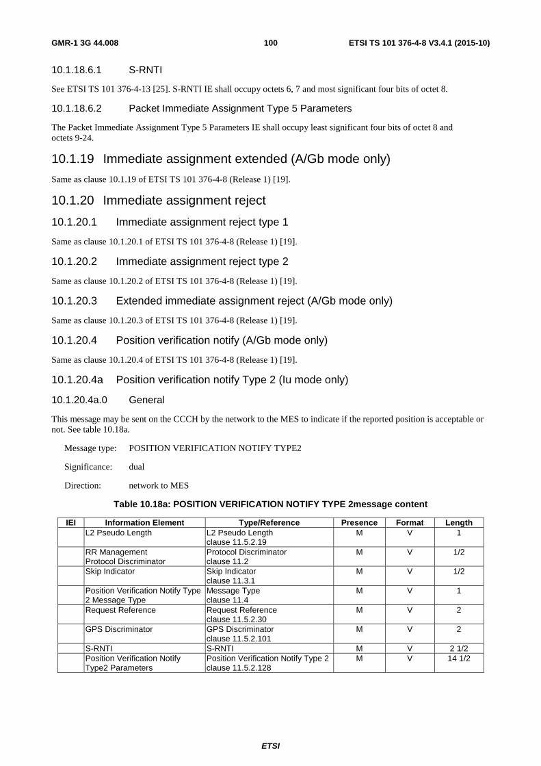
ETSI
ETSI TS 101 376-4-8 V3.4.1 (2015-10) 100GMR-1 3G 44.008
10.1.18.6.1 S-RNTI
See ETSI TS 101 376-4-13 [25]. S-RNTI IE shall occupy octets 6, 7 and most significant four bits of octet 8.
10.1.18.6.2 Packet Immediate Assignment Type 5 Parameters
The Packet Immediate Assignment Type 5 Parameters IE shall occupy least significant four bits of octet 8 and octets 9-24.
10.1.19 Immediate assignment extended (A/Gb mode only)
Same as clause 10.1.19 of ETSI TS 101 376-4-8 (Release 1) [19].
10.1.20 Immediate assignment reject
10.1.20.1 Immediate assignment reject type 1
Same as clause 10.1.20.1 of ETSI TS 101 376-4-8 (Release 1) [19].
10.1.20.2 Immediate assignment reject type 2
Same as clause 10.1.20.2 of ETSI TS 101 376-4-8 (Release 1) [19].
10.1.20.3 Extended immediate assignment reject (A/Gb mode only)
Same as clause 10.1.20.3 of ETSI TS 101 376-4-8 (Release 1) [19].
10.1.20.4 Position verification notify (A/Gb mode only)
Same as clause 10.1.20.4 of ETSI TS 101 376-4-8 (Release 1) [19].
10.1.20.4a Position verification notify Type 2 (Iu mode only)
10.1.20.4a.0 General
This message may be sent on the CCCH by the network to the MES to indicate if the reported position is acceptable or not. See table 10.18a.
Message type: POSITION VERIFICATION NOTIFY TYPE2
Significance: dual
Direction: network to MES
Table 10.18a: POSITION VERIFICATION NOTIFY TYPE 2message content
IEI Information Element Type/Reference Presence Format Length L2 Pseudo Length L2 Pseudo Length
clause 11.5.2.19 M V 1
RR Management Protocol Discriminator
Protocol Discriminator clause 11.2
M V 1/2
Skip Indicator Skip Indicator clause 11.3.1
M V 1/2
Position Verification Notify Type 2 Message Type
Message Type clause 11.4
M V 1
Request Reference Request Reference clause 11.5.2.30
M V 2
GPS Discriminator GPS Discriminator clause 11.5.2.101
M V 2
S-RNTI S-RNTI M V 2 1/2 Position Verification Notify
Type2 Parameters Position Verification Notify Type 2 clause 11.5.2.128
M V 14 1/2

ETSI
ETSI TS 101 376-4-8 V3.4.1 (2015-10) 101GMR-1 3G 44.008
10.1.20.4a.1 S-RNTI
See ETSI TS 101 376-4-13 [25]. S-RNTI IE shall occupy octets 8, 9 and most significant four bits of octet 10.
10.1.20.4a.2 Position Verification Notify Type2 Parameters
The Position Verification Notify Type2 Parameters IE shall occupy the least significant four bits of octet 10 and octets 11-24.
10.1.20.5 Immediate Assignment Reject Type 3
10.1.20.5.0 General
This message may be sent to the MES (requesting packet services) by the network on the CCCH to indicate that no channel is available for assignment or that the MES cannot be allowed access. This message may also indicate dark beam activation in progress or pause indication or indicate to the MES to switch to a new BCCH or transmit a new RACH Additionally the message also provides timing and frequency correction. See table 10.18.1. The L2 Pseudo Length of this message shall be the sum of all IEs present in the message, except the IAR Rest Octets and L2 Pseudo Length IEs.
Message type: IMMEDIATE ASSIGNMENT REJECT TYPE 3 MESSAGE TYPE
Significance: dual
Direction: network to MES
Table 10.18.1: IMMEDIATE ASSIGNMENT REJECT TYPE 3 message content
IEI Information Element (IE) Type/Reference Presence Format Length L2 Pseudo Length L2 Pseudo Length
clause 11.5.2.19 M V 1
RR Management Protocol Discriminator
Protocol Discriminator clause 11.2
M V 1/2
Skip Indicator Skip Indicator clause 11.3.1
M V 1/2
Immediate Assignment Reject Type 3 Message Type
Message Type clause 11.4
M V 1
Request Reference Request Reference clause11.5.2.30
M V 2
GPS Discriminator GPS Discriminator clause 11.5.2.101
M V 2
Reject Cause Reject Cause clause 11.5.2.56
M V 1
Pause Timer Pause Timer clause 11.5.2.103
C V 1
Illumination Retry Timer Illumination Retry Timer clause 11.5.2.108
C V 1
Packet BCCH Carrier Packet BCCH Carrier clause 11.5.2.104
C V 2
Timing Offset Timing Offset clause 11.5.2.40
M V 2
Frequency Offset Frequency Offset clause 11.5.2.49
M V 2
IAR Rest Octets IAR Rest Octets clause 11.5.2.17
M V 9 to 11
10.1.20.5.1 Packet BCCH Carrier
The Packet BCCH Carrier IE shall be present if B bit is set in the Reject Cause.
10.1.20.5.2 Illumination Retry Timer
The Illumination Retry Timer IE shall be present if T bit is set in the Reject Cause.

ETSI
ETSI TS 101 376-4-8 V3.4.1 (2015-10) 102GMR-1 3G 44.008
10.1.20.5.3 Pause Timer
The Pause timer IE shall be present if T bit is reset in the Reject Cause.
10.1.20.6 Immediate Assignment Reject Type 4 (Iu mode only)
10.1.20.6.0 General
This message may be sent to the MES (requesting packet services) by the network on the CCCH to indicate that no channel is available for assignment, that the MES might be associated with a Routing Area (RA) different from the one broadcast on the BCCH or that the MES cannot be allowed access. This message may also indicate dark beam activation in progress or pause indication or indicate to the MES to switch to a new BCCH or transmit a new RACH Additionally the message also provides timing and frequency correction. See table 10.18.2. The L2 Pseudo Length of this message shall be the sum of all IEs present in the message, except the IAR Rest Octets and L2 Pseudo Length IEs.
Message type: IMMEDIATE ASSIGNMENT REJECT TYPE 4 MESSAGE TYPE
Significance: dual
Direction: network to MES
Table 10.18.2: IMMEDIATE ASSIGNMENT REJECT TYPE 4 message content
IEI Information Element (IE) Type/Reference Presence Format Length L2 Pseudo Length L2 Pseudo Length
clause 11.5.2.19 M V 1
RR Management Protocol Discriminator
Protocol Discriminator clause 11.2
M V 1/2
Skip Indicator Skip Indicator clause 11.3.1
M V 1/2
Immediate Assignment Reject Type 4 Message Type
Message Type clause 11.4
M V 1
Request Reference Request Reference clause11.5.2.30
M V 2
GPS Discriminator GPS Discriminator clause 11.5.2.101
M V 2
Reject Cause Reject Cause clause 11.5.2.56
M V 1
Pause Timer Pause Timer clause 11.5.2.103
C V 1
Illumination Retry Timer Illumination Retry Timer clause 11.5.2.108
C V 1
BCCH Carrier BCCH Carrier clause 11.5.2.55
C V 2
Timing Offset Timing Offset clause 11.5.2.40
M V 2
Frequency Offset Frequency Offset clause 11.5.2.49
M V 2
01 CN Information CN Information Info ETSI TS 101 376-4-13 [25]
O TV 5
02 Redirected RAC Directed RAC clause 11.5.2.129
O TV 2
IAR Rest Octets IAR Rest Octets clause 11.5.2.17
M V 4 to 11
10.1.20.6.1 BCCH Carrier
This parameter shall be present if the network wishes to command the MES to access another BCCH. The BCCH Carrier IE shall be present if B bit is set in the Reject Cause.
10.1.20.6.2 Illumination Retry Timer
The Illumination Retry Timer IE shall be present if T bit is set in the Reject Cause.

ETSI
ETSI TS 101 376-4-8 V3.4.1 (2015-10) 103GMR-1 3G 44.008
10.1.20.6.3 Pause Timer
The Pause timer IE shall be present if T bit is reset in the Reject Cause. The MES shall ignore this Pause Timer IE when the Reject Cause is set to "Directed signalling connection re-establishment" or "RA Redirect".
10.1.20.6.4 CN Information Info
The CN Information Info IE may be present if the Reject Cause is set to "Directed signalling connection re-establishment". The IE shall be included when the network needs to direct a RRC connected mode MES to a specific Routing Area If the length of CN Information Info IE does not align to an octet boundary, spare bits shall be appended to align it to an octet boundary.
When the Reject Cause is set to "Directed signalling connection re-establishment" the MES behaviour shall be the same as that which applies in the event of an RRC Connection Release with the same Cause (see ETSI TS 101 376-4-13 [25]).
10.1.20.6.5 Directed RAC
The Directed RAC IE shall be present whenever the Reject Cause is set to a value of "RA Redirect". The IE, whenever provided, allows the network to inform the MES of the network-provided Routing Area Code to which the system access shall be redirected.
10.1.21 Measurement report (A/Gb mode only)
Same as clause 10.1.21 of ETSI TS 101 376-4-8 (Release 1) [19].
10.1.22 Paging request type 1
Same as clause 10.1.22 of ETSI TS 101 376-4-8 (Release 1) [19].
10.1.23 Paging request type 2
Same as clause 10.1.23 of ETSI TS 101 376-4-8 (Release 1) [19].
10.1.24 Paging request type 3
Same as clause 10.1.23 of ETSI TS 101 376-4-8 (Release 1) [19].
10.1.25 Paging response (A/Gb mode only)
Same as clause 10.1.25 of ETSI TS 101 376-4-8 (Release 1) [19].
10.1.26 Partial release (A/Gb mode only)
Same as clause 10.1.26 of ETSI TS 101 376-4-8 (Release 1) [19].
10.1.27 Partial release complete (A/Gb mode only)
Same as clause 10.1.27 of ETSI TS 101 376-4-8 (Release 1) [19].
10.1.28 Physical information (A/Gb mode only)
Same as clause 10.1.28 of ETSI TS 101 376-4-8 (Release 1) [19].
10.1.29 RR status (A/Gb mode only)
Same as clause 10.1.29 of ETSI TS 101 376-4-8 (Release 1) [19].
10.1.30 Synchronization channel information (A/Gb mode only)
Same as clause 10.1.30 of ETSI TS 101 376-4-8 (Release 1) [19].

ETSI
ETSI TS 101 376-4-8 V3.4.1 (2015-10) 104GMR-1 3G 44.008
10.1.31 System information type 1
Same as clause 10.1.31 of ETSI TS 101 376-4-8 (Release 1) [19].
10.1.32 System information type 2
Same as clause 10.1.32 of ETSI TS 101 376-4-8 (Release 1) [19].
10.1.33 System information type 2bis (Iu mode only)
Table 10.1.33: SYSTEM INFORMATION TYPE 2bis message content
IEI Information element Type / Reference Presence Format length L2 Pseudo Length L2 Pseudo Length M V 1 Clause 11.5.2.19 RR management Protocol Discriminator M V 1/2 Protocol Discriminator Clause 11.2 Skip Indicator Skip Indicator M V 1/2 Clause 11.3.1 System Information Message Type M V 1 Type 2bis Message Type Clause 11.4 Extended BCCH Segment Extended BCCH Segments
Clauses 11.5.2.84b, 11.5.2.84c M V 21
10.1.34 System information type 2ter
This function is not currently supported in GMR-1.
10.1.35 System information type 3
This function is not currently supported in GMR-1.
10.1.36 System information type 4
This function is not currently supported in GMR-1.
10.1.37 System information type 5
This function is not currently supported in GMR-1.
10.1.38 System information type 5bis
This function is not currently supported in GMR-1.
10.1.39 System information type 5ter
This function is not currently supported in GMR-1.
10.1.40 System information type 6
This function is not currently supported in GMR-1.
10.1.41 System information type 7
This function is not currently supported in GMR-1.
10.1.42 System information type 8
This function is not currently supported in GMR-1.

ETSI
ETSI TS 101 376-4-8 V3.4.1 (2015-10) 105GMR-1 3G 44.008
10.1.43 Alert request
10.1.43.0 General
This message is sent on the BACH or BACH3 by the network to an MES that is out of normal penetration coverage area to trigger channel access once the MES can decode the BCCH. The MES is identified by its TMSI or G-RNTI. It does not follow the basic format, and the length of this message is 36 bits. See table 10.22.
Message type: ALERT REQUEST
Significance: dual
Direction: network to MES
Table 10.22: ALERT REQUEST message content
IEI Information Element Type/Reference Presence Format Length
Mobile Identity TMSI (A/Gb mode) P-TMSI or G-RNTI (Iu mode) M V 4
Alerting Information Alerting Information 11.5.2.65 M V 1/2
10.1.43.1 Mobile Identity
In A/Gb mode, this field shall contain the TMSI. TMSI is defined in clause 11.5.2.42.
In Iu mode, this field shall contain the G-RNTI or the P-TMSI assigned to the MES. G-RNTI is defined in ETSI TS 101 376-4-13 [25].
10.1.44 Position update request (A/Gb mode only)
Same as clause 10.1.44 of ETSI TS 101 376-4-8 (Release 1) [19].
10.1.45 Position update accept (A/Gb mode only)
Same as clause 10.1.45 of ETSI TS 101 376-4-8 (Release 1) [19].
10.1.46 GBCH information
Same as clause 10.1.46 of ETSI TS 101 376-4-8 (Release 1) [19].
10.1.46a GBCH3 ECEF information
GBCH3 ECEF Information Messages shall be transmitted in the GBCH3. GBCH3 messages are sent in unacknowledged mode and have no link layer header. They have a fixed length of 192 bits.
The description of the messages uses the compact notation described in annex B of ETSI TS 101 376-4-7 [11].

ETSI
ETSI TS 101 376-4-8 V3.4.1 (2015-10) 106GMR-1 3G 44.008
<GBCH3 ECEF Information Message>::= - - 192 bits <GBCH3 ECEF Message Header> - - 8 bits <GBCH3 ECEF Information Type 1>| <GBCH3 ECEF Information Type 2>| <GBCH3 ECEF Information Type 3>| <GBCH3 ECEF Information Type 4>| <GBCH3 ECEF Information Type 5>| <GBCH3 ECEF Information Type 6>| <GBCH3 ECEF Information Type 7>| <GBCH3 ECEF Information Type 8>| <GBCH3 ECEF Information Type 9>| <GBCH3 ECEF Information Type 10>| <GBCH3 ECEF Information Type 11>| <GBCH3 ECEF Information Type 12>| <GBCH3 ECEF Information Type 13>| <GBCH3 ECEF Information Type 14>| <GBCH3 ECEF Information Type 15>| <GBCH3 ECEF Information Type 16>| <GBCH3 ECEF Information Type 17> <GBCH3 ECEF Message Header>::= Size: 8 bits <Escape/Coordinate Type bit: bit(1)> This bit shall be set to 0 for GBCH3 ECEF Information
Messages <GBCH3 ECEF Sequence Number: bitstring(2)> All messages with a common value of the GBCH3 Version
Number may be used as a group <GBCH3 ECEF Message Number: bitstring(5)> GBCH3 ECEF Message Number as defined in table 4.5
<GBCH3 ECEF Information Type 1>::= Size: 184 bits <GPS Time: bitstring(40) > • The time, in the centre of the spot beam at the
earth's surface, at the time tick defined by the Frame Number parameter (below). The time is a GPS time of week in GPS time coordinates (see IS-GPS-200 [29] specification for definition). First 20 bits are GPS time of week in integer seconds. The last 20 bits are GPS time of week in fractional seconds. There is an implied decimal point between the first 20 bits and the second 20 bits
<Curve Fit Time: bitstring(40) > • Time that is associated with the 2nd degree curve fits. The time is a GPS time of week in GPS time coordinates. (see IS-GPS-200 [29] specification for definition). First 20 bits are GPS time of week in integer seconds. The last 20 bits are GPS time of week in fractional seconds. There is an implied decimal point between the first 20 bits and the second 20 bits
<Frame Number: bitstring (19)> • The arrival of leading edge of the frame with this frame number defines a time tick. The time contained in the GPS Time parameter is precisely correct at this time tick, if located at the centre of spot beam on the earth's surface. For the definition of Frame Number refer to ETSI TS 101 376-5-2 [12]
<SV ID satellite 1: bitstring(6)> • 6-bit SV ID of satellite 1 of the 12 being broadcast. An ID with a value of "0" indicates "no satellite" and subsequent IEs for this satellite shall be ignored
<Doppler: bitstring (8) • 8-bit Doppler estimates for this satellite being broadcast 2's complement. LSB scale factor of 40 Hz
<Code Phase: bitstring (22)> • 22-bit estimated code phase offsets for this satellite being broadcast. 2's complement; LSB scale factor of 2-28 s
<X0: bitstring (24)> • x(t) ≈ X0 + VX0t + (1/2)VX1t2 + (1/3)VX2t3 for this
satellite. LSB scale factor of 22 m <VX0: bitstring (18)> • x(t) ≈ X0 + VX0t + (1/2)VX1t2 + (1/3)VX2t3 for this
satellite. LSB scale factor of 2-5 m/s

ETSI
ETSI TS 101 376-4-8 V3.4.1 (2015-10) 107GMR-1 3G 44.008
<spare: bitstring (7)> • Not used
<GBCH3 ECEF Information Type 2>::= Size: 184 bits <SV ID satellite 1: bitstring(6)> • 6-bit SV ID of satellite 1 of the 12 being broadcast.
An ID with a value of "0" indicates "no satellite" and subsequent IEs for this satellite shall be ignored
<VX1: bitstring (13)> • x(t) ≈ X0 + VX0t + (1/2)VX1t2 + (1/3)VX2t3 for this
satellite. LSB scale factor of 2-12 m/s2 <VX2: bitstring (8)> • x(t) ≈ X0 + VX0t + (1/2)VX1t2 + (1/3)VX2t3 for this
satellite. LSB scale factor of 2-19 m/s3 <Y0: bitstring (24)> • y(t) ≈ Y0 + VY0t + (1/2)VY1t2 + (1/3)VY2t3 for this
satellite. LSB scale factor of 22 m <VY0: bitstring (18)> • y(t) ≈ Y0 + VY0t + (1/2)VY1t2 + (1/3)VY2t3 for this
satellite. LSB scale factor of 2-5 m/s <VY1: bitstring (13)> • y(t) ≈ Y0 + VY0t + (1/2)VY1t2 + (1/3)VY2t3 for this
satellite. LSB scale factor of 2-12 m/s2 <VY2: bitstring (8)> • y(t) ≈ Y0 + VY0t + (1/2)VY1t2 + (1/3)VY2t3 for this
satellite. LSB scale factor of 2-19 m/s3 <Z0: bitstring (24)> • z(t) ≈ Z0 + VZ0t + (1/2)VZ1t2 + (1/3)VZ2t3 for this
satellite. LSB scale factor of 22 m <VZ0: bitstring (18)> • z(t) ≈ Z0 + VZ0t + (1/2)VZ1t2 + (1/3)VZ2t3 for this
satellite. LSB scale factor of 2-5 m/s <VZ1: bitstring (13)> • z(t) ≈ Z0 + VZ0t + (1/2)VZ1t2 + (1/3)VZ2t3 for this
satellite. LSB scale factor of 2-12 m/s2 <VZ2: bitstring (8)> • z(t) ≈ Z0 + VZ0t + (1/2)VZ1t2 + (1/3)VZ2t3 for this
satellite. LSB scale factor of 2-19 m/s3 <af1: bitstring (11)> • af1 is a 16-bit clock correction term broadcast by
this GPS satellite. Here rounded to 11 bits. LSB scale factor of 2-38 s/s
<SV ID satellite 2: bitstring(6)> • 6-bit SV ID of satellite 2 of the 12 being broadcast. An ID with a value of "0" indicates "no satellite" and subsequent IEs for this satellite shall be ignored
<Doppler: bitstring (8) • 8-bit Doppler estimates for this satellite being broadcast 2's complement; LSB scale factor of 40 Hz
<spare: bitstring (6)> • Not used

ETSI
ETSI TS 101 376-4-8 V3.4.1 (2015-10) 108GMR-1 3G 44.008
<GBCH3 ECEF Information Type 3>::= Size: 184 bits <SV ID satellite 2: bitstring(6)> • 6-bit SV ID of satellite 2 of the 12 being broadcast.
An ID with a value of "0" indicates "no satellite" and subsequent IEs for this satellite shall be ignored
<Code Phase: bitstring (22)> • 22-bit estimated code phase offsets for this satellite being broadcast. 2's complement; LSB scale factor of 2-28 s
<X0: bitstring (24)> • x(t) ≈ X0 + VX0t + (1/2)VX1t2 + (1/3)VX2t3 for this
satellite. LSB scale factor of 22 m <VX0: bitstring (18)> • x(t) ≈ X0 + VX0t + (1/2)VX1t2 + (1/3)VX2t3 for this
satellite. LSB scale factor of 2-5 m/s <VX1: bitstring (13)> • x(t) ≈ X0 + VX0t + (1/2)VX1t2 + (1/3)VX2t3 for this
satellite. LSB scale factor of 2-12 m/s2 <VX2: bitstring (8)> • x(t) ≈ X0 + VX0t + (1/2)VX1t2 + (1/3)VX2t3 for this
satellite. LSB scale factor of 2-19 m/s3 <Y0: bitstring (24)> • y(t) ≈ Y0 + VY0t + (1/2)VY1t2 + (1/3)VY2t3 for this
satellite. LSB scale factor of 22 m <VY0: bitstring (18)> • y(t) ≈ Y0 + VY0t + (1/2)VY1t2 + (1/3)VY2t3 for this
satellite. LSB scale factor of 2-5 m/s <VY1: bitstring (13)> • y(t) ≈ Y0 + VY0t + (1/2)VY1t2 + (1/3)VY2t3 for this
satellite. LSB scale factor of 2-12 m/s2 <VY2: bitstring (8)> • y(t) ≈ Y0 + VY0t + (1/2)VY1t2 + (1/3)VY2t3 for this
satellite. LSB scale factor of 2-19 m/s3 <Z0: bitstring (24)> • z(t) ≈ Z0 + VZ0t + (1/2)VZ1t2 + (1/3)VZ2t3 for this
satellite. LSB scale factor of 22 m <spare: bitstring (6)> • Not used
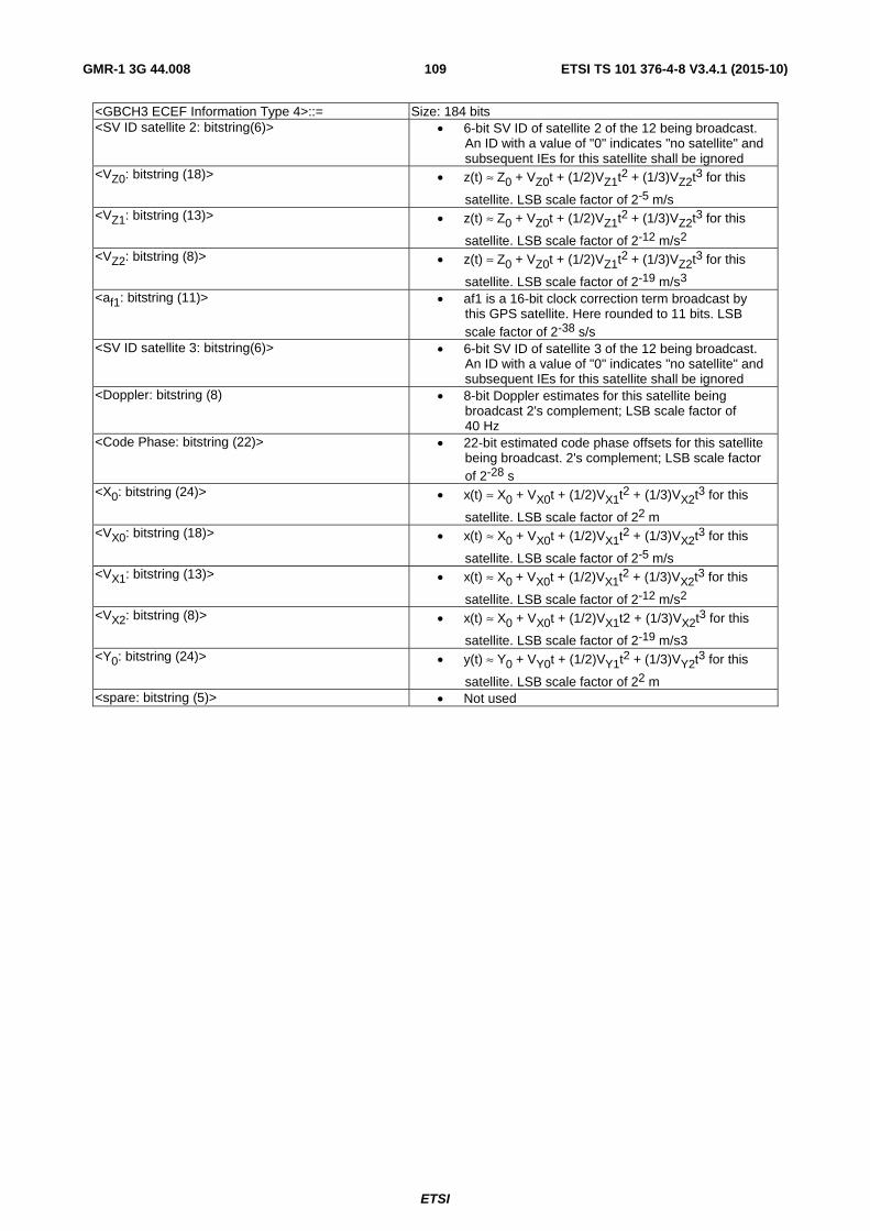
ETSI
ETSI TS 101 376-4-8 V3.4.1 (2015-10) 109GMR-1 3G 44.008
<GBCH3 ECEF Information Type 4>::= Size: 184 bits <SV ID satellite 2: bitstring(6)> • 6-bit SV ID of satellite 2 of the 12 being broadcast.
An ID with a value of "0" indicates "no satellite" and subsequent IEs for this satellite shall be ignored
<VZ0: bitstring (18)> • z(t) ≈ Z0 + VZ0t + (1/2)VZ1t2 + (1/3)VZ2t3 for this
satellite. LSB scale factor of 2-5 m/s <VZ1: bitstring (13)> • z(t) ≈ Z0 + VZ0t + (1/2)VZ1t2 + (1/3)VZ2t3 for this
satellite. LSB scale factor of 2-12 m/s2 <VZ2: bitstring (8)> • z(t) ≈ Z0 + VZ0t + (1/2)VZ1t2 + (1/3)VZ2t3 for this
satellite. LSB scale factor of 2-19 m/s3 <af1: bitstring (11)> • af1 is a 16-bit clock correction term broadcast by
this GPS satellite. Here rounded to 11 bits. LSB scale factor of 2-38 s/s
<SV ID satellite 3: bitstring(6)> • 6-bit SV ID of satellite 3 of the 12 being broadcast. An ID with a value of "0" indicates "no satellite" and subsequent IEs for this satellite shall be ignored
<Doppler: bitstring (8) • 8-bit Doppler estimates for this satellite being broadcast 2's complement; LSB scale factor of 40 Hz
<Code Phase: bitstring (22)> • 22-bit estimated code phase offsets for this satellite being broadcast. 2's complement; LSB scale factor of 2-28 s
<X0: bitstring (24)> • x(t) ≈ X0 + VX0t + (1/2)VX1t2 + (1/3)VX2t3 for this
satellite. LSB scale factor of 22 m <VX0: bitstring (18)> • x(t) ≈ X0 + VX0t + (1/2)VX1t2 + (1/3)VX2t3 for this
satellite. LSB scale factor of 2-5 m/s <VX1: bitstring (13)> • x(t) ≈ X0 + VX0t + (1/2)VX1t2 + (1/3)VX2t3 for this
satellite. LSB scale factor of 2-12 m/s2 <VX2: bitstring (8)> • x(t) ≈ X0 + VX0t + (1/2)VX1t2 + (1/3)VX2t3 for this
satellite. LSB scale factor of 2-19 m/s3 <Y0: bitstring (24)> • y(t) ≈ Y0 + VY0t + (1/2)VY1t2 + (1/3)VY2t3 for this
satellite. LSB scale factor of 22 m <spare: bitstring (5)> • Not used
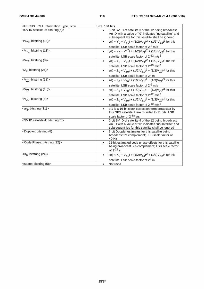
ETSI
ETSI TS 101 376-4-8 V3.4.1 (2015-10) 110GMR-1 3G 44.008
<GBCH3 ECEF Information Type 5>::= Size: 184 bits <SV ID satellite 2: bitstring(6)> • 6-bit SV ID of satellite 3 of the 12 being broadcast.
An ID with a value of "0" indicates "no satellite" and subsequent IEs for this satellite shall be ignored
<VY0: bitstring (18)> • y(t) ≈ Y0 + VY0t + (1/2)VY1t2 + (1/3)VY2t3 for this
satellite. LSB scale factor of 2-5 m/s <VY1: bitstring (13)> • y(t) ≈ Y0 + VY0t + (1/2)VY1t2 + (1/3)VY2t3 for this
satellite. LSB scale factor of 2-12 m/s2 <VY2: bitstring (8)> • y(t) ≈ Y0 + VY0t + (1/2)VY1t2 + (1/3)VY2t3 for this
satellite. LSB scale factor of 2-19 m/s3 <Z0: bitstring (24)> • z(t) ≈ Z0 + VZ0t + (1/2)VZ1t2 + (1/3)VZ2t3 for this
satellite. LSB scale factor of 22 m <VZ0: bitstring (18)> • z(t) ≈ Z0 + VZ0t + (1/2)VZ1t2 + (1/3)VZ2t3 for this
satellite. LSB scale factor of 2-5 m/s <VZ1: bitstring (13)> • z(t) ≈ Z0 + VZ0t + (1/2)VZ1t2 + (1/3)VZ2t3 for this
satellite. LSB scale factor of 2-12 m/s2 <VZ2: bitstring (8)> • z(t) ≈ Z0 + VZ0t + (1/2)VZ1t2 + (1/3)VZ2t3 for this
satellite. LSB scale factor of 2-19 m/s3 <af1: bitstring (11)> • af1 is a 16-bit clock correction term broadcast by
this GPS satellite. Here rounded to 11 bits. LSB scale factor of 2-38 s/s
<SV ID satellite 4: bitstring(6)> • 6-bit SV ID of satellite 4 of the 12 being broadcast. An ID with a value of "0" indicates "no satellite" and subsequent Ies for this satellite shall be ignored
<Doppler: bitstring (8) • 8-bit Doppler estimates for this satellite being broadcast 2's complement; LSB scale factor of 40 Hz
<Code Phase: bitstring (22)> • 22-bit estimated code phase offsets for this satellite being broadcast. 2's complement; LSB scale factor of 2-28 s
<X0: bitstring (24)> • x(t) ≈ X0 + VX0t + (1/2)VX1t2 + (1/3)VX2t3 for this
satellite. LSB scale factor of 22 m <spare: bitstring (5)> • Not used

ETSI
ETSI TS 101 376-4-8 V3.4.1 (2015-10) 111GMR-1 3G 44.008
<GBCH3 ECEF Information Type 6>::= Size: 184 bits <SV ID satellite 4: bitstring(6)> • 6-bit SV ID of satellite 4 of the 12 being broadcast.
An ID with a value of "0" indicates "no satellite" and subsequent IEs for this satellite shall be ignored
<VX0: bitstring (18)> • x(t) ≈ X0 + VX0t + (1/2)VX1t2 + (1/3)VX2t3 for this
satellite. LSB scale factor of 2-5 m/s <VX1: bitstring (13)> • x(t) ≈ X0 + VX0t + (1/2)VX1t2 + (1/3)VX2t3 for this
satellite. LSB scale factor of 2-12 m/s2 <VX2: bitstring (8)> • x(t) ≈ X0 + VX0t + (1/2)VX1t2 + (1/3)VX2t3 for this
satellite. LSB scale factor of 2-19 m/s3 <Y0: bitstring (24)> • y(t) ≈ Y0 + VY0t + (1/2)VY1t2 + (1/3)VY2t3 for this
satellite. LSB scale factor of 22 m <VY0: bitstring (18)> • y(t) ≈ Y0 + VY0t + (1/2)VY1t2 + (1/3)VY2t3 for this
satellite. LSB scale factor of 2-5 m/s <VY1: bitstring (13)> • y(t) ≈ Y0 + VY0t + (1/2)VY1t2 + (1/3)VY2t3 for this
satellite. LSB scale factor of 2-12 m/s2 <VY2: bitstring (8)> • y(t) ≈ Y0 + VY0t + (1/2)VY1t2 + (1/3)VY2t3 for this
satellite. LSB scale factor of 2-19 m/s3 <Z0: bitstring (24)> • z(t) ≈ Z0 + VZ0t + (1/2)VZ1t2 + (1/3)VZ2t3 for this
satellite. LSB scale factor of 22 m <VZ0: bitstring (18)> • z(t) ≈ Z0 + VZ0t + (1/2)VZ1t2 + (1/3)VZ2t3 for this
satellite. LSB scale factor of 2-5 m/s <VZ1: bitstring (13)> • z(t) ≈ Z0 + VZ0t + (1/2)VZ1t2 + (1/3)VZ2t3 for this
satellite. LSB scale factor of 2-12 m/s2 <VZ2: bitstring (8)> • z(t) ≈ Z0 + VZ0t + (1/2)VZ1t2 + (1/3)VZ2t3 for this
satellite. LSB scale factor of 2-19 m/s3 <af1: bitstring (11)> • af1 is a 16-bit clock correction term broadcast by
this GPS satellite. Here rounded to 11 bits. LSB scale factor of 2-38 s/s
<spare: bitstring (2)> • Not used

ETSI
ETSI TS 101 376-4-8 V3.4.1 (2015-10) 112GMR-1 3G 44.008
<GBCH3 ECEF Information Type 7>::= Size: 184 bits <SV ID satellite 5: bitstring(6)> • 6-bit SV ID of satellite 5 of the 12 being broadcast.
An ID with a value of "0" indicates "no satellite" and subsequent IEs for this satellite shall be ignored
<Doppler: bitstring (8) • 8-bit Doppler estimates for this satellite being broadcast 2's complement; LSB scale factor of 40 Hz
<Code Phase: bitstring (22)> • 22-bit estimated code phase offsets for this satellite being broadcast. 2's complement; LSB scale factor of 2-28 s
<X0: bitstring (24)> • x(t) ≈ X0 + VX0t + (1/2)VX1t2 + (1/3)VX2t3 for this
satellite. LSB scale factor of 22 m <VX0: bitstring (18)> • x(t) ≈ X0 + VX0t + (1/2)VX1t2 + (1/3)VX2t3 for this
satellite. LSB scale factor of 2-5 m/s <VX1: bitstring (13)> • x(t) ≈ X0 + VX0t + (1/2)VX1t2 + (1/3)VX2t3 for this
satellite. LSB scale factor of 2-12 m/s2 <VX2: bitstring (8)> • x(t) ≈ X0 + VX0t + (1/2)VX1t2 + (1/3)VX2t3 for this
satellite. LSB scale factor of 2-19 m/s3 <Y0: bitstring (24)> • y(t) ≈ Y0 + VY0t + (1/2)VY1t2 + (1/3)VY2t3 for this
satellite. LSB scale factor of 22 m <VY0: bitstring (18)> • y(t) ≈ Y0 + VY0t + (1/2)VY1t2 + (1/3)VY2t3 for this
satellite. LSB scale factor of 2-5 m/s <VY1: bitstring (13)> • y(t) ≈ Y0 + VY0t + (1/2)VY1t2 + (1/3)VY2t3 for this
satellite. LSB scale factor of 2-12 m/s2 <VY2: bitstring (8)> • y(t) ≈ Y0 + VY0t + (1/2)VY1t2 + (1/3)VY2t3 for this
satellite. LSB scale factor of 2-19 m/s3 <VZ0: bitstring (18)> • z(t) ≈ Z0 + VZ0t + (1/2)VZ1t2 + (1/3)VZ2t3 for this
satellite. LSB scale factor of 2-5 m/s <spare: bitstring (4)> • Not used

ETSI
ETSI TS 101 376-4-8 V3.4.1 (2015-10) 113GMR-1 3G 44.008
<GBCH3 ECEF Information Type 8>::= Size: 184 bits <SV ID satellite 5: bitstring(6)> • 6-bit SV ID of satellite 5 of the 12 being broadcast.
An ID with a value of "0" indicates "no satellite" and subsequent IEs for this satellite shall be ignored
<Z0: bitstring (24)> • z(t) ≈ Z0 + VZ0t + (1/2)VZ1t2 + (1/3)VZ2t3 for this
satellite. LSB scale factor of 22 m <VZ1: bitstring (13)> • z(t) ≈ Z0 + VZ0t + (1/2)VZ1t2 + (1/3)VZ2t3 for this
satellite. LSB scale factor of 2-12 m/s2 <VZ2: bitstring (8)> • z(t) ≈ Z0 + VZ0t + (1/2)VZ1t2 + (1/3)VZ2t3 for this
satellite. LSB scale factor of 2-19 m/s3 <af1: bitstring (11)> • af1 is a 16-bit clock correction term broadcast by
this GPS satellite. Here rounded to 11 bits. LSB scale factor of 2-38 s/s
<SV ID satellite 6: bitstring(6)> • 6-bit SV ID of satellite 6 of the 12 being broadcast. An ID with a value of "0" indicates "no satellite" and subsequent IEs for this satellite shall be ignored
<Doppler: bitstring (8) • 8-bit Doppler estimates for this satellite being broadcast 2's complement; LSB scale factor of 40 Hz
<Code Phase: bitstring (22)> • 22-bit estimated code phase offsets for this satellite being broadcast. 2's complement; LSB scale factor of 2-28 s
<X0: bitstring (24)> • x(t) ≈ X0 + VX0t + (1/2)VX1t2 + (1/3)VX2t3 for this
satellite. LSB scale factor of 22 m <VX0: bitstring (18)> • x(t) ≈ X0 + VX0t + (1/2)VX1t2 + (1/3)VX2t3 for this
satellite. LSB scale factor of 2-5 m/s <VX1: bitstring (13)> • x(t) ≈ X0 + VX0t + (1/2)VX1t2 + (1/3)VX2t3 for this
satellite. LSB scale factor of 2-12 m/s2 <VX2: bitstring (8)> • x(t) ≈ X0 + VX0t + (1/2)VX1t2 + (1/3)VX2t3 for this
satellite. LSB scale factor of 2-19 m/s3 <VY0: bitstring (18)> • y(t) ≈ Y0 + VY0t + (1/2)VY1t2 + (1/3)VY2t3 for this
satellite. LSB scale factor of 2-5 m/s <spare: bitstring (5)> • Not used

ETSI
ETSI TS 101 376-4-8 V3.4.1 (2015-10) 114GMR-1 3G 44.008
<GBCH3 ECEF Information Type 9>::= Size: 184 bits <SV ID satellite 6: bitstring(6)> • 6-bit SV ID of satellite 6 of the 12 being broadcast.
An ID with a value of "0" indicates "no satellite" and subsequent IEs for this satellite shall be ignored
<Y0: bitstring (24)> • y(t) ≈ Y0 + VY0t + (1/2)VY1t2 + (1/3)VY2t3 for this
satellite. LSB scale factor of 22 m <VY1: bitstring (13)> • y(t) ≈ Y0 + VY0t + (1/2)VY1t2 + (1/3)VY2t3 for this
satellite. LSB scale factor of 2-12 m/s2 <VY2: bitstring (8)> • y(t) ≈ Y0 + VY0t + (1/2)VY1t2 + (1/3)VY2t3 for this
satellite. LSB scale factor of 2-19 m/s3 <Z0: bitstring (24)> • z(t) ≈ Z0 + VZ0t + (1/2)VZ1t2 + (1/3)VZ2t3 for this
satellite. LSB scale factor of 22 m <VZ0: bitstring (18)> • z(t) ≈ Z0 + VZ0t + (1/2)VZ1t2 + (1/3)VZ2t3 for this
satellite. LSB scale factor of 2-5 m/s <VZ1: bitstring (13)> • z(t) ≈ Z0 + VZ0t + (1/2)VZ1t2 + (1/3)VZ2t3 for this
satellite. LSB scale factor of 2-12 m/s2 <VZ2: bitstring (8)> • z(t) ≈ Z0 + VZ0t + (1/2)VZ1t2 + (1/3)VZ2t3 for this
satellite. LSB scale factor of 2-19 m/s3 <af1: bitstring (11)> • af1 is a 16-bit clock correction term broadcast by
this GPS satellite. Here rounded to 11 bits. LSB scale factor of 2-38 s/s
<SV ID satellite 7: bitstring(6)> • 6-bit SV ID of satellite 7 of the 12 being broadcast. An ID with a value of "0" indicates "no satellite" and subsequent Ies for this satellite shall be ignored
<Doppler: bitstring (8) • 8-bit Doppler estimates for this satellite being broadcast 2's complement; LSB scale factor of 40 Hz
<Code Phase: bitstring (22)> • 22-bit estimated code phase offsets for this satellite being broadcast. 2's complement; LSB scale factor of 2-28 s
<VX0: bitstring (18)> • x(t) ≈ X0 + VX0t + (1/2)VX1t2 + (1/3)VX2t3 for this
satellite. LSB scale factor of 2-5 m/s <spare: bitstring (5)> • Not used

ETSI
ETSI TS 101 376-4-8 V3.4.1 (2015-10) 115GMR-1 3G 44.008
<GBCH3 ECEF Information Type 10>::= Size: 184 bits <SV ID satellite 7: bitstring(6)> • 6-bit SV ID of satellite 7 of the 12 being broadcast.
An ID with a value of "0" indicates "no satellite" and subsequent IEs for this satellite shall be ignored
<X0: bitstring (24)> • x(t) ≈ X0 + VX0t + (1/2)VX1t2 + (1/3)VX2t3 for this
satellite. LSB scale factor of 22 m <VX1: bitstring (13)> • x(t) ≈ X0 + VX0t + (1/2)VX1t2 + (1/3)VX2t3 for this
satellite. LSB scale factor of 2-12 m/s2 <VX2: bitstring (8)> • x(t) ≈ X0 + VX0t + (1/2)VX1t2 + (1/3)VX2t3 for this
satellite. LSB scale factor of 2-19 m/s3 <Y0: bitstring (24)> • y(t) ≈ Y0 + VY0t + (1/2)VY1t2 + (1/3)VY2t3 for this
satellite. LSB scale factor of 22 m <VY0: bitstring (18)> • y(t) ≈ Y0 + VY0t + (1/2)VY1t2 + (1/3)VY2t3 for this
satellite. LSB scale factor of 2-5 m/s <VY1: bitstring (13)> • y(t) ≈ Y0 + VY0t + (1/2)VY1t2 + (1/3)VY2t3 for this
satellite. LSB scale factor of 2-12 m/s2 <VY2: bitstring (8)> • y(t) ≈ Y0 + VY0t + (1/2)VY1t2 + (1/3)VY2t3 for this
satellite. LSB scale factor of 2-19 m/s3 <Z0: bitstring (24)> • z(t) ≈ Z0 + VZ0t + (1/2)VZ1t2 + (1/3)VZ2t3 for this
satellite. LSB scale factor of 22 m <VZ0: bitstring (18)> • z(t) ≈ Z0 + VZ0t + (1/2)VZ1t2 + (1/3)VZ2t3 for this
satellite. LSB scale factor of 2-5 m/s <VZ1: bitstring (13)> • z(t) ≈ Z0 + VZ0t + (1/2)VZ1t2 + (1/3)VZ2t3 for this
satellite. LSB scale factor of 2-12 m/s2 <VZ2: bitstring (8)> • z(t) ≈ Z0 + VZ0t + (1/2)VZ1t2 + (1/3)VZ2t3 for this
satellite. LSB scale factor of 2-19 m/s3 <spare: bitstring (7)> • Not used

ETSI
ETSI TS 101 376-4-8 V3.4.1 (2015-10) 116GMR-1 3G 44.008
<GBCH3 ECEF Information Type 11>::= Size: 184 bits <SV ID satellite 7: bitstring(6)> • 6-bit SV ID of satellite 7 of the 12 being broadcast.
An ID with a value of "0" indicates "no satellite" and subsequent IEs for this satellite shall be ignored
<af1: bitstring (11)> • af1 is a 16-bit clock correction term broadcast by this GPS satellite. Here rounded to 11 bits. LSB scale factor of 2-38 s/s
<SV ID satellite 8: bitstring(6)> • 6-bit SV ID of satellite 8 of the 12 being broadcast. An ID with a value of "0" indicates "no satellite" and subsequent Ies for this satellite shall be ignored
<Doppler: bitstring (8) • 8-bit Doppler estimates for this satellite being broadcast 2's complement; LSB scale factor of 40 Hz
<Code Phase: bitstring (22)> • 22-bit estimated code phase offsets for this satellite being broadcast. 2's complement; LSB scale factor of 2-28 s
<X0: bitstring (24)> • x(t) ≈ X0 + VX0t + (1/2)VX1t2 + (1/3)VX2t3 for this
satellite. LSB scale factor of 22 m <VX0: bitstring (18)> • x(t) ≈ X0 + VX0t + (1/2)VX1t2 + (1/3)VX2t3 for this
satellite. LSB scale factor of 2-5 m/s <VX1: bitstring (13)> • x(t) ≈ X0 + VX0t + (1/2)VX1t2 + (1/3)VX2t3 for this
satellite. LSB scale factor of 2-12 m/s2 <VX2: bitstring (8)> • x(t) ≈ X0 + VX0t + (1/2)VX1t2 + (1/3)VX2t3 for this
satellite. LSB scale factor of 2-19 m/s3 <Y0: bitstring (24)> • y(t) ≈ Y0 + VY0t + (1/2)VY1t2 + (1/3)VY2t3 for this
satellite. LSB scale factor of 22 m <VY0: bitstring (18)> • y(t) ≈ Y0 + VY0t + (1/2)VY1t2 + (1/3)VY2t3 for this
satellite. LSB scale factor of 2-5 m/s <VY1: bitstring (13)> • y(t) ≈ Y0 + VY0t + (1/2)VY1t2 + (1/3)VY2t3 for this
satellite. LSB scale factor of 2-12 m/s2 <VY2: bitstring (8)> • y(t) ≈ Y0 + VY0t + (1/2)VY1t2 + (1/3)VY2t3 for this
satellite. LSB scale factor of 2-19 m/s3 <spare: bitstring (5)> • Not used

ETSI
ETSI TS 101 376-4-8 V3.4.1 (2015-10) 117GMR-1 3G 44.008
<GBCH3 ECEF Information Type 12>::= Size: 184 bits <SV ID satellite 8: bitstring(6)> • 6-bit SV ID of satellite 8 of the 12 being broadcast.
An ID with a value of "0" indicates "no satellite" and subsequent IEs for this satellite shall be ignored
<Z0: bitstring (24)> • z(t) ≈ Z0 + VZ0t + (1/2)VZ1t2 + (1/3)VZ2t3 for this
satellite. LSB scale factor of 22 m <VZ0: bitstring (18)> • z(t) ≈ Z0 + VZ0t + (1/2)VZ1t2 + (1/3)VZ2t3 for this
satellite. LSB scale factor of 2-5 m/s <VZ1: bitstring (13)> • z(t) ≈ Z0 + VZ0t + (1/2)VZ1t2 + (1/3)VZ2t3 for this
satellite. LSB scale factor of 2-12 m/s2 <VZ2: bitstring (8)> • z(t) ≈ Z0 + VZ0t + (1/2)VZ1t2 + (1/3)VZ2t3 for this
satellite. LSB scale factor of 2-19 m/s3 <af1: bitstring (11)> • af1 is a 16-bit clock correction term broadcast by
this GPS satellite. Here rounded to 11 bits. LSB scale factor of 2-38 s/s
<SV ID satellite 9: bitstring(6)> • 6-bit SV ID of satellite 9 of the 12 being broadcast. An ID with a value of "0" indicates "no satellite" and subsequent IEs for this satellite shall be ignored
<Doppler: bitstring (8) • 8-bit Doppler estimates for this satellite being broadcast 2's complement; LSB scale factor of 40 Hz
<Code Phase: bitstring (22)> • 22-bit estimated code phase offsets for this satellite being broadcast. 2's complement; LSB scale factor of 2-28 s
<X0: bitstring (24)> • x(t) ≈ X0 + VX0t + (1/2)VX1t2 + (1/3)VX2t3 for this
satellite. LSB scale factor of 22 m <VX0: bitstring (18)> • x(t) ≈ X0 + VX0t + (1/2)VX1t2 + (1/3)VX2t3 for this
satellite. LSB scale factor of 2-5 m/s <VX1: bitstring (13)> • x(t) ≈ X0 + VX0t + (1/2)VX1t2 + (1/3)VX2t3 for this
satellite. LSB scale factor of 2-12 m/s2 <VX2: bitstring (8)> • x(t) ≈ X0 + VX0t + (1/2)VX1t2 + (1/3)VX2t3 for this
satellite. LSB scale factor of 2-19 m/s3 <spare: bitstring (5)> • Not used

ETSI
ETSI TS 101 376-4-8 V3.4.1 (2015-10) 118GMR-1 3G 44.008
<GBCH3 ECEF Information Type 13>::= Size: 184 bits <SV ID satellite 9: bitstring(6)> • 6-bit SV ID of satellite 9 of the 12 being broadcast.
An ID with a value of "0" indicates "no satellite" and subsequent IEs for this satellite shall be ignored
<Y0: bitstring (24)> • y(t) ≈ Y0 + VY0t + (1/2)VY1t2 + (1/3)VY2t3 for this
satellite. LSB scale factor of 22 m <VY0: bitstring (18)> • y(t) ≈ Y0 + VY0t + (1/2)VY1t2 + (1/3)VY2t3 for this
satellite. LSB scale factor of 2-5 m/s <VY1: bitstring (13)> • y(t) ≈ Y0 + VY0t + (1/2)VY1t2 + (1/3)VY2t3 for this
satellite. LSB scale factor of 2-12 m/s2 <VY2: bitstring (8)> • y(t) ≈ Y0 + VY0t + (1/2)VY1t2 + (1/3)VY2t3 for this
satellite. LSB scale factor of 2-19 m/s3 <Z0: bitstring (24)> • z(t) ≈ Z0 + VZ0t + (1/2)VZ1t2 + (1/3)VZ2t3 for this
satellite. LSB scale factor of 22 m <VZ0: bitstring (18)> • z(t) ≈ Z0 + VZ0t + (1/2)VZ1t2 + (1/3)VZ2t3 for this
satellite. LSB scale factor of 2-5 m/s <VZ1: bitstring (13)> • z(t) ≈ Z0 + VZ0t + (1/2)VZ1t2 + (1/3)VZ2t3 for this
satellite. LSB scale factor of 2-12 m/s2 <VZ2: bitstring (8)> • z(t) ≈ Z0 + VZ0t + (1/2)VZ1t2 + (1/3)VZ2t3 for this
satellite. LSB scale factor of 2-19 m/s3 <af1: bitstring (11)> • af1 is a 16-bit clock correction term broadcast by
this GPS satellite. Here rounded to 11 bits. LSB scale factor of 2-38 s/s
<SV ID satellite 10: bitstring(6)> • 6-bit SV ID of satellite 10 of the 12 being broadcast. An ID with a value of "0" indicates "no satellite" and subsequent Ies for this satellite shall be ignored
<Doppler: bitstring (8) • 8-bit Doppler estimates for this satellite being broadcast 2's complement; LSB scale factor of 40 Hz
<Code Phase: bitstring (22)> • 22-bit estimated code phase offsets for this satellite being broadcast. 2's complement; LSB scale factor of 2-28 s
<spare: bitstring (5)> • Not used

ETSI
ETSI TS 101 376-4-8 V3.4.1 (2015-10) 119GMR-1 3G 44.008
<GBCH3 ECEF Information Type14>::= Size: 184 bits <SV ID satellite 10: bitstring(6)> • 6-bit SV ID of satellite 10 of the 12 being broadcast.
An ID with a value of "0" indicates "no satellite" and subsequent IEs for this satellite shall be ignored
<X0: bitstring (24)> • x(t) ≈ X0 + VX0t + (1/2)VX1t2 + (1/3)VX2t3 for this
satellite. LSB scale factor of 22 m <VX0: bitstring (18)> • x(t) ≈ X0 + VX0t + (1/2)VX1t2 + (1/3)VX2t3 for this
satellite. LSB scale factor of 2-5 m/s <VX1: bitstring (13)> • x(t) ≈ X0 + VX0t + (1/2)VX1t2 + (1/3)VX2t3 for this
satellite. LSB scale factor of 2-12 m/s2 <VX2: bitstring (8)> • x(t) ≈ X0 + VX0t + (1/2)VX1t2 + (1/3)VX2t3 for this
satellite. LSB scale factor of 2-19 m/s3 <Y0: bitstring (24)> • y(t) ≈ Y0 + VY0t + (1/2)VY1t2 + (1/3)VY2t3 for this
satellite. LSB scale factor of 22 m <VY0: bitstring (18)> • y(t) ≈ Y0 + VY0t + (1/2)VY1t2 + (1/3)VY2t3 for this
satellite. LSB scale factor of 2-5 m/s <VY1: bitstring (13)> • y(t) ≈ Y0 + VY0t + (1/2)VY1t2 + (1/3)VY2t3 for this
satellite. LSB scale factor of 2-12 m/s2 <VY2: bitstring (8)> • y(t) ≈ Y0 + VY0t + (1/2)VY1t2 + (1/3)VY2t3 for this
satellite. LSB scale factor of 2-19 m/s3 <Z0: bitstring (24)> • z(t) ≈ Z0 + VZ0t + (1/2)VZ1t2 + (1/3)VZ2t3 for this
satellite. LSB scale factor of 22 m <VZ0: bitstring (18)> • z(t) ≈ Z0 + VZ0t + (1/2)VZ1t2 + (1/3)VZ2t3 for this
satellite. LSB scale factor of 2-5 m/s <spare: bitstring (10)> • Not used

ETSI
ETSI TS 101 376-4-8 V3.4.1 (2015-10) 120GMR-1 3G 44.008
<GBCH3 ECEF Information Type 15>::= Size: 184 bits <SV ID satellite 10: bitstring(6)> • 6-bit SV ID of satellite 10 of the 12 being broadcast.
An ID with a value of "0" indicates "no satellite" and subsequent IEs for this satellite shall be ignored
<VZ1: bitstring (13)> • z(t) ≈ Z0 + VZ0t + (1/2)VZ1t2 + (1/3)VZ2t3 for this
satellite. LSB scale factor of 2-12 m/s2 <VZ2: bitstring (8)> • z(t) ≈ Z0 + VZ0t + (1/2)VZ1t2 + (1/3)VZ2t3 for this
satellite. LSB scale factor of 2-19 m/s3 <af1: bitstring (11)> • af1 is a 16-bit clock correction term broadcast by
this GPS satellite. Here rounded to 11 bits. LSB scale factor of 2-38 s/s
<SV ID satellite 11: bitstring(6)> • 6-bit SV ID of satellite 11 of the 12 being broadcast. An ID with a value of "0" indicates "no satellite" and subsequent Ies for this satellite shall be ignored
<Doppler: bitstring (8) • 8-bit Doppler estimates for this satellite being broadcast 2's complement; LSB scale factor of 40 Hz
<Code Phase: bitstring (22)> • 22-bit estimated code phase offsets for this satellite being broadcast. 2's complement; LSB scale factor of 2-28 s
<X0: bitstring (24)> • x(t) ≈ X0 + VX0t + (1/2)VX1t2 + (1/3)VX2t3 for this
satellite. LSB scale factor of 22 m <VX0: bitstring (18)> • x(t) ≈ X0 + VX0t + (1/2)VX1t2 + (1/3)VX2t3 for this
satellite. LSB scale factor of 2-5 m/s <VX1: bitstring (13)> • x(t) ≈ X0 + VX0t + (1/2)VX1t2 + (1/3)VX2t3 for this
satellite. LSB scale factor of 2-12 m/s2 <VX2: bitstring (8)> • x(t) ≈ X0 + VX0t + (1/2)VX1t2 + (1/3)VX2t3 for this
satellite. LSB scale factor of 2-19 m/s3 <Y0: bitstring (24)> • y(t) ≈ Y0 + VY0t + (1/2)VY1t2 + (1/3)VY2t3 for this
satellite. LSB scale factor of 22 m <VY0: bitstring (18)> • y(t) ≈ Y0 + VY0t + (1/2)VY1t2 + (1/3)VY2t3 for this
satellite. LSB scale factor of 2-5 m/s <spare: bitstring (5)> • Not used

ETSI
ETSI TS 101 376-4-8 V3.4.1 (2015-10) 121GMR-1 3G 44.008
<GBCH3 ECEF Information Type 16>::= Size: 184 bits <SV ID satellite 11: bitstring(6)> • 6-bit SV ID of satellite 11 of the 12 being broadcast.
An ID with a value of "0" indicates "no satellite" and subsequent IEs for this satellite shall be ignored
<VY1: bitstring (13)> • y(t) ≈ Y0 + VY0t + (1/2)VY1t2 + (1/3)VY2t3 for this
satellite. LSB scale factor of 2-12 m/s2 <VY2: bitstring (8)> • y(t) ≈ Y0 + VY0t + (1/2)VY1t2 + (1/3)VY2t3 for this
satellite. LSB scale factor of 2-19 m/s3 <Z0: bitstring (24)> • z(t) ≈ Z0 + VZ0t + (1/2)VZ1t2 + (1/3)VZ2t3 for this
satellite. LSB scale factor of 22 m <VZ0: bitstring (18)> • z(t) ≈ Z0 + VZ0t + (1/2)VZ1t2 + (1/3)VZ2t3 for this
satellite. LSB scale factor of 2-5 m/s <VZ1: bitstring (13)> • z(t) ≈ Z0 + VZ0t + (1/2)VZ1t2 + (1/3)VZ2t3 for this
satellite. LSB scale factor of 2-12 m/s2 <VZ2: bitstring (8)> • z(t) ≈ Z0 + VZ0t + (1/2)VZ1t2 + (1/3)VZ2t3 for this
satellite. LSB scale factor of 2-19 m/s3 <af1: bitstring (11)> • af1 is a 16-bit clock correction term broadcast by
this GPS satellite. Here rounded to 11 bits. LSB scale factor of 2-38 s/s
<SV ID satellite 12: bitstring(6)> • 6-bit SV ID of satellite 12 of the 12 being broadcast. An ID with a value of "0" indicates "no satellite" and subsequent IEs for this satellite shall be ignored
<Doppler: bitstring (8) • 8-bit Doppler estimates for this satellite being broadcast 2's complement; LSB scale factor of 40 Hz
<Code Phase: bitstring (22)> • 22-bit estimated code phase offsets for this satellite being broadcast. 2's complement; LSB scale factor of 2-28 s
<X0: bitstring (24)> • x(t) ≈ X0 + VX0t + (1/2)VX1t2 + (1/3)VX2t3 for this
satellite. LSB scale factor of 22 m <VX0: bitstring (18)> • x(t) ≈ X0 + VX0t + (1/2)VX1t2 + (1/3)VX2t3 for this
satellite. LSB scale factor of 2-5 m/s <spare: bitstring (5)> • Not used

ETSI
ETSI TS 101 376-4-8 V3.4.1 (2015-10) 122GMR-1 3G 44.008
<GBCH3 ECEF Information Type 17>::= Size: 184 bits <SV ID satellite12: bitstring(6)> • 6-bit SV ID of satellite 12 of the 12 being broadcast.
An ID with a value of "0" indicates "no satellite" and subsequent IEs for this satellite shall be ignored
<VX1: bitstring (13)> • x(t) ≈ X0 + VX0t + (1/2)VX1t2 + (1/3)VX2t3 for this
satellite. LSB scale factor of 2-12 m/s2 <VX2: bitstring (8)> • x(t) ≈ X0 + VX0t + (1/2)VX1t2 + (1/3)VX2t3 for this
satellite. LSB scale factor of 2-19 m/s3 <Y0: bitstring (24)> • y(t) ≈ Y0 + VY0t + (1/2)VY1t2 + (1/3)VY2t3 for this
satellite. LSB scale factor of 22 m <VY0: bitstring (18)> • y(t) ≈ Y0 + VY0t + (1/2)VY1t2 + (1/3)VY2t3 for this
satellite. LSB scale factor of 2-5 m/s <VY1: bitstring (13)> • y(t) ≈ Y0 + VY0t + (1/2)VY1t2 + (1/3)VY2t3 for this
satellite. LSB scale factor of 2-12 m/s2 <VY2: bitstring (8)> • y(t) ≈ Y0 + VY0t + (1/2)VY1t2 + (1/3)VY2t3 for this
satellite. LSB scale factor of 2-19 m/s3 <Z0: bitstring (24)> • z(t) ≈ Z0 + VZ0t + (1/2)VZ1t2 + (1/3)VZ2t3 for this
satellite. LSB scale factor of 22 m <VZ0: bitstring (18)> • z(t) ≈ Z0 + VZ0t + (1/2)VZ1t2 + (1/3)VZ2t3 for this
satellite. LSB scale factor of 2-5 m/s <VZ1: bitstring (13)> • z(t) ≈ Z0 + VZ0t + (1/2)VZ1t2 + (1/3)VZ2t3 for this
satellite. LSB scale factor of 2-12 m/s2 <VZ2: bitstring (8)> • z(t) ≈ Z0 + VZ0t + (1/2)VZ1t2 + (1/3)VZ2t3 for this
satellite. LSB scale factor of 2-19 m/s3 <af1: bitstring (11)> • af1 is a 16-bit clock correction term broadcast by
this GPS satellite. Here rounded to 11 bits. LSB scale factor of 2-38 s/s
<spare: bitstring (20)> • Not used
10.1.46b GBCH3 Keplerian Coordinate information
GBCH3 Keplerian Coordinate Information Messages shall be transmitted in the GBCH3. GBCH3 messages are sent in unacknowledged mode and have no link layer header. They have a fixed length of 192 bits.
The description of the messages uses the compact notation described in annex B of ETSI TS 101 376-4-7 [11].
<GBCH3 KC Information Message>::= - - 192 bits <GBCH3 KC Message Header> - - 4 bits <GBCH3 KC Information Type 1>| <GBCH3 KC Information Type 2>| <GBCH3 KC Information Type 3>| <GBCH3 KC Information Type 4>| <GBCH3 KC Information Type 5>| <GBCH3 KC Information Type 6> <GBCH3 KC Message Header>::= Size: 4 bits <Escape/Type number bit: bit(1)> 1000: Protocol Escape
1001: Type 1 1010: Type 2 1011: Type 3 1100: Type 4 1101: Type 5 1110: Type 6
<GBCH3 KC Information Type 1>::=> Size: 188 bits < Message version number: bitstring(3)> GBCH3 KC Version Number <WN: Bit string(10) GPS week number (see IS-GPS-200 [29] specification for
definition)

ETSI
ETSI TS 101 376-4-8 V3.4.1 (2015-10) 123GMR-1 3G 44.008
<TOW: Bit string(40)> The time, in the centre of the spot beam at the earth's surface, at the time tick defined by the Frame Number parameter (below). The time is a GPS time of week in GPS time coordinates. (see IS-GPS-200 [29] specification for definition). First 20 bits are GPS time of week in integer seconds. The last 20 bits are GPS time of week in fractional seconds. There is an implied decimal point between the first 20 bits and the second 20 bits
<Frame Number: Bit string(19)> The arrival of leading edge of the frame with this frame number defines a time tick. The time contained in the GPS Time parameter is precisely correct at this time tick, if located at the centre of spot beam on the earth's surface. For the definition of Frame Number refer to ETSI TS 101 376-5-2 [12]
<Number of SV: Bit string(5)> Number of SV for which ephemeris is broadcast <IODE SV1: Bit string(8)> IODE is defined in IS-GPS-200 [29] <IODE SV2: Bit string(8)> <IODE SV3: Bit string(8)> <IODE SV4: Bit string(8)> <IODE SV5: Bit string(8)> <IODE SV6: Bit string(8)> <IODE SV7: Bit string(8)> <IODE SV8: Bit string(8)> <IODE SV9: Bit string(8)> <IODE SV10: Bit string(8)> <IODE SV11: Bit string(8)> <IODE SV12: Bit string(8)> <IODCmsb SV1: Bit string(1)> IODC is defined in IS-GPS-200 [29] <IODCmsb SV2: Bit string(1)> <IODCmsb SV3: Bit string(1)> <IODCmsb SV4: Bit string(1)> <IODCmsb SV5: Bit string(1)> <IODCmsb SV6: Bit string(1)> <IODCmsb SV7: Bit string(1)> <IODCmsb SV8: Bit string(1)> <IODCmsb SV9: Bit string(1)> <IODCmsb SV10: Bit string(1)> <IODCmsb SV11: Bit string(1)> <IODCmsb SV12: Bit string(1)> <Spare: bitstring(3)> <GBCH3 KC Information Type 2>::=> Size: 188 bits < Message version number: bitstring(3)> GBCH3 KC Version Number <SV number 1: Integer (0..63)> Identifies the satellite and is equal to (SV ID No - 1) where
SV ID No is defined in [29] <SV number 2: Integer (0..63)> Identifies the satellite and is equal to (SV ID No - 2) where
SV ID No is defined in [29] <TGD SV 1: Bit string(8)> Estimated group delay differential (See IS-GPS-200 [29]) <toc SV 1: Bit string(16)> Apparent clock correction (See IS-GPS-200 [29]) <af2 SV 1: Bit string(8)> Apparent clock correction (See IS-GPS-200 [29]) <af1 SV 1: Bit string(16)> Apparent clock correction (See IS-GPS-200 [29]) <af0 SV 1: Bit string(22)> Apparent clock correction (See IS-GPS-200 [29]) <TGD SV 2: Bit string(8)> Estimated group delay differential (See IS-GPS-200 [29]) <toc SV 2: Bit string(16)> Apparent clock correction (See IS-GPS-200 [29]) <af2 SV 2: Bit string(8)> Apparent clock correction (See IS-GPS-200 [29]) <af1 SV 2: Bit string(16)> Apparent clock correction (See IS-GPS-200 [29]) <af0 SV 2: Bit string(22)> Apparent clock correction (See IS-GPS-200 [29]) <Idot SV 1: Bit string(14)> Rate of Inclination Angle (semi-circles/sec)
(See IS-GPS-200 [29]) <Idot SV 2: Bit string(14)> Rate of Inclination Angle (semi-circles/sec)
(See IS-GPS-200 [29]) <Spare: bitstring(5)> <GBCH3 KC Information Type 3>::=> Size: 188 bits < Message version number: bitstring(3)> GBCH3 KC Version Number
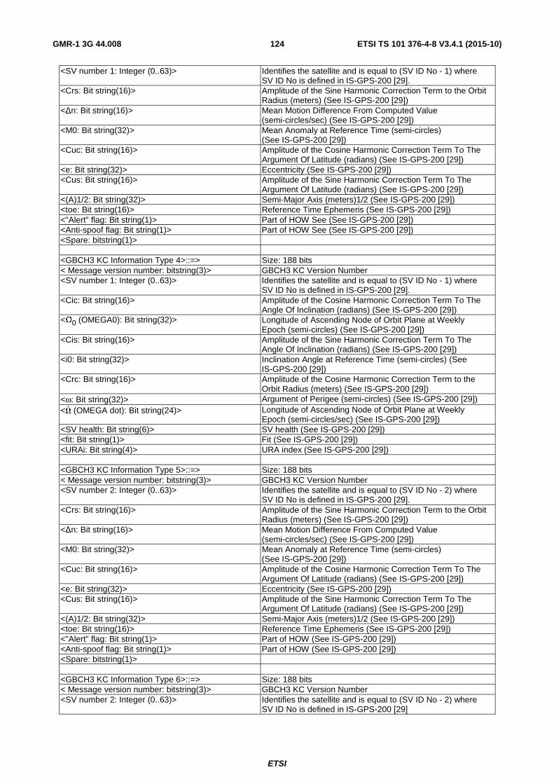
ETSI
ETSI TS 101 376-4-8 V3.4.1 (2015-10) 124GMR-1 3G 44.008
<SV number 1: Integer (0..63)> Identifies the satellite and is equal to (SV ID No - 1) where SV ID No is defined in IS-GPS-200 [29].
<Crs: Bit string(16)> Amplitude of the Sine Harmonic Correction Term to the Orbit Radius (meters) (See IS-GPS-200 [29])
<∆n: Bit string(16)> Mean Motion Difference From Computed Value (semi-circles/sec) (See IS-GPS-200 [29])
<M0: Bit string(32)> Mean Anomaly at Reference Time (semi-circles) (See IS-GPS-200 [29])
<Cuc: Bit string(16)> Amplitude of the Cosine Harmonic Correction Term To The Argument Of Latitude (radians) (See IS-GPS-200 [29])
<e: Bit string(32)> Eccentricity (See IS-GPS-200 [29]) <Cus: Bit string(16)> Amplitude of the Sine Harmonic Correction Term To The
Argument Of Latitude (radians) (See IS-GPS-200 [29]) <(A)1/2: Bit string(32)> Semi-Major Axis (meters)1/2 (See IS-GPS-200 [29]) <toe: Bit string(16)> Reference Time Ephemeris (See IS-GPS-200 [29]) <"Alert" flag: Bit string(1)> Part of HOW See (See IS-GPS-200 [29]) <Anti-spoof flag: Bit string(1)> Part of HOW See (See IS-GPS-200 [29]) <Spare: bitstring(1)> <GBCH3 KC Information Type 4>::=> Size: 188 bits < Message version number: bitstring(3)> GBCH3 KC Version Number <SV number 1: Integer (0..63)> Identifies the satellite and is equal to (SV ID No - 1) where
SV ID No is defined in IS-GPS-200 [29]. <Cic: Bit string(16)> Amplitude of the Cosine Harmonic Correction Term To The
Angle Of Inclination (radians) (See IS-GPS-200 [29]) <Ω0 (OMEGA0): Bit string(32)> Longitude of Ascending Node of Orbit Plane at Weekly
Epoch (semi-circles) (See IS-GPS-200 [29]) <Cis: Bit string(16)> Amplitude of the Sine Harmonic Correction Term To The
Angle Of Inclination (radians) (See IS-GPS-200 [29]) <i0: Bit string(32)> Inclination Angle at Reference Time (semi-circles) (See
IS-GPS-200 [29]) <Crc: Bit string(16)> Amplitude of the Cosine Harmonic Correction Term to the
Orbit Radius (meters) (See IS-GPS-200 [29]) <ω: Bit string(32)> Argument of Perigee (semi-circles) (See IS-GPS-200 [29]) <Ω (OMEGA dot): Bit string(24)> Longitude of Ascending Node of Orbit Plane at Weekly
Epoch (semi-circles/sec) (See IS-GPS-200 [29]) <SV health: Bit string(6)> SV health (See IS-GPS-200 [29]) <fit: Bit string(1)> Fit (See IS-GPS-200 [29]) <URAi: Bit string(4)> URA index (See IS-GPS-200 [29]) <GBCH3 KC Information Type 5>::=> Size: 188 bits < Message version number: bitstring(3)> GBCH3 KC Version Number <SV number 2: Integer (0..63)> Identifies the satellite and is equal to (SV ID No - 2) where
SV ID No is defined in IS-GPS-200 [29]. <Crs: Bit string(16)> Amplitude of the Sine Harmonic Correction Term to the Orbit
Radius (meters) (See IS-GPS-200 [29]) <∆n: Bit string(16)> Mean Motion Difference From Computed Value
(semi-circles/sec) (See IS-GPS-200 [29]) <M0: Bit string(32)> Mean Anomaly at Reference Time (semi-circles)
(See IS-GPS-200 [29]) <Cuc: Bit string(16)> Amplitude of the Cosine Harmonic Correction Term To The
Argument Of Latitude (radians) (See IS-GPS-200 [29]) <e: Bit string(32)> Eccentricity (See IS-GPS-200 [29]) <Cus: Bit string(16)> Amplitude of the Sine Harmonic Correction Term To The
Argument Of Latitude (radians) (See IS-GPS-200 [29]) <(A)1/2: Bit string(32)> Semi-Major Axis (meters)1/2 (See IS-GPS-200 [29]) <toe: Bit string(16)> Reference Time Ephemeris (See IS-GPS-200 [29]) <"Alert" flag: Bit string(1)> Part of HOW (See IS-GPS-200 [29]) <Anti-spoof flag: Bit string(1)> Part of HOW (See IS-GPS-200 [29]) <Spare: bitstring(1)> <GBCH3 KC Information Type 6>::=> Size: 188 bits < Message version number: bitstring(3)> GBCH3 KC Version Number <SV number 2: Integer (0..63)> Identifies the satellite and is equal to (SV ID No - 2) where
SV ID No is defined in IS-GPS-200 [29]

ETSI
ETSI TS 101 376-4-8 V3.4.1 (2015-10) 125GMR-1 3G 44.008
<Cic: Bit string(16)> Amplitude of the Cosine Harmonic Correction Term To The Angle Of Inclination (radians) (See IS-GPS-200 [29])
<Ω0 (OMEGA0): Bit string(32)> Longitude of Ascending Node of Orbit Plane at Weekly Epoch (semi-circles) (See IS-GPS-200 [29])
<Cis: Bit string(16)> Amplitude of the Sine Harmonic Correction Term To The Angle Of Inclination (radians) (See IS-GPS-200 [29])
<i0: Bit string(32)> Inclination Angle at Reference Time (semi-circles) (See IS-GPS-200 [29])
<Crc: Bit string(16)> Amplitude of the Cosine Harmonic Correction Term to the Orbit Radius (meters) (See IS-GPS-200 [29])
<ω: Bit string(32)> Argument of Perigee (semi-circles) (See IS-GPS-200 [29]) <Ω (OMEGA dot): Bit string(24)> Longitude of Ascending Node of Orbit Plane at Weekly
Epoch (semi-circles/sec) (See IS-GPS-200 [29]) <SV health: Bit string(6)> SV health (See IS-GPS-200 [29]) <fit: Bit string(1)> Fit (See IS-GPS-200 [29]) <URAi: Bit string(4)> URA index (See IS-GPS-200 [29])
10.1.47 Guard time violation (A/Gb mode only)
Same as clause 10.1.47 of ETSI TS 101 376-4-8 (Release 1) [19].
10.1.48 Link correction (A/Gb mode only)
Same as clause 10.1.48 of ETSI TS 101 376-4-8 (Release 1) [19].
10.1.49 Power control parameters update (A/Gb mode only)
Same as clause 10.1.49 of ETSI TS 101 376-4-8 (Release 1) [19].
10.1.50 TtT signalling link failure (A/Gb mode only)
Same as clause 10.1.50 of ETSI TS 101 376-4-8 (Release 1) [19].
10.1.51 Information request (A/Gb mode only)
Same as clause 10.1.51 of ETSI TS 101 376-4-8 (Release 1) [19].
10.1.52 Information response version (A/Gb mode only)
Same as clause 10.1.52 of ETSI TS 101 376-4-8 (Release 1) [19].
10.1.53 Information response spot beam selection (A/Gb mode only)
Same as clause 10.1.53 of ETSI TS 101 376-4-8 (Release 1) [19].
10.1.54 Information response current beam (A/Gb mode only)
Same as clause 10.1.54 of ETSI TS 101 376-4-8 (Release 1) [19].
10.1.55 Information response power control (A/Gb mode only)
Same as clause 10.1.55 of ETSI TS 101 376-4-8 (Release 1) [19].
10.1.56 Information response position (A/Gb mode only)
Same as clause 10.1.56 of ETSI TS 101 376-4-8 (Release 1) [19].
10.1.57 Information response vendor specific (A/Gb mode only)
Same as clause 10.1.57 of ETSI TS 101 376-4-8 (Release 1) [19].

ETSI
ETSI TS 101 376-4-8 V3.4.1 (2015-10) 126GMR-1 3G 44.008
10.1.58 Information response error (A/Gb mode only)
Same as clause 10.1.58 of ETSI TS 101 376-4-8 (Release 1) [19].
10.1.59 DTMF tone generate request (A/Gb mode only)
Same as clause 10.1.59 of ETSI TS 101 376-4-8 (Release 1) [19].
10.1.60 DTMF tone generate acknowledge (A/Gb mode only)
Same as clause 10.1.60 of ETSI TS 101 376-4-8 (Release 1) [19].
10.1.61 GMPRS Resume Response (A/Gb mode only)
10.1.61.0 General
This message is sent on the CCCH by the network to inform the MES on the result of GMPRS service resumption. See table 10.39.
The L2 Pseudo Length of this message is the sum of the lengths of all IEs present in the message except the GMPRS Resume Rest Octets and L2 Pseudo Length IEs.
Message type: GMPRS RESUME RESPONSE
Significance: dual
Direction: network to MES
Table 10.39: GMPRS RESUME RESPONSE message content
IEI Information Element Type/Reference Presence Format Length L2 Pseudo Length L2 Pseudo Length
clause 11.5.2.19 M V 1
RR Management Protocol Discriminator
Protocol Discriminator clause 11.2
M V 1/2
Skip Indicator Skip Indicator clause 11.3.1 M V 1/2
GMPRS Resume Response Message Type
Message Type clause 11.4 M V 1
TLLI TLLI M V 4 Result GMPRS Resume Result
clause 11.5.2.121 M V 1
GMPRS Resume Response Rest Octets
GMPRS Resume Response Rest Octets clause 11.5.2.122
M V 16
10.1.61.1 TLLI
As described in ETSI TS 101 376-4-12 [20].
10.1.62 Paging Request Type 4 (Iu mode)
10.1.62.0 General
This message is sent on the PCH by the network to one or more MESs to trigger channel access by them. The MESs are identified by their IMSI, P-TMSI or G-RNTIs. See table 10.40. The L2 Pseudo Length of this message is the sum of the lengths of all the IEs present in the message.
Message type: PAGING REQUEST TYPE 4
Significance: dual
Direction: network to MES

ETSI
ETSI TS 101 376-4-8 V3.4.1 (2015-10) 127GMR-1 3G 44.008
Table 10.40: PAGING REQUEST TYPE 4 message content
IEI Information Element Type/Reference Presence Format Length
L2 Pseudo Length L2 Pseudo Length clause 11.5.2.19 M V 1
RR Management Protocol Discriminator
Protocol Discriminator clause 11.2 M V 1/2
Skip Indicator Skip Indicator clause 11.3.1
M V 1/2
Paging Request Type 4 Message Type
Message Type clause 11.4 M V 1
Page Mode Page Mode clause 11.5.2.26 M V 1/2
Paging Request Type 4 Parameters
Paging Request Type 4 Parameters clause 11.5.2.127
M V 20 1/2
10.1.62.1 Page Mode
Page Mode IE is defined in clause 11.5.2.26 of ETSI TS 101 376-4-8 (Release 1) [19]. Page Mode IE occupies most significant four bits of octet 4.
10.1.62.2 Paging Request Type 4 Parameters
Paging Request Type 4 Parameters IE is defined in clause 11.5.2.127. Paging Request Type 4 Parameters IE occupies the least significant four bits of octet 4 and octets 5-24.
10.2 Messages for mobility management Same as clause 10.2 of ETSI TS 101 376-4-8 (Release 1) [19].
10.3 Messages for circuit-switched call control (A/Gb mode only) Same as clause 10.3 of ETSI TS 101 376-4-8 (Release 1) [19].
10.4 GPRS Mobility Management messages Same as clause 9.4 of ETSI TS 124 008 [18].
For A/Gb mode, see clause 11.5.5.12a for the definition of the MS Radio Access capability IE.
For Iu mode, only the MES's terrestrial access technology capabilities (GSM, GERAN, 3G) shall be specified within the MS Radio Access capability IE. The IE definition shall be as given within clause 10.5.5.12a of ETSI TS 124 008 [18].
10.5 GPRS Session Management messages
10.5.0 General
Same as clause 9.5 of ETSI TS 124 008 [18] with the additional clause 10.5.1 for A/Gb mode.
10.5.1 Streaming service (A/Gb mode only)
A guaranteed bit rate service requested by MES shall specify the following parameters at the initiation of an Activate PDP Context Request message:
• Peak Throughput Class: This field shall be set to the highest peak throughput value of either uplink or downlink direction. The Peak Throughput value is specified in ETSI TS 123 060 [24].
• Delay class: This field shall be set to one of the predictive delay class value as specified in ETSI TS 123 060 [24]. Delay class 1 to 3 are predictive delay classes.

ETSI
ETSI TS 101 376-4-8 V3.4.1 (2015-10) 128GMR-1 3G 44.008
If the Delay class is not predictive, the network shall treat the service request as best effort. The best effort indicates that throughput shall be made available to the MES on a per need and availability basis.
MES shall not initiate guaranteed bit rate service with foreign or random TLLI.
11 General message format and information elements coding
11.0 General This clause describes the IEs that are used to define the L3 protocol messages in the GMR-1 system.
11.1 Overview Same as clause 11.1 of ETSI TS 101 376-4-8 (Release 1) [19].
11.2 Protocol discriminator Same as clause 11.2 of ETSI TS 101 376-4-8 (Release 1) [19].
11.3 Skip indicator and transaction identifier
11.3.1 Skip indicator
Same as clause 11.3.1 of ETSI TS 101 376-4-8 (Release 1) [19].
11.3.2 Transaction identifier
Same as clause 11.3.2 of ETSI TS 101 376-4-8 (Release 1) [19].
11.4 Message type
11.4.0 General
The Message Type IE and its use are defined in ETSI TS 101 376-4-7 [11], which also defines the value part of the Message Type IE used in the RR management protocol.
11.4.1 Radio resource management message types
Table 11.1: Message types for radio resource management
8 7 6 5 4 3 2 1 0 0 1 1 1 - - - Channel establishment messages: 1 1 1 IMMEDIATE ASSIGNMENT 0 1 0 IMMEDIATE ASSIGNMENT REJECT TYPE 1 0 1 1 IMMEDIATE ASSIGNMENT REJECT TYPE 2 1 1 0 EXTENDED IMMEDIATE ASSIGNMENT 0 1 1 EXTENDED IMM. ASSIGNMENT REJECT 0 0 1 POSITION VERIFICATION NOTIFY 1 0 0 IMMEDIATE ASSIGNMENT REJECT TYPE 3 1 1 0 IMMEDIATE ASSIGNMENT TYPE 2 1 0 1 IMMEDIATE ASSIGNMENT TYPE 3 0 0 1 1 0 - - - Ciphering messages: 1 0 1 CIPHERING MODE COMMAND 0 1 0 CIPHERING MODE COMPLETE

ETSI
ETSI TS 101 376-4-8 V3.4.1 (2015-10) 129GMR-1 3G 44.008
0 0 1 0 1 - - - Channel assignment/handover messages: 1 1 0 ASSIGNMENT COMMAND 1 0 1 0 ASSIGNMENT COMMAND 2 0 0 1 ASSIGNMENT COMPLETE 1 1 1 ASSIGNMENT FAILURE 0 1 1 HANDOVER COMMAND 1 0 0 HANDOVER COMPLETE 0 0 0 0 1 - - - Channel release messages: 1 0 1 CHANNEL RELEASE 1 1 0 TtT SIGNALING LINK FAILURE 0 0 1 0 0 - - - Paging messages: 0 0 1 PAGING REQUEST TYPE 1 0 1 0 PAGING REQUEST TYPE 2 1 0 0 PAGING REQUEST TYPE 3 1 1 1 PAGING RESPONSE 0 0 0 1 0 - - - Miscellaneous messages 0 0 0 CHANNEL MODE MODIFY 0 1 0 RR STATUS 1 1 1 CHANNEL MODE MODIFY ACKNOWLEDGE 1 1 0 CLASSMARK CHANGE 0 1 1 CLASSMARK ENQUIRY 1 0 0 POSITION UPDATE REQUEST 1 0 1 POSITION UPDATE ACCEPT 0 0 1 LINK CORRECTION MESSAGE 0 0 0 0 0 - - - 0 0 1 POWER CONTROL PARAMETERS UPDATE 0 1 0 GUARD TIME VIOLATION 1 0 0 EXTENDED CHANNEL REQUEST 1 0 1 GMPRS RESUME RESPONSE 0 1 0 0 - - - - Status and Diagnostic Messages 0 0 0 0 INFORMATION REQUEST 0 0 0 1 INFORMATION RESPONSE POSITION 0 0 1 0 INFORMATION RESPONSE VERSION 0 0 1 1 INFORMATION RESPONSE SPOT BEAM SELECTION 0 1 0 0 INFORMATION RESPONSE POWER CONTROL 0 1 0 1 INFORMATION RESPONSE VENDOR SPECIFIC 0 1 1 0 INFORMATION RESPONSE CURRENT BEAM 1 1 1 1 INFORMATION RESPONSE ERROR 1 0 0 0 0 0 0 0 IMMEDIATE ASSIGNMENT TYPE 4 1 0 0 0 0 0 0 1 PAGING REQUEST TYPE 4 1 0 0 0 0 0 1 0 POSITION VERIFICATION NOTIFY TYPE 2 1 0 0 0 0 0 1 1 IMMEDIATE ASSIGNMENT TYPE 5 1 0 0 0 0 1 0 0 IMMEDIATE ASSIGNMENT REJECT TYPE 4 1 0 0 0 0 1 0 1 SYSTEM INFORMATION TYPE 2bis
11.4.2 DTRS message types
Same as clause 11.4.2 of ETSI TS 101 376-4-8 (Release 1) [19].
11.5 Other information elements
11.5.0 General
Same as clause 10.5 of ETSI TS 144 018 [17].
11.5.1 Common information elements
11.5.1.1 Cell identity
Same as clause 11.5.1.1 of ETSI TS 101 376-4-8 (Release 1) [19].
11.5.1.2 Ciphering key sequence number
Same as clause 11.5.1.2 of ETSI TS 101 376-4-8 (Release 1) [19].

ETSI
ETSI TS 101 376-4-8 V3.4.1 (2015-10) 130GMR-1 3G 44.008
11.5.1.3 Location area identification
The purpose of the Location Area Identification IE is to provide an unambiguous identification of location areas within the area covered by the GMR-1 system. This IE is coded as shown in figure 11.2 and table 11.4. LAI is a Type 3 IE, 6 octets in length.
8 7 6 5 4 3 2 1
Location Area Identification IEI octet 1 MCC digit 2 MCC digit 1 octet 2
MNC digit 3 MCC digit 3 octet 3
MNC digit 2 MNC digit 1 octet 4 LAC octet 5 LAC (continued) octet 6
Figure 11.2: Location area identification IE
Table 11.4: Local area identification IE
MCC (octets 2 and 3) The MCC field is coded as in annex A of Recommendation ITU-T E.212 [34]. If the LAI is deleted, the MCC and MNC shall take the value from the deleted LAI. In abnormal cases, the MCC stored in the mobile earth station can contain elements not in the set 0, 1 … 9. In such cases the mobile earth station should transmit the stored values using full hexadecimal encoding. When receiving such an MCC, the network shall treat the LAI as deleted. MNC (octets 3 and 4) The coding of this field is the responsibility of each administration but BCD coding shall be used. If an administration decides to include only 1 digit in the MNC, then bits 5 to 8 of octet 4 are coded as "1111" (see note). If an administration only supports a 2-digit MNC, then bits 5 to 8 of octet 3 shall be coded as "1111" (see note). In abnormal cases, the MNC stored in the mobile earth station can have digit 1 not in the set 0, 1 … 9 and/or digit 2 not in the set 0, 1 ... 9, F hex. In such cases the mobile earth station should transmit the stored values, using full hexadecimal encoding. When receiving such an MNC, the network shall treat the LAI as deleted. LAC (octets 5 and 6) LAC is defined in ETSI TS 101 376-3-3 [3]. In A/Gb mode, the MSC and SGSN ID shall be bits 8 to 3 in octet 5. The Spot Beam ID shall be bits 2 to 1 in octet 5 and all of octet 6. In Iu mode, the Serving Radio Network ID shall be bits 8 to 3 in octet 5. The Spot Beam ID shall be bits 2 to 1 in octet 5 and all of octet 6. NOTE: ETSI TS 101 376-3-3 [3] states that a 2-digit MNC shall be used; however, the
possibility of using a 1-digit MNC in LAI is provided on the radio interface. For Iu mode, ETSI TS 123 003 [28] supports Mobile Network Codes (MNCs) consisting of two or three digits for GSM/UMTS applications. The length of the MNC (two or three digits) depends on the value of the MCC.
11.5.1.4 Mobile identity
For circuit switched services same as clause 10.5.1.4 of ETSI TS 144 018 [17].
For packet switched services same as clause 10.5.1.4 of ETSI TS 124 008 [18].
11.5.1.5 Mobile Earth Station (MES) classmark 1 (A/Gb mode only)
The purpose of the Mobile Earth Station Classmark 1 IE is to provide the network with information concerning aspects of the high priority of the MES. This affects the manner in which the network handles the operation of the MES. The MES classmark information indicates general mobile earth station characteristics.
The Mobile Earth Station Classmark 1 IE is coded as shown in figure 11.3, ETSI TS 101 376-4-8 (Release 1) [19] and table 11.5, ETSI TS 101 376-4-8 (Release 1) [19].

ETSI
ETSI TS 101 376-4-8 V3.4.1 (2015-10) 131GMR-1 3G 44.008
The Mobile Earth Station Classmark 1 is a Type 3 IE, 2 octets in length.
8 7 6 5 4 3 2 1
Mobile Earth Station Classmark 1 IEI octet 1
0 spare
Revision Level
ES IND A5/1 MES Terminal type octet 2
Figure 11.3: Mobile Earth Station classmark 1 IE
Table 11.5: Mobile Earth Station classmark 1 IE
Revision level (octet 3) Bits 7 6 0 0 Should be used by all Phase 1 MESs 0 1 Reserved for Phase 2 MESs All other values are reserved for future use ES IND (octet 2, bit 5) "Controlled Early Classmark Sending" option implementation 0 "Controlled Early Classmark Sending" option is not implemented 1 "Controlled Early Classmark Sending" option is implemented A5/1 algorithm supported (octet 3, bit 4) 0 Encryption algorithm A5/1 available 1 Encryption algorithm A5/1 not available MES Terminal Type (octet 2): Bits 3 2 1 0 0 0 Class 1 reserved 0 0 1 Class 2 used by all GMR-1 fixed terminals 0 1 0 Class 3 used by all GMR-1 VTs 0 1 1 Class 4 used by all GMR-1 handheld terminals All other values are reserved
11.5.1.6 Mobile Earth Station (MES) classmark 2 (A/Gb mode only)
Same as clause 11.5.1.6 of ETSI TS 101 376-4-8 (Release 1) [19].
11.5.1.7 Mobile Earth Station (MES) classmark 3 (A/Gb mode only)
Same as clause 11.5.1.7 of ETSI TS 101 376-4-8 (Release 1) [19].
11.5.1.8 Spare half octet
Same as clause 11.5.1.8 of ETSI TS 101 376-4-8 (Release 1) [19].
11.5.2 Radio resource management IEs
11.5.2.1 BA range
This function is not currently supported in GMR-1.
11.5.2.2 Cell description
This function is not currently supported in GMR-1.
11.5.2.3 Cell options (BCCH)
This function is not currently supported in GMR-1.
11.5.2.4 Cell selection parameters
This function is not currently supported in GMR-1.

ETSI
ETSI TS 101 376-4-8 V3.4.1 (2015-10) 132GMR-1 3G 44.008
11.5.2.5 Channel description
Same as clause 11.5.2.5 of ETSI TS 101 376-4-8 (Release 1) [19].
11.5.2.6 Channel mode
Same as clause 11.5.2.6 of ETSI TS 101 376-4-8 (Release 1) [19].
11.5.2.7 Channel mode 2
This function is not currently supported in GMR-1.
11.5.2.8 Channel needed
This function is not currently supported in GMR-1.
11.5.2.9 Cipher mode setting (A/Gb mode only)
Same as clause 11.5.2.9 of ETSI TS 101 376-4-8 (Release 1) [19].
11.5.2.10 Cipher response (A/Gb mode only)
Same as clause 11.5.2.10 of ETSI TS 101 376-4-8 (Release 1) [19].
11.5.2.11 Control channel description
This function is not currently supported in GMR-1.
11.5.2.12 Frequency channel sequence
This function is not currently supported in GMR-1.
11.5.2.13 Frequency list
This function is not currently supported in GMR-1.
11.5.2.14 Frequency short list
This function is not currently supported in GMR-1.
11.5.2.15 Handover reference
This function is not currently supported in GMR-1.
11.5.2.16 IA rest octets
The IA Rest Octets IE is coded as shown in figure 11.8 and contains only spare bits. The IA Rest Octets IE is a Type 5 IE, 1 octet to 5 octets in length.
8 7 6 5 4 3 2 1
IA Rest Octets IEI octet 1
0 Spare
0 Spare
1 Spare
0 Spare
1 Spare
0 Spare
1 Spare
1 Spare octet 2
0 Spare
0 Spare
1 Spare
0 Spare
1 Spare
0 Spare
1 Spare
1 Spare
• •
0 Spare
0 Spare
1 Spare
0 Spare
1 Spare
0 Spare
1 Spare
1 Spare octet 5
Figure 11.8: IA Rest Octets IE

ETSI
ETSI TS 101 376-4-8 V3.4.1 (2015-10) 133GMR-1 3G 44.008
11.5.2.17 IAR rest octets
The IAR Rest Octets IE is coded as shown in figure 11.9 and contains only spare bits. The IAR Rest Octets IE is a Type 5 IE, 1 to 5 octets in length.
8 7 6 5 4 3 2 1
IAR Rest Octets IEI octet 1
0 Spare
0 Spare
1 Spare
0 Spare
1 Spare
0 Spare
1 Spare
1 Spare octet 2
0 Spare
0 Spare
1 Spare
0 Spare
1 Spare
0 Spare
1 Spare
1 Spare
• •
0 Spare
0 Spare
1 Spare
0 Spare
1 Spare
0 Spare
1 Spare
1 Spare octet 5
0 Spare
0 Spare
1 Spare
0 Spare
1 Spare
0 Spare
1 Spare
1 Spare octet 6
0 Spare
0 Spare
1 Spare
0 Spare
1 Spare
0 Spare
1 Spare
1 Spare octet 7
0 Spare
0 Spare
1 Spare
0 Spare
1 Spare
0 Spare
1 Spare
1 Spare octet 8
0 Spare
0 Spare
1 Spare
0 Spare
1 Spare
0 Spare
1 Spare
1 Spare octet 9
Figure 11.9: IAR rest octets IE
11.5.2.18 IAX rest octets
This function is not currently supported in GMR-1.
11.5.2.19 L2 pseudo length
Same as clause 11.5.2.19 of ETSI TS 101 376-4-8 (Release 1) [19].
11.5.2.20 Measurement results
This function is not currently supported in GMR-1.
11.5.2.21 Mobile allocation
This function is not currently supported in GMR-1.
11.5.2.22 Neighbour cells description
This function is not currently supported in GMR-1.
11.5.2.23 P1 rest octets
Same as clause 11.5.2.23 of ETSI TS 101 376-4-8 (Release 1) [19].
11.5.2.24 P2 rest octets
Same as clause 11.5.2.24 of ETSI TS 101 376-4-8 (Release 1) [19].
11.5.2.25 P3 rest octets
Same as clause 11.5.2.25 of ETSI TS 101 376-4-8 (Release 1) [19].
11.5.2.26 Page mode
Same as clause 11.5.2.26 of ETSI TS 101 376-4-8 (Release 1) [19].
11.5.2.27 NCC permitted
This function is not currently supported in GMR-1.

ETSI
ETSI TS 101 376-4-8 V3.4.1 (2015-10) 134GMR-1 3G 44.008
11.5.2.28 Power command
This function is not currently supported in GMR-1.
11.5.2.29 RACH control parameters
The purpose of the RACH Control Parameters IE is to provide parameters to control RACH utilization. See figure 11.14 and table 11.12. RACH Control Parameters is a Type 3 IE, 4 octets in length.
8 7 6 5 4 3 2 1 RACH Control Parameters IEI octet 1
Max retrans Spare CELL BAR ACCESS Spare octet 2
AC C15
AC C14
AC C13
AC C12
AC C11
AC C10
AC C09
AC C08
octet 3
AC C07
AC C06
AC C05
AC C04
AC C03
AC C02
AC C01
AC C00 octet 4
Figure 11.14: RACH control parameter IE
Table 11.12: RACH control parameter IE
Max retrans, Maximum number of retransmissions (octet 2) Bits 8 7 0 0 Maximum 0 retransmission 0 1 Maximum 1 retransmissions 1 0 Maximum 2 retransmissions 1 1 Maximum 3 retransmissions The spare bits shall be coded as 0s CELL_BAR_ACCESS, Cell Barred for Access (octet 2) Bit 2 see ETSI TS 101 376-3-10 [4] EC Emergency Call allowed (octet 3 bit 3) Bit 3 0 Emergency call allowed in the cell to all MESs 1 Emergency call not allowed in the cell except for the MESs that belong to one of the classes between 11 to 15 AC CN (Access Control Class N) (octet 3, except bit 3, and octet 4) For a mobile earth station with AC C = N access is not barred if the AC CN bit is coded with a "0;" N = 0, 1, .. 9, 11, .., 15
11.5.2.30 Request Reference
The Request Reference IE shall be used by the MES to accept or discard the message received in response to the CHANNEL REQUEST message. The network builds the Request Reference IE by using the random number specified in the CHANNEL REQUEST message, the frame number in which the CHANNEL REQUEST message was received by it and the establishment cause. The network transfers the Request Reference IE to MES with IMMEDIATE ASSIGNMENT message over the AGCH. This IE is coded as shown in figure 11.15 and table 11.13. Request Reference is a Type 3 IE, 3 octets in length.

ETSI
ETSI TS 101 376-4-8 V3.4.1 (2015-10) 135GMR-1 3G 44.008
8 7 6 5 4 3 2 1
Request Reference IEI octet 1
Establishment cause group ID Random Access Information octet 2
Frame Number octet 3
Figure 11.15: Request reference IE
Table 11.13: request reference IE
Random Access Information (octet 2, bits 5 to 1) Random Reference in CHANNEL REQUEST message. Random Reference shall be set as follows: b5 b4 b3 b2 b1 Channel Request Type b5 b4 b3 b2 b1 Random reference from CHANNEL REQUEST TYPE 1 0 0 0 b2 b1 Retry Counter from CHANNEL REQUEST TYPE 3 Establishment Cause group identifier(octet 2, bits 8 to 6) The establishment causes are grouped as follows group-ID Establishment Cause 000 MO call 001 In response to paging/alerting 010 Location update/IMSI detach 011 Emergency call 100 Supplementary/short message service 101 Position verification 110 Any other valid cause 111 Packet Switched Services NOTE: For Iu mode of operation, the Establishment Cause Group Identifier shall be set to
"101" for Position Verification procedure, for all other causes the value "111" shall be used.
Frame Number (octet 3) Lower 8 bits of the frame number
11.5.2.31 RR cause
Same as clause 11.5.2.31 of ETSI TS 101 376-4-8 (Release 1) [19].
11.5.2.32 SI 1 rest octets
This function is not currently supported in GMR-1.
11.5.2.33 SI 2bis rest octets
This function is not currently supported in GMR-1.
11.5.2.34 SI 3 rest octets
This function is not currently supported in GMR-1.
11.5.2.35 SI 4 rest octets
This function is not currently supported in GMR-1.
11.5.2.36 SI 7 rest octets
This function is not currently supported in GMR-1.
11.5.2.37 SI 8 rest octets
This function is not currently supported in GMR-1.

ETSI
ETSI TS 101 376-4-8 V3.4.1 (2015-10) 136GMR-1 3G 44.008
11.5.2.38 Starting time
This function is not currently supported in GMR-1.
11.5.2.39 Synchronization indication
This function is not currently supported in GMR-1.
11.5.2.40 Timing offset
Same as clause 11.5.2.40 of ETSI TS 101 376-4-8 (Release 1) [19].
11.5.2.41 Time difference
This function is not currently supported in GMR-1.
11.5.2.42 TMSI
Same as clause 11.5.2.42 of ETSI TS 101 376-4-8 (Release 1) [19].
11.5.2.43 Wait indication
Same as clause 11.5.2.43 of ETSI TS 101 376-4-8 (Release 1) [19].
11.5.2.44 MES information flag (A/Gb mode only)
Same as clause 11.5.2.44 of ETSI TS 101 376-4-8 [19].
11.5.2.45 TTCH channel description (A/Gb mode only)
Same as clause 11.5.2.45 of ETSI TS 101 376-4-8 (Release 1) [19].
11.5.2.46 MES configuration (A/Gb mode only)
Same as clause 11.5.2.46 of ETSI TS 101 376-4-8 (Release 1) [19].
11.5.2.47 TtT common cipher key (A/Gb mode only)
Same as clause 11.5.2.47 of ETSI TS 101 376-4-8 (Release 1) [19].
11.5.2.48 Access information (A/Gb mode only)
Same as clause 11.5.2.48 of ETSI TS 101 376-4-8 (Release 1) [19].
11.5.2.49 Frequency offset
Same as clause 11.5.2.49 of ETSI TS 101 376-4-8 (Release 1) [19].
11.5.2.50 Extended power class (A/Gb mode only)
This IE is used to describe the RF power class of the MES. Its coding is shown in figure 11.24. The various components of the element are described in table 11.22.
8 7 6 5 4 3 2 1 Ext Power Class IEI Extended Power Class octet 1
Figure 11.24: Extended power class IE

ETSI
ETSI TS 101 376-4-8 V3.4.1 (2015-10) 137GMR-1 3G 44.008
Table 11.22: Extended power class IE
Extended Power Class Bits 4 3 2 1 0 0 0 0 Power Class 1 0 0 0 1 Power Class 2 0 0 1 0 Power Class 3 0 0 1 1 Power Class 4 0 1 0 0 Power Class 5 0 1 0 1 Power Class 6 0 1 1 0 Power Class 7 0 1 1 1 Power Class 8 1 0 0 0 Power Class 9 1 0 0 1 Power Class 10 1 0 1 0 Power Class 11 1 0 1 1 Power Class 12 1 1 0 0 Power Class 13 1 1 0 1 Power Class 14 1 1 1 0 Power Class 15 1 1 1 1 Power Class 16 See ETSI TS 101 376-5-5 [14] for details of the Power Class.
11.5.2.51 Paging Information
The Paging Information IE is used to indicate MSC ID/SGSN ID associated with a Mobile ID in the paging message. This IE is coded as shown in figure 11.25 and table 11.23. The Paging Information IE is a Type 3 IE, 2 octets in length.
8 7 6 5 4 3 2 1
0 Paging Information IEI octet 1 MSC ID/SGSN ID Channel Needed octet 2
Figure 11.25: Paging information IE
Table 11.23: Paging information IE
Channel needed for Paging Mobile (octet 2) Bits 2 1 0 0 any 0 1 SDCCH 1 0 TCH3 1 1 PDCH Bits 3 to 8 of octet 2 contain the MSC ID/SGSN ID to be used by the mobile at immediate assignment procedure.
11.5.2.52 Position display
Same as clause 11.5.2.52 of ETSI TS 101 376-4-8 (Release 1) [19].
11.5.2.53 GPS position
Same as clause 11.5.2.53 of ETSI TS 101 376-4-8 (Release 1) [19].
11.5.2.54 Idle or dedicated mode position update information
Same as clause 11.5.2.54 of ETSI TS 101 376-4-8 (Release 1) [19].
11.5.2.55 BCCH carrier
Same as clause 11.5.2.55 of ETSI TS 101 376-4-8 (Release 1) [19].

ETSI
ETSI TS 101 376-4-8 V3.4.1 (2015-10) 138GMR-1 3G 44.008
11.5.2.56 Reject Cause
The Reject Cause IE is used to specify cause for rejecting the access request and the presence of additional information to the MES. This IE is coded as shown in figure 11.30 and table 11.28. Reject Cause IE is a Type 3 IE, 2 octets in length.
8 7 6 5 4 3 2 1
0 Reject Cause IEI octet 1 Cause T B octet 2
Figure 11.30: Reject cause IE
Table 11.28: Reject cause IE
BCCH carrier (B) (octet 2) Bit 1 0 BCCH carrier information absent 1 BCCH carrier information present
Timer (T) (octet 2) Bit 2 0 Pause Timer T3115 is present 1 Illumination Retry Timer T3333 is present Cause (octet 2) Bits 8 7 6 5 4 3 0 0 0 0 0 0 Lack of resources (default) 0 1 0 0 0 1 Invalid position for selected LAI 0 1 0 0 1 0 Invalid position for selected spot beam 0 1 0 0 1 1 Invalid position 0 1 0 1 0 1 Position too old 0 1 0 1 1 0 Invalid position for service provider 0 1 0 1 1 1 Redirect to new satellite 0 1 1 0 0 0 Pause Indication 0 1 1 0 0 1 Dark beam activation in progress 0 1 1 0 1 0 Switch to new BCCH 0 1 1 0 1 1 Incorrect Class-2 RACH Info 0 1 1 1 0 0 Non-availability of Satellite Resources for PD 0 1 1 1 0 1 Non-Availability of service 1 1 1 1 1 1 Reported position acceptable. 0 1 1 1 1 0 Requested QoS not satisfied 0 1 1 1 1 1 Invalid QoS parameters 1 0 0 0 0 0 Directed signalling connection re-establishment 1 0 0 0 0 1 RRC Connection Reject 1 0 0 0 1 0 RA Redirect 1 0 0 0 1 1 RRC Connection Release All other values reserved.
11.5.2.57 GPS timestamp
Same as clause 11.5.2.57 of ETSI TS 101 376-4-8 (Release 1) [19].
11.5.2.58 Timing correction
Same as clause 11.5.2.58 of ETSI TS 101 376-4-8 (Release 1) [19].
11.5.2.59 MES information 2 flag
Same as clause 11.5.2.59 of ETSI TS 101 376-4-8 (Release 1) [19].
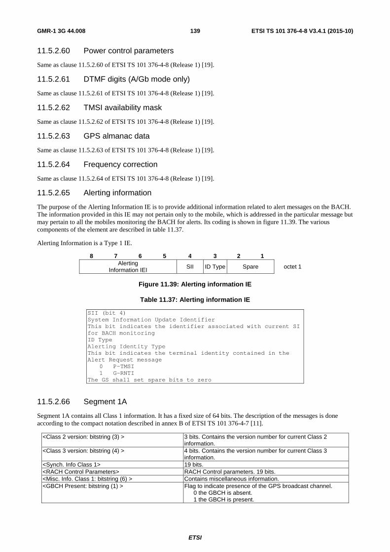
ETSI
ETSI TS 101 376-4-8 V3.4.1 (2015-10) 139GMR-1 3G 44.008
11.5.2.60 Power control parameters
Same as clause 11.5.2.60 of ETSI TS 101 376-4-8 (Release 1) [19].
11.5.2.61 DTMF digits (A/Gb mode only)
Same as clause 11.5.2.61 of ETSI TS 101 376-4-8 (Release 1) [19].
11.5.2.62 TMSI availability mask
Same as clause 11.5.2.62 of ETSI TS 101 376-4-8 (Release 1) [19].
11.5.2.63 GPS almanac data
Same as clause 11.5.2.63 of ETSI TS 101 376-4-8 (Release 1) [19].
11.5.2.64 Frequency correction
Same as clause 11.5.2.64 of ETSI TS 101 376-4-8 (Release 1) [19].
11.5.2.65 Alerting information
The purpose of the Alerting Information IE is to provide additional information related to alert messages on the BACH. The information provided in this IE may not pertain only to the mobile, which is addressed in the particular message but may pertain to all the mobiles monitoring the BACH for alerts. Its coding is shown in figure 11.39. The various components of the element are described in table 11.37.
Alerting Information is a Type 1 IE.
8 7 6 5 4 3 2 1 Alerting
Information IEI SII ID Type Spare octet 1
Figure 11.39: Alerting information IE
Table 11.37: Alerting information IE
SII (bit 4) System Information Update Identifier This bit indicates the identifier associated with current SI for BACH monitoring ID Type Alerting Identity Type This bit indicates the terminal identity contained in the Alert Request message
0 P-TMSI 1 G-RNTI
The GS shall set spare bits to zero
11.5.2.66 Segment 1A
Segment 1A contains all Class 1 information. It has a fixed size of 64 bits. The description of the messages is done according to the compact notation described in annex B of ETSI TS 101 376-4-7 [11].
<Class 2 version: bitstring (3) > 3 bits. Contains the version number for current Class 2 information.
<Class 3 version: bitstring (4) > 4 bits. Contains the version number for current Class 3 information.
<Synch. Info Class 1> 19 bits. <RACH Control Parameters> RACH Control parameters. 19 bits. <Misc. Info. Class 1: bitstring (6) > Contains miscellaneous information. <GBCH Present: bitstring (1) > Flag to indicate presence of the GPS broadcast channel.
0 the GBCH is absent. 1 the GBCH is present.
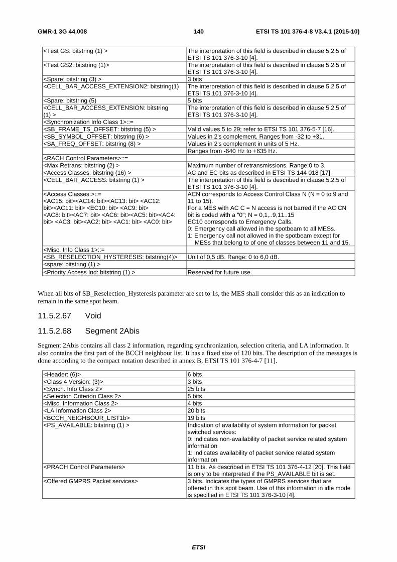
ETSI
ETSI TS 101 376-4-8 V3.4.1 (2015-10) 140GMR-1 3G 44.008
<Test GS: bitstring (1) > The interpretation of this field is described in clause 5.2.5 of ETSI TS 101 376-3-10 [4].
<Test GS2: bitstring (1)> The interpretation of this field is described in clause 5.2.5 of ETSI TS 101 376-3-10 [4].
<Spare: bitstring (3) > 3 bits <CELL_BAR_ACCESS_EXTENSION2: bitstring(1) The interpretation of this field is described in clause 5.2.5 of
ETSI TS 101 376-3-10 [4]. <Spare: bitstring (5) 5 bits <CELL_BAR_ACCESS_EXTENSION: bitstring (1) >
The interpretation of this field is described in clause 5.2.5 of ETSI TS 101 376-3-10 [4].
<Synchronization Info Class 1>::= <SB_FRAME_TS_OFFSET: bitstring (5) > Valid values 5 to 29; refer to ETSI TS 101 376-5-7 [16]. <SB_SYMBOL_OFFSET: bitstring (6) > Values in 2's complement. Ranges from -32 to +31. <SA_FREQ_OFFSET: bitstring (8) > Values in 2's complement in units of 5 Hz. Ranges from -640 Hz to +635 Hz. <RACH Control Parameters>::= <Max Retrans: bitstring (2) > Maximum number of retransmissions. Range:0 to 3. <Access Classes: bitstring (16) > AC and EC bits as described in ETSI TS 144 018 [17]. <CELL_BAR_ACCESS: bitstring (1) > The interpretation of this field is described in clause 5.2.5 of
ETSI TS 101 376-3-10 [4]. <Access Classes:>::= <AC15: bit><AC14: bit><AC13: bit> <AC12: bit><AC11: bit> <EC10: bit> <AC9: bit> <AC8: bit><AC7: bit> <AC6: bit><AC5: bit><AC4: bit> <AC3: bit><AC2: bit> <AC1: bit> <AC0: bit>
ACN corresponds to Access Control Class N (N = 0 to 9 and 11 to 15). For a MES with AC C = N access is not barred if the AC CN bit is coded with a "0"; N = 0,1,..9,11..15 EC10 corresponds to Emergency Calls. 0: Emergency call allowed in the spotbeam to all MESs. 1: Emergency call not allowed in the spotbeam except for
MESs that belong to of one of classes between 11 and 15. <Misc. Info Class 1>::= <SB_RESELECTION_HYSTERESIS: bitstring(4)> Unit of 0,5 dB. Range: 0 to 6,0 dB. <spare: bitstring (1) > <Priority Access Ind: bitstring (1) > Reserved for future use.
When all bits of SB_Reselection_Hysteresis parameter are set to 1s, the MES shall consider this as an indication to remain in the same spot beam.
11.5.2.67 Void
11.5.2.68 Segment 2Abis
Segment 2Abis contains all class 2 information, regarding synchronization, selection criteria, and LA information. It also contains the first part of the BCCH neighbour list. It has a fixed size of 120 bits. The description of the messages is done according to the compact notation described in annex B, ETSI TS 101 376-4-7 [11].
<Header: (6)> 6 bits <Class 4 Version: (3)> 3 bits <Synch. Info Class 2> 25 bits <Selection Criterion Class 2> 5 bits <Misc. Information Class 2> 4 bits <LA Information Class 2> 20 bits <BCCH_NEIGHBOUR_LIST1b> 19 bits <PS_AVAILABLE: bitstring (1) > Indication of availability of system information for packet
switched services: 0: indicates non-availability of packet service related system information 1: indicates availability of packet service related system information
<PRACH Control Parameters> 11 bits. As described in ETSI TS 101 376-4-12 [20]. This field is only to be interpreted if the PS_AVAILABLE bit is set.
<Offered GMPRS Packet services> 3 bits. Indicates the types of GMPRS services that are offered in this spot beam. Use of this information in idle mode is specified in ETSI TS 101 376-3-10 [4].

ETSI
ETSI TS 101 376-4-8 V3.4.1 (2015-10) 141GMR-1 3G 44.008
<Offered GMR-3G Services: bitstring(3)>::= 3 bits. Indicates the GMR-3G services available in this spot beam. b2 b1 b0
0 0 0: GMR-3G Services Unavailable 0 0 1: Iu-Mode - PS Domain Only All other values are reserved.
<Paired Spectrum Operation: bitstring(1)> 0: Paired spectrum operation. The RACH ARFCN shall be the same as the ARFCN of the corresponding forward control carrier. SA_RACH_LIST is not present. 1: Non-Paired spectrum operation, RACH ARFCN shall be specified in SA_RACH_LIST. The listing of RACH ARFCN in the SA_RACH_LIST list shall correspond one-to-one to the order in which Normal CCCH and AGCH/CCCHs are specified in SA_CCCH_LIST and SA_AGCH_LIST respectively.
<SA_PCH_CONFIG_EXT: bitstring(1)> SA_PCH_CONFIG_EXT is defined in ETSI TS 101 376-5-2 [12].
<PCCCH_Code: bitstring (1)> If PCCCH_Code 0: indicates use of clause 11.5.2.109 for PCCCH format if network interface support is A/Gb mode (see clause 11.5.2.71) and use of clause 11.5.2.109a for PCCCH format if network interface support is Iu mode. 1: indicates use of clause 11.5.2.109b for PCCCH format
<Selection Criterion Class 2 extended range> 2 bits <Spare: bitstring (15) > <Header Segment 2Abis>::= <Class Type 2: 10><Segment type: 0000> <Synch. Info Class 2>::= <SA_SIRFN_DELAY: bitstring (4) > Delay of system information relative to superframe timing.
Refer ETSI TS 101 376-5-2 [12] for details. <SA_BCCH_STN: bitstring (5) > Binary representation of starting timeslot number.
Range (0 to 23); refer to ETSI TS 101 376-5-2 [12] for details. <Superframe number: bitstring (13) > Superframe number. <Multiframe number: bitstring (2) > Multiframe number in a superframe. <MFFN high bit:bit> High bit of the TDMA FN in a multiframe. NOTE: The frame number FN refers to the frame in which Segment 2Abis is transmitted. Using the MFFN high
bit the MES knows the position of the BCCH burst within a group of 8 frames (see ETSI TS 101 376-5-2 [12]). The MES can derive the correct frame number knowing that the BCCH burst always occurs in (2+SA_SIRFN_DELAY)mod 8.
<Selection Criterion Class 2>::= Refer to ETSI TS 101 376-5-6 [15] for details. <RXLEV_SELECT_MIN: bitstring (5) > Adjustment to threshold to camp on system in units of 0,5 dB.
Valid range: 0 dB to 15,5 dB. <Misc. Information Class 2>::= <SB_SELECTION_POWER: bitstring (4) > In units of 0,5 dB. Valid range: 0 to 6,0 dB. <LA Information Class 2>::= Contains information for the LAI; refer to ETSI
TS 101 376-5-6 [15]. <SA_PCH_CONFIG: bitstring (2) > Paging group configuration information. <SA_BACH_CONFIG: bitstring (8) > Alerting group configuration information. <RACH_TS_OFFSET: bitstring (5) > Start of RACH window with respect to BCCH (see ETSI
TS 101 376-5-2 [12]). Value in the range 0 to 23. <N_Page_Occurrences: bitstring (2) > Number of times a page shall be retransmitted after the initial
transmission. Value of 0 indicates that the page shall be transmitted once and not subsequently.
<IMSI attach-detach ind: bitstring (1) > ATT flag. Value 0 means MESs shall not apply IMSI attach and detach procedure for this LA. Value 1 means MESs shall apply IMSI attach and detach procedure for this LA.
<ECSC indication: bitstring (1) > Early classmark Sending Control. This bit controls early sending of the classmark by the MES implementing "Controlled Early Classmark Sending" option: 1 Early sending is explicitly accepted. 0 Early sending is explicitly prohibited.
<SI_update_ind: bitstring (1) > Flag for BACH reorganization. Value changes after each reorganization.

ETSI
ETSI TS 101 376-4-8 V3.4.1 (2015-10) 142GMR-1 3G 44.008
<BCCH_NEIGHBOUR_LIST1b>::= One BCCH shall be specified. The neighbours shall be ordered in a clockwise fashion around the centre beam, starting with the first neighbour positioned at the northernmost location. The first neighbour shall be stored in BCCH_NEIGHBOUR_LIST1b and the last five neighbours shall be stored in BCCH_ NEIGHBOUR_LIST2b. Missing beams shall have all the bits of ARFCN, SA_BCCH_STN, and RELATIVE_ FRAME_OFFSET set to 1s.
<ARFCN: bitstring (11) > <SA_BCCH_STN: bitstring (5) > <RELATIVE_FRAME_OFFSET: bitstring (3) > Frame number relative to the BCCH frame number of the
centre beam. <Offered GMPRS Packet services>::= <60 kbps service: bitstring (1) > 0: 60 kbps services not available
1: 60 kbps services available <144 kbps service: bitstring (1) > 0: 144 kbps services not available
1: 144 kbps services available <Reserved: bitstring (1) > Reserved for future use. See ETSI TS 101 376-3-22 [23] for definition of 60 kbps and
144 kbps services. <Selection Criterion Class 2 extended range>::= Refer to ETSI TS 101 376-5-6 [15] for details. <RXLEV_SELECT_MIN_msbs: bitstring (2) > Extends the range of RXLEV_SELECT_MIN to 50 dB.
decimal values higher than 101 are reserved.
11.5.2.69 Void
11.5.2.70 Segment 2Bbis
Segment 2Bbis contains the last part of the BCCH neighbour list and the ARFCN on which extended SI is transmitted. It has a fixed size of 120 bits. The description of the messages is done according to the compact notation described in annex B of ETSI TS 101 376-4-7 [11].
<Header: bitstring (6)> 6 bits <BCCH NEIGHBOUR LIST2b> 95 bits (five BCCH neighbours) <System Information Extension: bitstring(1)> 1 bit. This field indicates if the System Information cycle is
extended with additional Class 3 segments. 0: System information is not extended. 1: System Information is extended.
<Spare: bitstring(18)> 18 bits <Header Segment 2Bbis>::= <Class Type 2: 10><Segment type: 0001> <BCCH NEIGHBOUR LIST2b>::= Five (5) remaining BCCHs shall be specified. Missing beams
shall have all the bits of ARFCN, SA_BCCH_STN, and RELATIVE_FRAME_OFFSET set to 1s
<ARFCN: bitstring(11)> <SA_BCCH_STN: bitstring(5)> <RELATIVE_FRAME_OFFSET: bitstring(3)> Frame number relative to the BCCH frame number of the
centre beam
11.5.2.71 Segment 3A
Segment 3A contains the LAI, system and satellite ID, satellite position, and beam centre position. The description of the messages is done according to the compact notation described in annex B of ETSI TS 101 376-4-7 [11].
Size: 120 bits
<Header: bitstring(5)> - 5 bits <LAI> - 40 bits (for this gateway station) <System > - 6 bits <Satellite Position> - 36 bits <BEAM_CENTER_POS_main> - 23 bits <Misc. Information Class 3> - 6 bits <Network Interface Support> - 1 bit <Spare: bitstring (3)> - 3 bits

ETSI
ETSI TS 101 376-4-8 V3.4.1 (2015-10) 143GMR-1 3G 44.008
<Header Segment 3A>::= <Class Type 3: 0><Segment type: 0000> <LAI>::= • Refer to clause 11.5.1.3 for a complete definition <Location Area Identifier: octet string(5)> • Format is V, i.e. without IEI field. First octet of the
string maps to first octet of the value part in table in clause 11.5.1.3, second octet maps to second octet of the value part in table in clause 11.5.1.3, and so on
<System>::= <Satellite Id: bitstring(2)> <System Id: bitstring(4)> <Satellite Position>::= <Latitude: bitstring(8)> • The latitude is in 2's complement represented in units
of 0,1 degree. Range is from -12,8 degrees to +12,7 degrees. Positive indicates North
<Longitude: bitstring(12)> • The longitude is represented in unit of 0,1 degree with range 0 degrees to 360 degrees. The degree spans in the westward direction with 0 degrees at Greenwich
<Radius: bitstring(16)> • The geocentric orbit radius is represented in units of 0,005 km with a range of -163,84 km to +163,83 km, as the deviation from a default value of 42 162 km
<BEAM_CENTER_POS_main>::= <Latitude: bitstring(11)> • The geocentric latitude is represented in units of
0,1 degree with range from -90 degrees to +90 degrees latitude. Positive indicates North
<Longitude: bitstring(12)> • The geocentric longitude is represented in units of 0,1 degree with range from 0 degrees to 360 degrees. Starting from 0 degrees at Greenwich, the degree reading increases in the westward direction
<Misc. Information 3>::= <SB_RESELECTION_TIMER: bitstring(6)> • In units of 4 minutes. Valid range:
0 minutes to 252 minutes <Network Interface Support: bitstring(1)> 1 bit. This field indicates the Network Interface
0: A/Gb mode 1: Iu mode
11.5.2.72 Void
11.5.2.73 Segment 3Bbis
Segment 3Bbis contains the first partition of the concurrent BCCH information list. The second partition is transmitted in Segment 3Ebis. The description of the messages is done according to the compact notation described in annex B of ETSI TS 101 376-4-7 [11].
Size: 120 bits
<Header::bitstring(5)> <Number of Concurrent BCCH: bitstring(4)> • Range from 0 to 15, the maximum value depends
upon the number of BCCHs that can actually be accommodated
<Concurrent BCCH Information_part1:bitstring(91)> • First partition of the concurrent BCCH information list. Compressed encoding (see clause 4.2.2.1.4)
<SB_Mask: bitstring (8)> • Range 0 to 255. This bit field shall be applied as described in ETSI TS 101 376-5-3 [13]
<Implicit Detach Timer: bitstring (12)> • Range 0 to 4095. Value of T3219 in 6-minute increments. A value of 0 indicates that T3219 shall not be used
<Header Segment 3Bbis>::= <Class Type 3: 0><Segment type: 0001>

ETSI
ETSI TS 101 376-4-8 V3.4.1 (2015-10) 144GMR-1 3G 44.008
11.5.2.74 Segment 3C
Segment 3C contains the first partition of the differentially encoded normal CCCH carrier list (SA_CCCH_LIST) and optionally the RACH list (SA_RACH_LIST). The description of the messages is done according to the compact notation described in annex B of ETSI TS 101 376-4-7 [11].
Size: 120 bits
<Header: bitstring(5)> <SA_CCCH_CHANS: bitstring (5) > Range 1 to 31. See ETSI TS 101 376-5-2 [12]. <SA_CCCH_LIST_PART1: bitstring (A) > | < SA_CCCH_LIST_PART1: bitstring (A1)> < SA_RACH_LIST: bitstring (A2)>
First partition of the differentially encoded CCCH list. See clause 4.2.2.1.4. A is less than or equal to 82 bits. If BCCH/CCCH carrier and all normal CCCHs have been completely encoded with in SA_CCCH_LIST_PART1, then the RACH list will immediately start in this segment if there are spare bits available. A1+A2 <= 82. If the entire SA_RACH_LIST cannot be encoded within A2 bits, then the remaining bits of SA_RACH_LIST shall continue in Segment 3D. (See note)
<Packet_Control_Channel_Definition_Part1: bitstring (B) >
First partition of list of packet control channels. See clause 4.2.2.1.4.3. B is less than or equal to 110 - A.
<Spare: bitstring (C) > C is less than or equal to 110-A-B. <Header Segment 3C>::= <Class Type 3: 0><Segment type: 0010> Rules for defining CCCH and PCCCH lists: 1) <SA_CCCH_LIST_PART1> containing CCCH ARFCNs and optional <SA_RACH_LIST>
containing RACH ARFCNs will be defined within A bits where A is ≤ 82 bits. 2) <Packet_Control_Channel_Definition_Part1> definition shall be contained within B bits
where B <= 110 - A. 3) Number of spare bits will be equal to C bits where C = 110 -A - B. NOTE: SA_RACH_LIST shall be present only if indicated so in Segment 2A bis.
11.5.2.75 Segment 3D
Segment 3D contains the second partition of the differentially encoded normal CCCH carrier list (SA_CCCH_LIST) and optionally the RACH list (SA_RACH_LIST) (see clause 4.2.2.1.4). The description of the messages is done according to the compact notation described in annex B of ETSI TS 101 376-4-7 [11].
Size: 120 bits
<Header: bitstring (5) > 5 bits. <SA_CCCH_LIST_PART2: bitstring (A) >> | < SA_CCCH_LIST_PART2: bitstring (A1)> < SA_RACH _LIST: bitstring (A2)> | < SA_RACH_LIST: bitstring (A)
Second partition of the differentially encoded CCCH list. (See clause 4.2.2.1.4). If normal CCCHs ends within SA_CCCH_LIST_PART2, then the RACH list will immediately start in this segment if spare bits are available. A1+A2 <= 82. If SA_CCCH_LIST_PART2 is not required, then the RACH list will occupy the bit space of SA_CCCH_LIST_PART2. The SA_RACH_LIST will be a continuation from previous segment or will start in this segment. A <= 82. If the entire SA_RACH_LIST cannot be encoded within A bits, then the remaining bits of SA_RACH_LIST shall continue in Segment 3F. (See note)
<Packet_Control_Channel_Definition_Part2: bitstring (B)>
Second partition of list of packet control channels. See clause 4.2.2.1.4.3
<Spare: bitstring (C) > <Header Segment 3D>::= <Class Type 3: 0><Segment type: 0011>

ETSI
ETSI TS 101 376-4-8 V3.4.1 (2015-10) 145GMR-1 3G 44.008
Rules for defining CCCH and PCCCH lists: 1) <SA_CCCH_LIST_PART2> containing CCCH ARFCNs and optional <SA_RACH_LIST>
containing RACH ARFCNs will be defined within A bits where A <= 82 bits. 2) <Packet_Control_Channel_Definition_Part2> definition shall be contained within B bits
where B <= 115 - A. 3) Number of spare bits will be equal to C bits where C = 115 - (A + B). NOTE: SA_RACH_LIST shall be present only if indicated so in Segment 2A bis.
11.5.2.76 Void
11.5.2.77 Segment 3Ebis
Segment 3Ebis contains the second and last partition of the Concurrent BCCH information list. The description of the messages is done according to the compact notation described in annex B, ETSI TS 101 376-4-7 [11].
Size: 120 bits
<Header: bitstring(5)> <Concurrent BCCH_information_part2: bitstring (A) >
Second partition of the concurrent BCCH information list.
<Packet_Control_Channel_Definition_Part3: bitstring (B) >
Third partition of list of packet control channels. See clause 4.2.2.1.4.3
<Spare: bitstring (C) > <Header Segment 3Ebis>::= <Class Type 3: 0><Segment type: 0100> <Concurrent BCCH Information_part2>::= Compressed encoding (see clause 4.2.2.1.4) Rules for defining CCCH and PCCCH lists: 1) <Concurrent BCCH_information_part2> containing BCCH ARFCNs will be defined within A bits
where A is less than or equal to 50 bits. 2) <Packet_Control_Channel_Definitions_Part3> definition shall be contained within B bits
where B <= 115 - A. 3) Number of spare bits will be equal to C bits where C = 115 - (A + B).
11.5.2.78 Segment 3F
Segment 3F contains the first partition of the differentially coded normal CCCH list and optionally the RACH list (SA_RACH_LIST). The description of the messages is done according to the compact notation described in annex B, ETSI TS 101 376-4-7 [11].
Size: 120 bits
<Header: bitstring (5) > 5 bits. <SA_AGCH_CHANS: bitstring (5) > Range 0 to 31. Indicates number of AGCHs/ CCCHs in the
LAI. <SA_AGCH_LIST_PART1: bitstring (A) >| <SA_AGCH_LIST_PART1: bitstring (A1)> <SA_RACH_LIST: bitstring (A2) >|
First partition of differentially encoded AGCH/CCCH list. See clause 4.2.2.1.4.1. If all AGCH/CCCHs have been completed encoded with in SA_AGCH_LIST_PART1, then the RACH list will occupy the remaining bit space (if any) in this segment. The SA_RACH_LIST will be a continuation from segment 3D if the bit space of SA_CCCH_LIST was used to encode the SA_RACH_LIST. The SA_RACH_LIST will start in this segment if it could not be accommodated in the bit space of SA_CCCH_LIST and there are spare bits available in this segment. A1+A2 <= 82. If the entire SA_RACH_LIST cannot be encoded within A2 bits, then the remaining bits of SA_RACH_LIST shall continue in Segment 3G bis. (See note)

ETSI
ETSI TS 101 376-4-8 V3.4.1 (2015-10) 146GMR-1 3G 44.008
<Packet_Control_Channel_Definition_Part4: bitstring (B)>
Fourth partition of list of packet control channels. See clause 4.2.2.1.4.3.
<Spare: bitstring (C) > <Header Segment 3F>::= <Class Type 3: 0><Segment type: 0101> Rules for defining CCCH and PCCCH lists: 1) <SA_AGCH_LIST_PART1> containing CCCH ARFCNs and optional <SA_RACH_LIST>
containing RACH ARFCNs will be defined within A bits where A < = 82 bits. 2) <Packet_Control_Channels_Definition_Part4> definition shall be contained within B bits
where B < = 110 - A. 3) Number of spare bits will be equal to C bits where C = 110 - (A + B). NOTE: SA_RACH_LIST shall be present only if indicated so in Segment 2A bis.
11.5.2.79 Void
11.5.2.80 Segment 3Gbis
Segment 3Gbis contains the second part of the AGCH/CCCH list and optionally the RACH list. The description of the messages is done according to the compact notation described in annex B of ETSI TS 101 376-4-7 [11].
Size: 120 bits
<Header: bitstring(5)> <SA_AGCH_LIST_PART2: bitstring (A) >| < SA_AGCH_LIST_PART2: bitstring (A1)> < SA_RACH_LIST: bitstring (A2)> | < SA_RACH_LIST: bitstring (A2)
Second partition of differentially encoded list. See clause 4.2.2.1.4.1. If AGCH/CCCHs ends within SA_AGCH_LIST_PART2, then the SA_RACH_LIST list will immediately start in this segment. If the entire SA_RACH_LIST cannot be encoded within A2 bits, then the remaining bits of SA_RACH_LIST shall continue in Segment 3L. If SA_AGCH_LIST_PART2 is not required, then the SA_RACH_LIST will occupy the bit space of SA_AGCH_LIST_PART2. The SA_RACH_LIST will be a continuation from previous segment or will start in this segment. A1+A2 <= 32. If the entire SA_RACH_LIST cannot be encoded within A2 bits, then the remaining bits of SA_RACH_LIST shall continue in Segment 3L. NOTE: SA_RACH_LIST shall be present only if indicated
so in Segment 2A or 2A bis. <Packet_Control_Channel_Definition_Part5: bitstring (B)>
Fifth partition of list of packet control channel parameters. See clause 4.2.2.1.4.3.
<Packet_Spotbeam_Specific_Parameters: bitstring (60)>
This field shall be interpreted only if the PS_AVAILABLE information element in Segment 2A is set to 1.
Spare: bitstring (D) Rules for defining CCCH and PCCCH lists: 1) <SA_AGCH_LIST_PART2> containing CCCH ARFCNs will be defined within A bits where A <= 32. 2) <Packet_Control_Channel_Definition_Part5> definition shall be contained within B bits where B <= 55-A. 3) Number of spare bits will be equal to D bits where D = 55 - A - B Packet Spotbeam Specific Parameters::= <RAC: bitstring (8) > Routeing Area Code (RAC) identifies the routeing area within
a location area. <PRIORITY_ACCESS_THRESHOLD> Bit
3 2 1 0 0 0 packet access is not allowed in the cell; 0 0 1 spare, shall be interpreted as "000" (packet access not allowed); 0 1 0 spare, shall be interpreted as "000" (packet access not allowed); 0 1 1 packet access is allowed for priority level 1; 1 0 0 packet access is allowed for priority level 1 to 2; 1 0 1 packet access is allowed for priority level 1 to 3; 1 1 0 packet access is allowed for priority level 1 to 4; 1 1 1 spare, shall be interpreted as "110" (packet access allowed).

ETSI
ETSI TS 101 376-4-8 V3.4.1 (2015-10) 147GMR-1 3G 44.008
<GMPRS BCCH Options> See clause 11.5.2.111 if the Network Interface supported is A/Gb mode and clause 11.5.2.111a if the Network Interface supported is Iu mode. Network interface support is indicated in clause 11.5.2.71.
<CS_AVAILABLE: bitstring (1) > Reserved for future use. <BCCH_Type_Flag: bitstring (1) > Indication of type of BCCH
0: A-BCCH 1: T-BCCH
Packet Link Quality Report: bitstring (1) Link Quality Reporting 0: Enabled 1: Disabled
Link Failure Measurement Interval: bitstring (3) Bit 3 2 1 0 0 0 Reserved 0 0 1 05 seconds 0 1 0 10 seconds 0 1 1 15 seconds 1 0 0 20 seconds 1 0 1 25 seconds 1 1 0 30 seconds 1 1 1 Reserved
<MAC_FORWARD_TS_OFFSET: bitstring (2)> MAC Slot 0 Offset from absolute start of frame in downlink 0 to 2
<MAC_RETURN_TS_OFFSET: bitstring (5)> MAC Slot 0 Offset from absolute start of frame in uplink 0 to 23
<Header Segment 3G>::= <Class Type 3: 0><Segment type: 0110>
11.5.2.81 Segment 3H (A/Gb Mode)
Segment 3H contains the third and last partition of the differentially encoded AGCH/CCCH list. The description of the messages is done according to the compact notation described in annex B of ETSI TS 101 376-4-7 [11].
Size: 120 bits
<Header: bitstring (5) > <SA_AGCH_LIST_PART3: bitstring (A)> Third and last partition of the differentially encoded
AGCH/CCCH list. <Packet_Control_Channel_Definition_Part6: bitstring (B)>
Sixth partition of list of packet control channels. See clause 4.2.2.1.4.3.
Spare: bitstring (C) <Class Type 3: 0><Segment type: 0111> Rules for defining CCCH and PCCCH lists: 1) <SA_AGCH_LIST_PART3> containing CCCH ARFCNs will be defined within A bits
where A is less than or equal to 82 bits. 2) <Packet_Control_Channel_Definition_Part6> definition shall be contained within B bits
where B <= 115 - A. 3) Number of spare bits will be equal to C bits where C = 115-A-B.
11.5.2.82 Segment 3I
Segment 3I contains many parameters used during idle mode. The description of the messages is done according to the compact notation described in annex B of ETSI TS 101 376-4-7 [11].
Size: 120 bits
<Header: bitstring(5)> • 5 bits <LA Information Class 3> • 55 bits <Periodic LU Timer: bitstring(8)> • Value of the timer T3212.
This timer applies only to A/Gb mode Range 0 minutes to 1 530 minutes in units of 6 minutes
<Dual Mode Hold Timer: bitstring(3)> • Range 15 minutes to 120 minutes in units of 15 minutes
<Position Parameters> • 44 bits

ETSI
ETSI TS 101 376-4-8 V3.4.1 (2015-10) 148GMR-1 3G 44.008
<Spare: bitstring(5) - 5 bits <Header Segment 3I>::= <Class Type 3: 0><Segment type: 1001> <LA Information Class 3>::= <Spare: bitstring(2)> <SA_CBCH_CONFIG: bitstring(4)> • Bitmap of CBCH frame pairs in use.
See ETSI TS 101 376-5-2 [12] <SA_CBCH_RF_CH: bitstring(11)> • ARFCN of the CBCH. Range 1 to 1 087.
"11111111111" signifies that there is no CBCH <SA_CBCH_TS: bitstring(5)> • Starting timeslot of CBCH channel on BCCH carrier.
Range 0 to 23. Should be set to 0 if there is no CBCH
<Pause Time: bitstring(8)> • Value of T3115 in 100 ms units <RACH Access Timer: bitstring(8)> • Value of T3126 in 100 ms units <Alert Timer: bitstring(8)> • Value of Alert Timer (T3112) in 1-second units <Page Timer: bitstring(8)> • Value of Page Timer (T3114) in 1-second units <Almanac Present: bitstring(1)> • Flag to indicate the presence of almanac data on
the PCH • 1 PCH contains almanac data • 0 PCH does not contain almanac data
<Position Parameters>::= <RACH Position Timer: bitstring(8)> • In 100 ms <GPS Update Timer: bitstring(8)> • In 3-minute increments. Value 0 indicates that no
periodic GPS measurements shall be required <GPS Update Distance: bitstring(8)> • In kilometres. Value 0 indicates that the distance
should not be checked for position reporting <GPS Position Age: bitstring(8)> • In 6-minute increments; applicable for all accesses
except MT calls <Page GPS Position Age: bitstring(8)> • In 6-minute increments; applicable for MT calls <Page Response Current GPS: bitstring(1)> • Applicable to MT calls only
• 0 Use RACH Position timer • 1 Use Page Timer/Alert timer
<Position Reporting Required: bitstring(2)> • Specifies the GPS usage and reporting (see ETSI TS 101 376-3-21 [36] for specific requirements)
• 00 Required • 01 Optional • 10 No Reporting • 11: GPS forbidden
<Power-Based Access Permitted: bitstring(1)> • Specifies whether the UT is required to use a GPS position to determine if it is within the "region of suitability" (see ETSI TS 101 376-5-6 [15]) for a beam in order to access the beam. If GPS position is required, the UT GPS position shall be newer than GPS Position Age
• 0 access using "power-based region of suitability" is permitted if a fresh GPS position is unavailable
• 1 access shall require GPS position based selection
11.5.2.83 Void
11.5.2.84 Segment 3Jbis
Segment 3Jbis contains the neighbour beam centre positions. The description of the messages is done according to the compact notation described in annex B of ETSI TS 101 376-4-7 [11].

ETSI
ETSI TS 101 376-4-8 V3.4.1 (2015-10) 149GMR-1 3G 44.008
Size: 120 bits
<Header: bitstring(5)> <BEAM_CENTER_POS_neighbours> 108 bits <BEAM_CENTER_DEFINITION> 1 bit
0 BEAM_CENTER_POSITION neighbours is the center of the six neighbour beams. This option is available only if the Network Interface supported is A/Gb mode. 1 BEAM_CENTER_POSITION neighbours is the six vertices of the main beam. This option applies if the Network Interface supported is Iu mode. Network Interface supported is indicated in clause 11.5.2.71.
<Spare: bitstring (6)> <Header Segment 3Jbis>::= <Class Type 3: 0><Segment type: 1010> <BEAM_CENTER_POS_neighbours>::= This information is repeated six times, one for each
neighbour/vertex. The positions shall be ordered in a clockwise fashion around the centre beam. If the information corresponds to the center of a neighbouring beam, then the first entry will correspond to the northernmost neighbouring beam location (which will correspond to the first entry in the list, BCCH_NEIGHBOUR_LIST1b). If the information corresponds to a vertex, then the first entry will correspond to the more counter-clockwise of the two beam vertices shared with the first entry in the neighbouring list (i.e. BCCH_NEIGHBOUR_LIST1b). Missing positions shall have a latitude and longitude offset of 0,0 degree.
<Latitude: bitstring (9)> This parameter contains the geocentric latitude offset from the latitude of the main beam centre point, as provided in BEAM_ CENTER_POS_main. It is a 2's complement number, in units of 0,1 degree, with a valid range of -25,6 degrees to +25,5 degrees.
<Longitude: bitstring (9)> This parameter contains the geocentric longitude offset from the longitude of the main beam centre as provided in BEAM_ CENTER_POS_main. It is a 2's complement number in units of 0,1 degree with a valid range of -25,6 degrees to +25,5 degrees.
11.5.2.84a Segment 3Kbis (Iu Mode)
Segment 3Kbis contains parameters specific to Iu mode operation. The description of the messages is done according to the compact notation described in annex B of ETSI TS 101 376-4-7 [11].
Size: 120 bits
<Header: bitstring (5) > <Load Factor> 8 bits. This field indicates the network loading in this spot
beam. This field shall be used by the MES as specified in ETSI TS 101 376-3-10 [4]. A value of "11111111" indicates that the Load Factor shall not be used by MES.
<Load_Factor_Definition: bitstring(1)> 1 bit 0 Load Factor comprises a 4 bit capacity indicator and a 4 bit load indicator 1 Load Factor comprises an 8 bit available capacity
<SB_SELECTION_DISTANCE: bitstring(2)> This field defines the distance in terms of percentage relative to a beam's radius that a terminal may consider a neighbouring beam as "suitable". b1 b0 0 0 - 0 % 0 1 - 10 % 1 0 - 20 % 1 1 - 30 % Use of this field is defined in ETSI TS 101 376-3-10 [4].

ETSI
ETSI TS 101 376-4-8 V3.4.1 (2015-10) 150GMR-1 3G 44.008
<SB_SELECTION_LOAD_COUNT: bitstring(3)> This field defines the number of expirations of the SB_RESELECTION_TIMER between the use of load factor in periodic spot beam reselection. Load factor shall therefore be considered in periodic spot beam reselection only after every 2n expirations of the SB_RESELECTION_TIMER. b2 b1 b0 0 0 0 - load factors used after every timer expirations 0 0 1 - load factors used after every 2 timer expirations 0 1 0 - load factors used after every 4 timer expirations 0 1 1 - load factors used after every 6 timer expirations …. …. 1 1 0 - load factors used after every 12 timer expirations 1 1 1 - load factors used only for initial spot beam selection
<SIP_WAIT_TIMEOUT: bitstring(4)> This field contains the maximum time duration for which MES or the Network will queue SIP messages before interrupting voice traffic. b3 b2 b1 b0 0 0 0 0 - Timer not used (SIP messages shall not be queued. Voice shall be pre-empted) 0 0 0 1 - 400 ms 0 0 1 0 - 800 ms 0 0 1 1 - 1 200 ms … 1 1 1 1 - 6 000 ms
Spare: bitstring (97) Spare bits. <Header Segment 3Kbis>::= <Class Type 3: 0>< Segment type: 1011> <Load Factor>::=
<Capacity Indicator: bitstring(4)>
Capacity Indicator shall encode the total frequency spectrum available in the physical beam to which the logical beam is mapped. The total frequency spectrum available shall be the smaller of the total forward or total return spectrum. Capacity shall be specified in terms of 5x (156,25 KHz) equivalent carriers. b3 b2 b1 b0 0 0 0 0 ≤ 1 0 0 0 1 > 1 and ≤ 2 0 0 1 0 > 2 and ≤ 3 …. …. 0 1 1 1 >7 and ≤ 8 1 1 1 1 - Capacity Indicator not used.
<Load Indicator: bitstring(4)>
Load Indicator shall encode the average load based on total capacity utilization across all spectrum resources meant for carrying user traffic in the spotbeam. b3 b2 b1 b0 0 0 0 0 - 12,5 % 0 0 0 1 - 25 % 0 0 1 0 …. …. 0 1 1 1 - 100 % 1 1 1 1 - Load Indicator not used.
<available capacity: bitstring(8)> The available capacity is defined in ETSI TS 101 376-3-10 [4].

ETSI
ETSI TS 101 376-4-8 V3.4.1 (2015-10) 151GMR-1 3G 44.008
11.5.2.84b Segment 3L (Iu Mode)
Segment 3L contains the continuation of differentially encoded normal CCCH carrier list SA_CCCH_LIST and the optional SA_RACH_LIST. The description of the messages is done according to the compact notation described in annex B of ETSI TS 101 376-4-7 [11]. Segment 3L is transmitted on extended BCCH.
Size: 168 bits
<Header: bitstring (5) > <Reserved: bitstring(66) <SA_CCCH_LIST_PART3: bitstring (A) > | < SA_CCCH_LIST_PART3: bitstring (A1)> < SA_RACH_LIST: bitstring (A2)>
Third and last partition of the differentially encoded CCCH list. See clause 4.2.2.1.4. If normal CCCHs ends within SA_CCCH_LIST_PART3, then the RACH list will immediately start in this segment. A1+A2 <= 82. If SA_CCCH_LIST_PART3 is not required, then the RACH list will occupy the bit space of SA_CCCH_LIST_PART3. The SA_RACH_LIST will start in this segment or be a continuation from previous segment. See note
<Packet_Control_Channel_Definition: bitstring (B)> List of packet control channels. See clause 4.2.2.1.4.3. Spare: bitstring (C) <Header Segment 3L>::= <Class Type 3: 0><Segment type: 1100> Rules for defining CCCH and PCCCH lists: 1) <SA_CCCH_LIST_PART3> containing CCCH ARFCNs and optional <SA_RACH_LIST> containing
RACH ARFCNs will be defined within A bits where A < = 82 bits. 2) <Packet_Control_Channels_Definition > definition shall be contained within B bits where B < = 97 - A. 3) Number of spare bits will be equal to C bits where C = 97 - (A + B). NOTE: SA_RACH_LIST shall be present only if indicated so in Segment 2A or 2A bis.
11.5.2.84c Segment 3M (Iu Mode)
Segment 3M contains the continuation of differentially encoded AGCH/CCCH carrier list (SA_AGCH_LIST and optional SA_RACH_LIST). The description of the messages is done according to the compact notation described in annex B of ETSI TS 101 376-4-7 [11]. Segment 3M is transmitted on extended BCCH.
Size: 168 bits
<Header: bitstring (5) > <Reserved: bitstring(66)> <SA_AGCH_LIST_PART3: bitstring (A) > | < SA_AGCH_LIST_PART3: bitstring (A1)> < SA_RACH_LIST: bitstring (A2)>
Third and last partition of the differentially encoded AGCH/CCCH list. See clause 4.2.2.1.4. If AGCH/CCCHs ends within SA_AGCH_LIST_PART3, then the RACH list will immediately start or continue in the segment and end in this segment. A1+A2 <= 82. If SA_AGCH_LIST_PART3 is not required, then the RACH list will occupy the bit space of SA_AGCH_LIST_PART3. The SA_RACH_LIST will be a continuation from previous segment or will start and end in this segment. A <= 82. (See note)
<Packet_Control_Channel_Definition: bitstring (B)> List of packet control channels. See clause 4.2.2.1.4.3 Spare: bitstring (C) <Header Segment 3M>::= <Class Type 3: 0><Segment type: 1101> Rules for defining CCCH and PCCCH lists: 1) <SA_AGCH_LIST_PART3> containing AGCH ARFCNs and optional <SA_RACH_LIST> containing
RACH ARFCNs will be defined within A bits where A < = 82 bits. 2) <Packet_Control_Channels_Definition > definition shall be contained within B bits where B < = 97 - A. 3) Number of spare bits will be equal to C bits where C = 97 - (A + B). NOTE: SA_RACH_LIST shall be present only if indicated so in Segment 2A bis.

ETSI
ETSI TS 101 376-4-8 V3.4.1 (2015-10) 152GMR-1 3G 44.008
11.5.2.85 Segment 4A
Segment 4A contains various Class 4 information. The description of the messages is done according to the compact notation described in annex B of ETSI TS 101 376-4-7 [11].
Size: 120 bits
<Header: bitstring(7)> <RADIO_LINK_TIMEOUT: bitstring (8)> System parameter for deriving the maximum value of radio
link fail counter S. See ETSI TS 101 376-5-6 [15].
<3G Neighbour Cell Description: bitstring (A) See clause 11.5.2.126 <Spare: bitstring(B)> <Header Segment 4A>::= <Class Type 4: 110><Segment type: 0000>
NOTE: A + B = 97 bits A =47 B <= 97 - A
11.5.2.86 Segment 4B
Segment 4B contains the first sublist of the BCCH_Full_List parameter. The description of the messages is done according to the compact notation described in annex B of ETSI TS 101 376-4-7 [11].
Size: 120 bits
<Header: bitstring(7)> <BCCH_CHANS: bitstring(6)> • Valid range 1 to 32 (number of the BCCH carriers
present) <BCCH_FULL_LIST_PART1: bitstring(60)> • First partition of the differentially encoded list.
See clause 4.2.2.1.4.1 <Spare: bitstring(47)> <Header Segment 4B>::= <Class Type 4: 110><Segment type: 0001>
11.5.2.87 Segment 4C
Segment 4C contains the Power Control parameters. The description of the messages is done according to the compact notation described in annex B of ETSI TS 101 376-4-7 [11].
Size: 120 bits
<Header: bitstring(7)> <Power Control Params> • 112 bits <Spare: bitstring(1)> <Header Segment 4C>::= <Class Type 4: 110><Segment type: 0010> <Power Control Parameters> <HHT SQT: bitstring(7)> • SQT value for Extended Power Class 0 terminals
except during fax and data. This parameter also covers all other Extended Power Classes not specifically listed in this clause
<HHT Data SQT: bitstring(7)> • SQT value for Extended Power Class 0 terminals during fax and data. This parameter also covers all other Extended Power Classes not specifically listed in this clause
<VT SQT: bitstring(7)> • SQT value for Extended Power Class 1 terminals except during fax and data
<VT Data SQT: bitstring(7)> • SQT value for Extended Power Class 1 terminals during fax and data
<FT SQT: bitstring(7)> • SQT value for Extended Power Class 6 terminals except during fax and data

ETSI
ETSI TS 101 376-4-8 V3.4.1 (2015-10) 153GMR-1 3G 44.008
<FT Data SQT: bitstring(7)> • SQT value for Extended Power Class 6 terminals during fax and data
<PANinit: bitstring(6)> <PANmin: bitstring(6)> <PANmax: bitstring(6)> <GainUp: bitstring(5)> <GainDn: bitstring(5)> <Olthresh: bitstring(5)> <OlupGain: bitstring(5)> <OldnGain: bitstring(5)> <VarUp: bitstring(5)> <VarDn: bitstring(5)> <SQIfactor: bitstring(5)> <Mestep: bitstring(4)> <LQI-n1: bitstring(4)> <LQI-n2: bitstring (4)>
11.5.2.88 Segment 4D
Segment 4D contains the second sublist of the BCCH_Full_List parameter. The description of the messages is done according to the compact notation described in annex B of ETSI TS 101 376-4-7 [11].
Size: 120 bits
<Header: bitstring(7)> <BCCH_FULL_LIST_PART2: bitstring(60)> • Second partition of the differentially encoded BCCH
list. See clause 4.2.2.1.4.1 <Spare: bitstring(53)> <Header Segment 4D>::= <Class Type 4: 110><Segment type: 0011>
11.5.2.89 Segment 4E
Segment 4E contains the third sublist of the BCCH_Full_List parameter. The description of the messages is done according to the compact notation described in annex B of ETSI TS 101 376-4-7 [11].
Size: 120 bits
<Header: bitstring(7)> <BCCH_FULL_LIST_PART3: bitstring(60)> • Third partition of the differentially encoded BCCH
list. See clause 4.2.2.1.4.1 <Spare: bitstring(53)> <Header Segment 4E>::= <Class Type 4: 110><Segment type: 0100>
11.5.2.90 Segment 4F
Segment 4F contains the last sublist of the BCCH_Full_List parameter. The description of the messages is done according to the compact notation described in annex B of ETSI TS 101 376-4-7 [11].
Size: 120 bits
<Header: bitstring(7)> <BCCH_FULL_LIST_PART4: bitstring(60)> • Fourth partition of the differentially encoded BCCH
list. See clause 4.2.2.1.4.1 <Spare: bitstring(53)>. <Header Segment 4F>::= <Class Type 4: 110><Segment type: 0101>

ETSI
ETSI TS 101 376-4-8 V3.4.1 (2015-10) 154GMR-1 3G 44.008
11.5.2.90a Segment 4G (Iu mode only)
Segment 4G contains the first sublist of the BCCH_Full_List_Bis parameter. The description of the messages is done according to the compact notation described in annex B of ETSI TS 101 376-4-7 [11].
Size: 120 bits
<Header: bitstring(7)> <BCCH_CHANS_BIS: bitstring(6)> Valid range 0 to 32 (number of the BCCH BIS carriers
present) <BCCH_FULL_LIST_BIS_PART1: bitstring(100)> First partition of the differentially encoded list.
See clause 4.2.2.1.4.1 <Spare: bitstring(7)> <Header Segment 4G>::= <Class Type 4: 110><Segment type: 0110>
11.5.2.90b Segment 4H (Iu mode only)
Segment 4H contains the second sublist of the BCCH_Full_List_Bis parameter. The description of the messages is done according to the compact notation described in annex B of ETSI TS 101 376-4-7 [11].
Size: 120 bits
<Header: bitstring(7)> <BCCH_FULL_LIST_BIS_PART2: bitstring(100)> Second partition of the differentially encoded list.
See clause 4.2.2.1.4.1 <Spare: bitstring(13)> <Header Segment 4H>::= <Class Type 4: 110><Segment type: 0111>
11.5.2.90c Segment 4I (Iu mode only)
Segment 4I contains the third sublist of the BCCH_Full_List_Bis parameter and the first sublist of the BCCH_Full_List_Ter parameter. The description of the messages is done according to the compact notation described in annex B of ETSI TS 101 376-4-7 [11].
Size: 120 bits
<Header: bitstring(7)> <BCCH_FULL_LIST_BIS_PART3: bitstring(40)> Third partition of the differentially encoded list.
See clause 4.2.2.1.4.1 <BCCH_CHANS_TER: bitstring(6)> Valid range 0 to 32 (number of the BCCH TER carriers
present) <BCCH_FULL_LIST_TER_PART1: bitstring(60)> First partition of the differentially encoded list.
See clause 4.2.2.1.4.1 <Spare: bitstring(7)> <Header Segment 4I>::=
<Class Type 4: 110><Segment type: 1000>
11.5.2.90d Segment 4J (Iu mode only)
Segment 4J contains the second sublist of the BCCH_Full_List_Ter parameter. The description of the messages is done according to the compact notation described in annex B of ETSI TS 101 376-4-7 [11].

ETSI
ETSI TS 101 376-4-8 V3.4.1 (2015-10) 155GMR-1 3G 44.008
Size: 120 bits
<Header: bitstring(7)> <BCCH_FULL_LIST_TER_PART2: bitstring(100)> Second partition of the differentially encoded list.
See clause 4.2.2.1.4.1 <Spare: bitstring(13)> <Header Segment 4J>::= <Class Type 4: 110><Segment type: 1001>
11.5.2.90e Segment 4K (Iu mode only)
Segment 4K contains the third sublist of the BCCH_Full_List_Ter parameter. The description of the messages is done according to the compact notation described in annex B of ETSI TS 101 376-4-7 [11].
Size: 120 bits
<Header: bitstring(7)> <BCCH_FULL_LIST_TER_PART3: bitstring(80)> Third partition of the differentially encoded list.
See clause 4.2.2.1.4.1 <Spare: bitstring(33)> <Header Segment 4K>::= <Class Type 4: 110><Segment type: 1010>
11.5.2.91 Disconnection indication (A/Gb mode only)
Same as clause 11.5.2.91 of ETSI TS 101 376-4-8 (Release 1) [19].
11.5.2.92 Handover parameter (A/Gb mode only)
Same as clause 11.5.2.92 of ETSI TS 101 376-4-8 (Release 1) [19].
11.5.2.93 Information request code (A/Gb mode only)
Same as clause 11.5.2.93 of ETSI TS 101 376-4-8 (Release 1) [19].
11.5.2.94 Last spot beams information (A/Gb mode only)
Same as clause 11.5.2.94 of ETSI TS 101 376-4-8 (Release 1) [19].
11.5.2.95 Current spot beam information (A/Gb mode only)
Same as clause 11.5.2.95 of ETSI TS 101 376-4-8 (Release 1) [19].
11.5.2.96 Power control information (A/Gb mode only)
Same as clause 11.5.2.96 of ETSI TS 101 376-4-8 (Release 1) [19].
11.5.2.97 Version information (A/Gb mode only)
Same as clause 11.5.2.97 of ETSI TS 101 376-4-8 (Release 1) [19].
11.5.2.98 Information response error code (A/Gb mode only)
Same as clause 11.5.2.98 of ETSI TS 101 376-4-8 (Release 1) [19].
11.5.2.99 Vendor specific subcommand (A/Gb mode only)
Same as clause 11.5.2.99 of ETSI TS 101 376-4-8 (Release 1) [19].
11.5.2.100 MSC ID (A/Gb mode only)
Same as clause 11.5.2.100 of ETSI TS 101 376-4-8 (Release 1) [19].

ETSI
ETSI TS 101 376-4-8 V3.4.1 (2015-10) 156GMR-1 3G 44.008
11.5.2.101 GPS discriminator
Same as clause 11.5.2.101 of ETSI TS 101 376-4-8 (Release 1) [19] with the following additional requirements:
• The Discriminator Value shall be set to zero if this IE is included in a response to a Channel Request Type 1 message whose Class 2 bits were not correctly received.
• When relative position is sent by the MES, Relative latitude and longitude fields are extended to form 40 bit field as shown in table 11.27a and then the CRC is calculated.
Table 11.27a: Prefixed GPS position IE
<1><Prefixed Latitude: bit(19)><Prefixed Longitude: bit(20)> Prefixed Latitude (19 bit field) 12 or 19 bit relative latitude prefixed with 0s to form 19 bit field. Prefixed Longitude (20 bit field) 13 or 19 bit relative longitude prefixed with 0s to form 20 bit field.
11.5.2.102 Current timing offset (A/Gb mode only)
Same as clause 11.5.2.102 of ETSI TS 101 376-4-8 (Release 1) [19].
11.5.2.103 Pause Timer
The Pause Timer IE gives the time period the MES should wait before re-transmitting the CHANNEL REQUEST message for requesting packet services. This IE is coded as shown in figure 11.51 and table 11.49. The Pause Timer IE is a Type 3 IE, 2 octets in length.
8 7 6 5 4 3 2 1
0 Pause Timer IEI octet 1 Pause Timer octet 2
Figure 11.51.1: Pause timer information element
Table 11.49.1: Pause Timer information element
The Pause Timer shall be a 8-bit unsigned value representing the time period of T3115 in 100 ms units. The value conveyed through this information element shall override the value conveyed through BCCH.
11.5.2.104 Packet BCCH carrier
The Packet BCCH Carrier IE is used when the network wants the MES to access another BCCH carrier. This IE is coded as shown in figure 11.51.2 and table 11.49.2. Packet BCCH Carrier IE is a Type 3 IE, 3 octets in length.
8 7 6 5 4 3 2 1
0 BCCH Carrier IEI octet 1 ARFCN (msb) octet 2
Spare SI RI Freq Plan ID ARFCN (lsb) octet 3
Figure 11.51.2: Packet BCCH carrier IE

ETSI
ETSI TS 101 376-4-8 V3.4.1 (2015-10) 157GMR-1 3G 44.008
Table 11.49.2: Packet BCCH carrier IE
ARFCN (octet 2 and octet 3, bits 1 to 3). Range: 1 to 1 087 Binary representation of absolute RF channel number of the BCCH. Octet 2 is the most significant bits SI: Satellite Indication bit (bit6, octet 3) 0 BCCH carrier is on the same satellite 1 BCCH carrier is on a different satellite RI: Reselection Indication bit (bit 5, octet 3) 0 spot beam reselection not needed; use the spot beam with given BCCH 1 spot beam reselection needed; use the BCCH for spot beam reselection Frequency Plan Identifier (bit 4, octet 3) As described in ETSI TS 101 376-5-5 [14]
11.5.2.105 Packet Immediate Assignment Type 3 Parameters (A/Gb mode only)
The purpose of the Packet Immediate Assignment Type 3 Parameters is to provide information related to quality of service, temporary block flow and MAC-slot allocation. Its coding is shown in figure 11.51.3. The various components of the element are described in table 11.49.3.
8 7 6 5 4 3 2 1
0 Packet Assignment IEI octet 1
Downlink TFI (MSB) Spare
RLC Mode octet 2
Starting Frame Number Downlink TFI (LSB) octet 3 MAC-slot Allocation octet 4
Figure 11.51.3: Packet Immediate Assignment Type 3 Parameters IE
Table 11.49.3: Packet Immediate Assignment Type 3 Parameters IE
RLC Mode As described in ETSI TS 101 376-4-12 [20] Downlink TFI As described in ETSI TS 101 376-4-12 [20] Starting Frame Number As described in ETSI TS 101 376-4-12 [20] MAC-slot Allocation As described in ETSI TS 101 376-4-12 [20]
11.5.2.106 Packet Frequency Parameters (A/Gb mode only)
The Packet Frequency Parameters information element defines frequency parameters which may be allocated to a mobile earth station to define its channel configuration. All MAC-slots in the channel configuration of the mobile earth station shall use the same frequency parameters.
The frequency parameters shall consist of an ARFCN , bandwidth information for the downlink, an uplink frequency difference between actual uplink frequency and frequency derived from ARFCN and bandwidth information for the uplink. Its coding is as shown in figure 11.51.4 and description is as shown in table 11.49.4.
8 7 6 5 4 3 2 1 0 Packet Frequency Parameters IEI octet 1
ARFCN (msb) octet 2 Uplink Freq
Distance (MSB)
Downlink Bandwidth Downlink Freq Plan
ID ARFCN (lsb) octet 3
Spare Uplink Bandwidth Uplink Freq Distance octet 4
Figure 11.51.4: Packet Frequency Parameters IE

ETSI
ETSI TS 101 376-4-8 V3.4.1 (2015-10) 158GMR-1 3G 44.008
Table 11.49.4: Packet Frequency Parameters IE
ARFCN As described in ETSI TS 101 376-5-5 [14]. Downlink Frequency Plan Identifier As described in ETSI TS 101 376-5-5 [14]. Downlink Bandwidth This field represents the bandwidth to be used for the PDCH in multiples of 31,25 kHz, see ETSI TS 101 376-5-5 [14]. Uplink Frequency Distance As defined in ETSI TS 101 376-4-12 [20]. Uplink Bandwidth This field represents the bandwidth to be used for the PDCH in multiples of 31,25 kHz, see ETSI TS 101 376-5-2 [12]. Range: 1 to 7.
11.5.2.107 Packet Immediate Assignment Type 2 Parameters (A/Gb mode only)
The purpose of the Packet Immediate Assignment Type 2 Parameters is to provide information related to quality of service, temporary block parameters and modulation and coding scheme.
The message content of the Packet Immediate Assignment Type 2 Parameters depends on the GMPRS terminal type (See ETSI TS 101 376-5-2 [12] for GMPRS Terminal Types).
The coding used by MES of GMPRS terminal type A or C is shown in figure 11.51.5a. The various components of the element are described in table 11.49.5a.
8 7 6 5 4 3 2 1
0 Packet Assignment IEI octet 1
MAC Mode Downlink Control MAC-slot USF
Granularity
Final Allocati
on Spare octet 2
RLC Data Blocks Granted (MSB) Starting Frame Number octet 3
MCS RLC_Data_Blocks Granted(LSB) octet 4
Spare TFI octet 5 MAC-Slot Allocation octet 6
Figure 11.51.5a: Packet Immediate Assignment Type 2 Parameters IE
(GMPRS terminal type A or C)
Table 11.49.5a: Packet Immediate Assignment Type 2 Parameters IE (GMPRS terminal type A or C)
MAC Mode Bits 0 0 Dynamic allocation All other values are reserved Downlink Control MAC-Slot This field is reserved. Starting Frame Number This field is reserved. USF_Granularity As described in ETSI TS 101 376-4-12 [20] TFI As described in ETSI TS 101 376-4-12 [20] MCS As described in ETSI TS 101 376-5-2 [12] Final_Allocation This field is reserved MAC-slot Allocation As described in ETSI TS 101 376-4-12 [20]

ETSI
ETSI TS 101 376-4-8 V3.4.1 (2015-10) 159GMR-1 3G 44.008
The coding used by MES of GMPRS terminal type D is shown in figure 11.51.5b. The various components of the element are described in table 11.49.5b.
8 7 6 5 4 3 2 1
0 Packet Assignment IEI octet 1 Channel_MCS_Command_PNB_5_12 Channel_MCS_Command octet 2
Spare octet 3 Spare RLC_Data_Blocks Granted octet 4 USF
Granularity
TFI octet 5
MAC-Slot Allocation octet 6 Figure 11.51.5b: Packet Immediate Assignment Type 2 Parameters IE (GMPRS terminal type D)
Table 11.49.5b: Packet Immediate Assignment Type 2 Parameters IE (GMPRS terminal type D)
Channel_MCS_Command (Octet 2 - Bits 1 to 4) As described in ETSI TS 101 376-4-12 [20] Channel_MCS_Command_PNB_5_12 (Octet 2 - Bits 5 to 8) As described in ETSI TS 101 376-4-12 [20] Spare (Octet 3) RLC Data Blocks Granted (Octet 4 - Bits 1-7) As described in ETSI TS 101 376-4-12 [20] Spare (Octet 4 - Bit 8) TFI (Octet 5 - Bits 1 to 7) As described in ETSI TS 101 376-4-12 [20] USF_Granularity (Octet 5 - Bit 8) As described in ETSI TS 101 376-4-12 [20] MAC-slot Allocation (Octet 6 - Bits 1 to 8) As described in ETSI TS 101 376-4-12 [20]
11.5.2.108 Illumination Retry Timer (A/Gb mode only)
The Illumination Retry Timer IE gives the time period the MES should wait before re-transmitting the CHANNEL REQUEST TYPE 1 message for requesting packet services. This IE is coded as shown in figure 11.51.6 and table 11.49.6. The Illumination Retry timer is a Type 3 IE, 2 octets in length.
8 7 6 5 4 3 2 1
0 Illumination Retry Timer IEI octet 1 Scaling Factor Illumination Retry Timer octet 2
Figure 11.51.6: Illumination Retry Timer information element
Table 11.49.6: Illumination Retry Timer information element
Scaling Factor Bits 8 7 0 0 <Absolute value of Illumination Retry Timer> x 8 s 0 1 <Absolute value of Illumination Retry Timer> x 16 s 1 0 <Absolute value of Illumination Retry Timer> x 32 s 1 1 <Absolute value of Illumination Retry Timer> x 64 s The Illumination Retry Timer shall be a 6-bit unsigned value representing the time period of T3333 in 1 second units.

ETSI
ETSI TS 101 376-4-8 V3.4.1 (2015-10) 160GMR-1 3G 44.008
11.5.2.109 Packet Control Channel Definition (A/Gb mode only)
The Packet Control Channel Definition IE describes the encoding scheme for packet control channel parameters in A/Gb mode.
Table 11.49.7: Packet Control Channel Definition information element
Packet Control Channel Definition::= <Packet Control Channel List> <SA_PCCCH_CHANS: bitstring (5) > <Downlink Bw: bitstring(3)> <Packet Control Channel Parameters > × val(SA_PCCCH_CHANS) <Packet Control Channel Parameters>::= <DownlinkARFCN:bitstring (11) > <FrequencyPlanID: bitstring (1) > 111 -- Fixed PRACH slot configuration as opposed to USF=Free mechanism <Uplink PRACH Frequency Distance: bit(2)> <Uplink PRACH MAC Slots Indicator: bitstring (2) > <PRACH Frame Periodicity: bit (2) | -- USF=Free based PRACH Overlay mechanism <PRACH Overlay: bitstring(3) == (000 | 001 | 010 | 011 | 100 | 101 | 110) > <Uplink PRACH Channels: bitstring (6) > References: DOWNLINK_BW as defined in ETSI TS 101 376-5-5 [14]. SA_PCCCH_CHANS: 0 to 31, indicates number of PCCCH carrying PDCH-carriers of bandwidth DownlinkBW in the spotbeam. Downlink ARFCN: ARFCN of the downlink PDCH See ETSI TS 101 376-5-5 [14]. Frequency Plan ID as defined in ETSI TS 101 376-5-5 [14]. PRACH Overlay see clause 11.5.2.118 Indicates the number of parallel overlaid PRACH channels available in a single slot. As defined in ETSI TS 101 376-4-12 [20]. Uplink PRACH Channels see clause 11.5.2.112. UplinkPRACH Frequency Distance see clause 11.5.2.123. Uplink PRACH MAC Slots Indicator see clause 11.5.2.120. PRACH Frame Periodicity see clause 11.5.2.124.
11.5.2.109a Packet Control Channel Definition (Iu Mode Only)
The Packet Control Channel Definition IE describes the encoding scheme for packet control channel parameters in Iu mode.
Table 11.49.7a: Packet Control Channel Definition information element in Iu Mode
Packet Control Channel Definition::= < Packet Control Channel Sublist > ** 0; -- Termination of Packet Control Definition is indicated when SA_PCCCH_CHANS = 0; -- Minimum size of Packet Control Definition is bit(SA_PCCCH_CHANS) <Packet Control Channel Sublist>::= <SA_PCCCH_CHANS: bitstring (5) > <Downlink Bandwidth: bitstring(3)> <Packet Control Channel Parameters > ∗ val(SA_PCCCH_CHANS); <Packet Control Channel Parameters>::= <Downlink ARFCN: bit (11) > <Reserved: bit(10);

ETSI
ETSI TS 101 376-4-8 V3.4.1 (2015-10) 161GMR-1 3G 44.008
Downlink Bandwidth (3 bit field) This field represents the bandwidth to be used for the PDCH-Carrier in multiples of 31,25 kHz, see ETSI TS 101 376-5-5 [14]. Range: 1 to 7. Downlink ARFCN (11 bit field) This field is the binary representation of the absolute radio frequency channel number (ARFCN) defined in ETSI TS 101 376-5-5 [14]. Range 0 to 2048. This field is present only when SA_PCCCH_CHANS is non-zero. SA_PCCCH_CHANS (5 bit field) This field indicates the number of entries within each sublist. A value of 0 signals end of the Packet Control Definition.
11.5.2.109b Packet Control Channel Definition (Iu Mode Only)
The Packet Control Channel Definition IE describes the encoding scheme for packet control channel parameters in Iu mode.
Table 11.49.7b: Packet Control Channel Definition information element in Iu Mode
Packet Control Channel Definition::= < Packet Control Channel Sublist > ** 0; -- Termination of Packet Control Definition is indicated when SA_PCCCH_CHANS = 0; -- Minimum size of Packet Control Definition is bit(SA_PCCCH_CHANS) <Packet Control Channel Sublist>::= <SA_PCCCH_CHANS: bitstring (5) > <Downlink Bandwidth: bitstring(3)> <Packet Control Channel Parameters > ∗ val(SA_PCCCH_CHANS); <Packet Control Channel Parameters>::= <Downlink ARFCN: bit (11) >
Downlink Bandwidth (3 bit field) This field represents the bandwidth to be used for the PDCH-Carrier in multiples of 31,25 kHz, see ETSI TS 101 376-5-5 [14]. Range: 1 to 7. Downlink ARFCN (11 bit field) This field is the binary representation of the absolute radio frequency channel number (ARFCN) defined in ETSI TS 101 376-5-5 [14]. Range 0 to 2048. This field is present only when SA_PCCCH_CHANS is non-zero. SA_PCCCH_CHANS (5 bit field) This field indicates the number of entries within each sublist. A value of 0 signals end of the Packet Control Definition.
11.5.2.110 USF
The purpose of the USF field is to provide USF allocation in dynamic/extended dynamic mode on the uplink.
8 7 6 5 4 3 2 1
0 USF IEI octet 1 Spare octet 2 Spare octet 3
Spare USF Allocated octet 4
Figure 11.51.7: USF IE
Table 11.49.8: USF IE
USF As described in ETSI TS 101 376-4-12 [20]

ETSI
ETSI TS 101 376-4-8 V3.4.1 (2015-10) 162GMR-1 3G 44.008
11.5.2.111 GMPRS BCCH options (A/Gb mode only)
The GMPRS BCCH Options information element is used to control a set of cell options related to GMPRS.
This information element may include a nested Extension Bit information element to allow future extension of cell option parameters.
Table 11.49.9: GMPRS BCCH options information element
< GPRS BCCH Options IE >::= < NMO: bit (2) > < T3168: bit (3) > < T3192: bit (3) > < T3202: bit (6) > < BS_CV_MAX: bit (9) > < USF_DELAY: bit (2) > < PKT_TIMING_CORR_CYCLE: bit (8) > < PARALLEL_TBF: bit (1) > < SEND_PDU_NOTBF: bit (1) > <BITMAP_COMPRESS: bit (1) > --Optional extension: 0 | 1 < Extension Bits IE > -- See ETSI TS 101 376-4-12 [20] <GMPRS_SUPPORT: bit (1) > 0 | 1 < Extension Length: bit (6) > < bit (val(Extension Length) + 1) & <GMPRS Extension Information > ! bit ** = <no string> > ; < GMPRS Extension Information >::= < USF_DELAY Adjustment: bit (2) > -- Additional adjustments for USF_DELAY < spare bit > ** ;
Table 11.49.10: GPRS BCCH options information element details
NMO (2 bit field) This field is the binary representation of the Network Mode of Operation, see ETSI TS 101 376-4-12 [20]:
bit 2 1 0 0 Network Mode of Operation I 0 1 Network Mode of Operation II 1 0 Network Mode of Operation III 1 1 Reserved.
T3168 (3 bit field) Reserved for future use. Set to zero by the network.
T3192 (3 bit field) This field is the binary representation of the timeout value of timer T3192. Range: 0 to 7. The timeout value is given as the binary value plus one in units of 500 millisecond.
T3202 (6 bit field) This field is the binary representation of the timeout value of timer T3202. Range: 0 to 63. If the value is zero, the timeout is infinite. If the value is nonzero, the value represents the timeout in minutes.
BS_CV_MAX (9 bit field) This field is the binary representation of the parameter BS_CV_MAX. Range: 0 to 512.
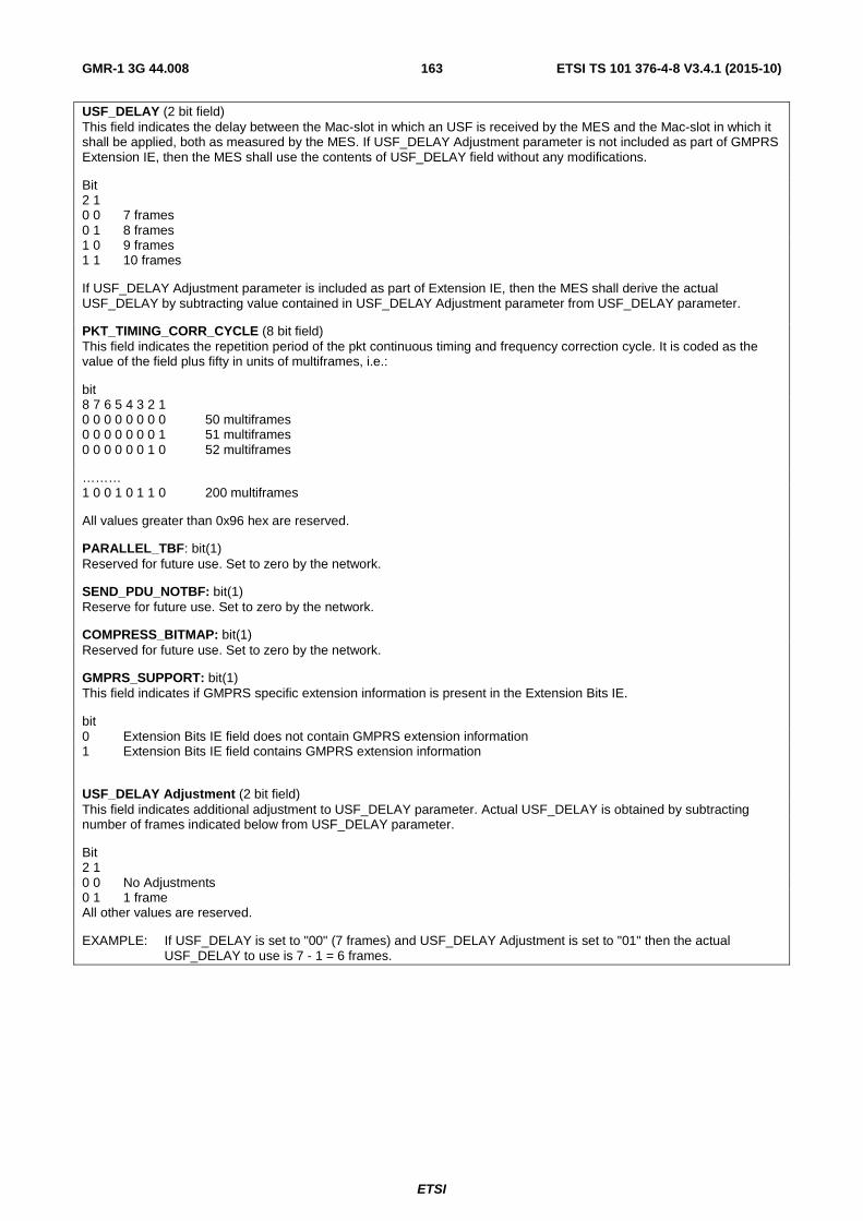
ETSI
ETSI TS 101 376-4-8 V3.4.1 (2015-10) 163GMR-1 3G 44.008
USF_DELAY (2 bit field) This field indicates the delay between the Mac-slot in which an USF is received by the MES and the Mac-slot in which it shall be applied, both as measured by the MES. If USF_DELAY Adjustment parameter is not included as part of GMPRS Extension IE, then the MES shall use the contents of USF_DELAY field without any modifications.
Bit 2 1 0 0 7 frames 0 1 8 frames 1 0 9 frames 1 1 10 frames
If USF_DELAY Adjustment parameter is included as part of Extension IE, then the MES shall derive the actual USF_DELAY by subtracting value contained in USF_DELAY Adjustment parameter from USF_DELAY parameter.
PKT_TIMING_CORR_CYCLE (8 bit field) This field indicates the repetition period of the pkt continuous timing and frequency correction cycle. It is coded as the value of the field plus fifty in units of multiframes, i.e.:
bit 8 7 6 5 4 3 2 1 0 0 0 0 0 0 0 0 50 multiframes 0 0 0 0 0 0 0 1 51 multiframes 0 0 0 0 0 0 1 0 52 multiframes
……… 1 0 0 1 0 1 1 0 200 multiframes
All values greater than 0x96 hex are reserved.
PARALLEL_TBF: bit(1) Reserved for future use. Set to zero by the network.
SEND_PDU_NOTBF: bit(1) Reserve for future use. Set to zero by the network.
COMPRESS_BITMAP: bit(1) Reserved for future use. Set to zero by the network.
GMPRS_SUPPORT: bit(1) This field indicates if GMPRS specific extension information is present in the Extension Bits IE.
bit 0 Extension Bits IE field does not contain GMPRS extension information 1 Extension Bits IE field contains GMPRS extension information
USF_DELAY Adjustment (2 bit field) This field indicates additional adjustment to USF_DELAY parameter. Actual USF_DELAY is obtained by subtracting number of frames indicated below from USF_DELAY parameter.
Bit 2 1 0 0 No Adjustments 0 1 1 frame All other values are reserved.
EXAMPLE: If USF_DELAY is set to "00" (7 frames) and USF_DELAY Adjustment is set to "01" then the actual USF_DELAY to use is 7 - 1 = 6 frames.

ETSI
ETSI TS 101 376-4-8 V3.4.1 (2015-10) 164GMR-1 3G 44.008
11.5.2.111a GMPRS BCCH options (Iu mode only)
The GMPRS BCCH Options information element is used to control a set of cell options related to GMPRS.
Table 11.49.9a: GMPRS BCCH options information element
< GMPRS BCCH Options IE >::= < Iu_MODE_NMO_SUPPORT: bit (1) > < T3168: bit(3)> < T3192: bit (3) > < T3202: bit (6) > < BS_CV_MAX: bit (9) > < USF_DELAY: bit (3) > < PKT_TIMING_CORR_CYCLE: bit (8) > < GRA_AND CELL UPDATE TIMER: bit (3) > <padding bits> ! < Distribution part error: bit (*) = < no string >> ;
Table 11.49.9b: GMPRS BCCH options information element details
Iu_MODE_NMO_SUPPORT (1 bit field) This parameter is used for determining network mode of operation for the 3G SGSN and the 3G MSC. The mobile earth station may assume that the network has set this field equally in all instances of this message.
Bit 0 Network Mode Operation I 1 Network Mode Operation II
T3168 (3 bit field) This field is the binary representation of the timeout value of timer T3168. Range: 0 to 7. The timeout value is given as follows:
3 2 1 0 0 0 3 000 ms 0 0 1 3 500 ms 0 1 0 4 000 ms 0 1 1 4 500 ms 1 0 0 5 000 ms 1 0 1 5 500 ms All other values are reserved. T3192 (3 bit field) This field is the binary representation of the timeout value of timer T3192. Range: 0 to 7. The timeout value is given as the binary value plus one in units of 500 millisecond
T3202 (6 bit field) This field is the binary representation of the timeout value of timer T3202. Range: 0 to 63. If the value is zero, the timeout is infinite. If the value is nonzero, the value represents the timeout in minutes.
BS_CV_MAX (9 bit field) This field is the binary representation of the parameter BS_CV_MAX. Range: 0 to 512.
USF_DELAY (3 bit field) This field contains the value used by the MES to derive the uplink frame number in which the allocated USF is valid. See ETSI TS 101 376-5-7 [16]
bit 3 2 1 0 0 0 6 0 0 1 7 0 1 0 8 0 1 1 9 1 0 0 10 All remaining values are reserved

ETSI
ETSI TS 101 376-4-8 V3.4.1 (2015-10) 165GMR-1 3G 44.008
PKT_TIMING_CORR_CYCLE (8 bit field) This field indicates the repetition period of the pkt continuous timing and frequency correction cycle. It is coded as the value of the field plus fifty in units of multiframes
8 7 6 5 4 3 2 1 0 0 0 0 0 0 0 0 50 multiframes 0 0 0 0 0 0 0 1 51 multiframes 0 0 0 0 0 0 1 0 52 multiframes
…..
1 0 0 1 0 1 1 0 200 Multiframes
All remaining values are reserved.
GRA_AND_CELL_UPDATE_TIMER (3 bit field) This field is the binary representation of GRA and CELL UPDATE TIMERs (T305).
bit 3 2 1 0 0 0 10 minutes 0 0 1 30 minutes 0 1 0 60 minutes 0 1 1 120 minutes (default value) 1 0 0 240 minutes 1 0 1 360 minutes 1 1 0 720 minutes 1 1 1 Infinity (no update)
11.5.2.112 Uplink PRACH channels (A/Gb mode only)
A bitmap indicating the location of the available PRACH channels within a subband. The most significant bit refers to the presence or absence of a PRACH channel at the lowest numbered 31,25 kHz subcarrier within the uplink frequency band. The value "1" indicates the presence of a PRACH channel; "0" indicates the absence of a PRACH channel. The number of bits set to "1" within Uplink PRACH Channels is always equal to the number of active PRACH channels specified in the PRACH_OVERLAY IE (see clause 11.5.2.118).
11.5.2.113 Void
11.5.2.114 Void
11.5.2.115 Void
11.5.2.116 Void
11.5.2.117 Void
11.5.2.118 PRACH overlay (A/Gb mode only)
This 3-bit field indicates whether PRACH overlay is supported, and if so, how many overlaid channels are supported. The number of channels supported is 1 plus the value of this field.
EXAMPLE: Bit 3 2 1 0 0 0 PRACH overlay not supported, only one channel 0 0 1 PRACH overlay supported, two channels 0 1 0 PRACH overlay supported, three channels 0 1 1 PRACH overlay supported, four channels 1 0 0 PRACH overlay supported, five channels 1 0 1 Reserved 1 1 0 Reserved

ETSI
ETSI TS 101 376-4-8 V3.4.1 (2015-10) 166GMR-1 3G 44.008
The particular 31,25 kHz subchannels within a subband that support PRACH arfFe indicated opinionative by the Uplink PRACH Channels IE defined in clause 11.5.2.112.
11.5.2.119 Uplink PRACH ARFCN (A/Gb mode only)
This 11-bit field is the ARFCN on which PRACH is transmitted by the mobile earth station.
11.5.2.120 Uplink PRACH MAC Slots Indicator (A/Gb mode only)
This 2-bit field indicates the pair of consecutive MAC slots on which the mobile earth station can transmit PRACH in a frame. The mobile earth station randomly chooses one MAC slot out of the two to transmit PRACH. The following table shows the value that the field can take and the corresponding MAC slots on which PRACH can be transmitted.
Table 11.49.10a: Uplink PRACH MAC Slots Indicator
Value
List of MAC slots on which PRACH can be
transmitted 0 0 and 1 1 2 and 3 2 4 and 5 3 6 and 7
11.5.2.121 GMPRS Resume Result (A/Gb mode only)
The GMPRS Resume Result IE gives the outcome of the GMPRS resume procedure. This IE is coded as shown in figure 11.51.8 and table 11.49.11. The GMPRS Resume Result is a Type 3 IE, 2 octets in length.
8 7 6 5 4 3 2 1 0 GMPRS Resume Result IEI octet 1
Spare Result octet 2
Figure 11.51.8: GMPRS Resume Result information element
Table 11.49.11: GMPRS Resume Result information element
Result is a 1 bit field 0: GMPRS services not successfully resumed 1: GMPRS services successfully resumed
11.5.2.122 GMPRS Resume Response Rest Octets (A/Gb mode only)
The GMPRS Resume Response Rest Octets IE contains only spare bits. This IE is coded as shown in figure 11.51.9. The GMPRS Resume Response Rest Octets IE is a Type 5 IE, 16 octets in length.
8 7 6 5 4 3 2 1 GMPRS Resume Response Rest Octets IEI octet 1
0 Spare
0 Spare
1 Spare
0 Spare
1 Spare
0 Spare
1 Spare
1 Spare octet 2*
0 Spare
0 Spare
1 Spare
0 Spare
1 Spare
0 Spare
1 Spare
1 Spare octet 3*
0 Spare
0 Spare
1 Spare
0 Spare
1 Spare
0 Spare
1 Spare
1 Spare octet n*
Figure 11.51.9: GMPRS Resume Response rest octets IE

ETSI
ETSI TS 101 376-4-8 V3.4.1 (2015-10) 167GMR-1 3G 44.008
11.5.2.123 Uplink PRACH Frequency Distance (A/Gb mode only)
This 2-bit field represents the difference between the uplink PDCH carrier frequency and the actual PRACH frequency in units of 31,25 kHz. The PRACH carrier location interpretation is as follows:
Table 11.49.12: Uplink PRACH Frequency Distance
Bits 1 0 PRACH carrier location 0 0 PRACH frequency = uplink PDCH carrier frequency 0 1 PRACH frequency = uplink PDCH carrier frequency + 31,25 kHz 1 1 PRACH frequency = uplink PDCH carrier frequency - 31,25 kHz 1 0 Reserved
Note that the computation of uplink PDCH carrier frequency at the MES utilizes the downlink ARFCN, frequency plan Id from the PCCCH list (see table 11.49.7) and the value of "uplink frequency distance" parameter from the last received PACKET UPLINK ASSIGNMENT or IMMEDIATE ASSIGNMENT message.
11.5.2.124 PRACH Frame Periodicity (A/Gb mode only)
This 2-bit field indicates the PRACH MAC slots periodicity in terms of frames. The mobile earth station is allowed to transmit on PRACH MAC slots only in those frames as given in table 11.49.13.
Table 11.49.13: PRACH Frame Periodicity
Value PRACH Frame Periodicity 0 Every Frame 1 Once every two frames on frames satisfying (FN mod 2) = 0 2 Once every two frames on frames satisfying (FN mod 2) = 1 3 Reserved
where:
• "FN" represents Frame Number at the satellite.
• "mod" represents modulo.
11.5.2.125 Packet Immediate Assignment Type 4 Parameters (Iu mode only)
Packet Immediate Assignment Type 4 Parameters IE defines parameters for one or more TBFs. This IE is defined in compact notation. The total length of this IE is 100 bits, spare bits are added at end of this IE to align this to the maximum length.
Table 11.49.14a: Packet Immediate Assignment Type 4 Parameters
<Packet Immediate Assignment Type 4 Parameters>::= <Power Control Parameter: bit(6)> 0 | 1 <PDCH Channel MCS Info: <PDCH MCS IE>> -- Used when uplink allocation is on PDCH 0 | 1 <Downlink MAC Slot Allocation: bit (8)> -- Used when downlink is on PDCH <TBF1: < TBF Assignment Struct>> 0 | 1 <TBF2: <TBF Assignment Struct> <Uplink Frequency Allocation: bit(1)> <Frequency Allocation: <Frequency Allocation IE>> <Color Code Usage: bit(1)> -- 0 the MES shall apply SB_MASK of eight zeros. 1 the MES shall apply SB_MASK broadcast in system information 0 | 1 <MAC_FORWARD_TS_OFFSET: bit(2)> --see ETSI TS 101 376-5-7 [16] for definition <USF_DELAY: bit(3)> -- see ETSI TS 101 376-5-7 [16] for definition 0 | 1 <MAC_RETURN_TS_OFFSET: bit(5)> --see ETSI TS 101 376-5-7 [16] for definition <Spare Padding>;

ETSI
ETSI TS 101 376-4-8 V3.4.1 (2015-10) 168GMR-1 3G 44.008
< TBF Assignment Struct>::= 0 < Uplink PDCH TBF Allocation: <Uplink TBF Allocation Struct>> | 10 < Uplink DCH TBF Allocation: < UL DCH TBF Allocation Struct>> | 110<Uplink and Downlink DCH TBF Allocation: < ULDL DCH TBF Allocation Struct> | null|0 bit** = <no string>; <Uplink TBF Allocation Struct>::= -- Dynamic Allocation < Uplink TFI: bit(8) 0 | 1 < Uplink Status Flag: bit (8) > -- 0 indicates USF has the same value as TFI < RB Id: bit (5) > < Return Frequency Set: bit(1)>; < UL DCH TBF Allocation Struct >::= < Channel Info: <Channel Info IE>> < Power Control Synch Offset: bit (2)> < DCH Channel MCS Info: <DCH MCS IE> 0 <Uplink MAC Slot Allocation: bit(8)> | 1< Uplink Slot Allocation: <Slot Allocation IE>> < RB Id: bit (5) > ; < ULDL DCH TBF Allocation Struct >::= < Channel Info: <Channel Info IE>> < Power Control Synch Offset: bit (2)> -- Applies only to uplink DCH < DCH Channel MCS Info: <DCH MCS IE> 0<Downlink MAC Slot Allocation: bit(8)> | 1< Downlink Slot Allocation: <Slot Allocation IE>> 0 <Uplink MAC Slot Allocation: bit(8)> | 1 < Uplink Slot Allocation: <Slot Allocation IE>> < RB Id: bit (5) > ;
Table 11.49.14b: Packet Immediate Assignment Type 4 Parameters Details
Power Control Parameter (6 bit field) This field is defined in ETSI TS 101 376-4-12 [20]. The parameter specifies the initial value of the power control field (PAR value) to be applied by the MES for the channel assignment. PDCH Channel MCS Info PDCH Channel MCS is defined in ETSI TS 101 376-4-12 [20]. DCH Channel MCS Info DCH Channel MCS is defined in ETSI TS 101 376-4-12 [20]. Frequency Allocation This field is defined in ETSI TS 101 376-4-12 [20]. Channel Info This field is defined in ETSI TS 101 376-4-12 [20]. Power Control Synch Offset (2 bit field) This field is defined in ETSI TS 101 376-4-12 [20]. This field is applicable only to the uplink DCH. Downlink MAC Slot Allocation This field is defined in ETSI TS 101 376-4-12 [20]. Uplink MAC Slot Allocation This field is defined in ETSI TS 101 376-4-12 [20]. Slot Allocation This field is defined in ETSI TS 101 376-4-12 [20]. Uplink TFI (8 bit field) This field is defined in ETSI TS 101 376-4-12 [20]. Uplink Status Flag (8 bit field) This field is defined in ETSI TS 101 376-4-12 [20]. If field is not present, then the USF value shall be the same as the value Uplink TFI. RB Id (5 bit field) The RB Id indicates the identification number for the radio bearer. See ETSI TS 101 376-4-13 [25]. Return Frequency Set (1 bit field) This field is indicates the uplink frequency set on which the uplink resources are allocated. This is defined in ETSI TS 101 376-4-12 [20]. Uplink Frequency Allocation (1 bit) 0: Uplink ARFCN in Frequency Allocation is applicable for PDCH allocations. 1: Uplink ARFCN for PDCH allocations specified in PDCH Organization message or PDCH Uplink Organization IE (see ETSI TS 101 376-4-12 [20]).

ETSI
ETSI TS 101 376-4-8 V3.4.1 (2015-10) 169GMR-1 3G 44.008
11.5.2.126 3G Neighbour Cell Description (Iu mode only)
3G Neighbour cell description contains information on the cells of a terrestrial 3G network that are present within the spotbeam. These frequencies may be used in the cell selection procedure, see ETSI TS 125 304 [32]. The total length of this IE is 47 bits. If all bits are not used, then IE shall be padded with spare bits.
Table 11.49.15a: 3G Neighbour Cell Description
< 3G Neighbour Cell Description>::= 0 | 1 < Bandwidth_FDD: bit (3) > 1 < Repeated UTRAN FDD Neighbour Cells: Repeated UTRAN FDD Neighbour Cells struct >> ** 0 <Spare bits>; < Repeated UTRAN FDD Neighbour Cells struct >::= < FDD-ARFCN: bit (14) > < FDD_Indic0: bit > < NR_OF_FDD_CELLS: bit (5) > < FDD_CELL_INFORMATION Field: bit(p(NR_OF_FDD_CELLS)) > ; -- p(x) defined in table 11.2.9b.2.a/ETSI TS 144 060 [35]
Table 11.49.15b: 3G Neighbour Cell Description Details
See ETSI TS 144 060 [35] for description of fields in 3G Neighbour Cell Description
11.5.2.127 Paging Request Type 4 Parameters (Iu mode only)
The Paging Request Type 4 parameter IE contains paging information for one or more MES. The maximum length of this IE is 164 bits, spare bits shall be added at end of this IE to align this to the maximum length.
Table 11.49.16a: Paging Request Type 4 Parameters
<Paging Request Type 4 Parameters>::= 1 < Repeated Iu Page info: < Repeated Iu Page info struct > > ** 0 <Spare Padding>; < Repeated Iu Page info struct >::= 0 < G-RNTI: bit(32) > 0 | 1 < Page info struct: < Page info struct > > -- only included for a CN page | 1 00 < Reserved: bit (32) > | 01 < PTMSI: bit (32) > | 11 < Length of Mobile Identity contents: bit (4) > < Mobile Identity: octet (val (Length of Mobile Identity contents)) > < Page info struct: < Page info struct > > ! < Ignore: bit (*) = <no string> > ; < Page info struct >:: = < PAGING CAUSE: bit (3) > < CN DOMAIN IDENTITY: bit (2) > 0 | 1 < Paging Record Type Identifier: bit (2) > ;

ETSI
ETSI TS 101 376-4-8 V3.4.1 (2015-10) 170GMR-1 3G 44.008
Table 11.49.16b: Paging Request Type 4 Parameters Details
G-RNTI (32 bits) The G-RNTI field identifies the MES within the network when an RRC connection exists between this MES and network. G-RNTI is defined in ETSI TS 101 376-4-13 [25]. REPEATED IU PAGE INFO STRUCT The Repeated Iu Page info struct is repeated as many times as required to fulfil the number of wanted paged mobiles. If Paging Request message is used with only G-RNTIs, the field can be repeated up to four times within one message. If the Paging Request Message is used with only P-TMSIs, the field can be repeated up to three times. If the Paging Request Message is used with only IMSIs, the field can be repeated up to two times within one message. CN DOMAIN IDENTITY (2 bit field) The CN Domain Identity field indicates the domain of the core network from which the MES is paged, as defined in ETSI TS 101 376-4-13 [25]. Bit 2 1 0 1 PS domain All other values are reserved PAGING CAUSE (3 bits field) The Paging Cause field indicates the cause for paging, as defined in ETSI TS 101 376-4-13 [25]. bit 3 2 1 0 0 0 Terminating Conversational Call 0 0 1 Terminating Streaming Call 0 1 0 Terminating Interactive Call 0 1 1 Terminating Background Call 1 0 0 Terminating High Priority Signalling 1 0 1 Terminating Low Priority Signalling 1 1 0 Terminating - cause unknown 1 1 1 Reserved PAGING RECORD TYPE IDENTIFIER (2 bits field) This IE is for FFS.
11.5.2.128 Position Verification Notify Type 2 Parameters (Iu mode only)
The Position Verification Notify Type 2 parameter IE indicates if the position reported in position verification request is acceptable or not with respect to the current spotbeam. The IE also allows the network to redirect the MES, if necessary, to a particular RA where multiple RAs are defined within the current or alternate spot beam. In addition this IE may also contain updates information on idle mode position reporting. The maximum length of this IE is 116 bits, spare bits shall be added at end of this IE to align this to the maximum length.

ETSI
ETSI TS 101 376-4-8 V3.4.1 (2015-10) 171GMR-1 3G 44.008
Table 11.49.17a: Position Verification Notify Type 2 Parameters
<Position Verification Notify Type 2 Parameters>::= 0 -- Reported position acceptable within current spotbeam 0 | 1 < Directed RAC: < Directed RAC IE >> 0 | 1 < CN Information Info: < CN Information Info IE >> 0 | 1 < Idle Mode Position Update Info: <Position Update Information IE>> | 1 -- Reported position not acceptable within current spotbeam 0 | 1 <Alternate Spotbeam Information: < BCCH Carrier IE>> 0 | 1 < Directed RAC: < Directed RAC IE >> <Spare Padding>; Directed RAC This IE is defined in clause 11.5.2.129. The IE shall be included by the network when the MES performs the position verification procedure while in RRC Idle mode (as indicated by the MES RRC Indicator within the CHANNEL REQUEST TPYE 3 message) or when the MES is required to enter RRC idle mode for accessing an alternate spotbeam. CN Information Info This IE is defined in ETSI TS 101 376-4-13 [25]. The IE shall be included by the network only when a change of RA is required when the MES performs the position verification procedure while in RRC connected (GRA_PCH) mode (as indicated by the MES RRC Mode Indicator being set within the CHANNEL REQUEST TPYE 3 message). If the CN Information Info IE is provided to the MES, the MES shall respond to the received POSITION VERIFICATION NOTIFY TYPE 2 message in the same way as if an RRC CONNECTION RELEASE message had been received from the network with a Cause equal to "Directed signalling connection re-establishment" (see ETSI TS 101 376-4-13 [25]) and with the provided CN Information Info IE. Idle Mode Position Update Info This IE contains value part of Position Update Information IE defined in clause 11.5.2.54. Alternate Spotbeam Information This IE contains value part of BCCH Carrier IE defined in clause 11.5.2.55.
11.5.2.129 Directed RAC (Iu mode only)
The Directed RAC is used to provide the MES with the Routing Area Code (RAC) that is associated with the MES current position location. The IE is relevant for maintaining GMM functionality and allows the MES to update the NAS Routing Area Identifier (RAI) based on the network-provided RAC. The IE is used as part of the RA Redirect mechanism to allow support for multiple, position-defined RAs within a given spot beam mobility area.
The content of the Directed RAC information element is coded as shown in figure 11.5.2.129 and table 11.5.2.129. The length of this element is two octets.
8 7 6 5 4 3 2 1
Directed RAC IEI octet 1
RAC octet 2
Figure 11.5.2.129: Directed RAC information element
Table 11.5.2.129: Directed RAC information element
RAC, Routing Area Code (8 bit field) This field is the binary representation of the Routing Area Code, see ETSI TS 123 003 [28]. Bit 8 in octet 2 is the most significant bit and bit 1 in octet 2 is the least significant bit.
11.5.2.130 Packet Immediate Assignment Type 5 Parameters (Iu mode only)
The Packet Immediate Assignment Type 5 Parameters IE shall include a single, network-to-MES equivalent RRC message with message type identified in accordance with ETSI TS 101 376-4-13 [25] (see clause 9.2.1.2). The maximum length of this IE is 132 bits, spare bits shall be added at end of this IE to align this to the maximum length.
The current version of the specification shall support the sending of the RRC GRA UPDATE CONFIRM message within the Packet Immediate Assignment Type 5 Parameters IE with coding according to table 11.5.2.130.

ETSI
ETSI TS 101 376-4-8 V3.4.1 (2015-10) 172GMR-1 3G 44.008
Table 11.5.2.130: Packet Immediate Assignment Type 5 Parameters
< Packet Immediate Assignment Type 5 Parameters >::= 0 <RRC Message: <RRC Message Struct>> <Spare Padding> ; <RRC Message Struct>::= < MESSAGE_TYPE: 00000101 ><RRC GRA Update Confirm Message Struct>> ! < Unknown message type: bit (8) = < no string > ; < RRC GRA Update Confirm Message Struct>::= 0 | 1 < New G-RNTI: < G-RNTI IE >> 0 | 1 < GRA Identity: < GRA Identity IE >> ! < Content part error: bit (*) = < no string > > ; New G-RNTI This IE assigns a new G-RNTI to the MES. The G-RNTI IE is defined in ETSI TS 101 376-4-13 [25]. GRA Identity This IE is defined in ETSI TS 101 376-4-13 [25].
11.5.2.131 CN Information Info
The CN Information Info IE is type 3 IE 5 octets in length. The value part of CN Information Info IE is defined in ETSI TS 101 376-4-13 [25].
8 7 6 5 4 3 2 1
CN Information Info IEI octet 1
CN Information Info octet 2-5
11.5.3 Mobility management IEs
Same as clause 11.5.3 of ETSI TS 101 376-4-8 (Release 1) [19].
11.5.4 Call control IEs (A/Gb mode only)
Same as clause 11.5.4 of ETSI TS 101 376-4-8 (Release 1) [19].
11.5.5 GMM IEs
11.5.5.1 Attach request
Same as clause 10.5.5.1 of ETSI TS 124 008 [18].
11.5.5.2 Attach type
Same as clause 10.5.5.2 of ETSI TS 124 008 [18].
11.5.5.3 Ciphering algorithm
Same as clause 10.5.5.3 of ETSI TS 124 008 [18].
11.5.5.4 Void
11.5.5.5 Detach type
Same as clause 10.5.5.5 of ETSI TS 124 008 [18].
11.5.5.6 DRX parameter
Same as clause 10.5.5.6 of ETSI TS 124 008 [18].

ETSI
ETSI TS 101 376-4-8 V3.4.1 (2015-10) 173GMR-1 3G 44.008
11.5.5.7 Force to standby
Same as clause 10.5.5.7 of ETSI TS 124 008 [18].
11.5.5.8 PTMSI signature
Same as clause 10.5.5.8 of ETSI TS 124 008 [18].
11.5.5.9 Identity type 2
Same as clause 10.5.5.9 of ETSI TS 124 008 [18].
11.5.5.10 IMEISV request
Same as clause 10.5.5.10 of ETSI TS 124 008 [18].
11.5.5.11 Receive N-PDU Numbers list
Same as clause 10.5.5.11 of ETSI TS 124 008 [18].
11.5.5.12 MS network capability
Same as clause 10.5.5.12 of ETSI TS 124 008 [18].
11.5.5.12a MS Radio Access capability (A/Gb mode only)
The purpose of the MS RA capability information element is to provide the radio part of the network with information concerning radio aspects of the mobile earth station. The contents might affect the manner in which the network handles the operation of the mobile earth station.
The MS RA capability is a type 4 information element, with a maximum length of 14 octets.
The value part of a MS RA capability information element is coded a shown in table 10.5.146 of ETSI TS 124 008 [18].
• SEMANTIC RULE: Only the GMPRS access type technology is supported.
• Error handling: If a received Access Technology Type is unknown to the receiver, it shall ignore all the corresponding fields.
• If within a known Access Technology Type a receiver recognizes an unknown field it shall ignore it.
• See more details about error handling of MS radio access capability in ETSI TS 148 018 [33].
Table 11.49.14: Mobile Station Radio Access Capability IE
< MS Radio Access capability IE >::= <MS Radio Access capability IEI: 00100100 > <Length of MS RA capability: <octet>> -- length in octets of MS RA capability value part and spare bits <MS RA capability value part: < MS RA capability value part struct >> <spare bits>** ; -- may be used for future enhancements <MS RA capability value part struct >::= --recursive structure allows any number of Access technologies < Access Technology Type: bit (4) > < Access capabilities: <Access capabilities struct> > 0 | 1 <MS RA capability value part struct> ; < Access capabilities struct >::= < Length: bit (7) > -- length in bits of Content and spare bits <Access capabilities: <Content>> <spare bits>** ; -- expands to the indicated length
may be used for future enhancements
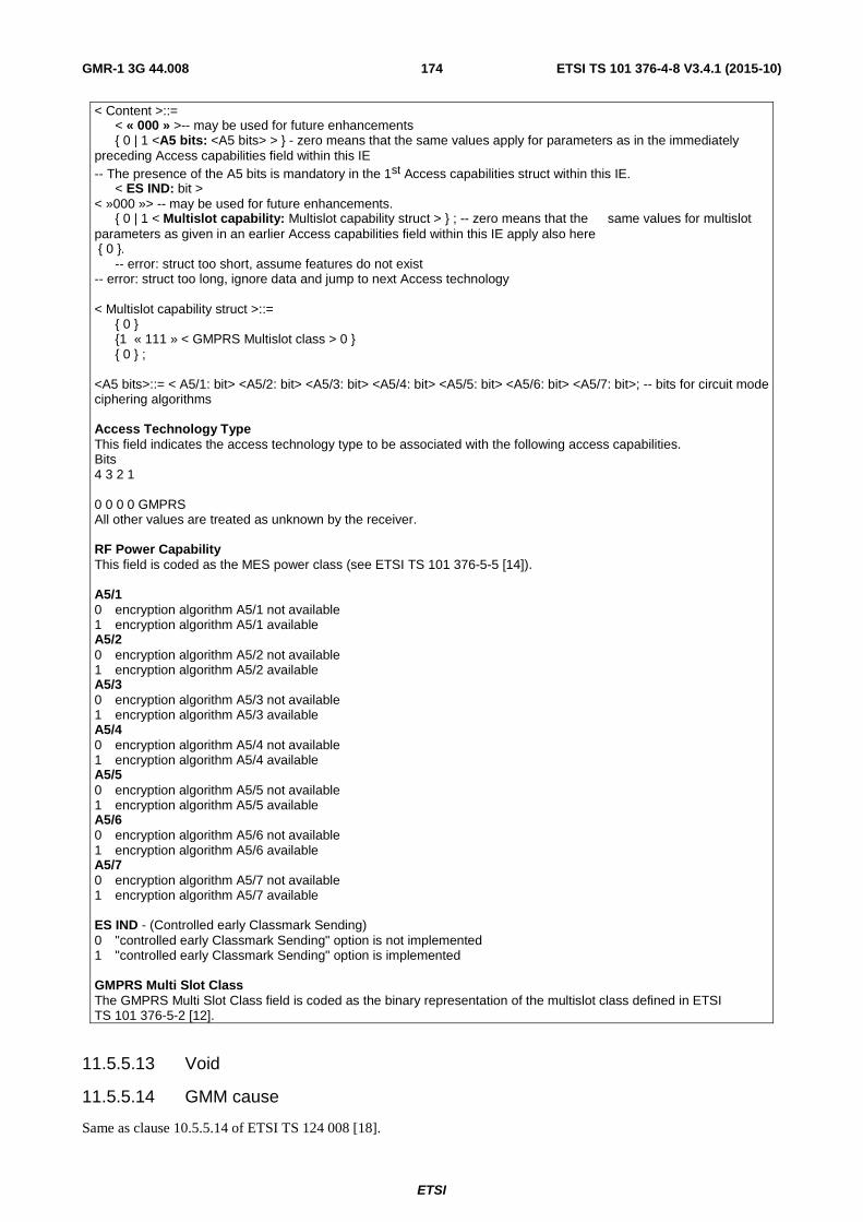
ETSI
ETSI TS 101 376-4-8 V3.4.1 (2015-10) 174GMR-1 3G 44.008
< Content >::= < « 000 » >-- may be used for future enhancements 0 | 1 <A5 bits: <A5 bits> > - zero means that the same values apply for parameters as in the immediately preceding Access capabilities field within this IE -- The presence of the A5 bits is mandatory in the 1st Access capabilities struct within this IE. < ES IND: bit > < »000 »> -- may be used for future enhancements. 0 | 1 < Multislot capability: Multislot capability struct > ; -- zero means that the same values for multislot parameters as given in an earlier Access capabilities field within this IE apply also here 0 . -- error: struct too short, assume features do not exist -- error: struct too long, ignore data and jump to next Access technology < Multislot capability struct >::= 0 1 « 111 » < GMPRS Multislot class > 0 0 ; <A5 bits>::= < A5/1: bit> <A5/2: bit> <A5/3: bit> <A5/4: bit> <A5/5: bit> <A5/6: bit> <A5/7: bit>; -- bits for circuit mode ciphering algorithms Access Technology Type This field indicates the access technology type to be associated with the following access capabilities. Bits 4 3 2 1 0 0 0 0 GMPRS All other values are treated as unknown by the receiver. RF Power Capability This field is coded as the MES power class (see ETSI TS 101 376-5-5 [14]). A5/1 0 encryption algorithm A5/1 not available 1 encryption algorithm A5/1 available A5/2 0 encryption algorithm A5/2 not available 1 encryption algorithm A5/2 available A5/3 0 encryption algorithm A5/3 not available 1 encryption algorithm A5/3 available A5/4 0 encryption algorithm A5/4 not available 1 encryption algorithm A5/4 available A5/5 0 encryption algorithm A5/5 not available 1 encryption algorithm A5/5 available A5/6 0 encryption algorithm A5/6 not available 1 encryption algorithm A5/6 available A5/7 0 encryption algorithm A5/7 not available 1 encryption algorithm A5/7 available ES IND - (Controlled early Classmark Sending) 0 "controlled early Classmark Sending" option is not implemented 1 "controlled early Classmark Sending" option is implemented GMPRS Multi Slot Class The GMPRS Multi Slot Class field is coded as the binary representation of the multislot class defined in ETSI TS 101 376-5-2 [12].
11.5.5.13 Void
11.5.5.14 GMM cause
Same as clause 10.5.5.14 of ETSI TS 124 008 [18].

ETSI
ETSI TS 101 376-4-8 V3.4.1 (2015-10) 175GMR-1 3G 44.008
11.5.5.15 Routing Area Identification (RAI)
Same as clause 10.5.5.15 of ETSI TS 124 008 [18].
11.5.5.16 Void
11.5.5.17 Update result
Same as clause 10.5.5.17 of ETSI TS 124 008 [18].
11.5.5.18 Update type
Same as clause 10.5.5.18 of ETSI TS 124 008 [18].
11.5.5.19 A&C reference number
Same as clause 10.5.5.19 of ETSI TS 124 008 [18].
11.5.6 SM IEs
Same as clause 10.5.6 of ETSI TS 124 008 [18].
The following element is not currently supported in GMR-1:
• AA Deactivation Cause.
11.5.7 GPRS Common Information Elements
Same as clause 10.5.7 of ETSI TS 124 008 [18].
12 List of system parameters
12.0 General The description of timers in this clause should be considered a brief summary. The details are provided in clauses 3 to 6, which should be considered the definitive descriptions.
12.1 Timers and counters for radio resource management
12.1.1 Timers on the MES side
T3122: This timer is used during random access, after the receipt of an IMMEDIATE ASSIGNMENT REJECT message. The Wait timer is used by the MES to extend the access time period. Its value is indicated by the network in the IMMEDIATE ASSIGNMENT REJECT message. Its value is given by the network in the IMMEDIATE ASSIGNMENT REJECT message.
T3126: This timer is started after sending a CHANNEL REQUEST message during an immediate assignment procedure. This timer is also started after sending a CHANNEL REQUEST TYPE 2 message during an GMPRS suspend procedure. Its purpose is to detect the lack of an answer from the network. It is stopped upon receipt of an IMMEDIATE ASSIGNMENT message or an IMMEDIATE ASSIGNMENT REJECT message. At its expiry, another CHANNEL REQUEST (or CHANNEL REQUEST TYPE 2 if the access was for GMPRS suspend procedure) message is sent if the maximum count has not been achieved or else the immediate assignment procedure is aborted.
T3110: This timer is used to delay channel deactivation after receipt of a CHANNEL RELEASE. Its purpose is to allow time for disconnection of the main signalling link. Its value is set such that the DISC frame is sent twice in case of no answer from the network. It should be chosen to obtain a good probability of normal termination (i.e. no time out of T3109) of the channel release procedure.

ETSI
ETSI TS 101 376-4-8 V3.4.1 (2015-10) 176GMR-1 3G 44.008
T3112: This timer is used when the MES receives an alert message. It is the maximum amount of time available to the MES to read the BCCH and send in a CHANNEL REQUEST message answering the alert. This value is broadcast by the network over the BCCH. This is referred to as Alert timer. The value of this timer is also an upper limit on the MES to obtain the current GPS position, if the current position is needed in the CHANNEL REQUEST in response to alerting.
T3114: The value of this timer is an upper limit on the MES to obtain the current GPS position if the current position is needed in the CHANNEL REQUEST message in response to paging. This is referred to as Page timer.
T3115: The Pause timer is used by the MES to extend the access time period. Its value is broadcast by the network with the BCCH information.
T3118: The RACH Position timer is used by the MES to calculate the current GPS position, if not already available, before sending a message on the RACH channel, in a spot beam where position is required for access. Its value is broadcast over the BCCH.
T3119: The GPS Update timer is used by the MES to update its GPS position in idle mode and in-call. It is broadcast over the BCCH and may be overridden for a particular MES by a value provided in IMMEDIATE ASSIGNMENT or IMMEDIATE ASSIGNMENT REJECT message.
T3117: This timer is used by the MES to wait for a response to its updated position report to the network, which is transmitted in unacknowledged mode. This timer should be large enough to account for the round-trip delay and processing delay at the network. Because this timer triggers retransmission, a small value could lead to excessive load on the signalling channel.
T3127: This timer is started after sending an EXTENDED CHANNEL REQUEST message during an immediate assignment procedure. Its purpose is to detect the lack of an answer from the network. It is stopped upon receipt of an EXTENDED IMMEDIATE ASSIGNMENT message or an EXTENDED IMMEDIATE ASSIGNMENT REJECT message. At its expiry, the immediate assignment procedure is aborted.
T3142: This timer is used during packet access on CCCH, after the receipt of an IMMEDIATE ASSIGNMENT REJECT TYPE 1 message with reject cause "lack of resources". The value of this timer shall be given by the network in IMMEDIATE ASSIGNMENT REJECT TYPE 1 message.
T3144: This timer is used during packet access on CCCH, after the receipt of an IMMEDIATE ASSIGNMENT REJECT TYPE 1 or TYPE 3 or TYPE 4 message with reject cause "non-availability of service". The value of this timer shall be 20 minutes.
T3146: This timer is started after sending CHANNEL REQUEST TYPE 1 or TYPE 3 message during a packet access procedure. It is stopped at receipt of an IMMEDIATE ASSIGNMENT (TYPE 2 or TYPE 3 or TYPE4) message. At its expiry, another CHANNEL REQUEST TYPE 1 or TYPE 3 message is sent if the maximum count has not been reached or else the immediate assignment procedure is aborted.
T3147: This timer is started on receiving IMMEDIATE ASSIGNMENT TYPE 4 specifying resource allocation on shared channels but without uplink frequency information. It is stopped at receipt PDCH ORGANIZATION message from the network. At its expiry, immediate assignment procedure is aborted and upper layers are informed on failure to access the network.
T3190: This timer is used during packet downlink assignment on CCCH. It is started at the receipt of an IMMEDIATE ASSIGNMENT TYPE 3 message. It is stopped at the receipt of a RLC/MAC lock on the assigned temporary block flow, see ETSI TS 101 376-4-12 [20]. At expiry, the mobile earth station returns to the packet idle mode. The value of the timer is 5 seconds.
T3333: This timer is started on receipt of an IMMEDIATE ASSIGNMENT REJECT message with reject cause non-availability of satellite resources. While this timer is running, the mobile shall remain in idle mode and is not permitted to initiate an access procedure in this spot-beam.
T3202: As defined in ETSI TS 101 376-4-12 [20]. T3208: As defined in ETSI TS 101 376-4-12 [20]. T3196: As defined in ETSI TS 101 376-4-12 [20].

ETSI
ETSI TS 101 376-4-8 V3.4.1 (2015-10) 177GMR-1 3G 44.008
12.1.2 Timers on the network side
T3101: This timer is started when a channel is allocated with an IMMEDIATE ASSIGNMENT message. It is stopped when the MES has correctly seized the channels. Its value is network-dependent. NOTE 1: It could be higher than the maximum time for an L2 establishment attempt.
T3103: This timer is started by the sending of a HANDOVER message and is stopped when the MES has correctly seized the new channel. Its purpose is to limit the time required to perform the handover. Its value is network-dependent. NOTE 2: It could be higher than the transmission time of the HANDOVER COMMAND message in unacknowledged mode with the required success probability plus the maximum duration of an attempt to establish a data link multiframe mode.
T3107: This timer is started by sending an ASSIGNMENT COMMAND 1 message in an MES-to-GS call and is normally stopped when the MES has correctly seized the new channels. Its purpose is to keep the old channel long enough for the MES to be able to return to the old channels and to release the channels if the MES is lost. Its value is network-dependent. NOTE 3: It could be higher than the maximum transmission time of the ASSIGNMENT COMMAND 1 message plus twice the maximum duration of an attempt to establish a data link multiframe mode.
T3108: This timer is started by sending an ASSIGNMENT COMMAND 2 message in an MES-to-MES call and is normally stopped when the MES has correctly seized the new channels. Its purpose is to keep the old channel long enough for the MES to be able to return to the old channels, and to release the channels if the MES is lost. Its value is network-dependent. NOTE 4: It could be higher than the maximum transmission time of the ASSIGNMENT COMMAND 2 message plus twice the maximum duration of an attempt to establish a TACCH multiframe mode.
T3109: This timer is started when a lower layer failure is detected by the network when it is not engaged in an RF procedure. It is also used in the channel release procedure. Its purpose is to release the channels in case of loss of communication. Its value is network-dependent. NOTE 5: Its value should be large enough to ensure that the mobile earth station detects a radio link failure.
T3111: This timer is used to delay the channel deactivation after disconnection of the main signalling link. Its purpose is to allow time for possible repetition of the disconnection. Its value is equal to the value of T3110.
T3113: In A/Gb mode, this timer is started when the network has sent a PAGING REQUEST message and is stopped when the network has received the PAGING RESPONSE message. In Iu mode, this timer is used when stateful paging procedure is used. This timer is started when the network has sent PAGING REQUEST TYPE 4 message and is stopped when the network has received a request for Cell Update from the MES. See ETSI TS 101 376-4-13 [25] for Cell Update procedure. Its value is network-dependent. NOTE 6: The value could allow for repetition of the CHANNEL REQUEST message and the requirements associated with T3101.
THPA: Timer in alert mode on the network side, when network is operating in A/Gb mode. This is started when an ALERT REQUEST message is sent by the network to an MES. Its value is network-dependent. At the expiry of this timer, the alerting procedure is aborted at the network. This timer is stopped when a PAGING RESPONSE message corresponding with the ALERT REQUEST message sent is received.
T3141: This timer is started when a temporary block flow is allocated with an IMMEDIATE ASSIGNMENT (TYPE 2 or TYPE 3) message during a packet access procedure. It is stopped when the network receives a packet from the mobile earth station on the assigned temporary block flow. Its value is network dependent.
TUSF: This timer is started when the network has sent an IMMEDIATE ASSIGNMENT TYPE 2 or TYPE 4 message to MES during packet access procedures. At the expiry of this timer network starts scheduling USF for that MES. This timer has to be based on estimate of processing delays in MES for decoding IMMEDIATE ASSIGNMENT TYPE 2 or TYPE 4 and listening to PDCH for its USF.
12.1.3 Other parameters
Same as clause 11.1.3 of ETSI TS 144 018 [17].
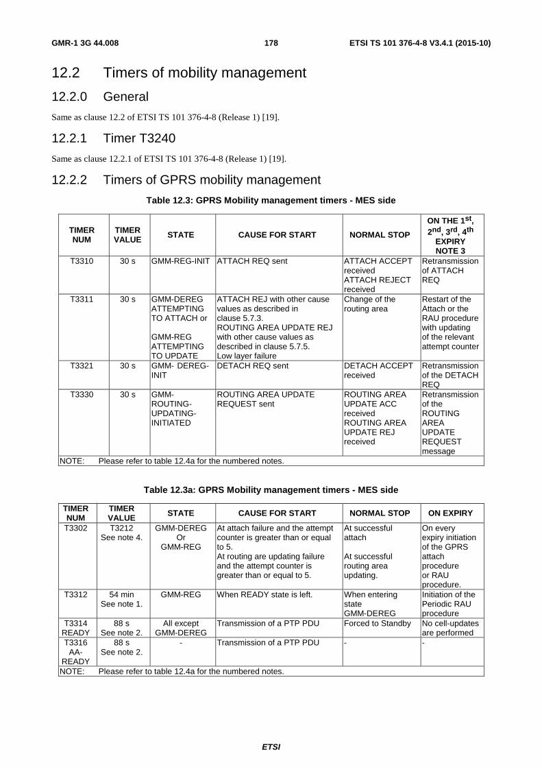
ETSI
ETSI TS 101 376-4-8 V3.4.1 (2015-10) 178GMR-1 3G 44.008
12.2 Timers of mobility management
12.2.0 General
Same as clause 12.2 of ETSI TS 101 376-4-8 (Release 1) [19].
12.2.1 Timer T3240
Same as clause 12.2.1 of ETSI TS 101 376-4-8 (Release 1) [19].
12.2.2 Timers of GPRS mobility management
Table 12.3: GPRS Mobility management timers - MES side
TIMER NUM
TIMER VALUE STATE CAUSE FOR START NORMAL STOP
ON THE 1st, 2nd, 3rd, 4th
EXPIRY NOTE 3
T3310 30 s GMM-REG-INIT ATTACH REQ sent ATTACH ACCEPT received ATTACH REJECT received
Retransmission of ATTACH REQ
T3311 30 s GMM-DEREG ATTEMPTING TO ATTACH or GMM-REG ATTEMPTING TO UPDATE
ATTACH REJ with other cause values as described in clause 5.7.3. ROUTING AREA UPDATE REJ with other cause values as described in clause 5.7.5. Low layer failure
Change of the routing area
Restart of the Attach or the RAU procedure with updating of the relevant attempt counter
T3321 30 s GMM- DEREG-INIT
DETACH REQ sent DETACH ACCEPT received
Retransmission of the DETACH REQ
T3330 30 s GMM-ROUTING-UPDATING-INITIATED
ROUTING AREA UPDATE REQUEST sent
ROUTING AREA UPDATE ACC received ROUTING AREA UPDATE REJ received
Retransmission of the ROUTING AREA UPDATE REQUEST message
NOTE: Please refer to table 12.4a for the numbered notes.
Table 12.3a: GPRS Mobility management timers - MES side
TIMER NUM
TIMER VALUE STATE CAUSE FOR START NORMAL STOP ON EXPIRY
T3302 T3212 See note 4.
GMM-DEREG Or
GMM-REG
At attach failure and the attempt counter is greater than or equal to 5. At routing are updating failure and the attempt counter is greater than or equal to 5.
At successful attach At successful routing area updating.
On every expiry initiation of the GPRS attach procedure or RAU procedure.
T3312 54 min See note 1.
GMM-REG When READY state is left. When entering state GMM-DEREG
Initiation of the Periodic RAU procedure
T3314 READY
88 s See note 2.
All except GMM-DEREG
Transmission of a PTP PDU Forced to Standby No cell-updates are performed
T3316 AA-
READY
88 s See note 2.
- Transmission of a PTP PDU - -
NOTE: Please refer to table 12.4a for the numbered notes.

ETSI
ETSI TS 101 376-4-8 V3.4.1 (2015-10) 179GMR-1 3G 44.008
Table 12.4: GPRS Mobility management timers - Network side
TIMER NUM
TIMER VALUE STATE CAUSE FOR START NORMAL STOP
ON THE 1st, 2nd, 3rd, 4th
EXPIRY NOTE 3 T3322 12 s GMM-DEREG-
INIT DETACH REQ sent DETACH ACCEPT
received Retransmission of ATTACH REQ
T3350 12 s GMM-COMMON-PROC-INIT
ATTACH ACC sent with P-TMSI and/or TMSI RAU ACCEPT sent with P-TMSI and/or TMSI P-TMSI REALLOC COMMAND sent
ATTACH COMPLETE received RAU COMPLETE received P-TMSI REALLOC COMPLETE received
Retransmission of the same message type, i.e. ATTACH ACCEPT, RAU ACCEPT or REALLOC COMMAND
T3360 12 s GMM-COMMON-PROC-INIT
AUTH AND CIPH REQUEST sent
AUTH AND CIPH RESPONSE received
Retransmission of AUTH and CIPH request
T3370 12 s GMM-COMMON-PROC-INIT
IDENTITY REQUEST sent IDENTITY RESPONSE received
Retransmission of IDENTITY REQUEST
NOTE: Please refer to table 12.4a for the numbered notes.
Table 12.4a: GPRS Mobility management timers - Network side
TIMER NUM
TIMER VALUE STATE CAUSE FOR START NORMAL STOP ON EXPIRY
T3313 See note 1 GMM-REG
Paging procedure initiated Paging procedure completed
Network dependent
T3314 READY
88 s See note 2
All except GMM-DEREG
Receipt of a PTP PDU Forced to Standby The network shall page the MES if a PTP PDU has to be sent to the MES
T3316 AA-
READY
88 s See note 2
- Receipt of a PTP PDU - -
Mobile Reacha
ble
Default 4 min
greater than T3312
All except GMM-DEREG
Change from READY to STANDBY state
PTP PDU received Network dependent but typically paging is halted on 1st expiry
NOTE 1: The value of this timer is network dependent. NOTE 2: The default value of this timer is used if neither the MES nor the Network sends another value, or if the
Network sends this value, in a signalling procedure. NOTE 3: Typically, the procedures are aborted on the fifth expiry of the relevant timer. Exceptions are described in
the corresponding procedure description. NOTE 4: T3302 is loaded with the same value which is used to load T3212.

ETSI
ETSI TS 101 376-4-8 V3.4.1 (2015-10) 180GMR-1 3G 44.008
12.2.3 Timers of GPRS session management
Table 12.5: GPRS Session management timers - MES side
TIMER NUM
TIMER VALUE STATE CAUSE FOR START NORMAL STOP
ON THE 1st, 2nd, 3rd, 4th
EXPIRY T3380 60 s PDP-ACTIVE-
PEND ACTIVATE PDP CONTEXT REQUEST sent
ACTIVATE PDP CONTEXT ACCEPT received ACTIVATE PDP CONTEXT REJECT received
Retransmission of ACTIVATE PDP CONTEXT REQ
T3390 16 s PDP-INACT-PEND
DEACTIVATE PDP CONTEXT REQUEST sent
DEACTIVATE PDP CONTEXT ACC received
Retransmission of DEACTIVATE PDP CONTEXT REQUEST
Table 12.5a: GPRS Session management timers - Network side
TIMER NUM
TIMER VALUE STATE CAUSE FOR START NORMAL STOP
ON THE 1st, 2nd, 3rd, 4th
EXPIRY T3385 16 s PDP-ACT-
PEND REQUEST PDP CONTEXT ACTIVATION sent
ACTIVATE PDP CONTEXT REQ received
Retransmission of REQUEST PDP CONTEXT ACTIVATION
T3386 16 s PDP- MOD-PEND
MODIFY PDP CONTEXT REQUEST sent
MODIFY PDP CONTEXT ACC received
Retransmission of MODIFY PDP CONTEXT REQ
T3395 16 s PDP-INACT-PEND
DEACTIVATE PDP CONTEXT REQUEST sent
DEACTIVATE PDP CONTEXT ACC received
Retransmission of DEACTIVATE PDP CONTEXT REQ
T3397 16 s PDP-INACT-PEND
DEACTIVATE AA PDP CONTEXT REQUEST sent
DEACTIVATE AA PDP CONTEXT
ACCEPT received
Retransmission of DEACTIVATE AA PDP CONTEXT REQUEST
NOTE: Typically, the procedures are aborted on the fifth expiry of the relevant timer. Exceptions are described in the corresponding procedure description.
12.3 Timers of circuit-switched call control Same as clause 12.3 of ETSI TS 101 376-4-8 (Release 1) [19].

ETSI
ETSI TS 101 376-4-8 V3.4.1 (2015-10) 181GMR-1 3G 44.008
Annex A (informative): Example of subaddress information element coding Same as annex A of ETSI TS 101 376-4-8 (Release 1) [19].

ETSI
ETSI TS 101 376-4-8 V3.4.1 (2015-10) 182GMR-1 3G 44.008
Annex B (informative): Void

ETSI
ETSI TS 101 376-4-8 V3.4.1 (2015-10) 183GMR-1 3G 44.008
Annex C (informative): Void

ETSI
ETSI TS 101 376-4-8 V3.4.1 (2015-10) 184GMR-1 3G 44.008
Annex D (informative): Void

ETSI
ETSI TS 101 376-4-8 V3.4.1 (2015-10) 185GMR-1 3G 44.008
Annex E (informative): Void

ETSI
ETSI TS 101 376-4-8 V3.4.1 (2015-10) 186GMR-1 3G 44.008
Annex F (informative): GMR specific cause values for radio resource management This annex is the same as annex F of ETSI TS 101 376-4-8 (Release 1) [19].

ETSI
ETSI TS 101 376-4-8 V3.4.1 (2015-10) 187GMR-1 3G 44.008
Annex G (informative): GMR specific cause values for session management This annex is the same as annex I of ETSI TS 101 376-4-8 (Release 1) [19].

ETSI
ETSI TS 101 376-4-8 V3.4.1 (2015-10) 188GMR-1 3G 44.008
Annex H (informative): Bibliography ETSI TS 101 376-3-7: "GEO-Mobile Radio Interface Specifications; Part 3: Network specifications; Sub-part 7: Discontinuous Reception (DRX); GMR-1 03.013".
NOTE: This is a reference to a GMR-1 Release 1 specification. See the introduction for more details.
ETSI TS 101 376-3-18: "GEO-Mobile Radio Interface Specifications; Part 3: Network specifications; Sub-part 18: Terminal-to-Terminal Call (TtT); GMR-1 03.296".
NOTE: This is a reference to a GMR-1 Release 1 specification. See the introduction for more details.
ETSI TS 101 376-3-20: "GEO-Mobile Radio Interface Specifications; Part 3: Network specifications; Sub-part 20: Technical realization of High-Penetration Alerting; GMR-1 03.298".
NOTE: This is a reference to a GMR-1 Release 1 specification. See the introduction for more details.
ETSI ETS 300 502 (Version 4.3.1): "European digital cellular telecommunications system (Phase 2); Teleservices supported by a GSM Public Land Mobile Network (PLMN) (GSM 02.03)".
ETSI ETS 300 559 (Version 4.10.0): "Digital cellular telecommunications system (Phase 2); Point-to-Point (PP) Short Message Service (SMS) support on mobile radio interface; (GSM 04.11)".
GPS Interface Control Document ICD-GPS-200C: "NAVSTAR GPS Space Segment/Navigation User Interfaces, Public Release Version". February 1995.
ETSI ETS 300 628: "European digital cellular telecommunications system (Phase 2); Alphabets and language-specific information (GSM Phase 2); (GSM 03.38)".
ETSI TS 101 351: "Digital cellular telecommunications system (Phase 2+); General Packet Radio Service (GPRS); Mobile Station - Serving GPRS Support Node (MS-SGSN) Logical Link Control (LLC) (3GPP TS 04.64 Release 1997)".
ETSI ETS 300 506: "Digital cellular telecommunications system (Phase 2) (GSM); Security aspects (GSM Phase 2); (GSM 02.09)".
ETSI TS 101 376-3-9: "GEO-Mobile Radio Interface Specifications; Part 3: Network specifications; Sub-part 9: Security related Network Functions; (GMR-1 03.020)".
NOTE: This is a reference to a GMR-1 Release 1 specification. See the introduction for more details.
ETSI TS 101 344: "Digital cellular telecommunications system (Phase 2+);General Packet Radio Service (GPRS); Service description; Stage 2 (3GPP TS 03.60 Release 1997)".
ETSI TS 100 974: "Digital cellular telecommunications system (Phase 2+);Mobile Application Part (MAP) specification (3GPP TS 09.02 Release 1997)".
ETSI TS 101 343: "Digital cellular telecommunications system (Phase 2+);General Packet Radio Service (GPRS); Base Station System (BSS) - Serving GPRS Support Node (SGSN); BSS GPRS Protocol (BSSGP) (3GPP TS 08.18 Release 1997)".

ETSI
ETSI TS 101 376-4-8 V3.4.1 (2015-10) 189GMR-1 3G 44.008
History
Document history
V1.1.1 March 2001 Publication
V1.2.1 April 2002 Publication
V1.3.1 February 2005 Publication
V2.1.1 March 2003 Publication
V2.2.1 March 2005 Publication
V2.3.1 August 2008 Publication
V3.1.1 July 2009 Publication
V3.2.1 February 2011 Publication
V3.3.1 December 2012 Publication
V3.4.1 October 2015 Publication