Embed Size (px)
Citation preview

ETSI TS 101 281 V1.2.1 (2001-11)
Technical Specification
Electromagnetic compatibilityand Radio spectrum Matters (ERM);
Terrestrial Flight Telecommunications System;Protocol to support GSM-A

ETSI
ETSI TS 101 281 V1.2.1 (2001-11)2
Reference DTS/ERM-RP05-021
Keywords GSM, TFTS, radio
ETSI
650 Route des Lucioles F-06921 Sophia Antipolis Cedex - FRANCE
Tel.: +33 4 92 94 42 00 Fax: +33 4 93 65 47 16
Siret N° 348 623 562 00017 - NAF 742 C
Association à but non lucratif enregistrée à la Sous-Préfecture de Grasse (06) N° 7803/88
Important notice
Individual copies of the present document can be downloaded from: http://www.etsi.org
The present document may be made available in more than one electronic version or in print. In any case of existing or perceived difference in contents between such versions, the reference version is the Portable Document Format (PDF).
In case of dispute, the reference shall be the printing on ETSI printers of the PDF version kept on a specific network drive within ETSI Secretariat.
Users of the present document should be aware that the document may be subject to revision or change of status. Information on the current status of this and other ETSI documents is available at
http://portal.etsi.org/tb/status/status.asp
If you find errors in the present document, send your comment to: [email protected]
Copyright Notification
No part may be reproduced except as authorized by written permission. The copyright and the foregoing restriction extend to reproduction in all media.
© European Telecommunications Standards Institute 2001.
All rights reserved.

ETSI
ETSI TS 101 281 V1.2.1 (2001-11)3
Contents
Intellectual Property Rights ................................................................................................................................6
Foreword.............................................................................................................................................................6
1 Scope ........................................................................................................................................................7
2 References ................................................................................................................................................7
3 Abbreviations ...........................................................................................................................................8
4 Overview ..................................................................................................................................................9 4.1 General ...............................................................................................................................................................9 4.2 Service definition ...............................................................................................................................................9 4.2.1 Services supported ........................................................................................................................................9 4.2.1.1 Services supported to fixed cabin equipment..........................................................................................9 4.2.1.2 Services supported to passengers' own mobile phones .........................................................................10 4.2.2 System architecture.....................................................................................................................................10
5 Functional specification (Fixed Cabin System) .....................................................................................12 5.1 Cabin communications system .........................................................................................................................12 5.1.1 General........................................................................................................................................................12 5.1.2 Passenger registration .................................................................................................................................12 5.1.2.1 Registration messages ...........................................................................................................................12 5.1.2.2 Registration buffer ................................................................................................................................13 5.1.2.3 Call alert routing to handset ..................................................................................................................13 5.1.2.4 CCS register of passengers....................................................................................................................13 5.1.3 Ground to air call alert ................................................................................................................................14 5.1.4 Call connect to GSS....................................................................................................................................15 5.1.5 Ground-to-air SMS delivery .......................................................................................................................15 5.2 Avionics termination ........................................................................................................................................15 5.2.1 General........................................................................................................................................................15 5.2.2 Location management.................................................................................................................................16 5.2.2.1 Location registration/update..................................................................................................................16 5.2.2.2 Location de-registration ........................................................................................................................17 5.2.2.3 TFTS ground to air availability notification..........................................................................................17 5.2.3 Passenger registration message handling....................................................................................................17 5.2.4 Incoming call page handling.......................................................................................................................17 5.2.5 Incoming SMS Page Handling....................................................................................................................18 5.3 Ground station system ......................................................................................................................................18 5.3.1 General........................................................................................................................................................18 5.3.2 GSS architecture .........................................................................................................................................18 5.3.3 GSS to GLR communications.....................................................................................................................18 5.3.3.1 Message routing options and link management - X.25 networks..........................................................19 5.3.3.1.1 Link management - GSS to GLR.....................................................................................................19 5.3.3.1.2 Link management - GLR to GSS ....................................................................................................19 5.3.4 Registration and location management .......................................................................................................19 5.3.5 Incoming call page message handling ........................................................................................................20 5.3.5.1 Receipt of incoming call alert ...............................................................................................................20 5.3.5.2 Mechanism to page AS .........................................................................................................................21 5.3.6 Call connection ...........................................................................................................................................22 5.3.7 Call forwarding...........................................................................................................................................22 5.3.8 Administration ............................................................................................................................................23 5.4 Gateway location register .................................................................................................................................24 5.4.1 General........................................................................................................................................................24 5.4.2 Location management.................................................................................................................................24 5.4.3 Registration management ...........................................................................................................................24 5.4.3.1 Registration ...........................................................................................................................................24 5.4.3.2 De-registration ......................................................................................................................................25 5.4.4 Call handling...............................................................................................................................................25

ETSI
ETSI TS 101 281 V1.2.1 (2001-11)4
5.4.4.1 Incoming call.........................................................................................................................................25 5.4.4.2 Call forwarding .....................................................................................................................................25 5.4.5 Signalling and message translation.............................................................................................................26 5.4.6 Data management .......................................................................................................................................26 5.4.7 SMS handling .............................................................................................................................................27 5.5 Information flows .............................................................................................................................................27
6 Functional Specification (GSM Cabin Microcell) .................................................................................30 6.1 Cabin Sub-System ............................................................................................................................................30 6.1.1 General........................................................................................................................................................30 6.1.2 Protocol Handling Using TFTS Page Channel ...........................................................................................30 6.1.3 Passenger registration .................................................................................................................................31 6.1.3.1 Registration messages ...........................................................................................................................31 6.1.3.2 Registration buffer (Optional) ...............................................................................................................31 6.1.3.3 Call alert routing to MS.........................................................................................................................31 6.1.3.4 ABSS register of passengers .................................................................................................................31 6.1.4 Ground to air call alert ................................................................................................................................32 6.1.5 Call connect to GSS....................................................................................................................................33 6.1.6 Ground -to- Air SMS delivery ....................................................................................................................33 6.1.7 Air -to- Ground SMS delivery ....................................................................................................................33 6.2 Avionics termination ........................................................................................................................................33 6.2.1 General........................................................................................................................................................33 6.2.2 Location management.................................................................................................................................34 6.2.2.1 Location registration/update..................................................................................................................34 6.2.2.2 Location de-registration ........................................................................................................................35 6.2.2.3 TFTS ground to air availability notification..........................................................................................35 6.2.3 Passenger registration message handling....................................................................................................35 6.2.4 Incoming call page handling.......................................................................................................................36 6.2.5 SMS Handling ............................................................................................................................................36 6.3 Ground station system ......................................................................................................................................36 6.3.1 General........................................................................................................................................................36 6.3.2 GSS architecture .........................................................................................................................................37 6.3.3 GSS to GLR communications.....................................................................................................................37 6.3.3.1 Message routing options and link management - X.25 networks..........................................................37 6.3.3.1.1 Link management - GSS to GLR.....................................................................................................37 6.3.3.1.2 Link management - GLR to GSS ....................................................................................................38 6.3.4 Registration and location management .......................................................................................................38 6.3.5 Incoming call page message handling ........................................................................................................39 6.3.5.1 Receipt of incoming call alert ...............................................................................................................39 6.3.5.2 Mechanism to page AS .........................................................................................................................40 6.3.6 Call connection ...........................................................................................................................................41 6.3.7 Call forwarding...........................................................................................................................................41 6.3.8 Administration ............................................................................................................................................42 6.4 Gateway Location Register ..............................................................................................................................42 6.4.1 General........................................................................................................................................................42 6.4.2 Location management.................................................................................................................................43 6.4.3 Registration management ...........................................................................................................................43 6.4.3.1 Registration ...........................................................................................................................................43 6.4.3.2 De-registration ......................................................................................................................................43 6.4.4 Call handling...............................................................................................................................................44 6.4.4.1 Incoming call.........................................................................................................................................44 6.4.4.2 Call forwarding .....................................................................................................................................44 6.4.5 Signalling and message translation.............................................................................................................44 6.4.6 Data management .......................................................................................................................................45 6.4.7 SMS handling .............................................................................................................................................45 6.5 Information flows .............................................................................................................................................46
7 Timers and counters ...............................................................................................................................49 7.1 Timers ..............................................................................................................................................................49 7.2 Counters ...........................................................................................................................................................49
Annex A (normative): Modified ARINC 746 Attachment 11 messages ..........................................50

ETSI
ETSI TS 101 281 V1.2.1 (2001-11)5
A.1 TFTS availability....................................................................................................................................50
A.2 Paging registration type of number ........................................................................................................50
A.3 User Information ....................................................................................................................................51 A.3.1 Protocol Discriminator .....................................................................................................................................51 A.3.2 Call Reference ..................................................................................................................................................51 A.3.3 Message type ....................................................................................................................................................51 A.3.4 More data..........................................................................................................................................................51 A.3.5 User-to-User field.............................................................................................................................................51 A.3.5.1 Length of user to user contents ...................................................................................................................52 A.3.5.2 Protocol discriminator.................................................................................................................................52 A.3.5.3 User information field.................................................................................................................................52
Annex B (informative): Bibliography...................................................................................................53
History ..............................................................................................................................................................54

ETSI
ETSI TS 101 281 V1.2.1 (2001-11)6
Intellectual Property Rights IPRs essential or potentially essential to the present document may have been declared to ETSI. The information pertaining to these essential IPRs, if any, is publicly available for ETSI members and non-members, and can be found in ETSI SR 000 314: "Intellectual Property Rights (IPRs); Essential, or potentially Essential, IPRs notified to ETSI in respect of ETSI standards", which is available from the ETSI Secretariat. Latest updates are available on the ETSI Web server (http://webapp.etsi.org/IPR/home.asp).
Pursuant to the ETSI IPR Policy, no investigation, including IPR searches, has been carried out by ETSI. No guarantee can be given as to the existence of other IPRs not referenced in ETSI SR 000 314 (or the updates on the ETSI Web server) which are, or may be, or may become, essential to the present document.
Foreword This Technical Specification (TS) has been produced by ETSI Technical Committee Electromagnetic compatibility and Radio spectrum Matters (ERM).

ETSI
ETSI TS 101 281 V1.2.1 (2001-11)7
1 Scope The present document defines the technical requirements necessary to implement the interworking between Terrestrial Flight Telecommunications System (TFTS) and Global System for Mobile Communications (GSM) digital cellular communication networks. This interworking will enable users of GSM mobile phones to place and receive calls by roaming on the TFTS network, while on-board equipped civil passenger transport aircraft, either by using terminals provided on-board the aircraft or by using their own mobile phone. The initial services supported by the present document are speech calls and short message service (SMS) initiated both from the ground and from the air. The specification may also be developed to support the inter-connection of TFTS with other network systems.
The end-to-end system specification is based on functionality specified within ETS 300 326. The specification defines the application of this functionality and details supplementary information required on existing ARINC 746 specifications. A new TFTS GSS to Gateway Location Register interface is specified.
The present document has two main parts. The first part (clause 5) consists of the system specified in the original version of the document. This describes a system delivering outgoing and incoming calls and SMS to GSM subscribers through fixed terminal equipment installed within the aircraft. The second part (clause 6) defines a system delivering GSM services direct to passengers own mobile phones through TFTS and a GSM microcell within the aircraft. The exact implementation of air to ground services is currently outside the scope of the present document.
2 References The following documents contain provisions which, through reference in this text, constitute provisions of the present document.
• References are either specific (identified by date of publication and/or edition number or version number) or non-specific.
• For a specific reference, subsequent revisions do not apply.
• For a non-specific reference, the latest version applies.
[1] ETSI ETS 300 326-1: "ElectroMagnetic Compatibility and Radio Spectrum Matters (ERM); Terrestrial Flight Telecommunications System (TFTS); Part 1: Speech services, facilities and requirements".
[2] ETSI ETS 300 326-2: "ElectroMagnetic Compatibility and Radio Spectrum Matters (ERM); Terrestrial Flight Telecommunications System (TFTS); Part 2: Speech services, radio interface".
[3] ETSI ETS 300 326-3: "ElectroMagnetic Compatibility and Radio Spectrum Matters (ERM); Terrestrial Flight Telecommunications System (TFTS); Part 3: Speech services, network aspects".
[4] ARINC Characteristic 752-1: "Terrestrial Flight Telephone System (TFTS) Airborne Radio Subsystem (January 15, 1993)".
[5] ARINC Characteristic 746-4: "Cabin Communications System (CCS) (April 1, 1996)".
[6] CAA AIC 96/1993: "CAA Aeronautical Information Circular - Use of Portable Telephones in Aircraft".
[7] ETSI ETS 300 974: "Digital cellular telecommunications system (Phase 2+) (GSM); Mobile Application Part (MAP) specification (GSM 09.02 version 5.15.1 Release 1996)".
[8] ETSI ETS 300 901: "Digital cellular telecommunications system (Phase 2+) (GSM); Technical realization of Short Message Service (SMS) Point-to-Point (PP) (GSM 03.40 version 5.8.1 Release 1996)".
[9] ETSI ETS 300 942: "Digital cellular telecommunications system (Phase 2+) (GSM); Point-to-Point (PP) Short Message Service (SMS) support on mobile radio interface (GSM 04.11 version 5.2.1)".

ETSI
ETSI TS 101 281 V1.2.1 (2001-11)8
[10] ETSI ETS 300 900: "Digital cellular telecommunications system (Phase 2+) (GSM); Alphabets and language-specific information (GSM 03.38 version 5.6.1)".
[11] ITU-T Recommendation E.164 (1988): "The international public telecommunication numbering plan".
[12] ITU-T Recommendation X.25: "Interface between data terminal equipment (DTE) and data circuit-terminating equipment (DCE) for terminals operating in the packet mode and connected to public data networks by dedicated circuit".
3 Abbreviations For the purposes of the present document, the following abbreviations apply:
ABSS Airborne Base Station System (GSM cell within aircraft) AS Aircraft Station AT Avionics Termination ATEI Aircraft Termination Equipment Identity BCCH Broadcast Control CHannel BSS GSM-A Base Station System (GSM BTS + GSM BSC +PC) BTS Base Transmitter Station (GSM) CC Credit Card CCM Call Control Management CFB Call Forward Busy CFNRc Call Forward Not Reachable CFNRy Call Forward No Reply CFU Call Forward Unconditional CLI Calling Line Identity DDI Direct Dialling In GLR Gateway Location Register (TFTS) GMSC Gateway Mobile Switching Centre GS Ground Station (TFTS) GSC Ground Switching Centre (TFTS) GSIC Ground Station Identity Code (TFTS) GSM Global System for Mobile GSS Ground Station System (TFTS) HLR Home Location Register IMSI International Mobile Subscriber Identify ISDN Integrated Services Digital Network LU Location Update MAP Mobile Applications Part MS Mobile Station (GSM – handset) MSC Mobile Switching Centre MSISDN Mobile Subscriber ISDN PC Protocol Converter PIN Personal Identification Number PRN Provide Roaming Number RRM Radio Resource Management SIM Subscriber Identification Module SM Short Message SMS Short Message Service SMSC Short Message Service Centre SP Service Provider SRI Send Routing Information SVC Switched Virtual Circuit TFTS Terrestrial Flight Telecommunications System VLR Visitor Location Register VMSC Visited Mobile Switching Centre WOW Weight on Wheels

ETSI
ETSI TS 101 281 V1.2.1 (2001-11)9
4 Overview
4.1 General The Terrestrial Flight Telecommunications Systems (TFTS) [1], [2], [3], [4] is a digital cellular radio technology, which offers communication services to aeronautical passengers. The scope of the original ETS 300 326 [1] and [2], specifies functionality and services which enable calls to be placed in the air-to-ground direction only.
The technology specified in ETS 300 326 [1] and [2] and ARINC 746 [5] provides functionality, which also enable a ground-to-air calling service to be implemented. However, additional information is needed to define the specific service, which has been proposed to enable calls to be delivered between the ground networks and passenger GSM terminals on board aircraft. The present document details how existing TFTS and GSM functionality can be used to implement voice calling and SMS services. The technical specification also details and defines additional functionality required.
Although the scope of the present document is for interworking between TFTS and GSM, the infrastructure required is likely with development to be capable of supporting interworking between TFTS and other networking systems, either fixed or mobile.
4.2 Service definition
4.2.1 Services supported
The service defined will enable GSM subscribers to access GSM services, via the TFTS system and airborne avionics equipment.
4.2.1.1 Services supported to fixed cabin equipment
The service defined (in clause 5) will enable GSM subscribers to use the TFTS system as a replacement for the mobile handset when flying. To receive calls on-board, the passenger and GSM subscriber shall first make a one-off subscription to this service. This is achieved by establishing an association between the user's MSISDN number and a magnetic stripe card number, which is stored on the GLR Once subscribed to the service, the user may register on-board the aircraft to receive calls.
The registration shall be invoked by swiping the magnetic card through a telephone handset on-board a TFTS equipped aircraft. The passenger and GSM user shall also be presented with an option to de-register from TFTS when necessary. The passenger registration shall be passed to the GSM HLR, enabling calls destined for his mobile phone to be routed to the aircraft. The passenger shall be alerted to an incoming call by an indicator on the telephone handset and will be prompted to accept the call. The GSM user's MSISDN or other appropriate message shall be displayed on the handset and a card swipe may be requested to authenticate the user. Roaming charges for calls received on-board the aircraft will be charged to the user's GSM account.
The system may evolve to support alternative supplementary registration methods, such as voice recognition, calling from GSM with CLI or GSM SIM card reading.
This service will help address one of the remaining limitations on the mobility offered by GSM services, due to the restrictions that have been put in place by commercial airlines, based on requirements of Aviation Regulatory Authorities and Airframe Manufacturers [5]. The imposed restrictions prevent the use of mobile phones during flight. However, the interworking of TFTS and GSM will enable the TFTS system to be used as a substitute to the GSM mobile handset during this period.
The services offered are:
a) ground to air voice calls received from GSM, via TFTS system, roaming charges billed to GSM account;
b) receiving SMS messages on-board the aircraft.
The system may enable GSM users to selectively register for speech, SMS or both services in the ground-to-air direction.

ETSI
ETSI TS 101 281 V1.2.1 (2001-11)10
An overview of the following services is provided, although the exact technical specification for these services is currently considered as outside of the scope of the present document:
a) air to ground calls from TFTS, with calls billed to GSM account;
b) sending SMS messages from the aircraft.
The system may also evolve to offer GSM fax, circuit data and packet data services.
4.2.1.2 Services supported to passengers' own mobile phones
The service defined (in clause 6) will enable users of GSM mobile terminals, to initiate and receive voice calls and SMS messages on-board an aircraft, via the TFTS system and airborne avionics equipment. This service will help address one of the remaining limitations on the mobility offered by GSM services.
The services offered are:
a) Call from a mobile subscriber registered in VLR.
b) Call to a mobile subscriber (In the aircraft).
c) Subscriber identity authentication.
d) Short Message Service.
4.2.2 System architecture
An overview of the system architecture required to achieve interworking between GSM and TFTS networks is shown in figure 1. The solution provides a signalling path between GSM and the TFTS Gateway Location Register (GLR), using GSM Mobile Applications Part (MAP) [7]. Call switching and transmission between GSM and TFTS is achieved through ISDN switched connections. The TFTS GLR acts as a GSM VLR and for SMS an, SMSC and part mobile terminal. The TFTS GLR manages aircraft location and passenger registration and performs signalling conversion between GSM MAP and TFTS protocols.
PSTN� GMSCSS C7 TFTS
GSCISDN
X.25
GSM:HomeLocationRegister
TFTS:GatewayLocationRegister
Call Delivery
C7MAP
AS AirBSC/BTS
ETS300-326
ARINC
746
�
alling Party
C7 MAP
PASSENGERS’ OWNGSM PHONE
Fixedcabinsystems
Figure 1: System architecture for GSM and TFTS interworking

ETSI
ETSI TS 101 281 V1.2.1 (2001-11)11
GMSC
GLR
TFTSGSC
X.25
AT BSS �ISDN
HLR
GSM TFTS GSM
Figure 2: Scope of GSM and TFTS network elements
GS ‘A’
GSC ‘A’
GS ‘B’
GSC ‘B’
X.25 PSTN
GLR GSM
Transmission
Signalling
12
3
7
89
4
10
11
5 6 12 12b
12c
Figure 3: Signalling call flow sequence - Ground to air calling
Table 1: Ground to air call set-up actions
Reference Action 1 Calling party dials GSM user number 2 GSM request routing number from TFTS (GLR)
3/4 Page Call Alert sent to GSS 5/6 Page Call Alert broadcast, page channel established and data sent by GSS
7/8/9 DDI routing number provided to GSM 10/11 GSM routes and connects call to TFTS
12 Aircraft establishes call to GSC DDI number 12 b/c Alternative call routing in event of aircraft re-selecting new GS/GSC
ETSI
ETSI TS 101 281 V1.2.1 (2001-11)12
5 Functional specification (Fixed Cabin System)
5.1 Cabin communications system
5.1.1 General
The Cabin Communications System (CCS) provides the interface between the TFTS system and the passenger and connects the ground to air call. To enable GSM calls to be delivered to a passenger on-board the aircraft, the main functions performed by the CCS are:
a) to enable the passenger to register or de-register to receive calls from GSM;
b) to route incoming call requests to telephone handset;
c) to display called party identity information on telephone handset;
d) to collect air to ground call routing information;
e) to complete the connection by establishing air to ground call;
f) to enable receipt of GSM SMS messages and subsequent presentation to passengers on the aircraft handset;
g) to enable composition and sending of GSM SMS messages by passengers (emulation of GSM mobile station functionality).
These functions utilize functionality specified within ETS 300 326-2 [2], ARINC Characteristic 746 [4], ETS 300 901 [8], ETS 300 942 [9] and ETS 300 974 [7]. The following information specifies the functions required and details how these can be utilized to implement ground to air calling. The format of additional messaging required is also detailed.
5.1.2 Passenger registration
5.1.2.1 Registration messages
Although the system may evolve to provide a variety of methods for the passenger to register to receive calls, initially passenger registration shall be carried out by requesting a magnetic card swipe. This shall initiate a call control SETUP message to the GSS, which if released successfully from the ground shall indicate a successful registration. An option will also be provided for the passenger to de-register from GSM.
The registration/de-registration SETUP message shall use the called party BCD number field ARINC 746 attachment 11 (ETS 300 326-2 [2], clause 10.11.8.5.3.4) to indicate the type of registration message. The types of message are shown in table 2. The SPID field shall be default to "000". This same normal call SETUP message format shall also be used for AT Location Update and call establishment of the air to ground portion of a call from GSM. Table 3 defines the coding of this field as applicable to ground-to-air calling and the interpretation of these codes. The ground to air portion of a call to GSM will use a full international number in the called party BCD number field.

ETSI
ETSI TS 101 281 V1.2.1 (2001-11)13
Table 2: Called party BCD number
Called Party BCD Number
Type of Message Type of Number Numbering Plan
SP ID Type XXX 10 Passenger registration
(speech only) Paging registration Data
XXX 20 Passenger de-registration (speech only)
Paging registration Data
XXX 30 AT Location Update - Registration
Paging registration Data
XXX 40 AT Location Update - De-Registration
Paging registration Data
XXX 50 Passenger registration (speech +SMS)
Paging registration Data
XXX 60 Passenger de-registration (speech + SMS)
Paging registration Data
5.1.2.2 Registration buffer
If a passenger attempts to register and TFTS is unavailable (outside of coverage), the CCS shall accept the registration and store in a buffer. These messages shall be sent in sequence to the ground, once WOW is disabled AND TFTS is available. No more than two requests shall be sent at any time, with the objective of minimizing potential congestion of resources and maintaining layer two communication until all requests have been transmitted.
5.1.2.3 Call alert routing to handset
In order for the ground to air call alert message to be directed to the correct handset, two methods are specified, to provide flexibility for specific implementations.
The first method is that a handset identifier number be included in the passenger registration SETUP message. The handset identifier may be included in the called party sub-address (ARINC 746 attachment 11 [5], clause 4.2.4.4), however the maximum length of the field shall be four bytes. For the purpose of identifying handset identifier, sub-address information should be specified as user specific, one byte binary coded with handset identifier. The ground to air call alert PAGE message (SETUP paging - ARINC 746 attachment 11 [5], clause 4.1.4.2) shall contain the handset identifier.
An alternative method of routing incoming call alert to handset is for the CCS to store a register of magnetic stripe cards which have been used to register, together with an associated handset identifier. In this case, the incoming call alert PAGE message shall contain the magnetic stripe number of the passenger's card which was used to register, which can be associated with the correct handset identifier.
5.1.2.4 CCS register of passengers
The CCS may retain a record of passengers who have registered successfully. The register would store the magnetic stripe card number used to register and the handset from which registration took place, together with a Class of Service status indication. The Class of Service indication will be determined from the registration message disconnect cause code, as detailed in table 7. This will indicate if there are any restrictions on calling, such as international calls barred, outgoing calls barred, or calls to home country only. Once registered, authorization to place calls may be determined by the class of service field.

ETSI
ETSI TS 101 281 V1.2.1 (2001-11)14
5.1.3 Ground to air call alert
Notification of a ground to air call (and ground-to-air SMS delivery) is received by the CCS as a USER to USER INFORMATION MESSAGE [5] attachment 11, clause 4.2.4.15. The format of this message is shown in table 3. The USER to USER information is preceded by SETUP Paging message ARINC 764 attachment 11 [5], clause 4.2.3.
Table 3: Ground to air page alert data format
Element Format Reference Length Type of Page MF table 5 1 binary CC Number MF see note 1 40 Handset Identity OF
(see note 2) binary 4
Routing Number OV (see note 3)
ETS 300 326-2 clause 10.11.8.5.3.4
max 18
MSISDN or TEXT Label OV (see note 4)
ASCII
max 30
SMS Message - SMS-DELIVER type
OV ETS 300 901 [8] ~(GSM 03.40) clause 9.2.2.1
max 165
NOTE 1: The page message generated by GLR formats this field as ETS 300 326-2, clause 10.11.8.5.3.7. This format is converted by the AT to ARINC 746 [5], clause 4.2.5.1.
NOTE 2: The first byte of an optional field is represented by an Information Element Identity as specified in table 4. The second byte indicates length of field.
NOTE 3: This field is only included in the case of a ground to air call NOTE 4: This element may be omitted in the case of ground to air SMS.
The optional and variable length elements if used, shall be identified by the value identity code detailed in table 4. For variable length elements, the field identifier byte is immediately followed by a single byte indicating the length of element data field.
Table 4: Page data field identity codes
Element Information Element Identity Handset Identity 0000 0001 Routing Number 0000 0010
MSISDN or TEXT 0000 0011 SMS Message 0000 0100
The CC number field is 40 bytes max. If track 2 credit card data is less than 40 bytes, the remaining bytes are filled with zeros.
Once the ground to air alert PAGE is directed to the handset, the MSISDN number of the called party (or the text message included in the PAGE message) is displayed and the passenger is presented with an option to accept or decline the call (or SMS message). The GSM user's MSISDN shall be displayed for a time T_PW. If the call (or SMS message) is rejected explicitly (or the timer T_PW expires), the PAGE channel is released. If the call (or SMS message) is accepted, the passenger is prompted to swipe the magnetic swipe card, which is used to authenticate that the call (or SMS message) is delivered to the correct passenger.
The CCS is required to convert the routing number from the ETS 300 326-2 [2], clause 10.11.8.5.3.4 format, to the ARINC 746 attachment 11, clause 4.2.4.3.
Table 5: Type of page message
Type Application 0000 0001 Ground to air call 0000 0010 Ground to air SMS 0000 0011 Air to Ground SMS (see note)
other values Reserved NOTE 1: Air to ground SMS may not be implemented as an initial service. NOTE 2: Refer to table 23 in the present document for enhanced coding definitions.

ETSI
ETSI TS 101 281 V1.2.1 (2001-11)15
When the page channel is released, the cause codes indicated in table 6 shall detail the reason for release. These values are additional to those specified as MR-cause (see ETS 300 326-2 [2], clause 10.11.8.5.4.5).
Table 6: Page release cause codes
Cause Meaning 0110 1001 Call accepted or message delivered 0110 1010 Call rejected (user determined busy) or message not delivered 0110 1011 Time out of T_PW or message not delivered 0110 1100 Failure to connect or message not delivered
5.1.4 Call connect to GSS
On accepting a call, the CCS initiates a normal call control SETUP, to the routing number provided in the ground to air call alert PAGE message. The routing number is provided from the call alert page message in the format ETS 300 326-2, clause 10.11.8.5.3.4. The CCS shall convert this number to the format specified in ARINC 746 attachment 11, clause 4.2.4.3. The routing number is contained in the call alert page message in the ETS 300 326 format, and is passed transparently via the AT as a normal page message. The call alert page message data is passed to the CCS as User Information. Normal call control used for the duration of the call.
5.1.5 Ground-to-air SMS delivery
On receipt of the ground-to-air PAGE message containing the SMS-DELIVER type message, the CCS shall alert the passenger via the handset displaying their mobile number (or text message if appropriate) and on confirmation from the passenger of their willingness to accept the message decode and display the SMS message. The text message shall be delivered to the CCS as User Information, in the format of SMS-DELIVER type, detailed in ETS 300 901 [8] (GSM 03.40), clause 9.2.2.1. The CCS shall decode and display the data on the handset. The PAGE data link shall be held until the message has been read or rejected so that the necessary response/confirmation messages can be returned to the GSM network.
5.2 Avionics termination
5.2.1 General
The following functionality is required for the AT, in addition to ETS 300 326-2 [2] and ARINC Characteristic 752 [4] and ARINC Characteristic 746-4 [5]:
a) Location Management;
b) Passenger Registration Message Handling (normal call SETUP);
c) Incoming Call Page Handling and Credit Card Number format conversion.
Location management is required to ensure that the TFTS GLR is aware of the AS location at any time. This enables incoming call PAGE messages to be directed to a target AS. The AT shall send a Location Update (LU) to the GLR whenever a new GS is selected.
The AT shall route passenger registration/de-registration messages, which are initiated by the CCS to the GSS. These messages shall be handled as standard TFTS call control messages.
The AT shall monitor BCCH (D) information on the current GS in a manner which ensures a high probability of detecting a PAGE request message. On detecting a PAGE request message for an incoming call, the AT shall set-up a page channel and route the page message to the CCS. The AT shall maintain its connection with the current GS and shall not initiate handover to a new GS until the page transaction is complete. This requires the AT to defer handover or cell re-selection for a period T_HO.

ETSI
ETSI TS 101 281 V1.2.1 (2001-11)16
5.2.2 Location management
The AT shall send a Location Update (LU) to the GLR whenever a new GS or GSC is selected. The initiation of an LU should be based on a configurable parameter requiring LU on either change of GS or change of GSC, which can be determined from the GSIC.
5.2.2.1 Location registration/update
When an initial GS is selected (ETS 300 326-2 [2], clause 8.10.6), the Radio Resource Management (RRM) shall send a request for LU to the Call Control Management (CCM). On receipt of the LU the CCM shall initiate a call SETUP (ETS 300 326-2 [2], clause 10.11.4.2). This call SETUP message shall contain "called party BCD number" (ETS 300 326-2 [2], clause 10.11.8.5.3.4) with values listed in table 2.
On receipt of the DISCONNECT message, the CCM entity shall interpret the cause code based on the information detailed in table 7 and indicate the state of the LU registration to RRM. On receipt of the DISCONNECT message with an error cause, the CCM entity shall indicate to the RRM the LU has failed. Timeout or RR failure the CCM shall indicate to RRM that the LU has failed. In the event of an LU failure, RRM shall re-attempt. The retransmit period shall be determined by timer T_LU. N_LU re-tries shall be permitted after which the aircraft shall cease Location Update/registration attempts. A new selection of GSIC or a WOW "cycle" shall initiate a new Location Registration/Update.
The cause code values (ETS 300 326-2 [2], clause 10.11.8.5.3.6) shown in table 7 shall be used between GSC and AT to indicate the status of Location Registration/Update requests together with, where appropriate, the outgoing call barring services active for the GSM subscriber.
Table 7: CCM Cause value usage for location management
Cause Value
Cause Number
GSS Response
Code
Cause Diagnostic
765 4321 000 0010 2 S60 Successful Passenger Location
Update/Registration - all outgoing calls barred
000 0100 4 S61 Successful Passenger Location Update/Registration - all outgoing international calls barred
000 0101 5 S62 Successful Passenger Location Update/Registration - all outgoing international calls barred except to home PLMN country
Home country code included as a string of IA5 characters
000 1101 13 S63 Successful Aircraft Location Update 000 1110 14 S64 Successful Aircraft/Passenger
Deregistration
000 1111 15 S65 Successful Passenger Location Update/Registration - no calls barred
010 1001 41 S68 Aircraft/Passenger Location Update/Registration/Deregistration failure - temporary failure
100 0101 69 S69 Aircraft/Passenger Location Update/Registration/Deregistration failure - permanent failure
The AT shall perform periodic Location Updating. A further Location Update shall be attempted T_PLU following a successful Location Update.
Once a LU has been completed, calls shall be placed on the selected GS until a cell re-selection is required or until failed call attempts are encountered. In the event of a failed call attempt, the call re-attempt can be placed on an alternative GS, followed immediately by a LU on the new GS.

ETSI
ETSI TS 101 281 V1.2.1 (2001-11)17
5.2.2.2 Location de-registration
When the AT approaches the limit of the current selected GS and there are no surrounding GS available which satisfy the handover criteria, the AT shall initiate Location De-registration. The procedure shall follow that defined in clause 5.2.2.1.
5.2.2.3 TFTS ground to air availability notification
In the event of a failed Location Update, an ECL message shall be initiated by the AT and passed to the CCS. This message is a modified TFTS Available message (ARINC 746 attachment 11). The ECL message is organized so that there are three message types: EVENT REPORT, GET and SET. A new TFTS Ground to Air Availability Message is proposed with an attribute 54H. The new attribute will have the same characteristics as TFTS Available. See annex A.
5.2.3 Passenger registration message handling
A Passenger Registration or De-Registration message shall be received from the CCS as a normal call control SETUP message. On receipt, the CCM entity shall request the establishment of radio resources as ETS 300 326-2 [2], clause 10.11.4.2. When the indicated radio resources are established CCM shall forward the SETUP (Passenger Registration or Passenger De-Registration) message to the GSS, as a normal call SETUP. The handling of the CALL PROCEEDING, DISCONNECT messages and subsequent release of radio resources shall be as per ETS 300 326-2 [2], clause 10.11.4. A successful registration/de-registration shall be determined by the CCS, based on a successful release cause value from the GSS (see table 7).
5.2.4 Incoming call page handling
The AT shall monitor all GS on the scanning receiver such that the current selected GS is scanned alternately with each of the other GS in the current list:
- Current_GS;
- GS1;
- Current_GS;
- GS2;
- Current_GS;
- GS3 ... etc.
This shall ensure the AT is capable of receiving a SYSTEM INFORMATION 6 (ETS 300 326-2 [2]) PAGE request message on the BCCH (D) channel for 6 seconds in every 12 seconds.
When the AT receives a PAGE request for an incoming call, it shall delay any decision on selection of a new GS (LU) until the page transaction has been completed and the page channel released. This requires the AT to defer handover or cell re-selection for a period T_HO. The AT is not required to delay the cell selection before initiating the call set-up for the air to ground portion of the call. The routing number provided in the CALL ALERT PAGE message will be used to route the call to the correct GSC.
The processing of a PAGE request shall be as defined in ETS 300 326-2 [2], clause 10.11.3.3.
If a PAGE request for an incoming call is received from a GS which is not the GS on which the last location update is made, the PAGE request shall be ignored.
A PAGE channel is established between the GSS and the CCS. Received PAGE data is transferred by the AT to CCS, (reference ARINC 746 attachment 11).
The AT shall interpret the call alert page data message (table 3) and convert the credit card format from ETS 300 326-2 [2], clause 10.11.8.5.3.7.2 to format ARINC 746-4 [5] attachment 11, clause 4.2.5.1.

ETSI
ETSI TS 101 281 V1.2.1 (2001-11)18
5.2.5 Incoming SMS Page Handling
The AT shall receive incoming PAGE request which shall be delivered as a classical TFTS page message, containing the SMS message. The AT shall establish a connection to the CCS. The PAGE data link shall be held until the message has been read or rejected so that the necessary response/confirmation messages can be returned to the GSM network. In the case that a cell re-selection is required during this period, the page channel shall not be held for longer than T_HO, from the decision to re-select.
5.3 Ground station system
5.3.1 General
The functionality carried out by the GSS includes:
a) receive passenger registration and location update SETUP messages from the AS;
b) generate passenger registration and location update messages and forward to GLR;
c) page AS and transfer incoming call alert page data from GLR to AS;
d) generate ground to air call routing number and insert in page data;
e) connect incoming call from GSM and air to ground call from AS on current GSC or from another GSC;
f) handle conditional call diverts, in conjunction with GLR;
g) handle transfer of SMS messages to aircraft;
h) manage call record generation.
5.3.2 GSS architecture
An overview of TFTS GSS architecture is shown in figure 4.
X.25GS 1
TFTSProcessor
GS n
TFTSPBX
ISDNEchoCancellor
GSC
GSS
Figure 4: GSS architecture
5.3.3 GSS to GLR communications
Physical requirements for GSS to GLR communications are not prescribed by the present document and therefore any suitable data transmission media and protocols may be utilized in the implementation. Information on data networking requirements is therefore only provided for information. The present document does however specify the information content and format of all data messages.
ETSI
ETSI TS 101 281 V1.2.1 (2001-11)19
5.3.3.1 Message routing options and link management - X.25 networks
Where X.25 public data networks are used to provide data transmission between GSC and GLR, it is possible to provide different networking configuration, to gain efficiencies in data transmission costs.
A point to point connection is used where a single Telecom Operator's GSC has to be connected internationally to the GLRs. An intermediate GLR or message router could be used where a Telecom Operator has multiple GSCs. This Intermediate Location Register (ILR) is used as a gateway and is transparent on the messages routed between the GSCs and the GLRs.
5.3.3.1.1 Link management - GSS to GLR
A dedicated virtual circuit is used for messages sent from GSC to the GLR. Virtual circuits can be established to more than one GLR where necessary. This is an "on-demand" access, that is to say, if the link is not opened, the GSC opens it, and keeps it opened until a timer expires (Timer is restarted each time there is a new transaction on that virtual circuit). If the timer parameter is set to 0, that means it is a permanent circuit (i.e. not cleared by the GSC).
Call setup
The X.25 call setup is sent to the corresponding Service Provider's GLR. The call packet user data field contains 16 digits with:
- byte 1: 8 ascii (38H);
- byte 2 to 16: space (or SP).
5.3.3.1.2 Link management - GLR to GSS
A dedicated incoming access is reserved at the GSC side, on a per GLR basis. It is opened on request from each GLR.
It is not the role of the GSC to clear this link when no more transactions are needed.
Call setup
The X25 call setup is sent by the corresponding service provider's GLR. The call packet user data field contains 16 digits with:
- byte 1: 9 ascii (39H);
- byte 2 to 16, access control: 9 bytes for login;
- 6 bytes for password.
5.3.4 Registration and location management
The GSS receives both passenger registration/de-registration and AS LU messages from the AS as call control SETUP messages (see clause 5.1.2.1).
The information contained in these messages is formatted into a common Registration/LU Request message and forwarded to the GLR. No record of registered AS or passengers is retained by the GSS, as there may be no positive de-registration or notification of change of location.
In the event of a failed passenger registration, a Passenger Registration Request Response message is returned from the GLR. The GSS then disconnect the registration SETUP call from the AS, with a failure cause. This information shall enable the CCS to display information to the passenger to indicate that the registration has failed.
The format and content of the Registration/LU messages is shown in table 8.

ETSI
ETSI TS 101 281 V1.2.1 (2001-11)20
Table 8: Registration/LU Messages
Element No. Element Format Comment Message ID n4 Request: 0320
Repeat: 0321 Bit Map b64 22 20 00 00 20 A0 00 02
3 Processing Code n6 VCR Reference 7 Transmission Date & time n10
11 System Audit Trace No. n6 35 Track Two Data LL-CC 41 Card Acceptor Terminal ID n9 43 No. Destination Telephone Number n18 Location Registration Services (table 2) 63 User Data LLL-UD "013"
3 hex GSIC 3 ascii SPID 4 hex Handset ID
If the handset ID field is not used, this shall be filled with spaces.
Each Registration/LU Request Message is initiated by the GSS. The GLR responds with a Registration/LU Response message. The transmission time and date field should always be generated by the network element which is the source of the message.
The format of the Response message is shown in table 9.
Table 9: Registration/LU response message
Element No. Element Format Comment Message ID n4 Response: 0330
Bit Map b64 22 20 00 00 02 80 00 02
3 Processing Code n6 VCR Reference 7 Transmission Date &time n10
11 System Audit Trace No. n6 39 Response code n3 Table 7 - GSS - GLR Cause 41 Card Acceptor Terminal n9 63 User Data LLL-UD "009"
3 hex GSIC 3 ascii SPID
5.3.5 Incoming call page message handling
5.3.5.1 Receipt of incoming call alert
When a mobile terminating call is received by the GSM user's HLR, routing information is requested from the GLR and subsequently from the GSS. The message from the GLR to the GSS performs the following:
- alerts the GSS of the incoming call;
- provides the GSS with details of target AS, passenger and handset;
- requests from the GSS routing information.
A Call Alert Page Request message is received from the GLR. The format of this message is shown in table 10. This information shall be formatted in a page message to the AS in the format specified in table 3. The Routing Number is generated by the GSC and inserted in the Routing Number field.

ETSI
ETSI TS 101 281 V1.2.1 (2001-11)21
Table 10: Call alert page request format
Element No. Element Format Comment Message ID n4 Request: 0340 Repeat:0341 Bit Map b64 02 20 00 00 20 84 00 16
7 Transmission Date&time n10 11 System Audit Trace No. n6 35 Track Two Data LL-CC ETS 300 326-2 [2],
clause 10.11.8.5.3.7.2 41 Card Acceptor Terminal ID n9 ASI + AEN 46 Reference n5 00000 up to 49999 60 Addressing Mode n1 0 - single element
1 - all elements default = 0
62 Broadcast Duration n5 00001 up to 32767 63 User Data LLL-UD
3 hex GSIC 3 ascii SPID 4 hex Handset ID n11 hex Service Discriminator
Table 5 1 hex Length of text 0-30 MSISDN or TEXT Label- table 3 1 hex Length of text 0-163 SMS-DELIVER- table 3
Once a page channel has been established with the AS, the GSS provides routing information to the GLR, in a Call Alert Page Response message (see table 11). This message is interpreted by the GLR as a Send Routing Number message.
Table 11: Call alert page response
Element No. Element Format Comment Message ID n4 Response: 0350
Bit Map b64 02 20 00 00 02 24 00 02
7 Transmission Date&time n10 11 System Audit Trace No. n6 39 Response Code n3 Table 7
In addition:- S52 - Uplink channel request S57 - No resource available S90 - Unknown equipment identity S91 - Unknown NMIC S92 - Invalid request parameter S93 - Unable to process
43 Destination Telephone No n18 DDI routing No at GSC E.164 [11] Numbering Plan for the ISDN Era
46 Reference n5 same as Request message (table 10) 63 User Data LLL-UD "009"
3 hex GSIC 3 ascii SPID
The page message is specified in ETS 300 326-2 [2], clause 10.11.5.2.2.
5.3.5.2 Mechanism to page AS
In order to efficiently use radio resources and optimize the page delivery time, an algorithm is required in the GSS to deliver page requests on a regular pattern. See clause 5.2.4.

ETSI
ETSI TS 101 281 V1.2.1 (2001-11)22
This algorithm is not defined within the scope of the present document. However, the design objective of the algorithm is to maximize the traffic carrying capacity of the system, by broadcasting page information in a timely manner that supports optimal capacity.
5.3.6 Call connection
The GSS provides a routing number to the GLR, which is a DDI number on the GSS PBX. This call is received by the GSC, which responds to GSM with an ALERTING message and in-band ringing tone.
When the passenger accepts the incoming call, a call is established by the CCS in the normal manner, from air to ground. The routing of this call is to a GSS initiated number, which can be recognized and connected to the incoming call.
Once the incoming call SET-UP message has been received from the PSTN, the GSS initiates a PAGE RELEASE REQUEST message as in table 12. On receipt of this message, the GLR returns a PAGE REQUEST CONFIRM message. The GLR will close the SVC if no transactions are in process.
Table 12: Page release request and confirm
Element No. Element Format Comment Message ID n4 Request: 0380
Repeat: 0381 Confirm: 0390
Bit Map b64 2220 0000 0204 0002 3 Processing Code n6 VCR reference 7 Transmission Date&time n10
11 System Audit Trace No. n6 39 Response Code n3 Request:
In addition:- S60 - Call control accepted S68 - Call control rejected Confirm: = 3 spaces
46 Reference n5 Request: 00000 up to 49999 Confirm: same as request
63 User Data LLL-UD "009" 3 hex GSIC 3 ascii SPID
The response code is returned by the GSC. A timer T_AGS is initiated on initiation of the page to the aircraft. On expiration of this timer determines no reply to ground to air call.
5.3.7 Call forwarding
In the event that the call cannot be completed, due to a TFTS state listed in table 13, the GSS shall hold the incoming call and requests call forwarding information from the GLR. This shall be achieved by sending a Get New Number message formatted according table 14.
Table 13: TFTS to GSM Call state translation
TFTS STATE GSM STATE CONDITION Handset busy BUSY CFB Incoming call rejected by passenger BUSY CFB No answer from passenger NO REPLY CFNRy No response to page (page channel not established)
NOT REACHABLE CFNRc
Page transaction incomplete (data transfer) NOT REACHABLE CFNRc No resource available (radio or GSS) NOT REACHABLE CFNRc

ETSI
ETSI TS 101 281 V1.2.1 (2001-11)23
Table 14: Get new number
Element No. Element Format Comment Message ID n4 Request: 0360
Request Repeat:0361 Bit Map b64 22 20 00 00 00 04 00 02
3 Processing Code n6 VCR Reference 7 Transmission Date&time n10
11 System Audit Trace No. n6 46 Reference n5 Call alert page reference 63 User Data LLL-UD "010"
3 hex GSIC 3 ascii SPID n1 Reject Cause
1 Not reachable 2 No answer 3 Busy
A response to the Get New Number message shall be returned by the GLR in the format detailed in table 15.
Table 15: Get new number response
Element No. Element Format Comment Message ID n4 Response :0370
Bit Map b64 22 20 00 00 00 24 00 00
3 Processing Code n6 VCR Reference 7 Transmission Date&time n10
11 System Audit Trace No. n6 43 Destination Number for Divert n18 E.164 [11] 46 Reference n5 same as Request message (table 14) 63 User data LLL-UD "009"
3 hex GSIC 3 ascii SPID
If the GSM user has no configured divert numbers, the GET NEW NUMBER RESPONSE message will be returned with an empty destination number field. In this case, the call handling should be completed by the GSS by providing appropriate in-band signalling information (tones or message).
5.3.8 Administration
The GSS creates administration records for each registration/LU message. System reference numbers are included in all GSS initiated messages.
ETSI
ETSI TS 101 281 V1.2.1 (2001-11)24
5.4 Gateway location register
5.4.1 General
The Gateway Location Register (GLR) provides an interface between TFTS and GSM networks and carries out the following primary functions:
a) Location Management;
b) Registration Management;
c) GSM Visitor Location Register;
d) Call Handling;
e) Signalling and Message Translation;
f) Data management;
g) GSM Visited MSC functionality for Mobile Terminated SMS.
5.4.2 Location management
The GLR stores a register of aircraft permitted to receive calls from GSM. Each aircraft provides a LU to the GLR when it changes GS/GSC. The register of aircraft stores the current GS/GSC for each aircraft, to enable ground to air calls to be delivered to the correct GS/GSC.
Messaging required to establish an AS location register is between GSS and GLR only. The message is initiated as a SETUP message by the CTU, and a message is created by the GSS and passed to the GLR. This message is carried on an X.25 network connection, which is established either as a switched or permanent virtual circuit. The X.25 session includes a login and password for authentication.
5.4.3 Registration management
5.4.3.1 Registration
Passenger registration messages are sent from the CCS to the GLR, as a SETUP message to the GSS and then as a GSS generated message to the GLR. The message is carried on an X.25 network connection from the GSS to the GLR which is established either as a switched or permanent virtual circuit. The X.25 session includes a login and password for authentication. A passenger registration message is required for each passenger registering to receive calls. Passenger de-registration messages are transmitted in the same manner.
The information provided in the registration message shall identify the passenger within the GLR database and to identify the MSISDN of the passenger. However, to register the user on the GSM HLR, the MSISDN shall be converted to IMSI. This is carried out using the MAP SRI-SM operation and requires that the user has SMS-MT enabled.
The GLR accepts the registration, converts the information as required, communicates with the GSM HLR, updates the GLR database (with information from the GSS and GSM HLR) and responds to the GSS. If the registration is unsuccessful, the GLR responds to the GLR with a Passenger Registration Request Response message indicating failure. The response is based on the cause codes listed in table 7.
The GLR stores a register of all GSM users who have pre-registered to roam on the TFTS system. The passenger registration is carried out before a flight. The register stores the GSM users' MSISDN number, an associated magnetic stripe card number which would be used to invoke registration, an optional text message to be displayed with the incoming call and the registration status. The status of each GSM user's registration is maintained by registration/de-registration messages forwarded from the GSS.
The GLR shall accept the registration, convert the information as required, communicate with the GSM HLR, update its own database (with information from the GSS and GSM HLR) and respond to the GSS, indicating not only the whether the registration has been successful but also the call barring services applicable to the GSM subscriber. The latter shall be communicated to the GLR using the GSS Response Codes detailed in table 6.

ETSI
ETSI TS 101 281 V1.2.1 (2001-11)25
5.4.3.2 De-registration
Passengers who have registered to receive calls can be de-registered from TFTS in a number of ways:
a) All passengers registered on an aircraft are de-registered once X % of the registered passengers have de-registered, by registering on a GSM network (switching on GSM handset). This global de-registration would only occur after a period T1 minutes after the first passenger registration on GSM;
b) All passengers on an aircraft would be de-attached if a positive LU is not received from an aircraft for a period of T2 minutes;
c) All passengers on an aircraft would be de-registered if an AS LU de-registration message is received. This message is initiated by the AS when the AS does not detect any GS other than the current GS and it is approaching the LIM of the current GS. The message should be initiated by the AS approximately T4 minutes before the AS is estimated to reach LIM, estimated based on current speed and course;
d) If implemented, the CTU register of passengers would be deleted T5 minutes after the aircraft has landed (Weight on Wheels = TRUE), independent of TFTS coverage;
e) A passenger may manually elect to de-register from TFTS by selecting an option on the telephone handset. This invokes a passenger de-registration message to be sent to the GLR.
Table 16: De-registration parameters
Parameter Default Value Proportion X % of passengers to de-register from a single aircraft
50 %
T1 5 min T2 30 min T4 2 min T5 10 min
5.4.4 Call handling
5.4.4.1 Incoming call
When an incoming call request is received by the home network, the HLR requests call routing information from the GLR, which shall be registered and function as the associated VLR for the mobile subscriber. The GLR shall in turn request routing information from the GSS. This is carried out by a Call Alert Page Request message, initiated from the GLR. The Call Alert Page Request alerts the GSS of the incoming call provides call routing information including AS, passenger and handset identifier and requests call routing information. The target GSS shall be the current GSS for the AS from which the subscriber registered. The GSS returns the routing number at the GSC, which the GLR shall forward to the GSM HLR.
The GLR shall format the Call Alert Page Request message in the format specified in table 10.
When the incoming call is received at the GSS, a PAGE REQUEST RELEASE message is sent to the GLR. On receipt, the GLR closes the SVC.
5.4.4.2 Call forwarding
GSM call conditions Call Forwarding Unconditional (CFU) and Call Forwarding Not Reachable (CFNRc) are generally handled by the HLR. However, in the case of delivering a call to an aircraft, it is possible that the subscriber shall become not reachable during the time that the call control is being handed over to the GSS. The GSS should therefore process the call as a GSM VLR/VMSC. Call forwarding information is not provided to the GSS but is retained in the GLR (received during location update to HLR). If the GSS is unable to complete the call, the GSS shall request the call forward routing information from the GLR. The TFTS states, which may require call forwarding and the associated GSM call states are shown in table 13.

ETSI
ETSI TS 101 281 V1.2.1 (2001-11)26
5.4.5 Signalling and message translation
The GLR carries out communication management of both X.25, for the GSS to GLR interface, and MAP communications for the GLR to HLR interface and SMS GMSC to GLR interface.
In most cases, the GLR carries out message translation between GSS and HLR/SMS GMSC originated messages. The translation may be required on each individual message (e.g. passenger registration) or in response to a single message (e.g. aircraft de-registration).
The GLR shall also handle other GSM initiated messages. A list of GSM HLR originated messages and the action to be taken by the GLR is detailed in table 17.
Table 17: Handling of GSM HLR originated messages
HLR message Action taken by GLR Cancel Location This message means that the mobile subscriber has registered
back in GSM. The GLR should perform location de-registration. If the proportion of subscribers registered on the same aircraft exceeds the parameter listed in table 11, then the GLR should de-register the location for all subscribers from the same aircraft, after time T1.
Insert Subscriber Data If subscriber data is updated by the HLR, this shall be forwarded to the GLR and accepted in the GLR database.
Delete Subscriber Data If subscriber data is deleted by the HLR, a message shall be forwarded to the GLR and deleted from the GLR database.
Reset A message shall be forwarded to the GLR in the event of a failure with the HLR. This should be ignored by the GLR.
Restore If a message is received from the HLR for an unidentified subscriber, the GLR responds with a Restore MAP message.
Forward Check SS Indication This message shall be ignored by the GLR. Active Trace Mode This message shall be ignored by the GLR. De activate Trace Mode This message shall be ignored by the GLR.
5.4.6 Data management
In addition to the standard VLR profile information required to allow subscribers to interwork between the two systems, the minimum subscriber data required is detailed in table 18.
Table 18: GLR data elements
Information source Information element Status of data GSS GSIC (GCC+GSN) Static X.25 Network User Address Static Registered Flag Static Aircraft ATEI (ASI+AEN) Static GSIC (GCC+GSN) Dynamic Registered Flag Dynamic Passenger CC Value Static ATEI Code Dynamic IMSI Dynamic MSISDN Static PIN Static Services Registered Dynamic (initially should be able to register
SMS, speech or both, but extensions to support fax and data may be required)
CFB Number Static/dynamic CFNRy Number Static/dynamic CFNRc Number Static/dynamic Registered Flag Dynamic

ETSI
ETSI TS 101 281 V1.2.1 (2001-11)27
The status of data elements indicates that static elements are those controlled by operation and administration and dynamic elements are those which are controlled and modified by the network. Static data is provisioned once and maintained on an ongoing basis. Dynamic data is continually updated from the network.
5.4.7 SMS handling
The GLR shall emulate a mobile terminal receiving SMS messages (ETS 300 901 [8], ETS 300 942 [9], ETS 300 900 [10]). The full SMS-DELIVER type message received shall be transported to the GSS as a Call Alert Page message (table 10). The GLR shall wait for a PAGE RELEASE REQUEST from the GSS before acknowledging delivery of the SMS. The GLR may store all SMS messages and re-transmit to mobile terminals when re-attached to a GSM network.
5.5 Information flows For all of the following information flows, dashed lines have been used to highlight commands which may not be required due to a specific implementation. Particularly, these relate to previously established X.25 connections.
CCS AT GSS GLR HLR
ARINC 746 ETS 300 326 GSS-GLR MAP
Location Update
SETUP
DISCONNECT
Call Proceeding
LU Request
LU Request Response
RELEASE
RELEASE COMPLETE
Figure 5: Location update call flow

ETSI
ETSI TS 101 281 V1.2.1 (2001-11)28
CCS AT GSS GLR HLR
ARINC 746 ETS 300 326 GSS-GLR MAP
Passenger Registration/De-registration
SETUP
DISCONNECT
Call Proceeding
Passenger Registration Request
Passenger Registration RequestResponse
SETUP
SRI for SM (MSISDN)
SRI for SMRsp (IMSI)
Update Location (IMSI, LR)
Insert Sub data (Data 1)
Insert Sub data (Data N)
Insert Sub data Resp (Data 1)
Insert Sub data Resp (Data N)
Update Location Response
Call Proceeding
DISCONNECT
RELEASE RELEASE
RELEASE COMPLETERELEASE COMPLETE
Figure 6: Passenger registration/de-registration - call flow
CCS AT GSS GLR HLR
ARINC 746 ETS 300 326 GSS-GLR MAP
Call Delivery
PRN (IMSI)
Call Alert PAGE Request
Call Alert Page ResponseSRN (DDI)
PAGE
PAGE Channel Response
PAGE Data TransferUSER Information
Setup PAGING
Connect
PAGE Channel ReleaseRelease
SET UP
Call SETUP from GSM MSC
PRN Resp (DDI)
PAGE RELEASE CONFIRM
PAGE RELEASE REQUEST
From PSTNRelease complete
Figure 7: Call delivery - call flow

ETSI
ETSI TS 101 281 V1.2.1 (2001-11)29
CCS AT GSS GLR HLR
ARINC 746 ETS 300 326 GSS-GLR MAP
Call Forwarding
Get New Number Response
Get New Number
Call SETUP from GSM MSC
Figure 8: Call forwarding - Call flow
CCS AT GSS GLR SMS GMS
ARINC 746 ETS 300 326 GSS-GLR MAP
SMS - Ground to Air
Forward_Short_MessageCall Alert PAGE Request
(SMS User Data)PAGE
PAGE Channel Response
PAGE Data TransferUSER Information
Setup PAGING
Connect
PAGE RELEASE CONFIRM
PAGE RELEASE REQUEST
Forward_Short_Message_ack
PAGE Channel ReleaseRelease
Release Complete
Figure 9: Ground-to-air SMS
ETSI
ETSI TS 101 281 V1.2.1 (2001-11)30
6 Functional Specification (GSM Cabin Microcell)
6.1 Cabin Sub-System
6.1.1 General
The Cabin Equipment (BTS, BSC and Protocol Converter), to be referred to as the ABSS, provides the interface between the TFTS system and the passenger's GSM mobile. To enable the service to be delivered to a passenger on-board the aircraft, the main functions performed are:
a) to manage the operation of the MS within the aircraft through the broadcast channel, and through management of the registration process;
b) to control the delivery of service;
c) to support the provision of outgoing and incoming voice calls;
d) to support the provision of outgoing and incoming SMS.
These functions utilize functionality specified within ETS 300 326-2 [2], ARINC Characteristic 746-4 [5], ETS 300 901 [8], ETS 300 942 [9] ETS 300 974 [7] and TS 101 281. The following information specifies the additional functions required and details how these can be utilized to implement the specified functionality. The format of additional messaging required is also detailed.
6.1.2 Protocol Handling Using TFTS Page Channel
A page channel shall be used to carry GSM protocol business between the airborne protocol converter and the GLR.
On receipt of messages that require GLR interaction other than Call Control from the MS, the protocol converter initiates a channel to the GLR by transmitting an ARINC 746 call control SETUP message to the AT, which, on receipt at the GSS is released immediately. The GSS response is to transmit a message to the GLR indicating the request for a paging channel. The GLR response is to request a PAGE on the TFTS Broadcast channel at the GS supporting the cell in which the aircraft is currently registered. In the event that the GLR initiates protocol activity, it sends a page request message to the appropriate GSS. There are two page request messages appropriate to this process. They establish different forms of paging channel. In one case, a channel is established between the ABSS/AT and the GSC, in the other the channel is established between the ABSS and the GLR. The page channel types and their application are identified in table 19.
Table 19: Page Channel Types
Type Resulting channel end points Usage Classical page GLR – APC non-call-related including registration (with
authentication) messaging Uplink establish page GSS - CCS uplink call control messages
On establishment of the paging channel, the AT shall transmit a SETUP PAGING message to the ABSS. This will result in a page channel being established between the ABSS and the GLR. Once established, the channel can be used for multiple protocol transactions simultaneously. On completion of the last transaction, the ABSS shall release the page channel. The page channel can be released by the GLR.
The SETUP message used to request initiation of a page channel shall use the called party BCD number field in ARINC 746 attachment 11 (ETS 300 326-2 [2] clause 10.11.8.5.3.4) to indicate the type of registration message. The types of message are shown in table 20. The SPID field shall be default to "000". This same normal call SETUP message format shall also be used for AT Location Update and call establishment of the air to ground portion of a call from GSM. Table 21 defines the coding of this field as applicable to ground-to-air calling and the interpretation of these codes. The ground to air portion of a call to GSM will use a full international number in the called party BCD number field.
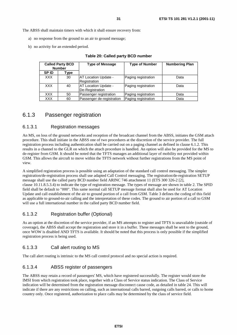
ETSI
ETSI TS 101 281 V1.2.1 (2001-11)31
The ABSS shall maintain timers with which it shall ensure recovery from:
a) no response from the ground to an air to ground message;
b) no activity for an extended period.
Table 20: Called party BCD number
Called Party BCD Number
Type of Message Type of Number Numbering Plan
SP ID Type XXX 30 AT Location Update -
Registration Paging registration Data
XXX 40 AT Location Update - De-Registration
Paging registration Data
XXX 50 Passenger registration Paging registration Data XXX 60 Passenger de-registration Paging registration Data
6.1.3 Passenger registration
6.1.3.1 Registration messages
An MS, on loss of the ground networks and reception of the broadcast channel from the ABSS, initiates the GSM attach procedure. This shall initiate in the ABSS one of two procedures at the discretion of the service provider. The full registration process including authentication shall be carried out on a paging channel as defined in clause 6.1.2. This results in a channel to the GLR on which the attach procedure is handled. An option will also be provided for the MS to de-register from GSM. It should be noted that the TFTS manages an additional layer of mobility not provided within GSM. This allows the aircraft to move within the TFTS network without further registrations from the MS point of view.
A simplified registration process is possible using an adaptation of the standard call control messaging. The simpler registration/de-registration process shall use adapted Call Control messaging. The registration/de-registration SETUP message shall use the called party BCD number field ARINC 746 attachment 11 (ETS 300 326-2 [2], clause 10.11.8.5.3.4) to indicate the type of registration message. The types of message are shown in table 2. The SPID field shall be default to "000". This same normal call SETUP message format shall also be used for AT Location Update and call establishment of the air to ground portion of a call from GSM. Table 3 defines the coding of this field as applicable to ground-to-air calling and the interpretation of these codes. The ground to air portion of a call to GSM will use a full international number in the called party BCD number field.
6.1.3.2 Registration buffer (Optional)
As an option at the discretion of the service provider, if an MS attempts to register and TFTS is unavailable (outside of coverage), the ABSS shall accept the registration and store it in a buffer. These messages shall be sent to the ground, once WOW is disabled AND TFTS is available. It should be noted that this process is only possible if the simplified registration process is being used.
6.1.3.3 Call alert routing to MS
The call alert routing is intrinsic to the MS call control protocol and no special action is required.
6.1.3.4 ABSS register of passengers
The ABSS may retain a record of passengers' MS, which have registered successfully. The register would store the IMSI from which registration took place, together with a Class of Service status indication. The Class of Service indication will be determined from the registration message disconnect cause code, as detailed in table 24. This will indicate if there are any restrictions on calling, such as international calls barred, outgoing calls barred, or calls to home country only. Once registered, authorization to place calls may be determined by the class of service field.

ETSI
ETSI TS 101 281 V1.2.1 (2001-11)32
6.1.4 Ground to air call alert
Notification of a ground to air call is received by the ABSS as a USER to USER INFORMATION MESSAGE [5] attachment 11, clause 4.2.4.15. The format of this message is shown in table 21. The USER to USER information is preceded by SETUP Paging message ARINC 764 attachment 11 [5], clause 4.2.3.
Table 21: Ground to air page alert data format
Element Format Reference Length Type of Page MF table 23 1 binary CC Number MF see note 1 40 Handset Identity OF
(see note 2) binary 4
Routing Number OV (see note 3)
ETS 300 326-2 [2], clause 10.11.8.5.3.4
max 18
MSISDN or TEXT Label OV (see note 4)
ASCII
max 30
SMS Message - SMS-DELIVER type
OV ETS 300 901 [8] ~(GSM 03.40) clause 9.2.2.1
max 165
NOTE 1: The page message generated by GLR formats this field as ETS 300 326-2 [2], clause 10.11.8.5.3.7. This format is converted by the AT into ARINC 746, clause 4.2.5.1.
NOTE 2: The first byte of an optional field is represented by an Information Element Identity as specified in table 22. The second byte indicates length of field.
NOTE 3: This field is only included in the case of a ground to air call NOTE 4: This element may be omitted in the case of ground to air SMS.
The optional and variable length elements, if used, shall be identified by the value identity code detailed in table 22. For variable length elements, the field identifier byte is immediately followed by a single byte indicating the length of the element data field.
Table 22: Page data field identity codes
Element Information Element Identity Handset Identity 0000 0001 Routing Number 0000 0010
MSISDN or TEXT 0000 0011 SMS Message 0000 0100
The CC number field is 40 bytes max. If track 2 credit card data is less than 40 bytes, the remaining bytes shall be filled with zeros.
Once the ground to air alert PAGE is directed to the ABSS, the MS is alerted of the incoming call or message. The GSM user's MSISDN shall be displayed for a time T_PW. If the call (or SMS message) is rejected explicitly, or if T_PW expires, the PAGE channel is released. If the call (or SMS message) is accepted, the call (or message) is delivered.
Table 23: Type of page message
Type Application 0000 0001 Ground to air call 0000 0010 Ground to air SMS 0000 0011 Air to Ground SMS (see note) 0000 0100 ABSS O&M
other values (00xx xxxx) Reserved for future channels terminated in ABSS
other values (01xx xxxx) Reserved for future channels terminated in AT
Other values (1xxx xxxx) Reserved NOTE: Air to ground SMS may not be implemented as an initial service.

ETSI
ETSI TS 101 281 V1.2.1 (2001-11)33
When the page channel is released, the cause codes indicated in table 24 shall detail the reason for release. These values are additional to those specified as MR-cause (ETS 300 326-2 [2], clause 10.11.8.5.4.5).
Table 24: Page release cause codes
Cause Meaning 0110 1001 Call accepted or message delivered 0110 1010 Call rejected (user determined busy) or message not delivered 0110 1011 Time out of T_PW or message not delivered 0110 1100 Failure to connect or message not delivered
6.1.5 Call connect to GSS
On accepting a ground to air call, the ABSS initiates a normal call control SETUP, to the routing number provided in the ground to air call alert PAGE message. The routing number is provided from the call alert page message in the format ETS 300 326-2, clause 10.11.8.5.3.4. The ABSS shall convert this number to the format specified in ARINC 746 attachment 11, clause 4.2.4.3. The routing number is contained in the call alert page message in the ETS 300 326-2 [2] format, and is passed transparently via the AT as a normal page message. The call alert page message data is passed to the ABSS as User Information. Normal call control is used for the duration of the call.
6.1.6 Ground -to- Air SMS delivery
The ground to air SMS delivery shall be achieved using the paging channel. The page channel shall be established between the ABSS and the GLR in response to initiation from the GLR. Once established, the page channel shall provide a pipe in which the SMS protocol shall be carried.
On completion of the SMS protocol, the page channel shall be cleared.
6.1.7 Air -to- Ground SMS delivery
The air-to-ground SMS delivery shall be achieved using the paging channel. The page channel shall be established between the ABSS and the GLR in response to initiation from the ABSS sending a call control SETUP message with information elements encoded as specified in clause 6.1.2. Once established, the page channel shall provide a pipe in which the SMS protocol shall be carried.
On completion of the SMS protocol, the page channel shall be cleared.
6.2 Avionics termination
6.2.1 General
The following functionality is required for the AT, in addition to ETS 300 326-2 [2] and ARINC Characteristic 752 [4] and ARINC Characteristic 746 [5]:
a) Location Management;
b) Passenger Registration Message Handling (normal call SETUP plus optional PAGE for authentication);
c) Incoming Call Page Handling and Credit Card Number format conversion.
Location management is required to ensure that the TFTS GLR is aware of the AS location at any time. This enables incoming call PAGE messages to be directed to a target AS. The AT shall send a Location Update (LU) to the GLR whenever a new GS is selected.
The AT shall route passenger registration/de-registration messages, which are initiated by the MS (in accordance with clause 6.1) to the GSS and thence to the GLR.

ETSI
ETSI TS 101 281 V1.2.1 (2001-11)34
The AT shall monitor BCCH (D) information on the current GS in a manner which ensures a high probability of detecting a PAGE request message within the target time defined in clause 6.2.4]. On detecting a PAGE request message for an incoming call, the AT shall set-up a page channel and route the page message to the ABSS. The AT shall maintain its connection with the current GS and shall not initiate handover to a new GS until the page transaction is complete. This requires the AT to defer handover or cell re-selection for a period up to a maximum of T_HO.
6.2.2 Location management
The AT shall send a Location Update (LU) to the GLR whenever a new GS or GSC is selected. The initiation of an LU should be based on a configurable parameter requiring LU on either change of GS or change of GSC, which can be determined from the GSIC.
6.2.2.1 Location registration/update
When an initial GS is selected (ETS 300 326-2 [2], clause 8.10.6), the AT Radio Resource Management (RRM) shall send a request for LU to the Call Control Management (CCM). On receipt of the LU the CCM shall initiate a call SETUP (ETS 300 326-2 [2], clause 10.11.4.2). This call SETUP message shall contain "called party BCD number" (ETS 300 326-2 [2], clause 10.11.8.5.3.4) with values listed in table 20.
On receipt of the Call Control DISCONNECT message, the CCM entity shall interpret the cause code based on the information detailed in table 25 and indicate the state of the LU registration to RRM. On receipt of the DISCONNECT message with an error cause, the CCM entity shall indicate to the RRM that the LU has failed. In the event of Timeout or RR failure the CCM shall indicate to RRM that the LU has failed. In the event of an LU failure, RRM shall re-attempt. The retransmit period shall be determined by timer T_LU. N_LU re-tries shall be permitted after which the aircraft shall cease Location Update/registration attempts. A new selection of GSIC or a WOW "cycle" shall re-enable Location Registration/Update.
The cause code values (ETS 300 326-2 [2], clause 10.11.8.5.3.6) shown in table 25 shall be used between GSC and AT to indicate the status of Location Registration/Update requests together with, where appropriate, the outgoing call barring services active for the GSM subscriber.
Table 25: CCM Cause value usage for location management
Cause Value
Cause Number
GSS Response
Code
Cause Diagnostic
765 4321 000 0010 2 S60 Successful Passenger Location
Update/Registration - all outgoing calls barred
000 0100 4 S61 Successful Passenger Location Update/Registration - all outgoing international calls barred
000 0101 5 S62 Successful Passenger Location Update/Registration - all outgoing international calls barred except to home PLMN country
Home country code included as a string of IA5 characters
000 1101 13 S63 Successful Aircraft Location Update 000 1110 14 S64 Successful Aircraft/Passenger
De-registration
000 1111 15 S65 Successful Passenger Location Update/Registration - no calls barred
010 1001 41 S68 Aircraft/Passenger Location Update/Registration/De-registration failure - temporary failure
100 0101 69 S69 Aircraft/Passenger Location Update/Registration/De-registration failure - permanent failure
The AT shall perform periodic Location Updating. A further Location Update shall be attempted T_PLU following a successful Location Update.

ETSI
ETSI TS 101 281 V1.2.1 (2001-11)35
Once an LU has been completed, calls shall be placed on the selected GS until a cell re-selection is required or until failed call attempts are encountered. In the event of a failed call attempt, the call re-attempt may be placed on an alternative GS, followed immediately by a LU on the new GS.
6.2.2.2 Location de-registration
When the AT approaches the limit of the current selected GS and there are no surrounding GS available which satisfy the handover criteria, the AT shall initiate Location De-registration. The procedure shall follow that defined in clause 6.2.2.1.
6.2.2.3 TFTS ground to air availability notification
In the event of a failed Location Update, an ECL message shall be initiated by the AT and passed to the ABSS. This message is a modified TFTS Available message (ARINC 746 attachment 11). The ECL message is organized so that there are three message types: EVENT REPORT, GET and SET. A new value shall be used for the TFTS Ground to Air Availability Message information element and attribute coding as defined in the table 26 and table 27 below.
Table 26
Information Element Attribute Identifier Coding
BITS 8 7 6 5 4 3 2 1 TFTS Availability 51H 0 1 0 1 0 0 0 1 TFTS Ground to Air Availability 54H 0 1 0 1 0 1 0 0
Table 27
TFTS Ground to Air Availability Information Element Attribute Values
ATTRIBUTE STATE VALUE
BITS
8 7 6 5 4 3 2 1
Ground to Air Service not available 0 0 0 0 0 0 0 0
Ground to Air Service available 0 0 0 0 0 0 0 1
Ground to Air Service not available due to shutdown
0 0 0 0 1 0 0 0
6.2.3 Passenger registration message handling
A Passenger Registration or De-Registration message shall be received from the ABSS as a normal call control SETUP message. On receipt, the CCM entity shall request the establishment of radio resources as ETS 300 326-2 [2], clause 10.11.4.2. When the indicated radio resources are established, CCM shall forward the SETUP (Passenger Registration or Passenger De-Registration) message to the GSS, as a normal call SETUP. The handling of the CALL PROCEEDING, DISCONNECT messages and subsequent release of radio resources shall be as per ETS 300 326-2 [2], clause 10.11.4.

ETSI
ETSI TS 101 281 V1.2.1 (2001-11)36
6.2.4 Incoming call page handling
The AT shall monitor all GS on the scanning receiver such that the current selected GS is scanned alternately with each of the other GS in the current list:
- Current_GS;
- GS1;
- Current_GS;
- GS2;
- Current_GS;
- GS3 ... etc.
This shall be timed to ensure the AT is capable of receiving a SYSTEM INFORMATION 6 (ETS 300 326-2 [2]) PAGE request message on the BCCH (D) channel for 6 seconds in every 12 seconds.
When the AT receives a PAGE request for an incoming call, it shall delay any decision on selection of a new GS (LU) until the page transaction has been completed and the page channel released within the limit of T_HO. This requires the AT to defer handover or cell re-selection for a period up to a maximum of T_HO. The AT is not required to delay the cell selection before initiating the call set-up for the air to ground portion of the call. The routing number provided in the CALL ALERT PAGE message will be used to route the call to the correct GSC.
The processing of a PAGE request shall be as defined in ETS 300 326-2 [2], clause 10.11.3.3.
If a PAGE request for an incoming call is received from a GS which is not the GS on which the last location update was made, the PAGE request shall be ignored.
A PAGE channel is established between the GSS and the AT. Received PAGE data is transferred by the AT to ABSS, (reference ARINC 746 attachment 11).
The AT shall interpret the call alert page data message (table 21) and convert the credit card format from ETS 300 326-2 [2], clause 10.11.8.5.3.7.2 to the format defined in ARINC 746 attachment 11, clause 4.2.5.1.
6.2.5 SMS Handling
The SMS services shall be supported through TFTS using a paging channel as specified in clauses 6.1 and 6.2.
6.3 Ground station system
6.3.1 General
The functionality carried out by the GSS includes:
a) receive passenger registration and location update SETUP messages from the AS;
b) generate passenger registration and location update messages and forward to GLR;
c) page AS and transfer incoming call alert page data from GLR to AS;
d) generate ground to air call routing number and insert in page data;
e) connect incoming call from GSM and air to ground call from AS on current GSC or from another GSC;
f) handle conditional call diverts, in conjunction with GLR;
g) handle transfer of SMS messages to aircraft;
h) manage call record generation;
i) allow remote management of ABSS.

ETSI
ETSI TS 101 281 V1.2.1 (2001-11)37
NOTE: a), b), c), g), and i) may all be handled through establishment of a page data channel between the ABSS and GLR.
6.3.2 GSS architecture
An overview of a typical TFTS GSS architecture is shown in figure 10.
X.25GS 1
TFTSProcessor
GS n
TFTSPBX
ISDNEchoCancellor
GSC
GSS
Figure 10: GSS architecture
6.3.3 GSS to GLR communications
Physical requirements for GSS to GLR communications are not prescribed by the present document and therefore any suitable data transmission media and protocols may be utilized in the implementation. Information on data networking requirements is therefore only provided for information. The present document does however specify the information content and format of all data messages.
6.3.3.1 Message routing options and link management - X.25 networks
Where X.25 public data networks are used to provide data transmission between GSC and GLR, it is possible to provide different networking configuration, to gain efficiencies in data transmission costs.
A point to point connection is used where a single Telecom Operator's GSC has to be connected internationally to the GLRs. An intermediate GLR or message router could be used where a Telecom Operator has multiple GSCs. This Intermediate Location Register (ILR) is used as a gateway and is transparent on the messages routed between the GSCs and the GLRs.
6.3.3.1.1 Link management - GSS to GLR
A dedicated connection is used for messages sent from GSC to the GLR. Connections can be established to more than one GLR where necessary. This is an "on-demand" access, that is to say, if the link is not opened, the GSC opens it, and keeps it opened until a timer expires (Timer is restarted each time there is a new transaction on that connection). If the timer parameter is set to 0, that means it is a permanent circuit (i.e. not cleared by the GSC).
X.25 Call setup
The X.25 call setup is sent to the corresponding Service Provider's GLR. The call packet user data field contains 16 digits with:
- byte 1: 8 ascii (38H);
- byte 2 to 16: space (or SP).

ETSI
ETSI TS 101 281 V1.2.1 (2001-11)38
TCP/IP Call Setup
The GLR services will be established on specific ports. Ports shall be assigned for specific services.
C7 Call Setup
The GLR services will be established using the C7 MUP.
6.3.3.1.2 Link management - GLR to GSS
A dedicated incoming access is reserved at the GSC side, on a per GLR basis. It is opened on request from each GLR.
It is not the role of the GSC to clear this link when no more transactions are needed.
X.25Call setup
The X25 call setup is sent by the corresponding service provider's GLR. The call packet user data field contains 16 digits with:
- byte 1: 9 ascii (39H);
- byte 2 to 16, access control: 9 bytes for login;
- 6 bytes for password.
TCP/IP Call Setup
The GLR services will be established on specific ports. Ports shall be assigned for specific services.
C7 Call Setup
The GLR services will be established using the C7 MUP.
6.3.4 Registration and location management
The following procedure shall apply if the GSS receives either passenger registration/de-registration or AS LU messages from the AS as call control SETUP messages (see clause 6.1.3).
The information contained in these messages is formatted into a common Registration/LU Request message and forwarded to the GLR. No record of registered AS or passengers is retained by the GSS, as there may be no positive de-registration or notification of change of location.
The format and content of the Registration/LU messages is shown in table 28. Further clarification of coding of information elements is available in Annex B.
Table 28: Registration/LU Messages
Element No. Element Format Comment Message ID n4 Request: 0320
Repeat: 0321 Bit Map b64 22 20 00 00 20 A0 00 02
3 Processing Code n6 VCR Reference 7 Transmission Date & time n10
11 System Audit Trace No. n6 35 Track Two Data LL-CC This shall be encoded with encryption to
identify the IMSI. The form of encryption is subject for further work
41 Card Acceptor Terminal ID n9 Called card acceptor terminal id to reflect origin of cc read data. ASI + AEN
43 No. Destination Telephone Number n18 Location Registration Services (table 2) 63 User Data LLL-UD "013"
3 hex GSIC 3 ascii SPID

ETSI
ETSI TS 101 281 V1.2.1 (2001-11)39
Each Registration/LU Request Message is initiated by the GSS. The GLR responds with a Registration/LU Response message. The transmission time and date field should always be generated by the network element which is the source of the message.
The information element labelled "bit map" is retained for compatibility with existing equipment. The meaning of the specific encoding is defined in the specifications attached as annex B.
The format of the Response message is shown in table 29.
Table 29: Registration/LU response message
Element No. Element Format Comment Message ID n4 Response: 0330 Bit Map b64 22 20 00 00 02 80 00 02
3 Processing Code n6 VCR Reference 7 Transmission Date & time n10
11 System Audit Trace No. n6 329 Response code n3 Table 25 - GSS - GLR Cause 41 Card Acceptor Terminal n9 63 User Data LLL-UD "009"
3 hex GSIC 3 ascii SPID
6.3.5 Incoming call page message handling
6.3.5.1 Receipt of incoming call alert
When a mobile terminating call is received by the GSM user's HLR, routing information is requested from the GLR and subsequently from the GSS. The message from the GLR to the GSS performs the following:
- alerts the GSS of the incoming call;
- provides the GSS with details of target AS and passenger;
- requests from the GSS routing information.
A Call Alert Page Request message is received from the GLR. This information shall be formatted in a page message to the AS in the format specified in table 3. The Routing Number is generated by the GSC and inserted in the Mobile subscriber Routing Number field.

ETSI
ETSI TS 101 281 V1.2.1 (2001-11)40
Table 30: Call alert page request format
Element No. Element Format Comment Message ID n4 Request: 0340 Repeat: 0341 Bit Map b64 02 20 00 00 20 84 00 16
7 Transmission Date & time n10 11 System Audit Trace No. n6 35 Track Two Data LL-CC ETS 300 326-2 [2],
clause 10.11.8.5.3.7.2 41 Card Acceptor Terminal ID n9 ASI + AEN 46 Reference n5 00000 up to 49999 60 Addressing Mode n1 0 - single element
1 - all elements default = 0
62 Broadcast Duration n5 00001 up to 32767 63 User Data LLL-UD
3 hex GSIC 3 ascii SPID 4 hex Handset ID n11 hex Service Discriminator
Table 22 1 hex Length of text 0-30 MSISDN or TEXT Label- table 21 1 hex Length of text 0-163 SMS-DELIVER- table 21
Once a page channel has been established with the AS, the GSS provides routing information to the GLR, in a Call Alert Page Response message (see table 31). This message is interpreted by the GLR as a Send Routing Number message.
Table 31: Call alert page response
Element No. Element Format Comment Message ID n4 Response: 0350
Bit Map b64 02 20 00 00 02 24 00 02
7 Transmission Date&time n10 11 System Audit Trace No. n6 39 Response Code n3 Table 7
In addition:- S52 - Uplink channel request S57 - No resource available S90 - Unknown equipment identity S91 - Unknown NMIC S92 - Invalid request parameter S93 - Unable to process
43 Destination Telephone No n18 DDI routing No at GSC E.164 [11] Numbering Plan for the ISDN Era
46 Reference n5 same as Request message (table 30) 63 User Data LLL-UD "009"
3 hex GSIC 3 ascii SPID
The page message is specified in ETS 300 326-2 [2], clause 10.11.5.2.2.
6.3.5.2 Mechanism to page AS
In order to efficiently use radio resources and optimize the page delivery time, an algorithm is required in the GSS to deliver page requests on a regular pattern. See clause 6.2.4.

ETSI
ETSI TS 101 281 V1.2.1 (2001-11)41
This algorithm is not defined within the scope of the present document. However, the design objective of the algorithm is to maximize the traffic carrying capacity of the system, by broadcasting page information in a timely manner that supports optimal capacity.
6.3.6 Call connection
The GSS provides a routing number to the GLR, which is a DDI number on the GSS PBX. This call is received by the GSC which responds to the GSM message and in-band ringing tone.
When the passenger accepts the incoming call, a call is established by the ABSS in the normal manner, from air to ground. The routing of this call is to a GSS initiated number, which can be recognized and connected to the incoming call. The GSS will send a connect message to the GMSC that sent the call.
Once the incoming call SET-UP message has been received from both the PSTN and the AS, the GSS initiates a PAGE RELEASE REQUEST message as in table 32. On receipt of this message, the GLR responds in accordance with the Paging protocol defined in ETS 300 326-2 [2]. The GLR will close the connection if no other transactions are in process.
Table 32: Page release request and confirm
Element No. Element Format Comment Message ID n4 Request: 0380
Repeat: 0381 Confirm: 0390
Bit Map b64 2220 0000 0204 0002 3 Processing Code n6 VCR reference 7 Transmission Date&time n10
11 System Audit Trace No. n6 39 Response Code n3 Request:
In addition:- S60 - Call control accepted S68 - Call control rejected Confirm: = 3 spaces
46 Reference n5 Request: 00000 up to 49999 Confirm: same as request
63 User Data LLL-UD "009" 3 hex GSIC 3 ascii SPID
The response code is returned by the GSC. A timer T_AGS is initiated on initiation of the page to the aircraft. Expiry of this timer determines no reply to ground to air call.
6.3.7 Call forwarding
In the event that the call cannot be completed, due to a TFTS state listed in table 33, the GSS shall hold the incoming call and requests call forwarding information from the GLR. This shall be achieved by sending a Get New Number message formatted according table 34.
Table 33: TFTS to GSM Call state translation
TFTS STATE GSM STATE CONDITION Handset busy BUSY CFB Incoming call rejected by passenger BUSY CFB No answer from passenger NO REPLY CFNRy No response to page (page channel not established)
NOT REACHABLE CFNRc
Page transaction incomplete (data transfer) NOT REACHABLE CFNRc No resource available (radio or GSS) NOT REACHABLE CFNRc

ETSI
ETSI TS 101 281 V1.2.1 (2001-11)42
Table 34: Get new number
Element No. Element Format Comment Message ID n4 Request: 0360
Request Repeat:0361 Bit Map b64 22 20 00 00 00 04 00 02
3 Processing Code n6 VCR Reference 7 Transmission Date&time n10
11 System Audit Trace No. n6 46 Reference n5 Call alert page reference 63 User Data LLL-UD "010"
3 hex GSIC 3 ascii SPID n1 Reject Cause
1 Not reachable 2 No answer 3 Busy
A response to the Get New Number message shall be returned by the GLR in the format detailed in table 35.
Table 35: Get new number response
Element No. Element Format Comment Message ID n4 Response: 0370
Bit Map b64 22 20 00 00 00 24 00 00
3 Processing Code n6 VCR Reference 7 Transmission Date&time n10
11 System Audit Trace No. n6 43 Destination Number for Divert n18 E.164 [11] 46 Reference n5 same as Request message (table 34) 63 User data LLL-UD "009"
3 hex GSIC 3 ascii SPID
If the GSM user has no configured divert numbers, the GET NEW NUMBER RESPONSE message will be returned with an empty destination number field. In this case, the call handling should be completed by the GSS by providing appropriate in-band signalling information (tones or message).
6.3.8 Administration
The GSS creates administration records for each registration/LU message. System reference numbers are included in all GSS initiated messages.
6.4 Gateway Location Register
6.4.1 General
The Gateway Location Register (GLR) provides an interface between TFTS and GSM networks and carries out the following primary functions:
a) Aircraft Location Management;
b) Registration Management;
c) GSM Visitor Location Register;
d) Call Handling;
e) Signalling and Message Translation;

ETSI
ETSI TS 101 281 V1.2.1 (2001-11)43
f) Data management;
g) GSM Visited MSC functionality for Mobile Terminated SMS.
6.4.2 Location management
The GLR stores a register of aircraft permitted to receive calls from GSM. Each aircraft provides an LU to the GLR when it changes GS/GSC. The register of aircraft stores the current GS/GSC for each aircraft, to enable ground to air calls to be delivered to the correct GS/GSC.
Messaging required to establish an AS location register is between GSS and GLR only. The message is initiated as a SETUP message by the CTU, and a message is created by the GSS and passed to the GLR. This message is carried on a connection, which is established either as a switched or permanent circuit.
6.4.3 Registration management
6.4.3.1 Registration
Passenger registration messages are sent from the ABSS to the GLR, as a SETUP message to the GSS and then as a GSS generated message to the GLR. The message is carried on an X.25 network connection from the GSS to the GLR which is established either as a switched or permanent virtual circuit. A passenger registration message is required for each passenger registering to receive calls. Passenger de-registration messages are transmitted in the same manner.
The information provided in the registration message shall identify the passenger within the GLR database and to identify the MSISDN of the passenger.
The GLR accepts the registration, converts the information as required, communicates with the GSM HLR, updates the GLR database (with information from the GSS and GSM HLR and responds to the GSS. If the registration is unsuccessful, the GLR responds to the GLR with a Passenger Registration Request Response message indicating failure. The response is based on the cause codes listed in table 25.
The status of each GSM user's registration is maintained by registration/de-registration messages forwarded from the GSS.
The GLR shall accept the registration, convert the information as required, communicate with the GSM HLR, update its own database (with information from the GSS and GSM HLR) and respond to the GSS, indicating not only the whether the registration has been successful but also the call barring services applicable to the GSM subscriber. The latter shall be communicated to the GLR using the GSS Response Codes detailed in table 24.
6.4.3.2 De-registration
Passengers who have registered to receive calls can be de-registered from TFTS in a number of ways:
a) All passengers registered on an aircraft are de-registered once X % (see table 36) of the registered passengers have de-registered, by registering on a GSM network (switching on GSM handset in ground coverage). This global de-registration would only occur after a period T1 minutes after the first passenger registration on GSM;
b) All passengers on an aircraft would be detached if a positive LU is not received from an aircraft for a period of T2 minutes;
c) All passengers on an aircraft would be de-registered if an AS LU de-registration message is received. (This message is initiated by the AS when the AS does not detect any GS other than the current GS and it is approaching the LIM of the current GS. The message should be initiated by the AS approximately T4 minutes before the AS is estimated to reach LIM, estimated based on current speed and course);
d) If implemented, the CTU register of passengers would be deleted T5 minutes after the aircraft has landed (Weight on Wheels = TRUE), independent of TFTS coverage;
e) Receipt of an IMSI detach message invokes a passenger de-registration message to be sent to the GLR.
Coding a timeout value to zero shall be interpreted as inactive.

ETSI
ETSI TS 101 281 V1.2.1 (2001-11)44
Table 36: De-registration parameters
Parameter Default Value (SEC) Proportion X % of passengers to de-register from a single aircraft
50 %
T1 300 T2 10 800 T4 120 T5 600
6.4.4 Call handling
6.4.4.1 Incoming call
When an incoming call request is received by the home network, the HLR requests call routing information from the GLR, which shall be registered and function as the associated VLR for the mobile subscriber. The GLR shall in turn request routing information from the GSS. This is carried out by a Call Alert Page Request message, initiated from the GLR. The Call Alert Page Request alerts the GSS of the incoming call, provides call routing information including AS, passenger and handset identifier and requests call routing information. The target GSS shall be the current GSS for the AS from which the subscriber registered. The GSS returns the routing number at the GSC, which the GLR shall forward to the GSM HLR.
The GLR shall format the Call Alert Page Request message in the format specified in table 30.
When the incoming call is received at the GSS, a PAGE REQUEST RELEASE message is sent to the GLR. On receipt, the GLR closes the connection.
6.4.4.2 Call forwarding
GSM call conditions Call Forwarding Unconditional (CFU) and Call Forwarding Not Reachable (CFNRc) are generally handled by the HLR. However, in the case of delivering a call to an aircraft, it is possible that the subscriber shall become not reachable during the time that the call control is being handed over to the GSS. The GSS should therefore process the call as a GSM VLR/VMSC. Call forwarding information is not provided to the GSS but is retained in the GLR (received during location update to HLR). If the GSS is unable to complete the call, the GSS shall request the call forward routing information from the GLR. The TFTS states which may require call forwarding and the associated GSM call states are shown in table 33.
6.4.5 Signalling and message translation
The GLR carries out communication management of both X.25, for the GSS to GLR interface, and MAP communications for the GLR to HLR interface and SMS GMSC to GLR interface.
In most cases, the GLR carries out message translation between GSS and HLR/SMS GMSC originated messages. The translation may be required on each individual message (e.g. passenger registration) or in response to a single message (e.g. aircraft de-registration).
The GLR shall also handle other GSM initiated messages. A list of GSM HLR originated messages and the action to be taken by the GLR is detailed in table 37.

ETSI
ETSI TS 101 281 V1.2.1 (2001-11)45
Table 37: Handling of GSM HLR originated messages
HLR message Action taken by GLR Cancel Location This message means that the mobile subscriber has registered back
in GSM. The GLR should perform location de-registration. If the proportion of subscribers registered on the same aircraft exceeds the parameter listed in table 31, then the GLR should de-register the location for all subscribers from the same aircraft, after time T1.
Insert Subscriber Data If subscriber data is updated by the HLR, this shall be forwarded to the GLR and accepted in the GLR database.
Delete Subscriber Data If subscriber data is deleted by the HLR, a message shall be forwarded to the GLR and deleted from the GLR database.
Reset A message shall be forwarded to the GLR in the event of a failure with the HLR. This should be ignored by the GLR.
Restore If a message is received from the HLR for an unidentified subscriber, the GLR responds with a Restore MAP message.
Forward Check SS Indication This message shall be ignored by the GLR. Active Trace Mode This message shall be ignored by the GLR. De activate Trace Mode This message shall be ignored by the GLR.
6.4.6 Data management
In addition to the standard VLR profile information required to allow subscribers to interwork between the two systems, the minimum subscriber data required is detailed in table 38.
Table 38: GLR data elements
Information source Information element Status of data GSS GSIC (GCC+GSN) Static X.25 Network User Address Static Registered Flag Static Aircraft ATEI (ASI+AEN) Static GSIC (GCC+GSN) Dynamic Registered Flag Dynamic Passenger CC Value Static ATEI Code Dynamic IMSI Dynamic MSISDN Static PIN Static Services Registered Dynamic (initially should be able to register
SMS, speech or both, but extensions to support fax and data may be required)
CFB Number Static/dynamic CFNRy Number Static/dynamic CFNRc Number Static/dynamic Registered Flag Dynamic
The status of data elements indicates that static elements are those controlled by operation and administration and dynamic elements are those which are controlled and modified by the network. Static data is provisioned once and maintained on an ongoing basis. Dynamic data is continually updated from the network.
6.4.7 SMS handling
The GLR shall emulate a mobile terminal receiving SMS messages (ETS 300 901 [8], ETS 300 942 [9], ETS 300 900 [10]). The full SMS-DELIVER type message received shall be transported to the GSS as a Call Alert Page message (see table 30). The GLR shall wait for a PAGE RELEASE REQUEST from the GSS before acknowledging delivery of the SMS. The GLR may store all SMS messages and re-transmit to mobile terminals when re-attached to a GSM network.

ETSI
ETSI TS 101 281 V1.2.1 (2001-11)46
6.5 Information flows These scenarios set out to reflect the functions defined in clause 6.
ABSS AT GSS GLR HLR
ARINC 746 ETS 300 326 GSS-GLR MAP
Location Update
SETUP
DISCONNECT
Call Proceeding
LU Request
LU Request Response
RELEASE
RELEASE COMPLETE
Figure 11

ETSI
ETSI TS 101 281 V1.2.1 (2001-11)47
ABSS AT GSS GLR HLR
ARINC 746 ETS 300-326 GSS-GLR MAP
Setup
Reg RequestSetup
Disc (cause)
Disconnect
Disconnect
Paging ReqSetup Paging Paging
Release Release Release
ReleaseCompleteRelease
CompleteRelease
Complete
PagingResponse Paging
Response
LU ChannelEstablish
LU RequestPax 1
LU RequestPax 2
LU Request
LU ChannelEstablish
LU ChannelEstablish
LU RequestLU Update
Auth Resp
Auth ReqAuth Req
Auth RespAuth Resp
Auth ReqAuth Req
LU UpdateAcceptLU Update
Accept
LU UpdateAccept
Disconnect
ReleaseRelease
ReleaseComplete
ReleaseComplete
Call control paging
Locationupdate
GSM PASSENGER REGISTRATION
Reg Resp
Figure 12

ETSI
ETSI TS 101 281 V1.2.1 (2001-11)48
ABSS AT GSS GLR HLR
ARINC 746 ETS 300 326 GSS-GLR MAP
Call Delivery
PRN (IMSI)
Call Alert PAGE Request
Call Alert Page ResponseSRN (DDI)
PAGE
PAGE Channel Response
PAGE Data TransferUSER Information
Setup PAGING
Connect
PAGE Channel ReleaseRelease
SET UP
Call SETUP from GSM MSC
PRN Resp (DDI)
PAGE RELEASE CONFIRM
PAGE RELEASE REQUEST
From PSTNRelease complete
Figure 13
ABSS AT GSS GLR HLR
ARINC 746 ETS 300 326 GSS-GLR MAP
Call Forwarding
Get New Number Response
Get New Number
Call SETUP from GSM MSC
Call established
Figure 14

ETSI
ETSI TS 101 281 V1.2.1 (2001-11)49
ABSS AT GSS GLR SMS GMSARINC 746 ETS 300 326 GSS-GLR MAP
SMS - Ground to Air
Forward_Short_MessageCall Alert PAGE Request
(SMS User Data)PAGE
PAGE Channel Response
PAGE Data TransferUSER Information
Setup PAGING
Connect
PAGE RELEASE CONFIRM
PAGE RELEASE REQUEST
Forward_Short_Message_ack
PAGE Channel ReleaseRelease
Release Complete
Figure 15
7 Timers and counters
7.1 Timers T_HO Default 15 s
T_PW Default 20 s
T_LU Default 60 s
T_PLU Default 1800 s (30 minutes)
T_AGS Default 30 s
7.2 Counters N_LU Default 2

ETSI
ETSI TS 101 281 V1.2.1 (2001-11)50
Annex A (normative): Modified ARINC 746 Attachment 11 messages
A.1 TFTS availability The TFTS availability status should be indicated to the CTU through the use of an information element within an Event Report message or, in response to a Get message.
ARINC 746 [5] contains the definition of the 'TFTS availability' information element, another one is defined here for ground to air calling.
For both of them, the coding of the attribute identifier and the attribute values should be as defined in the tables below.
Table A.1
Information Element Attribute Identifier Coding
BITS 8 7 6 5 4 3 2 1 TFTS Availability 51H 0 1 0 1 0 0 0 1 TFTS Ground to Air Availability 54H 0 1 0 1 0 1 0 0
Table A.2
TFTS Ground to Air Availability Information Element Attribute Values
ATTRIBUTE STATE VALUE
BITS
8 7 6 5 4 3 2 1
Ground to Air Service not available 0 0 0 0 0 0 0 0
Ground to Air Service available 0 0 0 0 0 0 0 1
Ground to Air Service not available due to shutdown
0 0 0 0 1 0 0 0
A.2 Paging registration type of number In ARINC746 [5], clause 4.2.4.3, the list of type of number values should be extended with the value "Paging registration"
Bits
7 6 5
1 1 1 Paging registration

ETSI
ETSI TS 101 281 V1.2.1 (2001-11)51
A.3 User Information The USER INFORMATION message is used to transfer the content of the ALERT message defined in clauses 5.1.3 and 6.1.3.3
This message should contain the elements described in ARINC 746 [5], clause 4.1.14:
Information Element Length (octets)
Protocol discriminator 1
Call reference 2
Message type 1
More data 1
User to User 2-255
Following clauses describe how each part of this message is used within the ground to air service.
A.3.1 Protocol Discriminator Protocol discriminator used in USER INFORMATION message should have the value 00001000, indicating user-network call control message.
A.3.2 Call Reference This field should be coded to identify which call to which the message applies as described in ARINC 746 [5], clause 4.2.2.
A.3.3 Message type Message type for USER INFORMATION message should be 00100000, as described in ARINC 746 [5], clause 4.2.3.
A.3.4 More data This field is not used. It should be set to value 0.
A.3.5 User-to-User field The User to User information element should be as below, as described in ARINC 746 [5], clause 4.2.4.15:
OCTET BITS 8 7 6 5 4 3 2 1 User-to-User
1 0 1 1 1 1 1 1 1 Information Element Identifier
2 Length of User-to-User contents 3 Protocol Discriminator 4 ... User Information
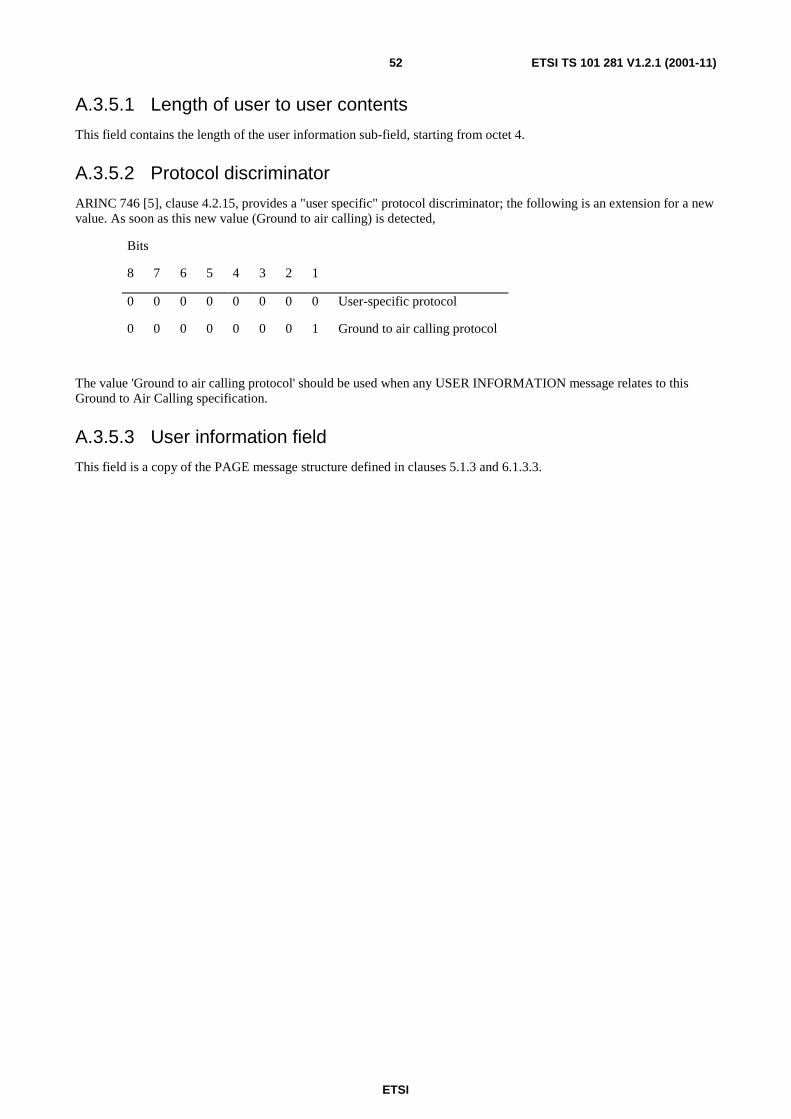
ETSI
ETSI TS 101 281 V1.2.1 (2001-11)52
A.3.5.1 Length of user to user contents
This field contains the length of the user information sub-field, starting from octet 4.
A.3.5.2 Protocol discriminator
ARINC 746 [5], clause 4.2.15, provides a "user specific" protocol discriminator; the following is an extension for a new value. As soon as this new value (Ground to air calling) is detected,
Bits
8 7 6 5 4 3 2 1
0 0 0 0 0 0 0 0 User-specific protocol
0 0 0 0 0 0 0 1 Ground to air calling protocol
The value 'Ground to air calling protocol' should be used when any USER INFORMATION message relates to this Ground to Air Calling specification.
A.3.5.3 User information field
This field is a copy of the PAGE message structure defined in clauses 5.1.3 and 6.1.3.3.

ETSI
ETSI TS 101 281 V1.2.1 (2001-11)53
Annex B (informative): Bibliography
GSS 50222: "Ground Station System GSS; Administration and Management interface; Messages and Codes".
GSS 50322: "Ground Station Systems GSS; Administration and Managment interface; Procedure description".

ETSI
ETSI TS 101 281 V1.2.1 (2001-11)54
History
Document history
V1.1.1 July 1998 Publication
V1.2.1 November 2001 Publication