Embed Size (px)
Citation preview
© State of NSW through Transport for NSW 2021
Common Requirements for Electric Power Equipment
TS 00011:1.0 EP 00 00 00 15 SP
Standard
Issue date: 28 October 2021
Effective date: 28 October 2021
TS 00011:1.0 Common Requirements for Electric Power Equipment
Effective date: 28 October 2021
© State of NSW through Transport for NSW 2021
Disclaimer
This document has been prepared by Transport for NSW (TfNSW) specifically for its own use and is also available for use by NSW public transport agencies for transport assets.
Any third parties considering use of this document should obtain their own independent professional advice about the appropriateness of using this document and the accuracy of its
contents. TfNSW disclaims all responsibility and liability arising whether directly or indirectly out of or in connection with the contents or use of this document.
TfNSW makes no warranty or representation in relation to the accuracy, currency or adequacy of this document or that the document is fit for purpose.
The inclusion of any third party material in this document, does not represent an endorsement by TfNSW of any third party product or service.
For queries regarding this document, please email Transport for NSW Asset Management Branch at [email protected] or visit www.transport.nsw.gov.au

TS 00011:1.0 Common Requirements for Electric Power Equipment
Effective date: 28 October 2021
© State of NSW through Transport for NSW 2021 Page 3 of 22
Document information
Owner: Director Energy Networks and Systems, Asset Management Branch, Safety, Environment and Regulation
Mode: Heavy rail
Discipline: Electrical
Document history
Revision Effective date Summary of changes
1.0 28/10/2021 First issue
TS 00011:1.0 Common Requirements for Electric Power Equipment
Effective date: 28 October 2021
© State of NSW through Transport for NSW 2021 Page 4 of 22
Preface
This standard supersedes EP 00 00 00 15 SP Common Requirements for Electric Power
Equipment version 3.1.
This is the first issue.
This document details the common requirements for electric power and control cubicles or assemblies forming part of switchgear, rectification equipment, transformers and similar
equipment deployed in the electric power sub-system of the RailCorp electrical network.
This standard includes requirements relating to the equipment as a whole and components
used in the equipment, to both hardware and software aspects and also the data set associated with the equipment.
It is intended that this document be called up in other equipment specifications and these requirements only apply when this document is referred to in the primary specification for the
equipment.
The changes to previous content in EP 00 00 00 15 SP include the following:
• replacement of RailCorp organisation roles and processes with those applicable to the current AMB organisational context
• minor amendments and clarification to content
• conversion of the standard to AMB format and style
TS 00011:1.0 Common Requirements for Electric Power Equipment
Effective date: 28 October 2021
© State of NSW through Transport for NSW 2021 Page 5 of 22
Table of contents 1 Scope ............................................................................................................................................ 6
2 Application .................................................................................................................................... 6
3 Referenced documents ................................................................................................................. 6
4 Terms, definitions and abbreviations ............................................................................................ 7
5 Technical requirements ................................................................................................................. 7 5.1 Panels and doors ......................................................................................................................... 7 5.2 Painting ....................................................................................................................................... 7 5.3 Cable entry .................................................................................................................................. 8 5.4 Access ........................................................................................................................................ 8 5.5 Lifting points ................................................................................................................................ 9 5.6 Fixing points ................................................................................................................................ 9 5.7 Colour convention for controls and indications ............................................................................... 9 5.8 Equipment mounting .................................................................................................................. 10 5.9 Labelling ................................................................................................................................... 10 5.10 Auxiliary supply voltage .............................................................................................................. 12 5.11 Wiring ....................................................................................................................................... 13 5.12 Terminal blocks and links ........................................................................................................... 14 5.13 Earth terminal ............................................................................................................................ 14 5.14 Lighting ..................................................................................................................................... 15 5.15 Auxiliary relays, push buttons and selector switches..................................................................... 15 5.16 Programmable equipment .......................................................................................................... 16 5.17 Current transformers .................................................................................................................. 16 5.18 Metering .................................................................................................................................... 17 5.19 Selection of components and equipment ..................................................................................... 17 5.20 Environmental ........................................................................................................................... 17 5.21 Human factors ........................................................................................................................... 17
6 Testing ........................................................................................................................................ 18 6.1 Type tests ................................................................................................................................. 18 6.2 Routine tests ............................................................................................................................. 18
7 Data set associated with the equipment ...................................................................................... 18 7.1 Drawings ................................................................................................................................... 18 7.2 Test results................................................................................................................................ 22
TS 00011:1.0 Common Requirements for Electric Power Equipment
Effective date: 28 October 2021
© State of NSW through Transport for NSW 2021 Page 6 of 22
1 Scope This standard sets out the requirements which apply to new power and control cubicles or assemblies as well as existing equipment that is modified or refurbished.
The standard relay and circuit naming conventions are included in Section 7.1.3, with further details provided in T HR EL 19002 ST.
2 Application This document will not affect the operation or maintenance of existing power and control cubicles or assemblies installed in the RailCorp network. The requirements of this standard only
apply to alterations of existing installations or procurement of new equipment.
3 Referenced documents The following documents are cited in the text. For dated references, only the cited edition applies. For undated references, the latest edition of the referenced document applies.
International standards
IEC 60051-2 Direct acting indicating analogue electrical measuring instruments - Part 2: Special
requirements for ammeters and voltmeters
IEEE Std C37.2 IEEE Standard for Electrical Power System Device Function Numbers,
Acronyms, and Contact Designations
Australian standards
AS 2067:2016 Substations and high voltage installations exceeding 1 kV a.c.
AS 2700-2011 Colour standards for general purposes
AS 60529 Degrees of protection provided by enclosures (IP Code)
AS/NZS IEC 61439.5 Low-voltage switchgear and controlgear assemblies - Part 5: Assemblies
for power distribution in public networks
AS/NZS 3000 Electrical installations - “Wiring Rules”
Transport for NSW standards
EP 00 00 00 13 SP Electrical Power Equipment – Design Ranges of Ambient Conditions
T HR EL 00002 PR Electrical Power Equipment – Integrated Support Requirements
T HR EL 19002 ST Protection System Requirements for the High Voltage Network
T MU HF 00001 ST Human Factors Integration – General Requirements
T MU MD 00006 ST Engineering Drawings and CAD Requirements
TS 00011:1.0 Common Requirements for Electric Power Equipment
Effective date: 28 October 2021
© State of NSW through Transport for NSW 2021 Page 7 of 22
4 Terms, definitions and abbreviations The following terms, definitions and abbreviations apply in this document:
ACCB alternating current circuit breaker
AMB Asset Management Branch
CT current transformer
DCCB direct current circuit breaker
HV high voltage
LED light-emitting diode
SCADA supervisory control and data acquisition
SIL safety integrity level
TCS trip circuit supervision
VT voltage transformer
5 Technical requirements
5.1 Panels and doors All panels, including doors, shall be constructed of mild steel sheet with robust steel framework where environmental conditions allow. The framework shall be sufficiently braced to prevent
warping and twisting. The minimum sheet thickness shall be 1.2 mm for panels and 1.6 mm for doors.
Other materials such as aluminium and stainless steel may be used in environmental conditions where the cubicle or assembly is located outside in a harsh environment. Other materials shall
be mechanically sound to avoid warping, flexing or twisting over time as well as having appropriate ingress protection (IP) rating and ultraviolet (UV) stability for the environmental
conditions.
The doors shall be fitted with removable-pin hinges and locking handles. Opening doors shall
have stops to prevent damage to doors or hinges from overswing. Panel doors in all positions should comply with the requirements of AS 2067 for clearances to exposed electrical
equipment.
5.2 Painting
5.2.1 Indoor equipment
Where the supplier is able to provide a customised paint finish, external cubicle surfaces shall be painted storm grey, colour code N42 in accordance with AS 2700-2011, in textured powder
TS 00011:1.0 Common Requirements for Electric Power Equipment
Effective date: 28 October 2021
© State of NSW through Transport for NSW 2021 Page 8 of 22
coat. The inside surfaces shall be painted white, colour code N14 in accordance with
AS 2700-2011, in smooth powder coat. Cubicles that will be installed in corrosive environments shall be painted with a fit-for-purpose system rather than powder coat.
Where customised painting is not available, the supplier’s standard paint system and colour may be accepted subject to approval by the Director of Energy Networks and Systems, Asset
Management Branch. However, the preferred colour for inside surfaces is white, colour code N14 in accordance with AS 2700-2011.
5.2.2 Outdoor equipment
Where external surfaces of outdoor equipment are to be painted, a paint system suitable for extended outdoor service shall be used. The paint system shall address the following:
• surface preparation, including protection of threads and other vulnerable features, and treatment of difficult access parts
• masking of items that must be kept paint free
• timing, including time between surface preparation and the application of the first coat of
paint, and the time between coats
• details of each coat to be applied including the type of coating, the method of application
and the required dry film thickness
• the repair scheme for minor damage
• the applicable quality assurance (QA) provisions.
5.3 Cable entry Floor mounted equipment shall be configured to accommodate cabling from both above and below.
Cable entries shall be designed for the installation of glands of all control cables. Sufficient space in gland plates and so forth shall be provided for the future installation of at least two
additional control cables and to accommodate cables with at least 15% spare cores.
5.4 Access All controls, alarms and indications shall be mounted for ready operator access at the front of
the cubicle.
Access to equipment, terminal strips and wiring for maintenance shall be unimpeded.
TS 00011:1.0 Common Requirements for Electric Power Equipment
Effective date: 28 October 2021
© State of NSW through Transport for NSW 2021 Page 9 of 22
5.5 Lifting points Where appropriate, equipment shall be provided with lifting points suitable for slinging the
equipment complete with all components installed.
5.6 Fixing points Fixing and mounting holes shall be welded or drilled and painted in the supplier’s works at locations to be shown on the general arrangement drawings.
All fixing and mounting holes shall be positioned to allow comfortable use of the appropriate tool during installation at site. Fixing holes shall not compromise the durability or aesthetics of the
equipment or its enclosure.
5.7 Colour convention for controls and indications
5.7.1 1500 V dc and HV devices
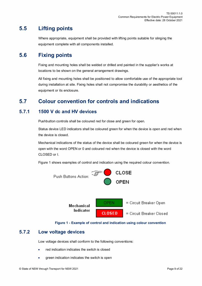
Pushbutton controls shall be coloured red for close and green for open.
Status device LED indicators shall be coloured green for when the device is open and red when
the device is closed.
Mechanical indications of the status of the device shall be coloured green for when the device is
open with the word OPEN or 0 and coloured red when the device is closed with the word CLOSED or I.
Figure 1 shows examples of control and indication using the required colour convention.
Figure 1 - Example of control and indication using colour convention
5.7.2 Low voltage devices
Low voltage devices shall conform to the following conventions:
• red indication indicates the switch is closed
• green indication indicates the switch is open
TS 00011:1.0 Common Requirements for Electric Power Equipment
Effective date: 28 October 2021
© State of NSW through Transport for NSW 2021 Page 10 of 22
• green control closes the switch
• red control opens the switch.
5.8 Equipment mounting All control equipment and circuitry shall be mounted so that it is easily removable for maintenance. This may be achieved by the use of plug-in modules or an equivalent method.
5.9 Labelling
5.9.1 Language
All labelling shall be in English.
5.9.2 Equipment labels
All individual components and items of equipment shall be labelled with a Traffolyte style label
or similar material which shall remain legible over the life of the equipment when subjected to all reasonable mechanical wear and abrasion conditions.
Lettering shall be black letters on a white background.
Labels shall be mounted on a fixed portion of the cubicle or compartment and not on the actual
components, equipment or duct covers. Labels shall be positioned to remain visible after wiring and cabling are completed and so that components and equipment are not blocked from view.
Components and equipment mounted inside the cubicle or compartment shall be labelled with the schematic designation (for example, 52OP) in lettering of not less than 3 mm in height.
Operator controls and equipment on the front panel shall be labelled with the device function (for example, Open ACCB, DCCB Closed) in lettering no less than 4 mm in height. Stand-alone
cubicles shall also be fitted with a main label inscribed with the name (for example, No. 1 Rectifier Control Cubicle) in lettering of not less than 30 mm in height.
Specific labelling requirements for protection equipment are in T HR EL 19002 ST.
5.9.3 Terminal strip labels
All terminals shall be clearly and indelibly labelled with the terminal number shown on the
schematic diagram using proprietary labels from the terminal supplier.
5.9.4 Wire identification and numbering
All control and protection wires shall have a unique number and shall be identified at each end by white number ferrules inscribed in black characters with the wire number shown on the
schematic diagram. Ferrules shall be a proprietary, interlocking type of size to match the wire diameter.
TS 00011:1.0 Common Requirements for Electric Power Equipment
Effective date: 28 October 2021
© State of NSW through Transport for NSW 2021 Page 11 of 22
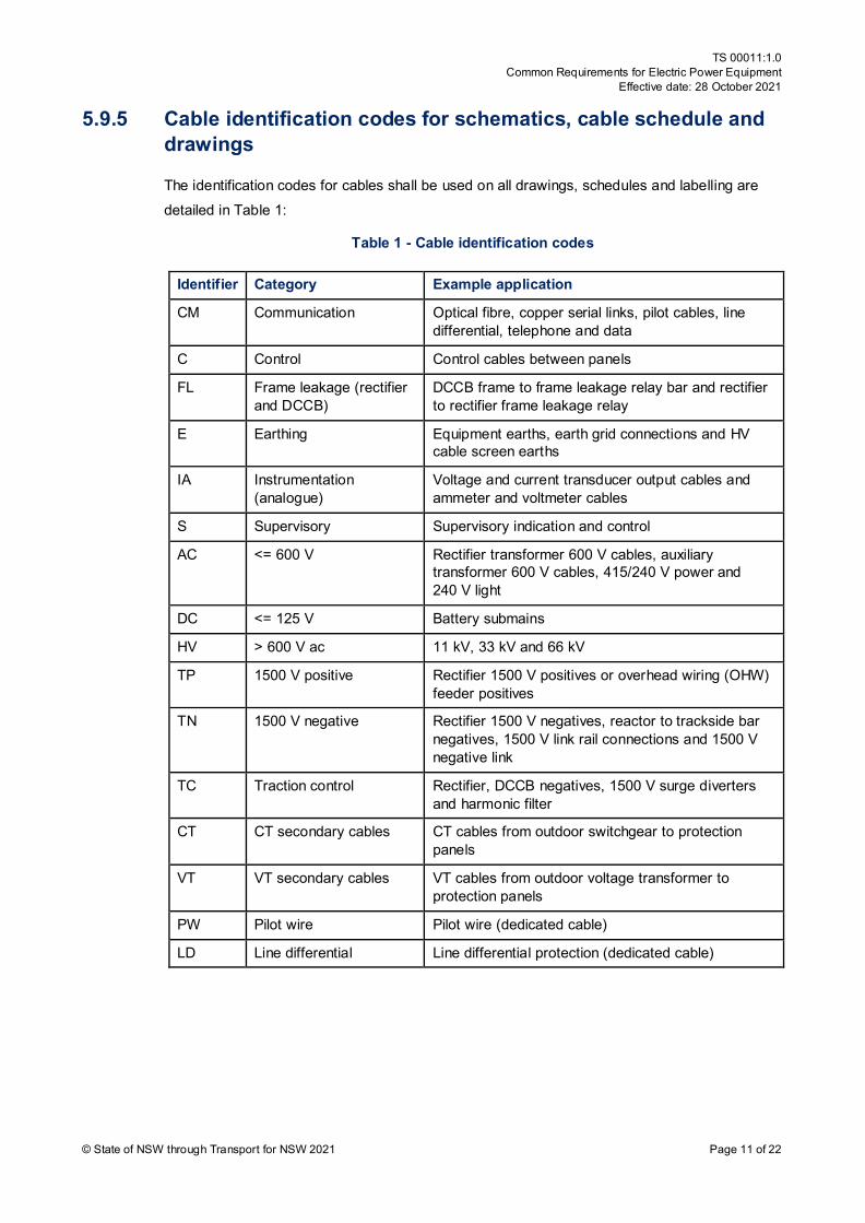
5.9.5 Cable identification codes for schematics, cable schedule and drawings
The identification codes for cables shall be used on all drawings, schedules and labelling are detailed in Table 1:
Table 1 - Cable identification codes
Identifier Category Example application
CM Communication Optical fibre, copper serial links, pilot cables, line differential, telephone and data
C Control Control cables between panels
FL Frame leakage (rectifier and DCCB)
DCCB frame to frame leakage relay bar and rectifier to rectifier frame leakage relay
E Earthing Equipment earths, earth grid connections and HV cable screen earths
IA Instrumentation (analogue)
Voltage and current transducer output cables and ammeter and voltmeter cables
S Supervisory Supervisory indication and control
AC <= 600 V Rectifier transformer 600 V cables, auxiliary transformer 600 V cables, 415/240 V power and 240 V light
DC <= 125 V Battery submains
HV > 600 V ac 11 kV, 33 kV and 66 kV
TP 1500 V positive Rectifier 1500 V positives or overhead wiring (OHW) feeder positives
TN 1500 V negative Rectifier 1500 V negatives, reactor to trackside bar negatives, 1500 V link rail connections and 1500 V negative link
TC Traction control Rectifier, DCCB negatives, 1500 V surge diverters and harmonic filter
CT CT secondary cables CT cables from outdoor switchgear to protection panels
VT VT secondary cables VT cables from outdoor voltage transformer to protection panels
PW Pilot wire Pilot wire (dedicated cable)
LD Line differential Line differential protection (dedicated cable)
TS 00011:1.0 Common Requirements for Electric Power Equipment
Effective date: 28 October 2021
© State of NSW through Transport for NSW 2021 Page 12 of 22
5.10 Auxiliary supply voltage
5.10.1 Traction substation – dc auxiliary supply
Traction substations have dc auxiliary supply. For new and upgraded traction substations the nominal voltage is 125 V dc.
Equipment supplied at 125 V dc shall be designed to operate satisfactorily with the auxiliary voltage in the range -30% to +10% of this nominal voltage. All connected loads shall operate
within this voltage range under ambient conditions in accordance with Section 5.20 and associated derating for the enclosure as necessary.
Strategic traction substations have two independent dc auxiliary supplies. Criteria determining which substations have two dc supplies is specified in T HR EL 19002 ST.
5.10.2 Traction substation – ac auxiliary supply
Traction substations have an ac auxiliary supply. For new and upgraded traction substations the nominal voltage is 3-phase 415/240 V ac.
Equipment supplied at 415/240 V ac shall be designed to operate satisfactorily with the auxiliary
voltage in the range -20% to +20% of this nominal voltage.
5.10.3 DC auxiliary supply – other than traction substations
DC auxiliary supply for equipment in sectioning huts, HV ac switching substations and other
locations can be 125 or 50 V dc nominal. At locations with 50 V dc, equipment must be designed to operate satisfactorily with the auxiliary voltage in the range -10% to +20% of this
nominal voltage.
5.10.4 AC auxiliary supply – other than traction substations
Sectioning huts, HV ac switching substations and other locations will have either a single phase or three phase ac supply. For new and upgraded locations the nominal voltage is 3-phase
415/240 V ac or 240 V ac single phase.
Equipment supplied shall be designed to operate satisfactorily with the auxiliary voltage in the
range -20% to +20% of this nominal voltage.
Equipment supplied for existing substations that use a 220V ac unearthed supply shall be
suitable for those installations.
TS 00011:1.0 Common Requirements for Electric Power Equipment
Effective date: 28 October 2021
© State of NSW through Transport for NSW 2021 Page 13 of 22
5.11 Wiring
5.11.1 General
All wiring shall be installed in accordance with AS/NZS 3000 and equipment supplier specifications.
All 125 V dc wiring (other than control wiring installed on 1500 V dc equipment) shall be able to withstand a 1 minute test voltage of 1.5 kV rms to earth.
Requirements for control wiring installed on 1500 V dc equipment such as DCCBs and rectifiers are detailed in the respective equipment specifications.
DC control wiring and the ac auxiliary supply wiring shall be segregated.
The requirements of Section 5.11.1 shall not apply to special purpose signal and electronic
wires.
Intermeshing of cores of different field cables on terminal blocks are not permitted.
Current and VT wiring shall be in accordance with T HR EL 19002 ST.
Wiring to swing-frames and doors shall be suitably formed to sustain the flexing imposed and
properly protected from damage.
5.11.2 Termination
All wires shall be terminated using proprietary crimp lugs (not bootlaces) of correct size for the conductor. Lugs shall be the insulated barrel type. Not more than two wires shall be terminated
in any tunnel-type terminal. Refer to T HR EL 19002 ST for further details.
5.11.3 Minimum wire size and wire type
Small wiring shall be stranded copper 0.6/1 kV or 0.45/0.75 kV V-90HT PVC insulated. 125 V dc
and 50 V dc control wiring shall be a minimum of 1.5 mm2 cross-section, flexible, multi-strand copper (30/0.25).
5.11.4 Wire colours
Colours for dc control wiring shall be brown for positives, light blue for negatives and grey for all
mid-wires. Mid-wires are all wires that are more than one device away from the positive and negative rails of the control circuit, where a device is a relay or switch contact, coil, indicating
light and so forth. Fuses for dc control wiring are not considered devices.
Colours for ac and dc power wiring shall be in accordance with AS/NZS 3000.
CT and other protection wiring shall be in accordance with T HR EL 19002 ST.

TS 00011:1.0 Common Requirements for Electric Power Equipment
Effective date: 28 October 2021
© State of NSW through Transport for NSW 2021 Page 14 of 22
5.12 Terminal blocks and links
5.12.1 General
Small wiring field terminals shall be the rail-mounted screw clamp type and suitable for 2.5 mm2 wiring. Terminals shall be grouped according to function and voltage and groups shall be
segregated by proprietary barriers.
Terminal numbers shall be allocated on the schematic diagrams so that all the cores of each
field cable can be terminated on consecutive terminals.
The terminal block shall include 15% spare terminals, or a minimum of 1, whichever is the
larger, for each cable to be terminated.
5.12.2 Terminal blocks for dc auxiliary supply
Terminal blocks for 125/50 V dc auxiliary supplies shall be suitable for 6 mm2 wiring.
Rectifier DCCB dc auxiliary supply terminals in non-metal enclosed 1500 V dc switchgear shall be suitable for 16 mm2 wiring.
5.12.3 Terminal blocks for ac auxiliary supply
Terminals energised at 415/240 V ac shall be shrouded and denoted as hazardous by warning
labels.
The terminal blocks for 415/240 V ac auxiliary supplies shall be suitable for 2.5 mm2 wiring.
5.12.4 Terminal blocks for current transformer and voltage transformer
CT and VT secondary wiring terminals shall be in accordance with T HR EL 19002 ST.
5.12.5 Links
Where links are installed the complete fitting shall be white in colour.
5.13 Earth terminal Standalone panels and cabinets intended to be located in substations shall be earthed in accordance with AS/NZS 3000 and as specified in the approved design. The size of the earth
conductor will depend on the purpose (that is, fault carrying or equipotential bonding).
An earth terminal shall be provided for this purpose.
TS 00011:1.0 Common Requirements for Electric Power Equipment
Effective date: 28 October 2021
© State of NSW through Transport for NSW 2021 Page 15 of 22
5.14 Lighting An appropriate 240 V ac light fitting shall be installed in the cubicle or assembly to illuminate
areas containing equipment and terminal strips where the design is such that this equipment will not be directly illuminated by external lighting. The light shall be activated by a switch on the
front panel or automatically when the door is opened.
Equipment supplied for existing substations that use a 220V ac unearthed supply shall be
suitable for the location.
Light fittings supplied for existing substations that use a 220V ac unearthed supply shall be
suitable for an unearthed system (that is, double insulated).
5.15 Auxiliary relays, push buttons and selector switches
5.15.1 Contacts
Contacts of auxiliary relays, push buttons and selector switches used at extra low voltage
(ELV), low current shall be designed for such duty. Particular attention shall be given to ensuring contact wetting by means of gold plated contacts, wiping contacts or other suitable
means.
5.15.2 Relays
All relays shall have clear and ready visual indication of the state of the relay, either by direct
observation of the mechanism (flag) or by means of a LED.
Plug-in relays are preferred.
All plug-in relays shall be positively retained in their bases.
5.15.3 Suppression diodes
Suppression diodes shall be provided across dc coils where appropriate to limit back electromagnetic force (EMF) in order to protect contacts and/or reduce electromagnetic
radiation (EMR).
5.15.4 Trip circuit supervision
Continuity of the circuit shall be monitored as well as availability of the power supply where TCS
is employed.
The TCS relay shall be connected physically to the end point of the wires in the trip circuit. That
is the tripping circuit is to be made by looping all wires right onto the terminals of each tripping contact, with the TCS relay furthest from the supply fuses or circuit breaker. In this way, a break
in the wiring of this circuit will be detected.

TS 00011:1.0 Common Requirements for Electric Power Equipment
Effective date: 28 October 2021
© State of NSW through Transport for NSW 2021 Page 16 of 22
The TCS relay shall drop out (providing indication to SCADA) before the voltage measured at
the end point of the circuit wiring falls to the minimum operating level of the control relays. SCADA indication is required based on the control relays’ capabilities. It is acceptable that the
indicating LEDs have stated minimum operating voltages different to this threshold.
5.15.5 Indicator lights
All indicator lights shall be LED types.
The colour of indicating lights shall be identified on schematics by placing an appropriate letter adjacent to the LED as follows:
• G – green
• R – red
• W – white.
5.16 Programmable equipment Programmable controllers used in electric power equipment shall be the product of a recognised supplier and be purpose-built to carry out the functions specified. Programming shall be carried
out using non-proprietary, commonly available and inexpensive equipment. It shall be possible to download the software from a storage medium or entry using keypad and display unit
mounted on the front of the cubicle or compartment.
Operator control and interrogation shall be possible using the keypad and display unit. Access
to keypad control functions and programming shall be restricted by password. Indications of status shall be continuous and immediately apparent without the need to use the keypad.
The controller shall include means of retaining programming for one year in the event of loss of auxiliary power.
Information related to the programmable equipment (for example, settings and software) shall be stored in the operator and maintainer’s asset management system.
Specific equipment specifications detail requirements for the SIL rating and other specific requirements to suit the application.
5.17 Current transformers The specific CT requirements are specified in the approved protection concept documents for
the specific location. The general requirements for CTs and of the protection concept are specified in T HR EL 19002 ST.
TS 00011:1.0 Common Requirements for Electric Power Equipment
Effective date: 28 October 2021
© State of NSW through Transport for NSW 2021 Page 17 of 22
5.18 Metering Where required, analogue display meters for indication purposes shall be between 96 mm and
144 mm square and comply with IEC 60051-2 with an accuracy class of 2.5.
Meters shall be mounted with the bottom not lower than 500 mm above floor level and the top
not higher than 2000 mm above floor level.
5.19 Selection of components and equipment The make and model of components and equipment used shall be as nominated on the schematic diagrams.
5.20 Environmental The ambient temperature rating shall be in accordance with EP 00 00 00 13 SP. The degree of
protection shall be in accordance with AS 60529. The equipment supplier shall make due allowance for the temperature rise that can occur within a panel or assembly when specifying
the ambient rating of components used in that panel or equipment assembly.
5.21 Human factors The design of power and control cubicles shall incorporate the principals of human factor
integration in T MU HF 00001 ST.
Human factors aspects to be considered relate to controls and displays, information content,
alarms and alerts.
5.21.1 Controls and displays
Human factors shall be considered in the design of all operational facets of the switchgear. This includes the following:
• location of any local controls and indication
• location and visibility of any meters
• accessibility of protection relays and other key items that the location is critical to ensure suitability for use by the operator and maintainer
All control, indication, meters and protection relays shall be accessible from floor level without the use of a ladder or platform.
5.21.2 Information content
Labelling of all controls shall be confirmed to be correct as it is critical to reduce the likelihood of operator error while switching. The design and location of the labelling that describes the
TS 00011:1.0 Common Requirements for Electric Power Equipment
Effective date: 28 October 2021
© State of NSW through Transport for NSW 2021 Page 18 of 22
protection relay, meters and other devices shall be confirmed to ensure correct identification by
the operator and maintainer.
Refer to T HR EL 19002 ST for requirements relating to protection relays.
6 Testing
6.1 Type tests All protection relays, electronic modules and controllers shall be type tested in accordance with
the relevant standards.
6.2 Routine tests Routine factory tests shall include the following as applicable to the equipment concerned:
• inspection in accordance with AS/NZS IEC 61439.5
• continuity (point-to-point) test of all wiring
• dielectric test at power frequency in accordance with AS/NZS IEC 61439.5 or section 9 of
AS 2067:2016 as appropriate
• function test of all logic and interlocks
• secondary injection testing of protection relays and metering
• polarity (flick) test of CTs and VTs
• group primary injections of CTs
• phasing of power circuits.
Copies of final inspection and equipment routine test reports shall be provided and comply with T HR EL 00002 PR.
7 Data set associated with the equipment The data specified in Section 7.1 to Section 7.2 shall be provided when relevant by the
equipment supplier and maintained for the life of the equipment. This data shall remain the property of Transport for NSW.
7.1 Drawings The drawing requirements for major items of equipment are specified in the relevant equipment standard. The requirements in Section 7.1.1 to Section 7.1.3 are for standalone equipment
items such as control cabinets and cubicles.
All drawings shall be produced in accordance with T MU MD 00006 ST.
TS 00011:1.0 Common Requirements for Electric Power Equipment
Effective date: 28 October 2021
© State of NSW through Transport for NSW 2021 Page 19 of 22
7.1.1 Drawings required
The following drawings shall be provided where applicable:
• General arrangements, giving cubicle dimensions and showing the location of all relays, operator controls, terminal blocks and other devices along with the entry points of all
cables. General arrangement views to include front, floor plan and end. Sheet metal fabrication details of cabinets showing material type and thickness, surface preparation and
paint finish details shall be provided.
• Single line diagram.
• Functional block diagram.
• Schematic diagrams of all circuitry, including a legend sheet listing all device identifiers
with their full description and giving their locations on the schematics.
• Component schedule listing the device schematic identifier, description, supplier, model
number, ratings if relevant and the location on the schematic diagram (this may be
integrated with the schematic diagrams legend sheet).
• Cable and termination schedule giving cable number, core number, wire number, origin
and destination, origin and destination terminal numbers, function of each core, number of
cores in cable, conductor material and cross-section, insulation grade, screen type if applicable, insulation and sheath material and any relevant comments.
• Cabling block diagram.
• Terminal block layout.
• Where programmable controllers are included, provide full functional specification of the
control logic, fully annotated logic diagrams, factory and site acceptance tests and, if
available, source code for any custom-built software.
• SCADA I/O list.
7.1.2 Manufacturers standard drawings
The manufacturer’s standard drawings for an item of equipment will be acceptable where they:
• accurately represent the equipment supplied
• provide all required information
• are presented on sheets not larger than A1
• are provided in the English language.
TS 00011:1.0 Common Requirements for Electric Power Equipment
Effective date: 28 October 2021
© State of NSW through Transport for NSW 2021 Page 20 of 22
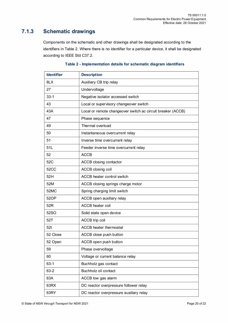
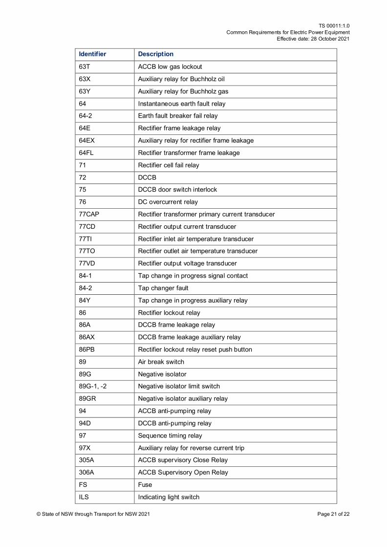
7.1.3 Schematic drawings
Components on the schematic and other drawings shall be designated according to the
identifiers in Table 2. Where there is no identifier for a particular device, it shall be designated according to IEEE Std C37.2.
Table 2 - Implementation details for schematic diagram identifiers
Identifier Description
8LX Auxiliary CB trip relay
27 Undervoltage
33-1 Negative isolator accessed switch
43 Local or supervisory changeover switch
43A Local or remote changeover switch ac circuit breaker (ACCB)
47 Phase sequence
49 Thermal overload
50 Instantaneous overcurrent relay
51 Inverse time overcurrent relay
51L Feeder inverse time overcurrent relay
52 ACCB
52C ACCB closing contactor
52CC ACCB closing coil
52H ACCB heater control switch
52M ACCB closing springs charge motor
52MC Spring charging limit switch
52OP ACCB open auxiliary relay
52R ACCB heater coil
52SO Solid state open device
52T ACCB trip coil
52t ACCB heater thermostat
52 Close ACCB close push button
52 Open ACCB open push button
59 Phase overvoltage
60 Voltage or current balance relay
63-1 Buchholz gas contact
63-2 Buchholz oil contact
63A ACCB low gas alarm
63RX DC reactor overpressure follower relay
63RY DC reactor overpressure auxiliary relay
TS 00011:1.0 Common Requirements for Electric Power Equipment
Effective date: 28 October 2021
© State of NSW through Transport for NSW 2021 Page 21 of 22
Identifier Description
63T ACCB low gas lockout
63X Auxiliary relay for Buchholz oil
63Y Auxiliary relay for Buchholz gas
64 Instantaneous earth fault relay
64-2 Earth fault breaker fail relay
64E Rectifier frame leakage relay
64EX Auxiliary relay for rectifier frame leakage
64FL Rectifier transformer frame leakage
71 Rectifier cell fail relay
72 DCCB
75 DCCB door switch interlock
76 DC overcurrent relay
77CAP Rectifier transformer primary current transducer
77CD Rectifier output current transducer
77TI Rectifier inlet air temperature transducer
77TO Rectifier outlet air temperature transducer
77VD Rectifier output voltage transducer
84-1 Tap change in progress signal contact
84-2 Tap changer fault
84Y Tap change in progress auxiliary relay
86 Rectifier lockout relay
86A DCCB frame leakage relay
86AX DCCB frame leakage auxiliary relay
86PB Rectifier lockout relay reset push button
89 Air break switch
89G Negative isolator
89G-1, -2 Negative isolator limit switch
89GR Negative isolator auxiliary relay
94 ACCB anti-pumping relay
94D DCCB anti-pumping relay
97 Sequence timing relay
97X Auxiliary relay for reverse current trip
305A ACCB supervisory Close Relay
306A ACCB Supervisory Open Relay
FS Fuse
ILS Indicating light switch
TS 00011:1.0 Common Requirements for Electric Power Equipment
Effective date: 28 October 2021
© State of NSW through Transport for NSW 2021 Page 22 of 22
Identifier Description
LCS1 ACCB local control switch
MTA Multi trip auto reset relay
MTM Multi trip manual reset relay
SEF Sensitive earth fault
TBK1, 2 Test block
TCS Trip circuit supervisory relay
TL DCCB test link
TM Charge motor timer
Xn Link terminal
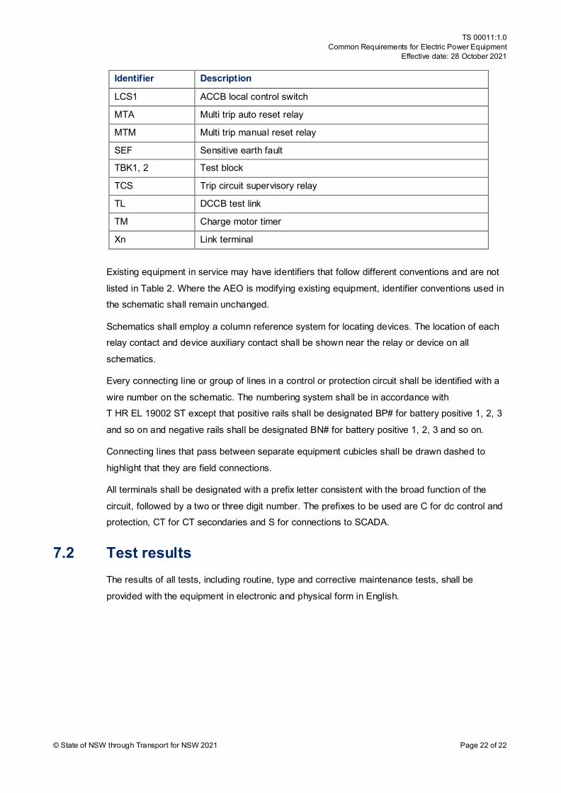
Existing equipment in service may have identifiers that follow different conventions and are not
listed in Table 2. Where the AEO is modifying existing equipment, identifier conventions used in the schematic shall remain unchanged.
Schematics shall employ a column reference system for locating devices. The location of each relay contact and device auxiliary contact shall be shown near the relay or device on all
schematics.
Every connecting line or group of lines in a control or protection circuit shall be identified with a
wire number on the schematic. The numbering system shall be in accordance with T HR EL 19002 ST except that positive rails shall be designated BP# for battery positive 1, 2, 3
and so on and negative rails shall be designated BN# for battery positive 1, 2, 3 and so on.
Connecting lines that pass between separate equipment cubicles shall be drawn dashed to
highlight that they are field connections.
All terminals shall be designated with a prefix letter consistent with the broad function of the
circuit, followed by a two or three digit number. The prefixes to be used are C for dc control and protection, CT for CT secondaries and S for connections to SCADA.
7.2 Test results The results of all tests, including routine, type and corrective maintenance tests, shall be
provided with the equipment in electronic and physical form in English.