Embed Size (px)
Citation preview
TRUSTED BASE SYSTEM ARCHITECTURE FOR Armv8-A
Document number: DEN 0021F
Release Quality: Beta
Release Number: 0
Confidentiality Non-Confidential
Date of Issue: 08/06/20
© Copyright Arm Limited 2017-2020. All rights reserved.
DEN 0021F Copyright © 2017 - 2020 Arm Limited or its affiliates. All rights reserved. Page ii 1.0 Beta (issue 0) Non-Confidential
Contents
About this document v
Release Information v
Arm Non-Confidential Document Licence (“Licence”) vi
References viii
Terms and abbreviations ix
Feedback x Feedback on this book x
1 Introduction 11
1.1 Target platform 11
1.2 Secure Development Lifecycle 12
1.3 Compliance 13
1.4 Scope 13
1.5 Audience 14
2 TrustZone® technology 15
2.1 Execution model 15
2.2 Memory access 17
3 Advanced CPU security 19
3.1 In-process security 19 3.1.1 Pointer Authentication 19
3.1.2 Branch Target Identification 19 3.1.3 Memory Tagging Extension 20
3.2 Side-channel attack defenses 20
3.3 Cryptography Support 21
4 System memory management 22
DEN 0021F Copyright © 2017 - 2020 Arm Limited or its affiliates. All rights reserved. Page iii 1.0 Beta (issue 0) Non-Confidential
5 TBSA Systems on Chip 23
5.1 Baseline architecture 25
5.2 Trusted Subsystems 25
6 Device lifecycle management 27
6.1 Security Lifecycle 28
7 TBSA security requirements 29
7.1 System view 29
7.2 Infrastructure 30 7.2.1 Memory system 30
7.2.1.1 Shared volatile storage 34 7.2.2 Interrupts 34 7.2.3 Secure RAM 35
7.2.4 Power and clock management 36 7.2.5 Peripherals 36
7.3 Fuses 38
7.4 Cryptographic keys 40
7.4.1 Characteristics 40 7.4.1.2 Volatility 41 7.4.1.3 Unique/Common 42
7.4.1.4 Source 42 7.4.2 Root keys 42
7.5 Trusted boot 44 7.5.1 Overview 44 7.5.2 Boot types 45 7.5.3 Boot configuration 45 7.5.4 Stored configuration 46 7.5.5 Trusted Subsystems 46
7.6 Trusted timers 47 7.6.1 Trusted clock source 47 7.6.2 General trusted timer 47 7.6.3 Watchdog 47 7.6.4 Trusted time 48
7.7 Version counters 49
DEN 0021F Copyright © 2017 - 2020 Arm Limited or its affiliates. All rights reserved. Page iv 1.0 Beta (issue 0) Non-Confidential
7.8 Entropy source 50
7.9 Cryptographic acceleration 52
7.10 Debug 53 7.10.1 Protection mechanisms 53 7.10.1.1 DPM overlap 54 7.10.1.2 DPM states 54
7.10.1.3 Unlock operations 56 7.10.1.4 Other debug functionality 57 7.10.1.5 Arm® debug implementation 57 7.10.1.6 Baseline architecture 58 7.10.1.7 Trusted Subsystem 58
7.11 External interface peripherals 59 7.11.1 Display 59
7.12 DRAM protection 60 7.12.1 Design considerations 61 7.12.2 Algorithmic strength 61 7.12.3 Key management 62 7.12.4 Configuration 62
8 Cryptography requirements 63
Appendix A: Requirements Checklist 64
DEN 0021F Copyright © 2017 - 2020 Arm Limited or its affiliates. All rights reserved. Page v 1.0 Beta (issue 0) Non-Confidential
About this document This manual is part of the Arm Platform Security Architecture (PSA) family of specifications. It sets out general requirements for hardware and firmware when designing systems based on Armv8-A processors.
Release Information
The change history table lists the changes that have been made to this document. For a detailed list of changes, see the change history table at the end of this document.
Date Version Confidentiality Change
January 2012 A Confidential First release
March 2012 B Confidential Second release
September 2016 C Confidential 3rd Edition. Update and restructure document. Draft release
July 2018 D Confidential Minor changes to wording of cryptography requirements.
September 2018 E Confidential Several further clarifications to cryptographic requirements and Boot Requirements
April 2020 F Non-Confidential Re-alignment to fit within PSA framework
DEN 0021F Copyright © 2017 - 2020 Arm Limited or its affiliates. All rights reserved. Page vi 1.0 Beta (issue 0) Non-Confidential
TRUSTED BASE SYSTEM ARCHITECTURE FOR Arm®v8-A Copyright ©2018-2020 Arm Limited or its affiliates. All rights reserved. The copyright statement reflects the fact that some draft issues of this document have been released, to a limited circulation.
Arm Non-Confidential Document Licence (“Licence”)
This Licence is a legal agreement between you and Arm Limited (“Arm”) for the use of the document accompanying this Licence (“Document”). Arm is only willing to license the Document to you on condition that you agree to the terms of this Licence. By using or copying the Document you indicate that you agree to be bound by the terms of this Licence. If you do not agree to the terms of this Licence, Arm is unwilling to license this Document to you and you may not use or copy the Document. “Subsidiary” means any company the majority of whose voting shares is now or hereafter owner or controlled, directly or indirectly, by you. A company shall be a Subsidiary only for the period during which such control exists. This Document is NON-CONFIDENTIAL and any use by you and your Subsidiaries (“Licensee”) is subject to the terms of this Licence between you and Arm. Subject to the terms and conditions of this Licence, Arm hereby grants to Licensee under the intellectual property in the Document owned or controlled by Arm, a non-exclusive, non-transferable, non-sub-licensable, royalty-free, worldwide licence to: (i) use and copy the Document for the purpose of designing and having designed products that comply with the Document; (ii) manufacture and have manufactured products which have been created under the licence granted in (i) above; and
(iii) sell, supply and distribute products which have been created under the licence granted in (i) above. Licensee hereby agrees that the licences granted above shall not extend to any portion or function of a product that is not itself compliant with part of the Document. Except as expressly licensed above, Licensee acquires no right, title or interest in any Arm technology or any intellectual property embodied therein. THE DOCUMENT IS PROVIDED “AS IS”. ARM PROVIDES NO REPRESENTATIONS AND NO WARRANTIES, EXPRESS, IMPLIED OR STATUTORY, INCLUDING, WITHOUT LIMITATION, THE IMPLIED WARRANTIES OF MERCHANTABILITY, SATISFACTORY QUALITY, NON-INFRINGEMENT OR FITNESS FOR A PARTICULAR PURPOSE WITH RESPECT TO THE DOCUMENT. Arm may make changes to the Document at any time and without notice. For the avoidance of doubt, Arm makes no representation with respect to, and has undertaken no analysis to identify or understand the scope and content of, third party patents, copyrights, trade secrets, or other rights. NOTWITHSTANING ANYTHING TO THE CONTRARY CONTAINED IN THIS LICENCE, TO THE FULLEST EXTENT PETMITTED BY LAW, IN NO EVENT WILL ARM BE LIABLE FOR ANY DAMAGES, IN CONTRACT, TORT OR OTHERWISE, IN CONNECTION WITH THE SUBJECT MATTER OF THIS LICENCE (INCLUDING WITHOUT LIMITATION) (I) LICENSEE’S USE OF THE DOCUMENT; AND (II) THE IMPLEMENTATION OF THE DOCUMENT IN ANY PRODUCT CREATED BY LICENSEE UNDER THIS LICENCE). THE EXISTENCE OF MORE THAN ONE CLAIM OR SUIT WILL NOT ENLARGE OR EXTEND THE LIMIT. LICENSEE RELEASES ARM FROM ALL OBLIGATIONS, LIABILITY, CLAIMS OR DEMANDS IN EXCESS OF THIS LIMITATION. This Licence shall remain in force until terminated by Licensee or by Arm. Without prejudice to any of its other rights, if Licensee is in breach of any of the terms and conditions of this Licence then Arm may terminate this Licence immediately upon giving written notice to Licensee. Licensee may terminate this Licence at any time. Upon termination of this Licence by Licensee or by Arm, Licensee shall stop using the Document and destroy all copies of the Document in its possession. Upon termination of this Licence, all terms shall survive except for the licence grants. Any breach of this Licence by a Subsidiary shall entitle Arm to terminate this Licence as if you were the party in breach. Any termination of this Licence shall be effective in respect of all Subsidiaries. Any rights granted to any Subsidiary hereunder shall automatically terminate upon such Subsidiary ceasing to be a Subsidiary. The Document consists solely of commercial items. Licensee shall be responsible for ensuring that any use, duplication or disclosure of the Document complies fully with any relevant export laws and regulations to assure that the Document or any portion thereof is not exported, directly or indirectly, in violation of such export laws.
DEN 0021F Copyright © 2017 - 2020 Arm Limited or its affiliates. All rights reserved. Page vii 1.0 Beta (issue 0) Non-Confidential
If any of the provisions contained in this Licence conflict with any of the provisions of any click-through or signed written agreement with Arm relating to the Document, then the click-through or signed written agreement prevails over and supersedes the conflicting provisions of this Licence. This Licence may be translated into other languages for convenience, and Licensee agrees that if there is any conflict between the English version of this Licence and any translation, the terms of the English version of this Licence shall prevail. The Arm corporate logo and words marked with ® or ™ are registered trademarks or trademarks of Arm Limited (or its subsidiaries) in the US and/or elsewhere. All rights reserved. Other brands and names mentioned in this document may be the trademarks of their respective owners. No licence, express, implied or otherwise, is granted to Licensee under this Licence, to use the Arm trade marks in connection with the Document or any products based thereon. Visit Arm’s website at https://www.arm.com/company/policies/trademarks for more information about Arm’s trademarks. The validity, construction and performance of this Licence shall be governed by English Law. Copyright © [2020] Arm Limited (or its affiliates). All rights reserved. Arm Limited. Company 02557590 registered in England. 110 Fulbourn Road, Cambridge, England CB1 9NJ. Arm document reference: LES-PRE-21585
DEN 0021F Copyright © 2017 - 2020 Arm Limited or its affiliates. All rights reserved. Page viii 1.0 Beta (issue 0) Non-Confidential
References
This document refers to the following documents. Ref Document Number Title
[0] Arm DEN 0079 PSA Security Model
[1] PRD29-GENC-009492 Arm® Security Technology - Building a Secure System using TrustZone® Technology
[2] Arm DDI 0487 Armv8-A Architecture Reference Manual
[3] Arm® Trusted Firmware https://github.com/ARM-Software/arm-trusted-firmware
[4] Arm DEN 0072 PSA Trusted Boot and Firmware Update (TBFU), 2019 https://pages.arm.com/psa-resources-tbfu.html
[5] Arm IHI 0070C Arm System Memory Management Unit Architecture Specification
[6] NIST SP 800-193 Platform Firmware Resiliency Guidelines, NIST Special Publication 800-193, May 2018. https://nvlpubs.nist.gov/nistpubs/SpecialPublications/NIST.SP.800-193.pdf
[7] NIST SP 800-90A NIST SP 800-90B NIST SP 800-90C
NIST Special Publication 800-90A Recommendation for Random Number Generation Using Deterministic Random Bit Generators NIST Special Publication 800-90B Recommendation for the Entropy Sources Used for Random Bit Generation NIST Special Publication 800-90C Recommendation for Random Bit Generator (RBG) Constructions
[8] NIST SP 800-22 NIST Special Publication 800-22rev1a: A Statistical Test Suite for the Validation of Random Number Generators and Pseudo Random Number Generators for Cryptographic Applications
[9] CNSA Commercial National Security Algorithm Suite. (superseding NSA Suite B Cryptography)
[10] SEC - Recommended Elliptic Curve Domain Parameters
[11] GlobalPlatform TEE Protection Profile Specification v1.2
[12] NIST Special Publication 800-108 Recommendation for Key Derivation Using Pseudorandom Functions
[13] NIST SP 800-57 NIST Special Publication 800-57 Part 1 Revision 4 Recommendation for Key Management
[14] NIST SP 800-107 NIST Special Publication 800-107 Recommendation for Applications Using Approved Hash Algorithms
[15] Common Methodology for Information Technology Security Evaluation 3.1
[16] NIST FIPS PUB 202 SHA-3 Standard
[17] IETF RFC 8032 Edwards-Curve Digital Signature Algorithm (EdDSA) Algorithms
[18] OG-IS Crypto Evaluation Scheme Agreed Cryptographic Mechanisms
[19] IPA/ISEC:JCMVP:Approved Security Functions
[20] Office of State Commercial Cryptography Administration, P.R. China
[21] Arm® Whitepaper Cache Speculation Side-channels (October 2018)
DEN 0021F Copyright © 2017 - 2020 Arm Limited or its affiliates. All rights reserved. Page ix 1.0 Beta (issue 0) Non-Confidential
Terms and abbreviations
This document uses the following terms and abbreviations. Term Meaning
AES Advanced Encryption Standard, a symmetric-key encryption standard
APB Advanced Peripheral Bus - an ARM Advanced Microcontroller Bus Architecture specification
AXI Advanced eXtensible Interface - an ARM Advanced Microcontroller Bus Architecture specification
Digest The output of a hash operation DRM Digital Rights Management.
HMAC Hashed Message Authentication Code
HUK Hardware Unique Key
Measurement A cryptographic hash of code and/or data
MPU Memory Protection Unit
MTP Multi-Time Programmable. A characteristic of some type of NVM
NIST National Institute of Standards and Technology (http://www.nist.gov)
NSAID Non-Secure Address IDentifier
NVM Non-volatile memory OEM Original Equipment Manufacturer
OTP One Time Programmable. A characteristic of some types of NVM
OWF Cryptographic One-Way Function
PE Processing Element ROM Read-only memory
ROTPK Root of Trust Public Key (for firmware verification)
Runtime firmware Generic term to describe the firmware that executes after boot has completed
SE Secure Element. An isolated and shielded secure processing module, for example, a smart card.
SoC System on Chip System Inseparable component integrating all processing elements, bus masters, and
secure software. Typically an SoC or equivalent.
TEE Trusted Execution Environment.
Trusted subsystem A self-contained subsystem providing security functionality e.g. a secure element
DEN 0021F Copyright © 2017 - 2020 Arm Limited or its affiliates. All rights reserved. Page x 1.0 Beta (issue 0) Non-Confidential
Feedback
Arm welcomes feedback on its documentation.
Feedback on this book
If you have comments on the content of this book, send an e-mail to [email protected]. Give:
• The title (TRUSTED BASE SYSTEM ARCHITECTURE FOR Arm®v8-A ).
• The number and release (DEN 0021F 1.0 Beta 0).
• The page numbers to which your comments apply.
• The rule identifiers to which your comments apply, if applicable.
• A concise explanation of your comments.
Arm also welcomes general suggestions for additions and improvement.
Introduction
DEN 0021F Copyright © 2017 - 2020 Arm Limited or its affiliates. All rights reserved. Page 11 1.0 Beta (issue 0) Non-Confidential
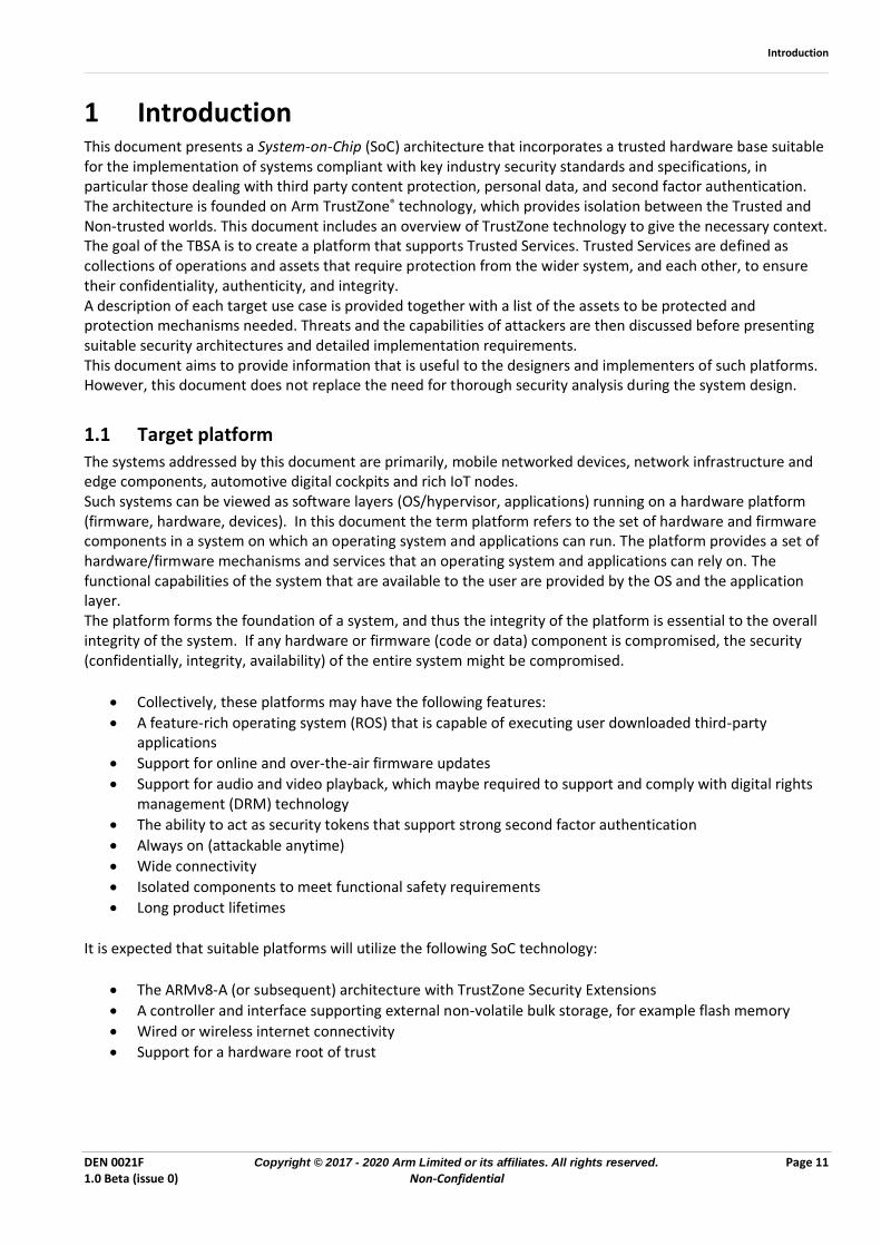
1 Introduction This document presents a System-on-Chip (SoC) architecture that incorporates a trusted hardware base suitable for the implementation of systems compliant with key industry security standards and specifications, in particular those dealing with third party content protection, personal data, and second factor authentication. The architecture is founded on Arm TrustZone® technology, which provides isolation between the Trusted and Non-trusted worlds. This document includes an overview of TrustZone technology to give the necessary context. The goal of the TBSA is to create a platform that supports Trusted Services. Trusted Services are defined as collections of operations and assets that require protection from the wider system, and each other, to ensure their confidentiality, authenticity, and integrity. A description of each target use case is provided together with a list of the assets to be protected and protection mechanisms needed. Threats and the capabilities of attackers are then discussed before presenting suitable security architectures and detailed implementation requirements. This document aims to provide information that is useful to the designers and implementers of such platforms. However, this document does not replace the need for thorough security analysis during the system design.
1.1 Target platform The systems addressed by this document are primarily, mobile networked devices, network infrastructure and edge components, automotive digital cockpits and rich IoT nodes. Such systems can be viewed as software layers (OS/hypervisor, applications) running on a hardware platform (firmware, hardware, devices). In this document the term platform refers to the set of hardware and firmware components in a system on which an operating system and applications can run. The platform provides a set of hardware/firmware mechanisms and services that an operating system and applications can rely on. The functional capabilities of the system that are available to the user are provided by the OS and the application layer. The platform forms the foundation of a system, and thus the integrity of the platform is essential to the overall integrity of the system. If any hardware or firmware (code or data) component is compromised, the security (confidentially, integrity, availability) of the entire system might be compromised.
• Collectively, these platforms may have the following features:
• A feature-rich operating system (ROS) that is capable of executing user downloaded third-party applications
• Support for online and over-the-air firmware updates
• Support for audio and video playback, which maybe required to support and comply with digital rights management (DRM) technology
• The ability to act as security tokens that support strong second factor authentication
• Always on (attackable anytime)
• Wide connectivity
• Isolated components to meet functional safety requirements
• Long product lifetimes
It is expected that suitable platforms will utilize the following SoC technology:
• The ARMv8-A (or subsequent) architecture with TrustZone Security Extensions
• A controller and interface supporting external non-volatile bulk storage, for example flash memory
• Wired or wireless internet connectivity
• Support for a hardware root of trust
Introduction
DEN 0021F Copyright © 2017 - 2020 Arm Limited or its affiliates. All rights reserved. Page 12 1.0 Beta (issue 0) Non-Confidential
Furthermore, some platforms may utilize:
• On chip peripherals supporting data entry, for example keyboard, touch pad, fingerprint sensor
• Video display and audio output
• Image and audio signal processors
• One or more integrated DRAM controllers and interfaces to support a large shared memory pool
In addition, a SoC that targets applications with strict power consumption or thermal limitations will require a high degree of power control and is therefore likely to embed an advanced power control subsystem to meet its power targets. Note that secure platform firmware must extend beyond the host SoC firmware components and into any firmware used by these supporting components. There is a wide diversity of platforms and products that are within the scope of this document. The resulting collection of use cases, assets, threats, and necessary security measures needs to be understood in the context of a secure development lifecycle for the device (see section 1.2). Attacks on systems always get better, with the effect that old security defenses need to be strengthened and new security defenses need to be implemented to maintain the required level of security. The requirements described in this document represent best practice at the time of writing. Some requirements significantly raise the bar in comparison with earlier versions of this document. In all cases, the differences are in the degree of security provided, or demanded by other market specifications: the newer requirements described here are more resilient to certain types of attack.
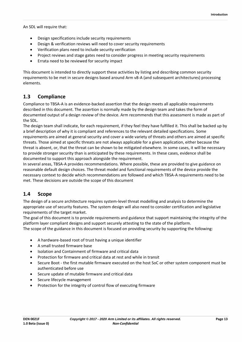
1.2 Secure Development Lifecycle A Security Development Lifecycle (SDL) is a structured methodology for the creation of products which incorporate secure practices as a part of each stage of the design lifecycle. An SDL establishes a series of processes, policies, and activities that expand a design lifecycle to improve product security. SDLs are normally customized to fit with the particular design flow of the organization performing the design. Amongst the early output of an SDL are the items tabulated below.
Artifact Description
Security Product Requirements Application and usage specific security requirements. Including those imposed by the market, certifications required as well as those which arise directly from the application itself.
Threat Modeling Identifies assets and threats - at architectural level and micro-architectural/design level. Relevant threats are determined using market requirements, vulnerability and risk analysis.
Security Objectives Countermeasures (high-level, descriptive) to mitigate the in-scope threats for identified vulnerabilities. Include assumptions.
Security Functional Requirements (+ non-requirements)
Security Objectives mapped to specific mechanisms (low-level, prescriptive), which are to be implemented in the design
Introduction
DEN 0021F Copyright © 2017 - 2020 Arm Limited or its affiliates. All rights reserved. Page 13 1.0 Beta (issue 0) Non-Confidential
An SDL will require that:
• Design specifications include security requirements
• Design & verification reviews will need to cover security requirements
• Verification plans need to include security verification
• Project reviews and stage gates need to consider progress in meeting security requirements
• Errata need to be reviewed for security impact
This document is intended to directly support these activities by listing and describing common security requirements to be met in secure designs based around Arm v8-A (and subsequent architectures) processing elements.
1.3 Compliance Compliance to TBSA-A is an evidence-backed assertion that the design meets all applicable requirements described in this document. The assertion is normally made by the design team and takes the form of documented output of a design review of the device. Arm recommends that this assessment is made as part of the SDL. The design team shall indicate, for each requirement, if they feel they have fulfilled it. This shall be backed up by a brief description of why it is compliant and references to the relevant detailed specifications. Some requirements are aimed at general security and cover a wide variety of threats and others are aimed at specific threats. Those aimed at specific threats are not always applicable for a given application, either because the threat is absent, or, that the threat can be shown to be mitigated elsewhere. In some cases, it will be necessary to provide stronger security than is anticipated by these requirements. In these cases, evidence shall be documented to support this approach alongside the requirement. In several areas, TBSA-A provides recommendations. Where possible, these are provided to give guidance on reasonable default design choices. The threat model and functional requirements of the device provide the necessary context to decide which recommendations are followed and which TBSA-A requirements need to be met. These decisions are outside the scope of this document
1.4 Scope The design of a secure architecture requires system-level threat modelling and analysis to determine the appropriate use of security features. The system design will also need to consider certification and legislative requirements of the target market. The goal of this document is to provide requirements and guidance that support maintaining the integrity of the platform layer compliant designs and support securely attesting to the state of the platform. The scope of the guidance in this document is focused on providing security by supporting the following:
• A hardware-based root of trust having a unique identifier
• A small trusted firmware base
• Isolation and Containment of firmware and critical data
• Protection for firmware and critical data at rest and while in transit
• Secure Boot - the first mutable firmware executed on the host SoC or other system component must be authenticated before use
• Secure update of mutable firmware and critical data
• Secure lifecycle management
• Protection for the integrity of control flow of executing firmware
Introduction
DEN 0021F Copyright © 2017 - 2020 Arm Limited or its affiliates. All rights reserved. Page 14 1.0 Beta (issue 0) Non-Confidential
This document specifies requirements and guidance for both firmware and hardware. Key areas of guidance that facilitate platform integrity include:
• Protection of firmware and critical data. Mutable firmware and critical data must be updatable, with updates being authorized and verified.
• Detection of corruption of firmware and critical data. All mutable firmware and critical data must be signed so that it can be verified during boot, forming a chain-of-trust rooted in an immutable hardware root-of-trust.
• First instruction integrity. The first mutable firmware executed on the host SoC or other system component must be authenticated, by an immutable bootloader.
• Hardware requirements for secure memory (isolation and partitioning essentials for SRAM, DDR, NVM)
This document focuses on the requirements for deployed, production systems. It is not expected that development systems or debug builds of firmware meet the same security standards as production systems. This is expected to be governed by the lifecycle manager of the device. The following list identifies some of the threats that are out of scope for this document:
• Threats to the normal world operating system / hypervisor and application software stacks. The platform assumes that the normal world OS and software stacks are not trusted.
• CPU side channel attacks, including differential power analysis attacks, timing attacks, speculative execution attacks
• Laboratory attacks in which devices are unpackaged and probed
• Power, clock, temperature and energy glitch attacks which cause faults such as-- instruction skipping, malformed data in reads/writes, or instruction decoding errors
• Supply chain attacks. While the guidance in this document does provide mitigations against some potential attacks in a supply chain (e.g. firmware tampering), it does not directly address supply chain security.
1.5 Audience This document is primarily intended for the use of chipset manufacturers who wish to assert compliance with Arm TBSA-A requirements. Architects, designers and verification engineers can also use this specification in order to support the process of certification against PSA with independent laboratories.
TrustZone® technology
DEN 0021F Copyright © 2017 - 2020 Arm Limited or its affiliates. All rights reserved. Page 15 1.0 Beta (issue 0) Non-Confidential
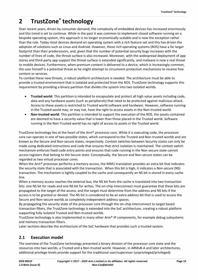
2 TrustZone® technology Over recent years, driven by consumer demand, the complexity of embedded devices has increased enormously and this trend is set to continue. While in the past it was common to implement closed software running on a bespoke operating system, this approach is no longer economically scalable and is now the exception rather than the rule. Today most devices demand an operating system with a rich feature-set and this has driven the adoption of solutions such as Linux and Android. However, these rich operating systems (ROS) have a far larger footprint than their predecessors, and, given that the number of potential security bugs increases with the number of lines of code, the threat surface is also increased. Moreover, with the widespread deployment of app stores and third-party app support the threat surface is extended significantly, and malware is now a real threat to mobile devices. Furthermore, when premium content is delivered to a device, which is increasingly common, the user himself is a potential threat as he might attempt to circumvent protection mechanisms to receive free content or services. To combat these new threats, a robust platform architecture is needed. The architecture must be able to provide a trusted environment that is isolated and protected from the ROS. TrustZone technology supports this requirement by providing a binary partition that divides the system into two isolated worlds.
• Trusted world: This partition is intended to encapsulate and protect all high value assets including code, data and any hardware assets (such as peripherals) that need to be protected against malicious attack. Access to these assets is restricted to Trusted world software and hardware. However, software running in the Trusted world may, or may not, have the right to access assets in the Non-trusted world.
• Non-trusted world: This partition is intended to support the execution of the ROS, the assets contained are deemed to have a security value that is lower than those placed in the Trusted world. Software running in the Non-Trusted world has no right of access to assets in the Trusted world.
TrustZone technology lies at the heart of the Arm® processor core. While it is executing code, the processor core can operate in one of two possible states, which correspond to the Trusted and Non-trusted worlds and are known as the Secure and Non-secure states, respectively. Context switches between Security states can only be made using dedicated instructions and code that ensures that strict isolation is maintained. The context switch mechanism enforces fixed code entry points and ensures that code running in the Non-secure state cannot access registers that belong to the Secure state. Conceptually, the Secure and Non-secure states can be regarded as two virtual processor cores. When the Arm® processor performs a memory access, the MMU translation provides an extra bit that indicates the security state that is associated with the transaction. When this bit is high, it indicates a Non-secure (NS) transaction. The mechanism is tightly coupled to the cache and consequently an NS bit is stored in every cache line. When a memory access reaches the external bus, the NS bit from the cache is translated into two transaction bits: one NS bit for reads and one NS bit for writes. The on-chip interconnect must guarantee that these bits are propagated to the target of the access, and the target must determine from the address and NS bits if the access is to be granted or denied. The NS bit is considered to be an extra address bit that is used to access the Secure and Non-secure worlds as completely independent address spaces. By propagating the security state of the processor core through the on-chip interconnect to target based transaction filters, the TrustZone technology is extended into the SoC architecture, creating a robust platform supporting fully isolated Trusted and Non-trusted worlds. TrustZone technology is also implemented in many other Arm® IP components, for example debug subsystems and memory transaction filters. Later sections describe the architecture of the SoC hardware that provides such a trusted system.
2.1 Execution model
The overview of the TrustZone technology presented a binary division of the processor core state and the resources into two worlds, a Trusted and a Non-trusted world. However, in ARMv8-A and later architectures, additional privilege levels provide support for the traditional user/supervisor (unprivileged/privileged)
TrustZone® technology
DEN 0021F Copyright © 2017 - 2020 Arm Limited or its affiliates. All rights reserved. Page 16 1.0 Beta (issue 0) Non-Confidential
separation that a modern ROS expects, as well as support for the virtualization layer introduced in the ARMv7-A architecture. These distinct levels of separation are referred to as Exception levels in ARMv8-A and later architectures and are denoted EL0 to EL3, EL0 being the lowest privilege level and EL3 the highest. Execution can move between Exception levels only on taking an exception, or on returning from an exception:
• On taking an exception, the Exception level either increases or remains the same. The Exception level cannot decrease on taking an exception.
• On returning from an exception, the Exception level either decreases or remains the same. The Exception level cannot increase on returning from an exception.
The resulting Exception level, is called the target Exception level of the exception:
• Every exception type has a target Exception level that is either implicit in the nature of the exception, or defined by configuration bits in the System registers.
• An exception cannot target the EL0 Exception level.
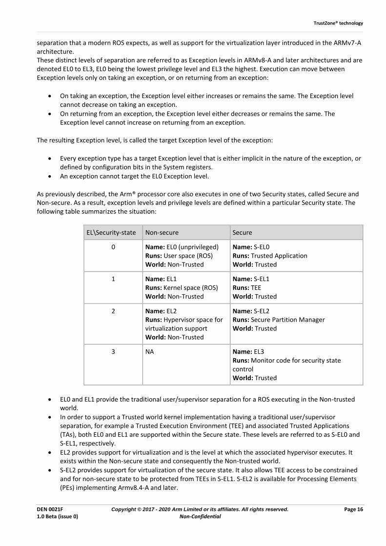
As previously described, the Arm® processor core also executes in one of two Security states, called Secure and Non-secure. As a result, exception levels and privilege levels are defined within a particular Security state. The following table summarizes the situation:
EL\Security-state Non-secure Secure
0 Name: EL0 (unprivileged) Runs: User space (ROS) World: Non-Trusted
Name: S-EL0 Runs: Trusted Application World: Trusted
1 Name: EL1 Runs: Kernel space (ROS) World: Non-Trusted
Name: S-EL1 Runs: TEE World: Trusted
2 Name: EL2 Runs: Hypervisor space for virtualization support World: Non-Trusted
Name: S-EL2 Runs: Secure Partition Manager World: Trusted
3 NA Name: EL3 Runs: Monitor code for security state control World: Trusted
• EL0 and EL1 provide the traditional user/supervisor separation for a ROS executing in the Non-trusted world.
• In order to support a Trusted world kernel implementation having a traditional user/supervisor separation, for example a Trusted Execution Environment (TEE) and associated Trusted Applications (TAs), both EL0 and EL1 are supported within the Secure state. These levels are referred to as S-EL0 and S-EL1, respectively.
• EL2 provides support for virtualization and is the level at which the associated hypervisor executes. It exists within the Non-secure state and consequently the Non-trusted world.
• S-EL2 provides support for virtualization of the secure state. It also allows TEE access to be constrained and for non-secure state to be protected from TEEs in S-EL1. S-EL2 is available for Processing Elements (PEs) implementing Armv8.4-A and later.
TrustZone® technology
DEN 0021F Copyright © 2017 - 2020 Arm Limited or its affiliates. All rights reserved. Page 17 1.0 Beta (issue 0) Non-Confidential
• EL3 has the highest privilege level and exists within the Secure state and consequently the Trusted world. It provides support for a monitor mode. Monitor code executing in EL3 is responsible for managing the security state transitions at lower privilege levels.
2.2 Memory access An important property of a TrustZone system is that a Trusted service might access both Secure and Non-secure memory. To achieve this, two possible approaches are evident:
1. A Trusted service can issue either Secure or Non-secure memory transactions, and the transaction filters only permit a Secure transaction to access Secure memory. A Secure transaction cannot access Non-secure memory. This is the recommended approach.
2. A Trusted service always issues Secure memory transactions and the transaction filters permit a Secure transaction to access any memory, Secure or Non-secure. This approach has been implemented in legacy systems but is no longer recommended by Arm®.
Note: In both cases a Non-secure memory transaction is only permitted to access Non-secure memory, it is never possible for a Non-secure transaction to access Secure memory.
Approach (2) leads to aliased entries in the cache and translation lookaside buffer (TLB), and can cause coherency and security problems, and Arm® recommends using approach (1) instead of approach (2). When using approach (1), software executing in a Secure state that wants to access Non-secure memory must issue Non-secure memory transactions, by means of translation table control flags. The security state of each memory transaction is propagated with each access, and used to tag cache lines. It exists at all stages of the memory hierarchy up to the final access control filter. At the SoC interconnect level, it is propagated in the form of the tag bits previously described, which effectively creates two address spaces, one for Trusted and one for Non-trusted. When the processor is in the Non-secure state (EL2, EL1, or EL0), all memory transactions are Non-secure. When the processor is in the Secure state (EL3, S-EL2, S-EL1, or S-EL0), the security state of memory transactions is determined as follows:
• If the MMU is enabled, the security state of memory transactions can be determined by attributes in the translation table. Consequently, a Trusted kernel in S-EL1 can provide mappings that send Secure or Non-secure memory accesses into the memory system.
• If the MMU is disabled, Translation tables are not utilized, and all Secure state accesses default to Secure transactions on the bus.
Note: The processor core integrates an internal configuration bit that is held in the Security Configuration Register (SCR), which determines the security state of levels below EL3. This bit can only be updated in EL3. In the 64-bit architecture (AArch64), it is referred to as SCR_EL3.NS, when high a Non-secure state is indicated.
Transitions between the two Security states are managed by a dedicated software module called the Secure Monitor, which runs in EL3. The Secure Monitor is responsible for providing a clean context switch and must therefore support the safe save and restore of processor state, including the content of registers, while maintaining isolation between the two worlds. A Secure Monitor Call (SMC) instruction is used to enter EL3 and safely invoke the Secure monitor code. Because this instruction can only be executed in privileged mode, a user process that requests a change from one world to the other must do so using an SVC instruction, which is usually done via an underlying OS kernel. Furthermore, an SMC can optionally be trapped by EL2, and prevent even the OS kernel (EL1) from directly invoking the Secure Monitor (EL3). Interrupts and exceptions can also be configured to cause the processor core to switch into EL3. Independent exception and vector tables support this functionality.
TrustZone® technology
DEN 0021F Copyright © 2017 - 2020 Arm Limited or its affiliates. All rights reserved. Page 18 1.0 Beta (issue 0) Non-Confidential
The Armv8.4-A architecture introduces the Secure EL2 extension, adding support for virtualization in the Secure world. This brings the features that are available for virtualization in the non-secure state to the secure state. A key feature in virtualization support is the addition of a hypervisor-controlled second stage of translation. This allows a hypervisor to control which areas of physical memory are available to a virtual machine.
Further, the Arm System MMU architecture 3.2 and higher supports stage 2 translations in the secure state for other IO masters, see Section 4. Together, these features bring virtualization support to the Secure world and provide a hardware basis that meets a number of practical architectural security requirements. In short, secure virtualization enables:
1. Isolating EL3 software from Secure EL1 software 2. Isolating Normal world software from Secure EL1 software 3. Isolating distinct Secure EL1 software components from each other
The architecture extensions provided by Secure EL2 enable the isolation of Secure world software from different vendors. This architecture also enables isolating software stacks that have different purposes. Traditionally, Trusted OSs can access any location in the system address map. As the trusted OS is a privileged entity, a weakness in its implementation could be exploited to access any memory address in the system, secure or non-secure. Indeed, privilege escalation attacks of this nature have been reported on some trusted OS implementations. Secure EL2 mitigates this escalation by restricting the memory regions accessible by software resident in Secure EL1 or Secure EL0. This is enabled by the use of stage 2 translations. Control of stage 2 translations in the secure state of a System MMU, extends this protection to include DMA-capable trusted hardware resources.

Advanced CPU security
DEN 0021F Copyright © 2017 - 2020 Arm Limited or its affiliates. All rights reserved. Page 19 1.0 Beta (issue 0) Non-Confidential
3 Advanced CPU security The majority of security breaches are caused by software vulnerabilities. A key aspect therefore of hardware system architecture is selecting and configuring security features of a host processor. The goal is to support a secure software framework which minimizes the likelihood of threats identified in the security development lifecycle of the product combining with vulnerabilities in software being exploited by an attacker during product deployment. Arm recommends that processor security extensions are selected according to the software architecture and threat model of the product. See [2] for more detail.
3.1 In-process security Misuse and abuse of pointers and use of memory-unsafe languages is responsible for a significant proportion of software vulnerabilities This section describes three mitigations for different, but common, types of software security problems. Return oriented programming (ROP) and Jump-oriented programming (JOP) are both common types of code-reuse attack. They re-use legitimate code fragments (called gadgets) of a vulnerable program to construct an arbitrary computation without the attacker having to inject code. These techniques allow an attacker to execute code even in the presence of countermeasures such as execute-never memory and code signing. In ROP attacks each gadget ends in a return instruction and employs the return register (link register) to control the flow of execution. Here, the stack is loaded up with the addresses of gadgets, in order of execution, together with any data that is required for a gadget and the padding that may be necessary between executing one gadget and the next. Each gadget executes, consumes its data from the stack, pops the next address off the stack and “returns” to the next gadget in the sequence. In this way an attacker has gained effective control of the computation. JOP attacks are different in that they do not corrupt the legitimate return from a call. Instead they take advantage of the freedom that allows any indirect branch to legally land anywhere in the program and the attacker constructs a table of gadgets to iterate through, typically by overflowing a buffer with address and data.
3.1.1 Pointer Authentication Pointer authentication is a countermeasure for Return-Oriented Programming (ROP) exploits. Pointer Authentication uses the fact that the actual address space in 64-bit architectures is less than 64-bits. There are unused bits in pointer values that can be re-purposed to hold a Pointer Authentication Code (PAC) for this pointer. A PAC could be inserted into each protected pointer before writing it to memory, and then verify its integrity before using it. An attacker who wants to modify a protected pointer would have to be able to generate the correct PAC to be able to control the program flow. The pointer authentication scheme makes generation of a correct PAC code cryptographically difficult for an attacker. Different pointers have different purposes within a program, pointers should be valid only in a specific context. In Pointer Authentication, there are two parts to ensuring this: having separate keys for major use cases and by computing the PAC over both the pointer and a 64-bit context. The Arm pointer authentication specification defines five keys: two for instruction pointers, two for data pointers and one for a separate general-purpose instruction for computing a MAC over longer sequences of data. The instruction encoding determines which key to use. The context is useful for isolating different types of pointers used with the same key. The context is specified as an additional argument together with the pointer when computing and verifying the PAC. The PAC is added and checked by special instructions and the PAC uses a cryptographically strong algorithm to resist forging. ROP can be defended against by protecting a return address with a PAC. Pointer Authentication is available for Processing Elements implementing Armv8.3-A and later.
3.1.2 Branch Target Identification Branch Target Identification (BTI) provides a defense against Jump-oriented programming (JOP) exploits. BTI ensures indirect branches must land on corresponding instructions. In the BTI mechanism every indirect instruction is paired with a corresponding legal instruction. Because almost all other instructions are invalid branch targets and branching to an incompatible instruction raises a branch target exception, forcing branches
Advanced CPU security
DEN 0021F Copyright © 2017 - 2020 Arm Limited or its affiliates. All rights reserved. Page 20 1.0 Beta (issue 0) Non-Confidential
to land on certain instructions makes it difficult for an attacker to find desirable gadgets and therefore defends against the use of this technique. Branch target identification is available for PEs implementing Armv8.5-A and later.
3.1.3 Memory Tagging Extension
The use of memory-unsafe languages such as C and C++ means that memory related errors will continue to be vulnerable to exploitation. These include bounds violations, use-after-free, use-after-return, use-out-of-scope and use-before-initialization errors. The Memory Tagging Extension provides architectural support for run-time, always-on detection of various classes of memory error to aid with software debugging to eliminate vulnerabilities before they can be exploited. Memory tagging (also known as coloring, versioning or tainting) is a lightweight, probabilistic version of a lock and key system where one of a limited set of lock values can be associated with the memory locations forming part of an allocation, and the equivalent key is stored in unused high bits of addresses used as references to that allocation. On each use of a reference the key is checked to make sure that it matches with the lock before an access is made. On freeing an allocation, the lock value associated with each location is changed to one of the other lock values so further uses of the reference have a reasonable probability of failure. This extension implements support for storage, access and checking of the lock values in hardware leaving software to select and set the values on allocation and deallocation. The general idea of memory tagging on 64-bit platforms is as follows:
• Every TG (tagging granularity) bytes of memory aligned by TG are associated with a tag of TS (tag size) bits. These TG bytes are called the granule.
• TS bits in the upper part of every pointer contain a tag.
• Memory allocation (e.g. malloc) chooses a tag, associates the memory chunk being allocated with this tag, and sets this tag in the returned pointer.
• Every load or store instruction raises an exception on mismatch between the pointer and memory tags.
• On freeing an allocation, the tag associated with each location is changed to one of the other tag values so further uses of the reference have a reasonable probability of failure.
The Armv8.5-A Memory Tagging Extension implements support for storage, access and checking of the lock values in hardware leaving software to select and set the values on allocation and deallocation. Note that implementing the memory tagging extension requires the system architecture to provide additional storage for memory tags. There is execution cost in tagging heap and stack objects during allocation and deallocation. It is possible to use memory tagging only during development however there is compelling evidence that testing alone will miss many memory-safety bugs which occur in deployment. The benefits and costs of always-on detection should be weighed by architects in the context of the threat model.
3.2 Side-channel attack defenses The vulnerability which underlies cache timing side-channels is that the pattern of allocations into the cache of a CPU, and, in particular, which cache sets have been used for the allocation, can be determined by measuring the time taken to access entries that were previously in the cache, or by measuring the time to access the entries that have been allocated. This may leak information about the pattern of cache allocations that could be read by other, less privileged software. The new feature of speculation-based cache timing side-channels is their use of speculative memory reads. Speculative memory reads are common in very high-performance CPUs. By performing speculative memory reads to cacheable locations beyond an architecturally unresolved branch (or other change in program flow), the result of those reads can themselves be used to form the addresses of further speculative memory reads. These speculative reads cause allocations of entries into the cache whose addresses are indicative of the values of the first speculative read. This becomes an exploitable side-channel if untrusted code is able to control the speculation in such a way it causes a first speculative read of location which would not otherwise be accessible
Advanced CPU security
DEN 0021F Copyright © 2017 - 2020 Arm Limited or its affiliates. All rights reserved. Page 21 1.0 Beta (issue 0) Non-Confidential
to that untrusted code. But the effects of the second speculative allocation within the caches can be measured by that untrusted code. Arm recommends that the software mitigations described in the Cache Speculation Side-channels whitepaper [21] be deployed where protection against malicious applications is required by the threat model. Arm introduced processor features in Armv8.5-A, which can be implemented from Armv8.0, that provide resilience to this type of attack.
3.3 Cryptography Support The software performance of cryptographic functions impacts the security of the device because insufficient performance can create an unwanted trade-off between the real-time functional requirements of the device and the security requirements. It is often important that random number generation, hash functions together with symmetric and asymmetric cipher computation are given support in the ISA and that such computations should be robust, for example having constant time implementations. When specifying the processing element for the SoC consideration should be given to optional CPU extensions which support cryptographic acceleration instructions. See [2] for an example of advanced cryptography support.
System memory management
DEN 0021F Copyright © 2017 - 2020 Arm Limited or its affiliates. All rights reserved. Page 22 1.0 Beta (issue 0) Non-Confidential
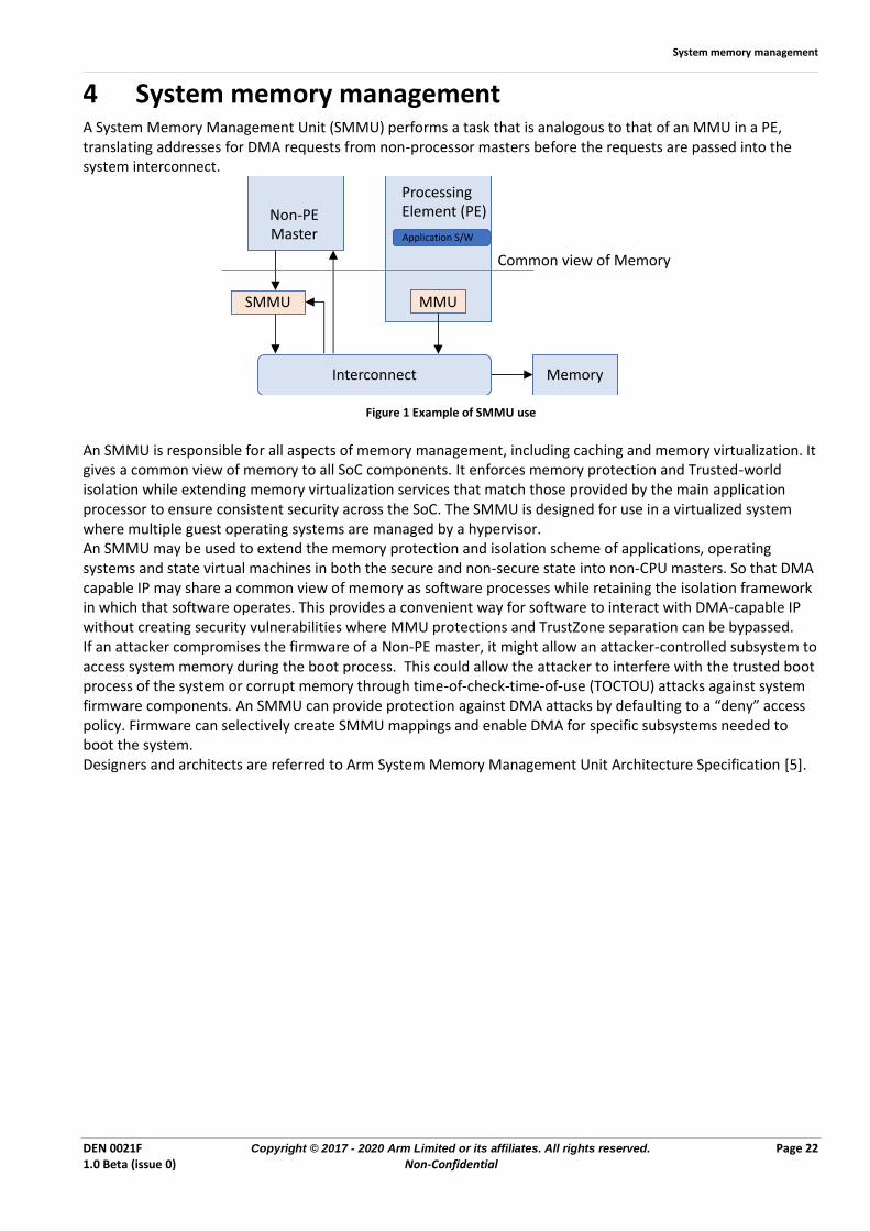
4 System memory management A System Memory Management Unit (SMMU) performs a task that is analogous to that of an MMU in a PE, translating addresses for DMA requests from non-processor masters before the requests are passed into the system interconnect.
Figure 1 Example of SMMU use
An SMMU is responsible for all aspects of memory management, including caching and memory virtualization. It gives a common view of memory to all SoC components. It enforces memory protection and Trusted-world isolation while extending memory virtualization services that match those provided by the main application processor to ensure consistent security across the SoC. The SMMU is designed for use in a virtualized system where multiple guest operating systems are managed by a hypervisor. An SMMU may be used to extend the memory protection and isolation scheme of applications, operating systems and state virtual machines in both the secure and non-secure state into non-CPU masters. So that DMA capable IP may share a common view of memory as software processes while retaining the isolation framework in which that software operates. This provides a convenient way for software to interact with DMA-capable IP without creating security vulnerabilities where MMU protections and TrustZone separation can be bypassed. If an attacker compromises the firmware of a Non-PE master, it might allow an attacker-controlled subsystem to access system memory during the boot process. This could allow the attacker to interfere with the trusted boot process of the system or corrupt memory through time-of-check-time-of-use (TOCTOU) attacks against system firmware components. An SMMU can provide protection against DMA attacks by defaulting to a “deny” access policy. Firmware can selectively create SMMU mappings and enable DMA for specific subsystems needed to boot the system. Designers and architects are referred to Arm System Memory Management Unit Architecture Specification [5].
MemoryInterconnect
SMMU MMU
Processing Element (PE)Non-PE
Master Application S/W
Common view of Memory
TBSA Systems on Chip
DEN 0021F Copyright © 2017 - 2020 Arm Limited or its affiliates. All rights reserved. Page 23 1.0 Beta (issue 0) Non-Confidential
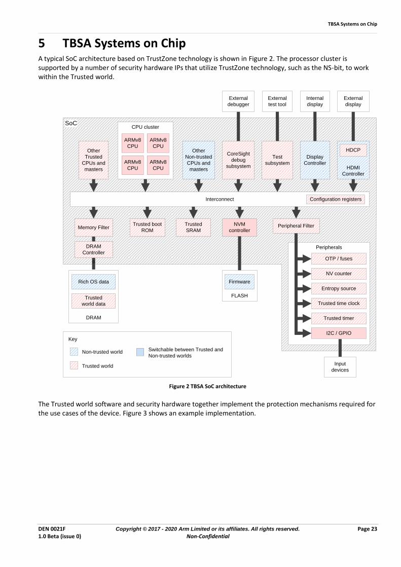
5 TBSA Systems on Chip A typical SoC architecture based on TrustZone technology is shown in Figure 2. The processor cluster is supported by a number of security hardware IPs that utilize TrustZone technology, such as the NS-bit, to work within the Trusted world.
SoC
Key
Non-trusted world
Trusted world
Switchable between Trusted and
Non-trusted worlds
Interconnect Configuration registers
Peripheral Filter
Peripherals
Input
devices
Memory Filter
DRAM
Controller
D
Trusted boot
ROM
Trusted
SRAM
NVM
controller
Other
Trusted
CPUs and
masters
CPU cluster
ARMv8
CPU
ARMv8
CPU
ARMv8
CPU
ARMv8
CPU
Other
Non-trusted
CPUs and
masters
CoreSight
debug
subsystem
External
debugger
Test
subsystem
External
test tool
Display
Controller
Internal
display
HDMI
Controller
HDCP
External
display
I2C / GPIO
Trusted timer
Trusted time clock
Entropy source
NV counter
OTP / fuses
DRAM
Rich OS data
Trusted
world data
FLASH
Firmware
Figure 2 TBSA SoC architecture
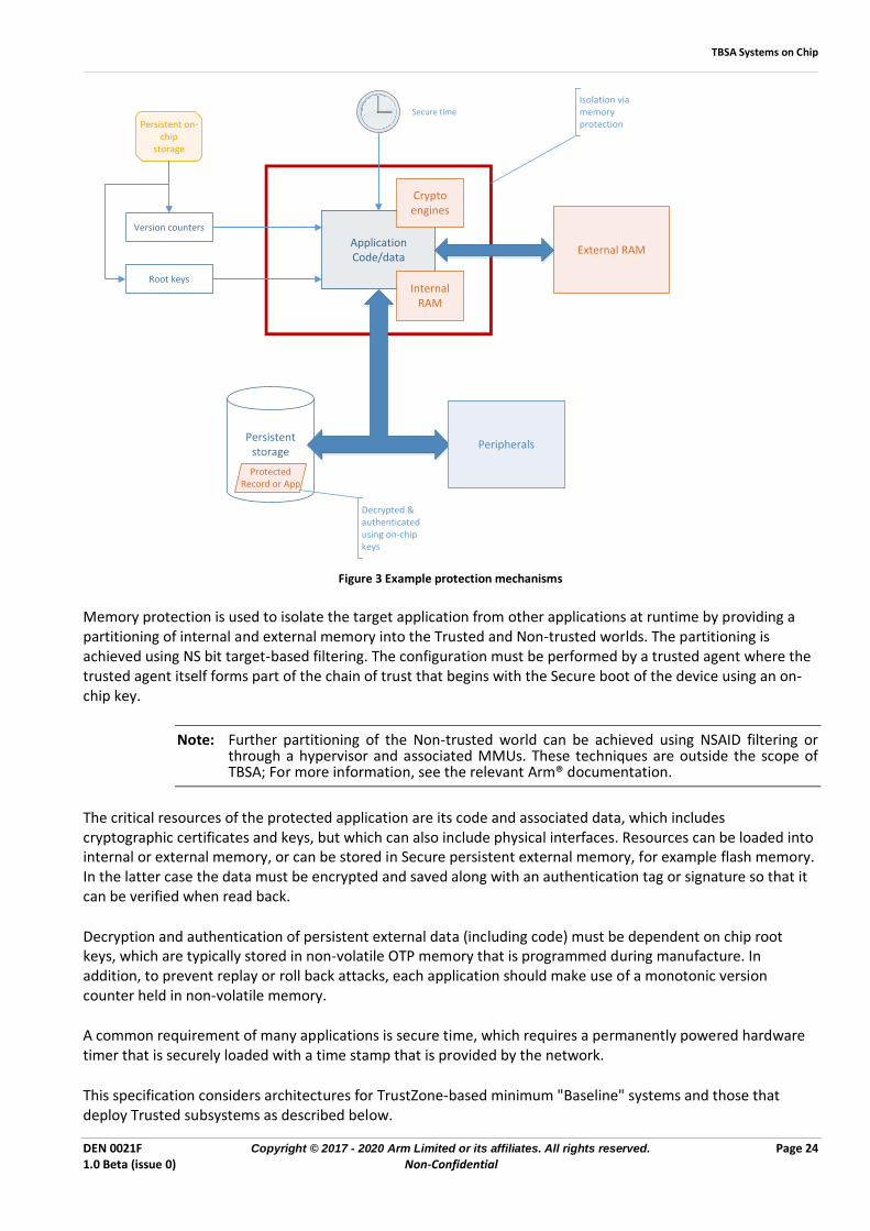
The Trusted world software and security hardware together implement the protection mechanisms required for the use cases of the device. Figure 3 shows an example implementation.
TBSA Systems on Chip
DEN 0021F Copyright © 2017 - 2020 Arm Limited or its affiliates. All rights reserved. Page 24 1.0 Beta (issue 0) Non-Confidential
Secure time
ApplicationCode/data
Persistent on-chip
storage
Persistentstorage
External RAM
Peripherals
Protected Record or App
Version counters
Root keysInternal
RAM
Cryptoengines
Isolation via memory protection
Decrypted & authenticated using on-chip keys
Figure 3 Example protection mechanisms
Memory protection is used to isolate the target application from other applications at runtime by providing a partitioning of internal and external memory into the Trusted and Non-trusted worlds. The partitioning is achieved using NS bit target-based filtering. The configuration must be performed by a trusted agent where the trusted agent itself forms part of the chain of trust that begins with the Secure boot of the device using an on-chip key.
Note: Further partitioning of the Non-trusted world can be achieved using NSAID filtering or through a hypervisor and associated MMUs. These techniques are outside the scope of TBSA; For more information, see the relevant Arm® documentation.
The critical resources of the protected application are its code and associated data, which includes cryptographic certificates and keys, but which can also include physical interfaces. Resources can be loaded into internal or external memory, or can be stored in Secure persistent external memory, for example flash memory. In the latter case the data must be encrypted and saved along with an authentication tag or signature so that it can be verified when read back.
Decryption and authentication of persistent external data (including code) must be dependent on chip root keys, which are typically stored in non-volatile OTP memory that is programmed during manufacture. In addition, to prevent replay or roll back attacks, each application should make use of a monotonic version counter held in non-volatile memory.
A common requirement of many applications is secure time, which requires a permanently powered hardware timer that is securely loaded with a time stamp that is provided by the network.
This specification considers architectures for TrustZone-based minimum "Baseline" systems and those that deploy Trusted subsystems as described below.
TBSA Systems on Chip
DEN 0021F Copyright © 2017 - 2020 Arm Limited or its affiliates. All rights reserved. Page 25 1.0 Beta (issue 0) Non-Confidential
5.1 Baseline architecture The Baseline Architecture performs the majority of the security functions within Trusted world software on the Processor cluster. It is supported by a minimum set of required security hardware, for example:
• Trusted Boot ROM
• Trusted RAM and/or Trusted External Memory Partitioning
• Trusted peripheral:
• OTP Fuses
• Entropy Source
• Timer
• Watchdog
The Baseline architecture focuses on ensuring that the Trusted world software has access to all the assets it requires, and has the underlying mechanisms to protect the integrity, confidentiality, and authenticity of the Trusted world. The Trusted world software exports crypto services to the Non-trusted world, and supports the execution of trusted services, for example by implementing a TEE capable of running trusted applications. In a TEE architecture, the API that is exposed to the trusted applications by the TEE will be responsible for providing secure time, secure version counters, and cryptographic services that utilize the device root keys. A Trusted application in turn, can expose further services to the Non-trusted world through its API. The exact requirements for the Trusted Hardware depend on the use cases that the device must support.
5.2 Trusted Subsystems A trusted subsystem is an isolated hardware block which provides trusted services to the rest of the SoC. It contains hardware to accelerate and offload cryptographic operations from Trusted world software, and to provide increased protection to high value assets, such as root keys and other secrets.
An architecture which uses a trusted subsystem builds on the Baseline Architecture to provide additional robustness to an implementation.
Trusted Subsystems are often designed to support the most commonly used algorithms for encryption, decryption, and authentication. These are likely to include AES, SHA, RSA, and ECC. Arm® recommends increasing protection for the keys in the system by implementing a hardware key store that enables use of the keys by the cryptographic accelerators while preventing the keys from being read by both Non-trusted and Trusted software.
Trusted subsystems can include on and off-chip modules and may be called security enclaves, security elements, Trusted Platform Modules (TPMs) or Hardware Security Modules (HSMs). The security services provided may include:
• Secure storage for boot measurements, supporting the ability to perform secure attestation
• An endorsement key for a unique, unclonable identity bound to hardware
• Key storage and management
• Secure cryptography where keys are never visible outside the trusted subsystem
• key derivation
• True random number generation
The threat model for a system will dictate any specific requirements of a trusted subsystem. There might be requirements necessitated by the chosen operating system or by the market or region in which the device is to operate. Trusted subsystems are commonly implemented as a Trusted peripheral which means that for trusted subsystems having only a single interface to the rest of the system that interface is only directly accessible by
TBSA Systems on Chip
DEN 0021F Copyright © 2017 - 2020 Arm Limited or its affiliates. All rights reserved. Page 26 1.0 Beta (issue 0) Non-Confidential
the trusted world. This supports the use of flexible policies in how the normal world interacts with a trusted subsystem. More complex trusted subsystems may have several interfaces to the system in which case the design should ensure that the subsystem may only be controlled from the Trusted World. In the case that the trusted subsystem is off-chip this means that the associated interface controller is implemented in the Trusted World.
Device lifecycle management
DEN 0021F Copyright © 2017 - 2020 Arm Limited or its affiliates. All rights reserved. Page 27 1.0 Beta (issue 0) Non-Confidential
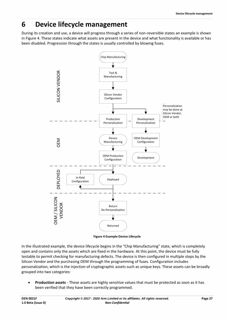
6 Device lifecycle management During its creation and use, a device will progress through a series of non-reversible states an example is shown in Figure 4. These states indicate what assets are present in the device and what functionality is available or has been disabled. Progression through the states is usually controlled by blowing fuses.
Chip Manufacturing
Test & Manufacturing
Silicon VendorConfiguration
OEM Production Configuration
Device Manufacturing
Deployed
Returned
In-field Configuration
ReturnDe-Personalization
SILI
CO
N V
END
OR
OEM
OEM
/ S
ILIC
ON
V
END
OR
DEP
LOYE
D
Development Personalization
OEM Development Configuration
Development
Production Personalization
Personalization may be done at Silicon Vendor, OEM or both
Figure 4 Example Device Lifecycle
In the illustrated example, the device lifecycle begins in the “Chip Manufacturing” state, which is completely open and contains only the assets which are fixed in the hardware. At this point, the device must be fully testable to permit checking for manufacturing defects. The device is then configured in multiple steps by the Silicon Vendor and the purchasing OEM through the programming of fuses. Configuration includes personalization, which is the injection of cryptographic assets such as unique keys. These assets can be broadly grouped into two categories:
• Production assets - These assets are highly sensitive values that must be protected as soon as it has been verified that they have been correctly programmed.
Device lifecycle management
DEN 0021F Copyright © 2017 - 2020 Arm Limited or its affiliates. All rights reserved. Page 28 1.0 Beta (issue 0) Non-Confidential
• Development assets - These are values known to the OEM and/or Silicon Vendor, and are used during the development of the system.
Devices that are destined for sale to consumers are personalized with production assets by the Silicon Vendor and OEM, and configured to enable all of the security mechanisms required to protect those assets and any other assets that are made accessible to the device, for example in flash memory. When this configuration is complete, the device enters the “Deployed” state.
A device that is in the “Development” state will have a subtly different configuration from the production parts, because features such as debug can still be enabled. These parts are not intended to ever leave the OEM.
A device that is in the “Deployed” state only permits configuration operations that support the required use cases.
A device might also support a state, “Returned”. If the device develops a fault while in the field, it might be necessary to return it to the manufacturer. The manufacturer might want to run some of the original test & manufacturing operations to determine if there is a hardware fault in the device. These operations must not reveal any of the assets that are accessible to the device. The transition to the “Returned” state permanently removes access to production assets and permits manufacturing test and debug operations. This state change, like the others, is non-reversible.
The precise set of lifecycle states and their transitions is highly device-specific and arises from the threat analysis.
6.1 Security Lifecycle
TBSA mandates hardware support for managing the security state of the root-of-trust of the device. Each security state in the lifecycle of a device defines the security properties in that state. Security state can depend on:
• Software versions
• Run-time status such as data measurements, hardware configuration, and status of debug ports
• Product lifecycle phase e.g. whether the device is in a development or deployed state
TBSA security requirements
DEN 0021F Copyright © 2017 - 2020 Arm Limited or its affiliates. All rights reserved. Page 29 1.0 Beta (issue 0) Non-Confidential
7 TBSA security requirements
7.1 System view At an abstract level, the TBSA can be viewed as a system that comprises a collection of assets, together with operations that act on those assets. In this context, an asset is defined as a data set that has an owner and a particular intrinsic value, for example a monetary value. All data sets are assets that are associated with a value, even if that value is zero. A data set can be any stored or processed information; this includes executable code as well as the data it operates on. High value assets that require protection belong to the Trusted world, while lower value assets that do not require protection belong to the Non-trusted world. The actual classification, ranking, and mapping of assets to worlds depends on the target specifications, and is therefore beyond the scope of this document. Similarly, an operation belongs to a world and is therefore classified as either Trusted or Non-trusted.
R010_TBSA_BASE A Non-trusted world operation shall only access Non-trusted world assets.
R020_TBSA_BASE A Trusted world operation can access both Trusted and Non-trusted world assets.
In the Arm® architecture, code executing on an Arm® TZ processor core exists in one of two Security states, Secure or Non-secure, where the Secure state corresponds to Trusted world operations, and the Non-secure state corresponds to Non-trusted world operations. In order to add robustness, the ability of the Trusted world to access Non-trusted world assets may be restricted by configuration. For example, it is possible to prevent a TZ processor in the Secure state from fetching instructions from the normal world in order to mitigate certain types of attack.
R030_TBSA_BASE The SoC shall be based on version v8-A of the Arm® architecture or later.
Arm® recognizes that the security features of a TBSA device will not be entirely implemented in hardware, and also that hardware might be configurable by software.
R040_TBSA_BASE The hardware and software of a TBSA device shall work together to ensure all the security requirements are met.
A device must provide a security lifecycle control mechanism which governs the security properties of the device for each lifecycle state. The term lifecycle-aware is used to mean that a function is conditional on the prevailing secure lifecycle state.
R050_TBSA_BASE A device shall implement a secure lifecycle control mechanism and Boot, Debug and Test access functions shall be lifecycle-aware.
The security features of Boot and debug are subject to whether the secure lifecycle state permits it and the device shall be able to prevent scan out of provisioned secrets held by the device dependent on the lifecycle state. In addition, Arm recommends that:
• The lifecycle state should be held in, or derivable from, the state kept in on-chip, protected non-volatile storage.
• All lifecycle state transitions appear atomic to the functions which depend on them. Transitions are restricted to being between a designated set in which there is at least a designated initial state from which all systems start, a designated deployed state which mandates the use of the security features of the system and a designated terminal state (e.g. end-of-life) from which no further transitions are allowed.
• A transition into the terminal state should address how to deal with any secret and private cryptographic keys in the system.
TBSA security requirements
DEN 0021F Copyright © 2017 - 2020 Arm Limited or its affiliates. All rights reserved. Page 30 1.0 Beta (issue 0) Non-Confidential
7.2 Infrastructure The TBSA is underpinned by a hardware infrastructure that provides strong isolation between the operations and assets of the Trusted and non-Trusted worlds. The Arm® TZ processor core is a key component of a larger SoC design that performs operations on stored assets within the wider system, where storage comprises registers, random access memory, and non-volatile memory. To provide the required protection for assets, the storage is divided into two types: Secure and Non-secure, which correspond to the Trusted and Non-trusted worlds, respectively. Which world an operation belongs to is determined by its security state. A Secure operation belongs to the Trusted world, while a Non-secure operation belongs to the Non-trusted world. The ARMv8 processor core and some complex hardware IPs can support operations in both worlds.
7.2.1 Memory system Operations and assets are connected by transactions, where a transaction represents a read or write access to storage containing the asset. Each transaction has a security state that is defined by the originating operation, and can be Secure or Non-secure. As described in section 2.2, the memory map as seen by the TZ processor core is divided into two spaces: Secure and Non-secure storage, where Trusted world assets are held in Secure storage and Non-trusted world assets are held in Non-secure storage. The security state of the transaction is interpreted as an additional address bit, which is referred to as ADDRESS.NS for clarity. ADDRESS.NS is high in a Non-secure state, and low in a Secure state. To build a useful system, it is necessary to facilitate communication between worlds through shared memory. In the TBSA this is achieved by permitting a Trusted operation to issue both Secure and Non-secure transactions. The opposite, however, is not true: a Non-trusted operation can only issue Non-secure transactions.
R010_TBSA_INFRA A Trusted operation can issue Secure or Non-secure transactions.
R020_TBSA_INFRA A Non-trusted operation shall only issue Non-secure transactions.
As described in section 2.2, Arm® recommends that a consistent system-wide approach is adopted, such that Secure transactions only access Secure storage, and Non-secure transactions only access Non-secure storage. Moreover, this approach is mandatory where data is cached, to guarantee coherency.
R030_TBSA_INFRA A Secure transaction shall only access Secure storage.
R040_TBSA_INFRA A Non-secure Transaction shall only access Non-secure storage.
The following rules summaries the link between operations, transactions and storage:
• A Non-trusted operation is said to operate in a Non-secure state and shall only issue Non-secure transactions targeting Non-secure storage locations. It shall not issue Secure transactions and therefore cannot access Trusted assets.
• A Trusted operation is said to operate in a Secure state and can issue either Secure or Non-secure transactions. As such it is capable of accessing both Secure and Non-secure storage. However, Arm® recommends that a Secure transaction only access Trusted assets and a Non-secure transaction only access Non-trusted assets.
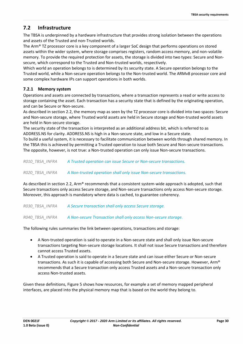
Given these definitions, Figure 5 shows how resources, for example a set of memory mapped peripheral interfaces, are placed into the physical memory map that is based on the world they belong to.
TBSA security requirements
DEN 0021F Copyright © 2017 - 2020 Arm Limited or its affiliates. All rights reserved. Page 31 1.0 Beta (issue 0) Non-Confidential
Non-secure
Peripheral interfaces
0
Top
Physical memory map
Non-secure
Secure
Secure
Non-secure
Secure
Non-secure
Secure
Secure
Non-secure
Non-secure
Secure
Secure
Secure
Non-secure
Secure
Conceptually interfaces are mapped into the physical address space and may only reside in one world.
Figure 5: Peripheral to physical memory mapping
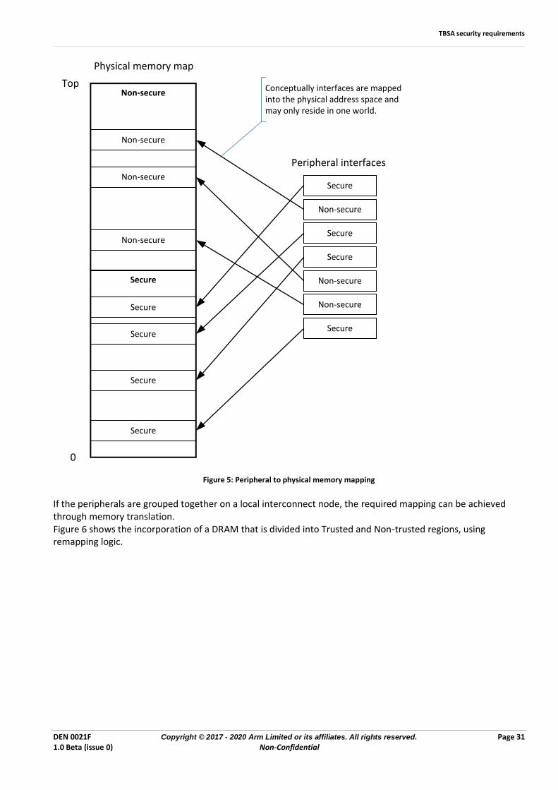
If the peripherals are grouped together on a local interconnect node, the required mapping can be achieved through memory translation. Figure 6 shows the incorporation of a DRAM that is divided into Trusted and Non-trusted regions, using remapping logic.
TBSA security requirements
DEN 0021F Copyright © 2017 - 2020 Arm Limited or its affiliates. All rights reserved. Page 32 1.0 Beta (issue 0) Non-Confidential
{ADDRESS, ADDRESS.NS}
Non-secure
SecureNon-secure
Secure
DRAM Secure
DRAM Non-secure
DRAM
0
Top
Physical memory map
Figure 6: DRAM to physical memory mapping
In this example, and in many real-world cases, the DRAM is simply split into only two regions, Secure and Non-secure. to map the two DRAM regions correctly into the larger physical address map, remapping logic must be implemented. In simple implementations, this can be fixed logic, but it is more likely to be programmable logic, as this offers greater flexibility if software is updated. In the latter case, the relevant configuration registers must only be accessible to Secure transactions, and belong to the Trusted world.
R050_TBSA_INFRA If programmable address remapping logic is implemented in the interconnect then its configuration shall only be possible from the Trusted world.
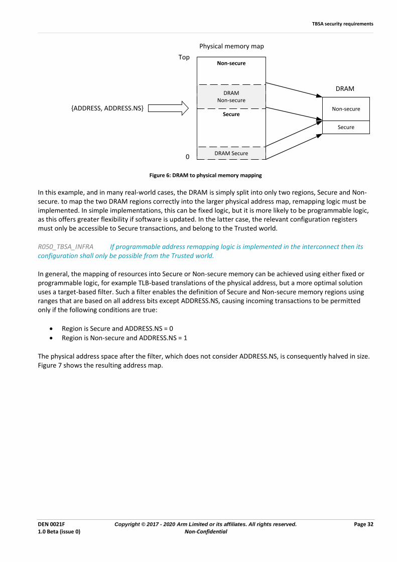
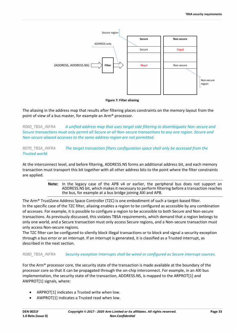
In general, the mapping of resources into Secure or Non-secure memory can be achieved using either fixed or programmable logic, for example TLB-based translations of the physical address, but a more optimal solution uses a target-based filter. Such a filter enables the definition of Secure and Non-secure memory regions using ranges that are based on all address bits except ADDRESS.NS, causing incoming transactions to be permitted only if the following conditions are true:
• Region is Secure and ADDRESS.NS = 0
• Region is Non-secure and ADDRESS.NS = 1
The physical address space after the filter, which does not consider ADDRESS.NS, is consequently halved in size. Figure 7 shows the resulting address map.
TBSA security requirements
DEN 0021F Copyright © 2017 - 2020 Arm Limited or its affiliates. All rights reserved. Page 33 1.0 Beta (issue 0) Non-Confidential
{ADDRESS, ADDRESS.NS}
Secure Illegal
Illegal Non-secureFilter
Secure Non-secure
ADDRESS only
Secure region
Non-secure region
Figure 7: Filter aliasing
The aliasing in the address map that results after filtering places constraints on the memory layout from the point of view of a bus master, for example an Arm® processor.
R060_TBSA_INFRA A unified address map that uses target side filtering to disambiguate Non-secure and Secure transactions must only permit all Secure or all Non-secure transactions to any one region. Secure and Non-secure aliased accesses to the same address region are not permitted.
R070_TBSA_INFRA The target transaction filters configuration space shall only be accessed from the Trusted world.
At the interconnect level, and before filtering, ADDRESS.NS forms an additional address bit, and each memory transaction must transport this bit together with all other address bits to the point where the filter constraints are applied.
Note: In the legacy case of the APB v4 or earlier, the peripheral bus does not support an ADDRESS.NS bit, which makes it necessary to perform filtering before a transaction reaches the bus, for example at a bus bridge joining AXI and APB.
The Arm® TrustZone Address Space Controller (TZC) is one embodiment of such a target-based filter. In the specific case of the TZC filter, aliasing enables a region to be configured as accessible by any combination of accesses. For example, it is possible to configure a region to be accessible to both Secure and Non-secure transactions. As previously discussed, this violates TBSA requirements, which demand that a region belongs to only one world, and a Secure transaction must only access Secure regions, and a Non-secure transaction must only access Non-secure regions. The TZC filter can be configured to silently block illegal transactions or to block and signal a security exception through a bus error or an interrupt. If an interrupt is generated, it is classified as a Trusted interrupt, as described in the next section.
R080_TBSA_INFRA Security exception Interrupts shall be wired or configured as Secure interrupt sources.
For the Arm® processor core, the security state of the transaction is made available at the boundary of the processor core so that it can be propagated through the on-chip interconnect. For example, in an AXI bus implementation, the security state of the transaction, ADDRESS.NS, is mapped to the ARPROT[1] and AWPROT[1] signals, where:
• ARPROT[1] indicates a Trusted write when low.
• AWPROT[1] indicates a Trusted read when low.
TBSA security requirements
DEN 0021F Copyright © 2017 - 2020 Arm Limited or its affiliates. All rights reserved. Page 34 1.0 Beta (issue 0) Non-Confidential
Similarly, a hardware IP that is an AXI bus master will generate the same signals to indicate the security state of each transaction. In architectures that use a network-on-chip interconnect approach, it might be possible to re-configure the routing of packets so that they arrive at a different interface. Even though the access address remains unchanged, this is dangerous and can lead to an exploit. Any such configuration shall only be possible from the Trusted world using Secure transactions.
R090_TBSA_INFRA Configuration of the on-chip interconnect that modifies routing or the memory map shall only be possible from the Trusted world.
The different techniques for address remapping and filtering are both methods of constraint that bind storage locations to worlds. Whatever the method of constraint, it must not be possible for a memory transaction to bypass it. A particular example is the case where multiple caches that are up-stream from a target filter are synchronized via a coherency mechanism. If such a mechanism, for example bus snooping, is implemented, the mechanism must force a coherency transaction to pass through the target filter.
R100_TBSA_INFRA All transactions must be constrained; it must not be possible for a transaction to bypass a constraining mechanism.
7.2.1.1 Shared volatile storage When assets from different worlds can occupy the same physical volatile storage location, the underlying storage, for example internal RAM, external RAM, or peripheral space, is referred to as shared volatile storage. A shared volatile storage implementation therefore enables a storage location or region that previously held a Trusted asset to hold a Non-trusted asset. Before such a storage location or region can be reallocated from Trusted to Non-trusted, the Trusted asset must be securely removed. This can be achieved using scrubbing. Scrubbing is defined as the atomic process of overwriting a Trusted asset with an unrelated value, which is either a constant, a Non-trusted asset value, or a randomly generated number of the same size. Atomic means that the process must not be interrupted by the Non-trusted world.
R110_TBSA_INFRA If shared volatile storage is implemented, then the associated location or region must be scrubbed, before it can be reallocated from Trusted to Non-trusted.
Note: When a copy of Trusted data is held in a cache, it is important that the implementation does not permit any mechanism that provides the Non-Trusted world with access to that data, as required by 0 and 0. If a hardware engine is used for scrubbing, careful attention must be given to the sequence to make sure that the relevant cached data is flushed and invalidated before the scrubbing operation.
7.2.2 Interrupts In most cases a Trusted interrupt, which is an interrupt that is generated by a Trusted operation, must not be visible to a Non-trusted operation to prevent information leaks that might be useful to an attacker. Consequently, the on-chip interrupt network must be capable of routing any interrupt to any world with the caveat that the routing of Trusted interrupts shall only be configured from the Trusted world. The number of interrupts that must be supported in each world depends on the target requirements and is therefore not specified in this document.
R120_TBSA_INFRA An interrupt originating from a Trusted operation must by default be mapped only to a Trusted target. By default, we mean that this must be the case following a system reset.
R130_TBSA_INFRA Any configuration to mask or route a Trusted interrupt shall only be carried out from the Trusted world.
TBSA security requirements
DEN 0021F Copyright © 2017 - 2020 Arm Limited or its affiliates. All rights reserved. Page 35 1.0 Beta (issue 0) Non-Confidential
R140_TBSA_INFRA The interrupt network might be configured to route an interrupt originating from a Trusted operation to a Non-trusted target.
R150_TBSA_INFRA Any status flags recording Trusted interrupt events shall only be read from the Trusted world, unless specifically configured by the Trusted world, to be readable by the Non-trusted world.
For example, these rules permit a Non-trusted world request to a Trusted operation to result, after passing the policy check, in a Trusted Interrupt being delivered to a non-trusted target to signal the end of the operation. Configuration of the interrupt in this way must be done by the Trusted world before or during the Trusted operation. In the Arm® architecture, these requirements can be supported using the GIC interrupt controller block.
7.2.3 Secure RAM In a TBSA system, Trusted code is expected to execute from Secure RAM. The Trusted code will also store high value assets within the Secure RAM. In the context of this document, Secure RAM refers to one or more dedicated regions that are mapped onto one or more physical RAMs. When a physical RAM is not entirely dedicated to Secure storage, it is shared between worlds. However, the underlying locations are not classified as shared volatile storage unless they are re-allocated from Secure to Non-secure. The mapping of Secure regions can be static and fixed by design, or programmable at runtime. Arm® recommends the use of on-chip RAM, but it is acceptable to use SRAM on a separate die if it is within the same package as the main SoC. Example Secure RAM use cases are:
• Secure boot code and data
• Monitor code
• A Secure OS
• Cryptographic services
• Trusted services, for example Global Platform TEE and TAs
The Secure RAM size depends on the target requirements and is therefore not specified in this document. As an example, a quad core system typically integrates 256 KB of SRAM.
R160_TBSA_INFRA A TBSA system must integrate a Secure RAM.
R170_TBSA_INFRA Secure RAM must be mapped into the Trusted world only.
R180_TBSA_INFRA If the mapping of Secure RAM into regions is programmable, then configuration of the regions must only be possible from the Trusted world.
Note, if Secure RAM is re-mapped from the Trusted world to the Non-trusted world, it is classified as shared volatile storage, and it must meet the requirements of a shared volatile storage. For a description of the use of external DRAM for Secure RAM see 7.12
TBSA security requirements
DEN 0021F Copyright © 2017 - 2020 Arm Limited or its affiliates. All rights reserved. Page 36 1.0 Beta (issue 0) Non-Confidential
7.2.4 Power and clock management Modern battery powered mobile platforms have a high degree of power control and might integrate an advanced power management subsystem using dedicated hardware, and execute a small software stack from local RAM. In such cases, the management subsystem has control over a number of Trusted assets, for example:
• Clock generation and selection. Examples include: o Phase-Locked Loops (PLL) o Clock dividers o Glitch-less clock switching o High-level clock gating
• Reset generation. Examples include: o Registers to enable or disable clocks o State machines to sequence the assertion and de-assertion of resets in relation to clocks and power
states o Re-synchronization of resets
• Power control. Examples include: o Access to an off-chip power controller/switch/regulator o State machine for sequencing when changing power states o Logic or processing to intelligently apply power states either on request, or dynamically
• State saving and restoration. To dynamically apply power states, some subsystems can also perform saving and restoration of system states without the involvement of the main application processor.
Unrestricted access to this functionality is dangerous, because it could be used by an attacker to induce a fault that targets a Trusted service, for example by perturbing a system clock. To mitigate this threat, the advanced power mechanism must integrate a Trusted management function, which performs policy checks on any requests from the Non-trusted word, before they can be applied. This approach still permits most of the Non-trusted complex peripheral wake up code, which is usually created by the OEM and subject to frequent updates, to be executed from the Non-trusted world.
R190_TBSA_INFRA The advanced power mechanism must integrate a Trusted management function to control clocks and power. It must not be possible to directly access clock and power functionality from the Non-trusted world.
R200_TBSA_INFRA The power and clock status must be available to the Non-trusted world.
Note: All system clocks are classified as Trusted because they can only be configured via the Trusted manager.
7.2.5 Peripherals
A peripheral is a hardware block that is not a processor core, and which implements one or more operations that act on assets. It has an interface to receive commands and data from one or more processor cores and might be capable of direct memory access. A simple peripheral can have its operations mapped into one world or the other by the wider system depending on its role in the current use case.
R210_TBSA_INFRA If access to a peripheral, or a subset of its operations, can be dynamically switched between Trusted world and Non-trusted world, then this shall only be done under the control of the Trusted world.
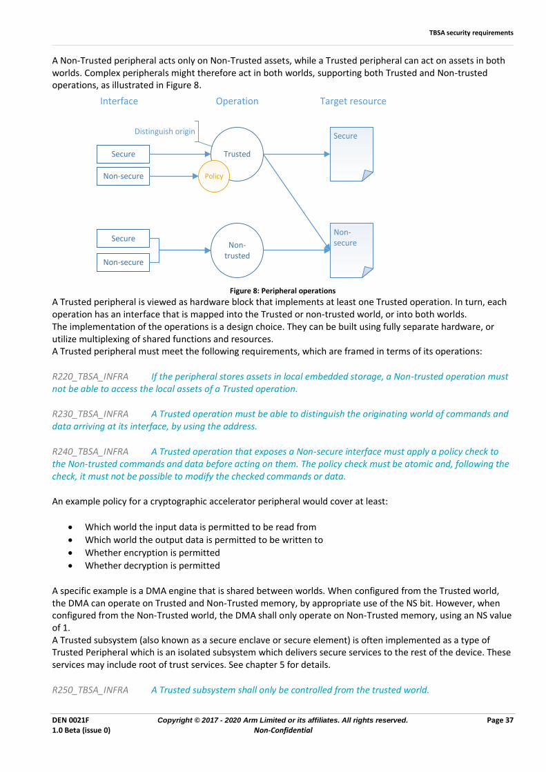
TBSA security requirements
DEN 0021F Copyright © 2017 - 2020 Arm Limited or its affiliates. All rights reserved. Page 37 1.0 Beta (issue 0) Non-Confidential
A Non-Trusted peripheral acts only on Non-Trusted assets, while a Trusted peripheral can act on assets in both worlds. Complex peripherals might therefore act in both worlds, supporting both Trusted and Non-trusted operations, as illustrated in Figure 8.
Trusted
Non-trusted
Operation Target resourceInterface
Secure
Non-secure
Secure
Non-secure Policy
Secure
Non-secure
Distinguish origin
Figure 8: Peripheral operations
A Trusted peripheral is viewed as hardware block that implements at least one Trusted operation. In turn, each operation has an interface that is mapped into the Trusted or non-trusted world, or into both worlds. The implementation of the operations is a design choice. They can be built using fully separate hardware, or utilize multiplexing of shared functions and resources. A Trusted peripheral must meet the following requirements, which are framed in terms of its operations:
R220_TBSA_INFRA If the peripheral stores assets in local embedded storage, a Non-trusted operation must not be able to access the local assets of a Trusted operation.
R230_TBSA_INFRA A Trusted operation must be able to distinguish the originating world of commands and data arriving at its interface, by using the address.
R240_TBSA_INFRA A Trusted operation that exposes a Non-secure interface must apply a policy check to the Non-trusted commands and data before acting on them. The policy check must be atomic and, following the check, it must not be possible to modify the checked commands or data.
An example policy for a cryptographic accelerator peripheral would cover at least:
• Which world the input data is permitted to be read from
• Which world the output data is permitted to be written to
• Whether encryption is permitted
• Whether decryption is permitted
A specific example is a DMA engine that is shared between worlds. When configured from the Trusted world, the DMA can operate on Trusted and Non-Trusted memory, by appropriate use of the NS bit. However, when configured from the Non-Trusted world, the DMA shall only operate on Non-Trusted memory, using an NS value of 1. A Trusted subsystem (also known as a secure enclave or secure element) is often implemented as a type of Trusted Peripheral which is an isolated subsystem which delivers secure services to the rest of the device. These services may include root of trust services. See chapter 5 for details.
R250_TBSA_INFRA A Trusted subsystem shall only be controlled from the trusted world.
TBSA security requirements
DEN 0021F Copyright © 2017 - 2020 Arm Limited or its affiliates. All rights reserved. Page 38 1.0 Beta (issue 0) Non-Confidential
For Trusted subsystems having only a single interface to the rest of the system that interface must only be directly accessible by the trusted world. This supports the use of flexible policies in how the normal world interacts with a trusted subsystem. More complex trusted subsystems may have several interfaces to the rest of the system in which case the design should still ensure that the subsystem must only be controlled from the Trusted World. In the case that the trusted subsystem is off-chip this means that the associated interface controller must be implemented in the Trusted World.
7.3 Fuses A modern SoC requires non-volatile storage to store a range of data across power cycles. These vary from the device firmware to cryptographic keys and system configuration parameters. Non-volatile storage can use a variety of technologies, for example floating gate memories or oxide-breakdown antifuse cells. These technologies vary with respect to certain properties, most notably whether they are one-time-programmable (OTP) or many-time-programmable (MTP). Not all non-volatile storage technologies are available in all semiconductor processes. Floating gate memories, for example, are not economic in modern bulk CMOS processes. Where needed, off-chip non-volatile memory can be used to augment the available on-chip non-volatile storage. Non-Volatile storage technologies generally require error correction mechanisms to ensure the correct storage of data over the lifespan of the device.
R010_TBSA_FUSE A non-volatile storage technology shall meet the lifetime requirements of the device, either through its intrinsic characteristics, or through the use of error correction mechanisms.
The majority of security assets and settings that need to be stored on-chip require OTP non-volatile storage to ensure that the values cannot be changed. Following the industry norm, the rest of this document will use the term fuse to refer to on-chip OTP non-volatile storage. Fuses can be implemented using antifuses or an MTP technology with controlling logic to make it OTP. The fundamental requirements for implementing fuses in a TBSA device are:
R020_TBSA_FUSE A fuse is permitted to transition in one direction only, from its un-programmed state to its programmed state. The reverse operation shall be prevented.
R030_TBSA_FUSE A fuse shall be programmed only once as multiple programming operations might degrade the programmed cell(s) and introduce a fault.
R040_TBSA_FUSE It shall be possible to blow at least a subset of the fuses when the device has left the silicon manufacturing facility.
R050_TBSA_FUSE All fuse values shall be stable before any parts of the SoC that depend on them are released from reset.
R060_TBSA_FUSE Fuses that configure the security features of the device shall be configured so that the programmed state of the fuse enables the feature. i.e. the programming of a security configuration fuse will always increase security within the SoC.
This ensures that after a security feature is enabled, it cannot be deactivated.
R070_TBSA_FUSE Lifetime guarantee mechanisms to correct for in-field failures shall not indicate which fuses have had errors detected or corrected, just that an error has been detected or corrected. This indicator shall only be available after all fuses have been checked.
TBSA security requirements
DEN 0021F Copyright © 2017 - 2020 Arm Limited or its affiliates. All rights reserved. Page 39 1.0 Beta (issue 0) Non-Confidential
The full error information will be available to the lifetime guarantee mechanism and the security of the mechanism implementation must be considered. Arm® recommends implementing the mechanism in hardware, but this might not always be practical. Assets stored in fuses have a variety of characteristics that in turn determine the way that the fuses are accessed. The characteristics of fuses can be summarized as follows: Confidential/Public - "Confidential" fuses must only be read by the intended recipient, or a particular hardware module or software process. "Public" fuses can be accessed by any piece of software or hardware. Lockable/Open - “Lockable” fuses shall comply with one of the following requirements:
• Prevent re-writing of a locked value.
A mechanism that prevents the programming of a fuse bit or group of fuse bits can be implemented by reserving an additional fuse bit to act as a lock bit:
• Writing the value is followed by its lock bit being set. Glue logic ensures that no further programming is possible.
• Writing zero, which corresponds to the un-programmed fuse state, causes no value to be written, only the lock bit to be set.
• Use tamper detection to detect that the value has been modified.
A tamper protection mechanism can be implemented by storing a code in additional fuses that is sufficient to detect any modification to the value:
• Writing the value is followed by storing the detection code.
• When the value is read by the system, a mechanism must recalculate the code from the value and compare it with the stored code.
• If the codes do not match, the value shall not be returned to the system.
By definition, "Open" fuse bits might be programmed only once, at any point in the device lifetime. Bitwise/Bulk - "Bitwise" fuses can be programmed one logical fuse at a time, regardless of the number of fuses required to store the value. "Bulk" fuses store multi-bit values that must be programmed at the same time and are treated as an atomic unit. Bitwise and bulk fuses must comply with the following requirements:
R080_TBSA_FUSE A confidential fuse whose recipient is a hardware IP shall not be readable by any software process.
R090_TBSA_FUSE A confidential fuse whose recipient is a hardware IP shall be connected to the IP using a path that is not visible to software or any other hardware IP.
Usually, this is implemented as a direct wire connection.
R100_TBSA_FUSE A confidential fuse whose recipient is a software process might be readable by that process and shall be readable by software of a higher exception level.
This permits a kernel level driver to access fuses for a user space process. The confidentiality relies on the kernel level driver only passing fuse values to the correct user space process.
R110_TBSA_FUSE A confidential fuse whose recipient is a Trusted world software process shall be protected by a hardware filtering mechanism that can only be configured by S-EL1, S-EL2 or EL3 software, for example an MPU, an MMU, or an NS-bit filter.
TBSA security requirements
DEN 0021F Copyright © 2017 - 2020 Arm Limited or its affiliates. All rights reserved. Page 40 1.0 Beta (issue 0) Non-Confidential
R120_TBSA_FUSE It must be possible to fix a lockable fuse in its current state, regardless of whether it is programmed or un-programmed.
R130_TBSA_FUSE The locking mechanism for a lockable fuse can be shared with other lockable fuses, depending on the functional requirements.
For example, there can be one locking mechanism for all fuses that are programmed by the silicon vendor.
R140_TBSA_FUSE A bulk fuse shall also be a lockable fuse to ensure that any unprogrammed bits cannot be later programmed.
R150_TBSA_FUSE Additional fuses that are used to implement lifetime guarantee mechanisms shall have the same confidential and write lock characteristics as the logical fuse itself.
7.4 Cryptographic keys Fundamental to the security of a system are the cryptographic keys that provide authenticity and confidentiality of the assets that are used by the system. It is important that a key is treated as an atomic unit when it is created, updated, or destroyed. This applies at the level of the requesting entity. Replacing part of a key with a known value and then using that key in a cryptographic operation makes it significantly easier for an attacker to discover the key using a divide and conquer brute-force attack. This is especially relevant when a key is stored in memory units that are smaller than the key, for example a 128-bit key that is stored in four 32-bit memory locations. Entities, such as trusted firmware functions, which implement creation, updating or destruction services for keys should ensure that it is not possible for their clients to observe or use keys in a manner which breaks the assumption of atomicity.
R010_TBSA_KEY A key shall be treated as an atomic unit. It shall not be possible to use a key in a cryptographic operation before it has been fully created, during an update operation, or during its destruction.
R020_TBSA_KEY Any operations on a key shall be atomic. It shall not be possible to interrupt the creation, update, or destruction of a key.
R030_TBSA_KEY When a key is no longer required by the system, it must be put beyond use to prevent a hack at a later time from revealing it.
If a key is “put beyond use” there must be no possible way of using or accessing it, which can be achieved by hiding the key through blocking access to it, or by removing the key from the system through scrubbing the storage location that contains the key.
7.4.1 Characteristics Keys have a range of characteristics that influence the level of protection that must be applied, and how the keys can be used.
7.4.1.1 Cryptographic Schemes
A cryptographic scheme provides one or more security services and is based on a purpose and an algorithm requiring specific key properties and key management. Keys are characterized depending on their classification as private, public or symmetric keys and according to their use.
TBSA security requirements
DEN 0021F Copyright © 2017 - 2020 Arm Limited or its affiliates. All rights reserved. Page 41 1.0 Beta (issue 0) Non-Confidential
Broadly, each key should only be used for a single purpose, such as encryption, digital signature, integrity, and key wrapping. The main motivations for this principle are:
• Limiting the uses of a key limits the potential harm if the key is compromised.
• The use of a single key for two or more different cryptographic schemes can reduce the security provided by one or more of the processes.
• Different uses of a single key can lead to conflicts in the way each key should be managed. For example, the different lifetime of keys used in different cryptographic processes may result in keys having to be retained longer than is best practice for one or more uses of that key.
In cases where a scheme can provide more than one cryptographic service, this principle does not prevent use of a single key. For instance, when a symmetric key is used both to encrypt and authenticate data in a single operation or when a digital signature is used to provide both authentication and integrity. Re-using part of a larger key in a scheme that uses a shorter key, or using a shorter key in a larger algorithm and padding the key input, can leak information about the key. So, this too, is prohibited.
R035_TBSA_KEY A key must only be used by the cryptographic scheme for which it was created.
7.4.1.2 Volatility Keys used by the system will have vastly different lifespans. Some keys are programmed during SoC manufacture and never change, while others will exist only during the playback of a piece of content. Static - A static key is a key that cannot change after it has been introduced to the device. It might be stored in an immutable structure like a ROM or a set of fuses. Although a static key cannot have its value changed, it does not preclude it from being revoked or made inaccessible by the system.
R070_TBSA_KEY A static key shall be stored in an immutable structure, for example a ROM or a set of Bulk-Lockable fuses.
Ephemeral - Ephemeral keys have a short lifespan. In many cases, they only exist between power cycles of the device. Ephemeral keys can be created in the device in a number of ways:
• Derivation - Sometimes it is useful to create one or more keys from a source key. This method is called key derivation. Derivation is used most often, to create ephemeral keys from static keys.
A key derivation operation shall use a cryptographic one-way function that preserves the entropy of the source key, and the operation shall be unique for each derived key. Common derivation constructions are based on use a keyed-Hash Message Authentication Code (HMAC) or a Cipher-based Message Authentication Code (CMAC). Collectively, the inputs to the one-way derivation function are referred to as “Source Material”.
R080_TBSA_KEY To dispose of a derived key, at least one part of the Source Material shall be put beyond use until the next boot to ensure that the key cannot be derived again.
• Injection - A key is introduced into the system from storage or via a communication link. One example is the key within a DRM license certificate. To ensure that the key is encrypted during transit, the injection is often protected by another key.
• Generation - Ephemeral keys can be generated on the device by simply sampling random numbers or by using random numbers to create a key, for example in a Diffie-Hellman key exchange protocol.
When an ephemeral key is no longer required, it must be removed securely from the system. This must happen even if the event that makes the key redundant is unexpected, for example in case of a reset.
TBSA security requirements
DEN 0021F Copyright © 2017 - 2020 Arm Limited or its affiliates. All rights reserved. Page 42 1.0 Beta (issue 0) Non-Confidential
R090_TBSA_KEY If an ephemeral key is stored in memory or in a register in clear text form, the storage location must be scrubbed before being used for another purpose.
7.4.1.3 Unique/Common Device Unique - A device unique key is statistically unique for each device, meaning that the probability of another device having the same key value is insignificant. For TBSA systems, a key with at least 128-bits of entropy is considered to be sufficient for device uniqueness. Common - A common key is present on multiple devices.
7.4.1.4 Source Non-trusted world:
R100_TBSA_KEY A key that is accessible to, or generated by, the Non-trusted world shall only be used for Non-trusted world cryptographic operations, which are operations that are either implemented in Non-trusted world software, or have both input data and output data in the Non-trusted world.
Trusted world:
R110_TBSA_KEY A key that is accessible to, or generated by, the Trusted world can be used for operations in both Non-trusted and Trusted worlds, and even across worlds, as long as:
1. The Non-trusted world cannot access the key directly.
2. The Trusted world can control the use of the key through a policy.
An example policy would cover at least:
• Which world the input data is permitted to be read from
• Which world the output data is permitted to be written to
• Permitted operations
In an architecture which uses a trusted subsystem, the "Source" key characteristic is extended to include "Trusted hardware" where the key is derived or generated by hardware and/or immutable firmware.
R120_TBSA_KEY A Trusted hardware key shall not be directly accessible by any software.
A Trusted hardware key can be used for Trusted world cryptographic operations, but its usage in a Non-trusted world must be subject to a policy.
R130_TBSA_KEY The Trusted world must be able to enforce a usage policy for any Trusted hardware key which can be used for Non-trusted world cryptographic operations.
7.4.2 Root keys A TBSA-compliant SoC must be capable of providing authentication and encryption services through the use of embedded cryptographic keys. The exact number of embedded keys and their type depends on the target requirements, and is not specified in this document. However, as a minimum, a TBSA-compliant device must embed two root keys, one for confidentiality and one for authentication, from which others can be derived:
• A hardware unique root symmetric key (HUK) for encryption and decryption
• A root authentication key that is the public key half of an asymmetric key pair, it might belong to an RSA or elliptic curve cryptosystem (ECC) and is referred to as the Root of Trust Public Key (ROTPK)
TBSA security requirements
DEN 0021F Copyright © 2017 - 2020 Arm Limited or its affiliates. All rights reserved. Page 43 1.0 Beta (issue 0) Non-Confidential
Examples of other embedded root keys are:
• Endorsement keys - these are asymmetric key pairs used to prove identity and therefore trustworthiness to the external world
• Additional symmetric keys for firmware decryption and provisioning - alternatively, if ownership is not an issue, these can be derived from the HUK
The use of an elliptic curve cryptosystem for asymmetric cryptography is often beneficial because its smaller key sizes lessens storage and transmission requirements. For example, the RSA algorithm of key size 3072 bits gives comparable security to an ECC algorithm of key size in the range 256-383 bits depending on details of the algorithm and parameters chosen. System architects should also review the comparative resource requirements and performance of RSA and ECC implementations for each of the relevant key use cases.
R140_TBSA_KEY A TBSA device must either entirely embed a root of trust public key (ROTPK), or the information that is needed to securely recover it as part of a protocol.
R150_TBSA_KEY If stored in its entirety, the ROTPK must reside in on-chip non-volatile memory that is only accessible until all the operations requiring it are complete. The ROTPK can be hard wired into the device, for example a ROM, or it can be programmed securely into Confidential-Bulk-Lockable fuses during manufacture.
When no longer in use, hiding the ROTPK requires a non-reversible mechanism, for example a sticky register bit that is activated by the boot software.
R160_TBSA_KEY An elliptic-curve-based ROTPK must achieve a level of security matching that of at least 256 bits.
R170_TBSA_KEY An RSA-based ROTPK must achieve a level of security matching that of at least 3072 bits in size.
If an RSA cryptosystem is implemented, the following approaches are permitted to reduce the ROTPK storage footprint:
• Instead of the key itself, a cryptographic hash of the key can be stored in on-chip non-volatile storage. The public key can then be stored1, in external non-volatile memory. When required, the key must be retrieved from external memory, and successfully compared with the stored hash by Trusted hardware or software, before it is used. This approach is known as hash locking. Because this approach is not susceptible to a second pre-image attack, only half of the digest bits from an approved hash algorithm need to be stored. It is not important which subset of bits is stored, but typically the leftmost 128 bits from a SHA-256 digest are used.
• Instead of the key itself, a 256-bit seed can be stored in on-chip non-volatile storage. The public/private key pair can then be re-generated by Trusted hardware or software. Because the seed enables the re-creation of both the public and private key, Arm® recommend not to use this approach if only the public key is required. Moreover, in many target specifications it is a mandatory requirement that the signing, or private, key component must not be present in the device.
R180_TBSA_KEY If a cryptographic hash of the ROTPK is stored in on chip non-volatile memory, rather than the key itself, it must be immutable.
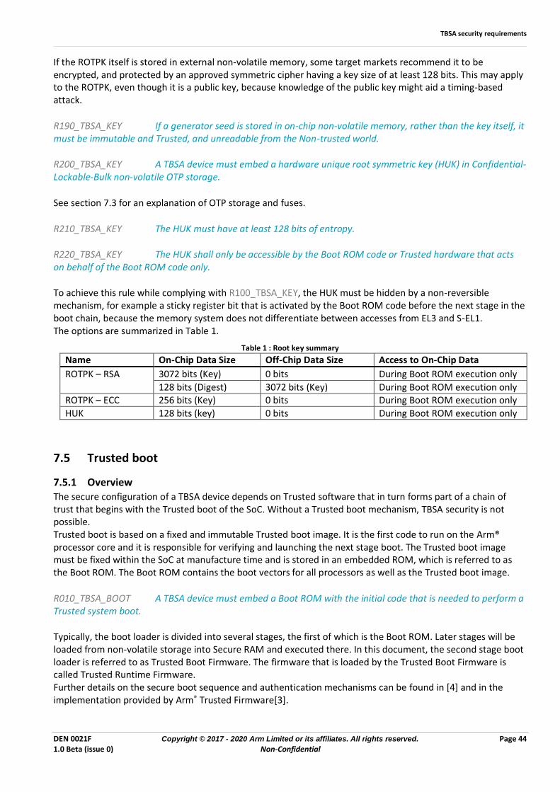
TBSA security requirements
DEN 0021F Copyright © 2017 - 2020 Arm Limited or its affiliates. All rights reserved. Page 44 1.0 Beta (issue 0) Non-Confidential
If the ROTPK itself is stored in external non-volatile memory, some target markets recommend it to be encrypted, and protected by an approved symmetric cipher having a key size of at least 128 bits. This may apply to the ROTPK, even though it is a public key, because knowledge of the public key might aid a timing-based attack.
R190_TBSA_KEY If a generator seed is stored in on-chip non-volatile memory, rather than the key itself, it must be immutable and Trusted, and unreadable from the Non-trusted world.
R200_TBSA_KEY A TBSA device must embed a hardware unique root symmetric key (HUK) in Confidential-Lockable-Bulk non-volatile OTP storage.
See section 7.3 for an explanation of OTP storage and fuses.
R210_TBSA_KEY The HUK must have at least 128 bits of entropy.
R220_TBSA_KEY The HUK shall only be accessible by the Boot ROM code or Trusted hardware that acts on behalf of the Boot ROM code only.
To achieve this rule while complying with R100_TBSA_KEY, the HUK must be hidden by a non-reversible mechanism, for example a sticky register bit that is activated by the Boot ROM code before the next stage in the boot chain, because the memory system does not differentiate between accesses from EL3 and S-EL1. The options are summarized in Table 1.
Table 1 : Root key summary
Name On-Chip Data Size Off-Chip Data Size Access to On-Chip Data
ROTPK – RSA 3072 bits (Key) 0 bits During Boot ROM execution only
128 bits (Digest) 3072 bits (Key) During Boot ROM execution only ROTPK – ECC 256 bits (Key) 0 bits During Boot ROM execution only
HUK 128 bits (key) 0 bits During Boot ROM execution only
7.5 Trusted boot
7.5.1 Overview The secure configuration of a TBSA device depends on Trusted software that in turn forms part of a chain of trust that begins with the Trusted boot of the SoC. Without a Trusted boot mechanism, TBSA security is not possible. Trusted boot is based on a fixed and immutable Trusted boot image. It is the first code to run on the Arm® processor core and it is responsible for verifying and launching the next stage boot. The Trusted boot image must be fixed within the SoC at manufacture time and is stored in an embedded ROM, which is referred to as the Boot ROM. The Boot ROM contains the boot vectors for all processors as well as the Trusted boot image.
R010_TBSA_BOOT A TBSA device must embed a Boot ROM with the initial code that is needed to perform a Trusted system boot.
Typically, the boot loader is divided into several stages, the first of which is the Boot ROM. Later stages will be loaded from non-volatile storage into Secure RAM and executed there. In this document, the second stage boot loader is referred to as Trusted Boot Firmware. The firmware that is loaded by the Trusted Boot Firmware is called Trusted Runtime Firmware. Further details on the secure boot sequence and authentication mechanisms can be found in [4] and in the implementation provided by Arm® Trusted Firmware[3].
TBSA security requirements
DEN 0021F Copyright © 2017 - 2020 Arm Limited or its affiliates. All rights reserved. Page 45 1.0 Beta (issue 0) Non-Confidential
7.5.2 Boot types A cold boot is a boot that is not based on a previous system state. Normally, a cold boot only occurs when the platform is powered up and a hard-reset signal is generated by a power-on reset circuit. However, depending on the design, a hard-reset option that triggers a cold boot might also be available to the user in case of a software lock-up. A warm boot can deploy one of the following methods to reuse the stored system state, for example on resuming from sleep:
• The Boot ROM can use a platform-specific mechanism that is designed into the Boot ROM to distinguish between a warm boot and a cold boot.
• The platform can use platform-specific registers to support an alternate reset vector for a warm boot.
R020_TBSA_BOOT If the device supports warm boots, a flag or register that survives the sleep state must exist to enable distinguishing between warm and cold boots. This register shall be programmable only by the Trusted world and shall be reset after a cold boot.
Typically, any storage that is needed to support these mechanisms is implemented within an always-on power domain.
7.5.3 Boot configuration
If the SoC implements multiple processor cores the designated boot processor core is called the primary. After the de-assertion of a reset, the primary processor core executes the Boot ROM code, and the remaining cores are held in reset or a safe platform-specific state until the primary processor core initializes and boots them.
R030_TBSA_BOOT On a cold boot, the primary processor core must boot from the Boot ROM. It must not be possible to boot from any other storage unless Trusted Kernel debug is enabled. For detailed information about Trusted Kernel debug, see section 7.10.
R040_TBSA_BOOT All secondary processor cores must remain inactive until permitted to boot by the primary processor core.
In one implementation, the platform power controller holds all secondary processor cores in a reset state, while the primary processor core executes the Boot ROM until it requests the secondary processor cores to be released. In an alternative implementation, all processor cores execute from the generic boot vector in the Boot ROM after a cold boot. However, the Boot ROM identifies the primary processor core and permits it to boot using the Trusted boot image, while the secondary processor cores are made inactive. The ARMv8 architecture supports both 32-bit and 64-bit execution, which are labelled AArch32 and AArch64, respectively. The execution mode on boot is implementation-defined. For example, in the specific case of the Cortex-A53 and Cortex-A57 processors, the execution mode is controlled by a signal (AA64nAA32) which is sampled at reset. This boot execution mode signal can be hard-wired or depend on on-chip fuse bits. Arm® recommends that the primary processor core boots into 64-bit mode, AArch64.
R050_TBSA_BOOT The processor execution mode (Aarch32 or Aarch64) at cold boot must be fixed and unchangeable. It must not be possible to change the boot mode through any external means, for example by using dedicated pins at the SoC boundary.
If a different execution mode is required, the Boot ROM can change the processor core execution mode and provoke a warm boot. If the platform does not support a programmable reset vector, two Trusted boot images (one for each execution mode) are required to be present in the Boot ROM. The ARMv8-A architecture, when implemented with the TrustZone extensions, will always boot into EL3. The Trusted Boot ROM contains sensitive code that verifies and optionally decrypts the next stage of the boot. For some devices, if an attacker were able to read and disassemble the ROM image, they could gain valuable
TBSA security requirements
DEN 0021F Copyright © 2017 - 2020 Arm Limited or its affiliates. All rights reserved. Page 46 1.0 Beta (issue 0) Non-Confidential
information that could be used to target an attack that circumvents the verification mechanism. For example, timing information can be used to target a fault injection attack. Contingent on the threat model, it may aid robustness if the Trusted boot image within the Boot ROM is accessible only during boot. Device designers should consider implementing a non-reversible mechanism which prevents access by, for example, hiding the Trusted boot image using a sticky register bit that is activated by the boot software. Arm recommends that when stored in external NVM, the Trusted Boot Firmware image should be stored encrypted using an approved algorithm. This is to deter the acquisition of the image by an attacker to inspect for vulnerabilities. The Trusted Boot Firmware image can be encrypted using the HUK, or a HUK-derived key, which would require a unique image for each device, or using a common static key, which enables the same image to be used across a set of devices. Arm recommends that externally held Firmware is authenticated using an approved algorithm. Arm recommends that the key that decrypts Trusted boot firmware is protected from being accessed or re-derived after boot to mitigate the threat of attacks revealing the plaintext of Trusted Boot Firmware image. The key and its source material must either be made inaccessible or accessible only by the Trusted world. It is important that the key that is used to decrypt Trusted Boot Firmware is not available to the system at a later point, not even for decrypting Trusted Runtime Firmware, because this ensures that a software-controlled decryption operation cannot reveal the plaintext Trusted Boot Firmware image. The Trusted Boot Firmware code is responsible for verifying and, if successful, launching the next stage boot, Trusted Runtime Firmware, which is held in off chip memory, typically flash memory. This is a non-trivial operation, because the image must be copied to DRAM before authentication, which requires the clocks, pad logic, and the DRAM controller to be configured correctly in advance. When loaded into DRAM, the image is optionally decrypted before it is verified, and if and only if verification is successful, the image is executed. Verification is based on public key cryptography, which uses a digital signature scheme, and Arm® recommends that decryption uses a different key to the one that is used for Trusted Boot Firmware. A boot status register can be implemented to indicate the boot state of each processor within the Trusted world. For example, the boot status register enables the application processor to check if other Trusted processors are booted up correctly. The register can also be used as a general boot status register.
R100_TBSA_BOOT If a boot status register is implemented, then it must be accessible only by the Trusted world.
7.5.4 Stored configuration Some aspects of the secure boot behavior, which are governed by the Trusted ROM, might depend on stored configuration information. For example, in the case of a warm boot, configuration information might be stored in Trusted registers that are immutable between secure boot executions. This can be implemented using a sticky register bit to prevent access to the data. The sticky bit is set by the secure boot code when the necessary operations of a cold or warm boot have been performed, and reset by triggering a warm or a cold boot. In the case of a cold boot, the Trusted ROM behavior might be entirely fixed in the implementation. However, it can also be influenced by additional configuration information stored in fuses. Fuse configuration information can be used for the following purposes:
• Selection of the boot device
• Storage of the root public authentication key
• Storage of a root key for boot image decryption
• Storage of other boot specific parameters
7.5.5 Trusted Subsystems
At each step in the boot chain, each stage must verify the next, and because the Trusted Boot Firmware is encrypted, a decryption step is also needed. Verification of an image is based on a cryptographic hash function and asymmetric cryptography, while decryption of an image is based on symmetric cryptography. Because the underlying cryptographic algorithms are CPU-intensive, Trusted subsystems often implements hardware acceleration.
TBSA security requirements
DEN 0021F Copyright © 2017 - 2020 Arm Limited or its affiliates. All rights reserved. Page 47 1.0 Beta (issue 0) Non-Confidential
In an architecture which uses a Trusted subsystem with a symmetric decryption acceleration peripheral, any symmetric key used to decrypt the Trusted Boot Firmware should be used only by the accelerator peripheral, and shall not visible to software.
R110_TBSA_BOOT In an architecture which uses a Trusted subsystem to accelerate the decryption of Trusted Boot Firmware the decryption key shall be visible only to the acceleration peripheral.
7.6 Trusted timers
7.6.1 Trusted clock source
Trusted clock sources are needed to implement Trusted watchdog timers and Trusted time. By definition, all system clock sources are classified as Trusted, and can only be configured from the Trusted world. In addition to this, a Trusted clock source must be robust against tampering that happens outside of the control of the associated Trusted manager. Two protection strategies are possible:
• Internal clock source: The clock source is an integrated autonomous oscillator within the die and cannot be easily altered or stopped without deploying invasive techniques.
• External clock source: The clock source is an external XTAL or clock module and connects to the main SoC through an I/O pin. In this case, an attacker can easily stop the clock or alter its frequency. If this is the case, then the main SoC must implement monitoring hardware that can detect when the clock frequency is outside its acceptable range.
R010_TBSA_TIME If the Trusted clock source is external, then monitoring hardware must be implemented that checks the clock frequency is within acceptable bounds.
R020_TBSA_TIME If clock monitoring hardware is implemented, then it must expose a status register that indicates whether the associated clock source is compromised. This register must be readable only from the Trusted world.
To signal a clock frequency violation, it might also be useful to add a Trusted interrupt to any Trusted clock monitoring hardware.
7.6.2 General trusted timer
Trusted timers are needed to provide time-based triggers to Trusted world services. A TBSA system must support one or more Trusted timers.
R030_TBSA_TIME At least one Trusted timer must exist.
R040_TBSA_TIME A Trusted timer shall only be modified by a Trusted access. Examples of modifications are the timer being refreshed, suspended, or reset.
R050_TBSA_TIME The clock source that drives a Trusted timer must be a Trusted clock source.
7.6.3 Watchdog A TBSA system must support one or more Trusted watchdog timers. Trusted watchdog timers are needed to protect against denial of service, for example where secure services depend on the ROS scheduler. In such cases, if the Trusted world is not entered before a pre-defined time limit, a reset is issued and the SoC is restarted. It is desirable for a Trusted watchdog timer to have the ability to signal an interrupt in advance of the reset, permitting some state save before a reboot.
R060_TBSA_TIME At least one Trusted watchdog timer must exist.
TBSA security requirements
DEN 0021F Copyright © 2017 - 2020 Arm Limited or its affiliates. All rights reserved. Page 48 1.0 Beta (issue 0) Non-Confidential
R070_TBSA_TIME After a system restart, trusted watchdog timers must be started automatically.
R080_TBSA_TIME A Trusted watchdog timer shall only be modified by a Trusted access. Examples of modifications are the timer being refreshed, suspended, or reset.
Arm® recommends that a clock speed of at least 1 Hz is used when the device is not in a power saving cycle.
R090_TBSA_TIME Before needing a refresh, a Trusted watchdog timer must be capable of running for a time period that is long enough for the Non-trusted re-flashing of early boot loader code.
R100_TBSA_TIME A Trusted watchdog timer must be able to trigger a Warm reset of the SoC, which is similar to a cold boot, after a pre-defined period of time. This value can be fixed in hardware or programmed by a Trusted access.
R110_TBSA_TIME A Trusted watchdog timer must implement a flag that indicates the occurrence of a timeout event that causes a Warm reset, to distinguishes this from a powerup cold boot.
R120_TBSA_TIME The clock source driving a Trusted watchdog timer must be a Trusted clock source.
7.6.4 Trusted time Many Trusted services, for example DRM stacks, rely on the availability of Trusted time. Typically, Trusted time is implemented using an on-chip real-time counter that is synchronized securely with a remote time server. An ideal implementation of a Trusted real-time clock (TRTC) would consist of a continuously powered counter driven by a continuous and accurate clock source, with Trusted time programmable only from the Trusted world. However, devices that contain a removable battery must deal with power outages. A suitable solution for dealing with power outages can be realized by implementing a counter together with a status flag that indicates whether a valid time has been loaded. A TBSA system that deploys this solution implements Trusted time using a TRTC that consists of a Trusted hardware timer that is associated with a status flag that indicates whether the current time is valid, and receives a Trusted clock source. The valid flag is set when the Trusted timer has been updated by a Trusted service and is cleared when power is removed from the timer. Arm® recommends that the Trusted timer and valid flag reside in a power domain that remains on as much as possible. When the Trusted time is lost due to a power outage, the response will depend on the target specifications. For example, it might be acceptable to restrict specific Trusted services until the TRTC has been updated by the appropriate Trusted service.
R130_TBSA_TIME A TRTC shall be configured only by a Trusted world access.
R140_TBSA_TIME All components of a TRTC shall be implemented within the same power domain.
R150_TBSA_TIME On initial power up, and following any other outage of power to the TRTC, the valid flag of the TRTC shall be cleared to zero.
R160_TBSA_TIME The TRTC must be driven by a Trusted clock source.
TBSA security requirements
DEN 0021F Copyright © 2017 - 2020 Arm Limited or its affiliates. All rights reserved. Page 49 1.0 Beta (issue 0) Non-Confidential
7.7 Version counters A compliant TBSA system must implement a core set of Trusted non-volatile counters, which are required for version control of firmware and trusted data held in external storage. An important property of these counters is that it must not be possible to roll them back, to prevent replay attacks. The following counters are mandatory:
• A Trusted firmware version counter
• A Non-trusted firmware version counter
Ideally, a SoC implementation implements version counters using on-chip multiple time programmable (MTP) storage, for example floating gate (EE ROM) or phase transition technology. While this is possible for most smart card designs, it is recognized that an MTP based approach is currently not economically scalable for larger die sizes because the process overhead is very costly compared to a standard bulk CMOS process. By contrast, one-time programmable (OTP) storage, which is based on anti-fuse technology, is widely available and cost effective. A non-volatile counter can be implemented by mapping each possible value that is greater than one onto a separate fuse bit. Each counter increment is achieved by programming a further bit. Because one bit is required for each value, this approach has the downside of being very costly for large counters, for example a 10-bit counter requires 1024 bits of storage. For this reason, practical limitations must be imposed on the maximum count values for fuse-based implementations. The size requirement for a version counter depends on the target specification. For a TBSA system, the minimum requirement is as follows:
R010_TBSA_COUNT An on-chip non-volatile Trusted firmware version counter implementation must provide a counter range of 0 to 63.
R020_TBSA_COUNT An on-chip non-volatile Non-trusted firmware version counter implementation must provide a counter range of 0 to 255.
All on-chip non-volatile version counters must also meet the following requirements:
R030_TBSA_COUNT It must only be possible to increment a version counter through a Trusted access.
R040_TBSA_COUNT It must only be possible to increment a version counter; it must not be possible to decrement it.
R050_TBSA_COUNT When a version counter reaches its maximum value, it must not roll over, and no further changes must be possible.
R060_TBSA_COUNT A version counter must be non-volatile, and the stored value must survive a power down period up to the lifetime of the device.
Further Trusted version counters are also needed to support version control of other platform software, for example Trusted services, a hypervisor, or the VMs running on top of the TBSA system, as well as individual applications. A suitable implementation might employ one counter per software instance, or group together a list of version numbers inside a database file, which is itself versioned using a single counter. Whatever the implementation, the software can be updated many times over the lifetime of the product, so the associated counters must be able to support a range that is likely to be too large to implement economically using OTP technology.

TBSA security requirements
DEN 0021F Copyright © 2017 - 2020 Arm Limited or its affiliates. All rights reserved. Page 50 1.0 Beta (issue 0) Non-Confidential
In these cases, the following alternative strategies are possible:
• Using an external secure element, or a TPM, that supports an MTP counter that is cryptographically paired with the SoC, for example eMMC replay protected memory
• Embedding an MTP storage die within the same package
• Using a battery backed hardware up counter
• Using a hardware up counter in an always-on domain on a remote trusted server with a Trusted service mechanism that is able to restore the counter value after a cold boot if power is removed. In this case, it is acceptable to limit availability of services until the version count is restored.
In the latter two cases, a Trusted service is responsible for cryptographically pairing the external reference, and for appropriately updating an internal hardware counter. Arm® recommends that at least one such counter is implemented, supporting 232 values.
7.8 Entropy source Many cryptographic protocols depend on challenge response mechanisms that utilize truly random numbers which makes an embedded true random number generator (TRNG) an important element of a TBSA system. Where platform requirements demand a TRNG there is normally an associated requirement that specifies the quality of the source, or more commonly, a set of tests that must be passed by a compliant source. The quality of a random source is normally described in terms of entropy. In information theory, entropy is measured on a logarithmic scale in the range [0,1]. For a given string of bits provided by a TRNG, the maximum entropy of 1 is achieved if all bit combinations are equally probable. A formal treatment of entropy can be found in [7]. A hardware realization of a TRNG consists of two main components: an entropy source and a digital post processing block, as illustrated in Figure 9.
Digital post processing
FIFO
FIFO
FIFO
Entropysource
Filter Compress Expand
Figure 9: Entropy source top level
The entropy (noise) source incorporates the non-deterministic, entropy-providing circuitry that provides the uncertainty associated with the digital output by the entropy source. Most techniques for constructing an on-chip entropy source in some way exploit thermal noise on the die. The digital post-processing block is responsible for collecting entropy from the analog source through sampling, for monitoring the quality of the source, and for filtering it appropriately, to ensure a high level of gathered entropy. For example, repeated periodic sequences are clearly predictable and must be rejected. This is important because fault injection techniques can be used to induce predictable behavior into a TRNG and attack the protocols that make use of it. For any entropy source design, the quality of the entropy is reduced as the sample rate increases. Any design has a maximum safe ceiling for the sample rate, and this sample rate might not be high enough to meet the overall system requirements.
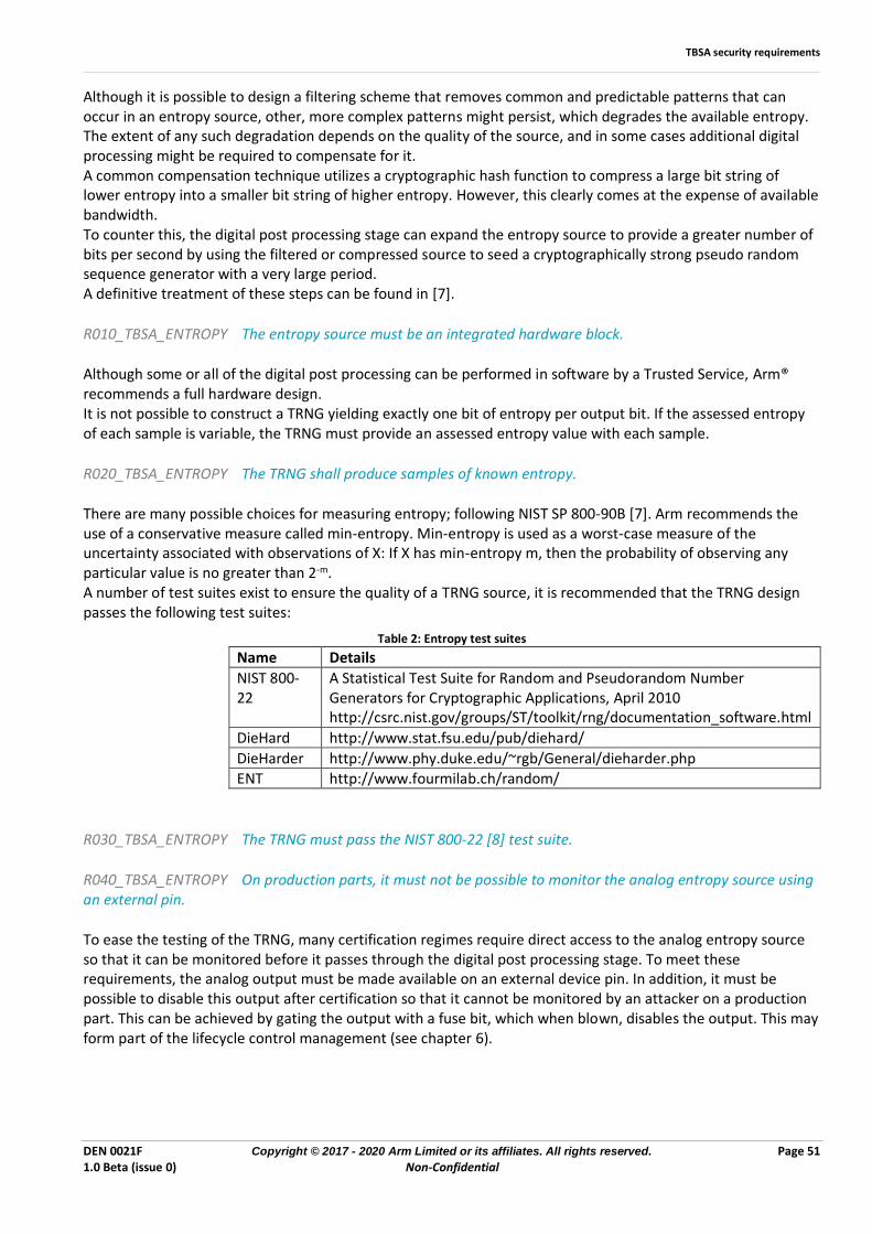
TBSA security requirements
DEN 0021F Copyright © 2017 - 2020 Arm Limited or its affiliates. All rights reserved. Page 51 1.0 Beta (issue 0) Non-Confidential
Although it is possible to design a filtering scheme that removes common and predictable patterns that can occur in an entropy source, other, more complex patterns might persist, which degrades the available entropy. The extent of any such degradation depends on the quality of the source, and in some cases additional digital processing might be required to compensate for it. A common compensation technique utilizes a cryptographic hash function to compress a large bit string of lower entropy into a smaller bit string of higher entropy. However, this clearly comes at the expense of available bandwidth. To counter this, the digital post processing stage can expand the entropy source to provide a greater number of bits per second by using the filtered or compressed source to seed a cryptographically strong pseudo random sequence generator with a very large period. A definitive treatment of these steps can be found in [7].
R010_TBSA_ENTROPY The entropy source must be an integrated hardware block.
Although some or all of the digital post processing can be performed in software by a Trusted Service, Arm® recommends a full hardware design. It is not possible to construct a TRNG yielding exactly one bit of entropy per output bit. If the assessed entropy of each sample is variable, the TRNG must provide an assessed entropy value with each sample.
R020_TBSA_ENTROPY The TRNG shall produce samples of known entropy.
There are many possible choices for measuring entropy; following NIST SP 800-90B [7]. Arm recommends the use of a conservative measure called min-entropy. Min-entropy is used as a worst-case measure of the uncertainty associated with observations of X: If X has min-entropy m, then the probability of observing any particular value is no greater than 2-m. A number of test suites exist to ensure the quality of a TRNG source, it is recommended that the TRNG design passes the following test suites:
Table 2: Entropy test suites
Name Details
NIST 800-22
A Statistical Test Suite for Random and Pseudorandom Number Generators for Cryptographic Applications, April 2010 http://csrc.nist.gov/groups/ST/toolkit/rng/documentation_software.html
DieHard http://www.stat.fsu.edu/pub/diehard/
DieHarder http://www.phy.duke.edu/~rgb/General/dieharder.php ENT http://www.fourmilab.ch/random/
R030_TBSA_ENTROPY The TRNG must pass the NIST 800-22 [8] test suite.
R040_TBSA_ENTROPY On production parts, it must not be possible to monitor the analog entropy source using an external pin.
To ease the testing of the TRNG, many certification regimes require direct access to the analog entropy source so that it can be monitored before it passes through the digital post processing stage. To meet these requirements, the analog output must be made available on an external device pin. In addition, it must be possible to disable this output after certification so that it cannot be monitored by an attacker on a production part. This can be achieved by gating the output with a fuse bit, which when blown, disables the output. This may form part of the lifecycle control management (see chapter 6).
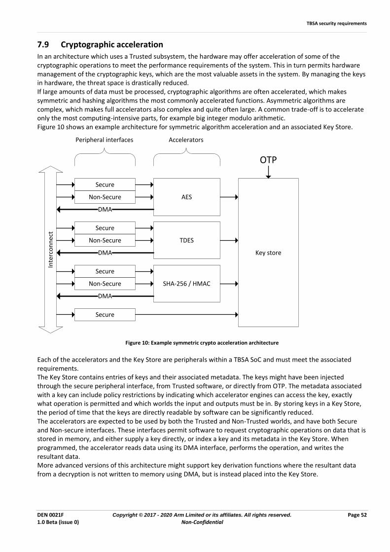
TBSA security requirements
DEN 0021F Copyright © 2017 - 2020 Arm Limited or its affiliates. All rights reserved. Page 52 1.0 Beta (issue 0) Non-Confidential
7.9 Cryptographic acceleration In an architecture which uses a Trusted subsystem, the hardware may offer acceleration of some of the cryptographic operations to meet the performance requirements of the system. This in turn permits hardware management of the cryptographic keys, which are the most valuable assets in the system. By managing the keys in hardware, the threat space is drastically reduced. If large amounts of data must be processed, cryptographic algorithms are often accelerated, which makes symmetric and hashing algorithms the most commonly accelerated functions. Asymmetric algorithms are complex, which makes full accelerators also complex and quite often large. A common trade-off is to accelerate only the most computing-intensive parts, for example big integer modulo arithmetic. Figure 10 shows an example architecture for symmetric algorithm acceleration and an associated Key Store.
TDES
AES
SHA-256 / HMAC
Secure
Non-Secure
Secure
Non-Secure
Secure
Non-Secure
Key store
Secure
Inte
rco
nn
ect
DMA
DMA
DMA
Peripheral interfaces Accelerators
OTP
Figure 10: Example symmetric crypto acceleration architecture
Each of the accelerators and the Key Store are peripherals within a TBSA SoC and must meet the associated requirements. The Key Store contains entries of keys and their associated metadata. The keys might have been injected through the secure peripheral interface, from Trusted software, or directly from OTP. The metadata associated with a key can include policy restrictions by indicating which accelerator engines can access the key, exactly what operation is permitted and which worlds the input and outputs must be in. By storing keys in a Key Store, the period of time that the keys are directly readable by software can be significantly reduced. The accelerators are expected to be used by both the Trusted and Non-Trusted worlds, and have both Secure and Non-secure interfaces. These interfaces permit software to request cryptographic operations on data that is stored in memory, and either supply a key directly, or index a key and its metadata in the Key Store. When programmed, the accelerator reads data using its DMA interface, performs the operation, and writes the resultant data. More advanced versions of this architecture might support key derivation functions where the resultant data from a decryption is not written to memory using DMA, but is instead placed into the Key Store.
TBSA security requirements
DEN 0021F Copyright © 2017 - 2020 Arm Limited or its affiliates. All rights reserved. Page 53 1.0 Beta (issue 0) Non-Confidential
7.10 Debug As SoCs have become more and more complex, the mechanisms for debugging the hardware and software have increased in complexity too. The fundamental principles of debugging, which require access to the system state and system information, are in direct conflict with the principles of security, which require the restriction of access to assets. This section brings together the high-level security requirements for all debug mechanisms in the SoC. In general, the debug requirements of a device depend on its position in its lifecycle (see section 6). Debug functionality should be lifecycle-aware so that a policy on which features are permitted, restricted or prohibited can be imposed consistent with the lifecycle from system development to deployment through to device disposal. Lifecycle management is highly device and application dependent and is out of scope of this document. ARMv8 supports the following debug modes: Self-hosted debug - The processor core itself hosts a debugger, and developer software and a debug kernel run on the same processor core. For more information, see Arm®v8-A ARM [2] Section D2. External debug - The debugger is external to the processor core. The debugging might be either on-chip, for example in a second processor core, or off-chip, for example a JTAG debugger. External debug is particularly useful for:
• Hardware bring-up. That is, debugging during development when a system is first powered up and not all of the software functionality is available.
• Processor cores that are deeply embedded inside systems
For more information, see ARMv8-A ARM [2], Part H. The ARMv8 architecture also includes definitions for invasive and non-invasive debug. From a security perspective there is no need to distinguish between these, because non-invasive debug would leak any assets accessed by that processor core.
7.10.1 Protection mechanisms Debug mechanisms give an external entity access to the system assets, so there must be protection mechanisms in place to ensure that the external entity is permitted access to those assets. These shall be referred to as Debug Protection Mechanisms (DPMs).
R010_TBSA_DEBUG All debug functionality shall be protected by a DPM such that only an authorized external entity shall access the debug functionality.
Note that there might be scenarios where all external entities can access the debug functionality, for example Android application debugging.
R020_TBSA_DEBUG A DPM mechanism shall be implemented either in pure hardware or in software running at a higher level of privilege.
The system assets are grouped by the worlds they are accessible by, i.e. Non-Trusted and Trusted, and the execution space, i.e. Privileged and User.
R030_TBSA_DEBUG There shall be a DPM to permit access to all assets (Trusted Privileged).
R040_TBSA_DEBUG There shall be a DPM to permit access to all Non-trusted world assets (Non-Trusted Privileged). This mechanism shall not permit access to Trusted world assets.
R050_TBSA_DEBUG If a DPM to permit access to only Trusted User space assets exists, then this mechanism shall not permit access to Trusted Privileged assets. (It is expected to be used in conjunction with the Non-Trusted Privileged debug protection mechanism.)
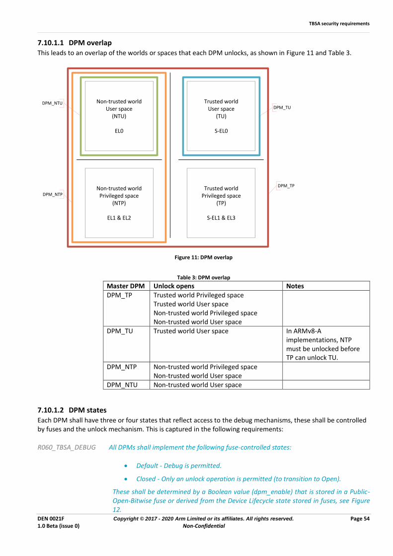
TBSA security requirements
DEN 0021F Copyright © 2017 - 2020 Arm Limited or its affiliates. All rights reserved. Page 54 1.0 Beta (issue 0) Non-Confidential
7.10.1.1 DPM overlap This leads to an overlap of the worlds or spaces that each DPM unlocks, as shown in Figure 11 and Table 3.
Non-trusted worldUser space
(NTU)
EL0
Non-trusted worldPrivileged space
(NTP)
EL1 & EL2
Trusted worldUser space
(TU)
S-EL0
DPM_TU
DPM_TP
DPM_NTU
DPM_NTPTrusted world
Privileged space(TP)
S-EL1 & EL3
Figure 11: DPM overlap
Table 3: DPM overlap
Master DPM Unlock opens Notes DPM_TP Trusted world Privileged space
Trusted world User space Non-trusted world Privileged space Non-trusted world User space
DPM_TU Trusted world User space In ARMv8-A implementations, NTP must be unlocked before TP can unlock TU.
DPM_NTP Non-trusted world Privileged space Non-trusted world User space
DPM_NTU Non-trusted world User space
7.10.1.2 DPM states
Each DPM shall have three or four states that reflect access to the debug mechanisms, these shall be controlled by fuses and the unlock mechanism. This is captured in the following requirements:
R060_TBSA_DEBUG All DPMs shall implement the following fuse-controlled states:
• Default - Debug is permitted.
• Closed - Only an unlock operation is permitted (to transition to Open).
These shall be determined by a Boolean value (dpm_enable) that is stored in a Public-Open-Bitwise fuse or derived from the Device Lifecycle state stored in fuses, see Figure 12.
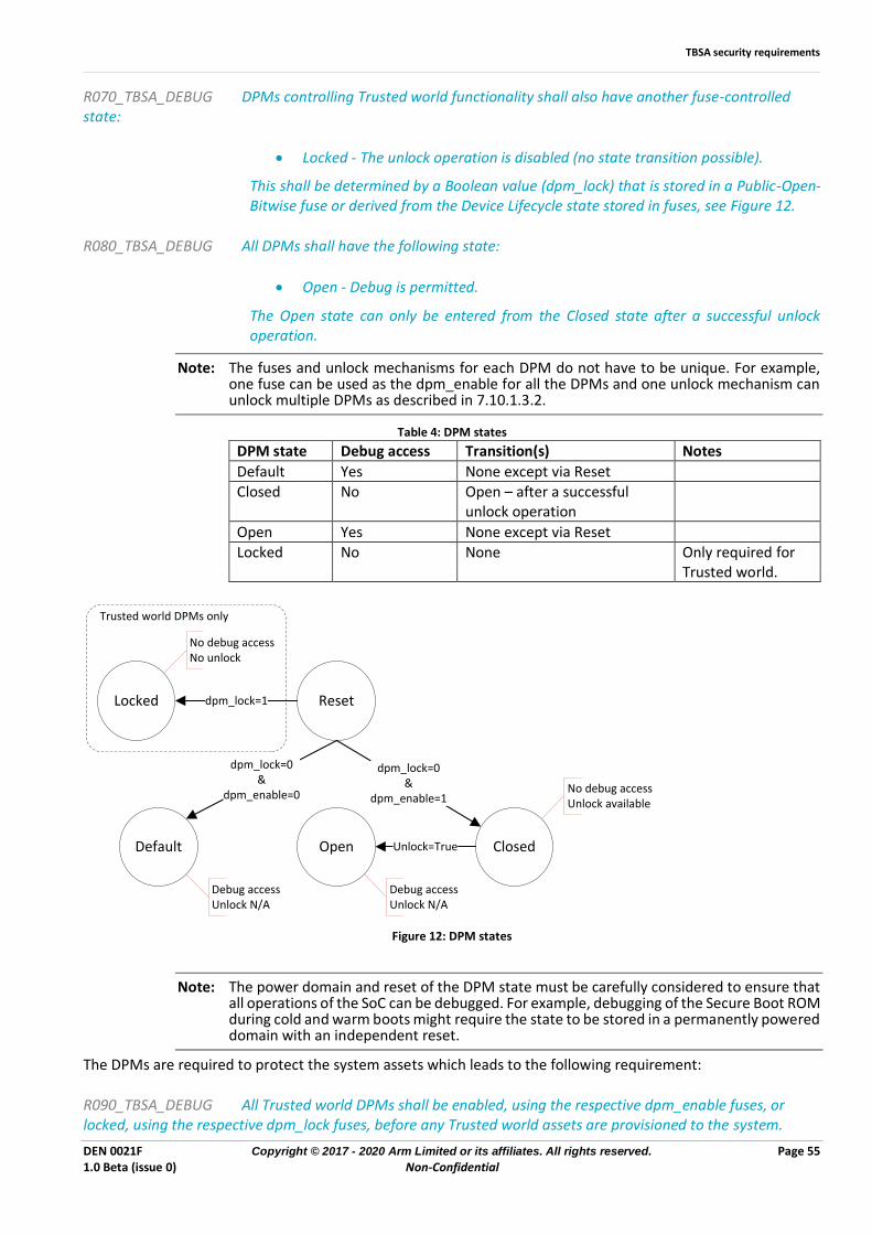
TBSA security requirements
DEN 0021F Copyright © 2017 - 2020 Arm Limited or its affiliates. All rights reserved. Page 55 1.0 Beta (issue 0) Non-Confidential
R070_TBSA_DEBUG DPMs controlling Trusted world functionality shall also have another fuse-controlled state:
• Locked - The unlock operation is disabled (no state transition possible).
This shall be determined by a Boolean value (dpm_lock) that is stored in a Public-Open-Bitwise fuse or derived from the Device Lifecycle state stored in fuses, see Figure 12.
R080_TBSA_DEBUG All DPMs shall have the following state:
• Open - Debug is permitted.
The Open state can only be entered from the Closed state after a successful unlock operation.
Note: The fuses and unlock mechanisms for each DPM do not have to be unique. For example, one fuse can be used as the dpm_enable for all the DPMs and one unlock mechanism can unlock multiple DPMs as described in 7.10.1.3.2.
Table 4: DPM states
DPM state Debug access Transition(s) Notes
Default Yes None except via Reset
Closed No Open – after a successful unlock operation
Open Yes None except via Reset
Locked No None Only required for Trusted world.
Reset
Default ClosedOpen
Locked dpm_lock=1
dpm_lock=0&
dpm_enable=0
dpm_lock=0&
dpm_enable=1
Unlock=True
No debug accessNo unlock
No debug accessUnlock available
Debug accessUnlock N/A
Debug accessUnlock N/A
Trusted world DPMs only
Figure 12: DPM states
Note: The power domain and reset of the DPM state must be carefully considered to ensure that all operations of the SoC can be debugged. For example, debugging of the Secure Boot ROM during cold and warm boots might require the state to be stored in a permanently powered domain with an independent reset.
The DPMs are required to protect the system assets which leads to the following requirement:
R090_TBSA_DEBUG All Trusted world DPMs shall be enabled, using the respective dpm_enable fuses, or locked, using the respective dpm_lock fuses, before any Trusted world assets are provisioned to the system.
TBSA security requirements
DEN 0021F Copyright © 2017 - 2020 Arm Limited or its affiliates. All rights reserved. Page 56 1.0 Beta (issue 0) Non-Confidential
7.10.1.3 Unlock operations To perform the state transition from "Closed" to "Open" an unlock operation must be performed by the debug protection mechanism to ensure that the external entity has access to a token that authorizes access to the associated assets. The token might take the form of a simple password or a cryptographically signed certificate. The choice between these often depends on the trade-off between complexity on the device and complexity on a token management server. For example, it is more complicated to implement signature checking on a device than to compare passwords, but managing a database of unique passwords is more complicated than one or two private keys on a server. To prevent the leak of an unlock token that affects multiple devices:
R100_TBSA_DEBUG Unlock tokens shall be unique for each device.
To ensure that the external entity knows which unlock token to use:
R110_TBSA_DEBUG The device shall store a unique ID in Public-Lockable fuses.
7.10.1.3.1 Unlock token - password
Password-based unlock operations are implemented as a simple comparison. However, it is not advisable to store a copy of the password on the device itself. Instead, a cryptographic hash of the password that is created using a one-way function (OWF) shall be stored. When the password token is injected via an interface from the external entity, it is passed through the same OWF and compared with the stored hash.
R120_TBSA_DEBUG The device shall not store a copy of the password unlock token, instead it shall store a cryptographic hash of the token in Lockable-Bulk fuses.
R130_TBSA_DEBUG On receipt of a password unlock token, it shall be passed through a cryptographic hash and the resultant hash shall be compared with the stored hash.
Because the comparison is simple, it must be protected from Brute Force attacks by making the password sufficiently large:
R140_TBSA_DEBUG A password unlock token shall be at least 128bits in length.
To ensure that different external entities can be given different tokens for a device, depending on their ownership of assets in the system:
R150_TBSA_DEBUG Each debug protection mechanism shall use a unique password unlock token.
7.10.1.3.2 Unlock token - private key
Private key-based unlock operations require the injection of a certificate that has been cryptographically signed by a private key. To meet R110_TBSA_DEBUG:
R160_TBSA_DEBUG The unique ID (see R110_TBSA_DEBUG) shall be included in a certificate unlock token.
The debug protection mechanism shall check the signature of the certificate:
R170_TBSA_DEBUG An unlock operation using a certificate unlock token shall use an approved asymmetric algorithm to check the certificate signature.
TBSA security requirements
DEN 0021F Copyright © 2017 - 2020 Arm Limited or its affiliates. All rights reserved. Page 57 1.0 Beta (issue 0) Non-Confidential
R180_TBSA_DEBUG An unlock operation using a certificate unlock token shall have access to an asymmetric public key stored on the device. The asymmetric public key used to authenticate the certificate unlock token shall either be immutably stored on the device or have been loaded as a certificate during secure boot and authenticated by a chain of certificates that begins with the ROTPK.
R190_TBSA_DEBUG A certificate unlock token shall indicate which DPM(s) it is able to unlock using an authenticated field.
R200_TBSA_DEBUG A loadable public key for certificate unlock token authentication shall include an authenticated field indicating which DPM(s) it is authorized to unlock.
R210_TBSA_DEBUG A certificate unlock token shall only unlock a DPM that its public key is authorized to unlock.
7.10.1.4 Other debug functionality Complex SoCs often include extra debug functionality beyond the main processor. Examples of this are initiators on the interconnect, which are controlled directly from an external debug interface, and system trace modules. Care must be taken to make sure that they are controlled by the correct DPM. They must be evaluated based on their access to assets that belong to each world, and assigned the corresponding DPM.
7.10.1.5 Arm® debug implementation The Arm® processor and CoreSight IPs include an Authentication Interface comprising of the following signals:
Table 5: Arm® authentication interface
Signal Name Action DBGEN Debug Enable Enables invasive & non-invasive debug
of Non-secure state. Debug components are disabled but accessible.
NIDEN Non-invasive Debug Enable Enables non-invasive debug of Non-secure state.
SPIDEN Secure Privileged Invasive Debug Enable
When asserted with DBGEN enables invasive & non-invasive debug of Secure state.
SPNIDEN Secure Privileged Non-Invasive Debug Enable
When asserted with NIDEN, enables non-invasive debug of Secure state.
The CoreSight IP also has the following input:
Table 6: DEVICEEN
Signal Name Action
DEVICEEN Device Debug Enable Enables the external debug tool connection to the device, and drives the DBGSWENABLE input to the CoreSight components and Cortex-A series processor.
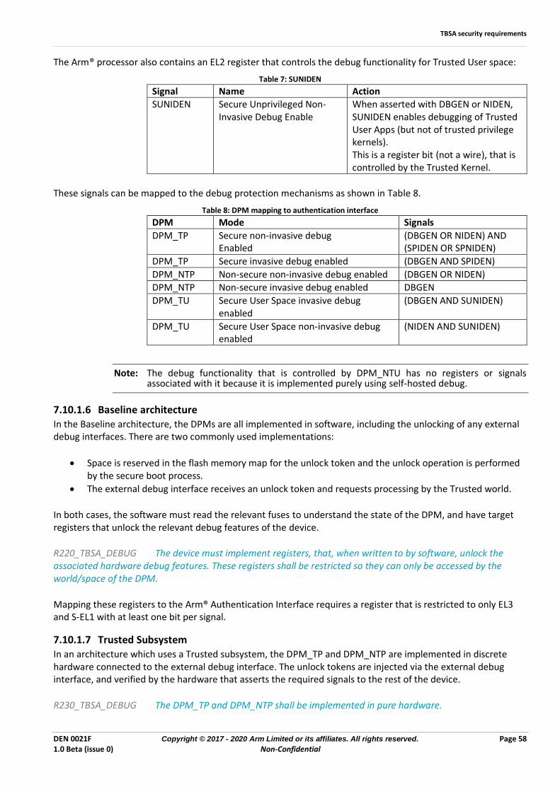
TBSA security requirements
DEN 0021F Copyright © 2017 - 2020 Arm Limited or its affiliates. All rights reserved. Page 58 1.0 Beta (issue 0) Non-Confidential
The Arm® processor also contains an EL2 register that controls the debug functionality for Trusted User space:
Table 7: SUNIDEN
Signal Name Action SUNIDEN Secure Unprivileged Non-
Invasive Debug Enable When asserted with DBGEN or NIDEN, SUNIDEN enables debugging of Trusted User Apps (but not of trusted privilege kernels). This is a register bit (not a wire), that is controlled by the Trusted Kernel.
These signals can be mapped to the debug protection mechanisms as shown in Table 8.
Table 8: DPM mapping to authentication interface
DPM Mode Signals
DPM_TP Secure non-invasive debug Enabled
(DBGEN OR NIDEN) AND (SPIDEN OR SPNIDEN)
DPM_TP Secure invasive debug enabled (DBGEN AND SPIDEN)
DPM_NTP Non-secure non-invasive debug enabled (DBGEN OR NIDEN) DPM_NTP Non-secure invasive debug enabled DBGEN
DPM_TU Secure User Space invasive debug enabled
(DBGEN AND SUNIDEN)
DPM_TU Secure User Space non-invasive debug enabled
(NIDEN AND SUNIDEN)
Note: The debug functionality that is controlled by DPM_NTU has no registers or signals associated with it because it is implemented purely using self-hosted debug.
7.10.1.6 Baseline architecture In the Baseline architecture, the DPMs are all implemented in software, including the unlocking of any external debug interfaces. There are two commonly used implementations:
• Space is reserved in the flash memory map for the unlock token and the unlock operation is performed by the secure boot process.
• The external debug interface receives an unlock token and requests processing by the Trusted world.
In both cases, the software must read the relevant fuses to understand the state of the DPM, and have target registers that unlock the relevant debug features of the device.
R220_TBSA_DEBUG The device must implement registers, that, when written to by software, unlock the associated hardware debug features. These registers shall be restricted so they can only be accessed by the world/space of the DPM.
Mapping these registers to the Arm® Authentication Interface requires a register that is restricted to only EL3 and S-EL1 with at least one bit per signal.
7.10.1.7 Trusted Subsystem In an architecture which uses a Trusted subsystem, the DPM_TP and DPM_NTP are implemented in discrete hardware connected to the external debug interface. The unlock tokens are injected via the external debug interface, and verified by the hardware that asserts the required signals to the rest of the device.
R230_TBSA_DEBUG The DPM_TP and DPM_NTP shall be implemented in pure hardware.
TBSA security requirements
DEN 0021F Copyright © 2017 - 2020 Arm Limited or its affiliates. All rights reserved. Page 59 1.0 Beta (issue 0) Non-Confidential
7.11 External interface peripherals SoCs contain many functions of the final device, but they will often need to talk to other electronic peripherals to receive and transmit data. Examples of these External Interface Peripherals (EIPs) include network controllers, displays, and, interface controller hubs, e.g. PCIe and Secure Element (SE) chips. Some interfaces are simple connections via SPI or UART whereas others can embed high bandwidth controllers within the SoC itself. Often these interfaces are used to receive Trusted user data, and consideration must be given to the assets that are transferred across these interfaces:
• Which on-chip world do the assets belong to?
• Are the assets entering or leaving the device?
• Are the assets in the clear or encrypted?
• Are the assets authenticated?
• If the assets are encrypted or authenticated, how was the key exchanged?
• What is the impact if the assets are modified?
• Can commands be received from an external device?
Often the easiest approach is to let the Non-trusted world manage the interface and the Trusted world supply the data to be transferred. This is acceptable when the Non-trusted world is no more of a security risk than the external connection. For example, non-authenticated encrypted content can be sent via the Non-trusted world, because changing the encrypted content does not compromise the security of any assets. However, if the assets being transferred include user data and are not authenticated, the Non-trusted world can perform a man-in-the-middle attack in the same way as an attacker with access to the external interface. It follows that if there are any secret values that are not encrypted, the Non-trusted world must not be able to access them, and the external interface must be correspondingly protected.
R010_TBSA_EIP If an EIP is used to send or receive clear or unauthenticated Trusted world assets, it is implementing a Trusted operation and shall meet the requirements of a Trusted peripheral.
R020_TBSA_EIP Where an EIP can receive commands from an external device, e.g. PCIe, then the system shall enforce a policy to check that those commands will not breach the security of the TBSA device.
This does not only apply to the commands that can affect the Trusted world: unrestricted access to the Non-trusted world by an external device is still a security risk. Where a specialized biometric input device is connected to an EIP, for example a fingerprint scanner, a device supporting link encryption must be chosen where possible.
R030_TBSA_EIP If a biometric user input device supports encryption, it must be cryptographically paired with a trusted service. This means that an authenticated encrypted tunnel can be created to prevent an attacker from monitoring or modifying data in transit to the main SoC.
R040_TBSA_EIP Any sensitive user data that is stored must be stored in Secure storage.
R050_TBSA_EIP In the specific case of camera input for UV retina imaging, the UV LED activation shall be under the control of the Trusted world.
7.11.1 Display When a display is used to present sensitive or private information, it must be protected from the Non-trusted world. In particular, it must not be possible for a rogue application that runs in the Non-trusted world to access a display buffer that contains sensitive information. A TBSA system is therefore required to provide a Trusted display mechanism. Data that is stored in memory, and is to be rendered by the device display, is referred to as display data. This definition includes full display frames that occupy the entire display and smaller sub-regions.
TBSA security requirements
DEN 0021F Copyright © 2017 - 2020 Arm Limited or its affiliates. All rights reserved. Page 60 1.0 Beta (issue 0) Non-Confidential
Trusted display data is defined as display data that is stored in Trusted memory, and Non-trusted display data is display data that is stored in Non-trusted memory. A Trusted display can display a mixture of Trusted and Non-trusted display data, with the following qualifications:
R060_TBSA_EIP The rendering of Trusted display data must be entirely under the control of the Trusted world; it must not be possible to control the rendering of Trusted display data from the Non-trusted world.
R070_TBSA_EIP If Trusted display data is being displayed, it must not be possible to obscure, either fully or partially, the image using an overlay that originates from the Non-trusted world.
In a compositor-based system, this could be achieved simply by ensuring that the Trusted display data is always on top. More generally, it is achieved by ensuring that Trusted display planes always have a higher priority or exist in a higher layer than any Non-trusted display plane.
R080_TBSA_EIP If the display subsystem is capable of handling both Trusted and Non-Trusted display data, then at least two display layers must be supported.
7.12 DRAM protection
Many SoC designs that integrate an Arm® processor also rely on external DRAM to store assets. However, this external memory is vulnerable to probing attacks that can be used to extract or modify data. An attacker can use these techniques to:
• Recover content or other sensitive assets
• Subvert the behavior of the device to extract further assets, or to use the device for illegitimate purposes
• Exploitable assets that might be held in DRAM are:
• The Rich OS and associated apps
• User data
• Multimedia content
• Trusted code and data, for example in a TEE
To mitigate these risks, encryption can be applied to an asset before it is stored in DRAM, after which an attacker is unable to recover the plain text. With the addition of authentication, external modifications of DRAM data can also be detected, enabling and execution to be halted to prevent an attacker from exploiting any such modifications. The cryptographic algorithms that are needed and their strength depend on the assets and the target requirements. For multimedia content, the encryption strength varies according to the resolution (SD, HD, 4K) and the release window, and authentication may not be required. However, for TEE based trusted execution, strong encryption and authentication are needed.
Note: In systems that implement suspension to RAM and power down the main die, the DRAM is particularly vulnerable, because the SoC pins to the DRAM are in a high impedance state, which makes it easy to probe the interface and take direct control of the DRAM.
A TBSA system with assets that require DRAM protection implements embedded cryptographic hardware within the memory system that is capable of protecting those assets within the memory system. Arm® recommends that the mechanism is transparent to the processor or bus initiator, encrypt the assets as they are written to DRAM, and decrypt them as they are read back, while performing authentication as required. Designers should consider if the threat model indicates that DRAM integrity protection is required. In some circumstance ECC protection can add robustness against row-hammer attacks. In other circumstances designers will want to deploy DRAM controllers which are able to increase the refresh interval when the high activation rate characteristics of row hammer attacks are detected.
TBSA security requirements
DEN 0021F Copyright © 2017 - 2020 Arm Limited or its affiliates. All rights reserved. Page 61 1.0 Beta (issue 0) Non-Confidential
7.12.1 Design considerations There are two symmetric cipher types on which a DRAM encryption system can be founded:
• Block ciphers
• Stream ciphers
A block cipher works on a block size, for example 64 or 128 bits, and transforms a block of plain text into a block of cipher text, or conversely, based on a secret key. A drawback of this approach is that it is not possible to process only a portion of the block, and writing a single byte, for example, requires reading and decrypting a whole block, modifying the byte, and encrypting and writing the block back to DRAM. This means that a read-modify-write buffer must be implemented, which has an impact on the performance of sub-block sized accesses, particularly writes. Alternatively, the block cipher can be used in conjunction with a cache, where the cache line size is a multiple of the block size. A stream cipher is based on the one-time pad. It generates a key stream of the same length as the plain text to be encrypted, and combines it with the plain text to form the cipher text. To be considered secure, the key stream must never repeat, so, once a key has been used, it is not permissible to re-use a sequence of key bytes with different data bytes. Typically, the data and key material are combined using a bitwise XOR function, in which case encryption and decryption are the same operation. The key is the same size as the data, and therefore very large, so it is generated using a smaller key in conjunction with a block cipher, which is commonly configured in counter mode, where incrementing count values are successively encrypted, and the output becomes the key stream. An advantage of the stream cipher approach is that there is no fixed block size, so for example a single byte write does not need a read modify write buffer or cache, as would be the case for the block cipher. However, to re-create the correct portion of the key stream for a decryption operation following a read, the counter value must be known. This is only possible if the counter value is stored alongside the data in DRAM, which complicates the implementation and increases the memory footprint. If authentication is also required, data written to DRAM must be tagged with an authentication code, which increases the memory footprint. The addition of such cryptographic hardware to the memory system carries performance and die size penalties that increase with the cryptographic strength. For example, a block cipher is typically composed of a number of rounds N, with each cipher operation taking N cycles. When a high throughput is required, it must be pipelined, which multiplies the area by up to N times and adds up to N cycles of latency. Adding the cipher at the DRAM interface represents the worst case, because it places the hardware at a high-performance interface through which all of the DRAM traffic passes. Often, it is not feasible to place a cipher of high cryptographic strength at this point in the system, particularly for very high clock frequencies, because sub round pipelining is required, which leads to very large implementation sizes and high latency. A better approach is to adopt a tiered implementation that limits high-strength cryptographic protection to the memory traffic that requires it. A lower strength protection can be added at the DRAM interface if required.
7.12.2 Algorithmic strength DRAM encryption and authentication is provided through performance-optimized cryptographic hardware blocks, each of which receives a symmetric key. The cryptographic strength of a given keyed algorithm is defined as the number of key values that an attacker must try before discovering the correct key, taking into account any known short cuts that are caused by weaknesses in the algorithm. This value is normally defined in bits, so if the best-known attack requires an exhaustive search through 1024 keys, for example, the strength of the algorithm is said to be 10 bits.
Note: Traditionally the term encryption is reserved for encryption algorithms of high cryptographic strength, and the terms scrambling and obfuscation are used to refer to algorithms of lower strength.
The required level of cryptographic protection depends on the target requirements and is not specified here.
TBSA security requirements
DEN 0021F Copyright © 2017 - 2020 Arm Limited or its affiliates. All rights reserved. Page 62 1.0 Beta (issue 0) Non-Confidential
7.12.3 Key management
R010_TBSA_DRAM A key provided to a DRAM encryption or authentication block must be unique to the SoC.
This rule prevents using a successful key recovery attack to compromise other devices.
R020_TBSA_DRAM Each DRAM encryption scheme must have a unique key.
A cryptographic scheme is defined in section 7.4.1.1 This rule prevents using a key that is recovered from a weaker algorithm to compromise a stronger algorithm or use of a key for multiple cryptographic purposes. Suitable unique keys can be stored in on-chip fuses, or might alternatively be derived from a key that is common across many devices that use a unique SoC ID. A key of this type is classed as a symmetric, static, unique, trusted hardware key.
R030_TBSA_DRAM If a key is stored in on-chip fuses or derived from a key that is common across many devices that use a unique SoC ID, it shall meet the requirements of a symmetric, static, unique, Trusted hardware key.
Unique ephemeral keys can also be sourced from a TRNG at boot time. Arm recommends this method because it gives better protection by generating keys that are different for every boot cycle.
R040_TBSA_DRAM A TRNG sourced key shall have an entropy, measured in bits, equal to or greater than the key strength demanded by the target algorithm.
If the TRNG sourced bits have full entropy, as defined in [7], there will be one TRNG source bit per key bit. However, if the TRNG sourced bits have lower entropy, additional bits must be sourced to reach or exceed the target key strength.
R050_TBSA_DRAM If an ephemeral key is used, it shall meet the requirements for a symmetric, ephemeral, unique, Trusted world key.
For example, if the TRNG delivers bit strings with an entropy of 0.5 bits per bit, then a 40-bit key strength will require 80 bits to be sourced from the TRNG. An ephemeral TRNG based approach also means that a Trusted save and restore mechanism is needed for the keys if the system enters a suspend to RAM state where the main die is powered down.
R060_TBSA_DRAM If suspend to RAM is implemented and the main die is powered down such that the DRAM protection keys needs to be saved and restored, these operations shall be handled by a Trusted service and the keys stored in Trusted non-volatile storage.
7.12.4 Configuration Depending on the assets under protection, different cryptographic modules, of differing strength, can be integrated in various positions within the on-chip interconnect hierarchy targeting a DRAM interface. In addition, the DRAM space can be divided into protected and non-protected regions, where each protected region is associated with an asset class, and therefore an algorithm and key strength. In any case, whether a particular cryptographic functionality is applied is based on the target address of an access within the physical memory map. Any potential method to change the memory map from the Non-trusted world could be exploited to bypass the DRAM protection and cause clear text to be written. Such modification must be controlled by restricting such changes to the Trusted world.
R070_TBSA_DRAM If the mapping of cryptographic hardware into the memory system is configurable, then it must only be possible to perform the configuration from the Trusted world.
Cryptography requirements
DEN 0021F Copyright © 2017 - 2020 Arm Limited or its affiliates. All rights reserved. Page 63 1.0 Beta (issue 0) Non-Confidential
Similarly, other interconnect changes, up or down stream of a cryptographic module, that modify the memory map, must only be possible from the Trusted world, as already detailed in the Infrastructure section of this document.
R080_TBSA_DRAM The activation and deactivation of encryption and authentication shall only be possible from the Trusted world.
R090_TBSA_DRAM If a memory region is assigned as protected, and configured for encryption, then there shall not exist any alias in the memory system, such that the same region can be accessed directly, bypassing the protection.
These rules prevent the collection of cipher text that could aid cryptanalysis, and is a particular problem for algorithms of lower cryptographic strengths.
8 Cryptography requirements TBSA-A requires that cryptographic algorithms use standards which meet or exceed 128-bit security. This means that:
• Symmetric ciphers must be equivalent to at least AES with 128-bit keys.
• Asymmetric cryptography must be equivalent to at least:
• ECDSA with P256
• RSA/DSA 3072
• Hash functions must be equivalent to at least SHA-256.
Arm recommends using approved algorithms from the Commercial National Security Algorithm Suite, which supersedes NSA Suite B Cryptography [9]. Alternatively, designers should refer to the approved cryptographic algorithm lists that SOG-IS, IPA, and CC have published for the EU[18], Japan[19], and China[20]. For specific devices it may be appropriate to select algorithms according to the certification regime that the marketplace requires and according to the recommendations and requirements of the relevant governing security agency. Furthermore, the deployment time frame of the device, resource dimensioning, and performance of algorithm choices may play a part in this selection. These criteria should be a documented part of the device security review and are outside the scope of this document. Depending on the threat model of the device, it may be necessary to anticipate migration to newer algorithms, potentially quantum-resistant ones, within the lifetime of the device. In addition, if protection for long-term data privacy is required, adopting a higher security level for symmetric cryptographic algorithms may be needed.
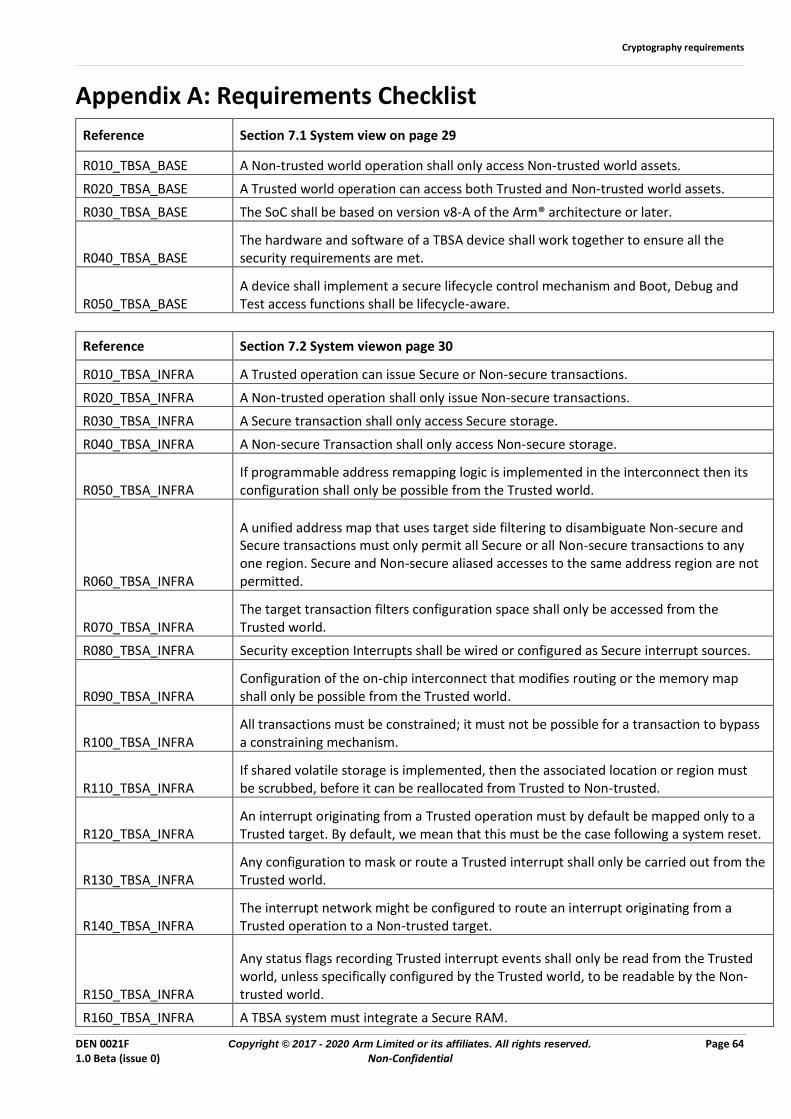
Cryptography requirements
DEN 0021F Copyright © 2017 - 2020 Arm Limited or its affiliates. All rights reserved. Page 64 1.0 Beta (issue 0) Non-Confidential
Appendix A: Requirements Checklist
Reference Section 7.1 System view on page 29
R010_TBSA_BASE A Non-trusted world operation shall only access Non-trusted world assets.
R020_TBSA_BASE A Trusted world operation can access both Trusted and Non-trusted world assets.
R030_TBSA_BASE The SoC shall be based on version v8-A of the Arm® architecture or later.
R040_TBSA_BASE The hardware and software of a TBSA device shall work together to ensure all the security requirements are met.
R050_TBSA_BASE A device shall implement a secure lifecycle control mechanism and Boot, Debug and Test access functions shall be lifecycle-aware.
Reference Section 7.2 System viewon page 30
R010_TBSA_INFRA A Trusted operation can issue Secure or Non-secure transactions.
R020_TBSA_INFRA A Non-trusted operation shall only issue Non-secure transactions.
R030_TBSA_INFRA A Secure transaction shall only access Secure storage.
R040_TBSA_INFRA A Non-secure Transaction shall only access Non-secure storage.
R050_TBSA_INFRA If programmable address remapping logic is implemented in the interconnect then its configuration shall only be possible from the Trusted world.
R060_TBSA_INFRA
A unified address map that uses target side filtering to disambiguate Non-secure and Secure transactions must only permit all Secure or all Non-secure transactions to any one region. Secure and Non-secure aliased accesses to the same address region are not permitted.
R070_TBSA_INFRA The target transaction filters configuration space shall only be accessed from the Trusted world.
R080_TBSA_INFRA Security exception Interrupts shall be wired or configured as Secure interrupt sources.
R090_TBSA_INFRA Configuration of the on-chip interconnect that modifies routing or the memory map shall only be possible from the Trusted world.
R100_TBSA_INFRA All transactions must be constrained; it must not be possible for a transaction to bypass a constraining mechanism.
R110_TBSA_INFRA If shared volatile storage is implemented, then the associated location or region must be scrubbed, before it can be reallocated from Trusted to Non-trusted.
R120_TBSA_INFRA An interrupt originating from a Trusted operation must by default be mapped only to a Trusted target. By default, we mean that this must be the case following a system reset.
R130_TBSA_INFRA Any configuration to mask or route a Trusted interrupt shall only be carried out from the Trusted world.
R140_TBSA_INFRA The interrupt network might be configured to route an interrupt originating from a Trusted operation to a Non-trusted target.
R150_TBSA_INFRA
Any status flags recording Trusted interrupt events shall only be read from the Trusted world, unless specifically configured by the Trusted world, to be readable by the Non-trusted world.
R160_TBSA_INFRA A TBSA system must integrate a Secure RAM.
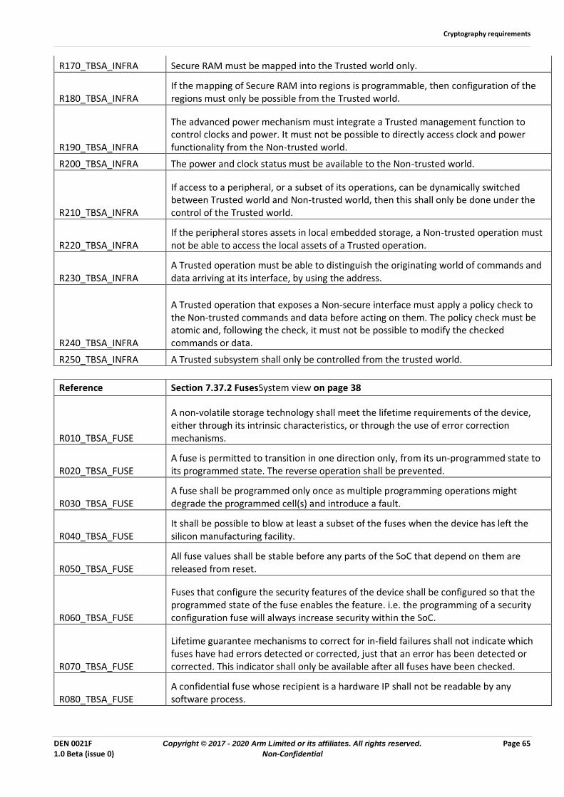
Cryptography requirements
DEN 0021F Copyright © 2017 - 2020 Arm Limited or its affiliates. All rights reserved. Page 65 1.0 Beta (issue 0) Non-Confidential
R170_TBSA_INFRA Secure RAM must be mapped into the Trusted world only.
R180_TBSA_INFRA If the mapping of Secure RAM into regions is programmable, then configuration of the regions must only be possible from the Trusted world.
R190_TBSA_INFRA
The advanced power mechanism must integrate a Trusted management function to control clocks and power. It must not be possible to directly access clock and power functionality from the Non-trusted world.
R200_TBSA_INFRA The power and clock status must be available to the Non-trusted world.
R210_TBSA_INFRA
If access to a peripheral, or a subset of its operations, can be dynamically switched between Trusted world and Non-trusted world, then this shall only be done under the control of the Trusted world.
R220_TBSA_INFRA If the peripheral stores assets in local embedded storage, a Non-trusted operation must not be able to access the local assets of a Trusted operation.
R230_TBSA_INFRA A Trusted operation must be able to distinguish the originating world of commands and data arriving at its interface, by using the address.
R240_TBSA_INFRA
A Trusted operation that exposes a Non-secure interface must apply a policy check to the Non-trusted commands and data before acting on them. The policy check must be atomic and, following the check, it must not be possible to modify the checked commands or data.
R250_TBSA_INFRA A Trusted subsystem shall only be controlled from the trusted world.
Reference Section 7.37.2 FusesSystem view on page 38
R010_TBSA_FUSE
A non-volatile storage technology shall meet the lifetime requirements of the device, either through its intrinsic characteristics, or through the use of error correction mechanisms.
R020_TBSA_FUSE A fuse is permitted to transition in one direction only, from its un-programmed state to its programmed state. The reverse operation shall be prevented.
R030_TBSA_FUSE A fuse shall be programmed only once as multiple programming operations might degrade the programmed cell(s) and introduce a fault.
R040_TBSA_FUSE It shall be possible to blow at least a subset of the fuses when the device has left the silicon manufacturing facility.
R050_TBSA_FUSE All fuse values shall be stable before any parts of the SoC that depend on them are released from reset.
R060_TBSA_FUSE
Fuses that configure the security features of the device shall be configured so that the programmed state of the fuse enables the feature. i.e. the programming of a security configuration fuse will always increase security within the SoC.
R070_TBSA_FUSE
Lifetime guarantee mechanisms to correct for in-field failures shall not indicate which fuses have had errors detected or corrected, just that an error has been detected or corrected. This indicator shall only be available after all fuses have been checked.
R080_TBSA_FUSE A confidential fuse whose recipient is a hardware IP shall not be readable by any software process.

Cryptography requirements
DEN 0021F Copyright © 2017 - 2020 Arm Limited or its affiliates. All rights reserved. Page 66 1.0 Beta (issue 0) Non-Confidential
R090_TBSA_FUSE A confidential fuse whose recipient is a hardware IP shall be connected to the IP using a path that is not visible to software or any other hardware IP.
R100_TBSA_FUSE A confidential fuse whose recipient is a software process might be readable by that process and shall be readable by software of a higher exception level.
R110_TBSA_FUSE
A confidential fuse whose recipient is a Trusted world software process shall be protected by a hardware filtering mechanism that can only be configured by S-EL1,S-EL2 or EL3 software, for example an MPU, an MMU, or an NS-bit filter.
R120_TBSA_FUSE It must be possible to fix a lockable fuse in its current state, regardless of whether it is programmed or un-programmed.
R130_TBSA_FUSE The locking mechanism for a lockable fuse can be shared with other lockable fuses, depending on the functional requirements.
R140_TBSA_FUSE A bulk fuse shall also be a lockable fuse to ensure that any unprogrammed bits cannot be later programmed.
R150_TBSA_FUSE Additional fuses that are used to implement lifetime guarantee mechanisms shall have the same confidential and write lock characteristics as the logical fuse itself.
Reference Section 7.47.2 Cryptographic keysSystem view on page 40
R010_TBSA_KEY
A key shall be treated as an atomic unit. It shall not be possible to use a key in a cryptographic operation before it has been fully created, during an update operation, or during its destruction.
R020_TBSA_KEY Any operations on a key shall be atomic. It shall not be possible to interrupt the creation, update, or destruction of a key.
R030_TBSA_KEY When a key is no longer required by the system, it must be put beyond use to prevent a hack at a later time from revealing it.
R035_TBSA_KEY A key must only be used by the cryptographic scheme for which it was created.
R070_TBSA_KEY A static key shall be stored in an immutable structure, for example a ROM or a set of Bulk-Lockable fuses.
R080_TBSA_KEY To dispose of a derived key, at least one part of the Source Material shall be put beyond use until the next boot to ensure that the key cannot be derived again.
R090_TBSA_KEY If an ephemeral key is stored in memory or in a register in clear text form, the storage location must be scrubbed before being used for another purpose.
R100_TBSA_KEY
A key that is accessible to, or generated by, the Non-trusted world shall only be used for Non-trusted world cryptographic operations, which are operations that are either implemented in Non-trusted world software, or have both input data and output data in the Non-trusted world.
R110_TBSA_KEY A key that is accessible to, or generated by, the Trusted world can be used for operations in both Non-trusted and Trusted worlds, and even across worlds, as long as:
R120_TBSA_KEY A Trusted hardware key shall not be directly accessible by any software.
R130_TBSA_KEY The Trusted world must be able to enforce a usage policy for any Trusted hardware key which can be used for Non-trusted world cryptographic operations.
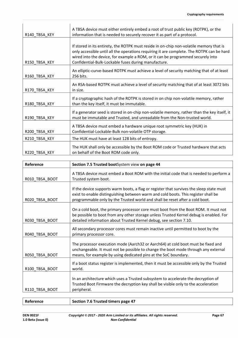
Cryptography requirements
DEN 0021F Copyright © 2017 - 2020 Arm Limited or its affiliates. All rights reserved. Page 67 1.0 Beta (issue 0) Non-Confidential
R140_TBSA_KEY A TBSA device must either entirely embed a root of trust public key (ROTPK), or the information that is needed to securely recover it as part of a protocol.
R150_TBSA_KEY
If stored in its entirety, the ROTPK must reside in on-chip non-volatile memory that is only accessible until all the operations requiring it are complete. The ROTPK can be hard wired into the device, for example a ROM, or it can be programmed securely into Confidential-Bulk-Lockable fuses during manufacture.
R160_TBSA_KEY An elliptic-curve-based ROTPK must achieve a level of security matching that of at least 256 bits.
R170_TBSA_KEY An RSA-based ROTPK must achieve a level of security matching that of at least 3072 bits in size.
R180_TBSA_KEY If a cryptographic hash of the ROTPK is stored in on chip non-volatile memory, rather than the key itself, it must be immutable.
R190_TBSA_KEY If a generator seed is stored in on-chip non-volatile memory, rather than the key itself, it must be immutable and Trusted, and unreadable from the Non-trusted world.
R200_TBSA_KEY A TBSA device must embed a hardware unique root symmetric key (HUK) in Confidential-Lockable-Bulk non-volatile OTP storage.
R210_TBSA_KEY The HUK must have at least 128 bits of entropy.
R220_TBSA_KEY The HUK shall only be accessible by the Boot ROM code or Trusted hardware that acts on behalf of the Boot ROM code only.
Reference Section 7.5 Trusted bootSystem view on page 44
R010_TBSA_BOOT A TBSA device must embed a Boot ROM with the initial code that is needed to perform a Trusted system boot.
R020_TBSA_BOOT
If the device supports warm boots, a flag or register that survives the sleep state must exist to enable distinguishing between warm and cold boots. This register shall be programmable only by the Trusted world and shall be reset after a cold boot.
R030_TBSA_BOOT
On a cold boot, the primary processor core must boot from the Boot ROM. It must not be possible to boot from any other storage unless Trusted Kernel debug is enabled. For detailed information about Trusted Kernel debug, see section 7.10.
R040_TBSA_BOOT All secondary processor cores must remain inactive until permitted to boot by the primary processor core.
R050_TBSA_BOOT
The processor execution mode (Aarch32 or Aarch64) at cold boot must be fixed and unchangeable. It must not be possible to change the boot mode through any external means, for example by using dedicated pins at the SoC boundary.
R100_TBSA_BOOT If a boot status register is implemented, then it must be accessible only by the Trusted world.
R110_TBSA_BOOT
In an architecture which uses a Trusted subsystem to accelerate the decryption of Trusted Boot Firmware the decryption key shall be visible only to the acceleration peripheral.
Reference Section 7.6 Trusted timers page 47
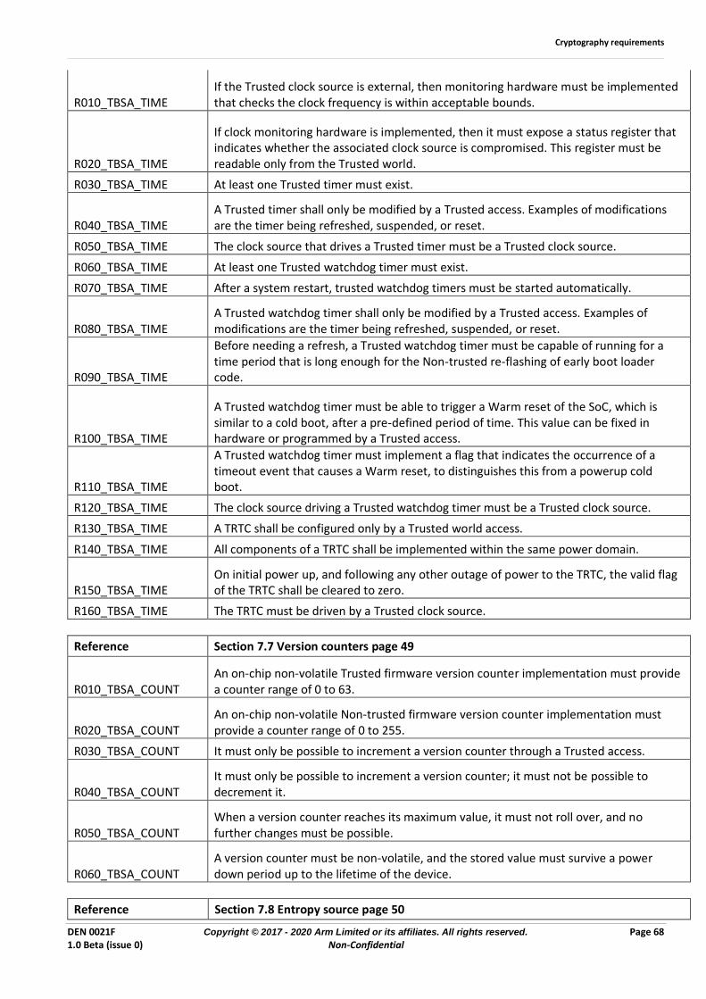
Cryptography requirements
DEN 0021F Copyright © 2017 - 2020 Arm Limited or its affiliates. All rights reserved. Page 68 1.0 Beta (issue 0) Non-Confidential
R010_TBSA_TIME If the Trusted clock source is external, then monitoring hardware must be implemented that checks the clock frequency is within acceptable bounds.
R020_TBSA_TIME
If clock monitoring hardware is implemented, then it must expose a status register that indicates whether the associated clock source is compromised. This register must be readable only from the Trusted world.
R030_TBSA_TIME At least one Trusted timer must exist.
R040_TBSA_TIME A Trusted timer shall only be modified by a Trusted access. Examples of modifications are the timer being refreshed, suspended, or reset.
R050_TBSA_TIME The clock source that drives a Trusted timer must be a Trusted clock source.
R060_TBSA_TIME At least one Trusted watchdog timer must exist.
R070_TBSA_TIME After a system restart, trusted watchdog timers must be started automatically.
R080_TBSA_TIME A Trusted watchdog timer shall only be modified by a Trusted access. Examples of modifications are the timer being refreshed, suspended, or reset.
R090_TBSA_TIME
Before needing a refresh, a Trusted watchdog timer must be capable of running for a time period that is long enough for the Non-trusted re-flashing of early boot loader code.
R100_TBSA_TIME
A Trusted watchdog timer must be able to trigger a Warm reset of the SoC, which is similar to a cold boot, after a pre-defined period of time. This value can be fixed in hardware or programmed by a Trusted access.
R110_TBSA_TIME
A Trusted watchdog timer must implement a flag that indicates the occurrence of a timeout event that causes a Warm reset, to distinguishes this from a powerup cold boot.
R120_TBSA_TIME The clock source driving a Trusted watchdog timer must be a Trusted clock source.
R130_TBSA_TIME A TRTC shall be configured only by a Trusted world access.
R140_TBSA_TIME All components of a TRTC shall be implemented within the same power domain.
R150_TBSA_TIME On initial power up, and following any other outage of power to the TRTC, the valid flag of the TRTC shall be cleared to zero.
R160_TBSA_TIME The TRTC must be driven by a Trusted clock source.
Reference Section 7.7 Version counters page 49
R010_TBSA_COUNT An on-chip non-volatile Trusted firmware version counter implementation must provide a counter range of 0 to 63.
R020_TBSA_COUNT An on-chip non-volatile Non-trusted firmware version counter implementation must provide a counter range of 0 to 255.
R030_TBSA_COUNT It must only be possible to increment a version counter through a Trusted access.
R040_TBSA_COUNT It must only be possible to increment a version counter; it must not be possible to decrement it.
R050_TBSA_COUNT When a version counter reaches its maximum value, it must not roll over, and no further changes must be possible.
R060_TBSA_COUNT A version counter must be non-volatile, and the stored value must survive a power down period up to the lifetime of the device.
Reference Section 7.8 Entropy source page 50
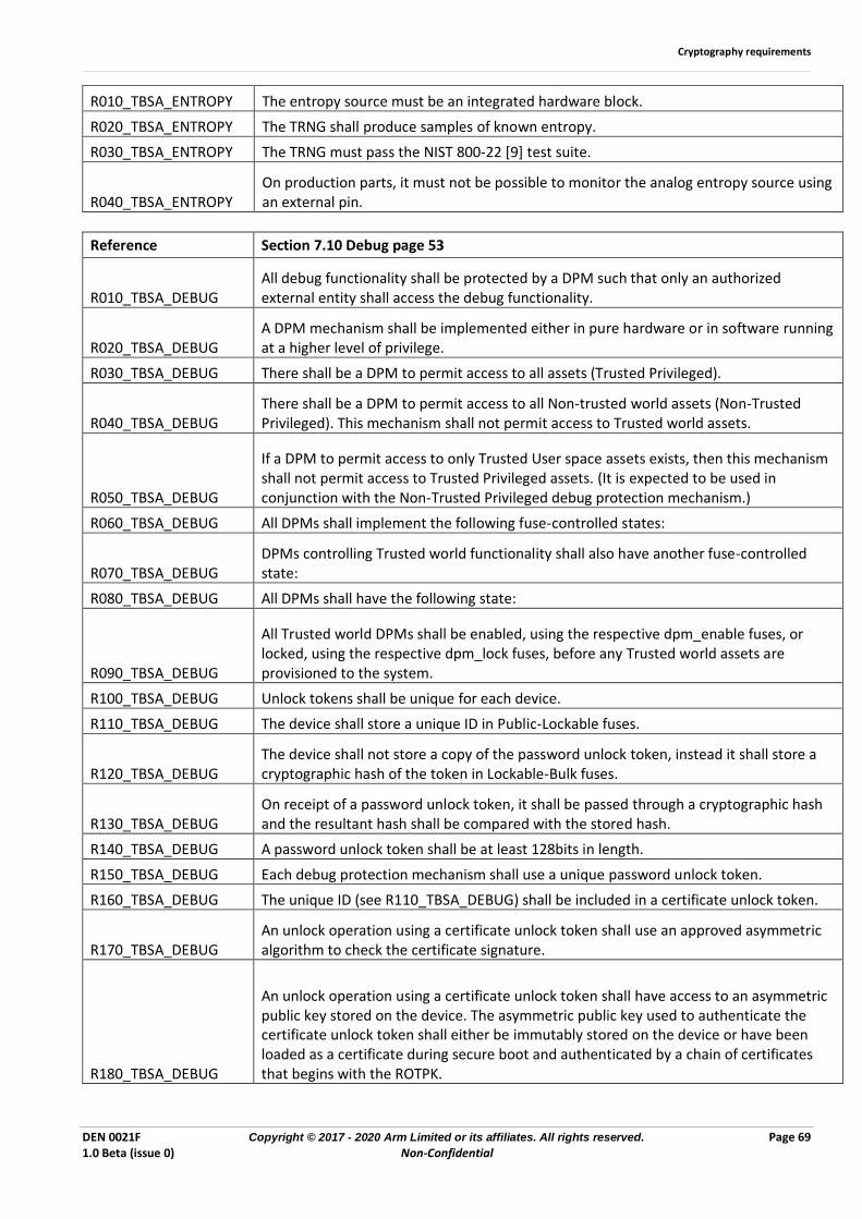
Cryptography requirements
DEN 0021F Copyright © 2017 - 2020 Arm Limited or its affiliates. All rights reserved. Page 69 1.0 Beta (issue 0) Non-Confidential
R010_TBSA_ENTROPY The entropy source must be an integrated hardware block.
R020_TBSA_ENTROPY The TRNG shall produce samples of known entropy.
R030_TBSA_ENTROPY The TRNG must pass the NIST 800-22 [9] test suite.
R040_TBSA_ENTROPY On production parts, it must not be possible to monitor the analog entropy source using an external pin.
Reference Section 7.10 Debug page 53
R010_TBSA_DEBUG All debug functionality shall be protected by a DPM such that only an authorized external entity shall access the debug functionality.
R020_TBSA_DEBUG A DPM mechanism shall be implemented either in pure hardware or in software running at a higher level of privilege.
R030_TBSA_DEBUG There shall be a DPM to permit access to all assets (Trusted Privileged).
R040_TBSA_DEBUG There shall be a DPM to permit access to all Non-trusted world assets (Non-Trusted Privileged). This mechanism shall not permit access to Trusted world assets.
R050_TBSA_DEBUG
If a DPM to permit access to only Trusted User space assets exists, then this mechanism shall not permit access to Trusted Privileged assets. (It is expected to be used in conjunction with the Non-Trusted Privileged debug protection mechanism.)
R060_TBSA_DEBUG All DPMs shall implement the following fuse-controlled states:
R070_TBSA_DEBUG DPMs controlling Trusted world functionality shall also have another fuse-controlled state:
R080_TBSA_DEBUG All DPMs shall have the following state:
R090_TBSA_DEBUG
All Trusted world DPMs shall be enabled, using the respective dpm_enable fuses, or locked, using the respective dpm_lock fuses, before any Trusted world assets are provisioned to the system.
R100_TBSA_DEBUG Unlock tokens shall be unique for each device.
R110_TBSA_DEBUG The device shall store a unique ID in Public-Lockable fuses.
R120_TBSA_DEBUG The device shall not store a copy of the password unlock token, instead it shall store a cryptographic hash of the token in Lockable-Bulk fuses.
R130_TBSA_DEBUG On receipt of a password unlock token, it shall be passed through a cryptographic hash and the resultant hash shall be compared with the stored hash.
R140_TBSA_DEBUG A password unlock token shall be at least 128bits in length.
R150_TBSA_DEBUG Each debug protection mechanism shall use a unique password unlock token.
R160_TBSA_DEBUG The unique ID (see R110_TBSA_DEBUG) shall be included in a certificate unlock token.
R170_TBSA_DEBUG An unlock operation using a certificate unlock token shall use an approved asymmetric algorithm to check the certificate signature.
R180_TBSA_DEBUG
An unlock operation using a certificate unlock token shall have access to an asymmetric public key stored on the device. The asymmetric public key used to authenticate the certificate unlock token shall either be immutably stored on the device or have been loaded as a certificate during secure boot and authenticated by a chain of certificates that begins with the ROTPK.
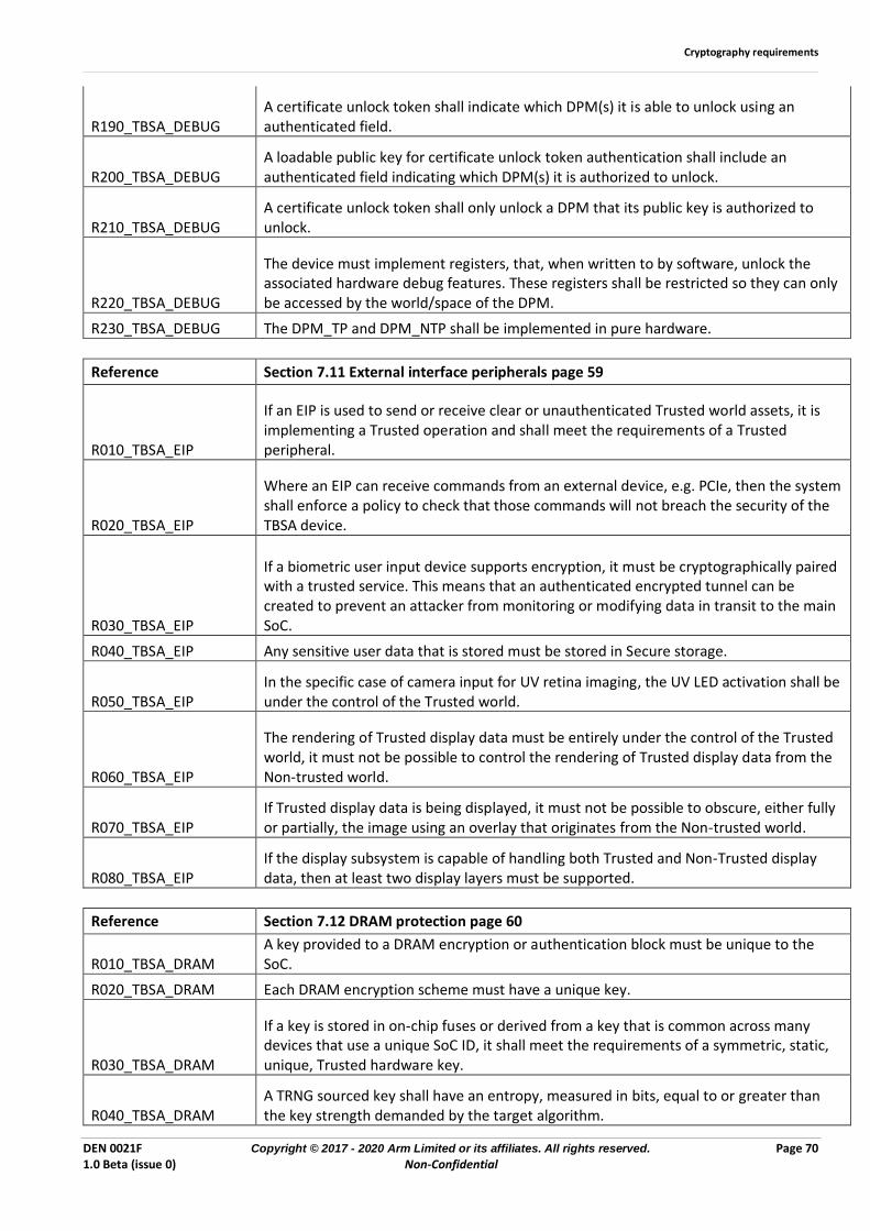
Cryptography requirements
DEN 0021F Copyright © 2017 - 2020 Arm Limited or its affiliates. All rights reserved. Page 70 1.0 Beta (issue 0) Non-Confidential
R190_TBSA_DEBUG A certificate unlock token shall indicate which DPM(s) it is able to unlock using an authenticated field.
R200_TBSA_DEBUG A loadable public key for certificate unlock token authentication shall include an authenticated field indicating which DPM(s) it is authorized to unlock.
R210_TBSA_DEBUG A certificate unlock token shall only unlock a DPM that its public key is authorized to unlock.
R220_TBSA_DEBUG
The device must implement registers, that, when written to by software, unlock the associated hardware debug features. These registers shall be restricted so they can only be accessed by the world/space of the DPM.
R230_TBSA_DEBUG The DPM_TP and DPM_NTP shall be implemented in pure hardware.
Reference Section 7.11 External interface peripherals page 59
R010_TBSA_EIP
If an EIP is used to send or receive clear or unauthenticated Trusted world assets, it is implementing a Trusted operation and shall meet the requirements of a Trusted peripheral.
R020_TBSA_EIP
Where an EIP can receive commands from an external device, e.g. PCIe, then the system shall enforce a policy to check that those commands will not breach the security of the TBSA device.
R030_TBSA_EIP
If a biometric user input device supports encryption, it must be cryptographically paired with a trusted service. This means that an authenticated encrypted tunnel can be created to prevent an attacker from monitoring or modifying data in transit to the main SoC.
R040_TBSA_EIP Any sensitive user data that is stored must be stored in Secure storage.
R050_TBSA_EIP In the specific case of camera input for UV retina imaging, the UV LED activation shall be under the control of the Trusted world.
R060_TBSA_EIP
The rendering of Trusted display data must be entirely under the control of the Trusted world, it must not be possible to control the rendering of Trusted display data from the Non-trusted world.
R070_TBSA_EIP If Trusted display data is being displayed, it must not be possible to obscure, either fully or partially, the image using an overlay that originates from the Non-trusted world.
R080_TBSA_EIP If the display subsystem is capable of handling both Trusted and Non-Trusted display data, then at least two display layers must be supported.
Reference Section 7.12 DRAM protection page 60
R010_TBSA_DRAM A key provided to a DRAM encryption or authentication block must be unique to the SoC.
R020_TBSA_DRAM Each DRAM encryption scheme must have a unique key.
R030_TBSA_DRAM
If a key is stored in on-chip fuses or derived from a key that is common across many devices that use a unique SoC ID, it shall meet the requirements of a symmetric, static, unique, Trusted hardware key.
R040_TBSA_DRAM A TRNG sourced key shall have an entropy, measured in bits, equal to or greater than the key strength demanded by the target algorithm.
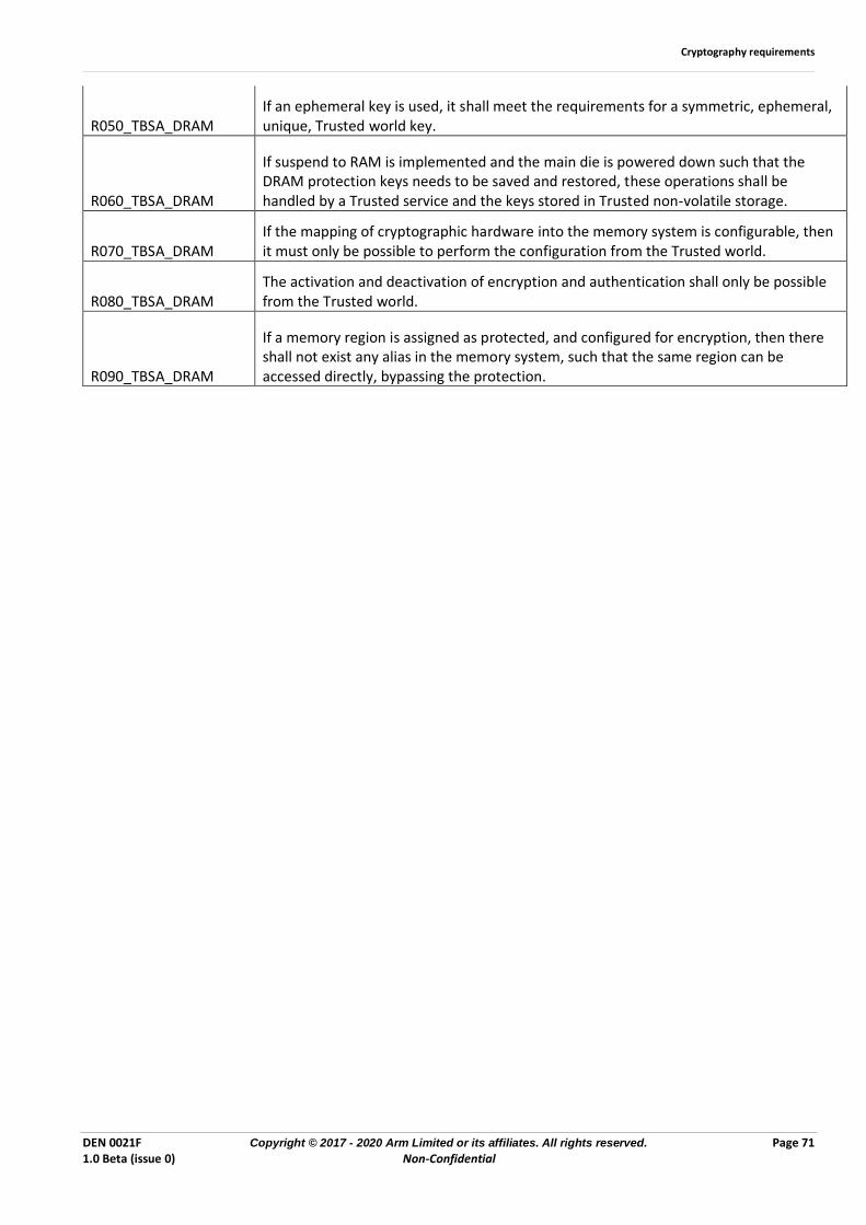
Cryptography requirements
DEN 0021F Copyright © 2017 - 2020 Arm Limited or its affiliates. All rights reserved. Page 71 1.0 Beta (issue 0) Non-Confidential
R050_TBSA_DRAM If an ephemeral key is used, it shall meet the requirements for a symmetric, ephemeral, unique, Trusted world key.
R060_TBSA_DRAM
If suspend to RAM is implemented and the main die is powered down such that the DRAM protection keys needs to be saved and restored, these operations shall be handled by a Trusted service and the keys stored in Trusted non-volatile storage.
R070_TBSA_DRAM If the mapping of cryptographic hardware into the memory system is configurable, then it must only be possible to perform the configuration from the Trusted world.
R080_TBSA_DRAM The activation and deactivation of encryption and authentication shall only be possible from the Trusted world.
R090_TBSA_DRAM
If a memory region is assigned as protected, and configured for encryption, then there shall not exist any alias in the memory system, such that the same region can be accessed directly, bypassing the protection.