Embed Size (px)
Citation preview

Truss Plate Institute of Canada Tel: 905-952-2686 Fax: 905-952-2687
SOLAR READY TRUSS DESIGN
PHASE 1: Implications on Loads and Truss Strength
April, 2011
Robert Baynit Truss Plate Institute of Canada
and
Jeremy Sager Natural Resources Canada / CanmetENERGY

TPIC_NRCAN Page 2
Table of Contents
1. Background ..................................................................................................................................... 3
2. Solar Panel System Location on a Roof Plane ................................................................................... 3
a. Solar Panel Distribution:.............................................................................................................. 3
b. Solar Panel Location Above Eve/Overhang: ................................................................................. 4
Suggested Revision to SR Guidelines ................................................................................................ 4
TPIC SR Design Assumptions ............................................................................................................ 4
3. Loads ............................................................................................................................................... 4
a. Dead Loads: ................................................................................................................................ 4
b. Snow Loads:................................................................................................................................ 5
c. Wind Loads: ................................................................................................................................ 5
d. Load distribution:........................................................................................................................ 5
TPIC SR Design Assumptions ............................................................................................................ 5
4. Spacing of Connection Points of Solar Panels to Roof ....................................................................... 6
Suggested Revision to SR Guidelines ................................................................................................ 6
TPIC SR Design Assumptions ............................................................................................................ 6
5. Solar Panel Attachment Details........................................................................................................ 6
a. Lag screws: ................................................................................................................................. 6
b. Lag screw or threaded rod connection through block and spanner:............................................. 7
c. Lag screws with blocking between truss top chords: ................................................................... 8
d. J and U bolt connection:.............................................................................................................. 8
e. Lag screws attached to scabs that are attached to truss top chords: ........................................... 9
TPIC SR Design Assumptions .......................................................................................................... 10
6. Spacing Between the Solar Panels and Roof Decking...................................................................... 10
Suggested Revision to SR Guidelines .............................................................................................. 10
TPIC SR Design Assumption............................................................................................................ 10
7. Consultation with Canadian Solar Industries Association................................................................ 11
8. Solar Ready Truss Design - Phase 2 ................................................................................................ 11
9. Keeping in Step with NRC work on National Building Code............................................................. 11

TPIC_NRCAN Page 3
1. Background The Solar Ready Guidelines have been developed by Natural Resources Canada’s (NRCan) CanmetENERGY and Office of Energy Efficiency New Housing Division in partnership with the Canadian Solar Industries Association. During the Stakeholder Review process of these Guidelines, recommendations were made to develop a Solar Ready Truss design process that would enable builders using truss systems to readily overcome potential structural design concerns related to additional loads associated with solar systems that may be installed on their Solar Ready homes. This would also enable building code inspectors to quickly determine whether the structural design of the roof system of a house labelled Solar Ready was adequate at the time of installing a solar system. Provincial and Federal building codes developers have also expressed interest in resolving this issue. The Truss Plate Institute of Canada (TPIC) and NRCAN embarked on the project to address this issue in two phases. The scope of the first phase, which is now complete, is limited to the assessment of load & design implications of solar systems based on the panel layouts, dimensions and methods of fastening to the roof. Furthermore, this assessment is limited to systems installed on the roofs of Part 9 buildings. The assessment applies to solar collectors for solar domestic hot water / space heating systems as well as solar modules for solar photovoltaic systems, collectively termed “solar panels” in this report. At the conclusion of the first phase, TPIC has identified the implications of installing solar systems on roofs to be the increased loads on trusses and reduced strength of the trusses. These implications are discussed in detail in this report. The objective of this report is to bring to light specific issues that will help NRCan, TPIC and the Canadian Solar Industries Association (CanSIA) to develop a set of requirements that will enable certain homes to be built Solar Ready. The issues covered relate to: solar panels location on a roof plane, loads, spacing of connection points of solar panels to the roof, solar panel attachment details and spacing between the solar panels and roof decking. 2. Solar Panel System Location on a Roof Plane Solar panels may be installed on roofs in various configurations and dimensional orientations.
a. Solar Panel Distribution:
Solar panel systems may be distributed throughout the entire roof plane that contains the area allocated as per the Solar Ready requirements on trusses with 3 m (10’) or greater truss-panel length. The long truss-panels will accommodate multiple solar panels on one truss-panel, thus creating the possibility for multiple point loads. These point loads are not expected to be distributed in a predictable way and, after detailed inspection of the solar panel layouts, TPIC has concluded that these loads should be lumped into one point load: one at truss joint and the

TPIC_NRCAN Page 4
other at mid truss-panel point. The magnitude of the point load at mid truss-panel will depend on the panel length, truss spacing and the load on the solar panel surface. The magnitude of the point load at a truss joint will depend on length of panels on both sides of the joint as well as the truss spacing and the load on the solar panel surface. b. Solar Panel Location Above Eve/Overhang:
Solar panel systems may be positioned at locations near the eve line or overhang. This is not a desirable location since the overhang is less stiff and may over deflect. Also, the first truss-panel next to the overhang is the most stressed truss-panel and may result in the entire top chord to be up-sized due to possible design implications described elsewhere in this report. The higher up the slope and closer to the peak, the lesser the need to upsize because the upper truss-panels are often less stressed than the lower truss-panels. However, since truss-panels are quite long it is not practical to avoid locating solar panels over the lower truss-panel.
Suggested Revision to SR Guidelines The TPIC suggests that Solar Ready recommend solar panels be located above the wall line, away from overhang areas.
TPIC SR Design Assumptions The TPIC Solar Ready truss design procedure will assume the entire roof plane coincident with the allocated roof area designated in Solar Ready may be used to accommodate solar panels (except areas over the eve/overhang as described above).
The TPIC Solar Ready design procedure will also limit truss-panels to 2.4 m (8’) long to limit the magnitude of the point load to be applied to the truss-panels and to truss joints and to keep the cost of the truss reasonable, while allowing the flexibility in solar panel dimensions and orientation on the roof.
The TPIC Solar Ready truss design procedure will assume solar panels can be located at any vertical location along the truss panels except areas located over the roof eve/overhang. 3. Loads
a. Dead Loads:
National and Provincial building codes define specified dead loads for a structural member to consist of:
the weight of the member itself, the weight of all materials of construction incorporated into the building to
be supported permanently by the member,

TPIC_NRCAN Page 5
the weight of partition, the weight of permanent equipment and, the vertical load due to earth plants and trees.
The weight of solar panels fits as item 4 and must be included as dead load in the solar ready roof truss design. b. Snow Loads:
Part 9 of the building code does not require Part 9 roof structures to be designed to withstand unbalanced snow loads or to withstand snow loads due to drifting or sliding snow (see letters from NBC code advisors in Appendix A). However, TPIC is uncertain as to whether the Part 9 subcommittee had considered rack mounted solar panels as comparable to any other standard roof obstructions such as chimneys, valleys, etc.
c. Wind Loads:
Part 9 of the building code does not require roof trusses to be designed to withstand wind pressure. The design for the effects of wind loads is left up to the authority having jurisdiction. However, solar panel connection to roof trusses must be designed for wind uplift to ensure that the solar panel does not detach from the roof. Trusses themselves may not require wind analysis because of other counteracting gravity loads unless required by authority having jurisdiction. d. Load distribution:
Dead load due to solar panel mass is supported at discrete points underneath the panels. Similarly loads due to snow and rain and, where applicable, loads due to wind pressure are also supported through the same support points.
TPIC SR Design Assumptions The installation of solar systems will add more dead load to the roof system. This additional dead load may change the load duration factor in accordance with CSA O86 section 4.3.2.3. This change may result in a slight truss capacity reduction in areas where there is very light snow load. The TPIC Solar Ready design procedure will allow for a solar system dead load equivalent to 130 kg (285 lb) for the 3.7 m x 3.1 m (12’ x 10’) designated area, which corresponds to 30 kg/m2 or 0.3 kPa for the entire roof plane. The TPIC Solar Ready design procedure will account for all of the loads that are supported by solar panels, including self weight (dead load) by treating them as point loads to supporting trusses. As the location of the points of attachment of the solar panels to the roof structure cannot be known ahead of time (see notes regarding points of attachment below), to

TPIC_NRCAN Page 6
ensure safe design, all point loads on the truss-panel will be treated as a single point load concentrated at the center of the truss-panel and truss joints. 4. Spacing of Connection Points of Solar Panels to Roof Spacing of connectors horizontally on a given plane is of concern. Spacing of connectors horizontally will normally be dependent on the truss spacing, 0.61 m (2’) OC being the most common. The wider the horizontal spacing of connectors, the greater the load implication. If horizontal connectors are spaced at 0.61 m (2’) OC or less, the increase in load carrying capacity factor of 10% can be used as permitted by CSA O86 for trusses spaced at 0.61 m (2’) OC. It is believed that 0.61 m (2’) horizontal connector spacing is the optimum spacing. It is, however, recognised that a connection spacing of every 1.2 m (4’) is commonly used in the market, so this would require a change to industry common practice in connector attachment spacing of solar collectors to the roof structure. See Section 7 below. Vertical spacing of connectors is not as important as the horizontal spacing with respect to load implication since the point loads are on the same truss. Suggested Revision to SR Guidelines The TPIC recommends Solar Ready make it clear that the design procedure will apply to systems installed at the spacing stipulated by the TPIC design procedure (maximum 0.61 m (2’) horizontal and 2.4 m (8’) vertical), pending confirmation through consultation (see Section 7 below). TPIC SR Design Assumptions The TPIC intends to design Solar Ready truss’ according to a maximum horizontal spacing of every 0.61 m (2’) and 2.4 m (8’) vertical), pending confirmation through consultation (see Section 7 below). 5. Solar Panel Attachment Details
Solar panel systems must be attached to roof trusses directly or indirectly by connectors to prevent the system from blowing / sliding off the roof and to prevent the system from damaging the roof deck due to gravity loads. There are several methods of attaching solar panels to the roof: (a) Lag screws directly attached to truss top chords; (b) Lag screw or threaded rod connection through block and spanner; and (c) Bearing type of connectors such as J & U bolts that bear against the truss chord. Each of these categories has pros and cons that have implications on the cost of solar ready roofs.
a. Lag screws:
Lag screws are installed directly into truss top chords and provide resistance against uplift and sliding of solar panels from the roof. The attachment of the screws to truss chords will reduce the cross-section of the top chord and hence reduce top chord
TPIC_NRCAN Page 7
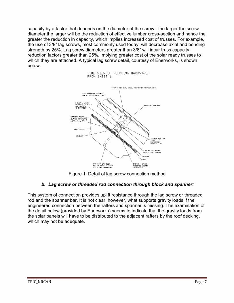
capacity by a factor that depends on the diameter of the screw. The larger the screw diameter the larger will be the reduction of effective lumber cross-section and hence the greater the reduction in capacity, which implies increased cost of trusses. For example, the use of 3/8” lag screws, most commonly used today, will decrease axial and bending strength by 25%. Lag screw diameters greater than 3/8” will incur truss capacity reduction factors greater than 25%, implying greater cost of the solar ready trusses to which they are attached. A typical lag screw detail, courtesy of Enerworks, is shown below.
Figure 1: Detail of lag screw connection method
b. Lag screw or threaded rod connection through block and spanner:
This system of connection provides uplift resistance through the lag screw or threaded rod and the spanner bar. It is not clear, however, what supports gravity loads if the engineered connection between the rafters and spanner is missing. The examination of the detail below (provided by Enerworks) seems to indicate that the gravity loads from the solar panels will have to be distributed to the adjacent rafters by the roof decking, which may not be adequate.

TPIC_NRCAN Page 8
Figure 2: Detail of lag screw or threaded rod connection through block and spanner
c. Lag screws with blocking between truss top chords:
In this system of connection, the lag screws are attached to 10.2 cm x 10.2 cm (4”x4”) blocking, which is in turn attached to the adjacent truss top chords. The connection between the blocking and the truss top chords must be designed to support gravity loads and uplift loads due to wind. While this detail keeps cost of trusses down, it may increase the labour cost of installation. See Figure 3, courtesy of EnerWorks.
Figure 3: Detail of lag screws with blocking between truss top chords
d. J and U bolt connection:
These connectors are truss friendly in that they do not reduce lumber cross-section or attach any fastener to truss chords and provide resistance to both gravity loads and wind loads. The U bolt is ideal in that it imposes loads symmetrically to truss chords while the J bolt will add a slight eccentricity to truss chords. However, the cost of the materials and of installing these bolts is likely more than the cost of other connection systems. See Figure 4, courtesy of EnerWorks.

TPIC_NRCAN Page 9
Figure 4: J bolt and U bolt connection of c-channels carrying solar panels to truss top
chords
e. Lag screws attached to scabs that are attached to truss top chords:
In this system of connection, lag screws are attached to scabs that are in turn attached to truss chords using nails. The advantage of this system is that it does not reduce truss chord load carrying capacity and the nails will provide resistance to both gravity and wind loads. The additional cost is due to the additional lumber of the scab, which would run the entire length of the top chord of every truss implicated in the designated roof plane. See Figure 5 showing the design of a scab. The Figure shows a scab member limited to one area of the truss panel. In Solar Ready, the scab member would run the full length of the truss top chord, less the distance occurring over the eaves/roof overhang.
Figure 5: Design of a scab member method of attachment to truss the top chord
Scab member
Truss Plan view
Truss Elevation view

TPIC_NRCAN Page 10
TPIC SR Design Assumptions The TPIC Solar Ready design procedure will allow for direct connection of solar panels to the truss top chord via a 3/8” lag screw as detailed in attachment method a, Figure 1. The TPIC does not recommend design procedure as currently specified in attachment method b, shown in Figure 2. Any connection to be added to this detail to correct the existing deficiency would need to be approved by the TPIC to ensure the connectors do not diminish the load carrying capacity of the truss chord to which they are fastened. The TPIC Solar Ready design procedure will allow for connection of lag screws with blocking between truss top chords as described in method c, shown in Figure 3. The TPIC Solar Ready design procedure will allow for connection of c-channel systems with J or U bolt connections to the truss top chords as described in method d, shown in Figure 4. 6. Spacing Between the Solar Panels and Roof Decking Rack mounting of solar panels, though preferred in some locations to maximise annual solar output, may have significant implications on the roof structural integrity, particularly with respect to snow loads and wind loads. Research to ascertain these affects is beyond the scope of this design process. Suggested Revision to SR Guidelines For the purposes of the Solar Ready design procedure, the TPIC does not recommend the installation of rack mounted solar panels on Part 9 roofs because the rack mounted panels could act as a snow fence and accumulate significant snow and/or experience dynamic forces that may be generated by wind, which is not considered in truss design (see notes on wind loads). Flush mounted solar panels installed at a significant height above the roof deck will also allow snow to accumulate below the panels as well as snow on top of the panels and hence create two levels where snow can accumulate. Limiting the height to the order of 5.1 cm (2”) or less will not accumulate significant snow below the solar panels and hence snow will only accumulate on one level, i.e., on top of the solar panels. TPIC SR Design Assumption The TPIC Solar Ready design procedure will assume solar panels are installed on Solar Ready homes in parallel to the roof deck with no more than 5.1 cm (2”) spacing between the roof decking and the underside of the solar panels. Therefore, rack mounted solar panels will not be included in the TPIC design procedure.

TPIC_NRCAN Page 11
7. Consultation with Canadian Solar Industries Association The TPIC, together with NRCan will consult with CanSIA to solicit industry views on the design assumptions put forth in this Phase 1 report. In particular, the TPIC is seeking industry views on sections 4 and 6 of this report. This relates to the assumed attachment spacing of every 0.61 m (2’) horizontally and every 2.4 m (8’) vertically and the maximum spacing above the roof deck of 5.1 cm (2”). The attachment spacing has substantial implications on the truss design (and cost). From the point of view of maximising truss strength (and minimising additional truss cost), this attachment spacing equivalent to the truss spacing and truss panel length is the preferred spacing. It is, however, recognised that the horizontal spacing of every 0.61 m (2’) differs from industry common practice and as such may add costs in labour and materials associated with solar system installation. It should be noted that the objectives of Solar Ready are first and foremost to maximise builder participation. 8. Solar Ready Truss Design - Phase 2 In Phase 2 of this project, the TPIC will work from the Phase 1 report and feedback from CanSIA to produce a Solar Ready truss design procedure, which it will post on its website for truss designers across Canada to use when designing truss systems for homes being built Solar Ready according to NRCan’s Solar Ready Guidelines. NRCan will modify the Solar Ready Guidelines to reflect the suggested changes put forth in the report, as confirmed by consultation with CanSIA, and it will refer builders to the TPIC website for the Solar Ready truss design procedure. 9. Keeping in Step with NRC work on National Building Code TPIC and NRCan recognise that NRC is working on loading implications of solar systems on Part 9 buildings in the coming years, in its process of the release of the next National Building Code scheduled for release in 2013. TPIC will liaise with NRC to ensure the Solar Ready truss design remains in step with NRC’s activities and NRCan will liaise with NRC to ensure the Solar Ready Guidelines remain in step with NRC’s activities.