Embed Size (px)
Citation preview

Troubleshooting Common HPLC Problems

Waters Corp. © 2002
Potential Sources of Chromatographic Problems
Mobile PhaseInjectorIn-Line FilterColumnDetectorSample
PumpGuard ColumnConnecting Tubing and FittingsIntegrator/RecorderSoftware
Scientist/Analyst --need for logical approach to
save time

Waters Corp. © 2002
Problem
CHEMISTRY
COLUMNGUARD COLUMN
MOBILE PHASESAMPLE/VIALS
PUMPINJECTORDETECTORDATA COLLECTIONBAND SPREADING/
CONNECTIONSCOLUMNSSAMPLE VIALS
Troubleshooting Strategy
Try to simplify --assess impact on lab efficiency --
inspect the chromatography --try to categorize
troubleshoot the easiest to fix items first
MECHANICAL

Waters Corp. © 2002
Detector Cell
Waters c 1998
How to Categorize --Inspect Chromatogram
How do you get sharp peaks with excellentresolution?– Well Shaped Bands -- Well Separated– (Good Mechanical And Chemical Performance)

Waters Corp. © 2002
Detector Cell
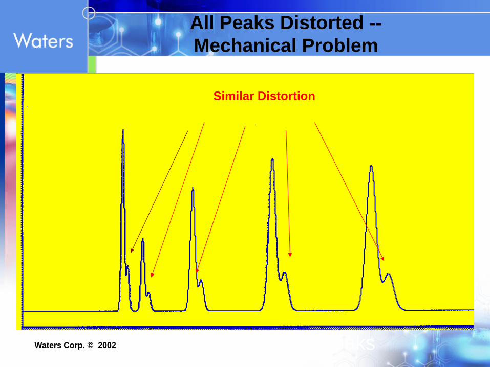
Why Do You Get Distorted Peaks?
Why do you get all distorted peaks?– Distorted Bands –
Mechanical Problem Chemical ProblemInjector - Too Strong Sample SolventVoided ColumnPoor Connections
_
Waters Corp. © 2002
Voids - high back pressure, distorted and/or double peaks
All Peaks Distorted --Mechanical Problem
Similar Distortion

Waters Corp. © 2002
All Peaks Distorted – Chemical ProblemIncorrect Sample Solvent –
STRONGER than mobile phase
(Too strong)Stronger

Waters Corp. © 2002
Detector Cell
Why Do You Get One/Some Distorted Peaks?
Why do you get one or some distorted peaks?– Distorted Band – Chemical Problem
Cation exchange of one analyte to particle surface

Waters Corp. © 2002
Great Peak Shape for Some Peaks, but Others Have Poor Peak Shape --- Chemical Problem
(Not Mechanical)
Minutes0 5 10 15 20 25
Example of chemical induced tailing for this compound --Wrong choice in packing material brand
or mobile phase pH
Other peaks have Great Peak shape

Waters Corp. © 2002
* Extra-Column (Non – Column) Band Spreading
Injection VolumeInjector (seal problem)Connecting Tubing
Injector to ColumnColumn to Detector
End-fittings and FritsDetector Volume
Mechanical
* Column Itself•Voiding•Plugged frits
•Remember: the band is initially created by the injector}

Waters Corp. © 2002
0.090" Parker Style
0.130" WatersStyle
Other Waters® Columns
Waters Spherisorb® andmany other brands
Column Installation and Connections - Mechanical

Waters Corp. © 2002
Make sure column connected correctly Make sure nut and ferrule are seated
Installation -- Mechanical
NOTE: Column connector not seated properly --creates void (Parker ferrule position into a Waters’ End-fitting)
Good Seal
(PEEK Slip Connectors Easier to Use)
Void

Waters Corp. © 2002
Band Spreading due to ImproperColumn Connection- Mechanical
Column Connection
Band SpreadingDead Volume
Proper
Improper
Waters Corp. © 2002
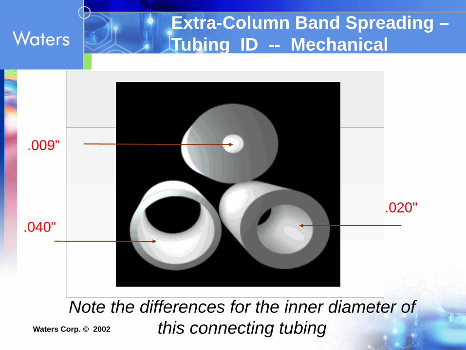
.009"
.020".040"
Note the differences for the inner diameter of this connecting tubing
Extra-Column Band Spreading –Tubing ID -- Mechanical

Waters Corp. © 2002
Effect of Connecting Tubing on System Band Spreading
.009"
.020".040"
Sample band dispersion inside tubing
Note: longer tubing lengthscreates more Band Spreading

Waters Corp. © 2002
Effect of Band Spreadingon Resolution ES- TIC
7.00 7.50 8.00 7.00 7.50 8.00
• Customer’s plumbing• Lack of sensitivity• Quattro Ultima • Metabolite study
• Improved plumbing• Replace 10 connections between
the injector, switching valve and mass spec
• Removed 4 feet of extra 0.005 inch id tubing
2X Gain in SensitivityMetabolite in tail of peak now resolved
Original Customer’s System Optimized System
J. Li

Waters Corp. © 2002
Now, Perform Plate Count --Install Column (Isocratic)
Plate Count Information included in Appendix
If System OK, Now Test Column and System Together (Plate Count)--If poor result --implies Column Failure/Connection
VR

Waters Corp. © 2002
P e rfo rm a n c e M o n ito r in gC o lu m n E ffic ie n c y : N = th e n u m b e r o f T h e o re tic a l P la te sa = is a c o n s ta n t d e p e n d in g o n th e M e th o d u s e dtr = re te n tio n tim e o f p e a kW = th e p e a k w id th (t im e u n its ) a t a g iv e n p e a k h e ig h t
N = a ( )t r
W
2
M E T H O D aP e a k W id th a t H a lf H e ig h t 5 .5 4P e a k W id th a t 4 .4 % P e a k H e ig h t (5 S ig m a ) 2 5 .0T a n g e n t 1 6 .0
Note: Value will depend on CONDITIONS.(Analyte k, flow rate, temperature etc.)

Waters Corp. © 2002Well packed column
Mechanical -- Column
Packing Material Flush

Waters Corp. © 2002
Well packed column
Good Results(System OK , Column OK, Connections OK)

Waters Corp. © 2002
Column Collapse -- Mechanical
Voided column- Channeling
Packing Material SettledPacking Material Settled

Waters Corp. © 2002
Voids - high back pressure, distorted and/or double peaks
Column Collapse (voiding)(shock / high pH {dissolution of particle})
All Peaks Distorted

Waters Corp. © 2002
Broad and Tailing peaks
* PARTIALLY PLUGGED COLUMN INLET FILTER- Remove end-fitting
* CONTAMINATED IN-LINE FILTER- Replace frit
* CONTAMINATED GUARD COLUMN- Replace guard column/insert
Peak Shape Problems
See Appendix for more information
Other Reasons forPoor Peak Shape

Waters Corp. © 2002
Most Common Problem in HPLC:
Distorted peaks will cause integration or resolution problems
Indication that optimal column performance is not being attained
Peak Shape Problems

Waters Corp. © 2002
Peak Shape Problems
Column DestroyedIncorrect Sample SolventSecondary InteractionsColumn Overload
– Mass Overload– Volume Overload
Other Extra-Column Effects– Sampling Rate– Time Constant

Waters Corp. © 2002
Voids - high back pressure, distorted and/or double peaks
Column Collapse (voiding)(shock / high pH {dissolution of particle})
All Peaks Distorted

Waters Corp. © 2002
All Peaks AffectedCOLUMN- Connection- Replace frit/ Guard Column- Regenerate or replace column
COLUMN ITSELF DESTROYEDpH <2 washes off functional grouppH >8 dissolves silica base
fronting peaks
Peak Shape Problems
double peaks

Waters Corp. © 2002
Dissolution ofSilica gel
pH Limitations of Traditional Silica Based Packing Materials
0.1
1
0 2 4 6 8 10 12 14pH
Hydrolysis of Bonded Ligand
XTerra Hybrid -- Wide pH Range

Waters Corp. © 2002
Hydrolysis of a Bonded Phase Material: Monofunctional Ligand
Note: Sometimes called “Column Bleed”
+ HCl
+
+
Low pH (hydrolysis of ligand)
SiC
CC
CC
CC
CH3
CH3
H3C
Cl
OHSi
O
O
O
SiC
CC
CC
CC
CH3
CH3
H3C
OSi
O
O
O
SiC
CC
CC
CC
CH3
CH3
H3C
HOOH
SiO
O
O
Note: as hydrolysis of ligand continues, you will obtain less retentivity and potentially poor peak shape for bases.
BONDING
Mobile phase

Waters Corp. © 2002
Dissolution ofSilica gel
pH Limitations of Traditional Silica Based Packing Materials
0.1
1
0 2 4 6 8 10 12 14pH
Hydrolysis of Bonded Ligand
XTerra Hybrid -- Wide pH Range

Waters Corp. © 2002
Solu
bilit
y of
Sili
ca in
Wat
er (p
pm)
1 2 3 4 5 6 7 8 9 10
240-220-200-180-160-140-120-100-80-60-40-20-
0-
pH
Silica Solubility Curve
Silica pH 2 - 8Polymer pH 2 -12
At pH >8 silica dissolves
Mobile Phase pH and Column Life-time
pH > 8 causes VOIDINGfor traditional silica/ bonded particles

Waters Corp. © 2002
Peak Shape Problems
Column DestroyedIncorrect Sample SolventSecondary InteractionsColumn Overload
– Mass Overload– Volume Overload
Other Extra-Column Effects– Sampling Rate– Time Constant

Waters Corp. © 2002
All Peaks Distorted – Chemical ProblemIncorrect Sample Solvent –
STRONGER than mobile phase
(Too strong)Stronger

Waters Corp. © 2002
All Peaks Distorted – Chemical ProblemIncorrect Sample Solvent – STRONGER than
mobile phase
(Too strong)
STRONGER SAMPLE SOLVENT
Column: SymmetryShield™ RP18, 3.5 µm, 3.9 x 150 mm
Guard Column: Sentry™ Guard Column SymmetryShield RP18, 5µmTemperature: 30°CMobile Phase: 0.1% TFA:Methanol
(60:40)Detection: UV at 210 nmFlow Rate: 1 mL/minInj. Volume: 30 µL
Sample Identification1.EDDP2. Diphenhydramine (IS)3. Methadone
5 1510 Min.
Sample in Water
0.04AU
1
23
Sample in 80% MeOH, 2% HAc
15
12
30.02AU

Waters Corp. © 2002
Peak Shape Problems
Column DestroyedIncorrect Sample SolventSecondary InteractionsColumn Overload
– Mass Overload– Volume Overload
Other Extra-Column Effects– Sampling Rate– Time Constant

Waters Corp. © 2002
Minutes0 5 10 15 20 25
Poor Peak Shape on Basic Compound due to Secondary Interactions
Integration ErrorsReduced Resolution Reduced Sensitivity
Acids and Neutrals have Good peak shape --Basic Analyte “Tails”

Waters Corp. © 2002
Tailing of Bases -- Chemical Problem (column brand / pH)
Time (min) 50
Conventional C18
Modern C18
Neutral
Base
Neutral
Base
0
pH 7
Differences in Silanol Activity ofColumn Brands

Waters Corp. © 2002
Peak Shape Problems
Column DestroyedIncorrect Sample SolventSecondary InteractionsColumn Overload
– Mass Overload– Volume Overload
Other Extra-Column Effects– Sampling Rate– Time Constant

Waters Corp. © 2002
Encountered when mass injected onto column exceeds a certain limit – note earlier lift-off point
6.25 µg injected
2 Minutes
Analytical load of 6µg yields efficient peak shape
4 6
Absorbance
Absorbance
25 mg injected
Preparative load of 25 mg generates mass overload peak shape
Note that the back of the peaks of the analytical and prep loads are at the same retention (-------)
2 4Minutes 6
Concentration/Mass Overload

Waters Corp. © 2002
EFFECT OF INJECTION VOLUME ON PEAK DISTORTION
500 µL
300 µL100 µL
10 µL
Column/Volume Overload

Waters Corp. © 2002
Volume Overload
Note: same lift-off point

Waters Corp. © 2002
Volume Overload
6.25µg injected in 5 µL
% of column volume: 0.625
2 4Minutes 6
Absorbance
0.625 mg injected in 500 µL
% of column volume: 62.5
2 4Minutes 6
Absorbance
Column Volume: 0.8 mL (800 µL)
Wider peaks first observed at low retention
Peak position shifts to higher retention in proportion to the injection volume

Waters Corp. © 2002
Peak Shape Problems
Column DestroyedIncorrect Sample SolventSecondary InteractionsColumn Overload
– Mass Overload– Volume Overload
Other Extra-Column Effects– Sampling Rate– Time Constant

Waters Corp. © 2002
Course Outline
Part 2 of 3
Retention Time Reproducibility-Temperature- Organic %- pH- Ion Pairing- Hydrophobic Collapse
Methods Development Suggestions
Extraneous Peaks

Waters Corp. © 2002
Retention Time Problems
Reproducibility &
- Solvent Composition
- Temperature
- pH-Control
- Ion Pairing
Drifting Retention
- Equilibration
- Stationary Phase Stability
- Column Contamination
- Hydrophobic Collapse-Low organic < 5%

Waters Corp. © 2002
Retention Time Variability
Less or More Retention Time All Peaks
• Pump Flow Rate Problem (check actual volume/time being delivered)
• Wrong Column Type (C8 – less retention, vs C18 – more retention)
• Temperature Problem (warmer – less retention, colder – more retention)
• % Organic In Mobile Phase (more organic – less retention, less organic –more retention)

Waters Corp. © 2002
Retention Time Reproducibility
Non-Column Influences:
Temperature
Reduction of Retention with Increasing Temperature
1% to 2% Change / per 1° Celsius
Shifts in Selectivity (Usually Small)

Waters Corp. © 2002
300C
500C
600C
Minutes1.00 2.00 3.00 4.00 5.00 6.00 7.00 8.00 9.00 10.00
400C
Effect of Temperature (Isocratic Separations)
1920 psiN= 1680
N=2250Plates
1160 psi
Benefits of Higher
Temperature:
* Shorter Run Time
* Better Sensitivity
* Sharper Peaks, N
* Lower Back Pressure
(less viscosity)
Back Pressure

Waters Corp. © 2002
TemperatureAU
0.00
0.05
0.10
0.15
AU
0.00
0.05
0.10
0.15
AU
0.00
0.05
0.10
0.15
Minutes
0.00 1.00 2.00 3.00 4.00 5.00 6.00 7.00 8.00 9.00 10.00 11.00 12.00
1
2
3
45
1
1
2
3
4
5
2 3
4
5
30°C
40°C
50°C1 Triamterene
2 Althiazide
3 Bumetanide
4 Benzthiazide
5 Ethacrynic Acid
Small, but significant selectivity changes obtained from temperature changes.
Useful for selectivity fine tuning.
Column: XTerra MS C183.5 µm, 4.6 mm x 50 mm Mobile phase:25% MeOH, 65% water, 10% ammonium bicarbonate buffer, pH 9
Wagrowski, Tran
Waters Corp. © 2002
Retention Time Reproducibility
Non-Column Influences:
Solvent (Organic) Composition
Exponential Relationship between k and Volume %
Retention Time Change of 5% to 15% per 1% Change in Solvent Composition
Bonded Phase Collapse in High Water Content

Waters Corp. © 2002
Isocratic LC - Changing Retention TimeChange in Solvent Composition
1 2 3 4
1 2 3 4
More Organic--Faster Run time
Less Organic --Slower Run time

Waters Corp. © 2002
Retention Time Variability
Less or More Retention Time
Some Peaks
• Chemistry Problem
• Wrong Column Type (CN vs C18)
• Incorrect pH or un-buffered system
• Incorrect % Organic In Mobile Phase, or wrong organic solvent

Waters Corp. © 2002
Retention Time Reproducibility
Non-Column Influences:Ion Pairing Reagents (Hexane Sulfonic Acid)
Retention– Increases Proportional to the Concentration of the
Pairing Agent at Low Concentration– Nearly Independent of the Concentration of the
Pairing Agent at High (~10mM/L) Concentration
Long Equilibration Times– Due to Adsorption of the Reagent on the Stationary
Phase (can be up to 500 Column Volumes)

Waters Corp. © 2002
Columns using Paired Ion Mobile Phase - require significantly more equilibration time1 µmol/m2 300 m2/g 2 g
(Surface coverage) (Silica surface area) (Amt. material in column)
* Equals 600 µmoles of ion pairing reagent needed for surface coverage in this column
* If mobile phase concentration of PIC reagent is 1 mM/litre, then 600 mL of solvent is needed
*** 600 minutes @ 1mL/min ***
Equilibration of Ion Pairing Methods
(10 hours)

Waters Corp. © 2002
Isocratic LC - Negative PeakCommon for Ion-Pairing -- Sample Solvent
Sample does Not contain Ion Pairing Reagent

Waters Corp. © 2002
Problem
CHEMISTRY
COLUMNGUARD COLUMN
MOBILE PHASESAMPLE/VIALS
PUMPINJECTORDETECTORDATA COLLECTIONBAND SPREADING/
CONNECTIONSCOLUMNSSAMPLE VIALS
Troubleshooting Strategy
Try to simplify --assess impact on lab efficiency --
inspect the chromatography --try to categorize --
troubleshoot the easiest to fix items first
MECHANICAL

Waters Corp. © 2002
Retention Time Problems
Reproducibility &
- Solvent Composition
- Temperature
- pH-Control
- Ion Pairing
Drifting Retention
- Equilibration
- Stationary Phase Stability
- Column Contamination
- Hydrophobic Collapse-Low organic < 5%
- Methods Development

Waters Corp. © 2002
Hydrophobic Collapse (Low % Organic solvent)
Chromatographers have observed complete loss of retention when working with low organic mobile phases. (Polars)
When this phenomenon was investigated it was found that retention times were stable for over 20 hrs (77 injections) using 100% aqueous mobile phase.
However, when the flow was stopped, then restarted, retention was lost.This observation suggested that the mobile phase was extruded from the pores when pressure was released from the column.
?
40 min 40 min
Vo

Waters Corp. © 2002
What is “Hydrophobic Collapse?”
Dewetted Pore (No retention)Wetted Pore (Good retention)Note: Retentivity is a function of the surface area and ligand density. However, if the surface is non-wetted, then the effective chromatographic surface area is reduced > 95%. Therefore, reducing the retentivity of the analyte --> poor capture = Hydrophobic collapseRemember all most all of the surface area is in the pores!
Low organic or pure aqueous mobile phase is expelled from pores
(dewetted)
C18 Silica-gel
Particle Pores

Waters Corp. © 2002
How does flow stoppage cause this problem in an HPLC Column? -- Possible Mechanism
Flow stoppage may relieve the pressure that was forcing the aqueous mobile phase into the pores. When the pressure goes down, the hydrophobic pore surface can expel the polar mobile phase and “dewet” the pore.
At flow with pressure on the mobile phase.
Stopped flow with no pressure on the mobile phase -- pores de-wet --restart flow -- pores still de-wetttedanalytes never enter pores - resulting in no retention. (Need ~ 40% MeOH to re-wet pores)
Note: Packings with Embedded Polar Group Ligands do not show Collapse
Analytes
Analytes properly retained

Waters Corp. © 2002
High Carbon C8 Column “Hydrophobic Collapse -- HPLC”
Minutes0 2 4 6 8 10
Initial(column was wetted first with organic)
After Flow Stoppage (Pores de-wet 100%)
Mobile phase: Aqueous 0.1% Acetic Acid
Amoxicillin
Vo: No retentivity for analyteNote:Hydrophobic Collapse for ColumnsDiscussed in CCD Column Seminar Series Part 2
1,500psi
Note: Column is not broken --just stopped working --Rewet >> ok
1,500psi

Waters Corp. © 2002
Re-wetting a Stationary Phase Once De-wetted:
Use a mobile phase containing > 40 % methanol or other polar organic solvent
(other organic solvents may vary in % required for wetting)
– This works by reducing the contact angle
Do not use pressure to force aqueous mobile phase back into pores
– Not practical because column outlet is at atmospheric pressure
1,500 psi 1 atm

Waters Corp. © 2002
Embedded Polar Ligand: Reduces Hydrophobic Collapse
Polar group increases water concentration on the surface layer of the pores
OSi
O
O
O
OHH-
Si OC
N(CH2)7
CH3
H3C
O
O
HCH3
Si
O
O
O For HPLC Columnsembedded polar groupavoids hydrophobic collapse
Polar “Hook”

Waters Corp. © 2002
SymmetryShield™ RP8: No Hydrophobic Collapse
Minutes0 2 4 6 8 10
Initial
After Flow Stoppage (Pore dewetting: ~3%)
Minimal change in retention time - embedded polar group does not dewet
Amoxicillin
Mobile phase: Aqueous 0.1% Acetic AcidPolar “Hook” keeps
pores wet – goodretention

Waters Corp. © 2002
Isocratic LC - Extra Peak - Sharp - Contaminant
Extraneous Peaks
Could be from; sample, vial, septum etc.

Waters Corp. © 2002
Isocratic LC - Broad Peak -- from Previous Injection
Extraneous Peaks

Waters Corp. © 2002
Isocratic LC - Broad Peak -- from Oxygen/MeOH complex in SAMPLE, But NOT in Degassed MOBILE PHASE @ 210nm
Extraneous Peaks
210nm

Waters Corp. © 2002SYN
CH
RO
NO
US
NO
ISE ALMOST ALWAYS CAUSED BY THE PUMP
Air in pump head - Prime pump and degas solvent
Check valve problem - Rebuild or replace
Broken plunger - Replace (blame it on someone else)
Mixing problem - Increase system volume
Electrical noise - Change circuits, remove source
Synchronous Noise

Waters Corp. © 2002
ASY
NC
HR
ON
OU
S N
OIS
E B U B B L E SD e g a s m o b ile p h a s e
G A S C A U G H T IN D E T E C T O RD e g a s m o b ile p h a s e . P u t b a c k p re s s u re o n c e ll.
L E A K SF ix le a k s , re p la c e fitt in g s
M IX IN G P R O B L E M SIn c re a s e s y s te m v o lu m e
P L U G G E D L IN E SR e m o v e p lu g , f lu s h s y s te m
E L E C T R IC A L P R O B L E M SR e m o v e s o u rc e , c h a n g e c irc u its
Asynchronous Noise

Waters Corp. © 2002
Mobile Phase Degassing
Best Solution:
Consider an in-line degassing accessory unit for your HPLC system.Some modern HPLC systems contain a built-in degasser(e.g., Waters Alliance™ System).
Alternatives:
Helium sparging – be careful not to alter mobile phase compositionby evaporation of volatile components.
Offline vacuum degassing in an ultrasonic bath –incomplete method which provides short-lived degassing.

Waters Corp. © 2002
S o lv e n t D e g a s s in g P r e c a u t io n s
1 . D e g a s s o l v e n t s p r i o r t o a d d i n g m o d i f i e r s
2 . H e l i u m s p a r g e i s g o o d , a s l o n g a s s o l v e n t d o e s n ' t c h a n g e d u e t o v o l a t i l i t y o f s o l v e n t s a n d / o r a d d i t i v e s
3 . S o l v e n t s s h o u l d b e d e g a s s e d d a i l y
D e g a s S o lv e n ts
V a c u u m
U lt ra s o n ic b a th T im e = 1 m in u te
Waters Corp. © 2002
Samples
• Sample Solubility• Test in MOBILE PHASE
(Avoid precipitation – plug column)
•Sample Analyte Stability• pH• Light (use amber vials)• Temperature• Time/Solvent
* Problems associated with Vials

Waters Corp. © 2002
% N
ominal C
oncentration
Room Temperature Stability of
SalineMethanol
Acetonitrile
Spiked Solutions
0
20
40
60
80
100
3 Day 5 Day
Betamethasone Valerate(20 µg/mL)
Sample in Solutions
0 5 10 15 20 25Minutes
t=0 stock
t=5 days saline
t=5 daysMeOH
t=5 daysMeCN
a
a: betamethasone valerateb: breakdown products
b b
b
b
Test in vials you will be using -- may make a difference
(hydrolysis)

Waters Corp. © 2002
Vials -- often the last thing considered, but may be the best place to start your troubleshooting
–Sample Vials

Waters Corp. © 2002
Choosing the Right SEPTUM
Wrong choice of Septum may result in :
– Evaporative loss of sample– Lack of reproducibility for repetitive injections– Septum coring– Needle damage– Septum dislodging

Waters Corp. © 2002
Choosing the right SEPTUM
Material Compatibility Recommendations Self Sealing Max. Temp.
PTFE (Teflon) All solvents; Ideal for MS applications Only suitable for one injection No 260°C
PTFE/Silicone
PTFE resistance until punctured. After 1st injection: alcohols, acetone, ether, DMF, DMSO
Recommended for multiple injections and sample storage. Very good 200°C
PTFE/Silicone pre slit same as above
Very good for multiple injections. Eliminates vacuum formation and delivers excellent reproducibility. Prevents coring from bottom draw-port needles.
Good 200°C
Note: 1) Use Self Sealing Septum to minimize evaporative loss of volatiles 2) PTFE/Silicone septum – always have the PTFE side to the sample to
reduce extractables

Waters Corp. © 2002
Problem - Septum Dislodging
Common problem with Non-bonded septum --Can jam autosampler
Don’t immediately blame the needle or needle alignment
Switch to preslit septum-Less force required to pierce
Choose bonded septum (LectraBond™)-Septum is bonded to the cap. Eliminates dislodging
-Electron welded; no chemicals or adhesives

Waters Corp. © 2002
Problem – Sample Draw Volume Reproducibility -- Venting
Symptom: Peak area increases after first injection from the same vial (first injection – low, latter injections OK)
– Possible cause: Inadequate venting upon needle piercing the septum/cap for the FIRST Time. (Vacuum formation) Caused by the septum/cap sealing around the injection needle --vacuum draws some sample back out of the needle
Situation can be aggravated by over filling the vial(Never fill the vial all the way to the top)
Test: remove cap and septum from vial, perform multiple injections, measure peak area to determine if the septum/cap is the cause. *
*Some auto samplers may have to have the vial sensor defeated

Waters Corp. © 2002
Problem – Sample Draw Volume Reproducibility -- Venting
Solutions:– If using self sealing PTFE/silicone septum:
Switch to preslit PTFE/silicone septum– Preslit septum will provide adequate venting with
good resealing capabilitySwitch to PTFE septum– PTFE will tear upon piercing and provide adequate
venting. However it will not reseal– If using solid closure (star burst design)
Available from a variety of suppliers and vary dramatically in performance. – contact the HPLC instrument supplier to find a cap
designed for your HPLC system

Waters Corp. © 2002
Problem – Sample Draw Volume Reproducibility – Coring of Septum
Symptom: Peak area varies (increases /decreases) from injection to injection from the same vial– Possible cause:Coring of Septum by Needle If using a bottom
draw port needle, the draw port could be plugged with septum material
Check needle draw port for septum material, remove / replace.
Solution: if using self sealing PTFE/silicone septum:Switch to preslit PTFE/silicone septum– Preslit septum will eliminate coring and deliver good
resealing capability
Or, Switch to PTFE septum– PTFE will eliminate coring. However, it will not reseal
Silicone SeptumMaterial Lodges in Bottom Draw Needle

Waters Corp. © 2002
Problem -- Spurious Peaks
Contaminants can come from three sources and can be either sample dependent or detection-method dependent– Vial– Cap– Septum
Most common contributor– Chemical compatibility– Absorbs contaminants from atmosphere– Observance of problem can be detection-method
dependent

Waters Corp. © 2002
Problem -- Spurious Peaks
Simple, quick testRemove cap and septum from vial, run sample to see if spurious peaks still appear.– If peaks don’t appear, the problem is coming form
the septumSwitch to a PTFE septum (most chemically inert material)
If peak still appears, troubleshoot the vialVials are manufactured from different grades of glass. Choose a vial manufactured from a different grade / class of glassPackaging used for shipping the vials can also contribute to this problem. Choose a vial from an alternative supplier

Waters Corp. © 2002
Choosing the Right VIAL –Excessive residual sample volume
When sample volume is limited and / or injection volumes are very low, traditionally, analysts use Low Volume Inserts (LVIs)
Additional pieces to buy and to handleSample spillageProper fit of LVILimited capacityNarrow neck opening / difficult to fill

Waters Corp. © 2002
Problem -- Excessive Residual Sample Volumes
Problem: inability to draw all the sample from the vial– Function of the needle design and the internal
vial shape Side Draw Bottom Draw

Waters Corp. © 2002
Problem -- Excessive Residual Sample Volumes
– Needle Design
Side Draw Port– Draw port in located along the needle shaft, not at
the base of the needleBenefit: Eliminates coringDrawback: Unable to draw sample below the draw port location
– Use vial with internal taper designed for side draw port needles
Waters Total Recovery™ vialsQsertVial™Low Volume Inserts

Waters Corp. © 2002
Problem -- Excessive Residual Sample Volumes
Needle Design– Bottom Draw port needles
Benefit: Higher level of sample draw– Still will not draw all the sample out of a flat bottom
vialProblems: Coring and sample draw volume reproducibility caused by bottoming out
Use vial with internal taper designed for bottom draw port needles/preslit septum– Waters Maximum Recovery™ vial– QsertVial™– Low volume insert
– Use vials recommended by the instrument manufacturer

Waters Corp. © 2002
Problem -- Excessive Residual Sample Volumes
Standard Total Recovery Max Recovery QSertBottom Draw Side Draw Bottom Draw

Waters Corp. © 2002
APPENDIX
Column Installation and EquilibrationColumn Protection
Guard ColumnsIn–line FiltersSolvent Viscosities
Column StorageBand Spread Test / Plate CountBuffers

Waters Corp. © 2002
Care & Use Manuals
- Good Source for Information- Guidelines (Care, Use, Storage) - Help Identify Problem "Not Necessarily Column Related”- Troubleshooting Tips
Column Maintenance Information

Waters Corp. © 2002
Purge column with 10 column volumes of mobile phase to be used in analysis
(4.6x150mm >=25mL)(see table -- next page)
Reversed-Phase (C18, C8 etc.) columns equilibrate faster than Normal Phase columns
– (order of magnitude = 10)
Normal phase columns (silica or alumina) may take several DAYS at flow rates of 1.0 ml/min
Installation and Equilibration

Waters Corp. © 2002
Installation and Equilibration
Internal diameter (mm) Length (mm) Volume (ml)
2.0 150 .472.0 300 .943.9 50 .63.9 75 .93.9 100 1.23.9 150 1.83.9 300 3.64.6 150 2.54.6 250 4.25 100 2.08 100 5.0
7.8 300 4.319 150 4325 100 4930 300 21240 100 12547 300 52050 300 589

Waters Corp. © 2002
Column Protection

Waters Corp. © 2002
HPLC columns require relatively little care.
However, they can be damaged if:
1. Dropped on the ground2. Banged around (drawer)3. Stored in the freezer/ refrigerator
(depends on type of solvent)
Column Maintenance

Waters Corp. © 2002
HPLC columns have a finite lifetime.Deterioration may occur due to:
Contamination from adsorbed materials
Debris from instrument seals
Chemical Degradation (hydrolysis) of Column
Particulate Contamination
Performance Monitoring

Waters Corp. © 2002
Major cause of column deterioration is contamination.Use of guard columns may increase column life-time to > 10,000 analyses
Column Protection
30mm Guard ColumnColumn
Coupler

Waters Corp. © 2002
Guard column should be regarded as a cost-effective sacrifice to extend analytical column life-time
Should contain IDENTICAL packing material as the analytical column e.g. using a different C18, with different retention properties could actually destroy the separation or impair protection
Well designed, well packed guard columns will actually IMPROVE the analytical separation efficiency
In some cases, SPE may be more desirable
Column Protection

Waters Corp. © 2002
Waters Sentry Guard Column & Universal Holder
Column Protection

Waters Corp. © 2002
Column Protection
20 4 6 8 10
Minutes
2
1
Injection 10,020
Start
ConditionsColumn: Symmetry™ C 8 3.9 mm X 150
mm with Sentry™ GuardColumn 3.9 mm X 20 mm
Mobile Phase: water/methanol/glacial aceticacid 79:20:12: Sulfadiazine
1: Sulfanilamide
3: Sulfathiazole
4: Sulfamerazine
5: Sulfamethazine
6: Succinylsulfathiazole
Chromatogram of Life-time Test
Sentry Guard Column Replaced every 500 injections

Waters Corp. © 2002
Extension of column lifetime with Guard Column using a mixture of sulpha drugs as the sampleA. Initial injection on Symmetry C8 Sentry guard columnB. After 950 injections on same Sentry guard columnC. New Sentry Guard column for injection 951 on analytical column
Column Protection

Waters Corp. © 2002
Other Techniques to Protect the Column:
– In-line Filter between the Injector and Column
– Filtering of the Sample (Doesn't Protect against Seal Shedding)
– Sample Cleanup through Solid Phase Extraction (SPE)
– Limit High Back Pressures ( solvent viscosity)
Column Protection

Waters Corp. © 2002
Contaminated In-Line Filter --Poor Peak Shape
New Frit = 800 psi
Contaminated Frit = 2500 psi
Debris from seal shedding, particulates from buffer,particulates from sample

Waters Corp. © 2002
Solvent ViscositiesSolvent Viscosity [cP] at 20° CMethyl acetate 0.37Methylene chloride 0.44
Methylethyl ketone 0.4
n-Heptane 0.42n-Hexane 0.33N-Methyl pyrrolidone 1.67 (25º C)
n-Pentane 0.235n-Propanol 2.3o-Dichlorobenzene 1.41
Tetrahydrofuran 0.46
Toluene 0.591.2.4-Trichlorobenzene 1.89 (25º C)
Water 1.0m-Xylene 0.62o-Xylene 0.81
Solvent Viscosity [cP] at 20° CAcetone 0.32Acetonitrile 0.37Cyclohexanone 0.98Di-isopropylether 0.37
Diethyl ether 0.23Dimethyl acetamide 2.1
Dimethyl formamide 0.92
Dimethyl sulfoxide 2.2
Dioxane 1.54Ethanol 1.2Ethyl acetate 0.45Hexafluoroisopropanol
1.0
iso-Propanol 2.5Isooctane 0.5Methanol 0.6

Waters Corp. © 2002
Column Regeneration
* Always follow column vendor’s guideline for regeneration
* Regeneration can bring back a column’s performanceif problem relates to compounds, which are retainedunder method conditions, causing changes in chromatography. Washing them off with moreaggressive solvents can return performance
* If surface has been chemically altered, ie hydrolysis of ligands and endcapping, then performance may not be restored

Waters Corp. © 2002
Solvent/Water Mixtures Create High Viscosities -- Back Pressure

Waters Corp. © 2002
Increasing solubility of silica at high pH
Chemical instability of bonded phase at low pH
Elevated temperatures will decrease column lifetime (up to 3 x for 10°C rise)
C18 (ODS) approximately 1000 times more stable than CN (cyanopropyl)
Column Use (Silica Based)

Waters Corp. © 2002
Column Use (Polymer Based)
Susceptible to pressure 'shock'– Require gradual flow increase/decrease
Compatibility with solvents– Expansion vs. Contraction– Solvent changeover– Aqueous vs. Organic
Limited range of solvents– Packing material dependant

Waters Corp. © 2002
Store in Mobile Phase for Short Periods of Time ( <72hrs.)
Store in Shipping Solvent for Longer Periods of Time
Column Storage

Waters Corp. © 2002
Column should be stored in solvent which manufacturer recommends
For bonded phases, use organic solvent (eg. MeOH or ACN) -- Using non-aqueous solvents minimizes hydrolysis.
Some bonded phases (CN) become unstable in polar organic mobile phases. Storage in water or buffer is then okay.
Worst mobile phase for CN column is CH3CN
Column Storage

Waters Corp. © 2002
* Columns which may be stored in Water or Buffered Solvents:
- Ion exchangers - Aqueous SEC packings
However:Prevent microbial growth by using 0.05% sodium azide in mobile phase
ORSmall quantity of organic solvent (acetonitrile 5% or methanol 10%)
Column Storage

Waters Corp. © 2002
* Columns which should be stored in Mobile Phase:
- Normal Phase - Organic SEC (GPC)
Column Storage


![Eighteen painting with procedures. Review [bitmap-from-procedure procedure width height] Returns a bitmap width pixels by height pixels Obtains colors](https://img.dokumen.tips/doc/110x75/56649d635503460f94a461cf/eighteen-painting-with-procedures-review-bitmap-from-procedure-procedure.jpg)


![[height=1.5cm,width=9cm,keepaspectratio]CREWlogo ECE 566](https://img.dokumen.tips/doc/110x75/61775363eabd112ada44876c/height15cmwidth9cmkeepaspectratiocrewlogo-ece-566-.jpg)


![- [width=10cm,height=2cm]logocimac.png Análisis en](https://img.dokumen.tips/doc/110x75/61d07949ad20a11006073b94/-width10cmheight2cm-anlisis-en-.jpg)


