Embed Size (px)
Citation preview

TrnsysIntroduction and a little more …
MEB/MEC/BEPM
Ing. Daniel Adamovský, Ph.D.Department of Microenvironmental and Building Servic es
EngineeringFaculty of Civil Engineering
Czech Technical University in Prague

Outline
• Introduction of TRNSYS programme• Environment description• How to create a model?• Some examples
• Programme TRNSYS – read as transys• a TRaNsient SYstem Simulation program
125MEB/MEC/BEPM: Introduction to TRNSYS
Katedra technických zařízení budov, Fakulta stavební, ČVUT v Praze
Introduction to Trnsys
• Programme developers• Main team:
– Solar Energy Laboratory, University of Wisconsin-Madison
– http://sel.me.wisc.edu/trnsys– TESS – Thermal Energy Systems
Specialists– http://www.tess-inc.com
• Cooperators:– CSTB – Centre Scientifique et Technique du
Bâtiment– http://software.cstb.fr– TRANSSOLAR Energietechnik GmbH– http://www.transsolar.com
Katedra technických zařízení budov, Fakulta stavební, ČVUT v Praze

• Basic description• Comprehensive simulation tool suitable for modeling of
energy systems• Modular structure - a model composed of individual
components• Open "source code" - the customization options and
developing their own models (base written in Fortra n)• The possibility of linking the model with other pro grams -
Excel, Matlab, Fluent, etc.
Katedra technických zařízení budov, Fakulta stavební, ČVUT v Praze
Introduction to Trnsys
125MEB/MEC/BEPM: Introduction to TRNSYS

• Field of use• Modelling of energy systems for buildings
– Solar systemsSystems with other renewables - photovoltaics, fuel c ells, cogeneration, ...
– Heat and cold storage– Ventilation systems– Links to one or more zones– Using real climatic data, traffic profiles, load zon es,
Katedra technických zařízení budov, Fakulta stavební, ČVUT v Praze
Introduction to Trnsys
125MEB/MEC/BEPM: Introduction to TRNSYS
• Field of use• Modeling of control systems
– The databases includes different models of controll ers– Including the possibility of its own programming
• Analysis of energy systems– Depth analysis of the system– Finding solutions to energy system changes– Finding solutions to the problematic behavior of sy stems
• Optimization– Optimization of the proposed solutions– Sensitivity analysis on different variables and the ir changes
Katedra technických zařízení budov, Fakulta stavební, ČVUT v Praze
Introduction to Trnsys
125MEB/MEC/BEPM: Introduction to TRNSYS

• What is not suitable for Trnsys• More complex models of the indoor environment (air
flow pattern, temperature field, etc.)• A more accurate description of behavior of building s
(heat transfer, thermal bridges, etc.)• Complexity and detail of model depends on partial
components used within it.
Katedra technických zařízení budov, Fakulta stavební, ČVUT v Praze
Introduction to Trnsys
125MEB/MEC/BEPM: Introduction to TRNSYS

• Benefits of program• The modular structure of the model creation
– The model consists of individual components– Accompanied by a three level description
• Basic description of the search components• Detailed description of the algorithm and the physi cal nature• Summary of mathematical equations
• Clarity of the whole model• Clearly defined inputs and outputs flow between
components• Clear arrangement of model outputs - just get the re sults
I want
Katedra technických zařízení budov, Fakulta stavební, ČVUT v Praze
Introduction to Trnsys
125MEB/MEC/BEPM: Introduction to TRNSYS

• Benefits of program• If we do not have a database in the "component" is
possible:– Create
• Summarize the physical and technical nature of the p roblem• Create algorithm and define the inputs and outputs• Algorithm programmed in Fortran
– Buy from a large database of other authors
Katedra technických zařízení budov, Fakulta stavební, ČVUT v Praze
Introduction to Trnsys
125MEB/MEC/BEPM: Introduction to TRNSYS

Trnsys environment description
• Basic Terminology• Component model - sub-module representing specific part such
heater, heat exchanger, or any auxiliary element for output generation
• Project Assembly - an assembly of sub-modules (component models), each logically linked to the model
• Deck file - TRNSYS input file (*. dck) - file generated before calculating containing links between components and inputs into the calculation
• model file (*. TPF) - file containing information about the project• calculation protocol (*. lst) - A set of calculation, comments on
the progress of calculation, list of major errors
Katedra technických zařízení budov, Fakulta stavební, ČVUT v Praze
125MEB/MEC/BEPM: Introduction to TRNSYS

Mainwindow
Katedra technických zařízení budov, Fakulta stavební, ČVUT v Praze
Components list
Model space
Typical File menu
Orders forsimulation
setup
Simulation Studio – user environment for model creation
Trnsys environment description
125MEB/MEC/BEPM: Introduction to TRNSYS

Windowfor graphicoutput
Katedra technických zařízení budov, Fakulta stavební, ČVUT v Praze
Time line – simulation lenght
Resuts on the left axeTrnexe
Results on the right axe
Trnsys environment description
125MEB/MEC/BEPM: Introduction to TRNSYS

Katedra technických zařízení budov, Fakulta stavební, ČVUT v Praze
• Auxiliary applications• TRNbuild – multizone building
modeler
• TRNedit – dck files editor –manual editing of input files
Trnsys environment description
125MEB/MEC/BEPM: Introduction to TRNSYS

Katedra technických zařízení budov, Fakulta stavební, ČVUT v Praze
• Component modules overview• Controllers – regulators, • Electrical –batteries, PV panels, wind turbines, aj.• Heat exchangers – different types of heat
exchangers, • HVAC – heaters, coolers, cooling towers, heat
pumps,• Hydrogen systems – fuel cells, compressors,
pressure tanks,
Trnsys environment description
125MEB/MEC/BEPM: Introduction to TRNSYS

Katedra technických zařízení budov, Fakulta stavební, ČVUT v Praze
• Component modules overview• Hydronics – fans, pumps, flow diverters• Load and Structure – single and multi zone
modules, heat storage walls, windows• Obsolete – old modules from previous versions• Output – graphical and textual outputs to screen or
file• Physical phenomena – calculations of
thermodynamic state properties from climatic data• Solar thermal collectors – different types of solar
thermal collectors
Trnsys environment description
125MEB/MEC/BEPM: Introduction to TRNSYS

Katedra technických zařízení budov, Fakulta stavební, ČVUT v Praze
• Component modules overview• Thermal storage – heat and cold storage,• Utility – integrators, external data loaders, calling
external programmes• Weather data reading – reading and loading of
climatic data
Trnsys environment description
125MEB/MEC/BEPM: Introduction to TRNSYS

1. You do have a clear idea of the problem!2. You know how you want to portray it!3. You know what results you need!4. Select appropriate modules, which specify the req uired
parameters
How to create a model?
Katedra technických zařízení budov, Fakulta stavební, ČVUT v Praze
Proforma- Component description- Simplification - Link to mathematical formulation in manual
Placing a component
125MEB/MEC/BEPM: Introduction to TRNSYS

Katedra technických zařízení budov, Fakulta stavební, ČVUT v Praze
1. You do have a clear idea of the problem.2. You know how you want to portray it.3. Do you know what you need results.4. Select appropriate modules, which specify the req uired
parameters.Output- Search results provided by a component
Inputs and parameters:- Parameters- Inputs- (External file)
Placing a component
How to create a model?
125MEB/MEC/BEPM: Introduction to TRNSYS

Katedra technických zařízení budov, Fakulta stavební, ČVUT v Praze
4. Select appropriate modules, which specify the required parameters.
5. Define the logical links between the modules.
Component modules links
Output of previous is linked to input of following module.
How to create a model?
125MEB/MEC/BEPM: Introduction to TRNSYS

Katedra technických zařízení budov, Fakulta stavební, ČVUT v Praze
5. Define the logical links between the modules.6. Determine the basic properties and limits of calc ulation
Control cards- Start of simulation- End of simulation- Time step of simulation
How to create a model?
125MEB/MEC/BEPM: Introduction to TRNSYS

Katedra technických zařízení budov, Fakulta stavební, ČVUT v Praze
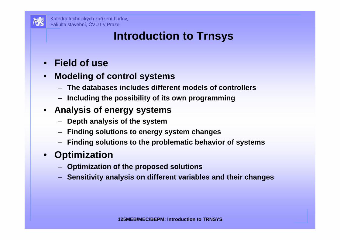
6. Determine the basic properties and limits of calculation.7. Deck file generation and start of the simulation.
How to create a model?
Receive some results.
125MEB/MEC/BEPM: Introduction to TRNSYS
Katedra technických zařízení budov, Fakulta stavební, ČVUT v Praze
7. Deck file generation and start of the simulation.8. We make adjustments to the model to obtain the
desired results
How to create a model?
125MEB/MEC/BEPM: Introduction to TRNSYS

Examples
Katedra technických zařízení budov, Fakulta stavební, ČVUT v Praze
Climatic data
heater Results output
Case 1:The outside air flow rate 3000 m3/h enters a space, where is heatedwith heating rate 30 kW up to required temperature 30 °C. Isdesigned heating rate suitable for first two weeks of January? Weneed to know if this heater is able to heat outside air from outdoorair temperature to required temperature. Parameters take from theexterior climate data for locations of Prague.
125MEB/MEC/BEPM: Introduction to TRNSYS

Katedra technických zařízení budov, Fakulta stavební, ČVUT v Praze
Results:
Output air temperature
Outside air temperature
Energy consumption in the heater
Examples
!
125MEB/MEC/BEPM: Introduction to TRNSYS

Results summary:• Output of 30 kW heater heats the outdoor air flow rate 3000 m3/h
at the desired temperature of 30 °C only in the fir st 97 hours ,• The heater provides required supply air temperature when the
outdoor temperature is over 0 °C ,• If we want respect the required output temperature we need heat
output of a heater 45.5 kW,• If we require compliance with the outlet temperature and do not
want to have to increase heating output, we are to reduce the flow of air to 1980 m3/h,
Katedra technických zařízení budov, Fakulta stavební, ČVUT v Praze
Basic situation
Raised thermal output
Lower flow rate
Energy for heating 9 644 kWh 10 938 kWh 7 219 kWh
Operational costs 17 360 Kč 19 690 Kč 13 000 Kč
Examples
125MEB/MEC/BEPM: Introduction to TRNSYS

Katedra technických zařízení budov, Fakulta stavební, ČVUT v Praze
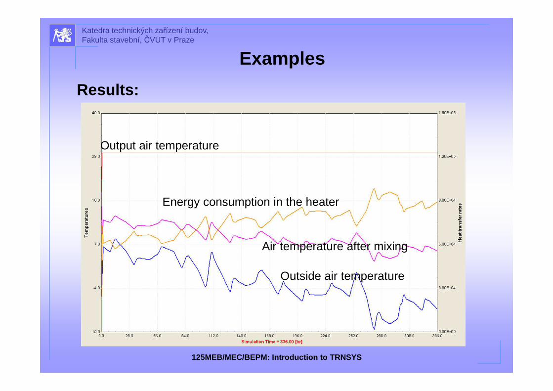
Case 2: Add mixing chamber• Add mixing of an outside air with a circulation air• 30 kW heater and the required supply air temperature 30°C are
the same• The amount of supply air remains at 3000 m3/h• Supply air will be mixture of 50% fresh and 50% circular air• Circulating air will have temperature of 20 °C
Climatic data
heater Results output
Mixing chamber
Examples
125MEB/MEC/BEPM: Introduction to TRNSYS
Katedra technických zařízení budov, Fakulta stavební, ČVUT v Praze
Results:
Air temperature after mixing
Examples
Output air temperature
Energy consumption in the heater
Outside air temperature
125MEB/MEC/BEPM: Introduction to TRNSYS

Katedra technických zařízení budov, Fakulta stavební, ČVUT v Praze
Results summary:• The heater output of 30 kW is appropriately dimensioned,• maximum thermal output at the time of the simulation is 27.4 kW at
outdoor temperature -14.2 °C and mixing temperature of 2.9 °C
Case 1 Case 2
Basic situation
Raised thermal output
Lower flow rate
Mixing
Energy for heating
9 644 kWh 10 938 kWh 7 219 kWh 7 170 kWh
Operational costs
17 360 Kč 19 690 Kč 13 000 Kč 12 900 Kč
Examples
125MEB/MEC/BEPM: Introduction to TRNSYS

Katedra technických zařízení budov, Fakulta stavební, ČVUT v Praze
Case 3: Heat recovery• We will add heat recovery from exhaust air,• 30 kW heater and the required supply air temperature 30°C are the
same• The amount of supply air remains at 3000 m3/h• Circulation - supplied 50% of fresh air (for recovery) and 50% circular• Heat recovery heat exchanger will have efficiency 60%
Climatic data
Heater Results output
Mixing
Heat recovery
Examples
125MEB/MEC/BEPM: Introduction to TRNSYS

Katedra technických zařízení budov, Fakulta stavební, ČVUT v Praze
Results:
Heat recovery
Air temperature after heat recovery
Examples
Air temperature after mixing
Output air temperature
Energy consumption in the heater
Outside air temperature
125MEB/MEC/BEPM: Introduction to TRNSYS

Katedra technických zařízení budov, Fakulta stavební, ČVUT v Praze
Examples
Results summary:• The heater output of 30 kW is now oversized,• maximum heating output in the time of the simulation is 16.9 kW
• While outside temperature is -14.2 °C, air tempera ture after heat recovery is 6.6°C and after air mixing is 13.3 °C.
• Using all thermal output of the heater we can achieve supply air temperature 43 °C
Case 1 Case 2 Case 3
Basic situation
Raised thermal output
Lower flow rate
Mixing With heat recovery
Heat recovery savings
Energy for heating
9 644 kWh 10 938 kWh 7 219 kWh 7 170 kWh 4 870 kWh 2 290 kWh
Operational costs
17 360 Kč 19 690 Kč 13 000 Kč 12 900 Kč 8 770 Kč 4 130 Kč
125MEB/MEC/BEPM: Introduction to TRNSYS

Katedra technických zařízení budov, Fakulta stavební, ČVUT v Praze
Thermal solar collectors
a. Determine the impact of solar collectors inclinat ionWhat is the difference in energy of the incident solar radiation on collector surface and energy produced by collectors for inclinations 10°, 25°, 45°, 60° and 90°?
b. Determine the impact of changes in the volume of hot water tank
What will be the modification of the output temperature of hot water tank after the charging period during which the solar collectors supply energy?Determine impact of changes in the volume of hot water tank to temperature in the upper output for optional volume of 200 l, 400 l, 600 l, 800 l and 1000 l .
Examples
125MEB/MEC/BEPM: Introduction to TRNSYS

Katedra technických zařízení budov, Fakulta stavební, ČVUT v Praze
24 h integration
Hot water daily consumption
profile
Climatic data
Solar collectorspump
regulátor
Hot water tank
Tank outlet mixing with cold water
Cold water diverter
results
results
results
Examples
125MEB/MEC/BEPM: Introduction to TRNSYS

Katedra technických zařízení budov, Fakulta stavební, ČVUT v Praze
slope
Daily summary of
incident energy to
collectors
Daily energy production
from collectors
Icoll Qucoll
° kJ/m2 kJ
10 5081 8437
25 4922 8319
45 4295 6855
60 3803 6118
90 2710 4627
Tank
volume
After hot water
consumptionAfter charging period
4330 4334
l h h
200 59,7 81,3
300 61,8 76,4
400 66,1 74,1
500 66,4 72,2
600 65,4 70,3
700 64 68,5
800 62,8 67,1
900 61,4 65,5
1000 60,4 64,3
a) impact of solar collectors inclination b) impact of changes in the volume of hot water tank
0
1000
2000
3000
4000
5000
6000
7000
8000
9000
10 25 45 60 90
Icoll
Qucoll
4045505560657075808590
200 300 400 500 600 700 800 900 1000
4330
4334
Examples
125MEB/MEC/BEPM: Introduction to TRNSYS
Computer model contra reality
Ground of this work:Experimental storage tank installed in new laboratory,Prediction of storage tank behavior and replace of repeating basic experiments,
• The computer model serves for mutual comparison between simulation and experiment,
• Suitable for preparation of more advanced experiments,
• Tank and model available also for students.
Katedra technických zařízení budov, Fakulta stavební, ČVUT v Praze
125MEB/MEC/BEPM: Introduction to TRNSYS
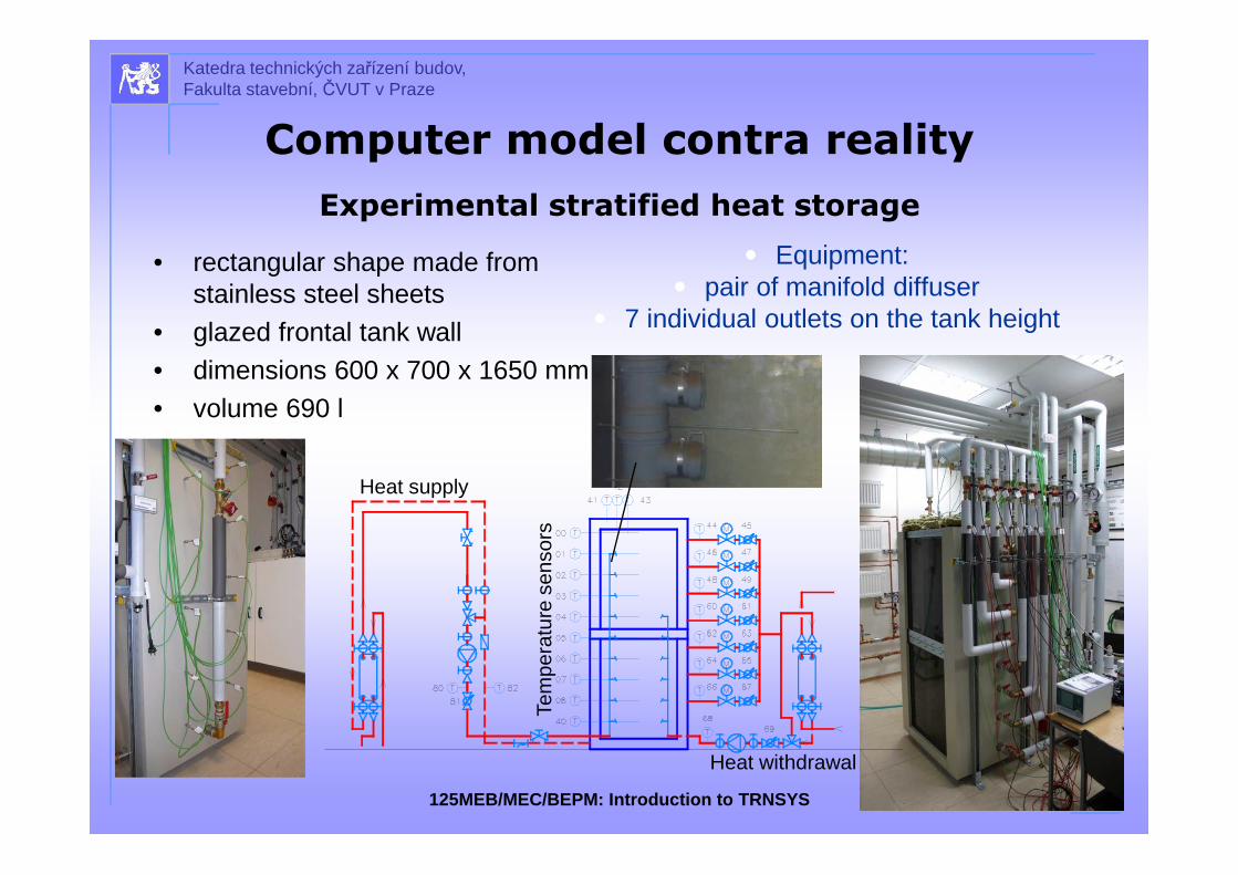
Experimental stratified heat storage
• rectangular shape made from stainless steel sheets
• glazed frontal tank wall • dimensions 600 x 700 x 1650 mm• volume 690 l
� Equipment:� pair of manifold diffuser
� 7 individual outlets on the tank height
Heat supply
Heat withdrawal
Tem
pera
ture
sen
sors
Katedra technických zařízení budov, Fakulta stavební, ČVUT v Praze
125MEB/MEC/BEPM: Introduction to TRNSYS
Computer model contra reality

Principle of simulation model
Katedra technických zařízení budov, Fakulta stavební, ČVUT v Praze
125MEB/MEC/BEPM: Introduction to TRNSYS
Computer model contra reality
Energy supply Energy
consumptionStratified
storage tank

Principle of simulation model
• TRNSYS model – calculate from energy balance of flows the average temperature of separate fully mixed layers – every time step
• Defined 17 temperature layers for model calculation– provide smoother view of vertical temperature
grid– 10 nodes for our tank is minimal
• Model input data are based on the data measured in the experiment.– inlet/outlet flows, inlet temperatures – surrounding temperature
• The most suitable for our storage tank is type 531 (Tess database) Type531
Model scheme
Katedra technických zařízení budov, Fakulta stavební, ČVUT v Praze
125MEB/MEC/BEPM: Introduction to TRNSYS
Computer model contra reality

Experimental stages
Stage 1
Withdraw from the top outlet•constant position of inlets at bottom,•constant energy output•only for mutual compare of Trnsys models Type 4, 60, 531.
Stage 2
Withdraw from the outlet 6, high output•temperature of return cooled water is lower than storagetank bottom temperature,•constant energy output 3.8 kW.
Stage 3
Withdraw from the top outlet 7, variable output•temperature of return cooled water is lower than storagetank bottom temperature,•energy output changes twice during experiment.
Stage 4
Return stratification manifold•temperature of return cooled water is higher than storagetank bottom temperature,•constant energy output 0.6 kW.
Stage 5
Temporary withdraw than heating•stops at 95 minute,•start of heat up the storage tank.
Stage 1
Stage 2
Stage 3
Stage 5
Stage 4
Katedra technických zařízení budov, Fakulta stavební, ČVUT v Praze
125MEB/MEC/BEPM: Introduction to TRNSYS
Computer model contra reality
Examples of results and discussion
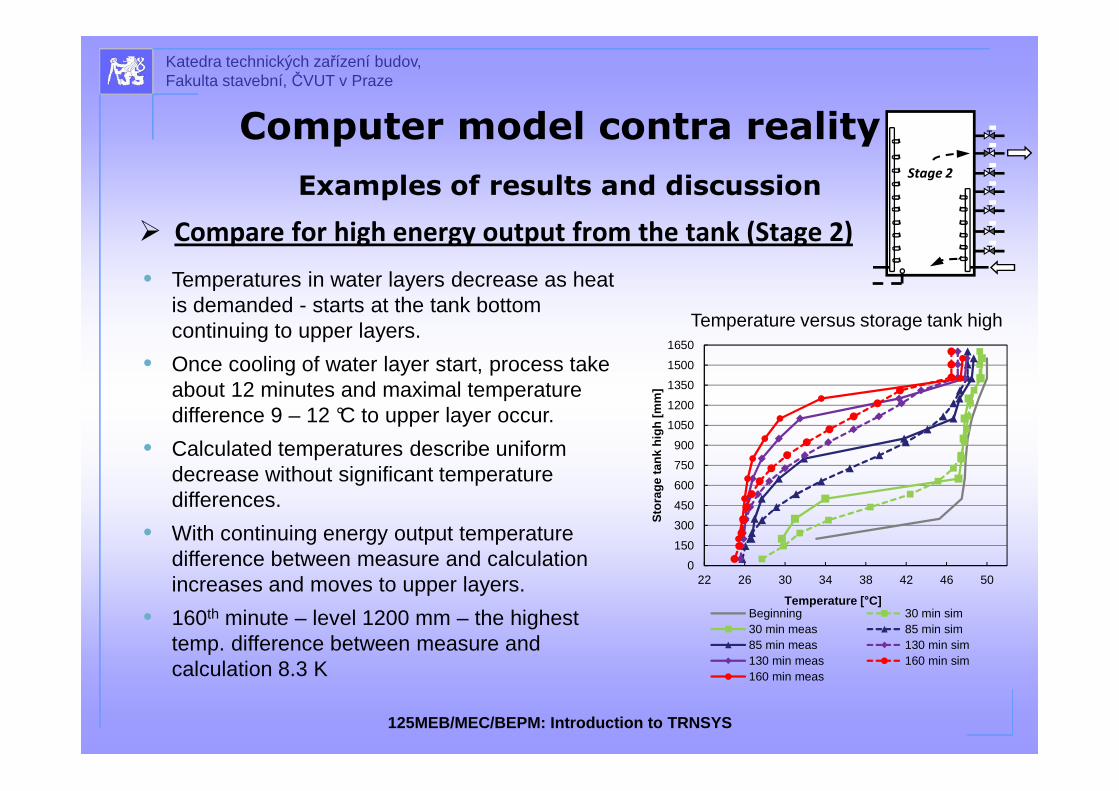
� Compare for high energy output from the tank (Stage 2)
Temperature versus storage tank high
• Temperatures in water layers decrease as heat is demanded - starts at the tank bottom continuing to upper layers.
• Once cooling of water layer start, process take about 12 minutes and maximal temperature difference 9 – 12 °C to upper layer occur.
• Calculated temperatures describe uniform decrease without significant temperature differences.
• With continuing energy output temperature difference between measure and calculation increases and moves to upper layers.
• 160th minute – level 1200 mm – the highest temp. difference between measure and calculation 8.3 K
Stage 2
0
150
300
450
600
750
900
1050
1200
1350
1500
1650
22 26 30 34 38 42 46 50
Sto
rage
tank
hig
h [m
m]
Temperature [ °C]Beginning 30 min sim30 min meas 85 min sim85 min meas 130 min sim130 min meas 160 min sim160 min meas
Katedra technických zařízení budov, Fakulta stavební, ČVUT v Praze
125MEB/MEC/BEPM: Introduction to TRNSYS
Computer model contra reality

� Compare for low energy output from the tank (Stage 3)
Temperature versus time
• starts with high energy output
• energy output from the storage tank changes:
• 57 minutes - thermal output 6 kW,
• 53 minutes decreases to 2.6 kW,
• finally last 92 minutes increases to 4.5 kW.
• 500 mm layer is influenced by high energy output – similar to stage 2
• while energy output is low results show excellent conformity
• 950 – 1400 mm layers – significant examples
Stage 3
10
15
20
25
30
35
40
45
50
55
1 16 31 46 61 76 91 106 121 136 151 166 181 196
Tem
pera
ture
[°C
]
Time [min]
1400 mm sim 1400 mm meas1250 mm sim 1250 mm meas950 mm sim 950 mm meas500 mm sim 500 mm meas
6 kW 2.6 kW 4.5 kW
Katedra technických zařízení budov, Fakulta stavební, ČVUT v Praze
125MEB/MEC/BEPM: Introduction to TRNSYS
Computer model contra reality
Examples of results and discussion

Conclusion
Katedra technických zařízení budov, Fakulta stavební, ČVUT v Praze
Conclusion:• TRNSYS program is usable for a wide application of energy systems
simulations.• It is suitable for their design, optimization and for different case
studies.• Every model needs verification process!
• Another calculation, already verified model• Measured data (validation with reality)
• The program works with an open structure, so you can if you have the programming knowledge to create own components.
• The wide use around the world provides the opportunity to consult problems and results with other users.
• It is also possible to find published results of existing studies - useful to verify own results and to avoid possible errors already resolved.
125MEB/MEC/BEPM: Introduction to TRNSYS

Thank you for your attention
Daniel AdamovskýCTU in Prague, Faculty of Civil Engineering
Department of Microenvironmental and Building Services Engineering
email: [email protected]
Katedra technických zařízení budov, Fakulta stavební, ČVUT v Praze