Embed Size (px)
Citation preview

Triton Imaging, Inc.
eXtended Triton Format (XTF) Rev. 37

NAME DATE DESCRIPTION
COMPILED BY Richard Clark 1/15/2002 XTF File Format Documentation
ENGINEER Liz Shaw REV: X13
ENGINEER Geoff Shipton 9/20/04 REV: X14
ENGINEER Geoff Shipton 2/1/2005 REV: X15
ENGINEER Geoff Shipton 2/14/2005 REV: X16
ENGINEER Douglas Bergersen 2/1/2006 REV. X17
ENGINEER Geoff Shipton 2/13/2006 REV. X18
ENGINEER Geoff Shipton 4/20/2006 REV X19
ENGINEER Geoff Shipton 10/6/2006 REV X20
ENGINEER Geoff Shipton 12/27/2006 REV X21
ENGINEER Geoff Shipton 1/10/2006 REV X22
ENGINEER Geoff Shipton 6/22/2007 REV X23
ENGINEER Geoff Shipton 6/22/2007 REV X24
ENGINEER Geoff Shipton 7/1/2008 REV X25
ENGINEER Geoff Shipton 12/18/2008 REV X26
ENGINEER Geoff Shipton 9/29/2010 REV X27
ENGINEER Geoff Shipton 9/30/2010 REV X28
ENGINEER Geoff Shipton 1/7/2011 REV X29
ENGINEER GeoffShipton 3/10/2011 REV X30
ENGINEER Geoff Shipton 4/10/2011 REV X31
ENGINEER GeoffShipton 12/5/2011 REV X32
ENGINEER GeoffShipton 12/24/2011 REV X33
ENGINEER
ENGINEER
ENGINEER
ENGINEER
GeoffShipton
GeoffShipton
GeoffShipton
GeoffShipton
2/21/2012
2/4/2013
7/10/2014
10/14/2014
REV X34
REV X35
REV X36
REV X37

REV DESCRIPTION OF CHANGE DATE BY ENG
X1 First Draft 01/15/2002 RLC
X2 Update References 01/30/2002 RLC
X3 Add Reference to Read_xtf.c and demo_xtf.c 02/12/2002 RLC
X4 Add reference to MillivoltScale. 03/29/2002 RLC
X5 Update structure size for XTFPINGHEADER 04/09/2002 RLC
X6 Added XTFHIGHSPEEDSENSOR structure and updated
header types for XTFPINGHEADER.
05/31/2002 RLC
X7 Added ISISFORWARDBEAMHEADER and
XTFBEAMXYZA Structures.
06/03/2002
X8 Update FileHeader’s SonarType. Added
XTF_BATHY_SNIPPET data format and SNP0, SNP1
structures associated with the XTF_BATHY_SNIPPET
packet type. Updated description of
XTFPINGCHANHEADER.
08/12/2002 RLC
X9 Reviewed an edited for accuracy 8/20/2002 RS RS
X10 Remove Read_XTF.c reference. 9/24/2002 RLC RLC
X11 XTFPINGHEADER/XTFBATHHEADER,
HIGHSPEEDSENSOR, XTFBEAMXYZA offset listings
were incorrect,updated to display correct offsets.
10/17/2002 RLC RLC
X12 Added XTF_SARA_CAATI_HEADER packet description
Updated XTFATTITUDEDATA structure to include new
fields, new packet types
XTF_HEADER_KLEIN3000_DATA_PAGE,
XTF_HEADER_POS_RAW_NAVIGATION
03/24/2003 RLC RLC
X13 Added section 2.3.1, Odd-numbered sidescan sonar channels
Corrected the EventNumber byte offset in the
XTFPINGHEADER structure (deleted the CurrentLineID
field)
04/27/2004 LCS LCS
X14 Further update to EventNumber and explanation 9/20/2004 GVS GVS
X15 Added CODA Echoscope 2/1/2005 GVS GVS
X16 Added CODA Echoscope Config (and corrected name) 14/2/2005 GVS GVS
X17 Added QPS data records for single beam echosounders and
multi-transducer echosounders
2/1/2006 DDB DDB
X18 Added Benthos C3D, Edgetech 4200, Benthos SIS1624, C-
MAX, Edgetech MP-X . Modified XTFATTITUDE
Reserved3[10] to Reserved3[1]. Modified
XTFPINGCHANHEADER to include a WeightFactor field
in bytes 58 and 59.
19/4/2006 GVS GVS
X19 Added Reson 7125 6/6/2006 GVS GVS
X20 Added Kongsberg SAS; corrected weighting data type 10/6/2006 GVS GVS
X21 Corrected size of usAmpl in XTFBEAMXYZA structure 12/27/06 GVS GVS
X22 Add 32bit logging capability (CHANINFO Byte74) and
Klein v4 Header Type 108 in XTFPINGHEADER
1/10/2006 GVS GVS
X23 Added CODA Echoscope Image HeaderType = 72 6/22/2007 GVS GVS
X24
X25
X26
X27
X28
X29
X30
X31
X32
X33
X34
X35
X36
X37
Added XTFRAWCUSTOMHEADER
Added XTF_HEADER_Q_MULTIBEAM structure
Corrected description of WORD Microseconds
Added various new sonar types inc QINSy R2Sonics, C-
Max, GeoAcoustics
Updates to Type 3 Attitude packet and addition of type 42
navigation and type 84 gyro packets
Updates to R2Sonic sonar types for QINSy and Triton
Added Klein 3500, 5900 and Edgetech 4600
Added Reson Type 76 – 7027 packet
Remove Reson Type 76 – 7027 packet
Add Appendix for Recon – 7nnn packets
Added cable out hundredths
Changes to CHANINFO remove latency adjust byte count
Added Reson 7018 Watercolumn and other data packets
Added R2Sonic Watercolumn and other data packets
6/22/2007
6/30/2008
12/18/2008
9/29/2010
9/29/2010
1/7/2010
3/10/2011
4/10/2011
12/2/2011
12/24/2011
2/21/2012
2/4/2012
7/10/2014
10/14/2014
GVS
GVS
GVS
GVS
GVS
GVS
GVS
GVS
GVS
GVS
GVS
GVS
GVS
GVS
GVS
GVS
GVS
GVS
GVS
GVS
GVS
GVS
GVS
GVS
GVS
GVS
GVS
GVS

1. Introduction
1.1. Purpose
This document is intended to address file format and suggested ways for TEI engineers to process XTF files.
1.2. Definitions, abbreviations, and acronyms.
XTF Extended Triton Format.
EOF End of file
MRU Motion Reference Unit
RTK Real Time Kinematic
CTD Conductivity Temperature Depth
1.3. References
Isis Sonar User’s Manual, Volume 2, TEI, Inc 2000
Xtf.h file located in source safe xtftools project (internal reference) TEI, Inc 1998.
Xtftools workspace located in source safe under devparis\library\xtftools. (internal reference) TEI, Inc 1998.
Speed of sound in seawater at high pressures. J. Acoust. Soc. Am., 62 (5), 1129-1135.). Chen Millero formula.
(C. T. Chen and F. J. Millero, 1977,
Appendix D Xtf File Format. June 1999 Isis® Sonar Users Manual, Volume 2
IsisFmt.h, Usercode.h files. Located in Isis workspace. Isis version 5.94 (internal reference), TEI, Inc 1998.

2. Overall Description
2.1. Format perspective
The XTF file format (eXtended Triton Format) was created to answer the need for saving many different
types of sonar, navigation, telemetry and bathymetry information. The format can easily be extended to
include new types of data that may be encountered in the future.
2.2. Methodology
An XTF file can be thought of as a “pool” of data. If you use XTF to collect data during a survey, you can
add data to the file at any time without needing to synchronize your data packets. For example, bathymetry
data may be logged five times per second while sonar data is being logged at 10 times per second. No
storage space is wasted and no “holes” are created in the saved data stream. While processing an XTF file,
the processing software can easily ignore unknown or unnecessary data packets. For example, Tritons
TargetPro utility program will read an XTF file for sonar data and skip over any saved bathymetry data.
When a non-sonar data packet is encountered, TargetPro simply ignores it and reads another packet. Any
software that reads XTF files should also ignore unnecessary packets because it guarantees compatibility
with files that may contain new kinds of data that may be included in the future.
Some users may think that the XTF file format frequently changes. That thought comes from a basic
misunderstanding of the XTF methodology. As new kinds of sensors are introduced into the marketplace,
new XTF packet types are created to store the unique data produced by those sensors. Those packets may
not be recognized by legacy software programs, but those programs should be written to benignly skip over
unrecognized XTF packets.
Since the pool of data in an XTF file is written asynchronously, it is impossible to calculate a byte offset for
a specific record in the file. However, there is a straightforward method to quickly search a file for any
specific data packet. This method is described later in this appendix.
2.2.1. Note to programmers
When using the structures described in this document, note that the packing should be 1. In the Microsoft
Visual C++ compiler, the statement
#pragma pack(1)
should be placed before the structure definitions and
#pragma pack()
after the definitions (or equivalent). By default, Microsoft compilers use a packing of eight, which will
result in different structure alignment than described in this document.
All structures should be zero-filled before use. Unused values should remain zero.

2.3. General Description
Data stored in an XTF file uses a general message format. Each XTF file begins with a file header record
and is followed by one or more data packets. The file header data is stored in the XTFFILEHEADER
structure. Each XTFFILEHEADER contains room for six channels. Channel data is stored in the
CHANINFO structure.
Note: A “channel” in XTF is generated from a “ping.” Basic sidescan sonars are two channels. Dual-
frequency sidescan sonars are four channels. A single bathymetry system is a single channel. Speed sensors,
altimeters, or any other sensor that outputs data as a single numeric value (typically over a serial port) is
NOT considered a channel in XTF. This kind of numeric data is entered into the system and stored in
dedicated fields within the XTF files.
The basic XTF file header record is 1024 bytes in size. It can be larger than 1024 bytes when the total
number of channels to be stored in the file is greater than six. In this event, the total size of the file header
record grows in increments of 1024 bytes until there is enough room to hold all of the CHANINFO structures.
All XTF data packets written by Isis are padded so that the total packet size is a multiple of 64 bytes.
This is not a requirement, but doing so makes playback functions faster in Isis.
Two important elements of the file header are:
• Number of sonar channels
• Number of bathymetry channels
These are used to determine how many CHANINFO structures will be in the header record. The
CHANINFO structures for all of the sonar channels will always precede the structures for the bathymetry
channels.
Except where otherwise documented, all values are stored using the metric system (typically meters) or
degrees of angle. When using Isis to display XTF files, the user can elect to display the data in feet, and the
conversion happens at display-time.
2.3.1. Odd-numbered sidescan sonar channels
For odd-numbered channels, the sample order is reversed. This is done so that the channels will display in a
conventional manner in the waterfall window. When channels are selected as sub-bottom, the sample order
is not reversed..

2.4. Xtf File Data Layout
Figure 1. XTF File Data Layout
XTFFILEHEADER
(1024 bytes)
Various XTF
Packets…
The file header is the first data in the file. Depending on total number of sonar and bathy channels,
CHANINFO structures may follow the file header. After the File Header and possible CHANINFO
structures, data packets follow until the end of the file.
2.4.1. Xtf File Header Layout
The XTF File header structure is described in Table C. The size is 1024 bytes. If more than six
channels of data are to be logged in the XTF file, then the header can grow in increments of 1024
bytes to allow for additional CHANINFO structures are required.
2.4.2. XTFPINGHEADER data layout
The value of NumChansToFollow in XTFPINGHEADER (structure defined in table H) determines
the number of XTFPINGCHANHEADERs (structure defined in Table I.) that follows the
XTFPINGHEADER.
Figure 2. XTF Sonar Ping Header Data Layout (example for two-channel Sidescan)
XTFPINGHEADER XTFPINGCHANHEADER
for the first channel
Data
samples for
first channel
XTFPINGCHANHEADER
for the second channel
Data
samples
for second
channel
Pad
bytes
as
necess
ary
2.4.3. XTFBATHYHEADER data layout
XTFBATHHEADER structure is defined in table H. The structure is followed by a payload of
bathymetry data, logged “raw” – that is, the data is unchanged and is logged exactly as received from
the multibeam system. The packet is then padded with zero-filled bytes to bring the total XTF packet
size to an even multiple of 64 bytes.
For details on processing the actual bathymetry data, consult the bathymetry system manufacturer.
Figure 3. XTF Bathymetry Ping Header Data Layout
XTFBATHYHEADER Bathymetry data
payload (raw,
from sensor)
Pad bytes
necessary to make
total XTF packet a
multiple of 64
bytes.
2.5. Binary Data Representation
Except for some bathymetry data (which is logged “raw”), all data is written with Intel 80x86 byte ordering
(LSB to MSB). If an XTF file is to be processed on a non-Intel computer such as one from Sun
Microsystems, Inc., Silicon Graphics, Inc., or Apple Computer, Inc., the order of the bytes in all values must
be exactly reversed. For example, a float value (4 bytes) would need to be reordered from (1,2,3,4) to
(4,3,2,1) in the target machine’s memory before treating the number as a floating-point value. This
effectively converts the value from little-endian (least-significant byte first) to big-endian (most-significant
byte first).
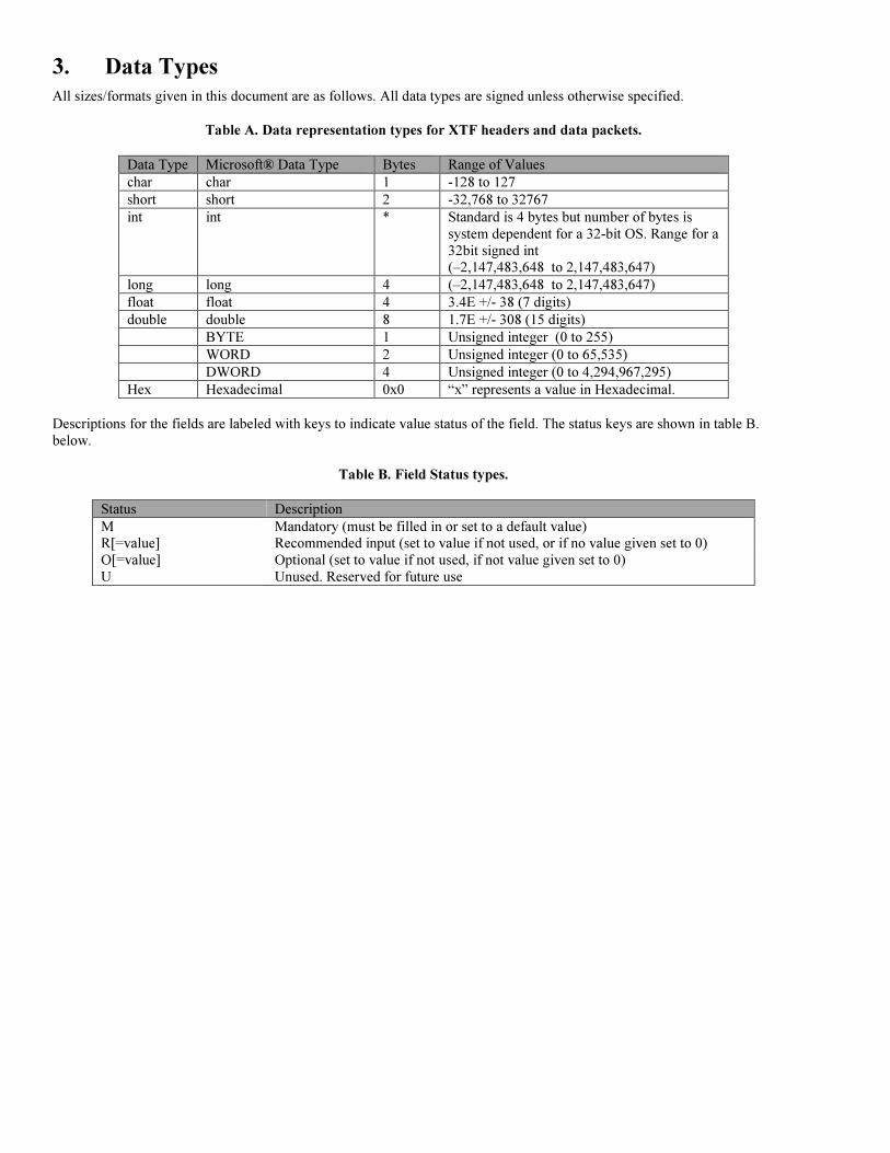
3. Data Types
All sizes/formats given in this document are as follows. All data types are signed unless otherwise specified.
Table A. Data representation types for XTF headers and data packets.
Data Type Microsoft® Data Type Bytes Range of Values
char char 1 -128 to 127
short short 2 -32,768 to 32767
int int * Standard is 4 bytes but number of bytes is
system dependent for a 32-bit OS. Range for a
32bit signed int
(–2,147,483,648 to 2,147,483,647)
long long 4 (–2,147,483,648 to 2,147,483,647)
float float 4 3.4E +/- 38 (7 digits)
double double 8 1.7E +/- 308 (15 digits)
BYTE 1 Unsigned integer (0 to 255)
WORD 2 Unsigned integer (0 to 65,535)
DWORD 4 Unsigned integer (0 to 4,294,967,295)
Hex Hexadecimal 0x0 “x” represents a value in Hexadecimal.
Descriptions for the fields are labeled with keys to indicate value status of the field. The status keys are shown in table B.
below.
Table B. Field Status types.
Status Description
M Mandatory (must be filled in or set to a default value)
R[=value] Recommended input (set to value if not used, or if no value given set to 0)
O[=value] Optional (set to value if not used, if not value given set to 0)
U Unused. Reserved for future use

3.1.1. XTFFILEHEADER Structure
Table C. XTFFILEHEADER structure.
XTFFILEHEADER
Field Byte
Offset
Status
Comment
BYTE FileFormat 0 M Set to 123 (0x7B)
BYTE SystemType 1 M Set to 1
char RecordingProgramName[8] 2 M Example: "Isis"
char RecordingProgramVersion[8] 10 M Example: "556" for version 5.56
char SonarName[16] 18 R Name of server used to access sonar. Example:
"C31_SERV.EXE"
WORD SonarType 34 M 0 = NONE , default.
1 = JAMSTEC, Jamstec chirp 2-channel
subbottom.
2 = ANALOG_C31, PC31 8-channel.
3 = SIS1000, Chirp SIS-1000 sonar.
4 = ANALOG_32CHAN, Spectrum with
32-channel DSPlink card.
5 = KLEIN2000, Klein system 2000 with
digital interface.
6 = RWS, Standard PC31 analog with special
nav code.
7 = DF1000, EG&G DF1000 digital
interface.
8 = SEABAT, Reson SEABAT 900x
analog/serial.
9 = KLEIN595, 4-chan Klein 595, same as
ANALOG_C31.
10 = EGG260, 2-channel EGG260, same as
ANALOG_C31.
11 = SONATECH_DDS, Sonatech Diver
Detection System on Spectrum DSP32C.
12 = ECHOSCAN, Odom EchoScanII
multibeam (with simultaneous analog
sidescan).
13 = ELAC, Elac multibeam system.
14 = KLEIN5000, Klein system 5000 with
digital interface.
15 = Reson Seabat 8101.
16 = Imagenex model 858.
17 = USN SILOS with 3-channel analog.
18 = Sonatech Super-high res sidescan sonar.
19 = Delph AU32 Analog input (2 channel)..
20 = Generic sonar using the memory-mapped
file interface.
21 = Simrad SM2000 Multibeam Echo
Sounder.
22 = Standard multimedia audio.
23 = Edgetech (EG&G) ACI card for 260
sonar through PC31 card.
24 = Edgetech Black Box.
25 = Fugro deeptow.
26 = C&C's Edgetech Chirp conversion
program.
27 = DTI SAS Synthetic Aperture processor
(memmap file).
28 = Fugro's Osiris AUV Sidescan data.
29 = Fugro's Osiris AUV Multibeam data.
30 = Geoacoustics SLS.
31 = Simrad EM2000/EM3000.
32 = Klein system 3000.

33 = SHRSSS Chirp system
34 = Benthos C3D SARA/CAATI
35 = Edgetech MP-X
36 = CMAX
37 = Benthos sis1624
38 = Edgetech 4200
39 = Benthos SIS1500
40 = Benthos SIS1502
41 = Benthos SIS3000
42 = Benthos SIS7000
43 = DF1000 DCU
44 = NONE_SIDESCAN
45 = NONE_MULTIBEAM
46 = Reson 7125
47 = CODA Echoscope
48 = Kongsberg SAS
49 = QINSy
50 = GeoAcoustics DSSS
51 = CMAX_USB
52 = SwathPlus Bathy
53= R2Sonic QINSy
55= R2Sonic Triton
54 = Converted SwathPlus Bathy
56= Edgetech 4600
57=Klein 3500
58=Klein 5900
char NoteString[64] 36 R Notes as entered in the Sonar Setup dialog box
char ThisFileName[64] 100 R Name of this file. Example:"LINE12-B.XTF"
WORD NavUnits 164 M 0=Meters (i.e., UTM) or 3=Lat/Long
WORD NumberOfSonarChannels 166 M if > 6, header grows to 2K in size
WORD NumberOfBathymetryChannels 168 M
BYTE NumberOfSnippetChannels 170 M
BYTE NumberOfForwardLookArrays 171 M
WORD NumberOfEchoStrengthChannels 172 M
BYTE NumberOfInterferometryChannels 174 M
BYTE Reserved1 175 U Reserved. Set to 0.
WORD Reserved2 176 U Reserved. Set to 0.
float ReferencePointHeight 178 O Height of reference point above water line (m)
Navigation System Parameters
BYTE ProjectionType[12] 182 U Not currently used. Set to 0.
BYTE SpheriodType[10] 194 U Not currently used. Set to 0.
long NavigationLatency 204 O Latency of nav system in milliseconds.
(Usually GPS).
ISIS Note: This value is entered on the Serial
port setup dialog box. When computing a
position, Isis will take the time of the
navigation and subtract this value.
float OriginY 208 U Not currently used. Set to 0.
float OriginX 212 U Not currently used. Set to 0.
float NavOffsetY 216 O Orientation of positive Y is forward. ISIS
Note: This offset is entered in the Multibeam
setup dialog box
float NavOffsetX 220 O Orientation of positive X is to starboard. ISIS
Note: This offset is entered in the Multibeam
setup dialog box
float NavOffsetZ 224 O Orientation of positive Z is down. Just like
depth. ISIS Note: This offset is entered in the
Multibeam setup dialog box
float NavOffsetYaw 228 O Orientation of positive yaw is turn to right.
ISIS Note: This offset is entered in the
Multibeam setup dialog box
float MRUOffsetY 232 O Orientation of positive Y is forward. ISIS

Note: This offset is entered in the Multibeam
setup dialog box
float MRUOffsetX 236 O Orientation of positive X is to starboard. ISIS
Note: This offset is entered in the Multibeam
setup dialog box
float MRUOffsetZ 240 O Orientation of positive Z is down. Just like
depth. ISIS Note: This offset is entered in the
Multibeam setup dialog box
float MRUOffsetYaw 244 O Orientation of positive yaw is turn to right.
ISIS Note: This offset is entered in the
Multibeam setup dialog box
float MRUOffsetPitch 248 O Orientation of positive pitch is nose up. ISIS
Note: This offset is entered in the Multibeam
setup dialog box. ISIS Note: This offset is
entered in the Multibeam setup dialog box
float MRUOffsetRoll 252 O Orientation of positive roll is lean to starboard.
ISIS Note: This offset is entered in the
Multibeam setup dialog box
CHANINFO ChanInfo[6] 256 M Data for each channel. The CHANINFO
structures for all sidescan channels will always
precede the structures for the bathymetry
channels. If more than 6 structures are
required, the header can grow in increments of
1024 bytes to allow for more CHANINFO
structures.
The overall size is 1024 bytes.

3.1.2. CHANINFO structure
Table D. CHANINFO Structure.
CHANINFO
Field Byte
Offset
Statu
s
Comment
BYTE TypeOfChannel 0 M SUBBOTTOM=0, PORT=1, STBD=2,
BATHYMETRY=3
BYTE SubChannelNumber 1 O Index for which CHANINFO structure this is.
WORD CorrectionFlags 2 O 1=sonar imagery stored as slant-range, 2=sonar
imagery stored as ground range (corrected)
WORD UniPolar 4 O 0=data is polar, 1=data is unipolar
WORD BytesPerSample 6 M 1 (8-bit data) or 2 (16-bit data) or 4 (32-bit)
DWORD Reserved 8 U Isis Note: Previously this was
SamplesPerChannel. Isis now supports the
recording of every sample per ping, which
means that number of samples per channel can
vary from ping to ping if the range scale
changes. Because of this, the NumSamples
value in the XTFPINGCHANHEADER
structure (defined in Section 3.18) holds the
number of samples to read for a given channel.
For standard analog systems, this Reserved
value is still filled in with 1024, 2048 or
whatever the initial value is for
SamplesPerChannel.
char ChannelName[16] 12 O Text describing channel. i.e., "Port 500"
float VoltScale 28 O This states how many volts are represented by
a maximum sample value in the range
[-5.0 to +4.9998] volts. Default is 5.0.
float Frequency 32 O Center transmit frequency
float HorizBeamAngle 36 O Typically 1 degree or so
float TiltAngle 40 O Typically 30 degrees
float BeamWidth 44 O 3dB beam width, Typically 50 degrees
float OffsetX 48 O Orientation of positive X is to starboard. Note:
This offset is entered in the Multibeam setup
dialog box
float OffsetY 52 O Orientation of positive Y is forward. Note:
This offset is entered in the Multibeam setup
dialog box
float OffsetZ 56 O Orientation of positive Z is down. Just like
depth. Note: This offset is entered in the
Multibeam setup dialog box
float OffsetYaw 60 O Orientation of positive yaw is turn to right. If
the multibeam sensor is reverse mounted
(facing backwards), then OffsetYaw will be
around 180 degrees. Note: This offset is
entered in the Multibeam setup dialog box
float OffsetPitch 64 O Orientation of positive pitch is nose up. Note:
This offset is entered in the Multibeam setup
dialog box
float OffsetRoll 68 O Orientation of positive roll is lean to starboard.
Note: This offset is entered in the Multibeam
setup dialog box
WORD BeamsPerArray 72 O For forward look only (i.e., Sonatech DDS)

Char ReservedArea2[54] 74 U Unused Set value to 0
Channel information structure (contained in the file header). One-time information describing each channel. This is data
pertaining to each channel that will not change during the course of a run. The overall size is 128 bytes

3.1.3. Data Packet Structure
Packet Header (usually 256 bytes). Identifies number of channels in this packet and total size of the
packet. Each packet begins with a key pattern of bytes, called the "magic number", which can be used
to align the data stream to the start of a packet. For each channel:
• Channel header (optional, usually 64 bytes)
• Channel data (optional, byte count varies)
These data packet types currently exist for XTF files:
• Attitude (XTFATTITUDEDATA )
• Annotation (XTFNOTESHEADER)
• Bathymetry (XTFBATHHEADER)
• ELAC (XTFBATHHEADER)
• Forward Look Sonar (XTFPINGHEADER)
• Raw ASCII from serial port (XTFRAWSERIALHEADER)
• Sonar (XTFPINGHEADER)

3.1.4. XTFATTITUDEDATA structure (Attitude data packet)
Table E. XTFATTITUDEDATA Structure.
XTFATTITUDEDATA
Field Byte
Offset
Status
Comment
WORD MagicNumber 0 M Must be set to 0xFACE (hexadecimal value).
BYTE HeaderType 1 M 3 = XTF_HEADER_ATTITUDE
(defined in Xtf.h)
BYTE SubChannelNumber 2 O When HeaderType is Bathy, indicates which
head.
WORD NumChansToFollow 4 O If Sonar Ping, Number of channels to follow
WORD Reserved1[2] 6 U Unused. Set to 0.
DWORD NumBytesThisRecord 10 M Total byte count for this ping including this
ping header. Note: Isis records data packets in
multiples of 64 bytes. If the size of the data
packet is not an exact multiple of 64 bytes,
zeros are padded at the end packet and this
value will be promoted to the next 64 byte
granularity. In all cases this will be the
EXACT size of this packet.
DWORD Reserved2[2] 14 U Unused. Set to 0.
DWORD EpochMicroseconds 22 O 0 -999999
DWORD SourceEpoch 26 O Source Epoch Seconds since 1/1/1970, will be
followed attitude data even to 64 bytes
float Pitch 30 O Positive value is nose up
float Roll 34 O Positive value is roll to starboard
float Heave 38 O Positive value is sensor up. Isis Note: The TSS
sends heave positive up. The MRU sends
heave positive down. In order to make the data
logging consistent, the sign of the MRU's
heave is reversed before being stored in this
field.
float Yaw 42 O Positive value is turn right
DWORD TimeTag 46 O System time reference in milliseconds
float Heading
WORD Year
50
54
O
In degrees, as reported by MRU. TSS doesn't
report heading, so when using a TSS this value
will be the most recent ship gyro value as
received from GPS or from any serial port
using 'G' in the template.
Fix year.
BYTE Month 56 O Fix month.
BYTE Day 57 O Fix day.
BYTE Hour 58 O Fix hour.
BYTE Minutes 59 O Fix minute.
BYTE Seconds 60 O Fix seconds.
WORD Milliseconds 61 O (0 – 999). Fix milliseconds.
BYTE Reserved3[1] 63 U Unused. Set to 0.
The overall size is 64 bytes.

3.1.5. XTFNOTESHEADER structure (Annotation data packet)
Table F. XTFNOTESHEADER Structure.
XTFNOTESHEADER
Field Byte
Offset
Status
Comment
WORD MagicNumber 0 M Must be set to 0xFACE (hexadecimal value).
BYTE HeaderType 2 M 1 = XTF_HEADER_NOTES
(defined in Xtf.h)
BYTE SubChannelNumber 3 O 0=XTF notes from Param window, 1=vessel
name, 2=survey area, 3=operator name.
WORD NumChansToFollow 4 U Unused. Set to 0.
WORD Reserved[2] 6 U Unused. Set to 0.
DWORD NumBytesThisRecord 10 M Must be 256 (size of this packet is always 256
bytes).
WORD Year 14 M Annotation Year
BYTE Month 16 M Annotation month
BYTE Day 17 M Annotation day
BYTE Hour 18 M Annotation hour
BYTE Minute 19 M Annotation minute
BYTE Second 20 M Annotation second
BYTE ReservedBytes[35] 21 U Unused. Set to 0.
char NotesText[200] 56 M Annotation text
The overall size is 256 bytes.

3.1.6. XTFRAWSERIALHEADER (Raw Serial data packets)
Table G. XTFRAWSERIALHEADER Structure.
XTFRAWSERIALHEADER
Field Byte
Offset
Status
Comment
WORD MagicNumber 0 M Must be set to 0xFACE (hexadecimal value).
BYTE HeaderType 2 M 6 = XTF_HEADER_RAW_SERIAL
(defined in Xtf.h)
BYTE SerialPort 3 O Serial port used to receive this data. COM1=1,
COM2=2, etc. Set to 0 when data is received
by other means (i.e., memory-mapped file).
WORD NumChansToFollow 4 U Unused. Set to 0.
WORD Reserved[2] 6 U Unused. Set to 0.
DWORD NumBytesThisRecord 10 M Total byte count for this ping including this
ping header. Isis Note: Isis records data packets
in multiples of 64 bytes. If the size of the data
packet is not an exact multiple of 64 bytes,
zeros are padded at the end packet and this
value will be promoted to the next 64-byte
granularity. In all cases, this value will be the
EXACT size of this packet.
WORD Year 14 M Year
BYTE Month 16 M Month
BYTE Day 17 M Day
BYTE Hour 18 M Hour
BYTE Minute 19 M Minute
BYTE Second 20 M Seconds
BYTE HSeconds 21 O Hundredths of seconds (0-99)
WORD JulianDay 22 O Days since Jan 1
DWORD TimeTag 24 O Millisecond timer value
WORD StringSize 28 M Number of valid chars in RawAsciiData string
char RawAsciiData[StringSize] 30 M Characters of Raw ASCII data

3.1.7. XTFPINGHEADER and XTFBATHHEADER (Sonar and Bathymetry data
packets)
Table H. XTFPINGHEADER/ XTFBATHHEADER Structure.
XTFPINGHEADER/ XTFBATHHEADER
Field Byte
Offset
Status
Comment
WORD MagicNumber 0 M Must be set to 0xFACE (hexadecimal value).
BYTE HeaderType 2 M 0 = XTF_HEADER_SONAR (Sidescan data)
1 = XTF_HEADER_NOTES
2 = XTF_HEADER_BATHY (bathymetry
data)
3 = XTF_HEADER_ATTITUDE (attitude
packet)
4 = XTF_HEADER_FORWARD
Forward look data (Sonatech)
5 = XTF_HEADER_ELAC
Elac raw data packet.
6 = XTF_HEADER_RAW_SERIAL
Raw ASCII serial port data.
7 = XTF_HEADER_EMBED_HEAD
Embedded header record - num samples
probably
changed.
8 = XTF_HEADER_HIDDEN_SONAR
Redundant (overlapping) ping from Klein
5000.
9 =
XTF_HEADER_SEAVIEW_PROCESSED_BAT
HY
Bathymetry (angles) for Seaview.
10 = XTF_HEADER_SEAVIEW_DEPTHS
Bathymetry from Seaview data (depths).
11 =
XTF_HEADER_RSVD_HIGHSPEED_SENSOR
Used by Klein. 0=roll, 1=yaw.
12 = XTF_HEADER_ECHOSTRENGTH
Elac EchoStrength (10 values).
13 = XTF_HEADER_GEOREC
Used to store mosaic parameters.
14 = XTF_HEADER_KLEIN_RAW_BATHY
Bathymetry data from the Klein 5000.
15 = XTF_HEADER_HIGHSPEED_SENSOR2
High speed sensor from Klein 5000.
16 = XTF_HEADER_ELAC_XSE
Elac dual-head.
17 = XTF_HEADER_BATHY_XYZA
18 = XTF_HEADER_K5000_BATHY_IQ
Raw IQ data from Klein 5000 server
19 = XTF_HEADER_BATHY_SNIPPET
20 = XTF_HEADER_GPS
GPS Position.
21 = XTF_HEADER_STAT
GPS statistics.
22 = XTF_HEADER_SINGLEBEAM
23 = XTF_HEADER_GYRO
Heading/Speed Sensor.
24 = XTF_HEADER_TRACKPOINT
25 = XTF_HEADER_MULTIBEAM
26 = XTF_HEADER_Q_SINGLEBEAM
27 = XTF_HEADER_Q_MULTITX

28 = XTF_HEADER_Q_MULTIBEAM
50 = XTF_HEADER_TIME
60 =
XTF_HEADER_BENTHOS_CAATI_SARA.
Custom Benthos data.
61 = XTF_HEADER_7125
7125 Bathy Data
62 = XTF_HEADER_7125_SNIPPET
7125 Bathy Data Snippets
65 =
XTF_HEADER_QINSY_R2SONIC_BATHY
QINSy R2Sonic bathymetry data
66 = XTF_HEADER_QINSY_R2SONIC_FTS
QINSy R2Sonics Foot Print Time Series
(snippets)
67=
68= XTF_HEADER_R2SONIC_BATHY
Triton R2Sonic bathymetry data
69= XTF_HEADER_R2SONIC_FTS
Triton R2Sonic Footprint Time Series
70 =
XTF_HEADER_CODA_ECHOSCOPE_DATA
Custom CODA Echoscope Data
71 =
XTF_HEADER_CODA_ECHOSCOPE_CONFI
G Custom CODA Echoscope Data
72 =
XTF_HEADER_CODA_ECHOSCOPE_IMAGE
Custom CODA Echoscope Data
73= XTF_HEADER_EDGETECH_4600
76 =
78 = XTF_HEADER_RESON_7018_
WATERCOLUMN
100 = XTF_HEADER_POSITION
Raw position packet - Reserved for use by
Reson, Inc. RESON ONLY.
102 = XTF_HEADER_BATHY_PROC
103 = XTF_HEADER_ATTITUDE_PROC
104 = XTF_HEADER_SINGLEBEAM_PROC
105 = XTF_HEADER_AUX_PROC
Aux Channel + AuxAltitude +
Magnetometer.
106 =
XTF_HEADER_KLEIN3000_DATA_PAGE
107 =
XTF_HEADER_POS_RAW_NAVIGATION
108 = XTF_HEADER_KLEINV4_DATA_PAGE
200 = XTF_HEADER_USERDEFINED
This packet type is reserved for specific
applications. (defined in Xtf.h)
BYTE SubChannelNumber 3 M If HeaderType is bathymetry, this indicates
which head; if HeaderType is forward-looking
sonar, and then this indicates which array. Also,
Klein 5000 beam numbers are logged here.
WORD NumChansToFollow 4 M If HeaderType is sonar, number of channels to
follow.
WORD Reserved1[2] 6 U Unused. Set to 0.
DWORD NumBytesThisRecord 10 M Total byte count for this ping including this ping
header. Isis Note: Isis records data packets in
multiples of 64 bytes. If the size of the data packet
is not an exact multiple of 64 bytes, zeros are
padded at the end packet and this value will be

promoted to the next 64-byte granularity. In all
cases, this value will be the EXACT size of this
packet.
WORD Year 14 M Ping year
BYTE Month 16 M Ping month
BYTE Day 17 M Ping day
BYTE Hour 18 M Ping hour
BYTE Minute 19 M Ping minute
BYTE Second 20 M Ping seconds
BYTE HSeconds 21 M Ping hundredths of seconds (0-99)
WORD JulianDay 22 O Julian day of a ping’s occurrence.
DWORD EventNumber 24 O Last logged event number; nav interface template
token=O
NOTE: In Isis v4.30 and earlier this field was
located at byte 26-27 and was a two byte WORD.
At byte 24-25 there used to be a WORD
CurrentLineID. The CurrentLineID field no
longer exists in the .XTF format. Therefore, to
read the event number correctly an application
MUST check the Isis version string starting at
byte 10 of the XTFFILEHEADER structure.
DWORD PingNumber 28 M Counts consecutively (usually from 0) and
increments for each update. Isis Note: The
counters are different between sonar and
bathymetry updates.
float SoundVelocity 32 M m/s, Isis uses 750 (one way), some XTF files use
1500. Note: Can be changed on Isis menu. This
value is never computed and can only be changed
manually by the user. See
ComputedSoundVelocity below.
float OceanTide 36 O Altitude above Geoide (from RTK), if present;
ELSE Ocean tide in meters; nav interface
template token = {t} Isis Note: Can be changed by
the user on the Configure menu in Isis.
DWORD Reserved2 40 U Unused. Set to 0.
float ConductivityFreq 44 O Conductivity frequency in Hz. nav interface
template token = Q Raw CTD information. The
Freq values are those sent up by the Seabird CTD.
The Falmouth Scientific CTD sends up computed
data.
float TemperatureFreq 48 O Temperature frequency in Hz. nav interface
template token = b Raw CTD information. The
Freq values are those sent up by the Seabird CTD.
The Falmouth Scientific CTD sends up computed
data.
float PressureFreq 52 O Pressure frequency in Hz. nav interface template
token = 0. Raw CTD information. The Freq
values are those sent up by the Seabird CTD. The
Falmouth Scientific CTD sends up computed data.
float PressureTemp 56 O Pressure temperature (Degrees C); nav interface
template token = ; Raw CTD information. The
Freq values are those sent up by the Seabird CTD.
The Falmouth Scientific CTD sends up computed
data.
float Conductivity 60 O Conductivity in Siemens/m; nav interface token =
{c}; can be computed from Q Computed CTD
information. When using a Seabird CTD, these
values are computed from the raw Freq values
(above).
float WaterTemperature 64 O Water temperature in Celsius. nav interface token
= {w}; can be computed from b. Computed CTD

information. When using a Seabird CTD, these
values are computed from the raw Freq values
(above).
float Pressure 68 O Water pressure in psia; nav interface token = {p};
can be computed from 0. Computed CTD
information. When using a Seabird CTD, these
values are computed from the raw Freq values
(above).
float ComputedSoundVelocity 72 O Meters/second computed from Conductivity,
WaterTemperature, and Pressure using the Chen
Millero formula (1977), formula (JASA, 62,
1129-1135)
float MagX 76 O X-axis magnetometer data in mgauss. Nav
interface template token = e. Sensors Information.
float MagY 80 O Y-axis magnetometer data in mgauss. Nav
interface template token = w. Sensors
Information.
float MagZ 84 O Z-axis magnetometer data in mgauss. Nav
interface template token = z. Sensors Information.
float AuxVal1 88 O Sensors Information. Nav interface template token
= 1. Auxiliary values can be used to store and
display any value at the user's discretion. Not used
in any calculation in Isis or Target. Isis Note:
Displayed in the “Sensors” window by selecting
“Window�Text�Sensors”
float AuxVal2 92 O Sensors Information. Nav interface template token
= 2. Auxiliary values can be used to store and
display any value at the user's discretion. These
are not used in any calculation in Isis or Target.
Isis Note: Displayed in the “Sensors” window by
selecting “Window�Text�Sensors”
float AuxVal3 96 O Sensors Information. Nav interface template token
= 3. Auxiliary values can be used to store and
display any value at the user's discretion. These
are not used in any calculation in Isis or Target.
Isis Note: Displayed in the “Sensors” window by
selecting “Window�Text�Sensors”
float AuxVal4 100 O Sensors Information. Nav interface template token
= 4. Auxiliary values can be used to store and
display any value at the user's discretion. These
are not used in any calculation in Isis or Target.
Isis Note: Displayed in the “Sensors” window by
selecting “Window�Text�Sensors”
float AuxVal5 104 O Sensors Information. Nav interface template token
= 5. Auxiliary values can be used to store and
display any value at the user's discretion. These
are not used in any calculation in Isis or Target.
Isis Note: Displayed in the “Sensors” window by
selecting “Window�Text�Sensors”
float AuxVal6 108 O Sensors Information. Nav interface template token
= 6. Auxiliary values can be used to store and
display any value at the user's discretion. These
are not used in any calculation in Isis or Target.
Isis Note: Displayed in the “Sensors” window by
selecting “Window�Text�Sensors”
float SpeedLog 112 O Sensors Information. Speed log sensor on towfish
in knots; Note: This is not fish speed. Nav
interface template token = s.
float Turbidity 116 O Sensors Information. Turbidity sensor (0 to +5
volts) multiplied by 10000. nav interface template
token = | (the “pipe” symbol).

float ShipSpeed 120 O Ship Navigation information. Ship speed in knots.
nav interface template token = v. Isis Note: These
values are stored only and are not part of any
equation or computation in Isis.
float ShipGyro 124 O Ship Navigation information. Ship gyro in
degrees. nav interface template token = G. Isis
Note: This is used as the directional sensor for
Multibeam Bathymetry data.
double ShipYcoordinate 128 O Ship Navigation information. Ship latitude or
northing in degrees. nav interface template token
= y. Isis Note: These values are stored only and
are not part of any equation or computation in
Isis.
double ShipXcoordinate 136 O Ship Navigation information. Ship longitude or
easting in degrees. nav interface template token =
x. Isis Note: These values are stored only and are
not part of any equation or computation in Isis.
WORD ShipAltitude 144 O Ship altitude in decimeters
WORD ShipDepth 146 O Ship depth in decimeters.
BYTE FixTimeHour 148 R Sensor Navigation information. Hour of most
recent nav update. nav interface template token =
H. Isis Note: The time of the nav is adjusted by
the NavLatency stored in the XTF file header.
BYTE FixTimeMinute 149 R Sensor Navigation information. Minute of most
recent nav update. nav interface template token =
I. Isis Note: The time of the nav is adjusted by the
NavLatency stored in the XTF file header.
BYTE FixTimeSecond 150 R Sensor Navigation information. Second of most
recent nav update. nav interface template token =
S. Isis Note: The time of the nav is adjusted by the
NavLatency stored in the XTF file header.
BYTE FixTimeHsecond 151 R Sensor Navigation information. Hundredth of a
Second of most recent nav update. Isis Note: The
time of the nav is adjusted by the NavLatency
stored in the XTF file header.
float SensorSpeed 152 R Sensor Navigation information. Speed of towfish
in knots. Used for speed correction and position
calculation; nav interface template token = V.
float KP 156 O Sensor Navigation information. Kilometers Pipe;
nav interface template token = {K}.
double SensorYcoordinate 160 R Sensor Navigation information. Sensor latitude or
northing; nav interface template token = E. Note:
when NavUnits in the file header is 0, values are
in meters (northings and eastings). When
NavUnits is 3, values are in Lat/Long. Also see
the Layback value, below.
double SensorXcoordinate 168 R Sensor Navigation information. Sensor longitude
or easting; nav interface template token = N.
Note: when NavUnits in the file header is 0,
values are in meters (northings and eastings).
When NavUnits is 3, values are in Lat/Long.
Also see the Layback value, below.
WORD SonarStatus 176 O Tow Cable information. System status value,
sonar dependant (displayed in Status window).
WORD RangeToFish 178 O Slant range to sensor in decimeters; nav interface
template token = ? (question mark). Stored only –
not used in any computation.
WORD BearingToFish 180 O Bearing to towfish from ship, stored in degrees
multiplied by 100; nav interface template token =
> (greater-than sign). Stored only – not used in
any computation in Isis.
WORD CableOut 182 O Tow Cable information. Amount of cable payed

out in meters; nav interface template token = o.
float Layback 184 O Tow Cable information. Distance over ground
from ship to fish.; nav interface template token =
l. Isis Note: When this value is non-zero, Isis
assumes that SensorYcoordinate and
SensorXcoordinate need to be adjusted with the
Layback. The sensor position is then computed
using the current sensor heading and this layback
value. The result is displayed when a position is
computed in Isis.
float CableTension 188 O Tow Cable information Cable tension from serial
port. Stored only; nav interface template token =
P float SensorDepth 192 R Sensor Attitude information. Distance (m) from
sea surface to sensor. The deeper the sensor goes,
the bigger (positive) this value becomes. nav
interface template token = 0 (zero)
float SensorPrimaryAltitude 196 R Sensor Attitude information. Distance from
towfish to the sea floor; nav interface template
token = 7. Isis Note: This is the primary altitude
as tracked by the Isis bottom tracker or entered
manually by the user. Although not
recommended, the user can override the Isis
bottom tracker by sending the primary altitude
over the serial port. The user should turn the Isis
bottom tracker Off when this is done.
float SensorAuxAltitude 200 O Sensor Attitude information. Auxiliary altitude;
nav interface template token = a. Isis Note: This is
an auxiliary altitude as transmitted by an altimeter
and received over a serial port. The user can
switch between the Primary and Aux altitudes via
the "options" button in the Isis bottom track
window.
float SensorPitch 204 R Sensor Attitude information. Pitch in degrees
(positive=nose up); nav interface template token =
8.
float SensorRoll 208 R Sensor Attitude information. Roll in degrees
(positive=roll to starboard); nav interface template
token = 9.
float SensorHeading 212 R Sensor Attitude information. Sensor heading in
degrees; nav interface template token = h.
float Heave 216 O Attitude information. Sensors heave at start of
ping. Positive value means sensor moved up.
Note: These Pitch, Roll, Heading, Heave and Yaw
values are those received closest in time to this
sonar or bathymetry update. If a TSS or MRU is
being used with a multibeam/bathymetry sensor,
the user should use the higher-resolution attitude
data found in the XTFATTITUDEDATA
structures.
float Yaw 220 O Attitude information. Sensor yaw. Positive means
turn to right. Note: These Pitch, Roll, Heading,
Heave and Yaw values are those received closest
in time to this sonar or bathymetry update. If a
TSS or MRU is being used with a
multibeam/bathymetry sensor, the user should use
the higher-resolution attitude data found in the
XTFATTITUDEDATA structures. Since the
heading information is updated in high resolution,
it is not necessary to log or use Yaw in any
processing. Isis does not use Yaw.
DWORD AttitudeTimeTag 224 R Attitude information. In milliseconds - used to
coordinate with millisecond time value in Attitude

packets. (M)andatory when logging
XTFATTITUDE packets.
float DOT 228 O Misc. Distance Off Track
DWORD NavFixMilliseconds 232 R Misc. millisecond clock value when nav received.
BYTE ComputerClockHour 236 O Isis Note: The Isis computer clock time when this
ping was received. May be different from ping
time at start of this record if the sonar time-
stamped the data and the two systems aren't
synched. This time should be ignored in most
cases.
BYTE ComputerClockMinute 237 O Isis Note: see above Isis Note
BYTE ComputerClockSecond 238 O Isis Note: see above Isis Note
BYTE ComputerClockHsec 239 O Isis Note: see above Isis Note
short FishPositionDeltaX 240 O Additional Tow Cable and Fish information from
Trackpoint. Stored as meters multiplied by 3.0,
supporting +/- 10000.0m (usually from
trackpoint); nav interface template token = {DX}.
short FishPositionDeltaY 242 O Additional Tow Cable and Fish information from
Trackpoint. X, Y offsets can be used instead of
logged layback.; nav interface template token =
{DY}.
unsigned char FishPositionErrorCode
unsigned int
BYTE CableOutHundredths
244
245
249
O
O
O
Additional Tow Cable and Fish information from
Trackpoint. Error code for FishPosition delta x,y.
(typically reported by Trackpoint).
OptionalOffsey (Triton 7125 only)
Hundredths of a meter of cable out, to be added
to the CableOut field.
BYTE ReservedSpace2[6] 245 U Unused. Set to 0.
ISISFORWARDHEADER and ISISECHOSTRENGTHHEADER are defined as XTFPINGHEADERs. The
overall size is 256 bytes

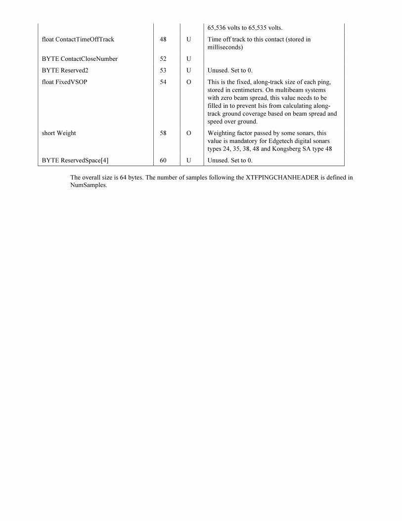
3.1.8. XTFPINGCHANHEADER structure
XTFPINGCHANHEADER is used to hold data that can be unique to each channel from ping to ping.
One of these headers follows each XTFPINGHEADER, no XTFPINGCHANHEADERS follow a
XTFBATHYHEADER.
Table I. XTFPINGCHANHEADER structure.
XTFPINGCHANHEADER
Field Byte
Offset
Status
Comment
WORD ChannelNumber 0 M Typically
0=port (low frequency)
1=stbd (low frequency)
2=port (high frequency)
3=stbd (high frequency)
WORD DownsampleMethod 2 O 2 = MAX; 4 = RMS
float SlantRange 4 M Slant range of the data in meters
float GroundRange 8 O Ground range of the data; in meters (SlantRange2
- Altitude2)
float TimeDelay 12 O Amount of time, in seconds, to the start of
recorded data. (almost always 0.0).
float TimeDuration 16 R Amount of time, in seconds, recorded (typically
SlantRange/750)
float SecondsPerPing 20 R Amount of time, in seconds, from ping to ping.
(SlantRange/750)
WORD ProcessingFlags 24 O 4 = TVG; 8 = BAC&GAC; 16 = filter, etc.
(almost always zero)
WORD Frequency 26 R Ccenter transmit frequency for this channel.
WORD InitialGainCode 28 O Settings as transmitted by sonar
WORD GainCode 30 O Settings as transmitted by sonar
WORD BandWidth 32 O Settings as transmitted by sonar
DWORD ContactNumber 34 U Contact information . Upated when contacts are
saved in Target utility.
WORD ContactClassification 38 U Contact information . Updated when contacts are
saved in Target utility.
BYTE ContactSubNumber 40 U Contact information . Udated when contacts are
saved in Target utility
BYTE ContactType 41 U Contact information . Updated when contacts are
saved in Target utility
DWORD NumSamples 42 M Number of samples that will follow this
structure. The number of bytes will be this value
multiplied by the number of bytes per sample.
BytesPerSample found in CHANINFO structure
(given in the file header).
WORD MillivoltScale 46 O Maximum voltage, in mv, represented by a full-
scale value in the data.If zero, then the value
stored in the VoltScale should be used instead.
VoltScale can be found in the XTF file header,
ChanInfo structure. Note that VoltScale is
specified in volts, while MillivoltScale is stored
in millivolts. This provides for a range of –
65,536 volts to 65,535 volts.
float ContactTimeOffTrack 48 U Time off track to this contact (stored in
milliseconds)
BYTE ContactCloseNumber 52 U
BYTE Reserved2 53 U Unused. Set to 0.
float FixedVSOP 54 O This is the fixed, along-track size of each ping,
stored in centimeters. On multibeam systems
with zero beam spread, this value needs to be
filled in to prevent Isis from calculating along-
track ground coverage based on beam spread and
speed over ground.
short Weight 58 O Weighting factor passed by some sonars, this
value is mandatory for Edgetech digital sonars
types 24, 35, 38, 48 and Kongsberg SA type 48
BYTE ReservedSpace[4] 60 U Unused. Set to 0.
The overall size is 64 bytes. The number of samples following the XTFPINGCHANHEADER is defined in
NumSamples.

3.1.9. XTFHIGHSPEEDSENSOR structure
Table J. XTFHIGHSPEEDSENSOR structure
XTFHIGHSPEEDSENSOR
Field Byte
Offset
Status
Comment
WORD MagicNumber 0 M Must be set to 0xFACE (hexadecimal value).
BYTE HeaderType 2 M 15 = XTFHIGHSPEEDSENSOR
(defined in Xtf.h)
BYTE SubChannelNumber 3 M 0=altitude, 1=roll, 2=yaw
WORD NumChansToFollow 4 U Unused. Set to 0
WORD Reserved1[2] 6 U Unused. Set to 0.
DWORD NumBytesThisRecord 10 M Total byte count for this ping including this
ping header. Isis Note: Isis records data packets
in multiples of 64 bytes. If the size of the data
packet is not an exact multiple of 64 bytes,
zeros are padded at the end packet and this
value will be promoted to the next 64-byte
granularity. In all cases, this value will be the
EXACT size of this packet.
Word Year 14 M
BYTE Month 16 M
BYTE Day 17 M
BYTE Hour 18 M
BYTE Minute 19 M
BYTE Second 20 M
BYTE HSeconds 21 M
DWORD NumSensorBytes 22 M Number of bytes of sensor data following this
structure.
DWORD RelativeBathyPingNum 26 M Bathymetry ping number belonging to this
sensor data.
BYTE Reserved3[34] 30 U Unused. Set to 0.
The overall size is 64 bytes.

3.1.10. XTFBEAMXYZA structure (processed bathymetry)
Table M. XTFBEAMXYZA Structure.
XTFBEAMXYZA
Field Byte
Offset
Status
Comment
double dPosOffsetTrX 0 M Offset Northing from fish
double dPosOffsetTrY 8 M Offset Easting from fish
float fDepth 16 M Absolute Depth
double dTime 20 M Two way travel time
short usAmpl 28 M Amplitude
BYTE ucQuality 30 M Quality.
The overall size is 31 bytes.

3.1.11. XTF BATHY SNIPPET
Figure 4. XTF Bathy Snippet data layout
XTFPINGHEADER
Structure
SNP
0
SNP1 Fragment
samples
… SNP1 Fragment
Samples
The XTF BATHY SNIPPET data starts with an XTFPINGHEADER then it is followed by SNP0,
refer to table N. The number of SNP1 (refer to table O) structures to follow the SNP0 is determined
by the beamcount value stored in the SNP0 structure. The entire XTF packet is padded with zero-
filled bytes to make the size an even multiple of 64.
Table N. SNP0 structure (generated by Reson Seabat)
SNP0
Field Byte
Offset
Status
Comment
unsigned long ID 0 M Identifier code. SNP0= 0x534E5030
unsigned short HeaderSize 4 M Header size, bytes.
unsigned short DataSize 6 M Data size following header, bytes.
unsigned long PingNumber 8 M Sequential ping number.
unsigned long Seconds. 12 M Time since 00:00:00, 1-Jan-1970
unsigned long Millisec 16 M
unsigned short Latency 20 M Time from ping to output (milliseconds)
unsigned short SonarID[2] 22 M Least significant four bytes of Ethernet
address.
unsigned short SonarModel 26 M Coded model number of sonar.
unsigned short Frequency 28 M Sonar frequency (kHz).
unsigned short SSpeed 30 M Programmed sound velocity (m/sec).
unsigned short SampleRate 32 M A/D sample rate (samples/sec).
unsigned short PingRate 34 M Pings per second, 0.001 Hz steps.
unsigned short Range 36 M Range setting (meters).
unsigned short Power 38 M Power
unsigned short Gain 40 M (b15=auto, b14=TVG, b6..0=gain).
unsigned short PulseWidth 42 M Transmit pulse width (microseconds).
unsigned short Spread 44 M TVG spreading, n*log(R), 0.25dB steps.
unsigned short Absorb 46 M TVG absorption, dB/km, 1dB steps.
unsigned short Proj 48 M b7 = steering, b4..0 = projector type.
unsigned short ProjWidth 50 M Transmit beam width along track, 0.1 deg
steps.
unsigned short SpacingNum 52 M Receiver beam spacing, numerator, degrees.
unsigned short SpacingDen 54 M Receiver beam spacing, denominator.
short ProjAngle 56 M Projector steering, degrees*PKT_STEER_RES
unsigned short MinRange 58 M Range filter settings
unsigned short MaxRange 60 M
unsigned short MinDepth 62 M Depth filter settings.
unsigned short MaxDepth 64 M Depth filter settings.
unsigned short Filters 66 M Enabled filters: b1=depth, b0=range.
BYTE bFlags[2] 68 M Bits 0 – 11 spare,
Bits 12 – 14 snipMode,
Bit 15 RollStab. Bit 0: roll stabilization
enabled.
Short HeadTemp 70 M Head temperature, 0.1C steps.
unsigned short BeamCnt 72 M number of beams
The overall size is 74 bytes.
Table O. SNP1 structure.
SNP1
Field Byte
Offset
Status
Comment

unsigned long ID 0 M Identifier code. SNP1= 0x534E5031
unsigned short HeaderSize 4 M Header size, bytes.
unsigned short DataSize 6 M Data size following header, bytes.
unsigned long PingNumber 8 M Sequential ping number.
unsigned short Beam 12 M Beam number, 0..N-1.
unsigned short SnipSamples 14 M Snippet size, samples.
unsigned short GainStart 16 M Gain at start of snippet, 0.01 dB steps,
0=ignore.
unsigned short GainEnd 18 M Gain at end of snippet, 0.01 dB steps,
0=ignore.
unsigned short FragOffset 20 M Fragment offset, samples from ping.
unsigned short FragSamples 22 M Fragment size, samples.
The overall size is 24 bytes.

3.1.12. XTF_HEADER_BENTHOS_CAATI_SARA data layout
CAATI Packet Data
Use existing XTF header type 60 = XTF_HEADER_BENTHOS_CAATI_SARA.
Store SARA/CAATI 3D data in an XTFPINGHEADER followed by one XTFPINGCHANHEADER
followed by the Benthos SARA/CAATI “PINGINFO” data. For more information on the Benthos
PINGINFO structure, please contact Benthos.
Figure 5. BENTHOS CAATI SARA ping data layout
XTFPINGHEADER XTFPINGCHANHDEADER
Benthos
PINGINFO
structure
Benthos
PINGINFO data
samples

3.1.13. XTF POSRAW NAVIGATION
Table P. XTFPOSRAWNAVIGATION Structure.
XTFPOSRAWNAVIGATION
Field Byte
Offset
Status
Comment
WORD MagicNumber
BYTE HeaderType
BYTE SubChannelNumber
WORD NumChansToFollow
WORD Reserved1[2]
DWORD NumBytesThisRecord
WORD Year
0
2
3
4
6
10
14
M
M
U
U
U
M
M
Must be set to 0xFACE (hexadecimal value).
107 =
XTF_HEADER_POS_RAW_NAVIGATION
Unused. Set to 0.
Unused. Set to 0.
Unused. Set to 0.
Must be 64. (Size of this packet is always 64
bytes).
Fix year.
BYTE Month 16 M Fix month.
BYTE Day 17 M Fix day.
BYTE Hour 18 M Fix hour.
BYTE Minutes 19 M Fix minute.
BYTE Seconds 20 M Fix seconds.
WORD MicroSeconds 21 M (0 – 9999). Fix tenths of milliseconds.
double RawYcoordinate
double RawXcoordinate
double RawAltitude
float Pitch
float Roll
float Heave
float Heading
BYTE Reserved2
23
31
39
47
51
55
59
63
M
M
O
O
O
O
O
U
Raw position from POSRAW or other time
stamped nav source.
Raw position from POSRAW or other time
stamped nav source.
Altitude, can hold RTK altitude.
Positive value is nose up
Positive value is roll to starboard
Positive value is sensor up. Isis Note: The TSS
sends heave positive up. The MRU sends
heave positive down. In order to make the data
logging consistent, the sign of the MRU’s
heave is reversed before being stored in this
field.
In degrees, as reported by MRU. TSS doesn’t
report heading, so when using a TSS this value
will be the most recent ship gyro value as
received from GPS or from any serial port
using ‘G’ in the template.
Unused.
The overall size is 64 bytes.

3.1.14. XTF_HEADER_Q_SINGLEBEAM data layout
For each single beam transducer update one XTFQPSSINGLEBEAM record is written to the XTF
file.
A single beam record is identified by it Header type (=XTF_HEADER_Q_SINGLEBEAM)
The Record description is shown in Table Q:
Table Q. XTFQPSSINGLEBEAM Structure.
XTFQPSSINGLEBEAM
Field Byte
Offset
Status
Comment
WORD MagicNumber
0 M
Must be set to 0xFACE (hexadecimal value).
BYTE HeaderType
2
M
26 = XTF_HEADER_Q_SINGLEBEAM
BYTE SubChannelNumber
3
M ID in CHANNELINFO structures
WORD NumChansToFollow
4
U
Unused. Set to 0.
WORD Reserved1[2]
6
U
Unused. Set to 0. 2 * size of (Word)
DWORD NumBytesThisRecord
10
M
Total byte count for this ping including this
ping header. Isis Note: Isis records data
packets in multiples of 64 bytes. If the size of
the data packet is not an exact multiple of 64
bytes, zeros are padded at the end packet and
this value will be promoted to the next 64-
byte granularity. In all cases, this value will
be the EXACT size of this packet.
DWORD TimeTag 14 M Time stamp given in milliseconds
int Id 18 O ID
float SoundVelocity 22 M Sound Velocity in m/sec
float Intensity 26 O Signal Strength
int Quality 30 O Quality
float TwoWayTravelTime 34 M Two way travel time in seconds
WORD 38 M Year
BYTE 40 M Month
BYTE 41 M Day
BYTE 42 M Hour
BYTE 43 M Minute
BYTE 44 M Second
WORD 45 M MilliSeconds
BYTE Reserved[7] M For future expansion
Note: To identify the transducer location of the update you should look up the sub channel number in the
CHANINFO structures in the XTF file header. The XTF files generated by QPS will have for each channel
info structure a unique sub channel number.

3.1.15. XTF_HEADER_Q_MULTITX data layout
For each single beam transducer update one XTFBATHHEADER record is written to the XTF file.
This Header is followed by N times XTFQPSMULTITXENTRY, where N is the number of
transducers.
N is also written in the NumChansToFollow member of the Header.
The Record description is shown in Table R:
Table R. XTFQPSMULTITXENTRY Structure.
XTFQPSMULTITXENTRY
Field Byte
Offset
Status
Comment
int Id 0 O Beam ID
float Intensity 4 O Signal Strength
int Quality 8 O Quality
float TwoWayTravelTime 12 M Two way travel time in seconds
float DeltaTime 16 M Difference between header in seconds
float OffsetX 20 M Location of ship’s reference frame
float OffsetY 24 M Location of ship’s reference frame
float OffsetZ 28 M Location of ship’s reference frame
float Reserved[4] 32 M Reserved
Delta Time member is important to calculate the exact timestamp of the transducers ping time. In order to get
the right absolute timestamp for the transducer then you must take the timetag from the XTFBATHHEADER
and ADD the delta time to it. Usually the delta time figures are negative.
3.1.16. XTF_HEADER_Q_MBEENTRY data layout
For one multibeam system update one XTFBATHHEADER record is written to the XTF file. This
header is followed by N times XTFQPSMBEENTRY, where N is the number of beams that updated.
N is also written in the NumChansToFollow member of the header.
The record description is shown in Table S:
Table S. XTFQPSMBEENTRY Structure
XTFQPSMULTITXENTRY
Field Byte
Offset
Status
Comment
int Id 0 O Beam ID
double Intensity 4 O Signal Strength
int Quality 12 O Quality
double TwoWayTravelTime 16 M Two way travel time in seconds
double DeltaTime 24 M Beam time offset
double Beam Angle 32 M Beam angle
double Tilt Angle 40 M Tilt angle
float Reserved[4] 48 M Reserved

-Reported time in XTFBATHHEADER will always be the transmission (ping) time
-Delta Time can be used for profilers to calculate the ping time per beam.
-Beam Angle convention, Negative to port side, nadir beam 0degs, positive to starboard side.
-Tilt angle convention positive forward, negative backward (used for pitch steering)
3.1.17. XTFRAWCUSTOMHEADER structure
The purpose of this structure is that it should be used as a 64 byte header in front of some user defined data block. The
NumBytesThisRecord field defines the length of this block of data +64 bytes for this header. It is not mandatory that the user
defined data block is padded such that its total size is a multiple of 64 bytes, however for compatibility with other structures in
XTF it is recommended.
Table S. XTFRAWCUSTOMHEADER structure
XTFRAWCUSTOMHEADER
Field Byte
Offset
Status
Comment
WORD MagicNumber 0 M Must be set to 0xFACE (hexadecimal value).
BYTE HeaderType 2 M 199 = custom vendor data follows
(defined in Xtf.h)
BYTE ManufacturerID 3 O (eg 1 = Benthos, 2 = Reson, 3 =Edgetech up
to maximum of 256 vendors (see table)
WORD SonarID 4 O TBD (eg 4200, 1624, 4700, 7125 etc)
WORD PacketID 6 O TBD (eg 7000, 7503 etc)
WORD Reserved1[1] 8 U Unused. Set to 0.
DWORD NumBytesThisRecord 10 M Total byte count for this data packet including
this header. (NumCustomerBytes +64) Note
that the user data indicated by
NumCustomerBytes may also be padded to a
64 byte boundary. (Optional but
recommended)
WORD Year 14 O
BYTE Month 16 O
BYTE Day 17 O
BYTE Hour 18 O
BYTE Minute 19 O
BYTE Second 20 O
BYTE Hseconds 21 O Hundredths of seconds (0-99)
WORD Julian Day 22 O
WORD Reserved2 [2] 24 U
DWORD PingNumber 28 O
DWORD TimeTag 32 O
DWORD NumCustomerBytes 36 O
BYTE Reserved3 [24] 40 U Padding to make the structure 64 bytes
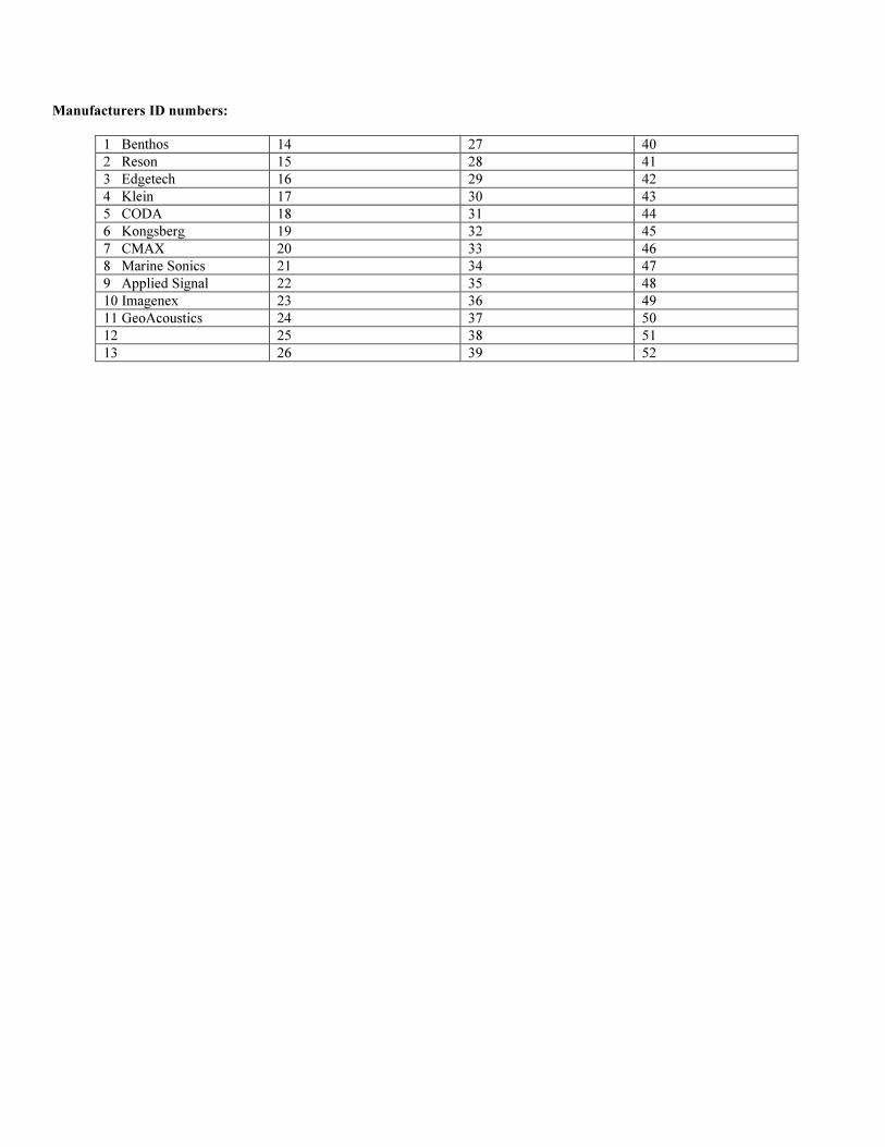
Manufacturers ID numbers:
1 Benthos 14 27 40
2 Reson 15 28 41
3 Edgetech 16 29 42
4 Klein 17 30 43
5 CODA 18 31 44
6 Kongsberg 19 32 45
7 CMAX 20 33 46
8 Marine Sonics 21 34 47
9 Applied Signal 22 35 48
10 Imagenex 23 36 49
11 GeoAcoustics 24 37 50
12 25 38 51
13 26 39 52

3.1.18. XTFHEADERNAVIGATION structure
Source time-stamped navigation data, holds updates of any nav data. (Type 42 navigation)
XTFHEADERNAVIGATION
Field Byte
Offset
Status
Comment
WORD MagicNumber 0 M Must be set to 0xFACE (hexadecimal value).
BYTE HeaderType 2 M 42 = XTF_HEADER_NAVIGATION
(defined in Xtf.h)
BYTE Reserved [7] 3 M Must be here!
DWORD NumBytesThisRecord 10 M Total byte count for this ping including this
ping header. Isis Note: Isis records data
packets in multiples of 64 bytes. If the size of
the data packet is not an exact multiple of 64
bytes, zeros are padded at the end packet and
this value will be promoted to the next 64-byte
granularity. In all cases, this value will be the
EXACT size of this packet.
WORD Year 14 O Source time Year
BYTE Month 16 O Source time Month
BYTE Day 17 O Source time Day
BYTE Hour 18 O Source time Hour
BYTE Minute 19 O Source time Minute
BYTE Second 20 O Source time Seconds
DWORD Microseconds 21 O 0 - 999999
DWORD SourceEpoch 25 Source Epoch Seconds since 1/1/1970
DWORD TimeTag 29 System Reference time in milliseconds
Double Raw Y Coordinate 33 O Raw position from POSMV or other time
stamped navigation source
Double Raw X Coordinate 41 O Raw position from POSMV or other time
stamped navigation source
Double Raw Altitude 49 O Altitude, can hold real-time kinematics
altitude
BYTE TimeFlag 57 O Time stamp validity:
0 = only receive time valid
1 = only source time valid
3 = both valid
BYTE Reserved1 [6] 58 U Padding to make the structure 64 bytes

3.1.19. XTFHEADERGYRO structure
Source time-stamped gyro data holds updates of any gyro data (Type 84)
XTFHEADERNAVIGATION
Field Byte
Offset
Status
Comment
WORD MagicNumber 0 M Must be set to 0xFACE (hexadecimal value).
BYTE HeaderType 2 M 84 = XTF_HEADER_SOURCETIME_GYRO
(defined in Xtf.h)
BYTE Reserved [7] 3 M Must be here!
DWORD NumBytesThisRecord 10 M Total byte count for this ping including this
ping header. Isis Note: Isis records data
packets in multiples of 64 bytes. If the size of
the data packet is not an exact multiple of 64
bytes, zeros are padded at the end packet and
this value will be promoted to the next 64-byte
granularity. In all cases, this value will be the
EXACT size of this packet.
WORD Year 14 O Source time Year
BYTE Month 16 O Source time Month
BYTE Day 17 O Source time Day
BYTE Hour 18 O Source time Hour
BYTE Minute 19 O Source time Minute
BYTE Second 20 O Source time Seconds
DWORD Microseconds 21 O 0 - 999999
DWORD SourceEpoch 25 O Source Epoch Since 1/1/1970
DWORD TimeTag 29 O System Time reference in milliseconds
float Gyro 33 O Raw heading (0 – 360)
BYTE TimeFlag 37 O Time stamp validity:
0 = only receive time valid
1 = only source time valid
3 = both valid
BYTE Reserved1 [26] 38 U Padding to make the structure 64 bytes

APPENDIX 1: RESON 71xx Data Structures
There are three types of pings, snippet, sidescan and bathy. Refer to the 7125 documentation from
Reson for references to 7125 specific structures like DRF and RTH formats.
The following are stored in the XTF file after transferring the data to Isis from the Reson server via the memory mapped file:
Snippet ( Reson 7008):
XTFPingHeader 256 bytes
Reson 7008 data:
{
Raw snippet data consisting of:
.
RECORD_HEADER (RTH) (The Data Record Frame DRF is NOT included)
SNIPPET_BEAM_DESCRIPTOR[ RECORD_HEADER.N ]
Data samples
Appended to the 7008 data is the Reson 7004 data:
SonarID 64 byte integer
N number of samples followed by four arrays of N 4 byte floating point numbers.
}
This gets repeated for as many heads as there are. One for single head, 2 for dual head.
Sidescan (Reson 7007):
XTFPingHeader 256 bytes
{
XTFChanHeader 64 bytes
Raw sidescan data, this is only the record data (RD) It does NOT include the Data Record Frame (DRF) and it does NOT
include the Record Type Header (RTH)
}
This gets repeated for as many channels as there are. There will be 2 for single head and 4 for dual head.
Bathy (Reson 7006):
XTFPingHeader
Reson 7006 record starting with the DRF:
Data Record Frame (DRF)
Record Type Header (RTH)
Record Data (RD) which consists of:
the array of 4 byte floating point travel times,
the array of 1 bytes quality flags
the array of 4 byte floating point intensity values
the array of 4 byte floating point Min TWT
the array of 4 byte floating point Max TWT
Appended to the 7006 data is the 7004 data:
SonarID 64 byte integer, N number of samples 32 byte integer followed by four arrays of N 4 byte floating point numbers.
The bathy data is stored WITHOUT the XTFChanHeaders. The bathy data pings for separate heads (dual head mode) come
in separate pings. The data for the two heads is NOT combined into one ping as it is with sidescan and snippet.
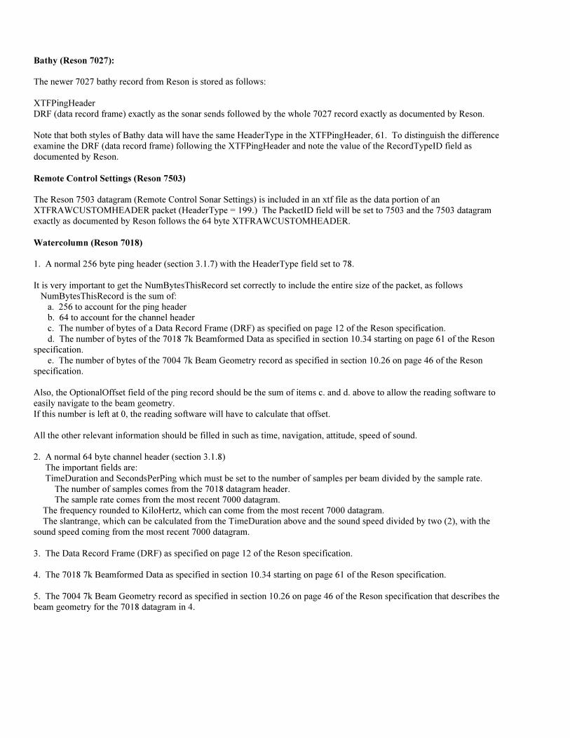
Bathy (Reson 7027):
The newer 7027 bathy record from Reson is stored as follows:
XTFPingHeader
DRF (data record frame) exactly as the sonar sends followed by the whole 7027 record exactly as documented by Reson.
Note that both styles of Bathy data will have the same HeaderType in the XTFPingHeader, 61. To distinguish the difference
examine the DRF (data record frame) following the XTFPingHeader and note the value of the RecordTypeID field as
documented by Reson.
Remote Control Settings (Reson 7503)
The Reson 7503 datagram (Remote Control Sonar Settings) is included in an xtf file as the data portion of an
XTFRAWCUSTOMHEADER packet (HeaderType = 199.) The PacketID field will be set to 7503 and the 7503 datagram
exactly as documented by Reson follows the 64 byte XTFRAWCUSTOMHEADER.
Watercolumn (Reson 7018)
1. A normal 256 byte ping header (section 3.1.7) with the HeaderType field set to 78.
It is very important to get the NumBytesThisRecord set correctly to include the entire size of the packet, as follows
NumBytesThisRecord is the sum of:
a. 256 to account for the ping header
b. 64 to account for the channel header
c. The number of bytes of a Data Record Frame (DRF) as specified on page 12 of the Reson specification.
d. The number of bytes of the 7018 7k Beamformed Data as specified in section 10.34 starting on page 61 of the Reson
specification.
e. The number of bytes of the 7004 7k Beam Geometry record as specified in section 10.26 on page 46 of the Reson
specification.
Also, the OptionalOffset field of the ping record should be the sum of items c. and d. above to allow the reading software to
easily navigate to the beam geometry.
If this number is left at 0, the reading software will have to calculate that offset.
All the other relevant information should be filled in such as time, navigation, attitude, speed of sound.
2. A normal 64 byte channel header (section 3.1.8)
The important fields are:
TimeDuration and SecondsPerPing which must be set to the number of samples per beam divided by the sample rate.
The number of samples comes from the 7018 datagram header.
The sample rate comes from the most recent 7000 datagram.
The frequency rounded to KiloHertz, which can come from the most recent 7000 datagram.
The slantrange, which can be calculated from the TimeDuration above and the sound speed divided by two (2), with the
sound speed coming from the most recent 7000 datagram.
3. The Data Record Frame (DRF) as specified on page 12 of the Reson specification.
4. The 7018 7k Beamformed Data as specified in section 10.34 starting on page 61 of the Reson specification.
5. The 7004 7k Beam Geometry record as specified in section 10.26 on page 46 of the Reson specification that describes the
beam geometry for the 7018 datagram in 4.

APPENDIX 2: R2Sonic Data Structures.
For XTF data structures, consult the XTF format.
The file header should specify: NumberOfBathymetryChannels = 1
Offsets can be filled in if that information is available.
The first CHANINFO structure should be filled in with TypeOfChannel = 3 and BytesPerSample = 2 for the bathymetry data.
No CHANINFO is necessary for the water column data.
The NumBytesThisRecord of the XTFPINGHEADER must be equal to the total number of bytes of raw R2Sonic data plus
256.
Bathymetry
The bathymetry datagram is stored exactly as it is broadcast by R2Sonic and that data should follow the R2Sonic specification
as published by R2Sonic. In the XTF file, each bathy datagram is preceded by a standard XTFPINGHEADER with:
HeaderType = 68
Date and time fields should be accurately filled in as well as PingNumber, SoundVelocity (half), ship and sensor latitude and
longitude (same values for both,) ShipGyro and SensorHeading (same value for both if desired) and any other fields for which
the data is available.
If navigation and heading are not available, they can be left as zero, but some further processing will have to supply that
information.
It is important that the datagram that follows the XTFPINGHEADER conforms exactly to the R2Sonic published standard..
The data stored in the XTF file should include all headers and data as delivered by the sonar.
The R2sonic bathy datagram starts with the ASCII characters BTH0
Foot Print Time Series FTS (snippets)
The FTS datagram is stored exactly as it is broadcast by R2Sonic and that data should follow the R2Sonic specification as
published by R2Sonic. In the XTF file, each FTS datagram is proceeded by a standard XTFPINGHEADER with :
HeaderType = 69
Date and time fields should be accurately filled in as well as PingNumber, SoundVelocity (half), ship and sensor latitude and
longitude (same values for both,) ShipGyro and SensorHeading (same value for both if desired) and any other fields for which
the data is available.
If navigation and heading are not available, they can be left as zero, but some further processing will have to supply that
information.
It is important that the datagram that follows the XTFPINGHEADER conforms exactly to the R2Sonic published standard..
The data stored in the XTF file should include all headers and data as delivered by the sonar.
Since the FTS datagram is large, it is not delivered in real time as one complete package but rather as a series of packets, each
beginning with the SNP0 information string. The data stored in the XTF file should include all headers and data as delivered
by the sonar
The R2sonic bathy datagram starts with the ASCII characters SNP0
Water Column
The XTF file should contain both bathy and water column pings of data. Therefore, the file header should specify:
NumberOfBathymetryChannels = 1
The water column datagram is stored exactly as it is broadcast by R2Sonic and that data should follow the R2Sonic
specification as published by R2Sonic. In the XTF file, each water column datagram is proceeded by a standard
XTFPINGHEADER with :
HeaderType = 79
Date and time fields should be accurately filled in as well as PingNumber, SoundVelocity (half), ship and sensor latitude and
longitude (same values for both,) ShipGyro and SensorHeading (same value for both if desired) and any other fields for which
the data is available.

If navigation and heading are not available, they can be left as zero, but some further processing will have to supply that
information.
It is important that the datagram that follows the XTFPINGHEADER conforms exactly to the R2Sonic published standard.
Since the datagram is large, it is not delivered in real time as one complete package but rather as a series of packets, each
beginning with the WCD0 information string. The data stored in the XTF file should include all headers and data as delivered
by the sonar


4. XTF File Format Usage Notes
4.1. VERSION
In order for XTF files to be read correctly in Isis, the XTFFileHeader->RecordingProgramVersion string
must contain an ASCII string which represents a number >= "223".
strcpy(XTFFileHeader->RecordingProgramVersion, "223");
It's best to use "223" but you can use any other number. However, do not use numbers in the range of "303"
to "312". There was a bug in Isis versions within this range that caused the size of each channel to be padded
to a multiple of 64 bytes, rather than the size of the entire packet. Isis detects XTF files within this version
range, and adapts to read these particular files correctly.
To increase the available event numbers in an .XTF the data type for EventNumber was changed from a
WORD to DWORD. This change was made in Isis v3.41. To correctly read the event numbers applications
should check the RecordingVersion string in the XTFFileHeader structure.
4.2. PADDING
XTF packets can be any size >= 64 bytes. The entire size of the packet must be given in bytes 10-13 of the
packet. Isis is slightly more efficient if the packets are created in multiple of 64 bytes, but Isis or the XTF
format does not require this. To pad an XTF packet to a multiple of 64 bytes, do the following:
• Set the packet size to be the next greater than or even multiple of 64.
size = ((size+63)/64)*64
• Zero-fill the unused pad bytes.
That's it. Isis will ignore the pad bytes. This works because within each XTF packet, the size of the data that
is actually used is either specified explicitly or implicitly within the XTF packet itself, so extra bytes are
benignly ignored.
4.3. SAMPLES PER CHANNEL
The XTF format documented before October 27, 1998 called for the number of samples per channel to be
given in the XTF file header. After this date, the samples per channel has been moved to the
XTFPINGCHANHEADER->NumSamples field. This allows for the number of samples to change on the
fly, without having to create a new XTF file whenever the range scale changes on some sonars.
The XTFFILEHEADER->ChanInfo->Reserved field was previously the NumSamples field for the whole
XTF file. For backwards compatibility, Isis does the following procedure.
• Sets the expected number of samples per channel to the “Reserved” value in the XTF header.
• If the RecordingProgramVersion field indicates a version >= “223”, then it looks in the channel
header. If XTFPINGCHANHEADER->NumSamples is non-zero, then the expected number of
samples per channel is taken from that field.

When writing XTF files, the safest practice is to:
• Put some reasonable value in the XTFFILEHEADER->ChanInfo->Reserved fields. 1024 is a
good number. This does not help Isis, but there are some 3rd
party XTF viewers that crash if
this field is zero.
• Set version to “223” as discussed in Version above.
• Fill in the XTFPINGCHANHEADER->NumSamples field to the correct number of samples
per channel.
• Always zero-fill XTF packets before filling them in. Unused values in XTF files are zero-
filled.