Embed Size (px)
Citation preview

Trinity-300 Series
Installation and Operational Guide
Repeatit AB Tel: +46 8 570 106 66 Hamngatan 33 Fax: +46 8 570 106 67 172 66 Sundbyberg E-mail: [email protected] Sweden www.repeatit.se

1
Quick start
Before proceeding with the installation verify that the equipment works on the ground. Power up both units and put them between your computer and network access, you should have full commu- nication within a few minutes of powering up the units. (If the units have no internal antenna make sure you place the antenna connectors directly opposite each other.)
The units are pre-configured and paired from factory with the fol- lowing parameters.
Master Client IP address Username Password
10.0.0.1 admin public
10.0.0.2 admin public
Installing the link
• Mount the first unit, point it towards the site of the second unit. Power it up and make sure the Power LED is lit and the status LED blinks slowly.
• Mount the second unit. Power it up and adjust it for best signal using the status LED see section 1.9 for details .
• Adjust the first unit for best signal using the Status LED.
Warning This product transmitts information using microwave ra- dio signals. Installation of fixed outdoor radio links should only be performed by a qualified and trained technician familiar with local radio, electric and saftey regulations.

Trinity-300 Series
• Make sure all cables are secured and connect the link to the
network.
• Configure the distance parameters at the master unit to re- flect the correct distance between the units.
Note Make sure that the polarization on both units are in the same direction. Unaligned polarization will significantly reduce the signal strength.
2

Contents
1 Installation Guide 4 1.1 Who should use this guide ...................................................... 4 1.2 Package contents ...................................................................... 4 1.3 Additional tools required ....................................................... 5 1.4 Unit description ....................................................................... 5 1.5 Installation ................................................................................ 5 1.6 Mounting a Trinity-300 unit .................................................... 6
Mounting instruction for Trinity-323 and Trinity-316 . . 7 Mounting instruction for Trinity-300 7
1.7 Ethernet cabling ...................................................................... 8 1.8 Installing the power supply ................................................... 8 1.9 Finalizing the installation ....................................................... 9
Configuration ................................................................................ 9 Alignment ...................................................................................... 9 Securing the installation ..................................................... 10
2 Configuration 11 2.1 Trinity-300 series Configuration concepts ........................ 11
Configuration areas ................................................................ 11 2.2 Configuring using the Trinity-300 series web interface 12
Modifying the configuration ............................................... 12 Applying a new configuration ............................................ 12 Saving settings to flash memory ....................................... 13 Rolling back settings ........................................................... 14
2.3 Configuration parameters .................................................... 15 Radio settings .......................................................................... 16 CAC Policy .................................................................................... 19 Network settings ................................................................... 19 System settings ..................................................................... 20
3 Unit Operation 21 3.1 Unit status ............................................................................ 21
Default view ......................................................................... 21
3
Trinity-300 Series CONTENTS
Extended information ......................................................... 21 Status information .............................................................. 22
3.2 Link Diagnostic Tools ....................................................................... 23 Spectrum analyzer ............................................................. 23 Speed test ............................................................................ 24
3.3 Firmware upgrading ........................................................... 25 3.4 Restore to defaults ............................................................. 25
4 Support 26
5 Technical Specifications 27
6 Usage restrictions and legal information 28
CONTENTS 4

Installation Guide
1.1 Who should use this guide
Installing fixed outdoor radio links requires technical expertise and should only be carried out by a technician.
You should only attempt to install and configure the Trinity link if you have
• Experience with mounting outdoor radio equipment and an- tenna installation.
• An understanding, or common knowledge, of network equip- ment.
• Made sure that the installation site is suitable and complies with local radio, electrical and safety regulations.
1.2 Package contents
Please inspect the package before proceeding with the installa- tion. Your Trinity-300 package should contain the following content
• Trinity-300
– 2 Trinity-300 units with N-female antenna connector – 2 Mounting kits
5
Warning Radio regulations differs between countries and all op- tions and/or combinations in this manual might not be allowed in your current region. Local radio regulations or legislation may im- pose restriction on allowed usage such as
• Allowed radio channel frequencies for outdoor usage.
• Maximum allowed EIRP.
You are responsible for that your installation complies with local radio, electrical and safety regulations.

Installation Guide Trinity-300 TDD Series
Installation Guide 6
– 2 PoE with power adapter for your local region
• Trinity-323
– 2 Trinity-323 units with integrated 23 dBi antenna – 2 Mounting kits – 2 PoE with power adapter for your local region
• Trinity-316
– 2 Trinity-316 units with integrated 16 dBi antenna – 2 Mounting kits – 2 PoE with power adapter for your local region
• Trinity-318
– 2 Trinity-318 units with integrated 18 dBi antenna – 2 Mounting kits – 2 PoE with power adapter for your local region
1.3 Additional tools required
Depending on the conditions at the installation site other tools might be needed, including, but not limited to
• Cat5E Ethernet cable
• RJ-45 crimp tool and RJ-45 connectors if not using a pre-assembled Ethernet cable
• An adjustable wrench
• Drill for wall mounting
• Ground cables
• Cable ties to secure cabling
1.4 Unit description
There are three LEDs, power, status and Ethernet link/activity.
1.5 Installation

Installation Guide Trinity-300 TDD Series
Installation Guide 7
Installing a Trinity-300 system consists of the steps outlined below, each step is explained more thoroughly in the following sections. The Trinity-300 link system consists of two Trinity-300 units, one master unit and one client unit, the installation steps needs to be carried out for both units.

Installation Guide Trinity-300 TDD Series
Installation Guide 8
LED Colour Status
Power (P) Status (S)
Green Green
On Flashing Blinking
Power on Signal strength pattern Firmware upgrade progress
in
Ethernet (E) Green On/blinking Reflects Ethernet traffic and link status
Off No Ethernet link
1. Mount the Trinity-300 unit and antenna (if applicable) at site A.
2. Install the PoE at an indoor location where power and network equipment is available.
3. Run Ethernet cable from the PoE to the mounted Trinity-300 unit.
4. Repeat the above steps for the unit at site B.
5. Align antennas for best signal reception.
6. For optimal link throughput the following parameters must be updated in the web interface
• Distance - should accurately reflect the distance in kilo- meters between the units.
1.6 Mounting a Trinity-300 unit
A Trinity-300 unit should preferably be mounted on a mast, if this is not possible due to the surrounding area it could also be mounted directly on to a wall. Make sure there are no obstacles directly in front of or near the unit.
Note The Trinity units should be mounted with their antennas having a clear line of sight between them!
Observe the antenna polarization and make sure they match
at both installation sites; failure to install the units with matching polarization will result in radio signal degradation.
Use the supplied mounting kit to securely mount the units at both locations, make sure the mounting brackets are connected to ground.

Installation Guide Trinity-300 TDD Series
Installation Guide 9
Tip Do not tightly secure the unit and/or antenna until the alignment process in complete
Mounting instruction for Trinity-323 and Trinity-316
See the supplied document for detailed mounting instructions.
Figure 1.1: Trinity-323 and Trinity-316 pole mounting
Mounting instruction for Trinity-300 The Trinity-300 is supplied with mounting brackets for pole mounting.
1. Run the pole clamps around the mounting pole.
2. Run the pole clamps through the mounting brackets.
3. Attach the pole clamps to the unit using the supplied screws.
RJ-45 connector assembly for Trinity-300 Series The connector casing is delivered assembled, unscrew the con- nector as shown in figure ?? (you do not need to remove the gas- ket (4)).
1. Unscrew the sealing cap from the connector.
2. Gently pull out the seal.
3. Pull the cable through the sealing cap.

Installation Guide Trinity-300 TDD Series
Installation Guide 10
4. Insert the RJ45 cable and make sure it is fully inserted into the
connector.
5. Put the seal around the cable and push it into the connector.
6. Fasten the sealing cap to the connector and tighten.
1.7 Ethernet cabling
Run Cat5E Ethernet cable from the location where the PoE is to be installed to the location of the Trinity-300 unit, allow for some slack on the wire to avoid putting extra strain on the Ethernet con- nectors. Make sure the Ethernet cable you are using is rated for outdoor use to avoid decreased cable life time.
RJ-45 pin-out If you are not using a pre-assembled Ethernet cable, apply the RJ- 45 connectors on to the both ends of the cable using the pin-out table and diagram below.
PoE Wire Colour Function RJ-45 1 Twisted pair White/Green Ethernet (RxN) 1 2 Twisted pair Green RxT 2 3 Twisted pair White/Orange Ethernet (TxT) 3 4 Twisted pair Orange Ethernet (TxN) 6 5 Twisted pair Blue Power (+) 4 6 Twisted pair White/Blue Power (+) 5 7 Twisted pair White/Brown Power (-) 7 8 Twisted pair Brown Power (-) 8
1.8 Installing the power supply
Install the supplied PoE indoor where power and other network equipment is available. The PoE can be located at most 100 me- ters from the unit.
Note The supplied PoE-adapter (Power-over-Ethernet) is strictly for indoor use only!
Installation Guide Trinity-300 TDD Series
Installation Guide 10
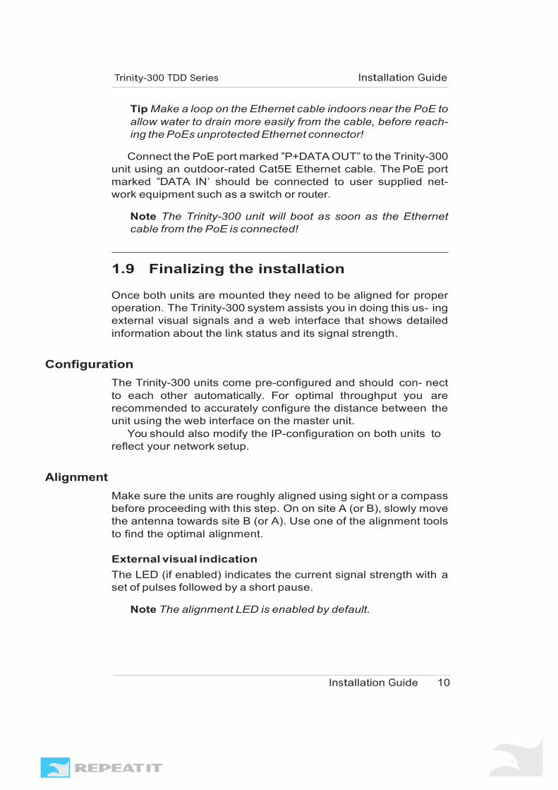
Tip Make a loop on the Ethernet cable indoors near the PoE to allow water to drain more easily from the cable, before reach- ing the PoEs unprotected Ethernet connector!
Connect the PoE port marked ”P+DATA OUT” to the Trinity-300
unit using an outdoor-rated Cat5E Ethernet cable. The PoE port marked ”DATA IN’ should be connected to user supplied net- work equipment such as a switch or router.
Note The Trinity-300 unit will boot as soon as the Ethernet cable from the PoE is connected!
1.9 Finalizing the installation
Once both units are mounted they need to be aligned for proper operation. The Trinity-300 system assists you in doing this us- ing external visual signals and a web interface that shows detailed information about the link status and its signal strength.
Configuration
The Trinity-300 units come pre-configured and should con- nect to each other automatically. For optimal throughput you are recommended to accurately configure the distance between the unit using the web interface on the master unit.
You should also modify the IP-configuration on both units to reflect your network setup.
Alignment
Make sure the units are roughly aligned using sight or a compass before proceeding with this step. On on site A (or B), slowly move the antenna towards site B (or A). Use one of the alignment tools to find the optimal alignment. External visual indication The LED (if enabled) indicates the current signal strength with a set of pulses followed by a short pause.
Note The alignment LED is enabled by default.

Installation Guide Trinity-300 TDD Series
Installation Guide 11
Pulses from dBm to dBm 1 pulse 1 9 2 pulses 10 14 3 pulses 15 19 4 pulses 20 24 5 pulses 25 29 6 pulses 30
Web interface The web interface contains status indicators for both link status and signal strength.
Color Status
Green Very good signal strength Yellow/green Good signal strength Orange Bad signal strength Red No link
Securing the installation When the Trinity-300 link is running and the antennas have been properly aligned the units must be secured in place to avoid the units moving due to strong winds. If the units become mis- aligned the link might be lost.
Tightly fasten the mounting brackets to secure the unit in place, make sure the brackets and chassis are connected to ground. Se- cure Ethernet and antenna cabling using cable ties to avoid un- necessary wear on the cabling material and connectors.

Configuration
The Trinity-300 series units can be configured via a web inter- face built-in into the unit or using the Repeatit network manage- ment system RCS.
2.1 Trinity-300 series Configuration con- cepts
The Trinity-300 series features an advanced configuration management system with the ability to roll back to previously working settings, even with automatic rollback in case of link loss. This helps you to try out different settings to optimize your link throughput while minimizing the risk of a disconnected link.
Configuration areas
A Trinity-300 series unit has several what is called “configu- ration areas”, these areas hold configuration data and each area contains one unique configuration instance. Some areas contain different data depending on the unit status whilst some only con- tain static configuration data that never change.
The following different areas exists with in a Trinity-300 series system
In-active When you modify the configuration via the web interface all changes end up in this area. This is only a place holder until you choose to apply the new configuration, until that time you can rollback and/or keep modifying any setting without disrupting the unit or link status.
Active This area always contains the current settings in use by the unit.
Stored Contains the configuration currently written to flash, this might differ from both the in-active and active configuration.
12

Configuration Trinity-300 TDD Series
Configuration 13
Factory defaults Static bare basic configuration.
Note The factory default IP address is 10.0.0.1, the default username is “admin” and default password is “public”.
2.2 Configuring using the Trinity-300 series web interface
Both units in your Trinity-300 series link can be fully config- ured using the built-in web interface. The following section will guide you through how to use the interface to modify the link con- figuration, please refer to section 2.3 for details on the available configuration parameters.
All configuration options in the Trinity-300 series can be found under the tab marked “Configuration” in the web interface.
Modifying the configuration
To modify a configuration parameter, change its value and press the button labeled “Set”. This will save your changes to the “in- active” configuration area, but will not modify the running con- figuration of the unit. This means that the unit will continue to operate while you are modifying your configuration.
Tip Clicking the question mark next to an option will bring up an instant help dialog with a brief description of the parameter.
After modifying a setting the current value in use by the unit
will be shown to the right of the option. Attempting to set an in- valid value, such as a too large distance value or an invalid IP- address, the configuration modification will fail and the field con- taining invalid data will be highlighted in red.
Applying a new configuration
When you have performed your required modifications you need to “apply” the new settings for the unit to use them. This is ac- complished by clicking the “Apply” button in the status pane to the left of the settings, as shown in figure 2.1.
When you click the “Apply” button the unit will attempt to re- configure itself with the new settings. If the apply operation is successful the unit will be running with your new settings, if the

Configuration Trinity-300 TDD Series
Configuration 14
(a) After set (b) Configuration
Figure 2.1: Configuration after set
apply fails the unit will automatically revert back to the previous working settings.
If you happen to make a configuration mistake you are able to manually roll back to a previous working configuration by using the “Load configuration” functionality, see section 2.2 more infor- mation.
Note Apply does not permanently save settings to flash!
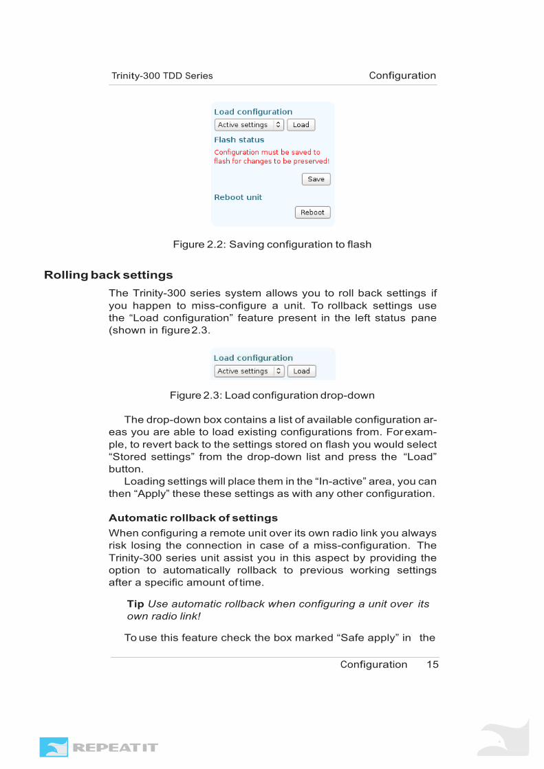
Saving settings to flash memory Once you have a configuration running you are satisfied with you need to save this to flash so that the configuration is retained across a power failure or reboot of the unit. Saving settings to flash can only be done after you have successfully applied a new configuration, this is to protect the unit from miss-configuration.
Note Settings will be lost if you do not save your configuration to flash!
When the unit detect that it is running with a configuration that
has not been saved to flash it will show a “Save” button in the left status pane as illustrated by figure 2.2.
Configuration Trinity-300 TDD Series
Configuration 15
Figure 2.2: Saving configuration to flash
Rolling back settings The Trinity-300 series system allows you to roll back settings if you happen to miss-configure a unit. To rollback settings use the “Load configuration” feature present in the left status pane (shown in figure 2.3.
Figure 2.3: Load configuration drop-down
The drop-down box contains a list of available configuration ar- eas you are able to load existing configurations from. For exam- ple, to revert back to the settings stored on flash you would select “Stored settings” from the drop-down list and press the “Load” button.
Loading settings will place them in the “In-active” area, you can then “Apply” these these settings as with any other configuration.
Automatic rollback of settings When configuring a remote unit over its own radio link you always risk losing the connection in case of a miss-configuration. The Trinity-300 series unit assist you in this aspect by providing the option to automatically rollback to previous working settings after a specific amount of time.
Tip Use automatic rollback when configuring a unit over its own radio link!
To use this feature check the box marked “Safe apply” in the

Configuration Trinity-300 TDD Series
Configuration 16
(a) Safe apply (b) Countdown
Figure 2.4: Automatic configuration rollback
left status pane before pressing the “Apply” button. You can se- lect a different timeout than the default 5 minute by changing the value in the box next to the checkbox.
When you press “Apply” the unit will reconfigure itself with the new settings and the buttons “Keep” and “Revert” will appear next to a countdown timer. Once the timer expires the unit will auto- matically revert back to its previous settings, to keep your settings you need to press the “Keep” button. If you want to revert your changes before the timer expires you can do so by pressing “Re- vert”.
Restore to default You can load the “Factory defaults” to restore the unit to a basic working condition.
It is also possible to restore the unit to default settings in one action without the need for an explicit “Apply” and “Save” by using the dedicated “Restore to default” function available on the “Ad- min” tab or by using the Repeatit RTD client software, see section 3.4 for more information on this.
2.3 Configuration parameters
Numerous configuration parameters can be set, some are only available on “master” units. The following section describes the available configuration parameters in more detail.

Configuration Trinity-300 TDD Series
Configuration 17
Radio settings
The radio settings control parameters related to the radio inter- face.
Mode A unit can operate in two different modes, master or client. A master is passive while the client is the active participant.
Master Defines the channel to operate on and the distance to its client. Which client that is allowed to connect is determined by the remote MAC address setting.
Client The client will attempt to connect to any master that matches its configured remote MAC address.
Remote MAC Radio device MAC address of the remote peer. Settings this will ensure that your unit only connects to a specific peer. If left blank (00:00:00:00:00:00) the Trinity-300 unit will use the Link ID and RSSI values of surrounding units to select which peer to connect to.
Note If left blank it is recommended to use a unique Link ID per link
Channel Specifies which radio channel that should be used. Selecting “Auto channel” will make the unit sweep the spectrum and select a chan- nel free from other transmissions. Only required on the “master” side.
Note For European ETSI domains the frequency range 5.15- 5.35 GHz is solely for indoor use. It is not allowed to use chan- nels within this band in an outdoor installation.
Transmit rate Controls the radio modulation used for transmission, which af- fects the transmission rate. If “Channel bandwidth” is changed the same modulation will be used but the display will be updated to show the actual data rate. Only required on the “master” side.

Configuration Trinity-300 TDD Series
Configuration 18
Link ID An arbitrary, 32 character long, identifier that allows you to differ- entiate between multiple Trinity-300 links.
Note The Link ID Must be equal on both units
Encryption key Specifies an encryption key phrase used for the AES-128 bit en- cryption of the radio traffic.
Note It is not possible to disable encryption and the key must be equal on both units
Regulatory domain The frequency band is divided up into channels, with each local regulatory agency defining what is permitted for use in its area. This affects which channels that are available and the max TX power.
Channel bandwidth How much of the frequency band should be used for a single chan- nel. Setting this to 40MHz will increase the available transmit rate, but each channel will require twice the spectrum width.
Guard interval Guard interval determines the radio gap between transmissions and has the purpose of making the transmission immune to prop- agation delays and other radio artifacts. Using a short guard in- terval increases throughput at the cost of reduced immunity to
Warning While it is possible to choose a different regulatory do- main that enables the use of other frequencies, it is at all times the customers responsibility to ensure that the correct regulatory domain is selected for the country of operation.
• The installation must comply with local radio regulations re- garding allowed frequencies.
• Repeatit AB and its resellers or distributors are not liable for any damage or violation of government regulations that may arise from failing to comply with these guidelines.
Configuration Trinity-300 TDD Series
Configuration 19
propagation delays and transmission interference. Can be set to short versus long, with short only available at 40MHZ.
Antenna selection Allows you to limit transmission to only one antenna. Trinity-300 units with built-in antennas are shipped with dual polarization MIMO (Multiple Input-Multiple Output) antennas that allows for two si- multaneous data streams to achieve higher throughput. This should be set to dual on a MIMO antenna for best throughput.
Transmit power Effect in dBm of the signal transmitted from the radio device. Most regulatory domains have a limit on how high the transmit effect plus antenna gain may be. Please consult your local regulatory agency for information on limits in your area.
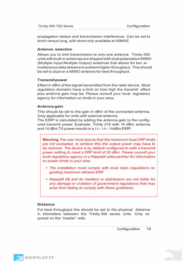
Antenna gain This should be set to the gain in dBm of the connected antenna. Only applicable for units with external antenna. The EIRP is calculated by adding the antenna gain to the config- ured transmit power. Example, Trinity 216 with 16 dBm antenna and 14 dBm TX power results in a 14 + 16 = 30dBm EIRP.
Distance For best throughput this should be set to the physical distance in kilometers between the Trinity-300 series units. Only re- quired on the “master” side.
Warning The user must assure that the maximum local EIRP limits are not exceeded, to achieve this the output power may have to be reduced. The device is by default configured to with a transmit power setting to meet a EIRP limit of 30 dBm. Please consult your local regulatory agency or a Repeatit sales partner for information on power limits in your area.
• The installation must comply with local radio regulations re- garding maximum allowed EIRP.
• Repeatit AB and its resellers or distributors are not liable for any damage or violation of government regulations that may arise from failing to comply with these guidelines.

Configuration Trinity-300 TDD Series
Configuration 20
CAC Policy
This will allow you to control the DFS CAC (Channel Availability Check, i.e the amount of time to listen for radar before using a channel) policy. Selecting “Regulatory” will follow the rules ac- cording to the selected regulatory domain, this is the recommended setting. Selecting “Custom” will allow you to enter a custom DFS CAC time.
Note Note that in Europe, according to the ETSI EN 301 893 regulation, there is a 10 minute CAC time on the 5.6GHz band due to weather radars.
Network settings IP IP-address on this Trinity-300 series unit.
Netmask IP-netmask to use.
Gateway Specifies the default gateway for this unit.
VLAN VLAN (IEEE 802.1Q) ID, range 1-4094.
Note Configuring an invalid VLAN ID might result in the loss of Ethernet connectivity if the there is a mismatch with your switch configuration.
DNS Specifies one or more nameservers. The default configuration contains two working servers.
Enable SNMP Enable SNMP version 2c for monitoring.
Warning Overriding this might violate the regulations in your area! You are required to consult with your local regulatory agency before modifying this setting!

Configuration Trinity-300 TDD Series
Configuration 21
Read-only community Specify the SNMPv2c read-only community name.
Read-write community Specify the SNMPv2c read/write community name.
STP (IEEE 802.1D) Enable/disable the usage of Spanning Tree Protocol (IEEE 802.1D) on the bridge.
System settings
Unit name Allows you to specify a custom unit name for easier identification.
Location Allows you to specify a descriptive name for the units geographical location.
Status LED Visual signal level/link status indicator. Can be set to pulse mode or disabled. If set to “pulse mode” the LEDs will blink according to the current signal strength.
Use RCS Enable/Disable the use of Repeatits network management system RCS.
RCS IP The IP address of your RCS server.
RCS SSL Port SSL port number your RCS is using. The default port number is 9998.
NTP Enable/disable the usage of NTP (Network Time Protocol) and which NTP servers to use.
Password Controls the password for the web interface.

Unit Operation
3.1 Unit status
The status page is the first page you see when accessing the web- interface of a Trinity-300 series unit. This page gives you a fast overview of the link and unit status.
Default view
Figure 3.1: Unit status
The default view (see figure 3.1) shows a small selection of sta- tus that should tell at a glance that everything is working. When more information is interesting extended information can accessed by clicking “show more” at the bottom of the page.
Extended information
The extended information (see figure 3.2) includes the same as the Default view above, a set of diagnostic information and some information useful when configuring the units. You can hide this information again by clicking the “show less” button.
22

Unit Operation Trinity-300 TDD Series
Unit Operation 23
Figure 3.2: Expanded unit status
Status information Radio status RSSI Current signal strength above fictive noise floor of -95dBm.
Channel The current channel that the link is using.
Frequency The current frequency the link is using.
Signal level The current signal level in dBm.
Noise level The current thermal noise level measured by the ra- dio card in dBm.
TX Rate The current transmit rate used by the uunit.
Link uptime The time the link has been connected and up.
Remote MAC MAC address of the currently connected remote unit.

Unit Operation Trinity-300 TDD Series
Unit Operation 24
System status Uptime The time the unit has been up since last power up or re-
boot.
Interface addresses Radio MAC MAC address of the radio card.
Ethernet mac MAC address of the Ethernet interface.
Package statistics Ethernet frames This is the number of Ethernet packets sent
over the radio link.
Success (radio) This is the number of radio frames holding one or more Ethernet packets sent over the radio link.
Excessive retries (radio) This is the number of radio frames that has been dropped even after all retransmission attempts.
Checksum errors Total number of radio frames received with CRC error.
PHY errors Total number of PHY errors received by the radio card. PHY errors can be an indication on interference.
Radar PHY errors Total number of PHY errors received by the radio card that could be potential radar signals.
3.2 Link Diagnostic Tools
The “Tools” page contains diagnostic tools for optimizing your Trinity- 300 series link.
Spectrum analyzer
The spectrum analyzer tool assist you in selecting a clear channel free from other OFDM radio traffic and with minimum amount of background noise.
The spectrum analyzer shows the amount of environmental RF energy for each available channel, classified as valid OFDM signals and other RF noise.
Refreshing the noise information requires the unit to disable the link and listen for a short time (less than a second) on each channel, this operation might take several minutes to complete.

Unit Operation Trinity-300 TDD Series
Unit Operation 25
Figure 3.3: Spectrum analyzer
Note The radio traffic will be disabled during the time the an- alyzer is running!
Speed test
The integrated speed test will show you the available raw radio throughput (±10%) of your link. The speed test takes approxi-
Figure 3.4: Speed test
mately 5-10 seconds to complete and does not interrupt normal traffic. The graph will the show the last 10 test runs so that you are able to detect improvements.

Unit Operation Trinity-300 TDD Series
Unit Operation 26
3.3 Firmware upgrading
The firmware in a Trinity-300 series unit is upgradeable, new firmware brings both bug fixes and new features to the device. To upgrade the firmware navigate to the “Admin” tab in the web in- terface and select “Firmware upgrade”, then follow the on-screen instructions to perform the upgrade.
It is recommended that you always have the same firmware version on both the master and client unit.
Note Never interrupt power during a firmware upgrade as this might damage the device
Tip Always upgrade the unit on the remote side of a link first when performing a firmware upgrade
You can find the latest firmware version on the Repeatit web
site at http://www.repeatit.se/support
3.4 Restore to defaults
There are three ways to restore a unit to its factory default set- tings.
On the “Admin” tab in the web interface you can chose to re- store settings to both the factory default in a single operation. Note that the unit will automatically reboot after this.
On the “Configure tab” page you can load the factory defaults to look at them before applying the factory settings, see 2.2.
There is also Restore to default client software available at http://www.repeatit.se/support. This software will automatically detect any Repeatit units within the first few minutes after boot, and allows you to restore the unit to its default settings.
Tip Use the RTD client to detect units for which you do not know its IP address

27
Support
Support as well as firmware updates for the Trinity-300 prod- uct series can be obtained from Repeatits web site at http://www.repeatit.se, there you will also find product news, FAQ and other information related to our products.

28
Technical Specifications
Radio Trinity-316 Plus Trinity-323 Plus Trinity-300
Frequency Bands 5.150 - 5.845 GHz1 5.150 - 5.845 GHz 5.1501 5.845 GHz1 Channel widths supported 10/20/40 MHz 10/20 10/20/40 MHz(Plus) 10/20/40 MHz Capacity 190 Mbps aggregated 100/190(Plus) Mbps aggregated 190 Mbps aggregated throughput throughput throughput Modulation OFDM OFDM OFDM BPSK/QPSK/16QAM/64QAM BPSK/QPSK/16QAM/64QAM BPSK/QPSK/16QAM/64QAM Max TX Power 23 dBm2 23 dBm2 23 dBm2 Max RX sensitivity -97 dBm -97 dBm -97 dBm Error Correction FEC; k=1/2,2/3,3/4,5/6 FEC; k=1/2,2/3,3/4,5/6 FEC; k=1/2,2/3,3/4,5/6 Encryption 128 bit AES 128 bit AES 128 bit AES Surge Protection 15kV 15kV 15kV Antenna Protection Internal DC Grounding Internal DC Grounding Internal DC Grounding DFS Yes Yes Yes Bandwidth control Yes Yes Yes
Antenna Internal Internal External (not incl.) Gain typ. 16dBi typ. 23dBi VSWR 3 dB Beam-Width, H-Plane 3 dB Beam-Width, V-Plane
max. 1.5:1 typ. 20◦ typ. 20◦
max 1.5:1 typ. 7◦ typ. 7◦
Polarization Vertical/Horizontal Vertical/Horizontal Connector N/A N/A 2 x N-female
Ethernet Interface Type 10/100/1000 BaseT Interface 10/100/1000 BaseT Interface 10/100/1000 BaseT Interface with Auto-negotiation (IEEE with Auto-negotiation (IEEE with Auto-negotiation (IEEE 802.3) 802.3) 802.3) Number of Ethernet Ports 1 1 1 Framing/Coding IEEE 802.3u IEEE 802.3u IEEE 802.3u Traffic Handling MAC layer bridging, self MAC layer bridging, MAC layer bridging, learning, 802.1q transparent self-learning 802.1q transparent self-learning 802.1q transparent Data Latency < 2ms (typical) < 2ms (typical) < 2ms (typical) Packets/second >40000 >40000 >40000 VLAN ID for Management Supported Supported Supported QoS Four Access Categories (AC) Four Access Categories (AC) Four Access Categories (AC) Voice, Video, Best Effort, and Voice, Video, Best Effort, and Voice, Video, Best Effort, and Background. Traffic Background. Traffic Background. Traffic classification according to WMM classification according to WMM classification according to WMM Power over Ethernet 12 - 48V DC (<6W typ.) 12 - 48V DC (<6W typ.) 12 - 48V DC (<6W typ.) Connector RJ-45 RJ-45 RJ-45
Management Link Management Web interface Web interface Web interface Protocol SNMP SNMP SNMP NMS Application RCS (Repeatit NMS) RCS (Repeatit NMS) RCS (Repeatit NMS) Tools in web interface Spectrum Analyser Spectrum Analyser Spectrum Analyser Speed Test Speed Test Speed Test
Environment IP Code Temperature
IP65 -40◦ / +55◦ C
IP65 -40◦ / +55◦ C
IP67 -40◦ / +55◦ C
Size 270 x 300 x 80 mm 370 x 370 x 80 mm 284 x 174 x 81 mm Weight per unit 2.7 Kg 2.7 Kg 2.0 Kg
1Allowed frequency range depends on the country of operation. 2Maximum allowed EIRP depends on the country of operation.

29
Usage restrictions and legal information
This product contains radio equipment for which the use in sev-
eral countries is subject to restrictions, licens or government au- thorization.
European Union Notices The product may be used in all EU countries (and other countries following the EU directive 1999/5/EC) without any limitations ex- cept for the counties mentioned below. In EU and other Eurpoean countries, the 5-GHz bands have been made available for the use of wireless local area networks (LANs). The overview of Regulatory Requirements for wireless LANs table provides an overwiew of the regulatory requirements applicable for the 5-GHz bands. Require- ments for individual countries may change, Repeatit recomends that you check with your local regulatory agency for the latest status on regulations for 5GHz fixed radio links.
Overwiew of Regulatory Requirements
Frequency band Max power level mW (EIRP) Usage 5150-5350 5470-5725
200 (23 dBm) 1000 (30 dBm)
Indoor ONLY Indoor and outdoor
The Regulatory limits for maximum output power are specified in EIRP. The EIRP level of a device can be calculated by adding the gain of the antenna used(specified in dB) to the output power available at the connector (specified in dBm). The usage of power level above the maximum is illegal.

Usage restrictions and legal information Trinity-300 TDD Series
Usage restrictions and legal information 30
Denmark
In Denmark, the band 5150-5350 MHz is also allowed for outdoor useage.
Italy
The use of 5.8GHz (5725-5850 MHz) is forbidden in Italy.
United Kingdom
A license from Ofcom (ofcom.org.uk) is required for use of the 5.8GHz (5725.5850 MHz) band in the United Kingdom.

Usage restrictions and legal information Trinity-300 TDD Series
Usage restrictions and legal information 31
Warranty
Repeatit AB, Hamngatan 33, S-172 66 Sundbyberg, Sweden, guar- antee that our products do not have any defects regarding mate- rial or function upon delivery. All of Repeatits products are covered by a 12 month international warranty.
If during the time of warranty the product displays any defects regarding material or function, the products should be returned to your reseller, who will, according to their own judgment, either repair or replace the product according to the following conditions:
Conditions
1. The warranty is only valid in combination with an original re-
ceipt issued by the reseller at the date of delivery or sale. The receipt needs to contain the products serial number or similar identification.
2. If Repeatit repairs or replaces the product, the repaired or re- placed product will be covered by the original warranty during the remainder of the guarantee period. During repair, some parts might be replaced. These parts are then the property of Repeatit AB.
3. The warranty does not cover normal wear and tear, faulty us- age or handling, or other usage other than the one described by Repeatit AB. The warranty does not cover defects caused by accidents.
4. The warranty is not valid if service is performed on the product by a, by Repeatit non-unauthorized person or company.
5. The warranty is not valid if any products that are not Repeatit original accessories are used with the product.
6. There are no warranty, written or oral, other than this printed warranty.