Embed Size (px)
Citation preview

RIGGING, INSTALLATION, OPERATION & MAINTENANCE MANUAL
TrilliumSeries™ Adiabatic Products –

DANGER• DANGER: Do not perform any service on or near the fans, motors, and drives, without first ensuring that the fans are disconnected, locked out,
and tagged out.
• WARNING: Failure to use designated lifting points can result in a dropped load causing severe injury, death, and/or property damage. Lifts must be performed by qualified riggers following BAC published Rigging Instructions and generally accepted lifting practices. The use of supplemental safety slings may also be required if the lift circumstances warrant its use, as determined by the rigging contractor.
• WARNING: Only personnel qualified to do so should undertake the installation, operation, maintenance and repair of this equipment. Proper care, procedures, and tools must be used in handling, lifting, installing, operating, maintaining, and repairing this equipment to prevent personal injury and/or property damage.
• WARNING: To prevent possible contamination of the make-up water supply, install a backflow prevention method in accordance with applicable local and national codes.
• WARNING: The top horizontal surface of the unit is not intended to be used as a walking surface or working platform. If access to the top of the unit is desired, the purchaser/end-user is cautioned to use appropriate means complying with applicable safety standards of governmental authorities.
• WARNING: All electrical, mechanical, and rotating machinery are potential hazards, particularly for those not familiar with their design, construction, and operation. Accordingly, use appropriate lockout procedures. Adequate safeguards (including the use of protective enclosures where necessary) should be taken with this equipment both to safeguard the public from injury and to prevent damage to the equipment, its associated system, and the premises.
• WARNING: Incoming power lines to the disconnect switch remain energized. Take proper electrical precautions when working near energized equipment.
• WARNING: The TrilliumSeries™ Adiabatic Product controls are set up to periodically flush and drain the water system, thereby eliminating the need for water treatment. However there may be unusual circumstances where chemicals or biological contaminants could be introduced into the recirculating water system, which could be harmful if inhaled or ingested. If there is a concern that this has happened, wear appropriate respiratory protection as a precaution, when exposed to the discharge air stream or to the mists produced by cleaning activities associated with the recirculating water system or Pre-Cooler Pads.
• CAUTION: The operation, maintenance, and repair of this equipment shall be undertaken only by personnel authorized and qualified to do so. All such personnel shall be thoroughly familiar with the equipment, the associated system and controls, and the procedures set forth in this manual. Proper care, personal protective equipment, procedures, and tools must be used in handling, lifting, installing, operating,
maintaining, and repairing this equipment to prevent personal injury and/or property damage.
• BAC units are typically installed immediately after shipment and many operate year round. However, if the unit is to be stored for a prolonged period of time either before or after installation, certain precautions should be observed.
• Do not run the unit wet with the pre-cooler pads out and the fans on (thereby getting the coils wet). Wet/dry cycling of the unit this way could shorten the coil life, and voids the warranty.
• Before an actual lift is undertaken, open the access hatch(es) and check to ensure no water, snow, ice, or debris has collected in the sump or elsewhere in the unit. Such accumulations will substantially add to the equipment’s lifting weight.
• When connecting power to the unit, do not penetrate the top of the control panel. Doing so may allow moisture to enter the panel. All cable and conduit should be supported separately from the unit. Do not penetrate the unit for supports or other connections.
• Do not use steam, high pressure water, or high pressure air to clean any component.
• Do not attempt to remove the Pre-Cooler Pads while wet to prevent excessive degradation.
WARNING
NOTICE
CAUTION

Table of ContentsRIGGING, INSTALLATION, OPERATION & MAINTENANCE » TRILLIUMSERIES™ ADIABATIC PRODUCTS
WarrantiesPlease refer to the Limitation of Warranties in the submittal packet applicable to and in effect at the time of the sale/purchase of these products.
Described in this manual are the recommended services for start-up, operation, and shutdown, and the approximate frequency of each. For
generic terms and conditions, refer to www.baltimoreaircoil.com/terms.
PART 1 Unit Description
2 Unit Overview
PART 2 Rigging
4 Safety
4 Pre-Rigging Checks
6 Layout Guidelines
7 Rigging
10 Prolonged Outdoor Storage
PART 3 Installation
11 Refrigerant Connection
13 Piping Guidelines
13 Water Connection
16 Ammonia Installation Instructions
16 Customer Electrical Connections
17 Wiring and Electrical Information
23 Controls Setup for Microchannel Coils
PART 4 Unit Operation
24 Start-Up
28 Modes of Operation
32 Winter Operation
32 Coil Freeze Protection
33 Discrete Spray Connection
34 Auto-Discrete Backup Spray System
35 EcoFlex™ Controls Operation
PART 5 Detailed Component Maintenance
38 Pre-Cooler Pad and Water System Maintenance
39 Water Distribution System Maintenance
40 Strainer and Pump Maintenance
40 Sump and Water Collection Maintenance
41 Fan and Motor Maintenance
41 Coil Maintenance
42 Water Treatment
42 EcoFlex™ Controls Maintenance
PART 6 Troubleshooting Guide
46 Troubleshooting Guide
Appendix a EcoFlex™ Controls
48 Menus
52 Datalogging
Appendix b Danfoss and Emerson
55 Danfoss
58 Emerson

WWW.BALTIMOREAIRCOIL .COM
2
Unit Overview
TRILLIUMSERIES™ ADIABATIC PRODUCTS
Unit Description1
Figure 1a. TrilliumSeries™ Adiabatic Condenser (TSDC Shown)
4
7
2
1
1
2
3
3 4
Detail A, TSDC Shown
13 8
9
10 11
17
13 14
Detail B. TSDC2 Shown
Figure 1b. TrilliumSeries™ Adiabatic Condenser (TSDC2 Shown)
7
8 12
19
19
10
11
15
15 16
16
17
20

WWW.BALTIMOREAIRCOIL .COM
3
1. Coils: TrilliumSeries™ Adiabatic Producs have either microchannel, or tube/fin coils. The coils are designed to be corrosion resistant, minimize refrigerant or fluid charge, allow for thermal expansion, and be easy to inspect and clean.
2. Whisper Quiet Fan(s): The fans have integrated electronically commutated motors (ECMs). These motors have embedded speed control and are highly efficient. They communicate with the EcoFlex™ Controls via Modbus.
3. Pre-Cooler Pads: when saturated with water, the pads precool the air to 1-3°F above the wet bulb temperature, thus improving the ability of the unit to reject heat on hot summer days. In conjunction with the distribution system they are designed to keep the water off the coils. When dry, the pads are removable for coil inspection or for cleaning.
4. Refrigerant/Fluid Connections: This is where customers connect to their piping systems. Some units have these connections on the opposite end from the controls.
5. Discrete Spray Connection (Not Shown): Since uptime is critical, this backup connection is available for water supply to the spray system. Should the pump or valve get damaged, or main water supply be interrupted on a hot day, a garden hose can be connected to this connection for a backup. See page 31 for more details.
6. Auto-Discrete Valve (Optional): This normally closed (NC) valve is located at the discrete spray connection location. Should the pump, make-up valve, or float switch get damaged, the valve will automatically open to supply water to the spray system.
7. Access Hatch: This door allows access to the sump, pump(s), float switch, strainer, and for general inspection. There is no general need to climb inside the unit; reaching into the sump is all that would be necessary during inspection and maintenance.
8. Pump(s): The industrial grade stainless steel pump(s) are controlled by the EcoFlex™ Controls to deliver water to the distribution system when the unit is in the Pre-Cooler Mode. The pump(s) are rated for continuous duty and can run dry for short periods without harm.
9. Pump Valve (Optional, Not Shown): This valve is a slow acting, normally open (NO) ball valve that prevents water from discharging through the pump when the Discrete Spray Connection is used. When the optional Auto-Discrete Backup Spray System mode is activated, the valve automatically closes.
10. Sump: This stainless steel basin collects the water from the gutters and the spray system, and houses the pump(s). It can be accessed through the access hatch(es).
11. Strainer(s): The strainer(s) surrounds the pump(s). It protects the spray system from collecting debris that is larger than the holes in the distribution system.
12. Float Switch (Not Shown for TSDC): The industrial grade stainless steel float switch detects the water level in the sump, ensures that water doesn’t overflow, and, in concert with the EcoFlex™ Controls, protects the pump(s) from operating dry.
13. Make-up Valve: This normally closed (NC) valve provides fresh water to the unit to replenish the water that evaporates into the entering air stream, and the water that is drained to keep the unit clean.
14. Make-up Pressure Balancing Valve (TSDC2 Only): This valve is adjusted to set the correct water flow to the pre-cooler pads. This valve is preset a the factory. See page 24 for more information.
15. Water Distribution System: Water is evenly dispersed over the full length of the pad using a PVC pipe system (TSDC) or a stainless steel gutter system (TSDC2 and TSDF2).
16. Water Collection Gutter: The unused water from the pre-cooling pads is collected in this gutter and returned to the sump to be recycled instead of dumping the water to a drain.
17. Drain Valve: This valve is a slow opening, normally open (NO) ball valve that drains water from the unit when the unit cycles into Dry Mode or during periodic cleaning cycles.
18. Outdoor Air Sensor (Not Shown): This sensor determines the outside temperature, and when comparing it to the precool set temperature helps the controller determine whether the unit should be in Dry Mode or Pre-Cooler Mode.
19. EcoFlex™ Controls: Each unit is shipped with custom controls logic that reduces energy consumption and optimizes water usage. With preset controls, the system is programmed and ready to operate upon arrival from the factory. For more information, see pages 28, 33 and 40.
20. Flow Meter(s) with Valve (TSDC2 and TSDF2 Only): This is set from the factory to control the flow of water over the Pre-Cooler Pads. See page 24 for adjustment.
21. Easy Pad Removal (Not Shown) (TSDC2 and TSDF2 Only): Steel partitions facilitate pad removal without damage while minimizing downtime. See page 36 for more information.
Unit Description
Unit Overview
Detail A, TSDC Shown
Detail B. TSDC2 Shown
NOTE: For transcritical CO2 operation, the coil operates with vapor in and vapor out. For subcritical CO2 operation, the coil operates with subcritical vapor in and liquid out.

WWW.BALTIMOREAIRCOIL .COM
4
TRILLIUMSERIES™ ADIABATIC CONDENSER
Rigging
Safety
Adequate precautions appropriate for the installation and location of these products should be taken to safeguard the equipment and the premises from damage, and the public from possible injury. The procedures listed in this manual must be thoroughly reviewed prior to rigging. Read all dangers, warnings, cautions, notices, and notes detailed in the margins.
Pre-Rigging Checks
When the unit is delivered to the jobsite, it should be checked thoroughly to ensure all required items have been received and are free of any shipping damage prior to signing the bill of lading. If the unit will be in prolonged outdoor storage, refer to page 10.
The following parts should be inspected:
2
For TrilliumSeries™ Adiabatic products that have been shipped charged with Nitrogen, verify that the coil maintained pressure (15 psi) by measuring the pressure with a Shrader valve prior to installation.
� Fan Motor(s)
� Fan Guard(s)
� Fan(s)
� Drain Valve
� Make-up Valve
� Water Distribution System
� Pump
� Pump Valve (Optional)
� Auto-Discrete Valve (Optional)
� Sump and Gutters
� Exterior Surfaces
� Pre-Cooler Pads
� EcoFlex™ Control Panel
� Coils
� Inlet Strainer(s) (Optional)
WARNING: Failure to use designated
lifting points can result in a
dropped load causing severe injury,
death, and/or property damage.
Lifts must be performed by qualified
riggers following BAC published
Rigging Instructions and generally
accepted lifting practices. The
use of supplemental safety slings
may also be required if the lift
circumstances warrant its use,
as determined by the rigging
contractor.
WARNING: Only personnel qualified
to do so should undertake the
installation, operation, maintenance
and repair of this equipment. Proper
care, procedures, and tools must be
used in handling, lifting, installing,
operating, maintaining, and
repairing this equipment to prevent
personal injury and/or property
damage.

WWW.BALTIMOREAIRCOIL .COM
5
Unit WeightsBefore rigging any unit, the weight should be verified from the unit submittal drawing.
AnchoringFor the TSDC, 7/8” diameter holes are provided in the bottom flanges of the unit for bolting the unit to the support beams. Refer to the suggested support drawing included in the submittal for location and quantity of the mounting holes. The unit must be level in both length and width directions for proper operation (max 1/16”/ft for the TSDC2 and TSDF2). Anchor bolts must be provided by others, BAC recommends 3/4” bolt SAE J429 Grade 5, ASME A325 Type 1 or equivalent. If vibration isolated supports are to be used, the units shall be installed on steel support first and the vibration isolators (provided by others) should be mounted under the steel support. Refer to the vibration isolation manufacturer’s guidelines before loading/unloading weight from the unit.
Point Support for Curb Mounting (For TSDC Only)If mounting a TrilliumSeries™ Adiabatic Product on a curb, follow Figure 2 below for point support locations.
NOTICE: Before an actual lift is
undertaken, open the access hatch
and check to ensure no water, snow,
ice, or debris has collected in the
sump or elsewhere in the unit. Such
accumulations will substantially
add to the equipment’s lifting
weight.
UNIT OUTLINE
AIR INLET
11'-0 1/2"
4'-2"
PLAN VIEW
AIR INLET
10'-7 7/8"2" MIN
4" MIN
5"
10" M
IN
CONN
ECTI
ON E
ND
POINT 1
POINT 2
POINT 3
POINT 4
2" MIN
Figure 2. Unit Point Support for Curb Installation (TSDC Only)
Rigging
Safety
Pre-Rigging ChecksUnit Weights
Anchoring

WWW.BALTIMOREAIRCOIL .COM
6
Layout Guidelines
TrilliumSeries™ Adiabatic Products must be located to ensure an adequate supply of fresh air to the coils. The axial fan(s) are not equipped to overcome external static pressure. When units are located adjacent to walls or in enclosures, care must be taken to ensure the discharge air is not deflected and recirculated back to the air intakes.
Each unit must be located and positioned to prevent the introduction of discharge air into the ventilation systems of the building on which the unit is located and of adjacent buildings. For detailed recommendations, see Figure 3 and Table 1.
Figure 3. TrilliumSeries™ Adiabatic Product Location
Elevation ViewParapet wall is not restrictive provided D(or C, as applicable) is equal to or greater than 2X.
D or CX
Plan View(TSDC-058-6.2 Shown)
Minimum Wall Separation Distance
Solid Wall
D
Sol
id W
all
1.6xD
Note: Additional units canbe added with 1.6xD
between them. This dimensionappliesif there is a wall or no wall.
C
1.6xCNote: Additional units can
be added with 1.6xCbetween them.
Solid Wall
C
3’-6”3’-6”
3’-3”
Well InstallationsInstallations Near Walls

WWW.BALTIMOREAIRCOIL .COM
7
Model Number D C
TSDC-xxx-3 1’-6” 2’-0”
TSDC-xxx-6.2 2’-4” 2’-11”
TSDC-xxx-9.6 3’-0” 3’-8”
TSDC-xxx-12.4 3'-6" 4'-0"
TSDx2-xxx-12.4 2'-8" 4'-6"
TSDx2-xxx-18.6 3'-8" 5'-6"
TSDx2-xxx-24.8 4'-3" 6'-2"
TSDx2-xxx-31.0 4'-7" 6'-8"
TSDx2-xxx-37.2 5'-3" 7'-0”
TSDx2-xxx-43.4 5'-7" 7'-3"
Table 1. Minimum Wall Separation Distance
Rigging
Layout Guidelines
Rigging
Rigging
Refer to Table 2 and Figure 4 for each unit’s required minimum spreader bar length “W1” and the recommended minimum vertical dimension “H”. Dimension“H” is the vertical distance from the lift point to the lifting device.
Model Number# of Fans H W1 W2 S
TSDC-xxx-3 1 2'-0" 3'-4" 1'-8" 2’-10”
TSDC-xxx-6.2 2 3'-1" 3'-4" 1'-8" 4’-5”
TSDC-xxx-9.6 3 5'-5" 3'-4" 1'-8" 7’-3”
TSDC-xxx-12.4 4 6'-6" 3'-4" 1'-8" 9’-8”
Model Number# of Fans H W L
TSDx2-xxx-12.4 4 10’-11” 5’-6” - 7’-11”
TSDx2-xxx-18.6 6 10’-11” 5’-6” - 11’-10”
TSDx2-xxx-24.8 8 10’-11” 5’-6” - 15’-9”
TSDx2-xxx-31.0 10 10’-11” 5’-6” - 19’-9”
TSDx2-xxx-37.2 12 10’-11” 5’-6” - 23’-8”
TSDx2-xxx-43.4 14 10’-11” 5’-6” - 27’-7”
Table 2. Recommended Vertical Dimension

WWW.BALTIMOREAIRCOIL .COM
8
NOTE: For weight information, refer
to the submittal drawing package.
W1
H
W2
S
Figure 4a. TSDC Lift (TSDC-xxx-9.6 Shown)
WARNING: Failure to use designated
lifting points can result in a
dropped load causing severe injury,
death, and/or property damage.
Lifts must be performed by qualified
riggers following BAC published
Rigging Instructions and generally
accepted lifting practices. The
use of supplemental safety slings
may also be required if the lift
circumstances warrant its use,
as determined by the rigging
contractor.H
NOTICE: To avoid damage during
hoisting, a spreader beam should
be used and the angles shown in
the figures must be observed.
Figure 7. TSDx2-xxx-18.6 Side View (6 Fan)
NOTICE: When lifting the TSDC or
the TSDC2/TSDF2, the spreader bar
is oriented differently. The TSDC2
and TSDF2 have strict requirements
on lifting angles and the number of
lifting points.
Figure 4b. TSDC2 and TSDF2 Lift (TSDC2-xxx-24.8 Shown)
Figure 6. TSDx2-xxx-12.4 Side View (4 Fan shown)
Figure 5. TSDC2 or TSDF2 End View

WWW.BALTIMOREAIRCOIL .COM
9
Figure 8. TSDx2-xxx-24.8 Side View (8 Fan)
Figure 9. TSDx2-xxx-31.0 Side View (10 Fan)
Figure 11. TSDx2-xxx-43.4 Side View (14 Fan)
Rigging
Rigging
Figure 10. TSDx2-xxx-37.2 Side View (10 Fan)

WWW.BALTIMOREAIRCOIL .COM
10
Prolonged Outdoor Storage
TrilliumSeries™ Adiabatic Products are shipped wrapped. If the unit is going to remain in outdoor storage in excess of three months prior to installation, remove the strech-wrap and tarp and follow the storage recommendations below.
Storage Preparation• Ensure the sump is fully drained. Remove any leaves or debris that may have
accumulated in the sump and gutters.
• For extended shutdown periods after start-up, coils should be charged with nitrogen at 15 psig in the field and capped by adding a threaded connection or a welded cap. Upon start-up, the coil connections will require cutting.
• Insert desiccant bags into the EcoFlex™ Control panel to absorb moisture. Seal the control panel for storage.
• Inspect the protective finish on the unit. Clean as required.
Motor RecommendationsTrilliumSeries™ Adiabatic Product motors are designed for storage at ambient temperatures of -40ºF to 176ºF (-40ºC to 80ºC). Prolonged periods of exposure above or below these specified conditions could degrade components of the motor and cause malfunction or premature failure.
• Care must also be taken to protect the motor from flooding or from harmful chemical vapors.
• The storage area should be free from ambient vibration. Excessive vibration can cause damage.
• Keep stored motor(s) dry and protected from weather.
• Rotate the fan once per month.
Preparation After Prolonged StorageKeep in mind that start-up procedures after long periods of storage are just as important as pre-shutdown procedures. Follow the instructions in the rest of this manual after prolonged storage. Be especially thorough for cleaning and inspection prior to start-up. Also, check the battery of the EcoFlex™ Control Panel.
NOTICE: BAC units are typically
installed immediately after
shipment and many operate year
round. However, if the unit is to
be stored for a prolonged period
of time either before or after
installation, certain precautions
should be observed.
Figure 12. Refrigerant Connection

WWW.BALTIMOREAIRCOIL .COM
11
TRILLIUMSERIES™ ADIABATIC PRODUCT
Installation 3Refrigerant Connection and Fluid Connections
The Pre-Cooler Pads represents the only potential flammable component of the TrilliumSeries™ Adiabatic Product. Remove the first two Pre-Cooler Pads on each side of the unit closest to the coil connection end on each side prior to brazing or welding the refrigerant or fluid piping.
For TrilliumSeries™ Condenser units, each unit must be piped with a trapped drop leg as shown in Figure 12. To ensure the unit operates with full capacity ensure that the drop leg is tall enough so the column of liquid has a static pressure greater than the pressure drop through the coil. This will be particularly important on multi-unit installations. Typical pressure drops through microchannel coils for TSDC are 5-6 psi for HFCs and 2 psi for NH3, which correspond to ~10 foot drop leg heights, although this will vary with unit sizing and application. For TSDC HFC’s in tube/fin coils the typical pressure drop is ~ 2 psi. For TSDC CO2 coils, the pressure drop is 4-12 psi. For TSDC2 the maximum allowed pressure drops is 12 psi for water, 10 psi for CO2, 1 psi for NH3 and 3 psi for HFCs. Contact BAC for special selections that may fall outside of these parameters.
NOTICE:1. Weld/braze the pipes with care,
noting that the coil itself may be aluminum. Protect the PVC piping and any exposed wiring from weld splatter.
2. Vacuum and clean all copper dust.
3. When piping the refrigerant connections, take care not to block the door opening of the access hatch or control panel.
4. For units equipped with threaded connections, be sure not to apply all torque directly to the header as this may cause damage and leaks.
5. Connections for fluid coolers are available in red brass MPT, flanged, or copper sweat. Always follow best practices when connecting refrigerant or fluid connections.
Figure 12. Refrigerant Connection
Equalizing L
ine
Compres
sor Disc
harge
Liquid to Syst
em
Receiver
Condenser
Rel
ief
Valv
e
Piping with Top Inlet Receiver Using Ammonia or CO2
Supply of valves and fittings beyond these pointsare supplied and installed by others.
Refrigerant Ball Valves
Field Supplied and Installed Charge & Purge Valves
Relief Valve
Drop Leg
Discharg
e Line
NOTE: If you are unable to pipe an
adequate drop leg, the discharge
line can be piped to the bottom of
the receiver.

WWW.BALTIMOREAIRCOIL .COM
12
Figure 13a. Parallel Piping with Common Liquid Header above Receiver Level Alternative 1
Refrigerant Piping for Multiple UnitsSee Figures 13a and 13b for the refrigerant piping connections for multiple units:
• All valves and piping shown to be field provided and installed if necessary.
• These piping diagrams show the arrangement of multiple TrilliumSeries™ Adiabatic Condensers. Additional piping requirements may be necessary for your system such as backflow valves or equalizing lines.
• Weld/braze the pipes with care to prevent damage to the coil and unit.
• When piping the refrigerant connections, take care not to block the door opening of the access hatch or control panel. See Figure 14.
• It is desirable to trap the liquid header as shown in Figure 13a. Trapping the header will insure a stable operating condition for the condensers. If the liquid header is not trapped, there will be times, particularly at initial start-up, where there will be erratic condenser operation until all liquid leg seals are stabilized. Piping must be sized for 100 fpm drain velocities, and should be sloped a minimum of 1/4” per foot toward the receiver.
• Figure 13b indicates an alternative method of trapping the main liquid header using a vertical trap. The volume of the vertical trap between the bottom inlet connection and the top outlet connection must be equal to the combined volume of the liquid in all of the drop legs. The top of the vertical trap must be connected to the equalizing line to prevent a siphoning effect from the liquid header to the receiver. There is no need to trap the individual drip legs when a vertical trap is used. The drop legs and the common liquid header should be sized for a maximum liquid velocity of 100 fpm.
Figure 13b. Parallel Piping with Common Liquid Header above Receiver Level Alternative 2

WWW.BALTIMOREAIRCOIL .COM
13
Piping Guidelines
When piping the unit, route the water pipes down or to the side so that there is a clear landing area in front of the unit for accessing the control panel and access hatch(es) in compliance with NEC regulations.
Water Connection
Water PipingTrilliumSeries™ Adiabatic Products require a water supply between 25 and 60 psi in a ¾” pipe for the TSDC and in a 1” pipe for the TSDC2 and TSDF2 at the unit’s inlet. If your building’s pressure is too high, it is recommended to use a pressure reducing valve.
If multiple TrilliumSeries™ Adiabatic Products are being installed, use Table 3 to determine the proper size of the water line that should be run to the units. This is critical for proper operation of the unit. Failure to meet these requirements will result in poor performance, lower capacity, and possible damage to the pump.
Number of Units
Nominal Pipe Size of Main Water Line (Inches)
TSDC TSDx2
1 3/4 1
2 1 1/4 1 1/2
3 1 1/2 2
4 1 1/2 2
5 2 2 1/2
6 2 2 1/2
Table 3. Nominal Pipe Size of Main Water Line
ClearWorking
Area
Figure 14. Clear Working Area
Installation
Refrigerant ConnectionRefrigerant Piping for Multiple Units
Piping Guidelines
Water ConnectionWater Piping

WWW.BALTIMOREAIRCOIL .COM
14
• For units with the water monitoring option, a water regulator will be provided with the unit which will be shipped loose inside the basin. The regulator must be installed before the make up valve and must be sized according to Figure 16 on page 16. If multiple units are ordered one water regulator should be installed per unit.
• If the optional Auto-Discrete Backup Spray System is ordered, the water supply to the unit can be split to provide water to both the make-up valve and auto-discrete valve. -
• Customers in climates that reach below freezing temperatures should refer to page 30 for winter operation.
• On page 15, Figures 15a and 14b show the suggested water piping for one or multiple units. These figures show an optional hose faucet connection which can be used to connect a garden hose for cleaning the unit or for the discrete spray back up. They also show a 3-way valve which allows the water piping to be remotely drained when temperatures are below freezing. This valve is field provided, installed, and controlled.
• Backflow prevention should be installed on TrilliumSeries™ Adiabatic Products per local and national codes.

WWW.BALTIMOREAIRCOIL .COM
15
1 1/2" MPT Overflow
1 1/4" FPT Dump/Drain Valve (Factory Supplied on the Unit)
3/4" FPT Make Up Valve (Factory Supplied on the Unit)
3-way valve
Ball Valve
Backflow Preventer
Ball Valve
Overflow piped to the drain line
Cold weather drain piping if necessary
DRAININCOMINGWATER
Above the Roof
Below the Roof
Field Provided and Installed If Necessary
Hose faucet
Pressure Reducing Valve (PRV)
Strainer
Auto-Discrete Valve
3/4" FPT Make Up Valve (Field provided and installed, if necessary)
Figure 15a. Water Piping (TSDC Shown)
NOTES FOR FIGURES 8A AND 8B:1. Only valves labeled factory
supplied are provided with the unit.
2. Optional hose faucet connection and 3-way valve shown (supplied by others).
3. The hose faucet can also be used as a vent during winter operation.
4. Backflow prevention should be installed per local and national codes.
5. Ensure proper venting for all piping.
6. For TSDC2 and TSDF2 models, refer to the submittal package for specific connection and valve locations.
Figure 15b. Water Piping for Multiple Models (TSDC Shown)
1 1/2" MPT Overflow
1 1/4" FPT Dump/Drain Valve (Factory Supplied on the Unit)
3/4" FPT Make Up Valve (Factory Supplied on the Unit)
3-way valve
Ball Valve
Backflow Preventer
Ball Valve
Overflow piped to the drain line
Cold weather drain piping if necessary
DRAININCOMINGWATER
Above the Roof
Below the Roof
Field Provided and Installed If Necessary
Main TrilliumSeries™ Condenser Water Line (see Table 3 for sizing)
Hose faucet
Pressure Reducing Valve (PRV)
Installation
Water ConnectionWater Piping
Main TrilliumSeries™ Product Water Line (see Table 3 for sizing)

WWW.BALTIMOREAIRCOIL .COM
16
Installation of the Pressure Regulating ValveAs part of the Water Monitoring option, a pressure regulating valve (PRV) is supplied. Follow the instructions for installation. The valve must be installed on straight rigid pipe 7.5” (19 cm) from the make-up valve, refer to the diagram below for more information.
Direction of Flow
Minimum of 10 InletPipe Diameters from
PRV to First Turn
Minimum of 20 InletPipe Diameters from
PRV to First Turn
Set to 20 psi
Figure 16. Pressure Regulating Valve
Ammonia Installation Instructions
If using ammonia, on TSDC models the following additions are recommended to ensure integrity and cleanliness of the microchannel coil:
• Discharge strainer (provided by others) on the discharge line from the compressor to the TrilliumSeries™ Adiabatic Condenser as close to the unit as possible. The strainer will catch weld slag and other system impurities during start-up. Suggested strainers are Danfoss FIA 50 with a 100 mesh strainer or finer.
• Filter dryer for the ammonia in the exiting liquid line, such as Parker C-40016-P replaceable core filter dryers or similar. This eliminates any moisture in the ammonia.
• Autopurger installed to eliminate any non-condensables.
Customer Electrical Connections
• Customer connection of 3 phase power and earth/ground is within the isolator/disconnect. Ensure correct voltage is supplied to the unit. Refer the submittal in the Customer Information Packet for this information.
• The connection of the above items will allow the TrilliumSeries™ Adiabatic Product to operate as specified. Please see the following sections for further details and see “Wiring and Electrical Information” on page 17.
Installation of Leaving Fluid Temperature Sensor (TSDF2 Fluid Cooler Models Only)
As part of the self-contained Temperature Control Package, a leaving water temperature sensor is supplied with a socket for installation in the piping leaving the unit. The sensor should be installed at least 10 times the pipe diameter from curves in the piping. The socket is equipped with a PG7-IP68 cable gland applied to the hexagonal end to secure the cable.
Figure 17. Leaving Fluid Temperature Sensor

WWW.BALTIMOREAIRCOIL .COM
17
Installation
Water ConnectionInstallation of the Pressure Regulating Valve
Ammonia Installation Instructions
Customer Electrical Connections
Wiring and Electrical Information
For the diagram showing customer power and control signal input connections, refer to the submittal package. This information is also in a package on the inside of the control panel.
NOTE:
FLA = Full Load Amps
MCA = Minimum Circuit Ampacity
MOP = Maximum Overcurrent
Protection
Table 4. FLA, MCA and MOP Ratings (amps) for 60 Hz Three Phase Power
Model Number Fan Qty. Pump Qty. FLA MCA MOP460V
TSDC-xxx-3 1 1 4.7 5.9 15
TSDC-xxx-6.2 2 1 8.7 10.8 15
TSDC-xxx-9.6 3 1 12.6 15.8 20
TSDC-xxx-12.4 4 1 16.6 20.7 25
TSDx2-xxx-xxx-12.4 4 2 16 20 25
TSDx2-xxx-xxx-18.6 6 2 23.3 29.1 30
TSDx2-xxx-xxx-24.8 8 2 30.6 38.2 40
TSDx2-xxx-xxx-31.0 10 2 37.9 47.3 50
TSDx2-xxx-xxx-37.2 12 2 45.1 56.4 60
TSDx2-xxx-xxx-43.4 14 2 52.4 65.5 70
380VTSDC-xxx-3 1 1 5.7 7.1 15TSDC-xxx-6.2 2 1 10.5 13.1 15TSDC-xxx-9.6 3 1 15.3 19.1 20TSDC-xxx-12.4 4 1 20.1 25.1 30TSDx2-xxx-xxx-12.4 4 2 19.4 24.3 25TSDx2-xxx-xxx-18.6 6 2 28.2 35.3 40TSDx2-xxx-xxx-24.8 8 2 37 46.3 50TSDx2-xxx-xxx-31.0 10 2 45.8 57.3 60TSDx2-xxx-xxx-37.2 12 2 54.6 68.3 70TSDx2-xxx-xxx-43.4 14 2 63.5 79.3 80
230VTSDC-xxx-3 1 1 9.6 12 15TSDC-xxx-6.2 2 1 17.8 22.2 25TSDC-xxx-9.6 3 1 25.9 32.4 40TSDC-xxx-12.4 4 1 34 42.5 50TSDx2-xxx-xxx-12.4 4 2 31.6 39.5 40TSDx2-xxx-xxx-18.6 6 2 45.9 57.4 60TSDx2-xxx-xxx-24.8 8 2 60.2 75.3 80TSDx2-xxx-xxx-31.0 10 2 74.6 93.2 100TSDx2-xxx-xxx-37.2 12 2 88.9 111.1 125TSDx2-xxx-xxx-43.4 14 2 103.2 129 150
200VTSDC-xxx-3 1 1 11.2 14 20TSDC-xxx-6.2 2 1 20.6 25.7 30TSDC-xxx-9.6 3 1 30 37.5 40TSDC-xxx-12.4 4 1 39.4 49.2 50TSDx2-xxx-xxx-12.4 4 2 36.5 45.6 50TSDx2-xxx-xxx-18.6 6 2 52.9 66.2 70TSDx2-xxx-xxx-24.8 8 2 69.4 86.8 90TSDx2-xxx-xxx-31.0 10 2 85.9 107.4 110TSDx2-xxx-xxx-37.2 12 2 102.4 127.9 150TSDx2-xxx-xxx-43.4 14 2 118.8 148.5 150
NOTE: For other voltages, contact
your local BAC Representative.

WWW.BALTIMOREAIRCOIL .COM
18
Electrical Power QualityThis unit requires clean electrical power to operate properly. Voltage and frequency should be within 10% of the designed voltage for the unit. Failure to provide this power may damage the unit.
The EC fan motors contain built-in protection circuits that will shut down the fan if there is a power quality issue. If the fans go into protection mode, the unit must be shut down and restarted to return to normal operation.
Power ConnectionsTrilliumSeries™ Adiabatic Products require a 3 phase 60Hz power source (50Hz also available). The voltages available are 200V, 230V, and 460V (380V and 415V also available). Please ensure that the correct voltage is supplied to the unit. If unsure, check your unit’s submittal to verify that the provided power matches your unit. The TSDC includes a power wire port on the upper left-hand side. The TSDC2 and TSDF2 includes a power wire port on the bottom right-hand side. In both instances, remove the NEMA plug. Make sure to use the proper sealing methods to comply with NEMA standards. This will maintain the panel’s NEMA 4 rating and prevent water ingression to the unit.
Controls ConnectionsThe controls wiring should be provided in a separate conduit from any power wiring. BAC recommends penetrating the control panel from the bottom or side panel observing standards. It is also recommended to use of shielded wire to avoid interference.
BAC offers the following options to control the TrilliumSeries™ Adiabatic Product. Check the submittal package to determine how the unit was setup and shipped:
• Control signal (0-10VDC, 10-0VDC or 4-20mA): The 0-10VDC signal commands the fans off at 0V and full speed at 10V. The 10-0VDC signal commands the fans off at 10V and full speed at 0V. The voltage signals should be wired to terminals – V (negative) and 10V (positive). The 4-20mA signal commands the fans off at 4mA and full speed at 20mA. The 4-20mA should be wired to terminals 10V (negative) and mA (positive).
• Communications via ModBus or BACnet: BAC offers both protocols over RS485 and BACnet over IP. For RS485 connection, BAC recommends the use of twisted shielded twisted paired wire with a ground. The communications card will be located on the bottom of the controller. The BAC modbus and BACnet connections do not have any device restrictions or proprietary protocols. However, you should contact your building management system provider or controls integrator to verify your system will work with the TrilliumSeries™ Adiabatic Product communications protocols. Please see Table 5 on page 16 for specific communication points map.
• Head Pressure Control: For units with this option, BAC has already preset the controller to operate with the specified refrigerant at the factory. A pressure sensor will be furnished with the unit. This sensor must be installed in the piping either on the supply side or discharge side of the coil using a Schrader 7/16” 20 UNF valve (provided by others). The sensor must be wired to terminals 48 (positive) and 49 (negative). To program the temperature set point into the controller, scroll down on the screen until the refrigerant temp set point is shown, press enter and using the up/down arrows select the desired temperature and press enter. Please note, there is only a single temperature set point in the TrilliumSeries™ Adiabatic Condenser controller. If you desire to control the unit based on pressure, the pressure value will need to be converted to temperature for that specific refrigerant.
• Leaving Fluid Temperature Control: For fluid cooler units, the leaving fluid temperature is monitored with a sensor installed in the leaving water piping. The sensor must be wired to terminals as shown in wiring diagrams included with submittal package.
NOTICE: When connecting power
to the unit, do not penetrate the
top of the control panel. Doing so
may allow moisture to enter the
panel. All cable and conduit should
be supported separately from the
unit. Do not penetrate the unit for
supports or other connections.
NOTE: EcoFlex™ Controls come
with preset date and time from
the factory and do not need
modification during initial start-up.
NOTE: Units purchased after
November 2015 are fully integrated
with Emerson CPC Controller.
NOTE: The minimum fan speed is
5%. Any signal sent below 5% (i.e.
9.95V or 0.05V) will be ignored and
the fans will turn off.

WWW.BALTIMOREAIRCOIL .COM
19
BAC Controller Side Rack Controller (or BMS) Side
Carel Index Description
Read/Write Variable Name
Data Type
Modbus RTU
Modbus TCP/IP BACNet SNMP
1 pressure sensor signal R pressure_disp_um A 30002 30002 AV1 1.3.6.1.4.1.9839.2.1.2.1.0
2 Outside Air Temperature R oa_t_disp A 30003 30003 AV2 1.3.6.1.4.1.9839.2.1.2.2.0
3 customer fan speed signal R fan_speed A 30004 30004 AV3 1.3.6.1.4.1.9839.2.1.2.3.0
4 Modbus Fan speed R/W cust_mb_speed A 40005 40005 AV4 1.3.6.1.4.1.9839.2.1.2.4.0
5 Required Fan Speed [ 0.0% - 100.0%] R SpeedReq_Fan A 30006 30006 AV5 1.3.6.1.4.1.9839.2.1.2.5.0
7 Floating Head Delta T UOM for Display R FltgHdDeltaT_um A 30008 30008 AV7 1.3.6.1.4.1.9839.2.1.2.7.0
8 OAT Ramp Set Point R/W OAT_Ramp_SP_um A 40009 40009 AV8 1.3.6.1.4.1.9839.2.1.2.8.0
10 Leaving Fluid Temperature sensor R LvgFluidTempDisp_um A 30011 30011 AV10 1.3.6.1.4.1.9839.2.1.2.10.0
12 Pre Cool Air temperature sensor R PreCoolAirTempDisp_um A 30013 30013 AV12 1.3.6.1.4.1.9839.2.1.2.12.0
22 Fluid Temperature Set Point Display R/W LFTSetPoint_um A 40023 40023 AV22 1.3.6.1.4.1.9839.2.1.2.22.0
23 Floating Head Delta T Set Point Display R/W FltgHdDeltaT_StPt_um A 40024 40024 AV23 1.3.6.1.4.1.9839.2.1.2.23.0
24 Minimum Head pressure Set Point Display R/W MinHeadPrsrStPt_um A 40025 40025 AV24 1.3.6.1.4.1.9839.2.1.2.24.0
25 Floating Head Delta T R FltgHdDeltaT A 30026 30026 AV25 1.3.6.1.4.1.9839.2.1.2.25.0
26 Low Speed Mode Maximum Fan Speed R/W LSMMaxFanSpd A 40027 40027 AV26 1.3.6.1.4.1.9839.2.1.2.26.0
28 Low Speed Mode Adiabatic Switchpoint Display R/W LSMAdSwPt_um A 40029 40029 AV28 1.3.6.1.4.1.9839.2.1.2.28.0
1 Fan kW Total - move decimal left two spaces R Power_Total_ZA I 30210 35002 AV1001 1.3.6.1.4.1.9839.2.1.3.1.0
2 Unit kW Total - move decimal left two spaces R Power_Total_Unit I 30211 35003 AV1002 1.3.6.1.4.1.9839.2.1.3.2.0
3 Current day R CURRENT_DAY I 30212 35004 AV1003 1.3.6.1.4.1.9839.2.1.3.3.0
4 Current hour R CURRENT_HOUR I 30213 35005 AV1004 1.3.6.1.4.1.9839.2.1.3.4.0
5 Current minute R CURRENT_MINUTE I 30214 35006 AV1005 1.3.6.1.4.1.9839.2.1.3.5.0
6 Current month R CURRENT_MONTH I 30215 35007 AV1006 1.3.6.1.4.1.9839.2.1.3.6.0
7 Current year R CURRENT_YEAR I 30216 35008 AV1007 1.3.6.1.4.1.9839.2.1.3.7.0
8 Current second R CURRENT_SECOND I 30217 35009 AV1008 1.3.6.1.4.1.9839.2.1.3.8.0
9 Fan kW Total - move decimal left two spaces R Power_Total_EBM I 30218 35010 AV1009 1.3.6.1.4.1.9839.2.1.3.9.0
10 Unit kW Total - move decimal left two spaces R Power_Total_Unit1 I 30219 35011 AV1010 1.3.6.1.4.1.9839.2.1.3.10.0
12 Time during which output remains at set step R/W RampStepPeriod I 40221 45013 AV1012 1.3.6.1.4.1.9839.2.1.3.12.0
13 Low Speed Mode Monday Start hour R/W LSMMonStrtHr I 40222 45014 AV1013 1.3.6.1.4.1.9839.2.1.3.13.0
14 Low Speed Mode Monday Stop hour R/W LSMMonStopHr I 40223 45015 AV1014 1.3.6.1.4.1.9839.2.1.3.14.0
15 Low Speed Mode Monday Start minute R/W LSMMonStrtMin I 40224 45016 AV1015 1.3.6.1.4.1.9839.2.1.3.15.0
16 Low Speed Mode Monday Stop minute R/W LSMMonStopMin I 40225 45017 AV1016 1.3.6.1.4.1.9839.2.1.3.16.0
17 Low Speed Tuesday Start hour R/W LSMTueStrtHr I 40226 45018 AV1017 1.3.6.1.4.1.9839.2.1.3.17.0
18 Low Speed Wednesday Start hour R/W LSMWedStrtHr I 40227 45019 AV1018 1.3.6.1.4.1.9839.2.1.3.18.0
19 Low Speed Thursday Start hour R/W LSMThuStrtHr I 40228 45020 AV1019 1.3.6.1.4.1.9839.2.1.3.19.0
20 Low Speed Friday Start hour R/W LSMFriStrtHr I 40229 45021 AV1020 1.3.6.1.4.1.9839.2.1.3.20.0
21 Low Speed Saturday Start hour R/W LSMSatStrtHr I 40230 45022 AV1021 1.3.6.1.4.1.9839.2.1.3.21.0
22 Low Speed Sunday Start hour R/W LSMSunStrtHr I 40231 45023 AV1022 1.3.6.1.4.1.9839.2.1.3.22.0
23 Low Speed Tuesday Stop hour R/W LSMTueStopHr I 40232 45024 AV1023 1.3.6.1.4.1.9839.2.1.3.23.0
24 Low Speed Wednesday Stop hour R/W LSMWedStopHr I 40233 45025 AV1024 1.3.6.1.4.1.9839.2.1.3.24.0
25 Low Speed Thursday Stop hour R/W LSMThuStopHr I 40234 45026 AV1025 1.3.6.1.4.1.9839.2.1.3.25.0
26 Low Speed Friday Stop hour R/W LSMFriStopHr I 40235 45027 AV1026 1.3.6.1.4.1.9839.2.1.3.26.0
27 Low Speed Saturday Stop hour R/W LSMSatStopHr I 40236 45028 AV1027 1.3.6.1.4.1.9839.2.1.3.27.0
28 Low Speed Sunday Stop hour R/W LSMSunStopHr I 40237 45029 AV1028 1.3.6.1.4.1.9839.2.1.3.28.0
29 Low Speed Tuesday Start Minute R/W LSMTueStrtMin I 40238 45030 AV1029 1.3.6.1.4.1.9839.2.1.3.29.0
30 Low Speed Wednesday Start Minute R/W LSMWedStrtMin I 40239 45031 AV1030 1.3.6.1.4.1.9839.2.1.3.30.0
Table 5. Points Table

WWW.BALTIMOREAIRCOIL .COM
20
BAC Controller Side Rack Controller (or BMS) Side
Carel Index Description
Read/Write Variable Name
Data Type
Modbus RTU
Modbus TCP/IP BACNet SNMP
31 Low Speed Thursday Start Minute R/W LSMThurStrtMin I 40240 45032 AV1031 1.3.6.1.4.1.9839.2.1.3.31.0
32 Low Speed Friday Start Minute R/W LSMFriStrtMin I 40241 45033 AV1032 1.3.6.1.4.1.9839.2.1.3.32.0
33 Low Speed Saturday Start Minute R/W LSMSatStrtMin I 40242 45034 AV1033 1.3.6.1.4.1.9839.2.1.3.33.0
34 Low Speed Sunday Start Minute R/W LSMSunStrtMin I 40243 45035 AV1034 1.3.6.1.4.1.9839.2.1.3.34.0
35 Low Speed Tuesday Stop Minute R/W LSMTueStopMin I 40244 45036 AV1035 1.3.6.1.4.1.9839.2.1.3.35.0
36 Low Speed Wednesday Stop Minute R/W LSMWedStopMin I 40245 45037 AV1036 1.3.6.1.4.1.9839.2.1.3.36.0
37 Low Speed Thursday Stop Minute R/W LSMThuStopMin I 40246 45038 AV1037 1.3.6.1.4.1.9839.2.1.3.37.0
38 Low Speed Friday Stop Minute R/W LSMFriStopMin I 40247 45039 AV1038 1.3.6.1.4.1.9839.2.1.3.38.0
39 Low Speed Saturday Stop Minute R/W LSMSatStopMin I 40248 45040 AV1039 1.3.6.1.4.1.9839.2.1.3.39.0
40 Low Speed Sunday Stop Minute R/W LSMSunStopMin I 40249 45041 AV1040 1.3.6.1.4.1.9839.2.1.3.40.0
1At least one alarm is present for the Zhiel-Abegg fan 1
R Al_Present_ZA D 10002 10002 BV1 1.3.6.1.4.1.9839.2.1.1.1.0
2At least one alarm is present for the Zhiel-Abegg fan 2
R Al_Present_ZA2 D 10003 10003 BV2 1.3.6.1.4.1.9839.2.1.1.2.0
3At least one alarm is present for the Zhiel-Abegg fan 3
R Al_Present_ZA3 D 10004 10004 BV3 1.3.6.1.4.1.9839.2.1.1.3.0
4At least one alarm is present for the Zhiel-Abegg fan 4
R Al_Present_ZA4 D 10005 10005 BV4 1.3.6.1.4.1.9839.2.1.1.4.0
5At least one alarm is present for the Zhiel-Abegg fan 5
R Al_Present_ZA5 D 10006 10006 BV5 1.3.6.1.4.1.9839.2.1.1.5.0
6At least one alarm is present for the Zhiel-Abegg fan 6
R Al_Present_ZA6 D 10007 10007 BV6 1.3.6.1.4.1.9839.2.1.1.6.0
7alarm when pump turns off and float not made for (default 25s)
R al_low_water D 10008 10008 BV7 1.3.6.1.4.1.9839.2.1.1.7.0
8 make up valve failure or no water alarm R makeup_valve_al D 10009 10009 BV8 1.3.6.1.4.1.9839.2.1.1.8.0
9 discharge pressure alarm R pr_al D 10010 10010 BV9 1.3.6.1.4.1.9839.2.1.1.9.0
11 Outside air temperature sensor failure R oa_t_fail D 10012 10012 BV11 1.3.6.1.4.1.9839.2.1.1.11.0
12 pressure sensor out of range R mAin_pr_fail D 10013 10013 BV12 1.3.6.1.4.1.9839.2.1.1.12.0
13 conductivity probe R Din_conductivity D 10014 10014 BV13 1.3.6.1.4.1.9839.2.1.1.13.0
14 Digital input for manual wet mode - Preccol R DIN_Precool D 10015 10015 BV14 1.3.6.1.4.1.9839.2.1.1.14.0
15 pump proving switch R din_pump D 10016 10016 BV15 1.3.6.1.4.1.9839.2.1.1.15.0
16 float switch R DIN_float_sw D 10017 10017 BV16 1.3.6.1.4.1.9839.2.1.1.16.0
17 fan alarm R Din_fan_al D 10018 10018 BV17 1.3.6.1.4.1.9839.2.1.1.17.0
18 value from logic that controls relay output R water_pump D 10019 10019 BV18 1.3.6.1.4.1.9839.2.1.1.18.0
19 value from logic that controls relay output R Dump_Valve D 10020 10020 BV19 1.3.6.1.4.1.9839.2.1.1.19.0
20 value from logic that controls relay output R makeup_valve D 10021 10021 BV20 1.3.6.1.4.1.9839.2.1.1.20.0
21 pump proving did not occur R al_pump D 10022 10022 BV21 1.3.6.1.4.1.9839.2.1.1.21.0
22 Customer Fan Speed sensor Failure R fan_speed_fail D 10023 10023 BV22 1.3.6.1.4.1.9839.2.1.1.22.0
23 pressure sensor out of range R Ain_pr_fail D 10024 10024 BV23 1.3.6.1.4.1.9839.2.1.1.23.0
24 Manual Precool Force R/W Man_Precool D 00025 00025 BV24 1.3.6.1.4.1.9839.2.1.1.24.0
25At least one alarm is present for the Zhiel-Abegg fan 7
R Al_Present_ZA7 D 10026 10026 BV25 1.3.6.1.4.1.9839.2.1.1.25.0
26At least one alarm is present for the Zhiel-Abegg fan 8
R Al_Present_ZA8 D 10027 10027 BV26 1.3.6.1.4.1.9839.2.1.1.26.0
27At least one alarm is present for the Zhiel-Abegg fan 9
R Al_Present_ZA9 D 10028 10028 BV27 1.3.6.1.4.1.9839.2.1.1.27.0
28At least one alarm is present for the Zhiel-Abegg fan 10
R Al_Present_ZA10 D 10029 10029 BV28 1.3.6.1.4.1.9839.2.1.1.28.0
Table 5. Points Table (Continued)

WWW.BALTIMOREAIRCOIL .COM
21
BAC Controller Side Rack Controller (or BMS) Side
Carel Index Description
Read/Write Variable Name
Data Type
Modbus RTU
Modbus TCP/IP BACNet SNMP
29At least one alarm is present for the Zhiel-Abegg fan 11
R Al_Present_ZA11 D 10030 10030 BV29 1.3.6.1.4.1.9839.2.1.1.29.0
30At least one alarm is present for the Zhiel-Abegg fan 12
R Al_Present_ZA12 D 10031 10031 BV30 1.3.6.1.4.1.9839.2.1.1.30.0
31At least one alarm is present for the Zhiel-Abegg fan 13
R Al_Present_ZA13 D 10032 10032 BV31 1.3.6.1.4.1.9839.2.1.1.31.0
32At least one alarm is present for the Zhiel-Abegg fan 14
R Al_Present_ZA14 D 10033 10033 BV32 1.3.6.1.4.1.9839.2.1.1.32.0
33At least one alarm is present for the Zhiel-Abegg fan 15
R Al_Present_ZA15 D 10034 10034 BV33 1.3.6.1.4.1.9839.2.1.1.33.0
34At least one alarm is present for the Zhiel-Abegg fan 16
R Al_Present_ZA16 D 10035 10035 BV34 1.3.6.1.4.1.9839.2.1.1.34.0
37 Fan Ramp is Active R FanRampActive D 10038 10038 BV37 1.3.6.1.4.1.9839.2.1.1.37.0
38At least one alarm is present for the Ebmpapst fan 1
R Al_Present_EBM_1 D 10039 10039 BV38 1.3.6.1.4.1.9839.2.1.1.38.0
39At least one alarm is present for the Ebmpapst fan 2
R Al_Present_EBM_2 D 10040 10040 BV39 1.3.6.1.4.1.9839.2.1.1.39.0
40At least one alarm is present for the Ebmpapst fan 3
R Al_Present_EBM_3 D 10041 10041 BV40 1.3.6.1.4.1.9839.2.1.1.40.0
41At least one alarm is present for the Ebmpapst fan 4
R Al_Present_EBM_4 D 10042 10042 BV41 1.3.6.1.4.1.9839.2.1.1.41.0
42At least one alarm is present for the Ebmpapst fan 5
R Al_Present_EBM_5 D 10043 10043 BV42 1.3.6.1.4.1.9839.2.1.1.42.0
43At least one alarm is present for the Ebmpapst fan 6
R Al_Present_EBM_6 D 10044 10044 BV43 1.3.6.1.4.1.9839.2.1.1.43.0
44At least one alarm is present for the Ebmpapst fan 7
R Al_Present_EBM_7 D 10045 10045 BV44 1.3.6.1.4.1.9839.2.1.1.44.0
45At least one alarm is present for the Ebmpapst fan 8
R Al_Present_EBM_8 D 10046 10046 BV45 1.3.6.1.4.1.9839.2.1.1.45.0
46At least one alarm is present for the Ebmpapst fan 9
R Al_Present_EBM_9 D 10047 10047 BV46 1.3.6.1.4.1.9839.2.1.1.46.0
47At least one alarm is present for the Ebmpapst fan 10
R Al_Present_EBM_10 D 10048 10048 BV47 1.3.6.1.4.1.9839.2.1.1.47.0
48At least one alarm is present for the Ebmpapst fan 11
R Al_Present_EBM_11 D 10049 10049 BV48 1.3.6.1.4.1.9839.2.1.1.48.0
49At least one alarm is present for the Ebmpapst fan 12
R Al_Present_EBM_12 D 10050 10050 BV49 1.3.6.1.4.1.9839.2.1.1.49.0
50At least one alarm is present for the Ebmpapst fan 13
R Al_Present_EBM_13 D 10051 10051 BV50 1.3.6.1.4.1.9839.2.1.1.50.0
51At least one alarm is present for the Ebmpapst fan 14
R Al_Present_EBM_14 D 10052 10052 BV51 1.3.6.1.4.1.9839.2.1.1.51.0
52At least one alarm is present for the Ebmpapst fan 15
R Al_Present_EBM_15 D 10053 10053 BV52 1.3.6.1.4.1.9839.2.1.1.52.0
53At least one alarm is present for the Ebmpapst fan 16
R Al_Present_EBM_16 D 10054 10054 BV53 1.3.6.1.4.1.9839.2.1.1.53.0
54 Fluid temp Sensor fail R Ain_LFT_fail D 10055 10055 BV54 1.3.6.1.4.1.9839.2.1.1.54.0
55 PreCool temp Sensor fail R Ain_PCTemp_fail D 10056 10056 BV55 1.3.6.1.4.1.9839.2.1.1.55.0
61 Head pressure below Minimum setting R LowHeadPressure D 10062 10062 BV61 1.3.6.1.4.1.9839.2.1.1.61.0
62 Low Speed Mode Enable R/W LowSpeedMode D 00063 00063 BV62 1.3.6.1.4.1.9839.2.1.1.62.0
63 Low Speed Mode Control Mode (Clock/BMS) R/W LSMControlMode D 00064 00064 BV63 1.3.6.1.4.1.9839.2.1.1.63.0
64 Low Speed Active R LowSpdActv D 10065 10065 BV64 1.3.6.1.4.1.9839.2.1.1.64.0
Table 5. Points Table (Continued)

WWW.BALTIMOREAIRCOIL .COM
22
BAC Controller Side Rack Controller (or BMS) Side
Carel Index Description
Read/Write Variable Name
Data Type
Modbus RTU
Modbus TCP/IP BACNet SNMP
65 ZAFan1Disabled R/W ZAFan1Dis D 00066 00066 BV65 1.3.6.1.4.1.9839.2.1.1.65.0
66 ZA Fan16 Disabled R/W ZAFan16Dis D 00067 00067 BV66 1.3.6.1.4.1.9839.2.1.1.66.0
67 ZA Fan15 Disabled R/W ZAFan15Dis D 00068 00068 BV67 1.3.6.1.4.1.9839.2.1.1.67.0
68 ZA Fan14 Disabled R/W ZAFan14Dis D 00069 00069 BV68 1.3.6.1.4.1.9839.2.1.1.68.0
69 ZA Fan12 Disabled R/W ZAFan12Dis D 00070 00070 BV69 1.3.6.1.4.1.9839.2.1.1.69.0
70 ZA Fan13 Disabled R/W ZAFan13Dis D 00071 00071 BV70 1.3.6.1.4.1.9839.2.1.1.70.0
71 ZA Fan11 Disabled R/W ZAFan11Dis D 00072 00072 BV71 1.3.6.1.4.1.9839.2.1.1.71.0
72 ZA Fan10 Disabled R/W ZAFan10Dis D 00073 00073 BV72 1.3.6.1.4.1.9839.2.1.1.72.0
73 ZA Fan9 Disabled R/W ZAFan9Dis D 00074 00074 BV73 1.3.6.1.4.1.9839.2.1.1.73.0
74 ZA Fan8 Disabled R/W ZAFan8Dis D 00075 00075 BV74 1.3.6.1.4.1.9839.2.1.1.74.0
75 ZA Fan7 Disabled R/W ZAFan7Dis D 00076 00076 BV75 1.3.6.1.4.1.9839.2.1.1.75.0
76 ZA Fan6 Disabled R/W ZAFan6Dis D 00077 00077 BV76 1.3.6.1.4.1.9839.2.1.1.76.0
77 ZA Fan5 Disabled R/W ZAFan5Dis D 00078 00078 BV77 1.3.6.1.4.1.9839.2.1.1.77.0
78 ZA Fan4 Disabled R/W ZAFan4Dis D 00079 00079 BV78 1.3.6.1.4.1.9839.2.1.1.78.0
79 ZA Fan3 Disabled R/W ZAFan3Dis D 00080 00080 BV79 1.3.6.1.4.1.9839.2.1.1.79.0
80 ZA Fan2 Disabled R/W ZAFan2Dis D 00081 00081 BV80 1.3.6.1.4.1.9839.2.1.1.80.0
81 EBM Fan16 Disabled R/W EBMFan16Dis D 00082 00082 BV81 1.3.6.1.4.1.9839.2.1.1.81.0
82 EBM Fan15 Disabled R/W EBMFan15Dis D 00083 00083 BV82 1.3.6.1.4.1.9839.2.1.1.82.0
83 EBM Fan14 Disabled R/W EBMFan14Dis D 00084 00084 BV83 1.3.6.1.4.1.9839.2.1.1.83.0
84 EBM Fan13 Disabled R/W EBMFan13Dis D 00085 00085 BV84 1.3.6.1.4.1.9839.2.1.1.84.0
85 EBM Fan12 Disabled R/W EBMFan12Dis D 00086 00086 BV85 1.3.6.1.4.1.9839.2.1.1.85.0
86 EBM Fan11 Disabled R/W EBMFan11Dis D 00087 00087 BV86 1.3.6.1.4.1.9839.2.1.1.86.0
87 EBM Fan10 Disabled R/W EBMFan10Dis D 00088 00088 BV87 1.3.6.1.4.1.9839.2.1.1.87.0
88 EBM Fan9 Disabled R/W EBMFan9Dis D 00089 00089 BV88 1.3.6.1.4.1.9839.2.1.1.88.0
89 EBM Fan8 Disabled R/W EBMFan8Dis D 00090 00090 BV89 1.3.6.1.4.1.9839.2.1.1.89.0
90 EBM Fan7 Disabled R/W EBMFan7Dis D 00091 00091 BV90 1.3.6.1.4.1.9839.2.1.1.90.0
91 EBM Fan6 Disabled R/W EBMFan6Dis D 00092 00092 BV91 1.3.6.1.4.1.9839.2.1.1.91.0
92 EBM Fan5 Disabled R/W EBMFan5Dis D 00093 00093 BV92 1.3.6.1.4.1.9839.2.1.1.92.0
93 EBM Fan4 Disabled R/W EBMFan4Dis D 00094 00094 BV93 1.3.6.1.4.1.9839.2.1.1.93.0
94 EBM Fan3 Disabled R/W EBMFan3Dis D 00095 00095 BV94 1.3.6.1.4.1.9839.2.1.1.94.0
95 EBM Fan2 Disabled R/W EBMFan2Dis D 00096 00096 BV95 1.3.6.1.4.1.9839.2.1.1.95.0
96 EBM Fan1 Disabled R/W EBMFan1Dis D 00097 00097 BV96 1.3.6.1.4.1.9839.2.1.1.96.0
97 Water management Enable R WtrMngEnbl D 10098 10098 BV97 1.3.6.1.4.1.9839.2.1.1.97.0
98 Low Speed Monday Active R LSMMonActv D 10099 10099 BV98 1.3.6.1.4.1.9839.2.1.1.98.0
99 Low Speed Tuesday Active R LSMTueActv D 10100 10100 BV99 1.3.6.1.4.1.9839.2.1.1.99.0
100 Low Speed Wednesday Active R LSMWedActv D 10101 10101 BV100 1.3.6.1.4.1.9839.2.1.1.100.0
101 Low Speed Thursday Active R LSMThuActv D 10102 10102 BV101 1.3.6.1.4.1.9839.2.1.1.101.0
102 Low Speed Friday Active R LSMFriActv D 10103 10103 BV102 1.3.6.1.4.1.9839.2.1.1.102.0
103 Low Speed Saturday Active R LSMSatActv D 10104 10104 BV103 1.3.6.1.4.1.9839.2.1.1.103.0
104 Low Speed Sunday Active R LSMSuntActv D 10105 10105 BV104 1.3.6.1.4.1.9839.2.1.1.104.0
105 BMS Command for Low Speed Control R/W LSM_BMS_Command D 00106 00106 BV105 1.3.6.1.4.1.9839.2.1.1.105.0
106 Low Speed Mode is active from BMS R LSM_BMS_Active D 10107 10107 BV106 1.3.6.1.4.1.9839.2.1.1.106.0
107 Low Speed Mode Clock Active for Display R LSMClockActv D 10108 10108 BV107 1.3.6.1.4.1.9839.2.1.1.107.0
108 Anti Cycling Ramp Function Enable R/W RampEnable D 00109 00109 BV108 1.3.6.1.4.1.9839.2.1.1.108.0
Table 5. Points Table (Continued)

Controls Setup for Microchannel Coils (TSDC Only)
The TrilliumSeries™ Adiabatic Condenser is the most efficient product in its class and as such it has very unique characteristics that need to be taken into account when integrated into a traditional refrigeration system. It is capable of maintaining a steady drop leg pressure in the system year long without the need of floating set points or periodically adjusting flood valves to control capacity on colder days. It is important to monitor the condenser to avoid rapid cycling of the fans, more specifically when the ambient temperatures drop below freezing.
During the colder season the condenser becomes more efficient and the hot gas entering the coils condenses much faster. During these conditions the drop leg pressure and temperature may fluctuate rapidly if the control system is not properly tuned. This rapid fluctuation will produce a significant amount of cycling of the condenser’s fan motors.
This rapid cycling will not only increase the cost of operating the unit but also cause severe stress on all mechanical components which could lead to costly repairs. As with other refrigeration equipment, care should be taken in the setup of the control system to ensure the fan motor is started from rest no more than 6 times per hour. Excess cycling on cold days can thermally shock the microchannel and can cause premature deterioration, leading to failure. Coil failure due to excessive system cycling is not covered under warranty. This excess cycling will also manifest wear on other parts of the refrigeration system such as compressors and valves.
To avoid excess cycling, ensure the control system is properly tuned for a condenser with low refrigerant volume. Typical PID (Proportional Integral Derivative) control settings may be tuned by default for larger volume condensers and may respond erratically when placed in service with a microchannel condenser without tuning. Check with your controls vendor for custom microchannel settings. In some cases, Proportional only (sometimes called ‘Linear’) control, based on the dropleg temperature or pressure, is a stopgap solution until proper Integral & Derivative settings can be determined. Alternatively, installing the TrilliumSeries™ Adiabatic Condenser with the ‘Head Pressure Control’ option eliminates fan fluctuations by taking over fan control from the refrigeration system and ensures steady year-round operation and protection against erratic refrigeration system control. For more information, see pages 15, 23, and 32.
WWW.BALTIMOREAIRCOIL .COM
23
NOTICE: Excess cycling on cold
days can thermally shock the
microchannel and can cause
premature deterioration, leading to
failure.
NOTE: It is recommended to set the
hold back valve to 10 PSI below the
controller’s setpoint
Installation
Controls Setup for Microchannel Coils

WWW.BALTIMOREAIRCOIL .COM
24
TRILLIUMSERIES™ ADIABATIC CONDENSER
Unit Operation
Start-Up
TrilliumSeries™ Adiabatic Products are shipped fully wrapped. If the unit is going to remain in outdoor storage in excess of three months prior to installation, remove the shrink wrap and follow the storage recommendations on page 10. If you start-up the unit within three months of delivery, follow the instructions below.
General• Verify fan and unit pump motor breakers are off, locked out, and tagged out.
• The unit must be level in both length and width directions for proper operation.
Inspection• Conduct external inspection of the equipment. Check for leaks, corrosion, and any
structural damage.
• Conduct internal inspection of the equipment. Check for anything unusual such as structural or mechanical component damage.
• Inspect the pump, make-up valve, and drain valve. Remove any construction debris from inside the valves/sump.
• Thoroughly inspect the fan(s) for any mechanical or physical damage.
• Check that the float switch moves freely.
• Inspect the distribution system as described in “Water Distribution System Maintenance” on page 37.
Cleaning• Remove all dirt and debris from the fan guard(s).
• Inspect and clean the distribution system.
• Clean all of the mechanical components, such as the fan and motor.
• Flush the sump to remove any accumulated dirt and debris.
• Remove, clean, and replace the pump strainer.
• Flush the piping supply water to the unit for at least 5 minutes to remove flux shavings and other construction debris.
• If necessary, clean the coil.
• Clean out the optional inlet strainers every quarter and after start-up.
DANGER: Do not perform any service
on or near the fans, motors, and
drives, without first ensuring that
the fans are disconnected, locked
out, and tagged out.
4
NOTE: BAC offers Factory Start-Up
and commissioning which adds an
extra year to the warranty. Contact
your local BAC Representative for
more details.

WWW.BALTIMOREAIRCOIL .COM
25
• If necessary, clean the Pre-Cooler Pads.
• After installation, remove any steel shavings from inside the unit. This will prevent shavings from rusting onto the surface of the thermosetting hybrid polymer, which may affect the coating’s integrity over extended time.
Start-Up• Verify the correct voltage to the control panel with a meter.
• Before power has been provided to the unit, proceed to flip all the breakers to the ON position inside the control panel.
• Close the control panel and ensure that both locks have been fully engaged by rotating 90 degrees on each bolt.
• Remove any materials from the sump.
• Turn on breaker or other power supply that supplies power to the unit.
• Close the pump access hatch firmly.
• Flip the main disconnect switch to the ON position.
• The TrilliumSeries™ Adiabatic Product will start momentarily.
• The EcoFlex™ Controls are pre-set from the factory. No setup is required for the standard unit. The only setup required is for the optional Water Monitoring (see below). More information on the EcoFlex™ Controls connections can be found on page 16.
• The following items can be adjusted at the time of start-up, if desired. However, the unit ships from the factory preset with defaults.
– Precool set point
– Time of daily drain
– If multiple units are installed at one site, some prefer to stagger the daily drain time a few minutes apart to manage undersized drains
– Duration of daily drain
– Settings for Self-Clean Cycle
– Date/Time
– Settings for head pressure control unit (only applicable if the option is ordered)
– Communication settings (only applicable if the option is ordered)
– Water saving logic or energy saving logic
– Auto-Discrete logic (only applicable if the option is ordered)
– More information on EcoFlex™ Controls Operation can be found on page 28 and more information on EcoFlex™ Controls Maintenance can be found on page 40.
Setting the Parameters for the Water Monitoring OptionTrilliumSeries™ Adiabatic Products can be ordered with a sensor that monitors the water quality so that water is bled out only when needed. Without this package, the water will be bled at preset intervals. This package also comes with a water consumption meter that can be set to measure consumption over defined intervals of time. Please use the following procedure to set those intervals. This option monitors the amount of purged from the Condenser given the following conditions:
• The pressure regulating valve provided by BAC is properly field installed and set to 20.
NOTE: It is imperative that both
bolts are fully engaged to maintain
the control panel’s NEMA 4 rating.
Unit Operation
Start-UpGeneral
Inspection
Cleaning
Start-Up
Setting the Parameters for the Water Monitoring Option

WWW.BALTIMOREAIRCOIL .COM
26
Figure 18. Water Meter Set Up
• The pressure of the incoming water is 25 psi or greater on a pipe (¾” for TSDC, 1” forTSDC2 and TSDF2).
• There are no interruptions of water delivery when the unit is on Pre-Cooler Mode.
• The controller is properly set up.
• The Pressure Regulating valve is properly maintained and tested biyearly.
– This water meter will automatically measure the amount of water that passesthrough the make-up valve in Gallons and monitor it during specified periods oftime. The meter has an accuracy of +/- 5%.
Water Meter Set-up (Optional)When the unit is started up for the first time, the start and finish dates will be 00/00 and 0:00.
• The first two numbers are the Month/Day; for instance, if the counter was to be setfrom April 19th until May 7th, the start should read 04/19 while the finish shouldread 05/07.
• The timer numbers are the start/finish times with hours in the 24-hour format andminutes; for instance, if the timer should start at 6:00 AM and finish at 4:30 PM, themonitor would read “Start 6:00” and “Finish 16:30”.
Pre-Cooler Pad Water Flow (For TSDC2 and TSDF2 Models Only)
Make-Up Pressure Balancing ValveA minimum water flow must be distributed over the Pre-Cooler Pads as per the minimum water flow rates (see Table 6). The water flow of the make-up will depend on the supply water pressure. The pressure balancing valve will balance the pressure to the correct value. This valve will be preset at the factory. The correct values can be found in Table 6.
• Change the pressure by rotating the knob. See callout 1 in Figure 19.
• Check to ensure the pressure on the gauge exactly matches what is listed in Table 6.
Model Number
Make-Up Pumps
Make-up Flow Rate (GPM)
Preset Reducing Valve Pressure Flow Rate per Pump
(psi) (bar) GPM l/min
TSDx2-xxx-xxx-12.4 2.9 3.6 0.25 4.2 15.8
TSDx2-xxx-xxx-18.6 4.6 6.0 0.42 6.2 23.6
TSDx2-xxx-xxx-24.8 5.8 7.7 0.53 8.3 31.5
TSDx2-xxx-xxx-31.0 7.5 10.1 0.70 9.0 34.0
TSDx2-xxx-xxx-37.2 9.1 12.4 0.85 10.8 40.8
TSDx2-xxx-xxx-43.4 10.4 14.2 0.98 12.6 47.6
Table 6. Recommended Pre-Cooler Pad Water Flow Rates for the Make-Up and Pump (TSDC2 and TSDF2 Models Only)

WWW.BALTIMOREAIRCOIL .COM
27
Figure 20a. Schematic for Water Flow Adjustment Screw
NOTES FOR FIGURE 19A:1. 6 mm hexagonal adjustment
screw
2. Flow indicator
3. Water flow in l/min
4. 8 mm hexagonal set screw
Unit Operation
Start-UpSetting the Parameters for the Water Monitoring Option
Water Meter Set-up
Pre-Cooler Pad Water Flow
1
2
3
4
Figure 19. Make-up Pressure Balancing Valve
1 2
NOTES FOR FIGURE 18:1. Change the pressure by rotating
the knob
2. Gauge
Flow Balancing Valves for Pumps• A minimum water flow must be distributed over the Pre-Cooler Pads as per the
minimum water Flow rates (see Table 6). The water flow generated by the pumps willdepend on the size of the unit. This valve has been preset at the factory.
– First, open the plastic cover plate of the water flow adjustment screw.
– Next, loosen the set screw (8 mm hex screw).
– Then, adjust the adjustment screw (6 mm hex screw) until the correct flow isreached.
– Finally, tighten the set screw again.
Figure 20b. Schematic for Water Flow Adjustment Screw

WWW.BALTIMOREAIRCOIL .COM
28
Warm Air Out
Air in atDry-Bulb
Temp
Air in atDry-Bulb
Temp
Air Cooledto 2-3ºF of Wet-
BulbTemp
Air Cooledto 2-3ºF of Wet-
BulbTemp
Water Distribution
System
Water Distribution
System
PumpLiquid Out
MicrochannelCoils
Liquid Out
Vapor InVapor In
Pre-CoolerMedia
Pre-CoolerMedia
[1]
[1] [1]
[1]
NOTE: For transcritical CO2 operation, the coil operates with vapor in and vapor out. For subcritical CO2 operation, the coil operates with subcritical vapor in and liquid out.
Figure 22. Pre-Cooler Mode Operation
Warm Air Out
Air in at Dry-Bulb
Temp
Air in atDry-Bulb
Temp
Liquid Out
Pre-CoolerPads
MicrochannelCoils
Liquid Out
Vapor InVapor In
Pre-CoolerPads
[1]
[1] [1]
[1]
Figure 21. Dry Mode Operation
Modes of Operation
TrilliumSeries™ Adiabatic Products will operate in two basic modes: Dry Mode and Pre-Cooler Mode. In Dry Mode, the water pump will be off and the unit will operate as an air-cooled condenser or fluid cooler. During Pre-Cooler Mode, the unit will use a pump to deliver water over the Pre-Cooler Pads, making the unit operate as an adiabatic condenser or fluid cooler.
Dry ModeWhen the ambient air is below the set point, the unit runs as a dry cooler to save water and energy. The ambient air condenses the refrigerant or cools the process fluid in the coils which is then returned to the system.
Pre-Cooler ModeWhen the unit is in Pre-Cooler Mode to manage the water: maximizing Pre-Cooler Pad wetting in Pre-Cooler mode and the ambient air reaches a pre-set temperature, water is evenly sprayed over the highly efficient Pre-Cooler Pads. The air is humidified as it passes through the media, cooling down to 2-3ºF above the wet-bulb temperature. Such substantial depression of the dry bulb temperature results in a major increase in dry cooling capacity.
The cooler air passes over the coil and condenses the refrigerant or cools the process fluid in the coil which is then returned to the system. In the sump there is an industrial-duty pump that supplies the water. Part of the distributed water is evaporated while the excess water assists in rinsing the pads. The EcoFlex Controls determine when the water is purged from the sump.
WWW.BALTIMOREAIRCOIL .COM
29
Unit Operation
Modes of OperationDry Mode
Pre-Cooler Mode
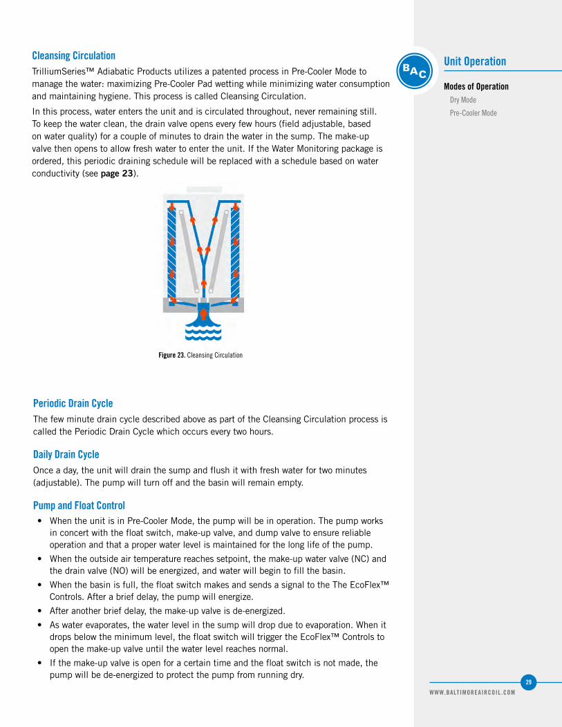
Cleansing CirculationTrilliumSeries™ Adiabatic Products utilizes a patented process in Pre-Cooler Mode to manage the water: maximizing Pre-Cooler Pad wetting while minimizing water consumption and maintaining hygiene. This process is called Cleansing Circulation.
In this process, water enters the unit and is circulated throughout, never remaining still. To keep the water clean, the drain valve opens every few hours (field adjustable, based on water quality) for a couple of minutes to drain the water in the sump. The make-up valve then opens to allow fresh water to enter the unit. If the Water Monitoring package is ordered, this periodic draining schedule will be replaced with a schedule based on water conductivity (see page 23).
Figure 23. Cleansing Circulation
Periodic Drain CycleThe few minute drain cycle described above as part of the Cleansing Circulation process is called the Periodic Drain Cycle which occurs every two hours.
Daily Drain CycleOnce a day, the unit will drain the sump and flush it with fresh water for two minutes (adjustable). The pump will turn off and the basin will remain empty.
Pump and Float Control• When the unit is in Pre-Cooler Mode, the pump will be in operation. The pump works
in concert with the float switch, make-up valve, and dump valve to ensure reliable operation and that a proper water level is maintained for the long life of the pump.
• When the outside air temperature reaches setpoint, the make-up water valve (NC) and the drain valve (NO) will be energized, and water will begin to fill the basin.
• When the basin is full, the float switch makes and sends a signal to the The EcoFlex™ Controls. After a brief delay, the pump will energize.
• After another brief delay, the make-up valve is de-energized.
• As water evaporates, the water level in the sump will drop due to evaporation. When it drops below the minimum level, the float switch will trigger the EcoFlex™ Controls to open the make-up valve until the water level reaches normal.
• If the make-up valve is open for a certain time and the float switch is not made, the pump will be de-energized to protect the pump from running dry.

WWW.BALTIMOREAIRCOIL .COM
30
• If the pump receives a signal to operate and after repeated attempts cannot turn on due to the float switch not sensing adequate water, the EcoFlex™ Controls will indicate a fault (optional alarm). See the Troubleshooting Guide on page 44 for suggestions on how to address this.
EcoFlex™ ControlsBAC’s exclusive EcoFlex™ Controls allow for the TrilliumSeries™ Adiabatic Product to operate in the mode of operation specific for your job conditions without you having to think about it. Each unit is shipped from the factory with your specific climate conditions and preferences in mind.
Modes of Operation OptimizationThere are three different ways to optimize unit operation. The unit’s mode is located at the default controls menu. Once the menu is shown, press enter and select the desired mode of operation.
1. Standard Logic (Default): The controller will start the Pre-Cooler Mode at a preset outside air temperature to increase the unit’s capacity and efficiency. This is the default mode.
2. Water Saver Logic: The controller will optimize the unit’s efficiency and only use water when the conditions require the extra cooling capacity. Pre-Cooler Mode will be initiated only when the outside air temperature is above the switch point and the fans are running at 90% or above for over 60 seconds. This mode will recheck conditions every two hours.
3. Energy Saver Logic: The controller will optimize its sequence so that the least amount of energy is consumed to meet the present load of the unit. If the outside air temperature is 10°F (5.6°C) below the switch point and the fan speed is above 35%, Pre-Cooler Mode will be initiated.
There are also additional settings and options to optimize operation:
Table 7. EcoFlex™ Controls Additional Settings and Options

WWW.BALTIMOREAIRCOIL .COM
31
Unit Operation
Modes of OperationPre-Cooler Mode
EcoFlex™ Controls
Modes of Operation Optimization
Fan ControlEvery fan will run at the same speed at all times. The fans are connected to each other via ModBus RS485 and controlled using one of these three methods. Water Saver Logic and Energy Saver Logic will need to be pre-ordered as extra devices and configuration are added at the factory:
4. Customer provided Analog signal (0-10V, 10-0V and 4-20mA): Customers provide an Analog Input signal to the controller from their rack controller or Energy Management System. An equivalent signal is re- broadcasted to the fans via ModBus.
5. Pressure sensor (Head Pressure Control), Optional: A pressure sensor supplies an Analog Input (4-20mA) to the controller to indicate head pressure. The controller modulates the fan speed using a PID loop comparing the head pressure to the setpoint to control the fan speed. The loop is tuned in such a way that the fans operate smoothly to preserve the fan’s motor life and energy. The fans’ speed signal is sent to the fans via ModBus. If the pressure sensor fails, the controller sends an alarm to the interface screen and via ModBus to the customer; as well as sending a signal to the fans to run at 80% via ModBus.
6. Customer provided communications: The unit is connected to the customer’s BAS system via ModBus or BACnet. The speed signal is a ModBus or BACnet virtual point that the controller sends to all fans to control speed. A full list of all points can be found on page 16.
Pre-Cooler Mode Activation During Dry Mode, the drain valve remains open while the make-up valve remains closed. When the unit gets the signal to enter Pre-Cooler Mode, the following sequence occurs:
• The drain valve closes.
• The make-up valve opens to fill the sump, and remains on.
• When the sump is full and the float switch makes the pump turns on.
• The pump drains the sump as it fills the spray system and wets the Pre-Cooler Pads.
• If the incoming water pressure is low, the pump may turn off as the sump drains faster with the pump in operation than the make-up valve can replenish the water. The pump is rated to run dry for short periods of time without harm.
• The system will reach equilibrium when the spray system is filled, the Pre-Cooler Pads are saturated, and the sump is filled. The unit will then follow the ‘Pump and Float Control’ described on page 27.
1. Customer provided Analog signal (0-10V, 10-0V and 4-20mA): Customers provide an Analog Input signal to the controller from their rack controller or Energy Management System. An equivalent signal is re- broadcasted to the fans via ModBus.
2. Head Pressure Control Package, Optional: A pressure sensor supplies an Analog Input (4-20mA) to the controller to indicate head pressure. The controller modulates the fan speed using a PID loop comparing the head pressure to the setpoint to control the fan speed. The loop is tuned in such a way that the fans operate smoothly to preserve the fan’s motor life and energy. The fans’ speed signal is sent to the fans via ModBus. If the pressure sensor fails, the controller sends an alarm to the interface screen and via ModBus to the customer as well as sending a signal to the fans to run at 80%.
3. Customer provided communications: The unit is connected to the customer’s BAS system via ModBus or BACnet. The speed signal is a ModBus or BACnet virtual point that the controller sends to all fans to control speed. A full list of all points can be found on page 18.
4. Leaving Fluid Temperature Control (TSDF2 Only): A temperature sensor supplies an Analog Input (NTC) to the controller to indicate leaving fluid temperature. The controller modulates the fan speed using a PID loop comparing the fluid temperature to the setpoint to control the fan speed. The loop is tuned in such a way that the fans operate smoothly to preserve the fan’s motor life and energy. The fans’ speed signal is sent to the fans via ModBus. If the temperature sensor fails, the controller sends an alarm to the interface screen and via ModBus to the customer; as well as sending a signal to the fans to run at 80%.
NOTE: For winter operation, the
hose faucet can be used as
vent. Refer to Page 12 for more
information. Also, consult with a
licensed plumber.

WWW.BALTIMOREAIRCOIL .COM
32
Self-Clean Cycle The TrilliumSeries™ Adiabatic Product Self-Clean Cycle was developed to help maintain maximum operational performance of the unit by reducing the amount of accumulation of debris on the coils and the Pre-Cooler Pads. The Self-Clean Cycle is not intended to replace regular maintenance. Please follow the regular maintenance schedule as indicated in this manual to ensure proper operation.
Special ConsiderationsThe unit capacity will be affected during the Self-Clean Cycle. The amount of air passing through the coils will be lower than in normal operation, and BAC recommends enabling this feature during low load periods of the day. The unit comes preset to operate the Self-Clean Cycle at 5:45 am for three minutes. If you would like to set a different time or duration, refer to page 41. Also note, the Self-Clean Cycle is automatically disabled below 40°F (4°C).
OperationThe Self-Clean Cycle allows the fans to rotate backwards for a set amount of time. By pushing the air in the opposite direction of normal operation, most debris accumulated on the outer areas of the coils and pads get “pushed” out minimizing accumulation. This feature is active once a day, every day. Refer to page 41 for additional information.
Winter Operation
When the unit is in Dry Mode, the unit completely drains with no standing water. During winter operation, the EcoFlex™ Controls automatically disables Pre-Cooler Mode when the ambient temperature is below 40°F (4.4°C). Turn off the water to the unit and drain all exposed external piping, including pump piping, when below freezing temperatures are expected.
• Customers in climates that reach below freezing temperatures should take necessary precaution to protect the water pipes from freezing. This may include installing a valve to prevent standing water in the pipes (provided by others). Heat trace all exposed make-up water lines if the water cannot be shutoff and/or external piping cannot be drained.
Figure 24. Self-Clean Cycle
Coil Freeze Protection (TSDF2 Only)
For protection against coil freeze-up, recommended coil fluid solutions are an industrial grade inhibited ethylene glycol or propylene glycol solution. When the use of glycol is not practical, the system must be designed to meet the minimum temperature requirements.

WWW.BALTIMOREAIRCOIL .COM
33
Figure 25a. Water Connection - Valve Open (TSDC Only) Figure 25b. Water Connection - Valve Closed (TSDC Only)
Bleed Valve
Valve Open Valve
Closed
Bleed Valve
Discrete Spray Connection
The discrete spray connection offers a water by-pass connection in case of pump failure. The connection is made for a standard garden hose and is not designed to hold weight such as attached piping. For the TSDC only, in case of pump failure, turn the pump valve to the horizontal (closed) position in order to isolate the pump and divert water flow.
Unit Operation
Modes of OperationSelf-Clean Cycle
Winter Operation
Coil Freeze ProtectionMinimum Operation
Emergency Coil Drain
Discrete Spray Connection
Discrete Spray Connection
Make-up Pressure Balancing Valve
Figure 26. Manual Discrete Connection for the TSDC2 and TSDF2 (Garden Hose Connection)
Make-up Valve
Strainer (Optional)
Model NumberHeat LossData
(BTU/HR)1
TSDF2-WG-22S-12.4 2,951,500
TSDF2-WG-22L-12.4 2,993,180
TSDF2-WG-23M-18.6 4,447,840
TSDF2-WG-23R-18.6 4,511,940
TSDF2-WG-24D-24.8 5,893,040
TSDF2-WG-24S-24.8 6,024,400
NOTE: Heat loss data based on
102°F (39°C) entreing coil water,
nominal flowrate and -10°F (-23°C)
ambient air temperature with a
45MPH (72 km/hr) wind velocity.
Fans and pump are off.
Model NumberHeat LossData
(BTU/HR)1
TSDF2-WG-25D-31.0 7,438,720
TSDF2-WG-25M-31.0 7,520,760
TSDF2-WG-26T-37.2 8,854,240
TSDF2-WG-26D-37.2 8,974,820
TSDF2-WG-27T-43.4 10,389,840
TSDF2-WG-27D-43.4 10,511,320
Minimum Operation When a glycol solution is not utilized, operate the system to meet the following conditions.• Maintain the minimum recommended flow through the unit coils at all times.• Maintain a minimum heat load on the circulating fluid so that the temperature of the fluid leaving the coil is not less than 50°F (10°C). To maintain the leaving fluid temperature at 50°F (10°C) when the process load is extremely light or shut off, apply an auxiliary heat load to the circulating fluid and adjust the flow to ensure that fluid leaving the coil maintains the minimum required temperature.
Emergency Coil DrainDo not drain the coils as a normal method of freeze protection. Frequent draining promotes corrosion inside the coil tubes. However, draining is acceptable as an emergency method of freeze protection if the coils are not protected by a glycol solution. If the coils are not protected, automatic drain valves and vacuum breakers are recommended to drain the coils if flow stops or the fluid temperature drops below 50°F (10°C) when the ambient temperature is below freezing. Further protection against coil freeze-up is possible with the installation of an alarm to alert personnel when the temperature of the fluid leaving the coils falls below 50°F (10°C). Contact your local BAC Representative for guidelines on the installation of an emergency coil drain system.

WWW.BALTIMOREAIRCOIL .COM
34
Auto-Discrete Backup Spray System
The Auto-Discrete Backup Spray System provides a backup water system for adiabatic cooling in case of component failure. The system senses if the pump, make-up valve, or float switch fails, and if so, disables the pump and triggers a backup supply of water to spray over the Pre-Cooler Pads. The system also sends an alarm signal. The system has an automatic reset feature, whereby it periodically checks the components to identify if the fault has cleared. If it has cleared, it returns the unit to normal operation, or the system can be manually reset.
Figure 27b. Auto-Discrete Operation (TSDC)
Auto-Discrete Valve Open (Water In)
Pump Valve Closed
Drain Open
Figure 27a. Pre-Cool Mode Operation (TSDC)
Auto-Discrete Valve Closed
Pump Valve Open
(Water In)
Figure 28. Location of Auto-Discrete Valve on TSDC2 and TSDF2 Detail A

WWW.BALTIMOREAIRCOIL .COM
35
Unit Operation
Auto-Discrete Backup Spray System
EcoFlex™ Controls Operation
EcoFlex™ Controls Operation
TrilliumSeries™ Adiabatic Products are furnished standard with state of the art controls that provide efficient year round performance. Each unit is shipped with custom controls logic that reduces energy consumption and optimizes water usage. With preset controls, the system is programmed and ready to operate upon arrival from the factory.
Below are optional controls packages available at time of ordering:
• General Alarm: The TrilliumSeries™ Adiabatic Product provides a normally open contact that notifies of any trouble with the unit by closing its contact.
– Pump Alarm: Occurs when the pump is commanded on but does not start.
– Fan Alarm: Occurs when the fan produces an alarm in its controller and communicates that back to the TrilliumSeries™ Adiabatic Product controller.
– Make-up Valve Alarm (No Water): Occurs when the make up valve is open ,and the unit does not fill up with water.
– Air Temp Alarm: Occurs when the outside air temperature sensor reading is out of range.
– Pressure Sensor Alarm (Optional Head Pressure Control Unit): Occurs when the pressure sensor reading is out of range.
– High Head Pressure Alarm (Optional Head Pressure Control Unit): Occurs when the head pressure read by the sensor is above the set point.
– Clean Conductivity Sensor (Optional Head Pressure Control Unit): Occurs every six months to remind the operator to clean the conductivity sensor. If this error is not cleared (and the sensor is not cleaned), the unit will revert back to the standard drain cycle routine.
• Water Monitoring Package: The TrilliumSeries™ Adiabatic Product can monitor the water quality so that water is only bled out when needed. This package also comes with a water consumption meter that can be set for a defined interval of time, up to 2 months. The optional Auto-Discrete Backup Spray System can be added to this package only.
• Energy Package: The TrilliumSeries™ Adiabatic Product can be ordered with a sensor that monitors the amount of power consumed by the unit in Watts. The information will be displayed in the main screen and will be broken down per fan. Also, other information will be provided regarding the fans including motor temperature, RPM, and current drawn. The last screen will provide a total power consumption value of the whole unit.
• Communications Package: The TrilliumSeries™ Adiabatic Product can be ordered with a communications card; either BACnet or ModBus over BACnetIP or RS485. This option allows full control of the unit and the ability to monitor alarms. The EcoFlex™ Controls communication must be coordinated with your Building Management System (by others).
• Head Pressure Control Package: The TrilliumSeries™ Adiabatic Product can regulate the fan speed by monitoring the refrigerant inlet pressure. This option uses a pressure sensor which is furnished by BAC but installed by others in the field.
For information on modes of operation, refer to page 26.
NOTE: For units purchased prior
to April 2014, contact BAC for the
previous generation manual.
NOTE: Refer to page 40 for more
information on EcoFlex™ Controls
Maintenance and refer to the
EcoFlex™ Controls Appendix
on page 46 for details on menu
navigation.

WWW.BALTIMOREAIRCOIL .COM
36
EcoFlex™ Controls Features
Figure 29. EcoFlex™ Controls Panel (TSDC Shown)
Control Panel Disconnect Switch
• Control Panel Disconnect Switch: De-energizes the entire unit and control panel as well as unlocks the control panel door. Note, power still enters the control panel even if the disconnect switch has been turned in the off position.
• Fan Speed Control
– Customer Signal Control: Fan speed control provided by 0 – 10V, 10 – 0V, or 4 – 20mA control signal. The fan speed control is supplied by others.
– Communication Control: Fan speed control provided by either BACnet or ModBus over Ethernet or RS485 and requires the Communication Package be ordered. The fan speed control is supplied by others.
– Head Pressure Control: Fan speed control provided by monitoring the inlet refrigerant pressure and requires the Head Pressure Control Package to be ordered.
– Leaving Fluid Temperature Control (TSDF2 Only): The controller modulates the fan speed using a PI loop comparing the outlet fluid temperature to a temperature setpoint. An NTC temperature sensor to be mounted in the leaving fluid piping out is included and requires installation in the field.
WARNING: Incoming power lines
to the disconnect switch remain
energized. Take proper electrical
precautions when working near
energized equipment.
Controller Display Inside
Temperature Sensor (Below the Panel)

WWW.BALTIMOREAIRCOIL .COM
37
Recommended Maintenance Intervals[1]
Inspect and clean as necessary: Start-Up Monthly Quarterly Semi Annually Annually
Inspect general condition of the unit and check unit for unusual noises or vibrations
Inspect sump
Flush water distribution system
Clean pump strainer(s)
Inspect Pre-Cooler Pads[1]
Check operation of make-up valve and drain valve
Clean the optional inlet strainers
Inspect the optional pressure regulating valve
Check operation of pump(s)
Inspect coil
Run Fan Reversal Start Self-Clean Cycle
Inspect unit finish
Inspect the optional conductivity sensor
Inspect the optional pump valve and the auto-discrete valve
Mechanical equipment system: Start-Up Monthly Quarterly Semi Annually Annually
Check motor voltage and current
Check general condition of the fan
Fan cycling, smooth operation
DANGER: Do not perform any
service on or near the fans,
motors, and drives, without
first ensuring that the fans are
disconnected, locked out, and
tagged out.
NOTE:
1. If removal of the pre-cooler pads is needed, only remove them when dry.
2. Recommended service intervals are the minimum for typical installations. Different environmental conditions may dictate more frequent servicing.
TRILLIUMSERIES™ ADIABATIC CONDENSER
Detailed Component Maintenance 5

WWW.BALTIMOREAIRCOIL .COM
38
Pre-Cooler Pad Maintenance
The Pre-Cooler Pads, which act as air filters and as such protect the coil from fouling, can catch airborne debris. An inspection is recommended monthly and should focus on:
• Signs of excessive fouling and scaling of the Pre-Cooler Pads.
• Full and even wetting of the face area (when in Pre-Cooler Mode).
• To keep the Pre-Cooler Pads at their top condition, enable the Self-Clean Cycle for the daily cleaning operation. See page 30 for further details.
Scaling and FoulingIf excessive dust, debris, scale, etc. has accumulated on the Pre-Cooler Pads, it is recommended to wash the Pre-Cooler Pads by removing them from the unit and rinsing them using a standard garden hose at a downward angle. Continue rinsing until water flows freely to the other side. Never use a brush or a high-pressure hose for cleaning off the Pre-Cooler Pads.
Scale may deposit when the Pre-Cooler Pads dries at the end of each adiabatic cycle. The rate of scaling will depend on:
• The number of adiabatic starts and stops.
• The water quality.
– To reduce the amount of scaling on the Pre-Cooler pads due to poor water quality, throttle the bleed line valve open at the pump discharge.
• Poor air quality and debris can cause an accelerated rate of scaling.
• See the Troubleshooting Guide on page 44 for additional ideas on how to address scaling.
Pre-Cooler Pad Removal Removal of the pre-cooler pads has been designed as a tool-free operation for quick access to the interior of the unit for inspection of the coils and sump area. To remove the pads:
• Remove the knobs or latches located along the length of the water distribution system covers.
• Lift the hinged spray system covers. This will allow the pre-cooler pads to be removed.
• For TSDC2 or TSDF2 units equipped with the EasyPad™ Removal option, locate the pad installed between the metal baffles. This pad should be removed first to allow space for removal of subsequent pads. The baffles can also be easily lifted out of place prior to removal of other pads.
NOTICE: Do not attempt to remove
the Pre-Cooler Pads while wet to
prevent excessive degradation.
NOTICE: For the TSDC, one of the
Pre-Cooler Pads is smaller than
the others and must be returned to
its designated location. Follow the
yellow label of the unit to identify
the location.
Figure 30a. EasyPad™ Removal Option Figure 30b. EasyPad Removal Option, Pad Removed

WWW.BALTIMOREAIRCOIL .COM
39
Detailed Component Maintenance
Pre-Cooler Pad and Water System Maintenance
Scaling & Fouling
Pre-Cooler Pad Removal
Water Distribution System Maintenance
TSDC Only
TSDC2 ans TSDF2 Only
Water Distribution System Maintenance
TSDC OnlyTo inspect the water distribution system quarterly, unlatch the quick release clasps and lift spray branch covers. Water is distributed through a corrosion resistant polyvinyl chloride (PVC) spray distribution system.
The inspection procedure is as follows:
• Make sure the unit is operating in Pre-Cooler Mode.
• Check to see if the distribution is spraying consistently.
• Clean any clogged holes. If additional cleaning is necessary, both ends of the distribution header can be removed by carefully unscrewing the ends
• Open the access hatch and verify there are no leaks in the water distribution system.
TSDC2 ans TSDF2 OnlyTo inspect the water distribution system quarterly, unscrew the knobs and lift the hinged cover. Water is distributed through a Type 304 stainless steel gutter distribution system. The inspection procedure is as follows:
• Make sure the unit is operating in Pre-Cooler Mode.
• Check to see if the distribution is spraying consistently.
• Clean any clogged holes. If additional cleaning is necessary, use a clean piece of cloth to remove any dirt or debris from the gutter.
NOTICE: Do not use steam, high
pressure water, or high pressure air
to clean any component.
Figure 31. Pre-Cooler Pad Cover Figure 32. Clean Dirt and Debris From Gutter (Callout #1)
NOTE: If the unit is operating in
dry mode, force the unit into the
correct mode by placing a hand
over the temperature sensor at
the bottom of the control panel or
temporarily lower the switchpoint
in the controller until the make-up
valve opens.
• Reinstall the pads in reverse order:
– TSDC: Note that one of the Pre-Cooler Pads is smaller than the others and must be returned to the designated location. Ensure the smaller pad is installed per the location indicated on the yellow label.
– TSDC2 and TSDF2: Note that the blue-colored side of the pad faces outward and that all Pre-Cooler Pads are the same size.

WWW.BALTIMOREAIRCOIL .COM
40
Strainer and Pump Maintenance
The strainer at the pump is sized to keep debris out of the water distribution system, however if cleaning is necessary, both the pump and strainer can be cleaned during adiabatic operation. However, before performing any maintenance on the pumps beyond cleaning, cut the power to the pumps in the electrical panel first. Adiabatic operation can be controlled through the controller’s maintenance menu.
The procedure is as follows:
• Open the access hatch.
• Lift the pump out of the strainer and remove it through the access hatch.
• Remove the strainer in the sump in order to clean it outside of the unit.
• Reinstall in the reverse order.
Figure 33. Remove Access Hatch (TSDC2 Shown)
Sump and Water Collection Gutters Maintenance
When performing the quarterly maintenance, the sump and water collection gutters should be inspected and cleaned as sediment can collect during typical operation. Water is collected in the Type 304 Stainless Steel sump and water collection gutters.
The procedure is as follows:
• Remove any trash or debris that my have accumulated in the sump, strainer, or water collection gutters.
• Using a standard garden hose, flush the sump area and water collection gutters with fresh water.
• When flushing the sump, remove the strainer(s) and pump(s).
• Be sure to clean the basin strainer(s) and strainer on the outside of the pump(s).
• Remove the Pre-Cooler Pads to inspect the water collection gutters.
• TSDC2 and TSDF2 Only: If necessary, the Pre-Cooler Pad supports located in the water collection gutters can be removed by lifting the pieces out of the gutters. Note the orientation of the arrows toward the sump for re-installation of the supports. See Figure 35 for more detail.
Figure 34. Remove Pump (TSDC2 Shown)
DANGER: Do not perform any service
on or near the fans, motors, and
drives, without first ensuring that
the fans are disconnected, locked
out, and tagged out.
Access Hatch

WWW.BALTIMOREAIRCOIL .COM
41
Fan and Motor Maintenance
TrilliumSeries™ Adiabatic Producs use axial fan(s) with variable speed, electronically commutated motors and as such require little maintenance. As the fan are provided with sealed bearings, lubrication is not required. With the fan(s) running, check for any unusual noises or vibrations.
Coil Maintenance
Coil types will vary depending on the model and design. Proper coil maintenance should be followed regardless of coil type.
• To keep the coils in optimum condition, ensure that the Self-Clean Cycle is enabled. See pages 30 and 41 for more details.
• To inspect the coil, the Pre-Cooler Pads must be removed and the unit must be operating in dry mode. It is recommended to perform coil maintenance when the pads are dry as they are easier to remove than when they are wet. The coil should be inspected quarterly.
• Inspect the coil surface. Any corrosion, damage, or obstructions must be corrected.
• Do not use sharp or pointed objects, including screwdrivers and similar, near the coil or to realign microchannel fins. Also, do not use harsh chemicals or extreme water pressure.
• To manually clean the coils, use a standard garden hose. Never use a brush or pressure washer. First, rinse the outside surface dust and dirt into the water collection gutters and the sump. Continue to rinse until the water easily flows to the inside of the unit and into the sump.
Figure 35. Water Collection Gutters as seen with Pre-Cooler Pads Removed (TSDC2 and TSDF2 Only)
Detailed Component Maintenance
Strainer and Pump Maintenance
Sump and Water Collection Gutters Maintenance
Fan and Motor Maintenance
Coil Maintenance

WWW.BALTIMOREAIRCOIL .COM
42
• Additional cleaning steps that can be used to dislodge clogged coils include high pressure air, vacuum/Shop-Vac®, or a mild detergent such as Nu Calgon’s Cal-Green MX coil cleaner (use per manufacturing instructions).
• The sump and water collection gutters should be cleaned immediately after cleaning the coil to avoid clogging the pump and drain valves.
• Coated coils: Inspect coil coating. To touch up blemished areas, use a Red Epoxy Repair Kit.
• Return the Pre-Cooler Pads to the original locations. See Pre-Cooler Pad Maintenance on page 36.
Water Treatment
The sump, water distribution system, and gutters are automatically drained every 24 hours, which reduces the risk of microbiological contamination. Therefore, TrilliumSeries™ Adiabatic Products may not require water treatment. Check your local codes for treatment requirements.
The drained water may be suitable for non-potable use such as irrigation. Refer to local codes and regulations to determine allowable uses.
In applications where hard water is supplied to the unit, a good quality water softener may extend the lift of the Pre-Cooler Pads.
The Pre-Cooler Pads have been treated with an algaecide to minimize the potential for algae growth. In cases where excessive fouling is observed and is suspected to be interfering with the airflow, the Pre-Cooler Pads should be cleaned and/or changed more frequently.
To further optimize water use and lengthen pad life, consider ordering the Water Monitoring Package from your local BAC Representative or enabling the Water Saver Logic.
EcoFlex™ Controls Maintenance
Setting Date and TimeThe date and time are preset from the factory and do not require modification during initial start-up or operation of the unit. However, if the unit is in storage for an extended period of time, the date and time may need to be reset and check the battery of the controller.
NOTE: Refer to page 28 for
more information on EcoFlex™
Controls Operation and refer to
the EcoFlex™ Controls Appendix
on page 46 for details on menu
navigation.
NOTICE: For the TSDC, one of the
Pre-Cooler Pads is smaller than
the others and must be returned to
its designated location. Follow the
yellow label of the unit to identify
the location.

WWW.BALTIMOREAIRCOIL .COM
43
Detailed Component Maintenance
Coil Maintenance
Water Treatment
EcoFlex™ Controls Maintenance
Setting Date and Time
Commandable Values
Self-Clean Cycle
• Press Prg.
• Scroll up/down and select Technician, then press enter. Use the password 1703 when prompted.
• Scroll up/down and select Clock, then press enter.
• While in the Clock menu, press enter to begin making changes. Use the up/down arrow to set the correct time and date. Then press enter to accept the changes.
Commandable ValuesThe commandable values menu is part of the default menu. To access it, scroll down using the arrows on the screen. Once the menu is shown, press enter and begin adjusting.
• OA Temp Setpt: This is the temperature at which the Pre-Cooler mode is initiated. The settings range is from 40°F (4.4°C) up to 120°F (48.9°C). BAC presets all units according to weather data for each region and optimizes them for your location.
• Force Precool: This function allows the customer to force the unit into Pre-Cooler Mode. BAC recommends using this feature only if the temperature sensor has failed or for testing purposes.
• Daily Drain: This function allows the customer to change the time of the daily drain of the unit. BAC has it preset at 2 am. On systems with multiple TrilliumSeries™ Adiabatic Products, it is advisable to offset the drain times so that all units are not draining simultaneously.
Self-Clean CycleThe unit comes preset to operate the Self-Clean Cycle at 5:45 am for three minutes (180 seconds).
• With the unit on, scroll down on the main screen until the Self-Clean Cycle menu is found.
• Time On: Time at which the feature starts.
– The BAC default is 5:45 am.
• Time Duration: Time in seconds that the fan(s) rotate in reverse.
– The BAC default is 3 minutes (180 seconds).
• Max Temp Set Point: The maximum limit for the outside air temperature. If the temperature exceeds this value, the cycle will not start. Increasing this temperature is not recommended as this may be a high or peak load time.
– The BAC default is 90°F (32.2°C).
• Min Temp Set Point: The minimum limit for the outside air temperature. If the temperature is below this value, the cycle will not start. Decreasing this temperature is not recommended as it is protecting the coil from additional thermal cycling.
– The BAC default is 40°F (4°C).
• Auto Fan Clean: Turns the Self-Clean Cycle on/off.
Figure 36. Commandable Values Menu

WWW.BALTIMOREAIRCOIL .COM
44
Forced Overnight Dry ModeIn most climates, the nightly temperature dips below the precool setpoint which causes an automatic ‘dry cycle’ each day for a period of time. This increases the life of the Pre-Cooler Pads. However, there are some climates where the nightly temperature stays above the setpoint. To extend the life of the pads, the user can initiate a forced ‘dry cycle’ by enabling the Forced Overnight Dry Mode in the EcoFlex™ Controls.
To enable the Forced Overnight Dry Mode in the EcoFlex™ Controls, set the Drain Duration to a period of at least 240 minutes (4 hours) and ensure the Make-up Duration is less than 10 minutes. Lastly, set the Daily Drain time to a night-time hour. Refer to the EcoFlex™ Controls Appendix for details on menu navigation.
Software Verification for a pCO ControllerIf a BAC Factory Technician is troubleshooting the controller/program over the phone, they may ask for the software version. To provide them with the information, follow these steps from the control panel screen:
• Press Prg.
• Scroll up/down and select the Technician menu. Then, press enter.
• Scroll up/down and select the Information menu. Then, press enter.
• The software version will be displayed along with other information.
Retrieval of Logged DataWhen ordered, the energy usage can be retrieved from the datalog files using the USB flash drive provided in the Customer Information Packet and the procedure below.
1. Plug the USB flash drive into the pCO controller and follow the steps shown below.
a. Enter in the system masks pressing Alarm+Enter for a few seconds.
b. Select USB Pen drive.
c. Select Flash/USB Memory then download (pCP -> pen).
d. Select download logs.
Figure 37. Self-Clean Cycle
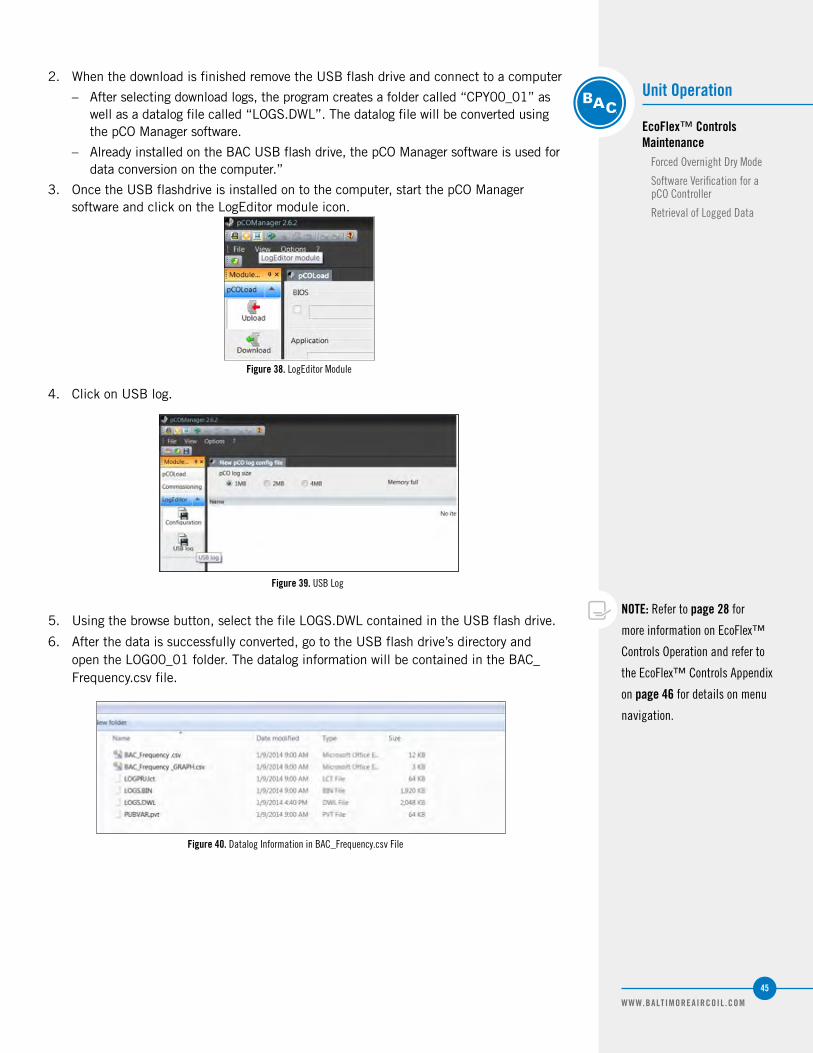
WWW.BALTIMOREAIRCOIL .COM
45
Unit Operation
EcoFlex™ Controls Maintenance
Forced Overnight Dry Mode
Software Verification for a pCO Controller
Retrieval of Logged Data
2. When the download is finished remove the USB flash drive and connect to a computer
– After selecting download logs, the program creates a folder called “CPY00_01” as well as a datalog file called “LOGS.DWL”. The datalog file will be converted using the pCO Manager software.
– Already installed on the BAC USB flash drive, the pCO Manager software is used for data conversion on the computer.”
3. Once the USB flashdrive is installed on to the computer, start the pCO Manager software and click on the LogEditor module icon.
Figure 40. Datalog Information in BAC_Frequency.csv File
Figure 39. USB Log
4. Click on USB log.
5. Using the browse button, select the file LOGS.DWL contained in the USB flash drive.
6. After the data is successfully converted, go to the USB flash drive’s directory and open the LOG00_01 folder. The datalog information will be contained in the BAC_Frequency.csv file.
Figure 38. LogEditor Module
NOTE: Refer to page 28 for
more information on EcoFlex™
Controls Operation and refer to
the EcoFlex™ Controls Appendix
on page 46 for details on menu
navigation.

WWW.BALTIMOREAIRCOIL .COM
46
Problem Possible Cause Solution
Fan Does Not Run
No Power to the Fans
Cycle power on/off the unit.
Confirm that power is applied to the unit at the main disconnect.
Confirm that power is applied to each fan by checking terminals xT1, xT2, xT3 & xT4.
Check all terminals for tightness.
Check power wires at fan's housing.
Check all terminals at Modbus module for tightness.
Fan Internal Fault (For TSDC Only)
Check the LED light on top of the fan for fault codes, refer to section 7.2 of Assembly Instructions ECblue Basic Version UL at www.ziehl-abegg.com for more details.
Control Signal IssueCheck with a meter the control voltage at terminals -V, 10V or mA depending on control
signal.
Ensure a fan speed control signal is being sent to the unit.
Fan Spins Backwards Fan is Off/FaultyTurn the unit off. Allow all fans to stop completely. Check all breakers and power
connections. Restart the unit and ensure all fans are operational.
Fan Does Not Respond to the Control Signal
Communications Fault
Ensure the communications cable is connected to the controller on port J8.
Ensure the communications cable is not cut or damaged.
Ensure the communications cable is properly connected at the fan's motors.
Circuit Breaker Tripped Re-set the circuit breaker.
No Water Sprayor Pump Does Not Runor Pre-Cooler Mode Doesn’t Work
Incorrect Set PointCheck the pre-cool set point on the controller, see page 41. The pump will not run if the
outside air temperature is below 40°F (4.4°C). Note: Pre-Cooler Mode will be initiated only when outside air temperatures are above the set point.
No Water Supply
Ensure water is being supplied to the make up valve (green valve on the left).
If there is a faulty make up valve, contact your local BAC Representative for a replacement.
To check for a faulty sump float, manually raise and lower the float to ensure functionality.
Faulty Pump
Ensure the pump is receiving 120V by checking terminals 2&3 at the bottom left corner of the control panel. For the pump to be energized, the sump needs to be filled with water and
the unit must be in Pre-Cooler Mode.
To check for a faulty drain valve, ensure the valve closes completely when unit is in Pre-Cooler Mode.
Clogged Pump Strainer Clean the pump strainer quarterly.
Spray System FaultEnsure that the pump's isolation valve (TSDC only) is on the open (vertical) position. See
Figure 24 on page 31.
Check for kinks or damage to the internal hoses.
Circuit Breaker Tripped Re-set the circuit breaker.
TRILLIUMSERIES™ ADIABATIC CONDENSER
Troubleshooting Guide6

WWW.BALTIMOREAIRCOIL .COM
47
WWW.BALTIMOREAIRCOIL .COM
47
Problem Possible Causes Checks/Solutions
Uneven Sprayor Dry Sections on Pre-Cooler Pads
Water Distribution System Clogged
TSDC: Clean the spray branches by opening both ends of the distribution header.TSDC2 or TSDF2: Clean the water distribution gutters.
See page 37 for more details on Water Distribution System Maintenance.”
If the water spray system does not work, connect a garden hose to the discrete spray system. For the TSDC, close the pump isolation valve. See “Discrete Spray Connection” on page 31
for more details.
Low PerformanceLack of Maintenance
Inspect the Pre-Cooler Pads monthly and replace as needed. The coils should be inspected quarterly and cleaned as needed.
See page 30 for more details on “Self-Clean Cycle.”
Pre-Cooler Mode Not Working
Check to ensure setpoint is at the desired point. See page 33 for more details.
Scale Formation on Pre-Cooler Pads
Hard Water
Decrease the duration of the daily drain time. See page 41 for more details.
Consider installing a water softener at the facility.
If your unit has a bleed valve, partially open it. This is a substitute for increasing the duration of the daily drain time, mentioned above.
Faulty Drain ValveEnsure the drain valve opens and closes 100%. Otherwise, contact your local BAC
Representative for a replacement.
Excessive Wear on Pre-Cooler Pads
After Few Years, Pads Need to be Replaced
Pre-Cooler Pads should be replaced. Contact your local BAC Representative for replacement or they can be ordered at www.CoolingTowerWorld.com.
Unit Remains in Auto-Discrete Mode
Pump Failure, Make up Valve Failure, or No
WaterSee EcoFlex™ Controls Alarm Descriptions below..
Conductivity Sensor Failure
Clean the sensor and check wiring.
Make sure there is no air trapped at the sensor.
Contact your local BAC representative for a replacement sensor
Replacement PartsTo order replacement parts, contact us at [email protected] or visit www.CoolingTowerWorld.com to place your order today.
Problem Possible Causes Checks/Solutions
Make-up Valve Failure or No Water
Faulty Make-up Valve Contact your local BAC representative for a replacement valve.
No Water in the System Ensure that water is available at the minimum required flow and pressure at all times.
Incoming Water Pressure is Below
BACs Recommended Value (25 psi)
Ensure the water main is not shut down during winter for areas where the temperature drops below freezing.
This alarm could be present if an unusually warm day occurs during the winter. To eliminate this alarm, it is recommended to raise the setpoint of the unit 5-10°F during the winter and
return the setpoint back to normal when the main water lines are reopen for the spring.
Fan Failure – Same as “Fan Does Not Run” on page 44.
Pump Failure Pump is Not Working
Check that all breakers are in the ON position. When the pump is commanded “ON”, verify 120VAC is measured between terminals 2 and 3.
Verify that the pump starter relay C1 is operating correctly.
Verify that the isolation valve located by the pump is fully open.
If problem persists, contact your local BAC representative for a replacement pump kit.
EcoFlex™ Controls Alarm Descriptions

WWW.BALTIMOREAIRCOIL .COM
48
TRILLIUMSERIES™ ADIABATIC PRODUCT
Appendix: EcoFlex™ ControlsaThe BAC TrilliumSeries™ Adiabatic Product controller is the brains of the unit and manages all the peripherals. At lower ambients, the TrilliumSeries™ Adiabatic Product will act like an air cooled condenser or cooler with variable speeds. At higher ambients, the TrilliumSeries™ Adiabatic Product goes into Pre-Cooler Mode which opens the supply valve, fills the sump until the liquid level sensor is satisfied, then turns on the pump to disperse water over the Pre-Cooler Pads. The water will continue to recycle as part of the internal daily drain and cleansing circulation schedules or in the case of the Water Saver option, until the water quality conductivity sensor initiates a dump.
The fans are controlled via an external 0-10V, 10-0V, 4-20mA, BacNet, or Modbus signal from the refrigeration BMS system (based off a condenser discharge pressure setpoint) or via an internal PID loop driven by a pressure sensor of the condenser pressure. Below are details showing the menu structure of the controller and how to navigate it.
Menus
Main Menu
Figure 41. Main Menu
Enter
Up
Down
Alarm
Program
Escape

WWW.BALTIMOREAIRCOIL .COM
49
WWW.BALTIMOREAIRCOIL .COM
49
Enter
Up
Down
Button Name Description
Alarm
This button will illuminate red when an alarm is present in the unit; by
pressing it, the display will show the alarm description.
PrgPressing this button will display all
the main submenus.
EscPressing this button will bring the menu back to the previous screen.
Up and DownThese buttons will allow the used to
scroll up & down.
EnterPressing this button will accept any
changes made in the unit.
By pressing Esc, the main menu is shown. The main screen has six buttons:
Status MenuThe status menu provides information about the operation status of the unit as well as the means to customize some parameters for the site.
Figure 42. Status Screen
As shown above in Figure 41, the main status screen communicates information about:
• Time and Date
• Outside Air Temperature
• Fan Speed
• Unit’s mode of operation (Precool or Dry Mode)
• Alarms[1]
– If the alarms option was purchased and an alarm was activated, an alarm note would display here.
NOTE: 1. Optional features that might not
be included in your unit.
Appendix a: EcoFlex™ Controls
MenusMain Menu
Status Menu

WWW.BALTIMOREAIRCOIL .COM
50
In the next few screens, additional parameters can be viewed and modified. To access those screens, press enter.
As described on page 47, scroll through the menus using the up/down arrows. To change an item, press enter, scroll to the item, and press enter. Once the item value starts to flash, use the up/down arrows to modify the value and press enter to set the value.
Figure 43. Modifiable Parameters in Status Menu• Temperature setpoint
• Gas Temperature/Pressure
• Self-Clean Cycle screen (see page 41 for more details)
• Manual Precool on/off
• Daily Drain parameters
• Forced Overnight Dry Operation (see page 42 for more details)
• Default, Energy Save or Water save mode (see page 28 for more details)
• Fan Power, voltage, current and motor Temperature[1] (view only)
SubmenusThe main menu displays the three submenus available – Status, Technician, and Factory.
NOTE: 1. Optional features that might not
be included in your unit.
Figure 44. Submenus
• Status: Goes back to the default Status screen as described on page 47.
• Technician: See page 49 for more information.
• Factory: This menu is password protected and only available for BAC factory personnel.

WWW.BALTIMOREAIRCOIL .COM
51
Appendix a: EcoFlex™ Controls
MenusSubmenus
Technician MenuThis menu is password protected (1703) and provides access to several submenus that allow the user to make changes on the settings of the unit and test every control. It also allows the user to place the valves, pump or fans in manual mode. The technician menu has four submenus described below.
1. Diagnostics: This submenu will display all the current operating conditions of the unit and all the set points. The following information can be viewed and modified from this menu:
– Outside Air Temperature
– Gas Pressure[1]
– Gas Temperature[1]
– Mode of operation
– Manual Precool
– Pump Proof
– Float Switch
– Conductivity
– Water Pump
– Dump Valve
– Make-up Valve
– Fan Speed
– Fan Request
– Outside Air Setpoint
– Outside Air Differential
– Drain time
– Cycle
– Daily Drain Time
– Daily Drain Duration
– Pump on Delay
– Pump/Make-up Delay
– Make-up off Delay
– Pump Fail Delay
– Press Fail Delay
– Make-up Fail Delay
– High Head Pressure Alarm Setpoint
– High Head Pressure Alarm Delay
– Antifreeze Protection Setpoint
– Unit Mode
– Auto-Discrete Backup System[1]
NOTE: 1. Optional features that might not
be included in your unit.
Figure 45a. Diagnostics Figure 45b. Diagnostics
Figure 45c. Diagnostics Figure 45d. Diagnostics
Figure 45e. Diagnostics Figure 45f. Diagnostics

WWW.BALTIMOREAIRCOIL .COM
52
2. Information: This submenu allows the user to view the software version, the BIOS, and the dates of the latest update.
3. Manual Control: This submenu allows the user to manually control the valves, the fans, the pump, and all other analog and digital inputs and outputs. Note, after 15 minutes in inactivity, the controller will revert back into automatic operation of the components. The following items can be manually controlled:
– Fans
– Water Pump
– Dump Valve
– Make-up Valve
– General Alarm
– Outside Air Temperature
– Float Switch
– Pre-Cooler Mode
– Pump Proof - a current detecting switch on the pump; it closes if the pump runs and signals to the controller that the pump draws power
4. Clock: This submenu will allow the user to set the date and time on the controller.
Datalogging
If you have purchased the Energy Monitoring Package with your TrilliumSeries™ Adiabatic Product, the EcoFlex™ Controls stores historical data from the unit and make it available for downloading using a USB flash drive. The parameters are recorded every 10 minutes (adjustable). When the total memory of the controller is 90% used, the new data override the oldest set of data. Datalog files are stored in an excel format. Datalog inputs are selectable from the interface screen.
The following parameters are recorded:
– Date and time of day
– Outside Air Temperature
– Fan Speed
– Pump Status
– Make-up valve position
– Dump Valve
– kW
– All alarms
– Head Pressure [1] (only for units with the Head Pressure Control Package)
– Conductivity [1] (only for units with the optional Water Monitoring Package)
NOTE: 1. Optional parameters only
recorded if the applicable feature is purchased.

WWW.BALTIMOREAIRCOIL .COM
53
Type Screen Name DescriptionDefault Value
Adjustable Range Comments
M Time & Date — — — —
VOutside Air
Temperature— — — —
M Fan Speed Manually adjust fan speed — 0-100% —
V Mode of OperationDry Mode - Pre-Cooler Mode - Flush Mode - Self-Clean Cycle
— — —
V AlarmsIndicates if any alarms are
faulted— —
Alarms are not self-clearing. After resolution of the issue, the Alarm button on the screen must be pressed and held to clear the alarm.
'Commandable Values' Screen - Main Menu
M Outside Air SetpointTemperature at which unit goes
to Pre-Cooler Mode
MCWB for shipped-to
city40-120°F —
M Force Precool Manually enable Precool Mode — Open/Closed —
M Daily DrainTime of the day the daily drain
occurs2:00 AM
12:00 AM-11:59 PM
NOTE: For multiple units at one site, recommended to stagger daily drains by a few minutes
M Drain DurationDuration of the daily drain
cycle
5 min TSDC240 min TSDC2
1-480 min
NOTE: Note: In climates where the dry bulb does not dip below the setpoint, force an overnight dry cycle by setting the drain duration to 250- 480 minutes and the drain time to an evening hour. This will ensure the pads maintain a long life and algae-free operation by drying overnight. See
page 34 for more information.WARNING: Adjusting this variable to less than 2 minutes will prevent proper unit cleaning and
will void the unit warranty.
M Make-up DurationDuration of make-up valve
being open during daily drain10 min TSDC7 min TSDC2
10-99 minThe make-up duration will be shorter than the daily drain timer. If the daily drain duration is
set for longer than the makeup duration, the unit will operate dry for the remainder of the drain duration time.
'BMS Configuration' Screen - Main Menu
V BMS CommunicationDetails on digital communication
— — Only present w/ 'Modbus / BACNet communication' Control Option (see page 15)
Self-Clean Cycle - Main Menu
M Auto Fan Clean Self-Clean Cycle On On/Off Included with every unit.
M Time OnTime of day Self-Clean Cycle
activates5:45 AM
12:00 AM-11:59 PM
It is recommended that this time be set to a less noise-sensitive time of day due to the fans running at full speed in reverse.
M Time Duration Duration of Self-Clean Cycle 180 sec 20-999 secNOTICE: Setting the self-clean cycle for shorter than the default time will reduce the unit’s ability
to clean itself.
M Temp MinMinimum Temp at which Self-Clean Cycle operates
40°F 30-99°F NOTICE: To protect the coil, keep the min temp > 35°F
M Temp MaxMaximum Temp at which Self-Clean Cycle operates
90°F 30-99°F —
‘Auto-Discrete’ Mode – Diagnostics - Technician Menu[1]
M Enable Auto-Discrete Mode Yes Yes/No Only present w/ ‘Water Saver Package with Auto-Discrete Spray System Option’ (See page 32.)
M AutoD Time Duration of Auto-Discrete Mode 120 min60 min - 240
min
This is the amount of time the unit will remain in Auto-Discrete. After this timer expires the system will “check” the condition of the pump, make-up valve, and float and resume operation
accordingly.
M LowCond DelayDuration of time the
conductivity sensor must read below 200 µS
5 min2 min - 240
minThis timer will only take effect is the unit is giving the pump command.
Unit Mode - Main Menu
M Unit ModeEnergy/Water favoritism mode
of preference
NONpageE, Water, Energy
See page 23.
Diagnostics Mode - Technician Menu
V OA Temp DifferentialDead Band for precool
activation below setpoint3°F 0-9.9°F CAUTION: Lowering the value below 1°F will result in significant cycling of the water system.
V OA Temp Off Delay
Delay between when temp sensor indicates to turn
Pre-Coolers off, and when the pump is turned off
10min 0-99 min —
NOTE: 1. Optional features that might not be included in your unit.
2. V=Viewable, M=Modifiable, R=Read Only, and W=Read/Write.
Table 8. Complete EcoFlex™ Controls Menu Listing

WWW.BALTIMOREAIRCOIL .COM
54
Type Screen Name DescriptionDefault Value
Adjustable Range Comments
Diagnostics Mode - Technician Menu Continued
M Fan Speed Manually adjust fan speed 0-100% —
V Conductivity[1] Conductivity of basin water (0-2000μS). Only present w/ "Water Monitoring Package" (See page 28)[1]
M Drain TimeDuration of the periodic flush
used for bleed
120 sec TSDC480 sec TSDC2
0-999 secCAUTION: Lowering this value may result in scaling the unit. Increasing this value may result in
increased water usage
M CycleHow far apart the periodic flush
cycles are2 hrs 1-22 hrs NOTE: This variable is not used with the "Water Saver" Option
V Pump On DelayDelay after float switch closes
before pump turns on5 sec 0-20 sec —
VPump/Make-up
DelayDelay after float switch opens
before pump turns off
35 sec TSDC100 sec TSDC2
0-999 sec —
V Make-up on DelayDelay after float switch opens before Make-up valve opens
30 sec TSDC10 sec TSDC2
0-99 sec —
V Make-up off DelayDelay after float switch closes before Make-up valve turns off
10 secTSDC
30 sec TSDC20-999 sec
CAUTION: Increasing this value may result in increased water usage, with water spilling into the overflow
V Pump Fail DelayAllowable delay between pump
activation and pump proof received before alarm trips
30 sec 0-999 sec —
V Press Fail Delay
Allowable delay between sensor signal going above/below
acceptable range and alarm tripping
10 sec 0-999 sec —
V Make-up Fail DelayAllowable time for Make-up to be on and float-switch to not be made before alarm trips
180 sec TSDC1,800 TSDC2
0-2,000 sec
MHigh Head Pressure
Alarm Setpoint[1]
High head pressure alarm setpoint
500psi 0-3000psi Only present w/ 'Head Pressure' Control Option (see page 15)[1]
MHigh Head Pressure
Alarm Delay[1]
Delay before high pressure alarm activates
30 sec 0-999 sec Only present w/ ‘Head Pressure’ Control Option (see page 15)[1]
MAntifreeze protection
setpointTemperature below which Pre-
Cooler Mode is disabled40°F 0-100°F
WARNING: Adjusting this value to below 35°F will void the warranty, and may cause damage to the unit. Increasing the value will limit the wet operation.
M Gas Pressure[1] — — — Only present w/ ‘Head Pressure’ Control Option (see page 15)[1]
M Gas Temperature[1] — — — Only present w/ ‘Head Pressure’ Control Option (see page 15)[1]
VFan Power, Voltage, Current, Motor Temp
Fan/Motor information — — —
Manual Control - Technician Menu
V Pump ProofCheck whether pump is
energized— — —
V Float SwitchCheck whether float switch
is made— — —
M Water Pump Manually turn on/off pump — Open/Closed —
M Dump ValveManually turn on/off dump
valve— Open/Closed —
M Make-up valveManually turn on/off make-up
valve— Open/Closed —
V Fan RequestFan Speed control voltage that
the controller receives from customer analog input
—0-10V/10-0V/4-20mA
—
NOTE: 1. Optional features that might not be included in your unit.
2. V=Viewable, M=Modifiable, R=Read Only, and W=Read/Write.
Table 8. Complete EcoFlex™ Controls Menu Listing (Continued)

WWW.BALTIMOREAIRCOIL .COM
55
Type Screen Name DescriptionDefault Value
Adjustable Range Comments
Diagnostics Mode - Technician Menu Continued
M Fan Speed Manually adjust fan speed 0-100% —
V Conductivity[1] Conductivity of basin water (0-2000μS). Only present w/ "Water Monitoring Package" (See page 28)[1]
M Drain TimeDuration of the periodic flush
used for bleed
120 sec TSDC480 sec TSDC2
0-999 secCAUTION: Lowering this value may result in scaling the unit. Increasing this value may result in
increased water usage
M CycleHow far apart the periodic flush
cycles are2 hrs 1-22 hrs NOTE: This variable is not used with the "Water Saver" Option
V Pump On DelayDelay after float switch closes
before pump turns on5 sec 0-20 sec —
VPump/Make-up
DelayDelay after float switch opens
before pump turns off
35 sec TSDC100 sec TSDC2
0-999 sec —
V Make-up on DelayDelay after float switch opens before Make-up valve opens
30 sec TSDC10 sec TSDC2
0-99 sec —
V Make-up off DelayDelay after float switch closes before Make-up valve turns off
10 secTSDC
30 sec TSDC20-999 sec
CAUTION: Increasing this value may result in increased water usage, with water spilling into the overflow
V Pump Fail DelayAllowable delay between pump
activation and pump proof received before alarm trips
30 sec 0-999 sec —
V Press Fail Delay
Allowable delay between sensor signal going above/below
acceptable range and alarm tripping
10 sec 0-999 sec —
V Make-up Fail DelayAllowable time for Make-up to be on and float-switch to not be made before alarm trips
180 sec TSDC1,800 TSDC2
0-2,000 sec
MHigh Head Pressure
Alarm Setpoint[1]
High head pressure alarm setpoint
500psi 0-3000psi Only present w/ 'Head Pressure' Control Option (see page 15)[1]
MHigh Head Pressure
Alarm Delay[1]
Delay before high pressure alarm activates
30 sec 0-999 sec Only present w/ ‘Head Pressure’ Control Option (see page 15)[1]
MAntifreeze protection
setpointTemperature below which Pre-
Cooler Mode is disabled40°F 0-100°F
WARNING: Adjusting this value to below 35°F will void the warranty, and may cause damage to the unit. Increasing the value will limit the wet operation.
M Gas Pressure[1] — — — Only present w/ ‘Head Pressure’ Control Option (see page 15)[1]
M Gas Temperature[1] — — — Only present w/ ‘Head Pressure’ Control Option (see page 15)[1]
VFan Power, Voltage, Current, Motor Temp
Fan/Motor information — — —
Manual Control - Technician Menu
V Pump ProofCheck whether pump is
energized— — —
V Float SwitchCheck whether float switch
is made— — —
M Water Pump Manually turn on/off pump — Open/Closed —
M Dump ValveManually turn on/off dump
valve— Open/Closed —
M Make-up valveManually turn on/off make-up
valve— Open/Closed —
V Fan RequestFan Speed control voltage that
the controller receives from customer analog input
—0-10V/10-0V/4-20mA
—
TRILLIUMSERIES™ ADIABATIC CONDENSER
Appendix: Danfoss and Emerson CPC Rack Controllers bThe settings shown below for Danfoss and Emerson CPC are recommended starting settings based on BAC’s experience with TrilliumSeries™ Products in the field. However, all sites are different and may require additional tuning. Please contact BAC for additional assistance if required.
Danfoss
Step 1. From the Main Menu select Configuration. Step 2. From Configuration select Refrigeration.
Step 3. From Rack Configuration select Rack. Step 4. From Configure Rack select Condensers.
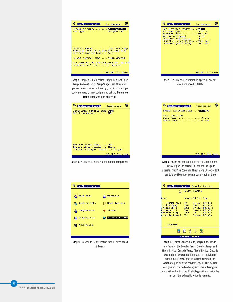
WWW.BALTIMOREAIRCOIL .COM
56
Step 5. Program as: Air cooled, Single Fan, Sat Cond Temp, Ambient Temp, Ramp Stages, set Min cond T
per customer spec or rack design, set Max cond T per customer spec or rack design, and set the Condenser
Delta T per wet bulb design TD.
Step 6. PG DN and set Minimum speed 1.0%, set Maximum speed 100.0%.
Step 7. PG DN and set Individual outside temp to Yes. Step 8. PG DN set the Normal Reaction Zone 60.0psi. This will give the normal PID the max range to
operate. Set Plus Zone and Minus Zone 60 sec – 120 sec to slow the out of normal zone reaction time.
Step 9. Go back to Configuration menu select Board & Points
Step 10. Select Sensor Inputs, program the Bd-Pt and Type for the Dropleg Press, Dropleg Temp, and
the individual Outside Temp. The individual Outside (Example below Outside Temp A is the individual)
should be a sensor that is located between the Adiabatic pad and the condenser coil. This sensor will give you the coil entering air. This entering air
temp will make it so the TD strategy will work with dry air or if the adiabatic water is running.

WWW.BALTIMOREAIRCOIL .COM
57
Step 11. Go back to the Main Menu and select Refrigeration.
Step 12. Select the Rack.
Step 13. Select Condenser. Step 14. Select Settings, starter setting: Linear Factor 2.0, Sensitivity 4.0. If saturated condensing temp
swings more than plus or minus a few degrees F then increase Sensitivity to reduce swing.
Appendix b: Danfoss and Emerson
Danfoss

WWW.BALTIMOREAIRCOIL .COM
58
Emerson
Step 1. From the general tab setting, select the above options.
NOTE: If you are using a blend gas
like R-407A in this example you
may want to find a gas that follows
the correct curve for the bubble.
CPC’s conversion does not do Dew &
Bubble it just splits the difference.
So for the SAT conversion your
conversion will always be off by half
the glide. For R-407A R-404A has
about the same bubble curve.
Step 2. Here are the setpoint tab settings. The two setpoints you will need to check are in bold. The TEMP DIF STPT will depend on your condenser’s TD design. For the TrilliumSeries™ Adiabatic Condenser, it will most
likely be 15°F – 20°F. The TR Temperature 10 should be good but may need a little adjustment.

WWW.BALTIMOREAIRCOIL .COM
59
Step 3. The Advanced tab: PID settings should be entered into this tab as shown above.
Appendix b: Danfoss and Emerson
Emerson

WWW.BALTIMOREAIRCOIL .COM
60
WWW.BALTIMOREAIRCOIL .COM
60
Spare Parts Available on Cooling Tower World• Pre-cooler Pad Kit
• Pump Replacement Kit
• Spray Piping Kit
• Float Switch
• Make-Up Valve
• Dump Valve
• Strainer Replacement
• Spare Fans
• Spare Coils
• and more!
BAC’s Factory Authorized Parts are manufactured to meet rigourous cooling tower duty specifications and are guaranteed to fit your unit and perform as original equipment.
BAC is proud to introduce Cooling Tower World, the only place to purchase BAC Factory Authorized Parts online. All Cooling Tower Parts are shipped second day and carry a full 1-year warranty backed by BAC. To purchase parts online, visit www.CoolingTowerWorld.com today.
BAC Factory Authorized Parts can also be ordered through your local BAC Representative. In addition, most BAC Representatives maintain a local inventory of commonly used parts. For a free unit inspection, call your local BAC Representative today.
Even with this fast delivery capability, it is still recommended that certain essential, emergency repair parts be maintained in your local inventory to minimize any potential downtime.
Recommended Spare Parts
P a r t s a v a i l a b l e f o r p u r c h a s e a t w w w .
C o o l i n g T o w e r W o r l d . c o m

RIGGING, INSTALLATION, OPERATION & MAINTENANCE MANUAL
COOLING TOWERS
CLOSED CIRCUIT COOLING TOWERS
ICE THERMAL STORAGE
EVAPORATIVE CONDENSERS
HYBRID PRODUCTS
PARTS & SERVICES
w w w . B a l t i m o r e A i r c o i l . c o m
7600 Dorsey Run Road, Jessup, MD 20794 › Telephone: (410) 799-6200 › Fax: (410) 799-6416
© 2020 Baltimore Aircoil Company › M450/6-E