Embed Size (px)
Citation preview

Tribomatic II ManualPowder Spray Gun
Customer Product ManualPart 1098020A
Issued 9/09
NORDSON CORPORATION • AMHERST, OHIO • USA
For parts and technical support, call the Finishing Customer Support Center at (800) 433-9319.
Check http://emanuals.nordson.com/finishing for the latest version.This document is subject to change without notice.

Part 1098020A � 2009 Nordson Corporation
Table of ContentsSafety 1. . . . . . . . . . . . . . . . . . . . . . . . . . . . . . . . . . . . . . .
Qualified Personnel 1. . . . . . . . . . . . . . . . . . . . . . . . .Intended Use 1. . . . . . . . . . . . . . . . . . . . . . . . . . . . . .Regulations and Approvals 1. . . . . . . . . . . . . . . . . .Personal Safety 2. . . . . . . . . . . . . . . . . . . . . . . . . . . .Fire Safety 2. . . . . . . . . . . . . . . . . . . . . . . . . . . . . . . .Grounding 3. . . . . . . . . . . . . . . . . . . . . . . . . . . . . . . . .Action in the Event of a Malfunction 3. . . . . . . . . . .Disposal 3. . . . . . . . . . . . . . . . . . . . . . . . . . . . . . . . . .Safety Label 4. . . . . . . . . . . . . . . . . . . . . . . . . . . . . . .
Description 5. . . . . . . . . . . . . . . . . . . . . . . . . . . . . . . . . .Introduction 5. . . . . . . . . . . . . . . . . . . . . . . . . . . . . . . .Spray Gun Components 6. . . . . . . . . . . . . . . . . . . . .Theory of Operation 6. . . . . . . . . . . . . . . . . . . . . . . .
Installation 7. . . . . . . . . . . . . . . . . . . . . . . . . . . . . . . . . .Typical System Connections 7. . . . . . . . . . . . . . . . .
Operation 9. . . . . . . . . . . . . . . . . . . . . . . . . . . . . . . . . . .Air Pressure Settings 9. . . . . . . . . . . . . . . . . . . . . . . .Daily Maintenance 9. . . . . . . . . . . . . . . . . . . . . . . . . .
Troubleshooting 11. . . . . . . . . . . . . . . . . . . . . . . . . . . . .
Repair 13. . . . . . . . . . . . . . . . . . . . . . . . . . . . . . . . . . . . . .Preparing for Disassembly 13. . . . . . . . . . . . . . . . . . .Charge Module Service Kit Installation 14. . . . . . . .Inner and Outer Wear Sleeve Replacement 17. . . .Handle Repair 18. . . . . . . . . . . . . . . . . . . . . . . . . . . . .
Handle Disassembly 18. . . . . . . . . . . . . . . . . . . . .Handle Assembly 19. . . . . . . . . . . . . . . . . . . . . . . .
Parts 20. . . . . . . . . . . . . . . . . . . . . . . . . . . . . . . . . . . . . . .Spray Gun Parts 20. . . . . . . . . . . . . . . . . . . . . . . . . . .Diffuser 24. . . . . . . . . . . . . . . . . . . . . . . . . . . . . . . . . . . .
Service Kits 25. . . . . . . . . . . . . . . . . . . . . . . . . . . . . . . . . .Charge Module Service Kit 25. . . . . . . . . . . . . . . . . . .Inner/Outer Wear Sleeve Service Kit 26. . . . . . . . . .Handle Service Kit 27. . . . . . . . . . . . . . . . . . . . . . . . .Positioning and Spacing Ring Service Kit 27. . . . . .
Options 28. . . . . . . . . . . . . . . . . . . . . . . . . . . . . . . . . . . . .Sprayheads and Nozzles 28. . . . . . . . . . . . . . . . . . . .Deflectors 28. . . . . . . . . . . . . . . . . . . . . . . . . . . . . . . . .Powder Feed Hose and Air Tubing 28. . . . . . . . . . . .PTFE Charge Module Service Kit 29. . . . . . . . . . . . .
Contact UsNordson Corporation welcomes requests for information, comments, andinquiries about its products. General information about Nordson can befound on the Internet using the following address:http://www.nordson.com.Address all correspondence to:
Nordson CorporationAttn: Customer Service555 Jackson StreetAmherst, OH 44001
NoticeThis is a Nordson Corporation publication which is protected by copyright.Original copyright date 2009. No part of this document may bephotocopied, reproduced, or translated to another language without theprior written consent of Nordson Corporation. The information containedin this publication is subject to change without notice.
Trademarks
Tribomatic, Vantage, Nordson, and the Nordson logo are registeredtrademarks of Nordson Corporation.
Viton is a registered trademark of DuPont Performance Elastomers. L.L.C.
Tivar is a registered trademark of Poly Hi / Solidur, Inc.

Tribomatic II Manual Powder Spray Gun 1
Part 1098020A� 2009 Nordson Corporation
Tribomatic II Manual Powder Spray Gun
Safety Read and follow these safety instructions. Task- and equipment-specificwarnings, cautions, and instructions are included in equipmentdocumentation where appropriate.
Make sure all equipment documentation, including these instructions, isaccessible to all persons operating or servicing equipment.
Qualified Personnel Equipment owners are responsible for making sure that Nordson equipmentis installed, operated, and serviced by qualified personnel. Qualifiedpersonnel are those employees or contractors who are trained to safelyperform their assigned tasks. They are familiar with all relevant safety rulesand regulations and are physically capable of performing their assignedtasks.
Intended Use Use of Nordson equipment in ways other than those described in thedocumentation supplied with the equipment may result in injury to personsor damage to property.
Some examples of unintended use of equipment include
� using incompatible materials
� making unauthorized modifications
� removing or bypassing safety guards or interlocks
� using incompatible or damaged parts
� using unapproved auxiliary equipment
� operating equipment in excess of maximum ratings
Regulations and Approvals Make sure all equipment is rated and approved for the environment in whichit is used. Any approvals obtained for Nordson equipment will be voided ifinstructions for installation, operation, and service are not followed.
All phases of equipment installation must comply with all federal, state, andlocal codes.

Tribomatic II Manual Powder Spray Gun2
Part 1098020A � 2009 Nordson Corporation
Personal Safety To prevent injury follow these instructions.
� Do not operate or service equipment unless you are qualified.
� Do not operate equipment unless safety guards, doors, or covers areintact and automatic interlocks are operating properly. Do not bypass ordisarm any safety devices.
� Keep clear of moving equipment. Before adjusting or servicing anymoving equipment, shut off the power supply and wait until theequipment comes to a complete stop. Lock out power and secure theequipment to prevent unexpected movement.
� Relieve (bleed off) hydraulic and pneumatic pressure before adjusting orservicing pressurized systems or components. Disconnect, lock out,and tag switches before servicing electrical equipment.
� Obtain and read Material Safety Data Sheets (MSDS) for all materialsused. Follow the manufacturer’s instructions for safe handling and useof materials, and use recommended personal protection devices.
� To prevent injury, be aware of less-obvious dangers in the workplacethat often cannot be completely eliminated, such as hot surfaces, sharpedges, energized electrical circuits, and moving parts that cannot beenclosed or otherwise guarded for practical reasons.
Fire Safety To avoid a fire or explosion, follow these instructions.
� Do not smoke, weld, grind, or use open flames where flammablematerials are being used or stored.
� Provide adequate ventilation to prevent dangerous concentrations ofvolatile materials or vapors. Refer to local codes or your material MSDSfor guidance.
� Do not disconnect live electrical circuits while working with flammablematerials. Shut off power at a disconnect switch first to preventsparking.
� Know where emergency stop buttons, shutoff valves, and fireextinguishers are located. If a fire starts in a spray booth, immediatelyshut off the spray system and exhaust fans.
� Clean, maintain, test, and repair equipment according to the instructionsin your equipment documentation.
� Use only replacement parts that are designed for use with originalequipment. Contact your Nordson representative for parts informationand advice.

Tribomatic II Manual Powder Spray Gun 3
Part 1098020A� 2009 Nordson Corporation
Grounding
WARNING: Operating faulty electrostatic equipment is hazardous and cancause electrocution, fire, or explosion. Make resistance checks part of yourperiodic maintenance program. If you receive even a slight electrical shockor notice static sparking or arcing, shut down all electrical or electrostaticequipment immediately. Do not restart the equipment until the problem hasbeen identified and corrected.
Grounding inside and around the booth openings must comply with NFPArequirements for Class II Division 1 or 2 Hazardous Locations. Refer toNFPA 33, NFPA 70 (NEC articles 500, 502, and 516), and NFPA 77, latestconditions.
� All electrically conductive objects in the spray areas shall be electricallyconnected to ground with a resistance of not more than 1 megohm asmeasured with an instrument that applies at least 500 volts to the circuitbeing evaluated.
� Equipment to be grounded includes, but is not limited to, the floor of thespray area, operator platforms, hoppers, photoeye supports, andblow-off nozzles. Personnel working in the spray area must begrounded.
� There is a possible ignition potential from the charged human body.Personnel standing on a painted surface, such as an operator platform,or wearing non-conductive shoes, are not grounded. Personnel mustwear shoes with conductive soles or use a ground strap to maintain aconnection to ground when working with or around electrostaticequipment.
� Operators must maintain skin-to-handle contact between their hand andthe gun handle to prevent shocks while operating manual electrostaticspray guns. If gloves must be worn, cut away the palm or fingers, wearelectrically conductive gloves, or wear a grounding strap connected tothe gun handle or other true earth ground.
� Shut off electrostatic power supplies and ground gun electrodes beforemaking adjustments or cleaning powder spray guns.
� Connect all disconnected equipment, ground cables, and wires afterservicing equipment.
Action in the Event of a Malfunction If a system or any equipment in a system malfunctions, shut off the systemimmediately and perform the following steps:
� Disconnect and lock out electrical power. Close pneumatic shutoffvalves and relieve pressures.
� Identify the reason for the malfunction and correct it before restarting theequipment.
Disposal Dispose of equipment and materials used in operation and servicingaccording to local codes.
Tribomatic II Manual Powder Spray Gun4
Part 1098020A � 2009 Nordson Corporation
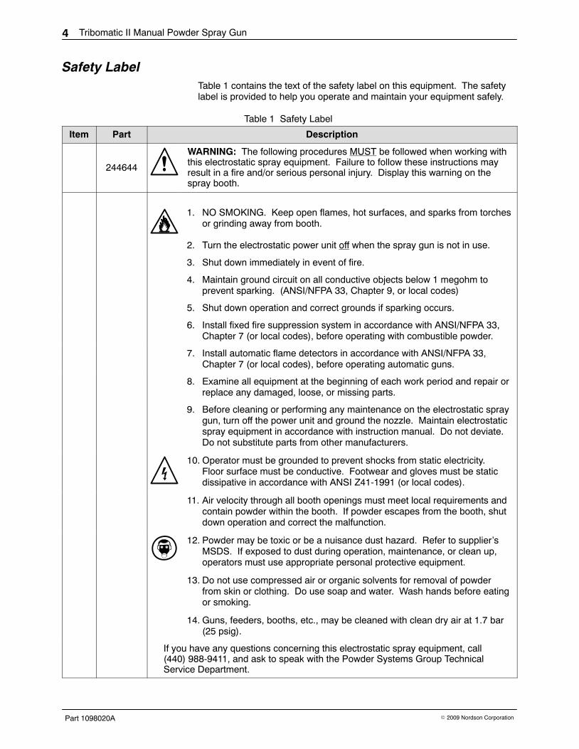
Safety Label Table 1 contains the text of the safety label on this equipment. The safetylabel is provided to help you operate and maintain your equipment safely.
Table 1 Safety Label
Item Part Description
244644
WARNING: The following procedures MUST be followed when working withthis electrostatic spray equipment. Failure to follow these instructions mayresult in a fire and/or serious personal injury. Display this warning on thespray booth.
1. NO SMOKING. Keep open flames, hot surfaces, and sparks from torchesor grinding away from booth.
2. Turn the electrostatic power unit off when the spray gun is not in use.
3. Shut down immediately in event of fire.
4. Maintain ground circuit on all conductive objects below 1 megohm toprevent sparking. (ANSI/NFPA 33, Chapter 9, or local codes)
5. Shut down operation and correct grounds if sparking occurs.
6. Install fixed fire suppression system in accordance with ANSI/NFPA 33,Chapter 7 (or local codes), before operating with combustible powder.
7. Install automatic flame detectors in accordance with ANSI/NFPA 33,Chapter 7 (or local codes), before operating automatic guns.
8. Examine all equipment at the beginning of each work period and repair orreplace any damaged, loose, or missing parts.
9. Before cleaning or performing any maintenance on the electrostatic spraygun, turn off the power unit and ground the nozzle. Maintain electrostaticspray equipment in accordance with instruction manual. Do not deviate.Do not substitute parts from other manufacturers.
10. Operator must be grounded to prevent shocks from static electricity.Floor surface must be conductive. Footwear and gloves must be staticdissipative in accordance with ANSI Z41-1991 (or local codes).
11. Air velocity through all booth openings must meet local requirements andcontain powder within the booth. If powder escapes from the booth, shutdown operation and correct the malfunction.
12. Powder may be toxic or be a nuisance dust hazard. Refer to supplier’sMSDS. If exposed to dust during operation, maintenance, or clean up,operators must use appropriate personal protective equipment.
13. Do not use compressed air or organic solvents for removal of powderfrom skin or clothing. Do use soap and water. Wash hands before eatingor smoking.
14. Guns, feeders, booths, etc., may be cleaned with clean dry air at 1.7 bar(25 psig).
If you have any questions concerning this electrostatic spray equipment, call(440) 988-9411, and ask to speak with the Powder Systems Group TechnicalService Department.

Tribomatic II Manual Powder Spray Gun 5
Part 1098020A� 2009 Nordson Corporation
Description
IntroductionThe Tribomatic II manual powder spray gun uses friction to electrostaticallycharge powder coatings as they are forced through the gun by compressedair. The spray gun is used with a Vantage� control unit and a Tribomatic IIpowder pump.
The spray gun can be retrofitted into an existing Nordson Tribomatic orVersa-Spray system and used with older-style Tribomatic powder pumps. Itis equipped with a 6-meter (19.7 ft) trigger cable.
Figure 1 Tribomatic II Manual Gun
The spray gun is made of PTFE and Tivar. These materials are used withmost organic powder coatings. Table 2 describes the characteristics ofTivar and PTFE and their use.
Table 2 Material Description and Usage
Material Appearance Usage
Tivar Greyish, translucentwhite
Standard material for inlet and outlet distributors and wearsleeves in manual guns. Longer wear-life than PTFE, butsome powders may impact-fuse to Tivar. Switch to PTFE ifimpact-fusion is a problem.
PTFE Opaque white Standard material for inlet and outlet distributors and wearsleeves in automatic guns. Optional for manual guns. Shorterwear-life than Tivar, but reduces or eliminates impact-fusion.
Refer to Options on page 28 for optional equipment for this spray gun.
The sprayheads and nozzles used with Tribomatic automatic spray gunscan be used in place of the standard nozzle and deflector shown inFigure 1. Refer to the Tribomatic Optional Nozzles and Sprayheads sheet,part number 1040999A.
Tribomatic II Manual Powder Spray Gun6
Part 1098020A � 2009 Nordson Corporation
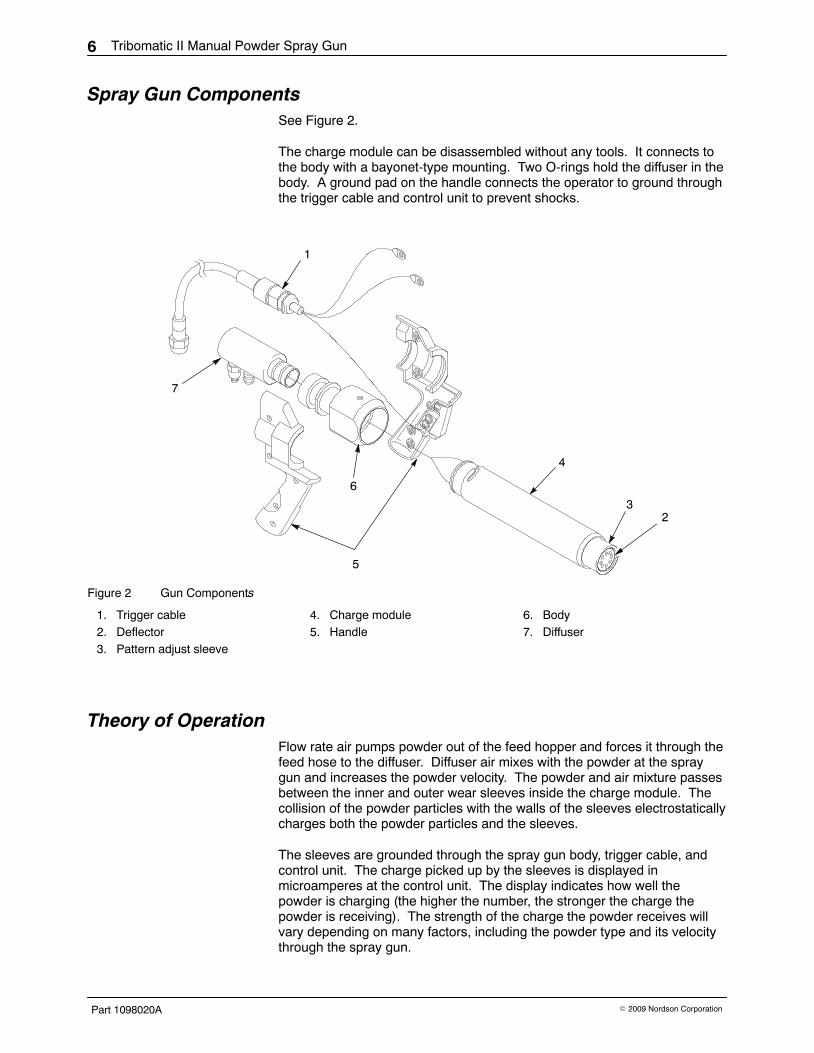
Spray Gun ComponentsSee Figure 2.
The charge module can be disassembled without any tools. It connects tothe body with a bayonet-type mounting. Two O-rings hold the diffuser in thebody. A ground pad on the handle connects the operator to ground throughthe trigger cable and control unit to prevent shocks.
3
5
2
6
7
1
4
Figure 2 Gun Components
1. Trigger cable2. Deflector3. Pattern adjust sleeve
4. Charge module5. Handle
6. Body7. Diffuser
Theory of Operation Flow rate air pumps powder out of the feed hopper and forces it through thefeed hose to the diffuser. Diffuser air mixes with the powder at the spraygun and increases the powder velocity. The powder and air mixture passesbetween the inner and outer wear sleeves inside the charge module. Thecollision of the powder particles with the walls of the sleeves electrostaticallycharges both the powder particles and the sleeves.
The sleeves are grounded through the spray gun body, trigger cable, andcontrol unit. The charge picked up by the sleeves is displayed inmicroamperes at the control unit. The display indicates how well thepowder is charging (the higher the number, the stronger the charge thepowder is receiving). The strength of the charge the powder receives willvary depending on many factors, including the powder type and its velocitythrough the spray gun.

Tribomatic II Manual Powder Spray Gun 7
Part 1098020A� 2009 Nordson Corporation
Installation WARNING: Allow only qualified personnel to perform the following tasks.Follow the safety instructions in this document and all other relateddocumentation.
WARNING: All electrically conductive equipment in the spray area must begrounded. Ungrounded or poorly grounded equipment can store anelectrostatic charge which can give personnel a severe shock or arc andcause a fire or explosion.
Typical System ConnectionsSee Figure 3.
Connection Tubing Size Connection Connect To
Ground Wires with Clamp(Control Unit and Hopper) — True earth ground
Fluidizing Air Tubing (Blue) 10-mm OD Powder feed hopperfluidizing air fitting
Atomizing Air Tubing (Blue) 6-mm OD Diffuser (use 8-mm stem x6-mm tubing reducer)
Flow-rate Air Tubing (Black) 6-mm ODPowder pump (use 8-mmstem x 6-mm tubingreducer)
Powder Feed Hose 12.7-mm(1/2-in.) ID − Powder pump outlet;
diffuser inlet
Spray Gun Cable —GUN OUTPUT
Tighten cable nut to 6 N�m(4.4 ft-lb).
Spray gun (prewired)
POWER INPUT Cable — POWER INPUT (prewired)Plug or eletrical panel85−250 Vac, 1 phase,50−60 Hz, 40 VA
Air Supply Tubing (Blue) 10-mm ODIN
0−100 PSI0−7 BAR
Main air supply
NOTE: Bundle powder feed hose, cable, and diffuser air tubing with spiral-cut tubing. Install a few inchesof spiral-cut tubing at the hose connections and at any bend in the hose to prevent the hose from kinkingand blocking the flow of powder.

Tribomatic II Manual Powder Spray Gun8
Part 1098020A � 2009 Nordson Corporation
1
8
10
7
114
39
2
12
Tighten to6 N�m (4.4 ft−lb)
65
GUNOUTPUT
POWERINPUT
VIBRATORYMOTOR CTL.
10
13
To BoothVent Stub
BLU
E (
N)
BR
N (
L)G
RN
/YE
L (G
ND
)
Figure 3 Typical System Connections
1. Vantage control unit2. Tribomatic spray gun3. Gun cable4. Powder feed hose5. Atomizing air tubing
6. Flow-rate air tubing7. Fluidizing air tubing8. Supply air tubing9. Control unit power cable
10. Ground cables11. Powder pump12. Powder feed hopper13. Hopper vent hose

Tribomatic II Manual Powder Spray Gun 9
Part 1098020A� 2009 Nordson Corporation
Operation WARNING: Allow only qualified personnel to perform the following tasks.Follow the safety instructions in this document and all other relateddocumentation.
WARNING: The operator must maintain skin contact with the ground pad inthe spray gun handle. If wearing gloves, cut away the palm. Failure toobserve this warning could result in a severe shock.
WARNING: Before spraying powder or cleaning the gun with compressedair, make sure the trigger cable is connected to the control unit and thecontrol unit is grounded. A potentially dangerous charge could build up inthe spray gun unless it is grounded.
WARNING: Versa-Spray, EXP-100, and Vantage control units weredesigned to be used with corona-type spray guns with internal high-voltagepower supplies. Turn off electrostatic voltage at the control unit when usinga Tribomatic II spray gun with one of these control units.
Air Pressure SettingsFlow-rate and diffuser (atomizing) air pressures made at the gun control unitcontrol the powder velocity, flow rate, and atomization. As a starting point,set air pressures to
Flow-rate air pressure: 1.8 bar (26 psi)Diffuser (atomizing) air pressure: 2.5 bar (36 psi)
These pressures can be adjusted to obtain the desired results as follows:
� Increase the flow-rate air pressure to increase the film build; decrease itto decrease the film build.
� Increase the diffuser air pressure to increase the powder velocity andelectrostatic charge on the powder; decrease it to decrease the charge.
Daily Maintenance 1. Remove the powder feed hose from the pump. Make sure the booth
exhaust fan is on. Point the gun into the booth and blow out the hose,diffuser, and gun with compressed air.
NOTE: Always blow out the feed hose in the direction of powder flow (frompump to gun). Never blow out the feed hose from the gun back into thepump.
2. Remove the diffuser from the gun. Remove the diffuser nozzle. Cleanthe nozzle and housing with low-pressure compressed air and a clean,soft cloth.

Tribomatic II Manual Powder Spray Gun10
Part 1098020A � 2009 Nordson Corporation
Daily Maintenance (contd)
3. Remove and disassemble the charge module. Clean all the parts withlow-pressure compressed air and a clean, soft cloth. Disassemble andclean the lance extension (if it is used).
4. Disassemble the powder pump and clean all the parts with low-pressurecompressed air and a clean, soft cloth.
NOTE: Never use a knife or other sharp object to clean the gun or pumpparts. Powder particles will build up on scratches, fuse together on impact,and clog the gun and pump.
WARNING: All electrically conductive equipment in the spray area must begrounded. Ungrounded or poorly grounded equipment can store anelectrostatic charge which can give personnel a severe shock or arc andcause a fire or explosion.
5. Make sure all equipment ground wires and straps are securelyconnected to a true earth ground.

Tribomatic II Manual Powder Spray Gun 11
Part 1098020A� 2009 Nordson Corporation
Troubleshooting WARNING: Allow only qualified personnel to perform the following tasks.Follow the safety instructions in this document and all other relateddocumentation.
These troubleshooting procedures cover only the most common problems.If you cannot solve a problem with the information given here, contact yourlocal Nordson representative for help.
Problem Possible Cause Corrective Action
1. Powder does not flowwhen gun triggered
No supply air or pressure set toolow
Make sure control unit is getting air.Check supply air pressure.
Blockage in system Shut down the system and clean itstarting with the pump. Check the airdryer for proper operation, drain airfilters and inspect filter element.Make sure the powder supply in thefeed hopper is dry.
Control unit malfunction, solenoidvalve is not opening
Repair or replace the control unit.
Flow rate (ejector) air pressure toolow
Increase the flow rate air pressure.
2. Powder puffing fromgun
Blockage in system Shut down the system. Clean thesystem starting with pump.
Pump venturi throat worn out Change the venturi throat.
Diffuser (atomizing) air pressuretoo high or incorrect ratio ofdiffuser to flow rate air pressure
Decrease the diffuser air pressure orincrease the flow rate air pressure.
Powder feed hose ID too large orhose too short
Change to a smaller ID hose orchange the hose length. Best resultsare obtained when the hose is4−6 meters (13−20 ft.) long.
Continued...

Tribomatic II Manual Powder Spray Gun12
Part 1098020A � 2009 Nordson Corporation
Problem Possible Cause Corrective Action
3. Poor powdercharging—noelectrostatic wrap oradhesion
Flow rate air pressure too high ordiffuser air pressure too low
Decrease the flow rate air pressureor increase the diffuser air pressure.
Parts not properly grounded Check the conveyor and hangerswith standard ohmmeter for coatingbuildup that could affect ground.Resistance between parts andground should not exceed1 megohm. For best resultsresistance should not exceed500 ohms.
Too much moisture in compressedair supply
Check the air dryer for properoperation. Use a refrigerated orregenerative desiccant air dryer thatcan produce a 3.4 �C (38 �F) orlower dew point at 7 bar (100 psi).Drain the air filter and check filterelement.
Inner and outer wear sleeves worn Disassemble the gun and reverseinner and outer wear sleeves (turnend-for-end). Replace sleeves ifnecessary.
Too many fine particles in powdersupply
Replace the powder supply withvirgin powder. Consult with thepowder manufacturer.
Powder not suitable fortribo-charging
Consult with the powdermanufacturer.
4. Inadequate powderflow
Flow rate air pressure too low Increase the flow rate air pressure.
Wet powder causing clogging andrestriction in system
Check the air filters, dryer, andpowder supply. Service the filtersand/or dryer and change the powdersupply.
5. Powder is fusing onimpact with inlet andoutlet distributors andinlet and outlet wearsleeves
Standard distributors and wearsleeves are Tivar, which is notsmooth enough for some powders
Order and install optional PTFEdistributors and wear sleeves.

Tribomatic II Manual Powder Spray Gun 13
Part 1098020A� 2009 Nordson Corporation
Repair WARNING: Allow only qualified personnel to perform the following tasks.Follow the safety instructions in this document and all other relateddocumentation.
Preparing for Disassembly 1. See Figure 4. Turn off the control unit.
2. Disconnect the powder feed hose (5) from the pump and the diffuser airtubing (6) from the diffuser (7).
3. Leave the trigger cable connected to the control unit and the boothexhaust fan running.
4. Aim the gun into the booth and blow out the feed hose, diffuser, and gunwith compressed air.
NOTE: Always blow out the feed hose in the direction of powder flow− fromthe pump to the gun.
5. Disconnect the feed hose from the diffuser.
6. Remove the diffuser from the gun. Clean the body (4) and chargemodule (3) with low-pressure compressed air.
7. Remove the pattern adjust sleeve (2) and deflector (1) or the sprayheador lance extension from the charge module (3).
2
1
3
5
6
7
4
Figure 4 Preparing for Disassembly
1. Deflector2. Pattern adjust sleeve3. Charge module
4. Body5. Powder feed hose
6. Diffuser air tubing7. Diffuser

Tribomatic II Manual Powder Spray Gun14
Part 1098020A � 2009 Nordson Corporation
Charge Module Service Kit Installation 1. See Figure 5. Push the extension (1) toward the body (3). Twist it
counterclockwise to release it from the body pins.
NOTE: The body pins can be removed and replaced if they are broken.Refer to the parts list for part numbers.
2. Pull the extension out of the body and slide it off the inner/outer wearsleeve assembly (2). The inlet wear sleeve will stay in the body.
2
1
3
Figure 5 Removing Charge Module
1. Extension and outlet wear sleeve2. Inner/outer wear sleeve assembly
3. Body
3. See Figure 6. Push the inlet wear sleeve assembly (3) out of thebody (4) with a wooden dowel or piece of 3/4-in. OD schedule 40 PVCpipe.
4. Remove the outlet wear sleeve (2) from the extension (1).
2
1
4
3
Figure 6 Removing Inlet and Outlet Wear Sleeves
1. Extension2. Outlet wear sleeve
3. Inlet wear sleeve4. Body

Tribomatic II Manual Powder Spray Gun 15
Part 1098020A� 2009 Nordson Corporation
5. To disassemble the inner/outer wear sleeve assembly and salvageparts, follow the lettered steps below. If you are discarding all the oldparts go on to step 6.
a. See Figure 7. Push on the flat end of the outlet distributor (3) toremove the inner wear sleeve (4) from the outer wear sleeve (2).
b. Remove the spacing ring (1) from the outer wear sleeve.
c. Grasp the inlet distributor (7) and outlet distributor (3) and twist themin opposite directions. Unscrew the distributors from the threadedstud (6).
6
7
5
4
3
2
1
Figure 7 Disassembling Inner/Outer Wear Sleeve Assembly
1. Spacing ring2. Outer wear sleeve3. Outlet distributor4. Inner wear sleeve
5. Positioning ring6. Threaded stud7. Inlet distributor
6. Clean powder from the body and the extension with a clean, lint-freecloth.
7. See Figure 8. Remove the inlet wear sleeve assembly (2) from theservice kit and install it in the body (1).
8. Remove the outlet wear sleeve assembly (4) from the service kit andinstall it in the extension (5).
9. Insert the inner/outer wear sleeve assembly (3) into the body, inletdistributor first. While pushing on it, rock the inner/outer wear sleeveassembly slightly to make sure it seats into the inlet wear sleeve.
10. Make sure the spacing ring is in place in the end of the outer wearsleeve. Slide the extension (with the outlet wear sleeve installed) overthe outer wear sleeve. Engage the slots in the extension with the pins inthe body, then push the extension in and rotate it clockwise until theends of the slots hit the pins.

Tribomatic II Manual Powder Spray Gun16
Part 1098020A � 2009 Nordson Corporation
Charge Module Service Kit Installation (contd)
1
2
3
4
5
Figure 8 Installing New Charge Module Service Kit
1. Body2. Inlet wear sleeve3. Inner/outer wear sleeve assembly
4. Outlet wear sleeve5. Extension
11. See Figure 9. Install the pattern adjust sleeve (2) and deflector (1) onthe end of the charge module (3).
12. Push the diffuser (7) into the body (4) and reconnect the powder feedhose (5) and diffuser air tubing (6).
2
1
3
5
6
7
4
Figure 9 Completing Gun Assembly
1. Deflector2. Pattern adjust sleeve3. Charge module
4. Body5. Powder feed hose
6. Diffuser air tubing7. Diffuser

Tribomatic II Manual Powder Spray Gun 17
Part 1098020A� 2009 Nordson Corporation
Inner and Outer Wear Sleeve Replacement 1. Perform all steps under Preparing for Disassembly on page 13, and
steps 1 through 5 under Charge Module Service Kit Installation onpage 14.
2. Discard the outer wear sleeve, spacing ring, inner wear sleeve, andpositioning ring. Reuse the distributors, threaded stud, and inlet andoutlet wear sleeves if they are not worn or damaged.
3. See Figure 10. Slide the new positioning ring (5) onto one end of thenew inner wear sleeve (4).
NOTE: The spacing and positioning rings and the inner and outer wearsleeves are reversible together or individually.
4. Screw the inlet distributor (7) onto one end of the threaded stud (6).Insert the threaded stud through the positioning ring and the inner wearsleeve. Screw the outlet distributor (3) onto the end of the threadedstud. Hand-tighten the distributors to trap the positioning ring and innerwear sleeve between them.
6
7
5
4
3
2
1
Figure 10 Installing Inner/Outer Wear Sleeve Service Kit
1. Spacing ring2. Outer wear sleeve3. Outlet distributor
4. Inner wear sleeve5. Positioning ring
6. Threaded stud7. Inlet distributor
5. Push the inner wear sleeve assembly constructed in step 4 into theouter wear sleeve (2) until the positioning ring seats properly into theend of the outer wear sleeve.
6. Install the new spacing ring (1) over the outlet distributor (3) and seat itin the end of the outer wear sleeve.
7. Install the inlet wear sleeve (item 2, Figure 8) in the body and the outletwear sleeve (item 4, Figure 8) in the extension.
8. Perform steps 9 through 12 under Charge Module Service KitInstallation on page 15.

Tribomatic II Manual Powder Spray Gun18
Part 1098020A � 2009 Nordson Corporation
Handle Repair See Figure 11. Handles consist of two halves: the handle half and the coverhalf. Threaded brass inserts molded into the handle half are used to securethe trigger switch, ground wires, and ground pad and hold the halvestogether.
9
9
11
9 8
7
6
2
5
1
10
3
4
Figure 11 Handle Repair
1. Body2. Gun ground wire3. Trigger pivot4. Trigger switch
5. Trigger6. Switch actuator7. Switch screws8. Handle ground wire (green)
9. Captive screws10. Ground pad11. Oval-head screws
Handle Disassembly 1. Remove the ground pad (10) from the existing handle. Save the pad
and the two oval-head screws (11) for reuse.
2. Loosen the four captive screws (9) and separate the handle halves.
3. Loosen the two screws (7) that secure the trigger switch (4) to thehandle. Remove the screws, switch, and actuator (6) from the handle.Save the switch actuator and screws for reuse.
4. Remove the body (1) from the handle.
5. Remove the screw and washer securing the handle ground wire (8) tothe handle.
6. Remove the trigger pivot (3) and trigger (5) from the handle.
Tribomatic II Manual Powder Spray Gun 19
Part 1098020A� 2009 Nordson Corporation
Handle Assembly 1. Install the trigger pivot and trigger on the new handle.
2. Insert the trigger switch screws (7) through the switch (4) andactuator (6). Place the switch and actuator assembly over the threadedinserts below the trigger pivot and tighten the screws.
3. Secure the handle ground wire (8) to the threaded insert in the handlewith the pan head screw and washer. See Figure 11 for the correctlocation.
4. Install the body (1) in the handle. The groove in the body mates with theraised edges of the handle. Make sure that all wiring is routed under thebody at its smallest diameter.
5. Bend the gun ground wire (2) terminal, if necessary, so that it fits into therecess provided in the handle.
6. Fit the trigger cable end into the recess in the handle. Arrange the wiresso they will not be pinched or damaged when the handle is assembled.
7. Position the handle cover on top of the handle and tighten the captivescrews (9) in the cover half.
8. Slide the ground pad (10) into the recess in the handle. Secure the padto the handle with the oval head screws (11).

Tribomatic II Manual Powder Spray Gun20
Part 1098020A � 2009 Nordson Corporation
Parts To order parts, call the Nordson Finishing Customer Support Center at (800)433-9319 or contact your local Nordson representative.
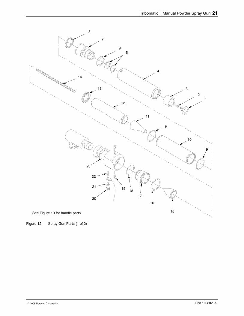
Spray Gun Parts See Figure 12.
Item Part Description Quantity Note— 1097997 HANDGUN assembly, Tribomatic II, 6 meter,
PTFE, Tivar1
— 631361 � DEFLECTOR ASSEMBLY, 26-mm, holes(Tivar)
1
1 - - - - - - � � DEFLECTOR, 26 mm, holes (Tivar) 1
2 940066 � � O-RING, silicone, 0.125 x 0.25 x 0.063 in. 1
3 631359 � SLEEVE, pattern adjust 1
4 631225 � EXTENSION, complete 1
— 631344 � SLEEVE ASSEMBLY, wear, outlet, Tivar 1 A
5 940224 � � O-RING, silicone, 1.00 x 1.25 x 0.063 in. 2 A
6 631222 � � SPRING, silicone, 1.25 x 1.50 in. 1 A
7 - - - - - - � � SLEEVE, wear, outlet, Tivar 1 A
8 - - - - - - � RING, spacing 1 A, B, C
9 940284 � O-RING, silicone, 1.375 x 1.50 x 0.063 in. 2 A, C
10 - - - - - - � SLEEVE, wear, outer 1 A, C
11 631346 � DISTRIBUTOR, outlet, Tivar 1 A
12 - - - - - - � SLEEVE, wear, inner 1 A, C
13 - - - - - - � RING, positioning 1 A, B, C
14 631211 � STUD, M8 x 9.56 in. 1 A
15 631345 � DISTRIBUTOR, inlet, Tivar 1 A
— 631342 � SLEEVE ASSEMBLY, wear, inlet, Tivar 1 A
16 940284 � � O-RING, silicone, 1.375 x 1.50 x 0.063 in. 1 A
17 - - - - - - � � SLEEVE, wear, inlet, Tivar 1 A
18 940243 � � O-RING, silicone, 1.125 x 1.25 x 0.063 in. 1 A
— - - - - - - � BODY ASSEMBLY, manual gun, Tribomatic II 1 D
19 631235 � � PIN, quick connect 2 D
20 984447 � � NUT, hex, jam, M5 1 D
21 983127 � � WASHER, M5, internal 1 D
22 982845 � � SCREW, set, cup, M5 x 12, black 1 D
23 - - - - - - � � BODY, Tribomatic II, manual gun 1 D
NOTE A: Available in PTFE/Tivar charge module service kit, part 631325. Refer to page 25.
B: Available in positioning and spacing ring service kit, part 631209. Refer to page 27.
C: Available in PTFE inner/outer wear sleeve service kit, part 631208. Refer to page 26.
D: Available in body service kit part 631339. When ordering furnish gun part number and serial number.Continued...
Tribomatic II Manual Powder Spray Gun 21
Part 1098020A� 2009 Nordson Corporation
8
7
65
4
3
21
9
10
9
11
12
13
14
15
16
1718
19
20
21
22
23
See Figure 13 for handle parts
Figure 12 Spray Gun Parts (1 of 2)

Tribomatic II Manual Powder Spray Gun22
Part 1098020A � 2009 Nordson Corporation
See Figure 13.
Item Part Description Quantity Note24 - - - - - - � HANDLE, manual gun, Tribomatic II 1 E
25 132336 � ACTUATOR, switch 1
26 983510 � WASHER, flat, 0.094 x 0.188 in. 2
27 983113 � LOCK WASHER, split, #2 2
28 981915 � SCREW, pan head, #2-56 x 0.375 in. 2
29 125617 � TRIGGER, manual gun 1 F
30 132334 � PIVOT, trigger 1 F
31 133783 � SPRING, trigger return 1 F
32 982370 � SCREW, pan head, slotted, M2 x 5 1 F
33 983416 � WASHER, M4, internal 1
34 982164 � SCREW, pan head, slotted, M4 x 6 1
35 940060 � O-RING, Viton, 0.125 x 0.25 x 0.063 in. 4 E
36 981626 � SCREW, captive, slotted, M4 x 12 4 E
37 982062 � SCREW, M4 x 6, oval head, slotted 2
38 631334 � GROUND PAD, Tribomatic II 1
39 - - - - - - � HANDLE, cover, Tribomatic II 1 E
40 1076395 � CABLE, Tribomatic 500, 6 meter, Vantage 1
41 631371 � DIFFUSER, short, Tribomatic II, single 1 G
NOTE E: Available in handle service kit, part 631328. Refer to page 27.
F: Available in trigger service kit, part 160104.
G: Refer to parts breakdown in this section. Refer to page 24.

Tribomatic II Manual Powder Spray Gun 23
Part 1098020A� 2009 Nordson Corporation
24
25
26
2728
2930
31
3235
34
33
36
37
38
39
40
41
See Figure 12 for charge module and gun body parts
Figure 13 Spray Gun Parts (2 of 2)

Tribomatic II Manual Powder Spray Gun24
Part 1098020A � 2009 Nordson Corporation
DiffuserSee Figure 14.
Item Part Description Quantity Note— 631371 DIFFUSER, short, Tribomatic II, single 1
1 631375 � NOZZLE, short diffuser, Tribomatic II 1
2 940117 � O-RING, silicone, 0.312 x 0.428 x 0.063 in. 2
3 631374 � HOUSING, short diffuser, Tribomatic II 1
4 940224 � O-RING, silicone, 1.00 x 1.125 x 0.063 in. 2
5 635006 � CONNECTOR, diffuser 1
6 972080 � CONNECTOR, male, 1/4-in. tube x 1/8-in. NPTF 1
7 939247 � CLAMP, hose 1
3
7
1
56
4
2
Figure 14 Diffuser Parts
Tribomatic II Manual Powder Spray Gun 25
Part 1098020A� 2009 Nordson Corporation
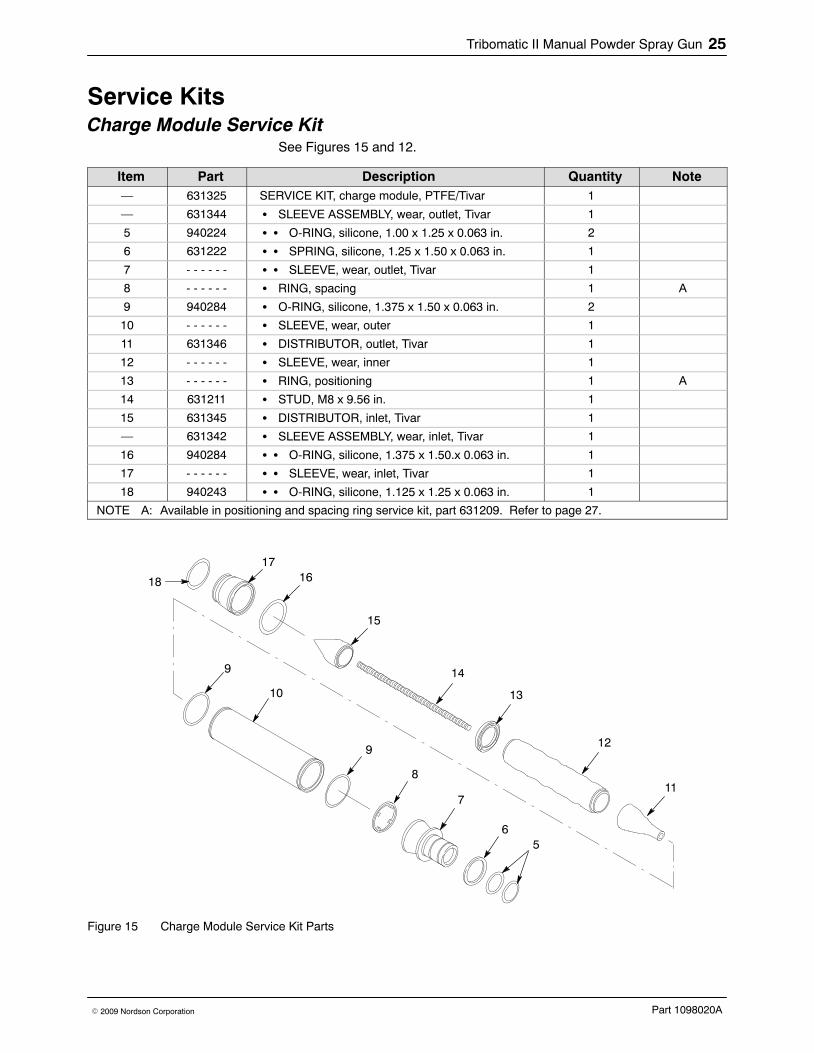
Service KitsCharge Module Service Kit
See Figures 15 and 12.
Item Part Description Quantity Note— 631325 SERVICE KIT, charge module, PTFE/Tivar 1
— 631344 � SLEEVE ASSEMBLY, wear, outlet, Tivar 1
5 940224 � � O-RING, silicone, 1.00 x 1.25 x 0.063 in. 2
6 631222 � � SPRING, silicone, 1.25 x 1.50 x 0.063 in. 1
7 - - - - - - � � SLEEVE, wear, outlet, Tivar 1
8 - - - - - - � RING, spacing 1 A
9 940284 � O-RING, silicone, 1.375 x 1.50 x 0.063 in. 2
10 - - - - - - � SLEEVE, wear, outer 1
11 631346 � DISTRIBUTOR, outlet, Tivar 1
12 - - - - - - � SLEEVE, wear, inner 1
13 - - - - - - � RING, positioning 1 A
14 631211 � STUD, M8 x 9.56 in. 1
15 631345 � DISTRIBUTOR, inlet, Tivar 1
— 631342 � SLEEVE ASSEMBLY, wear, inlet, Tivar 1
16 940284 � � O-RING, silicone, 1.375 x 1.50.x 0.063 in. 1
17 - - - - - - � � SLEEVE, wear, inlet, Tivar 1
18 940243 � � O-RING, silicone, 1.125 x 1.25 x 0.063 in. 1
NOTE A: Available in positioning and spacing ring service kit, part 631209. Refer to page 27.
9
10
9
8
7
65
18
1716
15
14
13
12
11
Figure 15 Charge Module Service Kit Parts

Tribomatic II Manual Powder Spray Gun26
Part 1098020A � 2009 Nordson Corporation
Inner/Outer Wear Sleeve Service KitSee Figures 16 and 12.
Item Part Description Quantity Note— 631208 SERVICE KIT, inner and outer wear sleeves, PTFE 1
8 - - - - - - � RING, spacing 1 A
9 940284 � O-RING, silicone, 1.375 x 1.50 x 0.063 in. 2
10 - - - - - - � SLEEVE, wear, outer 1
12 - - - - - - � SLEEVE, wear, inner 1
13 - - - - - - � RING, positioning 1 A
NOTE A: Available in positioning and spacing ring service kit, part 631209. Refer to page 27.
13
12
9
10
9
8
Figure 16 Inner/Outer Wear Sleeve Service Kit Parts

Tribomatic II Manual Powder Spray Gun 27
Part 1098020A� 2009 Nordson Corporation
Handle Service Kit See Figures 17 and 13.
Item Part Description Quantity Note— 631328 SERVICE KIT, handles, Tribomatic II 1
24 - - - - - - � HANDLE, Tribomatic II 1
35 940060 � O-RING, Viton, 0.125 x 0.25 x 0.063 in. 4
36 981626 � SCREW, captive, slotted, M4 x 12 4
39 - - - - - - � HANDLE, cover, Tribomatic II 1
24
35
39
36
Figure 17 Handle Service Kit Parts
Positioning and Spacing Ring Service Kit See Figures 18 and 12.
Item Part Description Quantity Note— 631209 SERVICE KIT, positioning and spacing rings 1
8 - - - - - - � SPACING ring 1
13 - - - - - - � POSITIONING ring 1
13
8
Figure 18 Positioning and Spacing Ring Service Kit Parts

Tribomatic II Manual Powder Spray Gun28
Part 1098020A � 2009 Nordson Corporation
Options
Sprayheads and NozzlesThe sprayheads and nozzles used on the Tribomatic II automatic gun canbe used on the Tribomatic II manual gun. Refer to the Tribomatic OptionalSprayheads and Nozzles instruction sheet for information.
DeflectorsSee Figure 19. Refer to Material Descriptions on page 5 for usage.
Item Part Description Quantity Note1 631363 TIVAR, 26-mm, deflector assembly 1
1 631367 PTFE, 26-mm,deflector assembly 1
2 631365 PTFE w/holes, 26-mm, deflector assembly 1 A
3 940066 � O-ring, silicone, 0.125 x 0.25 x 0.063 in. 1 B
NOTE A: Tivar deflector with holes is included with each manual gun.
B: Included with all deflectors.
3
2
3
1
Figure 19 Deflectors
Powder Feed Hose and Air Tubing
Part Description Note
Powder Feed Hose630061 12 mm (PVC)
630237 10 mm (PVC)
900549 LOW-FLOW, 3/8 in. (black rubber)
900550 HIGH-FLOW, 1/2 In. (black rubber)
Air Tubing900509 BLACK POLYETHYLENE, 1/4-in. OD
900730 BLUE POLYURETHANE, 1/4-in. OD
900741 BLACK POLYURETHANE, 6-mm OD
900742 BLUE POLYURETHANE, 6-mm OD
Hose Clamps and Spiral Wrap939247 HOSE CLAMP, small (for 3/8- and 1/2-in. hose)
900517 TUBING, spiral-cut A
NOTE A: Order in 1-ft increments.

Tribomatic II Manual Powder Spray Gun 29
Part 1098020A� 2009 Nordson Corporation
PTFE Charge Module Service KitSee Figure 20. If the powder you are using fuses to the standard Tivar inletand outlet wear sleeves and distributors, you can replace them with either aPTFE charge module service kit or just the wear sleeve assemblies anddistributors.
Item Part Description Quantity Note— 631207 SERVICE KIT, charge module, complete, PTFE 1
2 631221 � SLEEVE, wear, outlet, assy, PTFE 1
3 940224 � � O-RING, silicone, 1.00 x 1.125 in. 2
4 631222 � � SPRING, silicone, 1.25 x 1.50 in. 1
5 - - - - - - � � SLEEVE, wear, outlet, PTFE 1
6 - - - - - - � RING, spacing 1 A
7 - - - - - - � SLEEVE, wear, outer, PTFE 1
8 940284 � � O-RING, silicone, 1.375 x 1.50 in. 2
9 631224 � DISTRIBUTOR, outlet, PTFE 1
10 631237 � � PLUG, distributor, outlet, Tivar 1 B
11 940066 � � O-RING, silicone, 0.125 x 0.25 x 0.063 in. 1 B
12 631236 � � DISTRIBUTOR, outlet, PTFE 1
13 - - - - - - � SLEEVE, wear, inner, PTFE 1
14 - - - - - - � RING, positioning 1 A
15 631211 � STUD, M8 x 9.65 in. long 1
16 631234 � DISTRIBUTOR, inlet, PTFE 1
17 631232 � SLEEVE, wear, inlet, assy, PTFE 1
18 940284 � � O-RING, silicone, 1.375 x 1.50 in. 1
19 - - - - - - � � SLEEVE, wear, inlet, PTFE 1
20 940243 � � O-RING, silicone, 1.125 x 1.25 in. 1
NOTE A: Also available as a set, order part 631209 service kit.
B: Not used in manual guns. Discard or save for use on Tribomatic II automatic guns.

Tribomatic II Manual Powder Spray Gun30
Part 1098020A � 2009 Nordson Corporation
Kit, part 631 207
20
19
1816
15
14
13
10
8
7
86
5
4
3
17
2
11
12
9
Figure 20 Charge Module Service Kit


