Embed Size (px)
Citation preview

1Tribology – Friction, Wear,and Lubrication
Tribology is a relatively new term derived from the Greek word tribos for ‘rubbing’. It isnow universally applied to the emerging science of friction, wear, and lubrication involvedat moving contacts. In its broad scope, it involves mechanical, chemical, and materialtechnology. Usual tasks in tribology are reduction of friction and wear to conserve energy,enabling faster and more precise motions, increased productivity, and reduced maintenance.
Tribology was formally identified as an important and unified technical field in a reportissued by a committee of the British Ministry of State for Education and Science chaired byPeter Jost (1966). The report concluded that huge savings would be possible in the UnitedKingdom by fully utilizing improved design and lubrication procedures. The unified approachto this field filled an existing void, and the American Society of Mechanical Engineers(ASME) then adopted the term for its Tribology Division in 1983 and the American Societyof Lubrication Engineers revised its name to the Society of Tribologists and LubricationEngineers in 1985.
Fundamental interest in tribology now exists for lubricant formulation, industrial opera-tions, aerospace and transportation equipment, material shaping and machining, computersand electronic devices, power generation, and almost all phases of life where motion isencountered. This text focuses primarily on tribology of bearings and a number of relatedapplications. Fundamentals are applied in such a way as to allow application of the principlesof tribology to a variety of other machine elements.
1.1 History of tribology
Many of the advances in tribology and bearing technology evolved over years, decades,or even centuries to meet the needs of new machinery. The Industrial Revolution, withits increase in rotational speeds beyond those of the windmill and cart axle, brought fullhydrodynamic lubrication into normal use. Theory and technical understanding commonly
Applied Tribology 2e: Bearing Design and Lubrication M. Khonsari and E.R. Booser© 2008 John Wiley & Sons, Ltd
COPYRIG
HTED M
ATERIAL

4 Applied Tribology
followed actual machinery applications. In many cases, this understanding of technical detailsplayed a vital role in continued improvements in bearing design, lubricants, and surfacetreatments for industrial machinery, aerospace units, transportation equipment, magneticstorage, and microelectromechanical devices.
A few historical stepping stones related to the primary subjects covered in this textbookwill now be reviewed. Many of these events are covered in more detail in the referencespresented at the end of this chapter. The interested reader is referred to Dowson (1998) foran excellent review of the history of tribology.
FRICTION
Notebooks of the famed engineer and artist Leonardo da Vinci revealed his postulation in1508 of the concept of a characteristic coefficient of friction as the ratio of friction forceto normal load. The French physicist Guillaume Amontons (1699) again established thesignificance of a coefficient of friction, which was independent of the apparent area ofcontact. The French physicist C.A. Coulomb (1785) further distinguished between staticfriction and kinetic friction, which was independent of velocity. Mechanisms for reductionof friction and wear with soft coatings and adherent molecular and lubricant surface layerswere elucidated by Bowden and Tabor (1950).
WEAR
This subject has proven to be quite complex, and generalizations are still elusive. Hundredsof empirical equations have been generated for specific materials and conditions. The mostuseful one appears to be that of Archard (1953), which enables a generalized dimensionlesswear coefficient k = VH/Wd to relate wear volume V to sliding distance d, normal load W ,and indentation hardness H of the wearing material (see Chapter 4).
BEARING MATERIALS
For many centuries wood, stone, leather, iron, and copper were common bearing materials.Almost all engineering materials have now been employed in the continuing search forthe best bearing material (see Chapter 4). In an early consideration of improved materials,Robert Hooke (1684) suggested steel shafts and bell-metal bushes as preferable to woodshod with iron for wheel bearings (Bhushan, 1999). High-lead and high-tin alloys patentedin the United States in 1839 by Isaac Babbitt are unsurpassed for a wide range of industrial,automotive, and railway applications. An early German study of railway journal bearingsby F.A. von Pauli (1849) established a composition similar to that of Babbitt (91% tin, 6%copper, and 3% zinc) as the best of 13 bearing metals (Cameron, 1966; 1976).
Suitably hard, fatigue-resistant rolling element bearing materials were achieved with mod-ification of tool steel in Europe about 1900. This led to the development of AISI 52100 steeland its derivatives, which have since been used for all types of commercial and automotiverolling bearings.
Porous metal bearings were introduced in the 1920s. Plastics and composites involvingpolymers compounded with a wide variety of solid filler materials have found wide use,

Tribology – Friction, Wear, and Lubrication 5
gaining their greatest impetus with the invention of nylon and polytetrafluoroethylene (PTFE)during World War II. The search continues, with ceramics among the materials beingdeveloped for high-temperature capability in aircraft engines and for high-speed rollingelement bearings.
LUBRICANTS
Tallow was used to lubricate chariot wheels before 1400 bc. Although vegetable oils andgreases were used later, significant advances in the development of lubricants occurredonly after the founding of the modern petroleum industry with the opening of theDrake well in Titusville, Pennsylvania, in 1859. Lubricant production reached 9500 m3/yr(2 500 000 gal/yr) in the following 20 years; worldwide production now exceeds 1000 timesthat volume at 3 billion gal/yr. Petroleum lubricants still constitute well over 95% of totaloil and grease production volume.
Polymerized olefins were the first synthetic oils to be produced. This occurred in 1929in an effort to improve on properties of petroleum oils. Interest in ester lubricants datesfrom 1937 in Germany, and their production and use expanded rapidly during and followingWorld War II to meet military needs and for use in the newly developed jet aircraft engines.A broad range of other synthetic lubricants came into production during that same period forwide-temperature use, fire resistance, and other uses geared to a range of unique properties(see Chapter 2). Current production of synthetics approaches 100 million gal/yr, with nearlyhalf being polyalphaolefin synthetic hydrocarbons.
Development of chemical additives to upgrade the properties and extend the lives oflubricating oils began about 1920. Commercial use has proceeded since about 1930 instep with increasing demands in automobiles, jet engines and other aerospace units, andhigh-speed and high-pressure hydraulic equipment (see Chapter 2).
Air, water, gasoline, solvents, refrigerant gases, air, and various fluids being processedin individual machines began to find use as ‘lubricants’ on a broadening scale in fluid-filmbearings in the second half of the 1900s as improved designs and mating materials weredeveloped on a customized basis.
FLUID-FILM BEARINGS
The first studies of a shaft and bearing running under full hydrodynamic conditions wereperformed by F.A. von Pauli in 1849 and by G.A. Hirn in 1854 (see Cameron, 1966). In 1883the celebrated Russian Nikilay Petroff concluded that friction in fluid-film bearings was ahydrodynamic phenomenon. His resulting power loss equation has continued to provide afoundation in this field.
Beauchamp Tower in 1883 found experimentally and reported the generation of pressurein the oil film of a journal bearing. In considering Tower’s findings, Osborne Reynolds(both working under stimulus of the British Institution of Mechanical Engineers) in 1886developed a mathematical expression for this pressure buildup that has become the foundationof hydrodynamic analysis of bearing performance (see especially Chapters 5 and 6).
Solution of the Reynolds equation was difficult, and Arnold Sommerfeld in 1904 devel-oped a direct integration that enabled ‘infinite length’ analyses. Alastair Cameron and

6 Applied Tribology
Mrs W.L. Wood in 1949 made an extremely useful extension of Reynolds equation forfinite-length journal bearings by a relaxation procedure carried out with a mechanical desk-top calculator. Initiated in 1958 by Oscar Pinkus and by Albert Raimondi and John Boyd,digital computer analysis of journal bearing performance has come into widespread use forobtaining numerical solutions of the Reynolds equation. Recent advances have focused onsolving the Reynolds equation with consideration of cavitation. Particularly fruitful has beenevaluation of dynamics effects in bearings that take into account the orbit of the shaft, alongwith simultaneous solutions of the energy equation taking lubricant property variations intoconsideration.
ROLLING ELEMENT BEARINGS
Several isolated examples have been recorded of application of rollers in 484–424 bc fortransporting vessels on land and for launching military missiles. While historical sourcesincreasingly mention the use of balls and rollers for bearing purposes following aboutad 1500, widespread application of rolling contact bearings occurred during the twentiethcentury (see especially Allan, 1945).
1780 Perhaps the earliest ball bearing: a 610 mm bore bearing was developed for a rotatingmill in Norwich, UK.
1868 General use of ball bearings in bicycles began.1899 Timken began the manufacture of tapered roller bearings.1902 Conrad obtained a British patent for the present design of the deep-groove ball bearing
with its cage.1904 Ball and roller bearings were used in electric automobiles.1907 SKF founded.1949 Grubin established the elastohydrodynamic principles involved in the lubrication of
rolling contacts.
Recent research has been geared toward understanding the relationship between surfacetopography (Chapter 3), film thickness, and pressure distribution in rolling element bearings.Under highly loaded conditions, when surface asperities tend to interact, a mixed-filmlubrication regime may have to be considered. Prediction of subsurface stress fields and theirrelationship to fatigue are also subjects of current research.
NANOTRIBOLOGY AND SURFACE EFFECTS
Atomic-scale studies have been expanding rapidly to develop new materials with improvedtribological properties. With an atom being approximately 1/3 nanometer (nm) in diam-eter, Krim in 1991 initiated naming this field ‘nanotribology’ to parallel the broadfield of ‘nanotechnology’ (Krim, 1991; Cantor, 2004). The nanometer (10−12 m, or 10ångstroms) then provides a convenient scale for atomic and molecular sizes such as those inTable 1.1.
An early definition of atomic surface compositions that produces satisfactory slidingcharacteristics was provided in General Motors rubbing tests of all available metallic elements

Tribology – Friction, Wear, and Lubrication 7
Table 1.1 Representative nanometer dimensions in tribology
Size range (nm)
Atomic scalea
C–C bond length 0.15C–H bond length 0.11
Lubricant moleculesLube oil 1–5Absorbed rust inhibitorsa 3Viscosity index improvers (VIs) 100–250Lithium soap grease fibers, diameter × lengthb 0�2×2
Computer magnetic headsa
Air film 0.15–0.3Liquid film 1–2
a Source: Bhushan (1997, 1999).b Source: Klamann (1984).
on steel (Roach et al., 1956). As detailed in Chapter 4, good scoring resistance was foundonly with elements that had atomic diameters at least 15% greater than iron and that werein the B subgroup of the periodic table, implying lack of tenacious metallic bonds at anylocalized junctions with steel.
Bushan (1997, 1999) updated consideration of atomic structure and related surface andlubricant details for avoiding wear under demanding operation with 0.15–0.3 nm thick airfilms in magnetic storage and micromechanical devices such as those involved in computersystems. Analysis of related air film bearings is provided in Chapter 11.
1.2 Tribology principles
Several distinct regimes are commonly employed to describe the fundamental principles oftribology. These range from dry sliding to complete separation of two moving surfaces byfluid-film lubrication, with an intermediate range involving partial separation in boundary ormixed lubrication. When elastic surface deformation exerts a strong influence on fluid-filmbehavior, as in ball and roller bearings, elastohydrodynamic lubrication (EHL) introduces itsdistinctive characteristics.
DRY SLIDING
In the absence of a fluid film, actual contact between two rubbing surfaces involves onlysufficient high spots, or asperities, of the softer material so that their yield pressure balancesthe total load (Rabinowicz, 1995). Under load W in Figure 1.1, the real contact area is arelatively minute portion of the apparent total area and tends to increase proportionately withthe load (see Chapter 4).
A measurable force is required to slide a surface along on the contacting asperities (surfacepeaks) of another surface. This force must overcome the friction force associated with

8 Applied Tribology
Figure 1.1 Surface films at asperity contacts between rubbing surfaces. (Harris, 1991. Copyright ©1991 by John Wiley & Sons, Inc. Reprinted by permission of John Wiley & Sons, Inc.)
asperity yield strength. As suggested in Figure 1.1, friction can be significantly reduced by athin, soft coating of a solid film lubricant such as graphite, molybdenum disulfide, or PTFEplastic, or by a sulfur- or phosphorus-rich layer formed by adsorption of additives from alubricating oil. Wear volume can be related to the generation of wear fragments from aportion of these asperity contacts during sliding (see Chapters 2–4).
FLUID-FILM LUBRICATION
In this regime, the moving surfaces are completely separated by a film of liquid or gaseouslubricant. A load-supporting pressure is commonly generated by one of the following typesof action:
1. Hydrodynamic lubrication (HL) results from a film of separating fluid being drawn intoa converging, wedge-shaped zone (as in Figure 1.2a) by the self-acting pumping actionof a moving surface (Booser, 1995). Both the pressure and the frictional power loss inthis film are a function of the lubricant’s viscosity in combination with the geometryand shear rate imposed by bearing operating conditions (see Chapter 5). Hydrodynamicbearings are commonly in the form of either (a) a sleeve bearing (also called a journalbearing) surrounding its mating journal surface on the shaft of a machine as a radialbearing or (b) a thrust bearing to provide an oil film at the face of a shaft shoulder orcollar for location and axial support of a rotor.
2. The squeeze-film action shown in Figure 1.2(b) is encountered in dynamically loadedbearings in reciprocating engines and under shock loads (see Chapter 9). Because time isrequired to squeeze the lubricant film out of a bearing, much higher loads can be carriedin sleeve bearings for automotive engines and metal rolling mills than with a steady,unidirectional load, as reflected in the typical values presented in Table 1.2. The much

Tribology – Friction, Wear, and Lubrication 9
Figure 1.2 Principles of fluid-film action in bearings. (Booser, 1995. Copyright © 1995 by JohnWiley & Sons, Inc. Reprinted by permission of John Wiley & Sons, Inc.)
lower load capacity of bearings lubricated with low-viscosity fluids such as water and airis also indicated in Table 1.2.
3. Externally pressurized feed by an external pumping source may be used to generatepressure in the fluid before its introduction into the bearing film, as shown in Figure 1.2(c).Such a procedure is common in cases where limited hydrodynamic pumping action isavailable within the bearing itself, as during starting and slow-speed running with heavymachines or with low-viscosity fluids (see Chapter 10).

10 Applied Tribology
Table 1.2 Typical design loads for hydrodynamic bearings
Bearing type Load on projected area MPa (psi)
Oil lubricatedSteady load
Electric motors 1.4 (200)Turbines 2.1 (300)Railroad car axles 2.4 (350)
Dynamic loadsAutomobile engine main bearings 24 (3 500)Automobile connecting-rod bearings 34 (5 000)Steel mill roll necks 35 (5 000)
Water lubricated 0.2 (30)
Air bearings 0.2 (30)
Source: Khonsari and Booser (2004).
ELASTOHYDRODYNAMIC LUBRICATION (EHL)
This is a form of hydrodynamic lubrication in which pressures are large enough to causesignificant elastic deformation of the lubricated surfaces. As with HL, converging filmthickness, sliding motion, and fluid viscosity play an essential role. Temperature effects,inadequate lubricant supply to the EHL film, and boundary lubrication play roles of varyingimportance, much as with fluid films in HL.
Significant differences between HL and EHL involve the added importance of materialhardness, viscosity increase under high pressure, and degree of geometric conformation ofthe contacting surfaces. Conformal surfaces match snugly, such as the journal in a sleevebearing with hydrodynamic lubrication shown in Figure 1.2, so that the load is carried ona relatively large area. With nonconformal surfaces, as with the two contacting rollers inFigure 1.3, the load must be carried on a small area: typically of the order of 1000-foldsmaller than with a conformal conjunction. The following two distinct regimes exist in EHL:
Line of centresfor the two rollers
Elastohydrodynamicoil-film pressure
Hertz elastic pressurefor static contact
Distance in direction of oil flow
Con
tact
pre
ssur
e
Entrancezone Exit
Figure 1.3 Pressure distribution between two rollers under load

Tribology – Friction, Wear, and Lubrication 11
1. Hard EHL. This involves materials of high elastic modulus in nonconformal contacts,commonly contacts involving primarily rolling action or combined rolling and sliding inball and roller bearings, gear teeth, cams, and some friction drives. Since the surfacesdo not conform well, the load is concentrated on small, elastically deformed areas, andhydrodynamic lubrication of these EHL contacts is commonly characterized by a verythin separating oil film that supports local stresses that tax the fatigue strength of thestrongest steels.
Oil-film pressures in these EHL contacts commonly range up to 0.5–3 GPa, 1000 timesthat in most hydrodynamic bearings, with a pattern which closely follows the Hertz elasticcontact stress for a static contact, as illustrated in Figure 1.3. The overall oil-film thickness(often about 0�1–0�5 �m) is set primarily by oil viscosity, film shape, and velocity at theentry of the contact zone (see Chapter 15).
2. Soft EHL. Elastic deformation also plays an important role in film formation in rubberseals, tires, human joints, water-lubricated rubber bearings, and babbitt journal bearingsunder heavy loads and low speeds, as well as in similar applications of hydrodynamicbearings using soft bearing materials having low elastic modulus. Since the low contactpressures involved have a negligible effect on fluid viscosity in the conjunction, analyticalrelations are simpler for soft EHL in contrast to the hard EHL encountered with rollingelement bearings. Hamrock (1994) and Khonsari and Hua (1997) give analytical tools forperformance analysis within the various realms of EHL.
BOUNDARY LUBRICATION
As the severity of operation increases, the speed N and viscosity � eventually becomeincapable of generating sufficient oil-film pressure P to support the entire load. Asperities ofthe mating surfaces then penetrate with increasing contact area, plastic deformation, higherasperity temperatures, and finally surface tearing and seizure on a broad scale. The regionof lubrication in Figure 1.4 shifts from full film with a friction coefficient (ratio of friction
Figure 1.4 Stribeck dimensionless �N/P curve relating lubrication regime and friction coefficientto absolute viscosity �, rotational speed N , and unit load P. (Booser, 1995. Copyright © 1995 by JohnWiley & Sons, Inc. Reprinted by permission of John Wiley & Sons, Inc.)

12 Applied Tribology
force to normal force) of the order of 0.001 to boundary (or mixed-film) lubrication, wherethe friction coefficient rises to 0.03–0.1, and finally to complete loss of film support, wherethe friction coefficient may reach 0.2–0.4, typical for dry sliding.
When operating with an adsorbed surface layer or a chemical reaction coating in bound-ary lubrication, chemical additives in the oil and chemical, metallurgical, and mechanicalfactors involving the two rubbing surfaces determine the extent of wear and the degree offriction.
1.3 Principles for selection of bearing types
Most bearings can be classified as either fluid-film bearings, dry or semilubricated slidingbearings, or rolling element bearings (Khonsari and Booser, 2004). Their relative advantagesare listed in Table 1.3. A general preliminary guide to selection of each of these types fordifferent load, speed, and size relations is provided in Figure 1.5.
Example 1.1 A radial load of 500 N (112 lb) is to be carried by a bearing on a 25 mm(0.98 in.) diameter shaft. Which bearing types could be considered for speeds of 100, 1000,10 000, and 100 000 rpm?
Table 1.3 Characteristics of common classes of bearings
Fluid filmbearings
Dry bearings Semilubricated Rollingelementbearings
Start-up frictioncoefficient
0.25 0.15 0.10 0.002
Running frictioncoefficient
0.001 0.10 0.05 0.001
Velocity limit High Low Low MediumLoad limit High Low Low HighLife limit Unlimited Wear Wear FatigueLubrication
requirementsHigh None Low/none Low
High-temperaturelimit
Lubricant Material Lubricant Lubricant
Low-temperaturelimit
Lubricant None None Lubricant
Vacuum Not applicable Good Lubricant LubricantDamping capacity High Low Low LowNoise Low Medium Medium HighDirt/dust Need seals Good Fair Need sealsRadial space
requirementSmall Small Small Large
Cost High Low Low Medium
Source: Kennedy et al. (1998).

Tribology – Friction, Wear, and Lubrication 13
Figure 1.5 General guide for selecting the journal bearing type. Except for rolling element bearings,the length/diameter ratio = 1. Medium-viscosity mineral oil is assumed for hydrodynamic bearings.(From ESDU Data Item No. 65007, 1965)

14 Applied Tribology
Follow horizontally across Figure 1.5 for a ‘Typical maximum load’ of 500 N. Speed andload limits are then found to be adequate for the following bearing types:
Speed (rpm) Possible bearing types
100 Rubbing, porous metal, rolling element, oil film1 000 Porous metal, rolling element, oil film
10 000 Rolling element, oil film100 000 Oil film
While the Engineering Sciences Data Unit (ESDU) also has a companion chart for thrustbearings, the same general type used for the journal bearing should be considered first.
Final selection of the most suitable basic type is then related to the following factors:
1. Mechanical requirements;2. Environmental conditions;3. Economics.
Representative considerations follow for each of these factors, and later chapters givefurther guidelines for performance to be expected with individual bearing types. In manycases, preliminary pursuit of design details for several possibilities is helpful in making afinal selection.
MECHANICAL REQUIREMENTS
Unless the bearing fulfills all mechanical requirements imposed by the machine of whichit is a part, other considerations such as environment and cost are of no importance. Briefcomparisons of these items are included in Table 1.3.
Friction and power loss
Low starting friction, especially under a load, is a prime advantage of ball and rollerbearings. While involving added complexity, externally pressurized oil lift pockets pro-vide oil-film bearings with zero starting friction in a variety of large, heavy machinessuch as electric generators at hydroelectric dams and in utility power plants. For runningmachines, a coefficient of friction of the order of 0.001–0.002 is typical for both rolling-element and oil-film bearings. Start-up coefficients at breakaway of 0.15–0.25 are typicalfor oil-film bearings and for dry and semilubricated plastic and porous metal bearings.With dry and semilubricated surfaces, friction then drops by about half as motion getsunderway.
The localized temperature increase generated by friction in rubbing asperities was analyzedby Blok (1937) to place a limit on the maximum speed and load which can be tolerated inbearing and gear contacts.

Tribology – Friction, Wear, and Lubrication 15
Speed
Each of the four classes of bearings presented in Table 1.3 has a practical speed limit.Common practice limits rolling bearings using oil lubrication to a (DN) value (mm bore ×rpm) of 500 000 to 1 000 000, corresponding to a surface speed of 1600–3100 m/min (5000–10 000 ft/min). Limits with fluid-film bearings are much higher and less well defined, butsurface speeds in turbine bearings range up to about 8700 m/min (30 000 ft/min). A typicaldental drill uses air for journal bearing lubrication while spinning smoothly at speeds of300 000 rpm. Much lower speed limits in the range of 100–500 m/min are imposed by surfaceheating effects with dry and semilubricated bearings, for which the appropriate operatingzone is illustrated in Figure 1.6. (Note: Figure 1.6 does not show scales on its axes and isonly meant to show the trend. See Chapter 12 for typical numerical values.)
Load
Rolling element bearings are generally more versatile in being able to carry their fatigue-rated load at all speeds from zero up and in all directions with normal lubrication. The loadcapacity of oil-film bearings, on the other hand, is very much a function of speed and oilviscosity, with their influence on oil-film formation. Dry and semilubricated porous metaland plastic bearings encounter a surface heating limit in their PV factor (contact pressure ×surface velocity) which gives a much lower load limit with rising speed, but high loads arepossible with appropriate material combinations at low speeds.
Hydrostatic bearings using externally pressurized oil have been used to support enormousstructures such as observatory domes, telescopes, and large radio antennas where weightrequirements range from 250 000 to over 1 000 000 pounds (see Chapter 10).
Momentary shock loads can be reasonably tolerated by both fluid film and rolling elementbearings. Rotor unbalance loads and cyclic loads in internal combustion engines are wellcarried by oil-film bearings. Combined radial and thrust load capacity is a useful attributeof conventional deep-groove, single-row ball bearings.
Shaded area for design
Log
V (
m /s
)
Log P (N/m2)
Vmax
PmaxP .V = C
Figure 1.6 Operating zone for the design of dry and semilubricated bearings. (Fuller, 1984. Copyright© 1984 by John Wiley & Sons, Inc. Reprinted by permission of John Wiley & Sons, Inc.)
16 Applied Tribology
Life
Rolling element bearings have a distinct fatigue life limit which results from the repeatedcontact stressing of the balls and rollers on their raceways, while fluid-film bearingsin the usual rotating equipment provide essentially unlimited life. The same life patternhas been found with rolling element and oil-film bearings, however, in industrial electricmotors, where maintenance needs and contamination commonly dictate life. Fatigue lifeis also a limiting factor for oil-film bearings under cyclic loading in internal combustionengines.
In dry and semilubricated bearings, life is estimated from a wear coefficient, which relateswear rate to unit loading and peripheral sliding distance. In the rapidly expanding use of thisclass of bearings, life is also related to temperature, contamination, and other environmentalconditions.
Lubrication
In general, a rolling element bearing requires only enough lubricant to provide a film coatingover the surface roughness of working surfaces. Less than one drop supplies this need formany small and medium-sized ball and roller bearings. Under conditions of heavy load andhigh speed, additional lubricant must be supplied, not for lubrication needs but to removeheat and maintain a reasonable limit on temperature. Many rolling element bearings dependonly on an initial grease fill for years of operation when DN values are less than 300 000(mm bore × rpm).
While no oil is usually fed to small sliding-type bearings which are to operate dry orsemilubricated, oil-film bearings generally require relatively large quantities of oil to maintainthe separating film between the bearing and its mating surface. This feed rate is proportionalto the bearing length, width, clearance, and surface velocity and ranges up to 4 m3/ min(1000 gal/min) for the oil-film bearings in a steam turbine generator at an electric powerstation. Specially designed fluid-film bearings are unique in being able to operate with gasor ambient liquids such as water or gasoline as their hydrodynamic fluid.
Space requirement
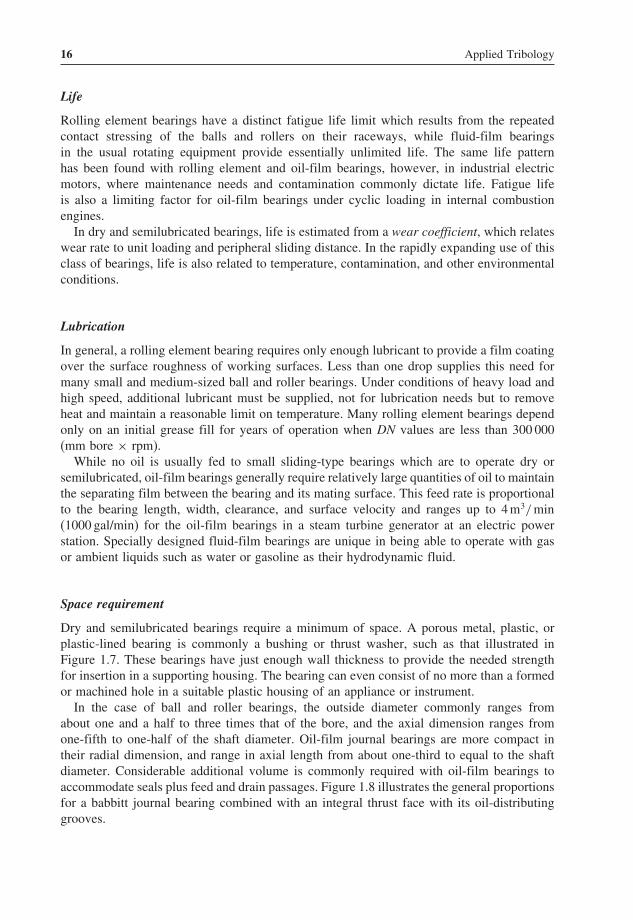
Dry and semilubricated bearings require a minimum of space. A porous metal, plastic, orplastic-lined bearing is commonly a bushing or thrust washer, such as that illustrated inFigure 1.7. These bearings have just enough wall thickness to provide the needed strengthfor insertion in a supporting housing. The bearing can even consist of no more than a formedor machined hole in a suitable plastic housing of an appliance or instrument.
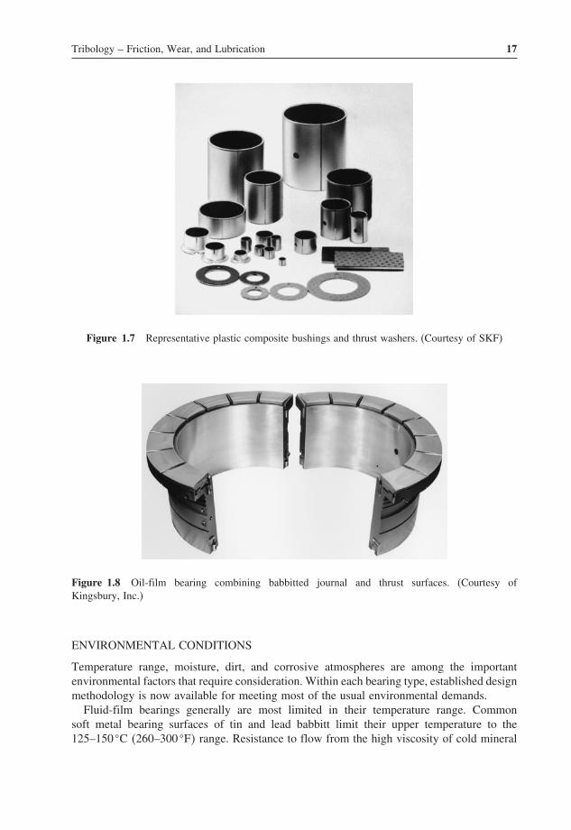
In the case of ball and roller bearings, the outside diameter commonly ranges fromabout one and a half to three times that of the bore, and the axial dimension ranges fromone-fifth to one-half of the shaft diameter. Oil-film journal bearings are more compact intheir radial dimension, and range in axial length from about one-third to equal to the shaftdiameter. Considerable additional volume is commonly required with oil-film bearings toaccommodate seals plus feed and drain passages. Figure 1.8 illustrates the general proportionsfor a babbitt journal bearing combined with an integral thrust face with its oil-distributinggrooves.
Tribology – Friction, Wear, and Lubrication 17
Figure 1.7 Representative plastic composite bushings and thrust washers. (Courtesy of SKF)
Figure 1.8 Oil-film bearing combining babbitted journal and thrust surfaces. (Courtesy ofKingsbury, Inc.)
ENVIRONMENTAL CONDITIONS
Temperature range, moisture, dirt, and corrosive atmospheres are among the importantenvironmental factors that require consideration. Within each bearing type, established designmethodology is now available for meeting most of the usual environmental demands.
Fluid-film bearings generally are most limited in their temperature range. Commonsoft metal bearing surfaces of tin and lead babbitt limit their upper temperature to the125–150 �C �260–300 �F� range. Resistance to flow from the high viscosity of cold mineral

18 Applied Tribology
oil in feed and drain passages, at the other extreme, limits the low temperature range ofmany oil-film bearings to −20 to +10 �C (−5 to 50 �F).
Ball and roller bearings can be adapted to meet wide-ranging environmental demands. Forgeneral applications, multipurpose greases and double-sealed and double-shielded enclosuresprovide water and contamination resistance, rust protection, and sufficiently long life toeliminate the need for routine maintenance. Synthetic oils and greases used with tool steeland ceramic bearing materials allow applications in an ever-broadening range of temperaturesand other environmental conditions.
ECONOMICS
Overall economic considerations in selecting a bearing type include not only the first costof the bearing itself, but also later costs in maintenance and eventually in replacement at theend of the useful life.
Cost
Where other factors do not dictate the choice, initial cost commonly is a dominant selectionfactor. For many mass-produced items such as small electric motors, household appliances,and automotive auxiliaries with low surface speeds and light loads, dry and semilubricatedbushings and thrust washers have by far the lowest cost and are finding continually broad-ening use in bore sizes up to about 25 mm. Mass-produced oil-film bearings of smaller sizesalso fall in this low-cost range for automobile engines, appliances, and fractional-horsepowermotors. In general, they avoid the speed limits for porous metals and polymer compositions.
If these sliding element bearings appear marginal or impractical, ball and roller bearingsshould be considered as the next higher-priced alternative. While available from very smalldiameters in the 3–5 mm range, their use is common for 25–100 mm shaft diameters, andtheir use in larger diameters is growing. Chapters 13–15 provide application, lubrication,and performance guidelines for their use over a broad range of conditions.
More expensive oil-film bearings are common in larger sizes for high loads and highspeeds, such as those used with auxiliary oil feed systems involving cooling and filtrationof contaminants.
Maintenance and life
Fluid-film bearings operating with parts separated by an oil film require little or no main-tenance and their life is virtually unlimited, except under cyclic loading, where the bearingmetal may suffer fatigue. In contrast, the repeated cyclic loading on the contacts in rollingelement bearings results in limited life due to fatigue.
Maintenance of greased rolling bearings may at most require occasional purging or greasechange. With oil lubrication of either sliding or rolling bearings, the supply system requiresoccasional attention for a change of oil, a new filter, or general cleaning.
With dry and semilubricated bearings, calculated bearing wear life is commonly selectedto at least match the expected life of the overall unit. Required maintenance is usually limitedto the replacement of worn bearings.

Tribology – Friction, Wear, and Lubrication 19
1.4 Modernization of existing applications
Reassessing the bearing class and bearing design is a common need for existing machinesor products. This need may arise from problems with the present bearings, from extensionof the product line, or in updating a machine design.
Industrial electric motors provide an example of modernization over an extended time.The earliest electric motors around 1900 used fluid-film bearings with an oil ring for alubricant supply (see Chapter 12). With increasing availability of ball bearings by the time ofWorld War I, their small size and reduced maintenance needs allowed their use in fractionalhorsepower motors and in motors for electric automobiles and small mine locomotives. Inthe 1920s, ball bearing use was extended to motor sizes up to about 200 horsepower (hp),but only at a premium price and with concerns over reliability. With lower bearing costsand the availability of long-life greases, ball bearings became standard for industrial motorsup to 25–50 hp in the 1950s. Today, following subsequent redesigns, very few motors usingoil-film bearings are available in sizes below about 1000 hp.
On the other hand, bearings continue to be of the oil-film type in stationary steam andgas turbines, particularly those in electric power service. The value of their essentiallyunlimited life far surpasses the higher cost of these bearings and their extended lubricationsystem compared with rolling element bearings. The trend toward lightweight and high-speedconstruction also depends to a large extent on the inherent damping and higher speed limitavailable with oil-film bearings.
For jet aircraft turbine engines, however, rolling element bearing use is firmly established.Dominant factors are a small lubricant supply, easy low-temperature starting, high thrust loadcapacity, and light weight. Moreover, ball bearings are better suited to these applications,where there may be an instantaneous interruption in the oil supply. This is an importantconsideration since aircraft experience a variety of operating conditions including takeoff,landing, and maneuvering, which can be conveniently handled by ball bearings.
With turbines, as with many other machines, selection of the bearing type will continueto be a question. Oil-film bearings may be considered for land-based derivatives of aircraftturbines, and ball and roller bearings will probably continue to be evaluated for small land-based turbines, compressors, and their accessory units, where oil-film bearings have beentraditional.
Automotive chassis bearings have undergone a wide range of modifications to eliminatethe need for relubrication. Automobile engine bearings will likely also undergo detailedevaluation of their type and materials with the advent of new electric propulsion and fuelcell components in the drive system. Such factors and innovations such as ceramic rollingelements, new plastic and composite sliding bearing materials, and new high-performancelubricants will call for continuing reevaluation of almost all bearing design and performancedetails.
1.5 A look ahead
Coming trends for bearing applications will likely be set by the needs for lower maintenancewhile operating at higher speeds and higher temperatures in more compact designs. Thefollowing are likely trends for the future of classification of bearings covered in this chapter(Khonsari and Booser, 2004).

20 Applied Tribology
DRY AND SEMILUBRICATED BEARINGS
Plastics and their composites will continue to find broadening use for mild operating con-ditions as small bushings in household appliances, machine tools, instruments, businessmachines, automobile chassis and construction equipment. Many of these applications willinvolve direct integration of the bearings with housing and structural elements.
BALL AND ROLLER BEARINGS
While continuing their dominance in jet engines and aerospace, rolling element bearing usewill broaden in small electric motors, automobile accessories, machine tools, constructionand agriculture machines, and railroad equipment. Their very small lubrication needs willlikely bring innovations in greases, self-contained lubricant impregnation in ball and rollerbearing cages, and solid lubricant films. Further developments of ceramics, tool steels, andspecial lubricants will enable continually higher speeds and temperatures.
FLUID-FILM BEARINGS
Conventional oil-lubricated bearings will continue to fill their traditional role in reciprocatingautomotive and diesel engines, electrical turbine generators, and other large machinery. Useof gases and low-viscosity liquids will likely escalate. Air-film bearings now used in flyingheads on computer discs and in airliner cabin compressors will gradually expand in their usefor aerospace, industrial, and instrument units. Water, gasoline, liquid ammonia, and a widevariety of liquid chemical and food process streams will likely be employed in bearings toavoid the complexity and contamination with conventional mineral oils and greases.
These are but a sampling of challenges coming in the twenty-first century: new bearingmaterials, new lubricants, advanced analysis and designs techniques, and improved surfaceprofiles to match extremely thin fluid films.
Problems
1.1 Select a bearing type for applications with a 2.0 in. diameter shaft, medium-viscositymineral oil lubricant, and the following specifications:
(a) 10 rpm, 500 lbf load;(b) 1000 rpm, 500 lbf load;(c) 10 000 rpm, 500 lbf load;(d) 1000 rpm, 10 000 lbf load.
1.2 List three general advantages and disadvantages to be expected in applying water-lubricated bearings rather than oil-film or rolling element bearings. Give five applica-tions in which you conclude that water bearings would be advantageous.
1.3 Repeat Problem 1.2 for air bearings.1.4 A 30 mm bore tapered roller bearing is being considered for use in supporting the
impeller in a household food-disposal unit for kitchen sinks. High-shock loading isexpected, as solids and possibly tableware enter the unit. Suggest two other possible

Tribology – Friction, Wear, and Lubrication 21
types of bearings and compare their major attributes, as selected from items in Table 1.3.Which type of bearing is your primary recommendation?
1.5 A 5000 rpm gas turbine with a 6 in. shaft diameter at the bearing locations is to be usedin driving a natural gas line pumping unit. List the major factors that might be expectedto dictate the selection of rolling or fluid-film bearings. Should magnetic bearings beconsidered that would suspend and center the shaft while using an electronic controlfor the magnet elements?
1.6 State two types of bearings or bearing systems that you would consider for a conveyorcarrying 10 lb castings in 20 min passage at a speed of 2 m/min through a 350 �C heat-treating oven. List five selection factors to be considered. Which factor appears to bemost critical?
References
Allan, R.K. 1945. Rolling Bearings. Pitman & Sons, Ltd, London.Archard, J.F. 1953. ‘Contact and Rubbing of Flat Surfaces,’ Journal of Applied Physics, Vol. 24, pp. 981–988.Bhushan, B. 1997. ‘Tribology of Magnetic Storage Systems,’ Handbook of Tribology and Lubrication Engineering,
Vol. 3. CRC Press, Boca Raton, Fla, pp. 325–374.Bhushan, B. 1999. Principles and Applications of Tribology. John Wiley & Sons, New York.Blok, H. 1937. ‘Theoretical Study of Temperature Rise at Surfaces of Actual Contact under Oiliness Operating
Conditions,’ Institution of Mechanical Engineers, Lubrication Discussion, Vol. 2, pp. 222–235.Booser, E.R. 1995. ‘Lubrication and Lubricants,’ Encyclopedia of Chemical Technology, 4th edn., Vol. 15. John
Wiley & Sons, New York, pp. 463–517.Bowden, F.P. and Tabor, D. 1950. The Friction and Lubrication of Solids. Clarendon Press, Oxford (republished
in 1986).Cameron, A. 1966. Principles of Lubrication. Longman Green & Co., Ltd, London.Cameron A. 1976. Basic Lubrication Theory, 2nd edn. Ellis Horwood, Ltd, Chichester, UK.Cantor, N. 2004. ‘Nanotribology: the Science of Thinking Small,’ Tribology and Lubrication Technology, Society
of Tribologists and Lubrication Engineers, Vol. 60(6), pp. 43–49.Dowson, D. 1998. History of Tribology, 2nd edn. Institution of Mechanical Engineers, London.Engineering Sciences Data Unit (ESDU). 1965. General Guide to the Choice of Journal Bearing Type, Item 65007.
Institution of Mechanical Engineers, London.Fuller, D.D. 1984. Theory and Practice of Lubrication for Engineers, 2nd edn. John Wiley & Sons, New York.Hamrock, B.J. 1994. Fundamentals of Fluid Film Lubrication. McGraw-Hill Book Co., New York.Harris, T.A. 1991. Rolling Bearing Analysis, 3rd edn. John Wiley & Sons, New York.Jost, H.P. 1966. Lubrication (Tribology): a Report on the Present Position and Industry’s Needs. Department of
Education and Science, Her Majesty’s Stationery Office, London.Kennedy, F.E., Booser, E.R., and Wilcock, D.F. 1998. ‘Tribology, Lubrication, and Bearing Design,’ The CRC
Handbook of Mechanical Engineering, F. Kreith (ed.). CRC Press, Boca Raton, Fla, pp. 3.128–3.169.Khonsari, M.M. and Booser, E.R. 2004. ‘An Engineering Guide for Bearing Selection,’ STLE Tribology and
Lubrication Technology, Vol. 60(2), pp. 26–32.Khonsari, M.M. and Hua, D.Y. 1997. ‘Fundamentals of Elastohydrodynamic Lubrication,’ Tribology Data Hand-
book, E.R. Booser (ed.). CRC Press, Boca Raton, Fla, pp. 611–637.Klamann, D. 1984. Lubricants and Related Products. Verlag Chemie, Deerfield Beach, Fla.Krim, I.J. 1991. ‘Nanotribology of a Kr Monolayer: a Quartz-Crystal Microbalance Study of Atomic-Scale Friction,’
Physical Review Letters, Vol. 66, pp. 181–184.Rabinowicz, E. 1995. Friction and Wear of Materials, 2nd edn. John Wiley & Sons, New York.Roach, A.E., Goodzeit, C.L., and Hunnicut, R.P. 1956. Transactions ASME, Vol. 78, p. 1659.