Embed Size (px)
Citation preview

TRIBAL PARTNERS CANADA INC.
FUNCTIONAL SERVICING REPORT
12035 DIXIE ROAD
MARCH 11, 2021

FUNCTIONAL SERVICING
REPORT
12035 DIXIE ROAD
TRIBAL PARTNERS CANADA INC.
PROJECT NO.: 20M-01429
DATE: MARCH 2021
WSP
UNIT 500
119 SPADINA AVENUE
TORONTO, ON, CANADA M5V 2L1
T: +1 416 260-0387
F: +1 416 260-3028
WSP.COM

Q U A L I T Y M A N A G E M E N T
ISSUE/REVISION FIRST ISSUE REVISION 1 REVISION 2 REVISION 3
Remarks SUBMISSION #1
Date March 11, 2021
Prepared by Dabi Abikoye
Signature
Checked by Justin Gleben
Signature
Authorised by Alex Williams
Signature
Project number 20M-01429
Report number
File reference

FUNCTIONAL SERVICING REPORT
Project No. 20M-01429
TRIBAL PARTNERS CANADA INC.
WSP
March 2021
Page iii
S I G N A T U R E S
PREPARED BY
Justin Gleben, M.Eng., P.Eng.
Project Engineer
REVIEWED BY
Alex Williams, P.Eng.
Project Manager
This report was prepared by WSP for the account of Tribal Partners Canada Inc. in accordance with the professional services agreement. The disclosure of any information contained in this report is the sole responsibility of the intended recipient. The material in it reflects WSP’s best judgement in light of the information available to it at the time of preparation. Other than the City of Toronto who can rely on this report for approval purposes, any use which a third party makes of this report, or any reliance on or decisions to be made based on it, are the responsibility of such third parties. WSP accepts no responsibility for damages, if any, suffered by any third party as a result of decisions made or actions based on this report. This limitations statement is considered part of this report. The original of the technology-based document sent herewith has been authenticated and will be retained by WSP for a minimum of ten years. Since the file transmitted is now out of WSP’s control and its integrity can no longer be ensured, no guarantee may be given with regards to any modifications made to this document.

FUNCTIONAL SERVICING REPORT
Project No. 20M-01429
TRIBAL PARTNERS CANADA INC.
WSP
March 2021
Page 1
1 INTRODUCTION ..................................................... 3
1.1 Scope .................................................................................... 3
1.2 Site Description ................................................................ 3
2 WATER SUPPLY ..................................................... 7
2.1 Existing Conditions ......................................................... 7
2.2 Domestic Water Demands ........................................... 7
2.3 Fire supply .......................................................................... 7
2.4 Proposed Servicing ......................................................... 8
2.5 regional water improvements .................................... 8
3 SANITARY SEWERS ........................................... 10
3.1 Existing Sewer System ................................................ 10
3.2 Proposed Development ............................................... 10
3.3 Proposed Sewage Flows ............................................. 10
4 STORM DRAINAGE ............................................. 12
4.1 Existing Storm Sewers .................................................. 12
4.2 Minor Storm Drainage System ................................... 12
4.3 Major Storm Drainage System ................................... 12
5 UTILITIES ................................................................. 14
5.1 Existing Conditions ........................................................ 14
5.2 Relocation of Existing Utilities and Provision for
new Services ..................................................................... 14
6 CONCLUSIONS ..................................................... 15
6.1 Water Servicing ............................................................... 15
6.2 Sanitary Servicing ........................................................... 15
6.3 Storm Servicing ............................................................... 15

FUNCTIONAL SERVICING REPORT
Project No. 20M-01429
TRIBAL PARTNERS CANADA INC.
WSP
March 2021
Page 2
TABLES
TABLE 1 Domestic Water Demand and Fire
Flow Requirements
FIGURES
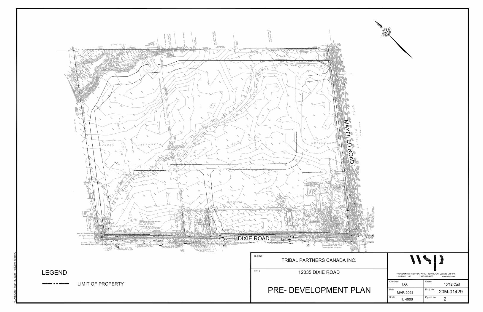
FIGURE 1 Location Plan
FIGURE 2 Pre-Development Plan
FIGURE 3 Proposed Development Plan
FIGURE 4 Water Servicing Plan
FIGURE 5 Sanitary Servicing Plan
FIGURE 6 Storm Servicing Plan
APPENDICES
APPENDIX A FUS Fire Flow Calculations
APPENDIX B Sanitary Flow Calculations

FUNCTIONAL SERVICING REPORT
Project No. 20M-01429
TRIBAL PARTNERS CANADA INC.
WSP
March 2021
Page 3
1 INTRODUCTION
1.1 SCOPE
WSP Canada Incorporated (WSP) has been retained by Tribal Partners Canada Inc. to prepare a Functional Servicing Report (FSR) to support a zoning by-law amendment and site plan approval application for the proposed development of 12035 Dixie Road in Caledon, Ontario. The purpose of this report is to provide a conceptual framework for servicing the proposed development with respect to water supply, sanitary sewage and storm drainage. A Stormwater Management (SWM) Report outlining the proposed quality and quantity controls for stormwater on this site has been prepared under separate cover, also by WSP.
In preparing this report, WSP staff secured and analyzed available Region of Peel Record Drawings, architectural drawings prepared by Baldassarra Architects, as well as a topographic survey prepared by R. Avis Surveying Inc.
1.2 SITE DESCRIPTION
The site is a 56.1 ha parcel of land bounded by Mayfield Road to the east, Dixie Road to the south, agricultural lands to the north, and existing industrial warehousing lands to the west. The site is currently used for agricultural purposes, and is primarily vacant with the exception of some structures associated with the current agricultural usage. Tributary 2 of the West Humber River flows through the site, conveying flow from the west to east, which will be re-aligned as part of the development. A woodlot which includes a wetland forms a portion of the site along the northwest boundary.
The proposed development will consist of four (4) industrial warehouse shell buildings with loading dock areas and associated trailer and car parking spaces. All site drainage is conveyed to a stormwater management pond to control storm runoff from the site to meet quantity and quality control targets. The total Gross Floor Area (GFA) of each of Buildings A, B, C, D respectively area: 123,456 m2; 37,691 m2; 17,635 m2; 21,509 m2.
All buildings will be serviced by existing watermains and sanitary sewer in the adjacent rights-of-way along Dixie Road and Mayfield Road. Refer to Figure 1 for the Location Map, Figure 2 for the Predevelopment Plan, and Figure 3 for an illustration of the Proposed Development Plan.


FUNCTIONAL SERVICING REPORT
Project No. 20M-01429
TRIBAL PARTNERS CANADA INC.
WSP
March 2021
Page 7
2 WATER SUPPLY
2.1 EXISTING CONDITIONS
WSP has obtained sewer record drawings from the Region of Peel for the area surrounding the site. Existing watermains in the vicinity of the site include a 300mm diameter Zone 6 watermain and a 400mm diameter Zone 7 watermain on Dixie Road as well as a 750mm dia. CPP transmission watermain on Mayfield Road.
2.2 DOMESTIC WATER DEMANDS
The peak domestic water demand for the development was calculated using the Region of Peel’s design criteria for industrial development. A population density of 70 persons per hectare, average consumption of 300L/employee/day, a maximum day factor of 1.4 and peak hour factor of 3.0 were used to estimate the demands from each building. The estimated fire flows have been calculated using the recommendations of the 1999 Fire Underwriter’s Survey. The table below lists the domestic and fire demands for buildings 1, 2, 3 and 4. For detailed calculations, see Appendix A.
Table 1: Domestic Water Demand and Fire Flow Requirements
Domestic Demands (L/s) Fire Flow (FUS)
Building Gross
Floor Area (m2)
Avg. Day Max. Day Peak Hour USGPM L/min L/s
A 123,456 3.0 4.2 9.0 11,346 43,000 717
B 37,691 0.9 1.3 2.8 6332 24,000 400
C 17,635 0.4 0.6 1.3 4222 16,000 267
D 21,509 0.5 0.7 1.6 4749 18,000 300
2.3 FIRE SUPPLY
WSP completed a hydrant flow test on hydrants connected to the existing 400mm diameter watermain along Dixie Road on February 23, 2021 to determine the available water supply for fire protection. The results of the test indicate that at 20 psi, a fire flow of 3900 GPM (246 L/s) is available from the hydrant nearest to the proposed water connection to Dixie Road. Therefore, the existing water supply is insufficient to provide the required fire protection outlined in Table 1.
To increase the available fire supply to the site, a looped connection is proposed to the existing 300mm diameter watermain along Russel Creek Drive. An additional hydrant flow test will be conducted to confirm the available fire supply at the hydrant along Russel Creek Drive, south of the Mayfield Road intersection. It is our understanding that the Region of Peel will use the multi-use demand table appended to this report to confirm using their water model that supply is available to meet the estimated demand of the proposed development.


FUNCTIONAL SERVICING REPORT
Project No. 20M-01429
TRIBAL PARTNERS CANADA INC.
WSP
March 2021
Page 8
2.4 PROPOSED SERVICING
To provide fire protection for the site, a 300mm diameter watermain loop is proposed within the site’s internal drive aisles which will have two connection points to the municipal water network: a connection to the existing 400mm diameter watermain along Dixie Road, and a connection to the existing 300mm watermain on Russel Creek Drive, immediately south of its interconnection to the existing 750mm diameter watermain along Mayfield Road. Each of the 4 proposed buildings will have a separate 300mm diameter fire connection made to the proposed 300mm watermain loop.
Each building shall have a separate 150mm domestic connection to the Regional water network, separately metered and fitted with a backflow preventer. Buildings C and D shall connect to the existing 400mm diameter watermain along Dixie Road, north of Merchant Road, while Buildings A and B shall connect to the existing 300mm diameter watermain along Dixie Road, south of Merchant Road.
Hydrants shall be provided in front of each proposed building. All service connections are proposed to include valve and boxes at the property line. The on-site watermains within the proposed building will be designed by the site mechanical consultant. Refer to Figure 4 for proposed water servicing layout.
2.5 REGIONAL WATER IMPROVEMENTS
Ultimately the existing 400mm diameter watermain along Dixie Road will be interconnected with watermains on Mayfield Road and Heart Lake Road and transferred to Zone 7, providing additional pressure to the site.

FUNCTIONAL SERVICING REPORT
Project No. 20M-01429
TRIBAL PARTNERS CANADA INC.
WSP
March 2021
Page 10
3 SANITARY SEWERS
3.1 EXISTING SEWER SYSTEM
There is an existing concrete pressure pipe sanitary sewer along the west side of the Dixie Road right-of-way, varying in size between 525mm and 600mm diameter. A 75mm diameter leachate line is also present within the Dixie Road right-of-way. The existing sanitary sewer is quite deep, constructed at a cover depth of approximately 11m along the site frontage of Dixie Road.
3.2 PROPOSED DEVELOPMENT
To calculate the theoretical peak sanitary flows, the following design criteria have been utilized:
► 70 persons/ha for industrial land use
► 302.8 L/cap/day average flow generation rate
► Harmon Peaking Factor
► Infiltration = 0.26 L/s/ha
The demand and peaking factors are based on Region of Peel Sanitary Sewer Design Criteria, March 2017.
3.3 PROPOSED SEWAGE FLOWS
The proposed buildings are industrial warehouses. The sanitary flow for this type of warehouse development are based on Region of Peel standards of 70 people/ha and result in an estimated total population of 1402 persons. According to Region of Peel standard drawing 2-9-2, the estimated sanitary generation for the proposed development is approximately 0.0193 m3/s. See Appendix B for the sanitary design sheet.
Sanitary sewage from the four proposed buildings will be directed to two sanitary sewers, each connecting to the existing 600mm diameter sanitary sewer along Dixie Road. Buildings A and B will share an internal 200mm sanitary sewer connecting to an existing manhole along Dixie Road. Buildings C and D will direct sanitary drainage to another 200mm diameter sanitary sewer connecting to Dixie Road. This connection will include a new maintenance hole and drop structure connecting to the existing 600mm diameter sanitary sewer.
The proposed on-site sanitary sewers will each include a control manhole located at the property line. The proposed sanitary servicing configuration is shown in Figure 5.


FUNCTIONAL SERVICING REPORT
Project No. 20M-01429
TRIBAL PARTNERS CANADA INC.
WSP
March 2021
Page 12
4 STORM DRAINAGE
A Stormwater Management Report for this development has been prepared under a separate cover by WSP Canada Inc. which details the stormwater quantity and quality controls provided to meet the requirements of the TRCA and Town of Caledon. A Channel Realignment Report has also been prepared under a separate cover by WSP Canada Inc. to detail the channel design considerations.
4.1 EXISTING STORM SEWERS
There are currently no existing storm sewers in the vicinity of the site. The existing site drainage primarily drains overland towards Tributary 2 of the West Humber River, which cuts through the middle of the site (to be realigned as part of the proposed development) and discharges to an existing culvert at the southeast corner of the site, crossing underneath Mayfield Road.
4.2 MINOR STORM DRAINAGE SYSTEM
For minor storm events, all storm drainage on-site will be captured via catchbasins, and conveyed through an on-site storm sewer system sized for the 5 year storm event. The drainage from the entire site is conveyed to a stormwater management pond which provides quantity and quality control for the site drainage.
A portion of the rooftop drainage from Building A is directed to a flow spreader adjacent to Kilamanagh Creek, a tributary of the West Humber River, to maintain surface recharge of this feature.
Refer to Figure 6 for an illustration of the proposed storm servicing. For further details regarding the stormwater management, refer to WSP’s SWM Report.
4.3 MAJOR STORM DRAINAGE SYSTEM
The major storm system is a conveyance system for flows in excess of the minor system flows. For the development of the site, the grading design is such that the surface (i.e. parking lots, drive aisles, walkways and landscaped areas) grades will direct surface drainage away from the building to the stormwater management pond through overland flow routes. The proposed grading of the subject site will ensure that existing grade elevations will be met along the property limits.


FUNCTIONAL SERVICING REPORT
Project No. 20M-01429
TRIBAL PARTNERS CANADA INC.
WSP
March 2021
Page 14
5 UTILITIES
5.1 EXISTING CONDITIONS
The servicing utilities companies in the geographical area including: Bell, Rogers, Hydro One, and Enbridge Gas have been contacted to determine the location of existing facilities at or near the site. The location of all utilities must be confirmed in the field prior to construction.
5.2 RELOCATION OF EXISTING UTILITIES AND PROVISION
FOR NEW SERVICES
New building construction and any roadworks will require field locates by each utility company and relocation as needed. As the current site is undeveloped and used primarily for agricultural uses, no on-site utility relocations are anticipated.
Each utility provider must confirm the capacity of their existing infrastructure to support the demands of the proposed development and upgrade infrastructure as necessary.

FUNCTIONAL SERVICING REPORT
Project No. 20M-01429
TRIBAL PARTNERS CANADA INC.
WSP
March 2021
Page 15
6 CONCLUSIONS
6.1 WATER SERVICING
A new internal 300mm diameter watermain is proposed, with connection points to both the existing 300mm diameter watermains along Dixie Road and Russel Creek Drive (at the Mayfield Road intersection). Domestic and fire service connections for Buildings A and B are proposed to connect to the internal 300mm diameter watermain.
To service Buildings C and D, separate domestic water connections and a shared fire connection will be made to the existing 400mm diameter watermain along Dixie Road.
6.2 SANITARY SERVICING
Sanitary sewage from this development will be conveyed to the existing 600mm diameter sanitary sewer along Dixie Road. Two connections will be made to the existing Regional sewer: Buildings A and B will connect to an existing manhole, while Buildings C and D will share a connection to a new manhole installed on the existing 600mm sanitary sewer.
Based on the Region of Peel sanitary sewer design criteria, the internal sanitary sewers have sufficient capacity to convey sewage to Dixie Road.
6.3 STORM SERVICING
Minor and major storm drainage for the proposed development will be collected by the internal site drainage system and directed to a stormwater management pond to provide quantity and quality control of site runoff.
For details concerning stormwater management, refer to the Stormwater Management Report under a separate cover.

Project: 12035 Dixie Road
Job No.: 20M-01429
Fire Flow Calculation Procedure per Water Supply for Public Fire Protection, 1999 by Fire Underwriter Survey, p 20.
whereF = Fire flow in Litres per minute (Lpm)C = coefficient related to the type of constructionA = total floor area in square metres
A. Determine Type of Construction
=> Non-combustible ConstructionTherefore C = 0.8
B. Determine Ground Floor Area
=> Fire-resistive building with vertical openings and exterior vertical communications properly protected
Therefore A = Total GFA of Largest Floor - one floor only
A = 123,456 m2
C. Determined the Fire Flow
F = 220 x 0.8 x √123456F = 61,840 Lpm
D. Determine Increase or Decrease for Occupancy
=> No Reduction for Combustible OccupanciesTherefore 0% reduction
0% reduction of 61840 Lpm = - Lpm61840 - 0 = 61,840 Lpm
E. Determine Decrease for Automatic Sprinkler Protection
=> Has Automatic Sprinkler Protection (Per NFPA 13 Standards)Therefore 30% reduction
30% reduction of 61840 Lpm = 18,552 Lpm61840 - 18552 = 43,288 Lpm
F. Determine the Total Increase For Exposures
West Side >45 0%East Side >45 0%
North Side >45 0%South Side >45 0%
Total 0% of 61,840 =
G. Req'd Fire Flow = C - E + F
F = 43,288 LpmF = 43,000 Lpm (2,000 Lpm < F < 45,000 Lpm; OK)
F = 11,345.6464 US GPM
Note
APPENDIX A
FIRE FLOW CALCULATIONS - BUILDING A
0 Lpm
ACF 220=
Date Printed: 3/12/2021 X:\DIV10\20M-01429 - 12035 Dixie Road\MUN\FSR\20M-01429 _FUS Fire Calculation_v2.xls

Project: 12035 Dixie Road
Job No.: 20M-01429
Fire Flow Calculation Procedure per Water Supply for Public Fire Protection, 1999 by Fire Underwriter Survey, p 20.
whereF = Fire flow in Litres per minute (Lpm)C = coefficient related to the type of constructionA = total floor area in square metres
A. Determine Type of Construction
=> Non-combustible ConstructionTherefore C = 0.8
B. Determine Ground Floor Area
=> Fire-resistive building with vertical openings and exterior vertical communications properly protectedTherefore A = Total GFA of Largest Floor - one floor only
A = 37,691 m2
C. Determined the Fire Flow
F = 220 x 0.8 x √37691F = 34,169 Lpm
D. Determine Increase or Decrease for Occupancy
=> No Reduction for Combustible OccupanciesTherefore 0% reduction
0% reduction of 34169 Lpm = - Lpm34169 - 0 = 34,169 Lpm
E. Determine Decrease for Automatic Sprinkler Protection
=> Has Automatic Sprinkler Protection (Per NFPA 13 Standards)Therefore 30% reduction30% reduction of 34169 Lpm = 10,251 Lpm
34169 - 10251 = 23,918 Lpm
F. Determine the Total Increase For Exposures
West Side >45 0%East Side >45 0%
North Side >45 0%South Side >45 0%
Total 0% of 34,169 =
G. Req'd Fire Flow = C - E + F
F = 23,918 LpmF = 24,000 Lpm (2,000 Lpm < F < 45,000 Lpm; OK)
F = 6,332 US GPM
Note
APPENDIX A
FIRE FLOW CALCULATIONS - BUILDING B
0 Lpm
ACF 220=
Date Printed: 3/12/2021 X:\DIV10\20M-01429 - 12035 Dixie Road\MUN\FSR\20M-01429 _FUS Fire Calculation_v2.xls

Project: 12035 Dixie Road
Job No.: 20M-01429
Fire Flow Calculation Procedure per Water Supply for Public Fire Protection, 1999 by Fire Underwriter Survey, p 20.
whereF = Fire flow in Litres per minute (Lpm)C = coefficient related to the type of constructionA = total floor area in square metres
A. Determine Type of Construction
=> Non-combustible ConstructionTherefore C = 0.8
B. Determine Ground Floor Area
=> Fire-resistive building with vertical openings and exterior vertical communications properly protectedTherefore A = Total GFA of Largest Floor - one floor only
A = 17,635 m2
C. Determined the Fire Flow
F = 220 x 0.8 x √17635F = 23,372 Lpm
D. Determine Increase or Decrease for Occupancy
=> No Reduction for Combustible OccupanciesTherefore 0% reduction
0% reduction of 23372 Lpm = - Lpm23372 - 0 = 23,372 Lpm
E. Determine Decrease for Automatic Sprinkler Protection
=> Has Automatic Sprinkler Protection (Per NFPA 13 Standards)Therefore 30% reduction30% reduction of 23372 Lpm = 7,012 Lpm
23372 - 7012 = 16,360 Lpm
F. Determine the Total Increase For Exposures
West Side >45 0%East Side >45 0%
North Side >45 0%South Side >45 0%
Total 0% of 23,372 =
G. Req'd Fire Flow = C - E + F
F = 16,360 LpmF = 16,000 Lpm (2,000 Lpm < F < 45,000 Lpm; OK)
F = 4,222 US GPM
Note
APPENDIX A
FIRE FLOW CALCULATIONS - BUILDING C
0 Lpm
ACF 220=
Date Printed: 3/12/2021 X:\DIV10\20M-01429 - 12035 Dixie Road\MUN\FSR\20M-01429 _FUS Fire Calculation_v2.xls

Project: 12035 Dixie Road
Job No.: 20M-01429
Fire Flow Calculation Procedure per Water Supply for Public Fire Protection, 1999 by Fire Underwriter Survey, p 20.
whereF = Fire flow in Litres per minute (Lpm)C = coefficient related to the type of constructionA = total floor area in square metres
A. Determine Type of Construction
=> Non-combustible ConstructionTherefore C = 0.8
B. Determine Ground Floor Area
=> Fire-resistive building with vertical openings and exterior vertical communications properly protectedTherefore A = Total GFA of Largest Floor - one floor only
A = 21,509 m2
C. Determined the Fire Flow
F = 220 x 0.8 x √21509F = 25,812 Lpm
D. Determine Increase or Decrease for Occupancy
=> No Reduction for Combustible OccupanciesTherefore 0% reduction
0% reduction of 25812 Lpm = - Lpm25812 - 0 = 25,812 Lpm
E. Determine Decrease for Automatic Sprinkler Protection
=> Has Automatic Sprinkler Protection (Per NFPA 13 Standards)Therefore 30% reduction30% reduction of 25812 Lpm = 7,744 Lpm
25812 - 7744 = 18,068 Lpm
F. Determine the Total Increase For Exposures
West Side >45 0%East Side >45 0%
North Side >45 0%South Side >45 0%
Total 0% of 25,812 =
G. Req'd Fire Flow = C - E + F
F = 18,068 LpmF = 18,000 Lpm (2,000 Lpm < F < 45,000 Lpm; OK)
F = 4,749 US GPM
Note
APPENDIX A
FIRE FLOW CALCULATIONS - Building D
0 Lpm
ACF 220=
Date Printed: 3/12/2021 X:\DIV10\20M-01429 - 12035 Dixie Road\MUN\FSR\20M-01429 _FUS Fire Calculation_v2.xls

Diameter: 400 mm Material: Residual Hydrant:
Area: 0.126 m2 Flow Hydrant:
TABLE A: TESTED PRESSURES AND FLOWS
Start Finish (kPa) (psi) (L/s) (GPM) (L/s) (GPM) (L/s) (GPM) (m/s)
Static 460 522 356 51.6 0.0 0 0.0 0 0.0 0 0.0
2'' 595 638 351 50.9 38.0 602 0.0 0 38.0 602 0.3
2" 0 0.0 0.0 0 0.0 0 0.0 0 0.0
1" + 2" 0 0.0 0.0 0 0.0 0 0.0 0 0.0
2" + 2" 699 729 335 48.6 35.7 566 33.9 537 69.6 1103 0.6
Test 1 - 12035 Dixie Road
Subject Watermain Details Subject Hydrant & Valve Details
Start of Test
8:52:40
S3 on Residual Hydrant: Port 1 (S1) Port 2 (S2)PointTime
Residual Flow Hydrant ()Total Flow Velocity
31
32
33
34
35
36
37
38
39
290
305
320
335
350
365
380
395
410
450 490 530 570 610 650 690 730 770 810 850 890
Flo
w (
L/s
)
Pre
ss
ure
(k
Pa)
Time from Start of Test (s)
Residual Flow 1 Flow 2
2"
Stat
ic
2"
+ 2
"

Date: Time: 8:52 Municipality(hh/mm) Operator:
Tested By:Test No:
51.6 psi 356 kPa
51.6 psi 356 kPa
0.0 psi 0 kPa
0.0 ft 0.0 m
Test Notes:
Port Size
(in)
Nozzle
Pressure
(psi)
(USGPM) (L/s)Monitoring
Hydrant
Flow Hydrant
(Corrected) *
STATIC n/a 0 0 51.6 51.6
2 14.9 602.0 38.0 50.9 50.9 20 4596 290 NO
2 20
1
2
2 11.8 537.0 33.9
2 13.2 566.0 35.7
* Pressure correction is equal to the elevation difference. Column 2 (and Table A) show the nozzle pressure while flowing.
(psi) (kPa) (gpm) (L/s)
51.6 356 3900 246
Class AA Color BLUE
13200 L
Rounded up to closest 100L
WSP Canada Inc. 100 Commerce Valley Drive West, Thornhill, Ontario L3T 0A1 20M-01429-00
Elevation Difference:
0
Sen 1
Conditions before Test (STATIC)
12035 Dixie Road HYDRANT FLOW TEST RESULTS
23-Feb-21 Town of Caledon
(Flow El. - Residual El.)
Residual Hydrant:
Hydrant that will Flow:
∆ pressure:
5% Pressure Drop
Achieved?
Single Port Tests
Two Port Test
20
TEST TEST FLOW RESIDUAL PRESSURE (psi)
Minimum
Residual Pr (psi)
Fire Flow at
Minimum
Residual, Qr
(USGPM)
Fire Flow at
Minimum
Residual, Qr
(L/s)
3912 247 YES
Results
Two Port Test
48.6 48.6 20
* Results carried to nearest 50 gpm or 100 gpm if over 1000 gpm
Static Pressure Flow at 20 psi (140kPa)*
Hydrant Classification as per NFPA 291
Water Discharged During Test:
DISCLAIMER FOR FIRE FLOW TESTS
While WSP makes every effort to ensure that the information contained herein is accurate and up to date, WSP is not responsible for unintended or incorrect use of the data
and information described and/or contained herein. The user must make his/her own determination as to its accuracy and suitability. The information is representative for a
dynamic water system that may change over time.
© WSP Canada Inc. 2014.
This information sheet can be reproduced by the client for internal use but not redistributed to third parties without the written authorization of WSP.
Tel.: (905) 882-1100
0
10
20
30
40
50
60
0 1000 2000 3000 4000 5000
PR
ES
SU
RE
(P
SI)
FLOW (GPM)
Residual Pressure vs. Hydrant Flow
N
Flow
Residual

APPENDIX
B SANITARY FLOW CALCULATIONS

SHEET 1 OF 1
THE REGIONAL MUNICIPALITY OF PEEL SANITARY DESIGN CHART
12035 DIXIE ROAD
CONSULTANT: * DESIGN FLOWS AS PER REGION OF DATE: 11-Mar-21
WSP Canada Inc PEEL SANITARY SEWER DESIGN FLOW DESIGNED BY: J.G.
CHART STD. DWG. 2 - 5 - 2 Manning's n= 0.013 CHECKED BY: A.W.
SEWAGE INFILTRATION TOTAL
LOCATION FROM TO AREA AREA UNITS POP. CUM. CUM. FLOW * FLOW * FLOW FALL LENGTH GRADIENT PIPE SIZE CAPACITY VELOCITY
MH MH DENSITY AREA POP. 0.00020
(ha) (ppha) (ha) (m³/sec) (m³/sec/ha) (m³/sec) (m) (m) (%) (mm) (m³/sec) (m/sec)
Proposed Building D PLUG MH1A 2.15 70 151 2.15 151 0.0130 0.0004 0.0134 10.0 1.00 200 0.033 1.04
MH1A MH2A 0 2.15 151 0.0130 0.0004 0.0134 107.5 1.00 200 0.033 1.04
Proposed Building C PLUG MH2A 1.76 70 123 1.76 123 0.0130 0.0004 0.0134 10.0 1.00 200 0.033 1.04
MH2A MH3A 0 3.91 274 0.0130 0.0008 0.0138 107.5 1.00 200 0.033 1.04
Proposed Building A PLUG MH9A 12.35 70 865 12.35 865 0.0130 0.0025 0.0155 20.0 1.00 200 0.033 1.04
MH9A MH3A 0 12.35 865 0.0130 0.0025 0.0155 58.5 1.00 200 0.033 1.04
MH3A MH4A 0 16.26 1138 0.0151 0.0033 0.0184 94.0 1.00 200 0.033 1.04
MH4A MH5A 0 16.26 1138 0.0151 0.0033 0.0184 59.7 1.00 200 0.033 1.04
MH5A MH6A 0 16.26 1138 0.0151 0.0033 0.0184 57.4 1.00 200 0.033 1.04
Proposed Building B PLUG MH8A 3.77 70 264 3.77 264 0.0130 0.0008 0.0138 30.0 1.00 200 0.033 1.04
MH8A MH6A 0 3.77 264 0.0130 0.0008 0.0138 20.0 1.00 200 0.033 1.04
MH6A MH7A 0 20.03 1402 0.0181 0.0040 0.0221 31.0 1.00 200 0.033 1.04
MH7A EX MH 0 20.03 1402 0.0181 0.0040 0.0221 36.0 1.00 200 0.033 1.04
C:\Users\glebenj\Documents\_PROJECT FILES\12035 Dixie\SAN DESIGN SHEET (1).xlsSANSHEET (2) Printed: 3/15/2021

REGION OF PEEL MULTI-USE DEMAND TABLE
WATER CONNECTION
1. Fire - Existing 300mm Watermain on Russel Creek Drive
2. Fire - Existing 400mm Watermain on Dixie Road at Merchant Road
3. Dom. - Existing 300mm Watermain on Dixie Road south of Merchant Road
4. Dom. - Existing 300mm Watermain on Dixie Road at Merchant Road
5. Dom. - Existing 400mm Watermain on Dixie Road north of Merchant Road
6. Dom. - Existing 400mm Watermain on Dixie Road north of Merchant Road
Total equivalent population to be serviced 1404
Total lands to be serviced(ha) 20.0
Pressure (psi) Flow (GPM)
51.6 STATIC
50.9 4596
48.6 3912.0
1 Average day flow (L/s) 3.0 0.9 0.4 0.5 4.9
2 Maximum day flow (L/s) 4.2 1.3 0.6 0.7 6.8
3 Peak hour flow (L/s) 9.0 2.8 1.3 1.6 14.6
4 Fire flow (L/s) 716.7 400.0 266.7 300.0 716.7
5 Maximum day plue fire flow (L/s) 720.9 401.3 267.3 300.7 723.5
6 Peak hour flow (L/s) 9.0 2.8 1.3 1.6 14.6
7 Maximum demand flow (L/s) 720.9 401.3 267.3 300.7 723.5
WASTEWATER CONNECTION
Connection Point: Ex MH, intersection of Dixie Road and Merchant Road
Total Lands to be serviced (ha): 20
Total equivalent population to be serviced (ICI): 1404
Wastewater Sewer Effluent (m3/s): 0.0221
CONNECTION POINT
Pressure zone of connection point
Pressure Zone 7
Hydrant Flow Test
East side of Dixie Road, north of Merchant Road
Analysis
Total
Water demand
Demand typeNo.
Building A Building B Building C Building D