Embed Size (px)
Citation preview

Triaxial mQisture-controlled creep tests
of hardened cement paste
at high temperature
Z. P. Bazant C), s. S. Kim (2), S. Meiri (3)
Creep tests of sealed specimens as u'ell as unsealed specimens exposed to either pressurized water or air have heen conducted at t'ario[(s constant temperatures ji-om 100 to 300°C and durations up to 24 hours. Apart from the need to study multiaxial deformations, the triaxial loading is required to prevent moisture escape ji-om the sealed specimen. The specimens are suffiCiently small to achieve uniform temperature and moisture content in less than 3 minutes. Overcoming various difficulties, a triaxial testiny daice U'(lS huilt. Specimens heated at the time of loading and before loading u'ere tested. Some neu' and unexpected results are .found: (a) unsealed specimens exposed to pressurized hot u'ater creep much less than sealed specimells and the difference in creep rate hecomes weater (ifter afetC hours; (h) daiatoric creep of sealed specimens is at high temperatures much larger than the mlumetric creep; (c) at l00°e, unsealed specimens loaded at the time of heatiny creep much more than sealed specimens, but at 200°C the situation is reversed; (d) the shrinkage and the additional creep due to dryiny exhihit weat delay after dryiny. Furthermore, with a several hour increase of the period of preheating hef()re loading, creep is substantially reduced, and the axial creep appears to depend nearly linearly on the axial stress superimposed on a hydrostatic pressure. 711e results appear to have some neu' implications for the accident analysis of reactor vessels as u'e/I as .fire resistance.
INTRODUCTION
When the long time stress is not negligible compared to the allowable stress, creep is the largest part of deformations of concrete, even at room temperatures. At high temperatures, exceeding 100°C, creep predominates by far, and is significant even for loads whose durations are in seconds. Therefore, if we want to reliably calculate thermal stress, the inherent cracking, deflections and redundant forces in concrete structures subjected to fire, in concrete reactor vessels subjected to a hypothetical nuclear core-disruptive accident, or in vessels for coal
liquefaction exposed to process heat, we must take account of creep in the first place.
(') Professor of Civil Engineering, Northwestern University, Evanston, Illinois 60201.
(l) Graduate Research Assistant, Northwestern University. Evanston, Illinois, 6020 I.
e) Research Engineer, Northwestern University, Evanston. Illinois, 6020 I.
0025-5432/1979/447/$ 4.00/lcl BORDAS-DUNOD
The effect of moisture conditions at high temperature upon creep is as strong as it is at room temperature. It is tremendously important whether the specimen holds, loses or gains water, and whether the loss or gain happens during creep or well before loading. Because of the ease in testing, most high temperature creep tests carried out so far dealt with specimens that were losing moisture, either freely or within an enveloping seal ( [5], [7], [9]- [18 D. The free moisture loss regime is characteristic of the surface layer of a concrete structure subjected to fire, but is not pertinent for the core of the cross sections, especially if we deal with thicker members. Because moisture permeability is much less than heat conductivity of concrete, the core loses moisture only relatively long after it gets heated. The blockage of
447
Vol. 12 - N° 72 - Materiaux et Constructions
mQisture loss is extreme for reactor vessels, not only because they are so massive but also because they are usually provided with an anchored steel liner on the heated face. This has been of course realized early, yet beyond lOOoe no creep tests at zero moisture loss have been carried out to date. The specimens were, for example, enclosed in metallic jackets, but the jackets bulged under the internal pressure produced by heating and moisture collected within the jacket outside the specimen. The moisture loss cannot be eliminated by making the jacket stiff rather than flexible, for the stress and displacement boundary conditions could not then be properly controlled.
How can we then test the creep at zero moisture loss? In triaxial loading, and this is the main idea of this work. The past high temperature creep testing has all been uniaxial, yet we obviously need lateral external pressure, p, to prevent bulging of a flexible jacket. In fact, uniaxial creep at zero moisture loss does not, at high temperature, exist. This is because it is not feasible to apply pressure at concrete surface on the pores (gel pores), so as to keep moisture in the specimen, and at the same time apply no pressure on the solid microstructure, as required for achieving the state of uniaxial stress. Indeed, the external lateral pressure needed to prevent bulging of a flexible jacket must at least equal the internal pressure which is induced by rapid heating within the core of a massive structure. And since triaxial stress states are typical of such structures, triaxial creep testing is more appropriate anyway.
Aside from creep of sealed specimens, the triaxial loading enables testing the creep at oversaturation, i. e., when the pressure of hot water exceeds the saturation' pressure for the given temperature, causing the water content to exceed that for saturation pressure. This apparently has not yet been studied. It will be seen that, surprisingly, the creep under such conditions is not at all the same as the creep at zero change of moisture content, which is important for the behavior of an oversaturated layer of concrete that is always created deeper under the surface just ahead of the advancing heat front [5]. For comparison, the creep of unsealed specimens exposed to hot air as well as pressurized hot water will be also reported.
EXPERIMENT AL METHOD
Test specimens
To keep the costs of building the test chamber low, only small specimens, made of hydrated cement paste, were used. They were solid cylinders, 14.5 mm in diameter and 59. 5 mm in length. The behavior of concrete may be expected to be similar and could be estimated from the test results by calculating the restraining effect of the aggregate, which behaves elastically within the range considered.
The small size has, however, its own advantages.
448
It makes the specimen response to a change in environmental temperature or moisture condition much faster. This can be illustrated by the temperature equalization period, understood as the time, t95 , in which the center of the cylinder attains 95% of the previous sudden change in surface temperature. According to the diffusion theory [8], t95 :::::: D2/8k where D=cylinder diameter, k=heat (or moisture) diffusivity. For concre~e, we typically have perhaps k=0.8 em2/min. [5], and so t95 :::::: 35 minutes for a 15 em cylinder, while for our specimen we get t95=20 seconds. For moisture conduction at constant temperatures in excess of 100°C, we get, according to [5], t95 :::::: 20 hours for a 15 cm cylinder, and 2.8 minutes for our specimen, whereas at room temperature we get t95 :::::: 1 year for a 15 em cylinder and t95 = 20 hours for our specimen.
So the moisture content no doubt equalizes in our heated specimen within less than 3 minutes. Note, however, that this does not imply cessation of shrinkage after 3 minutes. Moisture content is governed by the degree of saturation of macropores, whereas shrinkage is largely affected by local microscopic moisture migration between the macropore and the adjacent micropores. This process, leading to equalization of Gibbs' free energy between micropores and macropores, can continue for a long time after an equilibrium between the macropore and the ambient medium has been achieved.
Thus, we see that for high temperature creep our specimen is small enough to assure that even if temperature or moisture conditions are changed at the moment of loading, a state of uniform temperature and moisture content will prevail during the creep test. With larger (concrete) specimens this condition cannot be achieved (unless the environmental temperature is raised very slowly); this causes that internal stresses develop within the test specimen.
The creep measurements have been continued only for 24 hours. This is entirely sufficient for the major applications - for fire effects as well as reactor accidents the duration of interest does not usually exceed 1 day.
The specimens were made of Portland cement 20687, ASTM Type I, with water-cement ratio 0.45 by weight. To eliminate entrapped air bubbles, the paste was mixed under vacuum and then poured into brass molds. The specimen was cured in the mold for 1 day at 25°C and 100% relative humidity, then unmolded and cured until the age of 28 days in a water bath of 25°C temperature, containing lime to prevent carbonation. Each specimen was then placed in a lime water bath of 2°C and kept in it until the test. This cold storage can be assumed to have essentially arrested hydration, so that the effective age of each specimen may be taken roughly as 28 days even though the periods of cold storage varied, as convenient. The ends of the specimen were ground in wet condition shortly before the test, in order to achieve perfectly flat and orthogonal end surfaces.
The creep of the specimen material at ordinary temperatures was reported in [2] and [3].
Uppec $pe(:lmen Cop
~'-LLLL<~j-O_rI ng
14.5mm
Cement Paste Specimen
Teflon Tube (Up to 3OCl"C) or Copper FOil (above 300'C)
Bottom / /-rr.=t<t- Specimen
Cap
Ib)
Pressurized Waterline for A)(lal Load ~
z. P. Bazant - S. S. Kim - S. Meiri
Tl43mm----------ool
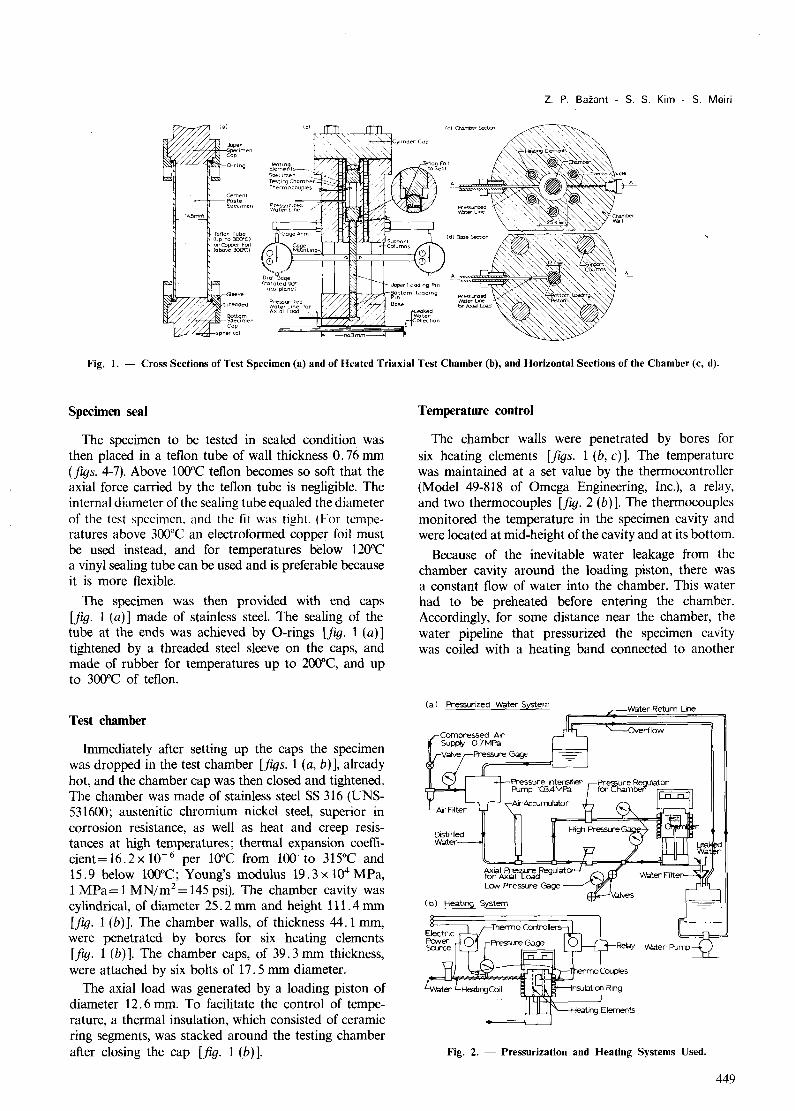
Fig. 1. - Cross Sections of Test Specimen (a) and of Heated Triaxial Test Chamber (b), and Horizontal Sections of the Chamber (c, d).
Specimen seal
The specimen to be tested in sealed condition was then placed in a teflon tube of wall thickness 0.76 mm (fl{}s. 4-7). Above 100°C teflon becomes so soft that the axial force carried by the teflon tube is negligible. The internal diameter of the sealing tube equaled the diameter of the test specimen. and the fit was tight. (For temperatures above 300"e an electroformed copper foil must be used instead, and for temperatures below 120°C a vinyl sealing tube can be used and is preferable because it is more flexible.
The specimen was then provided with end caps [fig. 1 (a)] made of stainless steel. The sealing of the tube at the ends was achieved by O-rings [fig. 1 (a)] tightened by a threaded steel sleeve on the caps, and made of rubber for temperatures up to 2000e, and up to 300°C of teflon.
Test chamber
Immediately after setting up the caps the specimen was dropped in the test chamber [fl{}s. 1 (a, b)], already hot, and the chamber cap was then closed and tightened. The chamber was made of stainless steel SS 316 (UNS-531600; austenitic chromium nickel steel, superior in corrosion resistance, as well as heat and creep resistances at high temperatures; thermal expansion coefficient=16.2x 10- 6 per 10°C from 100 to 315°C and 15.9 below 100°C; Young's modulus 19.3 x 10⁴ MPa, 1 MPa= 1 MN/m2= 145 psi). The chamber cavity was cylindrical, of diameter 25.2 mm and height 111. 4 mm [fig. 1 (b)]. The chamber walls, of thickness 44.1 mm, were penetrated by bores for six heating elements [fig. 1 (b)]. The chamber caps, of 39. 3 mm thickness, were attached by six bolts of 17. 5 mm diameter.
The axial load was generated by a loading piston of diameter 12.6 mm. To facilitate the control of temperature, a thermal insulation, which consisted of ceramic ring segments, was stacked around the testing chamber after closing the cap [fig. 1 (b)].
Temperature control
The chamber walls were penetrated by bores for six heating elements [[I{}s. 1 (b, en The temperature was maintained at a set value by the thermocontroller (Model 49-818 of Omega Engineering, Inc.), a relay, and two thermocouples [fl{}. 2 (b)]. The thermocouples monitored the temperature in the specimen cavity and were located at mid-height of the cavity and at its bottom.
Because of the inevitable water leakage from the chamber cavity around the loading piston, there was a constant flow of water into the chamber. This water had to be preheated before entering the chamber. Accordingly, for some distance near the chamber, the water pipeline that pressurized the specimen cavity was coiled with a heating band connected to another
(a) Pressurized water System
Distilled Wdier
fo'f'.hxFt..~legulator-Lo.v Pre5SJre Gage
( b) Heating System
ater Return line
Fig. 2. - Pressurization and Heating Systems Used.
449

Ul<m1OC01Hrolicr, a"d was healed aooul 30 10 5Cre higher lh"" the desired ,cmpcml uTC fOT Inc Specimcn c"vit}, boc:!\l se the flow of waler proyenls il to reach ful ly (ne temperature of lhc m ib ! pipdi rl~.
I" "II 10m. 'he "'hok: t riaxial chamber had Ix'en preh.aloo (o r at 1e,,'1 lw~ hours before the test wa\ &wrIW. in urder '0 p,,-",elll th erm;ol ""JXmsio ll of lilC cha m ber during the lest. Hefore lesting. it was chcrkcd whclilcr lil e lcml'"rMu= irldic"lc. l b)' holh therrn<>_ couples W~'fC c~l lI al: Ihey W"'" rC<.Juired 10 be "'i lhin j Oe.
The k..,t specimen \YllS then dropj>cd in1<llhe h<J1 d ",mbcr. II look only "bool I hr~"<: minul'" to ""I the 'P'-"<:itn<11 into the cha m ber and ;opply (ho Io;,d , alld the errors due 10 lhi. lime intc,,'ul were con.idereJ irl c;,~luating lhe r",,,li ng, ,
I ,oad roUlrol
Di"li llc~1 w,Oler w;os used (0 press" ri", the spocimcn c""it )' as weli a, to dri"e the axia l l"'Ld ing piston , Waler Wa< pres'uri'cd hy an inlen,ir.". fi uid pump dr iYen hy oo""pressed "ir supply (H",kd pump Mood A W i JO-A(.1. hQ\'ing i ntcnsirlC~lion ratio [ : ISO which provides maxi mum p,os.,urc of [(Xl MP"J, Di. lilled ,,'ater ,,-as used. <0 '" 10) pr"vCnl cloggiTl g, [0 \- i~'W or \ h~ "c-.:<J 10 ruJuce lhe Ica~ "He arou nd (he piS10U. the possihili ly of using high yiso:;OSily hlbricanb (silicon oi ls. lDOlor "i l) w,", stud ied bUI was not adopted because Jl high tempe .. 'tUfe lhc "iseo,it), "d"anlago O)\W ,,'aler I "",,,,,,~, , ma ll. " "d iJ,x;L USC " nscalc~[ specimens cxposC<J 10 prcosuri;--cd " '" te, must be also included in lhe lcsting rrog",m.
Pressure reducing regulators (Tescom, Model 26-1012-24, limited to 41 MPa) were used to control pressure in the specimen cavity as weIl as that on the axial loading piston. To eliminate friction on the bottom part of piston, gravity loading with a 20 : 1 lever arm was also tried, but was abandoned because rotation of the lever introduced a horizontal force upon the piston, causing its tilting. Pressure gages were mounted on the lines from the regulator to the specimen cavity, and from the other regulator to the loading piston. The axial load applied upon the specimen equals the piston pressure minus the cavity pressure times the piston area.
The pressure reducing regulator which supplied the high pressures (up to 41 MPa) could not control with sufficient accuracy the low axial piston pressures needed just to keep the piston in contact during the shrinkage tests of drying specimens. For this purpose, another pressure-reducing regulator, limited to 3.4 MPa pressure, was mounted on the water line to the axial loading piston [fig. 2 (a)]. Two valves were installed on the line before and after the low pressure gage; the first one (front) was used for blocking the high pressure from this gage to protect it, and the second one (rear) was to release the pressure leaked by the first valve. Pressure accumulator was used to eliminate pressure fluctuations during the retractive stroke of the pump. Water that inevitably leaked around the piston was collected, filtered and returned to the system.
For tests of unsealed specimens exposed to air the water lines were disconnected and the chamber was vented.
Leakage and friction on the piston
This was the most difficult problem to overcome in building the test device. If the rate of water leak is large, it impairs the temperature control of the specimen cavity. Moreover, it causes cooling of the piston, which then contracts and aIlows a still higher leak rate. The temperature of the piston must be equal to the temperature of the chamber in order to assure a tight enough fit (for this reason, too, the same material, having the same thermal dilatation coefficient, must be used for the piston and the chamber). Water leakage can be reduced by a tighter fit of the piston. But this has its limits, not only because of the tolerances of machining, but mainly because a tighter fit increases friction on the loading piston. Any significant friction must be avoided because, for other reasons, it was decided to measure the load and deformation outside the hot cavity.
To reduce friction, yet obtain a tight enough fit, electroplating of the piston with a soft, non-corroding metal, gold, proved to be somewhat beneficial and has been used. However, a not too tight fit appeared to be preferable because of friction, and a gap of 0.025 mm was used. (Gaps as small as 0.0025 mm could be obtained by machining, and were actuaIly tried but abandoned because of unacceptable friction.)
z. P. Bazant - s. S. Kim - S. Meiri
The leak problem was solved by placing a thin circular teflon sheet at the bottom of the specimen cavity. The pressurized water would press this sheet tightly upon the piston head and the adjacent bottom waIl of cavity, and the sheet would bridge the narrow gap. The sheet ran through the point where the piston would contact the steel cap of the specimen. This might be suspected of affecting the .deformation transmitted from, the specimen to the gage; however, due to the applied load the sheet (hot and soft) gets compressed at this point to such a smaIl thickness that the effect of the sheet on measured displacements is undetectable.
The magnitude of friction was checked by calibration tests in which a dummy steel specimen was loaded, unloaded and reloaded in the heated chamber; all deformation was quite well recoverable and repetitive, with a negligible hysteresis (the hysteresis loops having a width of not more than 7% of the maximum value).
Consideration has been given to the bedding effects in the contacts at the various interfaces (specimen-end cap-piston). Such effects, if significant, would not be quite eliminated by the calibration. For concrete specimens at room temperature they are known to be significant. Fortunately, though, the creep deformation of heated cement paste is found to be so much larger that the bedding effects can have no significance.
As a further improvement (which, however, has not been used in the tests reported here), a floating type seal, lap-matched and free to slide laterally to adjust itself to any alignment of the piston, is desirable. This would assure that the sealing contact of the piston on the seal would receive no lateral load.
Measurement of deformations
Because creep strains of cement paste at high temperature are comfortably large, far greater than those of concrete at room temperature, dial gages are sufficient to measure them. To have a foolproof control, it was decided to measure the displacements outside the heated area, on the exposed part of the loading piston [fig. 1 (b)). Two symmetrically located dial gages (Starett, of resolution 0.0001 inch, were used for this purpose) [jig. 1 (b)]. The axial load was measured also outside the heated area, by means of the pressure on the loading piston.
For measurements at variable temperature, the whole testing device must be calibrated with a dummy specimen made of an elastic material of precisely known thermal expansion (e. g., steel, invar).
Test procedure
After setting the specimen in the heated chamber, the specimen was allowed 2 minutes to heat up. Then the axial load was quickly raised to the prescribed level and the first gage reading was made. For unsealed specimens exposed to air (without pressure), the axial load was
451
Vol. 12 - N° 72 - Materiaux et Constructions
(a) at 100·C 30
1: -6 as MP.l, B,C
rOM .. A . \
(b) at 2f:xfC 60
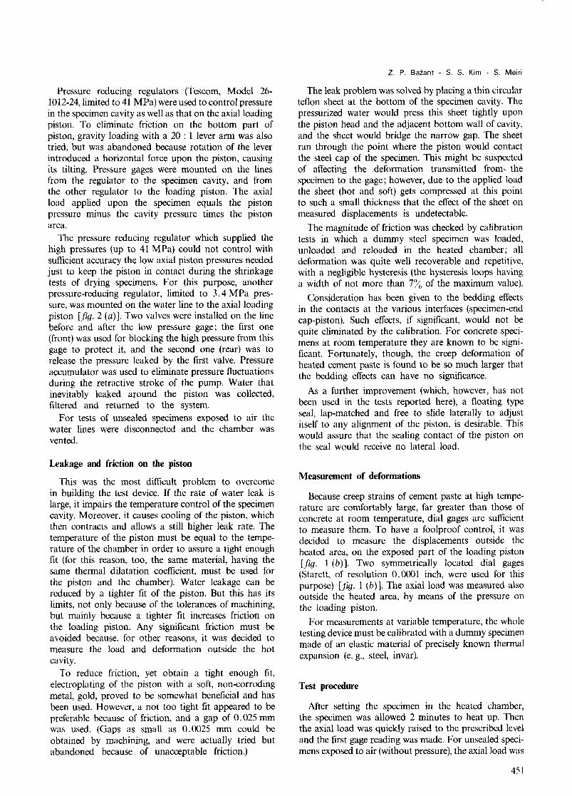
Fig. 4. - Comparison of Creep of Sealed Specimens and Unsealed Specimens in Air or Water.
applied immediately after closing the chamber. Because of the rather scattered and erratic values of the initial strain co from the first dial gage readings, only the deformation increases c - eo from the time of the first reading are reported in the figures (figs. 4-8).
All the curves plotted in figures 4-8 are based on the average from at least two specimens, unless otherwise noted on the curves. If the differences in strains exceeded about 20%, another test was performed, and one of the two previous tests was rejected. Many test curves are based on the average from three or four specimens, as marked.
Main observations from tests
1. At 200°C the axial creep of a sealed specimen (with zero moisture loss) at hydrostatic pressure p is much larger than the axial creep of an unsealed specimen exposed to hot water under the same pressure p, and at 100°C it is somewhat larger [figs. 4 (a, b)], whereas below 100°C the creep under these two conditions is known to be about the same.
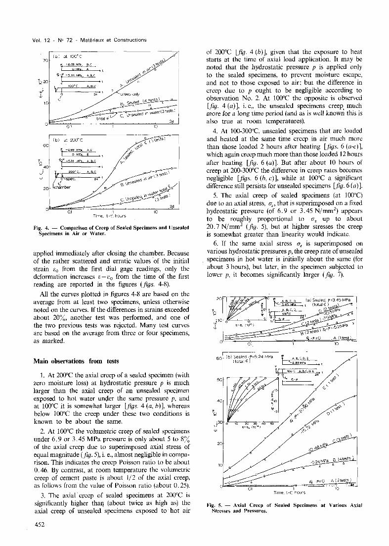
2. At 100°C the volumetric creep of sealed specimens under 6.9 or 3.45 MPa pressure is only about 5 to 8% of the axial creep due to superimposed axial stress of equal magnitude (fig. 5), i. e., almost negligible in comparison. This indicates the creep Poisson ratio to be about 0.46. By contrast, at room temperature the volumetric creep of cement paste is about 1/2 of the axial creep, as follows from the value of Poisson ratio (about 0.25).
3. The axial" creep of sealed specimens at 200°C is significantly higher thaq (about twice as high as) the axial creep of unsealed specimens exposed to hot air
452
of 200°C [fig. 4 (b)], given that the exposure to heat starts at the time of axial load application. It may be noted that the hydrostatic pressure p is applied only to the sealed specimens, to prevent moisture escape, and not to those exposed to air; but the difference in creep due to p ought to be negligible according to observation No.2. At 100°C the opposite is observed [fig. 4 (a)], i. e" the unsealed specimens creep, much more for a long time period (and as is well known this is also true at room temperatures).
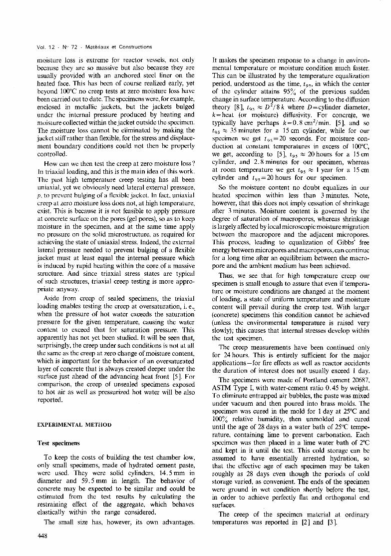
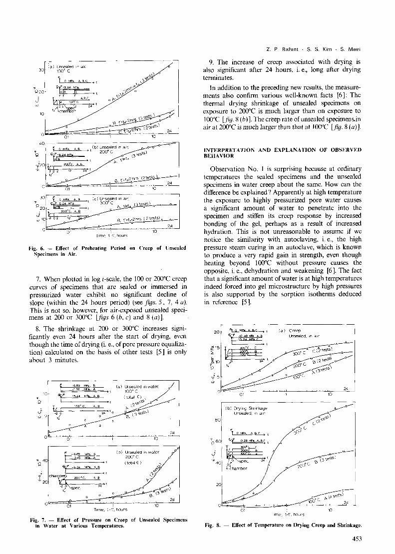
4. At lOO-300°C, unsealed specimens that are loaded and heated at the same time creep in air much more than those loaded 2 hours after heating [figs. 6 (a-c)], which again creep much more than those loaded 12 hours after heating [fig. 6 (an But after about 10 hours of creep at 200-300°C the difference in creep rates becomes negligible [figs. 6 (b, c)], while at 100°C a significant difference still persists for unsealed specimens [fig. 6 (a)].
5. The axial creep of sealed specimens (at 100°C) due to an axial stress, Uz ' that is superimposed on a fixed hydrostatic pressure (of 6.9 or 3.45 N/mm2) appears to be roughly proportional to U z up to about 20.7 N/mm2 (fig. 5), but at higher stresses the creep is somewhat greater than linearity would indicate.
6. If the same axial stress Uz is superimposed on various hydrostatic pressures p, the creep rate of unsealed specimens in hot water is initially about the same (for about 3 hours), but later, in the specimen subjected to lower p, it becomes significantly larger (fig. 7).
Fig. 5. - Axial Creep of Sealed Specimens at Various Axial Stresses and Pressures.
(a) Unsealed In air, 30 100' C
10
o 0.1 10
30 l' a Me;, A, B (c) Unsealed In air, 10 "( 5 24 Mea ' 300' C 't (3 tests) -0---"--'-20 _Ie It n ~o~o-o
J tr-~~ o~ , 10 -2 02 12 c?-0~ 8 \ 0\,.2 hrs (2 t'?;ts) ,,--,,--
w __ 0--- ,,_,,_"-- 24
o 01 I 10
Time, \-t', hours
Fig. 6. - Effect of Preheating Period on Creep of Unsealed Specimens in Air.
7. When plotted in log t-scale, the 100 or 2000e creep curves of specimens that are sealed or immersed in pressurized water exhibit no significant decline of slope (within the 24 hours period) (see figS. 5, 7, 4 a), This is not so, however, for air-exposed unsealed specimens at 200 or 3000e [jigs 6 (b, c) and 8 (a)].
8. The shrinkage at 200 or 3000e increases significantly even 24 hours after the start of drying, even though the time of drying (i, e., of pore pressure equalization) calculated on the basis of other tests [5] is only about 3 minutes.
t -689 ~~: ~ -138
10 Oi-/' -2.24 M!'li A,S
" t '0 T 100· C A, B tr-I
'" -2 a J., 5 ,t
f' -689 MPa, B
tl ~~34~5~MPi~A~_ [ .,
.,
"
(a) L.hsealed In water. / 100'C /
(total~ e;S~/ \.'<~
!'-' ° ('3 tests) \3,
(b) L.hsealed In water 200'C (total E )
Fig. 7. - Effect of Pressure on Creep of Unsealed Specimens in Water at Various Temperatures.
Z. P. Bazant - S, S. Kim - S. Meiri
9. The increase of creep associated with drying is also significant after 24 hours, i, e., long after drying terminates.
In addition to the preceding new results, the measurements also confirm various well-known facts [6]: The thermal drying shrinkage of unsealed specimens on exposure to 2000e is much larger than on exposure to loooe [jig. 8 (b) ], The creep rate of unsealed specimens..in air at 2000e is much larger than that at lOOoe [jig, 8 (a)).
INTERPRETATION AND EXPLANATION OF OBSERVED BEHAVIOR
Observation No, 1 is surprising because at ordinary temperatures the sealed specimens and the unsealed specimens in water creep about the same. How can the difference be explained? Apparently at high temperature the exposure to highly pressurized pore water causes a significant amount of water to penetrate into the specimen and stiffen its creep response by increased bonding of the gel, perhaps as a result of increased hydration. This is not unreasonable to assume if we notice the similarity with autoclaving, i. e., the high pressure steam curing in an autoclave, which is known to produce a very rapid gain in strength, even though heating beyond 1000e without pressure causes the opposite, i, e" dehydration and weakening [6]. The fact that a significant amount of water is at high temperatures indeed forced into gel microstructure by high pressures is also supported by the sorption isotherms deduced in reference [5].
20
&,15 :;:
~10 1 Q
80
~60
(b) Drying Otlrlnkage Unsealed, In air
(a) Creep Unsealed, In air
Of-( -028 WPa A,B,t t( 300D c C
B
01 I Time, t-t', hours
10
Fig. 8. - Effect of Temperature on Drying Creep and Shrinkage.
453
Vol. 12 - N° 72 - Materiaux et Constructions
Observation No.2 is also surprising. It means that heating beyond 100°C increases mainly the deviatoric (or shear) creep, and not the volumetric creep (volume change). Thus, the creep Poisson ratio would increase from the value of about 0.25 at 25°C to values close to O. 5 as temperature exceeds 100°e. This further indicates that the creep mechanism must be substantially different and sliding of surfaces rather than compaction of layers or pores in gel must be the prevailing phenomenon. This may be at least partly due to the fact that creep strains at high temperature are of much larger magnitude than at room temperature; in fact, if there existed a certain limit on possible compaction of layers and pores in the gel [1], the observed behavior would then follow.
Observations No.3 and 4 are quite interesting as well. At room temperature the creep of drying specimens is at the beginning always higher than the creep of sealed specimens ([1], [4 D. If we would accept the same basic mechanism as that at room temperature, a change in the moisture content would produce an inbalance between capillary pores and gel micropores, create an instability in the solid microstructure and thus facilitate migration of solid particles from loaded to load-free regions. This local microscopic exchange of moisture, which does not represent a macroscopic change in moisture content, proceeds for some time after a uniform moisture content throughout the specimen gets established. This may explain observation No.4, i. e. the decline of creep in specimens as the time of loading is delayed after the time of heating, which is similar to the behavior at room temperature.
However, as indicated by observation No.4, and contrary to the situation at room temperature [1], the acceleration due to a change in moisture content is, even at the beginning, insufficient to offset the decrease of creep due to a diminished moisture content. The reason may consist in the fact that the drying time (period of equalization of moisture content throughout the specimen) is for our heated specimens only about 3 minutes while for 15 em concrete cylinders at room temperature it is more than 10 years ([1], [3 D. Therefore, the transitory stage of moisture content comes to an end at high temperatures too rapidly and the inherent creep acceleration is at best short-lived and weak, if it is present at high temperatures at all. (Whether or not the preceding explanation is correct could be checked by testing more massive specimens in which the drying time at high temperatures exceeds 1 hour.)
Observation No. 5 coincides with the behavior that may be expected by analogy with creep at room temperature. Observation No. 6 indicates that an unsealed specimen is stiffened by penetration of pressurized hot water into the specimen, which was already mentioned before on the basis of observation No. 1. We also see the delay of this stiffening; it only occurs after a certain time (about 3 hours), which is much longer than the time needed for the pore pressures to equalize with the surroundings (about 3 minutes). Thus, the stiffening of
454
response cannot be due merely to the load exerted by pore water on the pore walls or to the penetration of more water into the pores, but it must be due to some chemical or microstructural changes which develop gradually after the penetration of pressurized hot water (as in autoclaving).
The decline of the slope of creep curves of the drying heated specimens in the log-time scale (observatioN No.7) is similar to what is seen at room temperature ([1], [4]) and undoubtedly reflects the transitory nature of the microstructure during drying. In situations without drying, the creep curves do not show any significant decrease of slope in the log t-scale, which is similar to the time-shapes at ordinary temperatur~s ([1], [4 D.
The drying times based on previous weight or pore pressure measurements [5] characterize the moisture loss only from the macropores. The local microscopic exchange of water molecules and free energy equalization [1] between the macropores and the adjacent micropores cannot be directly observed by drying tests. Observations No.8 and 9 reveal that the shrinkage and creep must be for the most part due to this second phenomenon. This is a rather interesting finding; it gives us for the first time a direct evidence for what has been theoretically deduced but not directly observed for room temperatures ([1], [4 D (i. e., that shrinkage and especially drying creep exhibit a significant delay after drying).
Although an analysis of the consequences of the present test results for predicting structural performance will have to await development of constitutive relations, hopefully substantiated by further tests, some insight is possible already now. For example, the observation that the specimens with zero moisture loss creep much more than the unsealed ones would mean that much higher creep would have to be considered to occur in massive or steel lined walls and slabs than has been thought on the basis of previous tests. This would be beneficial for relaxation of local thermal stresses, but detrimental for deflections, prestress loss, or creep buckling. Heated concrete with negligible moisture loss is found deep under the surface, and so after a longer heating period when this concrete gets also heated the stress will be partly transferred from the core of cross section upon the dried surface layer. This will tend to close the surface drying cracks but will also increase the tendency, in compressed or prestressed members, for the surface layer to spall, which can be an explosive event. The oversaturated zone with pressurized pore water is produced just ahead of the heat front [5] as the moisture is driven away from the heat and into an already saturated concrete. Later this zone gets heated because heat diffuses faster than moisture does, and this causes concrete in this zone to stiffen, just like in autoclaving. This will reduce further creep, which will be an opposite tendency to that just mentioned.
The observation that volumetric creep of heated concrete is small compared to deviatoric creep would cause, e. g., that in compressed members with confining
spirals, stirrups or ties a much larger confining pressure would develop as the transverse reinforcement opposes the tendency for larger lateral creep strains in heated concrete. This will impede cracking and improve the strength and ducility in such heated members. Thus, confining transverse reinforcement seems to be at high temperatures relatively more effective than it is at room temperature. However, it is impossible to get an accurate picture without calculations.
CONCLUSION
At high temperatures, the creep at zero moisture loss, as well as the creep of oversaturated concrete, can be tested only in a triaxial testing device. The measurements indicate various surprising, new results and important differences in the creep response, as compared to unsealed specimens losing moisture to air. The use of small specimens is needed to achieve rapid attainment of an essentially uniform temperature as well as moisture content throughout the specimen, thus facilitating the interpretation of results.
ACKNOWLEDGEMENT
Support of the U.S. National Science Foundation under Grants ENG 75-14848 and Eng 75-14848-AOl to Northwestern University is gratefully appreciated. Thanks are also due to John Schmidt, research technician at Northwestern University, for useful suggestions and advice in developing the test device.
REFERENCES
[I] BAzANT Z. P. - Theory of creep and shrinkage in concrete structures,' A precis of recent developments, Mechanics Today, Vol. 2, Pergamon Press, New York, 1975, pp. 1-93.
[2] BAzANT Z. P., ASGHARI A. A., SCHMIDT J. - Experimental study of creep of hardened Portland cement paste at variable water content, Materials and Structures (RILEM), Vol. 9, No. 52, 1976, pp. 279-290.
[3] BAzANT Z. P., HEMAN J. H., KOLLER H., NAJJAR R. J.
- A thin-wall cement paste cylinder j(lr creep tests at variable humidity and temperature, Materials and Structures (RILEM), Vol. 6, 1973, pp. 277-328.
[4] BAzANT Z. P., PANULA L. - Practical prediction of creep and shrinkage of concrete, Materials and Structures (RILEM), Parts I and II, Vol. II, 1978, pp. 307-328; Parts III and IV, Vol. II, 1978, pp. 415-434; Parts V and VI, Vol. 12, 1979, pp. 169-183.
RESUME
Essais triaxiaux de fluage it humidite cootrolee de la pate de cimeot it haute temperature. - On a entrepris des essais de jluage d'eprouvettes h(//lches et non hunches en milieu eau ou air sous pression, a des temperatures eievees s'echelonnant entre 100 et 300°C et pour des
Z. P. Bazant - S. S. Kim - S. Meiri
[5] BAZANT Z. P., THONGUTHAI W. - Pore pressure and heated concrete at high temperature, J. of Eng. Mech. Div., Proc. ASCE, Vol. 104, EM5, 1978.
[6] BAZANT Z. P. - Review of literature on high temperature behavior of concrete, Report ORNL-TM-514S, Oak Ridge National Laboratory (Contract W-7405-eng 26), Tenn., January 1976, pp. 71-142 (obtainable from Nat. Techn. Inf. Service, Springfield, Virginia).
[7] BERTERO V. V., POLIVKA M. - Influence of thermal exposures on mechanical characteristics of conc~ete, Concrete for Nuclear Reactors, Vol. I, ACI Sp-34, 1972, pp. 505-534.
[8] CARSLAW H. S., JAEGER J. C. - Conduction of heat in solids, Oxford Engineering, Clarendon Press, 1947.
[9] FISHER R. - Uber das Verhalten von Zementmortel u. Beton bei Hijheren Temperaturen, Deutscher Ausschuss fUr Stahl beton, Heft 214, W. Ernst & Sohn, Berlin, 1970.
[10] GROSS H. - On high-temperature creep of concrete, 2nd Int. Conf. on Str. Mech. in Reactor Tech., Vol. H, Paper H6/5, T. A. Jaeger, Ed., Berlin, 1973.
[II] HICKEY K. B. - Creep, strength, and elasticity of concrete at elevated temperatures, Rept. No. C-1257, Concrete and Structural Branch. Div. of Research, U.S. Dept. of the Interior, Bureau of Reclamation, Denver, Colorado, December 1967.
[12] MAREcHAL J. C. - Contribution d !'etude des proprihes thermiques et mecaniques du beton en fonction de la temperature, Annales de I'Institut Technique du Biitiment et des Travaux Publics, Vol. 23, No. 274, October 1970, pp. 123-145.
[13] MAREcHAL J. C. - Fluage du beton en fonction de la temperature, Annales de l'Institut Technique du Biitiment et des travaux Publics, Vol. 23, No. 266, February 1970, pp. 13-24.
[14] SULLIVAN P. J. E., LABANI J. M. - The performance oj1ighf-ll'eight agxregate concrete at elevated temperature, Imperial College, Concr. Str. and Tech. Rept. CSTR No. 73/2, London, Preprint of a paper for FIP Congress, New York, 1974.
[15] THELANDERSSON S. - Effect ofhigh temperature exposure on tensile strength of concrete, Nordisk Betong, 1972, No.2, pp. 1-28.
[16] WITTMANN F. H. - Bestimmung physikalisher Eigenschaften des Zementsteins, Deutscher Ausschuss fUr Stahlbeton, Heft 232, W. Ernst und Sohn, Berlin, 1974.
[17] YORK G. P., KENNEDY T. W., PERRY E. S. - Experimental investigation (if creep in concrete subjected to multiaxial compressive stresses and elevated temperatures, Research Rept. 2864-2, Dept. of Civil Eng., Univ. of Texas, Austin, June 1970.
[18] ZIELINSKI J. L., SADOWSKI A. - The influence of moisture content on the creep of concrete at elevated temperatures, 2nd Int. Conf. on Str. Mech. in Reactor Technology, Paper H6/3, 1973, pp. 1-8.
durees qui ne depassaient pas 24 heures. On a eu recours a l'essai triaxial non seulement pour l'etude des deformations sous contraintes pluriaxiales mais pour assurer fa rhention de ['eau dans les eprouvettes hanches. Ces eprouvettes etaient suffisamment petites pour que fut realisee une temperature et une teneur en eau constantes en moins de 3 minutes. En depit de diverses difficultes,
455
Vol. 12 - N° 72 - Mat€lriaux et Constructions
on a pu e/aborer un dispositif d'essai triaxial. Us eprouvettes chaujJees au moment du chargement et avant celui-ci furent essayees. Des resultats nouveaux et inattendus ont he obtenus : (a) les eprouvettes non etanches exposees a l'eau chaude sous pression fluent beaucoup moins que les eprouvettes hanches et la difference de vitesse de fluage s'accroit apres quelques heures; (b) Ie fluage en cisaillement des eprouvettes hanches est aux temperatures e/evees beaucoup plus grand que Ie fluage volumetrique; (c) a lOooe les eprouvettes non hanches chargees au moment du chaujJage fluent beaucoup plus que les
456
eprouvettes hanches; a 2000e la situation s'inverse; (Ii) Ie retrait et Ie .tlllaue additinl1lleis dlls all .w;ci1aqc 11('
se manijestent qu'avec un de/ai important apres sechage. En outre, avec une augmentation de plusieurs heures de la periode de pre-chaujJage avant chargement, Ie fluage se trouve notablement reduit et Ie fluage axial parait dependre presque lineairement de la contrainte axiale superposee a la pression hydrostatique. II y a tout lieu de croire que ces resultats peuvent fournir des vues nouvelles pour {,hude tant des accidents des enceintes nucleaires que pour celle de la resistance au feu.