Embed Size (px)
Citation preview

Trenchmix technology as the answer in the railway’s
modernization problems.
Izabela Nitka, Urszula Tomczak
Soletanche Polska Sp. z o.o., Warsaw, Poland, [email protected],
ABSTRACT: There is the immense development of the infrastructure network of railways in Poland in recent years. The
railway's embankments are often just modernized and customized. The aged embankments were often built without keep-
ing the proper technology regime. The material used, according to present geotechnical tests are highly nonhomogeneous,
and the geotechnical parameters are really challenging to predict. The soils below the embankment can be problematic.
There is also the aspect of the regulations which are significantly improved, are stricter in the manner of settlement and
slope stability. This means that the existing embankments need additional treatment before railways reopen, even without
increasing the maximum velocity of trains on the particular line. For that purpose, Trenchmix technology can be used.
The current paper describes how to guaranty fulfilling requirements for railway’s embankments, using the Trenchmix
method and also includes FEM analyzes for that problem.
Keywords: Trenchmix, soil improvement, soil mixing techniques, railways, embankments.
1. The railway’s modernization program in
Poland.
The railway's system in Poland is one of the biggest in
Europe with 19275 km of railways, but at the same time,
it is one of the most backward. In its basic shape, it comes
from before 1918. The density of the railway's system is
one of the smallest in central Europe counties as well. In
2011 the PKP PLK S.A. (Polish State Railways) pub-
lished the report [1] about the railway infrastructure de-
velopment. 29% of the railways was in unsatisfactory
condition. In 2017, due to the finished investments, only
15.6% remained in unsuitable condition [2]. The report
from 2017 [2] was showed also the maximum speed of
the trains in the train schedule (Fig. 1). Only 11.4% of
trains exceeded the velocity of 160 km/h.
Figure 1. Percentage structure of top timetable speeds as at the day
when the Train Timetable 2017/2018 [2]
The European trend in railway’s development is in-
creasing the number of high-speed train lines. In accord-
ance with Regulation (EU), No 1315/2013 of the Euro-
pean Parliament and of the Council of 11 December 2013
on EU regulation concerning the development of the
Transeuropean Network - Transport (TEN-T) [3] Poland
is obligated to implement this development program, due
to cross-border connections improvement. This means
building new railways for example the high-speed line
Warszawa – Łódź – Poznań with the connection to the
Berlin, and Warszawa – Łódź – Wrocław with the con-
nection to Prague, and as well modernizing existing ones.
Figure 2. Current investment in the railways in Poland. Red color
means the planned investment. Green means the already begun
investment [4]
The main investment goals of Polish State Railways are
the improvement of railways transport efficiency by up-
grading the technical condition of the rail lines, increas-
ing the maximum velocity on the rail lines and as well as
fulfilling European union regulations about the Transeu-
ropean Network - Transport (TEN-T) [3]. Current
investment in the railways in Poland are presented in Fig.
2.

2. The current requirements for the
railway’s embankment in Poland.
The actual requirements are in the Id-3 instruction re-
leased by Polish State Railways [5].
2.1. Settlement.
The requirements for the embankment settlement are
4 mm per year on length 30 meters and 10 mm per year
on length 200 meters. There is no information about the
total allowed settlement.
2.2. Slope stability.
The instruction gives the safety factor for slope stabil-
ity, but not points out how the slope stability should be
calculated (Table 1).
Table 1. Safety factors value given in Id-3 Instruction [5].
Conditions Required safety
factor value
new build and rebuild railway embankment F ≥ 2.0
railway embankment in exploitation F ≥ 1.5
railway embankment immediately after repair F ≥ 1.3
According to Eurocode PN-EN 1997-1 [6] for slope
stability safety factors, the DA3 design approach should
be used. For that approach, partial safety factors are:
• γQ = 1.3 for the a variable action;
• γφ’ =1.25 for the angle of shearing resistance
(tan φ’);
• γc’ =1.25 for the effective cohesive;
• γcu =1.4 for the undrained shear strength;
• γqu =1.4 for unconfined strength;
• γγ =1.0 for the weight density;
• γR,e =1.0 for passive earth resistance.
Thus the sufficient value of the stability safety factor γR,e
≥ 1.
Seeing what’s above, the accepted practice is to con-
sider safety factor values from the Id-3 instruction as the
global safety factor, which should be combined with the
characteristic values for action and as well soil parame-
ters.
3. The impact of the cyclic load.
The repeated application of train loading causes
progressive shear failure (Fig. 3) and cumulative plastic
settlement (Fig. 4). The influence of the cyclic and
dynamic load are significant especially in weak soils like
organic soils or soft clays.
In each cycle of loading, the pore pressure rises, but
the excess pore pressure does not return to zero before
the next cycle, which leads to the reduction of the shear
resistance of the soil [7]. Progressive shear failure causes
the formation of the cess heave in the subgrade.
Figure 3. Progressive shear deformation due to subgrade shear failure.
Figure 4. Cumulative plastic deformation scheme.
At the same time, cyclic train loading generates
settlement of soil. This settlement consists of elastic
displacement but as well plastic one. The biggest part of
the settlement is elastic displacement. Nevertheless,
permanent plastic displacement accumulates and induces
displacement of the subballast and even tracks as well.
4. The Trenchmix technology.
Trenchmix is one of deep soil mixing methods. The
general rule is the same as for the widely known DSM
technology. The soil is mixed with the binding agent.
The machine called trencher is used as the mixing tool.
The continuous chain is cutting and destroying the
natural structure of the soil and at the same time mixing
it together with the binding agent. As a binder, one can
use cement, lime, specially designed mix to fulfill special
situations or particular objectives. Pulverulent or pre-
mixed grout can be introduced respectively for the dry
and wet method. The first stage of the execution is
preparing pre-trench excavation on the top of the working
platform. In the dry method, the cement is put in that
excavations. In the wet method, cement grout is prepared
aside in batching plant. Then the panels are done. All the
above mentioned stages are present in Fig. 5.
As the final result, one get panels of treated soil with
far much better parameters comparing to the untreated
soil.

Figure 5. The mechanism of soil stabilization.
5. The mechanism of soil stabilization.
The general mechanism of soil stabilization with the
cement binder could be divided into 4 main parts:
hydration of cement binder, cation exchange, hardening
due to the hydration of the cement binder and pozzolanic
reaction (Fig. 6). The process of the water absorption
decreasing the initial moisture of the stabilized soil. The
cation exchanges lead to the change of the physical
parameters of the soil and decreasing the plasticity of the
soil.
Hardening due to the hydration of the cement is a fast
reaction, in contrast to the hardening which relies on the
pozzolanic reaction which is a long process. That is why
the strength of the Trenchmix panels should be tested not
after the 28 days, but at least 56 or even 90 days.
Figure 6. The general mechanism of soil stabilization with the cement
binder [9].
6. Factors affecting strength of deep mixed
soil.
To design soil mixing technologies is necessary to
predict the physical and mechanical parameters of the
soil-mix material. The leading parameter is the
unconfined compressive strength (UCS). Many factors
affecting the strength of the deep mixed soil, such as
characteristics of binder, characteristic of soil, mixing
condition, curing condition and loadings condition
(Table 2). Not every factor affects the UCS to the same
extent. Most of the panel material is natural soil, so in
fact, the soil has the biggest influence on the Trenchmix
panels material parameters (Fig. 7). Investigation of the
soil properties is thus a very important part of the design
process.
Table 2. Factors affecting strength of deep mixed soil [10].
Category Factors
Characteristics
of binder
Type of binder(s)
Quality
Mixing water and additives
Characteristics
of soil
Physical, chemical and mineralogical properties
of soil
Organic content
pH of pore water
Water content
Mixing
conditions
Amount of binder
Mixing efficiency
Timing of mixing/remixing
Curing
conditions
Temperature
Curing time
Humidity
Wetting and drying, freezing and thawing
Loading
conditions
Loading rate
Confining pressure
Stress path (compression, tension, and simple
shear)
As it can be seen from the table above, the prediction
of the UCS could be a very complex task and need
experience. The UCS values could be taken from the
previous practise in a similar soil condition, but the best
option is to design the program of the pilot samples
testing. Samples prepared in the laboratory (for example
with different amount of the cement, and other
components of mix material) are examined for the UCS.
Because the laboratory samples are mixed way better
than on the building site, the reduction coefficient should
be used. The reduction coefficient for the UCS values is
usually between 0.5 to 1.0 [9]. Base on the data obtained
from the laboratory the optimal composition of mix or
amount of the cement can be found. Type of cement does
not have such a huge impact on the UCS. The cement
CEM I - III are widely used. It is also worth to mention
that the aggressive environment is not the method
limitation. Trenchmix panels can be used freely in case
of XA1 aggression, and for sulfate attack even for XA2
[9].
Another very important parameter which affects the
UCS is mixing factor (Fig. 8). The classics BRN (Blade
rotation number) formula for the mixing factor cannot be
applied for this method. In spite of that below formula
can be used:
𝐼𝑚 =𝑁 ∙ 𝑉 𝑐ℎ𝑎𝑖𝑛
𝑉𝑎 (1)
where:
𝑁 - nb blades / ml chain [1/m]
𝑉𝑐ℎ𝑎𝑖𝑛 - linear speed of the chain [m/s]
𝑉𝑎 - advance speed of the trencher [m/s]

Table 3. Mixing factors values according to Soletanche experience.
Minimum mixing
ratios
Granular Soils Cohesive soils
Wet method 100 to 150 200 to 250
Dry method 150 to 230 250 to 350
The trencher tool allows mixing the soil trough all
layers from the surface to the lowest part of the panel,
because of that, all layers are mixed together not only in
the horizontal direction but as well in a vertical one,
which leads to the more homogenous material, than in
case of the DSM columns. Mixing ratio is displayed in
the cabin to monitor whether the minimum degree of
mixing is reached. Mixing factors values according to
Soletanche experinece are prestened in Table 3.
Figure 7. Cement dosage (kg cement/m3 soil).
Figure 8. Mixing factor (number/meter).
7. Deep soil mixed material properties.
7.1. The characteristic and design values of
the UCS.
The strength of stabilized soil has relatively high
variability. The characteristic values of the UCS could be
evaluated on the basis of the statistical method. It is
shown in [9,11] that the lognormal distribution
approximates better the UCS values than the normal
distribution. In [9,11] the following procedure for
determining the characteristic value of the UCS is given:
𝑓𝑐𝑘 = min {exp [ 𝑓𝑐𝑚(𝑙𝑛𝑓𝑐) − 𝑚𝑠𝑑(𝑙𝑛𝑓𝑐)]
12 𝑀𝑃𝑎 (2)
𝑓𝑐𝑚(𝑙𝑛𝑓𝑐) = 1
𝑛∑ 𝑙𝑛(𝑓𝑐𝑖
𝑛𝑖=1 ) (3)
𝑠𝑑 (𝑙𝑛𝑓𝑐) = √1
𝑛−1∑ (𝑙𝑛(𝑓𝑐𝑖
𝑛𝑖=1 ) − 𝑓𝑐𝑚(𝑙𝑛𝑓𝑐))2 (4)
where:
𝑓𝑐𝑘 − the characteristics value of UCS for the whole
population
𝑓𝑐 − the UCS
𝑓𝑐𝑖 − the UCS for i sample
𝑓𝑐𝑚 − the mean value of ln(𝑓𝑐𝑖)
12 𝑀𝑃𝑎 − the maximum values fo the fck given in [12]
𝑛 − number of samples in the population
𝑚 − the probabilistic parameters which correspond to the
confidence that any measured 𝑓𝑐𝑖 would be higher than
𝑓𝑘, for the 90% confidence 𝑚 = 1.28
𝑠𝑑 − standard deviation of ln(𝑓𝑐𝑖)
Topolnicki [9] suggests also to use this method for the
number of samples greater than 10.
Once the characteristics UCS is found, the design
values should be calculated as well. According to [12] the
design UCS is:
𝑓𝑐𝑑 = 0.85 ∙𝑓𝑐𝑘
𝑦𝑚 (5)
where:
0.85 − reduction factor for long-term effects which can
reduce the strength of the deep mixed soil,
𝑦𝑚 − partial factor, 𝑦𝑚 = 1.5 for permanent and
transient loads, 𝑦𝑚 = 1.3 for accidental loads.
At the first step, the designer should assume the UCS
value from the previous realization or the pilot sample
tests. Then the maximum stress in panels should be found
and compared to the assumed UCS.
Lesniewska [11] gives another way to evaluat values
of the UCS. According to [11] the arithmetic mean value
of the whole population of the UCS cannot be smaller
than the maximum stress in single Trenchmix panel
multiplied by the safety factor. In the case of the
foundation directly on the Trenchmix panels, the
minimum measured value of the UCS cannot be smaller
than the maximum characteristic stress in single
Trenchmix panel.
𝑓�̅� ≥ 𝑦𝐹 ∙ 𝜎𝑘 = 𝜎𝑑 (6)
but, the value of every measured UCS should be limited
to:
𝑓𝑐,𝑖 ≥ 2 ∙ 𝜎𝑑 = 2 ∙ 𝑦𝐹 ∙ 𝜎𝑘 (7)
min 𝑓𝑐,𝑖 ≥ 𝜎𝑘 (8)
where:
𝑦𝐹 − safety factor
𝑓�̅� − the arithmetic mean value of the whole population
of the UCS
min 𝑓𝑐,𝑖 – the minimum measured value of the UCS, for
the for i sample
𝜎𝑘 − the maximum characteristic value of stress in the
panel
𝜎𝑑 – the design value of stresses in panels

7.2. The elasticity modulus.
In the design practice, E50 - secant Young's modulus of
the elasticity at 50 percent of the unconfined compressive
strength is used. To determine the E50 value one can use
the result of the UCS test with the measurement of the
strain (Fig. 9).
Figure 9. E50 modulus estimation from the UCS test with deformation
measurement.
To estimate modulus one can use also correlation
between E50 and UCS. Different researches show various
values of this correlation. It is stated in [11,13] that good
estimation for the design purpose is E50 as 380 times the
𝑓𝑐𝑚. In [9] the relations are given:
300 𝑓𝑐𝑚 ≤ 𝐸50 ≤ 400 𝑓𝑐𝑚 (9) 500 𝑓𝑐𝑘 ≤ 𝐸50 ≤ 800 𝑓𝑐𝑘 (10) where:
𝑓𝑐𝑘 − the characteristics value of UCS
𝑓𝑐𝑚 − the mean value of UCS
7.3. Other parameters.
The design shear strength could be assumed from the
relation to the UCS. The safe estimation of shear strength
is 20% of the 𝑓𝑐𝑑 [9,13]. However, it is shown in [9,13]
that relation between the shear strength and the UCS
changes depending on the UCS values:
0.4 𝑡𝑜 0.5 × 𝑓𝑐𝑑 , 𝑓𝑜𝑟 𝑓𝑐𝑘 < 1 Mpa (11)
0.3 𝑡𝑜 0.35 × 𝑓𝑐𝑑, 𝑓𝑜𝑟 1 < 𝑓𝑐𝑘 < 4 Mpa (12)
0.2 × 𝑓𝑐𝑑, 𝑓𝑜𝑟 𝑓𝑐𝑘 > 4 Mpa (13)
where:
𝑓𝑐𝑘 − the characteristics value of UCS
𝑓𝑐𝑑 − the design value of UCS
The tensile strength is usually between 10% to 20% of
the 𝑓𝑐𝑑 [9,11,13].
The Poisson ratio taken to the calculation should be
between 0.3 and 0.4 [9] and it does not depend on the
UCS.
8. Trenchmix technology implementation
options.
Trenchmix technology can be used in most case when
the requirements for rail embankment cannot be fulfilled
without any soil improvement. This means that the
Trenchmix can solve problems connected with:
• Fulfilling the requirement for the stability
safety factor for the high embankment. Fig. 10
shows the example of extension of the railway
line by the second track. On the right side of
the embankment, because of worse unconsoli-
dated weak soil, the safety factor of the em-
bankment global stability is lower than 2.0,
thus the soil improvement is necessary.
• Fulfilling the settlement requirements. When
the soil condition vary really much with the
length of the tracks. The requirements for the
differential settlement cannot be fulfilled
without soil improvement. Also close to the
railway's bridge and other structures like cul-
verts, settlement of the rail embankment
should be limited to small value.
• The low embankment on the weak soil, the
possible negative impact of the cyclic loading
for the embankment settlement, as it is shown
in Fig. 11.
• Increasing the velocity of trains to high-speed
trains. It causes a bigger influence of the dy-
namic loading (especially for velocity which
exceeds the 160 km/h [8]) thus can lead to an
excessive settlement on the railway line.
Lots of the execution aspects need to be considered
during the implementation of the method. Especially
water flow condition should be checked, as Trenchmix
panels are impervious. In the case of the blockade of the
flow of the groundwater, the special technology breaks in
the panel should be designed. There are some limitations
with the organic soil mixing. Organic matter content and
pH should not exceed some safe value for using this
technology.
Figure 10. Improvement of the global stability safety factor for the embankment through used Trenchmix panels.

Figure 11. The embankment settlement reduction through used Trenchmix panels.
9. The FEM calculation.
As the example, reopened and rebuilt line with
additional construction of the second track is shown. The
live load is 63 kPa in every case.
9.1. Geotechnical profiles.
The geotechnical profiles show a significant
difference in layers (Fig. 12). Section A consists of sands
(IVa, IVb) and clays (IIIc) with compression index Cc =
0.1. About 50 metres further the conditions changes to
the very soft clays (IIIa) with compression index Cc = 0.3.
Figure 12. Geotechnical profiles.
9.2. Trenchmix panel parameters.
The Trenchmix panels are represented by the linearly
elastic perfectly plastic Mohr – Coulomb model with
parameters:
𝑓𝑐𝑘 = 1.8 [𝑀𝑃𝑎] - the characteristics value of UCS
𝑓𝑐𝑑 = 1.0 [𝑀𝑃𝑎] - the designed value of UCS
𝑠𝑢 = 0.3 ∙ 𝑓𝑐𝑑 = 300 [𝑘𝑃𝑎] - shear strenght
𝐸50 = 500 ∙ 𝑓𝑐𝑘 = 900 [𝑀𝑃𝑎] - the elasticity modulus
γ = 24 [kN
𝑚3] - weight of panels
ν = 0.3 [−] - the Poisson coefficient
9.3. Soil parameters.
Hardening soil model is employed. For the non-
cohesive soils (sands IVa, IVb) 𝐸50𝑟𝑒𝑓
, 𝐸𝑜𝑒𝑑𝑟𝑒𝑓
, 𝐸𝑢𝑟𝑟𝑒𝑓
are used
and for the cohesive soils (clays IIIa, IIIb) the
compression and swell indexes 𝐶𝑐 , 𝐶𝑠 from the
oedometer test are used (Table 4).
Table 4. Soils parameters used in calculation.
9.4. Calculation phases.
The calculation phases are the same as the work
sequence:
• demolition of the old-track;
• working platform execution;
• panels execution;
• transmission layer execution;
• rest of the line's structure.
9.5. Numerical results.
The calculation is done for the A and B section. The
level of the embankment and live loading (63 [kPa]) are
more or less the same for both cases, but the soil
condition changes a lot, which means that one can expect
too large difference in the settlement in these two
sections. As the requirements for settlements are time
related, the consolidation analysis needs to be done.
On the first step, the settlement without soil
improvement is determined. Details about models used
are presented in the below figures. FEM model for A
section without soil improvement is presented in Fig. 13
(the first phase, existed rail embankment) and in Fig. 14
(the last phase, new-build rail embankment with live
loads). FEM model for B section without soil
improvement is presented in Fig. 16 (the first phase,
existed rail embankment) and in Fig. 17 (the last phase,
new-build rail embankment with live loads).
IIIa IIIc IVa IVb
[ᵒ] 25 30 33 35
[kPa] 5 5 1 1
[kN/m3] 20 21,5 19 19
[MPa] - - 50 60
[MPa] - - 50 60
[MPa] - - 100 120
m [-] - - 0,5 0,5
[-] 0,1 0,03 - -
[-] 0,03 0,01 - -
[-] 0,52 0,42 0,5 0,5
[m/day] 0,0002 0,0002 1 1

Figure 13. FEM model for A section without soil improvement: the
first phase, existed rail embankment.
Figure 14. FEM model for A section without soil improvement: the
last phase, new-build rail embankment with live loads.
Figure 15. The settlements for the A section without soil improve-
ment, the first year of the line operation.
Figure 16. FEM model for B section without soil improvement: the
first phase, existed rail embankment.
Figure 17. FEM model for B section without soil improvement: the
last phase, new-build rail embankment with live loads.
Figure 18. The settlements for the B section without soil improve-
ment, first year of the line operation.
The settlement for the A section (good soil conditions)
is 19.1 [mm] for the first year of the rail line operation
(Fig. 15). For section B (worse soil condition) for the
same period of time, the settlement is 106.1 [mm] (Fig.
18), thus the soil improvement is necessary.
Section B is recalculated with Trenchmix panels. FEM
model for B section with Trenchmix panels is presented
in Fig. 19.
Figure 19. FEM model for B section with Trenchmix panels: the last
phase, new-build rail embankment with live loads.
Figure 20. The settlements for the B section with Trenchmix panels,
the first year of the line operation.
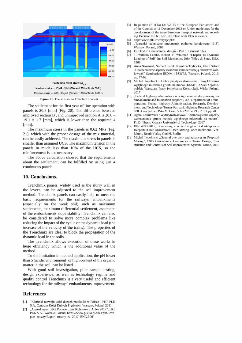
Figure 21. The stresses in Trenchmix panels.
The settlement for the first year of line operation with
panels is 20.8 [mm] (Fig. 20). The difference between
improved section B , and unimproved section A is 20.8 –
19.1 = 1.7 [mm], which is lower than the required 4
[mm].
The maximum stress in the panels is 0.62 MPa (Fig.
21), which with the proper dosage of the mix material,
can be easily achieved. The maximum stress in panels is
smaller than assumed UCS. The maximum tension in the
panels in much less than 10% of the UCS, so the
reinforcement is not necessary.
The above calculation showed that the requirements
about the settlement, can be fulfilled by using just 4
continuous panels.
10. Conclusions.
Trenchmix panels, widely used as the slurry wall in
the levees, can be adjusted to the soil improvement
method. Trenchmix panels can easily help to meet the
basic requirements for the railways' embankments
(especially on the weak soil) such as maximum
settlements, maximum differential settlement, assurance
of the embankments slope stability. Trenchmix can also
be considered to solve more complex problems like
reducing the impact of the cyclic or the dynamic load (the
increase of the velocity of the trains). The properties of
the Trenchmix are ideal to block the propagation of the
dynamic load in the soils.
The Trenchmix allows execution of these works in
huge efficiency which is the additional value of the
method.
To the limitation in method application, the pH lower
than 5 (acidic environment) or high content of the organic
matter in the soil, can be listed.
With good soil investigation, pilot sample testing,
design experience, as well as technology regime and
quality control Trenchmix is a very useful and efficient
technology for the railways' embankments improvement.
References
[1] “Kierunki rozwoju kolei dużych prędkości w Polsce”, PKP PLK S.A. Centrum Kolei Dużych Prędkości, Warsaw, Poland, 2011
[2] „Annual report PKP Polskie Linie Kolejowe S.A. for 2017”, PKP PLK S.A., Warsaw, Poland, https://www.plk-sa.pl/files/public/ra-
port_roczny/Raport_roczny_za_2017_ENG.PDF
[3] Regulation (EU) No 1315/2013 of the European Parliament and
of the Council of 11 December 2013 on Union guidelines for the development of the trans-European transport network and repeal-
ing Decision No 661/2010/EU Text with EEA relevance
[4] http://www.plk-inwestycje.pl/#/ [5] „Warunki techniczne utrzymania podtorza kolejowego Id-3”,
Warsaw, Poland, 2009
[6] Eurokod 7: Geotechnical design – Part 1: General rules. [7] T. William Lambe, Robert V. Whitman “Chapter 15 Dynamic
Loading of Soil” In: Soil Mechanics, John Wiley & Sons, USA,
1969 [8] Anna Nowosad, Norbert Kurek, Karolina Trybocka, Jakub Saloni
„Geotechniczne aspekty związane z modernizacją obiektów kole-
jowych” Seminarium IBDiM i PZWFS, Warsaw, Poland, 2019, pp. 77-92
[9] Michal Topolnicki „Dobra praktyka stosowania i projektowania
wgłębnego mieszania gruntu na morko (DSM)”, XXXII Ogólno-polskie Warsztaty Pracy Projektanta Konstrukcji, Wisla, Poland,
2017
[10] „Federal highway administration design manual: deep mixing for embankment and foundation support”, U.S. Department of Trans-
portation, Federal highway Administration, Research, Develop-
ment, and Technology Turner-Fairbank Highway Research Center 6300 Georgetown Pike McLean, VA 22101-2296, 2013, pp. 41
[11] Agata Leśniewska “Wytrzymałościowe i technologiczne aspekty
wzmacniania gruntu metodą wgłębnego mieszania na mokro”, Ph.D. Thesis, Gdansk University of Technology, 2007
[12] DIN 4093:2015, Bemessung von verfestigten Bodenkörpern –
Hergestellt mit Düsenstrahl-Deep-Mixing- oder Injektions- Ver-fahren, Beuth Verlag GmbH, Berlin
[13] Michal Topolnicki „General overview and advances in Deep soil
Mixing”, XXIV Geotechnical Conference of Torino Design, Con-struction and Controls of Soil Improvement System, Torino, 2016